Embed Size (px)
Citation preview

www.PEBsteel.com
ERECTIO
N M
AN
UA
L
PEB Steel Buildings Co., Ltd
PEB
Steel B
uildings Co., Ltd
HCMC Office:
Unit 701, 7th Floor, C.T Plaza, 60A Truong Son St., Ward 2, Tan Binh Dist.,Ho Chi Minh City, Vietnam.Tel : (84) (28) 3 8 475 475 Fax: (84) (28) 3 8 476 476
Factories:
Dong Xuyen Industrial Park, Ba Ria Vung Tau Province, Vietnam.Thilawa Special Economic Zone - TSEZ, Yangon, Myanmar.Pithampur, Madhya Pradesh State, India.
Year 2017
ERECTION MANUALFor Site Engineers
PRE - ENGINEERED BUILDINGS

CO
NTE
NTS 1. GENERAL INTRODUCTION 3
1.1. INTRODUCTION1.2. IMPORTANT NOTICE
33
2. BASIC PRINCIPLES 4-72.1. JOB SITE PREPARATION2.2. FOUNDATIONS AND ANCHOR BOLTS2.3. MATERIAL LAYOUT2.4. RECEIVING YOUR BUILDING
44-6
77
3. STORAGE & PROTECTION 8-93.1. FOR ROOF & WALL PANELS3.2. FIBERGLASS BLANKET INSULATION3.3. PROPER STORAGE FOR MAIN FRAME & GALVANIZED MEMBERS
889
5. INSTALLATION PROCEDURE FOR ROOFING, CLADDING, FLASHING & TRIMS 31-435.1. GENERAL NOTE5.2. INSTALLATION OF ROOFING FOR LOK-SEAM® & CLADDING5.3. INSTALLATION OF ROOFING FOR PEBSEAM128TM
5.4. INSTALLATION OF TRIM AND ACCESSORIES
3131-3940-43
43
446. FINAL CHECK
457. SAFETY ORDERS
46-528. SAFETY PHOTOS UNDER CONSTRUCTION
53-549. BASIC ERECTION EQUIPMENTS9.1. LIFTING EQUIPMENT, ROPES AND LINES.9.2. ELECTRICAL EQUIPMENT9.3. HAND TOOLS
535354
55-6010. RELATED FORM10.1.10.2.10.3.10.4.10.5.10.6.10.7.10.8.
SITE DAILY REPORTERECTION WEEKLY REPORTA/B SETTING INSPECTIONPLUMBING INSPECTION HIGHT STRENGTH BOLTS INSPECTION RECORDACCEPTANCE MINUTE WORKFINAL INSPECTION REPORTPUNCH LIST FORM
555656575859
60-6162
4. ERECTION PROCEDURE FOR MAIN FRAMES 10-304.1. STRUCTURAL FRAMING ERECTION PROCEDURE 4.1.1. DETAIL ERECTION GUIDE FOR STRUCTURAL FRAME 4.1.2. RIGID FRAME CONNECTION DETAILS4.2. PEBHYBRID ERECTION PROCEDURE 4.2.1 DESCRIPTION 4.2.2 ADVANTAGES 4.2.3 ERECTION PROCEDURE FOR PEBHYBRID4.3. CHOICE OF THE CRANE4.4. LOAD ON FRAMES AND PURLINS4.5. METHODS OF BOLT TIGHTENING4.6. STRUCTURAL FASTENERS
10-1710-16
1718-24
1818
18-2425-28
2929-30
30
GENERAL INTRODUCTION
03
1.1. INTRODUCTION
The policy of PEB STEEL is to create satisfied customers. Buildings are designed using sound principles of Engineering. Fabrication is of the highest quality. However, there remains one final and all important phase that must be accomplished. That is, the assembling of the various component parts those make up the building. This final phase is “ERECTION”.
The term “ERECTION” is generally thought of as applying to the fabricated steel for the building, but it is much more. It actually begins with the foundation, building anchorage and carries through to cleaning up the jobsite on completion of erection. It is our purpose here to help you in obtaining “Quality Erection” there by creating an owner completely satisfied and proud of his PEB STEEL building.
The methods and procedures suggested by this erection guide are fundamental in nature and represent good, safe erection practices. They can, and should be modified when necessary to adapt to special conditions or circumstances. Before you begin, familiarize yourself with the building details and the sequence of erection. This will enable you to plan your work and avoid unnecessary delays during construction.
1.2. IMPORTANT NOTICE
If PEB STEEL erection crews are not being used to erect the building, PEB STEEL accepts no responsibility for erection quality, leakage, defects or collapse due to negligence or improper erection procedures.
1. GENERAL INTRODUCTION

04
BASIC PRINCIPLES
2.2. FOUNDATIONS AND ANCHOR BOLTS
Any building, regardless of size or type, depends on a good foundation for a satisfactory life expectancy and a minimum maintenance cost during that life. Accurate foundation dimensions and proper anchor bolt locations are critical to the overall erection procedure. Therefore it should be accurate and within the tolerance specified in the erection drawing.
Job site is clean and ready to receive your building
2.1. JOB SITE PREPARATION
If you have not already done so, you must now make a detailed inspection of the job site and note all conditions that will affect building erection.
Some important points to check are:
A. Location 1. Job Site – is it clean, level and ready. The ground-soil is hard enough for crane to move 2. Storage locationB. Accessibility for delivery trucks and equipmentsC. Obstructions, below ground, above ground, overhead cablesD. Maneuvering room for equipmentsE. Utilities available.
Existing conditions should be determined before material delivery and should be considered in pre-construction planning. There are many benefits to a clean and orderly job site.
2. BASIC PRINCIPLES
BASIC PRINCIPLES
05
STEP 1 STEP 2
Marking center line and elevationAB Setting
STEP 3
Insert AB, template andtack weld hub and AB
STEP 4
Pouring concrete
STEP 5
Removing template
Center line marking
Elevation marking
Center line marking
Tack weld hub and A/B
Elevation marking
Center line marking
Tack weld hub and A/B
Elevation marking

06
BASIC PRINCIPLES
Following up during casting concrete to make sure that the position of A/B is not move
A/B was assembled and connected to steel rod by welding
07
BASIC PRINCIPLES
Some pictures for Unloading at job site
2.3. MATERIAL LAYOUT
Materials should be laid out to avoid double handling, layout will depend on size of building and site conditions. Use timber blocks between bundles or members for ease of handling.
2.4. RECEIVING YOUR BUILDING
All PEB STEEL buildings are carefully checked and loaded to ensure safe delivery and to avoid shortages. Materials are packaged and can be unloaded by use of heavy duty Fork-lift or by crane. Care should be exercised when handing materials to avoid damages.
At time of unloading, materials should be checked against Bill of Materials or Packing List. Any shortages must be reported to PEB STEEL within a week. After this time PEB STEEL will not accept responsibility for shortages or transit damage.
STORAGE AND PROTECTION
09
Cover with canvas tarpaulin to protect from rain » Tie down cover ends to keep from wind blows » Block above ground to keep water out » Wood slabs to serve as platform for laying down the insulations.
3.3. PROPER STORAGE FOR MAIN FRAME & GALVANIZED MEMBERS
08
43 WOOD BOARD
When galvanized or zincalume panels becomes wet from rain, natural condensation or other causes, white rust may result. This may occur either during transit or due to improper storage at the job site.
If sheetings are to be stored temporarily in open area and this is absolutely necessary, then they should be covered with tarpaulin or any water proof materials. (Never use plastic since it promotes moisture). If no covering is available, the procedure shown below must be followed to prevent the entry of moisture into the panels and consequent storage stain.
Panels are to be stacked on top each other and wooden supports need to be placed under the bottom panels to provide air space. The top panels “3” is extended outward at least 900 mm plus or minus and the second panels “2” to be extended down yard to almost near the ground to protect the zincalume panels “1” below. Also wrap the upper portion of the panels “1” below about 300 mm of polythene sheets.
Note: Zincalume sheets should be keep away from whitewash, cement, lime, mud etc.
WATER ROOFCOVERING
300
900
SLOPE 15 o - 20 o
Z/A PANEL
AIR SPACEDRY GROUND
PAINTED PANEL
2
1
3
STORAGE OF FIBERGLASS INSULATION
DRY GROUND
1
4
TARPAULIN
TIE
WOOD BLOCKABOVE GROUND
ABOVE ALL, TIDINESS IS IMPORTANT FOR SAFETY,AND WILL AVOID LOSS OR DAMAGE OF PARTS
3.2. FIBERGLASS BLANKET INSULATION
3.1. FOR ROOF & WALL PANELS
3. STORAGE AND PROTECTION
STORAGE AND PROTECTION

ERECTION PROCEDURE FOR MAIN FRAMES
10
4. ERECTION PROCEDURE FOR MAIN FRAMES
4.1. STRUCTURAL FRAMING ERECTION PROCEDURE
4.1.1. DETAIL ERECTION GUIDE FOR STRUCTURAL FRAME
STEP 1
- Installing columns, girts, flange brace and wall bracing, tube struts (if have) - Checking alignment of columns before proceeding step 2.
STEP 2.
- Using 2 cranes to lift first rafter (Crane capacity should be considered actual weight and height of rafter). - We must start installation with bracing bay
ERECTION PROCEDURE FOR MAIN FRAMES
11
STEP 3.
- Fixing temporary guide wire as sketch (consider degree max 500). - Quantity of guide wire should be 6 meter/pcs in plane.
Note: Temporary bracing should keep until completed all items of Main frame.
200130
Pipe Ø21x15x2
Pipe Ø21x15x2
10
Pipe Ø42x220x2
Pipe Ø21x185x2
Pipe Ø42x700x2
Sti�ener W3: 60x50x5
Plate W1: 120x120x5
Bolt M12x50 (Q’ty 4pcs)
Plate W2: 300x120x5
700
RAFTER
Detail B
Ground
Angle 75x75
Detail A
1500
100
600
Temporary cablebracing
STEP 4.
- Lifting second rafter as sketch. - Installing full purlins.

Purlin block
ERECTION PROCEDURE FOR MAIN FRAMES
13
STEP 6.
- Continute to lift third rafter as step 2.
STEP 7.
When we completed 2 bays. We must start to fix: - Purlin blocks - Sag Arrestor
Note: (We must install the Purlin Block first and after that Sag Arrestor)
ERECTION PROCEDURE FOR MAIN FRAMES
12
STEP 5.
- Installing full roof bracing, tube struts and flange brace. - Checking and aligning first bay before next rafter
WRONG CORRECT
WRONG WRONG CORRECT
SMALL FLANGE
SMALL FLANGEBIG FLANGE
SMALL FLANGE
SMALL FLANGE BIG FLANGE
BIG FLANGE SMALL FLANGE
BIG FLANGE
SMALL FLANGE
BIG FLANGE BIG FLANGE
* Correct purlin lapping
* Correct stitch bolt

ERECTION PROCEDURE FOR MAIN FRAMES
15
STEP 9.
- Lifting next rafter as sketch. - Installing full purlins.
STEP 10.
- Continute to install mainframe till finishing as step 2 to step 9. - Doing alignment all erected frame. - Doing HSB tightening. - Pouring grouting before installation of roof and wall sheeting
ERECTION PROCEDURE FOR MAIN FRAMES
14
STEP 8.
- Installing roof bracing and flange brace. - In case permanent bracing bays, 100% menbers must be installed. - In case none bracing bay: 50% purlins and 100% flange brace must be installed. 100% girts and flange brace must be installed.
Sag arrestor
Tem
pora
ry b
racin
g 12
mm
dia
<=450
Tem
pora
ry b
racin
g 12
mm
dia
<=450

ERECTION PROCEDURE FOR MAIN FRAMES
16
Photos reference for structural framing erection
ERECTION PROCEDURE FOR MAIN FRAMES
17
4.1.2. RIGID FRAME CONNECTION DETAILS
» Refer to Erection Drawings for quantity and size of bolts at every connections » All connections bolts in rigid frames are high strength bolts » All bolts are to be installed using the snug tight method unless noted otherwise. » Install and tighten all bolts at all frame connections as each rigid frame is assembled.

ERECTION PROCEDURE FOR MAIN FRAMES
STEP 2
- Inserting square tube as sketch. - Fixing bolt and tightening
19
ERECTION PROCEDURE FOR MAIN FRAMES
18
4.2.2. ADVANTAGES:
1. Save weight about 15-20% of rafters. 2. Save time fabrication by roll cold formed machines form Galvanized coils no need welding &
painting. 3. Columns are built-up sections, can design for factories with overhead cranes. 4. Truss structure rafters (open web) better for useful space as fire, air, water…. piping systems. 5. Truss structure rafters also good for roof systems. 6. Galvanized rafters make long life for buildings, reduce maintenance cost. 7. Easier in transportation to jobsites. 8. Friendly for environment
4.2.3. ERECTION PROCEDURE FOR PEBHYBRID:
STEP 1
- Segregating materials and put them on timber support.
4.2. PEBHYBRID ERECTION PROCEDURE
4.2.1 DESCRIPTIONS:
PebHybrid a form of Pre-Engineered Buildings, it was developed by PEB Steel Buildings Company with: - Columns are built-up sections; - Rafters are truss structure from 2 Omegas cold formed section (upper and lower) connected with square tubes hollow sections by bolts. - All purlins, girts, flange bracings, X-bracings… are same PEB structures before.

ERECTION PROCEDURE FOR MAIN FRAMES
21
STEP 6
- Fixing temporary guide wire as sketch.
STEP 7
- Installing second rafters and completed all of Purlins, Bracing, Flange brace, etc. After that, we must check and align this bay. - Continue to third trusses as sketch. - Installing flange brace for columns and trusses.
ERECTION PROCEDURE FOR MAIN FRAMES
20
STEP 4
- Installing columns, girts, wall bracing, strut tube and flange brace - Align columns before lifting PebHybrid.
STEP 3
- Joining 2 trusses together.
STEP 5
- Lifting first PebHybrid truss as sketch.

ERECTION PROCEDURE FOR MAIN FRAMES
22
STEP 8
- Continute to lift next truss as sketch. - Keep fixing sag arrestors and purlin blocks as sketch.
STEP 9
- Continute to install mainframe till finishing as step 2 to step 8. - Doing alignment all erected frame. - Doing HSB tightening. - Pouring grouting before installation of roof and wall sheeting.
- Continute to the end
Purlin block
ERECTION PROCEDURE FOR MAIN FRAMES
23
Photos Referrence for PebHybrid Erection
1. Fitting up rafters on the ground:
2. Installation mainframe:

ERECTION PROCEDURE FOR MAIN FRAMES
24
3. Main frame:
4. Sheeting:
5. Testing:
» The erection of first bay always requires more power. You should prepare all steel member and bring all necessary girts, purlins, bracing cables, flange braces of first bay near to their permanent position and build up the hoisting frame part one day before the erection.
In other case, use the spreader – bar to support the erection, so you can save the crane-height.
MIN 45o
h
H
L
≥ 45o
4.3. CHOICE OF THE CRANE
The necessary height of crane beam depends on the height of permanent position of the highest rafter in the building and on the length of above rafter.
Say: + Height of highest rafter is “h” + Length of rafter part is “L”
The crane - height (H) should be more than H = [h + ( L/4 )] The degree between hoisting cable and rafter should be more than 450.
ERECTION PROCEDURE FOR MAIN FRAMES
25

ERECTION PROCEDURE FOR MAIN FRAMES
26
Setting steel column
Connection between Rafter and column
Connection between Rafter and Rafter
ERECTION PHOTOS REFERENCE
ERECTION PROCEDURE FOR MAIN FRAMES
27
The first frame with temporary bracing
The first bay with full purlins and X-bracing
Continue to next bay
ERECTION PHOTOS REFERENCE

ERECTION PROCEDURE FOR MAIN FRAMES
29
4.4. LOAD ON FRAMES AND PURLINS
No loads should be supported from the purlins unless the building has been designed for additional loads. In such cases the loads should not be supported from the purlins until the roof sheets have been installed and fully screwed.
The following sketches show correct and incorrect methods of support from rafters and purlins.
4.5. METHODS OF BOLT TIGHTENING
METRIC BOLT AND CAP SCREW TORQUE VALUES
M36 1150 850 1450 1075 2250 1650 2850 2100 3200 2350 4050 3000 3750 2750 4750 3500M33 900 675 1150 850 1750 1300 220 1650 2500 1850 3150 2350 2900 2150 3700 2750M30 675 490 850 625 1300 950 1650 1200 1850 1350 2300 1700 2150 1600 2700 2000M27 490 360 625 450 950 700 1200 875 1350 1000 1700 1250 1600 1150 2000 1500M24 330 250 425 310 650 475 825 600 925 675 1150 850 1075 800 1350 1000M22 260 190 330 250 510 375 650 475 725 540 925 675 850 625 1075 800M20 190 140 240 180 375 275 475 350 530 400 675 500 625 460 800 580M18 135 100 175 125 260 195 330 250 375 275 475 350 440 325 560 410M16 100 73 125 92 190 140 240 175 275 200 350 225 320 240 400 300M14 63 47 80 60 120 88 150 110 175 130 225 165 205 150 260 190M12 40 29 50 37 75 55 95 70 110 80 140 105 130 95 165 120M10 23 17 29 21 43 32 55 40 63 47 80 60 75 55 95 70M8 12 8.5 15 11 22 16 28 20 32 24 40 30 37 28 47 35M6 4.8 3.5 6 4.5 9 6.5 11 8.5 13 9.5 17 12 15 11.5 19 14.5
N-m Lb-ft N-m Lb-ft N-m Lb-ft N-m Lb-ft N-m Lb-ft N-m Lb-ft N-m Lb-ft N-m Lb-ft
DrysLubricated
Class 4.8
Size
Class 10.9Class 8.8 or 9.8 Class 12.9
Lubricated Lubricated LubricatedDrys Drys Drys
8.8 9.8
8.8 9.8
8.8 9.8
10.9
10.9
10.9
12.9 12.9
12.9 12.9
12.9
5
5
5
10
10
10
10
10
10
12
12
12
4.8
4.8
4.8
PropertyClass andHeadMarkings
PropertyClass andNut Markings
ERECTION PROCEDURE FOR MAIN FRAMES
28
…Continue…
…Continue…
Completed main frame installing
ERECTION PHOTOS REFERENCE
wrong correct
- For structural frames - For PebHybrid frames
- For purlins
CORRECT

ERECTION PROCEDURE FOR MAIN FRAMES
30
Do not use these values if a di�erence torque value or tightening procedure is give for specific application. Torque values listed are for general use only. Check tightness of fasteners periodically.
Shear bolts are designed to fail under predetermined loads. Always replace shear bolts with identical property class.
Fasteners should be replace with the same or higher property class. If higher property class fasteners are used, these should only be tightened to the strength of the original.
a " Lubricated means coated with a lubricant such as engine oil, or fasteners with phosphate and oil coatings. "Dry" means plain or zinc plated without any lubrication."
Make sure fasteners threads are clean and that you properly start thread engagement. This will prevent them from failing when tightening.
Tighten plastic insert or crimped steel-stype lock nuts to the full torque value.
4.6. STRUCTURAL FASTENERS
The chart below identifies the most commonly used bolts in PEB Steel Building and indicates where they are used in connecting the various components.
(ASTM A – 307)Machine Bolt & Nut
or (DIN 4.6)
M12
M12
30mm, 50mm
Attachment of secondary& Primary structurals
bolting forces areminimal.
(ASTM A – 307)Fin Neck Bolt & Nut
Or (DIN 4.6)
30mm
Used where bolt head willbe exposed in openingwhere flush heads arerequired for clearance
or appearance.
STANDARD BOLT METRIC STANDARD SIZE TYPICAL USE
M 16 45mm, 60mm
M 20 60mm, 80mm
M 24 80mm, 100mm
M 30 120mm
Attachment of primarystructurals where
bolting forces are high(moment type connection)
(ASTM A – 325)High – Strength Bolt,
Nut & Washeror (DIN 8.8)
INSTALLATION PROCEDUREFOR ROOFING, CLADDING, FLASHING & TRIMS
31
5.1. GENERAL NOTES
1. Always use a chalk line for accurate drilling and screwing. This gives better appearance and less risk of leakage due to misdrilling 2. At the end of each working day clean the roof with asoft brush. Sweep off old drill bits, pop rivets, swarf from drilling or cutting. These items can cause rusting if they are not removed 3. When walking on the roof, do not stand on high ribs, stand only on the low ribs, preferably over the purlin line. Standing on high ribs can cause severe damage which could lead to possible leakage 4. Do not walk on skylights 5. Mark out the sheeting along the length of the building, this will give correct overlaps and avoid creep.
5.2. INSTALLATION OF ROOFING FOR LOK-SEAM & CLADDING
Sheeting installation procedure
TOO LOOSE TOO TIGHT CORRECT
1 mm
5. INSTALLATION PROCEDURE FOR ROOFING, CLADDING, FLASHING & TRIMS
®

INSTALLATION PROCEDUREFOR ROOFING, CLADDING, FLASHING & TRIMS
33
STEP 3
- Installing first Lokseam panel.- Fixing screw at eave at sketch.
STEP 4
- Continute to install Lokseam as step 2 to step 3.
Clip
STEP 1.
- Fixing rack support, rack angle as sketch.
STEP 2.
- Laying insulation, fixing inside metal closure with bead mastic.- Spacing among inside metal closures are 470mm.- NFR-1 is always bottom layer as sketch.
Fiber Glass
Aluminium Facing (Middle Layer)
NFR1 Facing (Bottom Layer)
Rack support
Expansion clip
Rack angle
Bead mastic
Inside metan closure
INSTALLATION PROCEDUREFOR ROOFING, CLADDING, FLASHING & TRIMS
32
INSTALLATION PROCEDUREFOR ROOFING, CLADDING, FLASHING & TRIMS
35
STEP 7
- Installing endwall panel as sketch.
STEP 8
- Fixing outside foam clousure.
Fixing outside foam closure
INSTALLATION PROCEDUREFOR ROOFING, CLADDING, FLASHING & TRIMS
34
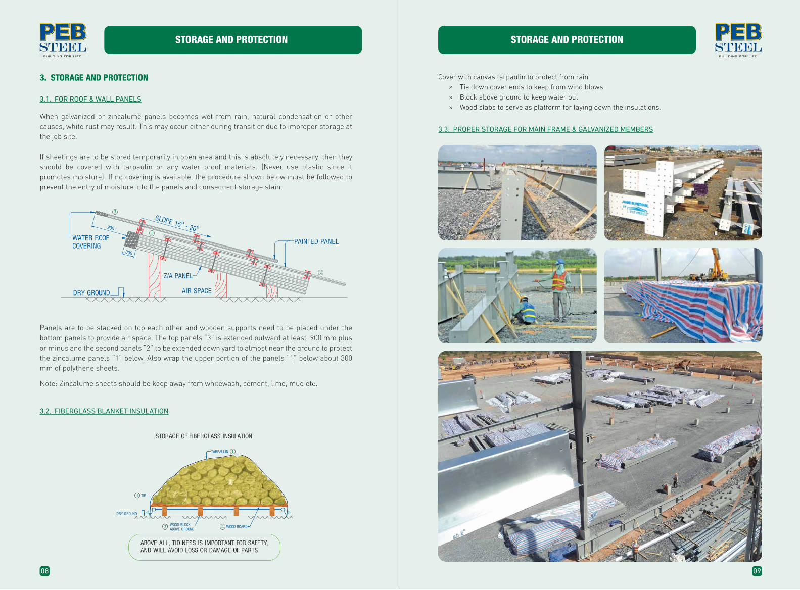
STEP 5
- Fixing drip trim, adjustable conner trim as sketch.
- Fixing inside foam clousure.
STEP 6
Installing wall panel as sketch.
Wall insulation should be clamped at the eave-strut or secured with double-faced tape, and pulled tight before screwing the panel.
Successive “drops” of insulation should be stapled to the previous by the side tabs. This is important to complete the vapour barrier seal.
Roof insulation should be fixed or clamped at one eave strut and stretched as tight as possible before fixing at the other eave strut. On average sized buildings one roll of insulation will span the full width, but on wider buildings it may be necessary to splice, this should be done on a purlin. After the roof sheets have been placed, the next run of insulation can be stapled at the side tabs and work continue.
Process lock with special machine
Connection between clip and LOK-SEAM® panel
Adjustable conner trim

INSTALLATION PROCEDUREFOR ROOFING, CLADDING, FLASHING & TRIMS
37
STEP 11
- Installing endwall panel as sketch.
STEP 12
- Bending top end panel.
Bending top end panel
INSTALLATION PROCEDUREFOR ROOFING, CLADDING, FLASHING & TRIMS
36
STEP 9
- Fixing conner trim and eave trim.
STEP 10
- Fixing gutter strap as sketch.
Fixing gutter strap
Fixing eave trim

INSTALLATION PROCEDUREFOR ROOFING, CLADDING, FLASHING & TRIMS
38
STEP 13
- Fixing outside metal closure with bead mastic.
STEP 14
- Fixing ridge cap.
Fixing outside metal closure
Fixing ridge cap
39
INSTALLATION PROCEDUREFOR ROOFING, CLADDING, FLASHING & TRIMS
STEP 15
- Fixing PEB peak sign as sketch.
STEP 17
- Seaming Lokseam panel and cleaning roof.
STEP 16
- Installing downspout as sketch.
Fixing downspout
Completed Roof sheeting installing

INSTALLATION PROCEDUREFOR ROOFING, CLADDING, FLASHING & TRIMS
40
INSTALLATION PROCEDUREFOR ROOFING, CLADDING, FLASHING & TRIMS
41
STEP 2
Installing the support Z clip from the endof purlin 70mm.
STEP 3
Installing the TR-0012A on support Z clips.
STEP 5
STEP 4
Installing TR-0003
5.3. INSTALLATION OF ROOFING FOR PEBSEAM128TM
Double SC-1002 screw
TR-0007
Z clip
70mm
STEP 1
Installing the TR-0007 with double SC-1002 screw at one location. Because length of TR-0007 is 3100mm, each TR-0007 should be had 12 screws at six locations as below figure.
TR-0012ATR-0012A
TR-0003
PEBSEAM inside metal closure
STEP 6
Putting the PEBSEAM panel on right location and control straightness of end point of panel. We must fix the first PEBSEAM panel and TR-0003A by SC-1001 screw at 500mm.
STEP 7
Assembling PEBSEAM clip and support Z clip with two SC-1002 screws.
Installing component PEBSEAM clip and support Z clip to purlin with two SC-1002 screws.
PEBSEAM Clip Z Clip
SC-1002
Hook of PEBSEAM Clip
440mm
STEP 9
Putting second PEBSEAM panel on right location and controlling straightness of end point of panel.
Second panelFirst panel
STEP 8
Setting new inside metal closure of PEBSEAM from last inside metal closure 400mm.
STEP 10
Installing component PEBSEAM clip and support Z clip to purlin with two SC-1002 screws.
400mm
PEBSEAM panel
500mm
Covering inside metal closure of PEBSEAM panel by bead mastic and then fix it to TR-0007.

42
INSTALLATION PROCEDUREFOR ROOFING, CLADDING, FLASHING & TRIMS
INSTALLATION PROCEDUREFOR ROOFING, CLADDING, FLASHING & TRIMS
43
GENERAL NOTES
» Use the proper tools for cutting: aviation snips for cutting trims, nibbler and shear for cutting sheets
» Use a chalk line to keep things straight » Use a spirit level to keep things plumb » Always clean-o� your work » Study the standard drawing supplied, these indicate correct trims, and fixing details for each
application. Take note of spacing of screws and rivets or the number of fasteners per item » Observe where foam closures have to be installed » Be sure that sealant or mastic is applied where required » Read all the notes on the drawing, they are important » Follow manufactures instructions for installation of Roll-up-door, Personnel doors or Special
Accessories » Use the correct tools » Turn up of panel valley end to form a dam » This should be applied for every roof opening and transition connections.
5.4. INSTALLATION OF TRIMS AND ACCESSORIES
Keep it neat - keep it straight, the neatness of trimming and installation of accessories is of paramount importance to give the finished building the quality look.
Conner Trim, Gable Trim, Louvers and Downspout
STEP 11
Fixing SC-1003 and SC-0001 screws at the end of PEBSEAM panel.
SC-1001 SC-1003
STEP 14
Installing TR-0012A on support Z clips.
TR-0012A
STEP 12
Continue from step 8 to step 11.
STEP 13
Installing final support Z clip line with 440mm length from last support Z clip line.
Z clip
440mm
STEP 15
Installing TR-0003
TR-0012A
STEP 16
Putting final PEBSEAM panel on right location, then fixing all screws at the end and side of PEBSEAM panel.
OVERVIEW
44
FINAL CHECK
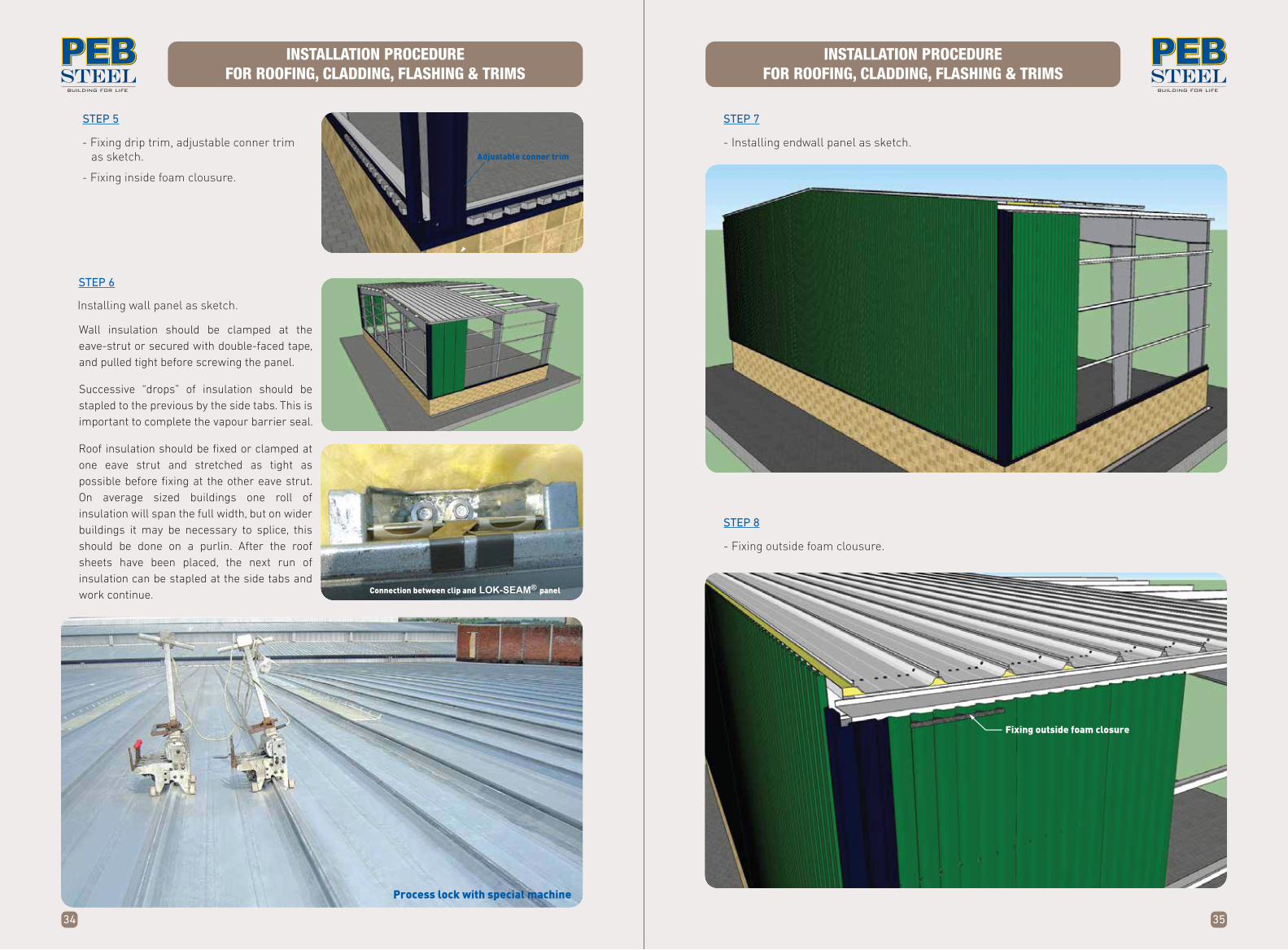
6. FINAL CHECK
CLEANING OF 1st LAYER PANEL BEFORE INSULATION & LOK-SEAM® INSTALLATION
After completing all trims and accessories a final inspection of the building should be made.
1. All bracing in position and tightened
2. All bolts in place and high strength bolts tightened to correct tension
3. Check that roof an gutters are clear of debris and ferrous metals
4. Check for misdrilled screws
5. Check all roof penetrations for weather tightness
6. Check operation of all doors
7. Touch-up any damaged paint
8. Clean-up the site
9. Handover keys and the building.
SAFETY ORDERS
45
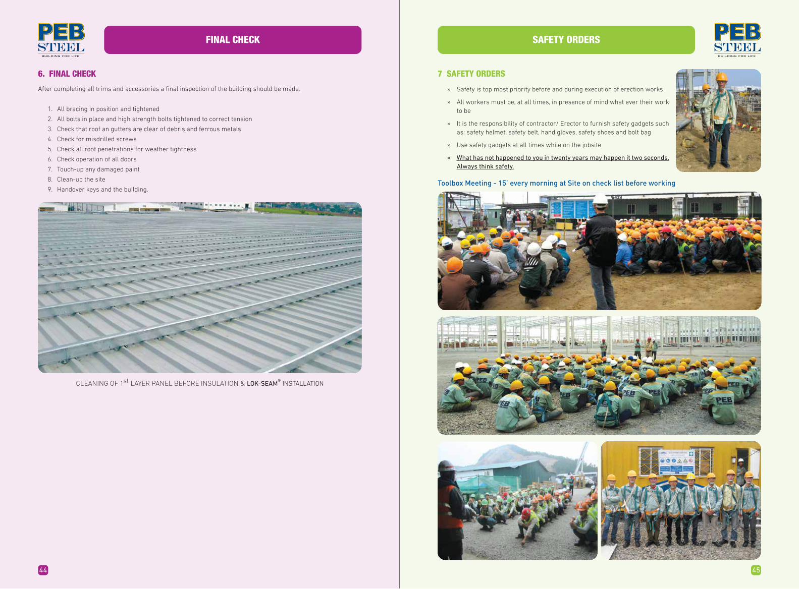
7 SAFETY ORDERS
» Safety is top most priority before and during execution of erection works
» All workers must be, at all times, in presence of mind what ever their work to be
» It is the responsibility of contractor/ Erector to furnish safety gadgets such as: safety helmet, safety belt, hand gloves, safety shoes and bolt bag
» Use safety gadgets at all times while on the jobsite
» What has not happened to you in twenty years may happen it two seconds. Always think safety.
Toolbox Meeting - 15’ every morning at Site on check list before working
46
SAFETY PHOTOS UNDER CONSTRUCTION SAFETY PHOTOS UNDER CONSTRUCTION
47
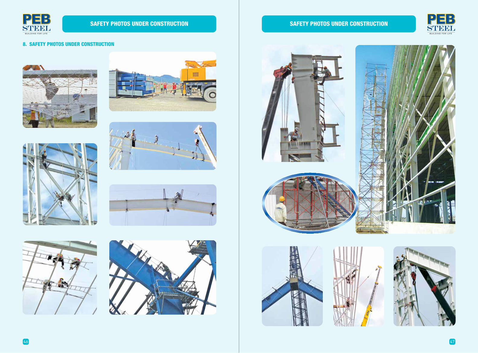
8. SAFETY PHOTOS UNDER CONSTRUCTION

48
SAFETY PHOTOS UNDER CONSTRUCTION SAFETY PHOTOS UNDER CONSTRUCTION
49

SAFETY PHOTOS UNDER CONSTRUCTION
51
MAN LIFTMAN LIFT
50
SAFETY PHOTOS UNDER CONSTRUCTION

BASIC ERECTION EQUIPMENTS
53
The following items are basic requirements of a six man erection crew.
9.1. LIFTING EQUIPMENT, ROPES AND LINES. Telescopic crane. 03 Ton Forklift with 10 m Mast (for Smaller Size) buildings. Spreader Bars – 6 m and 12 m. Assorted Slings, in various sizes and lengths. Steel guy lines of temporary bracing. (minimum 08 no.) Manila ropes for hand lines (minimum 02 no.) “Come-alongs”, “Tirfors”, or Turnbuckles (08 no.)
9.2. ELECTRICAL EQUIPMENT
Generator/Welder. Extension Leads and Pigtails. Heavy Duty Drill 1 / 2’’ (01 No.) Heavy Duty Drill 1 / 4’’ (02 No.) Electric Nibbler (01 No.) Electric Shear (01 No.) Angle Grinder (1 No.) Concrete Drill (01 No.)
Welding MachineElectric Shear Grinder
Heavy Duty Drill with Reamer Generator
9. BASIC ERECTION EQUIPMENTS
52
SAFETY PHOTOS UNDER CONSTRUCTION

10. RELATED FORM
54
BASIC ERECTION EQUIPMENTS
9.3. HAND TOOLS
Socket Wrench 3 / 4’’ or 1’’ drive with asst. sockets. Open ended wrenches assorted imperial sizes Spud wrenches, 15/16’’ opening up to 1-1/8’’ Pipe wrench - 12’’ Screw drivers – Standard and Philips. Aviation snip – Left and Right. Pop rivet puller. (02 No.) Vice grips (08 No.) 4lb. Sledge hammer. Hacksaw frame an blades. Wood saw Spirit level and plumb-bob. Chalk line Steel measuring tapes 30 m and 6 m Utility knife. Staple applicators. Cold Chisel. Oxy-Acetylence cutting outfit. Welding hood. Hard hats. Safety belts – Bolt bags. Broom Masonry drill bits 12mm Extension ladders 02 no. Step ladder. Hilti gun, cartriges and nails.
Pop Rivet Puller
Screw Gun
Powder Actuated Tool
Aviation Snip
Ratchet SpannerVice Grips
Nibbler
Torque Wrench Impact Wrench
Drill 10mm
Hard Hat Safety Boots Welding Hood
Gloves
Goggles Oxy-AcetyleneCutting Out�e
Ladders
RELATED FORM
55
SITE DAILY REPORT
Date / /
I. Manpover & equipment
1. Supervisor 4. Worker
2. Safety O�cer 5. Crane
3. Warehouse keeper 6. Trailer
II. Safety
1. Safety checking: AM PM
2. Note
III. Material status
IV. Erection progress
V. Weather
VI. Generat Comments
Erection Representative PEB Steel Representative
Item:
10.1. SITE DAILY REPORT

RELATED FORM
57
RELATED FORM
56
- Main frame col. alignment - Crane beam straightness
- Crane beam elevation
10mm+-
10mm+-
1:300; 1:500
PLUMBING RECORD
Name
Signature
Date
Name
Signature
Date
Name
Signature
Date
Job No.
1. GENERAL TOLERANCES
2. RECORD
3 . NOTE
Surveyor Contractor PEB-Erection Coordinator
3 . COMMENTS
Building No. Ref. Drawing Page
ACTUAL RESULT
Grid Line
- Method
- Equipment original:
- Equipment calibrication Yes
Hand tool Theodolite
No
Tolerance DeviationTop Accept Reject
RemarkBottom
10.4. PLUMBING INSPECTION
ANCHOR BOLT INSPECTION REPORT
Job No.
Surveyor Contractor PEB-Erection Coordinator
Grid Line Critical Distance
a . Temporary plate
b. Size of Anchor Bolf's Correctness
c. Projection Correctness
Name
Signature
Date
Name
Signature
Date
Name
Signature
Date
Yes
Yes
Yes
No
No
No
Bay Spacing Elevation Remark
1. RECORD DIMENSIONS
2. ANCHOR BOLT GROUPS
3. GENERAL COMMENTS
Building No. Ref. Drawing
Cladding
Prepared by Checked by
ERECTION WEEKLY REPORT
Job No.
No. Items
A/B setting
Main frame
Roofing,Ridge vent
M2
M2
M2
Group
UnitBOMQty
Week 1Date
Week 2Date
Week 3Date
Week 4Date
Week 5Date
Week 6Date
Week 7Date
Week 7Date
Bldg No. Project Name: Location:
10.2. ERECTION WEEKLY REPORT
10.3. A/B SETTING INSPECTION

RELATED FORM
59
RELATED FORM
58
HIGH STRENGTH BOLTS INSPECTION RECORD
Name
Signature
Date
Name
Signature
Date
Name
Signature
Date
Job No.
1. RECORD
2. NOTE
3. COMMENTS
Surveyor Contractor PEB-Erection Coordinator
- Method
- Check
Snug-tight
Random 10%
Torque wrench
100% check
Line Grid Line Connection Qty x Bolt SizeConnection
Part No. Part No.Remarks
Building No. Ref. Drawing Page
10.5. HIGHT STRENGTH BOLTS INSPECTION RECORD 10.6. ACCEPTANCE MINUTE WORK
ACCEPTANCE MINUTE OF WORK ITEM
Project No. :
Project Name:
Work Item:
Location:
Today,
Mr. : Position:
Mr. : Position:
Mr. : Position:
A. Representative of Owner
Mr. : Position:
Mr. : Position:
Mr. : Position:
B. Representative of Erector:
After checking the job site, the parties agreed to sign the minute of acceptance with the followingitems:
Item I: TECHNICAL & QUANTITY WORK
Item II: QUANTITY OF WORK
Item III: CONCLUSION
OwnerName Signature Name Signature
Erector
, at the job site of We are:

RELATED FORM
60
10.7. FINAL INSPECTION REPORT
base
or lean-to
installed
corner trims correctly fitted & fastened
correctly
FINAL INSPECTION REPORT
fastened
fastened
correctly
closures
mastic
folded
RELATED FORM
61

RELATED FORM
62
10.8. PUNCH LIST FORM
Revision 2, September 2017, Document for Private Internal Circulation Only.
“Copyright© 2017 by PEB Steel Buildings Co.,Ltd. All rights reserved. No part of this brochure may be reproduced without the prior written consent of PEB Steel Buildings Co., Ltd.”