Embed Size (px)
Citation preview

BEST A2 & A4 Keys System Training

BEST Interchangeable Core Types

BEST Standard Cores
• Original Frank Best design from 1921
• Available in 6-pin and 7-pin versions
• 5-pin available by special order
• Contains Keyway Families:
• A,D,E,F,G
• J,K,L,M
• Keyway families can be used to
expand the key system size
beyond its normal limitations
• J, K, L & M keyways can be operated
by their respective CORMAX
Keyways, MJ, MK, ML & MM

4 Keyways in a Keyway Family(also known as Sectional or Multiplex Keyways)
J K L M

A Multi-Milled Key for the
Same Keyway Family
JKLM Key

Multi-Milled Key Enters All 4
Keyways in this Family
J K L M

BEST Premium Cores
• Similar to Standard Cores
• Keyway shapes were
protected by Design
Patent
• Highly figured keyways
provide additional picking
resistance
• Heavier, thicker key
• Shoulder of key enters
notch above keyway to
help prevent key
breakage
• 7-pin only
Distinctive notch at
top of keyway

BEST PEAKS Cores
• “Peaks” on top and
bottom of key blade lift
“Patent Pin” to its own
unique shearline
• Produced under license
from Kaba
• Patent expired June, 2010
Peaks cores have a domed face
on the plug that acts as a “stop”
for the shoulder of the key.

(Standard lock cylinder shown)
BEST PEAKS
“Peaks” on the top and
bottom of the key blade
operate the Patent Pin

• Similar to PEAKS but
with a modified Patent
Pin and Peak design
• Patent expires in the
year 2024
BEST PREFERRED Cores
“Preferred” cores have
domed plugs like the
“Peaks” cores but there is
also the word PREFERRED
on the core face.

BEST PREFERRED Cores
(Previously MX8)
• Originally called MX8
• Stanley engineers
redesigned the “Patent
Pin” and a new patent
was issued by the U.S.
Patent Office
• Rebranded as CORMAX
• Patent expires in the year
2027CORMAX Patent Pin is
clearly visible at the back
of the core
CORMAX (and MX8) cores have
CORMAX (or MX8) branding
above the BEST logo.

M Series X Series
BEST CORMAX Cores
M series CORMAX keys are
backwards compatible with
their corresponding standard
J, K, L, or M keyway cores.
X series CORMAX keys are
newer keyways and are not
backwards compatible with
any older BEST keyways.

Keyway Backwards Compatibility
The key on the right will be able to enter its own keyway and the keyway
of the core associated with the key on the left, but not vice versa.

Keyway Backwards Compatibility
If we cover the BLACK keyway profile with the BLUE keyway profile we can see that
the blue keyway is slightly different in shape and smaller than the black keyway. This is
what allows the blue to fit into the black keyway but not the opposite.

4 different slot/pin
configurations are
available per
keyway.

BEST Key System Types

BEST A2 & A4 System Specifications
7-pin systems have 16,384 total key codes (4,096 for 6-pin)
7-pin systems have 78,125 total key codes (15,625 for 6-pin)

BEST A3 System Specifications
7-pin systems have 279,936 total key codes (46,656 for 6-pin)

BEST Key System Hierarchies

This sheet is a sample BEST “Code Page”.
Code pages contain masterkey system
information. To understand the information on
the code page you must first understand the
key system structure or hierarchy.

College / University
Example

Systems are laid out in
this format to help the
designer lay out the
design. It is also similar to
the format that our AIMS
(Automated Integrated
Masterkey System) and
BESTCode systems use.

“A2” is a BEST key-system
that utilizes 10 different key
cut depths...0-9.

“7” means that the cores will
have 7 barrels (holes) & the
keys will have 7 cuts
(notches).

“TB” is the keyway
(keyhole) “name”. BEST
has produced dozens of
keyways over the years.
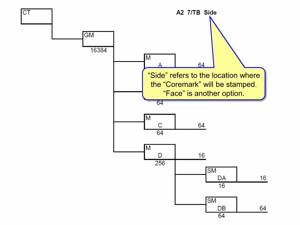
“Side” refers to the location where
the “Coremark” will be stamped.
“Face” is another option.

“CT” and “C” are
common
abbreviations for
“Control Key”. The CT
key is used to remove
and install cores.

The GM key
(grandmaster)
typically
operates all
cores / locks in
a masterkey
system.

“M” stands for Master.
Masterkeys work
smaller groups of codes
under the GM.

A, B, C, D, etc. are typical
“Keymarks” that BEST
uses to “name” the
masterkeys.

“SM” is short for “Submaster”.
Submaster keys work smaller
groups under a masterkey.

DA, DB, etc. are
keymarks for
submaster keys.

This number shows how
many total codes work
under the grandmaster.

This number shows how
many total codes work
under master A.

This number shows how
many total codes work
under submaster DA.

Master “D” has 256
total codes that
work under it.

16 of the codes that
work under Master “D”
do not have a submaster
key over them. These
codes are called “Direct
to Master”.

The keymarks for these
codes would start with
D1 and end with D16.

The “DA” submaster
has 16 codes that
work under it. The
keymarks for these
codes would be DA1
through DA16

Q: Where does the BAC18 key belong in a masterkey system hierarchy?
A: Operating Key
Q: What is the keymark of the GM?
A: Usually GM
Q: What is the keymark of the M?
A: B
Q: What is the keymark of the SM?
A: BA
Q: What is the keymark of the SSM?
A: BAC
BAC18

CONTROL
GRANDMASTER
MASTER
SUBMASTER
SUB-SUBMASTER
OPERATING KEY
CT
GM
B
BA
BAC
BAC18
HIERARCHY KEYMARK
The markings listed above are all of the keys
that will operate the BAC18 core.
What keys operate a BAC18 Core?


What is different with
this Hierarchy Tree,
comparing it to the
one you saw earlier?

Direct to Control
Series
Direct to Grandmaster
Series
Numeric Masters
(numbers instead of
letters)
A4 systems have
more codes than A2
systems
Submasters & Sub-
submasters will have
letters after the numbers
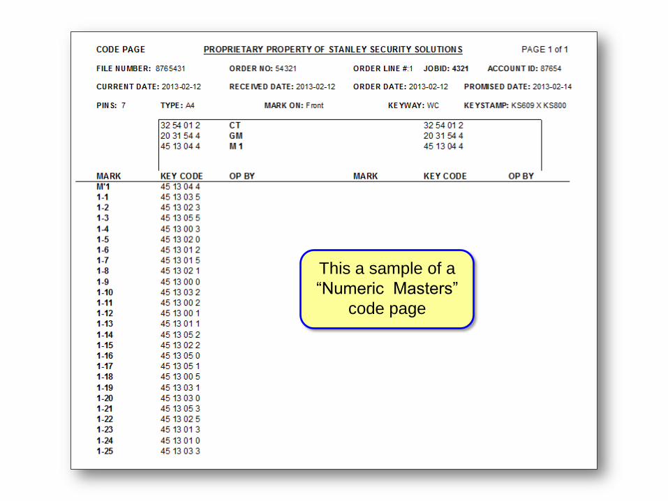
This a sample of a
“Numeric Masters”
code page

A2 Key System:Calculating Pin Segments

BEST Interchangeable Core Terminology
(Front Cut-Away View)
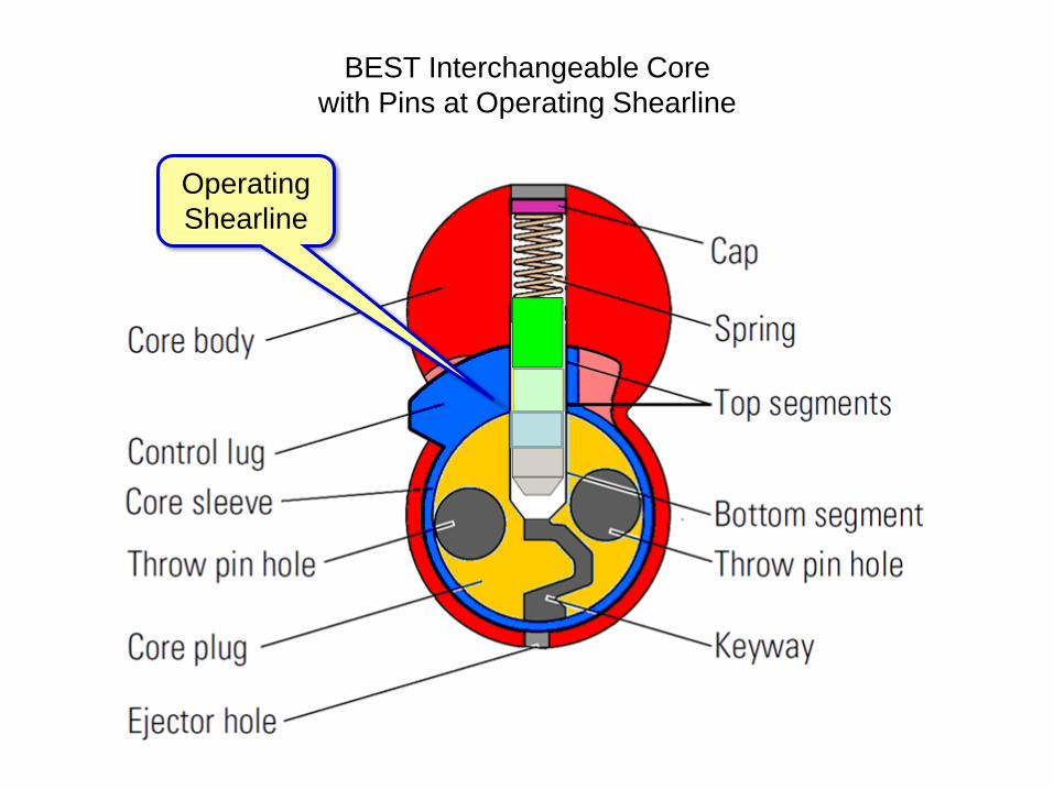
Operating
Shearline
BEST Interchangeable Core
with Pins at Operating Shearline

Control
Shearline
BEST Interchangeable Core
with Pins at Control Shearline

We use Codes from
Code Pages for
cutting keys.

The BEST AD433
Key Combinator

Anatomy of a BEST KeyKey
Stamp
Bow (Key Head)Bottom of
Key Blade
Top of Key Blade (where
the cuts will be made)

Anatomy of a BEST Key
Keyway Marking
(not on all keys)
Tip Stop
Serialization Marking
(optional)
Keymark
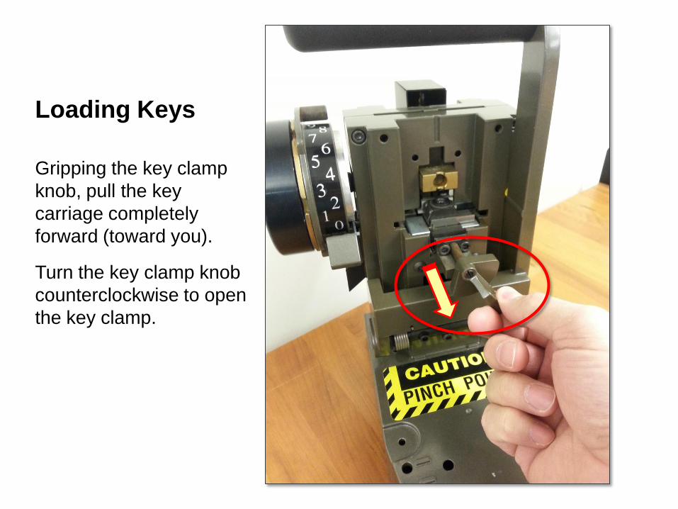
Loading Keys
Gripping the key clamp
knob, pull the key
carriage completely
forward (toward you).
Turn the key clamp knob
counterclockwise to open
the key clamp.

With the curved edge of
the key blank (bottom
edge) against the
locating surface, slide
the key blank into the
key opening.

Make sure the “Knife
Edge” of the key clamp
fits into the groove of the
key.
Turn the key clamp knob
clockwise to lock the
blank in place.

Cutting Keys

Make sure the Key
Carriage is completely
forward (toward you)
before cutting the key.

Place the Chip Tray
under the Ejection
Chute to catch the cut
pieces of the keys.
Ejection
Chute

NOTE:
ZERO is not all of the way
down on the Cut Depth
Indicator. Zero is one
“notch” up.
The bottom position is
used for cutting a
“Calibration Key” for
adjusting the depth of cut.
“Zero”
Depth

Move the Depth
Selector to your first
cut depth. Make sure
to COVER the depth
that you plan to cut (a
# 4 depth is being cut
in this example).
Depth
Selector

NOTE:
The first pull of the
handle does not
make a cut, it just
sets the blank in the
correct position for
the first cut.

Pull the handle twice for
the first cut and once for
each additional cut.
Make sure the handle is
completely depressed
until it contacts the
rubber stop on the base.
Rubber Stop

The Key Combinator will
advance the blank with
each handle pull.
Key
Carriage
shown fully
advanced

Pull the key clamp knob
and carriage toward you
when the key is finished
being cut.

Turn the key clamp
knob counter
clockwise to release
the key clamp and
remove the cut key.

The Cut Key

Calculating Pin Lengths
The Stack Height (or Total
Stack) equals the sum of a
barrel’s pin lengths. Having a
consistent Stack Height
ensures that there is enough
overall pin stack length to lock
both shearlines and enough
overhead room for the springs
to fully compress without
being crushed.

Stack Height (or Total Stack)
7A
7B
3B
6B
+
23
There is a simple process for
calculating pin lengths and a
consistent Stack Height.
(An A2 System Stack Height
example is shown at right)

Keys Codes from Sample
Code Page:
CONTROL (CT) 4189250
GRAND MASTER (GM) 8301836
MASTER (B) 6701836
SUB-MASTER (BA) 6783836
OPERATING KEY (BA1) 6783058
The Total Stack in a standard BEST
A2 system is 23 (The Total Stack is the
sum total of all pin segments in a barrel).
Enter the Total Stack in the code chart
for all barrels.
Add 10 to each cut of the Control Key
and record the numbers on the chart.
(10 is added to the Control Key cuts to
compensate for the thickness of the
control lug, which is ten “increments”
thick)
Forgetting to add 10 to the
control cuts is the cause of
many combinating problems.
Record the Grand Master and
Individual Operating Key on the
appropriate lines on the chart.
23 23 23 23 23 23 23
14 11 18 19 12 15 10
8 3 0 1 8 3 6
5 803876
NOTE: It is NOT necessary to enter any master-level
keys other than the GM. They will automatically work.
BA1 Example

Barrel
1
Pins
Barrel
2
Pins
Barrel
3
Pins
Barrel
4
Pins
Barrel
5
Pins
Barrel
6
Pins
Barrel
7
PinsCodes CodesCodes Codes Codes Codes Codes
A
B
B
B
A
B
B
B
A
B
B
B
A
B
B
B
A
B
B
B
A
B
B
B
A
B
B
B
The codes from each barrel
are entered into the chart
below, in ascending order (Smallest Number at the bottom,
largest Number at the top).
18
8
0
23
19
3
1
23
12
8
0
23
15
5
3
23
10
8
6
23
14
8
6
23
11
7
3
23
Smallest Number
Largest Number
23 23 23 23 23 23 23
14 11 18 19 12 15 10
8 3 0 1 8 3 6
5 803876
BA1 Example

A
B
B
B
23
14
8
6
9
6
2
6
4th - To find the 3rd “B” pin segment,
subtract the 2nd “B” code from the 3rd
“B” code and enter the difference into the
chart.
3rd - To find the 2nd “B” pin segment,
subtract the 1st “B” code from the 2nd
“B” code and enter difference into the
chart.
2nd - To find the find 1st “B” pin segment
subtract the “A” code (6) from the 1st “B”
code (8). The difference is 2 and it is
entered into the chart as a 2 pin segment.
1st - The smallest code number is always
the “A” pin segment. It goes in the “A”
box in the Pin Segments column.
Barrel 1
Barrel 1
PinsCodes

A
B
B
B
23
11
7
3
12
4
4
3
4th - To find the 3rd “B” pin segment,
subtract the 2nd “B” code from the 3rd
“B” code and enter the difference into the
chart.
3rd - To find the 2nd “B” pin segment,
subtract the 1st “B” code from the 2nd
“B” code and enter difference into the
chart.
2nd - To find the find 1st “B” pin segment
subtract the “A” code (3) from the 1st “B”
code (7). The difference is 4 and it is
entered into the chart as a 4 pin segment.
1st - The smallest code number is always
the “A” pin segment. It goes in the “A”
box in the Pin Segments column.
Barrel 2
PinsCodes
Barrel 2

A
B
B
B
23
18
8
0
5
10
8
0
4th - To find the 3rd “B” pin segment,
subtract the 2nd “B” code from the 3rd
“B” code and enter the difference into the
chart.
3rd - To find the 2nd “B” pin segment,
subtract the 1st “B” code from the 2nd
“B” code and enter difference into the
chart.
2nd - To find the find 1st “B” pin segment
subtract the “A” code (0) from the 1st “B”
code (8). The difference is 8 and it is
entered into the chart as a 8 pin segment.
1st - The smallest code number is always
the “A” pin segment. It goes in the “A”
box in the Pin Segments column.
Barrel 3
Barrel 3
PinsCodes

Barrel
1
Pins
Barrel
2
Pins
Barrel
3
Pins
Barrel
4
Pins
Barrel
5
Pins
Barrel
6
Pins
Barrel
7
PinsCodes CodesCodes Codes Codes Codes Codes
A
B
B
B
A
B
B
B
A
B
B
B
A
B
B
B
A
B
B
B
A
B
B
B
A
B
B
B
The smallest code number is always the
“A” pin segment. It goes in the “A” box in
the Pin Segments column.
To find the find 1st “B” pin segment
subtract the “A” code from the 1st “B” code.
The difference is entered into the chart as
a pin segment.
To find the 2nd “B” pin segment, subtract
the 1st “B” code from the 2nd “B” code and
enter difference into the chart.
To find the 3rd “B” pin segment, subtract
the 2nd “B” code from the 3rd “B” code and
enter difference into the chart.
6
2
6
9
3
4
4
12
0
10
8
5
1 60 3
2
10
8
2
2
13
2
16
4
8
4
11
18
8
0
23
19
3
1
23
12
8
0
23
15
5
3
23
10
8
6
23
14
8
6
23
11
7
3
23
23 23 23 23 23 23 23
14 11 18 19 12 15 10
8 3 0 1 8 3 6
5 803876
BA1 Example

Barrel
1
Pins
Barrel
2
Pins
Barrel
3
Pins
Barrel
4
Pins
Barrel
5
Pins
Barrel
6
Pins
Barrel
7
PinsCodes CodesCodes Codes Codes Codes Codes
A
B
B
B
A
B
B
B
A
B
B
B
A
B
B
B
A
B
B
B
A
B
B
B
A
B
B
B
Put lines through the code columns so
that you do not confuse them with the
pin segment columns.
Starting with the “A” pin segment and
ending with the top “B” pin segment,
load all pin segments into each barrel.
Start with barrel 1 and finish with
barrel 7 (barrel six in a 6-pin system).
23 23 23 23 23 23 23
14 11 18 19 12 15 10
8 3 0 1 8 3 6
5 803876
6
2
6
9
3
4
4
12
0
10
8
5
1 60 3
2
10
8
2
2
13
2
16
4
8
4
11
18
8
0
23
19
3
1
23
12
8
0
23
15
5
3
23
10
8
6
23
14
8
6
23
11
7
3
23
BA1 Example

Barrel
1
Pins
Barrel
2
Pins
Barrel
3
Pins
Barrel
4
Pins
Barrel
5
Pins
Barrel
6
Pins
Barrel
7
PinsCodes CodesCodesCodes CodesCodesCodes
A
B
B
B
A
B
B
B
A
B
B
B
A
B
B
B
A
B
B
B
A
B
B
B
A
B
B
B
B B B B B B B
B B B B B B B
B B B B B B B
Selective Keying (or cross-keying) is
the deliberate process of combinating a
core in a masterkey system to two or
more different keys, which would not
normally be expected to operate
together.
The process of calculating the pin
segments for selective keying is basically
the same as standard keying except the
that the pin segment stacks will have
more segments.
23 23 23 23 23 23
11 18 19 12 15 10
3 0 1 8 3 6
5 80387
23
14
8
6 BA1
BA4X Example

Barrel
1
Pins
Barrel
2
Pins
Barrel
3
Pins
Barrel
4
Pins
Barrel
5
Pins
Barrel
6
Pins
Barrel
7
PinsCodes CodesCodesCodes CodesCodesCodes
A
B
B
B
A
B
B
B
A
B
B
B
A
B
B
B
A
B
B
B
A
B
B
B
A
B
B
B
B B B B B B B
B B B B B B B
B B B B B B B
In the sample chart at the right we have
the same Control, Grandmaster and
Individual Operating key that we worked
with earlier.
The difference is that we are going to
add three additional operating keys into
the core.
Adding more keys to a core does not
add to the Total Stack height but it does
require a larger chart to calculate the pin
segment stacks.
523876
543876
563876
8
8
8
BA2
BA3
BA4
23 23 23 23 23 23
11 18 19 12 15 10
3 0 1 8 3 6
23
14
8
5 803876 BA1
BA4X Example

Barrel
1
Pins
Barrel
2
Pins
Barrel
3
Pins
Barrel
4
Pins
Barrel
5
Pins
Barrel
6
Pins
Barrel
7
PinsCodes CodesCodesCodes CodesCodesCodes
A
B
B
B
A
B
B
B
A
B
B
B
A
B
B
B
A
B
B
B
A
B
B
B
A
B
B
B
B B B B B B B
B B B B B B B
B B B B B B B
The smallest code number is always the “A”
pin segment. It goes in the “A” box in the Pin
Segments column.
To find the find 1st “B” pin segment subtract
the “A” code from the 1st “B” code. The
difference is entered into the chart as a pin
segment.
To find the 2nd “B” pin segment, subtract the
1st “B” code from the 2nd “B” code and enter
difference into the chart.
To find the 3rd, 4th, 5th & 6th “B” pin segments,
repeat the previous pattern.
6
2
6
9
3
4
4
12
0
10
8
5
1 60 3
2
10
8
2
2
13
2
16
4
2
2
4
18
8
0
23
19
3
1
12
8
0
23
15
5
3
23
10
8
6
23
14
8
6
23
11
7
3
23
2
4
6
2
2
523876
543876
563876
8
8
8
BA2
BA3
BA4
23 23 23 23 23 23
11 18 19 12 15 10
3 0 1 8 3 6
23
14
8
5 803876 BA1
BA4X Example
11 23

A2 Key System
Coremark ______
Barrel # 1 2 3 4 5 6 7
Total Stack
Control (+ 10)
GM
Master
Sub-masterOperating
Operating
Operating
Operating
23 23 23 23 23 23 23
Barrel 1Pins
Barrel 2Pins
Barrel 3Pins
Barrel 4Pins
Barrel 5Pins
Barrel 6Pins
Barrel 7Pins
Codes CodesCodes Codes Codes Codes Codes
A A AAAAA
B B BBBBB
B B BBBBB
B B BBBBB

NO KEY INSERTED
6A
9B
6B
2B
3A
4B
4B
12B
1A
2B
16B
4B
0A
8B
4B
11B
3A
10B
2B
8B
6A
2B
13B
2B
0A
8B
5B
10B
NO SHEARLINES ARE MET

INCORRECT KEY
6A
9B
6B
2B
3A
4B
4B
12B
1A
2B
16B
4B
0A
8B
4B
11B
3A
10B
2B
8B
6A
2B
13B
2B
0A
8B
5B
10B
NO SHEARLINES ARE MET

GRANDMASTER KEY (GM)
6A
9B
6B
2B
3A
4B
4B
12B
1A
2B
16B
4B
0A
8B
4B
11B
3A
10B
2B
8B
6A
2B
13B
2B
0A
8B
5B
10B
8 3 0 1 8 3 6

MASTER KEY (B)
6A
9B
6B
2B
3A
4B
4B
12B
1A
2B
16B
4B
0A
8B
4B
11B
3A
10B
2B
8B
6A
2B
13B
2B
0A
8B
5B
10B
6 7 0 1 8 3 6

SUB-MASTER KEY (BA)
6A
9B
6B
2B
3A
4B
4B
12B
1A
2B
16B
4B
0A
8B
4B
11B
3A
10B
2B
8B
6A
2B
13B
2B
0A
8B
5B
10B
6 7 8 3 8 3 6

INDIVIDUAL OPERATING KEY (BA1)
6A
9B
6B
2B
3A
4B
4B
12B
1A
2B
16B
4B
0A
8B
4B
11B
3A
10B
2B
8B
6A
2B
13B
2B
0A
8B
5B
10B
6 7 8 3 0 5 8

CONTROL KEY (CT)
6A
9B
6B
2B
3A
4B
4B
12B
1A
2B
16B
4B
0A
8B
4B
11B
3A
10B
2B
8B
6A
2B
13B
2B
0A
8B
5B
10B
4 1 8 9 2 5 0

SELECTIVE KEYING: CORE BA4X (With KEY BA1 Inserted)
6A
9B
6B
2B
3A
4B
4B
12B
1A
2B
16B
4B
3A
10B
2B
8B
6A
2B
13B
2B
0A
8B
5B
10B
0A
4B
11B
2B
2B
2B
2B
6 7 8 3 0 5 8

6A
9B
6B
2B
3A
4B
4B
12B
1A
2B
16B
4B
3A
10B
2B
8B
6A
2B
13B
2B
0A
8B
5B
10B
0A
4B
11B
2B
2B
2B
2B
6 7 8 3 2 5 8
SELECTIVE KEYING: CORE BA4X (With KEY BA2 Inserted)

6A
9B
6B
2B
3A
4B
4B
12B
1A
2B
16B
4B
3A
10B
2B
8B
6A
2B
13B
2B
0A
8B
5B
10B
0A
4B
11B
2B
2B
2B
2B
6 7 8 3 4 5 8
SELECTIVE KEYING: CORE BA4X (With KEY BA3 Inserted)

6A
9B
6B
2B
3A
4B
4B
12B
1A
2B
16B
4B
3A
10B
2B
8B
6A
2B
13B
2B
0A
8B
5B
10B
0A
4B
11B
2B
2B
2B
2B
6 7 8 3 6 5 8
SELECTIVE KEYING: CORE BA4X (With KEY BA4 Inserted)

EJECTING PINS
If a used core is
going to be
rekeyed and still
has pins in it, you
will need to eject
the existing pins.

The easiest way to eject pins from
a core is to turn the core upside
down on a carpet square or pad,
insert the Ejector Pin into an
Ejector Hole and tap it with a
hammer or mallet. The pins will
eject onto the carpet.
A Capping Block can also be
used for de-capping, but, if used
incorrectly can cause damage to
the core.
EJECTING PINS

Damage to Core by incorrect use of Ejector Pin &
Capping/De-capping Block

• Barrel 1 is at the back of the core
• Barrel 7 is at the face of the core
• Barrel 6 is at the face for 6-pin cores
• Always start loading pins at barrel 1 and work toward the core face
• Load one barrel completely before moving to the next
• “A” pins are inserted with the point down
• “B” pin segments are the same on both ends and can be inserted either way
• Springs are loaded after all pin segments are loaded into the barrels and after
the core is in the capping block
• Test the Control Key and all Operating Keys in every core
• Cores can be lubricated with Dixon Ticonderoga #2 Flaked Graphite, LPS1
spray lubricant or Corrosion Free Formula 8000 spray lubricant
• DO NOT mix dry & wet lubricants
IMPORTANT POINTS TO REMEMBER

GRAPHITE GUN LPS SPRAY LUBRICANTCORROSION FREE
FORMULA 8000

BEST COMBINATING KIT

Please DO NOT put used pin segments
back into the combinating kits.

Make sure the
Keyway is vertical
and the Control Lug
is extended before
dropping pins into
the core.
The tip of the Ejector
Pin can be used to
extend the Control Lug.

The Bottom Segments
get loaded first with the
beveled end pointing
down.
The Top Segments get
loaded next, in
ascending order from
the pinning chart. The
Top segments are the
same top and bottom.
Springs and Caps get
loaded AFTER the
core is placed in the
Capping Block or
Press

HAND CAPPING PIN
BEST CORE CAPPING BLOCK
The “Tip Stop” must
be used to properly
align the core for
capping. The Tip
Stop MUST NOT be
used to seat the
caps.
NOTE: The Capping Block is not intended to hold cores for pinning.

The BEST CD517
Capping/De-Capping
Press is an optional tool
but makes capping
quicker, easier and
more consistent.

When you are done, please put the tools back into
the kit just like you see in this picture. Thanks!

A4 Key System:Calculating Pin Segments

GUIDELINES FOR A4 SYSTEM SETUP
• The A4 system does NOT use the odd / even pattern of
the A2 system
• Since the A4 system utilizes a single step progression
and there is no odd / even pattern, all A4 system codes
should be scrambled for higher security
• The A4 system utilizes code depths 0 through 5
• The A4 system works in powers of 5
• There should not be more than one Control or
Grandmaster on the same keyway for the same
customer with the A4 system (unless the system is
limited or restrictive)

The Total Stack in a standard BEST
A4 system is 14 (The Total Stack is the
sum total of all pin segments in a barrel).
Enter the Total Stack in the code chart
for all barrels.
Add 6 to each cut of the Control Key
and record the numbers on the chart.
Example: If the first cut of the Control Key
is 3, the Control Number for the first
barrel will be 9 (6 is added to the Control
Key cuts to compensate for the thickness
of the control lug, which is six
“increments” thick).
Forgetting this step is the cause
of many combinating problems.
Record the Grand Master, Master,
and Individual Operating Key on the
appropriate lines on the chart.
Sample Keys:
CONTROL 3254012
GRAND MASTER 2031544
MASTER 4513024
INDIVIDUAL OPERATING 4513021
14 14 14 14 14 14 14
9 8 11 10 6 7 8
2 0 3 1 5 4 4
2 103154
It is NOT necessary to enter any master-level keys
other than the GM. They will automatically work.

Barrel
1
Pins
Barrel
2
Pins
Barrel
3
Pins
Barrel
4
Pins
Barrel
5
Pins
Barrel
6
Pins
Barrel
7
PinsCodes CodesCodes Codes Codes Codes Codes
E
F
F
F
E
F
F
F
E
F
F
F
E
F
F
F
E
F
F
F
E
F
F
F
E
F
F
F
The codes from each
barrel are entered into the
chart below, in ascending
order ( Smallest code at the
bottom; Total Stack at the
top).
11
3
1
14
10
3
1
14
6
5
0
14
7
4
2
14
8
4
1
14
9
4
2
14
8
5
0
14
14 14 14 14 14 14 14
9 8 11 10 6 7 8
2 0 3 1 5 4 4
2 103154
Smallest Number
Largest Number

Barrel
1
Pins
Barrel
2
Pins
Barrel
3
Pins
Barrel
4
Pins
Barrel
5
Pins
Barrel
6
Pins
Barrel
7
PinsCodes CodesCodes Codes Codes Codes Codes
E
F
F
F
E
F
F
F
E
F
F
F
E
F
F
F
E
F
F
F
E
F
F
F
E
F
F
F
The smallest code number is always the
“E” pin segment. It goes in the “E” box in
the Pin Segments column.
In this example the 1st “F” code is 4. To
find the find 1st “F” pin segment subtract
the “E” code (2) from the 1st “F” code (4).
The difference is 2 and it is entered into
the chart as a 2 pin segment.
To find the 2nd “F” pin segment, subtract
the 1st “F” code from the 2nd “F” code and
enter difference into the chart.
To find the 3rd “F” pin segment, repeat
the previous pattern.
2
2
5
5
0
5
3
6
1
8
2
3
1 10 2
2
3
7
3
4
6
2
7
4
5
1
8
14 14 14 14 14 14 14
9 8 11 10 6 7 8
2 0 3 1 5 4 4
2 103154
11
3
1
14
10
3
1
14
6
5
0
14
7
4
2
14
8
4
1
14
9
4
2
14
8
5
0
14

Barrel
1
Pins
Barrel
2
Pins
Barrel
3
Pins
Barrel
4
Pins
Barrel
5
Pins
Barrel
6
Pins
Barrel
7
PinsCodes CodesCodes Codes Codes Codes Codes
E
F
F
F
E
F
F
F
E
F
F
F
E
F
F
F
E
F
F
F
E
F
F
F
E
F
F
F
Put lines through the code columns so
that you do not confuse them with the
pin segment columns.
Starting with the “E” pin segment and
ending with the 3rd “F” pin segment,
load all pin segments into each barrel.
Start with barrel 1 and finish with
barrel 7 (barrel six in a 6-pin system).
Complete and test each barrel
before moving to the next.
14 14 14 14 14 14 14
9 8 11 10 6 7 8
2 0 3 1 5 4 4
2 103154
2
2
5
5
0
5
3
6
1
8
2
3
1 10 2
2
3
7
3
4
6
2
7
4
5
1
8
11
3
1
14
10
3
1
14
6
5
0
14
7
4
2
14
8
4
1
14
9
4
2
14
8
5
0
14

•Barrel 1 is at the back of the core.
•Barrel 7 (or 6) is at the face of the core.
•Always start at barrel 1 and work toward barrel 7 (or 6).
•Load one barrel completely before moving to the next.
•“A” pins are inserted with the point down.
•“B” pin segments are the same on both ends and can be inserted either way.
•Only use original BEST pin segments.
•Springs are loaded after all pin segments are loaded into the barrels.
•Test the Control Key and all Operating Keys in every core.
•Cores can be lubricated with graphite, LPS1 or Corrosion Free Formula 8000
•Do not mix lubricants, especially wet graphite and spray lubricant
IMPORTANT POINTS TO REMEMBER

A4 Key System
Coremark ______
Barrel 1Pins
Barrel 2Pins
Barrel 3Pins
Barrel 4Pins
Barrel 5Pins
Barrel 6Pins
Barrel 7Pins
Codes CodesCodes Codes Codes Codes Codes
E E EEEEE
F F FFFFF
F F FFFFF
F F FFFFF

Troubleshooting

Possible Reasons for Keys Not Operating a Core
• Keys have been cut to the incorrect depths
• Key Combinator needs to be calibrated
• Key was “duplicated” on a rotary key duplicator instead an
original key being generated on a BEST “punch” cutter
• The initial “index” pull of the BEST Key Combinator handle was
forgotten leaving the key one cut short
• Incorrect pins were dropped into the core
• The core was pinned from front to back instead of back to front
• Bottom pins were inserted upside down (pointed end upward)
• Too few or too many pins per barrel
• Stack Height exceeding the system specifications
• Key not fully inserted in the core
• Damaged core or key
• Extremely worn pins in the core from many years of hard use
• Old lubrication has dried out and solidified
• Foreign object is blocking the key from fully entering the keyway

Thumb Check Procedure
If the core does not operate,
first check the key for proper
key cut depths. Then, before
ejecting the pins, use the
Thumb Check Procedure to
check for incorrect stack heights
caused by incorrect pin lengths
or too few or too many pins per
barrel.

Thumb Check Procedure
Insert the Ejector Pin into an Ejector
Hole and push until the spring is fully
compressed.
Use your thumb to mark the depth on the
ejector pin. Keep your thumb in place.
Insert the pin into the other ejector holes.
If the pin segment stack height varies,
use the ejector pin to force out the
segments, springs, and caps of the
barrels that are incorrectly loaded.
Discard the used segments, springs, and
caps. Reload the barrels with correct pin
segments, springs, and caps.