Embed Size (px)
Citation preview
Benefits of Installing Restrictive Orifice Plates on the Suction of Reciprocating Pumps:
1D Pulsation and CFD Studies
Kelly Eberle, BSc, PEngPrincipal Consultant, Wood Group
Presenter
2
Kelly Eberle Kelly is a principal consultant with Wood Group’s vibration, dynamics and noise team since 1988. He has been a professional member of APEGA since 1991. Kelly has accumulated a wide range of design and field experience, particularly in the area of pressure pulsation analysis and mechanical analysis of reciprocating compressor and pump installations. The scope of his experience includes pulsation simulations, thermal flexibility studies, dynamic finite element analysis, structural analysis and foundation analysis.
Zixiang Chen, PhDEngineerWood Group
Zixiang has recently completed his doctoral work in the field of fluid dynamics. His academic research interest is on the sensor‐based estimation of large‐scale coherent structures in turbulent flows using optical flow diagnostics and numerical simulations. Prior to joining Wood Group in 2014, he worked on combustion modelling for the GT24/26 and compressor aerodynamics for the PT6.
Cajetan Ijeomah, MSc, PEngSenior EngineerWood Group
Cajetan is a professional engineer with over 14 years of industry experience, the majority of which is in dynamic engineering and vibration design. His responsibilities include acoustical (pulsation), mechanical and thermal analysis of reciprocating compressor and pump systems, evaluation of piping systems and related dynamic studies. Cajetan manages complex design projects involving multiple vibration disciplines and is proficient in the use of various engineering analysis software tools.
Jordan Grose, PEng, MBAService Lead – AmericasWood Group
Jordan is a mechanical engineer with extensive domestic and international design, field, and monitoring experience with compressors, pumps, pipelines, and other production machinery. He has specialized skills in vibration, liquid transient analysis, performance, and troubleshooting in onshore and offshore production facilities. Jordan currently leads Wood Group’s vibration integrity group, addressing plant‐wide vibration risks in piping and machinery systems. He has been with Wood Group (formerly BETA Machinery Analysis) for over 14 years, during which time he has authored and co‐authored several papers.
Other authors
3
It is well understood that static pressure at the inlet of reciprocating pumps, quantified typically by Net Positive Suction Head Available (NPSHA), must be sufficient to avoid cavitation in the pump suction manifold and chamber. In an effort to conserve NPSHA, pump designers generally rely on rules of thumb that resist the addition of pressure drop elements such as restrictive orifice plates, choke tubes and line‐size reductions to the inlet piping of all pumps, including reciprocating pumps.
Another design consideration of reciprocating pumps is the generation of pressure pulsations due to pump piston and valve motion. Uncontrolled pulsations can result in cavitation and vibration‐related fatigue failures. In many cases, pressure drop elements are required to control pressure pulsations. Can there be a balance between the pulsation control benefits of pressure drop elements and the need to meet NPSHA?
This paper is of interest to designers and engineers working with reciprocating pump installations. It aims at challenging industry resistance to using pressure drop elements in the suction piping of reciprocating pumps by, first, outlining the virtues achieved in terms of pulsation and vibration control, and second, presenting results from numerical simulations (one‐dimensional pulsation and detailed CFD modelling). Recent field data from a quintuplex pump installation were used to validate the 1‐D pulsation model. The results show that well‐designed orifice plates, and other pressure drop elements, are beneficial for reducing pulsations and cavitation risks; and can be used in the suction piping of reciprocating pumps.
Abstract
4
Objective
Demonstrate that proper use of orifice plates and other pressure drop elements (choke tubes and line‐size reductions) in the suction piping of reciprocating pumps are beneficial for pulsation control and mitigation of cavitation risks.
Analysis approachField‐measured pulsations and numerical simulations (1‐D pulsation model and CFD modelling).
5
Contents
1. Author bios
2. Abstract
3. Contents
4. Objective
5. Introduction
6. 1‐D model
7. CFD model
8. Validation of 1‐D model
9. 1‐D model results
10. Definition of pressure loss terms
11. Average pressure loss: 1‐D vs CFD
12. Total pressure loss: 1‐D vs CFD
13. CFD visualization: pressure recovery
14. Conclusions
6

Introduction
• Reciprocating pumps:– Widespread use in industry– Generate pressure pulsations– Uncontrolled pulsations vibrations, cavitation, failures
• Orifice plates:– Reduced pressure under‐spikes lower cavitation risk – Pressure drop reduced NPSHA higher cavitation risk
7
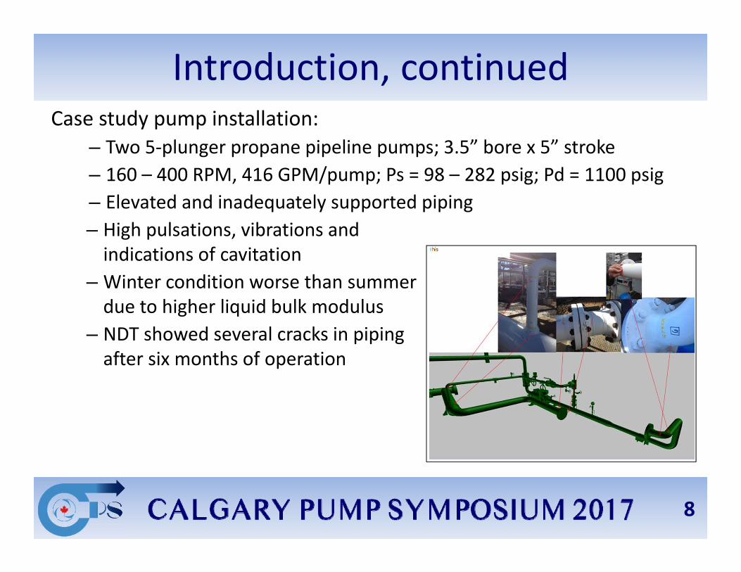
Introduction, continuedCase study pump installation:
– Two 5‐plunger propane pipeline pumps; 3.5” bore x 5” stroke – 160 – 400 RPM, 416 GPM/pump; Ps = 98 – 282 psig; Pd = 1100 psig– Elevated and inadequately supported piping– High pulsations, vibrations and indications of cavitation
– Winter condition worse than summer due to higher liquid bulk modulus
– NDT showed several cracks in piping after six months of operation
8
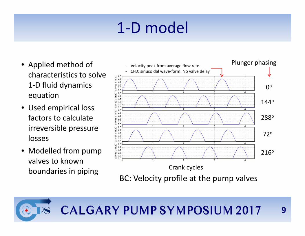
1‐D model
• Applied method of characteristics to solve 1‐D fluid dynamics equation
• Used empirical loss factors to calculate irreversible pressure losses
• Modelled from pump valves to known boundaries in piping
0o
144o
216o
72o
288o
Plunger phasing
BC: Velocity profile at the pump valvesCrank cycles
‐ Velocity peak from average flow rate.‐ CFD: sinusoidal wave‐form. No valve delay.
9
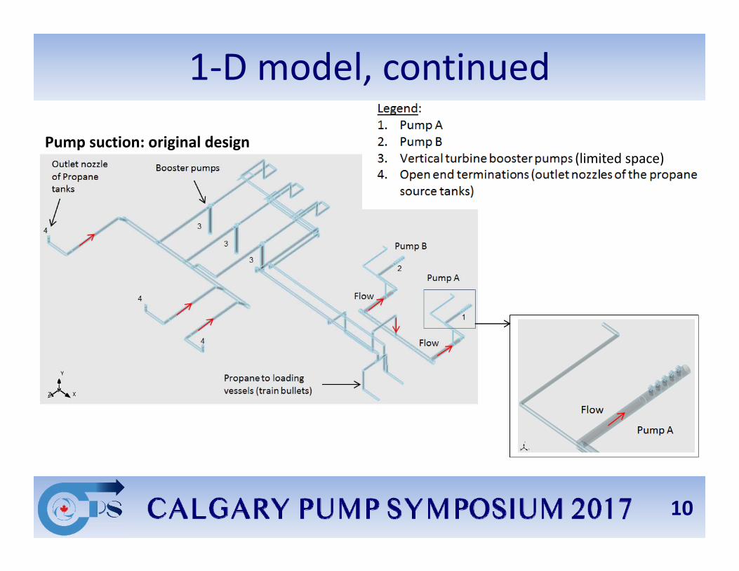
1‐D model, continued
Pump suction: original design(limited space)
10

1‐D model, continued
Pump suction: modified design
3.125” ID orifice plate
11
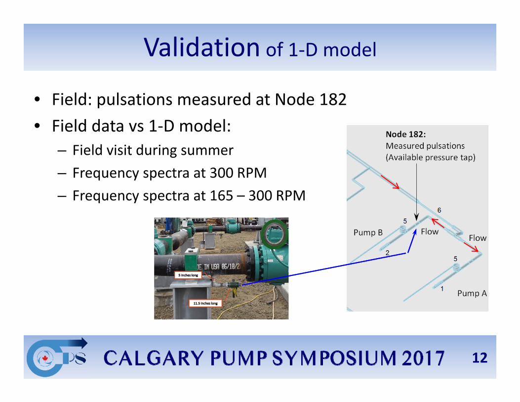
Validation of 1‐D model
• Field: pulsations measured at Node 182• Field data vs 1‐D model:
– Field visit during summer– Frequency spectra at 300 RPM– Frequency spectra at 165 – 300 RPM
12
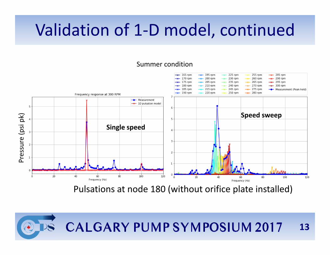
Validation of 1‐D model, continued
Pulsations at node 180 (without orifice plate installed)
Summer condition
Single speed
Speed sweep
Pressure (p
si pk)
13
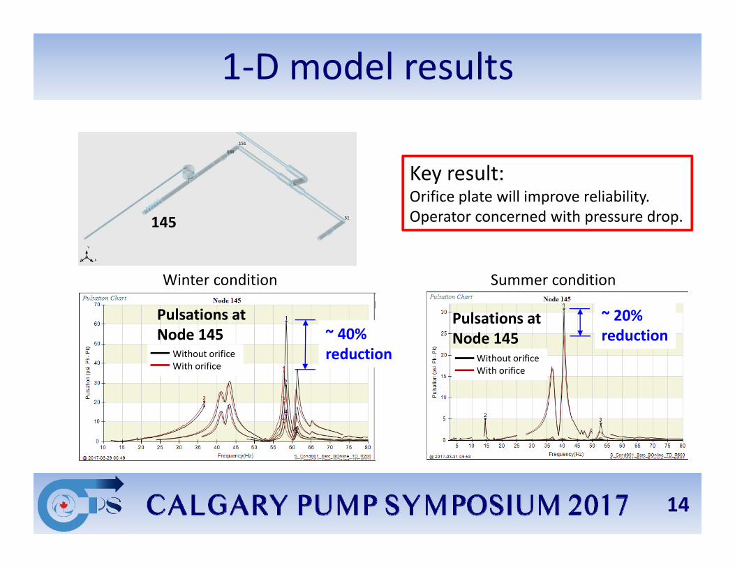
1‐D model results
Key result: Orifice plate will improve reliability. Operator concerned with pressure drop.
Summer conditionWinter condition
Pulsations at Node 145
145
Pulsations at Node 145
Without orificeWith orifice
Without orificeWith orifice
~ 40% reduction
~ 20% reduction
14
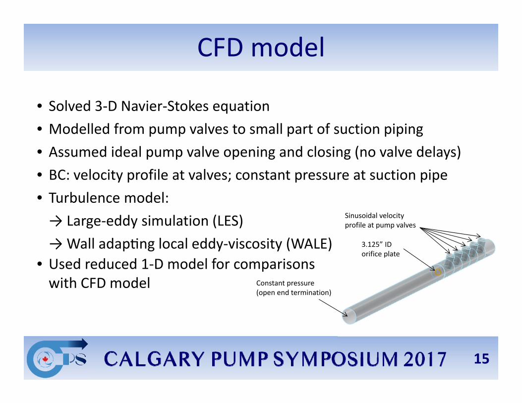
• Solved 3‐D Navier‐Stokes equation• Modelled from pump valves to small part of suction piping• Assumed ideal pump valve opening and closing (no valve delays)• BC: velocity profile at valves; constant pressure at suction pipe• Turbulence model: → Large‐eddy simulation (LES) → Wall adap ng local eddy‐viscosity (WALE)
• Used reduced 1‐D model for comparisonswith CFD model
CFD model
Constant pressure (open end termination)
Sinusoidal velocity profile at pump valves
3.125” ID orifice plate
15
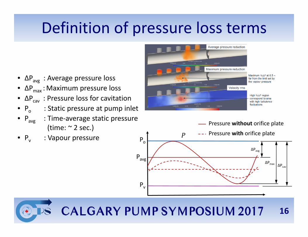
Definition of pressure loss terms
• ∆Pavg : Average pressure loss• ∆Pmax :Maximum pressure loss• ∆Pcav : Pressure loss for cavitation• Po : Static pressure at pump inlet• Pavg : Time‐average static pressure
(time: ~ 2 sec.)• Pv : Vapour pressure Po
Pv
Pavg∆Pavg
∆Pmax ∆Pcav
Pressure without orifice plate
Pressure with orifice plate
16
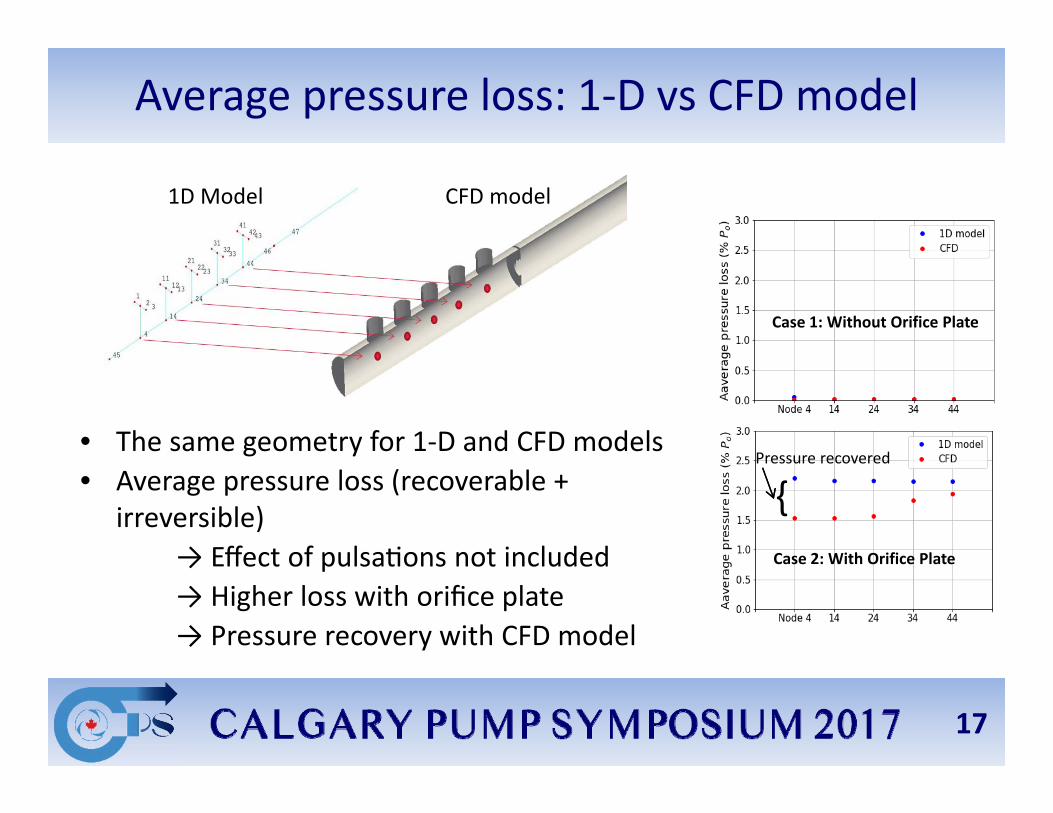
Average pressure loss: 1‐D vs CFD model
• The same geometry for 1‐D and CFD models• Average pressure loss (recoverable +
irreversible)→ Effect of pulsa ons not included→ Higher loss with orifice plate→ Pressure recovery with CFD model
1D Model CFD model
Case 1: Without Orifice Plate
Case 2: With Orifice Plate
{Pressure recovered
17

Total pressure loss: 1‐D vs CFD model
• Maximum pressure loss (pulsations + recoverable + irreversible)
→ Mainly due to pulsa ons→ Higher with orifice plate→ Pressure recovery with CFD model→ Same trend in both models. Increases towards closed end
Case 1: no orifice plate
{Pressure recovered
Case 2: with orifice plate
Key result: • Average pressure loss in 1D model is irreversible
(no pressure recovery) → more conserva ve
18

CFD visualization: pressure recovery
19

CFD animation with orifice
20
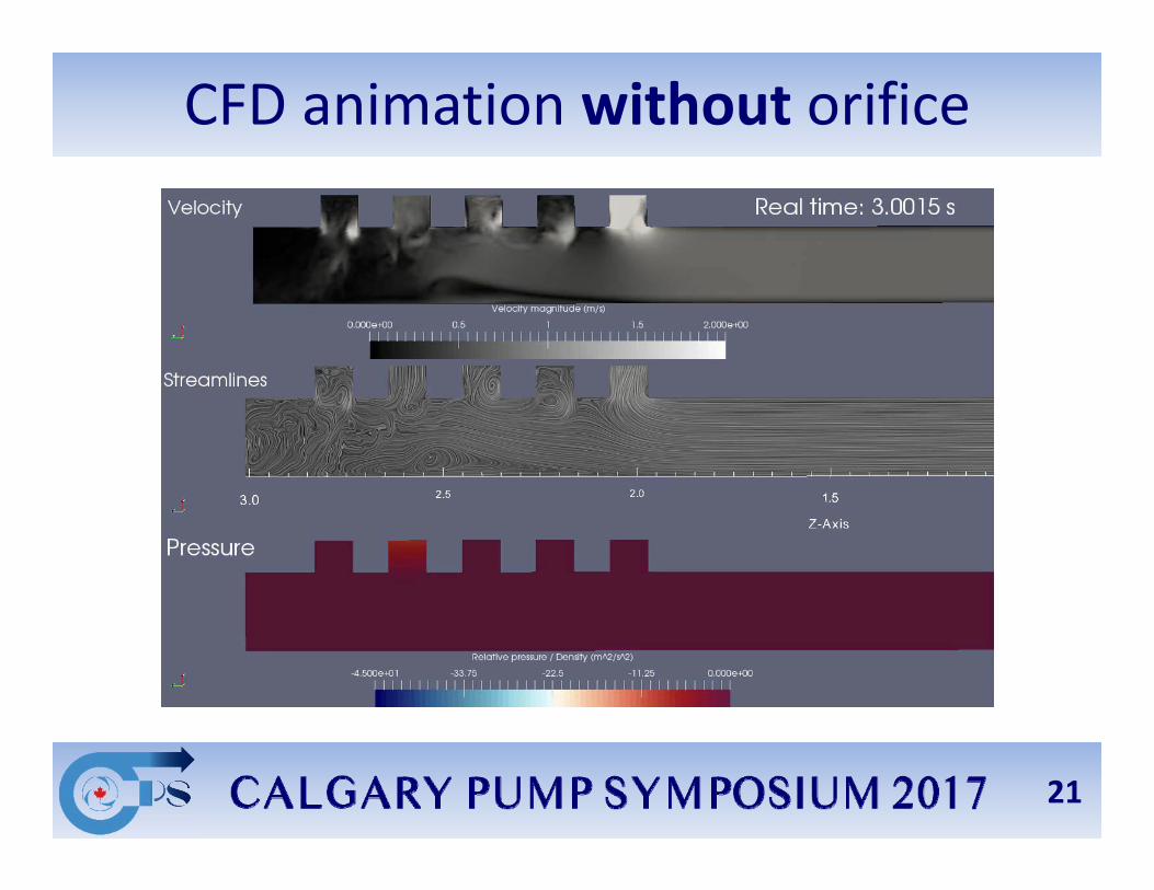
CFD animation without orifice
21
Conclusions
• 1D pulsation model validated with field data: good agreement
• Predicted pressure losses consistent between 1‐D and CFD models
• CFD simulation provided more information, incl recovered pressure loss
• Well‐designed orifice plates and other pressure drop elements:→ Are beneficial for reducing pulsa ons, vibra ons and cavita on
risks→ Can be used in the suc on piping of reciproca ng pumps
if properly sized for mean and dynamic pressure losses
• Orifices not yet implemented, more validation needed (ongoing)
22
Questions
Visit us at Table 10 or contact me at [email protected] further questions or support.
www.woodgroup.com/ais