Embed Size (px)
Citation preview
Data sheet DS/FPD150/160–EN
FPD150/160Differential pressure – primary flow element orifice plates and orifice flange unions
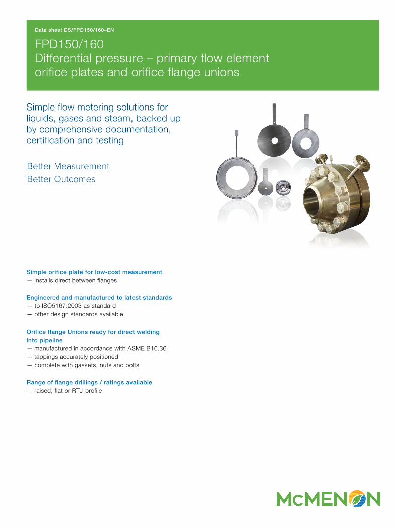
Simple flow metering solutions for liquids, gases and steam, backed up by comprehensive documentation, certification and testing
Better Measurement Better Outcomes
Simple orifice plate for low-cost measurement— installs direct between flanges
Engineered and manufactured to latest standards— to ISO5167:2003 as standard— other design standards available
Orifice flange Unions ready for direct welding into pipeline— manufactured in accordance with ASME B16.36— tappings accurately positioned— complete with gaskets, nuts and bolts
Range of flange drillings / ratings available— raised, flat or RTJ-profile
FPD150/160Differential pressure – primary flow element orifice plates and orifice flange unions
2 DS/FPD150/160–EN | FPD150/160 | Differential pressure – primary flow element orifice plates and orifice flange unions
Orifice plates
The differential pressure generated is sensed at a pair (or multiple pairs) of tapping points, each pair comprising a high pressure (inlet or upstream) and a low pressure (outlet or downstream) tapping. A variety of configurations are specified within ISO5167 and other standards, including the following:
D and D/2 taps— the tappings are generally located in the pipe wall — the upstream tapping is one pipe inside diameter (D) from
the upstream face of the plate — the downstream tapping is half the pipe inside diameter
(D/2) from the downstream face of the plate
Flange taps— the tappings are generally located in the pipe flanges — the upstream tapping is 25.4 mm (1 in.) from the upstream
face of the plate — the downstream tapping is 25.4 mm (1 in.) from the
downstream face of the plate
Corner taps— the tappings are generally located in the pipe flanges — the tappings break into the pipe at the corners formed by
the upstream and downstream flange faces and the pipe wall
Orifice plate bore profilesMcMenon offers a variety of orifice plate bore profiles to cover a wide range of applications. These bore profiles can be classified as follows:— circular bore, concentric with the pipe — circular bore, adjacent to the pipe wall — segmental profile bore, adjacent to the pipe wall
McMenon orifice plates are usually supplied with a data tab welded to the circumference. This tab can be engraved with orifice plate details (such as tag number and bore size) that are visible without removing the plate from the line.
Orifice plate types
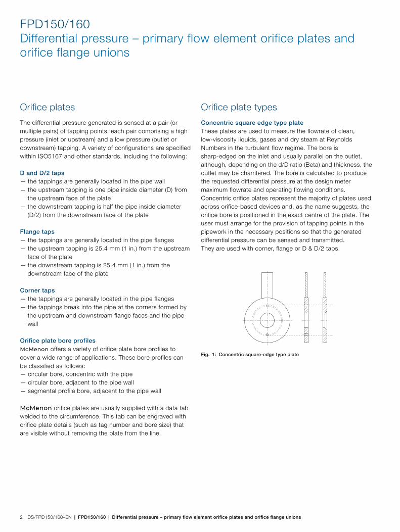
Concentric square edge type plateThese plates are used to measure the flowrate of clean, low-viscosity liquids, gases and dry steam at Reynolds Numbers in the turbulent flow regime. The bore is sharp-edged on the inlet and usually parallel on the outlet, although, depending on the d/D ratio (Beta) and thickness, the outlet may be chamfered. The bore is calculated to produce the requested differential pressure at the design meter maximum flowrate and operating flowing conditions.Concentric orifice plates represent the majority of plates used across orifice-based devices and, as the name suggests, the orifice bore is positioned in the exact centre of the plate. The user must arrange for the provision of tapping points in the pipework in the necessary positions so that the generated differential pressure can be sensed and transmitted.They are used with corner, flange or D & D/2 taps.
Fig. 1: Concentric square-edge type plate
FPD150/160 | Differential pressure – primary flow element orifice plates and orifice flange unions | DS/FPD150/160–EN 3
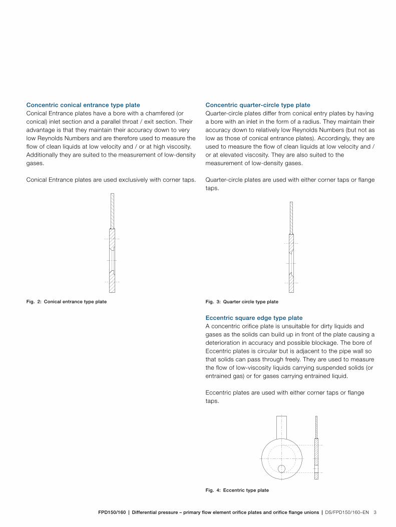
Concentric conical entrance type plateConical Entrance plates have a bore with a chamfered (or conical) inlet section and a parallel throat / exit section. Their advantage is that they maintain their accuracy down to very low Reynolds Numbers and are therefore used to measure the flow of clean liquids at low velocity and / or at high viscosity. Additionally they are suited to the measurement of low-density gases.
Conical Entrance plates are used exclusively with corner taps.
Concentric quarter-circle type plateQuarter-circle plates differ from conical entry plates by having a bore with an inlet in the form of a radius. They maintain their accuracy down to relatively low Reynolds Numbers (but not as low as those of conical entrance plates). Accordingly, they are used to measure the flow of clean liquids at low velocity and / or at elevated viscosity. They are also suited to the measurement of low-density gases.
Quarter-circle plates are used with either corner taps or flange taps.
Eccentric square edge type plateA concentric orifice plate is unsuitable for dirty liquids and gases as the solids can build up in front of the plate causing a deterioration in accuracy and possible blockage. The bore of Eccentric plates is circular but is adjacent to the pipe wall so that solids can pass through freely. They are used to measure the flow of low-viscosity liquids carrying suspended solids (or entrained gas) or for gases carrying entrained liquid.
Eccentric plates are used with either corner taps or flange taps.
Fig. 2: Conical entrance type plate Fig. 3: Quarter circle type plate
Fig. 4: Eccentric type plate

FPD150/160Differential pressure – primary flow element orifice plates and orifice flange unions
4 DS/FPD150/160–EN | FPD150/160 | Differential pressure – primary flow element orifice plates and orifice flange unions
Segmental square-edge type plateThe bore of segmental plates is in the shape of a segment of a circle with its curved edge adjacent to the pipe wall so that solids can pass through freely. It is used to measure the flow of either low-viscosity liquids carrying suspended solids (or entrained gas) or for gases carrying entrained liquid. However, the eccentric type is preferred for such applications.
Segmental plates are used with flange taps.
Orifice flange unions
McMenon orifice flange unions combine the orifice plate with a pair of flanges, complete with nuts, bolts, washers and gaskets. To enable separation of the two flanges for removal and installation of the orifice plate, the assembly is supplied with jacking bolts. The resultant assembly is typically butt-welded into the pipework, although the flanges can be supplied for socket weld or screwed installation into the pipework. The orifice plates are usually supplied with a data tab welded to the circumference. This tab can be engraved with plate information (such as tag number and bore size), that is visible without removing the plate from the line.The differential pressure generated is sensed at a pair (or multiple pairs) of tapping points within the flange assembly, each pair comprising of a high pressure (inlet) and a low pressure (outlet) tapping.As standard our orifice flange unions are supplied as welding-neck type. Other types, including socket weld and threaded, are available.
Fig. 5: Segmental type plate
Fig. 6: Orifice flange union

FPD150/160 | Differential pressure – primary flow element orifice plates and orifice flange unions | DS/FPD150/160–EN 5
Applications
Orifice plates are an incredibly versatile flow metering technology and can be used in a wide range of flow measurement applications, including: — Clean liquids, gases and steam— Fluids containing solids— High viscosity fluids— Fluids at low flowrates— Flow monitoring— Gas and utility flows to combustion plants— Steam consumption — Pilot plants
Comprehensive documentation
McMenon offers unsurpassed quality in its DP devices and we also provide the full testing and documentation that your application needs. Whether the requirement is a single orifice plate with a simple certificate of conformity or a project requiring full material inspection, traceability, third-party verification and comprehensive data dossiers – the McMenon facility at Workington satisfies all of the requirements.
Standards and servicesThese are just some of the standards we follow and the services we can provide:
Quality systemsBS EN ISO 9001:2000 Q 05907
Environmental impactISO 14001EMS 40882
EU Pressure Equipment Directive97/23/EC
DesignBS EN ISO 5167-1:2003R W Miller AGAAPI ASME
Materials and Traceability BS EN 10204 3.1 B,C NACE MR-01-75
Product testing services Magnetic particle inspection Dye-penetrant Inspection PMI (Texas Nuclear) Customer inspectionIndependent third party Inspection
Base metal testing Charpy impact testing Hardness surveyHIC testingIntercrystalline corrosion testing etc.
Certification / Documentation to your requirementsBore calculations PED 97/23/ECMaterial certificates to BS EN 10204 3.1 B,C NACE MR-01-75 conformity certificateWelding qualifications to ASME IX, EN BS 288/287 GA drawingsCertificates of conformity Weight certificatesNDT certificates and procedures Quality plansFull data dossiersInstallation and operating manuals etc.
FPD150/160Differential pressure – primary flow element orifice plates and orifice flange unions
6 DS/FPD150/160–EN | FPD150/160 | Differential pressure – primary flow element orifice plates and orifice flange unions
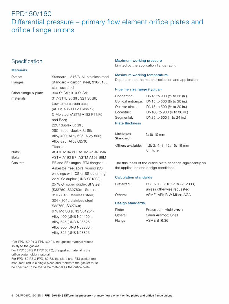
Specification
Materials
*For FPD150.P1 & FPD160.F1, the gasket material relatessolely to the gasket.For FPD150.P2 & FPD160.F2, the gasket material is theorifice plate holder material.For FPD150.P3 & FPD160.F3, the plate and RTJ gasket aremanufactured in a single piece and therefore the gasket mustbe specified to be the same material as the orifice plate.
Maximum working pressureLimited by the application flange rating.
Maximum working temperatureDependent on the material selection and application.
Pipeline size range (typical)
The thickness of the orifice plate depends significantly on the application and design conditions.
Calculation standards
Design standards
Plates: Standard – 316/316L stainless steel
Flanges: Standard – carbon steel; 316/316L
stainless steel
Other flange & plate
materials:
304 St Stl ; 310 St Stl;
317/317L St Stl ; 321 St Stl;
Low temp carbon steel
(ASTM A350 LF2 Class 1);
CrMo steel (ASTM A182 F11,F5
and F22);
22Cr duplex St Stl ;
25Cr super duplex St Stl;
Alloy 400; Alloy 625; Alloy 800;
Alloy 825; Alloy C276;
Titanium;
Nuts: ASTM A194 2H; ASTM A194 8MA
Bolts: ASTM A193 B7; ASTM A193 B8M
Gaskets: RF and FF flanges, RTJ flanges* –
Asbestos free; spiral wound (SS
windings with CS or SS outer ring)
22 % Cr duplex (UNS S31803);
25 % Cr super duplex St Steel
(S32750, S32760); Soft iron;
316 / 316L stainless steel;
304 / 304L stainless steel
S32750, S32760);
6 % Mo SS (UNS S31254);
Alloy 400 (UNS N04400);
Alloy 625 (UNS N06625);
Alloy 800 (UNS N08800);
Alloy 825 (UNS N08825)
Concentric: DN15 to 900 (½ to 36 in.)
Conical entrance: DN15 to 500 (½ to 20 in.)
Quarter circle: DN15 to 500 (½ to 20 in.)
Eccentric: DN100 to 900 (4 to 36 in.)
Segmental: DN25 to 600 (1 to 24 in.)
Plate thickness
3; 6; 10 mm
Others available: 1.5; 2; 4; 8; 12; 15; 16 mm1/2; 3/4 in.
Preferred:
Others:
Plate:
Others:
Flange:
BS EN ISO 5167-1 & -2: 2003,
unless otherwise requested ASME; API; R W Miller; AGA
Preferred – McMenon
Saudi Aramco; Shell
ASME B16.36
McMenon Standard:
FPD150/160 | Differential pressure – primary flow element orifice plates and orifice flange unions | DS/FPD150/160–EN 7
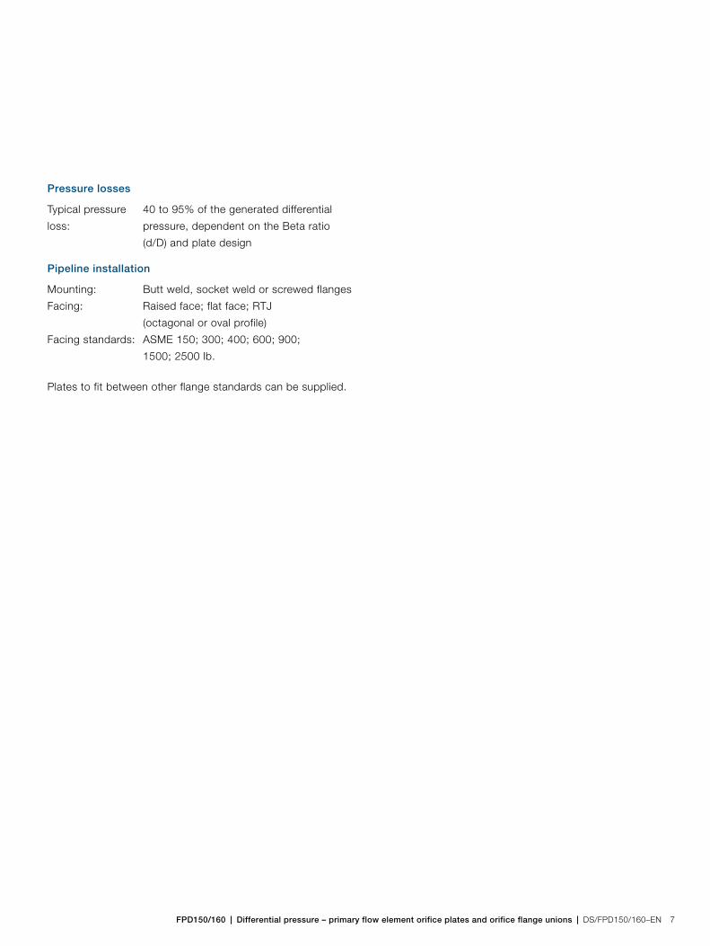
Pressure losses
Pipeline installation
Plates to fit between other flange standards can be supplied.
Typical pressure
loss:
40 to 95% of the generated differential
pressure, dependent on the Beta ratio
(d/D) and plate design
Mounting: Butt weld, socket weld or screwed flanges
Facing: Raised face; flat face; RTJ
(octagonal or oval profile)
Facing standards: ASME 150; 300; 400; 600; 900;
1500; 2500 lb.

FPD150/160Differential pressure – primary flow element orifice plates and orifice flange unions
8 DS/FPD150/160–EN | FPD150/160 | Differential pressure – primary flow element orifice plates and orifice flange unions
Ordering information
FPD150 orifice plates
Main code Optional code
Orifice plates FPD150 XX XX XX XXX XX XX XX XXX XX XX XXX XXX XX XXX XX XX XXX XX XXX XXX
Product design See pages 11, 12 and 13
Orifice plate only (for RF/FF flanges)Orifice plate screwed into RTJ male carrierOrifice RTJ male plate (integral, one piece)
P1P2P3
Customer-specific design
McMenon StandardAamco StandardShell Standard
A1A2S1
Orifice design
Concentric square edged – corner tapsConcentric square edged – flange tapsConcentric – D & D/2 tapsConical entrance – corner tapsEccentric – corner tapsEccentric – flange taps 90°Eccentric – flange taps 180°Quarter circle – corner tapsQuarter circle – flange tapsSegmental – flange taps
C1C2C3L1E1E2E3U1U2S2
Line nominal bore
DN 15 (1/2 in.)DN 20 (3/4 in.)DN 25 (1 in.)DN 32 (11/4 in.)DN 40 (11/2 in.)DN 50 (2 in.)DN 65 (21/2 in.)DN 80 (3 in.)DN 90 (31/2 in.)DN 100 (4 in.)DN 125 (5 in.)DN 150 (6 in.)DN 200 (8 in.)DN 250 (10 in.)DN 300 (12 in.)DN 350 (14 in.)DN 400 (16 in.)DN 450 (18 in.)DN 500 (20 in.)DN 550 (22 in.)DN 600 (24 in.)DN 650 (26 in.)DN 700 (28 in.)DN 750 (30 in.)DN 800 (32 in.)DN 850 (34 in.)DN 900 (36 in.)DN 950 (38 in.)DN 1000 (40 in.)DN 1050 (42 in.)Others
015020025032040050065080090100125150200250300350400450500550600650700750800850900950001051999
Continued on next page …

FPD150/160 | Differential pressure – primary flow element orifice plates and orifice flange unions | DS/FPD150/160–EN 9
See page 8 See pages 11, 12 and 13
Pipe schedule
Schedule 5SSchedule 5Schedule 10SSchedule 10Schedule 20Schedule 30Schedule 40SSchedule 40Schedule STDSchedule 60Schedule 80SSchedule 80Schedule XSSchedule 100Schedule 120Schedule 140Schedule 160Schedule XXSOthers
S1S2S3S4S5S6S7S8S9T1T2T3T4T5T6T7T8T9Z9
Pipe material
316 / 316L stainless steel304 / 304L stainless steel310 stainless steel321 stainless steel317 / 317L stainless steel22 % Cr duplex (UNS S31803)25 % Cr super duplex (UNS S3275025 % Cr super duplex (UNS S32760)6 % Mo SS (UNS S31254)Alloy 400 (UNS N04400)Alloy 625 (UNS N06625)Alloy 800 (UNS N08800)Alloy 825 (UNS N08825)Alloy C276 (UNS N10276)Others
S6S4S3S2S8D1D2D3M1M4N2U4U5U7Z9
Continued on next page …
Main code Optional code
Orifice plates FPD150 XX XX XX XXX XX XX XX XXX XX XX XXX XXX XX XXX XX XX XXX XX XXX XXX

FPD150/160Differential pressure – primary flow element orifice plates and orifice flange unions
10 DS/FPD150/160–EN | FPD150/160 | Differential pressure – primary flow element orifice plates and orifice flange unions
See page 8 page 9 See pages 11, 12 and 13
Element material
316 / 316L stainless steel304 / 304L stainless steel310 stainless steel321 stainless steel317 / 317L stainless steel22% Cr duplex (UNS S31803)25% Cr super duplex (UNS S32750)25% Cr super duplex (UNS S32760)6% Mo SS (UNS S31254)Alloy 400 (UNS N04400)Alloy 625 (UNS N06625)Alloy 800 (UNS N08800)Alloy 825 (UNS N08825)Alloy C276 (UNS N10276)Others
S6S4S3S2S8D1D2D3M1M4N2U4U5U7Z9
Orifice plate thickness
1.5 mm2 mm3 mm4 mm6 mm8 mm10 mm12 mm15 mm16 mmOthers
S01S02S03S04S05S06S07S08S09S10Z99
Flange type
Raised face flangeOval RTJOctagonal RTJFlat face flange (within bolt circle)Flat face flange (full face diameter plate with bolt holes)Others
R1J1J3F1F2Z9
Continued on next page …
Main code Optional code
Orifice plates FPD150 XX XX XX XXX XX XX XX XXX XX XX XXX XXX XX XXX XX XX XXX XX XXX XXX
FPD150/160 | Differential pressure – primary flow element orifice plates and orifice flange unions | DS/FPD150/160–EN 11
See page 8 page 9 See page 10
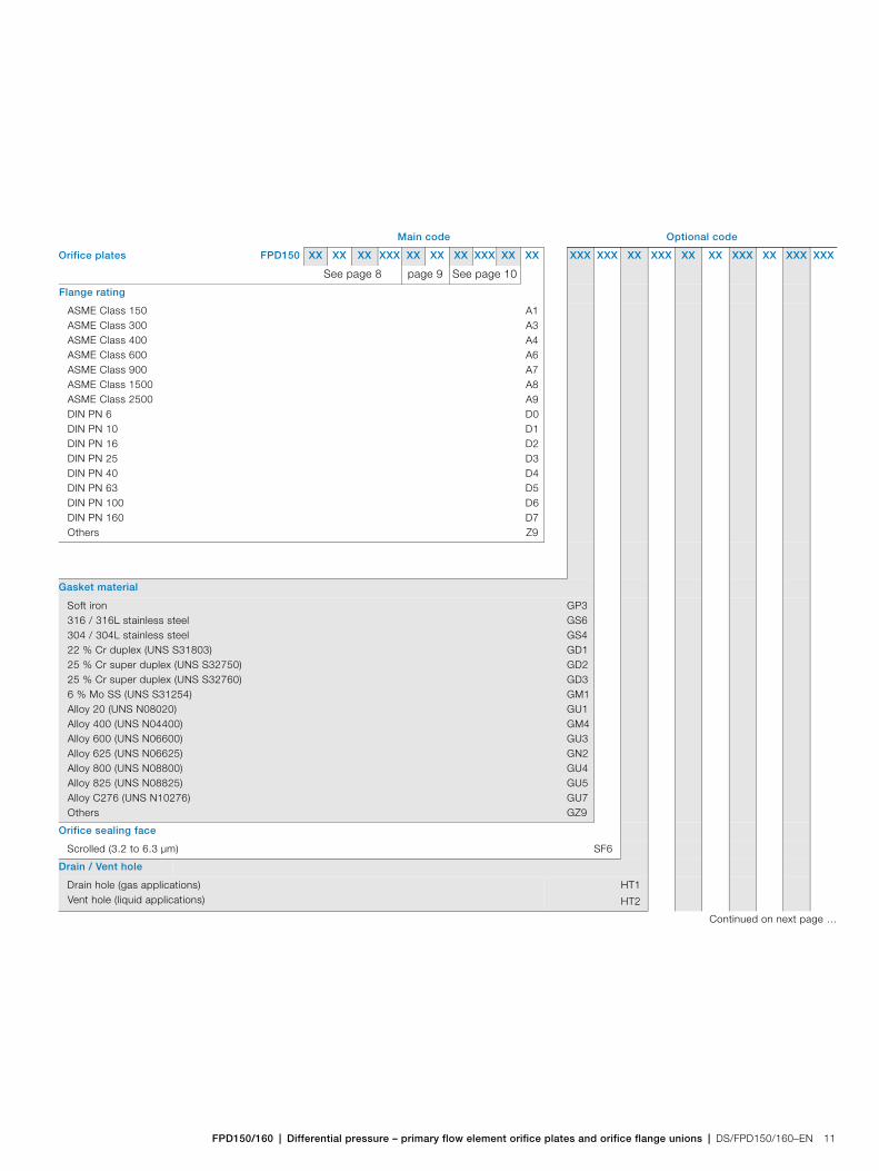
Flange rating
ASME Class 150ASME Class 300ASME Class 400ASME Class 600ASME Class 900ASME Class 1500ASME Class 2500DIN PN 6DIN PN 10DIN PN 16DIN PN 25DIN PN 40DIN PN 63DIN PN 100DIN PN 160Others
A1A3A4A6A7A8A9D0D1D2D3D4D5D6D7Z9
Gasket material
Soft iron316 / 316L stainless steel304 / 304L stainless steel22 % Cr duplex (UNS S31803)25 % Cr super duplex (UNS S32750)25 % Cr super duplex (UNS S32760)6 % Mo SS (UNS S31254)Alloy 20 (UNS N08020)Alloy 400 (UNS N04400)Alloy 600 (UNS N06600)Alloy 625 (UNS N06625)Alloy 800 (UNS N08800)Alloy 825 (UNS N08825)Alloy C276 (UNS N10276)Others
GP3GS6GS4GD1GD2GD3GM1GU1GM4GU3GN2GU4GU5GU7GZ9
Orifice sealing face
Scrolled (3.2 to 6.3 µm) SF6
Drain / Vent hole
Drain hole (gas applications)Vent hole (liquid applications)
HT1
HT2
Continued on next page …
Main code Optional code
Orifice plates FPD150 XX XX XX XXX XX XX XX XXX XX XX XXX XXX XX XXX XX XX XXX XX XXX XXX

FPD150/160Differential pressure – primary flow element orifice plates and orifice flange unions
12 DS/FPD150/160–EN | FPD150/160 | Differential pressure – primary flow element orifice plates and orifice flange unions
See page 8 page 9 See page 10
Drain / vent hole size
1 mm1.5 mm2 mm3 mm4 mm5 mm5.5 mm6 mm6.5 mm7.5 mm8 mm10 mm3/32 in.1/8 in.5/32 in.3/16 in.7/32 in.1/4 in.9/32 in.5/16 in.11/32 in.3/8 in.13/32 in.7/16 in.15/32 in.1/2 in.Others
HA1HA2HA3HA4HA5HA6HA7HA8HA9HB1HB2HB3HB4HB5HB6HB7HB8HB9HC1HC2HC3HC4HC5HC6HC7HC8HZ9
Surface Treatment
Oxygen cleaningOthers
P1
Z9
Certification
Material certificates to BS EN 10204 3.1 BMaterial certificates to BS EN 10204 3.1 CMaterial NACE MR0175Material NACE MR0103Positive material identification (NITRON XRF)100% dimensional checkOthers
C2
C3
CN
CM
CA
C6
Z9
Continued on next page …
Main code Optional code
Orifice plates FPD150 XX XX XX XXX XX XX XX XXX XX XX XXX XXX XX XXX XX XX XXX XX XXX XXX
FPD150/160 | Differential pressure – primary flow element orifice plates and orifice flange unions | DS/FPD150/160–EN 13
See page 8 page 9 See page 10
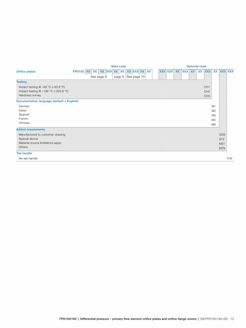
Testing
Impact testing @ –46 °C (–50.8 °F)Impact testing @ –196 °C (–320.8 °F)Hardness survey
CH1
CH2
CH3
Documentation language (default = English)
GermanItalianSpanishFrenchChinese
M1
M2
M3
M4
M6
Added requirements
Manufactured to customer drawingSpecial deviceMaterial source limitations applyOthers
GD9
STZ
MS1
MZ9
Tab handle
No tab handle TH0
Main code Optional code
Orifice plates FPD150 XX XX XX XXX XX XX XX XXX XX XX XXX XXX XX XXX XX XX XXX XX XXX XXX
FPD150/160Differential pressure – primary flow element orifice plates and orifice flange unions
14 DS/FPD150/160–EN | FPD150/160 | Differential pressure – primary flow element orifice plates and orifice flange unions
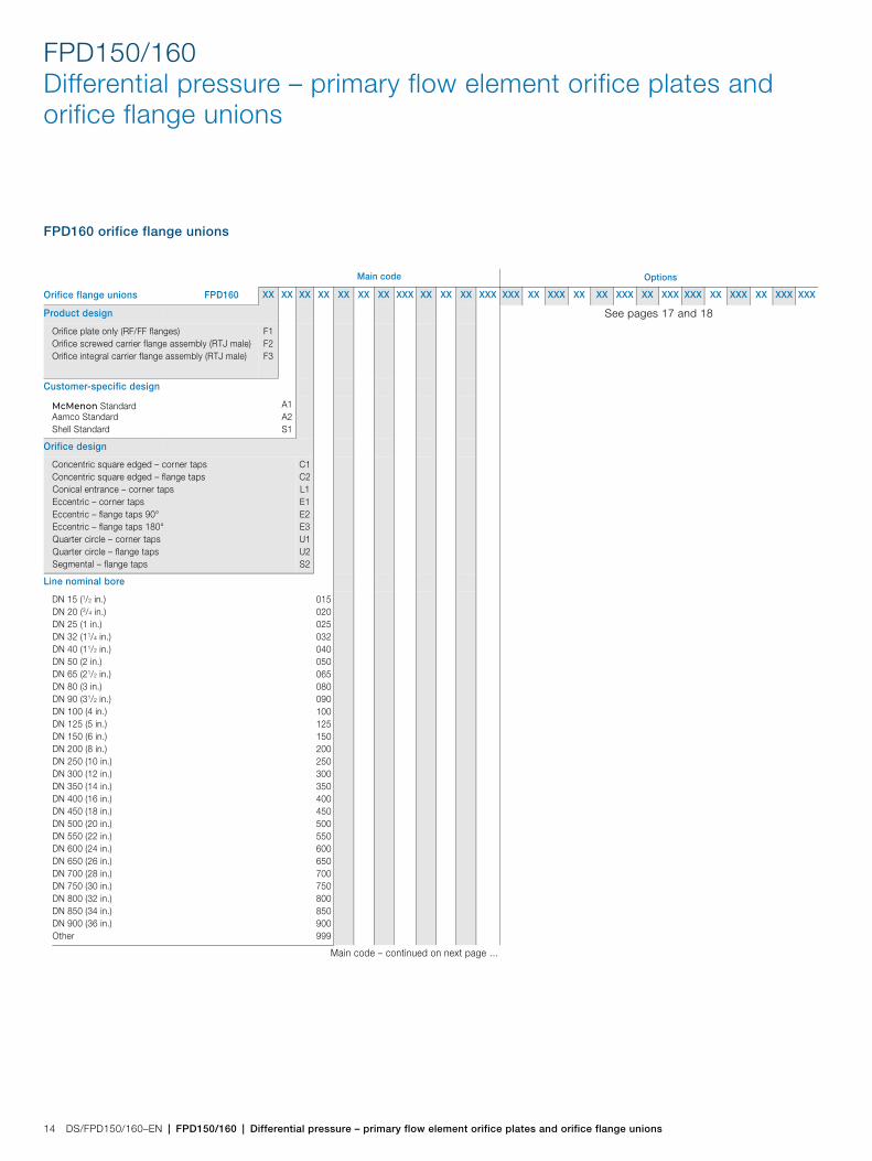
FPD160 orifice flange unions
OT1 Main code Options
Orifice flange unions FPD160 XX XX XX XX XX XX XX XXX XX XX XX XXX XXX XX XXX XX XX XXX XX XXX XXX XX XXX XX XXX XXX
Product design See pages 17 and 18
Orifice plate only (RF/FF flanges)Orifice screwed carrier flange assembly (RTJ male)Orifice integral carrier flange assembly (RTJ male)
F1F2F3
Customer-specific design
McMenon StandardAamco StandardShell Standard
A1A2S1
Orifice design
Concentric square edged – corner tapsConcentric square edged – flange tapsConical entrance – corner tapsEccentric – corner tapsEccentric – flange taps 90°Eccentric – flange taps 180°Quarter circle – corner tapsQuarter circle – flange tapsSegmental – flange taps
C1C2L1E1E2E3U1U2S2
Line nominal bore
DN 15 (1/2 in.)DN 20 (3/4 in.)DN 25 (1 in.)DN 32 (11/4 in.)DN 40 (11/2 in.)DN 50 (2 in.)DN 65 (21/2 in.)DN 80 (3 in.)DN 90 (31/2 in.)DN 100 (4 in.)DN 125 (5 in.)DN 150 (6 in.)DN 200 (8 in.)DN 250 (10 in.)DN 300 (12 in.)DN 350 (14 in.)DN 400 (16 in.)DN 450 (18 in.)DN 500 (20 in.)DN 550 (22 in.)DN 600 (24 in.)DN 650 (26 in.)DN 700 (28 in.)DN 750 (30 in.)DN 800 (32 in.)DN 850 (34 in.)DN 900 (36 in.)Other
015020025032040050065080090100125150200250300350400450500550600650700750800850900999
Main code – continued on next page …
FPD150/160 | Differential pressure – primary flow element orifice plates and orifice flange unions | DS/FPD150/160–EN 15
See page 14 See pages 17 and 18
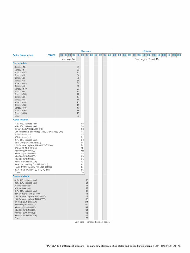
Pipe schedule
Schedule 5SSchedule 5Schedule 10SSchedule 10Schedule 20Schedule 30Schedule 40SSchedule 40Schedule STDSchedule 60Schedule 80SSchedule 80Schedule XSSchedule 100Schedule 120Schedule 140Schedule 160Schedule XXSOther
S1S2S3S4S5S6S7S8S9T1T2T3T4T5T6T7T8T9Z9
Flange material
316 / 316L stainless steel304 / 304L stainless steelCarbon Steel (A105N/A106 Gr.B)Low temperature carbon steel (A350 LF2 C1/A333 Gr 6)310 stainless steel321 stainless steel317 / 317L stainless steel22 % Cr duplex (UNS S31803)25% Cr super duplex (UNS S32750/S32760)6 % Mo SS (UNS S31254)Alloy 400 (UNS N04400)Alloy 625 (UNS N06625)Alloy 800 (UNS N08800)Alloy 825 (UNS N08825)Alloy C276 (UNS N10276)5 Cr-1/2 Mo low alloy F5 (UNS K41545)11/4 Cr-1/2 Mo low alloy F11 (UNS K11597)21/4 Cr-1 Mo low alloy F22 (UNS K21590)Others
S6S4C3C4S3S2S8D1D2M1M4N2U4U5U7F3F4F5Z9
Element material
316 / 316L stainless steel304 / 304L stainless steel310 stainless steel321 stainless steel317 / 317L stainless steel22% Cr duplex (UNS S31803)25% Cr super duplex (UNS S32750)25% Cr super duplex (UNS S32760)6% Mo SS (UNS S31254)Alloy 400 (UNS N04400)Alloy 625 (UNS N06625)Alloy 800 (UNS N08800)Alloy 825 (UNS N08825)Alloy C276 (UNS N10276)Others
S6S4S3S2S8D1D2D3M1M4N2U4U5U7Z9
Main code – continued on next page …
OT1 Main code Options
Orifice flange unions FPD160 XX XX XX XX XX XX XX XXX XX XX XX XXX XXX XX XXX XX XX XXX XX XXX XXX XX XXX XX XXX XXX

FPD150/160Differential pressure – primary flow element orifice plates and orifice flange unions
16 DS/FPD150/160–EN | FPD150/160 | Differential pressure – primary flow element orifice plates and orifice flange unions
See page 14 See page 15 See pages 17 and 18
Orifice plate thickness
1.5 mm2 mm3 mm4 mm6 mm8 mm10 mm12 mm1/2 in.15 mm16 mm3/4 in.Others
S01S02S03S04S05S06S07S08T01T03S09T02Z99
Flange type
Raised face flangeOval RTJ flangeOctagonal RTJ flangeFlat face flangeFlat face flange – full face plate with bolt holesOthers
R1J1J3F1F2Z9
Flange rating
ASME Class 300ASME Class 400ASME Class 600ASME Class 900ASME Class 1500ASME Class 2500Others
A3A4A6A7A8A9Z9
Body type and material
ASTM A193 B7 / ASTM A194 2HASTM A193 B8M / ASTM A194 8MA
BGC
BGS
Gasket Material
Asbestos-free 1.6 mmSpiral wound – SS windings with CS outer; 4.5 mmSoft iron316 / 316L stainless steel304 / 304L stainless steel22 % Cr duplex (UNS S31803)25 % Cr super duplex (UNS S32750)25 % Cr super duplex (UNS S32760)6 % Mo SS (UNS S31254)Alloy 400 (UNS N04400)Alloy 625 (UNS N06625)Alloy 800 (UNS N08800)Alloy 825 (UNS N08825)Others
GT1GT2GP3GS6GS4GD1GD2GD3GM1GM4GN2GU4GU5GZ9
Optional codes continued on next page …
OT1 Main code Options
Orifice flange unions FPD160 XX XX XX XX XX XX XX XXX XX XX XX XXX XXX XX XXX XX XX XXX XX XXX XXX XX XXX XX XXX XXX
FPD150/160 | Differential pressure – primary flow element orifice plates and orifice flange unions | DS/FPD150/160–EN 17
See page 14 See page 15 See page 16
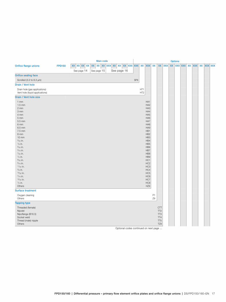
Orifice sealing face
Scrolled (3.2 to 6.3 µm) SF6
Drain / Vent hole
Drain hole (gas applications)Vent hole (liquid applications)
HT1HT2
Drain / Vent hole size
1 mm1.5 mm2 mm3 mm4 mm5 mm5.5 mm6 mm6.5 mm7.5 mm8 mm10 mm3/32 in.1/8 in.5/32 in.3/16 in.7/32 in.1/4 in.9/32 in.5/16 in.11/32 in.3/8 in.13/32 in.7/16 in.15/32 in.1/2 in.Others
HA1HA2HA3HA4HA5HA6HA7HA8HA9HB1HB2HB3HB4HB5HB6HB7HB8HB9HC1HC2HC3HC4HC5HC6HC7HC8HZ9
Surface treatment
Oxygen cleaningOthers
P1Z9
Tapping type
Threaded (female) NipoletNipoflange (B16.5)Socket weldThread (male) nippleOthers
CTTTT2TT3TT4TT5TZ9
Optional codes continued on next page …
OT1 Main code Options
Orifice flange unions FPD160 XX XX XX XX XX XX XX XXX XX XX XX XXX XXX XX XXX XX XX XXX XX XXX XXX XX XXX XX XXX XXX
FPD150/160Differential pressure – primary flow element orifice plates and orifice flange unions
18 DS/FPD150/160–EN | FPD150/160 | Differential pressure – primary flow element orifice plates and orifice flange unions
See page 14 See page 15 See page 16 See page 17
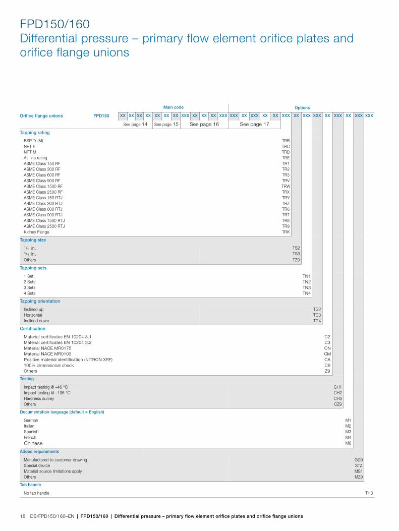
Tapping rating
BSP Tr (M)NPT FNPT MAs line ratingASME Class 150 RFASME Class 300 RFASME Class 600 RFASME Class 900 RFASME Class 1500 RFASME Class 2500 RFASME Class 150 RTJASME Class 300 RTJASME Class 600 RTJASME Class 900 RTJASME Class 1500 RTJASME Class 2500 RTJKidney Flange
TRBTRCTRDTRETR1TR2TR3TRVTRWTRXTRYTRZTR6TR7TR8TR9TRK
Tapping size
1/2 in.3/4 in.Others
TS2TS3TZ9
Tapping sets
1 Set2 Sets3 Sets4 Sets
TN1TN2TN3TN4
Tapping orientation
Inclined upHorizontal Inclined down
TG2TG3TG4
Certification
Material certificates EN 10204 3.1Material certificates EN 10204 3.2Material NACE MR0175Material NACE MR0103Positive material identification (NITRON XRF)100% dimensional checkOthers
C2C3CNCMCAC6Z9
Testing
Impact testing @ –46 °CImpact testing @ –196 °CHardness surveyOthers
CH1CH2CH3CZ9
Documentation language (default = English)
GermanItalianSpanishFrenchChinese
M1M2M3M4M6
Added requirements
Manufactured to customer drawingSpecial deviceMaterial source limitations applyOthers
GD9STZMS1MZ9
Tab handle
No tab handle TH0
OT1 Main code Options
Orifice flange unions FPD160 XX XX XX XX XX XX XX XXX XX XX XX XXX XXX XX XXX XX XX XXX XX XXX XXX XX XXX XX XXX XXX

FPD150/160 | Differential pressure – primary flow element orifice plates and orifice flange unions | DS/FPD150/160–EN 19
Notes

DS
/FP
D15
0/16
0–E
N02
.201
5NoteWe reserve the right to make technical changes or modify the contents of this document without prior notice. With regard to purchase orders, the agreed particulars shall prevail. McMenon does not accept any responsibility whatsoever for potential errors or possible lack of information in this document.
We reserve all rights in this document and in the subject matter and illustrations contained therein. Any reproduction, disclosure to third parties or utilization of its contents in whole or in parts – is forbidden without prior written consent of McMenon.
Copyright© 2015 McMenonAll rights reserved
Contact us
McMenon Engineering Services
Salterbeck Trading Estate WorkingtonCumbria CA14 5DSUKTel: +44 (0)1946 830 611 Fax: +44 (0)1946 832 661
www.mcmenon.com


![Flow Product Catalogue - DynaFluid catalogue - Final [Compatibility Mode].pdf · Flow Product Catalogue ORIFICE PLATES ||| | ... Restriction Orifice plate ... single restriction orifice](https://img.dokumen.tips/doc/110x75/5aabb76c7f8b9a693f8c48a7/flow-product-catalogue-catalogue-final-compatibility-modepdfflow-product.jpg)