Embed Size (px)
Citation preview

Belt
Conveyor
HB-826 - 12/03

To contact FKI Logistex, Automation Division:For service: Customer Service and Support Group (CSSG)Hotline 1-800-992-1267
On the World Wide Web: www.fkilogistex.com/automation
By mail:FKI Logistex, Automation Division10045 International BoulevardCincinnati, Ohio 45246(513) 874-0788
The information presented in this document is correct at the time of publication. FKI Logistex Automation Division has made every effort to ensure that the information presented is correct and free from error. However, some errors or misprints may occur. Please contact FKI Logistex, Automation Division with any corrections.
This document is copyrighted © 2001 by FKI Logistex, Automation Division, all rights reserved. No Part of this Users Guide may be reproduced and/or distributed to parties other than the customer and the customer’s employees for whom it was originally produced.
Direct questions and comments concerning the information contained in this manual to:
[email protected] or Product ManagementFKI Logistex, Automation Division10045 International BoulevardCincinnati, Ohio 45246(513) 874-0788
HB-826 - 12/03
Table of Contents
Engineering DataIntroduction - - - - - - - - - - - - - - - - - - - - - - - - - - - - - - - - - - - - - - - - - - - - - - - - - - - - - 1Engineering Data - - - - - - - - - - - - - - - - - - - - - - - - - - - - - - - - - - - - - - - - - - - - - - - - - 1
Product Width - Straight Conveyor - - - - - - - - - - - - - - - - - - - - - - - - - - - - - - - - - - 1Product Width - Curves - - - - - - - - - - - - - - - - - - - - - - - - - - - - - - - - - - - - - - - - - - 1Product Length - Horizontal Conveyor - - - - - - - - - - - - - - - - - - - - - - - - - - - - - - - - 2Product Length - Incline/Decline Conveyor - - - - - - - - - - - - - - - - - - - - - - - - - - - - - 2Product Weight - - - - - - - - - - - - - - - - - - - - - - - - - - - - - - - - - - - - - - - - - - - - - - - - 2Product Loading - - - - - - - - - - - - - - - - - - - - - - - - - - - - - - - - - - - - - - - - - - - - - - - 3
Belt Pull, Horsepower and Belt Width Calculations - - - - - - - - - - - - - - - - - - - - - - - - - -10Belt Pull Calculations - - - - - - - - - - - - - - - - - - - - - - - - - - - - - - - - - - - - - - - - - - - -10
Live Load (A) - - - - - - - - - - - - - - - - - - - - - - - - - - - - - - - - - - - - - - - - - - - - - - -10Dead Load (B) - - - - - - - - - - - - - - - - - - - - - - - - - - - - - - - - - - - - - - - - - - - - - -10Belt Pull (C) - - - - - - - - - - - - - - - - - - - - - - - - - - - - - - - - - - - - - - - - - - - - - - - -11Inclines/Declines (D) - - - - - - - - - - - - - - - - - - - - - - - - - - - - - - - - - - - - - - - - - -12Deflectors (E) - - - - - - - - - - - - - - - - - - - - - - - - - - - - - - - - - - - - - - - - - - - - - - -14Transition Points (F) - - - - - - - - - - - - - - - - - - - - - - - - - - - - - - - - - - - - - - - - - -14Effective Belt Pull - - - - - - - - - - - - - - - - - - - - - - - - - - - - - - - - - - - - - - - - - - - -14
Horsepower Calculations - - - - - - - - - - - - - - - - - - - - - - - - - - - - - - - - - - - - - - - - - - - -15Belt Width Calculations - - - - - - - - - - - - - - - - - - - - - - - - - - - - - - - - - - - - - - - - - - - - -16Conveyor Belting - - - - - - - - - - - - - - - - - - - - - - - - - - - - - - - - - - - - - - - - - - - - - - - - -17
Belt Fasteners - - - - - - - - - - - - - - - - - - - - - - - - - - - - - - - - - - - - - - - - - - - - - - - - -17Unit Conveyors
Horizontal Belt Conveyor - Intermediate Drive - Model BHC - - - - - - - - - - - - - - - - - - -19Horizontal Belt Conveyor - End Drive - Model BHE - - - - - - - - - - - - - - - - - - - - - - - - -22Standard Duty - Brake/Meter Belt - Model BMB - - - - - - - - - - - - - - - - - - - - - - - - - - - -25
Drive Mounted Above - C1565 - Drive Mounted Below - C1566 - - - - - - - - - - - - - -25General Description - - - - - - - - - - - - - - - - - - - - - - - - - - - - - - - - - - - - - - - - - - - - -28Application - - - - - - - - - - - - - - - - - - - - - - - - - - - - - - - - - - - - - - - - - - - - - - - - - - -28Brake Belt Considerations - - - - - - - - - - - - - - - - - - - - - - - - - - - - - - - - - - - - - - - -28Meter Belt - - - - - - - - - - - - - - - - - - - - - - - - - - - - - - - - - - - - - - - - - - - - - - - - - - - -28
Heavy Duty Horizontal Belt Conveyor - Intermediate Drive - Model HBC - - - - - - - - - -2913° Inclined Belt Conveyor - Model BIC-13 - - - - - - - - - - - - - - - - - - - - - - - - - - - - - - -3220° Inclined Belt Conveyor - Model BIC-20 - - - - - - - - - - - - - - - - - - - - - - - - - - - - - - -3626° Inclined Belt Conveyor - Model BIC-26 - - - - - - - - - - - - - - - - - - - - - - - - - - - - - - -39Power Feeders - - - - - - - - - - - - - - - - - - - - - - - - - - - - - - - - - - - - - - - - - - - - - - - - - - -42C1252 2 Pulley P.T.O. - - - - - - - - - - - - - - - - - - - - - - - - - - - - - - - - - - - - - - - - - - - - - -43C1418 Three Roller Device - - - - - - - - - - - - - - - - - - - - - - - - - - - - - - - - - - - - - - - - - -44
HB-826 - 12/03 TOC - 1

Table of Contents
ComponentsSA2000 Intermediate Drive - - - - - - - - - - - - - - - - - - - - - - - - - - - - - - - - - - - - - - - - - -45SA2001 Low Profile Intermediate Drive - - - - - - - - - - - - - - - - - - - - - - - - - - - - - - - - - -58C1716 End Drive - - - - - - - - - - - - - - - - - - - - - - - - - - - - - - - - - - - - - - - - - - - - - - - - -71C1721 Low Profile End Drive - - - - - - - - - - - - - - - - - - - - - - - - - - - - - - - - - - - - - - - - -77C1239 End Roller / Take-Up Unit - - - - - - - - - - - - - - - - - - - - - - - - - - - - - - - - - - - - - -83C1626 End Roller Unit - - - - - - - - - - - - - - - - - - - - - - - - - - - - - - - - - - - - - - - - - - - - - -83C1264 Intermediate Take-Up - - - - - - - - - - - - - - - - - - - - - - - - - - - - - - - - - - - - - - - - -85C1510 Vertical Take-Up - - - - - - - - - - - - - - - - - - - - - - - - - - - - - - - - - - - - - - - - - - - -85C1641 Intermediate Section - Trash Removal Conveyor - - - - - - - - - - - - - - - - - - - - - -86C1640 End Section - Trash Removal Conveyor - - - - - - - - - - - - - - - - - - - - - - - - - - - -86C1237 Conveyor Section - - - - - - - - - - - - - - - - - - - - - - - - - - - - - - - - - - - - - - - - - - - -88C1238 Slider Bed Sections - - - - - - - - - - - - - - - - - - - - - - - - - - - - - - - - - - - - - - - - - -89C1267 Vertical Bend - - - - - - - - - - - - - - - - - - - - - - - - - - - - - - - - - - - - - - - - - - - - - - -90C1245 - Snub Roller - - - - - - - - - - - - - - - - - - - - - - - - - - - - - - - - - - - - - - - - - - - - - - -91D10374 Bottom Closure - - - - - - - - - - - - - - - - - - - - - - - - - - - - - - - - - - - - - - - - - - - -92C1304 Belt Trainer Roller - - - - - - - - - - - - - - - - - - - - - - - - - - - - - - - - - - - - - - - - - - -93C1304 Belt Trainer Roller - - - - - - - - - - - - - - - - - - - - - - - - - - - - - - - - - - - - - - - - - - -95C1252 Two Pulley P.T.O. - - - - - - - - - - - - - - - - - - - - - - - - - - - - - - - - - - - - - - - - - - -96C1418 Three Roller Device - - - - - - - - - - - - - - - - - - - - - - - - - - - - - - - - - - - - - - - - - -98C1504 Power Take-Off - - - - - - - - - - - - - - - - - - - - - - - - - - - - - - - - - - - - - - - - - - - -100C1286 Slider Bed - Box Type Slider Tread - - - - - - - - - - - - - - - - - - - - - - - - - - - - - -102Return Rollers - For Box Type Slider Bed - - - - - - - - - - - - - - - - - - - - - - - - - - - - - - -103C1292 Intermediate Drive - Heavy Duty - - - - - - - - - - - - - - - - - - - - - - - - - - - - - - - -104C1300 and C1301 End Roll - Heavy Duty - - - - - - - - - - - - - - - - - - - - - - - - - - - - - - -107C1404 Idler Roller - (For Heavy Duty Tread Section) - - - - - - - - - - - - - - - - - - - - - - -108C1291 Intermediate Take-Up - Heavy Duty - - - - - - - - - - - - - - - - - - - - - - - - - - - - - -109C1298 Conveyor Section - Heavy Duty - - - - - - - - - - - - - - - - - - - - - - - - - - - - - - - - -111C1297 - Vertical Bend - Heavy Duty - - - - - - - - - - - - - - - - - - - - - - - - - - - - - - - - - - -112C1245 - Snub Roller - - - - - - - - - - - - - - - - - - - - - - - - - - - - - - - - - - - - - - - - - - - - - -113C1299 Two Pulley P.T.O. - Heavy Duty - - - - - - - - - - - - - - - - - - - - - - - - - - - - - - - - -114C1296 - Three Pulley Device - Heavy Duty - - - - - - - - - - - - - - - - - - - - - - - - - - - - - -116
TOC - 2 HB-826 - 12/03

Table of Contents
SupportsC1230 Floor Single Leg Floor Support - 750 Pound Capacity - - - - - - - - - - - - - - -119C1231 Floor Support - 1500 Pound Capacity - - - - - - - - - - - - - - - - - - - - - - - - - -119
For use with AR, CR and PR Channel Frame Rails - - - - - - - - - - - - - - - - - - -119C1275 - Hanger Support - 1500 Pound Capacity - - - - - - - - - - - - - - - - - - - - - - -122
For use with Standard Duty Belt Conveyors- - - - - - - - - - - - - - - - - - - - - - - - -122C686 - Hanger Support - 750 Pound Capacity - - - - - - - - - - - - - - - - - - - - - - - - -125
For use with Standard Duty Belt Conveyors- - - - - - - - - - - - - - - - - - - - - - - - -125C693, C694, C695, C696 Floor Support - 3000 Pounds Capacity - - - - - - - - - - - -126
For use with Heavy Duty Conveyors - - - - - - - - - - - - - - - - - - - - - - - - - - - - - -126Accessories
C1276 Straight Adjustable Guard Rail - - - - - - - - - - - - - - - - - - - - - - - - - - - - - - -131For Use with Standard Duty Belt Conveyors - - - - - - - - - - - - - - - - - - - - - - - -131
C1443 Angle Guard Rail - - - - - - - - - - - - - - - - - - - - - - - - - - - - - - - - - - - - - - - - -132C1303 Channel Guard Rail - - - - - - - - - - - - - - - - - - - - - - - - - - - - - - - - - - - - - - -133C1249 Vertical Bend Guard - - - - - - - - - - - - - - - - - - - - - - - - - - - - - - - - - - - - - -134
Component Belt Length RequirementTelescoping Belt Conveyor
Double and Triple Boom - - - - - - - - - - - - - - - - - - - - - - - - - - - - - - - - - - - - - - - - -137Flat Belt Curves
Powered Belt Curves - - - - - - - - - - - - - - - - - - - - - - - - - - - - - - - - - - - - - - - - - - -141Electrical Components & Control Equipment
Combination Starters - - - - - - - - - - - - - - - - - - - - - - - - - - - - - - - - - - - - - - - - - - - - - -145Components For Driving and Controlling the Powered Conveyors - - - - - - - - - - - - - -147
Motors - - - - - - - - - - - - - - - - - - - - - - - - - - - - - - - - - - - - - - - - - - - - - - - - - - - - -147Gear Reducer - - - - - - - - - - - - - - - - - - - - - - - - - - - - - - - - - - - - - - - - - - - - - - - -148Brakes - - - - - - - - - - - - - - - - - - - - - - - - - - - - - - - - - - - - - - - - - - - - - - - - - - - - -149Clutch Brake - - - - - - - - - - - - - - - - - - - - - - - - - - - - - - - - - - - - - - - - - - - - - - - - -149Motor Starters - - - - - - - - - - - - - - - - - - - - - - - - - - - - - - - - - - - - - - - - - - - - - - - -149
Manual Motor Starters - - - - - - - - - - - - - - - - - - - - - - - - - - - - - - - - - - - - - - - -149Magnetic Motor Starters- - - - - - - - - - - - - - - - - - - - - - - - - - - - - - - - - - - - - - -149Combination Magnetic Motor Starters and Control Panels- - - - - - - - - - - - - - -150
Electrical Enclosures - - - - - - - - - - - - - - - - - - - - - - - - - - - - - - - - - - - - - - - - - - -151Switching Devices - - - - - - - - - - - - - - - - - - - - - - - - - - - - - - - - - - - - - - - - - - - - -151
Push Buttons - - - - - - - - - - - - - - - - - - - - - - - - - - - - - - - - - - - - - - - - - - - - - -151Limit Switches- - - - - - - - - - - - - - - - - - - - - - - - - - - - - - - - - - - - - - - - - - - - - -151Selector Switches - - - - - - - - - - - - - - - - - - - - - - - - - - - - - - - - - - - - - - - - - - -151Photoelectric Relays - - - - - - - - - - - - - - - - - - - - - - - - - - - - - - - - - - - - - - - - -151
Solenoid Valves - - - - - - - - - - - - - - - - - - - - - - - - - - - - - - - - - - - - - - - - - - - - - - -152Air Controls - - - - - - - - - - - - - - - - - - - - - - - - - - - - - - - - - - - - - - - - - - - - - - - - - -152
HB-826 - 12/03 TOC - 3

Table of Contents
TOC - 4 HB-826 - 12/03

Engineering Data
Engineering Data
IntroductionA belt conveyor is a conveyor in which the product rides directly on the belt. The belt is supported byeither a roller bed conveyor section or a slider bed conveyor section. This manual will explain thevarious types of Mathews’ belt conveyors.
This manual describes the following types of belt conveyors:
1. Horizontal Belt Conveyors
2. Heavy Duty Horizontal Belt Conveyors
3. Incline/Decline Belt Conveyors
4. Belt Curves
5. Telescoping Belt Conveyors
In this manual, we are depicting standard units, illustrating the components from which they areassembled, as well as offering a description of these various components. Also included aredescriptions of supports and accessories for each type of conveyor.
Engineering DataThere are several product features that will determine the conveyor specifications:
Product Width - Straight ConveyorThe conveyor width (W) should be approximately 3" wider than the widest product to be conveyed,with the belt being approximately the width of the product. Our standard widths are 15", 21", 27", 33”and 39” Between Frames for most of our product line and the standard belt width is W - 3".
Example: 23" wide product + 3" = 26"Next larger standard is 27" Between Frames
Product Width - CurvesMany times curves in a system will dictatethe width of the conveyor for the entiresystem, in that the product may require“additional space” to negotiate the turn.This “additional space” depends upon thewidth and length of the product.
As a general rule, the inside radius of thecurve should be greater than the length ofthe product. Due to the many combinationsof belt width and radius, the followingformula should be used to determinedistance between frames or guard rails.
G Radius PackageWidth+( ) 2 PackageLength2
2 Radius 2–( )–+=
HB-826 - 12/03 Engineering Data - 1

Engineering Data
Product Length - Horizontal ConveyorIt is good practice, for horizontal belt conveyors with a roller bed, to have a minimum of two rollersunder the product at all times. To determine roller spacing, take the length of the shortest carton, divideby 2 and choose the standard roller spacing required. The standard roller centers are 3", 4-1/2", 6", 9"or 12".
Example:
The closest standard roller spacing is 4-1/2" centers.
Product Length - Incline/Decline ConveyorIt is good practice, for incline/decline conveyors with a roller bed, to have a minimum of three rollersunder the product at all times. To determine roller spacing, take the length of the shortest carton, divideby 3 and choose the standard roller spacing required. The standard roller centers are 3", 4-1/2", 6", 9"or 12".
Example:
The closest standard roller spacing is 3" centers.
Product WeightThe power required to pull a belt and its product over a slider bed section is six times greater than if aroller section had been utilized. For this reason, roller sections are generally preferred. Slider bedsections are used to convey light products that have small irregular bases, where smooth travel isrequired.
For roller sections, a check should be made to ensure that the capacity of the roller is not exceeded.Divide the various carton weights by the number of rollers under the product and compare the weightper roller with the rated capacity of the roller for that width.
*Basic Dynamic Capacity for 1 Million Revolution Life. Design loading should be significantly less forextended life.See CEMA Standard #401.
10″ long carton2
------------------------------------------- 5″=
10″ long carton3
------------------------------------------- 3.33″=
1.90” dia. x .065” Steel Roll 2.50” dia. x .120” Roller
BetweenFrames
Dimension
Roller Weight
w/o Axle
Roller Capacityw/ B1020
BetweenFrames
Dimension
Roller Weight
w/o Axle
Roller* Capacity
15” 2.0# 310# 27” 8.1# 610#21” 2.6# 310# 33” 9.6# 610#27” 3.3# 310# 39” 11.1# 610#33” 3.9# 306# 45” 12.6# 597#39” 4.5# 272# 51” 14.2# 596#
57” 15.7# 586#
Engineering Data - 2 HB-826 - 12/03
Engineering Data
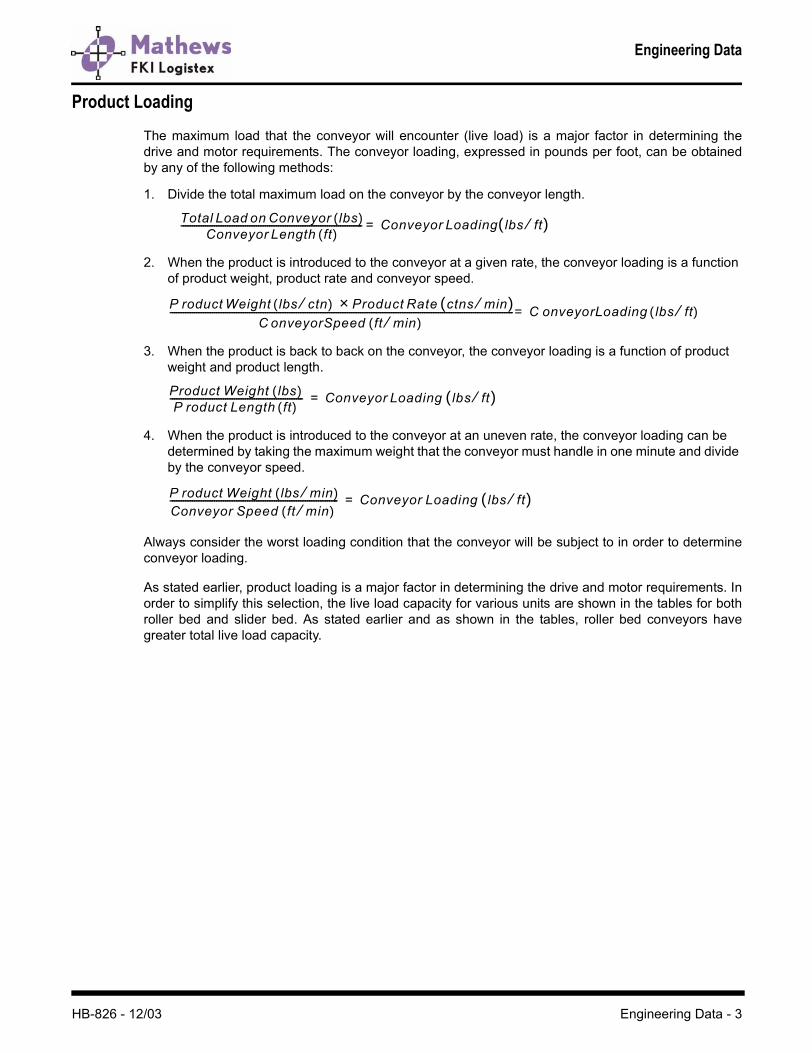
Product LoadingThe maximum load that the conveyor will encounter (live load) is a major factor in determining thedrive and motor requirements. The conveyor loading, expressed in pounds per foot, can be obtainedby any of the following methods:
1. Divide the total maximum load on the conveyor by the conveyor length.
2. When the product is introduced to the conveyor at a given rate, the conveyor loading is a function of product weight, product rate and conveyor speed.
3. When the product is back to back on the conveyor, the conveyor loading is a function of product weight and product length.
4. When the product is introduced to the conveyor at an uneven rate, the conveyor loading can be determined by taking the maximum weight that the conveyor must handle in one minute and divide by the conveyor speed.
Always consider the worst loading condition that the conveyor will be subject to in order to determineconveyor loading.
As stated earlier, product loading is a major factor in determining the drive and motor requirements. Inorder to simplify this selection, the live load capacity for various units are shown in the tables for bothroller bed and slider bed. As stated earlier and as shown in the tables, roller bed conveyors havegreater total live load capacity.
Total Load on Conveyor lbs( )Conveyor Length ft( )
---------------------------------------------------------------------------------- Conveyor Loading lbs ft⁄( )=
P roduct Weight lbs ctn⁄( ) Product Rate ctns min⁄( )×C onveyorSpeed ft min⁄( )
----------------------------------------------------------------------------------------------------------------------------------------------------------- C onveyorLoading lbs ft⁄( )=
Product Weight lbs( )P roduct Length ft( )
------------------------------------------------------------ Conveyor Loading lbs ft⁄( )=
P roduct Weight lbs min⁄( )Conveyor Speed ft min⁄( )---------------------------------------------------------------------------- Conveyor Loading lbs ft⁄( )=
HB-826 - 12/03 Engineering Data - 3

Engineering Data
End Drive - Roller Bed - Horizontal Belt ConveyorLive Load Capacity @ 70 FPM
VariableLength
1/2 HP 3/4 HP 1 HP
lbs./ft. Total lbs./ft. Total lbs./ft. Total13’-0” 100 1300 100 1300 100 130018’-0” 100 1800 100 1800 100 180023’-0” 91 2110 100 2300 100 230028’0” 73 2058 100 2800 100 280033’-0” 60 2007 100 3300 100 330038’-0” 51 1954 89 3394 100 380043’-0” 44 1903 77 3343 100 4300
End Drive - Slider Bed - Horizontal Belt ConveyorLive Load Capacity @ 70 FPM
VariableLength
1/2 HP 3/4 HP 1 HP
lbs./ft. Total lbs./ft. Total lbs./ft. Total13’-0” 17 225 35 465 52 67818’-0” 11 203 24 443 36 65623’-0” 7 182 18 422 27 63528’0” 5 159 14 399 21 61233’-0” 4 137 11 377 17 59038’-0” 3 116 9 356 14 56943’-0” 2 93 7 333 12 546
Engineering Data - 4 HB-826 - 12/03

Engineering Data
Intermediate Drive - Roller Bed - Horizontal Belt ConveyorLive Load Capacity @ 70 FPM
VariableLength
1/2 HP 3/4 HP 1 HP 1-1/2 HP 2 HP
lbs./ft. Total lbs./ft. Total lbs./ft. Total lbs./ft. Total lbs./ft Total12’-0” 100 1200 100 1200 100 1200 100 1200 100 120017’-0” 100 1700 100 1700 100 1700 100 1700 100 170022’-0” 96 2122 100 2200 100 2200 100 2200 100 220027’-0” 76 2070 100 2700 100 2700 100 2700 100 270032’-0” 63 2018 100 3200 100 3200 100 3200 100 320037’-0” 53 1966 92 3406 100 3700 100 3700 100 370042’-0” 45 1914 79 3354 100 4200 100 4200 100 420047’-0” 39 1862 70 3302 97 4582 100 4700 100 470052‘’-0” 34 1810 62 3250 87 4530 100 5200 100 520062’-0” 27 1706 50 3146 71 4426 100 6200 100 620072’-0” 22 1602 42 3042 60 4322 100 7200 100 720082’-0” 18 1498 35 2938 51 4218 100 8200 100 820092’-0” 15 1394 30 2834 44 4144 93 8634 100 9200102’-0” 12 1290 26 2730 39 4010 83 8530 100 10200
Intermediate Drive - Slider Bed - Horizontal Belt ConveyorLive Load Capacity @ 70 FPM
VariableLength
1/2 HP 3/4 HP 1 HP 1-1/2 HP 2 HP
lbs./ft Total lbs./ft. Total lbs./ft. Total lbs./ft. Total lbs./ft Total12’-0” 19 231 39 471 57 684 100 1200 100 120017’0” 12 209 26 449 38 662 83 1416 100 170022’-0” 8 187 19 427 29 640 63 1394 87 193427’-0” 6 165 15 405 22 618 50 1372 70 191232’-0” 4 143 11 383 18 596 42 1350 59 189037’-0” 3 121 9 361 15 574 35 1328 50 186842’-0” 2 99 8 339 13 552 31 1306 43 184647’-0” 1 77 6 317 11 530 27 1284 38 182452‘-0’ 1 55 5 295 9 508 24 1262 34 180262’-0” 4 251 7 464 19 1218 28 175872’-0” 2 207 5 420 16 1174 23 171482’-0” 1 163 4 376 13 1130 20 167092’-0” 1 119 3 332 11 1086 17 1626102’-0” 2 288 10 1042 15 1582
HB-826 - 12/03 Engineering Data - 5

Engineering Data
Intermediate Drive - Roller Bed - 13° Incline Belt ConveyorLive Load Capacity @ 70 FPM
“L”Length
1/2 HP 3/4 HP 1 HP 1-1/2 HP 2 HP
lbs./ft Total lbs./ft. Total lbs./ft. Total lbs./ft. Total lbs./ft Total11’-0” 35 392 59 650 79 878 100 1100 100 110016’-0” 23 382 39 639 54 867 100 1600 100 160021’-0” 17 371 29 628 40 857 79 1664 100 210026’-0” 13 357 23 614 32 842 63 1650 85 222831’-0” 11 346 19 603 26 832 52 1639 71 221736’-0” 9 335 16 592 22 821 45 1628 61 220741’-0” 7 325 14 582 19 810 39 1617 53 219646’-0” 6 314 12 571 17 800 34 1607 47 218551’-0” 5 303 10 560 15 789 31 1596 42 2175
Intermediate Drive - Slider Bed - 13° Incline Belt ConveyorLive Load Capacity @ 70 FPM
“L”Length
1/2 HP 3/4 HP 1 HP 1-1/2 HP 2 HP
lbs./ft Total lbs./ft. Total lbs./ft. Total lbs./ft. Total lbs./ft Total11’-0” 10 118 23 254 34 375 72 801 100 110016’-0” 6 101 14 237 22 358 49 784 68 109021’-0” 3 83 10 218 16 339 36 766 51 107126’-0” 2 66 7 201 12 322 28 749 40 105431’-0” 1 47 5 183 9 303 23 730 33 103536’-0” 4 164 7 284 19 711 28 101641’-0” 3 147 6 267 16 694 24 100046’-0” 2 128 5 249 14 675 21 98151’-0” 2 111 4 232 12 658 18 964
Engineering Data - 6 HB-826 - 12/03

Engineering Data
Intermediate Drive - Roller Bed - 20° Incline Belt ConveyorLive Load Capacity @ 70 FPM
“L”Length
1/2 HP 3/4 HP 1 HP 1-1/2 HP 2 HP
lbs./ft Total lbs./ft. Total lbs./ft. Total lbs./ft. Total lbs./ft Total11’-0” 25 282 42 466 57 630 100 1100 100 110016’-0” 17 274 28 458 38 623 75 1202 100 160021’-0” 12 266 21 451 29 615 56 1194 76 161026’-0” 9 256 16 441 23 605 45 1184 61 160031’-0” 8 248 13 433 19 597 37 1176 51 159236’-0” 6 241 11 425 16 589 32 1169 44 158441’-0” 5 233 10 417 14 582 28 1161 38 1576
Intermediate Drive - Slider Bed - 20° Incline Belt ConveyorLive Load Capacity @ 70 FPM
“L”Length
1/2 HP 3/4 HP 1 HP 1-1/2 HP 2 HP
lbs./ft Total lbs./ft. Total lbs./ft. Total lbs./ft. Total lbs./ft Total11’-0” 8 98 19 210 28 310 60 664 83 91716’-0” 5 84 12 196 18 296 40 650 56 90321’-0” 3 68 8 181 13 281 30 634 42 88726’-0” 2 54 6 167 10 267 23 620 33 87331’-0” 1 39 4 151 8 251 19 604 27 85736’-0” 3 135 6 235 16 589 23 84241’-0” 2 121 5 221 14 575 20 828
HB-826 - 12/03 Engineering Data - 7

Engineering Data
Intermediate Drive - Roller Bed - 26° Incline Belt ConveyorLive Load Capacity @ 70 FPM
“L”Length
1/2 HP 3/4 HP 1 HP 1-1/2 HP 2 HP
lbs./ft Total lbs./ft. Total lbs./ft. Total lbs./ft. Total lbs./ft Total11’-0” 20 224 33 371 45 502 87 963 100 110016’-0” 13 218 22 365 30 495 59 957 80 128721’-0” 10 212 17 359 23 489 45 951 61 128126’-0” 7 204 13 351 18 481 36 942 48 127331’-0” 6 197 11 344 15 475 30 936 40 1267
Intermediate Drive - Slider Bed - 26° Incline Belt ConveyorLive Load Capacity @ 70 FPM
“L”Length
1/2 HP 3/4 HP 1 HP 1-1/2 HP 2 HP
lbs./ft Total lbs./ft. Total lbs./ft. Total lbs./ft. Total lbs./ft Total11’-0” 7 85 16 182 24 268 52 574 72 79316’-0” 4 72 10 170 16 256 35 562 48 78121’-0” 2 59 7 156 11 243 26 548 36 76726’-0” 1 47 5 144 8 231 20 536 29 75531’-0” 1 33 4 131 7 217 16 522 23 741
Engineering Data - 8 HB-826 - 12/03

Engineering Data
The capacities listed above are based on the specified speeds. If other speeds are required, the liveload capacity is inversely proportional to the speed change and can be calculated as follows:
Example: Intermediate DriveRoller BedHorizontal Belt42'-0" in length1-1/2 HPSpeed required - 90 FPM
The capacities listed are calculated using a procedure that makes assumptions that result in aconservative figure for live load capacity.
In order to determine actual belt pull, HP requirements and belt width, use the following procedure.
Intermediate Drive - Roller Bed - Horizontal Heavy Duty Belt ConveyorLive Load Capacity @ 70 FPM
VariableLength
1/2 HP 3/4 HP 1 HP 1-1/2 HP
lbs./ft Total lbs./ft. Total lbs./ft. Total lbs./ft. Total12’-0” 135 1620 200 2400 200 2400 200 240022’-0” 60 1320 125 2760 183 4040 200 440032’-0” 31 1020 76 2460 116 3740 200 640042’-0” 17 720 51 2160 81 3440 189 796052‘-0’ 8 420 35 1860 60 3140 147 766062’-0” 2 120 25 1560 45 2840 118 736072’-0” 17 1260 35 2540 98 706082’-0” 11 960 27 2240 82 676092’-0” 7 660 21 1940 70 6460102’-0” 3 360 16 1640 60 6160
Intermediate Drive - Roller Bed - Horizontal Heavy Duty Belt ConveyorLive Load Capacity @ 70 FPM
VariableLength
2 HP 3 HP 5 HP
lbs./ft Total lbs./ft. Total lbs./ft. Total12’-0” 200 2400 200 2400 200 240022’-0” 200 4400 200 4400 200 440032’-0” 200 6400 200 6400 200 640042’-0” 200 8400 200 8400 200 840052‘-0’ 200 10400 200 10400 200 1040062’-0” 170 10600 200 12400 200 1240072’-0” 143 10300 191 13760 200 1440082’-0” 121 10000 164 13460 200 1640092’-0” 105 9700 143 13160 200 18400
102’-0” 92 9400 126 12860 200 20400
70FPM Std( )90FPM Req( )------------------------------------- x 4200 lbs L ive Load Cap at 70 FPM( ) 3266 lbs Live Load Cap at 90 FPM=
HB-826 - 12/03 Engineering Data - 9

Engineering Data
Belt Pull, Horsepower and Belt Width CalculationsBelt Pull CalculationsLive Load (A)
The total weight of the product being conveyed is normally expressed in pounds per foot (lbs./ft.). Forvarious formulas to determine loading see the Product Loading topic in this section.
Live Load (lbs./ft.) x Conveyor Length = Total Live Load (lbs.)
Dead Load (B)
When power is applied to a roller bed belt conveyor, all carrying rollers, return idler rollers and allpulleys are turning and therefore must be used in our calculations.The same is true for slider bedconstruction except there are no carrying rollers. This dead load is a combination of two parts.
1. The first part is the weight of all rollers and belting and is expressed in lbs./ft. This weight has beencalculated for the various roller centers (roller bed only), widths and types of belt conveyor.
Dead Load (Part 1) x Conveyor Length = DL1 (lbs.)
2. The second part is the weight of all drive pulleys and end rollers and is expressed in lbs. This weight has been calculated for you for the various widths and types of belt conveyor. This weight is constant and is not dependent on conveyor length.
Dead Load (Part 2) = DL2 (lbs.)
Dead Loads Belt Conveyor - Roller Bed
Carrying Roller
Centers
15” Wlbs./ft.
21” Wlbs./ft.
27” Wlbs./ft.
33” Wlbs./ft.
39” Wlbs./ft.
Part 1
3” 9.6 12.8 16.4 19.6 22.84-1/2” 6.9 9.3 12.0 14.4 16.8
6” 5.6 7.6 9.8 11.8 13.89” 4.5 5.9 7.6 9.2 10.8
12” 3.6 5.0 6.5 7.9 9.3
Part 2
Drives & End Assemblies
80# 110# 140# 170# 200#
Power Feed Assemblies
75# 100# 125# 150# 175#
Engineering Data - 10 HB-826 - 12/03

Engineering Data
DL1 + DL2 = B (Total Dead Load)
Belt Pull (C)
Belt pull is the force required to start and maintain the movement of all rollers, pulleys, belting and liveload and is obtained by multiplying the total live load plus dead load by the coefficient of friction, whichvaries with the type of conveyor.
(A + B) x Coefficient of Friction = C (Belt Pull in lbs.)
Dead Loads Belt Conveyor - Slider Bed
15” Wlbs./ft.
21” Wlbs./ft.
27” Wlbs./ft.
33” Wlbs./ft.
39” Wlbs./ft.
Part 1 1.6 2.4 3.2 4.0 4.8
Part 2
Drives & End Assemblies
80# 110# 140# 170# 200#
Power Feed Assemblies
75# 100# 125# 150# 175#
Dead Loads Heavy Duty Belt Conveyor - Roller Bed
Carrying Roller
Centers
27” Wlbs./ft.
33” Wlbs./ft.
39” Wlbs./ft.
45” Wlbs./ft.
51” Wlbs./ft.
57” Wlbs./ft.
Part 1
3” 35.6 42.4 49.2 56.0 63.2 70.04-1/2” 24.8 29.6 34.4 39.2 44.3 49.1
6” 19.4 23.2 27.0 340.8 34.8 38.69” 14.0 16.8 129.6 22.4 25.3 28.112” 11.3 13.6 15.9 18.2 20.6 22.9
Part 2
Drives & End Assemblies
250# 300# 350# 400# 450# 500#
Power Feed Assemblies
210# 250# 290# 330# 370# 140#
Coefficient ofFriction
Roller Bed Belt Conveyor .05Slider Bed Belt Conveyor .30
HB-826 - 12/03 Engineering Data - 11

Engineering Data
Inclines/Declines (D)
There are a number of methods used to determine whether a solidly packed, uniformly loaded productwill negotiate a given angle of incline or decline without tumbling.
1. One method is to set the angle of incline/decline so that a vertical line drawn through the center ofgravity, falls within the middle 1/3 of the package length.
• Draw a scale diagram of the product at the set angle of incline/decline.
• Draw intersecting lines from corner to corner of the product.
• Divide the base of the product into three equal parts.
• A vertical line drawn through the center of gravity should
2. The maximum degree of incline/decline can be calculated using the following formula:
Then find the maximum angle of incline/decline from the following chart:
Example: Product Length = 32" Product Height = 30"
Maximum degree of incline/decline = 19°
The table on the following page is based on the same formula.
Note: There are numerous factors that affect products being transported on incline/decline beltconveyors: product height vs. length, number of rollers under the belt, speed, starts and stops, productcenter of gravity, etc. These conditions should be taken into consideration before the selection processof a unit is completed.
Tangent For Various AnglesAngle Tangent Angle Tangent Angle Tangent
4° .07 12° .21 20° .366° .11 14° 25 22° .408° .14 16° .29 24° .45
10° .18 18° .32 26° .49
T angent of the Angle 33 Product LengthProduct Height-------------------------------------×=
Tangent of the Angle 33 3230------× 0.35==
Engineering Data - 12 HB-826 - 12/03

Engineering Data
Maximum Degree of Incline/DeclineProduct Height
1” 2” 3” 4” 5” 6” 7” 8” 9” 10” 11” 12” 13” 14” 15” 16” 17” 18” 19” 20” 21” 22” 23” 24” 25” 26” 27” 28” 29” 30” 31” 32” 33” 34” 35” 36”
PRODUCT
LENGTH
1” 18 9 6 4 3 3 2 2 2 1 1 1 1 1 1 1 1 1 1 1 0 0 0 0 0 0 0 0 0 0 0 0 0 0 0 02” 18 12 9 7 6 5 4 4 3 3 3 2 2 2 2 2 3 3 2 2 2 2 2 2 2 2 2 2 1 1 1 1 1 1 13” 26 18 14 11 9 8 7 6 5 5 4 4 4 3 3 2 2 2 1 1 1 1 1 1 1 1 1 1 1 1 1 1 1 1 14” 24 18 14 12 10 9 8 7 6 6 5 5 5 4 4 4 4 3 3 3 3 3 3 2 2 2 2 2 2 2 2 2 2 25” 22 18 15 13 11 10 9 8 7 7 6 6 5 5 5 5 4 4 4 4 4 3 3 3 3 3 3 3 3 2 2 2 26” 26 21 18 15 14 12 11 10 9 8 8 7 7 6 6 6 5 5 5 5 4 4 4 4 4 3 3 3 3 3 3 3 37” 25 21 18 16 14 13 12 11 10 9 8 8 7 7 7 6 6 6 5 5 5 5 4 4 4 4 4 4 4 3 3 38” 24 20 18 16 14 13 12 11 10 10 9 8 8 8 7 7 6 6 6 6 5 5 5 5 5 4 4 4 4 4 49” 26 23 20 18 16 15 14 13 12 11 10 10 9 9 8 8 7 7 7 6 6 6 6 5 5 5 5 5 5 4 410” 25 22 20 18 16 15 14 13 12 11 11 10 10 9 9 8 8 7 7 7 7 6 6 6 6 5 5 5 5 511” 24 22 20 18 17 15 14 13 12 12 11 11 10 9 9 9 8 8 8 7 7 7 7 6 6 6 6 6 512” 26 24 21 20 18 17 15 14 14 13 12 12 11 10 10 9 9 9 8 8 8 7 7 7 7 6 6 6 613” 25 23 21 19 18 17 16 15 14 13 13 12 11 11 10 10 9 9 9 8 8 8 8 7 7 7 7 614” 25 23 21 19 18 17 16 15 14 14 13 12 12 11 11 10 10 9 9 9 8 8 8 8 7 7 715” 26 24 22 21 19 18 17 16 15 15 14 13 12 12 11 11 10 10 10 9 9 9 8 8 8 8 716” 25 24 22 20 19 18 17 16 16 14 14 13 13 12 12 11 11 10 10 10 9 9 9 8 8 817” 25 23 22 20 19 18 17 17 15 15 14 13 13 12 12 11 11 11 10 10 10 9 9 9 818” 26 24 23 21 20 19 18 18 16 15 15 14 14 13 13 12 12 11 11 11 10 10 10 9 919” 26 24 22 21 20 19 19 17 16 16 15 14 14 13 13 12 12 11 11 11 10 10 10 1020” 25 24 22 21 20 20 18 17 16 16 15 14 14 13 13 12 12 12 11 11 11 10 1021” 26 25 23 22 21 21 19 18 17 16 16 15 15 14 14 13 13 12 12 12 11 11 1122” 26 24 23 22 22 20 19 18 17 17 16 15 15 14 14 13 13 12 12 12 11 1123” 25 24 23 22 21 20 19 18 17 17 16 15 15 14 14 13 13 13 12 12 1224” 26 25 24 23 21 20 20 19 18 17 17 16 15 15 14 14 14 13 13 12 1225” 26 24 24 22 21 20 19 19 18 17 17 16 16 15 15 14 14 13 13 1326” 25 25 23 22 21 20 19 19 18 17 17 16 16 15 15 14 14 13 1327” 26 26 24 23 22 21 20 19 19 18 17 17 16 16 15 15 14 14 1428” 25 24 23 22 21 20 19 19 18 17 17 16 16 15 15 14 1429” 25 24 23 22 21 21 20 19 19 18 17 17 16 16 15 15 1530” 26 25 24 23 22 21 21 20 19 19 18 17 17 16 16 15 1531”
NOTE:
Degree of incline is limited by the coefficient of friction between the product conveyed and the belting.
THIS CHART IS FOR CARTON HANDLING APPLICATIONS
26 25 24 23 22 21 20 20 19 19 18 17 17 16 16 1632” 26 25 24 24 23 22 21 20 20 19 19 18 17 17 16 1633” 26 25 24 23 22 22 21 20 20 19 19 18 17 17 1734” 26 25 24 23 22 22 21 20 20 19 19 18 17 1735” 26 25 25 24 23 22 21 21 20 20 19 18 18 1836” 26 25 24 24 23 22 21 21 20 20 19 18 1837” 26 25 24 23 23 22 21 21 20 19 19 1838” 26 26 25 24 23 22 22 21 21 20 19 1939” 26 25 24 24 23 22 22 21 20 20 1940” 26 25 24 24 23 22 22 21 20 2041” 26 26 25 24 23 23 22 21 21 2042” 26 25 25 24 23 23 22 21 2143” 26 25 24 24 23 22 22 2144” 26 26 25 24 24 23 22 2245” 26 25 25 24 23 23 2246” 26 25 24 24 23 2347” 26 26 25 24 24 2348” 26 25 25 24 24
HB-826 - 12/03 Engineering Data - 13

Engineering Data
Additional belt pull is generated by elevating the product and must be added to the belt pull alreadycalculated. This additional belt pull can be determined two ways.
1. Total Live Load on Incline (lbs.) x Sine of Angle = Additional Belt Pull (lbs.)
2. This second method can be used for uniformly loaded conveyors.
Average Live Load (lbs./ft.) x Rise in Elevation (ft.) = Additional Belt Pull (lbs.)
The increase in belt pull generated by an incline is not affected by the coefficient of friction. The sameforces act on a decline belt conveyor as they do on an incline. However, on a decline belt conveyor, themotor must resist the forces which require practically the same horsepower as the incline unit.
Deflectors (E)
Deflecting a product off of a belt conveyor is not recommended and deflecting off a rough top beltshould never be attempted. Due to the many variables that could affect the performance, requirementsfor deflecting products weighing more than 10 lbs. off a belt conveyor should be referred to the homeoffice.
Where applied, deflectors add to the belt pull due to the force required to slide the product off the belt.For each deflector, add 30% of the weight of the heaviest product being deflected, to the belt pull.
Number of Deflectors x Heaviest Product (lbs.) x .30 = Additional Belt Pull (lbs.)
Transition Points (F)
Additional belt pull is generated on an inclined belt conveyor when using two pulley or three rollerdevice. To calculate this additional belt pull, use the following formula:
Total Live Load Preceding the Device (lbs.) x .05 = Additional Belt Pull (lbs.)
Effective Belt Pull
For effective belt pull, add 25% to the total belt pull for belt flexing, drive chain flexing and bearingfriction losses in the end rollers, take-up and drive.
Total Belt Pull (C + D + E + F) x 1.25 = Eff. Belt Pull (lbs.)
Sines For Various AnglesAngle Sine Angle Sine Angle Sine
4° .07 42° .24 24° .416° .10 16° .28 26° .448° .14 18° .31 28° .47
10° .17 20° .34 30° .5012° .21 22° .37
Engineering Data - 14 HB-826 - 12/03

Engineering Data
Horsepower CalculationsThe required drive horsepower may be calculated as follows:
Reducer have inherent inefficiencies, due to design. These inefficiencies vary and the outputhorsepower from the reducer is less than the input horsepower of the motor.
Use the Horsepower calculation and select the next highest standard horsepower motor for the RPM.output required from the Motor Horsepower table below.
*2 HP Maximum for End Drive 3 HP Maximum for C1743 Int. Drive with Sprocket and Chain 5 HP for Heavy Duty or Timing Belt Drives
Motor / Reducer Horsepower Output
Motor HPReducer RPM
22 29 43 58 69 86 1151/2 .330 .330 .354 .377 .361 .381 .4113/4 .509 .525 .552 .593 .620 .623 .6011 .674 .729 .750 .797 .826 .847 .856
1-1/2 1.037 1.076 1.178 1.241 1.244 1.280 1.316*2 1.312 1.478 1.570 1.636 1.690 1.732 1.764*3 1.968 2.217 2.397 2.448 2.556 2.628 2.691*5 --- 3.600 3.920 4.170 4.335 4.420 4.465
Effective Belt Pull lbs( ) Conveyor Speed FPM( )×33 000, ReducerEfficiency 0.9××
------------------------------------------------------------------------------------------------------------------------------------------- H P=
HB-826 - 12/03 Engineering Data - 15
Engineering Data
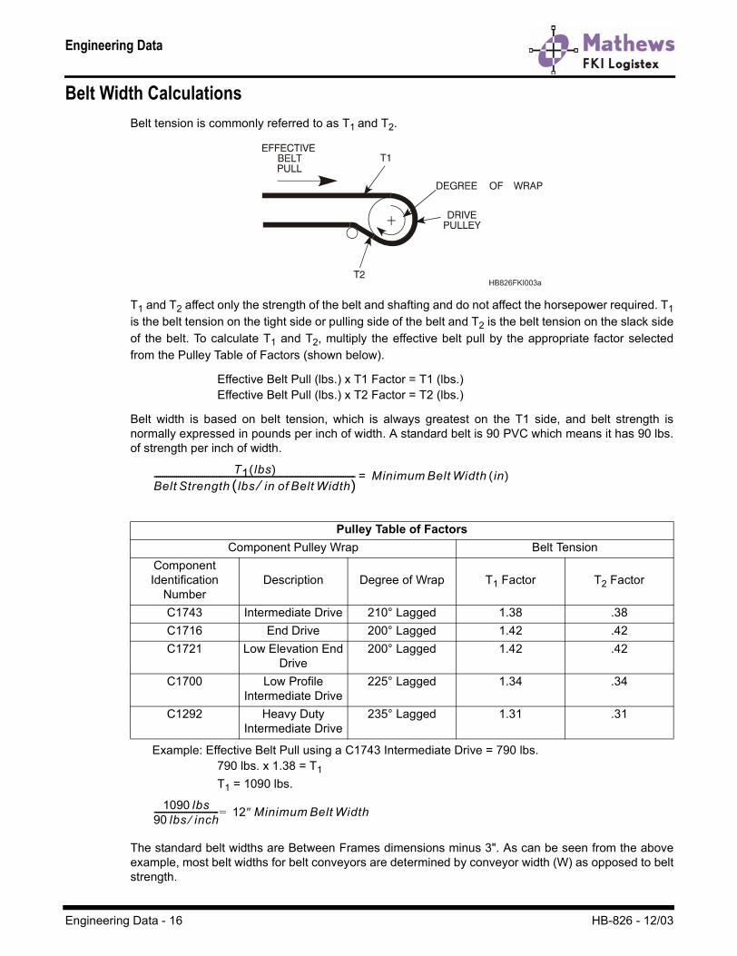
Belt Width CalculationsBelt tension is commonly referred to as T1 and T2.
T1 and T2 affect only the strength of the belt and shafting and do not affect the horsepower required. T1is the belt tension on the tight side or pulling side of the belt and T2 is the belt tension on the slack sideof the belt. To calculate T1 and T2, multiply the effective belt pull by the appropriate factor selectedfrom the Pulley Table of Factors (shown below).
Effective Belt Pull (lbs.) x T1 Factor = T1 (lbs.)Effective Belt Pull (lbs.) x T2 Factor = T2 (lbs.)
Belt width is based on belt tension, which is always greatest on the T1 side, and belt strength isnormally expressed in pounds per inch of width. A standard belt is 90 PVC which means it has 90 lbs.of strength per inch of width.
Example: Effective Belt Pull using a C1743 Intermediate Drive = 790 lbs.790 lbs. x 1.38 = T1T1 = 1090 lbs.
The standard belt widths are Between Frames dimensions minus 3". As can be seen from the aboveexample, most belt widths for belt conveyors are determined by conveyor width (W) as opposed to beltstrength.
Pulley Table of FactorsComponent Pulley Wrap Belt Tension
Component Identification
NumberDescription Degree of Wrap T1 Factor T2 Factor
C1743 Intermediate Drive 210° Lagged 1.38 .38C1716 End Drive 200° Lagged 1.42 .42C1721 Low Elevation End
Drive200° Lagged 1.42 .42
C1700 Low Profile Intermediate Drive
225° Lagged 1.34 .34
C1292 Heavy Duty Intermediate Drive
235° Lagged 1.31 .31
T1 lbs( )Belt Strength lbs in of Belt Width⁄( )---------------------------------------------------------------------------------------------------- Minimum Belt Width in( )=
1090 lbs90 lbs inch⁄-------------------------------- 12″ Minimum Belt Width=
Engineering Data - 16 HB-826 - 12/03

Engineering Data
Conveyor BeltingThere are many types of belting available, some of which are more popular than others. The mostwidely used types are described below.
Conveyor belts are usually manufactured of polyester, nylon, cotton, rubber, elastomers, and plasticsin 100% pure form or in some combination. The resulting product is flexible and if designed,manufactured, slit and laced properly will go where directed by the conveyor system as designed andbuilt.
Unit handling belt is usually made of one or more plies of a textile fabric impregnated with an elastomercoupled with appropriate covers. One of the most widely used types now is a PVC belting. It is made ofa single ply, all polyester fiber woven in either a straight wrap or solid woven configuration and issaturated and covered with a (polyvinyl chloride) PVC elastomer. This belt construction does not have“covers” in the conventional sense, rather the manufacturing process results in a solid block of PVCelastomer with a reinforcing textile (polyester) fabric running through it.
Belt FastenersEndless splices are occasionally used on unit handling conveyors. However, by far the most commonmethod of joining belt ends is the metal fastener such as the “clipper” type wire lace or the “alligator”type steel hinges.
The “clipper” wire lace type of fastener consists of many wires pressed into the belt forming a series ofwire loops extending beyond the ends of the belt. The belt ends, each containing one-half of thefastener, are meshed together and the pin inserted like a door hinge. A lacing machine must be usedfor proper installation of the fastener into the belt.
The “alligator” steel hinge type of lace can be applied with a hammer. The belt is simply laid down on aflat surface and the ends of the prongs driven into the belt. The two belt ends are now meshedtogether and a steel hinge pin is used in a manner similar to that above.
The size of the fastener used is governed by the thickness of the belt and the diameter of the smallestpulley involved. The metal fastener manufacturer’s instructions should be used to install and connectthe fasteners used.
HB-826 - 12/03 Engineering Data - 17

Engineering Data
Engineering Data - 18 HB-826 - 12/03
Unit Conveyors
Unit Conveyors
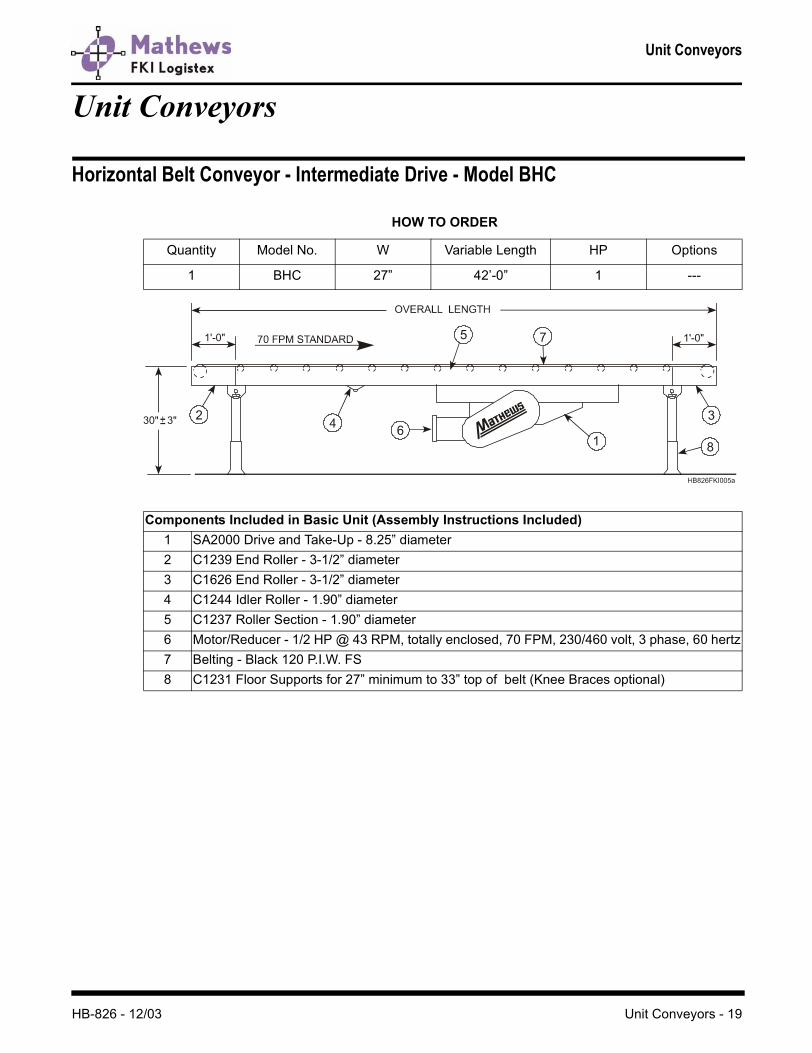
Horizontal Belt Conveyor - Intermediate Drive - Model BHC
HOW TO ORDER
Quantity Model No. W Variable Length HP Options
1 BHC 27” 42’-0” 1 ---
Components Included in Basic Unit (Assembly Instructions Included)1 SA2000 Drive and Take-Up - 8.25” diameter2 C1239 End Roller - 3-1/2” diameter3 C1626 End Roller - 3-1/2” diameter4 C1244 Idler Roller - 1.90” diameter5 C1237 Roller Section - 1.90” diameter6 Motor/Reducer - 1/2 HP @ 43 RPM, totally enclosed, 70 FPM, 230/460 volt, 3 phase, 60 hertz7 Belting - Black 120 P.I.W. FS8 C1231 Floor Supports for 27” minimum to 33” top of belt (Knee Braces optional)
HB-826 - 12/03 Unit Conveyors - 19

Unit Conveyors
CONVEYOR WIDTH Standard - 15”, 21”, 27”, 33” and 39” Between Frames only.DRIVE Standard - 8.25” finished dia. lagged straight face pulley with
1-11/16” dia. shaft. 3.50” dia. machine crowned take-up roller with 10” adjustment.Option - Timing belt drive (TB) available (see Components section).
END ROLLER TAKE-UP Standard - 3.50” dia. machine crowned roller with 1-1/16” hex axle.CARRYING ROLLERS Standard - 1.90” dia. x .065” (16 ga.) steel roller with grease packed
bearings and 7/16” hex spring loaded axles on 6” centers. Rollers are 3/8” high.
IDLER ROLLER Standard - 1.90” dia. x .065” (16 ga.) steel rollers with grease packed bearings and 7/16” hex axles on maximum 10’-0” centers.
SUPPORTS Standard - Floor type on maximum 10’-0” centers for conveying height of 27” to 33” (1500# capacity).Option - Other supports, hanger on floor type, are available (see Supports section.
ROLLER SECTION Standard - 5” x 1-1/2” x .120” (11 ga.) formed steel channel with welded butt couplings.Option - Roller sections available with rollers on 3”, 6”, 9” or 12” centers. 14 ga. slider bed sections also available.
BELT Standard - 120 P.I.W. FS. Width is 3” less than the Between Frames dimension.
MOTOR / REDUCER (For 70 FPM)
Standard - 43 RPM right angle reducer, 3 phase, 60 hertz, 230/460 volt, totally enclosed motor.Option - Other motor/reducer combinations are available as load and speeds change. See tables on the following page or Components section).
SIDE GUARDS Option - Standard angle, channel or adjustable guards available (see the Accessories section).
LENGTHS Option - Intermediate lengths available (in 3” increments).ELECTRICAL CONTROLS Option - As required (see Controls section).
Unit Conveyors - 20 HB-826 - 12/03

Unit Conveyors
Intermediate Drive - Roller BedLive Load Capacity @ 70 FPM
VariableLength
1/2 HP 3/4 HP 1 HP 1-1/2 HP 2 HP
lbs./ft Total lbs./ft. Total lbs./ft. Total lbs./ft. Total lbs./ft Total12’-0” 100 1200 100 1200 100 1200 100 1200 100 120017’0” 100 1700 100 1700 100 1700 100 1700 100 170022’-0” 96 2122 100 2200 100 2200 100 2200 100 220027’-0” 76 2070 100 2700 100 2700 100 2700 100 270032’-0” 63 2018 100 3200 100 3200 100 3200 100 320037’-0” 53 1966 92 3406 100 3700 100 3700 100 370042’-0” 45 1914 79 3354 100 4200 100 4200 100 420047’-0” 39 1862 70 3302 97 4582 100 4700 100 470052‘-0’ 34 1810 62 3250 87 4530 100 5200 100 520062’-0” 27 1706 50 3146 71 4426 100 6200 100 620072’-0” 22 1602 42 3042 60 4322 100 7200 100 720082’-0” 18 1498 35 2938 51 4218 100 8200 100 820092’-0” 15 1394 30 2834 44 4144 93 8634 100 9200102’-0” 12 1290 26 2730 39 4010 83 8530 100 10200
Intermediate Drive - Slider BedLive Load Capacity @ 70 FPM
VariableLength
1/2 HP 3/4 HP 1 HP 1-1/2 HP 2 HP
lbs./ft Total lbs./ft. Total lbs./ft. Total lbs./ft. Total lbs./ft Total12’-0” 19 231 39 471 57 684 100 1200 100 120017’0” 12 209 26 449 38 662 83 1416 100 170022’-0” 8 187 19 427 29 640 63 1394 87 193427’-0” 6 165 15 405 22 618 50 1372 70 191232’-0” 4 143 11 383 18 596 42 1350 59 189037’-0” 3 121 9 361 15 574 35 1328 50 186842’-0” 2 99 8 339 13 552 31 1306 43 184647’-0” 1 77 6 317 11 530 27 1284 38 182452‘-0’ 1 55 5 295 9 508 24 1262 34 180262’-0” 4 251 7 464 19 1218 28 175872’-0” 2 207 5 420 16 1174 23 171482’-0” 1 163 4 376 13 1130 20 167092’-0” 1 119 3 332 11 1086 17 1626102’-0” 2 288 10 1042 15 1582
HB-826 - 12/03 Unit Conveyors - 21

Unit Conveyors
Horizontal Belt Conveyor - End Drive - Model BHE
Note: Please list options.
HOW TO ORDER
Quantity Model No. W Variable Length HP Options
1 BHE 27” 43’-0” 1 ---
Components Included in Basic Unit (Assembly Instructions Included)1 C1716 Drive - 4” diameter crowned2 C1239 End Roller - 3-1/2” diameter3 C1244 Idler Roller - 1.90” diameter4 C1237 Roller Section - 1.90” (16 ga.) rollers on 6” centers5 Motor/Reducer - 1/2 HP @ 58 RPM, totally enclosed, 70 F.).M., 230/460 volts, 3 phase, 60
hertz6 Belting - Black 120 PIW FS7 C1231 Floor Supports for 27” minimum to 33” top of belt (Knee Braces optional)
Unit Conveyors - 22 HB-826 - 12/03

Unit Conveyors
CONVEYOR WIDTH Standard - 15”, 21”, 27”, 33” and 39” Between Frame only.DRIVE Standard - 4” dia. crowned pulley with 1-3/16” dia. shaft and take-up.
Option - Available without take-up (NT). See the table on the next page for recommended maximum lengths without take-up (assumes nominal take-up in end roller unit). Available with timing belt drive (TB), see Components section.
END ROLLER TAKE-UP Standard - 3.50” dia. machine crowned roller with 1-1/16” hex axle.CARRYING ROLLERS Standard - 1.90” dia. x .065” (16 ga.) steel rollers with grease
packed bearings and 7/16” hex spring loaded axles on 6” centers. Rollers are 3/8” high.
IDLER ROLLER 1.90” dia. x .065” (16 ga.) steel rollers with grease packed bearings and 7/16” hex axle on maximum 10’-0” centers.
SUPPORTS Standard - Floor type on maximum 10’-0” centers for conveying height of 27” to 33” 91500# capacity).Option - Other supports, hanger or floor type, are available (see Supports section).
ROLLER SECTION Standard - 5” x 1-1/2” x .120” (11 ga.) formed steel channel with welded butt couplings.Option - roller sections available with rollers on 3”, 6”, 9” or 12” centers. 14 ga. slider bed sections are also available.
BELT Standard - 120 P.I.W. FS. width is 3” less than the Between Frame dimension.
MOTOR / REDUCER (For 70 FPM)
Standard - 58 RPM right angle reducer, 3 phase, 60 hertz, 230/460 volt, totally enclosed motor.Option - Other motor/reducer combinations are available as load and speeds change. See the tables on the following page or Components section.
SIDE GUARDS Option - Standard angle, channel or adjustable guards available (see Accessories section).
LENGTHS Option - Intermediate lengths available (in 3” increments).ELECTRICAL CONTROLS Option - As required (see Controls section).
HB-826 - 12/03 Unit Conveyors - 23

Unit Conveyors
End Drive - Roller BedLive Load Capacity @ 70 FPM
VariableLength
1/2 HP 3/4 HP 1 HP
lbs./ft. Total lbs./ft. Total lbs./ft. Total13’-0” 100 1300 100 1300 100 130018’-0” 100 1800 100 1800 100 180023’-0” 91 2110 100 2300 100 230028’0” 73 2058 100 2800 100 280033’-0” 60 2007 100 3300 100 330038’-0” 51 1954 89 3394 100 380043’-0” 44 1903 77 3343 100 4300
End Drive - Slider BedLive Load Capacity @ 70 FPM
VariableLength
1/2 HP 3/4 HP 1 HP
lbs./ft. Total lbs./ft. Total lbs./ft. Total13’-0” 17 225 35 465 52 67818’-0” 11 203 24 443 36 65623’-0” 7 182 18 422 27 63528’0” 5 159 14 399 21 61233’-0” 4 137 11 377 17 59038’-0” 3 116 9 356 14 56943’-0” 2 93 7 333 12 546
Maximum Recommended Conveyor Length with “NT” OptionW 15” W 21” W 27” W 33” W 39” WLength 13’-0” 20’-0” 28’-0” 33’-0” 38’-0”
Unit Conveyors - 24 HB-826 - 12/03

Unit Conveyors
Standard Duty - Brake/Meter Belt - Model BMBDrive Mounted Above - C1565 - Drive Mounted Below - C1566
Note: Please list options.
HOW TO ORDER
Quantity Model No. W Overall
Length
Meter Belt
SpeedRatio HP Motor Options
1 C1566 27” 10’-0” 150 2.0:1 1 Std. RG
HB-826 - 12/03 Unit Conveyors - 25

Unit Conveyors
CONVEYOR WIDTH Standard - 15” through 39” in 3” incrementsCONVEYOR LENGTH Standard - 120” through 228” in 12” incrementsDRIVE Standard - Timing belt driven 4” dia. machine crowned pulleys.METER SPEEDS Standard - 70, 90, 100, 120, and 150 through 400 in 25 FPM
increments.HORSEPOWER Standard - 1 and 2 HP. (2 HP not available on speeds less than 150
FPM.MORO/REDUCER For 70 FPM
Standard - Brakemotor mounted on right angle reducer, 3 phase, 60 hertz, 230/460 volt.Option - Eurodrive helical-bevel right angle gearmotor with brake (specify “EU”). 3 phase, 60 hertz, 230/460 or 575 volt or single phase, 60 hertz, 115 volt.
METER/BRACKE RATIOS Standard - 1.21:1, 1.43:1, 1.57:1, 1.71:1 and 2:1.BELT Standard - 90 P.I.W. grooved. Belt width is 3’ less than the Between
Frame dimension.END ROLLERS Standard - 3.5” dia. crowned face roller with 1-1/16” hex axle.
Option - Regreaseable bearings (specify “RG” under Options in How To Order).
FRAME Standard - 7” x 1-1/2” x .120” (11 ga.) formed steel channels with welded butt couplings and 14 ga. steel slider beds. Unistrut provided on discharge end for photoeye mounting.
SUPPORTS Standard - Floor type for 27” to 33” top of belt elevation (1500# capacity each).Option - Higher and lower floor supports and ceiling hanger supports are available (see Supports section).
GUARD RAILS Option - Angle, channel or adjustable outrigger guards available (see Accessories section).
ELECTRICAL CONTROL Option - Manual and magnetic starters with remote pushbutton stations (see Controls section).
Unit Conveyors - 26 HB-826 - 12/03

Unit Conveyors
Assumptions: 39” W 1.21:1 Ratio 80% Reducer Efficiency
C1565 and C1566 Brake/Meter Belt - 1 HPLive Load Capacity in lb./ft.
OverallLength
(ft.)
Speed
70 90 100 120 150 175 200 225 250 275 300 325 350 375 400
10 100.6 76.5 68.0 55.3 42.7 35.4 30.0 25.8 22.4 19.6 17.3 15.4 13.7 12.2 11.011 93.7 71.1 63.2 51.4 39.6 32.8 27.7 23.8 20.6 18.0 15.9 14.1 12.5 11.2 10.012 87.5 66.4 59.0 47.9 36.8 30.5 25.7 22.0 19.1 16.7 14.6 12.9 11.5 10.2 9.113 82.2 62.3 55.3 44.9 34.4 28.5 24.0 20.5 17.7 15.4 13.5 11.9 10.6 9.4 8.314 77.4 58.6 52.0 42.1 32.3 26.7 22.4 19.1 16.5 14.4 12.6 11.0 9.7 8.6 7.615 73.1 55.3 49.1 39.7 30.4 25.0 21.0 17.9 15.4 13.4 11.7 10.3 9.0 8.0 7.016 69.2 52.3 46.4 37.5 28.7 23.6 19.8 16.8 14.5 12.5 10.9 9.5 8.4 7.4 6.517 65.7 49.6 44.0 35.5 27.1 22.3 18.6 15.8 13.6 11.7 10.2 8.9 7.8 6.8 6.018 62.6 47.2 41.8 33.7 25.7 21.1 17.6 14.9 12.8 11.0 9.5 8.3 7.2 6.3 5.519 59.7 45.0 39.8 32.1 24.4 20.0 16.7 14.1 12.0 10.4 9.0 7.8 6.8 5.9 5.1
C1565 and C1566 Brake/Meter Belt - 2 HPLive Load Capacity in lb./ft.
OverallLength (ft.)
Speed
150 175 200 225 250 275 300 325 350 375 400
10 93.4 78.9 68.0 59.6 52.8 47.3 42.7 38.8 35.4 32.5 30.011 86.9 73.4 63.2 55.3 49.0 43.9 39.6 35.9 32.8 30.1 27.712 81.2 68.5 59.0 51.6 45.7 40.9 36.8 33.4 30.5 28.0 25.713 76.2 64.3 55.3 48.3 42.8 38.2 34.4 31.2 28.5 26.1 24.014 71.7 60.5 52.0 45.4 40.2 35.9 32.3 29.3 26.7 24.4 22.415 67.7 57.1 49.1 42.8 37.8 33.8 30.4 27.5 25.0 22.9 21.016 64.2 54.0 46.4 40.5 35.8 31.9 28.7 25.9 23.6 21.6 19.817 60.9 51.2 44.0 38.4 33.9 30.2 27.1 24.5 22.3 20.3 18.618 58.0 48.7 41.8 36.4 32.1 28.6 25.7 23.2 21.1 19.2 17.619 55.3 46.4 39.8 34.7 30.6 27.2 24.4 22.0 20.0 18.2 16.7
HB-826 - 12/03 Unit Conveyors - 27

Unit Conveyors
General DescriptionThe BMB Unit has two slider bed sections driven by a common timing belt drive. High friction roughtopbelting is provided for both sections and the unit is floor supported with three 1500 lb. capacitysupports.
ApplicationThe primary function of a brake/meter belt is two-fold. First, the brake/meter belt must be able to stopand hold products on the brake portion. Secondly, the brake/meter belt, meters products onto adischarge conveyor.
Brake Belt ConsiderationsA brake belt can only resist upstream line pressure less than (Product Weight on Brake Belt xCoefficient of Friction Product to Belt). An Approximate coefficient of friction between the belt andcardboard is 0.8. Plastic totes on belt have reduced friction values.
Products accumulating on the upstream conveyor often impact and try to push products through thebrake belt. Since the holding force is dependent upon the weight of the product on the brake belt, thenforce is brake belt length dependent. The maximum standard belt brake length is 15 ft. and theminimum is 6 ft.
Meter BeltThe meter belt receives product from the brake belt and discharges onto the downstream conveyor. Abrake/meter belt working together can create gaps between products if the meter belt is running fasterthan the brake belt. Gaps can be achieved by speed ratios and by starting and stopping. Meter lengthis a constant 48".
The speed of the meter belt is generally the same as the downstream conveyor and by dividing that bythe ratio of the P.T.O., you have the speed of the brake belt.
The ratio to select is determined by the carton length and the required gap between them. Forexample, if you have 18" long cartons, and you require a 6" gap between them,
OR 6 ÷ 18 + 1 = 1.33
Select the next higher standard ratio, 1.43 to 1. The unit is normally driven by a right angle motor/reducer with a brake, which assists in holding back the accumulating cartons. The brakemotor issuitable for normal system applications where the unit is not required to start and stop more than 60times per minute. In situations where 6 to 30 start-stops per minute are required, the use of anEurodrive brakemotor is recommended. In situations where more than 30 start-stops per minute arerequired, consult the factory.
t he ratio Required GapCarton Length----------------------------------------- 1+=
Unit Conveyors - 28 HB-826 - 12/03

Unit Conveyors
Heavy Duty Horizontal Belt Conveyor - Intermediate Drive - Model HBC
Note: Please list options.
HOW TO ORDER
Quantity Model No. W Variable Length HP Options
1 HBC 39” 72’-0” 1-1/2 ---
Components Included in Basic Unit (Assembly Instructions Included)1 C1292 Drive and Take-Up - 13-1/4” diameter2 C1300 End Roller - 6” diameter3 C1301 End Roller - 6” diameter4 C1404 Idler Roller - 1.90” diameter5 C1298 Roller Section - 2.50” x .120” (11 ga.) rollers on 6” centers in 6” channel frame6 Motor/Reducer - HP as required @ 35 RPM, totally enclosed, 70 FPM, 230/460 volt, 3 phase,
60 hertz7 Belting - Black 120 P.I.W. FS8 C695 Floor Supports on 5’-0” centers for 31” to 34” top of belt (Knee Braces included)
HB-826 - 12/03 Unit Conveyors - 29
Unit Conveyors
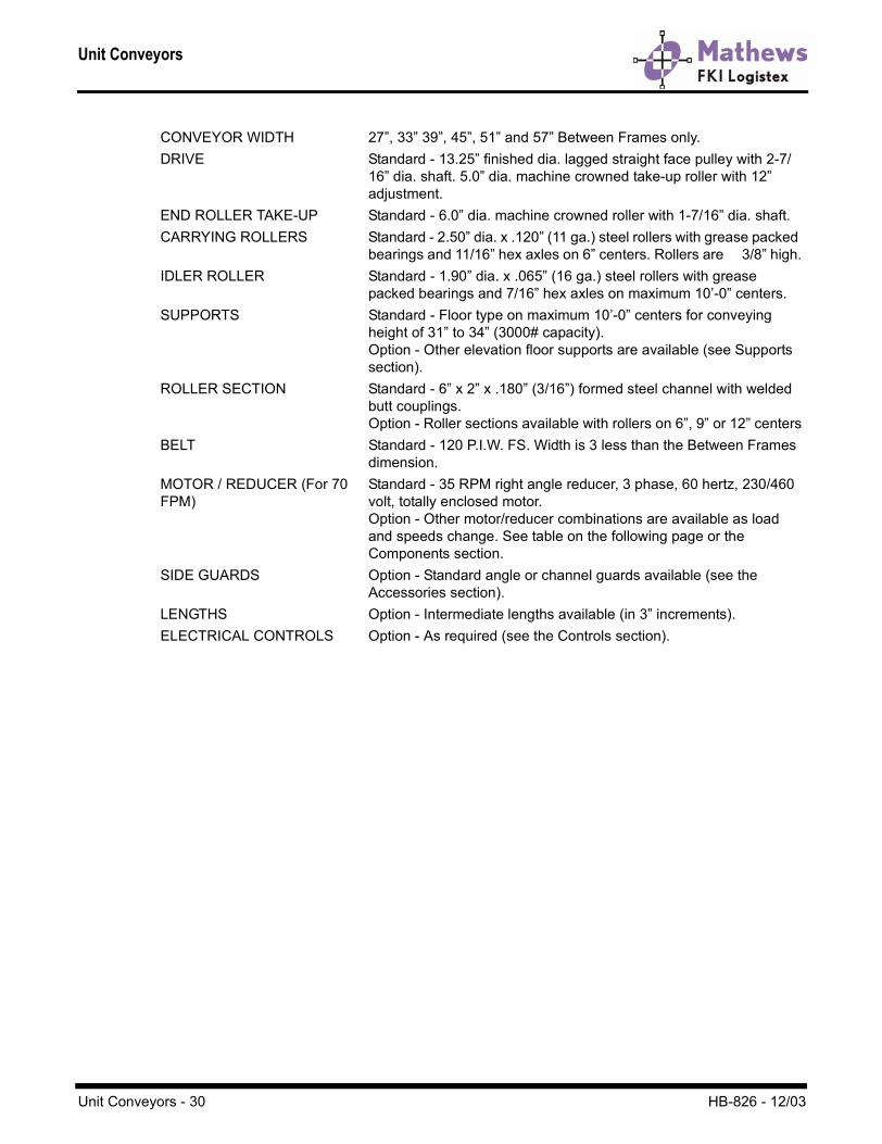
CONVEYOR WIDTH 27”, 33” 39”, 45”, 51” and 57” Between Frames only.DRIVE Standard - 13.25” finished dia. lagged straight face pulley with 2-7/
16” dia. shaft. 5.0” dia. machine crowned take-up roller with 12” adjustment.
END ROLLER TAKE-UP Standard - 6.0” dia. machine crowned roller with 1-7/16” dia. shaft.CARRYING ROLLERS Standard - 2.50” dia. x .120” (11 ga.) steel rollers with grease packed
bearings and 11/16” hex axles on 6” centers. Rollers are 3/8” high.IDLER ROLLER Standard - 1.90” dia. x .065” (16 ga.) steel rollers with grease
packed bearings and 7/16” hex axles on maximum 10’-0” centers.SUPPORTS Standard - Floor type on maximum 10’-0” centers for conveying
height of 31” to 34” (3000# capacity).Option - Other elevation floor supports are available (see Supports section).
ROLLER SECTION Standard - 6” x 2” x .180” (3/16”) formed steel channel with welded butt couplings.Option - Roller sections available with rollers on 6”, 9” or 12” centers
BELT Standard - 120 P.I.W. FS. Width is 3 less than the Between Frames dimension.
MOTOR / REDUCER (For 70 FPM)
Standard - 35 RPM right angle reducer, 3 phase, 60 hertz, 230/460 volt, totally enclosed motor.Option - Other motor/reducer combinations are available as load and speeds change. See table on the following page or the Components section.
SIDE GUARDS Option - Standard angle or channel guards available (see the Accessories section).
LENGTHS Option - Intermediate lengths available (in 3” increments).ELECTRICAL CONTROLS Option - As required (see the Controls section).
Unit Conveyors - 30 HB-826 - 12/03

Unit Conveyors
Intermediate Drive - Roller Bed - Horizontal Heavy Duty Belt ConveyorLive Load Capacity @ 70 FPM
VariableLength
1/2 HP 3/4 HP 1 HP 1-1/2 HP
lbs./ft Total lbs./ft. Total lbs./ft. Total lbs./ft. Total12’-0” 135 1620 200 2400 200 2400 200 240022’-0” 60 1320 125 2760 183 4040 200 440032’-0” 31 1020 76 2460 116 3740 200 640042’-0” 17 720 51 2160 81 3440 189 796052‘-0’ 8 420 35 1860 60 3140 147 766062’-0” 2 120 25 1560 45 2840 118 736072’-0” 17 1260 35 2540 98 706082’-0” 11 960 27 2240 82 676092’-0” 7 660 21 1940 70 6460102’-0” 3 360 16 1640 60 6160
Intermediate Drive - Roller Bed - Horizontal Heavy Duty Belt ConveyorLive Load Capacity @ 70 FPM
VariableLength
2 HP 3 HP 5 HP
lbs./ft Total lbs./ft. Total lbs./ft. Total12’-0” 200 2400 200 2400 200 240022’-0” 200 4400 200 4400 200 440032’-0” 200 6400 200 6400 200 640042’-0” 200 8400 200 8400 200 840052‘-0’ 200 10400 200 10400 200 1040062’-0” 170 10600 200 12400 200 1240072’-0” 143 10300 191 13760 200 1440082’-0” 121 10000 164 13460 200 1640092’-0” 105 9700 143 13160 200 18400
102’-0” 92 9400 126 12860 200 20400
HB-826 - 12/03 Unit Conveyors - 31

Unit Conveyors
13° Inclined Belt Conveyor - Model BIC-13
Note: Please list options.
HOW TO ORDER
Quantity Model No. W “L” Length HP Options
1 BIC-13 27” 31’-0” 1/2 ---
Components Included in Basic Unit (Assembly Instructions Included)1 SA2000 Drive and Take-Up - 8.25” diameter2 C1239 End Roller - 3-1/2” diameter3 C1626 End Roller - 3-1/2” diameter4 C1267 (2) Vertical Bends - 13°5 C1245 Snub Roller - 2-1/2” diameter6 C1244 Idler Roller - 1.90” diameter7 C1237 Roller Section - 1.90” diameter (16 ga.) rollers on 6” centers8 Motor/Reducer - 1/2 HP @ 43 RPM, totally enclosed, 70 FPM, 230/460 volt, 3 phase, 60 hertz9 Belting - Roughtop, 120 P.I.W. RT10 C1231 Floor Supports at feed and discharge end. C1275 Hanger Supports at each conveyor
section joint.11 Bottom Closure (D10374) included for incline up to 8’-0” elevation
Unit Conveyors - 32 HB-826 - 12/03

Unit Conveyors
13° Incline“L” Length “B” Length “H” Net Lift
11’-0” 12’-8-5/8” 2’-7-1/4”16’-0” 17’-7-1/8” 3’-8-3/4”21’-0” 22’-5-1/2” 4’-10-1/4”26’-0” 27’-4” 5’-11-3/4”31’-0” 32’-2-1/2” 7’-1-1/4”36’-0” 37’-1” 8’-2-3/4”41’-0” 41’-11-3/8” 9’-4-1/4”46’-0” 46’-9-7/8” 10’-5-3/4”51’-0” 51’-8-3/8” 11’-7-1/4”
HB-826 - 12/03 Unit Conveyors - 33

Unit Conveyors
CONVEYOR WIDTH 15”, 21”, 27”, 33” and 39” Between Frames only.DRIVE Standard 8.25” finished dia. lagged straight face pulley with 1-11/16”
dia. shaft. 3.50” dia. machine crowned take-up roller with 10” adjustment.Option - Timing belt drive (TB) available (see the Components section).
END ROLLER TAKE-UP Standard - 3.50” dia. machine crowned roller with 1-1/16” hex axle.CARRYING ROLLERS Standard - 1.90” dia. x .065” (16 ga.) steel rollers with grease
packed bearings and 7/16” hex spring loaded axles on 6” centers. Rollers are 3/8” high.
IDLER ROLLER Standard - 1.90” dia. x .065” (16 ga.) steel rollers with grease packed bearings and 7/16” hex axles on maximum 10’-0” centers.
SNUB ROLLER Standard - 2.50” dia. x .120” (11 ga.) steel roller with grease packed bearings and 11/16” hex axles.
SUPPORTS Standard - For receive and discharge ends, adjustable floor supports from 27” to 33” elevation. All other supports 10’-0” long hanger type (1500# capacity).Option - Other supports are available (see the Supports section).
ROLLER SECTION Standard - 5” x 1-1/2” x .120” (11 ga.) formed steel channel with welded butt couplings.Option - Roller sections available with rollers on 3”, 6”, 9” or 12” centers. 14 ga. slider bed sections also available.
BELT Standard - Roughtop. Width is 3” less than the Between Frames dimension.
MOTOR / REDUCER (For 70 FPM)
(For 70 FPM)Standard - 43 RPM right angle reducer, 3 phase, 60 hertz, 230/460 volt, totally enclosed motor.Option - Other motor/reducer combinations are available as load and speeds change. See the tables on the next page or the Components section.
SIDE GUARDS Option - Standard angle, channel or adjustable guards available (see the Accessories section).
LENGTHS Option - Intermediate lengths available (in 3” increments).POWER FEEDER Level feeder sections with a two-pulley PTO and PVC 90 FS belting
are recommended for reversible operation.Feeder sections with a three roller device are available for non-reversing operation (see the Power Feeder topic in this section).
ELECTRICAL CONTROLS Option - As required (see the Controls section).
Unit Conveyors - 34 HB-826 - 12/03

Unit Conveyors
Intermediate Drive - Roller Bed - 13° InclineLive Load Capacity @ 70 FPM
“L”Length
1/2 HP 3/4 HP 1 HP 1-1/2 HP 2 HP
lbs./ft Total lbs./ft. Total lbs./ft. Total lbs./ft. Total lbs./ft Total11’-0” 35 392 59 650 79 878 100 1100 100 110016’-0” 23 382 39 639 54 867 100 1600 100 160021’-0” 17 371 29 628 40 857 79 1664 100 210026’-0” 13 357 23 614 32 842 63 1650 85 222831’-0” 11 346 19 603 26 832 52 1639 71 221736’-0” 9 335 16 592 22 821 45 1628 61 220741’-0” 7 325 14 582 19 810 39 1617 53 219646’-0” 6 314 12 571 17 800 34 1607 47 218551’-0” 5 303 10 560 15 789 31 1596 42 2175
Intermediate Drive - Slider Bed - 13° InclineLive Load Capacity @ 70 FPM
“L”Length
1/2 HP 3/4 HP 1 HP 1-1/2 HP 2 HP
lbs./ft Total lbs./ft. Total lbs./ft. Total lbs./ft. Total lbs./ft Total11’-0” 10 118 23 254 34 375 72 801 100 110016’-0” 6 101 14 237 22 358 49 784 68 109021’-0” 3 83 10 218 16 339 36 766 51 107126’-0” 2 66 7 201 12 322 28 749 40 105431’-0” 1 47 5 183 9 303 23 730 33 103536’-0” 4 164 7 284 19 711 28 101641’-0” 3 147 6 267 16 694 24 100046’-0” 2 128 5 249 14 675 21 98151’-0” 2 111 4 232 12 658 18 964
HB-826 - 12/03 Unit Conveyors - 35
Unit Conveyors
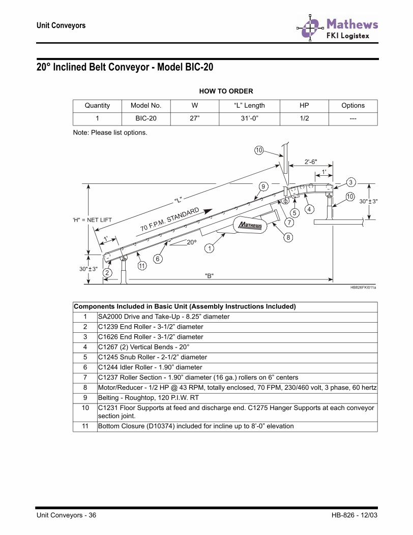
20° Inclined Belt Conveyor - Model BIC-20
Note: Please list options.
HOW TO ORDER
Quantity Model No. W “L” Length HP Options
1 BIC-20 27” 31’-0” 1/2 ---
Components Included in Basic Unit (Assembly Instructions Included)1 SA2000 Drive and Take-Up - 8.25” diameter2 C1239 End Roller - 3-1/2” diameter3 C1626 End Roller - 3-1/2” diameter4 C1267 (2) Vertical Bends - 20°5 C1245 Snub Roller - 2-1/2” diameter6 C1244 Idler Roller - 1.90” diameter7 C1237 Roller Section - 1.90” diameter (16 ga.) rollers on 6” centers8 Motor/Reducer - 1/2 HP @ 43 RPM, totally enclosed, 70 FPM, 230/460 volt, 3 phase, 60 hertz9 Belting - Roughtop, 120 P.I.W. RT10 C1231 Floor Supports at feed and discharge end. C1275 Hanger Supports at each conveyor
section joint.11 Bottom Closure (D10374) included for incline up to 8’-0” elevation
Unit Conveyors - 36 HB-826 - 12/03

Unit Conveyors
20° Incline“L” Length “B” Length “H” Net Lift
11’-0” 12’-10-3/8” 3’-11”16’-0” 17’-7” 5’-7-1/8”21’-0” 22’-3-1/2” 7’-3-1/8”26’-0” 27’-1/8” 8’-11-1/8”31’-0” 31’-8-5/8” 10’-7-1/8”36’-0” 36’-5-1/4” 12’-3-1/4”41’-0” 41’-1-3/4” 13’-11-1/4”
CONVEYOR WIDTH 15”, 21”, 27”, 33” and 39” Between Frames only.DRIVE Standard 8.25” finished dia. lagged straight face pulley with 1-11/16”
dia. shaft. 3.50” dia. machine crowned take-up roller with 10” adjustment.Option - Timing belt drive (TB) available (see the Components section).
END ROLLER TAKE-UP Standard - 3.50” dia. machine crowned roller with 1-1/16” hex axle.CARRYING ROLLERS Standard - 1.90” dia. x .065” (16 ga.) steel rollers with grease
packed bearings and 7/16” hex spring loaded axles on 6” centers. Rollers are 3/8” high.
IDLER ROLLER Standard - 1.90” dia. x .065” (16 ga.) steel rollers with grease packed bearings and 7/16” hex axles on maximum 10’-0” centers.
SNUB ROLLER Standard - 2.50” dia. x .120” (11 ga.) steel roller with grease packed bearings and 11/16” hex axles.
SUPPORTS Standard - For receive and discharge ends, adjustable floor supports from 27” to 33” elevation. All other supports 10’-0” long hanger type (1500# capacity).Option - Other supports are available (see the Supports section).
ROLLER SECTION Standard - 5” x 1-1/2” x .120” (11 ga.) formed steel channel with welded butt couplings.Option - Roller sections available with rollers on 3”, 6”, 9” or 12” centers. 14 ga. slider bed sections also available.
BELT Standard - Roughtop. Width is 3” less than the Between Frames dimension.
MOTOR / REDUCER (For 70 FPM)
(For 70 FPM)Standard - 43 RPM right angle reducer, 3 phase, 60 hertz, 230/460 volt, totally enclosed motor.Option - Other motor/reducer combinations are available as load and speeds change. See the tables on the next page or the Components section.
SIDE GUARDS Option - Standard angle, channel or adjustable guards available (see the Accessories section).
LENGTHS Option - Intermediate lengths available (in 3” increments).POWER FEEDER Level feeder sections with a two-pulley PTO and PVC-90 FS belting
are recommended for reversible operation.Feeder sections with a three roller device are available for non-reversing operation (see the Power Feeder topic in this section).
ELECTRICAL CONTROLS Option - As required (see the Controls section).
HB-826 - 12/03 Unit Conveyors - 37

Unit Conveyors
Intermediate Drive - Roller Bed - 20° InclineLive Load Capacity @ 70 FPM
“L”Length
1/2 HP 3/4 HP 1 HP 1-1/2 HP 2 HP
lbs./ft Total lbs./ft. Total lbs./ft. Total lbs./ft. Total lbs./ft Total11’-0” 25 282 42 466 57 630 100 1100 100 110016’-0” 17 274 28 458 38 623 75 1202 100 160021’-0” 12 266 21 451 29 615 56 1194 76 161026’-0” 9 256 16 441 23 605 45 1184 61 160031’-0” 8 248 13 433 19 597 37 1176 51 159236’-0” 6 241 11 425 16 589 32 1169 44 158441’-0” 5 233 10 417 14 582 28 1161 38 1576
Intermediate Drive - Slider Bed - 20° Incline Live Load Capacity @ 70 FPM
“L”Length
1/2 HP 3/4 HP 1 HP 1-1/2 HP 2 HP
lbs./ft Total lbs./ft. Total lbs./ft. Total lbs./ft. Total lbs./ft Total11’-0” 8 98 19 210 28 310 60 664 83 91716’-0” 5 84 12 196 18 296 40 650 56 90321’-0” 3 68 8 181 13 281 30 634 42 88726’-0” 2 54 6 167 10 267 23 620 33 87331’-0” 1 39 4 151 8 251 19 604 27 85736’-0” 3 135 6 235 16 589 23 84241’-0” 2 121 5 221 14 575 20 828
Unit Conveyors - 38 HB-826 - 12/03

Unit Conveyors
26° Inclined Belt Conveyor - Model BIC-26
Note: Please list options.
HOW TO ORDER
Quantity Model No. W “L” Length HP Options
1 BIC-26 27” 31’-0” 1/2 ---
Components Included in Basic Unit (Assembly Instructions Included)1 SA2000 Drive and Take-Up - 8.25” diameter2 C1239 End Roller - 3-1/2” diameter3 C1626 End Roller - 3-1/2” diameter4 C1267 (2) Vertical Bends - 20°5 C1245 Snub Roller - 2-1/2” diameter6 C1244 Idler Roller - 1.90” diameter7 C1237 Roller Section - 1.90” diameter (16 ga.) rollers on 6” centers8 Motor/Reducer - 1/2 HP @ 43 RPM, totally enclosed, 70 FPM, 230/460 volt, 3 phase, 60 hertz9 Belting - Roughtop, 120 P.I.W. RT10 C1231 Floor Supports at feed and discharge end. C1275 Hanger Supports at each conveyor
section joint.11 Bottom Closure (D10374) included for incline up to 8’-0” elevation
HB-826 - 12/03 Unit Conveyors - 39

Unit Conveyors
26° Incline“L” Length “B” Length “H” Net Lift
11’-0” 12’-10-5/8” 5’-3-3/8”16’-0” 17’-4-5/8” 7’-5-5/8”21’-0” 21’-10-1/2” 9’-8”26’-0” 26’-4-3/8” 11’-10-1/4”31’-0” 30’-10-3/8” 14’-5/8”
CONVEYOR WIDTH 15”, 21”, 27”, 33” and 39” Between Frames only.DRIVE Standard 8.25” finished dia. lagged straight face pulley with 1-11/16”
dia. shaft. 3.50” dia. machine crowned take-up roller with 10” adjustment.Option - Timing belt drive (TB) available (see the Components section).
END ROLLER TAKE-UP Standard - 3.50” dia. machine crowned roller with 1-1/16” hex axle.CARRYING ROLLERS Standard - 1.90” dia. x .065” (16 ga.) steel rollers with grease
packed bearings and 7/16” hex spring loaded axles on 6” centers. Rollers are 3/8” high.
IDLER ROLLER Standard - 1.90” dia. x .065” (16 ga.) steel rollers with grease packed bearings and 7/16” hex axles on maximum 10’-0” centers.
SNUB ROLLER Standard - 2.50” dia. x .120” (11 ga.) steel roller with grease packed bearings and 11/16” hex axles.
SUPPORTS Standard - For receive and discharge ends, adjustable floor supports from 27” to 33” elevation. All other supports 10’-0” long hanger type (1500# capacity).Option - Other supports are available (see the Supports section).
ROLLER SECTION Standard - 5” x 1-1/2” x .120” (11 ga.) formed steel channel with welded butt couplings.Option - Roller sections available with rollers on 3”, 6”, 9” or 12” centers. 14 ga. slider bed sections also available.
BELT Standard - Sure Grip Roughtop. Width is 3” less than the Between Frames dimension.
MOTOR / REDUCER (For 70 FPM)
(For 70 FPM)Standard - 43 RPM right angle reducer, 3 phase, 60 hertz, 230/460 volt, totally enclosed motor.Option - Other motor/reducer combinations are available as load and speeds change. See the tables on the next page or the Components section.
SIDE GUARDS Option - Standard angle, channel or adjustable guards available (see the Accessories section).
LENGTHS Option - Intermediate lengths available (in 3” increments).POWER FEEDER Level feeder sections with a two-pulley PTO and PVC 90 FS belting
are recommended for reversible operation.Feeder sections with a three roller device are available for non-reversing operation (see the Power Feeder topic in this section).
ELECTRICAL CONTROLS Option - As required (see the Controls section).
Unit Conveyors - 40 HB-826 - 12/03

Unit Conveyors
Note: 26° Inclined units are not recommended for use with very light or empty totes. Consult Factory.
Intermediate Drive - Roller Bed - 26° InclineLive Load Capacity @ 70 FPM
“L”Length
1/2 HP 3/4 HP 1 HP 1-1/2 HP 2 HP
lbs./ft Total lbs./ft. Total lbs./ft. Total lbs./ft. Total lbs./ft Total11’-0” 20 224 33 371 45 502 87 963 100 110016’-0” 13 218 22 365 30 495 59 957 80 128721’-0” 10 212 17 359 23 489 45 951 61 128126’-0” 7 204 13 351 18 481 36 942 48 127331’-0” 6 197 11 344 15 475 30 936 40 1267
Intermediate Drive - Slider Bed - 26° InclineLive Load Capacity @ 70 FPM
“L”Length
1/2 HP 3/4 HP 1 HP 1-1/2 HP 2 HP
lbs./ft Total lbs./ft. Total lbs./ft. Total lbs./ft. Total lbs./ft Total11’-0” 7 85 16 182 24 268 52 574 72 79316’-0” 4 72 10 170 16 256 35 562 48 78121’-0” 2 59 7 156 11 243 26 548 36 76726’-0” 1 47 5 144 8 231 20 536 29 75531’-0” 1 33 4 131 7 217 16 522 23 741
HB-826 - 12/03 Unit Conveyors - 41

Unit Conveyors
Power FeedersLengths in the following table are minimum recommended lengths for the various width belts. Shorterunits could cause belt tracking problems.
Style and length must be listed under Options, i.e. “with 2 Pulley P.T.O. Power Feeder 7'-0" long withtype 2 sprocket ratio”.
Between Frame (W) 15” 21” 27” 33” 39”Belt Width 12” 18” 24” 30” 36”
Power Feeder Minimum Lengths2 Pulley P.T.O. One Way Travel Reversible Travel
3’-0”5’-0”
5’-0”7’-0”
6’-0”10’-0”
8’-0”12’-0”
9’-0”12’-0”
3 Roller Device One Way Travel 3’-0” 4’-0” 5’-0” 5’-0” 5’-0”
Unit Conveyors - 42 HB-826 - 12/03

Unit Conveyors
C1252 2 Pulley P.T.O.This unit recommended when a speed change is required between the horizontal and inclined portionof the conveyor or the conveyor is used in a reversing operation. In the case of reversing operation it isalso recommended that PVC 120 FS belting be used on the level portion and that the length of thefeeder section be at least five times the width of the belting.
For one way travel the length of the feeder section may be at least three times the belt width.
Feeder section speeds may run faster, slower or the same as the incline conveyor and may bespecified by type 1, 2 or 3 as shown in the table below.
Power feeders are ordered as options to incline conveyors, i.e., “with Two Pulley P.T.O. 7'-0" long withtype 2 sprocket ratio”.
Type 1 2 3Ratio 1.16:1 1:1 1.5:1
HB-826 - 12/03 Unit Conveyors - 43

Unit Conveyors
C1418 Three Roller DeviceThis unit may be used when a simple change in angle from level to incline is required. The same beltruns through both inclined and level portions and the speed is constant. It is recommended for oneway travel, either incline or decline, and the length of the level portion is at least three times the widthof the belting.
The unit would be ordered as an option to an inclined belt conveyor, i.e., “with Three Pulley PowerFeeder 5'-0" long”.
Unit Conveyors - 44 HB-826 - 12/03
Components
Components
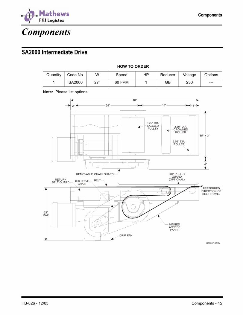
SA2000 Intermediate Drive
Note: Please list options.
HOW TO ORDER
Quantity Code No. W Speed HP Reducer Voltage Options
1 SA2000 27” 60 FPM 1 GB 230 ---
HB-826 - 12/03 Components - 45

Components
CONVEYOR WIDTH Standard - 15” - 39” W, in 3” increments. For trash removal conveyor only 15” - 45” W, in 3” increments.
CAPACITY Standard - 900# maximum effective belt pull.
SPEED Series 400, 600, and 800 End Drives - 30, 45, 60, 75, 90, 120, 150*, 180, 200, 250, 300, 350, and 400 FPM.Note: *150 FpM maximum for Series 400.Chain Drive - 30, 45, 60, 75, 90, 105, 120, 135, 150, 165, and 180 FPM.Time Belt Drive - 30, 45, 60, 75, 90, 105, 120, 135, 150, 165, 180, 200, 225, 250, 275, 300, 325, 350, 375, 400, 425, 450, 475 and 500 FPM.
CHAIN DRIVE Series 400, 600, and 800 - RC50, RC60, RC80 and RC100 (all speeds).RC60 (up to 180 FPM).
CHAIN SPROCKETS Series 400 - RC50, bored and keyed Type B hub, hardened teethSeries 600 and 800 - RC60, RC80, and RC100, keeyed Taper-Lock hubs. hardened teeth or bored and keyed Type B hubs depending on speed/horsepower requirements.RC60, keyed Taper-Lock hubs, hardened.
DRIVE Standard - Furnished as shown for position of motor/reducer, unless specified “opposite hand”. #60 chain drive available 1/2 HP through 7.5 HP. All driver sprockets have hardened teeth.Option - Timing belt (TB) drives are available 1/2 HP through 5 HP.
MOTOR Standard - 230/460VAC - 3PH - 60 HZ.Optional - 575VAC - 3PH - 60HZ and 115VAC - 1PH - 60HZ.1/2 through 7-1/2 HP - C-Face TEFC (Baldor or Reliance).Chain Drive - 1/2, 3/4, 1, 1-1/2, 2 and 3 HP (Baldor or Reliance)Timing Belt Drive - 1/2, 3/4, 1, 1-1/2, 2, 3, 5, and 7-1/2 HP (Baldor or Reliance)Solenoid actuated brake motor supplied on all incline/decline conveyors.
REDUCER Standard - Right Angle worm Gear 5:1 to 60:1 ratios.
DRIVE PULLEY Standard - 8-1/4” dia. straight faced lagged pulley with 1-11/16” dia. shaft and pre-lubricated pillow block bearings.
TAKE-UP ROLLER Standard - 3-1/2” dia. crowned roller with 10” adjustment (20” belt), 1-1/16” hex axle and B1160 bearings.
SNUB ROLLER Standard - 2-9/16” dia. rollers with 11/16” hex axle and B1150 bearings.
BELT Standard - Width is 3” less than the Between Frames dimension. Belt length required is 33”.
SAFETY GUARDING Standard - Sprockets, chain and return belt are totally enclosed for safety. Drive and Take-up Pulleys are guarded below.Option - For guards above the drive and take-up pulleys, specify “PG” in the How to Order.
Components - 46 HB-826 - 12/03
Components
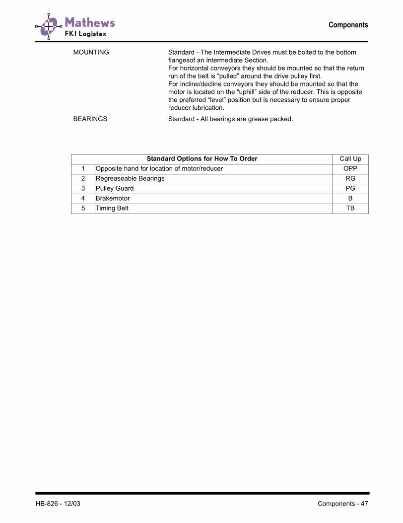
MOUNTING Standard - The Intermediate Drives must be bolted to the bottom flangesof an Intermediate Section.For horizontal conveyors they should be mounted so that the return run of the belt is “pulled” around the drive pulley first.For incline/decline conveyors they should be mounted so that the motor is located on the “uphill” side of the reducer. This is opposite the preferred “level” position but is necessary to ensure proper reducer lubrication.
BEARINGS Standard - All bearings are grease packed.
Standard Options for How To Order Call Up1 Opposite hand for location of motor/reducer OPP2 Regreaseable Bearings RG3 Pulley Guard PG4 Brakemotor B5 Timing Belt TB
HB-826 - 12/03 Components - 47

Components
Grove - #60 Chain Drive Table (Standard) Grove - #60 Chain Drive Table (Standard) Nominal
Belt Speed (FPM)
Motor Effective Belt Pull
(lb.)
Reducer Gear Ratio
Reducer Efficiency
No. of Teeth in Reducer Sprocket
Nominal Belt
speed (FPM
Motor Effective Belt Pull
(lb.)
Reducer Gear Ratio
Reducer Efficiency
No. of Teeth in Reducer Sprocket
HP HP
30
0.5 361
60:1
.691
16
120
0.5 110
20:1
.845
20
0.75 546 .697 0.75 166 .845
1 728 .697 1 221 .845
1.5 900 .717 1.5 334 .852
45
0.5 241
60:1
.691
23
2 449 .86
0.75 364 .697 3 685 .873
1 485 .697
135
0.5 98
20:1
.845
23
1.5 749 .717 0.75 147 .845
60
0.5 193
40:1
.738
21
1 196 .845
0.75 293 .748 1.5 297 .852
1 402 .769 2 399 .86
1.5 612 .781 3 609 .873
2 837 .801
150
0.5 91
15:1
.875
19
3 900 .801 0.75 137 .875
75
0.5 154
40:1
.738
25
1 183 .875
0.75 235 .748 1.5 276 .881
1 322 .769 2 375 .896
1.5 490 .781 3 559 .892
2 669 .801
165
0.5 83
15:1
.875
21
3 900 .801 0.75 125 .875
90
0.5 137
30:1
.788
23
1 166 .875
0.75 208 .795 1.5 251 .881
1 277 .795 2 341 .896
1.5 428 .818 3 508 .892
2 569 .817
180
0.5 76
15:1
.875
23
3 900 .836 0.75 114 .875
105
0.5 123
25:1
.825
22
1 152 .875
0.75 185 .825 1.5 230 .881
1 247 .827 2 312 .896
1.5 378 .844 3 466 .892
2 503 .842
3 777 .867
Components - 48 HB-826 - 12/03

Components
Grove - Timing Belt Drive Table (OptionalNominal Belt
Speed (FPM)
MotorEffective Belt
Pull (lb.)Reducer
Gear RatioReducer Efficiency
Reducer Sprocket No.
Teeth
Pulley Sprocket No.
Teeth
Drive Belt
HP Belt Pitch (mm)
Belt Width (mm)
30
1/2 371 50 .711 32 80 8 213/4 574 50 .733 32 80 8 361 776 60 .742 28 56 14 37
1-1/2 900 60 .742 28 56 14 37
45
1/2 261 40 .748 40 80 8 213/4 391 40 .748 40 80 8 211 536 40 .769 40 80 8 36
1-1/2 837 40 .801 28 56 14 37
60
1/2 208 30 .795 40 80 8 213/4 312 30 .795 40 80 8 211 428 30 .818 40 80 8 36
1-1/2 655 30 .836 28 56 14 372 900 30 .836 28 56 14 37
75
1/2 173 25 .827 40 80 8 213/4 259 25 .827 40 80 8 211 346 25 .827 40 80 8 21
1-1/2 534 25 .852 40 80 8 362 725 25 .867 28 56 14 373 900 25 .867 28 56 14 37
90
1/2 147 20 .845 38 80 8 213/4 221 20 .845 38 80 8 211 297 20 .852 38 80 8 21
1-1/2 445 20 .852 38 80 8 362 617 20 .886 28 56 14 373 900 20 .886 28 56 14 37
105
1/2 131 15 .875 34 80 8 213/4 197 15 .881 34 80 8 211 263 15 .881 34 80 8 21
1-1/2 394 15 .881 34 80 8 212 532 15 .892 34 80 8 363 793 20 .886 31 56 14 375 900 20 .886 31 56 14 37
120
1/2 114 15 .875 38 80 8 213/4 171 15 .875 38 80 8 211 229 15 .875 38 80 8 21
1-1/2 351 15 .896 38 80 8 212 468 15 .895 38 80 8 363 711 15 .907 28 56 14 375 900 15 .907 28 56 14 37
135
1/2 102 15 .875 42 80 8 213/4 152 15 .875 42 80 8 211 204 15 .881 42 80 8 21
1-1/2 307 15 .881 42 80 8 212 416 15 .896 42 80 8 363 624 15 .895 30 56 14 375 900 15 .907 30 56 14 37
HB-826 - 12/03 Components - 49
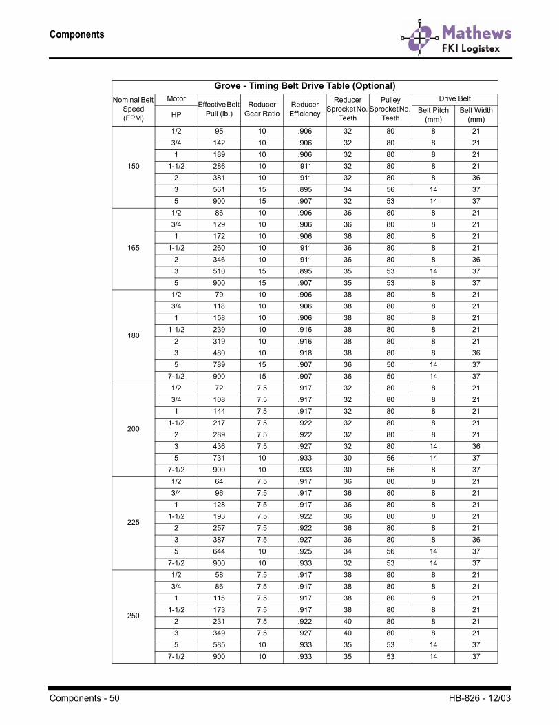
Components
Grove - Timing Belt Drive Table (Optional)Nominal Belt
Speed (FPM)
MotorEffective Belt
Pull (lb.)Reducer
Gear RatioReducer Efficiency
Reducer Sprocket No.
Teeth
Pulley Sprocket No.
Teeth
Drive Belt
HP Belt Pitch (mm)
Belt Width (mm)
150
1/2 95 10 .906 32 80 8 213/4 142 10 .906 32 80 8 211 189 10 .906 32 80 8 21
1-1/2 286 10 .911 32 80 8 212 381 10 .911 32 80 8 363 561 15 .895 34 56 14 375 900 15 .907 32 53 14 37
165
1/2 86 10 .906 36 80 8 213/4 129 10 .906 36 80 8 211 172 10 .906 36 80 8 21
1-1/2 260 10 .911 36 80 8 212 346 10 .911 36 80 8 363 510 15 .895 35 53 14 375 900 15 .907 35 53 8 37
180
1/2 79 10 .906 38 80 8 213/4 118 10 .906 38 80 8 211 158 10 .906 38 80 8 21
1-1/2 239 10 .916 38 80 8 212 319 10 .916 38 80 8 213 480 10 .918 38 80 8 365 789 15 .907 36 50 14 37
7-1/2 900 15 .907 36 50 14 37
200
1/2 72 7.5 .917 32 80 8 213/4 108 7.5 .917 32 80 8 211 144 7.5 .917 32 80 8 21
1-1/2 217 7.5 .922 32 80 8 212 289 7.5 .922 32 80 8 213 436 7.5 .927 32 80 14 365 731 10 .933 30 56 14 37
7-1/2 900 10 .933 30 56 8 37
225
1/2 64 7.5 .917 36 80 8 213/4 96 7.5 .917 36 80 8 211 128 7.5 .917 36 80 8 21
1-1/2 193 7.5 .922 36 80 8 212 257 7.5 .922 36 80 8 213 387 7.5 .927 36 80 8 365 644 10 .925 34 56 14 37
7-1/2 900 10 .933 32 53 14 37
250
1/2 58 7.5 .917 38 80 8 213/4 86 7.5 .917 38 80 8 211 115 7.5 .917 38 80 8 21
1-1/2 173 7.5 .917 38 80 8 212 231 7.5 .922 40 80 8 213 349 7.5 .927 40 80 8 215 585 10 .933 35 53 14 37
7-1/2 900 10 .933 35 53 14 37
Components - 50 HB-826 - 12/03
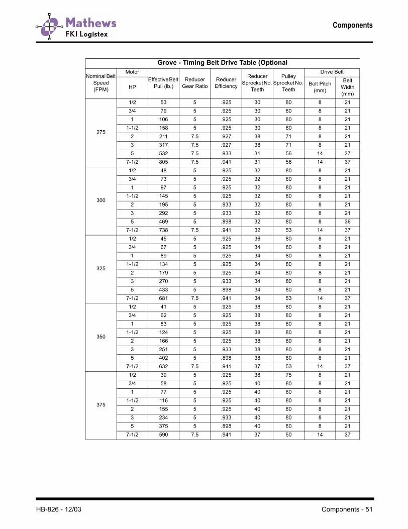
Components
Grove - Timing Belt Drive Table (Optional
Nominal Belt Speed (FPM)
MotorEffective Belt
Pull (lb.)Reducer
Gear RatioReducer Efficiency
Reducer Sprocket No.
Teeth
Pulley Sprocket No.
Teeth
Drive Belt
HP Belt Pitch (mm)
Belt Width (mm)
275
1/2 53 5 .925 30 80 8 213/4 79 5 .925 30 80 8 211 106 5 .925 30 80 8 21
1-1/2 158 5 .925 30 80 8 212 211 7.5 .927 38 71 8 213 317 7.5 .927 38 71 8 215 532 7.5 .933 31 56 14 37
7-1/2 805 7.5 .941 31 56 14 37
300
1/2 48 5 .925 32 80 8 213/4 73 5 .925 32 80 8 211 97 5 .925 32 80 8 21
1-1/2 145 5 .925 32 80 8 212 195 5 .933 32 80 8 213 292 5 .933 32 80 8 215 469 5 .898 32 80 8 36
7-1/2 738 7.5 .941 32 53 14 37
325
1/2 45 5 .925 36 80 8 213/4 67 5 .925 34 80 8 211 89 5 .925 34 80 8 21
1-1/2 134 5 .925 34 80 8 212 179 5 .925 34 80 8 213 270 5 .933 34 80 8 215 433 5 .898 34 80 8 21
7-1/2 681 7.5 .941 34 53 14 37
350
1/2 41 5 .925 38 80 8 213/4 62 5 .925 38 80 8 211 83 5 .925 38 80 8 21
1-1/2 124 5 .925 38 80 8 212 166 5 .925 38 80 8 213 251 5 .933 38 80 8 215 402 5 .898 38 80 8 21
7-1/2 632 7.5 .941 37 53 14 37
375
1/2 39 5 .925 38 75 8 213/4 58 5 .925 40 80 8 211 77 5 .925 40 80 8 21
1-1/2 116 5 .925 40 80 8 212 155 5 .925 40 80 8 213 234 5 .933 40 80 8 215 375 5 .898 40 80 8 21
7-1/2 590 7.5 .941 37 50 14 37
HB-826 - 12/03 Components - 51

Components
Grove - Timing Belt Drive Table (OptionalNominal Belt
Speed (FPM)
MotorEffective Belt
Pull (lb.)Reducer
Gear RatioReducer Efficiency
Reducer Sprocket No.
Teeth
Pulley Sprocket No.
Teeth
Drive Belt
HP Belt Pitch (mm)
Belt Width (mm)
400
1/2 36 5 .925 42 80 8 213/4 54 5 .925 42 80 8 211 73 5 .925 42 80 8 21
1-1/2 109 5 .925 42 80 8 212 145 5 .925 42 80 8 213 219 5 .933 42 80 8 215 352 5 .898 42 80 8 21
7-1/2 557 5 .948 30 56 14 37
425
1/2 34 5 .925 45 80 8 213/4 51 5 .925 45 80 8 211 68 5 .925 45 80 8 21
1-1/2 102 5 .925 45 80 8 212 138 5 .933 45 80 8 213 206 5 .933 45 80 8 215 331 5 .898 45 80 8 21
7-1/2 525 5 .948 32 56 14 37
450
1/2 32 5 .925 48 80 8 213/4 48 5 .925 48 80 8 211 64 5 .925 48 80 8 21
1-1/2 97 5 .925 48 80 8 212 129 5 .925 48 80 8 213 195 5 .933 48 80 8 215 313 5 .898 48 80 8 21
7-1/2 496 5 .948 32 53 14 37
475
1/2 31 5 .925 50 80 8 213/4 46 5 .925 50 80 8 211 61 5 .925 50 80 8 21
1-1/2 92 5 .925 50 80 8 212 122 5 .925 50 80 8 213 185 5 .933 50 80 8 215 296 5 .898 50 80 8 21
7-1/2 469 5 .948 33 53 14 37
500
1/2 29 5 .925 48 71 8 213/4 44 5 .925 48 71 8 211 58 5 .925 48 71 8 21
1-1/2 87 5 .925 48 71 8 212 116 5 .925 48 71 8 213 176 5 .936 48 71 8 215 281 5 .898 48 71 8 36
7-1/2 446 5 .948 35 53 14 37
Components - 52 HB-826 - 12/03

Components
Dodge - #60 Chain Drive Table (Standard) Dodge - #60 Chain Drive Table (Standard) Nominal
Belt Speed (FPM)
Motor Effective Belt Pull
(lb.)
Reducer Gear Ratio
Reducer Efficiency
No. of Teeth in Reducer Sprocket
Nominal Belt
speed (FPM
Motor Effective Belt Pull
(lb.)
Reducer Gear Ratio
Reducer Efficiency
No. of Teeth in Reducer Sprocket
HP HP
30
0.5 327
60:1
.625
16
120
0.5 103
20:1
.787
20
0.75 508 .648 0.75 154 .787
1 677 .648 1 219 .84
45
0.5 218
60:1
.625
23
1.5 329 .84
0.75 339 .648 2 434 .831
1 451 .648 3 651 .831
1.5 715 50:1 .684 19
135
0.5 91
20:1
.787
2360
0.5 172
40:1
.657
20
0.75 137 .787
0.75 272 .693 1 195 .84
1 375 .718 1.5 293 .84
1.5 563 .718 2 386 .831
2 821 30:1 .786 16 3 579 .831
75
0.5 137
40:1
.657
25
150
0.5 87
15:1
.828
19
0.75 217 .693 0.75 130 .828
1 300 .718 1 173 .828
1.5 450 .718 1.5 267 .853
2 657 30:1 .786 19 2 357 .853
90
0.5 131
25:1
.755
19
3 544 .867
0.75 197 .755
165
0.5 79
15:1
.828
21
1 281 .808 0.75 118 .828
1.5 422 .808 1 157 .828
2 562 .807 1.5 243 .853
105
0.5 113
25:1
.755
22
2 324 .853
0.75 169 .755 3 494 .867
1 241 .808
180
0.5 72
15:1
.828
23
1.5 362 .808 0.75 108 .828
2 482 .807 1 144 .828
3 744 20:1 .831 18 1.5 223 .853
2 297 .853
3 453 .867
HB-826 - 12/03 Components - 53
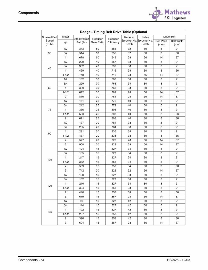
Components
Dodge - Timing Belt Drive Table (OptionalNominal Belt
Speed (FPM)
MotorEffective Belt
Pull (lb.)Reducer
Gear RatioReducer Efficiency
Reducer Sprocket No.
Teeth
Pulley Sprocket No.
Teeth
Drive Belt
HP Belt Pitch (mm)
Belt Width (mm)
301/2 343 50 .656 32 80 8 213/4 514 50 .656 32 80 8 361 678 60 .649 28 56 14 37
45
1/2 229 40 .657 38 80 8 213/4 362 40 .693 38 80 8 211 499 40 .716 38 80 8 36
1-1/2 748 40 .716 28 56 14 37
60
1/2 182 30 .696 38 80 8 213/4 299 30 .763 38 80 8 211 399 30 .763 38 80 8 21
1-1/2 612 30 .781 28 56 14 372 816 30 .781 28 56 14 37
75
1/2 161 25 .772 40 80 8 213/4 242 25 .772 40 80 8 211 336 25 .803 40 80 8 21
1-1/2 503 25 .803 40 80 8 362 671 25 .803 40 80 8 36
90
1/2 137 20 .784 38 80 8 213/4 205 20 .784 38 80 8 211 291 20 .836 38 80 8 21
1-1/2 437 20 .836 38 80 8 362 577 20 .828 28 56 14 373 900 20 .828 28 56 14 37
105
1/2 124 15 .827 34 80 8 213/4 185 15 .827 34 80 8 211 247 15 .827 34 80 8 21
1-1/2 382 15 .853 34 80 8 212 509 15 .853 34 80 8 363 742 20 .828 32 56 14 37
120
1/2 108 15 .827 38 80 8 213/4 162 15 .827 38 80 8 211 216 15 .827 38 80 8 21
1-1/2 334 15 .853 38 80 8 212 446 15 .853 38 80 8 363 679 15 .867 28 56 14 37
135
1/2 96 15 .827 42 80 8 213/4 144 15 .827 42 80 8 211 192 15 .827 42 80 8 21
1-1/2 297 15 .853 42 80 8 212 396 15 .853 42 80 8 363 604 15 .867 28 56 14 37
Components - 54 HB-826 - 12/03

Components
Dodge - Timing Belt Drive Table (Optional)Nominal Belt
Speed (FPM)
MotorEffective Belt
Pull (lb.)Reducer
Gear RatioReducer Efficiency
Reducer Sprocket No.
Teeth
Pulley Sprocket No.
Teeth
Drive Belt
HP Belt Pitch (mm)
Belt Width (mm)
150
1/2 91 10 .87 32 80 8 213/4 136 10 .87 32 80 8 211 182 10 .87 32 80 8 21
1-1/2 273 10 .87 32 80 8 212 371 10 .886 32 80 8 363 543 15 .867 34 56 14 37
165
1/2 83 10 .87 36 80 8 213/4 124 10 .87 36 80 8 211 165 10 .87 36 80 8 21
1-1/2 248 10 .87 36 80 8 212 337 10 .886 36 80 8 213 494 15 .867 34 56 14 37
180
1/2 76 10 .87 38 80 8 213/4 114 10 .87 38 80 8 211 152 10 .87 38 80 8 21
1-1/2 227 10 .87 38 80 8 212 309 10 .886 38 80 8 213 463 10 .886 38 80 8 365 783 10 .899 28 56 14 37
200
1/2 70 7.5 .888 32 80 8 213/4 104 7.5 .888 32 80 8 211 139 7.5 .888 32 80 8 21
1-1/2 209 7.5 .888 32 80 8 212 284 7.5 .905 32 80 8 213 426 7.5 .905 32 80 8 365 705 10 .899 30 56 14 37
225
1/2 62 7.5 .888 36 80 8 213/4 93 7.5 .888 36 80 8 211 124 7.5 .888 36 80 8 21
1-1/2 186 7.5 .888 36 80 8 212 252 7.5 .905 36 80 8 213 378 7.5 .905 36 80 8 365 626 10 .899 34 56 14 37
250
1/2 56 7.5 .888 38 75 8 213/4 84 7.5 .888 38 75 8 211 111 7.5 .888 38 75 8 21
1-1/2 167 7.5 .888 38 75 8 212 227 7.5 .905 38 75 8 213 341 7.5 .905 38 75 8 365 564 10 .899 34 53 14 37
HB-826 - 12/03 Components - 55
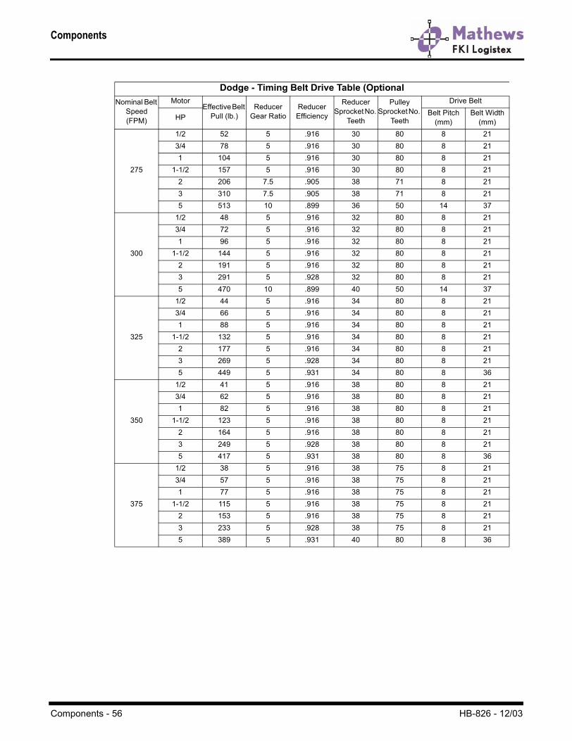
Components
Dodge - Timing Belt Drive Table (OptionalNominal Belt
Speed (FPM)
MotorEffective Belt
Pull (lb.)Reducer
Gear RatioReducer Efficiency
Reducer Sprocket No.
Teeth
Pulley Sprocket No.
Teeth
Drive Belt
HP Belt Pitch (mm)
Belt Width (mm)
275
1/2 52 5 .916 30 80 8 213/4 78 5 .916 30 80 8 211 104 5 .916 30 80 8 21
1-1/2 157 5 .916 30 80 8 212 206 7.5 .905 38 71 8 213 310 7.5 .905 38 71 8 215 513 10 .899 36 50 14 37
300
1/2 48 5 .916 32 80 8 213/4 72 5 .916 32 80 8 211 96 5 .916 32 80 8 21
1-1/2 144 5 .916 32 80 8 212 191 5 .916 32 80 8 213 291 5 .928 32 80 8 215 470 10 .899 40 50 14 37
325
1/2 44 5 .916 34 80 8 213/4 66 5 .916 34 80 8 211 88 5 .916 34 80 8 21
1-1/2 132 5 .916 34 80 8 212 177 5 .916 34 80 8 213 269 5 .928 34 80 8 215 449 5 .931 34 80 8 36
350
1/2 41 5 .916 38 80 8 213/4 62 5 .916 38 80 8 211 82 5 .916 38 80 8 21
1-1/2 123 5 .916 38 80 8 212 164 5 .916 38 80 8 213 249 5 .928 38 80 8 215 417 5 .931 38 80 8 36
375
1/2 38 5 .916 38 75 8 213/4 57 5 .916 38 75 8 211 77 5 .916 38 75 8 21
1-1/2 115 5 .916 38 75 8 212 153 5 .916 38 75 8 213 233 5 .928 38 75 8 215 389 5 .931 40 80 8 36
Components - 56 HB-826 - 12/03
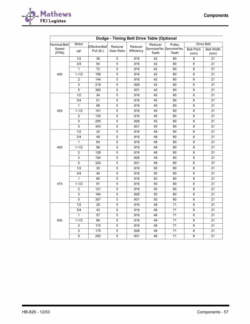
Components
Dodge - Timing Belt Drive Table (OptionalNominal Belt
Speed (FPM)
MotorEffective Belt
Pull (lb.)Reducer
Gear RatioReducer Efficiency
Reducer Sprocket No.
Teeth
Pulley Sprocket No.
Teeth
Drive Belt
HP Belt Pitch (mm)
Belt Width (mm)
400
1/2 36 5 .916 42 80 8 213/4 54 5 .916 42 80 8 211 72 5 .916 42 80 8 21
1-1/2 108 5 .916 42 80 8 212 144 5 .916 42 80 8 213 218 5 .928 42 80 8 215 365 5 .931 42 80 8 21
425
1/2 34 5 .916 45 80 8 213/4 51 5 .916 45 80 8 211 68 5 .916 45 80 8 21
1-1/2 101 5 .916 45 80 8 212 135 5 .916 45 80 8 213 205 5 .928 45 80 8 215 343 5 .931 45 80 8 21
450
1/2 32 5 .916 48 80 8 213/4 48 5 .916 48 80 8 211 64 5 .916 48 80 8 21
1-1/2 96 5 .916 48 80 8 212 128 5 .916 48 80 8 213 194 5 .928 48 80 8 215 324 5 .931 48 80 8 37
475
1/2 30 5 .916 50 80 8 213/4 45 5 .916 50 80 8 211 60 5 .916 50 80 8 21
1-1/2 91 5 .916 50 80 8 212 121 5 .916 50 80 8 213 184 5 .928 50 80 8 215 307 5 .931 50 80 8 21
500
1/2 29 5 .916 48 71 8 213/4 43 5 .916 48 71 8 211 57 5 .916 48 71 8 21
1-1/2 86 5 .916 48 71 8 212 115 5 .916 48 71 8 213 175 5 .928 48 71 8 215 292 5 .931 48 71 8 21
HB-826 - 12/03 Components - 57

Components
SA2001 Low Profile Intermediate Drive
Note: Please list options
HOW TO ORDER
Quantity Code No. W Speed HP Voltage Options
1 SA2001 27 60 FPM 1 230 ---
Components - 58 HB-826 - 12/03

Components
CONVEYOR WIDTH Standard - 15” - 39” W, in 3” increments. For trash removal conveyor only 15” - 45” W, in 3” increments.
CAPACITY Standard - 800# maximum effective belt pull.
SPEED Series 400, 600, and 800 End Drives - 30,45, 60, 75, 90, 120, 150*, 180, 200, 250, 300, 350 and 400 FPM.Note: *150 FPM maximum for Series 400.Chain Drive - 30, 45, 60, 75, 90, 105 120, 135, 150, 165 and 180 FPM.Timing Belt - 30, 45, 60, 75, 90, 105, 120, 135, 150, 165, 180, 200, 225, 250, 275, 300, 325, 350, 375, 400, 425, 450, 475 and 500 FPM.
CHAIN DRIVE Series 400, 600, and800 - RC50, RC60, RC80 and RC100 (all speeds).RC60 (up to 180 FPM).
CHAIN SPROCKETS Series 400 - RC50, bored and keyed Type B hub, hardened teethSeries 600 and 800 - RC60, RC80, and RC100, keeyed Taper-Lock hubs. hardened teeth or bored and keyed Type B hubs depending on speed/horsepower requirements.RC60, keyed Taper-Lock hubs, hardened.
DRIVE Standard - 230/460VAC - 3PH - 60 HZ.Optional - 575VAC - 3PH - 60HZ and 115VAC - 1PH - 60HZ.1/2 through 7-1/2 HP - C-Face TEFC (Baldor or Reliance).Chain Drive - 1/2, 3/4, 1, 1-1/2, 2 and 3 HP (Baldor or Reliance)Timing Belt Drive - 1/2, 3/4, 1, 1-1/2, 2, 3, 5, and 7-1/2 HP (Baldor or Reliance).Solenoid actuated brake motor supplied on all incline/decline conveyors.
MOTOR 1/2 through 7-1/2 HP - C-Face TEFC (Baldor or Reliance).Chain Drive - 1/2, 3/4, 1, 1-1/2, 2 and 3 HP (Baldor or Reliance).Timing Belt - 1/2, 3/4, 1, 1-1/2, 2, 3, 5, and 7-1/2 HP (Baldor or Reliance).Standard - 3 PH / 60 HZ / 230-460 VAC TEFCOption - 3 PH/60 HZ/575 VAC or 1 PH/60 HZ/115 VAC.
REDUCER Standard - Right Angle Worm Gear 5:1 to 50:1 ratios.
DRIVE PULLEY Standard - 5-7/8” dia. straight faced lagged pulley with 1-11/16’ dia. shaft and flange bearings.
TAKE-UP ROLLER Standard - 3-1/2” dia. crowned roller with 10” adjustment (20” belt), 1-1/16” hex axle and B1160 bearings.
SNUB ROLLER Standard - 2-9/16” dia. rollers with 11/16” hex axle and B1150 bearings.
BELT Standard - Width is 3” less than the Between Frames dimension. Belt length required is 30”.
SAFETY GUARDING Standard - Sprockets, chain and return belt are totally enclosed for safety. Drive and Take-up Pulleys are guarded below.Option - For guards above the drive and take-up pulleys, specify “PG” in the How to Order.
HB-826 - 12/03 Components - 59
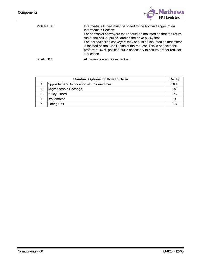
Components
MOUNTING Intermediate Drives must be bolted to the bottom flanges of an Intermediate Section.For horizontal conveyors they should be mounted so that the return run of the belt is “pulled” around the drive pulley first.For incline/decline conveyors they should be mounted so that motor is located on the “uphill” side of the reducer. This is opposite the preferred “level” position but is necessary to ensure proper reducer lubrication.
BEARINGS All bearings are grease packed.
Standard Options for How To Order Call Up1 Opposite hand for location of motor/reducer OPP2 Regreaseable Bearings RG3 Pulley Guard PG4 Brakemotor B5 Timing Belt TB
Components - 60 HB-826 - 12/03

Components
Grove - #60 Chain Drive Table (Standard) Grove - #60 Chain Drive Table (Standard)Nominal
Belt Speed (FPM)
Motor Effective Belt Pull
(lb.)
Reducer Gear Ratio
Reducer Efficiency
No. of Teeth in Reducer Sprocket
Nominal Belt
speed (FPM
Motor Effective Belt Pull
(lb.)
Reducer Gear Ratio
Reducer Efficiency
No. of Teeth in Reducer Sprocket
HP HP
30
0.5 371
50:1
.711
16
120
0.5 114
15:1
.875
18
0.75 577 .736 0.75 171 .875
1 766 .733 1 229 .875
40
0.5 267
40:1
.738
17
1.5 345 .881
0.75 391 .748 2 468 .896
1 536 .769 3 800 .892
1.5 800 .781
135
0.5 102
15:1
.875
2060
0.5 193
40:1
.738
23
0.75 152 .875
0.75 293 .748 1 203 .875
1 102 .769 1.5 307 .881
1.5 612 .781 2 416 .898
2 800 .801 3 621 .892
75
0.5 165
32:1
.788
22 160
0.5 91
15:1
.875
22
0.75 249 .795 0.75 137 .875
1 332 .795 1 183 .875
1.5 513 .818 1.5 276 .881
2 683 .817 2 375 .896
3 800 .836 3 559 .892
90
0.5 144
25:1
.825
22 165
0.5 83
15:1
.875
23
0.75 216 .825 0.75 126 .875
1 288 .827 1 166 .875
1.5 441 .844 1.5 251 .881
2 587 .842 2 341 .898
3 800 .867 3 508 .892
105
0.5 131
15:1
.875
15 180
0.5 79
10:1
.906
17
0.75 196 .875 0.75 118 .906
1 261 .875 1 158 .906
1.5 394 .881 1.5 237 .906
2 535 .896 2 317 .911
3 800 .892 3 479 .916
HB-826 - 12/03 Components - 61

Components
Grove - Timing Belt Drive Table (Optional)Nominal Belt
Speed (FPM)
MotorEffective Belt
Pull (lb.)Reducer
Gear RatioReducer Efficiency
Reducer Sprocket No.
Teeth
Pulley Sprocket No.
Teeth
Drive Belt
HP Belt Pitch (mm)
Belt Width (mm)
301/2 371 50 .711 36 63 8 213/4 574 50 .733 36 63 8 361 728 60 .697 33 48 14 37
45
1/2 257 40 .738 42 63 8 213/4 391 40 .748 42 63 8 211 536 40 .769 42 63 8 36
1-1/2 800 50 .748 40 48 14 37
60
1/2 215 25 .825 36 63 8 213/4 324 25 .827 36 63 8 211 432 25 .827 36 63 8 21
1-1/2‘ 568 25 .852 36 63 8 362 800 30 .817 34 48 14 37
75
1/2 177 20 .845 36 63 8 213/4 265 20 .845 36 63 8 211 356 20 .852 36 63 8 21
1-1/2 539 20 .860 36 63 8 362 730 20 .873 36 63 8 363 800 25 .867 34 48 14 37
90
1/2 152 15 .875 32 63 8 213/4 229 15 .875 32 63 8 211 307 15 .881 32 63 8 21
1-1/2 460 15 .881 32 63 8 212 599 20 .860 42 60 8 363 800 20 .873 33 48 14 37
105
1/2 131 15 .875 38 63 8 213/4 196 15 .875 38 63 8 211 261 15 .875 38 63 8 21
1-1/2 394 15 .881 38 63 8 212 532 15 .892 38 63 8 363 800 20 .873 38 48 14 37
120
1/2 114 15 .875 42 63 8 213/4 171 15 .875 42 63 8 211 229 15 .875 42 63 8 21
1-1/2 345 15 .881 42 63 8 212 468 15 .896 42 63 8 363 702 15 .896 42 63 8 365 800 15 .907 33 48 14 37
135
1/2 105 10 .906 32 63 8 213/4 158 10 .906 32 63 8 211 210 10 .906 32 63 8 21
1-1/2 317 10 .911 32 63 8 212 423 10 .911 32 63 8 213 521 15 .892 42 63 8 215 800 15 .907 37 48 14 37
Components - 62 HB-826 - 12/03

Components
Grove - Timing Belt Drive Table (OptionalNominal Belt
Speed (FPM)
MotorEffective Belt
Pull (lb.)Reducer
Gear RatioReducer Efficiency
Reducer Sprocket No.
Teeth
Pulley Sprocket No.
Teeth
Drive Belt
HP Belt Pitch (mm)
Belt Width (mm)
150
1/2 95 10 .906 36 63 8 213/4 142 10 .906 36 63 8 211 189 10 .906 36 63 8 21
1-1/2 286 10 .911 36 63 8 212 381 10 .911 36 63 8 213 576 10 .918 36 63 8 365 800 10 .925 20 48 14 37
165
1/2 86 10 .906 40 63 8 213/4 129 10 .906 40 63 8 211 172 10 .906 40 63 8 21
1-1/2 258 10 .906 40 63 8 212 346 10 .911 40 63 8 213 523 10 .918 40 63 8 365 800 10 .925 30 48 14 37
180
1/2 80 7.5 .917 32 63 8 213/4 120 7.5 .917 32 63 8 211 160 7.5 .917 32 63 8 21
1-1/2 240 7.5 .917 32 63 8 212 321 7.5 .922 32 63 8 213 484 7.5 .927 32 63 8 365 800 10 .925 33 48 14 37
200
1/2 72 7.5 .917 36 63 8 213/4 108 7.5 .917 36 63 8 211 144 7.5 .917 36 63 8 21
1-1/2 216 7.5 .917 36 63 8 212 289 7.5 .922 36 63 8 213 436 7.5 .927 36 63 8 365 731 10 .933 36 63 8 37
7-1/2 800 .925 36 48 14 21
225
1/2 64 7.5 .917 40 63 8 213/4 96 7.5 .917 40 63 8 211 128 7.5 .917 40 63 8 21
1-1/2 192 7.5 .917 40 63 8 212 257 7.5 .922 40 63 8 213 357 7.5 .927 40 63 8 365 650 7.5 .933 40 63 8 37
7-1/2 800 10 .925 40 48 14 21
250
1/2 58 7.5 .917 45 63 8 213/4 86 7.5 .917 45 63 8 211 115 7.5 .917 45 63 8 21
1-1/2 173 7.5 .917 45 63 8 212 231 7.5 .922 45 63 8 213 349 7.5 .927 45 63 8 365 585 7.5 .933 42 63 8 37
7-1/2 800 7.5 .941 34 48 14 21
HB-826 - 12/03 Components - 63

Components
Grove - Timing Belt Drive Table (Optional)Nominal Belt
Speed (FPM)
MotorEffective Belt
Pull (lb.)Reducer
Gear RatioReducer Efficiency
Reducer Sprocket No.
Teeth
Pulley Sprocket No.
Teeth
Drive Belt
HP Belt Pitch (mm)
Belt Width (mm)
275
1/2 53 5 .925 34 63 8 213/4 79 5 .925 34 63 8 211 106 5 .925 34 63 8 21
1-1/2 158 5 .925 34 63 8 212 211 5 .925 34 63 8 213 319 5 .933 34 63 8 215 512 5 .898 34 63 8 36
7-1/2 800 7.5 .941 37 48 14 37
300
1/2 48 5 .925 36 63 8 213/4 73 5 .925 36 63 8 211 97 5 .925 36 63 8 21
1-1/2 145 5 .925 36 63 8 212 193 5 .925 36 63 8 213 292 5 .933 36 63 8 215 469 7.5 .898 36 63 8 36
7-1/2 738 .941 38 45 14 37
325
1/2 45 5 .925 38 63 8 213/4 67 5 .925 38 63 8 211 89 5 .925 38 63 8 21
1-1/2 134 5 .925 38 63 8 212 179 5 .925 38 63 8 213 270 5 .933 38 63 8 215 433 5 .898 38 63 8 36
7-1/2 686 5 .948 30 48 14 37
350
1/2 41 5 .925 42 63 8 213/4 62 5 .925 42 63 8 211 83 5 .925 42 63 8 21
1-1/2 124 5 .925 42 63 8 212 166 5 .925 42 63 8 213 251 5 .933 42 63 8 215 402 5 .898 42 63 8 21
7-1/2 637 5 .948 42 63 8 36
375
1/2 39 5 .925 45 63 8 213/4 58 5 .925 45 63 8 211 77 5 .925 45 63 8 21
1-1/2 116 5 .925 45 63 8 212 155 5 .925 45 63 8 213 234 5 .933 45 63 8 215 375 5 .898 42 60 8 21
7-1/2 595 5 .948 42 60 8 36
Components - 64 HB-826 - 12/03

Components
Grove - Timing Belt Drive Table (Optional)Nominal Belt
Speed (FPM)
MotorEffective Belt
Pull (lb.)Reducer
Gear RatioReducer Efficiency
Reducer Sprocket No.
Teeth
Pulley Sprocket No.
Teeth
Drive Belt
HP Belt Pitch (mm)
Belt Width (mm)
400
1/2 36 5 .925 45 60 8 213/4 54 5 .925 45 60 8 211 73 5 .925 45 60 8 21
1-1/2 109 5 .925 45 60 8 212 145 5 .925 45 60 8 213 219 5 .933 45 60 8 215 352 5 .898 45 60 8 21
7-1/2 557 5 .948 45 60 8 36
425
1/2 34 5 .925 45 56 8 213/4 51 5 .925 45 56 8 211 68 5 .925 45 56 8 21
1-1/2 102 5 .925 45 56 8 212 137 5 .925 45 56 8 213 206 5 .933 45 56 8 215 331 5 .898 45 56 8 21
7-1/2 525 5 .948 45 56 8 36
450
1/2 32 5 .925 48 56 8 213/4 48 5 .925 48 56 8 211 64 5 .925 48 56 8 21
1-1/2 97 5 .925 48 56 8 212 129 5 .925 48 56 8 213 195 5 .933 48 56 8 215 313 5 .898 48 56 8 21
7-1/2 496 5 .948 48 56 8 36
475
1/2 31 5 .925 45 50 8 213/4 46 5 .925 45 50 8 211 61 5 .925 45 50 8 21
1-1/2 92 5 .925 45 50 8 212 122 5 .925 45 50 8 213 185 5 .933 45 50 8 215 296 5 .898 45 50 8 21
7-1/2 469 5 .948 45 50 8 36
500
1/2 29 5 .925 38 40 8 213/4 44 5 .925 38 40 8 211 58 5 .925 38 40 8 21
1-1/2 87 5 .925 38 40 8 212 116 5 .925 38 40 8 213 175 5 .933 38 40 8 215 281 5 .898 38 40 8 21
7-1/2 446 5 .948 38 40 14 37
HB-826 - 12/03 Components - 65

Components
Dodge - #60 Chain Drive Table (Standard) Dodge - #60 Chain Drive Table (Standard) Nominal
Belt Speed (FPM)
Motor Effective Belt Pull
(lb.)
Reducer Gear Ratio
Reducer Efficiency
No. of Teeth in Reducer Sprocket
Nominal Belt
speed (FPM
Motor Effective Belt Pull
(lb.)
Reducer Gear Ratio
Reducer Efficiency
No. of Teeth in Reducer Sprocket
HP HP
30
0.5 342
50
.655
15
120
0.5 108
15
.828
18
0.75 513 .655 0.75 162 .828
1 715 .684 1 216 .828
45
0.5 229
40
.657
17
1.5 334 .853
0.75 362 .693 2 446 .853
1 500 .718 3 680 .867
1.5 750 .718
135
0.5 96
15
.828
2060
0.5 183
30
.699
17
0.75 144 .828
0.75 298 .761 1 192 .828
1 398 .761 1.5 297 .853
1.5 616 .786 2 396 .853
2 800 .786 3 604 .867
75
0.5 158
25
.755
18150
0.5 87
15
.828
22
0.75 237 .755 0.75 130 .828
1 338 .808 1 173 .828
1.5 507 .808 1.5 267 .853
2 675 .807 2 357 .853
90
0.5 137
20
.787
17
3 544 .867
0.75 206 .787
165
0.5 79
15
.828
23
1 293 .84 0.75 118 .828
1.5 439 .84 1 157 .828
2 579 .831 1.5 243 .853
3 800 .831 2 324 .853
105
0.5 124
15
.828
15
3 494 .867
0.75 185 .828
180
0.5 76
10
.870
17
1 247 .828 0.75 114 .870
1.5 382 .853 1 152 .870
2 509 .853 1.5 227 .870
3 800 .867 2 310 .891
3 466 .891
Components - 66 HB-826 - 12/03

Components
Dodge - Timing Belt Drive Table (OptionalNominal Belt
Speed (FPM)
MotorEffective Belt
Pull (lb.)Reducer
Gear RatioReducer Efficiency
Reducer Sprocket No.
Teeth
Pulley Sprocket No.
Teeth
Drive Belt
HP Belt Pitch (mm)
Belt Width (mm)
301/2 342 50 .655 36 63 8 213/4 513 50 .655 36 63 8 361 677 60 .648 33 48 14 37
45
1/2 229 40 .657 42 63 8 213/4 362 40 .693 42 63 8 211 500 40 .718 42 63 8 36
1-1/2 715 50 .684 40 48 14 37
60
1/2 197 25 .755 36 63 8 213/4 296 25 .755 36 63 8 211 422 25 .808 36 63 8 21
1-1/2 633 25 .808 36 63 8 362 800 30 .786 34 48 14 37
75
1/2 164 20 .787 36 63 8 213/4 247 20 .787 36 63 8 211 351 20 .840 36 63 8 21
1-1/2 527 20 .840 36 63 8 362 695 20 .831 36 63 8 363 800 20 .831 28 48 14 37
90
1/2 144 15 .828 32 63 8 213/4 216 15 .828 32 63 8 211 268 15 .828 32 63 8 21
1-1/2 446 15 .853 32 63 8 212 579 20 .831 42 60 8 363 800 20 .831 33 48 14 37
105
1/2 124 15 .828 38 63 8 213/4 185 15 .828 38 63 8 211 247 15 .828 38 63 8 21
1-1/2 382 15 .853 38 63 8 212 509 15 .853 38 63 8 363 744 20 .831 38 48 14 37
120
1/2 108 15 .828 42 63 8 213/4 162 15 .828 42 63 8 211 216 15 .828 42 63 8 21
1-1/2 334 15 .853 42 63 8 212 446 15 .853 42 63 8 213 680 15 .867 42 63 8 36
135
1/2 101 10 .870 32 63 8 213/4 152 10 .870 32 63 8 211 202 10 .870 32 63 8 21
1-1/2 303 10 .870 32 63 8 212 414 10 .891 32 63 8 213 604 15 .867 42 56 8 36
HB-826 - 12/03 Components - 67

Components
Dodge - Timing Belt Drive Table (Optional)Nominal Belt
Speed (FPM)
MotorEffective Belt
Pull (lb.)Reducer
Gear RatioReducer Efficiency
Reducer Sprocket No.
Teeth
Pulley Sprocket No.
Teeth
Drive Belt
HP Belt Pitch (mm)
Belt Width (mm)
150
1/2 91 10 .870 36 63 8 213/4 136 10 .870 36 63 8 211 182 10 .870 36 63 8 21
1-1/2 273 10 .870 36 63 8 212 372 10 .891 36 63 8 213 559 10 .891 36 63 8 365 800 10 .902 28 48 14 37
165
1/2 83 10 .870 40 63 8 213/4 124 10 .870 40 63 8 211 165 10 .870 40 63 8 21
1-1/2 248 10 .870 40 63 8 212 339 10 .891 40 63 8 213 508 10 .891 40 63 14 365 800 10 .902 30 48 8 37
180
1/2 77 7.5 .888 32 63 8 213/4 116 7.5 .888 32 63 8 211 155 7.5 .888 32 63 8 21
1-1/2 232 7.5 .888 32 63 8 212 316 7.5 .906 32 63 8 213 473 7.5 .906 32 63 8 365 800 10 .902 33 48 14 37
200
1/2 70 7.5 .888 36 63 8 213/4 104 7.5 .888 36 63 8 211 139 7.5 .888 36 63 8 21
1-1/2 209 7.5 .888 36 63 8 212 284 7.5 .906 36 63 8 213 426 7.5 .906 36 63 8 215 707 10 .902 36 48 14 37
225
1/2 62 7.5 .888 40 63 8 213/4 93 7.5 .888 40 63 8 211 124 7.5 .888 40 63 8 21
1-1/2 186 7.5 .888 40 63 8 212 252 7.5 .906 40 63 8 213 379 7.5 .906 40 63 8 215 628 10 .902 40 45 14 37
250
1/2 56 7.5 .888 45 63 8 213/4 84 7.5 .888 45 63 8 211 111 7.5 .888 45 63 8 21
1-1/2 167 7.5 .888 45 63 8 212 227 7.5 .906 45 63 8 213 341 7.5 .906 45 63 8 215 566 10 .902 38 40 14 37
Components - 68 HB-826 - 12/03

Components
Dodge - Timing Belt Drive Table (OptionalNominal Belt
Speed (FPM)
MotorEffective Belt
Pull (lb.)Reducer
Gear RatioReducer Efficiency
Reducer Sprocket No.
Teeth
Pulley Sprocket No.
Teeth
Drive Belt
HP Belt Pitch (mm)
Belt Width (mm)
275
1/2 52 5 .916 34 63 8 213/4 78 5 .916 34 63 8 211 104 5 .916 34 63 8 21
1-1/2 157 5 .916 34 63 8 212 209 5 .916 34 63 8 213 315 5 .922 34 63 8 215 530 5 .929 34 63 14 36
300
1/2 48 5 .916 36 63 8 213/4 72 5 .916 36 63 8 211 96 5 .916 36 63 8 21
1-1/2 144 5 .916 36 63 8 212 191 5 .916 36 63 8 213 289 5 .922 36 63 8 215 485 5 .929 36 63 8 36
325
1/2 44 5 .916 38 63 8 213/4 66 5 .916 38 63 8 211 88 5 .916 38 63 8 21
1-1/2 133 5 .916 38 63 8 212 177 5 .916 38 63 8 213 267 5 .922 38 63 8 215 405 5 .929 38 63 8 36
350
1/2 41 5 .916 42 63 8 213/4 62 5 .916 42 63 8 211 82 5 .916 42 63 8 21
1-1/2 123 5 .916 42 63 8 212 164 5 .916 42 63 8 213 248 5 .922 42 63 8 215 416 5 .929 42 63 8 36
375
1/2 38 5 .916 45 63 8 213/4 57 5 .916 45 63 8 211 77 5 .916 45 63 8 21
1-1/2 115 5 .916 45 63 8 212 153 5 .916 45 63 8 213 231 5 .922 45 63 8 215 388 5 .929 42 60 8 36
HB-826 - 12/03 Components - 69
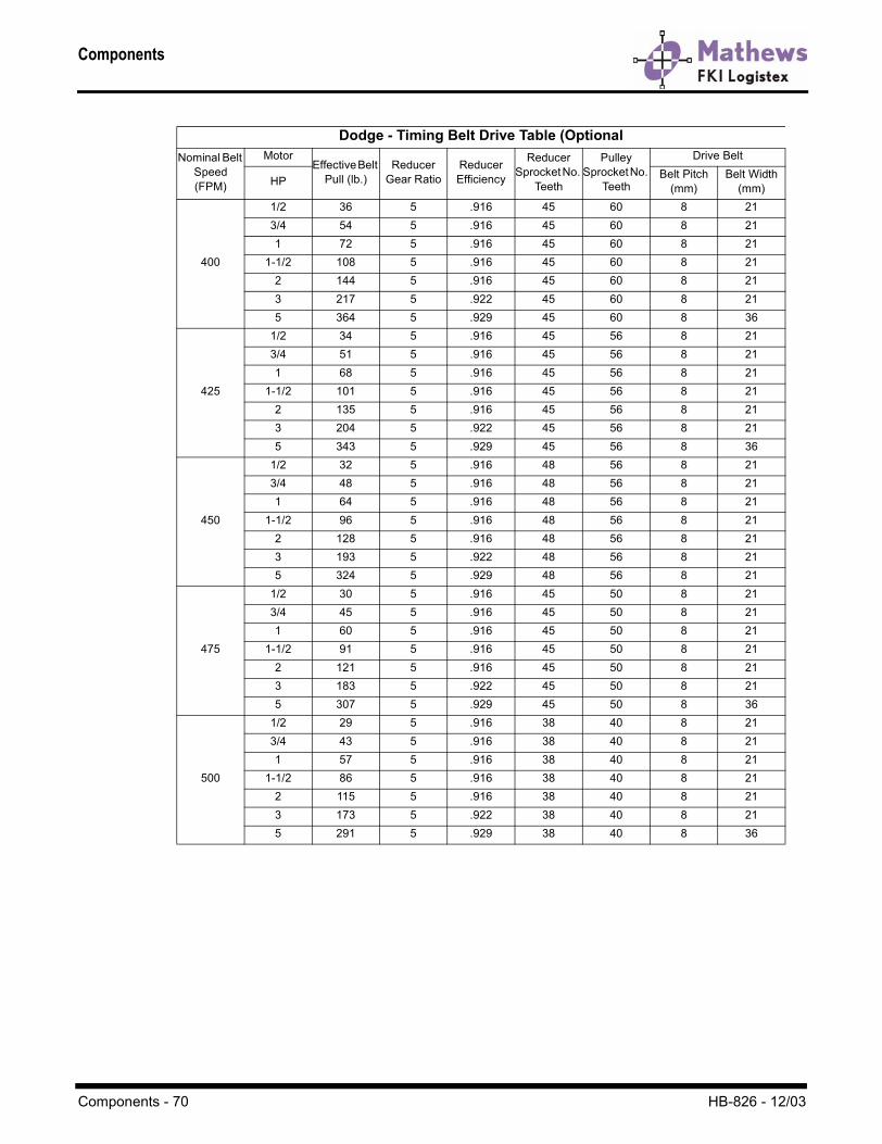
Components
Dodge - Timing Belt Drive Table (OptionalNominal Belt
Speed (FPM)
MotorEffective Belt
Pull (lb.)Reducer
Gear RatioReducer Efficiency
Reducer Sprocket No.
Teeth
Pulley Sprocket No.
Teeth
Drive Belt
HP Belt Pitch (mm)
Belt Width (mm)
400
1/2 36 5 .916 45 60 8 213/4 54 5 .916 45 60 8 211 72 5 .916 45 60 8 21
1-1/2 108 5 .916 45 60 8 212 144 5 .916 45 60 8 213 217 5 .922 45 60 8 215 364 5 .929 45 60 8 36
425
1/2 34 5 .916 45 56 8 213/4 51 5 .916 45 56 8 211 68 5 .916 45 56 8 21
1-1/2 101 5 .916 45 56 8 212 135 5 .916 45 56 8 213 204 5 .922 45 56 8 215 343 5 .929 45 56 8 36
450
1/2 32 5 .916 48 56 8 213/4 48 5 .916 48 56 8 211 64 5 .916 48 56 8 21
1-1/2 96 5 .916 48 56 8 212 128 5 .916 48 56 8 213 193 5 .922 48 56 8 215 324 5 .929 48 56 8 21
475
1/2 30 5 .916 45 50 8 213/4 45 5 .916 45 50 8 211 60 5 .916 45 50 8 21
1-1/2 91 5 .916 45 50 8 212 121 5 .916 45 50 8 213 183 5 .922 45 50 8 215 307 5 .929 45 50 8 36
500
1/2 29 5 .916 38 40 8 213/4 43 5 .916 38 40 8 211 57 5 .916 38 40 8 21
1-1/2 86 5 .916 38 40 8 212 115 5 .916 38 40 8 213 173 5 .922 38 40 8 215 291 5 .929 38 40 8 36
Components - 70 HB-826 - 12/03

Components
C1716 End Drive
Note: Please list options
HOW TO ORDER
Quantity Code No. W Speed HP Voltage Options
1 C1716 21” 70 3/4 230 NT
Standard Options for How To Order Call Up1 Opposite hand for location of motor/reducer OPP2 Regreaseable Bearings RG3 Brakemotor B4 Lagged Pulley LP5 Without Take-Up NT6 Timing Belt Drive TB
HB-826 - 12/03 Components - 71

Components
CONVEYOR WIDTH Standard - 15”, 21”, 27”, 33” and 39” Between Frames.
CAPACITY Standard - 400# effective belt pull.
SPEED Standard - 70 FPM nominal with 58 RPM reducer. Reducer has a 22 tooth sprocket, pulley has a 19 tooth sprocket. All driver sprockets have hardened teeth.Option - See Motor/Reducer Selection Table on the following page. For speeds other than 70 FPM, the reducer RPM and sprocket combination must be specified under Options on How To Order.
DRIVE Standard - Furnished as shown for position of motor/reducer, unless specified “opposite hand”. #50 chain driver available 1/2 HP through 3 HP. The drive chain is totally enclosed for safety. 5.5” of take-up adjustment provided. It is recommended that this drive be used for single direction application and placed at the discharge end of the conveyor.Option - Available without take-up (NT). See table for recommended maximum lengths without take-up (assumes nominal take-up in end roller unit). Timing belt (TB) drives available 1/2 HP through 5 HP.
PULLEY Standard - 4” dia. crowned pulley with pre-lubricated outboard flanged block bearings and 1-3/16” dia. shaft.Option - Lagged pulley is available.
BELT Standard - Width is 3” less than the Between Frames dimension. Belt length required is 66” with take-up roller or 50” without take-up.
BEARINGS Standard - All bearings are greased packed.
Components - 72 HB-826 - 12/03

Components
#60 Chain Drive Table (Standard) #60 Chain Drive Table (Standard)Nominal
Belt Speed (FPM)
Motor Effective Belt Pull
(lb.)
Reducer Gear Ratio
Reducer Efficiency
No. of Teeth in Reducer Sprocket
Nominal Belt
speed (FPM
Motor Effective Belt Pull
(lb.)
Reducer Gear Ratio
Reducer Efficiency
No. of Teeth in Reducer Sprocket
HP Frame HP Frame
330.5
56C342
50:1.719
17
110
0.5
56C
125
15:1
.876
17
.075 400 .713 0.75 187 .876
400.5
56C288
40:1.736
171 250 .876
0.75 400 .736 1.5 374 .876
50
0.5
56C
248
30:1
.791
17
2 400 .882
0.75 372 .791
135
0.5
56C
102
15:1
.876
21
1 400 .797 0.75 153 .876
60
0.5
56C
207
30:1
.791
19
1 203 .876
0.75 310 .791 1.5 305 .876
1 400 .797 2 400 .882
70
0.5
56C
177
30:1
.791
22
155
0.5
56C
92
10:1
.910
16
0.75 266 .791 0.75 138 .910
1 357 .797 1 184 .910
1.5 400 .827 1.5 276 .910
80
0.5
56C
166
20:1
.846
17
2 368 .910
0.75 249 .846 3 182TC 400 .,916
1 332 .846
175
0.5
56C
82
10:1
.910
18
1.5 400 .853 0.75 122 .910
90
0.5
56C
147
20:1
.846
19
1 163 .910
0.75 221 .846 1.5 245 .910
1 295 .846 2 326 .910
1.5 400 .853 3 182TC 400 .916
Maximum Recommended Conveyor Length With “NT” Option
Between Frames (W) 15” W 21” W 27” W 33” W 39” W
Length 13’-0” 20’-0” 28’-0” 33’-0” 38’-0”
HB-826 - 12/03 Components - 73

Components
Timing Belt Drive Table (Optional)Nominal
Belt Speed (FPM)
MotorEffective Belt Pull
(lb.)
Reducer Gear Ratio
Reducer Efficiency
Reducer Sprocket No. Teeth
Pulley Sprocket No. Teeth
Drive Belt
HP Frame Belt Pitch (mm)
Belt Width (mm)
331/2
56C356 40 .750 32 48 8 35
3/4 400 40 .750 32 48 8 35
401/2
56C310 30 .791 32 48 8 35
3/4 400 30 .797 32 48 8 35
501/2
56C259 25 .826 34 48 8 35
3/4 390 25 .829 34 48 8 351 400 25 .829 34 48 8 35
601/2
56C221 20 .846 32 48 8 35
3/4 332 20 .846 32 48 8 351 400 20 .853 32 48 8 35
70
1/2
56C
189 20 .846 32 40 8 353/4 284 20 .846 32 40 8 351 382 20 .853 32 40 8 35
1-1/2 400 20 .853 32 40 8 35
80
1/2
56C
172 15 .876 32 48 8 353/4 257 15 .876 32 48 8 351 343 15 .876 32 48 8 35
1-1/2 400 15 .882 32 48 8 35
90
1/2
56C
153 15 .876 34 44 8 353/4 229 15 .876 34 44 8 351 305 15 .876 34 44 8 35
1-1/2 400 15 .882 34 44 8 35
110
1/2
56C
125 15 .876 32 36 8 353/4 187 15 .876 32 36 8 351 250 15 .876 32 36 8 35
1-1/2 383 15 .897 32 36 8 352 400 15 .897 32 36 8 35
135
1/2
56C
106 10 .910 34 44 8 353/4 158 10 .910 34 44 8 351 211 10 .910 34 44 8 35
1-1/2 317 10 .910 34 44 8 352 400 10 .912 34 44 8 35
155
1/2
56C
92 10 .910 32 38 8 353/4 138 10 .910 32 38 8 351 184 10 .910 32 38 8 35
1-1/2 276 10 .910 32 38 8 352 369 10 .910 32 38 8 353 182TC 400 10 .916 32 38 8 35
Components - 74 HB-826 - 12/03

Components
Timing Belt Drive Table (Optional)Nominal
Belt Speed (FPM)
MotorEffective Belt Pull
(lb.)
Reducer Gear Ratio
Reducer Efficiency
Reducer Sprocket No. Teeth
Pulley Sprocket No. Teeth
Drive Belt
HP Frame Belt Pitch (mm)
Belt Width (mm)
175
1/2
56C
82 7.5 .918 32 44 8 353/4 123 7.5 .918 32 44 8 351 164 7.5 .918 32 44 8 35
1-1/2 247 7.5 .918 32 44 8 352 331 7.5 .923 32 44 8 353 182TC 400 7.5 .927 32 44 8 35
200
1/2
56C
72 7.5 .918 32 38 8 353/4 108 7.5 .918 32 38 8 351 144 7.5 .918 32 38 8 35
1-1/2 216 7.5 .918 32 38 8 352 289 7.5 .923 32 38 8 353 182TC 400 7.5 .927 32 38 8 35
225
1/2
56C
64 7.5 .918 44 48 8 353/4 96 7.5 .918 44 48 8 351 128 7.5 .918 44 48 8 35
1-1/2 192 7.5 .918 44 48 8 352 256 7.5 .918 44 48 8 353 182TC 387 7.5 .927 44 48 8 35
250
1/2
56C
58 5 .928 34 48 8 353/4 87 5 .928 34 48 8 351 116 5 .928 34 48 8 35
1-1/2 175 5 .928 34 48 8 352 233 5 .928 34 48 8 353 182TC 353 5 .939 34 48 8 355 182TC 400 5 .939 34 48 8 42
275
1/2
56C
53 5 .928 34 44 8 353/4 79 5 .928 34 44 8 351 106 5 .928 34 44 8 35
1-1/2 159 5 .928 34 44 8 352 212 5 .928 34 44 8 353 182TC 321 5 .939 34 44 8 355 182TC 400 5 .939 34 44 8 42
300
1/2
56C
48 5 .928 32 38 8 353/4 73 5 .928 32 38 8 351 97 5 .928 32 38 8 35
1-1/2 145 5 .928 32 38 8 352 194 5 .928 32 38 8 353 182TC 294 5 .939 32 38 8 355 182TC 400 5 .939 32 38 8 35
HB-826 - 12/03 Components - 75

Components
Timing Belt Drive Table (Optional)Nominal
Belt Speed (FPM)
MotorEffective Belt Pull
(lb.)
Reducer Gear Ratio
Reducer Efficiency
Reducer Sprocket No. Teeth
Pulley Sprocket No. Teeth
Drive Belt
HP Frame Belt Pitch (mm)
Belt Width (mm)
325
1/2
56C
45 5 .928 34 38 8 353/4 67 5 .928 34 38 8 351 90 5 .928 34 38 8 35
1-1/2 134 5 .928 34 38 8 352 179 5 .928 34 38 8 353 182TC 272 5 .939 34 38 8 355 182TC 400 5 .939 34 38 8 35
350
1/2
56C
42 5 .928 38 38 8 353/4 62 5 .928 38 38 8 351 83 5 .928 38 38 8 35
1-1/2 125 5 .928 38 38 8 352 166 5 .928 38 38 8 353 182TC 252 5 .939 38 38 8 355 182TC 400 5 .939 38 38 8 35
375
1/2
56C
39 5 .928 40 38 8 353/4 58 5 .928 40 38 8 351 78 5 .928 40 38 8 35
1-1/2 116 5 .928 40 38 8 352 155 5 .928 40 38 8 353 182TC 236 5 .939 40 38 8 355 182TC 393 5 .939 40 38 8 35
400
1/2
56C
36 5 .928 44 40 8 353/4 55 5 .928 44 40 8 351 73 5 .928 44 40 8 35
1-1/2 109 5 .928 44 40 8 352 145 5 .928 44 40 8 353 182TC 221 5 .939 44 40 8 355 182TC 368 5 .939 44 40 8 35
Components - 76 HB-826 - 12/03
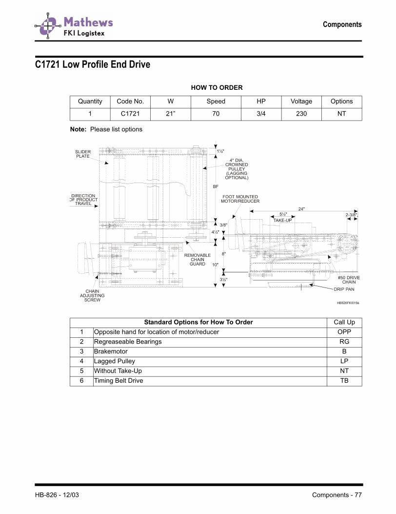
Components
C1721 Low Profile End Drive
Note: Please list options
HOW TO ORDER
Quantity Code No. W Speed HP Voltage Options
1 C1721 21” 70 3/4 230 NT
Standard Options for How To Order Call Up1 Opposite hand for location of motor/reducer OPP2 Regreaseable Bearings RG3 Brakemotor B4 Lagged Pulley LP5 Without Take-Up NT6 Timing Belt Drive TB
HB-826 - 12/03 Components - 77
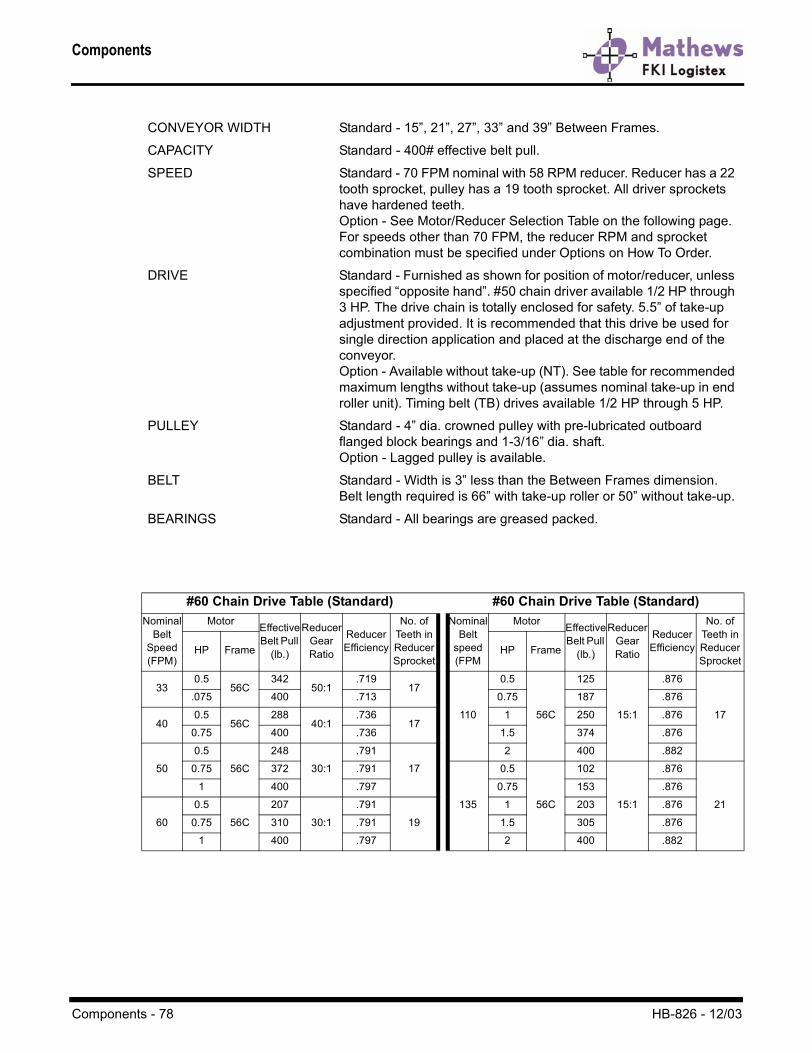
Components
CONVEYOR WIDTH Standard - 15”, 21”, 27”, 33” and 39” Between Frames.
CAPACITY Standard - 400# effective belt pull.
SPEED Standard - 70 FPM nominal with 58 RPM reducer. Reducer has a 22 tooth sprocket, pulley has a 19 tooth sprocket. All driver sprockets have hardened teeth.Option - See Motor/Reducer Selection Table on the following page. For speeds other than 70 FPM, the reducer RPM and sprocket combination must be specified under Options on How To Order.
DRIVE Standard - Furnished as shown for position of motor/reducer, unless specified “opposite hand”. #50 chain driver available 1/2 HP through 3 HP. The drive chain is totally enclosed for safety. 5.5” of take-up adjustment provided. It is recommended that this drive be used for single direction application and placed at the discharge end of the conveyor.Option - Available without take-up (NT). See table for recommended maximum lengths without take-up (assumes nominal take-up in end roller unit). Timing belt (TB) drives available 1/2 HP through 5 HP.
PULLEY Standard - 4” dia. crowned pulley with pre-lubricated outboard flanged block bearings and 1-3/16” dia. shaft.Option - Lagged pulley is available.
BELT Standard - Width is 3” less than the Between Frames dimension. Belt length required is 66” with take-up roller or 50” without take-up.
BEARINGS Standard - All bearings are greased packed.
#60 Chain Drive Table (Standard) #60 Chain Drive Table (Standard)Nominal
Belt Speed (FPM)
Motor Effective Belt Pull
(lb.)
Reducer Gear Ratio
Reducer Efficiency
No. of Teeth in Reducer Sprocket
Nominal Belt
speed (FPM
Motor Effective Belt Pull
(lb.)
Reducer Gear Ratio
Reducer Efficiency
No. of Teeth in Reducer Sprocket
HP Frame HP Frame
330.5
56C342
50:1.719
17
110
0.5
56C
125
15:1
.876
17
.075 400 .713 0.75 187 .876
400.5
56C288
40:1.736
171 250 .876
0.75 400 .736 1.5 374 .876
50
0.5
56C
248
30:1
.791
17
2 400 .882
0.75 372 .791
135
0.5
56C
102
15:1
.876
21
1 400 .797 0.75 153 .876
60
0.5
56C
207
30:1
.791
19
1 203 .876
0.75 310 .791 1.5 305 .876
1 400 .797 2 400 .882
Components - 78 HB-826 - 12/03

Components
70
0.5
56C
177
30:1
.791
22
155
0.5
56C
92
10:1
.910
16
0.75 266 .791 0.75 138 .910
1 357 .797 1 184 .910
1.5 400 .827 1.5 276 .910
80
0.5
56C
166
20:1
.846
17
2 368 .910
0.75 249 .846 3 182TC 400 .,916
1 332 .846
175
0.5
56C
82
10:1
.910
18
1.5 400 .853 0.75 122 .910
90
0.5
56C
147
20:1
.846
19
1 163 .910
0.75 221 .846 1.5 245 .910
1 295 .846 2 326 .910
1.5 400 .853 3 182TC 400 .916
Maximum Recommended Conveyor Length With “NT” Option
Between Frames (W) 15” W 21” W 27” W 33” W 39” W
Length 13’-0” 20’-0” 28’-0” 33’-0” 38’-0”
#60 Chain Drive Table (Standard) #60 Chain Drive Table (Standard)Nominal
Belt Speed (FPM)
Motor Effective Belt Pull
(lb.)
Reducer Gear Ratio
Reducer Efficiency
No. of Teeth in Reducer Sprocket
Nominal Belt
speed (FPM
Motor Effective Belt Pull
(lb.)
Reducer Gear Ratio
Reducer Efficiency
No. of Teeth in Reducer Sprocket
HP Frame HP Frame
HB-826 - 12/03 Components - 79
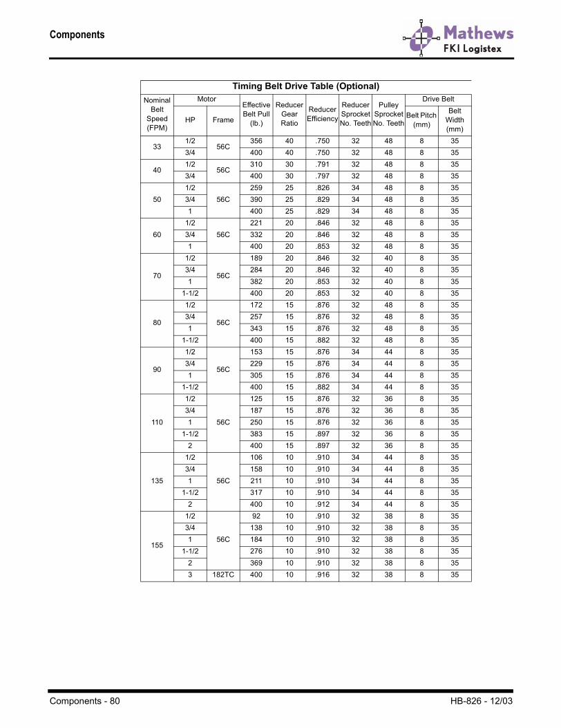
Components
Timing Belt Drive Table (Optional)Nominal
Belt Speed (FPM)
MotorEffective Belt Pull
(lb.)
Reducer Gear Ratio
Reducer Efficiency
Reducer Sprocket No. Teeth
Pulley Sprocket No. Teeth
Drive Belt
HP Frame Belt Pitch (mm)
Belt Width (mm)
331/2
56C356 40 .750 32 48 8 35
3/4 400 40 .750 32 48 8 35
401/2
56C310 30 .791 32 48 8 35
3/4 400 30 .797 32 48 8 35
501/2
56C259 25 .826 34 48 8 35
3/4 390 25 .829 34 48 8 351 400 25 .829 34 48 8 35
601/2
56C221 20 .846 32 48 8 35
3/4 332 20 .846 32 48 8 351 400 20 .853 32 48 8 35
70
1/2
56C
189 20 .846 32 40 8 353/4 284 20 .846 32 40 8 351 382 20 .853 32 40 8 35
1-1/2 400 20 .853 32 40 8 35
80
1/2
56C
172 15 .876 32 48 8 353/4 257 15 .876 32 48 8 351 343 15 .876 32 48 8 35
1-1/2 400 15 .882 32 48 8 35
90
1/2
56C
153 15 .876 34 44 8 353/4 229 15 .876 34 44 8 351 305 15 .876 34 44 8 35
1-1/2 400 15 .882 34 44 8 35
110
1/2
56C
125 15 .876 32 36 8 353/4 187 15 .876 32 36 8 351 250 15 .876 32 36 8 35
1-1/2 383 15 .897 32 36 8 352 400 15 .897 32 36 8 35
135
1/2
56C
106 10 .910 34 44 8 353/4 158 10 .910 34 44 8 351 211 10 .910 34 44 8 35
1-1/2 317 10 .910 34 44 8 352 400 10 .912 34 44 8 35
155
1/2
56C
92 10 .910 32 38 8 353/4 138 10 .910 32 38 8 351 184 10 .910 32 38 8 35
1-1/2 276 10 .910 32 38 8 352 369 10 .910 32 38 8 353 182TC 400 10 .916 32 38 8 35
Components - 80 HB-826 - 12/03
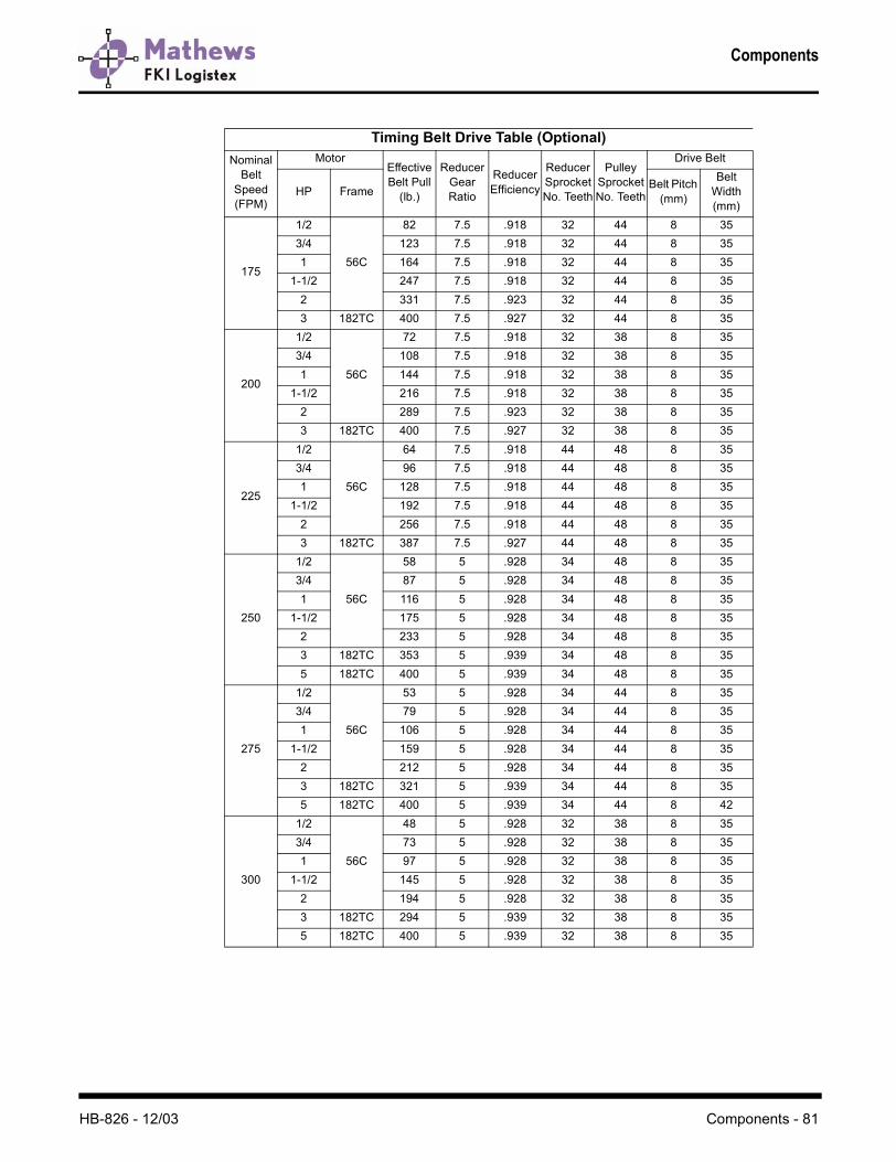
Components
Timing Belt Drive Table (Optional)Nominal
Belt Speed (FPM)
MotorEffective Belt Pull
(lb.)
Reducer Gear Ratio
Reducer Efficiency
Reducer Sprocket No. Teeth
Pulley Sprocket No. Teeth
Drive Belt
HP Frame Belt Pitch (mm)
Belt Width (mm)
175
1/2
56C
82 7.5 .918 32 44 8 353/4 123 7.5 .918 32 44 8 351 164 7.5 .918 32 44 8 35
1-1/2 247 7.5 .918 32 44 8 352 331 7.5 .923 32 44 8 353 182TC 400 7.5 .927 32 44 8 35
200
1/2
56C
72 7.5 .918 32 38 8 353/4 108 7.5 .918 32 38 8 351 144 7.5 .918 32 38 8 35
1-1/2 216 7.5 .918 32 38 8 352 289 7.5 .923 32 38 8 353 182TC 400 7.5 .927 32 38 8 35
225
1/2
56C
64 7.5 .918 44 48 8 353/4 96 7.5 .918 44 48 8 351 128 7.5 .918 44 48 8 35
1-1/2 192 7.5 .918 44 48 8 352 256 7.5 .918 44 48 8 353 182TC 387 7.5 .927 44 48 8 35
250
1/2
56C
58 5 .928 34 48 8 353/4 87 5 .928 34 48 8 351 116 5 .928 34 48 8 35
1-1/2 175 5 .928 34 48 8 352 233 5 .928 34 48 8 353 182TC 353 5 .939 34 48 8 355 182TC 400 5 .939 34 48 8 35
275
1/2
56C
53 5 .928 34 44 8 353/4 79 5 .928 34 44 8 351 106 5 .928 34 44 8 35
1-1/2 159 5 .928 34 44 8 352 212 5 .928 34 44 8 353 182TC 321 5 .939 34 44 8 355 182TC 400 5 .939 34 44 8 42
300
1/2
56C
48 5 .928 32 38 8 353/4 73 5 .928 32 38 8 351 97 5 .928 32 38 8 35
1-1/2 145 5 .928 32 38 8 352 194 5 .928 32 38 8 353 182TC 294 5 .939 32 38 8 355 182TC 400 5 .939 32 38 8 35
HB-826 - 12/03 Components - 81

Components
Timing Belt Drive Table (Optional)Nominal
Belt Speed (FPM)
MotorEffective Belt Pull
(lb.)
Reducer Gear Ratio
Reducer Efficiency
Reducer Sprocket No. Teeth
Pulley Sprocket No. Teeth
Drive Belt
HP Frame Belt Pitch (mm)
Belt Width (mm)
325
1/2
56C
45 5 .928 34 38 8 353/4 67 5 .928 34 38 8 351 90 5 .928 34 38 8 35
1-1/2 134 5 .928 34 38 8 352 179 5 .928 34 38 8 353 182TC 272 5 .939 34 38 8 355 182TC 400 5 .939 34 38 8 35
350
1/2
56C
42 5 .928 38 38 8 353/4 62 5 .928 38 38 8 351 83 5 .928 38 38 8 35
1-1/2 125 5 .928 38 38 8 352 166 5 .928 38 38 8 353 182TC 252 5 .939 38 38 8 355 182TC 400 5 .939 38 38 8 35
375
1/2
56C
39 5 .928 40 38 8 353/4 58 5 .928 40 38 8 351 78 5 .928 40 38 8 35
1-1/2 116 5 .928 40 38 8 352 155 5 .928 40 38 8 353 182TC 236 5 .939 40 38 8 355 182TC 393 5 .939 40 38 8 35
400
1/2
56C
36 5 .928 44 40 8 353/4 55 5 .928 44 40 8 351 73 5 .928 44 40 8 35
1-1/2 109 5 .928 44 40 8 352 145 5 .928 44 40 8 353 182TC 221 5 .939 44 40 8 355 182TC 368 5 .939 44 40 8 35
Components - 82 HB-826 - 12/03

Components
C1239 End Roller / Take-Up Unit C1626 End Roller Unit
Note: Please list options
HOW TO ORDER
Quantity Code No. W Options
1 C1239 21” RG
For Use at Entrance End
For Use at Discharge End
HB-826 - 12/03 Components - 83

Components
CONVEYOR WIDTH Standard - 15”, 21”, 27”, 33” and 39” Between Frames.
CAPACITY Standard - 900# effective belt pull.
END ROLLER Standard - 3.50” dia. machine crowned roller with 1-1/16” hex axle and B1161-2 power service grease packed bearings.Option - Regreaseable end roller bearings are optional (add “RG” on How To Order).
SAFETY ROLLER Standard - 1.90” dia. x .065” (16 ga.) steel roller with B1020-2 grease packed bearings and 7/16” hex axle.
BELT Standard - Width is 3” less than the Between Frames dimension.For C1239 belt length required is 22”.For C1626 belt length required is 22”.
COUPLINGS Standard - Welded butt couplings.
Components - 84 HB-826 - 12/03

Components
C1264 Intermediate Take-UpC1510 Vertical Take-Up
Note: Please list options
HOW TO ORDER
Quantity Code No. W Options
1 C1264 21” ---
CONVEYOR WIDTH Standard - 15”, 21”, 27”, 33” and 39” Between Frames.
CAPACITY Standard - 900# effective belt pull.
TAKE-UP ROLLER Standard - 3.50” dia. machine crowned roller with 1-1/16” hex axle and B1161-2 power service grease packed bearings. Sides and bottom totally enclosed for safety.Option - Optional roller guard for C1264 only if take-up is accessible to personnel (add “PG” on How To Order).
BELT Standard - Width is 3” less than the Between Frame dimension.For C1264 belt length required is 29”.For C1510 belt length required is 5”.
BEARINGS Option - Regreaseable bearings are option (add “RG” on How To Order.
HB-826 - 12/03 Components - 85
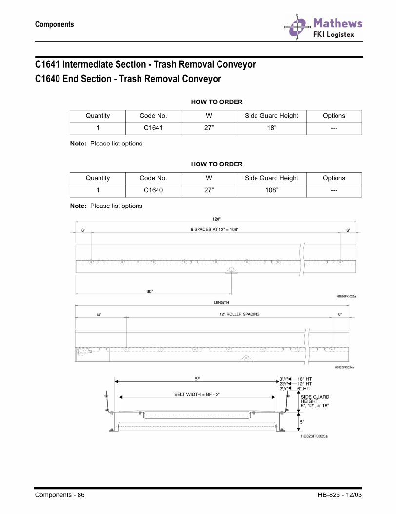
Components
C1641 Intermediate Section - Trash Removal ConveyorC1640 End Section - Trash Removal Conveyor
Note: Please list options
Note: Please list options
HOW TO ORDER
Quantity Code No. W Side Guard Height Options
1 C1641 27” 18” ---
HOW TO ORDER
Quantity Code No. W Side Guard Height Options
1 C1640 27” 108” ---
Components - 86 HB-826 - 12/03

Components
CONVEYOR WIDTH Standard - 27” through 45” Between Frames in 3” increments.
LENGTHS Standard - 10’-0” lengths.Option - End units 3’-0” through 10’-0” lengths, available in 1’-0” increments.
END ROLLER TAKE-UP Standard - 3.50” dia. machine crowned roller with 1-1/16” hex axle.
CARRYING ROLLERS Standard 1.90” dia. x .065” (16 ga.) steel rollers with B1020-2 grease packed bearings and 7/16” hex spring-loaded axles on 12” centers.
IDLER ROLLERS Standard - 1.90” dia. x .065” (16 ga.) steel rollers with grease packed bearings and 7/16” hex axles.Note: Idler rollers are designed into the frame rail of the trash removal conveyor. All intermediate sections and end sections over 5’-0” long have idler rollers.
BELT Standard - PVC 120 FS x FS. Width is 3” less than the Between Frames dimension. Belt length required is twice the conveyor length.
SIDE GUARDS Standard - Guards come in three standard heights: 6”, 12”, and 18”.
HB-826 - 12/03 Components - 87

Components
C1237 Conveyor Section
HOW TO ORDER
Quantity Code No. W Length Roller Spacing
1 C1237 21” 120” 6”
FRAME Standard - “PR” rail - 5” x 1-1/2” x .120” (11 ga.) formed steel channel.
WIDTHS Standard - 15”, 21”, 27”, 33” and 39” Between Frames.
LENGTHS Standard - 12” through 120” in 3” increments only.
CAPACITY Standard - 1000# per 10’-0” section.
ROLLERS Standard - 1.90” dia. x .065” (16 ga.) steel with B1020-2 grease packed bearings and 7/16” hex axles. Rollers are mounted 3/8” high.
ROLLER SPACING Standard - 3”, 6”, 9” or 12” for carrying rollers.
BELT Standard - Width is 3” less than the Between Frames dimension. Belt length required is twice the conveyor section length.
COUPLINGS Standard - Welded butt.
Components - 88 HB-826 - 12/03

Components
C1238 Slider Bed Sections
HOW TO ORDER
Quantity Code No. W Length
1 C1238 21” 120”
FRAME Standard - “PR” rail - 5” x 1-1/2” x .120” (11 ga.) formed steel channel.
WIDTHS Standard - 15”, 21”, 27”, 33” and 39” Between Frames.
LENGTHS Standard - 12” through 120” in 3” increments only.
CAPACITY 1000# per 10’-0” section.
SLIDER BED Standard - 14 ga. hot rolled steel.
BELT Standard - Width is 3” less than the Between Frames dimension. Belt length required is twice the conveyor section length.
COUPLINGS Standard - Welded butt.
HB-826 - 12/03 Components - 89

Components
C1267 Vertical Bend
HOW TO ORDER
Quantity Code No. W Option
1 C1267 21” ---
FRAME Standard - 5” x 1-1/2” x .120” (11 ga.) formed steel channel.
WIDTHS Standard - 15”, 21”, 27”, 33” and 39” Between Frames.
ROLLER Standard - 2.50” dia. x .120” (11 ga.) steel with B1064-2 grease packed bearings and 11/16” hex axle.Option - Regreaseable bearings are optional (add (“TG” on How To Order).
BELT Standard - Width is 3” less than the Between Frames dimension. Belt length required is 12” per unit.Note: 1 unit = 6-1/2°. For greater degrees, additional units are required. Use two for 13°, three for 20°, four for 26°.
COUPLINGS Standard - Welded butt.
Components - 90 HB-826 - 12/03
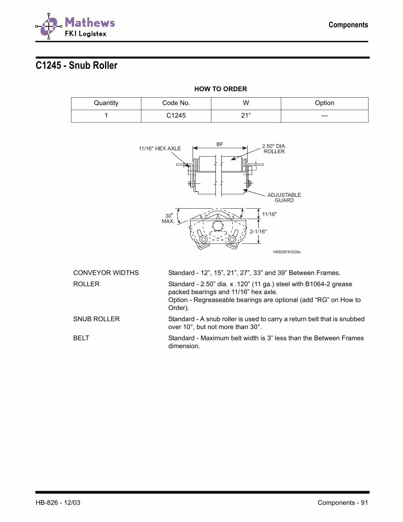
Components
C1245 - Snub Roller
HOW TO ORDER
Quantity Code No. W Option
1 C1245 21” ---
CONVEYOR WIDTHS Standard - 12”, 15”, 21”, 27”, 33” and 39” Between Frames.
ROLLER Standard - 2.50” dia. x .120” (11 ga.) steel with B1064-2 grease packed bearings and 11/16” hex axle.Option - Regreaseable bearings are optional (add “RG” on How to Order).
SNUB ROLLER Standard - A snub roller is used to carry a return belt that is snubbed over 10°, but not more than 30°.
BELT Standard - Maximum belt width is 3” less than the Between Frames dimension.
HB-826 - 12/03 Components - 91

Components
D10374 Bottom Closure
HOW TO ORDER
Quantity Code No. W Length
2 D10374 21” 117”
LENGTH Standard - 10’-0”.Option - 12” through 120” (in 3” increments).
MATERIAL Standard - 14 ga. sheet metal.
ASSEMBLY Standard - D10375 brackets with hardware provided on 24” centers.
Components - 92 HB-826 - 12/03
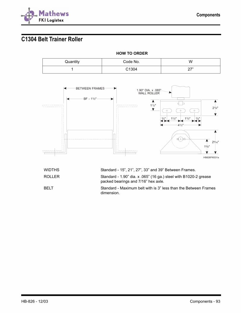
Components
C1304 Belt Trainer Roller
HOW TO ORDER
Quantity Code No. W
1 C1304 27”
WIDTHS Standard - 15”, 21”, 27”, 33” and 39” Between Frames.
ROLLER Standard - 1.90” dia. x .065” (16 ga.) steel with B1020-2 grease packed bearings and 7/16” hex axle.
BELT Standard - Maximum belt with is 3” less than the Between Frames dimension.
HB-826 - 12/03 Components - 93

Components
This assembly can be used to help track the belt on a short power feeder section of the belt conveyorper the examples.
Components - 94 HB-826 - 12/03

Components
C1304 Belt Trainer Roller
HOW TO ORDER
Quantity Code No. W
1 C1244 21”
WIDTHS Standard - 15”, 21”, 27”, 33” and 39” Between Frames.
ROLLER Standard - 1.90” dia. x .065” (16 ga.) steel with B1020-2 grease packed bearings and 7/16” hex axle.
IDLER ROLLER Standard - Idler roller used to carry a straight return belt snubbed no more than 10°. Idler roller spacing should not exceed 10’-0” centers.
BELT Standard - Maximum belt width is 3” less than the Between Frames dimension.
HB-826 - 12/03 Components - 95
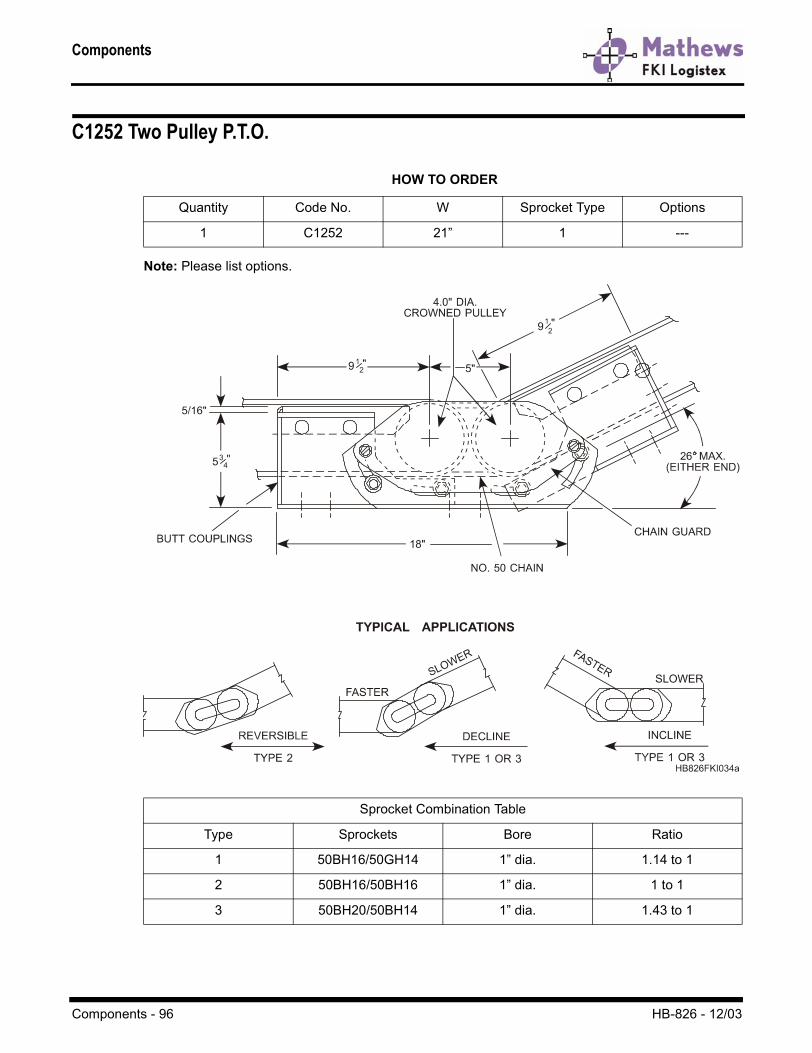
Components
C1252 Two Pulley P.T.O.
Note: Please list options.
HOW TO ORDER
Quantity Code No. W Sprocket Type Options
1 C1252 21” 1 ---
Sprocket Combination Table
Type Sprockets Bore Ratio
1 50BH16/50GH14 1” dia. 1.14 to 1
2 50BH16/50BH16 1” dia. 1 to 1
3 50BH20/50BH14 1” dia. 1.43 to 1
Components - 96 HB-826 - 12/03

Components
WIDTHS Standard - 15”, 21”, 27”, 33” and 39” Between Frames.
CAPACITY Standard - 275# effective belt pull.
BELT Standard - Width is 3” less than the Between Frames dimension.Belt length required is 25-1/2” each pulleyNote: Due to possible belt tracking problems, it is recommended that the minimum length of the level power feeder unit be three times the belt width for one way travel and five times the belt width for reversing service.
COUPLINGS Standard - Welded butt.
PULLEY Standard - 4.0” dia. crowned roller with pre-lubricated outboard flanged block bearings and 1-3/16” dia. shaft. The P.T.O. chain is totally enclosed for safety. The P.T.O. is furnished as shown for position of chain (near side). This unit is recommended for reversible operation. This unit may be used for incline or horizontal conveyors.Option - Opposite hand (add “OPP” on How To Order). Regreaseable flanged block bearings are optional (add “RG” on How To Order).Sprocket combination must be specified by type.
HB-826 - 12/03 Components - 97

Components
C1418 Three Roller Device
Note: Please list options.
Note: This unit is used for Incline or Decline Conveyors only.
HOW TO ORDER
Quantity Code No. W Options
1 C1418 21” ---
Components - 98 HB-826 - 12/03

Components
Note: Due to possible belt tracking problems, the following minimum power feeder lengths arerecommended.
Note: Not recommended for reversible operations.
WIDTHS Standard - 15”, 21”, 27”, 33” and 39” Between Frames.
CAPACITY Standard - 900# effective belt pull.
ROLLERS Standard - 3.50” dia. x .300” wall with power service grease packed bearings and 1-1/16” hex axle.
BELT Standard - Width is 3” less than the Between Frames dimension. Belt length required is 76”.Option - Regreaseable bearings are optional 9add “RG” on How To Order).
COUPLINGS Standard - Welded butt.
B.F. 15” 21” 27” 33” 39”
Belt Width 12” 18” 24” 30” 36”
Length 3’-0” 4’-0” 5’-0” 5’-0” 5’-0”
HB-826 - 12/03 Components - 99

Components
C1504 Power Take-Off
Note: Please list options.
Note: For use with Level Belt Conveyors only.
HOW TO ORDER
Quantity Code No. W Ratio Options
1 C1504 21” 1.25”1 ---
Components - 100 HB-826 - 12/03

Components
Standard speed ratios are shown in the table below. For other speed ratios consult the factory.
Note: Due to possible belt tracking problems the length of the metering belt conveyor should be five ormore times the width of the belting. Also, for units with less than a seven-to-one length to width ratio, itis recommended that the slider bed is used, and belting specifications be considered.
WIDTHS Standard - 15”, 21”, 27”, 33” and 39” Between Frames.
CAPACITY Standard - 275# effective belt pull.
PULLEY Standard - 4.0” dia. machine crowned roller with pre-lubricated flange block bearings and 1-3/16’ dia. shaft. The P.T.O. chain is totally enclosed for safety. The P.T.O. is furnished as shown with sprockets near side.Option - Opposite hand (add “OPP” on How To Order). Regreaseable bearings are optional (add “RG” on How To Order).
BELT Standard - Width is 3” less than the Between Frames dimension. Belt length required is 52”, (26” each side).
COUPLINGS Standard - Welded butt.
Sprocket Combination Table (Nominal)
Sprockets Bore Ratio
50GH14/50GH14 1” dia. 1:1
50BH14/50BH17 (Std.) 1” dia. 1.25:1
50BH14/50BH21 1” dia. 1.50:1
50BH14/50BH22 1” dia. 1.60:1
50BH14/50BH25 1” dia. 1.80:1
50BH14/50BH28 1” dia. 2:1
HB-826 - 12/03 Components - 101

Components
C1286 Slider Bed - Box Type Slider TreadNote: Assembles with standard drives, end rolls and supports.
Note: Please list options.
HOW TO ORDER
Quantity Code No. W Length Options
1 C1286 27” 120” C
FRAME Standard - 11 ga. (.120”) formed steel with formed angle cross braces.
WIDTHS Standard - 15”, 21”, 27”, 33” and 39” Between Frames. Overall width is Between Frames + 3-1/4”.
LENGTH Standard - 12” through 120” in 3” increments.
CAPACITY Standard - 1000 lbs. per 10’-0” maximum load.
BELT Standard - Maximum belt width is 3” less than the Between Frames dimension. Belt length required is twice the conveyor section length.
COUPLINGS Standard - Formed angle couplings and cross brace.Option - For hardware to attach end drive or end roller unit (order option “C” on How To Order) (Includes one pair formed angle couplings.)
Components - 102 HB-826 - 12/03
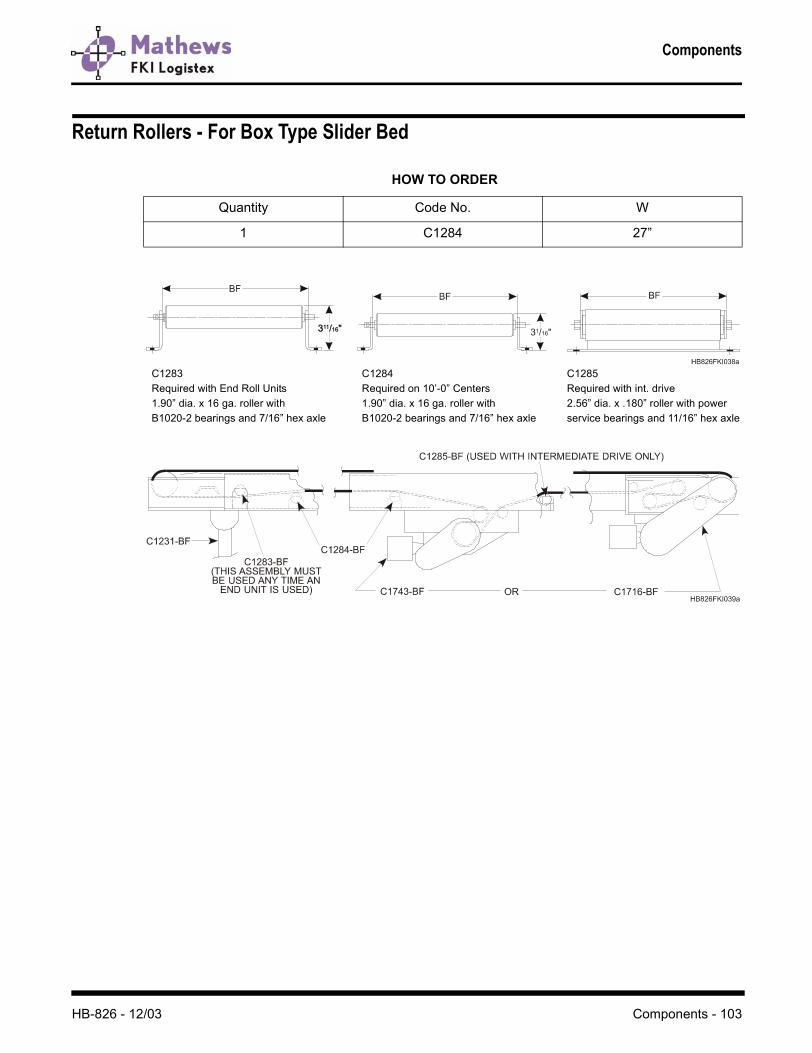
Components
Return Rollers - For Box Type Slider Bed
HOW TO ORDER
Quantity Code No. W
1 C1284 27”
C1283Required with End Roll Units1.90” dia. x 16 ga. roller withB1020-2 bearings and 7/16” hex axle
C1284Required on 10’-0” Centers1.90” dia. x 16 ga. roller withB1020-2 bearings and 7/16” hex axle
C1285Required with int. drive2.56” dia. x .180” roller with powerservice bearings and 11/16” hex axle
HB-826 - 12/03 Components - 103

Components
C1292 Intermediate Drive - Heavy Duty
Note: Please list options.
HOW TO ORDER
Quantity Code No. W Speed HP Voltage Options
1 C1292 33” 70 2 230 ---
Components - 104 HB-826 - 12/03

Components
CONVEYOR WIDTH Standard - 27”, 33”, 39”, 45”, 51” and 57” Between Frames.
CAPACITY Standard - 1500# effective belt pull, (5 HP maximum).
SPEED Standard - 70 FPM standard with 35 R.P.M reducer. Reducer has a 19H tooth sprocket, pulley has a 32 tooth sprocket. All driver sprockets have hardened teeth. See Motor/Reducer Selection Table on the next page for other standard speeds and horsepower requirements.Option - Other speeds available, consult factory.
DRIVE Standard - Furnished as shown for position of motor/reducer, unless specified opposite hand. This drive may be mounted under a level or inclined heavy duty conveyor and should be positioned so that the belt is “pulled” around the drive pulley first. The drive pulley and chain are totally enclosed for safety.Option - The top pulley guard is optional.
PULLEY Standard - 13.25” finished dia. straight faced lagged pulley with pre-lubricated outboard pillow block bearings and 2-7/16” dia. shaft.
BELT Standard - Width is 3” less than the Between Frames dimension. Belt length required is 42”.Option - Return belt guard that fits over the reducer mount is available.
BEARINGS Standard - All bearings are grease packed.
HB-826 - 12/03 Components - 105

Components
Standard Options for How To Order Call Up1 Opposite hand for location of motor/reducer OPP2 Regreaseable Bearings RG3 Brakemotor B4 Return belt guard for bottom guarding total drive assembly BG5 Top Pulley Guard PG
Motor/Reducer Selection Table
Nominal Belt Speed (FPM)
Belt Pull (lbs.)
H.P.Required
Nominal Reducer
Output (RPM)
Number of Teeth inReducer Sprocket
Chain Size
33760 1
22 15H60
1145 1-1/2 601500 2 80
40
630 1
22 17H
60955 1-1/2 601270 2 801500 3 100
50
520 1
29 16H
60780 1-1/2 601040 2 801500 3 100
60
440 1
29 19H
60655 1-1/2 60875 2 801355 3 100
70
565 1-1/2
35 19H
60750 2 801135 3 801500 5 100
80
495 1-1/2
35 22H
60665 2 801000 3 801500 5 100
110520 2
58 18H80
775 3 801305 5 100
Components - 106 HB-826 - 12/03

Components
C1300 and C1301 End Roll - Heavy Duty
Note: Please list options.
HOW TO ORDER
Quantity Code No. W Options
1 C1300 39” ---
CONVEYOR WIDTH Standard 27”, 33”, 39”, 45”, 51” and 57” Between Frames.
CAPACITY Standard - 1500# effective belt pull.
SAFETY ROLLER Standard - 1.90” dia. x .065” (16 ga.) steel roller with B1020-2 grease packed bearings and 7/16” hex axle.Option - Regreaseable flange block bearings are optional (add “RG” on How To Order).
PULLEY Standard - 6’-0” dia. crowned pulley with pre-lubricated outboard flanged bearings and 1-11/16” dia. shaft.
BELT Standard - Width is 3” less than the Between Frames dimension.For C1300, belt length required is 27”.For C1301, belt length required is 25”.
COUPLINGS Standard - Welded butt couplings.
HB-826 - 12/03 Components - 107

Components
C1404 Idler Roller - (For Heavy Duty Tread Section)
Note: Please list options.
HOW TO ORDER
Quantity Code No. W
1 C1404 39”
WIDTHS Standard - 27”, 33”, 39”, 45”, 51” and 57” Between Frames.
ROLLER Standard - 1.90” dia. x .065” (16 ga.) steel roller with B1020-2 grease packed bearings and 7/16” hex axle.
IDLER ROLLER Standard - Idler roller used to carry a straight return belt snubbed no more than 10°. Idler roller spacing should not exceed 10’-0” centers.
BELT Standard - Width is 3” less than the Between Frames dimension.
Components - 108 HB-826 - 12/03
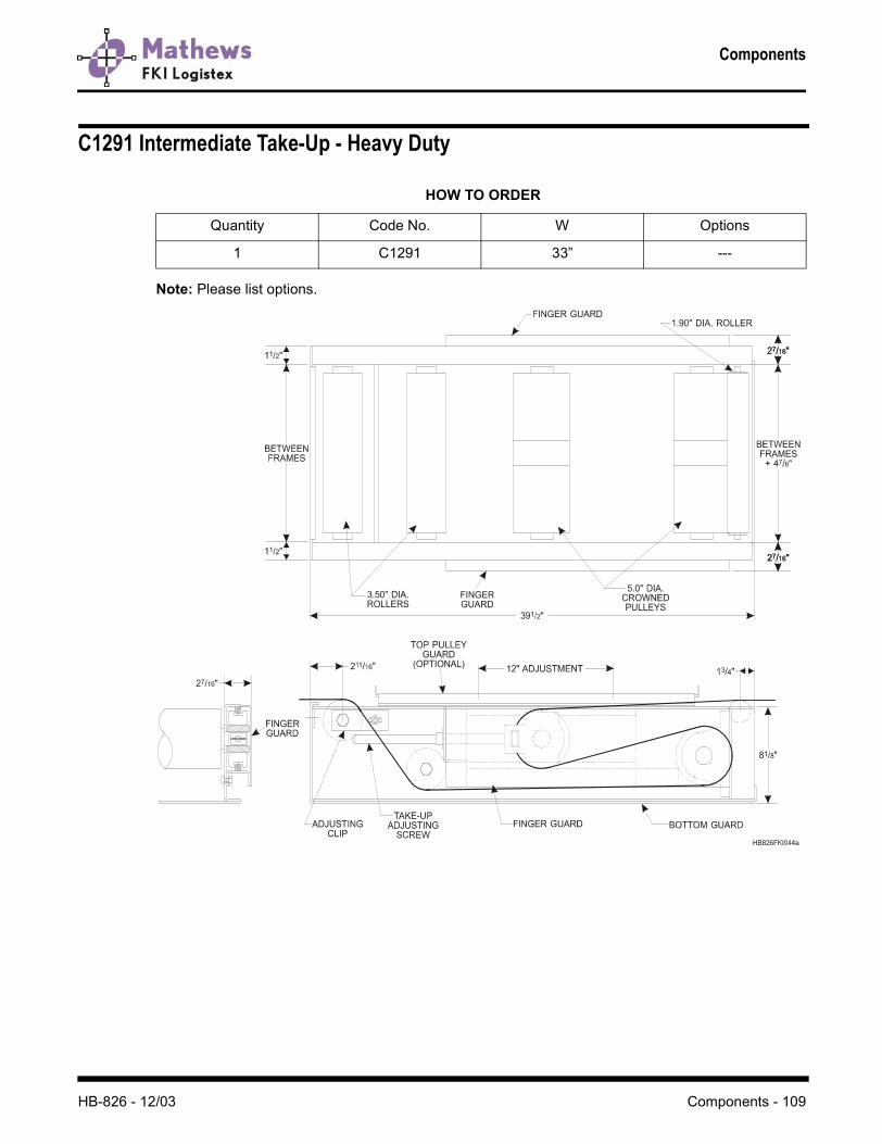
Components
C1291 Intermediate Take-Up - Heavy Duty
Note: Please list options.
HOW TO ORDER
Quantity Code No. W Options
1 C1291 33” ---
HB-826 - 12/03 Components - 109

Components
CONVEYOR WIDTHS Standard - 27”, 33”, 39”, 45”, 51” and 57” Between Frames.
CAPACITY Standard - 1500# effective belt pull.
TAKE-UP ROLLER Standard - 5’-0” dia. machine crowned roller with pre-lubricated outboard bearings and 1-11/16’ dia. shaft. Sides and bottom totally enclosed for safety.
PULLEY GUARD Option - Pulley guard on top is available if take-up is accessible to personnel (add “PG” on How To Order).
BELT Standard - Width is 3” less than the Between Frames dimension. Belt length required is 39”.
BEARINGS Option - Regreaseable bearings are optional (add “RG” on How To Order.)
Components - 110 HB-826 - 12/03

Components
C1298 Conveyor Section - Heavy Duty
HOW TO ORDER
Quantity Code No. W Length Roller Spacing
1 C1298 33” 120” 6”
FRAME Standard - 6” x 2” x .180” (7 ga.) formed steel channel.
WIDTHS Standard - 27”, 33”, 39”, 45”, 51” and 57” Between Frames.
LENGTHS Standard - 24” through 120” in 12” increments only.
CAPACITY Standard - Maximum load is 2000 lbs. per 10’-0” section.
ROLLERS Standard - 2.50” dia. x .120” (11 ga.) steel with B1064-2 grease packed bearings and 11/16” hex axles. Rollers are mounted 3/8” high.
ROLLER SPACING Standard - 6”, 9” or 12” for carrying rollers.
BELT Standard - Width is 3” less than the Between Frame dimension.Belt length required is twice the conveyor section length.
COUPLINGS Standard - Welded butt.
HB-826 - 12/03 Components - 111

Components
C1297 - Vertical Bend - Heavy Duty
Note: Please list options.
HOW TO ORDER
Quantity Code No. W Options
3 C1297 45” ---
FRAME Standard - 6” x 2” x .180” (7 ga.) formed steel channel.
WIDTHS Standard - 27”, 33”, 39”, 45”, 51” and 57” Between Frames.
ROLLER Standard - 2.50” dia. x .120” (11 ga.) steel with B1064-2 grease packed bearings and 1/16” hex axle.Option - Regreaseable bearings are optional (add “RG” on How to Order).
BELT Standard - Width is 3” less than the Between Frames dimension. Belt length required is 12” per unit.Note: 1 unit = 6-1/2°. For greater degrees, additional units are required. Use two for 13°, three for 20°, four for 26°.
COUPLINGS Standard - Welded butt.
Components - 112 HB-826 - 12/03

Components
C1245 - Snub Roller
Note: Please list options.
HOW TO ORDER
Quantity Code No. W Options
3 C1245 27” ---
CONVEYOR WIDTHS Standard - 27”, 33”, 39”, 45”, 51” and 57” Between Frames.
ROLLER Standard - 2.50” dia. x .120” (11 ga.) steel with B1064-2 grease packed bearings and 11/16” hex axle.Option - Regreaseable bearings are optional (add “RG” on How To Order).
SNUB ROLLER Standard - A snub roller is used to carry a return belt that is snubbed over 10°, but nor more than 30°.
BELT Standard - Maximum belt width is 3” less than the Between Frames dimension.
HB-826 - 12/03 Components - 113

Components
C1299 Two Pulley P.T.O. - Heavy Duty
Note: Please list options.
HOW TO ORDER
Quantity Code No. W Sprocket type Options
1 C1299 33” 1 ---
Components - 114 HB-826 - 12/03

Components
Sprocket combinations must be specified by type.
Note: Due to possible belt tracking problems, the following are minimum recommended lengths forpower feeders driven by the P.T.O.
One Way Travel = 3 x Belt WidthReversible Travel = 5 x Belt Width
WIDTHS Standard - 27”, 33”, 39”, 45”, 51” and 57” Between Frames.
CAPACITY Standard - 400# effective belt pull.
BELT Standard - Width is 3” less than the Between Frames dimension.Belt length required is 26-1/2” each pulley
COUPLINGS Standard - Welded butt.
PULLEY Standard - 6’-0” dia. crowned pulley with pre-lubricated outboard flanged block bearings and 1-11/16” dia. shaft. This unit may be used for incline or horizontal conveyors.Option - Regreaseable flanged block bearings are optional (add “RG” on How To Order).
P.T.O. Standard - P.T.O. chain is totally enclosed for safety. Furnished as shown.Option - For opposite hand (add “OPP” on How To Order).
Sprocket Combination Table
Type Sprockets Bore Ratio
1 60BH16/60GH14 1-11/16” dia. 1.14 to 1
2 60BH16/60BH16 1-11/16” dia. 1 to 1
HB-826 - 12/03 Components - 115

Components
C1296 - Three Pulley Device - Heavy Duty
Note: Please list options.
Notes:1. Type C695 Support can be used with horizontal or inclined unit. Specify support between frames
as (conveyors W + 7/8”).2. Type C699 Support can only be used with horizontal unit. Specify support to be used with 6” rail.
HOW TO ORDER
Quantity Code No. W Options
1 C1296 39” ---
Components - 116 HB-826 - 12/03

Components
Note: Due to possible belt tracking problems, the following are minimum recommended lengths forpower feeders incorporating this 3 Pulley Device.
Note: Not recommended for reversible operations.
WIDTHS Standard - 27”, 33”, 39”, 45”, 51” and 57” Between Frames.
CAPACITY Standard - 1500# effective belt pull.
RETURN ROLLERS Standard - 3.50” dia. x .300” wall with power service grease packed bearings and 1-1/16” hex axle.Option - Regreaseable bearings are optional (add “RG” on How To Order).
PULLEYS Standard - 6.0” dia. crowned pulley with pre-lubricated outboard flanged block bearings and 1-11/16” dia. shaft.
BELT Standard - Width is 3” less than the Between Frames dimension. Belt length required is 98”.
COUPLINGS Standard - Welded butt.
B.F. 27” 33” 39” 45” 51” 57
Power Feeder Min. Lengths
5’-0” 5’-0” 5’-0” 6’-0” 6’-0” 7’-0”
HB-826 - 12/03 Components - 117

Components
Components - 118 HB-826 - 12/03

Supports
SupportsC1230 Floor Single Leg Floor Support - 750 Pound CapacityC1231 Floor Support - 1500 Pound CapacityFor use with AR, CR and PR Channel Frame Rails
*SL denotes single leg
HOW TO ORDER
Description Quantity Code No. W Nominal Height
Knee Brace(if required)
Single Leg 1 C1230 SL* 28” KB
Double Leg 1 C1231 21” 34” KB
3 Rail 3 3C1231 33” 16” No
Nominal Heights 2-1/8”, ± 1-1/2” Adjustment Nominal Heights 5-1/2”, ± 1-1/2” Adjustment
Nominal Heights 7-3/4”, ± 2-1/4” Adjustment Nominal Heights 11-1/2”, ± 1-1/2” Adjustmen
HB-826 - 12/03 Supports - 119
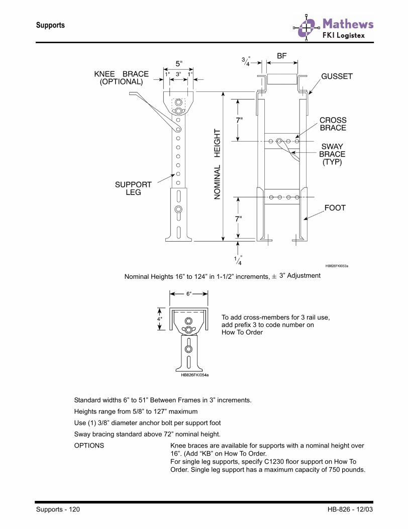
Supports
Standard widths 6” to 51” Between Frames in 3” increments.
Heights range from 5/8” to 127” maximum
Use (1) 3/8” diameter anchor bolt per support foot
Sway bracing standard above 72” nominal height.
OPTIONS Knee braces are available for supports with a nominal height over 16”. (Add “KB” on How To Order.For single leg supports, specify C1230 floor support on How To Order. Single leg support has a maximum capacity of 750 pounds.
Nominal Heights 16” to 124” in 1-1/2” increments, ± 3” Adjustment
To add cross-members for 3 rail use,add prefix 3 to code number onHow To Order
Supports - 120 HB-826 - 12/03

Supports
Available in 1-1/2” increments.
Support Selection TableNominalHeight Minimum Height Maximum Height Adjustment Cross Brace
2-1/8” 5/8” 3-5/8” 3” 05-1/2” 4” 7” 3” 17-3/4” 5-1/2” 10” 4-1/2” 111-1/2” 10” 13” 3” 1
13” 11-1/2” 14-1/2” 3” 116” 13” 19” 6” 119” 16” 22” 6” 122” 19” 25” 6” 125” 22” 28” 6” 228” 25” 31” 6” 231” 28” 34” 6” 234” 31” 37” 6” 237” 34” 40” 6” 240” 37” 43” 6” 243” 40” 46” 6” 246” 43” 49” 6” 249” 46” 52” 6” 252” 49” 55” 6 255” 52” 58” 6” 358” 55” 61” 6” 361” 58” 64” 6” 364” 61” 67” 6” 367” 64” 70” 6” 370” 67” 73” 6” 473” 70” 76” 6” 476” 73” 79” 6” 479” 76” 82” 6” 482” 79” 85” 6” 485” 82” 88” 6” 488” 85” 91” 6” 491” 88” 94” 6” 494” 91” 97” 6” 497” 94” 100” 6” 4100” 97” 103” 6” 4103” 100” 106” 6” 4106” 103” 109” 6” 4109” 106” 112” 6” 4112” 109” 115” 6” 4115” 112” 118” 6” 4118” 115” 121” 6” 4121” 118” 124” 6” 4124” 121” 127” 6” 4
HB-826 - 12/03 Supports - 121
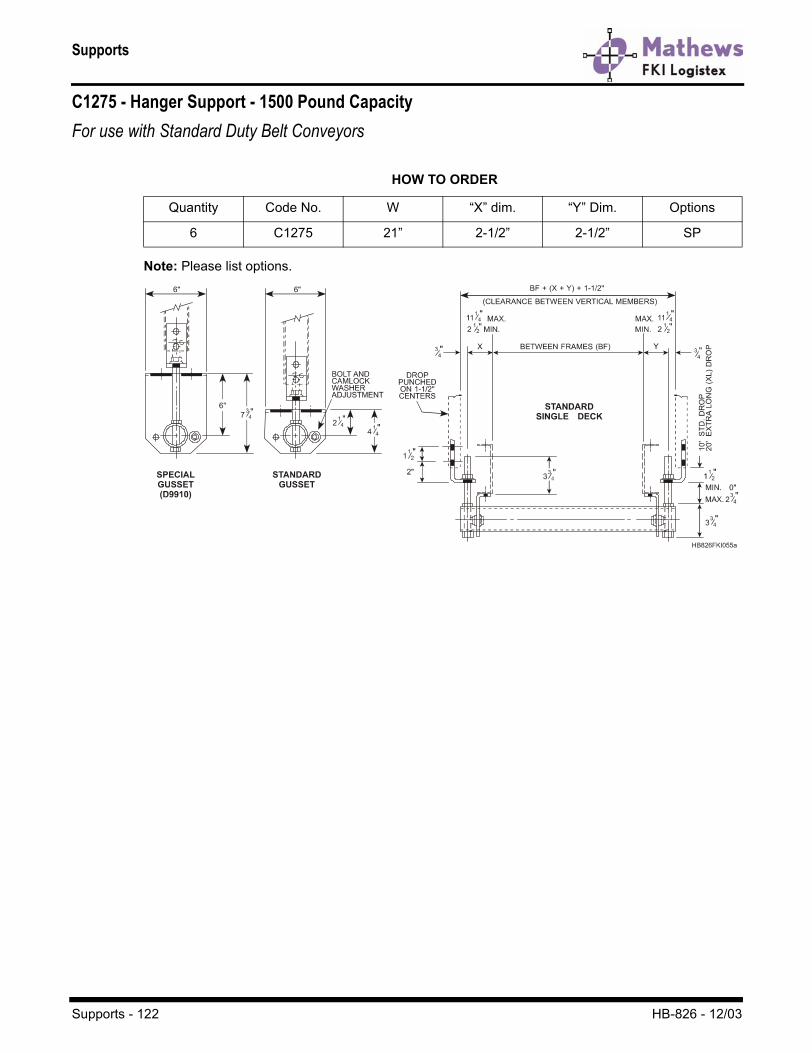
Supports
C1275 - Hanger Support - 1500 Pound CapacityFor use with Standard Duty Belt Conveyors
Note: Please list options.
HOW TO ORDER
Quantity Code No. W “X” dim. “Y” Dim. Options
6 C1275 21” 2-1/2” 2-1/2” SP
Supports - 122 HB-826 - 12/03

Supports
HB-826 - 12/03 Supports - 123

Supports
WIDTH Standard - 15” through 39” Between Frames in 3” increments.
VERTICAL MEMBERS Standard - 2-1/2” x 1” x .109” (12 ga.) formed channel. Standard length is 10’-0”. Extra long length is 20’-0” (add “XL” in How To Order). Maximum clearance between vertical members = W + X + Y 1-1/2” = 63”.
HORIGONAL MEMBER Standard - 2.50” x .120” wall tubing.Option - D9910 Spacer for use with VBLR and line shaft conveyors (add “SP” in How To Order).
ADJUSTING BOLT Standard - 5/8” dia. threaded rod, 2-3/4” adjustment.
SPECIAL NOTE This support may be used for single or multiple decks. Maximum load capacity per deck is 1500# and maximum load capacity per support is 3000#. Attachments to overhead structures to be supplied by purchaser, and must be sufficient to develop the full capacity of the support.The following are “optional” and must be ordered separately: D2835 - Top Bracket (750# capacity each) D2834 - Cross member D2832 - Splice Coupling D921 - BraceTo order additional hardware for second deck, order as C1275-W-X-Y-omit D2452 Drops.
NOTES 1. Vertical members shipped in nominal 10’-0” (std) or 20’-0” (XL) lengths. Cut to proper length in the field.2. All components shipped loose.
Supports - 124 HB-826 - 12/03

Supports
C686 - Hanger Support - 750 Pound CapacityFor use with Standard Duty Belt Conveyors
HOW TO ORDER
Quantity Code No. W “X” Dim. “Y” Dim. Options
3 C686 21” 2-1/2” 2-1/2” ---
WIDTHS Standard - 15” through 39” Between Frames in 3” increments.
VERTICAL MEMBERS Standard - 1/2” dia. threaded rod 10’-0” long.Option - 20’0” rod length (add “XL” in How To Order).
HORIZONTAL MEMBERS Standard - 3-1/2” x 1-1/2” x 11 ga. channel. Maximum Width = W + X + Y + 1-1/2” = 52-1/2”.Option - D2998 Spacer (3-1/2” wide) for use with VBLR and line shaft conveyors (add “SP” in How To Order).
NOTES 1. Attachment to overhead structure to be supplied by purchaser and must be sufficient to develop the full capacity of the support.
2. Vertical members shipped in nominal 10’-0” lengths. Cut to proper length in the field.
3. All components shipped loose.
HB-826 - 12/03 Supports - 125

Supports
C693, C694, C695, C696 Floor Support - 3000 Pounds CapacityFor use with Heavy Duty Conveyors
*SL denotes single leg.
HOW TO ORDER
Description Quantity Code No. W Nominal Height
Single Leg 3 C695 SL* 25”
Double Leg 7 C696 33” 43”
3 Rail 5 3C695 27” 26”
Nominal Heights 13” to 119”, ± 1-1/2” Adjustment
Supports - 126 HB-826 - 12/03

Supports
WIDTHS Standard - 27” through 57” Between Frames
HEIGHTS Standard - 2-7/8” to 121-1/4” maximum
KNEE BRACES Standard - Knee braces are standard at 23” nominal height and above.Use (1) 3/8” diameter anchor bolt per support foot.
Code No. NominalHeight Minimum Height Maximum
Height Adjustment Cross Brace
C6943” 2-7/8” 3-3/4” 7/8” 04” 3-7/8” 4-3/4” 7/8” 05” 4-7/8” 5-3/4” 7/8” 0
C693 6” 5-5/8” 7-1/8” 1-1/2” 18” 7-1/8” 8-5/8” 1-1/2” 19” 8-5/8” 10-1/8’ 1-1/2” 111” 10-1/8” 11-5/8” 1-1/2” 112” 11-5/8” 13-1/8” 1-1/2” 1
C695
13” 11-3/4” 14-3/4” 3” 114” 13-1/4” 16-1/4” 3” 116” 14-3/4” 17-3/4” 3” 117” 16-1/4” 19-1/4” 3” 119” 17-3/4” 20-3/4” 3” 120” 19-1/4” 22-1/4” 3” 122” 20-3/4” 23-3/4” 3” 223” 22-1/4” 25-1/4” 3” 225” 23-3/4” 26-3/4” 3” 226” 25-1/4” 28-1/4” 3” 228” 26-3/4” 29-3/4” 3” 229” 28-1/4” 31-1/4” 3” 2
C696
31” 29-3/4” 32-3/4” 3” 232” 31-1/4” 34-1/4” 3” 234” 32-3/4” 35-3/4” 3” 235” 34-1/4” 37-1/4” 3” 237” 35-3/4” 38-3/4” 3” 238” 37-1/4” 40-1/4” 3” 240” 38-3/4” 41-3/4” 3” 241” 40-1/4” 43-1/4” 3” 243” 41-3/4” 44-3/4” 3” 244” 43-1/4” 46-1/4” 3” 246” 44-3/4” 47-3/4” 3” 247” 46-1/4” 49-1/4” 3” 249” 47-3/4” 50-3/4” 3” 250” 49-1/4” 52-1/4” 3” 3
HB-826 - 12/03 Supports - 127

Supports
C696
52” 50-3/4” 53-3/4” 3” 353” 52-1/4” 55-1/4” 3” 355” 53-3/4” 56-3/4” 3” 356” 55-1/4” 58-1/4” 3” 358” 56-3/4” 59-3/4” 3” 359” 58-1/4” 61-1/4” 3” 361” 59-3/4” 62-3/4” 3” 362” 61-1/4” 64-1/4” 3” 364” 62-3/4” 65-3/4” 3” 365” 64-1/4” 67-1/4” 3” 367” 65-3/4” 68-3/4” 3” 368” 67-1/4” 70-1/4” 3” 370” 68-3/4” 71-3/4” 3” 371” 70-1/4” 73-1/4” 3” 373” 71-3/4” 74-3/4” 3” 374” 73-1/4” 76-1/4” 3” 476” 74-3/4” 77-3/4” 3” 477” 77-1/4” 79-1/4” 3” 479” 77-3/4” 80-3/4” 3” 480” 79-1/4” 82-1/4” 3” 482” 80-3/4” 83-3/4” 3” 483” 82-1/4” 85-1/4” 3” 485” 83-3/4” 86-3/4” 3” 486” 85-1/4” 88-1/4” 3” 488” 86-3/4” 89-3/4” 3” 489” 88-1/4” 91-1/4” 3” 491” 89-3/4” 92-3/4” 3” 492” 91-1/4” 94-1/4” 3” 494” 92-3/4” 95-3/4” 3” 495” 94-1/4” 97-1/4” 3” 497” 95-3/4” 98-3/4” 3” 498” 97-1/4” 100-1/4” 3” 4100” 98-3/4” 101-3/4” 3” 4101” 100-1/4” 103-1/4” 3” 4103” 101-3/4” 104-3/4” 3” 4104” 103-1/4” 106-1/4” 3” 4106” 104-3/4” 107-3/4” 3” 4107” 106-1/4” 109-1/4” 3” 4109” 107-3/4” 110-3/4” 3” 4110” 109-1/4” 112-1/4” 3” 4112” 110-3/4” 113-3/4” 3” 4113” 112-1/4” 115-1/4” 3” 4
Code No. NominalHeight Minimum Height Maximum
Height Adjustment Cross Brace
Supports - 128 HB-826 - 12/03

Supports
C696
115” 113-3/4” 116-3/4” 3” 4116” 115-1/4” 118-1/4” 3” 4118” 116-3/4” 119-3/4” 3” 4119” 118-1/4” 121-1/4” 3” 4
Code No. NominalHeight Minimum Height Maximum
Height Adjustment Cross Brace
HB-826 - 12/03 Supports - 129

Supports
Supports - 130 HB-826 - 12/03

Accessories
AccessoriesC1276 Straight Adjustable Guard RailFor Use with Standard Duty Belt Conveyors
HOW TO ORDER
Quantity Code No. W Length Option
1 C1276 21” 120” 12” Double High
LENGTH Standard - 10’-0”, odd lengths cut in field.WIDTHS Standard - 15”, 21”, 27”, 33” and 39” Between FramesAll components galvanized.C1276 guards include rail both sides, four posts, four sets of clips, two splice plates and two post support tubes.OPTION Double high “Y” DIM = 6”, 9” or 12” (includes 4 rails).
HB-826 - 12/03 Accessories - 131

Accessories
C1443 Angle Guard Rail
HOW TO ORDER C1443 ANGLE GUARD (Example):
Quantity Code No. Length Length
1 C1443 3” 120”
LENGTH Standard - 10’0” (odd length cut in field).HEIGHTS 3”, 6”, 9” and 12”.Galvanized finish standard.C1443 guards (includes 2 rails).For one side only, order D1443-HT-120.
Accessories - 132 HB-826 - 12/03

Accessories
C1303 Channel Guard Rail
Note: Please list options.
HOW TO ORDER C1303 CHANNEL GUARD (Example):
Quantity Code No. Length Option
4 C1303 120” B
LENGTH Standard - 10’0” (odd length cut in field).PAINT Standard - Standard paint (except guard face).
C1303 guard (includes 2 rails).COUPLINGS Option - Welded butt couplings (add “B” to How To Order).
HB-826 - 12/03 Accessories - 133

Accessories
C1249 Vertical Bend Guard
HOW TO ORDER
Quantity Code No. Degrees
4 C1249 19-1/2°
DEGREES Standard - 6-1/2°, 13°, 19-1/2° and 26°.C1249 (includes 2 guard assemblies, 1 per side).Galvanized finish standard.
Accessories - 134 HB-826 - 12/03

Component Belt Length Requirement
Component Belt Length RequirementTo determine the length of belting required for a conveyor, add the lengths shown in the following tablefor each of the components required for the conveyor.
Code Number Description Belt Length RequiredC1237 Conveyor Section Twice Conveyor Section
LengthC1238 Slider Bed Conveyor Section Twice Conveyor Section
LengthC1239 End Roller / Take-Up Unit 22”C1626 End Roller Unit 22”C1743 Intermediate Drive 33”C1252 Two Pulley PTO 25-1/2” Each SideC1264 Intermediate Take-Up 29”C1267 Vertical Bend Unit 12”C1418 Three Roller Device 76”C1700 Low Profile Intermediate Drive 30”C1504 PTO 26” Each SideC1510 Take-Up 5”C1716
C1721-NTEnd Drive with Take-Up
End Drive without Take-Up66”50”
C1721C1721-NT
Low Profile End Drive with Take-UpLow Profile End Driver without Take-Up
66”50”
C1291 Heavy Duty Intermediate Take-Up 39”C1292 Heavy Duty Intermediate Drive 42”C1296 Heavy Duty Three Pulley Device 98”C1297 Heavy Duty Vertical Bend 12” Each UnitC1298 Heavy Duty Conveyor Section Twice Conveyor Section
LengthC1299 Heavy Duty Two Pulley PTO 26-1/2” Each PulleyC1300 Heavy Duty End Roller / Take-Up Unit 27”C1301 Heavy Duty End Roller / Take-Up Unit 25”
HB-826 - 12/03 Component Belt Length Requirement - 135

Component Belt Length Requirement
Component Belt Length Requirement - 136 HB-826 - 02/03
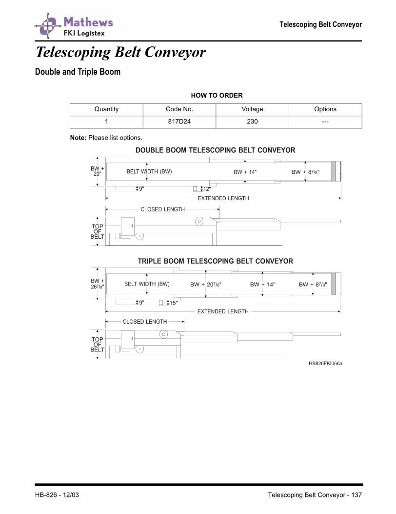
Telescoping Belt Conveyor
Telescoping Belt ConveyorDouble and Triple Boom
Note: Please list options.
HOW TO ORDER
Quantity Code No. Voltage Options
1 817D24 230 ---
HB-826 - 12/03 Telescoping Belt Conveyor - 137

Telescoping Belt Conveyor
CAPACITY Standard - 100 pounds per foot live load.
SPEED Standard - 80 FPMOption - 30 to 150 FPM
DRIVE Standard - Fully enclosed, oil bath lubricated gearmotor.
GUARDS Standard - Guards and covers provided on all drives, take-ups and other moving parts.
SAFETY FEATURES Standard - Safety pop-up transition at boom end to prevent injury. Slider plate at boom end to allow bundle to stop before handling. Emergency stop at boom end. Motor mounted brake on boom drive to prevent drift of booms.
HORSEPOWER Standard - Double boom has a 2 HP belt motor and 3/4”HP boom motor. Triple boom has a 3 HP belt motor and 1 HP boom motor.
BELT Standard - PVK-120-COS laced belt.Option - Belt width can be specified from 12” to 36” wide.
STRUCTURE Standard - Welded structural channel construction.
SHIPPING Standard - Shipped fully assembled and wired.
FIHISH Standard - As specified.
OPTIONS Available on all models.1. Reversing belt drive (REV).2. Hydraulic control on front or rear of unit (HYD CON).3. Elevating control pushbutton at end of boom (ELEV PB).4. Portable for use on a track system: Manual (MAN) or Powered
Drive (PWR).5. 3 ft. long powered conveyor belt (stacker) mounted on boom end
and powered 30° up and down (STKR).6. Powered incline or decline conveyor mounted on top of base
(INCL/DECL).
POWER Standard - Power normally 230/460 volts, 3 phase, 60 hertz.
Telescoping Belt Conveyor - 138 HB-826 - 12/03

Telescoping Belt Conveyor
STANDARD DOUBLE BOOM SPECIFICATIONS
Code No. Closed Length
Extended Length
Boom Extension
BeltWidth
BaseWidth
Approx. Weight
817D24 8’-3” 17’-0” 9’-0” 24” 44” 2500#1021D24 10’-3” 21-’0” 11’-0” 24” 44” 3700#1225D24 12’-3” 25’-0” 13’-0” 24” 44” 4000#1328D24 13’-3” 28’-0” 15’-0” 24” 44” 4400#1431D24 14’-3” 31’-0” 17’-0” 24” 44” 4900#1534D24 15’-3” 34’-0” 19’-0” 24” 44” 5400#1637D24 16’-3” 37’-0” 21’-0” 24” 44” 5700#1740D24 17’-3” 40’-0” 23’-0” 24” 44” 6000#1843D24 18’-3” 43’-0” 25’-0” 24” 44” 6400#1946D2D 19’-3” 46’-0” 27’-0” 24” 44” 6800#2049D24 20’-3” 49’-0” 29’-0” 24” 44” 7100#2560D24 25’-3” 60’-0” 35’-0” 24” 44” 7500#
STANDARD TRIPLE BOOM SPECIFICATIONS
Code No. Closed Length
Extended Length
Boom Extension
BeltWidth
BaseWidth
Approx. Weight
1030T24 10’-3” 30’-0” 20’-0” 24” 51” 5200#1134T24 11’-3” 34’-0” 23’-0” 24” 51” 5300#1238T24 12’-3” 38’-0” 26’-0” 24” 51” 5600#1340T24 13’-3” 40’-0” 27’-0” 24” 51” 5900#1444T24 14’-3” 44’-0” 30’-0” 24” 51” 6400#1548T24 15’-3” 48’-0” 33’-0” 24” 51” 6800#1650T24 16’-3” 50’-0” 34’-0” 24” 51” 7200#1754T24 17’-3” 54’-0” 37’-0” 24” 51” 7500#1858T24 18’-3” 58’-0” 40’-0” 24” 51” 8200#1961T24 19’-3” 61’-0” 42’-0” 24” 51” 8900#2065T24 20’-3” 65’-0” 45’-0” 24” 51” 9200#2169T24 21’-3” 69’-0” 48’-0” 24” 51” 9800#
HB-826 - 12/03 Telescoping Belt Conveyor - 139

Telescoping Belt Conveyor
Telescoping Belt Conveyor - 140 HB-826 - 12/03

Flat Belt Curves
Flat Belt CurvesPowered Belt Curves
Note: Please list options.
HOW TO ORDER
Quantity Code No. Degree Speed Drive Location HP Electrical
Specs. Options
1 A3610 90° 70 RO 1/2 230V - 3 PH Floor Supports 30”
TOB
HB-826 - 12/03 Flat Belt Curves - 141

Flat Belt Curves
FRAME Standard - 12 ga. formed teel.
CAPACITY Standard - 40 lbs. per foot at centerline. with relief rollers, 75 lbs. per foot at centerline.
DRIVE SYSTEM Standard - Shaft mounted gear reducer with open drip proof flange mounted motor. Normal mounting at outside radius discharge end. (RO or LO position as shown.)Option - totally enclosed, fan cooled motor. Explosion prof motor.
BELT Standard - Black SBR-FIT. Temperature range 20° to 225° F.Option - special belting available.
DEGREE Standard - 30° to 180°.
SPEED Standard - Fixed speeds from 5 FPM to 170 FPM. Measured at the center of the belt.Option - Variable and other fixed speeds.
Live Load Capacity at 70 FPMHP Live Load1/2 150#3/4 250#1 350#
Flat Belt Curves - 142 HB-826 - 12/03

Flat Belt Curves
Belt Conveyor CurvesCurveCode
Number
“A”Inside Radius
“B” Centerline
Radius
“C” Outside Conveying
Radius
“D”Outside Radius
“E”Effective
Belt Width
“G”Frame Height
Minimum Product Length
AAA-224-206-188
-1610-1412-1214
22”20”18”16”14”12”
25”24”23”22”21”20”
27” 30-1/2”
4”6”8”10”12”14”
6-1/2” 10”
*
AA-306-288
-2610AA-2412
-2214-2016
30”28”26”24”22”20”
34”33”32”31”30”29”
37” 40-1/2”
6”8”10”12”14”16”
8-1/2” 12”
A-406-388
-3610-3412-3214
40”38”36”34”32”
44”43”42”41”40”
47” 50-1/2”
6”8”10”12”14”
8-1/2” 14”
*
*
A-3016A-2818
-2620-2422
A-2224
30”28”26”24”22”
39”38”37”36”35”
47” 50-1/2”
16”18”20”22”24”
8-1/2” 14”
B-4612-4414-4216-4018-3820-3622-3424
46”44”42”40”38”36”34”
53”52”51”50”49”48”47”
59” 62-1/2”
12”14”16”18”20”22”24”
9” 14”
*
*
*
B-3226-3028
B-2830-2632-2434
B-2236
32”30”28”26”24”22”
46”45”44”43”42”41”
59” 62-1/2”
26”28”30”32”34”36”
9” 14”
C-7610-7412-7214-7016-6818-6620-6422-6224-6026
76”74”72”70”68”66”64”62”60”
82”81”80”79”78”77”76”75”74”
87” 90-1/2”
10”12”14”16”18”20”22”24”26”
10” 14”
HB-826 - 12/03 Flat Belt Curves - 143

Flat Belt Curves
*90° units in bolt print offer best delivery.
*
*
C-5828-5630
C-5432-5234
C-5036
58”56”54”52”50”
73”72”71”70”69”
87” 90-1/2”
28”38”32”34”36”
10” 14”
C-4838-4640-4442-4244-4046-3848
48”46”44”42”40”38”
68”67”66”65”64”63”
87” 90-1/2”
38”40”42”44”46”48”
12” 18”
SUPPORT OPTIONS 1. Minimum Heights (G) shown in table on previous page.2. Non-adjustable floor supports are available form minimum height
to 21” top of elevation.3. Adjustable floor supports are available from 21” top of belt
elevation and up and are adjustable ± 1”.4. Ceiling support brackets are available.5. Add support type and required elevation to How To Order under
Options.
SIDE GUARD OPTIONS 1. Standard heights of 6”, 12”, 18” and 24’.2. Inside and Outside available.3. Optional guards are 14 gage steel, rolled to match the belt curve
with a 1” flange on top turned out.
Belt Conveyor CurvesCurveCode
Number
“A”Inside Radius
“B” Centerline
Radius
“C” Outside Conveying
Radius
“D”Outside Radius
“E”Effective
Belt Width
“G”Frame Height
Minimum Product Length
Flat Belt Curves - 144 HB-826 - 12/03
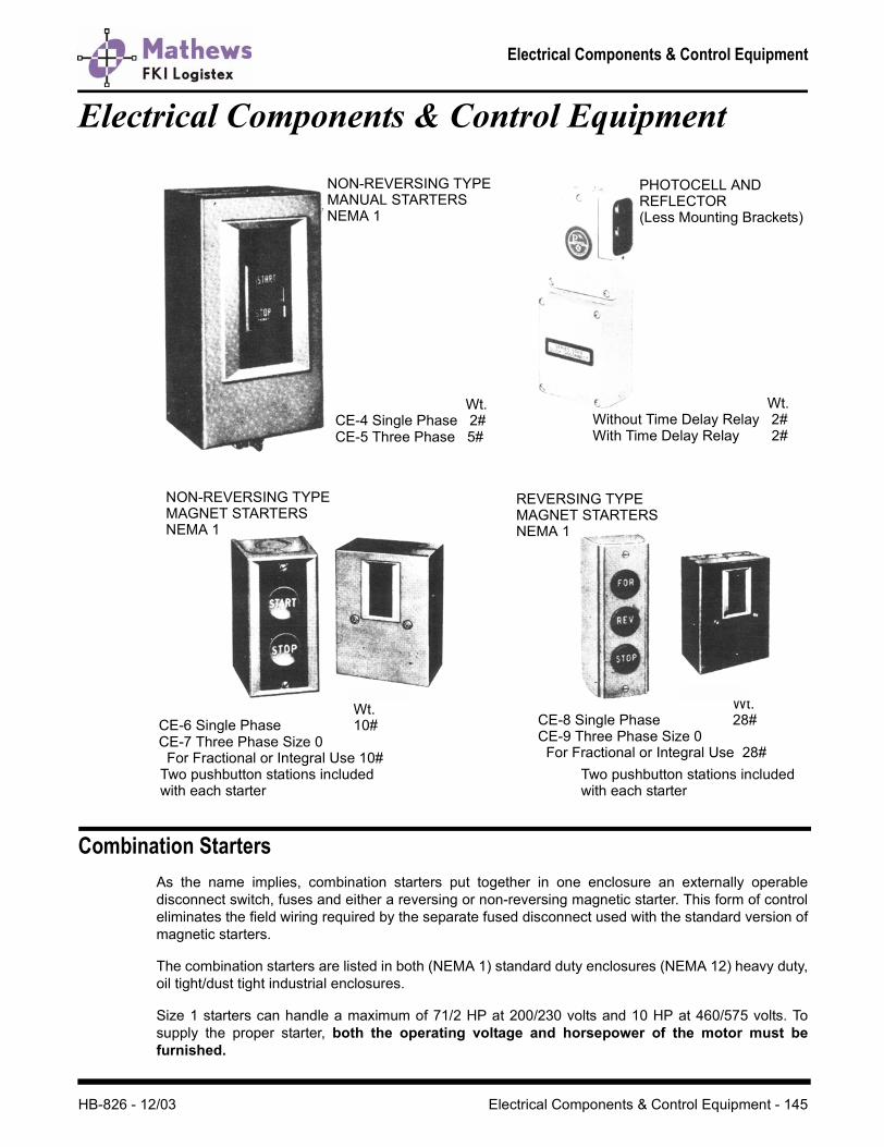
Electrical Components & Control Equipment
Electrical Components & Control Equipment
Combination StartersAs the name implies, combination starters put together in one enclosure an externally operabledisconnect switch, fuses and either a reversing or non-reversing magnetic starter. This form of controleliminates the field wiring required by the separate fused disconnect used with the standard version ofmagnetic starters.
The combination starters are listed in both (NEMA 1) standard duty enclosures (NEMA 12) heavy duty,oil tight/dust tight industrial enclosures.
Size 1 starters can handle a maximum of 71/2 HP at 200/230 volts and 10 HP at 460/575 volts. Tosupply the proper starter, both the operating voltage and horsepower of the motor must befurnished.
NON-REVERSING TYPEMANUAL STARTERSNEMA 1
PHOTOCELL ANDREFLECTOR(Less Mounting Brackets)
CE-5 Three Phase 5#CE-4 Single Phase 2#
Wt.
With Time Delay Relay 2#Without Time Delay Relay 2#
Wt.
NON-REVERSING TYPEMAGNET STARTERSNEMA 1
CE-7 Three Phase Size 0CE-6 Single Phase 10#
Wt.
For Fractional or Integral Use 10#
REVERSING TYPEMAGNET STARTERSNEMA 1
CE-9 Three Phase Size 0CE-8 Single Phase 28#
Wt.
For Fractional or Integral Use 28#Two pushbutton stations includedwith each starter
Two pushbutton stations includedwith each starter
HB-826 - 12/03 Electrical Components & Control Equipment - 145

Electrical Components & Control Equipment
Standard voltages, which can be furnished, are 200, 230, 460 and 575. Above units are available withseparate 120 volt operating coil, add suffix “S”.
Transformers for other starter coils are available by adding suffix “T”.
Above starters include two pushbutton stations.
SIZE 1 COMBINATION STARTERS
NON-REVERSING Wt.CE-12 NEMA 1 35#CE12A NEMA 12 36#
REVERSING Wt.CE-13 NEM 1 35#CE-13A NEMA 12 36#
Electrical Components & Control Equipment - 146 HB-826 - 12/03
Electrical Components & Control Equipment
Components For Driving and Controlling the Powered ConveyorsThis section deals with the components that drive and control powered conveyors. It presents a reviewof the various components used and information required to make the proper selection. These variouscontrol mechanisms can be used to control single units or be incorporated into systems.
MotorsThere are three basic types of motor enclosures:
1. Open
The motor windings can be seen through the vents at the end of the motor.
2. Totally Enclosed
The motors are completely encased in a metal enclosure.
3. Explosion Proof
The enclosure of the motor will withstand an explosion from within itself and will not allow sparks or hot gas to escape into the surrounding atmosphere.
Explosion proof motors are further rated by class and group by the National Electric Code according tothe environment in which they are designed to operate.
Class I - Hazardous VaporGroup C - Ethers, Alcohols, etc.Group D - Petroleum Base
Class II - Hazardous DustGroup E - MetalGroup F - CarbonsGroup G - Grains
There are three designations required when specifying the power source an A.C. motor is to operatefrom:
1. Phase - Three or One
2. Frequency - Hertz
3. Voltage - Volts
Common single phase voltages are 115 and 230. Common three phase voltages are 208, 230, 460and 575. Motors for 230 or 460 volt applications normally are supplied as dual voltage, (i.e. 230/460).When specifying motors, the single voltage which will be used to operate the motor must be stated ifthe proper controls for starting and stopping the motor are to be selected.
Motors are commonly mounted by two principle means, foot mounted or C-face. Foot mounted isnothing more than a set of mounting feet which are welded or otherwise attached to the bottom of themotor. C-face mounting consists of a cast ring or collar on the end of the motor with four mountingholes which allows the motor to be attached to a reducer, machine, etc.
HB-826 - 12/03 Electrical Components & Control Equipment - 147

Electrical Components & Control Equipment
Gear ReducerA reducer is a device which converts a high RPM with low torque (usually supplied by a motor at thereducer’s input shaft) to a lower RPM with higher torque on the reducer’s output shaft, which isconnected to the conveyor drive.
Reducers are generally selected based on the amount of the horsepower to be transmitted and theamount of reduction in speed that is required. Terminology used in speed reduction is “ratio”. Ratio isthe rate of the output speed as compared to the input speed. Typical ratios are 10:1, 40:1, etc. If an1800 RPM motor is coupled to a 40:1 ratio reducer, the resultant output speed would be 1800 dividedby 40 which equals 45 RPM Manufacturer’s rating tables are used to select a reducer with the properhorsepower rating.
Gear reducers are generally grouped into two categories, parallel shaft and right angle shaft. Thedetermination is made by the position of the output shaft relative to the input shaft. If the output shaft isin position parallel to the input shaft, then the gear reducer is termed a parallel reducer. If the outputshaft is in a position forming a right angle to the input shaft, the reducer is termed a right angle reducer.
The most common mounting arrangement for reducers is foot mounted. This consists of a set of feet,with holes in them, that are attached to the reducer. With this arrangement, the reducer can be boltedto any flat surface. Since the reducer requires oil to lubricate the gears, it is necessary to know whetherit is intended to be mounted with the feet up and the reducer below, such as a ceiling hung mountingposition or with the feet down and the reducer above them, which would be termed a floor mountedposition. Another important consideration in gear reducers is how the motor will be attached to thereducer. One simple means is to foot mount the reducer and foot mount the motor at relative positionsso that the output shaft of the motor is aligned with the input shaft of the reducer. A suitable couplingcan then be used to connect the two. An alternative approach is to use a C-face motor and C-facereducer. Remember that a C-face motor has a ring or collar on the end of the motor with four mountingholes. Reducers can be purchased that have a corresponding collar around the input shaft of thereducer. A plastic collar couples the output shaft of the motor to the input shaft of the reducer andwhen the motor and reducer are bolted together, it encloses the “coupling” eliminating the need for aguard.
Because of the popularity of C-face motor reducer combinations when they were originally introduced,manufacturers carried that concept forward with the introduction of the integral gearmotor. An integralgearmotor is a motor and reducer or “gear box”, cast into one housing. Basically, the motor is made“open ended” on the end next to the gear box and the gear box has a flat plate and collar to accept themotor. This eliminates the need for C-face rings on the motor and reducer and therefore is moreeconomical. The disadvantages of the integral gearmotor is that if either the motor or reducer fails,both have to be replaced since it is an integral unit. In the case of a C-face motor and C-face reducer,if the motor fails, only the motor has to be replaced. If the reducer fails, only the reducer has to bereplaced.
Electrical Components & Control Equipment - 148 HB-826 - 12/03

Electrical Components & Control Equipment
BrakesThe most common types of brakes used with motors are spring set/electrically released type. This is adisc type brake, that when power to the motor is eliminated, a spring sets the brake to stop the rotationof the motor. When power is applied to the motor, the brake is released by an electrical solenoid.Brakes are sized in terms of the torque they produce. Normally, for a holding brake such as is used ona conveyor, a brake should be sized 3 ft. lbs. per horsepower or as an example, a 3 ft. lb. brake is usedfor a 1 horsepower motor and a 6 ft. lb. brake for a 2 horsepower motor.
Clutch BrakeA clutch-brake is a device that is mounted between the motor and the reducer. With a clutch-brake, themotor runs continuously. When the conveyor is to start, the clutch is energized and the brake isreleased. When it is desirable to stop the conveyor, the clutch is released and the brake is applied.Clutch-brakes require a special power supply and controlling device. This controller allows the forcebetween the clutch discs and brake discs to be varied. This provides a means of adjusting the startingand stopping motions of the conveyor from “soft” to “violent”.
Three phase motors with brakes generally can be started and stopped up to six times per minute. Forapplications requiring more starts and stops per minute, a clutch brake should be used.
Motor StartersManual Motor Starters
Manual motor starters are devices which, when a button is pushed or a toggle type switch is thrown,operate a set of electrical contacts which supply power to a motor. The button or toggle switch is anintegral part of the manual starter. Manual motor starters can be used when a conveyor is beingcontrolled from one point only and can not be connected with any other remotely located control circuitdevices, such as a second push button, a limit switch, or photoelectric relay. In order to select theproper manual motor starter, the following must be known:
1. Reversing or Non-Reversing
2. Single Phase or 3 Phase
3. Frequency of Power Supply (60 Hertz)
4. Voltage at which the motor is to be run (this must be one voltage, not dual voltage such as 230/460.
5. Horsepower of motor controlled by the starter.
Magnetic Motor Starters
Magnetic motor starters are used where it is desirable to control a conveyor from more than onelocation. Magnetic motor starters have basically two circuits associated with them. One is a controlcircuit and the other is a power circuit. The power circuit turns electrical line power to the motor off oron. The line power provides the energy for the motor to actually do work while the control circuit tells itwhen. The control circuit is controlled by push button, limit switches, photoelectric relays and switchingdevices. Technically, these switching devices are used to energize the magnetic coil of the starterwhich in turn operates a set of multiple contacts. These contacts are used to complete the powercircuit to the motor. The control circuit voltage is usually lower than the power circuit voltage.
In order to select the proper magnetic starter, the following must be known:
1. Reversing or Non-Reversing
2. Phase, frequency and voltage the motor is to run on (power voltage).
HB-826 - 12/03 Electrical Components & Control Equipment - 149

Electrical Components & Control Equipment
3. Phase, frequency and voltage the push button is to be run on (control voltage)
4. Is a transformer required to change motor voltage to control voltage? (This would be required if, for instance, there was only one power source available, such as 230 volts, which is acceptable for the line power for the motor but the push buttons are desired to operate at 115 volts.)
5. Horsepower of the motor to be controlled.
Combination Magnetic Motor Starters and Control Panels
The National Electrical Code requires both short circuit protection and running overload protection foreach motor in a conveyor system. In addition, a lockable disconnecting device must be provided withsight and (also) within 50 feet of each motor.
The running overload protection for a motor is provided by the “heaters” in a starter. Heaters are anintegral part of all motor starters. This leaves the problem of providing short circuit protection and adisconnecting means to consider.
Providing a combination motor starter for each motor meets both of these requirements. The fuses orcircuit breakers in a combination starter provide the short circuit protection and the disconnect orcircuit breaker provides the disconnecting means. The circuit breakers provide the same function as afused-disconnect. The only other requirement of this alternative to meeting the criteria of the NationalElectrical Code is physically locating the combination starters within 50 feet and in sight of the motorsthey control. Typically these starters are individually located directly beside the motor they control andare mounted on the side of the conveyor drive.
A second alternative to meeting this requirement of the National Electrical Code is to provide “acrossthe line” magnetic starters and provide a fused-disconnect in a separate enclosure. Typically thefused-disconnects are provided by whoever is doing the field wiring. Although this is typical it is anoften misunderstood point. If “across the line” starters are provided by the equipment supplier, it shouldbe established early in the development of a project whether the equipment supplier is also providingfuse-disconnects or whether they will be provided by the field wiring supplier.
A third alternative to meeting the requirements of the National Electrical Code is providing a prewiredcontrol panel. The control panel houses “across the line” starters and fuses or circuit breakers for eachmotor in a common enclosure. This meets the short circuit protection requirement. The control panelincludes a main disconnect switch which meets the disconnecting means requirement of the code aslong as all of the motors are located within 50 feet and within sight of the control panel. If some of themotors are beyond a 50 foot radius of the panel or are not visible from the panel, then a non-fuseddisconnect must be provided for each motor. These disconnects are usually provided by the fieldwiring contractor but not always. Caution must be exercised between the parties involved in a projectthat everyone understands who is providing what.
In summary, there are three essential parts to motor control: the disconnecting means, the overload“heaters” contained in the magnetic starter, and the short circuit protection. These can be grouped invarious combinations in multiple or common enclosures.
Electrical Components & Control Equipment - 150 HB-826 - 12/03

Electrical Components & Control Equipment
Electrical EnclosuresStandards for the manufacture of electrical control devices have been agreed on by the NationalElectrical Manufacturers Association or N.E.M.A. N.E.M.A. has established various classifications forenclosures or boxes enclosing push buttons, motor starters, photoelectric cells, etc. A numberingsystem is used to describe these enclosures, and the following are some of the more common that youwill encounter.
1. N.E.M.A. Type 1 - Surface Mounting (General Purpose Sheet Metal)
Type 1 enclosures are intended for indoor use, primarily to provide a degree of protection against contact with enclosed equipment in locations where usual service conditions do not exist. The enclosure is sheet metal and treated to resist corrosion.
2. N.E.M.A. Type 4 (Water Tight)
Type 4 enclosures are intended for in-door or external use primarily to provide a degree of protection against wind blown dust and rain, splashing water, and hose directed water. They are designed to meet hosed down, dust, external icing and rust resistance design tests. They are not intended to provide protection against conditions such as internal condensation or internal icing. Enclosures are made of heavy gauge stainless steel, cast aluminum or heavy gauge sheet metal, depending upon the type of unit. The cover has a synthetic rubber gasket.
3. N.E.M.A. Type 7 and 9 (Explosion Proof)
These enclosures are intended for indoor use. N.E.M.A. type 7 is normally used in atmospheres that contain hazardous gas and will be used in areas that correspond with Class 1, Group C and D motors. N.E.M.A. type 9 would normally be used in atmospheres that contain hazardous dust and would be used in conjunction with motors that are classified as Class II, Group E, F, and G.
4. N.E.M.A. 12 (Industrial Dust-Tight)
These enclosures are intended for use indoors to protect the enclosed equipment against fibers, flying lint, dust and dirt and light splashing, seepage, dripping and external condensation of non-corrosive liquids.
Switching DevicesPush Buttons
Push buttons are about the simplest switching device known. The operator simply pushes a buttonwhich causes an electrical contact to close, thus providing a signal for something else to happen.
Limit Switches
Limit switches are switching devices which are actuated by a machine motion striking a lever on theswitch. The lever causes an electrical contact to operate which causes some other action to happen.
Selector Switches
Selector switches are similar to a push button except the operator rotates the switch as opposed topushing down on the switch to cause an electrical contact to operate.
Photoelectric Relays
Photoelectric relays are a “no touch” switching device. This is a device which operates an electricalcontact when a beam of light is broken.
HB-826 - 12/03 Electrical Components & Control Equipment - 151

Electrical Components & Control Equipment
Solenoid ValvesA solenoid valve is an air or hydraulic valve combined with a solenoid. The solenoid is a magnetic coilwhich is turned on by a switching device or logic device. When the coil is turned on, it causes anarmature to move and push a plunger in one direction or the other. The plunger and the solenoid shiftsa spool in the valve to cause a different flow path for the air or hydraulic fluid.
Air ControlsAir control used on conveyors normally consist of valves and filter-regulators which may be used toraise and lower stops and transveyors or perhaps to actuate some other divert mechanism.
A filter-regulator-lubricator is a combination of three devices. The filter cleans the dirt and grit out of theair, the regulator regulates the pressure in the air line and keeps it below a certain maximum pressure.The lubricator squirts oil into the air passing through it. This lubrication is used to lubricate the valveand cylinder which is normally connected to the filter-regulator-lubricator.
Electrical Components & Control Equipment - 152 HB-826 - 12/03
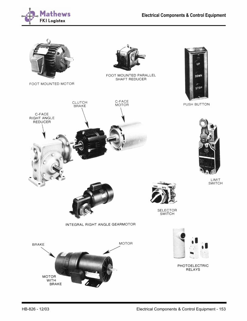
Electrical Components & Control Equipment
HB-826 - 12/03 Electrical Components & Control Equipment - 153

Electrical Components & Control Equipment
Electrical Components & Control Equipment - 154 HB-826 - 12/03


![1 SERIES Belt Conveyor System B090 - Bett Sistemi Srl€¦ · CONVEYOR BELT DEVELOPMENT CALCULATION FORMULA Conveyor belt length = 300 + {[(L-94)-(2• Conveyor belt thick. )]•2}](https://img.dokumen.tips/doc/110x75/5ad3c4047f8b9a48398b7ae4/1-series-belt-conveyor-system-b090-bett-sistemi-conveyor-belt-development-calculation.jpg)