Embed Size (px)
Citation preview

http://www.iaeme.com/IJCIET/index.
International Journal of Civil Engineering and Technology (IJCIET)Volume 9, Issue 11, November 201
Available online at http://www.iaeme.com/ijciet/issues.
ISSN Print: 0976-6308 and ISSN Online: 0976
©IAEME Publication
BEHAVIOR OF PILED
UNDER EARTHQUAKE LOA
Q. S. Mohammed Shafiqu and R. H.
Department of Civil Engineering, College of Engineering,
Al
ABSTRACT
In this research, the seismic piled raft foundation behavior is investigated via
finite element method. Analyses of the numerical model of multi
applied under the acceleration time history for the Ha
soil types of Iraq. And a parametric study is carried out for investigating the influence
of earthquake acceleration characteristics on the bending moment values along the
piles and settlements of raft foundation. The
one of the most effective dynamic parameter that affected on piles bending moment
and raft settlements. The bending moment values in all piles and raft settlements are
obtained to be higher in cohesive soils than in coh
also coherent with the fact that the shear wave velocities of the clayey soils had higher
values than the shear wave velocities of the sandy soils analysed in this study. The
higher values for bending moments along piles
occurs at soil profiles consisting of soft cohesive soils with large thickness reaching to
about half piles length underlain by layers of medium to loose cohesionless soils.
While the lowest moments and settlements appe
of rock or very dense silty sand. The maximum values of the bending moments has
been obtained at head of piles or at depth of about 5
from the top.
Keywords: Piled-Raft, Earthquake, Dy
Cite this Article: Q. S. Mohammed Shafiqu and R. H. Sa'ur, Behavior of Piled
Foundation Under Earthquake Loading In Various Types of Soil
Journal of Civil Engineering and Technology (IJCIET)
http://www.iaeme.com/IJCIET/issues.asp?JType=IJCIET&VType=9&IType=11
1. INTRODUCTION
The foundation of high-rise building is usually piled foundation subjected to a combined of
normal, horizontal and overturning loads. Foundation of piled
buildings as the raft provides a bearing capacity estimated based on each element stiffness.
IJCIET/index.asp 2770 [email protected]
International Journal of Civil Engineering and Technology (IJCIET) 2018, pp. 2770–2781, Article ID: IJCIET_09_11_277
http://www.iaeme.com/ijciet/issues.asp?JType=IJCIET&VType=
and ISSN Online: 0976-6316
Scopus Indexed
BEHAVIOR OF PILED-RAFT FOUNDATION
UNDER EARTHQUAKE LOADING IN VARIOUS
TYPES OF SOIL
Q. S. Mohammed Shafiqu and R. H. Sa'ur
Department of Civil Engineering, College of Engineering,
Al-Nahrain University, Baghdad, Iraq
In this research, the seismic piled raft foundation behavior is investigated via
nalyses of the numerical model of multi-storey building were
applied under the acceleration time history for the Hallabjah earthquake in differe
parametric study is carried out for investigating the influence
of earthquake acceleration characteristics on the bending moment values along the
piles and settlements of raft foundation. The results indicate the shear wave velocity as
one of the most effective dynamic parameter that affected on piles bending moment
and raft settlements. The bending moment values in all piles and raft settlements are
obtained to be higher in cohesive soils than in cohesionless soils. This conclusion is
also coherent with the fact that the shear wave velocities of the clayey soils had higher
values than the shear wave velocities of the sandy soils analysed in this study. The
higher values for bending moments along piles and raft settlements were generally
occurs at soil profiles consisting of soft cohesive soils with large thickness reaching to
about half piles length underlain by layers of medium to loose cohesionless soils.
While the lowest moments and settlements appeared in soil profiles consisting mostly
of rock or very dense silty sand. The maximum values of the bending moments has
been obtained at head of piles or at depth of about 5-15% of the pile length measured
Raft, Earthquake, Dynamic Behavior, Various Soils.
Q. S. Mohammed Shafiqu and R. H. Sa'ur, Behavior of Piled
Foundation Under Earthquake Loading In Various Types of Soil
Journal of Civil Engineering and Technology (IJCIET) 9(11), 2018, pp.
http://www.iaeme.com/IJCIET/issues.asp?JType=IJCIET&VType=9&IType=11
rise building is usually piled foundation subjected to a combined of
normal, horizontal and overturning loads. Foundation of piled-raft type may be used for such
buildings as the raft provides a bearing capacity estimated based on each element stiffness.
IJCIET_09_11_277
asp?JType=IJCIET&VType=9&IType=11
RAFT FOUNDATION
DING IN VARIOUS
Department of Civil Engineering, College of Engineering,
In this research, the seismic piled raft foundation behavior is investigated via
storey building were
llabjah earthquake in different
parametric study is carried out for investigating the influence
of earthquake acceleration characteristics on the bending moment values along the
indicate the shear wave velocity as
one of the most effective dynamic parameter that affected on piles bending moment
and raft settlements. The bending moment values in all piles and raft settlements are
esionless soils. This conclusion is
also coherent with the fact that the shear wave velocities of the clayey soils had higher
values than the shear wave velocities of the sandy soils analysed in this study. The
and raft settlements were generally
occurs at soil profiles consisting of soft cohesive soils with large thickness reaching to
about half piles length underlain by layers of medium to loose cohesionless soils.
ared in soil profiles consisting mostly
of rock or very dense silty sand. The maximum values of the bending moments has
15% of the pile length measured
Q. S. Mohammed Shafiqu and R. H. Sa'ur, Behavior of Piled-Raft
Foundation Under Earthquake Loading In Various Types of Soil, International
p. 2770-2781.
http://www.iaeme.com/IJCIET/issues.asp?JType=IJCIET&VType=9&IType=11
rise building is usually piled foundation subjected to a combined of
t type may be used for such
buildings as the raft provides a bearing capacity estimated based on each element stiffness.

Behavior of Piled-Raft Foundation Under Earthquake Loading In Various Types of Soil
http://www.iaeme.com/IJCIET/index.asp 2771 [email protected]
Piled raft foundation behavior under earthquake loads is considered very significant and can
influence the stability of structure, and its performance. In liquefiable or soft soil conditions
the consequences can be severe. Davis and Poulos [3] introduced the idea for utilizing piled
raft foundation, and then many researchers described the performance of such foundation
system. Recently various methods for piled raft analysis are presented due to increase of using
such foundations for high-rise buildings instead of relying only on the capacity of the piles.
Many researchers have extensively studied the normal load bearing mechanism by using the
elasticity theory [10] and by applying the finite element method [12]. Piled rafts are designed
in practical use, depending on these results. Studies on the piled raft foundation response
under lateral loads or when subjected to seismic action, however, are rare [4;6]. The
complexity of the behavior during earthquakes due to dynamic interaction among a raft, piles
and a soil necessitates that the design method should include the influence of this mechanism
in an appropriate manner.
The behavior of the raft built on piles in clayey soil subjected to seismic loads is a
problem that attracts the interest of many researchers recently [13]. However, the researches
on the behavior of piled raft under lateral and earthquake loadings in soft clayey soil are
relatively very limited. Furthermore the influence of using piled raft as foundation for a tall
building considering interaction of soil-structure was investigated [2]. In this study where a
Finite Element Code ANSYS was used to model the behavior, it was concluded that soil-
structure interaction was effectively influencing the structure behavior. In another study, the
dynamic response of a 25-storey building resting on piled raft foundation was examined [11]
using SAP 2000 software. It was found that the piled raft in subsoil of dense sand was a
perfect combination for good bearing behavior of the building.
In the current study, procedure for modeling piled raft in various types of soil under
seismic load using PLAXIS software is presented. A parametric study is done dealing with
effect of subsoil types on the behavior of piled raft as foundation for tall building under the
effect of Halabjah earthquake.
2. MODELLING AND ANALYSIS
By finite element technique with using PLAXIS program the piled raft is modelled as solid
elements with finite meshing and the frame system is modelled as a 3D frame. Moreover, up
to a sufficient depth, the soil is taken into consideration knowing that from all four sides the
boundaries are restricted to appropriate distance from the frame structure. The soil mass is
modelled by Mohr-Coulomb and the piles are assumed as a slender beam elements, which are
virtually connected to soil by skin and base interfaces. These structural elements can have
arbitrary cross and inclination through the soil elements at arbitrary positions. The interaction
of the soil and pile at the base is modelled by considering point to volume interface elements,
while the interaction at the skin interface is modelled by line to volume interface elements.
3. NUMERICAL MODELLING OF PILED RAFT FOUNDATION
UNDER EARTHQUAKE LOADING
In this numerical analysis, a 10 storey square building with the same structural system for the
problem of a 15-storeybuilding tested under static force[1] is selected. The raft is at 2.0 m depth
under the ground surface. The dimensions of raft are 25 m × 25 m × 1.5 m with an overhang
of 2.5 m. A 0.75 m diameter concrete circular pile with depth of 15m and a total number of
25 is used below the raft. The parameters for structural, soil and pile elements are as in Table
2.

Q. S. Mohammed Shafiqu and R. H. Sa'ur
http://www.iaeme.com/IJCIET/index.asp 2772 [email protected]
Table 1Structural, pile and soil parameters[1]
Material
Unsaturated
weight
(γunsat), kN/m3
Saturated
weight
(γsat),kN/m3
Modulus of
elasticity
(E ), kN/m2
Poisson’s
ratio
(ν)
Dilatancy
(ψ),
degree
Friction
angle
(φ),
degree
Cohesion
(c),
kN/m2
Concrete 25 - 3.4 × 10⁷ 0.2 - - -
Pile 25 - 2.35 × 10⁷ 0.2 - - -
Loose Sand 17 20 20000 0.2 2 32 0.1
Dense Sand 19 21 60000 0.2 8 38 0.1
The PLAXIS 3D program is used for the analysis of the 10-storey building structure
having piled-raft foundation in various soil layers for different sites in Iraq area. The columns
and piles are modelled as frame elements while the floor slab and raft are modelled using
triangular plate elements. Also wedge triangular continuum type elements are modelled soil
layers. The linear elastic and non-linear Mohr-Coulomb models are considered for structural
and soil elements respectively. Figure (1) show connectivity plot and finite element mesh
plots for the piled raft in a typical site.
Figure 1 Connectivity plot and Finite Element Mesh for the piled raft in S10 site
3.1. Soil Properties used in the Analyses
In this study, the database prepared by Mohammed Shafiqu and Abdulrasool [7] with respect
to static and dynamic parameters of most Iraqi soils is used. This database was collected from
many sources and based on different reports for geophysical and geotechnical investigation
works of forty seven projects site. The sites consisted of various layers of rock, cohesionless
and cohesive soils and represents projects for stadiums, pumping stations, oil refinery, multi-
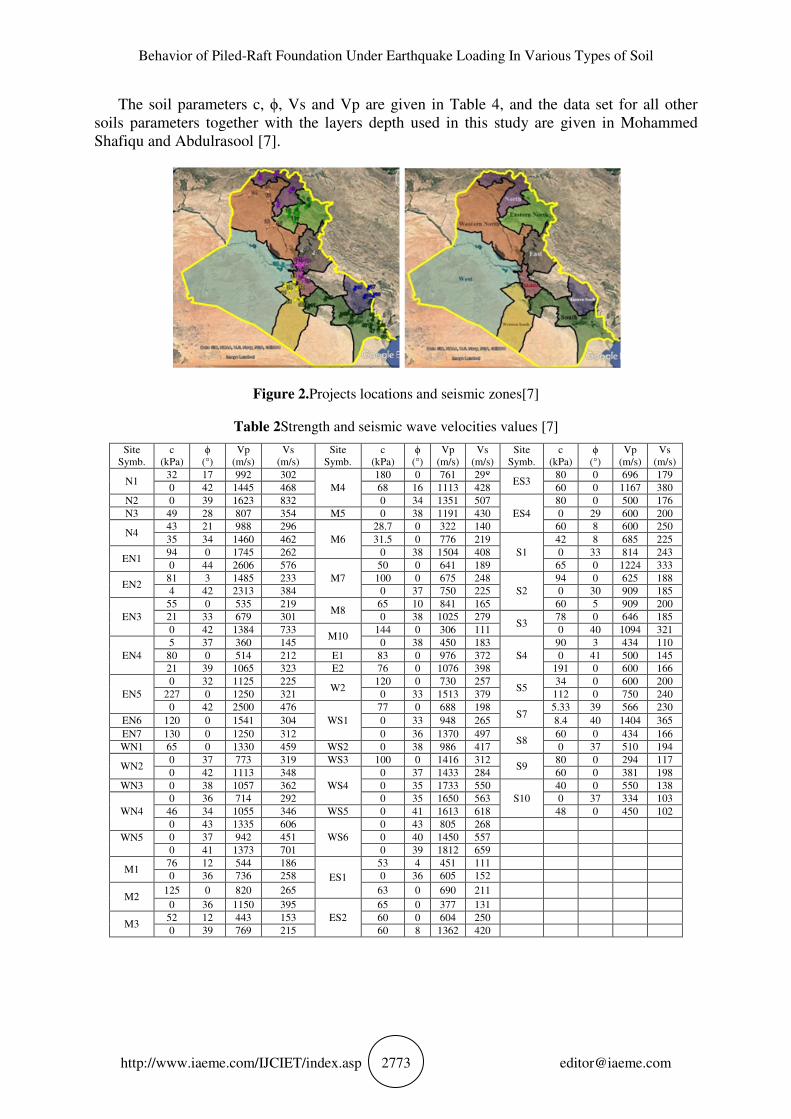
story buildings, electrical substations, plants for water treatment, etc. with locations given in
Figure (2). Nine zones were created according to the Iraqi governorates boundaries, namely
North (N), South (S), Eastern North (EN), Western North (WN), Middle (M), East (E), West
(W), Western and Eastern South (WS and ES respectively)as shown inFigure (2). The sites
symbols in these zones are as listed in Table 2. All the data necessary for Mohr-Coulomb
model were available. The parameters with standard units are as listed below [9]:
E : Young’s Modulus (kN/m2), c : Cohesion (kN/m
2), ϕ : Angle of internal friction (°), υ :
Poisson's ratio (-), ψ : Angle of dilatancy (°), γsat, γunsat : Saturated and unsaturated unit
weight respectively (kN/m3),
The dynamic parameters are [9]: Vs and Vp: Shear and Pressure wave velocities
respectively (m/s), Ed: Dynamic Young's modulus (kN/m2), Gd: Dynamic shear modulus
(kN/m2).
Behavior of Piled-Raft Foundation Under Earthquake Loading In Various Types of Soil
http://www.iaeme.com/IJCIET/index.asp 2773 [email protected]
The soil parameters c, ϕ, Vs and Vp are given in Table 4, and the data set for all other
soils parameters together with the layers depth used in this study are given in Mohammed
Shafiqu and Abdulrasool [7].
Figure 2.Projects locations and seismic zones[7]
Table 2Strength and seismic wave velocities values [7]
Site
Symb.
c
(kPa)
ϕ
(°)
Vp
(m/s)
Vs
(m/s)
Site
Symb.
c
(kPa)
ϕ
(°)
Vp
(m/s)
Vs
(m/s)
Site
Symb.
c
(kPa)
ϕ
(°)
Vp
(m/s)
Vs
(m/s)
N1 32 17 992 302
M4
180 0 761 298 ES3
80 0 696 179
0 42 1445 468 68 16 1113 428 60 0 1167 380
N2 0 39 1623 832 0 34 1351 507
ES4
80 0 500 176
N3 49 28 807 354 M5 0 38 1191 430 0 29 600 200
N4 43 21 988 296
M6
28.7 0 322 140 60 8 600 250
35 34 1460 462 31.5 0 776 219
S1
42 8 685 225
EN1 94 0 1745 262 0 38 1504 408 0 33 814 243
0 44 2606 576
M7
50 0 641 189 65 0 1224 333
EN2 81 3 1485 233 100 0 675 248
S2
94 0 625 188
4 42 2313 384 0 37 750 225 0 30 909 185
EN3
55 0 535 219 M8
65 10 841 165 60 5 909 200
21 33 679 301 0 38 1025 279 S3
78 0 646 185
0 42 1384 733 M10
144 0 306 111 0 40 1094 321
EN4
5 37 360 145 0 38 450 183
S4
90 3 434 110
80 0 514 212 E1 83 0 976 372 0 41 500 145
21 39 1065 323 E2 76 0 1076 398 191 0 600 166
EN5
0 32 1125 225 W2
120 0 730 257 S5
34 0 600 200
227 0 1250 321 0 33 1513 379 112 0 750 240
0 42 2500 476
WS1
77 0 688 198 S7
5.33 39 566 230
EN6 120 0 1541 304 0 33 948 265 8.4 40 1404 365
EN7 130 0 1250 312 0 36 1370 497 S8
60 0 434 166
WN1 65 0 1330 459 WS2 0 38 986 417 0 37 510 194
WN2 0 37 773 319 WS3 100 0 1416 312
S9 80 0 294 117
0 42 1113 348
WS4
0 37 1433 284 60 0 381 198
WN3 0 38 1057 362 0 35 1733 550
S10
40 0 550 138
WN4
0 36 714 292 0 35 1650 563 0 37 334 103
46 34 1055 346 WS5 0 41 1613 618 48 0 450 102
0 43 1335 606
WS6
0 43 805 268
WN5
0 37 942 451 0 40 1450 557
0 41 1373 701 0 39 1812 659
M1 76 12 544 186
ES1
53 4 451 111
0 36 736 258 0 36 605 152
M2 125 0 820 265 63 0 690 211
0 36 1150 395
ES2
65 0 377 131
M3 52 12 443 153 60 0 604 250
0 39 769 215 60 8 1362 420

Q. S. Mohammed Shafiqu and R. H. Sa'ur
http://www.iaeme.com/IJCIET/index.asp 2774 [email protected]
3.2. Earthquake Modelling
To study the effects of acceleration characteristics on the piled raft response, a real
acceleration history for Halabjah, the strongest earthquake in Iraq hit Halabjah city in
Sulaymaniah Province on November 12, 2017 with a magnitude of 7.3 MWwas utilized as
shown in Figure (3). In the numerical analysis, the model bottom boundary is subjected to the
acceleration-time records given in the figure through the x-axis. A 80 seconds section was
applied to the model at intervals of 0.1 seconds.
Figure 3.Halabjah earthquake acceleration time data
3.3. Influence of Dynamic Soil Parameters on the Bending Moment
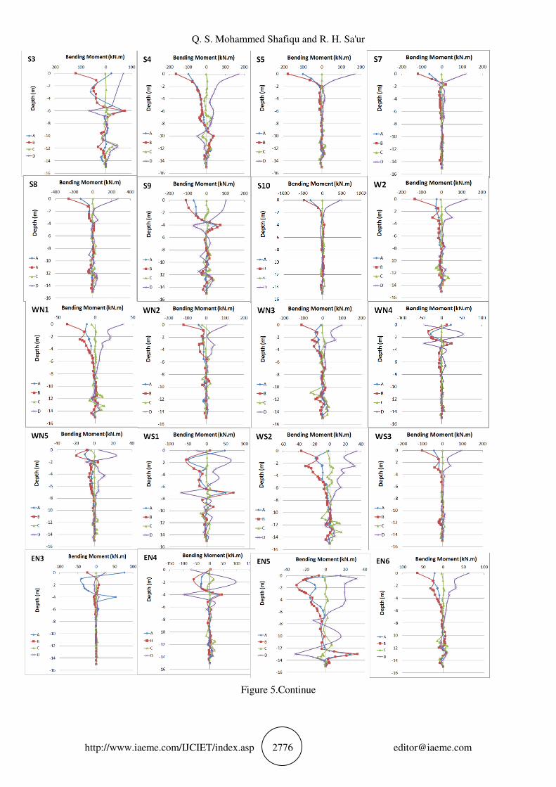
The results of bending moments along piles A, B, C and D shown in Figure (4) are given in
Figure (5). The results show minimum bending moments for soil profiles consisting generally
of rock or very dense silty sand where the piles working as end bearing piles and the
maximum bending moments appears in soil profiles consisting of lower layers of medium to
loose cohesionless soils where the tip of piles are resting overlaid by large thickness of soft
cohesive soils reaching to about half piles length. With respect to the zones, the highest
bending moments along piles length are predicted at N3, M10, WN2, WS3, E2, EN7, ES4 and
S10 zones. It is observed that generally the bending moment is large at the upper part of the
pile near the ground/the base of the foundation. It is important to note that the pile head is
fixed to the cap and values of moments in between the tip and top of piles are varied from
positive to negative or both according to type, depth and number of soil layers. It is also
indicated that the bending moment is influenced mostly to a depth over length ratio of about
50% in most of the sites. And maximum bending moment calculated is about 500 (kN.m) at
the head of pile for S10 site in south of Iraq which has a soil profile consisting mostly of
layers of cohesive soils with lowest values for shear wave velocities. While the lower values
of bending moments appears in N2 site in north of Iraq with values about 2.0% for that of S10
site.The soil profile for N2 site consisting of rock fragment of limestone with silty sand of
highest shear wave velocities. Thus the shear wave velocity can be considered one of the most
effective dynamic properties that influenced the values of bending moments along the piles.
The bending moment values in all piles are obtained to be higher in cohesive soils than in
cohesionless soils as the velocities of pressure and shear are higher in sandy soils. The pile is
influenced by differential forces as the waves reaching the layers of soils. In homogeneous
soils kinematic pile bending occurs because seismic waves may have different strengths
owing on thickness of soil layers and the structures around that cause a non-uniform damping
in the wave [6]. Therefore, the bending moment may shows sudden changes in value typically
at the two soil layers interface because of the various wave velocity of soils strata.
Results of bending moments in Figure (5) indicates that pile A at centre of raft foundation
has been insignificantly influenced by the earthquake acceleration, piles B and D at centre of
edges for raft foundation are generally the most effected by the earthquake acceleration where
the higher bending moments are appeared mostly along pile B in front of seismic waves.
While generally pile A at the edge of raft foundation is less influenced by the earthquake

Behavior of Piled-Raft Foundation Under Earthquake Loading In Various Types of Soil
http://www.iaeme.com/IJCIET/index.asp 2775 [email protected]
comparing to that at B and D. In a lot of soil profiles and generally as the depth increased the
seismic wave velocities increased. The strength of sand soil depends on the frictional
parameters and on the effective stresses. As the depth increased the soil strength will be
higher thus the wave velocities being larger in values. Subsequent bending with curvatures via
strong waves from earthquake has been identified [8] as kinematic bending and liquefaction
induced bending.
For the current study, embedding pile tip through sand or gravel overlaid with clayey soil
predicts lower bending moments at pile tip being higher at the top layers but the bending
moments are mostly influenced through the pile length. For soil profiles consisting of sandy
or clayey soil layer and/or multiple sandy or clayey soil layers, bending moment values are
mostly appeared to be influenced for depth to length ratio of about 50%.
Figure 4.Piles A, B, C and D in the piled raft foundation
Figure 5.Bending moments along the piles A, B, C and D at the various sites
Q. S. Mohammed Shafiqu and R. H. Sa'ur
http://www.iaeme.com/IJCIET/index.asp 2776 [email protected]
Figure 5.Continue

Behavior of Piled-Raft Foundation Under Earthquake Loading In Various Types of Soil
http://www.iaeme.com/IJCIET/index.asp 2777 [email protected]
Figure 5.Continue

Q. S. Mohammed Shafiqu and R. H. Sa'ur
http://www.iaeme.com/IJCIET/index.asp 2778 [email protected]
3.4. Influence of dynamic soil parameters on the foundation vertical settlement
In this section the evaluation of the maximum vertical settlement and differential settlement
for the raft foundation is carried out. It has been observed that the maximum settlements
appeared in soil profiles where a layers of soft clayey soils are top layers reaching about half
piles length underlaid by layers of medium to loose sand or loose sand followed by soft
clayey soil. While the minimum settlements indicated in soil profiles consisting generally of
rock or very dense silty sand. The large values of settlements are predicted in N3 site in North
zone, M3 in Middle zone, WS1 in South-West zone, WN3 in North-West zone, E2 in East
zone, EN4 in North- East zone, ES1 in South-East zone and S10 in South zone. Figure (6)
presents the total settlement contours for these zones at the raft level 2m below the ground
level for the PLAXIS3D model with structural elements. The PLAXIS3D model with solid
elements for S10 site resulted in higher predicted maximum settlement (smax=5.2 mm) and
differential settlement between the centre and corner of raft (0.357smax) compared to the
other sites. Knowing that the eight times high shear wave velocity site N2 which consist
mainly of rock fragment of limestone with silty sand is recognized by lower maximum
settlement and differential settlement with a values lesser by about 98% than S10 site
consisting mainly of layers of soft and loose cohesion and cohesionless soils respectively. The
foundation overall stability is usually not ensured by piles but it can be indicate that for
minimizing settlements, differential settlements and reducing the tilting of building, piles can
be used for that together with ensuring the good performance of foundation system.
Piles in Piled raft foundations employ for support or control of vertical displacements and
they applying most of the stiffness at serviceability forces, while the raft provides extra
bearing capacity at maximum loading. Consequently, it is mostly possible to minimize the
required piles number when the raft element provides such additional capacity.
From results it can be said that the raft may apply redundancy to piles, such that if there
are one or more weaker or defective piles, or if a number of piles suffered from karstic
conditions in the subsoil. Also the stress applied by piled rafts to the soil cause an increase in
the lateral stress in the soil between the underlying piles, and thus may increase the ultimate
load capacity of a pile as compared to freestanding piles [5]. The obtained results indicates
that soil profiles made up of relatively dense sands or stiff clays, the raft element can provide
a considerable proportion of the stiffness and required load capacity, with the piles working to
boost the action of the foundation, rather than being the major support means.
Thus it can be understand that the utilize of piled raft foundation is an effective procedure
for limiting both total and differential settlements under the dynamic loads provided by the
earthquake, enhancing the bearing capacity of a shallow foundation, and effectively reducing
the internal stress levels and bending moments within a pile.

Behavior of Piled-Raft Foundation Under Earthquake Loading In Various Types of Soil
http://www.iaeme.com/IJCIET/index.asp 2779 [email protected]
Figure 6.Continue
4. CONCLUSION
The following conclusions can be drawn based on the results of this study.
• The results of the parametric Finite Element study indicated the most influential dynamic
property of soils that affected the bending moments along the piles and vertical settlements of
the raft is the shear wave velocity. The bending moment values in all piles and raft settlements
[×10-

Q. S. Mohammed Shafiqu and R. H. Sa'ur
http://www.iaeme.com/IJCIET/index.asp 2780 [email protected]
are obtained to be higher in cohesive soils than in cohesionless soils. This conclusion is also
coherent with the fact that the shear wave velocities of the clayey soils had higher values than
the shear wave velocities of the sandy soils analysed in this study.
• The higher values for bending moments along piles generally occurs at soil profiles consisting
of soft cohesive soils with large thickness reaching to about half piles length underlaid by
layers of medium to loose cohesionless soils. While the lowest moments appeared in soil
profiles consisting mostly of rock or very dense silty sand with a values of about 98% lower
than that for higher values. The maximum values of the bending moments has been obtained
at head of piles or at depth of about 5-15% of the pile length measured from the top.
• The piles at the edges of the foundation experienced the highest bending moments during the
earthquakes acceleration. It was also observed that the highest bending moments occurred
mostly along the piles in front of the seismic waves. And pile at the corner of the edge of raft
foundation is less influenced by the earthquake comparing to the pile at center of the edge.
Also the piles at center of raft foundation can be considered as being insignificantly influenced
by the earthquake acceleration.
• The raft settlements are highest in soil profiles of soft clayey soils with large thickness
reaching about 10m or 50% piles length underlaid by layers of medium to loose sand or loose
sand followed by soft clayey soil. The lowest settlements appeared in soil profiles consisting
mostly of rock or very dense silty sand. The lower vertical and differential settlements values
in these soil profiles are about 2-5% the higher values where the shear wave velocity are
higher in these soils by about 3-8 times.
• It appears also that the settlements will be about 30-40% the higher values when soft or loose
to medium soils overlaid stiff or dense cohesive and cohesionless soils respectively. And the
percentages will be 20-30% when medium to stiff cohesive soils overlaid loose to medium
cohesionless soils layers decreased as the soils consistency being stiffer or denser where the
shear and compression wave velocities becomes lower.
• The piled raft foundation may be an effective way for minimizing total and differential
vertical settlements when subjected to earthquake loadings, enhancing the bearing capacity for
shallow foundation, and significantly minimizing the levels of internal stress and the bending
moments within a pile.
REFERENCES
[1] Ahmed, M., Mohamed, M.H., Mallick, J. andAbulHasan, M. 3D-Analysis of Soil-
Foundation-structure Interaction in Layered Soil.Open Journal of Civil Engineering, 4,
2014,pp. 373-385.
[2] Chaudhari R.R. andKadam, K.N. Effect of Piled Raft Design on High-Rise Building
Considering Soil Structure interaction.International Journal of Scientific and Technology
Research, 2(6), 2013.
[3] Davis, E. and Poulos, H. The Analysis of Piled Raft Systems.Australia Geotechnique
Journal, 2(1), 1972, pp. 21-27.
[4] Hamada, J. Shigeno, Y. Nakamura, N. Onimaru, S. Tanikawa T. and Yamashita, K.
Seismic numerical analysis of piled raft foundation with grid-form deep mixing walls
supporting a base isolated building based on seismic observation records.Journal of
Structural and Construction Engineering(Transactions of AIJ),79(701), 2014, pp. 941-950.
[5] Katzenbach, R., Arslan, U., Moormann, C. andReul, O., Piled raft foundation interaction
between piles and raft.Darmstadt Geotechnics, Darmstadt University of Technology, 4,
1998, pp. 279-296.
[6] Mano, H. andNakai, S. An Approximate Analysis for Stress of Piles in a Laterally
Loaded Piled Raft Foundation.Journal of Structural Engineering, 46B, 2000, pp. 43-50.

Behavior of Piled-Raft Foundation Under Earthquake Loading In Various Types of Soil
http://www.iaeme.com/IJCIET/index.asp 2781 [email protected]
[7] Mohammed Shafiqu, Q. S. andAbdulrasool, M. A., Database of Dynamic Soil Properties
for Most Iraq Soils.American Scientific Research Journal for Engineering, Technology,
and Sciences (ASRJETS), 37(1), 2017, pp. 230-254.
[8] Mylonakis, G. and Nikolaou, S. Design Methods for Earthquake-Induced Pile Bending.
Proc. Int. Conf. and Exposition, Deep Foundations Institute, 2002, pp. 1-9.
[9] PLAXIS 3D Manual, Delt University of Technology & PLAXIS, Netherland, 2013.
[10] Poulos, H. An Approximate Numerical Analysis of Pile Raft Interaction.International
Journal for Numerical and Analytical Methods in Geomechanics, 18(2), 1994, pp. 73-92.
[11] Shukla, S.J., Desai, A.K. andSolanki, C. H. A Dynamic Behavioral Study of 25 Storey
Building with Piled Raft Foundation with Variable Subsoils.Int. J. of Structural and Civil
Engineering Research, 2(1), 2013, pp. 119-130.
[12] Yamashita, K., Analyses of Piled raft Model Provided by ISSMGE TC-18 Part2 :
Estimation by three-dimensional finite analysis, ISSMGE TC18 JGS member’s meeting
on Piled rafts, 1998.
[13] Zhang, L. Goh S. and Liu, H. Seismic response of pile-raft-clay system subjected to a
long-duration earthquake: centrifuge test and finite element analysis.Soil Dynamics and
Earthquake Engineering, 92, 2017, pp.488-502.