Embed Size (px)
Citation preview

AMERICAN INSTITUTE OF MINING AND METALLURGICAL ENGINEERS Technical Publication No. 2158
Classes A and C, Metals Technology, August 1947 DISCUSSION OF THIS PAPER IS INVITED. Discussion in writing (a copies) may be sent to the
Secretary. American Institute of Mining and Metallurgical Engineers 29 West 39th Street Sew York 18. N. Y. Unless special arrangement is made, discussion of this paper will cldse so". I . 1947. ~ r ; y discussion offered thereafter should preferably be in the form of a new paper.
Behavior of Metal Cavity Liners in Shaped Explosive Charges
BY GEORGE B. CLARK* AND WALTER H. BRUCKNER,~ MEMBERS AIME
(New York Meeting. March 1947)
SINCE the end of World War I1 interest has been increasing in the use of shaped charges in the mining industry and in other industries using explosives for blasting purposes. Shaped charges employ the principle known as the "Munroe effect," which was discovered by Charles E. Mun- roe more than 50 years ago (in 1888). Details of their design have been explained e1sewhere.l-2nJ Fig I shows the essential features of design of two types of shaped charges (with conical and hemispherical cavities) and a schematic sketch of their action upon detonation.
The following discussion deals with the behavior of the metal in the cavity liners when they are subjected to intense pres- sures exerted when the explosive charge is detonated. Among the conclusions reached in research on shaped explosive charges, the following have been established con- cerning cavity
I. The optimum wall thickness of a conical cavity liner is dependent upon the apex angle of the cone as well as on the base diameter of the charge. Acute apex angles require thinner walls for optimum per- formance and more obtuse angles require thicker walls for the same base diameter.
2. Cones were more effective in forming
a penetrating jet when the walls were tapered; i.e., the thickness of the wall of the cone increased from the apex down.
3. The physical and mechanical proper- ties of metals have a marked effect upon their performance as cavity-liner material. Boiling point, ductility, malleability, ten- sile strength, and hardness are among the properties that influence the effectiveness of a metal used as a cavity liner. Lead, for example, makes a wide, flat crater in steel plates. Aluminum makes a deeper crater than lead, and an aluminum alloy having a high tensile strength makes a deeper hole, but slightly smaller in diameter. Cast iron makes a deep, narrow hole.
These findings, together with the follow- ing analysis under Metallographic Survey of Slug, offer solutions to many of the prob- lems involved in solving the mechanism of the formation of Munroe jets.
It has been fairly well established that cavity liners collapse in a manner similar to that indicated in Fig 2. Conical liners are known to collapse upon themselves while hemispherical liners are believed to turn inside out in the process of jet forma- tion. The first has been definitely proved by recovery of collapsed portions of cones, while liners from partly detonated charges show that hemispheres may turn inside out.
Manuscript received a t the office of the Fig 3 shows a sketch of a recovered slug Institute Dec. 16. 1946. Previously published in Mining T e c h n o l o ~ y . May. 1947. from a 6-in. shaped charge using a 45" cone
Assistant Professor of Mining Engineering, made of cast iron. hi^ size of charge University of Illinois. Urbana. Illinois. t Research Assistant Professor of Metallurgi- drilled holes up to 3 ft in depth in solid
cal Engineering, University of Illinois. I References are a t the end of the paper. granodiorite.)
Copyright. 1947, by the American Institute of Mining and Metallurgical Engineers, Inc. Printed in USA

2 BEHAVIOR OF METAL CAVITY LINERS IN SHAPED EXPLOSIVE CHARGES
FIG I-SKETCHES OF SHAPED CHARGES WITH (a) HEMISPHERICAL AND ( b ) CONICAL CAVITIES SHOWING MECHANISM OP FORMATION OP MUNROE JET.' 1
FIG P-DIAGRAMMATIC SKETCH OP COLLAPSE OP CAVITY LINERS SHOWING APPROXIMATE POSI- TION OP DETONATION WAVE AND FORMATION OF JETS PROM REGIONS OF GREATEST COMPRESSION IN TKE METAL.

GEORGE B. CLARK AND WALTER II. BRUCKNER 3
The cast-iron slug was sectioned on a diametral plane through the original axis of the cone. This plane of metal received a metallographic polish and was etched with 5 per cent nital to give the macrograph in Fig 4 a t a magnification of approximately 235 diameters.
A piece of the original iron casting from which the cast-iron cone had been made was also available. I t was polished and etched to observe the original microstruc- ture of the slug. A typical representation of this microstructure is shown in Fig 6. The structure shows the presence of straight-sided masses of graphite from which graphite flakes radiate (type C, ASTM). There appears to be little or no free ferrite, thus the microstructure con- sisted mainly of pearlite and graphite. However, it was reported that the cone had been heated after machining to a cherry red (temperature approx. qoo0F) and furnace-cooled. There was no speci- men available to determine the effect on the microstructure of the heat-treatment given the iron. The structure of the recov- ered slug near the top outer edges and other portions representing regions of least plastic deformation are comparable with the microstructure shown in Fig 6, thus the heat-treatment was ineffective in producing any major change in microstructure.
A survey of the microstructure on the entire plane of polish of the slug illustrated in Fig 4 was made. A record was made of characteristic regions a t a magnification of IOO and 500 diameters. In Fig 5 a copy of Fig 4 is given with circled areas, which are lettered to correspond with the micrographs that follow in Figs 7 to 14. The micro- graphs are oriented the same as Fig 5 with respect to top and bottom and were taken in the circled regions shown in Fig 5 .
Fig 7 shows a region a t the center, top of the slug, which had suffered considerable
plastic deformation, as indicated by the "lining up" of the graphite flakes. Where the largest amount of flow or deformation took place, shown a t the right side a t the
EXPLOSIVE PRESSURE
FIG 3-COLLAPSED SLUG FROM SIX-INCH CAST-IRON CONE AND PORTION OF ORIGINAL CONE FROM W I C H IT CAME.
Pressure is represented by arrows normal to the surface and curves inside the cone are probable paths of particles from the inside sur- face of the cone.
bottom of Fig 7, the graphite was sur- rounded by free ferrite and the pearlite areas were compacted. Fig 8 shows- the manner in which the flow took place in this particular region. In the area in the lower right-hand side of Fig 8, the graphite, pearlite and ferrite are compacted into flow layers adjacent to a region of prac- tically undisturbed lamellar pearlite a t the top left. The structure a t the right consists of free ferrite, graphite and compacted pearlite. Fig 9 shows a region in which the center field has a large amount of ferrite from which the graphite was almost com- pletely removed. The ferrite shows a new granular structure resulting from recrystal- lization and the pearlite is distributed throughout as a h e dispersion. The pearl- ite in the surrounding areas appeared to have been partially spheroidized. The

IOR OF M VITY LINI CHARGES
FIG 4-CAST-IRON SLUG. X 2 % .
recrystallization of the ferrite and the a horizontal line shown in Fig 5. The partial spheroidization of the pearlite indi- sequence is shown by the deformation of cate that a temperature in the neighbor- the ferrite in Fig 10, the partial recry- hood of 13ooOF was attained in the stallization of the deformed ferrite in particular region. Fig 11 and the complete recrystallization
Figs 10, I I, and 12 show a series of of the ferrite and the partially spheroidized micrographs that form a sequence along pearlite in Fig 12. The sequence suggests

UCKNER
thi bet ter 1: -
i t a temperature gradient may have en established in the slug with the nperature maximum along the center
lille of the slug and with the maxima increasing from top to bottom of the slug shown in Figs 4 and 5. I t was also observed that in going toward the center of the slug the microstructure progressively con- tained less graphite, while in the central area of the slug the graphite appeared to have been squeezed out into large areas of agglomerated, practically pure graphite. I n the sequence of Figs 10, 11, and 12 the direction of flow pro- gressively changed until, as in Fig 12, i t was almost parallel with the axis of the original cone.
Figs 13 and 14 show the microstructures near the bottom of the slug. Fig 13 shows a region that consists of recrystallized ferrite and recrystallized pearlite plus some graphite, while Fig 14 shows only recrystallized ferrite and spheroidized pearl- ite plus graphite. The areas of recrystal- lized pearlite in Fig 13 must have attained a temperature considerably in excess of I~oo'F, below which temperature the deformed ferrite alone will recrystallize.
Near the bottom of the slug there were a number of fractures along the direction of flow. The fractures invariably went through areas of graphite that represented planes of weakness.
The extreme ductility exhibited by the interior regions of the slug is unusual for a gray cast-iron composition representa- tive of the cone material. I n tension the gray iron is notoriously a material of low strength and brittleness. Under the compressional stress of the shaped charge and the rapid application of the stress, the ductile behavior of the cast iron may have been enhanced by the heat developed internally by friction.
If it is assumed that approximately 2 5 per cent of the cavity liner was ejected
to form the jet, Fig 3 shows the approxi- mate length of the original cone that is represented by the slug. The macroscopic flow structure indicates that the paths
of the grains remaining within the slug are hyperbolic in shape; that is to say, the grains appear to have been acted upon by two forces, one perpendicular to the wall, of the original cone and one parallel to the axis of the cone, the velocity due to the latter increasing in magnitude as the cone collapsed and the velocity due to the force normal to the surface being changed into a velocity parallel to the axis.
The kinetic pressure against the outside of a liner is caused by the intense bom- bardment of molecules of the explosive gases. These molecules probably do not penetrate more than one or two atomic layers into the surface of the metal liner.
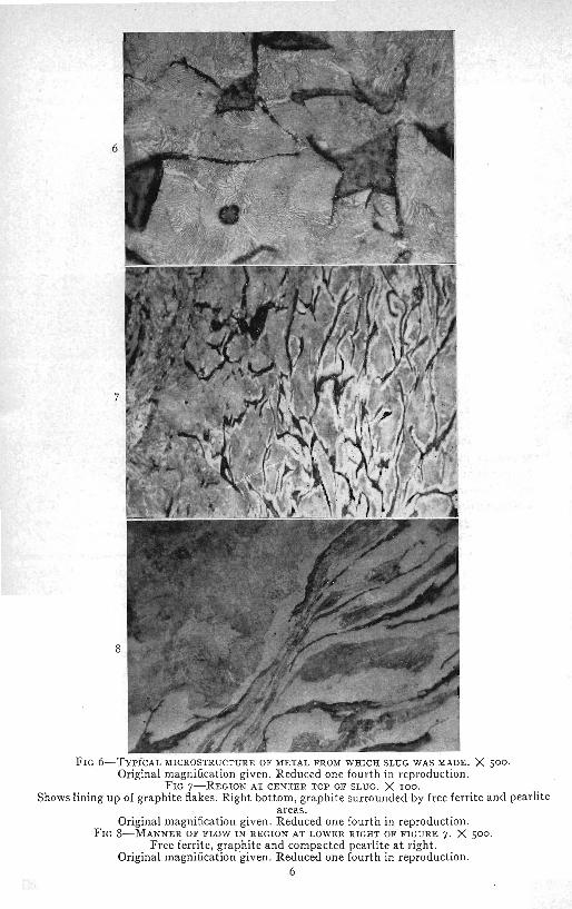
FIG 6-TYPICAL MICROSTRUCTURE OF METAL FROM WHICH SLUG WAS MADE. X jOO. Original magnification given. Reduced one fourth in reproduction. -
FIG~-REGIOS AT CENTER TOP OF SLUG. X 100. Shows lining up of graphite flakes. Right bottom, graphite surrounded by free ferrite and pearlite
areas. Original magnification given. Reduced one fourth in reproduction.
FIG 8-MANNER OF FLOW I N REGION AT LOWER RIGHT OF FIGURE 7. X 500. Free ferrite, graphite and compacted pearlite a t right.
Original magnification given. Reduced one fourth in reproduction. 6

CLARK A
heir intense impact pressure, however, properties of the metal, together with tuses the wall of the liner to be forced wall thickness, type of explosive, and
toward the axis of the cone. A study other factors. oi the microstructure of the collapsed Microscopic examination of the col-
FIG 9-FERRITE BRON ~ T ~ H I C H GRAPHITE WAS ALMOST COUPLETELY RE~IOVED. X 500. Original magnification given. Reduced one fourth in reproduction.
slug of cast iron (Figs 4 to 14) shows that the more malleable constituents of the iron have been literally squeezed into a new structure in the direction of the axis of the slug. The total picture
'of the mechanism of jet formation then must include the effect of the impact of the explosive gases plus the compressive forces set up in the metal. I t was con- cluded that in a cone the grains are in effect acted upon by two sets of corn- pressional forces. The structure of the cast iron in Figs 4 to 13 would lead to the same conclusion; i.e., that compressive forces in the collapsing liner cause the ejection of particles from the inside surface, and these particles travel in hyperbolic paths asymptotic to or coin- cident with the axis of the cone.
The laws that govern the division of liner material into slug and jet are not quite clear. The contact angle of impact of the collapsing walls would have a marked influence on the separation as well as the physical and mechanical
lapsed slug of cast iron shows that the metal near the center of the slug reached much higher temperatures than the metal near the outside. At the center of the slug the metal is very fine grained, grains of one and two microns in diameter being very common. As a cone collapses the metal on the inside "layers" of the cone wall, which is the metal that goes to form the jet and the center of the slug, are subject to greater heat of deforma- tion than the outside layers 'of the cone. The internal heat of friction of these layers is greater than that for the outside layers, with a resulting higher temperature and greater fluidity (plasticity) in the center.
The mechanism involved probably could be described as "extrusion through a gradient orifice"; that is, the collapsing cone furnishes the extruding agent, the extruded material and the "ofifice" through which the material is forced. We would have, in effect, a syringe with a self-contained moving conical metal ['bulb"

BEHAVIOR O F METAI, CAVITY LINE SRS I N SI PLOSIVE CHARGES
FIGS 10-12-SERIES OF MICROGRAPHS ALONG JIORIZONTAL LINE IN FIGURE 5. X 500 Fig 10, deformation of ferrite. F ie 11. ~ a r t i a l recrvstallization of deformed ferrite. 1:ig r 2; colnplete r&rystallization of ferrite-and partially spheroidized pearlite
Original magnilication given. Reduced one fourth in reproduction.

sul .- to
of t n
~ j e c t to compressional forces normal sides of the "bulb," the whole process its walls. The "bulb" consists of metal moving progressively down the axis of increasing fluidity from the outside the cone. T h e velocity of the jet with ., the axis, owing to the temperature respect to a fixed point would then be
FIGS 13 AND 14-MICROSTRUCTURES NEAR BOTTOY OF SLUG. X 500. Fig 13, recrystallized ferrite and recrystallized pearlite, plus graphite. Fig 14, recrystallized ferrite and spheroidized pearlite plus graphite.
Original magnification given. Reduced one fourth in reproduction.
gradient established by explosive pressure. The "orifice" consists of a partially - constricted channel made by the flow of metal toward the axis of the cone, the metal having reached a temperature and state of fluidity just below that of the metal in the "bulb." The reservoir of fluid metal is constantly fed from the
equal to the velocity with which the metal is fed into the "bulb" ,plus the velocity of the point of contact of the col- lapsing walls.
From results of experimentation, it appears there is a relationship between the cavity-liner wall thickness and the momentum of the jet. As wall thickness

1 0 BEHAVIOR OF METAL CAVITY LINERS IN SHAPED EXPLOSIVE CHARGES
is increased from zero, the penetration effect of the jet increases also until an optimum thickness is reached, after which the penetration of the jet decreases as the walls become thicker. Then, based upon the conception of collapse described above, the property of cohesiveness of the metal also seems to be an important factor in determining the suitability of a metal for cavity liners.
When the cavity walls are too thin, apparently they do not possess the neces- sary mass to form both an "orifice" and a "bulb" and to furnish a quantity of plastic material to form the jet. Hence, jets from thin liners possess relatively low momentum. On the other hand, when the wall is thicker than optimum it offers too much resistance to the trans- mission of the energy of the explosion. As wall thickness increases above the optimum relatively less and less material goes into the jet, and if it is increased until the entire cavity is filled with metal the total mass would move forward with a velocity lower than the velocity of detonation.
The optimum thickness of a conical cavity liner probably would also vary according to the physical and mechanical properties of the metal employed.
The mechanism of jet formation in hemispherical cavities is not so clearly defined as it is in conical cavities. Slugs from hemispherical charges have not been recovered in complete enough form to en- able metallographic studies to be carried out on them. If hemispherical cavity liners
that the particles that form the jet are ejected by compressional forces. The same probably is equally true of hemispheres. At the time when the detonation wave strikes a hemisphere, the inside layers a t the apex are subject to compressional forces. As collapse proceeds, the region of compres- sional forces moves down the inside of the liner until collapse is complete (Fig 2 ) . If the liner turns inside out the portions of the metal that were subject to compression are in turn subject to tensional forces. I t is from the regions of compression that the jet par- ticles must emerge. The region of compres- sion would be composed of a symmetrical section of the hemisphere, beginning as a point and widening into a larger and larger circle as the process of collapse advances. The particles would then be ejected normal to the surface, which would focus them along the axis of the cavity to form the jet.
Apparently the particles thus squeezed out move parallel to the axis of the hemi- sphere. This is assumed for the following reasons: Cast-iron hemispheresZ make holes of relatively small diameters in steel plates, while more ductile metals make fun- nel-shaped holes with a diameter a t the first plate almost equal to the diameter of the hemisphere. This would lead to the be- lief that with cast-iron hemispheres the process of collapse is interrupted if not terminated by rupture of the liner while collapse is only partially complete. For more ductile metals the process of collapse probably continues down the entire height of the liner, the lower portions of tbe liner provide a wide jet, which has less penetrat- ing force per unit area and only acts to widen the hole already produced by the portion of the jet emanating from the upper
are regarded in the same manner as conical portion of the cavity liner. From the present cavity liners with reference to the ratio of concepts it appears that jet impact effects mass of the jet to the mass of the liner, and for a given explosive vary over a small the accompanying relationships between range for corresponding relatively large pressure, velocity, and energy, the same changes in the apex angle in cones. Jets theory should apply in both cases. from acute-angle cones may penetrate
In the case of cones it appears certain deeper because of the greater length (or the

GEORGE B. CLARK AND WALTER H. BRUCKNER I I
greater period of duration) of the jet. I t is believed, however, that increased penetra- tion is not caused only by increased jet velocity due to a change in the apex angle of the cone but that other factors enter in as well.
A description of the metallographic changes in the microstructure of a cast-iron liner from a 6-in. shaped charge has been given. The time required for the com- plete deformation of the cone was in the neighborhood of 10 or 1 5 microseconds, taking the velocity of detonation of IOO per cent blasting gelatin as 26,200 ft per sec. This ultra-high-speed deformation involv- ing high pressures applied a t velocities that are extremely high in comparison with metal deformation under ordinary condi- tions had the effect of making the cast iron ductile enough to flow quite readily. . The essential changes that have taken place in the iron of the slug from surface to axis range from a limited amount of de- formation a t the surface through a phase of more complete deformation, recrystalliza- tion of ferrite and agglomeration of graphite to an area of partial spheroidiza- tion in the region of the axis of the slug.
Considering the microstructure of the slug in terms of the mechanics of jet formation, there are a number of elements that may be given consideration. The forces acting on the liner during the explosion are represented by vectors of equal magnitude in Fig 3. The only upward force of any magnitude would be one due to the inertia of the slug itself. Hence, the forces involved are mostly compressional forces or those of shear. Microscopically, flow structure varies in character from irregular multidirectional undisturbed patterns to relatively straight lines in regions of shear and greatest flow. Fig 8 represents a region of differential flow; that is, the ferrite and the graphite in the right two thirds of the photograph
have been subject to flow while the pearlite in the upper left seems relatively undisturbed.
In addition, there is an almost complete welding of the grains of the cast iron along the axis of the slug. At the axis, too, the particles of ferrite and the pearlite colonies are very fine, portions of the ferrite being recrystallized. The grain size of femte increases toward the outside of the slug and the amount of recrystallization of the ferrite decreases.
Well-developed shea; planes are shown in Figs g and I I , the upper section in each case showing greater relative motion to- ward the axis of the slug. This is clearly indicated by the drag on the lower block of metal a t the lower left side. The process of collapse apparently involved the movement of rigid colonies of pearlite in a "viscous medium" of ferrite and graphite until por- tions of this flowing heterogeneous mass reached the vicinity of the axis, where it was probably pulverized or partially spheroidized to form a Munroe jet. The fine-grained iron in Figs 12 and 13 un- doubtedly represents the approximate type of material that goes to form a jet. This would be composed, then, of a very high- velocity spray of fine graphite and fin, particles of ferrite and pearlite.
I. A theory based upon the microstmc- ture of a collapsed cast-iron cone is offered to explain some of the physical laws in- volved in jet formation.
2. A study of the microstructure of a collapsed cavity liner shows that cast iron is ductile under conditions of temperature and pressure involved and indicates that jets from cast-iron liners are composed of a fine spray of graphite, partially spheroi- dized pearlite and ferrite.
3. Collapse of cast-iron conical liners appears to involve processes of compres- sion, shear, and extrusion of particles from the inside of the liner.
4. Jet formation from cones also involves

I2 BEHAVIOR OF HETAL CAVITY LINERS IN SHAPED EXPLOSIVE CHARGES
flow of metal subject to intense pressures REFERENCES and temperatures that are below the melt- ,. R. s. Lewis and G . B. Clark: Apdi&ation '1 ing point of the metal. The metal appears to of Shaped Charges to Mining Operations:
Tests on Steel and Rock. Bull. Univ. of obey the laws of hydraulic flow. Utah (July 1946) 37. Y
- . . - . 2. G. B. ~l&k:-studies of the Design of Shaped
Explosive Charges and Their Effect in ACKNOWLEDGMENT \
Breaking Concrete Blocks. Mininn Tech.. The section on the metallographic sur- A.I.M.E (May 1947-T.P. 2157)- 4
vey of the cast-iron slug was written by 3. J. B- Huttl: The Shaped C h a r g e f o r Cheaper Mine Blasting. Eng. and Min.
W. H. Bruckner. Jnl. (May 1946) 147~58-63. 4