Embed Size (px)
Citation preview
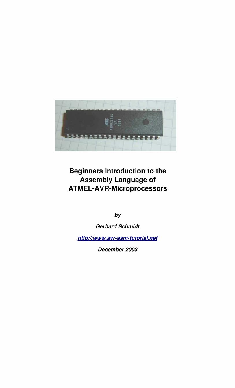
Beginners Introduction to theAssembly Language of
ATMELAVRMicroprocessors
by
Gerhard Schmidt
http://www.avrasmtutorial.net
December 2003


Avr-Asm-Tutorial 1 http://www.avr-asm-tutorial.net
ContentWhy learning Assembler?..........................................................................................................................1
Short and easy.......................................................................................................................................1Fast and quick........................................................................................................................................1Assembler is easy to learn.....................................................................................................................1AT90Sxxxx are ideal for learning assembler........................................................................................1Test it!....................................................................................................................................................1
Hardware for AVRAssemblerProgramming...........................................................................................2The ISPInterface of the AVRprocessor family...................................................................................2Programmer for the PCParallelPort....................................................................................................2Experimental board with a AT90S2313................................................................................................3Readytouse commercial programming boards for the AVRfamily...................................................4
Tools for AVR assembly programing........................................................................................................5The editor..............................................................................................................................................5The assembler........................................................................................................................................6Programming the chips..........................................................................................................................7Simulation in the studio.........................................................................................................................7
Register......................................................................................................................................................9What is a register?.................................................................................................................................9Different registers................................................................................................................................10Pointerregister....................................................................................................................................10Recommendation for the use of registers............................................................................................11
Ports.........................................................................................................................................................12What is a Port?....................................................................................................................................12Details of relevant ports in the AVR...................................................................................................13The status register as the most used port.............................................................................................13Port details...........................................................................................................................................14SRAM..................................................................................................................................................15Using SRAM in AVR assembler language.........................................................................................15What is SRAM?...................................................................................................................................15For what purposes can I use SRAM?..................................................................................................15How to use SRAM?.............................................................................................................................15Use of SRAM as stack.........................................................................................................................16
Defining SRAM as stack................................................................................................................16Use of the stack...............................................................................................................................17Bugs with the stack operation.........................................................................................................17
Jumping and Branching............................................................................................................................19Controlling sequential execution of the program................................................................................19
What happens during a reset?.........................................................................................................19Linear program execution and branches..............................................................................................20Timing during program execution.......................................................................................................20Macros and program execution...........................................................................................................21Subroutines..........................................................................................................................................21Interrupts and program execution........................................................................................................23
Calculations..............................................................................................................................................25Number systems in assembler.............................................................................................................25
Positive whole numbers (bytes, words, etc.)..................................................................................25Signed numbers (integers)..............................................................................................................25Binary Coded Digits, BCD.............................................................................................................25Packed BCDs..................................................................................................................................26Numbers in ASCIIformat..............................................................................................................26
Bit manipulations................................................................................................................................26Shift and rotate....................................................................................................................................27Adding, subtracting and comparing....................................................................................................28Format conversion for numbers...........................................................................................................29Multiplication......................................................................................................................................30
Decimal multiplication...................................................................................................................30Binary multiplication......................................................................................................................30
Avr-Asm-Tutorial 2 http://www.avr-asm-tutorial.net
AVRAssembler program...............................................................................................................31Binary rotation................................................................................................................................32Multiplication in the studio.............................................................................................................32
Division...............................................................................................................................................34Decimal division.............................................................................................................................34Binary division...............................................................................................................................34Program steps during division........................................................................................................35Division in the simulator................................................................................................................35
Number conversion.............................................................................................................................37Decimal Fractions................................................................................................................................37
Linear conversions..........................................................................................................................37Example 1: 8bitADconverter with fixed decimal output............................................................38Example 2: 10bitADconverter with fixed decimal output..........................................................40
Annex.......................................................................................................................................................41Commands sorted by function.............................................................................................................41Command list in alphabetic order.......................................................................................................43
Assembler directives.......................................................................................................................43Commands......................................................................................................................................43
Port details...........................................................................................................................................45StatusRegister, Accumulator flags................................................................................................45Stackpointer....................................................................................................................................45SRAM and External Interrupt control............................................................................................45External Interrupt Control...............................................................................................................46Timer Interrupt Control..................................................................................................................46Timer/Counter 0..............................................................................................................................47Timer/Counter 1..............................................................................................................................48WatchdogTimer.............................................................................................................................49EEPROM........................................................................................................................................49Serial Peripheral Interface SPI........................................................................................................50UART.............................................................................................................................................51Analog Comparator........................................................................................................................51I/O Ports..........................................................................................................................................52
Ports, alphabetic order.........................................................................................................................52List of abbreviations............................................................................................................................53
Avr-Asm-Tutorial 1 http://www.avr-asm-tutorial.net
Why learning Assembler?Assembler or other languages, that is the question. Why should I learn another language, if I alreadylearned other programming languages? The best argument: while you live in France you are able to getthrough by speaking english, but you will never feel at home then, and life remains complicated. You canget through with this, but it is rather inappropriate. If things need a hurry, you should use the country'slanguage.
Short and easyAssembler commands translate one by one to executed machine commands. The processor needs only toexecute what you want it to do and what is necessary to perform the task. No extra loops and unnecessaryfeatures blow up the generated code. If your program storage is short and limited and you have to optimizeyour program to fit into memory, assembler is choice 1. Shorter programs are easier to debug, every stepmakes sense.
Fast and quickBecause only necessary code steps are executed, assembly programs are as fast as possible. Theduration of every step is known. Time critical applications, like time measurements without a hardwaretimer, that should perform excellent, must be written in assembler. If you have more time and don't mind ifyour chip remains 99% in a wait state type of operation, you can choose any language you want.
Assembler is easy to learnIt is not true that assmbly language is more complicated or not as easy to understand than otherlanguages. Learning assembly language for whatever hardware type brings you to understand the basicconcepts of any other assembly language dialect. Adding other dialects later is easy. The first assemblycode does not look very attractive, with every 100 additional lines programmed it looks better. Perfectprograms require some thousand lines of code of exercise, and optimization requires lots of work. Assome features are hardware-dependant optimal code requires some familiarity with the hardware conceptand the dialect. The first steps are hard in any language. After some weeks of programming you will laughif you go through your first code. Some assembler commands need some monthes of experience.
AT90Sxxxx are ideal for learning assemblerAssembler programs are a little bit silly: the chip executes anything you tell it to do, and does not ask you ifyou are sure overwriting this and that. All protections must be programmed by you, the chip does anythinglike it is told. No window warns you, unless you programmed it before.
Basic design errors are as complicated to debug like in any other computer language. But: testingprograms on ATMEL chips is very easy. If it does not do what you expect it to do, you can easily add somediagnostic lines to the code, reprogram the chip and test it. Bye, bye to you EPROM programmers, to theUV lamps used to erase your test program, to you pins that don't fit into the socket after having themremoved some douzend times.
Changes are now programmed fast, compiled in no time, and either simulated in the studio or checked in-circuit. No pin is removed, and no UV lamp gives up just in the moment when you had your excellent ideaabout that bug.
Test it!Be patient doing your first steps! If you are familiar with another (high-level) language: forget it for the firsttime. Behind every assembler language there is a certain hardware concept. Most of the special featuresof other computer languages don't make any sense in assembler.
The first five commands are not easy to learn, then your learning speed rises fast. After you had your firstlines: grab the instruction set list and lay back in the bathtub, wondering what all the other commands arelike.
Don't try to program a mega-machine to start with. This does not make sense in any computer language,and just produces frustration.
Comment your subroutines and store them in a special directory, if debugged: you will need them again ina short time.
Have success!
Avr-Asm-Tutorial 2 http://www.avr-asm-tutorial.net
Hardware for AVRAssemblerProgrammingLearning assembler requires some simple hardware equipment to test your programs, and see if it worksin practice.
This section shows two easy schematics that enable you to homebrew the required hardware and givesyou the necessary hints on the required background. This hardware really is easy to build. I know nothingeasier than that to test your first software steps. If you like to make more experiments, leave some morespace for future extensions on your experimental board.
If you don't like the smell of soldering, you can buy a ready-to-use board, too. The available boards arecharacterised in this section below.
The ISPInterface of the AVRprocessor familyBefore going into practice, we have to learn a few essentials on the serial programming mode of the AVRfamily. No, you don't need three different voltages to program and read an AVR flash memory. No, youdon't need another microprocessor to program the AVRs. No, you don't need 10 I/O lines to tell the chipwhat you like it to do. And you don't even have to remove the AVR from your experimental board, beforeprogramming it. It's even easier than that.
All this is done by a build-in interface in the AVR chip, that enables you to write and read the content of theprogram flash and the built-in-EEPROM. This interface works serially and needs three signal lines:
• SCK: A clock signal that shifts the bits to be written to the memory into an internal shift register, andthat shifts out the bits to be read from another internal shift register,
• MOSI: The data signal that sends the bits to be written to the AVR,
• MISO: The data signal that receives the bits read from the AVR.
These three signal pins are internally connected to the programming machine only if you change theRESET (sometimes also called RST or restart) pin to zero. Otherwise, during normal operation of the AVR,these pins are programmable I/O lines like all the others.
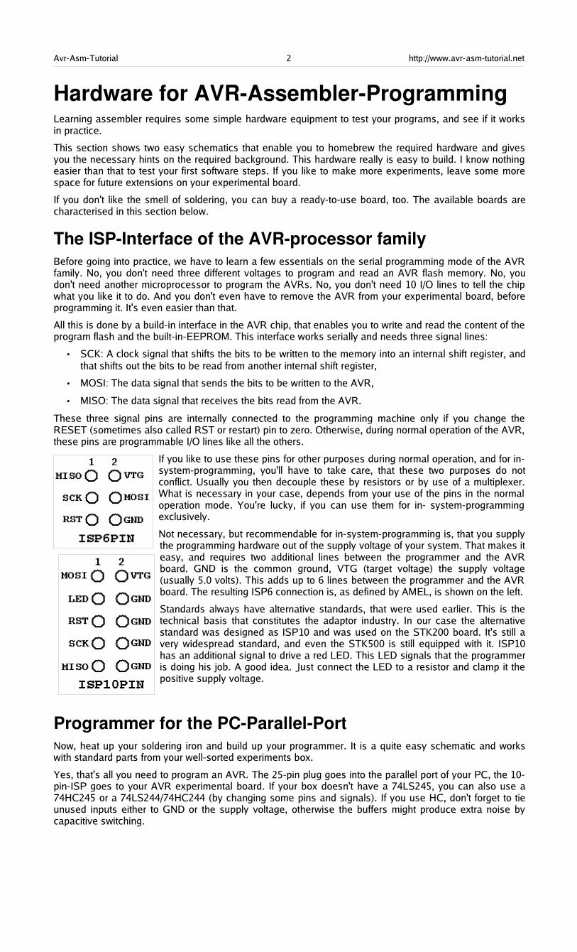
If you like to use these pins for other purposes during normal operation, and for in-system-programming, you'll have to take care, that these two purposes do notconflict. Usually you then decouple these by resistors or by use of a multiplexer.What is necessary in your case, depends from your use of the pins in the normaloperation mode. You're lucky, if you can use them for in- system-programmingexclusively.
Not necessary, but recommendable for in-system-programming is, that you supplythe programming hardware out of the supply voltage of your system. That makes iteasy, and requires two additional lines between the programmer and the AVRboard. GND is the common ground, VTG (target voltage) the supply voltage(usually 5.0 volts). This adds up to 6 lines between the programmer and the AVRboard. The resulting ISP6 connection is, as defined by AMEL, is shown on the left.
Standards always have alternative standards, that were used earlier. This is thetechnical basis that constitutes the adaptor industry. In our case the alternativestandard was designed as ISP10 and was used on the STK200 board. It's still avery widespread standard, and even the STK500 is still equipped with it. ISP10has an additional signal to drive a red LED. This LED signals that the programmeris doing his job. A good idea. Just connect the LED to a resistor and clamp it thepositive supply voltage.
Programmer for the PCParallelPortNow, heat up your soldering iron and build up your programmer. It is a quite easy schematic and workswith standard parts from your well-sorted experiments box.
Yes, that's all you need to program an AVR. The 25-pin plug goes into the parallel port of your PC, the 10-pin-ISP goes to your AVR experimental board. If your box doesn't have a 74LS245, you can also use a74HC245 or a 74LS244/74HC244 (by changing some pins and signals). If you use HC, don't forget to tieunused inputs either to GND or the supply voltage, otherwise the buffers might produce extra noise bycapacitive switching.

Avr-Asm-Tutorial 3 http://www.avr-asm-tutorial.net
The necessary program algorithm is done by the ISP software, that is available from ATMEL's softwaredownload page.
Experimental board with a AT90S2313For test purposes we use a AT90S2313 on an experimental board. The schematic shows
• a small voltage supply for connection to an AC transformer and a voltage regulator 5V/1A,
• a XTAL clock generator (here with a 10 Mcs/s, all other frequencies below the maximum for the 2313will also work),
• the necessary parts for a safe reset during supply voltage switching,
• the ISP-Programming-Interface (here with a ISP10PIN-connector).
So that's what you need to start with. Connect other peripheral add-ons to the numerous free I/O pins ofthe 2313.
The easiest output device can be a LED, connected via a resistor to the positive supply voltage. With that,you can start writing your first assembler program switching the LED on and off.

Avr-Asm-Tutorial 4 http://www.avr-asm-tutorial.net
Readytouse commercial programming boards for theAVRfamilyIf you do not like homebrewed hardware, and if have some extra money left that you don't know what to dowith, you can buy a commercial programming board. Easy to get is the STK500 (e.g. from ATMEL. It hasthe following hardware:
• Sockets for programming most of the AVR types,
• serial und parallel programming,
• ISP6PIN- and ISP10PIN-connector for external In-System-Programming,
• programmable oscillator frequency and suplly voltages,
• plug-in switches and LEDs,
• a plugged RS232C-connector (UART),
• a serial Flash-EEPROM,
• access to all ports via a 10-pin connector.
Experiments can start with the also supplied AT90S8515. The board is connected to the PC using a serialport (COMx) and is controlled by later versions of AVR studio, available from ATMEL's webpage. Thiscovers all hardware requirements that the beginner might have.
Avr-Asm-Tutorial 5 http://www.avr-asm-tutorial.net
Tools for AVR assembly programingThis section provides informations about the necessary tools that are used to program AVRs with theSTK200 board. Programming with the STK500 is very different and shown in more detail in the Studiosection. Note that the older software for the STK200 is not supported any more.
Four basic programs are necessary for assembly programming. These tools are:
• the editor,
• the assembler program,
• the chip programing interface, and
• the simulator.
The necessary software tools are ©ATMEL and available on the webpage of ATMEL for download. Thescreenshots here are ©ATMEL. It should be mentioned that there are different versions of the softwareand some of the screenshots are subject to change with the used version. Some windows or menues lookdifferent in different versions. The basic functions are mainly unchanged. Refer to the programer'shandbook, this page just provides an overview for the beginner's first steps and is not written for theassembly programing expert.
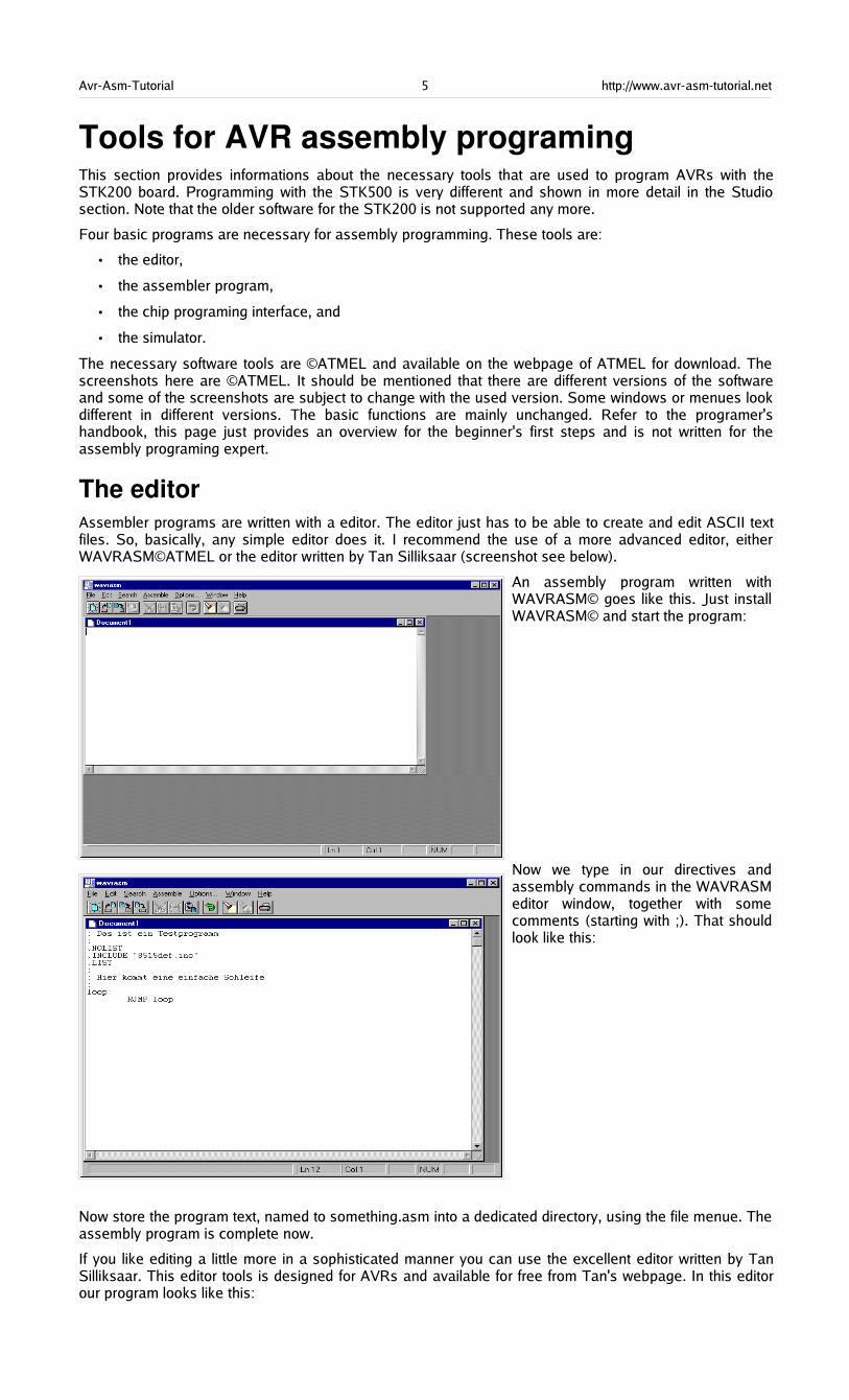
The editorAssembler programs are written with a editor. The editor just has to be able to create and edit ASCII textfiles. So, basically, any simple editor does it. I recommend the use of a more advanced editor, eitherWAVRASM©ATMEL or the editor written by Tan Silliksaar (screenshot see below).
An assembly program written withWAVRASM© goes like this. Just installWAVRASM© and start the program:
Now we type in our directives andassembly commands in the WAVRASMeditor window, together with somecomments (starting with ;). That shouldlook like this:
Now store the program text, named to something.asm into a dedicated directory, using the file menue. Theassembly program is complete now.
If you like editing a little more in a sophisticated manner you can use the excellent editor written by TanSilliksaar. This editor tools is designed for AVRs and available for free from Tan's webpage. In this editorour program looks like this:
Avr-Asm-Tutorial 6 http://www.avr-asm-tutorial.net
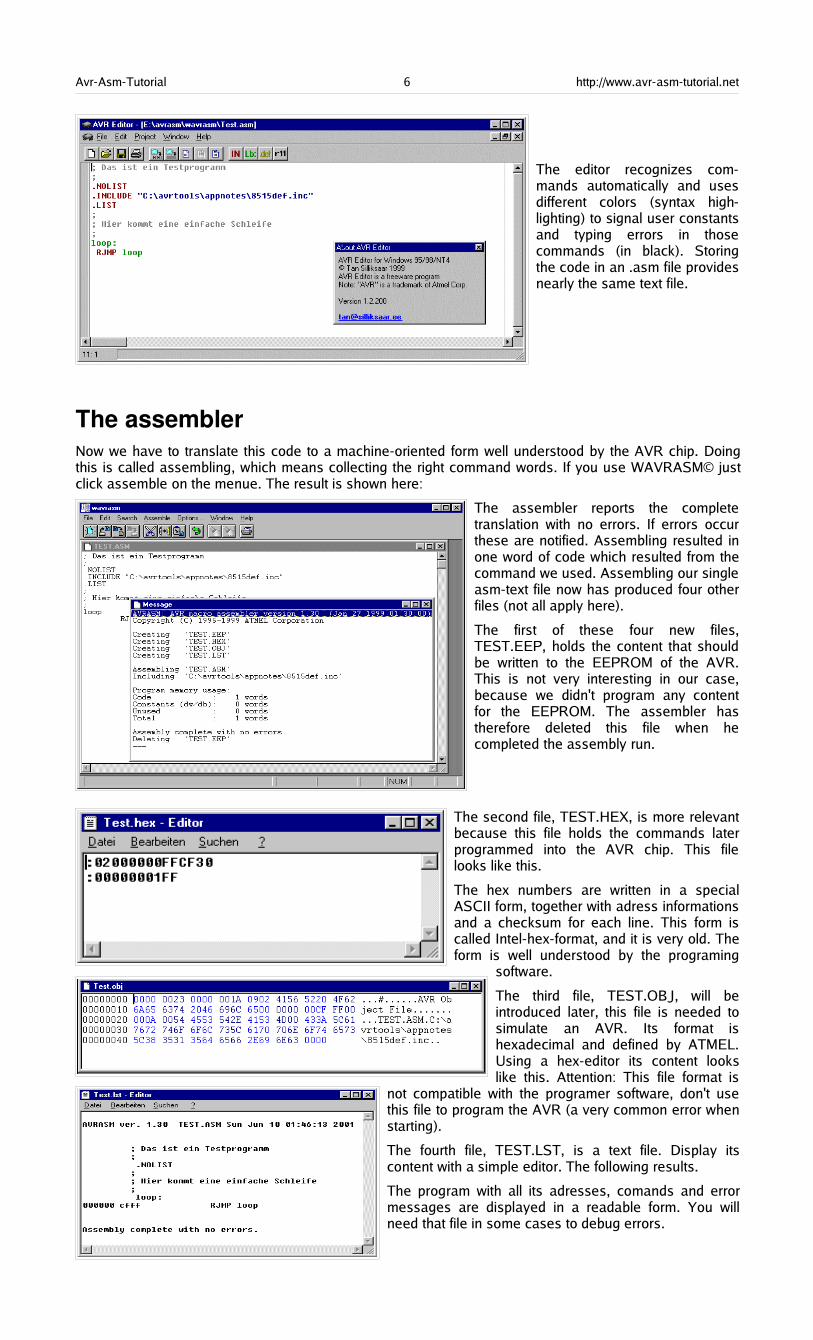
The editor recognizes com-mands automatically and usesdifferent colors (syntax high-lighting) to signal user constantsand typing errors in thosecommands (in black). Storingthe code in an .asm file providesnearly the same text file.
The assemblerNow we have to translate this code to a machine-oriented form well understood by the AVR chip. Doingthis is called assembling, which means collecting the right command words. If you use WAVRASM© justclick assemble on the menue. The result is shown here:
The assembler reports the completetranslation with no errors. If errors occurthese are notified. Assembling resulted inone word of code which resulted from thecommand we used. Assembling our singleasm-text file now has produced four otherfiles (not all apply here).
The first of these four new files,TEST.EEP, holds the content that shouldbe written to the EEPROM of the AVR.This is not very interesting in our case,because we didn't program any contentfor the EEPROM. The assembler hastherefore deleted this file when hecompleted the assembly run.
The second file, TEST.HEX, is more relevantbecause this file holds the commands laterprogrammed into the AVR chip. This filelooks like this.
The hex numbers are written in a specialASCII form, together with adress informationsand a checksum for each line. This form iscalled Intel-hex-format, and it is very old. Theform is well understood by the programing
software.
The third file, TEST.OBJ, will beintroduced later, this file is needed tosimulate an AVR. Its format ishexadecimal and defined by ATMEL.Using a hex-editor its content lookslike this. Attention: This file format is
not compatible with the programer software, don't usethis file to program the AVR (a very common error whenstarting).
The fourth file, TEST.LST, is a text file. Display itscontent with a simple editor. The following results.
The program with all its adresses, comands and errormessages are displayed in a readable form. You willneed that file in some cases to debug errors.
Avr-Asm-Tutorial 7 http://www.avr-asm-tutorial.net
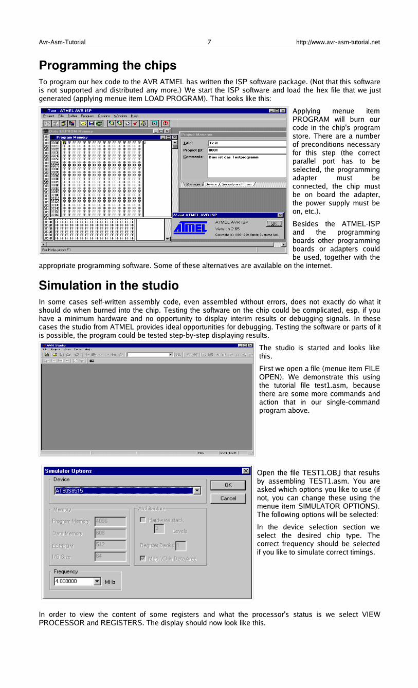
Programming the chipsTo program our hex code to the AVR ATMEL has written the ISP software package. (Not that this softwareis not supported and distributed any more.) We start the ISP software and load the hex file that we justgenerated (applying menue item LOAD PROGRAM). That looks like this:
Applying menue itemPROGRAM will burn ourcode in the chip's programstore. There are a numberof preconditions necessaryfor this step (the correctparallel port has to beselected, the programmingadapter must beconnected, the chip mustbe on board the adapter,the power supply must beon, etc.).
Besides the ATMEL-ISPand the programmingboards other programmingboards or adapters couldbe used, together with the
appropriate programming software. Some of these alternatives are available on the internet.
Simulation in the studioIn some cases self-written assembly code, even assembled without errors, does not exactly do what itshould do when burned into the chip. Testing the software on the chip could be complicated, esp. if youhave a minimum hardware and no opportunity to display interim results or debugging signals. In thesecases the studio from ATMEL provides ideal opportunities for debugging. Testing the software or parts of itis possible, the program could be tested step-by-step displaying results.
The studio is started and looks likethis.
First we open a file (menue item FILEOPEN). We demonstrate this usingthe tutorial file test1.asm, becausethere are some more commands andaction that in our single-commandprogram above.
Open the file TEST1.OBJ that resultsby assembling TEST1.asm. You areasked which options you like to use (ifnot, you can change these using themenue item SIMULATOR OPTIONS).The following options will be selected:
In the device selection section weselect the desired chip type. Thecorrect frequency should be selectedif you like to simulate correct timings.
In order to view the content of some registers and what the processor's status is we select VIEWPROCESSOR and REGISTERS. The display should now look like this.
Avr-Asm-Tutorial 8 http://www.avr-asm-tutorial.net
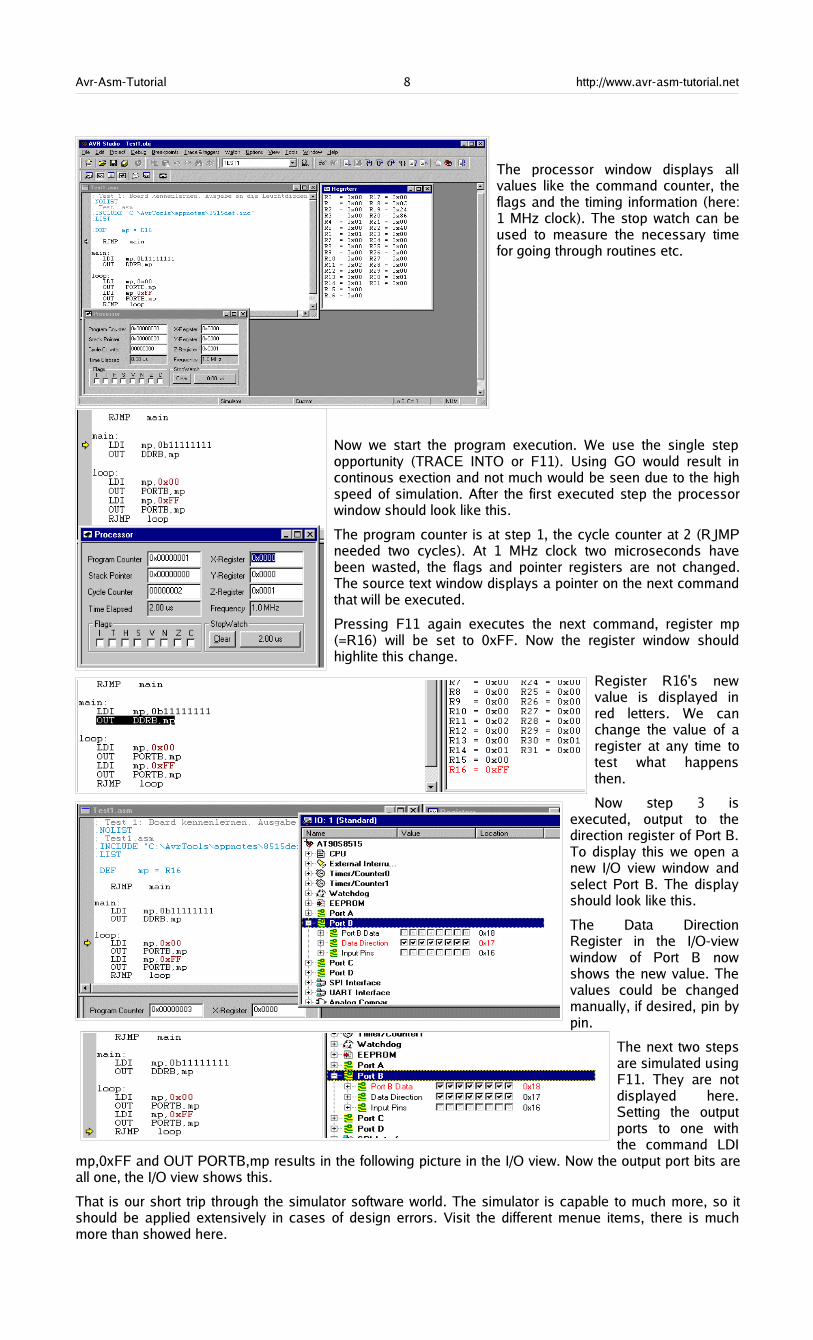
The processor window displays allvalues like the command counter, theflags and the timing information (here:1 MHz clock). The stop watch can beused to measure the necessary timefor going through routines etc.
Now we start the program execution. We use the single stepopportunity (TRACE INTO or F11). Using GO would result incontinous exection and not much would be seen due to the highspeed of simulation. After the first executed step the processorwindow should look like this.
The program counter is at step 1, the cycle counter at 2 (RJMPneeded two cycles). At 1 MHz clock two microseconds havebeen wasted, the flags and pointer registers are not changed.The source text window displays a pointer on the next commandthat will be executed.
Pressing F11 again executes the next command, register mp(=R16) will be set to 0xFF. Now the register window shouldhighlite this change.
Register R16's newvalue is displayed inred letters. We canchange the value of aregister at any time totest what happensthen.
Now step 3 isexecuted, output to thedirection register of Port B.To display this we open anew I/O view window andselect Port B. The displayshould look like this.
The Data DirectionRegister in the I/O-viewwindow of Port B nowshows the new value. Thevalues could be changedmanually, if desired, pin bypin.
The next two stepsare simulated usingF11. They are notdisplayed here.Setting the outputports to one withthe command LDI
mp,0xFF and OUT PORTB,mp results in the following picture in the I/O view. Now the output port bits areall one, the I/O view shows this.
That is our short trip through the simulator software world. The simulator is capable to much more, so itshould be applied extensively in cases of design errors. Visit the different menue items, there is muchmore than showed here.

Avr-Asm-Tutorial 9 http://www.avr-asm-tutorial.net
Register
What is a register?Registers are special storages with 8 bits capacity and they look like this:
Bit 7 Bit 6 Bit 5 Bit 4 Bit 3 Bit 2 Bit 1 Bit 0
Note the numeration of these bits: the least significant bit starts with zero (20 = 1).
A register can either store numbers from 0 to 255 (positive number, no negative values), or numbers from-128 to +127 (whole number with a sign bit in bit 7), or a value representing an ASCII-coded character(e.g. 'A'), or just eight single bits that do not have something to do with each other (e.g. for eight singleflags used to signal eight different yes/no decisions).
The special character of registers, compared to other storage sites, is that
• they can be used directly in assembler commands,
• operations with their content require only a single command word,
• they are connected directly to the central processing unit called the accumulator,
• they are source and target for calculations.
There are 32 registers in an AVR. They are originally named R0 to R31, but you can choose to name themto more meaningful names using an assembler directive. An example:
.DEF MyPreferredRegister = R16Assembler directives always start with a dot in column 1 of the text. Instructions do NEVER start in column1, they are always preceeded by a Tab- or blank character!
Note that assembler directives like this are only meaningful for the assembler but do not produce any codethat is executable in the AVR target chip. Instead of using the register name R16 we can now use our ownname MyPreferredRegister, if we want to use R16 within a command. So we write a little bit more text eachtime we use this register, but we have an association what might be the content of this register.
Using the command line
LDI MyPreferredRegister, 150
which means: load the number 150 immediately to the register R16, LoaD Immediate. This loads a fixedvalue or a constant to that register. Following the assembly or translation of this code the program storagewritten to the AVR chip looks like this:
000000 E906
The load command code as well as the target register (R16) as well as the value of the constant (150) ispart of the hex value E906, even if you don't see this directly. Don't be afraid: you don't have to rememberthis coding because the assembler knows how to translate all this to yield E906.
Within one command two different registers can play a role. The easiest command of this type is the copycommand MOV. It copies the content of one register to another register. Like this:
.DEF MyPreferredRegister = R16
.DEF AnotherRegister = R15LDI MyPreferredRegister, 150MOV AnotherRegister, MyPreferredRegister
The first two lines of this monster program are directives that define the new names of the registers R16and R15 for the assembler. Again, these lines do not produce any code for the AVR. The command lineswith LDI and MOV produce code:
000000 E906000001 2F01
The commands write 150 into register R16 and copy its content to the target register R15. IMPORTANTNOTE:
The first register is always the target register where the result is written to!
(This is unfortunately different from what one expects or from how we speak. It is a simple convention thatwas once defined that way to confuse the beginners learning assembler. That is why assembler is thatcomplicated.)

Avr-Asm-Tutorial 10 http://www.avr-asm-tutorial.net
Different registersThe beginner might want to write the above commands like this:
.DEF AnotherRegister = R15LDI AnotherRegister, 150
And: you lost. Only the registers from R16 to R31 load a constant immediately with the LDI command, R0to R15 don't do that. This restriction is not very fine, but could not be avoided during construction of thecommand set for the AVRs.
There is one exception from that rule: setting a register to Zero. This command
CLR MyPreferredRegister
is valid for all registers.
Besides the LDI command you will find this register class restriction with the following additionalcommands:
• ANDI Rx,K ; Bit-And of register Rx with a constant value K,
• CBR Rx,M ; Clear all bits in register Rx that are set to one within the constant mask value M,
• CPI Rx,K ; Compare the content of the register Rx with a constant value K,
• SBCI Rx,K ; Subtract the constant K and the current value of the carry flag from the content ofregister Rx and store the result in register Rx,
• SBR Rx,M ; Set all bits in register Rx to one, that are one in the constant mask M,
• SER Rx ; Set all bits in register Rx to one (equal to LDI Rx,255),
• SUBI Rx,K ; Subtract the constant K from the content of register Rx and store the result in registerRx.
In all these commands the register must be between R16 and R31! If you plan to use these commandsyou should select one of these registers for that operation. It is easier to program. This is an additionalreason why you should use the directive to define a register's name, because you can easier change theregisters location afterwards.
PointerregisterA very special extra role is defined for the register pairs R26:R27, R28:R29 and R30:R31. The role is soimportant that these pairs have extra names in AVR assembler: X, Y and Z. These pairs are 16-bit pointerregisters, able to point to adresses with max. 16-bit into SRAM locations (X, Y or Z) or into locations inprogram memory (Z).
The lower byte of the 16-bit-adress is located in the lower register, the higher byte in the upper register.Both parts have their own names, e.g. the higher byte of Z is named ZH (=R31), the lower Byte is ZL(=R30). These names are defined in the standard header file for the chips. Dividing these 16-bit-pointer-names into two different bytes is done like follows:
.EQU Adress = RAMEND ; RAMEND is the highest 16-bit adress in SRAMLDI YH,HIGH(Adress) ; Set the MSBLDI YL,LOW(Adress) ; Set the LSB
Accesses via pointers are programmed with specially designed commands. Read access is named LD(LoaD), write access named ST (STore), e.g. with the X-pointer:
Pointer Sequence Examples
X Read/Write from adress X, don't change the pointer LD R1,X or ST X,R1
X+ Read/Write from/to adress X and increment the pointer afterwards byone
LD R1,X+ or ST X+,R1
-X Decrement the pointer by one and read/write from/to the new adressafterwards
LD R1,-X or ST -X,R1
Similiarly you can use Y and Z for that purpose.
There is only one command for the read access to the program storage. It is defined for the pointer pair Zand it is named LPM (Load from Program Memory). The command copies the byte at adress Z in theprogram memory to the register R0. As the program memory is organised word-wise (one command onone adress consists of 16 bits or two bytes or one word) the least significant bit selects the lower or higherbyte (0=lower byte, 1= higher byte). Because of this the original adress must be multiplied by 2 and accessis limited to 15-bit or 32 kB program memory. Like this:
Avr-Asm-Tutorial 11 http://www.avr-asm-tutorial.net
LDI ZH,HIGH(2*Adress)LDI ZL,LOW(2*Adress)LPM
Following this command the adress must be incremented to point to the next byte in program memory. Asthis is used very often a special pointer incrementation command has been defined to do this:
ADIW ZL,1LPM
ADIW means ADd Immediate Word and a maximum of 63 can be added this way. Note that the assemblerexpects the lower of the pointer register pair ZL as first parameter. This is somewhat confusing as additionis done as 16-bit- operation.
The complement command, subtracting a constant value of between 0 and 63 from a 16-bit pointerregister is named SBIW, Subtract Immediate Word. (SuBtract Immediate Word). ADIW and SBIW arepossible for the pointer register pairs X, Y and Z and for the register pair R25:R24, that does not have anextra name and does not allow access to SRAM or program memory locations. R25:R24 is ideal forhandling 16-bit values.
How to insert that table of values in the program memory? This is done with the assembler directives .DBand .DW. With that you can insert bytewise or wordwise lists of values. Bytewise organised lists look likethis:
.DB 123,45,67,89 ; a list of four bytes
.DB "This is a text. " ; a list of byte characters
You should always place an even number of bytes on each single line. Otherwise the assembler will add azero byte at the end, which might be unwanted.
The similiar list of words looks like this:
.DW 12345,6789 ; a list of two words
Instead of constants you can also place labels (jump targets) on that list, like that:
Label1:[ ... here are some commands ... ]Label2:[ ... here are some more commands ... ]Table:.DW Label1,Label2 ; a wordwise list of labels
Labels ALWAYS start in column 1!. Note that reading the labels with LPM first yields the lower byte of theword.
A very special application for the pointer registers is the access to the registers themselves. The registersare located in the first 32 bytes of the chip's adress space (at adress 0x0000 to 0x001F). This access isonly meaningful if you have to copy the register's content to SRAM or EEPROM or read these values fromthere back into the registers. More common for the use of pointers is the access to tables with fixed valuesin the program memory space. Here is, as an example, a table with 10 different 16-bit values, where thefifth table value is read to R25:R24:
MyTable:.DW 0x1234,0x2345,0x3456,0x4568,0x5678 ; The table values, wordwise.DW 0x6789,0x789A,0x89AB,0x9ABC,0xABCD ; organisedRead5: LDI ZH,HIGH(MyTable*2) ; Adress of table to pointer Z
LDI ZL,LOW(MyTable*2) ; multiplied by 2 for bytewise accessADIW ZL,10 ; Point to fifth value in tableLPM ; Read least significant byte from program memoryMOV R24,R0 ; Copy LSB to 16-bit registerADIW ZL,1 ; Point to MSB in program memoryLPM ; Read MSB of table valueMOV R25,R0 ; Copy MSB to 16-bit register
This is only an example. You can calculate the table adress in Z from some input value, leading to therespective table values. Tables can be organised byte- or character-wise, too.
Recommendation for the use of registers• Define names for registers with the .DEF directive, never use them with their direct name Rx.
• If you need pointer access reserve R26 to R31 for that purpose.
• 16-bit-counter are best located R25:R24.
• If you need to read from the program memory, e.g. fixed tables, reserve Z (R31:R30) and R0 for thatpurpose.
• If you plan to have access to single bits within certain registers (e.g. for testing flags), use R16 toR23 for that purpose.
Avr-Asm-Tutorial 12 http://www.avr-asm-tutorial.net
Ports
What is a Port?Ports in the AVR are gates from the central processing unit to internal and external hard- and softwarecomponents. The CPU communicates with these components, reads from them or writes to them, e.g. tothe timers or the parallel ports. The most used port is the flag register, where results of previous operationsare written to and branch conditions are read from.
There are 64 different ports, which are not physically available in all different AVR types. Depending on thestorage space and other internal hardware the different ports are either available and accessable or not.Which of these ports can be used is listed in the data sheets for the processor type.
Ports have a fixed address, over which the CPU communicates. The address is independent from the typeof AVR. So e.g. the port adress of port B is always 0x18 (0x stands for hexadecimal notation). You don'thave to remember these port adresses, they have convenient aliases. These names are defined in theinclude files (header files) for the different AVR types, that are provided from the producer. The includefiles have a line defining port B's address as follows:
.EQU PORTB, 0x18
So we just have to remember the name of port B, not its location in the I/O space of the chip. The includefile 8515def.inc is involved by the assembler directive
.INCLUDE "C:\Somewhere\8515def.inc"
and the registers of the 8515 are all defined then and easily accessable.
Ports usually are organised as 8-bit numbers, but can also hold up to 8 single bits that don't have much todo with each other. If these single bits have a meaning they have their own name associated in the includefile, e.g. to enable manipulation of a single bit. Due to that name convention you don't have to rememberthese bit positions. These names are defined in the data sheets and are given in the include file, too. Theyare provided here in the port tables.
As an example the MCU General Control Register, called MCUCR, consists of a number of single controlbits that control the general property of the chip (see the description in MCUCR in detail). It is a port, fullypacked with 8 control bits with their own names (ISC00, ISC01, ...). Those who want to send their AVR toa deep sleep need to know from the data sheet how to set the respective bits. Like this:
.DEF MyPreferredRegister = R16LDI MyPreferredRegister, 0b00100000OUT MCUCR, MyPreferredRegisterSLEEP
The Out command brings the content of my preferred register, a Sleep-Enable-Bit called SE, to the portMCUCR and sets the AVR immediately to sleep, if there is a SLEEP instruction executed. As all the otherbits of MCUCR are also set by the above instructions and the Sleep Mode bit SM was set to zero, a modecalled half-sleep will result: no further command execution will be performed but the chip still reacts totimer and other hardware interrupts. These external events interrupt the big sleep of the CPU if they feelthey should notify the CPU.
Reading a port's content is in most cases possible using the IN command. The following sequence
.DEF MyPreferredRegister = R16IN MyPreferredRegister, MCUCR
reads the bits in port MCUCR to the register. As many ports have undefined and unused bits in certainports, these bits always read back as zeros.
More often than reading all 8 bits of a port one must react to a certain status of a port. In that case we don'tneed to read the whole port and isolate the relevant bit. Certain commands provide an opportunity toexecute commands depending on the level of a certain bit (see the JUMP section). Setting or clearingcertain bits of a port is also possible without reading and writing the other bits in the port. The twocommands are SBI (Set Bit I/o) and CBI (Clear Bit I/o). Execution is like this:
.EQU ActiveBit=0 ; The bit that is to be changedSBI PortB, ActiveBit ; The bit will be set to oneCBI PortB, Activebit ; The bit will be cleared to zero
These two instructions have a limitation: only ports with an adress smaller than 0x20 can be handled, portsabove cannot be accessed that way.
For the more exotic programmer: the ports can be accessed using SRAM access commands, e.g. ST andLD. Just add 0x20 to the port's adress (the first 32 addresses are the registers!) and access the port thatway. Like demonstrated here:
.DEF MyPreferredRegister = R16LDI ZH,HIGH(PORTB+32)
Avr-Asm-Tutorial 13 http://www.avr-asm-tutorial.net
LDI ZL,LOW(PORTB+32)LD MyPreferredRegister,Z
That only makes sense in certain cases, but it is possible. It is the reason why the first address location ofthe SRAM is always 0x60.
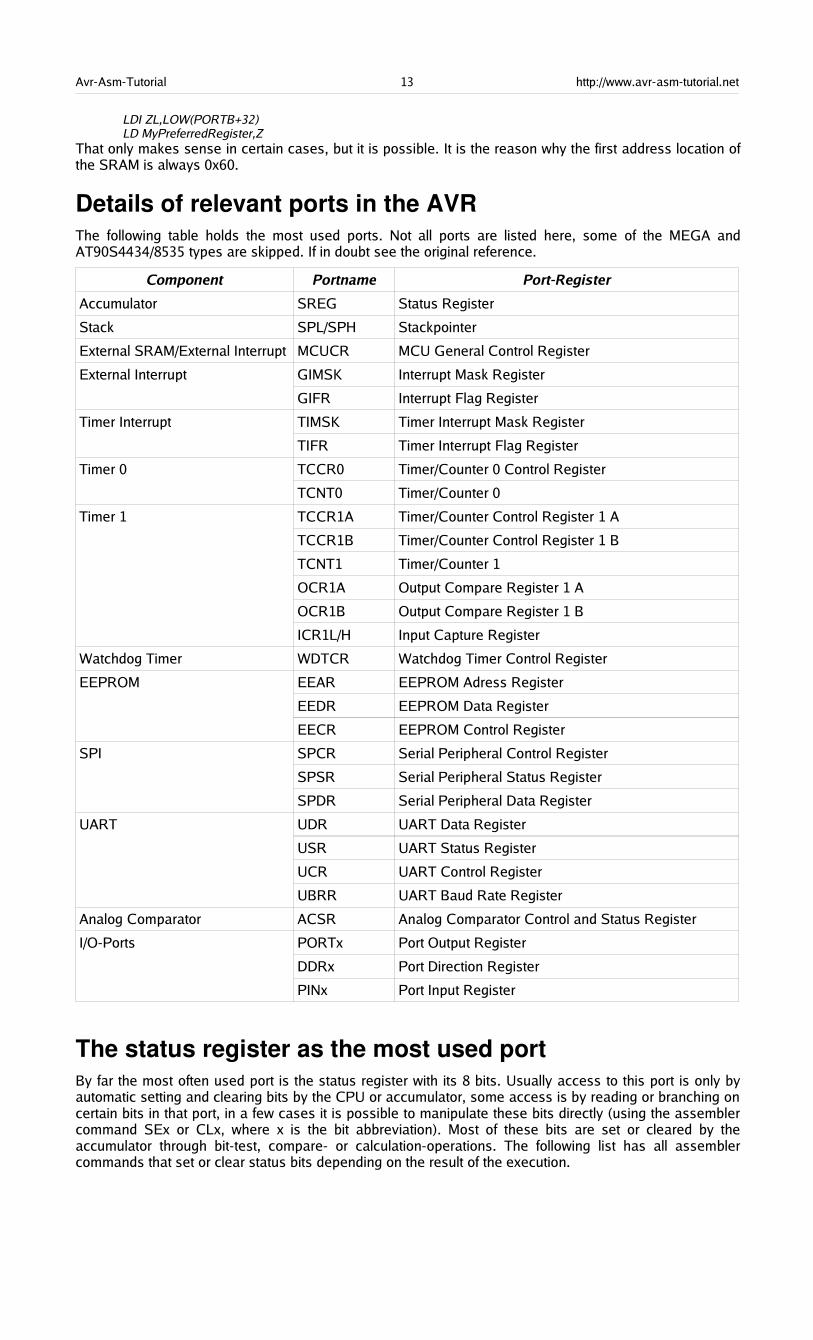
Details of relevant ports in the AVRThe following table holds the most used ports. Not all ports are listed here, some of the MEGA andAT90S4434/8535 types are skipped. If in doubt see the original reference.
Component Portname Port-Register
Accumulator SREG Status Register
Stack SPL/SPH Stackpointer
External SRAM/External Interrupt MCUCR MCU General Control Register
External Interrupt GIMSK Interrupt Mask Register
GIFR Interrupt Flag Register
Timer Interrupt TIMSK Timer Interrupt Mask Register
TIFR Timer Interrupt Flag Register
Timer 0 TCCR0 Timer/Counter 0 Control Register
TCNT0 Timer/Counter 0
Timer 1 TCCR1A Timer/Counter Control Register 1 A
TCCR1B Timer/Counter Control Register 1 B
TCNT1 Timer/Counter 1
OCR1A Output Compare Register 1 A
OCR1B Output Compare Register 1 B
ICR1L/H Input Capture Register
Watchdog Timer WDTCR Watchdog Timer Control Register
EEPROM EEAR EEPROM Adress Register
EEDR EEPROM Data Register
EECR EEPROM Control Register
SPI SPCR Serial Peripheral Control Register
SPSR Serial Peripheral Status Register
SPDR Serial Peripheral Data Register
UART UDR UART Data Register
USR UART Status Register
UCR UART Control Register
UBRR UART Baud Rate Register
Analog Comparator ACSR Analog Comparator Control and Status Register
I/O-Ports PORTx Port Output Register
DDRx Port Direction Register
PINx Port Input Register
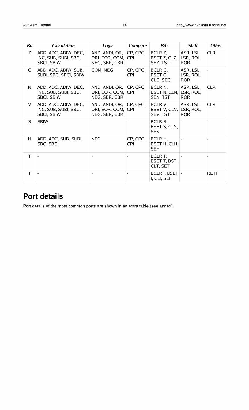
The status register as the most used portBy far the most often used port is the status register with its 8 bits. Usually access to this port is only byautomatic setting and clearing bits by the CPU or accumulator, some access is by reading or branching oncertain bits in that port, in a few cases it is possible to manipulate these bits directly (using the assemblercommand SEx or CLx, where x is the bit abbreviation). Most of these bits are set or cleared by theaccumulator through bit-test, compare- or calculation-operations. The following list has all assemblercommands that set or clear status bits depending on the result of the execution.
Avr-Asm-Tutorial 14 http://www.avr-asm-tutorial.net
Bit Calculation Logic Compare Bits Shift Other
Z ADD, ADC, ADIW, DEC,INC, SUB, SUBI, SBC,SBCI, SBIW
AND, ANDI, OR,ORI, EOR, COM,NEG, SBR, CBR
CP, CPC,CPI
BCLR Z,BSET Z, CLZ,SEZ, TST
ASR, LSL,LSR, ROL,ROR
CLR
C ADD, ADC, ADIW, SUB,SUBI, SBC, SBCI, SBIW
COM, NEG CP, CPC,CPI
BCLR C,BSET C,CLC, SEC
ASR, LSL,LSR, ROL,ROR
-
N ADD, ADC, ADIW, DEC,INC, SUB, SUBI, SBC,SBCI, SBIW
AND, ANDI, OR,ORI, EOR, COM,NEG, SBR, CBR
CP, CPC,CPI
BCLR N,BSET N, CLN,SEN, TST
ASR, LSL,LSR, ROL,ROR
CLR
V ADD, ADC, ADIW, DEC,INC, SUB, SUBI, SBC,SBCI, SBIW
AND, ANDI, OR,ORI, EOR, COM,NEG, SBR, CBR
CP, CPC,CPI
BCLR V,BSET V, CLV,SEV, TST
ASR, LSL,LSR, ROL,ROR
CLR
S SBIW - - BCLR S,BSET S, CLS,SES
- -
H ADD, ADC, SUB, SUBI,SBC, SBCI
NEG CP, CPC,CPI
BCLR H,BSET H, CLH,SEH
- -
T - - - BCLR T,BSET T, BST,CLT, SET
- -
I - - - BCLR I, BSETI, CLI, SEI
- RETI
Port detailsPort details of the most common ports are shown in an extra table (see annex).
Avr-Asm-Tutorial 15 http://www.avr-asm-tutorial.net
SRAM
Using SRAM in AVR assembler languageNearly all AT90S-AVR-type MCUs have static RAM (SRAM) on board (some don't). Only very simpleassembler programs can avoid using this memory space by putting all info into registers. If you run out ofregisters you should be able to program the SRAM to utilize more space.
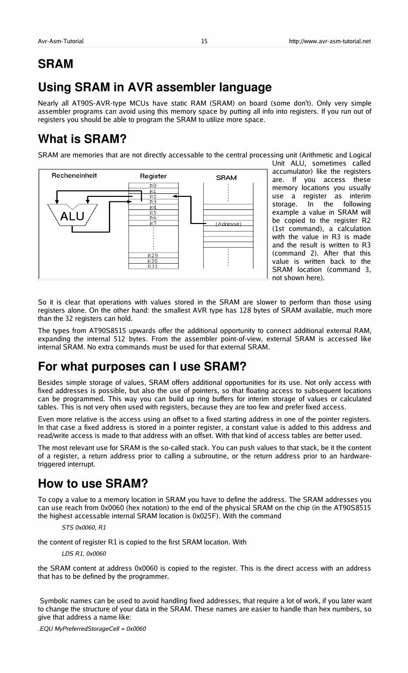
What is SRAM?SRAM are memories that are not directly accessable to the central processing unit (Arithmetic and Logical
Unit ALU, sometimes calledaccumulator) like the registersare. If you access thesememory locations you usuallyuse a register as interimstorage. In the followingexample a value in SRAM willbe copied to the register R2(1st command), a calculationwith the value in R3 is madeand the result is written to R3(command 2). After that thisvalue is written back to theSRAM location (command 3,not shown here).
So it is clear that operations with values stored in the SRAM are slower to perform than those usingregisters alone. On the other hand: the smallest AVR type has 128 bytes of SRAM available, much morethan the 32 registers can hold.
The types from AT90S8515 upwards offer the additional opportunity to connect additional external RAM,expanding the internal 512 bytes. From the assembler point-of-view, external SRAM is accessed likeinternal SRAM. No extra commands must be used for that external SRAM.
For what purposes can I use SRAM?Besides simple storage of values, SRAM offers additional opportunities for its use. Not only access withfixed addresses is possible, but also the use of pointers, so that floating access to subsequent locationscan be programmed. This way you can build up ring buffers for interim storage of values or calculatedtables. This is not very often used with registers, because they are too few and prefer fixed access.
Even more relative is the access using an offset to a fixed starting address in one of the pointer registers.In that case a fixed address is stored in a pointer register, a constant value is added to this address andread/write access is made to that address with an offset. With that kind of access tables are better used.
The most relevant use for SRAM is the so-called stack. You can push values to that stack, be it the contentof a register, a return address prior to calling a subroutine, or the return address prior to an hardware-triggered interrupt.
How to use SRAM?To copy a value to a memory location in SRAM you have to define the address. The SRAM addresses youcan use reach from 0x0060 (hex notation) to the end of the physical SRAM on the chip (in the AT90S8515the highest accessable internal SRAM location is 0x025F). With the command
STS 0x0060, R1
the content of register R1 is copied to the first SRAM location. With
LDS R1, 0x0060
the SRAM content at address 0x0060 is copied to the register. This is the direct access with an addressthat has to be defined by the programmer.
Symbolic names can be used to avoid handling fixed addresses, that require a lot of work, if you later wantto change the structure of your data in the SRAM. These names are easier to handle than hex numbers, sogive that address a name like:
.EQU MyPreferredStorageCell = 0x0060

Avr-Asm-Tutorial 16 http://www.avr-asm-tutorial.net
STS MyPreferredStorageCell, R1
Yes, it isn't shorter, but easier to remember. Use whatever name that you find to be convenient.
Another kind of access to SRAM is the use of pointers. You need two registers for that purpose, that holdthe 16-bit address of the location. As we learned in the Pointer-Register-Division pointer registers are thepairs X (XH:XL, R27:R26), Y (YH:YL, R29:R28) and Z (ZH:ZL, R31:R30). They allow access to thelocation they point to directly (e.g. with ST X, R1), after prior decrementing the address by one (e.g. ST -X,R1) or with subsequent incrementation of the address (e.g. ST X+, R1). A complete access to three cellsin a row looks like this:
.EQU MyPreferredStorageCell = 0x0060
.DEF MyPreferredRegister = R1
.DEF AnotherRegister = R2
.DEF AndAnotherRegister = R3LDI XH, HIGH(MyPreferredStorageCell)LDI XL, LOW(MyPreferredStorageCell)LD MyPreferredRegister, X+LD AnotherRegister, X+LD AndAnotherRegister, X
Easy to operate, those pointers. And as easy as in other languages than assembler, that claim to beeasier to learn.
The third construction is a little bit more exotic and only experienced programmers use this. Let's assumewe very often in our program need to access three SRAM locations. Let's futher assume that we have aspare pointer register pair, so we can afford to use it exclusively for our purpose. If we would use theST/LD instructions we always have to change the pointer if we access another location. Not veryconvenient.
To avoid this, and to confuse the beginner, the access with offset was invented. During that access theregister value isn't changed. The address is calculated by temporarly adding the fixed offset. In the aboveexample the access to location 0x0062 would look like this. First, the pointer register is set to our centrallocation 0x0060:
.EQU MyPreferredStorageCell = 0x0060
.DEF MyPreferredRegister = R1LDI YH, HIGH(MyPreferredStorageCell)LDI YL, LOW(MyPreferredStorageCell)
Somewhere later in the program I'd like to access cell 0x0062:
STD Y+2, MyPreferredRegister
Note that 2 is not really added to Y, just temporarly. To confuse you further, this can only be done with theY- and Z-register-pair, not with the X-pointer!
The corresponding instruction for reading from SRAM with an offset
LDD MyPreferredRegister, Y+2
is also possible.
That's it with the SRAM, but wait: the most relevant use as stack is still to be learned.
Use of SRAM as stackThe most common use of SRAM is its use as stack. The stack is a tower of wooden blocks. Eachadditional block goes onto the top of the tower, each recall of a value removes the upmost block from thetower. This structure is called Last-In-First-Out (LIFO) or easier: the last to go on top will be the firstcoming down.
Defining SRAM as stackTo use SRAM as stack requires the setting of the stack pointer first. The stack pointer is a 16-bit-pointer,accessable like a port. The double register is named SPH:SPL. SPH holds the most significant addressbyte, SPL the least significant. This is only true, if the AVR type has more than 256 byte SRAM. If not, SPHis undefined and must not and cannot be used. We assume we have more than 256 bytes in the followingexamples.
To construct the stack the stack pointer is loaded with the highest available SRAM address. (In our casethe tower grows downwards, towards lower addresses!).
.DEF MyPreferredRegister = R16LDI MyPreferredRegister, HIGH(RAMEND) ; Upper byteOUT SPH,MyPreferredRegister ; to stack pointerLDI MyPreferredRegister, LOW(RAMEND) ; Lower byteOUT SPL,MyPreferredRegister ; to stack pointer
Avr-Asm-Tutorial 17 http://www.avr-asm-tutorial.net
The value RAMEND is, of course, specific for the processor type. It is defined in the INCLUDE file for theprocessor type. The file 8515def.inc has the line:
.equ RAMEND =$25F ; Last On-Chip SRAM Location
The file 8515def.inc is included with the assembler directive
.INCLUDE "C:\somewhere\8515def.inc"
at the beginning of our assembler source code.
So we defined the stack now, and we don't have to care about the stack pointer any more, becausemanipulations of that pointer are automatic.
Use of the stackUsing the stack is easy. The content of registers are pushed onto the stack like this:
PUSH MyPreferredRegister ; Throw that value
Where that value goes to is totally uninteresting. That the stack pointer was decremented after that push,we don't have to care. If we need the content again, we just add the following instruction:
POP MyPreferredRegister ; Read back the value
With POP we just get the value that was last pushed on top of the stack. Pushing and popping registersmakes sense, if
•the content is again needed some lines of code later,
•all registers are in use, and if
•no other opportunity exists to store that value somewhere else.
If these conditions are not given, the use of the stack for saving registers is useless and just wastesprocessor time.
More sense makes the use of the stack in subroutines, where you have to return to the program locationthat called the routine. In that case the calling program code pushes the return address (the currentprogram counter value) onto the stack and jumps to the subroutine. After its execution the subroutine popsthe return address from the stack and loads it back into the program counter. Program execution iscontinued exactly one instruction behind the call instruction:
RCALL Somewhat ; Jump to the label somewhat [...] here we continue with the program.
Here the jump to the label somewhat somewhere in the program code,
Somewhat: ; this is the jump address
[...] Here we do something[...] and we are finished and want to jump back to the calling location:
RET
During execution of the RCALL instruction the already incremented program counter, a 16-bit-address, ispushed onto the stack, using two pushes. By reaching the RET instruction the content of the previousprogram counter is reloaded with two pops and execution continues there.
You don't need to care about the address of the stack, where the counter is loaded to. This address isautomatically generated. Even if you call a subroutine within that subroutine the stack function is fine. Thisjust packs two return addresses on top of the stack, the nested subroutine removes the first one, thecalling subroutine the remaining one. As long as there is enough SRAM, everything is fine.
Servicing hardware interrupts isn't possible without the stack. Interrupts stop the normal exection of theprogram, wherever the program currently is. After execution of a specific service routine as a reaction tothat interrupt program execution must return to the previous location, before the interrupt occurred. Thiswould not be possible if the stack is not able to store the return address.
The enormous advances of having a stack for interrupts are the reason, why even the smallest AVRswithout having SRAM have at least a very small hardware stack.
Bugs with the stack operationFor the beginner there are a lot of possible bugs, if you first learn to use stack.
Very clever is the use of the stack without first setting the stack pointer. Because this pointer is set to zeroat program start, the pointer points to register R0. Pushing a byte results in a write to that register,overwriting its previous content. An additional push to the stack writes to 0xFFFF, an undefined position (ifyou don't have external SRAM there). A RCALL and RET will return to a strange address in programmemory. Be sure: there is no warning, like a window popping up saying something like „Illegal Access toMem location xxxx“.

Avr-Asm-Tutorial 18 http://www.avr-asm-tutorial.net
Another opportunity to construct bugs is to forget to pop a previously pushed value, or popping a valuewithout pushing one first.
In a very few cases the stack overflows to below the first SRAM location. This happens in case of a never-ending recursive call. After reaching the lowest SRAM location the next pushes write to the ports (0x005Fdown to 0x0020), then to the registers (0x001F to 0x0000). Funny and unpredictable things happen withthe chip hardware, if this goes on. Avoid this bug, it can even destroy your hardware!

Avr-Asm-Tutorial 19 http://www.avr-asm-tutorial.net
Jumping and BranchingHere we discuss all commands that control the sequential execution of a program. It starts with the startingsequence on power-up of the processor, jumps, interrupts, etc.
Controlling sequential execution of the program
What happens during a reset?When the power supply of an AVR rises and the processor starts its work, the hardware triggers a resetsequence. The counter for the program steps will be set to zero. At this address the execution alwaysstarts. Here we have to have our first word of code. But not only during power-up this address is activated:
•During an external reset on the reset pin a restart is executed.
•If the Watchdog counter reaches its maximum count, a reset is initiated. A watchdog timer is aninternal clock that must be resetted from time to time by the program, otherwise it restarts theprocessor.
•You can call reset by a direct jump to that address (see the jump section below).
The third case is not a real reset, because the automatic resetting of register- and port-values to a well-defined default value is not executed. So, forget that for now.
The second option, the watchdog reset, must first be enabled by the program. It is disabled by default.Enabling requires write commands to the watchdog's port. Setting the watchdog counter back to zerorequires the execution of the command
WDR
to avoid a reset.
After execution of a reset, with setting registers and ports to default values, the code at address 0000 iswordwise read to the execution part of the processor and is executed. During that execution the programcounter is already incremented by one and the next word of code is already read to the code fetch buffer(Fetch during Execution). If the executed command does not require a jump to another location in theprogram the next command is executed immediately. That is why the AVRs execute extremely fast, eachclock cycle executes one command (if no jumps occur).
The first command of an executable is always located at address 0000. To tell the compiler (assemblerprogram) that our source code starts now and here, a special directive can be placed at the beginning,before the first code in the source is written:
.CSEG
.ORG 0000
The first directive lets the compiler switch to the code section. All following is translated as code and iswritten to the program memory section of the processor. Another target segment would be the EEPROMsection of the chip, where you also can write bytes or words to.
.ESEG
The third segment is the SRAM section of the chip.
.DSEG
Other than with EEPROM content, that really goes to the EEPROM during programming of the chip, theDSEG segment content is not programmed to the chip. It is only used for correct label calculation duringthe assembly process.
The ORG directive above stands for origin and manipulates the address within the code segment, whereassembled words go to. As our program always starts at 0x0000 the CSEG/ORG directives are trivial, youcan skip these without getting into an error. We could start at 0x0100, but that makes no real sense as theprocessor starts execution at 0000. If you want to place a table exactly to a certain location of the codesegment, you can use ORG. If you want to set a clear sign within your code, after first defining a lot ofother things with .DEF- and .EQU-directives, use the CSEG/ORG sequence, even though it might not benecessary to do that.
As the first code word is always at address zero, this location is also called the reset vector. Following thereset vector the next positions in the program space, addresses 0x0001, 0x0002 etc., are interrupt vectors.These are the positions where the execution jumps to if an external or internal interrupt has been enabledand occurs. These positions called vectors are specific for each processor type and depend on the internalhardware available (see below). The commands to react to such an interrupt have to be placed to theproper vector location. If you use interrupts, the first code, at the reset vector, must be a jump command, tojump over the other vectors. Each interrupt vector must hold a jump command to the respective interruptservice routine. The typical program sequence at the beginning is like follows:
Avr-Asm-Tutorial 20 http://www.avr-asm-tutorial.net
.CSEG
.ORG 0000RJMP StartRJMP IntServRout1
[...] here we place the other interrupt vector commands
[...] and here is a good place for the interrupt service routines themselves
Start: ; This here is the program start[...] Here we place our main program
The command RJMP results in a jump to the label Start:, located some lines below. Remeber, labelsalways start in column 1 of the source code and end with a :. Labels, that don't fulfil these conditions arenot taken for serious by many compiler. Missing labels result in an error message ("Undefined label"), andcompilation is interrupted.
Linear program execution and branchesProgram execution is always linear, if nothing changes the sequential execution. These changes are theexecution of an interrupt or of branching instructions.
Branching is very often depending on some condition, conditioned branching. As an example we assumewe want to construct a 32-bit-counter using registers R1 to R4. The least significant byte in R1 isincremented by one. If the register overflows during that operation (255 + 1 = 0), we have to increment R2similiarly. If R2 overflows, we have to increment R3, and so on.
Incrementation by one is done with the instruction INC. If an overflow occurs during that execution ofINC R1 the zero bit in the status register is set to one (the result of the operation is zero). The carry bit inthe status register, usually set by overflows, is not changed during an INC. This is not to confuse thebeginner, but carry is used for other purposes instead. The Zero-Bit or Zero-flag in this case is enough todetect an overflow. If no overflow occurs we can just leave the counting sequence.
If the Zero-bit is set, we must execute additional incrementation of the other registers.To confuse thebeginner the branching command, that we have to use, is not named BRNZ but BRNE (BRanch if NotEqual). A matter of taste ...
The whole count sequence of the 32-bit-counter should then look like this:
INC R1BRNE GoOn32INC R2BRNE GoOn32INC R3BRNE GoOn32INC R4
GoOn32:
So that's about it. An easy thing. The opposite condition to BRNE is BREQ or BRanch EQual.
Which of the status bits, also called processor flags, are changed during execution of a command is listedin instruction code tables, see the List of Instructions. Similiarly to the Zero-bit you can use the other statusbits like that:
BRCC label/BRCS label; Carry-flag 0 oder 1BRSH label; Equal or greaterBRLO label; SmallerBRMI label; MinusBRPL label; PlusBRGE label; Greater or equal (with sign bit)BRLT label; Smaller (with sign bit)BRHC label/BRHS label; Half overflow flag 0 or 1BRTC label/BRTS label; T-Bit 0 or 1BRVC label/BRVS label; Two's complement flag 0 or 1BRIE label/BRID label; Interrupt enabled or disabled
to react to the different conditions. Branching always occurs if the condition is met. Don't be afraid, most ofthese commands are rarely used. For the beginner only Zero and Carry are relevant.
Timing during program executionLike mentioned above the required time to execute one instruction is equal to the processor's clock cycle.If the processor runs on a 4 MHz clock frequency then one instruction requires 1/4 µs or 250 ns, at 10 MHzclock only 100 ns. The required time is as exact as the xtal clock. If you need exact timing an AVR is theoptimal solution for your problem. Note that there are a few commands that require two or more cycles,e.g. the branching instructions (if branching occurs) or the SRAM read/write sequence. See the instructiontable for details.
To define exact timing there must be an opportunity that does nothing else than delay program execution.
Avr-Asm-Tutorial 21 http://www.avr-asm-tutorial.net
You might use other instructions that do nothing, but more clever is the use of the NO Operation commandNOP. This is the most useless instruction:
NOP
This instruction does nothing but wasting processor time. At 4 MHz clock we need just four of theseinstructions to waste 1 µs. No other hidden meanings here on the NOP instruction. For a signal generatorwith 1 kHz we don't need to add 4000 such instructions to our source code, but we use a software counterand some branching instructions. With these we construct a loop that executes for a certain number oftimes and are exactly delayed. A counter could be a 8-bit-register that is decremented with the DECinstruction, e.g. like this:
CLR R1Count:
DEC R1BRNE Count
16-bit counting can also be used to delay exactly, like this
LDI ZH,HIGH(65535)LDI ZL,LOW(65535)
Count:SBIW ZL,1BRNE Count
If you use more registers to construct nested counters you can reach any delay. And the delay isabsolutely exact, even without a hardware timer.
Macros and program executionVery often you have to write identical or similiar code sequences on different occasions in your sourcecode. If you don't want to write it once and jump to it via a subroutine call you can use a macro to avoidgetting tired writing the same sequence several times. Macros are code sequences, designed and testedonce, and inserted into the code by its macro name. As an example we assume we need to delay programexecution several times by 1 µs at 4 MHz clock. Then we define a macro somewhere in the source:
.MACRO Delay1NOPNOPNOPNOP
.ENDMACRO
This definition of the macro does not yet produce any code, it is silent. Code is produced if you call thatmacro by its name:
[...] somewhere in the source codeDelay1
[...] code goes on here
This results in four NOP incstructions inserted to the code at that location. An additional Delay1 insertsadditional four NOP instructions.
By calling a macro by its name you can add some parameters to manipulate the produced code. But this ismore than a beginner has to know about macros.
If your macro has longer code sequences, or if you are short in code storage space, you should avoid theuse of macros and use subroutines instead.
SubroutinesIn contrary to macros a subroutine does save program storage space. The respective sequence is onlyonce stored in the code and is called from whatever part of the code. To ensure continued execution of thesequence following the subroutine call you need to return to the caller. For a delay of 10 cycles you needto write this subroutine:
Delay10:NOPNOPNOPRET
Subroutines always start with a label, otherwise you would not be able to jump to it, here Delay10:. ThreeNOPs follow and a RET instruction. If you count the necessary cycles you just find 7 cycles (3 for theNOPs, 4 for the RET). The missing 3 are for calling that routine:
[...] somewhere in the source code:RCALL Delay10
[...] further on with the source code
Avr-Asm-Tutorial 22 http://www.avr-asm-tutorial.net
RCALL is a relative call. The call is coded as relative jump, the relative distance from the calling routine tothe subroutine is calculated by the compiler. The RET instruction jumps back to the calling routine. Notethat before you use subroutine calls you must set the stackpointer (see Stack), because the return addressmust be packed on the stack by the RCALL instruction.
If you want to jump directly to somewhere else in the code you have to use the jump instruction:
[...] somewhere in the source codeRJMP Delay10
Return:[...] further on with source code
The routine that you jumped to can not use the RET command in that case. To return back to the callinglocation in the source requires to add another label and the called routine to jump back to this label.Jumping like this is not like calling a subroutine because you can't call this routine from different locationsin the code.
RCALL and RJMP are unconditioned branches. To jump to another location, depending on somecondition, you have to combine these with branching instructions. Conditioned calling of a subroutine canbest be done with the following commands. If you want to call a subroutine depending on a certain bit in aregister use the following sequence:
SBRC R1,7 ; Skip the next instruction if bit 7 is 0RCALL UpLabel ; Call that subroutine
SBRC reads „Skip next instruction if Bit 7 in Register R1 is Clear(Zero)“. The RCALL instruction toUpLabel: is only executed if bit 7 in register R1 is 1, because the next instruction is skipped if it would be 0.If you like to call the subroutine in case this bit is 0 then you use the corresponding instruction SBRS. Theinstruction following SBRS/SBRC can be a single word or double word instruction, the processor knowshow far he has to jump over it. Note that execution times are different then. To jump over more than onefollowing instruction these commands cannot be used.
If you have to skip an instruction if two registers have the same value you can use the following exoticinstruction
CPSE R1,R2 ; Compare R1 and R2, skip if equalRCALL SomeSubroutine ; Call SomeSubroutine
A rarely used command, forget it for the beginning. If you like to skip the following instruction depending ona certain bit in a port use the following instructions SBIC und SBIS. That reads Skip if the Bit in I/o space isClear (or Set), like this:
SBIC PINB,0 ; Skip if Bit 0 on port B is 0RJMP ATarget ; Jump to the label ATarget
The RJMP-instruction is only executed if bit 0 in port B is high. This is something confusing for thebeginner. The access to the port bits is limited to the lower half of ports, the upper 32 ports are not usablehere.
Now, another exotic application for the expert. Skip this if you are a beginner. Assume we have a bit switchwith 4 switches connected to port B. Depending on the state of these 4 bits we would like to jump to 16different locations in the code. Now we can read the port and use several branching instructions to find out,where we have to jump to today. As alternative you can write a table holding the 16 addresses, like this:
MyTab:RJMP Routine1RJMP Routine2[...]RJMP Routine16
In our code we copy that adress of the table to the Z pointer register:
LDI ZH,HIGH(MyTab)LDI ZL,LOW(MyTab)
and add the current state of the port B (in R16) to this address.
ADD ZL,R16BRCC NoOverflowINC ZH
NoOverflow:
Now we can jump to this location in the table, either for calling a subroutine:
ICALL
or as a jump with no way back:
IJMP
The processor loads the content of the Z register pair into its program counter and continues operationthere. More clever than branching over and over?
Avr-Asm-Tutorial 23 http://www.avr-asm-tutorial.net
Interrupts and program executionVery often we have to react on hardware conditions or other events. An example is a change on an inputpin. You can program such a reaction by writing a loop, asking whether a change on the pin has occurred.This method is called polling, its like a bee running around in circles searching for new flowers. If there areno other things to do and reaction time does not matter, you can do this with the processor. If you have todetect short pulses of less than a µs duration this method is useless. In that case you need to program aninterrupt.
An interrupt is triggered by some hardware conditions. The condition has to be enabled first, all hardwareinterrupts are disabled at reset time by default. The respective port bits enabling the component's interruptability are set first. The processor has a bit in its status register enabling him to respond to the interrupt ofall components, the Interrupt Enable Flag. Enabling the general response to interrupts requires thefollowing command:
SEI ; Set Int Enable Bit
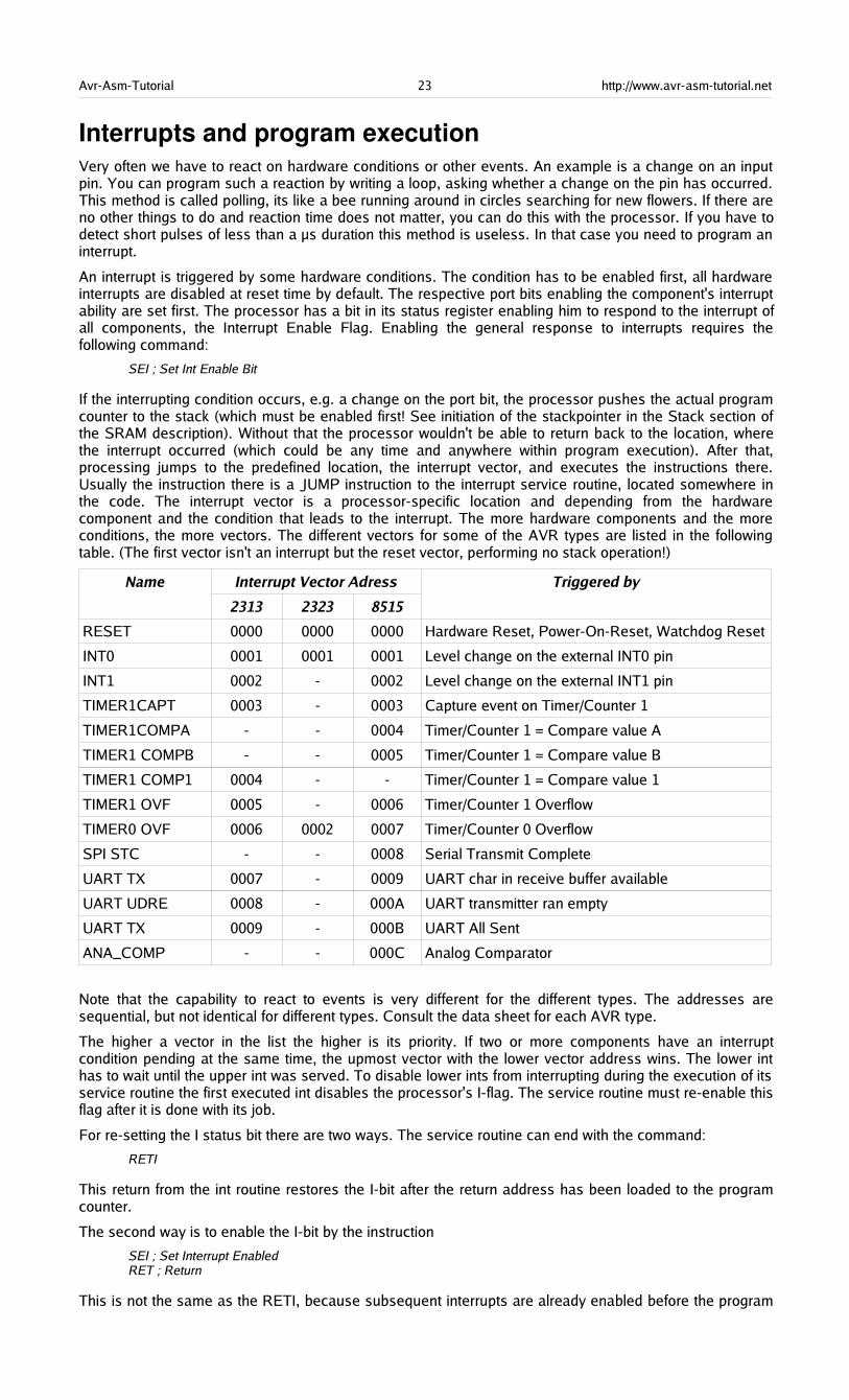
If the interrupting condition occurs, e.g. a change on the port bit, the processor pushes the actual programcounter to the stack (which must be enabled first! See initiation of the stackpointer in the Stack section ofthe SRAM description). Without that the processor wouldn't be able to return back to the location, wherethe interrupt occurred (which could be any time and anywhere within program execution). After that,processing jumps to the predefined location, the interrupt vector, and executes the instructions there.Usually the instruction there is a JUMP instruction to the interrupt service routine, located somewhere inthe code. The interrupt vector is a processor-specific location and depending from the hardwarecomponent and the condition that leads to the interrupt. The more hardware components and the moreconditions, the more vectors. The different vectors for some of the AVR types are listed in the followingtable. (The first vector isn't an interrupt but the reset vector, performing no stack operation!)
Name Interrupt Vector Adress
2313 2323 8515
Triggered by
RESET 0000 0000 0000 Hardware Reset, Power-On-Reset, Watchdog Reset
INT0 0001 0001 0001 Level change on the external INT0 pin
INT1 0002 - 0002 Level change on the external INT1 pin
TIMER1CAPT 0003 - 0003 Capture event on Timer/Counter 1
TIMER1COMPA - - 0004 Timer/Counter 1 = Compare value A
TIMER1 COMPB - - 0005 Timer/Counter 1 = Compare value B
TIMER1 COMP1 0004 - - Timer/Counter 1 = Compare value 1
TIMER1 OVF 0005 - 0006 Timer/Counter 1 Overflow
TIMER0 OVF 0006 0002 0007 Timer/Counter 0 Overflow
SPI STC - - 0008 Serial Transmit Complete
UART TX 0007 - 0009 UART char in receive buffer available
UART UDRE 0008 - 000A UART transmitter ran empty
UART TX 0009 - 000B UART All Sent
ANA_COMP - - 000C Analog Comparator
Note that the capability to react to events is very different for the different types. The addresses aresequential, but not identical for different types. Consult the data sheet for each AVR type.
The higher a vector in the list the higher is its priority. If two or more components have an interruptcondition pending at the same time, the upmost vector with the lower vector address wins. The lower inthas to wait until the upper int was served. To disable lower ints from interrupting during the execution of itsservice routine the first executed int disables the processor's I-flag. The service routine must re-enable thisflag after it is done with its job.
For re-setting the I status bit there are two ways. The service routine can end with the command:
RETI
This return from the int routine restores the I-bit after the return address has been loaded to the programcounter.
The second way is to enable the I-bit by the instruction
SEI ; Set Interrupt EnabledRET ; Return
This is not the same as the RETI, because subsequent interrupts are already enabled before the program
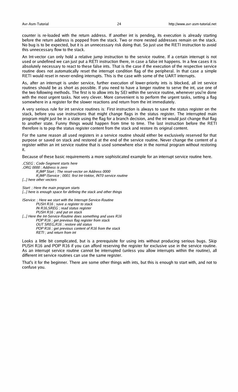
Avr-Asm-Tutorial 24 http://www.avr-asm-tutorial.net
counter is re-loaded with the return address. If another int is pending, its execution is already startingbefore the return address is popped from the stack. Two or more nested addresses remain on the stack.No bug is to be expected, but it is an unnecessary risk doing that. So just use the RETI instruction to avoidthis unnecessary flow to the stack.
An Int-vector can only hold a relative jump instruction to the service routine. If a certain interrupt is notused or undefined we can just put a RETI instruction there, in case a false int happens. In a few cases it isabsolutely necessary to react to these false ints. That is the case if the execution of the respective serviceroutine does not automatically reset the interrupt condition flag of the peripheral. In that case a simpleRETI would reset in never-ending interrupts. This is the case with some of the UART interrupts.
As, after an interrupt is under service, further execution of lower-priority ints is blocked, all int serviceroutines should be as short as possible. If you need to have a longer routine to serve the int, use one ofthe two following methods. The first is to allow ints by SEI within the service routine, whenever you're donewith the most urgent tasks. Not very clever. More convenient is to perform the urgent tasks, setting a flagsomewhere in a register for the slower reactions and return from the int immediately.
A very serious rule for int service routines is: First instruction is always to save the status register on thestack, before you use instructions that might change flags in the status register. The interrupted mainprogram might just be in a state using the flag for a branch decision, and the int would just change that flagto another state. Funny things would happen from time to time. The last instruction before the RETItherefore is to pop the status register content from the stack and restore its original content.
For the same reason all used registers in a service routine should either be exclusively reserved for thatpurpose or saved on stack and restored at the end of the service routine. Never change the content of aregister within an int service routine that is used somewhere else in the normal program without restoringit.
Because of these basic requirements a more sophisticated example for an interrupt service routine here.
.CSEG ; Code-Segment starts here
.ORG 0000 ; Address is zeroRJMP Start ; The reset-vector on Address 0000RJMP IService ; 0001: first Int-Vektor, INT0 service routine
[...] here other vectors Start: ; Here the main program starts[...] here is enough space for defining the stack and other things IService: ; Here we start with the Interrupt-Service-Routine
PUSH R16 ; save a register to stackIN R16,SREG ; read status registerPUSH R16 ; and put on stack
[...] Here the Int-Service-Routine does something and uses R16POP R16 ; get previous flag register from stackOUT SREG,R16 ; restore old statusPOP R16 ; get previous content of R16 from the stackRETI ; and return from int
Looks a little bit complicated, but is a prerequisite for using ints without producing serious bugs. SkipPUSH R16 and POP R16 if you can afford reserving the register for exclusive use in the service routine.As an interrupt service routine cannot be interrupted (unless you allow interrupts within the routine), alldifferent int service routines can use the same register.
That's it for the beginner. There are some other things with ints, but this is enough to start with, and not toconfuse you.
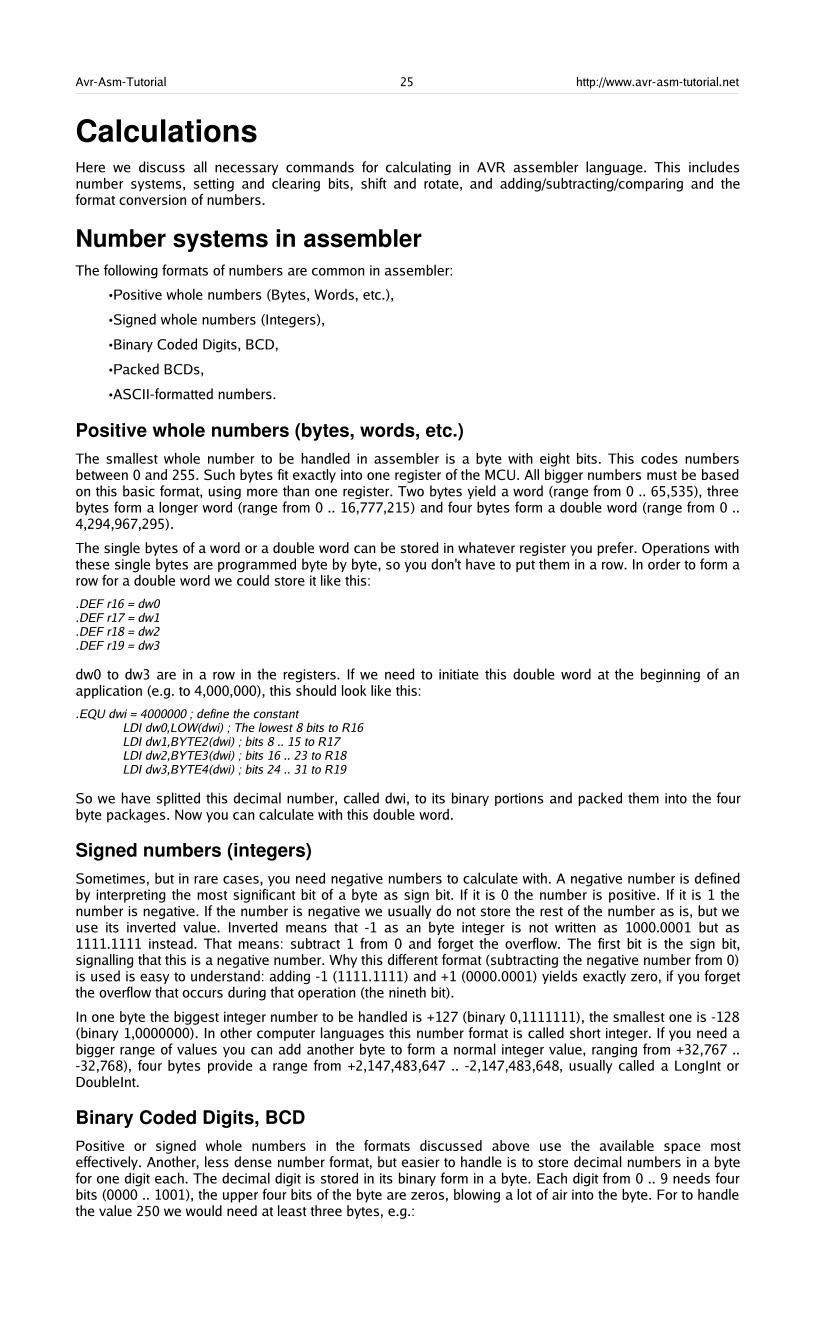
Avr-Asm-Tutorial 25 http://www.avr-asm-tutorial.net
CalculationsHere we discuss all necessary commands for calculating in AVR assembler language. This includesnumber systems, setting and clearing bits, shift and rotate, and adding/subtracting/comparing and theformat conversion of numbers.
Number systems in assemblerThe following formats of numbers are common in assembler:
•Positive whole numbers (Bytes, Words, etc.),
•Signed whole numbers (Integers),
•Binary Coded Digits, BCD,
•Packed BCDs,
•ASCII-formatted numbers.
Positive whole numbers (bytes, words, etc.)The smallest whole number to be handled in assembler is a byte with eight bits. This codes numbersbetween 0 and 255. Such bytes fit exactly into one register of the MCU. All bigger numbers must be basedon this basic format, using more than one register. Two bytes yield a word (range from 0 .. 65,535), threebytes form a longer word (range from 0 .. 16,777,215) and four bytes form a double word (range from 0 ..4,294,967,295).
The single bytes of a word or a double word can be stored in whatever register you prefer. Operations withthese single bytes are programmed byte by byte, so you don't have to put them in a row. In order to form arow for a double word we could store it like this:
.DEF r16 = dw0
.DEF r17 = dw1
.DEF r18 = dw2
.DEF r19 = dw3
dw0 to dw3 are in a row in the registers. If we need to initiate this double word at the beginning of anapplication (e.g. to 4,000,000), this should look like this:
.EQU dwi = 4000000 ; define the constantLDI dw0,LOW(dwi) ; The lowest 8 bits to R16LDI dw1,BYTE2(dwi) ; bits 8 .. 15 to R17LDI dw2,BYTE3(dwi) ; bits 16 .. 23 to R18LDI dw3,BYTE4(dwi) ; bits 24 .. 31 to R19
So we have splitted this decimal number, called dwi, to its binary portions and packed them into the fourbyte packages. Now you can calculate with this double word.
Signed numbers (integers)Sometimes, but in rare cases, you need negative numbers to calculate with. A negative number is definedby interpreting the most significant bit of a byte as sign bit. If it is 0 the number is positive. If it is 1 thenumber is negative. If the number is negative we usually do not store the rest of the number as is, but weuse its inverted value. Inverted means that -1 as an byte integer is not written as 1000.0001 but as1111.1111 instead. That means: subtract 1 from 0 and forget the overflow. The first bit is the sign bit,signalling that this is a negative number. Why this different format (subtracting the negative number from 0)is used is easy to understand: adding -1 (1111.1111) and +1 (0000.0001) yields exactly zero, if you forgetthe overflow that occurs during that operation (the nineth bit).
In one byte the biggest integer number to be handled is +127 (binary 0,1111111), the smallest one is -128(binary 1,0000000). In other computer languages this number format is called short integer. If you need abigger range of values you can add another byte to form a normal integer value, ranging from +32,767 ..-32,768), four bytes provide a range from +2,147,483,647 .. -2,147,483,648, usually called a LongInt orDoubleInt.
Binary Coded Digits, BCDPositive or signed whole numbers in the formats discussed above use the available space mosteffectively. Another, less dense number format, but easier to handle is to store decimal numbers in a bytefor one digit each. The decimal digit is stored in its binary form in a byte. Each digit from 0 .. 9 needs fourbits (0000 .. 1001), the upper four bits of the byte are zeros, blowing a lot of air into the byte. For to handlethe value 250 we would need at least three bytes, e.g.:
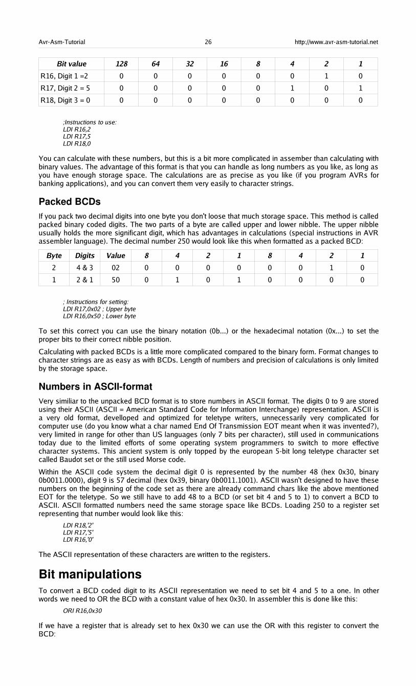
Avr-Asm-Tutorial 26 http://www.avr-asm-tutorial.net
Bit value 128 64 32 16 8 4 2 1
R16, Digit 1 =2 0 0 0 0 0 0 1 0
R17, Digit 2 = 5 0 0 0 0 0 1 0 1
R18, Digit 3 = 0 0 0 0 0 0 0 0 0
;Instructions to use:LDI R16,2LDI R17,5LDI R18,0
You can calculate with these numbers, but this is a bit more complicated in assember than calculating withbinary values. The advantage of this format is that you can handle as long numbers as you like, as long asyou have enough storage space. The calculations are as precise as you like (if you program AVRs forbanking applications), and you can convert them very easily to character strings.
Packed BCDsIf you pack two decimal digits into one byte you don't loose that much storage space. This method is calledpacked binary coded digits. The two parts of a byte are called upper and lower nibble. The upper nibbleusually holds the more significant digit, which has advantages in calculations (special instructions in AVRassembler language). The decimal number 250 would look like this when formatted as a packed BCD:
Byte Digits Value 8 4 2 1 8 4 2 1
2 4 & 3 02 0 0 0 0 0 0 1 0
1 2 & 1 50 0 1 0 1 0 0 0 0
; Instructions for setting:LDI R17,0x02 ; Upper byteLDI R16,0x50 ; Lower byte
To set this correct you can use the binary notation (0b...) or the hexadecimal notation (0x...) to set theproper bits to their correct nibble position.
Calculating with packed BCDs is a little more complicated compared to the binary form. Format changes tocharacter strings are as easy as with BCDs. Length of numbers and precision of calculations is only limitedby the storage space.
Numbers in ASCIIformatVery similiar to the unpacked BCD format is to store numbers in ASCII format. The digits 0 to 9 are storedusing their ASCII (ASCII = American Standard Code for Information Interchange) representation. ASCII isa very old format, develloped and optimized for teletype writers, unnecessarily very complicated forcomputer use (do you know what a char named End Of Transmission EOT meant when it was invented?),very limited in range for other than US languages (only 7 bits per character), still used in communicationstoday due to the limited efforts of some operating system programmers to switch to more effectivecharacter systems. This ancient system is only topped by the european 5-bit long teletype character setcalled Baudot set or the still used Morse code.
Within the ASCII code system the decimal digit 0 is represented by the number 48 (hex 0x30, binary0b0011.0000), digit 9 is 57 decimal (hex 0x39, binary 0b0011.1001). ASCII wasn't designed to have thesenumbers on the beginning of the code set as there are already command chars like the above mentionedEOT for the teletype. So we still have to add 48 to a BCD (or set bit 4 and 5 to 1) to convert a BCD toASCII. ASCII formatted numbers need the same storage space like BCDs. Loading 250 to a register setrepresenting that number would look like this:
LDI R18,'2'LDI R17,'5'LDI R16,'0'
The ASCII representation of these characters are written to the registers.
Bit manipulationsTo convert a BCD coded digit to its ASCII representation we need to set bit 4 and 5 to a one. In otherwords we need to OR the BCD with a constant value of hex 0x30. In assembler this is done like this:
ORI R16,0x30
If we have a register that is already set to hex 0x30 we can use the OR with this register to convert theBCD:
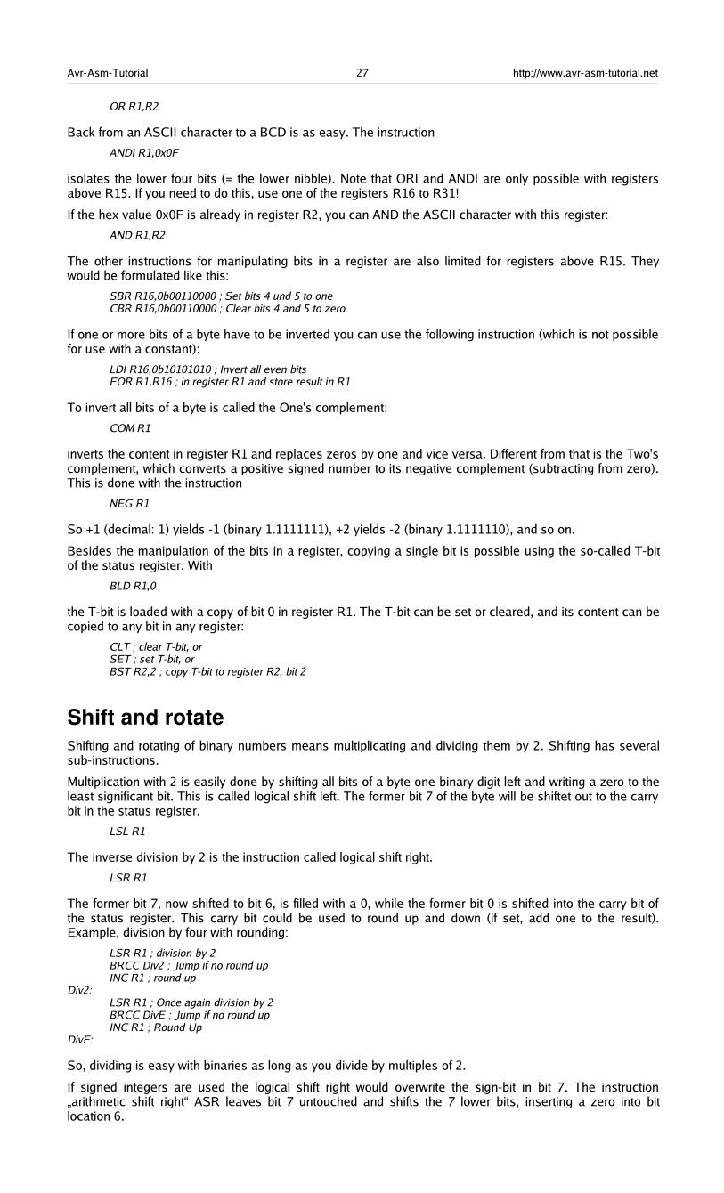
Avr-Asm-Tutorial 27 http://www.avr-asm-tutorial.net
OR R1,R2
Back from an ASCII character to a BCD is as easy. The instruction
ANDI R1,0x0F
isolates the lower four bits (= the lower nibble). Note that ORI and ANDI are only possible with registersabove R15. If you need to do this, use one of the registers R16 to R31!
If the hex value 0x0F is already in register R2, you can AND the ASCII character with this register:
AND R1,R2
The other instructions for manipulating bits in a register are also limited for registers above R15. Theywould be formulated like this:
SBR R16,0b00110000 ; Set bits 4 und 5 to oneCBR R16,0b00110000 ; Clear bits 4 and 5 to zero
If one or more bits of a byte have to be inverted you can use the following instruction (which is not possiblefor use with a constant):
LDI R16,0b10101010 ; Invert all even bitsEOR R1,R16 ; in register R1 and store result in R1
To invert all bits of a byte is called the One's complement:
COM R1
inverts the content in register R1 and replaces zeros by one and vice versa. Different from that is the Two'scomplement, which converts a positive signed number to its negative complement (subtracting from zero).This is done with the instruction
NEG R1
So +1 (decimal: 1) yields -1 (binary 1.1111111), +2 yields -2 (binary 1.1111110), and so on.
Besides the manipulation of the bits in a register, copying a single bit is possible using the so-called T-bitof the status register. With
BLD R1,0
the T-bit is loaded with a copy of bit 0 in register R1. The T-bit can be set or cleared, and its content can becopied to any bit in any register:
CLT ; clear T-bit, orSET ; set T-bit, orBST R2,2 ; copy T-bit to register R2, bit 2
Shift and rotateShifting and rotating of binary numbers means multiplicating and dividing them by 2. Shifting has severalsub-instructions.
Multiplication with 2 is easily done by shifting all bits of a byte one binary digit left and writing a zero to theleast significant bit. This is called logical shift left. The former bit 7 of the byte will be shiftet out to the carrybit in the status register.
LSL R1
The inverse division by 2 is the instruction called logical shift right.
LSR R1
The former bit 7, now shifted to bit 6, is filled with a 0, while the former bit 0 is shifted into the carry bit ofthe status register. This carry bit could be used to round up and down (if set, add one to the result).Example, division by four with rounding:
LSR R1 ; division by 2BRCC Div2 ; Jump if no round upINC R1 ; round up
Div2:LSR R1 ; Once again division by 2BRCC DivE ; Jump if no round upINC R1 ; Round Up
DivE:
So, dividing is easy with binaries as long as you divide by multiples of 2.
If signed integers are used the logical shift right would overwrite the sign-bit in bit 7. The instruction„arithmetic shift right“ ASR leaves bit 7 untouched and shifts the 7 lower bits, inserting a zero into bitlocation 6.
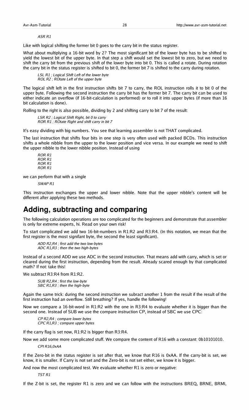
Avr-Asm-Tutorial 28 http://www.avr-asm-tutorial.net
ASR R1
Like with logical shifting the former bit 0 goes to the carry bit in the status register.
What about multiplying a 16-bit word by 2? The most significant bit of the lower byte has to be shifted toyield the lowest bit of the upper byte. In that step a shift would set the lowest bit to zero, but we need toshift the carry bit from the previous shift of the lower byte into bit 0. This is called a rotate. During rotationthe carry bit in the status register is shifted to bit 0, the former bit 7 is shifted to the carry during rotation.
LSL R1 ; Logical Shift Left of the lower byteROL R2 ; ROtate Left of the upper byte
The logical shift left in the first instruction shifts bit 7 to carry, the ROL instruction rolls it to bit 0 of theupper byte. Following the second instruction the carry bit has the former bit 7. The carry bit can be used toeither indicate an overflow (if 16-bit-calculation is performed) or to roll it into upper bytes (if more than 16bit calculation is done).
Rolling to the right is also possible, dividing by 2 and shifting carry to bit 7 of the result:
LSR R2 ; Logical Shift Right, bit 0 to carryROR R1 ; ROtate Right and shift carry in bit 7
It's easy dividing with big numbers. You see that learning assembler is not THAT complicated.
The last instruction that shifts four bits in one step is very often used with packed BCDs. This instructionshifts a whole nibble from the upper to the lower position and vice versa. In our example we need to shiftthe upper nibble to the lower nibble position. Instead of using
ROR R1ROR R1ROR R1ROR R1
we can perform that with a single
SWAP R1
This instruction exchanges the upper and lower nibble. Note that the upper nibble's content will bedifferent after applying these two methods.
Adding, subtracting and comparingThe following calculation operations are too complicated for the beginners and demonstrate that assembleris only for extreme experts, hi. Read on your own risk!
To start complicated we add two 16-bit-numbers in R1:R2 and R3:R4. (In this notation, we mean that thefirst register is the most signifant byte, the second the least significant).
ADD R2,R4 ; first add the two low-bytesADC R1,R3 ; then the two high-bytes
Instead of a second ADD we use ADC in the second instruction. That means add with carry, which is set orcleared during the first instruction, depending from the result. Already scared enough by that complicatedmath? If not: take this!
We subtract R3:R4 from R1:R2.
SUB R2,R4 ; first the low-byteSBC R1,R3 ; then the high-byte
Again the same trick: during the second instruction we subract another 1 from the result if the result of thefirst instruction had an overflow. Still breathing? If yes, handle the following!
Now we compare a 16-bit-word in R1:R2 with the one in R3:R4 to evaluate whether it is bigger than thesecond one. Instead of SUB we use the compare instruction CP, instead of SBC we use CPC:
CP R2,R4 ; compare lower bytesCPC R1,R3 ; compare upper bytes
If the carry flag is set now, R1:R2 is bigger than R3:R4.
Now we add some more complicated stuff. We compare the content of R16 with a constant: 0b10101010.
CPI R16,0xAA
If the Zero-bit in the status register is set after that, we know that R16 is 0xAA. If the carry-bit is set, weknow, it is smaller. If Carry is not set and the Zero-bit is not set either, we know it is bigger.
And now the most complicated test. We evaluate whether R1 is zero or negative:
TST R1
If the Z-bit is set, the register R1 is zero and we can follow with the instructions BREQ, BRNE, BRMI,
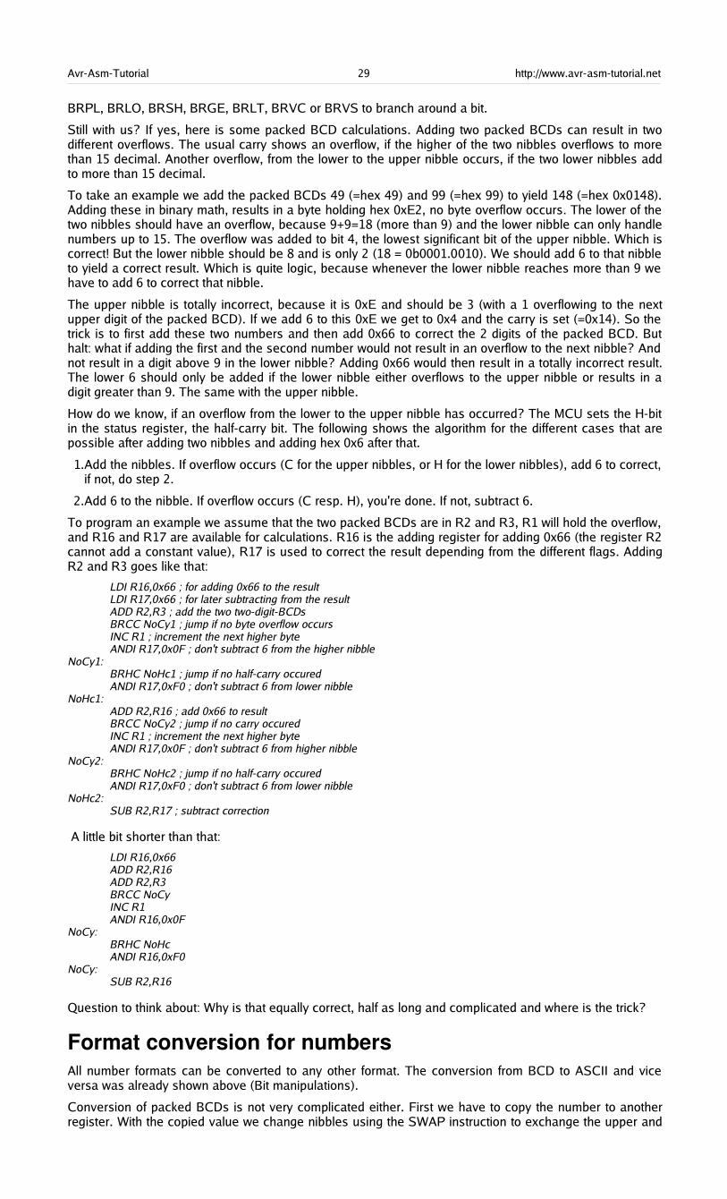
Avr-Asm-Tutorial 29 http://www.avr-asm-tutorial.net
BRPL, BRLO, BRSH, BRGE, BRLT, BRVC or BRVS to branch around a bit.
Still with us? If yes, here is some packed BCD calculations. Adding two packed BCDs can result in twodifferent overflows. The usual carry shows an overflow, if the higher of the two nibbles overflows to morethan 15 decimal. Another overflow, from the lower to the upper nibble occurs, if the two lower nibbles addto more than 15 decimal.
To take an example we add the packed BCDs 49 (=hex 49) and 99 (=hex 99) to yield 148 (=hex 0x0148).Adding these in binary math, results in a byte holding hex 0xE2, no byte overflow occurs. The lower of thetwo nibbles should have an overflow, because 9+9=18 (more than 9) and the lower nibble can only handlenumbers up to 15. The overflow was added to bit 4, the lowest significant bit of the upper nibble. Which iscorrect! But the lower nibble should be 8 and is only 2 (18 = 0b0001.0010). We should add 6 to that nibbleto yield a correct result. Which is quite logic, because whenever the lower nibble reaches more than 9 wehave to add 6 to correct that nibble.
The upper nibble is totally incorrect, because it is 0xE and should be 3 (with a 1 overflowing to the nextupper digit of the packed BCD). If we add 6 to this 0xE we get to 0x4 and the carry is set (=0x14). So thetrick is to first add these two numbers and then add 0x66 to correct the 2 digits of the packed BCD. Buthalt: what if adding the first and the second number would not result in an overflow to the next nibble? Andnot result in a digit above 9 in the lower nibble? Adding 0x66 would then result in a totally incorrect result.The lower 6 should only be added if the lower nibble either overflows to the upper nibble or results in adigit greater than 9. The same with the upper nibble.
How do we know, if an overflow from the lower to the upper nibble has occurred? The MCU sets the H-bitin the status register, the half-carry bit. The following shows the algorithm for the different cases that arepossible after adding two nibbles and adding hex 0x6 after that.
1.Add the nibbles. If overflow occurs (C for the upper nibbles, or H for the lower nibbles), add 6 to correct,if not, do step 2.
2.Add 6 to the nibble. If overflow occurs (C resp. H), you're done. If not, subtract 6.
To program an example we assume that the two packed BCDs are in R2 and R3, R1 will hold the overflow,and R16 and R17 are available for calculations. R16 is the adding register for adding 0x66 (the register R2cannot add a constant value), R17 is used to correct the result depending from the different flags. AddingR2 and R3 goes like that:
LDI R16,0x66 ; for adding 0x66 to the resultLDI R17,0x66 ; for later subtracting from the resultADD R2,R3 ; add the two two-digit-BCDsBRCC NoCy1 ; jump if no byte overflow occursINC R1 ; increment the next higher byteANDI R17,0x0F ; don't subtract 6 from the higher nibble
NoCy1:BRHC NoHc1 ; jump if no half-carry occuredANDI R17,0xF0 ; don't subtract 6 from lower nibble
NoHc1:ADD R2,R16 ; add 0x66 to resultBRCC NoCy2 ; jump if no carry occuredINC R1 ; increment the next higher byteANDI R17,0x0F ; don't subtract 6 from higher nibble
NoCy2:BRHC NoHc2 ; jump if no half-carry occuredANDI R17,0xF0 ; don't subtract 6 from lower nibble
NoHc2:SUB R2,R17 ; subtract correction
A little bit shorter than that:
LDI R16,0x66ADD R2,R16ADD R2,R3BRCC NoCyINC R1ANDI R16,0x0F
NoCy:BRHC NoHcANDI R16,0xF0
NoCy:SUB R2,R16
Question to think about: Why is that equally correct, half as long and complicated and where is the trick?
Format conversion for numbersAll number formats can be converted to any other format. The conversion from BCD to ASCII and viceversa was already shown above (Bit manipulations).
Conversion of packed BCDs is not very complicated either. First we have to copy the number to anotherregister. With the copied value we change nibbles using the SWAP instruction to exchange the upper and
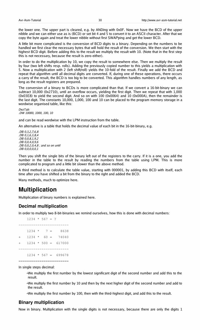
Avr-Asm-Tutorial 30 http://www.avr-asm-tutorial.net
the lower one. The upper part is cleared, e.g. by ANDing with 0x0F. Now we have the BCD of the uppernibble and we can either use as is (BCD) or set bit 4 and 5 to convert it to an ASCII character. After that wecopy the byte again and treat the lower nibble without first SWAPping and get the lower BCD.
A little bit more complicated is the conversion of BCD digits to a binary. Depending on the numbers to behandled we first clear the necessary bytes that will hold the result of the conversion. We then start with thehighest BCD digit. Before adding this to the result we multiply the result with 10. (Note that in the first stepthis is not necessary, because the result is zero either).
In order to do the multiplication by 10, we copy the result to somewhere else. Then we multiply the resultby four (two left shifts resp. rolls). Adding the previously copied number to this yields a multiplication with5. Now a mulitiplication with 2 (left shift/roll) yields the 10-fold of the result. Finally we add the BCD andrepeat that algorithm until all decimal digits are converted. If, during one of these operations, there occursa carry of the result, the BCD is too big to be converted. This algorithm handles numbers of any length, aslong as the result registers are prepared.
The conversion of a binary to BCDs is more complicated than that. If we convert a 16-bit-binary we cansubtract 10,000 (0x2710), until an overflow occurs, yielding the first digit. Then we repeat that with 1,000(0x03E8) to yield the second digit. And so on with 100 (0x0064) and 10 (0x000A), then the remainder isthe last digit. The constants 10,000, 1,000, 100 and 10 can be placed to the program memory storage in awordwise organised table, like this:
DezTab:.DW 10000, 1000, 100, 10
and can be read wordwise with the LPM instruction from the table.
An alternative is a table that holds the decimal value of each bit in the 16-bit-binary, e.g.
.DB 0,3,2,7,6,8
.DB 0,1,6,3,8,4
.DB 0,0,8,1,9,2
.DB 0,0,4,0,9,6
.DB 0,0,2,0,4,8 ; and so on until
.DB 0,0,0,0,0,1
Then you shift the single bits of the binary left out of the registers to the carry. If it is a one, you add thenumber in the table to the result by reading the numbers from the table using LPM. This is morecomplicated to program and a little bit slower than the above method.
A third method is to calculate the table value, starting with 000001, by adding this BCD with itself, eachtime after you have shifted a bit from the binary to the right and added the BCD.
Many methods, much to optimize here.
MultiplicationMultiplication of binary numbers is explained here.
Decimal multiplicationIn order to multiply two 8-bit-binaries we remind ourselves, how this is done with decimal numbers:
1234 * 567 = ?
------------------------
1234 * 7 = 8638
+ 1234 * 60 = 74040
+ 1234 * 500 = 617000
------------------------
1234 * 567 = 699678
========================
In single steps decimal:
•We multiply the first number by the lowest significant digit of the second number and add this to theresult.
•We multiply the first number by 10 and then by the next higher digit of the second number and add tothe result.
•We multiply the first number by 100, then with the third-highest digit, and add this to the result.
Binary multiplicationNow in binary. Multiplication with the single digits is not necessary, because there are only the digits 1

Avr-Asm-Tutorial 31 http://www.avr-asm-tutorial.net
(add the number) and 0 (don't add the number). Multiplication by 10 in decimal goes to multiplication by 2in binary mode. Multiplication by 2 is done easily, either by adding the number with itself, or by shifting allbits one position left and writing a 0 to the void position on the right. You see that binary math is very mucheasier than decimal. Why didn't mankind use this from the beginning?
AVRAssembler programThe following source code demonstrates realisation of multiplication in assembler.
; Mult8.asm multiplies two 8-bit-numbers to yield a 16-bit-result;.NOLIST.INCLUDE "C:\avrtools\appnotes\8515def.inc".LIST;; Flow of multiplication;; 1.The binary to be multiplicated with, is shifted bitwise into the carry bit. If it is a one, the binary number is added to the; result, if it is not a one that was shifted out, the number is not added; 2.The binary number is multiplied by 2 by rotating it one position left, shifting a 0 into the void position.; 3.If the binary to be multiplied with, is not zero, the multiplication loop is repeated. If it is zero, the multiplication is done.;; Used registers;.DEF rm1 = R0 ; Binary number to be multiplicated (8 Bit).DEF rmh = R1 ; Interim storage.DEF rm2 = R2 ; Binary number to be multiplicated with (8 Bit).DEF rel = R3 ; Result, LSB (16 Bit).DEF reh = R4 ; Result, MSB.DEF rmp = R16 ; Multi purpose register for loading;.CSEG.ORG 0000; rjmp START;START: ldi rmp,0xAA ; example binary 1010.1010 mov rm1,rmp ; to the first binary register ldi rmp,0x55 ; example binary 0101.0101 mov rm2,rmp ; to the second binary register;; Here we start with the multiplication of the two binaries in rm1 und rm2, the result will go to reh:rel (16 Bit);MULT8:;; Clear start values clr rmh ; clear interim storage clr rel ; clear result registers clr reh;; Here we start with the multiplication loop;MULT8a:;; Step 1: Rotate lowest bit of binary number 2 to the carry flag (divide by 2, rotate a zero into bit 7); clc ; clear carry bit ror rm2 ; bit 0 to carry, bit 1 to 7 one position to the right, carry bit to bit 7;; Step 2: Branch depending if a 0 or 1 has been rotated to the carry bit; brcc MULT8b ; jump over adding, if carry has a 0;; Step 3: Add 16 bits in rmh:rml to the result, with overflow from LSB to MSB; add rel,rm1 ; add LSB of rm1 to the result adc reh,rmh ; add carry and MSB of rm1;MULT8b:;; Step 4: Multiply rmh:rm1 by 2 (16 bits, shift left); clc ; clear carry bit rol rm1 ; rotate LSB left (multiply by 2) rol rmh ; rotate carry into MSB and MSB one left;; Step 5: Check if there are still one's in binary 2, if yes, go on multiplicating; tst rm2 ; all bits zero? brne MULT8a ; if not, go on in the loop;

Avr-Asm-Tutorial 32 http://www.avr-asm-tutorial.net
; End of the multiplication, result in reh:rel;; Endless loop;LOOP: rjmp loop
Binary rotationFor understanding the multiplication operation,it is necessary to understand the binaryrotation commands ROL and ROR. Theseinstructions shift all bits of a register oneposition left (ROL) resp. right (ROR). The voidposition in the register is filled with the contentof the carry bit of the status register, the bit thatrolls out of the register is shifted to the carrybit. This operation is demonstrated using 0xAAas an example for ROL and 0x55 as anexample for ROR.
Multiplication in the studioThe following screenshots show the multiplication program in the simulator.
The object-code has beenopened, the cursor is placedon the first executableinstruction. F11 does singlesteps.
The registers R0 and R2 areset to 0xAA and 0x55, our testbinaries, to be multiplied.
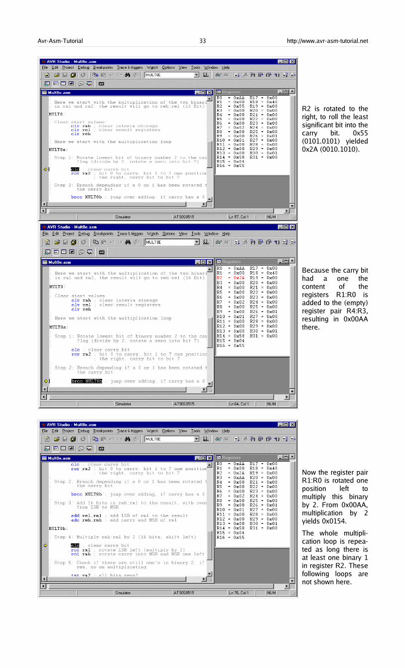
Avr-Asm-Tutorial 33 http://www.avr-asm-tutorial.net
R2 is rotated to theright, to roll the leastsignificant bit into thecarry bit. 0x55(0101.0101) yielded0x2A (0010.1010).
Because the carry bithad a one thecontent of theregisters R1:R0 isadded to the (empty)register pair R4:R3,resulting in 0x00AAthere.
Now the register pairR1:R0 is rotated oneposition left tomultiply this binaryby 2. From 0x00AA,multiplication by 2yields 0x0154.
The whole multipli-cation loop is repea-ted as long there isat least one binary 1in register R2. Thesefollowing loops arenot shown here.
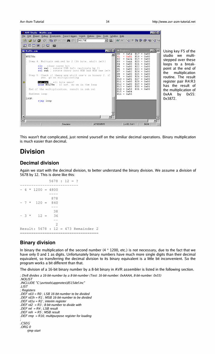
Avr-Asm-Tutorial 34 http://www.avr-asm-tutorial.net
Using key F5 of thestudio we multi-stepped over theseloops to a break-point at the end ofthe multiplicationroutine. The resultregister pair R4:R3has the result ofthe multiplication of0xAA by 0x55:0x3872.
This wasn't that complicated, just remind yourself on the similiar decimal operations. Binary multiplicationis much easier than decimal.
Division
Decimal divisionAgain we start with the decimal division, to better understand the binary division. We assume a division of5678 by 12. This is done like this:
5678 : 12 = ?--------------------------- 4 * 1200 = 4800 ---- 878- 7 * 120 = 840 --- 38- 3 * 12 = 36 -- 2Result: 5678 : 12 = 473 Remainder 2===================================
Binary divisionIn binary the multiplication of the second number (4 * 1200, etc.) is not necessary, due to the fact that wehave only 0 and 1 as digits. Unfortunately binary numbers have much more single digits than their decimalequivalent, so transferring the decimal division to its binary equivalent is a little bit inconvenient. So theprogram works a bit different than that.
The division of a 16-bit binary number by a 8-bit binary in AVR assembler is listed in the following section.
; Div8 divides a 16-bit-number by a 8-bit-number (Test: 16-bit-number: 0xAAAA, 8-bit-number: 0x55).NOLIST.INCLUDE "C:\avrtools\appnotes\8515def.inc".LIST; Registers.DEF rd1l = R0 ; LSB 16-bit-number to be divided.DEF rd1h = R1 ; MSB 16-bit-number to be divided.DEF rd1u = R2 ; interim register.DEF rd2 = R3 ; 8-bit-number to divide with.DEF rel = R4 ; LSB result.DEF reh = R5 ; MSB result.DEF rmp = R16; multipurpose register for loading;.CSEG.ORG 0 rjmp start
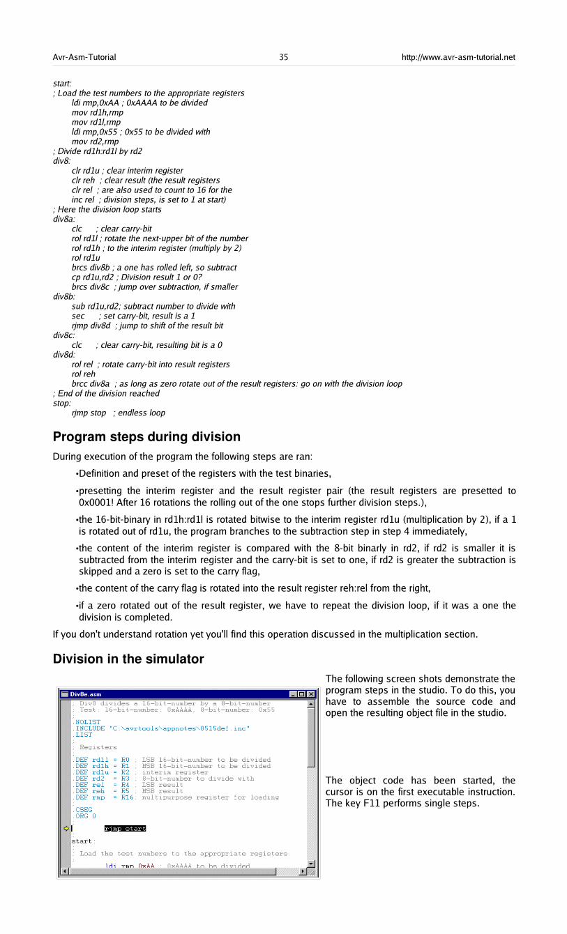
Avr-Asm-Tutorial 35 http://www.avr-asm-tutorial.net
start:; Load the test numbers to the appropriate registers ldi rmp,0xAA ; 0xAAAA to be divided mov rd1h,rmp mov rd1l,rmp ldi rmp,0x55 ; 0x55 to be divided with mov rd2,rmp; Divide rd1h:rd1l by rd2div8: clr rd1u ; clear interim register clr reh ; clear result (the result registers clr rel ; are also used to count to 16 for the inc rel ; division steps, is set to 1 at start); Here the division loop startsdiv8a: clc ; clear carry-bit rol rd1l ; rotate the next-upper bit of the number rol rd1h ; to the interim register (multiply by 2) rol rd1u brcs div8b ; a one has rolled left, so subtract cp rd1u,rd2 ; Division result 1 or 0? brcs div8c ; jump over subtraction, if smallerdiv8b: sub rd1u,rd2; subtract number to divide with sec ; set carry-bit, result is a 1 rjmp div8d ; jump to shift of the result bitdiv8c: clc ; clear carry-bit, resulting bit is a 0div8d: rol rel ; rotate carry-bit into result registers rol reh brcc div8a ; as long as zero rotate out of the result registers: go on with the division loop; End of the division reachedstop: rjmp stop ; endless loop
Program steps during divisionDuring execution of the program the following steps are ran:
•Definition and preset of the registers with the test binaries,
•presetting the interim register and the result register pair (the result registers are presetted to0x0001! After 16 rotations the rolling out of the one stops further division steps.),
•the 16-bit-binary in rd1h:rd1l is rotated bitwise to the interim register rd1u (multiplication by 2), if a 1is rotated out of rd1u, the program branches to the subtraction step in step 4 immediately,
•the content of the interim register is compared with the 8-bit binarly in rd2, if rd2 is smaller it issubtracted from the interim register and the carry-bit is set to one, if rd2 is greater the subtraction isskipped and a zero is set to the carry flag,
•the content of the carry flag is rotated into the result register reh:rel from the right,
•if a zero rotated out of the result register, we have to repeat the division loop, if it was a one thedivision is completed.
If you don't understand rotation yet you'll find this operation discussed in the multiplication section.
Division in the simulatorThe following screen shots demonstrate theprogram steps in the studio. To do this, youhave to assemble the source code andopen the resulting object file in the studio.
The object code has been started, thecursor is on the first executable instruction.The key F11 performs single steps.
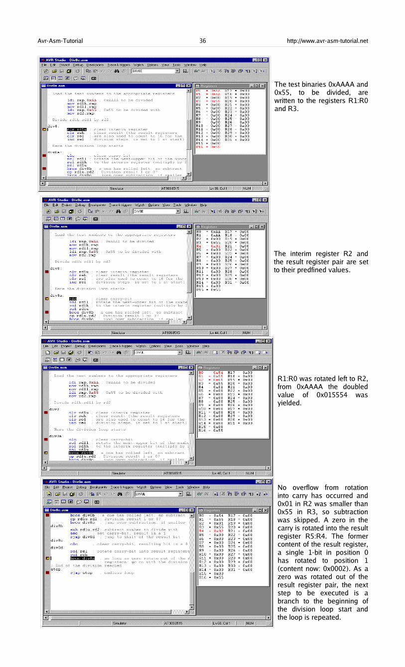
Avr-Asm-Tutorial 36 http://www.avr-asm-tutorial.net
The test binaries 0xAAAA and0x55, to be divided, arewritten to the registers R1:R0and R3.
The interim register R2 andthe result register pair are setto their predfined values.
R1:R0 was rotated left to R2,from 0xAAAA the doubledvalue of 0x015554 wasyielded.
No overflow from rotationinto carry has occurred and0x01 in R2 was smaller than0x55 in R3, so subtractionwas skipped. A zero in thecarry is rotated into the resultregister R5:R4. The formercontent of the result register,a single 1-bit in position 0has rotated to position 1(content now: 0x0002). As azero was rotated out of theresult register pair, the nextstep to be executed is abranch to the beginning ofthe division loop start andthe loop is repeated.
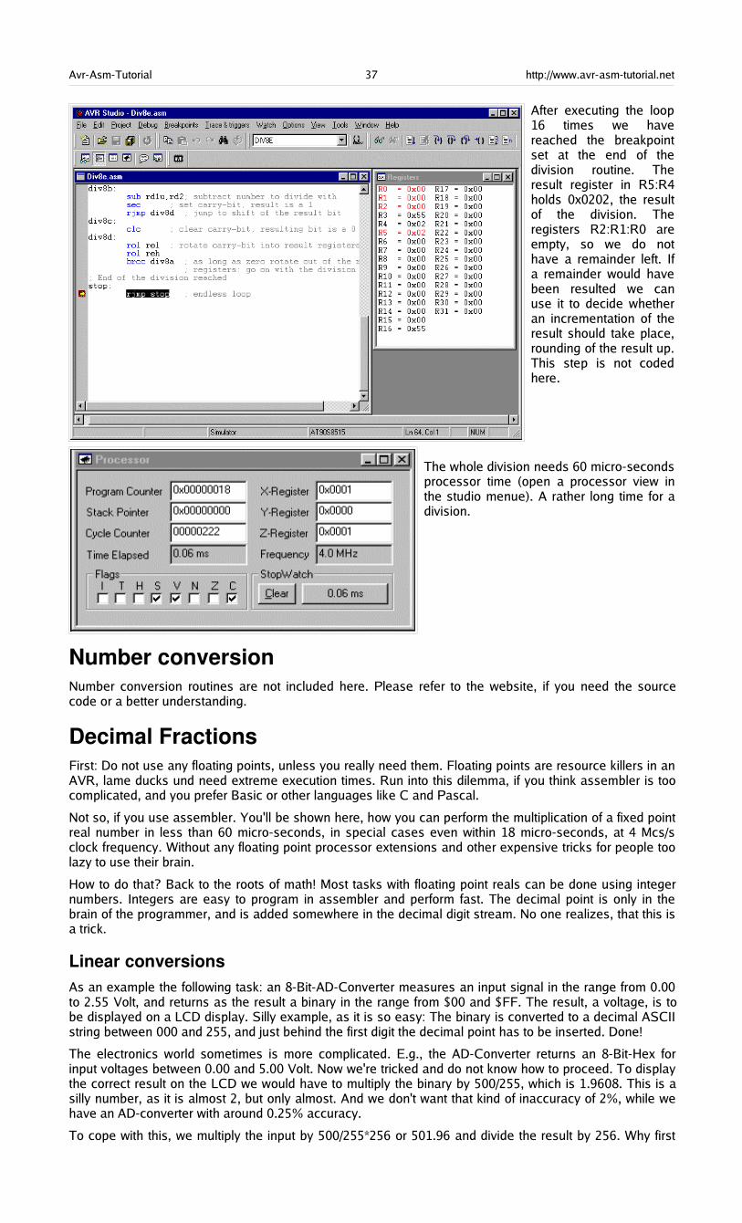
Avr-Asm-Tutorial 37 http://www.avr-asm-tutorial.net
After executing the loop16 times we havereached the breakpointset at the end of thedivision routine. Theresult register in R5:R4holds 0x0202, the resultof the division. Theregisters R2:R1:R0 areempty, so we do nothave a remainder left. Ifa remainder would havebeen resulted we canuse it to decide whetheran incrementation of theresult should take place,rounding of the result up.This step is not codedhere.
The whole division needs 60 micro-secondsprocessor time (open a processor view inthe studio menue). A rather long time for adivision.
Number conversionNumber conversion routines are not included here. Please refer to the website, if you need the sourcecode or a better understanding.
Decimal FractionsFirst: Do not use any floating points, unless you really need them. Floating points are resource killers in anAVR, lame ducks und need extreme execution times. Run into this dilemma, if you think assembler is toocomplicated, and you prefer Basic or other languages like C and Pascal.
Not so, if you use assembler. You'll be shown here, how you can perform the multiplication of a fixed pointreal number in less than 60 micro-seconds, in special cases even within 18 micro-seconds, at 4 Mcs/sclock frequency. Without any floating point processor extensions and other expensive tricks for people toolazy to use their brain.
How to do that? Back to the roots of math! Most tasks with floating point reals can be done using integernumbers. Integers are easy to program in assembler and perform fast. The decimal point is only in thebrain of the programmer, and is added somewhere in the decimal digit stream. No one realizes, that this isa trick.
Linear conversionsAs an example the following task: an 8-Bit-AD-Converter measures an input signal in the range from 0.00to 2.55 Volt, and returns as the result a binary in the range from $00 and $FF. The result, a voltage, is tobe displayed on a LCD display. Silly example, as it is so easy: The binary is converted to a decimal ASCIIstring between 000 and 255, and just behind the first digit the decimal point has to be inserted. Done!
The electronics world sometimes is more complicated. E.g., the AD-Converter returns an 8-Bit-Hex forinput voltages between 0.00 and 5.00 Volt. Now we're tricked and do not know how to proceed. To displaythe correct result on the LCD we would have to multiply the binary by 500/255, which is 1.9608. This is asilly number, as it is almost 2, but only almost. And we don't want that kind of inaccuracy of 2%, while wehave an AD-converter with around 0.25% accuracy.
To cope with this, we multiply the input by 500/255*256 or 501.96 and divide the result by 256. Why first
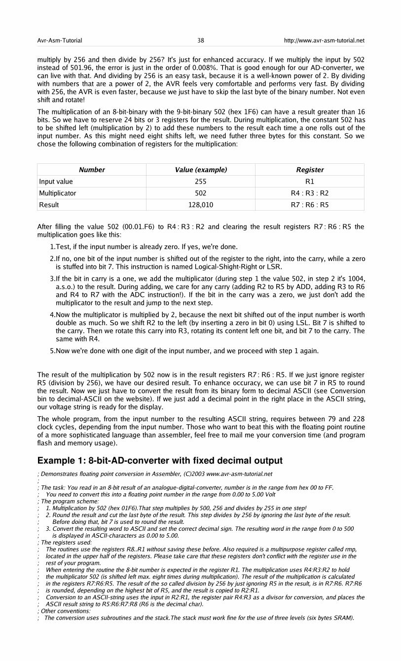
Avr-Asm-Tutorial 38 http://www.avr-asm-tutorial.net
multiply by 256 and then divide by 256? It's just for enhanced accuracy. If we multiply the input by 502instead of 501.96, the error is just in the order of 0.008%. That is good enough for our AD-converter, wecan live with that. And dividing by 256 is an easy task, because it is a well-known power of 2. By dividingwith numbers that are a power of 2, the AVR feels very comfortable and performs very fast. By dividingwith 256, the AVR is even faster, because we just have to skip the last byte of the binary number. Not evenshift and rotate!
The multiplication of an 8-bit-binary with the 9-bit-binary 502 (hex 1F6) can have a result greater than 16bits. So we have to reserve 24 bits or 3 registers for the result. During multiplication, the constant 502 hasto be shifted left (multiplication by 2) to add these numbers to the result each time a one rolls out of theinput number. As this might need eight shifts left, we need futher three bytes for this constant. So wechose the following combination of registers for the multiplication:
Number Value (example) Register
Input value 255 R1
Multiplicator 502 R4 : R3 : R2
Result 128,010 R7 : R6 : R5
After filling the value 502 (00.01.F6) to R4 : R3 : R2 and clearing the result registers R7 : R6 : R5 themultiplication goes like this:
1.Test, if the input number is already zero. If yes, we're done.
2.If no, one bit of the input number is shifted out of the register to the right, into the carry, while a zerois stuffed into bit 7. This instruction is named Logical-Shight-Right or LSR.
3.If the bit in carry is a one, we add the multiplicator (during step 1 the value 502, in step 2 it's 1004,a.s.o.) to the result. During adding, we care for any carry (adding R2 to R5 by ADD, adding R3 to R6and R4 to R7 with the ADC instruction!). If the bit in the carry was a zero, we just don't add themultiplicator to the result and jump to the next step.
4.Now the multiplicator is multiplied by 2, because the next bit shifted out of the input number is worthdouble as much. So we shift R2 to the left (by inserting a zero in bit 0) using LSL. Bit 7 is shifted tothe carry. Then we rotate this carry into R3, rotating its content left one bit, and bit 7 to the carry. Thesame with R4.
5.Now we're done with one digit of the input number, and we proceed with step 1 again.
The result of the multiplication by 502 now is in the result registers R7 : R6 : R5. If we just ignore registerR5 (division by 256), we have our desired result. To enhance occuracy, we can use bit 7 in R5 to roundthe result. Now we just have to convert the result from its binary form to decimal ASCII (see Conversionbin to decimal-ASCII on the website). If we just add a decimal point in the right place in the ASCII string,our voltage string is ready for the display.
The whole program, from the input number to the resulting ASCII string, requires between 79 and 228clock cycles, depending from the input number. Those who want to beat this with the floating point routineof a more sophisticated language than assembler, feel free to mail me your conversion time (and programflash and memory usage).
Example 1: 8bitADconverter with fixed decimal output; Demonstrates floating point conversion in Assembler, (C)2003 www.avr-asm-tutorial.net;; The task: You read in an 8-bit result of an analogue-digital-converter, number is in the range from hex 00 to FF.; You need to convert this into a floating point number in the range from 0.00 to 5.00 Volt; The program scheme:; 1. Multiplication by 502 (hex 01F6).That step multiplies by 500, 256 and divides by 255 in one step!; 2. Round the result and cut the last byte of the result. This step divides by 256 by ignoring the last byte of the result.; Before doing that, bit 7 is used to round the result.; 3. Convert the resulting word to ASCII and set the correct decimal sign. The resulting word in the range from 0 to 500; is displayed in ASCII-characters as 0.00 to 5.00.; The registers used:; The routines use the registers R8..R1 without saving these before. Also required is a multipurpose register called rmp,; located in the upper half of the registers. Please take care that these registers don't conflict with the register use in the; rest of your program.; When entering the routine the 8-bit number is expected in the register R1. The multiplication uses R4:R3:R2 to hold; the multiplicator 502 (is shifted left max. eight times during multiplication). The result of the multiplication is calculated; in the registers R7:R6:R5. The result of the so called division by 256 by just ignoring R5 in the result, is in R7:R6. R7:R6; is rounded, depending on the highest bit of R5, and the result is copied to R2:R1.; Conversion to an ASCII-string uses the input in R2:R1, the register pair R4:R3 as a divisor for conversion, and places the; ASCII result string to R5:R6:R7:R8 (R6 is the decimal char).; Other conventions:; The conversion uses subroutines and the stack.The stack must work fine for the use of three levels (six bytes SRAM).
Avr-Asm-Tutorial 39 http://www.avr-asm-tutorial.net
; Conversion times:; The whole routine requires 228 clock cycles maximum (converting $FF), and 79 clock cycles minimum (converting $00).; At 4 MHz the times are 56.75 microseconds resp. 17.75 microseconds.; Definitions:; Registers.DEF rmp = R16 ; used as multi-purpose register; AVR type: Tested for type AT90S8515, only required for stack setting, routines work fine with other AT90S-types also.NOLIST.INCLUDE "8515def.inc".LIST; Start of test program; Just writes a number to R1 and starts the conversion routine, for test purposes only.CSEG.ORG $0000 rjmp mainmain: ldi rmp,HIGH(RAMEND) ; Set the stack out SPH,rmp ldi rmp,LOW(RAMEND) out SPL,rmp ldi rmp,$FF ; Convert $FF mov R1,rmp rcall fpconv8 ; call the conversion routineno_end: ; unlimited loop, when done rjmp no_end; Conversion routine wrapper, calls the different conversion stepsfpconv8: rcall fpconv8m ; multiplicate by 502 rcall fpconv8r ; round and divide by 256 rcall fpconv8a ; convert to ASCII string ldi rmp,'.' ; set decimal char mov R6,rmp ret ; all done; Subroutine multiplication by 502fpconv8m: clr R4 ; set the multiplicant to 502 ldi rmp,$01 mov R3,rmp ldi rmp,$F6 mov R2,rmp clr R7 ; clear the result clr R6 clr R5fpconv8m1: or R1,R1 ; check if the number is all zeros brne fpconv8m2 ; still one's, go on convert ret ; ready, return backfpconv8m2: lsr R1 ; shift number to the right (div by 2) brcc fpconv8m3 ; if the lowest bit was 0, then skip adding add R5,R2 ; add the number in R6:R5:R4:R3 to the result adc R6,R3 adc R7,R4fpconv8m3: lsl R2 ; multiply R4:R3:R2 by 2 rol R3 rol R4 rjmp fpconv8m1 ; repeat for next bit; Round the value in R7:R6 with the value in bit 7 of R5fpconv8r: clr rmp ; put zero to rmp lsl R5 ; rotate bit 7 to carry adc R6,rmp ; add LSB with carry adc R7,rmp ; add MSB with carry mov R2,R7 ; copy the value to R2:R1 (divide by 256) mov R1,R6 ret; Convert the word in R2:R1 to an ASCII string in R5:R6:R7:R8fpconv8a: clr R4 ; Set the decimal divider value to 100 ldi rmp,100 mov R3,rmp rcall fpconv8d ; get ASCII digit by repeated subtraction mov R5,rmp ; set hundreds string char ldi rmp,10 ; Set the decimal divider value to 10 mov R3,rmp rcall fpconv8d ; get the next ASCII digit mov R7,rmp ; set tens string char ldi rmp,'0' ; convert the rest to an ASCII char add rmp,R1 mov R8,rmp ; set ones string char ret
Avr-Asm-Tutorial 40 http://www.avr-asm-tutorial.net
; Convert binary word in R2:R1 to a decimal digit by substracting the decimal divider value in R4:R3 (100, 10)fpconv8d: ldi rmp,'0' ; start with decimal value 0fpconv8d1: cp R1,R3 ; Compare word with decimal divider value cpc R2,R4 brcc fpconv8d2 ; Carry clear, subtract divider value ret ; done subtractionfpconv8d2: sub R1,R3 ; subtract divider value sbc R2,R4 inc rmp ; up one digit rjmp fpconv8d1 ; once again; End of conversion test routine
Example 2: 10bitADconverter with fixed decimal outputThis example is a bit more complicated. Refer to the website if you need it.
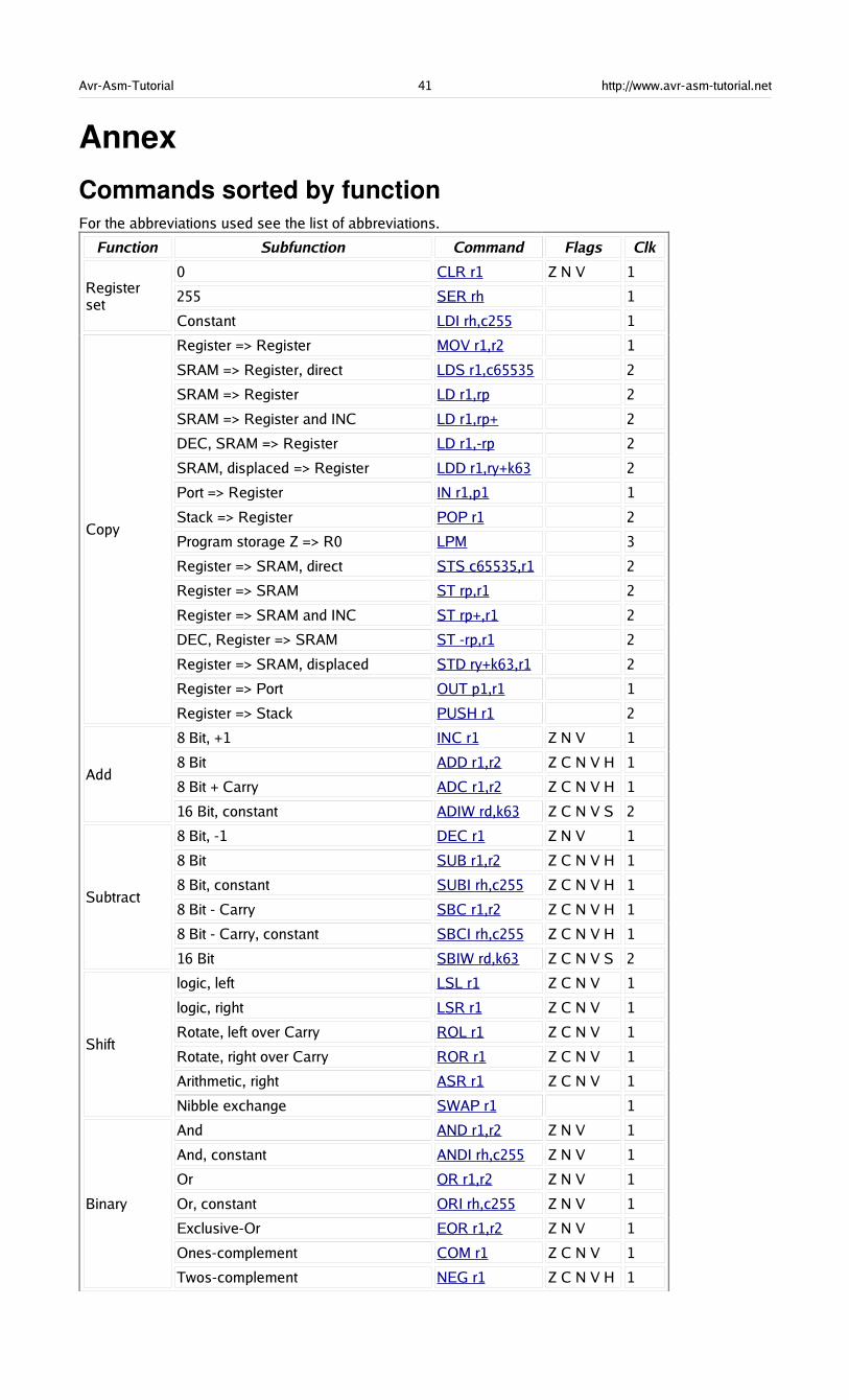
Avr-Asm-Tutorial 41 http://www.avr-asm-tutorial.net
Annex
Commands sorted by functionFor the abbreviations used see the list of abbreviations.
Function Subfunction Command Flags Clk
Registerset
0 CLR r1 Z N V 1
255 SER rh 1
Constant LDI rh,c255 1
Copy
Register => Register MOV r1,r2 1
SRAM => Register, direct LDS r1,c65535 2
SRAM => Register LD r1,rp 2
SRAM => Register and INC LD r1,rp+ 2
DEC, SRAM => Register LD r1,-rp 2
SRAM, displaced => Register LDD r1,ry+k63 2
Port => Register IN r1,p1 1
Stack => Register POP r1 2
Program storage Z => R0 LPM 3
Register => SRAM, direct STS c65535,r1 2
Register => SRAM ST rp,r1 2
Register => SRAM and INC ST rp+,r1 2
DEC, Register => SRAM ST -rp,r1 2
Register => SRAM, displaced STD ry+k63,r1 2
Register => Port OUT p1,r1 1
Register => Stack PUSH r1 2
Add
8 Bit, +1 INC r1 Z N V 1
8 Bit ADD r1,r2 Z C N V H 1
8 Bit + Carry ADC r1,r2 Z C N V H 1
16 Bit, constant ADIW rd,k63 Z C N V S 2
Subtract
8 Bit, -1 DEC r1 Z N V 1
8 Bit SUB r1,r2 Z C N V H 1
8 Bit, constant SUBI rh,c255 Z C N V H 1
8 Bit - Carry SBC r1,r2 Z C N V H 1
8 Bit - Carry, constant SBCI rh,c255 Z C N V H 1
16 Bit SBIW rd,k63 Z C N V S 2
Shift
logic, left LSL r1 Z C N V 1
logic, right LSR r1 Z C N V 1
Rotate, left over Carry ROL r1 Z C N V 1
Rotate, right over Carry ROR r1 Z C N V 1
Arithmetic, right ASR r1 Z C N V 1
Nibble exchange SWAP r1 1
Binary
And AND r1,r2 Z N V 1
And, constant ANDI rh,c255 Z N V 1
Or OR r1,r2 Z N V 1
Or, constant ORI rh,c255 Z N V 1
Exclusive-Or EOR r1,r2 Z N V 1
Ones-complement COM r1 Z C N V 1
Twos-complement NEG r1 Z C N V H 1
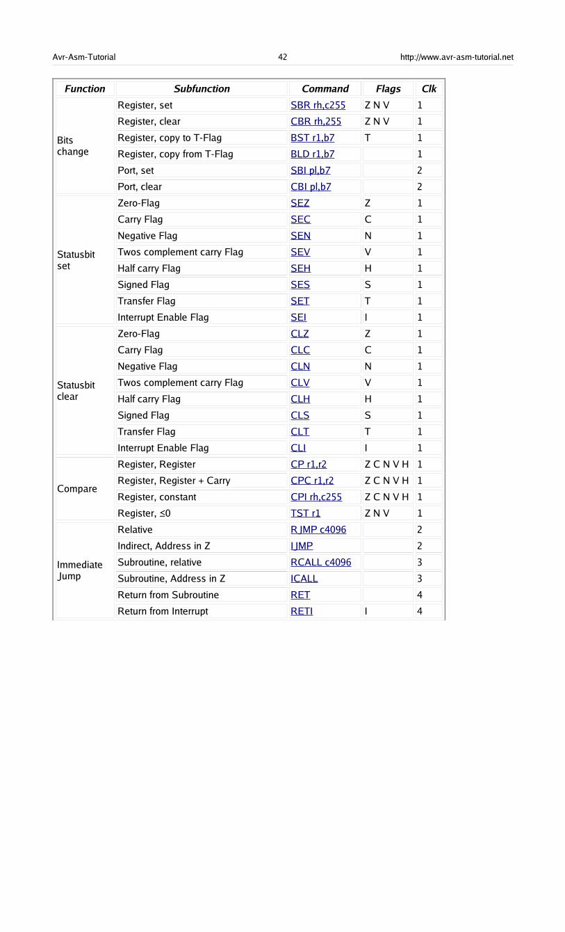
Avr-Asm-Tutorial 42 http://www.avr-asm-tutorial.net
Function Subfunction Command Flags Clk
Bitschange
Register, set SBR rh,c255 Z N V 1
Register, clear CBR rh,255 Z N V 1
Register, copy to T-Flag BST r1,b7 T 1
Register, copy from T-Flag BLD r1,b7 1
Port, set SBI pl,b7 2
Port, clear CBI pl,b7 2
Statusbitset
Zero-Flag SEZ Z 1
Carry Flag SEC C 1
Negative Flag SEN N 1
Twos complement carry Flag SEV V 1
Half carry Flag SEH H 1
Signed Flag SES S 1
Transfer Flag SET T 1
Interrupt Enable Flag SEI I 1
Statusbitclear
Zero-Flag CLZ Z 1
Carry Flag CLC C 1
Negative Flag CLN N 1
Twos complement carry Flag CLV V 1
Half carry Flag CLH H 1
Signed Flag CLS S 1
Transfer Flag CLT T 1
Interrupt Enable Flag CLI I 1
Compare
Register, Register CP r1,r2 Z C N V H 1
Register, Register + Carry CPC r1,r2 Z C N V H 1
Register, constant CPI rh,c255 Z C N V H 1
Register, 0≤ TST r1 Z N V 1
ImmediateJump
Relative RJMP c4096 2
Indirect, Address in Z IJMP 2
Subroutine, relative RCALL c4096 3
Subroutine, Address in Z ICALL 3
Return from Subroutine RET 4
Return from Interrupt RETI I 4
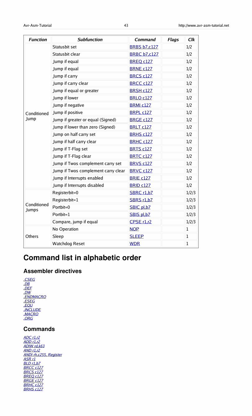
Avr-Asm-Tutorial 43 http://www.avr-asm-tutorial.net
Function Subfunction Command Flags Clk
ConditionedJump
Statusbit set BRBS b7,c127 1/2
Statusbit clear BRBC b7,c127 1/2
Jump if equal BREQ c127 1/2
Jump if equal BRNE c127 1/2
Jump if carry BRCS c127 1/2
Jump if carry clear BRCC c127 1/2
Jump if equal or greater BRSH c127 1/2
Jump if lower BRLO c127 1/2
Jump if negative BRMI c127 1/2
Jump if positive BRPL c127 1/2
Jump if greater or equal (Signed) BRGE c127 1/2
Jump if lower than zero (Signed) BRLT c127 1/2
Jump on half carry set BRHS c127 1/2
Jump if half carry clear BRHC c127 1/2
Jump if T-Flag set BRTS c127 1/2
Jump if T-Flag clear BRTC c127 1/2
Jump if Twos complement carry set BRVS c127 1/2
Jump if Twos complement carry clear BRVC c127 1/2
Jump if Interrupts enabled BRIE c127 1/2
Jump if Interrupts disabled BRID c127 1/2
ConditionedJumps
Registerbit=0 SBRC r1,b7 1/2/3
Registerbit=1 SBRS r1,b7 1/2/3
Portbit=0 SBIC pl,b7 1/2/3
Portbit=1 SBIS pl,b7 1/2/3
Compare, jump if equal CPSE r1,r2 1/2/3
Others
No Operation NOP 1
Sleep SLEEP 1
Watchdog Reset WDR 1
Command list in alphabetic order
Assembler directives.CSEG.DB.DEF.DW.ENDMACRO.ESEG.EQU.INCLUDE.MACRO.ORG
CommandsADC r1,r2ADD r1,r2ADIW rd,k63AND r1,r2ANDI rh,c255, RegisterASR r1BLD r1,b7BRCC c127BRCS c127BREQ c127BRGE c127BRHC c127BRHS c127
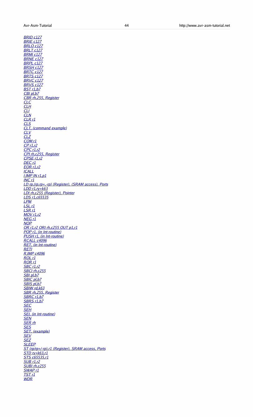
Avr-Asm-Tutorial 44 http://www.avr-asm-tutorial.net
BRID c127BRIE c127BRLO c127BRLT c127BRMI c127BRNE c127BRPL c127BRSH c127BRTC c127BRTS c127BRVC c127BRVS c127BST r1,b7CBI pl,b7CBR rh,255, RegisterCLCCLHCLICLNCLR r1CLSCLT, (command example)CLVCLZCOM r1CP r1,r2CPC r1,r2CPI rh,c255, RegisterCPSE r1,r2DEC r1EOR r1,r2ICALLIJMP IN r1,p1INC r1LD rp,(rp,rp+,-rp) (Register), (SRAM access), PortsLDD r1,ry+k63LDI rh,c255 (Register), PointerLDS r1,c65535LPMLSL r1LSR r1MOV r1,r2NEG r1NOPOR r1,r2 ORI rh,c255 OUT p1,r1POP r1, (in Int-routine)PUSH r1, (in Int-routine)RCALL c4096RET, (in Int-routine)RETIRJMP c4096ROL r1ROR r1SBC r1,r2SBCI rh,c255SBI pl,b7SBIC pl,b7SBIS pl,b7SBIW rd,k63SBR rh,255, RegisterSBRC r1,b7SBRS r1,b7SECSEHSEI, (in Int-routine)SENSER rhSESSET, (example)SEVSEZSLEEPST (rp/rp+/-rp),r1 (Register), SRAM access, PortsSTD ry+k63,r1STS c65535,r1SUB r1,r2SUBI rh,c255SWAP r1TST r1WDR

Avr-Asm-Tutorial 45 http://www.avr-asm-tutorial.net
Port detailsThe table of the relevant ports in the ATMEL AVR types AT90S2313, 2323 and 8515. Bytewiseaccessable ports or register pairs are not displayed in detail. No warranty for correctness, see the originaldata sheets!
StatusRegister, Accumulator flags
Port Function Port-Address RAM-Address
SREG Status Register Accumulator 0x3F 0x5F
7 6 5 4 3 2 1 0
I T H S V N Z C
Bit Name Meaning Opportunities Conmmand
7 I Global Interrupt Flag0: Interrupts disabled CLI
1: Interrupts enabled SEI
6 T Bit storage0: Stored bit is 0 CLT
1: Stored bit is 1 SET
5 H Halfcarry-Flag0: No halfcarry occured CLH
1: Halfcarry occured SEH
4 S Sign-Flag0: Sign positive CLS
1: Sign negative SES
3 V Two's complement-Flag0: No carry occured CLV
1: Carry occured SEV
2 N Negative-Flag0: Result was not negative/smaller CLN
1: Result was negative/smaller SEN
1 Z Zero-Flag0: Result was not zero/unequal CLZ
1: Result was zero/equal SEZ
0 C Carry-Flag0: No carry occured CLC
1: Carry occured SEC
Stackpointer
Port Function Port-Address RAM-Address
SPL/SPH Stackpointer 003D/0x3E 0x5D/0x5E
Name Meaning Availability
SPLLow-Byte ofStackpointer
From AT90S2313 upwards, not in 1200
SPHHigh-Byte ofStackpointer
From AT90S8515 upwards, only in devices with >256 bytes internal SRAM
SRAM and External Interrupt control
Port Function Port-Address RAM-Address
MCUCR MCU General Control Register 0x35 0x55
7 6 5 4 3 2 1 0
SRE SRW SE SM ISC11 ISC10 ISC01 ISC00
Bit Name Meaning Opportunities
7 SRE Ext.SRAM Enable0=No external SRAM connected
1=External SRAM connected
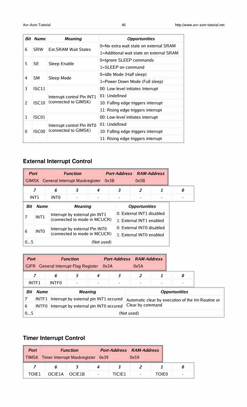
Avr-Asm-Tutorial 46 http://www.avr-asm-tutorial.net
Bit Name Meaning Opportunities
6 SRW Ext.SRAM Wait States0=No extra wait state on external SRAM
1=Additional wait state on external SRAM
5 SE Sleep Enable0=Ignore SLEEP commands
1=SLEEP on command
4 SM Sleep Mode0=Idle Mode (Half sleep)
1=Power Down Mode (Full sleep)
3 ISC11
2 ISC10Interrupt control Pin INT1(connected to GIMSK)
00: Low-level initiates Interrupt
01: Undefined
10: Falling edge triggers interrupt
11: Rising edge triggers interrupt
1 ISC01
0 ISC00Interrupt control Pin INT0(connected to GIMSK)
00: Low-level initiates interrupt
01: Undefined
10: Falling edge triggers interrupt
11: Rising edge triggers interrupt
External Interrupt Control
Port Function Port-Address RAM-Address
GIMSK General Interrupt Maskregister 0x3B 0x5B
7 6 5 4 3 2 1 0
INT1 INT0 - - - - - -
Bit Name Meaning Opportunities
7 INT1Interrupt by external pin INT1(connected to mode in MCUCR)
0: External INT1 disabled
1: External INT1 enabled
6 INT0Interrupt by external Pin INT0(connected to mode in MCUCR)
0: External INT0 disabled
1: External INT0 enabled
0...5 (Not used)
Port Function Port-Address RAM-Address
GIFR General Interrupt Flag Register 0x3A 0x5A
7 6 5 4 3 2 1 0
INTF1 INTF0 - - - - - -
Bit Name Meaning Opportunities
7 INTF1 Interrupt by external pin INT1 occured
6 INTF0 Interrupt by external pin INT0 occuredAutomatic clear by execution of the Int-Routine orClear by command
0...5 (Not used)
Timer Interrupt Control
Port Function Port-Address RAM-Address
TIMSK Timer Interrupt Maskregister 0x39 0x59
7 6 5 4 3 2 1 0
TOIE1 OCIE1A OCIE1B - TICIE1 - TOIE0 -
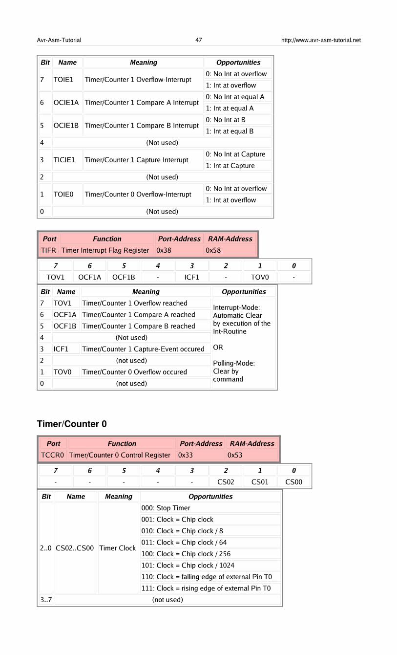
Avr-Asm-Tutorial 47 http://www.avr-asm-tutorial.net
Bit Name Meaning Opportunities
7 TOIE1 Timer/Counter 1 Overflow-Interrupt0: No Int at overflow
1: Int at overflow
6 OCIE1A Timer/Counter 1 Compare A Interrupt0: No Int at equal A
1: Int at equal A
5 OCIE1B Timer/Counter 1 Compare B Interrupt0: No Int at B
1: Int at equal B
4 (Not used)
3 TICIE1 Timer/Counter 1 Capture Interrupt0: No Int at Capture
1: Int at Capture
2 (Not used)
1 TOIE0 Timer/Counter 0 Overflow-Interrupt0: No Int at overflow
1: Int at overflow
0 (Not used)
Port Function Port-Address RAM-Address
TIFR Timer Interrupt Flag Register 0x38 0x58
7 6 5 4 3 2 1 0
TOV1 OCF1A OCF1B - ICF1 - TOV0 -
Bit Name Meaning Opportunities
7 TOV1 Timer/Counter 1 Overflow reached
6 OCF1A Timer/Counter 1 Compare A reached
5 OCF1B Timer/Counter 1 Compare B reached
4 (Not used)
3 ICF1 Timer/Counter 1 Capture-Event occured
2 (not used)
1 TOV0 Timer/Counter 0 Overflow occured
0 (not used)
Interrupt-Mode:Automatic Clearby execution of theInt-Routine
OR
Polling-Mode:Clear bycommand
Timer/Counter 0
Port Function Port-Address RAM-Address
TCCR0 Timer/Counter 0 Control Register 0x33 0x53
7 6 5 4 3 2 1 0
- - - - - CS02 CS01 CS00
Bit Name Meaning Opportunities
2..0 CS02..CS00 Timer Clock
000: Stop Timer
001: Clock = Chip clock
010: Clock = Chip clock / 8
011: Clock = Chip clock / 64
100: Clock = Chip clock / 256
101: Clock = Chip clock / 1024
110: Clock = falling edge of external Pin T0
111: Clock = rising edge of external Pin T0
3..7 (not used)
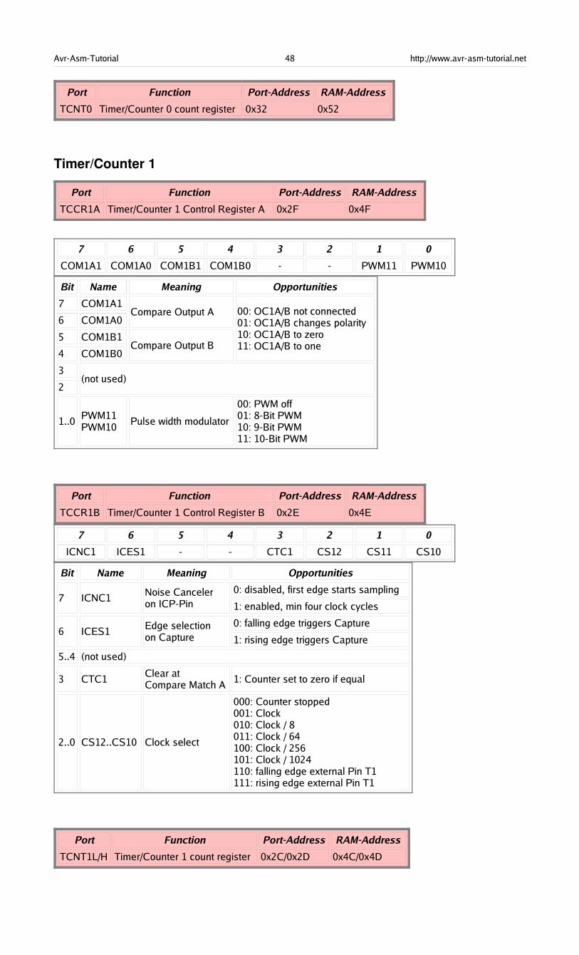
Avr-Asm-Tutorial 48 http://www.avr-asm-tutorial.net
Port Function Port-Address RAM-Address
TCNT0 Timer/Counter 0 count register 0x32 0x52
Timer/Counter 1
Port Function Port-Address RAM-Address
TCCR1A Timer/Counter 1 Control Register A 0x2F 0x4F
7 6 5 4 3 2 1 0
COM1A1 COM1A0 COM1B1 COM1B0 - - PWM11 PWM10
Bit Name Meaning Opportunities
7 COM1A1
6 COM1A0Compare Output A
5 COM1B1
4 COM1B0Compare Output B
00: OC1A/B not connected01: OC1A/B changes polarity10: OC1A/B to zero11: OC1A/B to one
3
2(not used)
1..0PWM11PWM10
Pulse width modulator
00: PWM off01: 8-Bit PWM10: 9-Bit PWM11: 10-Bit PWM
Port Function Port-Address RAM-Address
TCCR1B Timer/Counter 1 Control Register B 0x2E 0x4E
7 6 5 4 3 2 1 0
ICNC1 ICES1 - - CTC1 CS12 CS11 CS10
Bit Name Meaning Opportunities
7 ICNC1Noise Canceleron ICP-Pin
0: disabled, first edge starts sampling
1: enabled, min four clock cycles
6 ICES1Edge selectionon Capture
0: falling edge triggers Capture
1: rising edge triggers Capture
5..4 (not used)
3 CTC1Clear atCompare Match A
1: Counter set to zero if equal
2..0 CS12..CS10 Clock select
000: Counter stopped001: Clock010: Clock / 8011: Clock / 64100: Clock / 256101: Clock / 1024110: falling edge external Pin T1111: rising edge external Pin T1
Port Function Port-Address RAM-Address
TCNT1L/H Timer/Counter 1 count register 0x2C/0x2D 0x4C/0x4D
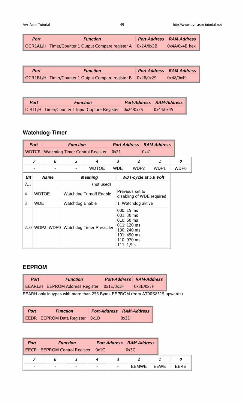
Avr-Asm-Tutorial 49 http://www.avr-asm-tutorial.net
Port Function Port-Address RAM-Address
OCR1AL/H Timer/Counter 1 Output Compare register A 0x2A/0x2B 0x4A/0x4B hex
Port Function Port-Address RAM-Address
OCR1BL/H Timer/Counter 1 Output Compare register B 0x28/0x29 0x48/0x49
Port Function Port-Address RAM-Address
ICR1L/H Timer/Counter 1 Input Capture Register 0x24/0x25 0x44/0x45
WatchdogTimer
Port Function Port-Address RAM-Address
WDTCR Watchdog Timer Control Register 0x21 0x41
7 6 5 4 3 2 1 0
- - - WDTOE WDE WDP2 WDP1 WDP0
Bit Name Meaning WDT-cycle at 5.0 Volt
7..5 (not used)
4 WDTOE Watchdog Turnoff EnablePrevious set todisabling of WDE required
3 WDE Watchdog Enable 1: Watchdog aktive
2..0 WDP2..WDP0 Watchdog Timer Prescaler
000: 15 ms001: 30 ms010: 60 ms011: 120 ms100: 240 ms101: 490 ms110: 970 ms111: 1,9 s
EEPROM
Port Function Port-Address RAM-Address
EEARL/H EEPROM Address Register 0x1E/0x1F 0x3E/0x3F
EEARH only in types with more than 256 Bytes EEPROM (from AT90S8515 upwards)
Port Function Port-Address RAM-Address
EEDR EEPROM Data Register 0x1D 0x3D
Port Function Port-Address RAM-Address
EECR EEPROM Control Register 0x1C 0x3C
7 6 5 4 3 2 1 0
- - - - - EEMWE EEWE EERE

Avr-Asm-Tutorial 50 http://www.avr-asm-tutorial.net
Bit Name Meaning Function
7..3
(not used)
2 EEMWE EEPROM Master Write Enable Previous set enables write cycle
1 EEWE EEPROM Write Enable Set to initiate write
0 EERE EEPROM Read Enable Set initiates read
Serial Peripheral Interface SPI
Port Function Port-Address RAM-Address
SPCR SPI Control Register 0x0D 0x2D
7 6 5 4 3 2 1 0
SPIE SPE DORD MSTR CPOL CPHA SPR1 SPR0
Bit Name Meaning Function
7 SPIE SPI Interrupt Enable0: Interrupts disabled
1: Interrupts enabled
6 SPE SPI Enable0: SPI disabled
1: SPI enabled
5 DORD Data Order0: MSB first
1: LSB first
4 MSTR Master/Slave Select0: Slave
1: Master
3 CPOL Clock Polarity0: Positive Clock Phase
1: Negative Clock Phase
2 CPHA Clock Phase0: Sampling at beginning of Clock Phase
1: Sampling at end of Clock Phase
1 SPR1
0 SPR0SCK clock frequency
00: Clock / 4
01: Clock / 16
10: Clock / 64
11: Clock / 128
Port Function Port-Address RAM-Address
SPSR SPI Status Register 0x0E 0x2E
7 6 5 4 3 2 1 0
SPIF WCOL - - - - - -
Bit Name Meaning Function
7 SPIF SPI Interrupt Flag Interrupt request
6 WCOL Write Collision Flag Write collission occured
5..0 (not used)
Port Function Port-Address RAM-Address
SPDR SPI Data Register 0x0F 0x2F
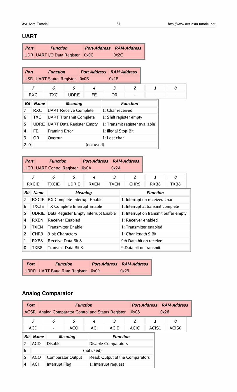
Avr-Asm-Tutorial 51 http://www.avr-asm-tutorial.net
UART
Port Function Port-Address RAM-Address
UDR UART I/O Data Register 0x0C 0x2C
Port Function Port-Address RAM-Address
USR UART Status Register 0x0B 0x2B
7 6 5 4 3 2 1 0
RXC TXC UDRE FE OR - - -
Bit Name Meaning Function
7 RXC UART Receive Complete 1: Char received
6 TXC UART Transmit Complete 1: Shift register empty
5 UDRE UART Data Register Empty 1: Transmit register available
4 FE Framing Error 1: Illegal Stop-Bit
3 OR Overrun 1: Lost char
2..0 (not used)
Port Function Port-Address RAM-Address
UCR UART Control Register 0x0A 0x2A
7 6 5 4 3 2 1 0
RXCIE TXCIE UDRIE RXEN TXEN CHR9 RXB8 TXB8
Bit Name Meaning Function
7 RXCIE RX Complete Interrupt Enable 1: Interrupt on received char
6 TXCIE TX Complete Interrupt Enable 1: Interrupt at transmit complete
5 UDRIE Data Register Empty Interrupt Enable 1: Interrupt on transmit buffer empty
4 RXEN Receiver Enabled 1: Receiver enabled
3 TXEN Transmitter Enable 1: Transmitter enabled
2 CHR9 9-bit Characters 1: Char length 9 Bit
1 RXB8 Receive Data Bit 8 9th Data bit on receive
0 TXB8 Transmit Data Bit 8 9.Data bit on transmit
Port Function Port-Address RAM-Address
UBRR UART Baud Rate Register 0x09 0x29
Analog Comparator
Port Function Port-Address RAM-Address
ACSR Analog Comparator Control and Status Register 0x08 0x28
7 6 5 4 3 2 1 0
ACD - ACO ACI ACIE ACIC ACIS1 ACIS0
Bit Name Meaning Function
7 ACD Disable Disable Comparators
6 (not used)
5 ACO Comparator Output Read: Output of the Comparators
4 ACI Interrupt Flag 1: Interrupt request
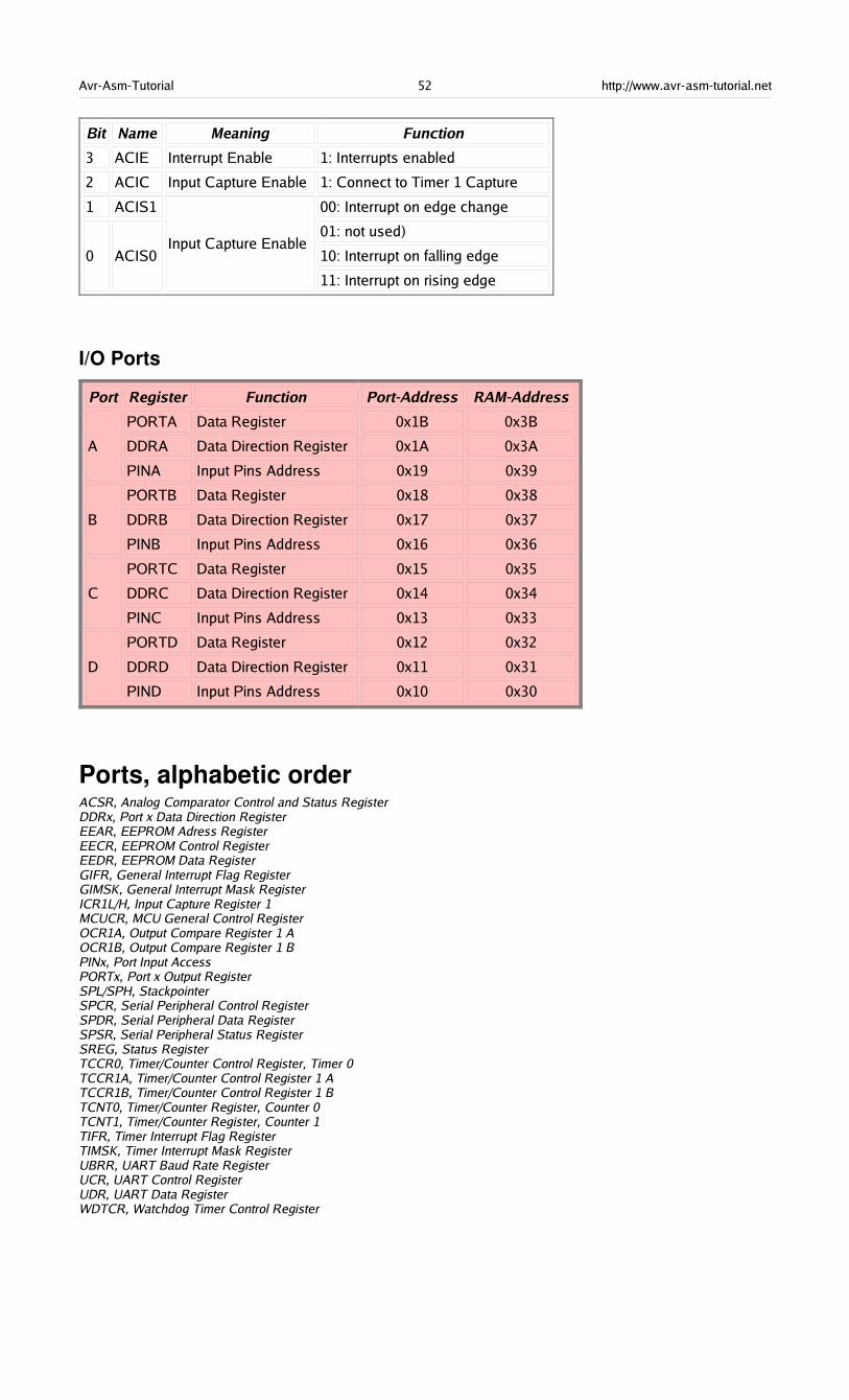
Avr-Asm-Tutorial 52 http://www.avr-asm-tutorial.net
Bit Name Meaning Function
3 ACIE Interrupt Enable 1: Interrupts enabled
2 ACIC Input Capture Enable 1: Connect to Timer 1 Capture
1 ACIS1
0 ACIS0Input Capture Enable
00: Interrupt on edge change
01: not used)
10: Interrupt on falling edge
11: Interrupt on rising edge
I/O Ports
Port Register Function Port-Address RAM-Address
A
PORTA Data Register 0x1B 0x3B
DDRA Data Direction Register 0x1A 0x3A
PINA Input Pins Address 0x19 0x39
B
PORTB Data Register 0x18 0x38
DDRB Data Direction Register 0x17 0x37
PINB Input Pins Address 0x16 0x36
C
PORTC Data Register 0x15 0x35
DDRC Data Direction Register 0x14 0x34
PINC Input Pins Address 0x13 0x33
D
PORTD Data Register 0x12 0x32
DDRD Data Direction Register 0x11 0x31
PIND Input Pins Address 0x10 0x30
Ports, alphabetic orderACSR, Analog Comparator Control and Status RegisterDDRx, Port x Data Direction RegisterEEAR, EEPROM Adress RegisterEECR, EEPROM Control RegisterEEDR, EEPROM Data RegisterGIFR, General Interrupt Flag RegisterGIMSK, General Interrupt Mask RegisterICR1L/H, Input Capture Register 1MCUCR, MCU General Control RegisterOCR1A, Output Compare Register 1 AOCR1B, Output Compare Register 1 BPINx, Port Input AccessPORTx, Port x Output RegisterSPL/SPH, StackpointerSPCR, Serial Peripheral Control RegisterSPDR, Serial Peripheral Data RegisterSPSR, Serial Peripheral Status RegisterSREG, Status RegisterTCCR0, Timer/Counter Control Register, Timer 0TCCR1A, Timer/Counter Control Register 1 ATCCR1B, Timer/Counter Control Register 1 BTCNT0, Timer/Counter Register, Counter 0TCNT1, Timer/Counter Register, Counter 1TIFR, Timer Interrupt Flag RegisterTIMSK, Timer Interrupt Mask RegisterUBRR, UART Baud Rate RegisterUCR, UART Control RegisterUDR, UART Data RegisterWDTCR, Watchdog Timer Control Register
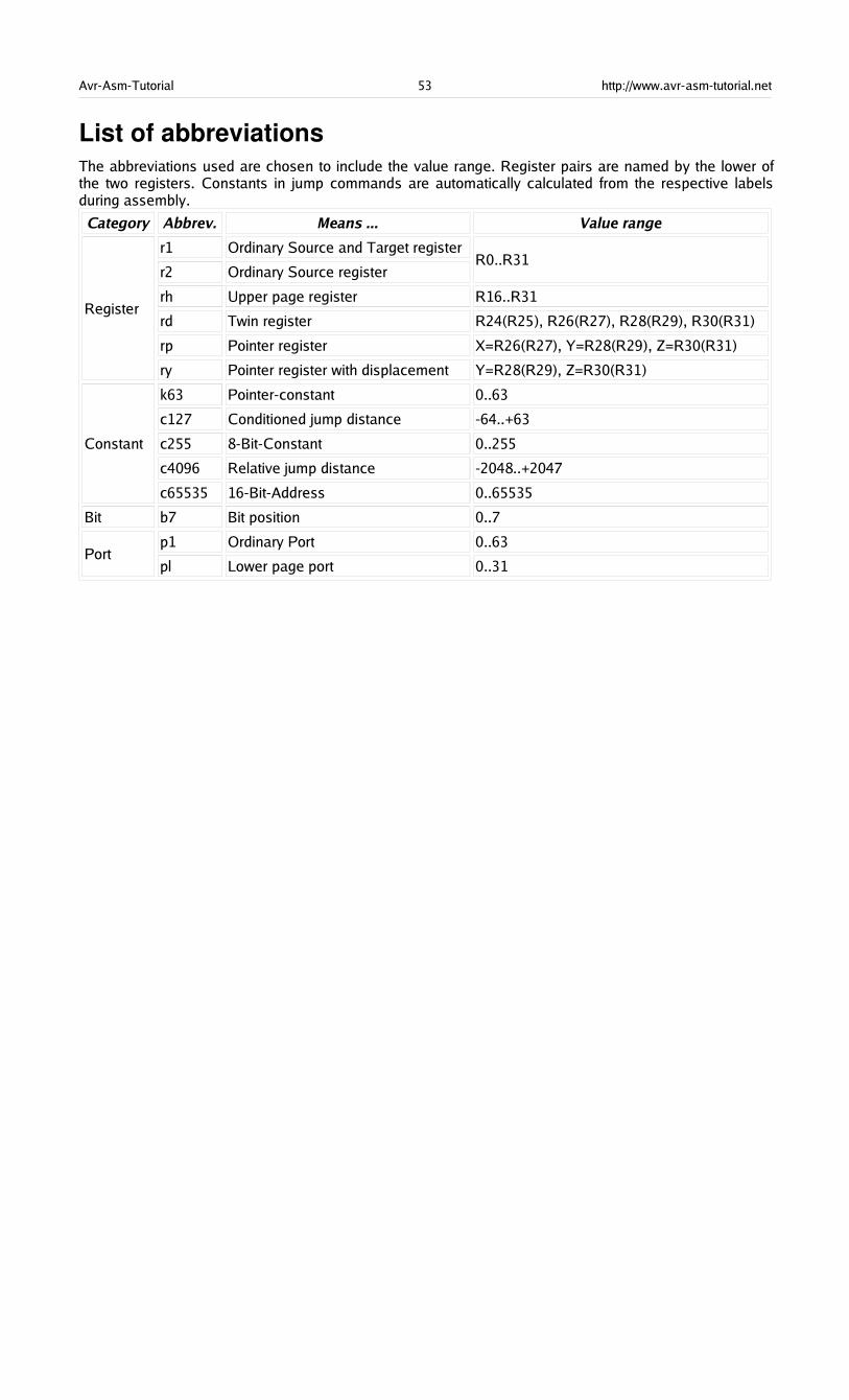
Avr-Asm-Tutorial 53 http://www.avr-asm-tutorial.net
List of abbreviationsThe abbreviations used are chosen to include the value range. Register pairs are named by the lower ofthe two registers. Constants in jump commands are automatically calculated from the respective labelsduring assembly.
Category Abbrev. Means ... Value range
Register
r1 Ordinary Source and Target register
r2 Ordinary Source registerR0..R31
rh Upper page register R16..R31
rd Twin register R24(R25), R26(R27), R28(R29), R30(R31)
rp Pointer register X=R26(R27), Y=R28(R29), Z=R30(R31)
ry Pointer register with displacement Y=R28(R29), Z=R30(R31)
Constant
k63 Pointer-constant 0..63
c127 Conditioned jump distance -64..+63
c255 8-Bit-Constant 0..255
c4096 Relative jump distance -2048..+2047
c65535 16-Bit-Address 0..65535
Bit b7 Bit position 0..7
Portp1 Ordinary Port 0..63
pl Lower page port 0..31


![AVR - dl.melec.irdl.melec.ir/download/pdf/AVR/CodeVision-Fusebit[Melec.ir].pdf · AVR AVR AVR AVR 01 CodeVision CKSEL3..0 Device Clocking Option CKSEL3..0 External Crystal/Ceramic](https://img.dokumen.tips/doc/110x75/5cf6e10d88c99387248bfc0e/avr-dlmelecirdlmelecirdownloadpdfavrcodevision-fusebitmelecirpdf.jpg)