Embed Size (px)
Citation preview

Waco Regional Airport ● P.O. Box 5500 ● Waco, Texas 76708
Beechcraft King Air
200 & 300 Series Airplanes
INSTRUCTIONS FOR CONTINUED
AIRWORTHINESS
ICA Manual No. 26012-30 Revision 4
May 2019

BEECHCRAFT KING AIR 200 & 300 SERIES SADDLE TANKS ICA MANUAL
MANUAL No. 26012-30 04/11/14
RECORD OF REVISIONS
Rev. No.
Date Inserted By Rev. No.
Date Inserted By Rev. No.
Date Inserted By
When a revision to this manual is issued, insert the revised or added pages into the manual. Record the revision number, date inserted, and the initials of the person responsible for the update on this page.
BEECHCRAFT KING AIR 200 & 300 SERIES SADDLE TANKS ICA MANUAL
MANUAL No. 26012-30 04/11/14
[Intentional Blank Page]
BEECHCRAFT KING AIR 200 & 300 SERIES SADDLE TANKS ICA MANUAL
MANUAL No. 26012-30 REV. 4, MAY 2019
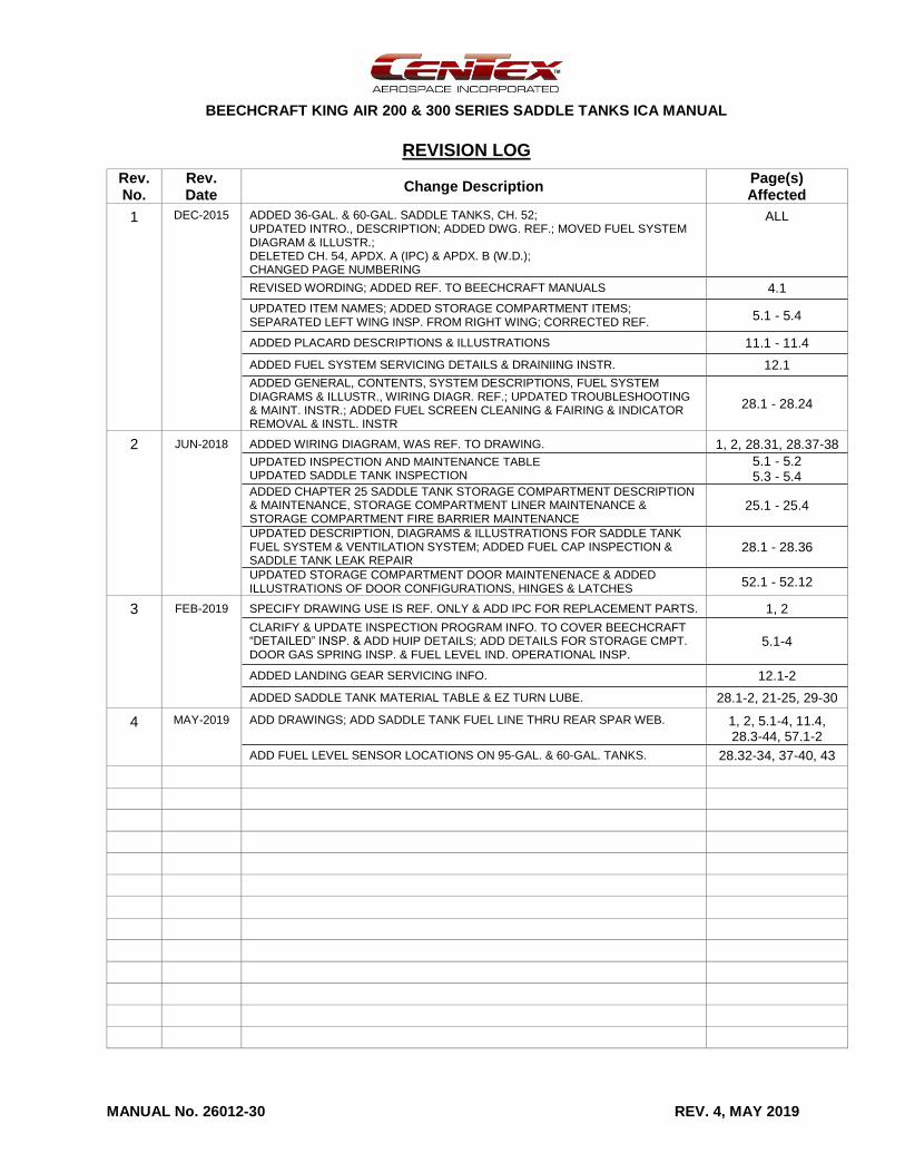
REVISION LOG
Rev. No.
Rev. Date
Change Description Page(s) Affected
1 DEC-2015 ADDED 36-GAL. & 60-GAL. SADDLE TANKS, CH. 52; UPDATED INTRO., DESCRIPTION; ADDED DWG. REF.; MOVED FUEL SYSTEM DIAGRAM & ILLUSTR.; DELETED CH. 54, APDX. A (IPC) & APDX. B (W.D.); CHANGED PAGE NUMBERING
ALL
REVISED WORDING; ADDED REF. TO BEECHCRAFT MANUALS 4.1
UPDATED ITEM NAMES; ADDED STORAGE COMPARTMENT ITEMS; SEPARATED LEFT WING INSP. FROM RIGHT WING; CORRECTED REF.
5.1 - 5.4
ADDED PLACARD DESCRIPTIONS & ILLUSTRATIONS 11.1 - 11.4
ADDED FUEL SYSTEM SERVICING DETAILS & DRAINIING INSTR. 12.1
ADDED GENERAL, CONTENTS, SYSTEM DESCRIPTIONS, FUEL SYSTEM DIAGRAMS & ILLUSTR., WIRING DIAGR. REF.; UPDATED TROUBLESHOOTING & MAINT. INSTR.; ADDED FUEL SCREEN CLEANING & FAIRING & INDICATOR REMOVAL & INSTL. INSTR
28.1 - 28.24
2 JUN-2018 ADDED WIRING DIAGRAM, WAS REF. TO DRAWING. 1, 2, 28.31, 28.37-38
UPDATED INSPECTION AND MAINTENANCE TABLE UPDATED SADDLE TANK INSPECTION
5.1 - 5.2 5.3 - 5.4
ADDED CHAPTER 25 SADDLE TANK STORAGE COMPARTMENT DESCRIPTION & MAINTENANCE, STORAGE COMPARTMENT LINER MAINTENANCE & STORAGE COMPARTMENT FIRE BARRIER MAINTENANCE
25.1 - 25.4
UPDATED DESCRIPTION, DIAGRAMS & ILLUSTRATIONS FOR SADDLE TANK FUEL SYSTEM & VENTILATION SYSTEM; ADDED FUEL CAP INSPECTION & SADDLE TANK LEAK REPAIR
28.1 - 28.36
UPDATED STORAGE COMPARTMENT DOOR MAINTENENACE & ADDED ILLUSTRATIONS OF DOOR CONFIGURATIONS, HINGES & LATCHES
52.1 - 52.12
3 FEB-2019 SPECIFY DRAWING USE IS REF. ONLY & ADD IPC FOR REPLACEMENT PARTS. 1, 2
CLARIFY & UPDATE INSPECTION PROGRAM INFO. TO COVER BEECHCRAFT “DETAILED” INSP. & ADD HUIP DETAILS; ADD DETAILS FOR STORAGE CMPT. DOOR GAS SPRING INSP. & FUEL LEVEL IND. OPERATIONAL INSP.
5.1-4
ADDED LANDING GEAR SERVICING INFO. 12.1-2
ADDED SADDLE TANK MATERIAL TABLE & EZ TURN LUBE. 28.1-2, 21-25, 29-30
4 MAY-2019 ADD DRAWINGS; ADD SADDLE TANK FUEL LINE THRU REAR SPAR WEB. 1, 2, 5.1-4, 11.4, 28.3-44, 57.1-2
ADD FUEL LEVEL SENSOR LOCATIONS ON 95-GAL. & 60-GAL. TANKS. 28.32-34, 37-40, 43
BEECHCRAFT KING AIR 200 & 300 SERIES SADDLE TANKS ICA MANUAL
MANUAL No. 26012-30 REV. 4, MAY 2019
[Intentional Blank Page]
BEECHCRAFT KING AIR 200 & 300 SERIES SADDLE TANKS ICA MANUAL
MANUAL No. 26012-30 REV. 4, MAY 2019
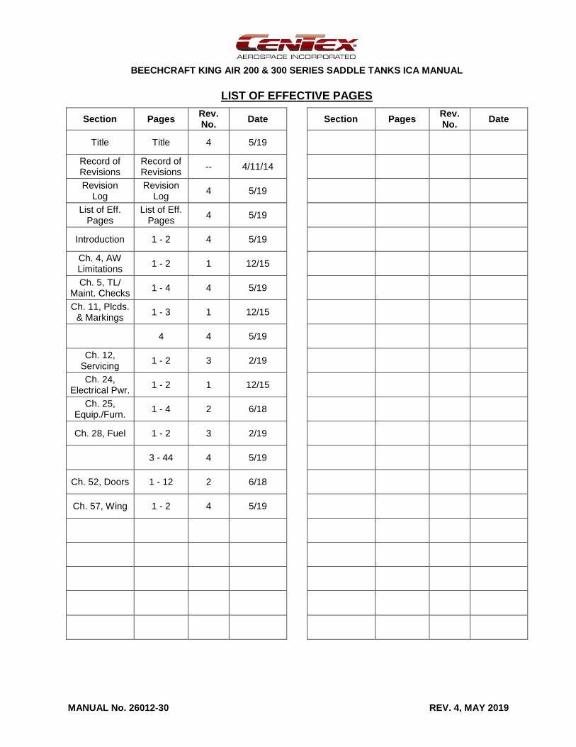
LIST OF EFFECTIVE PAGES
Section Pages Rev. No.
Date Section Pages Rev. No.
Date
Title Title 4 5/19
Record of Revisions
Record of Revisions
-- 4/11/14
Revision Log
Revision Log
4 5/19
List of Eff. Pages
List of Eff. Pages
4 5/19
Introduction 1 - 2 4 5/19
Ch. 4, AW Limitations
1 - 2 1 12/15
Ch. 5, TL/ Maint. Checks
1 - 4 4 5/19
Ch. 11, Plcds. & Markings
1 - 3 1 12/15
4 4 5/19
Ch. 12, Servicing
1 - 2 3 2/19
Ch. 24, Electrical Pwr.
1 - 2 1 12/15
Ch. 25, Equip./Furn.
1 - 4 2 6/18
Ch. 28, Fuel 1 - 2 3 2/19
3 - 44 4 5/19
Ch. 52, Doors 1 - 12 2 6/18
Ch. 57, Wing 1 - 2 4 5/19

BEECHCRAFT KING AIR 200 & 300 SERIES SADDLE TANKS ICA MANUAL
MANUAL No. 26012-30 REV. 4, MAY 2019
[Intentional Blank Page]
BEECHCRAFT KING AIR 200 & 300 SERIES SADDLE TANKS ICA MANUAL
PAGE 1 MANUAL No. 26012-30 INTRODUCTION REV. 4, MAY 2019
INTRODUCTION
GENERAL
This manual provides Instructions for Continued Airworthiness (ICA) for Beechcraft Super King Air 200 and 300 series airplanes modified by CenTex Aerospace’s (CTA) Saddle Tank STC. The Saddle Tank STC modification installs auxiliary fuel tanks on the wing, behind each engine nacelle as approved under FAA Supplemental Type Certificate (STC) number SA11142SC.
ASSOCIATED DRAWINGS
The following CenTex Aerospace drawings are provided to install the saddle tanks on the airplane. These drawings are listed as reference and are not required for maintaining the continued airworthiness of the airplane. Contact CenTex Aerospace for assistance in obtaining a copy of a specific drawing.
Number Title
26012-1000 INSTALLATION INSTRUCTIONS
26012-2000 INSTALLATION, SADDLE TANKS
26012-2100 MODIFICATION, REAR SPAR
26012-3000 INSTALLATION, FAIRING, SADDLE TANKS
26012-4000 INSTALLATION, FUEL & VENT SYSTEM MODIFICATION, SADDLE TANKS
26012-6000 INSTALLATION, FUEL LEVEL INDICATION, SADDLE TANKS
26012-7000 INSTALLATION, PLACARDS, SADDLE TANKS
26012-8000 TANK REMOVAL & NACELLE SKIN RE-INSTALLATION
26012-9000 MODIFICATION, INVERTER ACCESS PANEL
DESCRIPTION OF MODIFICATION
The Saddle Tank STC installs a set of the following saddle tanks on the airplane:
95-gallon full fuel tanks
60-gallon fuel tanks with 5 cubic foot storage compartment
36-gallon fuel tanks with 8 cubic foot storage compartment
The aluminum saddle fuel tanks are mounted behind each engine nacelle to the upper surface of the wing. Five ¼-inch (AN4) bolts hold each tank to the wing. Also, twelve AN3 bolts attach the front of the tank to the engine nacelle structure. An aluminum fairing between the engine nacelle and the front of the tank provides a smooth transition for air flow around the saddle tank.
To identify the specific saddle tank installed, placards at the fuel filler port on top of the tank provide the fuel capacity of the tank. If the saddle tank has a storage compartment, the hinged compartment door at the back of the tank opens upward upon depressing the two push-to-release latches. A pneumatic strut assists opening the door and keeps the door open. A placard inside the compartment specifies a weight limit.
Fuel in the saddle tank enters the wing center section auxiliary fuel tank by gravity flow. The main fuel line from the saddle tank either goes through the back of the wheel well (Series 1 routing) or through the rear spar web (Series 2 routing) and enters at the back of the auxiliary fuel tank. Ventilation for the saddle tank is provided by the existing fuel vent lines, which are split between the inboard and outboard wing in the wheel well and routed up, through the wing, and into the saddle tank.
BEECHCRAFT KING AIR 200 & 300 SERIES SADDLE TANKS ICA MANUAL
PAGE 2 MANUAL No. 26012-30 INTRODUCTION REV. 4, MAY 2019
Placards also identify each of the added tank and vent drain ports.
The saddle tanks each include five optical fuel level sensors connected to an indicator unit mounted to the pilot’s side wall. The indicator has five LED indicators for each tank, corresponding to an individual level sensor. When fuel is at or above the indicated level, the LED illuminates green. As fuel drops below each level sensor, the LED extinguishes with the exception of the last LED, which changes from green to amber.
Refer to the individual chapters in this manual for additional details and illustrations of saddle tank components and systems.
MAINTENANCE
Airworthiness limitations, inspection procedures, servicing information, and maintenance procedures provided in this manual apply to the equipment and modifications associated with this STC and supplement the standard aircraft maintenance manual (AMM); i.e., the latest revision of the Beechcraft King Air 200, 300 or B300 Maintenance Manual. For King Air 200, 300, or B300 series aircraft modified by this STC, follow the inspection, servicing, and maintenance procedures in the AMM, except as provided herein. This manual uses the same chapter numbering and general format as the AMM.
For standard aviation maintenance practices, such as cutting, splicing, and replacing wire, routing and securing lines, inspecting electrical wiring and equipment, etc. use the techniques and practices found in FAA Advisory Circular AC 43.13-1B/2B or later FAA approved revision.
REPLACEMENT PARTS
Refer to CenTex Aerospace Illustrated Parts Catalog (IPC) no. 26012-40 for a list of saddle tank parts installed on the airplane. Contact CenTex Aerospace for replacement parts.
WIRING DIAGRAM
The wiring diagram for the saddle tank fuel quantity indicating system is in Chapter 28 of this manual.
MANUAL UPDATES
A copy of this ICA Manual is provided with the STC upon installation. When changes to this ICA Manual are made, CenTex Aerospace will provide updates to the registered airplane owner by email or direct mail. Contact CenTex Aerospace to make other arrangements. If there is a change in airplane ownership or operator, please notify CenTex Aerospace in order to keep all contact information current.
The changes to the ICA manual will be identified by revision number and date in the Revision Log. CenTex will provide the owner with the revised pages, a Revision Log, and an updated List of Effective Pages. The owner, or responsible party, will add or replace the pages affected by the revision and make an entry in the Record of Revisions in order to document the update to the ICA Manual is accomplished.
ASSISTANCE
For assistance with continuing airworthiness issues or any other issues related to this STC, contact CenTex Aerospace at the following address or telephone number.
CenTex Aerospace Inc. 7925 Karl May Drive Waco, Texas 76708
(254) 752-4290 http://www.centex.aero/
BEECHCRAFT KING AIR 200 & 300 SERIES SADDLE TANKS ICA MANUAL
PAGE 4.1 MANUAL No. 26012-30 CHAPTER 4 REV. 1, DEC. 2015
CHAPTER 4
The Airworthiness Limitations section is FAA approved and specifies maintenance required under §§43.16 and 91.403 of the Federal Aviation Regulations unless an alternative program has been FAA approved.
Beechcraft King Air 200, 300, and B300 series airplanes with CenTex Aerospace saddle tanks installed under STC SA11142SC have no changes or additions to the original Airworthiness Limitations established by Beechcraft.
For airplane component life limits or structural inspections, refer to the applicable Beechcraft manual.

BEECHCRAFT KING AIR 200 & 300 SERIES SADDLE TANKS ICA MANUAL
PAGE 4.2 MANUAL No. 26012-30 CHAPTER 4 REV. 1, DEC. 2015
[Intentional Blank Page]
BEECHCRAFT KING AIR 200 & 300 SERIES SADDLE TANKS ICA MANUAL
PAGE 5.1 MANUAL No. 26012-30 CHAPTER 5 REV. 4, MAY 2019
CHAPTER 5
TIME LIMITS/MAINTENANCE CHECKS
GENERAL
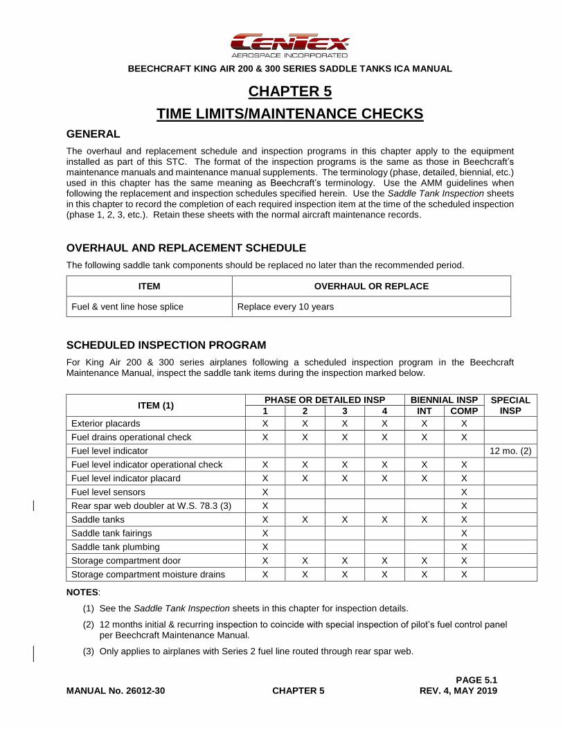
The overhaul and replacement schedule and inspection programs in this chapter apply to the equipment installed as part of this STC. The format of the inspection programs is the same as those in Beechcraft’s maintenance manuals and maintenance manual supplements. The terminology (phase, detailed, biennial, etc.) used in this chapter has the same meaning as Beechcraft’s terminology. Use the AMM guidelines when following the replacement and inspection schedules specified herein. Use the Saddle Tank Inspection sheets in this chapter to record the completion of each required inspection item at the time of the scheduled inspection (phase 1, 2, 3, etc.). Retain these sheets with the normal aircraft maintenance records.
OVERHAUL AND REPLACEMENT SCHEDULE
The following saddle tank components should be replaced no later than the recommended period.
ITEM OVERHAUL OR REPLACE
Fuel & vent line hose splice Replace every 10 years
SCHEDULED INSPECTION PROGRAM
For King Air 200 & 300 series airplanes following a scheduled inspection program in the Beechcraft Maintenance Manual, inspect the saddle tank items during the inspection marked below.
ITEM (1) PHASE OR DETAILED INSP BIENNIAL INSP SPECIAL
INSP 1 2 3 4 INT COMP
Exterior placards X X X X X X
Fuel drains operational check X X X X X X
Fuel level indicator 12 mo. (2)
Fuel level indicator operational check X X X X X X
Fuel level indicator placard X X X X X X
Fuel level sensors X X
Rear spar web doubler at W.S. 78.3 (3) X X
Saddle tanks X X X X X X
Saddle tank fairings X X
Saddle tank plumbing X X
Storage compartment door X X X X X X
Storage compartment moisture drains X X X X X X
NOTES:
(1) See the Saddle Tank Inspection sheets in this chapter for inspection details.
(2) 12 months initial & recurring inspection to coincide with special inspection of pilot’s fuel control panel per Beechcraft Maintenance Manual.
(3) Only applies to airplanes with Series 2 fuel line routed through rear spar web.
BEECHCRAFT KING AIR 200 & 300 SERIES SADDLE TANKS ICA MANUAL
PAGE 5.2 MANUAL No. 26012-30 CHAPTER 5 REV. 4, MAY 2019
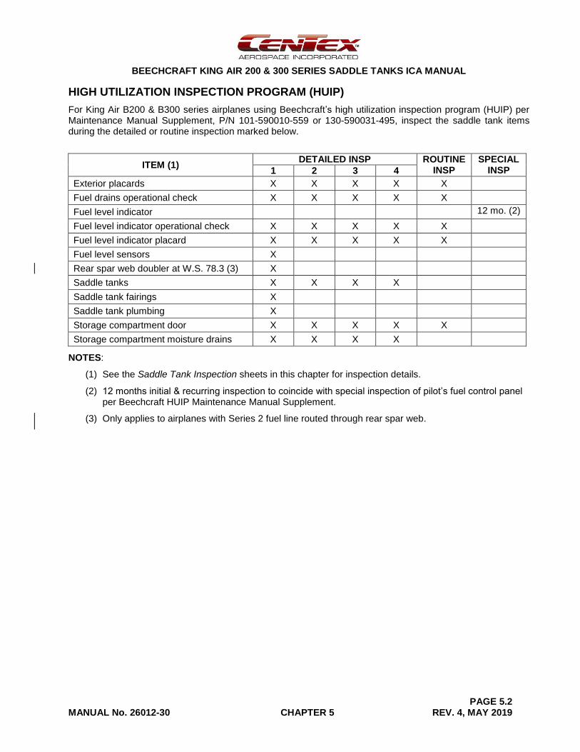
HIGH UTILIZATION INSPECTION PROGRAM (HUIP)
For King Air B200 & B300 series airplanes using Beechcraft’s high utilization inspection program (HUIP) per Maintenance Manual Supplement, P/N 101-590010-559 or 130-590031-495, inspect the saddle tank items during the detailed or routine inspection marked below.
ITEM (1) DETAILED INSP ROUTINE
INSP SPECIAL
INSP 1 2 3 4
Exterior placards X X X X X
Fuel drains operational check X X X X X
Fuel level indicator 12 mo. (2)
Fuel level indicator operational check X X X X X
Fuel level indicator placard X X X X X
Fuel level sensors X
Rear spar web doubler at W.S. 78.3 (3) X
Saddle tanks X X X X
Saddle tank fairings X
Saddle tank plumbing X
Storage compartment door X X X X X
Storage compartment moisture drains X X X X
NOTES:
(1) See the Saddle Tank Inspection sheets in this chapter for inspection details.
(2) 12 months initial & recurring inspection to coincide with special inspection of pilot’s fuel control panel per Beechcraft HUIP Maintenance Manual Supplement.
(3) Only applies to airplanes with Series 2 fuel line routed through rear spar web.
BEECHCRAFT KING AIR 200 & 300 SERIES SADDLE TANKS ICA MANUAL
PAGE 5.3 MANUAL No. 26012-30 CHAPTER 5 REV. 4, MAY 2019
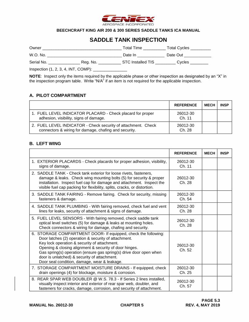
SADDLE TANK INSPECTION
Owner ___________________________________ Total Time __________ Total Cycles _________
W.O. No. _________________________________ Date In ____________ Date Out ____________
Serial No. ______________ Reg. No. __________ STC Installed TIS _________ Cycles ________
Inspection (1, 2, 3, 4, INT, COMP): _______________
NOTE: Inspect only the items required by the applicable phase or other inspection as designated by an “X” in the inspection program table. Write “N/A” if an item is not required for the applicable inspection.
A. PILOT COMPARTMENT
REFERENCE MECH INSP
1. FUEL LEVEL INDICATOR PLACARD - Check placard for proper adhesion, visibility, signs of damage.
26012-30 Ch. 11
2. FUEL LEVEL INDICATOR - Check security of attachment. Check connectors & wiring for damage, chafing and security.
26012-30 Ch. 28
B. LEFT WING
REFERENCE MECH INSP
1. EXTERIOR PLACARDS - Check placards for proper adhesion, visibility, signs of damage.
26012-30 Ch. 11
2. SADDLE TANK - Check tank exterior for loose rivets, fasteners, damage & leaks. Check wing mounting bolts (5) for security & proper installation. Inspect fuel cap for damage and attachment. Inspect the visible fuel cap packing for flexibility, splits, cracks, or distortion.
26012-30 Ch. 28
3. SADDLE TANK FAIRING - Remove fairing. Check for security, missing fasteners & damage.
26012-30 Ch. 54
4. SADDLE TANK PLUMBING - With fairing removed, check fuel and vent lines for leaks, security of attachment & signs of damage.
26012-30 Ch. 28
5. FUEL LEVEL SENSORS - With fairing removed, check saddle tank optical level switches (5) for damage & leaks at mounting holes. Check connectors & wiring for damage, chafing and security.
26012-30 Ch. 28
6. STORAGE COMPARTMENT DOOR- If equipped, check the following: Door latches (2) operation & security of attachment. Key lock operation & security of attachment. Opening & closing alignment & security of door hinges. Gas spring(s) operation (ensure gas spring(s) drive door open when door is unlatched) & security of attachment. Door seal condition, damage, wear & leakage.
26012-30 Ch. 52
7. STORAGE COMPARTMENT MOISTURE DRAINS - If equipped, check drain openings (4) for blockage, moisture & corrosion.
26012-30 Ch. 25
8. REAR SPAR WEB DOUBLER @ W.S. 78.3 - If Series 2 lines installed, visually inspect interior and exterior of rear spar web, doubler, and fasteners for cracks, damage, corrosion, and security of attachment.
26012-30 Ch. 57
BEECHCRAFT KING AIR 200 & 300 SERIES SADDLE TANKS ICA MANUAL
PAGE 5.4 MANUAL No. 26012-30 CHAPTER 5 REV. 4, MAY 2019
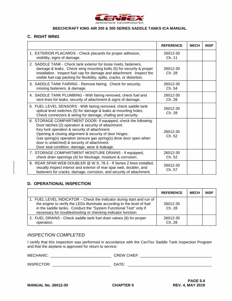
C. RIGHT WING
REFERENCE MECH INSP
1. EXTERIOR PLACARDS - Check placards for proper adhesion, visibility, signs of damage.
26012-30 Ch. 11
2. SADDLE TANK - Check tank exterior for loose rivets, fasteners, damage & leaks. Check wing mounting bolts (5) for security & proper installation. Inspect fuel cap for damage and attachment. Inspect the visible fuel cap packing for flexibility, splits, cracks, or distortion.
26012-30 Ch. 28
3. SADDLE TANK FAIRING - Remove fairing. Check for security, missing fasteners, & damage.
26012-30 Ch. 54
4. SADDLE TANK PLUMBING - With fairing removed, check fuel and vent lines for leaks, security of attachment & signs of damage.
26012-30 Ch. 28
5. FUEL LEVEL SENSORS - With fairing removed, check saddle tank optical level switches (5) for damage & leaks at mounting holes. Check connectors & wiring for damage, chafing and security.
26012-30 Ch. 28
6. STORAGE COMPARTMENT DOOR- If equipped, check the following: Door latches (2) operation & security of attachment. Key lock operation & security of attachment. Opening & closing alignment & security of door hinges. Gas spring(s) operation (ensure gas spring(s) drive door open when door is unlatched) & security of attachment. Door seal condition, damage, wear & leakage.
26012-30 Ch. 52
7. STORAGE COMPARTMENT MOISTURE DRAINS - If equipped, check drain openings (4) for blockage, moisture & corrosion.
26012-30 Ch. 52
8. REAR SPAR WEB DOUBLER @ W.S. 78.3 - If Series 2 lines installed, visually inspect interior and exterior of rear spar web, doubler, and fasteners for cracks, damage, corrosion, and security of attachment.
26012-30 Ch. 57
D. OPERATIONAL INSPECTION
REFERENCE MECH INSP
1. FUEL LEVEL INDICATOR – Check the indicator during start and run of the engine to verify the LEDs illuminate according to the level of fuel in the saddle tanks. Conduct the "System Functional Test" only if necessary for troubleshooting or checking indicator function.
26012-30 Ch. 28
2. FUEL DRAINS - Check saddle tank fuel drain valves (6) for proper operation.
26012-30 Ch. 28
INSPECTION COMPLETED
I certify that this inspection was performed in accordance with the CenTex Saddle Tank Inspection Program and that the airplane is approved for return to service:
MECHANIC: _____________________________ CREW CHIEF: __________________________________
INSPECTOR: ____________________________ DATE: ________________________________________
BEECHCRAFT KING AIR 200 & 300 SERIES SADDLE TANKS ICA MANUAL
PAGE 11.1 MANUAL No. 26012-30 CHAPTER 11 REV. 1, DEC. 2015
CHAPTER 11
PLACARDS AND MARKINGS
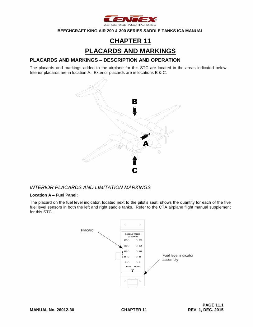
PLACARDS AND MARKINGS – DESCRIPTION AND OPERATION
The placards and markings added to the airplane for this STC are located in the areas indicated below. Interior placards are in location A. Exterior placards are in locations B & C.
INTERIOR PLACARDS AND LIMITATION MARKINGS
Location A – Fuel Panel:
The placard on the fuel level indicator, located next to the pilot’s seat, shows the quantity for each of the five fuel level sensors in both the left and right saddle tanks. Refer to the CTA airplane flight manual supplement for this STC.
C
B
A
635
535
370
65
LEFT RIGHT
SADDLE TANKS
QTY (LBS)
0
D
I
M
635
535
370
65
0
FUSE
Placard
Fuel level indicator assembly
BEECHCRAFT KING AIR 200 & 300 SERIES SADDLE TANKS ICA MANUAL
PAGE 11.2 MANUAL No. 26012-30 CHAPTER 11 REV. 1, DEC. 2015
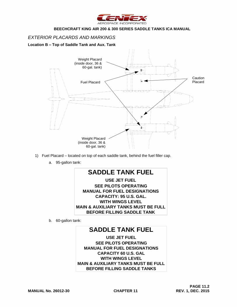
EXTERIOR PLACARDS AND MARKINGS
Location B – Top of Saddle Tank and Aux. Tank
1) Fuel Placard – located on top of each saddle tank, behind the fuel filler cap.
a. 95-gallon tank:
b. 60-gallon tank:
SADDLE TANK FUELUSE JET FUEL
SEE PILOTS OPERATING
MANUAL FOR FUEL DESIGNATIONS
CAPACITY: 95 U.S. GAL.
WITH WINGS LEVEL
MAIN & AUXILIARY TANKS MUST BE FULL
BEFORE FILLING SADDLE TANK
7.5
3.7
3.8
7.5
SADDLE TANK FUELUSE JET FUEL
SEE PILOTS OPERATING
MANUAL FOR FUEL DESIGNATIONS
CAPACITY 60 U.S. GAL
WITH WINGS LEVEL
MAIN & AUXILIARY TANKS MUST BE FULL
BEFORE FILLING SADDLE TANKS
045-7101-1 PLACARD
Fuel Placard
Caution Placard
Weight Placard (inside door, 36 &
60-gal. tank)
Weight Placard (inside door, 36 &
60-gal. tank)
BEECHCRAFT KING AIR 200 & 300 SERIES SADDLE TANKS ICA MANUAL
PAGE 11.3 MANUAL No. 26012-30 CHAPTER 11 REV. 1, DEC. 2015
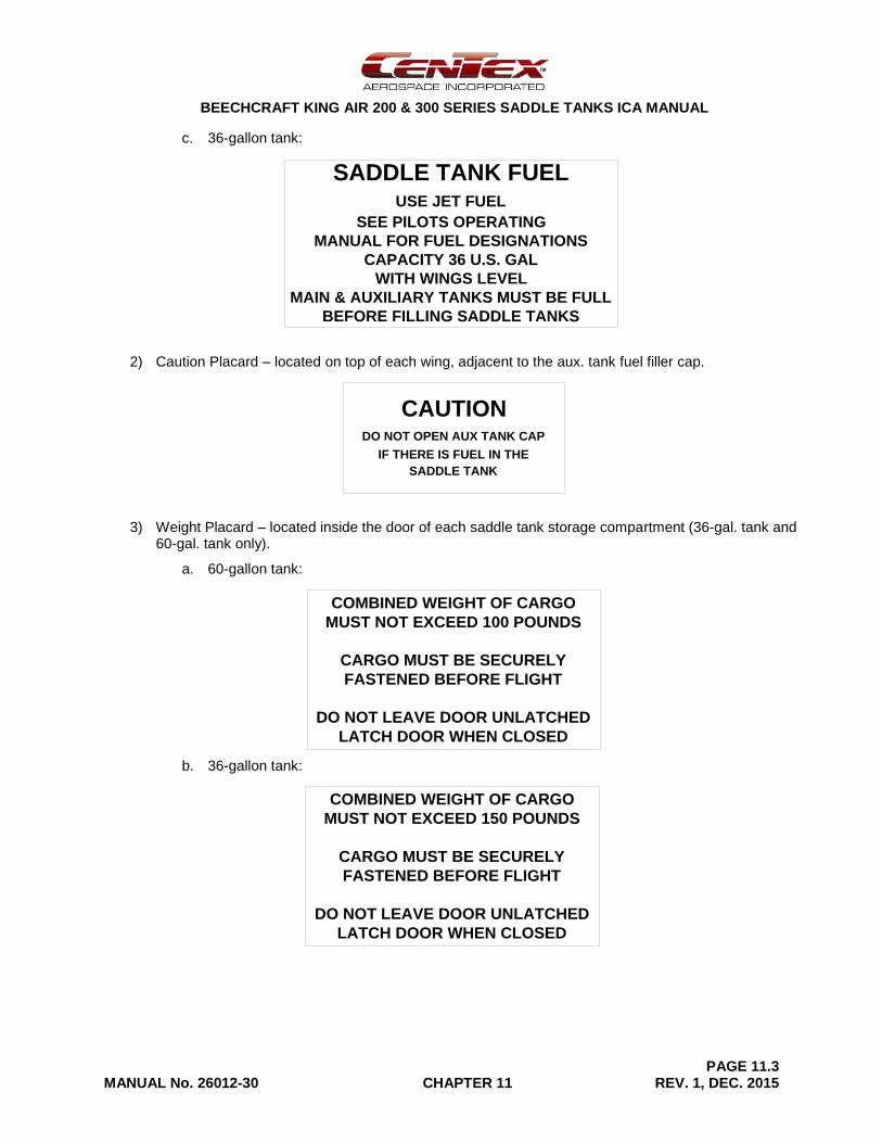
c. 36-gallon tank:
2) Caution Placard – located on top of each wing, adjacent to the aux. tank fuel filler cap.
3) Weight Placard – located inside the door of each saddle tank storage compartment (36-gal. tank and 60-gal. tank only).
a. 60-gallon tank:
b. 36-gallon tank:
3.8
7.5
SADDLE TANK FUELUSE JET FUEL
SEE PILOTS OPERATING
MANUAL FOR FUEL DESIGNATIONS
CAPACITY 36 U.S. GAL
WITH WINGS LEVEL
MAIN & AUXILIARY TANKS MUST BE FULL
BEFORE FILLING SADDLE TANKS
045-7201-1 PLACARD
CAUTIONDO NOT OPEN AUX TANK CAP
IF THERE IS FUEL IN THE
SADDLE TANK
4.0
2.0
045-7101-3 PLACARD
COMBINED WEIGHT OF CARGO
MUST NOT EXCEED 100 POUNDS
CARGO MUST BE SECURELY
FASTENED BEFORE FLIGHT
DO NOT LEAVE DOOR UNLATCHED
LATCH DOOR WHEN CLOSED
6.5
3.5
045-7201-3 PLACARD
COMBINED WEIGHT OF CARGO
MUST NOT EXCEED 150 POUNDS
CARGO MUST BE SECURELY
FASTENED BEFORE FLIGHT
DO NOT LEAVE DOOR UNLATCHED
LATCH DOOR WHEN CLOSED
6.5
3.5
BEECHCRAFT KING AIR 200 & 300 SERIES SADDLE TANKS ICA MANUAL
PAGE 11.4 MANUAL No. 26012-30 CHAPTER 11 REV. 4, MAY 2019
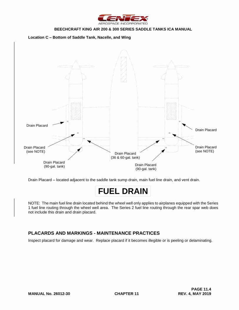
Location C – Bottom of Saddle Tank, Nacelle, and Wing
Drain Placard – located adjacent to the saddle tank sump drain, main fuel line drain, and vent drain.
NOTE: The main fuel line drain located behind the wheel well only applies to airplanes equipped with the Series 1 fuel line routing through the wheel well area. The Series 2 fuel line routing through the rear spar web does not include this drain and drain placard.
PLACARDS AND MARKINGS - MAINTENANCE PRACTICES
Inspect placard for damage and wear. Replace placard if it becomes illegible or is peeling or delaminating.
FUEL DRAIN
3.5
.7
Drain Placard (90-gal. tank)
Drain Placard
Drain Placard
Drain Placard (36 & 60-gal. tank)
Drain Placard (90-gal. tank)
Drain Placard (see NOTE)
Drain Placard (see NOTE)
BEECHCRAFT KING AIR 200 & 300 SERIES SADDLE TANKS ICA MANUAL
PAGE 12.1 MANUAL No. 26012-30 CHAPTER 12 REV. 3, FEB-2019
CHAPTER 12
SERVICING
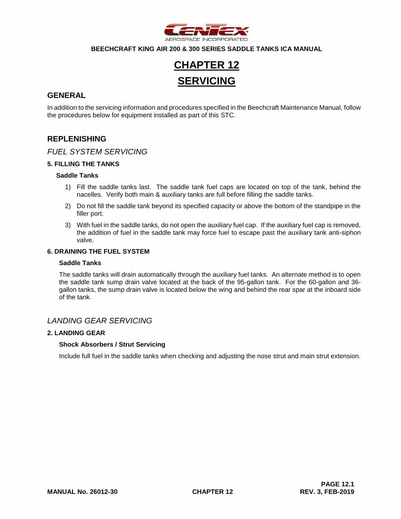
GENERAL
In addition to the servicing information and procedures specified in the Beechcraft Maintenance Manual, follow the procedures below for equipment installed as part of this STC.
REPLENISHING
FUEL SYSTEM SERVICING
5. FILLING THE TANKS
Saddle Tanks
1) Fill the saddle tanks last. The saddle tank fuel caps are located on top of the tank, behind the nacelles. Verify both main & auxiliary tanks are full before filling the saddle tanks.
2) Do not fill the saddle tank beyond its specified capacity or above the bottom of the standpipe in the filler port.
3) With fuel in the saddle tanks, do not open the auxiliary fuel cap. If the auxiliary fuel cap is removed, the addition of fuel in the saddle tank may force fuel to escape past the auxiliary tank anti-siphon valve.
6. DRAINING THE FUEL SYSTEM
Saddle Tanks
The saddle tanks will drain automatically through the auxiliary fuel tanks. An alternate method is to open the saddle tank sump drain valve located at the back of the 95-gallon tank. For the 60-gallon and 36-gallon tanks, the sump drain valve is located below the wing and behind the rear spar at the inboard side of the tank.
LANDING GEAR SERVICING
2. LANDING GEAR
Shock Absorbers / Strut Servicing
Include full fuel in the saddle tanks when checking and adjusting the nose strut and main strut extension.
BEECHCRAFT KING AIR 200 & 300 SERIES SADDLE TANKS ICA MANUAL
PAGE 12.2 MANUAL No. 26012-30 CHAPTER 12 REV. 3, FEB-2019
[Intentional Blank Page]
BEECHCRAFT KING AIR 200 & 300 SERIES SADDLE TANKS ICA MANUAL
PAGE 24.1 MANUAL No. 26012-30 CHAPTER 24 REV. 1, DEC. 2015
CHAPTER 24
ELECTRICAL POWER
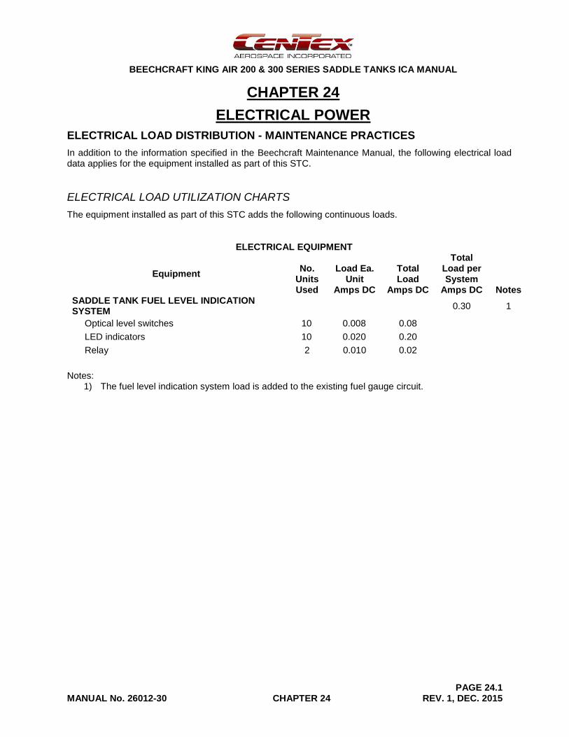
ELECTRICAL LOAD DISTRIBUTION - MAINTENANCE PRACTICES
In addition to the information specified in the Beechcraft Maintenance Manual, the following electrical load data applies for the equipment installed as part of this STC.
ELECTRICAL LOAD UTILIZATION CHARTS
The equipment installed as part of this STC adds the following continuous loads.
ELECTRICAL EQUIPMENT
Equipment No.
Units Used
Load Ea. Unit
Amps DC
Total Load
Amps DC
Total Load per System
Amps DC Notes SADDLE TANK FUEL LEVEL INDICATION SYSTEM
0.30 1
Optical level switches 10 0.008 0.08
LED indicators 10 0.020 0.20
Relay 2 0.010 0.02
Notes: 1) The fuel level indication system load is added to the existing fuel gauge circuit.

BEECHCRAFT KING AIR 200 & 300 SERIES SADDLE TANKS ICA MANUAL
PAGE 24.2 MANUAL No. 26012-30 CHAPTER 24 REV. 1, DEC. 2015
[Intentional Blank Page]
BEECHCRAFT KING AIR 200 & 300 SERIES SADDLE TANKS ICA MANUAL
PAGE 25.1 MANUAL No. 26012-30 CHAPTER 25 REV. 2, JUN-2018
CHAPTER 25
EQUIPMENT/FURNISHINGS
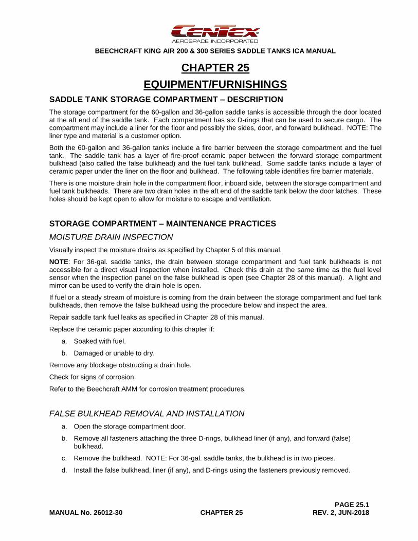
SADDLE TANK STORAGE COMPARTMENT – DESCRIPTION
The storage compartment for the 60-gallon and 36-gallon saddle tanks is accessible through the door located at the aft end of the saddle tank. Each compartment has six D-rings that can be used to secure cargo. The compartment may include a liner for the floor and possibly the sides, door, and forward bulkhead. NOTE: The liner type and material is a customer option.
Both the 60-gallon and 36-gallon tanks include a fire barrier between the storage compartment and the fuel tank. The saddle tank has a layer of fire-proof ceramic paper between the forward storage compartment bulkhead (also called the false bulkhead) and the fuel tank bulkhead. Some saddle tanks include a layer of ceramic paper under the liner on the floor and bulkhead. The following table identifies fire barrier materials.
There is one moisture drain hole in the compartment floor, inboard side, between the storage compartment and fuel tank bulkheads. There are two drain holes in the aft end of the saddle tank below the door latches. These holes should be kept open to allow for moisture to escape and ventilation.
STORAGE COMPARTMENT – MAINTENANCE PRACTICES
MOISTURE DRAIN INSPECTION
Visually inspect the moisture drains as specified by Chapter 5 of this manual.
NOTE: For 36-gal. saddle tanks, the drain between storage compartment and fuel tank bulkheads is not accessible for a direct visual inspection when installed. Check this drain at the same time as the fuel level sensor when the inspection panel on the false bulkhead is open (see Chapter 28 of this manual). A light and mirror can be used to verify the drain hole is open.
If fuel or a steady stream of moisture is coming from the drain between the storage compartment and fuel tank bulkheads, then remove the false bulkhead using the procedure below and inspect the area.
Repair saddle tank fuel leaks as specified in Chapter 28 of this manual.
Replace the ceramic paper according to this chapter if:
a. Soaked with fuel.
b. Damaged or unable to dry.
Remove any blockage obstructing a drain hole.
Check for signs of corrosion.
Refer to the Beechcraft AMM for corrosion treatment procedures.
FALSE BULKHEAD REMOVAL AND INSTALLATION
a. Open the storage compartment door.
b. Remove all fasteners attaching the three D-rings, bulkhead liner (if any), and forward (false) bulkhead.
c. Remove the bulkhead. NOTE: For 36-gal. saddle tanks, the bulkhead is in two pieces.
d. Install the false bulkhead, liner (if any), and D-rings using the fasteners previously removed.
BEECHCRAFT KING AIR 200 & 300 SERIES SADDLE TANKS ICA MANUAL
PAGE 25.2 MANUAL No. 26012-30 CHAPTER 25 REV. 2, JUN-2018
STORAGE COMPARTMENT LINER – MAINTENANCE PRACTICES
Clean the liner as needed.
Replace the liner as needed when worn out or damaged.
CLEANING
a. Remove any loose dirt or debris.
b. Wipe the liner with a soft cloth and a solution of mild soap or detergent and water.
c. Let the liner and compartment dry thoroughly before closing the door.
d. For leather liners, apply a leather conditioner after cleaning in order to prevent cracking (follow the manufacturer’s instructions for applying the conditioner).
e. If required, disinfect the storage compartment as follows (for non-leather liners only):
1. Dampen a clean cloth in a solution of bleach and water; i.e., not dripping wet.
NOTE: Disinfectant wipes may be used as an alternative.
2. Wipe down the liner and compartment surfaces with the cloth or wipe.
3. After all surfaces are disinfected, wipe dry with a clean, dry cloth.
CAUTION: Do NOT spray any cleaners or chemicals that can corrode Aluminum inside the storage compartment.
LINER REMOVAL AND INSTALLATION
a. Open the storage compartment door.
b. Remove all fasteners securing the liner to the floor or bulkhead.
c. Where the liner is glued, use a thin plastic scraper to separate the liner from the surface.
d. Pull out the liner.
e. Remove any old adhesive.
f. Clean the interior surfaces.
g. Install the liner using adhesive where needed.
NOTE: Available adhesives are listed in the Beechcraft AMM.
h. Re-install screws where removed.
BEECHCRAFT KING AIR 200 & 300 SERIES SADDLE TANKS ICA MANUAL
PAGE 25.3 MANUAL No. 26012-30 CHAPTER 25 REV. 2, JUN-2018
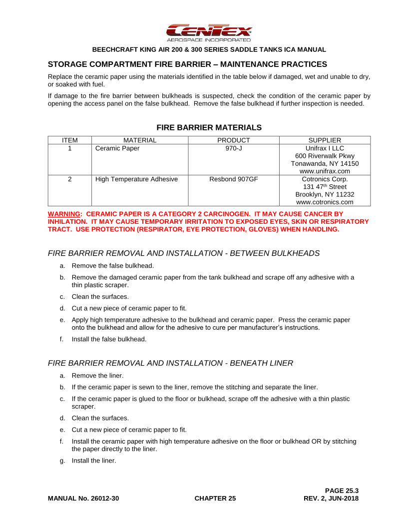
STORAGE COMPARTMENT FIRE BARRIER – MAINTENANCE PRACTICES
Replace the ceramic paper using the materials identified in the table below if damaged, wet and unable to dry, or soaked with fuel.
If damage to the fire barrier between bulkheads is suspected, check the condition of the ceramic paper by opening the access panel on the false bulkhead. Remove the false bulkhead if further inspection is needed.
FIRE BARRIER MATERIALS
ITEM MATERIAL PRODUCT SUPPLIER
1 Ceramic Paper 970-J Unifrax I LLC 600 Riverwalk Pkwy
Tonawanda, NY 14150 www.unifrax.com
2 High Temperature Adhesive Resbond 907GF Cotronics Corp. 131 47th Street
Brooklyn, NY 11232 www.cotronics.com
WARNING: CERAMIC PAPER IS A CATEGORY 2 CARCINOGEN. IT MAY CAUSE CANCER BY INHILATION. IT MAY CAUSE TEMPORARY IRRITATION TO EXPOSED EYES, SKIN OR RESPIRATORY TRACT. USE PROTECTION (RESPIRATOR, EYE PROTECTION, GLOVES) WHEN HANDLING.
FIRE BARRIER REMOVAL AND INSTALLATION - BETWEEN BULKHEADS
a. Remove the false bulkhead.
b. Remove the damaged ceramic paper from the tank bulkhead and scrape off any adhesive with a thin plastic scraper.
c. Clean the surfaces.
d. Cut a new piece of ceramic paper to fit.
e. Apply high temperature adhesive to the bulkhead and ceramic paper. Press the ceramic paper onto the bulkhead and allow for the adhesive to cure per manufacturer’s instructions.
f. Install the false bulkhead.
FIRE BARRIER REMOVAL AND INSTALLATION - BENEATH LINER
a. Remove the liner.
b. If the ceramic paper is sewn to the liner, remove the stitching and separate the liner.
c. If the ceramic paper is glued to the floor or bulkhead, scrape off the adhesive with a thin plastic scraper.
d. Clean the surfaces.
e. Cut a new piece of ceramic paper to fit.
f. Install the ceramic paper with high temperature adhesive on the floor or bulkhead OR by stitching the paper directly to the liner.
g. Install the liner.
BEECHCRAFT KING AIR 200 & 300 SERIES SADDLE TANKS ICA MANUAL
PAGE 25.4 MANUAL No. 26012-30 CHAPTER 25 REV. 2, JUN-2018
[Intentional Blank Page]
BEECHCRAFT KING AIR 200 & 300 SERIES SADDLE TANKS ICA MANUAL
PAGE 28.1 MANUAL No. 26012-30 CHAPTER 28 REV. 3, FEB-2019
CHAPTER 28
FUEL
GENERAL
Follow the basic fuel system information and procedures specified in the Beechcraft Maintenance Manual. Follow the procedures in this chapter for equipment installed as part of this STC.
CONTENTS
CHAPTER 28 SECTIONS
GENERAL
CONTENTS
SADDLE TANK FUEL SYSTEM – DESCRIPTION AND OPERATION
SADDLE TANK FUEL SYSTEM – TROUBLESHOOTING
SADDLE TANK FUEL SYSTEM – MAINTENANCE PRACTICES
FUEL FILLER CAP INSPECTION
FAIRING REMOVAL AND INSTALLATION
FUEL SCREEN INSPECTION
FUEL SCREEN REMOVAL AND INSTALLATION (95-GAL. TANK)
FUEL SCREEN REMOVAL AND INSTALLATION (36-GAL. & 60-GAL. TANK)
FUEL SCREEN CLEANING
SADDLE TANK REMOVAL
SADDLE TANK INSTALLATION
SADDLE TANK LEAK TEST
SADDLE TANK LEAK REPAIR
SADDLE TANK MATERIALS
SADDLE TANK FUEL INDICATING SYSTEM – DESCRIPTION AND OPERATION
SADDLE TANK FUEL INDICATING SYSTEM – TROUBLESHOOTING
SADDLE TANK FUEL INDICATING SYSTEM – MAINTENANCE PRACTICES
FUEL LEVEL INDICATING SYSTEM FUNCTIONAL TEST
FUEL LEVEL INDICATOR REMOVAL AND INSTALLATION
OPTICAL LEVEL SWITCH REMOVAL – UPPER SWITCH
OPTICAL LEVEL SWITCH REMOVAL – LOWER SWITCH
OPTICAL LEVEL SWITCH INSTALLATION
SADDLE TANK FUEL INDICATING SYSTEM – WIRING DIAGRAM
BEECHCRAFT KING AIR 200 & 300 SERIES SADDLE TANKS ICA MANUAL
PAGE 28.2 MANUAL No. 26012-30 CHAPTER 28 REV. 3, FEB-2019
[Intentional Blank Page]
BEECHCRAFT KING AIR 200 & 300 SERIES SADDLE TANKS ICA MANUAL
PAGE 28.3 MANUAL No. 26012-30 CHAPTER 28 REV. 4, MAY 2019
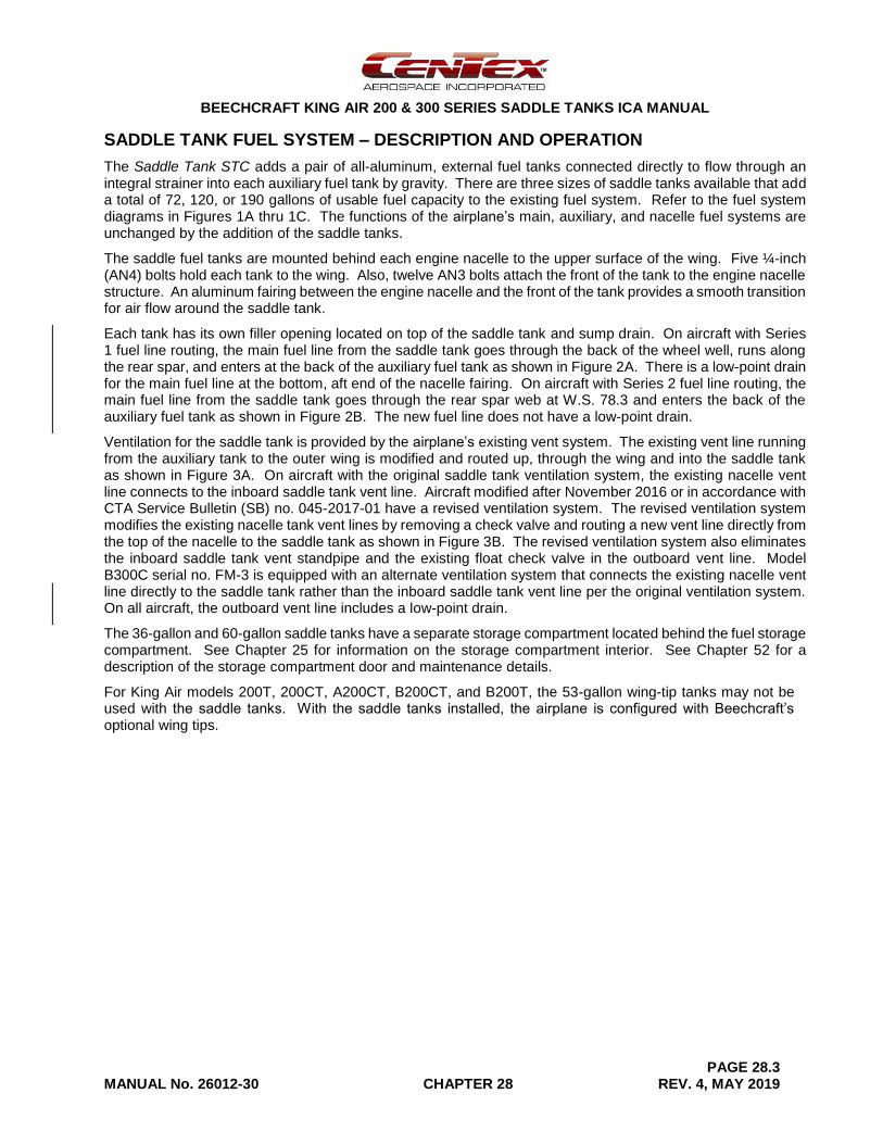
SADDLE TANK FUEL SYSTEM – DESCRIPTION AND OPERATION
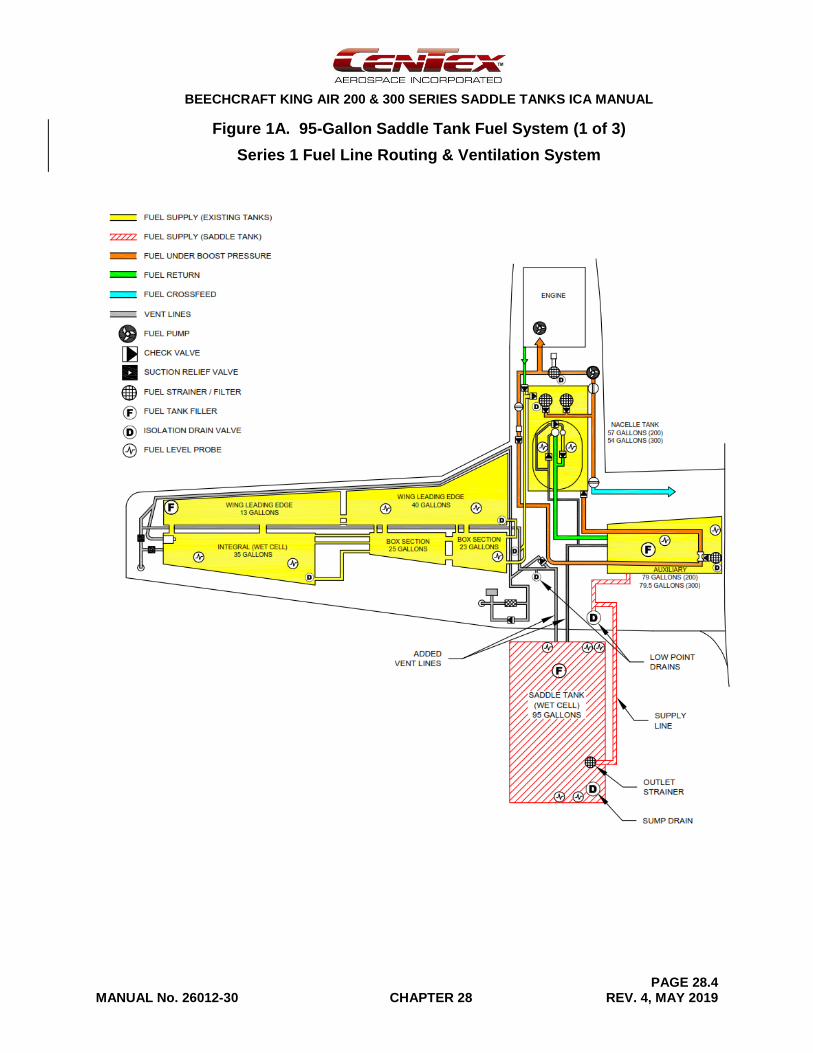
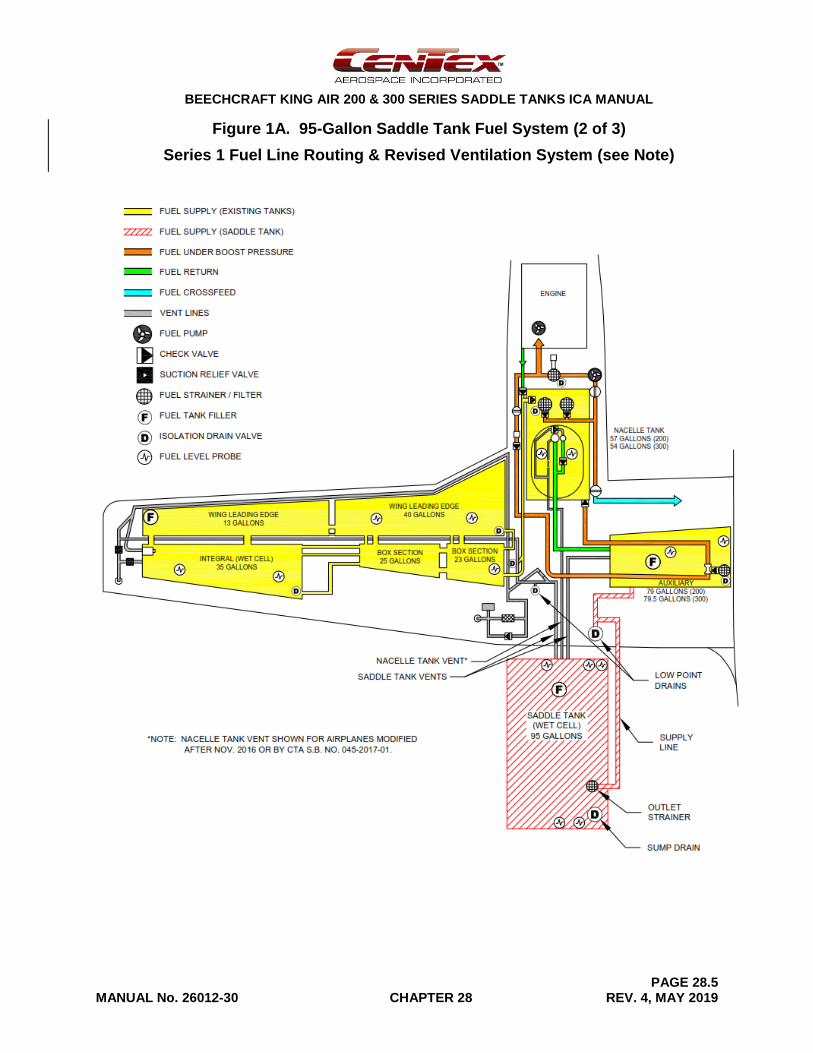
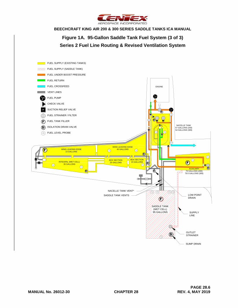
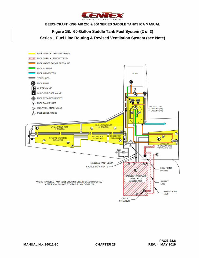
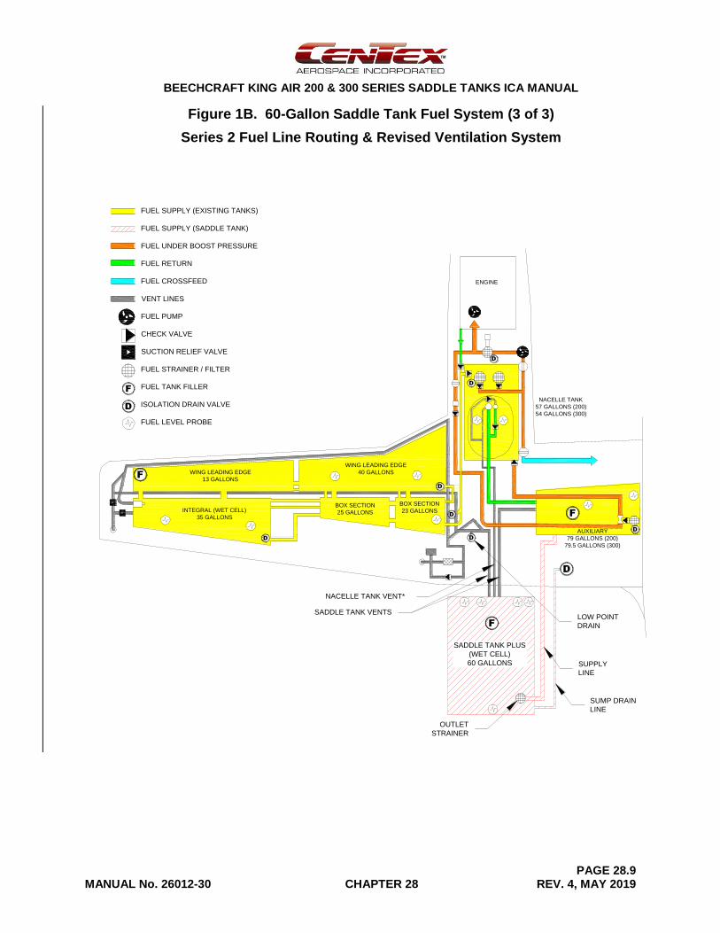
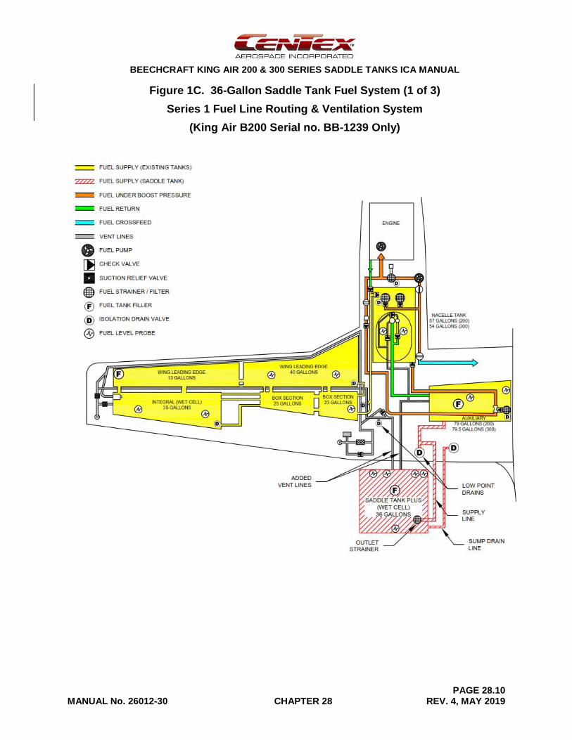
The Saddle Tank STC adds a pair of all-aluminum, external fuel tanks connected directly to flow through an integral strainer into each auxiliary fuel tank by gravity. There are three sizes of saddle tanks available that add a total of 72, 120, or 190 gallons of usable fuel capacity to the existing fuel system. Refer to the fuel system diagrams in Figures 1A thru 1C. The functions of the airplane’s main, auxiliary, and nacelle fuel systems are unchanged by the addition of the saddle tanks.
The saddle fuel tanks are mounted behind each engine nacelle to the upper surface of the wing. Five ¼-inch (AN4) bolts hold each tank to the wing. Also, twelve AN3 bolts attach the front of the tank to the engine nacelle structure. An aluminum fairing between the engine nacelle and the front of the tank provides a smooth transition for air flow around the saddle tank.
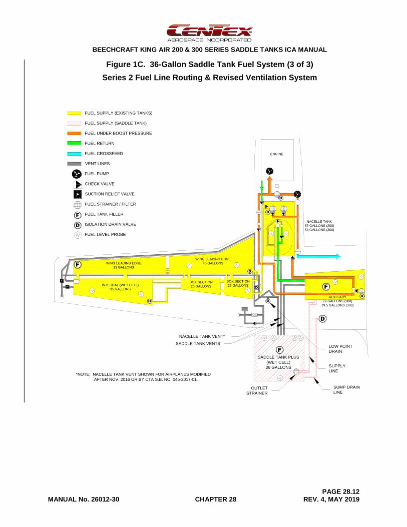
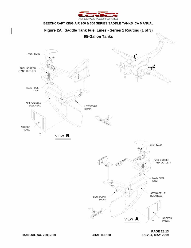
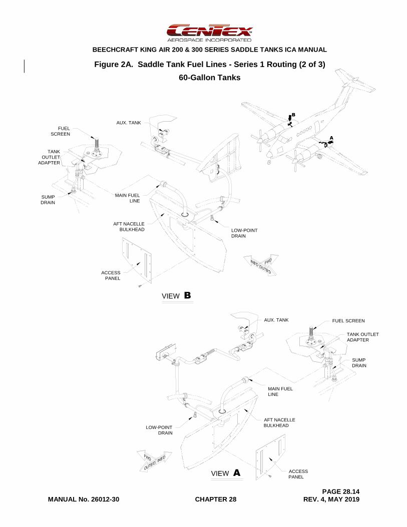
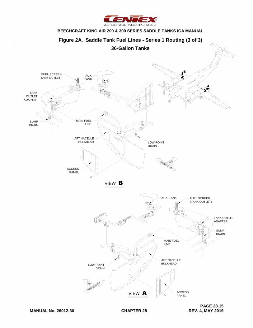
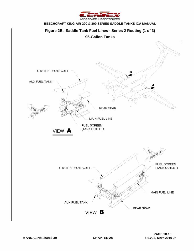
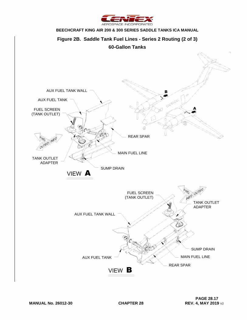
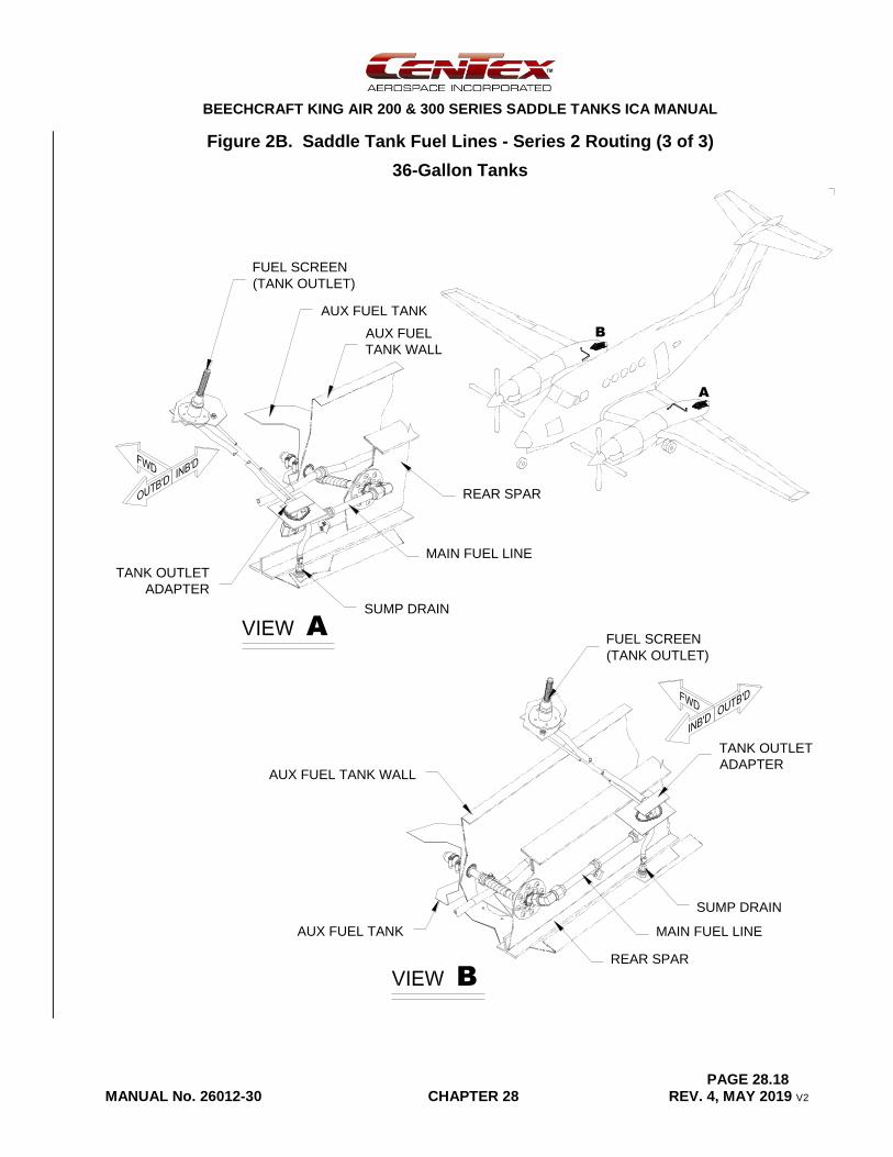
Each tank has its own filler opening located on top of the saddle tank and sump drain. On aircraft with Series 1 fuel line routing, the main fuel line from the saddle tank goes through the back of the wheel well, runs along the rear spar, and enters at the back of the auxiliary fuel tank as shown in Figure 2A. There is a low-point drain for the main fuel line at the bottom, aft end of the nacelle fairing. On aircraft with Series 2 fuel line routing, the main fuel line from the saddle tank goes through the rear spar web at W.S. 78.3 and enters the back of the auxiliary fuel tank as shown in Figure 2B. The new fuel line does not have a low-point drain.
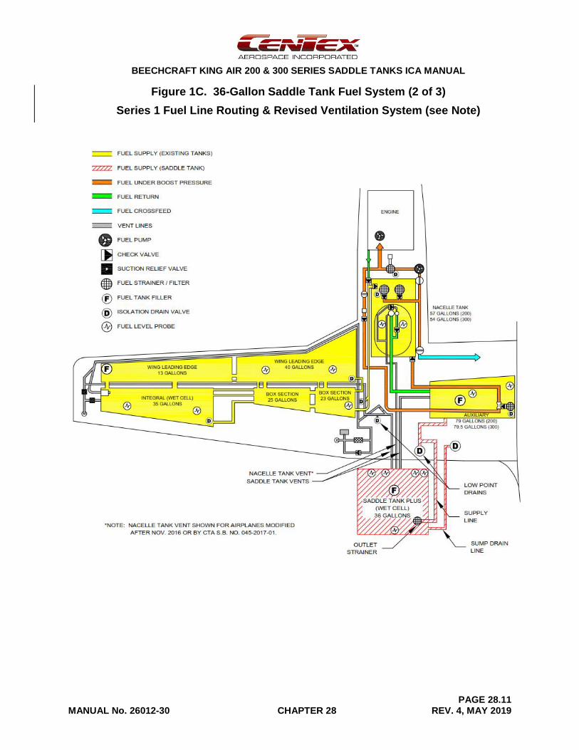
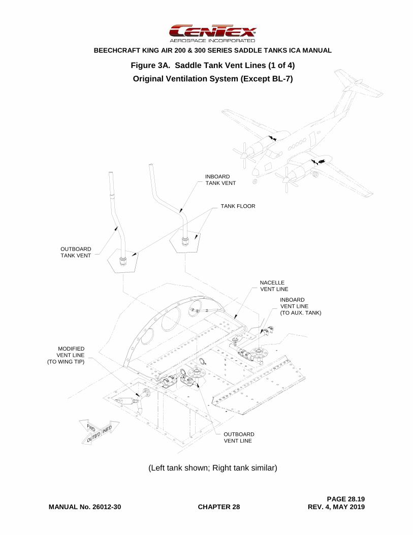
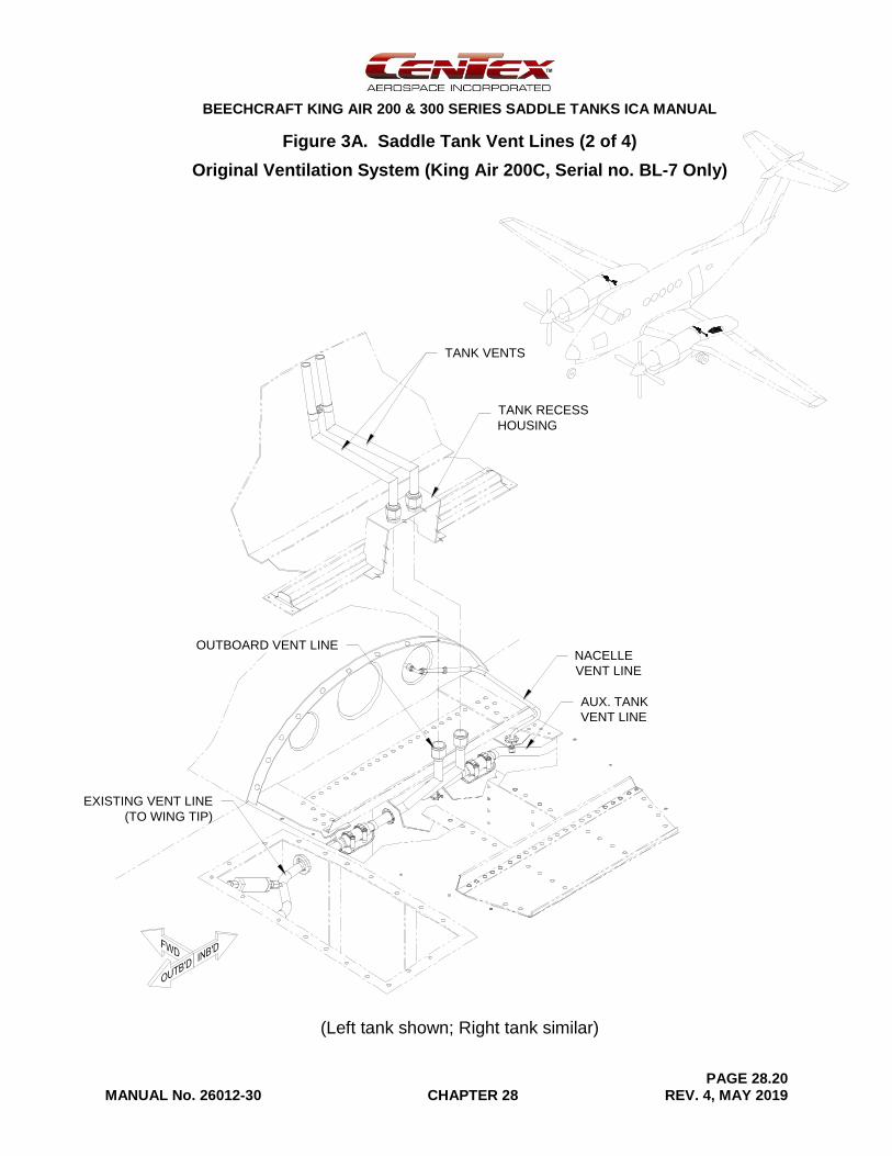
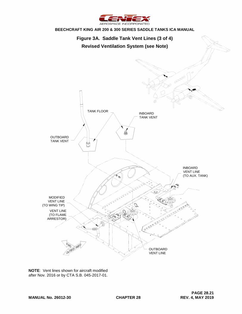
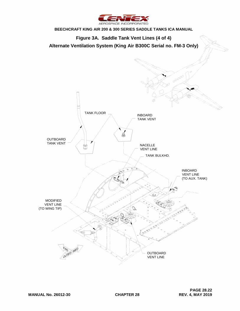
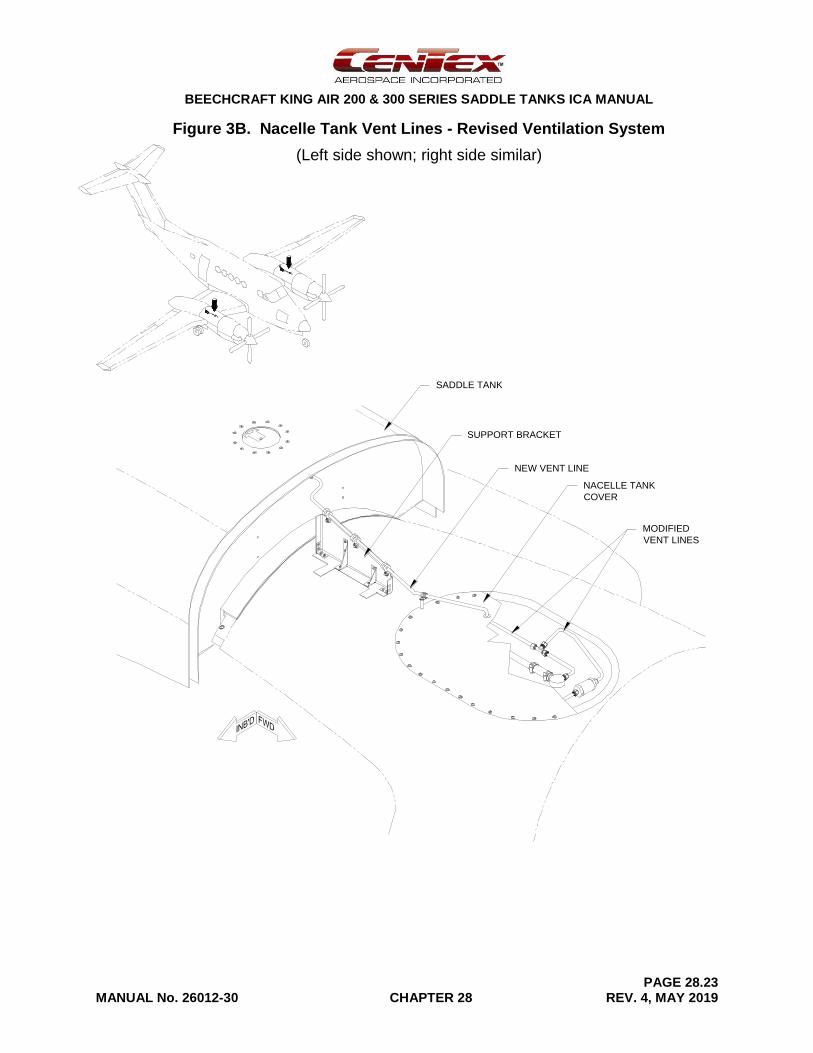
Ventilation for the saddle tank is provided by the airplane’s existing vent system. The existing vent line running from the auxiliary tank to the outer wing is modified and routed up, through the wing and into the saddle tank as shown in Figure 3A. On aircraft with the original saddle tank ventilation system, the existing nacelle vent line connects to the inboard saddle tank vent line. Aircraft modified after November 2016 or in accordance with CTA Service Bulletin (SB) no. 045-2017-01 have a revised ventilation system. The revised ventilation system modifies the existing nacelle tank vent lines by removing a check valve and routing a new vent line directly from the top of the nacelle to the saddle tank as shown in Figure 3B. The revised ventilation system also eliminates the inboard saddle tank vent standpipe and the existing float check valve in the outboard vent line. Model B300C serial no. FM-3 is equipped with an alternate ventilation system that connects the existing nacelle vent line directly to the saddle tank rather than the inboard saddle tank vent line per the original ventilation system. On all aircraft, the outboard vent line includes a low-point drain.
The 36-gallon and 60-gallon saddle tanks have a separate storage compartment located behind the fuel storage compartment. See Chapter 25 for information on the storage compartment interior. See Chapter 52 for a description of the storage compartment door and maintenance details.
For King Air models 200T, 200CT, A200CT, B200CT, and B200T, the 53-gallon wing-tip tanks may not be used with the saddle tanks. With the saddle tanks installed, the airplane is configured with Beechcraft’s optional wing tips.
BEECHCRAFT KING AIR 200 & 300 SERIES SADDLE TANKS ICA MANUAL
PAGE 28.4 MANUAL No. 26012-30 CHAPTER 28 REV. 4, MAY 2019
Figure 1A. 95-Gallon Saddle Tank Fuel System (1 of 3)
Series 1 Fuel Line Routing & Ventilation System
BEECHCRAFT KING AIR 200 & 300 SERIES SADDLE TANKS ICA MANUAL
PAGE 28.5 MANUAL No. 26012-30 CHAPTER 28 REV. 4, MAY 2019
Figure 1A. 95-Gallon Saddle Tank Fuel System (2 of 3)
Series 1 Fuel Line Routing & Revised Ventilation System (see Note)
BEECHCRAFT KING AIR 200 & 300 SERIES SADDLE TANKS ICA MANUAL
PAGE 28.6 MANUAL No. 26012-30 CHAPTER 28 REV. 4, MAY 2019
Figure 1A. 95-Gallon Saddle Tank Fuel System (3 of 3)
Series 2 Fuel Line Routing & Revised Ventilation System
*NOTE: NACELLE TANK VENT SHOWN FOR AIRPLANES MODIFIED
AFTER NOV. 2016 OR BY CTA S.B. NO. 045-2017-01.
SADDLE TANK VENTS
NACELLE TANK VENT*
SADDLE TANK
(WET CELL)
95 GALLONS
FUEL SUPPLY (EXISTING TANKS)
FUEL SUPPLY (SADDLE TANK)
FUEL UNDER BOOST PRESSURE
FUEL RETURN
FUEL CROSSFEED
VENT LINES
FUEL PUMP
CHECK VALVE
SUCTION RELIEF VALVE
FUEL STRAINER / FILTER
FUEL TANK FILLER
ISOLATION DRAIN VALVE
FUEL LEVEL PROBE
WING LEADING EDGE
13 GALLONS
INTEGRAL (WET CELL)
35 GALLONS
WING LEADING EDGE
40 GALLONS
BOX SECTION
25 GALLONS
BOX SECTION
23 GALLONS
AUXILIARY
79 GALLONS (200)
79.5 GALLONS (300)
NACELLE TANK
57 GALLONS (200)
54 GALLONS (300)
ENGINE
05/14/19 KING AIR 200/A200/B200/300/B300 saddle tank (ST190)
SUMP DRAIN
SUPPLY
LINE
OUTLET
STRAINER
LOW POINT
DRAIN

BEECHCRAFT KING AIR 200 & 300 SERIES SADDLE TANKS ICA MANUAL
PAGE 28.7 MANUAL No. 26012-30 CHAPTER 28 REV. 4, MAY 2019
Figure 1B. 60-Gallon Saddle Tank Fuel System (1 of 3)
Series 1 Fuel Line Routing & Alternate Ventilation System
(King Air B300C Serial no. FM-3 Only)
BEECHCRAFT KING AIR 200 & 300 SERIES SADDLE TANKS ICA MANUAL
PAGE 28.8 MANUAL No. 26012-30 CHAPTER 28 REV. 4, MAY 2019
Figure 1B. 60-Gallon Saddle Tank Fuel System (2 of 3)
Series 1 Fuel Line Routing & Revised Ventilation System (see Note)
BEECHCRAFT KING AIR 200 & 300 SERIES SADDLE TANKS ICA MANUAL
PAGE 28.9 MANUAL No. 26012-30 CHAPTER 28 REV. 4, MAY 2019
Figure 1B. 60-Gallon Saddle Tank Fuel System (3 of 3)
Series 2 Fuel Line Routing & Revised Ventilation System
SADDLE TANK PLUS
(WET CELL)
60 GALLONS
FUEL SUPPLY (EXISTING TANKS)
FUEL SUPPLY (SADDLE TANK)
FUEL UNDER BOOST PRESSURE
FUEL RETURN
FUEL CROSSFEED
VENT LINES
FUEL PUMP
CHECK VALVE
SUCTION RELIEF VALVE
FUEL STRAINER / FILTER
FUEL TANK FILLER
ISOLATION DRAIN VALVE
FUEL LEVEL PROBE
WING LEADING EDGE
13 GALLONS
INTEGRAL (WET CELL)
35 GALLONS
WING LEADING EDGE
40 GALLONS
BOX SECTION
25 GALLONS
BOX SECTION
23 GALLONS
AUXILIARY
79 GALLONS (200)
79.5 GALLONS (300)
NACELLE TANK
57 GALLONS (200)
54 GALLONS (300)
ENGINE
05/14/19 KING AIR 200/A200/B200/300/B300 saddle tank plus (ST120)
SUPPLY
LINE
OUTLET
STRAINER
LOW POINT
DRAIN
SUMP DRAIN
LINE
*NOTE: NACELLE TANK VENT SHOWN FOR AIRPLANES MODIFIED
AFTER NOV. 2016 OR BY CTA S.B. NO. 045-2017-01.
SADDLE TANK VENTS
NACELLE TANK VENT*
BEECHCRAFT KING AIR 200 & 300 SERIES SADDLE TANKS ICA MANUAL
PAGE 28.10 MANUAL No. 26012-30 CHAPTER 28 REV. 4, MAY 2019
Figure 1C. 36-Gallon Saddle Tank Fuel System (1 of 3)
Series 1 Fuel Line Routing & Ventilation System
(King Air B200 Serial no. BB-1239 Only)
BEECHCRAFT KING AIR 200 & 300 SERIES SADDLE TANKS ICA MANUAL
PAGE 28.11 MANUAL No. 26012-30 CHAPTER 28 REV. 4, MAY 2019
Figure 1C. 36-Gallon Saddle Tank Fuel System (2 of 3)
Series 1 Fuel Line Routing & Revised Ventilation System (see Note)
BEECHCRAFT KING AIR 200 & 300 SERIES SADDLE TANKS ICA MANUAL
PAGE 28.12 MANUAL No. 26012-30 CHAPTER 28 REV. 4, MAY 2019
Figure 1C. 36-Gallon Saddle Tank Fuel System (3 of 3)
Series 2 Fuel Line Routing & Revised Ventilation System
SADDLE TANK PLUS
(WET CELL)
36 GALLONS
FUEL SUPPLY (EXISTING TANKS)
FUEL SUPPLY (SADDLE TANK)
FUEL UNDER BOOST PRESSURE
FUEL RETURN
FUEL CROSSFEED
VENT LINES
FUEL PUMP
CHECK VALVE
SUCTION RELIEF VALVE
FUEL STRAINER / FILTER
FUEL TANK FILLER
ISOLATION DRAIN VALVE
FUEL LEVEL PROBE
WING LEADING EDGE
13 GALLONS
INTEGRAL (WET CELL)
35 GALLONS
WING LEADING EDGE
40 GALLONS
BOX SECTION
25 GALLONS
BOX SECTION
23 GALLONS
AUXILIARY
79 GALLONS (200)
79.5 GALLONS (300)
NACELLE TANK
57 GALLONS (200)
54 GALLONS (300)
ENGINE
05/14/19 KING AIR 200/A200/B200/300/B300 saddle tank plus (ST72)
SUPPLY
LINE
OUTLET
STRAINER
LOW POINT
DRAIN
SUMP DRAIN
LINE
*NOTE: NACELLE TANK VENT SHOWN FOR AIRPLANES MODIFIED
AFTER NOV. 2016 OR BY CTA S.B. NO. 045-2017-01.
SADDLE TANK VENTS
NACELLE TANK VENT*
BEECHCRAFT KING AIR 200 & 300 SERIES SADDLE TANKS ICA MANUAL
PAGE 28.13 MANUAL No. 26012-30 CHAPTER 28 REV. 4, MAY 2019
Figure 2A. Saddle Tank Fuel Lines - Series 1 Routing (1 of 3)
95-Gallon Tanks
B
ACCESS
PANEL
MAIN FUEL
LINE
AFT NACELLE
BULKHEAD
AUX. TANK
LOW-POINT
DRAIN
FUEL SCREEN
(TANK OUTLET)
B
A
A ACCESS
PANEL
MAIN FUEL
LINE
AFT NACELLE
BULKHEAD
AUX. TANK
LOW-POINT
DRAIN
A ACCESS
PANEL
MAIN FUEL
LINE
AFT NACELLE
BULKHEAD
AUX. TANK
LOW-POINT
DRAIN
FUEL SCREEN
(TANK OUTLET)
BEECHCRAFT KING AIR 200 & 300 SERIES SADDLE TANKS ICA MANUAL
PAGE 28.14 MANUAL No. 26012-30 CHAPTER 28 REV. 4, MAY 2019
Figure 2A. Saddle Tank Fuel Lines - Series 1 Routing (2 of 3)
60-Gallon Tanks
B
ACCESS
PANEL
MAIN FUEL
LINE
AFT NACELLE
BULKHEAD
AUX. TANK
LOW-POINT
DRAIN
FUEL
SCREEN
TANK
OUTLET
ADAPTER
SUMP
DRAIN
B
A
A ACCESS
PANEL
MAIN FUEL
LINE
AFT NACELLE
BULKHEAD
AUX. TANK
LOW-POINT
DRAIN
A ACCESS
PANEL
MAIN FUEL
LINE
AFT NACELLE
BULKHEAD
AUX. TANK
LOW-POINT
DRAIN
FUEL SCREEN
SUMP
DRAIN
TANK OUTLET
ADAPTER
BEECHCRAFT KING AIR 200 & 300 SERIES SADDLE TANKS ICA MANUAL
PAGE 28.15 MANUAL No. 26012-30 CHAPTER 28 REV. 4, MAY 2019
Figure 2A. Saddle Tank Fuel Lines - Series 1 Routing (3 of 3)
36-Gallon Tanks
B
ACCESS
PANEL
MAIN FUEL
LINE
AFT NACELLE
BULKHEAD
AUX.
TANK
LOW-POINT
DRAIN
FUEL SCREEN
(TANK OUTLET)
TANK
OUTLET
ADAPTER
SUMP
DRAIN
B
A
A ACCESS
PANEL
MAIN FUEL
LINE
AFT NACELLE
BULKHEAD
AUX. TANK
LOW-POINT
DRAIN
A ACCESS
PANEL
MAIN FUEL
LINE
AFT NACELLE
BULKHEAD
AUX. TANK
LOW-POINT
DRAIN
FUEL SCREEN
(TANK OUTLET)
SUMP
DRAIN
TANK OUTLET
ADAPTER
BEECHCRAFT KING AIR 200 & 300 SERIES SADDLE TANKS ICA MANUAL
PAGE 28.16 MANUAL No. 26012-30 CHAPTER 28 REV. 4, MAY 2019 V2
Figure 2B. Saddle Tank Fuel Lines - Series 2 Routing (1 of 3)
95-Gallon Tanks
MAIN FUEL LINE
AUX FUEL TANK
AUX FUEL TANK WALL
FUEL SCREEN
(TANK OUTLET)A
B
A
B
REAR SPAR
AUX FUEL TANK
REAR SPAR
MAIN FUEL LINE
FUEL SCREEN
(TANK OUTLET)AUX FUEL TANK WALL
BEECHCRAFT KING AIR 200 & 300 SERIES SADDLE TANKS ICA MANUAL
PAGE 28.17 MANUAL No. 26012-30 CHAPTER 28 REV. 4, MAY 2019 V2
Figure 2B. Saddle Tank Fuel Lines - Series 2 Routing (2 of 3)
60-Gallon Tanks
MAIN FUEL LINE
AUX FUEL TANK
AUX FUEL TANK WALL
REAR SPAR
A
AUX FUEL TANK WALL
B
A
B
AUX FUEL TANK
REAR SPAR
MAIN FUEL LINE
FUEL SCREEN
(TANK OUTLET)
SUMP DRAIN
SUMP DRAIN
FUEL SCREEN
(TANK OUTLET)
TANK OUTLET
ADAPTER
TANK OUTLET
ADAPTER
BEECHCRAFT KING AIR 200 & 300 SERIES SADDLE TANKS ICA MANUAL
PAGE 28.18 MANUAL No. 26012-30 CHAPTER 28 REV. 4, MAY 2019 V2
Figure 2B. Saddle Tank Fuel Lines - Series 2 Routing (3 of 3)
36-Gallon Tanks
AUX FUEL TANK
A
MAIN FUEL LINE
AUX FUEL TANK
AUX FUEL
TANK WALL
SUMP DRAIN
SUMP DRAIN
FUEL SCREEN
(TANK OUTLET)
TANK OUTLET
ADAPTER
TANK OUTLET
ADAPTER
FUEL SCREEN
(TANK OUTLET)
REAR SPAR
MAIN FUEL LINE
AUX FUEL TANK WALL
B
A
B
REAR SPAR
BEECHCRAFT KING AIR 200 & 300 SERIES SADDLE TANKS ICA MANUAL
PAGE 28.19 MANUAL No. 26012-30 CHAPTER 28 REV. 4, MAY 2019
Figure 3A. Saddle Tank Vent Lines (1 of 4)
Original Ventilation System (Except BL-7)
(Left tank shown; Right tank similar)
MODIFIED
VENT LINE
(TO WING TIP)
NACELLE
VENT LINE
INBOARD
VENT LINE
(TO AUX. TANK)
OUTBOARD
VENT LINE
INBOARD
TANK VENT
OUTBOARD
TANK VENT
TANK FLOOR
BEECHCRAFT KING AIR 200 & 300 SERIES SADDLE TANKS ICA MANUAL
PAGE 28.20 MANUAL No. 26012-30 CHAPTER 28 REV. 4, MAY 2019
Figure 3A. Saddle Tank Vent Lines (2 of 4)
Original Ventilation System (King Air 200C, Serial no. BL-7 Only)
(Left tank shown; Right tank similar)
TANK VENTS
EXISTING VENT LINE
(TO WING TIP)
OUTBOARD VENT LINENACELLE
VENT LINE
AUX. TANK
VENT LINE
TANK RECESS
HOUSING
BEECHCRAFT KING AIR 200 & 300 SERIES SADDLE TANKS ICA MANUAL
PAGE 28.21 MANUAL No. 26012-30 CHAPTER 28 REV. 4, MAY 2019
Figure 3A. Saddle Tank Vent Lines (3 of 4)
Revised Ventilation System (see Note)
NOTE: Vent lines shown for aircraft modified after Nov. 2016 or by CTA S.B. 045-2017-01.
MODIFIED
VENT LINE
(TO WING TIP)
INBOARD
VENT LINE
(TO AUX. TANK)
OUTBOARD
VENT LINE
INBOARD
TANK VENT
OUTBOARD
TANK VENT
TANK FLOOR
VENT LINE
(TO FLAME
ARRESTOR)
BEECHCRAFT KING AIR 200 & 300 SERIES SADDLE TANKS ICA MANUAL
PAGE 28.22 MANUAL No. 26012-30 CHAPTER 28 REV. 4, MAY 2019
Figure 3A. Saddle Tank Vent Lines (4 of 4)
Alternate Ventilation System (King Air B300C Serial no. FM-3 Only)
NACELLE
VENT LINE
TANK BULKHD.
MODIFIED
VENT LINE
(TO WING TIP)
INBOARD
VENT LINE
(TO AUX. TANK)
OUTBOARD
VENT LINE
INBOARD
TANK VENT
OUTBOARD
TANK VENT
TANK FLOOR
BEECHCRAFT KING AIR 200 & 300 SERIES SADDLE TANKS ICA MANUAL
PAGE 28.23 MANUAL No. 26012-30 CHAPTER 28 REV. 4, MAY 2019
Figure 3B. Nacelle Tank Vent Lines - Revised Ventilation System
(Left side shown; right side similar)
SADDLE TANK
MODIFIED
VENT LINES
SUPPORT BRACKET
NACELLE TANK
COVER
NEW VENT LINE
BEECHCRAFT KING AIR 200 & 300 SERIES SADDLE TANKS ICA MANUAL
PAGE 28.24 MANUAL No. 26012-30 CHAPTER 28 REV. 4, MAY 2019
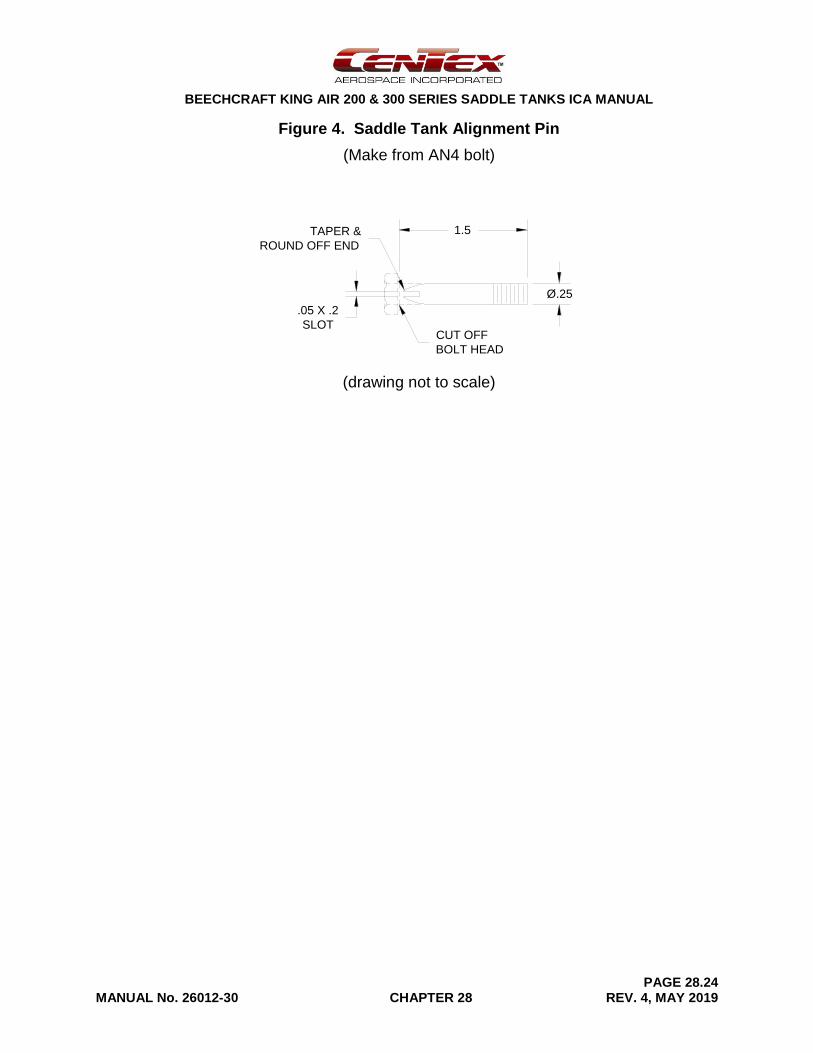
Figure 4. Saddle Tank Alignment Pin
(Make from AN4 bolt)
(drawing not to scale)
.05 X .2
SLOT
1.5
CUT OFF
BOLT HEAD
TAPER &
ROUND OFF END
Ø.25
BEECHCRAFT KING AIR 200 & 300 SERIES SADDLE TANKS ICA MANUAL
PAGE 28.25 MANUAL No. 26012-30 CHAPTER 28 REV. 4, MAY 2019
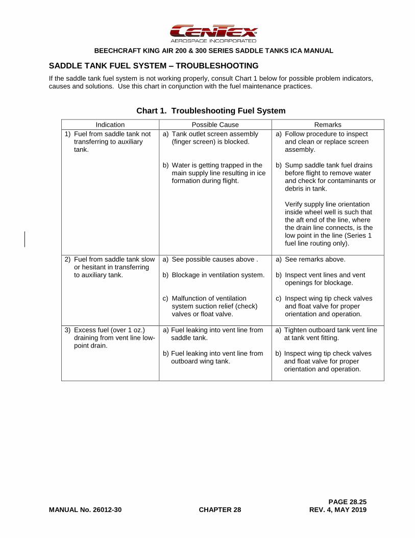
SADDLE TANK FUEL SYSTEM – TROUBLESHOOTING
If the saddle tank fuel system is not working properly, consult Chart 1 below for possible problem indicators, causes and solutions. Use this chart in conjunction with the fuel maintenance practices.
Chart 1. Troubleshooting Fuel System
Indication Possible Cause Remarks
1) Fuel from saddle tank not transferring to auxiliary tank.
a) Tank outlet screen assembly (finger screen) is blocked.
b) Water is getting trapped in the main supply line resulting in ice formation during flight.
a) Follow procedure to inspect and clean or replace screen assembly.
b) Sump saddle tank fuel drains before flight to remove water and check for contaminants or debris in tank. Verify supply line orientation inside wheel well is such that the aft end of the line, where the drain line connects, is the low point in the line (Series 1 fuel line routing only).
2) Fuel from saddle tank slow or hesitant in transferring to auxiliary tank.
a) See possible causes above .
b) Blockage in ventilation system.
c) Malfunction of ventilation system suction relief (check) valves or float valve.
a) See remarks above.
b) Inspect vent lines and vent openings for blockage.
c) Inspect wing tip check valves and float valve for proper orientation and operation.
3) Excess fuel (over 1 oz.) draining from vent line low-point drain.
a) Fuel leaking into vent line from saddle tank.
b) Fuel leaking into vent line from outboard wing tank.
a) Tighten outboard tank vent line at tank vent fitting.
b) Inspect wing tip check valves and float valve for proper orientation and operation.
BEECHCRAFT KING AIR 200 & 300 SERIES SADDLE TANKS ICA MANUAL
PAGE 28.26 MANUAL No. 26012-30 CHAPTER 28 REV. 4, MAY 2019
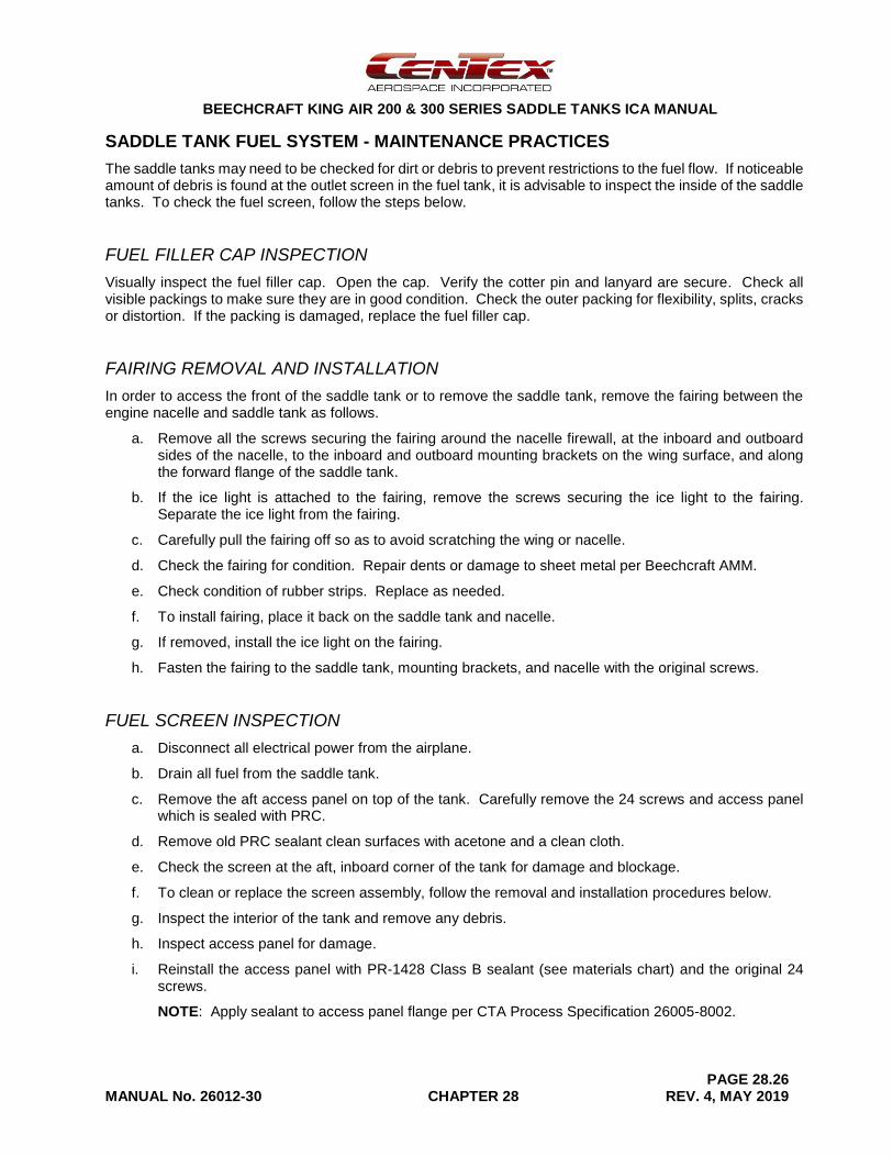
SADDLE TANK FUEL SYSTEM - MAINTENANCE PRACTICES
The saddle tanks may need to be checked for dirt or debris to prevent restrictions to the fuel flow. If noticeable amount of debris is found at the outlet screen in the fuel tank, it is advisable to inspect the inside of the saddle tanks. To check the fuel screen, follow the steps below.
FUEL FILLER CAP INSPECTION
Visually inspect the fuel filler cap. Open the cap. Verify the cotter pin and lanyard are secure. Check all visible packings to make sure they are in good condition. Check the outer packing for flexibility, splits, cracks or distortion. If the packing is damaged, replace the fuel filler cap.
FAIRING REMOVAL AND INSTALLATION
In order to access the front of the saddle tank or to remove the saddle tank, remove the fairing between the engine nacelle and saddle tank as follows.
a. Remove all the screws securing the fairing around the nacelle firewall, at the inboard and outboard sides of the nacelle, to the inboard and outboard mounting brackets on the wing surface, and along the forward flange of the saddle tank.
b. If the ice light is attached to the fairing, remove the screws securing the ice light to the fairing. Separate the ice light from the fairing.
c. Carefully pull the fairing off so as to avoid scratching the wing or nacelle.
d. Check the fairing for condition. Repair dents or damage to sheet metal per Beechcraft AMM.
e. Check condition of rubber strips. Replace as needed.
f. To install fairing, place it back on the saddle tank and nacelle.
g. If removed, install the ice light on the fairing.
h. Fasten the fairing to the saddle tank, mounting brackets, and nacelle with the original screws.
FUEL SCREEN INSPECTION
a. Disconnect all electrical power from the airplane.
b. Drain all fuel from the saddle tank.
c. Remove the aft access panel on top of the tank. Carefully remove the 24 screws and access panel which is sealed with PRC.
d. Remove old PRC sealant clean surfaces with acetone and a clean cloth.
e. Check the screen at the aft, inboard corner of the tank for damage and blockage.
f. To clean or replace the screen assembly, follow the removal and installation procedures below.
g. Inspect the interior of the tank and remove any debris.
h. Inspect access panel for damage.
i. Reinstall the access panel with PR-1428 Class B sealant (see materials chart) and the original 24 screws.
NOTE: Apply sealant to access panel flange per CTA Process Specification 26005-8002.
BEECHCRAFT KING AIR 200 & 300 SERIES SADDLE TANKS ICA MANUAL
PAGE 28.27 MANUAL No. 26012-30 CHAPTER 28 REV. 4, MAY 2019
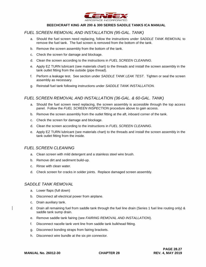
FUEL SCREEN REMOVAL AND INSTALLATION (95-GAL. TANK)
a. Should the fuel screen need replacing, follow the instructions under SADDLE TANK REMOVAL to remove the fuel tank. The fuel screen is removed from the bottom of the tank.
b. Remove the screen assembly from the bottom of the tank.
c. Check the screen for damage and blockage.
d. Clean the screen according to the instructions in FUEL SCREEN CLEANING.
e. Apply EZ TURN lubricant (see materials chart) to the threads and install the screen assembly in the tank outlet fitting from the outside (pipe thread).
f. Perform a leakage test. See section under SADDLE TANK LEAK TEST. Tighten or seal the screen assembly as necessary.
g. Reinstall fuel tank following instructions under SADDLE TANK INSTALLATION.
FUEL SCREEN REMOVAL AND INSTALLATION (36-GAL. & 60-GAL. TANK)
a. Should the fuel screen need replacing, the screen assembly is accessible through the top access panel. Follow the FUEL SCREEN INSPECTION procedure above to gain access.
b. Remove the screen assembly from the outlet fitting at the aft, inboard corner of the tank.
c. Check the screen for damage and blockage.
d. Clean the screen according to the instructions in FUEL SCREEN CLEANING.
e. Apply EZ TURN lubricant (see materials chart) to the threads and install the screen assembly in the tank outlet fitting from the inside.
FUEL SCREEN CLEANING
a. Clean screen with mild detergent and a stainless steel wire brush.
b. Remove dirt and sediment build-up.
c. Rinse with clean water.
d. Check screen for cracks in solder joints. Replace damaged screen assembly.
SADDLE TANK REMOVAL
a. Lower flaps (full down)
b. Disconnect all electrical power from airplane.
c. Drain auxiliary tank.
d. Drain all remaining fuel from saddle tank through the fuel line drain (Series 1 fuel line routing only) & saddle tank sump drain.
e. Remove saddle tank fairing (see FAIRING REMOVAL AND INSTALLATION).
f. Disconnect nacelle tank vent line from saddle tank bulkhead fitting.
g. Disconnect bonding straps from fairing brackets.
h. Disconnect wire bundle at the six pin connector.
BEECHCRAFT KING AIR 200 & 300 SERIES SADDLE TANKS ICA MANUAL
PAGE 28.28 MANUAL No. 26012-30 CHAPTER 28 REV. 4, MAY 2019
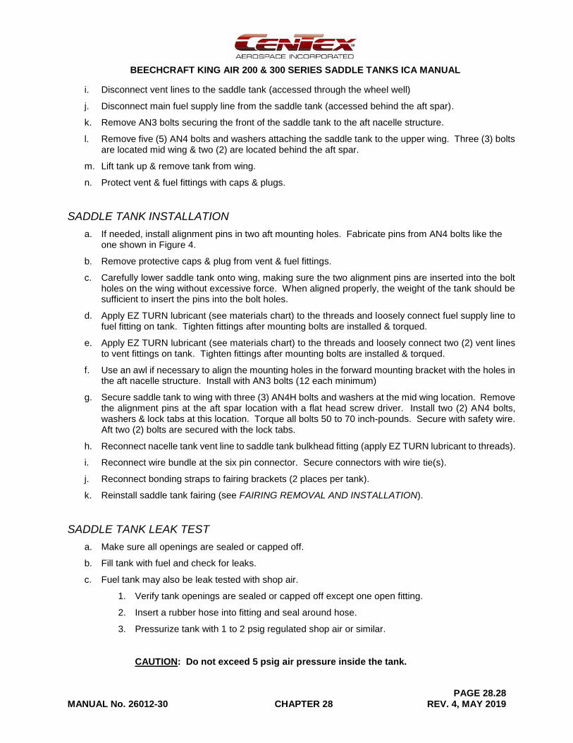
i. Disconnect vent lines to the saddle tank (accessed through the wheel well)
j. Disconnect main fuel supply line from the saddle tank (accessed behind the aft spar).
k. Remove AN3 bolts securing the front of the saddle tank to the aft nacelle structure.
l. Remove five (5) AN4 bolts and washers attaching the saddle tank to the upper wing. Three (3) bolts are located mid wing & two (2) are located behind the aft spar.
m. Lift tank up & remove tank from wing.
n. Protect vent & fuel fittings with caps & plugs.
SADDLE TANK INSTALLATION
a. If needed, install alignment pins in two aft mounting holes. Fabricate pins from AN4 bolts like the one shown in Figure 4.
b. Remove protective caps & plug from vent & fuel fittings.
c. Carefully lower saddle tank onto wing, making sure the two alignment pins are inserted into the bolt holes on the wing without excessive force. When aligned properly, the weight of the tank should be sufficient to insert the pins into the bolt holes.
d. Apply EZ TURN lubricant (see materials chart) to the threads and loosely connect fuel supply line to fuel fitting on tank. Tighten fittings after mounting bolts are installed & torqued.
e. Apply EZ TURN lubricant (see materials chart) to the threads and loosely connect two (2) vent lines to vent fittings on tank. Tighten fittings after mounting bolts are installed & torqued.
f. Use an awl if necessary to align the mounting holes in the forward mounting bracket with the holes in the aft nacelle structure. Install with AN3 bolts (12 each minimum)
g. Secure saddle tank to wing with three (3) AN4H bolts and washers at the mid wing location. Remove the alignment pins at the aft spar location with a flat head screw driver. Install two (2) AN4 bolts, washers & lock tabs at this location. Torque all bolts 50 to 70 inch-pounds. Secure with safety wire. Aft two (2) bolts are secured with the lock tabs.
h. Reconnect nacelle tank vent line to saddle tank bulkhead fitting (apply EZ TURN lubricant to threads).
i. Reconnect wire bundle at the six pin connector. Secure connectors with wire tie(s).
j. Reconnect bonding straps to fairing brackets (2 places per tank).
k. Reinstall saddle tank fairing (see FAIRING REMOVAL AND INSTALLATION).
SADDLE TANK LEAK TEST
a. Make sure all openings are sealed or capped off.
b. Fill tank with fuel and check for leaks.
c. Fuel tank may also be leak tested with shop air.
1. Verify tank openings are sealed or capped off except one open fitting.
2. Insert a rubber hose into fitting and seal around hose.
3. Pressurize tank with 1 to 2 psig regulated shop air or similar.
CAUTION: Do not exceed 5 psig air pressure inside the tank.
BEECHCRAFT KING AIR 200 & 300 SERIES SADDLE TANKS ICA MANUAL
PAGE 28.29 MANUAL No. 26012-30 CHAPTER 28 REV. 4, MAY 2019
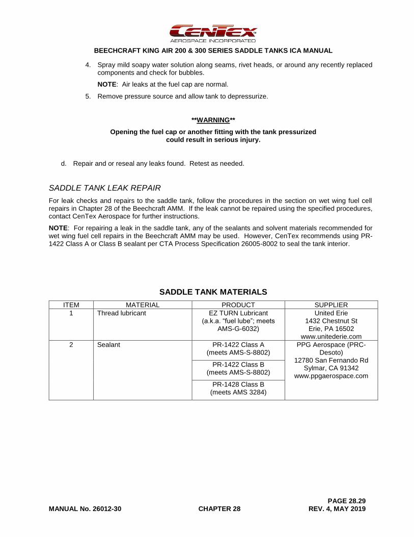
4. Spray mild soapy water solution along seams, rivet heads, or around any recently replaced components and check for bubbles.
NOTE: Air leaks at the fuel cap are normal.
5. Remove pressure source and allow tank to depressurize.
**WARNING**
Opening the fuel cap or another fitting with the tank pressurized could result in serious injury.
d. Repair and or reseal any leaks found. Retest as needed.
SADDLE TANK LEAK REPAIR
For leak checks and repairs to the saddle tank, follow the procedures in the section on wet wing fuel cell repairs in Chapter 28 of the Beechcraft AMM. If the leak cannot be repaired using the specified procedures, contact CenTex Aerospace for further instructions.
NOTE: For repairing a leak in the saddle tank, any of the sealants and solvent materials recommended for wet wing fuel cell repairs in the Beechcraft AMM may be used. However, CenTex recommends using PR-1422 Class A or Class B sealant per CTA Process Specification 26005-8002 to seal the tank interior.
SADDLE TANK MATERIALS
ITEM MATERIAL PRODUCT SUPPLIER
1 Thread lubricant EZ TURN Lubricant (a.k.a. “fuel lube”; meets
AMS-G-6032)
United Erie 1432 Chestnut St Erie, PA 16502
www.unitederie.com
2 Sealant PR-1422 Class A (meets AMS-S-8802)
PPG Aerospace (PRC-Desoto)
12780 San Fernando Rd Sylmar, CA 91342
www.ppgaerospace.com
PR-1422 Class B (meets AMS-S-8802)
PR-1428 Class B (meets AMS 3284)

BEECHCRAFT KING AIR 200 & 300 SERIES SADDLE TANKS ICA MANUAL
PAGE 28.30 MANUAL No. 26012-30 CHAPTER 28 REV. 4, MAY 2019
[Intentional Blank Page]
BEECHCRAFT KING AIR 200 & 300 SERIES SADDLE TANKS ICA MANUAL
PAGE 28.31 MANUAL No. 26012-30 CHAPTER 28 REV. 4, MAY 2019
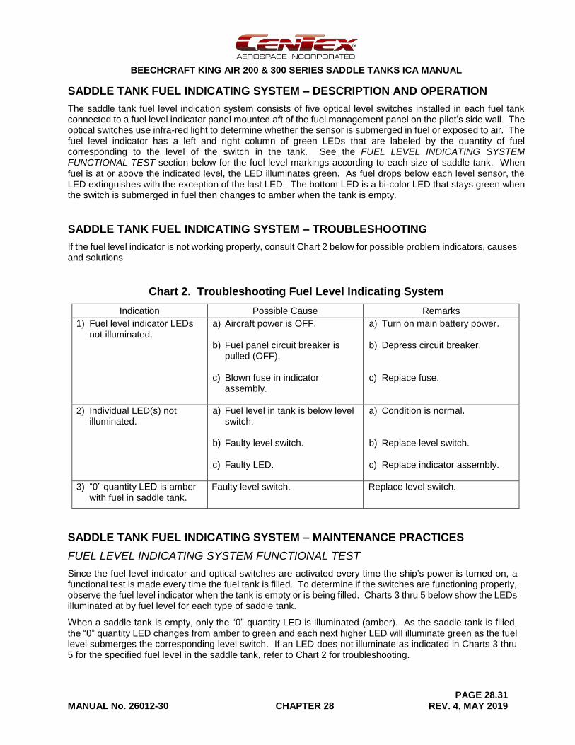
SADDLE TANK FUEL INDICATING SYSTEM – DESCRIPTION AND OPERATION
The saddle tank fuel level indication system consists of five optical level switches installed in each fuel tank connected to a fuel level indicator panel mounted aft of the fuel management panel on the pilot’s side wall. The optical switches use infra-red light to determine whether the sensor is submerged in fuel or exposed to air. The fuel level indicator has a left and right column of green LEDs that are labeled by the quantity of fuel corresponding to the level of the switch in the tank. See the FUEL LEVEL INDICATING SYSTEM FUNCTIONAL TEST section below for the fuel level markings according to each size of saddle tank. When fuel is at or above the indicated level, the LED illuminates green. As fuel drops below each level sensor, the LED extinguishes with the exception of the last LED. The bottom LED is a bi-color LED that stays green when the switch is submerged in fuel then changes to amber when the tank is empty.
SADDLE TANK FUEL INDICATING SYSTEM – TROUBLESHOOTING
If the fuel level indicator is not working properly, consult Chart 2 below for possible problem indicators, causes and solutions
Chart 2. Troubleshooting Fuel Level Indicating System
Indication Possible Cause Remarks
1) Fuel level indicator LEDs not illuminated.
a) Aircraft power is OFF.
b) Fuel panel circuit breaker is pulled (OFF).
c) Blown fuse in indicator assembly.
a) Turn on main battery power.
b) Depress circuit breaker.
c) Replace fuse.
2) Individual LED(s) not illuminated.
a) Fuel level in tank is below level switch.
b) Faulty level switch.
c) Faulty LED.
a) Condition is normal.
b) Replace level switch.
c) Replace indicator assembly.
3) “0” quantity LED is amber with fuel in saddle tank.
Faulty level switch. Replace level switch.
SADDLE TANK FUEL INDICATING SYSTEM – MAINTENANCE PRACTICES
FUEL LEVEL INDICATING SYSTEM FUNCTIONAL TEST
Since the fuel level indicator and optical switches are activated every time the ship’s power is turned on, a functional test is made every time the fuel tank is filled. To determine if the switches are functioning properly, observe the fuel level indicator when the tank is empty or is being filled. Charts 3 thru 5 below show the LEDs illuminated at by fuel level for each type of saddle tank.
When a saddle tank is empty, only the “0” quantity LED is illuminated (amber). As the saddle tank is filled, the “0” quantity LED changes from amber to green and each next higher LED will illuminate green as the fuel level submerges the corresponding level switch. If an LED does not illuminate as indicated in Charts 3 thru 5 for the specified fuel level in the saddle tank, refer to Chart 2 for troubleshooting.
BEECHCRAFT KING AIR 200 & 300 SERIES SADDLE TANKS ICA MANUAL
PAGE 28.32 MANUAL No. 26012-30 CHAPTER 28 REV. 4, MAY 2019
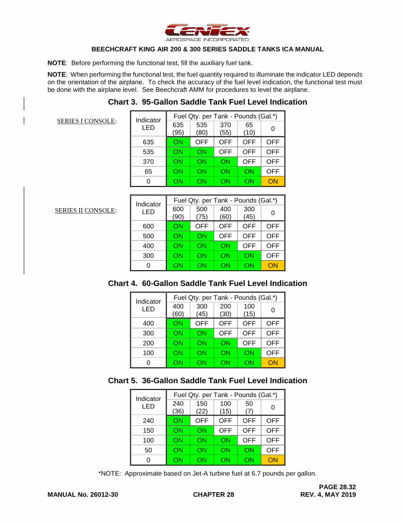
NOTE: Before performing the functional test, fill the auxiliary fuel tank.
NOTE: When performing the functional test, the fuel quantity required to illuminate the indicator LED depends on the orientation of the airplane. To check the accuracy of the fuel level indication, the functional test must be done with the airplane level. See Beechcraft AMM for procedures to level the airplane.
Chart 3. 95-Gallon Saddle Tank Fuel Level Indication
Indicator LED
Fuel Qty. per Tank - Pounds (Gal.*)
635 (95)
535 (80)
370 (55)
65 (10)
0
635 ON OFF OFF OFF OFF
535 ON ON OFF OFF OFF
370 ON ON ON OFF OFF
65 ON ON ON ON OFF
0 ON ON ON ON ON
Indicator LED
Fuel Qty. per Tank - Pounds (Gal.*)
600 (90)
500 (75)
400 (60)
300 (45)
0
600 ON OFF OFF OFF OFF
500 ON ON OFF OFF OFF
400 ON ON ON OFF OFF
300 ON ON ON ON OFF
0 ON ON ON ON ON
Chart 4. 60-Gallon Saddle Tank Fuel Level Indication
Indicator LED
Fuel Qty. per Tank - Pounds (Gal.*)
400 (60)
300 (45)
200 (30)
100 (15)
0
400 ON OFF OFF OFF OFF
300 ON ON OFF OFF OFF
200 ON ON ON OFF OFF
100 ON ON ON ON OFF
0 ON ON ON ON ON
Chart 5. 36-Gallon Saddle Tank Fuel Level Indication
Indicator LED
Fuel Qty. per Tank - Pounds (Gal.*)
240 (36)
150 (22)
100 (15)
50 (7)
0
240 ON OFF OFF OFF OFF
150 ON ON OFF OFF OFF
100 ON ON ON OFF OFF
50 ON ON ON ON OFF
0 ON ON ON ON ON
*NOTE: Approximate based on Jet-A turbine fuel at 6.7 pounds per gallon.
SERIES I CONSOLE:
SERIES II CONSOLE:
BEECHCRAFT KING AIR 200 & 300 SERIES SADDLE TANKS ICA MANUAL
PAGE 28.33 MANUAL No. 26012-30 CHAPTER 28 REV. 4, MAY 2019
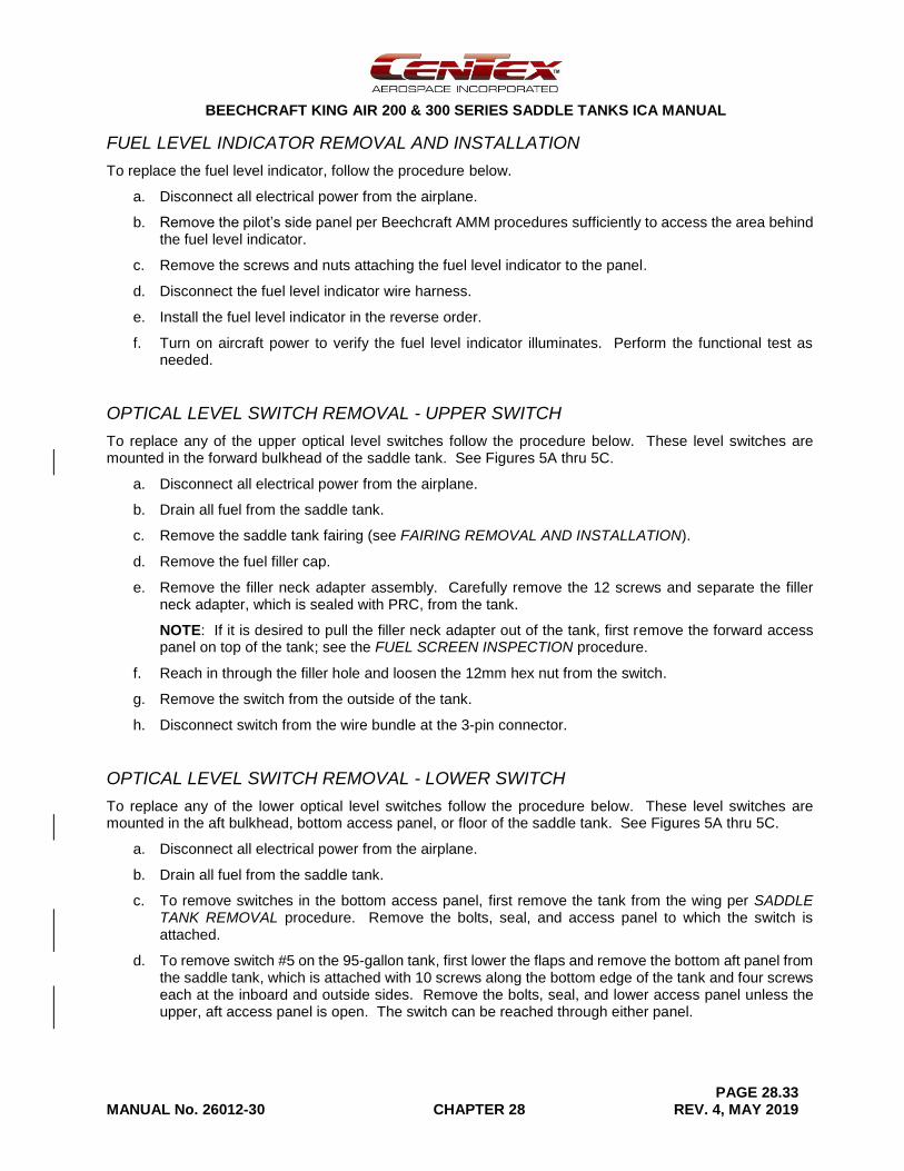
FUEL LEVEL INDICATOR REMOVAL AND INSTALLATION
To replace the fuel level indicator, follow the procedure below.
a. Disconnect all electrical power from the airplane.
b. Remove the pilot’s side panel per Beechcraft AMM procedures sufficiently to access the area behind the fuel level indicator.
c. Remove the screws and nuts attaching the fuel level indicator to the panel.
d. Disconnect the fuel level indicator wire harness.
e. Install the fuel level indicator in the reverse order.
f. Turn on aircraft power to verify the fuel level indicator illuminates. Perform the functional test as needed.
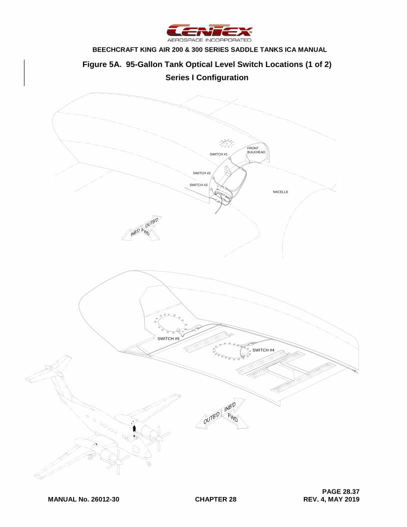
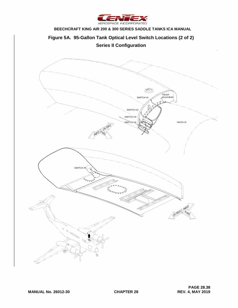
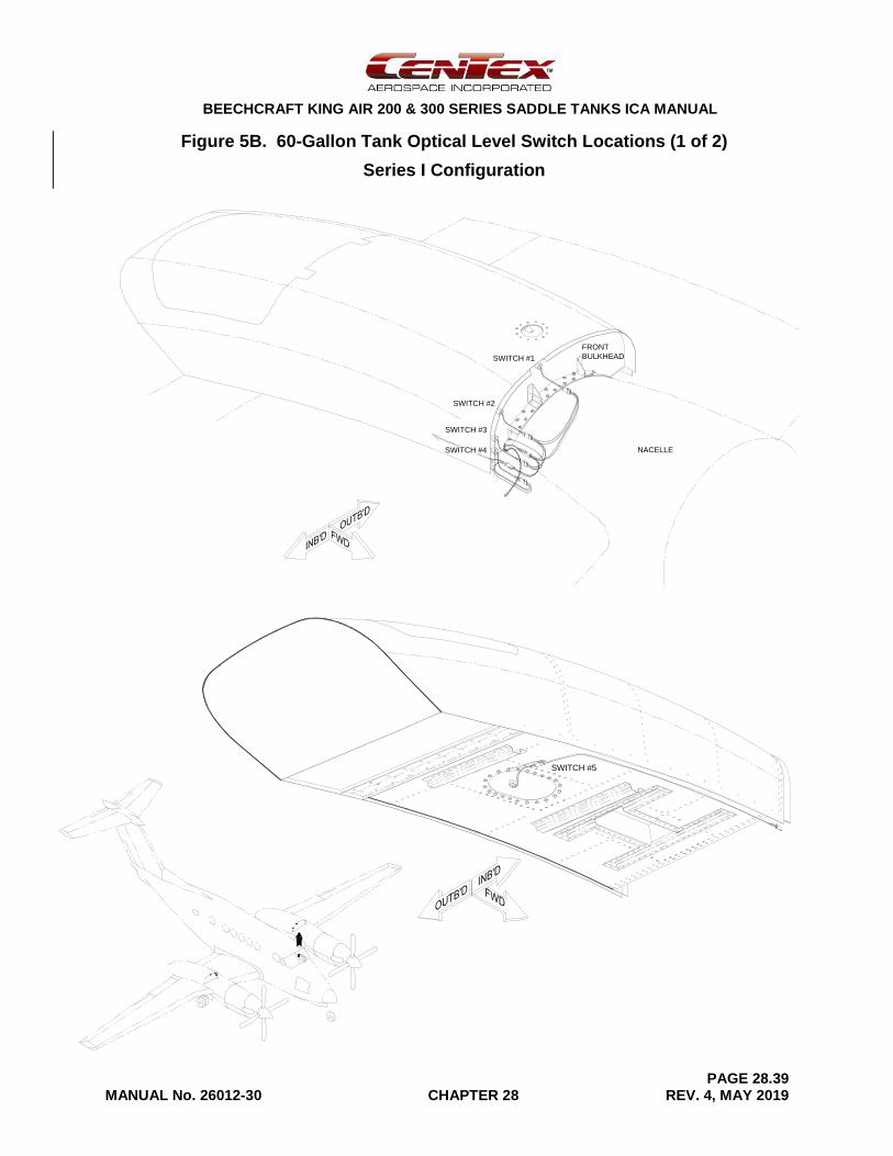
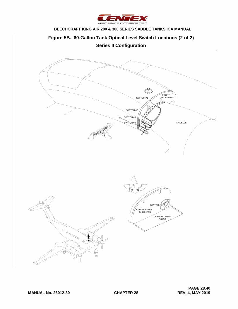
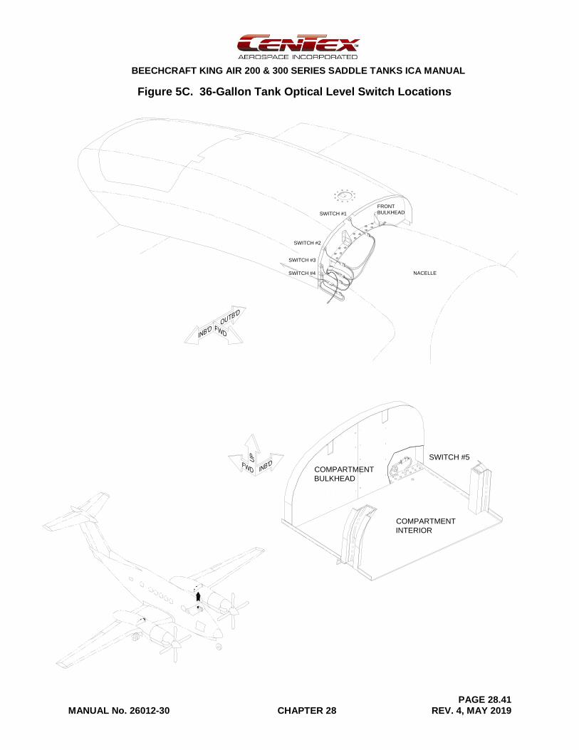
OPTICAL LEVEL SWITCH REMOVAL - UPPER SWITCH
To replace any of the upper optical level switches follow the procedure below. These level switches are mounted in the forward bulkhead of the saddle tank. See Figures 5A thru 5C.
a. Disconnect all electrical power from the airplane.
b. Drain all fuel from the saddle tank.
c. Remove the saddle tank fairing (see FAIRING REMOVAL AND INSTALLATION).
d. Remove the fuel filler cap.
e. Remove the filler neck adapter assembly. Carefully remove the 12 screws and separate the filler neck adapter, which is sealed with PRC, from the tank.
NOTE: If it is desired to pull the filler neck adapter out of the tank, first remove the forward access panel on top of the tank; see the FUEL SCREEN INSPECTION procedure.
f. Reach in through the filler hole and loosen the 12mm hex nut from the switch.
g. Remove the switch from the outside of the tank.
h. Disconnect switch from the wire bundle at the 3-pin connector.
OPTICAL LEVEL SWITCH REMOVAL - LOWER SWITCH
To replace any of the lower optical level switches follow the procedure below. These level switches are mounted in the aft bulkhead, bottom access panel, or floor of the saddle tank. See Figures 5A thru 5C.
a. Disconnect all electrical power from the airplane.
b. Drain all fuel from the saddle tank.
c. To remove switches in the bottom access panel, first remove the tank from the wing per SADDLE TANK REMOVAL procedure. Remove the bolts, seal, and access panel to which the switch is attached.
d. To remove switch #5 on the 95-gallon tank, first lower the flaps and remove the bottom aft panel from the saddle tank, which is attached with 10 screws along the bottom edge of the tank and four screws each at the inboard and outside sides. Remove the bolts, seal, and lower access panel unless the upper, aft access panel is open. The switch can be reached through either panel.
BEECHCRAFT KING AIR 200 & 300 SERIES SADDLE TANKS ICA MANUAL
PAGE 28.34 MANUAL No. 26012-30 CHAPTER 28 REV. 4, MAY 2019
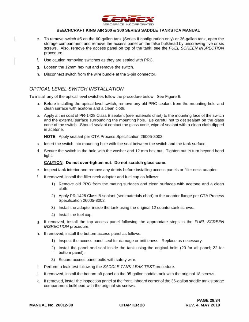
e. To remove switch #5 on the 60-gallon tank (Series II configuration only) or 36-gallon tank, open the storage compartment and remove the access panel on the false bulkhead by unscrewing five or six screws. Also, remove the access panel on top of the tank; see the FUEL SCREEN INSPECTION procedure.
f. Use caution removing switches as they are sealed with PRC.
g. Loosen the 12mm hex nut and remove the switch.
h. Disconnect switch from the wire bundle at the 3-pin connector.
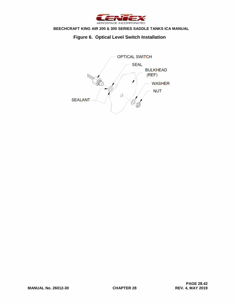
OPTICAL LEVEL SWITCH INSTALLATION
To install any of the optical level switches follow the procedure below. See Figure 6.
a. Before installing the optical level switch, remove any old PRC sealant from the mounting hole and clean surface with acetone and a clean cloth.
b. Apply a thin coat of PR-1428 Class B sealant (see materials chart) to the mounting face of the switch and the external surface surrounding the mounting hole. Be careful not to get sealant on the glass cone of the switch. Should sealant contact the glass cone, wipe of sealant with a clean cloth dipped in acetone.
NOTE: Apply sealant per CTA Process Specification 26005-8002.
c. Insert the switch into mounting hole with the seal between the switch and the tank surface.
d. Secure the switch in the hole with the washer and 12 mm hex nut. Tighten nut ½ turn beyond hand tight.
CAUTION: Do not over-tighten nut. Do not scratch glass cone.
e. Inspect tank interior and remove any debris before installing access panels or filler neck adapter.
f. If removed, install the filler neck adapter and fuel cap as follows:
1) Remove old PRC from the mating surfaces and clean surfaces with acetone and a clean cloth.
2) Apply PR-1428 Class B sealant (see materials chart) to the adapter flange per CTA Process Specification 26005-8002.
3) Install the adapter inside the tank using the original 12 countersunk screws.
4) Install the fuel cap.
g. If removed, install the top access panel following the appropriate steps in the FUEL SCREEN INSPECTION procedure.
h. If removed, install the bottom access panel as follows:
1) Inspect the access panel seal for damage or brittleness. Replace as necessary.
2) Install the panel and seal inside the tank using the original bolts (20 for aft panel; 22 for bottom panel).
3) Secure access panel bolts with safety wire.
i. Perform a leak test following the SADDLE TANK LEAK TEST procedure.
j. If removed, install the bottom aft panel on the 95-gallon saddle tank with the original 18 screws.
k. If removed, install the inspection panel at the front, inboard corner of the 36-gallon saddle tank storage compartment bulkhead with the original six screws.
BEECHCRAFT KING AIR 200 & 300 SERIES SADDLE TANKS ICA MANUAL
PAGE 28.35 MANUAL No. 26012-30 CHAPTER 28 REV. 4, MAY 2019
l. If removed, install the saddle tank following the SADDLE TANK INSTALLATION procedure.
m. Reconnect the optical level switch to the wire harness.
n. Check the indicating system per FUEL LEVEL INDICATING SYSTEM FUNCTIONAL TEST.
o. Reinstall saddle tank fairing (see FAIRING REMOVAL AND INSTALLATION).
SADDLE TANK FUEL INDICATING SYSTEM – WIRING DIAGRAM
Refer to Figure 7 Wiring Diagram, Fuel Qty. Indication, Saddle Tanks.

BEECHCRAFT KING AIR 200 & 300 SERIES SADDLE TANKS ICA MANUAL
PAGE 28.36 MANUAL No. 26012-30 CHAPTER 28 REV. 4, MAY 2019
[Intentional Blank Page]
BEECHCRAFT KING AIR 200 & 300 SERIES SADDLE TANKS ICA MANUAL
PAGE 28.37 MANUAL No. 26012-30 CHAPTER 28 REV. 4, MAY 2019
Figure 5A. 95-Gallon Tank Optical Level Switch Locations (1 of 2)
Series I Configuration
SWITCH #1
SWITCH #2
SWITCH #3
NACELLE
FRONT
BULKHEAD1
3
SWITCH #4
SWITCH #5
BEECHCRAFT KING AIR 200 & 300 SERIES SADDLE TANKS ICA MANUAL
PAGE 28.38 MANUAL No. 26012-30 CHAPTER 28 REV. 4, MAY 2019
Figure 5A. 95-Gallon Tank Optical Level Switch Locations (2 of 2)
Series II Configuration
SWITCH #4
FRONT
BULKHEAD
NACELLE
SWITCH #3
SWITCH #2
SWITCH #1
SWITCH #5
1
3
BEECHCRAFT KING AIR 200 & 300 SERIES SADDLE TANKS ICA MANUAL
PAGE 28.39 MANUAL No. 26012-30 CHAPTER 28 REV. 4, MAY 2019
Figure 5B. 60-Gallon Tank Optical Level Switch Locations (1 of 2)
Series I Configuration
SWITCH #1
SWITCH #2
SWITCH #3
NACELLE
FRONT
BULKHEAD
SWITCH #4
1
3
SWITCH #5
BEECHCRAFT KING AIR 200 & 300 SERIES SADDLE TANKS ICA MANUAL
PAGE 28.40 MANUAL No. 26012-30 CHAPTER 28 REV. 4, MAY 2019
Figure 5B. 60-Gallon Tank Optical Level Switch Locations (2 of 2)
Series II Configuration
SWITCH #2
SWITCH #4
FRONTBULKHEAD
NACELLE
SWITCH #3
SWITCH #1
SWITCH #5
1
3
1
3
COMPARTMENT
BULKHEAD
COMPARTMENT
FLOOR
BEECHCRAFT KING AIR 200 & 300 SERIES SADDLE TANKS ICA MANUAL
PAGE 28.41 MANUAL No. 26012-30 CHAPTER 28 REV. 4, MAY 2019
Figure 5C. 36-Gallon Tank Optical Level Switch Locations
SWITCH #1
SWITCH #2
SWITCH #3
NACELLE
FRONT
BULKHEAD
SWITCH #4
SWITCH #5
COMPARTMENT
INTERIOR
COMPARTMENT
BULKHEAD
1
3
1
3
BEECHCRAFT KING AIR 200 & 300 SERIES SADDLE TANKS ICA MANUAL
PAGE 28.42 MANUAL No. 26012-30 CHAPTER 28 REV. 4, MAY 2019
Figure 6. Optical Level Switch Installation
BEECHCRAFT KING AIR 200 & 300 SERIES SADDLE TANKS ICA MANUAL
PAGE 52.1 MANUAL No. 26012-30 CHAPTER 52 REV. 2, JUN-2018
CHAPTER 52
DOORS
GENERAL
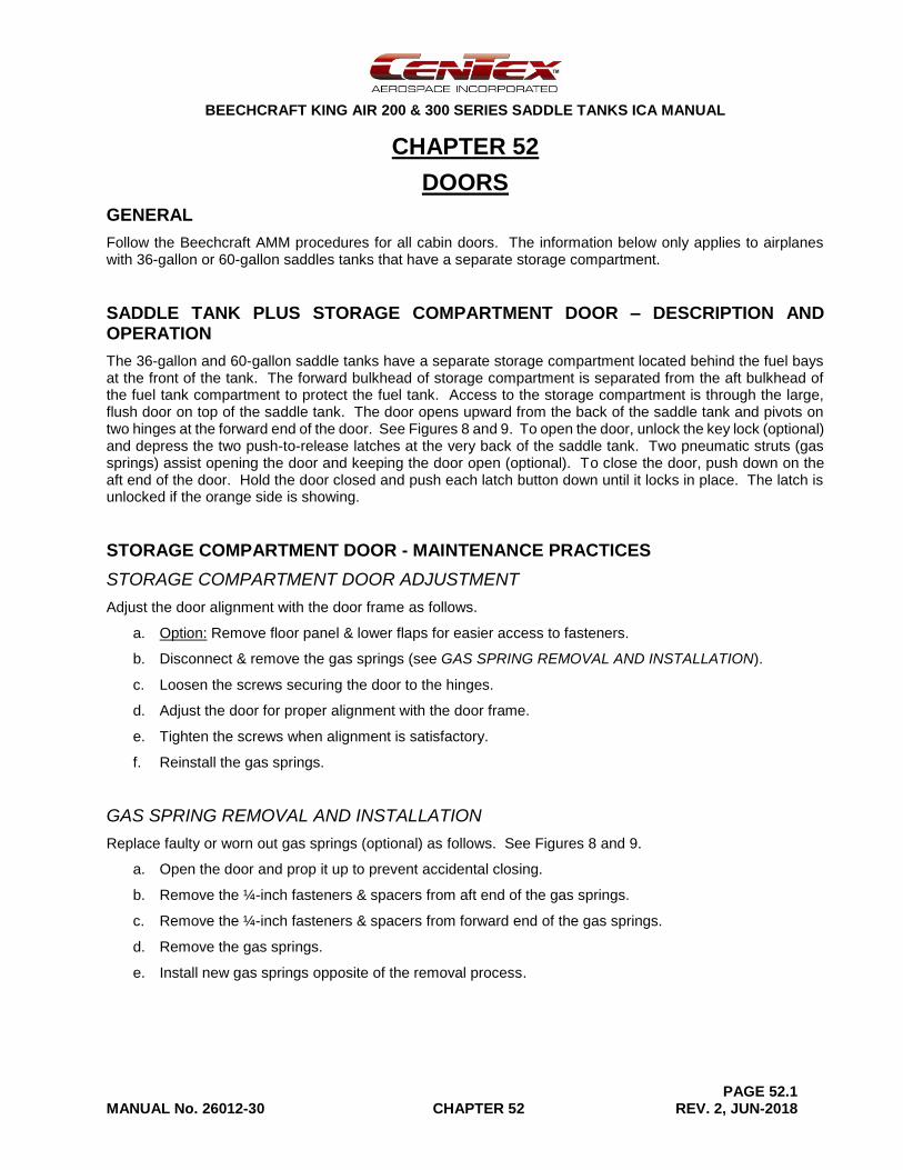
Follow the Beechcraft AMM procedures for all cabin doors. The information below only applies to airplanes with 36-gallon or 60-gallon saddles tanks that have a separate storage compartment.
SADDLE TANK PLUS STORAGE COMPARTMENT DOOR – DESCRIPTION AND OPERATION
The 36-gallon and 60-gallon saddle tanks have a separate storage compartment located behind the fuel bays at the front of the tank. The forward bulkhead of storage compartment is separated from the aft bulkhead of the fuel tank compartment to protect the fuel tank. Access to the storage compartment is through the large, flush door on top of the saddle tank. The door opens upward from the back of the saddle tank and pivots on two hinges at the forward end of the door. See Figures 8 and 9. To open the door, unlock the key lock (optional) and depress the two push-to-release latches at the very back of the saddle tank. Two pneumatic struts (gas springs) assist opening the door and keeping the door open (optional). To close the door, push down on the aft end of the door. Hold the door closed and push each latch button down until it locks in place. The latch is unlocked if the orange side is showing.
STORAGE COMPARTMENT DOOR - MAINTENANCE PRACTICES
STORAGE COMPARTMENT DOOR ADJUSTMENT
Adjust the door alignment with the door frame as follows.
a. Option: Remove floor panel & lower flaps for easier access to fasteners.
b. Disconnect & remove the gas springs (see GAS SPRING REMOVAL AND INSTALLATION).
c. Loosen the screws securing the door to the hinges.
d. Adjust the door for proper alignment with the door frame.
e. Tighten the screws when alignment is satisfactory.
f. Reinstall the gas springs.
GAS SPRING REMOVAL AND INSTALLATION
Replace faulty or worn out gas springs (optional) as follows. See Figures 8 and 9.
a. Open the door and prop it up to prevent accidental closing.
b. Remove the ¼-inch fasteners & spacers from aft end of the gas springs.
c. Remove the ¼-inch fasteners & spacers from forward end of the gas springs.
d. Remove the gas springs.
e. Install new gas springs opposite of the removal process.
BEECHCRAFT KING AIR 200 & 300 SERIES SADDLE TANKS ICA MANUAL
PAGE 52.2 MANUAL No. 26012-30 CHAPTER 52 REV. 2, JUN-2018
DOOR HINGE SLEEVE BEARING REMOVAL AND INSTALLATION
Replace the door hinge bearing as follows if the door does not open and close smoothly. See Figures 10 and 11.
a. Open the door and prop it up to prevent accidental closing.
b. Remove the gas springs per GAS SPRING REMOVAL AND INSTALLATION procedure.
c. Remove two (2) AN3 bolts securing the hinges to the hinge housings.
d. Remove the door & hinge from the hinge housing.
e. Check bearings for condition & wear.
f. If necessary, remove bearings from the hinges. Always replace bearings in pairs.
g. Install new bearings. Trim bearing lengths as needed for proper fit.
h. Reinstall the door opposite the door removal process.
DOOR LATCH REMOVAL AND INSTALLATION
Replace a faulty door latch as follows. See Figure 12.
a. Open the door and prop it up to prevent accidental closing.
b. Remove four (4) side screws securing the cover to the latch housing.
c. Remove one (1) countersunk screw securing the cover to the door frame.
d. Remove the cover.
e. Remove the malfunctioning latch by removing four (4) #8 screws.
f. Install a new latch opposite of the removal process.
KEY LOCK REMOVAL AND INSTALLATION
Replace a faulty key lock (optional) as follows.
a. Open the door and prop it up to prevent accidental closing.
b. Remove the screw securing the cam to the lock assembly.
c. Remove the nut securing the lock assembly to the door.
d. Remove the lock assembly.
e. Install a new lock assembly opposite of the removal process.
BEECHCRAFT KING AIR 200 & 300 SERIES SADDLE TANKS ICA MANUAL
PAGE 52.3 MANUAL No. 26012-30 CHAPTER 52 REV. 2, JUN-2018
DOOR SEAL REMOVAL AND INSTALLATION
Replace the door seal on condition as follows.
a. Open the door and prop it up to prevent accidental closing.
b. For an adhesive-backed seal, carefully peel and remove the old seal from storage compartment door frame doubler.
c. Use a clean cloth with MEK (methyl ethyl ketone) to remove residual adhesive from door frame doubler.
d. Install the new seal maintaining approximately 0.1 inches of spacing with the edge of storage compartment opening (tank shell).
e. For a push-on seal, pull the old seal off the door frame and replace it with a new seal.

BEECHCRAFT KING AIR 200 & 300 SERIES SADDLE TANKS ICA MANUAL
PAGE 52.4 MANUAL No. 26012-30 CHAPTER 52 REV. 2, JUN-2018
[Intentional Blank Page]
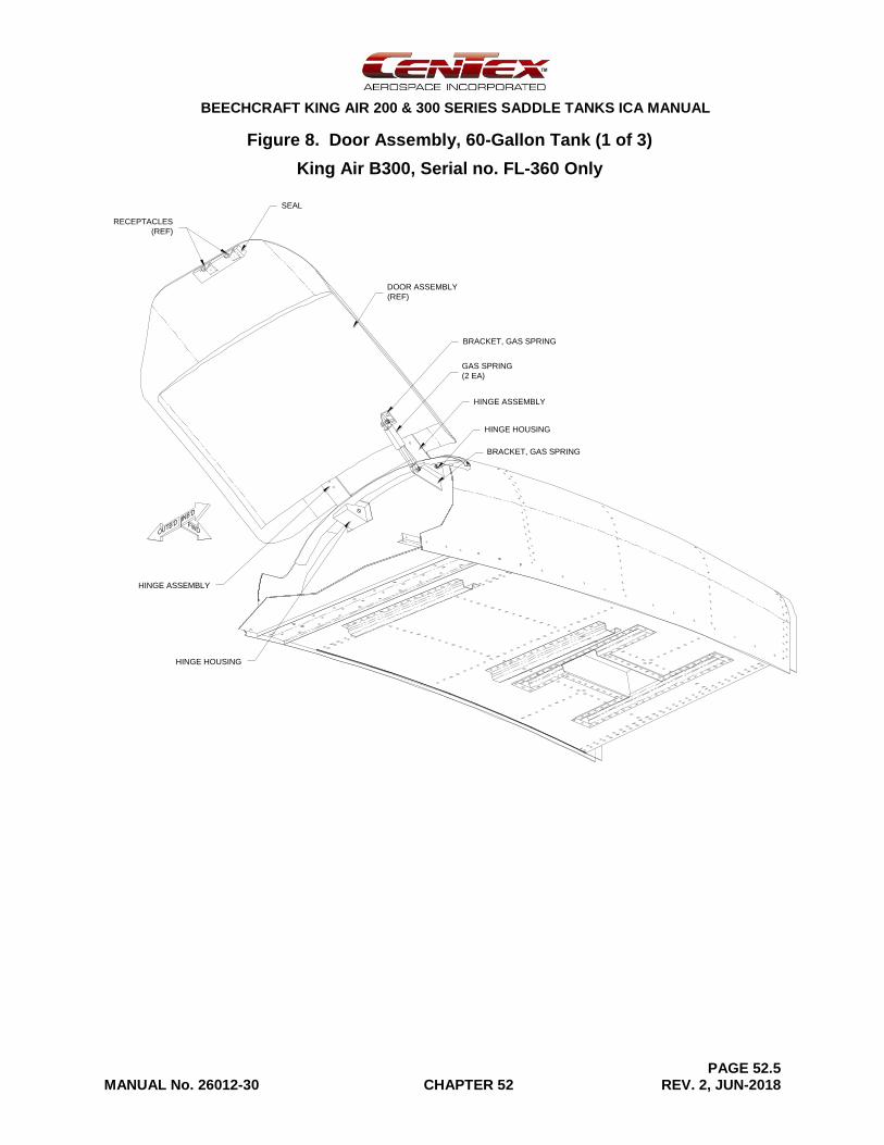
BEECHCRAFT KING AIR 200 & 300 SERIES SADDLE TANKS ICA MANUAL
PAGE 52.5 MANUAL No. 26012-30 CHAPTER 52 REV. 2, JUN-2018
Figure 8. Door Assembly, 60-Gallon Tank (1 of 3)
King Air B300, Serial no. FL-360 Only
HINGE ASSEMBLY
BRACKET, GAS SPRING
HINGE HOUSING
BRACKET, GAS SPRING
DOOR ASSEMBLY
(REF)
SEAL
RECEPTACLES
(REF)
GAS SPRING
(2 EA)
HINGE HOUSING
HINGE ASSEMBLY
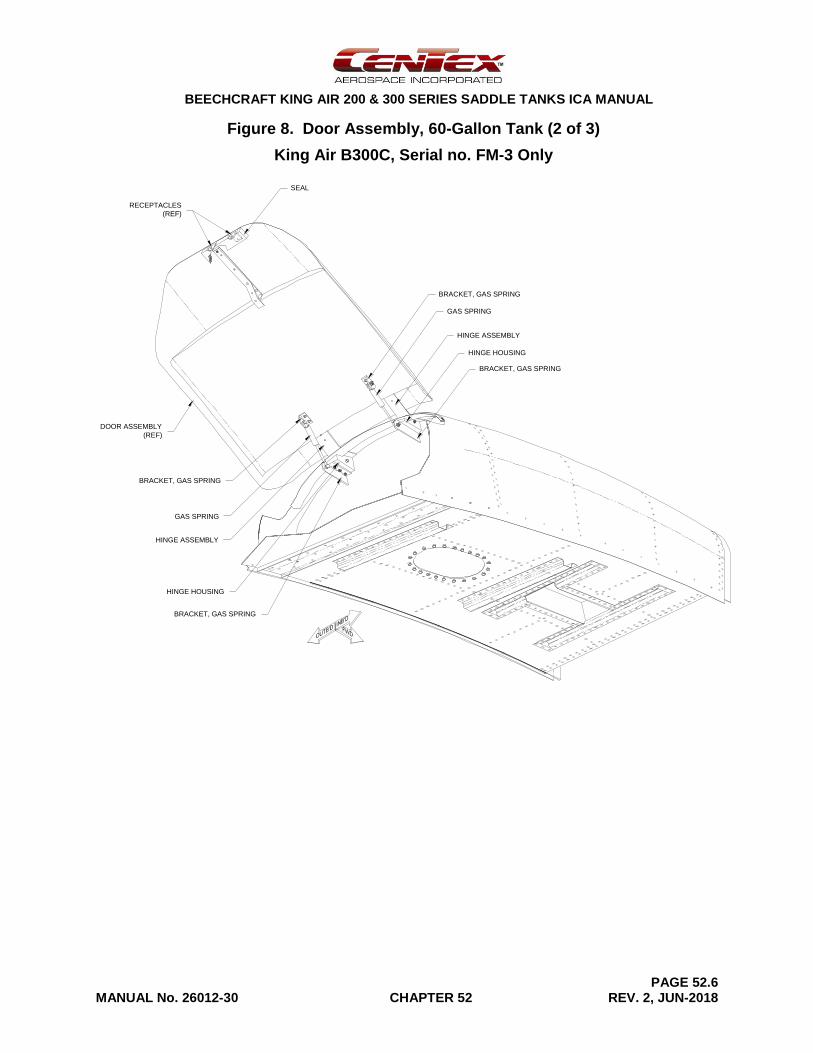
BEECHCRAFT KING AIR 200 & 300 SERIES SADDLE TANKS ICA MANUAL
PAGE 52.6 MANUAL No. 26012-30 CHAPTER 52 REV. 2, JUN-2018
Figure 8. Door Assembly, 60-Gallon Tank (2 of 3)
King Air B300C, Serial no. FM-3 Only
SEAL
RECEPTACLES
(REF)
DOOR ASSEMBLY
(REF)
GAS SPRING
BRACKET, GAS SPRING
BRACKET, GAS SPRING
HINGE ASSEMBLY
HINGE HOUSING
BRACKET, GAS SPRING
GAS SPRING
HINGE ASSEMBLY
HINGE HOUSING
BRACKET, GAS SPRING
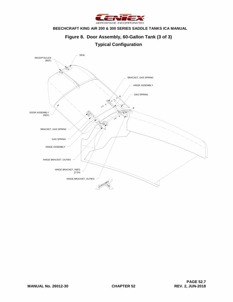
BEECHCRAFT KING AIR 200 & 300 SERIES SADDLE TANKS ICA MANUAL
PAGE 52.7 MANUAL No. 26012-30 CHAPTER 52 REV. 2, JUN-2018
Figure 8. Door Assembly, 60-Gallon Tank (3 of 3)
Typical Configuration
DOOR ASSEMBLY
(REF)
BRACKET, GAS SPRING
HINGE ASSEMBLY
SEAL
RECEPTACLES
(REF)
GAS SPRING
BRACKET, GAS SPRING
GAS SPRING
HINGE ASSEMBLY
HINGE BRACKET, OUTB'D
HINGE BRACKET, INB'D
(2 EA)
HINGE BRACKET, OUTB'D
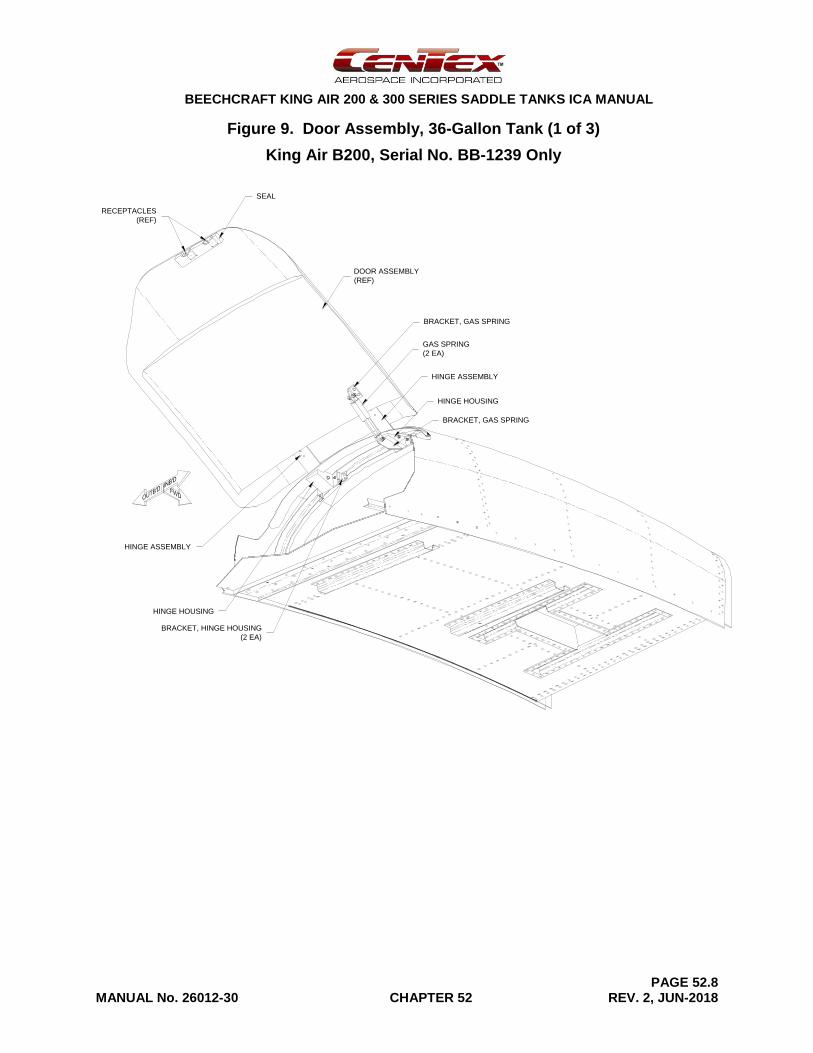
BEECHCRAFT KING AIR 200 & 300 SERIES SADDLE TANKS ICA MANUAL
PAGE 52.8 MANUAL No. 26012-30 CHAPTER 52 REV. 2, JUN-2018
Figure 9. Door Assembly, 36-Gallon Tank (1 of 3)
King Air B200, Serial No. BB-1239 Only
DOOR ASSEMBLY
(REF)
SEAL
RECEPTACLES
(REF)
GAS SPRING
(2 EA)
HINGE ASSEMBLY
BRACKET, GAS SPRING
HINGE HOUSING
BRACKET, GAS SPRING
HINGE HOUSING
HINGE ASSEMBLY
BRACKET, HINGE HOUSING
(2 EA)
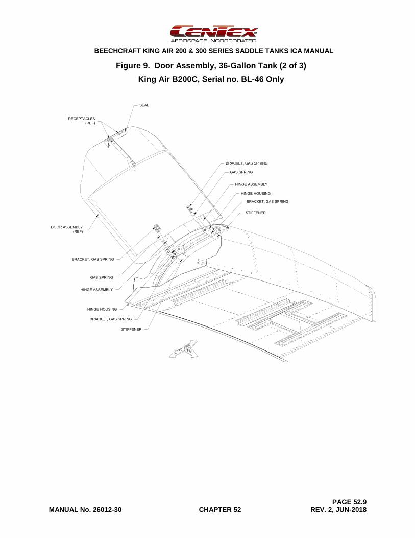
BEECHCRAFT KING AIR 200 & 300 SERIES SADDLE TANKS ICA MANUAL
PAGE 52.9 MANUAL No. 26012-30 CHAPTER 52 REV. 2, JUN-2018
Figure 9. Door Assembly, 36-Gallon Tank (2 of 3)
King Air B200C, Serial no. BL-46 Only
DOOR ASSEMBLY
(REF)
GAS SPRING
BRACKET, GAS SPRING
BRACKET, GAS SPRING
HINGE ASSEMBLY
HINGE HOUSING
BRACKET, GAS SPRING
GAS SPRING
HINGE ASSEMBLY
HINGE HOUSING
BRACKET, GAS SPRING
SEAL
RECEPTACLES
(REF)
STIFFENER
STIFFENER
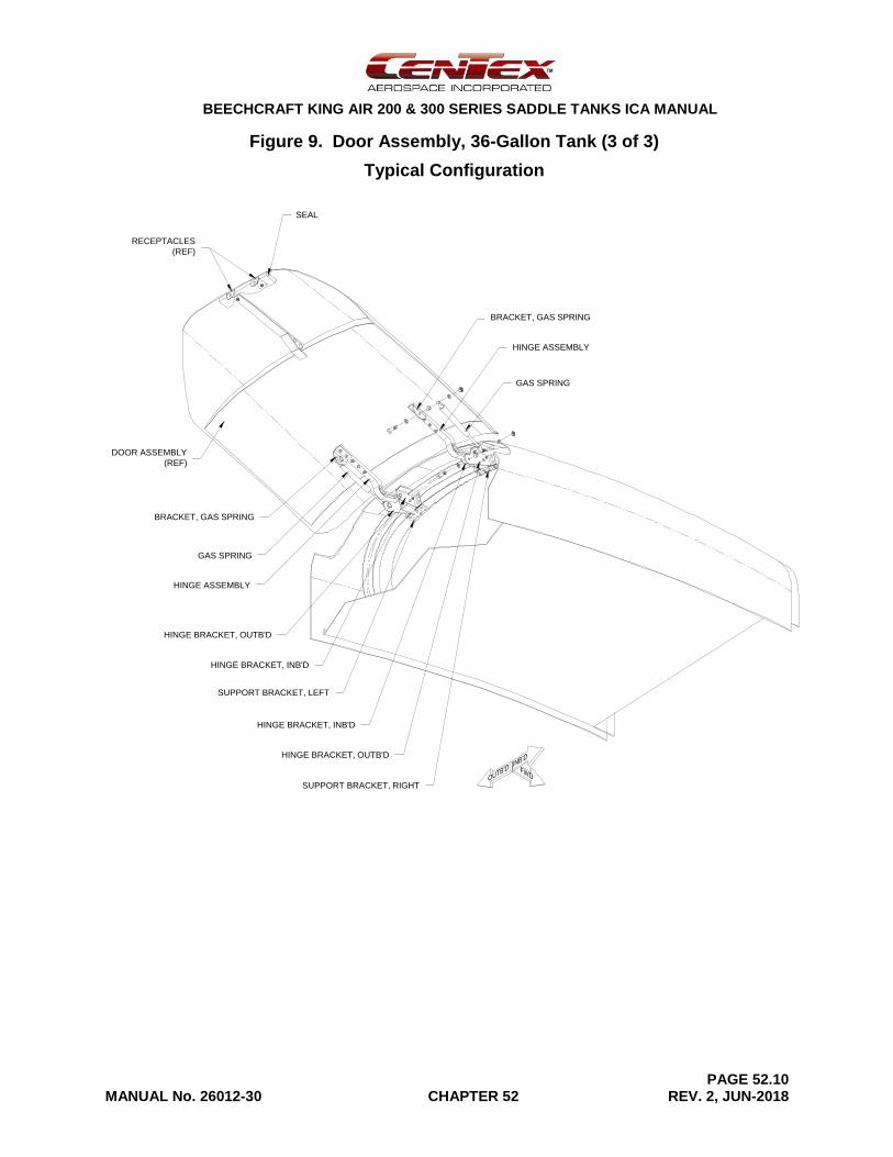
BEECHCRAFT KING AIR 200 & 300 SERIES SADDLE TANKS ICA MANUAL
PAGE 52.10 MANUAL No. 26012-30 CHAPTER 52 REV. 2, JUN-2018
Figure 9. Door Assembly, 36-Gallon Tank (3 of 3)
Typical Configuration
DOOR ASSEMBLY
(REF)
SEAL
RECEPTACLES
(REF)
BRACKET, GAS SPRING
HINGE ASSEMBLY
GAS SPRING
BRACKET, GAS SPRING
GAS SPRING
HINGE ASSEMBLY
HINGE BRACKET, OUTB'D
HINGE BRACKET, INB'D
HINGE BRACKET, OUTB'D
HINGE BRACKET, INB'D
SUPPORT BRACKET, RIGHT
SUPPORT BRACKET, LEFT
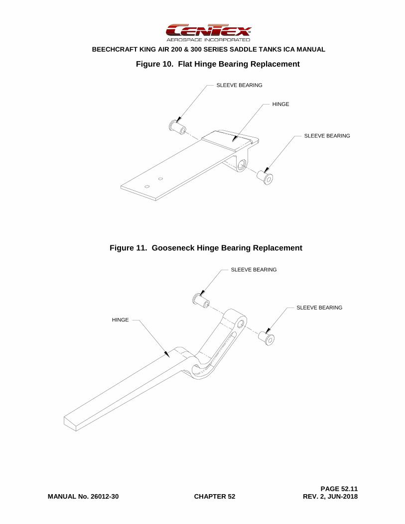
BEECHCRAFT KING AIR 200 & 300 SERIES SADDLE TANKS ICA MANUAL
PAGE 52.11 MANUAL No. 26012-30 CHAPTER 52 REV. 2, JUN-2018
Figure 10. Flat Hinge Bearing Replacement
Figure 11. Gooseneck Hinge Bearing Replacement
HINGE
SLEEVE BEARING
SLEEVE BEARING
HINGE
SLEEVE BEARING
SLEEVE BEARING
HINGE
SLEEVE BEARING
SLEEVE BEARING
HINGE
SLEEVE BEARING
SLEEVE BEARING
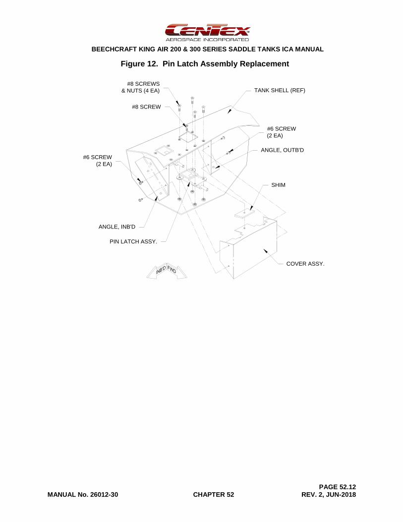
BEECHCRAFT KING AIR 200 & 300 SERIES SADDLE TANKS ICA MANUAL
PAGE 52.12 MANUAL No. 26012-30 CHAPTER 52 REV. 2, JUN-2018
Figure 12. Pin Latch Assembly Replacement
#8 SCREWS
& NUTS (4 EA)
#6 SCREW
(2 EA)
ANGLE, OUTB'D
ANGLE, INB'D
PIN LATCH ASSY.
#6 SCREW
(2 EA)
#8 SCREW
TANK SHELL (REF)
SHIM
COVER ASSY.
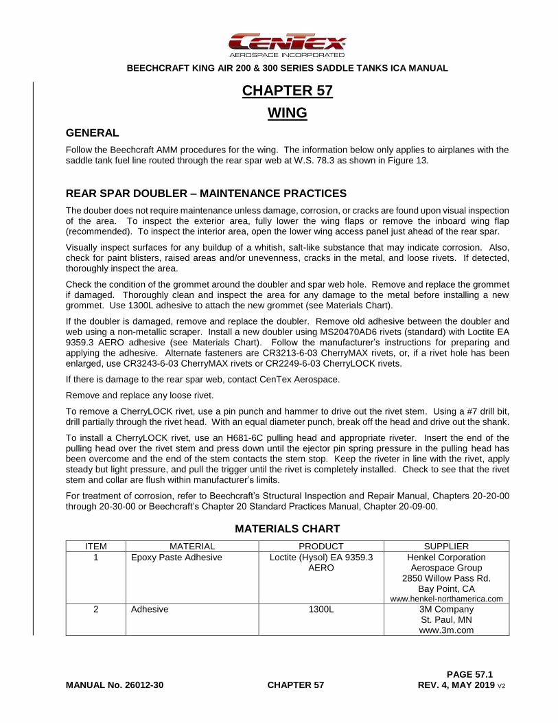
BEECHCRAFT KING AIR 200 & 300 SERIES SADDLE TANKS ICA MANUAL
PAGE 57.1 MANUAL No. 26012-30 CHAPTER 57 REV. 4, MAY 2019 V2
CHAPTER 57
WING
GENERAL
Follow the Beechcraft AMM procedures for the wing. The information below only applies to airplanes with the saddle tank fuel line routed through the rear spar web at W.S. 78.3 as shown in Figure 13.
REAR SPAR DOUBLER – MAINTENANCE PRACTICES
The douber does not require maintenance unless damage, corrosion, or cracks are found upon visual inspection of the area. To inspect the exterior area, fully lower the wing flaps or remove the inboard wing flap (recommended). To inspect the interior area, open the lower wing access panel just ahead of the rear spar.
Visually inspect surfaces for any buildup of a whitish, salt-like substance that may indicate corrosion. Also, check for paint blisters, raised areas and/or unevenness, cracks in the metal, and loose rivets. If detected, thoroughly inspect the area.
Check the condition of the grommet around the doubler and spar web hole. Remove and replace the grommet if damaged. Thoroughly clean and inspect the area for any damage to the metal before installing a new grommet. Use 1300L adhesive to attach the new grommet (see Materials Chart).
If the doubler is damaged, remove and replace the doubler. Remove old adhesive between the doubler and web using a non-metallic scraper. Install a new doubler using MS20470AD6 rivets (standard) with Loctite EA 9359.3 AERO adhesive (see Materials Chart). Follow the manufacturer’s instructions for preparing and applying the adhesive. Alternate fasteners are CR3213-6-03 CherryMAX rivets, or, if a rivet hole has been enlarged, use CR3243-6-03 CherryMAX rivets or CR2249-6-03 CherryLOCK rivets.
If there is damage to the rear spar web, contact CenTex Aerospace.
Remove and replace any loose rivet.
To remove a CherryLOCK rivet, use a pin punch and hammer to drive out the rivet stem. Using a #7 drill bit, drill partially through the rivet head. With an equal diameter punch, break off the head and drive out the shank.
To install a CherryLOCK rivet, use an H681-6C pulling head and appropriate riveter. Insert the end of the pulling head over the rivet stem and press down until the ejector pin spring pressure in the pulling head has been overcome and the end of the stem contacts the stem stop. Keep the riveter in line with the rivet, apply steady but light pressure, and pull the trigger until the rivet is completely installed. Check to see that the rivet stem and collar are flush within manufacturer’s limits.
For treatment of corrosion, refer to Beechcraft’s Structural Inspection and Repair Manual, Chapters 20-20-00 through 20-30-00 or Beechcraft’s Chapter 20 Standard Practices Manual, Chapter 20-09-00.
MATERIALS CHART
ITEM MATERIAL PRODUCT SUPPLIER
1 Epoxy Paste Adhesive Loctite (Hysol) EA 9359.3 AERO
Henkel Corporation Aerospace Group
2850 Willow Pass Rd. Bay Point, CA
www.henkel-northamerica.com
2 Adhesive 1300L 3M Company St. Paul, MN www.3m.com
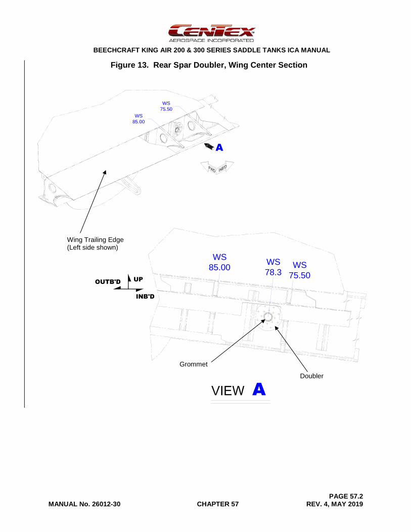
BEECHCRAFT KING AIR 200 & 300 SERIES SADDLE TANKS ICA MANUAL
PAGE 57.2 MANUAL No. 26012-30 CHAPTER 57 REV. 4, MAY 2019
Figure 13. Rear Spar Doubler, Wing Center Section
WS
75.50
WS
85.00
A
UP
INB'D
OUTB'D
A
WS
78.3
WS
85.00 WS
75.50
Wing Trailing Edge (Left side shown)
Doubler
Grommet
BEECHCRAFT KING AIR 200 & 300 SERIES SADDLE TANKS ICA MANUAL
MANUAL No. 26012-30 REV. 2, JUN-2018
END OF MANUAL

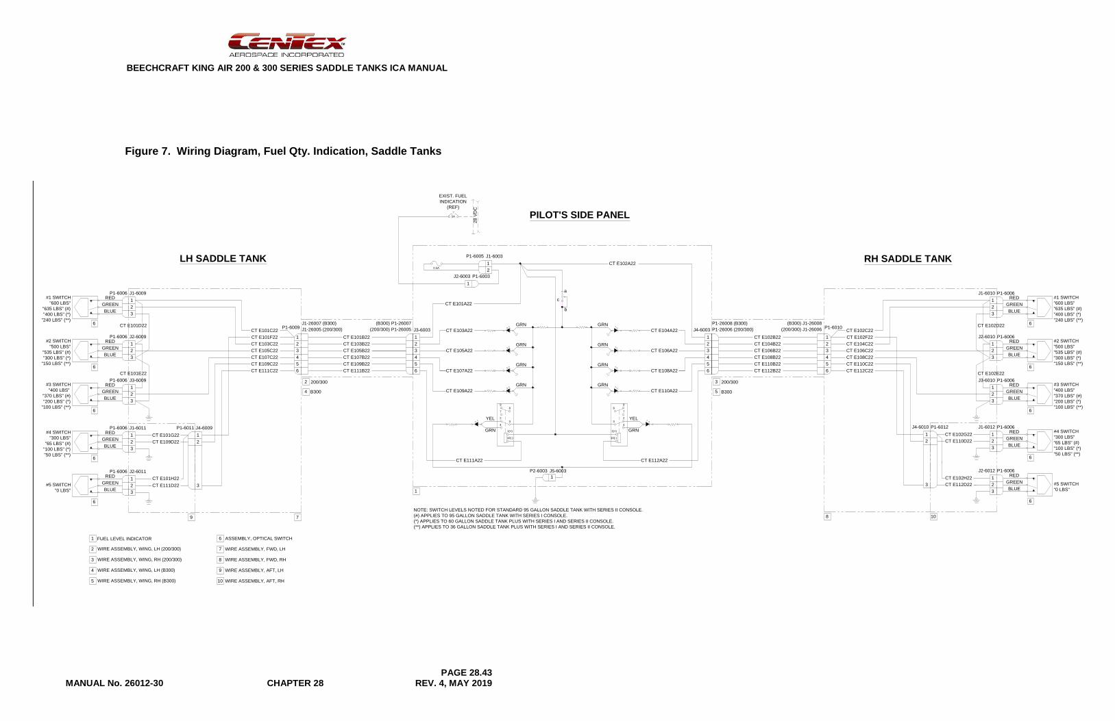
BEECHCRAFT KING AIR 200 & 300 SERIES SADDLE TANKS ICA MANUAL
PAGE 28.43 MANUAL No. 26012-30 CHAPTER 28 REV. 4, MAY 2019
Figure 7. Wiring Diagram, Fuel Qty. Indication, Saddle Tanks
4
3
2
1
5
6
LH SADDLE TANK
2
1
3
2
1
3
RED
GREEN
BLUE2
1
3
RED
GREEN
BLUE2
1
3
RED
GREEN
BLUE2
1
3
#1 SWITCH
"600 LBS"
"635 LBS" (#)
"400 LBS" (*)
"240 LBS" (**)
#2 SWITCH
"500 LBS"
"535 LBS" (#)
"300 LBS" (*)
"150 LBS" (**)
#3 SWITCH
"400 LBS"
"370 LBS" (#)
"200 LBS" (*)
"100 LBS" (**)
#4 SWITCH
"300 LBS"
"65 LBS" (#)
"100 LBS" (*)
"50 LBS" (**)
#5 SWITCH
"0 LBS"
2
1
3
CT E101B22
CT E103B22
CT E105B22
CT E107B22
CT E109B22
CT E111B22
CT E101C22
CT E101F22
CT E103C22
CT E105C22
CT E107C22
CT E109C22
CT E111C22
CT E101D22
CT E101E22
CT E101G22
CT E109D22
CT E111D22
CT E101H22
4
3
2
1
5
6
CT E102A22
CT E104A22
CT E106A22
CT E108A22
CT E110A22
CT E112A22
8
3
10(-)
1(+)
4
2
7
9
4
3
2
1
5
6
GRN
GRN
GRN
GRN
YEL
GRN
CT E103A22
CT E105A22
CT E107A22
CT E109A22
CT E111A22
CT E101A22
8
3
10(-)
1(+)
4
2
7
9
GRN
GRN
GRN
GRN
YEL
GRN
1
20.5A
5A
28
VD
C
EXIST. FUEL
INDICATION
(REF)
1
RED
GREEN
BLUE
RED
GREEN
BLUE
PILOT'S SIDE PANEL
1
b
c
a
9 7
6
6
6
6
6
200/3002
B3004
P1-6006
P1-6006
P1-6006
P1-6006
P1-6006
P1-6011 J4-6009
J1-6009
J2-6009
J3-6009
J1-6011
J2-6011
(200/300) P1-26005 J3-6003J1-26005 (200/300)P1-6009
P2-6003
P1-6005
J4-6003
1
J2-6003
J5-6003
J1-6003
P1-6003
(B300) P1-26007J1-26007 (B300)
4
3
2
1
5
6
2
1
3
2
1
3
RED
GREEN
BLUE2
1
3
RED
GREEN
BLUE2
1
3
RED
GREEN
BLUE2
1
3
#1 SWITCH
"600 LBS"
"635 LBS" (#)
"400 LBS" (*)
"240 LBS" (**)
#2 SWITCH
"500 LBS"
"535 LBS" (#)
"300 LBS" (*)
"150 LBS" (**)
#3 SWITCH
"400 LBS"
"370 LBS" (#)
"200 LBS" (*)
"100 LBS" (**)
#4 SWITCH
"300 LBS"
"65 LBS" (#)
"100 LBS" (*)
"50 LBS" (**)
#5 SWITCH
"0 LBS"
2
1
3
CT E102B22
CT E104B22
CT E106B22
CT E108B22
CT E110B22
CT E112B22
CT E102C22
CT E102F22
CT E104C22
CT E106C22
CT E108C22
CT E110C22
CT E112C22
CT E102D22
CT E102E22
CT E102G22
CT E110D22
CT E112D22
CT E102H22
RED
GREEN
BLUE
RED
GREEN
BLUE
RH SADDLE TANK
6
6
6
6
6
108
200/3003
B3005
J1-6010
J2-6010
J3-6010
J1-6012
J2-6012
J4-6010
P1-6006
P1-6006
P1-6006
P1-6006
P1-6006
P1-6012
P1-6010(200/300) J1-26006P1-26006 (200/300)
(B300) J1-26008P1-26008 (B300)
NOTE: SWITCH LEVELS NOTED FOR STANDARD 95 GALLON SADDLE TANK WITH SERIES II CONSOLE.
(#) APPLIES TO 95 GALLON SADDLE TANK WITH SERIES I CONSOLE.
(*) APPLIES TO 60 GALLON SADDLE TANK PLUS WITH SERIES I AND SERIES II CONSOLE.
(**) APPLIES TO 36 GALLON SADDLE TANK PLUS WITH SERIES I AND SERIES II CONSOLE.
FUEL LEVEL INDICATOR1
WIRE ASSEMBLY, WING, LH (200/300)2
WIRE ASSEMBLY, WING, RH (200/300)3
WIRE ASSEMBLY, WING, LH (B300)4
WIRE ASSEMBLY, WING, RH (B300)5
WIRE ASSEMBLY, FWD, RH8
WIRE ASSEMBLY, AFT, LH9
ASSEMBLY, OPTICAL SWITCH6
WIRE ASSEMBLY, FWD, LH7
WIRE ASSEMBLY, AFT, RH10
BEECHCRAFT KING AIR 200 & 300 SERIES SADDLE TANKS ICA MANUAL
PAGE 28.44 MANUAL No. 26012-30 CHAPTER 28 REV. 4, MAY 2019
[Intentional Blank Page]