Embed Size (px)
Citation preview

FLOW-TEK SERIES 19SEGMENTED BALL VALVEInstallation, Operation, and Maintenance Manual
BRAY.COM THE HIGH PERFORMANCE COMPANY
FLOW-TEK SERIES 19 SEGMENTED BALL VALVEInstallation, Operation, and Maintenance Manual
2 of 39© 2021 BRAY INTERNATIONAL, INC. ALL RIGHTS RESERVED. BRAY.COM The Information contained herein shall not be copied, transferred, conveyed, or displayed in any manner that would violate its proprietary nature without the express written permission of Bray International, Inc.
CONTENTS
1.0 DEFINITION OF TERMS . . . . . . . . . . . . . . . . . . . . . . . . . . . . . . . . . . . . . . . . . . . . . . . 3
2.0 INTRODUCTION . . . . . . . . . . . . . . . . . . . . . . . . . . . . . . . . . . . . . . . . . . . . . . . . . . . 4
3.0 PARTS IDENTIFICATION. . . . . . . . . . . . . . . . . . . . . . . . . . . . . . . . . . . . . . . . . . . . . . . 5
4.0 VALVE IDENTIFICATION. . . . . . . . . . . . . . . . . . . . . . . . . . . . . . . . . . . . . . . . . . . . . . . 9
5.0 GENERAL INFORMATION . . . . . . . . . . . . . . . . . . . . . . . . . . . . . . . . . . . . . . . . . . . . . . 10
6.0 HANDLING REQUIREMENTS . . . . . . . . . . . . . . . . . . . . . . . . . . . . . . . . . . . . . . . . . . . . 12
7.0 STORAGE . . . . . . . . . . . . . . . . . . . . . . . . . . . . . . . . . . . . . . . . . . . . . . . . . . . . . . . 14
8.0 INSTALLATION . . . . . . . . . . . . . . . . . . . . . . . . . . . . . . . . . . . . . . . . . . . . . . . . . . . . 16
9.0 OPERATION. . . . . . . . . . . . . . . . . . . . . . . . . . . . . . . . . . . . . . . . . . . . . . . . . . . . . . 19
10.0 PREVENTATIVE MAINTENANCE . . . . . . . . . . . . . . . . . . . . . . . . . . . . . . . . . . . . . . . . . .20
11.0 ACTUATOR REMOVAL AND REMOUNTING . . . . . . . . . . . . . . . . . . . . . . . . . . . . . . . . . . . . 21
12.0 REMOVING VALVE FROM PIPELINE . . . . . . . . . . . . . . . . . . . . . . . . . . . . . . . . . . . . . . . . 22
13.0 SEAT REPLACEMENT (S19 ASME 150, 300 | PN 10, 16, 25, 40) . . . . . . . . . . . . . . . . . . . . . . . . . 23
14.0 DISASSEMBLY AND INSPECTION (S19 ASME 150, 300 | PN 10, 16, 25, 40) . . . . . . . . . . . . . . . . . . 24
15.0 REASSEMBLY (S19 ASME 150, 300 | PN 10, 16, 25, 40). . . . . . . . . . . . . . . . . . . . . . . . . . . . . . 26
16.0 SEAT REPLACEMENT (S19 ASME 600) . . . . . . . . . . . . . . . . . . . . . . . . . . . . . . . . . . . . . . 29
17.0 DISASSEMBLY AND INSPECTION (S19 ASME 600) . . . . . . . . . . . . . . . . . . . . . . . . . . . . . . .30
18.0 REASSEMBLY (S19 ASME 600) . . . . . . . . . . . . . . . . . . . . . . . . . . . . . . . . . . . . . . . . . . . 32
19.0 TROUBLESHOOTING . . . . . . . . . . . . . . . . . . . . . . . . . . . . . . . . . . . . . . . . . . . . . . . . 35
20.0 RETURN MERCHANDISE AUTHORIZATION. . . . . . . . . . . . . . . . . . . . . . . . . . . . . . . . . . . . 36
21.0 APPENDIX A – TABLES . . . . . . . . . . . . . . . . . . . . . . . . . . . . . . . . . . . . . . . . . . . . . . . 37

FLOW-TEK SERIES 19 SEGMENTED BALL VALVEInstallation, Operation, and Maintenance Manual
3 of 39© 2021 BRAY INTERNATIONAL, INC. ALL RIGHTS RESERVED. BRAY.COM The Information contained herein shall not be copied, transferred, conveyed, or displayed in any manner that would violate its proprietary nature without the express written permission of Bray International, Inc.
READ AND FOLLOW THESE INSTRUCTIONS CAREFULLY. SAVE THIS MANUAL FOR FUTURE USE.
1.0 DEFINITION OF TERMS1.1 All information within this manual is relevant to the safe operation
and proper care of your Bray valve. Please understand the following examples of information used throughout this manual.
X.X IDENTIFIES CHAPTER HEADING
X.XX Indentifies and explains sequential procedure to be performed.
NOTE: Provides important information, useful tips, and recommendations related to a procedure.
SAFETY STATEMENTS
The terms DANGER, WARNING, CAUTION, and NOTICE are used in this document to prevent unwanted consequences. Standard symbols and classifications are:
DANGERIndicates an immediate hazardous situation which, if not avoided, will result in death or serious injury and/or property damage.
WARNINGIndicates a potentially hazardous situation which, if not avoided, could result in death or serious injury and/or property damage.
CAUTIONIndicates a potentially hazardous situation which, if not avoided, may result in minor or moderate injury and/or property damage.
NOTICEIndicates and provides additional technical information which may not be obvious, even to qualified personnel. The term is not used for personal injury hazards or warnings, but can be used to indicate possible equipment or property damage.
1.2 Compliance with other notes — regarding transport, assembly, operation & maintenance, and about technical documentation (e.g., in the operating instructions, product documentation, or on the product itself) — is essential, to avoid faults which can directly or indirectly cause severe personal injury or property damage.

FLOW-TEK SERIES 19 SEGMENTED BALL VALVEInstallation, Operation, and Maintenance Manual
4 of 39© 2021 BRAY INTERNATIONAL, INC. ALL RIGHTS RESERVED. BRAY.COM The Information contained herein shall not be copied, transferred, conveyed, or displayed in any manner that would violate its proprietary nature without the express written permission of Bray International, Inc.
2.0 INTRODUCTION
2.1 Information provided in this manual is for S19 segmented ball valves only. Specific instructions for non-standard materials of construction, temperature range, etc. should be referred to the factory.
2.2 This manual covers S19 valves in the following range: > NPS 1 to 16 | DN 25 to 400 > ASME Class 150, 300, 600 | PN 10, 16, 25, 40 > Body Style: Flanged, Flangeless
2.3 Additional product information (such as application data, engineering specifications, actuator selection, etc.) is available from your local Bray distributor or sales representative, or online at BRAY.COM
2.4 For complete details on the latest product certifications, visit BRAY.COM/Certifications.
2.5 The S19 segmented ball valve is designed per ASME B16.34.
FLOW-TEK SERIES 19 SEGMENTED BALL VALVEInstallation, Operation, and Maintenance Manual
5 of 39© 2021 BRAY INTERNATIONAL, INC. ALL RIGHTS RESERVED. BRAY.COM The Information contained herein shall not be copied, transferred, conveyed, or displayed in any manner that would violate its proprietary nature without the express written permission of Bray International, Inc.
2324
141516
13
12
11
10
6
8
22
1
3029
28
27
7
9
17
18
192021
34
526
2
25
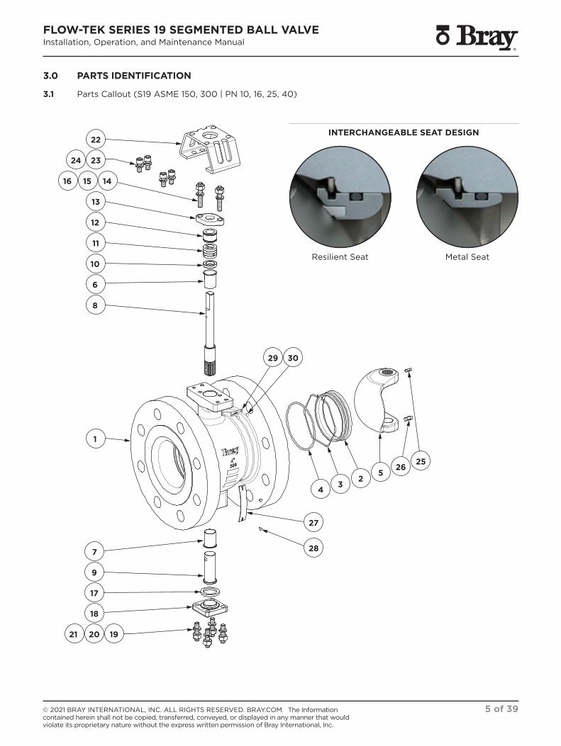
Resilient Seat Metal Seat
3.0 PARTS IDENTIFICATION
3.1 Parts Callout (S19 ASME 150, 300 | PN 10, 16, 25, 40)
INTERCHANGEABLE SEAT DESIGN

FLOW-TEK SERIES 19 SEGMENTED BALL VALVEInstallation, Operation, and Maintenance Manual
6 of 39© 2021 BRAY INTERNATIONAL, INC. ALL RIGHTS RESERVED. BRAY.COM The Information contained herein shall not be copied, transferred, conveyed, or displayed in any manner that would violate its proprietary nature without the express written permission of Bray International, Inc.
ITEM DESCRIPTION RECOMMENDED SPARE PARTS
1 Body
2 Seat
3 Seat Spring
4 Seat O-Ring
5 Segment
6 Stem Bearing
7 End Post Bearing
8 Stem
9 End Post
10 Thrust Washer
11 Stem Seal Kit
12 Gland Ring
13 Gland Retainer
14 Gland Stud
15 Gland Lock Washer
16 Gland Nut
17 Post Cover Gasket
18 Post Cover
19 Post Cover Washer
20 Post Cover Stud
21 Post Cover Nut
22 Mounting Bracket
23 Bracket Washer
24 Bracket Screw
25 Stem Pin
26 End Post Pin
27 Identification Plate
28 Identification Plate Drive Screw
29 Arrow Plate
30 Arrow Plate Drive Screw
3.2 Parts List (S19 ASME 150, 300 | PN 10, 16, 25, 40)

FLOW-TEK SERIES 19 SEGMENTED BALL VALVEInstallation, Operation, and Maintenance Manual
7 of 39© 2021 BRAY INTERNATIONAL, INC. ALL RIGHTS RESERVED. BRAY.COM The Information contained herein shall not be copied, transferred, conveyed, or displayed in any manner that would violate its proprietary nature without the express written permission of Bray International, Inc.
22
21
18
8
6
7
9
10
11
27
14
12
13
52
34
29
28
26
31 33
30 3219
151617
232425
20
1
Resilient Seat Metal Seat
3.3 Parts Callout (S19 ASME 600)
INTERCHANGEABLE SEAT DESIGN

FLOW-TEK SERIES 19 SEGMENTED BALL VALVEInstallation, Operation, and Maintenance Manual
8 of 39© 2021 BRAY INTERNATIONAL, INC. ALL RIGHTS RESERVED. BRAY.COM The Information contained herein shall not be copied, transferred, conveyed, or displayed in any manner that would violate its proprietary nature without the express written permission of Bray International, Inc.
ITEM DESCRIPTION RECOMMENDED SPARE PARTS
1 Body
2 Seat
3 Seat Spring
4 Seat O-Ring
5 Segment
6 Stem
7 Stem Bearing
8 Split Ring
9 Thrust Washer
10 Packing Spacer
11 Stem Seal Kit
12 Gland Ring
13 Retaining Ring
14 Gland Retainer
15 Gland Stud
16 Gland Lock Washer
17 Gland Nut
18 End Post
19 End Post Bearing
20 End Post Thrust Washer
21 Post Cover Gasket
22 Post Cover
23 Post Cover Stud
24 Post Cover Lock Washer
25 Post Cover Nut
26 Mounting Bracket
27 Mounting Bracket Lock Washer
28 Mounting Bracket Cap Screw
29 Stem Pin
30 Identification Plate
31 Arrow Plate
32 Identification Plate Screw
33 Arrow Plate Screw
3.4 Parts List (S19 ASME 600)

FLOW-TEK SERIES 19 SEGMENTED BALL VALVEInstallation, Operation, and Maintenance Manual
9 of 39© 2021 BRAY INTERNATIONAL, INC. ALL RIGHTS RESERVED. BRAY.COM The Information contained herein shall not be copied, transferred, conveyed, or displayed in any manner that would violate its proprietary nature without the express written permission of Bray International, Inc.
4.0 VALVE IDENTIFICATION
4.1 Identification TagAll valves, actuators, or control products are provided with a permanently affixed identification tag meeting the requirements of applicable standards and certifications for the product.
As each product is unique, data may vary.

FLOW-TEK SERIES 19 SEGMENTED BALL VALVEInstallation, Operation, and Maintenance Manual
10 of 39© 2021 BRAY INTERNATIONAL, INC. ALL RIGHTS RESERVED. BRAY.COM The Information contained herein shall not be copied, transferred, conveyed, or displayed in any manner that would violate its proprietary nature without the express written permission of Bray International, Inc.
5.0 GENERAL INFORMATION
5.1 UseThe following instructions are designed to assist in the unpacking, installation, operation, and maintenance as required for Bray segmented ball control valves.
Product users and maintenance personnel should thoroughly review this manual prior to installing, operating, or performing any maintenance.
In most cases, Bray valves, actuators, and accessories are designed for specific applications (e.g. with regard to medium, pressure and temperature). For this reason, they should not be used in other applications without first contacting the manufacturer.
WARNINGBefore installing the equipment, confirm that it is suitable for the intended service. The identification tags describe the maximum allowable service conditions for this product. Be sure that the installation is protected by appropriate pressure control and safety devices to ensure that acceptable limits are not exceeded.
5.2 OperationOperation of the valve is done by turning the stem a quarter-turn (90 degree turn). Clockwise to close, counter-clockwise to open.
CAUTIONValves with actuators should be checked for actuator/valve alignment. Misalignment will result in high operational torque, and cause damage to valve stem and seals.
5.3 ApplicabilityThe following instructions are applicable to the maintenance and installation of Bray segmented ball control valves. These instructions cannot claim to cover all details of all possible product variations, nor can they provide information for every possible example of installation, operation, or maintenance.
This means that the instructions normally include only the directions to be followed by qualified personal using the product for its defined purpose. If there are any uncertainties in this respect, particularly in the event of missing product related information, clarification must be obtained via the appropriate Bray sales office.

FLOW-TEK SERIES 19 SEGMENTED BALL VALVEInstallation, Operation, and Maintenance Manual
11 of 39© 2021 BRAY INTERNATIONAL, INC. ALL RIGHTS RESERVED. BRAY.COM The Information contained herein shall not be copied, transferred, conveyed, or displayed in any manner that would violate its proprietary nature without the express written permission of Bray International, Inc.
5.4 General PrecautionsBray products are often used in critical applications (e.g. under extremely high pressures with dangerous, toxic, or corrosive mediums). When performing service, inspection, or repair operations, always ensure that the valve and the actuator are depressurized, the valve has been cleaned, and the valve is free of harmful substances.
In such cases, all personnel operating, inspecting, maintaining, or repairing Bray products shall wear appropriate Personal Protection Equipment (PPE), such as: protective clothing, gloves, safety glasses, steel toes shoes, hard hat, etc.
5.5 Qualified PersonnelA qualified person (in terms of this document) is one who has been authorized by those responsible for the safety of the plant to perform the necessary work, while recognizing and avoiding possible dangers.
Qualifications include appropriate education, training, experience, and knowledge of relevant standards, specifications, operating conditions, and accident prevention.
5.6 Spare PartsUse only Bray original spare parts.
Recommended spare parts are identified in the Parts Identification drawing and list for each product model.
Bray cannot accept responsibility for any damages that occur from using spare parts or fastening materials from other manufacturers. If Bray products (especially soft good materials) have been stored for long periods of time, check them for corrosion or deterioration before putting them into use.
5.7 Service & RepairTo avoid possible injury to personnel or damage to products, safety terms must be strictly adhered to. Modifying this product, substituting non-factory parts, or using maintenance procedures other than those outlined in these Installation, Operation and Maintenance instructions could drastically affect performance, be hazardous to personnel and equipment, and may void existing warranties.
Apart from the operating instructions and the obligatory accident prevention directives valid in the country of use, all recognized regulations for safety and good engineering practices must be followed.
NOTICEBefore products are returned to Bray for repair or service, Bray must be provided with a certificate confirming that the product has been decontaminated and is clean.
FLOW-TEK SERIES 19 SEGMENTED BALL VALVEInstallation, Operation, and Maintenance Manual
12 of 39© 2021 BRAY INTERNATIONAL, INC. ALL RIGHTS RESERVED. BRAY.COM The Information contained herein shall not be copied, transferred, conveyed, or displayed in any manner that would violate its proprietary nature without the express written permission of Bray International, Inc.
6.0 HANDLING REQUIREMENTS
6.1 Packed Valves
Crates: Lifting and handling of the packed valves in crates will be carried out by a fork lift truck, by means of the appropriate fork hitches.
Cases: The lifting of packed valves in cases will be carried out in the lifting points and in the center of gravity position which has been marked. The transportation of all packed material must be carried out safely and following the local safety regulations.
NOTICEWhen lifting the valve from shipping container, use straps through valve body. Take care to position lifting straps to avoid damage to the tubing and mounted accessories.
6.2 Unpacked Valves
Lifting and handling of valves should be carried out by using appropriate means and observing the carrying limits. Handling must be carried out on pallets, protecting all machined surfaces to avoid any damage.
With large bore valves, rigging the load must be carried out by using the appropriate tools to prevent the valve from falling or moving during the lifting and handling.
CAUTIONFor handling and/or lifting, the lifting equipment (fasteners, hooks, etc.) must be sized and selected while considering the product weight indicated in our packing list and/or delivery note.
Lifting and handling must be performed only by qualified personnel.
Fasteners must be protected by plastic covers in sharp corner areas.
Caution must be taken during handling to avoid this equipment passing over workers, or over any other place where a possible fall could cause injury or damage. In all cases, local safety regulations must be respected.

FLOW-TEK SERIES 19 SEGMENTED BALL VALVEInstallation, Operation, and Maintenance Manual
13 of 39© 2021 BRAY INTERNATIONAL, INC. ALL RIGHTS RESERVED. BRAY.COM The Information contained herein shall not be copied, transferred, conveyed, or displayed in any manner that would violate its proprietary nature without the express written permission of Bray International, Inc.
6.3 Packing List
Check the packing list against the materials received. Lists describing the valve and accessories are included in each shipping container and general assembly drawing as applicable.
WARNINGNever lift the valve or valve package by the actuator, positioner, limit switch or their piping. When lifting a valve, be aware that the center of gravity may be above the lifting point. Therefore, support must be given to prevent the valve from rotating. Failure to do so can cause serious injury to personnel and damage to the valve and nearby equipment.
Contact your shipper immediately if there is shipping damage. Should any problem arise, contact your Bray representative.

FLOW-TEK SERIES 19 SEGMENTED BALL VALVEInstallation, Operation, and Maintenance Manual
14 of 39© 2021 BRAY INTERNATIONAL, INC. ALL RIGHTS RESERVED. BRAY.COM The Information contained herein shall not be copied, transferred, conveyed, or displayed in any manner that would violate its proprietary nature without the express written permission of Bray International, Inc.
7.0 STORAGE
NOTICEFailure to follow these procedures could affect product warranty.
The packaging is designed to protect the product only during shipping. If the product is not installed immediately after delivery, then it must stored according to these requirements.
These are general guidelines for valve storage. Storage guidelines for accessories fitted on valves shall be as per respective Installation, Operation and Maintenance manual. Please consult the factory for information regarding specific requirements.
7.1 Short-Term Storage Short-term storage is defined as storage of products and/or equipment to be used in the construction of a project within a relatively short amount of time (typically one to three months).
During short-term storage, the following is required:
7.1.1 The preferred storage location is a closed, clean, and dry environment. Do not expose the product to temperature extremes.
7.1.2 Valve should be stored in closed position.
7.1.3 End protectors shall remain on valve ends to prevent the entrance of dirt, debris, or insects/wildlife.
7.1.4 Product shall remain in the original shipping container with the original packaging materials. (This packaging method will not protect products that will be stored outside, uncovered, and unprotected.)
7.1.5 Storage of products in an open, uncovered area is permissible, but requires provisions for inclement weather. The product must elevated from the ground on a pallet, a shelf, or other suitable surface, and must be covered with a secure, waterproof tarp.
CAUTIONDo not stack the products on top of each other.
7.1.6 Manually actuated valves may be stored in the vertical or horizontal position. For air or hydraulically actuated valves, the preferred orientation is with the valve and cylinder in the vertical position. Access ports should be secured to prevent unauthorized entry and prevent contamination.

FLOW-TEK SERIES 19 SEGMENTED BALL VALVEInstallation, Operation, and Maintenance Manual
15 of 39© 2021 BRAY INTERNATIONAL, INC. ALL RIGHTS RESERVED. BRAY.COM The Information contained herein shall not be copied, transferred, conveyed, or displayed in any manner that would violate its proprietary nature without the express written permission of Bray International, Inc.
7.2 Long-Term Storage Long-term storage is defined as storage of products and/or equipment for periods longer than three months.
During long-term storage, the following is required:
7.2.1 The preferred storage location is a closed, clean, and dry environment. Do not expose the product to temperature extremes.
NOTICEThe preferred temperature range is 40°F (4°C) to 100°F (38°C). For long-term storage in temperatures lower or higher than the preferred range, please consult the factory for information regarding specific requirements.
7.2.2 Valve should be stored in closed position.
7.2.3 End protectors shall remain on the valve ends to prevent the entrance of dirt, debris, or insects/wildlife.
7.2.4 Product shall remain in the original shipping container with the original packaging materials.
CAUTIONDo not stack the valves on top of each other.
7.2.5 Manually actuated valves may be stored in the vertical or horizontal position. For air or hydraulically actuated valves, the preferred orientation is with the valve and cylinder in the vertical position. Access ports should be secured to prevent unauthorized entry and prevent contamination.
7.2.6 Valves and equipment containing elastomers, including O-rings, must be stored in a climate-controlled warehouse with these conditions:
> The ambient relative humidity to be less than 75%. > No exposure from direct ultraviolet or sunlight. > Protection from ozone generating equipment or combustible
gases and vapors. > Storage at temperatures below 100°F (38°C), away from direct
sources of heat. > No exposure to ionizing radiation.
7.3 Storage InspectionA visual inspection (with results recorded) shall be performed every three months to ensure the above conditions are maintained.
7.3.1 Inspection, as a minimum, shall include reviewing the following: > Packaging. > Flange covers. > Dryness. > Cleanliness.

FLOW-TEK SERIES 19 SEGMENTED BALL VALVEInstallation, Operation, and Maintenance Manual
16 of 39© 2021 BRAY INTERNATIONAL, INC. ALL RIGHTS RESERVED. BRAY.COM The Information contained herein shall not be copied, transferred, conveyed, or displayed in any manner that would violate its proprietary nature without the express written permission of Bray International, Inc.
8.0 INSTALLATION
8.1 PositionBray’s segmented ball valve is designed to be mounted between ASME or PN flanges. (Follow the direction of the flow arrow plate attached to body.)
NOTE: For flangeless design, the segment may extend into piping when operated to the OPEN position. Piping must be large enough to allow the segment to clear the pipe when operated. (Refer to the appropriate general assembly drawing for clearances.)
WARNINGTo avoid serious injury, keep hands, hair, clothing, etc. away from the segment and seat when the valve is working.
CAUTIONIf handle or actuator has been removed, do not rotate segment beyond fully open or closed position, as this could cause damage to sealing surfaces.
Provide proper overhead clearance to allow for disassembly of the actuator from the valve body. (Refer to the appropriate General Assembly Drawing for proper clearances.)
Provide necessary support for accessories when center of gravity for complete assembly is further off from pipe center line. (Refer to the appropriate General Assembly Drawing for center of gravity position.)
8.2 CleaningBefore installing the valve, clean the pipeline of all contamination, carbon deposits, welding chips, and other foreign material. Carefully clean gasket surfaces to ensure a tight seal. Pipelines must be correctly aligned to ensure that the valve is not fitted under tension.
CAUTIONBefore installation, check the order number, serial number, and/or tag number to ensure that the valve and actuator being installed are correct for the intended application.
Check the direction of fluid flow to ensure that the valve is correctly installed. (Flow direction is indicated by the arrow on the body.)

FLOW-TEK SERIES 19 SEGMENTED BALL VALVEInstallation, Operation, and Maintenance Manual
17 of 39© 2021 BRAY INTERNATIONAL, INC. ALL RIGHTS RESERVED. BRAY.COM The Information contained herein shall not be copied, transferred, conveyed, or displayed in any manner that would violate its proprietary nature without the express written permission of Bray International, Inc.
8.3 OrientationWith the segment in the closed position, carefully center the valve between the pipe flanges. For flanged end valves, ensure holes are aligned between valve and pipe flanges. For flangeless valves, ensure gaskets and valve end connections are centered and aligned with respect to serrations provided on the valve ends and the piping connection.
8.3.1 The S19 is to be installed in line per the flow arrow tag attached to the body with the seat ring in the upstream flow position.
8.3.2 Installation orientation may vary with certain applications and the flow arrow should be referenced prior to installation.
NOTICEBray segmented ball valves may be installed with the bore in the horizontal or vertical orientation. When installed with the bore in the horizontal orientation, it is recommended to also place the stem in the horizontal position, resulting in the segment opening towards the top of the body cavity.
8.4 GasketsGaskets should conform to the requirements of API 601 for ASME B16.5 class flanges. Spiral wound gaskets, such as Flexitallic CG or CGl series, conforming to ASME B16.20 or EN 1514-2 are acceptable.
8.5 BoltingUse standard flange bolting torques in accordance with the gasket manufacturers recommendations for gasket compression when bolting valve into the line. (Tighten alternately according to good practice. Torque should be applied incrementally to evenly load the end flange gasket.)
The user must, in all cases, confirm the capacity of the bolts to ensure a sufficiently tight gasket seal for the expected service conditions.
8.6 Actuator
8.6.1 If possible, install the valve so that the actuator can be disconnected without removing the valve from the piping.
8.6.2 The actuator must not touch the pipeline, because pipeline vibration may damage it or interfere with its operation. In some cases (for instance when a large-size actuator is used, or when the pipeline vibrates heavily) supporting the actuator is recommended.
FLOW-TEK SERIES 19 SEGMENTED BALL VALVEInstallation, Operation, and Maintenance Manual
18 of 39© 2021 BRAY INTERNATIONAL, INC. ALL RIGHTS RESERVED. BRAY.COM The Information contained herein shall not be copied, transferred, conveyed, or displayed in any manner that would violate its proprietary nature without the express written permission of Bray International, Inc.
8.7 Air SupplyFor valves with pneumatic actuator & accessories, connect the air supply and instrument signal lines.
8.7.1 Throttling control valves are equipped with a valve positioner. Connections are marked for the air supply and the instrument signal. Check that the actuator and positioner can withstand the maximum air supply from the network. The required air supply is indicated on a sticker located on the actuator. An air regulator will be necessary (in certain cases) to limit the air supply pressure to the actuator, if the supply exceeds the maximum allowable pressure of the actuator.
8.7.2 An air filter is recommended unless the air supplied is exceptionally clean and dry (air quality without humidity, oil, or dust as per IEC 770 and ISA-7.0.01).
8.7.3 All connections must be completely tight.
CAUTIONOn valves equipped with air filters, the air filter must point down to perform properly.
8.8 Pre-Commissioning CheckBefore commissioning, check the valve by following these steps:
8.8.1 Check for full stroke by varying the instrument signal settings appropriately. Observe the segment position indicator located on the actuator or the positioner. The segment should change position with a smooth turning movement.
8.8.2 For valves with pneumatic actuator & accessories, check all air connections for leaks. Tighten or replace any leaking lines.
8.8.3 Check packing gland retainer bolting for proper tightness.
CAUTIONDo not over tighten packing. This can cause excessive packing wear and high stem friction that may impede stem movement.
After the valve has been in service for a short period, recheck the packing gland retainer nuts. If packing leaks exist, tighten the gland nuts until leak stops. Do not exceed maximum torque values. (Refer to Tables in Appendix A.)
8.8.4 Ensure the valve fails in the proper direction if actuating medium supply is lost. This is done by positioning the valve at mid stroke, then shutting off the actuating medium supply to observe the failure direction. If the action is incorrect, refer to the appropriate actuator Installation, Operation, and Maintenance manual for instructions.

FLOW-TEK SERIES 19 SEGMENTED BALL VALVEInstallation, Operation, and Maintenance Manual
19 of 39© 2021 BRAY INTERNATIONAL, INC. ALL RIGHTS RESERVED. BRAY.COM The Information contained herein shall not be copied, transferred, conveyed, or displayed in any manner that would violate its proprietary nature without the express written permission of Bray International, Inc.
9.0 OPERATION9.1 Operation
Operation of the valve is done by turning the stem a quarter-turn (90 degree turn).
> The stem is turned clockwise to close, counter-clockwise to open.
9.2 IndicationThe valve open and closed position are indicated by the position of indentation on the stem.
> Valve OPEN position: Flats of Double-D stem are parallel to pipeline.
> Valve CLOSED position: Flats of Double-D stem are perpedicular to pipeline.
CAUTIONValves with actuators should be inspected for actuator/valve alignment. Misalignment will result in high operational torque and damage to valve stem and seals.
OPEN
CLOSED
Stem Indentation
Stem Indentation
Figure 1: Indication of valve Open and Closed position.

FLOW-TEK SERIES 19 SEGMENTED BALL VALVEInstallation, Operation, and Maintenance Manual
20 of 39© 2021 BRAY INTERNATIONAL, INC. ALL RIGHTS RESERVED. BRAY.COM The Information contained herein shall not be copied, transferred, conveyed, or displayed in any manner that would violate its proprietary nature without the express written permission of Bray International, Inc.
10.0 PREVENTATIVE MAINTENANCE
10.1 At least once every six months, check for proper operation by following the preventative maintenance steps outlined below. These steps may be performed while the valve is in line and without interrupting service. If an internal problem is suspected, refer to Troubleshooting section in this document.
10.2 Look for signs of gasket leakage through the end flanges and post. If necessary, re-torque end flanges and post cover.
10.3 Examine the valve for damage caused by corrosive fumes or process drippings.
10.4 Clean the valve and repaint areas of severe oxidation.
10.5 Check packing gland retainer bolting for proper tightness. If there is a persistent leak that cannot be stopped by tightening of the gland nuts, replace the packing. (Refer to Disassembly/Assembly section in this document.)
CAUTIONDo not over tighten packing. This can cause excessive packing wear and high stem friction that may impede stem movement.
Reference Tables in Appendix A for recommended and maximum torque values. Do not exceed maximum torque values.
10.6 If possible, stroke the valve — checking for smooth, full stroke operation. Unsteady stem movement may indicate an internal valve problem.
10.7 Check the calibration of the positioner/controller if available. For further preventative maintenance, see the instructions in the Installation, Operation, and Maintenance manual for the applicable positioner/controller.
10.8 Ensure all accessories, brackets and bolting are securely fastened.
10.9 If possible, remove power source (air supply/electrical signal) and observe actuator for correct fail-safe action.
10.10 Check the actuator and all air connections for leaks.
10.11 If an air filter is supplied, check and replace the cartridge if necessary.

FLOW-TEK SERIES 19 SEGMENTED BALL VALVEInstallation, Operation, and Maintenance Manual
21 of 39© 2021 BRAY INTERNATIONAL, INC. ALL RIGHTS RESERVED. BRAY.COM The Information contained herein shall not be copied, transferred, conveyed, or displayed in any manner that would violate its proprietary nature without the express written permission of Bray International, Inc.
11.0 ACTUATOR REMOVAL AND REMOUNTING
11.1 Removing Actuator
11.1.1 Refer to relevant actuator installation, operation, and maintenance instructions before proceeding.
11.1.2 Neutralize all energy sources (electrical, pressure and mechanical).
11.1.3 Support the actuator assembly before disconnecting it from the body assembly.
11.1.4 Unbolt the actuator assembly from valve mounting bracket.
11.1.5 Lift actuator assembly off stem.
11.2 Remounting Actuator
11.2.1 Before mounting an actuator on the valve body, verify that the segment rotation matches the actuator rotation and complies with the actuator failure mode requirements.
11.2.2 Bolt the bracket onto the body (if it has been removed.)
11.2.3 Slide the entire actuator assembly onto the stem.
11.2.4 Bolt actuator assembly to valve mounting bracket.
11.2.5 Verify and set actuator stops..
NOTICERefer to the actuator IOM for necessary adjustments.

FLOW-TEK SERIES 19 SEGMENTED BALL VALVEInstallation, Operation, and Maintenance Manual
22 of 39© 2021 BRAY INTERNATIONAL, INC. ALL RIGHTS RESERVED. BRAY.COM The Information contained herein shall not be copied, transferred, conveyed, or displayed in any manner that would violate its proprietary nature without the express written permission of Bray International, Inc.
12.0 REMOVING VALVE FROM PIPELINE
12.1 If an internal problem is suspected with the valve and disassembly is required, remove the valve from the pipeline by proceeding as follows.
WARNINGDepressurize line to atmospheric pressure, drain all process fluids and decontaminate the valve (if caustic or hazardous materials are present). Failure to do so can cause serious injury.
Make sure the valve is in closed position.
12.2 Neutralize all energy (electrical, pressure and mechanical) sources.
12.3 Attach a hoist or some means to support the valve.
12.4 Remove line bolting.
CAUTIONDo not attempt to pry line flanges apart by pushing or pulling on the valve or actuator.
12.5 Slide the valve carefully from the pipeline.
CAUTIONTo avoid damage to the gasket surfaces, do not twist the valve.
12.6 After the valve is completely removed from the line, slowly relieve actuating medium pressure from the actuator.
WARNINGEnsure hands and/or any other items are removed from the bore of the valve.

FLOW-TEK SERIES 19 SEGMENTED BALL VALVEInstallation, Operation, and Maintenance Manual
23 of 39© 2021 BRAY INTERNATIONAL, INC. ALL RIGHTS RESERVED. BRAY.COM The Information contained herein shall not be copied, transferred, conveyed, or displayed in any manner that would violate its proprietary nature without the express written permission of Bray International, Inc.
13.0 SEAT REPLACEMENT (S19 ASME 150, 300 | PN 10, 16, 25, 40)
NOTICEThese instructions apply to resilient seat and metal seat designs.
13.1 Removing the Seat
13.1.1 The valve must be removed from the pipeline. (Refer to section Removing Valve From Pipeline.)
13.1.2 Rotate the segment so that it does not touch the seat (i.e., beyond operating 90 degrees.)
13.1.3 Tap the seat with a soft spindle all around the circumference through the upstream bore until the seat is pushed from the seat pocket into the valve body.
13.1.4 Rotate the segment so that the seat may be removed from the body through the downstream bore.
13.2 Installing the Seat
13.2.1 Remove any burrs, round off the edges using a fine abrasive paper, and clean the flow port carefully prior to installing the seat.
13.2.2 Place the seat o-ring onto the seat.
13.2.3 Lubricate the flow port, seat, seat o-ring, and the seat spring(s) with a volatile, light lubricant.
NOTE: Ensure the lubricant is compatible with the process medium. (Prior to using any lubricant, review the product safety data sheet for compatibility and safety protocols.)
13.2.4 Place the seat spring on the seat.
13.2.5 Place the seat assembly into the body.
NOTE: When the valve is opened, the ends of the spring must be by the V-shaped opening of the segment.
13.2.6 Check that the spring angles extend to the control face.
13.2.7 Place a screwdriver on each visible spring angle to compress and move the spring into the seat pocket spring groove.
13.2.8 Rotate the segment 180° clockwise and press the remaining spring angles into the seat pocket spring groove.
13.2.9 Use a plastic spindle to ensure that the seat is correctly placed and can move freely.
13.3 Seat Test
13.3.1 After reassembly, perform a seat test to ensure proper operation.
Figure 3: Flow port in body that houses the seat & spring.
Figure 2: Segment position during seat replacement.
Figure 5: Spring position.
Figure 4: Seat placement.

FLOW-TEK SERIES 19 SEGMENTED BALL VALVEInstallation, Operation, and Maintenance Manual
24 of 39© 2021 BRAY INTERNATIONAL, INC. ALL RIGHTS RESERVED. BRAY.COM The Information contained herein shall not be copied, transferred, conveyed, or displayed in any manner that would violate its proprietary nature without the express written permission of Bray International, Inc.
14.0 DISASSEMBLY AND INSPECTION (S19 ASME 150, 300 | PN 10, 16, 25, 40)
NOTICEThese instructions apply to resilient seat and metal seat designs.
14.1 Dismantling the Valve
14.1.2 The valve must be removed from the pipeline. (Refer to section Removing Valve From Pipeline.)
14.1.3 Neutralize all energy sources (electrical, pressure and mechanical).
14.1.4 Rotate the valve to the closed position.
14.1.5 Remove actuator assembly. (Refer to section Actuator Removal and Remounting.)
14.1.6 Remove the gland retainer from the stem by dismantling packing nuts and washers. (Removing the studs is not necessary.)
14.1.7 Remove the post cover from the end post by dismantling post cover nuts and washers. Carefully insert a screwdriver between the post cover and the body to remove the post cover and gasket.
14.1.8 Using a punch and mallet, drive the stem pin and end post pin into the center of the stem and end post until the outward end of the pin clears the segment. Be careful not to damage the stem or end post. NOTE: The pins can be removed from the stem and end post by driving them out of the through-holes with a mallet and punch once the segment has been removed.
14.1.9 Remove the end post. NOTE: Inserting a bolt in the jack screw hole (tapped in the post) will help in removing the post.
14.1.10 Remove the stem, along with gland ring, stem seal kit, and thrust washer by pulling out through packing box side.
CAUTIONTake special care to not damage the splined end of stem during disassembly.
14.1.11 Remove the segment by rotating the segment inside the body so the non-splined end of the segment is toward the downstream port of the body. Remove the segment straight out of the body.
CAUTIONBe extremely careful not to gall or scratch the sealing surface of the segment when removing it from body. Scratches may later cause excessive leakage and seal wear.
14.1.12 Remove the stem and end post bearings, and clean the bearing housing spaces.
14.1.13 Remove the seat. (Refer to section Seat Replacement.)
Figure 6: Dismantling the valve.

FLOW-TEK SERIES 19 SEGMENTED BALL VALVEInstallation, Operation, and Maintenance Manual
25 of 39© 2021 BRAY INTERNATIONAL, INC. ALL RIGHTS RESERVED. BRAY.COM The Information contained herein shall not be copied, transferred, conveyed, or displayed in any manner that would violate its proprietary nature without the express written permission of Bray International, Inc.
14.2 Inspection of Removed Parts
14.2.1 Clean the removed parts.
NOTICECleaning should be done with acetone or equivalent product.
14.2.2 Visually inspect the stem and bearings for abnormal wear or damage.
14.2.3 Visually inspect the sealing surface of the segment and seat for abnormal wear or damage.
14.2.4 If necessary, replace the parts with new. (See section Parts Identification for spare parts list.)

FLOW-TEK SERIES 19 SEGMENTED BALL VALVEInstallation, Operation, and Maintenance Manual
26 of 39© 2021 BRAY INTERNATIONAL, INC. ALL RIGHTS RESERVED. BRAY.COM The Information contained herein shall not be copied, transferred, conveyed, or displayed in any manner that would violate its proprietary nature without the express written permission of Bray International, Inc.
15.0 REASSEMBLY (S19 ASME 150, 300 | PN 10, 16, 25, 40)
NOTICEThese instructions apply to resilient seat and metal seat designs.
15.1 Seat installation
15.1.1 Install the seat. (Refer to section Seat Replacement.)
15.2 Segment assembly
15.2.1 Check the segment sealing surface to make sure it is smooth and free of scoring and scratches.
CAUTION Damaged or dirty seal surfaces can cause excessive seat wear and high torque requirements. Damaged segment should be replaced.
15.2.2 Insert the segment into the body through the downstream bore, splined shaft hole first, towards the upstream seat pocket. Once the segment is fully in the body cavity, rotate the segment, placing the splined segment hole in alignment with the packing box.
15.2.3 Hold the segment inside the body so that it does not remain unsupported. (Larger sizes may require overhead lift with slings.)
CAUTION Be extremely careful not to gall or scratch the sealing surface of the segment when lowering it in the body. Scratches may later cause excessive leakage and seal wear.
Figure 7: Segment inserted into body.
Figure 8: Segment after rotation.

FLOW-TEK SERIES 19 SEGMENTED BALL VALVEInstallation, Operation, and Maintenance Manual
27 of 39© 2021 BRAY INTERNATIONAL, INC. ALL RIGHTS RESERVED. BRAY.COM The Information contained herein shall not be copied, transferred, conveyed, or displayed in any manner that would violate its proprietary nature without the express written permission of Bray International, Inc.
15.3 Stem assembly
15.3.1 Clean splines on stem thoroughly to ensure that splines are free from burrs.
15.3.2 Insert stem bearing through the packing box bore.
15.3.3 Insert the stem through the packing box bore, into the splined hole of segment.
15.3.4 Position stem so that pin holes in stem and segment are in alignment. Spline shall be engaged such that indention on stem is aligned with segment position.
15.3.5 Insert thrust washer over the drive end of the stem into the packing box bore.
15.3.6 Insert stem seal kit over the drive end of the stem into stuffing box bore.
NOTICE When packing set with PTFE rings + carbon fiber ring is used, carbon fiber packing ring shall be installed at last.
Always use new packing whenever rebuilding the packing box.
CAUTION When V-ring packing is used, it is imperative to avoid damage to the feather edge of the V-ring, as it is the sealing edge.
15.3.7 Install the gland ring, gland retainer, studs, lock washers, and nuts. NOTE: Only tighten the gland nuts hand tight during assembly. The gland nuts will receive final tightening to specified torque values at the shell testing phase.
NOTICE Before fully tightening the gland nuts for shell testing, cycle the valve at least 5 times to align the segment with the seat. Do not rotate the stem beyond fully open/fully closed position, as the segment will become misaligned with the seat.
Gland nuts should be tightened as necessary to prevent stem leakage. (Refer to Table 1 for estimated gland torque values.)
15.3.8 Attach bracket onto body using screws and washers.
Figure 9: Stem assembly.

FLOW-TEK SERIES 19 SEGMENTED BALL VALVEInstallation, Operation, and Maintenance Manual
28 of 39© 2021 BRAY INTERNATIONAL, INC. ALL RIGHTS RESERVED. BRAY.COM The Information contained herein shall not be copied, transferred, conveyed, or displayed in any manner that would violate its proprietary nature without the express written permission of Bray International, Inc.
15.4 End post assembly
15.4.1 Insert end post bearing.
15.4.2 Insert end post, aligning the post/segment pin holes.
15.4.3 Place the gasket in groove, followed by post cover, stud, washer, and nut.
NOTICE Post cover stud & nut shall be torqued as per Table 2.
15.4.4 Drive the stem pin and end post pin into the stem and end post until the outward end of the pin becomes flush with the segment. Be careful not to damage the stem or end post.
NOTICE Tools may be necessary to insert the pins, depending on the accessibility and interference fit.
End post pins are not applicable for CL600 rated valves
15.5 Shell and Seat Test
After reassembly, perform a shell and seat test to ensure proper operation.
Figure 10: End post assembly.

FLOW-TEK SERIES 19 SEGMENTED BALL VALVEInstallation, Operation, and Maintenance Manual
29 of 39© 2021 BRAY INTERNATIONAL, INC. ALL RIGHTS RESERVED. BRAY.COM The Information contained herein shall not be copied, transferred, conveyed, or displayed in any manner that would violate its proprietary nature without the express written permission of Bray International, Inc.
16.0 SEAT REPLACEMENT (S19 ASME 600)
NOTICEThese instructions apply to resilient seat and metal seat designs.
16.1 Removing the Seat
16.1.1 The valve must be removed from the pipeline. (Refer to section Removing Valve From Pipeline.)
16.1.2 Rotate the segment so that it does not touch the seat (i.e., beyond operating 90 degrees.)
16.1.3 Tap the seat with a soft spindle all around the circumference through the upstream bore until the seat is pushed from the seat pocket into the valve body.
16.1.4 Rotate the segment so that the seat may be removed from the body through the downstream bore.
16.2 Installing the Seat
16.2.1 Remove any burrs, round off the edges using a fine abrasive paper, and clean the flow port carefully prior to installing the seat.
16.2.2 Place the seat o-ring onto the seat.
16.2.3 Lubricate the flow port, seat, seat o-ring, and the seat spring(s) with a volatile, light lubricant.
NOTE: Ensure the lubricant is compatible with the process medium. (Prior to using any lubricant, review the product safety data sheet for compatibility and safety protocols.)
16.2.4 Place the seat spring on the seat.
16.2.5 Place the seat assembly into the body.
NOTE: When the valve is opened, the ends of the spring must be by the V-shaped opening of the segment.
16.2.6 Check that the spring angles extend to the control face.
16.2.7 Place a screwdriver on each visible spring angle to compress and move the spring into the seat pocket spring groove.
16.2.8 Rotate the segment 180° clockwise and press the remaining spring angles into the seat pocket spring groove.
16.2.9 Use a plastic spindle to ensure that the seat is correctly placed and can move freely.
16.3 Seat Test
16.3.1 After reassembly, perform a seat test to ensure proper operation.
Figure 12: Flow port in body that houses the seat & spring.
Figure 11: Segment position during seat replacement.
Figure 14: Spring position.
Figure 13: Seat placement.

FLOW-TEK SERIES 19 SEGMENTED BALL VALVEInstallation, Operation, and Maintenance Manual
30 of 39© 2021 BRAY INTERNATIONAL, INC. ALL RIGHTS RESERVED. BRAY.COM The Information contained herein shall not be copied, transferred, conveyed, or displayed in any manner that would violate its proprietary nature without the express written permission of Bray International, Inc.
17.0 DISASSEMBLY AND INSPECTION (S19 ASME 600)
NOTICEThese instructions apply to resilient seat and metal seat designs.
17.1 Dismantling the Valve
17.1.2 The valve must be removed from the pipeline. (Refer to section Removing Valve From Pipeline.)
17.1.3 Neutralize all energy sources (electrical, pressure and mechanical).
17.1.4 Rotate the valve to the closed position.
17.1.5 Remove actuator assembly. (Refer to section Actuator Removal and Remounting.)
17.1.6 Remove the gland retainer from the stem by dismantling gland nuts and washers. (Removing the studs is not necessary.)
17.1.7 Remove the post cover from the end post by dismantling post cover nuts and washers. Carefully insert a screwdriver between the post cover and the body to remove the post cover, gasket, and end post thrust washer.
17.1.8 Using a punch and mallet, drive the stem pin into the center of the stem until the outward end of the pin clears the segment. Be careful not to damage the stem. NOTE: The pin can be removed from the stem by driving it out of the through-holes with a mallet and punch once the segment has been removed.
17.1.9 Remove the end post. NOTE: Inserting a bolt in the jack screw hole (tapped in the post) will help in removing the post.
17.1.10 Remove the stem, along with retaining ring, gland ring, stem seal kit, packing spacer, thrust washer, and split ring by pulling out through packing box side.
CAUTIONTake special care to not damage the splined end of stem during disassembly.
17.1.11 Remove the segment by rotating the segment inside the body so the non-splined end of the segment is toward the downstream port of the body. Remove the segment straight out of the body.
CAUTIONBe extremely careful not to gall or scratch the sealing surface of the segment when removing it from body. Scratches may later cause excessive leakage and seal wear
17.1.12 Remove the bearings and clean the bearing housing spaces.
17.1.13 Remove the seat. (Refer to section Seat Replacement.)
Figure 15: Dismantling the valve.

FLOW-TEK SERIES 19 SEGMENTED BALL VALVEInstallation, Operation, and Maintenance Manual
31 of 39© 2021 BRAY INTERNATIONAL, INC. ALL RIGHTS RESERVED. BRAY.COM The Information contained herein shall not be copied, transferred, conveyed, or displayed in any manner that would violate its proprietary nature without the express written permission of Bray International, Inc.
17.2 Inspection of Removed Parts
17.2.1 Clean the removed parts.
NOTICECleaning should be done with acetone or equivalent product.
17.2.2 Visually inspect the stem and bearings for abnormal wear or damage.
17.2.3 Visually inspect the sealing surface of the segment and seat for abnormal wear or damage.
17.2.4 If necessary, replace the parts with new. (See section Parts Identification for spare parts list.)

FLOW-TEK SERIES 19 SEGMENTED BALL VALVEInstallation, Operation, and Maintenance Manual
32 of 39© 2021 BRAY INTERNATIONAL, INC. ALL RIGHTS RESERVED. BRAY.COM The Information contained herein shall not be copied, transferred, conveyed, or displayed in any manner that would violate its proprietary nature without the express written permission of Bray International, Inc.
18.0 REASSEMBLY (S19 ASME 600)
NOTICEThese instructions apply to resilient seat and metal seat designs.
18.1 Seat installation
18.1.1 Install the seat. (Refer to section Seat Replacement.)
0.2 Segment assembly
18.2.1 Check the segment sealing surface to make sure it is smooth and free of scoring and scratches.
CAUTION Damaged or dirty seal surfaces can cause excessive seat wear and high torque requirements. Damaged segment should be replaced.
18.2.2 Insert the segment into the body through the downstream bore, splined shaft hole first, towards the upstream seat pocket. Once the segment is fully in the body cavity, rotate the segment, placing the splined segment hole in alignment with the packing box.
18.2.3 Hold the segment inside the body so that it does not remain unsupported. (Larger sizes may require overhead lift with slings.)
CAUTION Be extremely careful not to gall or scratch the sealing surface of the segment when lowering it in the body. Scratches may later cause excessive leakage and seal wear.
18.3 Stem sub-assembly
18.3.1 Clean splines on stem thoroughly to ensure that splines are free from burrs.
18.3.2 Insert bearing onto stem from drive end.
NOTICECare shall be taken to ensure PTFE lined fabric on bearing is not damaged during assembly.
18.3.3 Ensure bearing is placed below the undercut towards spline. Place the split ring snugly into undercut. Insert thrust washer onto split ring from drive end of stem.
Figure 16: Segment inserted into body.
Figure 17: Segment after rotation.
FLOW-TEK SERIES 19 SEGMENTED BALL VALVEInstallation, Operation, and Maintenance Manual
33 of 39© 2021 BRAY INTERNATIONAL, INC. ALL RIGHTS RESERVED. BRAY.COM The Information contained herein shall not be copied, transferred, conveyed, or displayed in any manner that would violate its proprietary nature without the express written permission of Bray International, Inc.
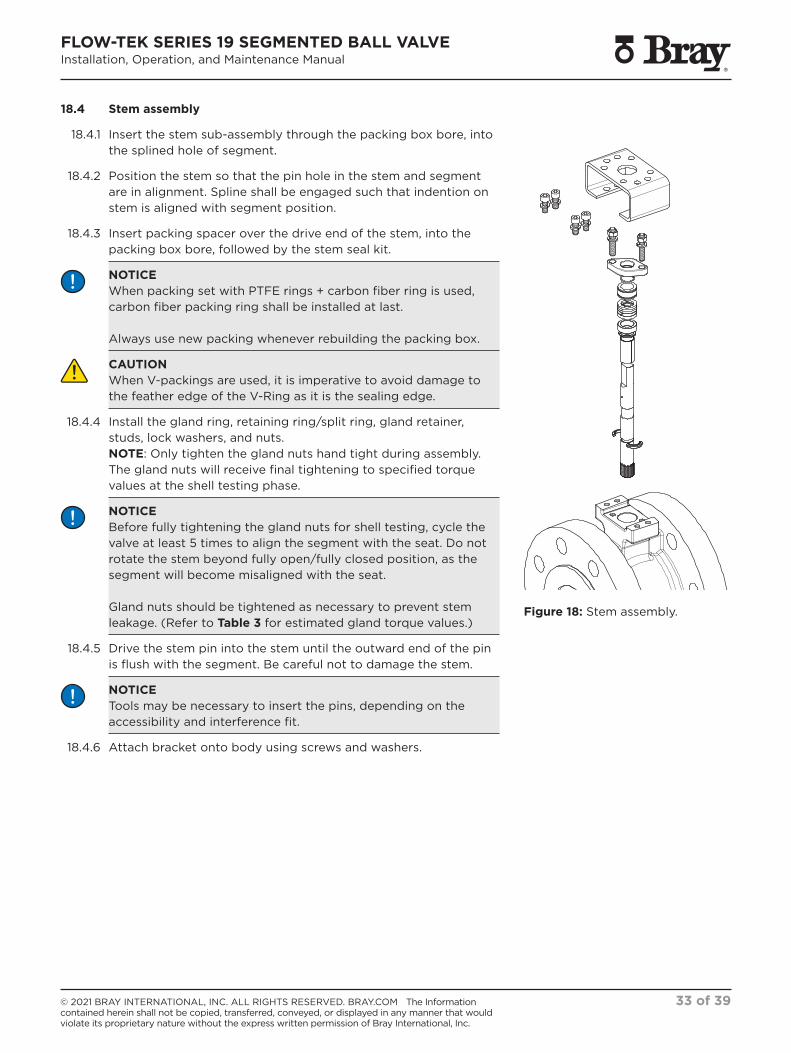
18.4 Stem assembly
18.4.1 Insert the stem sub-assembly through the packing box bore, into the splined hole of segment.
18.4.2 Position the stem so that the pin hole in the stem and segment are in alignment. Spline shall be engaged such that indention on stem is aligned with segment position.
18.4.3 Insert packing spacer over the drive end of the stem, into the packing box bore, followed by the stem seal kit.
NOTICE When packing set with PTFE rings + carbon fiber ring is used, carbon fiber packing ring shall be installed at last.
Always use new packing whenever rebuilding the packing box.
CAUTION When V-packings are used, it is imperative to avoid damage to the feather edge of the V-Ring as it is the sealing edge.
18.4.4 Install the gland ring, retaining ring/split ring, gland retainer, studs, lock washers, and nuts. NOTE: Only tighten the gland nuts hand tight during assembly. The gland nuts will receive final tightening to specified torque values at the shell testing phase.
NOTICEBefore fully tightening the gland nuts for shell testing, cycle the valve at least 5 times to align the segment with the seat. Do not rotate the stem beyond fully open/fully closed position, as the segment will become misaligned with the seat.
Gland nuts should be tightened as necessary to prevent stem leakage. (Refer to Table 3 for estimated gland torque values.)
18.4.5 Drive the stem pin into the stem until the outward end of the pin is flush with the segment. Be careful not to damage the stem.
NOTICE Tools may be necessary to insert the pins, depending on the accessibility and interference fit.
18.4.6 Attach bracket onto body using screws and washers.
Figure 18: Stem assembly.

FLOW-TEK SERIES 19 SEGMENTED BALL VALVEInstallation, Operation, and Maintenance Manual
34 of 39© 2021 BRAY INTERNATIONAL, INC. ALL RIGHTS RESERVED. BRAY.COM The Information contained herein shall not be copied, transferred, conveyed, or displayed in any manner that would violate its proprietary nature without the express written permission of Bray International, Inc.
18.5 End post assembly
18.5.1 Insert end post into body
18.5.2 Insert bearing onto end post.
NOTICECare shall be taken to ensure PTFE lined fabric on bearing is not damaged during assembly.
18.5.3 Place thrust washer on end post.
NOTICESmall quantity of compatible grease/adhesive may be used to place thrust washer, considering thickness.
18.5.4 Place the gasket in groove. Install post cover using studs, washers, and nuts.
NOTICEPost cover stud & nut shall be torqued as per Table 4.
18.6 Shell and Seat Test
18.6.1 After reassembly, perform a shell and seat test to ensure proper operation.
Figure 19: End post assembly.

FLOW-TEK SERIES 19 SEGMENTED BALL VALVEInstallation, Operation, and Maintenance Manual
35 of 39© 2021 BRAY INTERNATIONAL, INC. ALL RIGHTS RESERVED. BRAY.COM The Information contained herein shall not be copied, transferred, conveyed, or displayed in any manner that would violate its proprietary nature without the express written permission of Bray International, Inc.
NOTES: > Bray does not accept any responsibility for the product if wear parts not tested and approved by Bray are used. > Bray does not accept any responsibility for the product if maintenance instructions are not followed during maintenance.
19.0 TROUBLESHOOTING
SYMPTOM POSSIBLE CAUSE RECOMMENDED SOLUTION
Gland packing leak. Loose gland nuts. Retorque gland nuts.
Gland packing wear. Replace gland packing.
Corrosion or scoring on stem. Clean or replace stem and gland packing.
Corrosion on stuffing box. Clean stuffing box and replace gland packing. Valve to be replaced if excessive corrosion observed.
Bottom plate gasket leak. Loose nuts. Retorque nuts.
Gasket damage. Replace gasket.
Damage/corrosion in sealing area. Clean or replace bottom plate and/or body based on severity of damage.
Through bore leakage. Segment not in fully closed position. Adjust close limit travel stops in actuator or check for backlash in actuator drive.
Segment and seat misaligned. Loosen the gland packing and center the segment by cycling valve 3-5 times. Re-tighten the gland packing.
Media solidified or entrapped. Clean sealing surfaces and seat spring.
Seat seal damage (O-ring or flat seals). Replace seals.
Seat or segment damage. Replace segment or seat.
High valve torque. Gland nuts are over torqued. Loosen gland nuts to the recommended value.
Operator/actuator misalignment with valve stem.
Loosen mounting fasteners and adjust mounting base ensuring it is parallel and the operator is centered. Retighten the fasteners.
Valves are installed in incorrect orientation. Valves shall be installed per flow indicator tag.
Media solidified or accumulated. Remove accumulated media from body cavity, segment, and seat. Clean sealing areas.
Bearing damage. Replace bearing.
Seat and/or segment damage. Replace seat and/or segment.

FLOW-TEK SERIES 19 SEGMENTED BALL VALVEInstallation, Operation, and Maintenance Manual
36 of 39© 2021 BRAY INTERNATIONAL, INC. ALL RIGHTS RESERVED. BRAY.COM The Information contained herein shall not be copied, transferred, conveyed, or displayed in any manner that would violate its proprietary nature without the express written permission of Bray International, Inc.
20.0 RETURN MERCHANDISE AUTHORIZATION
0.1 All products that are returned require a Return Merchandise Authorization (RMA). Contact a Bray representative for instructions and RMA forms to be completed prior to return of any product.
0.2 The following information must be provided when submitting RMA.
> Serial number
> Part number
> Month and year of manufacture
> Actuator specifics
> Application
> Media
> Operating temperature
> Operating pressure
> Total estimated cycles (since last installation or repair)
NOTE: Product information is provided on identification tag attached to device.
NOTICEMaterials must be cleaned and sanitized prior to return. MSDS sheets and Declaration of Decontamination are required.

FLOW-TEK SERIES 19 SEGMENTED BALL VALVEInstallation, Operation, and Maintenance Manual
37 of 39© 2021 BRAY INTERNATIONAL, INC. ALL RIGHTS RESERVED. BRAY.COM The Information contained herein shall not be copied, transferred, conveyed, or displayed in any manner that would violate its proprietary nature without the express written permission of Bray International, Inc.
Table 1: Gland Nut Torque S19 ASME 150, 300 | PN 10, 16, 25, 40 (lbf-in)
Valve Size Nut size Estimated Torque Maximum Torque
NPS lbf-in lbf-in
1 5/16 UNC 54 177
11/2 5/16 UNC 54 177
2 5/16 UNC 54 177
3 5/16 UNC 62 177
4 5/16 UNC 62 177
6 5/16 UNC 89 177
8 3/8 UNC 89 213
10 3/8 UNC 89 213
12 3/8 UNC 98 213
16 M12 239 487
Table 1: Gland Nut Torque S19 ASME 150, 300 | PN 10, 16, 25, 40 (N m)
Valve Size Nut size Estimated Torque Maximum Torque
DN N m N m
25 5/16 UNC 6 20
40 5/16 UNC 6 20
50 5/16 UNC 6 20
80 5/16 UNC 7 20
100 5/16 UNC 7 20
150 5/16 UNC 10 20
200 3/8 UNC 10 24
250 3/8 UNC 10 24
300 3/8 UNC 11 24
400 M12 27 55
21.0 APPENDIX A – TABLES
Table 2: Post Cover Torque S19 ASME 150, 300 | PN 10, 16, 25, 40 (lbf-in)
Valve Size Nut size Estimated Torque Maximum Torque
NPS lbf-in lbf-in
1 1/4 UNC 45 80
11/2 1/4 UNC 45 80
2 1/4 UNC 54 80
3 5/16 UNC 71 177
4 5/16 UNC 71 177
6 3/8 UNC 89 213
8 3/8 UNC 107 213
10 3/8 UNC 124 213
12 3/8 UNC 151 213
16 M16 753 1213
Table 2: Post Cover Torque S19 ASME 150, 300 | PN 10, 16, 25, 40 (N m)
Valve Size Nut size Estimated Torque Maximum Torque
DN N m N m
25 1/4 UNC 5 9
40 1/4 UNC 5 9
50 1/4 UNC 6 9
80 5/16 UNC 8 20
100 5/16 UNC 8 20
150 3/8 UNC 10 24
200 3/8 UNC 12 24
250 3/8 UNC 14 24
300 3/8 UNC 17 24
400 M16 85 137

FLOW-TEK SERIES 19 SEGMENTED BALL VALVEInstallation, Operation, and Maintenance Manual
38 of 39© 2021 BRAY INTERNATIONAL, INC. ALL RIGHTS RESERVED. BRAY.COM The Information contained herein shall not be copied, transferred, conveyed, or displayed in any manner that would violate its proprietary nature without the express written permission of Bray International, Inc.
Table 4: Post Cover Torque S19 ASME 600 (lbf-in)
Valve Size Nut size Estimated Torque Maximum Torque
NPS lbf-in lbf-in
1 M08 54 142
11/2 M08 54 142
2 M08 62 142
3 M08 89 142
4 M08 89 142
6 M10 169 275
8 M10 169 275
10 M10 239 275
12 M12 372 487
16 M16 753 1213
Table 4: Post Cover Torque S19 ASME 600 (N m)
Valve Size Nut size Estimated Torque Maximum Torque
DN N m N m
25 M08 6 16
40 M08 6 16
50 M08 7 16
80 M08 10 16
100 M08 10 16
150 M10 19 31
200 M10 19 31
250 M10 27 31
300 M12 42 55
400 M16 85 137
Table 3: Gland Nut Torque S19 ASME 600 (lbf-in)
Valve Size Nut size Estimated Torque Maximum Torque
NPS lbf-in lbf-in
1 M08 54 142
11/2 M08 54 142
2 M08 54 142
3 M08 80 142
4 M08 80 142
6 M10 62 275
8 M10 71 275
10 M10 89 275
12 M12 116 487
16 M12 239 487
Table 3: Gland Nut Torque S19 ASME 600 (N m)
Valve Size Nut size Estimated Torque Maximum Torque
DN N m N m
25 M08 6 16
40 M08 6 16
50 M08 6 16
80 M08 9 16
100 M08 9 16
150 M10 7 31
200 M10 8 31
250 M10 10 31
300 M12 13 55
400 M12 27 55

HEADQUARTERS BRAY INTERNATIONAL, INC.13333 Westland East Blvd.Houston, Texas 77041Tel: +1.281.894.5454
SINCE 1986, BRAY HAS PROVIDED FLOW CONTROL SOLUTIONS FOR A VARIETY OF INDUSTRIES AROUND THE WORLD.
VISIT BRAY.COM TO LEARN MORE ABOUT BRAY PRODUCTS AND LOCATIONS NEAR YOU.
THE HIGH PERFORMANCE COMPANY
All statements, technical information, and recommendations in this bulletin are for general use only. Consult Bray representatives or factory for the specific requirements and material selection for your intended application. The right to change or modify product design or product without prior notice is reserved. Patents issued and applied for worldwide. Bray® is a registered trademark of Bray International, Inc.
© 2021 BRAY INTERNATIONAL. ALL RIGHTS RESERVED. BRAY.COM
BRAY.COM
EN_IOM_S19_20211216