Embed Size (px)
Citation preview

9487 Dielman Rock Island Industrial Dr. St. Louis, MO 63132 Tel:(314) 567-0088
Operator's Manual Rev: B09
Operator's Manual


9487 Dielman Rock Island Industrial Dr. St. Louis, MO 63132 Tel:(314) 567-0088
Operator's Manual Rev: B09
TABLE OF CONTENTS
Firmware Version ............................................................... 1 Environmental Conditions .................................................. 1 Electrical Specifications...................................................... 1 Warnings............................................................................. 2 Section A: Programming the Controller ............................ 3
A – 1: Adjusting the Display Contrast ........................... 3 A – 2: Security Settings ................................................. 3
A – 2.1: Access Codes and levels .............................. 3 A – 2.2: Setting Access Codes ................................... 3 A – 2.3: Controller Options........................................ 3
A – 3: Navigating the menus.......................................... 3 A – 3.1: Common status messages............................. 3 A – 3.2: The Menu Screens........................................ 4
A – 3.2.1: Entry Screens ........................................ 4 A – 3.2.2: List Screens ........................................... 4
A – 3.3: The Lock Screen Key................................... 5 A – 4: Inputs .................................................................. 6
A – 4.1: pH Setup....................................................... 6 A – 4.2: ORP Setup.................................................... 6 A – 4.3: ppm Setup .................................................... 6
A – 4.3.1: Input Source: Calculated ........................ 6 A – 4.3.2: Input Source: Probe................................ 6
A – 4.4: Temperature Setup ....................................... 7 A – 4.5: Conductivity/TDS Setup .............................. 7 A – 4.6: Flow Rate Setup ........................................... 7 A – 4.7: pH Inventory Setup ...................................... 7
A – 4.7.1: Level Sensor.......................................... 7 A – 4.8: Chlorine (Bromine) Inventory Setup............ 7
A – 4.8.1: Level Sensor.......................................... 7 A – 4.9: Turbidity ...................................................... 8 A – 4.10: Surge Pit Level........................................... 8
A – 4.10.1: Level Sensor........................................ 8 A – 4.11: Pressure & Vacuum Setup ......................... 8
A – 4.11.1: Influent Pressure (Transducer) ............ 8 A – 4.11.2: Effluent Pressure (Transducer)............ 8 A – 4.11.3: Differential Pressure............................ 9 A – 4.11.4: Strainer Vacuum ................................. 9 A – 4.11.5: Total Dynamic Head ........................... 9
A – 5: Control Outputs................................................... 9 A – 5.1: pH Control ................................................... 9 A – 5.2: Chlorine (Bromine) Control....................... 10 A – 5.3: Chlorine (Bromine) Booster Control.......... 12 A – 5.4: Super Chlorination ..................................... 13 A – 5.5: Dechlorination............................................ 14 A – 5.6: Ozone Control ............................................ 14 A – 5.7: Heater......................................................... 14 A – 5.8: Polymer ...................................................... 15 A – 5.9: Autofill ....................................................... 15 A – 5.10: TDS Control............................................. 16 A – 5.11: Sensor Wash............................................. 16 A – 5.12: Enzyme .................................................... 16 A – 5.13: Alarm Relay ............................................. 16
A – 5.14: Recirculation Pump ..................................16 A – 6: Control Options .................................................17
A – 6.1: Flow Restored.............................................17 A – 6.2: Power Saver................................................17 A – 6.3: pH Lockout.................................................18
A – 7: Calculations .......................................................18 A – 7.1: Enter Parameters.........................................18 A – 7.2: LSI Setup....................................................18
A – 8: System Configuration........................................18 A – 8.1: SN...............................................................18 A – 8.2: Communication ..........................................18
A – 8.2.1: Direct Baud Rate (Operator)................18 A – 8.2.2 Modem type (Read Only) ......................18 A – 8.2.3: Ethernet Setup (Operator)....................18 A – 8.2.4: Call Out Setup (Operator).....................18 A – 8.2.5: Installed Options...................................19
A – 8.3: Datalog Frequency......................................19 A – 8.4: Date, Time & Units ....................................20 A – 8.5: User Setup ..................................................20 A – 8.6: Display Options ...........................................20
A – 9: VFD Turndowns................................................20 A – 10: Access Menu ...................................................20
Section B: The Normal Display .......................................21 B – 1: Inputs and Feeds ................................................21 B – 2: Alarms & Status messages.................................21
Section C: Using the Face Panel Quick Keys...................22 C – 1: The Set Points Key ............................................22 C – 2: The Relay Mode Key.........................................22 C – 3: The Cal Key (calibration) ..................................23 C – 4: The Reset Fail / Safe Key ..................................23 C – 5: The Emergency Off Key....................................23
Section D: Maintenance ...................................................24 D – 1: Potentiometric Sensors (pH and ORP) ..............24
D – 1.1: Electrode Cleaning .....................................24 D – 1.2: Long-Term Storage ....................................24
D – 2: Free Chlorine Sensor .........................................24 D – 2.1: Cleaning......................................................24 D – 2.2: Long-Term Storage ....................................24 D – 2.3: Filling electrolyte........................................24
D – 3: Conductivity Sensor ..........................................25 D – 3.1: Cleaning......................................................25
Section E: Tables..............................................................26 E – 1: Flow Meter K-Factors........................................26
E – 1.1 Schedule 40 PVC Pipe ..................................26 E – 1.2 Schedule 80 PVC Pipe ..................................26
Section F: Feed Charts .....................................................27 F – 1: Spa Feed Charts .................................................27 F – 2: Pool Feed Charts ................................................28
Section G: Installation Diagrams......................................29 G – 1: Pressure Filter Installation.................................29 G – 2: Vacuum Filter Installation.................................29
Section H: Warranty.........................................................30


Page 1 9487 Dielman Rock Island Industrial Dr. St. Louis, MO 63132 Tel:(314) 567-0088
Operator's Manual Rev: B09
Firmware Version
This manual was written for firmware v1.26. If you received newer firmware but did not receive a copy of the manual covering that version of firmware, please contact your distributor.
Environmental Conditions
The BECSys5 is housed in a NEMA 4X (IP65) enclosure. It should not be used in explosive environments. The BECSys5 should be mounted so that adequate ventilation is provided around the enclosure, preventing general environmental specifications from being exceeded (see table below).
Environmental Specifications Specification Rating Storage Temperature -40 to 85 Deg C Ambient Operating Temperature -18 to 50 Deg C Ambient Humidity 95% non condensing maximum humidity
Electrical Specifications
The BECSys5 may be ordered in either a 115VAC model or a 230VAC model. Following are the electrical specifications for each model:
115VAC Model: Voltage: 115VAC 60Hz Phase: Single Current: 12.25 Amps Full Load (¼ Amp – Controller) (12 Amps – Relay Outputs: 3A X 4)
230VAC Model: Voltage: 230VAC 50Hz Phase: Single Current: 12.125 Amps Full Load (⅛ Amp – Controller) (12 Amps – Relay Outputs: 3A X 4)

Page 2 9487 Dielman Rock Island Industrial Dr. St. Louis, MO 63132 Tel:(314) 567-0088
Operator's Manual Rev: B09
Warnings
Pay particular attention to the following warnings encountered while utilizing your BECSys5 Water Chemistry Controller:
Warning: Various other warnings may be found throughout the manual text.

Page 3 9487 Dielman Rock Island Industrial Dr. St. Louis, MO 63132 Tel:(314) 567-0088
Operator's Manual Rev: B09B09
Section A: Programming the Controller Section A: Programming the Controller
A – 1: Adjusting the Display Contrast You can adjust the display contrast by holding down either the up or down arrow keys for two seconds, then after the controller beeps three times, use the up and down keys to adjust the contrast.
A – 2: Security Settings A – 2.1: Access Codes and levels
To view what access level you were given, press the lock screen button while in any menu.
The Main Menu will also display who is logged on along with the version of firmware. You do not need to set all the access codes for each level if you do not wish to. Also, a disabled access code is not equivalent to 000, so entering 000 when it prompts for an access code will only work if you have specifically assigned an access code to be 000.
A – 2.2: Setting Access Codes To set an access code, press the menu button, then: Select System Config Choose User Setup Then select the access level you want to set an access code for. To set Operator 1's access code, you would select Oper. Access Codes, then select Operator 1.
Pressing and holding the +/- button disables the access code, while pressing enter will enable and set the access code to the value on the screen. Operators may only change their own access code. Managers may change their access code and any of the Operators.
A – 2.3: Controller Options Depending on how a particular controller is configured, not all of the options listed in this manual may be available.
A – 3: Navigating the menus The controller's menus incorporate built in help text to aid in understanding the function of each parameter, item, and option. A – 3.1: Common status messages
The very bottom line of the display contains the time and date on the left while the right is reserved for a number of status messages; the most common are as follows: "Busy..." - Indicates the controller is busy doing something critical and it cannot stop until it finishes. Until this message disappears, the controller will not respond to your key presses (although it does record them any will process them when done). Normally this message is only seen briefly after changing a setting, but it is also used for lengthier operations and in the extremely rare case where the internal diagnostics detect a memory problem and attempts to correct it.
Warning: Interrupting the controller by turning the power off while it displays the busy message could result in the complete loss of all
of its settings.
"(1 of 2) (More )" - and the like indicate there are more options for you to choose from than the controller could show at one time. Press the right arrow key (Next) to view them. The left number indicates the current page, while the right number indicates the total number of pages. "Bad Value, Retry..." - Accompanied by an error beep, this indicates the value you just entered was not within the allowable range of values and was not stored.

Page 4 9487 Dielman Rock Island Industrial Dr. St. Louis, MO 63132 Tel:(314) 567-0088
Operator's Manual Rev: B09A – 3.2: The Menu Screens
Most of the features of the controller are configured via the Menu button's menus. The menu screens can be broken up into two types: entry screens and lists. A – 3.2.1: Entry Screens
An entry screen is used to enter a value using the keypad.
The current value is usually displayed at the top while the cursor will be positioned under the current digit or character of the value you are entering in. The up and down arrows allow you to move the cursor right or left so you do not have to retype the existing digits if you only wish to change one. Most numerical values will display the minimum and maximum values you can enter in at the bottom of the display in the format "< ### to ###>". These ranges many times will be dependant on other values you have set, such as alarm points or set points, while others are simply fixed to stay within a reasonable range. Entering a value that is not within the acceptable range will result in an error beep and the message "Bad Value, Retry..." being displayed in the status area. For some values, certain keys may take on special functions that are explained in the lower lines of the screen. The Down/up message in the example above is one of them.
A – 3.2.2: List Screens The list screens are mainly composed of lists of menu items that you can choose from by either pressing an item's number or by using the up and down arrow keys to select it (indicated by the arrow) and then pressing enter to choose it. Using the up and down arrow keys also allows you to view each item's help text. And if the item leads to an entry screen or a list screen that sets a setting (see below), the current value is displayed in the lower right side. Lists can also be used to change a setting:
When a list is used this way, it will display the current setting followed by the words "Change to:". Because it is a list, you can select an item with the up/down buttons to see help information about that particular selection.
There are a few list screens that use the entire width of the display for displaying values associated with each item and therefore do not have help. See Section E: Using the Quick Set Face Panel Keys for examples of these types of screens.
Page 5 9487 Dielman Rock Island Industrial Dr. St. Louis, MO 63132 Tel:(314) 567-0088
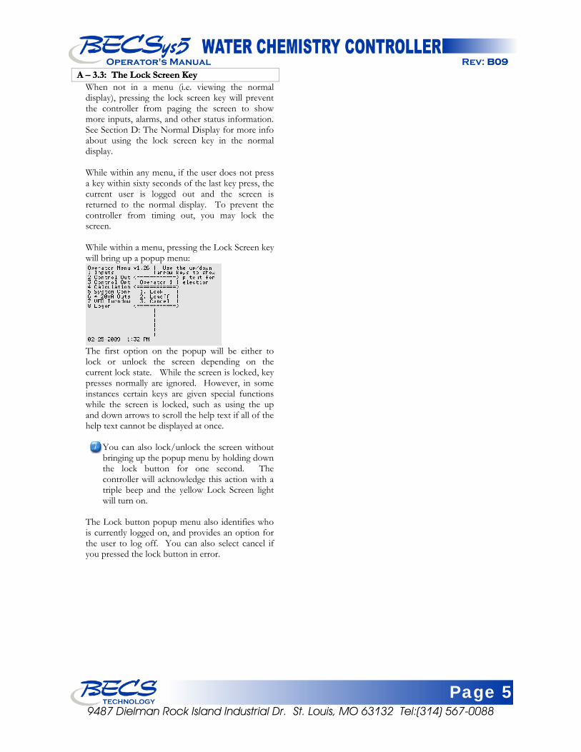
Operator's Manual Rev: B09B09A – 3.3: The Lock Screen Key A – 3.3: The Lock Screen Key
When not in a menu (i.e. viewing the normal display), pressing the lock screen key will prevent the controller from paging the screen to show more inputs, alarms, and other status information. See Section D: The Normal Display for more info about using the lock screen key in the normal display. While within any menu, if the user does not press a key within sixty seconds of the last key press, the current user is logged out and the screen is returned to the normal display. To prevent the controller from timing out, you may lock the screen. While within a menu, pressing the Lock Screen key will bring up a popup menu:
The first option on the popup will be either to lock or unlock the screen depending on the current lock state. While the screen is locked, key presses normally are ignored. However, in some instances certain keys are given special functions while the screen is locked, such as using the up and down arrows to scroll the help text if all of the help text cannot be displayed at once.
You can also lock/unlock the screen without bringing up the popup menu by holding down the lock button for one second. The controller will acknowledge this action with a triple beep and the yellow Lock Screen light will turn on.
The Lock button popup menu also identifies who is currently logged on, and provides an option for the user to log off. You can also select cancel if you pressed the lock button in error.

Page 6 9487 Dielman Rock Island Industrial Dr. St. Louis, MO 63132 Tel:(314) 567-0088
Operator's Manual Rev: B09
A – 4: Inputs To enter the program menu, press the Menu button on the front face panel of your controller. This will allow the viewing of the Main Menu where the programming options are displayed.
The ppm Input, Cl (Br) Inventory Input, Cl (Br) feed, and Cl (Br) booster feed are all displayed as either Chlorine and Cl or Bromine and Br depending on the chemical selected in the Cl (Br) feed menu. This manual is written using the Chlorine setting. If you select Bromine as the sanitizing chemical, the controller will display Bromine and Br instead of Chlorine and Cl, but the menus and functions are otherwise exactly the same as shown.
Select Inputs from the menu. A – 4.1: pH Setup
If your controller is configured to monitor pH, you will have the following options: High Alarm (Operator): The high alarm will activate when the pH rises above this setting. Input the desired level and press enter. Disable this alarm by holding down the +/- key for 1 second. The range is dependant on the pH feed's set point and/or the low alarm point. Low Alarm (Operator): The low alarm will activate when the pH falls below this setting. Input the desired level and press enter. Disable this alarm by holding down the +/- key for 1 second. The range is dependant on the pH feed's set point and/or the high alarm point. Alarm Hysteresis (Manager): This value sets the amount that the pH reading has to rise above the high alarm or fall below the low alarm before the alarm will shut off. Input the desired level and press enter. (the range is from 0.0 to 1.4)
A – 4.2: ORP Setup If your controller is configured to monitor ORP, you will have the following options: High Alarm (Operator): The high alarm will activate when the ORP rises above this setting. Input the desired level and press enter. Disable this alarm by holding down the +/- key for 1 second. The range is dependant on the Cl feed's ORP set point and/or the low alarm point. Low Alarm (Operator): The low alarm will activate when the ORP falls below this setting. Input the desired level and press enter. Disable this alarm by holding down the +/- key for 1 second. The range is dependant on the Cl feed's ORP set point and/or the high alarm point.
Alarm Hysteresis (Manager): This value sets the amount that the ORP reading has to rise above the high alarm or fall below the low alarm before the alarm will shut off. Input the desired level and press enter. (the range is from 0 to 200 mV)
A – 4.3: ppm Setup Depending on the controller setup, ppm may be calculated, a probe attached, or not installed: A – 4.3.1: Input Source: Calculated
High Alarm (Operator): The high alarm will activate when the ppm rises above this setting. Input the desired level and press enter. Disable this alarm by holding down the +/- key for 1 second. The range is dependant on the Cl (Br) feed's ppm set point and/or the low alarm point. Low Alarm (Operator): The low alarm will activate when the ppm falls below this setting. Input the desired level and press enter. Disable this alarm by holding down the +/- key for 1 second. The range is dependant on the Cl (Br) feed's ppm set point and/or the high alarm point. Alarm Hysteresis (Manager): This value sets the amount that the ppm reading has to rise above the high alarm or fall below the low alarm before the alarm will shut off. Input the desired level and press enter. (the range is from 0.0 to 2.0 ppm)
A – 4.3.2: Input Source: Probe High Alarm (Operator): The high alarm will activate when the ppm rises above this setting. Input the desired level and press enter. Disable this alarm by holding down the +/- key for 1 second. The range is dependant on the Cl (Br) feed's ppm set point and/or the low alarm point.) Low Alarm (Operator): The low alarm will activate when the ppm falls below this setting. Input the desired level and press enter. Disable this alarm by holding down the +/- key for 1 second. The range is dependant on the Cl (Br) feed's ppm set point and/or the high alarm point. Alarm Hysteresis (Manager): This value sets the amount that the ppm reading has to rise above the high alarm or fall below the low alarm before the alarm will shut off. Input the desired level and press enter. (the range is from 0.0 to 2.0 ppm) Calibrate (Operator): This selection allows you to do a single point calibration of ppm, enter the reading from you test kit, and press enter. The value entered must be 1.0 or greater.

Page 7 9487 Dielman Rock Island Industrial Dr. St. Louis, MO 63132 Tel:(314) 567-0088
Operator's Manual Rev: B09 Reset Calibration (Operator): Resets the calibration to the original factory setting.
A – 4.4: Temperature Setup If your controller is configured to monitor Temperature, you will have the following options: High Alarm (Operator): The high alarm will activate when the temperature rises above this setting. Input the desired temperature and press enter. Disable this alarm by holding down the +/- key for 1 second. The range is dependant on the Heater's set point (if installed) and/or the low alarm point. Low Alarm (Operator): The low alarm will activate when the temperature falls below this setting. Input the desired temperature and press enter. Disable this alarm by holding down the +/- key for 1 second. The range is dependant on the Heater's set point (if installed) and/or the high alarm point. Alarm Hysteresis (Manager): This value sets the amount that the temperature reading has to rise above the high alarm or fall below the low alarm before the alarm will shut off. Input the desired level and press enter. (the range is from 0 to 18)
A – 4.5: Conductivity/TDS Setup If your controller is configured to monitor Conductivity/TDS, you will have the following options: High Alarm (Operator): The high alarm will activate when the input rises above this setting. Enter the desired value and press enter. Disable this alarm by holding down the +/- key for 1 second. The range is dependant on the TDS control's set point (if installed) and/or the low alarm point. Low Alarm (Operator): The low alarm will activate when the input falls below this setting. Enter the desired value and press enter. Disable this alarm by holding down the +/- key for 1 second. The range is dependant on the TDS control's set point (if installed) and/or the high alarm point. Alarm Hysteresis (Manager): This value sets the amount that the Conductivity/TDS reading has to rise above the high alarm or fall below the low alarm before the alarm will shut off. Input the desired level and press enter. (the range is from 0 to 1000 for TDS and 0 to 2000 for conductivity)
A – 4.6: Flow Rate Setup If your controller is configured to monitor Flow Rate, you will have the following options: Low Alarm (Operator): This value sets the reading that the flow rate low alarm will be activated. Input the desired value and press enter. Disable this alarm by holding down the +/- key for 1 second. (The range is 0 to 3000.0 gpm or lpm) Alarm Hysteresis (Manager): This value sets the reading that the flow rate must rise above the low alarm before the alarm will shut off. Enter the desired number and press enter. (The range is 1 to 50.0 gpm or lpm)
A – 4.7: pH Inventory Setup pH Inventory can be setup several ways. Depending on the controller configuration the pH Inventory monitoring device may be a transducer (Level Sensor), contact switch (Float), or not even installed. There are no settable options if pH Inventory is setup for a contact switch. A – 4.7.1: Level Sensor
Low Alarm (Operator): This value sets at what level or weight the pH inventory low alarm will be activated. Enter the desired level or weight and press enter. You may also disable this alarm by holding down the +/- key for 1 second (the range is dependant on the input range). Alarm Hysteresis (Manager): This value sets at what level the pH inventory level or weight has to rise above the low level or weight alarm setting before the alarm will shut off. Enter the desired number and press enter (the range is 10% of the input range).
A – 4.8: Chlorine (Bromine) Inventory Setup Chlorine (Bromine) Inventory can be setup several ways. Depending on the controller configuration the Chlorine (Bromine) Inventory monitoring device may be a transducer (Level Sensor), contact switch (Float), or not even installed. There are no settable options if Chlorine (Bromine) Inventory is setup for a contact switch. A – 4.8.1: Level Sensor
Low Alarm (Operator): This value sets at what level or weight the pH inventory low alarm will be activated. Enter the desired level or weight and press enter. You may also disable this alarm by holding down the +/- key for 1 second (the range is dependant on the input range).

Page 8 9487 Dielman Rock Island Industrial Dr. St. Louis, MO 63132 Tel:(314) 567-0088
Operator's Manual Rev: B09
Alarm Hysteresis (Manager): This value sets at what level the Chlorine Inventory level or weight has to rise above the low level or weight alarm setting before the alarm will shut off. Enter the desired number and press enter (the range is 10% of the input range).
A – 4.9: Turbidity If your controller is configured to monitor Turbidity, you will have the following options: High Alarm (Operator): The high alarm will activate when the input reaches or rises above this setting. Enter the desired value and press enter. Disable this alarm by holding down the +/- key for 1 second. (The range is dependant on the input range.) Alarm Hysteresis (Manager): This value sets the level that the turbidity reading has to rise above the high alarm setting before the alarm will shut off. Input the desired level and press enter. (the range is 10% of the input range)
A – 4.10: Surge Pit Level The Surge Pit Level can be setup several ways. Depending on the controller configuration the Surge Pit Level monitoring device may be a transducer (Level Sensor), contact switch (Float), or not even installed. There are no settable options if the Surge Pit Level is setup for a contact switch. A – 4.10.1: Level Sensor
High Alarm (Operator): The high alarm will activate when the input rises above this setting. Enter the desired value and press enter. Disable this alarm by holding down the +/- key for 1 second. (the range is dependant on the input range) Low Alarm (Operator): The low alarm will activate when the input falls below this setting. Enter the desired value and press enter. Disable this alarm by holding down the +/- key for 1 second. (the range is dependant on the input range) Alarm Hysteresis (Manager): This value sets the amount that the surge pit level has to rise above the high alarm or fall below the low alarm before the alarm will shut off. Input the desired level and press enter.
A – 4.11: Pressure & Vacuum Setup The Pressure and Vacuum inputs can be setup several ways. Depending on the controller configuration the Pressure and Vacuum inputs device may be a transducer, contact switch, or not even installed. There are no settable options if the Pressure and Vacuum inputs are setup for a contact switch. A – 4.11.1: Influent Pressure (Transducer)
High Alarm: (Operator) The high alarm will activate when the pressure reaches or rises above this setting. Input the desired pressure and press enter. Disable this alarm by holding down the +/- key for 1 second. (The range is dependant on the low alarm point.)
Low Alarm: (Operator) The low alarm will activate when the pressure falls below this setting. Input the desired pressure and press enter. Disable this alarm by holding down the +/- key for 1 second. (The range is dependant on the high alarm point.)
Alarm Hysteresis: (Manager) This value sets the amount that the pressure reading has to rise above the high alarm or fall below the low alarm before the alarm will shut off. Input the desired level and press enter. (The range is from 0 to 5)
Display Input (Operator): This option enables/disables displaying the influent pressure on the normal display.
A – 4.11.2: Effluent Pressure (Transducer) High Alarm (Operator): The high alarm will activate when the pressure reaches or rises above this setting. Input the desired pressure and press enter. Disable this alarm by holding down the +/- key for 1 second. (The range is dependant on the low alarm point.)
Low Alarm (Operator): The low alarm will activate when the pressure falls below this setting. Input the desired pressure and press enter. Disable this alarm by holding down the +/- key for 1 second. (The range is dependant on the high alarm point.)

Page 9 9487 Dielman Rock Island Industrial Dr. St. Louis, MO 63132 Tel:(314) 567-0088
Operator's Manual Rev: B09B09
Alarm Hysteresis (Manager): This value sets the amount that the pressure reading has to rise above the high alarm or fall below the low alarm before the alarm will shut off. Input the desired level and press enter. (The range is from 0 to 5)
Alarm Hysteresis (Manager): This value sets the amount that the pressure reading has to rise above the high alarm or fall below the low alarm before the alarm will shut off. Input the desired level and press enter. (The range is from 0 to 5)
Display Input (Operator): This option enables/disables displaying the Effluent pressure on the normal display.
Display Input (Operator): This option enables/disables displaying the Effluent pressure on the normal display.
A – 4.11.3: Differential PressureA – 4.11.3: Differential Pressure High Alarm (Operator): The high alarm will activate when the pressure rises above this setting. Input the desired pressure and press enter. Disable this alarm by holding down the +/- key for 1 second. (the range is 0 to 40) Alarm Hysteresis (Manager): This value sets the amount that the pressure reading has to rise above the high alarm or fall below the low alarm before the alarm will shut off. Input the desired level and press enter. (the range is from 0 to 10)
A – 4.11.4: Strainer Vacuum High Vac Alarm (Operator): The high vacuum alarm will activate when the pressure falls below this setting. This is actually a low pressure alarm that operates in the negative pressure range, which is a vacuum. Input the desired pressure and press enter. Disable this alarm by holding down the +/- key for 1 second.
Alarm Hysteresis (Manager): This value sets the level that the vacuum reading must fall below the high alarm setting before the alarm will shut off. Input the desired level and press enter. (The range is from 0 to 5)
A – 4.11.5: Total Dynamic Head Depending on the controller configuration, the Total Dynamic Head of the pump may be calculated and able to be displayed: Display TDH (Operator): Will display the Total Dynamic Head on the normal display. High Alarm (Operator): The high alarm will activate when the Total Dynamic Head across the pump rises above this setting. Input the desired value and press enter. Disable this alarm by holding down the +/- key for 1 second. Low Alarm (Operator): The low alarm will activate when the Total Dynamic Head across the pump falls below this setting. Input the desired value and press enter. Disable this alarm by holding down the +/- key for 1 second.
Alarm Hysteresis (Manager): This value sets the amount that the Total Dynamic Head has to rise above the high alarm or fall below the low alarm before the alarm will shut off. Input the desired level and press enter (The range is from 0 to 5).
A – 5: Control Outputs Press the Menu button on the front face panel of the Controller and select Control Outputs. You will then be able to select the following items:
A – 5.1: pH Control
If your controller is configured to control pH, you will have the following options: Control Type (Operator): Choose from On/Off or Time Base Proportional control.
In general, if you are using a motor driven chemical feeder then you should choose the On/Off option. If you are using a solenoid driven or pulsed diaphragm chemical feeder (such as Pulsatron, most LMI models or most Prominent Models), you should choose the TBP option. This feature helps to hold a set point and to minimize over-shoot by making a standard feeder mimic the action of more sophisticated modulating feeders. If you choose the On/Off option and are feeding up, then the controller will activate the chemical feeder whenever the pH falls below the set point and continue to feed until the pH rises above the set point plus hysteresis at which point it will stop. If you choose the TBP option and are feeding up then the controller will activate the chemical feeder whenever the pH falls below the set point and will feed for a percentage of the Time Base (default one minute) proportional to the offset from set point. For the remainder of the Time Base the feeder will be paused. The feeder will continue this feed and pause cycle until the controller achieves the set point plus hysteresis. The closer to set point, the less time the feeder is ON.
Set Point (Operator): This value sets the desired level to maintain the pH at. Input the desired pH set point. (the range is 6.0 to 9.0 ppm)

Page 10 9487 Dielman Rock Island Industrial Dr. St. Louis, MO 63132 Tel:(314) 567-0088
Operator's Manual Rev: B09
Span/Prop. Bnd (Operator): This option is only shown if the Control Type is Time Base Proportional. This value sets the distance (or span) from the set point that the output will be proportionally controlled. (the range is from 0.0 to 2.0) Time Base (Operator): This option is only shown if the Control Type is Time Base Proportional. This sets the total time that control is based on. During this time, the feeder will turn on for a percentage of the Time Base and turn off for the remainder (the range is from 15 to 300 seconds). Failsafe Timer (Operator): This value sets the time that the relay is allowed to stay continuously on. (the range is 0:00 to 18:00 hours)
The most common failures of automated chemical feed systems are depletion of the chemical supply and/or chemical feeder failure. Both problems result in the controller being unable to reach set point in a reasonable period of time. The failsafe timer sets the maximum length of time the feeder can run. If the feeder has been trying to achieve set point without success for the selected time, the controller will cut power to the feeder, flash the Reset Fail/Safe LED on the face panel and display a message to alert the operator. If in TBP Pause mode, the controller will reset the timer. An operator must reset the failsafe through the Reset Fail/Safe button to re-enable normal control.
Dead Band (Manager): This option is only shown only if you have both feed up and feed down feeds enabled. This value sets the amount the input must exceed the set point by before the feed of the opposite
direction will trigger. (The range is from twice the feeds' hysteresis to 2.8 pH)
A – 5.2: Chlorine (Bromine) Control If your controller is configured to control Chlorine (Bromine), you will have the following options: Sanitizer Chemical (Operator): Sets the sanitizer chemical name (Chlorine or Bromine).
This option controls what chemical name the controller displays for the ppm Input and the primary sanitization/oxidizing chemical.
Warning: Increasing or decreasing the proportional band may cause the feed to
severely overshoot or never achieve set point. Adjust this option only when recommended to
do so by a factory representative. Control Input Src (Operator): This option is only available if the ppm Input source is set to Calculated or Probe. Choose between ORP and ppm to use as the primary control input for the sanitizer feed.
If the ppm Input is selected and the ppm Input source is set to probe, ORP is still used for control while the ppm interlock timer is running. If the ppm Input is selected and the ppm Input source is set to calculated, the controller still controls off of ORP, but the ORP set point is calculated by the controller based on the ppm set point, the pH set point, and the ppm calibration. Modification of any one of those three values will result in a new ORP set point.
Warning: Increasing or decreasing the time base may cause the feed to severely overshoot or never achieve set point. Adjust this option only when recommended to do so by a factory
representative.
Control Type (Operator): Choose from On/Off or Time Base Proportional control.
In general, if you are using a motor driven chemical feeder then you should choose the On/Off option. If you are using a solenoid driven or pulsed diaphragm chemical feeder (such as Pulsatron, most LMI models or most Prominent Models), you should choose the TBP option. This feature helps to hold a set point and to minimize over-shoot by making a standard feeder mimic the action of more sophisticated modulating feeders. If you choose the On/Off option, then the controller will activate the chemical feeder whenever the ORP falls below the set point and continue to feed until the ORP rises above the set point plus hysteresis at which point it will stop. If you choose the TBP option, then the controller will activate the chemical feeder whenever the ORP falls below the set point and will feed for a percentage of the Time Base (default one minute) proportional to the offset from set point. For the remainder of the Time Base the feeder will be paused. The feeder will continue this feed and pause cycle until the controller achieves the set point plus hysteresis. The closer to set point, the less time the feeder is ON.
Warning: Disabling the failsafe timers is highly discouraged. They are an important safety feature to protect against dangerous
chemical overfeeds and will protect the equipment from running continuously if it runs
out of chemical.

Page 11 9487 Dielman Rock Island Industrial Dr. St. Louis, MO 63132 Tel:(314) 567-0088
Operator's Manual Rev: B09B09 ORP Set Point (Operator): This option is NOT shown if the Control Source is set to ppm and the ppm Input source is set to Calculated. This value sets the desired level to maintain the ORP at (the range is 700 to 800 mV).
ORP Set Point (Operator): This option is NOT shown if the Control Source is set to ppm and the ppm Input source is set to Calculated. This value sets the desired level to maintain the ORP at (the range is 700 to 800 mV). ORP Span/Prop. Bnd (Operator): This option is only shown if the Control Type is Time Base Proportional and the ORP Set Point is shown above. This value sets the distance (or span) from the set point that the output will be proportionally controlled. (the range is from 0 to 500 mV)
ORP Span/Prop. Bnd (Operator): This option is only shown if the Control Type is Time Base Proportional and the ORP Set Point is shown above. This value sets the distance (or span) from the set point that the output will be proportionally controlled. (the range is from 0 to 500 mV) ppm Set Point (Operator): This option is only shown if the Control Source is set to ppm. This value sets the desired level to maintain the ppm at (the range is dependant on the ppm high and low alarms).
ppm Set Point (Operator): This option is only shown if the Control Source is set to ppm. This value sets the desired level to maintain the ppm at (the range is dependant on the ppm high and low alarms). ppm Span/Prop Bnd: (Operator) This option is only shown if the Control Type is Time Base Proportional, the Control Source is set to ppm, and the ppm Input source is set to probe. This value sets the distance (or span) from the set point that the output will be proportionally controlled (the range is from 0.0 to 2.0 ppm).
ppm Span/Prop Bnd: (Operator) This option is only shown if the Control Type is Time Base Proportional, the Control Source is set to ppm, and the ppm Input source is set to probe. This value sets the distance (or span) from the set point that the output will be proportionally controlled (the range is from 0.0 to 2.0 ppm). Time Base (Operator): This option is only shown if the Control Type is Time Base Proportional. This sets the total time that control is based on. During this time, the feeder will turn on for a percentage of the Time Base and turn off for the remainder (the range is from 15 to 300 seconds).
Time Base (Operator): This option is only shown if the Control Type is Time Base Proportional. This sets the total time that control is based on. During this time, the feeder will turn on for a percentage of the Time Base and turn off for the remainder (the range is from 15 to 300 seconds). Failsafe Timer (Operator): This value sets the time that the relay is allowed to stay continuously on. (the range is 0:00 to 18:00 hours)
Failsafe Timer (Operator): This value sets the time that the relay is allowed to stay continuously on. (the range is 0:00 to 18:00 hours)
The most common failures of automated chemical feed systems are depletion of the
chemical supply and/or chemical feeder failure. Both problems result in the controller being unable to reach set point in a reasonable period of time. The failsafe timer sets the maximum length of time the feeder can run. If the feeder has been trying to achieve set point without success for the selected time, the controller will cut power to the feeder, flash the Reset Fail/Safe LED on the face panel and display a message to alert the operator. If in TBP Pause mode, the controller will reset the timer.
The most common failures of automated chemical feed systems are depletion of the
chemical supply and/or chemical feeder failure. Both problems result in the controller being unable to reach set point in a reasonable period of time. The failsafe timer sets the maximum length of time the feeder can run. If the feeder has been trying to achieve set point without success for the selected time, the controller will cut power to the feeder, flash the Reset Fail/Safe LED on the face panel and display a message to alert the operator. If in TBP Pause mode, the controller will reset the timer. An operator must reset the failsafe through the Reset Fail/safe button to re-enable normal control.
An operator must reset the failsafe through the Reset Fail/safe button to re-enable normal control.
Warning: Increasing or decreasing the proportional band may cause the feed to
severely overshoot or never achieve set point. Adjust this option only when recommended to
do so by a factory representative.
Alt Set Point: The 4 Event 28 Day Timer allows you to program a schedule to define when to use alternate set point.
Alt Set Point: The 4 Event 28 Day Timer allows you to program a schedule to define when to use alternate set point.
Alt Set Point 4 Event 28 Day Timer (Operator): To program the 4 Event 28 Day Timer, perform the following:
Alt Set Point 4 Event 28 Day Timer (Operator): To program the 4 Event 28 Day Timer, perform the following: • Select the Alt. Set point from the Cl (Br)
Control menu. • Select the Alt. Set point from the Cl (Br)
Control menu. • Now select the 4Event 28Day Timer from the
Alt. Set Point menu. • Now select the 4Event 28Day Timer from the
Alt. Set Point menu. • Selecting Event1 will allow you to select the
weekly interval to use the alternate set point. • Selecting Event1 will allow you to select the
weekly interval to use the alternate set point. If the 1st, 2nd, 3rd, or 4th week is selected, the timer will only trigger on that week in the four-week cycle. The Odd Weeks selection will trigger on the 1st and 3rd weeks, the Even Weeks selection will trigger on the 2nd and 4th weeks, and the Every Week selection triggers every week.
If the 1st, 2nd, 3rd, or 4th week is selected, the timer will only trigger on that week in the four-week cycle. The Odd Weeks selection will trigger on the 1st and 3rd weeks, the Even Weeks selection will trigger on the 2nd and 4th weeks, and the Every Week selection triggers every week.
The week number and day of week for the current date is displayed on the bottom right side of these screens.
The week number and day of week for the current date is displayed on the bottom right side of these screens. The first week is fixed to be the week of Sunday, January 2nd, 2000 and every four weeks afterwards.
The first week is fixed to be the week of Sunday, January 2nd, 2000 and every four weeks afterwards. The next set of screens will allow you to choose the actual day(s). The next set of screens will allow you to choose the actual day(s).
• Select what day of the week, or every day, the
alternate set point should be used. • Select what day of the week, or every day, the
alternate set point should be used.
Warning: Disabling the failsafe timers is highly discouraged. They are an important safety feature to protect against dangerous
chemical overfeeds and will protect the equipment from running continuously if it runs
out of chemical.
Warning: Increasing or decreasing the proportional band may cause the feed to
severely overshoot or never achieve set point. Adjust this option only when recommended to
do so by a factory representative.
Warning: Increasing or decreasing the time base may cause the feed to severely overshoot or never achieve set point. Adjust this option only when recommended to do so by a factory
representative.

Page 12 9487 Dielman Rock Island Industrial Dr. St. Louis, MO 63132 Tel:(314) 567-0088
Operator's Manual Rev: B09• Once you make your selection you will be
returned to the 4Event 28Day Timer menu where you will have a new menu item: Event 1 Times.
• Select the Event1 Times from the 4Event 28Day Timer menu. This screen allows you to set both the start time and the end time for the event's programmed weeks/days. To toggle AM/PM, press the +/- key while the cursor is on the time you wish to change.
If your start time is before midnight (12:00 AM) and the end time is after midnight, the alternate set point will continue to be used the following day up to the end time even if that day did not fall within the week/day selection for that event.
Example: Event1 Week/Day: Odd weeks/ Tuesday Event1 Times: 11:00 PM to 3:00 AM Event2 Week/Day: Even weeks/ Monday Event2 Times: 11:00 PM to 6:00 AM Current Week/Day: 2nd/Tuesday Current Time: 4:00 PM The alternate set point last ran from 11:00 PM
last night to 6:00AM this morning. The next time the alternate set point will run will
be from 11:00 PM next Tuesday to 3:00AM next Wednesday.
ORP Set Point (Operator): This value sets the desired level to maintain the ORP at during any of the programmed alternate set point events. (the range is dependant on the alarm points) ppm Set Point (Operator): This option is only available if the ppm probe is installed and the Control Source is set to ppm. This value sets the desired level to maintain the ppm at during any of the programmed alternate set point events. (the range is dependant on the alarm points)
Bracketed ppm (Operator): This option is only available if the ppm probe is installed and the Control Source is set to ORP. If enabled, the controller will override the ORP control so that the ppm will not drop out of a programmed range. Bracketed ORP (Operator): This option is only available if the ppm probe is installed and the Control Source is set to ppm. If enabled, the controller will override the ppm control so that the ORP will not drop out of a programmed range.
A – 5.3: Chlorine (Bromine) Booster Control If your controller is configured to control a Chlorine (Bromine) Booster pump, you will have the following options: Control Input (Operator): This option is only available if the ppm Input is enabled. Choose between ORP, ppm or, if the ppm probe is used, both to control the chlorine booster. ORP Trigger Point (Operator): This option is only shown if the Control Input is ORP or Both. This value sets the ORP level that the input must drop below to activate the chlorine booster control. (the range is -1000 mV to the Cl Booster's ORP Set Point) ppm Trigger Point (Operator): This option is only shown if the Control Input is ppm or Both. This value sets the ppm level that the input must drop below to activate the chlorine booster control. (the range is from 0.0 ppm to the Cl Booster's ppm Set Point) ORP Set Point (Operator): This option is only shown if the Control Input is ORP or Both. This value sets the ORP level that once it is reached the chlorine booster control will shut off. (the range is from Cl Booster's ORP Trigger Point to the ORP high alarm point) ppm Set Point (Operator): This option is only shown if the Control Input is ppm or Both. This value sets the ppm level that once it is reached the chlorine booster control will shut off. (the range is from the Cl Booster's ppm Trigger Point to the ppm high alarm point) ORP Hysteresis (Operator): This option is only shown if the Control Input is ORP, Both, or, if ppm Input source is set to calculated, ppm. This value sets the level that the input must rise above the set point before the chlorine booster control will turn off. (the range is from 0 to 200 mV) ppm Hysteresis (Operator): This option is only shown if the ppm probe is used and the Control Input is ppm or Both. This value sets the level that the input must rise above the set point before the chlorine booster control will turn off. (the range is from 0.0 to 2.0 ppm)

Page 13 9487 Dielman Rock Island Industrial Dr. St. Louis, MO 63132 Tel:(314) 567-0088
Operator's Manual Rev: B09B09
Failsafe Timer (Operator): This value sets the time that the relay is allowed to stay continuously on. (the range is 0:00 to 18:00 hours)
Failsafe Timer (Operator): This value sets the time that the relay is allowed to stay continuously on. (the range is 0:00 to 18:00 hours)
The most common failures of automated chemical feed systems are depletion of the chemical supply and/or chemical feeder failure. Both problems result in the controller being unable to reach set point in a reasonable period of time. The failsafe timer sets the maximum length of time the feeder can run. If the feeder has been trying to achieve set point without success for the selected time, the controller will cut power to the feeder, flash the Reset Fail/Safe LED on the face panel and display a message to alert the operator. If in TBP Pause mode, the controller will reset the timer.
The most common failures of automated chemical feed systems are depletion of the chemical supply and/or chemical feeder failure. Both problems result in the controller being unable to reach set point in a reasonable period of time. The failsafe timer sets the maximum length of time the feeder can run. If the feeder has been trying to achieve set point without success for the selected time, the controller will cut power to the feeder, flash the Reset Fail/Safe LED on the face panel and display a message to alert the operator. If in TBP Pause mode, the controller will reset the timer. An operator must reset the failsafe through the Reset Fail/Safe button to re-enable normal control.
An operator must reset the failsafe through the Reset Fail/Safe button to re-enable normal control.
A – 5.4: Super Chlorination A – 5.4: Super Chlorination
Depending on the controller configuration, Super Chlorination may or may not be installed. If Super Chlorination is installed on your particular controller, choose Super Chlorination from the menu. This will allow you to program the following for Super Chlorination: Control Input (Operator): This option is only available if the ppm probe is installed. Choose between ppm and ORP to use to control the Super Chlorination feed. 4 Event 28 Day Timer (Operator): To program when the super chlorination should trigger, select 4Event 28Day Timer from the Super Chlorination menu:
Selecting Event1 will allow you to select the weekly interval to trigger the Super Chlorination. If the 1st, 2nd, 3rd, or 4th week is selected, the timer will only trigger on that week in the four-week cycle. The Odd Weeks selection will trigger on the 1st and 3rd weeks, the Even Weeks selection will trigger on the 2nd and 4th weeks, and the Every Week selection triggers every week.
The week number and day of week for the current date is displayed on the bottom right side of these screens.
The first week is fixed to be the week of Sunday, January 2nd, 2000 and every four weeks afterwards.
Next you can select the day of the week (or every day) the event should be triggered on.
Once you make your selection, you will be returned to the 4Event 28Day Timer menu where you will have a new menu item: Event 1 Start Time.
Select the Event1 Start Time from the 4Event 28Day Timer menu.
This screen allows you to set the time to trigger the event on the programmed weeks/days. The event will trigger at the start time if the controller is running at that time. To toggle AM/PM, press the +/- key. Enter the desired time and press enter. After setting the time, press the left arrow to return to Super Chlorination's main menu. Here you will notice the next scheduled super chlorination is displayed for you. The controller will also list the last super chlorination here once one has been completed.
Warning: Disabling the failsafe timers is highly discouraged. They are an important safety feature to protect against dangerous
chemical overfeeds and will protect the equipment from running continuously if it runs
out of chemical.
Maximum Time On (Operator): This value sets the maximum time you want the Super Chlorination on to reach the set point. If the time expires before set point is reached, the controller will trigger the SuperChlor failsafe alarm and end the SuperChlor feeds. (the range is from 0:00 to 18:00 hours)
An operator can reset the failsafe through the Reset Fail/Safe button; however the failsafe alarm will automatically clear itself when the regular Cl feed begins feeding.
ORP Set Point (Operator): This option is only shown if the Control Input is set to ORP. This value sets the desired ORP level to shock the pool. (the range is from -1000 to 1000 mV) ppm Set Point (Operator): This option is only shown if the Control Input is set to ppm. This value sets the desired ppm level to shock the pool. (the range is from 0.0 to 20.0 ppm)
Page 14 9487 Dielman Rock Island Industrial Dr. St. Louis, MO 63132 Tel:(314) 567-0088
Operator's Manual Rev: B09A – 5.5: Dechlorination
Depending on the controller configuration, Dechlorination may or may not be installed. If Dechlorination is installed on your particular controller, choose Dechlorination from the menu. This will allow you to program the following for Dechlorination: Control Input (Operator): This option is only available if the ppm probe is installed. Choose between ppm and ORP to use to control the dechlor feed. Follow Super Chlorination (Operator): Choose whether or not you want your dechlorination to automatically follow your super chlorination. 4 Event 28 Day Timer (Operator): The 4 Event 28 Day Timer allows you to program the dechlorination on a schedule. See the section on Super Chlorination's 4 Event 28 Day Timer for details on how to set this. Maximum Time On (Operator): This value sets the maximum time you want the dechlorination on to reach the set point. (the range is from 0:00 to 18:00 hours) ORP Set Point (Operator): This option is only shown if the Control Input is set to ORP. This value sets the desired final ORP level. (the range is from ORP low alarm point to the ORP high alarm point) ppm Set Point (Operator): This option is only shown if the Control Input is set to ppm. This value sets the desired final ppm level. (the range is from ppm low alarm point to the ppm high alarm point)
A – 5.6: Ozone Control Depending on the controller configuration, Ozone Control may or may not be installed. If Ozone Control is installed on your particular controller, choose Ozone Control from the menu. This will allow you to program the following for the Ozone Control: Control Input (Operator): This option is only available if the ppm probe is installed. Choose between ppm, ORP, or both to use to control the Ozone feed. ORP Set Point (Operator): This option is only shown if the Control Input is ORP or Both. This value sets the ORP level that the input must drop below to activate the Ozone. (the range is from ORP low alarm point to the ORP high alarm point) ppm Set Point (Operator): This option is only shown if the Control Input is ppm or Both. This value sets the ppm level that the input must drop below to activate the Ozone. (the range is from ppm low alarm point to the ppm high alarm point) ORP Hysteresis (Operator): This option is only shown if the Control Input is ORP or Both. This value
sets the level that the input must rise above the set point before the Ozone control will turn off the relay. (the range is from 0 to 200 mV) ppm Hysteresis (Operator): This option is only shown if the Control Input is ppm or Both. This value sets the level that the input must rise above the set point before the Ozone control will turn off the relay. (the range is from 0.0 to 2.0 ppm) Fireman Switch (Operator): This option is only shown if a relay is assigned to the recirculation pump. This value sets the minimum amount of time to leave the recirculation pump on after the Ozone relay shuts off. Failsafe Timer (Operator): This value sets the time that the relay is allowed to stay continuously on. (the range is 0:00 to 18:00 hours)
A – 5.7: Heater Depending on the controller configuration, a Heater may or may not be installed. If a Heater is installed on your particular controller, choose Heater from the menu. This will allow you to program the following for the Heater: Temp. Ctrl Enable (Operator): Enables or disables controlling the Heater using the Temperature Input. Set Point (Operator): Only shown if Temp. Ctrl is enabled. This value sets the desired temperature. (the range is from the temperature low alarm to the temperature high alarm) Failsafe Timer (Operator): Only shown if Temp. Ctrl is enabled. This value sets the time that the relay is allowed to stay on without reaching set point before the relay is locked out. If the heater has been trying to achieve set point without success for the selected time, the controller will cut power to the heater, flash the Reset Fail/Safe LED on the face panel and display a message to alert the operator. (the range is 0:00 to 18:00 hours)
An operator must reset the failsafe through the Reset Fail/safe button to re-enable normal control.
Fireman Switch (Operator): This option is only shown if a relay is assigned to the recirculation pump. This value sets the minimum amount of time to leave the recirculation pump on after the heater shuts off. Hysteresis (Operator): Only shown if Temp. Ctrl is enabled. This value sets the level that the input must rise above the set point before the heater control will turn off. (the range is from 0 to 18 °F or 0 to 10 °C) Alternate Temperature (Operator): Only shown if Temp. Ctrl is enabled. The 4 Event 28 Day Timer allows you to program an alternate set point on a

Page 15 9487 Dielman Rock Island Industrial Dr. St. Louis, MO 63132 Tel:(314) 567-0088
Operator's Manual Rev: B09B09schedule. See the Chlorine (Bromine) Control's Alt Set Point for details on how to set this. schedule. See the Chlorine (Bromine) Control's Alt Set Point for details on how to set this. After the schedule is set, you may choose the alternate temperature set point option and enter the desired setting.
After the schedule is set, you may choose the alternate temperature set point option and enter the desired setting.
A – 5.8: Polymer A – 5.8: Polymer Depending on the controller configuration, Polymer may or may not be installed. If Polymer is installed on your particular controller, choose Polymer from the menu. This will allow you to program the following for Polymer:
The polymer control is controlled by the Turbidity 4-20 mA input and will not trigger until the turbidity reading remains above the High Set Point for the Trigger Delay Time. The control cycle time is fixed at 10 minutes, but the user sets the actual feed On Time. The control cycle will repeat every 10 minutes until Low set point is achieved. The polymer feed will not trigger until 10 minutes after the last backwash cycle.
High Set Point (Operator): When the turbidity reading rises above this value for the Trigger Delay Time, the controller will trigger the polymer control cycle. Low Set Point (Operator): At the end of each 10 minute control cycle, the controller checks to see if the turbidity reading is below this value. If it is, the control cycle ends, otherwise the controller starts a new control cycle. On Time (Operator): This value sets how long the controller will feed polymer during each 10 minute control cycle. Trigger Delay Time (Operator): This value sets how long the turbidity reading must remain above the high set point before triggering the polymer control cycle. Failsafe Timer (Operator): This value sets the time that the control is allowed to stay active without reaching set point before the relay is locked out. If the polymer feed has been trying to achieve set point without success for the selected time, the controller will end the control cycle, flash the Reset Fail/Safe LED on the face panel and display a message to alert the operator. (the range is 0:00 to 18:00 hours)
An operator must reset the failsafe through the Reset Fail/safe button to re-enable normal control.
A – 5.9: Autofill Depending on the controller configuration, Autofill may or may not be installed. If Autofill is installed on your particular controller, choose Autofill from the menu. This will allow you to program the following for the Autofill: Set Point (Operator): Only shown if Autofill sensor type is set to Surge Pit Level. This value sets the surge pit level that the controller will fill to. (the range is from the surge pit low alarm point to the surge pit high alarm point) Alternate Set Point (Operator): Only shown if Autofill sensor type is set to Surge Pit Level. To program when to use the alternate set point, see the section on Chlorine (Bromine) Control’s Alternate Set point Timer Settings. After the schedule is set, you may choose the alternate set point option and enter the desired setting. Overfill Delay (Operator): This is a timer that sets how long the Autofill should continue filling after the set point has been reached (the input range is from 0 seconds to 1 hour). In order to disable this, set the timer to 0 seconds. Failsafe Timer (Operator): This value sets the time that the relay is allowed to stay on without reaching set point before the relay is locked out. If Autofill has been trying to achieve set point without success for the selected time, the controller will cut power to the relay, flash the Reset Fail/Safe LED on the face panel and display a message to alert the operator. (the range is 0:00 to 18:00 hours)
An operator must reset the failsafe through the Reset Fail/safe button to re-enable normal control.

Page 16 9487 Dielman Rock Island Industrial Dr. St. Louis, MO 63132 Tel:(314) 567-0088
Operator's Manual Rev: B09A – 5.10: TDS Control
Depending on the controller configuration, TDS Control may or may not be installed. If TDS Control is installed on your particular controller, choose TDS Control from the menu. This will allow you to program the following for TDS: Makeup water TDS (Operator): Enter the test kit TDS reading for the water controlled by your Autofill. This is used to determine the appropriate TDS set point. (the range is 0 to 5000 ppm) Pool TDS cycle (Operator): Enter the pools' cycle multiplier of the incoming makeup water. The resulting TDS set point is the incoming makeup water's TDS times this value. (range is 2.0 to 9.9) Failsafe Timer (Operator): This value sets the time that the relay is allowed to stay on without reaching set point before the relay is locked out. If the TDS control has been trying to achieve set point without success for the selected time, the controller will cut power to the relay, flash the Reset Fail/Safe LED on the face panel and display a message to alert the operator. (the range is 0:00 to 18:00 hours)
An operator must reset the failsafe through the Reset Fail/safe button to re-enable normal control.
A – 5.11: Sensor Wash Depending on the controller configuration, Sensor Wash may or may not be installed. If Sensor Wash is installed on your particular controller, choose Sensor Wash from the menu. This will allow you to program the following for Senor Wash: 4 Event 28 Day Timer (Operator): Once you have entered Sensor Wash, select 4Event 28Day Timer from the menu. The 4 Event 28 Day Timer allows you to program the sensor wash on a schedule. See the section on Super Chlorination's 4 Event 28 Day Timer for details on how to set this.
Start/End Time (Operator): Allows you to set what times the feed may be triggered during a day. # Of Cycles (Operator): Sets how many times the relay will trigger between the Start and End times.
Duration (Operator): Sets how long the feed will run for each cycle.
A – 5.12: Enzyme Depending on the controller configuration, Enzyme feed may or may not be installed. If Enzyme feed is installed on your particular controller, choose Enzyme from the menu. This will allow you to program the following for the Enzyme feed: Start/End Time (Operator): Allows you to set what times the feed may be triggered during a day. # Of Cycles (Operator): Sets how many times the relay will trigger between the Start and End times. Duration (Operator): Sets how long the feed will run for each cycle. Label (Operator): Allows you to change the name of this control. There is a 12 character maximum.
A – 5.13: Alarm Relay Depending on the controller configuration, an Alarm Relay may or may not be installed. There are no programmable options for the Alarm Relay. Whenever there is an alarm or Emergency Off is active, this relay will turn on.
A – 5.14: Recirculation Pump Depending on the controller configuration, the Recirculation Pump may or may not be under control of the controller. If the Recirculation Pump is controlled by your particular controller, choose Recirculation Pump from the menu. This will allow you to program the following for the Recirculation Pump: Pres. Alarm Delay (Operator): Delay pressure and vacuum alarms from triggering for this amount of time whenever the recirc pump starts up. Heater Fireman Switch (Operator): This option is only shown if a relay is assigned to the Heater control. This value sets the minimum amount of time to leave the recirculation pump on after the heater shuts off. Ozone Fireman Switch (Operator): This option is only shown if a relay is assigned to the Ozone control. This value sets the minimum amount of time to leave the recirculation pump on after the Ozone relay shuts off. VFD Control (Operator): Allows you to configure the VFD control settings for the Recirculation Pump. Once you have selected VFD Control you will have the following items to choose from:
Control Input (Operator): Allows you to select the input to use for VFD control.

Page 17 9487 Dielman Rock Island Industrial Dr. St. Louis, MO 63132 Tel:(314) 567-0088
Operator's Manual Rev: B09B09 Turndowns (Operator): Allows you to configure scheduled and manual turndowns. Turndowns (Operator): Allows you to configure scheduled and manual turndowns. OOR alarm delay (Operator): This option is only shown if the Control Input is set to Flow Meter. If the output required to meet the set point exceeds 100%, the triggering of the Out Of Range (OOR) alarm will be delayed by this amount of time. Set to 0 to disable the alarm.
OOR alarm delay (Operator): This option is only shown if the Control Input is set to Flow Meter. If the output required to meet the set point exceeds 100%, the triggering of the Out Of Range (OOR) alarm will be delayed by this amount of time. Set to 0 to disable the alarm. Set Point (Operator): Allows you to set the value to control to. (in %, flow rate, or pressure units depending on what the control input is set to).
Set Point (Operator): Allows you to set the value to control to. (in %, flow rate, or pressure units depending on what the control input is set to). Dead Band (Operator): This option is only shown if the Control Input is set to Flow Meter. The VFD output will not change until the input is this far away from the set point.
Dead Band (Operator): This option is only shown if the Control Input is set to Flow Meter. The VFD output will not change until the input is this far away from the set point.
A – 6: Control Options A – 6: Control Options Press Menu on the controller’s face panel and select Control Options from the menu. This will allow the programming of the following: A – 6.1: Flow Restored
After you have entered the Control Options section, select Flow Restored from the menu. This will allow for the programming of the following: Enable / Disable (Operator): Once you have entered the Flow Restored option, select Enable / Disable from the menu. Here you will be able to select whether you want to delay the chemical feeders after flow is restored to the system. Delay Duration (Operator): This option is only available if flow restored feed delay is enabled. Once you have entered the Flow Restored option, and selected to enable this option, you can select Delay Duration and enter the desired time that the chemical feeders must wait to operate after flow is restored. (the range is from 0:00 to 60:00 minutes)
A – 6.2: Power Saver Power Saver is a timer triggered function that saves energy by shutting down the recirculation pump for programmable periods of time while the pool is not in use. When active, power saver has the following states: • CONTROLLING: At least one control
function is currently feeding. Once all feeds have finished, the system will enter the GOING TO SLEEP state.
• GOING TO SLEEP: All control functions must be satisfied (they don't turn their feeds on) for the Enter Sleep Delay duration before allowing system to enter the SLEEPING state.
• SLEEPING: Timed period (Sleep Duration) where the shutdown of recirculation pump is
triggered and all feeds are disabled. After entering SLEEPING state, the recirculation pump will continue to run until the heater and ozone fireman switch timers run out. The sleep timer starts when all conditions have been met, not when controller shuts down the recirculation pump. Only a timer triggered backwash, the sleep timer expiring, or the Power Saver timer expiring will put the system into the WAKING UP state. No feeds or input alarms will operate while the system is asleep or waking up.
• WAKING UP: Timed period (Exit Sleep Delay) where the recirculation pump is ran before allowing feeds to operate. Once the wake up time expires, if the Power Saver timer expired, the system will remain awake even if all feeds are satisfied. Otherwise the system enters the CONTROLLING state, performing a backwash if triggered, and will reenter GOING TO SLEEP again once all feeds have been satisfied again. While Power Saver is active, the system automatically uses the Alternate Temperature set point for the Heater and the Alternate ORP and/or Alternate ppm set points for the Cl feed.
Enable (Operator): Enable or disable the Power Saver feature. 4 Event 28 Day Timer (Operator): The 4 Event 28 Day Timer allows you to program power saver's schedule. See the section on the Chlorine (Bromine) Control's Alt Set Point for details on how to set this. Sleep Duration (Operator): Sets how long the controller will sleep. Enter Sleep Delay (Operator): Sets how long to wait after all of the feeds have been satisfied before entering SLEEP (i.e. the GOING TO SLEEP duration). If any feed starts feeding during this time, the controller goes back to the CONTROLLING state. Exit Sleep Delay (Operator): Sets how long to wait after coming out of sleep before allowing any feeds to run. (i.e. the WAKING UP duration). Alternate ORP (Operator): Sets the alternate ORP value used during power saver and the Cl feed's alternate set point event timer. Alternate ppm (Operator): Sets the alternate ppm value used during power saver and the Cl feed's alternate set point event timer. Alternate temp (Operator): Sets the alternate temperature value used during power saver and the heater's alternate set point event timer.

Page 18 9487 Dielman Rock Island Industrial Dr. St. Louis, MO 63132 Tel:(314) 567-0088
Operator's Manual Rev: B09A – 6.3: pH Lockout
pH lockout (Manager) disables the sanitizer feed when a pH high and/or low alarm is activated:
Full lockout: The Cl (Br) feed is disabled when either a pH high or low alarm occurs.
Feed direction: For pH feed up, the Cl (Br) feed is disabled on a pH low alarm. For pH feed down, the Cl (Br) feed is disabled on a pH high alarm.
Disable: pH alarms do not disable the Cl (Br) feed. (Not Recommended)
A – 7: Calculations
Press Menu on the controller’s face panel and select Calculations from the menu. This will allow the programming of the following: A – 7.1: Enter Parameters
By selecting this, the controller will step you through entering the values for Pool Volume, whether it should use TDS for calculations, Calcium Hardness, and Alkalinity. Once the values have been entered, the calculated LSI & Ryzner reading will appear in the menu and on the display.
A – 7.2: LSI Setup Use TDS?: Selects if the controller should use TDS for the LSI/RSI calculations. Pool Volume: Allows you to enter the volume of the pool. Display RSI/LSI: Allows you to select if the RSI/LSI information is displayed on the routine display.
A – 8: System Configuration Press Menu on the controller’s face panel and select System Configuration from the menu. This will allow you to configure the following for the system: A – 8.1: SN
This shows the controller serial number. By selecting this menu, you are shown the System Info. This includes the System type and the Serial Number.
A – 8.2: Communication Once you have entered System Configuration, select Communication from the menu. Under communication, you can select from the following. A – 8.2.1: Direct Baud Rate (Operator)
This option is only shown if a BECSys Ethernet card is NOT installed. Here you can choose the desired direct connect baud rate for the system.
A – 8.2.2 Modem type (Read Only) This option is only shown if a BECSys Ethernet card is NOT installed. Shows the type of modem installed in the controller.
A – 8.2.3: Ethernet Setup (Operator) This option is only shown if a BECSys Ethernet card is installed. These parameters should be set to values provided by the network’s administrators.
Warning: Disabling the pH lockout will allow for chemical overfeeds which may damage
equipment or harm patrons.
Enable DHCP – Enables/disables using DHCP. If DHCP is enabled, the controller will retrieve its IP address information from a DHCP server on the network. If DHCP is disabled, the IP address information must be set manually via the remaining items listed here. IP Address - This option is only shown if DHCP is disabled. Sets the controllers IP address. IP Netmask - This option is only shown if DHCP is disabled. Sets the controllers IP netmask. IP Default Route - This option is only shown if DHCP is disabled. Sets the controllers IP default route/gateway. SMTP Server Addr - Sets the email SMTP server address used by alarm call-out to send email and text messages. SMTP Server Port - Sets the email SMTP TCP port. This value should be set to 25 unless otherwise instructed by a network administrator. DNS Server 1 - Sets the IP address for the primary DNS server. Required for email call-outs. DNS Server 2 - Sets the IP address for the secondary DNS server which is only used if DNS server 1 cannot be contacted.
A – 8.2.4: Call Out Setup (Operator) This option is only shown if a BECSys Ethernet card or modem is installed. Here you can set the parameters for the alarm call-out functions. Call Out Enable – Here you can choose to enable call outs. Call Start Time – Here you can set the time the controller will start allowing call outs. Call End Time – Here you can set the time the controller will stop allowing call outs.

Page 19 9487 Dielman Rock Island Industrial Dr. St. Louis, MO 63132 Tel:(314) 567-0088
Operator's Manual Rev: B09 Ack. Page outs – Allows the controller to determine if somebody is responding to the page. If somebody receives the page and calls the controller this stops the controller from calling the remaining page phone numbers. Pre-Delay – Here you can set the amount of time the controller will delay to allow for alarm to reset before calling out. (the range is from 1:00 to 60:00 minutes) Recipients Setup – Allows configuration of eight recipients which can individually be configured for fax, pager, email, or text message call-out.
Call-Out Type: • Pager: Requires a BECSys Ethernet Modem
card or a standard modem. Calls a numeric pager and leaves a callback number. After dialing the pager's number, the controller will wait for five seconds of silence before sending the callback number.
• Fax: Requires a BECSys Ethernet Modem card or a standard modem. Calls a fax machine and sends a fax containing all active alarms and the times they were triggered.
• Email: Requires a BECSys Ethernet card with functioning DNS and SMTP server settings. Sends an email to the recipient's email address containing all active alarms and the times they were triggered.
• Text Message: Requires BECSys Ethernet card with functioning DNS and SMTP server settings. Sends a text message with a list of active alarms to a text pager or cell phone using email.
• Disabled: Disables the call-out recipient. Pager Service # (pager) - This option is only shown if the call-out type is set to pager. Enter the recipient's pager phone number to dial. You may use commas to add two second delays in the dialing of the number. Example 9,1234567 will dial 9, wait two seconds, then dial 1234567. Callback # (pager) - This option is only shown if the call-out type is set to pager. Enter a number to leave as the callback number displayed on the pager. Fax Number (fax) – This option is only shown if the call-out type is set to fax. Enter the phone number of the recipient's fax machine. You may use commas to add two second delays in the dialing of the number. Example
9,1234567 will dial 9, wait two seconds, then dial 1234567. Email address (Email) – This option is only shown if the call-out type is set to email. Enter the recipients email address. Enter the local part of the email address (the part before the @) into the first screen, then enter the domain part of the email address (the part after the @) into the second screen. Email address (text message) - This option is only shown if the call-out type is set to text message. The recipients email address for text messaging is usually in the form of the pager's or cell's [email protected] or the like. ([email protected]). Enter the phone number into the first screen, then enter the domain part of the email address (the part after the @) into the second screen. Check with the recipient's wireless carrier for the correct email address to use. Post-Delay – The time to delay starting the next recipient call-out after this recipient call-out is triggered. Test – Triggers a test call-out of the current recipient only. Note you may only test one recipient at a time. Current State – Shows the current state of the recipient's call-out when a call-out is in progress. Last Status – Shows the status of the previous call-out for the selected recipient. This is only updated when a call-out has been completed. Some of the possible results are: success, no dial tone, busy, no answer, and no carrier.
A – 8.2.5: Installed Options This screen lists the currently supported notification hardware (modem and email) and their current status.
A – 8.3: Datalog Frequency Once you have entered System Configuration, select Datalog Frequency (Operator) from the menu. Here you can choose how often the controller collects data. By setting the Datalog Frequency longer, the more information the controller can store, but the less detailed the information is.

Page 20 9487 Dielman Rock Island Industrial Dr. St. Louis, MO 63132 Tel:(314) 567-0088
Operator's Manual Rev: B09A – 8.4: Date, Time & Units
Once you have entered System Configuration, select Date, Time & Units from the menu. Here you can enter the values for the following: Units (Operator): Here you can choose from U.S. or Metric measurements. Date Format (Operator): Here you can choose the format for the date. Current Date (Operator): Here you can set the current date. Current Time (Operator): Here you can set the current time. Use the + / - key to toggle between AM and PM.
A – 8.5: User Setup Once you have entered System Configuration, select User Setup from the menu. Operators can only change their own access code. Managers can change their own access code and any of the Operators. See the section on Access Codes for more information.
A – 8.6: Display Options Once you have entered System Configuration, select Display Options from the menu. Page Delay (Operator): Here you can set the delay for scrolling to the next page in the normal display. These screens will only scroll when not in a menu screen. Info Screens (Operator): If this option is enabled, pressing the number keys while in the
normal display will bring up detailed info about different features. Toggle LCD Mode (Operator): Toggles the LCD display between negative and positive modes.
A – 9: VFD Turndowns VFD Turndowns allow you to trigger or cancel manual turndowns (must have a manual turndown enabled for this menu to appear). This will also display the next scheduled turndown.
A – 10: Access Menu The controller will require users to enter their access code before allowing them to enter the menus or set any values under the quick set keys. The controller automatically displays the access screen whenever a user does not have a high enough access level to enter a specific screen.
To enter an Operator access code, press 1. To enter a Manager access code, press 2. If at anytime you wish to logon as another access level, you may do so by pressing the Menu key and selecting Logon from the main menu.

Page 21 9487 Dielman Rock Island Industrial Dr. St. Louis, MO 63132 Tel:(314) 567-0088
Operator's Manual Rev: B09B09
Section B: The Normal Display Section B: The Normal Display
The normal display refers to the screens that display all of your inputs, current alarms, and status messages. These are read only and do not offer any selections to chose from. B – 1: Inputs and Feeds
When no alarms or status messages are present, the entire screen will be used to display all of the enabled inputs. If a particular input is used by a control output and the control output is feeding based off of that input, the controller will display a message next to that input indicating so. Other information such as LSI/RSI calculated values and Customer/Location/Rep information may also be displayed. If there are more items to show than there is room for, the controller the controller will page through them until they all have been displayed, then start over.
Pressing the right arrow key (Next) will display the next page. Pressing the Lock Screen button will prevent the controller from paging the screen to show more inputs, alarms, and other status information. You can adjust the rate at which the controller pages by pressing the up and/or down arrow keys.
B – 2: Alarms & Status messages
When one or more alarms are active, the bottom three lines are used to list them. If more than three alarms are active, the controller will page through them three at a time until they all have been displayed, then start over. Super chlorination, dechlorination, sensor wash, backwash, and power saver all display status
information in this area as well. If there are any active alarms while one or more of these control functions' are active, the alarms will be shown every other page while the control functions will alternate with each other.

Page 22 9487 Dielman Rock Island Industrial Dr. St. Louis, MO 63132 Tel:(314) 567-0088
Operator's Manual Rev: B09
Section C: Using the Face Panel Quick Keys
C – 1: The Set Points Key The Set Points Key on the front face panel, when pressed, allows you to quickly change desired feed set points for the various control outputs that are available.
To change the existing feed set point, first select the desired option, input the new value, and then press enter. Pressing the Set Points key a second time will display the alarm set points for all of the available inputs.
To change the existing alarm set point, first select the desired option, input the new value, and then press enter.
C – 2: The Relay Mode Key
Pressing the Relay Mode key on the front face panel shows you which options have been assigned relays, and each of the relays' current mode (AUTO/MANUAL OFF/MANUAL ON) and its state (Off or On). If your controller was ordered with any Relay Modules, pressing the Relay Mode key again will cycle through any Relay Modules connected to the controller, showing what is assigned to those relays and their current state.
By selecting one of the assigned relays, you are allowed to choose between automatic, manual on or manual off. Unused relays and the alarm relay cannot be manually overridden, but their current state is always displayed. If Manual On is selected, you will be prompted to enter how long the relay can stay in Manual On before returning to Auto (the maximum on time is 30 minutes).
To test a relay or to prime a pump (on the local relay screen), lock the screen while in the main Relay Mode menu, then press the relay's numeric key (i.e., for relay 3, press the 3 key). This will turn the relay on for as long as you are pressing that key. If the relay is already on, this will have no affect. The Relay Expansion modules have a button to test the relays.
If your controller is set up to control a VFD, pressing the Relay Mode Key again will display the 4-20mA Control Outputs.
From here you can switch between auto and manual on. There are two different manual on options:
Manual % Out and Manual Flow Rate. Manual % Out sets the VFD output at a specified value.
Manual Flow Rate changes the VFD output to maintain a specified flow rate.

Page 23 9487 Dielman Rock Island Industrial Dr. St. Louis, MO 63132 Tel:(314) 567-0088
Operator's Manual Rev: B09B09
C – 3: The Cal Key (calibration) C – 3: The Cal Key (calibration) The Cal (calibration) key on the front face panel, when pressed shows you the inputs you can perform a single point calibration. The standard inputs that can be calibrated are pH and ORP. Any other available inputs that can be calibrated are also listed here. Select the input you wish to calibrate and enter the proper value.
Perform a single point calibration if the reading is off by a consistent amount throughout the input range. If the readings are accurate at one reading, but are off by an increasing amount the farther away you go from that reading, contact your distributor.
C – 4: The Reset Fail / Safe Key
The Reset Fail / Safe key on the front face panel, when pressed, lists any active failsafe alarms and allows you to reset them. A failsafe alarm is generally triggered when one of the relays has remained on past the set time the function has been given to reach its set point. By choosing to reset the failsafe, the control that triggered the failsafe will be able to resume operating normally once again.
Warning: Before resetting the Failsafe Alarm, ensure that all functions of the
controller are working properly.
C – 5: The Emergency Off Key When the Emergency Off button is pressed, all relays are automatically shut off except for the alarm relay which will turn on. All the other relays will remain off until the emergency off button is press again.

Page 24 9487 Dielman Rock Island Industrial Dr. St. Louis, MO 63132 Tel:(314) 567-0088
Operator's Manual Rev: B09
Section D: Maintenance
The BECSys5 requires no maintenance other than a periodic calibration check and sensor cleaning. D – 1: Potentiometric Sensors (pH and ORP)
D – 1.1: Electrode Cleaning Slow response time and large offsets may indicate the electrode has become coated. The nature of the coating will dictate the type of cleaning technique that should be used.
Soft coatings, like bacterial films, are best removed using a squirt bottle or the water jet from a faucet. If this is not successful, then gently wipe with a soft wet cloth. For a more severe coating, first try a strong detergent (something similar to Dawn liquid detergent) and warm water, using a soft brush (like a toothbrush). Isopropyl alcohol on a Q-tip is another good choice. Rinse the measuring end in distilled water before reinstallation. Greasy and oily coatings are best removed with a detergent solution or a solvent that will not attack the sensor body. Methanol and isopropyl alcohol are good choices for solvents. Acetone, MEK, THF, or trichloroethane will irreparably harm the electrode. Hard coatings, like calcium or lime scale, are best removed with a solvent appropriate for the particular coating. A 5% solution of hydrochloric acid (HCl) would be a good choice for calcium scale. If unsure of the proper solvent to remove a hard mineral coating, then alternate between a 5% hydrochloric acid and a 4% sodium hydroxide (NaOH) for 10 minutes each. After treating the electrode with these strong acids or bases, rinse the electrode with water and soak it in a pH 4 buffer for at least 1/2 hour. The platinum tip of an ORP sensor can be cleaned with an abrasive as a last resort. Gently scour the platinum with a 600 grit wet emery cloth, or preferably, a 1-3 micron alumina polishing powder.
D – 1.2: Long-Term Storage
Save the wetting cap that came with the sensor for long-term storage. After removing the sensor from the flow cell, clean it as in routine maintenance, then store it in the wetting cap using
a pH 4 buffer saturated with potassium chloride (KCl). The potassium chloride will prevent electrolyte from leaching out of the sensors reference cell. The wetting cap only needs to be half full. If a number of sites are going to be serviced, for example, at the end of a season, then it might be a good idea to carry a pint of 4.0/KCl storage solution.
D – 2: Free Chlorine Sensor
Warning: You may lightly blot the water On a pH sensor tip on a paper towel, but never vigorously rub or wipe the pH bulb because this may scratch the delicate outer layer on the pH
glass impairing its response.
Check the sensor measurement at regular intervals (at least once a month), and perform a recalibration if necessary. As a rule of thumb, refill the measuring cell with electrolyte once per season (or every 12 months). D – 2.1: Cleaning
If the sensor membrane is visibly soiled, then remove the sensor from the flow cell and clean the membrane with a gentle water jet, or soak the membrane for a few minutes in a 1% to 10% hydrochloric acid (HCl) solution. Avoid chemical additives as they may damage the membrane. Replace a heavily soiled or damaged membrane.
D – 2.2: Long-Term Storage
Save the yellow protective cap that came with the sensor for long-term storage. After removing the sensor from the flow cell, empty the measuring cell of electrolyte (particularly if dehydration of the membrane is possible). Rinse the measuring chamber and electrode shaft with cold water and let them dry. Then screw the measuring cell down loosely and not to the stop, so that the membrane remains unstressed. When the sensor is put back into service, it will have to be refilled with electrolyte and run through an initial polarization before calibration.
D – 2.3: Filling electrolyte Unscrew the measuring chamber from the shaft. Hold the measuring chamber at an angle and fill in approximately 7 to 8 ml electrolyte, up to approximately 1 cm under the top edge. Tap the filled chamber several times on a flat surface to release any air bubbles. Screw the electrode shaft into the measuring chamber vertically from above, displacing all air from inside. Tighten slowly to the stop.

Page 25 9487 Dielman Rock Island Industrial Dr. St. Louis, MO 63132 Tel:(314) 567-0088
Operator's Manual Rev: B09B09
D – 3: Conductivity Sensor D – 3: Conductivity Sensor D – 3.1: Cleaning
The sensor should be kept as clean as possible for optimum measurement accuracy. The frequency of cleaning will depend upon the application.
Warning: Residue from cleaning solutions, or even skin contact, can leave trace elements on
the sensor that may affect the reading,
When necessary, wash with strong detergent (something similar to Dawn liquid detergent) and warm water, using a pipe cleaner or small soft brush for most fouling. Rinse with tap water to completely remove the detergent, and then perform a final rinse with distilled or de-ionized water. For hard scale, try a mild acid solution. Vinegar will often do it, 5% hydrochloric acid if the vinegar doesn’t work. You can use acetone or something similar on this sensor.
Warning: Do not soak the sensor in a strong solvent as the O-rings may be attacked after
time.

Page 26 9487 Dielman Rock Island Industrial Dr. St. Louis, MO 63132 Tel:(314) 567-0088
Operator's Manual Rev: B09
Section E: Tables
E – 1: Flow Meter K-Factors
E – 1.1 Schedule 40 PVC Pipe +GF+Signet 515
(red) +GF+Signet 2536
(blue) Pipe Size
(in) U.S. GAL LITERS U.S. GAL LITERS SCH 80 PVC SADDLE ON SCH 40 PVC PIPE
2 27.350 7.226 54.700 14.4522-1/2 18.874 4.987 37.159 9.8183 12.638 3.339 23.697 6.2614 6.728 1.778 13.456 3.5556 3.730 0.985 7.459 1.9718 2.153 0.569 4.529 1.19710 1.350 0.357 2.800 0.740
12 0.960 0.254 1.980 0.523PP CLAMP-ON SADDLE ON SCH 40 PP PIPE
10 1.350 0.357 2.800 0.740
12 0.960 0.254 1.980 0.523
SCH 80 IRON SADDLE ON SCH 40 PIPE 2 26.820 7.086 53.640 14.1722-1/2 18.800 4.967 37.600 9.9343 11.990 3.168 23.220 6.1354 6.850 1.810 13.260 3.5035 5.330 1.408 11.040 2.9176 3.760 0.993 7.240 1.9138 2.130 0.563 4.400 1.16210 1.350 0.357 2.800 0.740
12 0.960 0.254 1.980 0.523WELDOLETS ON SCH 40 PIPE
2-1/2 18.800 4.967 37.600 9.9343 12.170 3.215 24.340 6.4314 6.960 1.839 13.920 3.6785 5.260 1.390 10.860 2.8696 3.690 0.975 7.520 1.9878 2.130 0.563 4.340 1.14710 1.350 0.357 2.760 0.729
12 0.960 0.254 1.940 0.513
E – 1.2 Schedule 80 PVC Pipe +GF+Signet 515
(red) +GF+Signet 2536
(blue) Pipe Size
(in) U.S. GAL LITERS U.S. GAL LITERS SCH 80 PVC TEES FOR SCH 80 PVC PIPE
1 174.670 46.148 352.440 93.1141-1/4 83.390 22.032 177.180 46.8121-1/2 58.580 15.477 117.850 31.1372 32.480 8.581 66.739 17.6332-1/2 21.833 5.768 42.994 11.3593 13.541 3.578 26.652 7.041
4 7.626 2.015 15.006 3.965SCH 80 PVC SADDLES FOR SCH 80 PVC PIPE
2 32.480 8.581 66.739 17.6332-1/2 21.833 5.768 42.994 11.3593 13.541 3.578 26.652 7.0414 7.626 2.015 15.006 3.9656 4.162 1.100 8.325 2.1998 2.371 0.626 5.016 1.32510 1.530 0.404 3.060 0.808
12 1.060 0.280 2.160 0.571PP CLAMP-ON SADDLE ON SCH 80 PP PIPE
10 1.530 0.404 3.060 0.808
12 1.060 0.280 2.160 0.571
SCH 80 IRON SADDLES ON SCH 80 PIPE 2 32.360 8.550 64.720 17.0992-1/2 22.220 5.871 42.480 11.2233 13.420 3.546 26.420 6.9804 7.660 2.024 14.700 3.8845 5.860 1.548 12.180 3.2186 4.090 1.081 8.440 2.2308 2.330 0.616 4.900 1.29510 1.530 0.404 3.060 0.808
12 1.060 0.280 2.160 0.571
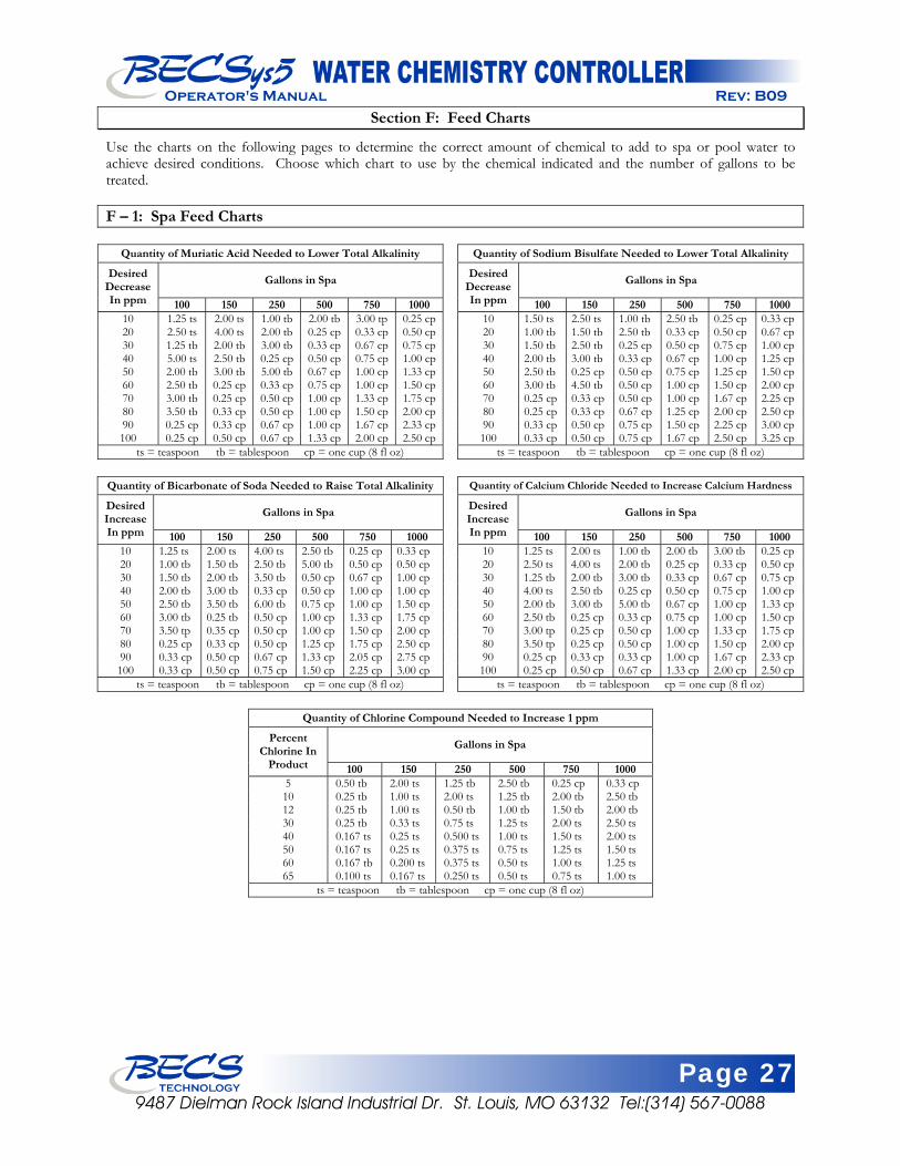
Page 27 9487 Dielman Rock Island Industrial Dr. St. Louis, MO 63132 Tel:(314) 567-0088
Operator's Manual Rev: B09
Section F: Feed Charts
Use the charts on the following pages to determine the correct amount of chemical to add to spa or pool water to achieve desired conditions. Choose which chart to use by the chemical indicated and the number of gallons to be treated. F – 1: Spa Feed Charts
Quantity of Muriatic Acid Needed to Lower Total Alkalinity
Gallons in Spa Desired Decrease In ppm 100 150 250 500 750 1000
10 1.25 ts 2.00 ts 1.00 tb 2.00 tb 3.00 tp 0.25 cp20 2.50 ts 4.00 ts 2.00 tb 0.25 cp 0.33 cp 0.50 cp30 1.25 tb 2.00 tb 3.00 tb 0.33 cp 0.67 cp 0.75 cp40 5.00 ts 2.50 tb 0.25 cp 0.50 cp 0.75 cp 1.00 cp50 2.00 tb 3.00 tb 5.00 tb 0.67 cp 1.00 cp 1.33 cp60 2.50 tb 0.25 cp 0.33 cp 0.75 cp 1.00 cp 1.50 cp70 3.00 tb 0.25 cp 0.50 cp 1.00 cp 1.33 cp 1.75 cp80 3.50 tb 0.33 cp 0.50 cp 1.00 cp 1.50 cp 2.00 cp90 0.25 cp 0.33 cp 0.67 cp 1.00 cp 1.67 cp 2.33 cp100 0.25 cp 0.50 cp 0.67 cp 1.33 cp 2.00 cp 2.50 cp
ts = teaspoon tb = tablespoon cp = one cup (8 fl oz)
Quantity of Sodium Bisulfate Needed to Lower Total Alkalinity
Gallons in Spa Desired Decrease In ppm 100 150 250 500 750 1000
10 1.50 ts 2.50 ts 1.00 tb 2.50 tb 0.25 cp 0.33 cp 20 1.00 tb 1.50 tb 2.50 tb 0.33 cp 0.50 cp 0.67 cp 30 1.50 tb 2.50 tb 0.25 cp 0.50 cp 0.75 cp 1.00 cp 40 2.00 tb 3.00 tb 0.33 cp 0.67 cp 1.00 cp 1.25 cp 50 2.50 tb 0.25 cp 0.50 cp 0.75 cp 1.25 cp 1.50 cp 60 3.00 tb 4.50 tb 0.50 cp 1.00 cp 1.50 cp 2.00 cp 70 0.25 cp 0.33 cp 0.50 cp 1.00 cp 1.67 cp 2.25 cp 80 0.25 cp 0.33 cp 0.67 cp 1.25 cp 2.00 cp 2.50 cp 90 0.33 cp 0.50 cp 0.75 cp 1.50 cp 2.25 cp 3.00 cp 100 0.33 cp 0.50 cp 0.75 cp 1.67 cp 2.50 cp 3.25 cp
ts = teaspoon tb = tablespoon cp = one cup (8 fl oz)
Quantity of Bicarbonate of Soda Needed to Raise Total Alkalinity
Gallons in Spa Desired Increase In ppm 100 150 250 500 750 1000
10 1.25 ts 2.00 ts 4.00 ts 2.50 tb 0.25 cp 0.33 cp 20 1.00 tb 1.50 tb 2.50 tb 5.00 tb 0.50 cp 0.50 cp 30 1.50 tb 2.00 tb 3.50 tb 0.50 cp 0.67 cp 1.00 cp 40 2.00 tb 3.00 tb 0.33 cp 0.50 cp 1.00 cp 1.00 cp 50 2.50 tb 3.50 tb 6.00 tb 0.75 cp 1.00 cp 1.50 cp 60 3.00 tb 0.25 tb 0.50 cp 1.00 cp 1.33 cp 1.75 cp 70 3.50 tp 0.35 cp 0.50 cp 1.00 cp 1.50 cp 2.00 cp 80 0.25 cp 0.33 cp 0.50 cp 1.25 cp 1.75 cp 2.50 cp 90 0.33 cp 0.50 cp 0.67 cp 1.33 cp 2.05 cp 2.75 cp 100 0.33 cp 0.50 cp 0.75 cp 1.50 cp 2.25 cp 3.00 cp
ts = teaspoon tb = tablespoon cp = one cup (8 fl oz)
Quantity of Calcium Chloride Needed to Increase Calcium Hardness
Gallons in Spa Desired Increase In ppm 100 150 250 500 750 1000
10 1.25 ts 2.00 ts 1.00 tb 2.00 tb 3.00 tb 0.25 cp 20 2.50 ts 4.00 ts 2.00 tb 0.25 cp 0.33 cp 0.50 cp 30 1.25 tb 2.00 tb 3.00 tb 0.33 cp 0.67 cp 0.75 cp 40 4.00 ts 2.50 tb 0.25 cp 0.50 cp 0.75 cp 1.00 cp 50 2.00 tb 3.00 tb 5.00 tb 0.67 cp 1.00 cp 1.33 cp 60 2.50 tb 0.25 cp 0.33 cp 0.75 cp 1.00 cp 1.50 cp 70 3.00 tp 0.25 cp 0.50 cp 1.00 cp 1.33 cp 1.75 cp 80 3.50 tp 0.25 cp 0.50 cp 1.00 cp 1.50 cp 2.00 cp 90 0.25 cp 0.33 cp 0.33 cp 1.00 cp 1.67 cp 2.33 cp 100 0.25 cp 0.50 cp 0.67 cp 1.33 cp 2.00 cp 2.50 cp
ts = teaspoon tb = tablespoon cp = one cup (8 fl oz)
Quantity of Chlorine Compound Needed to Increase 1 ppm
Gallons in Spa Percent Chlorine In
Product 100 150 250 500 750 1000 5 0.50 tb 2.00 ts 1.25 tb 2.50 tb 0.25 cp 0.33 cp 10 0.25 tb 1.00 ts 2.00 ts 1.25 tb 2.00 tb 2.50 tb 12 0.25 tb 1.00 ts 0.50 tb 1.00 tb 1.50 tb 2.00 tb 30 0.25 tb 0.33 ts 0.75 ts 1.25 ts 2.00 ts 2.50 ts 40 0.167 ts 0.25 ts 0.500 ts 1.00 ts 1.50 ts 2.00 ts 50 0.167 ts 0.25 ts 0.375 ts 0.75 ts 1.25 ts 1.50 ts 60 0.167 tb 0.200 ts 0.375 ts 0.50 ts 1.00 ts 1.25 ts 65 0.100 ts 0.167 ts 0.250 ts 0.50 ts 0.75 ts 1.00 ts
ts = teaspoon tb = tablespoon cp = one cup (8 fl oz)

Page 28 9487 Dielman Rock Island Industrial Dr. St. Louis, MO 63132 Tel:(314) 567-0088
Operator's Manual Rev: B09
F – 2: Pool Feed Charts
Quantity of Muriatic Acid Needed to Lower Total Alkalinity Gallons in Pool Desired Decrease
In ppm 10,000 25,000 50,000 75,000 100,000 200,000 500,000 750,000 1,000,000 10 1.30 pt 1.62 qt 3.25 qt 1.22 gl 1.62 gl 3.25 gl 8.13 gl 12.20 gl 16.25 gl 20 1.30 pt 3.25 qt 1.62 gl 2.43 gl 3.25 gl 7.50 gl 16.20 gl 24.30 gl 32.50 gl 30 1.95 qt 1.22 gl 2.44 gl 3.86 gl 4.98 gl 9.76 gl 24.40 gl 36.60 gl 48.80 gl 40 2.80 qt 1.63 gl 3.25 gl 4.87 gl 6.50 gl 13.00 gl 32.50 gl 48.80 gl 65.00 gl 50 3.25 qt 2.03 gl 4.07 gl 6.10 gl 8.14 gl 16.28 gl 40.70 gl 61.00 gl 81.40 gl 60 3.90 qt 2.44 gl 4.88 gl 7.32 gl 9.76 gl 19.52 gl 48.80 gl 73.20 gl 97.80 gl 70 1.14 gl 2.84 gl 5.69 gl 8.54 gl 11.38 gl 22.76 gl 56.90 gl 85.45 gl 113.80 gl 80 1.30 gl 3.25 gl 6.50 gl 9.75 gl 13.00 gl 26.00 gl 65.00 gl 97.50 gl 138.00 gl 90 1.48 gl 3.66 gl 7.31 gl 10.96 gl 14.82 gl 29.24 gl 73.10 gl 109.60 gl 146.20 gl 100 1.63 gl 4.06 gl 8.12 gl 12.18 gl 16.24 gl 32.48 gl 81.20 gl 121.80 gl 162.40 gl 120 1.96 gl 4.88 gl 9.76 gl 14.64 gl 19.52 gl 39.00 gl 97.80 gl 148.40 gl 196.20 gl 150 2.44 gl 6.09 gl 12.18 gl 18.27 gl 24.40 gl 48.80 gl 121.80 gl 182.70 gl 244.00 gl 200 3.25 gl 8.12 gl 18.24 gl 24.36 gl 32.50 gl 65.00 gl 162.40 gl 243.80 gl 325.00 gl
pt = one pt (16 fl oz) qt = one quart (32 fl oz) gl = one gallon (128 fl oz)
Quantity of Bicarbonate of Soda Needed to Raise Total Alkalinity Gallons in Pool Desired Increase
In ppm 10,000 25,000 50,000 75,000 100,000 200,000 500,000 750,000 1,000,000 10 1.50 lb 3.75 lb 7.50 lb 11.25 lb 15.00 lb 30.00 lb 75.00 lb 112.50 lb 150.00 lb 20 3.00 lb 7.50 lb 15.00 lb 22.50 lb 30.00 lb 60.00 lb 150.00 lb 225.00 lb 300.00 lb 30 4.50 lb 11.25 lb 22.50 lb 33.75 lb 45.00 lb 90.00 lb 225.00 lb 337.50 lb 450.00 lb 40 6.00 lb 15.00 lb 30.00 lb 45.00 lb 60.00 lb 120.00 lb 300.00 lb 450.00 lb 600.00 lb 50 7.50 lb 18.75 lb 37.50 lb 56.25 lb 75.00 lb 150.00 lb 375.00 lb 562.50 lb 750.00 lb 60 9.00 lb 22.50 lb 45.00 lb 67.50 lb 90.00 lb 180.00 lb 450.00 lb 675.00 lb 900.00 lb 70 10.50 lb 26.25 lb 52.50 lb 78.75 lb 105.00 lb 210.00 lb 525.00 lb 787.50 lb 1050.00 lb 80 12.00 lb 30.00 lb 60.00 lb 90.00 lb 120.00 lb 240.00 lb 600.00 lb 900.00 lb 1200.00 lb 90 13.50 lb 33.75 lb 67.50 lb 101.25 lb 135.00 lb 270.00 lb 675.00 lb 1012.50 lb 1350.00 lb 100 15.00 lb 37.50 lb 75.00 lb 112.50 lb 150.00 lb 300.00 lb 750.00 lb 1125.00 lb 1500.00 lb
lb =pounds of dry chemical
Quantity of Calcium Chloride Needed to Increase Calcium Hardness Gallons in Pool
10,000 25,000 50,000 75,000 100,000 200,000 500,000 750,000 1,000,000 Desired Increase In ppm lb oz lb oz lb oz lb oz lb oz lb lb oz lb oz lb
10 1 4 3 2 6 4 9 6 12 8 25 62 8 93 12 125 20 2 8 6 4 12 8 18 12 25 0 50 125 0 197 8 250 30 3 12 9 6 18 12 28 2 37 8 75 187 8 281 4 375 40 5 0 12 8 25 0 37 8 50 0 100 250 0 375 0 500 50 6 4 15 10 31 4 46 14 62 8 125 312 8 468 12 625 60 7 8 18 12 37 8 56 4 75 0 150 375 0 562 8 750 70 8 12 21 14 43 12 65 10 87 8 175 437 8 658 4 875 80 10 0 25 0 50 0 75 0 100 0 200 500 0 750 0 1,000 90 11 4 28 2 56 4 84 6 112 8 225 562 8 843 12 1,125 100 12 8 31 4 62 8 93 12 125 0 250 625 0 937 8 1,250 150 18 12 46 14 93 12 104 10 187 8 375 937 8 1,406 4 1,875 200 25 0 62 8 125 0 187 8 250 0 500 1,250 0 1,875 0 2,500
Quantity of Chlorine Compound Needed to Increase 1 ppm
Gallons in Pool Percent Chlorine In Product 10,000 25,000 50,000 75,000 100,000 200,000 500,000 750,000 1,000,000
5 3.2 cp 2 qt 1 gl 1.5 gl 2 gl 4 gl 10 gl 15 gl 20 gl 10 1.6 cp 1 qt 2 qt 3 qt 1 gl 2 gl 5 gl 7.5 gl 10 gl 12 1.33 cp 1.67 pt 1.517 qt 2.276 pt 3.33 qt 1.665 gl 4.163 gl 6.245 gl 8.326 gl 30 0.278 lb 0.665 lb 1.390 lb 2.085 lb 2.780 lb 5.580 lb 13.900 lb 20.850 lb 27.800 lb 40 0.209 lb 0.521 lb 1.043 lb 1.565 lb 2.086 lb 4.172lb 10.430 lb 15.645 lb 20.860 lb 50 0.167 lb 0.417 lb 0.834 lb 1.251 lb 1.668 lb 3.336lb 8.340lb 12.511 lb 16.680 lb 60 0.139 lb 0.348 lb 0.695 lb 1.043 lb 1.390 lb 2.780lb 6.950 lb 10.425 lb 13.900 lb 65 0.128 lb 0.321 lb 0.642 lb 0.963 lb 1.284 lb 2.568lb 6.420 lb 9.630lb 12.840 lb 70 0.119 lb 0.298 lb 0.596 lb 0.894 lb 1.192 lb 2.384lb 5.960lb 8.940 lb 11.920 lb 75 0.111 lb 0.278 lb 0.556 lb 0.834 lb 1.112 lb 2.224 lb 5.560 lb 8.340 lb 11.120 lb 80 0.104 lb 0.261 lb 0.521 lb 0.782 lb 1.042 lb 2.064 lb 5.210 lb 7.815 lb 10.420 lb 85 0.096 lb 0.417 lb 0.491 lb 0.737 lb 0.982 lb 1.964 lb 4.910 lb 7.365 lb 9.829 lb 90 0.093 lb 0.232 lb 0.463 lb 0.695 lb 0.926 lb 1.852 lb 4.630 lb 6.945 lb 9.260 lb 100 0.083 lb 0.209 lb 0.417 lb 0.626 lb 0.634 lb 1..668 lb 4.170 lb 6.225lb 8.340 lb
cp = one cup (8 fl oz) pt = one pt (16 fl oz) qt = one quart (32 fl oz) gl = one gallon (128 fl oz) lb =pounds of dry chemical
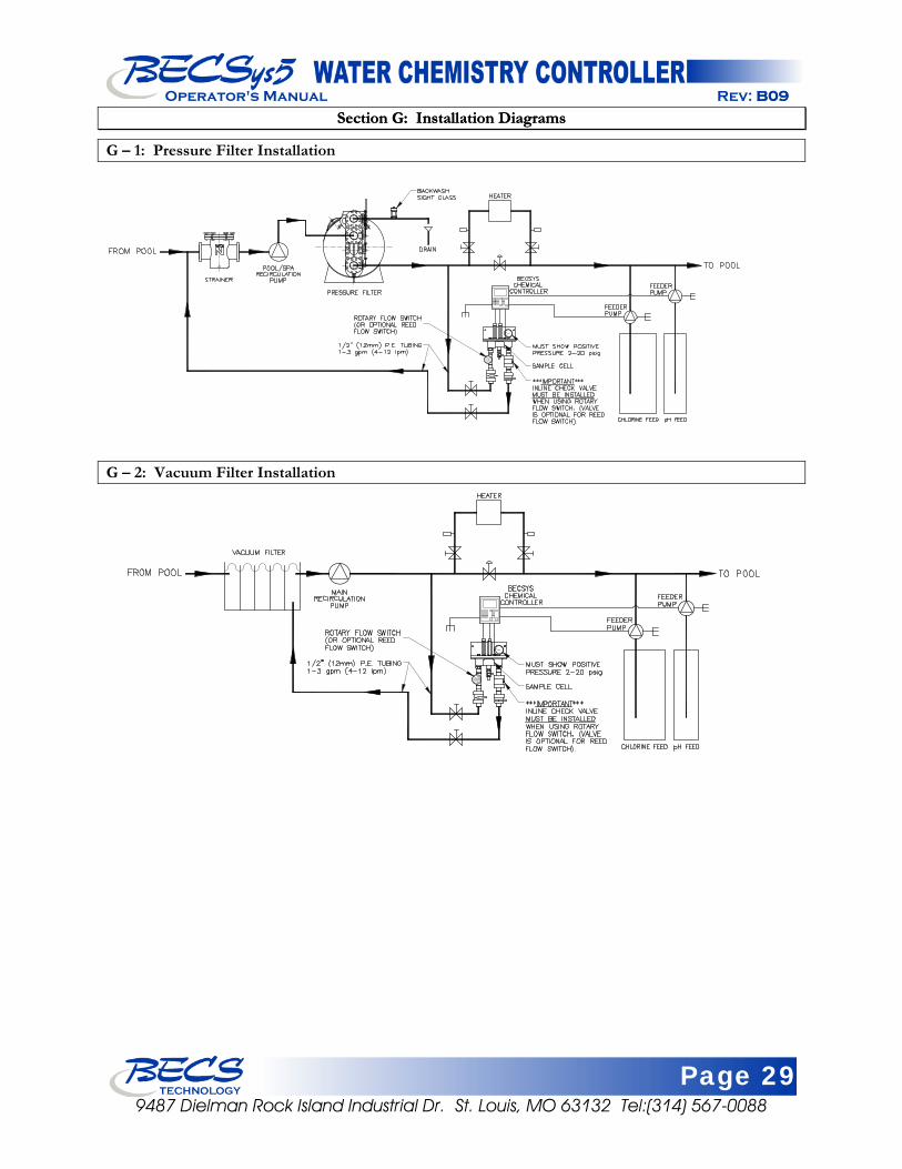
Page 29 9487 Dielman Rock Island Industrial Dr. St. Louis, MO 63132 Tel:(314) 567-0088
Operator's Manual Rev: B09B09
Section G: Installation Diagrams Section G: Installation Diagrams
G – 1: Pressure Filter Installation
G – 2: Vacuum Filter Installation
Page 30 9487 Dielman Rock Island Industrial Dr. St. Louis, MO 63132 Tel:(314) 567-0088
Operator's Manual Rev: B09
Section H: Warranty
LIMITED WARRANTY BECS warrants the controller electronics and flow cell against any defect in workmanship or materials for a period of five years from the date of shipment. BECS warrants the pH and ORP sensors against any defect in workmanship or materials for a period of two years from the date of shipment. In the event of a component failure due to any defect in workmanship or materials, BECS will repair, or if repair is not possible, replace the defective part or parts of the BECSys controller. BECS will have the sole right to determine whether to repair or replace a product. BECS will not be responsible for any expense associated with installation of repaired or replacement parts. LIMITATIONS AND EXCLUSIONS This is a LIMITED WARRANTY. BECS makes NO WARRANTIES other than those contained herein. The LIMITED WARRANTY replaces and is in lieu of any WARRANTIES of MERCHANTABILITY or of FITNESS FOR A PARTICULAR PURPOSE which are expressly DISCLAIMED. All GENERAL, SPECIAL, INDIRECT, INCIDENTAL AND/OR CONSEQUENTIAL DAMAGES ARE EXCLUDED AND DISCLAIMED. This Limited Warranty is governed by Missouri Law and all disputes related to or arising from this transaction or Limited Warranty shall be resolved in Circuit Court of St. Louis County, Missouri. Any claims under this Limited Warranty must be brought within ONE YEAR after the cause of action accrued.

Document Part Number: 8620007-B09
February 2009 9487 Dielman Rock Island Industrial Dr. St. Louis, MO 63132 Tel:(314) 567-0088
Operator's Manual Rev: B09B09
has been designing and manufacturing the industry’s
most reliable water chemistry controller for over 15 years. Our 24,000 ft2 facility in Saint Louis, Missouri is home to an exceptional design team, and all manufacturing is performed onsite at this facility where we can personally assure the quality of our products. The BECS commitment to excellence drives the most innovative new products and unparalleled customer service.
has been designing and manufacturing the industry’s most reliable water chemistry controller for over 15 years. Our 24,000 ft2 facility in Saint Louis, Missouri is home to an exceptional design team, and all manufacturing is performed onsite at this facility where we can personally assure the quality of our products. The BECS commitment to excellence drives the most innovative new products and unparalleled customer service.
BECSTECHNOLOGY Inc.