Embed Size (px)
Citation preview
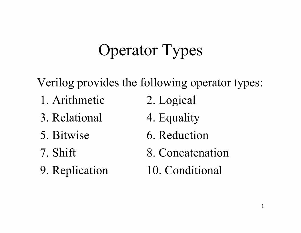
Operator Types
Verilog provides the following operator types:1 Arithmetic 2 Logical1. Arithmetic 2. Logical3. Relational 4. Equality5 Bi i 6 R d i5. Bitwise 6. Reduction7. Shift 8. Concatenation9. Replication 10. Conditional
1
Verilog Symbols
• Verilog only uses standard ASCII symbols.• No operators or anything else use specialNo operators or anything else use special
symbols not found on a standard keyboard.• Easy to enter Verilog code but• Easy to enter Verilog code, but
– Leads to dual use of symbolsA i diff i f ili– Assigns different meaning to some familiar symbols
2
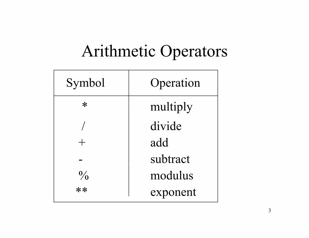
Arithmetic Operators
Symbol Operation
* lti l* multiply/ divide
+ add- subtract% modulus** exponent
3
exponent
Multiplication
• Hardware multiplication algorithms have improved, making using the multiply operator practical.
• Synthesizers will select a suitable hardware l i li ( difi d h lik l )multiplier (modified Booth Array, most likely)
from a “synthetic library” of scalable components.Th PROD M lti li * M lti li d i• Thus PROD <= Multiplier * Multiplicand is now an acceptable coding style. “Beating the machine” is tough
4
is tough.
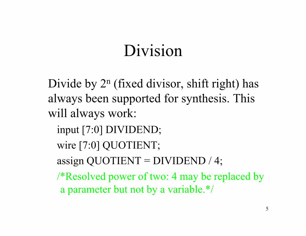
Division
Divide by 2n (fixed divisor, shift right) has always been supported for synthesis. This y pp ywill always work:
input [7:0] DIVIDEND;input [7:0] DIVIDEND;wire [7:0] QUOTIENT;assign QUOTIENT = DIVIDEND / 4;assign QUOTIENT DIVIDEND / 4;/*Resolved power of two: 4 may be replaced by a parameter but not by a variable.*/
5
a parameter but not by a variable. /
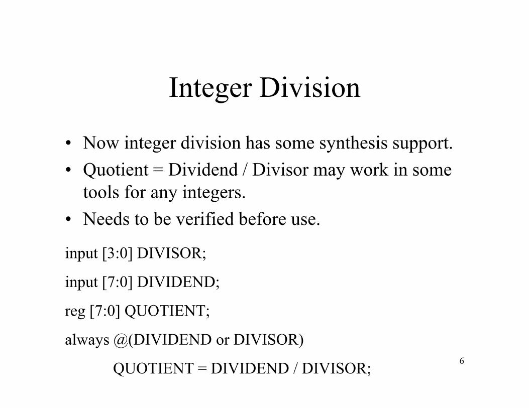
Integer Division
• Now integer division has some synthesis support.• Quotient = Dividend / Divisor may work in some Q y
tools for any integers.• Needs to be verified before use.
input [3:0] DIVISOR;
input [7:0] DIVIDEND;input [7:0] DIVIDEND;
reg [7:0] QUOTIENT;
6
always @(DIVIDEND or DIVISOR)
QUOTIENT = DIVIDEND / DIVISOR;

More on Division
• At best, integer division will work for both 2’s compliment and unsigned numbers.
• At worst, using a variable for divisor will produce a compile error: entirely tool dependent.
• Integer and real division can be freely used in test fixtures and when using Verilog as a general-purpose programming language.
7
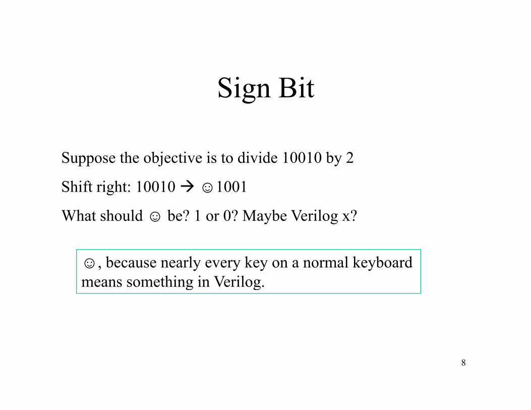
Sign Bit
Suppose the objective is to divide 10010 by 2
Shift right: 10010 ☺1001
What should ☺ be? 1 or 0? Maybe Verilog x?
☺, because nearly every key on a normal keyboardmeans something in Verilogmeans something in Verilog.
8

Assume 2’s Compliment
100102 = -14
Shift right one time: 01001 or 11001?Shift right one time: 01001 or 11001?
010012 = 9
11001 = 7110012 = -7
Division must extend sign bit.
This behavior always needs to be verified before depending on it in a circuit.
9
Signed Variables
• Verilog 2001 introduced signed variables and operators.p
• No need to manually extend sign bits when using themusing them.
• More on signed variables shortly.D d i d ll d• Do need to write code to manually extend sign bit when using normal variables.
10
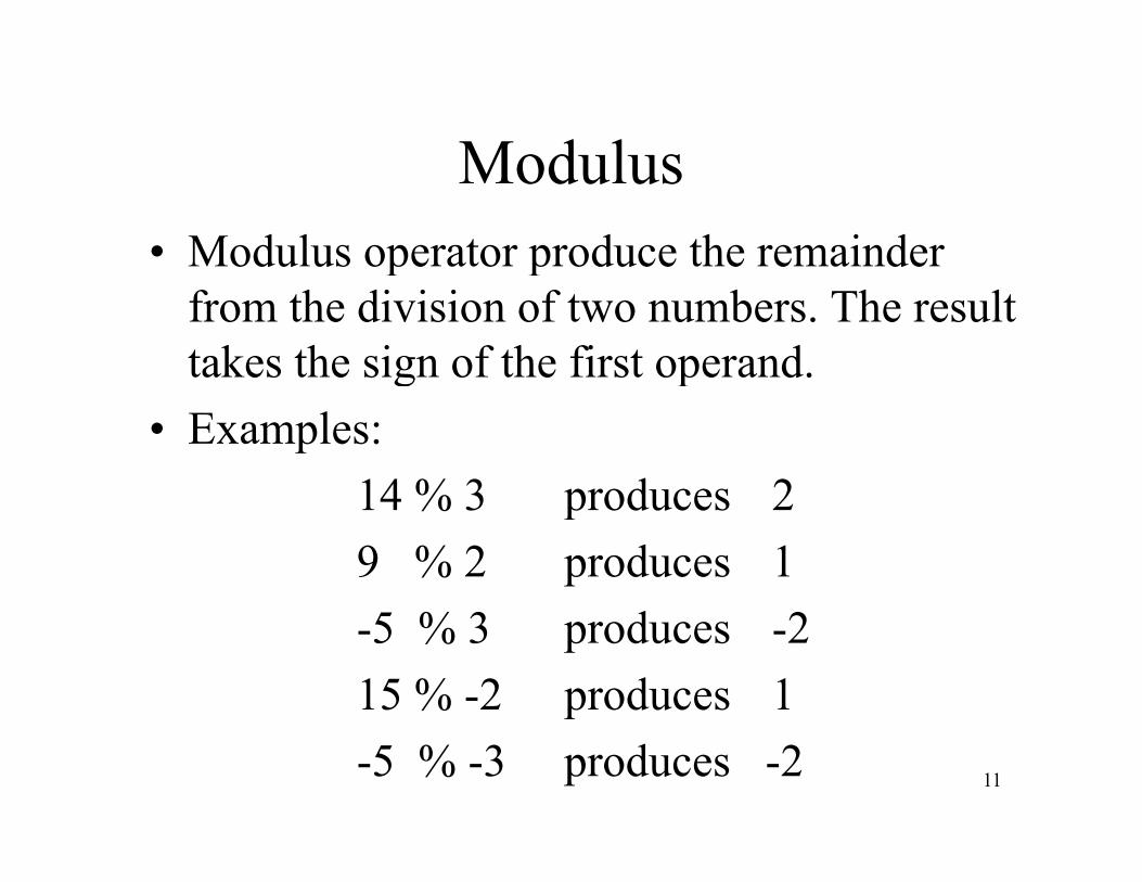
ModulusModulus• Modulus operator produce the remainder p p
from the division of two numbers. The result takes the sign of the first operand.g p
• Examples:14 % 3 produces 214 % 3 produces 29 % 2 produces 1-5 % 3 produces -215 % -2 produces 1
11-5 % -3 produces -2
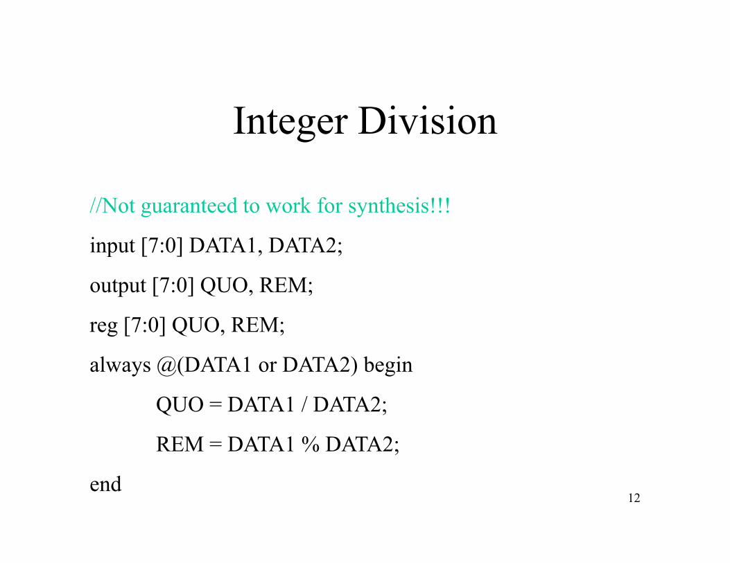
Integer Division
//Not guaranteed to work for synthesis!!!
input [7:0] DATA1 DATA2;input [7:0] DATA1, DATA2;
output [7:0] QUO, REM;
[ 0] Q Oreg [7:0] QUO, REM;
always @(DATA1 or DATA2) begin
QUO = DATA1 / DATA2;
REM = DATA1 % DATA2;
12end
Floating Point
• Sorry, no such luck.• Need to code up implement mantissaNeed to code up implement mantissa,
exponent algorithms manually.• Maybe someday• Maybe someday.
13
Addition
• Can be used freely on regs and wires.• C <= A + B works fineC < A + B works fine.• A suitable adder style will be chosen from
the universe of adder styles Synthesizerthe universe of adder styles. Synthesizer will look at design constraints and make a selectionselection.
• Generally two’s compliment is assumed.
14
Subtraction
No tricks here, just like addition.always @(A or B) C = A – B;always @(A or B) C A B;
15
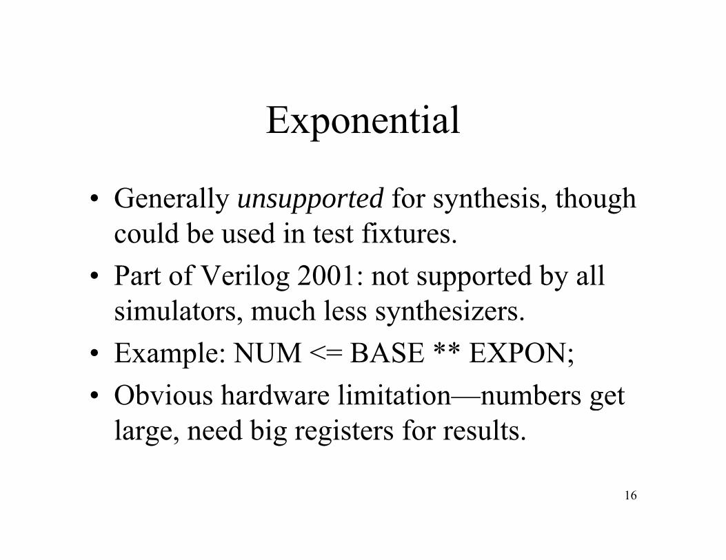
Exponential
• Generally unsupported for synthesis, though could be used in test fixtures.
• Part of Verilog 2001: not supported by all simulators much less synthesizerssimulators, much less synthesizers.
• Example: NUM <= BASE ** EXPON;Ob i h d li i i b• Obvious hardware limitation—numbers get large, need big registers for results.
16
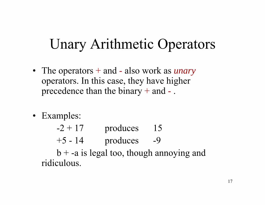
Unary Arithmetic Operators
• The operators + and - also work as unaryoperators. In this case, they have higher precedence than the binary + andprecedence than the binary + and - .
• Examples:• Examples:-2 + 17 produces 15+5 - 14 produces -9+5 - 14 produces -9b + -a is legal too, though annoying and
ridiculous.
17
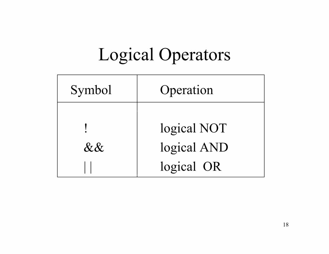
Logical Operators
Symbol Operation
! logical NOT&& l i l AND&& logical AND| | logical OR
18
Logical Operators
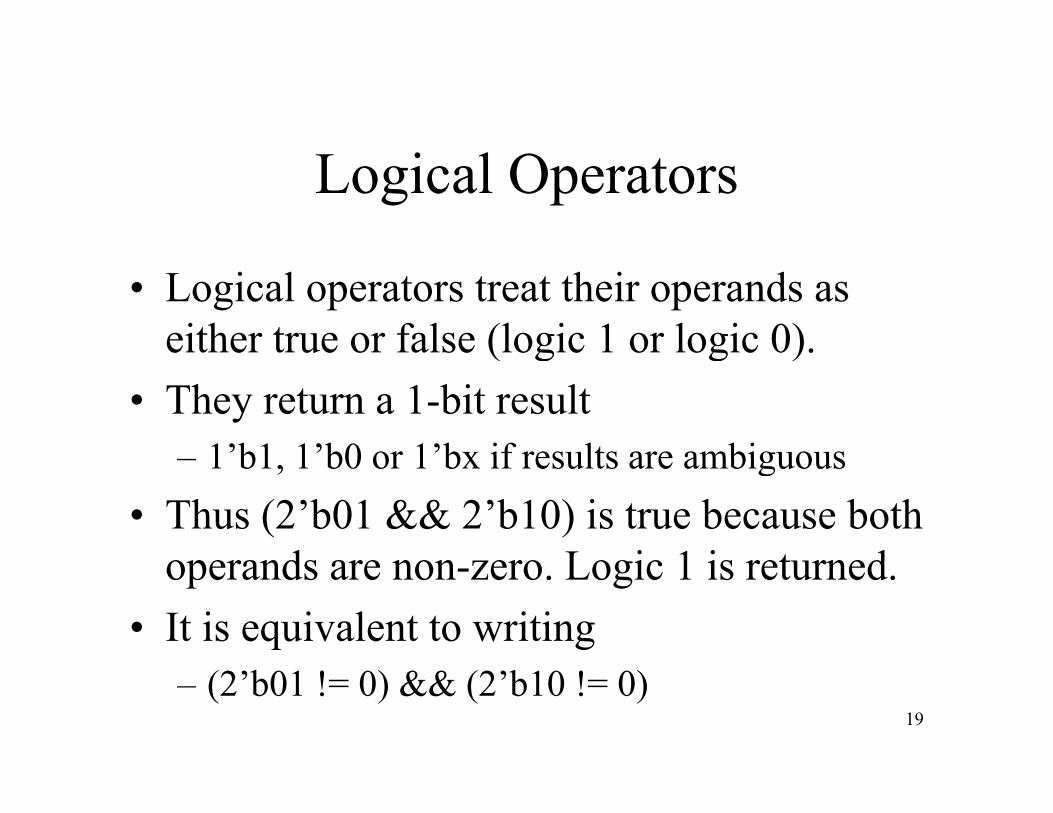
• Logical operators treat their operands as either true or false (logic 1 or logic 0).( g g )
• They return a 1-bit result1’b1 1’b0 or 1’bx if results are ambiguous– 1 b1, 1 b0 or 1 bx if results are ambiguous
• Thus (2’b01 && 2’b10) is true because both operands are non zero Logic 1 is returnedoperands are non-zero. Logic 1 is returned.
• It is equivalent to writing– (2’b01 != 0) && (2’b10 != 0)
19
Logical OperatorsLogical Operators
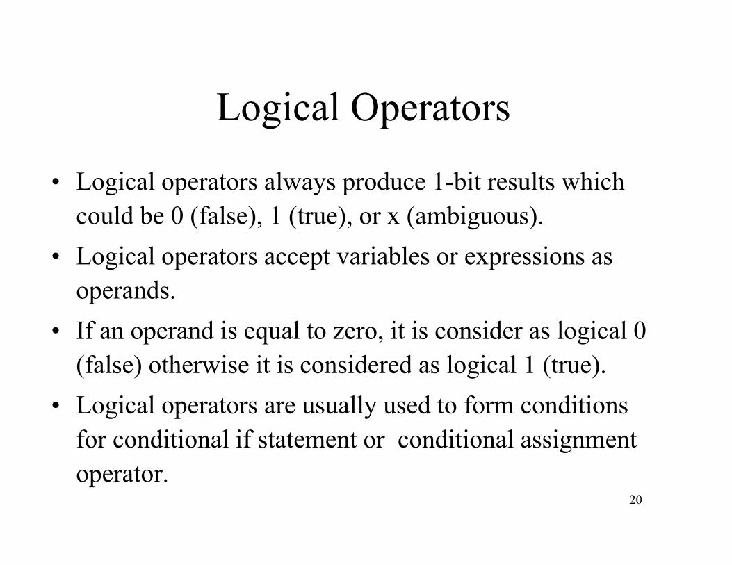
L i l t l d 1 bit lt hi h• Logical operators always produce 1-bit results which could be 0 (false), 1 (true), or x (ambiguous).
i l i bl i• Logical operators accept variables or expressions as operands.
• If an operand is equal to zero, it is consider as logical 0 (false) otherwise it is considered as logical 1 (true).
• Logical operators are usually used to form conditions for conditional if statement or conditional assignment
20
operator.

Logical Operand
• The operands used in a logical operation evaluate as zeros if and only if each bit is yzero.
• Otherwise it is a oneOtherwise it is a one.• Thus a logic AND of two operands will
result in a logic 1 result if both operandsresult in a logic 1 result if both operands have at least one bit set.
21
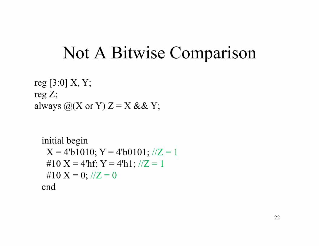
Not A Bitwise Comparisonreg [3:0] X, Y;reg Z;always @(X or Y) Z = X && Y;always @(X or Y) Z X && Y;
i iti l b iinitial beginX = 4'b1010; Y = 4'b0101; //Z = 1#10 X = 4'hf; Y = 4'h1; //Z = 1#10 X = 0; //Z = 0
end
22
Logical operatorsExamples:
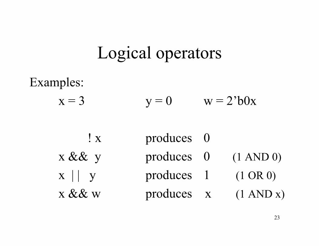
x = 3 y = 0 w = 2’b0xy
! x produces 0! x produces 0x && y produces 0 (1 AND 0)
x | | y produces 1 (1 OR 0)
x && w produces x (1 AND x)
23
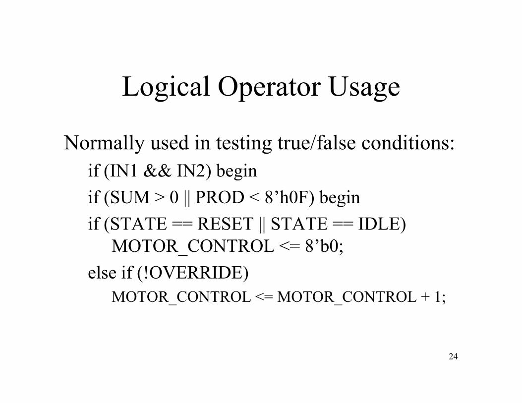
Logical Operator Usage
Normally used in testing true/false conditions:if (IN1 && IN2) beginif (IN1 && IN2) beginif (SUM > 0 || PROD < 8’h0F) beginif (STATE == RESET || STATE == IDLE)if (STATE RESET || STATE IDLE)
MOTOR_CONTROL <= 8’b0;else if (!OVERRIDE)else if (!OVERRIDE)
MOTOR_CONTROL <= MOTOR_CONTROL + 1;
24

Bit ise OperatorsBitwise Operators
Symbol Operation
~ bitwise negation& bitwise AND& bit i NAND~& bitwise NAND
| bitwise OR~| bitwise NOR~| bitwise NOR^ bitwise XOR
~^ or ^~ bitwise XNOR25
or bitwise XNOR

Bitwise Operators• Bitwise operators take each bit in one operand
and perform the operation with corresponding bit in the other operand.
• If one operand is shorter, it will be extended with zeros to match the length of the longer operand.
• In bitwise operation, a z is treated as an x.
26
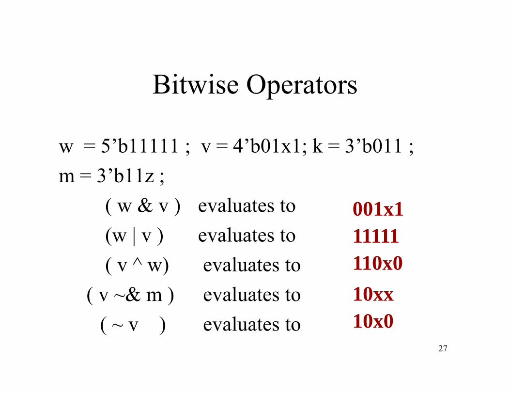
Bitwise Operators
w = 5’b11111 ; v = 4’b01x1; k = 3’b011 ; 3’b11m = 3’b11z ;( w & v ) evaluates to 001x1(w | v ) evaluates to( v ^ w) evaluates to
11111110x0( )
( v ~& m ) evaluates to( ) e al ates to
10xx10x0
27
( ~ v ) evaluates to 10x0

Bit i O tBitwise Operators
The Logical Equations :
Will b d i V il b
X = A B + A BY = A + B
Will be represented in Verilog by:
assign X = ~A&B | A &~ B;assign X = ~A&B | A &~ B;assign Y = A ^ B;
28
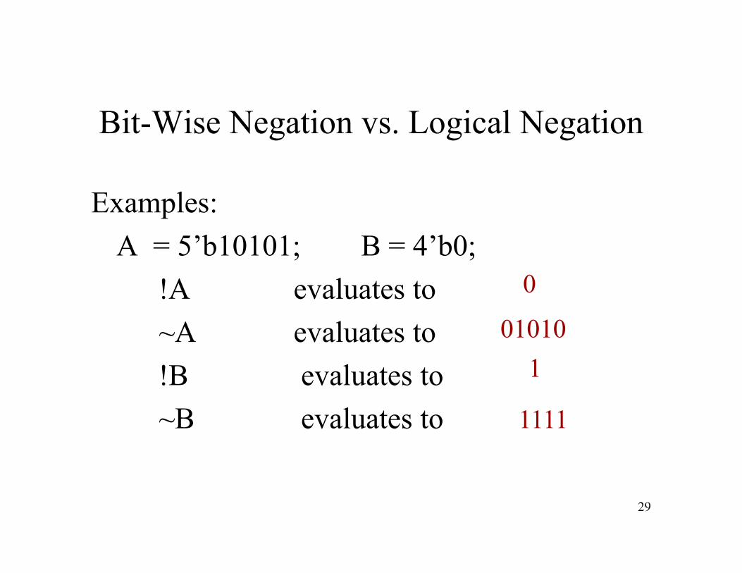
Bit-Wise Negation vs. Logical Negation
Examples:A = 5’b10101; B = 4’b0;A 5 b10101; B 4 b0;
!A evaluates to A l 01010
0
~A evaluates to!B evaluates to
010101
~B evaluates to 1111
29

Bitwise vs. Logical Operators
• Both perform standard Boolean operations.– AND, OR, etc.AND, OR, etc.
• Logical Operators are used for comparisons and generate a true/false conditionand generate a true/false condition.
• Bitwise operators can give multi-bit answers to Boolean operationsanswers to Boolean operations.
30
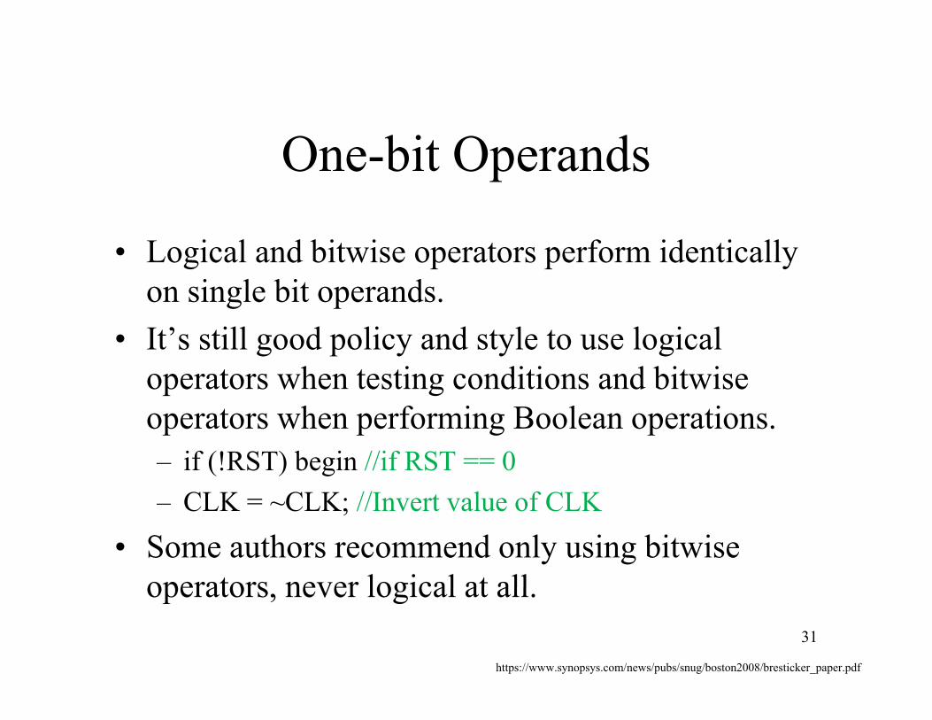
One-bit Operands
• Logical and bitwise operators perform identically on single bit operands.
• It’s still good policy and style to use logical operators when testing conditions and bitwise
h f i l ioperators when performing Boolean operations.– if (!RST) begin //if RST == 0
CLK CLK //I t l f CLK– CLK = ~CLK; //Invert value of CLK
• Some authors recommend only using bitwise operators never logical at alloperators, never logical at all.
31
https://www.synopsys.com/news/pubs/snug/boston2008/bresticker_paper.pdf
Reduction Operators
• Yet another form of Boolean operators, this one, like Logical Operators, only producing , g p , y p ga single bit output.
• Same symbols different applicationSame symbols, different application.• Reduction operators only operate on a
single operandsingle operand.
32
Reduction OperatorsReduction Operators
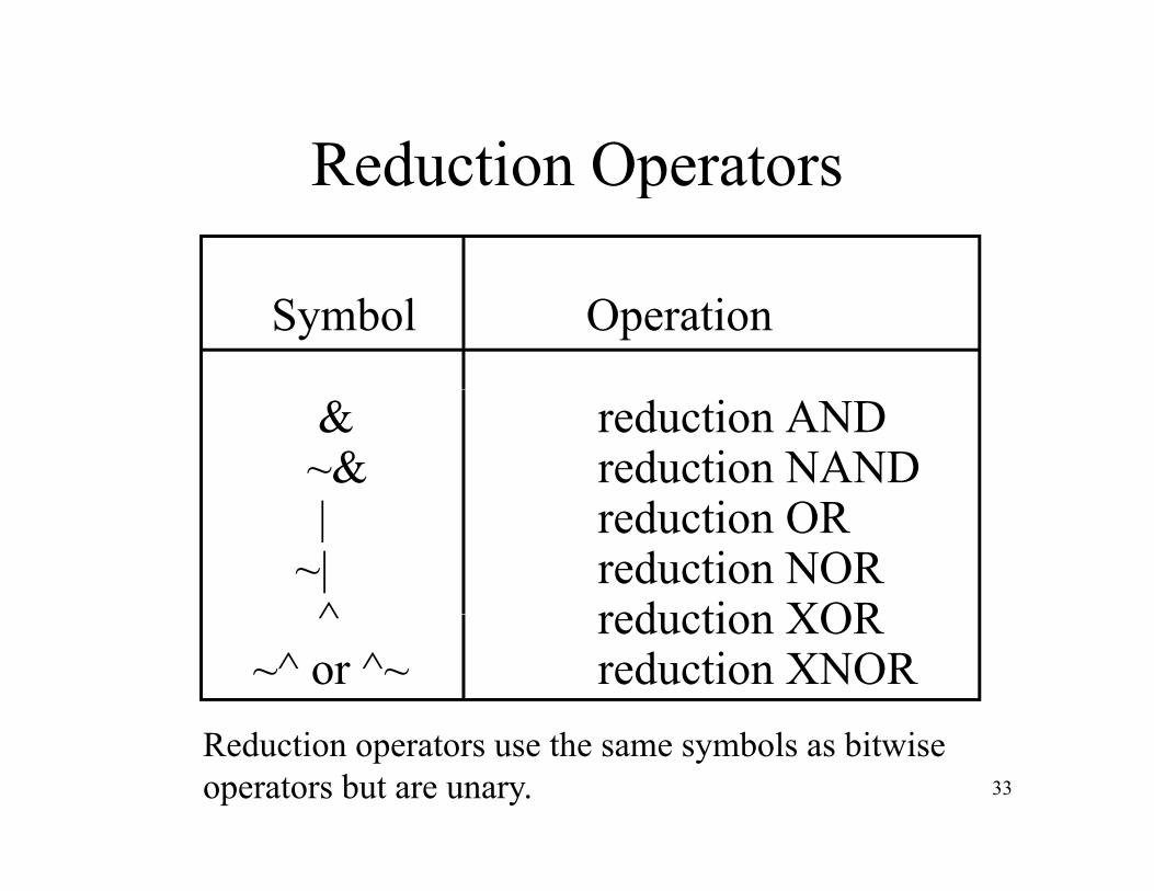
Symbol Operation
& reduction AND~& reduction NAND| d i OR| reduction OR
~| reduction NOR^ reduction XOR^ reduction XOR
~^ or ^~ reduction XNOR
33
Reduction operators use the same symbols as bitwise operators but are unary.

AND Reduction
reg [5:0] AND_BUS;
wire AND RED;wire AND_RED;
assign AND_RED = &AND_BUS;
AND_RED_
34
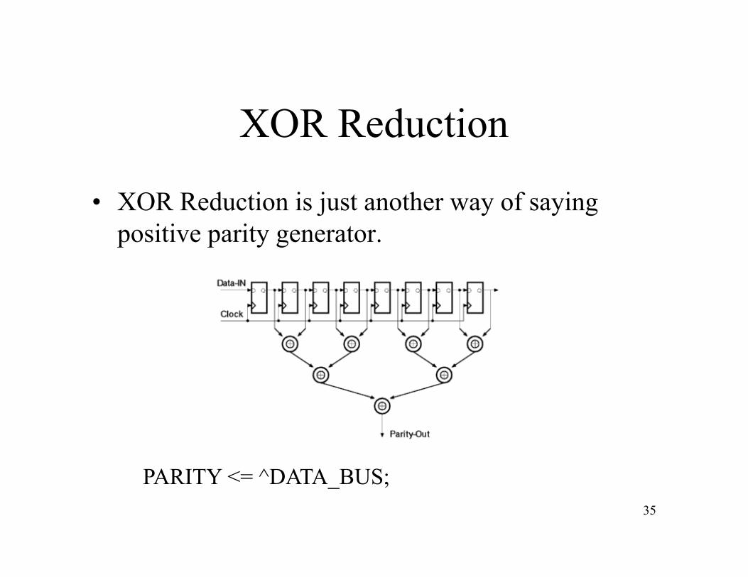
XOR Reduction
• XOR Reduction is just another way of saying positive parity generator.
PARITY ^DATA BUS35
PARITY <= ^DATA_BUS;
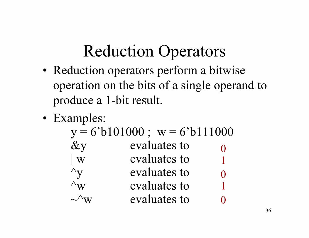
Reduction Operators• Reduction operators perform a bitwiseReduction operators perform a bitwise
operation on the bits of a single operand to produce a 1-bit result.p oduce a b t esu t.
• Examples:y = 6’b101000 ; w = 6’b111000y 6 b101000 ; w 6 b111000&y evaluates to | w evaluates to
01|
^y evaluates to ^w evaluates to
01
36
~^w evaluates to 0
Homework 2
• Is due now.
37
Exam 1
• Midterm exam 1 will be held on Tuesday, October 6.
• Bring a blue book.• There will be little to nothing to calculate• There will be little to nothing to calculate.
However, you may bring a simple calculatorcalculator.
• No other electronic devices are permitted.
38

Exam 1
• No electronic devices– This explicitly includes telephones, even if usedThis explicitly includes telephones, even if used
only as a watch or calculator.• Homework/review will be held next time.Homework/review will be held next time.• Bring questions.
Th ill b l b d L b t• There will be no lab exam day. Lab reports will be due the following week.
39

Relational Operators
Symbol Operation
> greater thanl h< less than
>= greater than or equal<= less than or equal
40
Relational Operators
• Relational operators are used in comparison expressions. p
• If the relation is true, it evaluates to logical
1 and if it is false it evaluates to logical 0.
• If any of the operands contains x or z the• If any of the operands contains x or z, the
relation evaluates to x.
41

Relational Operators
Examples:if x = 4 ; y = 8 ; w = 3’b11z ; v = 2’b0xif x 4 ; y 8 ; w 3 b11z ; v 2 b0x
lx < y evaluates to y <= x evaluates to
Logical 1Logical 0
x > v evaluates toy >= w evaluates to x
x
42
y > w evaluates to x
Resolving Unknown Bits
• Relational operators do not resolve if either operand contains an unknown bit.p
• This is inconsistent with the way equality operators workoperators work.
• Thus 1000 > 000x will return unknown, even if the answer appears obviouseven if the answer appears obvious.
• Just have to live with it.
43
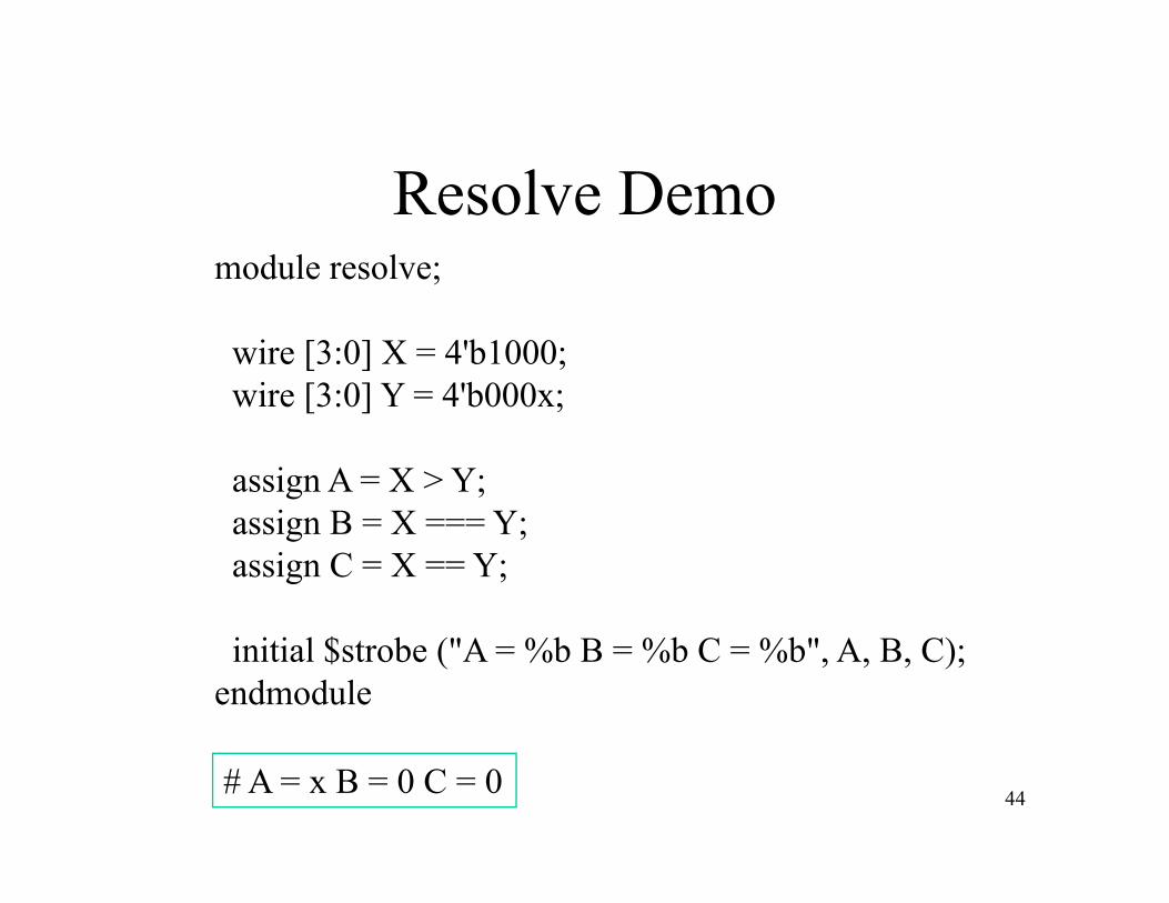
Resolve Demomodule resolve;;
wire [3:0] X = 4'b1000;wire [3:0] Y = 4'b000x;wire [3:0] Y = 4 b000x;
assign A = X > Y;assign B = X === Y;assign C = X == Y;
initial $strobe ("A = %b B = %b C = %b", A, B, C);endmodule
44# A = x B = 0 C = 0
Less Than or Equal/Non-BlockingLess Than or Equal/Non Blocking Assignment
• <= means less than or equal relationship op.• <= is the non-blocking assignment operator.• They are exactly the same symbolThey are exactly the same symbol.• The compiler will sort it out.
45

Using ConditionalsConditionals are used for testingConditionals are used for testing.
Example:
if (ENABLE && STATE < MAX STATE) // diti lif (ENABLE && STATE <= MAX_STATE) //conditional
RUN <= `TRUE; //assignment operator
else if (ENABLE)
RUN <= `FALSE;
else
RUN <= RUN;
46
;
//VHDL designers note lack of ‘null’ keyword.

Shift OperatorsSymbol OperationSymbol Operation
>> right shiftg<< left shift
Examples:Examples:w = 6’b111111;
>> 1 ill t t 011111v = w >> 1 will set v to 011111v = w << 1 will set v to 111110v = w << 3 will set v to 111000
47
v = w << 3 will set v to 111000
Shift Operators
• Note that shifts do not wrap around or sign extend.
• Shifted bits just wind up in the bit bucket.• Wrap or sign extend options must be added• Wrap or sign extend options must be added
manually.Fill i h f h i h f h• Fills with zeros, from the right or from the left.
48
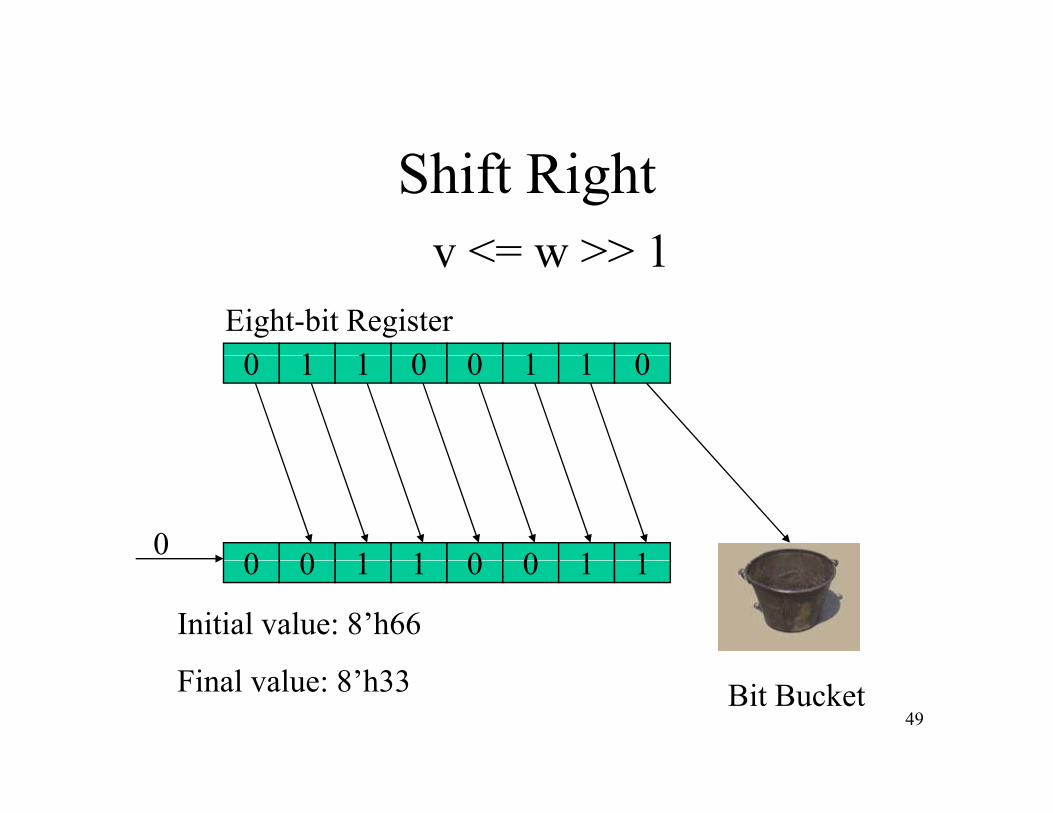
Shift Rightv <= w >> 1
0 1 1 0 0 1 1 0Eight-bit Register
v <= w >> 1
0 1 1 0 0 1 1 0
0 0 1 1 0 0 1 10 0 0 1 1 0 0 1 1
Initial value: 8’h66
49Bit BucketFinal value: 8’h33
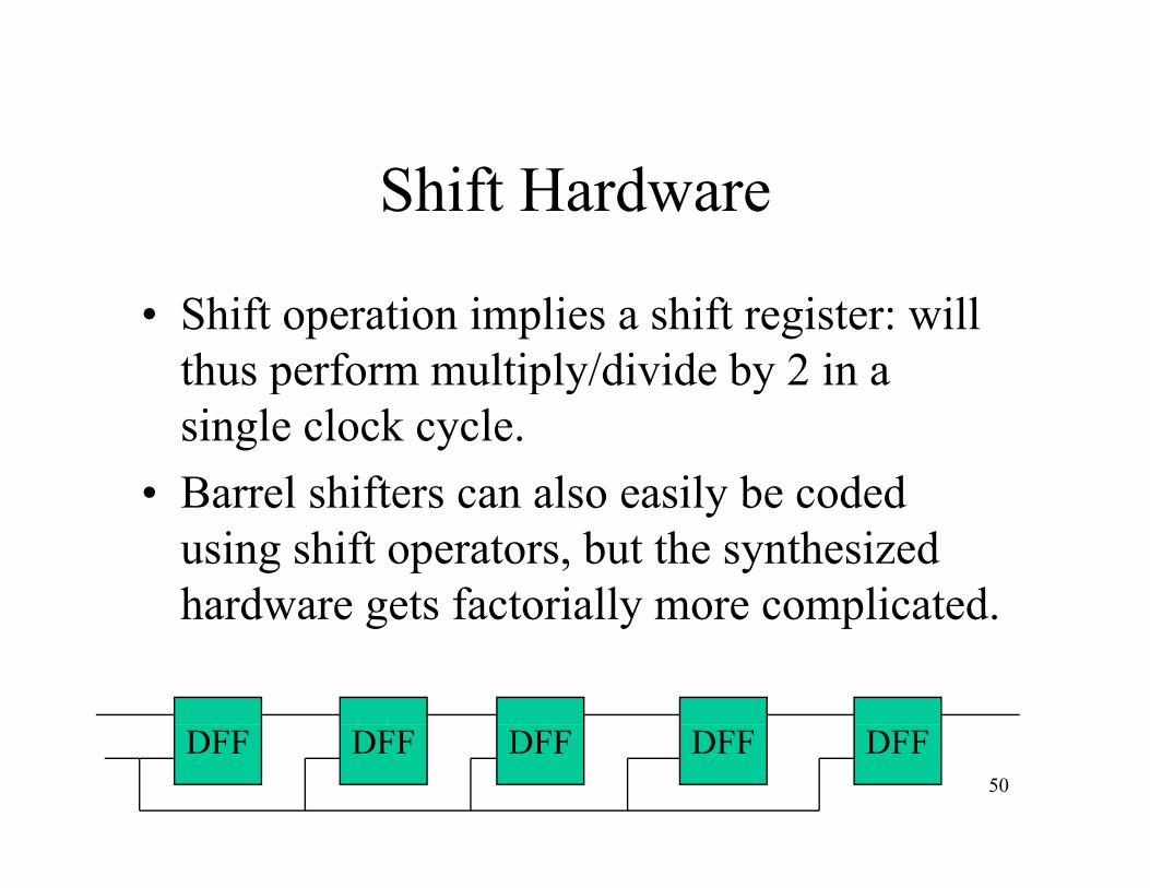
Shift Hardware
• Shift operation implies a shift register: will thus perform multiply/divide by 2 in a p p y ysingle clock cycle.
• Barrel shifters can also easily be codedBarrel shifters can also easily be coded using shift operators, but the synthesized hardware gets factorially more complicatedhardware gets factorially more complicated.
50
DFF DFF DFFDFF DFF

Arithmetic Shift Operators
Verilog 2001 adds Arithmetic Shift Operators:
A ith ti Shift Ri ht >>>Arithmetic Shift Right: >>>
Arithmetic Shift Left: <<<
Arithmetic Shift preserves sign bit. It works with signed operators, which were also introduced with Verilog 2001.
51
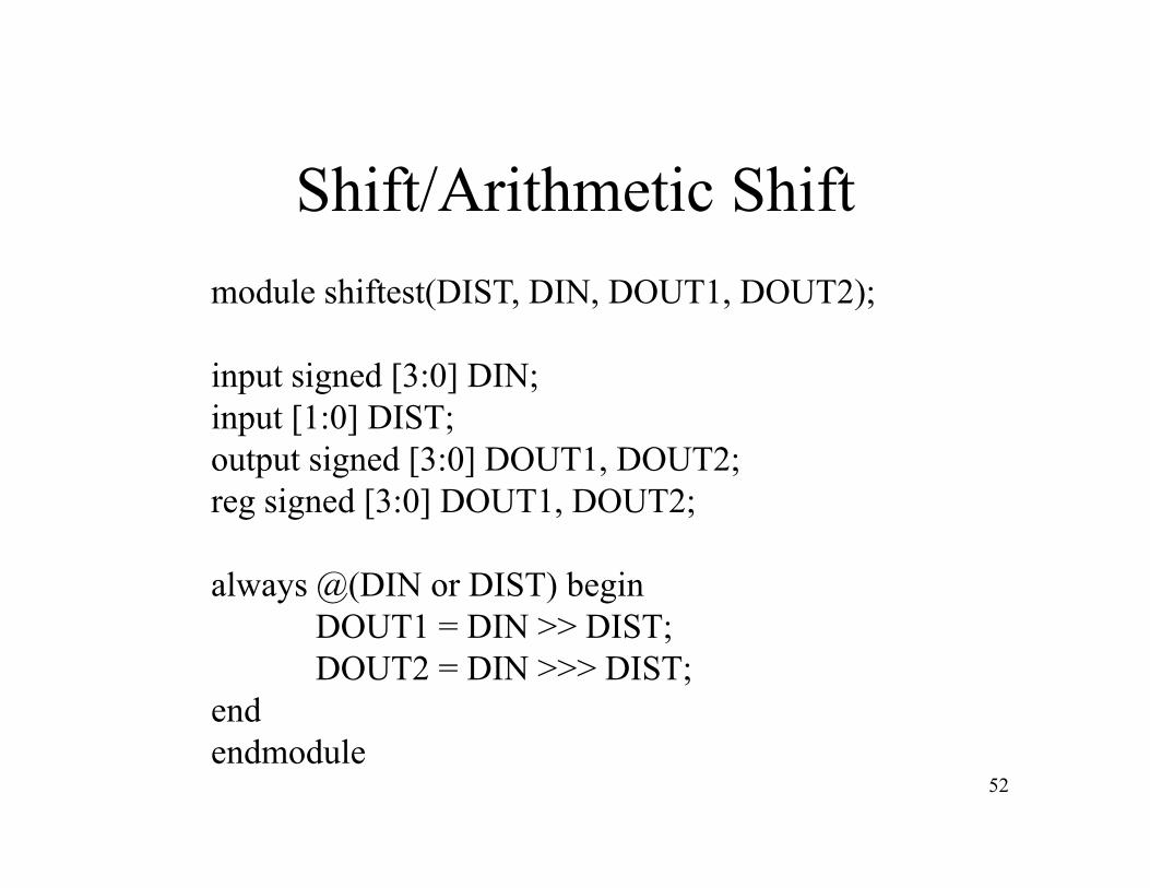
Shift/Arithmetic Shiftmodule shiftest(DIST, DIN, DOUT1, DOUT2);
input signed [3:0] DIN;p g [ ] ;input [1:0] DIST;output signed [3:0] DOUT1, DOUT2;reg signed [3:0] DOUT1 DOUT2;reg signed [3:0] DOUT1, DOUT2;
always @(DIN or DIST) beginDOUT1 = DIN >> DIST;DOUT2 = DIN >>> DIST;
end
52endmodule

Signed VariablesSigned Variables
I h di l i d• In the preceding example, inputs and outputs are signed integers.If h h hif• If they were not, the two shift operators would produce identical results: there would be no sign bit to extendbe no sign bit to extend.
• Since they are declared to be signed data, sign bits are preservedsign bits are preserved.
• Works with new version of simulator and synthesizer
53
synthesizer.

`timescale 1 ns / 1 nsmodule shiftdemo;parameter WIDTH = 8;reg signed [WIDTH - 1 : 0] A, B, C, D, E;
always @(E) beginA = E <<< 3;B = E << 3;B = E << 3;C = E >>> 3;D = E >> 3;
endend
initial beginE = 8'ha5;;#0 $strobe("%d A = %h B = %h C = %h D = %h", $time, A, B, C, D);#1 E = 8'h5a;$strobe("%d A = %h B = %h C = %h D = %h", $time, A, B, C, D);
54
endendmodule
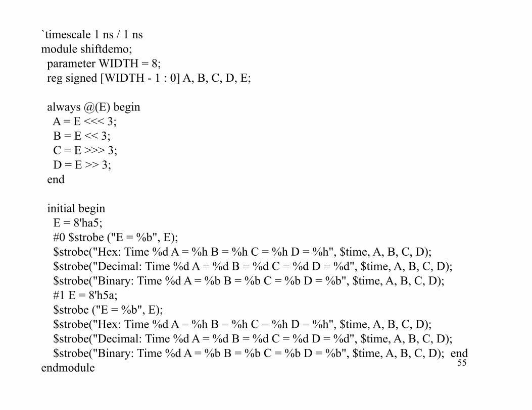
`timescale 1 ns / 1 nsmodule shiftdemo;parameter WIDTH = 8;
i d [WIDTH 1 0] A B C D Ereg signed [WIDTH - 1 : 0] A, B, C, D, E;
always @(E) beginA = E <<< 3;B = E << 3;C = E >>> 3;D = E >> 3;
endend
initial beginE = 8'ha5;#0 $strobe ("E = %b", E);$strobe("Hex: Time %d A = %h B = %h C = %h D = %h", $time, A, B, C, D);$strobe("Decimal: Time %d A = %d B = %d C = %d D = %d", $time, A, B, C, D);$strobe("Binary: Time %d A = %b B = %b C = %b D = %b" $time A B C D);$strobe( Binary: Time %d A %b B %b C %b D %b , $time, A, B, C, D);#1 E = 8'h5a;$strobe ("E = %b", E);$strobe("Hex: Time %d A = %h B = %h C = %h D = %h", $time, A, B, C, D);$ b (" i l i %d A %d %d C %d %d" $ i A C )
55
$strobe("Decimal: Time %d A = %d B = %d C = %d D = %d", $time, A, B, C, D);$strobe("Binary: Time %d A = %b B = %b C = %b D = %b", $time, A, B, C, D); end
endmodule
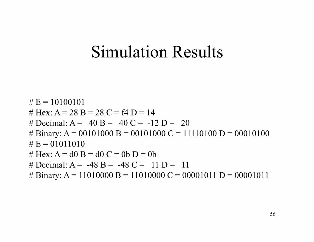
Simulation Results
# E = 10100101# Hex: A = 28 B = 28 C = f4 D = 14# Decimal: A = 40 B = 40 C = -12 D = 20# Binary: A = 00101000 B = 00101000 C = 11110100 D = 00010100y# E = 01011010# Hex: A = d0 B = d0 C = 0b D = 0b# Decimal: A = -48 B = -48 C = 11 D = 11# Decimal: A 48 B 48 C 11 D 11# Binary: A = 11010000 B = 11010000 C = 00001011 D = 00001011
56

Conclusions
• Shift left: signed and unsigned work the same.
• Shift right: unsigned fills with zeros, signed extends sign bitextends sign bit.
• Negative numbers (- sign) only show up when decimal numbers are usedwhen decimal numbers are used.
• That’s just for display.
57
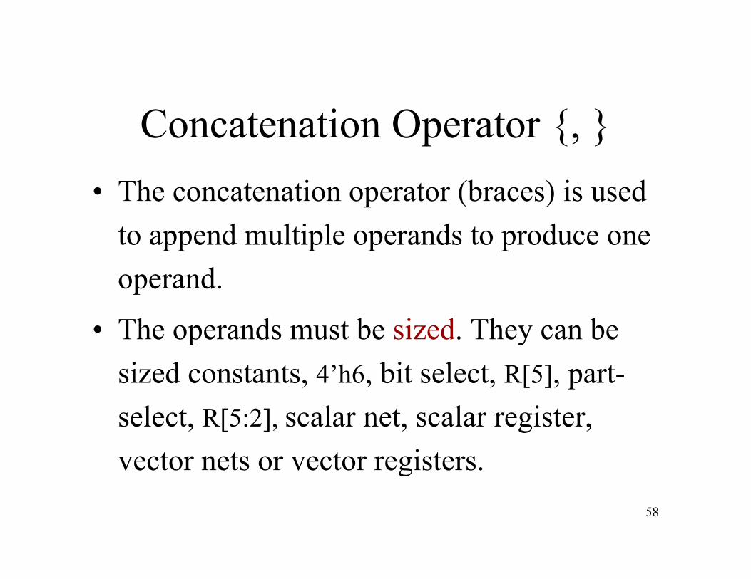
Concatenation Operator {, }h i (b ) i d• The concatenation operator (braces) is used
to append multiple operands to produce one operand.
• The operands must be sized They can be• The operands must be sized. They can be sized constants, 4’h6, bit select, R[5], part-select, R[5:2], scalar net, scalar register, vector nets or vector registers.
58
g

Concatenation Operator {, }
• reg [4:0] A; reg [2:0] B; reg [3:0] C; • Examples:Examples:• A= 5’b10110 ; B=3’b000 ; C=4’b0101
• Y= {A , B} will set Y to 8’b10110000
• Y= {A , B[2:1],C[0]} will set Y to• Y= {A[4] B[2] 3’O6} will set Y to 5’b10110
8’b10110001
59
Y {A[4] , B[2], 3 O6} will set Y to 5 b10110

Replication Operators {#{},}To repeat a concatenation a number of times, weTo repeat a concatenation a number of times, we precede each bracket by a replication number.
E lExample:reg L, M; reg [2:0]K ; reg [3:0] N;L=1’d1; M=1’b0; K= 3’b010; N= 4’hA ;
Y= { 2{L}, 2{M}, K, N} Y=11’b11000101010
Y 9’b00011010160
Y= { 3{M}, L, K[1:0], N[3:1]} Y=9’b000110101
Replicate 0 Times
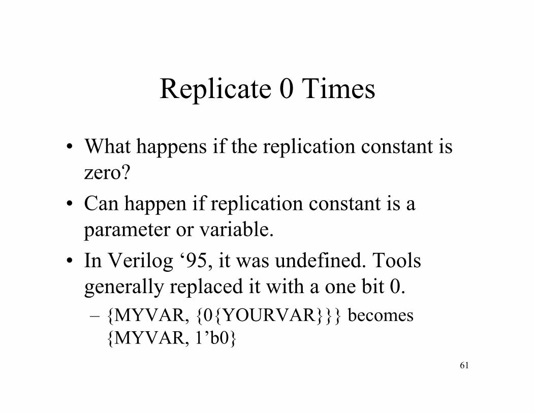
• What happens if the replication constant is zero?
• Can happen if replication constant is a parameter or variableparameter or variable.
• In Verilog ‘95, it was undefined. Tools generally replaced it with a one bit 0generally replaced it with a one bit 0.– {MYVAR, {0{YOURVAR}}} becomes
{MYVAR 1’b0}{MYVAR, 1 b0}61
Replicate 0 Times, 2001
• Correct operation would be to have replicated operand disappear.p p pp
• Verilog 2001 does something different: it just declares a 0 replication constant to bejust declares a 0 replication constant to be illegal, a syntax error.
• Verilog 2005 specification (not yet• Verilog 2005 specification (not yet available in tools) says it should disappear.
62
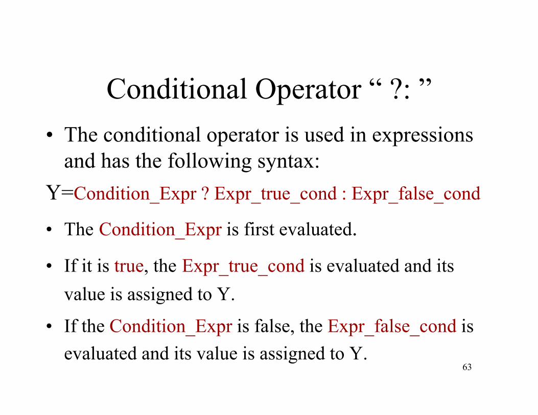
Conditional Operator “ ?: ”Th diti l t i d i i• The conditional operator is used in expressions and has the following syntax:
Y=Condition_Expr ? Expr_true_cond : Expr_false_cond
• The Condition Expr is first evaluated.The Condition_Expr is first evaluated.
• If it is true, the Expr_true_cond is evaluated and its value is assigned to Y.
• If the Condition_Expr is false, the Expr_false_cond is
63evaluated and its value is assigned to Y.

Conditional Operator “ ?: ”
If the value of Condition_Expr is undetermined (x), then both Expr_true_cond and Expr false cond are evaluated and their valuesExpr_false_cond are evaluated and their values are compared bit by bit. This will return the value
f th t di bit if th thof the two corresponding bits if they are the same and x if they different. The final result will then
64be assigned to Y.

Conditional Operator “ ?: ”In0
2-to-1MUX
In0
In1out
sel
• assign out = sel ? In1 : In0 ;
• assign data_bus = drive_enable ? ALU_out : 16’bz ;
65
16 bz ;

Conditional Operator “ ?: ”In0
4-to-1MUX
In0In1 outIn2In3
sel0
In3
sel1
assign out = sel1 ? (sel0 ? In3:In2) : (sel0 ? In1:In0);
sel0sel1
For 8-to1 MUX:assign out = sel2 ? (sel1 ? (sel0 ? In7:In6) : (sel0 ? In5:In4)):
66(sel1 ? (sel0 ? In3:In2) : (sel0 ? In1:In0)) ;
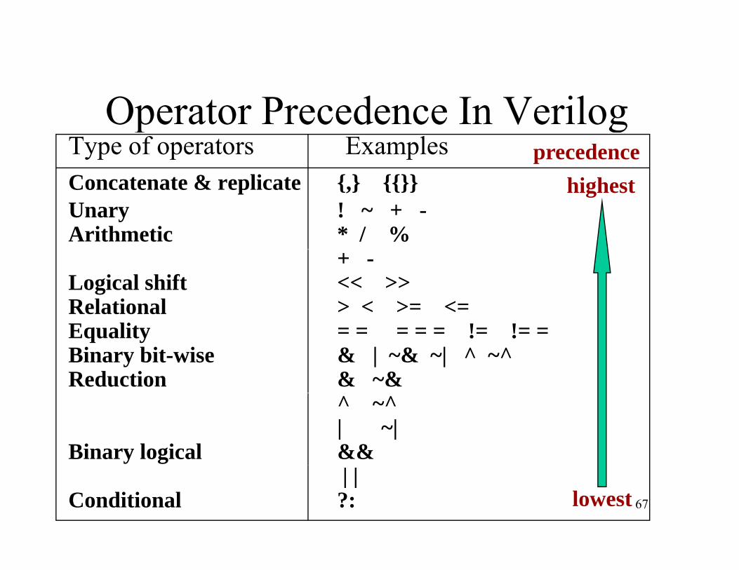
Operator Precedence In VerilogOperator Precedence In VerilogType of operators ExamplesC t t & li t { } {{}}
precedenceConcatenate & replicate {,} {{}}Unary ! ~ + -Arithmetic * / %
highest
+ -Logical shift << >>Relational > < >= <=Equality = = = = = != != =Binary bit-wise & | ~& ~| ^ ~^Reduction & ~&
^ ~^| ~|
Binary logical &&
67
| | Conditional ?: lowest

O t P d I V ilOperator Precedence In VerilogExample:Example:
A= 6’b110110; w = 6’b111111;
v = ^ A & w >> 3;shiftbit-wise AND
// v = ^ 110110 & 111111 >> 3; //// v = ^ 110110 & 000111; //
Reduction XOR
Final result// v = ^ 000110; //// v = 0; //
68
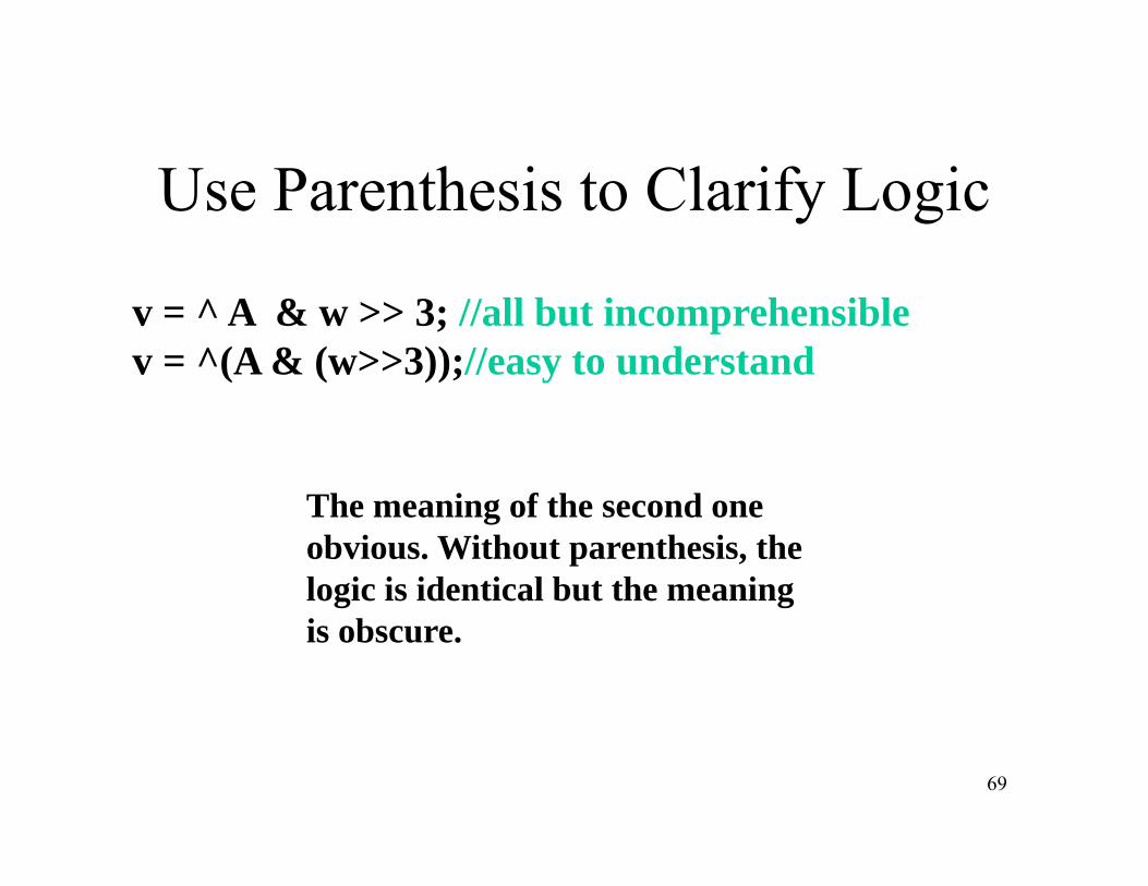
Use Parenthesis to Clarify Logic
v = ^ A & w >> 3; //all but incomprehensiblev = ^(A & (w>>3));//easy to understand
Th i f th dThe meaning of the second one obvious. Without parenthesis, the logic is identical but the meaning is obscure.
69
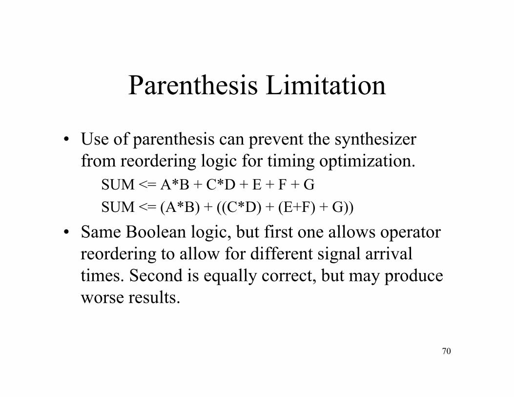
Parenthesis Limitation
• Use of parenthesis can prevent the synthesizer from reordering logic for timing optimization.
SUM <= A*B + C*D + E + F + GSUM <= (A*B) + ((C*D) + (E+F) + G))
• Same Boolean logic, but first one allows operator reordering to allow for different signal arrival times Second is equally correct but may producetimes. Second is equally correct, but may produce worse results.
70


![Propositions as [Types] - Andrej Bauermath.andrej.com/data/bracket_types.pdf · Propositions as [Types] ... so they model a natural modal operator in dependent type theory. ... used](https://img.dokumen.tips/doc/110x75/5b827b707f8b9aad638ea03f/propositions-as-types-andrej-propositions-as-types-so-they-model-a.jpg)