Embed Size (px)
Citation preview

International Journal of Automation and Computing 10(5), October 2013, 387-396
DOI: 10.1007/s11633-013-0735-8
Bearing-only Visual SLAM for Small Unmanned Aerial
Vehicles in GPS-denied Environments
Chao-Lei Wang Tian-Miao Wang Jian-Hong Liang Yi-Cheng Zhang Yi ZhouRobotics Institute, Beijing University of Aeronautics and Astronautics, Beijing 100191, China
Abstract: This paper presents a hierarchical simultaneous localization and mapping (SLAM) system for a small unmanned aerialvehicle (UAV) using the output of an inertial measurement unit (IMU) and the bearing-only observations from an onboard monocularcamera. A homography based approach is used to calculate the motion of the vehicle in 6 degrees of freedom by image feature match.
This visual measurement is fused with the inertial outputs by an indirect extended Kalman filter (EKF) for attitude and velocityestimation. Then, another EKF is employed to estimate the position of the vehicle and the locations of the features in the map. Bothsimulations and experiments are carried out to test the performance of the proposed system. The result of the comparison with thereferential global positioning system/inertial navigation system (GPS/INS) navigation indicates that the proposed SLAM can provide
reliable and stable state estimation for small UAVs in GPS-denied environments.
Keywords: Visual simultaneous localization and mapping (SLAM), bearing-only observation, inertial measurement unit, small un-
manned aerial vehicles (UAVs), GPS-denied environment.
1 Introduction
The navigation system for small unmanned aerial vehi-cles (UAVs) is typically composed of low-cost inertial sen-sors and a global positioning system (GPS) receiver due tothe limited onboard computational capability and payloadcapacity[1]. The GPS can bound the accumulated error ofthe inertial sensors by estimating the absolute velocity andposition of the vehicle. However, in many aerial applica-tions, the UAV is required to perform a task within theGPS-defined environment, such as indoors, urban canyons.GPS is also easy to be disturbed by the weather during theflight. For the autonomy of small UAVs in GPS-denied en-vironments, other sensors are required to be fused with theinertial measurement unit (IMU) for determination of thevehicle state without any priori information of the flight en-vironment. This is known as the simultaneous localizationand mapping (SLAM) system, with which the vehicle canbuild an online map and estimate its location in 6 degreesof freedom in that map.
Vision seems a good alternative to the GPS for the au-tonomous navigation of small UAVs in terms of weight, costand information. Visual sensors have been used in surveil-lance tasks of UAVs for years[2]. They have also playedan important role in autonomous navigation and control ofsmall UAVs[3]. Performing the SLAM with the visual mea-surement has received a lot of attention over the past fewyears[4, 5]. A visual 3-D SLAM was developed for UAVsin partially structured environments[6]. In this algorithm,the vehicle is modeled as a rigid body with uniform mo-tion and the acceleration is considered as the system noise.Another proposed visual SLAM system takes only naturallandmarks as observations[7]. In this system, a homography
Manuscript received March 4, 2013; revised July 4, 2013This work was supported by National High Technology Re-
search and Development Program of China (863 Program)(No. 2011AA040202) and National Science Foundation of China(No. 51005008).
based approach is used to estimate the motion of the UAVand a novel landmark initialization method is developed.
The fusion of IMU and visual sensors is usually used inautonomous robots[8−10]. In these implementations, the in-ertial measurement is usually used as the input of the pro-cess model in the filter. A robust inertial SLAM algorithmusing bearing-only observations was developed[11,12]. Thisextended Kalman filter (EKF) based SLAM is able to esti-mate the location of the vehicle in 6 degrees of freedom and3-D positions of the features in the environment. Monocu-lar vision is usually taken as the visual sensor for the SLAMof small UAVs. For these bearing-only sensors, the initial-ization of features in 3 dimensions is considered as a difficultproblem. Davison et al.[13] showed a delayed initializationmethod for bearing-only SLAM. It waits until the observa-tions have enough parallax to determine the 3-D position ofa feature and include it into the filter. An undelayed initial-ization method using the inverse depth of features relativeto the camera locations from which they are first viewed wasproposed[14]. In this algorithm, once the depth estimationof a feature is sufficiently accurate, the inverse depth formcan be converted into the Euclidean form safely. The abso-lute scale of the monocular SLAM can also be estimated byfusion of inertial and visual measurements[15]. Besides, theobservability and consistency of the EKF based SLAM wereanalyzed[16−18]. The research of the airborne visual SLAMalso involves the multi-UAV SLAM[19] and visual SLAM forindoor aerial vehicle[20].
In this paper, we will provide a monocular visual SLAMfor a small UAV in GPS-denied environments. A hierar-chical structure is employed in this system. A homographybased method is adopted to estimate the motion of the ve-hicle by a single onboard camera. Then, the velocity andthe attitude are estimated by the fusion of the inertial andvisual measurements. Another EKF takes the velocity asthe input and estimates the positions of the UAV and land-marks. Since the monocular vision is a bearing-only sensor,

388 International Journal of Automation and Computing 10(5), October 2013
an inverse depth algorithm is applied in the undelayed fea-ture initialization. The main contribution of this paperis the derivation of the hierarchical SLAM system withbearing-only observations for small UAVs. The perfor-mance of this system will be tested by both simulationsand experiments. The preliminary work can be found in[21].
2 Feature detection and match
In image processing, a scale invariant feature transform(SIFT) algorithm[22] is used for feature detection. The fea-tures are described with normalized descriptors, which areinvariant to scale, rotation and translation. A fuzzy-basedthreshold adjustment method[23] is proposed to stabilizethe number of the features in one image regardless of thechange of the scene. This method can reduce the compu-tational complexity without any decrease of the accuracy.The feature match is implemented by the calculation ofthe Euclidean distance between descriptors. A fast nearest-neighbor algorithm is applied to the match. A matched pairis accepted if and only if the distance of the two descriptorsis the shortest, less than a threshold and shorter than 0.8times the distance of the second nearest neighbor. The bi-directional match approach is also adopted to improve therobustness of the match.
The features are used to calculate the motion of the vehi-cle for attitude and velocity estimations. A contrast thresh-old is applied to the SIFT algorithm to eliminate featurecandidates with low contrast, because they are easy to bedisturbed by the image noise. The remaining features areused in the homography calculation. On this basis, parts ofthe features whose contrasts are higher than another thresh-old (usually at least twice than the contrast threshold inour experiments) are considered as landmarks in the SLAMsystem and used in the position estimation and mapping.Fig. 1 illustrates the SIFT features of an aerial image. Itcan be seen that the features for the position estimationand mapping compose a part of the whole feature set forthe homography calculation and motion estimation. Simi-larly, the feature match is also used in two items in this sys-tem: The homography calculation (attitude and velocity es-timation) and the data association (position estimation andmapping). The main difference is that the homography cal-culation requires feature match in consecutive frames, whilethe data association is the match between the features inthe map and observations. Besides, all the features in ouralgorithm are supposed to be stationary during the wholeexperiment. Moving features will be eliminated by randomsample consensus (RANSAC) algorithm in the homographycalculation and data association in the SLAM.
3 Attitude and velocity estimations
The attitude and velocity estimations of the SLAM aredescribed in this section. A homography based method isused to calculate the motion of the vehicle in 6 degreesof freedom by the corresponding features in consecutiveframes. Then, the visual measurement is fused with theoutput of the inertial sensors by an indirect EKF. State
update is propagated by the output of the IMU at 50Hz.The measurement update starts each time when the visualcomputer finishes the motion estimation. The flowchart ofthe whole process is shown in Fig. 2.
(a) For the motion estimation
(b) Landmark candidates in the SLAM
Fig. 1 SIFT features
Fig. 2 The flowchart of the motion estimation
3.1 State description and propagation
The system state for the attitude and velocity estima-tions is defined as
Xa = (vn, q, ba, bω)T (1)
C. L. Wang et al. / Bearing-only Visual SLAM for Small Unmanned Aerial Vehicles in GPS-denied Environments 389
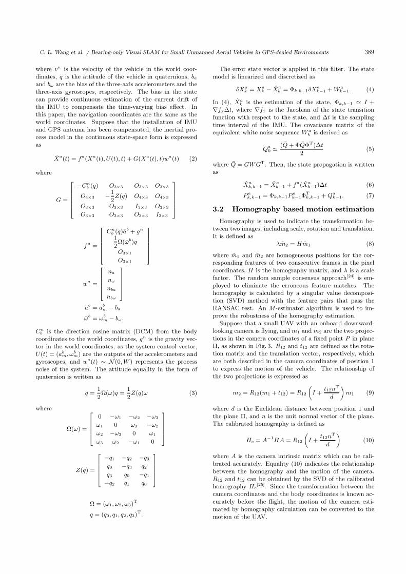
where vn is the velocity of the vehicle in the world coor-dinates, q is the attitude of the vehicle in quaternions, ba
and bω are the bias of the three-axis accelerometers and thethree-axis gyroscopes, respectively. The bias in the statecan provide continuous estimation of the current drift ofthe IMU to compensate the time-varying bias effect. Inthis paper, the navigation coordinates are the same as theworld coordinates. Suppose that the installation of IMUand GPS antenna has been compensated, the inertial pro-cess model in the continuous state-space form is expressedas
Xa(t) = fa(Xa(t), U(t), t) + G(Xa(t), t)wa(t) (2)
where
G =
⎡⎢⎢⎢⎢⎣
−Cnb (q) O3×3 O3×3 O3×3
O4×3 −1
2Z(q) O4×3 O4×3
O3×3 O3×3 I3×3 O3×3
O3×3 O3×3 O3×3 I3×3
⎤⎥⎥⎥⎥⎦
fa =
⎡⎢⎢⎢⎢⎣
Cnb (q)ab + gn
1
2Ω(ωb)q
O3×1
O3×1
⎤⎥⎥⎥⎥⎦
wa =
⎡⎢⎢⎢⎣
na
nω
nba
nbω
⎤⎥⎥⎥⎦
ab = abm − ba
ωb = ωbm − bω.
Cnb is the direction cosine matrix (DCM) from the body
coordinates to the world coordinates, gn is the gravity vec-tor in the world coordinates, as the system control vector,U(t) = (ab
m, ωbm) are the outputs of the accelerometers and
gyroscopes, and wa(t) ∼ N (0, W ) represents the processnoise of the system. The attitude equality in the form ofquaternion is written as
q =1
2Ω(ω)q =
1
2Z(q)ω (3)
where
Ω(ω) =
⎡⎢⎢⎢⎣
0 −ω1 −ω2 −ω3
ω1 0 ω3 −ω2
ω2 −ω3 0 ω1
ω3 ω2 −ω1 0
⎤⎥⎥⎥⎦
Z(q) =
⎡⎢⎢⎢⎣
−q1 −q2 −q3
q0 −q3 q2
q3 q0 −q1
−q2 q1 q0
⎤⎥⎥⎥⎦
Ω = (ω1, ω2, ω3)T
q = (q0, q1, q2, q3)T.
The error state vector is applied in this filter. The statemodel is linearized and discretized as
δXak = Xa
k − Xak = Φk,k−1δX
ak−1 + W a
k−1. (4)
In (4), Xak is the estimation of the state, Φk,k−1 � I +
∇fxΔt, where ∇fx is the Jacobian of the state transitionfunction with respect to the state, and Δt is the samplingtime interval of the IMU. The covariance matrix of theequivalent white noise sequence W a
k is derived as
Qak � (Q + ΦQΦT)Δt
2(5)
where Q = GWGT. Then, the state propagation is writtenas
Xak,k−1 = Xa
k−1 + fa(Xak−1)Δt (6)
P ak,k−1 = Φk,k−1P
ak−1Φ
Tk,k−1 + Qa
k−1. (7)
3.2 Homography based motion estimation
Homography is used to indicate the transformation be-tween two images, including scale, rotation and translation.It is defined as
λm2 = Hm1 (8)
where m1 and m2 are homogeneous positions for the cor-responding features of two consecutive frames in the pixelcoordinates, H is the homography matrix, and λ is a scalefactor. The random sample consensus approach[24] is em-ployed to eliminate the erroneous feature matches. Thehomography is calculated by a singular value decomposi-tion (SVD) method with the feature pairs that pass theRANSAC test. An M -estimator algorithm is used to im-prove the robustness of the homography estimation.
Suppose that a small UAV with an onboard downward-looking camera is flying, and m1 and m2 are the two projec-tions in the camera coordinates of a fixed point P in planeΠ, as shown in Fig. 3. R12 and t12 are defined as the rota-tion matrix and the translation vector, respectively, whichare both described in the camera coordinates of position 1to express the motion of the vehicle. The relationship ofthe two projections is expressed as
m2 = R12(m1 + t12) = R12
(I +
t12nT
d
)m1 (9)
where d is the Euclidean distance between position 1 andthe plane Π, and n is the unit normal vector of the plane.The calibrated homography is defined as
Hc = A−1HA = R12
(I +
t12nT
d
)(10)
where A is the camera intrinsic matrix which can be cali-brated accurately. Equality (10) indicates the relationshipbetween the homography and the motion of the camera.R12 and t12 can be obtained by the SVD of the calibratedhomography Hc
[25]. Since the transformation between thecamera coordinates and the body coordinates is known ac-curately before the flight, the motion of the camera esti-mated by homography calculation can be converted to themotion of the UAV.

390 International Journal of Automation and Computing 10(5), October 2013
Fig. 3 Two views of the same fixed point in a plane
3.3 Measurement update
The DCM from the body coordinates at position 2 inFig. 3 to the navigation coordinates is derived as
Cnb2 = Cn
b1CbcRT
12Ccb (11)
where Cnb1 is the DCM from the body coordinates at posi-
tion 1 to the navigation coordinates, which can be calcu-lated from the state of this filter at that moment, Cb
c andCc
b are transformation matrixes between the camera coordi-nates and the body coordinates. The attitude of the vehicleis calculated from Cn
b2 and used as a measurement of thefilter. The measurement model is written as
Z1,k = H1Xak + V1,k (12)
whereH1 = [O4×3 I4×4 O4×3 O4×3]
Z1 = q
V1 ∼ N (0, R1).
Then, the attitude measurement update is derived as
K1,k = P ak,k−1H
T1 (H1P
ak,k−1H
T1 + R1)
−1 (13)
Xak = Xa
k,k−1 + K1,k(Z1,k − H1Xak,k−1) (14)
P ak = (I − K1,kH1)P
ak,k−1. (15)
Suppose that two consecutive images are taken and cal-culated at time k−m and k, respectively. The time intervalbetween these two calculations is about m steps of the statepropagation. The average velocity of the vehicle in the nav-igation coordinates during the time interval is derived as
vnk−m,k =
Cnb1C
bcR12t12
mΔt. (16)
Since the velocity in the filter state is the instantaneous ve-locity, the above average velocity cannot be introduced intothe filter directly. An assumption is made that during ashort time interval in the flight, the velocity of the vehicledoes not fluctuate remarkably. Then, the average velocityduring time k − m and time k can be approximated as theinstantaneous velocity at time k − m
2as
vnk− m
2≈ vn
k−m,k. (17)
An example of the relationship between the average ve-locity and the instantaneous velocity is shown in Fig. 4. Itcan be observed that the above assumption is reasonable ifthe velocity is smooth. We suppose that the small UAV is ina stable flight and the above assumption is always tenable.
It is noteworthy that the velocity measurement at timek− m
2is obtained at time k under the above assumption. A
delay-based measurement update approach is proposed forthe velocity measurement update. The delay-based mea-surement model for the velocity estimation is defined as
Z2,k = H2Xak + V2,k (18)
Fig. 4 Relationship between the average velocity and the in-
stantaneous velocity
H2 = [I3×3 O3×4 O3×3 O3×3]
Z2 = vn
V2 ∼ N (0, R2).
The velocity measurement update is derived as
K2,k = P ak,k−1H
T2 (H2P
ak,k−1H
T2 + R2)
−1 (19)
Xak = Xa
k,k−1 + K2,k(Z2,k − H2Xak− m
2) (20)
P ak = (I − K2,kH2)P
ak,k−1. (21)
4 Position estimation and mapping
This section presents the position estimation and map-ping of the SLAM. No prior information of the scene isrequired in this EKF based filter, which takes the obser-vation of the features as the measurement. The velocityestimated in Section 3 is used as the input of the processmodel, and the attitude estimation provides the DCMs be-tween the navigation coordinates and the body coordinates.
4.1 Process model
The vehicle position and a map with the feature locationsof the environment are estimated using relative informationbetween the vehicle and each feature. The state vector isdefined as
Xb = (pn, Y1, · · · , Yn)T (22)
where pn is the vehicle position in the navigation coordi-nates and Yi, i = 1, · · · , n is the location of the i-th feature

C. L. Wang et al. / Bearing-only Visual SLAM for Small Unmanned Aerial Vehicles in GPS-denied Environments 391
in the navigation coordinates. The dynamic evolution ofthe position is given as
pnk = fb(Xa
k−1, pnk−1) + wb
k−1 =
pnk−1 + vn
k−1Δt + wbk−1
(23)
where vn is the velocity estimated in Section 3 and wb isthe Gaussian noise as wb ∼ N (0, Pv). Feature locations areconsidered to be stationary and the process model of thei-th feature is given as
Yi,k = Yi,k−1. (24)
It can be seen from (23) and (24) that the state transitionfunction is linear. This is favorable for the computationalcomplexity and stability of the filter.
4.2 Observation model
The onboard camera is able to produce relative bearing-only observations to the features in the map. As multiplefeatures might be observed at the same time, the observa-tion is defined as
Z3 = (zi, · · · , zj)T (25)
where zi is the observation of the i-th feature in the pixelcoordinates, which is expressed as
zi,k = hi(Xbk, k) + vi,k (26)
hi =
[u
v
]=
⎡⎢⎣
fuxc
zc+ u0
fvyc
zc+ v0
⎤⎥⎦ (27)
where (u, v)T is the location of the feature in the pixel co-ordinates, vi is the measurement noise as vi ∼ N (0, Ri),fu, fv, u0 and v0 are the intrinsic parameters of the camera,and pc = (xc, yc, zc)T is the location of the feature in thecamera coordinates. If the installation error of the camerato the vehicle has been compensated, then pc can be writtenas
pc = CcbCb
n(pni − pn) (28)
where Cbn is calculated from the attitude estimation in Sec-
tion 3, pn and pni are the positions of the vehicle and the
i-th landmark in the map in the navigation coordinates,respectively.
4.3 Estimation process
The vehicle position is predicted using (23). The statecovariance is propagated as
P bk,k−1 =[
F bpnPv,k−1(F
bpn)
T+ F b
xaP ak−1(F
bxa)
TPvf,k−1
Pfv,k−1 Pf,k−1
]
(29)where F b
pn and F bxa are the Jacobians of (23) with respect
to pn and Xa, Pv and Pf are the variances of the vehicleand the feature set, Pvf and Pfv are their covariances.
Suppose at time k, there are n features in the state andthat the i-th and j -th features are observed by the camera.The measurement update is derived as
K3,k = P bk,k−1H
T3 (H3P
bk,k−1H
T3 + R3)
−1 (30)
Xbk = Xb
k,k−1 + K3,k(Z3,k − H3Xbk,k−1) (31)
P bk = (I − K3,kH3)P
bk,k−1 (32)
where
R3 =
[Ri 0
0 Rj
]
H3 =
⎡⎢⎢⎢⎣
∂hi
∂pn
∂hi
∂Y1· · · ∂hi
∂Yn
∂hj
∂pn
∂hj
∂Y1· · · ∂hj
∂Yn
⎤⎥⎥⎥⎦ .
Ri and Rj are the measurement covariances of the i-th andj -th features in the pixel coordinates, ∂h
∂pn and ∂h∂Y
are theJacobians of the measurement function with respect to thevehicle position and the feature locations, respectively.
4.4 Feature initialization
In the monocular visual system, one bearing-only ob-servation is insufficient to initialize a position of a fea-ture in 3 dimensions for the SLAM filter with Gaussianuncertainty[11]. An inverse depth method is applied to theundelayed feature initialization[14] . This parameterizationdefines the position of a feature by 6 parameters as
Yi = (x0, y0, z0, θ, φ, ρ)T (33)
where p0 = (x0, y0, z0)T is the position of the camera op-
tical center from which the feature is first observed, θ andφ are the azimuth and elevation used to define a ray goingfrom p0 to the feature, and ρ is the inverse distance fromp0 to the feature along the ray. This parameterization isshown in Fig. 5. (x, y, z)T represents the navigation coordi-nates with the origin o. The location of this landmark inthe Euclidean coordinates is derived as
pi = p0 +m(θ, φ)
ρ(34)
m(θ, φ) =
⎡⎢⎣
cos θ cos φ
sin θ cos φ
sin φ
⎤⎥⎦ . (35)
Fig. 5 Inverse depth parameterization

392 International Journal of Automation and Computing 10(5), October 2013
4.5 Data association
Data association is very important to any SLAM appli-cation. The association between observations and featuresin the map affects the stability of the system directly. Erro-neous association can decrease the accuracy or even lead tosystem collapse. A Mahalanobis distance approach is usedin the data association, which is defined as
r = V TS−1V (36)
where
V = Z3 − H3Xb (37)
S = HT3 P bH3 + R3. (38)
Besides, the descriptor of the SIFT feature is also used toimprove the robustness of the data association. Each SIFTfeature has a unique 128-dimensional normalized descrip-tor, which is invariant to scale, rotation and translation.Thus, the descriptor of a new observation is compared withthose of the features in the map. The fast nearest-neighboralgorithm, described in Section 2, is also used in this sec-tion.
In our SLAM framework, observation zi is considered asthe correspondence to the j -th landmark in the map if thefollowing equation is satisfied:
di,j =√
r2 + d2SIFT < threshold (39)
where dSIFT is the Euclidean distance between the SIFT de-scriptor vectors of the observation and the landmark. Onlythe observation that passes the above test is considered asa right association. Although this double check algorithmmight reject correct matches that only pass one test, thesystem robustness is improved with erroneous associationseliminated remarkably.
5 Simulations
5.1 Simulation environment setup
An image-in-loop simulation system is set up to verifythe proposed SLAM, as shown in Fig. 6. A satellite imagetaken from Google Earth is loaded as the terrain map of theflight. The aerial image is simulated by the pixel interpola-tion with a resolution of 300× 300 in the pixel coordinates.The sensor data of the gyroscopes and accelerometers aresimulated with white noises and bias. The intrinsic matrixof the “onboard camera” is designed according to the pa-rameters of the real one in experiments. The features in themap are described with their uncertainties in 3 dimensions.Feature labels are also shown together with the “real-time”aerial images.
5.2 3D feature initialization
The feature initialization method is analyzed in this sec-tion. Fig. 7 shows the position errors of a feature duringthe first 15 observations and the expected 1-σ uncertain-ties. When the feature is first observed, the uncertainty israther large due to the initial selection of the inverse depth.The uncertainty converges rapidly after other observations
are obtained. The position error lies within the 1-σ boundfrom the beginning to the end and converges with the in-crease of the observations. After 10 observations, the po-sition estimation of the feature is stable and the inversedepth is accurate enough. Then, the feature parametersare converted from the inverse depth form to the Euclideanform. No obvious changes can be observed in the featureposition estimation and the uncertainty calculation duringthis conversion.
Fig. 6 Image-in-loop simulation system
Fig. 7 The position errors of the feature initialization
5.3 Trajectory test with loop closure
A circle trajectory with a radius of 100 m is designed totest the SLAM system. The UAV flies two laps along thetrajectory with the velocity of 10m/s in the body coordi-nates, so that there is a loop closure during the flight. Theprocessing time of this algorithm is about 120 s.
Figs. 8 and 9 are about the attitude and velocity errorswith 1-σ uncertainties, respectively. Both the attitude andvelocity errors are limited within the uncertainty boundduring the whole experiment.
Fig. 10 illustrates the position errors with 1-σ uncertain-ties. The estimations in the z direction seem to be betterthan those in x−y directions in this simulation. It could beattributed to the unchanged altitude in the designed trajec-tory, which makes the motion in the z direction much tinycompared to the motion in x − y directions. The positionerrors are small during the first 20 s. Then the estimationssuffer from an accumulated error which is generated by the

C. L. Wang et al. / Bearing-only Visual SLAM for Small Unmanned Aerial Vehicles in GPS-denied Environments 393
velocity error. The error might drift unboundedly in a fewseconds without the observation of the features. But in theSLAM system, it is approximately bounded within the 1-σuncertainties. Only the error in the x direction from 40 sto 60 s is outside the bound. The loop closure takes placeat about 60 s. It can be seen that both the errors in thex and y directions decrease sharply. From this time, theUAV is in the second lap and a lot of features which areinitialized in the first lap are observed again. Thus, afterthe loop closure, the errors keep smaller and stable withinthe boundaries. The uncertainty is also convergent.
Fig. 8 The attitude errors in the simulation
Fig. 9 The velocity errors in the simulation
6 Experiments
6.1 System description
The experimental testbed is a radio-controlled model he-licopter, as shown in Fig. 11. It carries a set of sensors, in-cluding an Rt 20 differential GPS receiver, an MS5540 baro-metric altimeter, an ADIS16355 IMU, a three-axis magne-tometer composed of HMC1052 and HMC1041, and a color
industrial digital camera MV-1300UC mounted verticallydownward at the bottom of the helicopter.
Fig. 10 The position errors in the simulation
Fig. 11 The experimental helicopter testbed
There are four onboard computers in the onboard avion-ics. DSP TI28335 runs an extended Kalman filter to fusethe measurement of GPS and inertial sensors to build aGPS/INS (inertial navigation system) for the helicopter.ARM LPC1766 is used to guide and output the controlsignals to the helicopter, as well as communicate with theground station. FPGA EP2C is the data logger and incharge of the control switching between human pilot and theautopilot. PC-104 PCM3362 is the vision computer. Dur-ing the real experiment, the sensor data and the GPS/INSnavigation output are logged by the FPGA and transferredto the vision computer. The vision computer receives theabove data and records the aerial images simultaneously.The ground station is used to send the high-level controlcommands and differential GPS correction to the helicopterand receive the flight state of the helicopter, including atti-tude, velocity and position. The onboard avionics is shownin Fig. 12.
6.2 Real flight experiment
An experiment is carried out to test the performance ofthe proposed SLAM system. During the experiment, theinertial sensor data is acquired at a rate of 50Hz and thevisual calculation is about 3–4 Hz.The improvement of thevisual sampling frequency is able to reduce the error intro-duced by the assumption in (17). But now the sampling
394 International Journal of Automation and Computing 10(5), October 2013
frequency of the visual system is limited by the computa-tional load of the visual algorithm. The SLAM system runsin an offline mode in this paper. The performance of theproposed bearing-only inertial SLAM is evaluated by com-paring with the referential GPS/INS navigation.
Fig. 12 The onboard avionics endcenter
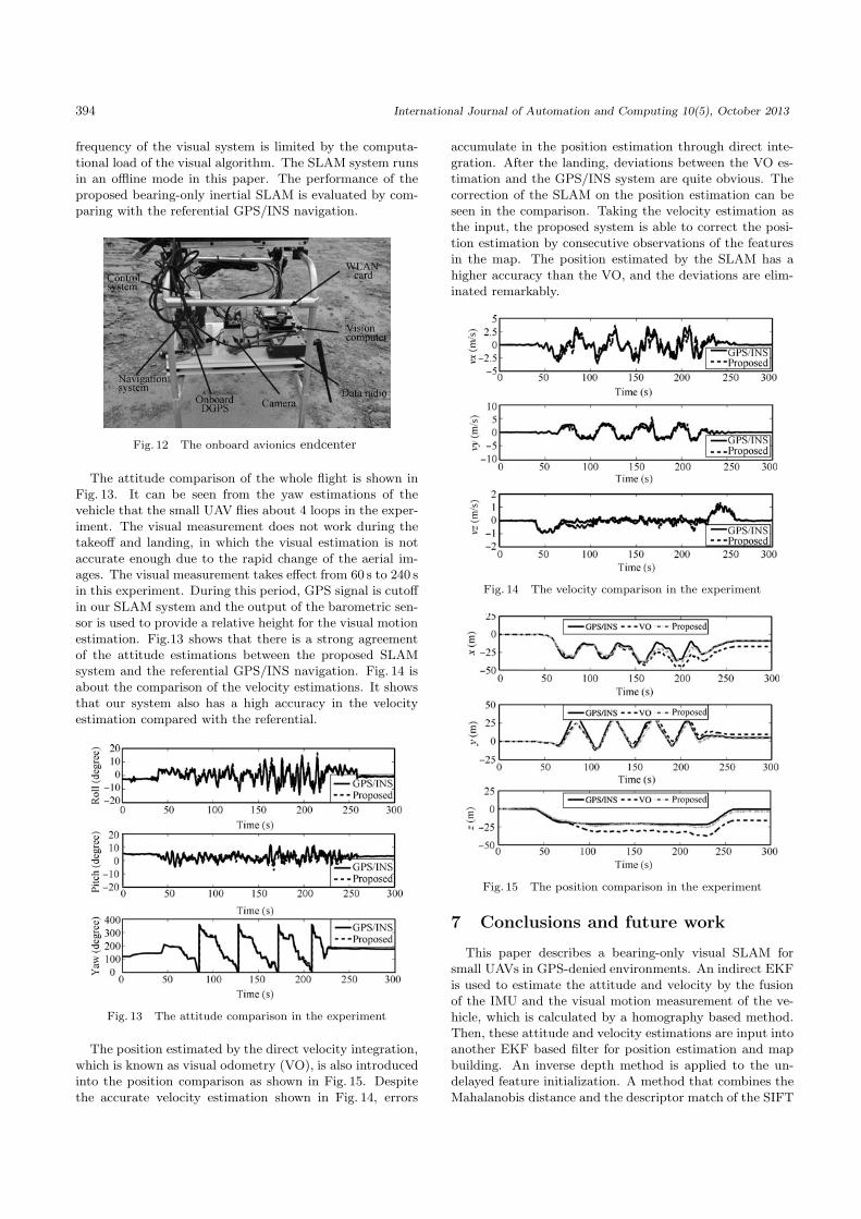
The attitude comparison of the whole flight is shown inFig. 13. It can be seen from the yaw estimations of thevehicle that the small UAV flies about 4 loops in the exper-iment. The visual measurement does not work during thetakeoff and landing, in which the visual estimation is notaccurate enough due to the rapid change of the aerial im-ages. The visual measurement takes effect from 60 s to 240 sin this experiment. During this period, GPS signal is cutoffin our SLAM system and the output of the barometric sen-sor is used to provide a relative height for the visual motionestimation. Fig.13 shows that there is a strong agreementof the attitude estimations between the proposed SLAMsystem and the referential GPS/INS navigation. Fig. 14 isabout the comparison of the velocity estimations. It showsthat our system also has a high accuracy in the velocityestimation compared with the referential.
Fig. 13 The attitude comparison in the experiment
The position estimated by the direct velocity integration,which is known as visual odometry (VO), is also introducedinto the position comparison as shown in Fig. 15. Despitethe accurate velocity estimation shown in Fig. 14, errors
accumulate in the position estimation through direct inte-gration. After the landing, deviations between the VO es-timation and the GPS/INS system are quite obvious. Thecorrection of the SLAM on the position estimation can beseen in the comparison. Taking the velocity estimation asthe input, the proposed system is able to correct the posi-tion estimation by consecutive observations of the featuresin the map. The position estimated by the SLAM has ahigher accuracy than the VO, and the deviations are elim-inated remarkably.
Fig. 14 The velocity comparison in the experiment
Fig. 15 The position comparison in the experiment
7 Conclusions and future work
This paper describes a bearing-only visual SLAM forsmall UAVs in GPS-denied environments. An indirect EKFis used to estimate the attitude and velocity by the fusionof the IMU and the visual motion measurement of the ve-hicle, which is calculated by a homography based method.Then, these attitude and velocity estimations are input intoanother EKF based filter for position estimation and mapbuilding. An inverse depth method is applied to the un-delayed feature initialization. A method that combines theMahalanobis distance and the descriptor match of the SIFT

C. L. Wang et al. / Bearing-only Visual SLAM for Small Unmanned Aerial Vehicles in GPS-denied Environments 395
features is used to improve the robustness of the data as-sociation. Simulations and real experiments have been car-ried out to test the performance of the system. The SLAMsystem developed in this paper has a high estimation ac-curacy of the UAV state by comparing with the referentialGPS/INS navigation. In conclusion, our bearing-only vi-sual SLAM system can provide stable estimations of smallUAVs while building a 3D feature map in GPS-denied en-vironments.
Future work will focus on the further improvement of theSLAM on computational complexity. In the EKF based al-gorithm, the state is always augmented with the observa-tions of new features in the map. The computational com-plexity grows quadratically with the number of the features.This is an unavoidable problem for the implementation ofthe real-time SLAM for small UAVs. In the future, a Rao-Blackwellized based FastSLAM will be developed based onthis research for a real-time SLAM that can reduce the com-putation to a linear complexity.
References
[1] D. B. Kingston, A. W. Beard. Real-time attitude and po-sition estimation for small UAVs using low-cost sensors. InProceedings of the AIAA 3rd Unmanned Unlimited Tech-nical Conference, Workshop and Exhibit, AIAA, Chicago,USA, pp. 6488–6496, 2004.
[2] B. Ludington, E. Johnson, G. Vachtsevanos. AugmentingUAV autonomy. Robotics & Automation Magazine, vol. 13,no. 3, pp. 63–71, 2006.
[3] M. K. Kaiser, N. R. Gans, W. E. Dixon. Vision-based esti-mation for guidance, navigation, and control of an aerialvehicle. IEEE Transactions on Aerospace and ElectronicSystems, vol. 46, no. 3, pp. 1064–1077, 2010.
[4] S. Weiss, D. Scaramuzza, R. Siegwart. Monocular-SLAM-based navigation for autonomous micro helicopters in GPS-denied environments. Journal of Field Robotics, vol. 28,no. 6, pp. 854–874, 2011.
[5] P. Yang, W. Y. Wu, M. Moniri, C. C. Chibelushi. A sensor-based SLAM algorithm for camera tracking in virtual stu-dio. International Journal of Automation and Computing,vol. 5, no. 2, pp. 152–162, 2008.
[6] J. Artieda, J. M. Sebastian, P. Campoy, J. F. Correa,I. F. Mondragon, C. Martinez, M. Olivares. Visual 3-DSLAM from UAVs. Journal of Intelligent & Robotic Sys-tems, vol. 55, no. 4–5, pp. 299–321, 2009.
[7] F. Caballero, L. Merino, J. Ferruz, A. Ollero. Vision-basedodometry and SLAM for medium and high altitude flyingUAVs. Journal of Intelligent & Robotic Systems, vol. 54,no. 1–3, pp. 137–161, 2009.
[8] J. Kelly, S. Saripalli, G. S. Sukhatme. Combined visual andinertial navigation for an unmanned aerial vehicle. In Pro-ceedings of the International Conference on Field and Ser-vice Robotics, FSR, Chamonix, France, pp. 255–264, 2007.
[9] K. H. Yang, W. S. Yu, X. Q. Ji. Rotation estimation formobile robot based on single-axis gyroscope and monocular
camera. International Journal of Automation and Comput-ing, vol. 9, no. 3, pp. 292–298, 2012.
[10] V. Sazdovski, P. M. G. Silson. Inertial navigation aided byvision-based simultaneous localization and mapping. IEEESensors Journal, vol. 11, no. 8, pp. 1646–1656, 2011.
[11] M. Bryson, S. Sukkarieh. Building a robust implementationof bearing-only inertial SLAM for a UAV. Journal of FieldRobotics, vol. 24, no. 1–2, pp. 113–143, 2007.
[12] J. Kim, S. Sukkarieh. Real-time implementation of airborneinertial-SLAM. Robotics and Autonomous Systems, vol. 55,no. 1, pp. 62–71, 2007.
[13] A. J. Davison, I. D. Reid, N. D. Molton, O. Stasse.MonoSLAM: Real-time single camera SLAM. IEEE Trans-actions on Pattern Analysis and Machine Intelligence,vol. 29, no. 6, pp. 1052–1067, 2007.
[14] J. Civera, A. J. Davison, J. Montiel. Inverse depthparametrization for monocular SLAM. IEEE Transactionson Robotics, vol. 24, no. 5, pp. 932–945, 2008.
[15] G. Nutzi, S. Weiss, D. Scaramuzza, R. Siegwart. Fusion ofIMU and vision for absolute scale estimation in monocularSLAM. Journal of Intelligent & Robotic Systems, vol. 61,no. 1–4, pp. 287–299, 2011.
[16] S. D. Huang, G. Dissanayake. Convergence and consis-tency analysis for extended Kalman filter based SLAM.IEEE Transactions on Robotics, vol. 23, no. 5, pp. 1036–1049, 2007.
[17] M. Bryson, S. Sukkarieh. Observability analysis and ac-tive control for airborne SLAM. IEEE Transactions onAerospace and Electronic Systems, vol. 44, no. 1, pp. 261–280, 2008.
[18] A. Nemra, N. Aouf. Robust airborne 3D visual simultane-ous localization and mapping with observability and con-sistency analysis. Journal of Intelligent & Robotic Systems,vol. 55, no. 4–5, pp. 345–376, 2009.
[19] M. T. Bryson, S. Sukkarieh. Decentralised trajectory con-trol for multi-UAV SLAM. In Proceedings of the 4th Inter-national Symposium on Mechatronics and its Applications,Sharjah, United Arab Emirates, 2007.
[20] K. Celik, C. Soon-Jo, M. Clausman, A. K. Somani. Monoc-ular vision SLAM for indoor aerial vehicles. In Proceedingsof the IEEE/RSJ International Conference on IntelligentRobots and Systems, IEEE, St. Louis, USA, pp. 1566–1573,2009.
[21] C. L. Wang, T. M. Wang, J. H. Liang, Y. Chen, Y. C.Zhang, C. Wang. Monocular visual SLAM for small UAVsin GPS-denied environments. In Proceedings of the 2012IEEE International Conference on Robotics and Biomimet-ics, IEEE, Guangzhou, China, pp. 896–901, 2012.
[22] D. G. Lowe. Distinctive image features from scale-invariantkeypoints. International Journal of Computer Vision,vol. 60, no. 2, pp. 91–110, 2004.

396 International Journal of Automation and Computing 10(5), October 2013
[23] C. L. Wang, T. M. Wang, J. H. Liang, Y. Chen, C. Wang.A fuzzy-based threshold method applied in SIFT for vi-sual navigation of small UAVs. In Proceedings of the 7thIEEE Conference on Industrial Electronics and Applica-tions, IEEE, Singapore, pp. 807–812, 2012.
[24] M. A. Fischler, R. C. Bolles. Random sample consensus: Aparadigm for model fitting with applications to image anal-ysis and automated cartography. Communications of theACM, vol. 24, no. 6, pp. 381–395, 1981.
[25] R. Tsai, T. Huang, W. L. Zhu. Estimating three-dimensional motion parameters of a rigid planar patch,II: Singular value decomposition. IEEE Transactions onAcoustics, Speech and Signal Processing, vol. 30, no. 4,pp. 525–534, 1982.
Chao-Lei Wang received the B. Sc. de-gree in mechanical engineering and automa-tion from Beijing University of Aeronauticsand Astronautics, China in 2008. He is nowa Ph. D. candidate in mechanical engineer-ing and automation, Beijing University ofAeronautics and Astronautics, China.
His research interests include systemmodeling and identification, integratednavigation and visual SLAM in small un-
manned aerial vehicle.E-mail: [email protected] (Corresponding author)
Tian-Miao Wang received the B. Sc.degree from Xi′an Jiaotong University,China, and the M. Sc. and Ph.D. degreesfrom Northwestern Polytechnic University,China in 1982 and 1990, respectively. Heis currently a professor with the School ofMechanical Engineering and Automation,Beijing University of Aeronautics and As-tronautics, China. He is the head of theExpertized Group in the field of advanced
manufacturing technology of the National High Technology Re-search and Development Program of China (863 Program). He
has undertaken and finished many national research projects inrecent years. He has published 87 papers in local and interna-tional journals and three professional books. He is a member ofChina Robotics Society.
His research interests include biomimetic robotics, medicalrobotic technology and embedded intelligent control technology.
E-mail: wtm [email protected]
Jian-Hong Liang received the B. Sc.and Ph. D. degrees in mechanical engineer-ing and automation from Beijing Universityof Aeronautics and Astronautics, China in2000 and 2007, respectively. He is currentlyan associate professor with the School ofMechanical Engineering and Automation,Beijing University of Aeronautics and As-tronautics, China. He has published 40 pa-pers in national and international journals
and two professional books.His research interests include biomimetic underwater robotics,
field robotics and small unmanned aerial vehicles.E-mail: dommy [email protected]
Yi-Cheng Zhang received the B. Sc. de-gree in mechanical engineering and automa-tion from Beijing University of Aeronauticsand Astronautics, China in 2010. He iscurrently a Ph. D. candidate in mechanicalengineering and automation, Beijing Uni-versity of Aeronautics and As Astronautics,China.
His research interests include flight con-troller design and system integration of
small unmanned aerial vehicle.E-mail: [email protected]
Yi Zhou received the B. Sc. degree in me-chanical engineering and automation fromBeijing University of Aeronautics and As-tronautics, China in 2012. He is currentlya Ph. D. candidate in mechanical engineer-ing and automation, Beijing University ofAeronautics and Astronautics, China.
His research interests include visual nav-igation and guidance of small unmannedaerial vehicle.
E-mail: [email protected]