Embed Size (px)
Citation preview

Beam Dynamics Study for TESLAwith the Integrated FEL
V.M. Tsakanov
Yerevan Physics Institute, Alikhanian Br. 2,
375036 Yerevan, Armenia
Contents
1 Introduction 2
2 The smoothly curved orbit (CDR) 3
2.1 Linear optic : : : : : : : : : : : : : : : : : : : : : : : : : : : : : : 4
2.2 Emittance preservation : : : : : : : : : : : : : : : : : : : : : : : 7
2.3 Conclusion 1 : : : : : : : : : : : : : : : : : : : : : : : : : : : : : 10
3 The TESLA high luminosity 11
3.1 Linear optics : : : : : : : : : : : : : : : : : : : : : : : : : : : : : 13
3.2 Free coherent oscillations. Dispersive e�ects : : : : : : : : : : : : 14
3.3 Free coherent oscillations. Wake�eld e�ects : : : : : : : : : : : : 15
3.4 Accelerator section misalignments : : : : : : : : : : : : : : : : : 16
4 Trajectory correction 18
4.1 One-to-one correction : : : : : : : : : : : : : : : : : : : : : : : : 18
4.2 Two beam operation : : : : : : : : : : : : : : : : : : : : : : : : : 20
4.3 On the two beam based trajectory correction : : : : : : : : : : : : 22
5 Summary 25
1

.
1 Introduction
In the TESLA project, part of the main linac will be used to accelerate the
beam for the integrated X-ray Free Electron Laser (FEL) facility. The beams for
high energy physics and FEL have di�erent requirements and correspondingly
have di�erent energies, emittances, bunch charge and length. Both beams are
assumed to accelerate in the �rst part of the linac in an interleaved pulse mode,
where RF pulses for high energy physics and those for X-ray physics alternate.
The TESLA beam dynamics, including the preliminary consideration of the
two-beam operation mode, is given in the Conceptual Design Report (CDR) [1].
The study presented in this report is basically related to beam dynamics in two-
beam operation mode.
We start with the beam dynamics in the �rst part of the main linac with
the existing design (CDR) when the orbit is smoothly vertically curved with a
bending radius of 915 km to level an 8 mrad tilt of the existing ring HERA
to enable the option for producing collisions of protons stored in HERA with
electrons from the main linac. The main features of the machine linear optic
are then two dispersions and two separate design orbits related to the TESLA
and FEL beams. In addition, with two di�erent energies of the beam, the use
of one-to-one correction technique for high energy beam is accompany by large
coherent oscillations of the low energy FEL beam leading to emittance grow.
The application of the beam based trajectory correction in curved part of the
linac also becomes problematic due to large dispersion of the TESLA beam and
separate design orbit of the FEL beam.
Therefore, the modi�ed approach is given based on the local bend of the 55
GeV high energy TESLA beam on about 8 mrad to adjust the design trajectory
with the horizontal direction of the main linac. The two-beam operation part of
the main linac is then straight and e�ects caused by the curved orbits vanish.
With the new design, the main aspects of the beam dynamics with regards on
emittance preservation for both beams are given including the wide-band energy
option of the FEL and TESLA beams with the reduced vertical emittance of the
high luminosity TESLA beam. Some features of the trajectory correction in two
beam operation part of the main linac are discussed.
2
2 The smoothly curved orbit (CDR)
The Linear Collider will be built underground at a depth of about 15 m. The
interaction point HERA west is about 20 m above sea level. The axis of the
main part of the linac tunnel lies about 10 m below sea level. The straight
section HERAWest has a slope of about 8 mrad out of the horizontal. Therefore,
to enable the option for producing collisions of protons stored in HERA with
electrons from the main linac, there is a transition from the initial slope into the
horizontal direction of the electron beam. Fig.1 shows an expanded pro�le of the
linear collider area North-Northwest of DESY together with the collider tunnel.
The two possibilities of the transition from the initial slope into the horizontal
direction are the smooth curve by the corrector dipoles and the local bend of the
TESLA beam (at energy about 50 GeV) by the achromat section. Note, that
the machine performance (the tunnel and the cells arrangement) in this part of
the linac is basically determined by the beam dynamics in two-beam operation
mode. Although, the di�erent aspects of the beam dynamics for single TESLA
and TESLA/FEL beam operations are given in CDR, there are some peculiarities
in two-beam operation mode which impose a certain constraints on the machine
performance and trajectory correction procedure.
In this section we give some aspects of the beam dynamics in two-beam oper-
ation mode when the design orbit of the TESLA beam is smoothly curved with
a bending radius of about 1000km as is shown in Fig1.
Fig.1 Expanded pro�le of the Linear Collider area North-Northwest of DESY.
3
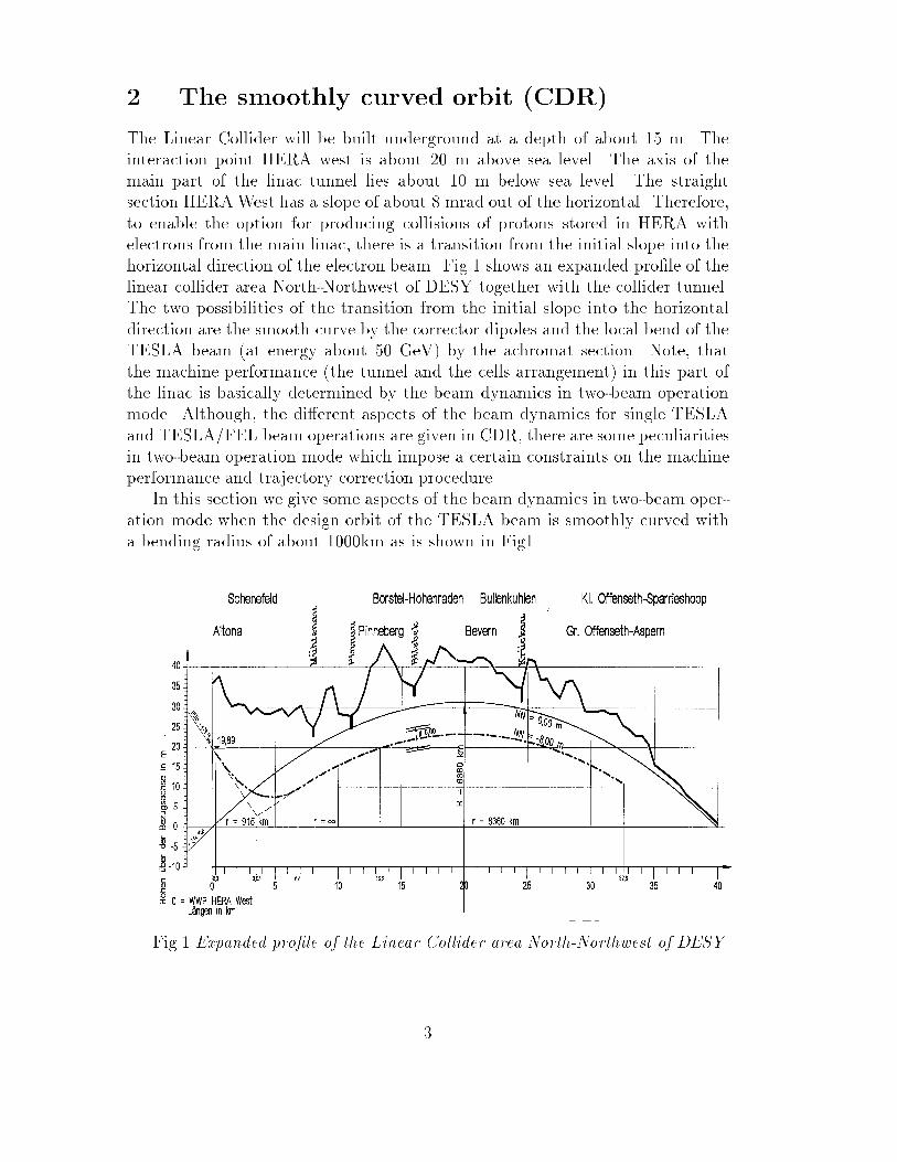
2.1 Linear optic
The linear optic design of the TESLA main linac is based on low phase advance
per single FODO cell �T = 60o. To accelerate in FEL mode with a gradient close
to the most e�cient one of UF = 18MeV=m keeping the constant ratio of TESLA
and FEL beam energies EF=ET = UF=UT = 0:72, the phase advance of the FEL
beam in thin lens approximation is given by
sin(�F =2) =UT
UF
sin(�T=2) (1)
and is approximately equal to �F = 90o. The injection energies of the TESLA
and FEL beams are then 3.2 and 2.3 GeV respectively. Note, that beyond some
energy o�set, no optical solution exists any more for a periodic FODO lattice.
For the TESLA lattice this occurs at about 40% of the linear collider operation
gradient. The periodic betatron functions for TESLA and FEL are shown in
�g.2.
0
10
20
30
40
50
60
70
80
90
100
0 50 100 150 200 250 300 350 400
Position
Bet
atro
n fu
nctio
n β(
m)
µ=60o K=0.086 m-2
TESLA
0
10
20
30
40
50
60
70
80
90
100
0 50 100 150 200 250 300 350 400
Position (m)
Bet
atro
n fu
nctio
n β(
m)
µ=88o K=0.12 m-2
FEL
Fig.2 The betatron functions of the TESLA and FEL beams.
4
The phase ellipses of injected beams for TESLA and FEL operations have
to be matched with machine ellipses to prevent the emittance dilution of the
beta-mismatch [3]�"
"
=1
2
"�
��
+ (� � ��)2��
�
+��
�
#(2)
where �; � machine initial Twiss parameters, ��
; �� the Twiss parameters at the
end of injection channels. As an example, if the matching point is at the middle
of the quadrupole (� = 0), for the 5% of emittance dilution we get
�� � 0:22; 0:75 �
��
�
� 1:27 (3)
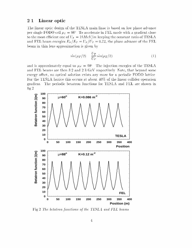
To estimate the e�ect of the curved TESLA beam trajectory in the �rst path
of the linac, we assume that the design orbit is smoothly curved by the dipole
corrector magnets. The number of FODO cells in the curved part of the linac
is approximately 160 and each magnet de ect the design trajectory by the angle
of about 0.05 mrad with the bending radius for TESLA beam about 10 km (one
magnet per cell). The o�-energy trajectories of the FEL and TESLA beams in
the two beam operation part of the linac is then given by two dispersions. The
periodic dispersion functions for the TESLA and FEL beams are shown in Fig.3.
Note, that the required magnetic �eld of the corrector dipoles with the TESLA
beam energy 140 GeV is then close to maximum �eld of 44 mT [1].
0
0.5
1
1.5
2
2.5
3
0 50 100 150 200 250 300 350 400
Position (m)
Dis
per
sio
n (
mm
)
TESLA
FEL
Fig.3 The periodic dispersion functions for the TESLA (solid line) and FEL
(dashed line) beams.
5

In addition, the low energy FEL beam central trajectory is given by
y00
F + 0
y0
F +KF yF = (1 �ET
EF
)GT (4)
with the neglect of nonlinear termGKy2. HereG = 1=� is the bending curvature,
K the quadrupole strength. It can be shown, that the periodic solution of the
equation of motion (4) is then de�ne the design orbit of the FEL beam in TESLA
(Fig.4a). Note, that the design orbit of the FEL beam is not follow to o�-energy
trajectory of the TESLA beam and has a reduction factor of about two due to
high betatron phase advance of the FEL beam. Actually, the FEL beam central
trajectory is the periodical solution if the bunch center position is matched with
the initial amplitudes y0; y0
0 of the design orbit. For comparison, Fig.4b presents
the FEL beam coherent oscillations when the beam is injected along the axis of
the main linac with the zero initial amplitudes.
0
0.1
0.2
0.3
0.4
0.5
0.6
0.7
0.8
0.9
1
0 50 100 150 200 250 300 350 400
Position (m)
Y(m
m)
FEL beam coherent oscillations(design periodic orbit)
a)
0
0.1
0.2
0.3
0.4
0.5
0.6
0.7
0.8
0.9
1
0 0.5 1 1.5 2 2.5 3
Position (km)
Y(m
m)
FEL beam coherent oscillations
(Y0=Y/0=0)
b)
Fig.4 The FEL beam design periodic orbit (a) and the coherent oscillations of
the beam with initial zero amplitudes (b)(on axis injection).
6
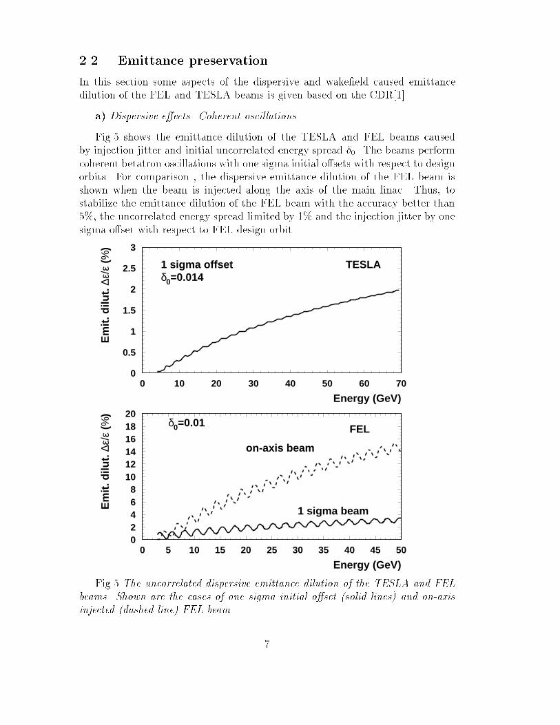
2.2 Emittance preservation
In this section some aspects of the dispersive and wake�eld caused emittance
dilution of the FEL and TESLA beams is given based on the CDR[1].
a) Dispersive e�ects. Coherent oscillations
Fig.5 shows the emittance dilution of the TESLA and FEL beams caused
by injection jitter and initial uncorrelated energy spread �0. The beams perform
coherent betatron oscillations with one sigma initial o�sets with respect to design
orbits. For comparison , the dispersive emittance dilution of the FEL beam is
shown when the beam is injected along the axis of the main linac. Thus, to
stabilize the emittance dilution of the FEL beam with the accuracy better than
5%, the uncorrelated energy spread limited by 1% and the injection jitter by one
sigma o�set with respect to FEL design orbit.
02468
101214161820
0 5 10 15 20 25 30 35 40 45 50
Energy (GeV)
Em
it. d
ilut.
∆ε/
ε (%
)
δ0=0.01 FEL
on-axis beam
1 sigma beam
0
0.5
1
1.5
2
2.5
3
0 10 20 30 40 50 60 70
Energy (GeV)
Em
it. d
ilut.
∆ε/
ε (%
)
δ0=0.0141 sigma offset TESLA
Fig.5 The uncorrelated dispersive emittance dilution of the TESLA and FEL
beams. Shown are the cases of one sigma initial o�set (solid lines) and on-axis
injected (dashed line) FEL beam.
7
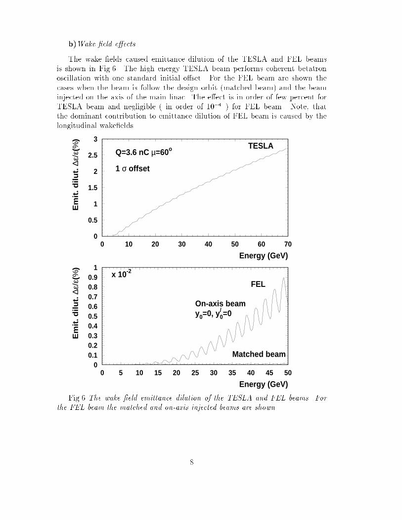
b)Wake �eld e�ects.
The wake �elds caused emittance dilution of the TESLA and FEL beams
is shown in Fig.6. The high energy TESLA beam performs coherent betatron
oscillation with one standard initial o�set. For the FEL beam are shown the
cases when the beam is follow the design orbit (matched beam) and the beam
injected on the axis of the main linac. The e�ect is in order of few percent for
TESLA beam and negligible ( in order of 10�4 ) for FEL beam. Note, that
the dominant contribution to emittance dilution of FEL beam is caused by the
longitudinal wake�elds.
00.10.20.30.40.50.60.70.80.9
1
0 5 10 15 20 25 30 35 40 45 50
Energy (GeV)
Em
it. d
ilu
t. ∆
ε/ε(
%)
x 10-2
On-axis beamy0=0, y/
0=0
Matched beam
FEL
0
0.5
1
1.5
2
2.5
3
0 10 20 30 40 50 60 70
Energy (GeV)
Em
it. d
ilu
t. ∆
ε/ε(
%)
Q=3.6 nC µ=60o
1 σ offset
TESLA
Fig.6 The wake �eld emittance dilution of the TESLA and FEL beams. For
the FEL beam the matched and on-axis injected beams are shown.
8
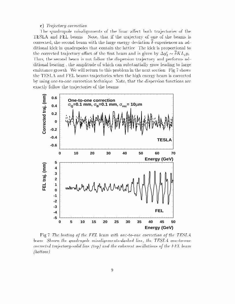
c) Trajectory correction
The quadrupole misalignments of the linac a�ect both trajectories of the
TESLA and FEL beams. Note, that if the trajectory of one of the beams is
corrected, the second beam with the large energy deviation � experiences an ad-
ditional kick in quadrupoles that contain the lattice. The kick is proportional to
the corrected trajectory o�set of the �rst beam and is given by �y02� �KLqy1.
Thus, the second beam is not follow the dispersion trajectory and performs ad-
ditional beating , the amplitude of which can substantially grow leading to large
emittance growth. We will return to this problem in the next section. Fig.7 shows
the TESLA and FEL beams trajectories when the high energy beam is corrected
by using one-to-one correction technique. Note, that the dispersion functions are
exactly follow the trajectories of the beams.
-0.6
-0.4
-0.2
0
0.2
0.4
0.6
0 10 20 30 40 50 60 70
Energy (GeV)
Cor
rect
ed tr
aj. (
mm
)
One-to-one correctionσQ=0.1 mm, σB=0.1 mm, σrez= 10µm
TESLA
-5
-4
-3
-2
-1
0
1
2
3
4
5
0 5 10 15 20 25 30 35 40 45 50
Energy (GeV)
FEL
traj
. (m
m)
FEL
Fig.7 The beating of the FEL beam with one-to-one correction of the TESLA
beam. Shown the quadrupole misalignments-dashed line, the TESLA one-to-one
corrected trajectory-solid line (top) and the coherent oscillations of the FEL beam
(bottom).
9
2.3 Conclusion 1
The results of this section with the study outlined in the Conceptual Design
Report show that the operation of the machine with the smoothly curved de-
sign orbit can be proceeded with emittance preservation for both beams at the
level of better than 10% by the separate one-to-one trajectory correction of the
TESLA and FEL beams. Otherwise, the one-to-one correction of the TESLA
beam only leads to large coherent oscillations of the FEL beam and the beam-
based trajectory correction technique should be in used to prevent the emittance
enlargement of the FEL beam. Note, that an application of the beam based
correction procedure supposes the information about on- and o�-energy beam
trajectories, which, in turn, includes an additional errors due to separate beam
trajectories and dispersions.
Summarizing the main aspects of the beam dynamics study in the smoothly
curved machine, the following main disadvantages can be listed.
Beam dynamics:
* the FEL beam should be matched with the design orbit to prevent the
emittance dilution of injection jitter;
* the dispersions of the TESLA and FEL beams should be matched to obtain
the minimum periodic dispersion of the machine;
* the application of one-to-one correction technique in two-beam operation
mode is excluded due to large coherent oscillation of the FEL beam;
* the periodic dispersion is still large (2.5 mm) and the application of the
beam based trajectory correction becomes problematic due to additional sources
of the errors.
Machine performance:
* an each FODO cell should be geometrically curved by about 0.05 mrad to
be linked with the design trajectory of the TESLA beam; in turn, the each cell
should be aligned with the accuracy better than 100�m;
* the option of the further colliding of the TESLA electron beam with HERA
proton beam needs some reconstruction of the machine elements as far as the
correction dipoles with the maximum magnetic �eld 44 mT could not provide
the corresponding bend of the electron beam at energies 200-250 GeV.
To prevent all these disadvantages of the machine performance and beam
dynamics issues, the part of the main linac with parallel operation of collider and
FEL beams is reasonable to be straight with further local bend of the collider
beam in achromat cell after the separation of collider and FEL beams (Fig.1).
The energy of the collider beam is then at the level of 55 GeV . The FEL beam
is extracted from the linac at the di�erent energies (15, 25 and 50 GeV) by the
fast kicker setup and is transported to the user laboratories.
10
3 The TESLA high luminosity
As it is shown in the previous section, the reasonable solution for the transition of
the collider beam to horizontal direction (the two-beam operation part of the main
linac) is the local bend of the high energy TESLA beam after the separation of
the FEL beam. An additional argument for this option is the new high luminosity
parameter set of the TESLA beam with the injection energy at the level of the
5 GeV [3, 4]. The parameter list for FEL and high luminosity TESLA beams is
given in Table 1.
TABLE 1
Parameters TESLA FEL
Injection energy (GeV) 5 2.2
Vertical emittance (mm �mrad) 0.03 0.7
Charge per bunch (nC) 3.2 1
Bunch rms length (mm) 0.4 0.025
Accel gradient (MeV/m) 25 18
The local bending section for the TESLA beam is started at the horizontal
position 3.55 km (Fig.1) when the high energy TESLA beam reaches the energy
55 GeV. The focusing cells arrangement of the TESLA main linac is given in
CDR report. The linac is divided into 3 sections, with quadrupole spacing of 2, 3
and 4 cryo-modules, respectively. The �st beta-step ( change of the optics) is at
the level of 55 GeV. Thus, the achromat cell includes the additional quadrupole
section for betatron matching. The layout of the achromat bending cell with the
betatron matching section is shown in �g.8.
The minimum bending radius of the TESLA beam is de�ned by the emit-
tance growth of the 200 GeV electron beam (the electron-proton collision option
with 250 GeV electron beam) caused by incoherent synchrotron radiation. In a
transport line, the emittance growth (�"=" << 1) due to incoherent synchrotron
radiation can be estimated by [5]
�( ")[m � rad] � 4:13 � 10�8E6[GeV ]I5[m�1] (5)
where E is the beam energy in GeV and I5 is the �fth synchrotron integral
I5 =Z L
0
G3
�
��2 + (��0 �
1
2�0
�)2�ds (6)
with G(s) = 1=�(s), � is the bending radius, L is the total length of the transport
line. For the maximumemittance growth �( ") � 10�7m�rad at the beam energy
200 GeV, the estimated bending radius is in order of 5 km ( magnetic �eld 0.1334
T). The total length of the bending magnets is then 40 m with de ection angle
of 8 mrad.
11
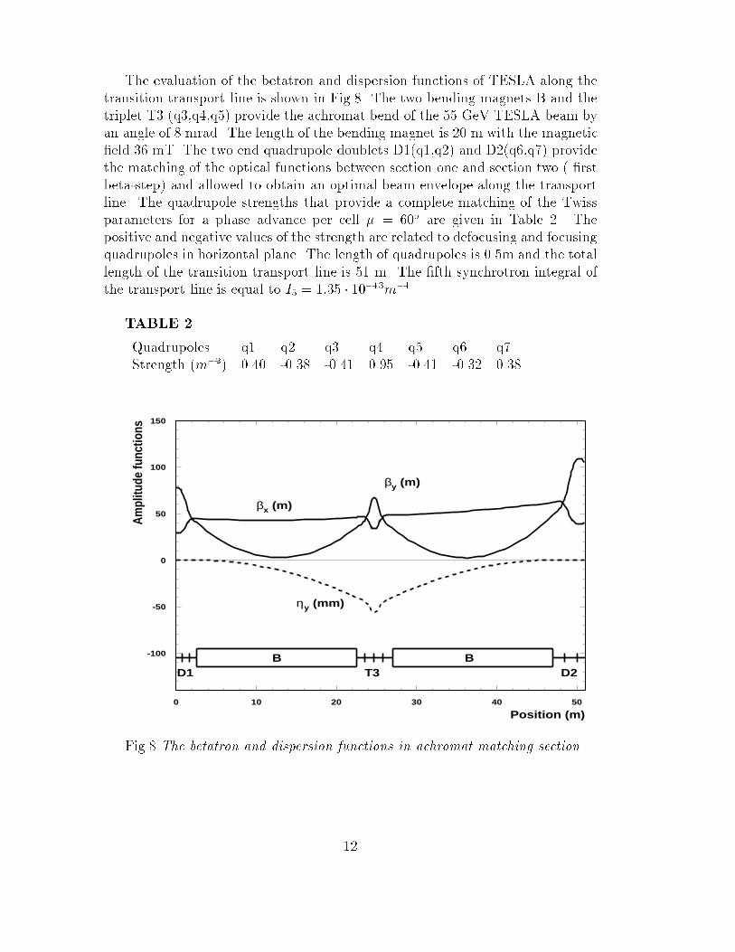
The evaluation of the betatron and dispersion functions of TESLA along the
transition transport line is shown in Fig.8. The two bending magnets B and the
triplet T3 (q3,q4,q5) provide the achromat bend of the 55 GeV TESLA beam by
an angle of 8 mrad. The length of the bending magnet is 20 m with the magnetic
�eld 36 mT. The two end quadrupole doublets D1(q1,q2) and D2(q6,q7) provide
the matching of the optical functions between section one and section two ( �rst
beta-step) and allowed to obtain an optimal beam envelope along the transport
line. The quadrupole strengths that provide a complete matching of the Twiss
parameters for a phase advance per cell � = 60o are given in Table 2. The
positive and negative values of the strength are related to defocusing and focusing
quadrupoles in horizontal plane. The length of quadrupoles is 0.5m and the total
length of the transition transport line is 51 m. The �fth synchrotron integral of
the transport line is equal to I5 = 1:35 � 10�13m�1.
TABLE 2
Quadrupoles q1 q2 q3 q4 q5 q6 q7
Strength (m�2) 0.40 -0.38 -0.41 0.95 -0.41 -0.32 0.38
-100
-50
0
50
100
150
0 10 20 30 40 50
Position (m)
Am
plitu
de fu
nctio
ns
βx (m)
βy (m)
ηy (mm)
B BD1 T3 D2
Fig.8 The betatron and dispersion functions in achromat matching section
12

3.1 Linear optics
The optical solution for two beams with di�erent initial energies to be accelerated
at the same FODO beamline is approximately given by the modi�ed formula
sin(�T=2) = sin(�1=2)
E0T
E0F
EF (n)
ET (n)
!�
(7)
sin(�F=2) = sin(�1T=2)
�E0T
E0F
�� ET (n)
EF (n)
!1��
(8)
where E0 is the initial energy of the beam, �n is the phase advance in the n� thFODO cell, E(n) = E0 + U � n is the energy at the entrance of the n � th cell,
U is the acceleration gradient, � is the scaling parameter and subscript (T,F)
indicates the TESLA and FEL beams respectively. The nominal focusing regime
for both beams is then given by the form.(1) and is reached at the energy of
about 20 GeV of a TESLA beam (about 20 cells).
0
10
20
30
40
50
60
70
80
90
100
5 10 15 20 25 30 35 40 45 50
Energy E(GeV)
Bet
atro
n fu
nctio
n β(
m)
µ1=45o TESLA E0=5 GeV
0
20
40
60
80
100
5 10 15 20 25 30 35
µ1=120o
Energy E(GeV)
Bet
atro
n fu
nctio
n β(
m)
FEL E0=2.2 GeV
Fig.9 The betatron functions for the TESLA and FEL beams.
13

For the injection energies ET=EF = 5=1:5, the compromise solution for both
beams is � = 0:85 with the phase advance per �rst cell for TESLA beam �1T =
30o and for FEL beam �1F = 119o. Actually, the relation of the injection energies
5/1.5 (GeV) is the limiting case since the further decreasing of the FEL beam
energy accompany by the strong wake�eld emittance dilution (scales as sin�2 �)
of the TESLA beam and strong dispersive emittance dilution (scales as tan2 �=2
of the FEL beam.
Therefore, we focus on the reasonable injection energy relation 5/2.2 (GeV)
of the TESLA and FEL beams with the optimal scaling parameter � = 0:6. The
phase advance per FODO cell for TESLA beam is then slightly increase from 45o
up to nominal value 60o, while the phase advance for the FEL beam decreases
from 120o to nominal value about 90o. Thus, the TESLA beam betatron function
envelope at the end of the �rst section of the machine is coincide with the CDR.
Fig.9 shows the variation of the betatron functions along the linac for TESLA
and FEL beams.
3.2 Free coherent oscillations. Dispersive e�ects
The dispersive emittance dilution of the beam in linear accelerator that is caused
by coherent betatron oscillations and particle energy spread is well known and is
given by
�" =1
2a2
0
0
(1 �sin2��
��2) (9)
where a20 is the area of the machine initial phase ellipse (divided by �), 0;
the initial and actual Lorenz factors of design particle, �� the betatron phase
shift of the o�-energy particle. The phase shift of o�-energy particle is caused by
correlated and uncorrelated energy spreads, and in constant beta lattice machine
(� = const) is given by
��un = 2�0 tan�
2
0
� ln 0
(10)
��cor = 2�c tan�
2
0
�
0
� ln
0
� 1
!: (11)
The corresponding emittance dilutions of the beam with one standard initial
o�set in low chromaticity machine (�� << 1) are then approximately given by
�"
" un= 2�20 tan
2(�=2)
0
�
!2
ln2 (z)
0
(12)
�"
" cor= 2�2c tan
2(�=2)
0
�
!2
0
� ln
0
� 1
!2
: (13)
14
where �0; �c are the rms initial uncorrelated and actual correlated energy spread
of the beam, � the energy gain per FODO cell.
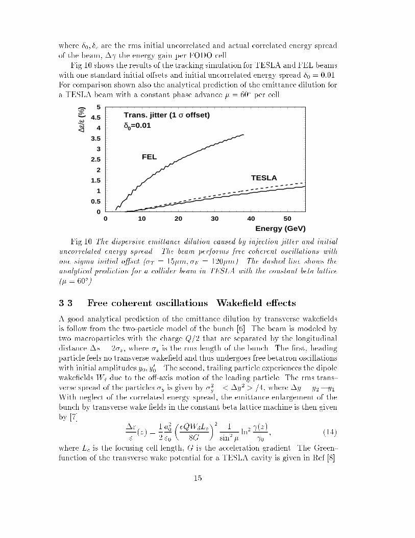
Fig.10 shows the results of the tracking simulation for TESLA and FEL beams
with one standard initial o�sets and initial uncorrelated energy spread �0 = 0:01.
For comparison shown also the analytical prediction of the emittance dilution for
a TESLA beam with a constant phase advance � = 60o per cell.
0
0.5
1
1.5
2
2.5
3
3.5
4
4.5
5
0 10 20 30 40 50
Energy (GeV)
∆ε/ε
(%)
δ0=0.01Trans. jitter (1 σ offset)
TESLA
FEL
Fig.10 The dispersive emittance dilution caused by injection jitter and initial
uncorrelated energy spread. The beam performs free coherent oscillations with
one sigma initial o�set (�T = 15�m; �F = 120�m). The dashed line shows the
analytical prediction for a collider beam in TESLA with the constant beta lattice
(� = 60o).
3.3 Free coherent oscillations. Wake�eld e�ects
A good analytical prediction of the emittance dilution by transverse wake�elds
is follow from the two-particle model of the bunch [6]. The beam is modeled by
two macroparticles with the charge Q=2 that are separated by the longitudinal
distance �s = 2�s, where �s is the rms length of the bunch. The �rst, heading
particle feels no transverse wake�eld and thus undergoes free betatron oscillations
with initial amplitudes y0; y0
0 . The second, trailing particle experiences the dipole
wake�elds Wd due to the o�-axis motion of the leading particle. The rms trans-
verse spread of the particles �y is given by �2y =< �y2 > =4, where �y = y2�y1.
With neglect of the correlated energy spread, the emittance enlargement of the
bunch by transverse wake �elds in the constant beta lattice machine is then given
by [7]
�"
"
(z) =1
2
a20
"0
�eQWdLc
8G
�2 1
sin2 �ln2
(z)
0
; (14)
where Lc is the focusing cell length, G is the acceleration gradient. The Green-
function of the transverse wake potential for a TESLA cavity is given in Ref.[8].
15
The value of the transverse wake potential experienced by the trailing charge for
TESLA beam is WD(2�s) = 16:6eV=pC=m2 and for FEL beam is WD(2�s) =
4:52eV=pC=m2.
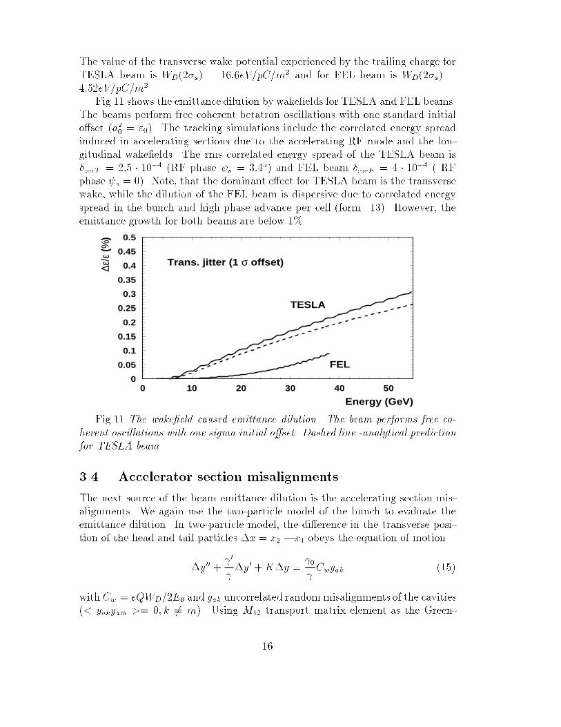
Fig.11 shows the emittance dilution by wake�elds for TESLA and FEL beams.
The beams perform free coherent betatron oscillations with one standard initial
o�set (a20= "0). The tracking simulations include the correlated energy spread
induced in accelerating sections due to the accelerating RF mode and the lon-
gitudinal wake�elds. The rms correlated energy spread of the TESLA beam is
�corT = 2:5 � 10�4 (RF phase s = 3:4o) and FEL beam �corF = 4 � 10�4 ( RF
phase s = 0). Note, that the dominant e�ect for TESLA beam is the transverse
wake, while the dilution of the FEL beam is dispersive due to correlated energy
spread in the bunch and high phase advance per cell (form. 13). However, the
emittance growth for both beams are below 1%.
0
0.05
0.1
0.15
0.2
0.25
0.3
0.35
0.4
0.45
0.5
0 10 20 30 40 50
Energy (GeV)
∆ε/ε
(%)
Trans. jitter (1 σ offset)
FEL
TESLA
Fig.11 The wake�eld caused emittance dilution. The beam performs free co-
herent oscillations with one sigma initial o�set. Dashed line -analytical prediction
for TESLA beam.
3.4 Accelerator section misalignments
The next source of the beam emittance dilution is the accelerating section mis-
alignments. We again use the two-particle model of the bunch to evaluate the
emittance dilution. In two-particle model, the di�erence in the transverse posi-
tion of the head and tail particles �x = x2 � x1 obeys the equation of motion
�y00 + 0
�y0 +K�y = 0
Cwyak (15)
with Cw = eQWD=2E0 and yak uncorrelated randommisalignments of the cavities
(< yakyam >= 0; k 6= m). Using M12 transport matrix element as the Green-
16

function, we obtain
�y(z) = Cw 0
vuut�(z)
(z)
NXk=1
yak
Z zk+dc
zk
vuut�(z0)
(z0)sin [�(z)� �(z0] dz0 (16)
where z is position along the linac, dc is the cavity length, N is the cavity num-
ber. Using the model that the trailing particle experience the kick at the center
of the cavity and replacing the beta function by it average value, the squared
displacement averaged over the phase � is then given by
�" =1
4
< �x2(z) >
�(z)=
1
8< y
2
a > C2
wd2
c
0
(z)
NXk=1
�k
0
k
(17)
Replacing the sum over the cavities by the integral in energy range, for constant
beta lattice � = Lcell= sin � we get
�"(z)
"
=< y
2a >
2Ncav"0
�eQWD
4G
�2 � 0
Lc
sin�ln (z)
0
(18)
where "0 is the beam initial natural emittance , Ncav is the number of the cavities
per single FODO cell. Fig.12 present the emittance dilution of the TESLA beam
averaged over the 50 random samples of the cavity misalignments with the rms
value �cav = 0:5mm . Note, that the same order of the emittance dilution is
predicted if the modules ( which contain 8 cavities) is misaligned by the rms
value �mod = 60�m. The emittance dilution of the FEL beam due to cavity
misalignments is in order �"=" � 10�5.
0
0.5
1
1.5
2
2.5
3
3.5
4
4.5
5
0 10 20 30 40 50
Energy (GeV)
∆ε/ε
(%)
Qb=3.25 nC, σz= 0.4 mm, δcor=2.5 10-4
Cavity misal. σcav =0.5 mm
TESLA
Fig 12. Emittance dilution of the TESLA beam because of the cavity misalign-
ments. Dashed line -analytical prediction.
17
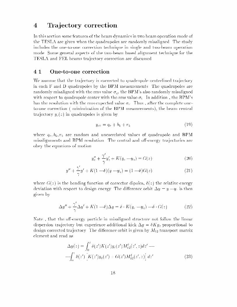
4 Trajectory correction
In this section some features of the beam dynamics in two beam operation mode of
the TESLA are given when the quadrupoles are randomly misaligned. The study
includes the one-to-one correction technique in single and two-beam operation
mode. Some general aspects of the two-beam based alignment technique for the
TESLA and FEL beams trajectory correction are discussed.
4.1 One-to-one correction
We assume that the trajectory is corrected to quadrupole centerlined trajectory
in each F and D quadrupoles by the BPM measurements. The quadrupoles are
randomly misaligned with the rms value �q, the BPM's also randomly misaligned
with respect to quadrupole center with the rms value �b. In addition , the BPM's
has the resolution with the rms expected value �r. Thus , after the complete one-
to-one correction ( minimization of the BPM measurements), the beam central
trajectory yc(z) in quadrupoles is given by
yck = qk + bk + rk (19)
where qk; bk; rk are random and uncorrelated values of quadrupole and BPM
misalignments and BPM resolution. The central and o�-energy trajectories are
obey the equations of motion
y00
c + 0
y0
c +K(yc � yq) = G(z) (20)
y00 +
0
y0 +K(1 � �)(y � yq) = (1� �)G(z) (21)
where G(z) is the bending function of corrector dipoles, �(z) the relative energy
deviation with respect to design energy. The di�erence orbit �y = y� yc is thengiven by
�y00 + 0
�y0 +K(1 � �)�y = � �K(yc � yq)� � �G(z) (22)
Note , that the o�-energy particle in misaligned structure not follow the linear
dispersion trajectory but experience additional kick �y = �Kyc proportional to
design corrected trajectory. The di�erence orbit is given byM12 transport matrix
element and read as
�y(z) =
Z z
0
�(z0)K(z0)yc(z0)M �
12(z0
; z)dz0 �
�Z z
0
�(z0)hK(z0)yq(z
0) +G(z0)M �12(z
0
; z)idz
0 (23)
18
For small energy di�erence (� << 1) we can neglect the high order term K��y.
By partial integration of the second term in the right hand side of the equation
we then get
�y(z) =
Z z
0
�(z0)K(z0)yc(z0)M �
12(z0
; z)dz0 � �(z)yc(z)�Z z
0
�0(z0)yc(z
0)dz0 (24)
It can be shown that the dominant contribution to emittance dilution is the �rst
term of the right hand side. For initial uncorrelated energy spread �0 the actual
energy spread in the bunch vary as �(z) = �0 0= . The squared rms deviation of
the o�-energy particle averaged over the actual betatron phase and initial energy
spread is then given by
< �y2(z) >=1
2< y
2
c > �2
0rms�(z) 0
(z)
Xn
0
n
K2
nL2
qn(�nmax+ �nmin) (25)
where < y2c >=< �
2q > + < �
2b > + < s
2r >. Using the well known relations for
symmetric FODO lattice
�max + �min =2Lc
sin�; KLqLc = 4 sin
�
2; (26)
the relative emittance dilution in thin lens approximation is then given by
�"
"
= 8�20rms
< y2c >
"0Lc
0
� tan
�
2� ln
(z)
0
(27)
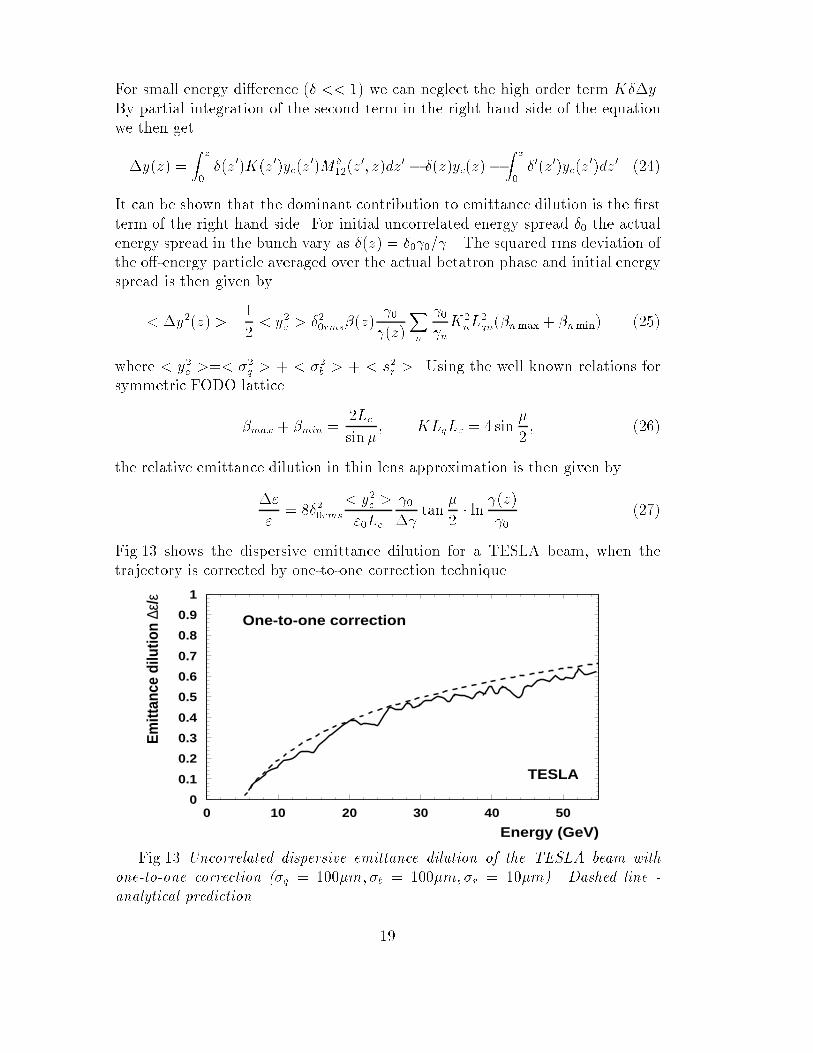
Fig.13 shows the dispersive emittance dilution for a TESLA beam, when the
trajectory is corrected by one-to-one correction technique.
0
0.1
0.2
0.3
0.4
0.5
0.6
0.7
0.8
0.9
1
0 10 20 30 40 50
Energy (GeV)
Em
ittan
ce d
ilutio
n ∆ε
/ε
One-to-one correction
TESLA
Fig.13 Uncorrelated dispersive emittance dilution of the TESLA beam with
one-to-one correction (�q = 100�m; �b = 100�m; �r = 10�m). Dashed line -
analytical prediction.
19
Note, that for high luminosity TESLA parameters , the uncorrelated disper-
sive emittance dilution is very large (�0 = 0:01) even for the quadrupole and
BPM misalignments at the level of 100�m. In addition, in two beam operation
mode, the coherent oscillations of the second beam not vanish and lead to large
emittance dilution of the FEL beam.
4.2 Two beam operation
Let us consider the transverse dynamics of two beams with di�erent energies in
misaligned structure when the central trajectory one of the beams ( let say high
energy beam) is corrected by one-to-one correction technique. We assume that
the ratio of initial energies is equal to ratio of acceleration gradients so that the
ratio ET=EF is constant along the linac. The second beam (FEL beam) will then
performs coherent oscillations according to
yf =ET
EF
yt +�y (28)
where
�y00+ 0
f
f
�y0 +Kf�y = ��Kfyt (29)
with � = (ET � EF )=EF , yt is the corrected TESLA beam trajectory, yf is
the trajectory of the FEL beam. Thus , for a large energy di�erence � � 0:4,
the second order dispersion trajectory of the FEL beam becomes the dominant,
and the beam performs large coherent oscillation which depends on the random
samples of quadrupole and BPM misalignments
�y = ��Z z
0
Kf (z0)yt(z
0)MF12(z0; z)dz0 (30)
Note that the oscillations of the FEL beam around the linear dispersion trajec-
tory is essentially adequate to beam coherent oscillation in misaligned structure
without the trajectory correction. Evaluating the integral we obtain
�y(z) = ��
vuut�(z)
(z)
Xk
ytkKfkLq
q�k k sin[�(z)� �(zk)] (31)
For squared displacement only the correlated members should be taken into ac-
count and we get
< �y2 >= �
2< y
2
t >�(z)
(z)
Xk
K2
fkL2
q�k k sin2[�(z)� �(zk)] (32)
The additional rms contribution to FEL disturb trajectory is then given by
y < �y2 > +2�y < �y�y0 > +�y < �y02 >= A2 (33)
20
where
A2 = �
2< y
2
t >1
(z)
Xk
K2
fkL2
q�k k � 8�2< y
2t >
Lc
0
� tan
�
2
"
0
� 0
#(34)
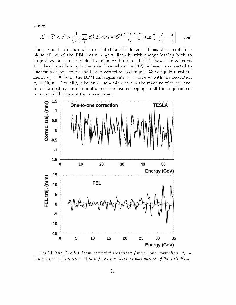
The parameters in formula are related to FEL beam . Thus, the rms disturb
phase ellipse of the FEL beam is grow linearly with energy leading both to
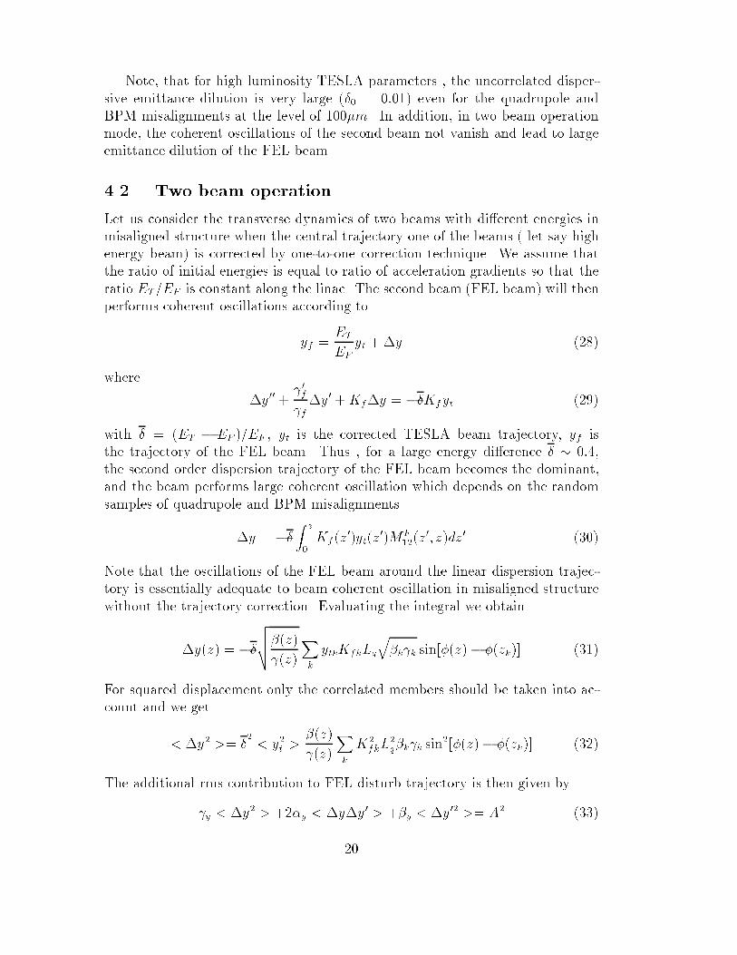
large dispersive and wake�eld emittance dilution. Fig.14 shows the coherent
FEL beam oscillations in the main linac when the TESLA beam is corrected to
quadrupoles centers by one-to-one correction technique. Quadrupole misalign-
ments �q = 0:5mm, the BPM misalignments �b = 0:1mm with the resolution
�r = 10�m. Actually, it becomes impossible to run the machine with the one-
to-one trajectory correction of one of the beams keeping small the amplitude of
coherent oscillations of the second beam.
-1.5
-1
-0.5
0
0.5
1
1.5
0 10 20 30 40 50
Energy (GeV)
Co
rrec. tr
aj. (
mm
)
One-to-one correction TESLA
-15
-10
-5
0
5
10
15
0 5 10 15 20 25 30 35
Energy (GeV)
FE
L t
raj. (
mm
)
FEL
Fig.14 The TESLA beam corrected trajectory (one-to-one correction, �q =
0:5mm;�b = 0:1mm;�r = 10�m ) and the coherent oscillations of the FEL beam.
21
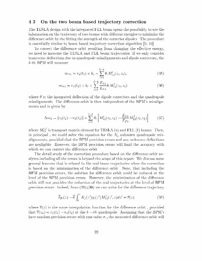
4.3 On the two beam based trajectory correction
The TESLA design with the integrated FEL beam opens the possibility to use the
information on the trajectory of two beams with di�erent energies to minimize the
di�erence orbit by the �tting the strength of the corrector dipoles. The procedure
is essentially similar to beam based trajectory correction algorithm [9, 10].
To correct the di�erence orbit resulting from changing the e�ective energy,
we need to measure the TESLA and FEL beam trajectories. If we only consider
transverse de ections due to quadrupole misalignments and dipole correctors, the
k-th BPM will measure
mTk = rk(t1) + bk +k�1Xl=1
�lMt12(zl; zk); (35)
mFk = rk(t2) + bk +k�1Xl=1
ETk
EFk
�lMf12(zl; zk) (36)
where � is the integrated de ection of the dipole correctors and the quadrupole
misalignments. The di�erence orbit is then independent of the BPM's misalign-
ments and is given by
�mk = [rk(t1)� rk(t2)] +k�1Xl=1
�l
�M
t12(zl; zk)�
ETk
EFk
M
f12(zl; zk)
�(37)
whereMt;f12 is transport matrix element for TESLA (t) and FEL (f) beams. Then,
in principal , we could solve the equation for the Nq unknown quadrupole mis-
alignments, provided that the BPM precision errors and any unknown de ections
are negligible. However, the BPM precision errors will limit the accuracy with
which we can correct the di�erence orbit.
The detail study of the correction procedure based on the di�erence orbit an-
alyzes including all the errors is beyond the scope of this report. We discuss some
general features that is related to the real beam trajectories when the correction
is based on the minimization of the di�erence orbit. Note, that including the
BPM precision errors, the solution for di�erence orbit could be reduced at the
level of the BPM precision errors. However, the minimization of the di�erence
orbit still not provides the reduction of the real trajectories at the level of BPM
precision errors. Indeed, from (28),(30) we can write for the di�erence trajectory
�yt(z)� �
Z z
0
Kf (z0)yt(z
0)Mf12(z
0
; z)dz0 = r(z) (38)
where r(z) is the some interpolation function for the di�erence orbit , provided
that r(zk) = rk(t1)� rk(t2) at the k � th quadrupole. Assuming that the BPM's
have random precision errors with rms value �r, the measured di�erence orbit will
22
di�er from the actual di�erence orbit by an rms error rrms =p2�r. In smooth
focusing model we could rewrite the expression for the di�erence orbit as
yt(z)� kf
Z z
0
yt(z0) sin[kf (z � z
0)] =r(z)
�
(39)
For simplicity, the beam acceleration is not taken into account. Using Laplace
transform , we get
Yt(p) = �
�1
1 +
k2f
p2
!L[r(z)]: (40)
The waiting trajectories for the TESLA and FEL beams is then given by
yt(z) = �
�1
f
"r(z) + k
2
f
Z z
0
Z z0
0
r(z00)dz00dz0#; (41)
yf (z) = �
�1
t
"r(z) + k
2
t
Z z
0
Z z0
0
r(z00)dz00dz0#; (42)
with �t;f = �E=Et;f , �E = Et � Ef , and kt;f the betatron wave numbers for
TESLA and FEL beams respectively. The real trajectories of the beams at the
n� th quadrupole is then given by
yt(zn) = �
�1
f
"rn + k
2
fD2
n�1Xk=1
kXm=1
rm
#(43)
yf(zn) = �
�1
t
"rn + k
2
tD2
n�1Xk=1
kXm=1
rm
#(44)
where D is the distance between two quadrupoles. Note, that the di�erence orbit
is at the level of BPM's precision errors yt�yf = rn = rn(t1)�rn(t2). Taking intoaccount that < rnrk >= 0 if n 6= k, for waiting rms trajectories of the TESLA
and FEL beams we get
< y2
t (z) >1=2�< y
2
f (z) >1=2�
Et
�E�rk
2
tDz (45)
The beam acceleration is not change the essential of the situation. The real
trajectories are diverge from the linac centerline and the waiting rms trajectories
of the TESLA and FEL beams grow approximately linear with the beam energy.
This occurs because the di�erence orbit is not referenced to the linac centerline
and small errors add. Thus we need to include some information about the real
trajectory while correcting the di�erence orbit.
The well established procedure [10] is to perform a least squares solution for
the unknowns, using both the original trajectory and the di�erence orbit weighted
with the absolute accuracy with which these trajectories are known. The dipole
corrector strengths are then minimize the sum
Xk
(mTk + yTk)2
�2r + �
2b
+(�mk +�yk)
2
2�2r(46)
23
Thus, we suppose, that the minimization of the both di�erence orbit and
original TESLA trajectory will provides the correction of the both TESLA and
FEL beam trajectories at the level of the BPM resolution.
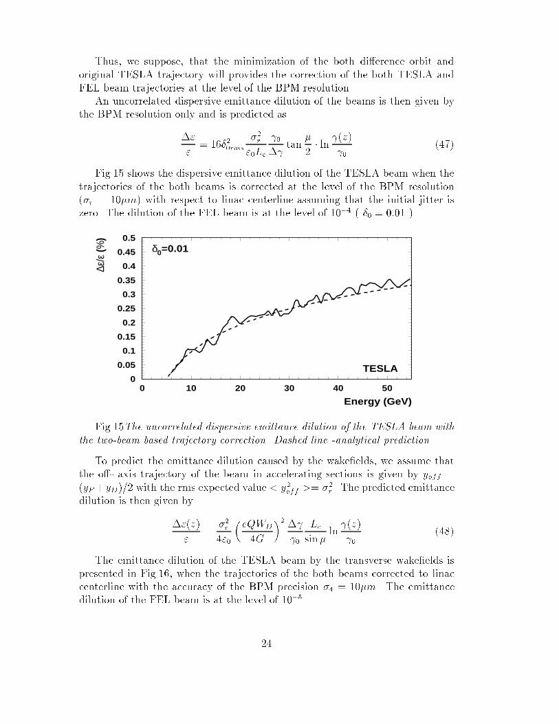
An uncorrelated dispersive emittance dilution of the beams is then given by
the BPM resolution only and is predicted as
�"
"
= 16�20rms
�2r
"0Lc
0
� tan
�
2� ln
(z)
0
(47)
Fig.15 shows the dispersive emittance dilution of the TESLA beam when the
trajectories of the both beams is corrected at the level of the BPM resolution
(�r = 10�m) with respect to linac centerline assuming that the initial jitter is
zero. The dilution of the FEL beam is at the level of 10�4 ( �0 = 0:01 ).
0
0.05
0.1
0.15
0.2
0.25
0.3
0.35
0.4
0.45
0.5
0 10 20 30 40 50
Energy (GeV)
∆ε/ε
(%)
δ0=0.01
TESLA
Fig.15The uncorrelated dispersive emittance dilution of the TESLA beam with
the two-beam based trajectory correction. Dashed line -analytical prediction.
To predict the emittance dilution caused by the wake�elds, we assume that
the o�- axis trajectory of the beam in accelerating sections is given by yoff =
(yF +yD)=2 with the rms expected value < y2off >= �
2r . The predicted emittance
dilution is then given by
�"(z)
"
=�2r
4"0
�eQWD
4G
�2 � 0
Lc
sin�ln (z)
0
(48)
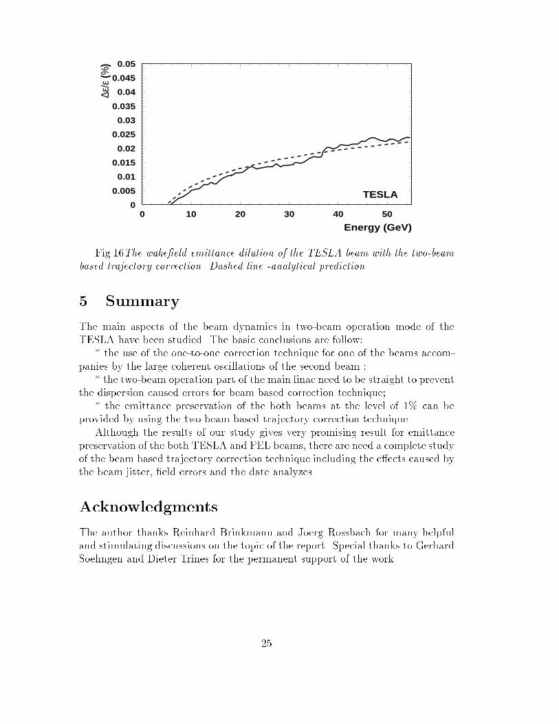
The emittance dilution of the TESLA beam by the transverse wake�elds is
presented in Fig.16, when the trajectories of the both beams corrected to linac
centerline with the accuracy of the BPM precision �4 = 10�m. The emittance
dilution of the FEL beam is at the level of 10�5.
24
0
0.005
0.01
0.015
0.02
0.025
0.03
0.035
0.04
0.045
0.05
0 10 20 30 40 50
Energy (GeV)
∆ε/ε
(%)
TESLA
Fig.16The wake�eld emittance dilution of the TESLA beam with the two-beam
based trajectory correction. Dashed line -analytical prediction.
5 Summary
The main aspects of the beam dynamics in two-beam operation mode of the
TESLA have been studied. The basic conclusions are follow:
* the use of the one-to-one correction technique for one of the beams accom-
panies by the large coherent oscillations of the second beam ;
* the two-beam operation part of the main linac need to be straight to prevent
the dispersion caused errors for beam based correction technique;
* the emittance preservation of the both beams at the level of 1% can be
provided by using the two beam based trajectory correction technique.
Although the results of our study gives very promising result for emittance
preservation of the both TESLA and FEL beams, there are need a complete study
of the beam based trajectory correction technique including the e�ects caused by
the beam jitter, �eld errors and the date analyzes.
Acknowledgments
The author thanks Reinhard Brinkmann and Joerg Rossbach for many helpful
and stimulating discussions on the topic of the report. Special thanks to Gerhard
Soehngen and Dieter Trines for the permanent support of the work.
25
References
[1] Conceptual Design of a 500 GeV e+e� Linear Collider with Integrated X-
Ray Laser Facility, edited by R. Brinkmann, G. Materlik, J. Rossbach and
A. Wagner, Hamburg, DESY 1997-048, 1997.
[2] P.J. Bryant, Proc. of the 1992 CERN Accel.School, CERN 94-01,1994.
[3] R.Brinkmann"High Luminosity TESLA-500", TESLA 97-13, 1997.
[4] W. Decking , TESLA Meeting, TESLA 99-13, 1999.
[5] M. Sands, "Emittance Growth from Radiation Fluctuations", SLAC-AP-47
(1985).
[6] P.Wilson in Physics of High Energy Particle Accelerators, edited by
R.A.Carrigan, F.R. Huson, and M. Month, AIP Conf. Proc. No. 87, ( AIP,
New York, 1982), Sec. 11.1.
[7] K. Bane, Report No. SLAC-PUB-4169, 1986.
[8] A.Mosnier, A.Novokhatsky, DAPNIA/SEA-9608, 1996.
[9] C.E. Adolphsen etc, SLAC-PUB-4902, March 1989.
[10] T.O. Raubenheimer and R.D. Ruth, NIM (A), 302, 191 (1991)
26