Embed Size (px)
Citation preview
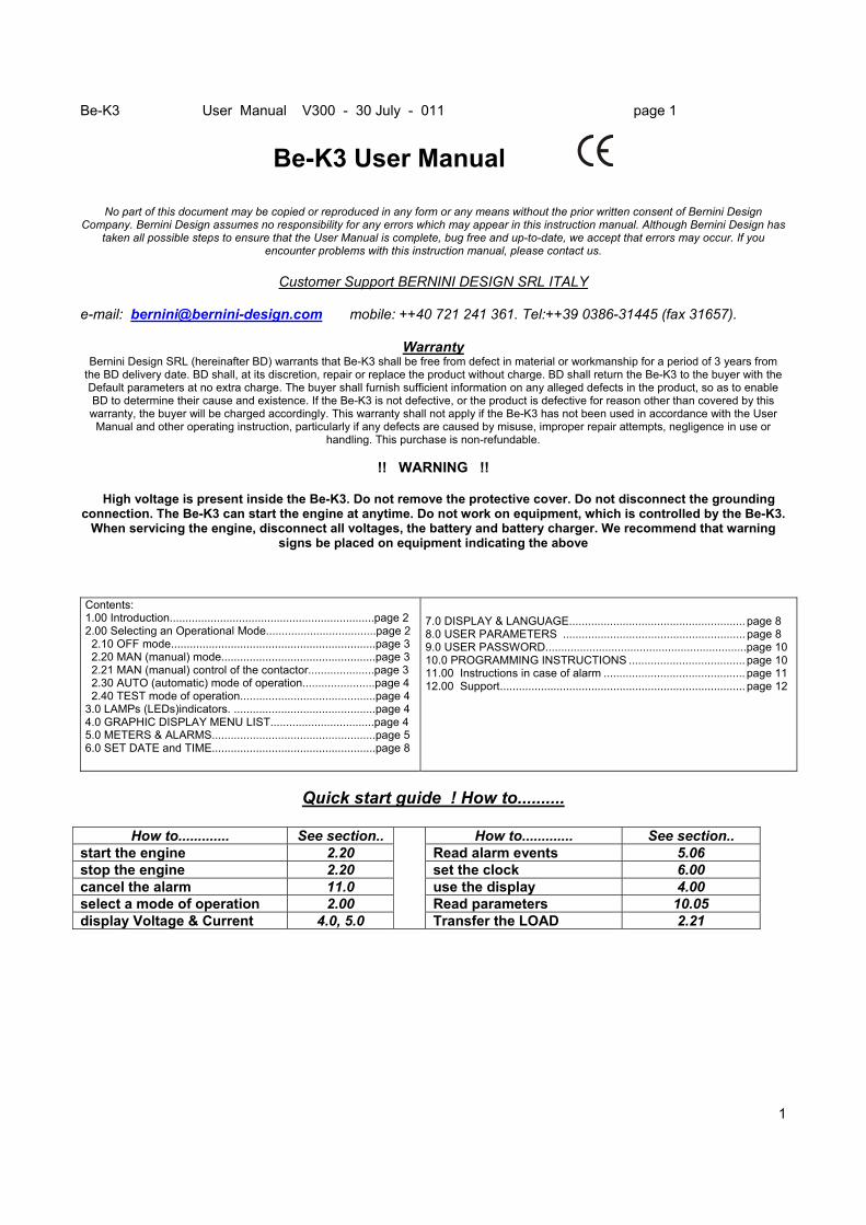
Be-K3 User Manual V300 - 30 July - 011 page 1
1
Be-K3 User Manual - -
No part of this document may be copied or reproduced in any form or any means without the prior written consent of Bernini Design Company. Bernini Design assumes no responsibility for any errors which may appear in this instruction manual. Although Bernini Design has
taken all possible steps to ensure that the User Manual is complete, bug free and up-to-date, we accept that errors may occur. If you encounter problems with this instruction manual, please contact us.
Customer Support BERNINI DESIGN SRL ITALY
e-mail: [email protected] mobile: ++40 721 241 361. Tel:++39 0386-31445 (fax 31657).
Warranty Bernini Design SRL (hereinafter BD) warrants that Be-K3 shall be free from defect in material or workmanship for a period of 3 years from
the BD delivery date. BD shall, at its discretion, repair or replace the product without charge. BD shall return the Be-K3 to the buyer with the Default parameters at no extra charge. The buyer shall furnish sufficient information on any alleged defects in the product, so as to enable BD to determine their cause and existence. If the Be-K3 is not defective, or the product is defective for reason other than covered by this warranty, the buyer will be charged accordingly. This warranty shall not apply if the Be-K3 has not been used in accordance with the User
Manual and other operating instruction, particularly if any defects are caused by misuse, improper repair attempts, negligence in use or handling. This purchase is non-refundable.
!! WARNING !!
High voltage is present inside the Be-K3. Do not remove the protective cover. Do not disconnect the grounding
connection. The Be-K3 can start the engine at anytime. Do not work on equipment, which is controlled by the Be-K3. When servicing the engine, disconnect all voltages, the battery and battery charger. We recommend that warning
signs be placed on equipment indicating the above Contents: 1.00 Introduction.................................................................page 2 2.00 Selecting an Operational Mode...................................page 2 2.10 OFF mode.................................................................page 3 2.20 MAN (manual) mode.................................................page 3 2.21 MAN (manual) control of the contactor.....................page 3 2.30 AUTO (automatic) mode of operation.......................page 4 2.40 TEST mode of operation...........................................page 4 3.0 LAMPs (LEDs)indicators. .............................................page 4 4.0 GRAPHIC DISPLAY MENU LIST.................................page 4 5.0 METERS & ALARMS....................................................page 5 6.0 SET DATE and TIME....................................................page 8
7.0 DISPLAY & LANGUAGE........................................................ page 8 8.0 USER PARAMETERS .......................................................... page 8 9.0 USER PASSWORD................................................................page 10 10.0 PROGRAMMING INSTRUCTIONS ..................................... page 10 11.00 Instructions in case of alarm ............................................. page 11 12.00 Support.............................................................................. page 12
Quick start guide ! How to..........
How to............. See section.. How to............. See section..
start the engine 2.20 Read alarm events 5.06 stop the engine 2.20 set the clock 6.00 cancel the alarm 11.0 use the display 4.00 select a mode of operation 2.00 Read parameters 10.05 display Voltage & Current 4.0, 5.0
Transfer the LOAD 2.21
Be-K3 User Manual V300 - 30 July - 011 page 2
2
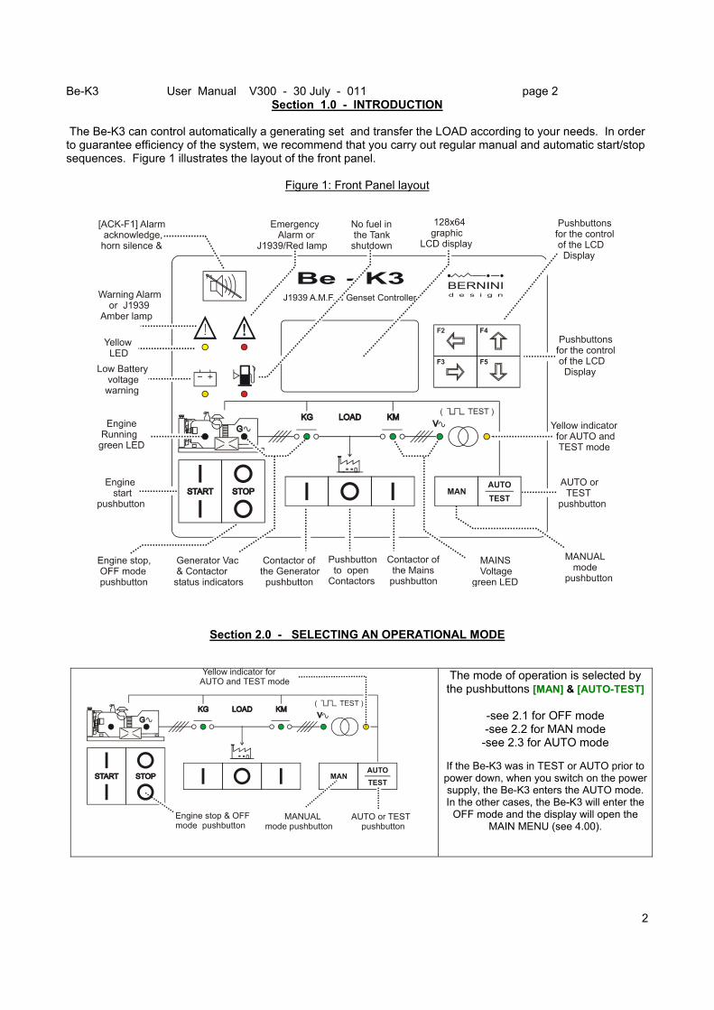
Section 1.0 - INTRODUCTION The Be-K3 can control automatically a generating set and transfer the LOAD according to your needs. In order to guarantee efficiency of the system, we recommend that you carry out regular manual and automatic start/stop sequences. Figure 1 illustrates the layout of the front panel.
Figure 1: Front Panel layout
F2
F3
F4
F5
J1939 A.M.F. & Genset Controller
F1
[ACK-F1] Alarm acknowledge, horn silence &
Contactor of the Generator pushbutton
Pushbutton to open Contactors
Contactor of the Mains pushbutton
Yellow LED
AUTO or TEST pushbutton
Yellow indicator for AUTO and TEST mode
MANUAL modepushbutton
Engine startpushbutton
Engine stop, OFF mode pushbutton
Generator Vac & Contactorstatus indicators
Pushbuttonsfor the control of the LCD Display
Pushbuttonsfor the control of the LCD Display
Low Battery voltage warning
No fuel in the Tank shutdown
Emergency Alarm orJ1939/Red lamp
128x64 graphic LCD display
Warning Alarm or J1939 Amber lamp
Engine Runninggreen LED
MAINS Voltagegreen LED
Section 2.0 - SELECTING AN OPERATIONAL MODE
AUTO or TEST pushbutton
Yellow indicator for AUTO and TEST mode
MANUALmode pushbutton
Engine stop & OFF mode pushbutton
The mode of operation is selected by the pushbuttons [MAN] & [AUTO-TEST]
-see 2.1 for OFF mode -see 2.2 for MAN mode
-see 2.3 for AUTO mode If the Be-K3 was in TEST or AUTO prior to power down, when you switch on the power supply, the Be-K3 enters the AUTO mode. In the other cases, the Be-K3 will enter the
OFF mode and the display will open the MAIN MENU (see 4.00).
Be-K3 User Manual V300 - 30 July - 011 page 3
3
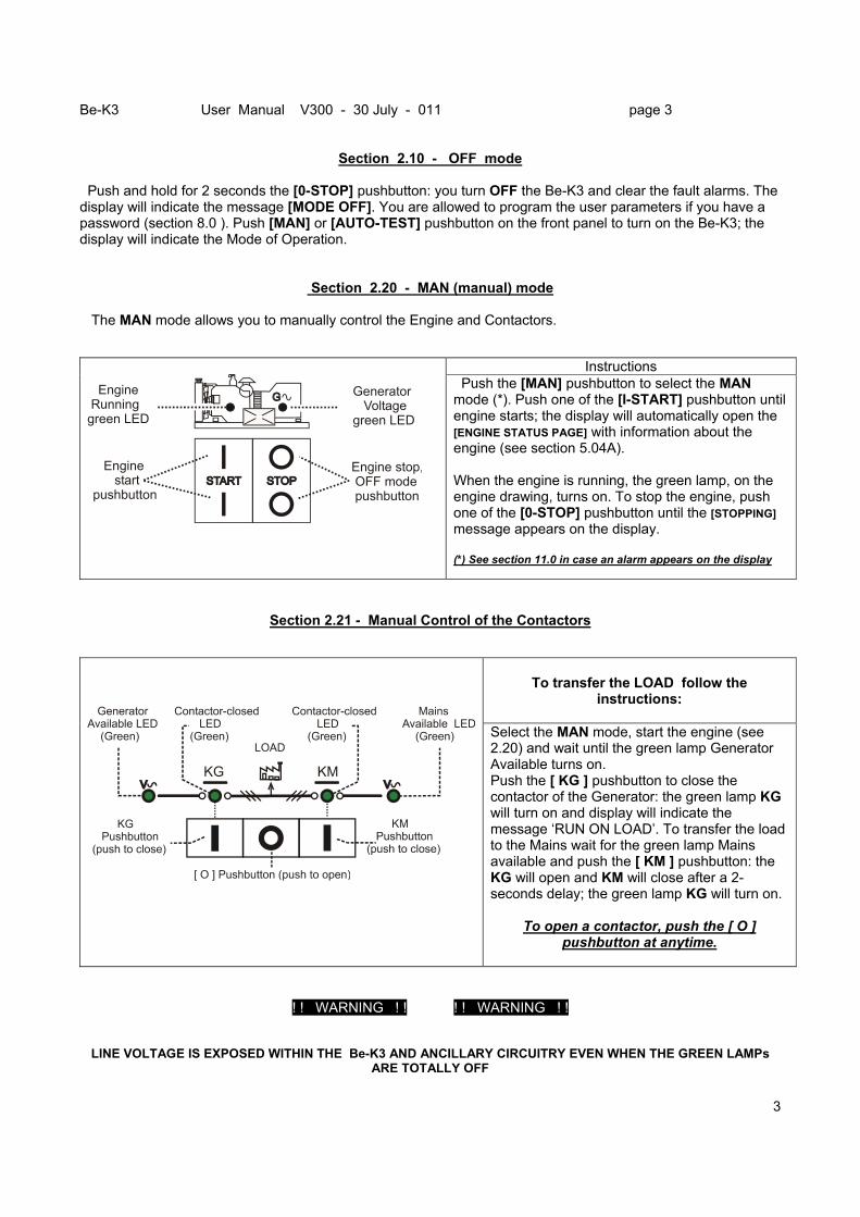
Section 2.10 - OFF mode Push and hold for 2 seconds the [0-STOP] pushbutton: you turn OFF the Be-K3 and clear the fault alarms. The display will indicate the message [MODE OFF]. You are allowed to program the user parameters if you have a password (section 8.0 ). Push [MAN] or [AUTO-TEST] pushbutton on the front panel to turn on the Be-K3; the display will indicate the Mode of Operation.
Section 2.20 - MAN (manual) mode The MAN mode allows you to manually control the Engine and Contactors.
Section 2.21 - Manual Control of the Contactors
! ! WARNING ! ! ! ! WARNING ! !
LINE VOLTAGE IS EXPOSED WITHIN THE Be-K3 AND ANCILLARY CIRCUITRY EVEN WHEN THE GREEN LAMPs ARE TOTALLY OFF
Instructions
Engine start pushbutton
Engine stop, OFF mode pushbutton
Engine Runninggreen LED
Generator Voltagegreen LED
Push the [MAN] pushbutton to select the MAN mode (*). Push one of the [I-START] pushbutton until engine starts; the display will automatically open the [ENGINE STATUS PAGE] with information about the engine (see section 5.04A). When the engine is running, the green lamp, on the engine drawing, turns on. To stop the engine, push one of the [0-STOP] pushbutton until the [STOPPING] message appears on the display. (*) See section 11.0 in case an alarm appears on the display
To transfer the LOAD follow the
instructions:
Select the MAN mode, start the engine (see 2.20) and wait until the green lamp Generator Available turns on. Push the [ KG ] pushbutton to close the contactor of the Generator: the green lamp KG will turn on and display will indicate the message ‘RUN ON LOAD’. To transfer the load to the Mains wait for the green lamp Mains available and push the [ KM ] pushbutton: the KG will open and KM will close after a 2-seconds delay; the green lamp KG will turn on.
To open a contactor, push the [ O ]
pushbutton at anytime.
Be-K3 User Manual V300 - 30 July - 011 page 4
4
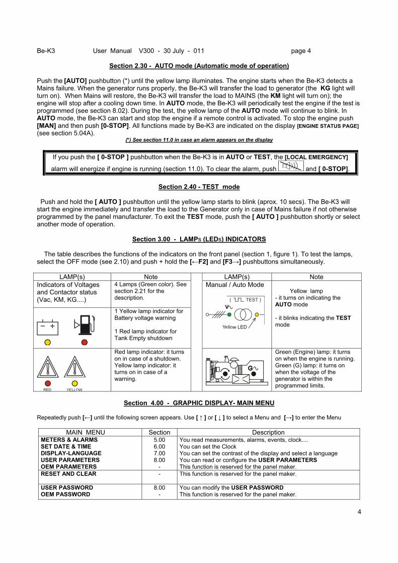
Section 2.30 - AUTO mode (Automatic mode of operation)
Push the [AUTO] pushbutton (*) until the yellow lamp illuminates. The engine starts when the Be-K3 detects a Mains failure. When the generator runs properly, the Be-K3 will transfer the load to generator (the KG light will turn on). When Mains will restore, the Be-K3 will transfer the load to MAINS (the KM light will turn on); the engine will stop after a cooling down time. In AUTO mode, the Be-K3 will periodically test the engine if the test is programmed (see section 8.02). During the test, the yellow lamp of the AUTO mode will continue to blink. In AUTO mode, the Be-K3 can start and stop the engine if a remote control is activated. To stop the engine push [MAN] and then push [0-STOP]. All functions made by Be-K3 are indicated on the display [ENGINE STATUS PAGE] (see section 5.04A).
(*) See section 11.0 in case an alarm appears on the display
If you push the [ 0-STOP ] pushbutton when the Be-K3 is in AUTO or TEST, the [LOCAL EMERGENCY]
alarm will energize if engine is running (section 11.0). To clear the alarm, push and [ 0-STOP].
Section 2.40 - TEST mode Push and hold the [ AUTO ] pushbutton until the yellow lamp starts to blink (aprox. 10 secs). The Be-K3 will start the engine immediately and transfer the load to the Generator only in case of Mains failure if not otherwise programmed by the panel manufacturer. To exit the TEST mode, push the [ AUTO ] pushbutton shortly or select another mode of operation.
Section 3.00 - LAMPs (LEDs) INDICATORS The table describes the functions of the indicators on the front panel (section 1, figure 1). To test the lamps, select the OFF mode (see 2.10) and push + hold the [←F2] and [F3→] pushbuttons simultaneously.
LAMP(s) Note LAMP(s) Note Indicators of Voltages and Contactor status (Vac, KM, KG....)
4 Lamps (Green color). See section 2.21 for the description.
1 Yellow lamp indicator for Battery voltage warning 1 Red lamp indicator for Tank Empty shutdown
Manual / Auto Mode
Yellow lamp - it turns on indicating the AUTO mode - it blinks indicating the TEST mode
RED YELLOW
Red lamp indicator: it turns on in case of a shutdown. Yellow lamp indicator: it turns on in case of a warning.
Green (Engine) lamp: it turns on when the engine is running. Green (G) lamp: it turns on when the voltage of the generator is within the programmed limits.
Section 4.00 - GRAPHIC DISPLAY- MAIN MENU
Repeatedly push [←] until the following screen appears. Use [ ↑ ] or [ ↓ ] to select a Menu and [→] to enter the Menu
MAIN MENU Section Description METERS & ALARMS SET DATE & TIME DISPLAY-LANGUAGE USER PARAMETERS OEM PARAMETERS
5.00 6.00
7.00 8.00
-
You read measurements, alarms, events, clock.... You can set the Clock You can set the contrast of the display and select a language You can read or configure the USER PARAMETERS This function is reserved for the panel maker.
RESET AND CLEAR -
This function is reserved for the panel maker.
USER PASSWORD OEM PASSWORD
8.00 -
You can modify the USER PASSWORD This function is reserved for the panel maker.
Be-K3 User Manual V300 - 30 July - 011 page 5
5
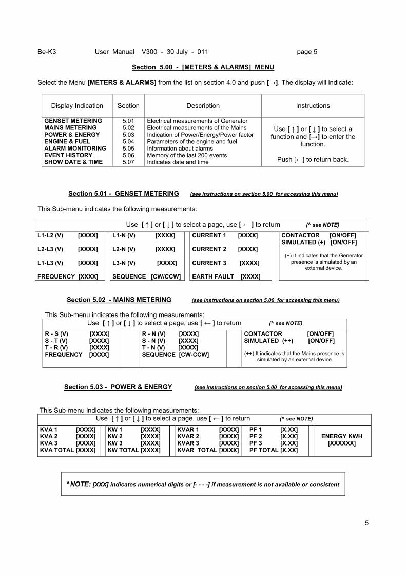
Section 5.00 - [METERS & ALARMS] MENU
Select the Menu [METERS & ALARMS] from the list on section 4.0 and push [→]. The display will indicate:
Display Indication
Section
Description
Instructions
GENSET METERING MAINS METERING POWER & ENERGY ENGINE & FUEL ALARM MONITORING EVENT HISTORY SHOW DATE & TIME
5.01 5.02 5.03 5.04 5.05 5.06 5.07
Electrical measurements of Generator Electrical measurements of the Mains Indication of Power/Energy/Power factor Parameters of the engine and fuel Information about alarms Memory of the last 200 events Indicates date and time
Use [ ↑ ] or [ ↓ ] to select a
function and [→] to enter the function.
Push [←] to return back.
Section 5.01 - GENSET METERING (see instructions on section 5.00 for accessing this menu) This Sub-menu indicates the following measurements: Use [ ↑ ] or [ ↓ ] to select a page, use [ ← ] to return (^ see NOTE) L1-L2 (V) [XXXX] L2-L3 (V) [XXXX] L1-L3 (V) [XXXX] FREQUENCY [XXXX]
L1-N (V) [XXXX] L2-N (V) [XXXX] L3-N (V) [XXXX] SEQUENCE [CW/CCW]
CURRENT 1 [XXXX] CURRENT 2 [XXXX] CURRENT 3 [XXXX] EARTH FAULT [XXXX]
CONTACTOR [ON/OFF] SIMULATED (+) [ON/OFF]
(+) It indicates that the Generator presence is simulated by an
external device.
Section 5.02 - MAINS METERING (see instructions on section 5.00 for accessing this menu) This Sub-menu indicates the following measurements:
Use [ ↑ ] or [ ↓ ] to select a page, use [ ← ] to return (^ see NOTE) R - S (V) [XXXX] S - T (V) [XXXX] T - R (V) [XXXX] FREQUENCY [XXXX]
R - N (V) [XXXX] S - N (V) [XXXX] T - N (V) [XXXX] SEQUENCE [CW-CCW]
CONTACTOR [ON/OFF] SIMULATED (++) [ON/OFF]
(++) It indicates that the Mains presence is
simulated by an external device
Section 5.03 - POWER & ENERGY (see instructions on section 5.00 for accessing this menu)
This Sub-menu indicates the following measurements:
Use [ ↑ ] or [ ↓ ] to select a page, use [ ← ] to return (^ see NOTE) KVA 1 [XXXX] KVA 2 [XXXX] KVA 3 [XXXX] KVA TOTAL [XXXX]
KW 1 [XXXX] KW 2 [XXXX] KW 3 [XXXX] KW TOTAL [XXXX]
KVAR 1 [XXXX]KVAR 2 [XXXX]KVAR 3 [XXXX]KVAR TOTAL [XXXX]
PF 1 [X.XX] PF 2 [X.XX] PF 3 [X.XX] PF TOTAL [X.XX]
ENERGY KWH [XXXXXX]
^NOTE: [XXX] indicates numerical digits or [- - - -] if measurement is not available or consistent
Be-K3 User Manual V300 - 30 July - 011 page 6
6
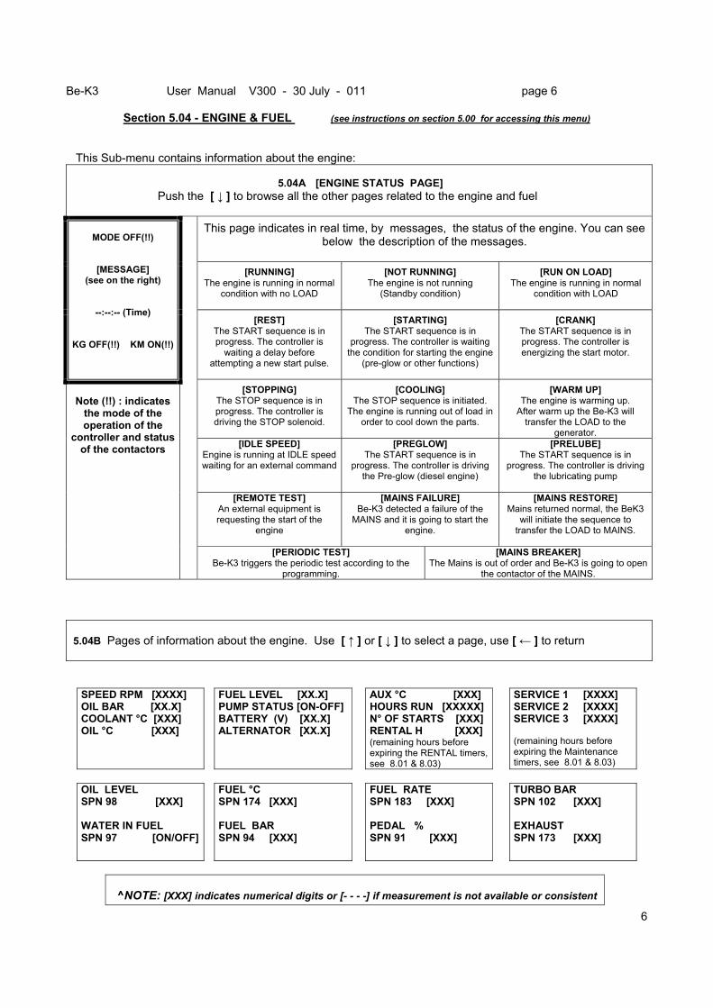
Section 5.04 - ENGINE & FUEL (see instructions on section 5.00 for accessing this menu)
This Sub-menu contains information about the engine:
5.04A [ENGINE STATUS PAGE] Push the [ ↓ ] to browse all the other pages related to the engine and fuel
This page indicates in real time, by messages, the status of the engine. You can see
below the description of the messages.
[RUNNING] The engine is running in normal
condition with no LOAD
[NOT RUNNING] The engine is not running
(Standby condition)
[RUN ON LOAD] The engine is running in normal
condition with LOAD
MODE OFF(!!)
[MESSAGE] (see on the right)
--:--:-- (Time)
KG OFF(!!) KM ON(!!)
[REST] The START sequence is in progress. The controller is
waiting a delay before attempting a new start pulse.
[STARTING] The START sequence is in
progress. The controller is waiting the condition for starting the engine
(pre-glow or other functions)
[CRANK] The START sequence is in progress. The controller is energizing the start motor.
[STOPPING] The STOP sequence is in progress. The controller is driving the STOP solenoid.
[COOLING] The STOP sequence is initiated.
The engine is running out of load in order to cool down the parts.
[WARM UP] The engine is warming up.
After warm up the Be-K3 will transfer the LOAD to the
generator. [IDLE SPEED]
Engine is running at IDLE speed waiting for an external command
[PREGLOW] The START sequence is in
progress. The controller is driving the Pre-glow (diesel engine)
[PRELUBE] The START sequence is in
progress. The controller is driving the lubricating pump
[REMOTE TEST] An external equipment is requesting the start of the
engine
[MAINS FAILURE] Be-K3 detected a failure of the
MAINS and it is going to start the engine.
[MAINS RESTORE] Mains returned normal, the BeK3
will initiate the sequence to transfer the LOAD to MAINS.
Note (!!) : indicates
the mode of the operation of the
controller and status of the contactors
[PERIODIC TEST] Be-K3 triggers the periodic test according to the
programming.
[MAINS BREAKER] The Mains is out of order and Be-K3 is going to open
the contactor of the MAINS. 5.04B Pages of information about the engine. Use [ ↑ ] or [ ↓ ] to select a page, use [ ← ] to return
SPEED RPM [XXXX] OIL BAR [XX.X] COOLANT °C [XXX] OIL °C [XXX]
FUEL LEVEL [XX.X] PUMP STATUS [ON-OFF] BATTERY (V) [XX.X] ALTERNATOR [XX.X]
AUX °C [XXX] HOURS RUN [XXXXX] N° OF STARTS [XXX] RENTAL H [XXX] (remaining hours before expiring the RENTAL timers, see 8.01 & 8.03)
SERVICE 1 [XXXX] SERVICE 2 [XXXX] SERVICE 3 [XXXX] (remaining hours before expiring the Maintenance timers, see 8.01 & 8.03)
OIL LEVEL SPN 98 [XXX] WATER IN FUEL SPN 97 [ON/OFF]
FUEL °C SPN 174 [XXX] FUEL BAR SPN 94 [XXX]
FUEL RATE SPN 183 [XXX] PEDAL % SPN 91 [XXX]
TURBO BAR SPN 102 [XXX] EXHAUST SPN 173 [XXX]
^NOTE: [XXX] indicates numerical digits or [- - - -] if measurement is not available or consistent
Be-K3 User Manual V300 - 30 July - 011 page 7
7
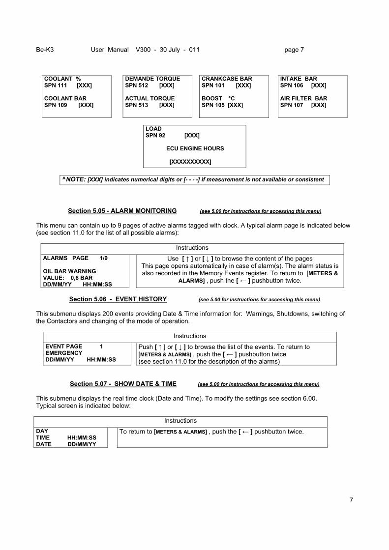
COOLANT % SPN 111 [XXX] COOLANT BAR SPN 109 [XXX]
DEMANDE TORQUE SPN 512 [XXX] ACTUAL TORQUE SPN 513 [XXX]
CRANKCASE BAR SPN 101 [XXX] BOOST °C SPN 105 [XXX]
INTAKE BAR SPN 106 [XXX] AIR FILTER BAR SPN 107 [XXX]
LOAD SPN 92 [XXX] ECU ENGINE HOURS [XXXXXXXXXX]
^NOTE: [XXX] indicates numerical digits or [- - - -] if measurement is not available or consistent
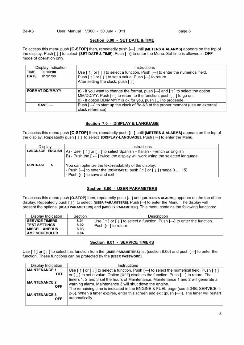
Section 5.05 - ALARM MONITORING (see 5.00 for instructions for accessing this menu) This menu can contain up to 9 pages of active alarms tagged with clock. A typical alarm page is indicated below (see section 11.0 for the list of all possible alarms):
Instructions ALARMS PAGE 1/9 OIL BAR WARNING VALUE: 0,8 BAR DD/MM/YY HH:MM:SS
Use [ ↑ ] or [ ↓ ] to browse the content of the pages This page opens automatically in case of alarm(s). The alarm status is also recorded in the Memory Events register. To return to [METERS &
ALARMS] , push the [ ← ] pushbutton twice.
Section 5.06 - EVENT HISTORY (see 5.00 for instructions for accessing this menu)
This submenu displays 200 events providing Date & Time information for: Warnings, Shutdowns, switching of the Contactors and changing of the mode of operation.
Instructions EVENT PAGE 1 EMERGENCY DD/MM/YY HH:MM:SS
Push [ ↑ ] or [ ↓ ] to browse the list of the events. To return to [METERS & ALARMS] , push the [ ← ] pushbutton twice (see section 11.0 for the description of the alarms)
Section 5.07 - SHOW DATE & TIME (see 5.00 for instructions for accessing this menu) This submenu displays the real time clock (Date and Time). To modify the settings see section 6.00. Typical screen is indicated below:
Instructions DAY TIME HH:MM:SS DATE DD/MM/YY
To return to [METERS & ALARMS] , push the [ ← ] pushbutton twice.
Be-K3 User Manual V300 - 30 July - 011 page 8
8
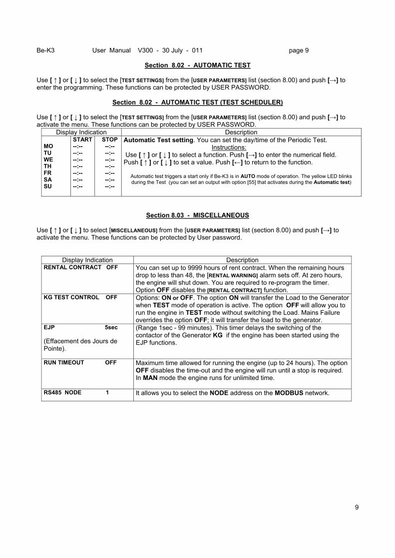
Section 6.00 - SET DATE & TIME
To access this menu push [O-STOP] then, repeatedly push [←] until [METERS & ALARMS] appears on the top of the display. Push [ ↓ ] to select [SET DATE & TIME]. Push [→] to enter the Menu. Set time is allowed in OFF mode of operation only.
Display Indication Instructions TIME 00:00:00 DATE 01/01/00
Use [ ↑ ] or [ ↓ ] to select a function. Push [→] to enter the numerical field. Push [ ↑ ] or [ ↓ ] to set a value. Push [←] to return. After setting the clock, push [ ↓ ].
FORMAT DD/MM/YY a) - If you want to change the format, push [→] and [ ↑ ] to select the option MM/DD/YY. Push [←] to return to the function; push [ ↓ ] to go on. b) - If option DD/MM/YY is ok for you, push [ ↓ ] to proceede.
SAVE → Push [ →] to start up the clock of Be-K3 at the proper moment (use an external clock reference)
Section 7.0 - DISPLAY & LANGUAGE To access this menu push [O-STOP] then, repeatedly push [←] until [METERS & ALARMS] appears on the top of the display. Repeatedly push [ ↓ ] to select [DISPLAY-LANGUAGE]. Push [→] to enter the Menu.
Display Instructions LANGUAGE ENGLISH A) - Use [ ↑ ] or [ ↓ ] to select Spanish – Italian - French or English
B) - Push the [ ← ] twice; the display will work using the selected language.
CONTRAST 5 You can optimize the text-readability of the display: - Push [→] to enter the [CONTRAST]; push [ ↑ ] or [ ↓ ] (range 0..... 15) - Push [←] to save and exit
Section 8.00 - USER PARAMETERS To access this menu push [O-STOP] then, repeatedly push [←] until [METERS & ALARMS] appears on the top of the display. Repeatedly push [ ↓ ] to select [USER PARAMETERS]. Push [→] to enter the Menu. The display will present the options [READ PARAMETERS] and [MODIFY PARAMETER]. This menu contains the following functions:
Display Indication Section Description SERVICE TIMERS TEST SETTINGS MISCELLANEOUS AMF SCHEDULER
8.01 8.02 8.03 8.04
Use [ ↑ ] or [ ↓ ] to select a function. Push [→] to enter the function. Push [←] to return.
Section 8.01 - SERVICE TIMERS
Use [ ↑ ] or [ ↓ ] to select this function from the [USER PARAMETERS] list (section 8.00) and push [→] to enter the function. These functions can be protected by the [USER PASSWORD].
Display Indication Instructions MAINTENANCE 1 OFF MAINTENANCE 2 OFF MAINTENANCE 3 OFF
Use [ ↑ ] or [ ↓ ] to select a function. Push [→] to select the numerical field. Push [ ↑ ] or [ ↓ ] to set a value. Option [OFF] disables the function. Push [←] to return. The timers 1, 2 and 3 set the hours of Maintenance. Maintenance 1 and 2 will generate a warning alarm. Maintenance 3 will shut down the engine. The remaining time is indicated in the ENGINE & FUEL page (see 5.04B, SERVICE-1-2-3). When a timer expires, enter this screen and exit (push [←]). The timer will restart automatically.
Be-K3 User Manual V300 - 30 July - 011 page 9
9
Section 8.02 - AUTOMATIC TEST
Use [ ↑ ] or [ ↓ ] to select the [TEST SETTINGS] from the [USER PARAMETERS] list (section 8.00) and push [→] to enter the programming. These functions can be protected by USER PASSWORD.
Section 8.02 - AUTOMATIC TEST (TEST SCHEDULER) Use [ ↑ ] or [ ↓ ] to select the [TEST SETTINGS] from the [USER PARAMETERS] list (section 8.00) and push [→] to activate the menu. These functions can be protected by USER PASSWORD.
Display Indication Description MO TU WE TH FR SA SU
START --:-- --:-- --:-- --:-- --:-- --:-- --:--
STOP --:-- --:-- --:-- --:-- --:-- --:-- --:--
Automatic Test setting. You can set the day/time of the Periodic Test. Instructions: Use [ ↑ ] or [ ↓ ] to select a function. Push [→] to enter the numerical field. Push [ ↑ ] or [ ↓ ] to set a value. Push [←] to return to the function.
Automatic test triggers a start only if Be-K3 is in AUTO mode of operation. The yellow LED blinks during the Test (you can set an output with option [55] that activates during the Automatic test)
Section 8.03 - MISCELLANEOUS Use [ ↑ ] or [ ↓ ] to select [MISCELLANEOUS] from the [USER PARAMETERS] list (section 8.00) and push [→] to activate the menu. These functions can be protected by User password.
Display Indication Description RENTAL CONTRACT OFF You can set up to 9999 hours of rent contract. When the remaining hours
drop to less than 48, the [RENTAL WARNING] alarm sets off. At zero hours, the engine will shut down. You are required to re-program the timer. Option OFF disables the [RENTAL CONTRACT] function.
KG TEST CONTROL OFF Options: ON or OFF. The option ON will transfer the Load to the Generator when TEST mode of operation is active. The option OFF will allow you to run the engine in TEST mode without switching the Load. Mains Failure overrides the option OFF; it will transfer the load to the generator.
EJP 5sec (Effacement des Jours de Pointe).
(Range 1sec - 99 minutes). This timer delays the switching of the contactor of the Generator KG if the engine has been started using the EJP functions.
RUN TIMEOUT OFF Maximum time allowed for running the engine (up to 24 hours). The option OFF disables the time-out and the engine will run until a stop is required. In MAN mode the engine runs for unlimited time.
RS485 NODE 1 It allows you to select the NODE address on the MODBUS network.
Be-K3 User Manual V300 - 30 July - 011 page 10
10
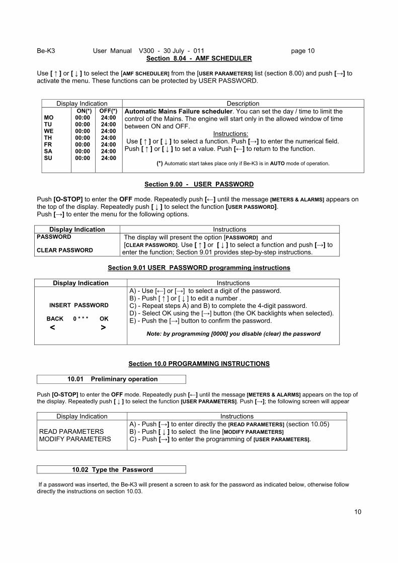
Section 8.04 - AMF SCHEDULER Use [ ↑ ] or [ ↓ ] to select the [AMF SCHEDULER] from the [USER PARAMETERS] list (section 8.00) and push [→] to activate the menu. These functions can be protected by USER PASSWORD.
Display Indication Description MO TU WE TH FR SA SU
ON(*) 00:00 00:00 00:00 00:00 00:00 00:00 00:00
OFF(*) 24:00 24:00 24:00 24:00 24:00 24:00
24:00
Automatic Mains Failure scheduler. You can set the day / time to limit the control of the Mains. The engine will start only in the allowed window of time between ON and OFF. Instructions: Use [ ↑ ] or [ ↓ ] to select a function. Push [→] to enter the numerical field. Push [ ↑ ] or [ ↓ ] to set a value. Push [←] to return to the function.
(*) Automatic start takes place only if Be-K3 is in AUTO mode of operation.
Section 9.00 - USER PASSWORD
Push [O-STOP] to enter the OFF mode. Repeatedly push [←] until the message [METERS & ALARMS] appears on the top of the display. Repeatedly push [ ↓ ] to select the function [USER PASSWORD]. Push [→] to enter the menu for the following options.
Display Indication Instructions PASSWORD CLEAR PASSWORD
The display will present the option [PASSWORD] and [CLEAR PASSWORD]. Use [ ↑ ] or [ ↓ ] to select a function and push [→] to enter the function; Section 9.01 provides step-by-step instructions.
Section 9.01 USER PASSWORD programming instructions
Display Indication Instructions
INSERT PASSWORD BACK 0 * * * OK < >
A) - Use [←] or [→] to select a digit of the password. B) - Push [ ↑ ] or [ ↓ ] to edit a number . C) - Repeat steps A) and B) to complete the 4-digit password. D) - Select OK using the [→] button (the OK backlights when selected). E) - Push the [→] button to confirm the password.
Note: by programming [0000] you disable (clear) the password
Section 10.0 PROGRAMMING INSTRUCTIONS
10.01 Preliminary operation Push [O-STOP] to enter the OFF mode. Repeatedly push [←] until the message [METERS & ALARMS] appears on the top of the display. Repeatedly push [ ↓ ] to select the function [USER PARAMETERS]. Push [→]; the following screen will appear
Display Indication Instructions READ PARAMETERS MODIFY PARAMETERS
A) - Push [→] to enter directly the [READ PARAMETERS] (section 10.05) B) - Push [ ↓ ] to select the line [MODIFY PARAMETERS] C) - Push [→] to enter the programming of [USER PARAMETERS].
10.02 Type the Password If a password was inserted, the Be-K3 will present a screen to ask for the password as indicated below, otherwise follow directly the instructions on section 10.03.
Be-K3 User Manual V300 - 30 July - 011 page 11
11
Display Indication How to insert a password INSERT PASSWORD BACK * * * * OK < >
A) - Use [←] or [→] to select a digit of the password. B) - Push [ ↑ ] or [ ↓ ] to edit a number . C) - Repeat steps A) and B) to complete the 4-digit password. D) - Select OK using the [→] button (the OK backlights when selected). E) - Push the [→] button to confirm the password.
10.03 Select a parameter
Choose the MENU of your interest by using the [ ↑ ] or [ ↓ ] buttons and then push [→] ; the list of the parameters will appear.
10.04 Programming a parameter - Select a parameter by using the [ ↑ ] or [ ↓ ] buttons (see section 8.00 for the list of parameters). - Push the [→] button to enter the numerical / options field of the parameter. - Modify the parameter using [ ↑ ] or [ ↓ ] according to your need. - Exit the numerical/options field using the [←] pushbutton. - You can modify another parameter by repeating the previous steps - Push twice the [←] pushbutton. The Be-K3 will provide you 3 options:
[EXIT ← ] SAVE [BACK →] Choose the proper option. After using the command ‘SAVE’, we recommend that you disconnect the supply for a few seconds, re-apply the supply and verify that the modifications have been saved in a way that Be-K3 operates according to your need.
10.05 How to Read a parameter To read a parameter, follow the set up indicated in section 10.01 then: - Choose a parameter using [ ↑ ] or [ ↓ ] - Push [→] to read the setting of the parameter - Repeatedly push [←] to return or exit
Section 11.0 - Instructions in case of alarm(s):
1) Look at the front panel and take note of LAMPs indicators (LED) and messages on display. 2) Some alarms, in order to cool down the engine, shutdown the engine after a programmable delay. We
recommend that you wait for the complete stop of the engine.
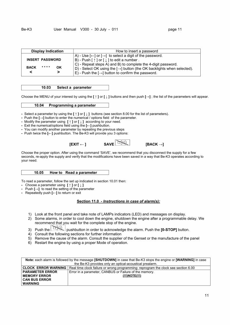
3) Push the pushbutton in order to acknowledge the alarm. Push the [0-STOP] button. 4) Consult the following sections for further information 5) Remove the cause of the alarm. Consult the supplier of the Genset or the manufacture of the panel 6) Restart the engine by using a proper Mode of operation.
Note: each alarm is followed by the message [SHUTDOWN] in case that Be-K3 stops the engine or [WARNING] in case the Be-K3 provides only an optical-acoustical prealarm.
CLOCK ERROR WARNING Real time clock failure or wrong programming: reprogram the clock see section 6.00 PARAMETER ERROR MEMORY ERROR CAN BUS ERROR WARNING
Error in a parameter, CANBUS or Failure of the memory. (!!!)NOTE(!!!)
Be-K3 User Manual V300 - 30 July - 011 page 12
12
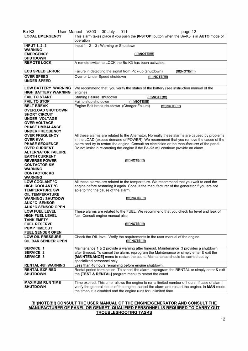
LOCAL EMERGENCY This alarm takes place if you push the [0-STOP] button when the Be-K3 is in AUTO mode of operation
INPUT 1..2..3 WARNING EMERGENCY SHUTDOWN
Input 1 - 2 – 3 : Warning or Shutdown (!!!)NOTE(!!!)
REMOTE LOCK
A remote switch to LOCK the Be-K3 has been activated.
ECU SPEED ERROR Failure in detecting the signal from Pick-up (shutdown) (!!!)NOTE(!!!) OVER SPEED UNDER SPEED
Over or Under Speed shutdown (!!!)NOTE(!!!)
LOW BATTERY WARNING HIGH BATTERY WARNING
We recommend that you verify the status of the battery (see instruction manual of the engine)
FAIL TO START Starting Failure shutdown (!!!)NOTE(!!!) FAIL TO STOP Fail to stop shutdown (!!!)NOTE(!!!) BELT BREAK Engine Belt break shutdown (Charger Failure) (!!!)NOTE(!!!) OVERLOAD SHUTDOWN SHORT CIRCUIT UNDER VOLTAGE OVER VOLTAGE PHASE UMBALANCE UNDER FREQUENCY OVER FREQUENCY OVER KVA PHASE SEQUENCE OVER CURRENT ALTERNATOR FAILURE EARTH CURRENT REVERSE POWER CONTACTOR KM WARNING CONTACTOR KG WARNING
All these alarms are related to the Alternator. Normally these alarms are caused by problems in the LOAD (excess demand of POWER). We recommend that you remove the cause of the alarm and try to restart the engine. Consult an electrician or the manufacturer of the panel. Do not insist in re-starting the engine if the Be-K3 will continue provide an alarm. (!!!)NOTE(!!!)
LOW COOLANT °C HIGH COOLANT °C TEMPERATURE SW OIL TEMPERATURE WARNING / SHUTDOW AUX °C SENSOR AUX °C SENSOR OPEN
All these alarms are related to the temperature. We recommend that you wait to cool the engine before restarting it again. Consult the manufacturer of the generator if you are not able to find the cause of the alarm. (!!!)NOTE(!!!)
LOW FUEL LEVEL HIGH FUEL LEVEL TANK EMPTY FUEL RESERVE PUMP TIMEOUT FUEL SENDER OPEN
These alarms are related to the FUEL. We recommend that you check for level and leak of fuel. Consult engine manual also (!!!)NOTE(!!!)
LOW OIL PRESSURE OIL BAR SENDER OPEN
Check the OIL level. Verify the requirements in the user manual of the engine. (!!!)NOTE(!!!)
SERVICE 1 SERVICE 2 SERVICE 3
Maintenance 1 & 2 provide a warning after timeout. Maintenance 3 provides a shutdown after timeout. To cancel the alarm, reprogram the Maintenance or simply enter & exit the [MAINTENANCE] menu to restart the count. Maintenance should be carried out by specialized personnel only.
RENTAL 48h WARNING Less than 48 hours remaining before engine shutdown. RENTAL EXPIRED SHUTDOWN
Rental period termination. To cancel the alarm, reprogram the RENTAL or simply enter & exit the [TEST & RENTAL] program menu to restart the count
MAXIMUM RUN TIME SHUTDOWN
Time expired. This timer allows the engine to run a limited number of hours. If case of alarm, verify the general status of the engine, cancel the alarm and restart the engine. In MAN mode the timeout is disabled and the engine runs for unlimited time.
(!!!)NOTE(!!!) CONSULT THE USER MANUAL OF THE ENGINE/GENERATOR AND CONSULT THE MANUFACTURER OF PANEL OR GENSET. QUALIFIED PERSONNEL IS REQUIRED TO CARRY OUT
TROUBLESHOOTING TASKS