Embed Size (px)
Citation preview

8/16/2019 Bcx-prc001-En 092013 Blower Coil Cat
http://slidepdf.com/reader/full/bcx-prc001-en-092013-blower-coil-cat 1/104
Blower Coil Air HandlerModels BCHD and BCVDAir Terminal Device400-3000 CFM
September 2013 BCX-PRC001A-EN
Catalog

8/16/2019 Bcx-prc001-En 092013 Blower Coil Cat
http://slidepdf.com/reader/full/bcx-prc001-en-092013-blower-coil-cat 2/104
2 BCX-PRC001A-EN
Introduction
Trane Blower Coils—Factory Packaged How You Need It—When You Need It
Trademarks
Frostat, Integrated Comfort, Rover, Sigma-Flo, TOPSS, Tracer, Tracer Summit, Trane, and the Tranelogo are trademarks or registered trademarks of Trane in the United States and other countries. All
trademarks referenced in this document are the trademarks of their respective owners.
BACnet is a registered trademark of American Society of Heating, Refrigerating and Air-
Conditioning Engineers (ASHRAE); LonTalk is a registered trademark of Echelon Corporation
Unit sizes 12, 18, 24,36, 54, 72, 90 MBh
Knockouts in all fourcorners for hanger rods
Main coil with copper tubes andenhances aluminum fins in 2-, 4-,or 6-row hydronic or 4- and 6-row DX
Throwaway MERV 8or MERV 13 filters
Internal filter frameaccommodates 1-inchor 2-inch filters
Main and auxiliary drainconnections on same side of unit
1/2 or 1 HP ECMmotor (standard)
Direct-drive up to2.5 inches total staticeliminates the difficultieswith belts
Control box: optionsinclude the UC400 controllerfor single zone VAV; CSTI,ZN010, ZN510 or ZN520
8/16/2019 Bcx-prc001-En 092013 Blower Coil Cat
http://slidepdf.com/reader/full/bcx-prc001-en-092013-blower-coil-cat 3/104
Table of Contents
BCX-PRC001A-EN 3
Introduction . . . . . . . . . . . . . . . . . . . . . . . . . . . . . . . . . . . . . . . . . . . . . . . . . . . . . . 2
Model Number Description . . . . . . . . . . . . . . . . . . . . . . . . . . . . . . . . . . . . . . . . . . 6
Features and Benefits . . . . . . . . . . . . . . . . . . . . . . . . . . . . . . . . . . . . . . . . . . . . . . 8
Factory Packaged – What You Need – When You Need It . . . . . . . . . . . . . . . 8
Single Source Responsibility . . . . . . . . . . . . . . . . . . . . . . . . . . . . . . . . . . . . 8
Piping Packages . . . . . . . . . . . . . . . . . . . . . . . . . . . . . . . . . . . . . . . . . . . . . . . . . 9
Energy Efficiency . . . . . . . . . . . . . . . . . . . . . . . . . . . . . . . . . . . . . . . . . . . . . . . . 9
Controls . . . . . . . . . . . . . . . . . . . . . . . . . . . . . . . . . . . . . . . . . . . . . . . . . . . . . . . 9
CSTI . . . . . . . . . . . . . . . . . . . . . . . . . . . . . . . . . . . . . . . . . . . . . . . . . . . . . . . . 9
Tracer Controllers . . . . . . . . . . . . . . . . . . . . . . . . . . . . . . . . . . . . . . . . . . . . . 9
End Devices . . . . . . . . . . . . . . . . . . . . . . . . . . . . . . . . . . . . . . . . . . . . . . . . . . 9
Flexibility . . . . . . . . . . . . . . . . . . . . . . . . . . . . . . . . . . . . . . . . . . . . . . . . . . . . . . 9Coil Options . . . . . . . . . . . . . . . . . . . . . . . . . . . . . . . . . . . . . . . . . . . . . . . . . 10
Filter Placement Options . . . . . . . . . . . . . . . . . . . . . . . . . . . . . . . . . . . . . . . 10
Motor Options . . . . . . . . . . . . . . . . . . . . . . . . . . . . . . . . . . . . . . . . . . . . . . . 10
Indoor Air Quality . . . . . . . . . . . . . . . . . . . . . . . . . . . . . . . . . . . . . . . . . . . . . . 10
Drain Pans . . . . . . . . . . . . . . . . . . . . . . . . . . . . . . . . . . . . . . . . . . . . . . . . . . 11
Filtration . . . . . . . . . . . . . . . . . . . . . . . . . . . . . . . . . . . . . . . . . . . . . . . . . . . . 11
Ventilation . . . . . . . . . . . . . . . . . . . . . . . . . . . . . . . . . . . . . . . . . . . . . . . . . . 11
Dehumidification . . . . . . . . . . . . . . . . . . . . . . . . . . . . . . . . . . . . . . . . . . . . . 11
Easy to Service . . . . . . . . . . . . . . . . . . . . . . . . . . . . . . . . . . . . . . . . . . . . . . . . 11
Durability . . . . . . . . . . . . . . . . . . . . . . . . . . . . . . . . . . . . . . . . . . . . . . . . . . . . . 11
Optional Accessory Sections . . . . . . . . . . . . . . . . . . . . . . . . . . . . . . . . . . . . . 12Mixing Box . . . . . . . . . . . . . . . . . . . . . . . . . . . . . . . . . . . . . . . . . . . . . . . . . . 12
Angle Filter Box and Combination Angle Filter/Mixing Box . . . . . . . . . . 12
Electric Heat . . . . . . . . . . . . . . . . . . . . . . . . . . . . . . . . . . . . . . . . . . . . . . . . . 12
Steam Coils . . . . . . . . . . . . . . . . . . . . . . . . . . . . . . . . . . . . . . . . . . . . . . . . . 12
Application Considerations . . . . . . . . . . . . . . . . . . . . . . . . . . . . . . . . . . . . . . . . . 13
Two-Pipe Units . . . . . . . . . . . . . . . . . . . . . . . . . . . . . . . . . . . . . . . . . . . . . . . . 13
Two-Pipe Units With Electric Heat . . . . . . . . . . . . . . . . . . . . . . . . . . . . . . . . . 13
Changeover in Two-Pipe Systems . . . . . . . . . . . . . . . . . . . . . . . . . . . . . . . 14
Four-Pipe Units . . . . . . . . . . . . . . . . . . . . . . . . . . . . . . . . . . . . . . . . . . . . . . . . 14
DX Cooling Units . . . . . . . . . . . . . . . . . . . . . . . . . . . . . . . . . . . . . . . . . . . . . . . 14
Dehumidification . . . . . . . . . . . . . . . . . . . . . . . . . . . . . . . . . . . . . . . . . . . . . . . 14Four-Pipe Unit with Reheat . . . . . . . . . . . . . . . . . . . . . . . . . . . . . . . . . . . . . 15
Chilled-Water Reset . . . . . . . . . . . . . . . . . . . . . . . . . . . . . . . . . . . . . . . . . . . 15
Airside Economizer . . . . . . . . . . . . . . . . . . . . . . . . . . . . . . . . . . . . . . . . . . . . . 15
Location and Installation . . . . . . . . . . . . . . . . . . . . . . . . . . . . . . . . . . . . . . . . 15
Acoustics . . . . . . . . . . . . . . . . . . . . . . . . . . . . . . . . . . . . . . . . . . . . . . . . . . . . . 16
Operating Limitations . . . . . . . . . . . . . . . . . . . . . . . . . . . . . . . . . . . . . . . . . . . 16
8/16/2019 Bcx-prc001-En 092013 Blower Coil Cat
http://slidepdf.com/reader/full/bcx-prc001-en-092013-blower-coil-cat 4/104
4 BCX-PRC001A-EN
Typical Blower Coil Applications . . . . . . . . . . . . . . . . . . . . . . . . . . . . . . . . . . 17
Selection Procedure . . . . . . . . . . . . . . . . . . . . . . . . . . . . . . . . . . . . . . . . . . . . . . . 20Cooling Selection Example . . . . . . . . . . . . . . . . . . . . . . . . . . . . . . . . . . . . . 21
Heating Selection Example . . . . . . . . . . . . . . . . . . . . . . . . . . . . . . . . . . . . . 22
General Data . . . . . . . . . . . . . . . . . . . . . . . . . . . . . . . . . . . . . . . . . . . . . . . . . . . . . 23
Valve Package Waterflow Limits . . . . . . . . . . . . . . . . . . . . . . . . . . . . . . . . 25
Coil Circuiting . . . . . . . . . . . . . . . . . . . . . . . . . . . . . . . . . . . . . . . . . . . . . . . 25
Performance Data . . . . . . . . . . . . . . . . . . . . . . . . . . . . . . . . . . . . . . . . . . . . . . . . 26
Air pressure drop adjustments . . . . . . . . . . . . . . . . . . . . . . . . . . . . . . . . . . . 26
Water Pressure Drop . . . . . . . . . . . . . . . . . . . . . . . . . . . . . . . . . . . . . . . . . . . . 28
Fan Curves . . . . . . . . . . . . . . . . . . . . . . . . . . . . . . . . . . . . . . . . . . . . . . . . . . . . 35
Chilled Water Cooling Capacities . . . . . . . . . . . . . . . . . . . . . . . . . . . . . . . . . . 55High-Capacity Chilled Water Cooling Capacities . . . . . . . . . . . . . . . . . . . . . 56
Distributor Selection . . . . . . . . . . . . . . . . . . . . . . . . . . . . . . . . . . . . . . . . . . 60
R-410A, DX Cooling Capacities . . . . . . . . . . . . . . . . . . . . . . . . . . . . . . . . . . . 61
Hot Water Heating Capacities . . . . . . . . . . . . . . . . . . . . . . . . . . . . . . . . . . . . 67
Controls . . . . . . . . . . . . . . . . . . . . . . . . . . . . . . . . . . . . . . . . . . . . . . . . . . . . . . . . 69
VelociTach™ ECM Engine Controller . . . . . . . . . . . . . . . . . . . . . . . . . . . . . . 70
Control Options . . . . . . . . . . . . . . . . . . . . . . . . . . . . . . . . . . . . . . . . . . . . . . . . 71
Manual Fan Speed Switch (FSS) . . . . . . . . . . . . . . . . . . . . . . . . . . . . . . . . 71
Customer Supplied Thermostat Interface (CSTI) . . . . . . . . . . . . . . . . . . . 72
Tracer Controls and Controllers . . . . . . . . . . . . . . . . . . . . . . . . . . . . . . . . . . . 72
Tracer ZN010 Controller . . . . . . . . . . . . . . . . . . . . . . . . . . . . . . . . . . . . . . . 73
Tracer ZN510 Controller . . . . . . . . . . . . . . . . . . . . . . . . . . . . . . . . . . . . . . . 73
Tracer ZN520 Controller . . . . . . . . . . . . . . . . . . . . . . . . . . . . . . . . . . . . . . . 73
Tracer UC400 Controller . . . . . . . . . . . . . . . . . . . . . . . . . . . . . . . . . . . . . . . 77
Tracer Controls Sequence of Operation . . . . . . . . . . . . . . . . . . . . . . . . . . 79
End Device Options . . . . . . . . . . . . . . . . . . . . . . . . . . . . . . . . . . . . . . . . . . . . . 80
Zone Sensor Options . . . . . . . . . . . . . . . . . . . . . . . . . . . . . . . . . . . . . . . . . . . 81
Control Valves . . . . . . . . . . . . . . . . . . . . . . . . . . . . . . . . . . . . . . . . . . . . . . . . . 83
Two-Position Control Valves . . . . . . . . . . . . . . . . . . . . . . . . . . . . . . . . . . . 83
Modulating Control Valves (Tracer ZN520 or UC400 only) . . . . . . . . . . . 83
How to Choose the Correct Control Valve . . . . . . . . . . . . . . . . . . . . . . . . . 84
Electrical Data . . . . . . . . . . . . . . . . . . . . . . . . . . . . . . . . . . . . . . . . . . . . . . . . . . . . 87
Dimensions and Weights . . . . . . . . . . . . . . . . . . . . . . . . . . . . . . . . . . . . . . . . . . 90
Horizontal Blower Coil . . . . . . . . . . . . . . . . . . . . . . . . . . . . . . . . . . . . . . . . . . 90
Vertical Blower Coil . . . . . . . . . . . . . . . . . . . . . . . . . . . . . . . . . . . . . . . . . . . . . 91
Angle Filter and Mixing Box . . . . . . . . . . . . . . . . . . . . . . . . . . . . . . . . . . . . 92
Bottom or Top Access Filter Box . . . . . . . . . . . . . . . . . . . . . . . . . . . . . . . . 93
8/16/2019 Bcx-prc001-En 092013 Blower Coil Cat
http://slidepdf.com/reader/full/bcx-prc001-en-092013-blower-coil-cat 5/104
BCX-PRC001A-EN 5
Electric Heat . . . . . . . . . . . . . . . . . . . . . . . . . . . . . . . . . . . . . . . . . . . . . . . . . 94
Steam Coil . . . . . . . . . . . . . . . . . . . . . . . . . . . . . . . . . . . . . . . . . . . . . . . . . . 96
Coil Connections . . . . . . . . . . . . . . . . . . . . . . . . . . . . . . . . . . . . . . . . . . . . . . . 97
Piping Packages . . . . . . . . . . . . . . . . . . . . . . . . . . . . . . . . . . . . . . . . . . . . . . . . 97
Basic Piping . . . . . . . . . . . . . . . . . . . . . . . . . . . . . . . . . . . . . . . . . . . . . . . . . 98
Deluxe Piping . . . . . . . . . . . . . . . . . . . . . . . . . . . . . . . . . . . . . . . . . . . . . . . . 99
Mechanical Specifications . . . . . . . . . . . . . . . . . . . . . . . . . . . . . . . . . . . . . . . . . 101
General . . . . . . . . . . . . . . . . . . . . . . . . . . . . . . . . . . . . . . . . . . . . . . . . . . . . 101
Casings . . . . . . . . . . . . . . . . . . . . . . . . . . . . . . . . . . . . . . . . . . . . . . . . . . . . 101
Coils . . . . . . . . . . . . . . . . . . . . . . . . . . . . . . . . . . . . . . . . . . . . . . . . . . . . . . 101
Fan . . . . . . . . . . . . . . . . . . . . . . . . . . . . . . . . . . . . . . . . . . . . . . . . . . . . . . . 102
EC Motors . . . . . . . . . . . . . . . . . . . . . . . . . . . . . . . . . . . . . . . . . . . . . . . . . 102
Drain Pan . . . . . . . . . . . . . . . . . . . . . . . . . . . . . . . . . . . . . . . . . . . . . . . . . . 102
Filters . . . . . . . . . . . . . . . . . . . . . . . . . . . . . . . . . . . . . . . . . . . . . . . . . . . . . 102Mixing Box . . . . . . . . . . . . . . . . . . . . . . . . . . . . . . . . . . . . . . . . . . . . . . . . . 103
Piping Packages . . . . . . . . . . . . . . . . . . . . . . . . . . . . . . . . . . . . . . . . . . . . . 103
Electric Heater . . . . . . . . . . . . . . . . . . . . . . . . . . . . . . . . . . . . . . . . . . . . . . 103
Controls . . . . . . . . . . . . . . . . . . . . . . . . . . . . . . . . . . . . . . . . . . . . . . . . . . . 103

8/16/2019 Bcx-prc001-En 092013 Blower Coil Cat
http://slidepdf.com/reader/full/bcx-prc001-en-092013-blower-coil-cat 6/104
6 BCX-PRC001A-EN
Following is a complete description of
the blower coil model number. Eachdigit in the model number has acorresponding code that identifies
specific unit options.
Digits 1, 2, 3, 4 — Unit M odel
BCHD =Horizontal Blower CoilBCVD =Vertical Blower Coil
Digits 5, 6, 7 — Unit Size
012 =Unit size 12 - 1 ton018 =Unit size 18 - 1 1/2 ton024 =Unit size 24 - 2 ton036 =Unit size 36 - 3 ton054 =Unit size 54 - 4 1/2 ton072 =Unit size 72 - 6 ton090 =Unit size 90 - 7 1/2 ton
Digit 8 — Unit VoltageA =115/60/1B =208/60/1C =230/60/1D =277/60/1
J =220/50/1K =240/50/1
Digit 9 —Insulation Type
1 =1 inch Matte-faced insulation2 =1 inch Foil-faced insulation
Digit s 10, 11 — Design Sequence
** =Factory sets the design sequence
Digit 12 — Motor and Control
Box Location
A =Same side as coil connections,horizontal or counterswirl optionsonly
B =Opposite side from coil connections,horizontal or counterswirl optionsonly
C =Same side as coil connections,preswirl option only
D =Opposite side from coil connections,preswirl only
Digit 13 — Coil Connection Side
1 =PVC drain pan right-hand coil anddrain connections
2 =PVC drain pan left-hand coil anddrain connections
3 =Stainless steel drain panright-hand coil and drain connections
4 =Stainless steel drain panleft-hand coil and drain connections
0 =None
Digit 14 — Coil #1 First in
AirstreamNote: All coils are hydronic unless stated
otherwise.
0 =No coil 1A =1-row preheatF =4-rowG =6-row
J =4-row with autochangeoverK =6-row with autochangeoverL =2-row high capacity preheatM =4-row high capacityN =6-row high capacityR =4-row high capacity with
autochangeover T =6-row high capacity with
autochangeover1 =3-row DX coil 3/16-inch (0.032) dist2 =4-row DX coil 3/16-inch (0.032) dist3 =6-row DX coil 3/16-inch (0.032) dist4 =3-row DX coil 3/16-inch (0.049) dist5 =4-row DX coil 3/16-inch (0.049) dist6 =6-row DX coil 3/16-inch (0.049) dist7 =4-row DX coil 3/16-inch (0.049) dist,
heat pump8 =6-row DX coil, 3/16-inch (0.049) dist,
heat pump
Digit 15 — Unit Coil #2
Note: All coils are hydronic unless statedotherwise.
0 =No coil 2A =1-row reheatF =4-rowG =6-row
J =4-row with autochangeoverK =6-row with autochangeoverL =2-row high capacity reheatM =4-row high capacityN =6-row high capacityR =4-row high capacity with
autochangeover T =6-row high capacity with
autochangeover1 =3-row DX coil 3/16-inch (0.032) dist2 =4-row DX coil 3/16-inch (0.032) dist3 =6-row DX coil 3/16-inch (0.032) dist4 =3-row DX coil 3/16-inch (0.049) dist5 =4-row DX coil 3/16-inch (0.049) dist6 =6-row DX coil 3/16-inch (0.049) dist7 =4-row DX coil 3/16-inch (0.049) dist,
heat pump8 =6-row DX coil, 3/16-inch (0.049) dist,
heat pump
Digit 16 — Motor Horsepower2 =1/2 hp4 =1 hp
Digit 17 — RPM
A =500 rpmB =600 rpmC =700 rpmD =800 rpmE =900 rpmF =1000 rpmG =1100 rpmH =1200 rpm
J =1300 rpmK =1400 rpmL =1500 rpmM =1600 rpmN =1700 rpmP =1800 rpmR =1900 rpm
T =2000 rpmU =2100 rpmV =2200 rpm
W =2300 rpmZ =TOPSS base performance
Digit 18 — Electric Heat Stages
1 =1-stage2 =2-stage0 =none
Digits 19, 20 , 21 — Electric Heat
Digit 2 2 — Electric Heat Controls
0 =NoneA =24 volt magnetic contactorsB =24 volt mercury contactors
Digit 23 — Electric Heat Options
0 =NoneA =Line fuseB =Door interlocking disconnect switchC =A and B
Digit 24 — Filters
0 =NoneA =1-in. throwawayB =2-in. MERV 8 throwawayC =2-in. MERV 13 throwaway
010 =1.0 kW
015 =1.5 kW 060 =6.0 kW
020 =2.0 kW 065 =6.5 kW
025 =2.5 kW 070 =7.0 kW
030 =3.0 kW 075 =7.5 kW
035 =3.5 kW 080 =8.0 kW
040 =4.0 kW 090 =9.0 kW
045 =4.5 kW 100 =10.0 kW050 =5.0 kW 110 =11.0 kW
055 =5.5 kW 000 =None
Model Number Description

8/16/2019 Bcx-prc001-En 092013 Blower Coil Cat
http://slidepdf.com/reader/full/bcx-prc001-en-092013-blower-coil-cat 7/104
BCX-PRC001A-EN 7
Model Number Description
Digit 25 — Accessory Section
0 =None
A =Mixing box onlyB =Angle filter boxC =Angle filter/mixing boxD =Top access filter moduleE =Bottom access filter moduleF =A and DG =A and EH =Steam coil module
J =A and HK =B and HL =C and HM =D and HN =E and HP =A, D and HR =A, E and H
Digit 26 — Control Type
1 =CSTI
2 =Tracer ZN0103 =Tracer ZN5104 =Tracer ZN5205 =UC4006 =No controls (FSS)
Digit 2 7 — Coil #1 Control ValveType
0 =NoneA =2-way, 2-position, N.C.B =2-way, 2-position, N.O.C =3-way, 2-position, N.C.D =3-way, 2-position, N.O.E =2-way modulatingF =3-way, modulatingG =Field-supplied valve, 2-position, N.C.H =Field-supplied valve, 2-position, N.O.
J =Field-supplied modulating valve
K =Field-supplied analog valveDigit 2 8 — Coil #1 Control ValveCv
0 =NoneA =3.3 Cv, 1/2-in. valve and pipeB =3.3 Cv, 1/2-in. valve, 3/4-in. pipeC =3.8 Cv, 1/2-in. valve, 3/4-in. pipeD =6.6 Cv, 1-in. valve and pipeE =7.4 Cv, 1-in. valve and pipeF =8.3 Cv, 1 1/4-in. valve and pipeG =3.5 Cv, 1/2-in. valve and pipeH =4.4 Cv, 1/2-in. valve and pipeK =8.0 Cv, 1-in. valve and pipeQ =1.3 Cv, 1/2-in. valve, 3/4-in. pipeR =1.8 Cv, 1/2-in. valve, 3/4-inc. pipe
T =2.3 Cv, 1/2-in. valve, 3/4-in. pipeU =2.7 Cv, 1/2-in. valve, 3/4-in. pipe
Digit 29 — Coil #1 PipingPackage
0 =None1 =Basic piping package2 =Deluxe piping package
Digit 3 0 — Coil #2 Control Valve
0 =None
A =2-way, 2-position, N.C.B =2-way, 2-position, N .O.C =3-way, 2-position, N.C.D =3-way, 2-position, N.O.E =2-way modulatingF =3-way modulatingG =Field-supplied valve, 2-position N.C.H =Field-supplied valve, 2-position N.O.
J =Field-supplied modulating valveK =Field-supplied analog valve
Digit 3 1— Coil #2 Control ValveCv
0 =NoneA =3.3 Cv, 1/2-in. valve and pipeB =3.3 Cv, 1/2-in. valve, 3/4-in. pipeC =3.8 Cv, 1/2-in. valve, 3/4-in. pipeD =6.6 Cv, 1-in. valve and pipe
E =7.4 Cv, 1-in. valve and pipeF =8.3 Cv, 1 1/4-in. valve and pipeG =3.5 Cv, 1/2-in. valve and pipeH =4.4 Cv, 1/2-in. valve and pipeK =8.0 Cv, 1-in. valve and pipeQ =1.3 Cv, 1/2-in. valve, 3/4-in. pipeR =1.8 Cv, 1/2-in. valve, 3/4-in. pipe
T =2.3 Cv, 1/2-in. valve, 3/4-in. pipeU =2.7 Cv, 1/2-in. valve, 3/4-in. pipe
Digit 3 2 — Coil #2 PipingPackage
0 =None1 =Basic piping package2 =Deluxe piping package
Digit 33 — Remote Heat Options
0 =No remote heat
1 =Remote staged electric heat2 =Remote 2-position hot water, N.C.
Digit 3 4 — M ixing Box DamperActuator
Note: The back damper is the controldamper when actuators areordered. The back damper is N.C.or N.O. as selected.
0 =None1 =2-position, N.O., ship loose2 =Modulating, N.C.3 =Modulating, N.O.4 =Modulating, ship loose5 =Field-supplied 2-position, N.O.6 =Field-supplied 2-position, N.C.7 =Field-supplied modulating
Digit 3 5 — Factory Mounted
Control Options
0 =NoneC =Condensate overflowD =Low LimitK =Condensate overflow and low limit
Digit 36 — Control Options 2
0 =None
A =Outside air sensor, field-mountedB =Discharge air sensorC =Outside air and discharge air sensor
Digit 37 — Control Options 3
0 =NoneA =Dehumidification with communicated
valueB =Dehumidification with local humidity
sensor
Digit 38 — Zone Sensors
0 =None1 =Wall-mounted temp sensor
(SP, OA, OCC/UNCOCC, COMM )3 =Wall-mounted temp sensor
(SP, OCC/UNOCC, COMM )4 =Wall-mounted temp sensor
(OCC/UNOCC, COMMC =Wireless temp sensor, unit-
mounted receiverE =Wall-mounted temp sensor
(SP, OALMH, OCC/UNOCC, COMM)F =Wall-mounted display sensor
(SP, OALMH, COMM )G =Wireless display sensor, unit-
mounted receiver (SP, OALMH)H =Wall-mounted FSS
Digit 39 — Seismic Certification
0 =None
Digit 40 — Extra Filter
0 =None1 =Ship loose extra 1-in. Throwaway2 =Ship loose extra 2-in. MERV 8throwaway
3 =Ship loose extra 2-in. MERV 13throwaway
8/16/2019 Bcx-prc001-En 092013 Blower Coil Cat
http://slidepdf.com/reader/full/bcx-prc001-en-092013-blower-coil-cat 8/104
8 BCX-PRC001A-EN
Features and Benefits
Factory Packaged – What You Need – When You Need It
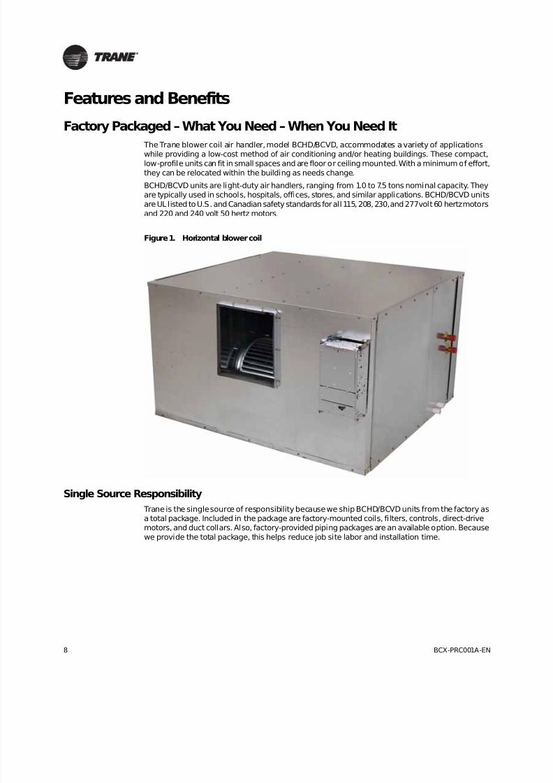
The Trane blower coil air handler, model BCHD/BCVD, accommodates a variety of applicationswhile providing a low-cost method of air conditioning and/or heating buildings. These compact,
low-profile units can fit in small spaces and are floor or ceiling mounted. With a minimum of effort,
they can be relocated within the building as needs change.
BCHD/BCVD units are light-duty air handlers, ranging from 1.0 to 7.5 tons nominal capacity. Theyare typically used in schools, hospitals, offices, stores, and similar applications. BCHD/BCVD units
are UL listed to U.S. and Canadian safety standards for all 115, 208, 230, and 277 volt 60 hertz motors
and 220 and 240 volt 50 hertz motors.
Single Source Responsibility
Trane is the single source of responsibility because we ship BCHD/BCVD units from the factory asa total package. Included in the package are factory-mounted coils, filters, controls, direct-drivemotors, and duct collars. Also, factory-provided piping packages are an available option. Because
we provide the total package, this helps reduce job site labor and installation time.
Figure 1. Horizontal blower coil
8/16/2019 Bcx-prc001-En 092013 Blower Coil Cat
http://slidepdf.com/reader/full/bcx-prc001-en-092013-blower-coil-cat 9/104
BCX-PRC001A-EN 9
Features and Benefits
Piping Packages
All blower coil air handlers are available with factory-built piping package options for fieldinstallation using field-supplied interconnecting piping. Basic or deluxe piping package options areavailable with a variety of control valve options:
• Two- or three-way
• 1/2-inch, 1-inch, or 1-1/4-inch
• Two-position or modulating
The basic piping package consists of two shutoff ball valves. The deluxe piping package has one
shutoff ball valve, a strainer, and a circuit setter balancing valve. Basic or deluxe piping packageswith a three-way control valve also include a balancing fitting on the bypass line.
Energy Efficiency
Trane’s commitment to providing premium quality products has led to the exclusive use of
Electronically Commutated Motors (ECM) in all blower coil (BCHD/BCVD) models. These brushlessDC motors incorporate the latest technology for optimized energy efficiency, acoustical abatement,maintenance free and extended motor life. Each motor comes with a VelociTach™ motor controlboard that allows for programmability, soft ramp-up, better airflow control, and serial
communication. Trane units equipped with ECMs are significantly more efficient than permanent
split capacitor (PSC) motors.
Controls
Trane offers a broad array of control options, from a simple control interface (CSTI) to the Tracercontrollers.
CSTI
The control interface is intended to be used with a field-supplied, low-voltage thermostat or
controller. The control box contains a disconnect switch (optional for units with electric heat). Allend devices are wired to a low-voltage terminal block and are run-tested, so only a power
connection and thermostat connection is needed to commission the unit. Changeover sensors andcontrols are provided whenever a change-over coil is selected.
Tracer Controllers
The Tracer family of controllers, ZN010, ZN510, ZN520, and UC400 offers the combined advantagesof simple and dependable operation with the latest Trane-designed controller. Standard control
features include options normally available on more elaborate control systems. All control optionsare available factory-configured or can be field-configured using Rover service software for the ZN
controllers, the UC400 is serviced via Tracer TU.
This is the industry’s first solution that is factory-mounted, -wired, and -programmed for infinite
modulation of fan speed based on space loads, using the Tracer UC400.
End DevicesOptional factory-mounted end devices such as a condensate float switch, freezestat, control valves,and actuators are available. Factory-installed and -wired electric heat features single-point powerconnection.
Flexibility
The Trane blower coil is available in either horizontal (model BCHD) or vertical (model BCVD)configurations. Horizontal units are typically ceiling suspended via threaded rods. Knockouts are

8/16/2019 Bcx-prc001-En 092013 Blower Coil Cat
http://slidepdf.com/reader/full/bcx-prc001-en-092013-blower-coil-cat 10/104
10 BCX-PRC001A-EN
Features and Benefits
provided in all four corners to pass the rods through the unit. Horizontal units can also be floor
mounted. Vertical units are typically floor mounted. They have a side inlet for easy duct connection,
and do not require a field-fabricated inlet plenum. Vertical units ship in two pieces and can be setup in either a pre-swirl or counter-swirl configuration.
In addition, blower coils have acoustical benefits because they are typically located outside the
occupied space, either in the ceiling or in a closet. This limits the amount of sound transmission(radiated) directly from the unit to the occupant. These units are applied with discharge ductwork,
which is frequently lined to help reduce the sound transmission (discharge) through the ductwork
into the occupied space. Blower coils (BCHD/BCVD) utilize a direct-drive motor solution for all unitswhich eliminates the single phase motor hum which is evident in capacitor split motors in belt-drive
applications.
Coil Options
Trane blower coils feature a wide variety of coil options that include:
• Two-, four-, or six-row hydronic cooling or heating
• Three-, four-, or six-row DX coils• High capacity hydronic coils for cooling or heating
• One- or two-row heating coil in either the preheat or reheat position
• One-row steam preheat
Filter Placement Options
All hydronic units have an internal flat filter frame for 1- or 2-inch filters. Other filter placementoptions include:
• Angle filter box for 2-inch filters
• Combination angle filter/mixing box
• Bottom or top access filter box that accommodates 2-inch filters. This option allows easy filter
access through a hinged door, from the bottom of the unit on horizontal units, and from the top
on vertical units.
Motor Options
Direct-drive motors range from 1/2 to 1 horsepower in a wide range of voltages. All motors have
internal current overload protection, permanently sealed ball bearings, and rubber grommets onthe mounting brackets to reduce noise and vibration transmission.
Motors come factory programmed for specific job requirements or can be programed based on
standardized motor speeds. Motors speeds have the ability to be adjusted on the job site with out
the requirement of specialized tools. This enables the unit to be balanced for changes to designstatic pressures fast and easy.
Indoor Air Quality
Indoor air quality is becoming a greater concern every day. That’s why Trane provides the most
complete indoor air quality options of any manufacturer.
8/16/2019 Bcx-prc001-En 092013 Blower Coil Cat
http://slidepdf.com/reader/full/bcx-prc001-en-092013-blower-coil-cat 11/104
BCX-PRC001A-EN 11
Features and Benefits
Filtration
All units have an internal flat filter frame that can accommodate 1- or 2-inch filters. An optionalbottom (horizontal units) or top (vertical units) filter access box is also available to improve
accessibility.
An optional angle filter box (2-inch only), or combination angle filter/mixing box, provides extrafilter face area, which results in extremely low face velocities and low pressure drop. Withincreased face area, the angle filters have substantially more dust-holding capacity than
conventional flat filters. MERV 8 and MERV 13 pleated angle or flat filters options are available.
Ventilation
The optional mixing box delivers ventilation air directly to each unit. When the unit is equipped with
a Tracer ZN520 or UC400 controller, the mixing box functions as a zero to 100 percent economizer
to improve energy efficiency. For units configured to automatically switch between high and lowfan speeds, the Tracer ZN520 or UC 400 controller automatically adjusts the mixing box damper
to provide the correct amount of fresh air to the space at all fan speeds.
Blower coil units are draw-thru configurations that use direct-drive fan motors with higherhorsepower than fan coils. This makes them an excellent choice for use in an air supply ductworksystem with diffusers—rather than a direct discharge system—because it enhances the space air
mixing and ventilation effectiveness.
Dehumidification
For direct control of space humidity, a BCHD/BCVD unit can be configured with a hydronic heating
coil in the reheat position and equipped with a Tracer ZN520 or UC400 controller. These controllers
can independently modulate the cooling and heating coils to directly control both temperature andhumidity in the space.
Easy to Service
The coils and motor are easily replaced within minutes, even when the unit is suspended. Coils
slide in and out by removing the coil access panel and a few screws at the rear of the unit. Withthe bottom filter access option, filters are easily accessed from the bottom of the unit. If the motor
requires servicing, only the motor side requires access.
Durability
Trane blower coils use durable materials, including heavy gage, galvanized steel for the casing.
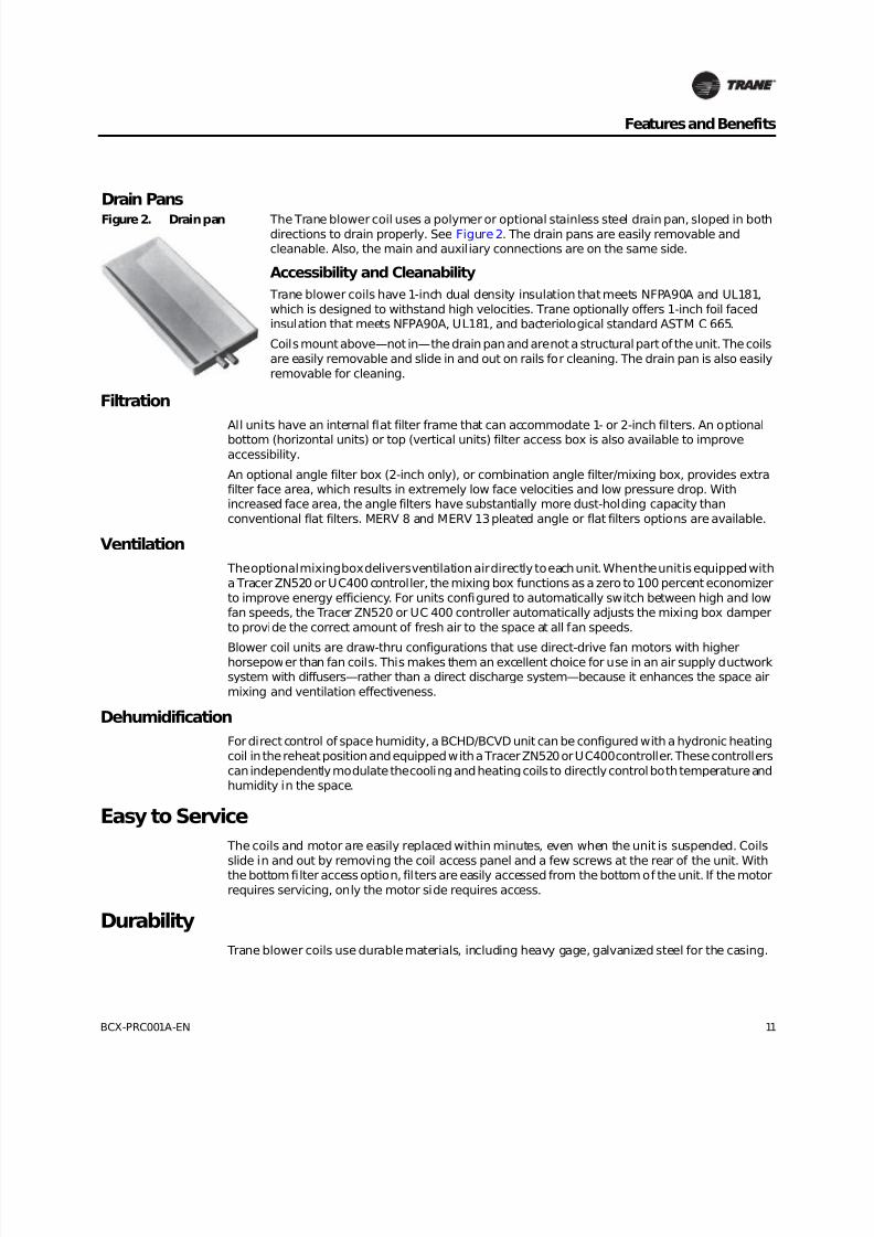
Drain Pans
Figure 2. Drain pan The Trane blower coil uses a polymer or optional stainless steel drain pan, sloped in bothdirections to drain properly. See Figure 2. The drain pans are easily removable andcleanable. Also, the main and auxiliary connections are on the same side.
Accessibility and Cleanability
Trane blower coils have 1-inch dual density insulation that meets NFPA90A and UL181,
which is designed to withstand high velocities. Trane optionally offers 1-inch foil facedinsulation that meets NFPA90A, UL181, and bacteriological standard ASTM C 665.
Coils mount above—not in—the drain pan and are not a structural part of the unit. The coils
are easily removable and slide in and out on rails for cleaning. The drain pan is also easily
removable for cleaning.

8/16/2019 Bcx-prc001-En 092013 Blower Coil Cat
http://slidepdf.com/reader/full/bcx-prc001-en-092013-blower-coil-cat 12/104
12 BCX-PRC001A-EN
Features and Benefits
Optional Accessory Sections
These accessory sections make the BCHD/BCVD product more flexible:
• Mixing box
• Angle filter box
• Angle filter and mixing box section
• Bottom or top hinged access filter box
• Electric heat box
• Steam coil box
Mixing Box
Angle Filter Box and Combination Angle Filter/Mixing Box
Electric Heat
A factory installed open-wire electric heater is available in a wide variety of voltages and kW’s. Allunits have a single point power connection. Optional heater fuses, mercury or magnetic
contactors, and a heater door interlocking disconnect switch are available.
Steam Coils
Figure 3. Mixing box The mixing box option ships separately and has internal low-leak aluminum dampers andaccess panels on both sides. The mixing box is insulated in the same as the main unit: matte
or foil, as ordered. The mixing box is easily located in field to allow “back/bottom” dampers.See Figure3.
Figure 4. Angle filter box/mixing box combo
Filter box options include an angle filter box and a bottom/top access filter box that arefactory-installed. The angle filter can be combined with the mixing box as one accessory
module. The flat filter frame can accommodate 1- or 2-inch filters. The angle filter frame
accommodates only 2-inch filters. See Figure4.
Figure 5. Steam coil A steam coil box with one-row coil is available in the preheat position. Module includes afilter rack for 1-inch flat filters. See Figure 5.

8/16/2019 Bcx-prc001-En 092013 Blower Coil Cat
http://slidepdf.com/reader/full/bcx-prc001-en-092013-blower-coil-cat 13/104
BCX-PRC001A-EN 13
Application Considerations
The Trane blower coil air handler offers a wide range of application flexibility between the fan coil
unit and Climate Changer™ air handlers.Units are available in seven nominal capacities ranging from 1.0 to 7.5 tons cooling and 400 to
3000cfm airflow. The basic unit is available in horizontal (model BCHD) as well as a vertical (modelBCVD) configuration.
The single-zone, constant volume applications discussed in this section are:
• Two-pipe hydronic units
• Two-pipe hydronic units with electric heat
• Four-pipe hydronic units
• Economizer
Other applications of the BCHD/BCVD are:
• DX cooling
• Two-pipe hydronic units with steam heating
• Single-zone VAV
Two-Pipe Units
The standard BCHD/BCVD unit is equipped with a hydronic coil. The unit can perform cooling only,heating and cooling (changeover system), or heating only. In a changeover system, the unit cools
during the spring, summer, and fall seasons (summer mode) and heats during the winter season(winter mode).
Use the Trane Official Product Selection System (TOPSS™) program for specific design criteriasuch as flow rate, temperature rise/drop, pressure drop, glycol mixtures, and capacity.
When selecting two-pipe changeover units, note that TOPSS will only provide output that meetsboth the cooling and heating capacity requirements. Because cooling and heating capacity
requirements for a given unit may differ significantly, a given coil may be optimally sized for one
load and over/under sized for the other load.
Two-Pipe Units With Electric Heat
With the addition of electric heat, the two-pipe system can heat or cool. In the non-changeoversystem, the main coil is always used for cooling and the electric heater is always used for heating.
In the changeover system, during the summer mode (spring, summer and fall), the main coil is usedfor cooling and electric heater is used for heating. During the winter mode, the main coil is used
for heating and the electric heater is disabled.
Two-pipe systems with electric heat are an economical solution to intermediate season (spring and
fall) comfort problems associated with straight two-pipe systems. In moderate climates or whereelectric rates are low, non-changeover systems are typically used. In climates with significant
heating loads and/or high electric rates, a changeover system—to allow hydronic heating—is
typically used.
All units with factory mounted electric heat are UL listed and interlocked with the fan motor switch.A call for Electric heat operation will turn the fan on. Motors controls are synchronized with fan/
valve operation to ensure safe operation and that two modes of heat are not operating
simultaneously. A transformer is supplied on any voltage unit, eliminating the need for fieldinstallation of a step-down transformer. Units come with either contactors or relays on the electric
heat. Mercury contactors are available. A high temperature cutout with automatic reset is providedas an integral part of the elements to de-energize the electric heat in the event of a malfunction.
8/16/2019 Bcx-prc001-En 092013 Blower Coil Cat
http://slidepdf.com/reader/full/bcx-prc001-en-092013-blower-coil-cat 14/104
14 BCX-PRC001A-EN
Application Considerations
Changeover in Two-Pipe Systems
Changing between cooling and heating modes in a two-pipe system requires energy to heat or coolthe mass of water in the piping system at switchover. ASHRAE Standard 90.1–2001 defines specific
requirements for minimizing the energy impact of this switchover:
• The system must allow a deadband between changeover from one mode to the other of at least15°F outdoor-air temperature.
• The system must include controls that allow the system to operate in one mode for at least four
hours before changing to the other mode.
• Reset controls must be provided to allow heating and cooling supply-water temperatures, at thechangeover point, to be no more than 30°F apart.
Four-Pipe Units
The addition of a one-row or two-row heating coil to the basic BCHD/BCVD unit makes it compatiblefor a four-pipe cooling and heating system. The heating coil is available factory installed in either
the preheat or reheat position.
Four-pipe systems solve the intermediate season (spring and fall) comfort problems associated
with straight two-pipe systems because they only either cool or heat year-round. However, they dorequire chiller and boiler operation to be available to operate year-round.
When making the choice between a two or four-pipe system, also consider:
• Cooling/heating loads in perimeter zones of the building
• Importance of temperature and humidity control for the zone
• First cost
TOPSS allows independent selection of the cooling and heating coils for flexibility in flow rates,
pressure drops, temperature rise/drop, and fluid type.
DX Cooling Units
A BCHD/BCVD unit with a DX cooling coil will often be connected to an air-cooled condensing unit.
Some condensing units have two, independent refrigeration circuits; DX coils in units sizes 12 to54 are single-circuited.
Notes:
Do not manifold two independent refrigeration circuits into a single-circuited DX (evaporator)
coil.
• DX coils in units sizes 72 and 90 are always dual-circuited.
Dehumidification
The BCHD/BCVD has two methods for improving the dehumidification performance of the
constant-volume unit - a four-pipe unit with reheat, and chilled water reset
8/16/2019 Bcx-prc001-En 092013 Blower Coil Cat
http://slidepdf.com/reader/full/bcx-prc001-en-092013-blower-coil-cat 15/104
BCX-PRC001A-EN 15
Application Considerations
Four-Pipe Unit with Reheat
BCHD/BCVD units equipped with a Tracer ZN520 or UC400 controller and a hydronic heating coilin the reheat position will provide direct control of space humidity. If the space humidity level does
not exceed the desired upper limit, the unit responds to reduced cooling load by modulating thecontrol valve and, if in AUTO mode, switching between fan speeds. However, if the space humidity
level rises above the upper limit, the capacity of the cooling coil is increased, overcooling the airto maintain the space humidity below the upper limit. Then, the capacity of the heating coil
modulates, adding a small amount of heat to temper the air and avoid overcooling the space.
The Tracer ZN520 or UC400 controller responds to a signal from a humidity sensor installed in the
space or a signal from a building automation system, and independently modulates the coolingand heating coils to directly control both temperature and humidity in the space. While this
configuration can directly control indoor humidity levels, it does require the boiler (or other source
of heat) to be available year-round.
Chilled-Water Reset
In many constant-flow pumping systems, the leaving chilled-water temperature setpoint is resetbased on either outdoor dry-bulb temperature or some indication of cooling load. Use cautionwhen implementing a chilled-water reset strategy because space humidity control can becompromised if the water gets too warm.
A BCHD/BCVD unit equipped with a Tracer ZN520 or UC4000 can accept an input signal from a
humidity sensor in the space. A building automation system will continually poll the humidity levelin all spaces, or in a single representative space, to limit the amount of chilled-water reset and
maintain space humidity levels.
Airside Economizer
Adding a mixing box with a damper actuator allows economizer or free cooling applications. When
using blower coils for these applications, Trane highly recommends using a freeze protectiondevice to protect the coil(s). If the unit has a Tracer ZN520 or UC400 controller, you must have anoutside air temperature signal from either a hard wired outside air sensor or from the building
automation system, such as Tracer Summit.
Location and Installation
Avoid locating the unit directly above spaces where sound levels may be critical, such as areas near
the occupied space. Install horizontal units over false ceilings in service areas such as corridors orstorage rooms. Install vertical units in closets or mechanical rooms.
Horizontal units are installed by suspending the corners of the unit with threaded rods. Use suitable
vibration isolators and take the following precautions to comply with generally acceptedinstallation practices.
• Use flexible duct connectors or supply and return sides (if ducted).
• Use acoustic lining on the inside of main supply duct for noise control.
• Do not attach ceiling suspension wires to unit or through ducts.
• Locate return air grilles as far as possible from the unit to avoid noise transmission.
• Design and install ductwork as per ASHRAE guides, SMACNA, and local code requirements.
8/16/2019 Bcx-prc001-En 092013 Blower Coil Cat
http://slidepdf.com/reader/full/bcx-prc001-en-092013-blower-coil-cat 16/104
16 BCX-PRC001A-EN
Application Considerations
Acoustics
Controlling outdoor and equipment noise within the occupied space is increasingly important tosystem designers and building occupants/owners. Therefore, give proper consideration to thissubject in the application of the BCHD/BCVD unit.
Selecting fan and coil combinations is inherently flexible for sound-sensitive applications. In suchinstances, a fan running at low speed with a high capacity coil normally yields satisfactory results.
It also may be desirable to select a larger nominal capacity unit and operate it at less than nominalairflow for further acoustic benefit.
BCHD/BCVD sound power, Lw, data for ducted discharge, inlet +casing, and casing radiated
components is available from TOPSS. This sound power data is useful in estimating the soundlevels in the occupied space for a given application.
Operating Limitations
Reference the General Data section for minimum and maximum operating limits. Units must not
operate above maximum fan rpm or unit airflow. Unit operation above the maximum fan rpm willdrastically reduce bearing life and may result in catastrophic failure. Operating the unit above the
maximum airflow in the cooling mode may result in unsatisfactory operation due to watercarryover from the coil. In addition, it is often uneconomical to operate a unit at its maximum rpm
due to greater motor power requirements.
The unit may not perform at an optimal acoustical performance level if it operates in the fan’s
traditional stall region.
Do not operate units with electric heat below the minimum airflow limit to prevent excessive
leaving air temperatures and electric heat limit trips.
Do not operate hydronic and electric heat simultaneously to prevent excessive leaving air
temperatures and limit trips. Electric heat units have a lockout switch to disable the electric heaterif the temperature off the hydronic coil is greater than 95°F.
Do not operate units with a leaving air temperature above 104°F.
Do not operate coils above the water flow limits to prevent erosion and noise. A minimum or “self-venting” water flow rate is also listed in the General Data Section. If the coil is set to operate belowthis flow rate, vent it periodically by flushing at a higher flow rate.
Do not operate piping packages and water valves above the water flow limit to prevent erosion andnoise. Water valves supplied with the BCHD/BCVD units as accessories are intended for use in
“treated” closed loop chilled or hot water systems.
Note: Do not use valves with open or potable water systems. Untreated water may cause scaling
and particulate collection interference with the valve function, and reduce the life andeffectiveness of the valve.

8/16/2019 Bcx-prc001-En 092013 Blower Coil Cat
http://slidepdf.com/reader/full/bcx-prc001-en-092013-blower-coil-cat 17/104
BCX-PRC001A-EN 17
Application Considerations
Typical Blower Coil Applications
Figure 6. Typical 4-pipe (preheat) applicationFigure 7. Typical 2-pipe application with electric heat
and mixing box
Return grille Return grille
Return ductwork Return ductwork
Filter Outside air grille
Auxiliary coil - 1 or 2 row Mixing box
Main coil - 2, 4, or 6 row Filter
Blower coil unit Main coil - 2, 4, or 6 row
Diffuser Blower coil
Supply ductwork Electric heat
2-way control valves - main and auxiliary coils Diffuser
Ductwork
Electric heater
2-way control valve
Modulating spring return actuator
R S R S
1
2 8
9
76543
R S
1
2
98
7
654
3
1312
11
10

8/16/2019 Bcx-prc001-En 092013 Blower Coil Cat
http://slidepdf.com/reader/full/bcx-prc001-en-092013-blower-coil-cat 18/104
18 BCX-PRC001A-EN
Application Considerations
Figure 8. Typical 2-pipe changeover applicationFigure 9. Typical 4-pipe vertical with changeover
application
Return grille Open return
Return ductwork Filter
2-position outside air damper with spring return actuator Auxiliary coil - 1 or 2 row
Outside air grille Main coil - 2, 4, or 6 row
Filter Vertical blower coil unit
Main coil - 2, 4, or 6 row Diffuser
Blower coil unit 2-way control valve
Supply ductwork Auto-changeover sensor
Diffusers 2-way control valve
Auto-changeover sensor
Bypass line
3-way “mixing” control valve
SR
1
2
987
65
4
3
12
11
10
R S SR
1 2
9
8
7
6
5
43

8/16/2019 Bcx-prc001-En 092013 Blower Coil Cat
http://slidepdf.com/reader/full/bcx-prc001-en-092013-blower-coil-cat 19/104
BCX-PRC001A-EN 19
Application Considerations
Figure 10. Typical DX with hot water preheat application
Return grille
Return ductwork
Filter
Hot water auxiliary coil - 1 or 2 row
DX main coil - 4 or 6 row
Blower coil unit
Diffuser
Supply ductwork
Discharge
Suction
R S
1
2
9
8
76
543
10

8/16/2019 Bcx-prc001-En 092013 Blower Coil Cat
http://slidepdf.com/reader/full/bcx-prc001-en-092013-blower-coil-cat 20/104
20 BCX-PRC001A-EN
Selection Procedure
These selection procedures are for manual computations using the general data and capacity
tables in this catalog. For particular design conditions not in this catalog, use the Trane OfficialProduct Selection System, TOPSS, or contact your local Trane office.
1. Determine unit capacity. Reference unit capacities on page 55 - page 68 to determine unitsize needed for cooling and/or heating. Interpolate between given values when necessary.
2. Verify air and water f low operating limits. If design airflow equals the unit rated airflow
with the chosen coil, use the waterflow rate shown in the appropriate performance table. If
using interpolation to determine capacity, determine waterflow using the formula: gpm =totalcapacity (MBh) / [(0.5) x (water temperature rise)].
Note: Airflow and water flow must fall within the unit operating limits in general data Table 1,
page 23 or you must reselect the unit.
3. Heating coils only: If entering air and water conditions are different than 60/180°F or 60/120°F
respectively, refer to the associated correction factors in Table 34, page 68. Divide the required
capacity by the correction factor and then refer to the table to locate the corrected capacity.
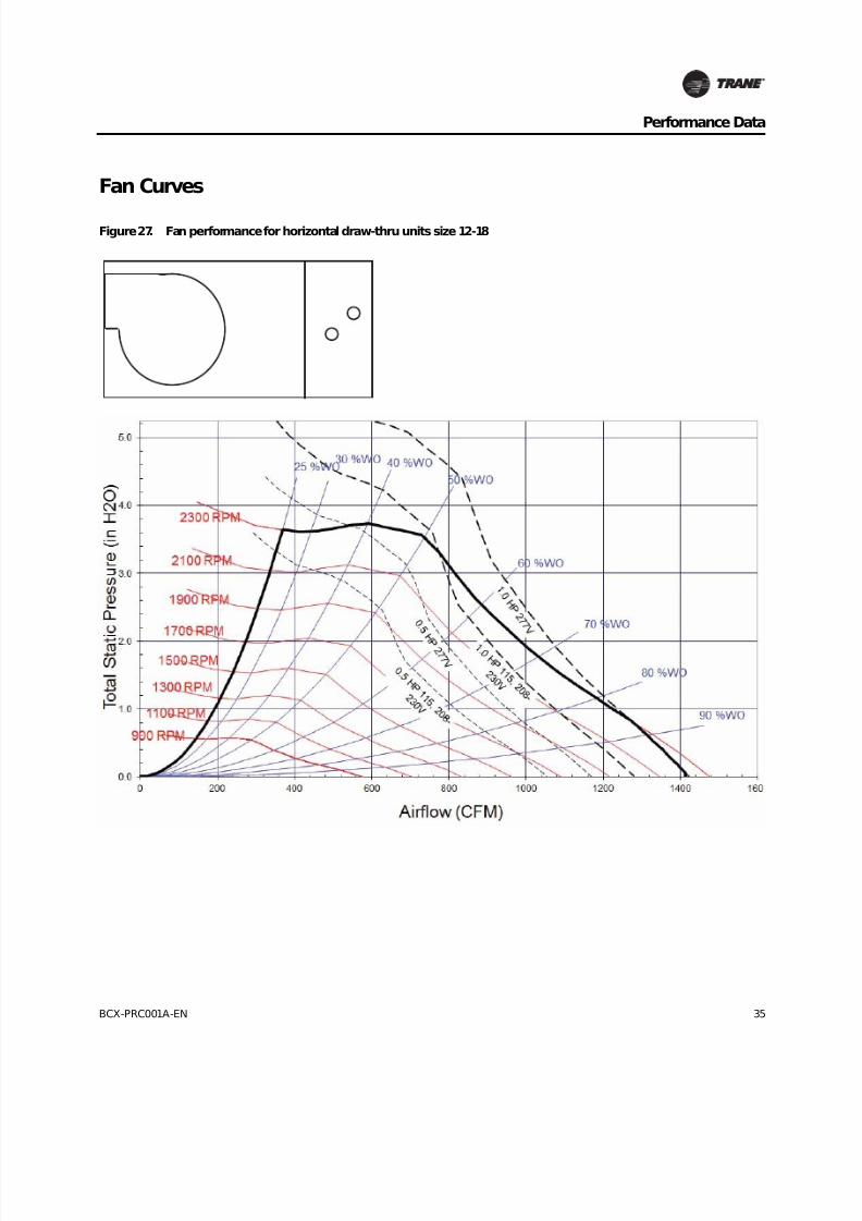
4. Calculate t he w ater pressure drop (hydronic coils only). Determine water pressure dropusing the appropriate figure on page 28 - page 34.
5. Check fan performance requirements. Reference fan performance data by unit size and
configuration on page 35 - page 54. These tables and curves include pressure drops from thecasing only. Reference air pressure drop for coils, filters, and accessories using Table 5, page 26 and Table 6, page 27.
6. Calculate tot al stat ic pressure requirement s. Add the external static pressure (ESP) of the
coil, filter, and accessories to the system esp to obtain the total fan static pressure requirement. Then determine BHP and fan RPM requirements using the fan performance curves. Then
determine which motor to use.
7. Determine m otor size. Check motor HP and fan RPM requirements to determine the correct
motor and size.
8. The fan curves and fan tables use the motor hp. Check CFM and SP to determine which motor
and RPM will meet the application. Select TOPSS base performance in order to use the TOPSScalculated RPM.

8/16/2019 Bcx-prc001-En 092013 Blower Coil Cat
http://slidepdf.com/reader/full/bcx-prc001-en-092013-blower-coil-cat 21/104
BCX-PRC001A-EN 21
Selection Procedure
Cooling Selection Example
J ob example:• Horizontal blower coil
• 2-inch pleated media filters
• Mixing box with dampers
• Total capacity required: 53.0 MBh
• Sensible capacity required: 42.9 MBh
• Airflow: 2000 cfm, 0.25” ESP
• Entering air conditions: 80°F DB/67°F WB
• Entering water: 45°F
• Water temperature rise: 10°F
1. Determine unit capacity. Using Table 18, page 48, the capacity of a BCHD 54 with a six-row
coil, 10°F ∆ T at 1800 cfm, is 74.51MBh total and 52.3 MBh sensible. At 2250cfm, it is 88.7MBhtotal and 63.4MBh sensible. Interpolate between these values for 2000 cfm to obtain 80.9MBhtotal and 56.7 sensible.
2. Verify CFM and GPM limit s. Using Table 18, page 48, the water flow rate =16.1 gpm.
Reference Table 1, page 23 for airflow and water limits. Both the water flow rate (16.1gpm) and
airflow (2000cfm) fall within the range specified for a BCHD054 with a six-row cooling coil.
3. Calculate WPD. From Table18, page 48, the water pressure drop for a size 54 unit, six-row coilat 16.1gpm =4.8 feet of water.
4. Check fan performance requirements. Calculate the air pressure drop for all components
using Table 5, page26 and Table 6, page 27, air pressure drop adjustment. Interpolate for2000 cfm as follows:
5. Calcula te TSP. Unit apd 1.135 inch wg +0.25 inch wg ESP=1.385 inch wg total static pressure.
6. Det ermine mot or and drive size. Using Table 11, page 40 (fan performance), interpolate for
2000 cfm at 1.385 inches wg total static pressure to obtain 955 rpm and 1.0 HP 115/208-230V or277V motor. Select TOPSS Base Performance to operate at 955 rpm.
6-row coil 0.934 inch wg
2-inch pleated filter 0.175 inch wg
mix. box/dampers 0.026 inch wg 1.135 inch wg

8/16/2019 Bcx-prc001-En 092013 Blower Coil Cat
http://slidepdf.com/reader/full/bcx-prc001-en-092013-blower-coil-cat 22/104
22 BCX-PRC001A-EN
Selection Procedure
Heating Selection Example
Select a heating coil for the BCHD054, selected in the cooling selection example. Operatingconditions are:
• 2000 cfm
• EWT =170°F
• EAT =60°F
• LAT =120°F
1. Determine unit capacity. Required capacity =CFM x 1.085 x (LAT - EAT) =2000 x 1.085 x (120
- 60) =130,200 Btu (130.2 MBh)
The capacity correction factor for a two-row coil is 0.917 for EAT =60°F and EWT =170°F. Corrected
capacity required =130.2/0.917 =142.0MBh
2. Verify water flow and airflow limits. Reference Table 1, page 23 for water flow limits and Table 2, page 24 for cfm limits. Both the water flow rate (10.9gpm) and airflow (2000 cfm) fall
within the range specified for a BCHD 054 with a 2-row heating coil.
3. Calculate w ater pressure drop (WPD). FromFigure 24, page 33, the water pressure drop fora size 54 unit is 20 feet of water. The wpd correction factor for the average water temperaturethrough the coil from Table34, page 68 is 1.01. Corrected water pressure drop =2.0 x 1.01 =
2.02 feet of water.
4. Calculate total static pressure and determine motor size. From Table 5, page 26, airpressure drop for a BCHD size 54 two-row coil is 0.222 inches wg.Adding this pressure drop to the total static pressure (calculated in the cooling example) gives
a total static pressure of 1.356 inches wg. From Table11, page 40, interpolating for 2000 cfm and
1.446 inches wg, we obtain 975 rpm and 1.0 115/208-230V or 277V motor. Select TOPSS BasePerformance to operate at 975 rpm.
10°F∆ T 15°F ∆ T
@1800 cfm 136.4 MBh 131.3 MBh
4.9 gpm 13.1 gpm
@2250 cfm 156.9 MBh 150.7 MBh
6.4 gpm 15.1 gpm@2000 cfm 145.5 MBh 139.9 MBh
5.6 gpm 14.0 gpm

8/16/2019 Bcx-prc001-En 092013 Blower Coil Cat
http://slidepdf.com/reader/full/bcx-prc001-en-092013-blower-coil-cat 23/104
BCX-PRC001A-EN 23
General Data
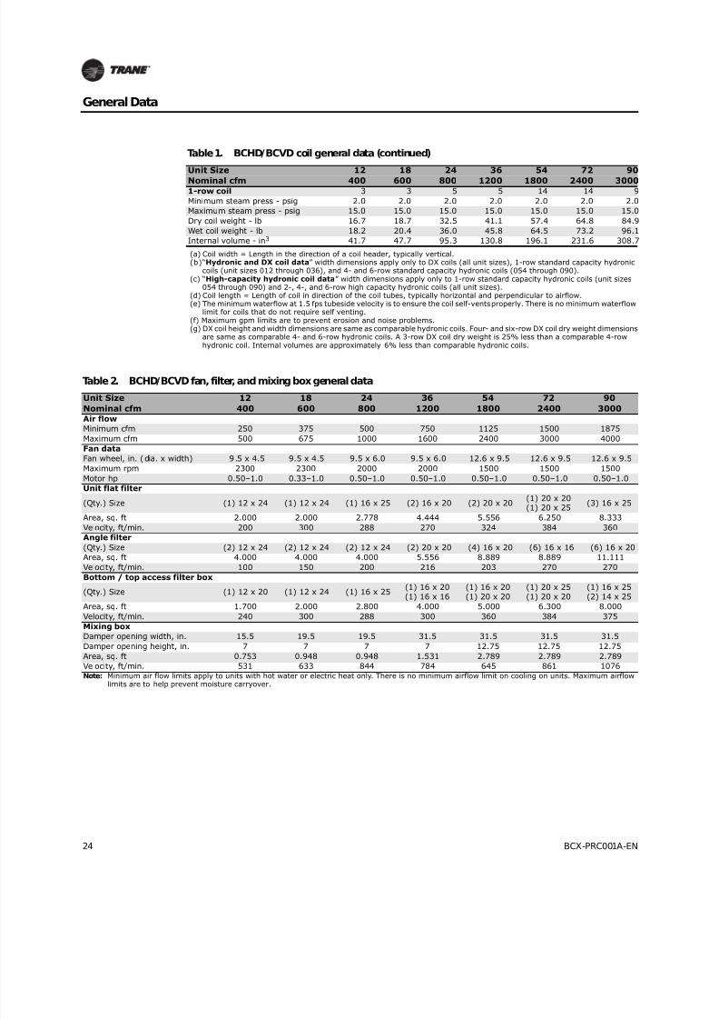
Table 1. BCHD/BCVD coil general data
Unit Size 12 18 24 36 54 72 90
Nominal cfm 400 600 800 1200 1800 2400 3000
Hydronic and DX coil data
Area - ft2 0.89 1.11 1.67 2.67 4.00 5.00 6.67
Width - in. (a), (b) 8 8 12 12 18 18 24
Length - in. (d) 16 20 20 32 32 40 40
Velocity - ft/min. 450 540 480 450 450 480 450
Hydronic coil data - high capacity
Area - ft2 0.89 1.11 1.67 2.67 3.89 4.86 6.25
Width - in. (a), (c) 8 8 12 12 17.5 17.5 22.5
Length - in. (d) 16 20 20 32 32 40 40
Velocity - ft/min. 450 540 480 450 463 494 480
1-row coil
Minimum gpm (e) 1.0 1.0 1.0 1.0 6.1 6.1 7.9
Maximum gpm (f) 5.2 5.2 5.2 5.2 32.6 32.6 42.0
Dry coil weight - lb 4.4 5.2 6.6 9.3 17.6 20.4 25.8
Wet coil weight - lb 5.1 6.0 7.8 11.0 22.4 26.0 32.9
Internal volume - in3 19.4 22.2 33.2 47.1 132.9 155.1 196.62-row coil - high capacity
Minimum gpm (e) 1.0 1.0 2.0 2.0 6.1 6.1 7.9
Maximum gpm (f) 5.2 5.2 10.4 10.4 32.6 32.6 42.0
Dry coil weight - lb 5.9 7.0 9.9 14.1 27.2 32.1 39.4
Wet coil weight - lb (kg) 7.2 8.4 12.3 17.6 36.1 42.5 52.6
Internal volume - in3 36.0 38.8 66.5 96.9 246.5 288.0 365.5
4-row coil - standard capacity
Minimum gpm (e) n/a n/a n/a n/a 8.8 8.8 11.7
Maximum gpm (f) n/a n/a n/a n/a 47.0 47.0 62.6
Dry coil weight - lb (g) n/a n/a n/a n/a 37.2 44.5 58.5
Wet coil weight - lb (g) n/a n/a n/a n/a 48.3 57.7 77.0
Internal volume - in3 (g) n/a n/a n/a n/a 307.4 365.5 512.3
4-row coil - high capacity
Minimum gpm (e) 2.0 2.0 2.9 2.9 6.1 6.1 7.9
Maximum gpm (f) 10.4 10.4 15.7 15.7 32.6 32.6 42.0
Dry coil weight - lb 10.5 12.4 17.7 25.5 47.0 56.3 73.1
Wet coil weight - lb 13.1 15.5 22.5 32.5 62.7 74.9 97.9
Internal volume - in3 72.0 85.8 132.9 193.8 433.0 516.7 688.36-row coil - standard capacity
Minimum gpm (e) n/a n/a n/a n/a 8.8 8.8 11.7
Maximum gpm (f) n/a n/a n/a n/a 47.0 47.0 62.6
Dry coil weight - lb (g) n/a n/a n/a n/a 52.4 63.1 82.7
Wet coil weight - lb (g) n/a n/a n/a n/a 68.1 82.0 108.7
Internal volume - in3 (g) n/a n/a n/a n/a 434.8 523.4 720.0
6-row coil - high capacity
Minimum gpm (e) 2.0 2.0 2.9 2.9 6.1 6.1 7.9
Maximum gpm (f) 10.4 10.4 15.7 15.7 32.6 32.6 42.0
Dry coil weight - lb 14.6 17.4 24.7 36.1 65.4 78.6 101.5
Wet coil weight - lb 18.2 21.8 31.5 46.1 87.8 105.6 137.0
Internal volume - in3 99.7 121.8 188.3 276.9 620.4 745.9 983.1
Steam coil data
Area - ft2 0.71 0.88 1.75 2.75 4.13 5.13 6.83
Width - in. (a) 6 6 12 12 18 18 24
Length - in. (d) 17 21 21 33 33 41 41
Velocity - ft/min. 26 25 18 17 17 16 16
8/16/2019 Bcx-prc001-En 092013 Blower Coil Cat
http://slidepdf.com/reader/full/bcx-prc001-en-092013-blower-coil-cat 24/104
24 BCX-PRC001A-EN
General Data
1-row coil 3 3 5 5 14 14 9
Minimum steam press - psig 2.0 2.0 2.0 2.0 2.0 2.0 2.0
Maximum steam press - psig 15.0 15.0 15.0 15.0 15.0 15.0 15.0
Dry coil weight - lb 16.7 18.7 32.5 41.1 57.4 64.8 84.9
Wet coil weight - lb 18.2 20.4 36.0 45.8 64.5 73.2 96.1
Internal volume - in3 41.7 47.7 95.3 130.8 196.1 231.6 308.7
(a) Coil width = Length in the direction of a coil header, typically vertical.(b)“Hydronic and DX coil data” width dimensions apply only to DX coils (all unit sizes), 1-row standard capacity hydronic
coils (unit sizes 012 through 036), and 4- and 6-row standard capacity hydronic coils (054 through 090).(c) “High-capacity hydronic coil data” width dimensions apply only to 1-row standard capacity hydronic coils (unit sizes
054 through 090) and 2-, 4-, and 6-row high capacity hydronic coils (all unit sizes).(d) Coil length = Length of coil in direction of the coil tubes, typically horizontal and perpendicular to airflow.(e) The minimum waterflow at 1.5 fps tubeside velocity is to ensure the coil self-vents properly. There is no minimum waterflow
limit for coils that do not require self venting.(f) Maximum gpm limits are to prevent erosion and noise problems.(g) DX coil height and width dimensions are same as comparable hydronic coils. Four- and six-row DX coil dry weight dimensions
are same as comparable 4- and 6-row hydronic coils. A 3-row DX coil dry weight is 25% less than a comparable 4-rowhydronic coil. Internal volumes are approximately 6% less than comparable hydronic coils.
Table 1. BCHD/BCVD coil general data (continued)
Unit Size 12 18 24 36 54 72 90
Nominal cfm 400 600 800 1200 1800 2400 3000
Table 2. BCHD/BCVD fan, filter, and mixing box general data
Unit Size 12 18 24 36 54 72 90
Nominal cfm 400 600 800 1200 1800 2400 3000
Air flow
Minimum cfm 250 375 500 750 1125 1500 1875
Maximum cfm 500 675 1000 1600 2400 3000 4000
Fan data
Fan wheel, in. (dia. x width) 9.5 x 4.5 9.5 x 4.5 9.5 x 6.0 9.5 x 6.0 12.6 x 9.5 12.6 x 9.5 12.6 x 9.5
Maximum rpm 2300 2300 2000 2000 1500 1500 1500
Motor hp 0.50–1.0 0.33–1.0 0.50–1.0 0.50–1.0 0.50–1.0 0.50–1.0 0.50–1.0
Unit flat filter
(Qty.) Size (1) 12 x 24 (1) 12 x 24 (1) 16 x 25 (2) 16 x 20 (2) 20 x 20 (1) 20 x 20
(1) 20 x 25 (3) 16 x 25
Area, sq. ft 2.000 2.000 2.778 4.444 5.556 6.250 8.333
Velocity, ft/min. 200 300 288 270 324 384 360
Angle filter(Qty.) Size (2) 12 x 24 (2) 12 x 24 (2) 12 x 24 (2) 20 x 20 (4) 16 x 20 (6) 16 x 16 (6) 16 x 20
Area, sq. ft 4.000 4.000 4.000 5.556 8.889 8.889 11.111
Velocity, ft/min. 100 150 200 216 203 270 270
Bottom / top access filter box
(Qty.) Size (1) 12 x 20 (1) 12 x 24 (1) 16 x 25 (1) 16 x 20
(1) 16 x 16
(1) 16 x 20
(1) 20 x 20
(1) 20 x 25
(1) 20 x 20
(1) 16 x 25
(2) 14 x 25
Area, sq. ft 1.700 2.000 2.800 4.000 5.000 6.300 8.000
Velocity, ft/min. 240 300 288 300 360 384 375
Mixing box
Damper opening width, in. 15.5 19.5 19.5 31.5 31.5 31.5 31.5
Damper opening height, in. 7 7 7 7 12.75 12.75 12.75
Area, sq. ft 0.753 0.948 0.948 1.531 2.789 2.789 2.789
Velocity, ft/min. 531 633 844 784 645 861 1076Note: Minimum air flow limits apply to units with hot water or electric heat only. There is no minimum airflow limit on cooling on units. Maximum airflow
limits are to help prevent moisture carryover.

8/16/2019 Bcx-prc001-En 092013 Blower Coil Cat
http://slidepdf.com/reader/full/bcx-prc001-en-092013-blower-coil-cat 25/104
BCX-PRC001A-EN 25
General Data
Valve Package Waterflow Limits
Coil Circuiting
Table 3. BCHD/BCVD valve package waterflow limits
Tube Size (in.) GPM
1/2 8.6
3/4 19.3
1 34.3
1-1/4 53.5
Figure 11. Single refrigerant coil Figure 12. Horizontal face split DX coil
Table 4. Number of circuits per coil
No. of
Rows
Application
Type1 Coil Type
Unit Size
12 18 24 36 54 72 90
1Heating
Standard capacity 2 2 2 2 7 7 9
2 High-capacity 2 2 4 4 7 7 9
3 Refrigerant DX 2 2 3 6 9 9 12
4 Hydronic
Standard capacity n/a n/a n/a n/a 18 18 18
High-capacity 4 4 6 6 7 7 9
Refrigerant DX 2 2 3 6 9 9 12
6 Hydronic
Standard capacity n/a n/a n/a n/a 18 18 18
High-capacity 2 2 4 4 7 7 9
Refrigerant DX 4 4 6 6 9 9/92 12/122
Note: 1Hydronic and refrigerant coils can be applied as heating or cooling. 2All refrigerant coils are single-circuit coi ls, except for sizes 72 and 90 with a 6-row coil, where there are two circuits that are face split.

8/16/2019 Bcx-prc001-En 092013 Blower Coil Cat
http://slidepdf.com/reader/full/bcx-prc001-en-092013-blower-coil-cat 26/104
26 BCX-PRC001A-EN
Performance Data
Air pressure drop adjustments
Table 5. Coil air pressure drop adjustments (in. wg)
Unit
Size CFM
Coil
Face
Velocity
2-Row 4-Row 6-Row DX Cooling
Hydronic
Heating Coil
Steam
Coil Electric Heat
High
Cap
Std
Cap
High
Cap
Std
Cap
High
Cap 3-Row 4-Row 6-Row 1-Row 2-Row 1-Row
Disch
Velocity Delta P
12
250 300 0.128 – 0.256 – 0.385 0.192 0.256 0.385 0.049 0.081 0.092 490 0.028
300 360 0.179 – 0.358 – 0.537 0.268 0.358 0.537 0.067 0.109 0.126 588 0.034
350 420 0.235 – 0.471 – 0.706 0.353 0.471 0.706 0.087 0.141 0.164 686 0.039
400 480 0.296 – 0.591 – 0.887 0.443 0.591 0.887 0.110 0.176 0.207 784 0.405
450 540 0.358 – 0.717 – 1.075 0.538 0.717 1.075 0.136 0.214 0.254 882 0.050
500 600 0.423 – 0.845 – 1.268 0.634 0.845 1.268 0.164 0.255 0.305 980 0.056
18
375 360 0.179 – 0.358 – 0.537 0.268 0.358 0.537 0.067 0.109 0.129 735 0.042
450 432 0.247 – 0.494 – 0.741 0.371 0.494 0.741 0.092 0.147 0.176 882 0.050
525 504 0.321 – 0.641 – 0.962 0.481 0.641 0.962 0.120 0.190 0.230 1029 0.059
600 576 0.397 – 0.794 – 1.191 0.595 0.794 1.191 0.152 0.238 0.290 1176 0.067
675 648 0.474 – 0.948 – 1.423 0.711 0.948 1.423 0.188 0.290 0.356 1324 0.076
24
500 288 0.119 – 0.238 – 0.357 0.178 0.238 0.357 0.046 0.076 0.064 571 0.033
600 346 0.166 – 0.332 – 0.499 0.249 0.332 0.499 0.062 0.102 0.088 686 0.039
700 403 0.219 – 0.438 – 0.657 0.329 0.438 0.657 0.081 0.131 0.114 800 0.046
800 461 0.276 – 0.552 – 0.828 0.414 0.552 0.828 0.103 0.164 0.144 914 0.052
900 518 0.336 – 0.671 – 1.007 0.503 0.671 1.007 0.126 0.200 0.176 1029 0.059
1000 576 0.397 – 0.794 – 1.191 0.595 0.794 1.191 0.152 0.238 0.211 1143 0.065
36
750 270 0.105 – 0.211 – 0.316 0.158 0.211 0.316 0.041 0.069 0.059 857 0.049
900 324 0.148 – 0.295 – 0.443 0.222 0.295 0.443 0.056 0.092 0.081 1029 0.059
1050 378 0.195 – 0.391 – 0.586 0.293 0.391 0.586 0.072 0.118 0.105 1200 0.069
1200 432 0.247 – 0.494 – 0.741 0.371 0.494 0.741 0.092 0.147 0.133 1371 0.078
1350 486 0.302 – 0.604 – 0.905 0.453 0.604 0.905 0.113 0.179 0.163 1543 0.092
1500 540 0.358 – 0.717 – 1.075 0.538 0.717 1.075 0.136 0.214 0.195 1714 0.118
54
1125 289 0.124 0.240 0.249 0.359 0.373 0.180 0.240 0.359 0.053 0.089 0.059 960 0.055
1350 347 0.168 0.335 0.336 0.503 0.504 0.251 0.335 0.503 0.073 0.118 0.081 1152 0.066
1575 405 0.215 0.441 0.430 0.662 0.645 0.331 0.441 0.662 0.096 0.151 0.105 1344 0.077
1800 463 0.265 0.556 0.530 0.834 0.795 0.417 0.556 0.834 0.122 0.187 0.133 1536 0.091
2025 521 0.317 0.676 0.634 1.014 0.952 0.507 0.676 1.014 0.149 0.226 0.163 1728 0.121
2250 579 0.371 0.799 0.741 1.199 1.112 0.600 0.799 1.199 0.180 0.269 0.195 1920 0.156
72
1500 309 0.138 0.270 0.277 0.405 0.415 0.203 0.270 0.405 0.060 0.099 0.067 1280 0.073
1800 370 0.186 0.376 0.373 0.565 0.559 0.282 0.376 0.565 0.082 0.131 0.091 1536 0.091
2100 432 0.238 0.494 0.476 0.741 0.714 0.371 0.494 0.741 0.108 0.167 0.119 1792 0.132
2400 494 0.293 0.620 0.585 0.929 0.878 0.465 0.620 0.929 0.136 0.207 0.150 2048 0.182
2700 555 0.349 0.750 0.698 1.125 1.047 0.562 0.750 1.125 0.167 0.252 0.184 2304 0.241
3000 617 0.407 0.882 0.813 1.323 1.220 0.662 0.882 1.323 0.202 0.300 0.220 2560 0.311
90
1875 300 0.132 0.256 0.264 0.385 0.397 0.192 0.256 0.385 0.057 0.095 0.060 1600 0.100
2250 360 0.178 0.358 0.356 0.537 0.534 0.268 0.358 0.537 0.078 0.125 0.082 1920 0.156
2625 420 0.228 0.471 0.456 0.706 0.683 0.353 0.471 0.706 0.102 0.160 0.107 2240 0.225
3000 480 0.280 0.591 0.561 0.887 0.841 0.443 0.591 0.887 0.130 0.198 0.134 2560 0.311
3375 540 0.335 0.717 0.670 1.075 1.005 0.538 0.717 1.075 0.159 0.240 0.164 2880 0.412
3750 600 0.391 0.845 0.781 1.268 1.172 0.634 0.845 1.268 0.192 0.286 0.197 3200 0.531Note:
• Cooling coil APD is for a 100 percent fully wetted fin.
• Heating coil APD is for dry fin surface.
8/16/2019 Bcx-prc001-En 092013 Blower Coil Cat
http://slidepdf.com/reader/full/bcx-prc001-en-092013-blower-coil-cat 27/104
BCX-PRC001A-EN 27
Performance Data
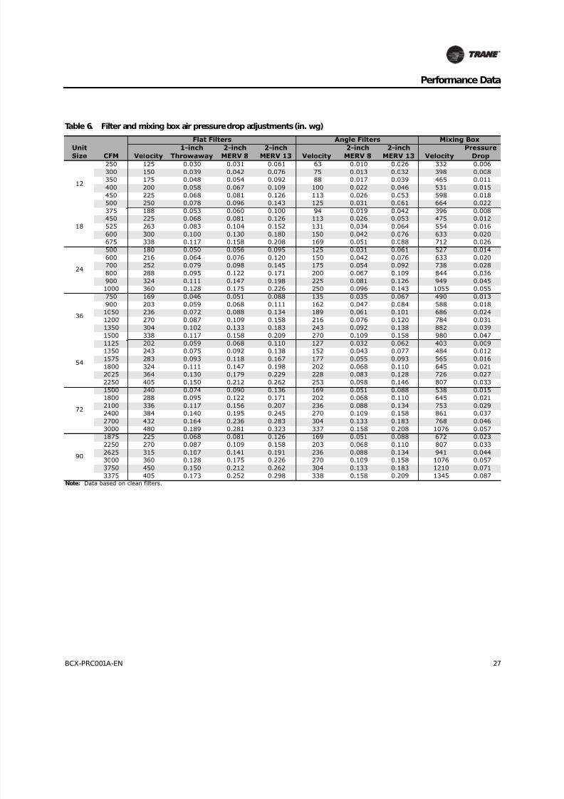
Table 6. Filter and mixing box air pressure drop adjustments (in. wg)
Flat Filters Angle Filters Mixing BoxUnit
Size CFM Velocity
1-inch
Throwaway
2-inch
MERV 8
2-inch
MERV 13 Velocity
2-inch
MERV 8
2-inch
MERV 13 Velocity
Pressure
Drop
12
250 125 0.030 0.031 0.061 63 0.010 0.026 332 0.006
300 150 0.039 0.042 0.076 75 0.013 0.032 398 0.008
350 175 0.048 0.054 0.092 88 0.017 0.039 465 0.011
400 200 0.058 0.067 0.109 100 0.022 0.046 531 0.015
450 225 0.068 0.081 0.126 113 0.026 0.053 598 0.018
500 250 0.078 0.096 0.143 125 0.031 0.061 664 0.022
18
375 188 0.053 0.060 0.100 94 0.019 0.042 396 0.008
450 225 0.068 0.081 0.126 113 0.026 0.053 475 0.012
525 263 0.083 0.104 0.152 131 0.034 0.064 554 0.016
600 300 0.100 0.130 0.180 150 0.042 0.076 633 0.020
675 338 0.117 0.158 0.208 169 0.051 0.088 712 0.026
24
500 180 0.050 0.056 0.095 125 0.031 0.061 527 0.014
600 216 0.064 0.076 0.120 150 0.042 0.076 633 0.020
700 252 0.079 0.098 0.145 175 0.054 0.092 738 0.028
800 288 0.095 0.122 0.171 200 0.067 0.109 844 0.036
900 324 0.111 0.147 0.198 225 0.081 0.126 949 0.0451000 360 0.128 0.175 0.226 250 0.096 0.143 1055 0.055
36
750 169 0.046 0.051 0.088 135 0.035 0.067 490 0.013
900 203 0.059 0.068 0.111 162 0.047 0.084 588 0.018
1050 236 0.072 0.088 0.134 189 0.061 0.101 686 0.024
1200 270 0.087 0.109 0.158 216 0.076 0.120 784 0.031
1350 304 0.102 0.133 0.183 243 0.092 0.138 882 0.039
1500 338 0.117 0.158 0.209 270 0.109 0.158 980 0.047
54
1125 202 0.059 0.068 0.110 127 0.032 0.062 403 0.009
1350 243 0.075 0.092 0.138 152 0.043 0.077 484 0.012
1575 283 0.093 0.118 0.167 177 0.055 0.093 565 0.016
1800 324 0.111 0.147 0.198 202 0.068 0.110 645 0.021
2025 364 0.130 0.179 0.229 228 0.083 0.128 726 0.027
2250 405 0.150 0.212 0.262 253 0.098 0.146 807 0.033
72
1500 240 0.074 0.090 0.136 169 0.051 0.088 538 0.015
1800 288 0.095 0.122 0.171 202 0.068 0.110 645 0.021
2100 336 0.117 0.156 0.207 236 0.088 0.134 753 0.029
2400 384 0.140 0.195 0.245 270 0.109 0.158 861 0.037
2700 432 0.164 0.236 0.283 304 0.133 0.183 768 0.0463000 480 0.189 0.281 0.323 337 0.158 0.208 1076 0.057
90
1875 225 0.068 0.081 0.126 169 0.051 0.088 672 0.023
2250 270 0.087 0.109 0.158 203 0.068 0.110 807 0.033
2625 315 0.107 0.141 0.191 236 0.088 0.134 941 0.044
3000 360 0.128 0.175 0.226 270 0.109 0.158 1076 0.057
3750 450 0.150 0.212 0.262 304 0.133 0.183 1210 0.071
3375 405 0.173 0.252 0.298 338 0.158 0.209 1345 0.087Note: Data based on clean filters.
8/16/2019 Bcx-prc001-En 092013 Blower Coil Cat
http://slidepdf.com/reader/full/bcx-prc001-en-092013-blower-coil-cat 28/104
28 BCX-PRC001A-EN
Performance Data
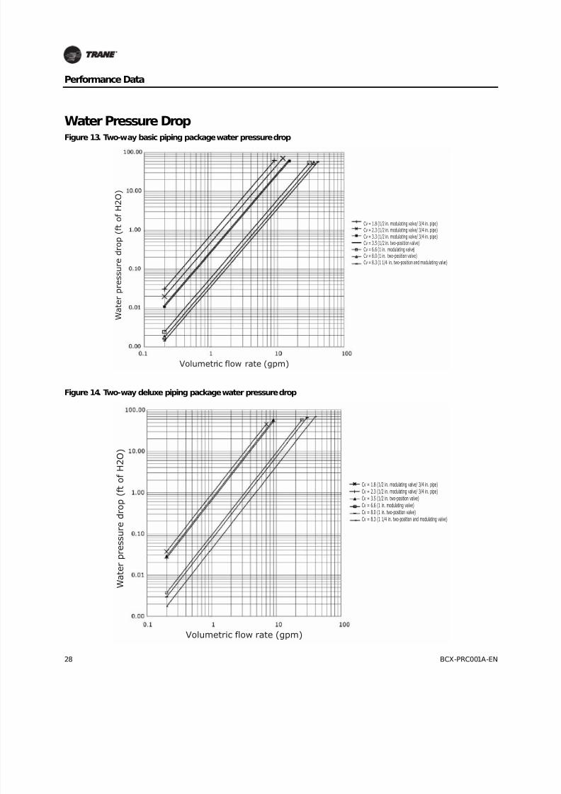
Water Pressure Drop
Figure 13. Two-way basic piping package water pressure drop
W a t e r p r e s
s u r e d r o p ( f t o f H 2 O )
Volumetric flow rate (gpm)
Cv = 1.8 (1/2 in. modulating valve/ 3/4 in. pipe)Cv = 2.3 (1/2 in. modulating valve/ 3/4 in. pipe)Cv = 3.3 (1/2 in. modulating valve/ 3/4 in. pipe)Cv = 3.5 (1/2 in. two-position valve)Cv = 6.6 (1 in. modulating valve)Cv = 8.0 (1 in. two-position valve)Cv = 8.3 (1 1/4 in. two-position and modulating valve)
Figure 14. Two-way deluxe piping package water pressure drop
Cv = 1.8 (1/2 in. modulating valve/ 3/4 in. pipe)Cv = 2.3 (1/2 in. modulating valve/ 3/4 in. pipe)Cv = 3.5 (1/2 in. two-position valve)Cv = 6.6 (1 in. modulating valve)Cv = 8.0 (1 in. two-position valve)Cv = 8.3 (1 1/4 in. two-position and modulating valve)
W a t e r p
r e s s u r e d r o p ( f t o f H 2 O )
Volumetric flow rate (gpm)
8/16/2019 Bcx-prc001-En 092013 Blower Coil Cat
http://slidepdf.com/reader/full/bcx-prc001-en-092013-blower-coil-cat 29/104
BCX-PRC001A-EN 29
Performance Data
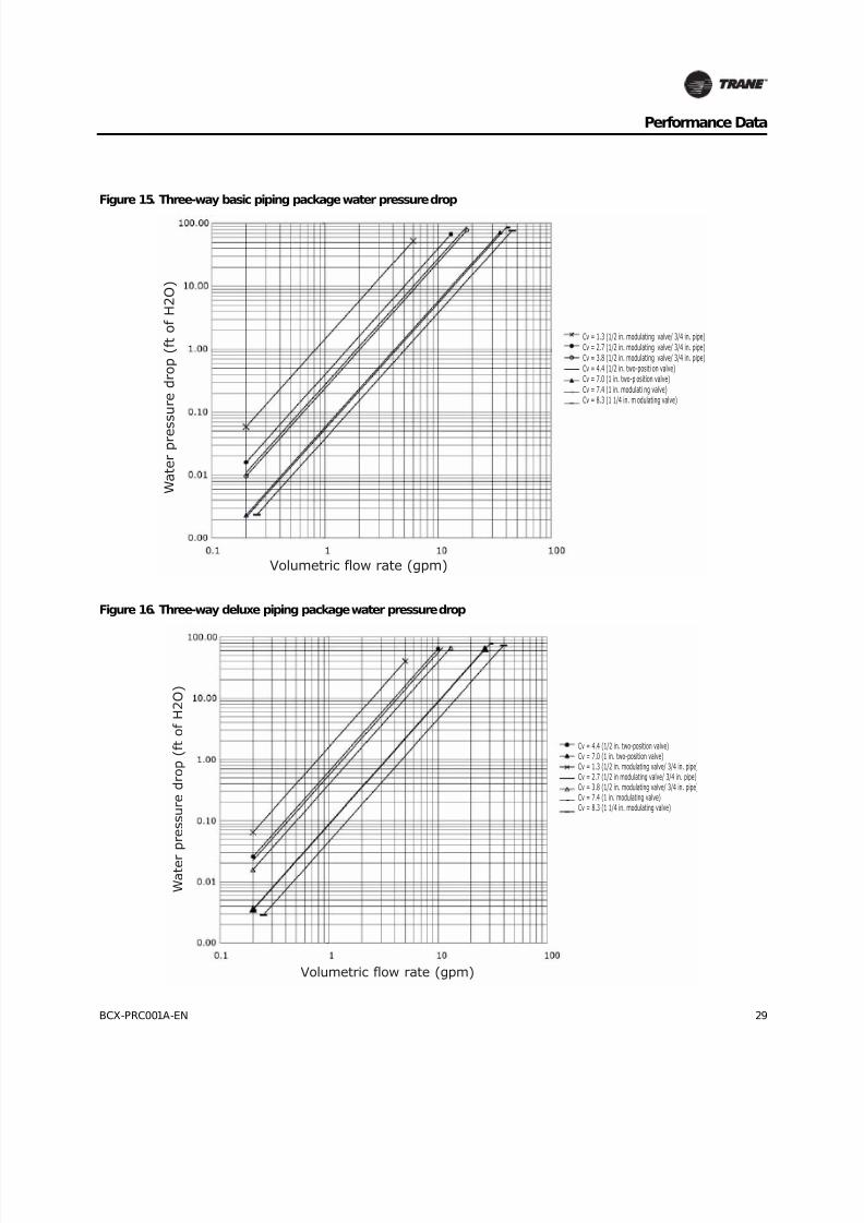
Figure 15. Three-way basic piping package water pressure drop
W a t e r p r e s
s u r e d r o p ( f t o f H 2 O )
Volumetric flow rate (gpm)
Cv = 1.3 (1/2 in. modulating valve/ 3/4 in. pipe)Cv = 2.7 (1/2 in. modulating valve/ 3/4 in. pipe)Cv = 3.8 (1/2 in. modulating valve/ 3/4 in. pipe)Cv = 4.4 (1/2 in. two-positi on valve)Cv = 7.0 (1 in. two-p osition valve)Cv = 7.4 (1 in. modulati ng valve)Cv = 8.3 (1 1/4 in. m odulating valve)
Figure 16. Three-way deluxe piping package water pressure drop
W a t e r
p r e s s u r e d r o p ( f t o f H 2 O )
Volumetric flow rate (gpm)
Cv = 4.4 (1/2 in. two-position valve)Cv = 7.0 (1 in. two-position valve)Cv = 1.3 (1/2 in. modulating valve/ 3/4 in. pipe)Cv = 2.7 (1/2 in modulating valve/ 3/4 in. pipe)Cv = 3.8 (1/2 in. modulating valve/ 3/4 in. pipe)Cv = 7.4 (1 in. modulating valve)Cv = 8.3 (1 1/4 in. modulating valve)

8/16/2019 Bcx-prc001-En 092013 Blower Coil Cat
http://slidepdf.com/reader/full/bcx-prc001-en-092013-blower-coil-cat 30/104
30 BCX-PRC001A-EN
Performance Data
Figure 17. Four-row standard cooling coil water pressure drop
W a t e r p r e s s u r e d r o p ( f t o f H 2 O )
Volumetric flow rate (gpm)
Size 54Size 72Size 90
Figure 18. Six-row standard cooling coil water pressure drop
W a t e r p r e s s u r e d r o p ( f t o f H 2 O )
Volumetric flow rate (gpm)
Size 54Size 72Size 90
8/16/2019 Bcx-prc001-En 092013 Blower Coil Cat
http://slidepdf.com/reader/full/bcx-prc001-en-092013-blower-coil-cat 31/104
BCX-PRC001A-EN 31
Performance Data
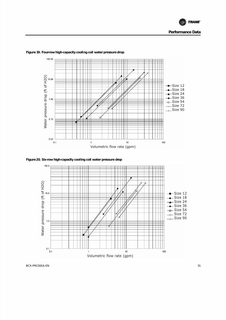
Figure 19. Four-row high-capacity cooling coil water pressure drop
W a t e r p r e s s u r e d r o p ( f t o f H 2 O )
Volumetric flow rate (gpm)
Size 12Size 18Size 24Size 36Size 54Size 72Size 90
Figure 20. Six-row high-capacity cooling coil water pressure drop
Size 12Size 18Size 24Size 36Size 54Size 72Size 90
W a t e r p
r e s s u r e d r o p ( f t o f H 2 O )
Volumetric flow rate (gpm)

8/16/2019 Bcx-prc001-En 092013 Blower Coil Cat
http://slidepdf.com/reader/full/bcx-prc001-en-092013-blower-coil-cat 32/104
32 BCX-PRC001A-EN
Performance Data
Figure 21. One-row standard heating coil water pressure drop
Size 12Size 18Size 24Size 36Size 54Size 72
Size 90
W a t e r p r
e s s u r e d r o p ( f t o f H 2 O )
Volumetric flow rate (gpm)
Figure 22. Four-row standard heating coil water pressure drop
Size 54Size 72Size 90
W a t e r p
r e s s u r e d r o p ( f t o f H 2 O )
Volumetric flow rate (gpm)

8/16/2019 Bcx-prc001-En 092013 Blower Coil Cat
http://slidepdf.com/reader/full/bcx-prc001-en-092013-blower-coil-cat 33/104
BCX-PRC001A-EN 33
Performance Data
Figure 23. Six-row standard heating coil water pressure drop
Size 54Size 72Size 90
W a t e r p r e s s u r e d r o p ( f t o f H 2 O )
Volumetric flow rate (gpm)
Figure 24. Two-row high-capacity heating coil water pressure drop
Size 12Size 18Size 24Size 36Size 54Size 72Size 90
W a t e r p r
e s s u r e d r o p ( f t o f H 2 O )
Volumetric flow rate (gpm)

8/16/2019 Bcx-prc001-En 092013 Blower Coil Cat
http://slidepdf.com/reader/full/bcx-prc001-en-092013-blower-coil-cat 34/104
34 BCX-PRC001A-EN
Performance Data
Figure 25. Four-row high-capacity heating coil water pressure drop
Size 12Size 18Size 24Size 36Size 54Size 72
Size 90
W a t e r p r e s s u r e d r o p ( f t o f H 2 O )
Volumetric flow rate (gpm)
Figure 26. Six-row high-capacity heating coil water pressure drop
Size 12Size 18Size 24Size 36Size 54Size 72Size 90
W a t e r p r e s s u r e d r o p ( f t o f H 2 O )
Volumetric flow rate (gpm)
8/16/2019 Bcx-prc001-En 092013 Blower Coil Cat
http://slidepdf.com/reader/full/bcx-prc001-en-092013-blower-coil-cat 35/104
BCX-PRC001A-EN 35
Performance Data
Fan Curves
Figure 27. Fan performance for horizontal draw-thru units size 12-18

8/16/2019 Bcx-prc001-En 092013 Blower Coil Cat
http://slidepdf.com/reader/full/bcx-prc001-en-092013-blower-coil-cat 36/104
36 BCX-PRC001A-EN
Performance Data
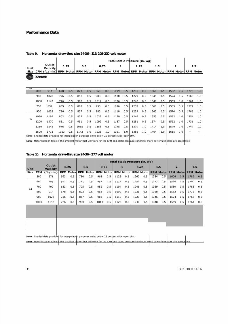
Table 7. Horizontal draw-thru size 12-18 - 115/208-230 volt motor
Unit
Size CFM
Outlet
Velocity
(ft./min)
Total Static Pressure (in. wg)
0.25 0.5 0.75 1 1.25 1.5 2 2.5
RPM Motor RPM Motor RPM Motor RPM Motor RPM Motor RPM Motor RPM Motor RPM Motor
12
250 490 684 0.5 853 0.5 1032 0.5 1205 0.5 1354 0.5 1479 0.5 1700 0.5 1893 0.5
300 588 751 0.5 893 0.5 1042 0.5 1187 0.5 1340 0.5 1478 0.5 1710 0.5 1905 0.5
350 686 815 0.5 962 0.5 1070 0.5 1205 0.5 1331 0.5 1460 0.5 1705 0.5 1914 0.5
400 784 879 0.5 1030 0.5 1138 0.5 1230 0.5 1351 0.5 1465 0.5 1688 0.5 1904 0.5
450 882 943 0.5 1096 0.5 1209 0.5 1298 0.5 1379 0.5 1484 0.5 1687 0.5 1886 0.5
500 980 1006 0.5 1160 0.5 1275 0.5 1368 0.5 1447 0.5 1520 0.5 1706 0.5 1885 0.5
18
375 735 848 0.5 997 0.5 1104 0.5 1215 0.5 1341 0.5 1455 0.5 1696 0.5 1913 0.5
450 882 943 0.5 1096 0.5 1209 0.5 1298 0.5 1379 0.5 1484 0.5 1687 0.5 1886 0.5
525 1029 1038 0.5 1192 0.5 1308 0.5 1404 0.5 1482 0.5 1554 0.5 1716 0.5 1895 0.5
600 1176 1135 0.5 1287 0.5 1404 0.5 1502 0.5 1586 0.5 1658 0.5 1786 0.5 1924 0.5
675 1323 1232 0.5 1382 0.5 1500 0.5 1599 0.5 1685 0.5 1761 0.5 1890 1.0 2002 1.0
Note: Shaded data provided for interpolation purposes only: below 25% wide-open cfm.
Note: Motor listed in table is the smallest motor that will work for the CFM and static pressure condition. More powerful motors are acceptable.
Table 8. Horizontal draw-thru size 12-18 - 277 volt motor
Unit
Size CFM
Outlet
Velocity
(ft./min)
Total Static Pressure (in. wg)
0.25 0.5 0.75 1 1.25 1.5 2 2.5
RPM Motor RPM Motor RPM Motor RPM Motor RPM Motor RPM Motor RPM Motor RPM Motor
12
250 490 684 0.5 853 0.5 1032 0.5 1205 0.5 1354 0.5 1479 0.5 1700 0.5 1893 0.5
300 588 751 0.5 893 0.5 1042 0.5 1187 0.5 1340 0.5 1478 0.5 1710 0.5 1905 0.5
350 686 815 0.5 962 0.5 1070 0.5 1205 0.5 1331 0.5 1460 0.5 1705 0.5 1914 0.5
400 784 879 0.5 1030 0.5 1138 0.5 1230 0.5 1351 0.5 1465 0.5 1688 0.5 1904 0.5
450 882 943 0.5 1096 0.5 1209 0.5 1298 0.5 1379 0.5 1484 0.5 1687 0.5 1886 0.5
500 980 1006 0.5 1160 0.5 1275 0.5 1368 0.5 1447 0.5 1520 0.5 1706 0.5 1885 0.5
18
375 735 848 0.5 997 0.5 1104 0.5 1215 0.5 1341 0.5 1455 0.5 1696 0.5 1913 0.5
450 882 943 0.5 1096 0.5 1209 0.5 1298 0.5 1379 0.5 1484 0.5 1687 0.5 1886 0.5
525 1029 1038 0.5 1192 0.5 1308 0.5 1404 0.5 1482 0.5 1554 0.5 1716 0.5 1895 0.5
600 1176 1135 0.5 1287 0.5 1404 0.5 1502 0.5 1586 0.5 1658 0.5 1786 0.5 1924 0.5
675 1323 1232 0.5 1382 0.5 1500 0.5 1599 0.5 1685 0.5 1761 0.5 1890 0.5 2002 0.5
Note: Shaded data provided for interpolation purposes only: below 25% wide-open cfm.
Note: Motor listed in table is the smallest motor that will work for the CFM and static pressure condition. More powerful motors are acceptable.

8/16/2019 Bcx-prc001-En 092013 Blower Coil Cat
http://slidepdf.com/reader/full/bcx-prc001-en-092013-blower-coil-cat 37/104
BCX-PRC001A-EN 37
Performance Data
Figure 28. Fan performance for horizontal draw-thru units size 24-36
8/16/2019 Bcx-prc001-En 092013 Blower Coil Cat
http://slidepdf.com/reader/full/bcx-prc001-en-092013-blower-coil-cat 38/104
38 BCX-PRC001A-EN
Performance Data
Table 9. Horizontal draw-thru size 24-36 - 115/208-230 volt motor
Unit
Size CFM
Outlet
Velocity
(ft./min)
Total Static Pressure (in. wg)
0.25 0.5 0.75 1 1.25 1.5 2 2.5
RPM Motor RPM Motor RPM Motor RPM Motor RPM Motor RPM Motor RPM Motor RPM Motor
24
500 571 563 0.5 780 0.5 968 0.5 1123 0.5 1260 0.5 1384 0.5 1604 0.5 1789 0.5
600 685 593 0.5 781 0.5 957 0.5 1116 0.5 1253 0.5 1377 0.5 1596 0.5 1790 0.5
700 799 633 0.5 795 0.5 952 0.5 1104 0.5 1246 0.5 1369 0.5 1589 0.5 1783 0.5
800 914 678 0.5 823 0.5 963 0.5 1099 0.5 1231 0.5 1360 0.5 1582 0.5 1775 1.0
900 1028 726 0.5 857 0.5 983 0.5 1110 0.5 1229 0.5 1345 0.5 1574 0.5 1768 1.0
1000 1142 776 0.5 900 0.5 1014 0.5 1126 0.5 1240 0.5 1348 0.5 1559 1.0 1761 1.0
36
750 857 655 0.5 808 0.5 958 0.5 1096 0.5 1239 0.5 1366 0.5 1585 0.5 1779 1.0
900 1028 726 0.5 857 0.5 983 0.5 1110 0.5 1229 0.5 1345 0.5 1574 0.5 1768 1.0
1050 1199 802 0.5 922 0.5 1032 0.5 1139 0.5 1246 0.5 1353 0.5 1552 1.0 1754 1.0
1200 1370 881 0.5 991 0.5 1092 0.5 1187 0.5 1281 0.5 1374 0.5 1562 1.0 1731 1.0
1350 1542 966 0.5 1065 0.5 1158 0.5 1245 0.5 1330 1.0 1414 1.0 1579 1.0 1747 1.0
1500 1713 1053 0.5 1142 1.0 1228 1.0 1311 1.0 1388 1.0 1464 1.0 1615 1.0 -- --
Note: Shaded data provided for interpolation purposes only: below 25 percent wide-open cfm.
Note: Motor listed in table is the smallest motor that will work for the CFM and static pressure condition. More powerful motors are acceptable.
Table 10. Horizontal draw-thru size 24-36 - 277 volt motor
UnitSize CFM
Outlet
Velocity(ft./min)
Total Static Pressure (in. wg)
0.25 0.5 0.75 1 1.25 1.5 2 2.5
RPM Motor RPM Motor RPM Motor RPM Motor RPM Motor RPM Motor RPM Motor RPM Motor
24
500 571 563 0.5 780 0.5 968 0.5 1123 0.5 1260 0.5 1384 0.5 1604 0.5 1789 0.5
600 685 593 0.5 781 0.5 957 0.5 1116 0.5 1253 0.5 1377 0.5 1596 0.5 1790 0.5
700 799 633 0.5 795 0.5 952 0.5 1104 0.5 1246 0.5 1369 0.5 1589 0.5 1783 0.5
800 914 678 0.5 823 0.5 963 0.5 1099 0.5 1231 0.5 1360 0.5 1582 0.5 1775 0.5
900 1028 726 0.5 857 0.5 983 0.5 1110 0.5 1229 0.5 1345 0.5 1574 0.5 1768 0.5
1000 1142 776 0.5 900 0.5 1014 0.5 1126 0.5 1240 0.5 1348 0.5 1559 0.5 1761 0.5
36
750 857 655 0.5 808 0.5 958 0.5 1096 0.5 1239 0.5 1366 0.5 1585 0.5 1779 0.5
900 1028 726 0.5 857 0.5 983 0.5 1110 0.5 1229 0.5 1345 0.5 1574 0.5 1768 0.5
1050 1199 802 0.5 922 0.5 1032 0.5 1139 0.5 1246 0.5 1353 0.5 1552 0.5 1754 1.0
1200 1370 881 0.5 991 0.5 1092 0.5 1187 0.5 1281 0.5 1374 0.5 1562 0.5 1731 1.0
1350 1542 966 0.5 1065 0.5 1158 0.5 1245 0.5 1330 0.5 1414 0.5 1579 1.0 1747 1.0
1500 1713 1053 0.5 1142 0.5 1228 0.5 1311 0.5 1388 1.0 1464 1.0 1615 1.0 1763 1.0
Note: Shaded data provided for interpolation purposes only: below 25 percent wide-open cfm.
Note: Motor listed in table is the smallest motor that will work for the CFM and static pressure condition. More powerful motors are acceptable.
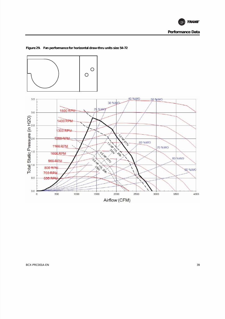
8/16/2019 Bcx-prc001-En 092013 Blower Coil Cat
http://slidepdf.com/reader/full/bcx-prc001-en-092013-blower-coil-cat 39/104
BCX-PRC001A-EN 39
Performance Data
Figure 29. Fan performance for horizontal draw-thru units size 54-72
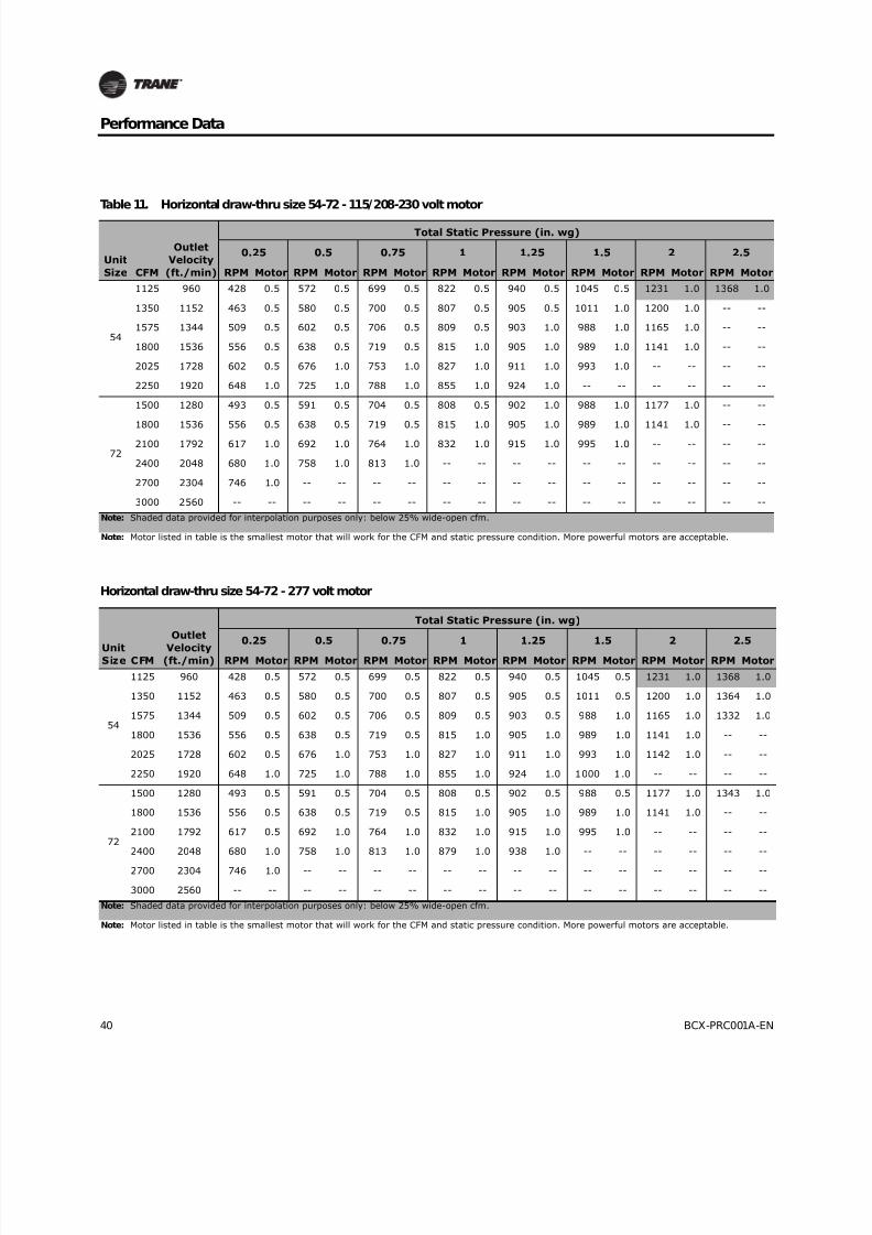
8/16/2019 Bcx-prc001-En 092013 Blower Coil Cat
http://slidepdf.com/reader/full/bcx-prc001-en-092013-blower-coil-cat 40/104
40 BCX-PRC001A-EN
Performance Data
Table 11. Horizontal draw-thru size 54-72 - 115/208-230 volt motor
Unit
Size CFM
Outlet
Velocity
(ft./min)
Total Static Pressure (in. wg)
0.25 0.5 0.75 1 1.25 1.5 2 2.5
RPM Motor RPM Motor RPM Motor RPM Motor RPM Motor RPM Motor RPM Motor RPM Motor
54
1125 960 428 0.5 572 0.5 699 0.5 822 0.5 940 0.5 1045 0.5 1231 1.0 1368 1.0
1350 1152 463 0.5 580 0.5 700 0.5 807 0.5 905 0.5 1011 1.0 1200 1.0 -- --
1575 1344 509 0.5 602 0.5 706 0.5 809 0.5 903 1.0 988 1.0 1165 1.0 -- --
1800 1536 556 0.5 638 0.5 719 0.5 815 1.0 905 1.0 989 1.0 1141 1.0 -- --
2025 1728 602 0.5 676 1.0 753 1.0 827 1.0 911 1.0 993 1.0 -- -- -- --
2250 1920 648 1.0 725 1.0 788 1.0 855 1.0 924 1.0 -- -- -- -- -- --
72
1500 1280 493 0.5 591 0.5 704 0.5 808 0.5 902 1.0 988 1.0 1177 1.0 -- --
1800 1536 556 0.5 638 0.5 719 0.5 815 1.0 905 1.0 989 1.0 1141 1.0 -- --
2100 1792 617 1.0 692 1.0 764 1.0 832 1.0 915 1.0 995 1.0 -- -- -- --
2400 2048 680 1.0 758 1.0 813 1.0 -- -- -- -- -- -- -- -- -- --
2700 2304 746 1.0 -- -- -- -- -- -- -- -- -- -- -- -- -- --
3000 2560 -- -- -- -- -- -- -- -- -- -- -- -- -- -- -- --
Note: Shaded data provided for interpolation purposes only: below 25% wide-open cfm.
Note: Motor listed in table is the smallest motor that will work for the CFM and static pressure condition. More powerful motors are acceptable.
Horizontal draw-thru size 54-72 - 277 volt motor
UnitSize CFM
Outlet
Velocity(ft./min)
Total Static Pressure (in. wg)
0.25 0.5 0.75 1 1.25 1.5 2 2.5
RPM Motor RPM Motor RPM Motor RPM Motor RPM Motor RPM Motor RPM Motor RPM Motor
54
1125 960 428 0.5 572 0.5 699 0.5 822 0.5 940 0.5 1045 0.5 1231 1.0 1368 1.0
1350 1152 463 0.5 580 0.5 700 0.5 807 0.5 905 0.5 1011 0.5 1200 1.0 1364 1.0
1575 1344 509 0.5 602 0.5 706 0.5 809 0.5 903 0.5 988 1.0 1165 1.0 1332 1.0
1800 1536 556 0.5 638 0.5 719 0.5 815 1.0 905 1.0 989 1.0 1141 1.0 -- --
2025 1728 602 0.5 676 1.0 753 1.0 827 1.0 911 1.0 993 1.0 1142 1.0 -- --
2250 1920 648 1.0 725 1.0 788 1.0 855 1.0 924 1.0 1000 1.0 -- -- -- --
72
1500 1280 493 0.5 591 0.5 704 0.5 808 0.5 902 0.5 988 0.5 1177 1.0 1343 1.0
1800 1536 556 0.5 638 0.5 719 0.5 815 1.0 905 1.0 989 1.0 1141 1.0 -- --
2100 1792 617 0.5 692 1.0 764 1.0 832 1.0 915 1.0 995 1.0 -- -- -- --
2400 2048 680 1.0 758 1.0 813 1.0 879 1.0 938 1.0 -- -- -- -- -- --
2700 2304 746 1.0 -- -- -- -- -- -- -- -- -- -- -- -- -- --
3000 2560 -- -- -- -- -- -- -- -- -- -- -- -- -- -- -- --
Note: Shaded data provided for interpolation purposes only: below 25% wide-open cfm.
Note: Motor listed in table is the smallest motor that will work for the CFM and static pressure condition. More powerful motors are acceptable.
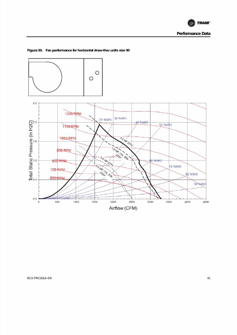
8/16/2019 Bcx-prc001-En 092013 Blower Coil Cat
http://slidepdf.com/reader/full/bcx-prc001-en-092013-blower-coil-cat 41/104
BCX-PRC001A-EN 41
Performance Data
Figure 30. Fan performance for horizontal draw-thru units size 90

8/16/2019 Bcx-prc001-En 092013 Blower Coil Cat
http://slidepdf.com/reader/full/bcx-prc001-en-092013-blower-coil-cat 42/104
42 BCX-PRC001A-EN
Performance Data
Table 12. Horizontal draw-thru size 90 - 115/208-230 volt motor
Unit
Size CFM
Outlet
Velocity
(ft./min)
Total Static Pressure (in. wg)
0.25 0.5 0.75 1 1.25 1.5 2 2.5
RPM Motor RPM Motor RPM Motor RPM Motor RPM Motor RPM Motor RPM Motor RPM Motor
90
1875 1600 498 0.5 629 0.5 749 0.5 860 1.0 963 1.0 -- -- -- -- -- --
2250 1920 544 0.5 661 1.0 767 1.0 867 1.0 962 1.0 -- -- -- -- -- --
2625 2240 596 1.0 701 1.0 798 1.0 -- -- -- -- -- -- -- -- -- --
3000 2560 650 1.0 -- -- -- -- -- -- -- -- -- -- -- -- -- --
3375 2880 -- -- -- -- -- -- -- -- -- -- -- -- -- -- -- --
3750 3200 -- -- -- -- -- -- -- -- -- -- -- -- -- -- -- --
Note: Shaded data provided for interpolation purposes only: below 25% wide-open cfm.
Note: Motor listed in table is the smallest motor that will work for the CFM and static pressure condition. More powerful motors are acceptable.
Table 13. Horizontal draw-thru size 90 - 277 volt motor
Unit
Size CFM
Outlet
Velocity
(ft./min)
Total Static Pressure (in. wg)
0.25 0.5 0.75 1 1.25 1.5 2 2.5
RPM Motor RPM Motor RPM Motor RPM Motor RPM Motor RPM Motor RPM Motor RPM Motor
90
1875 1600 498 0.5 629 0.5 749 0.5 860 1.0 963 1.0 1057 1.0 -- -- -- --
2250 1920 544 0.5 661 1.0 767 1.0 867 1.0 962 1.0 -- -- -- -- -- --
2625 2240 596 1.0 701 1.0 798 1.0 888 1.0 -- -- -- -- -- -- -- --
3000 2560 650 1.0 -- -- -- -- -- -- -- -- -- -- -- -- -- --
3375 2880 -- -- -- -- -- -- -- -- -- -- -- -- -- -- -- --
3750 3200 -- -- -- -- -- -- -- -- -- -- -- -- -- -- -- --
Note: Shaded data provided for interpolation purposes only: below 25% wide-open cfm.
Note: Motor listed in table is the smallest motor that will work for the CFM and static pressure condition. More powerful motors are acceptable.

8/16/2019 Bcx-prc001-En 092013 Blower Coil Cat
http://slidepdf.com/reader/full/bcx-prc001-en-092013-blower-coil-cat 43/104
BCX-PRC001A-EN 43
Performance Data
Figure 31. Fan performance for vertical draw-thru preswirl units size 24-36
Vertical preswirl

8/16/2019 Bcx-prc001-En 092013 Blower Coil Cat
http://slidepdf.com/reader/full/bcx-prc001-en-092013-blower-coil-cat 44/104
44 BCX-PRC001A-EN
Performance Data
Table 14. Horizontal draw-thru preswirl size 24-36 - 115/208-230 volt motor
Unit
Size CFM
Outlet
Velocity
(ft./min)
Total Static Pressure (in. wg)
0.25 0.5 0.75 1 1.25 1.5 2 2.5
RPM Motor RPM Motor RPM Motor RPM Motor RPM Motor RPM Motor RPM Motor RPM Motor
24
500 571 563 0.5 777 0.5 967 0.5 1124 0.5 1263 0.5 1388 0.5 1610 0.5 1806 0.5
600 685 597 0.5 778 0.5 954 0.5 1115 0.5 1253 0.5 1378 0.5 1600 0.5 1796 0.5
700 799 640 0.5 795 0.5 950 0.5 1100 0.5 1243 0.5 1369 0.5 1591 0.5 1786 1.0
800 914 688 0.5 827 0.5 960 0.5 1096 0.5 1227 0.5 1356 0.5 1581 0.5 1777 1.0
900 1028 740 0.5 865 0.5 986 0.5 1104 0.5 1226 0.5 1341 0.5 1570 0.5 1768 1.0
1000 1142 794 0.5 910 0.5 1020 0.5 1126 0.5 1234 0.5 1344 0.5 1554 1.0 1756 1.0
36
750 857 664 0.5 810 0.5 954 0.5 1092 0.5 1235 0.5 1364 0.5 1586 0.5 1782 1.0
900 1028 740 0.5 865 0.5 986 0.5 1104 0.5 1226 0.5 1341 0.5 1570 0.5 1768 1.0
1050 1199 822 0.5 934 0.5 1038 0.5 1142 0.5 1243 0.5 1348 0.5 1546 1.0 1748 1.0
1200 1370 905 0.5 1009 0.5 1103 0.5 1194 0.5 1285 0.5 1374 1.0 1555 1.0 1727 1.0
1350 1542 992 0.5 1088 0.5 1175 0.5 1257 1.0 1338 1.0 1419 1.0 1578 1.0 -- --
1500 1713 1082 0.5 1170 1.0 1251 1.0 1328 1.0 1402 1.0 1474 1.0 -- -- -- --
Note: Shaded data provided for interpolation purposes only: below 25 percent wide-open cfm.
Note: Motor listed in table is the smallest motor that will work for the CFM and static pressure condition. More powerful motors are acceptable.
Table 15. Horizontal draw-thru preswirl size 24-36 - 277 volt motor
UnitSize CFM
Outlet
Velocity(ft./min)
Total Static Pressure (in. wg)
0.25 0.5 0.75 1 1.25 1.5 2 2.5
RPM Motor RPM Motor RPM Motor RPM Motor RPM Motor RPM Motor RPM Motor RPM Motor
24
500 571 563 0.5 777 0.5 967 0.5 1124 0.5 1263 0.5 1388 0.5 1610 0.5 1806 0.5
600 685 597 0.5 778 0.5 954 0.5 1115 0.5 1253 0.5 1378 0.5 1600 0.5 1796 0.5
700 799 640 0.5 795 0.5 950 0.5 1100 0.5 1243 0.5 1369 0.5 1591 0.5 1786 0.5
800 914 688 0.5 827 0.5 960 0.5 1096 0.5 1227 0.5 1356 0.5 1581 0.5 1777 0.5
900 1028 740 0.5 865 0.5 986 0.5 1104 0.5 1226 0.5 1341 0.5 1570 0.5 1768 0.5
1000 1142 794 0.5 910 0.5 1020 0.5 1126 0.5 1234 0.5 1344 0.5 1554 0.5 1756 0.5
36
750 857 664 0.5 810 0.5 954 0.5 1092 0.5 1235 0.5 1364 0.5 1586 0.5 1782 0.5
900 1028 740 0.5 865 0.5 986 0.5 1104 0.5 1226 0.5 1341 0.5 1570 0.5 1768 0.5
1050 1199 822 0.5 934 0.5 1038 0.5 1142 0.5 1243 0.5 1348 0.5 1546 0.5 1748 1.0
1200 1370 905 0.5 1009 0.5 1103 0.5 1194 0.5 1285 0.5 1374 0.5 1555 0.5 1727 1.0
1350 1542 992 0.5 1088 0.5 1175 0.5 1257 0.5 1338 0.5 1419 0.5 1578 1.0 1740 1.0
1500 1713 1082 0.5 1170 0.5 1251 0.5 1328 1.0 1402 1.0 1474 1.0 1620 1.0 1762 1.0
Note: Shaded data provided for interpolation purposes only: below 25 percent wide-open cfm.
Note: Motor listed in table is the smallest motor that will work for the CFM and static pressure condition. More powerful motors are acceptable.

8/16/2019 Bcx-prc001-En 092013 Blower Coil Cat
http://slidepdf.com/reader/full/bcx-prc001-en-092013-blower-coil-cat 45/104
BCX-PRC001A-EN 45
Performance Data
Figure 32. Fan performance for vertical draw-thru preswirl units size 54-72
Vertical preswirl

8/16/2019 Bcx-prc001-En 092013 Blower Coil Cat
http://slidepdf.com/reader/full/bcx-prc001-en-092013-blower-coil-cat 46/104
46 BCX-PRC001A-EN
Performance Data
Table 16. Vertical draw-thru preswirl size 54-72 - 115/208-230 volt motor
Unit
Size CFM
Outlet
Velocity
(ft./min)
Total Static Pressure (in. wg)
0.25 0.5 0.75 1 1.25 1.5 2 2.5
RPM Motor RPM Motor RPM Motor RPM Motor RPM Motor RPM Motor RPM Motor RPM Motor
54
1125 960 465 0.5 603 0.5 726 0.5 842 0.5 954 0.5 1055 0.5 1224 1.0 1368 1.0
1350 1152 518 0.5 624 0.5 736 0.5 840 0.5 935 0.5 1034 1.0 1213 1.0 -- --
1575 1344 579 0.5 656 0.5 756 0.5 851 0.5 942 1.0 1027 1.0 1192 1.0 -- --
1800 1536 637 0.5 703 0.5 783 1.0 871 1.0 955 1.0 1035 1.0 -- -- -- --
2025 1728 691 1.0 763 1.0 818 1.0 897 1.0 975 1.0 1051 1.0 -- -- -- --
2250 1920 746 1.0 825 1.0 873 1.0 931 1.0 -- -- -- -- -- -- -- --
72
1500 1280 558 0.5 644 0.5 749 0.5 847 0.5 939 1.0 1025 1.0 1199 1.0 -- --
1800 1536 637 0.5 703 0.5 783 1.0 871 1.0 955 1.0 1035 1.0 -- -- -- --
2100 1792 709 1.0 784 1.0 833 1.0 908 1.0 983 1.0 -- -- -- -- -- --
2400 2048 784 1.0 -- -- -- -- -- -- -- -- -- -- -- -- -- --
2700 2304 -- -- -- -- -- -- -- -- -- -- -- -- -- -- -- --
3000 2560 -- -- -- -- -- -- -- -- -- -- -- -- -- -- -- --
Note: Shaded data provided for interpolation purposes only: below 25 percent wide-open cfm.
Note: Motor listed in table is the smallest motor that will work for the CFM and static pressure condition. More powerful motors are acceptable.
Table 17. Vertical draw-thru preswirl size 54-72 - 277 volt motor
UnitSize CFM
Outlet
Velocity(ft./min)
Total Static Pressure (in. wg)
0.25 0.5 0.75 1 1.25 1.5 2 2.5
RPM Motor RPM Motor RPM Motor RPM Motor RPM Motor RPM Motor RPM Motor RPM Motor
54
1125 960 465 0.5 603 0.5 726 0.5 842 0.5 954 0.5 1055 0.5 1224 1.0 1368 1.0
1350 1152 518 0.5 624 0.5 736 0.5 840 0.5 935 0.5 1034 0.5 1213 1.0 1369 1.0
1575 1344 579 0.5 656 0.5 756 0.5 851 0.5 942 0.5 1027 1.0 1192 1.0 1350 1.0
1800 1536 637 0.5 703 0.5 783 0.5 871 1.0 955 1.0 1035 1.0 1185 1.0 -- --
2025 1728 691 1.0 763 1.0 818 1.0 897 1.0 975 1.0 1051 1.0 1193 1.0 -- --
2250 1920 746 1.0 825 1.0 873 1.0 931 1.0 1000 1.0 -- -- -- -- -- --
72
1500 1280 558 0.5 644 0.5 749 0.5 847 0.5 939 0.5 1025 1.0 1199 1.0 1358 1.0
1800 1536 637 0.5 703 0.5 783 0.5 871 1.0 955 1.0 1035 1.0 1185 1.0 -- --
2100 1792 709 1.0 784 1.0 833 1.0 908 1.0 983 1.0 1057 1.0 -- -- -- --
2400 2048 784 1.0 867 1.0 913 1.0 -- -- -- -- -- -- -- -- -- --
2700 2304 -- -- -- -- -- -- -- -- -- -- -- -- -- -- -- --
3000 2560 -- -- -- -- -- -- -- -- -- -- -- -- -- -- -- --
Note: Shaded data provided for interpolation purposes only: below 25 percent wide-open cfm.
Note: Motor listed in table is the smallest motor that will work for the CFM and static pressure condition. More powerful motors are acceptable.
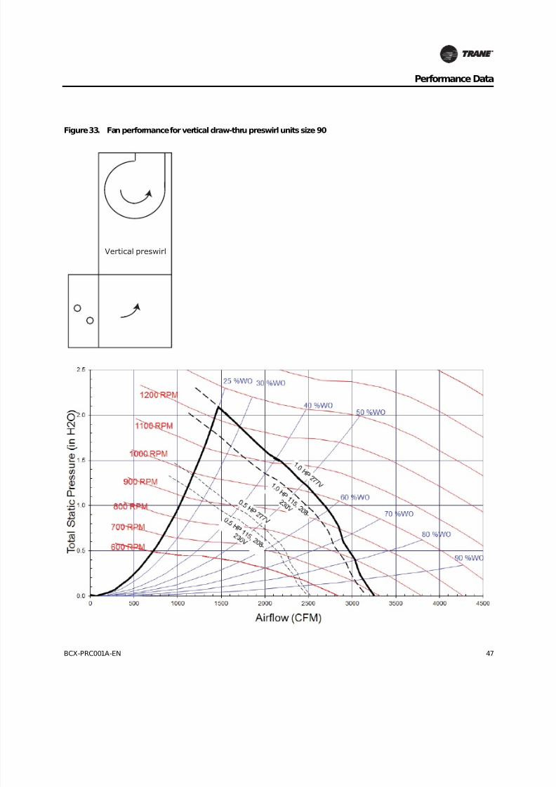
8/16/2019 Bcx-prc001-En 092013 Blower Coil Cat
http://slidepdf.com/reader/full/bcx-prc001-en-092013-blower-coil-cat 47/104
BCX-PRC001A-EN 47
Performance Data
Figure 33. Fan performance for vertical draw-thru preswirl units size 90
Vertical preswirl
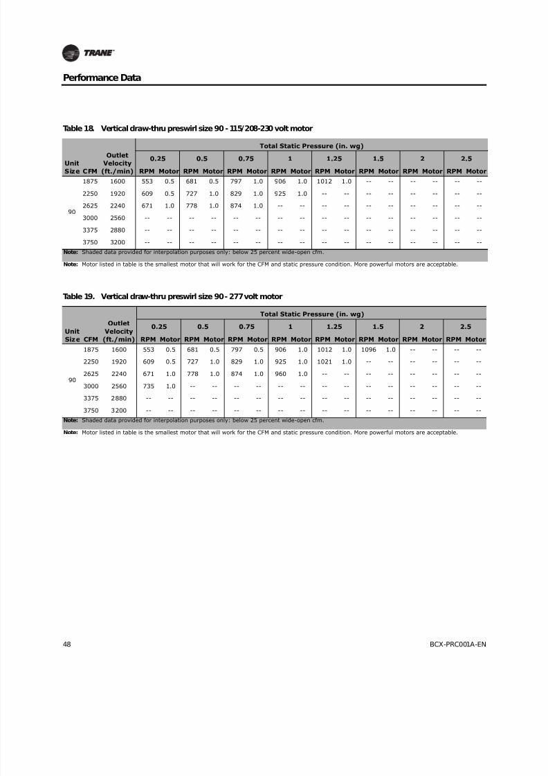
8/16/2019 Bcx-prc001-En 092013 Blower Coil Cat
http://slidepdf.com/reader/full/bcx-prc001-en-092013-blower-coil-cat 48/104
48 BCX-PRC001A-EN
Performance Data
Table 18. Vertical draw-thru preswirl size 90 - 115/208-230 volt motor
Unit
Size CFM
Outlet
Velocity
(ft./min)
Total Static Pressure (in. wg)
0.25 0.5 0.75 1 1.25 1.5 2 2.5
RPM Motor RPM Motor RPM Motor RPM Motor RPM Motor RPM Motor RPM Motor RPM Motor
90
1875 1600 553 0.5 681 0.5 797 1.0 906 1.0 1012 1.0 -- -- -- -- -- --
2250 1920 609 0.5 727 1.0 829 1.0 925 1.0 -- -- -- -- -- -- -- --
2625 2240 671 1.0 778 1.0 874 1.0 -- -- -- -- -- -- -- -- -- --
3000 2560 -- -- -- -- -- -- -- -- -- -- -- -- -- -- -- --
3375 2880 -- -- -- -- -- -- -- -- -- -- -- -- -- -- -- --
3750 3200 -- -- -- -- -- -- -- -- -- -- -- -- -- -- -- --
Note: Shaded data provided for interpolation purposes only: below 25 percent wide-open cfm.
Note: Motor listed in table is the smallest motor that will work for the CFM and static pressure condition. More powerful motors are acceptable.
Table 19. Vertical draw-thru preswirl size 90 - 277 volt motor
Unit
Size CFM
Outlet
Velocity
(ft./min)
Total Static Pressure (in. wg)
0.25 0.5 0.75 1 1.25 1.5 2 2.5
RPM Motor RPM Motor RPM Motor RPM Motor RPM Motor RPM Motor RPM Motor RPM Motor
90
1875 1600 553 0.5 681 0.5 797 0.5 906 1.0 1012 1.0 1096 1.0 -- -- -- --
2250 1920 609 0.5 727 1.0 829 1.0 925 1.0 1021 1.0 -- -- -- -- -- --
2625 2240 671 1.0 778 1.0 874 1.0 960 1.0 -- -- -- -- -- -- -- --
3000 2560 735 1.0 -- -- -- -- -- -- -- -- -- -- -- -- -- --
3375 2880 -- -- -- -- -- -- -- -- -- -- -- -- -- -- -- --
3750 3200 -- -- -- -- -- -- -- -- -- -- -- -- -- -- -- --
Note: Shaded data provided for interpolation purposes only: below 25 percent wide-open cfm.
Note: Motor listed in table is the smallest motor that will work for the CFM and static pressure condition. More powerful motors are acceptable.

8/16/2019 Bcx-prc001-En 092013 Blower Coil Cat
http://slidepdf.com/reader/full/bcx-prc001-en-092013-blower-coil-cat 49/104
BCX-PRC001A-EN 49
Performance Data
Figure 34. Fan performance for vertical draw-thru counterswirl units size 24-36
Verticalcounterswirl

8/16/2019 Bcx-prc001-En 092013 Blower Coil Cat
http://slidepdf.com/reader/full/bcx-prc001-en-092013-blower-coil-cat 50/104
50 BCX-PRC001A-EN
Performance Data
Table 20. Vertical draw-thru counterswirl size 24-36 - 115/208-230 volt motor
Unit
Size CFM
Outlet
Velocity
(ft./min)
Total Static Pressure (in. wg)
0.25 0.5 0.75 1 1.25 1.5 2 2.5
RPM Motor RPM Motor RPM Motor RPM Motor RPM Motor RPM Motor RPM Motor RPM Motor
24
500 571 583 0.5 796 0.5 980 0.5 1137 0.5 1275 0.5 1400 0.5 1622 0.5 1818 0.5
600 685 619 0.5 801 0.5 975 0.5 1130 0.5 1268 0.5 1393 0.5 1615 0.5 1811 0.5
700 799 665 0.5 823 0.5 974 0.5 1125 0.5 1261 0.5 1386 0.5 1608 0.5 1804 1.0
800 914 717 0.5 856 0.5 995 0.5 1123 0.5 1258 0.5 1379 0.5 1601 0.5 1797 1.0
900 1028 767 0.5 898 0.5 1021 0.5 1144 0.5 1257 0.5 1377 0.5 1594 0.5 1790 1.0
1000 1142 820 0.5 945 0.5 1057 0.5 1167 0.5 1277 0.5 1380 0.5 1591 1.0 1783 1.0
36
750 857 691 0.5 838 0.5 984 0.5 1124 0.5 1259 0.5 1383 0.5 1605 0.5 1800 1.0
900 1028 767 0.5 898 0.5 1021 0.5 1144 0.5 1257 0.5 1377 0.5 1594 0.5 1790 1.0
1050 1199 847 0.5 971 0.5 1077 0.5 1182 0.5 1288 0.5 1390 0.5 1590 1.0 1780 1.0
1200 1370 932 0.5 1048 0.5 1145 0.5 1238 0.5 1330 0.5 1422 1.0 1603 1.0 1778 1.0
1350 1542 1020 0.5 1125 0.5 1223 0.5 1305 1.0 1388 1.0 1469 1.0 1633 1.0 1793 1.0
1500 1713 1114 0.5 1206 1.0 1299 1.0 1381 1.0 1455 1.0 1530 1.0 1676 1.0 -- --
Note: Shaded data provided for interpolation purposes only: below 25 percent wide-open cfm.
Note: Motor listed in table is the smallest motor that will work for the CFM and static pressure condition. More powerful motors are acceptable.
Table 21. Vertical draw-thru counterswirl size 24-36 - 277 volt motor
UnitSize CFM
Outlet
Velocity(ft./min)
Total Static Pressure (in. wg)
0.25 0.5 0.75 1 1.25 1.5 2 2.5
RPM Motor RPM Motor RPM Motor RPM Motor RPM Motor RPM Motor RPM Motor RPM Motor
24
500 571 583 0.5 796 0.5 980 0.5 1137 0.5 1275 0.5 1400 0.5 1622 0.5 1818 0.5
600 685 619 0.5 801 0.5 975 0.5 1130 0.5 1268 0.5 1393 0.5 1615 0.5 1811 0.5
700 799 665 0.5 823 0.5 974 0.5 1125 0.5 1261 0.5 1386 0.5 1608 0.5 1804 0.5
800 914 717 0.5 856 0.5 995 0.5 1123 0.5 1258 0.5 1379 0.5 1601 0.5 1797 0.5
900 1028 767 0.5 898 0.5 1021 0.5 1144 0.5 1257 0.5 1377 0.5 1594 0.5 1790 0.5
1000 1142 820 0.5 945 0.5 1057 0.5 1167 0.5 1277 0.5 1380 0.5 1591 0.5 1783 0.5
36
750 857 691 0.5 838 0.5 984 0.5 1124 0.5 1259 0.5 1383 0.5 1605 0.5 1800 0.5
900 1028 767 0.5 898 0.5 1021 0.5 1144 0.5 1257 0.5 1377 0.5 1594 0.5 1790 0.5
1050 1199 847 0.5 971 0.5 1077 0.5 1182 0.5 1288 0.5 1390 0.5 1590 0.5 1780 1.0
1200 1370 932 0.5 1048 0.5 1145 0.5 1238 0.5 1330 0.5 1422 0.5 1603 0.5 1778 1.0
1350 1542 1020 0.5 1125 0.5 1223 0.5 1305 0.5 1388 0.5 1469 0.5 1633 1.0 1793 1.0
1500 1713 1114 0.5 1206 0.5 1299 0.5 1381 1.0 1455 1.0 1530 1.0 1676 1.0 1824 1.0
Note: Shaded data provided for interpolation purposes only: below 25 percent wide-open cfm.
Note: Motor listed in table is the smallest motor that will work for the CFM and static pressure condition. More powerful motors are acceptable.
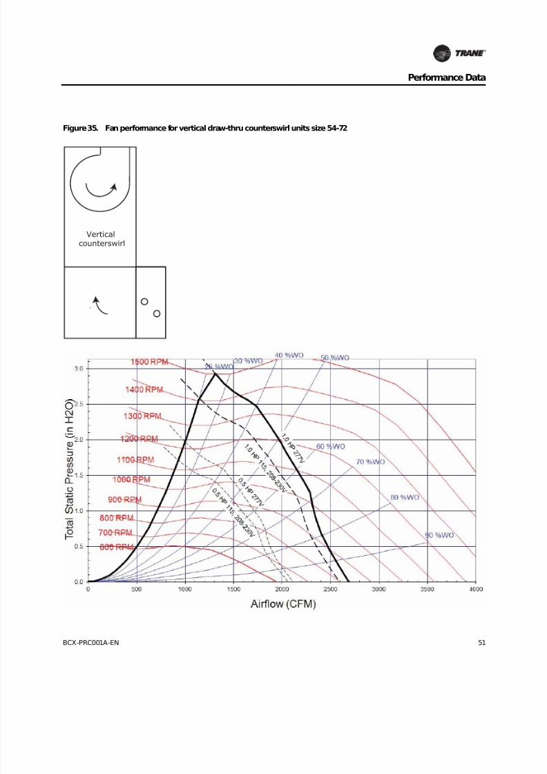
8/16/2019 Bcx-prc001-En 092013 Blower Coil Cat
http://slidepdf.com/reader/full/bcx-prc001-en-092013-blower-coil-cat 51/104
BCX-PRC001A-EN 51
Performance Data
Figure 35. Fan performance for vertical draw-thru counterswirl units size 54-72
Verticalcounterswirl
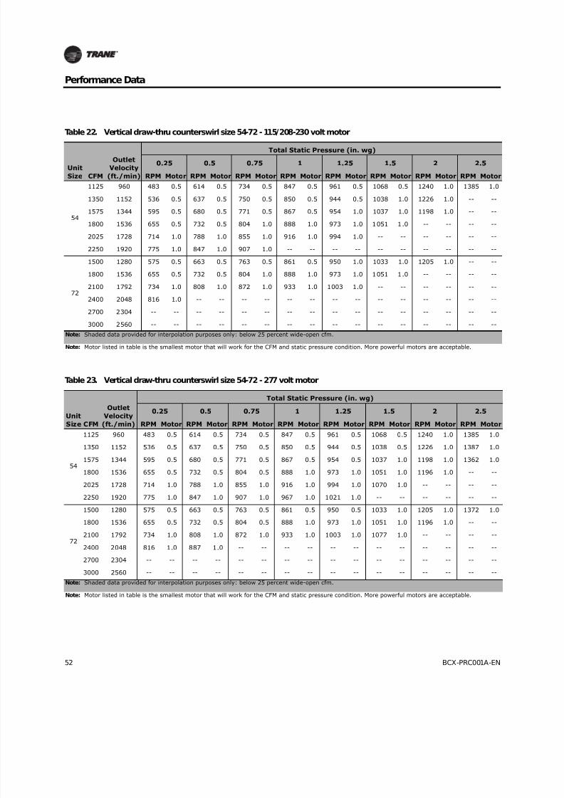
8/16/2019 Bcx-prc001-En 092013 Blower Coil Cat
http://slidepdf.com/reader/full/bcx-prc001-en-092013-blower-coil-cat 52/104
52 BCX-PRC001A-EN
Performance Data
Table 22. Vertical draw-thru counterswirl size 54-72 - 115/208-230 volt motor
Unit
Size CFM
Outlet
Velocity
(ft./min)
Total Static Pressure (in. wg)
0.25 0.5 0.75 1 1.25 1.5 2 2.5
RPM Motor RPM Motor RPM Motor RPM Motor RPM Motor RPM Motor RPM Motor RPM Motor
54
1125 960 483 0.5 614 0.5 734 0.5 847 0.5 961 0.5 1068 0.5 1240 1.0 1385 1.0
1350 1152 536 0.5 637 0.5 750 0.5 850 0.5 944 0.5 1038 1.0 1226 1.0 -- --
1575 1344 595 0.5 680 0.5 771 0.5 867 0.5 954 1.0 1037 1.0 1198 1.0 -- --
1800 1536 655 0.5 732 0.5 804 1.0 888 1.0 973 1.0 1051 1.0 -- -- -- --
2025 1728 714 1.0 788 1.0 855 1.0 916 1.0 994 1.0 -- -- -- -- -- --
2250 1920 775 1.0 847 1.0 907 1.0 -- -- -- -- -- -- -- -- -- --
72
1500 1280 575 0.5 663 0.5 763 0.5 861 0.5 950 1.0 1033 1.0 1205 1.0 -- --
1800 1536 655 0.5 732 0.5 804 1.0 888 1.0 973 1.0 1051 1.0 -- -- -- --
2100 1792 734 1.0 808 1.0 872 1.0 933 1.0 1003 1.0 -- -- -- -- -- --
2400 2048 816 1.0 -- -- -- -- -- -- -- -- -- -- -- -- -- --
2700 2304 -- -- -- -- -- -- -- -- -- -- -- -- -- -- -- --
3000 2560 -- -- -- -- -- -- -- -- -- -- -- -- -- -- -- --
Note: Shaded data provided for interpolation purposes only: below 25 percent wide-open cfm.
Note: Motor listed in table is the smallest motor that will work for the CFM and static pressure condition. More powerful motors are acceptable.
Table 23. Vertical draw-thru counterswirl size 54-72 - 277 volt motor
UnitSize CFM
Outlet
Velocity(ft./min)
Total Static Pressure (in. wg)
0.25 0.5 0.75 1 1.25 1.5 2 2.5
RPM Motor RPM Motor RPM Motor RPM Motor RPM Motor RPM Motor RPM Motor RPM Motor
54
1125 960 483 0.5 614 0.5 734 0.5 847 0.5 961 0.5 1068 0.5 1240 1.0 1385 1.0
1350 1152 536 0.5 637 0.5 750 0.5 850 0.5 944 0.5 1038 0.5 1226 1.0 1387 1.0
1575 1344 595 0.5 680 0.5 771 0.5 867 0.5 954 0.5 1037 1.0 1198 1.0 1362 1.0
1800 1536 655 0.5 732 0.5 804 0.5 888 1.0 973 1.0 1051 1.0 1196 1.0 -- --
2025 1728 714 1.0 788 1.0 855 1.0 916 1.0 994 1.0 1070 1.0 -- -- -- --
2250 1920 775 1.0 847 1.0 907 1.0 967 1.0 1021 1.0 -- -- -- -- -- --
72
1500 1280 575 0.5 663 0.5 763 0.5 861 0.5 950 0.5 1033 1.0 1205 1.0 1372 1.0
1800 1536 655 0.5 732 0.5 804 0.5 888 1.0 973 1.0 1051 1.0 1196 1.0 -- --
2100 1792 734 1.0 808 1.0 872 1.0 933 1.0 1003 1.0 1077 1.0 -- -- -- --
2400 2048 816 1.0 887 1.0 -- -- -- -- -- -- -- -- -- -- -- --
2700 2304 -- -- -- -- -- -- -- -- -- -- -- -- -- -- -- --
3000 2560 -- -- -- -- -- -- -- -- -- -- -- -- -- -- -- --
Note: Shaded data provided for interpolation purposes only: below 25 percent wide-open cfm.
Note: Motor listed in table is the smallest motor that will work for the CFM and static pressure condition. More powerful motors are acceptable.

8/16/2019 Bcx-prc001-En 092013 Blower Coil Cat
http://slidepdf.com/reader/full/bcx-prc001-en-092013-blower-coil-cat 53/104
BCX-PRC001A-EN 53
Performance Data
Figure 36. Fan performance for vertical draw-thru counterswirl units size 90
Verticalcounterswirl

8/16/2019 Bcx-prc001-En 092013 Blower Coil Cat
http://slidepdf.com/reader/full/bcx-prc001-en-092013-blower-coil-cat 54/104
54 BCX-PRC001A-EN
Performance Data
Table 24. Vertical draw-thru counterswirl size 90 - 115/208-230 volt motor
Unit
Size CFM
Outlet
Velocity
(ft./min)
Total Static Pressure (in. wg)
0.25 0.5 0.75 1 1.25 1.5 2 2.5
RPM Motor RPM Motor RPM Motor RPM Motor RPM Motor RPM Motor RPM Motor RPM Motor
90
1875 1600 514 0.5 641 0.5 758 1.0 869 1.0 972 1.0 -- -- -- -- -- --
2250 1920 564 1.0 678 1.0 781 1.0 879 1.0 -- -- -- -- -- -- -- --
2625 2240 621 1.0 723 1.0 -- -- -- -- -- -- -- -- -- -- -- --
3000 2560 -- -- -- -- -- -- -- -- -- -- -- -- -- -- -- --
3375 2880 -- -- -- -- -- -- -- -- -- -- -- -- -- -- -- --
3750 3200 -- -- -- -- -- -- -- -- -- -- -- -- -- -- -- --
Note: Shaded data provided for interpolation purposes only: below 25 percent wide-open cfm.
Note: Motor listed in table is the smallest motor that will work for the CFM and static pressure condition. More powerful motors are acceptable.
Table 25. Vertical draw-thru counterswirl size 90 - 277volt motor
Unit
Size CFM
Outlet
Velocity
(ft./min)
Total Static Pressure (in. wg)
0.25 0.5 0.75 1 1.25 1.5 2 2.5
RPM Motor RPM Motor RPM Motor RPM Motor RPM Motor RPM Motor RPM Motor RPM Motor
90
1875 1600 514 0.5 641 0.5 758 0.5 869 1.0 972 1.0 1061 1.0 -- -- -- --
2250 1920 564 1.0 678 1.0 781 1.0 879 1.0 972 1.0 -- -- -- -- -- --
2625 2240 621 1.0 723 1.0 816 1.0 -- -- -- -- -- -- -- -- -- --
3000 2560 -- -- -- -- -- -- -- -- -- -- -- -- -- -- -- --
3375 2880 -- -- -- -- -- -- -- -- -- -- -- -- -- -- -- --
3750 3200 -- -- -- -- -- -- -- -- -- -- -- -- -- -- -- --
Note: Shaded data provided for interpolation purposes only: below 25 percent wide-open cfm.
Note: Motor listed in table is the smallest motor that will work for the CFM and static pressure condition. More powerful motors are acceptable.
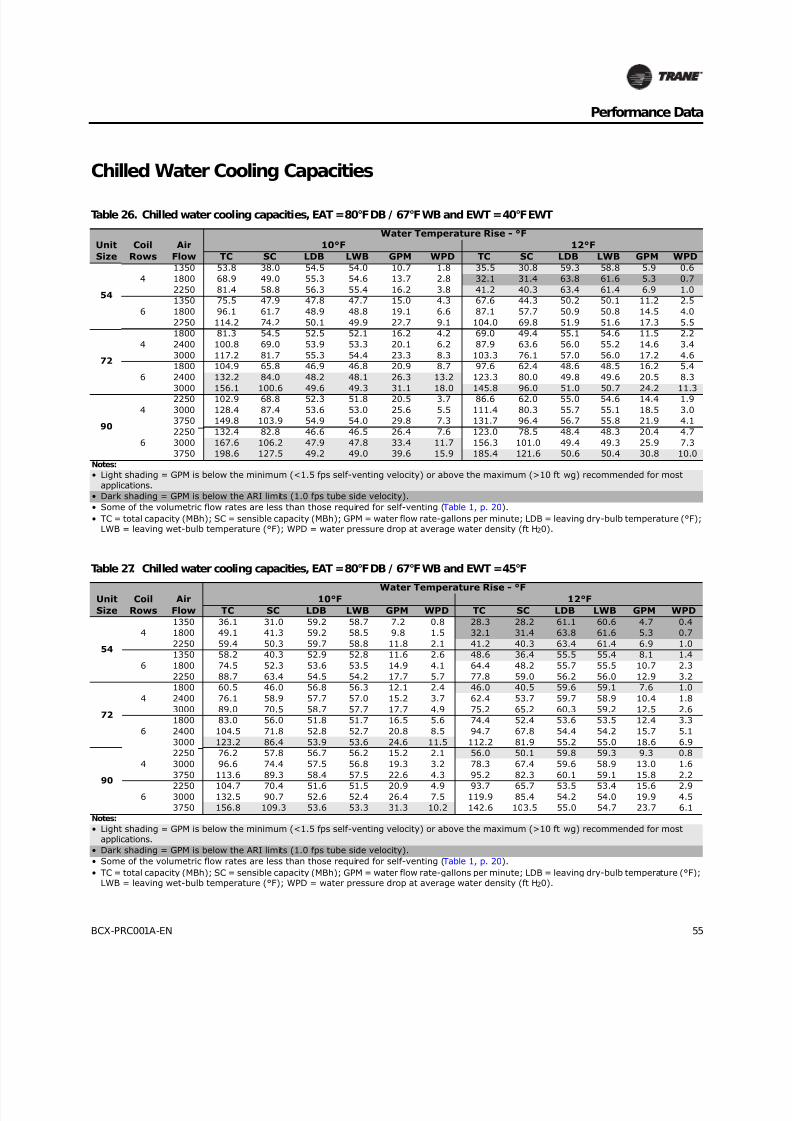
8/16/2019 Bcx-prc001-En 092013 Blower Coil Cat
http://slidepdf.com/reader/full/bcx-prc001-en-092013-blower-coil-cat 55/104
BCX-PRC001A-EN 55
Performance Data
Chilled Water Cooling Capacities
Table 26. Chilled water cooling capacities, EAT = 80°F DB / 67°F WB and EWT = 40°F EWT
Unit
Size
Coil
Rows
Air
Flow
Water Temperature Rise - °F
10°F 12°F
TC SC LDB LWB GPM WPD TC SC LDB LWB GPM WPD
54
4
1350 53.8 38.0 54.5 54.0 10.7 1.8 35.5 30.8 59.3 58.8 5.9 0.6
1800 68.9 49.0 55.3 54.6 13.7 2.8 32.1 31.4 63.8 61.6 5.3 0.7
2250 81.4 58.8 56.3 55.4 16.2 3.8 41.2 40.3 63.4 61.4 6.9 1.0
6
1350 75.5 47.9 47.8 47.7 15.0 4.3 67.6 44.3 50.2 50.1 11.2 2.5
1800 96.1 61.7 48.9 48.8 19.1 6.6 87.1 57.7 50.9 50.8 14.5 4.0
2250 114.2 74.2 50.1 49.9 22.7 9.1 104.0 69.8 51.9 51.6 17.3 5.5
72
4
1800 81.3 54.5 52.5 52.1 16.2 4.2 69.0 49.4 55.1 54.6 11.5 2.2
2400 100.8 69.0 53.9 53.3 20.1 6.2 87.9 63.6 56.0 55.2 14.6 3.4
3000 117.2 81.7 55.3 54.4 23.3 8.3 103.3 76.1 57.0 56.0 17.2 4.6
6
1800 104.9 65.8 46.9 46.8 20.9 8.7 97.6 62.4 48.6 48.5 16.2 5.4
2400 132.2 84.0 48.2 48.1 26.3 13.2 123.3 80.0 49.8 49.6 20.5 8.3
3000 156.1 100.6 49.6 49.3 31.1 18.0 145.8 96.0 51.0 50.7 24.2 11.3
90
4
2250 102.9 68.8 52.3 51.8 20.5 3.7 86.6 62.0 55.0 54.6 14.4 1.9
3000 128.4 87.4 53.6 53.0 25.6 5.5 111.4 80.3 55.7 55.1 18.5 3.0
3750 149.8 103.9 54.9 54.0 29.8 7.3 131.7 96.4 56.7 55.8 21.9 4.1
6
2250 132.4 82.8 46.6 46.5 26.4 7.6 123.0 78.5 48.4 48.3 20.4 4.7
3000 167.6 106.2 47.9 47.8 33.4 11.7 156.3 101.0 49.4 49.3 25.9 7.3
3750 198.6 127.5 49.2 49.0 39.6 15.9 185.4 121.6 50.6 50.4 30.8 10.0
Notes:
• Light shading = GPM is below the minimum (<1.5 fps self-venting velocity) or above the maximum (>10 ft wg) recommended for most
applications.
• Dark shading = GPM is below the ARI limits (1.0 fps tube side velocity).
• Some of the volumetric flow rates are less than those required for self-venting (Table 1, p. 20).
• TC = total capacity (MBh); SC = sensible capacity (MBh); GPM = water flow rate-gallons per minute; LDB = leaving dry-bulb temperature (°F);LWB = leaving wet-bulb temperature (°F); WPD = water pressure drop at average water density (ft H20).
Table 27. Chilled water cooling capacities, EAT = 80°F DB / 67°F WB and EWT = 45°F
Unit
Size
Coil
Rows
Air
Flow
Water Temperature Rise - °F10°F 12°F
TC SC LDB LWB GPM WPD TC SC LDB LWB GPM WPD
54
4
1350 36.1 31.0 59.2 58.7 7.2 0.8 28.3 28.2 61.1 60.6 4.7 0.4
1800 49.1 41.3 59.2 58.5 9.8 1.5 32.1 31.4 63.8 61.6 5.3 0.7
2250 59.4 50.3 59.7 58.8 11.8 2.1 41.2 40.3 63.4 61.4 6.9 1.0
6
1350 58.2 40.3 52.9 52.8 11.6 2.6 48.6 36.4 55.5 55.4 8.1 1.4
1800 74.5 52.3 53.6 53.5 14.9 4.1 64.4 48.2 55.7 55.5 10.7 2.3
2250 88.7 63.4 54.5 54.2 17.7 5.7 77.8 59.0 56.2 56.0 12.9 3.2
72
4
1800 60.5 46.0 56.8 56.3 12.1 2.4 46.0 40.5 59.6 59.1 7.6 1.0
2400 76.1 58.9 57.7 57.0 15.2 3.7 62.4 53.7 59.7 58.9 10.4 1.8
3000 89.0 70.5 58.7 57.7 17.7 4.9 75.2 65.2 60.3 59.2 12.5 2.6
6
1800 83.0 56.0 51.8 51.7 16.5 5.6 74.4 52.4 53.6 53.5 12.4 3.3
2400 104.5 71.8 52.8 52.7 20.8 8.5 94.7 67.8 54.4 54.2 15.7 5.1
3000 123.2 86.4 53.9 53.6 24.6 11.5 112.2 81.9 55.2 55.0 18.6 6.9
90
4
2250 76.2 57.8 56.7 56.2 15.2 2.1 56.0 50.1 59.8 59.3 9.3 0.8
3000 96.6 74.4 57.5 56.8 19.3 3.2 78.3 67.4 59.6 58.9 13.0 1.6
3750 113.6 89.3 58.4 57.5 22.6 4.3 95.2 82.3 60.1 59.1 15.8 2.2
62250 104.7 70.4 51.6 51.5 20.9 4.9 93.7 65.7 53.5 53.4 15.6 2.93000 132.5 90.7 52.6 52.4 26.4 7.5 119.9 85.4 54.2 54.0 19.9 4.5
3750 156.8 109.3 53.6 53.3 31.3 10.2 142.6 103.5 55.0 54.7 23.7 6.1Notes:
• Light shading = GPM is below the minimum (<1.5 fps self-venting velocity) or above the maximum (>10 ft wg) recommended for mostapplications.
• Dark shading = GPM is below the ARI limits (1.0 fps tube side velocity).
• Some of the volumetric flow rates are less than those required for self-venting (Table 1, p. 20).
• TC = total capacity (MBh); SC = sensible capacity (MBh); GPM = water flow rate-gallons per minute; LDB = leaving dry-bulb temperature (°F);LWB = leaving wet-bulb temperature (°F); WPD = water pressure drop at average water density (ft H20).

8/16/2019 Bcx-prc001-En 092013 Blower Coil Cat
http://slidepdf.com/reader/full/bcx-prc001-en-092013-blower-coil-cat 56/104
56 BCX-PRC001A-EN
Performance Data
High-Capacity Chilled Water Cooling Capacities
Table 28. Chilled water high-capacity cooling capacities, EAT = 80°F DB / 67°F WB and EWT = 40°F
Unit
Size
Coil
Rows Air Flow
Water Temperature Rise - °F
10°F 12°F
TC SC LDB LWB GPM WPD TC SC LDB LWB GPM WPD
12
4
300 12.6 8.7 53.7 53.2 2.5 2.2 10.3 7.8 56.6 56.1 1.7 1.1
400 15.7 11.1 54.9 54.2 3.1 3.2 13.2 10.0 57.2 56.5 2.2 1.7
500 18.4 13.2 56.1 55.2 3.7 4.3 15.6 12.1 58.1 57.1 2.6 2.3
6
300 16.9 10.7 47.6 47.5 3.4 4.9 15.5 10.1 49.6 49.5 2.6 3.0
400 21.4 13.7 48.8 48.7 4.3 7.5 19.7 12.9 50.6 50.5 3.3 4.6
500 25.4 16.5 50.0 49.8 5.1 10.3 23.3 15.6 51.7 51.5 3.9 6.3
18
4
450 20.0 13.4 52.9 52.4 4.0 5.4 17.6 12.5 54.9 54.3 2.9 3.1
600 24.4 16.8 54.6 53.8 4.9 7.8 21.7 15.7 56.3 55.4 3.6 4.5
750 28.1 19.8 56.0 55.0 5.6 10.1 25.1 18.6 57.5 56.4 4.2 5.9
6
450 25.7 16.2 47.3 47.2 5.1 11.5 24.1 15.4 48.9 48.8 4.0 7.3
600 32.1 20.6 48.9 48.7 6.4 17.2 30.0 19.6 50.3 50.1 5.0 10.9
750 37.7 24.5 50.3 50.0 7.5 23.1 35.2 23.4 51.7 51.4 5.8 14.6
24
4
600 27.4 18.3 52.3 51.9 5.5 4.1 24.1 16.9 54.4 54.0 4.0 2.3
800 33.8 23.1 53.9 53.2 6.7 6.0 29.9 21.5 55.7 55.0 5.0 3.4
1000 39.1 27.3 55.3 54.3 7.8 7.8 34.9 25.5 56.8 55.9 5.8 4.5
6
600 35.0 22.0 46.8 46.7 7.0 8.8 32.8 20.9 48.4 48.3 5.4 5.6
800 44.1 28.0 48.2 48.1 8.8 13.3 41.2 26.7 49.7 49.5 6.8 8.5
1000 52.0 33.6 49.6 49.3 10.4 18.0 48.6 32.0 50.9 50.7 8.1 11.4
36
4
900 46.8 30.0 49.7 49.4 9.3 13.7 43.5 28.6 51.2 50.8 7.2 8.6
1200 57.5 37.6 51.6 51.0 11.5 19.9 53.5 35.9 52.9 52.3 8.9 12.5
1500 66.7 44.4 53.1 52.3 13.3 26.0 61.9 42.4 54.4 53.5 10.3 16.3
6
900 56.1 34.6 45.1 45.0 11.2 26.5 53.7 33.5 46.2 46.1 8.9 17.7
1200 70.9 44.3 46.5 46.4 14.1 40.4 67.7 42.8 47.7 47.5 11.2 26.6
1500 84.3 53.2 47.8 47.6 16.8 55.0 80.0 51.3 49.0 48.8 13.3 36.0
54
4
1350 62.7 41.8 51.9 51.6 12.5 4.5 56.7 39.2 53.6 53.2 9.4 2.7
1800 76.5 52.4 53.6 53.1 15.3 6.5 69.6 49.5 55.1 54.5 11.6 3.8
2250 88.1 62.0 55.0 54.3 17.6 8.3 80.2 58.7 56.3 55.6 13.3 5.0
6
1350 78.9 49.5 46.8 46.7 15.8 9.4 74.6 47.5 48.1 48.0 12.4 6.1
1800 98.9 63.1 48.2 48.1 19.8 14.1 93.3 60.5 49.5 49.4 15.5 9.0
2250 116.6 75.5 49.6 49.4 23.3 19.0 109.5 72.3 50.9 50.7 18.2 12.0
72
4
1800 86.2 56.8 51.4 51.0 17.2 9.1 79.8 54.0 52.8 52.4 13.3 5.6
2400 104.8 71.0 53.2 52.6 21.0 12.9 96.8 67.6 54.5 53.9 16.1 7.9
3000 120.4 83.6 54.7 54.0 24.1 16.6 111.0 79.7 55.9 55.1 18.4 10.2
6
1800 106.6 66.7 46.4 46.3 21.3 18.5 101.6 64.3 47.6 47.5 16.9 12.1
2400 133.5 84.8 48.0 47.9 26.7 27.8 126.6 81.6 49.2 49.0 21.0 17.9
3000 157.1 101.4 49.4 49.2 31.4 37.2 148.5 97.4 50.5 50.4 24.6 23.8
90
4
2250 111.8 72.8 50.7 50.3 22.4 9.0 103.9 69.3 52.1 51.7 17.2 5.6
3000 136.6 91.2 52.5 51.9 27.3 12.9 126.6 86.8 53.8 53.2 21.0 8.0
3750 157.6 107.6 54.0 53.3 31.5 16.7 145.6 102.5 55.2 54.4 24.2 10.3
6
2250 136.5 84.9 45.8 45.7 27.3 18.1 130.5 81.9 47.0 46.9 21.7 11.8
3000 171.8 108.3 47.3 47.2 34.4 27.3 163.4 104.4 48.4 48.3 27.1 17.7
3750 203.0 129.7 48.6 48.5 40.6 36.8 192.3 124.8 49.8 49.6 31.9 23.7Notes:
• Light shading = GPM is below the minimum (<1.5 fps self-venting velocity) or above the maximum (>10 ft wg) recommended for mostapplications.
• Dark shading = GPM is below the ARI limits (1.0 fps tube side velocity).
• Some of the volumetric flow rates are less than those required for self-venting (Table 1, p. 20).
• Capacities calculated with 0.00000 tube-side fouling factor.
• High-capacity coils applicable where higher water pressure differentials are acceptable and are also recommended for EarthwiseTM applications.
• EarthwiseTM is a trademark of Trane to identify equipment designed for applications requiring greater water temperature rises, lower enteringwater temperatures (EWT) and lower air supply temperatures (LDB).
• TC = total capacity (MBh); SC = sensible capacity (MBh); GPM = water flow rate-gallons per minute; LDB = leaving dry-bulb temperature (°F);LWB = leaving wet-bulb temperature (°F); WPD = water pressure drop at average water density (ft H20).

8/16/2019 Bcx-prc001-En 092013 Blower Coil Cat
http://slidepdf.com/reader/full/bcx-prc001-en-092013-blower-coil-cat 57/104
BCX-PRC001A-EN 57
Performance Data
Table 28. Chilled water high-capacity cooling capacities, EAT = 80°F DB / 67°F WB and EWT = 40°F (continued)
Unit
Size
Coil
Rows Air Flow
Water Temperature Rise - °F
16°F 20°F
TC SC LDB LWB GPM WPD TC SC LDB LWB GPM WPD
12
4
300 7.9 6.8 59.3 58.8 1.0 0.4 6.9 6.5 60.4 59.9 0.7 0.2
400 8.9 8.4 60.9 60.1 1.1 0.5 8.2 8.2 61.5 60.7 0.9 0.3
500 10.0 10.0 61.8 60.9 1.3 0.7 8.5 8.3 64.6 61.9 0.9 0.5
6
300 11.6 8.4 54.6 54.5 1.4 1.1 9.7 7.6 56.9 56.8 1.0 0.5
400 15.2 11.1 54.9 54.7 1.9 1.7 11.1 9.5 58.5 58.3 1.1 0.7
500 18.4 13.5 55.4 55.2 2.3 2.4 12.3 11.2 59.6 59.4 1.2 0.8
18
4
450 11.3 10.0 59.9 59.2 1.4 0.8 9.4 9.3 61.3 60.6 0.93 0.4
600 15.2 13.2 60.1 59.2 1.9 1.4 10.5 10.0 64.6 61.7 1.05 0.5
750 18.3 16.0 60.6 59.5 2.3 2.0 11.5 11.2 66.2 62.4 1.14 0.7
6
450 19.9 13.6 52.5 52.4 2.5 3.1 14.2 11.3 57.1 57.0 1.4 1.1
600 25.1 17.5 53.5 53.3 3.1 4.7 19.0 15.1 57.2 57.0 1.9 1.9
750 29.6 21.0 54.5 54.2 3.7 6.3 23.0 18.5 57.7 57.3 2.3 2.7
24
4
600 15.2 13.4 59.7 59.1 1.9 0.6 13.3 12.8 60.7 60.2 1.3 0.3
800 20.4 17.7 59.9 59.1 2.5 1.0 14.7 14.7 63.4 61.4 1.4 0.4
1000 25.0 21.7 60.3 59.3 3.1 1.5 16.4 15.6 65.6 62.0 1.6 0.5
6
600 27.0 18.4 52.2 52.1 3.4 2.4 18.7 15.1 57.2 57.1 1.9 0.8
800 34.4 23.7 53.1 52.9 4.3 3.7 25.5 20.2 57.1 56.9 2.6 1.4
1000 40.7 28.7 54.0 53.7 5.1 4.9 31.3 24.9 57.4 57.1 3.1 2.1
36
4
900 35.9 25.3 54.5 54.0 4.5 3.6 25.4 21.2 58.7 58.2 2.5 1.3
1200 44.7 32.2 55.7 55.0 5.6 5.4 33.9 27.9 58.9 58.2 3.4 2.2
1500 52.0 38.3 56.8 55.9 6.5 7.0 40.7 33.9 59.5 58.6 4.1 3.0
6
900 48.2 30.9 48.8 48.7 6.0 8.7 40.8 27.7 52.1 52.0 4.1 4.3
1200 60.5 39.5 50.1 50.0 7.5 13.0 51.7 35.7 53.0 52.8 5.2 6.6
1500 71.2 47.3 51.4 51.2 8.9 17.3 61.1 43.1 54.0 53.7 6.1 8.8
54
4
1350 41.2 33.0 57.8 57.4 5.2 0.9 25.9 25.9 62.6 61.2 2.6 0.3
1800 52.9 42.9 58.4 57.8 6.6 1.4 29.6 29.6 65.1 62.0 3.0 0.3
2250 60.9 50.7 60.0 59.1 7.6 1.8 39.5 39.5 64.1 61.7 4.0 0.6
6
1350 63.7 42.6 51.4 51.3 8.0 2.8 49.4 36.7 55.3 55.2 4.9 1.2
1800 79.9 54.7 52.5 52.3 10.0 4.1 64.0 48.2 55.8 55.6 6.4 1.9
2250 93.9 65.7 53.5 53.4 11.7 5.5 76.3 58.6 56.4 56.2 7.6 2.5
72
4
1800 64.6 47.8 55.9 55.5 8.1 2.3 45.1 40.3 59.7 59.2 4.5 0.8
2400 79.6 60.6 57.1 56.5 9.9 3.3 59.7 53.1 60.0 59.3 6.0 1.3
3000 91.8 72.2 58.2 57.4 11.5 4.3 71.2 64.4 60.6 59.7 7.1 1.8
6
1800 89.8 59.0 50.3 50.2 11.2 5.8 75.1 52.7 53.4 53.3 7.5 2.8
2400 111.4 74.9 51.7 51.6 13.9 8.6 94.2 67.8 54.4 54.3 9.4 4.2
3000 12 89.4 53.0 52.8 16.2 11.3 110.4 81.5 55.4 55.2 11.0 5.6
90
4
2250 84.7 61.3 55.3 54.9 10.6 2.3 60.2 51.8 59.1 58.7 6.0 0.9
3000 104.6 77.9 56.5 55.9 13.1 3.4 79.3 68.1 59.4 58.8 7.9 1.4
3750 121.0 92.7 57.6 56.8 15.1 4.4 94.4 82.5 60.0 59.2 9.4 1.9
6
2250 115.9 75.4 49.6 49.5 14.5 5.8 97.6 67.4 52.8 52.7 9.8 2.9
3000 144.4 95.9 51.0 50.9 18.1 8.5 122.7 86.7 53.8 53.7 12.3 4.3
3750 168.9 114.6 52.3 52.1 21.1 11.3 144.2 104.4 54.8 54.6 14.4 5.7Notes:
• Light shading = GPM is below the minimum (<1.5 fps self-venting velocity) or above the maximum (>10 ft wg) recommended for mostapplications.
• Dark shading = GPM is below the ARI limits (1.0 fps tube side velocity).
• Some of the volumetric flow rates are less than those required for self-venting (Table 1, p. 20).
• Capacities calculated with 0.00000 tube-side fouling factor.
• High-capacity coils applicable where higher water pressure differentials are acceptable and are also recommended for EarthwiseTM applications.
• EarthwiseTM is a trademark of Trane to identify equipment designed for applications requiring greater water temperature rises, lower entering
water temperatures (EWT) and lower air supply temperatures (LDB).• TC = total capacity (MBh); SC = sensible capacity (MBh); GPM = water flow rate-gallons per minute; LDB = leaving dry-bulb temperature (°F);
LWB = leaving wet-bulb temperature (°F); WPD = water pressure drop at average water density (ft H20).
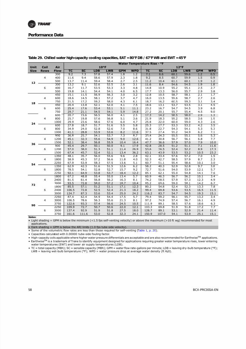
8/16/2019 Bcx-prc001-En 092013 Blower Coil Cat
http://slidepdf.com/reader/full/bcx-prc001-en-092013-blower-coil-cat 58/104
58 BCX-PRC001A-EN
Performance Data
Table 29. Chilled water high-capacity cooling capacities, EAT = 80°F DB / 67°F WB and EWT = 45°F
Unit
Size
Coil
Rows
Air
Flow
Water Temperature Rise - °F
10°F 12°F
TC SC LDB LWB GPM WPD TC SC LDB LWB GPM WPD
12
4
300 9.2 7.3 57.8 57.4 1.8 1.2 7.1 6.6 60.1 59.6 1.2 0.5
400 11.6 9.4 58.6 57.9 2.3 1.8 9.2 8.5 60.7 59.9 1.5 0.9
500 13.7 11.4 59.4 58.4 2.7 2.5 11.2 10.4 61.1 60.1 1.9 1.2
6
300 13.2 9.1 52.6 52.5 2.6 3.1 11.6 8.4 54.6 54.5 1.9 1.8
400 16.7 11.7 53.5 53.3 3.3 4.8 14.8 10.9 55.2 55.1 2.5 2.7
500 19.8 14.1 54.4 54.1 4.0 6.5 17.7 13.3 56.0 55.7 2.9 3.8
18
4
450 15.1 11.5 56.9 56.3 3.0 3.2 12.8 10.5 58.7 58.1 2.1 1.7
600 18.6 14.5 58.1 57.2 3.7 4.7 16.0 13.5 59.6 58.7 2.7 2.6
750 21.5 17.2 59.2 58.0 4.3 6.1 18.7 16.2 60.5 59.3 3.1 3.4
6
450 20.4 13.8 52.1 52.0 4.1 7.5 18.6 13.1 53.7 53.5 3.1 4.5
600 25.4 17.6 53.4 53.1 5.1 11.1 23.2 16.7 54.7 54.5 3.9 6.8
750 29.7 21.1 54.5 54.1 5.9 14.8 27.2 20.1 55.7 55.4 4.5 9.0
24
4
600 20.7 15.6 56.5 56.0 4.1 2.5 17.3 14.2 58.5 58.0 2.9 1.3
800 25.7 19.8 57.6 56.8 5.1 3.6 21.9 18.3 59.2 58.5 3.6 1.9
1000 29.9 23.6 58.6 57.6 6.0 4.7 25.8 22.0 60.0 59.0 4.3 2.6
6
600 27.8 18.7 51.7 51.6 5.5 5.8 25.3 17.7 53.3 53.2 4.2 3.5
800 34.9 24.0 52.8 52.6 7.0 8.6 31.8 22.7 54.3 54.1 5.3 5.3
1000 41.1 28.8 53.9 53.6 8.2 11.6 37.5 27.4 55.2 54.9 6.2 7.1
36
4
900 36.8 25.7 54.1 53.7 7.3 8.7 33.4 24.3 55.5 55.1 5.6 5.3
1200 45.1 32.3 55.6 54.9 9.0 12.6 41.2 30.8 56.7 56.1 6.8 7.7
1500 52.1 38.4 56.8 55.9 10.4 16.4 47.7 36.6 57.9 57.0 7.9 10.0
6
900 45.4 29.7 50.1 50.0 9.1 17.9 42.8 28.5 51.2 51.1 7.1 11.6
1200 57.0 38.0 51.3 51.1 11.4 26.9 53.6 36.5 52.4 52.2 8.9 17.3
1500 67.4 45.7 52.4 52.1 13.4 36.2 63.1 43.9 53.5 53.2 10.5 23.2
54
4
1350 48.1 35.7 56.0 55.6 9.6 2.8 42.1 33.4 57.6 57.2 7.0 1.5
1800 58.9 45.3 57.2 56.6 11.8 4.0 52.3 42.7 58.5 57.9 8.7 2.3
2250 67.9 53.9 58.3 57.5 13.6 5.1 60.7 51.1 59.4 58.6 10.1 3.0
6
1350 62.9 42.3 51.6 51.5 12.6 6.2 58.2 40.3 52.9 52.8 9.7 3.8
1800 78.5 54.1 52.8 52.7 15.7 9.2 72.7 51.6 54.0 53.9 12.1 5.7
2250 92.1 64.9 53.8 53.7 18.4 12.2 85.1 62.1 55.0 54.8 14.1 7.6
72
4
1800 67.2 48.8 55.4 55.0 13.4 5.7 60.9 46.3 56.7 56.2 10.1 3.4
2400 81.5 61.4 56.8 56.2 16.3 8.1 74.2 58.5 57.9 57.3 12.3 4.9
3000 93.5 72.8 58.0 57.2 18.7 10.4 85.2 69.6 59.0 58.1 14.2 6.2
6
1800 85.5 57.1 51.2 51.1 17.1 12.3 80.2 54.8 52.4 52.3 13.3 7.8
2400 106.5 72.8 52.5 52.4 21.3 18.2 99.4 69.8 53.6 53.5 16.5 11.5
3000 124.7 87.3 53.6 53.4 25.0 24.2 116.2 83.7 54.7 54.5 19.3 15.1
90
4
2250 87.4 62.4 54.9 54.4 17.5 5.7 79.4 59.2 56.1 55.7 13.2 3.4
3000 106.5 78.6 56.3 55.6 21.3 8.1 97.2 74.9 57.4 56.7 16.1 4.9
3750 122.6 93.3 57.4 56.6 24.5 10.5 111.9 89.1 58.5 57.6 18.6 6.3
6
2250 109.9 72.7 50.7 50.6 22.0 12.1 103.3 69.8 51.9 51.8 17.2 7.7
3000 137.4 92.9 51.9 51.8 27.5 18.0 128.7 89.1 53.1 52.9 21.4 11.4
3750 161.6 111.6 53.0 52.8 32.3 24.1 150.9 107.0 54.1 53.9 25.1 15.1Notes:
• Light shading = GPM is below the minimum (<1.5 fps self-venting velocity) or above the maximum (>10 ft wg) recommended for mostapplications.
• Dark shading = GPM is below the ARI limits (1.0 fps tube side velocity).
• Some of the volumetric flow rates are less than those required for self-venting (Table 1, p. 20).
• Capacities calculated with 0.00000 tube-side fouling factor.
• High-capacity coils applicable where higher water pressure differentials are acceptable and are also recommended for EarthwiseTM applications.
• EarthwiseTM is a trademark of Trane to identify equipment designed for applications requiring greater water temperature rises, lower entering
water temperatures (EWT) and lower air supply temperatures (LDB).• TC = total capacity (MBh); SC = sensible capacity (MBh); GPM = water flow rate-gallons per minute; LDB = leaving dry-bulb temperature (°F);
LWB = leaving wet-bulb temperature (°F); WPD = water pressure drop at average water density (ft H20).
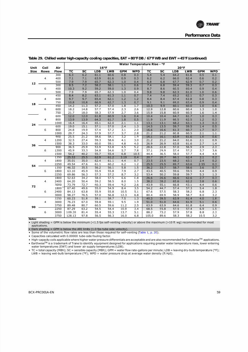
8/16/2019 Bcx-prc001-En 092013 Blower Coil Cat
http://slidepdf.com/reader/full/bcx-prc001-en-092013-blower-coil-cat 59/104
BCX-PRC001A-EN 59
Performance Data
Table 29. Chilled water high-capacity cooling capacities, EAT = 80°F DB / 67°F WB and EWT = 45°F (continued)
Unit
Size
Coil
Rows
Air
Flow
Water Temperature Rise - °F
16°F 20°F
TC SC LDB LWB GPM WPD TC SC LDB LWB GPM WPD
12
4
300 6.3 6.2 61.1 60.6 0.8 0.3 5.4 5.4 64.2 61.6 0.5 0.1
400 7.1 7.1 63.9 61.6 0.9 0.3 6.2 6.2 66.0 62.4 0.6 0.2
500 7.9 7.9 65.7 62.3 1.0 0.4 6.8 6.8 67.7 62.9 0.7 0.2
6
300 8.5 7.2 58.2 58.1 1.1 0.6 7.4 6.8 59.4 59.3 0.7 0.3
400 10.3 9.2 59.2 59.0 1.3 0.9 8.7 8.6 60.5 60.4 0.9 0.4
500 7.9 7.9 65.7 62.3 1.0 0.4 9.8 9.8 62.3 61.0 1.0 0.6
18
4
450 8.4 8.2 63.1 61.3 1.1 0.7 7.4 7.4 65.2 62.1 0.7 0.3
600 9.7 9.7 65.4 62.1 1.2 1.2 8.4 8.4 67.4 62.8 0.8 0.3
750 10.8 10.8 66.9 62.7 1.3 0.7 9.1 9.1 69.0 63.4 0.9 0.4
6
450 14.2 11.3 57.2 57.0 1.8 1.7 10.3 9.9 60.1 60.0 1.0 0.6
600 18.2 14.8 57.7 57.4 2.3 2.6 12.9 12.8 60.6 60.4 1.3 1.0
750 21.7 18.0 58.3 57.9 2.7 3.6 15.9 15.8 60.9 60.5 1.6 1.4
24
4
600 12.0 12.0 61.8 60.9 1.6 0.4 10.4 10.4 64.7 61.7 1.0 0.3
800 13.9 13.9 64.3 61.7 1.8 0.5 11.9 11.9 66.5 62.5 1.2 0.3
1000 16.4 16.4 65.1 62.0 2.1 1.1 13.1 13.1 68.2 63.1 1.3 0.3
6
600 19.0 15.1 57.1 57.0 2.4 1.3 14.5 13.5 59.7 59.5 1.4 0.5
800 24.8 19.9 57.4 57.2 3.1 2.0 16.6 16.6 61.3 60.7 1.7 0.7
1000 29.7 24.3 57.9 57.7 3.7 2.8 21.2 21.2 60.8 60.5 2.1 1.1
36
4
900 25.5 21.2 58.6 58.1 3.2 1.9 16.1 16.1 63.8 61.6 1.6 0.6
1200 32.5 27.4 59.3 58.6 4.1 3.0 21.2 21.2 64.0 61.6 2.1 0.9
1500 38.3 33.0 60.0 59.1 4.8 4.0 26.9 26.9 63.8 61.6 2.7 1.4
6
900 36.5 25.9 53.9 53.8 4.5 5.2 28.6 22.8 57.0 56.9 2.9 2.3
1200 45.9 33.3 54.8 54.6 5.7 7.8 37.1 29.9 57.4 57.2 3.7 3.6
1500 54.2 40.2 55.7 55.4 6.8 10.5 44.4 36.5 58.0 57.7 4.4 4.9
54
4
1350 25.53 25.5 62.9 61.2 3.19 0.4 20.7 20.7 66.1 62.4 2.1 0.2
1800 35.01 35.0 62.4 61.1 4.4 0.7 23.5 23.5 68.2 63.1 2.4 0.2
2250 49.54 47.6 61.1 60.2 6.2 1.2 25.5 25.5 69.7 63.6 2.55 0.3
6
1350 46.32 35.5 56.2 56.1 5.8 1.5 36.2 33.7 58.7 58.6 3.6 0.7
1800 63.10 45.9 55.9 55.8 7.9 2.7 43.5 40.5 59.6 59.5 4.4 0.9
2250 69.86 56.3 57.3 57.2 8.7 3.2 53.4 50.2 59.8 59.7 5.3 1.3
72
4
1800 52.63 34.2 58.0 57.5 6.6 0.8 26.6 26.6 66.6 62.6 2.7 0.3
2400 64.20 50.4 59.2 58.5 8.0 1.5 38.2 38.2 65.6 62.2 3.8 0.6
3000 73.79 72.7 60.3 59.4 9.2 2.6 43.9 55.1 66.8 63.1 4.4 0.6
6
1800 67.40 49.6 55.0 54.9 8.4 3.5 54.2 44.7 57.4 57.3 5.4 1.8
2400 84.13 63.8 55.9 55.8 10.5 5.1 67.6 57.5 58.3 58.2 6.8 2.3
3000 98.27 76.5 57.0 56.8 12.3 6.8 80.4 69.9 58.9 58.7 8.0 3.2
90
4
2250 60.23 51.8 59.1 58.7 7.5 1.3 40.3 39.5 63.9 61.4 4.0 1.8
3000 76.23 67.0 59.8 59.1 9.5 1.9 51.0 51.0 64.6 61.9 5.1 0.6
3750 89.48 80.7 60.5 59.6 11.2 2.5 63.9 63.9 64.6 61.8 6.4 0.9
6
2250 87.29 63.2 54.5 54.4 10.9 3.4 68.5 55.8 57.5 57.4 6.9 1.5
3000 109.30 81.4 55.4 55.3 13.7 5.1 88.2 73.2 57.9 57.8 8.8 2.3
3750 128.13 97.8 56.5 56.3 16.0 6.8 105.0 89.6 58.3 58.2 10.5 3.2Notes:
• Light shading = GPM is below the minimum (<1.5 fps self-venting velocity) or above the maximum (>10 ft wg) recommended for mostapplications.
• Dark shading = GPM is below the ARI limits (1.0 fps tube side velocity).
• Some of the volumetric flow rates are less than those required for self-venting (Table 1, p. 20).
• Capacities calculated with 0.00000 tube-side fouling factor.
• High-capacity coils applicable where higher water pressure differentials are acceptable and are also recommended for EarthwiseTM applications.
• EarthwiseTM is a trademark of Trane to identify equipment designed for applications requiring greater water temperature rises, lower entering
water temperatures (EWT) and lower air supply temperatures (LDB).• TC = total capacity (MBh); SC = sensible capacity (MBh); GPM = water flow rate-gallons per minute; LDB = leaving dry-bulb temperature (°F);
LWB = leaving wet-bulb temperature (°F); WPD = water pressure drop at average water density (ft H20).

8/16/2019 Bcx-prc001-En 092013 Blower Coil Cat
http://slidepdf.com/reader/full/bcx-prc001-en-092013-blower-coil-cat 60/104
60 BCX-PRC001A-EN
Performance Data
Distributor Selection
Select distributor size using MBh/Cir based on system analysis with matching condensing unitoperating.
Figure 37. R-410A Blower coil distributor selection
H e a t l o a d ( M
B h / C i r )
Saturated suction temperature (°F)
Max. BBh/Cir3/16 in. x 0.032 wall
Max. BBh/Cir3/16 in. x 0.032 wall
Max. BBh/Cir3/16 in. x 0.049 wall
Max. BBh/Cir3/16 in. x 0.049 wall
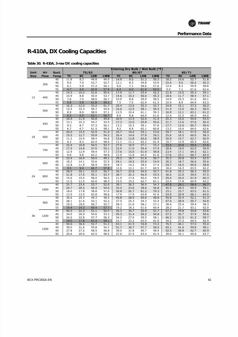
8/16/2019 Bcx-prc001-En 092013 Blower Coil Cat
http://slidepdf.com/reader/full/bcx-prc001-en-092013-blower-coil-cat 61/104
BCX-PRC001A-EN 61
Performance Data
R-410A, DX Cooling Capacities
Table 30. R-410A, 3-row DX cooling capacities
Unit
Size
Air
Flow
Suct.
Temp
Entering Dry Bulb / Wet Bulb (°F)
75/63 80/67 85/71
TC SC LDB LWB TC SC LDB LWB TC SC LDB LWB
12
300
40 11.8 8.3 49.8 49.0 14.9 9.5 51.2 50.3 18.2 10.6 52.7 51.8
45 9.0 7.0 53.7 52.7 12.1 8.3 54.8 53.9 15.4 9.5 56.2 55.3
50 6.1 5.9 57.2 56.1 9.0 7.1 58.6 57.6 12.4 8.3 59.9 58.8
55 4.7 4.6 60.8 57.9 6.4 6.0 61.6 60.5 9.0 7.1 63.6 62.4
400
40 14.3 10.2 51.6 50.4 17.9 11.7 53.4 52.2 21.8 13.0 55.3 54.1
45 10.9 8.8 55.0 53.7 14.6 10.3 56.6 55.3 18.6 11.7 58.4 57.1
50 7.6 7.5 58.0 56.7 10.9 8.8 59.9 58.5 14.9 10.3 61.6 60.1
55 5.8 5.8 61.8 58.2 7.5 7.5 62.9 61.3 10.9 8.9 64.9 63.3
500
40 16.3 12.0 53.2 51.7 20.4 13.6 55.3 53.7 24.8 15.1 57.5 56.0
45 12.5 10.3 56.2 54.6 16.6 12.0 58.1 56.5 21.0 13.6 60.3 58.5
50 8.9 8.9 58.9 57.1 12.5 10.4 61.1 59.3 16.9 12.1 63.1 61.2
55 6.5 6.5 63.1 58.7 8.8 8.8 64.0 61.6 12.4 10.5 66.0 64.0
18
450
40 16.9 11.9 50.8 49.8 20.9 13.5 52.6 51.5 25.3 15.0 54.6 53.545 13.1 10.3 54.2 53.0 17.3 12.0 55.8 54.6 21.7 13.6 57.6 56.4
50 9.3 8.7 57.3 56.1 13.2 10.3 59.1 57.8 17.7 12.0 60.7 59.4
55 6.7 6.7 61.5 58.1 9.2 8.9 62.1 60.8 13.2 10.4 64.0 62.6
600
40 20.0 14.5 52.9 51.4 24.7 16.4 55.1 53.6 29.7 18.1 57.5 56.0
45 15.5 12.7 55.8 54.2 20.4 14.6 57.8 56.2 25.6 16.5 60.0 58.3
50 11.2 10.9 58.4 56.8 15.6 12.8 60.6 58.9 20.9 14.7 62.7 60.9
55 8.3 8.3 62.4 58.5 11.1 11.1 63.2 61.4 15.7 12.9 65.5 63.6
750
40 22.4 16.8 54.5 52.7 27.6 18.9 57.1 55.2 33.5 20.8 59.6 57.6
45 17.5 14.8 57.0 55.1 22.9 17.0 59.4 57.4 28.6 19.0 62.0 59.9
50 12.9 12.9 59.4 57.3 17.6 15.0 61.9 59.8 23.4 17.1 64.3 62.1
55 9.8 9.8 63.2 58.8 12.9 12.8 64.5 61.8 17.6 15.1 66.7 64.4
24
600
40 23.4 16.4 50.0 49.1 29.2 18.7 51.6 50.7 35.3 20.8 53.4 52.5
45 18.2 14.1 53.6 52.5 24.1 16.5 55.0 54.0 30.3 18.7 56.6 55.6
50 12.8 11.9 56.9 55.9 18.3 14.2 58.5 57.4 24.7 16.5 60.0 58.8
55 9.5 9.4 60.7 57.8 12.6 12.1 61.7 60.5 18.4 14.3 63.5 62.2
800
40 28.0 20.1 52.0 50.7 34.7 22.8 54.0 52.7 41.8 25.2 56.3 55.0
45 21.8 17.5 55.1 53.7 28.7 20.3 56.9 55.5 36.0 22.9 59.0 57.5
50 15.6 15.0 58.0 56.5 21.9 17.6 60.0 58.5 29.4 20.4 61.9 60.355 11.5 11.5 62.0 58.3 15.5 15.2 62.7 61.1 22.0 17.8 64.9 63.2
1000
40 31.7 23.4 53.7 52.0 39.1 26.3 56.0 54.3 47.5 29.1 58.4 56.7
45 24.7 20.5 56.4 54.6 32.4 23.6 58.6 56.8 40.5 26.5 60.9 59.1
50 18.0 17.8 58.8 57.0 24.8 20.7 61.2 59.3 33.1 23.7 63.5 61.5
55 13.5 13.5 62.8 58.6 17.9 17.9 63.8 61.6 24.9 20.9 66.1 64.0
36
900
40 36.6 25.3 49.3 48.5 45.8 28.9 50.6 49.8 55.8 32.4 52.1 51.3
45 28.1 21.6 53.1 52.2 37.5 25.3 54.3 53.4 47.5 28.9 55.7 54.8
50 19.5 18.0 56.7 55.7 28.3 21.6 58.1 57.1 38.4 25.4 59.4 58.3
55 14.4 14.3 60.4 57.7 19.2 18.3 61.6 60.4 28.3 21.7 63.1 62.0
1200
40 44.3 31.3 51.1 50.0 55.3 35.7 52.9 51.7 67.2 39.8 54.8 53.6
45 34.0 26.9 54.6 53.3 45.3 31.4 56.2 54.8 57.2 35.7 57.9 56.6
50 24.0 22.8 57.7 56.3 34.2 27.0 59.5 58.1 46.2 31.5 61.2 59.7
55 18.0 17.8 61.4 58.1 23.7 23.2 62.5 61.0 34.2 27.2 64.5 62.9
1500
40 50.6 36.6 52.7 51.2 63.1 41.5 54.8 53.2 76.5 46.1 57.0 55.4
45 39.0 31.6 55.8 54.2 51.7 36.7 57.7 56.0 65.1 41.6 59.8 58.1
50 27.8 27.2 58.5 56.8 39.0 31.8 60.7 58.9 52.5 36.8 62.7 60.9
55 20.6 20.6 62.5 58.5 27.6 27.5 63.4 61.4 39.0 32.1 65.6 63.7

8/16/2019 Bcx-prc001-En 092013 Blower Coil Cat
http://slidepdf.com/reader/full/bcx-prc001-en-092013-blower-coil-cat 62/104
62 BCX-PRC001A-EN
Performance Data
54
1350
40 54.9 38.0 49.3 48.5 68.7 43.4 50.6 49.8 83.7 48.7 52.1 51.3
45 42.2 32.4 53.1 52.2 56.3 38.0 54.3 53.4 71.3 43.4 55.7 54.8
50 29.2 27.1 56.7 55.7 42.5 32.4 58.1 57.1 57.6 38.0 59.4 58.3
55 21.7 21.5 60.4 57.7 28.9 27.4 61.6 60.4 42.5 32.6 63.1 62.0
1800
40 66.4 47.0 51.1 50.0 83.0 53.5 52.9 51.7 100.8 59.7 54.8 53.6
45 51.1 40.4 54.6 53.3 67.9 47.1 56.2 54.8 85.8 53.5 57.9 56.6
50 36.0 34.2 57.7 56.3 51.3 40.5 59.5 58.1 69.3 47.2 61.2 59.7
55 26.9 26.7 61.4 58.1 35.6 34.8 62.5 61.0 51.3 40.8 64.5 62.9
2250
40 75.9 54.9 52.7 51.2 94.7 62.2 54.8 53.2 114.7 69.2 57.0 55.4
45 58.4 47.4 55.8 54.2 77.5 55.1 57.7 56.0 97.7 62.3 59.8 58.1
50 41.7 40.7 58.5 56.8 58.5 47.8 60.7 58.9 78.8 55.3 62.7 60.9
55 30.9 30.9 62.5 58.5 41.4 41.3 63.4 61.4 58.4 48.1 65.6 63.7
72
1800
40 72.1 50.1 49.6 48.7 89.6 56.9 51.1 50.3 108.3 63.4 52.9 52.0
45 56.3 43.1 53.2 52.2 74.1 50.2 54.6 53.6 93.1 57.0 56.2 55.2
50 39.8 36.3 56.6 55.6 56.8 43.2 58.2 57.0 76.1 50.3 59.6 58.5
55 28.4 28.4 60.7 57.8 39.4 36.7 61.5 60.3 57.2 43.4 63.1 61.9
2400
40 86.4 61.5 51.6 50.3 107.0 69.5 53.6 52.3 128.8 77.1 55.7 54.5
45 67.6 53.4 54.7 53.4 88.6 61.8 56.6 55.1 110.9 69.7 58.6 57.1
50 48.4 45.6 57.7 56.3 68.0 53.7 59.7 58.1 90.7 62.0 61.5 60.0
55 35.5 35.5 35.5 61.6 48.0 46.3 62.5 60.9 68.2 54.1 64.6 62.9
3000
40 97.9 71.5 53.3 51.7 120.9 80.4 55.6 53.9 143.8 87.0 58.5 56.5
45 76.7 62.4 56.0 54.3 100.3 71.9 58.2 56.4 125.1 80.8 60.5 58.7
50 55.7 54.0 58.6 56.8 77.1 62.9 60.9 59.0 102.3 72.3 63.1 61.1
55 41.7 41.7 41.7 62.4 55.3 55.0 63.4 61.4 77.2 63.5 65.8 63.7
90
2250
40 92.0 63.6 49.2 48.3 114.4 72.3 50.6 49.8 138.4 80.7 52.3 51.5
45 71.9 54.6 52.9 51.9 94.7 63.7 54.2 53.2 118.9 72.4 55.7 54.7
50 50.7 45.9 56.4 55.4 72.6 54.8 57.8 56.8 97.2 63.9 59.2 58.1
55 46.8 44.4 57.1 56.0 68.0 53.0 58.6 57.5 92.6 62.1 59.9 58.8
3000
40 110.8 78.4 51.1 50.0 137.3 88.7 53.0 51.8 165.6 98.5 55.1 53.9
45 86.7 67.9 54.4 53.1 113.7 78.7 56.1 54.8 142.4 89.0 58.0 56.7
50 61.9 57.8 57.5 56.1 87.3 68.3 59.3 57.9 116.5 79.0 61.1 59.6
55 57.5 56.1 58.0 56.6 81.8 66.2 59.9 58.5 110.9 77.0 61.7 60.2
3750
40 126.1 91.3 52.8 51.3 155.8 102.9 55.0 53.4 192.1 115.2 56.9 55.3
45 98.7 79.6 55.7 54.0 129.2 91.8 57.7 56.0 161.2 103.3 60.0 58.2
50 71.4 68.6 58.3 56.7 99.2 80.2 60.6 58.8 132.0 92.3 62.7 60.8
55 53.2 53.2 62.1 58.4 70.8 69.8 63.1 61.2 99.4 80.9 65.5 63.5Notes: To select the correct distributor size at conditions exactly matching those shown on this table, use the shading legend below:
• No shade = 3/16 in. x 0.049 wall distributor tubes
• Light shading = 3/16 in. x 0.032 wall distributor tubes.
• Dark shading = Distributor load (MBh) per circuit is under the minimum for 3/16 in. x 0.049 distributor or over the maximum for 3/16 in. x0.032 distributor. Use only for interpolation
• Values shown in this table are based on a liquid condensing temperature of 105°F. Capacities at liquid condensing temperatures between 90°Fand 120°F will generally be within ±5 percent of capacities shown in this table
• Distributor selection is based on TC capacities divided by number of circuits (see Table 4, p. 22).
• To select the correct distributor size at conditions other than exactly shown in this table interpolate to calculate the TC MBh, divide it by thenumber of circuits (see Table 4, p. 22) and plot the result on Figure 37, p. 60.
• TC and SC values do not include heat generated by the fan and motor.
• TC = total capacity (MBh); SC = sensible capacity (MBh); GPM = water flow rate-gallons per minute; LDB = leaving dry-bulb temperature (°F);LWB = leaving wet-bulb temperature (°F); WPD = water pressure drop at average water density (ft H20).
Table 30. R-410A, 3-row DX cooling capacities (continued)
UnitSize
AirFlow
Suct.Temp
Entering Dry Bulb / Wet Bulb (°F)
75/63 80/67 85/71TC SC LDB LWB TC SC LDB LWB TC SC LDB LWB

8/16/2019 Bcx-prc001-En 092013 Blower Coil Cat
http://slidepdf.com/reader/full/bcx-prc001-en-092013-blower-coil-cat 63/104
BCX-PRC001A-EN 63
Performance Data
Table 31. R-410A, 4-row DX cooling capacities
Unit
Size
Air
Flow
Suct
Temp
Entering Dry Bulb / Wet Bulb (°F)
75/63 80/67 85/71
TC SC LDB LWB TC SC LDB LWB TC SC LDB LWB
12
300
40 13.4 9.1 47.2 46.8 16.7 10.4 48.2 47.9 20.2 11.7 49.5 49.2
45 10.4 7.8 51.3 50.9 13.8 9.2 52.1 51.7 17.4 10.5 53.2 52.8
50 7.3 6.5 55.3 54.8 10.5 7.8 56.2 55.8 14.2 9.2 57.2 56.7
55 5.3 5.3 59.0 57.2 7.2 6.6 60.1 59.6 10.6 7.9 61.2 60.7
400
40 16.4 11.4 48.9 48.3 20.3 13.0 50.4 49.9 24.5 14.4 52.1 51.6
45 12.8 9.9 52.5 51.9 16.8 11.5 53.8 53.2 21.1 13.0 55.4 54.7
50 9.1 8.3 56.0 55.4 12.9 9.9 57.5 56.8 17.3 11.5 58.8 58.1
55 6.4 6.4 60.4 57.7 9.0 8.4 60.8 60.1 13.0 10.0 62.4 61.6
500
40 18.8 13.4 50.4 49.7 23.3 15.2 52.3 51.5 28.0 16.8 54.4 53.6
45 14.7 11.7 53.7 52.9 19.4 13.5 55.3 54.5 24.2 15.3 57.2 56.3
50 10.6 10.0 56.8 55.9 14.9 11.8 58.6 57.6 19.9 13.6 60.3 59.3
55 7.7 7.7 61.0 57.9 10.5 10.2 61.5 60.6 15.0 11.9 63.5 62.4
18
450
40 18.8 13.1 48.4 48.0 23.1 14.8 50.1 49.6 27.7 16.3 51.9 51.5
45 15.0 11.4 51.9 51.4 19.5 13.2 53.3 52.8 24.2 14.9 54.9 54.4
50 10.8 9.7 55.4 54.9 15.2 11.5 56.8 56.2 20.1 13.3 58.2 57.655 7.7 7.7 59.5 57.4 10.7 9.8 60.3 59.6 15.4 11.5 61.7 61.1
600
40 22.4 16.1 50.5 49.8 27.4 18.0 52.6 51.8 32.8 19.8 54.9 54.1
45 18.0 14.2 53.5 52.7 23.2 16.3 55.3 54.5 28.7 18.2 57.4 56.6
50 13.2 12.2 56.5 55.6 18.3 14.3 58.3 57.4 23.9 16.4 60.2 59.3
55 9.6 9.6 60.4 57.7 13.1 12.4 61.2 60.3 18.4 14.5 63.2 62.2
750
40 25.3 18.7 52.2 51.2 30.9 20.8 54.6 53.6 36.7 22.8 57.2 56.2
45 20.4 16.6 54.8 53.7 26.1 19.0 57.0 55.9 32.2 21.1 59.4 58.3
50 15.2 14.6 57.3 56.2 20.7 16.9 59.6 58.4 26.9 19.2 61.8 60.6
55 11.4 11.4 61.2 58.0 15.2 14.9 62.0 60.8 20.9 17.1 64.4 63.1
24
600
40 26.1 17.9 47.6 47.3 32.1 20.3 49.1 48.7 38.6 22.5 50.8 50.4
45 20.7 15.5 51.4 50.9 27.0 18.1 52.6 52.1 33.6 20.4 54.0 53.6
50 14.9 13.1 55.1 54.6 21.1 15.6 56.3 55.8 27.9 18.2 57.5 57.0
55 10.4 10.4 59.3 57.3 14.8 13.3 59.9 59.4 21.4 15.7 61.2 60.7
800
40 31.4 22.2 49.6 49.0 38.5 25.0 51.5 50.9 46.0 27.5 53.7 53.0
45 25.1 19.5 52.8 52.2 32.5 22.4 54.5 53.8 40.3 25.2 56.4 55.7
50 18.3 16.7 56.0 55.3 25.5 19.6 57.7 56.9 33.5 22.6 59.3 58.6
55 13.2 13.2 60.0 57.6 18.2 16.9 60.8 60.0 25.8 19.8 62.6 61.7
1000
40 35.7 25.9 51.3 50.5 43.5 29.0 53.6 52.7 51.9 31.7 56.0 55.145 28.6 22.9 54.1 53.2 36.9 26.2 56.1 55.2 45.5 29.3 58.3 57.4
50 21.2 19.9 56.9 55.9 29.1 23.2 58.9 57.9 38.0 26.5 60.9 59.9
55 15.7 15.7 60.8 57.8 21.1 20.3 61.6 60.5 29.4 23.5 63.7 62.6
36
900
40 41.3 27.9 46.6 46.3 51.3 31.9 47.6 47.3 62.1 35.6 48.8 48.5
45 32.3 23.9 50.8 50.3 42.6 28.0 51.6 51.2 53.5 31.9 52.7 52.3
50 22.8 19.9 54.8 54.4 32.8 24.0 55.8 55.3 43.9 28.0 56.7 56.2
55 16.2 16.1 58.6 57.0 22.6 20.1 59.7 59.2 33.2 24.0 60.8 60.2
1200
40 50.6 35.0 48.3 47.8 62.7 39.7 49.8 49.2 75.6 44.2 51.4 50.9
45 39.8 30.2 52.1 51.5 52.2 35.1 53.3 52.7 65.3 39.8 54.8 54.2
50 28.4 25.5 55.7 55.0 40.3 30.3 57.0 56.3 53.6 35.2 58.3 57.6
55 20.1 20.1 59.8 57.5 28.1 25.8 60.5 59.8 40.6 30.5 62.0 61.2
1500
40 58.4 41.2 49.9 49.1 72.2 46.6 51.7 50.9 86.8 51.6 53.6 52.9
45 46.0 35.8 53.2 52.4 60.1 41.4 54.8 54.0 75.0 46.8 56.6 55.8
50 33.1 30.6 56.5 55.6 46.4 36.0 58.2 57.2 61.7 41.6 59.8 58.9
55 24.0 24.0 60.5 57.7 32.8 31.0 61.2 60.3 46.7 36.3 63.1 62.1
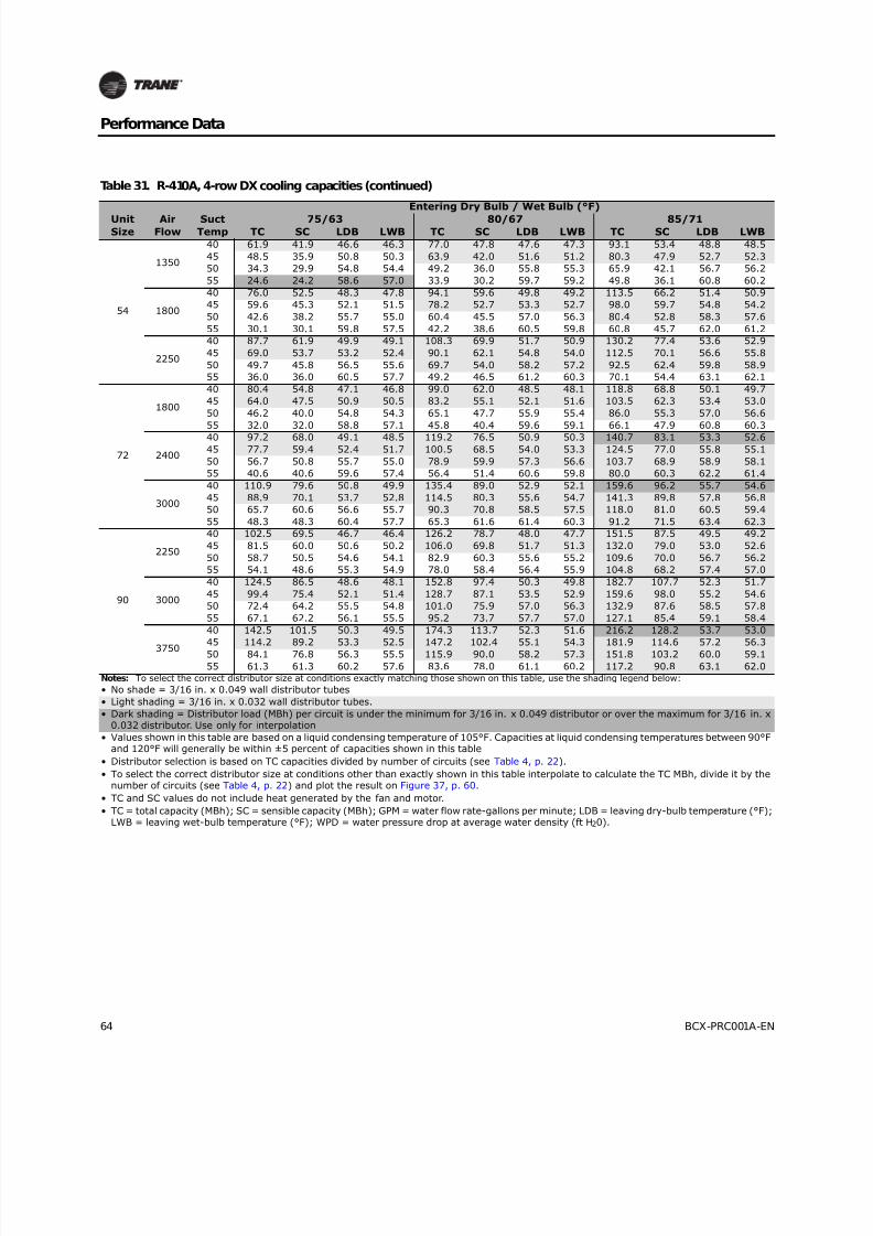
8/16/2019 Bcx-prc001-En 092013 Blower Coil Cat
http://slidepdf.com/reader/full/bcx-prc001-en-092013-blower-coil-cat 64/104
64 BCX-PRC001A-EN
Performance Data
54
1350
40 61.9 41.9 46.6 46.3 77.0 47.8 47.6 47.3 93.1 53.4 48.8 48.5
45 48.5 35.9 50.8 50.3 63.9 42.0 51.6 51.2 80.3 47.9 52.7 52.3
50 34.3 29.9 54.8 54.4 49.2 36.0 55.8 55.3 65.9 42.1 56.7 56.2
55 24.6 24.2 58.6 57.0 33.9 30.2 59.7 59.2 49.8 36.1 60.8 60.2
1800
40 76.0 52.5 48.3 47.8 94.1 59.6 49.8 49.2 113.5 66.2 51.4 50.9
45 59.6 45.3 52.1 51.5 78.2 52.7 53.3 52.7 98.0 59.7 54.8 54.2
50 42.6 38.2 55.7 55.0 60.4 45.5 57.0 56.3 80.4 52.8 58.3 57.6
55 30.1 30.1 59.8 57.5 42.2 38.6 60.5 59.8 60.8 45.7 62.0 61.2
2250
40 87.7 61.9 49.9 49.1 108.3 69.9 51.7 50.9 130.2 77.4 53.6 52.9
45 69.0 53.7 53.2 52.4 90.1 62.1 54.8 54.0 112.5 70.1 56.6 55.8
50 49.7 45.8 56.5 55.6 69.7 54.0 58.2 57.2 92.5 62.4 59.8 58.9
55 36.0 36.0 60.5 57.7 49.2 46.5 61.2 60.3 70.1 54.4 63.1 62.1
72
1800
40 80.4 54.8 47.1 46.8 99.0 62.0 48.5 48.1 118.8 68.8 50.1 49.7
45 64.0 47.5 50.9 50.5 83.2 55.1 52.1 51.6 103.5 62.3 53.4 53.0
50 46.2 40.0 54.8 54.3 65.1 47.7 55.9 55.4 86.0 55.3 57.0 56.6
55 32.0 32.0 58.8 57.1 45.8 40.4 59.6 59.1 66.1 47.9 60.8 60.3
2400
40 97.2 68.0 49.1 48.5 119.2 76.5 50.9 50.3 140.7 83.1 53.3 52.6
45 77.7 59.4 52.4 51.7 100.5 68.5 54.0 53.3 124.5 77.0 55.8 55.1
50 56.7 50.8 55.7 55.0 78.9 59.9 57.3 56.6 103.7 68.9 58.9 58.1
55 40.6 40.6 59.6 57.4 56.4 51.4 60.6 59.8 80.0 60.3 62.2 61.4
3000
40 110.9 79.6 50.8 49.9 135.4 89.0 52.9 52.1 159.6 96.2 55.7 54.6
45 88.9 70.1 53.7 52.8 114.5 80.3 55.6 54.7 141.3 89.8 57.8 56.8
50 65.7 60.6 56.6 55.7 90.3 70.8 58.5 57.5 118.0 81.0 60.5 59.4
55 48.3 48.3 60.4 57.7 65.3 61.6 61.4 60.3 91.2 71.5 63.4 62.3
90
2250
40 102.5 69.5 46.7 46.4 126.2 78.7 48.0 47.7 151.5 87.5 49.5 49.2
45 81.5 60.0 50.6 50.2 106.0 69.8 51.7 51.3 132.0 79.0 53.0 52.6
50 58.7 50.5 54.6 54.1 82.9 60.3 55.6 55.2 109.6 70.0 56.7 56.2
55 54.1 48.6 55.3 54.9 78.0 58.4 56.4 55.9 104.8 68.2 57.4 57.0
3000
40 124.5 86.5 48.6 48.1 152.8 97.4 50.3 49.8 182.7 107.7 52.3 51.7
45 99.4 75.4 52.1 51.4 128.7 87.1 53.5 52.9 159.6 98.0 55.2 54.6
50 72.4 64.2 55.5 54.8 101.0 75.9 57.0 56.3 132.9 87.6 58.5 57.8
55 67.1 62.2 56.1 55.5 95.2 73.7 57.7 57.0 127.1 85.4 59.1 58.4
3750
40 142.5 101.5 50.3 49.5 174.3 113.7 52.3 51.6 216.2 128.2 53.7 53.0
45 114.2 89.2 53.3 52.5 147.2 102.4 55.1 54.3 181.9 114.6 57.2 56.3
50 84.1 76.8 56.3 55.5 115.9 90.0 58.2 57.3 151.8 103.2 60.0 59.1
55 61.3 61.3 60.2 57.6 83.6 78.0 61.1 60.2 117.2 90.8 63.1 62.0Notes: To select the correct distributor size at conditions exactly matching those shown on this table, use the shading legend below:
• No shade = 3/16 in. x 0.049 wall distributor tubes
• Light shading = 3/16 in. x 0.032 wall distributor tubes.
• Dark shading = Distributor load (MBh) per circuit is under the minimum for 3/16 in. x 0.049 distributor or over the maximum for 3/16 in. x0.032 distributor. Use only for interpolation
• Values shown in this table are based on a liquid condensing temperature of 105°F. Capacities at liquid condensing temperatures between 90°Fand 120°F will generally be within ±5 percent of capacities shown in this table
• Distributor selection is based on TC capacities divided by number of circuits (see Table 4, p. 22).
• To select the correct distributor size at conditions other than exactly shown in this table interpolate to calculate the TC MBh, divide it by thenumber of circuits (see Table 4, p. 22) and plot the result on Figure 37, p. 60.
• TC and SC values do not include heat generated by the fan and motor.
• TC = total capacity (MBh); SC = sensible capacity (MBh); GPM = water flow rate-gallons per minute; LDB = leaving dry-bulb temperature (°F);LWB = leaving wet-bulb temperature (°F); WPD = water pressure drop at average water density (ft H20).
Table 31. R-410A, 4-row DX cooling capacities (continued)
UnitSize
AirFlow
SuctTemp
Entering Dry Bulb / Wet Bulb (°F)
75/63 80/67 85/71TC SC LDB LWB TC SC LDB LWB TC SC LDB LWB
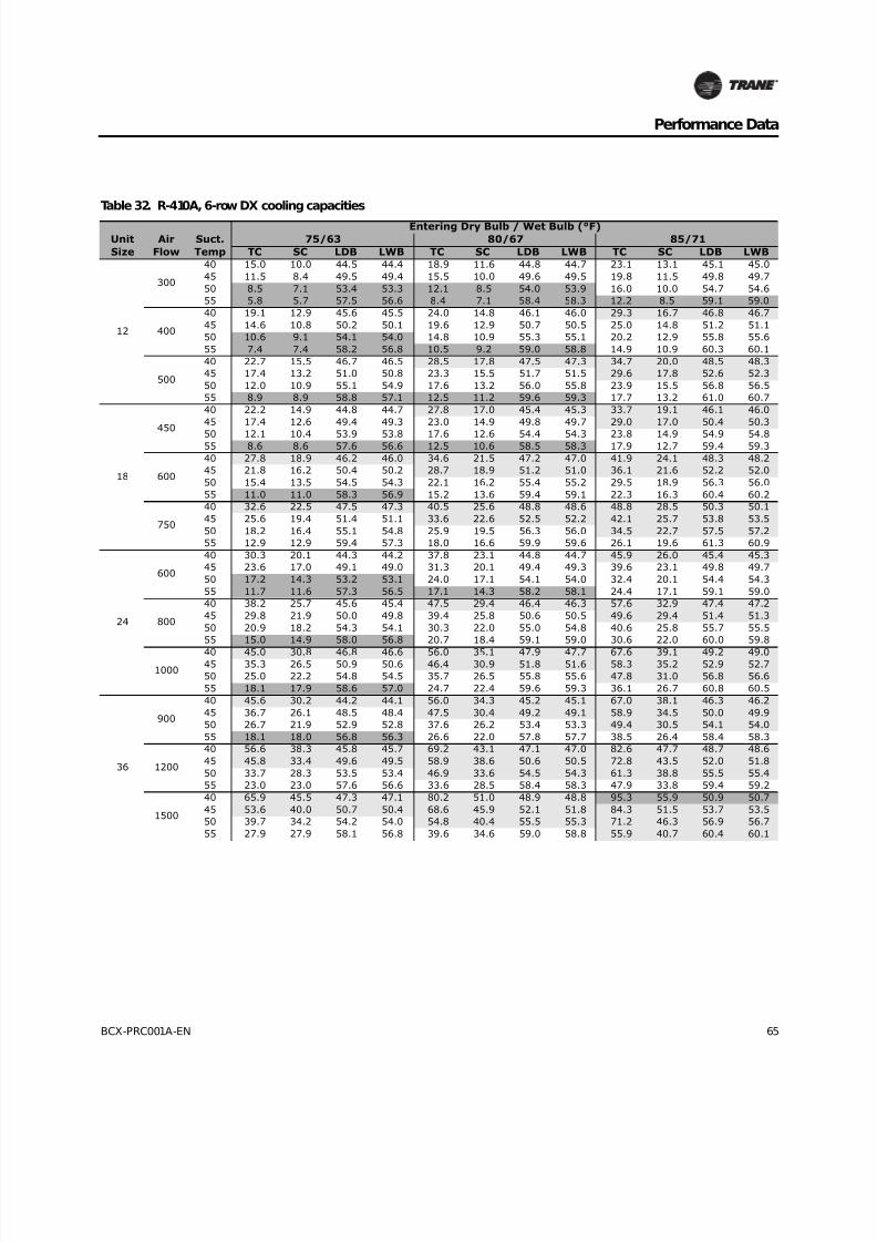
8/16/2019 Bcx-prc001-En 092013 Blower Coil Cat
http://slidepdf.com/reader/full/bcx-prc001-en-092013-blower-coil-cat 65/104
BCX-PRC001A-EN 65
Performance Data
Table 32. R-410A, 6-row DX cooling capacities
Unit
Size
Air
Flow
Suct.
Temp
Entering Dry Bulb / Wet Bulb (°F)
75/63 80/67 85/71
TC SC LDB LWB TC SC LDB LWB TC SC LDB LWB
12
300
40 15.0 10.0 44.5 44.4 18.9 11.6 44.8 44.7 23.1 13.1 45.1 45.0
45 11.5 8.4 49.5 49.4 15.5 10.0 49.6 49.5 19.8 11.5 49.8 49.7
50 8.5 7.1 53.4 53.3 12.1 8.5 54.0 53.9 16.0 10.0 54.7 54.6
55 5.8 5.7 57.5 56.6 8.4 7.1 58.4 58.3 12.2 8.5 59.1 59.0
400
40 19.1 12.9 45.6 45.5 24.0 14.8 46.1 46.0 29.3 16.7 46.8 46.7
45 14.6 10.8 50.2 50.1 19.6 12.9 50.7 50.5 25.0 14.8 51.2 51.1
50 10.6 9.1 54.1 54.0 14.8 10.9 55.3 55.1 20.2 12.9 55.8 55.6
55 7.4 7.4 58.2 56.8 10.5 9.2 59.0 58.8 14.9 10.9 60.3 60.1
500
40 22.7 15.5 46.7 46.5 28.5 17.8 47.5 47.3 34.7 20.0 48.5 48.3
45 17.4 13.2 51.0 50.8 23.3 15.5 51.7 51.5 29.6 17.8 52.6 52.3
50 12.0 10.9 55.1 54.9 17.6 13.2 56.0 55.8 23.9 15.5 56.8 56.5
55 8.9 8.9 58.8 57.1 12.5 11.2 59.6 59.3 17.7 13.2 61.0 60.7
18
450
40 22.2 14.9 44.8 44.7 27.8 17.0 45.4 45.3 33.7 19.1 46.1 46.0
45 17.4 12.6 49.4 49.3 23.0 14.9 49.8 49.7 29.0 17.0 50.4 50.3
50 12.1 10.4 53.9 53.8 17.6 12.6 54.4 54.3 23.8 14.9 54.9 54.855 8.6 8.6 57.6 56.6 12.5 10.6 58.5 58.3 17.9 12.7 59.4 59.3
600
40 27.8 18.9 46.2 46.0 34.6 21.5 47.2 47.0 41.9 24.1 48.3 48.2
45 21.8 16.2 50.4 50.2 28.7 18.9 51.2 51.0 36.1 21.6 52.2 52.0
50 15.4 13.5 54.5 54.3 22.1 16.2 55.4 55.2 29.5 18.9 56.3 56.0
55 11.0 11.0 58.3 56.9 15.2 13.6 59.4 59.1 22.3 16.3 60.4 60.2
750
40 32.6 22.5 47.5 47.3 40.5 25.6 48.8 48.6 48.8 28.5 50.3 50.1
45 25.6 19.4 51.4 51.1 33.6 22.6 52.5 52.2 42.1 25.7 53.8 53.5
50 18.2 16.4 55.1 54.8 25.9 19.5 56.3 56.0 34.5 22.7 57.5 57.2
55 12.9 12.9 59.4 57.3 18.0 16.6 59.9 59.6 26.1 19.6 61.3 60.9
24
600
40 30.3 20.1 44.3 44.2 37.8 23.1 44.8 44.7 45.9 26.0 45.4 45.3
45 23.6 17.0 49.1 49.0 31.3 20.1 49.4 49.3 39.6 23.1 49.8 49.7
50 17.2 14.3 53.2 53.1 24.0 17.1 54.1 54.0 32.4 20.1 54.4 54.3
55 11.7 11.6 57.3 56.5 17.1 14.3 58.2 58.1 24.4 17.1 59.1 59.0
800
40 38.2 25.7 45.6 45.4 47.5 29.4 46.4 46.3 57.6 32.9 47.4 47.2
45 29.8 21.9 50.0 49.8 39.4 25.8 50.6 50.5 49.6 29.4 51.4 51.3
50 20.9 18.2 54.3 54.1 30.3 22.0 55.0 54.8 40.6 25.8 55.7 55.5
55 15.0 14.9 58.0 56.8 20.7 18.4 59.1 59.0 30.6 22.0 60.0 59.8
1000
40 45.0 30.8 46.8 46.6 56.0 35.1 47.9 47.7 67.6 39.1 49.2 49.045 35.3 26.5 50.9 50.6 46.4 30.9 51.8 51.6 58.3 35.2 52.9 52.7
50 25.0 22.2 54.8 54.5 35.7 26.5 55.8 55.6 47.8 31.0 56.8 56.6
55 18.1 17.9 58.6 57.0 24.7 22.4 59.6 59.3 36.1 26.7 60.8 60.5
36
900
40 45.6 30.2 44.2 44.1 56.0 34.3 45.2 45.1 67.0 38.1 46.3 46.2
45 36.7 26.1 48.5 48.4 47.5 30.4 49.2 49.1 58.9 34.5 50.0 49.9
50 26.7 21.9 52.9 52.8 37.6 26.2 53.4 53.3 49.4 30.5 54.1 54.0
55 18.1 18.0 56.8 56.3 26.6 22.0 57.8 57.7 38.5 26.4 58.4 58.3
1200
40 56.6 38.3 45.8 45.7 69.2 43.1 47.1 47.0 82.6 47.7 48.7 48.6
45 45.8 33.4 49.6 49.5 58.9 38.6 50.6 50.5 72.8 43.5 52.0 51.8
50 33.7 28.3 53.5 53.4 46.9 33.6 54.5 54.3 61.3 38.8 55.5 55.4
55 23.0 23.0 57.6 56.6 33.6 28.5 58.4 58.3 47.9 33.8 59.4 59.2
1500
40 65.9 45.5 47.3 47.1 80.2 51.0 48.9 48.8 95.3 55.9 50.9 50.7
45 53.6 40.0 50.7 50.4 68.6 45.9 52.1 51.8 84.3 51.5 53.7 53.5
50 39.7 34.2 54.2 54.0 54.8 40.4 55.5 55.3 71.2 46.3 56.9 56.7
55 27.9 27.9 58.1 56.8 39.6 34.6 59.0 58.8 55.9 40.7 60.4 60.1

8/16/2019 Bcx-prc001-En 092013 Blower Coil Cat
http://slidepdf.com/reader/full/bcx-prc001-en-092013-blower-coil-cat 66/104
66 BCX-PRC001A-EN
Performance Data
54
1350
40 68.4 45.3 44.2 44.1 83.9 51.4 45.2 45.1 100.5 57.1 46.3 46.2
45 55.1 39.2 48.5 48.4 71.2 45.6 49.2 49.1 88.3 51.7 50.0 49.9
50 40.1 32.8 52.9 52.8 56.4 39.4 53.4 53.3 74.1 45.8 54.1 54.0
55 27.1 26.9 56.8 56.3 39.9 33.0 57.8 57.7 57.7 39.5 58.4 58.3
1800
40 84.9 57.5 45.8 45.7 103.8 64.7 47.1 47.0 123.9 71.5 48.7 48.6
45 68.7 50.1 49.6 49.5 88.4 57.9 50.6 50.5 109.2 65.2 52.0 51.8
50 50.5 42.4 53.5 53.4 70.4 50.4 54.5 54.3 91.9 58.2 55.5 55.4
55 34.5 34.5 57.6 56.6 50.3 42.7 58.4 58.3 71.9 50.7 59.4 59.2
2250
40 98.8 68.2 47.3 47.1 120.4 76.5 48.9 48.8 142.9 83.9 50.9 50.7
45 80.3 60.0 50.7 50.4 102.8 68.9 52.1 51.8 126.5 77.2 53.7 53.5
50 59.6 51.4 54.2 54.0 82.3 60.5 55.5 55.3 106.8 69.5 56.9 56.7
55 41.8 41.8 58.1 56.8 59.4 51.9 59.0 58.8 83.9 61.0 60.4 60.1
72
1800
40 92.6 61.2 43.9 43.8 115.3 70.1 44.3 44.2 139.7 78.8 44.9 44.8
45 72.9 52.0 48.6 48.5 95.9 61.2 48.9 48.8 120.7 70.2 49.4 49.3
50 52.3 43.0 53.1 53.0 74.2 52.1 53.6 53.5 99.3 61.3 54.0 53.9
55 35.6 35.4 57.0 56.4 52.3 43.2 58.1 57.9 75.4 52.1 58.7 58.6
2400
40 117.0 78.4 45.1 45.0 145.4 89.5 45.9 45.8 175.9 100.3 46.8 46.7
45 92.1 66.9 49.5 49.4 120.9 78.4 50.2 50.0 151.8 89.5 51.0 50.8
50 65.3 55.7 53.9 53.7 93.5 67.0 54.6 54.4 124.7 78.5 55.2 55.1
55 45.5 45.1 57.8 56.7 64.7 56.0 58.8 58.6 94.7 67.2 59.6 59.4
3000
40 138.3 94.0 46.3 46.1 171.6 106.9 47.4 47.2 207.2 119.3 48.6 48.5
45 109.0 80.7 50.4 50.2 142.6 94.1 51.4 51.1 178.8 107.1 52.5 52.2
50 77.8 67.7 54.4 54.2 110.4 80.9 55.4 55.2 146.9 94.2 56.4 56.1
55 54.4 54.0 58.5 57.0 77.0 68.3 59.3 59.0 111.6 81.2 60.4 60.1
90
2250
40 116.9 77.0 43.7 43.6 145.6 88.4 44.0 43.9 176.5 99.4 44.5 44.4
45 92.0 65.4 48.4 48.3 121.1 77.1 48.7 48.6 152.4 88.4 49.1 49.0
50 67.9 54.9 52.7 52.6 93.7 65.4 53.5 53.4 125.4 77.1 53.8 53.7
55 63.0 52.8 53.5 53.4 87.9 63.1 54.4 54.3 119.6 74.8 54.7 54.6
3000
40 148.3 99.0 44.8 44.7 184.3 113.2 45.5 45.4 223.1 126.8 46.3 46.2
45 116.7 84.4 49.3 49.2 153.2 99.0 49.9 49.7 192.5 113.2 50.6 50.4
50 82.6 70.0 53.7 53.6 118.6 84.5 54.3 54.2 158.3 99.1 54.9 54.8
55 76.0 67.3 54.6 54.4 111.3 81.6 55.2 55.1 150.9 96.2 55.8 55.7
3750
40 175.9 119.0 46.0 45.8 218.4 135.6 46.9 46.8 263.8 151.4 48.1 47.9
45 138.5 102.0 50.2 50.0 181.5 119.1 51.0 50.8 227.7 135.7 52.0 51.8
50 98.7 85.3 54.3 54.0 140.5 102.2 55.2 54.9 187.0 119.3 56.1 55.8
55 70.3 69.8 58.0 56.8 97.7 86.0 59.2 58.9 142.0 102.5 60.2 59.9Notes: To select the correct distributor size at conditions exactly matching those shown on this table, use the shading legend below:
• No shade = 3/16 in. x 0.049 wall distributor tubes
• Light shading = 3/16 in. x 0.032 wall distributor tubes.
• Dark shading = Distributor load (MBh) per circuit is under the minimum for 3/16 in. x 0.049 distributor or over the maximum for 3/16 in. x0.032 distributor. Use only for interpolation
• Values shown in this table are based on a liquid condensing temperature of 105°F. Capacities at liquid condensing temperatures between 90°Fand 120°F will generally be within ±5 percent of capacities shown in this table
• Distributor selection is based on TC capacities divided by number of circuits (see Table 4, p. 22).
• To select the correct distributor size at conditions other than exactly shown in this table interpolate to calculate the TC MBh, divide it by thenumber of circuits (see Table 4, p. 22) and plot the result on Figure 37, p. 60.
• TC and SC values do not include heat generated by the fan and motor.
• TC = total capacity (MBh); SC = sensible capacity (MBh); GPM = water flow rate-gallons per minute; LDB = leaving dry-bulb temperature (°F);LWB = leaving wet-bulb temperature (°F); WPD = water pressure drop at average water density (ft H20).
Table 32. R-410A, 6-row DX cooling capacities (continued)
UnitSize
AirFlow
Suct.Temp
Entering Dry Bulb / Wet Bulb (°F)
75/63 80/67 85/71TC SC LDB LWB TC SC LDB LWB TC SC LDB LWB
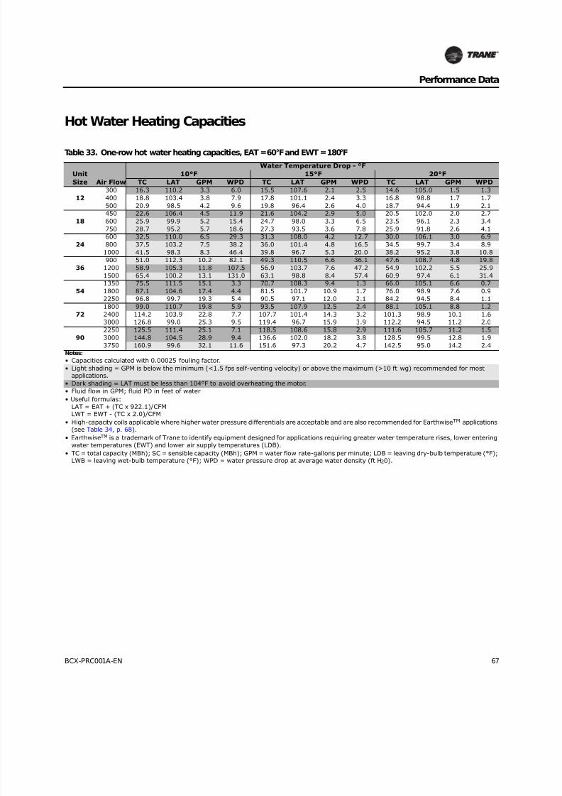
8/16/2019 Bcx-prc001-En 092013 Blower Coil Cat
http://slidepdf.com/reader/full/bcx-prc001-en-092013-blower-coil-cat 67/104
BCX-PRC001A-EN 67
Performance Data
Hot Water Heating Capacities
Table 33. One-row hot water heating capacities, EAT = 60°F and EWT = 180°F
Unit
Size Air Flow
Water Temperature Drop - °F
10°F 15°F 20°F
TC LAT GPM WPD TC LAT GPM WPD TC LAT GPM WPD
12
300 16.3 110.2 3.3 6.0 15.5 107.6 2.1 2.5 14.6 105.0 1.5 1.3
400 18.8 103.4 3.8 7.9 17.8 101.1 2.4 3.3 16.8 98.8 1.7 1.7
500 20.9 98.5 4.2 9.6 19.8 96.4 2.6 4.0 18.7 94.4 1.9 2.1
18
450 22.6 106.4 4.5 11.9 21.6 104.2 2.9 5.0 20.5 102.0 2.0 2.7
600 25.9 99.9 5.2 15.4 24.7 98.0 3.3 6.5 23.5 96.1 2.3 3.4
750 28.7 95.2 5.7 18.6 27.3 93.5 3.6 7.8 25.9 91.8 2.6 4.1
24
600 32.5 110.0 6.5 29.3 31.3 108.0 4.2 12.7 30.0 106.1 3.0 6.9
800 37.5 103.2 7.5 38.2 36.0 101.4 4.8 16.5 34.5 99.7 3.4 8.9
1000 41.5 98.3 8.3 46.4 39.8 96.7 5.3 20.0 38.2 95.2 3.8 10.8
36
900 51.0 112.3 10.2 82.1 49.3 110.5 6.6 36.1 47.6 108.7 4.8 19.8
1200 58.9 105.3 11.8 107.5 56.9 103.7 7.6 47.2 54.9 102.2 5.5 25.9
1500 65.4 100.2 13.1 131.0 63.1 98.8 8.4 57.4 60.9 97.4 6.1 31.4
54
1350 75.5 111.5 15.1 3.3 70.7 108.3 9.4 1.3 66.0 105.1 6.6 0.7
1800 87.1 104.6 17.4 4.4 81.5 101.7 10.9 1.7 76.0 98.9 7.6 0.9
2250 96.8 99.7 19.3 5.4 90.5 97.1 12.0 2.1 84.2 94.5 8.4 1.1
72
1800 99.0 110.7 19.8 5.9 93.5 107.9 12.5 2.4 88.1 105.1 8.8 1.2
2400 114.2 103.9 22.8 7.7 107.7 101.4 14.3 3.2 101.3 98.9 10.1 1.6
3000 126.8 99.0 25.3 9.5 119.4 96.7 15.9 3.9 112.2 94.5 11.2 2.0
90
2250 125.5 111.4 25.1 7.1 118.5 108.6 15.8 2.9 111.6 105.7 11.2 1.5
3000 144.8 104.5 28.9 9.4 136.6 102.0 18.2 3.8 128.5 99.5 12.8 1.9
3750 160.9 99.6 32.1 11.6 151.6 97.3 20.2 4.7 142.5 95.0 14.2 2.4
Notes:
• Capacities calculated with 0.00025 fouling factor.
• Light shading = GPM is below the minimum (<1.5 fps self-venting velocity) or above the maximum (>10 ft wg) recommended for mostapplications.
• Dark shading = LAT must be less than 104°F to avoid overheating the motor.
• Fluid flow in GPM; fluid PD in feet of water
• Useful formulas:
LAT = EAT + (TC x 922.1)/CFMLWT = EWT - (TC x 2.0)/CFM
• High-capacity coils applicable where higher water pressure differentials are acceptable and are also recommended for EarthwiseTM applications(see Table 34, p. 68).
• EarthwiseTM is a trademark of Trane to identify equipment designed for applications requiring greater water temperature rises, lower entering
water temperatures (EWT) and lower air supply temperatures (LDB).
• TC = total capacity (MBh); SC = sensible capacity (MBh); GPM = water flow rate-gallons per minute; LDB = leaving dry-bulb temperature (°F);LWB = leaving wet-bulb temperature (°F); WPD = water pressure drop at average water density (ft H20).

8/16/2019 Bcx-prc001-En 092013 Blower Coil Cat
http://slidepdf.com/reader/full/bcx-prc001-en-092013-blower-coil-cat 68/104
68 BCX-PRC001A-EN
Performance Data
Table 33. One-row hot water heating capacities, EAT = 60°F and EWT = 180°F (continued)
Unit
Size Air Flow
Water Temperature Drop - °F25°F 30°F 40°F
TC LAT GPM WPD TC LAT GPM WPD TC LAT GPM WPD
12
300 13.8 102.4 1.1 0.8 12.9 99.8 0.9 0.5 11.2 94.3 0.6 0.2
400 15.9 96.5 1.3 1.0 14.9 94.3 1.0 0.6 12.9 89.7 0.6 0.3
500 17.5 92.4 1.4 1.2 16.4 90.3 1.1 0.8 14.3 86.4 0.7 0.4
18
450 19.4 99.8 1.6 1.6 18.4 97.7 1.2 1.0 16.3 93.4 0.8 0.5
600 22.2 94.2 1.8 2.0 21.0 92.3 1.4 1.3 18.7 88.7 0.9 0.6
750 24.5 90.1 2.0 2.5 23.2 88.5 1.5 1.6 20.6 85.3 1.0 0.7
24
600 28.7 104.1 2.3 4.2 27.4 102.1 1.8 2.8 24.8 98.2 1.2 1.4
800 33.0 98.0 2.6 5.4 31.5 96.3 2.1 3.6 28.6 93.0 1.4 1.8
1000 36.5 93.6 2.9 6.6 34.8 92.1 2.3 4.3 31.7 89.2 1.6 2.1
36
900 45.8 107.0 3.7 12.3 44.1 105.2 2.9 8.2 40.5 101.5 2.0 4.1
1200 52.8 100.6 4.2 16.0 50.8 99.0 3.4 10.6 46.9 96.0 2.3 5.4
1500 58.6 96.0 4.7 19.4 56.3 94.6 3.8 12.9 52.1 92.0 2.6 6.6
54
1350 61.3 101.9 4.9 0.4 56.6 98.7 3.8 0.2 45.5 91.1 2.3 0.1
1800 70.5 96.1 5.6 0.5 65.0 93.3 4.3 0.3 53.1 87.2 2.7 0.1
2250 78.1 92.0 6.2 0.6 71.9 89.5 4.8 0.4 59.3 84.3 3.0 0.1
721800 82.6 102.3 6.6 0.7 77.2 99.5 5.1 0.4 66.2 93.9 3.3 0.22400 94.9 96.5 7.6 0.9 88.5 94.0 5.9 0.6 76.3 89.3 3.8 0.2
3000 105.1 92.3 8.4 1.1 97.9 90.1 6.5 0.7 84.5 86.0 4.2 0.3
90
2250 104.8 102.9 8.4 0.8 97.9 100.1 6.5 0.5 83.9 94.4 4.2 0.2
3000 120.4 97.0 9.6 1.1 112.3 94.5 7.5 0.7 96.8 89.8 4.8 0.3
3750 133.4 92.8 10.7 1.4 124.3 90.6 8.3 0.8 107.2 86.4 5.4 0.4Notes:
• Capacities calculated with 0.00025 fouling factor.
• Light shading = GPM is below the minimum (<1.5 fps self-venting velocity) or above the maximum (>10 ft wg) recommended for mostapplications.
• Dark shading = LAT must be less than 104°F to avoid overheating the motor.
• Fluid flow in GPM; fluid PD in feet of water
• Useful formulas:LAT = EAT + (TC x 922.1)/CFMLWT = EWT - (TC x 2.0)/CFM
• High-capacity coils applicable where higher water pressure differentials are acceptable and are also recommended for EarthwiseTM applications(see Table 34, p. 68).
• EarthwiseTM is a trademark of Trane to identify equipment designed for applications requiring greater water temperature rises, lower entering
water temperatures (EWT) and lower air supply temperatures (LDB).• TC = total capacity (MBh); SC = sensible capacity (MBh); GPM = water flow rate-gallons per minute; LDB = leaving dry-bulb temperature (°F);
LWB = leaving wet-bulb temperature (°F); WPD = water pressure drop at average water density (ft H20).
Table 34. Correction factors forTable33–Table33
Capacity correction factors: use the correction factors listed below for different entering air conditions.
EAT - EWT (°F) = 180 170 160 150 140 130 120 110 100 90 80 70 60 50 40 30 20
Correction factor = 1.50 1.42 1.33 1.25 1.167 1.08 1.00 0.92 0.83 0.75 0.67 0.58 0.50 0.42 0.33 0.25 0.17
Water pressure drop (WPD) correction factors: use the correction factors listed below for entering water temperatures
different than 180°F.
Average water temp. °F = 190 180 170 160 150 140 130 120 110 100 90 80
Correction factor = 1.00 1.00 1.01 1.01 1.02 1.03 1.04 1.06 1.07 1.09 1.11 1.14
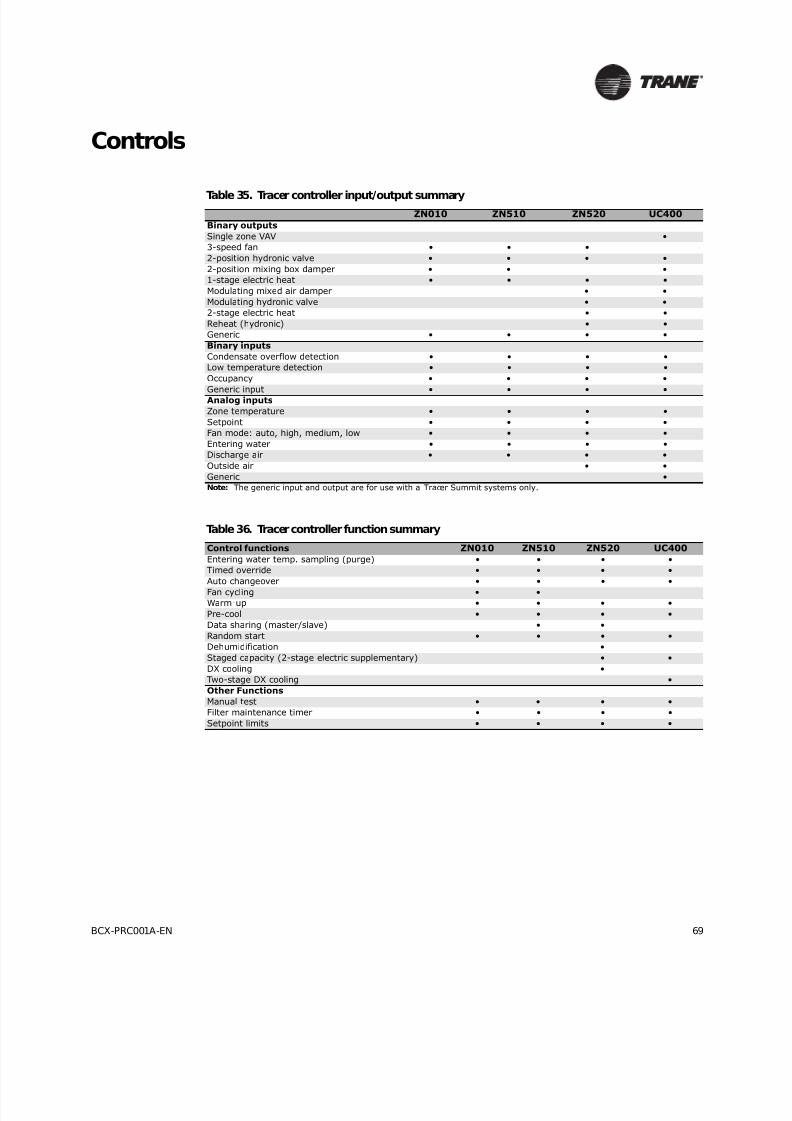
8/16/2019 Bcx-prc001-En 092013 Blower Coil Cat
http://slidepdf.com/reader/full/bcx-prc001-en-092013-blower-coil-cat 69/104
BCX-PRC001A-EN 69
Controls
Table 35. Tracer controller input/output summaryZN010 ZN510 ZN520 UC400
Binary outputs
Single zone VAV •
3-speed fan • • •
2-position hydronic valve • • • •
2-position mixing box damper • • •
1-stage electric heat • • • •
Modulating mixed air damper • •
Modulating hydronic valve • •
2-stage electric heat • •
Reheat (hydronic) • •
Generic • • • •
Binary inputs
Condensate overflow detection • • • •
Low temperature detection • • • •
Occupancy • • • •
Generic input • • • •Analog inputs
Zone temperature • • • •
Setpoint • • • •
Fan mode: auto, high, medium, low • • • •
Entering water • • • •
Discharge air • • • •
Outside air • •
Generic •Note: The generic input and output are for use with a Tracer Summit systems only.
Table 36. Tracer controller function summary
Control functions ZN010 ZN510 ZN520 UC400
Entering water temp. sampling (purge) • • • •
Timed override • • • •
Auto changeover • • • •
Fan cycling • •Warm-up • • • •
Pre-cool • • • •
Data sharing (master/slave) • •
Random start • • • •
Dehumidification •
Staged capacity (2-stage electric supplementary) • •
DX cooling •
Two-stage DX cooling •
Other Functions
Manual test • • • •
Filter maintenance timer • • • •
Setpoint limits • • • •

8/16/2019 Bcx-prc001-En 092013 Blower Coil Cat
http://slidepdf.com/reader/full/bcx-prc001-en-092013-blower-coil-cat 70/104
70 BCX-PRC001A-EN
Controls
VelociTach™ ECM Engine Controller
The Electronically Commutated Motor (ECM) engine controls and reports the performance of upto two Trane brushless DC (BLDC) motors.
• The engine also coordinates the operation of the fan in response to electric heat behavior andelectric behavior in response to hydronic heat behavior.
• The engine incorporates a user interface that allows adjustment of certain unit parameters andprovides constant feedback on motor operation.
• The engine integrates service and troubleshooting tools.
• The engine integrates a versatile configurable auxiliary temperature sensor.
• The engine incorporates various safety and lockout features, such as maintaining proper fan
speeds if electric heat is called for.
Status Display
Figure 38. VelociTach ECM engine controller board
Figure 39. Status display
The ECM engine board contains a four-digit, seven-segment displaythat is used to present information in a format close to real-world
language, while having a small-form factor. Most characters areimmediately recognizable; however, please consult Table 37 and
Table 38 for the graphical representation of each alphanumericcharacter.
Table 37. Screen representation of alphabetical characters
A B C D E F G H I J K L M N O P Q R S T U V W X Y Z
Table 38. Screen representation of numeric characters
1 2 3 4 5 6 7 8 9 0

8/16/2019 Bcx-prc001-En 092013 Blower Coil Cat
http://slidepdf.com/reader/full/bcx-prc001-en-092013-blower-coil-cat 71/104
BCX-PRC001A-EN 71
Controls
Control Options
Blower coil air handlers are available with one of six different control options:
• Manual fan speed switch (FSS)
• Customer supplied thermostat interface (CSTI)
• Tracer ZN010 controller
• Tracer ZN510 controller
• Tracer ZN520 controller
• Tracer UC400 controller
Control option descriptions follow below. A complete list of controller inputs and outputs are in
Table 35, page 69. See Table 39, page 81 for information on end device options.
Manual Fan Speed Switch (FSS)
The adapter allows direct customer interfacing through the use of terminal strips. Standard
interfacing includes:
• Fan speeds (H, M, L)
• Variable speed (2–10V) inputs
The standard adapter board eliminates many separate wiring harnesses in the panel and allows
simple, mistake-proofed single-plug interfacing of:
• ECM engine controller
• Transformers
• Motors
• Valves
• Dampers
• Electric heat control
• Fan speed switches
Figure 40. Adapter board
Customer low-voltageinterface for fan speeds,variable fan speed, and24 Vac supply

8/16/2019 Bcx-prc001-En 092013 Blower Coil Cat
http://slidepdf.com/reader/full/bcx-prc001-en-092013-blower-coil-cat 72/104
72 BCX-PRC001A-EN
Controls
The manual fan mode switch is available for fan-coil units that do not have Trane factory-mounted
control packages. This four-position switch (off, high, medium, low) allows manual fan mode
selection and is available wall mounted. The wall-mounted option is low-voltage using a factory-wired transformer.
Customer Supplied Thermostat Interface (CSTI)
The control interface is intended to be used with a field-supplied, low-voltage thermostat orcontroller. The control box contains a relay board which includes a line voltage to 24-volt
transformer and disconnect switch (for non-electric heat units). All end devices are wired to a low-
voltage terminal block and are run-tested, so the only a power connection and thermostatconnection is needed to commission the unit. Changeover sensors and controls are provided
whenever a change-over coil is selected. When N.O. valves are selected, inverting relays areprovided for use with standard thermostats.
The CSTI adapter board provides all the hookups of the standard adapter board, but in addition,
provides hookups for valve control (main and auxiliary coils), electric heat control, and damper
control. Screw terminal blocks provide convenient access to fan controls and to end device control.In addition, a courtesy 10-Vdc supply is provided for use with an external potentiometer or rheostat.
The 10-Vdc supply supports up to 10 mA draw.
Tracer Controls and Controllers
The Tracer family of controllers, ZN010, ZN510, ZN520, and UC400 offer the combined advantagesof simple and dependable operation with the latest Trane-designed controller. Standard control
features include options normally available on more elaborate control systems. All control optionsare available factory-configured or can be field-configured using Rover service software, the UC400
is services via Tracer TU. For more detailed information, refer to CNT-IOP-1 (for Tracer ZN010 or
ZN510) or CNT-SVX04A-EN (for Tracer ZN520), or the most recent version of the publication.
Figure 41. CSTI adapter board and field connections
1. VSP 10V
2. VSP 0–10V
3. VSP DC COM
1. 24 Vac Y (hot)
2. 24 Vac Y (gnd)
3. High
4. Medium
5. Low
6. V1Op/Cooling
7. V1Cl (not std)
8. Not used
9. Not used
10. V2Op/EH1St/Heating
11. V2Cl/EH2St (not std)
12. Damper Open
13. Dmp Cl (not std)
1 2 3 45678910111213 123
Customer low-voltageinterface for fan speeds,variable fan speed, and24 Vac supply, valve control,EH control, damper control,condensate overflow status
Valve(s), electric heat, andchangeover configurationswitches (factory-set)
,

8/16/2019 Bcx-prc001-En 092013 Blower Coil Cat
http://slidepdf.com/reader/full/bcx-prc001-en-092013-blower-coil-cat 73/104
BCX-PRC001A-EN 73
Controls
Tracer ZN010 Controller
Tracer ZN510 Controller
Tracer ZN520 Controller
Figure 42. Tracer ZN010 control board
Model Number Digit 26 =2
The Tracer ZN010 is a stand-alone microprocessorcontroller.
Figure 43. Tracer ZN510 control board
Model Number Digit 26 =3
The Tracer ZN510 can be used as either a stand-alone orcommunicating microprocessor controller.
Figure 44. Tracer ZN520 control board
Model Number Digit 26 =4
The Tracer ZN520 is a factory-installed, -tested and -commissioned
LonTalk® control designed to provide control of the classroom unitventilator and the blower coil products (see Figure 44).Features include:
• Automatic fan-speed reset
• Automatic ventilation reset
• Active dehumidification
• Manual output test• Filter maintenance
• Master slave
• Water valve override
• Freeze avoidance
• Interoperability
• Three generic I/O ports
Zone sensorconnections
Communicationsconnection
Servicebutton
and LED
Communication
LED
Auto test
Status LED
Power Generic

8/16/2019 Bcx-prc001-En 092013 Blower Coil Cat
http://slidepdf.com/reader/full/bcx-prc001-en-092013-blower-coil-cat 74/104
74 BCX-PRC001A-EN
Controls
The Tracer ZN520 controller is designed to be used in the following applications:
• As part of the Trane Tracer Summit™ building automation system, the Tracer ZN520 becomes
an important part of the Trane Integrated Comfort™ system (ICS).
• The Tracer ZN520 can function as a completely standalone controller in situations where abuilding automation system (BAS) is not present.
• For situations when a non-Trane BAS is present, the Tracer ZN520 can be used as an
interoperable unit controller.
Through building management of the HVAC system, optimizing energy consumption becomespossible at a classroom level. Each unit is capable of functioning independently of one anotherduring occupied and unoccupied hours of the day. This allows the temperature setpoint and
ventilation setting to be changed automatically based on classroom usage (seeFigure 45, page74).
Two Systems in One
In an ICS environment, the Tracer ZN520 is pre-designed to install quickly and easily into the
system. Since the controller and the unit are factory tested and commissioned, the start-up time
for the entire system is minimized. Trane becomes the single source of responsibility for theequipment, unit controls, and building automation system.
As a standalone controller, the Tracer ZN520 is ideally suited for fix-on-fail replacement of units
with old pneumatic controllers, or in situations where a BAS will be added at a later date. Oncepower is applied to the controller, it will automatically start up and run based upon the setpoint onthe local zone sensor. An individual time clock can be added to the unit for local scheduling.
The Tracer ZN520 is certified to the interoperable LONMARK ® Space Comfort Controller profile. Thisallows the controller to be used with another vendor’s BAS and thereby still provide the high quality
of factory installation and testing. In addition, the Tracer ZN520 provides one of the most extensiveinteroperable data lists of any controller of its type in the industry.
Figure 45. Tracer ZN520 system
Blower coil
Blower coil
Blower coil
Blower coil
To other buildingproducts
To other buildingproducts
Fire SafetySystem
LightingSystem
SecuritySystem
Rover™(optional)
TracerSummit®System
8/16/2019 Bcx-prc001-En 092013 Blower Coil Cat
http://slidepdf.com/reader/full/bcx-prc001-en-092013-blower-coil-cat 75/104
BCX-PRC001A-EN 75
Controls
Tracer ZN520 Features
Automatic Fan and Ventilation Reset. With the Tracer ZN520 controller, a two speed fancontrol for the unit ventilator delivers the airflow output customized to support the cfm spaceneeds. When less cfm is necessary to meet the load of the classroom (typically 75 to 80 percent of
the time), the equipment operates on low speed. However, if the room temperature rises, thecontroller will switch to high speed, and the outside air damper will adjust to satisfy the space
needs. This helps maintain the proper amount of ventilation air to the occupants independent ofthe fan speed. As part of the ventilation strategy, the controller will reposition the outside air
damper to confirm the minimum outside air cfm is met at both operating conditions.
Manual Output Test . The Tracer ZN520 controller includes a manual output test function. Thisfunction may be initiated from the blue test push button on the controller or through the Rover
service tool. This feature is used to manually exercise the outputs in a defined sequence.
The purpose of this test sequence is to verify output and end device operation. The manual outputtest function may also be used in the following situations:
• Reset latching diagnostics
• Verify output wiring and operation• Force the water valve(s) open to balance the hydronic system during installation set-up or
service.
Filter Maintenance. Filter status for the controller is based on the cumulative run hours of the
unit fan. The controller compares the amount of fan run time against an adjustable fan run hour(stored in the controller) to determine when maintenance is recommended for the unit. The run-
hours value may be user edited as required (through Rover). The valid range for the fan run hourslimit is 0 to 5000 hours with a default of 600 hours. Once the run hours limit has been exceeded,
the controller generates amaintenance required diagnostic (unit will not shut-down). The user willbe notified of this diagnostic through the building automation system or when a Trane Service Tool
is communicating with the controller.
Active Dehumidification. On unit ventilators with reheat coils, the Tracer ZN520 can provideactive dehumidification to the classroom. This means that the classroom relative humidity can be
kept below an adjustable setpoint independent outdoor weather conditions. Indoor humidity levelsare recommended by ASHRAE to be kept below 60% in order to minimize microbial growth andthe life span of airborne illness causing germs.
Master Slave (Data Sharing). Because the Tracer ZN520 controller utilizes LONWORKS®
technology, the controller can send or receive data (setpoint, heat/cool mode, fan request, spacetemperature, etc.) to and from other controllers on the communication link with or without the
existence of a building automation system. This applies to applications where multiple units mightshare one zone sensor for both stand-alone (with communication wiring between units) and a
building automation system (see Figure 46).

8/16/2019 Bcx-prc001-En 092013 Blower Coil Cat
http://slidepdf.com/reader/full/bcx-prc001-en-092013-blower-coil-cat 76/104
76 BCX-PRC001A-EN
Controls
Water Valve Override. The Tracer ZN520 can be commanded via the Rover service tool to open
all hydronic valves 100%. This allows for the faster water balancing of each unit and the entire
system when the command is sent globally to all controllers. A properly balanced system isessential for proper and efficient operation.
Hydronic Coil Freeze Protection (Freeze Avoidance). Blower coil systems in cold climates
need to take precautions to avoid hydronic coil freeze-up. The Tracer ZN520 does this from threedifferent aspects. Any of these methods of protections will result in the unit fan being disabled, the
outside air damper being shut, and the hydronic valves being opened 100 percent.
The three methods of freeze avoidance include:
1. A binary freeze protection thermostat is mounted on the coil and will cause a latching diagnosticif the coil temperature falls below 35°F.
2. An analog discharge air sensor monitors the temperature of the air coming off of the coil and
if the temperature falls below 40°F the outside air damper is closed, the fan is turned off and
the valves are fully opened.
3. When in the unoccupied mode the Tracer ZN520 has an adjustable freeze avoidance setpoint.
If the outside air temperature is below the setpoint the unit will open the valves to allow waterto flow through the coils.
Interoperability. Interoperability allows the owner freedom to select multiple vendors, and
multiple products. With this advantage, the owner can choose the best products, the bestapplication, and the best service from a variety of suppliers to meet their evolving building control
needs in a cost effective manner.
Generic Binary Input/Output. The three generic binary inputs/outputs are not part of thenormal control, but are actually controlled through the Tracer Summit system (when present) to
issue commands to the Tracer ZN520 control to turn the generic inputs/outputs of add-onequipment (such as baseboard heating, exhaust fans, occupancy sensor, lighting, etc.) on and off.
This binary port is not affected when other binary diagnostics interrupt unit operation.
Figure 46. Master slave system layout

8/16/2019 Bcx-prc001-En 092013 Blower Coil Cat
http://slidepdf.com/reader/full/bcx-prc001-en-092013-blower-coil-cat 77/104
BCX-PRC001A-EN 77
Controls
Tracer UC400 Controller
• Timed override on/cancel request
• Zone setpoint
• Current zone temperature
• Fan mode selection (off-auto-high-med-low)
For optimal system performance, blower coil units can operate as part of an Integrated Comfort
System (ICS) building automation system controlled by Tracer Summit. The controller is linkeddirectly to the Summit control panel via a twisted pair communication wire, requiring no additional
interface device (i.e., a command unit). The Trane ICS system can monitor or override UC400control points. This includes such points as temperature and output positions.
Tracer UC400 Zone Controller Features
• Single Zone VAV
• Automatic ventilation reset
• Active dehumidification
• Filter maintenance
• Water valve override
• Freeze avoidance
• Interoperability
• Unused I/O can be as generic I/O
Figure 47. Tracer UC400 controller
Model Number Digit 26 =5
The UC400 single zone VAV controller can beused in a stand-alone application or as part of a
Trane Integrated Comfort™ System (ICS).
In the stand-alone configuration, UC400
receives operation commands from the zonesensor and/or the auto changeover sensor (on
auto changeover units). The entering watertemperature is read from the auto changeover
sensor and determines if the unit is capable of
cooling or heating. The zone sensor module iscapable of transmitting the following
information to the controller:

8/16/2019 Bcx-prc001-En 092013 Blower Coil Cat
http://slidepdf.com/reader/full/bcx-prc001-en-092013-blower-coil-cat 78/104
78 BCX-PRC001A-EN
Controls
The Tracer UC400 is a factory-installed, -tested, and -commissioned BACnet® MS/TP control
designed to provide control of the blower coil. The Tracer UC400 controller is designed to be used
in the following applications: as stand-alone operation, part of the Trane Tracer SC buildingautomation system, or part of another BACnet MS/TP Building Automation System. The TracerUC400 can function as a completely standalone controller in situations where a building
automation system (BAS) is not present.
The Tracer UC400 is designed to install quickly and easily into the system. Since the controller and
the unit are factory-tested and -commissioned, the start-up time for the entire system is minimized.
Trane becomes the single source of responsibility for the equipment, unit controls, and buildingautomation system. As a standalone controller, the Tracer UC400 is ideally suited for fix-on-fail
replacement of units with old pneumatic controllers, or in situations where a BAS will be added ata later date. Once power is applied to the controller, it will automatically start up and run based
upon the setpoint on the local zone sensor. The Tracer UC400 is BTL listed as B-ASC profile. Thisensures the controller to be used with other BACnet® building automation systems.
Single Zone VAV with Fully Modulating Fan Speed. The Tracer UC400 will minimize fan
speed, and in turn energy usage, by only delivering the air flow needed.
Ventilation Reset. With the Tracer UC400 the blower coil delivers the airflow the space needs.When the air flow adjusts the outside air damper will also adjust to satisfy the space needs. Thishelps maintain the proper amount of ventilation air to the occupants independent of the fan speed.
As part of the ventilation strategy, the controller will reposition the outside air damper to confirm
the minimum outside airflow is met at both operating conditions.
Filter Maintenance. Filter status for the controller is based on the cumulative run hours of theunit fan. The controller compares the amount of fan run time against an adjustable fan run hour
(stored in the controller) to determine when maintenance is recommended for the unit. The run-hours value may be user edited as required. The valid range for the fan run hours limit is 0 to
5000hours with a default of 600 hours. Once the run hours limit has been exceeded, the controllergenerates a maintenance required diagnostic (unit will not shut-down). The user will be notified
of this diagnostic through the building automation system or when a Trane® service tool is
communicating with the controller.
Figure 48. Cool mode nominal hydronic cooling control
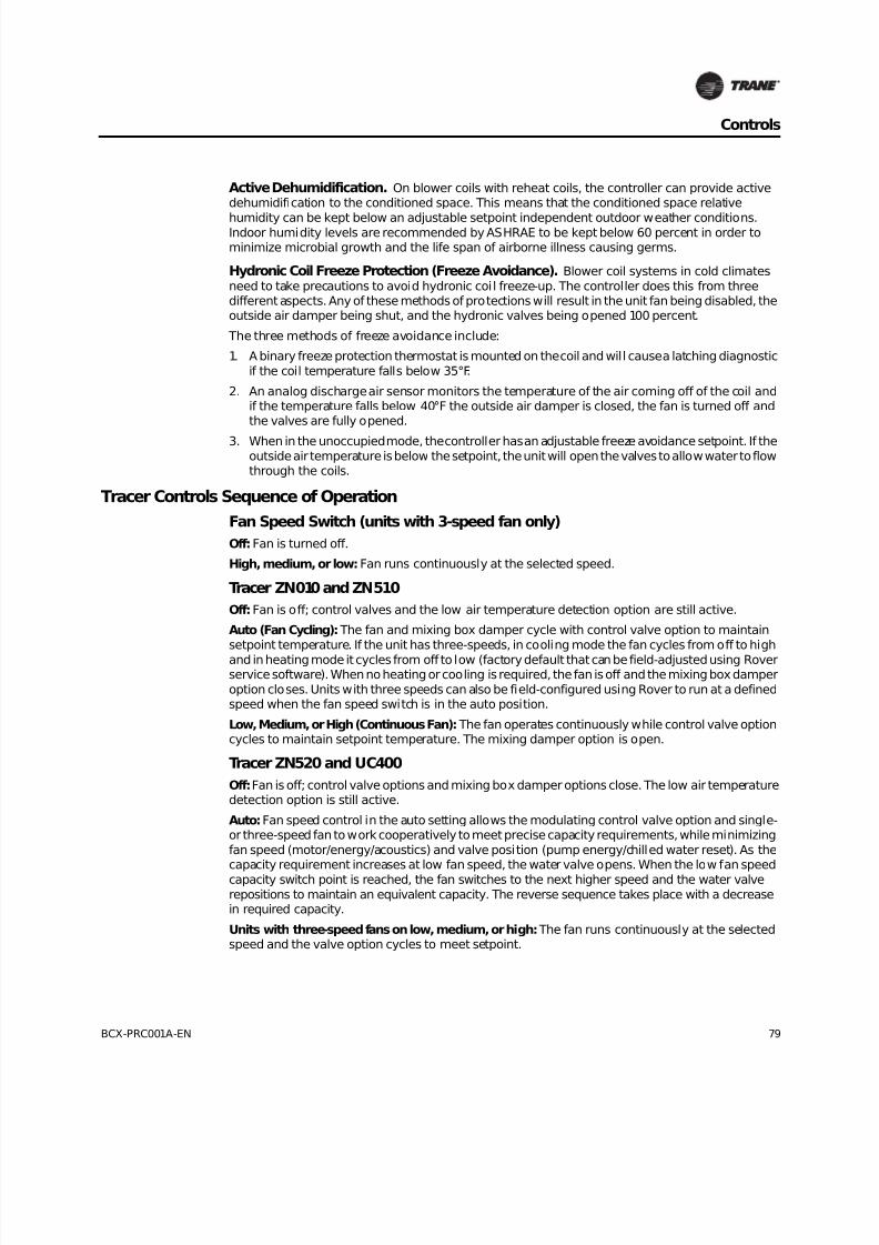
8/16/2019 Bcx-prc001-En 092013 Blower Coil Cat
http://slidepdf.com/reader/full/bcx-prc001-en-092013-blower-coil-cat 79/104
BCX-PRC001A-EN 79
Controls
Active Dehumidification. On blower coils with reheat coils, the controller can provide activedehumidification to the conditioned space. This means that the conditioned space relative
humidity can be kept below an adjustable setpoint independent outdoor weather conditions.Indoor humidity levels are recommended by ASHRAE to be kept below 60 percent in order tominimize microbial growth and the life span of airborne illness causing germs.
Hydronic Coil Freeze Protection (Freeze Avoidance). Blower coil systems in cold climates
need to take precautions to avoid hydronic coil freeze-up. The controller does this from threedifferent aspects. Any of these methods of protections will result in the unit fan being disabled, theoutside air damper being shut, and the hydronic valves being opened 100 percent.
The three methods of freeze avoidance include:
1. A binary freeze protection thermostat is mounted on the coil and will cause a latching diagnostic
if the coil temperature falls below 35°F.
2. An analog discharge air sensor monitors the temperature of the air coming off of the coil andif the temperature falls below 40°F the outside air damper is closed, the fan is turned off andthe valves are fully opened.
3. When in the unoccupied mode, the controller has an adjustable freeze avoidance setpoint. If theoutside air temperature is below the setpoint, the unit will open the valves to allow water to flowthrough the coils.
Tracer Controls Sequence of Operation
Fan Speed Switch (units with 3-speed fan only)
Off: Fan is turned off.
High, medium, or low: Fan runs continuously at the selected speed.
Tracer ZN010 and ZN510
Off: Fan is off; control valves and the low air temperature detection option are still active.
Auto (Fan Cycling): The fan and mixing box damper cycle with control valve option to maintain
setpoint temperature. If the unit has three-speeds, in cooling mode the fan cycles from off to high
and in heating mode it cycles from off to low (factory default that can be field-adjusted using Roverservice software). When no heating or cooling is required, the fan is off and the mixing box damper
option closes. Units with three speeds can also be field-configured using Rover to run at a definedspeed when the fan speed switch is in the auto position.
Low, Medium, or High (Continuous Fan): The fan operates continuously while control valve optioncycles to maintain setpoint temperature. The mixing damper option is open.
Tracer ZN520 and UC400
Off: Fan is off; control valve options and mixing box damper options close. The low air temperaturedetection option is still active.
Auto: Fan speed control in the auto setting allows the modulating control valve option and single-or three-speed fan to work cooperatively to meet precise capacity requirements, while minimizing
fan speed (motor/energy/acoustics) and valve position (pump energy/chilled water reset). As thecapacity requirement increases at low fan speed, the water valve opens. When the low fan speed
capacity switch point is reached, the fan switches to the next higher speed and the water valve
repositions to maintain an equivalent capacity. The reverse sequence takes place with a decreasein required capacity.
Units with three-speed fans on low, medium, or high: The fan runs continuously at the selectedspeed and the valve option cycles to meet setpoint.

8/16/2019 Bcx-prc001-En 092013 Blower Coil Cat
http://slidepdf.com/reader/full/bcx-prc001-en-092013-blower-coil-cat 80/104
80 BCX-PRC001A-EN
Controls
End Device Options
See Table 39, page 81 for a complete list of end device options.
Two-Position Mixing Box Damper Actuator (available with all control optionsexcept Tracer ZN520)
This damper actuator uses a 24V signal. It allows zero to 50percent fresh air. The damper will drive
open to an adjustable mechanical stop-position whenever the fan is running during occupied mode
and will spring-return closed when the fan turns off. The two-position damper ships separate forfield installation.
Note: Trane highly recommends using the low temperature detection option with mixing box
dampers to detect possible freeze conditions.
Low Temperature Detection
When the low temperature detection device senses an entering air temperature of 36°F to thehydronic coil, the normally-closed switch opens a corresponding set of binary input terminals. The
fan disables, control valves open, and the fresh air damper closes.
The low temperature detection device is an averaging type capillary tube and will reset when it
detects an entering air temperature of at least 44°F.
Condensate Overflow Detection
A float switch is factory-installed in the drain pan to detect a high condensate water level. When
the float switch rises, the normally-closed input opens a corresponding set of binary inputterminals. This also causes the fan to disable, and the control valve and fresh air damper options
to close. Although the float switch closes when the high condensate level recedes, you must
manually reset the controller before normal unit operation can occur. If you’re using a Tracer ZN510or ZN520 controller, you can reset using Tracer Summit. Use Rover service software to reset units
with Tracer ZN010, ZN510, ZN520, or Tracer TU to service units with the UC400.
Discharge Air Sensor
The discharge air sensor is factory-mounted on the fan housing downstream of the coils for useas a status point or with other control algorithms. On units with optional electric heat, the sensoris field-mounted in the ductwork, downstream of the unit discharge.
End Devices On Tracer ZN520 and UC400 Controllers
The following end device options are only available on blower coil air handlers with Tracer ZN520
or UC400:
• economizer damper actuator
• humidity
• outside air
Economizer Damper Actuator
This option is a modulating, spring-return damper actuator and is factory-wired and mounted tothe mixing box damper assembly. When the controller enables the economizer damper and theunit is in occupied mode, the damper modulates between its minimum position (configurable) and
the full open position to maintain setpoint temperature. If economizer operation stops or if the unit
is in the heating mode, the damper adjusts to its minimum position.
Note: Trane highly recommends using the low temperature detection option with a mixing box
damper to detect possible freeze conditions.
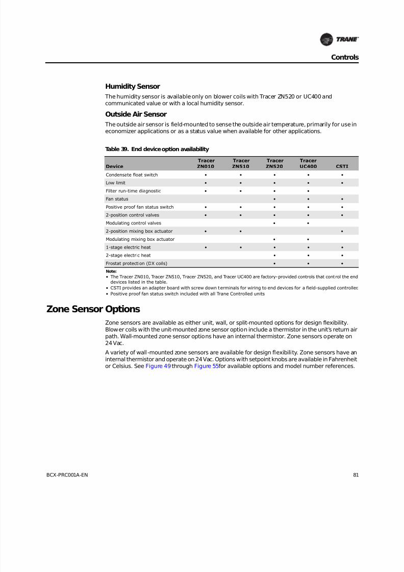
8/16/2019 Bcx-prc001-En 092013 Blower Coil Cat
http://slidepdf.com/reader/full/bcx-prc001-en-092013-blower-coil-cat 81/104
BCX-PRC001A-EN 81
Controls
Humidity Sensor
The humidity sensor is available only on blower coils with Tracer ZN520 or UC400 andcommunicated value or with a local humidity sensor.
Outside Air Sensor
The outside air sensor is field-mounted to sense the outside air temperature, primarily for use ineconomizer applications or as a status value when available for other applications.
Zone Sensor Options
Zone sensors are available as either unit, wall, or split-mounted options for design flexibility.
Blower coils with the unit-mounted zone sensor option include a thermistor in the unit’s return airpath. Wall-mounted zone sensor options have an internal thermistor. Zone sensors operate on24Vac.
A variety of wall-mounted zone sensors are available for design flexibility. Zone sensors have an
internal thermistor and operate on 24Vac. Options with setpoint knobs are available in Fahrenheitor Celsius. See Figure 49 through Figure 55for available options and model number references.
Table 39. End device option availability
Device
Tracer
ZN010
Tracer
ZN510
Tracer
ZN520
Tracer
UC400 CSTI
Condensate float switch • • • • •
Low limit • • • • •
Filter run-time diagnostic • • • •
Fan status • • •Positive proof fan status switch • • • • •
2-position control valves • • • • •
Modulating control valves • •
2-position mixing box actuator • • •
Modulating mixing box actuator • •
1-stage electric heat • • • • •
2-stage electric heat • • •
Frostat protection (DX coils) • • •
Note:
• The Tracer ZN010, Tracer ZN510, Tracer ZN520, and Tracer UC400 are factory-provided controls that control the enddevices listed in the table.
• CSTI provides an adapter board with screw down terminals for wiring to end devices for a field-supplied controller.
• Positive proof fan status switch included with all Trane Controlled units

8/16/2019 Bcx-prc001-En 092013 Blower Coil Cat
http://slidepdf.com/reader/full/bcx-prc001-en-092013-blower-coil-cat 82/104
82 BCX-PRC001A-EN
Controls
Figure 49. Digit 38 = 1Wall-mounted zone sensor with setpoint knob,off/auto fan speeds, occupied/unoccupied, andCOMM jack.
Figure 50. Digit 38 = 3Wall-mounted temp sensor with setpointknob, occupied/unoccupied, and COMM jack.
Figure 51. Digit 38 = 4
Wall-mounted temp sensor with occupied/unoccupied and COMM jack.
Figure 52. Digit 38 = C
Wireless temperature sensor and unit-mounted receiver.
Figure 53. Digit 38 = EWall-mounted temperature sensor with
setpoint knob, off/auto/low/medium/high fanspeeds
Figure 54. Digit 38 = FWall-mounted display temperature sensor
with setpoint knob, occupied/unoccupiedand COMM jack.
Figure 55. Digit 38 = GWireless display sensor, unit-mounted receiver.
X13511530-01 (wall)X13651467-02 (comm) X13511527-01 (wall)
X13651467-02 (comm)
X13511530-01 (wall)X13651467-02 (comm)
X13790821-01 (wall)X13790860-02 (unit)
X13511530-01
X13790886-01 (wall)X13651467-02 (comm)
X13790822-01 (wall)X13790855-01 (unit)

8/16/2019 Bcx-prc001-En 092013 Blower Coil Cat
http://slidepdf.com/reader/full/bcx-prc001-en-092013-blower-coil-cat 83/104
BCX-PRC001A-EN 83
Controls
Control Valves
Blower coil air handlers with either the control interface or any of the Tracer controllers (TracerZN010, ZN510, ZN520, or UC400) are available with chilled and/or hot water control valves for eachcoil configuration. Control valve options are available as:
• Modulating
• Two-position, normally-open or -closed (n.o. or n.c.)
• Two- or three-way configurations
• With sweat connections
• Sizes 1/2-inch, 1-inch, and 1-1/4-inches
See Table 41– Table 45, page 86 for a complete list of available valve options by size.
Three-way valve options allow either full waterflow through the coil or diverted waterflow through
the bypass.
See the section titled“How to Choose the Correct Control Valve,” p. 84 to help you select the proper
valve.
Two-Position Control Valves
Two-position valve options are available on blower coils with either Tracer ZN010, ZN510, ZN520,
UC400, or the control interface. See Table 42, page 85 for complete list of valve types, options, andsizes.
Two-position valve options are spring-return and non-spring-return types. See Table 42, page 85 for a complete list of valve types by size. Spring-return valves respond to a 24 V signal and will
either fully open or close. Also, these valves cannot be driven or actuated to a partially open orclosed position. If the spring-return type control valve loses power, the valve returns to its de-
energized position. Valves that are not spring-return will stop in their last position when they losepower.
Refer to Figure 13, page 25–Figure 16, page 26 for the pressure drop across the respective piping
packages associated with these valve Cv values. For a complete list of two-position valve optionsand sizes, see Table 42, page 85. See the section titled “How to Choose the Correct Control Valve,”
p. 84 to help you select the proper valve.
Modulating Control Valves (Tracer ZN520 or UC400 only)
Modulating control valves offer an alternative for more precise capacity control by modulating or
varying the water flow through the coil. The valve responds to a 24V triac signal from the controller,which determines the valve position by a control algorithm. If the valve loses power, it remains in
the position it was in when the power loss occurred.
The pressure drop across the modulating valve should fall within 25–70 percent of the pressure
drop across the branch circuit. Table43, page 85 shows the unit size, coil figuration, valve type, andthe recommended valve Cv. If a different size and/or Cv is preferred, Table 44 on page 86 shows the
valve size, valve type, and available Cv values. Refer to Figure 13, page 25–Figure 16, page 26 forthe pressure drop across the respective piping packages associated with these valve Cv values.
For a complete list of modulating valve options and sizes, see Table 44 on page 86. See the sectiontitled “How to Choose the Correct Control Valve,” p. 84 to help you select the proper valve.
Field-Supplied Valves
When using field-supplied valves, choose this option so the unit controller is factory-configured for
the valve’s normal position. For more descriptive information on this option, see“Model NumberDescriptions,” p. 17.
Note: Trane does not recommend wild coil applications.

8/16/2019 Bcx-prc001-En 092013 Blower Coil Cat
http://slidepdf.com/reader/full/bcx-prc001-en-092013-blower-coil-cat 84/104
84 BCX-PRC001A-EN
Controls
How to Choose the Correct Control Valve
Valve options are available in a variety of sizes and Cv values as discussed in the previousparagraphs. See Table 41– Table 45, page 86 for a complete list of valve recommendations and
sizes.
Select the proper control valve using these parameters:
1. Valve flow coefficient or Cv, which is represented by the following formula:
Cv =Q/square root of ∆P = Q/ P
2. Branch authority orβ (modulating valves only), which is represented by the following formula:
β =pressure drop across the valve divided by the pressure drop across the branch circuit * x100% =∆P valve/∆P branch circuit .
a. * Branch circuit includes the coil and piping package (control valve, circuit setter, ball valves,fittings, and piping) between the supply and return riser.
Note: For good control, β should be between 25 and 70percent.
3. Consider the valve close-off pressure (two-way valves only) to ensure close-off pressures are
not exceeded by pump discharge pressure necessary to overcome system pipe resistance. Seethe recommendations in Table 41 and Table 42, page 85, which are based on 100 ft of 1-1/4”
system piping plus branch circuit piping.
Two-Position Valve Cv Selection
The Cv value of the two-position control valve is less critical than for the modulating valve andshould be as high as available to minimize branch circuit pressure drop. Table 41, page 85 shows
the recommended valve size for each unit size and coil configuration. However, if a different Cv ispreferred, see Table 42, page 85 for the options listed by size, type, and associated Cv values. Note
that the 1-1/4”, two-way, n.o. valves are not available. Refer to Figure 13, page 25–Figure 16, page 26 for the pressure drop across the respective piping packages associated with the valve Cv values.
Modulating Valve Cv Selection
For good capacity control, the pressure drop across the valve should fall within 25 and 70 percent
of the pressure drop across the branch circuit. Table 43, page 85 shows the unit size, coilconfiguration, valve type and recommended valve Cv value. If a different size and/or Cv value ispreferred, see Table 44, page 86 for valve size, type, and available Cv values. Refer to Figure 13,
page 25–Figure 16, page 26 for the pressure drop across the respective piping packages associated
with these valve Cv values.
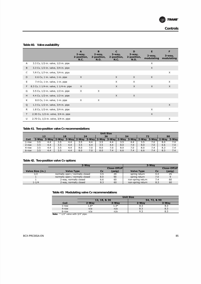
8/16/2019 Bcx-prc001-En 092013 Blower Coil Cat
http://slidepdf.com/reader/full/bcx-prc001-en-092013-blower-coil-cat 85/104
BCX-PRC001A-EN 85
Controls
Table 40. Valve availability
A B C D E F
2-way,2-position,
N.C.
2-way,2-position,
N.O.
3-way,2-position,
N.C.
3-way,2-position,
N.O.
2-way,modulating
3-way,modulating
A 3.3 Cv, 1/2-in. valve, 1/2-in. pipe X
B 3.3 Cv, 1/2-in. valve, 3/4-in. pipe X
C 3.8 Cv, 1/2-in. valve, 3/4-in. pipe X
D 6.6 Cv, 1-in. valve, 1-in. pipe X X X X
E 7.4 Cv, 1-in. valve, 1-in. pipe X X X
F 8.3 Cv, 1 1/4-in. valve, 1 1/4-in. pipe X X X X X
G 3.5 Cv, 1/2-in. valve, 1/2-in. pipe X X
H 4.4 Cv, 1/2-in. valve, 1/2-in. pipe X X
K 8.0 Cv, 1-in. valve, 1-in. pipe X X
Q 1.3 Cv, 1/2-in. valve, 3/4-in. pipe X
R 1.8 Cv, 1/2-in. valve, 3/4-in. pipe X
T 2.30 Cv, 1/2-in. valve, 3/4-in. pipe X
U 2.70 Cv, 1/2-in. valve, 3/4-in. pipe X
Table 41. Two-position valve Cv recommendations
Coil
Unit Size
12 18 24 36 54 72 90
2-Way 3-Way 2-Way 3-Way 2-Way 3-Way 2-Way 3-Way 2-Way 3-Way 2-Way 3-Way 2-Way 3-Way
1-row 3.5 4.4 3.5 4.4 3.5 4.4 3.5 4.4 3.5 4.4 3.5 7.0 8.0 7.0
2-row 3.5 4.4 3.5 4.4 3.5 4.4 3.5 4.4 8.0 7.0 8.0 7.0 6.6 7.4
4-row 3.5 4.4 3.5 4.4 8.0 7.0 8.0 7.0 8.0 7.0 8.0 7.4 8.3 7.4
6-row 3.5 4.4 3.5 4.4 8.0 7.0 8.0 7.4 6.6 7.4 6.6 7.4 8.3 7.4
Table 42. Two-position valve Cv options
Valve Size (in.)
2-Way 3-Way
Valve Type Cv
Close-Off P
(psig) Valve Type Cv
Close-Off P
(psig)
1/2 normally open / normally closed 3.5 20 spring return 4.4 25
1 normally open / normally closed 8.0 90 spring return 7.0 9
1 2-way, normally closed 6.6 60 non-spring return 7.4 60
1-1/4 2-way, normally closed 8.3 60 non-spring return 8.3 60
Table 43. Modulating valve Cv recommendations
Coil
Unit Size
12, 18, & 36 54, 72, & 90
2-Way 3-Way 2-Way 3-Way
1-row 1.8* 1.3* 8.3 8.3
4-row n/a n/a 8.3 8.3
6-row n/a n/a 8.3 8.3Note: * 1/2” valve with 3/4” pipe.

8/16/2019 Bcx-prc001-En 092013 Blower Coil Cat
http://slidepdf.com/reader/full/bcx-prc001-en-092013-blower-coil-cat 86/104
86 BCX-PRC001A-EN
Controls
Table 44. Modulating valve Cv recommendations (high-capacity coil)
Coil
Unit Size
12 & 18 24 & 36 54, 72, & 90
2-Way 3-Way 2-Way 3-Way 2-Way 3-Way
2-row 1.8* 1.3* 2.3* 2.7* 6.6 8.3
4-row 1.8* 2.7* 2.3* 2.7* 6.6 8.3
6-row 1.8* 2.7* 2.3* 2.7* 6.6 8.3Note: * 1/2-inch valve with 3/4-inch pipe
Table 45. Modulating valve Cv options
Valve size (in.) 2-Way 3-Way
1/2
1.8 2.7
2.3 3.8
3.3 N/A
1 6.6 7.4
1-1/4 8.3 8.3

8/16/2019 Bcx-prc001-En 092013 Blower Coil Cat
http://slidepdf.com/reader/full/bcx-prc001-en-092013-blower-coil-cat 87/104

8/16/2019 Bcx-prc001-En 092013 Blower Coil Cat
http://slidepdf.com/reader/full/bcx-prc001-en-092013-blower-coil-cat 88/104
88 BCX-PRC001A-EN
Electrical Data
Table 47. Available motor horsepower
Motor Unit Voltage
Motor Horsepower
0.50 1.00
60 Hz
115/1 • •
208/1 • •
230/1 • •
277/1 • •
50 Hz 220/1 • •
240/1 • •
Table 48. Motor electrical data
Voltage Voltage range RPM Rated HP LB FLA
115/60/1 104–126 1725 1/2 14 7.5
1.0 19 13.3
208–230/60/1 187–253 1725 1/2 14 4.3
1.0 19 7.7
277/60/1 249–305 1725 1/2 14 3.8
1.0 19 6.7
220/50/1 198–242 1725 1/2 14 4.3
1.0 19 7.7
240/50/1 216–264 1725 1/2 14 4.3
1.0 19 7.7

8/16/2019 Bcx-prc001-En 092013 Blower Coil Cat
http://slidepdf.com/reader/full/bcx-prc001-en-092013-blower-coil-cat 89/104
BCX-PRC001A-EN 89
Electrical Data
Table 49. Nominal RPM at 1-inch and 2-inch static pressure
Size Configuration CFM
Static
Pressure RPM
115/208-230V 277V 115/208-230V
Motor Motor BHP
12 and 18 Horizontal 400 1 1230 0.5 0.5 0.13
12 and 18 Horizontal 400 2 1688 0.5 0.5 0.27
12 and 18 Horizontal 600 1 1502 0.5 0.5 0.29
12 and 18 Horizontal 600 2 1786 0.5 0.5 0.42
24 and 36 Horizontal 800 1 1099 0.5 0.5 0.23
24 and 36 Horizontal 800 2 1582 0.5 0.5 0.46
24 and 36 Horizontal 1200 1 1187 0.5 0.5 0.44
24 and 36 Horizontal 1200 2 1562 1.0 0.5 0.7
24 and 36 Vertical - Preswirl 800 1 1096 0.5 0.5 0.23
24 and 36 Vertical - Preswirl 800 2 1581 0.5 0.5 0.47
24 and 36 Vertical - Preswirl 1200 1 1194 0.5 0.5 0.45
24 and 36 Vertical - Preswirl 1200 2 1555 1.0 0.5 0.72
24 and 36 Vertical - Counterswirl 800 1 1123 0.5 0.5 0.23
24 and 36 Vertical - Counterswirl 800 2 1601 0.5 0.5 0.46
24 and 36 Vertical - Counterswirl 1200 1 1238 0.5 0.5 0.45
24 and 36 Vertical - Counterswirl 1200 2 1603 1.0 0.5 0.71
54 and 72 Horizontal 1800 1 815 1.0 1.0 0.54
54 and 72 Horizontal 1800 2 1141 1.0 1.0 0.97
54 and 72 Horizontal 2400 1 879 -- 1.0 0.91
54 and 72 Horizontal 2400 2 1148 -- -- 1.4
54 and 72 Vertical - Preswirl 1800 1 871 1.0 1.0 0.58
54 and 72 Vertical - Preswirl 1800 2 1185 -- 1.0 1
54 and 72 Vertical - Preswirl 2400 1 956 -- -- 1.02
54 and 72 Vertical - Preswirl 2400 2 1218 -- -- 1.49
54 and 72 Vertical - Counterswirl 1800 1 888 1.0 1.0 0.61
54 and 72 Vertical - Counterswirl 1800 2 1196 -- 1.0 1.04
54 and 72 Vertical - Counterswirl 2400 1 1001 -- -- 1.11
54 and 72 Vertical - Counterswirl 2400 2 1241 -- -- 1.56
90 Horizontal 3000 1 918 -- -- 1.2
90 Horizontal 3000 2 1220 -- -- 1.95
90 Vertical - Preswirl 3000 1 1005 -- -- 1.24
90 Vertical - Preswirl 3000 2 1299 -- -- 2.08
90 Vertical - Counterswirl 3000 1 939 -- -- 1.32
90 Vertical - Counterswirl 3000 2 1235 -- -- 2.08

8/16/2019 Bcx-prc001-En 092013 Blower Coil Cat
http://slidepdf.com/reader/full/bcx-prc001-en-092013-blower-coil-cat 90/104
90 BCX-PRC001A-EN
Dimensions and Weights
Horizontal Blower Coil
Figure 56. Horizontal blower coil
1.00J
G
L
.95
A
1.502.15
H
W
F B F
C
DE
M M.95
R.H.L.H.
19 Nominal SCH 40 PVC mainand auxilliary drain connection
Heating and Cooling Coils
Filters
2.00
All coil connectionslocated in this area
Access panels
Unit control box
Q
K
5.50P
1.00
1.00
1.00
1.00 0.88 Knockout for hangerrods, top and bottom of unit
1.02R
1.33
2.00
3.32S
4.29
1.094Powerconnection
T
1.50
2.68
0.875 and 1.094 Power connections on opposite side
Filter accessOnly for wirelesszone sensor receiver
Table 50. Horizontal blower coil dimensions (in.) and weights (lb)
Unit
Size H W L A B C D E F
G
(RH)
G
(LH)
J
(RH)
J
(LH) K M P Q R S T
Basic
Unit
Weight
12 14.00 24.00 31.15 12.09 18.00 10.56 7.47 0.55 3.00 11.42 13.42 9.42 11.42 4.20 8.24 9.00 5.75 1.35 2.91 4.01 64.0
18 14.00 28.00 31.15 12.09 22.00 10.56 7.47 0.55 3.00 11.42 13.42 9.42 11.42 4.20 10.24 9.00 5.75 3.42 2.93 3.94 69.0
24 18.00 28.00 33.72 16.09 22.00 13.57 9.04 1.30 3.00 11.42 13.42 9.42 11.42 6.20 9.68 9.00 5.75 2.73 3.09 3.84 89.6
36 18.00 40.00 33.72 16.09 34.00 13.57 9.04 1.30 3.00 11.42 13.42 9.42 11.42 6.20 15.68 9.00 5.75 8.64 2.93 3.94 104.5
54 22.00 40.00 41.57 20.09 34.00 13.58 12.57 0.72 3.00 11.42 13.42 9.42 11.42 7.43 13.72 11.00 7.27 6.87 6.93 3.94 129.072 22.00 48.00 41.57 20.09 40.00 13.58 12.57 0.72 4.00 11.42 13.42 9.42 11.42 7.43 17.72 11.00 7.27 10.87 6.93 3.94 142.0
90 28.00 48.00 43.94 26.09 40.00 13.58 12.57 1.66 4.00 12.79 14.79 10.79 12.79 8.24 17.72 11.25 11.64 10.92 13.06 3.89 162.8
Note:
• All coil connections are sweat style.
• Weight of basic unit includes cabinet, fan, wiring and average filter. It does not include coil, motor or shipping package. Please refer to Table 48 for motor weights. Add to basic unit weight seven pounds for weight of control box.
• Control box factory-mounted on drive side.
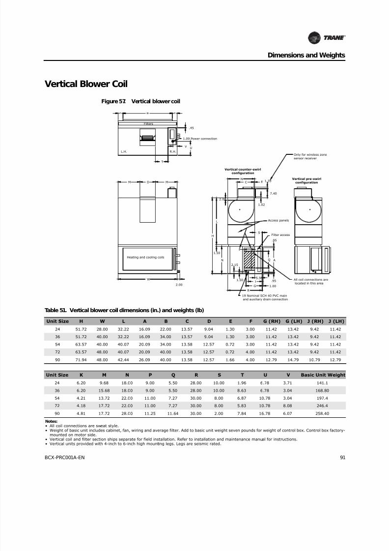
8/16/2019 Bcx-prc001-En 092013 Blower Coil Cat
http://slidepdf.com/reader/full/bcx-prc001-en-092013-blower-coil-cat 91/104
BCX-PRC001A-EN 91
Dimensions and Weights
Vertical Blower Coil
Figure 57. Vertical blower coil
1.00
J
G
.95
A
1.50
2.15
.95
R.H.L.H.
19 Nominal SCH 40 PVC main and auxiliary drain connection
Filters
Q
K
Heating and cooling coils
R
1.02
ECM D M
W
2.00
L
N
1.50
H
P
S
All coil connections are located in this area
Filter access
Access panels
N
Vertical counter-swirlconfiguration
T
2.00
7.40
1.33
Only for wireless zonesensor receiver
V U
Vertical pre-swirlconfiguration
.45
1.09 Power connection
5.50
Table 51. Vertical blower coil dimensions (in.) and weights (lb)
Unit Size H W L A B C D E F G (RH) G (LH) J (RH) J (LH)
24 51.72 28.00 32.22 16.09 22.00 13.57 9.04 1.30 3.00 11.42 13.42 9.42 11.42
36 51.72 40.00 32.22 16.09 34.00 13.57 9.04 1.30 3.00 11.42 13.42 9.42 11.42
54 63.57 40.00 40.07 20.09 34.00 13.58 12.57 0.72 3.00 11.42 13.42 9.42 11.42
72 63.57 48.00 40.07 20.09 40.00 13.58 12.57 0.72 4.00 11.42 13.42 9.42 11.42
90 71.94 48.00 42.44 26.09 40.00 13.58 12.57 1.66 4.00 12.79 14.79 10.79 12.79
Unit Size K M N P Q R S T U V Basic Unit Weight
24 6.20 9.68 18.00 9.00 5.50 28.00 10.00 1.96 6.78 3.71 141.1
36 6.20 15.68 18.00 9.00 5.50 28.00 10.00 8.63 6.78 3.04 168.80
54 4.21 13.72 22.00 11.00 7.27 30.00 8.00 6.87 10.78 3.04 197.4
72 4.18 17.72 22.00 11.00 7.27 30.00 8.00 5.83 10.78 8.08 246.4
90 4.81 17.72 28.00 11.25 11.64 30.00 2.00 7.84 16.78 6.07 258.40
Notes:• All coil connections are sweat style.• Weight of basic unit includes cabinet, fan, wiring and average filter. Add to basic unit weight seven pounds for weight of control box. Control box factory-
mounted on motor side.• Vertical coil and filter section ships separate for field installation. Refer to installation and maintenance manual for instructions.• Vertical units provided with 4-inch to 6-inch high mounting legs. Legs are seismic rated.
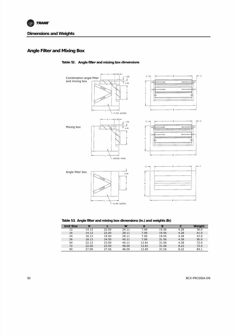
8/16/2019 Bcx-prc001-En 092013 Blower Coil Cat
http://slidepdf.com/reader/full/bcx-prc001-en-092013-blower-coil-cat 92/104
92 BCX-PRC001A-EN
Dimensions and Weights
Angle Filter and Mixing Box
Table 52. Angle filter and mixing box dimensions
Table 53. Angle filter and mixing box dimensions (in.) and weights (lb)
Unit Size H L W A B C Weight
12 14.12 22.00 24.11 7.06 15.56 4.28 36.0
16 14.12 22.00 28.11 7.06 19.56 4.28 41.0
24 18.12 19.50 28.11 7.06 19.56 4.28 43.0
36 18.12 24.50 40.11 7.06 31.56 4.28 56.0
54 22.12 23.50 40.11 12.81 31.56 4.28 72.0
72 22.00 23.50 48.00 12.81 31.56 8.22 72.5
90 27.90 27.56 48.00 12.85 31.56 8.22 84.1
combinationangle f ilter
& mixing box
mixing box
angle f ilterbox
Combination angle filterand mixing box
Mixing box
Angle filter box
C
C C
C
C C
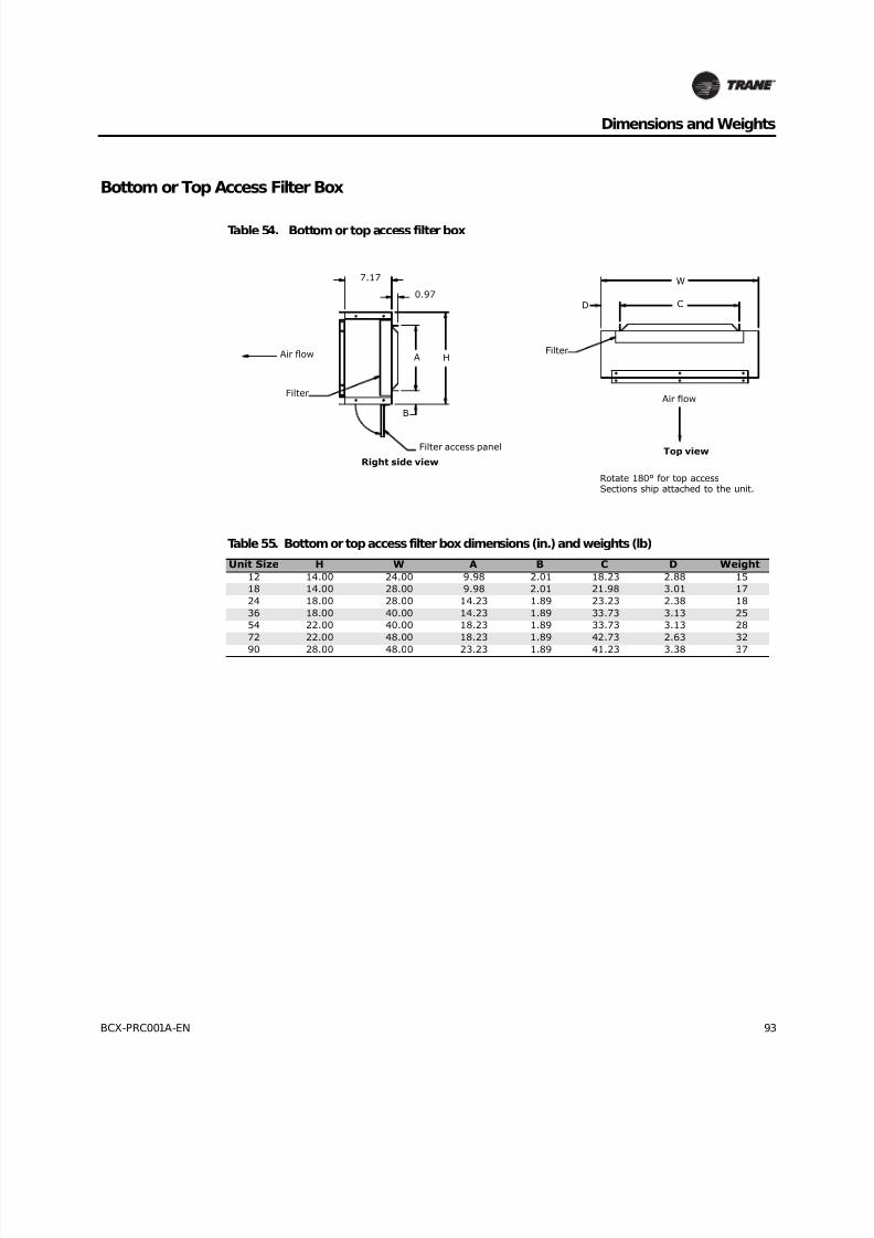
8/16/2019 Bcx-prc001-En 092013 Blower Coil Cat
http://slidepdf.com/reader/full/bcx-prc001-en-092013-blower-coil-cat 93/104
BCX-PRC001A-EN 93
Dimensions and Weights
Bottom or Top Access Filter Box
Table 54. Bottom or top access filter box
Table 55. Bottom or top access filter box dimensions (in.) and weights (lb)
Unit Size H W A B C D Weight
12 14.00 24.00 9.98 2.01 18.23 2.88 15
18 14.00 28.00 9.98 2.01 21.98 3.01 17
24 18.00 28.00 14.23 1.89 23.23 2.38 18
36 18.00 40.00 14.23 1.89 33.73 3.13 25
54 22.00 40.00 18.23 1.89 33.73 3.13 28
72 22.00 48.00 18.23 1.89 42.73 2.63 32
90 28.00 48.00 23.23 1.89 41.23 3.38 37
7.17
0.97
Air flow
Filter
Right side view
Filter access panel
A H
B
Filter
D C
W
Air flow
Top view
Rotate 180° for top accessSections ship attached to the unit.

8/16/2019 Bcx-prc001-En 092013 Blower Coil Cat
http://slidepdf.com/reader/full/bcx-prc001-en-092013-blower-coil-cat 94/104
94 BCX-PRC001A-EN
Dimensions and Weights
Electric Heat
Table 56. Blower coils with electric heat
Table 57. Blower coils with electric heat dimensions (in.) and weights (lb)
Unit Size W X Y12 28.28 37.97 n/a
18 32.29 37.97 n/a
24 30.54 40.75 48.54
36 42.57 40.75 60.57
54 44.32 48.39 66.32
72 48.29 48.60 70.29
90 48.29 50.96 76.29
Electric heat controls
Electric heat elements
Unitcontrol box
W
X
Y
Unitcontrol box
3.46W
Electric heat controls
Electric heat elements
Horizontal blower coil
Vertical blower coil
Only for units withCSTI, DX, and 2-stage EH.
1.33 only for wireless zonesensor receiver.
3.46
Only for units withCSTI, DX, and 2-stage EH.
1.33 only for wireless zonesensor receiver.

8/16/2019 Bcx-prc001-En 092013 Blower Coil Cat
http://slidepdf.com/reader/full/bcx-prc001-en-092013-blower-coil-cat 95/104
BCX-PRC001A-EN 95
Dimensions and Weights
• Electric heater is factory mounted on unit discharge face and wired to unit control box.
• Heater may be mounted with horizontal or vertical up airflow.
• Optional mercury contactors cannot be used with vertical up airflow.
• Electric heat may need field-supplied externally-wrapped insulation if the unit is installed in anunconditioned space or if sweating is an issue.
Table 58. Electric heat dimensions
Table 59. Electric heat dimensions (in.) and weights (lb)
Unit Size H W A B C D E Weight
12 14.06 17.88 8.13 6.79 10.50 8.75 0.03 10.0
18 14.06 19.88 10.13 8.79 10.50 8.75 0.03 10.8
24 18.06 17.75 7.63 6.29 13.50 9.13 0.80 11.3
36 18.06 23.75 13.63 12.29 13.50 9.13 0.80 12.8
54 18.06 27.25 13.63 11.67 13.50 12.63 0.22 16.0
72 18.06 27.25 13.63 11.67 13.50 12.63 0.22 17.4
90 18.06 27.25 13.63 11.67 13.50 12.63 1.16 19.2
1.501.50
A I R
F L O W
A
W
1.00
E
1.00
0.56
H
1.00
6.631.00
BD1.00
Duct opening
Ductopening
C
3.00
1.25
2.00
1.25
1.25
0.875 Power connectionon opposite side
0.875 Powerconnection
0.875 Powerconnectionon opposite side
Right hand heater shown.Left hand heater is mirrorimage of right hand.
Mounting flange top and bottomunit sizes 12, 18, 24, 36Top only unit sizes 54, 72, 90, 120
Control panel door
Mounting flange bottomunit sizes 54, 72, 90, 120

8/16/2019 Bcx-prc001-En 092013 Blower Coil Cat
http://slidepdf.com/reader/full/bcx-prc001-en-092013-blower-coil-cat 96/104
96 BCX-PRC001A-EN
Dimensions and Weights
Steam Coil
Table 60. Steam coil dimensions
Access panel
H e a t i n g c o i l
Filter access
Airflow
21.00
0.97
0.97
H A
W
B CC
Table 61. Steam coil box dimensions (in.) and weights (lb)
Unit Size H W A B C Weight
Coil Connections, NPT
Supply Return
12 14.00 24.00 12.06 18.04 2.98 34 1 3/4
18 14.00 28.00 12.06 22.04 2.98 37 1 3/4
24 18.00 28.00 16.06 22.04 2.98 40 1-1/2 1
36 18.00 40.00 16.06 34.04 2.98 48 1-1/2 1
54 22.00 40.00 20.06 34.04 2.98 50 2 1
72 22.00 48.00 20.06 42.04 2.98 56 2 1
90 28.00 48.00 26.06 40.04 3.98 63 2-1/2 1-1/4
Note:• Filter access and access panel located on both sides.
• Weight includes cabinet with average filter, but does not include coil weight. See general data section for coil weights.

8/16/2019 Bcx-prc001-En 092013 Blower Coil Cat
http://slidepdf.com/reader/full/bcx-prc001-en-092013-blower-coil-cat 97/104
BCX-PRC001A-EN 97
Dimensions and Weights
Coil Connections
Piping Packages
Table 62. Hydronic coil connection sizes, OD (in.)
Unit Size
Standard Capacity High Capacity
1-Row 4-Row 6-Row 2-Row 4-Row 6-Row
12 5/8 — — 5/8 7/8 7/8
18 5/8 — — 5/8 7/8 7/8
24 5/8 — — 7/8 1-1/8 1-1/8
36 5/8 — — 7/8 1-1/8 1-1/8
54 1-1/8 1-3/8 1-3/8 1-1/8 1-1/8 1-1/8
72 1-1/8 1-3/8 1-3/8 1-1/8 1-1/8 1-1/8
90 1-1/8 1-5/8 1-5/8 1-1/8 1-1/8 1-1/8
Table 63. DX coil connection sizes, OD (in.)
Unit Size
3-Row and 4-Row 6-Row
Suction Liquid Suction Liquid12 5/8 5/8 5/8 5/8
18 5/8 5/8 5/8 5/8
24 5/8 5/8 7/8 5/8
36 7/8 5/8 7/8 5/8
54 1-1/8 7/8 1-1/8 7/8
72 1-1/8 7/8 1-1/8 7/8
90 1-3/8 7/8 1-1/8 7/8
Table 64. Steam coil connection sizes, female connection, NPT (in.)
Unit Size Supply Return
12 1 3/4
18 1 3/4
24 1-1/2 1
36 1-1/2 1
54 2 172 2 1
90 2-1/2 1-1/4
Table 65. Piping package dimensions (in.)
Piping
Package
Nominal Tube
Size
Actual
Size A B C D E F
2-way 1/2 5/8 12.025 2.650 12.625 5.650 n/a n/a
1 1-1/8 13.295 4.260 13.220 9.288 3.020 N/A
3-way
1/2 5/8 12.088 2.097 12.688 4.497 6.351 6.351
3/4 7/8 15.623 1.750 15.313 6.290 6.701 6.701
1 1-1/8 13.370 3.690 13.210 9.060 9.813 9.813
1-1/4 1-3/8 16.885 3.738 16.410 10.023 3.052 10.520
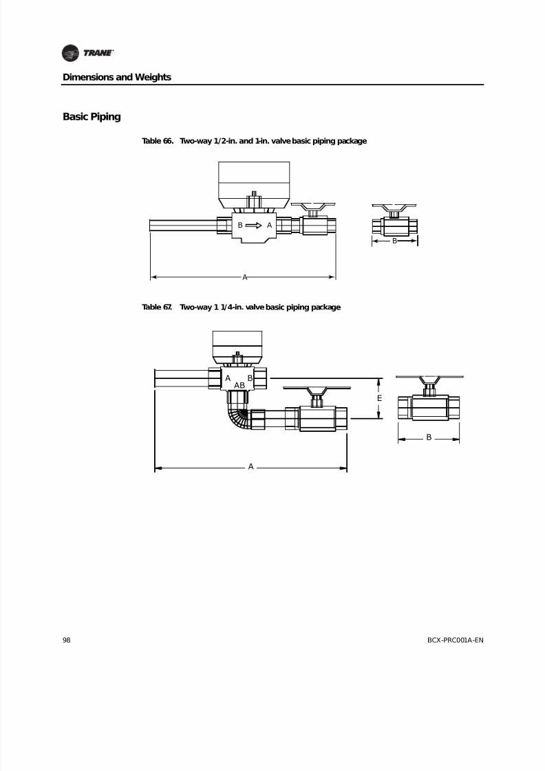
8/16/2019 Bcx-prc001-En 092013 Blower Coil Cat
http://slidepdf.com/reader/full/bcx-prc001-en-092013-blower-coil-cat 98/104
98 BCX-PRC001A-EN
Dimensions and Weights
Basic Piping
Table 66. Two-way 1/2-in. and 1-in. valve basic piping package
Table 67. Two-way 1 1/4-in. valve basic piping package
A
B
B A
A BAB
E
B
A

8/16/2019 Bcx-prc001-En 092013 Blower Coil Cat
http://slidepdf.com/reader/full/bcx-prc001-en-092013-blower-coil-cat 99/104
BCX-PRC001A-EN 99
Dimensions and Weights
Deluxe Piping
Table 68. Three-way, 1/2 in. and 1-in. valve basic piping package
A B
E
F
A BAB
Table 69. Two-way 1/2-in. and 1-in. valve deluxe piping package
D
B A
C

8/16/2019 Bcx-prc001-En 092013 Blower Coil Cat
http://slidepdf.com/reader/full/bcx-prc001-en-092013-blower-coil-cat 100/104
100 BCX-PRC001A-EN
Dimensions and Weights
Table 70. Two-way 1 1/4-in. valve deluxe piping package
Table 71. Three-way 1/2-in. and 1-in. valve deluxe piping package
D
A BAB
C
E
C D
E
F
A B
AB
8/16/2019 Bcx-prc001-En 092013 Blower Coil Cat
http://slidepdf.com/reader/full/bcx-prc001-en-092013-blower-coil-cat 101/104
BCX-PRC001A-EN 101
Mechanical Specifications
General
The product line consists of horizontal and vertical air handling units and mixing boxes. Units are
tested and certified with ARI 430 and ARI 260. The unit complies with NFPA 90A and is UL listedto U.S. and Canadian safety standards.
Air handlers consist of a hydronic and/or DX coil, drain pan, and centrifugal fan with motormounted in a common cabinet. Coil connections are independent for the same or opposite side
location.
Air handlers are provided with knockouts in all four corners for installing the unit suspended from
the ceiling with threaded rods.
Unit and accessories are insulated with 1-inch, 1-1/2 lb/ft3 density fiberglass insulation. One-inch
foil-faced insulation is also available.
Large motor access panels are provided on both sides of the unit and accessories. Vertical units
ship in two pieces.
CasingsCasings (structural components) are constructed of heavy-gauge galvanized steel, insulated with
one-inch, 1-1/2 lb density fiberglass fire resistant and odorless glass fiber material to providethermal and acoustical insulation. Fan housing sides are directly attached to the air handler top and
bottom panels strengthening the entire unit assembly. Coil access panels are located on both sidesof the air handler and allow easy removal of the internal coils and drain pan. Main access panels
provide generous access to the fan and motor from both sides of the air handler.
Coils
Hydronic Coils
Cooling coils are four- or six-row, chilled water. Heating coils are one- or two-row hot water. Heatingcoils are available factory-installed in the preheat or reheat position. All hydronic coils are 12 fins
per inch. All hydronic coils use highly efficient aluminum fins, mechanically bonded to seamless
copper tubes. All coils are specifically designed and circuited for water use. All coils are factorytested with 450 psi air under water. Maximum standard operating conditions are: 300 psig, 200°F.
Sweat type connections are standard. Coils are rated and certified in accordance with ARI Standard410.
Direct Expansion (DX) Coils
DX coils use refrigerant 410A, have 3/8” OD x 0.014” W round seamless copper tubes expanded intofull fin collars for permanent fin-tube bond. Three-, four-, and six-row DX coils use highly efficient
aluminum fins mechanically bonded to stainless copper tubes with 12 fins per inch fin spacing.
The coil casing is 16-gauge galvanized steel. A foam sealing strip between the casing (top and
bottom) channels and fins helps eliminate air bypass and reduce potential water carryover. Coilshave round, seamless, copper pipe liquid lines and suction headers with male sweat connections.
Suction headers have bottom connections to aid drainage of any oil that may collect in the coil.
Liquid line and suction connections are outside the unit casing (on the same side of the unit) tofacilitate field piping. Connections are clearly labeled to ensure coils are piped correctly. Coils have
a venturi-type distributor assembly designed with a vertical downflow feed for low pressure drops.
Coils are proof tested at 715 psig and leak tested at 650psig air-under-water. Coils are dehydrated
and sealed with a dry air charge. Maximum standard operating conditions are 650 psig at 127°Fwith R-410A. Coils are rated and tested in accordance with ARI Standard 410.

8/16/2019 Bcx-prc001-En 092013 Blower Coil Cat
http://slidepdf.com/reader/full/bcx-prc001-en-092013-blower-coil-cat 102/104
102 BCX-PRC001A-EN
Mechanical Specifications
Steam Coils (Type NS)
A one-row steam distributing coil section is available in the pre-heat position. Steam coils are non-freezing and are pitched to ensure adequate condensate drainage. Coils have 1” OD x 0.031” W
round seamless copper condensing tubes expanded into full fin collars for permanent fin-tubebond. Coil headers are cast iron for permanent leak-tight joints. Coils have continuous Sigma-Flo™
aluminum fins with full fin collars for maximum fin-tube contact and accurate spacing at 6 fpi. Thecoil casing is 16-gauge galvanized steel. Coil headers are gray cast iron with NPT internal thread
connections.
Supply, return, and vacuum breaker connections are located at the same end of the unit and clearly
labeled to ensure coils are piped correctly. Distributor tubes are 11/16” OD copper. Also, they have
die-formed, accurately-spaced directional kinetic orifices that discharge steam in the direction ofcondensate flow (toward the return connection) to ensure even steam distribution across the coilface area and push out condensate. Distributor tubes are located concentrically within condensing
tubes using corrosion resistant support clips. Supply header steam deflectors prevent
impingement of steam into tubes in supply connection area.
Coils are proof tested at 300psig and leak tested at 200 psig air-under-water. Maximum standardoperating conditions are 15 psig at 400°F. Coils are rated and tested in accordance with ARI
Standard 410.
Fan
The fans are DWDI (double width double inlet) forward curved centrifugal blower type. The fansare direct drive mounted directly to the motor shaft. All fans are dynamically balanced. All air
handlers have a single fan.
EC Motors
A 50/60 Hertz, variable speed, multiple voltage EC motor has a plus or minus 10 percent voltage
utilization range. The motor is open type with permanently sealed ball bearings, internal overloadprotection, and size 48 frame belly band design. The motor is factory installed, programmed, and
wired to the air handler control panel.
Drain Pan The drain pan is noncorrosive and double-sloped to allow condensate drainage. The drainpan
construction is polymer or optional stainless steel. Coils mount above the drain pan—not in the
drain pan—thus allowing the drain pan to be fully inspected and cleaned. The drain pan can alsobe removed for cleaning. The polymer drain pan connections are unthreaded 3/4-inch schedule
40PVC for solvent bonding. The stainless steel drain pan connection is 3/4-inch NPT schedule 40stainless steel pipe. The main drain connection is at the lowest point of the drain pan. An auxiliary
drain connection is provided on the same side as the main connection.
Filters
One-inch standard efficiency throwaway, two-inch MERV 8, and two-inch MERV 13 are available on
all blower coil units. Units have a standard flat filter rack that is sized for less that 500 feet per
minute at nominal airflow. An optional angle filter rack is available; this is sized for less than300feet per minute at nominal airflow. All units and filter racks use standard filter sizes.
Units equipped with MERV 8 filters have a rating based on ASHRAE Standard 52.2. The average
dust spot efficiency is no less than 35 to 40 percent when tested in accordance with ASHRAE 52.1
atmospheric dust spot method.

8/16/2019 Bcx-prc001-En 092013 Blower Coil Cat
http://slidepdf.com/reader/full/bcx-prc001-en-092013-blower-coil-cat 103/104
BCX-PRC001A-EN 103
Mechanical Specifications
Mixing Box
Mixing boxes are constructed of heavy-gauge galvanized steel. They are complete with two low-leak parallel blade dampers that are factory-linked together. A 1/2-inch extendible drive rod is
provided that can be used for actuator connection, either internally or externally. Damper bladesare extruded aluminum having interlocked PVC extruded edge seals. Damper frame seals are PVC
extruded forms interlocked to the damper frame and provided with a continuous edge seal to theblades. Damper seals are stable in the temperature range of -50°F to 230°F.
Mixing boxes also include two side access panels as standard to provide access to the unit’sinternal components.
Piping Packages
The maximum entering fluid temperature to the water valves is 200°F. Insulation on the pipingpackage is by others. The stop valves are ball type.
Electric Heater
The heater is a UL recognized resistance open-wire heater with disc-type automatic and manualreset-type thermal safety devices. The electric heater is factory-mounted and an air handler with
this heater is a UL/CUL product. One or two stages of control are available. A single-point powerconnection to the unit is provided. Optional mercury contactors, heater fuses, and a heater door
interlocking disconnect switch are available.
Controls
Controls options are: control interface, Tracer ZN010, ZN510, ZN520, and UC400. A variety of inputsand outputs are available for the control interface and Tracer controller options. A disconnect
switch (for non-electric heat units), fused transformer, contactor(s), and terminal strip are providedwith the control interface and Tracer controller options.
Customer Supplied Thermostat Interface (CSTI)
The control interface is intended to be used with a field-supplied, low-voltage thermostat or
controller. The control box contains a line voltage to 24-volt transformer and a disconnect switchon non-electric heat units.
Tracer ZN520
The Tracer ZN520 discrete speed controller can be used as part of a building automation systemwith Lontalk communication. The Tracer ZN520 offers the combined advantages of simple and
dependable operation. Standard control features include options normally available on more
elaborate control systems. All control options are available factory mounted, wired and configuredand can also be field configured using a service tool.
Tracer UC400
The Tracer UC400 controller delivers single zone VAV control in a stand-alone application or as partof a building automation system with BACnet communication. The UC400 ships with unit of
measure over BACnet link in SI units. When a BAS system is unable to convert to other desired unitsa free software tool is available for changing to other unit of measure. The Tracer UC400 offers the
combined advantages of a factory mounted, wired and programmed controller for dependable out-of-the box operation. Standard control features include options normally available on more
elaborate control systems. All control options are available factory programmed with additionalconfiguration and programming in the field using a service tool.

8/16/2019 Bcx-prc001-En 092013 Blower Coil Cat
http://slidepdf.com/reader/full/bcx-prc001-en-092013-blower-coil-cat 104/104