Embed Size (px)
Citation preview
BCRT-1
UT1553B BCRT
FEATURESp Comprehensive MIL-STD-1553B dual-redundant
Bus Controller (BC) and Remote Terminal (RT) functions
p MIL-STD-1773 compatible
p Multiple message processing capability in BC and RT modes
p Time-tagging and message logging in RT mode
p Automatic polling and intermessage delay in BC mode
p Programmable interrupt scheme and internally generated interrupt history list
p Register-oriented architecture to enhanceprogrammability
p DMA memory interface with 64K addressability
p Internal self-test
p Remote terminal operations in ASD/ENASD-certified (SEAFAC)
p The UT1553B BCRT is not available radiation-harden ed
p Packaged in 84-pin pingrid array, 84- and 132-lead flatpack, 84-lead leadless chip carrier packages
p Standard Microcircuit Drawing 5962-88628 available - QML Q and V compliant
16
16
16
HANDLERINTERRUPT
BUSTRANSFER
LOGIC
ADDRESS
16TIMEOUT
CLOCK &RESET
12MHZMASTERRESET
GENERATORADDRESS
16
1553HIGH-PRIORITY
RT ADDRESS
STANDARD INTERRUPT
HIGH-PRIORITY
INTERRUPT LOG
CURRENT COMMAND
BUILT-IN-TEST WORD
POLLING COMPARE
CURRENT BC BLOCK/
STATUS
CONTROL
REGISTERS
LIST POINTER
DATA
16
BUILT-IN-
TEST
16
16
RT TIMER TAG
INTERRUPT STATUS/RESET
INTERRUPT ENABLEDATACHANNELB
1553DATACHANNELA
LOGIC
HIGH-PRIORITYSTD PRIORITY LEVEL
STD PRIORITY PULSE
DMA ARBITRATIONREGISTER CONTROL
DUAL-PORT MEMORY CONTROL
RT DESCRIPTOR SPACE
ENABLE
BUILT-IN-TESTSTART COMMAND
PROGRAMMED RESET
RESET COMMAND
TIMERON
SERIAL to PARALLEL- CONVER-
SION
PARALLEL-TO-SERIAL CONVER-
SION
DUALCHANNELENCODER/DECODERMODULE
RT PROTOCOL& MESSAGE
HANDLER
DMA/CPUCONTROL
BC PROTOCOL& MESSAGEHANDLER
Figure 1. BCRT Block Diagram
BCRT-2
Table of Contents
1.0 INTRODUCTION . . . . . . . . . . . . . . . . . . . . . . . . . . . . . . . . . . . . . . . . . . . . . . . . . . . . . . . . . . . . 31.1 Features - Remote Terminal (RT) Mode . . . . . . . . . . . . . . . . . . . . . . . . . . . . . . .31.2 Features - Bus Controller (BC) Mode. . . . . . . . . . . . . . . . . . . . . . . . . . . . . . . . .3
2.0 PIN IDENTIFICATION AND DESCRIPTION . . . . . . . . . . . . . . . . . . . . . . . . . . . . . . . . . . . . 4
3.0 INTERNAL REGISTERS . . . . . . . . . . . . . . . . . . . . . . . . . . . . . . . . . . . . . . . . . . . . . . . . . . . . 12
4.0 SYSTEM OVERVIEW . . . . . . . . . . . . . . . . . . . . . . . . . . . . . . . . . . . . . . . . . . . . . . . . . . . . . . . 18
5.0 SYSTEM INTERFACE. . . . . . . . . . . . . . . . . . . . . . . . . . . . . . . . . . . . . . . . . . . . . . . . . . . . . . . 195.1 DMA Transfers . . . . . . . . . . . . . . . . . . . . . . . . . . . . . . . . . . . . . . . . . . . . . . . . .195.2 Hardware Interface . . . . . . . . . . . . . . . . . . . . . . . . . . . . . . . . . . . . . . . . . . . . . .195.3 CPU Interconnection . . . . . . . . . . . . . . . . . . . . . . . . . . . . . . . . . . . . . . . . . . . . .195.4 RAM Interface . . . . . . . . . . . . . . . . . . . . . . . . . . . . . . . . . . . . . . . . . . . . . . . . .205.5 Transmitter/Receiver Interface . . . . . . . . . . . . . . . . . . . . . . . . . . . . . . . . . . . . .20
6.0 REMOTE TERMINAL ARCHITECTURE . . . . . . . . . . . . . . . . . . . . . . . . . . . . . . . . . . . . . . 216.1 RT Functional Operation . . . . . . . . . . . . . . . . . . . . . . . . . . . . . . . . . . . . . . . . . .22
6.1.1 RT Subaddress Descriptor Definitions . . . . . . . . . . . . . . . . . . . . . . . . . .226.1.2 Message Status Word. . . . . . . . . . . . . . . . . . . . . . . . . . . . . . . . . . . . . . .246.1.3 Mode Code Descriptor Definition . . . . . . . . . . . . . . . . . . . . . . . . . . . . .25
6.2 RT Error Detection . . . . . . . . . . . . . . . . . . . . . . . . . . . . . . . . . . . . . . . . . . . . . .276.3 RT Operational Sequence . . . . . . . . . . . . . . . . . . . . . . . . . . . . . . . . . . . . . . . . .27
7.0 BUS CONTROLLER ARCHITECTURE . . . . . . . . . . . . . . . . . . . . . . . . . . . . . . . . . . . . . . . 287.1 BC Functional Operation . . . . . . . . . . . . . . . . . . . . . . . . . . . . . . . . . . . . . . . . .297.2 Polling . . . . . . . . . . . . . . . . . . . . . . . . . . . . . . . . . . . . . . . . . . . . . . . . . . . . . . . .317.3 BC Error Detection . . . . . . . . . . . . . . . . . . . . . . . . . . . . . . . . . . . . . . . . . . . . . .317.4 BC Operational Sequence . . . . . . . . . . . . . . . . . . . . . . . . . . . . . . . . . . . . . . . . .317.5 BC Operational Example . . . . . . . . . . . . . . . . . . . . . . . . . . . . . . . . . . . . . . . . .33
8.0 EXCEPTION HANDLING AND INTERRUPT LOGGING . . . . . . . . . . . . . . . . . . . . . . . . 34
9.0 MAXIMUM AND RECOMMENDED OPERATING CONDITIONS . . . . . . . . . . . . . . . . 37
10.0 DC ELECTRICAL CHARACTERISTICS . . . . . . . . . . . . . . . . . . . . . . . . . . . . . . . . . . . . . . 38
11.0 AC ELECTRICAL CHARACTERISTICS . . . . . . . . . . . . . . . . . . . . . . . . . . . . . . . . . . . . . . 39
12.0 PACKAGE OUTLINE DRAWINGS . . . . . . . . . . . . . . . . . . . . . . . . . . . . . . . . . . . . . . . . . . . . 46

BCRT-3
1.0 INTRODUCTIONThe monolithic CMOS UT1553B BCRT provides the system designer with an intelligent solution to MIL-STD-1553B multiplexed serial data bus designproblems. The UT1553B BCRT is a single-chip device that implements two of the defined MIL-STD-1553B functions - Bus Controller and Remote Terminal. Designed to reduce host CPU overhead, the BCRT’s powerful state machines automatically execute message transfers, provide interrupts, and generate status information. Multiple registers offer many programmable functions as well as extensive information for host use. In the BC mode, the BCRT uses a linked-list message scheme to provide the host with message chaining capability. The BCRT enhances memory use by supporting variable-size, relocatable data blocks. In the RT mode, the BCRT implements time-tagging and message history functions. It also supports multiple (up to 128) message buffering and variable length messages to any subaddress.
The UT1553B BCRT is an intelligent, versatile, and easy to implement device -- a powerful asset to system designers.
1.1 Features - Remote Terminal (RT) Mode
IndexingThe BCRT is programmable to index or buffer messages on a subaddress-by-subaddress basis. The BCRT, which can index as many as 128 messages, can also assert an interrupt when either the selected number of messages is reached or every time a specified subaddress is accessed.
Variable Space AllocationThe BCRT can use as little or as much memory (up to 64K) as needed.
Selectable Data StorageAddress programmability within the BCRT provides flexible data placement and convenient access.
Sequential Data StorageThe BCRT stores/retrieves, by subaddress, all messages in the order in which they are transacted.
Sequential Message Status InformationThe BCRT provides message validity, time-tag, and word-count information, and stores it sequentially in a separate, cross-referenced list.
Illegalizing Mode Codes and SubaddressesThe host can declare mode codes and subaddresses illegal by setting the appropriate bit(s) in memory.
Programmable Interrupt SelectionThe host CPU can select various events to cause an interrupt with provision for high and standard priority interrupts.
Interrupt History ListThe BCRT provides an Interrupt History List that records, in the order of occurrence, the events that caused the interrupts. The list length is programmable.
1.2 Features - Bus Controller (BC) Mode
Multiple Message ProcessingThe BCRT autonomously processes any number of messages or lists of messages that may be stored in a 64K memory space.
Automatic Intermessage DelayWhen programmed by the host, the BCRT can delay a host-specified time before executing the next message in sequence.
Automatic PollingWhen polling, the BCRT interrogates the remote terminals and then compares their status word responses to the contents of the Polling CompareRegister. The BCRT can interrupt the host CPU if an erroneous remote terminal status word response occurs.
Automatic RetryThe BCRT can automatically retry a message on busy, message error, and/or response time-out conditions. The BCRT can retry up to four times on the same or on the alternate bus.
Programmable Interrupt SelectionThe host CPU can select various events to cause an interrupt with provision for high and standard priority interrupts.
Interrupt History ListThe BCRT provides an Interrupt History List that records, in the order of occurrence, the events that caused the interrupts. The list length is program- mable.
Variable Space AllocationThe BCRT uses as little or as much memory (up to 64K) as needed.
Selectable Data StorageAddress programmability within the BCRT provides flexible data placement and convenient access.

BCRT-4
++
++
+
+
+
**
****
LCC, flatpack pin number not in parentheses.( ) Pingrid arraylead identification in parentheses.
TAZTAO
RAZRAO
TBZTBO
RBZRBO
RTA0RTA1RTA2RTA3RTA4
RTPTY
CLKMCLKMCLKD2
A0A1A2A3A4A5A6A7A8A9A10A11A12A13A14A15
D0D1D2D3D4D5D6D7D8D9D10D11D12D13D14D15
13 (K3)14 (L2)1718
(L4)(K6)
15161920
(L3)
(K5)(L5)
(K4)
28 (K8)29 (L9)30 (L10)31 (K9)32 (L11)
68 (A6)69 (A4)70 (B4)25 (K7)
26 (J7)
27 (L8)72 (A2)75 (B2)
33 (K10)
73 (B3)*
56 (A10)57 (A9)67 (B5)58 (B8)
61 (B7)60 (C7)
53 (A11)52 (C10)59 (A8)54 (B10)
62 (A7)
55 (B9)
66 (A5)11
(A3)
74
(K2)12
(A1)
10 (J2)24 (L7)
34(J10)35(K11)3637383940414445464748495051
(J11)(H10)(H11)(G9)(G10)(G11)(E9)(E11)(E10)(F11)(D11)(D10)(C11)(B11)
987654328382818079787776
(K1)(J1)(H2)(H1)(G3)(G2)(G1)(F1)(E1)(E2)(F2)(D1)(D2)(C1)(B1)(C2)
23436484
1224263
(L6)(F9)(C6)(E3)
(F3)(J6)(F10)(B6)
2165
(J5)(C5)
71
(L1)
BIPHASE OUT
BIPHASE IN
TERMINALADDRESS
STATUSSIGNALS
DMASIGNALS
CONTROLSIGNALS
ADDRESSLINES
DATALINES
POWER
GROUND
CLOCKSIGNALS
+
++++++
2.0 PIN IDENTIFICATION AND DESCRIPTION
+
**
**
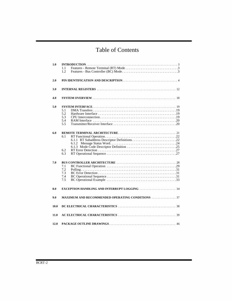
** Pin internally pulled up.+ Pin at high impedance when not asseted++ Bidirectional pin.* Formerly MEMWIN.
STDINTLSTDINTP
HPINTTIMERONCOMSTR
SSYSFBCRTFCHA/B
TEST
DMARDMAG
DMAGODMACKBURSTTSCTL
RDWRCS
AENBCRTSEL
LOCKMRST
EXTOVRRRDRWR
MEMCSIMEMCSO
VDDVDDVDDVDD
VSSVSSVSSVSS
Figure 2a. BCRT 84-lead Functional Pin Description
BCRT-5
++
++
LCC, flatpack pin number not in parentheses.( ) Pingrid arraylead identification in parentheses.
TAZTAO
RAZRAO
TBZTBO
RBZRBO
RTA0RTA1RTA2RTA3RTA4
RTPTY
CLKMCLKMCKD2
A0A1A2A3A4A5A6A7A8A9A10A11A12A13A14A15
D0D1D2D3D4D5D6D7D8D9D10D11D12D13D14D15
341011
791315
2729303132
89909222
24
2795101
35
97 *
70728874
7977
65647568
81
69
86131
98
213020
36374041424547515254565758606163
129127125124122120119118114112110108107105103102
34 50 66 83
496782
188594
BIPHASE OUT
BIPHASE IN
TERMINALADDRESS
STATUSSIGNALS
DMASIGNALS
CONTROLSIGNALS
ADDRESSLINES
DATALINES
POWER
GROUND
CLOCKSIGNALS
++++++
+
**
** Pin internally pulled up.+ Pin at high impedance when not asseted++ Bidirectional pin.* Formerly MEMWIN.
STDINTSTDPUL
HPINTTIMERONCOMSTR
SSYSFBCRTFCHA/B
TEST
DMARDMAG
DMAGODMACKBURSTTSCTL
RDWRCS
AENBCRTSEL
LOCKMRST
EXTOVRRRDRWR
MEMCSIMEMCSO
VDDVDDVDDVDD
VSSVSSVSS
Figure 2b. BCRT 132-lead Functional Pin Description
100115132
VDDVDDVDD
33
116
VSS
VSSVSS
99 VSS116 VSS
17 VDD
BCRT-6
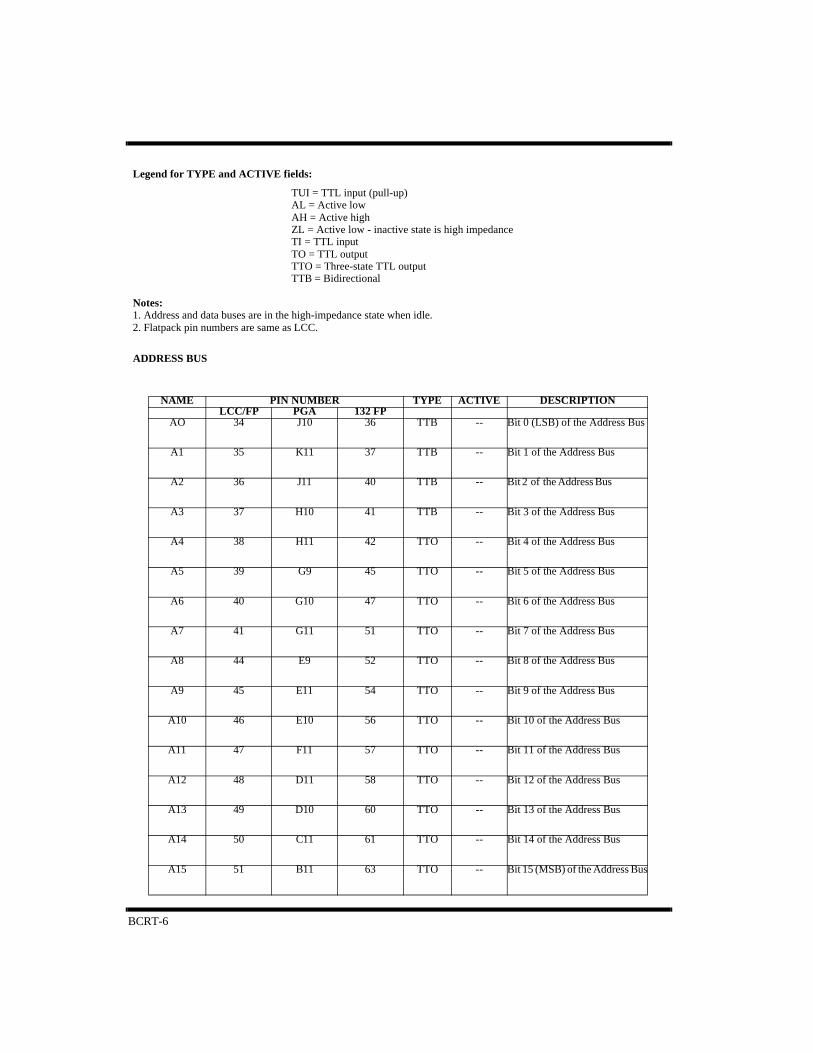
Legend for TYPE and ACTIVE fields:
TUI = TTL input (pull-up)AL = Active lowAH = Active highZL = Active low - inactive state is high impedanceTI = TTL inputTO = TTL outputTTO = Three-state TTL outputTTB = Bidirectional
Notes: 1. Address and data buses are in the high-impedance state when idle.2. Flatpack pin numbers are same as LCC.
ADDRESS BUS
NAME PIN NUMBER TYPE ACTIVE DESCRIPTIONLCC/FP PGA 132 FP
AO 34 J10 36 TTB -- Bit 0 (LSB) of the Address Bus
A1 35 K11 37 TTB -- Bit 1 of the Address Bus
A2 36 J11 40 TTB -- Bit 2 of the Address Bus
A3 37 H10 41 TTB -- Bit 3 of the Address Bus
A4 38 H11 42 TTO -- Bit 4 of the Address Bus
A5 39 G9 45 TTO -- Bit 5 of the Address Bus
A6 40 G10 47 TTO -- Bit 6 of the Address Bus
A7 41 G11 51 TTO -- Bit 7 of the Address Bus
A8 44 E9 52 TTO -- Bit 8 of the Address Bus
A9 45 E11 54 TTO -- Bit 9 of the Address Bus
A10 46 E10 56 TTO -- Bit 10 of the Address Bus
A11 47 F11 57 TTO -- Bit 11 of the Address Bus
A12 48 D11 58 TTO -- Bit 12 of the Address Bus
A13 49 D10 60 TTO -- Bit 13 of the Address Bus
A14 50 C11 61 TTO -- Bit 14 of the Address Bus
A15 51 B11 63 TTO -- Bit 15 (MSB) of the Address Bus
BCRT-7
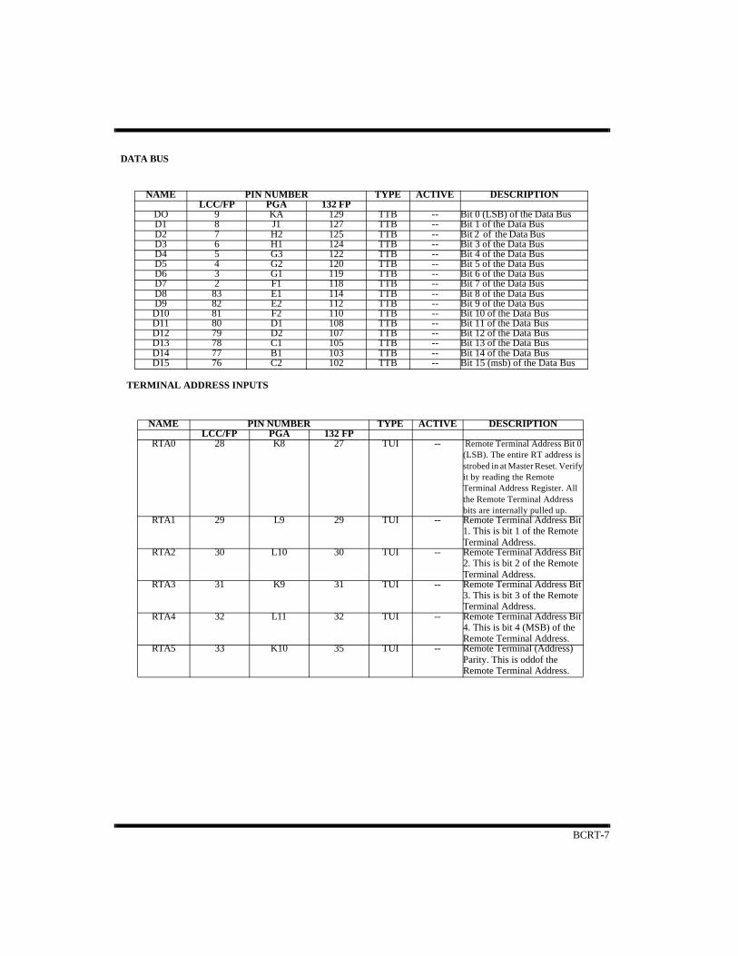
DATA BUS
TERMINAL ADDRESS INPUTS
NAME PIN NUMBER TYPE ACTIVE DESCRIPTIONLCC/FP PGA 132 FP
DO 9 KA 129 TTB -- Bit 0 (LSB) of the Data BusD1 8 J1 127 TTB -- Bit 1 of the Data BusD2 7 H2 125 TTB -- Bit 2 of the Data Bus D3 6 H1 124 TTB -- Bit 3 of the Data BusD4 5 G3 122 TTB -- Bit 4 of the Data BusD5 4 G2 120 TTB -- Bit 5 of the Data BusD6 3 G1 119 TTB -- Bit 6 of the Data BusD7 2 F1 118 TTB -- Bit 7 of the Data BusD8 83 E1 114 TTB -- Bit 8 of the Data BusD9 82 E2 112 TTB -- Bit 9 of the Data BusD10 81 F2 110 TTB -- Bit 10 of the Data BusD11 80 D1 108 TTB -- Bit 11 of the Data BusD12 79 D2 107 TTB -- Bit 12 of the Data BusD13 78 C1 105 TTB -- Bit 13 of the Data BusD14 77 B1 103 TTB -- Bit 14 of the Data BusD15 76 C2 102 TTB -- Bit 15 (msb) of the Data Bus
NAME PIN NUMBER TYPE ACTIVE DESCRIPTIONLCC/FP PGA 132 FP
RTA0 28 K8 27 TUI -- Remote Terminal Address Bit 0 (LSB). The entire RT address is strobed in at Master Reset. Verify it by reading the Remote Terminal Address Register. All the Remote Terminal Address bits are internally pulled up.
RTA1 29 L9 29 TUI -- Remote Terminal Address Bit 1. This is bit 1 of the Remote Terminal Address.
RTA2 30 L10 30 TUI -- Remote Terminal Address Bit 2. This is bit 2 of the Remote Terminal Address.
RTA3 31 K9 31 TUI -- Remote Terminal Address Bit 3. This is bit 3 of the Remote Terminal Address.
RTA4 32 L11 32 TUI -- Remote Terminal Address Bit 4. This is bit 4 (MSB) of the Remote Terminal Address.
RTA5 33 K10 35 TUI -- Remote Terminal (Address) Parity. This is oddof the Remote Terminal Address.

BCRT-8
CONTROL SIGNALS
NAME PIN NUMBER TYPE ACTIVE DESCRIPTIONLCC/FP PGA 132 FP
RD 61 B7 79 TI AL Read. The host uses this in conjunction with CS to read an internal BCRT register.
WR 60 C7 77 TI AL Write. The host uses this in conjunction with CS to write an internal BCRT register.
CS 62 A7 81 TI AL Chip Select. This selects theBCRT when accessing the BCRT’s internal register.
AEN 66 A5 86 TI AH Address Enable. The hostCPU uses AEN to indicate to the BCRT that the BCRT’s addresslines can be asserted; this is a precautionary signal provided to avoid address bus crash. If not used, it must be tied high.
BCRTSEL 11 L1 131 TUI -- BC/RT Select. This selects between either the Bus Controller or Remote Ter-minal mode. The BC/RT Mode Select bit in the Control Register overrides this input if the Lock pin is not high. This pin is internally pulled high.
LOCK 12 K2 2 TUI AH Lock. When set, this pin prevents inter-nal changes to both the RT address and BC/RT mode select functions. This pin is internally pulled high.
EXTOVR 24 L7 20 TUI AL External Override. Use this in multi-redundant applications. Upon receipt, the BCRT aborts all current activity. EXTOVR should be connected to COM-STR output of the adjacent BCRT when used. This pin is internally pulled high.
MRST 10 32 130 TI AL Master Reset. This resets all internal state machines, encoders, decoders, and registers. The minimum pulse width for a successful Master Reset is 500ns.
MEMCSO 54 B10 68 TO AL Memory Chip Select Out. This is the regenerated MEMCSI inout for external RAM during the pseudo-dual-port RAM mode. The BCRT also uses it to select external memory during memory accesses.
MEMCSI 59 A8 75 TUI AL Memory Chip Select In. Used in the pseudo-dual-port RAM mode only, MEMCSI is received from the host and is propagated through to MEMCSO.
RRD 53 A11 65 TO AL RAM Read. In the pseudo-dual-port RAM mode, the host uses this signal in conjunction with MEMCSO to read from external RAM through the BCRT. It is also the signal the BCRT uses to read from memory. It is asserted following receipt of DMAG. When the BCRT per-forms multiple reads, this signal is pulsed.
RWR 52 C10 64 TO AL RAM Write. In the pseudo-dual-port RAM mode, the CPU and BCRT use this to write to external RAM. This signal is asserted following receipt of DMAG. For multiple writes, this signal is pulsed.
BCRT-9
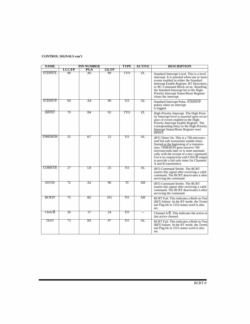
CONTROL SIGNALS con’t
NAME PIN NUMBER TYPE ACTIVE DESCRIPTIONLCC/FP PGA 132 FP
STDINTL 68 A6 89 TTO ZL Standard Interrupt Level. This is a level interrupt. It is asserted when one or more events enabled in either the Standard Interrupt Enable Register, RT Descriptor, or BC Command Block occur. Resetting the Standard Interrupt bit in the High-Priority Interrupt Status/Reset Register clears the interrupt.
STDINTP 69 A4 90 TO AL Standard Interrupt Pulse. STDINTP pulses when an interrupt is logged.
HPINT 70 B4 92 TTO ZL High-Priority Interrupt. The High Prior-ity Interrupt level is asserted upon occur-ance of events enabled in the High-Priority Interrupt Enable Register. The corresponding bit(s) in the High-Priority Interrupt Status/Reset Register reset HPINT.
TIMERON 25 K7 22 TO AL (RT) Timer On. This is a 760-microsec-ond fail-safe transmitter enable timer. Started at the beginning of a transmis-sion, TIMERON goes inactive 760 microseconds later or is reset automati-cally with the receipt of a new command. Use it in conjunction with CHA/B output to provide a fail-safe timer for Channels A and B transmitters.
COMSTR 27 L8 25 TO AL (RT) Command Strobe. The BCRT asserts this signal after receiving a valid command. The BCRT deactivates it after servicing the command.
SSYSF 72 A2 96 TI AH (RT) Command Strobe. The BCRT asserts this signal after receiving a valid command. The BCRT deactivates it after servicing the command.
BCRTF 75 B2 101 TO AH BCRT Fail. This indicates a Built-in-Test (BIT) failure. In the RT mode, the Termi-nal Flag bit in 1553 status word is also set.
CHA/B 26 37 24 TO -- Channel A/B. This indicates the active or last active channel.
TEST 73 B3 97 TO AL BCRT Fail. This indicates a Built-in-Test (BIT) failure. In the RT mode, the Termi-nal Flag bit in 1553 status word is also set.

BCRT-10
BIPHASE INPUTS
NAME PIN NUMBER TYPE ACTIVE DESCRIPTIONLCC/FP PGA 132 FP
RAO 16 K4 9 TI -- Receive Channel A One. This is the Manchester-encoded true signal input from Channel A of the bus receiver.
RAZ 15 L3 7 TI -- Receive Channel A Zero. This is the Manchester-encoded complementary sig-nal input from Channel A of the bus receiver.
RBO 20 L5 15 TI -- Receive Channel B One. This is the Manchester-encoded true signal input from Channel B of the bus receiver.
RBZ 19 K5 13 TI -- Receive Channel B Zero. This is the Manchester-encoded complementary sig-nal input from Channel B of the bus receiver.
BIPHASE OUTPUTS
NAME PIN NUMBER TYPE ACTIVE DESCRIPTIONLCC/FP PGA 132 FP
TAO 14 L2 4 TO -- Transmit Channel A One. This is the Manchester-encoded true output to be connected to the Channel A bus transmit-ter input. This signal is idle low.
TAZ 13 K3 3 TO -- Transmit Channel A Zero. This is the Manchester-encoded complementary output to be connected to the Channel A bus transmitter input. This signal is idle low.
TBO 18 K6 11 TO -- Transmit Channel B One. This is the Manchester-encoded true output to be connected to the Channel B bus transmit-ter input. This signal is idle low.
TBZ 17 L4 10 TO -- Transmit Channel B Zero. This is the Manchester-encoded complementary output to be connected to the Channel B bus transmitter input. This signal is idle low.

BCRT-11
CLOCK SIGNALSNAME PIN NUMBER TYPE ACTIVE DESCRIPTION
LCC/FP PGA 132 FPCLK 21 35 18 TI -- Clock. The 12MHz input clock requires a
50% ± 10% duty cycle with an accuracy of ± 0.01%. The accuracy is required in order to meet the Manchester encoding/decoding requirements of MIL-STD-1553B.
MCLK 65 C5 85 TI -- Memory Clock. This is the input clock frequency the BCRT uses for memory accesses. The memory cycle time is equal to two MCLK cycles. Therefore, RAM access time is dependent upon the chosen MCLK frequency (6MHz mini-mum, 12MHz maximum). Please see the BCRT DMA timing diagrams in this chapter.
MCLKD2 71 A3 94 TO -- Memory Clock Divided by Two. This signal is the Memory Clock input divided by two. It assists the host sub-system in synchronizing DMA events.
POWER AND GROUNDNAME PIN NUMBER TYPE ACTIVE DESCRIPTION
LCC/FP PGA 132 FPVDD 23, 43, 64, 84 L6, C9, C6,
’E317, 34, 50, 66, 83, 100, 115, 132
PWR -- +5V
VSS 1, 22, 42, 63 F3, J6, F10,
B6
1, 16, 33, 49, 67, 82, 99, 116
GND -- Ground
NAME PIN NUMBER TYPE ACTIVE DESCRIPTIONLCC/FP PGA 132 FP
DMAR 56 A10 70 TTO ZL DMA Request. The BCRTM issues this signal when access to RAM is required. It goes inactive after receiving a DMAG signal.
DMAG 57 A9 72 TI AL DMA Grant. This input to the BCRTM allows the BCRT to access RAM. It is recognized 45ns before the rising edge of MCLKD2.
DMAGO 67 B5 88 TO AL DMA Grant Out. If DMAG is received but not needed, it passes through to this output.
DMACK 58 B8 74 TTO ZL DMA Acknowledge. The BCRTM asserts this signal to confirm receipt of DMAG, it stays low until memory access is complete.
BURST 74 A1 98 TO AH Burst (DMA Cycle). This indicates that the current DMA cycle transfers at least two words; worst case is five words plus a “dummy” word.
TSCTL 55 B9 69 TO AL Three-State Control. This signal indicates when the BCRTM is actually accessing memory. The host subsystem’s address and data lines must be in the high-impedance state when the signals active. This signal assists in placing the external data and address buffers into the high-impedance state.
DMA SIGNALS
BCRT-12
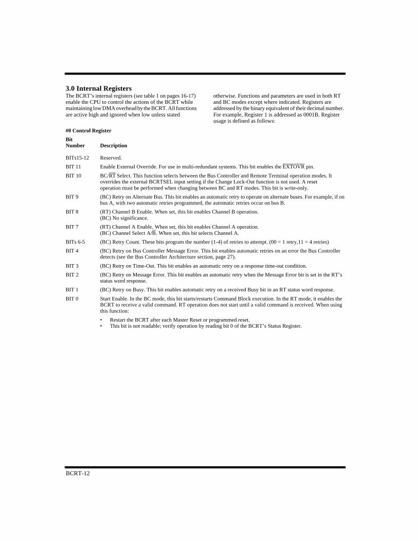
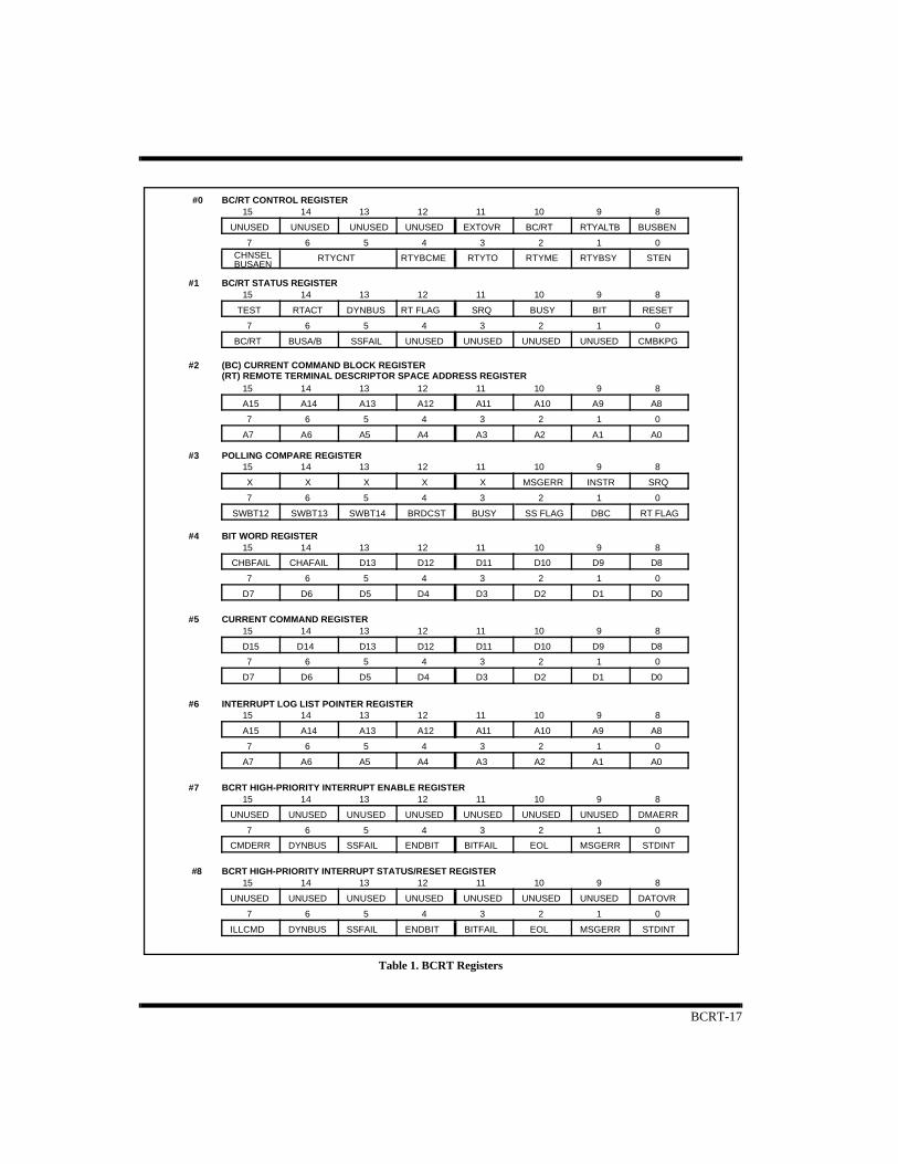
3.0 Internal RegistersThe BCRT’s internal registers (see table 1 on pages 16-17) enable the CPU to control the actions of the BCRT while maintaining low DMA overhead by the BCRT. All functions are active high and ignored when low unless stated
otherwise. Functions and parameters are used in both RT and BC modes except where indicated. Registers are addressed by the binary equivalent of their decimal number. For example, Register 1 is addressed as 0001B. Register usage is defined as follows:
#0 Control Register
Bit Number Description
BITs15-12 Reserved.
BIT 11 Enable External Override. For use in multi-redundant systems. This bit enables the EXTOVR pin.
BIT 10 BC/RT Select. This function selects between the Bus Controller and Remote Terminal operation modes. Itoverrides the external BCRTSEL input setting if the Change Lock-Out function is not used. A resetoperation must be performed when changing between BC and RT modes. This bit is write-only.
BIT 9 (BC) Retry on Alternate Bus. This bit enables an automatic retry to operate on alternate buses. For example, if onbus A, with two automatic retries programmed, the automatic retries occur on bus B.
BIT 8 (RT) Channel B Enable. When set, this bit enables Channel B operation.(BC) No significance.
BIT 7 (RT) Channel A Enable. When set, this bit enables Channel A operation.(BC) Channel Select A/B. When set, this bit selects Channel A.
BITs 6-5 (BC) Retry Count. These bits program the number (1-4) of retries to attempt. (00 = 1 retry,11 = 4 retries)
BIT 4 (BC) Retry on Bus Controller Message Error. This bit enables automatic retries on an error the Bus Controllerdetects (see the Bus Controller Architecture section, page 27).
BIT 3 (BC) Retry on Time-Out. This bit enables an automatic retry on a response time-out condition.
BIT 2 (BC) Retry on Message Error. This bit enables an automatic retry when the Message Error bit is set in the RT’sstatus word response.
BIT 1 (BC) Retry on Busy. This bit enables automatic retry on a received Busy bit in an RT status word response.
BIT 0 Start Enable. In the BC mode, this bit starts/restarts Command Block execution. In the RT mode, it enables theBCRT to receive a valid command. RT operation does not start until a valid command is received. When usingthis function:
• Restart the BCRT after each Master Reset or programmed reset.• This bit is not readable; verify operation by reading bit 0 of the BCRT’s Status Register.
BCRT-13
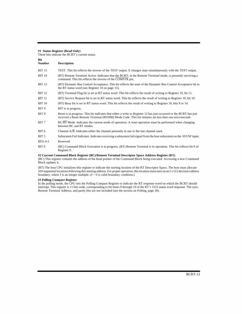
#1 Status Register (Read Only)These bits indicate the BCRT’s current status.
Bit Number Description
BIT 15 TEST. This bit reflects the inverse of the TEST output. It changes state simultaneously with the TEST output.
BIT 14 (RT) Remote Terminal Active. Indicates that the BCRT, in the Remote Terminal mode, is presently servicing acommand. This bit reflects the inverse of the COMSTR pin.
BIT 13 (RT) Dynamic Bus Control Acceptance. This bit reflects the state of the Dynamic Bus Control Acceptance bit inthe RT status word (see Register 10 on page 15).
BIT 12 (RT) Terminal Flag bit is set in RT status word. This bit reflects the result of writing to Register 10, bit 11.
BIT 11 (RT) Service Request bit is set in RT status word. This bit reflects the result of writing to Register 10, bit 10.
BIT 10 (RT) Busy bit is set in RT status word. This bit reflects the result of writing to Register 10, bits 9 or 14.
BIT 9 BIT is in progress.
BIT 8 Reset is in progress. This bit indicates that either a write to Register 12 has just occurred or the BCRT has justreceived a Reset Remote Terminal (#01000) Mode Code. This bit remains set less than one microsecond.
BIT 7 BC/RT Mode. Indicates the current mode of operation. A reset operation must be performed when changingbetween BC and RT modes.
BIT 6 Channel A/B. Indicates either the channel presently in use or the last channel used.
BIT 5 Subsystem Fail Indicator. Indicates receiving a subsystem fail signal from the host subsystem on the SSYSF input.
BITs 4-1 Reserved.
BIT 0 (BC) Command Block Execution is in progress. (RT) Remote Terminal is in operation. This bit reflects bit 0 ofRegister 0.
#2 Current Command Block Register (BC)/Remote Terminal Descriptor Space Address Register (RT)(BC) This register contains the address of the head pointer of the Command Block being executed. Accessing a new Command Block updates it.
(RT) The host CPU initializes this register to indicate the starting location of the RT Descriptor Space. The host must allocate 320 sequential locations following this starting address. For proper operation, this location must start on an I x 512 decimal address boundary, where I is an integer multiple. (I = 0 is valid boundary condition.)
#3 Polling Compare RegisterIn the polling mode, the CPU sets the Polling Compare Register to indicate the RT response word on which the BCRT should interrupt. This register is 11 bits wide, corresponding to bit times 9 through 19 of the RT’s 1553 status word response. The sync, Remote Terminal Address, and parity bits are not included (see the section on Polling, page 30).
BCRT-14
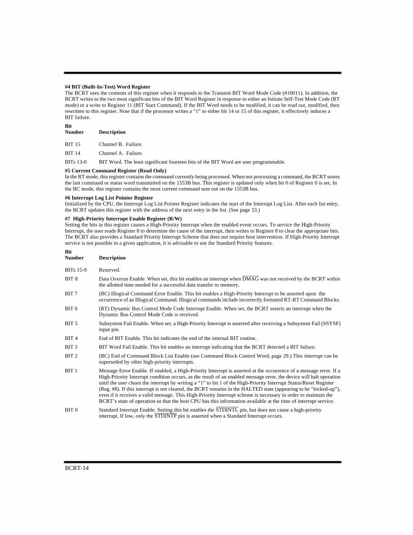
#4 BIT (Built-In-Test) Word RegisterThe BCRT uses the contents of this register when it responds to the Transmit BIT Word Mode Code (#10011). In addition, the BCRT writes to the two most significant bits of the BIT Word Register in response to either an Initiate Self-Test Mode Code (RT mode) or a write to Register 11 (BIT Start Command). If the BIT Word needs to be modified, it can be read out, modified, then rewritten to this register. Note that if the processor writes a “1” to either bit 14 or 15 of this register, it effectively induces a BIT failure.
Bit Number Description
BIT 15 Channel B. Failure.
BIT 14 Channel A. Failure.
BITs 13-0 BIT Word. The least significant fourteen bits of the BIT Word are user programmable.
#5 Current Command Register (Read Only)In the RT mode, this register contains the command currently being processed. When not processing a command, the BCRT stores the last command or status word transmitted on the 1553B bus. This register is updated only when bit 0 of Register 0 is set. In the BC mode, this register contains the most current command sent out on the 1553B bus.
#6 Interrupt Log List Pointer RegisterInitialized by the CPU, the Interrupt Log List Pointer Register indicates the start of the Interrupt Log List. After each list entry, the BCRT updates this register with the address of the next entry in the list. (See page 33.)
#7 High-Priority Interrupt Enable Register (R/W)Setting the bits in this register causes a High-Priority Interrupt when the enabled event occurs. To service the High-Priority Interrupt, the user reads Register 8 to determine the cause of the interrupt, then writes to Register 8 to clear the appropriate bits. The BCRT also provides a Standard Priority Interrupt Scheme that does not require host intervention. If High-Priority Interrupt service is not possible in a given application, it is advisable to use the Standard Priority features.
Bit Number Description
BITs 15-9 Reserved.
BIT 8 Data Overrun Enable. When set, this bit enables an interrupt when DMAG was not received by the BCRT withinthe allotted time needed for a successful data transfer to memory.
BIT 7 (BC) Illogical Command Error Enable. This bit enables a High-Priority Interrupt to be asserted upon theoccurrence of an Illogical Command. Illogical commands include incorrectly formated RT-RT Command Blocks.
BIT 6 (RT) Dynamic Bus Control Mode Code Interrupt Enable. When set, the BCRT asserts an interrupt when theDynamic Bus Control Mode Code is received.
BIT 5 Subsystem Fail Enable. When set, a High-Priority Interrupt is asserted after receiving a Subsystem Fail (SSYSF)input pin.
BIT 4 End of BIT Enable. This bit indicates the end of the internal BIT routine.
BIT 3 BIT Word Fail Enable. This bit enables an interrupt indicating that the BCRT detected a BIT failure.
BIT 2 (BC) End of Command Block List Enable (see Command Block Control Word, page 29.) This interrupt can besuperseded by other high-priority interrupts.
BIT 1 Message Error Enable. If enabled, a High-Priority Interrupt is asserted at the occurrence of a message error. If aHigh-Priority Interrupt condition occurs, as the result of an enabled message error, the device will halt operationuntil the user clears the interrupt by writing a “1” to bit 1 of the High-Priority Interrupt Status/Reset Register(Reg. #8). If this interrupt is not cleared, the BCRT remains in the HALTED state (appearing to be “locked-up”),even if it receives a valid message. This High-Priority Interrupt scheme is necessary in order to maintain theBCRT’s state of operation so that the host CPU has this information available at the time of interrupt service.
BIT 0 Standard Interrupt Enable. Setting this bit enables the STDINTL pin, but does not cause a high-priorityinterrupt. If low, only the STDINTP pin is asserted when a Standard Interrupt occurs.

BCRT-15
#8 High-Priority Interrupt Status/Reset RegisterWhen a High-Priority Interrupt is asserted, this register indicates the event that caused it. To clear the interrupt signal and reset the bit, write a “1” to the appropriate bit. See the corresponding bit definitions of Register 7, High-Priority Interrupt Enable Register.
Bit Number Description
BITs 15-9 Reserved.
BIT 8 Data Overrun.
BIT 7 Illogical Command.
BIT 6 Dynamic Bus Control Mode Code Received.
BIT 5 Subsystem Fail.
BIT 4 End of BIT.
BIT 3 BIT Word Fail.
BIT 2 End of Command Block.
BIT 1 Message Error.
BIT 0 Standard Interrupt. The BCRT sets this bit when any Standard Interrupt occurs, providing bit 0 of Register 7 isenabled. (Reset STDINTL output.)
#9 Standard Interrupt Enable RegisterThis register enables Standard Interrupt logging for any of the following enabled events (Standard Interrupt logging can also occur for events enabled in the BC Command Block or RT Subaddress/Mode Code Descriptor):
Bit Number Description
BITs 15-6 Reserved.
BIT 5 (RT) Illegal Broadcast Command. When set, this bit enables an interrupt indicating that an Illegal BroadcastCommand has been received.
BIT 4 (RT) Illegal Command. When set, this bit enables an interrupt indicating that an illegal command has beenreceived.
BIT 3 (BC) Polling Comparison Match. This enables an interrupt indicating that a polling event has occurred. The usermust also set bit 12 in the BC Command Block Control Word for this interrupt to occur.
BIT 2 (BC) Retry Fail. This bit enables an interrupt indicating that all the programmed number of retries have failed.
BIT 1 (BC, RT) Message Error Event. This bit enables a standard interrupt for message errors.
BIT 0 (BC) Command Block Interrupt and Continue. This bit enables an interrupt indicating that a Command Block,with the Interrupt and Continue Function enabled, has been executed.
BCRT-16
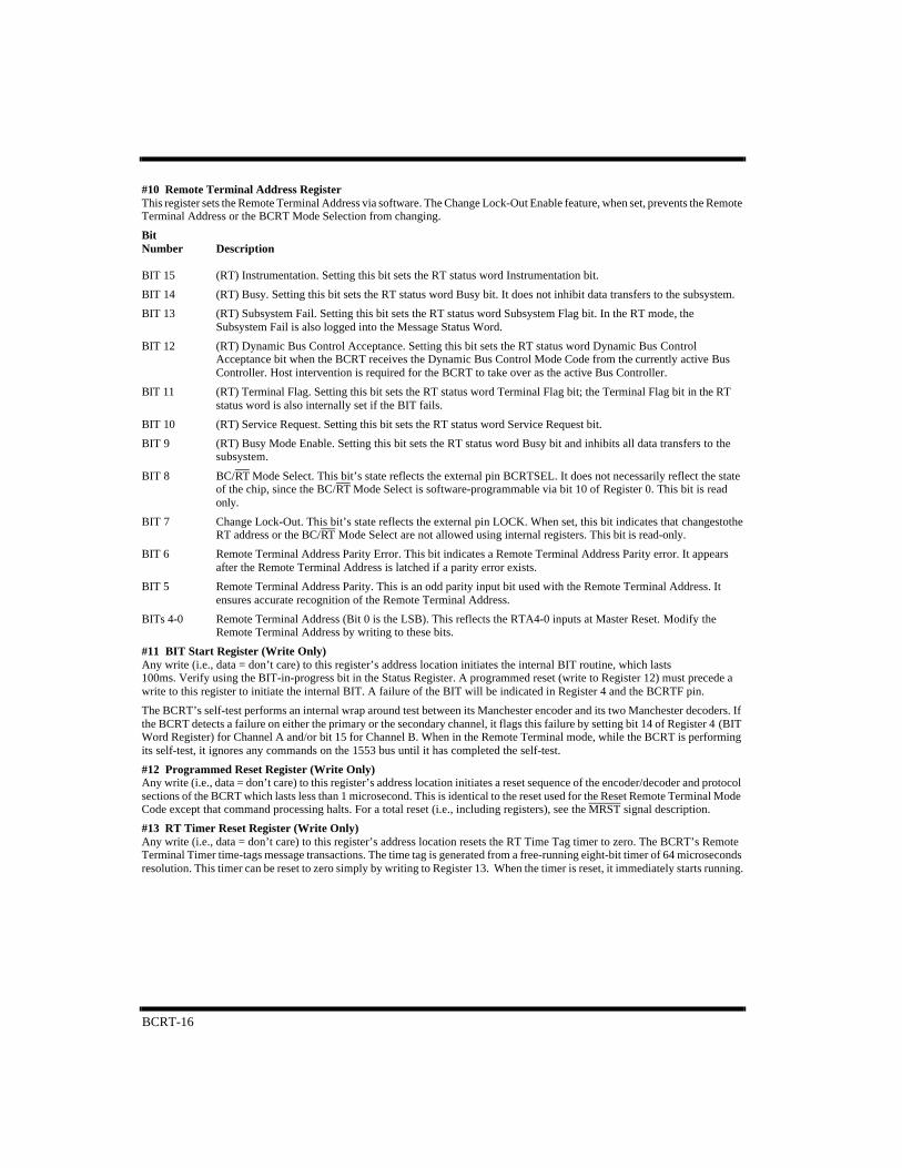
#10 Remote Terminal Address RegisterThis register sets the Remote Terminal Address via software. The Change Lock-Out Enable feature, when set, prevents the Remote Terminal Address or the BCRT Mode Selection from changing.
Bit Number Description
BIT 15 (RT) Instrumentation. Setting this bit sets the RT status word Instrumentation bit.
BIT 14 (RT) Busy. Setting this bit sets the RT status word Busy bit. It does not inhibit data transfers to the subsystem.
BIT 13 (RT) Subsystem Fail. Setting this bit sets the RT status word Subsystem Flag bit. In the RT mode, theSubsystem Fail is also logged into the Message Status Word.
BIT 12 (RT) Dynamic Bus Control Acceptance. Setting this bit sets the RT status word Dynamic Bus ControlAcceptance bit when the BCRT receives the Dynamic Bus Control Mode Code from the currently active BusController. Host intervention is required for the BCRT to take over as the active Bus Controller.
BIT 11 (RT) Terminal Flag. Setting this bit sets the RT status word Terminal Flag bit; the Terminal Flag bit in the RTstatus word is also internally set if the BIT fails.
BIT 10 (RT) Service Request. Setting this bit sets the RT status word Service Request bit.
BIT 9 (RT) Busy Mode Enable. Setting this bit sets the RT status word Busy bit and inhibits all data transfers to thesubsystem.
BIT 8 BC/RT Mode Select. This bit’s state reflects the external pin BCRTSEL. It does not necessarily reflect the stateof the chip, since the BC/RT Mode Select is software-programmable via bit 10 of Register 0. This bit is readonly.
BIT 7 Change Lock-Out. This bit’s state reflects the external pin LOCK. When set, this bit indicates that changes to theRT address or the BC/RT Mode Select are not allowed using internal registers. This bit is read-only.
BIT 6 Remote Terminal Address Parity Error. This bit indicates a Remote Terminal Address Parity error. It appearsafter the Remote Terminal Address is latched if a parity error exists.
BIT 5 Remote Terminal Address Parity. This is an odd parity input bit used with the Remote Terminal Address. Itensures accurate recognition of the Remote Terminal Address.
BITs 4-0 Remote Terminal Address (Bit 0 is the LSB). This reflects the RTA4-0 inputs at Master Reset. Modify theRemote Terminal Address by writing to these bits.
#11 BIT Start Register (Write Only)Any write (i.e., data = don’t care) to this register’s address location initiates the internal BIT routine, which lasts 100ms. Verify using the BIT-in-progress bit in the Status Register. A programmed reset (write to Register 12) must precede a write to this register to initiate the internal BIT. A failure of the BIT will be indicated in Register 4 and the BCRTF pin.
The BCRT’s self-test performs an internal wrap around test between its Manchester encoder and its two Manchester decoders. If the BCRT detects a failure on either the primary or the secondary channel, it flags this failure by setting bit 14 of Register 4 (BIT Word Register) for Channel A and/or bit 15 for Channel B. When in the Remote Terminal mode, while the BCRT is performing its self-test, it ignores any commands on the 1553 bus until it has completed the self-test.
#12 Programmed Reset Register (Write Only)Any write (i.e., data = don’t care) to this register’s address location initiates a reset sequence of the encoder/decoder and protocol sections of the BCRT which lasts less than 1 microsecond. This is identical to the reset used for the Reset Remote Terminal Mode Code except that command processing halts. For a total reset (i.e., including registers), see the MRST signal description.
#13 RT Timer Reset Register (Write Only)Any write (i.e., data = don’t care) to this register’s address location resets the RT Time Tag timer to zero. The BCRT’s Remote Terminal Timer time-tags message transactions. The time tag is generated from a free-running eight-bit timer of 64 microseconds resolution. This timer can be reset to zero simply by writing to Register 13. When the timer is reset, it immediately starts running.
BCRT-17
7 6 5 4 3 2 1 0
89101112131415
7 6 5 4 3 2 1 0
89101112131415
7 6 5 4 3 2 1 0
89101112131415
7 6 5 4 3 2 1 0
89101112131415
#0
RTYTO
UNUSEDUNUSEDUNUSEDUNUSED
UNUSEDUNUSEDUNUSEDUNUSED
A15 A14 A13 A12 A11 A10 A9 A8
A7 A6 A5 A4 A3 A2 A1 A0
(BC) CURRENT COMMAND BLOCK REGISTER
TEST RTACT DYNBUS RT FLAG SRQ BUSY BIT RESET
BC/RT BUSA/B SSFAIL CMBKPG
BC/RT STATUS REGISTER
EXTOVR BC/RT RTYALTB BUSBEN
BUSAENCHNSEL RTYCNT RTYBCME RTYME RTYBSY STEN
BC/RT CONTROL REGISTER
#3
#2
#1
7 6 5 4 3 2 1 0
89101112131415
(RT) REMOTE TERMINAL DESCRIPTOR SPACE ADDRESS REGISTER
POLLING COMPARE REGISTER
RT FLAGDBCSS FLAGBUSYBRDCSTSWBT14SWBT13SWBT12
SRQINSTRMSGERRXXXXX
D7 D6 D5 D4 D3 D2 D1 D0
CURRENT COMMAND REGISTER
D10 D9 D8
#4
#5
BIT WORD REGISTER
CHBFAIL CHAFAIL D13 D12 D11
7 6 5 4 3 2 1 0
89101112131415
D7 D6 D5 D4 D3 D2 D1 D0
D10 D9 D8D15 D14 D13 D12 D11
UNUSEDUNUSEDUNUSEDUNUSEDUNUSEDUNUSED
#7
#6 INTERRUPT LOG LIST POINTER REGISTER
A0A1A2A3A4A5A6A7
A8A9A10A11A12A13A14A15
BCRT HIGH-PRIORITY INTERRUPT ENABLE REGISTER
STDINTMSGERREOLBITFAILENDBITSSFAILDYNBUSCMDERR
DMAERRUNUSED
7 6 5 4 3 2 1 0
89101112131415
7 6 5 4 3 2 1 0
89101112131415
DATOVR
ILLCMD
BCRT HIGH-PRIORITY INTERRUPT STATUS/RESET REGISTER#815 14 13 12 11 10 9 8
UNUSED UNUSED UNUSED UNUSED UNUSED UNUSED UNUSED
01234567
DYNBUS SSFAIL ENDBIT BITFAIL EOL MSGERR STDINT
Table 1. BCRT Registers
BCRT-18
#12
#13
PROGRAMMED RESET REGISTER
REMOTE TERMINAL TIMER RESET REGISTER
X= DON’T CARE
XXXXXXXX
XXXXXXXX
7 6 5 4 3 2 1 0
89101112131415
XXXXXXXX
XXXXXXXX
7 6 5 4 3 2 1 0
89101112131415
15 14 13 12 11 10 9 8
01234567
X
INSTR BUSY1BUSY2 SS FLAG DBC RT FLAG SRQ BC/RT
LOCK PARERR RTAPAR RTA4 RTA3 RTA2 RTA1 RTA0
ILLBCMD ILLCMD POLFAIL RTYFAIL MSGERR CMDBLK
BUILT-IN-TEST START REGISTER
REMOTE TERMINAL ADDRESS REGISTER
STANDARD INTERRUPT ENABLE REGISTER
#11
#10
#915 14 13 12 11 10 9 8
UNUSED UNUSED UNUSED UNUSED UNUSED UNUSED UNUSED UNUSED
01234567
UNUSED UNUSED
15 14 13 12 11 10 9 8
01234567
X X X X X X X
X X X X X X X X
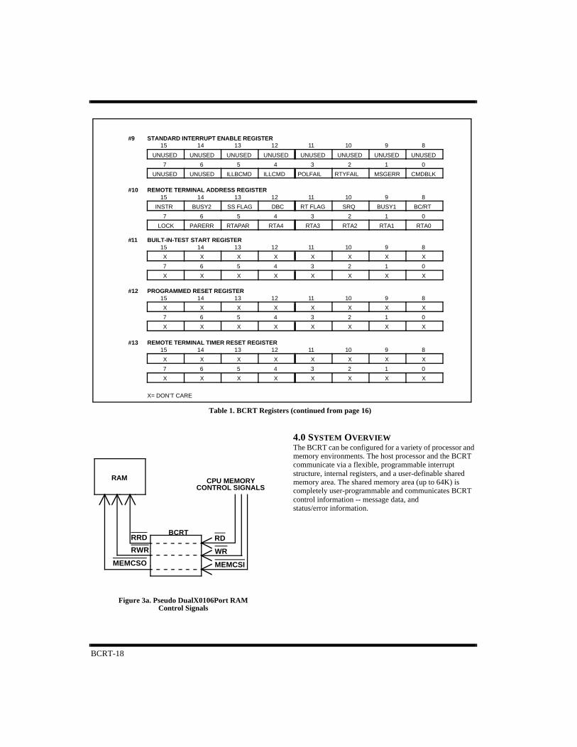
Table 1. BCRT Registers (continued from page 16)
RAM
BCRT
CPU MEMORYCONTROL SIGNALS
RRD
RWR
RD
WR
MEMCSIMEMCSO
Figure 3a. Pseudo DualX0106Port RAM Control Signals
4.0 SYSTEM OVERVIEWThe BCRT can be configured for a variety of processor and memory environments. The host processor and the BCRT communicate via a flexible, programmable interrupt structure, internal registers, and a user-definable shared memory area. The shared memory area (up to 64K) is completely user-programmable and communicates BCRT control information -- message data, and status/error information.
BCRT-19
Built-in memory management functions designed specifically for MIL-STD-1553B applications aid processor off-loading. The host needs only to establish the parameters within memory so the BCRT can access this information as required. For example, in the RT mode, the BCRT can store data associated with individual subaddresses anywhere within its 64K address space. The BCRT then can automatically buffer up to 128 incoming messages of the same subaddress, thus preventing the previous messages from being overwritten by subsequent messages. This buffering also extends the intervals required by the host processor to service the data. Selecting an appropriate MCLK frequency to meet system memory access time requirements controls the memory access rate. The completion of a user-defined task or the occurrence of a user-selected event is indicated by using the extensive set of interrupts provided.
In the BC mode, the BCRT can process multiple messages, assist in scheduling message lists, and provide host-programmable functions such as auto retry. The BCRT is incorporated in systems with a variety of interrupt latencies by using the Interrupt History List feature (see Exception Handling and Interrupt Logging, page 33). The Interrupt History List sequentially stores the events that caused the interrupt in memory without losing information if a host processor does not respond immediately to an interrupt.
5.0 SYSTEM INTERFACE
5.1 DMA TransfersThe BCRT initiates DMA transfers whenever it executes command blocks (BC mode) or services commands (RT mode). DMAR initiates the transfer and is terminated by the inactive edge of DMACK. The Address Enable (AEN) input enables the BCRT to output an address onto the Address bus.
The BCRT requests transfer cycles by asserting the DMAR output, and initiates them when a DMAG input is received. A DMACK output indicatesthat the BCRT has control of the Data and Address buses. The TSCTL output is asserted when the BCRT is actually asserting the Address and Data buses.
To support using multiple bus masters in a system, the BCRT outputs the DMAGO signal that results from the
DMAG signal passing through the chip when a BCRT bus request was not generated (DMAR inactive). You can use DMAGO in daisy-chained multimaster systems.
5.2 Hardware InterfaceThe BCRT provides a simple subsystem interface and facilitates DMA arbitration. The user can configure the BCRT to operate in a variety of memory-processor environments including the pseudo-dual-port RAM and standard DMA configurations.
For complete circuit description, such as arbitration logic and I/O, please refer to the appropriate application note.
5.3 CPU InterconnectionPseudo-Dual-Port RAM ConfigurationThe BCRT’s Address and Data buses connect directly to RAM, with buffers isolating the BCRT’s buses from those of the host CPU (figures 3a and 3b). The CPU’s memory control signals (RD, WR, and MEMCSI) pass through the BCRT and connect to memory as RRL, RWR, and MEMCSO.
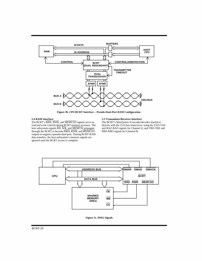
Standard DMA ConfigurationThe BCRT’s and CPU’s data, address, and control signals are connected to each other as shown in figures 3c and 3d. The RWR, RRL, and MEMCSO are activated after DMAG is asserted.
In either case, the BCRT’s Address and Data buses remain in a high-impedance state unless the CS and RD signals are active, indicating a host register access; or TSCTL is asserted, indicating a memory access by the BCRT. CPU attempts to access BCRT registers are ignored during BCRT memory access. Inhibit DMA transfers by using the Busy function in the Remote Terminal Address Register while operating in the Remote Terminal mode.
The designer can use TSCTL to indicate when the BCRT is accessing memory. AEN is also available (use is optional), giving the CPU control over the BCRT’s Address bus. A DMA Burst (BURST) signal indicates multiple DMA accesses.
Register AccessRegisters 0 through 13 are accessed with the decode of the four LSBs of the Address bus (A0-A3) and asserting CS. Pulse either RD or WR for multiple register accesses
BCRT-20
1553 BUS
BUS B
BUS A
XFMRXFMR
CONTROL/ARBITRATIONCONTROL
CPUHOST
BUFFERS
16 ADDRESS
16 DATA
RAM
DUALTRANSCEIVER
TRANSMITTERTIMEOUT
BCRT(DUAL REDUNDANT)
Figure 3b. CPU/BCRT Interface -- Pseudo-Dual-Port RAM Configuration
BCRTCPU
SHAREDMEMORY
AREA
•
•
•
ADDRESS BUS
DATA BUS
Figure 3c. DMA Signals
OE
WE
CS
MEMCSORWRRRD
DMACKDMAGDMAR
5.4 RAM InterfaceThe BCRT’s RRD, RWR, and MEMCSO signals serve as read and write controls during BCRT memory accesses. The host subsystem signals RD, WR, and MEMCSI propagate through the BCRT to become RRD, RWR, and MEMCSO outputs to support a pseudo-dual-port. During BCRT-RAM data transfers, the host subsystem’s memory signals are ignored until the BCRT access is complete.
5.5 Transmitter/Receiver InterfaceThe BCRT’s Manchester II encoder/decoder interfaces directly with the 1553 bus transceiver, using the TAO-TAZ and RAZ-RAO signals for Channel A, and TBO-TBZ and RBZ-RBO signals for Channel B.

BCRT-21
.
6.0 REMOTE TERMINAL ARCHITECTURE
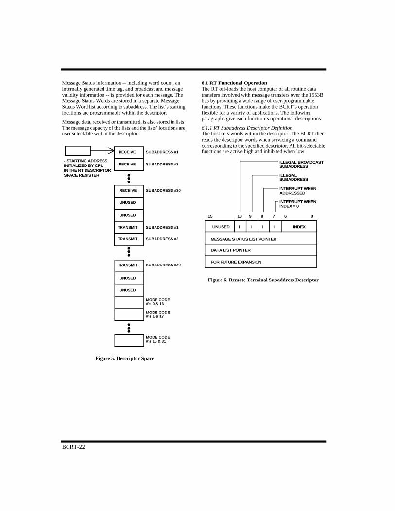
The Remote Terminal architecture is a descriptor-based configuration of relevant parameters. It is composed of an RT Descriptor Space (see figure 5) and internal, host-programmable registers. The Descriptor Space contains only descriptors. Descriptors contain programmable subaddress parameters relating to handling message transfers. Each descriptor consists of four words: (1) a Control Word, (2) a Message Status List Pointer, (3) a Data List Pointer, and (4) an unused fourth word (see figure 6.) These words indicate how to perform the data transfers associated with the designated subaddress.
A receive descriptor and a transmit descriptor are associated with each subaddress. The descriptors reside in memory and are listed sequentially by subaddress. By using the index within the descriptor, the BCRT can buffer incoming and outgoing messages, which reduces host CPU overhead. This message buffering also reduces the risk of incoming messages being overwritten by subsequent incoming messages.
Each descriptor contains a programmable interrupt structure for subsystem notification of user-selected message transfers and indicates when the message buffers are full. Illegalizing subaddresses, in normal and broadcast modes, is accomplished by using programmable bits within the descriptor (see the RT Functional Operation section on next page).
Figure 3d. CPU/BCRT Interface -- DMA Configuration
1553 BUS
BUS B
BUS A
XFMRXFMR
DUALTRANSCEIVER
MEMORY
ARBITRATION
CONTROL
ADDRESS
DATA
BCRT CPU
RAM
BUFFER
BCRT
CHANNEL A CHANNEL B
DUAL TXINHA TXINHB
CHANNEL A CHANNEL B
TRANSCEIVER
TIMERONCHA/B
Figure 4. Dual-Channel Transceiver
The BCRT also provides a TIMERON signal output and an active channel output indicator (CHA/B) to assist in meeting the MIL-STD-1553B fail-safe timer requirements (see figure 4).
BCRT-22
Message Status information -- including word count, an internally generated time tag, and broadcast and message validity information -- is provided for each message. The Message Status Words are stored in a separate Message Status Word list according to subaddress. The list’s starting locations are programmable within the descriptor.
Message data, received or transmitted, is also stored in lists. The message capacity of the lists and the lists’ locations are user selectable within the descriptor.
6.1 RT Functional OperationThe RT off-loads the host computer of all routine data transfers involved with message transfers over the 1553B bus by providing a wide range of user-programmable functions. These functions make the BCRT’s operation flexible for a variety of applications. The following paragraphs give each function’s operational descriptions.
6.1.1 RT Subaddress Descriptor DefinitionThe host sets words within the descriptor. The BCRT then reads the descriptor words when servicing a command corresponding to the specified descriptor. All bit-selectable functions are active high and inhibited when low.
- STARTING ADDRESSINITIALIZED BY CPUIN THE RT DESCRIPTORSPACE REGISTER
RECEIVE
UNUSED
UNUSED
TRANSMIT
TRANSMIT
SUBADDRESS #30
SUBADDRESS #1
SUBADDRESS #2
TRANSMIT
UNUSED
MODE CODE#’s 0 & 16
MODE CODE#’s 1 & 17
MODE CODE#’s 15 & 31
UNUSED
SUBADDRESS #30
RECEIVE
RECEIVE
SUBADDRESS #1
SUBADDRESS #2
Figure 5. Descriptor Space
FOR FUTURE EXPANSION
DATA LIST POINTER
MESSAGE STATUS LIST POINTER
INDEX
06815
UNUSED II
10
I I
9 7
ILLEGAL BROADCASTSUBADDRESS
ILLEGAL
INTERRUPT WHENADDRESSED
INTERRUPT WHENINDEX = 0
SUBADDRESS
Figure 6. Remote Terminal Subaddress Descriptor
BCRT-23
A. Control Word. The first word in the descriptor, the Control Word, selects or disables message transfers and selects an index.
Bit Number Description
BITs 15-11 Reserved.
BIT 10 Illegal Broadcast Subaddress. Indicates to the BCRT not to access this subaddress using broadcast commands.The Message Error bit in the status word is set if the illegal broadcast subaddress is addressed. Since transmitcommands do not apply to broadcast, this bit applies only to receive commands.
BIT 9 Illegal Subaddress. Set by the host CPU, it indicates to the BCRT that a command with this subaddress is illegal.If a command uses an illegal subaddress the Message Error bit in the 1553 status word is set. The IllegalCommand Interrupt is also asserted if enabled.
BIT 8 Interrupt Upon Valid Command Received. Indicates that the BCRT is to assert an interrupt every time a commandaddresses this descriptor. The interrupt occurs just prior to post-command descriptor updating.
BIT 7 Interrupt When Index = 0. Indicates that the BCRT initiates an interrupt when the index is decremented to zero.
BITs 6-0 Index. These bits are for indexed message buffering. Indexing means transacting a pre-specified number ofmessages before notifying the host CPU. After each message transaction, the BCRT decrements the index by oneuntil index = 0. Note that the index is decremented for messages that contain message errors.
B. Message Status List Pointer. The host sets the Message Status List Pointer, the second word within the descriptor, and the BCRT uses it as a starting address for the Message Status List. It is incremented by one with each Message status word write. If the Control Word Index is already equal to zero, the Message Status List Pointer is not incremented and the previous Message status word is overwritten. Note: A Message Status Word is also written and the pointer is incremented when the BCRT detects a message error.
C. Data List Pointer. The Data List Pointer is the third word within the descriptor. The BCRT stores data in RAM beginning at the address indicated by the Data List Pointer. The Data List Pointer is updated at the end of each successful message with the next message’s starting address with the following exceptions:
• If the message is erroneous, the Data List Pointer is not updated. The next message overwrites any data corresponding to the erroneous message.
• Upon receiving a message, if the index is already equal to zero, the Data List Pointer is not incremented and data from the previous message is overwritten.
D. Reserved. The fourth descriptor word is reserved for future use.
BCRT-24
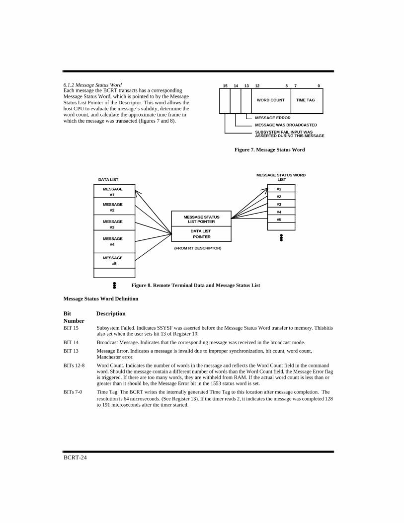
6.1.2 Message Status WordEach message the BCRT transacts has a corresponding Message Status Word, which is pointed to by the Message Status List Pointer of the Descriptor. This word allows the host CPU to evaluate the message’s validity, determine the word count, and calculate the approximate time frame in which the message was transacted (figures 7 and 8).
Message Status Word Definition
Bit DescriptionNumberBIT 15 Subsystem Failed. Indicates SSYSF was asserted before the Message Status Word transfer to memory. This bit is
also set when the user sets bit 13 of Register 10.
BIT 14 Broadcast Message. Indicates that the corresponding message was received in the broadcast mode.
BIT 13 Message Error. Indicates a message is invalid due to improper synchronization, bit count, word count, Manchester error.
BITs 12-8 Word Count. Indicates the number of words in the message and reflects the Word Count field in the commandword. Should the message contain a different number of words than the Word Count field, the Message Error flagis triggered. If there are too many words, they are withheld from RAM. If the actual word count is less than orgreater than it should be, the Message Error bit in the 1553 status word is set.
BITs 7-0 Time Tag. The BCRT writes the internally generated Time Tag to this location after message completion. Theresolution is 64 microseconds. (See Register 13). If the timer reads 2, it indicates the message was completed 128to 191 microseconds after the timer started.
ASSERTED DURING THIS MESSAGE
MESSAGE ERROR
MESSAGE WAS BROADCASTED
SUBSYSTEM FAIL INPUT WAS
WORD COUNT TIME TAG
15 14 13 12 8 7 0
Figure 7. Message Status Word
MESSAGE
MESSAGE
MESSAGE
MESSAGE
MESSAGE
(FROM RT DESCRIPTOR)
#5
#4
#3
#2
#1
#5
#4
#3
#2
#1
LISTMESSAGE STATUS WORD
DATA LIST
POINTER
DATA LIST
LIST POINTERMESSAGE STATUS
Figure 8. Remote Terminal Data and Message Status List
BCRT-25
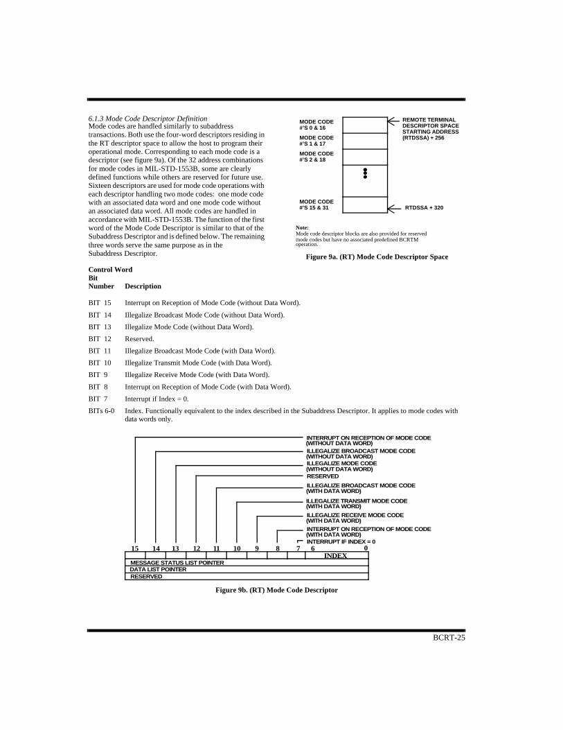
6.1.3 Mode Code Descriptor DefinitionMode codes are handled similarly to subaddress transactions. Both use the four-word descriptors residing in the RT descriptor space to allow the host to program their operational mode. Corresponding to each mode code is a descriptor (see figure 9a). Of the 32 address combinations for mode codes in MIL-STD-1553B, some are clearly defined functions while others are reserved for future use. Sixteen descriptors are used for mode code operations with each descriptor handling two mode codes: one mode code with an associated data word and one mode code without an associated data word. All mode codes are handled in accordance with MIL-STD-1553B. The function of the first word of the Mode Code Descriptor is similar to that of the Subaddress Descriptor and is defined below. The remaining three words serve the same purpose as in the Subaddress Descriptor.
Control WordBit Number Description
BIT 15 Interrupt on Reception of Mode Code (without Data Word).
BIT 14 Illegalize Broadcast Mode Code (without Data Word).
BIT 13 Illegalize Mode Code (without Data Word).
BIT 12 Reserved.
BIT 11 Illegalize Broadcast Mode Code (with Data Word).
BIT 10 Illegalize Transmit Mode Code (with Data Word).
BIT 9 Illegalize Receive Mode Code (with Data Word).
BIT 8 Interrupt on Reception of Mode Code (with Data Word).
BIT 7 Interrupt if Index = 0.
BITs 6-0 Index. Functionally equivalent to the index described in the Subaddress Descriptor. It applies to mode codes withdata words only.
mode codes but have no associated predefined BCRTMMode code descriptor blocks are also provided for reservedNote:
RTDSSA + 320MODE CODE
MODE CODE
MODE CODE (RTDSSA) + 256STARTING ADDRESSDESCRIPTOR SPACEREMOTE TERMINAL
#’S 15 & 31
#’S 2 & 18
#’S 1 & 17
#’S 0 & 16MODE CODE
operation.
Figure 9a. (RT) Mode Code Descriptor Space
15 14 13 12 11 10 9 8 7 6 0
MESSAGE STATUS LIST POINTERDATA LIST POINTERRESERVED
INDEX
ILLEGALIZE BROADCAST MODE CODE(WITHOUT DATA WORD)
INTERRUPT ON RECEPTION OF MODE CODE(WITHOUT DATA WORD)
ILLEGALIZE MODE CODE(WITHOUT DATA WORD)RESERVED
ILLEGALIZE BROADCAST MODE CODE(WITH DATA WORD)
ILLEGALIZE RECEIVE MODE CODE(WITH DATA WORD)INTERRUPT ON RECEPTION OF MODE CODE(WITH DATA WORD)INTERRUPT IF INDEX = 0
ILLEGALIZE TRANSMIT MODE CODE(WITH DATA WORD)
Figure 9b. (RT) Mode Code Descriptor
BCRT-26
The descriptors, numbered sequentially from 0 to 15, correspond to mode codes 0 to 15 without data words and mode codes 16 to 31 with data words. For example, mode codes 0 and 16 correspond to descriptor 0 and mode codes 1 and 17 correspond to descriptor 1. The Mode Code Descriptor Space is appended to the Subaddress Descriptor Space starting at 0100H (256D) of the 320-word RT Descriptor Space (see figure 5).
The BCRT autonomously supports all mode codes without data words by executing the specific function and transmitting the 1553 status word. The subsystem provides the data word for mode codes with data words (see the Data List Pointer section). For all mode codes, an interrupt can be asserted upon successful completion of the mode command by setting the appropriate bit in the control word (see figure 9b).
Dynamic Bus Control #00000This mode code is accepted automatically if the Dynamic Bus Control Enable bit in the Remote Terminal Address Register is set. Setting the DynamicBus Control Acceptance bit in the 1553 status word and BCRT Status Register confirms the mode code acceptance. A High-Priority Interrupt is also asserted if enabled. If the Dynamic Bus Control Enable bit is not set, the BCRT does not accept Dynamic Bus Control.
Synchronize (Without Data Word) #00001If enabled in the Mode Code #00001 Descriptor Control Word, the BCRT asserts an interrupt when this mode code is received.
Transmit Status Word #00010The BCRT automatically transmits the 1553 status word corresponding to the last message transacted.
Initiate Self-Test #00011The BCRT automatically starts its BIT routine. An interrupt, if enabled, is asserted when the test is completed. The BIT Word Register and external pin BCRTF are updated when the test is completed. A failure in BIT will also set the TF status word bit.
Transmitter Shutdown #00100The BCRT disables the channel opposite the channel on which the command was received.
Override Transmitter Shutdown #00101The BCRT enables the channel previously disabled.
Inhibit Terminal Flag Bit #00110The BCRT inhibits the Terminal Flag from being set in the status word.
Override Inhibit Terminal Flag Bit #00111The BCRT disables the Terminal Flag inhibit.
Reset Remote Terminal #01000The BCRT automatically resets the encoder, decoders, and protocol logic.
Transmit Vector Word #10000The BCRT transmits the vector word from the location addressed by the Data List Pointer in the Mode Code Descriptor Block.
Synchronize (with Data Word) #10001On receiving this mode code, the BCRT simply stores the associated data word.
Transmit Last Command #10010The BCRT transmits the last command executed and the corresponding 1553 status word.
Transmit BIT Word #10011The BCRT transmits BIT information from the BITRegister.
Selected Transmitter Shutdown #10100On receiving this mode code, the BCRT simply stores the associated data word.
Override Selected Transmitter Shutdown #10101On receiving this mode code, the BCRT simply stores the associated data word.
Mode codes 9-15 and 22-31 are reserved for future expansion of MIL-STD-1553B.
BCRT-27
6.2 RT Error DetectionIn accordance with MIL-STD-1553B, the remote terminal handles superseding commands on the same or opposite bus. When receiving, the remote terminal performs a response time-out function of 56 microseconds for RT-RT transfers. If the response time-out condition occurs, a Message Error bit is set in the 1553 status word and in the Message Status Word. Error checking occurs on both of the Manchester logic and the word formats. Detectable errors include word count errors, long words, short words, Manchester errors (including zero crossing deviation), parity errors, and data discontiguity.
6.3 RT Operational SequenceThe following is a general description of the typical behavior of the BCRT as it processes a message in the RT mode. It is assumed that the user has already written a “1” to Register 0, bit 0, enabling RT operation.
Valid Command Received.
COMSTR goes active
• DMA Descriptor Read. After receiving a valid command, the BCRT initiates a burst DMA:
DMA arbitration (BURST)Control Word readMessage Status List Pointer readData List Pointer read
Data Transmitted/Received.
• Data Word DMA.
If the BCRT needs to transmit data from memory, it initiates a DMA cycle for each Data Word shortly before the Data Word is needed on the 1553B bus:
DMA arbitrationData Word read (starting at Data List Pointer address, incremented for each successive word)
If the BCRT receives data, it writes each Data Word to memory after the Data Word is received:
DMA arbitrationData Word write (starting at Data List Pointer address, incremented for each successive word)
Status Word Transmission.
The BCRT automatically transmits the Status Word as defined in MIL-STD-1553B. The Message Error and Broadcast Command Received bits are generated internally. Writing to Register 10 enables the other predefined bits. For illegalized commands, the BCRT sets the Message Error Bit in the 1553 Status Word.
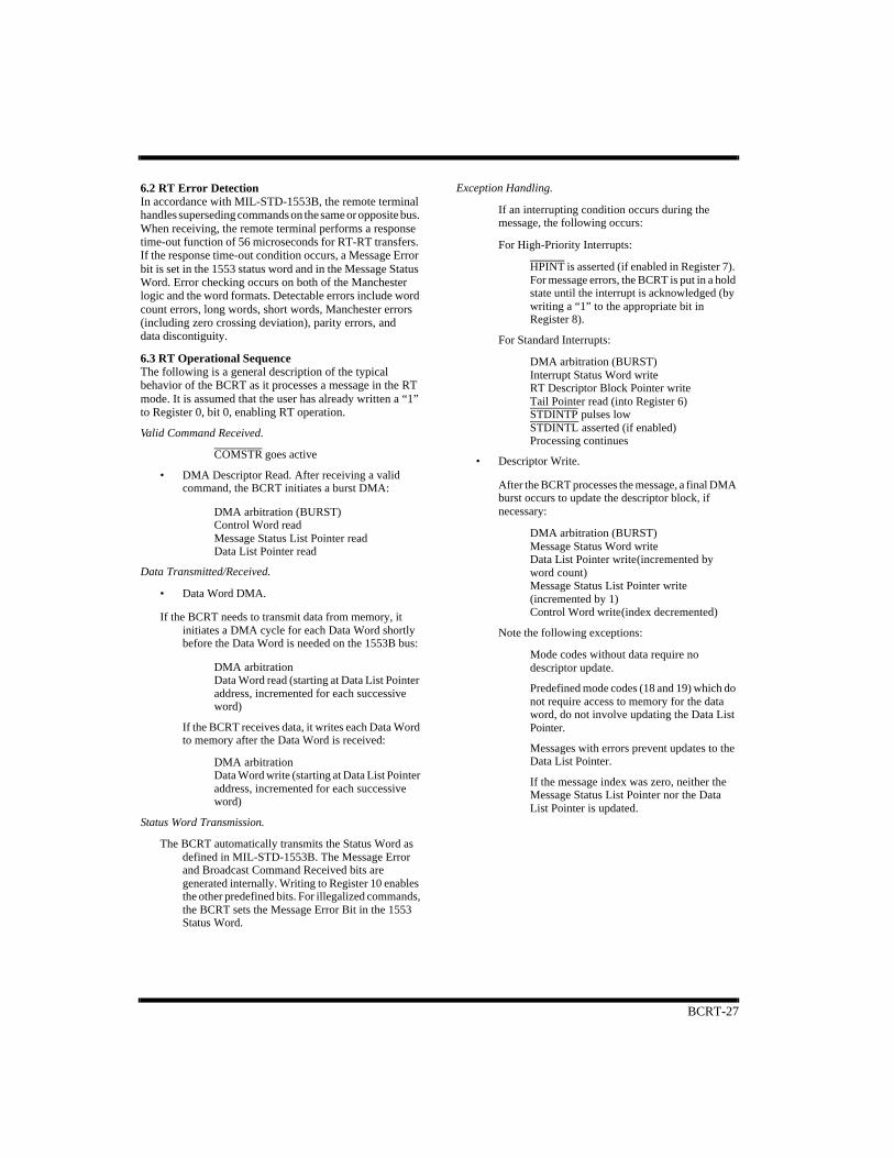
Exception Handling.
If an interrupting condition occurs during the message, the following occurs:
For High-Priority Interrupts:
HPINT is asserted (if enabled in Register 7). For message errors, the BCRT is put in a hold state until the interrupt is acknowledged (by writing a “1” to the appropriate bit in Register 8).
For Standard Interrupts:
DMA arbitration (BURST)Interrupt Status Word writeRT Descriptor Block Pointer writeTail Pointer read (into Register 6)STDINTP pulses lowSTDINTL asserted (if enabled)Processing continues
• Descriptor Write.
After the BCRT processes the message, a final DMA burst occurs to update the descriptor block, if necessary:
DMA arbitration (BURST)Message Status Word writeData List Pointer write(incremented by word count)Message Status List Pointer write (incremented by 1)Control Word write(index decremented)
Note the following exceptions:
Mode codes without data require no descriptor update.
Predefined mode codes (18 and 19) which do not require access to memory for the data word, do not involve updating the Data List Pointer.
Messages with errors prevent updates to the Data List Pointer.
If the message index was zero, neither the Message Status List Pointer nor the Data List Pointer is updated.
BCRT-28
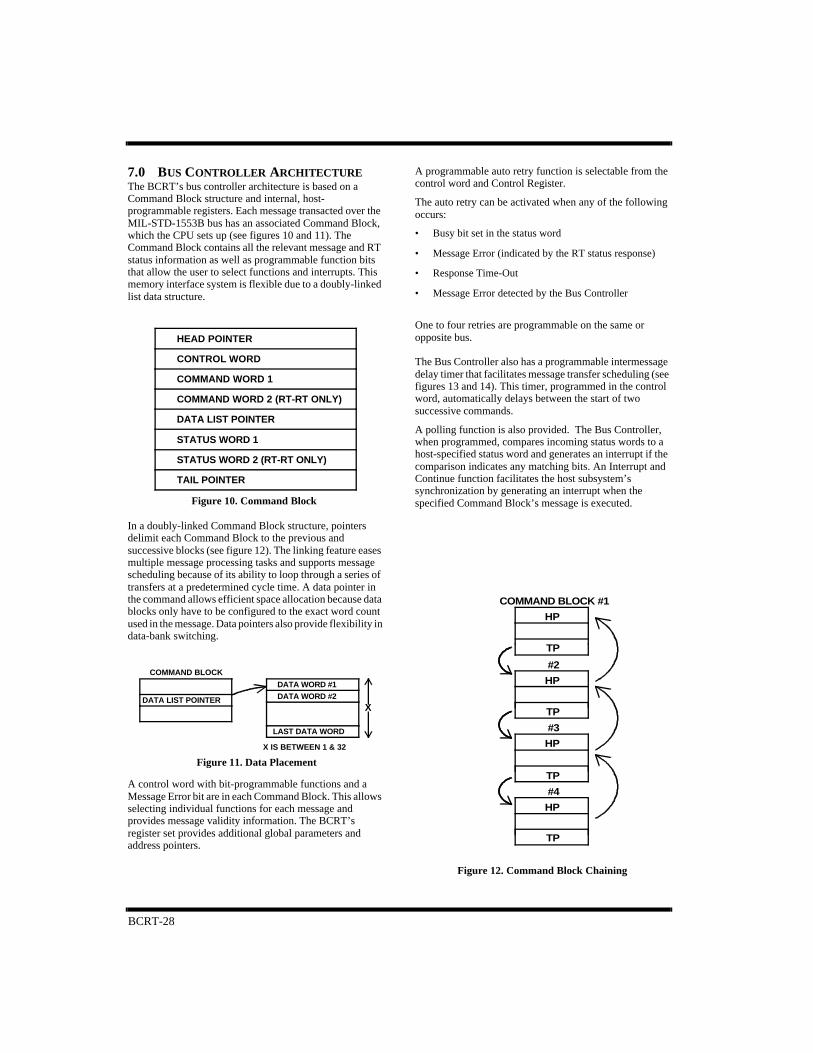
7.0 BUS CONTROLLER ARCHITECTUREThe BCRT’s bus controller architecture is based on a Command Block structure and internal, host-programmable registers. Each message transacted over the MIL-STD-1553B bus has an associated Command Block, which the CPU sets up (see figures 10 and 11). The Command Block contains all the relevant message and RT status information as well as programmable function bits that allow the user to select functions and interrupts. This memory interface system is flexible due to a doubly-linked list data structure.
In a doubly-linked Command Block structure, pointers delimit each Command Block to the previous and successive blocks (see figure 12). The linking feature eases multiple message processing tasks and supports message scheduling because of its ability to loop through a series of transfers at a predetermined cycle time. A data pointer in the command allows efficient space allocation because data blocks only have to be configured to the exact word count used in the message. Data pointers also provide flexibility in data-bank switching.
A control word with bit-programmable functions and a Message Error bit are in each Command Block. This allows selecting individual functions for each message and provides message validity information. The BCRT’s register set provides additional global parameters and address pointers.
A programmable auto retry function is selectable from the control word and Control Register.
The auto retry can be activated when any of the following occurs:
• Busy bit set in the status word
• Message Error (indicated by the RT status response)
• Response Time-Out
• Message Error detected by the Bus Controller
One to four retries are programmable on the same or opposite bus.
The Bus Controller also has a programmable intermessage delay timer that facilitates message transfer scheduling (see figures 13 and 14). This timer, programmed in the control word, automatically delays between the start of two successive commands.
A polling function is also provided. The Bus Controller, when programmed, compares incoming status words to a host-specified status word and generates an interrupt if the comparison indicates any matching bits. An Interrupt and Continue function facilitates the host subsystem’s synchronization by generating an interrupt when the specified Command Block’s message is executed.
TAIL POINTER
STATUS WORD 2 (RT-RT ONLY)
STATUS WORD 1
DATA LIST POINTER
COMMAND WORD 2 (RT-RT ONLY)
COMMAND WORD 1
CONTROL WORD
HEAD POINTER
X
X IS BETWEEN 1 & 32
LAST DATA WORD
DATA WORD #2DATA WORD #1
DATA LIST POINTER
COMMAND BLOCK
Figure 11. Data Placement
COMMAND BLOCK #1
HP
TP
#2
HP
TP
#3
HP
TP
#4
HP
TP
Figure 10. Command Block
Figure 12. Command Block Chaining
BCRT-29
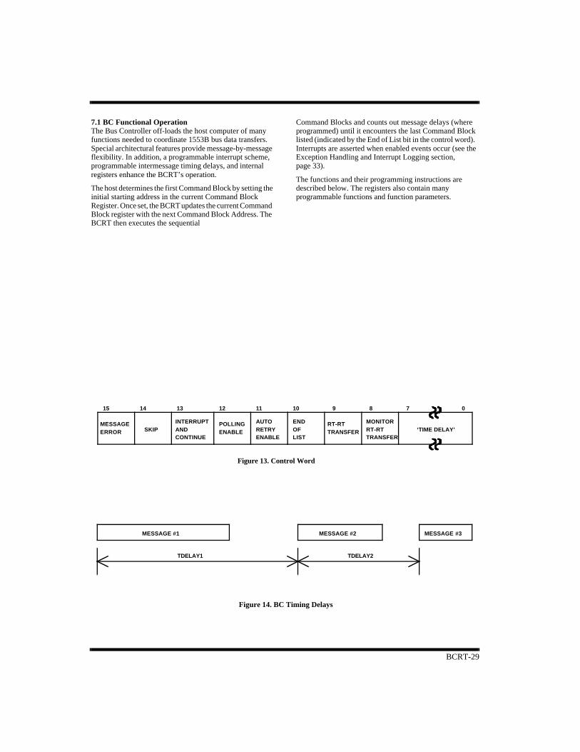
7.1 BC Functional OperationThe Bus Controller off-loads the host computer of many functions needed to coordinate 1553B bus data transfers. Special architectural features provide message-by-message flexibility. In addition, a programmable interrupt scheme, programmable intermessage timing delays, and internal registers enhance the BCRT’s operation.
The host determines the first Command Block by setting the initial starting address in the current Command Block Register. Once set, the BCRT updates the current Command Block register with the next Command Block Address. The BCRT then executes the sequential
Command Blocks and counts out message delays (where programmed) until it encounters the last Command Block listed (indicated by the End of List bit in the control word). Interrupts are asserted when enabled events occur (see the Exception Handling and Interrupt Logging section, page 33).
The functions and their programming instructions are described below. The registers also contain many programmable functions and function parameters.
‘TIME DELAY’TRANSFERRT-RTMONITOR
TRANSFERRT-RT
LISTOFEND
ENABLERETRYAUTO
ENABLEPOLLING
CONTINUEANDINTERRUPT
ERRORMESSAGE
SKIP
15 14 13 12 11 10 9 8 7 0
Figure 13. Control Word
MESSAGE #1 MESSAGE #2 MESSAGE #3
TDELAY1 TDELAY2
Figure 14. BC Timing Delays

BCRT-30
BC Command Block DefinitionEach Command Block contains (see figure 10):
A. Head Pointer. Host-written, this location can contain the address of the previous Command Block’s Head Pointer. The BCRT does not access this location.
B. Control Word. Host-written, the Control Word contains bit-selectable options and a Message Error bit the BCRT provides (see figure 13). The bit definitions follow.
Bit Number Description
BIT 15 Message Error. The BCRT sets this bit when it detects an invalid RT response as defined in MIL-STD-1553B.
BIT 14 Skip. When set, this bit instructs the BCRT to skip this Command Block and execute the next.
BIT 13 Interrupt and Continue. If set, a Standard Interrupt is asserted when this block is addressed; operation, however,continues. Note that this interrupt must also be enabled by setting bit 0 of Register 9.
BIT 12 Polling Enable. Enables the BCRT’s polling operation.
BIT 11 Auto Retry Enable. When set, the Auto Retry function, governed by the global parameters in the Control Register,is enabled for this message.
BIT 10 End of List. Set by the CPU, this bit indicates that the BCRT, upon completion of the current message, will halt andassert a High-Priority Interrupt. The interrupt must also be enabled in the High-Priority Interrupt Enable Register.
BIT 9 RT-RT. Set by the CPU, this indicates that this Command Block transacts an RT-RT transfer.
BIT 8 Monitor RT-RT Transfer. Set by the CPU, this function indicates that the BCRT should receive and store the messagebeginning at the location indicated by the data pointer.
BITs 7-0 Time Delay. The CPU sets this field, which causes the BCRT to delay the specified time between sequential messagestarts (see figures 13 and 14). Regardless of the value in the Time Delay field (including zero), the BCRT will at leastmeet the minimum 4ms intermessage gap time as specified in MIL-STD-1553B. The timer is enabled by having anon-zero value in this bit field. When using this function, please note:
• Timer resolution is16 microseconds. As an example, if a given message requires 116µs tocomplete (including the minimum 4µs intermessage gap time) the value in the Time Delay field must be at least 00001000 (8 x 16µs = 128µs) to provide an intermessage gap greater than the4µs minimum requirement.
• If the timer is enabled and the Skip bit is set, the timer provides the programmed delay before proceeding.
• If the message duration exceeds the timer delay, the message is completed just as if the timer were not enabled.
• If SKIP = 1 and EOL = 1, the HPINT is generated if enabled.
• If SKIP = 1 and Interrupt and Continue = 1, the STDINT is generated if enabled.
C. Command Word One. Initialized by the CPU, this location contains the first command word corresponding to the Command Block’s message transfer.
D. Command Word Two. Initialized by the CPU, this location is for the second (transmit) command word in RT-RT transfers. In messages involving only one RT, the location is unused.
E. Data Pointer. Initialized by the CPU, this location contains the starting location in RAM for the Command Block’s message (see figure 15).
F. Status Word One. Stored by the BCRT, this location contains the entire Remote Terminal status response.
G. Status Word Two. Stored by the BCRT, this location contains the receiving Remote Terminal status word. For transfers involving one Remote Terminal, the location is unused.
H. Tail Pointer. Initialized by the host CPU, the Tail Pointer contains the next Command Block’s starting address.
BCRT-31
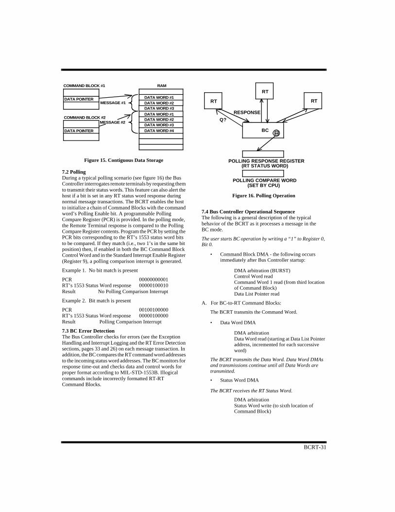
7.2 PollingDuring a typical polling scenario (see figure 16) the Bus Controller interrogates remote terminals by requesting them to transmit their status words. This feature can also alert the host if a bit is set in any RT status word response during normal message transactions. The BCRT enables the host to initialize a chain of Command Blocks with the command word’s Polling Enable bit. A programmable Polling Compare Register (PCR) is provided. In the polling mode, the Remote Terminal response is compared to the Polling Compare Register contents. Program the PCR by setting the PCR bits corresponding to the RT’s 1553 status word bits to be compared. If they match (i.e., two 1’s in the same bit position) then, if enabled in both the BC Command Block Control Word and in the Standard Interrupt Enable Register (Register 9), a polling comparison interrupt is generated.
Example 1. No bit match is present
PCR 00000000001 RT’s 1553 Status Word response 00000100010 Result No Polling Comparison Interrupt
Example 2. Bit match is present
PCR 00100100000RT’s 1553 Status Word response 00000100000Result Polling Comparison Interrupt
7.3 BC Error DetectionThe Bus Controller checks for errors (see the Exception Handling and Interrupt Logging and the RT Error Detection sections, pages 33 and 26) on each message transaction. In addition, the BC compares the RT command word addresses to the incoming status word addresses. The BC monitors for response time-out and checks data and control words for proper format according to MIL-STD-1553B. Illogical commands include incorrectly formatted RT-RT Command Blocks.
7.4 Bus Controller Operational SequenceThe following is a general description of the typical behavior of the BCRT as it processes a message in the BC mode.
The user starts BC operation by writing a “1” to Register 0, Bit 0.
• Command Block DMA - the following occurs immediately after Bus Controller startup:
DMA arbitration (BURST)Control Word readCommand Word 1 read (from third location of Command Block) Data List Pointer read
A. For BC-to-RT Command Blocks:
The BCRT transmits the Command Word.
• Data Word DMA
DMA arbitration Data Word read (starting at Data List Pointer address, incremented for each successive word)
The BCRT transmits the Data Word. Data Word DMAs and transmissions continue until all Data Words are transmitted.
• Status Word DMA
The BCRT receives the RT Status Word.
DMA arbitration Status Word write (to sixth location of Command Block)
COMMAND BLOCK #1
DATA POINTER
COMMAND BLOCK #2
DATA POINTER
MESSAGE #1
MESSAGE #2
RAM
DATA WORD #1DATA WORD #2
DATA WORD #1DATA WORD #2DATA WORD #3DATA WORD #4
DATA WORD #3
RT
BC
RESPONSE
Q?
RTRT
POLLING RESPONSE REGISTER(RT STATUS WORD)
POLLING COMPARE WORD(SET BY CPU)
Figure 16. Polling Operation
Figure 15. Contiguous Data Storage
BCRT-32
B. For RT-to-BC Command Blocks:
The BCRT transmits the Command Word.
• Status Word DMA
The BCRT receives the RT Status Word.
DMA arbitration Status Word write (to sixth location of Command Block)
The BCRT receives the first Data Word.
• Data Word DMA
DMA arbitration Data Word write (starting at Data List Pointer address, incremented for each successive word)
Data Word receptions and DMAs continue until all Data Words are received.
C. For RT(B)-to-RT(A) Command Blocks:
The BCRT transmits Command Word 1 to RT(B).
• Command Word 2 DMA
DMA arbitration Command Word 2 read (from fourth location of Command Block)
The BCRT transmits Command Word 2 to RT(A).
The BCRT receives the RT Status Word from RT(A).
• Status Word DMA for RT(A) Status Word
DMA arbitration Status Word write (to sixth location of Command Block)
The BCRT receives the first Data Word
• Data Word DMA (only if the BCRT is enabled to monitor the RT-to-RT message).
DMA arbitration Data Word write (starting at Data List Pointer address, incremented for each successive word)
Data Word receptions and DMAs continue until all Data Words are received.
The BCRT receives the RT Status Word from RT(B).
• Status Word DMA for RT(B) Status Word
DMA arbitration Status Word write (to seventh location of Command Block)
Exception Handling.
If an interrupting condition occurs during the message, the following occurs:
For High-Priority Interrupts:
HPINT is asserted (if enabled in Register 7). For message errors, the BCRT is put in a hold state until the interrupt is acknowledged (by writing a “1” to the appropriate bit in Register 8).
For Standard Interrupts:
DMA arbitration (BURST) Interrupt Status Word write Command Block Pointer writeTail Pointer read (into Register 6) STDINTP pulses low STDINTL asserted (if enabled) Processing continues
If Retries are enabled and a Retry condition occurs, the following DMA occurs:
DMA arbitration (BURST) Control Word readCommand Word 1 read (from third location of Command Block) Data List Pointer read
The BCRT proceeds from the current Command Block to the next successive Command Block.
• If no Message Error has occurred during the current Command Block, the following occurs:
DMA arbitration (BURST) Command Block Tail Pointer read (to determine location of next Command Block. Note that this occurs only if no Retry.)DMA hold cycle Control Word read (next Command Block) Command Word 1 read (next Command Block) Data List Pointer read
• If the BCRT detects a Message Error while processing the current Command Block, the following occurs:
DMA arbitration (BURST) Control Word write Command Block Tail Pointer read (to determine location of next Command Block. Note that this occurs only if no Retry.) DMA hold cycle Control Word read (next Command Block) Command Word 1 read (next Command Block) Data List Pointer read
The BCRT proceeds again from point A, B, or C as shown above.
BCRT-33
7.5 BC Operational Example (see figure 18 on page 35)The BCRT is programmed initially to accomplish the following:
The first Command Block is for a four-word RT-RT transfer with the BCRT monitoring the transfer and storing the data.
• Auto-retry is enabled on the opposite bus using only one retry attempt, if the incoming Status Word is received with the Message Error bit set.
• Wait for a time delay of 400µs before proceeding to the next Command Block.
• The Data List Pointer contains the address 0400H.
The second Command Block is for a BC-RT transfer of two words.
• The End of List bit is set in its Control Word.
• The Data List Pointer contains the address 0404H.
• The Polling Enable bit is set and the Polling Compare Register contains a one in the Subsystem Fail position (bit 2).
Then:
A. The CPU initializes all the appropriate registers and Command Blocks, and issues a Start Enable by writing a “1” to Register 0, bit 0.
B. The BCRT, through executing a DMA cycle, reads the control word, command words, and the Data List Pointer. The delay timer starts and message execution begins by transmitting the receive and transmit commands stored in the Command Blocks. The BCRT then waits to receive the status word back from the transmitting RT.
C. The BCRT receives the RT status word with all status bits low from the transmitting RT and stores the status word in Command Block 1. The incoming data words from the transmitting RT follow. The BCRT stores them in memory locations 0400H - 0403H.
If the status word indicates that the message cannot be transmitted (Message Error), the response time-out clock counts to zero and the allotted message time runs out. An auto-retry can be initiated if programmed to do so. Nevertheless, the ME bit in the control word is set.
D. The BCRT receives the status word response from the receiving RT. The ME bit in the status word is set, indicating the message is invalid. The BCRT initiates the auto retry function, (as programmed) on the alternate bus, re-transmits the command words, receives the correct status word, and stores the data again in locations 0400H - 0403H. This time the status word response from the receiving RT indicates the message transfer is successful.
E. The timer delay between the two successive transactions counts down another 135 microseconds before proceeding. This is determined as follows:
The message transaction time is approximately 130 microseconds (the only approximation is due to the range in status response and intermessage gap times specified by MIL-STD-1553B). Approximating that with the retry, the total duration for the two attempts is 265µs.
F. The BCRT reads the Tail Pointer of Command Block 1 and places it in the Current Command Register. It also reads the control word, command word, and Data List Pointer, and the first data word in the second Command Block.
G. Since this is a BC-RT transfer, the BCRT transmits the receive command followed by two data words from locations 0404H - 0405H in memory. The BCRT reads the second data word from memory while transmitting the first.
H. The BCRT receives the status response from the RT. In this case, the status word indicates, by the ME bit being low, that the message is valid. The status word also has the Subsystem Fail bit set.
I. The status word is stored in the Command Block. The BCRT, having encountered the end of the list, halts message transactions and waits for another start signal.
J. The BCRT asserts a High-Priority Interrupt indicating the end of the command list. Due to the polling comparison match, the BCRT also asserts a Standard Priority Interrupt and logs the event in the Interrupt Log List.
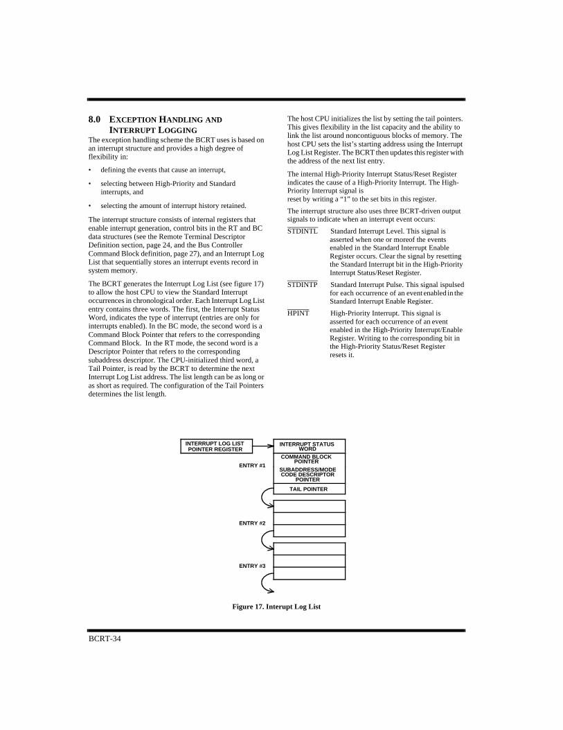
BCRT-34
8.0 EXCEPTION HANDLING AND INTERRUPT LOGGING
The exception handling scheme the BCRT uses is based on an interrupt structure and provides a high degree of flexibility in:
• defining the events that cause an interrupt,
• selecting between High-Priority and Standard interrupts, and
• selecting the amount of interrupt history retained.
The interrupt structure consists of internal registers that enable interrupt generation, control bits in the RT and BC data structures (see the Remote Terminal Descriptor Definition section, page 24, and the Bus Controller Command Block definition, page 27), and an Interrupt Log List that sequentially stores an interrupt events record in system memory.
The BCRT generates the Interrupt Log List (see figure 17) to allow the host CPU to view the Standard Interrupt occurrences in chronological order. Each Interrupt Log List entry contains three words. The first, the Interrupt Status Word, indicates the type of interrupt (entries are only for interrupts enabled). In the BC mode, the second word is a Command Block Pointer that refers to the corresponding Command Block. In the RT mode, the second word is a Descriptor Pointer that refers to the corresponding subaddress descriptor. The CPU-initialized third word, a Tail Pointer, is read by the BCRT to determine the next Interrupt Log List address. The list length can be as long or as short as required. The configuration of the Tail Pointers determines the list length.
The host CPU initializes the list by setting the tail pointers. This gives flexibility in the list capacity and the ability to link the list around noncontiguous blocks of memory. The host CPU sets the list’s starting address using the Interrupt Log List Register. The BCRT then updates this register with the address of the next list entry.
The internal High-Priority Interrupt Status/Reset Register indicates the cause of a High-Priority Interrupt. The High-Priority Interrupt signal isreset by writing a “1” to the set bits in this register.
The interrupt structure also uses three BCRT-driven output signals to indicate when an interrupt event occurs:
STDINTL Standard Interrupt Level. This signal is asserted when one or moreof the events enabled in the Standard Interrupt Enable Register occurs. Clear the signal by resetting the Standard Interrupt bit in the High-Priority Interrupt Status/Reset Register.
STDINTP Standard Interrupt Pulse. This signal is pulsed for each occurrence of an event enabled in the Standard Interrupt Enable Register.
HPINT High-Priority Interrupt. This signal is asserted for each occurrence of an event enabled in the High-Priority Interrupt/Enable Register. Writing to the corresponding bit in the High-Priority Status/Reset Register resets it.
ENTRY #3
ENTRY #2
ENTRY #1
TAIL POINTER
SUBADDRESS/MODE
COMMAND BLOCK
INTERRUPT STATUSPOINTER REGISTER
INTERRUPT LOG LIST
POINTER
WORD
CODE DESCRIPTORPOINTER
Figure 17. Interupt Log List
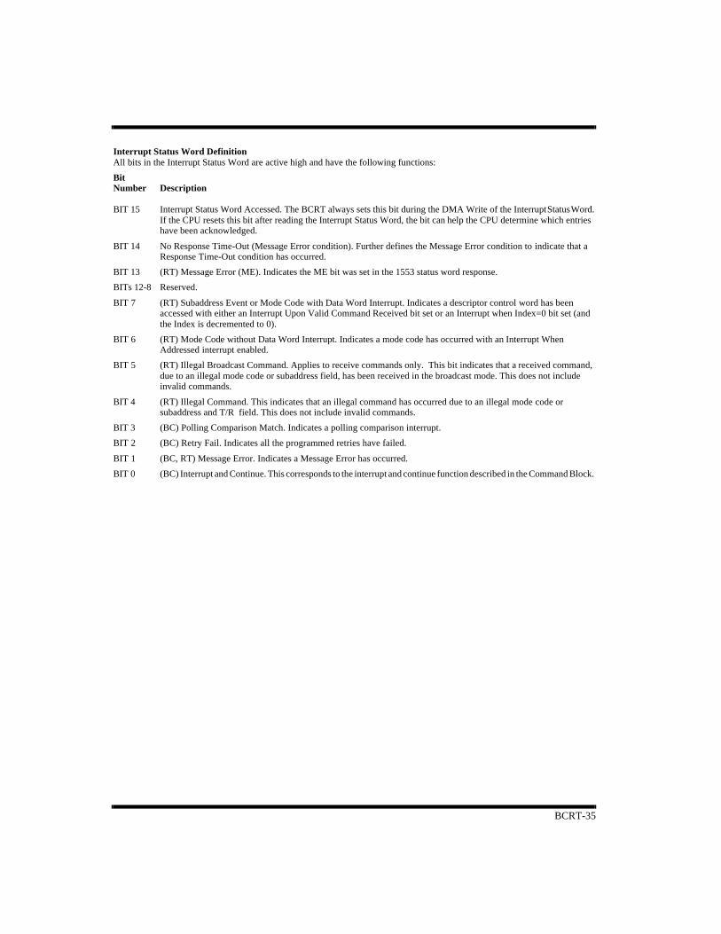
BCRT-35
Interrupt Status Word DefinitionAll bits in the Interrupt Status Word are active high and have the following functions:
Bit Number Description
BIT 15 Interrupt Status Word Accessed. The BCRT always sets this bit during the DMA Write of the Interrupt Status Word.If the CPU resets this bit after reading the Interrupt Status Word, the bit can help the CPU determine which entrieshave been acknowledged.
BIT 14 No Response Time-Out (Message Error condition). Further defines the Message Error condition to indicate that aResponse Time-Out condition has occurred.
BIT 13 (RT) Message Error (ME). Indicates the ME bit was set in the 1553 status word response.
BITs 12-8 Reserved.
BIT 7 (RT) Subaddress Event or Mode Code with Data Word Interrupt. Indicates a descriptor control word has beenaccessed with either an Interrupt Upon Valid Command Received bit set or an Interrupt when Index=0 bit set (andthe Index is decremented to 0).
BIT 6 (RT) Mode Code without Data Word Interrupt. Indicates a mode code has occurred with an Interrupt WhenAddressed interrupt enabled.
BIT 5 (RT) Illegal Broadcast Command. Applies to receive commands only. This bit indicates that a received command,due to an illegal mode code or subaddress field, has been received in the broadcast mode. This does not include invalid commands.
BIT 4 (RT) Illegal Command. This indicates that an illegal command has occurred due to an illegal mode code orsubaddress and T/R field. This does not include invalid commands.
BIT 3 (BC) Polling Comparison Match. Indicates a polling comparison interrupt.
BIT 2 (BC) Retry Fail. Indicates all the programmed retries have failed.
BIT 1 (BC, RT) Message Error. Indicates a Message Error has occurred.
BIT 0 (BC) Interrupt and Continue. This corresponds to the interrupt and continue function described in the Command Block.
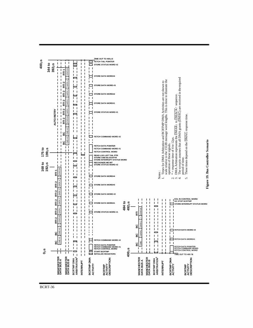
BCRT-36
Fig
ure
19. B
us C
ontr
olle
r S
cen
ario
RT
I 2R
TI 2
RT
I 2R
TI 2
**
**
STA
TU
SD
ATA
4D
ATA
3D
ATA
2D
ATA
1S
TAT
US
CM
D #
2C
MD
#1
RTI
2R
TI 1
BC
BC
STA
TU
SD
ATA
4D
ATA
3D
ATA
2D
ATA
1S
TAT
US
CM
D #
2C
MD
#1
RT
I 2R
TI 1
BC
BC
MA
NC
HE
ST
ER
DA
TA B
US
A
MA
NC
HE
ST
ER
DA
TA B
US
B
INT
ER
RU
PT
AC
TIV
ITY
BC
RTM
PA
CT
IVIT
YD
ES
CR
IPT
ION
RT
I 2R
TI 2
RT
I 2R
TI 2
BC
RT
MP
DM
A
AU
TO R
ET
RY
DE
SC
RIP
TIO
NA
CT
IVIT
YB
CR
TMP
AC
TIV
ITY
BC
RTM
P D
MA
INT
ER
RU
PT
DA
TA B
US
BM
AN
CH
ES
TER
DA
TA B
US
AM
AN
CH
ES
TER
BC
RT
IB
CB
CC
MD
DA
TA1
DA
TA 2
STAT
US
*
TIME OUT TO 400 SFETCH TAIL POINTER
STORE STATUS WORD #2
STORE DATA WORD#4
STORE DATA WORD #3
STORE DATA WORD#2
STORE DATA WORD#1
STORE STATUS WORD #1
FETCH COMMAND WORD #2
FETCH DATA POINTERFETCH COMMAND WORD #1
FETCH CONTROL WORD
READ LOG LIST TAIL PTRSTORE CMD BLOCKPTRSTORE INTERRUPT STATUS WORDRECOGNIZE ME BITSTORE STATUS WORD #2
STORE DATA WORD#4
STORE DATA WORD#3
STORE DATA WORD #2
STORE DATA WORD#1
STORE STATUS WORD #1
FETCH COMMAND WORD #2
FETCH DATA POINTERFETCH COMMAND WORD #1FETCH CONTROL WORDSTART BCRTMPINITIALIZE REGISTERS
SO STOP BCRTMPEOL IN CONTROL WORD
STORE INTERRUPT STATUS WORD
FETCH DATA WORD #2
FETCH DATA WORD#1
FETCH DATA POINTERFETCH COMMAND WORDFETCH CONTROL WORD
TIME OUT TO 400 s
µ
Not
es :
1.Ti
mes
for D
MA
Arb
itrat
ion
and
BC
RT
MP
DM
A A
ctiv
ities
are
not
sho
wn
to
scal
e re
lativ
e to
the
1553
B m
essa
ge w
ord
leng
ths.
Thi
s is
don
e to
illu
stra
te th
e op
erat
ion
of th
ese
sign
als.
2.*
= re
spon
se ti
me
of 4
to 1
2µs.
3.D
MA
Arb
itrat
ion
repr
esen
ts th
e D
MA
R↓
to D
MA
CK
↑ se
quen
ce.
4.T
he s
cena
rio a
ssum
es th
at a
ll D
MA
gra
nts
(DM
AG
) are
rece
ived
in th
e req
uire
d pe
riod
of ti
me.
5.T
hese
tim
es d
epen
d on
the
DM
AG
resp
onse
tim
e.
0µs
168
to
192µ
s17
5 to
19
9µs
484
to
492µ
s40
0µs
344
to
392µ
s
400µ
s
BC
RTM
P D
MA
A
RB
ITR
ATI
ON
3
BC
RTM
P D
MA
A
RB
ITR
ATI
ON
3
m
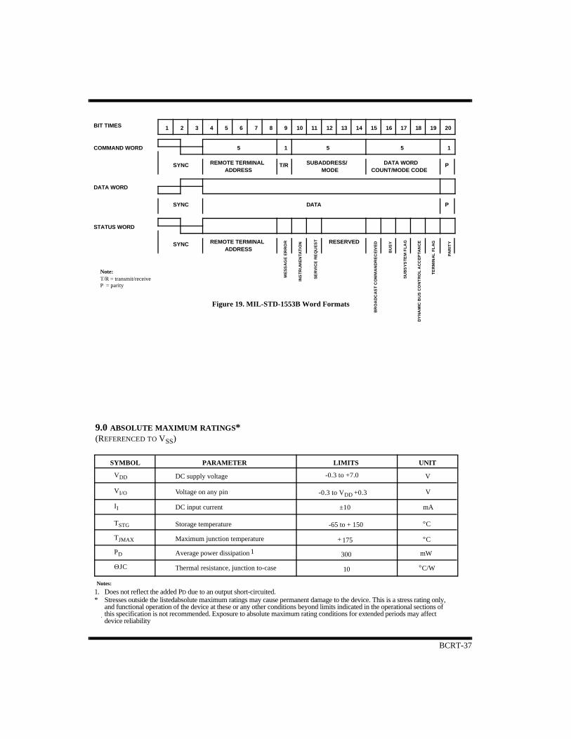
BCRT-37
1 2 3 4 5 6 7 8 9 10 11 12 13 14 15 16 17 18 19 20
5 1 5 5 1
RESERVEDREMOTE TERMINALADDRESS
SYNC
STATUS WORD
DATA WORD
SYNC
SYNC
DATA P
PREMOTE TERMINALADDRESS
T/R SUBADDRESS/MODE
DATA WORDCOUNT/MODE CODE
BIT TIMES
Note:T/R = transmit/receiveP = parity
COMMAND WORD
ME
SS
AG
E E
RR
OR
INS
TR
UM
EN
TAT
ION
SE
RV
ICE
RE
QU
ES
T
BR
OA
DC
AS
T C
OM
MA
ND
RE
CE
IVE
D
BU
SY
SU
BS
YS
TE
M F
LA
G
DY
NA
MIC
BU
S C
ON
TR
OL
AC
CE
PTA
NC
E
TE
RM
INA
L F
LA
G
PA
RIT
Y
1. Does not reflect the added PD due to an output short-circuited.* Stresses outside the listedabsolute maximum ratings may cause permanent damage to the device. This is a stress rating only,
and functional operation of the device at these or any other conditions beyond limits indicated in the operational sections of this specification is not recommended. Exposure to absolute maximum rating conditions for extended periods may affect device reliability
SYMBOL PARAMETER LIMITS UNIT
DC supply voltage
Voltage on any pin
DC input current
Storage temperature -65 to + 150
V
V
mA
Notes:
.
Maximum junction temperature 175+
Average power dissipation 300 mW
Thermal resistance, junction to-case 10 C/W°
VDD
VI/O
II
TSTG
TJMAX
PD
ΘJC
±10
-0.3 to +7.0
-0.3 to VDD +0.3
C°
C°
1
9.0 ABSOLUTE MAXIMUM RATINGS*(REFERENCED TO VSS)
Figure 19. MIL-STD-1553B Word Formats
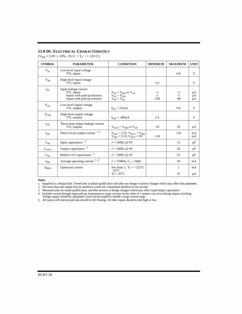
BCRT-38
11.0 DC ELECTRICAL CHARACTERISTICS(VDD = 5.0V ± 10%; -55×C < TC < + 125×C)
Notes:1. Supplied as a design limit. Tested only at initial qualification and after any design or proess changes which may affect this parameter.2. Not more than one output may be shorted at a time for a maximum duration of one second.3. Measured only for initial qualification, and after process or design changes which may affect input/output capacitance.4. Includes current through input pull-up. Instantaneous surge currents on the order of 1 ampere can occur during output switching.
Voltage supply should be adequately sized and decoupled to handle a large current surge.5. All inputs with internal pull-ups should be left floating. All other inputs should be tied high or low.
SYMBOL PARAMETER CONDITION MINIMUM MAXIMUM UNIT
VIL Low-level input voltageTTL inputs 0.8 V
VIH High-level input voltageTTL inputs 2.0 V
IIN Input leakage currentTTL inputsInputs with pull-up resistorsInputs with pull-up resistors
VIN = VDD or VSSVIN = VDDVIN = VSS
-1-1
-550
-1-1-80
µAµAµA
VOL Low-level output voltageTTL outputs IOL = 3.2mA 0.4 V
VOH High-level output voltageTTL outputs IOH = -400µA 2.4 V
IOZ Three-state output leakage currentTTL outputs VOUT = VDD or VSS -10 10 µA
IOS Short-circuit output current 1, 2 VDD = 5.5V, VOUT = VDDVDD = 5.5V, VOUT = 0V -110
110 mAmA
CIN Input capacitance 3 ƒ = 1MHz @ 0V 15 pF
COUT Output capacitance 3 ƒ = 1MHz @ 0V 20 pF
CIO Bidirect I/O capacitance 3 ƒ = 1MHz @ 0V 25 pF
IDD Average operating current 1, 4 ƒ = 12MHz, CL = 50pF 50 mA
QIDD Quiescent current See Note 5, Tc = +125oC -55oCTc = 25oC
1
35
mA
µA

BCRT-39
11.0 AC ELECTRICAL CHARACTERISTICS(OVER RECOMMENDED OPERATING CONDITIONS)
to data validto high Z
to response
to response
to response
INPUTINPUT
INPUT
INPUTINPUT
INPUT
INPUT
to high Z
to data valid
to responseINPUTPARAMETERSYMBOL
BUS
OUTPUTOUT-OF-PHASEOUTPUTIN-PHASE
INPUT
Notes:1. Timing measurements made at (VIH MIN + VIL MAX)/2.2. Timing measurements made at (VOL MAX + VOH MIN)/2.3. Based on 50pF load.4. Unless otherwise noted, all AC electrical characteristics are guaranteed by design or characterization.
tf
te
td
tc
tb
ta
th
tg
ta
tc
tb
td
te
tftg
th
VIH MINVIL MAX
VIH MINVIL MAX
VOH MINVOL MAX
VOH MINVOL MAX
VOH MIN
VOL MAX
↑
↑↑
↑
↑
↑
↑↓
↓
↓
↓↓
1 1
2 2
2 2
90%
Figure 21. AC Test Loads and Input Waveforms
Note:50pF including scope probe and test socket
Input Pulses
10%10%
90%
< 2ns < 2ns
50pF
3V
0V
5V
•
IREF (source)
IREF (sink)
VREF
Output Loading
Figure 20. Typical Timing Measurements
Device under Test

BCRT-40
MCLKD2
ADDRESS
DATA
AEN
BURST
DMA GRANT RECOGNIZED ON THIS EDGE
THMC1+1040
SYMBOL PARAMETER MIN MAX UNITS
0THMC1-10MCLK-20
nsnsnsnsnsns
0
0
2xMCLK
MCLK
µ
454xMCLK
6xMCLKMCLK+20
3.5 (1.9)
MCLK = period of the memory clock cycle.BURST signal is for multiple-word DMA accesses. THMC1 is equivalent to the positive phase of MCLK (see figure 23).
-10 ns10
s0 1.9 (0.8) µ s
ns0 10
(2)
DMAR
DMAG
DMACK
TSCTL
MEMCSO
tSHL1
tPW2
tOOZL1
tPHL4
tPHL1
tPHL2
tPZL1
tPHL3
RWR/RRD
tSHL16 DMACK↓ to DMAR High Impedance
DMAG↓ to DMACK↓ 3
DMAG↓ to TSCTL↓TSCTL↓ to ADDRESS validRWR/RRD↑ to DMACK↑TSCTL↓ to RWR/RRD↓
DMAG↓ to DMAG↑DMAR↓ to BURST↑DMAR↓ to DMAG↓ 5
DMAR↓ to DMAG↓ 4 Notes:1. Guaranteed by test.2. See figures 23 & 24 for detailed DMA read and write timing.3. DMAG must be asserted at least 45ns prior to the rising edge of MCLKD2 in order to be recognized for the next MCLKD2 cycle.
If DMAG is not asserted at least 45ns prior to the rising edge of MCLKD2, DMAG is not recognized until the following MCLKD2 cycle.
4. Provided MCLK = 12MHz. Number in parentheses indicates the longest DMAR↓ to DMAG↓ allowed during worst-case bus switching conditions in order to meet MIL-STD-1553B RT Response Time. The number not in parentheses applies to all other circumstances.
5. Provided MCLK = 6MHz. Number in parentheses indicates the longest DMAR↓ DMAG↓ allowed during worst-case bus switching conditions in order to meet MIL-STD-1553B RT Response Time. The number not in parentheses applies to all other circumstances
6. Tested only at initial qualification, and after any design or process changes which may affect this characteristic.
tPHL1
tPHL21tPZL16tHLH2tPHL3
tPW21tOOZL1tPHL4
tPHL4
tHLH2
Figure 22. BURST DMA Timing

BCRT-41
ns
ns
ns
ns
ns
ns
ns
40
-
-
THMC1+10
MCLK+5
THMC2-15
0
40
5
THMC1-10
MCLK-10
THMC2-10
(DATA setup)
(DATA hold)
(ADDRESS hold)
(ADDRESS setup)
UNITSMAXMINPARAMETERSYMBOL
RRD
DATA
ADDRESS
TSCTL
MCLKD2
MCLKTHMC1 THMC2
MEMCSO
ns600
1. Guaranteed by test.Note:
400
tIOHL1
tSHL1 tSLH1tPW1
tHLZ2
ADDRESS valid to RRD↓
RRD↓ to RRD↑
RRD↑ to ADDRESS High Impedance
RRD↑ to DATA High Impedance
DATA valid to RRD↑
MCLK↑ to MCLKD2↑
MCLK↑ to TSCTL/MEMCSO↓
MCLK↑ to RRD↓
tHLZ1
tSHL1
tPLH1
tPLH2
tPW1
tHLZ2
tHLZ1
tSLH1
tPLH1 1
tPLH2
tIOHL1 1
Figure 23. BCRT DMA Read Timing (One-Word Read)
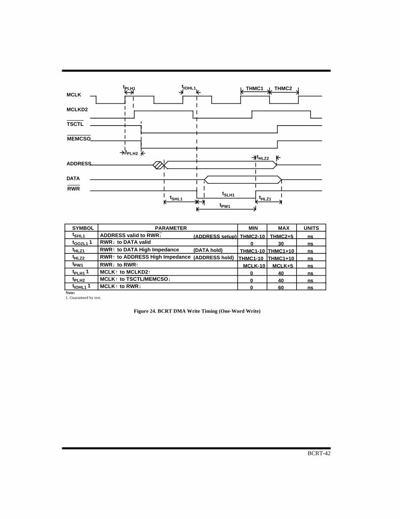
BCRT-42
nsnsnsnsnsnsns
400MCLK-10
THMC1-10THMC1-10
0THMC2-10
(DATA hold)(ADDRESS hold)
(ADDRESS setup)
UNITSMAXMINPARAMETERSYMBOL
DATA
ADDRESS
MCLKD2
MCLK
THMC2+530
THMC1+10THMC1+10
MCLK+5
THMC1 THMC2
ns600
1. Guaranteed by test.Note:
400
TSCTL
MEMCSO
RWR
tSHL1 ADDRESS valid to RWR↓RWR↓ to DATA validRWR↑ to DATA High ImpedanceRWR↑ to ADDRESS High Impedance
RWR↓ to RWR↑MCLK↑ to MCLKD2↑MCLK↑ to TSCTL/MEMCSO↓MCLK↑ to RWR↓
tOOZL1 1tHLZ1tHLZ2tPW1
tPLH1 1tPLH2tIOHL1 1
tPLH1 tIOHL1
tPLH2
tSHL1tSLH1
tPW1
tHLZ1
tHLZ2
Figure 24. BCRT DMA Write Timing (One-Word Write)

BCRT-43
101060
5--
nsnsnsnsnsns
(DATA hold)(ADDRESS hold)
(ADDRESS setup)UNITSMAXMINPARAMETERSYMBOL
ADDRESS
DATA
(DATA setup)60
80
-
---
tSHL1 tPW1 tHLH2
tPW2
ADDRESS valid to WR+CS↓DATA valid to WR+CS↓WR+CSØ to WR+CS↑WR+CS↑ to DATA High ImpedanceWR+CS↑ to ADDRESS High ImpedanceWR+CS↑ to WR+CS↓
WR+CS
tHLH1
tSHL1tSHL2
tPW1
tHLH1tHLH2tPW2
nsnsnsnsnsns
5
5-
(DATA hold)
(ADDRESS hold)
ADDRESS valid to DATA valid
UNITSMAXMINPARAMETERSYMBOL
ADDRESS
DATA
(DATA access)
6080
80
---
6050
-
Notes:1. Guaranteed by functional test.2. User must adhere to both tOOZH1 and tOOZH2 timing constraints to ensure valid data.
tOOZH2
tOOZH1 tHLH1
tHLH2tPW1 tPW2
RD+CS↑ to DATA High ImpedanceRD+CS↓ to DATA validRD+CS↑ to ADDRESS High ImpedanceRD+CS↓ to RD+CS↑RD+CS↑ to RD+CS↓
RD+CS
tOOZH2tHLH2tOOZH1 2tHLH1
tPW1tPW21
Notes:1. Guaranteed by functional test.
tSHL2
Figure 25. BCRT Register Read Timing
Figure 26. BCRT Register Write Timing
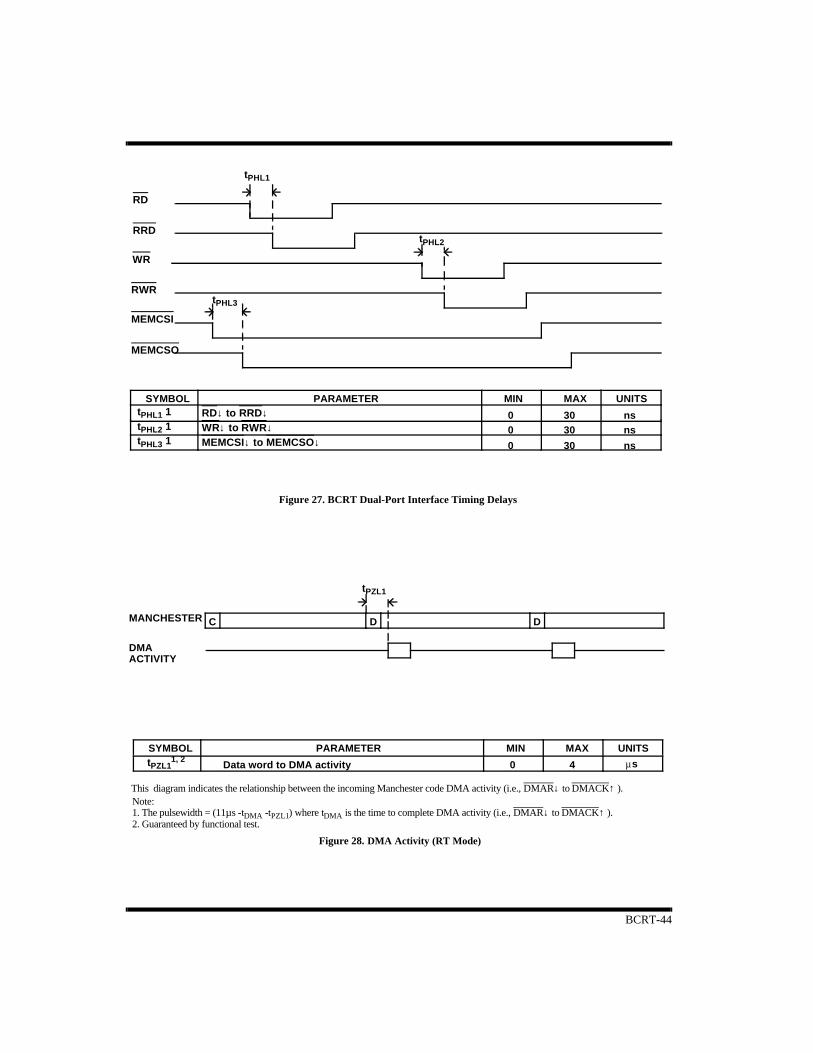
BCRT-44
nsns
UNITSMAXMINPARAMETERSYMBOL
00
0 ns
3030
30
tPHL1
tPHL2
tPHL3
tPHL1 1tPHL2 1tPHL3 1
RD
RRD
WR
RWR
MEMCSI
MEMCSO
RD↓ to RRD↓ WR↓ to RWR↓ MEMCSI↓ to MEMCSO↓
0
SYMBOL PARAMETER MIN MAX UNITS
MANCHESTER
DMAACTIVITY
C D D
Data word to DMA activity 4 µs
Note:1. The pulsewidth = (11µs -tDMA -tPZL1) where tDMA is the time to complete DMA activity (i.e., DMAR↓ to DMACK↑ ).2. Guaranteed by functional test.
tPZL1
This diagram indicates the relationship between the incoming Manchester code DMA activity (i.e., DMAR↓ to DMACK↑ ).
tPZL11, 2
Figure 28. DMA Activity (RT Mode)
Figure 27. BCRT Dual-Port Interface Timing Delays
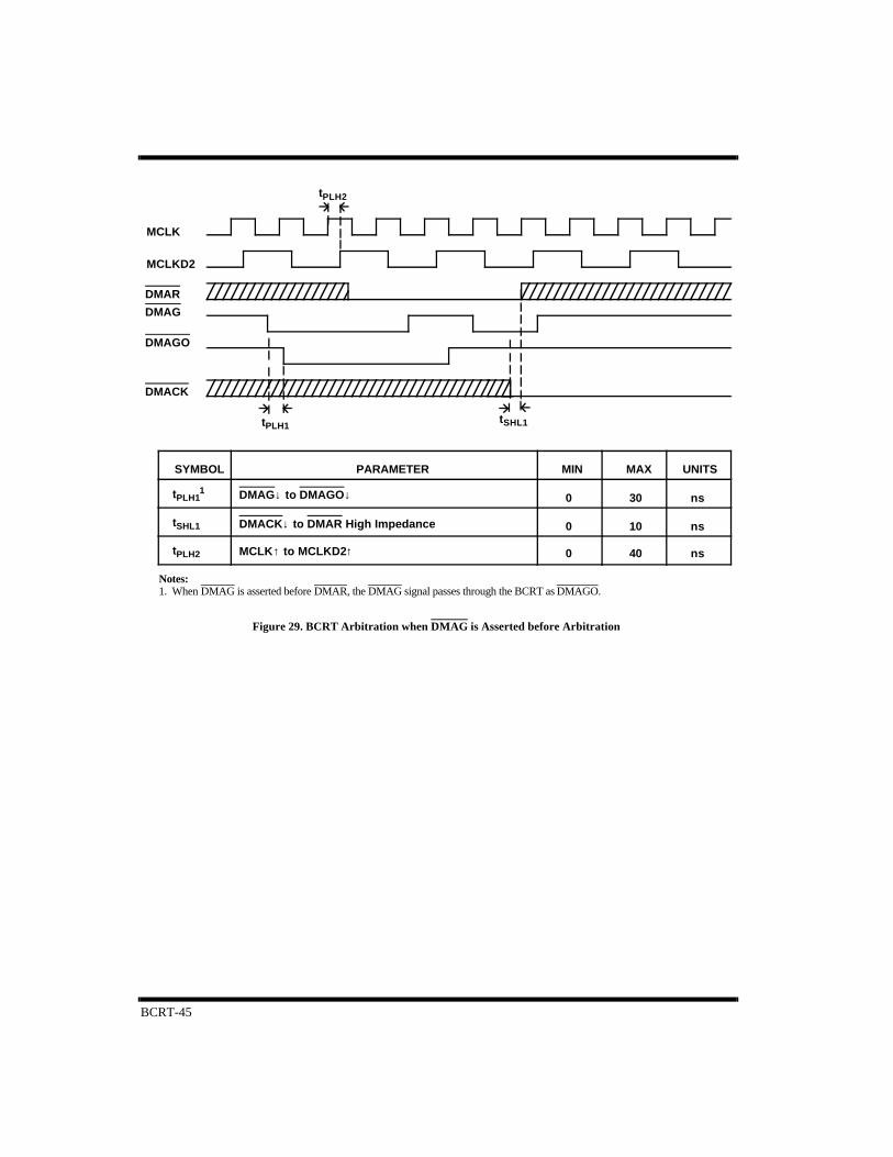
BCRT-45
40
30
10 ns
ns
UNITSMAXMINPARAMETERSYMBOL
0
0
0 ns
MCLK
MCLKD2
Notes:1. When DMAG is asserted before DMAR, the DMAG signal passes through the BCRT as DMAGO.
tPLH2
tPLH1tSHL1
tPLH11
tSHL1
tPLH2
DMAR
DMAG
DMAGO
DMACK
DMAG↓ to DMAGO↓
DMACK↓ to DMAR High Impedance
MCLK↑ to MCLKD2↑
Figure 29. BCRT Arbitration when DMAG is Asserted before Arbitration
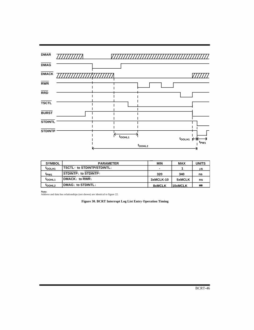
BCRT-46
Note:
3xMCLK-10 5xMCLK
10xMCLK
340
1
8xMCLK
320
-
ns
ns
UNITSMAXMINPARAMETERSYMBOL
BURST
Address and data bus relationships (not shown) are identical to figure 22.
µµs
sµ
DMAR
DMAG
DMACK
RWR
RRD
TSCTL
STDINTL
STDINTP
tOOHL1
tOOHL2
tOOLH1tPW1
tOOLH1
tPW1
tOOHL1
tOOHL2
TSCTL↑ to STDINTP/STDINTL↓
STDINTP↓ to STDINTP↑
DMACK↓ to RWR↓
DMAG↓ to STDINTL↓
Figure 30. BCRT Interrupt Log List Entry Operation Timing
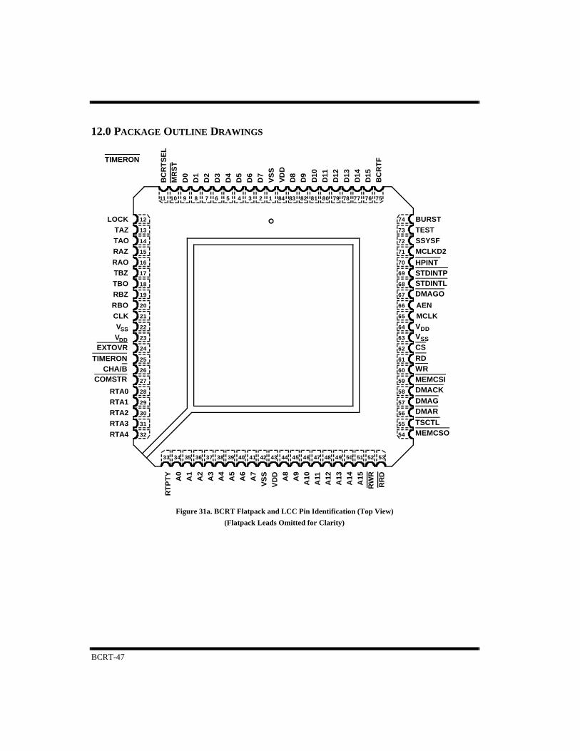
BCRT-47
12.0 PACKAGE OUTLINE DRAWINGS
DD
SS
LOCKTESTSSYSF
MCLKAEN
VV
RTA0
RTA4RTA3RTA2RTA1
RBORBZ
RAO
RAZ
TBOTBZ
TAOTAZ
CLK
73
72
71
70
69
68
67
66
65
64
63
62
61
60
59
58
57
56
55
54
535251504948474645444342414039383736353433
16
19
32
31
30
29
28
27
26
25
24
23
22
21
20
18
17
15
14
13
12 74 BURST
MCLKD2
11 10 9 8 7 6 5 4 3 2 1 84 83 82 81 80 79 78 77 76 75
RT
PT
YA
0A
1A
2A
3A
4A
5A
6A
7V
SS
VD
D A8
A9
A10
A11
A12
A13
A14
A15
RW
RR
RD
BC
RT
SE
LM
RS
T
D0
D1
D2
D3
D4
D5
D6
D7
VS
SV
DD
D8
D9
D10
D11
D12
D13
D14
D15
BC
RT
F
EXTOVRTIMERON
CHA/BCOMSTR
TIMERON
HPINT STDINTPSTDINTL DMAGO
VDDVSSCSRDWRMEMCSIDMACKDMAGDMARTSCTLMEMCSO
Figure 31a. BCRT Flatpack and LCC Pin Identification (Top View)
(Flatpack Leads Omitted for Clarity)
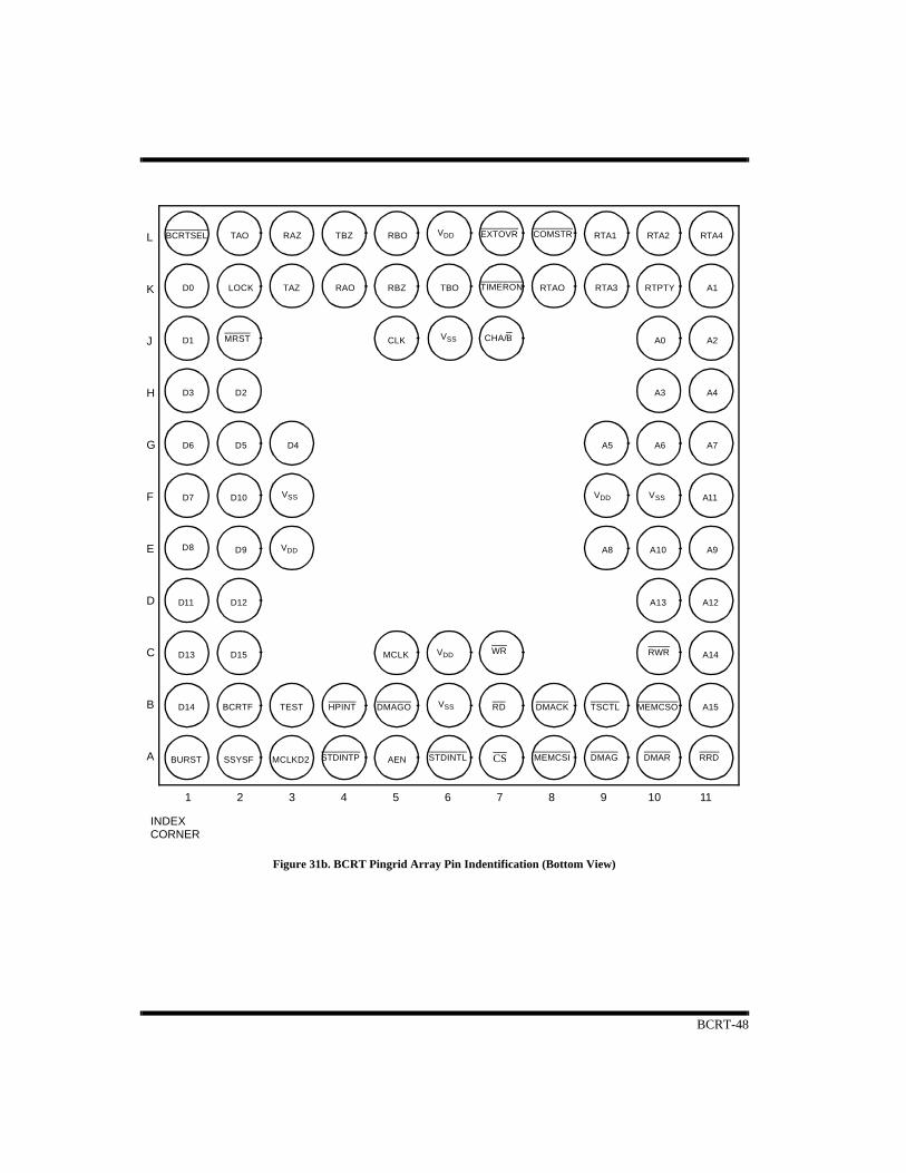
BCRT-48
DD
SS
V
V
DD
BURST SSYSFA
B
C
D
E
F
G
H
J
K
A0
A1
A2
A3 A4
A5 A6 A7
A8 A9A10
A11
A12A13
A14
A15
D0
D1
D3
D4D5D6
D7
D8 D9
D10
D11 D12
D13
D14
D15
AEN
CLK
MCLK
MCLKD2
L
TAZ
TAO TBZ
TBO
RAZ
RAO RBZ
RBOBCRTSEL
RTAO
RTA1 RTA2
RTA3
RTA4
RTPTY
BCRTF TEST
LOCK
1110987654321
D2
INDEXCORNER
BURST SSYSF
D8
TIMERON
EXTOVR COMSTR
MRST CHA/BVSS
VDD
VDDVSS VSS
VDD
WR
HPINT DMAGO TSCTL MEMCSO
STDINTP STDINTL CS MEMCSI DMAG DMAR RRD
DMACKRD
VDD
VSS
RWR
Figure 31b. BCRT Pingrid Array Pin Indentification (Bottom View)

Packaging-1
Package Selection Guide
NOTE:
1. 84LCC package is not available radiation-hardened.
ProductRTI RTMP RTR BCRT BCRTM BCRTMP RTS XCVR
24-pin DIP(single cavity)
X
36-pin DIP(dual cavity)
X
68-pin PGA X X84-pin PGA X X X X1
144-pin PGA X84-lead LCC X X X1
36-lead FP(dual cavity)(50-mil ctr)
X
84-lead FP X X132-lead FP X X

Packaging-2
1
144-Pin Pingrid Array
E1.565 ± 0.025
-B-
D1.565 ± 0.025 -A-
0.080 REF.(2 Places)
0.040 REF.
0.100 REF.(4 Places)
A0.130 MAX.
Q0.050 ± 0.010 A
A
L0.130 ±0.010
PIN 1 I.D.(Geometry Optional)
-C-(Base Plane)
b0.018 ± 0.002
0.0300.010
C A BC
SIDE VIEW
TOP VIEW
0.003 MIN. TYP.
D1/E11.400
0.100TYP.
e
PIN 1 I.D.(Geometry Optional)
2R
P
N
M
L
K
J
H
G
F
E
D
1 2 3 4 5 6 7 8 9 10 11 12 13 14 15
Notes:1. True position applies to pins at base plane (datum C).2. True position applies at pin tips.3. All package finishes are per MIL-M-38510.4. Letter designations are for cross-reference to MIL-M-38510.
BOTTOM VIEW
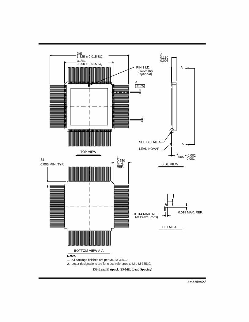
Packaging-3
132-Lead Flatpack (25-MIL Lead Spacing)
SIDE VIEW
TOP VIEW
BOTTOM VIEW A-A
DETAIL A
0.018 MAX. REF.0.014 MAX. REF.(At Braze Pads)
L0.250MIN.REF.
LEAD KOVAR
SEE DETAIL AA
A
C0.005 + 0.002
- 0.001
A0.1100.006D1/E1
0.950 ± 0.015 SQ.
D/E1.525 ± 0.015 SQ.
PIN 1 I.D.(GeometryOptional)
e0.025
Notes:1. All package finishes are per MIL-M-38510.2. Letter designations are for cross-reference to MIL-M-38510.
S1
0.005 MIN. TYP.
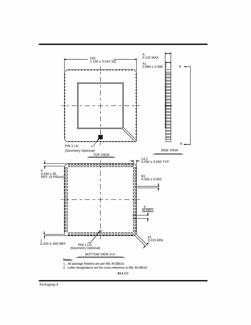
Packaging-4
84-LCC
SIDE VIEWTOP VIEW
BOTTOM VIEW A-A
Notes:1. All package finishes are per MIL-M-38510.2. Letter designations are for cross-reference to MIL-M-38510.
L/L10.050 ± 0.005 TYP.
B10.025 ± 0.003
e0.050
e10.015 MIN.
PIN 1 I.D.(Geometry Optional)
J0.020 X 455 REF.
h0.040 x 45_REF. (3 Places)
D/E1.150 ± 0.015 SQ.
A0.115 MAX.
A10.080 ± 0.008 A
APIN 1 I.D.
(Geometry Optional)
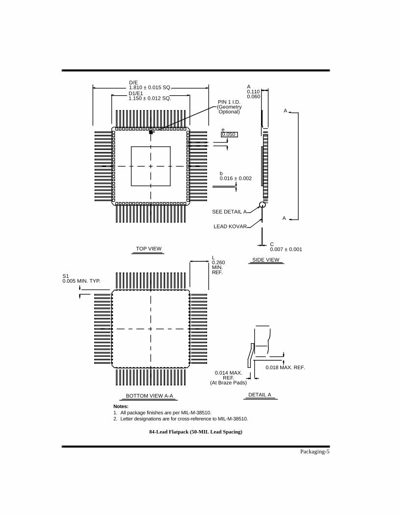
Packaging-5
84-Lead Flatpack (50-MIL Lead Spacing)
SIDE VIEW
TOP VIEW
BOTTOM VIEW A-A
D/E1.810 ± 0.015 SQ.
Notes:1. All package finishes are per MIL-M-38510.2. Letter designations are for cross-reference to MIL-M-38510.
DETAIL A
D1/E11.150 ± 0.012 SQ.
A0.1100.060
A
A
C0.007 ± 0.001
LEAD KOVAR
SEE DETAIL A
PIN 1 I.D.(GeometryOptional)
b0.016 ± 0.002
L0.260MIN.REF.
S10.005 MIN. TYP.
0.050e
0.014 MAX. REF.
(At Braze Pads)
0.018 MAX. REF.
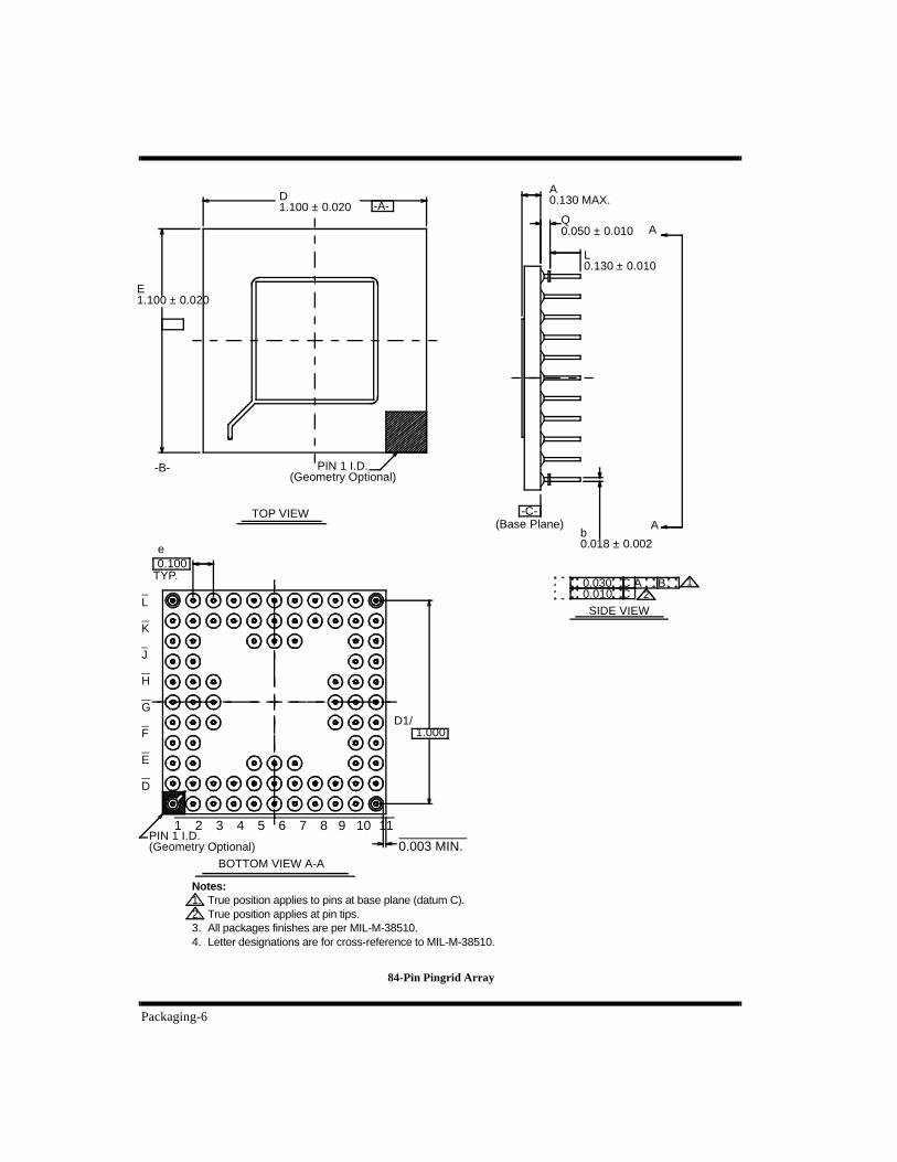
Packaging-6
84-Pin Pingrid Array
SIDE VIEW
TOP VIEW
BOTTOM VIEW A-A
D1.100 ± 0.020
E1.100 ± 0.020
-B-
-A-
A0.130 MAX.
Q0.050 ± 0.010
L0.130 ± 0.010
A
A
-C-(Base Plane)
b0.018 ± 0.002
PIN 1 I.D.(Geometry Optional)
1.000D1/
e0.100
TYP.
0.003 MIN.
L
K
J
H
G
F
E
D
1 2 3 4 5 6 7 8 9 10 11
Notes:1. True position applies to pins at base plane (datum C).2. True position applies at pin tips.3. All packages finishes are per MIL-M-38510.4. Letter designations are for cross-reference to MIL-M-38510.
PIN 1 I.D.(Geometry Optional)
10.0300.010
C A BC 2

Packaging-7
SIDE VIEW
TOP
BOTTOM VIEW A-A
D1.100 ± 0.020
PIN 1 I.D.(Geometry Optional)
LKJHGFEDCBA
1 2 3 4 5 6 7 8 9 10 11
Notes:1 True position applies to pins at base plane (datum C).2 True position applies at pin tips.3. All packages finishes are per MIL-M-38510.4. Letter designations are for cross-reference to MIL-M-38510.
PIN 1 I.D.(Geometry Optional)
D1/E11.00
0.003 MIN. TYP.
e0.100TYP.
A0.130 MAX.
Q0.050 ± 0.010
L0.130 ± 0.010
A
A
-A-
-B-
E1.100 ± 0.020
-C-(Base Plane)
68-Pin Pingrid Array
0.0300.010 C
A B 12
C∅∅
b
0.010 ± 0.002

Packaging-8
D1.800 ± 0.025
36-Lead Flatpack, Dual Cavity (100-MIL Lead Spacing)
TOP VIEW
END VIEW
E0.750 ± 0.015
Notes:1 All package finishes are per MIL-M-38510.2. It is recommended that package ceramic be mounted to
a heat removal rail located on the printed circuit board. A thermally conductive material such as MERECO XLN-589 or equivalent should be used.
3. Letter designations are for cross-reference to MIL-M-38510.
PIN 1 I.D.(Geometry Optional)
L0.490MIN.
b0.015 ± 0.002
e0.10
c0.008 + 0.002
- 0.001
Q0.080 ± 0.010(At Ceramic Body)
A0.130 MAX.

Packaging-9
36-Lead Flatpack, Dual Cavity (50-MIL Lead Spacing)
TOP
E0.700 + 0.015
Notes:1. All package finishes are per MIL-M-38510.2. It is recommended that package ceramic be mounted to
a heat removal rail located on the printed circuit board.A thermally conductive material such as MERECO XLN-589 or equivalent should be used.
3. Letter designations are for cross-reference to MIL-M-38510.
c0.007
+ 0.002 - 0.001
Q0.070 + 0.010(At Ceramic Body)
A0.100 MAX.
END
D1.000 ± 0.025
b0.016 + 0.002
e0.050
PIN 1 I.D(Geometry Optional)
L0.330MIN.
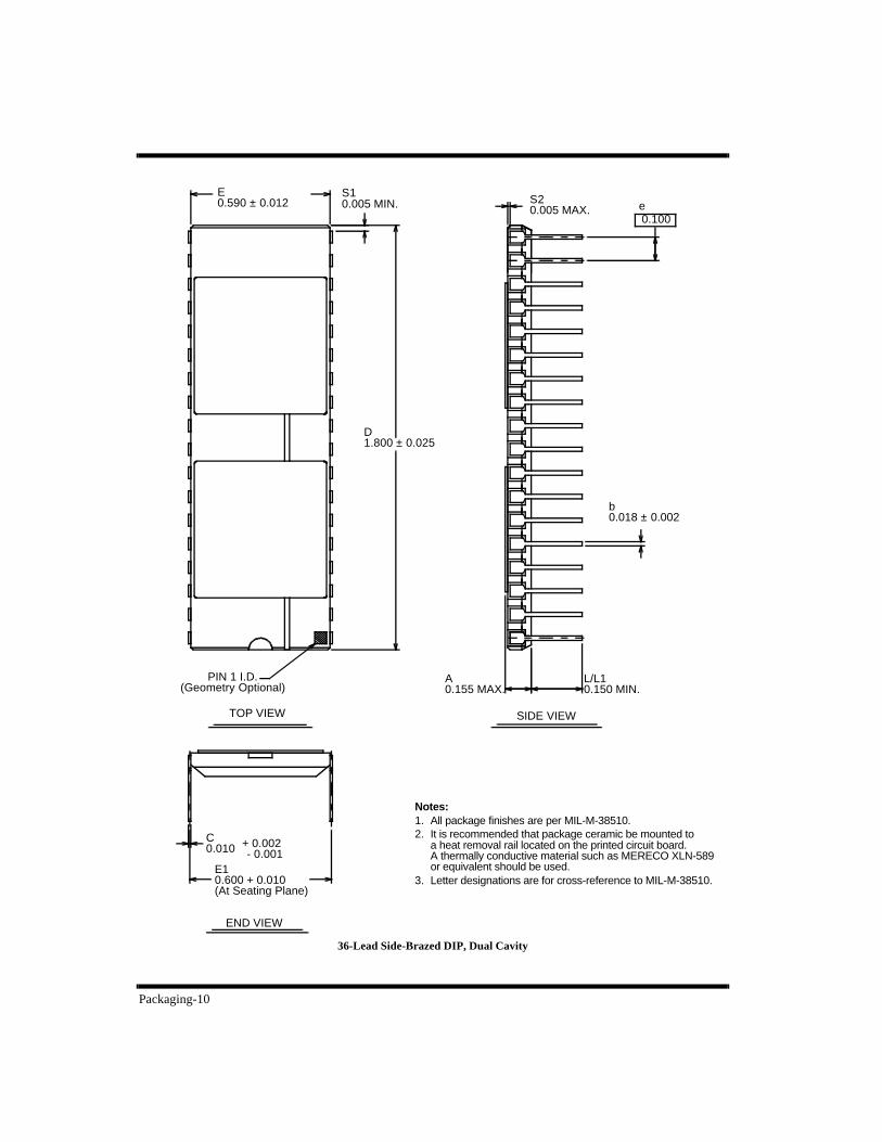
Packaging-10
36-Lead Side-Brazed DIP, Dual Cavity
TOP VIEW
END VIEW
E0.590 ± 0.012
Notes:1. All package finishes are per MIL-M-38510.2. It is recommended that package ceramic be mounted to
a heat removal rail located on the printed circuit board.A thermally conductive material such as MERECO XLN-589 or equivalent should be used.
3. Letter designations are for cross-reference to MIL-M-38510.
PIN 1 I.D.(Geometry Optional)
SIDE VIEW
S10.005 MIN.
D1.800 ± 0.025
S20.005 MAX. e
0.100
A0.155 MAX.
L/L10.150 MIN.
C0.010 + 0.002
- 0.001E10.600 + 0.010(At Seating Plane)
b0.018 ± 0.002
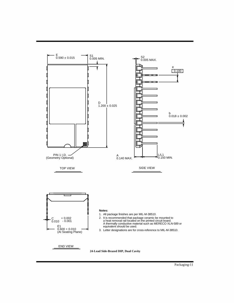
Packaging-11
E0.590 ± 0.015
S10.005 MIN. S2
0.005 MAX.
TOP VIEW
PIN 1 I.D.(Geometry Optional)
D1.200 ± 0.025
SIDE VIEW
A0.140 MAX.
L/L10.150 MIN.
0.100e
Notes:1. All package finishes are per MIL-M-38510.2. It is recommended that package ceramic be mounted to
a heat removal rail located on the printed circuit board.A thermally conductive material such as MERECO XLN-589 or equivalent should be used.
3. Letter designations are for cross-reference to MIL-M-38510.
END VIEW
C0.010
+ 0.002 - 0.001
E10.600 + 0.010(At Seating Plane)
b0.018 ± 0.002
24-Lead Side-Brazed DIP, Dual Cavity
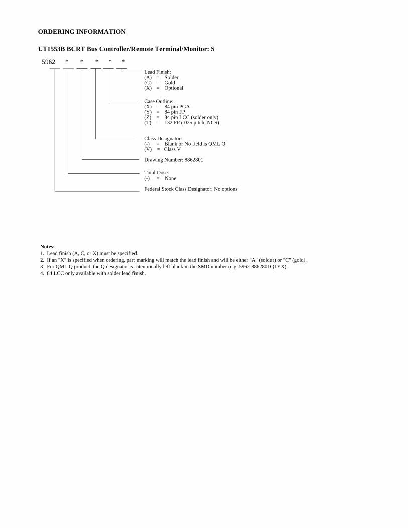
ORDERING INFORMATION
UT1553B BCRT Bus Controller/Remote Terminal/Monitor: S
Lead Finish:(A) = Solder (C) = Gold(X) = Optional
Case Outline:(X) = 84 pin PGA (Y) = 84 pin FP(Z) = 84 pin LCC (solder only)(T) = 132 FP (.025 pitch, NCS)
Class Designator:(-) = Blank or No field is QML Q(V) = Class V
Drawing Number: 8862801
Total Dose:(-) = None Federal Stock Class Designator: No options
5962 * * * * *
Notes:1. Lead finish (A, C, or X) must be specified.2. If an "X" is specified when ordering, part marking will match the lead finish and will be either "A" (solder) or "C" (gold).3. For QML Q product, the Q designator is intentionally left blank in the SMD number (e.g. 5962-8862801Q1YX).4. 84 LCC only available with solder lead finish.
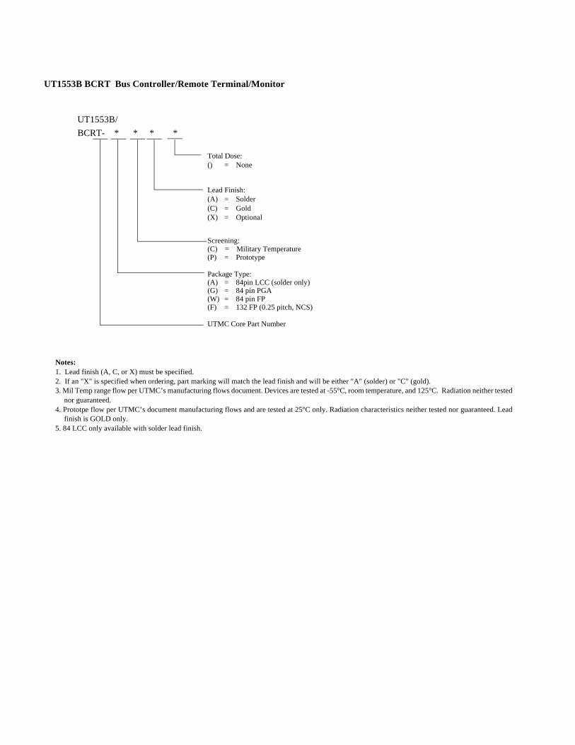
UT1553B BCRT Bus Controller/Remote Terminal/Monitor
Total Dose:() = None
Lead Finish:(A) = Solder (C) = Gold(X) = Optional
Screening:(C) = Military Temperature(P) = Prototype
Package Type:(A) = 84pin LCC (solder only)(G) = 84 pin PGA(W) = 84 pin FP(F) = 132 FP (0.25 pitch, NCS)
UTMC Core Part Number
UT1553B/
BCRT- * * * *
Notes:1. Lead finish (A, C, or X) must be specified.2. If an "X" is specified when ordering, part marking will match the lead finish and will be either "A" (solder) or "C" (gold).3. Mil Temp range flow per UTMC’s manufacturing flows document. Devices are tested at -55°C, room temperature, and 125°C. Radiation neither tested
nor guaranteed. 4. Prototpe flow per UTMC’s document manufacturing flows and are tested at 25°C only. Radiation characteristics neither tested nor guaranteed. Lead
finish is GOLD only.5. 84 LCC only available with solder lead finish.