Embed Size (px)
Citation preview

Wood chip
small
FINAL REPORT
Wood chip feeding technology of the future
small-scale biomass boilers – BioChipFeeding
FP7 Call
Leader: HET - Heiz- und Energietechnik
www.BioChipFeeding.com
FINAL REPORT
feeding technology of the future for
BioChipFeeding
FP7 Call- Research for SMEs
Project 606464
und Energietechnik Entwicklungs-GmbH
DI Thomas Bauer
www.BioChipFeeding.com

Contents Summary description of project context and objectives
Description of the main S&T results/foregrounds
System Overview ................................
Development and Design of Feeding Step 1
Crane system ................................
Wood chip gripper ................................
Sensorial concept ................................
Analysis and optimisation of Feeding Step 2
Overview of experimental results from the screw feeder
Results from discrete element simulations
System Design and Concept of the Overall Control System
Overall Control System ................................
General Functionality ................................
Hardware Setup ................................
Safety Concept................................
Circuit Diagram ................................
Control Algorithm ................................
System Design and Algorithm Description of the Image Recognition System
Objectives and Tasks of Image Recognition System
Sensor Architecture ................................
Algorithm Description – Segmentation
Algorithm Description – Sawdust Detection
Algorithm Description – Woodchip Size Estimation
Algorithm Description – Overlarge Wood Chip Detection
Algorithm Description – Quality Estimation
Algorithm Description – Foreign Object Detection
The potential impact ................................
The address of the project public website, if applicable as well as relevant contact details
Use and dissemination of foreground
Section A ................................................................
Template A1 ................................
Template A2 ................................
Section B ................................................................
Part B1 ................................
Part B2 ................................
Summary description of project context and objectives ................................................................
Description of the main S&T results/foregrounds ................................................................
................................................................................................................................
Development and Design of Feeding Step 1 ................................................................
................................................................................................................................
................................................................................................
................................................................................................
Analysis and optimisation of Feeding Step 2 ................................................................
Overview of experimental results from the screw feeder ................................
Results from discrete element simulations ................................................................
System Design and Concept of the Overall Control System ................................
................................................................................................
................................................................................................
................................................................................................
...............................................................................................................................
..............................................................................................................................
................................................................................................
and Algorithm Description of the Image Recognition System ................................
Objectives and Tasks of Image Recognition System ................................................................
................................................................................................
Segmentation ................................................................
Sawdust Detection ................................................................
Woodchip Size Estimation ................................................................
Overlarge Wood Chip Detection ................................
Quality Estimation ................................................................
Foreign Object Detection ................................................................
................................................................................................
The address of the project public website, if applicable as well as relevant contact details
Use and dissemination of foreground ................................................................................................
................................................................................................
................................................................................................................................
................................................................................................................................
1
........................................ 4
.................................................. 5
................................. 5
....................................................... 6
................................... 7
........................................................... 7
............................................................ 9
.................................................... 11
............................................................ 12
................................................... 13
............................................................. 17
.................................................. 17
.................................................... 17
............................................................. 18
............................... 19
.............................. 19
.......................................................... 19
.................................. 22
..................................... 22
....................................................... 22
......................................................... 22
................................................. 22
...................................... 23
............................................................ 23
.................................................. 24
....................................... 25
............................................................. 29
The address of the project public website, if applicable as well as relevant contact details ............... 30
................................... 34
............................................ 34
.................................. 34
.................................. 35
............................................ 36
........................................... 36
........................................... 37

2

Executive Summary
Max. 1 page
3

Summary description of project context and objectivesMax. 4 pages
ummary description of project context and objectives
4
ummary description of project context and objectives

Description of the main S&T results/foregrounds
System Overview Figure 1 shows an illustration of a heating plant using the BioChipFeeding
wood chip boiler. The BioChipFeeding
two subsystems: Feeding Step 1 and Feeding Step 2.
Feeding Step 1 handles the wood chips stored within the wood chip bunker using a gripper system
attached to an automatic crane system. Beside the functionality to transport the wood chips from
the bunker to Feeding Step 2, the sensors equipped at the gripper provide the ability to
wood chips regarding the properties: moisture content, particle size and color.
of this properties, the gripper is used to determine the filling level
Using the wood chip properties and filling level information from the bunker, the implemented
algorithm of the feeding control decides according to the current operating status reported b
boiler control which portion of the available wood chips is the most suitable. When possible, the
feeding control tries to blend different qualities of the wood chips in order to support a stable
combustion of the boiler.
Led by the feeding control, the gripper grabs the wood chips within the bunker and transports them
to the hopper of Feeding Step 2, where different qualities of wood chips are blended to a calculated
target quality. Continuing through the screw feeder, the wood chips are further tran
dosed by the stoker screw to the firing of the boiler.
escription of the main S&T results/foregrounds
shows an illustration of a heating plant using the BioChipFeeding-system for feeding the
The BioChipFeeding-system can be structured (regarding the material flow) into
ubsystems: Feeding Step 1 and Feeding Step 2.
Feeding Step 1 handles the wood chips stored within the wood chip bunker using a gripper system
attached to an automatic crane system. Beside the functionality to transport the wood chips from
ding Step 2, the sensors equipped at the gripper provide the ability to
wood chips regarding the properties: moisture content, particle size and color. Besides
of this properties, the gripper is used to determine the filling level of the bunker.
Figure 1: System Overview
Using the wood chip properties and filling level information from the bunker, the implemented
algorithm of the feeding control decides according to the current operating status reported b
boiler control which portion of the available wood chips is the most suitable. When possible, the
feeding control tries to blend different qualities of the wood chips in order to support a stable
the gripper grabs the wood chips within the bunker and transports them
to the hopper of Feeding Step 2, where different qualities of wood chips are blended to a calculated
target quality. Continuing through the screw feeder, the wood chips are further tran
dosed by the stoker screw to the firing of the boiler.
5
system for feeding the
system can be structured (regarding the material flow) into
Feeding Step 1 handles the wood chips stored within the wood chip bunker using a gripper system
attached to an automatic crane system. Beside the functionality to transport the wood chips from
ding Step 2, the sensors equipped at the gripper provide the ability to analyse the
Besides the screening
.
Using the wood chip properties and filling level information from the bunker, the implemented
algorithm of the feeding control decides according to the current operating status reported by the
boiler control which portion of the available wood chips is the most suitable. When possible, the
feeding control tries to blend different qualities of the wood chips in order to support a stable
the gripper grabs the wood chips within the bunker and transports them
to the hopper of Feeding Step 2, where different qualities of wood chips are blended to a calculated
target quality. Continuing through the screw feeder, the wood chips are further transported and

Development and Design of Feeding Step 1Feeding Step 1 needs to cover two main functions:
• Manipulation/transport of the wood chips starting at any point of the wood chip bunker up
to the defined material flow interface between Feeding Step 1 and Feeding Step 2
hopper.
• Providing information of the wood chips stored within the bunker regarding wood chip
quality and quantity.
In order to do so, a system was developed based on the VD
the Design of Technical Systems and Products”
a modular wood chip gripper with built
a semi-automatic2 crane system to move the gripper to its target position within the bunker.
1 Verein Deutscher Ingenieure: VDI 2221
Produkte, Beuth Verlag GmbH, 19932 The crane system is intended to be manually operated by the manufacturer, but was technically upgraded to
serve as an automated system.
Development and Design of Feeding Step 1 Feeding Step 1 needs to cover two main functions:
Manipulation/transport of the wood chips starting at any point of the wood chip bunker up
the defined material flow interface between Feeding Step 1 and Feeding Step 2
Providing information of the wood chips stored within the bunker regarding wood chip
Figure 2: core components of Feeding Step 1
In order to do so, a system was developed based on the VDI guideline 2221 “Systematic Approach to
the Design of Technical Systems and Products”1 containing two core components shown in
modular wood chip gripper with built-in sensor technology to provide the needed information and
crane system to move the gripper to its target position within the bunker.
Verein Deutscher Ingenieure: VDI 2221 – Methodik zum Entwickeln und Konstruieren technischer System und
Produkte, Beuth Verlag GmbH, 1993
The crane system is intended to be manually operated by the manufacturer, but was technically upgraded to
6
Manipulation/transport of the wood chips starting at any point of the wood chip bunker up
the defined material flow interface between Feeding Step 1 and Feeding Step 2 – the
Providing information of the wood chips stored within the bunker regarding wood chip
guideline 2221 “Systematic Approach to
containing two core components shown in Figure 2:
provide the needed information and
crane system to move the gripper to its target position within the bunker.
Methodik zum Entwickeln und Konstruieren technischer System und
The crane system is intended to be manually operated by the manufacturer, but was technically upgraded to

Crane system
Several crane systems from eight manufacturers were evaluated in a methodical decision process
leading to the ABUS ZHB system as the most suitable. Though the ABUS crane system offers no
automation as a standard, the system was chosen mainly because of its high mod
operable area and load capacity. Other systems, technically on par with ABUS’ system were omitted
because of economic aspects. Table
Key facts of the crane system
Mechanical
Construction
• Aluminium shape
• Fully adoptable to relevant
measures
• Modular construction
system
Crane girder • Length: 4500mm
(up to 12m)
• crane travel: 5/20 m/min
• trolley travel: 5/20 m/min
The system was upgraded to provide an automated mode using laser distance sensors and is fully
integrated into and controlled by the feeding control
Wood chip gripper Based on a detailed specification of the entire heating plant the objectives for the development
process as well as the boundary conditions were derived for the wood chip gripper. Using the
methodical development process provided by the VDI guideline 2221, starting with the
determination of the functions and their structures and carrying on with the search for solution
principles and their combinations, a layout of key modules could be developed, leaving enough scope
for the installation of the needed sensors. Through its modu
the possibility to attach different clamshells to the mainframe and thus providing usability
being operated in systems of different heating capacities. In the course of the project clamshells
providing a loading capacity of 35 liters and 75 liters were designed.
Figure 3 shows three spotlights of the development process: On the top left side, the identified
functions and their structure are shown. The bottom left side of the images shows the found
practicable solutions that are able to fulfil the functions. These solutions were evaluated in order to
develop the layout of the key modules shown on the right side of the image.
As main actuator for the movement of the clamshells two linear drives built by the comp
Antriebstechnik were chosen. Each
of 100mm. The asymmetrical installation position
positioning of the moisture content measurement sensor and the image recognition system in the
middle of the gripper’s mainframe and thus enables theses sensors to capture the largest possible
portion of the woodchips in the gripper, respectively underneath the gripper.
3 see Deliverable D2.1 (Detailed design of the gripper system equipped with fuel screening sensors
ane systems from eight manufacturers were evaluated in a methodical decision process
leading to the ABUS ZHB system as the most suitable. Though the ABUS crane system offers no
automation as a standard, the system was chosen mainly because of its high mod
operable area and load capacity. Other systems, technically on par with ABUS’ system were omitted
Table 1 shows a summary of the crane system chosen.
Table 1: ABUS ZHB system
Aluminium shape
Fully adoptable to relevant
Modular construction
Agitators • Asynchronous motor
• 400V; 50Hz
• Contactor control provided
• Conductor lines
Length: 4500mm
(up to 12m)
crane travel: 5/20 m/min
trolley travel: 5/20 m/min
Hoist • Capacity: 250kg
(up to 4t)
• Hoist speed: 2/8 m/min
• Hook path: 3000mm
(up to 32m)
• Power: 0.09/0.35kW
The system was upgraded to provide an automated mode using laser distance sensors and is fully
integrated into and controlled by the feeding control.
specification of the entire heating plant the objectives for the development
process as well as the boundary conditions were derived for the wood chip gripper. Using the
methodical development process provided by the VDI guideline 2221, starting with the
etermination of the functions and their structures and carrying on with the search for solution
principles and their combinations, a layout of key modules could be developed, leaving enough scope
for the installation of the needed sensors. Through its modular design, the developed layout offers
the possibility to attach different clamshells to the mainframe and thus providing usability
being operated in systems of different heating capacities. In the course of the project clamshells
capacity of 35 liters and 75 liters were designed.
shows three spotlights of the development process: On the top left side, the identified
functions and their structure are shown. The bottom left side of the images shows the found
solutions that are able to fulfil the functions. These solutions were evaluated in order to
develop the layout of the key modules shown on the right side of the image.
As main actuator for the movement of the clamshells two linear drives built by the comp
Each drive provides a force of 6000 newton over a positioning distance
The asymmetrical installation position (see Figure 4) of the linear drives allows the
positioning of the moisture content measurement sensor and the image recognition system in the
middle of the gripper’s mainframe and thus enables theses sensors to capture the largest possible
in the gripper, respectively underneath the gripper.
Detailed design of the gripper system equipped with fuel screening sensors
7
ane systems from eight manufacturers were evaluated in a methodical decision process3
leading to the ABUS ZHB system as the most suitable. Though the ABUS crane system offers no
automation as a standard, the system was chosen mainly because of its high modularity regarding
operable area and load capacity. Other systems, technically on par with ABUS’ system were omitted
shows a summary of the crane system chosen.
Asynchronous motor
Contactor control provided
Conductor lines
Capacity: 250kg
speed: 2/8 m/min
Hook path: 3000mm
Power: 0.09/0.35kW
The system was upgraded to provide an automated mode using laser distance sensors and is fully
specification of the entire heating plant the objectives for the development
process as well as the boundary conditions were derived for the wood chip gripper. Using the
methodical development process provided by the VDI guideline 2221, starting with the
etermination of the functions and their structures and carrying on with the search for solution
principles and their combinations, a layout of key modules could be developed, leaving enough scope
lar design, the developed layout offers
the possibility to attach different clamshells to the mainframe and thus providing usability when
being operated in systems of different heating capacities. In the course of the project clamshells
shows three spotlights of the development process: On the top left side, the identified
functions and their structure are shown. The bottom left side of the images shows the found
solutions that are able to fulfil the functions. These solutions were evaluated in order to
As main actuator for the movement of the clamshells two linear drives built by the company ATP
over a positioning distance
of the linear drives allows the
positioning of the moisture content measurement sensor and the image recognition system in the
middle of the gripper’s mainframe and thus enables theses sensors to capture the largest possible
Detailed design of the gripper system equipped with fuel screening sensors) for details

Figure
For the operation of the moisture content measurement sensor a second actuator system has been
installed (see Figure 5) in order to provide a constant contact force of 250 newton. The movement of
this sensor is performed using a spindle linear table of the manufacturer
joint allows the system to evenly press the sensor against the loaded wood chips regardless of their
topology.
Figure 4
Figure 3: excerpt of the results of the development process
For the operation of the moisture content measurement sensor a second actuator system has been
in order to provide a constant contact force of 250 newton. The movement of
this sensor is performed using a spindle linear table of the manufacturer Igus GmbH
evenly press the sensor against the loaded wood chips regardless of their
4: wood chip gripper Figure
8
For the operation of the moisture content measurement sensor a second actuator system has been
in order to provide a constant contact force of 250 newton. The movement of
GmbH. The built-in ball
evenly press the sensor against the loaded wood chips regardless of their
Figure 5: MCM system

Sensorial concept
In order to provide the feeding control with the needed information a comprehensive sensorial
concept was developed, covering the positioning and
well as the capturing of the wood chip quality.
their measurement task within the system:
• Capturing of the loaded wood chip mass
load cell (Co. ME-Meßsysteme GmbH)
• Determination of the positioning of the gripper alongside of the hoist’s chain
position underneath the trolley
position above wood chip level: ultrasonic sensor (Co. Wenglor)
• Determination of the positioning of the gripper alongside and transversely crane track
laser distance senor (Co. Wenglor)
• Determination of the inclination of the gripper
Inclinometer (Co. ME-Meßsysteme GmbH)
• Determination of the moisture content of the loaded wood chips
moisture content transmitter (Co.
• Determination of the particle size and color of the wood chips
image recognition system (see
The two key sensors of the system
recognition system – are described in
Moisture content measurement
In order to choose a suitable sensor system
for the determination of the wood chip’s
moisture content, sensors using different
physical principles (conductivity, microwaves
and time domain reflectometry) were
evaluated. Based on a first test series under
laboratory conditions a sensor using the
conductivity measurement principle was
chosen4. The sensor is attached to the
actuator system described in the previous
section. In the course of Task T4.1 (test series
without boiler operation5) the sensor was
tested under installation conditions.
Figure 6 shows an excerpt of the results of the
measurement series done for the verification of the sensor. The test series was done using wood
samples of different moisture content and particle size
actuator system. The actual moisture content of the samples was determined using the method
specified within the Standard EN 14774
Using the developed system, the moisture content of the wood chips can be determined with an
average deviation of under five percent points, which is sufficient for the classification of the wood
chips as stated in the section Control Algorithm
4 See Deliverable D2.1 (Detailed design of the gripper system equipped with fuel screening sensors
5 See Deliverable D4.1 (Report of test runs for cold operation including recommendations for optimisation
details
Figure 6: excerpt result of the measurement series for the
verification of the moisture content sensor
15,0 %wt
25,0 %wt
35,0 %wt
45,0 %wt
55,0 %wt
HDG-HG-coarse 1 HDG-HG-coarse 2
Testreihe Humimeter - grobes Hackgut 1
Humimeter - M1 Humimeter - M2 Humimeter - M3
In order to provide the feeding control with the needed information a comprehensive sensorial
concept was developed, covering the positioning and inclination of the gripper within the bunker as
well as the capturing of the wood chip quality. In the list below, the different sensors are assigned to
their measurement task within the system:
loaded wood chip mass:
Meßsysteme GmbH)
positioning of the gripper alongside of the hoist’s chain
n underneath the trolley – draw wire sensor (Co. Waycon)
position above wood chip level: ultrasonic sensor (Co. Wenglor)
positioning of the gripper alongside and transversely crane track
laser distance senor (Co. Wenglor)
inclination of the gripper:
Meßsysteme GmbH)
moisture content of the loaded wood chips:
moisture content transmitter (Co. Schaller)
particle size and color of the wood chips:
ognition system (see following section for details)
The two key sensors of the system – the moisture content measurement system and the image
are described in detail in the following section.
Moisture content measurement
In order to choose a suitable sensor system
for the determination of the wood chip’s
moisture content, sensors using different
s (conductivity, microwaves
and time domain reflectometry) were
Based on a first test series under
laboratory conditions a sensor using the
conductivity measurement principle was
The sensor is attached to the
system described in the previous
section. In the course of Task T4.1 (test series
) the sensor was
tested under installation conditions.
shows an excerpt of the results of the
measurement series done for the verification of the sensor. The test series was done using wood
samples of different moisture content and particle size with varying contact forces provided by the
The actual moisture content of the samples was determined using the method
specified within the Standard EN 14774-2 represented by the red dots of Figure 6
Using the developed system, the moisture content of the wood chips can be determined with an
average deviation of under five percent points, which is sufficient for the classification of the wood
Control Algorithm on page 19.
Detailed design of the gripper system equipped with fuel screening sensors
Report of test runs for cold operation including recommendations for optimisation
9
excerpt result of the measurement series for the
verification of the moisture content sensor
HDG-HG-coarse 2 HDG-HG-coarse 3
grobes Hackgut 1
Humimeter - M3 EN 14774-2
In order to provide the feeding control with the needed information a comprehensive sensorial
of the gripper within the bunker as
e list below, the different sensors are assigned to
positioning of the gripper alongside of the hoist’s chain:
positioning of the gripper alongside and transversely crane track:
the moisture content measurement system and the image
measurement series done for the verification of the sensor. The test series was done using wood
contact forces provided by the
The actual moisture content of the samples was determined using the method
6.
Using the developed system, the moisture content of the wood chips can be determined with an
average deviation of under five percent points, which is sufficient for the classification of the wood
Detailed design of the gripper system equipped with fuel screening sensors) for details
Report of test runs for cold operation including recommendations for optimisation) for

Image recognition system
10

Analysis and optimisation
TUM/fml’s task during the project was to analyse and propose improvements for feeding step 2. This
feeding step starts with receiving material from the gripper and ends with the transport of wood
chips into the furnace. Corresponding boundary conditions for the feeding process were defined in
the “book of technical specifications”.
The feeding system can be split into three main parts, which, among others, are shown in
They are the hopper (including an agitat
valve and the stoker screw feeder, which leads to the furnace. Within the project, the rota
valve was not part of the analyses, as it is a standard part and mere
Figure 7: Overview of the components of feeding step 2;
on the bottom (orange), the rotary gate valve (blue) as well as the
A more detailed view of the hopper/agitator/screw feeder assembly is provided in
agitator prevents the wood chips from arching and is mounted above the open trough zone
screw feeder. As soon as the wood chips leave the
of a fully enclosed profile. This screw feeder setup was used for experimental measurements of the
driving torque, mass flow and effective power consumption. Beforehand, the wood chips had been
classified into three different q
quality, based on their expected calorific value. For dimensions and operating conditions of the
system as well as the measurement results, please refer to the corresponding reports and
order to characterise the wood chip’s flow behaviour, basic bulk material experiments were carried
out. These included angle of repose, angle of slip
measurements.
All these data, including those from the
element (method) material model for the “low” quality wood chips. Especially the validation against
the results from the hopper/agitator/screw feeder system were computationally demanding. In the
end, one simulation of the hopper and agitator system took about 30 hours on a 20 CPU workstation.
Analysis and optimisation of Feeding Step 2
TUM/fml’s task during the project was to analyse and propose improvements for feeding step 2. This
feeding step starts with receiving material from the gripper and ends with the transport of wood
into the furnace. Corresponding boundary conditions for the feeding process were defined in
the “book of technical specifications”.
The feeding system can be split into three main parts, which, among others, are shown in
They are the hopper (including an agitator/mixer) with a screw feeder at the bottom, a rotary gate
valve and the stoker screw feeder, which leads to the furnace. Within the project, the rota
valve was not part of the analyses, as it is a standard part and merely used for fire safety issues.
: Overview of the components of feeding step 2; the main components are the hopper with
ry gate valve (blue) as well as the stoker screw feeder (green).
A more detailed view of the hopper/agitator/screw feeder assembly is provided in
agitator prevents the wood chips from arching and is mounted above the open trough zone
. As soon as the wood chips leave the area underneath the hopper, the trough consists
of a fully enclosed profile. This screw feeder setup was used for experimental measurements of the
driving torque, mass flow and effective power consumption. Beforehand, the wood chips had been
classified into three different qualities, which were referred to as “low”, “medium” and “high”
quality, based on their expected calorific value. For dimensions and operating conditions of the
system as well as the measurement results, please refer to the corresponding reports and
order to characterise the wood chip’s flow behaviour, basic bulk material experiments were carried
out. These included angle of repose, angle of slip, particle size distribution
All these data, including those from the screw feeder, were used to calibrate and validate a discrete
element (method) material model for the “low” quality wood chips. Especially the validation against
the results from the hopper/agitator/screw feeder system were computationally demanding. In the
end, one simulation of the hopper and agitator system took about 30 hours on a 20 CPU workstation.
11
TUM/fml’s task during the project was to analyse and propose improvements for feeding step 2. This
feeding step starts with receiving material from the gripper and ends with the transport of wood
into the furnace. Corresponding boundary conditions for the feeding process were defined in
The feeding system can be split into three main parts, which, among others, are shown in Figure 7.
the bottom, a rotary gate
valve and the stoker screw feeder, which leads to the furnace. Within the project, the rotary gate
ly used for fire safety issues.
he main components are the hopper with mixer and screw feeder
A more detailed view of the hopper/agitator/screw feeder assembly is provided in Figure 8. The
agitator prevents the wood chips from arching and is mounted above the open trough zone of the
hopper, the trough consists
of a fully enclosed profile. This screw feeder setup was used for experimental measurements of the
driving torque, mass flow and effective power consumption. Beforehand, the wood chips had been
ualities, which were referred to as “low”, “medium” and “high”
quality, based on their expected calorific value. For dimensions and operating conditions of the
system as well as the measurement results, please refer to the corresponding reports and [Zitat1]. In
order to characterise the wood chip’s flow behaviour, basic bulk material experiments were carried
, particle size distribution and bulk density
screw feeder, were used to calibrate and validate a discrete
element (method) material model for the “low” quality wood chips. Especially the validation against
the results from the hopper/agitator/screw feeder system were computationally demanding. In the
end, one simulation of the hopper and agitator system took about 30 hours on a 20 CPU workstation.

Figure 8: Schematic setup of the screw feeder; the hopper and its agitator are mount
Overview of experimental results from the screw feeder
The results from the basic bulk material tests were in good agreement with the literature. It could be
verified between the experiments that wood chips, despite lacking cohesion effects, are a poor
material which tends to arching.
abetted by the fibrous nature of wood.
: Schematic setup of the screw feeder; the hopper and its agitator are mounted on top of a screw feeder.
perimental results from the screw feeder
The results from the basic bulk material tests were in good agreement with the literature. It could be
verified between the experiments that wood chips, despite lacking cohesion effects, are a poor
ich tends to arching. This effect is based on interlocking between the wood chips and
abetted by the fibrous nature of wood.
12
ed on top of a screw feeder.
The results from the basic bulk material tests were in good agreement with the literature. It could be
verified between the experiments that wood chips, despite lacking cohesion effects, are a poor-flow
interlocking between the wood chips and

Figure 9 displays different results over time from the screw feeder experiments.
measured for the “low” quality wood chips. The hopper was filled with wood chips and agitator and
screw feeder (driven by the same motor) were run until the hopper was empty and the
trough completely emptied (see [Zitat1] for details).
power consumption of the motor and the mechanical power consumption of the drive shaft are
displayed. The latter was computed from the revolution speed and the torque measured
shaft.
Figure 9: Mass flow, driving torque and power consumption for the "low" quality wood chips ov
confidence interval band for N=8 experimental runs.
Starting from t=300 s in Figure 9
the decreasing fill level inside the hopper. After this point in time, the d
the screw feeder. Therefore, it can be concluded that the torque and thus the power
screw feeder is significantly lower than the power to have the agitator stir through the wood chips.
The overall maximum torque to drive both, the screw feeder and the agitator, is roughly 150 Nm, as
compared to slightly more than 50 Nm for the screw
investigate on optimised operating parameters for the agitator within the hopper.
Results from discrete element simulations
As mentioned above, the results from the screw feeder experiments and bulk material tests were
used to calibrate and validate a discrete element material model for the low
discrete element method (DEM) is a numerical simulation method, which can be used to model the
flow behaviour of systems of thousands of particles (modelled as spheres or clumps of spheres) and
their interaction with bulk material handling equipment; specifically
Discrete element method primarily demands for CPU time and is usually run in parallel. For large
6 At constant revolution speed.
t results over time from the screw feeder experiments.
measured for the “low” quality wood chips. The hopper was filled with wood chips and agitator and
screw feeder (driven by the same motor) were run until the hopper was empty and the
trough completely emptied (see [Zitat1] for details). In the lowermost part of Figure
power consumption of the motor and the mechanical power consumption of the drive shaft are
displayed. The latter was computed from the revolution speed and the torque measured
: Mass flow, driving torque and power consumption for the "low" quality wood chips over time, inclu
confidence interval band for N=8 experimental runs.
9, the agitator has lost contact with most of the wood chips, due to
decreasing fill level inside the hopper. After this point in time, the driving torque is dominated by
the screw feeder. Therefore, it can be concluded that the torque and thus the power
screw feeder is significantly lower than the power to have the agitator stir through the wood chips.
to drive both, the screw feeder and the agitator, is roughly 150 Nm, as
compared to slightly more than 50 Nm for the screw feeder on its own. Hence, it was decided to
investigate on optimised operating parameters for the agitator within the hopper.
from discrete element simulations
As mentioned above, the results from the screw feeder experiments and bulk material tests were
used to calibrate and validate a discrete element material model for the low-quality wood chips. The
(DEM) is a numerical simulation method, which can be used to model the
flow behaviour of systems of thousands of particles (modelled as spheres or clumps of spheres) and
their interaction with bulk material handling equipment; specifically mechanical
primarily demands for CPU time and is usually run in parallel. For large
13
t results over time from the screw feeder experiments. These results were
measured for the “low” quality wood chips. The hopper was filled with wood chips and agitator and
screw feeder (driven by the same motor) were run until the hopper was empty and the screw feeder
Figure 9, the effective
power consumption of the motor and the mechanical power consumption of the drive shaft are
displayed. The latter was computed from the revolution speed and the torque measured at the drive
er time, including 95 %
, the agitator has lost contact with most of the wood chips, due to
riving torque is dominated by
the screw feeder. Therefore, it can be concluded that the torque and thus the power6 to drive the
screw feeder is significantly lower than the power to have the agitator stir through the wood chips.
to drive both, the screw feeder and the agitator, is roughly 150 Nm, as
on its own. Hence, it was decided to
investigate on optimised operating parameters for the agitator within the hopper.
As mentioned above, the results from the screw feeder experiments and bulk material tests were
quality wood chips. The
(DEM) is a numerical simulation method, which can be used to model the
flow behaviour of systems of thousands of particles (modelled as spheres or clumps of spheres) and
mechanical loads on the latter.
primarily demands for CPU time and is usually run in parallel. For large

models with hundreds of thousands of particles, the computation duration can be as long as days or
weeks.
The material model which was us
spheres. Since wood chips are non
of them. This is a common approach in discrete element modelling
Screw feeder parameter study
As mentioned in the previous section, the overall driving power of feeding step 2 is mainly influenced
by the interaction of the agitator with the wood chips. Therefore, a parameter study was carried out.
It focused on the positioning o
whether the agitator’s location will affect the driving torque of feeding step 2.
Within the parameter study, the real
as a reference, which is the base
mass flow for a total of twelve configurations was computed. The two main factors of the parameter
study were the horizontal and vertical position of the agit
configuration the direction of rotation of the agitator was reversed. In order to reduce variance of
the results, the computations were repeated at least three times. Please refer to the second
BioChipFeeding periodic report or
Results for the vertical position change of the agitator are displayed
driving torque decreases with an increasing vertical position. This is due to having to stir less wood
chips. Even though the risk of arching increases with a higher position of the agitator, no such effect
was observed in the discrete element simulations. Simulatively mounting the agitator at a height of
280 mm was the maximum possible
lowest torque values. Even just translating the agitator
demand.
Figure 10: Influence of the vertical position of the agitator on the agitator's driving torque during hopper emptying
models with hundreds of thousands of particles, the computation duration can be as long as days or
The material model which was used to simulate the screw feeder and stoker screws is based on
spheres. Since wood chips are non-spherical, rolling friction was harnessed to account for the shape
of them. This is a common approach in discrete element modelling [Zitat2, Zitat3
As mentioned in the previous section, the overall driving power of feeding step 2 is mainly influenced
by the interaction of the agitator with the wood chips. Therefore, a parameter study was carried out.
It focused on the positioning of the agitator within the hopper and its aim was to investigate,
whether the agitator’s location will affect the driving torque of feeding step 2.
Within the parameter study, the real-life setup of the screw feeder/hopper/agitator system w
rence, which is the base to compare different configurations against. The driving torque and
mass flow for a total of twelve configurations was computed. The two main factors of the parameter
study were the horizontal and vertical position of the agitator inside the hopper and in another
configuration the direction of rotation of the agitator was reversed. In order to reduce variance of
the results, the computations were repeated at least three times. Please refer to the second
t or [Zitat4] for a more detailed description of the simulation setup.
Results for the vertical position change of the agitator are displayed in Figure
driving torque decreases with an increasing vertical position. This is due to having to stir less wood
chips. Even though the risk of arching increases with a higher position of the agitator, no such effect
element simulations. Simulatively mounting the agitator at a height of
possible translation due to limitations in design and resulted in the
Even just translating the agitator by 40 mm yielded a significantly l
: Influence of the vertical position of the agitator on the agitator's driving torque during hopper emptying
14
models with hundreds of thousands of particles, the computation duration can be as long as days or
ed to simulate the screw feeder and stoker screws is based on
spherical, rolling friction was harnessed to account for the shape
, Zitat3].
As mentioned in the previous section, the overall driving power of feeding step 2 is mainly influenced
by the interaction of the agitator with the wood chips. Therefore, a parameter study was carried out.
f the agitator within the hopper and its aim was to investigate,
life setup of the screw feeder/hopper/agitator system was used
to compare different configurations against. The driving torque and
mass flow for a total of twelve configurations was computed. The two main factors of the parameter
inside the hopper and in another
configuration the direction of rotation of the agitator was reversed. In order to reduce variance of
the results, the computations were repeated at least three times. Please refer to the second
for a more detailed description of the simulation setup.
Figure 10. The agitator’s
driving torque decreases with an increasing vertical position. This is due to having to stir less wood
chips. Even though the risk of arching increases with a higher position of the agitator, no such effect
element simulations. Simulatively mounting the agitator at a height of
translation due to limitations in design and resulted in the
by 40 mm yielded a significantly lower torque
: Influence of the vertical position of the agitator on the agitator's driving torque during hopper emptying.

The results from configurations with mutual horizontal and vertical translation of the
showed that the positive effect on the torque due to the vertical displacement can be enhanced by
horizontally shifting it.
Comparison of two stoker screw design variants
In addition to the parameter study, the validated discrete element material
compare two stoker screw design variants
feeding step 2, which feeds wood chips directly into the furnace. It is mounted underneath the rotary
gate valve.
Two variants, as depicted in Figure
related energy consumption and possible feeding problems like blockage or jam
mass flows. The design on the left
an altered trough geometry and inclination, while the existing design (TBZ 150) on the right
side is a horizontal screw conveyor with an upside down U
Figure 11: Proposed (left) and existing (right) stoker screw feeder designs from HDG Bav
A comparison between the designs’ respective driving torques is
Stoker 160 are displayed both ways, in
to account for the inclination and the resulting lifting work for the wo
medium mass flow (1. and 2.), both variants require about the same torque. However, Stoker 160
demands for roughly 85 % more torque for the high mass flow (3.)
The results from configurations with mutual horizontal and vertical translation of the
showed that the positive effect on the torque due to the vertical displacement can be enhanced by
Comparison of two stoker screw design variants
In addition to the parameter study, the validated discrete element material
compare two stoker screw design variants against each other. The stoker screw is the final part of
feeding step 2, which feeds wood chips directly into the furnace. It is mounted underneath the rotary
Figure 11, were compared against each other, with respect to the mass
related energy consumption and possible feeding problems like blockage or jam
mass flows. The design on the left-hand side of Figure 11 (Stoker 160) is the new design and features
d inclination, while the existing design (TBZ 150) on the right
side is a horizontal screw conveyor with an upside down U-shape trough.
: Proposed (left) and existing (right) stoker screw feeder designs from HDG Bavaria.
A comparison between the designs’ respective driving torques is shown in Figure
ways, in original and corrected. The correction was necessary, in order
to account for the inclination and the resulting lifting work for the wood chips. For the low and
medium mass flow (1. and 2.), both variants require about the same torque. However, Stoker 160
demands for roughly 85 % more torque for the high mass flow (3.)
15
The results from configurations with mutual horizontal and vertical translation of the agitator
showed that the positive effect on the torque due to the vertical displacement can be enhanced by
In addition to the parameter study, the validated discrete element material model was used to
. The stoker screw is the final part of
feeding step 2, which feeds wood chips directly into the furnace. It is mounted underneath the rotary
against each other, with respect to the mass-
related energy consumption and possible feeding problems like blockage or jamming for different
160) is the new design and features
d inclination, while the existing design (TBZ 150) on the right-hand
Figure 12. The results for
original and corrected. The correction was necessary, in order
od chips. For the low and
medium mass flow (1. and 2.), both variants require about the same torque. However, Stoker 160
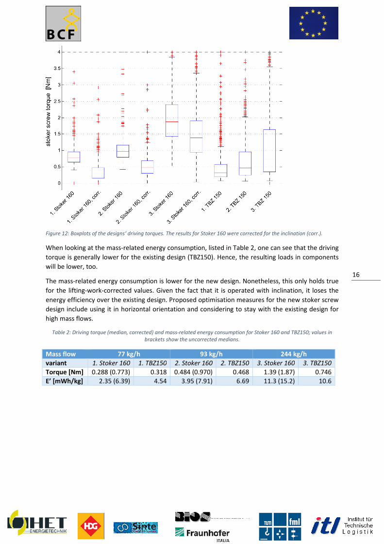
Figure 12: Boxplots of the designs‘ driving
When looking at the mass-related energy consumption,
torque is generally lower for the existing design (TBZ150)
will be lower, too.
The mass-related energy consumption
for the lifting-work-corrected values. Given the fact that it is operated with inclination, it loses the
energy efficiency over the existing design. Proposed optimisation measures for the new stoker screw
design include using it in horizontal orientation and co
high mass flows.
Table 2: Driving torque (median, corrected) and mass
Mass flow 77 kg/h
variant 1. Stoker 160 1. TBZ150
Torque [Nm] 0.288 (0.773)
E’ [mWh/kg] 2.35 (6.39)
driving torques. The results for Stoker 160 were corrected for the inclination
related energy consumption, listed in Table 2, one can
for the existing design (TBZ150). Hence, the resulting loads in components
related energy consumption is lower for the new design. Nonetheless, this only holds true
corrected values. Given the fact that it is operated with inclination, it loses the
energy efficiency over the existing design. Proposed optimisation measures for the new stoker screw
design include using it in horizontal orientation and considering to stay with the existing design for
corrected) and mass-related energy consumption for Stoker 160 and TBZ150; values in
brackets show the uncorrected medians.
kg/h 93 kg/h
1. TBZ150 2. Stoker 160 2. TBZ150 3. Stoker 160
0.318 0.484 (0.970) 0.468 1.39 (1.87)
4.54 3.95 (7.91) 6.69 11.3 (15.2)
16
torques. The results for Stoker 160 were corrected for the inclination (corr.).
, one can see that the driving
. Hence, the resulting loads in components
. Nonetheless, this only holds true
corrected values. Given the fact that it is operated with inclination, it loses the
energy efficiency over the existing design. Proposed optimisation measures for the new stoker screw
nsidering to stay with the existing design for
Stoker 160 and TBZ150; values in
244 kg/h
3. Stoker 160 3. TBZ150
1.39 (1.87) 0.746
11.3 (15.2) 10.6

System Design and Concept of the
Overall Control System The control system is in charge of
unloading area and main storage
The screw conveyor and the boiler use existing control systems and therefore are not part of this
description, because there are no further developments to be done in the control systems of th
components. As part of the modular approach of the whole concept this can be seen as advantage
for the product costs of the system, as it realizes the usage of existing devices where possible. The
developed crane and gripper control system is also in c
detecting errors that occur inside the crane and gripper control system. The crane and gripper
control system receives information and data from the boiler vi
this interface the crane and gripper control system receives information about the operational state
of the boiler and the actual mass flow. An interface to the image recognition system is used to
receive data about particle sizes and foreign materials in the storage, even if th
itself is only included as potential functional add
General Functionality Once the system is switched on, it is the turn of the worker to choose the mode: automatic, manual
or extended mode for troubleshooting.
feeding chips, the initialization step of the system is performed automatically in order to properly
taking into account the amount of chips available in the storage and their qualities. Initializat
also obligatory after refillment of the unloading area in the storage from outside and also after other
changes inside storage. After the selection of the automatic mode no further user interaction is
needed, except the system is shut down or an err
gripper system is stopped as soon as an error shows up. The automatic mode reacts autonomously to
the boiling process. The actual boiler load is transferred via Modbus to the crane and gripper
controlling system. There are several load operation states: ignition, low load, high load and full load
plus standby. The control system is setting automatically the priorities to different woodchip qualities
and mixtures to be loaded into the intermediate storage regard
Usually the automatic mode will work like this:
1. Receive information from the boiler about the boiler load state,
2. Analyse available woodchip qualities inside the storage based on pre
stored in the quality maps
3. Decide which quality or mixture of qualities should be taken,
4. Grip woodchips and transport them to the intermediate storage
5. Update the quality maps every time they change and be aware of errors in the meantime.
Therefore even in automatic mode, a situation can occur that the system is not feeding the
intermediate storage, e.g. if the boiler is stopped, working at very low loads or an error occurred
inside feeding step 2 or inside the boiler itself. This „spare time“ or stand by is u
and crane control system to update the quality maps of the storage with additional and refining
autonomous measurements and transporting woodchips from the unloading area into the storage.
Spare time is detected by filling sensors inside
information of a full or empty intermediate storage to the crane and gripper control system.
As soon as an error is detected the controlled devices are turned off and automatic mode is finished
as part of the prototype safety concept
qualified worker is needed to access extended operation mode for troubleshooting. This mode is
secured via a physical safety key. As soon as the safety key is turned t
System Design and Concept of the Overall Control System
The control system is in charge of controlling the feeding step 1, i.e. transporting woodchips from the
and main storage to the intermediate storage via an automated crane and gripper.
oiler use existing control systems and therefore are not part of this
description, because there are no further developments to be done in the control systems of th
components. As part of the modular approach of the whole concept this can be seen as advantage
for the product costs of the system, as it realizes the usage of existing devices where possible. The
developed crane and gripper control system is also in charge of picking the correct chips and
detecting errors that occur inside the crane and gripper control system. The crane and gripper
control system receives information and data from the boiler via an existing Modbus interface
e and gripper control system receives information about the operational state
of the boiler and the actual mass flow. An interface to the image recognition system is used to
receive data about particle sizes and foreign materials in the storage, even if th
itself is only included as potential functional add-on in the project.
Once the system is switched on, it is the turn of the worker to choose the mode: automatic, manual
or extended mode for troubleshooting. Normally the system will be in automatic mode, but before
feeding chips, the initialization step of the system is performed automatically in order to properly
taking into account the amount of chips available in the storage and their qualities. Initializat
also obligatory after refillment of the unloading area in the storage from outside and also after other
changes inside storage. After the selection of the automatic mode no further user interaction is
needed, except the system is shut down or an error occurs. In the automatic mode the crane and
gripper system is stopped as soon as an error shows up. The automatic mode reacts autonomously to
the boiling process. The actual boiler load is transferred via Modbus to the crane and gripper
em. There are several load operation states: ignition, low load, high load and full load
plus standby. The control system is setting automatically the priorities to different woodchip qualities
and mixtures to be loaded into the intermediate storage regarding these load operation states
Usually the automatic mode will work like this:
Receive information from the boiler about the boiler load state,
Analyse available woodchip qualities inside the storage based on pre-sensored information
quality maps
Decide which quality or mixture of qualities should be taken,
Grip woodchips and transport them to the intermediate storage
Update the quality maps every time they change and be aware of errors in the meantime.
tomatic mode, a situation can occur that the system is not feeding the
intermediate storage, e.g. if the boiler is stopped, working at very low loads or an error occurred
inside feeding step 2 or inside the boiler itself. This „spare time“ or stand by is u
and crane control system to update the quality maps of the storage with additional and refining
autonomous measurements and transporting woodchips from the unloading area into the storage.
Spare time is detected by filling sensors inside the intermediate storage which are directly giving the
information of a full or empty intermediate storage to the crane and gripper control system.
As soon as an error is detected the controlled devices are turned off and automatic mode is finished
rt of the prototype safety concept. The error description is shown on the user screen. A
qualified worker is needed to access extended operation mode for troubleshooting. This mode is
secured via a physical safety key. As soon as the safety key is turned the extended operation mode is
17
, i.e. transporting woodchips from the
to the intermediate storage via an automated crane and gripper.
oiler use existing control systems and therefore are not part of this
description, because there are no further developments to be done in the control systems of these
components. As part of the modular approach of the whole concept this can be seen as advantage
for the product costs of the system, as it realizes the usage of existing devices where possible. The
harge of picking the correct chips and
detecting errors that occur inside the crane and gripper control system. The crane and gripper
a an existing Modbus interface. Via
e and gripper control system receives information about the operational state
of the boiler and the actual mass flow. An interface to the image recognition system is used to
receive data about particle sizes and foreign materials in the storage, even if the image recognition
Once the system is switched on, it is the turn of the worker to choose the mode: automatic, manual
Normally the system will be in automatic mode, but before
feeding chips, the initialization step of the system is performed automatically in order to properly
taking into account the amount of chips available in the storage and their qualities. Initialization is
also obligatory after refillment of the unloading area in the storage from outside and also after other
changes inside storage. After the selection of the automatic mode no further user interaction is
or occurs. In the automatic mode the crane and
gripper system is stopped as soon as an error shows up. The automatic mode reacts autonomously to
the boiling process. The actual boiler load is transferred via Modbus to the crane and gripper
em. There are several load operation states: ignition, low load, high load and full load
plus standby. The control system is setting automatically the priorities to different woodchip qualities
ing these load operation states.
sensored information
Update the quality maps every time they change and be aware of errors in the meantime.
tomatic mode, a situation can occur that the system is not feeding the
intermediate storage, e.g. if the boiler is stopped, working at very low loads or an error occurred
inside feeding step 2 or inside the boiler itself. This „spare time“ or stand by is used by the gripper
and crane control system to update the quality maps of the storage with additional and refining
autonomous measurements and transporting woodchips from the unloading area into the storage.
the intermediate storage which are directly giving the
information of a full or empty intermediate storage to the crane and gripper control system.
As soon as an error is detected the controlled devices are turned off and automatic mode is finished
. The error description is shown on the user screen. A
qualified worker is needed to access extended operation mode for troubleshooting. This mode is
he extended operation mode is

activated and the gates to the storage can be passed to get to the crane or gripper system and solve
the problem. Before turning the key the whole system is blocked. In extended operation mode all
actuators can be directly controlled from the worker, all safety or limit switches are turned off to
allow failure debugging. In extended operation mode the control system allows the worker in charge
to drive the actuators also to positions, which are not allowed during automatic mode
the worker is responsible for system safety and should be conscious of his actions, i.e. enhanced
experience with the system is needed. It is also important for the worker to have eye contact to the
crane and gripper during this operation mode
the whole storage can be surveyed. Elimination of the failure has to be confirmed by the worker on
the user screen. Extended user mode cannot be left before failure is solved, i.e. error no longer
detected by the control system and failure elimination is confirmed by user. After this step the safety
key is turned back by the worker and user can choose next operation mode.
Additionally a manual operation mode is foreseen, which can be chosen by the user
during automatic mode, after system start
mode. In manual mode the crane and the gripper can be moved via direct user inputs, e.g. to drive
the crane to a specific position or to grip wood
manual mode the user is responsible for crane safety, e.g. crashing against objects inside the storage.
The manual mode can be used to transport woodchips into the intermediate storage to feed the
boiler, but all the information about the quality of the woodchips is not considered for the automatic
mode. As soon as leaving the manual mode to automatic mode, which is possible all the time, the
automatic mode will “clear” the intermediate storage by letti
filling-sensor level and then restart filling it up regarding the actual load state of the boiler.
Hardware Setup
The concept for the controlling hardware consists of
algorithm and 3 bus couplers with several in
cabinets and connected via EtherCAT.
for the in- and output cards components from Beckhoff Automat
diagram (Figure 13) gives a schematic overview of control units and hardware components for the
controlling system. It is divided into three sub controlling units: the main control, the crane control
and the gripper control.
Figure 13
main control
•industrial PC (soft PLC) and bus coupler
•safety control, safety in-and outputs
•interface to control panel
•interface to inamge recognition system and boiler
activated and the gates to the storage can be passed to get to the crane or gripper system and solve
the problem. Before turning the key the whole system is blocked. In extended operation mode all
trolled from the worker, all safety or limit switches are turned off to
allow failure debugging. In extended operation mode the control system allows the worker in charge
to drive the actuators also to positions, which are not allowed during automatic mode
the worker is responsible for system safety and should be conscious of his actions, i.e. enhanced
experience with the system is needed. It is also important for the worker to have eye contact to the
crane and gripper during this operation mode, therefore the user panel is positioned in
the whole storage can be surveyed. Elimination of the failure has to be confirmed by the worker on
the user screen. Extended user mode cannot be left before failure is solved, i.e. error no longer
cted by the control system and failure elimination is confirmed by user. After this step the safety
key is turned back by the worker and user can choose next operation mode.
Additionally a manual operation mode is foreseen, which can be chosen by the user
during automatic mode, after system start-up or after successfully finished extended operation
mode. In manual mode the crane and the gripper can be moved via direct user inputs, e.g. to drive
the crane to a specific position or to grip woodchips at a desired position inside the storage. During
manual mode the user is responsible for crane safety, e.g. crashing against objects inside the storage.
The manual mode can be used to transport woodchips into the intermediate storage to feed the
er, but all the information about the quality of the woodchips is not considered for the automatic
mode. As soon as leaving the manual mode to automatic mode, which is possible all the time, the
automatic mode will “clear” the intermediate storage by letting go down the filling to the lower
sensor level and then restart filling it up regarding the actual load state of the boiler.
The concept for the controlling hardware consists of one main industrial PC with the central control
3 bus couplers with several in- and outputs which are located in 3 different switching
cabinets and connected via EtherCAT. For the main controlling unit and the bus couplers as well as
and output cards components from Beckhoff Automation GmbH are used.
gives a schematic overview of control units and hardware components for the
controlling system. It is divided into three sub controlling units: the main control, the crane control
13: basic concept for the overall process control system
crane control
•bus coupler
•interface to positioning system (x,y) and chain hoist length sensor
•interface to crane control
•safety switch off and conductors for power supply of crane
gripper control
•bus coupler
•interface to gripper weight and tilt sensors
•interface to distance measurement (gripperfloor)
•interface to gripper actuators and moisture meter
18
activated and the gates to the storage can be passed to get to the crane or gripper system and solve
the problem. Before turning the key the whole system is blocked. In extended operation mode all
trolled from the worker, all safety or limit switches are turned off to
allow failure debugging. In extended operation mode the control system allows the worker in charge
to drive the actuators also to positions, which are not allowed during automatic mode. This means
the worker is responsible for system safety and should be conscious of his actions, i.e. enhanced
experience with the system is needed. It is also important for the worker to have eye contact to the
, therefore the user panel is positioned in a way that
the whole storage can be surveyed. Elimination of the failure has to be confirmed by the worker on
the user screen. Extended user mode cannot be left before failure is solved, i.e. error no longer
cted by the control system and failure elimination is confirmed by user. After this step the safety
Additionally a manual operation mode is foreseen, which can be chosen by the user at every time
up or after successfully finished extended operation
mode. In manual mode the crane and the gripper can be moved via direct user inputs, e.g. to drive
chips at a desired position inside the storage. During
manual mode the user is responsible for crane safety, e.g. crashing against objects inside the storage.
The manual mode can be used to transport woodchips into the intermediate storage to feed the
er, but all the information about the quality of the woodchips is not considered for the automatic
mode. As soon as leaving the manual mode to automatic mode, which is possible all the time, the
ng go down the filling to the lower
sensor level and then restart filling it up regarding the actual load state of the boiler.
with the central control
and outputs which are located in 3 different switching
and the bus couplers as well as
ion GmbH are used. The following
gives a schematic overview of control units and hardware components for the
controlling system. It is divided into three sub controlling units: the main control, the crane control
gripper control
bus coupler
interface to gripper weight and tilt sensors
interface to distance measurement (gripper-
interface to gripper actuators and moisture

The sub controlling units are connected via Ethercat, the main control has interfaces to the user
control panel, the image recognition system, which runs on a second industrial PC and
boiler.Following Sensors and Drives/Actuators were used:
Sensor/Drive/Actuator
Light Barrier IELT / IELR
Laser Distance Sensors DT35
Draw Wire Sensor SX120
Force Sensor KD9363s
Ultrasonic Sensor USM603U035
Tilt Sensor ME IS 28
Linear Actuator LMR03
Moisture Meter / Humimeter
Stepper Motor NEMA23XL
A detailed overview of all the components is given in Deliverable D2.3
process control.
Safety Concept For safety issues the controlling system is equipped with certain functionalities to prevent personal
injury and property damage. Therefore a safety controller and safety in
into the controlling system. If a person is entering the storage the crane system and the gripper are
disconnected from the power supply
light barrier is integrated into the
and shut off the crane. In addition several Emergency Stop Buttons are installed at the user control
and at the access points to the storage to shut off the system in emergency situations.
Circuit Diagram
The configuration of power supply
industrial PC, the control cabinet on the Abus crane and the control cabinet on the gripper. The
power supply for the control system is separated from the power supply for
gripper to prevent any interference. To avoid current peaks in our control circuit, which can occur
when the linear motors or the stepper motor on the gripper are switched on the power supplies of
the gripper motors and of the controllin
The detailed description of the power supply concept can be found in Deliverable 2.3.
Control Algorithm The control software is implemented using
Automation and widespread in the industry.
code was written using an object oriented approach to ensure simple adjustability for the later use
by the SME project partners.
The process starts with an initialization of the system. After that the user can choose between the
manual and the autonomous, i.e. continuous, operation mode. The autonomous operation mode as
major outcome of this project
overall control strategy see also Deliverable D2.3
In autonomous operation the algorithm handles
and transport, updating of the quality maps and
First the control unit communicates with the boiler to obtain the current operation (ignition, stand
by or one of the three continuous modes:
The sub controlling units are connected via Ethercat, the main control has interfaces to the user
control panel, the image recognition system, which runs on a second industrial PC and
and Drives/Actuators were used:
Task
Woodchip Level in Intermediate Storage
Position of crane in x and y direction
Length of Winch / Chain Hoist
Weight of Gripper and Load
Ultrasonic Sensor USM603U035 Distance from Gripper to Woodchip Surface in storage
Inclination Angle of Gripper (x and y direction)
Closing / Opening the Gripper
Moisture of Woodchips
Pressing Humimeter onto Woodchips inside of the Gripper
A detailed overview of all the components is given in Deliverable D2.3 – Detailed design
For safety issues the controlling system is equipped with certain functionalities to prevent personal
injury and property damage. Therefore a safety controller and safety in- and outputs are integrated
lling system. If a person is entering the storage the crane system and the gripper are
from the power supply and the winch for the gripper is mechanically blocked. A safety
integrated into the entrance gate of the storage to detect safety relevant situations
and shut off the crane. In addition several Emergency Stop Buttons are installed at the user control
and at the access points to the storage to shut off the system in emergency situations.
power supply splits in several parts, including the main control cabinet for the
industrial PC, the control cabinet on the Abus crane and the control cabinet on the gripper. The
power supply for the control system is separated from the power supply for
gripper to prevent any interference. To avoid current peaks in our control circuit, which can occur
when the linear motors or the stepper motor on the gripper are switched on the power supplies of
the gripper motors and of the controlling components are electrically separated from each other.
The detailed description of the power supply concept can be found in Deliverable 2.3.
implemented using Twincat V3, an IDE and runtime provided by Beckhoff
widespread in the industry. It uses IEC 61131-3 standards and all the controlling
code was written using an object oriented approach to ensure simple adjustability for the later use
The process starts with an initialization of the system. After that the user can choose between the
manual and the autonomous, i.e. continuous, operation mode. The autonomous operation mode as
is described in the following paragraph, for further details on the
overall control strategy see also Deliverable D2.3
the algorithm handles the monitoring of the storage, the material
transport, updating of the quality maps and the intelligent feeding of the intermediate storage.
First the control unit communicates with the boiler to obtain the current operation (ignition, stand
by or one of the three continuous modes: low, high and full load). During the ordinary operation the
19
The sub controlling units are connected via Ethercat, the main control has interfaces to the user
control panel, the image recognition system, which runs on a second industrial PC and the
Woodchip Level in Intermediate Storage
Distance from Gripper to Woodchip Surface in storage
Inclination Angle of Gripper (x and y direction)
Pressing Humimeter onto Woodchips inside of the Gripper
Detailed design of the
For safety issues the controlling system is equipped with certain functionalities to prevent personal
and outputs are integrated
lling system. If a person is entering the storage the crane system and the gripper are
and the winch for the gripper is mechanically blocked. A safety
etect safety relevant situations
and shut off the crane. In addition several Emergency Stop Buttons are installed at the user control
and at the access points to the storage to shut off the system in emergency situations.
parts, including the main control cabinet for the
industrial PC, the control cabinet on the Abus crane and the control cabinet on the gripper. The
power supply for the control system is separated from the power supply for the crane and the
gripper to prevent any interference. To avoid current peaks in our control circuit, which can occur
when the linear motors or the stepper motor on the gripper are switched on the power supplies of
g components are electrically separated from each other.
The detailed description of the power supply concept can be found in Deliverable 2.3.
Twincat V3, an IDE and runtime provided by Beckhoff
standards and all the controlling
code was written using an object oriented approach to ensure simple adjustability for the later use
The process starts with an initialization of the system. After that the user can choose between the
manual and the autonomous, i.e. continuous, operation mode. The autonomous operation mode as
ed in the following paragraph, for further details on the
the monitoring of the storage, the material selection
ing of the intermediate storage.
First the control unit communicates with the boiler to obtain the current operation (ignition, stand-
load). During the ordinary operation the

storage is fed with biochips, if the current mass in the intermediate storage falls below a predefined
level.
During the continuous operation it is necessary to derive the area that is tangible for the griper
to restrictions of the topology of the sto
quality of the wood chips. The algorithm computes the suitable qualities, defined by their ash
moisture content. The idea is to limit the qualities to those, that can be fed to the interm
storage and keep its parameters within certain limits. Finally the allowed qualities are superimposed
with the height profile of the previous step.
to come. This includes the feeding of the
featuring the needed priority or finally by mixing the available materials.
The algorithm tries to get the material with the
the boiler. In this case priority ranges from 1 to 15 with 1 as the highest priority.
material defined by the recent priority which results in the desired quality after mixing in the
intermediate storage is present. If so the algorithm primary u
moisture and high ash content). If no suitable material is present the algorithm tries to mix the
material with the desired priority value from two components. It first feeds the worse material, the
better later on. Due to the results of the evaluation of the prototypes
underlying priority maps for the algorithms where defined and implemented to the control algorithm
(Figure 14).
da
rk Priority
5
Priority
6
Priority
2
Priority
4
bri
gh
t
Priority
1
Priority
3
low
da
rk Priority
15
Priority
5
Priority
14
Priority
4
bri
gh
t
Priority
9
Priority
8
low
Moisture content, wet basis
Ash
co
nte
nt
- o
pti
cal i
nd
.
ignition
high load
Ash
co
nte
nt
- o
pti
cal i
nd
.
Moisture content, wet basis
Details can be seen in Deliverable D 6.1 results of tests with the optimized system
After the selection of the material quality to grab the
decides where to grab the material in the storage in case a specific quality is available in serveral
locations inside the storage. This selection process is realized respecting several conditions: flatten
the storage topology to increase potential positions to grab material and reduce ways for navigation
in storage. In spare time the picking routine
to main storage. For the deposition of material the process for emptying the s
reversed. The goal is to continuously fill the storage starting from a defined position. If possible
storage is fed with biochips, if the current mass in the intermediate storage falls below a predefined
During the continuous operation it is necessary to derive the area that is tangible for the griper
to restrictions of the topology of the storage. Next the tangible area is further restricted based on the
quality of the wood chips. The algorithm computes the suitable qualities, defined by their ash
moisture content. The idea is to limit the qualities to those, that can be fed to the interm
storage and keep its parameters within certain limits. Finally the allowed qualities are superimposed
with the height profile of the previous step. The so obtained tangible area lays the basis for the steps
to come. This includes the feeding of the intermediate storage with bad qualities, with material
featuring the needed priority or finally by mixing the available materials.
he algorithm tries to get the material with the highest priority value, depending on the loadmod
In this case priority ranges from 1 to 15 with 1 as the highest priority.
material defined by the recent priority which results in the desired quality after mixing in the
intermediate storage is present. If so the algorithm primary uses bad quality material (e.g. high
moisture and high ash content). If no suitable material is present the algorithm tries to mix the
material with the desired priority value from two components. It first feeds the worse material, the
to the results of the evaluation of the prototypes some
underlying priority maps for the algorithms where defined and implemented to the control algorithm
Priority
9
Priority
12
Priority
15 da
rk Priority
11
Priority
5
Priority
3
Priority
12
Priority
8
Priority
11
Priority
14
Priority
10
Priority
2
Priority
1
Priority
8
Priority
7
Priority
10
Priority
13 bri
gh
t
Priority
9
Priority
6
Priority
4
Priority
7
high low
Priority
3
Priority
10
Priority
13 da
rk Priority
11
Priority
8
Priority
9
Priority
12
Priority
6
Priority
2
Priority
12
Priority
10
Priority
5
Priority
4
Priority
7
Priority
7
Priority
1
Priority
11 bri
gh
t
Priority
1
Priority
2
Priority
3
Priority
6
high low
Moisture content, wet basis
ignition low load
Ash
co
nte
nt
- o
pti
cal i
nd
.
Moisture content, wet basis
high load full load
Ash
co
nte
nt
- o
pti
cal i
nd
.
Moisture content, wet basis Moisture content, wet basis
Figure 14: priority maps
Details can be seen in Deliverable D 6.1 results of tests with the optimized system
After the selection of the material quality to grab the handling strategy for storage management
decides where to grab the material in the storage in case a specific quality is available in serveral
locations inside the storage. This selection process is realized respecting several conditions: flatten
crease potential positions to grab material and reduce ways for navigation
he picking routine is also be used to transfer material
he deposition of material the process for emptying the s
reversed. The goal is to continuously fill the storage starting from a defined position. If possible
20
storage is fed with biochips, if the current mass in the intermediate storage falls below a predefined
During the continuous operation it is necessary to derive the area that is tangible for the griper due
. Next the tangible area is further restricted based on the
quality of the wood chips. The algorithm computes the suitable qualities, defined by their ash- and
moisture content. The idea is to limit the qualities to those, that can be fed to the intermediate
storage and keep its parameters within certain limits. Finally the allowed qualities are superimposed
The so obtained tangible area lays the basis for the steps
intermediate storage with bad qualities, with material
priority value, depending on the loadmode of
In this case priority ranges from 1 to 15 with 1 as the highest priority. Initially it checks if
material defined by the recent priority which results in the desired quality after mixing in the
ses bad quality material (e.g. high
moisture and high ash content). If no suitable material is present the algorithm tries to mix the
material with the desired priority value from two components. It first feeds the worse material, the
some adaptions to the
underlying priority maps for the algorithms where defined and implemented to the control algorithm
Priority
15
Priority
14
Priority
13
high
Priority
15
Priority
14
Priority
13
high
Moisture content, wet basis
Moisture content, wet basis
Details can be seen in Deliverable D 6.1 results of tests with the optimized system.
for storage management
decides where to grab the material in the storage in case a specific quality is available in serveral
locations inside the storage. This selection process is realized respecting several conditions: flatten
crease potential positions to grab material and reduce ways for navigation
from unloading area
he deposition of material the process for emptying the storage is basically
reversed. The goal is to continuously fill the storage starting from a defined position. If possible

material of the same quality
prevented.
Detailed information about the a
can be found in Deliverable 2.3.
Data recording and Visualization
System data can be visualized directly on the integrate
exported in standard formats, e.g. Microsoft Excel. Recent Activity of the system is presented to the
user on this touchscreen in form of a graphical animation of the crane and in textual form. The user
interacts with the system via software buttons on this touchscreen.
material of the same quality is placed nearby. Moreover areas whit too large gradients
Detailed information about the algorithm, implemented class diagram and underlying risk analysis
Data recording and Visualization is directly integrated in the graphical user interface of the system.
System data can be visualized directly on the integrated 19” touchscreen of the system or be
exported in standard formats, e.g. Microsoft Excel. Recent Activity of the system is presented to the
user on this touchscreen in form of a graphical animation of the crane and in textual form. The user
the system via software buttons on this touchscreen.
21
placed nearby. Moreover areas whit too large gradients are
ted class diagram and underlying risk analysis
is directly integrated in the graphical user interface of the system.
d 19” touchscreen of the system or be
exported in standard formats, e.g. Microsoft Excel. Recent Activity of the system is presented to the
user on this touchscreen in form of a graphical animation of the crane and in textual form. The user

System Design and Algorithm Description of the Image Recognition System
Objectives and Tasks of Image Recognition System
The main purpose of the Image Recognition System is to provide the control
about the visual properties of fuel at a certain location within the fuel storage. These properties have
been specified to be the average wood chip particle size at the surface as well as the mean fuel
quality at this location. Further tasks are the detection of oversized chips or foreign objects which
might damage the stoker or obstruct the grate, as well as the detection of large accumulations of saw
dust. In these cases the Image Recognition System alerts the control system of its
Sensor Architecture The Image Recognition System consists of two GigE Vision industrial Ethernet cameras, two 100W
LEDs as light sources driven by an Ethernet capable flash controller and a computer for image
acquisition and evaluation. Auxiliar
the flash controller to the image acquisition computer and two DC
providing the components with their required voltage from a common 24V power line.
The camera system operates independent from the control system. After power up, it enters an idle
state waiting for a trigger signal from the control system, upon which it acquires a sequence of
images illuminated alternatingly by LED1 and LED2 and generates an exposure s
evaluating these images statistics are transferred back to the control system. All operations are
performed autonomously, the only interaction necessary between control system and image
recognition system are the initiation of the image acqu
system) and the subsequent feedback of the evaluation metrics (image recognition system
system).
Algorithm Description – Segmentation
Woodchip particle segmentation is performed with an adapted shape
motivated by the shape detection algorithm proposed by Raskar et. al.
camera. To ease segmentation we strive to acquire images in which the chip area is overexposed
to the exception of the cast shadow
pair {ILED1, ILED2} is fused into a single image I
Individual wood chips are segmented by seeded region growing
binarized IMIN. The results are refined by separating the segments into star
Segmentation was tested on image sequences acquired both in the lab as well as during the test runs
at the BIOS prototype plant. Since no ground
qualitative evaluation was performed.
Algorithm Description – Sawdust Sawdust detection is based on the statistics of the segmentation without
sawdust flag is raised if the segmentation results in a few connected components
bounding box covers a large area of the image
are considerably larger than the component areas themselves.
that of individual wood chips are ignored for sawdust detection.
7 Non-photorealistic Camera: Depth Edge Detection and Stylized Rendering using Multi
Imaging, Raskar et. al., SIGGRAPH 2004.
System Design and Algorithm Description of the Image Recognition System
Objectives and Tasks of Image Recognition System
The main purpose of the Image Recognition System is to provide the control system with information
about the visual properties of fuel at a certain location within the fuel storage. These properties have
been specified to be the average wood chip particle size at the surface as well as the mean fuel
her tasks are the detection of oversized chips or foreign objects which
might damage the stoker or obstruct the grate, as well as the detection of large accumulations of saw
dust. In these cases the Image Recognition System alerts the control system of its
The Image Recognition System consists of two GigE Vision industrial Ethernet cameras, two 100W
LEDs as light sources driven by an Ethernet capable flash controller and a computer for image
acquisition and evaluation. Auxiliary components are an Ethernet switch connecting the cameras and
the flash controller to the image acquisition computer and two DC-DC switching power supplies
providing the components with their required voltage from a common 24V power line.
m operates independent from the control system. After power up, it enters an idle
state waiting for a trigger signal from the control system, upon which it acquires a sequence of
images illuminated alternatingly by LED1 and LED2 and generates an exposure s
evaluating these images statistics are transferred back to the control system. All operations are
performed autonomously, the only interaction necessary between control system and image
recognition system are the initiation of the image acquisition (control system → image recognition
system) and the subsequent feedback of the evaluation metrics (image recognition system
egmentation
Woodchip particle segmentation is performed with an adapted shape-from
the shape detection algorithm proposed by Raskar et. al.7 for their non
camera. To ease segmentation we strive to acquire images in which the chip area is overexposed
the cast shadows arising from lateral illuminating the scene.
} is fused into a single image IMIN by taking the pixel wise minimum of {I
Individual wood chips are segmented by seeded region growing the distance transformatio
. The results are refined by separating the segments into star-convex blobs.
image sequences acquired both in the lab as well as during the test runs
at the BIOS prototype plant. Since no ground-truth data is available for the segmentation task only
qualitative evaluation was performed.
awdust Detection Sawdust detection is based on the statistics of the segmentation without post processing
sawdust flag is raised if the segmentation results in a few connected components
bounding box covers a large area of the image, yet the filled areas of these connected components
are considerably larger than the component areas themselves. Small areas with a size comparable to
that of individual wood chips are ignored for sawdust detection.
photorealistic Camera: Depth Edge Detection and Stylized Rendering using Multi
SIGGRAPH 2004.
22
System Design and Algorithm Description of the Image Recognition System
system with information
about the visual properties of fuel at a certain location within the fuel storage. These properties have
been specified to be the average wood chip particle size at the surface as well as the mean fuel
her tasks are the detection of oversized chips or foreign objects which
might damage the stoker or obstruct the grate, as well as the detection of large accumulations of saw
dust. In these cases the Image Recognition System alerts the control system of its findings.
The Image Recognition System consists of two GigE Vision industrial Ethernet cameras, two 100W
LEDs as light sources driven by an Ethernet capable flash controller and a computer for image
y components are an Ethernet switch connecting the cameras and
DC switching power supplies
providing the components with their required voltage from a common 24V power line.
m operates independent from the control system. After power up, it enters an idle
state waiting for a trigger signal from the control system, upon which it acquires a sequence of
images illuminated alternatingly by LED1 and LED2 and generates an exposure sequence. After
evaluating these images statistics are transferred back to the control system. All operations are
performed autonomously, the only interaction necessary between control system and image
→ image recognition
system) and the subsequent feedback of the evaluation metrics (image recognition system → control
om-shadow approach
for their non-photorealistic
camera. To ease segmentation we strive to acquire images in which the chip area is overexposed up
the scene. The resulting image
minimum of {ILED1, ILED2}.
the distance transformation of a
convex blobs.
image sequences acquired both in the lab as well as during the test runs
available for the segmentation task only
post processing. The
sawdust flag is raised if the segmentation results in a few connected components where the
connected components
Small areas with a size comparable to
photorealistic Camera: Depth Edge Detection and Stylized Rendering using Multi-Flash

Figure 15 Exemplary result of the sawdust detection. Left: segmentation result without star
motivating the criteria for classification as sawdust.
Algorithm Description – Woodchip
Metric information is obtained by fitting a plane into a subset of
correspondences from sparse stereo reconstruction of the fuel surface
projected onto that plane and by this pixel areas measured in pixels are transformed into a metric
measurement in mm². Since the control system utilizes the mean chip size onl
shaped nature of wood chips this approximation is sufficient.
Algorithm Description – Overlarge
result of the sawdust detection. Left: segmentation result without star-convex separation applied
ing the criteria for classification as sawdust. Right: Illustration of the detection.
oodchip Size Estimation
Metric information is obtained by fitting a plane into a subset of the 100 best matching 3D point
from sparse stereo reconstruction of the fuel surface. The segmentation is then
and by this pixel areas measured in pixels are transformed into a metric
Since the control system utilizes the mean chip size only and due to the flat
shaped nature of wood chips this approximation is sufficient.
verlarge Wood Chip Detection
23
convex separation applied
best matching 3D point
The segmentation is then
and by this pixel areas measured in pixels are transformed into a metric
y and due to the flat-

An overlarge object is detected and the corresponding flag raised if the segmentation yields an
individual chip with an area or a major axis length
the objects surface and texture to behave in such a way that it appears as a single contiguous area in
the segmentation. Overlarge particles of the same substance as the fuel (i.e., wood in most cases)
can be expected to meet this constraint. Particles of foreign material will be detected by the foreign
object detection. Since handling is the same for both overlarge wood chips and foreign material a
detection by both algorithms does not pose a limitation to the performance.
Algorithm Description – Quality
The fuel quality is tied to the optical fuel brightness. Bright fuel is thought to contain just a small
amount of ashes and be of high quality, dark fuel with a large relative bark content is thought to be
of low quality with a rather high ash content. In order to
radiometric response functions of the sensors are calibrated according to the method proposed by
Debevec et.al.8. Fuel quality is then determined by calculating the rad
classifying it according to the radiance histograms of images of fuel samples of the predefined quality
classes.
8 Recovering High Dynamic Range Radiance Maps from Photographs, Debevec and Malik,
SIGGRAPH 1997
Figure 16 Segmentation (left) and detection (right, illustration) of an overlarge wood particle
An overlarge object is detected and the corresponding flag raised if the segmentation yields an
a major axis length exceeding a predefined threshold
the objects surface and texture to behave in such a way that it appears as a single contiguous area in
the segmentation. Overlarge particles of the same substance as the fuel (i.e., wood in most cases)
his constraint. Particles of foreign material will be detected by the foreign
object detection. Since handling is the same for both overlarge wood chips and foreign material a
detection by both algorithms does not pose a limitation to the performance.
uality Estimation
The fuel quality is tied to the optical fuel brightness. Bright fuel is thought to contain just a small
amount of ashes and be of high quality, dark fuel with a large relative bark content is thought to be
ity with a rather high ash content. In order to assess the fuel brightness reliably the
radiometric response functions of the sensors are calibrated according to the method proposed by
. Fuel quality is then determined by calculating the radiance map of a fuel sample and
classifying it according to the radiance histograms of images of fuel samples of the predefined quality
Recovering High Dynamic Range Radiance Maps from Photographs, Debevec and Malik,
Segmentation (left) and detection (right, illustration) of an overlarge wood particle
24
An overlarge object is detected and the corresponding flag raised if the segmentation yields an
ned threshold. This requires
the objects surface and texture to behave in such a way that it appears as a single contiguous area in
the segmentation. Overlarge particles of the same substance as the fuel (i.e., wood in most cases)
his constraint. Particles of foreign material will be detected by the foreign
object detection. Since handling is the same for both overlarge wood chips and foreign material a
The fuel quality is tied to the optical fuel brightness. Bright fuel is thought to contain just a small
amount of ashes and be of high quality, dark fuel with a large relative bark content is thought to be
the fuel brightness reliably the
radiometric response functions of the sensors are calibrated according to the method proposed by
iance map of a fuel sample and
classifying it according to the radiance histograms of images of fuel samples of the predefined quality
Recovering High Dynamic Range Radiance Maps from Photographs, Debevec and Malik,
Segmentation (left) and detection (right, illustration) of an overlarge wood particle
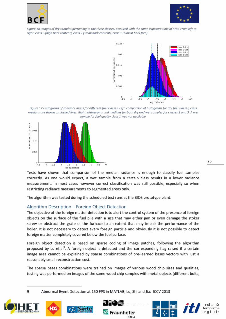
Figure 18 Images of dry samples pertaining
right: class 3 (high bark content), class 2 (
Tests have shown that comparison of the medi
correctly. As one would expect, a wet sample from a certain class results in a lower radiance
measurement. In most cases however correct classification was still possible, especially so when
restricting radiance measurements to segmented areas only.
The algorithm was tested during the scheduled test runs at the BIOS prototype plant.
Algorithm Description – Foreign The objective of the foreign matter detection is to alert the control system of t
objects on the surface of the fuel pile with a size that may either jam or even damage the stoker
screw or obstruct the grate of the furnace to an extent that may impair the performance of the
boiler. It is not necessary to detect ev
foreign matter completely covered below the fuel surface.
Foreign object detection is based on sparse coding of image patches, following the algorithm
proposed by Lu et.al9. A foreign object is detected and the corresponding flag raised if a certain
image area cannot be explained by
reasonably small reconstruction cost.
The sparse bases combinations were traine
testing was performed on images of the same wood chip samples with metal objects (different bolts,
9 Abnormal Event Detection at 150 FPS in MATLAB, Lu, Shi and Jia, ICCV 2013
Figure 17 Histograms of radiance maps for different fuel classes
medians are shown as dashed lines. Right: histograms and medians for both dry and wet samples for classes 2 and 3. A wet
sample for fuel quality class 1 was not available.
Images of dry samples pertaining to the three classes, acquired with the same exposure time of 4ms. From left to
right: class 3 (high bark content), class 2 (small bark content), class 1 (almost bark free).
Tests have shown that comparison of the median radiance is enough to classify fuel samples
correctly. As one would expect, a wet sample from a certain class results in a lower radiance
measurement. In most cases however correct classification was still possible, especially so when
ce measurements to segmented areas only.
during the scheduled test runs at the BIOS prototype plant.
oreign Object Detection The objective of the foreign matter detection is to alert the control system of the presence of foreign
objects on the surface of the fuel pile with a size that may either jam or even damage the stoker
screw or obstruct the grate of the furnace to an extent that may impair the performance of the
boiler. It is not necessary to detect every foreign particle and obviously it is not possible to detect
foreign matter completely covered below the fuel surface.
Foreign object detection is based on sparse coding of image patches, following the algorithm
. A foreign object is detected and the corresponding flag raised if a certain
be explained by sparse combinations of pre-learned bases
reasonably small reconstruction cost.
The sparse bases combinations were trained on images of various wood chip
testing was performed on images of the same wood chip samples with metal objects (different bolts,
Abnormal Event Detection at 150 FPS in MATLAB, Lu, Shi and Jia, ICCV 2013
Histograms of radiance maps for different fuel classes. Left: comparison of histograms for dry fuel classes, class
medians are shown as dashed lines. Right: histograms and medians for both dry and wet samples for classes 2 and 3. A wet
sample for fuel quality class 1 was not available.
25
he three classes, acquired with the same exposure time of 4ms. From left to
an radiance is enough to classify fuel samples
correctly. As one would expect, a wet sample from a certain class results in a lower radiance
measurement. In most cases however correct classification was still possible, especially so when
during the scheduled test runs at the BIOS prototype plant.
he presence of foreign
objects on the surface of the fuel pile with a size that may either jam or even damage the stoker
screw or obstruct the grate of the furnace to an extent that may impair the performance of the
ery foreign particle and obviously it is not possible to detect
Foreign object detection is based on sparse coding of image patches, following the algorithm
. A foreign object is detected and the corresponding flag raised if a certain
learned bases vectors with just a
images of various wood chip sizes and qualities,
testing was performed on images of the same wood chip samples with metal objects (different bolts,
Abnormal Event Detection at 150 FPS in MATLAB, Lu, Shi and Jia, ICCV 2013
comparison of histograms for dry fuel classes, class
medians are shown as dashed lines. Right: histograms and medians for both dry and wet samples for classes 2 and 3. A wet

a ring cut from a circular piece of pipe, and a steel strut) placed in them. The foreign objects were in
some cases partially covered by fuel, in other cases they were completely visible.
A further limitation of the current system is its inability to correctly handle previously unseen types
of biomass fuel. This may be tackled by providing the user with an opti
or alternatively by an online updating scheme.
Figure 19 Sample images of the test objects and some of the fuel types used for training respectively testing the foreign
object detection.
a ring cut from a circular piece of pipe, and a steel strut) placed in them. The foreign objects were in
me cases partially covered by fuel, in other cases they were completely visible.
A further limitation of the current system is its inability to correctly handle previously unseen types
of biomass fuel. This may be tackled by providing the user with an option to start a re
or alternatively by an online updating scheme.
Sample images of the test objects and some of the fuel types used for training respectively testing the foreign
26
a ring cut from a circular piece of pipe, and a steel strut) placed in them. The foreign objects were in
me cases partially covered by fuel, in other cases they were completely visible.
A further limitation of the current system is its inability to correctly handle previously unseen types
on to start a re-training phase
Sample images of the test objects and some of the fuel types used for training respectively testing the foreign

Figure 20 Example of a foreign object (steel strut) partially covered by wood chips. Patches detected by
Example of a foreign object (steel strut) partially covered by wood chips. Patches detected by
the system as foreign are marked in red.
27
Example of a foreign object (steel strut) partially covered by wood chips. Patches detected by

References
[Zitat1] Rackl, M.; Günthner, W.A.;
Wood Chips on Screw Feeding Performance.
(status: 12.10.2015)
[Zitat2] Wensrich, C.M.; Katterfeld, A.:
DEM. Powder Technology 217 (2012), p. 409
[Zitat3] Wensrich, C.M.; Katterfeld, A.
a normalised contact eccentric
[Zitat4] Rackl, M.; Top, F., Günthne
screw-conveyor-discharged hopper.
International Congress on Particle Technology, 19
Rackl, M.; Günthner, W.A.; Experimental Investigation on the Influence of Different Grades of
Wood Chips on Screw Feeding Performance. Submitted to Biomass & Bioenergy
Wensrich, C.M.; Katterfeld, A.: Rolling friction as a technique for modelling particle shape in
er Technology 217 (2012), p. 409-417.
Wensrich, C.M.; Katterfeld, A.; Sugo, D.: Characterisation of the effects of particle shape using
a normalised contact eccentricity. Granular Matter 16(2014), 3, p. 327-337
Rackl, M.; Top, F., Günthner, W.A.; DEM-based study on the interaction of an agitator with a
discharged hopper. Accepted poster presentation for PARTEC 2016
International Congress on Particle Technology, 19-21.April 2016; Nuremberg.
28
Influence of Different Grades of
Biomass & Bioenergy; under review
Rolling friction as a technique for modelling particle shape in
Characterisation of the effects of particle shape using
337
based study on the interaction of an agitator with a
Accepted poster presentation for PARTEC 2016 –
21.April 2016; Nuremberg.

The potential impactMax. 10 pag
The potential impact
29

The address of the project public website, if applicable as well
as relevant contact details
Project’s webpage The project’s website is available using the link
The website is structured into seven pages:
• BioChipFeeding (Start page/landing page)
• The Project (Information about the project and its main objectives)
• Consortium (List of all consortium members, including contact information)
• Project Meetings (Information about the project meetings, stated in the list of
all other meetings are not listed)
• Concept Illustrations (Videos and Images, illustrating the basic concept of the project)
• Prototype Facility (Information about the prototype plant in Massing, Germany)
• Conferences
Menu item “BioChipFeeding”
Menu item “Conferences”
The address of the project public website, if applicable as well
as relevant contact details
The project’s website is available using the link www.BioChipFeeding.com
The website is structured into seven pages:
(Start page/landing page)
The Project (Information about the project and its main objectives)
Consortium (List of all consortium members, including contact information)
Project Meetings (Information about the project meetings, stated in the list of
all other meetings are not listed)
Concept Illustrations (Videos and Images, illustrating the basic concept of the project)
Prototype Facility (Information about the prototype plant in Massing, Germany)
Menu item “The Project
30
The address of the project public website, if applicable as well
Consortium (List of all consortium members, including contact information)
Project Meetings (Information about the project meetings, stated in the list of deliverables –
Concept Illustrations (Videos and Images, illustrating the basic concept of the project)
Prototype Facility (Information about the prototype plant in Massing, Germany)
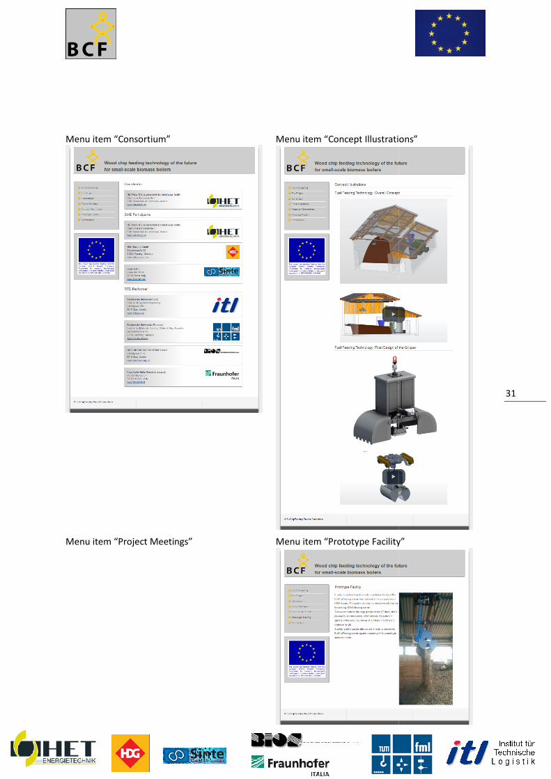
Menu item “Consortium”
Menu item “Project Meetings”
Menu item “Concept Illustrations”
Menu item “Prototype Facility”
31
Menu item “Concept Illustrations”
Menu item “Prototype Facility”

32

Furthermore, project logo, diagrams or photographs illustrating
project (including videos, etc…), as well as the list of all beneficiaries with the corresponding contact
names can be submitted without any restriction.
Furthermore, project logo, diagrams or photographs illustrating and promoting the work of the
project (including videos, etc…), as well as the list of all beneficiaries with the corresponding contact
names can be submitted without any restriction.
33
and promoting the work of the
project (including videos, etc…), as well as the list of all beneficiaries with the corresponding contact

Use and dissemination of foreground
Section A This section should describe the dissemination measures, including any scientific publications
to foreground. Its content will be made available in the public domain thus
value and positive impact of the project on the European Union.
Template A1
List of all scientific (peer reviewed) publications relating to the foreground of the project.
List of scientific (peer reviewed) publications, starting with the most important onesNO Title Main author Title of the
periodical
or th
series
Use and dissemination of foreground
describe the dissemination measures, including any scientific publications
to foreground. Its content will be made available in the public domain thus demonstrating the added
value and positive impact of the project on the European Union.
List of all scientific (peer reviewed) publications relating to the foreground of the project.
List of scientific (peer reviewed) publications, starting with the most important onesTitle of the
periodical
or the
Number,
date or
frequency
Publisher Place Year Relevant
pages
34
describe the dissemination measures, including any scientific publications relating
demonstrating the added-
List of all scientific (peer reviewed) publications relating to the foreground of the project.
List of scientific (peer reviewed) publications, starting with the most important ones Permanent
identifiers
(if available)
Open
access

Template A2
List of all dissemination activities (publications, conferences,
press releases, flyers, articles published in the popular press, videos, media briefings, presentations,
exhibitions, thesis, interviews, films, TV clips, posters).
List of dissemination activities NO Type of activities Main leader
List of all dissemination activities (publications, conferences, workshops, web sites/applications,
articles published in the popular press, videos, media briefings, presentations,
exhibitions, thesis, interviews, films, TV clips, posters).
Title Date/Period Place Type of
audience
Size of
audience
35
workshops, web sites/applications,
articles published in the popular press, videos, media briefings, presentations,
Size of
audience
Countries
adressed

Section B (Confidential or public: confidential information to be marked clearly)
This section should specify the exploitable foreground and provide the plans for exploitation. All
these data can be public or confidential; the report must clearly mark non
parts that will be treated as such by the Commission. Information under Section B
as confidential will be made available in the public domain thus
positive impact of the project on the European Union.
Part B1
The applications for patents, trademarks, registered designs, etc. shall be l
template B1 provided hereafter.
The list should, specify at least one unique identifier e.g. European Patent application reference. For
patent applications, only if applicable, contributions to standards should be specified. This
cumulative, which means that it should always show all applications from the
the end of the project.
or public: confidential information to be marked clearly)
the exploitable foreground and provide the plans for exploitation. All
these data can be public or confidential; the report must clearly mark non-publishable (confidential)
parts that will be treated as such by the Commission. Information under Section B
as confidential will be made available in the public domain thus demonstrating the added
positive impact of the project on the European Union.
The applications for patents, trademarks, registered designs, etc. shall be listed according to the
template B1 provided hereafter.
The list should, specify at least one unique identifier e.g. European Patent application reference. For
patent applications, only if applicable, contributions to standards should be specified. This
cumulative, which means that it should always show all applications from the
36
the exploitable foreground and provide the plans for exploitation. All
publishable (confidential)
parts that will be treated as such by the Commission. Information under Section B that is not marked
demonstrating the added-value and
isted according to the
The list should, specify at least one unique identifier e.g. European Patent application reference. For
patent applications, only if applicable, contributions to standards should be specified. This table is
beginning until after

Part B2
In addition to the table, please provide a text to explain the exploitable foreground, in particular:
• Its purpose
• How the foreground might be exploited, when and by whom
• IPR exploitable measures taken or intended
• Further research necessary, if any
• Potential/expected impact (quantify where possible)
•
In addition to the table, please provide a text to explain the exploitable foreground, in particular:
How the foreground might be exploited, when and by whom
IPR exploitable measures taken or intended
Further research necessary, if any
Potential/expected impact (quantify where possible)
37
In addition to the table, please provide a text to explain the exploitable foreground, in particular: