Embed Size (px)
Citation preview

Copyright © Australian energyraters.com.au 18/07/2012
BCA 2012 Section J1 to J8 Compliance report – 8178/12
Proposed Class 5 Building
Professional Consulting Rooms
9 Gormly Ave, Wagga Wagga NSW
NOTE: This report is to be read in conjunction with –
1. GPG Architecture & Design Drawings No. A1202-0001; A1202-1001; A1202-1002; A1202-3001; A1202-3002 & A1202-7001 dated 16/7/2012.

Report Number 8178/12 Page 2 of 12
Copyright © Australian energyraters.com.au 18/07/2012
"DTS" ENERGY EFFICIENCY COMPLIANCE REPORT
BUILDING CLASS CLIMATE ZONE JOB DESCRIPTION DATE
5 4 Proposed New Professional Consulting Rooms – 9 Gormly Ave, Wagga Wagga NSW 10/07/12
BCA CLAUSE MINIMUM COMPLIANCE FOR EACH SECTION PROPOSED BUILDING
BUILDING FABRIC J.1
J 1.1 Application of part
Apply to building envelope of a class 2 to 9 building other than – a Class 7,8 or 9b building that does not have a conditioned space;
or an atrium or solarium that is not conditioned and is separated from
the remainder of the building by an envelope.
The building envelope for the purpose of Section J includes internal and external walls, floor and roof areas and has been shown
highlighted in the attached floor plan at Annex A.
J 1.2 Thermal construction General
Where required, insulation must comply with AS/NZS 4859.1 and be installed so that it— abuts or overlaps adjoining insulation other than at supporting
members such as studs, noggings, joists, furring channels and the like where the insulation must butt against the member; and
forms a continuous barrier with ceilings, walls, bulkheads, floors or the like that inherently contribute to the thermal barrier; and
does not affect the safe or effective operation of a service or fitting. Where required, reflective insulation must be installed with— the necessary airspace to achieve the required R-Value between a
reflective side of the reflective insulation and a building lining or cladding; and
the reflective insulation closely fitted against any penetration, door or window opening; and
the reflective insulation adequately supported by framing members; and
each adjoining sheet of roll membrane being— overlapped not less than 50 mm; or taped together
Where required, bulk insulation must be installed so that— it maintains its position and thickness, other than where it crosses
roof battens, water pipes, electrical cabling or the like; and in a ceiling, where there is no bulk insulation or reflective insulation
in the wall beneath, it overlaps the wall by not less than 50 mm
Where applicable Installation of Reflective and bulk insulation must be in accord BCA J1.2 and comply with AS/NZS 4859.1

Report Number 8178/12 Page 3 of 12
Copyright © Australian energyraters.com.au 18/07/2012
BUILDING FABRIC J.1 (cont)
J 1.3a Roof & Ceiling
Climate 4 – must achieve a total R-value downwards depending on Solar absorptance (SA) as follows:
SA less than 0.4 = R3.2 downwards; SA greater than 0.4 but less than 0.6 = R3.7 downwards; & SA greater than 0.6 = R4.2 downwards (Ref. table J1.3a) Note: Thermal break criteria:
A roof that has metal sheet roofing fixed to metal – purlins, rafters or battens; that does or does not have a ceiling lining fixed directly to the same metal framing must have a thermal break with an R-value no < R0.2 installed between the metal roofing and the metal frame.
New Roof & Ceiling Construction: Metal Clad Roof 20o pitch (Ventilated) - Double-sided foil
sisalation & R3.5 Bulk insulation to flat or raked ceilings. - will achieve a total system R-Value >R3.7* downwards. Notes:
*Due to Roof Colour: Shale Grey, SA = 0.43
Thermal break - N/A to timber purlins.
The above systems can be replaced with equivalent insulation systems that achieve a total system of R3.7 downwards
J 1.3b Adjustment for loss of ceiling insulation
Due to operational or safety reasons associated with Exhaust fans, flues or recessed down lights the area of required ceiling insulation is reduced, the
remaining ceiling insulation area must be increased in accord with table J1.3b
R3.5 bulk insulation to ceilings will comply See attached Ceiling Penetration Data Sheet at Annex B
J 1.4 Roof lights Roof lights must have U & SHGC values in accord with Table J1.4. Roof Lights comply see Roof Light Calculations at Annex C
J 1.5 Walls
Climate 4 to 6 – External Walls must achieve a minimum system R value of 2.8
Note -Minimum R-value can be reduced– For a wall with surface density 220kg/m2 by 0.5; and For a wall that is –
facing the south orientation by 0.5; or shaded with a projection angle of – 30o to 60o by 0.5; more than 60o by 1.0.
Internal Walls must achieve a minimum system R value of 1.8 Note – Minimum R-value is N/A to enclosed unconditioned spaces with mechanical ventilation < 1.5 air changes / hr of outside air.
(Ref. tables J1.5a &b) Note: Thermal break criteria: Steel framed walls with light weight external cladding such as weatherboards, fibre cement or metal sheeting with or without an internal lining that is fixed directly to the same steel frame must have a thermal break of not less than R0.2 installed between the cladding & metal frame (Ref J:1.5 e)
New Wall Construction:
Brick Veneer / Foil sisalation/ R2.5 bulk insulation achieves a system value > R2.8
Weatherboard cladding / Foil sisalation/ R2.5 bulk insulation achieves a system value > R2.8
Notes:
All above wall constructions are considered to have a cavity frame/batten to suit the insulation system with an internal plasterboard lining. The system must be installed to the manufacturer’s specifications.
Thermal break - N/A to timber frames.
J 1.6 Floors
Climate 4 Unenclosed Suspended floors must achieve a total system R-value
of R2.0 (Ref. Table J1.6b) N/A - Enclosed Suspended floor or Concrete Slab on ground
Floor Construction:
N/A Concrete slab on ground

Report Number 8178/12 Page 4 of 12
Copyright © Australian energyraters.com.au 18/07/2012
EXTERNAL GLAZING J .2
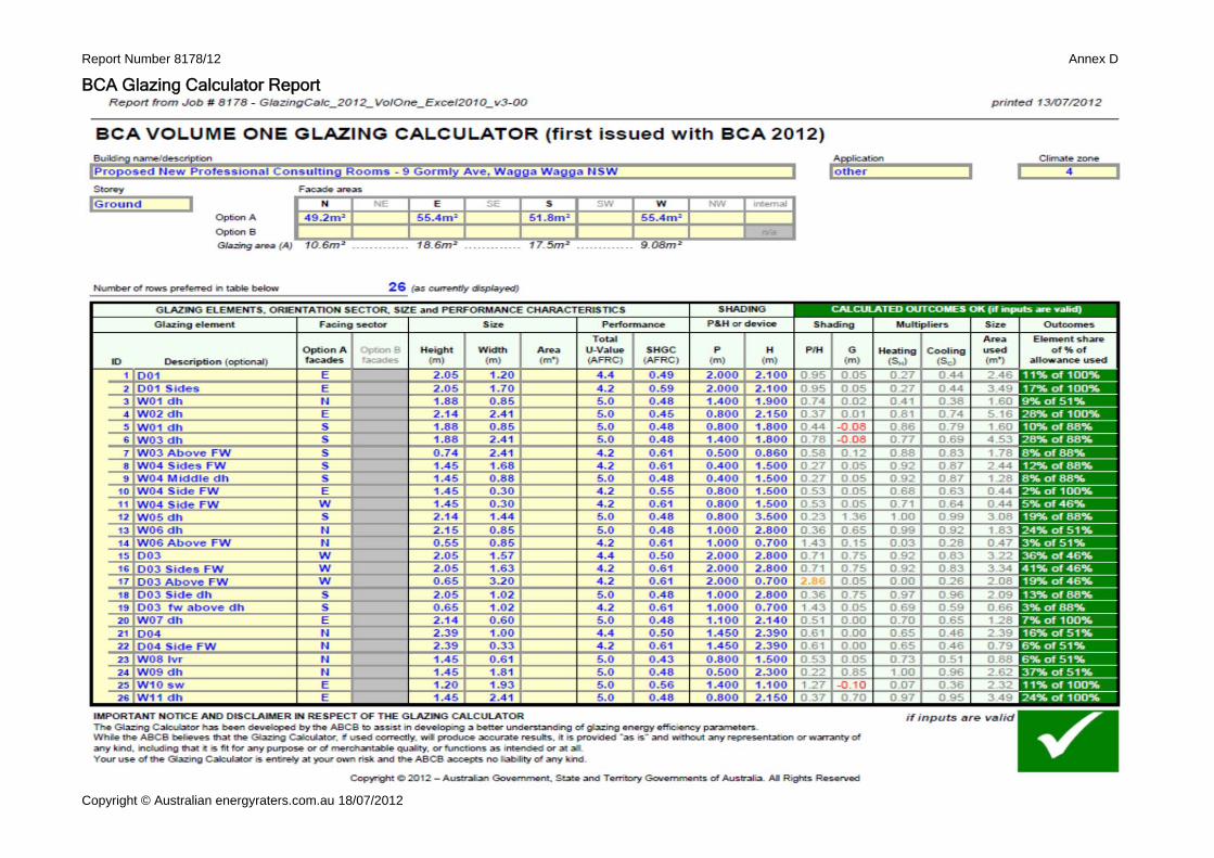
J 2.4 Glazing to conditioned space
Constants for conductance and solar heat gain (Ref BCA glazing calculator)
Notes: The tolerance for Glazing values used in the BCA glazing calculator
are : U-values must be equal to or less than those stated. SHGC values to be within +/- 10%
Only applicable to glazing in conditioned space or unconditioned areas that are beside conditioned spaces in accord with table J1.5b.
Refer to the attached BCA glazing calculator report at Annex D Glazing Type used as proxy - Veiwco aluminium frames as follows- Doors - Hinged – 50 Series, 6.38mm Comfort Plus clear, AWS-033-20 Windows - Sliding – 601 Series, 6.38mm Comfort Plus clear, AWS-022-18 Fixed – 400 Series 6.38mm Comfort Plus clear, AWS-027-12 Double Hung – 613 Series 6.38mm Com. Plus clear, VAN- 002-17 Louvre - 525 series, 6mm Evantage clear, AWS-058-03 Note:
Or equivalent glazing with U & SHGC values as per report.
BUILDING SEALING J.3
NSW J 3.1 Application of part
Buildings mechanically conditioned are to be sealed Excluding - where the only means is evaporative cooling, or there is sufficient pressurisation to prevent infiltration, or parts of buildings that cannot be fully enclosed.
The conditioned building envelope is to be sealed Note: existing building
J 3.2 Chimneys / flues Chimneys & flues to have dampers N/A
J 3.3 Roof lights All roof lights must have capability of being sealed Roof lights are sealed
J 3.4 Windows / doors All external doors and windows leading into a conditioned space must be sealed, exceptions to windows complying with AS/2047, fire doors
and roller shutters
External swinging doors to have air infiltration seals; and All windows sealed as per manufacturers standards
J 3.4d An entrance to a building
Must have an airlock, self-closing door or the like if leading to a conditioned space >50m2
Self-closing door has been provided to main entry. N/A – D03, D04 conditioned space < 50m2
J 3.5 Exhaust fans Within a conditioned space must be fitted with a sealing device All new exhaust fans to have self-closing dampers
J 3.6 Roof / walls / floors Building construction required to minimise air infiltration New construction Gaps & cracks sealed in accord with J3.6
J 3.7 Evaporative coolers Must be fitted with self closing damper when serving a heated space, or in a habitable room or public place in Climate zone 4 to 8 If fitted must have self closing damper
PART J:4 * * * *
Clause blank in BCA - N/A
Report Number 8178/12 Page 5 of 12
Copyright © Australian energyraters.com.au 18/07/2012
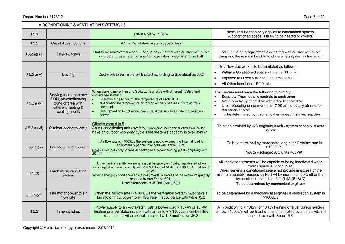
AIRCONDITIONING & VENTILATION SYSTEMS J:5
J 5.1 Clause blank in BCA Note: This Section only applies to conditioned spaces. A conditioned space is likely to be heated or cooled.
J 5.2 Capabilities / options A/C & Ventilation system capabilities
J 5.2 a(i)(ii) Time switches Unit to be inactivated when unoccupied & if fitted with outside return air dampers, these must be able to close when system is turned off
A/C unit to be programmable & if fitted with outside return air dampers, these must be able to close when system is turned off
J 5.2 a(iv) Ducting Duct work to be insulated & sized according to Specification J5.2
If fitted New ductwork is to be insulated as follows:
Within a Conditioned space - R-value R1.0min;
Exposed to Direct sunlight - R3.0 min; and
All Other locations - R2.0 min.
J 5.2 a (v)
Serving more than one SOU, air-conditioning
zone or area with different heating &
cooling needs
When serving more than one SOU, zone or area with different heating and cooling needs must– Thermostatically control the temperature of each SOU Not control the temperature by mixing actively heated air with actively
cooled air Limit reheating to not more than 7.5K at the supply air rate for the space
served.
The System must have the following to comply: Separate Thermostatic controls to each zone Not mix actively heated air with actively cooled air Limit reheating to not more than 7.5K at the supply air rate for
the space served To be determined by mechanical engineer/ installer/ supplier
J 5.2 a (vii) Outdoor economy cycle Climate zone 4 to 8 An Air conditioning unit / system, if providing Mechanical ventilation must have an outdoor economy cycle if the system’s capacity is over 35kWr.
To be determined by A/C engineer if unit / system capacity is over 35kWr.
J 5.2 a (ix) Fan Motor shaft power
If Air flow rate is >1000L/s the system is not to exceed the Internal load for equipment & people in accord with Table J5.2a.
Note – Does not apply to fans in packaged air -conditioning plant complying with J5.4(c).
To be determined by mechanical engineer if Airflow rate is >1000L/s.
N/A to Packaged A/C units <65kWr
J 5.2b Mechanical ventilation system
A mechanical ventilation system must be capable of being inactivated when unoccupied and must comply with AS 1668.2 and AS/NZS 3666.1 (Ref. F4.5b &
J5.2b) When serving a conditioned space not provide in excess of the minimum quantity
required by part F4 by >50%. Note: exemptions at J5.2b(ii)(A)(B) &(C)
All ventilation systems will be capable of being inactivated when room / space is unoccupied.
When serving a conditioned space not provide in excess of the minimum quantity required by Part F4 by more than 50% other than
by conditions stated at J5.2b(ii)(A)(B) &(C) To be determined by mechanical engineer
J 5.2b(iii) Fan motor power to air flow rate
When the air flow rate is >1000L/s the ventilation system must have a fan motor input power to air flow rate in accordance with table J5.2
To be determined by a mechanical engineer if ventilation system is >1000L/s
J 5.3 Time switches Power supply to an A/C system with a power load > 10kWr or 10 kW
heating or a ventilation system with an airflow > 1000L/s must be fitted with a time switch control in accord with Specification J6.3
Air conditioning > 10kWr or 10 kW heating or a ventilation system airflow >1000L/s will be fitted with and controlled by a time switch in
accordance with Spec J6.3
Report Number 8178/12 Page 6 of 12
Copyright © Australian energyraters.com.au 18/07/2012
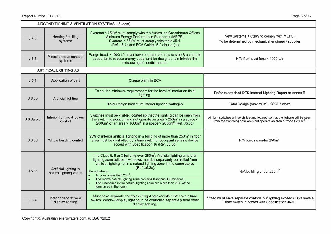
AIRCONDITIONING & VENTILATION SYSTEMS J:5 (cont)
J 5.4 Heating / chilling systems
Systems < 65kW must comply with the Australian Greenhouse Offices Minimum Energy Performance Standards (MEPS).
Systems > 65kW must comply with table J5.4. (Ref. J5.4c and BCA Guide J5.2 clause (c))
New Systems < 65kW to comply with MEPS. To be determined by mechanical engineer / supplier
J 5.5 Miscellaneous exhaust systems
Range hood > 1000 L/s must have operator controls to stop & a variable speed fan to reduce energy used; and be designed to minimize the
exhausting of conditioned air N/A if exhaust fans < 1000 L/s
ARTIFICAL LIGHTING J:6
J 6.1 Application of part Clause blank in BCA
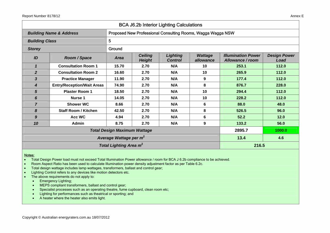
J 6.2b Artificial lighting
To set the minimum requirements for the level of interior artificial lighting. Refer to attached DTS Internal Lighting Report at Annex E
Total Design maximum interior lighting wattages Total Design (maximum) – 2895.7 watts
J 6.3a.b.c Interior lighting & power control
Switches must be visible, located so that the lighting can be seen from the switching position and not operate an area > 250m2 in a space <
2000m2 or an area > 1000m2 in a space > 2000m2 (Ref. J6.3c)
All light switches will be visible and located so that the lighting will be seen from the switching position & not operate an area or zone >250m2.
J 6.3d Whole building control 95% of interior artificial lighting in a building of more than 250m2 in floor
area must be controlled by a time switch or occupant sensing device accord with Specification J6 (Ref. J6.3d)
N/A building under 250m2.
J 6.3e Artificial lighting in natural lighting zones
In a Class 5, 6 or 8 building over 250m2, Artificial lighting a natural lighting zone adjacent windows must be separately controlled from
artificial lighting not in a natural lighting zone in the same storey (Ref. J6.3e).
Except where - A room is less than 20m2, The rooms natural lighting zone contains less than 4 luminaries, The luminaries in the natural lighting zone are more than 70% of the
luminaries in the room.
N/A building under 250m2
J 6.4 Interior decorative & display lighting
Must have separate controls & if lighting exceeds 1kW have a time switch. Window display lighting to be controlled separately from other
display lighting.
If fitted must have separate controls & if lighting exceeds 1kW have a time switch in accord with Specification J6-5
Report Number 8178/12 Page 7 of 12
Copyright © Australian energyraters.com.au 18/07/2012
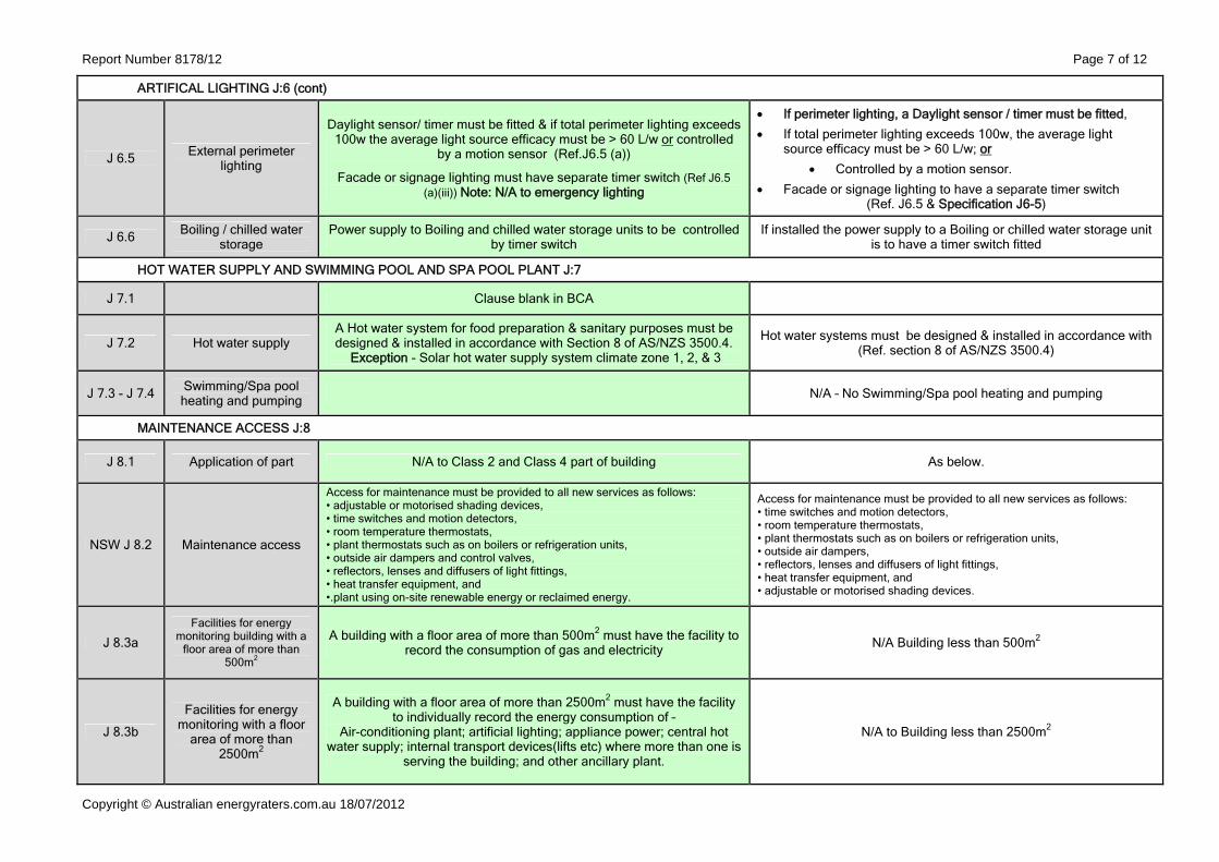
ARTIFICAL LIGHTING J:6 (cont)
J 6.5 External perimeter lighting
Daylight sensor/ timer must be fitted & if total perimeter lighting exceeds 100w the average light source efficacy must be > 60 L/w or controlled
by a motion sensor (Ref.J6.5 (a))
Facade or signage lighting must have separate timer switch (Ref J6.5 (a)(iii)) Note: N/A to emergency lighting
If perimeter lighting, a Daylight sensor / timer must be fitted,
If total perimeter lighting exceeds 100w, the average light source efficacy must be > 60 L/w; or
Controlled by a motion sensor.
Facade or signage lighting to have a separate timer switch (Ref. J6.5 & Specification J6-5)
J 6.6 Boiling / chilled water storage
Power supply to Boiling and chilled water storage units to be controlled by timer switch
If installed the power supply to a Boiling or chilled water storage unit is to have a timer switch fitted
HOT WATER SUPPLY AND SWIMMING POOL AND SPA POOL PLANT J:7
J 7.1 Clause blank in BCA
J 7.2 Hot water supply A Hot water system for food preparation & sanitary purposes must be designed & installed in accordance with Section 8 of AS/NZS 3500.4.
Exception - Solar hot water supply system climate zone 1, 2, & 3
Hot water systems must be designed & installed in accordance with (Ref. section 8 of AS/NZS 3500.4)
J 7.3 - J 7.4 Swimming/Spa pool heating and pumping N/A – No Swimming/Spa pool heating and pumping
MAINTENANCE ACCESS J:8
J 8.1 Application of part N/A to Class 2 and Class 4 part of building As below.
NSW J 8.2 Maintenance access
Access for maintenance must be provided to all new services as follows: • adjustable or motorised shading devices, • time switches and motion detectors, • room temperature thermostats, • plant thermostats such as on boilers or refrigeration units, • outside air dampers and control valves, • reflectors, lenses and diffusers of light fittings, • heat transfer equipment, and •.plant using on-site renewable energy or reclaimed energy.
Access for maintenance must be provided to all new services as follows: • time switches and motion detectors, • room temperature thermostats, • plant thermostats such as on boilers or refrigeration units, • outside air dampers, • reflectors, lenses and diffusers of light fittings, • heat transfer equipment, and • adjustable or motorised shading devices.
J 8.3a
Facilities for energy monitoring building with a
floor area of more than 500m2
A building with a floor area of more than 500m2 must have the facility to record the consumption of gas and electricity N/A Building less than 500m2
J 8.3b
Facilities for energy monitoring with a floor
area of more than 2500m2
A building with a floor area of more than 2500m2 must have the facility to individually record the energy consumption of –
Air-conditioning plant; artificial lighting; appliance power; central hot water supply; internal transport devices(lifts etc) where more than one is
serving the building; and other ancillary plant.
N/A to Building less than 2500m2

Report Number 8178/12 Annex A
Copyright © Australian energyraters.com.au 18/07/2012
Building Envelope – Conditioned and Non-conditioned areas
Conditioned space
Non‐conditioned space

Report Number 8178/12 Annex B
Copyright © Australian energyraters.com.au 18/07/2012
Dia. (m2) Qty Penetration
size (m2)
Exha ust fa ns 0.3 0.15 3 0.21D1 - Do wn lig hts 0.3 0.15 31 2.19
Length (m2)
W idth (m2)
Qty Penetration
size (m2)
T 5 T ro ffe r l ig ht 0.3 1.2 0 11 3.96
6.36 m2
221.5 m2
** Insu la tion needs to be adjusted only i f the tota l area o f penetra tion is greater than 0 .5%.Note: Cei l ing Penetrations m ust not exceed 5% of the tota l ce i l ing area.
Sq uare p e ne tra tio n *
BCA J1.3b Ceiling Insulat ion Penetrat ion Data Sheet
Build ing Name & Ad d re ssProposed New Professional Consulting Rooms -at 9 Gormly Ave, Wagga Wagga NSW
RECESSED EXHAUST FANS o r LIGHT FIT T INGS
Ro und p e ne tra tio n *
Tota l area o f ce i l ing insula tion penetra tions
= 2.87% **Cei l ing insulation area
REQUIRED CEILING INSULAT ION
Roof Construction - Tota l R-va lue to com ply R 3.7 downwards (SA = >0.4 <0.6)
M inim um bulk insulation to cei l ing to achieve com pl iance
R 1.6 bulk insulation to ceilingsNote: Double-sided foil sisalation to roof
Percentage of ce i l ing area uninsu lated 2.87%
Adjusted R-value to com ply wi th table J1.3b > R2.0 bulk insulation will comply
Notes: - *The penetration size is determined by measuring the area of the penetration in m2. - Penetration size inc ludes c learanc e to insulation from lighting and transformers - Requirements in ac c ord with BCA 2012 Sec tion J1.3 & Table J1.3b. - SA = Solar Absorptanc e of roof c olour is to be less than 0.6. Roof c olour - medium.

Report Number 8178/12 Annex C
Copyright © Australian energyraters.com.au 18/07/2012
No. Room / space Length Width Qty Roof light area /
Floor Area served
=% of floor area served
Average Height of shaft (m2)
/Avg. dia.
opening at ceiling (m2)
= Roof Light shaft Index
1 Reception/wait 1.4 0.78 2 2.184 62.97 3.47 * 1.45 1.09 1.33
2 Corridor 0.7 0.55 1 0.39 11.3 3.41 1.70 0.625 2.72
3 Manager 0.7 0.55 1 0.39 11.9 3.24 * 1.70 0.625 2.72
No. Room / space
1 Reception/wait2 Corridor3 Manager
No. Room / space
1 Reception/wait2 Corridor3 Manager
2.7** 0.33**
2.72 3% to 4% 2.5 and more Total U-Value not > than 4.3 SHGC not > 0.83
Velux FS; WERS-VEL-002-01Velux FS; WERS-VEL-002-01 2.7** 0.33**
Notes:** WERS Certif ied Product Directory AFRC values.*** Calculations and Requirements in accord w ith BCA 2012 Table J1.41. The roof light shaft index is determined by measuring the distance from the centre of the shaft at the roof to the centre of the shaft at the ceiling level and dividing it by the average internal dimension of the shaft opening at the ceiling level (or the diameter for a circular shaft) in the same units of measurement.2. The total area of roof lights is the combined area for all roof lights serving the room or space.3. The area of a roof light is the area of the roof opening that allow s light to enter the building.4. The thermal performance of an imperforate ceiling diffuser may be included in the Total U-Value of the roof light.
Proposed Thermal performance for Roof lights
1.33 3% to 4% 1.0 to less than 2.5 Total U-Value not > than 4.3 SHGC not > 0.69
2.72 3% to 4% 2.5 and more Total U-Value not > than 4.3 SHGC not > 0.83
Manufacturer Model U- Value Solar Heat Gain Coefficient
Velux VSE; WERS-VEL-001-01 2.9** 0.29**
BCA J1.4(b) Roof Light Calculations
Required Thermal performance for Proposed Roof lights as per BCA Table J1.4***Roof Light
Shaft index Floor area served% Roof Light Shaft index Required Thermal performance
Proposed New Professional Consulting Rooms - 9 Gormly Ave, Wagga Wagga NSW
Class 5
Building Name & Address
Building Class
Calculations - Proposed % of Roof light to served rooms or space Calculations - Roof Shaft Index for each Roof light
* The Proposed Total Roof light % is less than 5% of the area served. The Roof lights need to comply with BCA Table J1.4
Report Number 8178/12 Annex D
Copyright © Australian energyraters.com.au 18/07/2012
BCA Glazing Calculator Report
Report Number 8178/12 Annex E
Copyright © Australian energyraters.com.au 18/07/2012
BCA J6.2b Interior Lighting Calculations
Building Name & Address Proposed New Professional Consulting Rooms, Wagga Wagga NSW
Building Class 5
Storey Ground
ID Room / Space Area Ceiling Height
Lighting Control
Wattage allowance
Illumination Power Allowance / room
Design Power Load
1 Consultation Room 1 15.70 2.70 N/A 10 253.1 112.0 2 Consultation Room 2 16.60 2.70 N/A 10 265.9 112.0 3 Practice Manager 11.90 2.70 N/A 9 177.4 112.0 4 Entry/Reception/Wait Areas 74.90 2.70 N/A 8 876.7 228.0 5 Plaster Room 1 18.50 2.70 N/A 10 294.4 112.0 6 Nurse 1 14.05 2.70 N/A 10 228.2 112.0 7 Shower WC 8.66 2.70 N/A 6 88.0 48.0 8 Staff Room / Kitchen 42.50 2.70 N/A 8 526.5 96.0 9 Acc WC 4.94 2.70 N/A 6 52.2 12.0
10 Admin 8.75 2.70 N/A 9 133.2 56.0
Total Design Maximum Wattage 2895.7 1000.0
Average Wattage per m2 13.4 4.6
Total Lighting Area m2 216.5
Notes: Total Design Power load must not exceed Total Illumination Power allowance / room for BCA J 6.2b compliance to be achieved. Room Aspect Ratio has been used to calculate Illumination power density adjustment factor as per Table 6.2c. Total design wattage includes lamp wattages, transformers, ballast and control gear; Lighting Control refers to any devices like motion detectors etc. The above requirements do not apply to:
Emergency Lighting; MEPS compliant transformers, ballast and control gear; Specialist processes such as an operating theatre, fume cupboard, clean room etc; Lighting for performances such as theatrical or sporting; and A heater where the heater also emits light.