Embed Size (px)
Citation preview
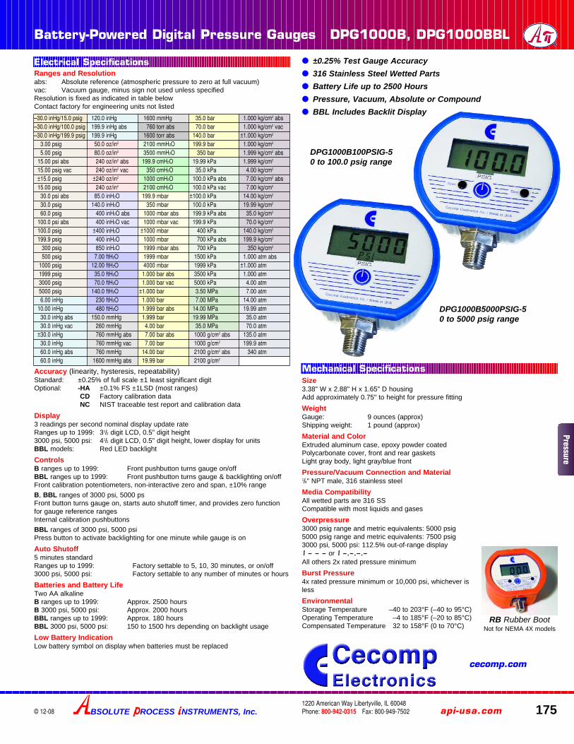
Battery-Powered Digital Pressure Gauges DPG1000B, DPG1000BBL
BSOLUTE ROCESS NSTRUMENTS, Inc. api-usa.com 1751220 American Way Libertyville, IL 60048Phone: 800-942-0315 Fax: 800-949-7502© 12-08
●● ±0.25% Test Gauge Accuracy●● 316 Stainless Steel Wetted Parts●● Battery Life up to 2500 Hours●● Pressure, Vacuum, Absolute or Compound●● BBL Includes Backlit Display
Size3.38" W x 2.88" H x 1.65" D housingAdd approximately 0.75" to height for pressure fitting
WeightGauge: 9 ounces (approx)Shipping weight: 1 pound (approx)
Material and ColorExtruded aluminum case, epoxy powder coatedPolycarbonate cover, front and rear gasketsLight gray body, light gray/blue front
Pressure/Vacuum Connection and Material1/4" NPT male, 316 stainless steel
Media CompatibilityAll wetted parts are 316 SSCompatible with most liquids and gases
Overpressure3000 psig range and metric equivalents: 5000 psig5000 psig range and metric equivalents: 7500 psig3000 psi, 5000 psi: 112.5% out-of-range display i – – – or i –.–.–.–All others 2x rated pressure minimum
Burst Pressure4x rated pressure minimum or 10,000 psi, whichever isless
EnvironmentalStorage Temperature –40 to 203°F (–40 to 95°C)Operating Temperature –4 to 185°F (–20 to 85°C)Compensated Temperature 32 to 158°F (0 to 70°C)
Ranges and Resolutionabs: Absolute reference (atmospheric pressure to zero at full vacuum)vac: Vacuum gauge, minus sign not used unless specifiedResolution is fixed as indicated in table belowContact factory for engineering units not listed
Accuracy (linearity, hysteresis, repeatability)Standard: ±0.25% of full scale ±1 least significant digitOptional: -HA ±0.1% FS ±1LSD (most ranges)
CD Factory calibration dataNC NIST traceable test report and calibration data
Display3 readings per second nominal display update rateRanges up to 1999: 31/2 digit LCD, 0.5" digit height3000 psi, 5000 psi: 41/2 digit LCD, 0.5" digit height, lower display for unitsBBL models: Red LED backlight
ControlsB ranges up to 1999: Front pushbutton turns gauge on/offBBL ranges up to 1999: Front pushbutton turns gauge & backlighting on/offFront calibration potentiometers, non-interactive zero and span, ±10% range
B, BBL ranges of 3000 psi, 5000 psFront button turns gauge on, starts auto shutoff timer, and provides zero functionfor gauge reference rangesInternal calibration pushbuttons
BBL ranges of 3000 psi, 5000 psiPress button to activate backlighting for one minute while gauge is on
Auto Shutoff5 minutes standardRanges up to 1999: Factory settable to 5, 10, 30 minutes, or on/off3000 psi, 5000 psi: Factory settable to any number of minutes or hours
Batteries and Battery LifeTwo AA alkalineB ranges up to 1999: Approx. 2500 hoursB 3000 psi, 5000 psi: Approx. 2000 hoursBBL ranges up to 1999: Approx. 180 hoursBBL 3000 psi, 5000 psi: 150 to 1500 hrs depending on backlight usage
Low Battery IndicationLow battery symbol on display when batteries must be replaced
DPG1000B100PSIG-50 to 100.0 psig range
DPG1000B5000PSIG-50 to 5000 psig range
Electrical Specifications
Mechanical Specifications
–30.0 inHg/15.0 psig 120.0 inHg 1600 mmHg 35.0 bar 1.000 kg/cm2 abs–30.0 inHg/100.0 psig 199.9 inHg abs 760 torr abs 70.0 bar 1.000 kg/cm2 vac–30.0 inHg/199.9 psig 199.9 inHg 1600 torr abs 140.0 bar ±1.000 kg/cm2
3.00 psig 50.0 oz/in2 2100 mmH2O 199.9 bar 1.000 kg/cm2
5.00 psig 80.0 oz/in2 3500 mmH2O 350 bar 1.999 kg/cm2 abs15.00 psi abs 240 oz/in2 abs 199.9 cmH2O 19.99 kPa 1.999 kg/cm2
15.00 psig vac 240 oz/in2 vac 350 cmH2O 35.0 kPa 4.00 kg/cm2
±15.0 psig ±240 oz/in2 1000 cmH2O 100.0 kPa abs 7.00 kg/cm2 abs15.00 psig 240 oz/in2 2100 cmH2O 100.0 kPa vac 7.00 kg/cm2
30.0 psi abs 85.0 inH2O 199.9 mbar ±100.0 kPa 14.00 kg/cm2
30.0 psig 140.0 inH2O 350 mbar 100.0 kPa 19.99 kg/cm2
60.0 psig 400 inH2O abs 1000 mbar abs 199.9 kPa abs 35.0 kg/cm2
100.0 psi abs 400 inH2O vac 1000 mbar vac 199.9 kPa 70.0 kg/cm2
100.0 psig ±400 inH2O ±1000 mbar 400 kPa 140.0 kg/cm2
199.9 psig 400 inH2O 1000 mbar 700 kPa abs 199.9 kg/cm2
300 psig 850 inH2O 1999 mbar abs 700 kPa 350 kg/cm2
500 psig 7.00 ftH2O 1999 mbar 1500 kPa 1.000 atm abs1000 psig 12.00 ftH2O 4000 mbar 1999 kPa ±1.000 atm1999 psig 35.0 ftH2O 1.000 bar abs 3500 kPa 1.000 atm3000 psig 70.0 ftH2O 1.000 bar vac 5000 kPa 4.00 atm5000 psig 140.0 ftH2O ±1.000 bar 3.50 MPa 7.00 atm6.00 inHg 230 ftH2O 1.000 bar 7.00 MPa 14.00 atm
10.00 inHg 480 ftH2O 1.999 bar abs 14.00 MPa 19.99 atm30.0 inHg abs 150.0 mmHg 1.999 bar 19.99 MPa 35.0 atm30.0 inHg vac 260 mmHg 4.00 bar 35.0 MPa 70.0 atm
±30.0 inHg 760 mmHg abs 7.00 bar abs 1000 g/cm2 abs 135.0 atm30.0 inHg 760 mmHg vac 7.00 bar 1000 g/cm2 199.9 atm60.0 inHg abs 760 mmHg 14.00 bar 2100 g/cm2 abs 340 atm60.0 inHg 1600 mmHg abs 19.99 bar 2100 g/cm2
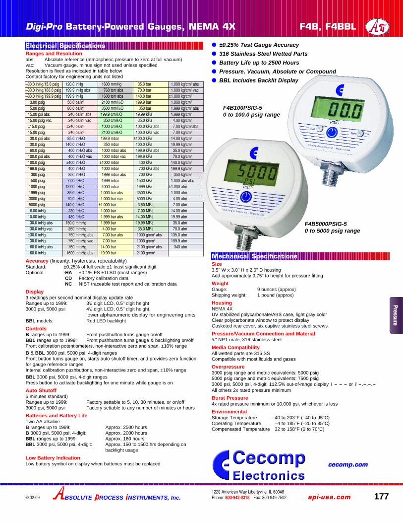
RB Rubber BootNot for NEMA 4X models
Pressure
cecomp.com
176
Cecomp DPG1000B, DPG1000BBL Instructions
© 01-07
INSTALLATION AND PRECAUTIONSInstall or remove gauge using wrench on hex fitting only. Do not attempt to tighten byturning housing or any other part of the gauge. Use fittings appropriate for the pres-sure range of the gauge. Do not apply vacuum to gauges not designed for vacuumoperation.
Due to the hardness of 316 stainless steel, it is recommended that a thread sealantbe used to ensure leak-free operation.
NEVER insert objects into the gauge port or blow out with compressed air.Permanent damage not covered by warranty will result to the sensor.
OPERATION – RANGES UP TO 1999Press the round button on the front of the gauge to activate the display. The gaugewill stay on for a period of time determined by the auto-shutoff time. The gauge canbe shut off at any time by pressing the button again. Display backlighting onDPG1000BBL models is on whenever the gauge is on. If the gauge was orderedwithout auto shutoff it will stay on until the button is pressed or until the batteries aredepleted. Turn gauge off when not in use to conserve battery.
OPERATION – 3000 PSI, 5000 PSI RANGESPress and hold the pushbutton for approx. 1 second. The full-scale range is indicat-ed, display segments are tested, and the reading and units are displayed.
Power-Up With One-Touch Zero (Gauge reference models only)1. Make absolutely certain no pressure is applied to the gauge. The gauge port
should be exposed to normal atmospheric pressure. Note that the zeroing func-tion may only be activated at power-up and the stored zero correction is erasedwhen the gauge is shut off.
2. Press and hold the pushbutton.
3. The full-scale range is indicated and the display segments are tested.
4. Continue to press the pushbutton until oooo is displayed and then release thebutton. This indicates that the gauge has been zeroed.
5. The actual pressure is displayed.
Attempting to zero the gauge with pressure greater than approximately 3% of full-scale applied will result in an error condition, and the display will alternately indicateE r r 0 and the actual measured pressure. The gauge must be powered down toreset the error condition.
Absolute reference gauges do not use the zero feature since they read atmosphericpressure under normal conditions.
Normal OperationFollowing the start-up initialization, the display indicates the pressure reading updat-ed approximately 3 times per second and the units. The auto shutoff timer startswhen the gauge is powered up or whenever the button is pushed, unless the gaugewas ordered without an auto shutoff time (-ON option).
If excessive vacuum is applied to a pressure-only gauge, the display will indicate – Er r until the vacuum is released. Applying vacuum to a gauge designed for pressuremay damage the pressure sensor. If excessive pressure is applied (112.5% overrange), an out-of-range indication of i – – – or i –.–.–.– will be displayed depend-ing on model.
Display Backlighting (BBL models only)Display backlighting can be turned on by momentarily pressing the button wheneverthe gauge is on. The backlighting will turn on for one minute and then automaticallyshut off. This also restarts the auto shutoff timer.
Shut-DownTo shut off the gauge manually at any time, press and hold the pushbutton until thedisplay indicates O F F (about 5 seconds) and then release.
For gauges with auto shutoff, the display indicates O F F five seconds prior to autoshutoff. The pushbutton can be pressed to keep the gauge on. The auto shutoff andbacklight (if equipped) timers are reset whenever the pushbutton is pressed andreleased.
If the gauge was ordered without auto shutoff (-ON option) it will stay on until manu-ally shut off or until the batteries are depleted. Turn gauge off when not in use to con-serve battery life.
CALIBRATIONAll Falcon gauges are factory calibrated on NIST traceable calibration equipment. Nocalibration is required before placing the gauge into service.
Ranges up to 1999: Remove the calibration potentiometer covers on the front of theunit to access the zero and span controls. Gauge reference units may be re-zeroedwithout affecting the span calibration. The gauge port must be open to the ambientwith no pressure or vacuum applied. Adjust the Zero control until the gauge readszero with the minus (–) sign occasionally flashing.
CALIBRATION (CONTINUED)Span calibration should only be attempted if the user has access to a pressure refer-ence of known accuracy. The quality of the calibration is only as good as the accu-racy of the calibration equipment and ideally should be at least four times the gaugeaccuracy. Zero calibration must be done before span calibration. Record readings atthree to five points over the range of gauge and adjust span control to minimize errorand meet specifications.
3000 psi and 5000 psi ranges – The calibration adjustments are internal on thesemodels. The procedure is available from cecomp.com or by calling to request the“F16” calibration instructions.
Absolute Reference – These models display atmospheric pressure if the gauge portis open to the ambient. It is normal for the reading to constantly change in responseto atmospheric pressure changes. Vacuum generation and atmospheric pressuremeasurement equipment for accurate calibration and thus these are more difficult tocalibrate in the field.
Gauges can be returned to Cecomp Electronics for factory certified recalibration,repairs and refurbishment. NIST traceability is available. Gauges can also be recali-brated by any metrology lab with pressure calibration equipment at least four timesmore accurate than the gauge.
BATTERY REPLACEMENTA low battery indication will be shown in the upper left-hand corner of the displaywhen the battery voltage falls sufficiently. The battery should be replaced soon afterthe indicator comes on or unreliable readings may result.Remove the 6 Phillips head screws on the back of the unit.
Carefully remove batteries from the holders by lifting up the positive end of the bat-tery (opposite the spring). Take care not to bend or distort the battery retentionsprings.
DO NOT discard the old battery into fire, any other sources of extreme heat, or in anyother hazardous manner. Please consult local authorities if there is any questionabout proper disposal.
Always replace both batteries at the same time with high quality alkaline batteries.Observe the polarity of the batteries when replacing them. The negative (flat) end ofeach battery should be inserted first, and should face the spring in the battery hold-er.
Replace the back cover, including the rubber sealing gasket.
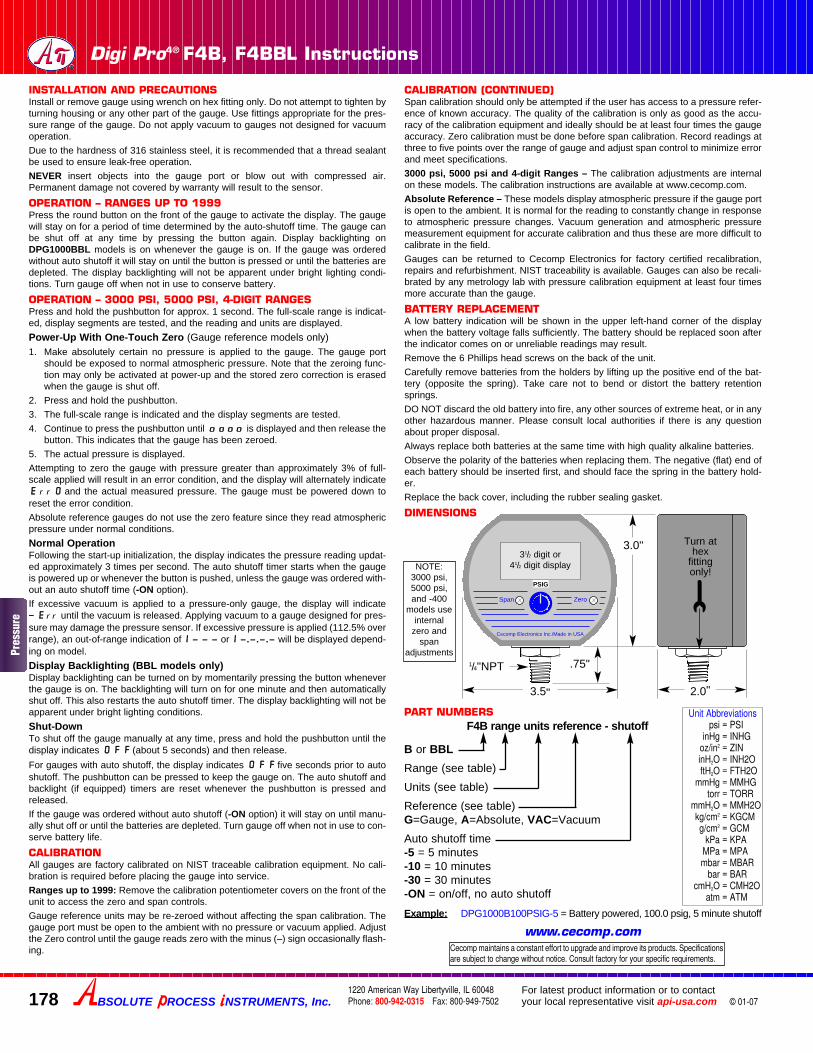
DIMENSIONS
Cecomp maintains a constant effort to upgrade and improve its products. Specificationsare subject to change without notice. Consult factory for your specific requirements.
1/4"NPT
Cecomp Electronics Inc./Made in USA
2.88"
3.38"
.75"
1.65"
Tightenat hexfittingonly
Span Zero
31/2 digit or 41/2 digit display
PART NUMBERS
Example: DPG1000B100PSIG-5 = Battery powered, 100.0 psig, 5 minute shutoff
DPG1000B range units reference - shutoff
B or BBLRange (see table)
Units (see table)
Reference (see table)G=Gauge, A=Absolute, VAC=Vacuum
Auto shutoff time -5 = 5 minutes-10 = 10 minutes-30 = 30 minutes-ON = on/off, no auto shutoff
NOTE:3000 psi and
5000 psimodels useinternal zero
and span adjustments
Unit Abbreviationspsi = PSI
inHg = INHGoz/in2 = ZINinH2O = INH2OftH2O = FTH2O
mmHg = MMHGtorr = TORR
mmH2O = MMH2Okg/cm2 = KGCMg/cm2 = GCM
kPa = KPAMPa = MPAmbar = MBAR
bar = BARcmH2O = CMH2O
atm = ATM
BSOLUTE ROCESS NSTRUMENTS, Inc.1220 American Way Libertyville, IL 60048Phone: 800-942-0315 Fax: 800-949-7502
For latest product information or to contactyour local representative visit api-usa.com
Pres
sure
BSOLUTE ROCESS NSTRUMENTS, Inc. api-usa.com 1771220 American Way Libertyville, IL 60048Phone: 800-942-0315 Fax: 800-949-7502
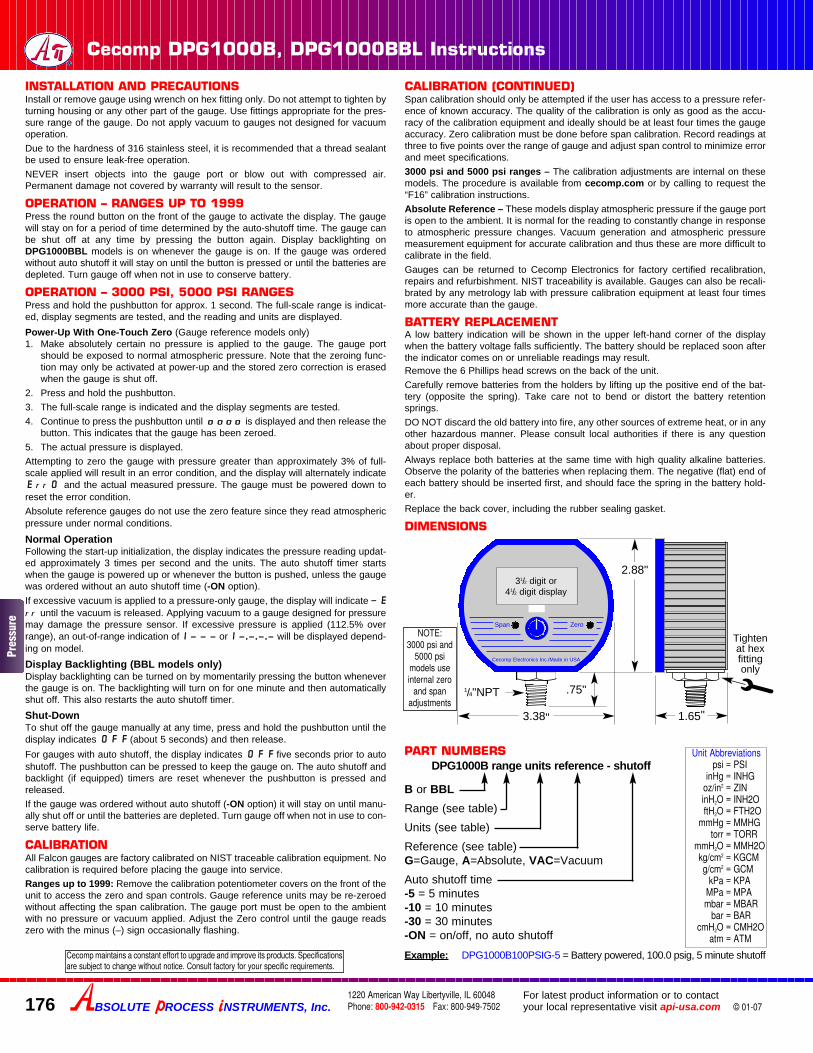
Digi-Pro Battery-Powered Gauges, NEMA 4X F4B, F4BBL
© 02-09
F4B100PSIG-50 to 100.0 psig range
F4B5000PSIG-5 0 to 5000 psig range
●● ±0.25% Test Gauge Accuracy●● 316 Stainless Steel Wetted Parts●● Battery Life up to 2500 Hours●● Pressure, Vacuum, Absolute or Compound●● BBL Includes Backlit Display
Size3.5" W x 3.0" H x 2.0" D housingAdd approximately 0.75" to height for pressure fitting
WeightGauge: 9 ounces (approx)Shipping weight: 1 pound (approx)
HousingNEMA 4XUV stabilized polycarbonate/ABS case, light gray colorClear polycarbonate window to protect displayGasketed rear cover, six captive stainless steel screws
Pressure/Vacuum Connection and Material1/4" NPT male, 316 stainless steel
Media CompatibilityAll wetted parts are 316 SSCompatible with most liquids and gases
Overpressure3000 psig range and metric equivalents: 5000 psig5000 psig range and metric equivalents: 7500 psig3000 psi, 5000 psi, 4-digit: 112.5% out-of-range display i – – – or i –.–.–.–All others 2x rated pressure minimum
Burst Pressure4x rated pressure minimum or 10,000 psi, whichever is less
EnvironmentalStorage Temperature –40 to 203°F (–40 to 95°C)Operating Temperature –4 to 185°F (–20 to 85°C)Compensated Temperature 32 to 158°F (0 to 70°C)
Ranges and Resolutionabs: Absolute reference (atmospheric pressure to zero at full vacuum)vac: Vacuum gauge, minus sign not used unless specifiedResolution is fixed as indicated in table belowContact factory for engineering units not listed
Accuracy (linearity, hysteresis, repeatability)Standard: ±0.25% of full scale ±1 least significant digitOptional: -HA ±0.1% FS ±1LSD (most ranges)
CD Factory calibration dataNC NIST traceable test report and calibration data
Display3 readings per second nominal display update rateRanges up to 1999: 31/2 digit LCD, 0.5" digit height3000 psi, 5000 psi: 41/2 digit LCD, 0.5" digit height,
lower alphanumeric display for engineering unitsBBL models: Red LED backlight
ControlsB ranges up to 1999: Front pushbutton turns gauge on/offBBL ranges up to 1999: Front pushbutton turns gauge & backlighting on/offFront calibration potentiometers, non-interactive zero and span, ±10% range
B & BBL 3000 psi, 5000 psi, 4-digit rangesFront button turns gauge on, starts auto shutoff timer, and provides zero functionfor gauge reference rangesInternal calibration pushbuttons, non-interactive zero and span, ±10% range
BBL 3000 psi, 5000 psi, 4-digit rangesPress button to activate backlighting for one minute while gauge is on
Auto Shutoff5 minutes standard)Ranges up to 1999: Factory settable to 5, 10, 30 minutes, or on/off3000 psi, 5000 psi: Factory settable to any number of minutes or hours
Batteries and Battery LifeTwo AA alkalineB ranges up to 1999: Approx. 2500 hoursB 3000 psi, 5000 psi, 4-digit: Approx. 2000 hoursBBL ranges up to 1999: Approx. 180 hoursBBL 3000 psi, 5000 psi, 4-digit: Approx. 150 to 1500 hrs depending on
backlight usage
Low Battery IndicationLow battery symbol on display when batteries must be replaced
–30.0 inHg/15.0 psig 120.0 inHg 1600 mmHg 35.0 bar 1.000 kg/cm2 abs–30.0 inHg/100.0 psig 199.9 inHg abs 760 torr abs 70.0 bar 1.000 kg/cm2 vac–30.0 inHg/199.9 psig 199.9 inHg 1600 torr abs 140.0 bar ±1.000 kg/cm2
3.00 psig 50.0 oz/in2 2100 mmH2O 199.9 bar 1.000 kg/cm2
5.00 psig 80.0 oz/in2 3500 mmH2O 350 bar 1.999 kg/cm2 abs15.00 psi abs 240 oz/in2 abs 199.9 cmH2O 19.99 kPa 1.999 kg/cm2
15.00 psig vac 240 oz/in2 vac 350 cmH2O 35.0 kPa 4.00 kg/cm2
±15.0 psig ±240 oz/in2 1000 cmH2O 100.0 kPa abs 7.00 kg/cm2 abs15.00 psig 240 oz/in2 2100 cmH2O 100.0 kPa vac 7.00 kg/cm2
30.0 psi abs 85.0 inH2O 199.9 mbar ±100.0 kPa 14.00 kg/cm2
30.0 psig 140.0 inH2O 350 mbar 100.0 kPa 19.99 kg/cm2
60.0 psig 400 inH2O abs 1000 mbar abs 199.9 kPa abs 35.0 kg/cm2
100.0 psi abs 400 inH2O vac 1000 mbar vac 199.9 kPa 70.0 kg/cm2
100.0 psig ±400 inH2O ±1000 mbar 400 kPa 140.0 kg/cm2
199.9 psig 400 inH2O 1000 mbar 700 kPa abs 199.9 kg/cm2
300 psig 850 inH2O 1999 mbar abs 700 kPa 350 kg/cm2
500 psig 7.00 ftH2O 1999 mbar 1500 kPa 1.000 atm abs1000 psig 12.00 ftH2O 4000 mbar 1999 kPa ±1.000 atm1999 psig 35.0 ftH2O 1.000 bar abs 3500 kPa 1.000 atm3000 psig 70.0 ftH2O 1.000 bar vac 5000 kPa 4.00 atm5000 psig 140.0 ftH2O ±1.000 bar 3.50 MPa 7.00 atm6.00 inHg 230 ftH2O 1.000 bar 7.00 MPa 14.00 atm
10.00 inHg 480 ftH2O 1.999 bar abs 14.00 MPa 19.99 atm30.0 inHg abs 150.0 mmHg 1.999 bar 19.99 MPa 35.0 atm30.0 inHg vac 260 mmHg 4.00 bar 35.0 MPa 70.0 atm
±30.0 inHg 760 mmHg abs 7.00 bar abs 1000 g/cm2 abs 135.0 atm30.0 inHg 760 mmHg vac 7.00 bar 1000 g/cm2 199.9 atm60.0 inHg abs 760 mmHg 14.00 bar 2100 g/cm2 abs 340 atm60.0 inHg 1600 mmHg abs 19.99 bar 2100 g/cm2
Electrical Specifications
Mechanical Specifications
Pressure
cecomp.com
INSTALLATION AND PRECAUTIONSInstall or remove gauge using wrench on hex fitting only. Do not attempt to tighten byturning housing or any other part of the gauge. Use fittings appropriate for the pres-sure range of the gauge. Do not apply vacuum to gauges not designed for vacuumoperation.
Due to the hardness of 316 stainless steel, it is recommended that a thread sealantbe used to ensure leak-free operation.
NEVER insert objects into the gauge port or blow out with compressed air.Permanent damage not covered by warranty will result to the sensor.
OPERATION – RANGES UP TO 1999Press the round button on the front of the gauge to activate the display. The gaugewill stay on for a period of time determined by the auto-shutoff time. The gauge canbe shut off at any time by pressing the button again. Display backlighting onDPG1000BBL models is on whenever the gauge is on. If the gauge was orderedwithout auto shutoff it will stay on until the button is pressed or until the batteries aredepleted. The display backlighting will not be apparent under bright lighting condi-tions. Turn gauge off when not in use to conserve battery.
OPERATION – 3000 PSI, 5000 PSI, 4-DIGIT RANGESPress and hold the pushbutton for approx. 1 second. The full-scale range is indicat-ed, display segments are tested, and the reading and units are displayed.
Power-Up With One-Touch Zero (Gauge reference models only)1. Make absolutely certain no pressure is applied to the gauge. The gauge port
should be exposed to normal atmospheric pressure. Note that the zeroing func-tion may only be activated at power-up and the stored zero correction is erasedwhen the gauge is shut off.
2. Press and hold the pushbutton.
3. The full-scale range is indicated and the display segments are tested.
4. Continue to press the pushbutton until oooooooo is displayed and then release thebutton. This indicates that the gauge has been zeroed.
5. The actual pressure is displayed.
Attempting to zero the gauge with pressure greater than approximately 3% of full-scale applied will result in an error condition, and the display will alternately indicateE r r 0 and the actual measured pressure. The gauge must be powered down toreset the error condition.
Absolute reference gauges do not use the zero feature since they read atmosphericpressure under normal conditions.
Normal OperationFollowing the start-up initialization, the display indicates the pressure reading updat-ed approximately 3 times per second. The auto shutoff timer starts when the gaugeis powered up or whenever the button is pushed, unless the gauge was ordered with-out an auto shutoff time (-ON option).
If excessive vacuum is applied to a pressure-only gauge, the display will indicate – E r r until the vacuum is released. Applying vacuum to a gauge designed for pres-sure may damage the pressure sensor. If excessive pressure is applied (112.5% overrange), an out-of-range indication of i – – – or i –.–.–.– will be displayed depend-ing on model.
Display Backlighting (BBL models only)Display backlighting can be turned on by momentarily pressing the button wheneverthe gauge is on. The backlighting will turn on for one minute and then automaticallyshut off. This also restarts the auto shutoff timer. The display backlighting will not beapparent under bright lighting conditions.
Shut-DownTo shut off the gauge manually at any time, press and hold the pushbutton until thedisplay indicates O F F (about 5 seconds) and then release.
For gauges with auto shutoff, the display indicates O F F five seconds prior to autoshutoff. The pushbutton can be pressed to keep the gauge on. The auto shutoff andbacklight (if equipped) timers are reset whenever the pushbutton is pressed andreleased.
If the gauge was ordered without auto shutoff (-ON option) it will stay on until manu-ally shut off or until the batteries are depleted. Turn gauge off when not in use to con-serve battery life.
CALIBRATIONAll gauges are factory calibrated on NIST traceable calibration equipment. No cali-bration is required before placing the gauge into service.
Ranges up to 1999: Remove the calibration potentiometer covers on the front of theunit to access the zero and span controls.
Gauge reference units may be re-zeroed without affecting the span calibration. Thegauge port must be open to the ambient with no pressure or vacuum applied. Adjustthe Zero control until the gauge reads zero with the minus (–) sign occasionally flash-ing.
CALIBRATION (CONTINUED)Span calibration should only be attempted if the user has access to a pressure refer-ence of known accuracy. The quality of the calibration is only as good as the accu-racy of the calibration equipment and ideally should be at least four times the gaugeaccuracy. Zero calibration must be done before span calibration. Record readings atthree to five points over the range of gauge and adjust span control to minimize errorand meet specifications.
3000 psi, 5000 psi and 4-digit Ranges – The calibration adjustments are internalon these models. The calibration instructions are available at www.cecomp.com.
Absolute Reference – These models display atmospheric pressure if the gauge portis open to the ambient. It is normal for the reading to constantly change in responseto atmospheric pressure changes. Vacuum generation and atmospheric pressuremeasurement equipment for accurate calibration and thus these are more difficult tocalibrate in the field.
Gauges can be returned to Cecomp Electronics for factory certified recalibration,repairs and refurbishment. NIST traceability is available. Gauges can also be recali-brated by any metrology lab with pressure calibration equipment at least four timesmore accurate than the gauge.
BATTERY REPLACEMENTA low battery indication will be shown in the upper left-hand corner of the displaywhen the battery voltage falls sufficiently. The battery should be replaced soon afterthe indicator comes on or unreliable readings may result.
Remove the 6 Phillips head screws on the back of the unit.
Carefully remove batteries from the holders by lifting up the positive end of the bat-tery (opposite the spring). Take care not to bend or distort the battery retentionsprings.
DO NOT discard the old battery into fire, any other sources of extreme heat, or in anyother hazardous manner. Please consult local authorities if there is any questionabout proper disposal.
Always replace both batteries at the same time with high quality alkaline batteries.
Observe the polarity of the batteries when replacing them. The negative (flat) end ofeach battery should be inserted first, and should face the spring in the battery hold-er.
Replace the back cover, including the rubber sealing gasket.
DIMENSIONS
Digi Pro4® F4B, F4BBL Instructions
© 01-07178
Cecomp maintains a constant effort to upgrade and improve its products. Specificationsare subject to change without notice. Consult factory for your specific requirements.
www.cecomp.com
1/4"NPT
Cecomp Electronics Inc./Made in USA
3.0"
3.5"
.75"
2.0"
PSIG
Span Zero
31/2 digit or 41/2 digit display
PART NUMBERS
Example: DPG1000B100PSIG-5 = Battery powered, 100.0 psig, 5 minute shutoff
F4B range units reference - shutoff
B or BBLRange (see table)
Units (see table)
Reference (see table)G=Gauge, A=Absolute, VAC=Vacuum
Auto shutoff time -5 = 5 minutes-10 = 10 minutes-30 = 30 minutes-ON = on/off, no auto shutoff
Unit Abbreviationspsi = PSI
inHg = INHGoz/in2 = ZINinH2O = INH2OftH2O = FTH2O
mmHg = MMHGtorr = TORR
mmH2O = MMH2Okg/cm2 = KGCMg/cm2 = GCM
kPa = KPAMPa = MPAmbar = MBAR
bar = BARcmH2O = CMH2O
atm = ATM
NOTE:3000 psi,5000 psi,and -400
models useinternal
zero andspan
adjustments
Turn athex
fittingonly!
BSOLUTE ROCESS NSTRUMENTS, Inc.1220 American Way Libertyville, IL 60048Phone: 800-942-0315 Fax: 800-949-7502
For latest product information or to contactyour local representative visit api-usa.com
Pres
sure
Digi Max® Battery-Powered Gauges, Min/Max F16B Series
BSOLUTE ROCESS NSTRUMENTS, Inc. api-usa.com 1791220 American Way Libertyville, IL 60048Phone: 800-942-0315 Fax: 800-949-7502© 02-09
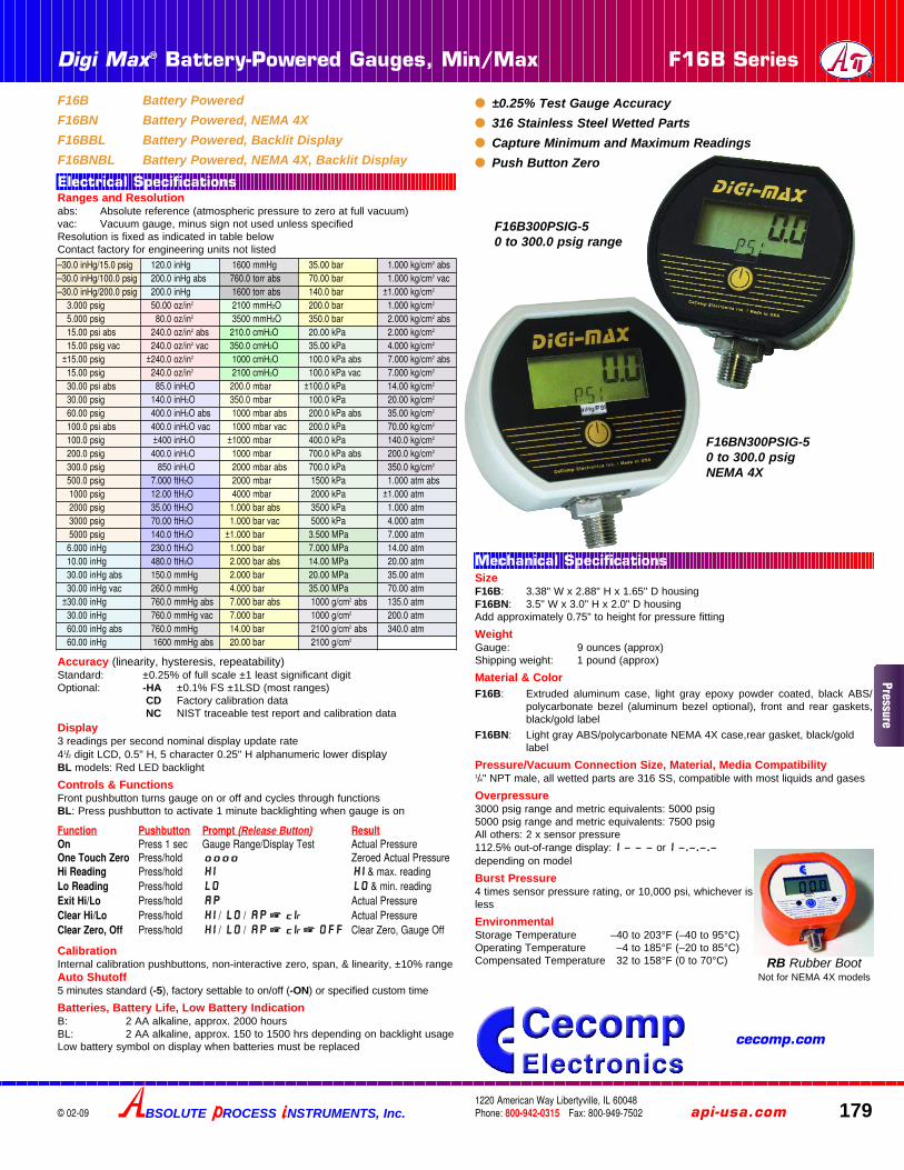
F16B Battery PoweredF16BN Battery Powered, NEMA 4XF16BBL Battery Powered, Backlit DisplayF16BNBL Battery Powered, NEMA 4X, Backlit Display
F16B300PSIG-50 to 300.0 psig range
F16BN300PSIG-50 to 300.0 psigNEMA 4X
●● ±0.25% Test Gauge Accuracy●● 316 Stainless Steel Wetted Parts●● Capture Minimum and Maximum Readings●● Push Button Zero
SizeF16B: 3.38" W x 2.88" H x 1.65" D housingF16BN: 3.5" W x 3.0" H x 2.0" D housingAdd approximately 0.75" to height for pressure fitting
WeightGauge: 9 ounces (approx)Shipping weight: 1 pound (approx)
Material & ColorF16B: Extruded aluminum case, light gray epoxy powder coated, black ABS/
polycarbonate bezel (aluminum bezel optional), front and rear gaskets,black/gold label
F16BN: Light gray ABS/polycarbonate NEMA 4X case,rear gasket, black/goldlabel
Pressure/Vacuum Connection Size, Material, Media Compatibility1/4" NPT male, all wetted parts are 316 SS, compatible with most liquids and gases
Overpressure3000 psig range and metric equivalents: 5000 psig5000 psig range and metric equivalents: 7500 psigAll others: 2 x sensor pressure112.5% out-of-range display: i – – – or i –.–.–.–depending on model
Burst Pressure4 times sensor pressure rating, or 10,000 psi, whichever isless
EnvironmentalStorage Temperature –40 to 203°F (–40 to 95°C)Operating Temperature –4 to 185°F (–20 to 85°C)Compensated Temperature 32 to 158°F (0 to 70°C)
Ranges and Resolutionabs: Absolute reference (atmospheric pressure to zero at full vacuum)vac: Vacuum gauge, minus sign not used unless specifiedResolution is fixed as indicated in table belowContact factory for engineering units not listed
Accuracy (linearity, hysteresis, repeatability)Standard: ±0.25% of full scale ±1 least significant digitOptional: -HA ±0.1% FS ±1LSD (most ranges)
CD Factory calibration dataNC NIST traceable test report and calibration data
Display3 readings per second nominal display update rate41/2 digit LCD, 0.5" H, 5 character 0.25" H alphanumeric lower displayBL models: Red LED backlight
Controls & FunctionsFront pushbutton turns gauge on or off and cycles through functionsBL: Press pushbutton to activate 1 minute backlighting when gauge is on
CalibrationInternal calibration pushbuttons, non-interactive zero, span, & linearity, ±10% rangeAuto Shutoff5 minutes standard (-5), factory settable to on/off (-ON) or specified custom time
Batteries, Battery Life, Low Battery IndicationB: 2 AA alkaline, approx. 2000 hoursBL: 2 AA alkaline, approx. 150 to 1500 hrs depending on backlight usageLow battery symbol on display when batteries must be replaced
Function Pushbutton Prompt (Release Button) ResultOn Press 1 sec Gauge Range/Display Test Actual Pressure One Touch Zero Press/hold oooo Zeroed Actual PressureHi Reading Press/hold HHII HHII & max. readingLo Reading Press/hold LLoo LLoo & min. readingExit Hi/Lo Press/hold AAPP Actual Pressure Clear Hi/Lo Press/hold HHII / LLOO / AAPP ☞☞ CCiir Actual PressureClear Zero, Off Press/hold HHII / LLOO / AAPP ☞☞ CCiir ☞☞ OOFFFF Clear Zero, Gauge Off
–30.0 inHg/15.0 psig 120.0 inHg 1600 mmHg 35.00 bar 1.000 kg/cm2 abs–30.0 inHg/100.0 psig 200.0 inHg abs 760.0 torr abs 70.00 bar 1.000 kg/cm2 vac–30.0 inHg/200.0 psig 200.0 inHg 1600 torr abs 140.0 bar ±1.000 kg/cm2
3.000 psig 50.00 oz/in2 2100 mmH2O 200.0 bar 1.000 kg/cm2
5.000 psig 80.0 oz/in2 3500 mmH2O 350.0 bar 2.000 kg/cm2 abs15.00 psi abs 240.0 oz/in2 abs 210.0 cmH2O 20.00 kPa 2.000 kg/cm2
15.00 psig vac 240.0 oz/in2 vac 350.0 cmH2O 35.00 kPa 4.000 kg/cm2
±15.00 psig ±240.0 oz/in2 1000 cmH2O 100.0 kPa abs 7.000 kg/cm2 abs15.00 psig 240.0 oz/in2 2100 cmH2O 100.0 kPa vac 7.000 kg/cm2
30.00 psi abs 85.0 inH2O 200.0 mbar ±100.0 kPa 14.00 kg/cm2
30.00 psig 140.0 inH2O 350.0 mbar 100.0 kPa 20.00 kg/cm2
60.00 psig 400.0 inH2O abs 1000 mbar abs 200.0 kPa abs 35.00 kg/cm2
100.0 psi abs 400.0 inH2O vac 1000 mbar vac 200.0 kPa 70.00 kg/cm2
100.0 psig ±400 inH2O ±1000 mbar 400.0 kPa 140.0 kg/cm2
200.0 psig 400.0 inH2O 1000 mbar 700.0 kPa abs 200.0 kg/cm2
300.0 psig 850 inH2O 2000 mbar abs 700.0 kPa 350.0 kg/cm2
500.0 psig 7.000 ftH2O 2000 mbar 1500 kPa 1.000 atm abs1000 psig 12.00 ftH2O 4000 mbar 2000 kPa ±1.000 atm2000 psig 35.00 ftH2O 1.000 bar abs 3500 kPa 1.000 atm3000 psig 70.00 ftH2O 1.000 bar vac 5000 kPa 4.000 atm5000 psig 140.0 ftH2O ±1.000 bar 3.500 MPa 7.000 atm6.000 inHg 230.0 ftH2O 1.000 bar 7.000 MPa 14.00 atm10.00 inHg 480.0 ftH2O 2.000 bar abs 14.00 MPa 20.00 atm30.00 inHg abs 150.0 mmHg 2.000 bar 20.00 MPa 35.00 atm30.00 inHg vac 260.0 mmHg 4.000 bar 35.00 MPa 70.00 atm
±30.00 inHg 760.0 mmHg abs 7.000 bar abs 1000 g/cm2 abs 135.0 atm30.00 inHg 760.0 mmHg vac 7.000 bar 1000 g/cm2 200.0 atm60.00 inHg abs 760.0 mmHg 14.00 bar 2100 g/cm2 abs 340.0 atm60.00 inHg 1600 mmHg abs 20.00 bar 2100 g/cm2
Electrical Specifications
Mechanical Specifications
RB Rubber BootNot for NEMA 4X models
Pressure
cecomp.com
INSTALLATION AND PRECAUTIONSInstall or remove gauge using wrench on hex fitting only. Do not attempt to tighten byturning housing or any other part of the gauge.
Use fittings appropriate for the pressure range of the gauge.
Do not apply vacuum to gauges not designed for vacuum operation.
Due to the hardness of 316 stainless steel, it is recommended that a thread sealantbe used to ensure leak-free operation.
NEVER insert objects into the gauge port or blow out with compressed air.Permanent damage not covered by warranty will result to the sensor.
POWER-UP1. Press and hold the pushbutton for approximately 1 second.
2. The full-scale range is indicated and the display segments are tested.
3. The actual pressure and units are displayed.
Power-Up With Zero (Gauge reference models only)1. Be sure the gauge port is exposed to normal atmospheric pressure and no pres-
sure is applied. The zeroing function is only activated at each power-up and thestored zero correction is erased when the gauge is shut off.
2. Press and hold the pushbutton.
3. The full-scale range is indicated and the display segments are tested.
4. Continue to press the pushbutton until oooooooo is displayed and then release thebutton. This indicates that the gauge has been zeroed.
5. The actual pressure is displayed.
Attempting to zero the gauge with pressure greater than approximately 3% of full-scale applied will result in an error condition, and the display will alternately indicateE r r 0 and the actual measured pressure. The gauge must be powered down toreset the error condition.
Absolute reference gauges do not use the zero feature since they read atmosphericpressure under normal conditions.
NORMAL OPERATIONFollowing the start-up initialization, the display indicates the pressure reading updat-ed approximately 3 times per second. The auto shutoff timer starts when the gaugeis powered up or whenever the button is pushed, unless the gauge was ordered with-out an auto shutoff time (-ON option).
If excessive vacuum is applied to a pressure-only gauge, the display will indicate – E r r until the vacuum is released. Applying vacuum to a gauge designed for pres-sure may damage the pressure sensor. If excessive pressure is applied (112.5% overrange), an out-of-range indication of i – – – or i –.–.–.– will be displayed depend-ing on model.
MINIMUM AND MAXIMUM READINGSMinimum and maximum readings are continuously stored and updated whenevergauge is on. The stored readings can be manually cleared if desired. The HI and LOmemory is also cleared whenever the gauge is off.
Press and hold the pushbutton for about 1 second until HI is displayed. The maxi-mum stored value is displayed.
After HI is displayed, press and hold the pushbutton again for about 1 second untilLO is displayed. The minimum stored value is displayed.
After LO is displayed, press and hold the pushbutton again for about 1 second untilAP (Applied Pressure) is displayed. The HI and LO memory is not erased and thegauge returns to normal operation with the display indicating the current pressure.
Press and continue to hold the pushbutton until the display indicates Cir HHii//LLoo
(about 3 seconds total) and then release the pushbutton. Both HI and LO values arecleared and the gauge returns to the normal mode and displays the current pressure.
DISPLAY BACKLIGHTING (BBL MODELS ONLY)Display backlighting can be turned on by momentarily pressing the button wheneverthe gauge is on. The backlighting will turn on for one minute and then automaticallyshut off. This also restarts the auto shutoff timer. The display backlighting will not beapparent under bright lighting conditions.
SHUT-DOWNTo shut off the gauge manually at any time, press and hold the pushbutton until thedisplay indicates OFF (about 5 seconds) and then release.
For gauges with auto shutoff, the display indicates OFF five seconds prior to autoshutoff. The pushbutton can be pressed to keep the gauge on. The auto shutoff andbacklight (if equipped) timers are reset whenever the pushbutton is pressed andreleased.
If the gauge was ordered without auto shutoff (-ON option) it will stay on until manu-ally shut off or until the batteries are depleted. Turn gauge off when not in use to con-serve battery life.
CALIBRATIONF16-series gauges use internal controls for calibration. The calibration instructionsare available at cecomp.com. Gauges can be recalibrated by any metrology lab withpressure calibration equipment at least 4 times more accurate than the gauge.Gauges may also be returned for factory recalibration and refurbishment. NIST trace-ability is available.
BATTERY REPLACEMENTA low battery indication will be shown in the upper left-hand corner of the displaywhen the battery voltage falls sufficiently. The battery should be replaced soon afterthe indicator comes on or unreliable readings may result.
1. Remove the 6 Phillips head screws on the back of the unit.
2. Remove batteries by lifting up the positive end of the battery (opposite the spring)taking care not to bend the battery holder spring.
3. Discard old batteries properly, DO NOT discard into fire, sources of extreme heat,or in any other hazardous manner.
4. Always replace both batteries at the same time with high quality alkaline batteries.Install batteries with correct orientation. The negative (flat) end of each batteryshould be inserted first facing the battery holder spring.
6. Replace the back cover, including the rubber sealing gasket.
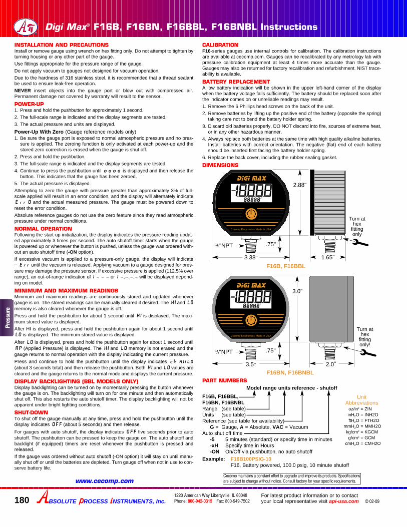
DIMENSIONS
180
Digi Max® F16B, F16BN, F16BBL, F16BNBL Instructions
© 02-09
1/4"NPT
Cecomp Electronics / Made in USA
2.88"
3.38"
.75"
PART NUMBERS
Example: F16B100PSIG-10F16, Battery powered, 100.0 psig, 10 minute shutoff
1.65"
Model range units reference - shutoff
Turn athex
fittingonly
UnitAbbreviations
oz/in2 = ZINinH2O = INH2OftH2O = FTH2O
mmH2O = MMH2Okg/cm2 = KGCMg/cm2 = GCM
cmH2O = CMH2O
1/4"NPT
3.0"
3.5"
.75"
2.0"
Turn athex
fittingonly!
Cecomp Electronics / Made in USA
F16B, F16BBL
F16BN, F16BNBL
F16B, F16BBL, F16BN, F16BNBLRange (see table)Units (see table)Reference (see table for availability)
G = Gauge, A = Absolute, VAC = VacuumAuto shut off time
-5 5 minutes (standard) or specify time in minutes-xH Specify time in Hours-ON On/Off via pushbutton, no auto shutoff
Digi Max
Digi Max
XXXXX888882
XXXXX888882
BSOLUTE ROCESS NSTRUMENTS, Inc.1220 American Way Libertyville, IL 60048Phone: 800-942-0315 Fax: 800-949-7502
For latest product information or to contactyour local representative visit api-usa.com
Cecomp maintains a constant effort to upgrade and improve its products. Specificationsare subject to change without notice. Consult factory for your specific requirements.www.cecomp.com
Pres
sure
Cecomp Battery Powered Digital Pressure Gauges with Selectable Units F18B, F18BN
cecomp.com1220 American Way Libertyville, IL 60048Phone: 800-942-0315 Fax: 800-949-7502
© 10-09
Ranges and ResolutionSee table below. Any engineering units equivalent to the PSI range can be ordered as the default range.Resolution is fixed for each engineering unit
AccuracyIncludes linearity, hysteresis, repeatabilityStandard: ±0.25% of full scale ±1 least significant digit-HA: ±0.1% FS ±1 LSD (see Options for availability)
Display3 readings per second nominal display update rate4 digit LCD, 0.5" H and 5 character 0.25" H alphanumericBL models: red LED backlight
Batteries, Battery Life, Low Battery IndicationB: 2 AA alkaline, approx. 2000 hoursBL: 2 AA alkaline, approx. 150 to 1500 hours depending on backlight usageLow battery symbol on display
Controls & FunctionsFront button turns gauge on or off, zeros gauge reference gauges, and cycles through min/max functionsInternal push buttons for calibration and selection of engi-neering units and auto shutoff timesBL: Front button activates backlighting for 1 minute
Min/Max FunctionsMinimum and maximum readings stored 4 times per secondFront button cycles through min display, max display, clearConfigurable for min only, max only, both, or noneConfigure to clear min/max at power off or retain min/max at power off
CalibrationPass code protected calibrationNon-interactive zero, span, and linearity, ±10% of range
±0.25% Test Gauge Accuracy 316 Stainless Steel Wetted Parts Capture Minimum and Maximum Readings
Selectable Units Selectable Auto Shutoff Times Zero Function
How to OrderOptions—add to end of model number-HA High accuracy, ±0.1% FS ±1 LSD. Not available with vacuum, compound, bipolar, absolute, or 3 psi sensor ranges.-PM Panel mount, 4.1" x 4.1". Not available with NEMA 4X models.-MC Metal front cover. Machined aluminum, epoxy powder coated. Synthetic oil resistant. Not available with NEMA 4X models.-CS Case stiffener strengthens case bottom for tire pressure applications.-CC Conformal coating on circuit board for moisture resistance.-SM Surface mount plate. Battery gauges only. Not available with NEMA 4X models.-TP Top port, gauge port on top of case. Used primarily for tire pressure applications.
AccessoriesRB Protective rubber boot. Not for NEMA 4X models.CD Calibration data, 5 test points, test date.NC NIST certificate with traceability documentation, 5 test points and date.
Model FeaturesF18B Standard housingF18BBL Standard housing, backlit displayF18BN NEMA 4X housingF18BNBL NEMA 4X housing, backlit display
Please SpecifyModel Range - Shutoff* - OptionsSpecify pressure or vacuum range and units. Include gauge or absolute reference as applicable.If vacuum gauge requires a minus sign, please specify.*Only specify if default time is to be other than 5 minutes
BSOLUTE ROCESS NSTRUMENTS, Inc.Division of
Auto ShutoffUser selectable 1 minute to 8 hours or front button on/offFactory default 5 minutes, unless other time is specified
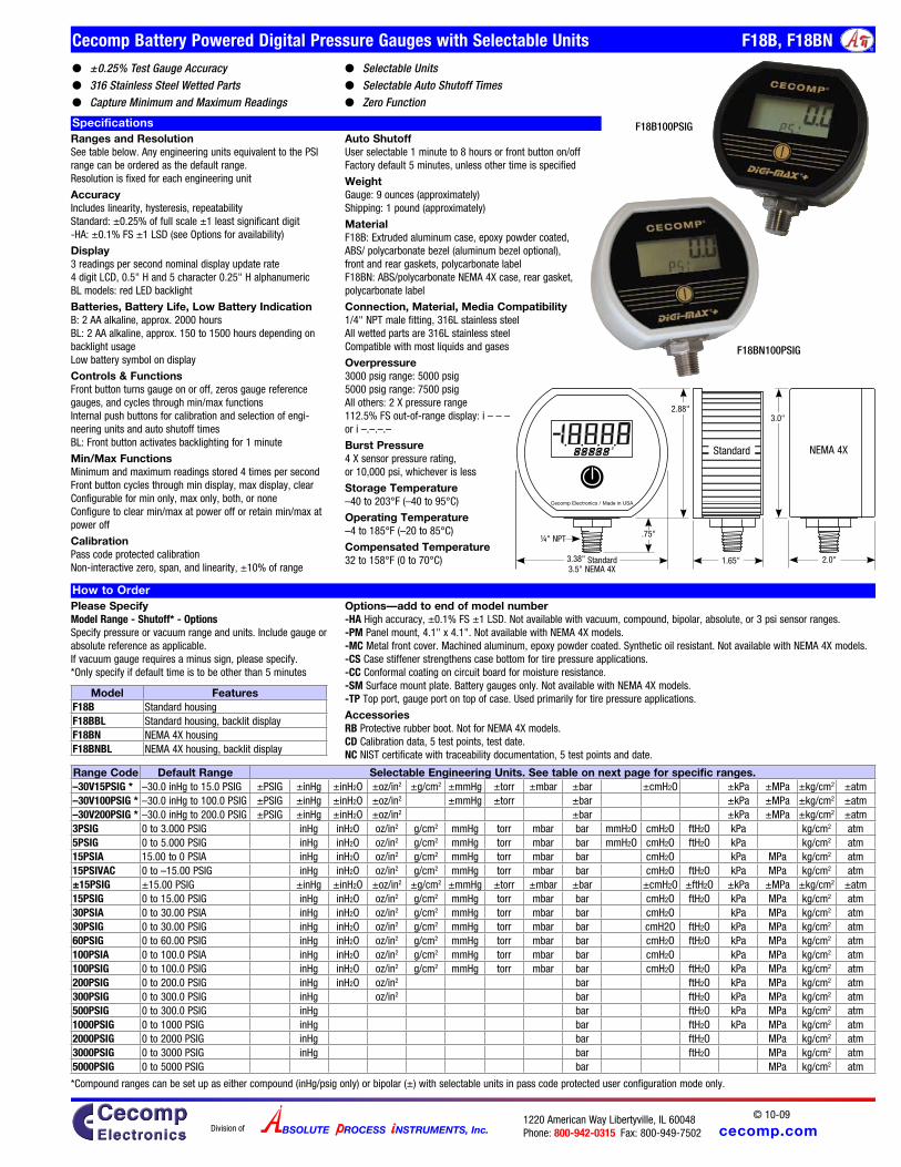
WeightGauge: 9 ounces (approximately)Shipping: 1 pound (approximately)
MaterialF18B: Extruded aluminum case, epoxy powder coated,ABS/ polycarbonate bezel (aluminum bezel optional),front and rear gaskets, polycarbonate labelF18BN: ABS/polycarbonate NEMA 4X case, rear gasket,polycarbonate label
Connection, Material, Media Compatibility1/4" NPT male fitting, 316L stainless steelAll wetted parts are 316L stainless steelCompatible with most liquids and gases
Overpressure3000 psig range: 5000 psig5000 psig range: 7500 psigAll others: 2 X pressure range112.5% FS out-of-range display: i – – – or i –.–.–.–
Burst Pressure4 X sensor pressure rating, or 10,000 psi, whichever is less
Storage Temperature–40 to 203°F (–40 to 95°C)
Operating Temperature–4 to 185°F (–20 to 85°C)
Compensated Temperature32 to 158°F (0 to 70°C) 2.0"
NEMA 4X
3.0"
¼" NPT
2.88"
3.38" Standard3.5" NEMA 4X
.75"
Cecomp Electronics / Made in USA
1.65"
StandardX X X X X88888 2
Specifications
Range Code Default Range Selectable Engineering Units. See table on next page for specific ranges.–30V15PSIG * –30.0 inHg to 15.0 PSIG ±PSIG ±inHg ±inH2O ±oz/in2 ±g/cm2 ±mmHg ±torr ±mbar ±bar ±cmH2O ±kPa ±MPa ±kg/cm2 ±atm–30V100PSIG * –30.0 inHg to 100.0 PSIG ±PSIG ±inHg ±inH2O ±oz/in2 ±mmHg ±torr ±bar ±kPa ±MPa ±kg/cm2 ±atm–30V200PSIG * –30.0 inHg to 200.0 PSIG ±PSIG ±inHg ±inH2O ±oz/in2 ±bar ±kPa ±MPa ±kg/cm2 ±atm3PSIG 0 to 3.000 PSIG inHg inH2O oz/in2 g/cm2 mmHg torr mbar bar mmH2O cmH2O ftH2O kPa kg/cm2 atm5PSIG 0 to 5.000 PSIG inHg inH2O oz/in2 g/cm2 mmHg torr mbar bar mmH2O cmH2O ftH2O kPa kg/cm2 atm15PSIA 15.00 to 0 PSIA inHg inH2O oz/in2 g/cm2 mmHg torr mbar bar cmH2O kPa MPa kg/cm2 atm15PSIVAC 0 to –15.00 PSIG inHg inH2O oz/in2 g/cm2 mmHg torr mbar bar cmH2O ftH2O kPa MPa kg/cm2 atm±15PSIG ±15.00 PSIG ±inHg ±inH2O ±oz/in2 ±g/cm2 ±mmHg ±torr ±mbar ±bar ±cmH2O ±ftH2O ±kPa ±MPa ±kg/cm2 ±atm15PSIG 0 to 15.00 PSIG inHg inH2O oz/in2 g/cm2 mmHg torr mbar bar cmH2O ftH2O kPa MPa kg/cm2 atm30PSIA 0 to 30.00 PSIA inHg inH2O oz/in2 g/cm2 mmHg torr mbar bar cmH2O kPa MPa kg/cm2 atm30PSIG 0 to 30.00 PSIG inHg inH2O oz/in2 g/cm2 mmHg torr mbar bar cmH2O ftH2O kPa MPa kg/cm2 atm60PSIG 0 to 60.00 PSIG inHg inH2O oz/in2 g/cm2 mmHg torr mbar bar cmH2O ftH2O kPa MPa kg/cm2 atm100PSIA 0 to 100.0 PSIA inHg inH2O oz/in2 g/cm2 mmHg torr mbar bar cmH2O kPa MPa kg/cm2 atm100PSIG 0 to 100.0 PSIG inHg inH2O oz/in2 g/cm2 mmHg torr mbar bar cmH2O ftH2O kPa MPa kg/cm2 atm200PSIG 0 to 200.0 PSIG inHg inH2O oz/in2 bar ftH2O kPa MPa kg/cm2 atm300PSIG 0 to 300.0 PSIG inHg oz/in2 bar ftH2O kPa MPa kg/cm2 atm500PSIG 0 to 300.0 PSIG inHg bar ftH2O kPa MPa kg/cm2 atm1000PSIG 0 to 1000 PSIG inHg bar ftH2O kPa MPa kg/cm2 atm2000PSIG 0 to 2000 PSIG inHg bar ftH2O MPa kg/cm2 atm3000PSIG 0 to 3000 PSIG inHg bar ftH2O MPa kg/cm2 atm5000PSIG 0 to 5000 PSIG bar MPa kg/cm2 atm
F18B100PSIG
F18BN100PSIG
*Compound ranges can be set up as either compound (inHg/psig only) or bipolar (±) with selectable units in pass code protected user configuration mode only.
cecomp.com1220 American Way Libertyville, IL 60048Phone: 800-942-0315 Fax: 800-949-7502
© 10-09
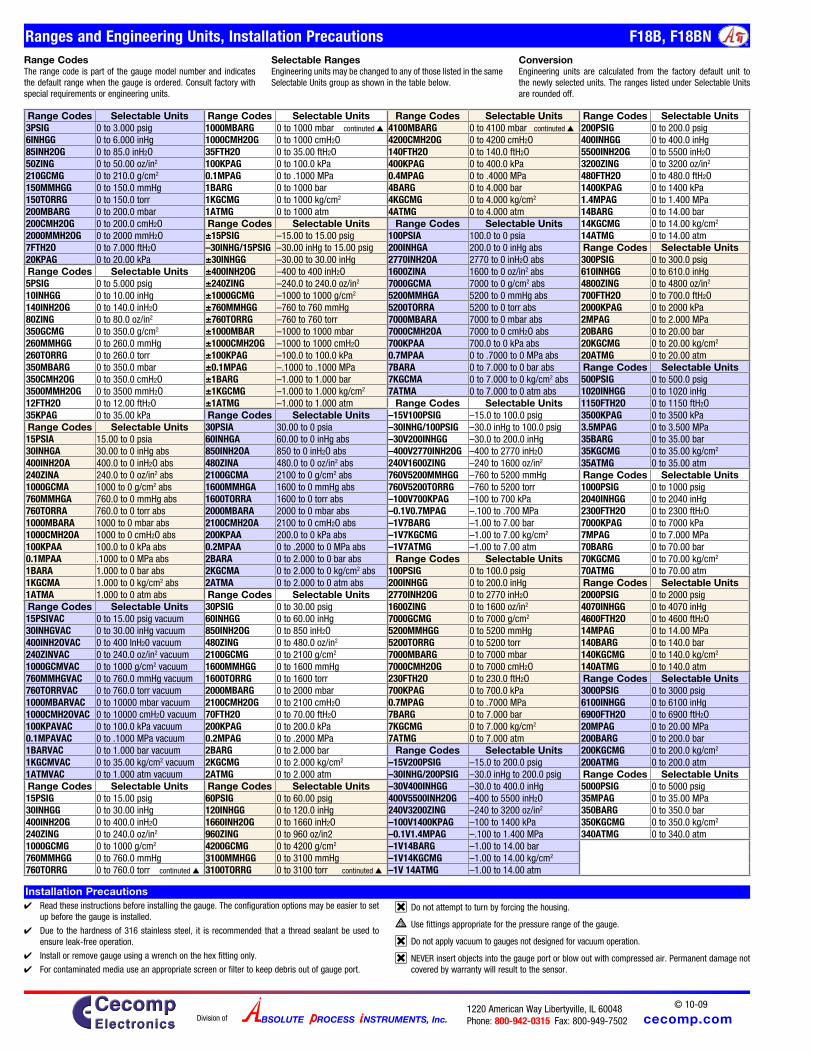
Ranges and Engineering Units, Installation Precautions F18B, F18BN
BSOLUTE ROCESS NSTRUMENTS, Inc.Division of
Installation Precautions
Range Codes Selectable Units Range Codes Selectable Units Range Codes Selectable Units Range Codes Selectable Units3PSIG 0 to 3.000 psig 1000MBARG 0 to 1000 mbar continuted 4100MBARG 0 to 4100 mbar continuted 200PSIG 0 to 200.0 psig6INHGG 0 to 6.000 inHg 1000CMH2OG 0 to 1000 cmH2O 4200CMH2OG 0 to 4200 cmH2O 400INHGG 0 to 400.0 inHg85INH2OG 0 to 85.0 inH2O 35FTH2O 0 to 35.00 ftH2O 140FTH2O 0 to 140.0 ftH2O 5500INH2OG 0 to 5500 inH2O50ZING 0 to 50.00 oz/in2 100KPAG 0 to 100.0 kPa 400KPAG 0 to 400.0 kPa 3200ZING 0 to 3200 oz/in2
210GCMG 0 to 210.0 g/cm2 0.1MPAG 0 to .1000 MPa 0.4MPAG 0 to .4000 MPa 480FTH2O 0 to 480.0 ftH2O150MMHGG 0 to 150.0 mmHg 1BARG 0 to 1000 bar 4BARG 0 to 4.000 bar 1400KPAG 0 to 1400 kPa150TORRG 0 to 150.0 torr 1KGCMG 0 to 1000 kg/cm2 4KGCMG 0 to 4.000 kg/cm2 1.4MPAG 0 to 1.400 MPa200MBARG 0 to 200.0 mbar 1ATMG 0 to 1000 atm 4ATMG 0 to 4.000 atm 14BARG 0 to 14.00 bar200CMH2OG 0 to 200.0 cmH2O Range Codes Selectable Units Range Codes Selectable Units 14KGCMG 0 to 14.00 kg/cm2
2000MMH2OG 0 to 2000 mmH2O ±15PSIG –15.00 to 15.00 psig 100PSIA 100.0 to 0 psia 14ATMG 0 to 14.00 atm7FTH2O 0 to 7.000 ftH2O –30INHG/15PSIG –30.00 inHg to 15.00 psig 200INHGA 200.0 to 0 inHg abs Range Codes Selectable Units20KPAG 0 to 20.00 kPa ±30INHGG –30.00 to 30.00 inHg 2770INH2OA 2770 to 0 inH2O abs 300PSIG 0 to 300.0 psigRange Codes Selectable Units ±400INH2OG –400 to 400 inH2O 1600ZINA 1600 to 0 oz/in2 abs 610INHGG 0 to 610.0 inHg5PSIG 0 to 5.000 psig ±240ZING –240.0 to 240.0 oz/in2 7000GCMA 7000 to 0 g/cm2 abs 4800ZING 0 to 4800 oz/in2
10INHGG 0 to 10.00 inHg ±1000GCMG –1000 to 1000 g/cm2 5200MMHGA 5200 to 0 mmHg abs 700FTH2O 0 to 700.0 ftH2O140INH2OG 0 to 140.0 inH2O ±760MMHGG –760 to 760 mmHg 5200TORRA 5200 to 0 torr abs 2000KPAG 0 to 2000 kPa80ZING 0 to 80.0 oz/in2 ±760TORRG –760 to 760 torr 7000MBARA 7000 to 0 mbar abs 2MPAG 0 to 2.000 MPa350GCMG 0 to 350.0 g/cm2 ±1000MBAR –1000 to 1000 mbar 7000CMH2OA 7000 to 0 cmH2O abs 20BARG 0 to 20.00 bar260MMHGG 0 to 260.0 mmHg ±1000CMH2OG –1000 to 1000 cmH2O 700KPAA 700.0 to 0 kPa abs 20KGCMG 0 to 20.00 kg/cm2
260TORRG 0 to 260.0 torr ±100KPAG –100.0 to 100.0 kPa 0.7MPAA 0 to .7000 to 0 MPa abs 20ATMG 0 to 20.00 atm350MBARG 0 to 350.0 mbar ±0.1MPAG –.1000 to .1000 MPa 7BARA 0 to 7.000 to 0 bar abs Range Codes Selectable Units350CMH2OG 0 to 350.0 cmH2O ±1BARG –1.000 to 1.000 bar 7KGCMA 0 to 7.000 to 0 kg/cm2 abs 500PSIG 0 to 500.0 psig3500MMH2OG 0 to 3500 mmH2O ±1KGCMG –1.000 to 1.000 kg/cm2 7ATMA 0 to 7.000 to 0 atm abs 1020INHGG 0 to 1020 inHg12FTH2O 0 to 12.00 ftH2O ±1ATMG –1.000 to 1.000 atm Range Codes Selectable Units 1150FTH2O 0 to 1150 ftH2O35KPAG 0 to 35.00 kPa Range Codes Selectable Units –15V100PSIG –15.0 to 100.0 psig 3500KPAG 0 to 3500 kPaRange Codes Selectable Units 30PSIA 30.00 to 0 psia –30INHG/100PSIG –30.0 inHg to 100.0 psig 3.5MPAG 0 to 3.500 MPa15PSIA 15.00 to 0 psia 60INHGA 60.00 to 0 inHg abs –30V200INHGG –30.0 to 200.0 inHg 35BARG 0 to 35.00 bar30INHGA 30.00 to 0 inHg abs 850INH2OA 850 to 0 inH2O abs –400V2770INH2OG –400 to 2770 inH2O 35KGCMG 0 to 35.00 kg/cm2
400INH2OA 400.0 to 0 inH2O abs 480ZINA 480.0 to 0 oz/in2 abs 240V1600ZING –240 to 1600 oz/in2 35ATMG 0 to 35.00 atm240ZINA 240.0 to 0 oz/in2 abs 2100GCMA 2100 to 0 g/cm2 abs 760V5200MMHGG –760 to 5200 mmHg Range Codes Selectable Units1000GCMA 1000 to 0 g/cm2 abs 1600MMHGA 1600 to 0 mmHg abs 760V5200TORRG –760 to 5200 torr 1000PSIG 0 to 1000 psig760MMHGA 760.0 to 0 mmHg abs 1600TORRA 1600 to 0 torr abs –100V700KPAG –100 to 700 kPa 2040INHGG 0 to 2040 inHg760TORRA 760.0 to 0 torr abs 2000MBARA 2000 to 0 mbar abs –0.1V0.7MPAG –.100 to .700 MPa 2300FTH2O 0 to 2300 ftH2O1000MBARA 1000 to 0 mbar abs 2100CMH2OA 2100 to 0 cmH2O abs –1V7BARG –1.00 to 7.00 bar 7000KPAG 0 to 7000 kPa1000CMH2OA 1000 to 0 cmH2O abs 200KPAA 200.0 to 0 kPa abs –1V7KGCMG –1.00 to 7.00 kg/cm2 7MPAG 0 to 7.000 MPa100KPAA 100.0 to 0 kPa abs 0.2MPAA 0 to .2000 to 0 MPa abs –1V7ATMG –1.00 to 7.00 atm 70BARG 0 to 70.00 bar0.1MPAA .1000 to 0 MPa abs 2BARA 0 to 2.000 to 0 bar abs Range Codes Selectable Units 70KGCMG 0 to 70.00 kg/cm2
1BARA 1.000 to 0 bar abs 2KGCMA 0 to 2.000 to 0 kg/cm2 abs 100PSIG 0 to 100.0 psig 70ATMG 0 to 70.00 atm1KGCMA 1.000 to 0 kg/cm2 abs 2ATMA 0 to 2.000 to 0 atm abs 200INHGG 0 to 200.0 inHg Range Codes Selectable Units1ATMA 1.000 to 0 atm abs Range Codes Selectable Units 2770INH2OG 0 to 2770 inH2O 2000PSIG 0 to 2000 psigRange Codes Selectable Units 30PSIG 0 to 30.00 psig 1600ZING 0 to 1600 oz/in2 4070INHGG 0 to 4070 inHg15PSIVAC 0 to 15.00 psig vacuum 60INHGG 0 to 60.00 inHg 7000GCMG 0 to 7000 g/cm2 4600FTH2O 0 to 4600 ftH2O30INHGVAC 0 to 30.00 inHg vacuum 850INH2OG 0 to 850 inH2O 5200MMHGG 0 to 5200 mmHg 14MPAG 0 to 14.00 MPa400INH2OVAC 0 to 400 InH20 vacuum 480ZING 0 to 480.0 oz/in2 5200TORRG 0 to 5200 torr 140BARG 0 to 140.0 bar240ZINVAC 0 to 240.0 oz/in2 vacuum 2100GCMG 0 to 2100 g/cm2 7000MBARG 0 to 7000 mbar 140KGCMG 0 to 140.0 kg/cm2
1000GCMVAC 0 to 1000 g/cm2 vacuum 1600MMHGG 0 to 1600 mmHg 7000CMH2OG 0 to 7000 cmH2O 140ATMG 0 to 140.0 atm760MMHGVAC 0 to 760.0 mmHg vacuum 1600TORRG 0 to 1600 torr 230FTH2O 0 to 230.0 ftH2O Range Codes Selectable Units760TORRVAC 0 to 760.0 torr vacuum 2000MBARG 0 to 2000 mbar 700KPAG 0 to 700.0 kPa 3000PSIG 0 to 3000 psig1000MBARVAC 0 to 10000 mbar vacuum 2100CMH2OG 0 to 2100 cmH2O 0.7MPAG 0 to .7000 MPa 6100INHGG 0 to 6100 inHg1000CMH2OVAC 0 to 10000 cmH2O vacuum 70FTH2O 0 to 70.00 ftH2O 7BARG 0 to 7.000 bar 6900FTH2O 0 to 6900 ftH2O100KPAVAC 0 to 100.0 kPa vacuum 200KPAG 0 to 200.0 kPa 7KGCMG 0 to 7.000 kg/cm2 20MPAG 0 to 20.00 MPa0.1MPAVAC 0 to .1000 MPa vacuum 0.2MPAG 0 to .2000 MPa 7ATMG 0 to 7.000 atm 200BARG 0 to 200.0 bar1BARVAC 0 to 1.000 bar vacuum 2BARG 0 to 2.000 bar Range Codes Selectable Units 200KGCMG 0 to 200.0 kg/cm2
1KGCMVAC 0 to 35.00 kg/cm2 vacuum 2KGCMG 0 to 2.000 kg/cm2 –15V200PSIG –15.0 to 200.0 psig 200ATMG 0 to 200.0 atm1ATMVAC 0 to 1.000 atm vacuum 2ATMG 0 to 2.000 atm –30INHG/200PSIG –30.0 inHg to 200.0 psig Range Codes Selectable UnitsRange Codes Selectable Units Range Codes Selectable Units –30V400INHGG –30.0 to 400.0 inHg 5000PSIG 0 to 5000 psig15PSIG 0 to 15.00 psig 60PSIG 0 to 60.00 psig 400V5500INH2OG –400 to 5500 inH2O 35MPAG 0 to 35.00 MPa30INHGG 0 to 30.00 inHg 120INHGG 0 to 120.0 inHg 240V3200ZING –240 to 3200 oz/in2 350BARG 0 to 350.0 bar400INH2OG 0 to 400.0 inH2O 1660INH2OG 0 to 1660 inH2O –100V1400KPAG –100 to 1400 kPa 350KGCMG 0 to 350.0 kg/cm2
240ZING 0 to 240.0 oz/in2 960ZING 0 to 960 oz/in2 –0.1V1.4MPAG –.100 to 1.400 MPa 340ATMG 0 to 340.0 atm1000GCMG 0 to 1000 g/cm2 4200GCMG 0 to 4200 g/cm2 –1V14BARG –1.00 to 14.00 bar760MMHGG 0 to 760.0 mmHg 3100MMHGG 0 to 3100 mmHg –1V14KGCMG –1.00 to 14.00 kg/cm2
760TORRG 0 to 760.0 torr continuted 3100TORRG 0 to 3100 torr continuted –1V 14ATMG –1.00 to 14.00 atm
Range CodesThe range code is part of the gauge model number and indicates the default range when the gauge is ordered. Consult factory with special requirements or engineering units.
Selectable RangesEngineering units may be changed to any of those listed in the same Selectable Units group as shown in the table below.
ConversionEngineering units are calculated from the factory default unit to the newly selected units. The ranges listed under Selectable Units are rounded off.
Read these instructions before installing the gauge. The configuration options may be easier to set up before the gauge is installed.
Due to the hardness of 316 stainless steel, it is recommended that a thread sealant be used to ensure leak-free operation.
Install or remove gauge using a wrench on the hex fitting only.
For contaminated media use an appropriate screen or filter to keep debris out of gauge port.
� Do not attempt to turn by forcing the housing.
� Use fittings appropriate for the pressure range of the gauge.
� Do not apply vacuum to gauges not designed for vacuum operation.
� NEVER insert objects into the gauge port or blow out with compressed air. Permanent damage not covered by warranty will result to the sensor.
cecomp.com1220 American Way Libertyville, IL 60048Phone: 800-942-0315 Fax: 800-949-7502
© 10-09BSOLUTE ROCESS NSTRUMENTS, Inc.Division of
Instructions F18B, F18BN
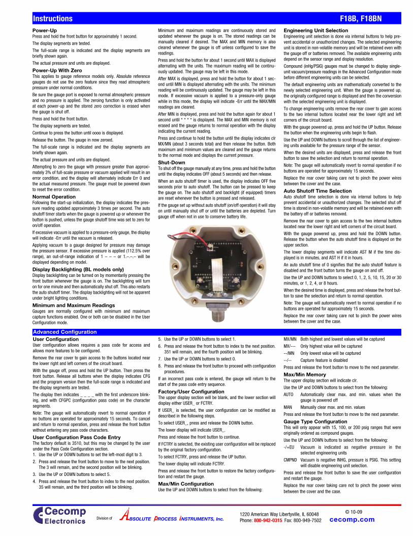
Advanced Configuration
Power-UpPress and hold the front button for approximately 1 second.
The display segments are tested.
The full-scale range is indicated and the display segments are briefly shown again.
The actual pressure and units are displayed.
Power-Up With ZeroThis applies to gauge reference models only. Absolute reference gauges do not use the zero feature since they read atmospheric pressure under normal conditions.
Be sure the gauge port is exposed to normal atmospheric pressure and no pressure is applied. The zeroing function is only activated at each power-up and the stored zero correction is erased when the gauge is shut off.
Press and hold the front button.
The display segments are tested.
Continue to press the button until oooo is displayed.
Release the button. The gauge in now zeroed.
The full-scale range is indicated and the display segments are briefly shown again.
The actual pressure and units are displayed.
Attempting to zero the gauge with pressure greater than approxi-mately 3% of full-scale pressure or vacuum applied will result in an error condition, and the display will alternately indicate Err 0 and the actual measured pressure. The gauge must be powered down to reset the error condition.
Normal OperationFollowing the start-up initialization, the display indicates the pres-sure reading updated approximately 3 times per second. The auto shutoff timer starts when the gauge is powered up or whenever the button is pushed, unless the gauge shutoff time was set to zero for on/off operation.
If excessive vacuum is applied to a pressure-only gauge, the display will indicate -Err until the vacuum is released.
Applying vacuum to a gauge designed for pressure may damage the pressure sensor. If excessive pressure is applied (112.5% over range), an out-of-range indication of 1 – – – or 1.–.–.– will be displayed depending on model.
Display Backlighting (BL models only)Display backlighting can be turned on by momentarily pressing the front button whenever the gauge is on. The backlighting will turn on for one minute and then automatically shut off. This also restarts the auto shutoff timer. The display backlighting will not be apparent under bright lighting conditions.
Minimum and Maximum ReadingsGauges are normally configured with minimum and maximum capture functions enabled. One or both can be disabled in the User Configuration mode.
Minimum and maximum readings are continuously stored and updated whenever the gauge is on. The stored readings can be manually cleared if desired. The MAX and MIN memory is also cleared whenever the gauge is off unless configured to save the readings.
Press and hold the button for about 1 second until MAX is displayed alternating with the units. The maximum reading will be continu-ously updated. The gauge may be left in this mode.
After MAX is displayed, press and hold the button for about 1 sec-ond until MIN is displayed alternating with the units. The minimum reading will be continuously updated. The gauge may be left in this mode. If excessive vacuum is applied to a pressure-only gauge while in this mode, the display will indicate -Err until the MAX/MIN readings are cleared.
After MIN is displayed, press and hold the button again for about 1 second until * * * * is displayed. The MAX and MIN memory is not erased and the gauge returns to normal operation with the display indicating the current reading.
Press and continue to hold the button until the display indicates clr MX/MN (about 3 seconds total) and then release the button. Both maximum and minimum values are cleared and the gauge returns to the normal mode and displays the current pressure.
Shut-DownTo shut off the gauge manually at any time, press and hold the button until the display indicates OFF (about 5 seconds) and then release.
When an auto shutoff timer is used, the display indicates OFF five seconds prior to auto shutoff. The button can be pressed to keep the gauge on. The auto shutoff and backlight (if equipped) timers are reset whenever the button is pressed and released.
If the gauge set up without auto shutoff (on/off operation) it will stay on until manually shut off or until the batteries are depleted. Turn gauge off when not in use to conserve battery life.
Engineering Unit SelectionEngineering unit selection is done via internal buttons to help pre-vent accidental or unauthorized changes. The selected engineering unit is stored in non-volatile memory and will be retained even with the gauge off or batteries removed. The available engineering units depend on the sensor range and display resolution.
Compound (inHg/PSIG) gauges must be changed to display single-unit vacuum/pressure readings in the Advanced Configuration mode before different engineering units can be selected.
The default engineering units are mathematically converted to the newly selected engineering unit. When the gauge is powered up, the originally configured range is displayed and then the conversion with the selected engineering unit is displayed.
To change engineering units remove the rear cover to gain access to the two internal buttons located near the lower right and left corners of the circuit board.
With the gauge powered up, press and hold the UP button. Release the button when the engineering units begin to flash.
Use the UP and DOWN buttons to scroll through the list of engineer-ing units available for the pressure range of the sensor.
When the desired units are displayed, press and release the front button to save the selection and return to normal operation.
Note: The gauge will automatically revert to normal operation if no buttons are operated for approximately 15 seconds.
Replace the rear cover taking care not to pinch the power wires between the cover and the case.
Auto Shutoff Time SelectionAuto shutoff time selection is done via internal buttons to help prevent accidental or unauthorized changes. The selected shut off time is stored in non-volatile memory and will be retained even with the battery off or batteries removed.
Remove the rear cover to gain access to the two internal buttons located near the lower right and left corners of the circuit board.
With the gauge powered up, press and hold the DOWN button. Release the button when the auto shutoff time is displayed on the upper section.
The lower display segments will indicate AST M if the time dis-played is in minutes, and AST H if it in hours.
An auto shutoff time of 0 signifies that the auto shutoff feature is disabled and the front button turns the gauge on and off.
Use the UP and DOWN buttons to select 0, 1, 2, 5, 10, 15, 20 or 30 minutes, or 1, 2, 4, or 8 hours.
When the desired time is displayed, press and release the front but-ton to save the selection and return to normal operation.
Note: The gauge will automatically revert to normal operation if no buttons are operated for approximately 15 seconds.
Replace the rear cover taking care not to pinch the power wires between the cover and the case.
User ConfigurationUser configuration allows requires a pass code for access and allows more features to be configured.
Remove the rear cover to gain access to the buttons located near the lower right and left corners of the circuit board.
With the gauge off, press and hold the UP button. Then press the front button. Release all buttons when the display indicates CFG and the program version then the full-scale range is indicated and the display segments are tested.
The display then indicates _ _ _ _ with the first underscore blink-ing, and with CFGPC (configuration pass code) on the character segments.
Note: The gauge will automatically revert to normal operation if no buttons are operated for approximately 15 seconds. To cancel and return to normal operation, press and release the front button without entering any pass code characters.
User Configuration Pass Code EntryThe factory default is 3510, but this may be changed by the user under the Pass Code Configuration section.1. Use the UP or DOWN buttons to set the left-most digit to 3.
2. Press and release the front button to move to the next position. The 3 will remain, and the second position will be blinking.
3. Use the UP or DOWN buttons to select 5.
4. Press and release the front button to index to the next position. 35 will remain, and the third position will be blinking.
5. Use the UP or DOWN buttons to select 1.
6. Press and release the front button to index to the next position. 351 will remain, and the fourth position will be blinking.
7. Use the UP or DOWN buttons to select 0.
8. Press and release the front button to proceed with configuration procedures.
If an incorrect pass code is entered, the gauge will return to the start of the pass code entry sequence.
Factory/User ConfigurationThe upper display section will be blank, and the lower section will display either USER_ or FCTRY.
If USER_ is selected, the user configuration can be modified as described in the following steps.
To select USER_, press and release the DOWN button.
The lower display will indicate USER_.
Press and release the front button to continue.
If FCTRY is selected, the existing user configuration will be replaced by the original factory configuration.
To select FCTRY, press and release the UP button.
The lower display will indicate FCTRY.
Press and release the front button to restore the factory configura-tion and restart the gauge.
Max/Min ConfigurationUse the UP and DOWN buttons to select from the following:
MX/MN Both highest and lowest values will be captured
MX/--- Only highest value will be captured
--/MN Only lowest value will be captured
--/-- Capture feature is disabled
Press and release the front button to move to the next parameter.
Max/Min MemoryThe upper display section will indicate clr.
Use the UP and DOWN buttons to select from the following:
AUTO Automatically clear max. and min. values when the gauge is powered off
MAN Manually clear max. and min. values
Press and release the front button to move to the next parameter.
Gauge Type ConfigurationThis will only appear with 15, 100, or 200 psig ranges that were originally ordered as compound gauges.
Use the UP and DOWN buttons to select from the following:
-/+EU Vacuum is indicated as negative pressure in the selected engineering units
CMPND Vacuum is negative INHG, pressure is PSIG. This setting will disable engineering unit selection.
Press and release the front button to save the user configuration and restart the gauge.
Replace the rear cover taking care not to pinch the power wires between the cover and the case.

cecomp.com1220 American Way Libertyville, IL 60048Phone: 800-942-0315 Fax: 800-949-7502
© 10-09
BSOLUTE ROCESS NSTRUMENTS, Inc.Division of
Instructions F18B, F18BN
SetupGauges are calibrated at the factory using equipment traceable to NIST. There is no need to calibrate the gauge before putting it into service. Calibration intervals depend on your quality control pro-gram requirements, although many customers calibrate annually.
Calibration should only be performed by qualified individuals using appropriate calibration standards and procedures. The calibration equipment should be at least four times more accurate than the gauge being calibrated.
The calibration system must be able to generate and measure pressure/vacuum over the full range of the gauge.
A vacuum pump able to produce a vacuum of 10 microns (0.01 torr or 10 millitorr) or lower is required for vacuum gauges. Warning: application of vacuum to non-vacuum models may result in irrepa-rable damage to the sensor.
Allow the gauge to acclimate to ambient temperature for 20 minutes.
Install fresh batteries.
Remove the rear cover to gain access to the UP and DOWN buttons located near the lower right and left corners of the circuit board.
Entering Calibration ModeWith the gauge off, press and hold the DOWN button. Then press the front button. Release all buttons when the display indicates CAL.
The display begins by indicating the full-scale positive pressure rating of the gauge in the engineering units as configured by the factory, and then shows all display segments.
Before the gauge enters the Calibration Mode, the display initially indicates _ _ _ _ with the first underscore blinking, and with CALPC (calibration pass code) on the lower display.
Note: The gauge will automatically revert to normal operation if no buttons are operated for approximately 15 seconds. To cancel and return to normal operation, press and release the front button without entering any pass code characters.
Enter the User-Modifiable Pass CodeThe factory default is 3510, but this is user changeable.
1. Use the UP or DOWN buttons to set the left-most digit to 3.
2. Press and release the front button to move to the next position. The 3 will remain, and the second position will be blinking.
3. Use the UP or DOWN buttons to select 5.
4. Press and release the front button to index to the next position. 35 will remain, and the third position will be blinking.
5. Use the UP or DOWN buttons to select 1.
6. Press and release the front button to index to the next position. 351 will remain, and the fourth position will be blinking.
7. Use the UP or DOWN buttons to select 0.
8. Press and release the front button to proceed with configuration procedures.
If an incorrect pass code is entered, the gauge will return to the start of the pass code entry sequence.
Calibration ModeThe gauge enters and remains in the calibration mode until restarted manually or power is removed. Features not related to calibration are disabled and compound range models are set for the same engineering units for pressure and for vacuum.
The calibration may be performed in any of the available engineer-ing units as well as percent (PCT). For greatest accuracy, use the UP and DOWN buttons to select engineering units for calibration with highest resolution (highest number of display counts). Press and release the front button when the appropriate engineering units are displayed. Suggested units are listed below.
Sensor Suggested units for calibration5 PSI 5.000 PSI15 PSI 775.7 MMHG (TORR)30 PSI 61.08 INHG50 PSI 50.00 PSI60 PSI 60.00 PSI100 PSI 7.031 KG/CM2200 PSI 407.2 INHG300 PSI 610.8 INHG500 PSI 500.0 PSI1000 PSI 70.31 KG/CM22000 PSI 4072 INHG3000 PSI 6108 INHG5000 PSI 5000 PSIAny 100.00 PCT (percent)
The display will then indicate the currently applied pressure in the engineering units selected for calibration.
UP and DOWN Button OperationEach time one of the calibration buttons is pressed and released quickly, a small change is made to the digitized pressure signal. It may take more than one of these small changes to result in a single digit change on the display.
To make larger changes, press and hold the appropriate calibration button. After about one second, the display will begin to change continuously. Release the button to stop. Then make fine adjust-ments by pressing and quickly releasing the calibration buttons as previously described.
Gauge Reference Pressure GaugesApply zero pressure by venting the gauge port to atmosphere. The character display will alternate between ZERO and CAL. Adjust for a display indication of zero using the UP and the DOWN buttons.
Apply full-scale pressure. The character display will alternate between +SPAN and CAL. Adjust for a display indication of full-scale pressure using the UP and the DOWN buttons.
Apply 50% full-scale pressure. The character display will alternate between +MID and CAL. Adjust for a display indication equal to 50% of full-scale pressure using the UP and the DOWN buttons.
Gauge Reference Vacuum GaugesApply zero pressure by venting the gauge port to atmosphere. The character display will alternate between ZERO and CAL. Adjust for a display indication of zero using the UP and the DOWN buttons.
Apply full-scale vacuum. The character display will alternate between +SPAN and CAL. Adjust for a display indication of full-scale vacuum using the UP and the DOWN buttons.
Apply 50% full-scale vacuum. The character display will alternate between +MID and CAL. Adjust for a display indication equal to 50% of full-scale vacuum using the UP and the DOWN buttons.
Absolute Reference GaugesApply full vacuum to the gauge. The character display will alternate between ZERO and CAL. Press the UP and DOWN buttons to obtain a display indication of zero.
Apply full-scale pressure. The character display will alternate between +SPAN and CAL. Press the UP and DOWN buttons to obtain a display indication equal to full-scale pressure.
Apply 50% of full-scale pressure. The lower display will alternate between +MID and CAL. Press the UP and DOWN buttons to obtain an indication equal to 50% of full-scale pressure.
Compound and Bipolar GaugesIn addition to the steps described above for pressure gauges, apply full-scale vacuum. The character display will alternate between -SPAN and CAL. Adjust for a display indication of actual applied vacuum using the UP and the DOWN buttons.
For bipolar and –30.00inHg/+15.00psig compound range models only, apply 50% full-scale vacuum. The character display will alter-nate between -MID and CAL. Adjust for a display indication equal to 50% of full-scale vacuum using the UP and the DOWN buttons.
Save CalibrationOnce the adjustments are complete, press and hold the front but-ton until the display indicates ---- then release the button to store the calibration parameters in non-volatile memory and restart the gauge.
Verify the pressure indications at 0%, 25%, 50%, 75% and 100% of full scale.
Replace the rear cover taking care not to pinch the wires between the cover and the case.
Calibration
Remove the rear cover to access the buttons located near the lower right and left corners of the circuit board.
View or change user configuration pass codeWith the unit off, press and hold the UP button, then press the front button.
Release all buttons when the display indicates CFG.
View or change user calibration pass codeWith the unit off, press and hold the DOWN button, then press the front button.
Release all buttons when the display indicates CAL.
Enter access code 1220
Before the unit enters the view or change pass code mode, the dis-play initially indicates ' _ _ _ _ ' with the first underscore blinking, and with CFGPC or CALPC on the character display.
Note: The gauge will automatically revert to normal operation if no
buttons are operated for approximately 15 seconds.
To cancel and return to normal operation, press and release the POWER button without entering any pass code characters.
1. Use the UP and DOWN buttons to set the left-most digit to 1.
2. Press and release the front button to move to the next position. The 1 will remain, and the second position will be blinking.
3. Use the UP and DOWN buttons to select 2.
4. Press and release the front button to index to the next position. 12 will remain, and the third position will be blinking.
5. Use the UP and DOWN buttons to select 2.
6. Press and release the front button to move to the next position. 1 2 2 will remain, and the fourth position will be blinking.
7. Use the UP and DOWN buttons to select 0.
8. Press and release the front button to proceed.
Note: If an incorrect access code was entered, the gauge will return to the start of the access code entry sequence.
Once the access code has been entered correctly, the display will indicate the existing user-defined pass code with CFGPC or CALPC on the character segments.
1. Operate the UP or DOWN button to select the first character of the new pass code.
2. When the correct first character is being displayed, press and release the front button to proceed to the next pass code char-acter.
3. Repeat above until the entire pass code is complete.
4. To exit, press and hold the front button. Release the button when the display indicates ---- to restart the gauge.
5. Replace the rear cover taking care not to pinch the power wires between the cover and the case.
User-Defined Pass Code Configuration
Battery ReplacementA low battery indication will be shown in the upper left-hand corner of the display when the battery voltage falls sufficiently. The battery should be replaced soon after the indicator comes on or unreliable readings may result.
1. Remove the 6 Phillips screws on the back of the unit.
2. Remove batteries by lifting up the positive end of the battery (opposite the spring) taking care not to bend the battery holder spring.
3. Discard old batteries properly, do not discard into fire, sources of extreme heat, or in any hazardous manner.
4. Always replace both batteries at the same time with high quality alkaline batteries. Install batteries with correct orientation. The negative (flat) end of each battery should be inserted first facing the battery holder spring.
6. Replace the back cover, including the rubber gasket.

■■ Replace Mercury Manometers in Fume Hoods■■ Monitor Vacuum Systems and Pumps■■ Vacuum Packaging
Absolute Reference Manometers ARM760 Series
BSOLUTE ROCESS NSTRUMENTS, Inc. api-usa.com 1811220 American Way Libertyville, IL 60048Phone: 800-942-0315 Fax: 800-949-7502© 02-09
●● ±0.25% Test Gauge Accuracy●● 316 Stainless Steel Wetted Parts●● 760 to 0 Torr Absolute●● BBL Includes Backlit Display
Range and Resolution760 to 0 torr absolute, 1 torr resolution
Optional Units and RangesVisit cecomp.com or consult factory or for a complete list of models andranges
Display31/2 digit LCD (3 digits are used for this range), 0.5" digit height3 readings per second nominal display update rate
Controls and LocationFront On/Off pushbuttonDisplay zero/span, non-interactive, ±10% rangeFront-accessible multiturn potentiometers
Accuracy (linearity, hysteresis, repeatability)Standard: ±0.25% of full scale ±1 least significant digitOptional: CD Factory calibration data
NC NIST traceable test report and calibration data
Power ARM760AD and ARM760ADBLIncludes 115VAC/12VDC wall mount power supplyGauge will operate on any DC source of 9 to 32 VDC or any AC source of 8to 24 VAC 50/60 HzARM760AD power consumption approximately 5 mAARM760ADBL power consumption approximately 75 mA
Electrical Connection ARM760AD and ARM760ADBL6 foot long, 2-conductor cable with female 3.5 mm socketPower supply; 6 foot long, 2-conductor cable with male 3.5 mm plug
Power ARM760B and ARM760BBLIncludes 2 AA alkaline batteriesARM760B battery life is approximately 2500 hoursARM760BBL battery life is approximately 180 hours30 minute auto shutoff
EnvironmentalStorage Temperature –40 to 203°F (–40 to 95°C)Operating Temperature –4 to 185°F (–20 to 85°C)Compensated Temperature 32 to 158°F (0 to 70°C)
Size3.38" W x 2.88" H x 1.65" D housingAdd approximately 0.75" to height for pressure fittingAdd approximately 1" to depth for strain relief and wire clearance.
Weight Gauge: 9 ounces (approx)Shipping weight: 1 pound (approx)
Material and ColorExtruded aluminum case, epoxy powder coated, light grayPolycarbonate cover, blue, Polycarbonate front labelFront and rear gaskets
Pressure/Vacuum Connection and Material1/4" NPT male, 316 stainless steel
Media CompatibilityAll wetted parts are 316 SS, Compatible with most liquids and gases
Overpressure2x rated pressure minimum
Burst Pressure4x rated pressure minimum
Hg
ARM760B
ARM760AD
Electrical Specifications
Mechanical Specifications
Model Version PowerARM760AD DC powered 115 VAC/12 VDC adapter
ARM760ADBL DC powered, backlit display 115 VAC/12 VDC adapter
ARM760B Battery-powered 2 AA batteries
ARM760BBL Battery, backlit display 2 AA batteries
Applications
RB Rubber BootNot for NEMA 4X models
Pressure
cecomp.com
182
ARM760 Series Instructions
© 01-07
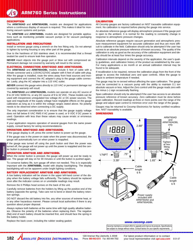
DESCRIPTIONThe ARM760AD and ARM760ADBL models are designed for applicationswhere a continuous display of vacuum is required. This makes it ideal for mon-itoring vacuum systems and pumps.
The ARM760B and ARM760BBL models are designed for portable applica-tions such as monitoring portable vacuum pumps or for vacuum packagingapplications.
INSTALLATION AND PRECAUTIONSInstall or remove gauge using a wrench on the hex fitting only. Do not attemptto tighten by turning housing or any other part of the gauge.
Due to the hardness of 316 stainless steel, it is recommended that a threadsealant be used to ensure leak-free operation.
NEVER insert objects into the gauge port or blow out with compressed air.Permanent damage not covered by warranty will result to the sensor.
ELECTRICAL CONNECTION ARM760AD AND ARM760ADBLThe ARM760AD and ARM760ADBL models include 6 feet of cable with afemale connector and a 115VAC/12VDC adapter with 6 feet of cable with plug.After the gauge is installed, route the wires away from heat sources and mov-ing equipment and connect the AC adapter’s plug to the gauge cable connec-tor. Lastly, plug the AC adapter into a 115 VAC outlet.
NEVER connect the gauge wires directly to 115 VAC or permanent damage notcovered by warranty will result.The ARM760AD and ARM760ADBL models can operate on any AC source of8 to 24 VAC 50/60 Hz, or any DC source of 9 to 32 VDC. These models can beused with inexpensive unregulated low voltage AC or DC power sources. Thetype and magnitude of the supply voltage have negligible effects on the gaugecalibration as long as it is within the voltage ranges stated above. No polarityneeds to be observed when connecting a DC supply.
The only important consideration is to ensure that the gauge supply voltagedoes not fall below 8 VAC RMS if AC power is used, or 9 VDC if DC power isused. Operation with less than these values may cause erratic or erroneousreadings.
If your application requires operation of several gauges from the same powersupply, consult factory for wiring recommendations.
OPERATION ARM760AD AND ARM760ADBLIf the gauge display is off, press the center button to power up the gauge.
If the gauge was in the power-on state when the power was disconnected, thegauge will automatically turn on when power is reapplied.
If the gauge was turned off using the push button and then the power wasturned off, the gauge will not power up until the power is reapplied and the cen-ter button is pressed again.
OPERATION ARM760B AND ARM760BBLWhen the center button is pressed, the gauge will power up and be ready touse. The gauge will stay on for 30 minutes or until the button is pushed again.
To conserve battery life, turn gauge off when not needed. This is is especiallyimportant with the ARM760BBL model with display backlighting. The displaybacklighting will not be apparent under bright lighting conditions.
BATTERY REPLACEMENT ARM760B AND ARM760BBLA low battery indication will be shown in the upper left-hand corner of the dis-play when the battery voltage falls sufficiently. The battery should be replacedsoon after the indicator comes on or unreliable readings may result.
Remove the 6 Phillips head screws on the back of the unit.
Carefully remove batteries from the holders by lifting up the positive end of thebattery (opposite the spring). Take care not to bend or distort the battery reten-tion springs.
DO NOT discard the old battery into fire, any other sources of extreme heat, orin any other hazardous manner. Please consult local authorities if there is anyquestion about proper disposal.
Always replace both batteries at the same time with high quality alkaline batter-ies. Observe the polarity of the batteries when replacing them. The negative(flat) end of each battery should be inserted first, and should face the spring inthe battery holder.
Replace the back cover, including the rubber sealing gasket.
CALIBRATIONAll Cecomp gauges are factory calibrated on NIST traceable calibration equip-ment. No calibration is required before placing the gauge into service.
An absolute reference gauge will display atmospheric pressure if the gauge portis open to the ambient. It is normal for the reading to constantly change inresponse to atmospheric pressure changes.
Absolute reference gauges require vacuum generation and atmospheric pres-sure measurement equipment for accurate calibration and thus are more diffi-cult to calibrate in the field. Calibration should only be attempted if the user hasaccess to an absolute pressure reference of known accuracy. The quality of thecalibration is only as good as the accuracy of the calibration equipment and ide-ally should be at least four times the gauge accuracy.
Calibration intervals depend on the severity of the application, the user’s quali-ty guidelines, and calibration history of the product as established by the user.For many applications a six month or an annual calibration interval may befound to be adequate.
If recalibration is be required, remove the calibration plugs from the front of thegauge to access the individual zero and span controls. Allow the gauge toadjust to ambient temperature if needed.
The gauge may be re-zeroed without affecting the span calibration. The gaugemust be connected to a vacuum pump with the ability to maintain 0.1 torrabsolute vacuum or less. Adjust the Zero control until the gauge reads zero withthe minus (–) sign occasionally flashing.
Span calibration should only be attempted if the user has access to an absolutepressure reference of known accuracy. Zero calibration must be done beforespan calibration. Record readings at three or more points over the range of thegauge and adjust span control to minimize error over the range of the gauge.
Gauges may be returned to Cecomp Electronics for factory certified recalibra-tion. NIST traceability is available.
DIMENSIONS
1/4"NPT
Cecomp Electronics Inc./Made in USA
2.88"
3.38"
.75"
1.65"
PSIG
Tightenat hexfittingonly
Span Zero
ARM760ADand
ARM760ADBLonly
Cablelength
6 ft
Cablelength
6 ft
Power supplyincluded with
ARM760AD andARM760ADBL
BSOLUTE ROCESS NSTRUMENTS, Inc.1220 American Way Libertyville, IL 60048Phone: 800-942-0315 Fax: 800-949-7502
For latest product information or to contactyour local representative visit api-usa.com
Cecomp maintains a constant effort to upgrade and improve its products. Specificationsare subject to change without notice. Consult factory for your specific requirements.
www.cecomp.com
Pres
sure


![CALIBRATION OF DIGITAL PRESSURE GAUGES, COMBINED …metrology-bg.org/fulltextpapers/360.pdf · pressure gauge and reference pressure according to [1]. Pressure gauges with class of](https://img.dokumen.tips/doc/110x75/5edfde0aad6a402d666b28ff/calibration-of-digital-pressure-gauges-combined-metrology-bgorgfulltextpapers360pdf.jpg)