Embed Size (px)
Citation preview


BaseUnits
(6ES7193-6BP.../3RK1908-0AP00…)
___________________
___________________
___________________
___________________
___________________
___________________
___________________
SIMATIC
ET 200SP BaseUnits (6ES7193-6BP.../3RK1908-0AP00…)
Manual
04/2016 A5E03727049-AF
Preface
Guide to the documentation 1
Product overview 2
BaseUnits for I/O modules 3
BaseUnits for motor starters 4
Dimension drawings of I/O modules
A
Dimension drawings of motor starters
B

Siemens AG Division Digital Factory Postfach 48 48 90026 NÜRNBERG GERMANY
A5E03727049-AF Ⓟ 04/2016 Subject to change
Copyright © Siemens AG 2012 - 2016. All rights reserved
Legal information Warning notice system
This manual contains notices you have to observe in order to ensure your personal safety, as well as to prevent damage to property. The notices referring to your personal safety are highlighted in the manual by a safety alert symbol, notices referring only to property damage have no safety alert symbol. These notices shown below are graded according to the degree of danger.
DANGER indicates that death or severe personal injury will result if proper precautions are not taken.
WARNING indicates that death or severe personal injury may result if proper precautions are not taken.
CAUTION indicates that minor personal injury can result if proper precautions are not taken.
NOTICE indicates that property damage can result if proper precautions are not taken.
If more than one degree of danger is present, the warning notice representing the highest degree of danger will be used. A notice warning of injury to persons with a safety alert symbol may also include a warning relating to property damage.
Qualified Personnel The product/system described in this documentation may be operated only by personnel qualified for the specific task in accordance with the relevant documentation, in particular its warning notices and safety instructions. Qualified personnel are those who, based on their training and experience, are capable of identifying risks and avoiding potential hazards when working with these products/systems.
Proper use of Siemens products Note the following:
WARNING Siemens products may only be used for the applications described in the catalog and in the relevant technical documentation. If products and components from other manufacturers are used, these must be recommended or approved by Siemens. Proper transport, storage, installation, assembly, commissioning, operation and maintenance are required to ensure that the products operate safely and without any problems. The permissible ambient conditions must be complied with. The information in the relevant documentation must be observed.
Trademarks All names identified by ® are registered trademarks of Siemens AG. The remaining trademarks in this publication may be trademarks whose use by third parties for their own purposes could violate the rights of the owner.
Disclaimer of Liability We have reviewed the contents of this publication to ensure consistency with the hardware and software described. Since variance cannot be precluded entirely, we cannot guarantee full consistency. However, the information in this publication is reviewed regularly and any necessary corrections are included in subsequent editions.

BaseUnits (6ES7193-6BP.../3RK1908-0AP00…) 4 Manual, 04/2016, A5E03727049-AF
Preface
Purpose of the documentation The present manual supplements the System Manual ET 200SP distributed I/O system (http://support.automation.siemens.com/WW/view/en/58649293) and the System Manual SIMATIC ET 200SP motor starters. Functions affecting the system in general are described there. ((Link for motor starters still to be added))
The information provided in this manual and in the system/function manuals supports you in commissioning the system.
Conventions Please also observe notes marked as follows:
Note
A note contains important information on the product described in the documentation, on the handling of the product and on the section of the documentation to which particular attention should be paid.
Changes compared to the previous version In contrast to the previous version, the chapters "BaseUnits for motor starters" and "Dimension drawings for motor starters" have been added to this manual.
Security information Siemens provides products and solutions with industrial security functions that support the secure operation of plants, solutions, machines, equipment and/or networks. They are important components in a holistic industrial security concept. With this in mind, Siemens’ products and solutions undergo continuous development. Siemens recommends strongly that you regularly check for product updates.
For the secure operation of Siemens products and solutions, it is necessary to take suitable preventive action (e.g. cell protection concept) and integrate each component into a holistic, state-of-the-art industrial security concept. Third-party products that may be in use should also be considered. You can find more information about industrial security on the Internet (http://www.siemens.com/industrialsecurity).
To stay informed about product updates as they occur, sign up for a product-specific newsletter. You can find more information on the Internet (http://support.automation.siemens.com).

BaseUnits (6ES7193-6BP.../3RK1908-0AP00…) Manual, 04/2016, A5E03727049-AF 5
Table of contents
Preface ................................................................................................................................................... 4
1 Guide to the documentation .................................................................................................................... 7
2 Product overview .................................................................................................................................. 10
3 BaseUnits for I/O modules .................................................................................................................... 13
3.1 BU15-P16+A10+2D (BU type A0) .......................................................................................... 13 3.1.1 Product overview .................................................................................................................... 13 3.1.2 Connecting up ......................................................................................................................... 15 3.1.3 Technical specifications .......................................................................................................... 16
3.2 BU15-P16+A0+2D (BU type A0) ............................................................................................ 17 3.2.1 Product overview .................................................................................................................... 17 3.2.2 Connection .............................................................................................................................. 19 3.2.3 Technical specifications .......................................................................................................... 20
3.3 BU15-P16+A10+2B (BU type A0) ........................................................................................... 21 3.3.1 Product overview .................................................................................................................... 21 3.3.2 Connection .............................................................................................................................. 23 3.3.3 Technical specifications .......................................................................................................... 24
3.4 BU15-P16+A0+2B (BU type A0) ............................................................................................. 25 3.4.1 Product overview .................................................................................................................... 25 3.4.2 Connection .............................................................................................................................. 26 3.4.3 Technical specifications .......................................................................................................... 27
3.5 BU15-P16+A0+12D/T (BU type A1) ....................................................................................... 28 3.5.1 Product overview .................................................................................................................... 28 3.5.2 Connection .............................................................................................................................. 30 3.5.3 Technical specifications .......................................................................................................... 31
3.6 BU15-P16+A0+2D/T (BU type A1) ......................................................................................... 32 3.6.1 Product overview .................................................................................................................... 32 3.6.2 Connection .............................................................................................................................. 34 3.6.3 Technical specifications .......................................................................................................... 35
3.7 BU15-P16+A0+12B/T (BU type A1) ....................................................................................... 36 3.7.1 Product overview .................................................................................................................... 36 3.7.2 Connection .............................................................................................................................. 38 3.7.3 Technical specifications .......................................................................................................... 39
3.8 BU15-P16+A0+2B/T (BU type A1) ......................................................................................... 40 3.8.1 Product overview .................................................................................................................... 40 3.8.2 Connection .............................................................................................................................. 42 3.8.3 Technical specifications .......................................................................................................... 43
3.9 BU20-P12+A4+0B (BU type B0) ............................................................................................. 44 3.9.1 Product overview .................................................................................................................... 44 3.9.2 Connecting .............................................................................................................................. 45 3.9.3 Technical specifications .......................................................................................................... 46

Table of contents
BaseUnits (6ES7193-6BP.../3RK1908-0AP00…) 6 Manual, 04/2016, A5E03727049-AF
3.10 BU20-P12+A0+4B (BU type B1) ............................................................................................ 47 3.10.1 Product overview.................................................................................................................... 47 3.10.2 Connecting up ........................................................................................................................ 48 3.10.3 Technical specifications ......................................................................................................... 49
3.11 BU20-P6+A2+4D (BU type C0) ............................................................................................. 50 3.11.1 Product overview.................................................................................................................... 50 3.11.2 Connecting ............................................................................................................................. 52 3.11.3 Technical specifications ......................................................................................................... 53
3.12 BU20-P6+A2+4B (BU type C1) .............................................................................................. 54 3.12.1 Product overview.................................................................................................................... 54 3.12.2 Connecting ............................................................................................................................. 56 3.12.3 Technical specifications ......................................................................................................... 57
3.13 BU20-P12+A0+0B (BU type D0)............................................................................................ 58 3.13.1 Product overview.................................................................................................................... 58 3.13.2 Connecting ............................................................................................................................. 60 3.13.3 Technical specifications ......................................................................................................... 61
3.14 BU20-P8+A4+0B (BU type F0) .............................................................................................. 62 3.14.1 Product overview.................................................................................................................... 62 3.14.2 Connecting up ........................................................................................................................ 64 3.14.3 Technical specifications ......................................................................................................... 65
4 BaseUnits for motor starters .................................................................................................................. 66
4.1 Introduction ............................................................................................................................ 66
4.2 BU30-MS1 - BaseUnit with 24 V DC and 500 V AC infeed ................................................... 67 4.2.1 Product overview.................................................................................................................... 67 4.2.2 Connection ............................................................................................................................. 69 4.2.3 Technical specifications ......................................................................................................... 71
4.3 BU30-MS2 - BaseUnit with 500 V AC infeed ......................................................................... 72 4.3.1 Product overview.................................................................................................................... 72 4.3.2 Connection ............................................................................................................................. 74 4.3.3 Technical specifications ......................................................................................................... 76
4.4 BU30-MS3 - BaseUnit with 24 V DC infeed ........................................................................... 77 4.4.1 Product overview.................................................................................................................... 77 4.4.2 Connection ............................................................................................................................. 79 4.4.3 Technical specifications ......................................................................................................... 80
4.5 BU30-MS4 - BaseUnit without infeed .................................................................................... 81 4.5.1 Product overview.................................................................................................................... 81 4.5.2 Connection ............................................................................................................................. 82 4.5.3 Technical specifications ......................................................................................................... 83
A Dimension drawings of I/O modules ...................................................................................................... 84
B Dimension drawings of motor starters ................................................................................................... 87
Index ...................................................................................................... Fehler! Textmarke nicht definiert.

BaseUnits (6ES7193-6BP.../3RK1908-0AP00…) Manual, 04/2016, A5E03727049-AF 7
Guide to the documentation 1
The documentation for the SIMATIC ET 200SP distributed I/O system is arranged into three areas. This arrangement enables you to access the specific content you require.
Basic information
The system manual describes in detail the configuration, installation, wiring and commissioning of the SIMATIC ET 200SP. distributed I/O system. The STEP 7 online help supports you in the configuration and programming.
Device information
Product manuals contain a compact description of the module-specific information, such as properties, terminal diagrams, characteristics and technical specifications.

Guide to the documentation
BaseUnits (6ES7193-6BP.../3RK1908-0AP00…) 8 Manual, 04/2016, A5E03727049-AF
General information
The function manuals contain detailed descriptions on general topics regarding the SIMATIC ET 200SP distributed I/O system, e.g. diagnostics, communication, Web server, designing interference-free controllers.
You can download the documentation free of charge from the Internet (http://w3.siemens.com/mcms/industrial-automation-systems-simatic/en/manual-overview/tech-doc-et200/Pages/Default.aspx).
Changes and supplements to the manuals are documented in a Product Information.
You can download the product information free of charge from the Internet.
Manual Collection ET 200SP The Manual Collection contains the complete documentation on the SIMATIC ET 200SP distributed I/O system gathered together in one file.
You can find the Manual Collection on the Internet (http://support.automation.siemens.com/WW/view/en/84133942).
"mySupport" With "mySupport", your personal workspace, you make the most of your Industry Online Support.
In "mySupport" you can store filters, favorites and tags, request CAx data and put together your personal library in the Documentation area. Furthermore, your data is automatically filled into support requests and you always have an overview of your current requests.
You need to register once to use the full functionality of "mySupport".
You can find "mySupport" in the Internet.
"mySupport" - Documentation In the Documentation area of "mySupport", you have the possibility to combine complete manuals or parts of them to make your own manual. You can export the manual in PDF format or in an editable format.
You can find "mySupport" - Documentation in the Internet (http://support.industry.siemens.com/My/ww/en/documentation).

Guide to the documentation
BaseUnits (6ES7193-6BP.../3RK1908-0AP00…) Manual, 04/2016, A5E03727049-AF 9
"mySupport" - CAx Data In the CAx Data area of "mySupport", you can have access the latest product data for your CAx or CAe system.
You configure your own download package with a few clicks.
In doing so you can select:
● Product images, 2D dimension drawings, 3D models, internal circuit diagrams, EPLAN macro files
● Manuals, characteristics, operating manuals, certificates
● Product master data
You can find "mySupport" - CAx Data in the Internet (http://support.industry.siemens.com/my/ww/en/CAxOnline).
Application examples The application examples support you with various tools and examples for solving your automation tasks. Solutions are shown in interplay with multiple components in the system - separated from the focus in individual products.
You can find the application examples on the Internet (http://support.industry.siemens.com/cs/ww/en/ps/ae).
TIA Selection Tool With the TIA Selection Tool, you can select, configure and order devices for Totally Integrated Automation (TIA). This tool is the successor of the SIMATIC Selection Tool and combines the known configurators for automation technology into one tool. With the TIA Selection Tool, you can generate a complete order list from your product selection or product configuration.
You can find the TIA Selection Tool on the Internet (http://w3.siemens.com/mcms/topics/en/simatic/tia-selection-tool).

BaseUnits (6ES7193-6BP.../3RK1908-0AP00…) 10 Manual, 04/2016, A5E03727049-AF
Product overview 2
General properties of the BaseUnits In the case of the distributed I/O system, there are different BaseUnits. The BaseUnit determines, among other things, the process connection, the suitable I/O modules/motor starters, and the infeed of the supply voltage. All properties can be identified by the short designation of the BaseUnit which is explained below.
Table 2- 1 Properties of the BaseUnits
Short description BU15-P16+A10+2D/T (example) BaseUnit properties Module width
BU
15 BaseUnit with width of 15 mm 20 BaseUnit with width of 20 mm 30 BaseUnit with width of 30 mm
Process connection P 4 • Connection method: Push-in terminal • Number of terminals to the I/O module: 4
8 • Connection method: Push-in terminal • Number of terminals to the I/O module: 8
16 • Connection method: Push-in terminal • Number of terminals to the I/O module: 16
Connection to the AUX busbar A 0 No connection to the AUX busbar 10 n = number of AUX terminals, e.g. 10
Self-assembling voltage buses 2 2 push-in terminals for supplying or tapping the supply voltage via the self-assembling voltage buses P1, P2 (see D, B)
12 • 2 push-in terminals for supplying or tapping the supply voltage via the self-assembling voltage buses P1, P2 (see D, B)
• 2x5 push-in additional terminals (1B to 5B, 1C to 5C) for con-necting further potential up to a maximum supply current of 24 V DC / 10 A
0 No terminals with access to the self-assembling voltage buses P1, P2
B • Looping through the potential group • Tapping of the supply voltage for external components or loop-
ing through with a maximum total current of 10 A per potential group
D • Opening a new potential group • Feeding in of supply voltage up to a maximum supply current
up to 10 A
Additional functions T Integrated temperature sensor to compensate the reference junc-tion temperature for thermocouples

Product overview
BaseUnits (6ES7193-6BP.../3RK1908-0AP00…) Manual, 04/2016, A5E03727049-AF 11
Selecting, installing and connecting BaseUnits See the System Manual ET 200SP distributed I/O system (http://support.automation.siemens.com/WW/view/en/58649293)
WARNING
Personal injury or damage to equipment is possible.
Connecting a rated supply voltage to the BaseUnit higher than the one given in the technical specifications may lead to dangerous situations in your plant or cause defects in ET 200SP components.
Therefore, only connect the rated supply voltage given in the technical specifications to the BaseUnit.
The connected rated supply voltage must correspond to the rated supply voltage of the I/O modules in the potential group.
When mains voltage is connected to the BaseUnit, ensure that all other supply voltages on this BaseUnit use the same phase as the mains.
The Totally Integrated Automation Selection Tool (TIA Selection Tool) (http://www.siemens.com/tia-selection-tool) supports you in selecting, configuring and ordering the ET 200SP modules. This tool can be downloaded free of charge from the Internet (http://support.automation.siemens.com/WW/view/en/58649293).
WARNING
Hazardous Voltage (when using ET 200SP motor starters) Can Cause Death, Serious Injury, or Property Damage.
Proper use of hardware products
This equipment is only allowed to be used for the applications described in the catalog and in the technical description, and only in conjunction with non-Siemens equipment and components recommended by Siemens.
Correct transport, storage, installation and assembly, as well as careful operation and maintenance, are required to ensure that the product operates safely and without faults.
EU note: Start-up/commissioning is absolutely prohibited until it has been ensured that the machine in which the component described here is to be installed fulfills the regulations/specifications of Machinery Directive 2006/42/EC.

Product overview
BaseUnits (6ES7193-6BP.../3RK1908-0AP00…) 12 Manual, 04/2016, A5E03727049-AF
WARNING
Hazardous Voltage (when using ET 200SP motor starters) Can Cause Death, Serious Injury, or Property Damage.
Please take note of our latest information
Systems with safety-related characteristics are subject to special operational safety requirements on the part of the operator. The supplier is also obliged to comply with special product monitoring measures. For this reason, we publish a special newsletter containing information on product developments and features that are (or could be) relevant to operation of safety-related systems. By subscribing to the appropriate newsletter, you will ensure that you are always up-to-date and able to make changes to your system, when necessary:
Siemens Newsletter (http://www.industry.siemens.com/newsletter)
Sign on to the following newsletter under "Products & Solutions": • Control Components and System Engineering News • Safety Integrated Newsletter

BaseUnits (6ES7193-6BP.../3RK1908-0AP00…) Manual, 04/2016, A5E03727049-AF 13
BaseUnits for I/O modules 3 3.1 BU15-P16+A10+2D (BU type A0)
3.1.1 Product overview
Article number 6ES7193-6BP20-0DA0
View
Image 3-1 BaseUnit BU15-P16+A10+2D

BaseUnits for I/O modules 3.1 BU15-P16+A10+2D (BU type A0)
BaseUnits (6ES7193-6BP.../3RK1908-0AP00…) 14 Manual, 04/2016, A5E03727049-AF
Properties ● BaseUnit suitable for all I/O modules of the BaseUnit type "A0/A1". Can be recognized by
the last two digits of the article number.
– Supply voltage (L+ terminal, ground): Max. 24 VDC/10 A
– Current-carrying capacity per process terminal (terminal 1 to 16): Max. 2 A
● The BaseUnit opens up a new potential group. The self-assembling voltage buses P1 and P2, and the AUX busbar are interrupted to the left-hand neighboring module (BaseUnit, interface module).
● Access to the AUX busbar via terminals
● 16 terminals to the process (assignment through the I/O module)
● 10 AUX terminals for connecting a protective conductor or potential. The AUX busbar is not connected to the I/O module.
● Connection method using push-in terminals
Maximum configuration per potential group The number of I/O modules that can be used per potential group depends on the following factors:
1. Total power requirement of all I/O modules operated on this potential group
2. Total power requirement of all loads connected externally to this potential group
The total current calculated from the sum of 1 and 2 may not exceed 10 A.

BaseUnits for I/O modules 3.1 BU15-P16+A10+2D (BU type A0)
BaseUnits (6ES7193-6BP.../3RK1908-0AP00…) Manual, 04/2016, A5E03727049-AF 15
3.1.2 Connecting up
Pin assignment
Table 3- 1 Pin assignment for BaseUnit BU15-P16+A10+2D
Pin assignment for BaseUnit BU15-P16+A10+2D Terminal Descriptions 1 to 16 Assignment is determined by the I/O module. See manual I/O Module
(http://support.automation.siemens.com/WW/view/en/55679691/133300). 1A, 2A, 3A, 4A, 5A, 6A, 7A, 8A, 9A, 10A, AUX
Protective-conductor terminal or potential bus freely usable up to 24 V DC with max. 10 A
L+, P1 / M, P2 L+: Rated supply voltage 24 V DC with max. 10 A M: Ground
Block diagram
① Backplane bus ② I/O module ③ Terminals with connection to the I/O module ④ Interrupted voltage buses with connection to the terminals for infeed ⑤ Disconnected AUX busbar connected to the terminals
Image 3-2 Block diagram BU15-P16+A10+2D

BaseUnits for I/O modules 3.1 BU15-P16+A10+2D (BU type A0)
BaseUnits (6ES7193-6BP.../3RK1908-0AP00…) 16 Manual, 04/2016, A5E03727049-AF
3.1.3 Technical specifications
Technical specifications of the BaseUnit BU15-P16+A10+2D
6ES7193-6BP20-0DA0 Product type designation BU15-P16+A10+2D Supply voltage Rated value (DC) 24 V External fuse for power supply lines Yes: 24 VDC / 10 A miniature circuit breaker with
type B or C tripping characteristic Current carrying capacity Current carrying capacity up to 60 °C, max. 10 A Electrical isolation between backplane bus and supply voltage Yes between the potential groups Yes Isolation Isolation tested with 707 VDC (type test) Dimensions Width 15 mm Height 141 mm Weights Weight, approx. 50 g

BaseUnits for I/O modules 3.2 BU15-P16+A0+2D (BU type A0)
BaseUnits (6ES7193-6BP.../3RK1908-0AP00…) Manual, 04/2016, A5E03727049-AF 17
3.2 BU15-P16+A0+2D (BU type A0)
3.2.1 Product overview
Article number 6ES7193-6BP00-0DA0
View
Image 3-3 BaseUnit BU15-P16+A0+2D

BaseUnits for I/O modules 3.2 BU15-P16+A0+2D (BU type A0)
BaseUnits (6ES7193-6BP.../3RK1908-0AP00…) 18 Manual, 04/2016, A5E03727049-AF
Properties ● BaseUnit suitable for all I/O modules of the BaseUnit type "A0/A1". Can be recognized by
the last two digits of the article number.
– Supply voltage (L+ terminal, ground): Max. 24 VDC/10 A
– Current-carrying capacity per process terminal (terminal 1 to 16): Max. 2 A
● The BaseUnit opens up a new potential group. The self-assembling voltage buses P1 and P2, and the AUX busbar are interrupted to the left-hand neighboring module (BaseUnit, interface module).
● No access to the AUX busbar via terminals
● 16 terminals to the process (assignment through the I/O module)
● Connection method using push-in terminals
Maximum configuration per potential group The number of I/O modules that can be used per potential group depends on the following factors:
1. Total power requirement of all I/O modules operated on this potential group
2. Total power requirement of all loads connected externally to this potential group
The total current calculated from the sum of 1 and 2 may not exceed 10 A.

BaseUnits for I/O modules 3.2 BU15-P16+A0+2D (BU type A0)
BaseUnits (6ES7193-6BP.../3RK1908-0AP00…) Manual, 04/2016, A5E03727049-AF 19
3.2.2 Connection
Pin assignment
Table 3- 2 Pin assignment for BaseUnit BU15-P16+A0+2D
Pin assignment for BaseUnit BU15-P16+A0+2D Terminal Descriptions 1 to 16 Assignment is determined by the I/O module. See manual I/O Module
(http://support.automation.siemens.com/WW/view/en/55679691/133300). (AUX) No access to the AUX busbar via terminals L+, P1 / M, P2 L+: Rated supply voltage 24 V DC with max. 10 A
M: Ground
Block diagram
① Backplane bus ② I/O module ③ Terminals with connection to the I/O module ④ Interrupted voltage buses with connection to the terminals for infeed ⑤ Disconnected AUX busbar not connected to the terminals
Image 3-4 Block diagram BU15-P16+A0+2D

BaseUnits for I/O modules 3.2 BU15-P16+A0+2D (BU type A0)
BaseUnits (6ES7193-6BP.../3RK1908-0AP00…) 20 Manual, 04/2016, A5E03727049-AF
3.2.3 Technical specifications
Technical specifications of the BaseUnit BU15-P16+A0+2D
6ES7193-6BP00-0DA0 Product type designation BU15-P16+A0+2D Supply voltage Rated value (DC) 24 V External fuse for power supply lines Yes: 24 VDC / 10 A miniature circuit breaker with
type B or C tripping characteristic Current carrying capacity Current carrying capacity up to 60 °C, max. 10 A Electrical isolation between backplane bus and supply voltage Yes between the potential groups Yes Isolation Isolation tested with 707 VDC (type test) Dimensions Width 15 mm Height 117 mm Weights Weight, approx. 40 g

BaseUnits for I/O modules 3.3 BU15-P16+A10+2B (BU type A0)
BaseUnits (6ES7193-6BP.../3RK1908-0AP00…) Manual, 04/2016, A5E03727049-AF 21
3.3 BU15-P16+A10+2B (BU type A0)
3.3.1 Product overview
Article number 6ES7193-6BP20-0BA0
View
Image 3-5 BaseUnit BU15-P16+A10+2B

BaseUnits for I/O modules 3.3 BU15-P16+A10+2B (BU type A0)
BaseUnits (6ES7193-6BP.../3RK1908-0AP00…) 22 Manual, 04/2016, A5E03727049-AF
Properties ● BaseUnit suitable for all I/O modules of the BaseUnit type "A0/A1". Can be recognized by
the last two digits of the article number.
– Current-carrying capacity per process terminal (terminal 1 to 16): Max. 2 A
● The BaseUnit conducts the potential group further. The self-assembling voltage buses P1 and P2, and the AUX busbar are connected to the left-hand neighboring module (BaseUnit).
● Access to the AUX busbar via terminals
● 16 terminals to the process (assignment through the I/O module)
● 10 AUX terminals for connecting a protective conductor or potential. The AUX busbar is not connected to the I/O module.
● Connection method using push-in terminals

BaseUnits for I/O modules 3.3 BU15-P16+A10+2B (BU type A0)
BaseUnits (6ES7193-6BP.../3RK1908-0AP00…) Manual, 04/2016, A5E03727049-AF 23
3.3.2 Connection
Pin assignment
Table 3- 3 Pin assignment for BaseUnit BU15-P16+A10+2B
Pin assignment for BaseUnit BU15-P16+A10+2B Terminal Descriptions 1 to 16 Assignment is determined by the I/O module. See manual I/O Module
(http://support.automation.siemens.com/WW/view/en/55679691/133300). 1A, 2A, 3A, 4A, 5A, 6A, 7A, 8A, 9A, 10A, AUX
Protective conductor connection or voltage bus freely usable up to 24 V DC with max. 10 A
L+, P1 / M, P2 L+: Rated supply voltage 24 V DC with max. 10 A M: Ground
Block diagram
① Backplane bus ② I/O module ③ Terminals with connection to the I/O module ④ Connected voltage buses with connection to the terminals ⑤ Connected AUX busbar connected to the terminals
Image 3-6 Block diagram BU15-P16+A10+2B

BaseUnits for I/O modules 3.3 BU15-P16+A10+2B (BU type A0)
BaseUnits (6ES7193-6BP.../3RK1908-0AP00…) 24 Manual, 04/2016, A5E03727049-AF
3.3.3 Technical specifications
Technical specifications of the BaseUnit BU15-P16+A10+2B
6ES7193-6BP20-0BA0 Product type designation BU15-P16+A10+2B Supply voltage Rated value (DC) 24 V External fuse for power supply lines Yes: 24 VDC / 10 A miniature circuit breaker with
type B or C tripping characteristic Current carrying capacity Current carrying capacity up to 60 °C, max. 10 A Electrical isolation between backplane bus and supply voltage Yes Isolation Isolation tested with 707 VDC (type test) Dimensions Width 15 mm Height 141 mm Weights Weight, approx. 50 g

BaseUnits for I/O modules 3.4 BU15-P16+A0+2B (BU type A0)
BaseUnits (6ES7193-6BP.../3RK1908-0AP00…) Manual, 04/2016, A5E03727049-AF 25
3.4 BU15-P16+A0+2B (BU type A0)
3.4.1 Product overview
Article number 6ES7193-6BP00-0BA0
View
Image 3-7 BaseUnit BU15-P16+A0+2B
Properties ● BaseUnit suitable for all I/O modules of the BaseUnit type "A0/A1". Can be recognized by
the last two digits of the article number.
– Current-carrying capacity per process terminal (terminal 1 to 16): Max. 2 A
● The BaseUnit conducts the potential group further. The self-assembling voltage buses P1 and P2, and the AUX busbar are connected to the left-hand neighboring module (BaseUnit).
● No access to the AUX busbar via terminals
● 16 terminals to the process (assignment through the I/O module)
● Connection method using push-in terminals

BaseUnits for I/O modules 3.4 BU15-P16+A0+2B (BU type A0)
BaseUnits (6ES7193-6BP.../3RK1908-0AP00…) 26 Manual, 04/2016, A5E03727049-AF
3.4.2 Connection
Pin assignment
Table 3- 4 Pin assignment for BaseUnit BU15-P16+A0+2B
Pin assignment for BaseUnit BU15-P16+A0+2B Terminal Descriptions 1 to 16 Assignment is determined by the I/O module. See manual I/O Module
(http://support.automation.siemens.com/WW/view/en/55679691/133300). (AUX) No access to the AUX busbar via terminals L+, P1 / M, P2 L+: Rated supply voltage 24 V DC with max. 10 A
M: Ground
Block diagram
① Backplane bus ② I/O module ③ Terminals with connection to the I/O module ④ Connected voltage buses with connection to the terminals ⑤ Connected AUX busbar not connected to the terminals
Image 3-8 Block diagram BU15-P16+A0+2B

BaseUnits for I/O modules 3.4 BU15-P16+A0+2B (BU type A0)
BaseUnits (6ES7193-6BP.../3RK1908-0AP00…) Manual, 04/2016, A5E03727049-AF 27
3.4.3 Technical specifications
Technical specifications of the BaseUnit BU15-P16+A0+2B
6ES7193-6BP00-0BA0 Product type designation BU15-P16+A0+2B Supply voltage Rated value (DC) 24 V External fuse for power supply lines Yes: 24 VDC / 10 A miniature circuit breaker with
type B or C tripping characteristic Current carrying capacity Current carrying capacity up to 60 °C, max. 10 A Electrical isolation between backplane bus and supply voltage Yes Isolation Isolation tested with 707 VDC (type test) Dimensions Width 15 mm Height 117 mm Weights Weight, approx. 40 g

BaseUnits for I/O modules 3.5 BU15-P16+A0+12D/T (BU type A1)
BaseUnits (6ES7193-6BP.../3RK1908-0AP00…) 28 Manual, 04/2016, A5E03727049-AF
3.5 BU15-P16+A0+12D/T (BU type A1)
3.5.1 Product overview
Order number 6ES7193-6BP40-0DA1
View
Image 3-9 BaseUnit BU15-P16+A0+12D/T

BaseUnits for I/O modules 3.5 BU15-P16+A0+12D/T (BU type A1)
BaseUnits (6ES7193-6BP.../3RK1908-0AP00…) Manual, 04/2016, A5E03727049-AF 29
Properties ● BaseUnit for all I/O modules of BaseUnit type "A1". Can be recognized by the last two
digits of the order number.
Note
Using another I/O module can trigger an internal, non-exchangeable fuse and you must exchange the terminal box.
– Supply voltage (L+ terminal, ground): Max. 24 VDC/10 A
– Current-carrying capacity per process terminal (terminal 1 to 16): Max. 2 A
● The BaseUnit opens up a new potential group. The self-assembling voltage buses P1 and P2, and the AUX busbar are interrupted to the left-hand neighboring module (BaseUnit, interface module).
● No access to the AUX busbar via terminals
● 16 terminals to the process (assignment through the I/O module)
● 2x5 additional terminals for supplying a supply voltage up to 24 V DC/ 10 A. The additional terminals are not connected to the I/O module.
● Recording of the terminal temperature for internal temperature compensation at connected thermocouples
● Connection method using push-in terminals
Maximum configuration per potential group The number of I/O modules that can be used per potential group depends on the following factors:
1. Total power requirement of all I/O modules operated on this potential group
2. Total power requirement of all loads connected externally to this potential group
The total current calculated from the sum of 1 and 2 may not exceed 10 A.

BaseUnits for I/O modules 3.5 BU15-P16+A0+12D/T (BU type A1)
BaseUnits (6ES7193-6BP.../3RK1908-0AP00…) 30 Manual, 04/2016, A5E03727049-AF
3.5.2 Connection
Pin assignment
Table 3- 5 Pin assignment for BaseUnit BU15-P16+A0+12D/T
Pin assignment for BaseUnit BU15-P16+A0+12D/T Terminal Descriptions 1 to 16 Assignment is determined by the I/O module. See manual I/O Module
(http://support.automation.siemens.com/WW/view/en/55679691/133300). 1B, 2B, 3B, 4B, 5B / 1C, 2C, 3C, 4C, 5C
2 x 5 add-on terminals for the infeed of a supply voltage up to 24 V DC with max. 10 A
(AUX) No access to the AUX busbar via terminals L+, P1 / M, P2 L+: Rated supply voltage 24 V DC with max. 10 A
M: Ground
Block diagram
① Backplane bus ② I/O module ③ Internal reference junction for temperature compensation ④ Terminals with connection to the I/O module ⑤ Additional terminals for feeding an additional supply voltage ⑥ Interrupted voltage buses with connection to the terminals for infeed ⑦ Disconnected AUX busbar not connected to the terminals
Image 3-10 Block diagram BU15-P16+A0+12D/T

BaseUnits for I/O modules 3.5 BU15-P16+A0+12D/T (BU type A1)
BaseUnits (6ES7193-6BP.../3RK1908-0AP00…) Manual, 04/2016, A5E03727049-AF 31
3.5.3 Technical specifications
Technical specifications of the BaseUnit BU15-P16+A0+12D/T
6ES7193-6BP40-0DA1 Product type designation BU15-P16+A0+12D/T Supply voltage Rated value (DC) 24 V External fuse for power supply lines Yes: 24 VDC / 10 A miniature circuit breaker with
type B or C tripping characteristic Current carrying capacity Current carrying capacity up to 60 °C, max. 10 A Analog inputs Thermocouple (TC) Temperature compensation • Internal temperature compensation Yes
Electrical isolation between backplane bus and supply voltage Yes between the potential groups Yes Isolation Isolation tested with 707 VDC (type test) Dimensions Width 15 mm Height 141 mm Weights Weight, approx. 50 g
BaseUnits for I/O modules 3.6 BU15-P16+A0+2D/T (BU type A1)
BaseUnits (6ES7193-6BP.../3RK1908-0AP00…) 32 Manual, 04/2016, A5E03727049-AF
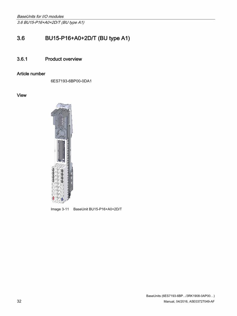
3.6 BU15-P16+A0+2D/T (BU type A1)
3.6.1 Product overview
Article number 6ES7193-6BP00-0DA1
View
Image 3-11 BaseUnit BU15-P16+A0+2D/T

BaseUnits for I/O modules 3.6 BU15-P16+A0+2D/T (BU type A1)
BaseUnits (6ES7193-6BP.../3RK1908-0AP00…) Manual, 04/2016, A5E03727049-AF 33
Properties ● BaseUnit for all I/O modules of BaseUnit type "A1". Can be recognized by the last two
digits of the article number.
Note
Using another I/O module can trigger an internal, non-exchangeable fuse and you must exchange the terminal box.
– Supply voltage (L+ terminal, ground): Max. 24 VDC/10 A
– Current-carrying capacity per process terminal (terminal 1 to 16): Max. 2 A
● The BaseUnit opens up a new potential group. The self-assembling voltage buses P1 and P2, and the AUX busbar are interrupted to the left-hand neighboring module (BaseUnit, interface module).
● No access to the AUX busbar via terminals
● 16 terminals to the process (assignment through the I/O module)
● Recording of the terminal temperature for internal temperature compensation at connected thermocouples
● Connection method using push-in terminals
Maximum configuration per potential group The number of I/O modules that can be used per potential group depends on the following factors:
1. Total power requirement of all I/O modules operated on this potential group
2. Total power requirement of all loads connected externally to this potential group
The total current calculated from the sum of 1 and 2 may not exceed 10 A.

BaseUnits for I/O modules 3.6 BU15-P16+A0+2D/T (BU type A1)
BaseUnits (6ES7193-6BP.../3RK1908-0AP00…) 34 Manual, 04/2016, A5E03727049-AF
3.6.2 Connection
Pin assignment
Table 3- 6 Pin assignment for BaseUnit BU15-P16+A0+2D/T
Pin assignment for BaseUnit BU15-P16+A0+2D/T Terminal Descriptions 1 to 16 Assignment is determined by the I/O module. See manual I/O Module
(http://support.automation.siemens.com/WW/view/en/55679691/133300). (AUX) No access to the AUX busbar via terminals L+, P1 / M, P2 L+: Rated supply voltage 24 V DC with max. 10 A
M: Ground
Block diagram
① Backplane bus ② I/O module ③ Internal reference junction for temperature compensation ④ Terminals with connection to the I/O module ⑤ Interrupted voltage buses with connection to the terminals for infeed ⑥ Disconnected AUX busbar not connected to the terminals
Image 3-12 Block diagram BU15-P16+A0+2D/T

BaseUnits for I/O modules 3.6 BU15-P16+A0+2D/T (BU type A1)
BaseUnits (6ES7193-6BP.../3RK1908-0AP00…) Manual, 04/2016, A5E03727049-AF 35
3.6.3 Technical specifications
Technical specifications of the BaseUnit BU15-P16+A0+2D/T
6ES7193-6BP00-0DA1 Product type designation BU15-P16+A0+2D/T Supply voltage Rated value (DC) 24 V External fuse for power supply lines Yes: 24 VDC / 10 A miniature circuit breaker with
type B or C tripping characteristic Current carrying capacity Current carrying capacity up to 60 °C, max. 10 A Analog inputs Thermocouple (TC) Temperature compensation • Internal temperature compensation Yes
Electrical isolation between backplane bus and supply voltage Yes between the potential groups Yes Isolation Isolation tested with 707 VDC (type test) Dimensions Width 15 mm Height 117 mm Weights Weight, approx. 40 g

BaseUnits for I/O modules 3.7 BU15-P16+A0+12B/T (BU type A1)
BaseUnits (6ES7193-6BP.../3RK1908-0AP00…) 36 Manual, 04/2016, A5E03727049-AF
3.7 BU15-P16+A0+12B/T (BU type A1)
3.7.1 Product overview
Article number 6ES7193-6BP40-0BA1
View
Image 3-13 BaseUnit BU15-P16+A0+12B/T

BaseUnits for I/O modules 3.7 BU15-P16+A0+12B/T (BU type A1)
BaseUnits (6ES7193-6BP.../3RK1908-0AP00…) Manual, 04/2016, A5E03727049-AF 37
Properties ● BaseUnit suitable for all I/O modules of BaseUnit type "A1". Can be recognized by the
last two digits of the article number.
Note
Using another I/O module can trigger an internal, non-exchangeable fuse and you must exchange the terminal box.
– Current-carrying capacity per process terminal (terminal 1 to 16): Max. 2 A
● The BaseUnit conducts the potential group further. The self-assembling voltage buses P1 and P2, and the AUX busbar are connected to the left-hand neighboring module (BaseUnit).
● No access to the AUX busbar via terminals
● 16 terminals to the process (assignment through the I/O module)
● 2x5 additional terminals for feeding a supply voltage up to 24 VDC/ 10 A. The additional terminals are not connected to the I/O module.
● Recording of the terminal temperature for internal temperature compensation at connected thermocouples
● Connection method using push-in terminals

BaseUnits for I/O modules 3.7 BU15-P16+A0+12B/T (BU type A1)
BaseUnits (6ES7193-6BP.../3RK1908-0AP00…) 38 Manual, 04/2016, A5E03727049-AF
3.7.2 Connection
Pin assignment
Table 3- 7 Pin assignment for BaseUnit BU15-P16+A0+12B/T
Pin assignment for BaseUnit BU15-P16+A0+12B/T Terminal Descriptions 1 to 16 Assignment is determined by the I/O module. See manual I/O Module
(http://support.automation.siemens.com/WW/view/en/55679691/133300). 1B, 2B, 3B, 4B, 5B / 1C, 2C, 3C, 4C, 5C
2 x 5 add-on terminals for the infeed of a supply voltage up to 24 V DC with max. 10 A
(AUX) No access to the AUX busbar via terminals L+, P1 / M, P2 L+: Rated supply voltage 24 V DC with max. 10 A
M: Ground
Block diagram
① Backplane bus ② I/O module ③ Internal reference junction for temperature compensation ④ Terminals with connection to the I/O module ⑤ Additional terminals for feeding an additional supply voltage ⑥ Connected voltage buses with connection to the terminals ⑦ Connected AUX busbar not connected to the terminals
Image 3-14 Block diagram BU15-P16+A0+12B/T

BaseUnits for I/O modules 3.7 BU15-P16+A0+12B/T (BU type A1)
BaseUnits (6ES7193-6BP.../3RK1908-0AP00…) Manual, 04/2016, A5E03727049-AF 39
3.7.3 Technical specifications
Technical specifications of the BaseUnit BU15-P16+A0+12B/T
6ES7193-6BP40-0BA1 Product type designation BU15-P16+A0+12B/T Supply voltage Rated value (DC) 24 V External fuse for power supply lines Yes: 24 VDC / 10 A miniature circuit breaker with
type B or C tripping characteristic Current carrying capacity Current carrying capacity up to 60 °C, max. 10 A Analog inputs Thermocouple (TC) Temperature compensation • Internal temperature compensation Yes
Electrical isolation between backplane bus and supply voltage Yes Isolation Isolation tested with 707 VDC (type test) Dimensions Width 15 mm Height 141 mm Weights Weight, approx. 50 g

BaseUnits for I/O modules 3.8 BU15-P16+A0+2B/T (BU type A1)
BaseUnits (6ES7193-6BP.../3RK1908-0AP00…) 40 Manual, 04/2016, A5E03727049-AF
3.8 BU15-P16+A0+2B/T (BU type A1)
3.8.1 Product overview
Article number 6ES7193-6BP00-0BA1
View
Image 3-15 BaseUnit BU15-P16+A0+2B/T

BaseUnits for I/O modules 3.8 BU15-P16+A0+2B/T (BU type A1)
BaseUnits (6ES7193-6BP.../3RK1908-0AP00…) Manual, 04/2016, A5E03727049-AF 41
Properties ● BaseUnit suitable for all I/O modules of BaseUnit type "A1". Can be recognized by the
last two digits of the article number.
Note
Using another I/O module can trigger an internal, non-exchangeable fuse and you must exchange the terminal box.
– Current-carrying capacity per process terminal (terminal 1 to 16): Max. 2 A
● The BaseUnit conducts the potential group further. The self-assembling voltage buses P1 and P2, and the AUX busbar are connected to the left-hand neighboring module (BaseUnit).
● No access to the AUX busbar via terminals
● 16 terminals to the process (assignment through the I/O module)
● Recording of the terminal temperature for internal temperature compensation at connected thermocouples
● Connection method using push-in terminals

BaseUnits for I/O modules 3.8 BU15-P16+A0+2B/T (BU type A1)
BaseUnits (6ES7193-6BP.../3RK1908-0AP00…) 42 Manual, 04/2016, A5E03727049-AF
3.8.2 Connection
Pin assignment
Table 3- 8 Pin assignment for BaseUnit BU15-P16+A0+2B/T
Pin assignment for BaseUnit BU15-P16+A0+2B/T Terminal Descriptions 1 to 16 Assignment is determined by the I/O module. See manual I/O Module
(http://support.automation.siemens.com/WW/view/en/55679691/133300). (AUX) No access to the AUX busbar via terminals L+, P1 / M, P2 L+: Rated supply voltage 24 V DC with max. 10 A
M: Ground
Block diagram
① Backplane bus ② I/O module ③ Internal reference junction for temperature compensation ④ Terminals with connection to the I/O module ⑤ Connected voltage buses with connection to the terminals ⑥ Connected AUX busbar not connected to the terminals
Image 3-16 Block diagram BU15-P16+A0+2B/T

BaseUnits for I/O modules 3.8 BU15-P16+A0+2B/T (BU type A1)
BaseUnits (6ES7193-6BP.../3RK1908-0AP00…) Manual, 04/2016, A5E03727049-AF 43
3.8.3 Technical specifications
Technical specifications of the BaseUnit BU15-P16+A0+2B/T
6ES7193-6BP00-0BA1 Product type designation BU15-P16+A0+2B/T Supply voltage Rated value (DC) 24 V External fuse for power supply lines Yes: 24 VDC / 10 A miniature circuit breaker with
type B or C tripping characteristic Current carrying capacity Current carrying capacity up to 60 °C, max. 10 A Analog inputs Thermocouple (TC) Temperature compensation • Internal temperature compensation Yes
Electrical isolation between backplane bus and supply voltage Yes Isolation Isolation tested with 707 VDC (type test) Dimensions Width 15 mm Height 117 mm Weights Weight, approx. 40 g

BaseUnits for I/O modules 3.9 BU20-P12+A4+0B (BU type B0)
BaseUnits (6ES7193-6BP.../3RK1908-0AP00…) 44 Manual, 04/2016, A5E03727049-AF
3.9 BU20-P12+A4+0B (BU type B0)
3.9.1 Product overview
Article number 6ES7193-6BP20-0BB0
View
Image 3-17 BaseUnit BU20-P12+A4+0B
Properties ● BaseUnit suitable for all I/O modules of the BaseUnit type "B0/B1". Can be recognized by
the last two digits of the article number.
– Current-carrying capacity per process terminal (terminal 1 to 12): Max. 5 A
● The BaseUnit conducts the potential group further. The self-assembling voltage buses P1 and P2, and the AUX busbar are connected to the left-hand neighboring module (BaseUnit).
● Access to the AUX busbar via terminals
● 12 terminals to the process (assignment with the I/O module)
● Connection method using push-in terminals

BaseUnits for I/O modules 3.9 BU20-P12+A4+0B (BU type B0)
BaseUnits (6ES7193-6BP.../3RK1908-0AP00…) Manual, 04/2016, A5E03727049-AF 45
3.9.2 Connecting
Pin assignment
Table 3- 9 Pin assignment for BaseUnit BU20-P12+A4+0B
Pin assignment for BaseUnit BU20-P12+A4+0B Terminal Descriptions 1 to 12 Assignment is determined by the I/O module.
See manual I/O Module (http://support.automation.siemens.com/WW/view/en/55679691/133300).
1A, 2A, 3A, 4A, AUX Protective conductor connection or voltage bus (freely usable up to 230 V AC/ DC with max 10 A). If you connect a voltage, it must belong to the same potential group as the rated supply voltage.
Block diagram
① Backplane bus ② I/O module ③ Terminals with connection to the I/O module ④ Connected voltage buses without connection to the terminals ⑤ Connected AUX busbar connected to the terminals
Image 3-18 Block diagram BU20-P12+A4+0B

BaseUnits for I/O modules 3.9 BU20-P12+A4+0B (BU type B0)
BaseUnits (6ES7193-6BP.../3RK1908-0AP00…) 46 Manual, 04/2016, A5E03727049-AF
3.9.3 Technical specifications
Technical specifications of the BaseUnit BU20-P12+A4+0B
6ES7193-6BP20-0BB0 Product type designation BU20-P12+A4+0B Supply voltage Rated value (DC) 24 V Rated value (AC) 230 V; 110 V Current carrying capacity Current carrying capacity up to 60 °C, max. 10 A Electrical isolation between backplane bus and supply voltage Yes Isolation Isolation tested with 3250 VDC Dimensions Width 20 mm Height 117 mm Weights Weight, approx. 48 g

BaseUnits for I/O modules 3.10 BU20-P12+A0+4B (BU type B1)
BaseUnits (6ES7193-6BP.../3RK1908-0AP00…) Manual, 04/2016, A5E03727049-AF 47
3.10 BU20-P12+A0+4B (BU type B1)
3.10.1 Product overview
Article number 6ES7193-6BP20-0BB1
View
Image 3-19 BaseUnit BU20-P12+A0+4B
Properties ● BaseUnit suitable for all I/O modules of the BaseUnit type "B1". Can be recognized by the
last two digits of the article number.
– Current-carrying capacity per process terminal (terminal 1 to 12): Max. 5 A
● The BaseUnit conducts the potential group further. The self-assembling voltage buses P1 and P2, and the AUX busbar are connected to the left-hand neighboring module (BaseUnit).
● No access to the power and AUX busbars via terminals
● 12 terminals to the process (assignment with the I/O module)
● Connection method using push-in terminals

BaseUnits for I/O modules 3.10 BU20-P12+A0+4B (BU type B1)
BaseUnits (6ES7193-6BP.../3RK1908-0AP00…) 48 Manual, 04/2016, A5E03727049-AF
3.10.2 Connecting up
Pin assignment
Table 3- 10 Pin assignment for BaseUnit BU20-P12+A0+4B
Pin assignment for BaseUnit BU20-P12+A0+4B Terminal Descriptions 1 to 12 Assignment is determined by the I/O module.
See manual I/O Module (AUX) No access to the AUX busbar via terminals 1L, 2L, (P1) / 1N, 2N, (P2) 1L, 2L: Rated supply voltage up to 230 V AC with max. 10 A
1N, 2N: Neutral/ground
Block diagram
① Backplane bus ② I/O module ③ Terminals with connection to the I/O module ④ Connected voltage buses without connection to the terminals ⑤ Connected AUX busbar not connected to the terminals
Image 3-20 Block diagram BU20-P12+A0+4B

BaseUnits for I/O modules 3.10 BU20-P12+A0+4B (BU type B1)
BaseUnits (6ES7193-6BP.../3RK1908-0AP00…) Manual, 04/2016, A5E03727049-AF 49
3.10.3 Technical specifications
Technical specifications of the BaseUnit BU20-P12+A0+4B
6ES7193-6BP20-0BB1 Product type designation BU20-P12+A0+4B Supply voltage Rated value (DC) 24 V Rated value (AC) 230 V; 110 V Current carrying capacity Current carrying capacity up to 60 °C, max. 10 A Electrical isolation between backplane bus and supply voltage Yes between process terminals and supply voltage Yes between Powerbus and supply voltage Yes Isolation Isolation tested with 3250 VDC Dimensions Width 20 mm Height 117 mm Weights Weight, approx. 48 g

BaseUnits for I/O modules 3.11 BU20-P6+A2+4D (BU type C0)
BaseUnits (6ES7193-6BP.../3RK1908-0AP00…) 50 Manual, 04/2016, A5E03727049-AF
3.11 BU20-P6+A2+4D (BU type C0)
3.11.1 Product overview
Article number 6ES7193-6BP20-0DC0
View
Image 3-21 BaseUnit BU20-P6+A2+4D

BaseUnits for I/O modules 3.11 BU20-P6+A2+4D (BU type C0)
BaseUnits (6ES7193-6BP.../3RK1908-0AP00…) Manual, 04/2016, A5E03727049-AF 51
Properties ● BaseUnit suitable for all I/O modules of BaseUnit type "C0/C1". Can be recognized by the
last two digits of the article number.
– Supply voltage (terminal 1L, 2L / 1N, 2N): Max. 230 V AC/10 A
– Current-carrying capacity per process terminal (terminal 1 to 4): Max. 5 A
– Current carrying capacity per process terminal (terminal 5 and 6): Max. 10 A
● The BaseUnit opens up a new potential group by means of the inserted I/O module. The self-assembling voltage buses P1 and P2, and the AUX busbar are interrupted to the left-hand neighboring module (BaseUnit, interface module).
● Access to the AUX busbar via terminals
● 6 terminals to the process (assignment with the I/O module)
● Two AUX terminals for connecting a PE terminal or potential. The AUX busbar is not connected to the I/O module.
● Connection method using push-in terminals
Maximum configuration per potential group The number of I/O modules that can be used per potential group depends on the following factors:
1. Total power requirement of all I/O modules operated on this potential group
2. Total power requirement of all loads connected externally to this potential group
The total current calculated from the sum of 1 and 2 may not exceed 10 A.

BaseUnits for I/O modules 3.11 BU20-P6+A2+4D (BU type C0)
BaseUnits (6ES7193-6BP.../3RK1908-0AP00…) 52 Manual, 04/2016, A5E03727049-AF
3.11.2 Connecting
Pin assignment
Table 3- 11 Pin assignment for BaseUnit BU20-P6+A2+4D
Pin assignment for BaseUnit BU20-P12+A2+4D Terminal Descriptions 1 to 6 Assignment is determined by the I/O module.
See manual I/O Module (http://support.automation.siemens.com/WW/view/en/55679691/133300).
1A, 2A, AUX Protective conductor connection or voltage bus freely usable up to 230 V AC/ DC with max 10 A. If you connect a voltage, it must belong to the same potential group as the rated supply voltage.
1L, 2L, (P1) / 1N, 2N, (P2) 1L, 2L: Rated supply voltage up to 230 V AC with max. 10 A 1N, 2N: Neutral/ground
Block diagram
① Backplane bus ② I/O module ③ Terminals with connection to the I/O module ④ Interrupted voltage buses with connection to the terminals for infeed (via the plugged-in I/O
module) ⑤ Disconnected AUX busbar connected to the terminals
Image 3-22 Block diagram BU20-P6+A2+4D

BaseUnits for I/O modules 3.11 BU20-P6+A2+4D (BU type C0)
BaseUnits (6ES7193-6BP.../3RK1908-0AP00…) Manual, 04/2016, A5E03727049-AF 53
3.11.3 Technical specifications
Technical specifications of the BaseUnit BU20-P6+A2+4D
6ES7193-6BP20-0DC0 Product type designation BU20-P6+A2+4D Supply voltage Rated value (DC) 24 V; 30 V Rated value (AC) 230 V; 110 V External fuse for power supply lines Yes; 10 A miniature circuit breaker with type B or
C tripping characteristic for the respective rated supply voltage
Current carrying capacity Current carrying capacity up to 60 °C, max. 10 A Electrical isolation between backplane bus and supply voltage Yes between process terminals and supply voltage Yes Isolation Isolation tested with 3250 VDC Dimensions Width 20 mm Height 117 mm Weights Weight, approx. 47 g

BaseUnits for I/O modules 3.12 BU20-P6+A2+4B (BU type C1)
BaseUnits (6ES7193-6BP.../3RK1908-0AP00…) 54 Manual, 04/2016, A5E03727049-AF
3.12 BU20-P6+A2+4B (BU type C1)
3.12.1 Product overview
Article number 6ES7193-6BP20-0BC1
View
Image 3-23 BaseUnit BU20-P6+A2+4B

BaseUnits for I/O modules 3.12 BU20-P6+A2+4B (BU type C1)
BaseUnits (6ES7193-6BP.../3RK1908-0AP00…) Manual, 04/2016, A5E03727049-AF 55
Properties ● BaseUnit suitable for all I/O modules of BaseUnit type "C0/C1". Can be recognized by the
last two digits of the article number.
– Current-carrying capacity per process terminal (terminal 1 to 4): Max. 5 A
– Current carrying capacity per process terminal (terminal 5 and 6): Max. 10 A
● The BaseUnit conducts the potential group further. The self-assembling voltage buses P1 and P2, and the AUX bus are connected to the left-hand neighboring module (BaseUnit).
● Access to the AUX busbar via terminals
● 6 terminals to the process (assignment with the I/O module)
● Two AUX terminals for connecting a PE terminal or potential. The AUX busbar is not connected to the I/O module.
● Connection method using push-in terminals

BaseUnits for I/O modules 3.12 BU20-P6+A2+4B (BU type C1)
BaseUnits (6ES7193-6BP.../3RK1908-0AP00…) 56 Manual, 04/2016, A5E03727049-AF
3.12.2 Connecting
Pin assignment
Table 3- 12 Pin assignment for BaseUnit BU20-P6+A2+4B
Pin assignment for BaseUnit BU20-P12+A2+4B Terminal Descriptions 1 to 6 Assignment is determined by the I/O module.
See manual I/O Module (http://support.automation.siemens.com/WW/view/en/55679691/133300).
1A, 2A, AUX Protective conductor connection or voltage bus freely usable up to 230 V AC/ DC with max 10 A. If you connect a voltage, it must belong to the same potential group as the rated supply voltage.
1L, 2L, (P1) / 1N, 2N, (P2) 1L, 2L: Rated supply voltage up to 230 V AC with max. 10 A 1N, 2N: Neutral/ground
Block diagram
① Backplane bus ② Power module ③ Terminals with connection to the I/O module ④ Connected voltage buses with connection to the terminals for infeed (via the plugged-in I/O
module) ⑤ Connected AUX busbar connected to the terminals
Image 3-24 Block diagram BU20-P6+A2+4B

BaseUnits for I/O modules 3.12 BU20-P6+A2+4B (BU type C1)
BaseUnits (6ES7193-6BP.../3RK1908-0AP00…) Manual, 04/2016, A5E03727049-AF 57
3.12.3 Technical specifications
Technical specifications of the BaseUnit BU20-P6+A2+4B
6ES7193-6BP20-0BC1 Product type designation BU20-P6+A2+4B Supply voltage Rated value (DC) 24 V; 30 V Rated value (AC) 230 V; 110 V Current carrying capacity Current carrying capacity up to 60 °C, max. 10 A Electrical isolation between backplane bus and supply voltage Yes between process terminals and supply voltage Yes Isolation Isolation tested with 3250 VDC Dimensions Width 20 mm Height 117 mm Weights Weight, approx. 47 g

BaseUnits for I/O modules 3.13 BU20-P12+A0+0B (BU type D0)
BaseUnits (6ES7193-6BP.../3RK1908-0AP00…) 58 Manual, 04/2016, A5E03727049-AF
3.13 BU20-P12+A0+0B (BU type D0)
3.13.1 Product overview
Article number 6ES7193-6BP00-0BD0
View
Image 3-25 BaseUnit BU20-P12+A0+0B

BaseUnits for I/O modules 3.13 BU20-P12+A0+0B (BU type D0)
BaseUnits (6ES7193-6BP.../3RK1908-0AP00…) Manual, 04/2016, A5E03727049-AF 59
Properties ● BaseUnit suitable for all I/O modules of the BaseUnit type "D0". Can be recognized by the
last two digits of the article number.
– Current-carrying capacity per process terminal (terminal 1 to 12): Max. 5 A
● The BaseUnit conducts the potential group further. The self-assembling voltage buses P1 and P2, and the AUX busbar are connected to the left-hand neighboring module (BaseUnit).
● No access to the power and AUX busbars via terminals
● 12 terminals to the process (assignment with the I/O module)
● Connection method using push-in terminals
Note
The shield connection (shield support and shield terminal) is not intended for BaseUnit BU20-P12+A0+0B and must not be installed.

BaseUnits for I/O modules 3.13 BU20-P12+A0+0B (BU type D0)
BaseUnits (6ES7193-6BP.../3RK1908-0AP00…) 60 Manual, 04/2016, A5E03727049-AF
3.13.2 Connecting
Pin assignment
Table 3- 13 Pin assignment for BaseUnit BU20-P12+A0+0B
Pin assignment for BaseUnit BU20-P12+A0+0B Terminal Descriptions 1 to 12 Assignment is determined by the I/O module.
See manual I/O Module (http://support.automation.siemens.com/WW/view/en/55679691/133300)
Block diagram
① Backplane bus ② I/O module ③ Terminals with connection to the I/O module ④ Connected voltage buses without connection to the terminals ⑤ Connected AUX busbar not connected to the terminals
Image 3-26 Block diagram BU20-P12+A0+0B

BaseUnits for I/O modules 3.13 BU20-P12+A0+0B (BU type D0)
BaseUnits (6ES7193-6BP.../3RK1908-0AP00…) Manual, 04/2016, A5E03727049-AF 61
3.13.3 Technical specifications
Technical specifications of the BaseUnit BU20-P12+A0+0B
6ES7193-6BP00-0BD0 Product type designation BU20-P12+A0+0B Supply voltage Rated value (AC) 400 V; 230 VAC (L1/ N) Current carrying capacity Current carrying capacity up to 60 °C, max. 5 A Electrical isolation between backplane bus and supply voltage Yes Isolation Isolation tested with 3250 VDC Dimensions Width 20 mm Height 117 mm Weights Weight, approx. 47 g

BaseUnits for I/O modules 3.14 BU20-P8+A4+0B (BU type F0)
BaseUnits (6ES7193-6BP.../3RK1908-0AP00…) 62 Manual, 04/2016, A5E03727049-AF
3.14 BU20-P8+A4+0B (BU type F0)
3.14.1 Product overview Note when you use the AUX terminals as a PE busbar:
NOTICE
If AUX is used as PE, AUX must be identified as green-yellow (e.g., gn/ye color-coded labels). These identifications must be removed if the terminals are no longer used as PE.
Article number 6ES7193-6BP20-0BF0
View
Image 3-27 BaseUnit BU20-P8+A4+0B

BaseUnits for I/O modules 3.14 BU20-P8+A4+0B (BU type F0)
BaseUnits (6ES7193-6BP.../3RK1908-0AP00…) Manual, 04/2016, A5E03727049-AF 63
Properties ● BaseUnit suitable for all I/O modules of the BaseUnit type "F0". Can be recognized by the
last two digits of the order number.
– Current carrying capacity per process terminal (terminals 1 to 4 and 9 to 12): Max. 5 A
● The BaseUnit loops the potential group through with the self-assembling voltage buses P1, P2 and the AUX bus of the left-hand neighboring module (BaseUnit).
● Access to the AUX busbar via terminals 1A to 4A
● 8 terminals to the process (occupied by the I/O module)
● Connection method using push-in terminals

BaseUnits for I/O modules 3.14 BU20-P8+A4+0B (BU type F0)
BaseUnits (6ES7193-6BP.../3RK1908-0AP00…) 64 Manual, 04/2016, A5E03727049-AF
3.14.2 Connecting up
Pin assignment Terminals of a potential group Fail-safe module
Overvoltage category 3 Non-fail-safe module
Overvoltage category 2 1 to 4 Up to 230 VAC/VDC (AC only one phase)
Assignment is determined by the I/O module. See manual I/O Module
(http://support.automation.siemens.com/WW/view/en/55679691/133300) 9 to 12 Safe extra low voltage SELV/PELV
Assignment is determined by the I/O module. See manual I/O Module
(http://support.automation.siemens.com/WW/view/en/55679691/133300) P1, P2, AUX (1A to 4A) SELV/PELV
(max. 10 A) SELV/PELV
or Up to 230 VAC/VDC (AC only one phase)
(max. 10 A)
The AUX terminals may only be used with an identical voltage or PE associated with the supply voltage.
Block diagram
① Backplane bus ② I/O module ③ Terminals with connection to the I/O module ④ Connected voltage buses without connection to the terminals ⑤ Connected AUX busbar connected to the terminals
Image 3-28 Block diagram BU20-P8+A4+0B

BaseUnits for I/O modules 3.14 BU20-P8+A4+0B (BU type F0)
BaseUnits (6ES7193-6BP.../3RK1908-0AP00…) Manual, 04/2016, A5E03727049-AF 65
3.14.3 Technical specifications
Technical specifications of the BaseUnit BU20-P8+A4+0B
6ES7193-6BP20-0BF0 Product type designation BU20-P8+A4+0B Supply voltage Rated value (DC) See manual Rated value (AC) See manual Current carrying capacity Current carrying capacity up to 60 °C, max. 10 A Electrical isolation between backplane bus and supply voltage Yes between process terminals and supply voltage Yes between Powerbus and supply voltage Yes Insulation Insulation tested with 3250 VDC 1 min (type test); 2545 VDC 2 s (rou-
tine test) Dimensions Width 20 mm Height 117 mm Weights Weight, approx. 48 g

BaseUnits (6ES7193-6BP.../3RK1908-0AP00…) 66 Manual, 04/2016, A5E03727049-AF
BaseUnits for motor starters 4 4.1 Introduction
Properties of the infeed bus
● The infeed bus is set up by connecting the BaseUnits, and wiring takes place automatically
● The infeed bus distributes the energy to the SIMATIC ET 200SP motor starter within one load group
● The max. current carrying capacity is up to 32 A (3-phase)
– With energy bus infeed (for one load group) and motor connection
– Infeed bus: 3-pole + PE
– The voltage range for power infeed is 48 … 500 V AC
You must observe the deratings depending on the configuration.
Properties of the self-assembling voltage bus (power bus)
● Maximum current: 7 A
● Rated voltage: 24 V
You must observe the deratings depending on the configuration.
AUX1 bus
The AUX1 bus is not supported in the BaseUnits of the SIMATIC ET 200SP motor starters.
You can find assembly rules of the BaseUnits for the SIMATIC ET 200SP motor starter in the System Manual SIMATIC ET 200SP motor starters.
WARNING
Infeed bus - electric shock
You must provide the infeed bus with a touch protection cover on the right (Article No.: 3RK1308-1DA00-2BP0).
Failure to do so will result in the danger of electric shock.
WARNING
BaseUnit without motor starter - electric shock
If you install a BaseUnit without motor starter in the ET 200SP system (e.g. options handling), you must provide the BaseUnit with a cover (Article No: 3RK1908-1CA00-0BP0).
Failure to do so will result in the danger of electric shock.

BaseUnits for motor starters 4.2 BU30-MS1 - BaseUnit with 24 V DC and 500 V AC infeed
BaseUnits (6ES7193-6BP.../3RK1908-0AP00…) Manual, 04/2016, A5E03727049-AF 67
4.2 BU30-MS1 - BaseUnit with 24 V DC and 500 V AC infeed
4.2.1 Product overview
Article number 3RK1908-0AP00-0AP0
View
Image 4-1 BaseUnit with 24 V DC and 500 V AC infeed

BaseUnits for motor starters 4.2 BU30-MS1 - BaseUnit with 24 V DC and 500 V AC infeed
BaseUnits (6ES7193-6BP.../3RK1908-0AP00…) 68 Manual, 04/2016, A5E03727049-AF
Properties ● BaseUnit suitable for all SIMATIC ET 200SP High Feature motor starters
● The BaseUnit opens a new potential group (24 V DC). The power buses P1 and P2 are interrupted to the left-hand neighboring module (BaseUnit, interface module/CPU).
● The BaseUnit opens a new potential group (500 V DC). The infeed bus L1 (L), L2 (N), L3, PE is interrupted to the left-hand BaseUnit of the ET 200SP motor starter.
● Connection method using push-in terminals
● The touch protection cover for the infeed bus is not included in the scope of delivery.
Maximum configuration per voltage group (24 V DC) The number of I/O modules that can be used per potential group depends on the following factors:
1. Total power requirement of all I/O modules operated on this potential group
2. Total power requirement of all loads connected externally to this potential group
The total overall current calculated according to 1. and 2. must not exceed 7 A.
Maximum configuration of the infeed bus (500 V AC) The number of motor starters that can be used per infeed group depends on the following factors:
1. Total current requirement of all motor starters operated on this infeed group.
2. Ambient temperature and installation type in which the motor starters are operated. You can find further information in the derating table in the Manual SIMATIC ET 200SP motor starters (https://support.industry.siemens.com/cs/ww/en/view/109479973).

BaseUnits for motor starters 4.2 BU30-MS1 - BaseUnit with 24 V DC and 500 V AC infeed
BaseUnits (6ES7193-6BP.../3RK1908-0AP00…) Manual, 04/2016, A5E03727049-AF 69
4.2.2 Connection
Pin assignment
Table 4- 1 Pin assignment for BaseUnit with 24 V DC and 500 V AC infeed
Pin assignment for BaseUnit with 24 V DC and 500 V AC infeed Terminal Descriptions L1(L), L2(N), L3, PE Power supply
Assignment is determined by the motor starter. See Manual ET 200SP motor starters (https://support.industry.siemens.com/cs/ww/en/view/109479973).
T1, T2, T3, PE Motor feeder 24 V DC, M 24 V DC: Rated supply voltage 24 V DC with max. 7 A
M: Ground

BaseUnits for motor starters 4.2 BU30-MS1 - BaseUnit with 24 V DC and 500 V AC infeed
BaseUnits (6ES7193-6BP.../3RK1908-0AP00…) 70 Manual, 04/2016, A5E03727049-AF
Block diagram The figure below shows the block diagram of the BaseUnit with 24 V DC and 500 V AC infeed.
① Backplane bus ② Motor starter module ③ Interrupted busbars 24 V DC, M ④ Interrupted AUX bus ⑤ Terminals for 24V DC and ground M ⑥ Interrupted busbars for the infeed system L1(L), L2(N), L3, PE ⑦ Infeed terminal for protective ground PE ⑧ Infeed terminal for L3 ⑨ Infeed terminal for L2(N) ⑩ Infeed terminal for L1(L) ⑪ Terminal for protective ground PE ⑫ Motor feeder terminal T3 ⑬ Motor feeder terminal T2 ⑭ Motor feeder terminal T1
Image 4-2 Block diagram BaseUnit with 24 V DC and 500 V AC infeed

BaseUnits for motor starters 4.2 BU30-MS1 - BaseUnit with 24 V DC and 500 V AC infeed
BaseUnits (6ES7193-6BP.../3RK1908-0AP00…) Manual, 04/2016, A5E03727049-AF 71
4.2.3 Technical specifications
Technical specifications of the BaseUnit with 24 V DC and 500 V AC infeed
3RK1908-0AP00-0AP0 Product type designation BU30-MS1 Galvanic isolation Galvanic isolation between backplane bus und supply voltage
Yes
Insulation tested with 2500 V AC Rated operating voltage 24 V AC Max. operating current 7 A (observe derating) Rated insulation voltage in accordance with IEC 60947-1
500 V
Impulse withstand voltage/rated value Uimp accord-ing to IEC 60947-1
6 kV
Operating voltage range 48 V ... 500 V AC Max. current-carrying capacity 32 A (observe derating) Isolating function between the infeed terminals L1(L), L2 (N), L3 and motor feeder terminals T1, T2, T3 for motor starters in parking position, or removed motor starters: impulse withstand volt-age/rated value Uimp according to IEC 60947-1
6 kV
Wiring Push-in Required tools for releasing: Standard screwdriv-
er size 1 (SZF1 - 0.6x3.5) Dimensions Width 30 mm Height 215 mm Weights Weight, approx. 164 g

BaseUnits for motor starters 4.3 BU30-MS2 - BaseUnit with 500 V AC infeed
BaseUnits (6ES7193-6BP.../3RK1908-0AP00…) 72 Manual, 04/2016, A5E03727049-AF
4.3 BU30-MS2 - BaseUnit with 500 V AC infeed
4.3.1 Product overview
Article number 3RK1908-0AP00-0CP0
View
Image 4-3 BaseUnit with 500 V AC infeed

BaseUnits for motor starters 4.3 BU30-MS2 - BaseUnit with 500 V AC infeed
BaseUnits (6ES7193-6BP.../3RK1908-0AP00…) Manual, 04/2016, A5E03727049-AF 73
Properties ● BaseUnit suitable for all SIMATIC ET 200SP High Feature motor starters
● The BaseUnit handles the potential group (P1, P2) of the left-hand neighboring module.
● The BaseUnit opens a new 500 V AC infeed group. The potential group (24 V DC) is looped through.
● Connection method using push-in terminals
● The touch protection cover for the infeed bus is not included in the scope of delivery.
Maximum configuration of the infeed bus (500 V AC) The number of motor starters that can be used per infeed group depends on the following factors:
1. Total current requirement of all motor starters operated on this infeed group.
2. Ambient temperature and installation type in which the motor starters are operated. You can find further information in the derating table in the Manual SIMATIC ET 200SP motor starters.

BaseUnits for motor starters 4.3 BU30-MS2 - BaseUnit with 500 V AC infeed
BaseUnits (6ES7193-6BP.../3RK1908-0AP00…) 74 Manual, 04/2016, A5E03727049-AF
4.3.2 Connection
Pin assignment
Table 4- 2 Pin assignment for BaseUnit with 500 V AC infeed
Pin assignment for BaseUnit with 500 V AC infeed Terminal Descriptions L1(L), L2(N), L3, PE Power supply
Assignment is determined by the motor starter. See Manual ET 200SP motor starters (https://support.industry.siemens.com/cs/ww/en/view/109479973).
T1, T2, T3, PE Motor feeder
BaseUnits for motor starters 4.3 BU30-MS2 - BaseUnit with 500 V AC infeed
BaseUnits (6ES7193-6BP.../3RK1908-0AP00…) Manual, 04/2016, A5E03727049-AF 75
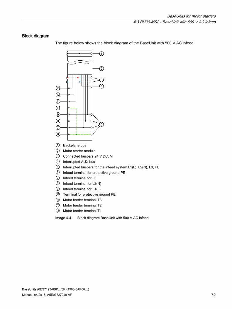
Block diagram The figure below shows the block diagram of the BaseUnit with 500 V AC infeed.
① Backplane bus ② Motor starter module ③ Connected busbars 24 V DC, M ④ Interrupted AUX bus ⑤ Interrupted busbars for the infeed system L1(L), L2(N), L3, PE ⑥ Infeed terminal for protective ground PE ⑦ Infeed terminal for L3 ⑧ Infeed terminal for L2(N) ⑨ Infeed terminal for L1(L) ⑩ Terminal for protective ground PE ⑪ Motor feeder terminal T3 ⑫ Motor feeder terminal T2 ⑬ Motor feeder terminal T1
Image 4-4 Block diagram BaseUnit with 500 V AC infeed

BaseUnits for motor starters 4.3 BU30-MS2 - BaseUnit with 500 V AC infeed
BaseUnits (6ES7193-6BP.../3RK1908-0AP00…) 76 Manual, 04/2016, A5E03727049-AF
4.3.3 Technical specifications
Technical specifications of the BaseUnit with 500 V AC infeed
3RK1908-0AP00-0CP0 Product type designation BU30-MS2 Galvanic isolation Galvanic isolation between backplane bus und supply voltage
Yes
Insulation tested with 2500 V AC Rated operating voltage 24 V AC Max. operating current 7 A (observe derating) Rated insulation voltage in accordance with IEC 60947-1
500 V
Impulse withstand voltage/rated value Uimp accord-ing to IEC 60947-1
6 kV
Operating voltage range 48 V ... 500 V AC Max. current-carrying capacity 32 A (observe derating) Isolating function between the infeed terminals L1(L), L2 (N), L3 and motor feeder terminals T1, T2, T3 for motor starters in parking position, or removed motor starters: impulse withstand volt-age/rated value Uimp according to IEC 60947-1
6 kV
Wiring Push-in Required tools for releasing: Standard screwdriv-
er size 1 (SZF1 - 0.6x3.5) Dimensions Width 30 mm Height 215 mm Weights Weight, approx. 160 g
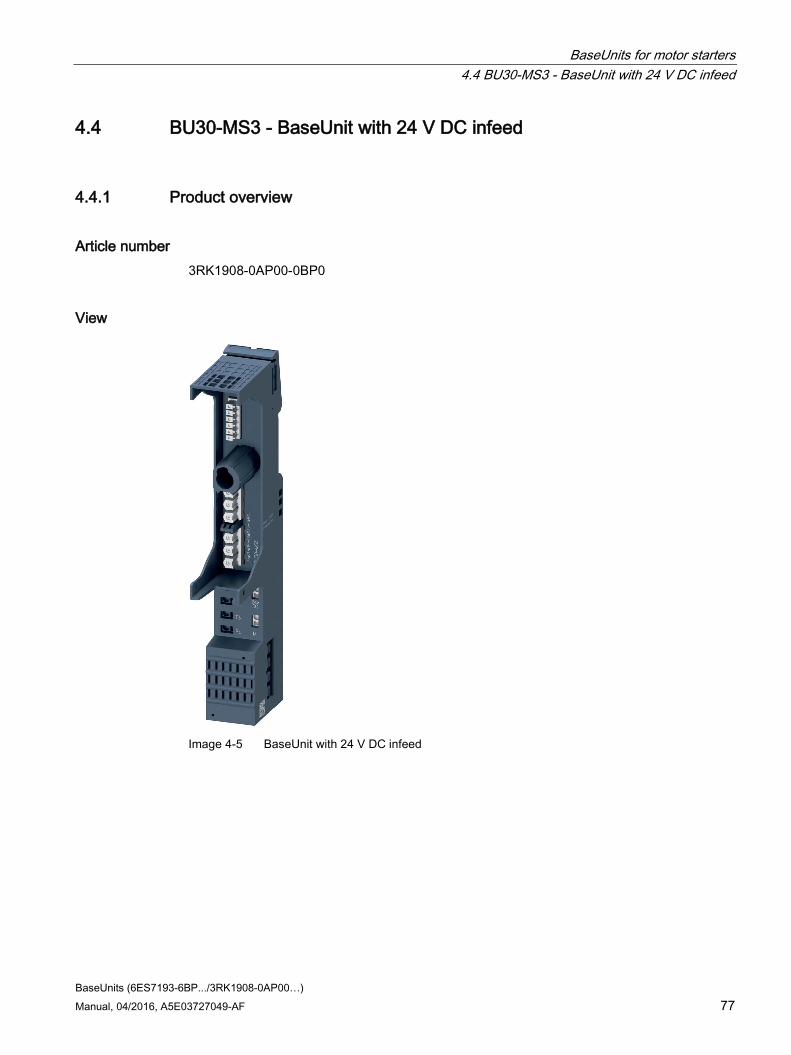
BaseUnits for motor starters 4.4 BU30-MS3 - BaseUnit with 24 V DC infeed
BaseUnits (6ES7193-6BP.../3RK1908-0AP00…) Manual, 04/2016, A5E03727049-AF 77
4.4 BU30-MS3 - BaseUnit with 24 V DC infeed
4.4.1 Product overview
Article number 3RK1908-0AP00-0BP0
View
Image 4-5 BaseUnit with 24 V DC infeed

BaseUnits for motor starters 4.4 BU30-MS3 - BaseUnit with 24 V DC infeed
BaseUnits (6ES7193-6BP.../3RK1908-0AP00…) 78 Manual, 04/2016, A5E03727049-AF
Properties ● BaseUnit suitable for all SIMATIC ET 200SP High Feature motor starters
● The BaseUnit opens a new potential group (24 V DC). The busbars P1 and P2 are interrupted to the left-hand neighboring module (BaseUnit, interface module/CPU).
● This BaseUnit handles the potential group/infeed bus (500 V AC) of the left-hand BaseUnit and loops this through.
● Connection method using push-in terminals
● The touch protection cover for the infeed bus is not included in the scope of delivery.
Maximum configuration per voltage group (24 V DC) The number of I/O modules that can be used per potential group depends on the following factors:
1. Total power requirement of all I/O modules operated on this potential group
2. Total power requirement of all loads connected externally to this potential group
The total overall current calculated according to 1. and 2. must not exceed 7 A.

BaseUnits for motor starters 4.4 BU30-MS3 - BaseUnit with 24 V DC infeed
BaseUnits (6ES7193-6BP.../3RK1908-0AP00…) Manual, 04/2016, A5E03727049-AF 79
4.4.2 Connection
Pin assignment
Table 4- 3 Pin assignment for BaseUnit with 24 V DC infeed
Pin assignment for BaseUnit with 24 V DC infeed Terminal Descriptions T1, T2, T3, PE Motor feeder 24 V DC, M 24 V DC: Rated supply voltage 24 V DC with max. 7 A
M: Ground
Block diagram The figure below shows the three-phase connection with 24 V infeed and mains infeed.
① Backplane bus ② Motor starter module ③ Interrupted busbars 24 V DC, M ④ Interrupted AUX bus ⑤ Terminal for 24 V DC and ground M ⑥ Connected busbars for the infeed system L1(L), L2(N), L3, PE ⑦ Terminal for protective ground PE ⑧ Motor feeder terminal T3 ⑨ Motor feeder terminal T2 ⑩ Motor feeder terminal T1
Image 4-6 Block diagram BaseUnit with 24 V DC infeed

BaseUnits for motor starters 4.4 BU30-MS3 - BaseUnit with 24 V DC infeed
BaseUnits (6ES7193-6BP.../3RK1908-0AP00…) 80 Manual, 04/2016, A5E03727049-AF
4.4.3 Technical specifications
Technical specifications of the BaseUnit with 24 V DC infeed
3RK1908-0AP00-0BP0 Product type designation BU30-MS3 Galvanic isolation Galvanic isolation between backplane bus und supply voltage
Yes
Insulation tested with 2500 V AC Rated operating voltage 24 V AC Max. operating current 7 A (observe derating) Rated insulation voltage in accordance with IEC 60947-1
500 V
Impulse withstand voltage/rated value Uimp accord-ing to IEC 60947-1
6 kV
Operating voltage range 48 V ... 500 V AC Max. current-carrying capacity 32 A (observe derating) Isolating function between the infeed terminals L1(L), L2 (N), L3 and motor feeder terminals T1, T2, T3 for motor starters in parking position, or removed motor starters: impulse withstand volt-age/rated value Uimp according to IEC 60947-1
6 kV
Wiring Push-in Required tools for releasing: Standard screwdriv-
er size 1 (SZF1 - 0.6x3.5) Dimensions Width 30 mm Height 215 mm Weights Weight, approx. 152 g

BaseUnits for motor starters 4.5 BU30-MS4 - BaseUnit without infeed
BaseUnits (6ES7193-6BP.../3RK1908-0AP00…) Manual, 04/2016, A5E03727049-AF 81
4.5 BU30-MS4 - BaseUnit without infeed
4.5.1 Product overview
Article number 3RK1908-0AP00-0DP0
View
Image 4-7 BaseUnit without infeed
Properties ● BaseUnit suitable for all SIMATIC ET 200SP High Feature motor starters
● No new potential groups are opened with this BaseUnit.
● The potential group (24 V DC) is looped through.
● The infeed group (500 V AC) is looped through.
● Connection method using push-in terminals
● The touch protection cover for the infeed bus is not included in the scope of delivery.

BaseUnits for motor starters 4.5 BU30-MS4 - BaseUnit without infeed
BaseUnits (6ES7193-6BP.../3RK1908-0AP00…) 82 Manual, 04/2016, A5E03727049-AF
4.5.2 Connection
Pin assignment
Table 4- 4 Pin assignment for BaseUnit without infeed
Pin assignment for BaseUnit without infeed Terminal Descriptions T1, T2, T3, PE Motor feeder
Block diagram The figure below shows the block diagram of the BaseUnit without infeed.
① Backplane bus ② Motor starter module ③ Connected busbars 24 V DC, M ④ Interrupted AUX busbar ⑤ Connected busbars for the infeed system L1(L), L2(N), L3, PE ⑥ Terminal for protective ground PE ⑦ Motor feeder terminal T3 ⑧ Motor feeder terminal T2 ⑨ Motor feeder terminal T1
Image 4-8 Block diagram BaseUnit without infeed

BaseUnits for motor starters 4.5 BU30-MS4 - BaseUnit without infeed
BaseUnits (6ES7193-6BP.../3RK1908-0AP00…) Manual, 04/2016, A5E03727049-AF 83
4.5.3 Technical specifications
Technical specifications of BaseUnit without infeed
3RK1908-0AP00-0DP0 Product type designation BU30-MS4 Galvanic isolation Galvanic isolation between backplane bus und supply voltage
Yes
Insulation tested with 2500 V AC Rated operating voltage 24 V AC Max. operating current 7 A (observe derating) Rated insulation voltage in accordance with IEC 60947-1
500 V
Impulse withstand voltage/rated value Uimp accord-ing to IEC 60947-1
6 kV
Operating voltage range 48 V ... 500 V AC Max. current-carrying capacity 32 A (observe derating) Isolating function between the infeed terminals L1(L), L2 (N), L3 and motor feeder terminals T1, T2, T3 for motor starters in parking position, or removed motor starters: impulse withstand volt-age/rated value Uimp according to IEC 60947-1
6 kV
Wiring Push-in Required tools for releasing: Standard screwdriv-
er size 1 (SZF1 - 0.6x3.5) Dimensions Width 30 mm Height 215 mm Weights Weight, approx. 150 g

BaseUnits (6ES7193-6BP.../3RK1908-0AP00…) 84 Manual, 04/2016, A5E03727049-AF
Dimension drawings of I/O modules A
Dimension drawing BU15-P16+A10+2D, BU15-P16+A10+2B, BU15-P16+A0+12D/T, BU15-P16+A0+12B/T
The figure below shows the dimension drawing of the BU15-P16+A10+2D with plugged-in I/O module as an example.
Image A-1 Dimension drawing BU15-P16+A10+2D

Dimension drawings of I/O modules
BaseUnits (6ES7193-6BP.../3RK1908-0AP00…) Manual, 04/2016, A5E03727049-AF 85
Dimension drawing BU15-P16+A0+2D, BU15-P16+A0+2B, BU15-P16+A0+2D/T, BU15-P16+A0+2B/T
The figure below shows the dimension drawing of the BU15-P16+A0+2D with plugged-in I/O module as an example.
Image A-2 Dimension drawing BU15-P16+A0+2D

Dimension drawings of I/O modules
BaseUnits (6ES7193-6BP.../3RK1908-0AP00…) 86 Manual, 04/2016, A5E03727049-AF
Dimension drawing BU20-P6+A2+4D, BU20-P6+A2+4B, BU20-P12+A4+0B, BU20-P12+A0+0B, BU20-P12+A0+4B, BU20-P8+A4+0B
The figure below shows the dimension drawing of the BU20-P12+A4+0B with plugged-in I/O module as an example.
Image A-3 Dimension drawing BU20-P12+A4+0B
Dimension drawing test probe for measurement tap The figure below shows the dimension drawing of a suitable test probe for measurement tap at the BaseUnit.
Image A-4 Dimension drawing test probe

BaseUnits (6ES7193-6BP.../3RK1908-0AP00…) Manual, 04/2016, A5E03727049-AF 87
Dimension drawings of motor starters B
Dimension drawing BU30-MS-1, BU30-MS-2, BU30-MS-3, BU30-MS-4 The figure below shows the dimension drawing of the BU30-MS-1 with plugged-in motor starter module as an example.
Image B-1 Dimension drawing BU30-MS-1