Embed Size (px)
Citation preview
Plo
t D
ate
Project No.
DateIssue
Th
ese
do
cu
me
nts
are
th
e p
rop
ert
y o
f H
ug
he
s A
rch
ite
ctu
re +
De
sig
n.
An
y u
na
uth
ori
zed
use
wit
ho
ut
the
wri
tte
n c
on
sen
t is
pro
hib
ite
d b
y la
w.
Hu
gh
es
Arc
hit
ec
ture
+ D
es
ign
dis
cla
ims
re
sp
on
sib
ility
fo
r th
e d
oc
um
en
ts if
use
d w
ho
le o
r in
pa
rt a
t a
ny
oth
er
loc
ati
on
.
REVISIONS ISSUED
SETS ISSUED
DateIssue
12
/10/2
019
10
:47:1
6 A
M
A0.00
COVER SHEET
201609
BA
RT
ER
RE
SID
EN
CE
36
44
BO
YE
R C
IRC
LE
LA
FA
YE
TT
E, C
A 9
45
49
GENERAL NOTES
OWNER
BARTER FAMILY 3644 BOYER CIRCLELAFAYETTE, CA 94549-
ARCHITECT
HUGHES ARCHITECTURE + DESIGN485 TECHNOLOGY WAYNAPA, CA 94558707 - 812 - 5431
ABBREVIATIONS
27. Contractor shall leave premises and all affected areas cleanand orderly, ready for occupancy. This includes cleaning of allglass (inside and outside) and frames, both new and existing.
28. Install smoke detectors in accordance with the specificationsand in conformance with local Fire Marshal requirements.
29. All exterior doors and windows are to be weather strippedunless otherwise noted in door details.
30. Glass subject to human impact shall be of safety glazingmaterial to meet State and Federal requirements.
31. Any survey monuments within the area of construction shall bepreserved or reset by a registered civil engineer or a licensedland surveyor.
32. Provide shop drawings for all millwork, metal work and customitems.
33. Contractor is responsible for reviewing and complying withrequirements of Soil Report as prepared by GeotechnicalEngineer.
20. All required exits shall be operable from inside, without the useof key or special knowledge.
21. All changes in floor materials occur at centerline of door orframed opening unless otherwise indicated on the drawings.
22. Install all fixtures, equipment and materials per manufacturer'srecommendations.
23. Verify clearances for flues, vents, chases, soffits, fixtures, etc.before any construction, ordering of, or installation of anyitems of work.
24. Sealant, caulking and flashing, etc. locations shown ondrawings are not intended to be inclusive. Followmanufacturer's installation recommendations and standardindustry and building practices.
25. All roof deck penetrations and exterior wall openings shall beguaranteed by the contractor to be water tight for a minimumperiod of one year after substantial completion of all workunder this contract.
26. The General Contractor shall remove all rubbish and wastematerials of all subcontractors and trades on a regular basis,and shall exercise a strict control over job cleaning to preventany direct debris or dust from affecting, in any way, finishedareas in or outside job site.
13. Contractor shall provide all seismic bracing and hold-downclips as required by Code for all suspended ceiling and soffitframing conditions.Contractor shall provide all seismic bracing and hold-downclips as required by Code for all suspended ceiling and soffitframing conditions.
14. Coordinate all work with existing conditions, including but notlimited to: irrigation pipes, electrical conduit, water lines, gaslines, drainage lines, etc.
15. Provide adequate temporary support as necessary to assurethe structural value or integrity of the building.
16. Protect all existing building and site conditions to remainincluding walls, cabinets, finishes, trees and shrubs, paving,etc.
17. Details shown are typical. Similar details apply in similarconditions.
18. Verify all architectural details with structural, and design/builddrawings before ordering or installation of any work.
19. Where locations of windows and doors are not dimensioned,they shall be centered in the wall or placed two stud widthsfrom adjacent wall as indicated on the drawings.
6. The General Contractor shall verify and assume responsibilityfor all dimensions and site conditions. The General Contractorshall inspect the existing premises and take note of existingconditions prior to submitting prices. No claim shall beallowed for difficulties encountered which could havereasonably been inferred from such examination.
7. Written dimensions take precedence. Do not scale drawings.
8. All dimensions to and from new construction when shown inplan are to face of concrete, face of masonry, centerline,unless otherwise noted.
9. All dimensions on reflected ceiling or electrical plans are fromface of finish or center line of column to center line of fixture orgroup of fixtures.
10. All vertical dimensions are to face of finish, finish floor, unlessotherwise noted.
11. All dimensions noted "Verify" and "V.I.F." are to be checked bycontractor prior to construction. Immediately report anyvariances to the architect for resolution.
12. Interior walls are 2x4 or 2x6 wood studs @ 16" o.c. unlessotherwise noted and all exterior wall are 2x6 wood studs @ 16"o.c. unless otherwise noted.
1. The work included under this contract consist of all labormaterials, transportation, tools and equipment necessary forthe construction of the project leaving all work ready for use.
2. All construction to conform to; 2016 California Building Code,2016 California Residential Code, 2016 California MechanicalCode, 2016 California Plumbing Code, 2016 California ElectricCode, 2016 California Green Building Standards Code, 2016California Energy Code, and 2016 California Fire Code; FireSafety Standards and any other local governing codes andordinances. In the event of conflict, the most stringentrequirements shall apply. In the event of conflict, the moststringent requirements shall apply.
3. The plans indicate the general extent of new constructionnecessary for the work, but are not intended to be all-inclusive.All demolition and all new work necessary to allow for afinished job in accordance with the intention of the drawing isincluded regardless of whether shown on the drawings ormentioned in the notes. All work is new, U.O.N.
4. Any errors, omissions or conflicts found in the various parts ofthe construction documents shall be brought to the attentionof the Architect and the Owner for clarification beforeproceeding with the work.
5. The General Contractor shall maintain a current and completeset of the construction documents on the job site during allphases of construction for use of all the trades and shallprovide all the subcontractors with current constructiondocuments as required.
BARTER RESIDENCE
PROJECT ADDRESS
3644 BOYER CIRCLELAFAYETTE, CA 94549APN 241-162-017
ZONING DISTRICT
R-10
FEMA FLOOD ZONE
N/A
CONSTRUCTION TYPE
Type VB
THK. Thick
TYP. Typical
U.B.C. Uniform Building Code
U.O.N. Unless Otherwise Noted
UNEXC. Unexcavated
UNF. Unfinished
V.C.T. Vinyl Compostition Tile
V.G.D.F. Vertical Grain Douglas Fir
V.I.F. Verify in Field
VAR. Varies
VEN. Veneer
VERT. Vertical
VEST. Vestibule
VOL. Volume
W. West
W.C. Wall Covering
W.H. Water Heater
W.P. Work Point or Waterproofing
W.P.M. Waterproof Membrane
W.S.P. Wet Standpipe
W.W. Welded Wire
w/ with
WD. Wood
WR. Water Resistant
WSCT. Wainscot
WT. Weight
SHT. Sheet
SHTG. Sheathing
SIM. Similar
SL. Sliding
SPEC. Specifications or Special
SQ. Square
STD. Standard
STL. Steel
STOR. Storage
STRL. Structural
SYM. Symmetrical
SYS. System
T. Tread
T.&G. Tongue & Groove
T.B. Towel Bar
T.B.D. To Be Determined
T.C. Top of Curb
T.M.E. To Match Existing
T.O. Top of
T.O.C. Top of Concrete
T.O.P. Top of Plate
T.O.PLY Top of Plywood
T.O.W. Top of Wall
TEL. Telephone
TEMP. Tempered
TER. Terrazzo
REQ. Required
RESIL. Resilient
RET. Retaining
REV. Revision
RM. Room
RWD. Redwood
RWL. Rain Water Leader
S. South
S.C. Solid Core
S.C.D. See Civil Drawings
S.D. Storm Drain
S.E.D. See Electrical Drawings
S.H. Sprinkler Head
S.K.D. See Kitchen Drawings
S.L.D. See Landscape Drawings
S.M.D. See Mechanical Drawings
S.P.D. See Plumbing Drawings
S.S. Stainless Steel
S.S.D. See Structural Drawings
S.S.K. Service Sink
S.V. Sheet Vinyl
S.W. Shear Wall
SCHED. Schedule
SECT. Section
SEP. Separation
SHR. Shower
OPP. Opposite
P.LAM. Plastic Laminate
P.S.I. Per Square Inch
P.T. Pressure Treated or Post Tensioned
P.T.D. Paper Towel Dispenser
P.T.R. Paper Towel Reseptical
PERIM. Perimeter
PL. Plate
PLAS. Plaster
PLYWD. Plywood
PNL. Panel
PNT. Part
PT. Paint
PTN. Partition
Q.T. Quarry Tile
R. Riser
R.A. Return Air
R.O. Rough Opening
RAD. Radius
REC. Recessed
REF. Referenced
REFL. Reflected
REFR. Refridgerator
REG. Register
REINF. Reinforced
REMOV. Removable
LT. Light
M.B. Machine Bolt
M.C. Medicine Cabinet
M.D.O. Medium Density Overlay
MACH. Machine
MAINT. Maintain
MAT. Material
MAX. Maximum
MECH. Mechanical
MEMB. Membrane
MFR. Manufacturer
MIN. Minimum
MISC. Miscellaneous
MTD. Mounted
MTL. Metal
MUL. Mullion
N. North
N.I.C. Not in Contract
N.T.S. Not to Scale
NO. Number
NOM. Nominal
O.A. Overall
O.C. On Center
O.D. Outside Diameter
o/ Over
OPNG. Opening
H.C. Hollow Core or Handicapped
H.M. Hollow Metal
H.R. Hand Rail
HD. Head
HDBD. Hardboard
HDR. Header
HDW. Hardware
HDWD. Hardwood
HGR. Hanger
HGT. Height
HORIZ. Horizontal
HR. Hour
I.D. Inside Diameter
IN. Inch
INSUL. Insulation
INT. Interior
INTER. Intermediate
JAN. Janitor
JST. Joist
JT. Joint
KIT. Kitchen
LAM. Laminate
LAV. Lavatory
LB. Pound
LIN. Linear
LN. Line
F.O.Ply Face of Plywood
F.O.S. Face of Stud
F.P.R.F. Fireproof
FIN. Finish
FIXT. Fixture
FLASH. Flashing
FLR. Floor
FLUOR. Fluorescent
FR. Frame
FT. Feet
FTG. Footing
FURR. Furring
FUT. Future
G. Gas Outlet
G.D. Garbadge Disposal
G.F.C.I. Ground Fault Circuit Interrupter
G.S.M. Galvanised Sheet Metal
G.W. Glass Washer
GA. Gauge
GALV. Galvanized
GEN. General
GL. Glass
GND. Ground
GR. Grade
GYP. Gypsum
H.B. Hose Bibb
DIA. Diameter
DIM. Angle
DISP. Dispenser
DN. Down
DR. Door
DWG. Drawing
DWR. Drawer
E.I.F.S. Exterior Insulation and Finish System
E.P.B. Electrical Panel Board
EA. Each
EL. Elevation
ELEC. Electrical
EMER. Emergency
ENCL. Enclosure
EQ. Equal
EQUIP. Equipment
EXIST. Existing
EXP. Expansion
EXT. Exterior
F.A. Fire Alarm
F.A.U. Forced Air Unit
F.B. Flat Bar
F.D. Floor Drain
F.E.C. Fire Extinguisher Cabinet
F.O.C. Face of Concrete
F.O.F. Face of Finish
BOT Bottom
BTWN. Between
C.B. Catch Basin
C.J. Control Joint
C.M.U. Concrete Masonry Unit
C.O. Clean Out
CEM. Cement
CER. Ceramic
CLG. Ceiling
CLKG. Caulking
CLR. Clear
CNTR. Counter
COL. Column
CONC. Concrete
COND. Condition
CONN. Connection
CONST. Construction
CONT. Continuous
CONTR. Counter
CTR. Center
D Data/Phone
D.F. Drinking Fountain
D.S. Down Spout
D.W. Dish Washer
DBL. Double
DET. Detail
# Pound or Number
& And
(E) Existing
(N) New
@ At
A.C. Air Conditioning
A.D. Area Drain
A.F.F. At Finish Floor
A.S.R.B. Architectural Site Review Board
ACOUS. Acoustical
ADJ. Adjustable
ADJAC. Adjacent
AGGR. Aggregate
ALT. Alternate
ALUM. Aluminum
APPROX. Approximate
ARCH. Architectural
ASPH. Asphalt
B.O. Bottom of
B.P. Building Paper
BD. Board
BITUM. Bituminous
BLDG. Building
BLK. Block
BLKG. Blocking
BM. Beam
PROJECT INFORMATION
OCCUPANCY
R-3: Main House
BUILDING HEIGHT
22'-4 1/4"
SCOPE OF WORK
The project consists of a two-story Type VB addition to an existing single-family residence, with the lower level intended as an accessory dwelling unit.
NUMBER OF STORIES
Two stories with crawlspace
AREA
Conditioned: 1,790 sfUnconditioned: 390 sf
DEFERRED SUBMITTALS
N/A
ADDITIONAL NOTES
CONTRACTOR
STRUCTURAL ENGINEER
BJUR STRUCTURAL ENGINEERING Ltd.2615 HEATHER FEILD LN.RENO, NV 89521775 - 852 - 7339
CONTACT INFORMATION
SHEET INDEX
T.B.D.
A0.00 - COVER SHEETA1.00 - LANDSCAPE PLANA1.01 - SITE CONTEXT MAPA1.02 - SITE PLANA2.01 - UPPER FLOOR PLANA2.02 - LOWER FLOOR PLANA2.03 - ROOF PLANA3.00 - ELEVATIONS - COLORED w/ MATERIALS
PLANNING SUBMITTAL 12-10-19
REVISION 1 01-28-2020
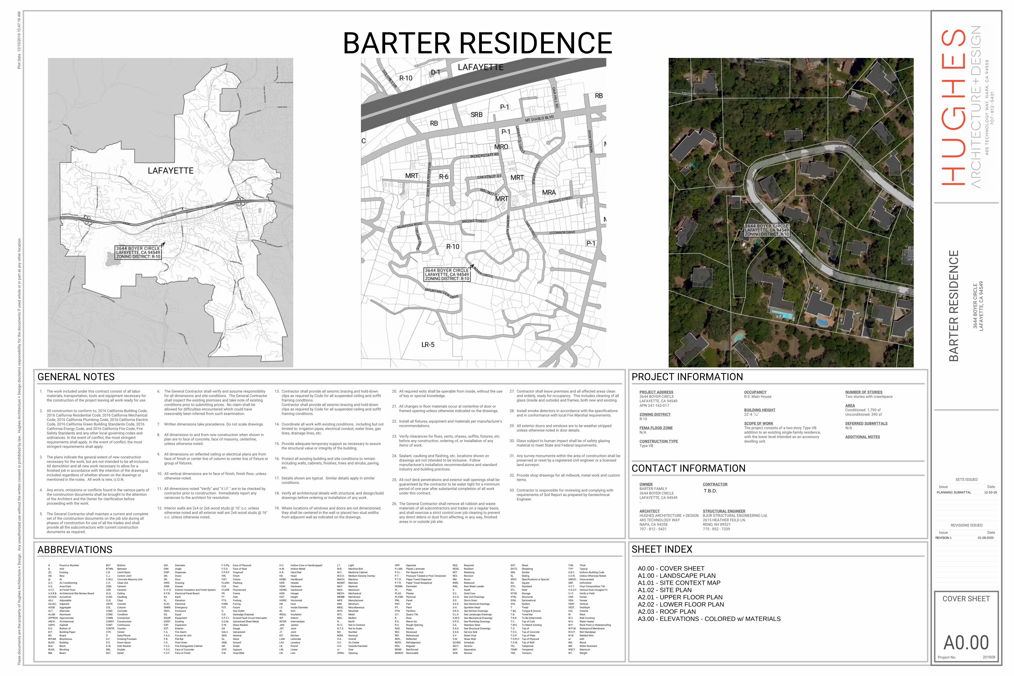
PROPOSEDADDITION
EXISTINGRESIDENCE
PLANNING SUBMITTAL 12-10-19
REVISION 1 01-28-2020

Plo
t D
ate
Project No.
DateIssue
Th
ese
do
cu
me
nts
are
th
e p
rop
ert
y o
f H
ug
he
s A
rch
ite
ctu
re +
De
sig
n.
An
y u
na
uth
ori
zed
use
wit
ho
ut
the
wri
tte
n c
on
sen
t is
pro
hib
ite
d b
y la
w.
Hu
gh
es
Arc
hit
ec
ture
+ D
es
ign
dis
cla
ims
re
sp
on
sib
ility
fo
r th
e d
oc
um
en
ts if
use
d w
ho
le o
r in
pa
rt a
t a
ny
oth
er
loc
ati
on
.
REVISIONS ISSUED
SETS ISSUED
DateIssue
12
/10/2
01
9 9
:23
:15
AM
A1.01
CONTEXT MAP
201609
BA
RT
ER
RE
SID
EN
CE
36
44
BO
YE
R C
IRC
LE
LA
FA
YE
TT
E, C
A 9
45
49
N
PR
OJ
EC
T N
OR
TH
SCALE : 3/32" = 1'-0"A1.01
1 CONTEXT MAPNOT TO SCALE
PLANNING SUBMITTAL 12-10-19
REVISION 1 01-28-2020
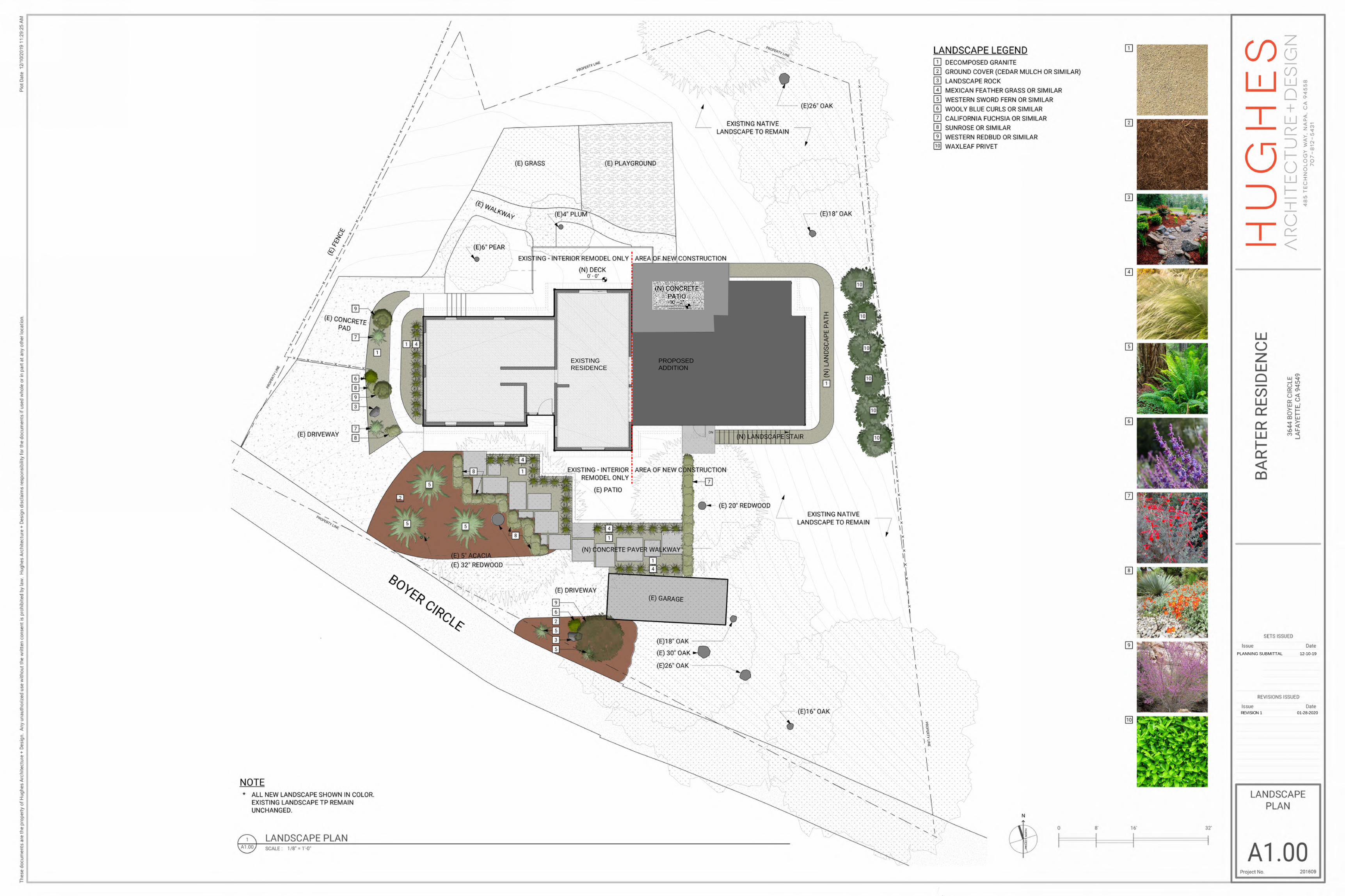
EXISTINGRESIDENCE
EXISTINGCARPORTTO REMAIN
PROPOSEDADDITION
MATCH (E)ROOFLINE ANDEAVE HEIGHTS
1,210 S.F.
885 S.F.
A1.02
EARLIER SURVEY OFEXISTING PROPERTYUSED
PLANNING SUBMITTAL 12-10-19
27' -
4"
21' - 8"
41' - 5"
44' -
8 3
/4"
15' - 1 3/4"
17' - 8"
REVISION 1 01-28-2020
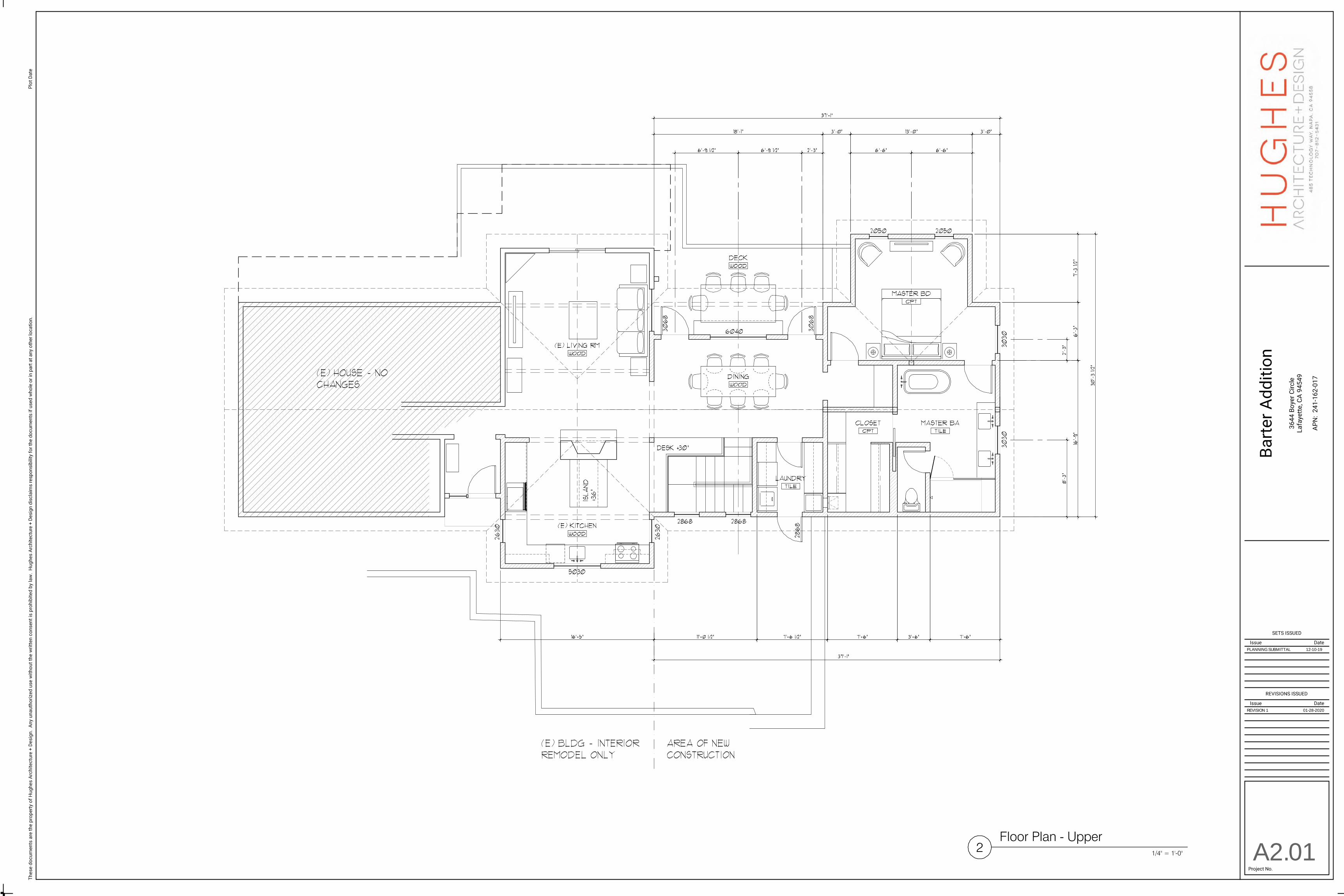
A2.01
PLANNING SUBMITTAL 12-10-19
REVISION 1 01-28-2020

A2.02
DEN
BEDROOM 2
BATHROOM
CL
PATIO
PLANNING SUBMITTAL 12-10-19
REVISION 1 01-28-2020
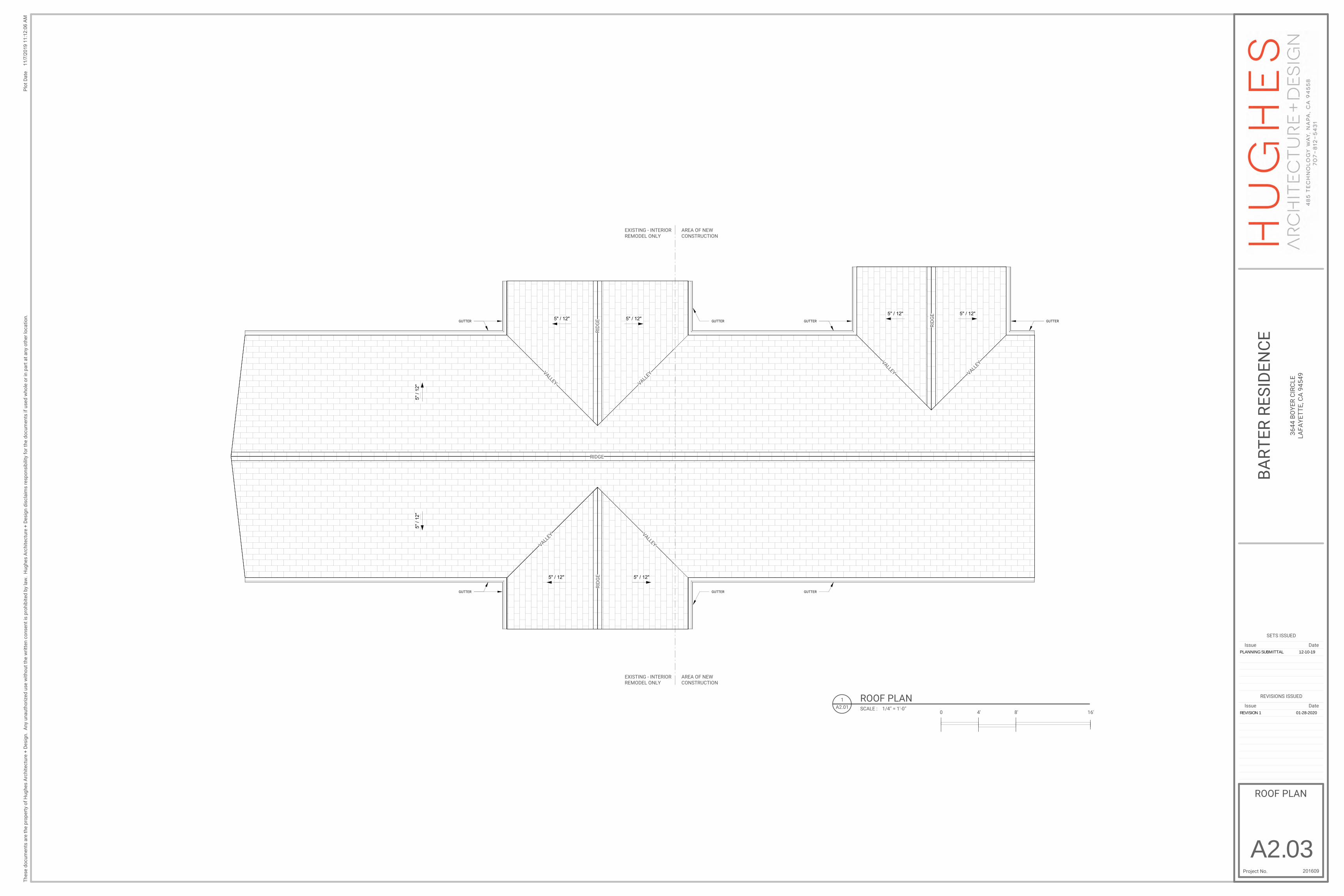
5"
/ 12
"
5" / 12"5" / 12"
5" / 12"5" / 12"
5" / 12" 5" / 12"
5"
/ 12
"
RIDGE
RID
GE
RID
GE
RID
GE
VALLEY
VALLEY
VALLEY
VALLEY
VALLEY VALLEY
GUTTER
GUTTER
GUTTER
GUTTERGUTTER
GUTTER GUTTER
EXISTING - INTERIOR REMODEL ONLY
AREA OF NEW CONSTRUCTION
EXISTING - INTERIOR REMODEL ONLY
AREA OF NEW CONSTRUCTION
Plo
t D
ate
Project No.
DateIssue
Th
ese
do
cu
me
nts
are
th
e p
rop
ert
y o
f H
ug
he
s A
rch
ite
ctu
re +
De
sig
n.
An
y u
na
uth
ori
zed
use
wit
ho
ut
the
wri
tte
n c
on
sen
t is
pro
hib
ite
d b
y la
w.
Hu
gh
es
Arc
hit
ec
ture
+ D
es
ign
dis
cla
ims
re
sp
on
sib
ility
fo
r th
e d
oc
um
en
ts if
use
d w
ho
le o
r in
pa
rt a
t a
ny
oth
er
loc
ati
on
.
REVISIONS ISSUED
SETS ISSUED
DateIssue
11
/7/2
019
11:1
2:0
6 A
M
ROOF PLAN
201609
BA
RT
ER
RE
SID
EN
CE
36
44
BO
YE
R C
IRC
LE
LA
FA
YE
TT
E, C
A 9
45
49
4' 8' 16'0SCALE : 1/4" = 1'-0"A2.01
1 ROOF PLAN
A2.03
PLANNING SUBMITTAL 12-10-19
REVISION 1 01-28-2020
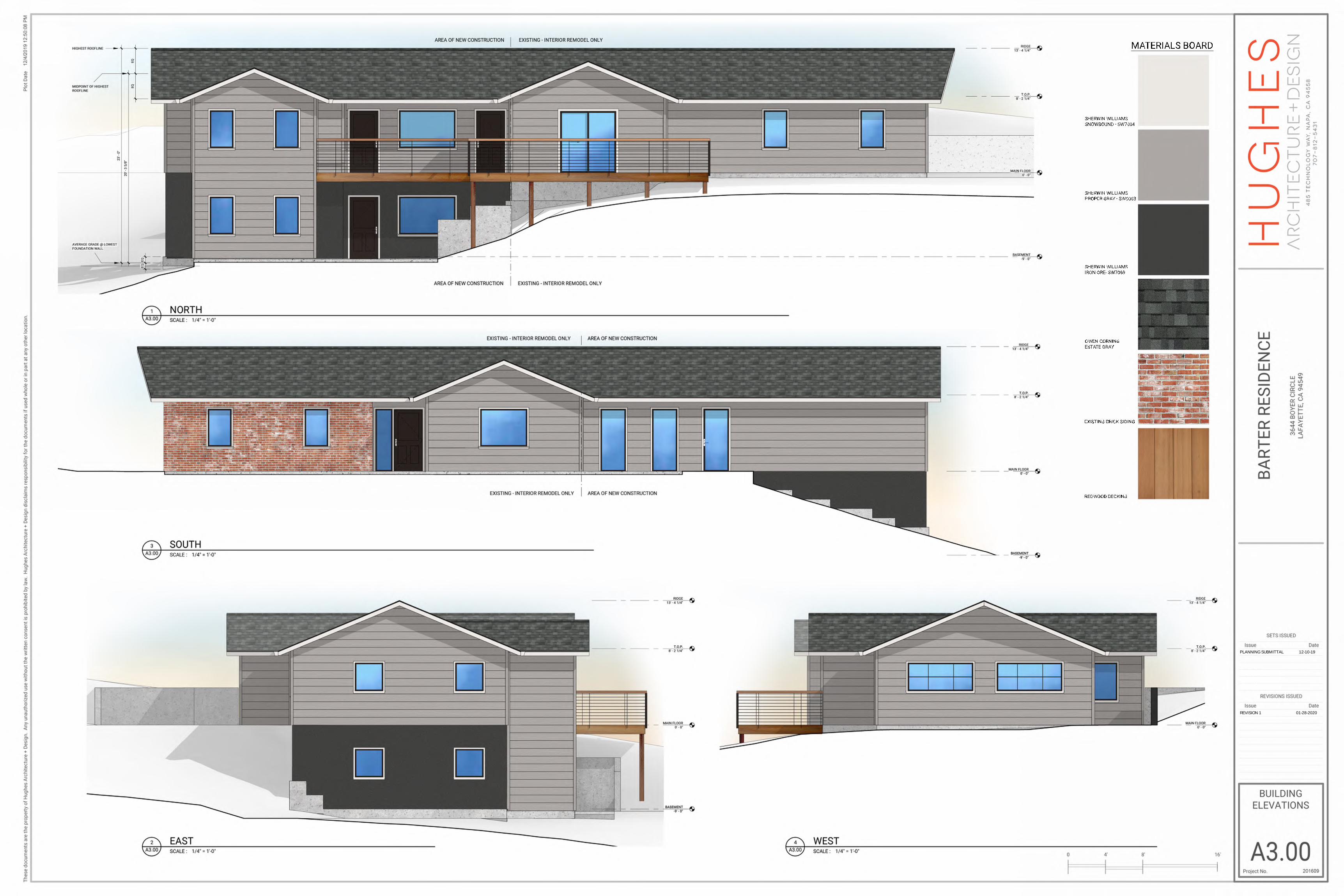
SHERWIN WILLIAMSSNOWBOUND - SW7004
MATERIALS BOARD
SHERWIN WILLIAMSPROPER GRAY - SW6003
SHERWIN WILLIAMSIRON ORE- SW7069
OWEN CORNINGESTATE GRAY
EXISTING BRICK SIDING
REDWOOD DECKING
PLANNING SUBMITTAL 12-10-19
REVISION 1 01-28-2020