Embed Size (px)
Citation preview

Version V3.3.0 - 18/7/03
Balsa:A Tutorial Guide.
Doug Edwards, Andrew Bardsley& Lilian Janin


Balsa: A Tutorial Guide. V3.3.0 - 18/7/03 i
Contents
1
Introduction
.................................................................. 1
1.1. Introducing Balsa
...................................................................................................1What is Balsa? .............................................................................................................1Basic concepts .............................................................................................................1
1.2. Tool set & design flow
.........................................................................................3Tools ............................................................................................................................4
1.3. Changes in this release
..........................................................................................5Deprecated or eliminated constructs/files ....................................................................5New constructs ............................................................................................................5Changed behaviour ......................................................................................................6Balsa-mgr .....................................................................................................................6Simulation environment ..............................................................................................6Channel viewer ............................................................................................................6Back-end technologies .................................................................................................6The Manual ..................................................................................................................6
2
Getting Started
............................................................. 7
2.1. A single-place buffer
.............................................................................................7Description ...................................................................................................................7Commentary on the code .............................................................................................8Reserved words ............................................................................................................8Compiling the circuit ...................................................................................................8The synthesised circuit. ...............................................................................................9
2.2. Two-place buffers
..................................................................................................91st design .....................................................................................................................92nd design ..................................................................................................................10
2.3. Parallel composition & module reuse
............................................................10Commentary on the code ...........................................................................................11
2.4. Placing multiple structures
................................................................................11Commentary on the code ...........................................................................................11

ii Balsa: A Tutorial Guide. V3.3.0 - 18/7/03
2.5. Using balsa-mgr
....................................................................................................12Creating a new project ...............................................................................................12Compiling a description .............................................................................................13Compilation errors .....................................................................................................14Circuit cost .................................................................................................................15Flattened vs non-flattened view .................................................................................16
2.6. Simulation.
.............................................................................................................17Adding a test fixture. .................................................................................................19Text-only simulation ..................................................................................................19Graphical Simulation Tools .......................................................................................21
2.7. Compilation and Simulation Options
.............................................................24Flattened vs hierarchical compilation ........................................................................24Direct Simulation vs Breeze -> Lard .........................................................................24Lard simulation options .............................................................................................24Structural vs behavioural simulation .........................................................................25
3
The Balsa Language
................................................... 27
3.1. Data Types
..............................................................................................................27Numeric types ............................................................................................................27Enumerated types ......................................................................................................28Record types ..............................................................................................................28Array types ................................................................................................................29Constants ...................................................................................................................29Arrayed channels .......................................................................................................30
3.2. Data Typing Issues
...............................................................................................30Casts ...........................................................................................................................30Auto-assignment ........................................................................................................31
3.3. Control Flow and Commands
...........................................................................32Sync ...........................................................................................................................32Channel assignment ...................................................................................................32Variable assignment ...................................................................................................33Sequence operator ......................................................................................................33Parallel composition ..................................................................................................33Continue & Halt .........................................................................................................33Looping constructs ....................................................................................................33Structural iteration .....................................................................................................34Conditional execution ................................................................................................34
3.4. Binary/Unary Operators
.....................................................................................35
3.5. Description Structure
...........................................................................................36File structure ..............................................................................................................36Declarations ...............................................................................................................37Procedures .................................................................................................................37Shared procedures ......................................................................................................38Functions ...................................................................................................................38Conditional declarations ............................................................................................38Variable ports ............................................................................................................39
3.6. Examples
.................................................................................................................40Modulo-16 counter ....................................................................................................40

Balsa: A Tutorial Guide. V3.3.0 - 18/7/03 iii
Removing auto-assignment .......................................................................................40Modulo-10 counter ....................................................................................................40A loadable up/down counter ......................................................................................41Sharing hardware .......................................................................................................42A “while” loop description ........................................................................................43The danger of “for” loops ..........................................................................................43Selecting channels .....................................................................................................44
4
Parameterised & Recursively Defined Circuits
......... 47
4.1. Summary
.................................................................................................................47
4.2. Parameterised descriptions
................................................................................47A variable width buffer definition .............................................................................47Pipelines of variable width and depth ........................................................................48
4.3. Recursive definitions
...........................................................................................49An n-way multiplexer ................................................................................................49Commentary on the code ...........................................................................................50A balsa test harness ....................................................................................................50Handshake multiplier .................................................................................................50
5
Handshake Enclosure
................................................ 53
Summary ....................................................................................................................53
5.1. Systolic counters
...................................................................................................53A systolic modulo-11 counter ....................................................................................55All even cells .............................................................................................................55All odd cells ...............................................................................................................55A faster all even cell ..................................................................................................56Parameterised version ................................................................................................56Active enclosure ........................................................................................................56
6
Balsa Design Examples
.............................................. 59
Summary ....................................................................................................................59
6.1. A Population Counter
..........................................................................................59Commentary on the code ...........................................................................................60Enclosed Selection .....................................................................................................60Avoiding deadlock: ....................................................................................................60
6.2. A Balsa shifter
.......................................................................................................61Testing the shifter ......................................................................................................62
6.3. An Arbiter Tree
.....................................................................................................62

iv Balsa: A Tutorial Guide. V3.3.0 - 18/7/03
7
Implementations
......................................................... 65
8
The Balsa Language Definition
................................. 67
Summary ....................................................................................................................67
8.1. Reserved words
.....................................................................................................67
8.2. Language Definition
............................................................................................67
9
References
.................................................................. 73

Balsa: A Tutorial Guide. V3.3.0 - 18/7/03 1
1
Introduction
1.1. Introducing Balsa
This document describes version 3.3 of the Balsa system. This release is a major upgrade fromprevious versions although some of the extra functionality has been available in the varioussnapshots that have been downloadable from the Balsa website. Significant changes have beenintroduced in all aspects of the system: language, simulation environment, back-end targettechnologies and not least in the documentation itself. If you are an existing user of Balsa, it isimportant that you are aware of changes which are summarised in the section “Changes in thisrelease” on page 5. Whilst most existing Balsa descriptions should compile without problems,changes to the syntax of the
while
construct may result in different behaviour. Most users shouldnot be affected by the changes, since while loops, although available in earlier releases, were notdescribed in the previous version of the manual.
Many of tools described here can be run on any supported Unix (including MacOS X) platform.However, in order to produce a concrete implementation in either silicon or FPGA form, vendorspecific tools are required: for example Xilinx design software, or the Cadence design frameworkwith an appropriate cell library technology.
What is Balsa?
Balsa is both a framework for synthesising asynchronous (clockless) hardware systems and thelanguage for describing such systems. The approach adopted is that of syntax-directed compilationinto communicating handshaking components and closely follows the Tangram [1] system ofPhilips. The advantage of this approach is that the compilation is transparent: there is a one-to-onemapping between the language constructs in the specification and the intermediate handshakecircuits that are produced. It is relatively easy for an experienced user to envisage the architecture ofthe circuit that results from the original description. Incremental changes made at the language levelresult in predictable changes at the circuit implementation level. This is important if optimisationsand design-tradeoffs are to be made easily and contrasts with a VHDL description in which smallchanges in the specification may make radical alterations to the resulting circuit.
Basic concepts
A circuit described in Balsa is compiled into a communicating network composed from a small(~45) set of handshake components. The components are connected by
channels
over which
communications
or
handshakes
take place. Channels may have datapaths associated with them (inwhich case a handshake involves the transfer of data), or may be purely control (in which case thehandshake acts as a synchronisation or rendez-vous point).

1.1. Introducing Balsa
2 Balsa: A Tutorial Guide. V3.3.0 - 18/7/03
Each channel connects exactly one
passive
port of a handshake component to to one
active
port ofanother handshake component. An active port is a port which initiates a communication. A passiveport responds (when it is ready) to the
request
from the active port by an
acknowledge
signal
Data channels may be
push
channels or
pull
channels. In a push channel, the direction of the dataflow is from the active port to the passive port, corresponding to a
micropipeline
style ofcommunication. Data validity is signalled by request and released on acknowledge. In a pullchannel, the direction of data flow is from the passive port to the active port. The active portrequests a transfer, data validity is signalled by an acknowledge from the passive port. An exampleof a circuit composed from handshake components is shown in Fig. 1.1.
Here a
Fetch
component, also known as a Transferer, (denoted by “
→
”) and a
Case
component(denoted by “@”) are connected by an internal data-bearing channel. Circuit action is activated by arequest to the Fetch component which in turn isues a request to its environment (on the left of thediagram). The environment supplies the demanded data indicating its validity by theacknowledgement signal and the Fetch component presents a handshake requestsand data to theCase component using an active port (shown as a filled circle) which the Case component receiveson a passive port (shown as an open circle). Depending on the data value, the Case componentissues a handshake to its environment on either the top right or bottom right port. Finally, when theacknowledgement is received by the case component, an acknowledgement is returned along theoriginal channel and terminating this handshake. The circuit is ready to operate once more.
Data follows the direction of the request in this example and the acknowledgement to that requestflows in the opposite direction. In this figure, individual physical request, acknowledgement anddata wires are explicitly shown. Data is carried on separate wires from the signalling (it is “bundled”with the control although this is not necessary with other data/signalling encoding schemes.
The bundled data scheme illustrated in Fig. 1.1 is not the only implementation possible.Methodologies exist (DI codes, dual rail encoding, NULL Convention Logic [2]) to implementchannel connections with delay-insensitive signalling where timing relationships between individualwires of an implemented channel do not affect the functionality of the circuit. Handshake circuitscan be implemented using these methodologies which are robust to naive realisations, processvariations and interconnect delay properties. Future releases of Balsa will include alternative back-ends
Normally, handshake circuits diagrams are not shown at the level of detail of Fig. 1.1, a channelbeing shown as a single arc with the direction of data being denoted by an arrow head on the arc andcontrol only channels, comprising only request/acknowledge wires, being indicated by an arcwithout an arrowhead. The circuit complexity of handshake circuits is often low: for example, aFetch component may be implemented using only wires. An example of a handshake circcuit for amodulo-10 counter [see “Removing auto-assignment” on page 40] is shown in Fig. 1.2. Thecorresponding gate level implementation is shown in Fig. 1.3.
Note that the compilation function results in circuit fragments in which both input and output portsare active. Since passive ports can only connect to active ports and vice-versa, circuits constructed
Figure 1.1:
Two connected handshake components
acknowledge
requestacknowledge
request
acknowledge
bundled data
acknowledgerequest
request request
acknowledge
@
"0;1"
0
1
→

Balsa: A Tutorial Guide. V3.3.0 - 18/7/03 3
1.2. Tool set & design flow
from compositions of compiled circuit fragments must have their interconnecting ports connectedby
passivator
components. A passivator synchronises requests from input and output ports andarranges the overlapping of the two handshakes (one push, one pull) such that the data-valid phasesof the two data-validity protocols overlap.
1.2. Tool set & design flow
An overview of the Balsa design flow is shown in Fig. 1.1. Behavioural simulation is provided by
breeze-sim
. This simulator allows source level debugging, visualisation of the channel activity at thehandshake circuit level as well as producing conventional waveform traces that can be viewed usingthe waveform viewer
gtkwave
. The old simulation route using
LARD
[4] is still available, but is nowdeprecated and
LARD
must be installed as a separate package. The various simulation options tied tothe Balsa framework are shown in Fig. 1.5. The target CAD system may also be used to performmore accurate simulations and to validate the design. Breeze-sim is still under active development:the facilites and user interface provided may be differ in detail from that described in this manual.
Figure 1.2:
Handshake circuit of a modulo-10 counter
Figure 1.3:
Gate level circuit of a modulo-10 counter
aclk
activate
count
04
4
4
|4
x /= 94 count
_reg
→
→
→
4tmp →
44
x + 1
14
# DW ;
*
44
→
@
"0;1"
10
1
(no ack)
aclk
activate
count
04
4
4
|4 4
tmpx /= 94 count
_reg @
"0;1"
10
1
→
→
→
→
→
44
x + 1
14
;
*
44
DW
Control sequencing components (3 gates each)
R
S
latch x4
r
S
S
a
0
1
# C
r a
Compare r
a
/= 9?
Incrementerr
latch
a

1.2. Tool set & design flow
4 Balsa: A Tutorial Guide. V3.3.0 - 18/7/03
Most of the Balsa tools are concerned with manipulatng the Breeze handshake intermediate files.Breeze files can be used by back-end tools implementations for Balsa descriptions, but also containprocedure and type definitions passed on from Balsa source files allowing Breeze to be used as thepackage description format for Balsa.
Tools
B
alsa comprises a collection of tools, some of the more important are:
•
balsa-c
: the compiler for the Balsa language. The ouput of the compiler is an intermediate language
Breeze.
•
balsa-netlist:
produces a netlist appropriate to the target technology/CAD framework from a Breeze description.
•
breeze2ps
: a tool which produces a postscript file of the handshake circuit graph.
•
breeze2lard
: a translater that converts a
breeze
description to a
LARD
behavioural model.
•
breeze-cost
: a tool which gives an area cost estimate of the circuit.
•
balsa-md: a tool for generating makefiles
• balsa-mgr: a graphical front-end to balsa-md with project management facilities.
• breeze-sim: the preferred simualtor working at he handshake component level
• breeze-sim-control: a graphical front-end to the simulation and visualisation environment
• gtkwave: a waveform viewer
Figure 1.4: Design Flow
reus
e
synt
hesi
s
Design refinement
Layout sim.
‘balsa−netlist’Simulationresults
Behavioural
Functional
Timing
‘breeze−cost’
Object / File Object / File‘Balsa tool’ / Automated process
Manual process
Key:
Commercial Si
Balsa behavioural
Balsa description
Breeze description(HC netlist)
Gate−level netlist
‘balsa−c’
simulation system
‘breeze2ps’
Gate−level sim.
Layout / bitstream
or FPGA P&R

Balsa: A Tutorial Guide. V3.3.0 - 18/7/03 5
1.3. Changes in this release
A balsa-mode is also available for xemacs providing automatic syntax-based indentation of Balsadescriptions.
1.3. Changes in this release
The changes listed here are major changes since the first version of the Balsa manual. Some of thesehave however appeared in various snapshots that have been published on the Balsa website andsome have been described a text book [3] produced to promote the European Low-Power Initiativefor Electronic System Design.
Deprecated or eliminated constructs/files
• public and private keywords have been eliminated
• else clauses of while statement are no longer supported
• the keyword local is not required for declarations which immediately follow procedure declarations.
• .sbreeze files are no longer generated as part of the compilation process. A modified .breeze format now replaces both .breeze and .sbreeze files.
New constructs
• variable read and write ports have been added. Ports to procedures can now be connected to variables to allow communications on the procedure’s ports to perform reads and writes to the variable [see “Variable ports” on page 39].
• a multicast keyword has been added to prefix channel/sync declarations to supress warning about multicast channels. The “-c warn-multicast” option to balsa-c now does nothing – it is enabled by default.
• implicants and don’t care values may used more widely in expressions [see “Constants” on page 29].
Figure 1.5: Balsa Simulation Flow
control
breeze
breeze2lard
LARD
LARD bytecode
breeze−sim−ctrl breeze−sim
GTKWave
Tracelc
(lard compiler)
(lard interpreter)li

1.3. Changes in this release
6 Balsa: A Tutorial Guide. V3.3.0 - 18/7/03
• ports, local and global declarations may be conditional [see “Conditional execution” on page 34].
• new loop constructs have been added [see “Looping constructs” on page 33].
• case statements may be parameterised [see “Conditional execution” on page 34]
• simulation time printing is now supported by the print command [see “Control Flow and Commands” on page 32]
• a bit-array-cast operator, #, has been added as syntactic sugar to simplify array slicing and casting.
• active input enclosure commands have been added
• the syntax of parameterised procedure calls has changed
Changed behaviour
• the syntax of the while command has been changed. This may cause existing programs to have a different behaviour [see “Looping constructs” on page 33] for more details.
• should multiple guards be true (in if and while) commands, the earliest command in the guard list is executed – previously the command chosen was undefined.
• if commands, ports and declarations now correctly fail to evaluate subsequent commands if an earlier guard is true.
• sbreeze files must be regenerated – they are no compatible with the latest version.
Balsa-mgr The GUI to the Balsa system, balsa-mgr, is now stable and is the recommended way of driving thetool set
Simulation environment
LARD is no longer the recommended functional simulation route. A new simulation engine operatingon the breeze description of circuits simulates directly and gives a speed improvement of x25,000.Co-simulation with existing lard test harnesses is still possible, but with reduced performance. Lardsupport for Balsa is no longer part of the main distribution, but is available as a separate package,balsa-lard.
Channel viewer
The LARD channel viewer is now longer used for a graphical representation of channel activity.Although impressive for small demonstration purposes, it was very slow, it was difficult to restrictthe view to “important” channels, snapshots could not be saved and restarted etc. The newsimulation viewer is based on a conventional waveform viewer derived from GTKWave.
Back-end technologies
A wide range of backend technologies and styles are supported and easily controlled via balsa-mgr.Users can select between single rail (bundled data), dual rail, 1-of-4 and NCL styles each withdifferent latch implementations. A Xilinx technology and a generic Verilog netlist are distibuted.For users with appropriate licensing arrangements, a number of silicon technologies, e.g. AMS0.35µ and ST 01.8µ are available.
The Manual The format of the manual has changed. A more complete definition of the language is included.There is now a section on how to create different back-end technologies and styles. The exampledescriptions have been extended. The emphasis of the manual has changed: the previous versionover emphasised passive enclosed selection. Many users were misled into believing that thisdescriptive style was good practice. It is hoped that this version separates the issue of passive versusactive ports from that of enclosed handshakes and encourages a more natural style of description.

Balsa: A Tutorial Guide. V3.3.0 - 18/7/03 7
2 Getting Started
Summary In this chapter, simple buffer circuits are described in Balsa introducing the basic elements of aBalsa description. The GUI to the Balsa system, balsa-mgr, is used to hide the complexity of theunderlying command line tools. All the examples illustrated here can be found in the Examplesdirectory of this documentation.
If the Balsa system has been compiled from source, it should only be necessary to include the binarydirectory in the user’s search path. Users using binary only distributions, should source theamutools.sh script located in the distribution package.
Previous users of the system should note that since LARD is no longer the preferred simulation route,LARD is no longer embedded within the Balsa system. Users who wish to use LARD must downloadand install the lard and balsa-lard packages separately.
2.1. A single-place buffer
Description A Balsa description, in buffer1a.balsa, of a byte-wide, single place buffer is:
buffer1a.balsa (-- Balsa program defining an 8 bit wide single place buffer This is an example of a multi-line (-- nested --) comment--)
-- Single line comments are also allowedimport [balsa.types.basic]
procedure buffer1 (input i : byte; output o : byte)is variable x : bytebegin loop i -> x -- Input communication ; -- Sequence operator o <- x -- Output communication endend

2.1. A single-place buffer
8 Balsa: A Tutorial Guide. V3.3.0 - 18/7/03
Commentary on the code
This Balsa description builds a single-place buffer, 8-bits wide. The circuit requests a byte from theenvironment which, when ready, transfers the data to the register. The circuit signals to theenvironment on its output channel that data is available and the environment reads it when itchooses. This little program introduces:
comments: Balsa supports both multi-line and single line comments; both types may be nested.
modular compilation: Balsa supports modular compilation. The import statement in this
example includes the definition of some standard data types such as byte, nibble, etc.1. A full listof the current definitions is given in <BalsaInstallDir>/share/balsa/types/basic.breeze. The searchpath given in the import statement is a dot separated directory path similar to that of Java exceptmulti-file packages are not implemented. The import statement may be used to include other pre-compiled balsa programs thereby acting as a library mechanism. The import statements mustprecede other declarations in the files. The import statement is included in this example forcompleteness only. None of the types defined in basic.breeze are actually used this example so theimport statement could have been omitted.
procedures: The procedure declaration introduces an object that looks similar to a proceduredefinition in a conventional programming language. In Balsa, a procedure is compiled to handshakecircuit comprising a network of handshake components. The parameters of the procedure define theinterface to the environment outside of the circuit block. In this case, the module has an 8-bit inputdatapath and an 8-bit output datapath. The body of the procedure definition defines an algorithmicbehaviour for the circuit; it also implies a structural implementation. In this example, a variable x(of type byte and therefore 8 bits wide) is declared implying that a 8-bit wide storage element willbe appear in the synthesised circuit.
The behaviour of the circuit is obvious from the code: 8-bit values are transferred from theenvironment to the storage variable, x, and then sequential output from the variable to theenvironment. This sequence of events is continually repeated (loop … end).
channel assignment: the assignment operators “->” and “<-” are a channel assignments andimply a communication or handshake over the channel. Because of the sequencing explicit in thedescription, the variable x will only accept a new value when it is ready; the value will only bepassed out to the environment when requested. Note that the channel is always on the left-hand sideof the expression and the corresponding variable on the right-hand side.
sequencing: The “;” symbol separating the two assignments is not merely a syntactic statementseparator, it explicitly denotes sequentiality. The program has been formatted somewhat artificiallyto emphasise the point. The contents of x are transferred to the output port after the input transfer hascompleted. Because a “;” connects two sequenced statements or blocks, it is an error to place a “;”after the last statement in a block.
Reserved words
Care must be take to avoid using Balsa’s keywords as variable or procedure names. Usually, this isnot a difficult restriction to remember, but a common mistake, especially for beginnersexperimenting with the language, is to name an input channel in. Unfortunately, in is a reservedword and will generate a Balsa compile error.
Compiling the circuit
balsa-c buffer1a
The compiler runs silently, producing an output file buffer1a.breeze. This is a file in an intermediateformat which can be imported back into other balsa source files (thereby providing a simple librarymechanism). The file extension (.balsa) of the source filename is optional and contains no specialsignificance to the compilation system. However, if a different file extension is used the file nameincluding the extension must be given as the argument to the balsa-c command. The file extension.breeze is of significance to the compilation system
1. there is no predefined type word

Balsa: A Tutorial Guide. V3.3.0 - 18/7/03 9
2.2. Two-place buffers
Breeze is a textual format file designed for ease of parsing and therefore somewhat opaque. Aprimitive graphical representation of the compiled circuit in terms of handshake components can beproduced (in buffer1a.ps) by:
breeze2ps buffer1a
The synthesised circuit.
The resulting handshake circuit is shown in Figure 2.1. Note that this is not actually taken from the
output of breeze2ps, but has been redrawn to make the diagram more readable. Although it is notnecessary to understand the exact operation of the compiled circuit, a knowledge of the structure ishelpful for an understanding of how to describe circuits which can be efficiently synthesised usingBalsa. A brief description of the operation of the circuit is given below. The circuit has beenannotated with the names of the various handshake elements.
The port at the top of the Loop component is an activation port which encloses (see “HandshakeEnclosure” on page 53) the behaviour of the circuit. It can be thought of as a reset signal which,when released, initiates the operation of the circuit. All compiled Balsa programs contain anactivation port.
The activation port starts the operation of the Repeater which initiates a handshake with theSequencer. This component first issues a handshake to the left-hand Fetch component causing datato be moved to the storage element in the Variable element. The Sequencer then handshakes withthe right-hand Fetch component causing data to be read from the Variable element. When theseoperations are complete, the Sequencer completes its handshake with the repeater which start thecycle again.
2.2. Two-place buffers
1st design Having built a single place buffer, an obvious goal is a pipeline of single buffer stages. Initiallyconsider a two-place buffer; there are a number of ways we might describe this. An obvious way isto define a circuit with two storage elements:
buffer2a.balsa -- buffer2a: Sequential 2-place buffer with assignment between variablesimport [balsa.types.basic]
procedure buffer2 (input i : byte; output o : byte)is
Figure 2.1: Handshake Circuit for a single place buffer
oi
Loop
Sequence
Variable
→
➤
FetchFetch
→
*
x
;
#

2.3. Parallel composition & module reuse
10 Balsa: A Tutorial Guide. V3.3.0 - 18/7/03
variable x1, x2 : bytebegin loop i -> x1; -- input communication x2 := x1; -- implied communication o <- x2 -- output communication endend
In this example in we explicitly introduce two storage elements, x1 and x2. The contents of thevariable x1 are caused to be transferred to the variable x2 by means of the assignment operator “:=”.However, transfer is still effected by means of a handshaking communication channel. Thisassignment operator is merely a way of concealing the channel for convenience.
2nd design The implicit channel can be made explicit as shown in buffer2b.balsa:
buffer2b.balsa -- buffer2b: Sequential version with an explicit internal channelimport [balsa.types.basic]
procedure buffer2 (input i : byte; output o : byte)is variable x1, x2 : byte channel chan : bytebegin loop i -> x1; -- Input communication chan <- x1 || chan -> x2; -- transfer x1 to x2 o <- x2 -- Output communication endend
The channel, which was in the previous example, concealed behind the use of the “:=” assignmentoperator has been made explicit. The handshake circuit produced (after some simple optimisations)is identical to buffer2a. The “||” operator is explained in the next example
It is important to understand the significance the operation of the circuits produced by buffer2a andbuffer2b. Remember the “;” is more than a syntactic separator: it is an operator denoting sequence.Thus, first the input, i, is transferred to x1. When this operation is complete, x1 is transferred to x2and finally the contents of x2 are written to the environment. Only after this sequence of operationsis complete can new data from the environment be read into x1 again.
2.3. Parallel composition & module reuse
The operation above is unnecessarily constrained: there is no reason why the circuit cannot bereading a new value into x1 at the same time that x2 is writing out its data to the environment. Theprogram in buffer2c achieves this optimisation.
-- buffer2c: a 2-place buffer using parallel compositionimport [balsa.types.basic]import [buffer1a]
procedure buffer2 (input i : byte; output o : byte)is channel c : bytebegin buffer1 (i, c) || buffer1 (c, o)end
Balsa: A Tutorial Guide. V3.3.0 - 18/7/03 11
2.4. Placing multiple structures
Commentary on the code
In the program above, a 2-place buffer is composed from 2 single-place buffers. The output of thefirst buffer is connected to the input of the second buffer by their respective output and input ports.However, apart from communications across the common channel, the operation of the two buffersis independent
The deceptively simple program above illustrates a number of new features of the balsa language:
modular compilation: The import mechanism is used to include the buffer1a circuit describedearlier.
connectivity by naming: The output of the first buffer is connected to the input of the secondbuffer because of the common channel name (c) in the parameter list in the instantiation of thebuffers.
parallel composition: The “||” operator specifies that the two units which it connects shouldoperate in parallel. This does not mean that the two units may operate totally independently: in thisexample the output of one buffer writes to the input of the other buffer creating a point ofsynchronisation. Note also that the parallelism referred to is a temporal parallelism. The two buffersare physically connected in series.
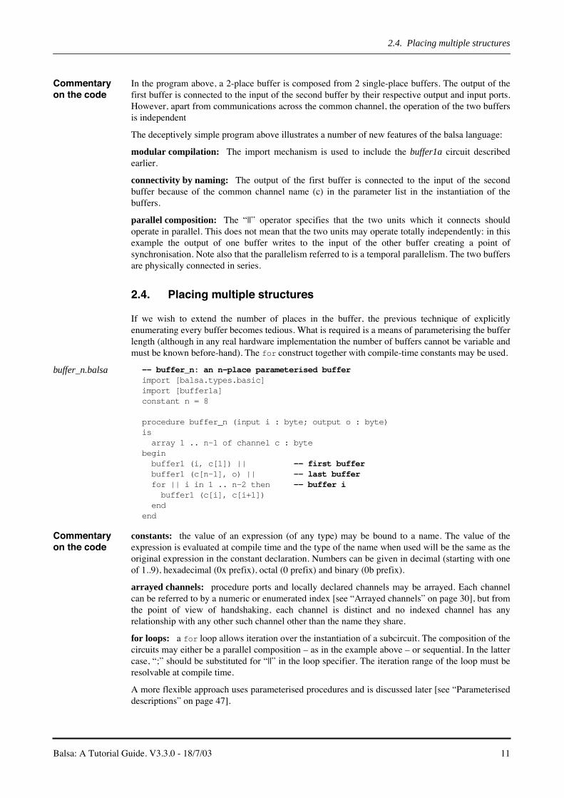
2.4. Placing multiple structures
If we wish to extend the number of places in the buffer, the previous technique of explicitlyenumerating every buffer becomes tedious. What is required is a means of parameterising the bufferlength (although in any real hardware implementation the number of buffers cannot be variable andmust be known before-hand). The for construct together with compile-time constants may be used.
buffer_n.balsa -- buffer_n: an n-place parameterised bufferimport [balsa.types.basic]import [buffer1a]constant n = 8
procedure buffer_n (input i : byte; output o : byte)is array 1 .. n-1 of channel c : bytebegin buffer1 (i, c[1]) || -- first buffer buffer1 (c[n-1], o) || -- last buffer for || i in 1 .. n-2 then -- buffer i buffer1 (c[i], c[i+1]) endend
Commentary on the code
constants: the value of an expression (of any type) may be bound to a name. The value of theexpression is evaluated at compile time and the type of the name when used will be the same as theoriginal expression in the constant declaration. Numbers can be given in decimal (starting with oneof 1..9), hexadecimal (0x prefix), octal (0 prefix) and binary (0b prefix).
arrayed channels: procedure ports and locally declared channels may be arrayed. Each channelcan be referred to by a numeric or enumerated index [see “Arrayed channels” on page 30], but fromthe point of view of handshaking, each channel is distinct and no indexed channel has anyrelationship with any other such channel other than the name they share.
for loops: a for loop allows iteration over the instantiation of a subcircuit. The composition of thecircuits may either be a parallel composition – as in the example above – or sequential. In the lattercase, “;” should be substituted for “||” in the loop specifier. The iteration range of the loop must beresolvable at compile time.
A more flexible approach uses parameterised procedures and is discussed later [see “Parameteriseddescriptions” on page 47].

2.5. Using balsa-mgr
12 Balsa: A Tutorial Guide. V3.3.0 - 18/7/03
2.5. Using balsa-mgr
Balsa-mgr is project manager environment which acts as a front-end to the Balsa commands suchas balsa-c and breeze2ps. It hides much of the complexity of the various command-line optionsthat more complicated compilation and simulation scenarios demand. The use of the projectmanager is best illustrated by using it to rerun the compilation of the single place buffer described inbuffer1a [“buffer1a.balsa” on page 7]
Creating a new project
The command balsa-mgr invokes the project manager. Select “Project ⇒ New” from the pull-
down menu as shown in Figure 2.2 to display the dialogue box shown in Figure 2.3. A default name
Figure 2.2: Creating a new project.
Figure 2.3: The New Project Dialogue Box.

Balsa: A Tutorial Guide. V3.3.0 - 18/7/03 13
2.5. Using balsa-mgr
for the project is generated; this may be over-ridden to something more meaningful. The “ProjectDirectory” text box specifies the root directory: a file named “Project” is created here containinginformation about the project. The button to the right of the text box activates a file browser forgraphically selecting the required directory. The “File Import Path” text box allows the directory inwhich the source Balsa files reside to be specified. By default, this is the current directory (relativeto the root of the project) but may be changed either by directly typing in the text box or by using thefile browser activated by clicking on the button to the right of the text box. More directory importpaths can be added by means of the “New” button.
Only one project is allowed per directory but each project may have several compilation targets. Theoptions in the other tabbed panes, “Compilation options” and “Definitions” are described later.
The source files to be compiled must be specified. Either select “Files ⇒ Add Files into Project”from the pull-down menu, or the keyboard accelerator Ctrl-A, or click on the icon as shown inFigure 2.4. Pick buffer1a.balsa and click “OK”. The filename should appear in the left-hand pane of
the project manager together with the name of any procedures listed in that file. Clicking on the fileor procedure name will cause the contents of the file to be listed in the right hand edit pane as shownin Figure 2.5. The file may be edited in-situ in the pane or by an external editor (defined in theenvironment options pane assessable by the “Project ⇒ New” pull-down menu) which can beinvoked by clicking on the edit icon above the edit pane.
Compiling a description
In order to compile the circuit, click on the Makefile tab in the left-hand pane. The new view,Figure 2.6, reveals the actions available. Click on the View button opposite the label “buffer1a.ps”.If the project has been changed since the user last saved it, a save-project dialogue box appears. Anew window, the execution window, is spawned which records various stages in the compilationprocess. Finally a postscript viewer will appear displaying the handshake circuit graph just as it didwhen the viewer was invoked via the command line.
Behind the scenes, balsa-mgr analyses the dependencies in the sources files in the project, creates aMakefile that reflects these dependencies and generates rules in the makefile to invoke the variousBalsa commands. If the initial balsa description is syntactically incorrect in such a way as to makeimpossible the determination of dependencies the makefile will not be correctly generated.
Figure 2.4: Adding Files to the Project Manager.

2.5. Using balsa-mgr
14 Balsa: A Tutorial Guide. V3.3.0 - 18/7/03
Running Balsa programs from the command line allows more flexibility within the Balsa system,however balsa-mgr is much more convenient for the majority of tasks. Since describing a GUI isexceptionally tedious, users are encouraged to browse the various icons and pull-down menusthemselves. Note that right-clicking in the various panes brings up various context sensitive menus.
Compilation errors
If errors are found during the compilation of a circuit, the errors, together with the line number andcharacter position of the error, are reported in the output pane of the execution window. Clicking on
Figure 2.5: Displaying a file in the Edit Pane.
Figure 2.6: The Makefile Pane.

Balsa: A Tutorial Guide. V3.3.0 - 18/7/03 15
2.5. Using balsa-mgr
the displayed error message causes the offending code to be highlighted in red in the edit panewindow.
1. Start balsa-mgr and select the project defined previously for the circuit buffer1a
2. Add the file buffer2b to the project
3. Compile the circuit by clicking on the Compile button for buffer2b.breeze. The circuit shouldcompile OK
4. Change the parallel composition operator “||” to the sequential operator “;”.
5. Save the file and recompile buffer2b.breeze
6. An compile time error should now be reported in the execution window:buffer2b.balsa:11:16: unbalanced channel usage; can't perform <write> ; <read> on channel `chan'
7. Click on the message. The offending code should be displayed in red in the edit-pane windowon line 11 starting at character position 16.
Quite apart from illustrating the mechanics of error reporting within the balsa-mgr framework, thisexample demonstrates why designing asynchronous circuits requires a deeper understanding thandoes the design of synchronous circuits. It is important to realise why the compiler objects to thecircuit description. Line 11 contains two statements. In the first, data is output from variable x1 tothe internal channel chan. The next statement, because of the sequence operator “;” cannot start untilthe previous statement has completed which requires data to be taken on the channel to beacknowledged. It is this second statement transferring data from the channel chan to the variable x2which would cause the data transfer on to the channel to be acknowledged. In other words, the firststatement is waiting for the second statement, but the second statement can not start until the firsthas terminated.
In this particular case, the compiler can spot the problem. However, conceptually similar deadlocksituations can arise at higher levels of system specification. In such cases, the circuit will compilesatisfactorily, but will deadlock in operation. Correct the error before proceeding further.
Circuit cost The area cost of a circuit may be found by determined by clicking on the Run button opposite thecost label. Doing so will cause the execution window (Figure 2.7) to display the area cost of thecircuit. This cost is only a guideline figure assuming a particular back-end implementation.Nevertheless, the cost figure is useful for gaining quick feedback on how changing the descriptionof a circuit affects its size. The output from breeze-cost needs some interpretation: each handshakecircuit is listed together with its cost, name, data width, and the internal channel identifiers to whichthe component is connected. Note that the cost of the Fetch component is zero. This is because in theback-end assumed for the cost function, a Fetch component is a wire only element.

2.5. Using balsa-mgr
16 Balsa: A Tutorial Guide. V3.3.0 - 18/7/03
Flattened vs non-flattened view
When a circuit is composed hierarchically, there is a choice of whether to view the resulting circuitin a hierarchical or flattened manner. Balsa-mgr allows either representation.
1. Start balsa-mgr and select the project defined previously for the circuit buffer1a
2. Delete the file buffer2b from the project by selecting it in the file pane and right clicking tochoose “Delete” from the pop-up menu. This step isn’t actually necessary but buffer2b is notused again
3. Add the file buffer2c to the project.
4. Click on the Makefile tab in the left-hand pane of the balsa-mgr window. A set of compilationactions for buffer2c (see Figure 2.8) has been added to those for buffer1a.
5. View the handshake circuit by clicking on the View button for buffer2c.ps. A hierarchical viewof the composed circuit is shown in Figure 2.9.
6. Determine the cost of the circuit: a cost of 22.51 should be reported. Note that this onlyincludes the components required for the composition of the two pre-compiled instances ofbuffer1a.
The description of buffer2c can be flattened during compilation by passing the appropriate flagthrough to the command line of the compilation tool. Balsa-mgr allows this to be done withoutdetailed knowledge of the command line tools.
1. Click on the “Project Options” icon or select Project ⇒ Options from the pull-down menu.
2. Click on the “Compilation Option” tab on the project dialogue window that appears (seeFigure 2.3)
3. Check the check-box marked Flattened Compilation in the compilation option pane (seeFigure 2.10). The exact layout of this window and the set of options available may be differentfrom that shown because of developments in the Balsa system.
Figure 2.7: Execution window, showing the cost of buffer1a
1. The exact cost may vary between different releases of Balsa.

Balsa: A Tutorial Guide. V3.3.0 - 18/7/03 17
2.6. Simulation.
4. Rerun the view of the of the handshake circuit graph. A flattened view should be obtained asshown in Figure 2.11.
5. Determine the cost of the circuit. The cost of the circuit (558.75) now reflects all componentsin the flattened circuit.
6. Restore the compilation settings to the default “Hierarchical Compilation”
2.6. Simulation.
Apart from the various simulation possibilities available once the design has been converted to asilicon layout, there are three strategies for evaluating/simulating the design from Balsa.
Figure 2.8: Buffer2c actions added to Makefile pane
Figure 2.9: Hierarchical view of buffer2c handshake circuit graph.
buffer2c
activate
.
C1: @10:18
0
i o
buffer1
C7: @10:11
0
1
buffer1
C5: @11:11
0
2
.
C2: i
1
C6: c
1
2
C3: o
2
C4: c
0
1

2.6. Simulation.
18 Balsa: A Tutorial Guide. V3.3.0 - 18/7/03
1. Default test harness.
A default test-harness can be generated. The default test harness exercises the target Balsablock by repeatedly handshaking on all external channels; input data channels receive thevalue 0 on each handshake, although it is possible to associate an input channel with a data file.Data sent to output channels appears on the output pane of th execution window. Note that ifthe interface to procedure under test is changed, a new test-harness must be generated. By
Figure 2.10: The Compilation Options pane
Figure 2.11: Flattened view of buffer2c
buffer2c
activate
.
C1: @10:18
0
i o
#
C10: @13:3
0
1
#
C4: @13:3
0
2
x[0..7]
;
C15: @14:11
0
1
T
C14: @14:7
0
1
.
C12: @15:7
1
2
C2: i
1
C13: x
0
2
T
C11: x
1
1
x[0..7]
C7: x
0
2
;
C9: @14:11
0
1
T
C6: @15:7
0
2
C8: @14:7
0
1
C3: o
2
C5: x
1
1
C16: @27:18
0
2

Balsa: A Tutorial Guide. V3.3.0 - 18/7/03 19
2.6. Simulation.
default, the Makefile can not check this dependency: the test-harness file must either beremoved manually or by running make clean.
2. Balsa test harness
If a more sophisticated test sequence is required, Balsa is a sufficiently flexible language in itsown right to be able specify most test sequences. A default test harness can then be generatedto exercise the Balsa test harness.
3. Custom LARD test harness.
For some applications, it may be necessary to write a custom test harness in a language such asLARD.
Adding a test fixture.
To simulate a circuit description. using Balsa’s simulation facilities, a test fixture has to be added tothe design framework. The easiest way is to automatically generate a default test harness.
1. Make sure that buffer2 is selected in the Files pane.
2. Pick “Select Item ⇒ Add Test Fixture” from the pull-down menu or right-click in the left-hand“File” pane. A window for creating a text fixture is spawned [Figure 2.12]
3. Change the name of the test fixture from the default (test1) to something more meaningful, e.g.buff2c
4. Select the Port Name “i”
5. Change the active radio button in the “Attached to” pane from “value/stdout” to “file”
6. Some test values (in a variety of representations: decimal, hex and binary) have been providedin the file th1.dat in the directory containing the example. Set the value of the filename in the“Port Value/Filename” text box to th1.dat either by typing directly into the text box or byclicking on the file browser button immediately to the right of the text box.
7. Dismiss the window by clicking OK.
Text-only simulation
In order to run the test, click on the Makefile tab. The Makefile view shown in Figure 2.15 nowshows two actions added under the Tests” subpane. Clicking on the Run button for sim-buff2c
Figure 2.12: The test fixtures pane

2.6. Simulation.
20 Balsa: A Tutorial Guide. V3.3.0 - 18/7/03
generates the following output in the execution window. The numbers reported on the left hand sideof each channel activity are simulation times – either the time at which data is presented at an inputchannel from the external environment or the time at which data is presented on an output channel tothe external environment. Note however that the simulator has a very simplistic timing model, sothese values should be treated with caution.
Figure 2.13: Test Harness added to Makefile pane
Figure 2.14: The ouput from a text-only simulation

Balsa: A Tutorial Guide. V3.3.0 - 18/7/03 21
2.6. Simulation.
Capturing output The contents of the output window of the execution window can be captured by right-clicking in theoutput pane; alternatively the output can be directed to a file when defining or editing the testharness.
Graphical Simulation Tools
In the previous examples, the output of the simulation is textual appearing in the output pane of theexecution window. The simulation may also be viewed in a conventional style waveform viewer orthe channel activity can be viewed directly on a representation of the handshake circuit graph. Toactivate the viewers, switch to the Makefile pane of Balsa-mgr and click on Run button forsim-win-buff2c. This will generate any intermediate files required and bring up a windowbreeze-sim-ctrl (Figure 2.16) which controls the simulations. and animations.
The controller allows:
• a new simulation file for a design to be produced and displayed in a waveform viewer (GTKWave).
• an existing simulation file to be viewed in the GTKWave viewer.
• the speed of the simulation to be varied.
• the handshake circuit graph to be displayed and animated.
• the source code to be displayed and stepped through as the handshake circuit graph is animated.
Figure 2.15: Test Harness added to Makefile pane
Figure 2.16: The Simulator Controller

2.6. Simulation.
22 Balsa: A Tutorial Guide. V3.3.0 - 18/7/03
Breeze-sim-controller icons
• If an existing simulation file is detected when the controller is started, a warning triangle icon is displayed to alert the user to the possibility that this file could be overwritten (the file has the extension of .hhh).
• An existing simulation file may be viewed without it being regenerated by clicking on the waveform viewer icon at the bottom of the controller window. If the waveform viewer is active, clicking on the icon kills the viewer.
• The coloured button at the bottom left of the controller window indicates the status of the simulation: red means the simulation is stopped, green that the simulation is running and yellow that the simulation is paused.
• New simulation files can be generated and displayed by clicking on the simulation run/pause button at top-left of the controller window. The simulation can be terminated by means of the simulation stop button to the right of the run/pause button. The simulation is displayed in the GTKWave viewer as the simulation file is produced. The speed of the simulation can be slowed down by means of the speed slider control.
• The three icons at the bottom right of the window reveal further functionality: the left icon reveals a tree view of the channels and ports of the design, the middle button reveals a graph of the handshake circuit and the right button opens a window onto the source code. The options menu controls the display of the channels. By default, all channels are displayed; however, the view may be restricted to procedure ports (which includes “hidden” activation channels) or just to named procedure ports. Only those channels displayed are passed to the GTKWave viewer.
Waveform Viewer Clicking on the waveform viewer icon or the simulation run button will start the GTKWave viewerand the channels visible from the channel tree viewer will be displayed in the right-hand pane asshown in Figure 2.17. Request signals are shown in read and acknowledge signals are shown in
green. Data bearing channels have the data value displayed under the request/acknowledge signals.Clicking in this pane will display a vertical timeline cursor in the window.
The left-hand pane shows the channel names and the state of the request/acknowledge signals anddata values at the cursor point. It is necessary to click in the waveform display pane to get the
Figure 2.17: Channel viewer window.

Balsa: A Tutorial Guide. V3.3.0 - 18/7/03 23
2.6. Simulation.
channel names to display correctly in the first instance. GTKWave is highly configurable: a detaileddescription of its operation is not given here, rather a summary of its capabilities is provided below.
• The display of the traces passed to the viewer from the simulation controller can be configurable by use of the add or add all buttons. The former allows signals to be chosen from a pick-list or by a regular expression description together with range specifiers – useful for specifying buses.
• Traces can be removed or repositioned by means of the cut and paste buttons.
• Traces can be sorted in a number of different ways.
• The traces can be zoomed in or out at the mid point of the display window by means of the zoom buttons.
• Specific areas of the display can be zoomed by right-click, drag in the display window.
• The display can be stepped by a fixed number of nsecs at a time or by the width of the display window.
• Data may be displayed in a number of formats.
• Markers can be added to the display.
• The various menubars and toolbars can be hidden by means of the icons at the bottom right of the window.
• The various menubars and tool bars are detachable. Click and drag on the gripper at the left-hand end of the bar to detach it. To return it to the window, drag it back to its correct place in the window or, more simply, double click on the gripper.
Animating the handshake circuit graph.
Note: the features described in this section are experimental and are likely to change in futurereleases.
If the channel tree viewer and handshake circuit graph icons are clicked, the controller windowchanges to that shown in Figure 2.18. It will be necessary to resize the window to display the
handshake circuit graph sensibly. To view the activity on the various channels, it is first necessary to
Figure 2.18: Channel tree and handshake circuit graph revealed.

2.7. Compilation and Simulation Options
24 Balsa: A Tutorial Guide. V3.3.0 - 18/7/03
generate a simulation (.hhh) file. The circuit may then be animated by clicking on the animatebutton. the speed of the animation can be modified by means of the slider control next to the button.The animation may stepped by means of the up/down buttons next to the current time value. As ashort-cut, right-clicking on the buttons will take the simulation to the start/end of the animation.This feature is useful for rerunning the animation.
Source Code Viewer
Clicking the source code viewer icon brings up a separate window. Initially this is empty, but if thehandshake circuit animator is started, the window will fill with a number of panes. The left-handpane gives a tree view of the concurrent threads. The right-hand panes list the contents of the sourcefiles that comprise the circuit description. as shown in Figure 2.19. As the animation proceeds, the
currently active threads and the dependencies between them are highlighted in the panes of thesource viewer.
2.7. Compilation and Simulation Options
These options are reached by clicking on the “Project Options” icon or selecting “Project ⇒Options” from the pull-down menu.s and selecting the compilation pane.
Flattened vs hierarchical compilation
As discussed in earlier (see “Flattened vs non-flattened view” on page 16), this option allows achoice of flattening the design during the compilation process or maintaining the hierarchy. Aflattened design allows a slightly greater degree of peephole optimisation to take place, but at theexpense of exposing the internal channels and losing the hierarchy at later stages of the designprocess. The hierarchical view is more appropriate for most users and this is the default setting in thebalsa-mgr.
Direct Simulation vs Breeze -> Lard
Users are strongly recommended to use only the direct simulation route. This uses the new breezesimulation engine and GTKWave channel viewer environment which has been described earlier.Checking the Breeze -> Lard box will enable the old deprecated LARD simulation environment.
Lard simulation options
If the Breeze -> Lard route is (against all advice) chosen, users have two choices:
Interpreted Simulation: This is the default option and works with the existing LARD channelviewer. It is however very slow.
Lard ⇒ C: This option considerably speeds simulation times (by up to two orders of magnitudecompared to an interpretedsimulation), but can not be used with the LARD channel viewer, nor can it
Figure 2.19: Source Viewer

Balsa: A Tutorial Guide. V3.3.0 - 18/7/03 25
2.7. Compilation and Simulation Options
currently be used under MacOS X. The speed is still significantly slower than the new breezesimulation engine.
Structural vs behavioural simulation
This option only applies to users who are still persisting with the deprecated LARD simulation route.Users may choose whether to use behavioural or structural simulation. Behavioural simulation (thedefault) is much faster. However the timings are not necessarily representative of relative channelactivity. Structural simulation allows the interaction between the handshake components to beexplored more accurately and is useful as a teaching aid to understanding the behaviour of finegrained asynchronous circuits. However, as the overall timings are still very approximate, users onlyinterested in functional simulation are recommended to use the behavioural option.
Users may wish to explore the significance of the various options by simulating buffer2c withvarious combinations of switches.

2.7. Compilation and Simulation Options
26 Balsa: A Tutorial Guide. V3.3.0 - 18/7/03

Balsa: A Tutorial Guide. V3.3.0 - 18/7/03 27
3 The Balsa Language
Summary The previous chapter introduced Balsa, but was mostly concerned with the auxiliary tools thatsupport the Balsa environment. The language itself is small and in this section most of its majorfeatures and constructs are introduced. Later chapters discuss more advanced topics such asparameterisation and recursively defined structures (“Parameterised & Recursively DefinedCircuits” on page 47) and the enclosed semantics of the choice operator (“Handshake Enclosure” onpage 53). A more formal and complete, BNF style, language description can be found in Table 8.1on page 67.
3.1. Data Types
Balsa is strongly typed with data types based on bit vectors. Results of expressions must beguaranteed to fit within the range of the underlying bit vector representation. There are two classesof anonymous types: numeric types which are declared with the bits keyword and arrays of othertypes. Numeric types can be either signed or unsigned. Signedness has an effect on expressionoperators and casting. Only numeric types and arrays of other types may be used without firstbinding a name to those types. Balsa has three separate namespaces: one for procedure and functionnames, a second for variable and channel names and a third for type declarations.
Numeric types Numeric types incorporate numbers over the range [0, 2n - 1] or [-2n-1, 2n-1 - 1] depending onwhether they represent either unsigned or signed and where n ∈ [1, INT_MAX]; on a 32-bit machine
n ∈ [1, 232 - 1]. Named numeric types are just aliases of the same range. An example of a numerictype declaration is:
type word is 16 bits
This defines a new type word which is unsigned (there is no unsigned keyword) covering the range
[0, 216 - 1]. Alternatively, a signed type could have been declared as:
type sword is 16 signed bits
which defines a new type sword covering the range [-215, 215 -1].
Some predefined types are available in <BalsaInstallDir>/share/balsa/types/basic.balsa. includingbyte, nibble, boolean and cardinal as well as the constants true and false. Other predefined

3.1. Data Types
28 Balsa: A Tutorial Guide. V3.3.0 - 18/7/03
types may be added from time to time. Users are advised to consult the contents of the file in theirparticular release of the Balsa system.
Enumerated types
Enumerated types consist of named numeric values. The named values are given values starting atzero and incrementing by one from left to right. Elements with explicit values reset the counter andmany names can be given to the same value, for example:
type Colour is enumeration Black, Brown, Red, Orange, Yellow, Green, Blue, Violet Purple=Violet, Grey, Gray=Grey, Whiteend
The value of the Violet element of Colour is 7, as is Purple. Both Grey and Gray have value 8.The total number of elements is 12. An enumeration can be padded to a fixed size by use of the overkeyword:
type SillyExample is enumeration e1=1, e2over 4 bits
Here 2 bits are sufficient to specify the 3 possible values of the enumeration (0 is not bound to aname, e1 has the value 1 and e2 has the value 2). The over keyword ensures that the representationof the enumerated type is actually 4 bits.
Occasionally, it is necessary when referring to an element of an enumeration to indicate the type towhich that element belongs. The notation Colour’Purple specifically indicates the identifierPurple as being a member of Colour. Most users will never need this notation; about the only timeit is required is when using elements of enumerations within casts and even in that case there aremore transparent ways of achieving the same effect.
Enumeration types must be bound to names by a type declaration before use.
Record types Records are bitwise compositions of named elements of possibly different (pre-declared) types withthe first element occupying the least significant bit positions, e.g.:
type Resistor is record FirstBand, SecondBand, Multiplier : Colour; Tolerance : ToleranceColourend
Resistor has four elements: FirstBand, SecondBand, Multiplier of type Colour and Toleranceof type ToleranceColour (both types must have been previously declared). FirstBand is the firstelement and so represents the least significant portion of the bitwise value of a type Resistor.Selection of elements within the record structure is accomplished with the usual dot notation. Thusif R15 is a variable of type Resistor, the value of its SecondBand can extracted byR15.SecondBand.
A record can be constructed by listing its fields as a list within braces. Thus if R4K7 is a recordvariable of type Resistor, its value may be set:
R4K7 := {Yellow, Violet, Red, Gold}
As with enumerations, record types can be padded:
type Flags is record carry, overflow, zero, negative, int_en : bitover byte
The 5-bit record is padded to 8 bits by use of the over keyword. Even in those cases where paddingis not required such as in the example below, specification of the data-type required is usefulbecause the compiler will enforce error checking to ensure that the structure is in fact what it isbelieved to be.
type Flags is record

Balsa: A Tutorial Guide. V3.3.0 - 18/7/03 29
3.1. Data Types
carry, overflow, zero, negative : bitover 4 bits
Array types Arrays are numerically indexed compositions of same-typed values. An example of the declarationof an array type is:
type RegBank_t : array 0..7 of byte
This introduces a new type RegBank_t which is an array type of 8 elements indexed across the range[0, 7], each element being of type byte. The ordering of the range specifier is irrelevant array 0..7is equivalent to array 7..0. In general a single expression, expr, can be used to specify the arraysize: this is equivalent of a range of 0..expr-1. Anonymous array types are allowed in Balsa, sothat variables can be declared as an array without first defining the array type:
variable RegBank : array 0..7 of byte
Arbitrary bit-fields within an array can be accessed by an array slicing mechanism e.g. a[5..7]extracts elements a5, a6, and a7. As with all range specifiers, the ordering of the range is irrelevant.In general Balsa packs all composite typed structures in a least significant to most significant, left toright manner. Array slices always return values which are based at index 0.
Arrays can be constructed by means of a list constructor or by concatenation of other arrays of thesame base type:
variable a, b, c, d, e ,f: bytevariable z2 : array 2 of bytevariable z4 : array 4 of bytevariable z6 : array 6 of byte
z4:= {a,b,c,d} -- array constructionz6:= z4 @ {e, f} -- array concatenationz2:= (z4 @ {e, f}) [3..4] -- element extraction by array slicing
In the last example, the first element of z2 is set to d and the second element is set to e. Theparentheses are necessary to satisfy the precedence rules. Note that array slices always return valueswhich are based at index 0. Thus in the following rather bizarre example, the first element of z2 isassigned to c and the second element to d:
z2:= (({a, b, c, d} @ {e, f}) [1..4])[1..2]-- returns {c,d}
Array slicing is useful to allow arbitrary bitfields to be extracted from other datatypes. In general,the original datatype has to be cast into an array first before bitfield extract and then cast back againinto the correct datatype. See “Casts” on page 30 for concrete examples.
Constants Constant values can be defined in terms of an expression resolvable at compile time. Constants maybe declared in terms of a predefined type otherwise they default to a numeric type. Examples are:
constant minx = 5constant maxx = minx + 10constant hue = Red : Colourconstant colour = Colour’Green
Complex data type (array and record) constants may be defined:
constant InitArray = {1, 2, 3, 4} : MyArrayTypeconstant R4K7 = {Yellow, Violet, Red, Gold} : Resistor
The two examples above may also be written:
constant InitArray = MyArrayType {1, 2, 3, 4}constant R4K7 = Resistor {Yellow, Violet, Red, Gold}
Integer constants may be specified in decimal (e.g. 42), binary (e.g. 0b00101010) octal (e.g. 052) orhexadecimal (e.g. 0x2a). Note that leading zero signifies an octal constant. The underscore character“_” is allowed within numbers to improve readability (e.g. 0b_0010_1010).

3.2. Data Typing Issues
30 Balsa: A Tutorial Guide. V3.3.0 - 18/7/03
Implicants – values containing don’t cares– are allowed as normal expression types and be used todefine both simple numeric constants and complex data type constants. The symbol “x” denotes asingle don’t care digit, and the value “?” yields an implicant matching all values of the expectedtype. Not all operators may be used with such implicants, working operators include as, array andrecord construction and #. Examples of the use of implicants are:
constant OddNum = 0bx1constant DataProcInst = {?, 0b00x, ?, ?} : IntructionFormat
The latter could be used in decoding an instruction formatted into four fields in which it is knownthat data-processing type instructions are uniquely identified by the value 000 or 001 in the secondfield.
The main use of implicants is in matching case guards [see “Conditional declarations” on page 38].
Arrayed channels
Channels may arrayed, that is they may consist of several distinct channels which can be referred toby a numeric or enumerated index. This is similar to the to the way in which variables can have anarray type but in the case of arrayed channels, each channel is distinct for the purposes ofhandshaking and each indexed channel has no relationship to the other channels in the array otherthan the single name they share. The syntax for arrayed channels is different to that of array typedvariables making it easier to disambiguate arrays from arrayed channels. As an example:
array 4 of channel XYZ : array 4 of byte
declares 4 channels, XYZ[0] to XYZ[3], each channel is a 32-bit wide type array 0..3 of byte.An example of the use of arrayed channels was shown previously when discussing the placement ofmultiple structures [see “Placing multiple structures” on page 11].
3.2. Data Typing Issues
As stated previously, Balsa is strongly typed: both left-hand and right side of assignments areexpected to have the same type. The only form of implicit type-casting is the promotion of numericliterals and constants to a wider numeric type. In particular care must be taken to ensure that heresult of an arithmetic operation will always be compatible with the declared result type. Considerthe assignment statement x := x + 1. This is not a a valid Balsa statement because potentially theresult is one bit wider than the width of the variable x. If the potential carry-out from the addition isto be ignored, the user must explicitly force the truncation by means of a cast.
Casts If the variable x was declared as 32 bits, the correct form of the assignment above is:
x := (x + 1 as 32 bits)
The keyword as indicates the cast operation. The parentheses are a necessary part of the syntax tomake the precedence of as more obvious. If the carry out of the addition of two 32-bit numbers isrequired, a record type can be used to hold the composite result:
type AddResult is record Result : 32 bits; Carry : bit;endvariable r : AddResult
r := (a + b as AddResult)
The expression r.Carry accesses the required carry bit, r.Result yields the 32-bit addition result.Casts are required when extracting bit fields. Here is an example from the instruction decoder of asimple microprocessor. The bottom 5 bits of 16-bit instruction word contain an 5-bit signedimmediate. It is required to extract the immediate field and sign-extend it to 16 bits:
type Word is 16 signed bitstype Imm5 is 5 signed bits

Balsa: A Tutorial Guide. V3.3.0 - 18/7/03 31
3.2. Data Typing Issues
variable Instr : 16 bits-- bottom 5 bits contain an immediatevariable Imm16 : Word
Imm16 := (((Instr as array 16 of bit) [0..4] as Imm5) as Word)
First, the instruction word, Instr, is cast into an array of bits from which an arbitrary subrange canbe extracted:
(Instr as array 16 of bit)
Next the bottom (least significant) 5 bits must be extracted:
(Instr as array 16 of bit) [0..4]
The extracted 5 bits must now be cast back into a 5-bit signed number:
((Instr as array 16 of bit) [0..4] as Imm5)
The 5-bit signed number is then signed extended to the 16-bit immediate value:
(((Instr as array 16 of bit) [0..4] as Imm5) as Word)
The double cast is required because a straight forward cast from 5 bits to the variable Imm16 of typeWord would have merely zero filled the topmost bit positions even though Word is a signed type.However, a cast from a signed numeric type to another (wider) signed numeric type will sign extendthe narrower value into the width of the wider target type.
Extracting bits from a field is a fairly common operation in many hardware designs. In general, theoriginal datatype has to be cast into an array of bits first before bitfield extraction. The smashoperator # provides a convenient shorthand for casting an object into an array of bits. Thus the signextension example above is more simply written
((#Instr [0..4] as Imm5) as Word)
Whilst anonymous array types are allowed, it is not always possible for the compiler to be able todeduce the appropriate type of an array constructor during a cast operation:
type Word32 is 32 bitsvariable a, b, c, d : bytevariable Imm32: Word32
Imm32 := ({a, b, c, d} as Word32)-- can’t determine type of array
The compiler has to be given a hint by specifying the type of the array constructor:
type A4_t is array 4 of byteImm32 := (A4_t {a, b, c, d} as Word32)
Here, A4_t indicates the type of the array constructor. Note that a previously declared type must beused, the following statement results in (many) compile time errors:
Imm32 := (array 4 of byte {a, b, c, d} as Word32) -- error
Auto-assignment
Statements of the form
x := f(x)
are allowed in Balsa. However, the implementation generates a temporary variable which is thenassigned back to the variable visible to the programmer – the variable is enclosed within a singlehandshake and cannot be read from and written to simultaneously. Since auto-assignment generatestwice as many variables as might be suspected, it is probably better practice to avoid the auto-assignment, explicitly introduce the extra variable and then rewrite the program to hide thesequential update thereby avoiding any time penalty. An example of this approach is given in“Removing auto-assignment” on page 40.

3.3. Control Flow and Commands
32 Balsa: A Tutorial Guide. V3.3.0 - 18/7/03
3.3. Control Flow and Commands
Balsa’s sparse command set is listed in Table 3.1. A more formal definition of the command syntaxis given in Table 8.2. on page 67.
Sync sync <channel> awaits a handshake on the named channel. Circuit action does not proceed untilthe handshake is completed.
Channel assignment
command Notes
sync Control only (dataless) handshake
<-handshake data transfer from an expression to an outputport
-> handshake data transfer to a variable from an input port
:= assigns a value to a variable
; sequence operator
|| parallel composition operator
continue a null command
halt causes deadlock
loop … end repeat forever
loop … while … then … also… end
conditional loop with optional initial command.
for … in … then … end structural (not temporal) iteration
if … then … else … endconditional execution, may have multiple guardedcommands
case … of … end conditional execution based on constant expressions
select … end non-arbitrated choice operator
arbitrate … end arbitrated choice operator
print <args>
if 1st arg is one of fatal, error, warning, report, printsubsequent args at compile time at the appropriate errorlevel. If 1st arg is runtime (the default) evaluate and printargs during a simulation
<block>allows inclusion of local definitions around a command andthe overriding of the precedence of command composition.See Table 8.1 on page 67.
Table 3.1: Balsa Commands
<channel_out> <- <expression> The result of the expression (commonly,the value of a variable) is transferred to thenamed output channel.
<channel_in> -> <variable> Data from the named input channel istransferred to a variable.

Balsa: A Tutorial Guide. V3.3.0 - 18/7/03 33
3.3. Control Flow and Commands
Variable assignment
<variable := <expression> transfers the result of an expression into a variable. The result typeof the expression and that of the variable must agree
Sequence operator
“;” separating two commands is not merely a syntactic operator, it explicitly denotes sequentiality.Because a semicolon connects two sequenced statements of a block, it is an error to place asemicolon after the last statement in a block. Doing so is a common beginner’s error and may resultthe error message:
expected one of tokens ‘ident [ { sync local begin continue halt loop while if case for select arbitrate print ’
Parallel composition
“||” composes two commands such that they operate concurrently and independently. Bothcommands must complete before the circuit action proceeds. Beware of inadvertently introducingdependencies between the two commands so that neither can proceed until the other has completed.The “||” operator binds tighter than “;”. If that is not what is intended, then commands may begrouped in blocks as shown below
[ CmdSeq1 ; CmdSeq2 ] || CmdPar1
Note the use of square brackets to group commands rather than parentheses. Alternatively, thekeywords begin … end may be used.
Continue & Halt
continue is effectively a null command. It has no effect, but may be required for syntacticcorrectness in some instances. The command halt causes a process thread to deadlock.
Looping constructs
The loop command causes an infinite repetition of a block of code. An example, summarisedbelow, was given in the description “A single-place buffer” on page 7.
loop i -> x ; o <- x end
Finite loops may be constructed using the loop while construct1. An example of its use with asingle guard is:
loop while x < 10 then x := (x+1 as byte)end
Multiple guards are allowed in as shown below:
loop while x < 10 then x := (x + 1 as byte)| x >= 10 then x := 0end
A variation on the while construct uses the also keyword to allow a final command which isexecuted at the end of each loop iteration if any of the guards is satisfied:
loop while x < 10 then x := (x+1 as byte)
<channel_in> -> <channel_out> Data from the named input channel istransferred to the named output channel.
<channel_in> -> then <command> end The handshake on the named input channelencloses the command block. Thus the dataremains valid until the command blockterminates. Data on the input channel can beread more than once, assigned to multiplechannels, but can not be assigned to a variable.
1. Note that previous releases of Balsa used a different syntax for the while command; descrip-tions that used while loops will no longer compile correctly

3.3. Control Flow and Commands
34 Balsa: A Tutorial Guide. V3.3.0 - 18/7/03
| x >= 10 then x := 0 also print "Value of x is ", x end -- loop
Loops with an initial command before the guard test – similar to a do … while loop found in otherlanguages – are supported. The example below illustrates such a repetitive loop using both multipleguards and the also statement. Both are optional as in the previous while loops
loop i -> x while x < 10 then print x, " is less than 10" | x < 100 then print x, " is > 10 and < 100" also print "about to read another value" end; print "exiting loop - value of x is: ", x
The example above also illustrates the ordering in the evaluation of the guards. For values of x lessthan 10, both guards are satisfied, however the language guarantees that only the commandassociated with the first in the list of guards will be executed. Note that the loop exits when a valuegreater or equal to 100 is read from the input channel i.
Structural iteration
Balsa has a for loop construct. Beware, in many programming languages it is a matter ofconvenience or style as to whether a loop is written in terms of a for loop or a while loop. This isnot so in Balsa. The for loop is similar to VHDL’s for … generate command and is used foriteratively laying out repetitive structures. An example of its use was given earlier [see “Placingmultiple structures” on page 11]. An illustration of the inappropriate use of the for command isgiven in “The danger of “for” loops” on page 43. Structures may be iteratively instantiated tooperate either sequentially or concurrently with one another.
Conditional execution
Balsa has if and case constructs to achieve conditional execution. The if … then … else
statement allows conditional execution based on the evaluation of expressions at run-time. Its syntaxis somewhat similar to that of the while loop.
if statements if condition1 then CmdA| condition2 then CmdB| condition3 then CmdCelse CmdDend
If more than guard (condition) is satisfied, then just as for a while loop, the command associatedwith the first mentioned guard is the one chosen. The else clause is optional.
The case statement is a multi-way decision maker that tests whether an expression matches one ormore possible values.
case statements Balsa’s case statement is similar to that in a conventional programming language. A single guardmay match more than one value of the guard expression.
case x+y of 1 .. 4 then o <- x| 5 .. 10 then o <- y else o <- zend

Balsa: A Tutorial Guide. V3.3.0 - 18/7/03 35
3.4. Binary/Unary Operators
Case guards may be generated by means of a for loop.
case s of for j in 1 .. 3 then o[j] <- i| 0 then print "Handling port 0 specially" || o[0] <- i-1end
The code above is equivalent to:
case s of 1 then o[1] <- i| 2 then o[2] <- i| 3 then o[3] <- i| 0 then print "Handling port 0 specially" || o[0] <- i-1end
The case matches in the for loop can be any general expressions resolvable at compile time. Onlyone for iteration variable is allowed per guard and the case matches must be disjoint from oneanother.
The form of case expansion illustrated in the example above is not particularly useful. It finds moreapplication in defining the behaviour of parameterised components.
Implicants (or don’t care conditions) [see “Constants” on page 29 ] may be used in case statements:
procedure imp1 isbegin for ; i in 1 .. 15 then case i of 0bx1x then print “don’t care guard: “, i else print “covering case: “, i end endend
3.4. Binary/Unary Operators
Balsa’s binary operators are shown in order of decreasing preference in Table 3.2
Symbol OperationValid types
Notes
. record indexing record
# smash anytakes value from any type andreduces it to an array of bits
[] array indexing arraynon-const index possible, cangenerate lots of hardware
^ exponentiation numeric
Table 3.2: Balsa binary/unary operators

3.5. Description Structure
36 Balsa: A Tutorial Guide. V3.3.0 - 18/7/03
3.5. Description Structure
File structure A typical design will consist of several files containing procedure/type/constant declarations whichcome together in a a top-level procedure that composes the overall design. This top-level procedurewould typically be at the end of a file which imports all the other relevant design files. Thisimporting feature forms a simple but effective way of allowing component reuse and maps simplyonto the notion of the imported procedures being either pre-compiled handshake circuits or existing(possibly hand crafted) library components. Declarations have a syntactically defined order (left toright, top to bottom) with each declaration having its scope defined from the point of declaration tothe end of the current (or importing) file. Thus Balsa has the same simple “declare before use” ruleof C and Modula, though without any facility for prototypes. Each Balsa design file has the
following simplified structure of Table 3.31. A complete syntax for the Balsa language is given in
Table 8.1 on page 67.
not,log,– (unary)
unary operators numeric
log only works on constants,returns the ceiling: e.g. log 15returns 4– returns a result 1 bit wider thanthe argument
*, /, %multiply, divide,remainder
numeric only applicable to constants
+,- add, subtract numericresults are one or 2 bits longer thanthe largest argument
@ concatenation arrays
<, >, <=, >= inequalitiesnumericenumerations
=, /=equals,not equals
allcomparison is by sign extendedvalue for signed numeric types
and bitwise and numericBalsa uses type 1 bits for if/while guards so bitwise andlogical operators are the same.
or, xor bitwise or numeric
Table 3.2: Balsa binary/unary operators
1. An extended form of BNF is used to describe the syntax. A terms ( a ) * denotes zero or more repetitions of the term a and ( a )? indicates that the term a is optional
⟨file⟩ ::= ( import [ ⟨dotted-path⟩ ] )* ⟨outer-declarations⟩
⟨dotted-path⟩ ::= ⟨identifier⟩ ( . ⟨identifier⟩ )*
⟨outer-declarations⟩ ::= ( ⟨outer-declaration⟩ )*
⟨outer-declaration⟩ ::= type ⟨identifier⟩ is ⟨type-declaration⟩
| constant ⟨identifier⟩ = ⟨expression⟩ ( : ⟨type⟩ )?
Table 3.3: Balsa File Structure

Balsa: A Tutorial Guide. V3.3.0 - 18/7/03 37
3.5. Description Structure
Declarations Declarations, shown in Table 3.3, introduce new type, constant or procedure names into the globalnamespaces from the point of declaration until the end of the enclosing block (or file in the case oftop-level declarations). There are three disjoint namespaces: one for types, one for procedures and athird for all other declarations. At the top level, only constants are this last category, however,variables and channels are included in procedure local declarations. Where a declaration within anenclosed/inner block has the same name as one previously made in an outer/enclosing context, thelocal declaration will hide the outer declaration for the remainder of that inner block.
Procedure names may be aliased. This feature is useful when instantiating particular instances ofparameterised procedure definitions [see “A variable width buffer definition” on page 47].
Procedures Procedures form the bulk of the a Balsa description. Each procedure has a name, a set of ports andan accompanying behavioural description. Procedure declarations follow the pattern of Table 3.4 (a
| procedure ⟨identifier⟩ is ⟨identifier⟩ ( ( ⟨procedure-formals⟩ ) )?
|
procedure ⟨identifier⟩ ( ( ⟨procedure-formals⟩ ) )? is ( local )? ⟨inner-declarations⟩ begin ⟨command⟩ end
|
function ⟨identifier⟩ ( ( ⟨function-formals⟩ ) )? = ⟨expression⟩ ( : ⟨type⟩ )?
|
if ⟨expression⟩ then ⟨outer-declarations⟩ ( | ⟨expression⟩ then ⟨outer-declarations⟩ )* ( else ⟨outer-declarations⟩ )? end
Table 3.3: Balsa File Structure
⟨procedure-formals⟩ ::= ⟨formal-parameters⟩
| ⟨formal-ports⟩
| ⟨formal-parameters⟩ ; ⟨formal-ports⟩
⟨formal-parameters⟩ ::= parameter ⟨identifiers⟩ : ⟨type⟩ ( ; parameter ⟨identifiers⟩ : ⟨type⟩ )*
⟨formal-ports⟩ ::= ⟨formal-port⟩ ( ; ⟨formal-port⟩ )*
⟨formal-port⟩ ::= ( array ⟨range⟩ of )? ( input | output ) ⟨identifiers⟩ : ⟨type⟩
| ( array ⟨range⟩ of )? sync ⟨identifiers⟩
|
if ⟨expression⟩ then ⟨formal-ports⟩ ( | ⟨expression⟩ then ⟨formal-ports⟩ )* ( else ⟨formal-ports⟩ )? end
⟨range⟩ ::= ⟨expression⟩
| ⟨expression⟩ .. ⟨expression⟩
| over ⟨type⟩
⟨inner-declarations⟩ ::= ( ⟨inner-declaration⟩ )*
⟨inner-declaration⟩ ::= ⟨outer-declaration⟩
| variable ⟨identifiers⟩ : ⟨type⟩
| ⟨chan-opts⟩ ( array ⟨range⟩ of )? channel ⟨identifiers⟩ : ⟨type⟩
Table 3.4: Procedure Port Declarations

3.5. Description Structure
38 Balsa: A Tutorial Guide. V3.3.0 - 18/7/03
complete syntax for the Balsa language is given in Table 8.1 on page 67). Each procedure may havea number of ports each of which can be connected to a channel. The sync keyword introducesnonput (dataless) channels. Both nonput and data bearing channels can be members of “arrayedchannels”. Arrayed channels allow numeric/enumerated indexing of otherwise functionally separatechannels. Examples of their use can be found in “Pipelines of variable width and depth” on page 48.
Procedures can also carry a list of local declarations which may include other procedures, type andconstants. The keyword local is optional for declarations which immediately follow the proceduredeclaration since the semantics of the Balsa language ensure that they must be local to the procedurein question.
Shared procedures
Normally each call to a procedure generates separate hardware to instantiate that procedure. Aprocedure may be shared, in which case calls to that procedure access common hardware therebyavoiding duplication of the circuit at the cost of some multiplexing to allow sharing to occur. Anexample of the use of a shared procedure is given in “Sharing hardware” on page 42.
Functions In many programming languages, functions can be thought of as procedures without side affectsreturning a result. However, in Balsa there is a fundamental difference between functions andprocedures. Parameters to a procedure define handshaking channels that interface to the circuitblock defined by the procedure. Function parameters on the other hand are merely typed identifiers.Balsa’s functions return results in a manner similar to functions in other programming languages.
Conditional declarations
Declarations, including procedure and port declarations may be conditional. Examples are shownbelow.
constant debug = true
if debug then procedure p1 is begin print "this is the debug version of procedure p1" end -- procedure p1end -- if debug
if not debug then procedure p1 is begin print "this is the production version of procedure p1" end -- procedure p1end -- if not debug
procedure main isbegin p1()end -- procedure main
In this example, procedure main calls procedure p1. Two definitions of p1 are provided: the actualdefinition used depends on the value of the constant debug.
Port declarations and variables may also may be conditional. The next example is a the 2-placebuffer described in “Parallel composition & module reuse” on page 10. Internal channels such as
| ⟨chan-opts⟩ ( array ⟨range⟩ of )? sync ⟨identifiers⟩
|
shared ⟨identifier⟩ is ( local )? ⟨inner-declarations⟩ begin ⟨command⟩ end
|
if ⟨expression⟩ then ⟨inner-declarations⟩ ( | ⟨expression⟩ then ⟨inner-declarations⟩ )* ( else ⟨inner-declarations⟩ )? end
Table 3.4: Procedure Port Declarations

Balsa: A Tutorial Guide. V3.3.0 - 18/7/03 39
3.5. Description Structure
that connecting the two 1-place buffers are not visible. It is occasionally necessary for debuggingpurposes to make an internal channel visible. It must therefore be included as a port in the proceduredeclaration. A conditional port declaration allows a single procedure definition to be used for bothdebugging and production purposes.
constant debug = true
procedure buf1 (input i : byte ; output o : byte) is variable x : bytebegin loop i -> x ; o <- x end -- loopend -- procedure buf1
procedure buf2 ( input i : byte; if debug then output c : byte end; output o : byte) is if not debug then channel c : byte endbegin buf1(i,c) || buf1(c,o)end -- procedure buf2
Variable ports Ports to procedures can be connected directly to variables to allow communications on theprocedure’s ports to perform reads and writes to the variable.
procedure write_zero( output o : byte) isbegin o <- 0 end
variable v : bytewrite_zero( -> v)
In this example, zero is written into the variable v. Variable read/writes can be used as anabbreviated way of passing expressions to a procedure. For example:
c1 <- expr1 ||c2 <- expr2 ||c3 -> var1 ||proc1(c1, c2, c3)
can be replaced by
proc1( <- expr1, <- expr2, -> var )
One advantage of this form of port connection is the ability for the value of the expression to be readan arbitrary (including zero number of times) number of times. For example:
c <- expr || proc(c)
If proc attempts to read c more than once, deadlock will occur (because of course the write tochannel c from expr will only occur once). A way round the problem is the description:
loop c <- expr end || proc(c)
However the resulting composition is permanent even if proc itself is non-permanent. A permanentcircuit is one that never returns – the consequence being that sequential compositions of suchcircuits are liable to deadlock, thus the following form may be preferred:
proc( <- expr)
This form of description is more efficient because of pull-style of Balsa implementations.

3.6. Examples
40 Balsa: A Tutorial Guide. V3.3.0 - 18/7/03
3.6. Examples
In this section various designs of counter are described in Balsa. In flavour, they resemble thespecifications of conventional synchronous counters, since these designs are more familiar tonewcomers to asynchronous systems. More sophisticated systolic counters, better suited to anasynchronous approach are described in “Systolic counters” on page 53. In this example below, therole of the clock which updates the state of the counter is taken by a dataless sync channel, namedaclk. The counter issues a handshake request over the sync channel., the environment responds withan acknowledge completing the handshake and the counter state is updated.
Modulo-16 counter
-- count16a.balsa: modulo 16 counterimport [balsa.types.basic]
procedure count16 (sync aclk; output count : nibble) isvariable count_reg : nibblebegin loop sync aclk ; count <- count_reg ; count_reg := (count_reg + 1 as nibble) endend
This counter interfaces to its environment by means of two channels: the dataless sync channel andthe channel count which outputs the current value of the counter. The internal register implied by thevariable count_reg and the output channel are of type nibble (4 bits) which is predefined inbalsa.types.basic. After count_reg is incremented, the result must be cast back to type nibble. Notethat issues of initialisation/reset have been ignored. The Balsa simulator gives a warning whenuninitialised variables are accessed.
Removing auto-assignment
The auto-assignment statement in the example above, although concise and expressive, hides thefact that in most back-ends, a temporary variable is created so that the update can be carried out in arace-free manner. By making this temporary variable explicit, advantage may be taken of itsvisibility to overlap its update with other activity as shown in the example below.
-- count16b.balsa: write-back overlaps output assignmentimport [balsa.types.basic]
procedure count16 (sync aclk; output count : nibble) isvariable count_reg, tmp : nibblebegin loop sync aclk; tmp := (count_reg + 1 as nibble)|| count <- count_reg; count_reg := tmp endend
In this example, the transfer of the count register to the output channel is overlapped with theincrementing of the temporary shadow register. There is some slight area overhead involved inparallelisation and any potential speed-up may be minimal in this case, but the principal of makingtrade-offs at the level of the source code is illustrated.
Modulo-10 counter
The basic counter description above can be easily modified to produce a modulo-10 counter. Asimple test is required to detect when the internal register reaches its maximum value and then toreset it to zero.
-- count10a.balsa: an asynchronous decade counterimport [balsa.types.basic]

Balsa: A Tutorial Guide. V3.3.0 - 18/7/03 41
3.6. Examples
type C_size is nibbleconstant max_count = 9
procedure count10(sync aclk; output count: C_size) is variable count_reg : C_size variable tmp : C_sizebegin loop sync aclk; if count_reg /= max_count then tmp := (count_reg + 1 as C_size) else tmp := 0 end || count <- count_reg ; count_reg := tmp end -- loopend -- begin
A loadable up/down counter
This example describes a loadable up/down decade counter. It introduces many of the languagefeatures discussed earlier in the chapter. The counter requires 2 control bits, one to determine thedirection of count, and the other to determine whether the counter should load or inc(dec)rement onthe next operation. The are several valid design options; in this example, count10b below, thecontrol bits and the data to be loaded are bundled together in a single channel, in_sigs.
-- count10b.balsa: an aysnchronous up/down decade counterimport [balsa.types.basic]
type C_size is nibbleconstant max_count = 9
type dir is enumeration down, up endtype mode is enumeration load, count endtype In_bundle is record data : C_size ; mode : mode; dir : dirend
procedure updown10 (input in_sigs: In_bundle; output count: C_size) is variable count_reg : C_size variable tmp : In_bundlebegin loop in_sigs -> tmp; -- read control+data bundle if tmp.mode = count then case tmp.dir of
down then -- counting downif count_reg /= 0 then tmp.data := (count_reg - 1 as C_size)else tmp.data := max_countend -- if
| up then -- counting upif count_reg /= max_count then tmp.data := (count_reg + 1 as C_size)else tmp.data := 0end -- if
end -- case tmp.dir end; -- if

3.6. Examples
42 Balsa: A Tutorial Guide. V3.3.0 - 18/7/03
count <- tmp.data || count_reg:= tmp.data end -- loopend -- begin
The example above illustrates the use of if … then … else and case control constructs as well theuse of record structures and enumerated types. The use of symbolic values within enumerated typesmakes the code more readable. Test harnesses which can be automatically generated by the Balsasystem [see “Simulation.” on page 17] can also read the symbolic enumerated values. For example,here is a test file which initialises the counter to 8, counts up, testing that the counter wraps round tozero, counts down checking that the counter correctly wraps to 9.
{8, load, up} load counter with 8{0, count, up} count to 9 {0, count, up} count & wrap to 0{0, count, up} count to 1{0, count, down} count down to 0{0, count, down} count down to 9{0, count, down} count down to 9{1, load, down} load counter with 1{0, count, down} count down to 0{0, count, down} count down & wrap to 9
Sharing hardware
In Balsa, every statement instantiates hardware in the resulting circuit. It is therefore worthexamining descriptions to see if there any repeated constructs that could either be moved to acommon point in the code or replaced by shared procedures. In count10b above, the descriptioninstantiates two adders: one used for incrementing and the other for decrementing. Since these twounits are not used concurrently, area can be saved by sharing a single adder (which adds either +1 or-1 depending in the direction of count) described by a shared procedure. The code below illustrateshow count10b can be rewritten to use a shared procedure. The shared procedure add_sub computesthe next count value by adding the current count value to a variable, inc, which can take values of +1or -1. Note that to accommodate these values, inc must be declared as 2 signed bits.
The area advantage of the approach is shown by running breeze-cost: count10b has a cost of 2141units, whereas the shared procedure version has a cost of only 1760. The relative advantage becomesmore pronounced as the size of the counter increases.
-- count10c.balsa: introducing shared proceduresimport [balsa.types.basic]
type C_size is nibbleconstant max_count = 9
type dir is enumeration down, up endtype mode is enumeration load, count endtype inc is 2 signed bits
type In_bundle is record data : C_size ; mode : mode; dir : dirend
procedure updown10 (input in_sigs: In_bundle; output count: C_size) isvariable count_reg : C_size variable tmp : In_bundle variable inc : inc
shared add_sub is begin tmp.data:= (count_reg + inc as C_size) end -- begin

Balsa: A Tutorial Guide. V3.3.0 - 18/7/03 43
3.6. Examples
begin loop in_sigs -> tmp; -- read control+data bundle if tmp.mode = count then case tmp.dir of
down then -- counting downif count_reg /= 0 then inc:= -1; add_sub()else tmp.data := max_countend -- if
| up then -- counting upif count_reg /= max_count then inc := +1; add_sub()else tmp.data := 0end -- if
end -- case tmp.dir end; -- if count <- tmp.data || count_reg:= tmp.data end -- loopend -- begin
In order to guarantee the correctness of implementations, there are a number of minor restrictions onthe use of shared procedures
• shared procedures can not have any arguments
• shared procedures can not use local channels
• if a shared procedure uses elements of the channel referenced by a select statement [see “Handshake Enclosure” on page 53], the procedure must be declared as local within the body of that select block.
A “while” loop description
An alternative description of the basic modulo-10 counter employs the while construct:
-- count10d.balsa: modulo 10 counter alternative implementationimport [balsa.types.basic]
type C_size is nibbleconstant max_count = 10
procedure count10(sync aclk; output count: C_size) is variable count_reg : C_sizebegin loop loop while count_reg < max_count then sync aclk; count <- count_reg; count_reg:= (count_reg + 1 as C_size) end; -- loop while count_reg:= 0 end -- loopend -- begin
The danger of “for” loops
In many programming languages, while loops and for loops can be used interchangeably. This isnot the case in Balsa: a for loop implements structural iteration, in other words, separate hardwareis instantiated for each pass through the loop. The following description, which superficially appearsvery similar to the while loop example of count10d previously, appears to be correct: it compiles

3.6. Examples
44 Balsa: A Tutorial Guide. V3.3.0 - 18/7/03
without problems and a LARD simulation appears to give the correct behaviour. However, breeze-cost reveals an area cost of 11577, a factor 10 increase. It is important to understand why this is thecase. The for loop is unrolled at compile time and 10 instances of the circuit to increment thecounter are created. Each instance of the loop is activated sequentially. The handshake circuit graphthat be produced is rather unreadable; setting max_count to 3 will be produce a more readable plot.
-- count10e.balsa: beware the “for” constructimport [balsa.types.basic]
type C_size is nibbleconstant max_count = 10
procedure count10(sync aclk; output count: C_size) is variable count_reg : C_sizebegin loop for ; i in 1 .. max_count then sync aclk; count <- count_reg; count_reg:= (count_reg + 1 as C_size) end; -- for ; i count_reg:= 0 end -- loopend -- begin
If, instead of using the sequential for construct, the parallel for construct ( for || ...) is used, thecompiler will give error message complaining about read/write conflicts from parallel threads. Inthis case, all instances of the counter circuits would attempt to update the counter register at thesame time leading to possible conflicts. If you understand the resulting potential handshake circuit,then you are well on the way to a good understanding of the methodology.
Selecting channels
The asynchronous circuit described below merges two input channels into a single output channel, itmay be thought of a self selecting multiplexer. The select statement chooses between the two inputchannels a and b by waiting for data on either channel to arrive. When a handshake on either a or bcommences, data is held valid on the input and the handshake not completed until the end of theselect … end block. This is an example of handshake enclosure and avoids the need for an internallatch to be created to store the data from the input channel; a possible disadvantage is that because ofthe delayed completion of the handshake, the input is not released immediately to continueprocessing independently. In this example, data is transferred to the output channel and the inputhandshake will complete as soon as data has been removed from the output channel. An example ofa more extended enclosure can be found in the code for the population counter [see “A PopulationCounter” on page 59].
-- merge1.balsa: unbuffered Mergeimport [balsa.types.basic]
procedure merge (input a, b : byte; output c : byte) isbegin loop select a then c <- a -- channel behaves like a variable | b then c <- b -- ditto end -- select a end -- loopend -- procedure merge
The system designer must ensure that inputs a and b never arrive simultaneously. In many cases,this is not a difficult obligation to satisfy. However, if a and b are truly independent, the possibilityof metastability failure arises just as in a synchronous system. In this case, select can be replacedby arbitrate which allows an arbitrated choice to be made. In this case, in contrast to asynchronous implementation, there is no possibility of failure, the delay-insensitive handshake

Balsa: A Tutorial Guide. V3.3.0 - 18/7/03 45
3.6. Examples
circuit paradigm ensures that no matter how long the arbiter takes to resolve, the circuit will stilloperate correctly. Arbiters are relatively expensive both in area and speed and may not be possiblein some gate array technologies and so should not employed unnecessarily.
-- merge2.balsa: unbuffered arbitrated MUX.import [balsa.types.basic]procedure merge2 (input a, b :byte; output c :byte) isbegin loop arbitrate a then c <- a -- channel behaves like a variable | b then c <- b -- ditto end -- arbitrate end -- loopend -- begin

3.6. Examples
46 Balsa: A Tutorial Guide. V3.3.0 - 18/7/03
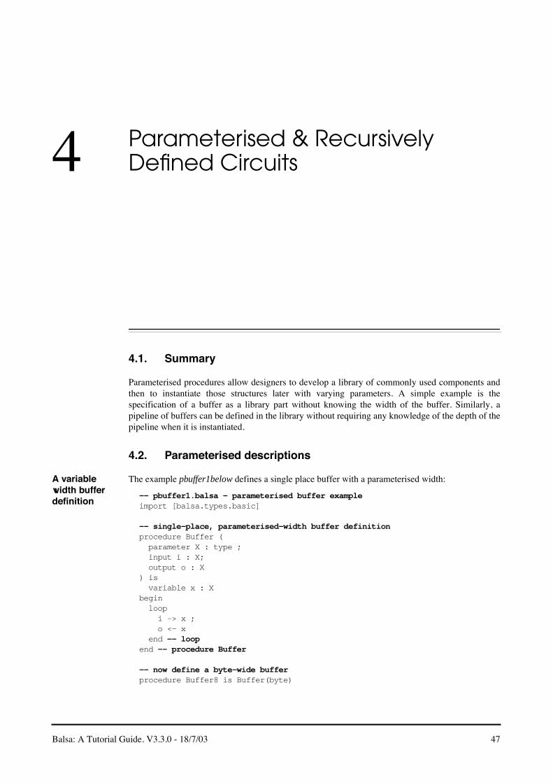
Balsa: A Tutorial Guide. V3.3.0 - 18/7/03 47
4 Parameterised & Recursively Defined Circuits
4.1. Summary
Parameterised procedures allow designers to develop a library of commonly used components andthen to instantiate those structures later with varying parameters. A simple example is thespecification of a buffer as a library part without knowing the width of the buffer. Similarly, apipeline of buffers can be defined in the library without requiring any knowledge of the depth of thepipeline when it is instantiated.
4.2. Parameterised descriptions
A variable width buffer definition
The example pbuffer1below defines a single place buffer with a parameterised width:
-- pbuffer1.balsa - parameterised buffer exampleimport [balsa.types.basic]
-- single-place, parameterised-width buffer definitionprocedure Buffer ( parameter X : type ; input i : X; output o : X) is variable x : Xbegin loop i -> x ; o <- x end -- loopend -- procedure Buffer
-- now define a byte-wide bufferprocedure Buffer8 is Buffer(byte)

4.2. Parameterised descriptions
48 Balsa: A Tutorial Guide. V3.3.0 - 18/7/03
-- now use the definitionprocedure test1(input a : byte; output b : byte) isbegin Buffer8(a,b)end -- procedure test1
-- alternativelyprocedure test2(input a : byte; output b : byte) isbegin Buffer(byte, a,b)end -- procedure test2
The definition of the single place buffer given previously [see “A single-place buffer” on page 7] ismodified by the addition of the parameter declaration which defines X to be of type type. In otherwords X is identified as being a type to be refined later. Once an abstract parameter type has beendeclared, it can be used in later declarations and statements: for example, input channel i is definedas being of type X. No hardware is generated for the parameterised procedure definition itself.
Having defined the procedure, it can be used in other procedure definitions. Buffer8 defines a bytewide buffer that can be instantiated as required as shown, for example, in procedure test1.Alternatively, a concrete realisation of the parameterised procedure can be used directly as shown inprocedure test2. Note that a test harness can be attached directly to the definition Buffer8 withimplied ports i and o.
Pipelines of variable width and depth
The next example illustrates how multiple parameters to a procedure may be specified. Theparameterised buffer element is included in a pipeline whose depth is also parameterised.
-- pbuffer2.balsa - parameterised pipeline exampleimport [balsa.types.basic]import [pbuffer1]
-- BufferN: a n-place parameterised, variable width bufferprocedure BufferN ( parameter n : cardinal ; parameter X : type ; input i : X ; output o : X) is procedure buffer is Buffer(X)begin if n = 1 then -- single place pipeline buffer(i, o) | n >= 2 then -- parallel evaluation local array 1 .. n-1 of channel c : X begin buffer(i, c[1]) || -- first buffer buffer(c[n-1], o) || -- last buffer for || i in 1 ..n-2 then buffer(c[i], c[i+1]) end end else print error, "zero length pipeline specified" endend
-- Now define a 4 deep, byte wide pipeline.procedure Buffer4 is BufferN (4, byte)
Buffer is the single place parameterised width buffer of the previous example and this is reused bymeans of the library statement import[pbuffer1]. In this code, BufferN is defined which in a very

Balsa: A Tutorial Guide. V3.3.0 - 18/7/03 49
4.3. Recursive definitions
similar manner to the example described in “Placing multiple structures” on page 11, except that thenumber of stages in the pipeline, n, is not a constant but is a parameter to the definition of typecardinal. Note that this definition includes some error checking. If an attempt is made to build a zerolength pipeline during a definition, an error message is printed.
4.3. Recursive definitions
Balsa allows a form of recursion in definitions (as long as the resulting structures can be staticallydetermined at compile time). Many structures can be elegantly described using this technique whichforms a natural extension to the powerful parameterisation mechanism. The remainder of thischapter illustrates recursive parameterisation, “Balsa Design Examples” on page 59 gives otherinteresting examples.
An n-way multiplexer
An n-way multiplexer can be constructed from a tree of 2-way multiplexers. A recursive definitionsuggests itself as the natural specification technique: an n-way multiplexer can be split into two n/2-way multiplexers connected by internal channels to a 2-way multiplexer.
--- Pmux1.balsa: A recursive parameterised MUX definitionimport [balsa.types.basic]
procedure PMux ( parameter X : type; parameter n : cardinal; array n of input inp : X; output out : X ) isbegin if n = 0 then print error,"Parameter n should not be zero" | n = 1 then loop select inp[0] then out <- inp[0] end -- select end -- loop
Figure 4.1: Decompostion of an n-way Multiplexer
0inp
n/2−1inp
n/2inp
n−1inp
0out
1out
out
After Decompostion
0inp
1inp
n−1inp
n−2inp
Before Decomposition
out

4.3. Recursive definitions
50 Balsa: A Tutorial Guide. V3.3.0 - 18/7/03
| n = 2 then loop select inp[0] then out <- inp[0] | inp[1] then out <- inp[1] end -- select end -- loop else local channel out0, out1 : X constant mid = n/2 begin PMux (X, mid, inp[0..mid-1], out0) || PMux (X, n-mid, inp[mid..n-1], out1) || PMux (X, 2, {out0,out1}, out) end -- begin end -- ifend -- begin
-- Here is a 5-way multiplexerprocedure PMux5Byte is PMux(byte, 5)
Commentary on the code
The multiplexer is parameterised in terms of the type of the inputs and the number of channels n.The code is straightforward. A multiplexer of size greater than 2 is decomposed into twomultiplexers half the size connected by internal channels to a 2-1 multiplexer. Notice how thearrayed channels, out0 and out1 are specified as a tuple. The recursive decomposition stops whenthe number of inputs is 2 or 1 (specification of a multiplexer with zero inputs generates an error).
A balsa test harness
The code below illustrates how a simple Balsa program can be used as a test harness to generate testvalues for the multiplexer. The test program is actually rather naive.
-- test_pmux.balsa - A test-harness for Pmux1import [balsa.types.basic]import [pmux1]
procedure test (output out : byte) is type ttype is sizeof byte + 1 bits array 5 of channel inp : byte variable i : ttypebegin begin i:= 1; loop while i <= 0x80 then inp[0] <- (i as byte); inp[1] <- (i+1 as byte); inp[2] <- (i+2 as byte); inp[3] <- (i+3 as byte); inp[4] <- (i+4 as byte); i:= (i + i as ttype) end end || PMux5Byte(inp, out)end
Handshake multiplier
Consider a procedure that for each handshake on an input port generates n handshakes on an outputport. A simple solution would use the for construct, but a more elegant (and less expensive)approach is to use the recursive approach.
If n is even, the repeater can be composed from two n/2 repeaters. If n is odd, the repeater can becomposed from two n/2 repeaters together with an additional extra handshake.

Balsa: A Tutorial Guide. V3.3.0 - 18/7/03 51
4.3. Recursive definitions
-- GenHS. A recursive procedure generating n Handshakes for each callimport [balsa.types.basic]
procedure repeat (parameter n : cardinal; sync o ) isbegin if n = 0 then print error, "Repeat n must not be 0" | n = 1 then sync o else local shared doNext is begin repeat(n/2, o) end begin if (n as bit) then -- n is odd sync o end ; doNext () ; doNext () end endend
procedure Gen11 is repeat(11)
procedure test (sync i, o) isbegin loop sync i; Gen11(o) -- Generate 11 Handshakes end -- loopend
A shared procedure doNext is responsible for the recursive call of repeat with half the repetitoncount. Note that doNext is local to the main repeat procedure.

4.3. Recursive definitions
52 Balsa: A Tutorial Guide. V3.3.0 - 18/7/03

Balsa: A Tutorial Guide. V3.3.0 - 18/7/03 53
5 Handshake Enclosure
Summary Normally handshakes are points of synchronisation for assignments between channels or betweenchannels and variables. A transfer is requested and when all parties to the transaction are able, thetransfer completes. After completion of the handshake, the data provider is free to remove the data.If the data on a channel is required more than once, it must be stored in a variable. Balsa has twolanguage constructs that allow the handshake on a channel to be held open whilst a sequence ofactions completes. The handshake is said to enclose the other commands.
There are several implications of handshake enclosure:
• since data is not removed until the end of the handshake enclosure, intermediate storage of the data is not required
• data does not have to be read once and only one: it may be read many times or indeed never at all without causing deadlock.
• the enclosing handshake does not complete until all its enclosed commands complete: this has performance implications since the the tree of handshakes connected to the enclosing handshake cannot themselves complete.
Handshake enclosure can be achieved by use of the select command or by assigning channels intoa command using the syntax: <channels> -> then command end. An example of the use ofselect was illustrated in the description of a merge circuit in “Selecting channels” on page 44. Inthis example, the fact that the handshake on the chosen input channel is held open allows a buffer-free description to be used – a more natural description of the mux-like structure than one whichincludes a storage element. One side effect of the select command is that a subcircuit with passiveports is generated – Balsa normally generates active ported circuits.
5.1. Systolic counters
A more complex example illustrating handshake enclosure is a description of systolic countersoriginally described by Kees van Berkel [REF]. These elegant counters possess the properties ofconstant repsonse time and a constant upper bound on power consumption regardless of the lengthof the counter. The basic idea is to recursively divide a modulo-n counter into a head counter and atail n/2 counter as shown in Figure 5.1.

5.1. Systolic counters
54 Balsa: A Tutorial Guide. V3.3.0 - 18/7/03
The derivation of the cells is given in [REF]. The head cell is either a Count-Odd cell (CO) for oddn or a Count-Even cell (CE) for even n. For CE cells, the head cell effectively doubles each a’communication of the n/2 counter along its right-hand a channel then passing b’ along b after the ncommunications along a. A Count-Odd cell issues an extra handshake to its left prior to handshaekfrom b’ to b. A special base case count-1 cell initates a handshake on its a port followed by ahandshake on its b port.
Note that ports a and b are active ports whereas a’ and b’ are passive ports. The counter is “primed”by handshakes flowing from right to left from the count-1 cell. The head cell chooses betweenhandshakes arriving on a’ and b’. The sequencing implicit in the description guarantees mutuallyexclusive use of the channels so that a non-arbitrated select construct may be used to implement thechoice. The architecture of the counter is somewhat similar to that described in Section, “Handshakemultiplier,” on page 50.
The descriptions of the basic cells are:
-- count-even cellprocedure ce(sync a_left, a_right, b_left, b_right) isbegin loop select a_right then sync a_left ; sync a_left | b_right then sync b_left end endend
-- count-odd cellprocedure co(sync a_left, a_right, b_left, b_right) isbegin loop sync a_left; select a_right then sync a_left | b_right then sync b_left end endend
-- count-1 cellprocedure c1(sync a, b) isbegin loop sync a; sync b endend
Figure 5.1: Counter Decomposition
head n div 2
a
b
a’
b’

Balsa: A Tutorial Guide. V3.3.0 - 18/7/03 55
5.1. Systolic counters
A systolic modulo-11 counter
Consider the case of a modulo-11 counter. It can be decomposed as:
11 = 1 + 2*5 = 1 + 2*(1 + 2*2) = 1 + 2*(1 + 2*(2*1))
The composition of the basic cells is shown in Figure 5.2. The description of the counter is simple:
procedure count11(sync a0, b0 ) issync a1, b1, a2, b2, a3, b3begin co(a0, a1, b0, b1)|| co(a1, a2, b1, b2) || ce(a2, a3, b2, b3) || c1(a3, b3)end
The behaviour of the circuit is shown in the trace of [REF]. An intriguing feature of this descriptionis that there appears to be be no state-holding variables defining the current state of the counter. Theanswer to this paradox is that the state of the counter is distributed over the control logic defined bythe circuit description.
All even cells The enclosed, non-buffered, semantics of the Balsa select statement may lead to performanceproblems. This is not obvious from the previous modulo-11 counter example. However, it is exposedby a modulo-8 counter composed eintirely from count-even stages. Each CE module awaits ahandshake on its right-hand a port.Upon initiation of this handshake, it issues a handshake to its lefthand a port. However, this handshake cannot immediately complete because the left-hand receivingport handshake encloses a command to issue a handshake to its left. Thus the operation procedesfrom the count-1 cell at the extreme right issuing a handshake which ripples through to the interfacea port on he extreme left. The acknowledgement ripples back to the count-1 cell whereupon thehandshake on the b channel ripples from right to left. As can be seen in [REF], the result is a highlysequential mode of operation.
All odd cells A modulo-15 counter composed entirely from count-odd stages exhibits similar behavour as shownin [REF]. However, it is possible to rewrite the descrition of the cout-odd stage to introduce extraconcurrency:
procedure co(sync a_left, a_right, b_left, b_right) isbegin loop sync a_left; select a_right then sync a_left | b_right then sync b_left end end
Here the extra handshake to the left has been taken outside of the select command. All stages cansimultaneously issue a handshake to their left and then await the incoming handshake which justbeen intiaited on its right. As can be seen from [REF], there is a significant incease in performance.
Figure 5.2: Modulo-11 Systolic Counter
CO CECO C1
a0 a1 a2 a3
b0 b1 b2 b3

5.1. Systolic counters
56 Balsa: A Tutorial Guide. V3.3.0 - 18/7/03
A faster all even cell
The effects of the enclosed behaviour of the select command may be mitigated by decoupling thereading of the selected channel from subsequent actions. It is necessary to record which of the twochannels a or b the handshake actually arrived on. This may be done by identifying the channel in asingle bit register as shown below:
procedure ceVar(sync a_left, a_right, b_left, b_right) is variable x : bitbegin loop select a_right then x := 0 | b_right then x := 1 end ; case x of 0 then sync a_left ; sync a_left | 1 then sync b_left end endend
Substituting this new version of the count-even cell in the modulo-8 counter results in the behaviourof [REF]. As can be seen, the channel activity has an entirely different characteristic from thecounter of [REF].
Parameterised version
The previous examples explicitly enumerated the constituent modules to emphasise how thecounters were composed. A more generic approach is to define a parameterised counter. Theexample below also uses a conditional declaration to choose between a count--even module withenclosed behaviour and one with a decoupled behaviour.
-- parameterised systolic ocunter with choice of decoupled even count.
constant Decoupled = true -- or false!!procedure countN (parameter n : cardinal ; sync a, b) is sync a_int, b_intbegin if n = 0 then print error, “Parameter n should not be zero” | n = 1 then c1(a, b) else if (n as bit) then -- Odd co(a, a_int, b, b_int) else if Decoupled = true then ceVar(a, a_int, b, b_int) else ce(a, a_int, b, b_int) end -- if Decoupled = true end || countN(n/2, a_int, b_int) endend
procedure Count11P is countN(15)
Active enclosure
The select command provides a means of choosing between a number of input channels. It alsohas two signifcant side effects
• an input port attached to a select command is a passive rather than an active port. The ability to coerce a port to be passive (rather than active) should normally be of little concern to users except when interfacing to external circuits.

Balsa: A Tutorial Guide. V3.3.0 - 18/7/03 57
5.1. Systolic counters
• the handshake behaviour, as discussed earlier, has enclosing semantics bringing the advantages of unbuffered channel access and the ability to read a channel multiple times as well as the disadvantages illustrated in the previous examples.
Since selection can be applied to any number channels (including a single channel), users trying toexploit the advantages of enclosed selection may be tempted to use select promiscuously. Resist thetemptation, there are some disadvantages: constructs such as:
select a then cmd1 ; select a then cmd2
results in non-delay insensitive behaviour. Furthermore there are inefficiencies associated with theuse of passive-ported structures within the generally pull-driven circuits generated by balsa. Betteris to use active enclosure and to reserve the us eof slect for those occasions when choice is genuinelyrequired.
Active enclosure – so called because it generates an active-ported structure – is of the form
to be completed

5.1. Systolic counters
58 Balsa: A Tutorial Guide. V3.3.0 - 18/7/03

Balsa: A Tutorial Guide. V3.3.0 - 18/7/03 59
6 Balsa Design Examples
Summary These examples are incomplete and must be revised. Please ignore this chapter until a furher release.
6.1. A Population Counter
This next example counts the number of bits set in a word. It comes from the requirement in anAMULET processor to know the number of registers to be restored/saved during LDM/STM (Load/Store Multiple) instructions.
The approach taken is to partition the problem into two parts. Initially, adjacent bits are addedtogether to form an arrray of 2-bit channels representing the numbers of bits that are set in each ofthe adjacent pairs. The array of 2-bit numbers are then added in a recursively defined tree of adders
-- popcount: count the number of bits set in a wordimport [balsa.types.basic]
procedure AddTree ( parameter inputCount : cardinal; parameter inputSize : cardinal; parameter outputSize : cardinal; array inputCount of input i : inputSize bits; output o : outputSize bits) isbegin if inputCount = 1 then select i[0] then o <- (i[0] as outputSize) end | inputCount = 2 then select i[0], i[1] then o <- (i[0] + i[1] as outputSize bits) end -- select else local constant lowHalfInputCount = inputCount / 2 constant highHalfInputCount = inputCount - lowHalfInputCount channel lowO, highO : outputSize - 1 bits begin

6.1. A Population Counter
60 Balsa: A Tutorial Guide. V3.3.0 - 18/7/03
AddTree (lowHalfInputCount, inputSize, outputSize - 1, i[0..lowHalfInputCount-1], lowO) || AddTree (highHalfInputCount, inputSize, outputSize - 1, i[lowHalfInputCount..inputCount-1], highO) || AddTree (2, outputSize - 1, outputSize, {lowO, highO}, o) end -- begin end -- ifend -- begin
procedure PopulationCount ( parameter n : cardinal; input i : n bits; output o : log (n+1) bits) isbegin if n % 2 = 1 then print error, "number of bits must be even" end; -- if loop select i then if n = 1 then o <- i | n = 2 then o <- (#i[0] + #i[1]) else local constant pairCount = n - (n / 2) array pairCount of channel addedPairs : 2 bits begin for || c in 0..pairCount-1 then addedPairs[c] <- (#i[c*2] + #i[(c*2)+1]) end || AddTree (pairCount, 2, log (n+1), addedPairs, o) end -- begin end -- if end -- select end -- loopend -- begin
procedure PopCount16 is PopulationCount (16)
Commentary on the code
Parameterisation: Procedures AddTree and PopulationCount are parameterised.PopulationCount can used to count the number of bits set in any sized word. AddTree isparameterised to allow a recursively defined adder of any number of arbitrary width vectors.
Enclosed Selection
The semantics of the enclosed handshake of select allow the contents of the input i to be referredto several times in the body of the select block without the need for an internal latch. An in-depthdiscussion of the implications of enclosed selection is given in [REF]
Avoiding deadlock:
Note that the formation of the sum of adjacent bits is specified by a parallel for loop.
for || c in 0..pairCount-1 then addedPairs[c] <- (#i[c*2] + #i[(c*2)+1])
It might be thought that a serial \texttt{for ;} loop could be used at, perhaps, the expense of speed.This is not the case: the system will deadlock illustrating why designing asynchronous circuitsrequires some real understanding of the methodology. In this case the adder to which the array ofaddPairs is connected requires pairs of inputs to be ready before it can complete the addition andrelease its inputs. However, if the sum of adjacent bits is computed serially, the next pair will not becomputed until the handshake for the previous pair has been completed -- which is not possiblebecause AddTree is awaiting all pairs to become valid: result deadlock!

Balsa: A Tutorial Guide. V3.3.0 - 18/7/03 61
6.2. A Balsa shifter
6.2. A Balsa shifter
General shifters are an essential element of all microprocessors including the AMULET processors.The following description forms the basis of such a shifter. It implements only a rotate rightfunction, but it is easily extensible to other shift functions. The main work of the shifter is localprocedure rorBody which recursively creates sub-shifters capable of optionally rotating 1, 2, 4, 8e.t.c. bits
import [balsa.types.basic]
procedure ror ( parameter X : type; input d : sizeof X bits; input i : X; output o : X) isbegin loop select d then local constant typeWidth = sizeof X procedure rorBody ( parameter distance : cardinal; input i : X; ) is output o : X ) is ) is local procedure rorStage ( output o : X ) is begin select i then if #d[log distance] then o <- (#i[typeWidth-1..distance] @ #i[distance-1..0] as X) else o <- i end -- if end -- select end -- begin channel c : X begin if distance > 1 then rorStage (c) || rorBody (distance / 2, c, o) else rorStage (o) end -- if end -- begin begin rorBody (typeWidth / 2, i, o) end -- begin end -- select end -- loopend -- begin
procedure ror32 is ror (32 bits)

6.3. An Arbiter Tree
62 Balsa: A Tutorial Guide. V3.3.0 - 18/7/03
Testing the shifter
Another small Balsa test routine for exercising the shifter:
import [balsa.types.basic]import [ror]
--test ror32procedure test_ror32(output o : 32 bits)is variable i : 5 bits channel shiftchan : 32 bits channel distchan : 5 bitsbegin begin i:= 1; while i < 31 then shiftchan <- 7 || distchan <- i; i:= (i+1 as 5 bits) end -- while end || ror32(distchan, shiftchan, o)end -- begin
6.3. An Arbiter Tree
The final example builds a parameterised arbiter. This circuit forms part of the DMA controller of[REF]. The architecture of an 8-input arbiter is shown [REF]. ArbFunnel is a paramaterisable treecomposed of two elements: ArbHead and ArbTree. Pairs of incoming sync requests arearbitrated andcombined into single bit decisions by ArbHead elements. These single bit channels are thenarbitrated between by ArbTree elements. An ArbTree takes a number of decision bits from each of anumber of inputs (on the i ports) and produces a rank of 2-input arbiters to reduce the problem tohalf as many inputs each with 1 extra decision bit. Recursive calls to ArbTree reduce the number ofinput channels to one (whose final decision value is returned on port o).
Figure 6.1:

Balsa: A Tutorial Guide. V3.3.0 - 18/7/03 63
6.3. An Arbiter Tree
import [balsa.types.basic]
-- ArbHead: 2 way arbcall with channel no. output^procedure ArbHead ( sync i0, i1; output o : bit) is begin loop arbitrate i0 then o <- 0 | i1 then o <- 1 end -- arbitrate end -- loopend -- begin
-- ArbTree: a tree arbcall which outputs a channel number-- prepended onto the input channel's data. (invokes itself-- recursively to make the tree)procedure ArbTree ( parameter inputCount : cardinal; parameter depth : cardinal; -- bits to carry from inputs array inputCount of input i : depth bits; output o : (log inputCount) + depth bits) is type BitArray is array 1 of bit type BitArray2 is array 2 of bit function AddTopBit (hd : bit; tl : depth bits) = ((tl as array depth of bit) @ {hd} as depth + 1 bits) function AddTopBit2 (hd : bit; tl : depth + 1 bits) = ((tl as array depth + 1 of bit) @ {hd} as depth + 2 bits) function AddTop2Bits (hd0 : bit; hd1 : bit; tl : depth bits) = ((tl as array depth + 1 of bit) @ {hd0,hd1} as depth + 2 bits)begin case inputCount of 0, 1 then print error, "Can't build an ArbTree with fewer than 2 inputs" | 2 then loop arbitrate i[0] -> i0 then o <- AddTopBit (0, i0) | i[1] -> i1 then o <- AddTopBit (1, i1) end -- arbitrate end -- loop | 3 then local channel lo : 1 + depth bits begin ArbTree (2, depth, i[0 .. 1], lo) || loop arbitrate lo then o <- AddTopBit2 (0, lo) | i[2] -> i2 then o <- AddTop2Bits (1, 0, i2) end -- arbitrate end -- loop end -- begin else local constant halfCount = inputCount / 2 constant halfBits = depth + log halfCount channel l, r : halfBits bits begin ArbTree (halfCount, depth, i[0 .. halfCount-1], l) || ArbTree (inputCount - halfCount, depth, i[halfCount .. inputCount-1], r) || ArbTree (2, halfBits, {l,r}, o) end -- begin end -- case inputCountend -- begin

6.3. An Arbiter Tree
64 Balsa: A Tutorial Guide. V3.3.0 - 18/7/03
-- ArbFunnel: build a tree arbcall (balanced apart from the last-- channel which is faster than the rest) which produces a channel-- number from an array of sync inputsprocedure ArbFunnel ( parameter inputCount : cardinal; array inputCount of sync i; output o : log inputCount bits) is constant halfCount = inputCount / 2 constant oddInputCount = inputCount % 2begin if inputCount < 2 then print error, "can't build an ArbFunnel with fewer than 2 inputs" | inputCount = 2 then ArbHead (i[0], i[1], o) | inputCount > 2 then local array halfCount + 1 of channel li : bit begin for || j in 0 .. halfCount - 1 then ArbHead (i[j*2], i[j*2+1], li[j]) end || if oddInputCount then ArbTree (halfCount + 1, 1, li[0 .. halfCount], o) || loop select i[inputCount - 1] then li[halfCount] <- 0 end -- select end -- loop else ArbTree (halfCount, 1, li[0 .. halfCount-1], o) end -- if end -- begin end -- ifend -- begin

Balsa: A Tutorial Guide. V3.3.0 - 18/7/03 65
7 Implementations
This chapter not yet complete - or even started.

66 Balsa: A Tutorial Guide. V3.3.0 - 18/7/03

Balsa: A Tutorial Guide. V3.3.0 - 18/7/03 67
8 The Balsa Language Definition
Summary The syntax of the balsa language is given in Table 8.1. An extended form of BNF is used to describethe syntax. A term ( a )* denotes zero or more repetitions of the term a, the term ( a )+ denotes oneor more repetitions of a and ( a )? indicates that the term a is optional (i.e. zero or one repetitions ofthe term a). Terminal symbols are shown in bold face, non terminal symbols are enclosed by anglebrackets ⟨⟩.
8.1. Reserved words
The following are reserved words. Most (but not all) correspond to current keywords in the Balsalanguage, others are reserved for future releases of the Balsa system.
active, also, and, arbitrate, array, as, begin, bits, case, channel, constant, continue, else, end,enumeration, fo,r function, halt, if, import, in, input, is, let, local, log, loop, multicast, new, not, of,or, output, over, parameter, passive, print, procedure, pull, push, record, select, shared, signed,sizeo, sync, then, type, val, variable, while, xor.
8.2. Language Definition
⟨bin-digit⟩ ::= ( 0 | 1 )
⟨oct-digit⟩ ::= ( 0 ... 7 )
⟨dec-digit⟩ ::= ( 0 ... 9 )
⟨hex-digit⟩ ::= ( 0 ... 9 | a ... f | A ... F )
⟨letter⟩ ::= ( a ... z | A ... Z )
⟨identifier⟩ ::= ( ⟨letter⟩ | _ ) ( ⟨letter⟩ | ⟨dec-digit⟩ | _ )*
Table 8.1: Balsa Language Definition

8.2. Language Definition
68 Balsa: A Tutorial Guide. V3.3.0 - 18/7/03
⟨literal⟩ ::= ( 1 ... 9 ) ( ⟨dec-digit⟩ | _ )*
| 0 ( ⟨oct-digit⟩ | _ )*
| ( 0b | 0B ) ( ⟨bin-digit⟩ | _ | x | X | ? )+
| ( 0x | 0X ) ( ⟨hex-digit⟩ | _ | x | X | ? )+
| ?
⟨string-char⟩ ::= ( ⟨letter⟩ | ⟨dec-digit⟩ | | ! | # | $ | % | & | ' | ( | ) | * | + | , | - | . | / | : | ; | < | = | > | ? | @ | [ | ] | ^ | _ | ` | { | | | } | ~ )
⟨string⟩ ::= " ( ⟨string-char⟩ )* "
⟨file⟩ ::= ( import [ ⟨dotted-path⟩ ] )* ⟨outer-declarations⟩
⟨dotted-path⟩ ::= ⟨identifier⟩ ( . ⟨identifier⟩ )*
⟨outer-declarations⟩ ::= ( ⟨outer-declaration⟩ )*
⟨outer-declaration⟩ ::= type ⟨identifier⟩ is ⟨type-declaration⟩
| constant ⟨identifier⟩ = ⟨expression⟩ ( : ⟨type⟩ )?
| procedure ⟨identifier⟩ is ⟨identifier⟩ ( ( ⟨procedure-formals⟩ ) )?
|
procedure ⟨identifier⟩ ( ( ⟨procedure-formals⟩ ) )? is ( local )? ⟨inner-declarations⟩ begin ⟨command⟩ end
|
function ⟨identifier⟩ ( ( ⟨function-formals⟩ ) )? = ⟨expression⟩ ( : ⟨type⟩ )?
|
if ⟨expression⟩ then ⟨outer-declarations⟩ ( | ⟨expression⟩ then ⟨outer-declarations⟩ )* ( else ⟨outer-declarations⟩ )? end
⟨type-declaration⟩ ::= ⟨type⟩
| new ⟨type⟩
|
record ⟨identifiers⟩ : ⟨type⟩ ( | ⟨identifiers⟩ : ⟨type⟩ )* ( end | ( over ⟨type⟩ ) )
|
enumeration ⟨identifier⟩ ( = ⟨expression⟩ )? ( | ⟨identifier⟩ ( = ⟨expression⟩ )? )* ( end | ( over ⟨type⟩ ) )
⟨identifiers⟩ ::= ⟨identifier⟩ ( ; ⟨identifier⟩ )*
⟨type⟩ ::= ⟨identifier⟩
| ⟨expression⟩ ( signed )? bits
| array ⟨range⟩ of ⟨type⟩
⟨function-formals⟩ ::= ⟨identifiers⟩ : ⟨type⟩ ( ; ⟨identifiers⟩ : ⟨type⟩ )*
⟨procedure-formals⟩ ::= ⟨formal-parameters⟩
| ⟨formal-ports⟩
| ⟨formal-parameters⟩ ; ⟨formal-ports⟩
Table 8.1: Balsa Language Definition

Balsa: A Tutorial Guide. V3.3.0 - 18/7/03 69
8.2. Language Definition
⟨formal-parameters⟩ ::= parameter ⟨identifiers⟩ : ⟨type⟩ ( ; parameter ⟨identifiers⟩ : ⟨type⟩ )*
⟨formal-ports⟩ ::= ⟨formal-port⟩ ( ; ⟨formal-port⟩ )*
⟨formal-port⟩ ::= ( array ⟨range⟩ of )? ( input | output ) ⟨identifiers⟩ : ⟨type⟩
| ( array ⟨range⟩ of )? sync ⟨identifiers⟩
|
if ⟨expression⟩ then ⟨formal-ports⟩ ( | ⟨expression⟩ then ⟨formal-ports⟩ )* ( else ⟨formal-ports⟩ )? end
⟨range⟩ ::= ⟨expression⟩
| ⟨expression⟩ .. ⟨expression⟩
| over ⟨type⟩
⟨inner-declarations⟩ ::= ( ⟨inner-declaration⟩ )*
⟨inner-declaration⟩ ::= ⟨outer-declaration⟩
| variable ⟨identifiers⟩ : ⟨type⟩
| ⟨chan-opts⟩ ( array ⟨range⟩ of )? channel ⟨identifiers⟩ : ⟨type⟩
| ⟨chan-opts⟩ ( array ⟨range⟩ of )? sync ⟨identifiers⟩
|
shared ⟨identifier⟩ is ( local )? ⟨inner-declarations⟩ begin ⟨command⟩ end
|
if ⟨expression⟩ then ⟨inner-declarations⟩ ( | ⟨expression⟩ then ⟨inner-declarations⟩ )* ( else ⟨inner-declarations⟩ )? end
⟨channel-options⟩ ::= ( multicast )?
⟨expression⟩ ::= ⟨identifier⟩
| ⟨literal⟩
| ⟨string⟩
| ( ⟨identifier⟩ )? { ⟨expressions⟩ }
| ⟨identifier⟩ ' ⟨identifier⟩
| ⟨unary-operator⟩ ⟨expression⟩
| sizeof ⟨identifier⟩
| ⟨expression⟩ ⟨binary-operator⟩ ⟨expression⟩
| ⟨expression⟩ . ⟨identifier⟩
| ⟨expression⟩ [ ⟨range⟩ ]
| ( ⟨expression⟩ as ⟨type⟩ )
| ( ⟨expression⟩ )
| ⟨identifier⟩ ( ( ⟨expressions⟩ )? )
⟨expressions⟩ ::= ⟨expression⟩ ( , ⟨expression⟩ )*
Table 8.1: Balsa Language Definition

8.2. Language Definition
70 Balsa: A Tutorial Guide. V3.3.0 - 18/7/03
⟨unary-operator⟩ ::= ( - | + | not | log | # )
⟨binary-operator⟩ ::= ( + | - | * | / | % | ^ | = | /= | < | > | <= | >= | and | or | xor | @ )
⟨command⟩ ::= continue
| halt
| ⟨channel⟩ -> ⟨lvalue⟩
| ⟨channel⟩ -> ⟨channel⟩
| ⟨channels⟩ -> then ⟨command⟩ end
| ⟨channel⟩ <- ⟨expression⟩
| sync ⟨channel⟩
| ⟨lvalue⟩ := ⟨expression⟩
| ⟨block⟩
| ⟨command⟩ ; ⟨command⟩
| ⟨command⟩ || ⟨command⟩
| loop ⟨command⟩ end
| loop ⟨command⟩ while ⟨expression⟩ end
| loop ( ⟨command⟩ )? while ⟨guards⟩ ( also ⟨command⟩ )? end
| if ⟨guards⟩ ( else ⟨command⟩ )? end
|
case ⟨expression⟩ of ⟨case-guard⟩ ( | ⟨case-guard⟩ )* ( else ⟨command⟩ )? end
| for ( || | ; ) ⟨identifier⟩ in ⟨range⟩ then ⟨command⟩ end
| select ⟨channel-guard⟩ ( | ⟨channel-guard⟩ )* end
| arbitrate ⟨channel-guard⟩ | ⟨channel-guard⟩ end
| print ⟨expressions⟩
| ⟨identifier⟩ ( ( ⟨procedure-actuals⟩ )? )
⟨channels⟩ ::= ⟨channel⟩ ( , ⟨channel⟩ )*
⟨channel⟩ ::= ⟨identifier⟩
| ⟨identifier⟩ [ ⟨expression⟩ ]
⟨lvalue⟩ ::= ⟨identifier⟩
| ⟨lvalue⟩ . ⟨identifier⟩
| ⟨lvalue⟩ [ ⟨expression⟩ ]
⟨block⟩ ::= ( local ⟨inner-declarations⟩ )? begin ⟨command⟩ end
| [ ⟨command⟩ ]
⟨guards⟩ ::= ⟨expression⟩ then ⟨command⟩ ( | ⟨expression⟩ then ⟨command⟩ )*
Table 8.1: Balsa Language Definition

Balsa: A Tutorial Guide. V3.3.0 - 18/7/03 71
8.2. Language Definition
⟨case-guard⟩ ::= ⟨case-matches⟩ then ⟨command⟩
| for ⟨identifier⟩ in ⟨case-matches⟩ then ⟨command⟩
⟨case-match⟩ ::= ⟨expression⟩
| ⟨expression⟩ .. ⟨expression⟩
⟨case-matches⟩ ::= ⟨case-match⟩ ( , ⟨case-match⟩ )*
⟨channel-guard⟩ ::= ⟨channels⟩ then ⟨command⟩ ( | ⟨channels⟩ then ⟨command⟩ )*
⟨procedure-actuals⟩ ::= ⟨actual-parameters⟩
| ⟨actual-channels⟩
| ⟨actual-parameters⟩ , ⟨actual-channels⟩
⟨actual-parameters⟩ ::= ⟨actual-parameter⟩ ( , ⟨actual-parameter⟩ )*
⟨actual-parameter⟩ ::= ⟨expression⟩
| ( type )? ⟨type⟩
⟨actual-channels⟩ ::= ⟨actual-channel⟩ ( , ⟨actual-channel⟩ )*
⟨actual-channel⟩ ::= ⟨identifier⟩
| ⟨actual-channel⟩ [ ⟨range⟩ ]
| <- ⟨expression⟩
| -> ⟨lvalue⟩
| ⟨block⟩
| { ⟨actual-channel⟩ ( , ⟨actual-channel⟩ )* }
| ⟨actual-channel⟩ @ ⟨actual-channel⟩
Table 8.1: Balsa Language Definition

8.2. Language Definition
72 Balsa: A Tutorial Guide. V3.3.0 - 18/7/03

Balsa: A Tutorial Guide. V3.1 73
9 References
[1] Kees van Berkel. “Handshake CIrcuits - an Asynchronous Architecture for VLSIprogramming”. Cambridge International Series on Parallel Computerss 5, Cambridge UniversityPress ,1993
[2] Theseus Logic Inc. <http://www.theseus.com>
[3] Part 2 of “Principles of Asynchronous Circuit Design: A Systems Perspective”, Eds Sparsø &Furber, Kluwer Academic Publishers, ISBN 0-7923-7613-7, 2001
[4] http://www.cs.man.ac.uk/apt/projects/lard/index.html