Embed Size (px)
Citation preview

BAC-5841/5842 UFAD and BAC-5841-16/5842-16 VAV AACs 1 Installation and Operation Guide
Installation and Operation Guide
Revision B 902-019-52B
BAC-5841/5842 UFAD andBAC-5841-16/5842-16 VAV
Advanced Application Controllers, 8 x 8
NOTE: Download these additional documents from the KMC Controls Partners web site!
• To install and properly address these controllers on a network, see Installation Instructions for MS/TP Automatic MAC Addressing!
• See the appropriate model’s data sheet for relevant accessories, specifications, and other important information!
• This document covers installation only for the preconfigured applications and accessories. For custom applications and accessories, see also the installation guide for the standard BAC-5801/5802 for more information.

BAC-5841/5842 UFAD and BAC-5841-16/5842-16 VAV AACs 2 Installation and Operation Guide
© 2012 KMC Controls, Inc.
The KMC logo is a registered trademark of KMC Controls, Inc.
All rights reserved. No part of this publication may be reproduced, transmitted, transcribed, stored in a retrieval system, or translated into any language in any form by any means without the written permission of KMC Controls, Inc.
Printed in U.S.A.
Disclaimer: The material in this manual is for information purposes only. The contents and the product it describes are subject to change without notice. KMC Controls, Inc. makes no representations or warranties with respect to this manual. In no event shall KMC Controls, Inc. be liable for any damages, direct or incidental, arising out of or related to the use of this manual.
FCC Compliance: This device complies with Part 15 of the FCC Rules. Operation is subject to the following two conditions: (1) this device may not cause harmful interference, and (2) this device must accept any interference received, including interference that may cause undesired operation. This Class A digital apparatus complies with Canadian ICES-003 Class A.
KMC Controls19476 Industrial DriveNew Paris, IN 46553U.S.A.
TEL: 574.831.5250
FAX: 574.831.5252
EMAIL: [email protected]
WEB: www.kmccontrols.com
SEE ALSO BACK PAGE

BAC-5841/5842 UFAD and BAC-5841-16/5842-16 VAV AACs 3 Installation and Operation Guide
CONTENTS
SECTION 1—Installation (Mounting and Wiring) ................................ 4 Mounting ............................................................................................................. 4
BAC-5841/4542 UFAD ........................................................................................ 4
BAC-5841-16/5842-16 VAV ................................................................................. 6
Connecting Inputs and Outputs ........................................................................... 7
Connecting to an MS/TP Network ....................................................................... 9
Connections and Wiring ................................................................................. 9
End of Line Termination Switches ................................................................. 10
Connecting Power .............................................................................................. 11
SECTION 2—Operation and Troubleshooting .................................... 12 Application Configuration with a NetSensor ..................................................... 12
Motion Sensing with a KMD-12x1 NetSensor .................................................... 12
Controls and Indicators ..................................................................................... 13
Network Disconnect Switch ........................................................................ 13
LED Indicator: Ready (Green) ...................................................................... 13
LED Indicator: MS/TP Communications (Amber) ......................................... 14
LED Indicator: Error Conditions ................................................................... 14
Isolation Bulbs (HPO-0054) ......................................................................... 15
Replacing the Fuse ............................................................................................. 15
Viewing the Firmware Version ........................................................................... 15
Real-Time Clock and Time Updates .................................................................... 16
Troubleshooting ................................................................................................. 17
Communication Issues ................................................................................. 17
Inputs or Outputs Not Working ................................................................... 17
LED Indicators and Isolation Bulbs Issues .................................................... 17
Temperature Is Not Controlled Properly ...................................................... 18
Other Configuration, Network, or Hardware Issues .................................... 18
Resetting (Reinitializing) the Controller ............................................................. 19
Types of Reset .............................................................................................. 19
Performing a WARM Start ............................................................................ 19
Performing a COLD Start ............................................................................. 20
Restoring Factory Defaults of Controller Functions ...................................... 20
INDEX ................................................................................................ 21

BAC-5841/5842 UFAD and BAC-5841-16/5842-16 VAV AACs 4 Installation and Operation Guide
SECTION 1—Installation KMC ControlsSECTION 1—Installation (Mounting and Wiring)
This section provides important instructions and guidelines for installing the controller. Carefully review this information before installation.
MountingUse the four mounting holes on the top and bottom of the controller to fasten it securely to a flat surface with #6 or #8 (or metric equivalents) hardware. To main-tain RF emission specifications, use either shielded connecting cables or enclose all cables in conduit.
BAC-5841/4542 UFADFor UFAD (but not VAV) applications, the cooling/heating control sequence is selected by the location and number of the STE-601x sensors connected to the “sensor pairs.”
Sensor Pair
STE-601x Connected to: H/C Output ModeOutput 1 (3)
Controlled by:Output 2 (4)
Controlled by:
1Sensor 1 and Sensor 2 Outputs 1 and 2 both
cooling Sensor 1 Sensor 2
Sensor 1 Only Output 1 cooling and Output 2 heating Sensor 1
2Sensor 3 and Sensor 4 Outputs 3 and 4 both
cooling (Sensor 3) (Sensor 4)
Sensor 3 Only Output 3 cooling and Output 4 heating (Sensor 3)
NOTE: This assumes the default jumper postions as shown in Illustration 1 below.A
CTU
ATO
RS
WA
LL SENSO
RS
1234
NS
1234
NS
1234
NS
1234
NS
ACTUATOR1 2 3 4 5
WALL SENSOR
OU
T6
GN
D
OU
T7
GN
D
OU
T8STE6014
STE6016
BAC-5841/5842
Output 2
Output 3
Output 4
Output 5
Output 1
Sensor 2
Sensor 3
Sensor 4
Sensor 1Sensor Pair 1
Sensor Pair 2
NetSensor
Illustration 1—Sensor Pairs and OutputsCooling outputs range between 2 and 10 VDC and heating outputs range between 0 and 10 VDC, each mapped to 100% of the associated control loop output.
For sample diagrams for under-floor air distribution applications, see Illustration 2 and Illustration 3 on page 5.
BAC-5841/5842 UFAD and BAC-5841-16/5842-16 VAV AACs 5 Installation and Operation Guide
SECTION 1—Installation KMC Controls
HSO-2212Actuator Cable
(12-ft. length between actuators)
A total of up to 23 MEP-4x42actuators in up to 5
actuator chains with up to 5 separate zones
(see the table for the max. # of actuators per chain)
StandardEthernetCables
NetSensorZONE 5
NetSensorCable
KMD-569x
AC
TUA
TOR
S
WA
LL SENSO
RS
1234
NS
1234
NS
1234
NS
1234
NS
ACTUATOR1 2 3 4 5
WALL SENSOR
OU
T6
GN
D
OU
T7
GN
D
OU
T8STE6014
STE6016
BAC-5841/5842
ZONE 2
ZONE 3
ZONE 4ZONE 5
5 ZONES COOLING
ACTUATORCHAIN 1
and ZONE 1
24 VAC (+20/-15%)XEE-6111-100
(Size VA to matchsystem requirements)
~
T
STE-601xZONE 1
STE-601xZONE 2
STE-601xZONE 3
STE-601xZONE 4
Note: Fuse on controller is 4 A fast-acting type.Fuse handles controller and actuators.
Note: STEs are either all 6014s or all 6016s. The switchnext to Output 6 must be set accordingly. This switch supplies power from Output 8 to the STE-6016s and also selects the proper setpoint look-up table.
Note: Ethernet cables should be standard straight-through (NOT cross-over) cables.
Illustration 2—Sample 5 Zones Cooling UFAD Application (BAC-5841/5842)
AC
TUA
TOR
S
WA
LL SENSO
RS
1234
NS
1234
NS
1234
NS
1234
NS
ACTUATOR1 2 3 4 5
WALL SENSOR
OU
T6
GN
D
OU
T7
GN
D
OU
T8STE6014
STE6016
BAC-5841/5842
CHAIN 2
CHAIN 3CHAIN 4
ACTUATORCHAIN 1
2 ZONES HEAT/COOL
ZONE 2 HEATING (Hot Water Valves)
ZONE 2 COOLING (Dampers)
ZONE 1 HEATING (Hot Water Valves)
ZONE 1 COOLING (Dampers)
24 VAC (+20/-15%)XEE-6111-100
(Size VA to matchsystem requirements)
~
TNote: Fuse on controller is 4 Afast-acting type. Fuse handlescontroller and actuators.
Note: Ethernet cablesshould be standardstraight-through (NOTcross-over) cables.
STE-601xZONE 1
STE-601xZONE 2
A total of up to 23MEP-4x42 actuatorsin up to 4 actuatorchains with up to 2
separate zones(see the table for the max. # of actuators per chain)
HSO-2212 Actuator Cable(12-ft. length between actuators)
StandardEthernetCables
Note: STEs are either all 6014s or all 6016s.The switch next to Output 6 must be setaccordingly. This switch supplies powerfrom Output 8 to the STE-6016s and alsoselects the proper setpoint look-up table.
(HSO-2350 Cable,alternate 0–10 VDC
connection to electricheat control, e.g., toREE-5001 3-Stage
Reheat Relay Module)
Illustration 3—Sample 2 Zones Heat/Cool UFAD (BAC-5841/5842)

BAC-5841/5842 UFAD and BAC-5841-16/5842-16 VAV AACs 6 Installation and Operation Guide
SECTION 1—Installation KMC Controls
BAC-5841-16/5842-16 VAVFor a sample diagram of a Variable Air Volume application, see Illustration 4.
AC
TUA
TOR
S
WA
LL SENSO
RS
1234
NS
1234
NS
1234
NS
1234
NS
ACTUATOR1 2 3 4 5
WALL SENSOR
OU
T6
GN
D
OU
T7
GN
D
OU
T8STE6014
STE6016
BAC-5841/5842-16
VAVZONE 2
4 Zone Output w/ 2H/2C Equipment
24 VAC (+20/-15%)XEE-6111-100
(Size VA to matchsystem requirements)
~
T
VAVZONE 3
VAVZONE 4
VAVZONE 1
G (Fan)
Y1 (Cool 1)
Y2 (Cool 2)
W1 (Heat 1)
W2 (Heat 2)
C
R
REE-5501 Relay Modules
NetSensorZONE 1
OUT 6 OUT 7
HSO-2250 (Typical) Cables
KMD-569x NetSensor Cable
BypassDamper
2H/2C
HV
AC
Equipment
Stages2
1S
C3
RE
E-5501
Isolated Staging Relay
24 VAC
0-10IN
Stages2
1S
C3
RE
E-5501
Isolated Staging Relay
24 VAC
0-10IN
Standard Ethernet Cables
TPE-1474-21Pressure
Transducer
STE-601xZONE 2
STE-601xZONE 3
STE-601xZONE 4
Note: Fuse on controller is 4 A fast-acting type.Fuse handles controller and actuators.
Note: Ethernet cables should be standardstraight-through (NOT cross-over) cables.
24 VACEquipmentTransformer
~ T
Note: For duct pressure/temp sensors, the Ethernert cable’s modular plug is cut off, the lead from pin 1 is connected to the TPE’s OUT terminal, the lead from pin 3 is connected to the TPE’s COM terminal, and the leads from pins 3 and 8 are connected to the temp sensor’s thermistor. The TPE’s Output must also be set to 0–5 VDC and the Range jumper must be set to 4 (0–2” wc).
STE-1xxx DuctTemp. Sensor
Note: The STE-601x sensors are either all 6014s or 6016s. The switch next to Output 6 must be set accordingly. This switch supplies power from Output 8 to the STE-6016s and also selects the proper setpoint look-up table.
1
3
3
8
Illustration 4—Sample 4 Zone VAV w/ 2H/2C Equipment (BAC-5841-16/5842-16)
BAC-5841/5842 UFAD and BAC-5841-16/5842-16 VAV AACs 7 Installation and Operation Guide
SECTION 1—Installation KMC Controls
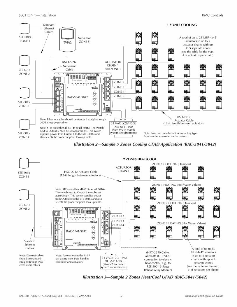
Connecting Inputs and OutputsEach of the modular input connectors is preconfigured to receive analog signals from temperature sensors and setpoint controls. Plug standard (not cross-over) Ethernet cables into the input connectors and the corresponding STE-6014 or STE-6016. Select the corresponding position on the sensor selection switch at the top of the controller. See Illustration 13 on page 13.
For outputs, use HSO-22xx cables to connect to MEP-4x42 actuators, using the modular connectors.
Cable P/N Cable LengthMax. # of Daisy-Chained MEP-4x42s
WithOUT HSO-5010 WITH HSO-5010*
HSO-2203 3 feet 8 8HSO-2206 6 feet 8 8HSO-2212 12 feet 6 8HSO-2220 20 feet 4 8HSO-2250 50 feet 2 4
*For examples of the HSO-5010 3-way “Y” modular connector in use with the actuators, see Illustration 5 on page 7.
The HSO-2350 can also provide a connection to the terminal block. See Illustration 5 on page 7.
HSO-5010 3-Way“Y” Modular Connector
HSO-2121 Transformer CableController
Up to 2 MEP-4x42s on each side of thetransformer with HSO-2250 cables
(see chart for more options)
HSO-2250 Actuator Cable,50-foot length between actuators
Wires: Orange& Orange Stripe
T
Wires: Green& Green Stripe
XEE-6xxx-xxxTransformer
24 VAC (+20/–15)4 VA per actuator
HSO-2350 DDC Controller(terminal block) to Actuator Cable
,
Illustration 5—Sample HSO-2350 and HSO-5010 Application
For output connections to devices other than MEP-4x42 actuators, use 14–22 AWG wire to the terminal block for Outputs 6–8. See Illustration 4 on page 6.
The maximum allowable output current is 100 mA per output OR 350 mA total.
NOTE: To change which input controls which output, adjust the sensor input to actuator output mapping selection jumpers as needed. See Illustration 13 on page 13.

BAC-5841/5842 UFAD and BAC-5841-16/5842-16 VAV AACs 8 Installation and Operation Guide
SECTION 1—Installation KMC Controls
NOTE: Room temperature sensor models cannot be mixed. Room temperature sensors must all be STE-6014s (with rotary setpoint dial) OR all be STE-6016s (with LCD display and up/down setpoint buttons) and the switch by Output 6 must be set accordingly. However, duct sensors may be used in the place of one of the room temperature sensors (see Illustration 4 on page 6.
NOTE: Ethernet cables should be standard straight-through (NOT cross-over) cables. To use a standard straight-through Ethernet cable with duct sensors:1. Cut off one modular plug.2. Strip the wires connected to pins 1, 3, and 8. See Illustration 6.3. Connect those wires to the duct sensors as noted in Illustration 4 on
page 6.4. Tape back or cut off all other wires.
Ethernet Cable Connector Pins Input Function
1 Setpoint
3 Ground
6 12 VDC Supply for STE-6016
8 Temperature Sensor
Pin 1 Pin 8
Illustration 6—Ethernet Cable Pins (for Modular Inputs)
Connector Pins Function
1 and 6 ~ 24 VAC (phase side)
2 and 5 Common
3 No Connection on BAC-584x (but 17.4 VDC out @ 10 mA Max. on MEP-4x42 actuators for powering CTE-5201-16)
4 Signal (2–10 VDC)
Pin 6
Pin 1
Illustration 7—Modular Output Connector Pins
See also Application Configuration with a NetSensor on page 12.
NOTE: Unlike standard BAC-580x controllers, these BAC-584x controllers do not support the use of HPO-67xx output override boards.

BAC-5841/5842 UFAD and BAC-5841-16/5842-16 VAV AACs 9 Installation and Operation Guide
SECTION 1—Installation KMC Controls
Connecting to an MS/TP Network
Connections and Wiring
Use the following principles when connecting a controller to an EIA-485 (formerly RS-485) MS/TP network:
• Use 18 gauge, twisted-pair, shielded cable with capacitance of no more than about 50 picofarads per foot for all network wiring. Belden cable model #82760 meets KMC requirements.
• Connect the –A terminals in parallel with all other –A terminals and the +B terminals in parallel with all other +B terminals. The EIA-485 terminals on most KMC controllers are labeled –A, +B, and S. The S terminal is provided as a connecting point for the shield. The terminal is not connected to the ground of the controller. (See Illustration 8.) When connecting to controllers from other manufacturers, verify the shield connection is not connected to ground.
• Connect the shields of the cable together at each controller. For KMC BACnet controllers use the S terminal or a wire nut. Connect the shield to an earth ground at one end only.
• To maintain communications in case of an open conductor on the network cable, redundant wiring routed separately enhances reliability.
�����
�����
�����
�����
����
�����
����
������ ����������������������
��
��
�
��
��
�
��
��
� �����
�����
�����
����������������� ��������
������������������
Illustration 8—MS/TP Network Wiring (Standard and Redundant Wiring)
• Connect no more than 128 addressable BACnet master devices (total) to one MS/TP network. The devices can be any mix of controllers or routers. (Up to 127 slave devices can also be connected.)

BAC-5841/5842 UFAD and BAC-5841-16/5842-16 VAV AACs 10 Installation and Operation Guide
SECTION 1—Installation KMC Controls
• Limiting the MS/TP network size to no more than about 60 BAC-A1616BC, BAC-5800, and BAC-7000 series controllers will optimize network perfor-mance.
• Use a KMC KMD-5575 repeater after every 31 MS/TP devices or if the cable length exceeds 4,000 feet (1,220 meters). Generally, use no more than four re-peaters per MS/TP network. Do not connect the cable shield to the circuit GND terminal on the KMD-5575. For each network segment, connect the shields to a good earth ground at only one end of the segment; tape back the shield ground at the other end.
• Place a KMC KMD-5567 surge suppressor in the cable where it exits a building.
See also Application Note AN0404A, Planning BACnet Networks for additional tips.
End of Line Termination Switches
The controllers on the physical ends of the EIA-485 wiring segment must have end-of-line termination installed for proper network operation. In the end controllers, set the end-of-line termination to On using the EOL switches. See Illustration 8 on page 9, Illustration 9, and Illustration 10.
EOL Termination
Illustration 9—End-of-Line Termination
AC
TUA
TORS
5
4
3
2
1~
- G
ND
POWER
WA
LL SENSO
RS
1 2 3 4
COMM
READY
OFF
ON
EOL-A +B S
NETSEN
SOR
ACTUATOR1 2 3 4 5
1234
NS
1234
NS
1234
NS
1234
NSWALL SENSOR
OUT
6
GN
D
OUT
7
GN
D
OUT
8
STE-6014
STE-6016
4 AMPSUPPLY VOLTAGE24VAC CLASS 2
EOL Switch
Network Disconnect Switch
On
Off
Disconnected (Off)
Connected (On)
Illustration 10—Location of Network Disconnect and EOL SwitchesThese controllers feature an automatic network addressing feature. See Installa-tion Instructions for MS/TP Automatic MAC Addressing for additional informa-tion about installing these controllers on a BACnet network!

BAC-5841/5842 UFAD and BAC-5841-16/5842-16 VAV AACs 11 Installation and Operation Guide
SECTION 1—Installation KMC Controls
Connecting PowerThe controller requires an external, 24 volt, AC power source. Use the following guidelines when choosing and wiring transformers.
• Use a KMC Controls Class-2 transformer of the appropriate size to supply power to the controllers. See the data sheets for all connected devices to calculate the required VA rating of the transformer.
• KMC Controls recommends powering only one controller from each trans-former.
• When installing a controller in a system with other controllers, you may power multiple controllers with a single transformer as long as the total power drawn from the transformer does not exceed its rating and phasing is correct.
• If several controllers are mounted in the same cabinet, you can share a trans-former between them provided the transformer does not exceed 100 VA or other regulatory requirements.
• Do not run 24 volt, AC power from within an enclosure to external controllers.
Connect the 24 volt AC power supply to the power terminal block on the lower right side of the controller near the power jumper. See Illustration 11. Connect the neutral lead from the transformer to the – terminal (middle terminal of the block) and the AC phase to the ~ (phase) terminal. Power is applied to the control-ler when the transformer is powered and the power jumper is in place.
HSO-2212Actuator Cable
(12-ft. length between actuators)
A total of up to 23 MEP-4x42actuators in up to 5
actuator chains with up to 5 separate zones
(see the table for the max. # of actuators per chain)
StandardEthernetCables
NetSensorZONE 5
NetSensorCable
KMD-569x
AC
TUA
TOR
S
WA
LL SENSO
RS
1234
NS
1234
NS
1234
NS
1234
NS
ACTUATOR1 2 3 4 5
WALL SENSOR
OU
T6
GN
D
OU
T7
GN
D
OU
T8STE6014
STE6016
BAC-5841/5842
ZONE 2
ZONE 3
ZONE 4ZONE 5
5 ZONES COOLING
ACTUATORCHAIN 1
and ZONE 1
24 VAC (+20/-15%)XEE-6111-100
(Size VA to matchsystem requirements)
~
T
STE-601xZONE 1
STE-601xZONE 2
STE-601xZONE 3
STE-601xZONE 4
Note: Fuse on controller is 4 A fast-acting type.Fuse handles controller and actuators.
Note: STEs are either all 6014s or all 6016s. The switchnext to Output 6 must be set accordingly. This switch supplies power from Output 8 to the STE-6016s and also selects the proper setpoint look-up table.
Note: Ethernet cables should be standard straight-through (NOT cross-over) cables.
Power Jumper
4 A Fuse
24 VAC (+20/–15%)
(Size VA to match system requirements)
Illustration 11—Power Terminal and Jumper

BAC-5841/5842 UFAD and BAC-5841-16/5842-16 VAV AACs 12 Installation and Operation Guide
SECTION 2—Operation and Troubleshooting KMC Controls
This section provides a brief overview of operating and troubleshooting the controller. Once set-up and powered, the controller requires very little user intervention.
Application Configuration with a NetSensorA KMD-1x6x/1x8x/12x1 NetSensor is connected to the controller via a KMD-569x cable.
If both a NetSensor is connected and an STE-601x is connected to the Sensor 1 port, then Output 5 will provide a cooling output. If no STE-601x is connected to the Sensor 1 port, then the connected NetSensor will control Sensor 1 values.
1
2
3 4
5 6 7
Illustration 12—NetSensor Buttons
Functions of the NetSensor buttons (under the hinged cover) are:
• Button 1 = AV1 = Temperature (Not Adjustable)
• Button 2 = AV2 = Setpoint
• Button3=AV3=OAT(Unused)
• Button 4 = BV4 = Override (UFAD); Standby Offset (VAV)
• Button 5 = AV5 = Setpoint Minimum Limit
• Button 6 = AV6 = Setpoint Offset
• Button 7 = AV7 = Setpoint Maximum Limit
NOTE: If power to the controller is lost, all user adjustments will be returned to their default values.
Motion Sensing with a KMD-12x1 NetSensorKMD-1261/1281 NetSensors have an integral motion sensor. If one of these models is used and no motion is detected for 30 minutes, the controller goes into standby mode until motion is detected again. In standby mode, the setpoint is raised by 3° for cooling or lowered by 3° for heating.
SECTION 2—Operation and Troubleshooting

BAC-5841/5842 UFAD and BAC-5841-16/5842-16 VAV AACs 13 Installation and Operation Guide
SECTION 2—Operation and Troubleshooting KMC Controls
Controls and IndicatorsThe following topics describe the controls and indicators found on the controller. Additional information for automatic addressing functions are described in the guide MS/TPAutomaticMACAddressingInstallationInstructions that is available from the KMC Controls Partners web site.
AC
TUA
TORS
5
4
3
2
1~
- G
ND
POWER
WA
LL SENSO
RS
1 2 3 4
COMM
READY
OFF
ON
EOL-A +B S
NETSEN
SOR
ACTUATOR1 2 3 4 5
1234
NS
1234
NS
1234
NS
1234
NSWALL SENSOR
OUT
6
GN
D
OUT
7
GN
D
OUT
8
STE-6014
STE-6016
4 AMPSUPPLY VOLTAGE24VAC CLASS 2
Network Disconnect
Switch
Restart Button
Isolation Bulbs
Power Jumper
Fuse
Sensor Selector
LED Indicators
Sensor to Actuator Chain Mapping Jumpers
Illustration 13—Controls and Indicators
Network Disconnect Switch
The network disconnect switch is located on the left side of the controller. See Illustration 13. Use this switch to enable or disable the MS/TP network connection. When the switch is ON the controller can communicate on the network; when it is OFF, the controller is isolated from the network.
Alternately, you may remove the isolation bulbs to isolate the controller from the network.
LED Indicator: Ready (Green)
The green Ready LED indicates the state of the controller. This includes automatic addressing functions that are fully described in the guide Installation Instruc-tions for MS/TP Automatic MAC Addressing.
Power Up
During controller initialization, the Ready LED is continuously illuminated for 5 to 20 seconds. Once initialization is complete, the Ready LED begins flashing to indicate normal operation.
Normal Operation
During normal operation, the Ready LED flashes a repeating pattern of one second on and then one second off.
Restart Button Acknowledge
The Restart button (see Illustration 13 on page 13) includes several functions for automatic addressing that are acknowledged with the Ready LED. When the Restart button is pressed, the Ready LED illuminates continuously until either of the following take place:

BAC-5841/5842 UFAD and BAC-5841-16/5842-16 VAV AACs 14 Installation and Operation Guide
SECTION 2—Operation and Troubleshooting KMC Controls
• The Restart button is released.
• The Restart button time-out period is reached and a restart operation is com-plete. Restart button operations are listed in the following table.
Ready LED Patterns for Restart Button Operations
Controller State LED Pattern
The controller is set as an automatic addressing anchor, and the MAC in the controller is set to 3
A rapid repeating pattern of a short flash followed by a short pause
The controller has sent the automatic addressing lock command to the network
Two short flashes followed by a long pause, and the pattern repeats until the restart button is released
No restart operation Ready LED remains unlit until the restart button is released
LED Indicator: MS/TP Communications (Amber)
The yellow Communications LED indicates how the controller is communicating with other controllers on the network. This includes automatic addressing func-tions that are fully described in the guide Installation Instructions for MS/TP Automatic MAC Addressing.
Sole Master
Repeating pattern of a long flash and a short pause that repeats once a second. It indicates that the controller has either generated the token or is a sole MS/TP master and has yet to establish communications with other MS/TP devices.
Token Passing
A short flash each time the token is passed. The frequency of the flash is an indica-tion of how often the device receives the token.
Nomad Patterns
There are three Communications LED patterns that indicate that the controller is an automatic addressing nomad controller that is receiving valid MS/TP traffic.
Automatic Addressing Nomad Patterns
Controller State LED Pattern
Lost nomad A long flash
Wandering nomad A long flash followed by three short flashes
Assigned nomad Three short flashes followed by a long pause
LED Indicator: Error Conditions
Error conditions are indicated with a combination of the Ready and Communica-tions LEDs.
• If the Ready LED and Com LED are both unlit, check the fuse, power, and connections to the controller.
• If the Ready LED alternates with the Com LED at a one-half-second rate, there is an error in the controller’s memory. Restoring the controller to factory default settings will typically resolve the problem.

BAC-5841/5842 UFAD and BAC-5841-16/5842-16 VAV AACs 15 Installation and Operation Guide
SECTION 2—Operation and Troubleshooting KMC Controls
Replacing the FuseKMC controllers do not require routine maintenance. If a fuse opens, investigate the cause, and then replace the fuse. To replace the fuse:
1. Remove the power jumper located near the fuse. See Illustration 11 on page 11.
2. Carefully pull out the open fuse from the fuse holder.
3. Carefully snap an identical 4 A, fast-acting, 5 x 20 mm fuse into the fuse holder.
4. Reinstall the power jumper.
NOTE: This is a different fuse than the 1 A fuses in BAC-580x controllers.
Viewing the Firmware VersionThe controller’s firmware is viewable with either BACstage or TotalControl. To view the controller’s firmware version with BACstage:
1. Start BACstage and select System List from under the Access menu.
2. Click the # of the appropriate network and enter the appropriate user name and password.
3. Select the appropriate controller from the Device List.
4. Select Device from under the Objects menu, and that controller’s firmware version will be displayed in the middle of the Device Object/Parameters dialog box.
To view the controller’s firmware version with TotalControl:
1. Log on to the site with Design Studio.
2. Expand the Network Manager list to reveal the device.
3. Point to the device.
4. TotalControl displays a Tool Tip with the model number and firmware build revision.
Isolation Bulbs (HPO-0054)
Two isolation bulbs are located near the network switch. (See Illustration 13 on page 13.) These bulbs serve three functions:
• Removing the bulbs will open the MS/TP network and isolate the controller from the network.
• If one, or both, bulbs are lit, it indicates the network is improperly phased. This means that the ground potential of the controller is not the same as other controllers on the network.
• If the voltage or current on the network exceeds safe levels, the bulbs operate as fuses and may protect the controller from damage.

BAC-5841/5842 UFAD and BAC-5841-16/5842-16 VAV AACs 16 Installation and Operation Guide
SECTION 2—Operation and Troubleshooting KMC Controls
Real-Time Clock and Time UpdatesThe BAC-5841 and BAC-5841-16 have a hardware real-time (RTC) clock and the BAC-5842-16 and BAC-5842-16 have a software-based clock. Both the real-time clock and software-based clocks are updated by time synchronization messages from a time master device, such as a computer with BACstage or TotalControl connected to the network.
Controllers with an RTC are guaranteed to maintain accurate time for 72 hours without power being supplied to the controller.
Controllers with a software-based clock can be updated (in addition to the time master device) by a controller with an RTC through the unconfirmed private transfer (UPT) time synchronization method. Without supplied power, the value of a software-based clock will be retained for at least six hours (but not maintaining current time). When power is off for longer than six hours, the time and date may reset to the default values (1/1/2000 12:00:00 a.m.). After power is restored, the controller with a software-based clock will automatically send out a Time_Request message to each controller on the network (starting with address MAC 1) until it receives a valid Time_Announce message or a time synchronization service. Until then, it will remain behind by the amount of time the power was off or (if longer than six hours) start over at the default values.

BAC-5841/5842 UFAD and BAC-5841-16/5842-16 VAV AACs 17 Installation and Operation Guide
SECTION 2—Operation and Troubleshooting KMC Controls
Troubleshooting
Communication Issues
• For MS/TP issues, see LED Indicator: MS/TP Communications (Amber) on page 14.
NOTE: Be very careful about setting the baud rate on the controllers on the MS/TP network. They should all match.
Inputs or Outputs Not Working
NOTE: Faulty wiring on one input can potentially cause fluctuating input values on all inputs.
• Check wiring. See Connecting Inputs and Outputs on page 7.
• For inputs, check the input selectors.
LED Indicators and Isolation Bulbs Issues
Ready LED (Green) Issues
After power is first applied, the green Power/Status LED will begin operating as described in Controls and Indicators on page 13 if the device is functioning nor-mally. If it is not illuminated, check the (4 A, fast-acting, 5 x 20 mm) fuse, power, and connections to the controller. See Replacing the Fuse on page 15.
MS/TP Network Communication LED (Amber) Issues
The amber LED flickers to indicate the state of its communication with the network as described in Controls and Indicators on page 13. If it is not operating as it should:
• Check the position of the network switch. See Network Disconnect Switch on page 13.
• Check the isolation bulbs. See Isolation Bulbs (HPO-0054) on page 15.
• Check network connections and configuration. See Connecting to an MS/TP Network on page 9.
• Restart the controller. See Resetting (Reinitializing) the Controller on page 19.
MS/TP Network Isolation Bulbs Issues
The network also has two isolation bulbs located near the network switch. (See Illustration 13 on page 13.) Normally they are not illuminated.
• If one or both bulbs is illuminated, it indicates the network is improperly phased (the ground potential of the controller is not the same as other controllers on the network). Remove power and check the MS/TP and power connections.
• If one or both bulbs is blown, it indicates the voltage or current on the net-work exceeded safe levels. Correct the conditions and replace the bulbs.

BAC-5841/5842 UFAD and BAC-5841-16/5842-16 VAV AACs 18 Installation and Operation Guide
SECTION 2—Operation and Troubleshooting KMC Controls
Temperature Is Not Controlled Properly
• Check inputs and outputs. See Inputs or Outputs Not Working on page 17.
• Check sensor selection and mapping jumpers. See Illustration 13 on page 13.
Other Configuration, Network, or Hardware Issues
• Thoroughly check appropriate connections, wiring, and settings.
• Reset the controller. See Resetting (Reinitializing) the Controller on page 19.
• Contact KMC Controls technical support.

BAC-5841/5842 UFAD and BAC-5841-16/5842-16 VAV AACs 19 Installation and Operation Guide
SECTION 2—Operation and Troubleshooting KMC Controls
Resetting (Reinitializing) the Controller
CAUTIONTo protect against equipment damage and loss of data, read ALL the information in this section before proceeding! Before resetting the controller, shut down or manually override (unplug connectors) all controlled equipment that might be damaged by abrupt changes in operation.
Types of Reset
If the controller appears to be operating incorrectly or is not responding to com-mands, it may need to be reset (reinitialized). Three types of controller reset exist:
• A warm start is the option least disruptive to the network and should usually be tried first.
• If problems persist, then try a cold start.
• If problems still persist, restoring all settings to their factory defaults (and reconfiguring and reprogramming the controller) may be required.
CAUTIONWhen any of the three types of reset are initiated, the controller will immediately reboot. It will NOT back up data in the memory to the nonvolatile flash memory before restarting. If needed, back up current information (using TotalControl or BACstage) before continuing.
Performing a WARM Start
A warm start does the following in the controller:
• Keeps present values at their last known values until the Control Basic programs update them (in contrast to a cold start).
• Restarts the controller’s Control Basic programs.
• Leaves configuration and programming intact.
CAUTIONIn the unlikely event that the checksum test in RAM fails during the warm start, the controller will automatically perform a cold start. During a cold start, object values are returned to their relinquished defaults, which may abruptly change the state of connected equipment.
A warm start can be performed:
• By removing the power jumper for a few seconds and then reinstall it (see Illustration 11—Power Terminal and Jumper on page 11).
• Through TotalControl or BACstage (see the software documentation).
NOTE: If power is off for less than about six hours and the RAM checksum test passes, a warm start will occur after reboot. If power is off for longer than that or if the RAM checksum test fails, a cold start will occur after reboot.

BAC-5841/5842 UFAD and BAC-5841-16/5842-16 VAV AACs 20 Installation and Operation Guide
SECTION 2—Operation and Troubleshooting KMC Controls
Performing a COLD Start
A cold start performs the same functions as a warm start except for retaining last known present values. Instead, a cold start returns all object values back to their relinquished defaults until they are updated by the controller (usually within a few seconds).
CAUTIONReturning object values to their relinquished defaults may abruptly change the state of connected equipment during the cold start. Before performing a cold start, manually override equipment as needed.
To perform a cold start:
1. While the controller is powered, press and hold the red Restart button. (See Illustration 13 on page 13.)
2. Remove the power jumper.
3. Release the red button before replacing the power jumper.
Restoring Factory Defaults of Controller Functions
CAUTIONRestoring factory defaults in the controller erases object configuration. You must then reconfigure the controller to establish normal operation.
Returning object values to their relinquished defaults may abruptly change the state of connected equipment during the cold start. Before restoring factory defaults, disconnect, turn off, and/or manually override controlled equipment as needed.
To restore the controller to factory defaults:
1. If possible, use BACstage or TotalControl to back up the controller.
2. Remove the power jumper. (See Illustration 11—Power Terminal and Jumper on page 11).
3. Press and hold red Restart button.
4. Replace the power jumper while continuing to hold the Restart button.
5. After the controller restarts, restore desired configuration and custom program-ming through BACstage or TotalControl.

BAC-5841/5842 UFAD and BAC-5841-16/5842-16 VAV AACs 21 Installation and Operation Guide
INDEX KMC Controls
INDEXAActuators: 5Applications, sample: 5
BBAC-5841-16/5842-16: 6BAC-5841/4542: 4Baud rate: 17
CCanadian ICESS-003: 2Clock: 16Cold start: 19Connections
Grounds: 11Inputs: 7MS/TP network: 9Outputs: 7Power: 11Troubleshooting: 17
DDefault settings
Relinquished defaults: 19Restoring factory configuration: 20Time: 16
Duct sensor: 8
EEnd of line (EOL) termination: 10Ethernet cables: 8
FFactory default settings, restoring: 19FCC compliance: 2Firmware version: 15Fuse: 17
HHPO-0054 isolation bulbs: 15, 17HPO-67xx output override boards: 8HSO-2xxx cables: 7HSO-5010 modular connector: 7
IICES-003 compliance: 2Indicators: 13Inputs: 7Isolation bulbs (HPO-0054): 15, 17
JJumpers
Input to output mapping: 7Power: 19
© 2012 KMC Controls, Inc. 902-019-52B
KKMD-1x6x/1x8x/12x1 NetSensor: 12
LLED indicators : 13, 14
MMEP-4x42 actuators: 5Motion Sensing: 12Mounting: 4MS/TP network: 9
NNetSensor: 12Network
Disconnect switch: 13Isolation bulbs: 15MS/TP: 9Troubleshooting: 17
OOperation: 12Output current, max.: 7Outputs: 4
PPower: 11
RREE-5501 relay module: 5Relinquished defaults: 19Reset/restart/reinitialize: 19Restoring factory default settings: 19RS-485. See MS/TP networkRTC: 16
SSensor pairs: 4Sensor selection switch: 7Standby Mode: 12STE-6014/6016 sensors: 7, 8
TTime: 16Troubleshooting: 17
UUFAD applications: 4
VVAV applications: 6
WWarm start: 19
SEE ALSO
PAGE 2


![Filles et garçons 2012...[ 12 ] fillesetgarçonssurlechemindel’égalité,del'écoleàl'enseignementsupérieur[2012] Les résultats Bac général Bac L Bac ES Bac S Bac techno Bac](https://img.dokumen.tips/doc/110x75/60dbc69bdcdd4d1dfb2b35f8/filles-et-garons-2012-12-fillesetgaronssurlechemindelagalitdelcolelenseignementsuprieur2012.jpg)