Embed Size (px)
Citation preview

G1 Parker Hannifin CorporationPneumatic DivisionRichland. Michiganwww.parker.com/pneumatics
G
Basic Valve Functions .........................................G2-G3
Basic Valve Features ...........................................G4-G5
Common Part Numbers .......................................G6-G7
Model Number Index .........................................G8-G11
Manifold / Subbases ........................................G12-G15
Accessories .............................................................G16
Sandwich Regulators ..............................................G17
Valve Options ..................................................G18-G19
Electrical Connectors / Accessories ................G20-G21
Section Gwww.parker.com/pneu/b
Technical Information.......................................G22-G24
Solenoid Repair Kits ................................................G25
Exploded Views & Kits.....................................G26-G29
Dimensions ......................................................G30-G46
Definitions & Weights ..............................................G47
BOLD ITEMS ARE MOST POPULAR.
“B” SeriesAir Control ValvesB3 – .75 Cv 1/8". 1/4" PortB5 – 1.40 Cv 1/4". 3/8" PortB6 – 2.70 Cv 3/8" PortB7 – 5.90 Cv 1/2" PortB8 – 7.00 Cv 3/4" Port

G2 Parker Hannifin CorporationPneumatic DivisionRichland. Michiganwww.parker.com/pneumatics
G
Single Solenoid 4-Way. 2-Position
De-energized position – Solenoid operator #14 de-energized. Pressure at inlet port 1 connected to outlet port 2. Outlet port 4 connected to exhaust port 5.
Energized position – Solenoid operator #14 energized. Pressure at inlet port 1 connected to outlet port 4. Outlet port 2 connected to exhaust port 3.
Double Solenoid 4-Way. 2-Position
Solenoid operator #14 energized last. Pressure at inlet port 1 connected to outlet port 4. Outlet port 2 connected to exhaust port 3.
Solenoid operator #12 energized last. Pressure at inlet port 1 connected to outlet port 2. Outlet port 4 connected to exhaust port 5.
4 2
5 31
#14 #12
4 2
5 31
Operator / Function 5
4 2
5 31
Operator / Function 6
4 2
5 31
Operator / Function 7
APB CE
PC
#12#14
#12#14 #12#14
4 2
5 31
4 2
5 31
Operator / Function 9Operator / Function 8
4 2
5 31
Operator / Function 0
CE
#12#14#12#14
#12#14
APB
PC
Double Solenoid 4-Way. 3-Position
Double Remote Pilot 4-Way. 3-Position
Dual Pressure: May be used for dual pressure service with pressure at ports 3 & 5. (Use either external pilot source option “K”. “W” or “X”. or dual pressure pilot source option “D” or “E”.) If pilot source “D” or “E” is selected. the high pressure must be at port #3. If pilot source “K”. “W” or “X” is selected. the external pilot must be plumbed to port #14 or “X” respectively. NOTE: The “B6” valve is also available with dual pressure using Port 5 for high pressure (Option “G” & “H”). This is only to be used if converting from a “42” (“CM”) Series traditional valve.
In the 3-Position valve. the effect of dual pressure is extremely important when the valve is in the center position. as the CE and PC functions are reversed. Therefore. care should be used when selecting a 3-Position valve.
“B” Series Valves4-Way Valve Functions
Catalog 0600P-10/USA
Basic Valve Functions
4 2
5 31
#14 #12
4 2
5 31
#14 #12
4 2
5 31
#14 #12
With #12 operator signaled – inlet port 1 connected to cylinder port 2. cylinder port 4 connected to exhaust port 5.
With #14 operator signaled – inlet port 1 connected to cylinder port 4. cylinder port 2 connected to exhaust port 3.
Function 8: All Ports Blocked All ports blocked in the center position.
Function 9: Center Exhaust Cylinder ports 2 and 4 connected to exhaust ports 3 and 5 in center position. Port 1 is blocked.
Function 0: Pressure Center Pressure port 1 connected to cylinder ports 2 and 4. and exhaust ports 3 and 5 blocked in center position.
With #12 operator energized – inlet port 1 connected to cylinder port 2. cylinder port 4 connected to exhaust port 5.
With #14 operator energized – inlet port 1 connected to cylinder port 4. cylinder port 2 connected to exhaust port 3.
Function 5: All Ports Blocked All ports blocked in the center position.
Function 6: Center Exhaust Cylinder ports 2 and 4 connected to exhaust ports 3 and 5 in center position. Port 1 is blocked.
Function 7: Pressure Center Pressure port 1 connected to cylinder ports 2 and 4. and exhaust ports 3 and 5 blocked in center position.
Single Remote Pilot 4-Way. 2-Position
Normal position – Pressure at inlet port 1 connected to outlet port 2. Outlet port 4 connected to exhaust port 5.
Operated position – Maintained air signal at port 14. Pressure at inlet port 1 connected to outlet port 4. Outlet port 2 connected to exhaust port 3.
Double Remote Pilot 4-Way. 2-Position
Momentary air signal at port 14 last. Pressure at inlet port 1 connected to outlet port 4. Outlet port 2 connected to exhaust port 3.
Momentary air signal at port 12 last. Pressure at inlet port 1 connected to outlet port 2. Outlet port 4 connected to exhaust port 5.

G3 Parker Hannifin CorporationPneumatic DivisionRichland. Michiganwww.parker.com/pneumatics
G
2
3
#12 #10
1
2
3
#12 #10
1
2
3
#12 #10
1
Single Solenoid 3-Way. 2-Position NC (NNP)
Normally Closed:
De-energized position – Solenoid #12 de-energized. Pressure at inlet port 1 blocked, outlet port 2 connected to exhaust port 3.
Energized position – Solenoid #12 energized. Pressure at inlet port 1 connected to outlet port 2, exhaust port 3 is blocked.
Single Solenoid 3-Way. 2-Position NO (NP)
Normally Open:
De-energized position – Solenoid #10 de-energized. Pressure at inlet port 1 connected to outlet port 2, exhaust port 3 is blocked.
Energized position – Solenoid #10 energized. Pressure at inlet port 1 blocked, outlet port 2 connected to exhaust port 3.
Double Solenoid 3-Way. 2-Position
Solenoid operator #12 energized last. Pressure at inlet port 1 connected to outlet port 2, exhaust port 3 is blocked.
Solenoid operator #10 energized last. Pressure at inlet port 1 blocked. outlet port 2 connected to exhaust port 3.
“B” Series Valves3-Way Valve
3-Way ConfigurationB6. B7. B8: Looking at the #1 and #3 ports, the solenoid (or remote operator) is always on the #3 port end. Different spools are used for NO and NC functions.
B3. B5: Looking at the #1 and #3 ports, the solenoid (or remote operator) is on the #3 port end for NC and the #1 port end for NO. The same spool is used for both.
2
3
#12 #10
1
2
3 1
#12 #10
2
3 1
#12 #10
Catalog 0600P-10/USA
Basic Valve Functions
Single Remote Pilot 3-Way. 2-Position NC (NNP)
Normally Closed:
Normal position – Pressure at inlet port 1 blocked, outlet port 2 connected to exhaust port 3.
Operated position – Maintained air signal at port 12. Pressure at inlet port 1 connected to outlet port 2, exhaust port 3 is blocked.
Single Remote Pilot 3-Way. 2-Position NO (NP)
Normally Open:
Normal position – Pressure at inlet port 1 connected to outlet port 2, exhaust port 3 is blocked.
Operated position – Maintained air signal at port 10. Pressure at inlet port 1 blocked, outlet port 2 connected to exhaust port 3.
Double Remote Pilot 3-Way. 2-Position
Momentary air signal at port 12 last. Pressure at inlet port 1 connected to outlet port 2, exhaust port 3 is blocked.
Momentary air signal at port 10 last. Pressure at inlet port 1 blocked. outlet port 2 connected to exhaust port 3.
(Revised 06-21-07)

G4 Parker Hannifin CorporationPneumatic DivisionRichland. Michiganwww.parker.com/pneumatics
G
“B” Series ValvesAir Control Valves
Catalog 0600P-10/USA
Basic Valve Features
Wear Compensation System• Maximum Performance
- Low Friction - Lower Operating Pressures
- Fast Response - Less Wear
• Long Cycle Life - Under pressure, radial expansion of the seal occurs to maintain sealing contact with the valve bore..
• Non-Lube Service - No lubrication required for continuous valve shifting.
• Bi-Directional Spool Seals - Common spool used for any pressure. including vacuum.
WCS
Refer to www.parker.com/pneu/bClick on Catalog B Series-E/USA

G5 Parker Hannifin CorporationPneumatic DivisionRichland. Michiganwww.parker.com/pneumatics
G
“B” Series ValvesAir Control Valves
Catalog 0600P-10/USA
Basic Valve Features
B3 Single Solenoid IEM Aluminum Bar ManifoldShown De-Energized
B3 Double Solenoid 3-Position Subbase MountedShown De-Energized
B5 Single Solenoid Inline - Air ReturnShown De-Energized
B6, B7 & B8 Single Solenoid Inline - Spring / Air ReturnShown De-Energized
5X 1
3
Pressure Exhaust
Flow Characteristics• B3: .75 Cv• B5: 1.40 Cv• B6: 2.70 Cv• B7: 5.90 Cv• B8: 7.00 Cv
Operating Pressure• Vacuum to 145 PSIG
Ports• B3: 1/8, 1/4 Inch• B5: 1/4, 3/8 Inch• B6: 3/8 Inch• B7: 1/2 Inch• B8: 3/4 Inch
Mounting• Inline• Subbase• IEM Stackable Base• IEM Aluminum Bar• 5-Port Subbase Aluminum Bar
Solenoids• 1.2 Watt – 15mm 3-Pin (DIN 43650C)• 2.5 to 7.3 Watt – Conduit, Grommet, 22mm & 30mm 3-Pin DIN (43650)• 12VDC to 240VAC• Female DIN Electrical Connectors
Certification / Approval• Approved to be CE marked• IP65 Rated• CSA / NRTL-C*
* See catalog technical section for more information.
“B” Series

G6 Parker Hannifin CorporationPneumatic DivisionRichland. Michiganwww.parker.com/pneumatics
G
B8
B7
B3
B6
B5
B3
Inline B320BB553C B320BB549C
120VAC 24VDC
1/8" 0.75 Cv
B521BB553C B521BB549C
120VAC 24VDC
1/4"
1.4 CvB522BB553C B522BB549C
120VAC 24VDC
3/8"
B622BB553A B622BB549A
120VAC 24VDC
3/8" 2.7 Cv
B723BB553A B723BB549A
120VAC 24VDC
1/2" 5.9 Cv
B824BB553A B824BB549A
120VAC 24VDC
3/4" 7.0 Cv
SubbaseB32VBB553C B32VBB549C
120VAC 24VDC
Less Base
0.65 CvB3
B8
B7
B6
B5
B3
Inline B310BB553C B310BB549C
120VAC 24VDC
1/8" 0.75 Cv
B511BB553C B511BB549C
120VAC 24VDC
1/4"1.4 Cv
B512BB553C B512BB549C
120VAC 24VDC
3/8"
B612BB553A B612BB549A
120VAC 24VDC
3/8" 2.7 Cv
B713BB553A B713BB549A
120VAC 24VDC
1/2" 5.9 Cv
B814BB553A B814BB549A
120VAC 24VDC
3/4" 7.0 Cv
SubbaseB31VBB553C B31VBB549C
120VAC 24VDC
Less Base
0.65 Cv
B8
B7
B6
B5
B3
B8
B7
B3
B6
B5
B3
4 2
5 31
#14 #12
“B” Series ValvesSolenoid, 3-Way & 4-Way
Single Solenoid 4-Way, 2-Position
Double Solenoid 4-Way, 2-Position
Single Solenoid 3-Way, 2-Position. NC
Double Solenoid 4-Way, 3-Position. APB
3-Pin DIN 43650C Electrical Connection. Non-Locking Flush Override.
Inline B350BB553C B350BB549C
120VAC 24VDC
1/8" 0.60 Cv
B551BB553C B551BB549C
120VAC 24VDC
1/4"1.1 Cv
B552BB553C B552BB549C
120VAC 24VDC
3/8"
B652BB553A B652BB549A
120VAC 24VDC
3/8" 2.1 Cv
B753BB553A B753BB549A
120VAC 24VDC
1/2" 5.7 Cv
B854BB553A B854BB549A
120VAC 24VDC
3/4" 6.6 Cv
Subbase
B35VBB553C B35VBB549C
120VAC 24VDC
LessBase
0.50 Cv
2
3
#12 #10
1
4 2
5 31
#14 #12
Inline B3G0BB553C B3G0BB549C
120VAC 24VDC
1/8" 0.75 Cv
B5G1BB553C B5G1BB549C
120VAC 24VDC
1/4"1.4 Cv
B5G2BB553C B5G2BB549C
120VAC 24VDC
3/8"
B6V2BB553A B6V2BB549A
120VAC 24VDC
3/8" 2.7 Cv
B7V3BB553A B7V3BB549A
120VAC 24VDC
1/2" 5.9 Cv
B8V4BB553A B8V 4BB549A
120VAC 24VDC
3/4" 7.0 Cv
Catalog 0600P-10/USA
Common Part Numbers
4 2
5 31
APB
#12#14
G7 Parker Hannifin CorporationPneumatic DivisionRichland. Michiganwww.parker.com/pneumatics
GB8
B7
B3
B6
B3
B5
4 2
5 3
#12#14
APB
1
4 2
5 31
#14 #12
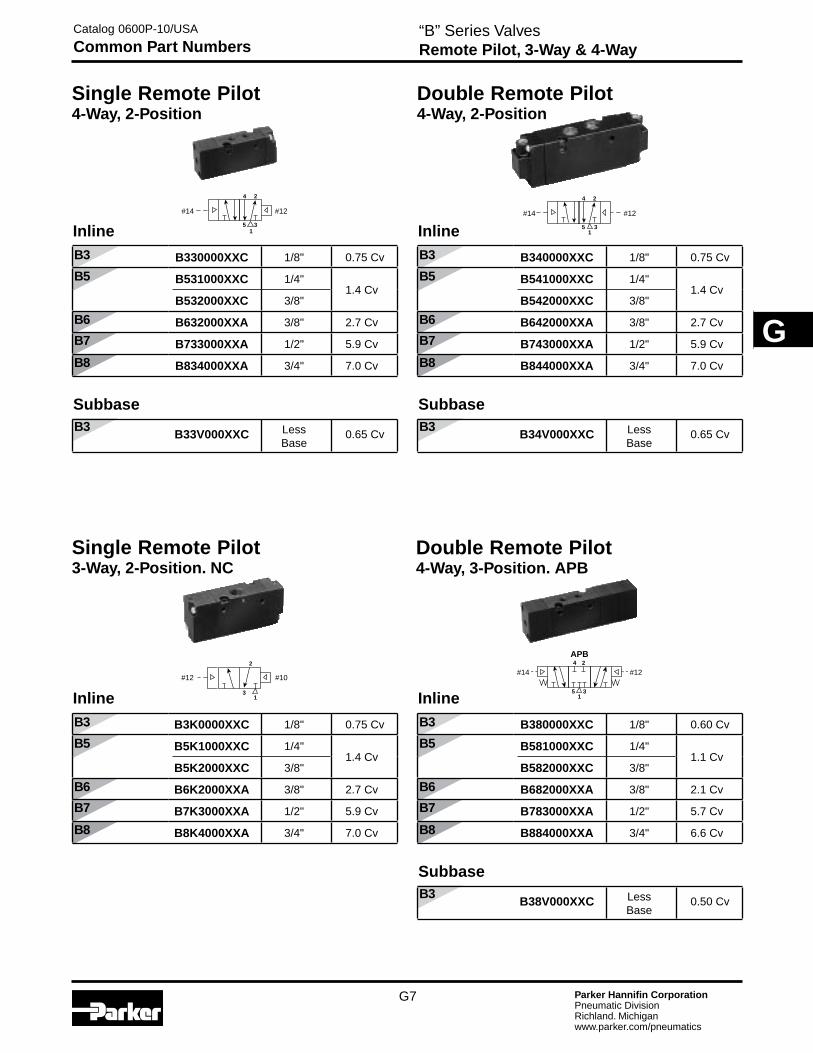
“B” Series ValvesRemote Pilot, 3-Way & 4-Way
Single Remote Pilot 4-Way, 2-Position
Double Remote Pilot 4-Way, 2-Position
Single Remote Pilot 3-Way, 2-Position. NC
Double Remote Pilot 4-Way, 3-Position. APB
4 2
5 31
#14 #12
Inline
B330000XXC 1/8" 0.75 Cv
B531000XXC 1/4"1.4 Cv
B532000XXC 3/8"
B632000XXA 3/8" 2.7 Cv
B733000XXA 1/2" 5.9 Cv
B834000XXA 3/4" 7.0 Cv
Subbase
B33V000XXC LessBase
0.65 Cv
2
3
#12 #10
1
Catalog 0600P-10/USA
Common Part Numbers
B8
B7
B3
B6
B3
B5
Inline
B340000XXC 1/8" 0.75 Cv
B541000XXC 1/4"1.4 Cv
B542000XXC 3/8"
B642000XXA 3/8" 2.7 Cv
B743000XXA 1/2" 5.9 Cv
B844000XXA 3/4" 7.0 Cv
Subbase
B34V000XXC LessBase
0.65 Cv
B8
B7
B3
B6
B5
Inline
B3K0000XXC 1/8" 0.75 Cv
B5K1000XXC 1/4"1.4 Cv
B5K2000XXC 3/8"
B6K2000XXA 3/8" 2.7 Cv
B7K3000XXA 1/2" 5.9 Cv
B8K4000XXA 3/4" 7.0 Cv
B8
B7
B3
B6
B3
B5
Inline
B380000XXC 1/8" 0.60 Cv
B581000XXC 1/4"1.1 Cv
B582000XXC 3/8"
B682000XXA 3/8" 2.1 Cv
B783000XXA 1/2" 5.7 Cv
B884000XXA 3/4" 6.6 Cv
Subbase
B38V000XXC LessBase
0.50 Cv

G8 Parker Hannifin CorporationPneumatic DivisionRichland. Michiganwww.parker.com/pneumatics
G
“B3” Series Valves3 & 4-Way, 2 & 3-Position Valves
BOLD OPTIONS ARE MOST POPULAR.
Pilot Source ‘X’ External-Manifold / Vented
INLINE & SUBBASE Valves –
Only used IF an IEM or 5-Ported Subbase Aluminum Bar Manifold requires a common external pilot signal thru the manifold for low pressure / vacuum applications OR when used with Sandwich Regulators.
B3 Series
Voltage Code
Override CodeStandard
B C D E42 O O – –45 O O – –49 S S O O53 S S O O57 O O – –
Voltage Code
“02” OptionB C D E
42 O O – –45 O O – –49 S S O O53 S S O O57 O O – –
§ Enclosure ‘5’ – Override / Voltage Availability
S - Standard O - Option
Catalog 0600P-10/USA
“B3” Model Number Index
Basic SeriesB3 Series B3
B3 1 0 B B 5 49 – C
Operator Function3-Way
Single Solenoid, 2-Position NC - Air Return GSingle Solenoid, 2-Position NO - Air Return HDouble Solenoid, 2-Position JSingle Remote Pilot, 2-Position NC - Air Return KSingle Remote Pilot, 2-Position NO - Air Return LDouble Remote Pilot, 2-Position MSingle Solenoid, 2-Position NC - Air Return / Spring Assist VSingle Solenoid, 2-Position NO - Air Return / Spring Assist WSingle Remote Pilot, 2-Position NC - Air Return / Spring Assist XSingle Remote Pilot, 2-Position NO - Air Return / Spring Assist Y
4-WaySingle Solenoid, 2-Position NC - Air Return 1Double Solenoid, 2-Position 2Single Remote Pilot, 2-Position - Air Return 3Double Remote Pilot, 2-Position 4Double Solenoid, 3-Position - APB 5Double Solenoid, 3-Position - CE 6Double Solenoid, 3-Position - PC 7Double Remote Pilot, 3-Position - APB 8Double Remote Pilot, 3-Position - CE 9Double Remote Pilot, 3-Position - PC 0Single Solenoid, 2-Position - Air Return / Spring Assist ESingle Remote Pilot, 2-Position - Air Return / Spring Assist F
OptionsBlank None02 Solenoid Rotated 180° - Pins Down
Engineering LevelC Current
Port Size / Thread Type3-Way
1/8" NPT Inline 0*1/8" BSPP “G” Inline 5*
Dual 3-Way & 4-Way1/8" NPT Inline 0*1/8" BSPP “G” Inline 5*1/4" NPT Subbase H‡
1/8" NPT Face Mount T**Subbase Valve Less Base V‡
* Available for use on IEM Manifolds.** 4-Way only.‡ Subbase valves available for 4-Way valves only.
Voltage §
AC DC60Hz 50Hz
42 24 2245 1249 2453 120 11057 240 230
XX Remote Pilot - M5 or Valve Less 15mm Solenoid
YY Remote Pilot - 5/32" (4mm) Tube
Enclosure / Lead Length0 None. Remote Pilot Valve5 15mm 3-Pin DIN 43650C (Male Only)X Valve Less 15mm Solenoid
Overrides§
0 None. Remote Pilot ValveB Flush - Non-LockingC Flush - LockingD Extended - Non-LockingE Extended - LockingX Valve Less 15mm Solenoid
Pilot Source / Pilot Exhaust0 None. Remote Pilot ValveB† Internal - Port #1 / VentedE* Dual Pressure - Port #3 / VentedK† External - Body / Tapped M5X‡ External - Manifold / Vented* Not available for 3-Way Valves.† Not available for Remote Pilot Valves.‡ See Pilot Source Note below.

G9 Parker Hannifin CorporationPneumatic DivisionRichland. Michiganwww.parker.com/pneumatics
G
“B5” Series Valves3 & 4-Way, 2 & 3-Position Valves
BOLD OPTIONS ARE MOST POPULAR.B5 Series
Voltage Code
Override CodeStandard
B C D E42 O O – –45 O O – –49 S S O O53 S S O O57 O O – –
§ Enclosure ‘5’ – Override / Voltage Availability S - Standard O - Option
Catalog 0600P-10/USA
“B5” Model Number Index
Basic SeriesB5 Series B5
B5 1 1 B B 5 49 – C
Operator Function3-Way
Single Solenoid, 2-Position NC - Air Return GSingle Solenoid, 2-Position NO - Air Return HDouble Solenoid, 2-Position JSingle Remote Pilot, 2-Position NC - Air Return KSingle Remote Pilot, 2-Position NO - Air Return LDouble Remote Pilot, 2-Position MSingle Solenoid, 2-Position NC - Air Return / Spring Assist VSingle Solenoid, 2-Position NO - Air Return / Spring Assist WSingle Remote Pilot, 2-Position NC - Air Return / Spring Assist XSingle Remote Pilot, 2-Position NO - Air Return / Spring Assist Y
4-WaySingle Solenoid, 2-Position NC - Air Return 1Double Solenoid, 2-Position 2Single Remote Pilot, 2-Position - Air Return 3Double Remote Pilot, 2-Position 4Double Solenoid, 3-Position - APB 5Double Solenoid, 3-Position - CE 6Double Solenoid, 3-Position - PC 7Double Remote Pilot, 3-Position - APB 8Double Remote Pilot, 3-Position - CE 9Double Remote Pilot, 3-Position - PC 0Single Solenoid, 2-Position - Air Return / Spring Assist ESingle Remote Pilot, 2-Position - Air Return / Spring Assist F
OptionsBlank None02 Solenoid Rotated 180° - Pins DownMD*†† Manual DetentV0† Fluorocarbon Seals* Only Available with Mobile Voltages “47” & “48”, or
Enclosures “N” or “X”.† Not available with Enclosure “0”, “5”, “X”, “E” or “F”.†† Only Available with Operator Function 1 & 3.
Engineering LevelC Current
Port Size / Thread Type3-Way
1/4" NPT Inline 1*3/8" NPT Inline 2*1/4" BSPP “G” Inline 6*3/8" BSPP “G” Inline 7*
4-Way1/4" NPT Inline 1*3/8" NPT Inline 2*1/4" BSPP “G” Inline 6*3/8" BSPP “G” Inline 7*3/8" NPT Subbase J†
1/4" NPT NAMUR Mount T‡†
Subbase Valve Less Base - NPT V‡
1/4" BSPP “G” NAMUR Mount W‡†
* Available for use on IEM Manifolds.† 4-Way only.‡ Available with pilot source “0”, “A”, and
“B” only.
Voltage §
AC DC60Hz 50Hz
42 24 2245 1249 2453 120 11057 240 230
XX Remote Pilot - M5 or Valve Less 15mm Solenoid
YY Remote Pilot - 5/32" (4mm) Tube
Enclosure / Lead Length0 None, Remote Pilot Valve5 15mm 3-Pin DIN 43650C (Male Only)A 30mm Square 3-Pin – ISO 4400 Form A (Male Only)B 22mm Rectangular 3-Pin – Type B Industrial (Male Only)C 3-Pin Automotive - MiniD 5-Pin Automotive - MiniE* Intrinsically Safe - 30mm 3-PinF** Hazardous Duty 1/2" NPT Conduit - 18" LeadsG Grommet - 18" LeadsH 1/2" NPT Conduit - 18" LeadsN Valve Less “A - R” CoilQ Grommet - 72" LeadsR 1/2" NPT Conduit - 72" LeadsX Valve Less 15mm Solenoid* 24 VDC & Override “A” Only.** 12 VDC, 24 VDC, 120 VAC or 240 VAC.
Pilot Source / Pilot ExhaustEnclosures “0, 5 & X”
None, Remote Pilot Valve 0Internal - Port #1 / Tapped M5 A†
Internal - Port #1 / Vented B†
Dual Pressure - Port #3 / Vented E*External - Body / Tapped M5 K†
External - Manifold / Vented X‡
Enclosures “A, B, C, D, E, F, G, H, N, Q & R”Internal - Port #1 / Tapped M5 A†
Internal - Port #1 / Vented B†
Dual Pressure - Port #3 / Tapped M5 D*†
External - Body / Tapped 1/8" K†
* Not available for 3-Way Valves.† Not available for Remote Pilot Valves.‡ See Pilot Source Note below.
PilotSource‘X’ External-Manifold / Vented or Tapped M5
INLINE&SUBBASEValves–
Only used IF an IEM Aluminum Bar Manifold requires a common external pilot signal thru the manifold for low pressure / vacuum applications.
Voltage Code
Override Code“02” OptionB C D E
42 O O – –45 O O – –49 S S O O53 S S O O57 O O – –
Overrides§
None. Remote Pilot Valve 0No Override A†
Flush - Non-Locking B*Flush - Locking CExtended - Non-Locking DExtended - Locking E*Valve Less 15mm Solenoid X* Only Available with Encl. “5”.† Only Available with Encl. “E”.
(Revised 07-10-07)

G10 Parker Hannifin CorporationPneumatic DivisionRichland. Michiganwww.parker.com/pneumatics
G
“B6” Series Valves3 & 4-Way, 2 & 3-Position Valves
B6 Series BOLD OPTIONS ARE MOST POPULAR.
Catalog 0600P-10/USA
“B6” Model Number Index
Basic SeriesB6 Series B6
B6 1 2 B B 5 49 – A
Operator Function3-Way
Single Solenoid, 2-Position NC - Air Return / Spring Assist VSingle Solenoid, 2-Position NO - Air Return / Spring Assist WSingle Remote Pilot, 2-Position NC - Air Return / Spring Assist XSingle Remote Pilot, 2-Position NO - Air Return / Spring Assist Y
4-WaySingle Solenoid, 2-Position NC - Air Return 1Double Solenoid, 2-Position 2Single Remote Pilot, 2-Position - Air Return 3Double Remote Pilot, 2-Position 4Double Solenoid, 3-Position - APB 5Double Solenoid, 3-Position - CE 6Double Solenoid, 3-Position - PC 7Double Remote Pilot, 3-Position - APB 8Double Remote Pilot, 3-Position - CE 9Double Remote Pilot, 3-Position - PC 0Single Solenoid, 2-Position - Air Return / Spring Assist ESingle Remote Pilot, 2-Position - Air Return / Spring Assist F
OptionsBlank None02 Solenoid Rotated 180° - Pins Down42* Series Cylinder Mount Replacement* Only Available with Port Size “T” and “0”, “A”.
“B”, and “L” Pilot Source.
Engineering LevelA Current
Port Size / Thread Type3-Way / 4-Way
3/8" NPT Inline 2*3/8" BSPP “G” Inline 7*1/4" NPT NAMUR Mount T†
* Available for use on IEM Manifolds.† 4-Way only. Available with pilot source “0”, “A”,
“B” and “L” only.
Voltage §
AC DC60Hz 50Hz
42 24 2245 1249 2453 120 11057 240 230
XX Remote Pilot - M5 or Valve Less 15mm Solenoid
YY Remote Pilot - 5/32" (4mm) Tube
Enclosure / Lead Length0 None, Remote Pilot Valve5 15mm 3-Pin DIN 43650C (Male Only)A 30mm Square 3-Pin – ISO 4400 Form A (Male Only)B 22mm Rectangular 3-Pin – Type B Industrial (Male Only)E* Intrinsically Safe - 30mm 3-PinF** Hazardous Duty 1/2" NPT Conduit - 18" LeadsG Grommet - 18" LeadsH 1/2" NPT Conduit - 18" LeadsN Valve Less “A - R” CoilQ Grommet - 72" LeadsR 1/2" NPT Conduit - 72" LeadsX Valve Less 15mm Solenoid* 24 VDC & Override “A” Only.** 12 VDC, 24 VDC, 120 VAC or 240 VAC.
Overrides§
None, Remote Pilot Valve 0No Override A†
Flush - Non-Locking B*Flush - Locking CExtended - Non-Locking DExtended - Locking E*Valve Less 15mm Solenoid X* Only Available with Encl. “5”.† Only Available with Encl. “E”.
Pilot Source / Pilot ExhaustEnclosures “0, 5 & X”
None. Remote Pilot Valve 0Internal - Port #1 / Tapped M5 A†
Internal - Port #1 / Vented B†
Dual Pressure - Port #5 / Vented HExternal - Body / Tapped M5 K†
Enclosures “A, B, C, D, E, F, G, H, N, Q & R”Internal - Port #1 / Tapped M5 A†
Internal - Port #1 / Vented B†
External - Body / Tapped 1/8" K†
* Not available for 3-Way Valves.† Not available for Remote Pilot Valves.
INLINEValves–Only used IF an IEM Aluminum Bar Manifold requires a common external pilot signal thru the manifold for low pressure / vacuum applications.
Voltage Code
Override CodeStandard
B C D E42 O O – –45 O O – –49 S S O O53 S S O O57 O O – –
§ Enclosure ‘5’ – Override / Voltage Availability S - Standard O - Option
Voltage Code
Override Code“02” OptionB C D E
42 O O – –45 O O – –49 S S O O53 S S O O57 O O – –
(Revised 07-10-07)

G11 Parker Hannifin CorporationPneumatic DivisionRichland. Michiganwww.parker.com/pneumatics
G
“B7 & B8” Series Valves3 & 4-Way, 2 & 3-Position Valves
B7 & B8 Series
Voltage Code
Override Code
StandardB C D E
42 O O – –45 O O – –49 S S O O53 S S O O57 O O – –
§ Enclosure ‘5’ – Override / Voltage Availability
S - Standard O - Option
Catalog 0600P-10/USA
“B7 & B8” Model Number Index
Basic SeriesB7 Series B7B8 Series B8
B7 1 3 A B G 53 – A
Operator Function3-Way
Single Solenoid, 2-Position NC - Air Return / Spring Assist VSingle Solenoid, 2-Position NO - Air Return / Spring Assist WSingle Remote Pilot, 2-Position NC - Air Return / Spring Assist XSingle Remote Pilot, 2-Position NO - Air Return / Spring Assist Y
4-WaySingle Solenoid, 2-Position NC - Air Return 1Double Solenoid, 2-Position 2Single Remote Pilot, 2-Position - Air Return 3Double Remote Pilot, 2-Position 4Double Solenoid, 3-Position - APB 5Double Solenoid, 3-Position - CE 6Double Solenoid, 3-Position - PC 7Double Remote Pilot, 3-Position - APB 8Double Remote Pilot, 3-Position - CE 9Double Remote Pilot, 3-Position - PC 0Single Solenoid, 2-Position - Air Return / Spring Assist ESingle Remote Pilot, 2-Position - Air Return / Spring Assist F
OptionsBlank None
Engineering LevelA Current
Port Size / Thread TypeB7 Series
1/2" NPT Inline 3*1/2" BSPP “G” Inline 8*
B8 Series3/4" NPT Inline 4*3/4" BSPP “G” Inline 9** Available for use on IEM Manifolds.
Voltage §
AC DC60Hz 50Hz
42 24 2245 1249 2453 120 11057 240 230
XX Remote Pilot - M5 or Valve Less 15mm Solenoid
YY Remote Pilot - 5/32" (4mm) Tube
Enclosure / Lead Length0 None, Remote Pilot Valve5 15mm 3-Pin DIN 43650C (Male Only)A 30mm Square 3-Pin – ISO 4400 Form A (Male Only)B 22mm Rectangular 3-Pin – Type B Industrial (Male Only)E* Intrinsically Safe - 30mm 3-PinF** Hazardous Duty 1/2" NPT Conduit - 18" LeadsG Grommet - 18" LeadsH 1/2" NPT Conduit - 18" LeadsN Valve Less “A - R” CoilR 1/2" NPT Conduit - 72" LeadsX Valve Less 15mm Solenoid* 24 VDC & Override “A” Only.** 12 VDC, 24 VDC, 120 VAC or 240 VAC.
Pilot Source / Pilot ExhaustEnclosures “0. 5 & X”
None. Remote Pilot Valve 0Internal - Port #1 / Tapped M5 A†
Internal - Port #1 / Vented B†
External - Body / Tapped M5 K†
Enclosures “A, B, C, D, E, F, G, H, N, Q & R”Internal - Port #1 / Tapped M5 A†
Internal - Port #1 / Vented B†
External - Body / Tapped 1/8" K†
† Not available for Remote Pilot Valves.
INLINEValves–Only used IF an IEM Aluminum Bar Manifold requires a common external pilot signal thru the manifold for low pressure / vacuum applications.
Overrides§
None, Remote Pilot Valve 0No Override A†
Flush - Non-Locking B*Flush - Locking CExtended - Non-Locking DExtended - Locking E*Valve Less 15mm Solenoid X* Only Available with Encl. “5”.† Only Available with Encl. “E”.
BOLD OPTIONS ARE MOST POPULAR.
(Revised 07-10-07)
G12 Parker Hannifin CorporationPneumatic DivisionRichland. Michiganwww.parker.com/pneumatics
GB5
B3
4-Way w/ Flow Control4-Way
1/8" (3mm)Hex Drive
4-Way Manifold4-Way Manifoldwith Flow Control
1/8" (3mm)Hex Drive
B3
B5
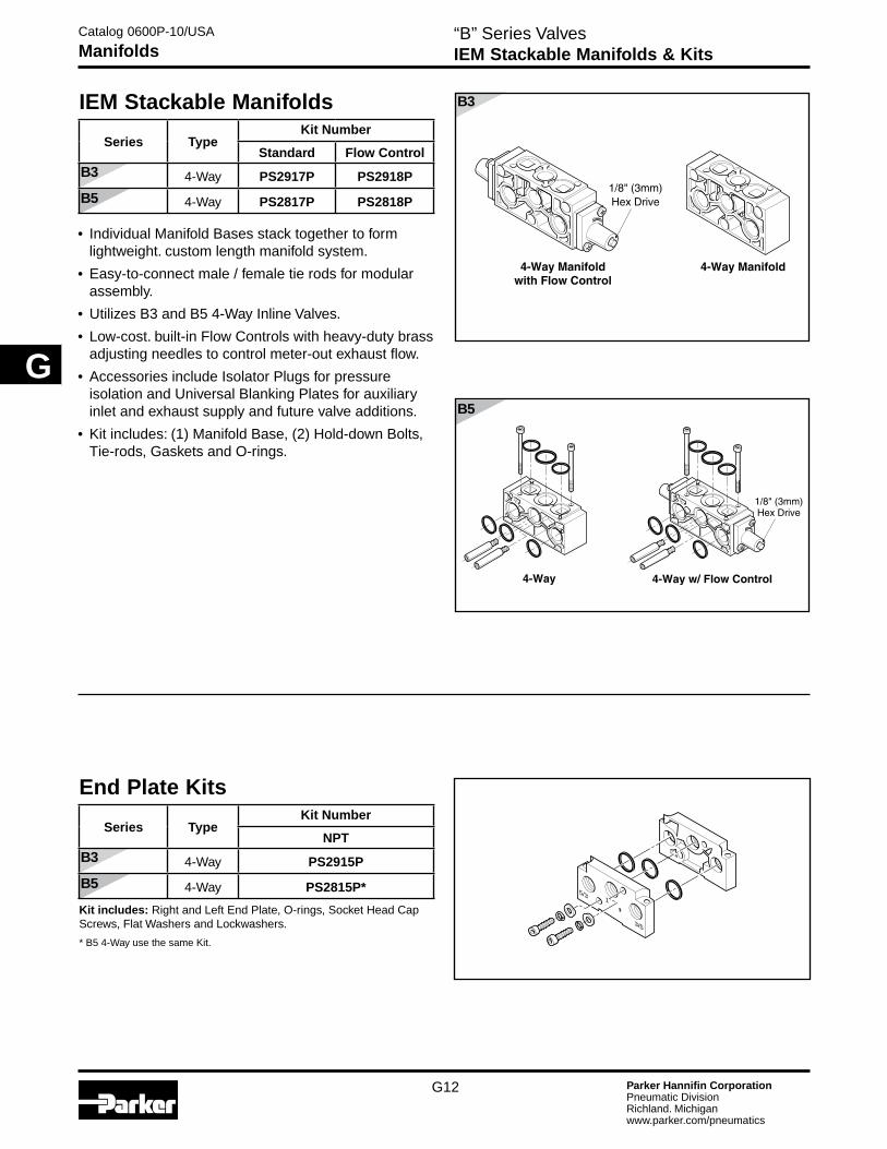
• Individual Manifold Bases stack together to form lightweight. custom length manifold system.
• Easy-to-connect male / female tie rods for modular assembly.
• Utilizes B3 and B5 4-Way Inline Valves.
• Low-cost. built-in Flow Controls with heavy-duty brass adjusting needles to control meter-out exhaust flow.
• Accessories include Isolator Plugs for pressure isolation and Universal Blanking Plates for auxiliary inlet and exhaust supply and future valve additions.
• Kit includes: (1) Manifold Base, (2) Hold-down Bolts, Tie-rods, Gaskets and O-rings.
“B” Series ValvesIEM Stackable Manifolds & Kits
5/3
3/5
1
IEM Stackable Manifolds
Series TypeKit Number
Standard Flow Control
4-Way PS2917P PS2918P
4-Way PS2817P PS2818P
Catalog 0600P-10/USA
Manifolds
B3
B5
End Plate Kits
Series TypeKit Number
NPT
4-Way PS2915P
4-Way PS2815P*
Kit includes: Right and Left End Plate, O-rings, Socket Head Cap Screws, Flat Washers and Lockwashers.
* B5 4-Way use the same Kit.

G13 Parker Hannifin CorporationPneumatic DivisionRichland. Michiganwww.parker.com/pneumatics
G
B3 Series
Assembly Model Number
“B3” Series ValvesSubbase Aluminum Bar Manifolds (5-Ported)
• Utilizes Subbase mount B3 valves.
• Available for 4-Way valves. If 3-Way function is required, plug a cylinder port.
• Common External Pilot galley is standard.
• Standard Internal Pilot valves need not use this galley, and the galley does not need to be plugged.
• External Pilot Valves – “X” or “W”, must have Common External Galley pressurized.
Catalog 0600P-10/USA
Bar Manifold Assemblies
4-Way, 1/8" NPT AAPSJ3B1N##NP ## – stations 02 to 12
Kit includes:
Subbase – (1) Manifold (bolts & gasket come with subbase valve).
ManifoldManifold Only BlankManifold with Valves Mounted AA
AA PS J 3 B 1 N 04 N POptions
N None
Type4-Way
Subbase Bottom Port KSubbase End Port J
SeriesB3 Series 3
PilotExternal (B3) B
Stations02 • • •12
Port TypeG BSPP “G”N NPT
Cylinder Ports1 1/8"
B3 Series
4-Way, 1/8" NPT PSJ3B1N##NP ## – stations 02 to 12
35mm DIN Rail Mount

G14 Parker Hannifin CorporationPneumatic DivisionRichland. Michiganwww.parker.com/pneumatics
GB7 & B8 Series
B3 Series B5 Series
B6 Series
“B” Series ValvesIEM Bar Manifolds (Inlet / Exhaust Manifold)
4-Way3-Way 4-Way
4-Way3-Way 4-Way3-Way
• Utilizes Inline mount “B” Series valves.• Different manifold for 3-Way & 4-Way valves (B7 and
B8 use common manifolds).• Common External Pilot galley is standard. Standard
Internal Pilot valves need not use this galley. This galley does not require a plug for internally piloted valves.
• External Pilot Valves – “X” or “W”, must have Common External Galley pressurized.
• Kits (PS....) include: (1) Manifold, Valve Hold Down Bolts, Gaskets.
3-Way, NPT AAPSG3BXN##NP ## – stations 02 to 124-Way, NPT AAPSM3BXN##NP
3-Way, NPT AAPSG5BXN##NP ## – stations 02 to 124-Way, NPT AAPSM5BXN##NP
3-Way, NPT AAPSG6BXN##NP ## – stations 02 to 124-Way, NPT AAPSM6BXN##NP
4-Way, NPT AAPSM7BXN##NP ## – stations 02 to 12
Catalog 0600P-10/USA
IEM Bar Manifold Assemblies
ManifoldManifold Only BlankManifold with Valves Mounted AA
AA PS M 5 B X N 04 N P
PilotExternal B
Stations02 • • •12
Port TypeG BSPP “G”N NPT
TypeIEM 3-Way G*IEM 4-Way M* Not available with B7. or B8.
OptionsN None
Cylinder PortsX IEM Manifold
IEM Bar Manifold Model Number
SeriesB3 Series 3B5 Series 5B6 Series 6B7 / B8 Series 7
35mm DIN Rail Mount

G15 Parker Hannifin CorporationPneumatic DivisionRichland. Michiganwww.parker.com/pneumatics
G
How To Order Aluminum Bar Manifold Assemblies1. List Manifold Assembly call out. Use AA + the
part number of the aluminum bar manifold. This automatically includes the aluminum bar manifold and assembly.
2. List complete valve model number, listing left to right, LookinG AT The #12 enD of the manifold. The left most station is station 1.
(if a blank station is needed, list the blanking plate part number at the desired station.)
#12 End
#14 End
Example: Application requires a 3-station “B3” 3-Way manifold with station #1 blanked off with valves assembled.
Qty. Part No. Comment
1 AASG3BXn03nP
1 PS2966P ..................... Station 1
1 B3k0000XXC .............. Station 2
1 B3J0BB553C ............... Station 3
Station Station Station 1 2 3
Looking at 12 End
“B” Series ValvesAluminum Bar Manifold Assemblies
AA PS******##P
Use Aluminum Bar Manifold kit numbers from previous pages.
AA Manifold Assembly
Catalog 0600P-10/USA
Ordering Information(Revised 07-24-07)

G16 Parker Hannifin CorporationPneumatic DivisionRichland. Michiganwww.parker.com/pneumatics
G
5
1 3
5
1
3
B7
B8
0.59(15mm)
1.38(35mm)
0.06(1.5mm)
B6
“B” Series ValvesSubbase / Manifolds
B3
B5
SubbaseType Size Kit Number
NPT
4-Way 1/4" PS2934P
4-Way 3/8" PS2834P
Kit includes: (1) subbase. (Hold down bolts & gasket are included with valve.)
B3
B5
Isolator Plugs
Series Kit Number
4-Way
PS2919P
PS2819P
• Used to isolate the #1. #3 or #5 gallery between two Manifold Bases. (IEM STACKABLE ONLY)
• Kit includes: (3) plugs and (6) o-rings
4-Way Isolator PlugsIEM Stackable
Blank Plate
B3
B5
Blanking Plate
Type
Kit NumberIEM Universal IEM Subbase
NPT BSPP “G” Blank Blank
3-Way PS2966P PS2967P PS2968P —
4-Way PS2920P PS2921P PS2969P PS2994P
3-Way PS2866P PS2867P PS2868P —
4-Way PS2820P PS2821P PS2869P —
3-Way4-Way
PS2620P PS2621P PS2669P —
4-Way PS2520P PS2521P PS2569P —
Kit includes: (1) Plate, (2) Screws, Seal / Gaskets
Universal Blanking Plate
1/8" – B31/4" – B53/8" – B61/2" – B7 & B8
B3
DIN Rail Hardware KitSeries IEM Bar 5-Port Subbase Bar
PS2990P PS2991P
Kit includes: (2) Screws, (2) Nuts, (2) Clamps
B3 B5
Initial PositionOf Clamp
Clamp LocksWhen Screw Is Tightened
Clamp
DIN Rail (sold separately)
Lockwasher
Torque ScrewTo 10 in/lbs
Washer
Catalog 0600P-10/USA
Accessories
B3
DIN RailSeries Length Part Number
6 Feet AM1DE200

G17 Parker Hannifin CorporationPneumatic DivisionRichland. Michiganwww.parker.com/pneumatics
G
Dual Port
“B” Series ValvesSandwich Regulator
Gauge 1" Face – 0-160 PSI ......PS4051160BP
Brass Adapters for Gauge – 1/8" to 1/8" Female Coupling ............. 207P-2
1/8" Male Pipe Nippled 1.5" ..... 215PNL-2-15 1/8" Male to Female Adapter .......... 222P-2-2
Sandwich Regulators• Use with B3 Subbase Valves on 5-Ported Subbase Bar Manifolds.
• Common Port or Dual Port regulation control.
• Unregulated Pressure Supplied to Valve Pilot - Use Pilot Source - ‘X’.
• Easy adjust knob control.
B3
14 25 3
14 25 3
1/8" to 1/8" 45° Female Elbow ...... 2201P-2-2 1/8" to 1/8" 90° Female Elbow ...... 2200P-2-2
Common Port
Catalog 0600P-10/USA
Accessories
B3 Series
Common Port with Gauge *
Dual Port without Gauge Cv
5-125 PSI PS2930166P PS2930233P .33
* Gauge is 160 PSI. Gauge shipped unassembled. For different gauge mounting configuration, use brass adapters listed at bottom of page.

G18 Parker Hannifin CorporationPneumatic DivisionRichland. Michiganwww.parker.com/pneumatics
G
“B” Series ValvesFeatured Valve Options
Tube Fitting Remote Pilot • “YY” Option
• 5/32" (4mm) Tube Fitting
Solenoid Rotated 180° - Pins Down • 1.8W (2.4VA) solenoids – Enclosure “5”.
• Override on top for easy access.
• “02” in the Options code.
Valve Less Solenoid • Valve ordered & shipped without solenoid.
• Efficient method in place of valve repair, fully tested at factory.
Alternate Solenoid Enclosures
“A” 30mm 3-Pin
“B” 22mm 3-Pin
“C” 3-Pin Mini
“D” 5-Pin Mini
“G”. “Q” Grommet
“F”. “H”. “R” 1/2" Conduit
• Enclosure “A”: 2.6W - 4.1VA (Coil rotates in 45° increments)
• Enclosure “B” – “R”: 4.6W - 7.3VA (Coil rotates in 90° increments)
B5 B6 B7 B8
B3 B5 B6 B7 B8
B3 B5 B6 B7 B8
Catalog 0600P-10/USA
Featured Valve Options
B3 B5 B6 B7 B8

G19 Parker Hannifin CorporationPneumatic DivisionRichland. Michiganwww.parker.com/pneumatics
G
“B” Series ValvesFeatured Valve Options
B5 With Manual Detent
• Positive mechanical contact of the override knob assures actuation of valve, however, knob does not move during normal cycling.
• Hard coated override to resist harsh environments.
• Override return spring is stainless steel, for harsh environments.
• Heavy duty locking mechanism to maintain position.
Catalog 0600P-10/USA
Featured Valve Options
Hazardous Duty Solenoid Valves (“F” Option) Hazardous Location Class:Class I; Zone I EX. M. II & T4Class I; Groups A. B. C. & DClass II & III; Div. I. Groups E. F. & GComes standard with non-lighted solenoid connector.
Voltage Range = +10° +/- 10%
Ambient Temp. Range = -20°C (-4°F) to 60°C (140°F)
Duty Factor = 100%
IP65 Rated (with Connected Conduit Connector)
Intrinsically Safe Solenoid Valves (“E” Option) Hazardous Location Class:
Class I; Groups A. B. C & D
Class II; Groups E. F. & G
Class III; Div. IFor use in low voltage (24VDC) Intrinsically Safe applications. NO OTHER VOLTAGE IS APPROVED.
Comes standard with non-lighted solenoid connector.
Must be connected to an FM approved Barrier.For dimensions. reference standard solenoid models. Maximum internally piloted valve pressure is 115 PSIG. Pressures to 145 PSIG can be used when external pilot is utilized and pilot pressure is limited to 115 PSIG.
Notes:
1. Maximum non-hazardous location voltage not to exceed 250V RMS.
2. Connect per Barrier Manufacturers instructions.
3. Factory Mutual requires connections per ISA RP 12.6 instructions.
4. CSA requires “Installation to be in accordance with the Canadian Electrical Code. Part I.”
PowerSupply
Factory Mutual&
CSA ApprovedBarrier Solenoid
Valve
2
1 3
Non-hazardous Location HazardousLocation
Intrinsically Safe Solenoid Pilot Assembly Kits
Part Number DescriptionP2FS13N1AE49 24VDC
Option FHazardous Duty FM / CSA

G20 Parker Hannifin CorporationPneumatic DivisionRichland. Michiganwww.parker.com/pneumatics
G
“B” Series ValvesFemale Electrical Connectors
0
1
1
➤
➤
16mm25.4mm
8mm
47mm
12
3
*
* Ground spade offset by 0.2mm toward pin 1.
Catalog 0600P-10/USA
Electrical Connectors
15mm 3-Pin DIN 43650C to 1/2" Conduit (Use with Enclosure “5”)
Connector Description
PS2998P1/2" NPTF Conduit – Unlighted with 3' (1m) Leads 20 AWG Wire
Note: Rated up to 250VAC or VDC; 6 Amps IP65 rated when properly installed.
0
1
1
➤
➤
21mm
15mm22 AWG Wire
2.3mmTop of light
Molded 6' Cord Shown
15mm 3-Pin DIN 43650C (Use with Enclosure “5”)
Engineering Data: Conductors: 2 Poles Plus Ground Cable Range (Connector Only): 4 to 6mm (0.16 to 0.24 Inch) Contact Spacing: 8mm
Connector Connector with Cord
Description
PS2932BP PS2932HBP 18 Inches Unlighted
PS2932BP PS2932JBP 6 Feet Unlighted
PS294675BP PS2946J75BP* 6 Feet Light – 12VAC or DC
PS294679BP PS2946J79BP* 6 Feet Light – 24VAC or DC
PS294683BP PS2946J83BP* 6 Feet Light – 110/120VAC
PS294687BP N/A Light – 240/230VAC
* LED with surge suppression.
Note: Max ø6.5mm cable size required for connector w/o 6' (2m) cord. IP65 rated when properly installed.

G21 Parker Hannifin CorporationPneumatic DivisionRichland. Michiganwww.parker.com/pneumatics
G
Bronze
A
B
30mm
40.5mm
11mm22mm
30mm
33mm
57mm
* LED with surge suppression.
Note: Max ø6.5mm cable size required for connector w/o 6' (2m) cord. IP65 rated when properly installed.
3-Pin 5-Pin
3-Pin / 5-Pin Male Automotive Connectors (Use on 22mm Rectangular 3-Pin Solenoid)
3-Pin 5-Pin DescriptionPS2893CP PS2893DP Unlighted
PS2893C##P PS2893D##P Lighted - Voltage
Exhaust MufflersPipe Thread Part Number
M5 P6M-PAC51/8" NPT EM121/4" NPT EM253/8" NPT EM371/2" NPT EM50
“B” Series ValvesFemale Electrical Connectors
Plastic SilencersThread
SizePart Number A
(mm)B
(mm)NPT BSPT
M5 AS-5 .43 (11) .32 (8)
1/8" ASN-6 AS-6 1.57 (40) .63 (16)
1/4" ASN-8 AS-8 2.56 (65) .83 (21)
3/8" ASN-10 AS-10 3.35 (85) .98 (25)
1/2" ASN-15 AS-15 3.74 (95) 1.18 (30)
P6M - Plastic; EM - Sintered Bronze
Female Electrical Connectors / Accessories30mm Square 3-Pin – ISO 4400, DIN 43650A (Use with Enclosure “A”)
Connector Connector
with 6' (2m) CordDescription
PS2028BP PS2028JBP Unlighted
PS203279BP PS2032J79BP* Light – 6-48V. 50/60Hz. 6-48VDC
PS203283BP PS2032J83BP* Light – 120V/60Hz
PS203283BP N/A Light – 240V/60Hz
* LED with surge suppression.
Note: Max ø6.5mm cable size required for connector w/o 6' (2m) cord. IP65 rated when properly installed.
30mm
18mm30mm
42mm
27mm
Engineering Data: Conductors: 2 Poles Plus Ground; Cable Range (Connector Only): 6 to 8mm (0.24 to 0.31 Inch); Contact Spacing: 11mm
Engineering Data: Conductors: 2 Poles Plus Ground; Cable Range (Connector Only): 8 to 10mm (0.31 to 0.39 Inch); Contact Spacing: 18mm
Catalog 0600P-10/USA
Electrical Connectors / Accessories
22mm Rectangular 3-Pin – Type B Industrial (Use with Enclosure “B”)
Connector Connector
with 6' (2m) CordDescription
PS2429BP PS2429JBP Unlighted
PS243079BP PS2430J79BP* Light – 24V60Hz. 24VDC
PS243083BP PS2430J83BP* Light – 120V/60Hz
PS243087BP N/A Light – 240V/60Hz
## — 79 = 6 to 48VAC/VDC 83 = 100 to 240VAC/48 to 120 VDC
(Revised 08-09-07)

G22 Parker Hannifin CorporationPneumatic DivisionRichland. Michiganwww.parker.com/pneumatics
G
B3
B7B3 B6B5 B8
B8
B7
B6
“B” Series ValvesTechnical Data
B5
Flow Rating (Cv)
SizePort Size
Mounting Style
2-Position 3-Position
1/8" Ports Inline .75 .60
1/4" Tube Inline .45 .45
1/8" Ports Subbase .65 .45
1/4" Ports Subbase .65 .50
1/4" Ports Inline 1.4 1.1
3/8" Ports Inline 1.4 1.1
1/4" Ports Subbase 1.4 1.1
3/8" Ports Subbase 1.4 1.1
3/8" Ports Inline 2.7 2.1
1/2" Ports Inline 5.9 5.7
3/4" Ports Inline 7.0 6.6
ANSI / (NFPA) T3.21.3-1990 standard for Cv measurement.
Temperature Rating5°F to 120°F (-15°C to 49°C) ambient. (Buna-N and Fluorocarbon)
Operating PressureMaximum: 145 PSIG (1000 kPa) Minimum:
Operator /
FunctionInternal Pilot
Minimum PSIG (kPa)
1. G. H Single Solenoid - Air Return
20 (138) 20 (138) 20 (138) 35 (241) 35 (241)2. A. J. S Double Solenoid
3. K. L Single Remote Pilot - Air Return
4. M Double Remote Pilot Vacuum
N. P. Q Double Solenoid - Dual 3/2 40 (275) — — — —
5. 6. 7 Double Solenoid - APB. CE. PC 30 (207) 30 (207) 30 (207) 45 (310) 45 (310)
8. 9. 0 Double Remote Pilot - APB. CE. PC Vacuum
E. V. WSingle Solenoid - Air Return / Spring Assist
35 (241) 35 (241) 35 (241) 35 (241) 35 (241)
F. X. YSingle Remote Pilot - Air Return / Spring Assist
External Pilot*†
All “B” Series Vacuum
* External Pilot Pressure / Remote Pilot Signal 35-145 PSIG (241-1000 kPa).
† External Pilot Not Available with B3 Dual 3/2.
Note: For CSA-NRTL/C approved solenoid valves – insert an ‘L’ at the end of the valve part number.
B3: Maximum pressure - 120 PSIB5: Maximum pressure - 145 PSI*§
B6: Maximum pressure - 145 PSI*§
B7: Maximum pressure - 145 PSI*†
B8: Maximum pressure - 145 PSI*†
* Enclosure Option E is CSA / FM approved at source. For certification of valve / solenoid assembly, consult factory.
† Not Available with Enclosure 5§ Not available with Enclosures 0. 5 & X
Catalog 0600P-10/USA
Technical Information

G23 Parker Hannifin CorporationPneumatic DivisionRichland. Michiganwww.parker.com/pneumatics
G
B5 B6 B5B7 B6 B7
Average Fill Time (Seconds): With 100 PSIG supply, time required to fill from 0-90 PSIG and exhaust from 100 PSIG to 10 PSIG is measured from instant of energizing, or de-energizing 120V/60Hz solenoid. Times shown are average.
* For 3/8" ported, 50 cu. in. test chamber is used. For 1/2" & 3/4", a 200 cu. in. test chamber is used.
Response Time
Valve Size
Port Size
Enclosure “5” Enclosure “A, B, C, D, G, H, Q & R”0 Cu. In. Test Chamber 25* Cu. In. Test Chamber 0 Cu. In. Test Chamber 25* Cu. In. Test Chamber
Fill Exhaust Fill Exhaust Fill Exhaust Fill Exhaust
2-Position Single Solenoid / Internal Air ReturnB3 1/8" .024 .026 .149 .242 — — — —
B5 1/4" .038 .040 .106 .156 .025 .026 .090 .142
B5* 3/8" .039 .041 .150 .245 .025 .027 .141 .241
B6* 3/8" .037 .038 .096 .132 .016 .018 .084 .119
B7 1/2" .073 .075 .195 .275 .049 .051 .167 .249
B8 3/4" .072 .074 .166 .226 .049 .051 .142 .206
2-Position Single Solenoid Spring / Air ReturnB3 1/8" .019 .022 .128 .217 — — — —
B5 1/4" .039 .041 .108 .162 .024 .026 .091 .143
B5* 3/8" .040 .042 .169 .261 .024 .026 .143 .240
B6* 3/8" .035 .036 .096 .133 .023 .024 .083 .120
B7 1/2" .071 .074 .194 .275 .049 .051 .167 .249
B8 3/4" .072 .074 .176 .239 .046 .048 .142 .204
2-Position Double SolenoidB3 1/8" .013 .015 .122 .213 — — — —
B5 1/4" .016 .018 .082 .132 .012 .014 .077 .128
B5* 3/8" .016 .018 .129 .222 .016 .018 .128 .225
B6* 3/8" .016 .017 .074 .110 .012 .013 .071 .107
B7 1/2" .026 .028 .145 .228 .022 .024 .138 .225
B8 3/4" .026 .028 .123 .185 .022 .024 .115 .178
3-Position Double SolenoidB3 1/8" .021 .023 .091 .141 — — — —
B5 1/4" .022 .023 .091 .141 .011 .011 .079 .135
B5* 3/8" .022 .024 .135 .229 .016 .019 .135 .234
B6* 3/8" .024 .026 .094 .139 .016 .018 .084 .132
B7 1/2" .049 .051 .167 .257 .028 .030 .148 .238
B8 3/4" .035 .037 .136 .206 .028 .030 .130 .195
“B” Series ValvesSolenoid Data
B8 B8
Solenoid Information (Solenoids are rated for continuous duty.)
Catalog 0600P-10/USA
Technical Information
Voltage Enclosure “5” VoltageEnclosure “A” Enclosure “B” to “R”
CodeAC
DCPower
ConsumptionHolding(Amps)
CodeAC
DCPower
ConsumptionHolding(Amps)
PowerConsumption
Holding(Amps)60Hz 50Hz 60Hz 50Hz
42 24 22 1.6VA .065 42 24 22 3.9VA .136 7.3VA .309
45 12 1.2W .098 45 12 2.6W .208 4.6W .365
47* 12 0.91W .074 47* 12 –– –– 4.9W .298
48* 24 0.91W .033 48* 24 –– –– 4.8W .142
49 24 1.2W .049 49 24 2.7W .112 4.8W .200
53 120 110 1.6W .013 53 120 110 4.1VA .033 6.3VA .047
57 240 230 1.6W .007 57 240 230 3.7VA .017 6.4VA .026
Note: For enclosure “5” with “02” Option, solenoid wattage is 1.8W (2.4VA). Response time is 10% faster. Voltage rated +10 / -15%.
* 47 and 48 code are mobile voltages. voltage +25 / -30%.

G24 Parker Hannifin CorporationPneumatic DivisionRichland. Michiganwww.parker.com/pneumatics
G
“B” Series ValvesPilot Configuration
A - Internal - Port #1 / Tapped M5
B - Internal - Port #1 / Vented
D - Dual Pressure - Port #3 / Tapped M5
G - Dual Pressure - Port #5 / Tapped M5 (Similar)
K - External - Body / Tapped M5
Tapped M5 Pilot Exhaust
B5 Shown
Vented Pilot Exhaust
B3 Shown
Port #3
Tapped M5 Pilot Exhaust
B3 Shown
Tapped M5
B3 Shown
Vented Pilot Exhaust
Vented Pilot Exhaust
Port #3B5 Shown
Tapped M5 Pilot Exhaust
*
*
Catalog 0600P-10/USA
Technical Information
E - Dual Pressure - Port #3 / Vented
H - Dual Pressure - Port #5 / Vented (Similar)

G25 Parker Hannifin CorporationPneumatic DivisionRichland. Michiganwww.parker.com/pneumatics
G
“B” Series ValvesSolenoid Kits
Solenoid Kits – B3 ‘C’, B5 ‘C’, B6 ‘A’, B7 ‘A’, B8 ‘A’ 3-Pin DIN 43650C 15mm
PS2982*##P – Enclosure ‘5’
* Override
## Voltage
42 45 47 48 49 53 57
B O O – – S S O
C O O – – S S O
D – – O O O O –
E – – O O O O –
STANDARD “02” OPTION
S - Standard; O - Option
* Mobile Voltage
Kit Includes: Solenoid, (2) Machine Screws, (2) Self Threading Screws, (1) Gasket, (1) 3-cell Gasket.
01
1‰
‰
Seal
SolenoidAssembly
(Pins Up Shown)
Alternate Seal - Used With
Other Products
Machine Screw(Gold Colored)Torque: .3 - .4 N·m (2.6 - 3.5 In. Lbs.)
Alternate Self Tapping ScrewUsed With Other ProductsTorque: .7 - .9 N·m(6 - 8 In. Lbs.)
Solenoid Kits Alternate Enclosures
Catalog 0600P-10/USA
Repair Information
PS3541 *##P – Enclosure ‘5 with “02” Option
* Override
## Voltage *Override
## Voltage
42 45 49 53 57
B O O S S B O
C O O S S C O
D – – O O D –
E – – O O E –
Enclosures / Lead Length30mm Square 3-Pin – ISO 4400 Form A (Male Only) A22mm Rectangular 3-Pin – Type B Industrial (Male Only) B
Hazardous Duty, FM / CSA F*
Grommet - 18" Leads G
1/2" NPT Conduit - 18" Leads H
Grommet 72" Leads Q1/2" Conduit 72" Leads R* Only Available with Voltage Codes “45”, “49”, “53” & “57”.
P2F C A 4 49Voltage / Frequency
42 24VAC45 12VDC47* 12 VDC Mobile48* 24 VDC Mobile49 24VDC53 120VAC57 240VAC* Only Available with Enclosures “A”.
“B” & “G”.
TypeSolenoid Kit C
Option A & E30mm Square.
3-Pin ISO 4400, DIN 43650AOption G & Q
Grommet, 18" or 72" LeadsOption F. H & R
1/2" Conduit, 18" or 72" Leads
Option B22mm Rectangular.
3-Pin DIN, Type B Industrial

G26 Parker Hannifin CorporationPneumatic DivisionRichland. Michiganwww.parker.com/pneumatics
G
Remote PilotAdapter - 5/32"
(4mm) Tube
15mm 3-PinDIN
14 12
4
2
01
1
15, 16, 17
36
21 2028
3218
19
31 23 21
4
33
2433
35
29
A B
33
33 27
306
39
31
26
2625
534
“B” Series Valves“B3C” Exploded Views & Kits
B3 SeriesSpool / Body Service Kits Kit Includes:PS2901CP 4-Way, 2-Pos Item 15, 21 (2), 24, 25, 31 (2), grease packetPS2902CP 4-Way, 3-Pos APB Item 16, 21 (2), 31 (2), grease packetPS2903CP 4-Way, 3-Pos CE Item 16, 21 (2), 31 (2), grease packetPS2904CP 4-Way, 3-Pos PC Item 16, 21 (2), 31 (2), grease packetPS2971CP 3-Way, 2-Pos Item 15, 21 (2), 24, 25, 31 (2), grease packet
Valve to Manifold KitsPS2980P Gasket (10) - Inline 3-Way Valve to Segmented ManifoldPS2981P Gasket (10) - Inline 4-Way Valve to Segmented ManifoldPS2984P O-ring (10) - Inline Valve to IEM Bar ManifoldPS2986P Gasket - Subbase Valve to Subbase Bar Manifold; Item 4 (10), 39 (10)PS2987P Mounting Bolts (10) - Inline Valve / Subbase Valve
Manifold to Manifold KitPS2995P O-ring (10), Sleeves (10), Tie Rods (10) - 3-Way ManifoldPS2996P Gasket (10), Tie Rods (10) - 4-Way Manifold
Sandwich Regulator Cartridge Kit PS299922P 2-60 PSI Cartridge (Item A, B)PS299933P 5-125 PSI Cartridge (Item A, B)
4* O-ring - Ext Pilot Valve to Manifold5 Inline Body - Tapped Ports6 Subbase Body7 Inline Body - Tube Ports15* Spool - 2-Position (Seals Assembled)16* Spool - 3-Position (Seals Assembled)17* Spool Seal18 Remote Pilot Adapter (PVAP111)19 Screw - Remote Pilot Adapter20 Return Operator21* Gasket - Body to Operator
31* Lip Seal - Operator Piston32 Operator Piston Mechanism - 3-Position33 Screws - Operator Adapter34* Gasket - Solenoid to Adapter35* 15mm Solenoid (see Page 27)36* Self Tapping Screw - Solenoid (Effective May 99)36* Machine Screw - Solenoid (Jan 96 - May 99)39* Gasket - Subbase Valve to Base40* Mounting Screws - Subbase Valve
Item Description
Item List – Parts not sold separately.
Note: * Parts are available in kits shown. For kit components, order VALVE LESS SOLENOID for assembled and tested repair valve.
Catalog 0600P-10/USA
Technical Information
Item Description Item Description23 Return Piston24* Lip Seal - Return Piston25* Spring, Return Assist26 Screws - Return Operator27 Remote Pilot Operator28a Solenoid Adapter - Vent Exhaust28b Solenoid Adapter - Ext Pilot. Vent Exhaust28c Solenoid Adapter - Ext Pilot. Tapped Exhaust28d Solenoid Adapter - Tapped Exhaust29 O-ring - Remote Pilot30 Operator Piston - 2-Position

G27 Parker Hannifin CorporationPneumatic DivisionRichland. Michiganwww.parker.com/pneumatics
G
4
2
14 12
01
XXX
B51_XXXXXXXX
20-150 PSI 1034 kPa
14
4 2
5 1 3T T
12
Remote PilotAdapter - 5/32"
(4mm) Tube
15mm 3-PinDIN
1/2" ConduitConnector
Lightly press into gasket track, pushingknob projectionsinto body slot.
1, 2, 3
122
122
25
123
18
17
116 6A, 6B*
67
13 6
10
1046
623 20172459
619
9
10
14*582457
15*2217
27
26
17
17
17
13
106
16
11
120
120 12
4
* Items 6A, 6B, 14 & 15,Used Only in 2-Position Kit.
Spool / Body Service Kits Kit Includes:PS2801*P 4-Way. 2-Pos Item 2. 10 (2), 14. 15. 116. 6 (2), grease packetPS2802*P 4-Way. 3-Pos APB Item 3. 6 (2), 10 (2), 13 (2), grease packetPS2803*P 4-Way. 3-Pos CE Item 3. 6 (2), 10 (2), 13 (2), grease packetPS2804*P 4-Way. 3-Pos PC Item 3. 6 (2), 10 (2), 13 (2), grease packetPS2871*P 3-Way. 2-Pos NC Item 2. 10 (2), 14. 15. 116. 6 (2), grease packet* Fluorocarbon Seal Kit (i.e. PS2801VP)
Pilot Replacement Kit – Alternate EnclosureKit Includes: Item 6. 9. 10. 11. 17 (2), 18 (2), 13. 19.
20. 22. 23. 24 (2), 57. 58 AssembledPS2897GBP Non-Locking. BSPPPS2897GCP Locking. BSPPPS2897NBP Non-Locking. NPTPS2897NCP Locking. NPT
Armature / Override Kit Kit Includes: Item 22. 23. 24 (2), 57. 58 Assembled
P2FP13N4D* Non-Locking
P2FP13N4C* Locking
* Comes with a Thru Nut and A Diffuser Nut.
01
01
“B” Series Valves“B5C” Exploded Views & Kits
B5 SeriesValve to Manifold KitsPS2884P O-ring (10) - Inline Valve to IEM Manifold (All)PS2886P Gasket (10) - Subbase Valve to SubbasePS2887P Mounting Bolts (10) - Inline & Subbase Valve
Manifold to Manifold KitPS2896P Gasket (10), Tie Rods (10) - 4-Way Manifold
1* Spool Seal2* Spool - 2-Position (Seals Assembled)3* Spool - 3-Position (Seals Assembled)4 Inline Body6A* Gasket - Body to Operator6B O-ring - Body to Operator (Effective July 2007)7 Remote Pilot Operator9 Operator Piston - 2-Position10* Lip Seal - Operator Piston11 Operator Piston Mechanism - 3-Position12 Adapter - 3-Position13* Gasket - 3-Position Adapter to Body14 Return Piston
15* Lip Seal - Return Piston16 Return Operator17* Screws - Operator Adapter - 2-Position18* Screws - Operator Adapter - 3-Position19* Operator Adapter - Alt Enclosure20* 1/8" NPT Pipe Plug22* O-ring - Small - Solenoid Base23* O-ring - Large - Solenoid Base24* Bolts - Solenoid Base25a* Self Tapping Screw - Solenoid (Effective May 99)25b* Machine Screw - Solenoid (Jan 96 - May 99)26 Remote Pilot Adapter - 5/32" Tube (PVAP111)27 Screws - Remote Pilot Adapter
57* Solenoid Nut58a* Solenoid Base Assembly - Locking58b* Solenoid Base Assembly - Non Locking59* Coil - Alternate Enclosure (see Page 27)104 Subbase Body106* Gasket - Subbase Valve to Base116* Spring, Return Assist120a Solenoid Adapter - Vent Exhaust120b Solenoid Adapter - Tapped Exhaust120d Solenoid Adapter - Ext Pilot. Vent Exhaust120e Solenoid Adapter - Ext Pilot. Tapped Exhaust122* Gasket - Solenoid to Adapter123* 15mm Solenoid (see Page 27)
Note: * Parts are available in kits shown. For kit components, order VALVE LESS SOLENOID for assembled and tested repair valve.
01
Catalog 0600P-10/USA
Technical Information
Item List – Parts not sold separately.
Item Description Item Description Item Description

G28 Parker Hannifin CorporationPneumatic DivisionRichland. Michiganwww.parker.com/pneumatics
G
4
2
14 12
01
XXX
B51_XXXXXXXX
20-150 PSI 1034 kPa
14
4 2
5 1 3T T
12
Remote PilotAdapter - 5/32"
(4mm) Tube
15mm 3-PinDIN
1/2" ConduitConnector
Lightly press into gaskettrack, pushing knobprojections into bodyslot.
1, 2, 3
122
122
25
123
17
16
14
67
13
11
6
9
1046
623 201624
98
59
618
8
95824
57 2216
100
16
16
16
13
11
15
10
120
120 12
4
01
01
01
“B” Series Valves“B6A” Exploded Views & Kits
B6 Series
Note: * Parts are available in kits shown. For kit components, order VALVE LESS SOLENOID for assembled and tested repair valve.
1* Spool Seal2* Spool - 2-Position (Seals Assembled)3* Spool - 3-Position (Seals Assembled)4 Inline Body - 4-Way6* Gasket - Body to Operator7 Remote Pilot Operator8 Operator Piston - 2-Position9* Lip Seal - Operator Piston10 Operator Piston Mechanism - 3-Position11* Gasket - Body to Return Cap12 Adapter - 3-Position13 Gasket - 3-Position Adapter to Body14* Spring, Return Assist
15a Return Operator 15b Return Operator - CSA Option16* Screws - Operator Adapter - 2-Position17* Screws - Operator Adapter - 3-Position18* Operator Adapter - Alt Enclosure20* 1/8" NPT Pipe Plug22* O-ring - Small - Solenoid Base23* O-ring - Large - Solenoid Base24* Bolts - Solenoid Base25* Self Tapping Screw - Solenoid (Effective Jan 00)57* Solenoid Nut58a* Solenoid Base Assembly - Locking
58b* Solenoid Base Assembly - Non Locking59* Coil - Alternate Enclosure (see Page 27)98* Remote Pilot Adapter - 5/32" Tube (PVAP111)100 Screws - Remote Pilot Adapter104 Inline Body - 3-Way120a Solenoid Adapter - Vent Exhaust120b Solenoid Adapter - Tapped Exhaust120c Solenoid Adapter - Ext Pilot. Vent Exhaust120d Solenoid Adapter - Ext Pilot. Tapped Exhaust122* Gasket - Solenoid to Adapter123* 15mm Solenoid (see Page 27)
Catalog 0600P-10/USA
Technical Information
Item Description
Item List – Parts not sold separately. Item Description Item Description
Spool / Body Service Kits Kit Includes:PS2601*P 4-Way. 2-Pos Item 2. 6 (2), 9 (2), 11. 14. grease packetPS2602*P 4-Way. 3-Pos APB Item 3. 6 (2), 9 (2), 13 (2), grease packetPS2603*P 4-Way. 3-Pos CE Item 3. 6 (2), 9 (2), 13 (2), grease packetPS2604*P 4-Way. 3-Pos PC Item 3. 6 (2), 9 (2), 13 (2), grease packetPS267101*P 3-Way. 2-Pos. NC Item 2. 6. 9. 14. grease packetPS267102*P 3-Way. 2-Pos. NO Item 2. 6. 9. 14. grease packet* Viton Seal Kit (i.e. PS2801VP)
Valve to Manifold KitsPS2684P O-ring (10) - Inline Valve to IEM Manifold PS2887P Mounting Bolts (10) - Inline Valve
Pilot Replacement Kit – Alternate EnclosureKit Includes: Item 6. 8. 9. 10. 16 (2), 17 (2), 18. 13.
20. 22. 23. 24 (2), 57. 58 AssembledPS2897GBP Non-Locking. BSPPPS2897GCP Locking. BSPPPS2897NBP Non-Locking. NPTPS2897NCP Locking. NPT
Armature / Override Kit – Kit Includes: Item 22, 23, 24 (2), 57, 58 Assembled
P2FP13N4D* Non-Locking P2FP13N4C* Locking
* Comes with a Thru Nut and A Diffuser Nut.

G29 Parker Hannifin CorporationPneumatic DivisionRichland. Michiganwww.parker.com/pneumatics
G
“B” Series Valves“B7A / B8A” Exploded Views & Kits
B7 & B8 Series
B71_XXXXXXXXMAX. PSI 145
12TT5 1 3
4 2
14
145 1
4 2
312
1/2" ConduitConnector
2316
20 7 6
6
16
16
16
24
25
123
5816 22
2457
59
18 9 8
9 10
1, 2, 3 4 14 11 16
1615
15mm 3-PinDIN
Remote PilotAdapter - 5/32"
(4mm) Tube
122 120
120104
12298
100
1* Spool Seal2* Spool - 2-Position (Seals Assembled)3* Spool - 3-Position (Seals Assembled)4 Inline Body - 4-Way6* Gasket - Body to Operator7 Remote Pilot Operator8 Operator Piston - 2-Position9* Lip Seal - Operator Piston10 Operator Piston Mechanism - 3-Position11* Gasket - Body to Return Cap14* Spring. Return Assist15a Return Operator
16* Screws - Operator Adapter8* Operator Adapter - Alt Enclosure20* 1/8" NPT Pipe Plug22* O-ring - Small - Solenoid Base23* O-ring - Large - Solenoid Base24* Bolts - Solenoid Base25* Self Tapping Screw - Solenoid (Effective Jan 00)57* Solenoid Nut58a* Solenoid Base Assembly - Locking58b* Solenoid Base Assembly - Non Locking59* Coil - Alternate Enclosure (see Page 26)
98* Remote Pilot Adapter - 5/32" Tube (PVAP111)100 Screws - Remote Pilot Adapter104 Inline Body - 3-Way120a Solenoid Adapter - Vent Exhaust120b Solenoid Adapter - Tapped Exhaust120c Solenoid Adapter - Ext Pilot. Vent Exhaust120d Solenoid Adapter - Ext Pilot. Tapped Exhaust122* Gasket - Solenoid to Adapter
Spool / Body Service Kits Kit Includes:PS2501P 4-Way. 2-Pos Item 2. 6 (2). 9 (2). 11. 14. grease packetPS2502P 4-Way. 3-Pos APB Item 3. 6 (2). 9 (2). 13 (2). grease packetPS2503P 4-Way. 3-Pos CE Item 3. 6 (2). 9 (2). 13 (2). grease packetPS2504P 4-Way. 3-Pos PC Item 3. 6 (2). 9 (2). 13 (2). grease packetPS257101P 3-Way. 2-Pos. NC Item 2. 6. 9. 14. grease packetPS257102P 3-Way. 2-Pos. NO Item 2. 6. 9. 14. grease packet
Valve to Manifold KitsPS2584P O-ring (10) - Inline Valve to IEM Manifold PS2587P Mounting Bolts (10) - Inline Valve
Pilot Replacement Kit – Alternate EnclosureKit Includes: Item 6. 8. 9. 10. 16 (4). 18. 20. 22.
23. 24 (2). 57. 58 AssembledPS2597GBP Non-Locking. BSPPPS2597GCP Locking. BSPPPS2597NBP Non-Locking. NPTPS2597NCP Locking. NPT
Catalog 0600P-10/USA
Technical Information
Note: * Parts are available in kits shown. For kit components. order VALVE LESS SOLENOID for assembled and tested repair valve.
Item Description
Item List – Parts not sold separately. Item Description Item Description
01
01
Armature / Override Kit – Kit Includes: Item 22. 23. 24 (2). 57. 58 Assembled
P2FP13N4D* Non-Locking P2FP13N4C* Locking
* Comes with a Thru Nut and A Diffuser Nut.

G30 Parker Hannifin CorporationPneumatic DivisionRichland. Michiganwww.parker.com/pneumatics
G
B3
B3 Single & Double Operators – 4-Way Inline
Single & Double Operators – 3-Way Inline
P (2 mtg. holes)
B
ENOTE:1
A (2-Pos. Sing. Sol.)
A1 (2 & 3-Pos. Dbl. Sol.)
D (2 & 3-Pos.)
14 12
4
2
H
G (2-Pos)& (3-Pos)
G1
E1
C1 C1C
R
Q
E P (2 mtg. holes)
F
EE1
E1 E1
H1
F1
FF1
J1
1/8 Pipe*2 Ports
J
KK
HH1
J1
J
KK
L
B2
B1
U
5
1
3
M
E
N
N1
M1
M
N
N1
M1
1/8 Pipe*3 Ports
P (2 mtg. holes)
C
A2 (2 Pos. Single)(2 Pos. Double)A3
D1
14 12
4
2L
P (2 mtg. holes)
M5 (10-32 UNF-2B)External Pilot Port
M5 (10-32 UNF-2B)External Pilot Port(Optional)
1/8 Pipe*2 Ports
5
1
3
1/8 Pipe*3 Ports
01
1
S (2-Pos. Single)
T (2-Pos. Double)
A4.20(107)
A1
5.96(151)
A2
2.65(67)
A3
2.86(73)
B1.66(42)
B1
1.05(27)
B2
.57(14)
C1.13(29)
C1
.84(21)
D2.93(74)
D1
1.38(35)
E.98(25)
E1
.44(11)
F1.32(34)
G.85(22)
G1
1.22(31)
H.71(18)
H1.36(9)
J.51(13)
J1
.26(7)
K.06(2)
L.11(3)
M.63(16)
M1
.27(7)
N.12(3)
N1
.06(2)
PØ .13
Ø (3.3)
Q.08(2)
“B3” Series ValvesInline Valves
NOTE 1: Series B3 valves with integral PRESTOLOK ports must use Parker PARFLEX tubing, which has the required O.D. tolerances for use. Be sure to use the tube support (part no. 63PTU) when using the series U polyurethane tubing. All applications should be carefully tested through the range of conditions which may be encountered prior to use.
P 2 mtg. holes)
B
E
A (2-Pos. Single)
D
A1 (2-Pos. Double)
F
H
G G1
E1
E1
C1 C1C
E P (2 mtg. holes)
EE1
E1
H1J1
1/8 PipePort
J
K
HH1
J1
J
K
L
B2
B1
M
E
N
N1
M1
Q
1/8 Pipe2 Ports
M
N
N1
M1 1/8 Pipe2 Ports
P (2 mtg. holes)
C
A2 (2-Pos. Single)A3 (2-Pos. Double)
D1
L
P (2 mtg. holes)M5 (10-32 UNF-2B)External Pilot Port
M5 (10-32 UNF-2B)External Pilot Port(Optional)
1/8 PipePort
01
1
M5 (10-32 UNF-2B)External Exhaust(Optional)
Remote PilotSolenoid
Remote PilotSolenoid
Catalog 0600P-10/USA
Dimensions
A4.67(119)
A1
6.44(164)
A2
3.12(79)
A3
3.33(85)
B1.66(42)
B1
1.05(27)
B2
.57(14)
C1.13(39)
C1 .84 (21)
D3.22(82)
D1
1.66(42)
E1.47(37)
E1
.732(19)
F.63(16)
F1
.32(8)
G1.13(29)
G1
1.50(38)
H.71(18)
H1 .36 (9)
J.51(13)
J1
.26(7)
K.06(2)
L.11(3)
M1.12(28)
M1
.56(14)
N.05(1)
N1
.05(1)
PØ .13
Ø (3.3)
Q 5/32Prestolok
1.54(39)
Q 1/4Prestolok
1.58(40)
Q 1/4Prestolok
.77(20)
R 1/4Prestolok
.79(20)
S2.69(68)
T5.37(136)
U1.16(29)
B3 4-Way Inline
Inches (mm)
B3 3-Way Inline
Inches (mm)
Remote Pilot(“YY” Option)
G31 Parker Hannifin CorporationPneumatic DivisionRichland. Michiganwww.parker.com/pneumatics
G
B3
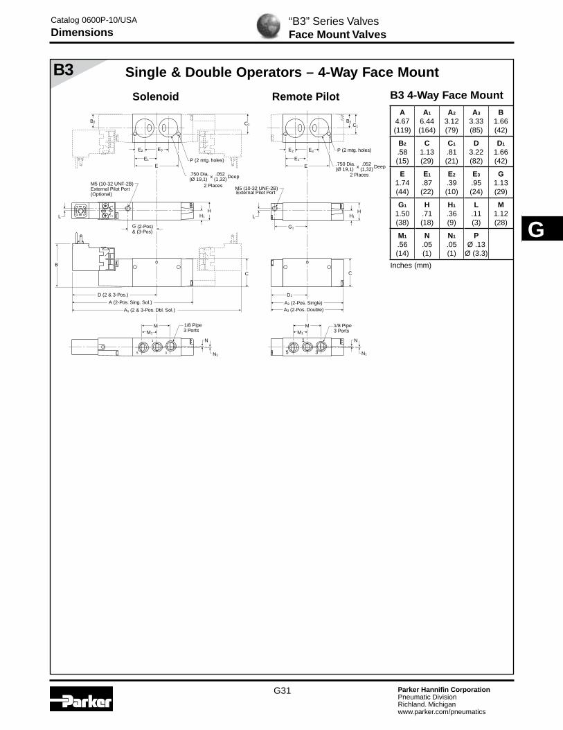
“B3” Series ValvesFace Mount Valves
Single & Double Operators – 4-Way Face Mount
B3 4-Way Face MountA
4.67(119)
A1
6.44(164)
A2
3.12(79)
A3
3.33(85)
B1.66(42)
B2
.58(15)
C1.13(29)
C1
.81(21)
D3.22(82)
D1
1.66(42)
E1.74(44)
E1
.87(22)
E2
.39(10)
E3
.95(24)
G1.13(29)
G1
1.50(38)
H.71(18)
H1
.36(9)
L.11(3)
M1.12(28)
M1
.56(14)
N.05(1)
N1
.05(1)
PØ .13
Ø (3.3)B
A (2-Pos. Sing. Sol.)
A1 (2 & 3-Pos. Dbl. Sol.)
D (2 & 3-Pos.)
H
G (2-Pos)& (3-Pos)
G1
C
H1
HH1L
5
1
3
M
N
N1
M1
M
N
N1
M1
1/8 Pipe3 Ports
C
A2 (2-Pos. Single)A3 (2-Pos. Double)
D1
L
M5 (10-32 UNF-2B)External Pilot Port
M5 (10-32 UNF-2B)External Pilot Port(Optional)
5
1
3
1/8 Pipe 3 Ports
01
1
P (2 mtg. holes)
C1 C1
E
E1
E2 E3
B2
P (2 mtg. holes)
E
E1
E2 E3
B2
.750 Dia. x .052 Deep(Ø 19,1) (1,32)
.750 Dia. x .052 Deep(Ø 19,1) (1,32)
2 Places
2 Places
Remote PilotSolenoid
Catalog 0600P-10/USA
Dimensions
Inches (mm)
G32 Parker Hannifin CorporationPneumatic DivisionRichland. Michiganwww.parker.com/pneumatics
G
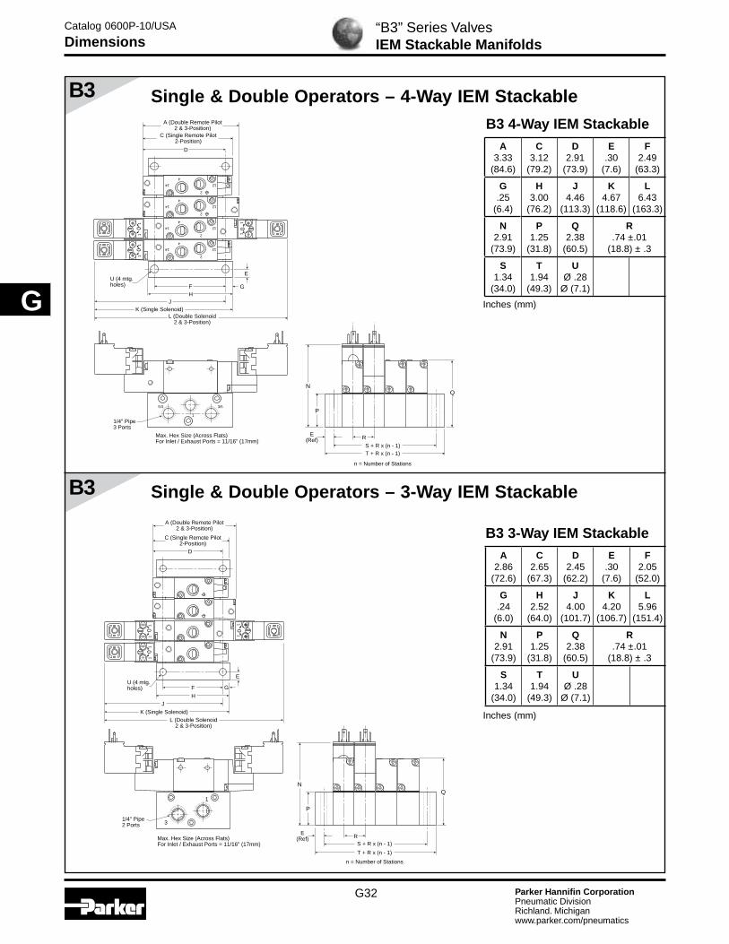
B3
B3 Single & Double Operators – 4-Way IEM StackableB3 4-Way IEM Stackable
A3.33
(84.6)
C3.12
(79.2)
D2.91
(73.9)
E.30
(7.6)
F2.49
(63.3)
G.25
(6.4)
H3.00
(76.2)
J4.46
(113.3)
K4.67
(118.6)
L6.43
(163.3)
N2.91
(73.9)
P1.25
(31.8)
Q2.38
(60.5)
R.74 ±.01
(18.8) ± .3
S1.34
(34.0)
T1.94
(49.3)
UØ .28
Ø (7.1)
Single & Double Operators – 3-Way IEM Stackable
“B3” Series ValvesIEM Stackable Manifolds
B3 3-Way IEM StackableA
2.86(72.6)
C2.65
(67.3)
D2.45
(62.2)
E.30
(7.6)
F2.05
(52.0)
G.24
(6.0)
H2.52
(64.0)
J4.00
(101.7)
K4.20
(106.7)
L5.96
(151.4)
N2.91
(73.9)
P1.25
(31.8)
Q2.38
(60.5)
R.74 ±.01
(18.8) ± .3
S1.34
(34.0)
T1.94
(49.3)
UØ .28
Ø (7.1)
G
E
1/4" Pipe3 Ports
A (Double Remote Pilot2 & 3-Position)
C (Single Remote Pilot2-Position)
5/3
1
3/5
14 12
4
2
01
1
14 12
4
2
01
1
01
1
U (4 mtg.holes)
14 12
4
2
14 12
4
2
FH
D
K (Single Solenoid)
J
L (Double Solenoid2 & 3-Position)
QN
P
RE
(Ref)
T + R x (n - 1)S + R x (n - 1)
n = Number of Stations
Max. Hex Size (Across Flats)For Inlet / Exhaust Ports = 11/16" (17mm)
G
E
01
10
11
01
1
U (4 mtg.holes) F
H
N
P
Q
1/4" Pipe2 Ports 3
1
A (Double Remote Pilot2 & 3-Position)
C (Single Remote Pilot2-Position)
D
J
K (Single Solenoid)L (Double Solenoid
2 & 3-Position)
RE
(Ref)
T + R x (n - 1)
S + R x (n - 1)
n = Number of Stations
Max. Hex Size (Across Flats)For Inlet / Exhaust Ports = 11/16" (17mm)
Catalog 0600P-10/USA
Dimensions
Inches (mm)
Inches (mm)

G33 Parker Hannifin CorporationPneumatic DivisionRichland. Michiganwww.parker.com/pneumatics
G
B3
B3
Single & Double Operators – 4-Way IEM Aluminum Bar
Single & Double Operators – 3-Way IEM Aluminum Bar
“B3” Series ValvesIEM Aluminum Bar Manifolds
B3 4-Way IEM Aluminum Bar Manifold
A3.33
(84.6)
C3.17
(80.5)
D2.94
(74.7)
E.25
(6.4)
F2.54
(64.5)
G.23
(5.9)
H3.00
(76.2)
J4.50
(114.2)
K4.73
(120.1)
L6.43
(163.3)
N2.94
(74.7)
P1.28
(32.5)
Q2.41
(61.2)
R .81
(20.5)
S1.13
(28.8)
T1.64
(41.6)
UØ .23
Ø (5.8)
G
E
1/4" Pipe3 Ports
1/8" Pipe
R
E(Ref)
A (Double Remote Pilot2 & 3-Position)
C (Single Remote Pilot2-Position)
14 12
4
2
01
1
14 12
4
2
01
1
01
1
U (4 mtg.holes)
14 12
4
2
14 12
4
2
FH
D
J
K (Single Solenoid)L (Double Solenoid
2 & 3-Position)
N
P
Q
5
X1
3
T + R x (n - 1)
S + R x (n - 1)
n = Number of Stations
Max. Hex Size (Across Flats)For Inlet / Exhaust Ports = 5/8" (16mm)
G
E
01
10
11
01
1
U (4 mtg.holes) F
N
P
Q
1/4" Pipe2 Ports
1/8" Pipe3 1
X
H
A (Double Remote Pilot2 & 3-Position)
C (Single Remote Pilot2-Position)
D
J
K (Single Solenoid)L (Double Solenoid
2 & 3-Position)
RE
(Ref)
T + R x (n - 1)
S + R x (n - 1)
n = Number of Stations
Max. Hex Size (Across Flats)For Inlet / Exhaust Ports = 5/8" (16mm)
Catalog 0600P-10/USA
Dimensions
Inches (mm)
B3 4-Way IEM Aluminum Bar Manifold
A2.86
(72.6)
C2.65
(67.3)
D2.33
(59.2)
E.25
(6.4)
F1.80
(45.7)
G.23
(5.9)
H2.25
(57.2)
J3.88
(98.6)
K4.20
(106.7)
L5.96
(151.4)
N2.93
(74.5)
P1.27
(32.4)
Q2.40
(61.1)
R .81
(20.5)
S1.13
(28.8)
T1.64
(41.6)
UØ .23
Ø (5.8)
Inches (mm)

G34 Parker Hannifin CorporationPneumatic DivisionRichland. Michiganwww.parker.com/pneumatics
G
B3
B3 Single & Double Operators – 5-Port Subbase Bar Manifold
Single & Double Operators – 4-Way Single Subbase
B
A (2-Pos. Sing. Sol.)A1 (2 & 3-Pos. Dbl. Sol.)
D (2 & 3-Pos.)
H
G1G
(2 & 3-Pos)
E
M1 M1
M(1/8" Port)
(1/4" Port)M
E1
H1J1
J
L
B1 B1
P (2 mtg. holes)
C1
C1
C
A2 (2-Pos. Single)A3 (2-Pos. Double)
D1
5 1 3 5 1 3
F1
F
4 2 4 2
P (2 mtg. holes)
M5 (10-32 UNF-2B)External Pilot Port
L
M5 (10-32 UNF-2B)External Pilot Port(Optional)
1/8 or 1/4 Pipe5 Ports
01
1
B3 4-Way Single SubbaseA
4.67(119)
A1
6.44(164)
A2
3.12(79)
A3
3.33(85)
B2.63(67)
B1
2.21(56)
C.47(12)
C1
.37(9)
D3.22(82)
D1
1.66(42)
E1.25(32)
E1
.38(10)
F.69(18)
F1
.34(9)
G1.13(29)
G1
1.50(38)
H1.50(38)
H1
.75(19)
J1.12(28)
J1
.56(14)
M .71(18)
M1
.76(19)
PØ .18Ø (4)
“B3” Series ValvesSubbase & Subbase Manifold
B3 5-Port Subbase Bar Manifold
A3.33
(84.6)
C3.12
(79.2)
D2.88
(73.2)
E.25
(6.3)
F2.43
(61.7)
G.22
(5.5)
H2.93
(74.5)
J4.66
(118.3)
K4.67
(118.6)
L6.43
(166.3)
N3.47
(88.2)
P1.81
(46.0)
Q2.94
(74.7)
R .81
(20.5)
S1.39
(35.4)
T1.89
(48.0)
UØ .22
Ø (5.6)
G
E
1/4" Pipe3 Ports
1/8" Pipe
14 1201
1
14 1201
1
01
1
U (4 mtg.holes)
14 12
14 12
F
NQ
P
3
1
5
X
2
4
A (Double Remote Pilot2 & 3-Position)
C (Single Remote Pilot2-Position)
D
HJ
K (Single Solenoid)L (Double Solenoid
2 & 3-Position)
RE
(Ref)
T + R x (n - 1)
S + R x (n - 1)
n = Number of Stations
Max. Hex Size (Across Flats)For Inlet / Exhaust Ports = 3/4" (19mm)
Remote PilotSolenoid
Catalog 0600P-10/USA
Dimensions
Inches (mm)
Inches (mm)

G35 Parker Hannifin CorporationPneumatic DivisionRichland. Michiganwww.parker.com/pneumatics
G
B5
4
214
12
T (2 mtg holes#6 or 4mm Screws)
.172 R Typ1/8 Inch PipePilot SupplyPort
5 1 3
1/4 PipePorts 3, 5
1/4 PipePorts 3, 5
DD1 (3-Pos)
K
B
S
S1
S
S1
RQB1
A2 (3-Pos)
LM
E1
G1
GG1
G
H1
J1J2
C1
CHJ
H1
J1 C1
CHJ
EE1
E
P1 N P
1/4 Or 3/8Pipe Port 1
1/4 Or 3/8Pipe Port 1
1/4 or 3/8 PipePorts 2, 4
1/4 or 3/8 PipePorts 2, 4
14 12
4
2
T (2 mtg. holes)(#6 or 4mm Screw)
U (2 mtg. holes)(5/16 or 8mmScrew)
U (2 mtg. holes)(5/16 or 8mmScrew)
1/8" PipePilot Port
L
PP1 N
M
5 1 3
R
D3(3-Pos.)
A3 (2-Pos Single)A (2-Pos Single)
A4 (2-Pos Double)A1 (2-Pos Double)
A5 (3-Pos.)
D2
Q
K1 (3-Pos)
F
F1 (3-Pos)
X
V (2-Pos. Single)
W (2-Pos. Double)
B5B5 4-Way Inline
A5.78(147)
A1
7.51(191)
A2
8.45(215)
A3
4.37(110)
A4
4.70(119)
A5
5.64(143)
B2.41(61)
B1
2.06(52)
C1.18(30)
C1
.59(15)
D3.76(96)
D1
4.23(107)
D2
2.35(60)
D3
2.82(72)
E1.89(48)
E1
.95(24)
F2.01(51)
F1
2.47(63)
G1.00(25)
G1
.50(13)
H.87(22)
H1
.16(4)
J.51(13)
J1
.36(9)
J.58(15)
K2.00(51)
K1
2.47(63)
L1.75(44)
M.88(22)
N.43(48)
P.50(13)
P1.37(92)
Q1.89(48)
R1.41(36)
S2.05(52)
S1
1.03(26)
TØ .177Ø (4.5)
UØ .34Ø (9)
V3.24(82)
W6.48(165)
X1.50(383)
Single & Double Operators – 3-Way Inline
B5 3-Way InlineA
5.29(134)
A1
7.03(179)
A2
3.88(99)
A3
4.21(107)
B2.41(61)
B1
2.06(52)
C1.18(30)
C1
.59(15)
D3.43(87)
D1
2.11(54)
E1.40(36)
E1
.70(18)
F1.77(45)
F1
.43(11)
G.06(2)
H.87(22)
H1
.16(4)
J1
.36(9)
J2
.58(15)
K1.67(42)
M.88(22)
M1
.44(11)
P.50(13)
P1
.37(9)
Q1.89(48)
R1.41(36)
TØ .177Ø (4.5)
UØ .26
Ø (6.6)
“B5” Series ValvesInline Valves
Single & Double Operators – 4-Way Inline
P
M
1/4 or 3/8Pipe Ports
1/4 or 3/8Pipe Ports
G
T (2 mtg. holes)(#6 or 4mm Screw)
U (2 mtg. holes)(1/4 or 6mm Screw)
1/8" PipePilot Port
R
E
A2 (2-Pos Single)A3 (2-Pos Double)
D1
Q
1/4 or 3/8Pipe Port
1/4 or 3/8Pipe Port
F1
F
T (2 mtg holes#6 or 4mm Screws)
.172 R Typ1/8 Inch PipePilot SupplyPort
D
K
B
E
RQB1
M
M1 M1
GH1
E1
J1J2
C1
CH
H1
J1 C1
CH
EE1
E
P1P1 P
U (2 mtg. holes)(1/4 or 6mm Screw)
A (2-Pos Single)
A1 (2-Pos Double)
Remote PilotSolenoid
Remote PilotSolenoid
Catalog 0600P-10/USA
Dimensions
Inches (mm)
Inches (mm)
Remote Pilot(“YY” Option)

G36 Parker Hannifin CorporationPneumatic DivisionRichland. Michiganwww.parker.com/pneumatics
G
B5
B5
1/8 Inch PipePilot SupplyPort
5 1 3
1/4 PipePorts 3, 5
1/4 PipePorts 3, 5
DD1 (3-Pos)
K
B
S
S1
S (Ref.)S1 (Ref.)
R
R (Ref.)
R1
QB1
B2
A2 (3-Pos)
LM
J3 C1
CC1
C
1/4 or 3/8Pipe Port 1
1/4 or 3/8Pipe Port 1
U (2 mtg. holes)(3/16 or 5mmScrew)
1/8" PipePilot Port
L
P P1
P2
N
M
5 1 3 P P1
P2
N
R
D3 (3-Pos.)
A3 (2-Pos Single)A (2-Pos Single)
A4 (2-Pos Double)A1 (2-Pos Double)
A5 (3-Pos.)
D2
Q
K1 (3-Pos)
F
F1 (3-Pos)
S
S1
P3P3
R1
R1 (Ref.)
U (2 mtg. holes)(3/16 or 5mmScrew)
.750 Dia. x .052 Deep(Ø 19,1) (1,32).750 Dia. x .052 Deep(Ø 19,1) (1,32)
2 Places
S (Ref.)S1 (Ref.)
R (Ref.)
B2
R1 (Ref.) 2 Places
“B5” Series ValvesNAMUR Mount Valves
Single & Double Operators – 4-Way NAMUR Mount
B5 4-Way NAMUR MountA
5.78(147)
A1
7.51(191)
A2
8.45(215)
A3
4.37(110)
A4
4.70(119)
A5
5.64(143)
B2.41(61)
B1
2.06(52)
B2
.84(21)
C1.18(30)
C1
.59(15)
D3.76(96)
D1
4.23(107)
D2
2.35(60)
D3
2.82(72)
F2.01(51)
F1
2.47(63)
J3
.74(19)
K2.00(51)
K1
2.47(63)
L1.75(44)
M.88(22)
N.44(11)
P.37
(9.4)
P1
.50(13)
P2
.16(4)
P3
.40(10)
Q1.89(48)
R1.26(32)
R1
.21(5)
S.94(24)
S1
.47(12)
UØ .224Ø (5.7)
C1
CC3
C2
Explosion Proof Solenoid Coil
F
G
01
Alternative Electrical Enclosure Option F
B5 4-Way NAMUR Mount with Option F Enclosure
C1.18(30)
C1
.59(15)
C2
1.42(36)
C3
.71(18)
F3.15(80)
G2.60(66)
Remote PilotSolenoid
Catalog 0600P-10/USA
Dimensions
Inches (mm)
Inches (mm)

G37 Parker Hannifin CorporationPneumatic DivisionRichland. Michiganwww.parker.com/pneumatics
G
B5
E3 (3-Pos.)
14 12
1/8 Inch PipePilot Port
E2
J
M
5 1
3
L
K
K2 4
R
N
1/4 or 3/8 Pipe2 Ports
F
G
C
F1
C1
H
P (2 mtg.holes)
M
2 4
5 1
3
L
D (2-Pos)D1 (3-Pos)
BB1
A2 (3-Pos)
1/8 Inch PipePilot SupplyPort
E1 (3-Pos)E
J1
D3 (3-Pos.)D2 (2-Pos.)
A3 (2-Pos Single)A (2-Pos Single)
A4 (2-Pos Double)A1 (2-Pos Double) A5 (3-Pos.)
B2
B5
Single & Double Operators – 4-Way Single Subbase
B5 4-Way SubbaseA
5.78(147)
A1
7.52(191)
A2
8.46(215)
A3
4.37(110)
A4
4.70(119)
A5
5.64(143)
B3.56(90)
B1
3.21(82)
B2
3.03(77)
C2.12(54)
C1
1.69(43)
D4.26(108)
D1
4.73(120)
D2
2.85(72)
D3
3.32(40)
E2.51(65)
E1
2.98(76)
E2
2.60(66)
E3
3.07(80)
F2.90(74)
F1
1.69(43)
G.95(24)
H.22(5)
J.84(21)
J1
.99(25)
K.71(18)
L1.50(38)
M.50(13)
N.46(12)
PØ .27Ø (7)
R1.00(25)
Remote Pilot
Single & Double Operators – 4-Way IEM Stackable
“B5” Series ValvesManifold & Subbase
Solenoid
B5 4-Way IEM StackableA
5.64(143.3)
B4.70
(119.4)
C4.37
(110.0)
D4.29
(109.0)
E.29
(7.4)
F3.44
(87.4)
G.24
(6.1)
H3.92
(99.6)
J5.48
(139.2)
K5.78
(146.8)
L7.52
(191.0)
M8.46
(214.9)
N3.56
(90.4)
P1.50
(38.1)
Q3.42
(86.9)
R1.21 ± .01
(30.7) ± (.3)
S1.79
(45.5)
T2.37
(60.2)
UØ .28
Ø (7.1)
3/8 Pipe3 Ports
5/3
F
U (4 mtg.holes)(1/4 or6mm Screw)
G
E
QN
P
4
214
12
4
214
12
14 12
4
2
Max. Hex Size (Across Flats)For Inlet / Exhaust Ports = 1" (25mm)
H
L (Double Solenoid)
K (Single Solenoid)
J
M (Double Solenoid 3-Position)
DC (Single Remote Pilot)
B (Double Remote Pilot2-Position)
A (Double Remote Pilot3-Position)
T + R x (n - 1)
E (Ref.)
S + R x (n - 1)
R
n = Number of Stations
14 12
4
2
Catalog 0600P-10/USA
Dimensions
Inches (mm)
Inches (mm)

G38 Parker Hannifin CorporationPneumatic DivisionRichland. Michiganwww.parker.com/pneumatics
G
B5
B5
Single & Double Operators – 3-Way IEM Aluminum Bar
Single & Double Operators – 4-Way IEM Aluminum Bar
“B5” Series ValvesIEM Aluminum Bar Manifold
B5 4-Way IEM Aluminum Bar Manifold
A5.64
(143.3)
B4.70
(119.4)
C4.37
(110.0)
D3.74
(95.0)
E.18
(4.6)
F2.78
(70.6)
G.17
(4.3)
H3.12
(79.2)
J5.15
(130.8)
K5.78
(146.8)
L7.52
(191.0)
M8.46
(214.9)
N3.50
(89.0)
P1.44
(36.6)
Q3.36
(85.3)
R1.26
(32.0)
S1.78
(45.2)
T2.14
(54.4)
UØ .22
Ø (5.5)
B5 3-Way IEM Aluminum Bar Manifold
B4.21
(106.9)
C3.88
(98.6)
D3.41
(86.6)
E.18
(4.6)
F2.12
(53.8)
G.17
(4.3)
H2.46
(62.5)
J4.82
(122.4)
K5.29
(134.4)
L7.03
(178.6)
N3.50
(89.0)
P1.44
(36.6)
Q3.36
(85.3)
R1.26
(32.0)
S1.76
(44.7)
T2.12
(53.8)
UØ .18
Ø (4.6)
3/8 Pipe3 Ports
5 3
1
FU (2 Mtg.Holes) G
E
QN
4
214
12
4
214
12
14 12
4
2
14 12
4
2
Max. Hex Size (Across Flats)For Inlet / Exhaust Ports = 3/4" (19mm)
D
H
L (Double Solenoid)
K (Single Solenoid)
J
M (Double Solenoid 3-Position)
C (Single Remote Pilot)
B (Double Remote Pilot2-Position)
A (Double Remote Pilot3-Position)
P
T + R x (n - 1)
E (Ref.)
S + R x (n - 1)
R
n = Number of Stations
1/8" Pipe
3/8 Pipe3 Ports
3 1
X
FU (2 Mtg.Holes)
G
E
QN
P
Max. Hex Size (Across Flats)For Inlet / Exhaust Ports = 13/16" (20mm))
H
L (Double Solenoid)
K (Single Solenoid)
J
DC (Single Remote Pilot)
B (Double Remote Pilot2-Position)
T + R x (n - 1)
E (Ref.)
S + R x (n - 1)
R
n = Number of Stations
1/8" Pipe
Catalog 0600P-10/USA
Dimensions
Inches (mm)
Inches (mm)

G39 Parker Hannifin CorporationPneumatic DivisionRichland. Michiganwww.parker.com/pneumatics
G
20-150 PSI 1034 kPa
144 2
513T T 12
4
2
14 12
5 1 3
E
Z2
D (Single Solenoid)
C (Double Solenoid)0
1
1/2" CONDUIT
1/2" CONDUIT
1/4 or 3/8 PipePorts 1,2,4
.34 (8.6)2 Mtg.Holes
H
Z
Z1
22mm RECT. DIN CONNECTOR
SQUARE ISO CONNECTOR
MANUAL DETENT
GROMMET/FLYING LEADS
100%
ED
F
F
F
3 OR 5-PIN AUTOMOTIVE CONNECTOR
F
B (3-Position)
A (3-Position)
NQR
UU
S S
L
1/4 PipePorts 3, 5
J
P
M
W
V
RK
.173 (4.4) Dia.2 Mtg. Holes
.177 (4.5) Dia.2 Mtg. Holes
T 2-Pos.T1 3-Pos
Ext. Supply
T2
Ext. Supply
Y G
100%
ED
F
100%
ED
100%
ED
100%
ED
100%
ED
Pneumatic
01
E1
D1 (Single Solenoid)
F
G
100%
ED
Z3
Z
Z1
MANUAL DETENT
1/4 or 3/8Pipe Ports
1/4 or 3/8Pipe Port
K1
U2
U1
S1R
L1 PQ
NM
K1
V1 W1
.26 (6.6)2 Mtg. Holes
B5
“B5” Series ValvesAlternative Electrical Enclosures
B5 Alternative – Electrical Enclosures Inches (mm)
A9.94
(252.5)
A1
.872(221.4)
B4.97
(126.2)
C9.00
(228.6)
D6.52
(165.6)
D1
6.02(152.9)
E4.50
(114.3)
E1
4.26(108.1)
F3.15
(80.0)
G2.47
(62.8)
H2.05
(52.1)
J1.03
(26.2)
K1.89
(48.0)
K1
1.40(35.5)
L.95
(24.1)
L1
.70(17.8)
M1.18
(30.0)
N.59
(15.0)
P.87
(22.1)
Q.43
(10.9)
R.08
(2.0)
S.50
(12.7)
S1
.06(1.5)
T2.01
(51.1)
T1
2.47(62.7)
T2
1.76(44.8)
U.87
(22.1)
U1
.43(10.9)
U2
.45(11.3)
V.06
(1.5)
V1
.37(9.3)
W.07
(1.8)
W1
.50(13)
Y2.90
(73.6)
Z2.40
(60.9)
Z1
2.12(53.8)
Z2
3.75(95.2)
Z3
4.17(105.8)
4-Way Alternative Electrical Enclosures
3-Way Alternative Electrical Enclosures
Catalog 0600P-10/USA
Dimensions

G40 Parker Hannifin CorporationPneumatic DivisionRichland. Michiganwww.parker.com/pneumatics
G
B6
B6
T (2 mtg holes)M5 x .8Pilot SupplyPort
DD1 (3-Pos)
B
S
S1
RQV R
QVB1
A2 (3-Pos Double Solenoid)
3/8 PipePorts 1, 3, 5
L
P1 N P
M
3/8 PipePorts 1, 3, 5
L
P1 N P
M
E1
H1
J1J2
C1
CHJ
E
3/8 PipePorts 2, 4
U (2 mtg. holes)(1/4 or 6mmScrew)
U (2 mtg. holes)(1/4 or 6mmScrew)
D3 (3-Pos.)
A3 (2-Pos. Single Remote Pilot)A (2-Pos Single Solenoid)
A4 (2-Pos. Double Remote Pilot)A1 (2-Pos Double Solenoid)
A5 (3-Pos. Double Remote Pilot)
D2
K
G1
G
K1 (3-Pos)
T (2 mtg holes)1/8 Inch PipePilot SupplyPort E1
H1
J1 C1
CHJ
E
3/8 PipePorts 2, 4F
G1
G
F1 (3-Pos)
S
S1
T (2 mtg holes)M5 x .8Pilot SupplyPort
D
B
RQV VR
QB1
3/8 PipePorts
L
N P
M
E1
H1
J1J2
C1
CH
E
3/8 PipePort
U (2 mtg. holes)(1/4 or 6mmScrew)
U (2 mtg. holes)(1/4 or 6mmScrew)
A3 (2-Pos. Single Remote Pilot)A (2-Pos Single Solenoid)
D2
K
T (2 mtg holes)1/8 Inch PipePilot SupplyPort E1
H1
J1 C1
CH
E
3/8 PipePortF
SS1
S
S1
3/8 PipePorts
L
N P
M
Single Operators – 3-Way Inline
“B6” Series ValvesInline Valves
Single & Double Operators – 4-Way Inline
B6 4-Way InlineA
6.67(169.5)
A1
8.41(213.7)
A2
9.35(237.6)
A3
5.26(133.7)
A4
5.59(142.1)
A5
6.54(166.0)
B2.41
(61.3)
B1
2.06(52.3)
C1.18
(30.0)
C1
.59(15.0)
D4.21
(106.8)
D1
4.68(118.8)
D2
2.80(71.0)
D3
3.27(83.0)
E2.79
(70.8)
E1
1.39(35.4)
F2.45
(62.3)
F1
2.92(74.3)
G1.03
(26.1)
G1
.51(13.1)
H.91
(23.0)
H1
.14(3.5)
J.51
(13.1)
J1
.39(10.0)
J2
.81(20.6)
K2.09
(53.0)
K1
2.56(64.9)
L2.34
(59.4)
M1.17
(29.7)
N.45
(11.5)
P.49
(12.5)
P1
.41(10.5)
Q1.89
(48.0)
R1.45
(36.8)
S2.09
(53.0)
S1
1.04(26.5)
TØ .17
Ø (4.4)
U Ø .27Ø (6.9)
V1.69
(43.0)
B6 3-Way InlineA
5.42(137.7)
A3
4.01(101.9)
B2.41
(61.3)
B1
2.06(52.3)
C1.18
(30.0)
C1
.59(15.0)
D3.63
(92.1)
D2
2.22(56.3)
E2.19
(55.6)
E1
0.82(20.7)
F1.87
(47.6)
H.91
(23.0)
H1
.14(3.5)
J1
.39(10.0)
J2
.81(20.6)
K1.51
(38.3)
L1.17
(29.7)
M.59
(15.0)
N.45
(11.5)
P.49
(12.5)
Q1.89
(48.0)
R1.45
(36.8)
S2.09
(53.0)
S1
0.76(19.4)
TØ .17
Ø (4.4)
UØ .27
Ø (6.9)
V1.69
(43.0)
Remote PilotSolenoid
Remote PilotSolenoid
Catalog 0600P-10/USA
Dimensions
Inches (mm)
Inches (mm)

G41 Parker Hannifin CorporationPneumatic DivisionRichland. Michiganwww.parker.com/pneumatics
G
B6
B6
“B6” Series ValvesNAMUR Mount Valves
Single & Double Operators – 4-Way NAMUR Mount
B6 4-Way NAMUR MountA
6.67(169.5)
A1
8.41(213.7)
A2
9.35(237.6)
A3
5.26(133.7)
A4
5.59(142.1)
A5
6.54(166.0)
B2.41
(61.3)
B1
2.06(52.3)
B2
.57(14.4)
C1.18
(30.0)
C1
.59(15)
D4.21
(106.8)
D1
4.68(118.8)
D2
2.80(71.0)
D3
3.27(83.0)
F2.45
(62.3)
F1
2.92(74.3)
G.95
(24.2)
G1
.02(0.53)
J3
.9524.1)
K2.09
(53.0)
K1
2.56(64.9)
L2.34
(59.4)
M1.17
(29.7)
N.59(15)
P.63(16)
P1
.55(14)
Q1.89
(48.0)
R1.26(32)
R1
.22(5.5)
S.94(24)
S1
.47(12)
TØ .17
Ø (4.4)
U Ø .27Ø (6.9)
M5 x .8Pilot SupplyPort
DD1 (3-Pos)
BQB1
A2 (3-Pos Double Solenoid)
3/8 PipePorts 1, 3, 5
L
P1 N P P1 N P
M
3/8 PipePorts 1, 3, 5
LM
J3C1
C
D3 (3-Pos.)
A3 (2-Pos. Single Remote Pilot)A (2-Pos Single Solenoid)
A4 (2-Pos. Double Remote Pilot)A1 (2-Pos Double Solenoid)
A5 (3-Pos. Double Remote Pilot)
D2
K
K1 (3-Pos)
1/8 Inch PipePilot SupplyPort
C1
C
F
F1 (3-Pos)
SS1
G1G
R
R1 R1
U (2 mtg. holes)(3/16 or 5mmScrew)
Q
SS1
G1G
R
B2B2
U (2 mtg. holes)(3/16 or 5mmScrew)
.816 Dia. x .052 Deep(Ø 20,7) (1,32).816 Dia. x .052 Deep(Ø 20,7) (1,32)
2 Places 2 Places
C3
C2
Hazardous Duty Solenoid Coil
F
G
01
C1
C
Alternative Electrical Enclosure Option F
B6 4-Way NAMUR Mount with Option F Enclosure
C1.18(30)
C1
.59(15)
C2
1.42(36)
C3
.71(18)
F3.15(80)
G2.60(66)
Remote PilotSolenoid
Catalog 0600P-10/USA
Dimensions
Inches (mm)
Inches (mm)

G42 Parker Hannifin CorporationPneumatic DivisionRichland. Michiganwww.parker.com/pneumatics
G
B6
B6
Single Operators – 3-Way IEM Aluminum Bar
Single & Double Operators – 4-Way IEM Aluminum Bar
“B6” Series ValvesIEM Aluminum Bar Manifold
B6 4-Way IEM Aluminum Bar Manifold
A6.54
(166.0)
B5.59
(142.1)
C5.26
(133.7)
D4.76
(121.0)
E.24
(6.0)
F3.94
(100.0)
G.24
(6.0)
H4.41
(112.0)
J6.17
(156.8)
K6.67
(169.5)
L8.41
(213.7)
M9.35
(237.6)
N3.60
(91.3)
P1.54
(39.0)
Q3.43
(87.0)
R1.24
(31.5)
S1.77
(45.0)
T2.24
(57.0)
Uø .26
ø (6.5)
B6 3-Way IEM Aluminum Bar Manifold
C5.00
(127.0)
D4.76
(121.0)
E.24
(6.0)
F3.94
(100.0)
G.24
(6.0)
H4.41
(112.0)
J6.17
(156.8)
K6.41
(162.8)
N3.60
(91.3)
P1.54
(39.0)
Q3.43
(87.0)
R1.24
(31.5)
S1.77
(45.0)
T2.24
(57.0)
UØ .26
Ø (6.5)
U (4 Mtg.Holes)
QN
1/2 Pipe3 PortsBoth Ends
1/8 Pipe PortsBoth Ends
Max. Hex Size (Across Flats)For Inlet / Exhaust Ports = .63 (16,0)
F G
E
H
L (Double Solenoid)
K (Single Solenoid)
J
M (Double Solenoid 3-Position)
DC (Single Remote Pilot)
B (Double Remote Pilot2-Position)
A (Double Remote Pilot3-Position)
P
T + R x (n - 1)
E (Ref.)
S + R x (n - 1)
R
n = Number of Stations
U(4 Mtg.Holes)
QN
1/2 Pipe3 PortsBoth Ends
1/8 Pipe PortsBoth Ends
Max. Hex Size (Across Flats)For Inlet / Exhaust Ports = .63 (16,0)
F G
E
H
K (Single Solenoid)
J
D
C (Single Remote Pilot)
P
T + R x (n - 1)
E (Ref.)
S + R x (n - 1)
R
n = Number of Stations
Inches (mm)
Catalog 0600P-10/USA
Dimensions
Inches (mm)

G43 Parker Hannifin CorporationPneumatic DivisionRichland. Michiganwww.parker.com/pneumatics
G
4
2
14 12
EF
D1 (Single Solenoid CSA NRTL-C “L” Option)
D (Single Solenoid)
C (Double Solenoid)
01
1/2" CONDUIT
3/8 PipePorts 1,2,4
.27 (6,9) Dia. 2 Mtg Holes(1/4 or 6mm Screw)
22mm RECT. DIN CONNECTOR
SQUARE ISO CONNECTOR
GROMMET/FLYING LEADS
100%
ED
F
F
F
3 OR 5-PIN AUTOMOTIVE CONNECTOR
B (3-Position)
A (3-Position)
NQRS S
L
H
J
P
M
NQ
R
R
P
K
.17 (4,4) Dia.2 Mtg. Holes
.17 (4,4) Dia.2 Mtg. Holes
T 2-Pos.T1 3-Pos
Ext. Supply
Y
G
100%
ED
F
100%
ED
100%
ED
100%
ED
100%
ED
01
T2 2-Pos.Ext. Supply
F
1/2" CONDUIT
G
100%
ED
3/8 Pipe Ports
V W X
U U
20-150 PSI 1034 kPa
12TT5 1 3
4 2
14
145 1
4 2
312
E1
L1
M
K13/8 PipePort
U (2 mtg. holes)(1/4 or 6mm Screw)
D2 (2-Pos Single Solenoid)
H1
J1
3/8 PipePorts
W X
U1
U1
B6
“B6” Series ValvesAlternative Electrical Enclosures
B6 Alternative – Electrical Enclosures Inches (mm)
A10.84
(275.3)
B5.41
(137.5)
C9.89
(251.3)
D7.41
(188.2)
D1
7.74(196.6)
D2
6.17(156.6)
E4.94
(125.6)
E2
4.37(111.0)
F3.15
(80.0)
G2.47
(62.8)
H2.09
(53.0)
H1
2.09(53.0)
J1.04
(26.5)
J1
0.76(19.4)
K2.79
(70.8)
K1
2.19(55.6)
L1.39
(35.4)
L1
.82(20.7)
M1.18
(30.0)
N.59
(15.0)
P.91
(23.0)
Q.45
(11.5)
R.06
(1.6)
S.51
(13.1)
T2.45
(62.3)
T1
2.93(29.7)
T2
1.89(48.0)
U.59
(15.0)
U1
.59(15.0)
V.41
(10.5)
W.45
(11.5)
X.49
(12.5)
Y2.90
(73.6)
4-Way Alternative Electrical Enclosures
3-Way Alternative Electrical Enclosures
Catalog 0600P-10/USA
Dimensions

G44 Parker Hannifin CorporationPneumatic DivisionRichland. Michiganwww.parker.com/pneumatics
G
B7
B8Remote PilotSolenoid
Remote PilotSolenoid
“B7” & “B8” Series ValvesInline Valves
Single & Double Operators – 4-Way Inline
Single Operators – 3-Way Inline
B7 & B8 4-Way InlineA
9.13(232)
A1
11.29(287)
A2
7.79(198)
A3
8.62(219)
B2.95(75)
B1
2.59(66)
C1.65(42)
C1
.83(21)
D1
4.29(109)
D2
5.63(143)
E4.21(107)
E1
2.13(54)
F4.06(103)
G1.73(44)
G1
.87(22)
H1.29(33)
H1
.16(4)
J.75(19)
J1
.59(15)
L3.39(86)
M1.69(43)
N.67(17)
P.75(19)
P1
.59(15)
Q2.68(68)
R2.32(59)
R1
.35(9)
S1.81(46)
S1
.90(23)
T3.94(100)
U.35(9)
B71_XXXXXXXXMAX. PSI 145
D2Ø .35 (9) Dia. 3 Mtg. Holes(5/16 or 8mm Screw)
A1 (2 & 3-PositionDouble Solenoid)
A (2-PositionSingle Solenoid)
A2 (2-PositionSingle Remote Pilot)
A3 (2 & 3-PositionDouble Remote Pilot)
Ø .24 (6) Dia. 2 Mtg. Holes
1/8 Pipe
M5 PilotSupply Port
BB1
U
S1 S1
S
R Q R Q
E
E1
E
E1
G1
GT
G1
G
JJ1 C1
H
H1
CJJ1 C1
H
H1
C
R1
1/2 Pipe (B7)3/4 Pipe (B8)
1/2 Pipe (B7)3/4 Pipe (B8)
1/2 Pipe (B7)3/4 Pipe (B8)
P1
ML
ML
N P P1 N P
S
12TT5 1 3
4 2
14
145 1
4 2
312
B71_XXXXXXXXMAX. PSI 145
D1Ø .35 (9) Dia. 3 Mtg. Holes(5/16 or 8mm Screw)
R1
1/2 Pipe (B7)3/4 Pipe (B8)
12TT5 1 3
4 2
14
145 1
4 2
312
Ø .24 (6) Dia. 2 Mtg. Holes
F
B71_XXXXXXXXMAX. PSI 145
A (2-PositionSingle Solenoid)
A2 (2-PositionSingle Remote Pilot)
BB1
D2
S1 S1
S
R Q R Q
E
E1
E
E1
G1 G1
J1 C1
H
H1
CJ1 C1
H
H1
C
R1
1/2 Pipe (B7)3/4 Pipe (B8)
1/2 Pipe (B7)3/4 Pipe (B8) 1/2 Pipe (B7)
3/4 Pipe (B8)
M
N P
S
12TT5 1 3
4 2
14
145 1
4 2
312
1/2 Pipe (B7)3/4 Pipe (B8)
M
N P
B71_XXXXXXXXMAX. PSI 145
D1
R1
12TT5 1 3
4 2
14
145 1
4 2
312
F
Ø .35 (9) Dia. 3 Mtg. Holes(5/16 or 8mm Screw)
Ø .35 (9) Dia. 3 Mtg. Holes(5/16 or 8mm Screw)
Ø .24 (6) Dia. 2 Mtg. Holes
Ø .24 (6) Dia. 2 Mtg. Holes
1/8" PipeM5 PilotSupply Port
U
T
Catalog 0600P-10/USA
Dimensions
Inches (mm)
B7 & B8 3-Way Inline A
7.99(203)
A2
6.65(169)
B2.95(75)
B1
2.59(66)
C1.65(42)
C1
.83(21)
D1
4.29(109)
D2
5.63(143)
E4.21(107)
E1
2.13(54)
F 4.06(103)
G1
.86(22)
H1.29(33)
H1
.16(4)
J1
.59(15)
M1.69(43)
N.67(17)
P.75(19)
Q2.68(68)
R2.32(59)
R1
.35(9)
S1.81(46)
S1
.90(23)
T3.94(100)
U.35(9)
Inches (mm)
B7
B8

G45 Parker Hannifin CorporationPneumatic DivisionRichland. Michiganwww.parker.com/pneumatics
G
B8
B71_XXXXXXXXMAX. PSI 145
E
GFH
J
M (2 & 3-Position Double Solenoid)
K (2-Position Single Solenoid)
1/2 Pipe (B7)
12TT5 1 3
4 2
14
145 1
4 2
312
C (2-PositionSingle Remote Pilot)
A (2 & 3-PositionDouble Remote Pilot)
1 35
X
D
N Q
P
T + R x (n - 1)
E (Ref.)
S + R x (n - 1)
R
n = Number of Stations
1/8" Pipe
B7
B7
B8
Single Operators – 3-Way IEM Aluminum Bar
Single & Double Operators – 4-Way IEM Aluminum Bar
“B7” & “B8” Series ValvesIEM Aluminum Bar Manifolds
B7 & B8 4-Way IEM Aluminum Bar Manifold
A7.79(198)
C8.62(219)
D6.26(159)
E.24(6)
F3.94(100)
G.45
(11.5)
H4.84(123)
J8.07(205)
K9.13(232)
M11.29(287)
N4.00
(101.5)
P1.48
(37.5)
Q4.15
(105.5)
R1.77(45)
S2.24(57)
T2.72(69)
B7 & B8 3-Way IEM Aluminum Bar Manifold
C6.65(169)
D4.92
(124.9)
E.24(6)
F3.94(100)
G.45
(11.5)
H4.84(123)
K7.99(203)
N4.00
(101.5)
P1.48
(37.5)
Q4.15
(105.5)
R1.77(45)
S2.24(57)
T2.72(69)
B71_XXXXXXXXMAX. PSI 145
E
GFH
K (2-Position Single Solenoid)
1/2 Pipe (B7)
12TT5 1 3
4 2
14
145 1
4 2
312
C (2-PositionSingle Remote Pilot)
1 35
X
D
N Q
P
T + R x (n - 1)
E (Ref.)
S + R x (n - 1)
R
n = Number of Stations
1/8" Pipe
Catalog 0600P-10/USA
Dimensions
Inches (mm)
Inches (mm)

G46 Parker Hannifin CorporationPneumatic DivisionRichland. Michiganwww.parker.com/pneumatics
G
B71_XXXXXXXXMAX. PSI 145
D
1/2" CONDUIT
22mm RECT. DIN CONNECTOR
GROMMET / FLYING LEADS
100%
ED
F
F
F3 OR 5-PIN AUTOMOTIVE CONNECTOR
A1 (2 & 3-PositionDouble Solenoid)
A (2-PositionSingle Solenoid)
YY1 QR
R1
100%
ED
F
100%
ED
100%
ED
100%
ED
01
SQUARE ISO CONNECTOR
F
100%
ED
12TT5 1 3
4 2
14
145 1
4 2
312
S1S
E
E1
G1
G
JJ1 C1
H
H1
C
P1
ML
N P
1/2 Pipe (B7)3/4 Pipe (B8)
Ø .35 (9) Dia. 3 Mtg. Holes(5/16 or 8mm Screw)
Ø .24 (6) Dia. 2 Mtg. Holes
B71_XXXXXXXXMAX. PSI 145
DA2 (2-Position
Single Solenoid)
S1
S
R Q
E
E1
G1
J1 C1
H
H1
C
M
N P
12TT5 1 3
4 2
14
145 1
4 2
312
1/2" CONDUIT
F
Y1
R1
100%
ED
01
1/2 Pipe (B7)3/4 Pipe (B8)
1/2 Pipe (B7)3/4 Pipe (B8)
1/2 Pipe (B7)3/4 Pipe (B8)
Ø .35 (9) Dia. 3 Mtg. Holes(5/16 or 8mm Screw)
Ø .24 (6) Dia. 2 Mtg. Holes
1/8" PipeZ
1/8" PipeZ
B7
B8
“B7” & “B8” Series Valves3 & 4-Way Alternative Electrical Enclosures
B7 & B8 3 & 4-Way Alternative – Electrical Enclosures Inches (mm)
A9.92(252)
A1
12.91(328)
A2
8.78(223)
C1.65(42)
C1
.83(21)
D6.46(164)
E4.21(107)
E1
2.13(54)
F3.74(95)
G1.73(44)
G1
.86(22)
H1.29(33)
H1
.16(4)
J.75(19)
J1
.59(15)
L3.39(86)
M1.69(43)
N.67(17)
P.75(19)
P1
.59(15)
Q2.68(68)
R2.32(59)
R1
.35(9)
S1.81(46)
S1
.90(23)
Y2.87(73)
Y1
2.71(69)
Z3.98(101)
4-Way Alternative Electrical Enclosures
3-Way Alternative Electrical Enclosures
Catalog 0600P-10/USA
Dimensions

G47 Parker Hannifin CorporationPneumatic DivisionRichland. Michiganwww.parker.com/pneumatics
G
B8
B7
Table 1 Compression Factors and “A” Constants
InletPressure
(PSIG)
Compression Factor
“A” Constants for Various Pressure Drop*
2 PSI P
5 PSI P
10 PSI P
10 1.6 .152 .10320 2.3 .126 .084 .06530 3.0 .111 .073 .05540 3.7 .100 .065 .04850 4.4 .091 .059 .04460 5.1 .085 .055 .04070 5.7 .079 .051 .03780 6.4 .075 .048 .03590 7.1 .071 .046 .033
100 7.8 .068 .044 .032110 8.5 .065 .042 .030120 9.2 .063 .040 .029130 9.9 .061 .039 .028140 10.6 .058 .037 .027150 11.2 .057 .036 .026160 11.9 .055 .035 .025170 12.6 .053 .034 .024180 13.3 .052 .033 .024190 14.0 .051 .032 .023200 14.7 .050 .032 .023
Note: Use “A” constant at 5 PSI P for most applications. On very critical applications. use “A” at 2 PSI P. You will find in many cases, a 10 PSI P is not detrimental, and can save money and mounting space.
* Tabulated values are the solution of where T is for 68°F and G =1 for Air.
Cv CalculationsCv ........Measure of calculating flow of a valve (or other
pneumatic device) that takes into effect the temperature, pressure, pressure drop, and flow. As a rule of thumb. a Cv of 1.0 is 25 SCFM with a 5 PSIG pressure drop.
Table 2Effective Square-Inch Areas forStandard-Bore-Size Cylinders
BoreSize
Cylinder Area
(Sq. In.)BoreSize
Cylinder Area
(Sq. In.)3/4" .44 4" 12.57
1" .79 4-1/2" 15.90
1-1/8" .99 5" 19.64
1-1/4" 1.23 6" 28.27
1-1/2" 1.77 7" 38.48
1-3/4" 2.41 8" 50.27
2" 3.14 10" 78.54
2-1/2" 4.91 12" 113.10
3-1/4" 8.30 14" 153.94
3-5/8" 10.32
DefinitionsCSA NRTL-C ...... Canadian Standards Association and UL
Applicable.IP65 ..................... International classification system for sealing
effectiveness for enclosures of electrical equipment. IP stands for “Ingress Protection” and the two digits XY stand for: X - protection from solid objects and Y - protection from moisture. IP 65 is protection from dust and water washdown.
NEMA 4 ............... National standard for electrical enclosure protection. NEMA 4 provides protection against dirt, dust, water hosedown and rain. (Similar to IP 65)
DIN 43650C ........ International standard for the 15mm 3-Pin connector. The pin spacing is 8mm.
3-WAY ................. Valve has three ways for air to flow. Also designated as 3/2.
4-WAY ................. Valve has four ways for air to flow. Also designated as 5/2 for 2-Position and 5/3 for 3-Position.
NC ....................... Normally Closed. Pressure is blocked when in neutral position. (Normally Non-Passing)
NO ....................... Normally Open. Pressure passes thru when in neutral position. (Normally Passing)
IEM ...................... Inlet / Exhaust manifold. The inlet and exhaust ports are located in the manifold. The cylinder ports are accessed in the valve.
5-Port Subbase Bar Manifold Manifold that includes the inlet and outlet ports as well as the #2 & #4 cylinder ports. Utilizes a subbase valve less base.
NLMOR ............... Non-Locking Manual Override. A constant actuation must be maintained for the valve to remain shifted.
LMOR .................. Locking Manual Override. Valve remains shifted without constant end user override actuation.
Surge Suppression Nullifies reverse EMF generated when a solenoid is de-energized.
SCFM .................. Measure of air flow. Standard Cubic Feet per Minute at 68°F and 36% humidity at sea level.
PSIG ................... Pounds per Square Inch measured with a gage. (Catalog pressure reflects PSIG)
PSIA .................... Pounds per Square Inch atmospheric.kPa ...................... Kilopascals. International measure of
pressure. 145 PSIG = 1000 kPaPSIG = 0 PSIA = 14.7 In. of Hg = 29.92 kPa = 0
“B” Series ValvesAir Control Valves
1 GT 22.48 (P1 – P2) P2
Cylinder Area Cylinder Compression “A” (Sq. In.) X Stroke X Factor X (Table 1)Cv = (See Table 2) (In.) (Table 1) Stroke Time (sec.) x 28.8
B6
B5
B3
SeriesSingle
Solenoid3-PositionSolenoid
ManifoldStackable
SubbaseEnd Plate
.25 .35 .20 .60 .50
.70 .80 .20 .80 .70
1.8 2.4 — — —
2.5 2.9 — — —
2.5 2.9 — — —
Weights are in pounds and are approximate.
Product Shipping Weights
Catalog 0600P-10/USA
Definitions & Weights

G48 Parker Hannifin CorporationPneumatic DivisionRichland. Michiganwww.parker.com/pneumatics
G
“B” Series ValvesCatalog 0600P-10/USA
Notes

� Parker Hannifin CorporationPneumatic DivisionRichland, Michiganwww.parker.com/pneumatics
! WARNINGFAILURE OR IMPROPER SELECTION OR IMPROPER USE OF THE PRODUCTS AND/OR SYSTEMS DESCRIBED HEREIN OR RELATED ITEMS CAN CAUSE DEATH, PERSONAL INJURY AND PROPERTY DAMAGE.This document and other information from Parker Hannifin Corporation, its subsidiaries and authorized distributors provide product and/or system options for further investigation by users having technical expertise. It is important that you analyze all aspects of your application including consequences of any failure, and review the information concerning the product or system in the current product catalog. Due to the variety of operating conditions and applications for these products or systems, the user, through its own analysis and testing, is solely responsible for making the final selection of the products and systems and assuring that all performance, safety and warning requirements of the application are met.The products described herein, including without limitation, product features, specifications, designs, availability and pricing, are subject to change by Parker Hannifin Corporation and its subsidiaries at any time without notice.
Offer of SaleThe items described in this document are hereby offered for sale by Parker Hannifin Corporation, its subsidiaries or its autho-rized distributors. This offer and its acceptance are governed by the provisions stated on the separate page of this document entitled “Offer of Sale”.
© Copyright 2007-�997, Parker Hannifin Corporation. All Rights Reserved.
GlobalPneumatics
This icon can be found next to products that are widely supported by Parker Pneumatics’ worldwide manufacturing and sales network. When you see this icon, you can be confident that this product is manufactured and / or stocked* worldwide for rapid delivery. In addition to local manufacturing or inventory, our sales network has been specifically trained on these products to provide our customers with the best possible service.
Products not showing this icon are still sold and distributed worldwide. However, The Global Pneumatics icon represents products that customers can expect the best level of support.
If you are a multi-national company, seek global sourcing or ship globally, depend on Parker Pneumatic for PREMIER CUSTOMER SERVICE.
* Stocking levels vary by country
Pneumatic ProductsCatalog 0600P-�0/USA
Global Pneumatics, Warning, Offer of Sale

Parker Hannifin CorporationPneumatic DivisionRichland, Michiganwww.parker.com/pneumatics
Y10
Y
Safety Guide For Selecting And Using Pneumatic Division Products And Related Accessories
WARNING:FAILURE OR IMPROPER SELECTION OR IMPROPER USE OF PNEUMATIC DIVISION PRODUCTS, ASSEMBLIES OR RELATED ITEMS (“PRODUCTS”) CAN CAUSE DEATH, PERSONAL INJURY, AND PROPERTY DAMAGE. POSSIBLE CONSEQUENCES OF FAILURE OR IMPROPER SELECTION OR IMPROPER USE OF THESE PRODUCTS INCLUDE BUT ARE NOT LIMITED TO:• Unintended or mistimed cycling or motion of machine members or failure to cycle
• Work pieces or component parts being thrown off at high speeds.
• Failure of a device to function properly for example, failure to clamp or unclamp an associated item or device.
• Explosion
• Suddenly moving or falling objects.
• Release of toxic or otherwise injurious liquids or gasses.
Before selecting or using any of these Products, it is important that you read and follow the instructions below.
!
Pneumatic ProductsWarnings
Catalog 0600P-10/USA
Safety Guide
1. GENERAL INSTRUCTIONS 1.1. Scope: This safety guide is designed to cover general guidelines on the installation, use, and maintenance of Pneumatic Division
Valves, FRLs (Filters, Pressure Regulators, and Lubricators), Vacuum products and related accessory components. 1.2. Fail-Safe: Valves, FRLs, Vacuum products and their related components can and do fail without warning for many reasons. Design all
systems and equipment in a fail-safe mode, so that failure of associated valves, FRLs or Vacuum products will not endanger persons or property.
1.3 Relevant International Standards: For a good guide to the application of a broad spectrum of pneumatic fluid power devices see: ISO 4414:1998, Pneumatic Fluid Power – General Rules Relating to Systems. See www.iso.org for ordering information.
1.4. Distribution: Provide a copy of this safety guide to each person that is responsible for selection, installation, or use of Valves, FRLs or Vacuum products. Do not select, or use Parker valves, FRLs or vacuum products without thoroughly reading and understanding this safety guide as well as the specific Parker publications for the products considered or selected.
1.5. User Responsibility: Due to the wide variety of operating conditions and applications for valves, FRLs, and vacuum products Parker and its distributors do not represent or warrant that any particular valve, FRL or vacuum product is suitable for any specific end use system. This safety guide does not analyze all technical parameters that must be considered in selecting a product. The user, through its own analysis and testing, is solely responsible for: • Making the final selection of the appropriate valve, FRL, Vacuum component, or accessory.
• Assuring that all user’s performance, endurance, maintenance, safety, and warning requirements are met and that the application presents no health or safety hazards.
• Complying with all existing warning labels and / or providing all appropriate health and safety warnings on the equipment on which the valves, FRLs or Vacuum products are used; and,
• Assuring compliance with all applicable government and industry standards. 1.6. Safety Devices: Safety devices should not be removed, or defeated. 1.7. Warning Labels: Warning labels should not be removed, painted over or otherwise obscured. 1.8. Additional Questions: Call the appropriate Parker technical service department if you have any questions or require any additional
information. See the Parker publication for the product being considered or used, or call 1-800-CPARKER, or go to www.parker.com, for telephone numbers of the appropriate technical service department.
2. PRODUCT SELECTION INSTRUCTIONS 2.1. Flow Rate: The flow rate requirements of a system are frequently the primary consideration when designing any pneumatic system.
System components need to be able to provide adequate flow and pressure for the desired application. 2.2. Pressure Rating: Never exceed the rated pressure of a product. Consult product labeling, Pneumatic Division catalogs or the
instruction sheets supplied for maximum pressure ratings. 2.3. Temperature Rating: Never exceed the temperature rating of a product. Excessive heat can shorten the life expectancy of a product
and result in complete product failure. 2.4. Environment: Many environmental conditions can affect the integrity and suitability of a product for a given application. Pneumatic
Division products are designed for use in general purpose industrial applications. If these products are to be used in unusual circumstances such as direct sunlight and/or corrosive or caustic environments, such use can shorten the useful life and lead to premature failure of a product.
2.5. Lubrication and Compressor Carryover: Some modern synthetic oils can and will attack nitrile seals. If there is any possibility of synthetic oils or greases migrating into the pneumatic components check for compatibility with the seal materials used. Consult the factory or product literature for materials of construction.
2.6. Polycarbonate Bowls and Sight Glasses: To avoid potential polycarbonate bowl failures: • Do not locate polycarbonate bowls or sight glasses in areas where they could be subject to direct sunlight, impact blow, or temperatures outside of the rated range.
• Do not expose or clean polycarbonate bowls with detergents, chlorinated hydro-carbons, keytones, esters or certain alcohols. • Do not use polycarbonate bowls or sight glasses in air systems where compressors are lubricated with fire resistant fluids such as
phosphate ester and di-ester lubricants.

Parker Hannifin CorporationPneumatic DivisionRichland, Michiganwww.parker.com/pneumatics
Y11
Y
2.7. Chemical Compatibility: For more information on plastic component chemical compatibility see Pneumatic Division technical bulletins Tec-3, Tec-4, and Tec-5
2.8. Product Rupture: Product rupture can cause death, serious personal injury, and property damage. • Do not connect pressure regulators or other Pneumatic Division products to bottled gas cylinders.
• Do not exceed the maximum primary pressure rating of any pressure regulator or any system component. • Consult product labeling or product literature for pressure rating limitations.3. PRODUCT ASSEMBLY AND INSTALLATION INSTRUCTIONS 3.1. Component Inspection: Prior to assembly or installation a careful examination of the valves, FRLs or vacuum products must be
performed. All components must be checked for correct style, size, and catalog number. DO NOT use any component that displays any signs of nonconformance.
3.2. Installation Instructions: Parker published Installation Instructions must be followed for installation of Parker valves, FRLs and vacuum components. These instructions are provided with every Parker valve or FRL sold, or by calling 1-800-CPARKER, or at www.parker.com.
3.3. Air Supply: The air supply or control medium supplied to Valves, FRLs and Vacuum components must be moisture-free if ambient temperature can drop below freezing
4. VALVE AND FRL MAINTENANCE AND REPLACEMENT INSTRUCTIONS 4.1. Maintenance: Even with proper selection and installation, valve, FRL and vacuum products service life may be significantly reduced
without a continuing maintenance program. The severity of the application, risk potential from a component failure, and experience with any known failures in the application or in similar applications should determine the frequency of inspections and the servicing or replacement of Pneumatic Division products so that products are replaced before any failure occurs. A maintenance program must be established and followed by the user and, at minimum, must include instructions 4.2 through 4.10.
4.2. Installation and Service Instructions: Before attempting to service or replace any worn or damaged parts consult the appropriate Service Bulletin for the valve or FRL in question for the appropriate practices to service the unit in question. These Service and Installation Instructions are provided with every Parker valve and FRL sold, or are available by calling 1-800-CPARKER, or by accessing the Parker web site at www.parker.com.
4.3. Lockout / Tagout Procedures: Be sure to follow all required lockout and tagout procedures when servicing equipment. For more information see: OSHA Standard – 29 CFR, Part 1910.147, Appendix A, The Control of Hazardous Energy – (Lockout / Tagout)
4.4. Visual Inspection: Any of the following conditions requires immediate system shut down and replacement of worn or damaged components: • Air leakage: Look and listen to see if there are any signs of visual damage to any of the components in the system. Leakage is an indication of worn or damaged components.
• Damaged or degraded components: Look to see if there are any visible signs of wear or component degradation. • Kinked, crushed, or damaged hoses. Kinked hoses can result in restricted air flow and lead to unpredictable system behavior. • Any observed improper system or component function: Immediately shut down the system and correct malfunction. • Excessive dirt build-up: Dirt and clutter can mask potentially hazardous situations. Caution: Leak detection solutions should be rinsed off after use. 4.5. Routine Maintenance Issues:
• Remove excessive dirt, grime and clutter from work areas. • Make sure all required guards and shields are in place. 4.6. Functional Test: Before initiating automatic operation, operate the system manually to make sure all required functions operate
properly and safely. 4.7. Service or Replacement Intervals: It is the user’s responsibility to establish appropriate service intervals. Valves, FRLs and vacuum
products contain components that age, harden, wear, and otherwise deteriorate over time. Environmental conditions can significantly accelerate this process. Valves, FRLs and vacuum components need to be serviced or replaced on routine intervals. Service intervals need to be established based on: • Previous performance experiences.
• Government and / or industrial standards. • When failures could result in unacceptable down time, equipment damage or personal injury risk. 4.8. Servicing or Replacing of any Worn or Damaged Parts: To avoid unpredictable system behavior that can cause death, personal
injury and property damage: • Follow all government, state and local safety and servicing practices prior to service including but not limited to all OSHA Lockout Tagout procedures (OSHA Standard – 29 CFR, Part 1910.147, Appendix A, The Control of Hazardous Energy – Lockout / Tagout).
• Disconnect electrical supply (when necessary) before installation, servicing, or conversion. • Disconnect air supply and depressurize all air lines connected to system and Pneumatic Division products before installation, service,
or conversion. • Installation, servicing, and / or conversion of these products must be performed by knowledgeable personnel who understand how
pneumatic products are to be applied. • After installation, servicing, or conversions air and electrical supplies (when necessary) should be connected and the product tested
for proper function and leakage. If audible leakage is present, or if the product does not operate properly, do not put product or system into use.
• Warnings and specifications on the product should not be covered or painted over. If masking is not possible, contact your local representative for replacement labels.
4.9. Putting Serviced System Back into Operation: Follow the guidelines above and all relevant Installation and Maintenance Instructions supplied with the valve FRL or vacuum component to insure proper function of the system.
Pneumatic ProductsWarnings
Catalog 0600P-10/USA
Safety Guide

Pneumatic ProductsCatalog 0600P-10/USA
Offer of Sale
Parker Hannifin CorporationPneumatic DivisionRichland, Michiganwww.parker.com/pneumatics
Y12
Y
The items described in this document and other documents or descriptions provided by Parker Hannifin Corporation, its subsidiaries and its authorized distributors, are hereby offered for sale at prices to be established by Parker Hannifin Corporation, its subsidiaries and its authorized distributors. This offer and its acceptance by any customer (“Buyer”) shall be governed by all of the following Terms and Conditions. Buyer’s order for any such item, when communicated to Parker Hannifin Corporation, its subsidiaries or an authorized distributor (“Seller”) verbally or in writing, shall constitute acceptance of this offer.
1. Terms and Conditions of Sale: All descriptions, quotations, proposals, offers, acknowledgments, acceptances and sales of Seller’s products are subject to and shall be governed exclusively by the terms and conditions stated herein. Buyer’s acceptance of any offer to sell is limited to these terms and conditions. Any terms or conditions in addition to, or inconsistent with those stated herein, proposed by Buyer in any acceptance of an offer by Seller, are hereby objected to. No such additional, different or inconsistent terms and conditions shall become part of the contract between Buyer and Seller unless expressly accepted in writing by Seller. Seller’s acceptance of any offer to purchase by Buyer is expressly conditional upon Buyer’s assent to all the terms and conditions stated herein, including any terms in addition to, or inconsistent with those contained in Buyer’s offer. Acceptance of Seller’s products shall in all events constitute such assent.
2. Payment: Payment shall be made by Buyer net 30 days from the date of delivery of the items purchased hereunder. Amounts not timely paid shall bear interest at the maximum rate permitted by law for each month or portion thereof that the Buyer is late in making payment. Any claims by Buyer for omissions or shortages in a shipment shall be waived unless Seller receives notice thereof within 30 days after Buyer’s receipt of the shipment.
3. Delivery: Unless otherwise provided on the face hereof, delivery shall be made F.O.B. Seller’s plant. Regardless of the method of delivery, however, risk of loss shall pass to Buyer upon Seller’s delivery to a carrier. Any delivery dates shown are approximate only and Seller shall have no liability for any delays in delivery.
4. Warranty: Seller warrants that the items sold hereunder shall be free from defects in material or workmanship for a period of 18 months from date of shipment from Parker Hannifin Corporation. THIS WARRANTY COMPRISES THE SOLE AND ENTIRE WARRANTY PERTAINING TO ITEMS PROVIDED HEREUNDER. SELLER MAKES NO OTHER WARRANTY, GUARANTEE, OR REPRESENTATION OF ANY KIND WHATSOEVER. ALL OTHER WARRANTIES, INCLUDING BUT NOT LIMITED TO, MERCHANTABILITY AND FITNESS FOR PURPOSE, WHETHER EXPRESS, IMPLIED, OR ARISING BY OPERATION OF LAW, TRADE USAGE, OR COURSE OF DEALING ARE HEREBY DISCLAIMED.
NOTWITHSTANDING THE FOREGOING, THERE ARE NO WARRANTIES WHATSOEVER ON ITEMS BUILT OR ACQUIRED WHOLLY OR PARTIALLY, TO BUYER’S DESIGN OR SPECIFICATIONS.
5. Limitation of Remedy: SELLER’S LIABILITY ARISING FROM OR IN ANY WAY CONNECTED WITH THE ITEMS SOLD OR THIS CONTRACT SHALL BE LIMITED EXCLUSIVELY TO REPAIR OR REPLACEMENT OF THE ITEMS SOLD OR REFUND OF THE PURCHASE PRICE PAID BY BUYER, AT SELLER’S SOLE OPTION. IN NO EVENT SHALL SELLER BE LIABLE FOR ANY INCIDENTAL, CONSEQUENTIAL OR SPECIAL DAMAGES OF ANY KIND OR NATURE WHATSOEVER, INCLUDING BUT NOT LIMITED TO LOST PROFITS ARISING FROM OR IN ANY WAY CONNECTED WITH THIS AGREEMENT OR ITEMS SOLD HEREUNDER, WHETHER ALLEGED TO ARISE FROM BREACH OF CONTRACT, EXPRESS OR IMPLIED WARRANTY, OR IN TORT, INCLUDING WITHOUT LIMITATION, NEGLIGENCE, FAILURE TO WARN OR STRICT LIABILITY.
6. Changes, Reschedules and Cancellations: Buyer may request to modify the designs or specifications for the items sold hereunder as well as the quantities and delivery dates thereof, or may request to cancel all or part of this order, however, no such requested modification or cancellation shall become part of the contract between Buyer and Seller unless accepted by Seller in a written amendment to this Agreement. Acceptance of any such requested modification or cancellation shall be at Seller’s discretion, and shall be upon such terms and conditions as Seller may require.
7. Special Tooling: A tooling charge may be imposed for any special tooling, including without limitations, dies, fixtures, molds and patterns, acquired to manufacture items sold pursuant to this contract. Such special tooling shall be and remain Seller’s property notwithstanding payment of any charges by Buyer. In no event will Buyer acquire any interest in apparatus belonging to Seller which is utilized in the manufacture of the items sold hereunder, even if such apparatus has been specially converted or adapted for such manufacture and notwithstanding any
charges paid by Buyer. Unless otherwise agreed, Seller shall have the right to alter, discard or otherwise dispose of any special tooling or other property in its sole discretion at any time.
8. Buyer’s Property: Any designs, tools, patterns, materials, drawings, confidential information or equipment furnished by Buyer, or any other items which become Buyer’s property, may be considered obsolete and may be destroyed by Seller after two (2) consecutive years have elapsed without Buyer placing an order for the items which are manufactured using such property. Seller shall not be responsible for any loss or damage to such property while it is in Seller’s possession or control.
9. Taxes: Unless otherwise indicated on the face hereof, all prices and charges are exclusive of excise, sales, use, property, occupational or like taxes which may be imposed by any taxing authority upon the manufacture, sale or delivery of the items sold hereunder. If any such taxes must be paid by Seller or if Seller is liable for the collection of such tax, the amount thereof shall be in addition to the amounts for the items sold. Buyer agrees to pay all such taxes or to reimburse Seller therefore upon receipt of its invoice. If Buyer claims exemption from any sales, use or other tax imposed by any taxing authority, Buyer shall save Seller harmless from and against any such tax, together with any interest or penalties thereon which may be assessed if the items are held to be taxable.
10. Indemnity For Infringement of Intellectual Property Rights: Seller shall have no liability for infringement of any patents, trademarks, copyrights, trade dress, trade secrets or similar rights except as provided in this Part 10. Seller will defend and indemnify Buyer against allegations of infringement of U.S. patents, U.S. trademarks, copyrights, trade dress and trade secrets (hereinafter “Intellectual Property Rights”). Seller will defend at its expense and will pay the cost of any settlement or damages awarded in an action brought against Buyer based on an allegation that an item sold pursuant to this contract infringes the Intellectual Property Rights of a third party. Seller’s obligation to defend and indemnify Buyer is contingent on Buyer notifying Seller within ten (10) days after Buyer becomes aware of such allegations of infringement, and Seller having sole control over the defense of any allegations or actions including all negotiations for settlement or compromise. If an item sold hereunder is subject to a claim that it infringes the Intellectual Property Rights of a third party, Seller may, at its sole expense and option, procure for Buyer the right to continue using said item, replace or modify said item so as to make it noninfringing, or offer to accept return of said item and return the purchase price less a reasonable allowance for depreciation. Notwithstanding the foregoing, Seller shall have no liability for claims of infringement based on information provided by Buyer, or directed to items delivered hereunder for which the designs are specified in whole or part by Buyer, or infringements resulting from the modification, combination or use in a system of any item sold hereunder. The foregoing provisions of this Part 10 shall constitute Seller’s sole and exclusive liability and Buyer’s sole and exclusive remedy for infringement of Intellectual Property Rights.
If a claim is based on information provided by Buyer or if the design for an item delivered hereunder is specified in whole or in part by Buyer, Buyer shall defend and indemnify Seller for all costs, expenses or judgements resulting from any claim that such item infringes any patent, trademark, copyright, trade dress, trade secret or any similar right.
11. Force Majeure: Seller does not assume the risk of and shall not be liable for delay or failure to perform any of Seller’s obligations by reason of circumstances beyond the reasonable control of Seller (hereinafter “Events of Force Majeure”). Events of Force Majeure shall include without limitation, accidents, acts of God, strikes or labor disputes, acts, laws, rules or regulations of any government or government agency, fires, floods, delays or failures in delivery of carriers or suppliers, shortages of materials and any other cause beyond Seller’s control.
12. Entire Agreement/Governing Law: The terms and conditions set forth herein, together with any amendments, modifications and any different terms or conditions expressly accepted by Seller in writing, shall constitute the entire Agreement concerning the items sold, and there are no oral or other representations or agreements which pertain thereto. This Agreement shall be governed in all respects by the law of the State of Ohio. No actions arising out of sale of the items sold hereunder or this Agreement may be brought by either party more than two (2) years after the cause of action accrues.