Embed Size (px)
Citation preview
2/25/13 335 FS226005-06_Br3
AXLE SCISSOR LINK ASSEMBLY PROCEDURE - FRONT 226005-06
TOP & BOTTOM SCISSOR LINK PINS -
PART 1
The following procedures apply to both thetop and the bottom scissor link pin assem-blies. All parts are to be clean and free ofburrs from machining.
1. Press both bearing cups (31) so they arefully seated in the link bores as shown.
If the cups are cooled
and installed, then after
the cup has warmed, place a steel rod at
its perimeter and strike the rod to
ensure the cup is fully seated in its
bore.
2. Fit one bearing cone (32) into a cup (31). Install an o-ring(35) in the seal carrier (56) groove and then press the sealcarrier into the link bore. The carrier must be flush withthe link surface as shown. Install the lip seal (60) onto theseal carrier as shown.
3. Repeat step 2 to install the other bearing cone, seal carrierand seal.
4. While being careful not to damage the seals (60), positionthe link so the bearing bores and the bores of the housingears are aligned in preparation for installing the pin (58).
Wear protective clothing to protect
against frostbite when working with cold components.5. Cool the pin (58) to shrink it for installation. (At room temperature the bearing cones are press fit on the
pin.)6. When the pin is sufficiently cooled, quickly install it through the bearing cones, slide the spacer (57) over
the pin, install the retainer (34) backwards with the tapered holes toward the pin. Install three hexheadcapscrews (.75 UNC x 1.75 inch) with flatwashers and torque these capscrews to 125 ft-lbs. (169 N·m).Apply anti-seize (T11093) to washers only. Rotate the pin 3 revolutions and re-torque. A capscrew can be threaded into the opposite end of the pin and then a wrench can be
attached to keep the pin from rotating while torquing.
7. Allow the pin (58) to return to room temperature before proceeding. This could take as long as 24hours. If the pin is not allowed to warm up before final torque of the capscrews, the bearings will nothave the proper preload. The ends of the pin can be warmed, but not beyond 250° F (121° C).
8. When the pin has returned to room temperature, torque the three hexhead capscrews to 125 ft-lbs. (169N·m). Rotate the pin (52) 3 full revolutions.
9. Repeat step 8 until the cap-screws maintain specified torque. Measure and document rotational torque(not breakaway) of pin.
2/25/13 336 FS226005-06_Br3
CENTER SCISSOR LINK PIN ASSEMBLY - PART 2
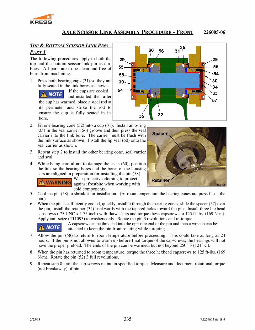
Center scissor link bearings are a matched set consisting of
2 cups, 2 cones, and a cone spacer. All parts must be used
together as shown in the first image to the right.
10.The bearing cups (17) are to be fully seated against the bottom of their
respective bores.
11. Install one bearing cone (17) into the inboard bearing cup and then
install one half of the seal assembly (19) into the link to hold the bear-
ing cone in position.
12. Repeat step 11 to the other scissor link.
13. Position the bores of the top link and the bottom link in alignment with
each other being careful not to damage the seal (19) in the process. The
bottom portion of the suspension assembly may have to slightly rotated
to allow the two halves of the seal to pass by each other.
14. Slide one bearing cone (17) onto the pin (18) with the tapered rollers
end going on last. Slide the respective cone spacer on the pin. Install
the pin into the lower link bore, through the inboard bearing cone of the
lower and upper link assemblies until the outboard bearing cone seats
against its cup (17).
15. Install the outboard cone spacer and bearing cone (17) into the upper
link bore until it seats against its cup.
16. Install the washer (16) over the threaded end of the pin (18) as shown
on the right. Do not use the washer provided with the locknut. Use
Kress washer with insert tab.
17. Thread the locknut (59) onto the pin until it is snug enough to have
pulled the seal halves (19) together.
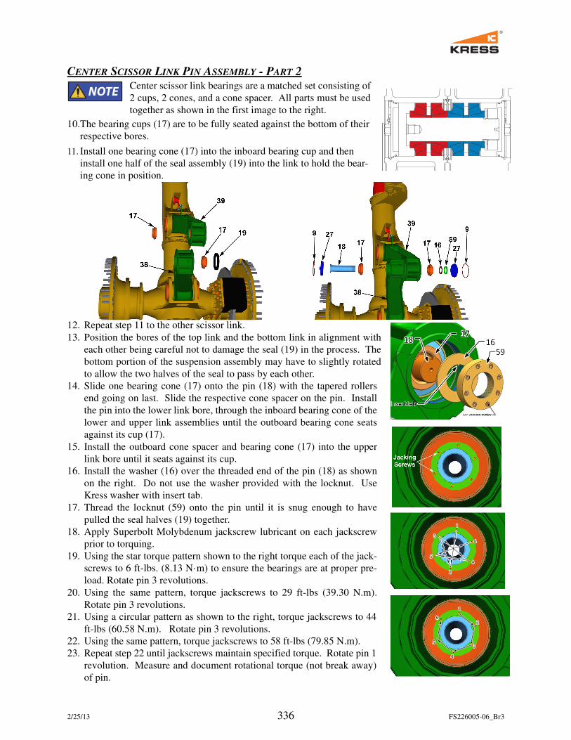
18. Apply Superbolt Molybdenum jackscrew lubricant on each jackscrew
prior to torquing.
19. Using the star torque pattern shown to the right torque each of the jack-
screws to 6 ft-lbs. (8.13 N·m) to ensure the bearings are at proper pre-
load. Rotate pin 3 revolutions.
20. Using the same pattern, torque jackscrews to 29 ft-lbs (39.30 N.m).
Rotate pin 3 revolutions.
21. Using a circular pattern as shown to the right, torque jackscrews to 44
ft-lbs (60.58 N.m). Rotate pin 3 revolutions.
22. Using the same pattern, torque jackscrews to 58 ft-lbs (79.85 N.m).
23. Repeat step 22 until jackscrews maintain specified torque. Rotate pin 1
revolution. Measure and document rotational torque (not break away)
of pin.
66
66
2/25/13 337 FS226005-06_Br3
24. Install an o-ring (1) into the groove on the outside
diameter of both end caps (27).
25. Install both end caps (27) and then install the wire
retainers (9) into their grooves to hold the end caps in
place. One end cap should have a grease relief fitting
and the other cap should have a grease zerk installed.
26. Pump grease into the grease zerk in the end cap (27)
until grease exits the grease relief fitting in the other
end cap (27).
TOP & BOTTOM SCISSOR LINK PINS - PART 3
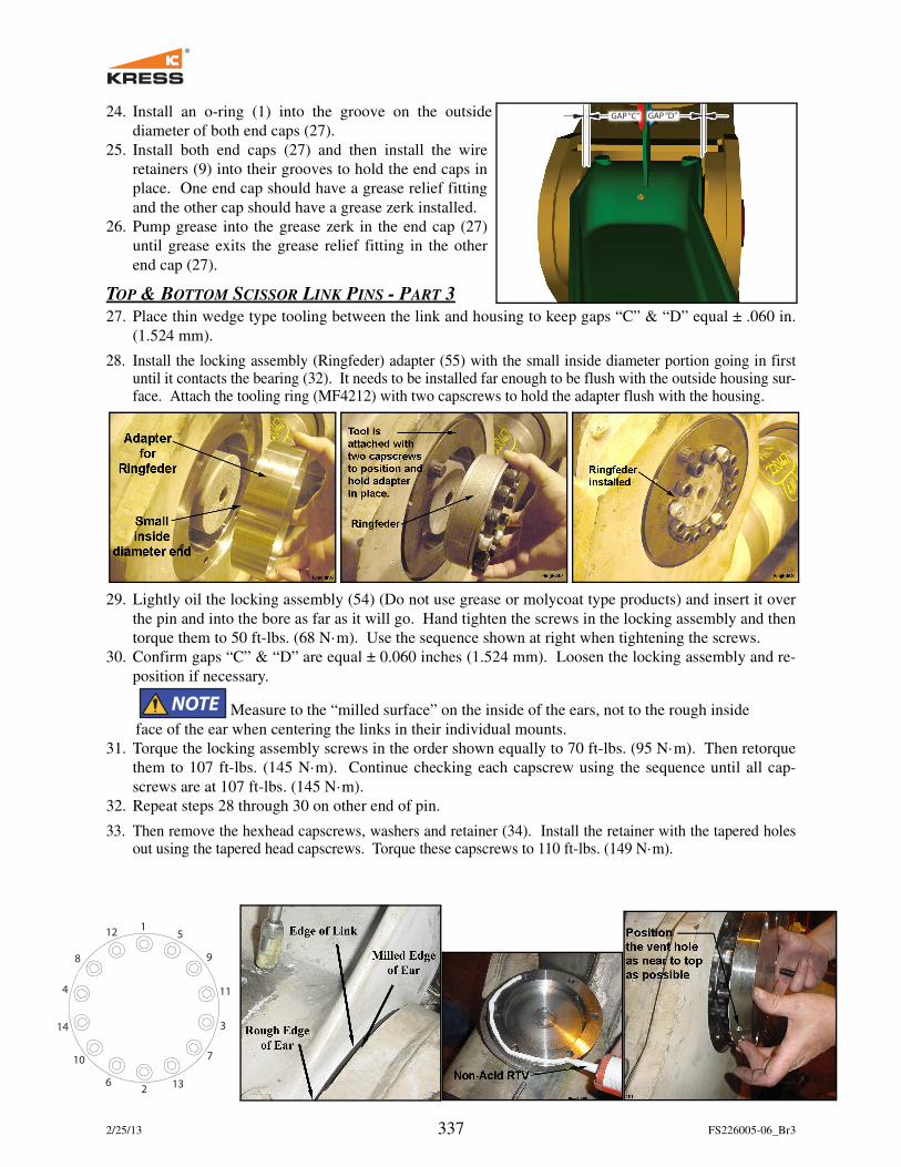
27. Place thin wedge type tooling between the link and housing to keep gaps “C” & “D” equal ± .060 in.
(1.524 mm).
28. Install the locking assembly (Ringfeder) adapter (55) with the small inside diameter portion going in firstuntil it contacts the bearing (32). It needs to be installed far enough to be flush with the outside housing sur-face. Attach the tooling ring (MF4212) with two capscrews to hold the adapter flush with the housing.
29. Lightly oil the locking assembly (54) (Do not use grease or molycoat type products) and insert it over
the pin and into the bore as far as it will go. Hand tighten the screws in the locking assembly and then
torque them to 50 ft-lbs. (68 N·m). Use the sequence shown at right when tightening the screws.
30. Confirm gaps “C” & “D” are equal ± 0.060 inches (1.524 mm). Loosen the locking assembly and re-
position if necessary.
Measure to the “milled surface” on the inside of the ears, not to the rough inside
face of the ear when centering the links in their individual mounts.
31. Torque the locking assembly screws in the order shown equally to 70 ft-lbs. (95 N·m). Then retorque
them to 107 ft-lbs. (145 N·m). Continue checking each capscrew using the sequence until all cap-
screws are at 107 ft-lbs. (145 N·m).
32. Repeat steps 28 through 30 on other end of pin.
33. Then remove the hexhead capscrews, washers and retainer (34). Install the retainer with the tapered holesout using the tapered head capscrews. Torque these capscrews to 110 ft-lbs. (149 N·m).
GAP “D”GAP “C”
1
2
3
4
5
6
7
8 9
10
11
12
13
14
2/25/13 338 FS226005-06_Br3
226005-06 FRONT SUSPENSION MODULE
1 O-ring
2 Bolt - .50-20NF x 2.00
3 Grease Fitting, Straight
4 Bolt - .63-18NF x 1.50
5 Bolt - .50-20NF x 2.50
6 Bolt - 1.00-14NF x 4.00
7 O-Ring
8 O-Ring
9 Retaining Wire
10 Washer, Hard - 1.00
11 Fitting, Relief 1/8 NPT
12 Washer, Hard - .62
13 Washer, Hard - .50
14 Retainer Stop
15 Lifting Eye
16 Washer
17 Seal Assembly
18 Pin
19 Seal HDDF Heavy Duty
20 O-Ring
21 Cap Nut -4 ORS
22 Bolt - Drilled Head 1.00-14NF x 4.50
23 Pin, Tapered
24 Retainer Plate, Lower
25 Wiper Seal
26 Bushing, Tapered
27 End Cap Structure
28 Retainer Plate, Upper
29 Capscrew - 12pt - .50NF x 1.25
30 End Cap
31 Bearing Cup
32 Bearing Cone
33 Screw, Flat Sockethead - .75 x 1.50NC
34 Retainer
35 O-Ring
36 Spacer, Plastic
37 Fitting, Straight -4ORS-4BOSS
38 Scissor Link
39 Scissor Link Structure
40 Thrust Bearing, Lower - 115 degree
41 Thrust Bearing, Lower - 60 degree
42 Thrust Bearing, Lower - 60 degree
43 Bearing, Lower
44 Bushing, Tapered
45 Spacer
46 Rod Retainer Plate
47 Cylinder, Front Suspension
48 Axle Assembly, Front
49 Brake Lines, Front
50 Steering Tube, Front
51 Valve Extension
52 Valve Stem Assembly
53 Leveling Group, Front
54 Locking Assembly - 3.937 x 5.709
55 Adapter, Locking Assembly
56 Carrier, Seal
57 Spacer, Shaft
58 Pin, Scissor Link
59 Locknut, Bearing
60 Seal, V-Ring - 6.89 - 7.29 Viton
226005-06 FRONT SUSPENSION MODULE
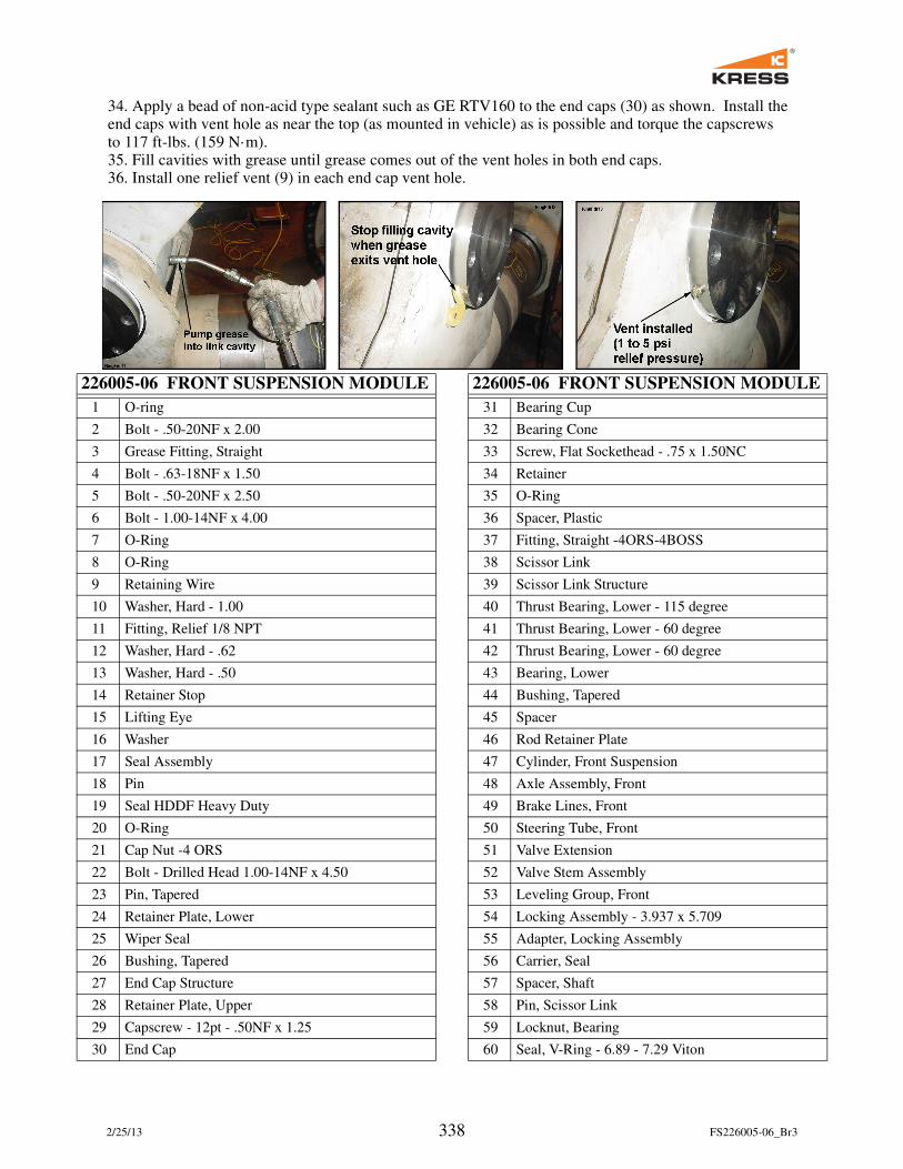
34. Apply a bead of non-acid type sealant such as GE RTV160 to the end caps (30) as shown. Install the end caps with vent hole as near the top (as mounted in vehicle) as is possible and torque the capscrews to 117 ft-lbs. (159 N·m).35. Fill cavities with grease until grease comes out of the vent holes in both end caps.36. Install one relief vent (9) in each end cap vent hole.
2/25/13 339 FS226005-06_Br3
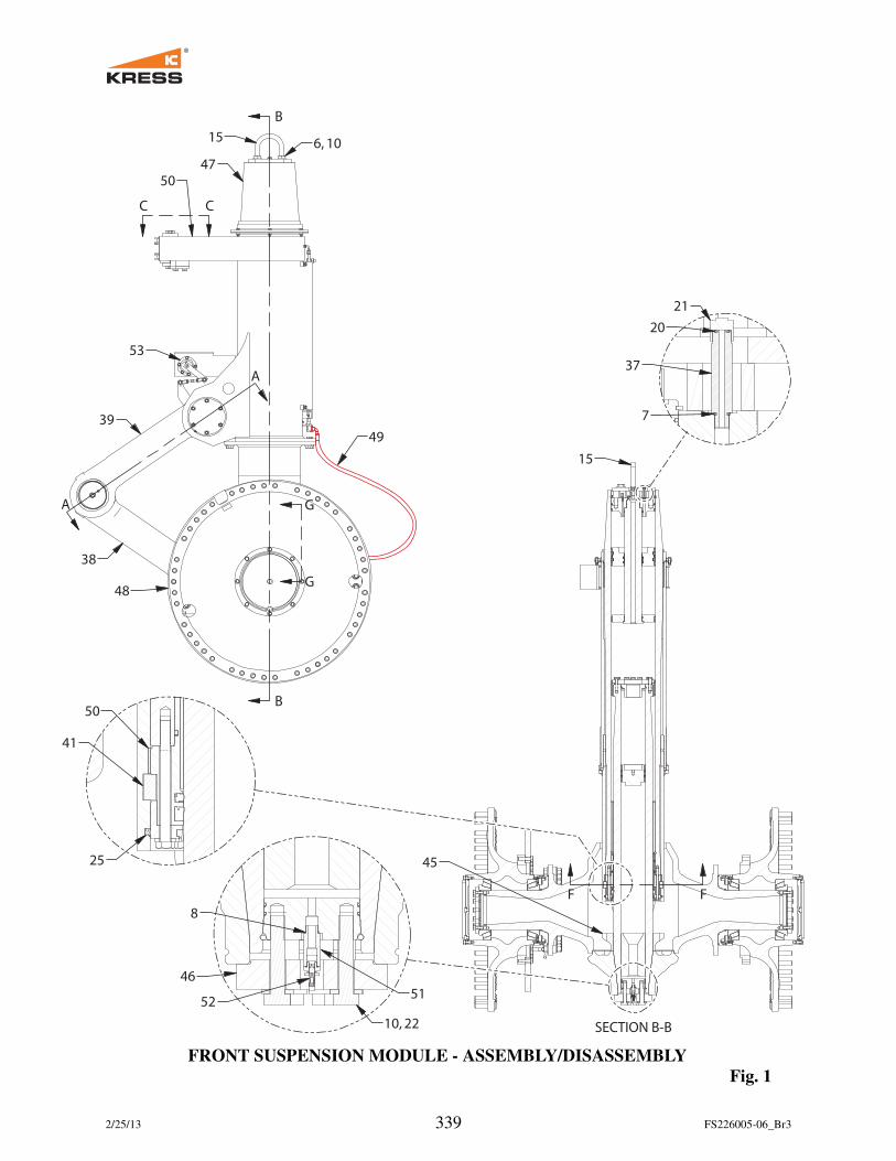
FRONT SUSPENSION MODULE - ASSEMBLY/DISASSEMBLY
Fig. 1
SECTION B-B
B
B
G
G
C C
50
47
156, 10
39
53
A
A
38
48
49
15
21
20
37
7
F F
8
46
52
10, 22
51
45
50
41
25
2/25/13 340 FS226005-06_Br3
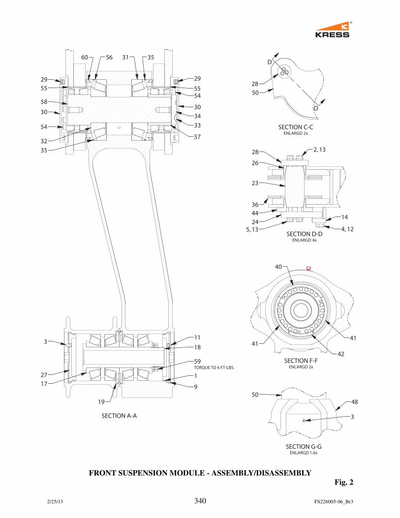
FRONT SUSPENSION MODULE - ASSEMBLY/DISASSEMBLY
Fig. 2
SECTION A-A
SECTION C-CENLARGD 2x
SECTION D-DENLARGD 4x
SECTION F-FENLARGD 2x
SECTION G-GENLARGD 1.6x
29
55
58
30
54
60 56 31 35
29
55
54
30
34
33
5732
35
3
27
17
19
9
1
59TORQUE TO 6 FT-LBS.
18
11
D
D
28
50
28
26
23
36
44
24
5, 13
2, 13
14
4, 12
40
4141
42
50
48
3
2/25/13 341 FS226005-06_Br3
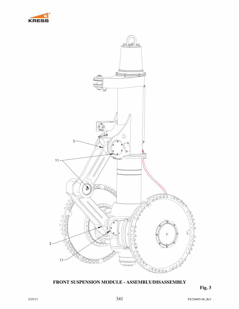
FRONT SUSPENSION MODULE - ASSEMBLY/DISASSEMBLY
Fig. 3
3
11
3
11
2/25/13 342 FS226005-06_Br3
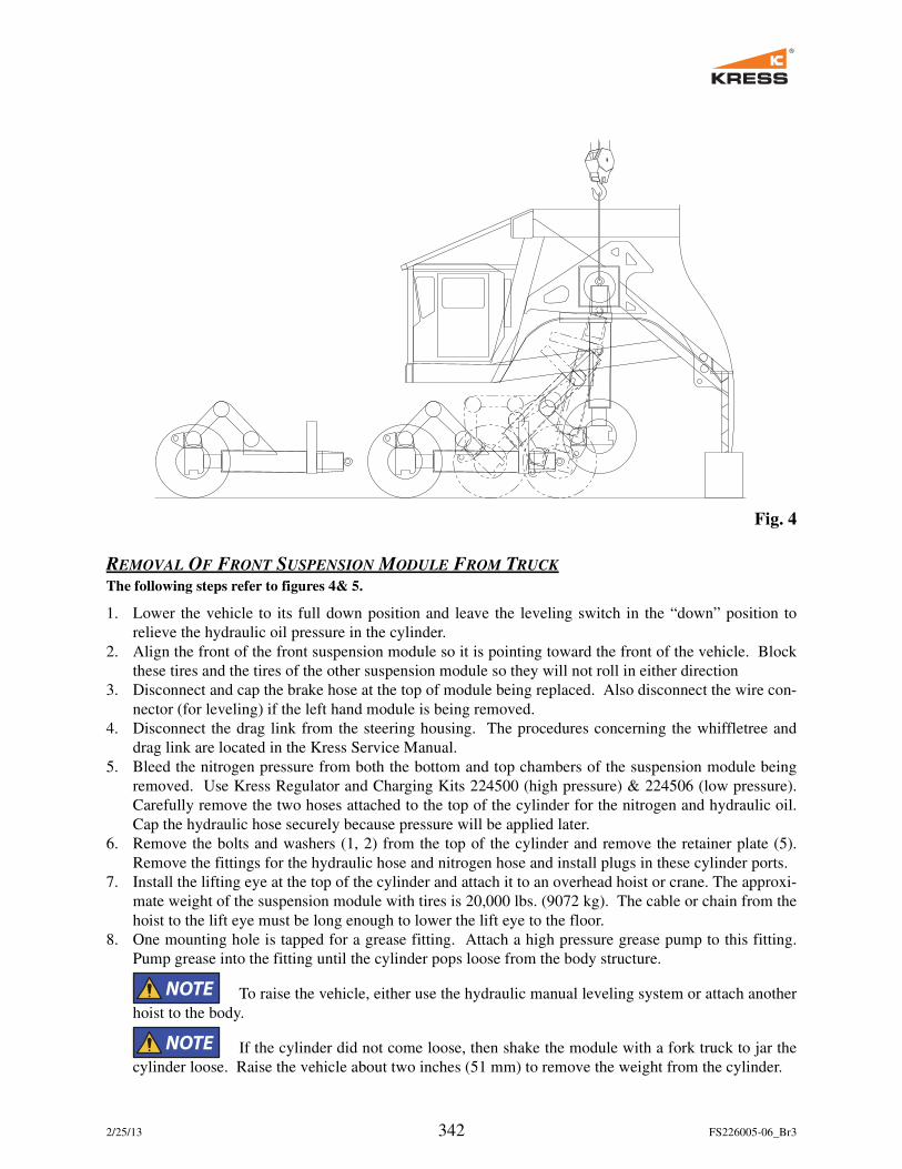
Fig. 4
REMOVAL OF FRONT SUSPENSION MODULE FROM TRUCK
The following steps refer to figures 4& 5.
1. Lower the vehicle to its full down position and leave the leveling switch in the “down” position to
relieve the hydraulic oil pressure in the cylinder.
2. Align the front of the front suspension module so it is pointing toward the front of the vehicle. Block
these tires and the tires of the other suspension module so they will not roll in either direction
3. Disconnect and cap the brake hose at the top of module being replaced. Also disconnect the wire con-
nector (for leveling) if the left hand module is being removed.
4. Disconnect the drag link from the steering housing. The procedures concerning the whiffletree and
drag link are located in the Kress Service Manual.
5. Bleed the nitrogen pressure from both the bottom and top chambers of the suspension module being
removed. Use Kress Regulator and Charging Kits 224500 (high pressure) & 224506 (low pressure).
Carefully remove the two hoses attached to the top of the cylinder for the nitrogen and hydraulic oil.
Cap the hydraulic hose securely because pressure will be applied later.
6. Remove the bolts and washers (1, 2) from the top of the cylinder and remove the retainer plate (5).
Remove the fittings for the hydraulic hose and nitrogen hose and install plugs in these cylinder ports.
7. Install the lifting eye at the top of the cylinder and attach it to an overhead hoist or crane. The approxi-
mate weight of the suspension module with tires is 20,000 lbs. (9072 kg). The cable or chain from the
hoist to the lift eye must be long enough to lower the lift eye to the floor.
8. One mounting hole is tapped for a grease fitting. Attach a high pressure grease pump to this fitting.
Pump grease into the fitting until the cylinder pops loose from the body structure.
To raise the vehicle, either use the hydraulic manual leveling system or attach another
hoist to the body.
If the cylinder did not come loose, then shake the module with a fork truck to jar the
cylinder loose. Raise the vehicle about two inches (51 mm) to remove the weight from the cylinder.
2/25/13 343 FS226005-06_Br3
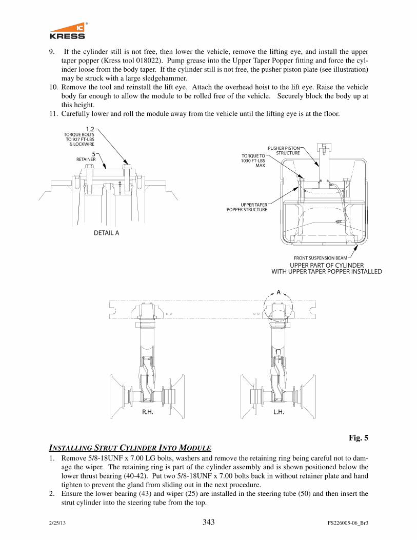
9. If the cylinder still is not free, then lower the vehicle, remove the lifting eye, and install the upper
taper popper (Kress tool 018022). Pump grease into the Upper Taper Popper fitting and force the cyl-
inder loose from the body taper. If the cylinder still is not free, the pusher piston plate (see illustration)
may be struck with a large sledgehammer.
10. Remove the tool and reinstall the lift eye. Attach the overhead hoist to the lift eye. Raise the vehicle
body far enough to allow the module to be rolled free of the vehicle. Securely block the body up at
this height.
11. Carefully lower and roll the module away from the vehicle until the lifting eye is at the floor.
Fig. 5
INSTALLING STRUT CYLINDER INTO MODULE
1. Remove 5/8-18UNF x 7.00 LG bolts, washers and remove the retaining ring being careful not to dam-
age the wiper. The retaining ring is part of the cylinder assembly and is shown positioned below the
lower thrust bearing (40-42). Put two 5/8-18UNF x 7.00 bolts back in without retainer plate and hand
tighten to prevent the gland from sliding out in the next procedure.
2. Ensure the lower bearing (43) and wiper (25) are installed in the steering tube (50) and then insert the
strut cylinder into the steering tube from the top.
5RETAINER
1,2TORQUE BOLTSTO 927 FT-LBS
& LOCKWIRE
DETAIL A
R.H. L.H.
PUSHER PISTONSTRUCTURE
TORQUE TO1030 FT-LBS
MAX
UPPER TAPERPOPPER STRUCTURE
FRONT SUSPENSION BEAM
UPPER PART OF CYLINDERWITH UPPER TAPER POPPER INSTALLED
A
2/25/13 344 FS226005-06_Br3
3. Raise the strut cylinder up relative to the steering tube enough to expose the groove for the lower thrust
bearings (40-42). Remove the two bolts installed in step 1. Install the lower thrust bearings by first in-
stalling one 40. Then two 41, one on each side of the 40 so the ends are flush with each other. Then
insert one 42 into the remaining space.
4. Lower the strut cylinder against the lower thrust bearings. Install the retainer plate being careful not to
damage wiper seal (25).
5. Install the 5/8-18UNF x 7.00 LG bolts and washers.
6. Torque bolts to 190 ft-lbs. (258 N·m).
REMOVING STRUT CYLINDER FROM MODULE
1. Remove 5/8-18UNF x 7.00 LG bolts, washers and retainer plate, being careful not to damage wiper (25).
2. Raise the strut cylinder up relative to the steering tube enough to expose the lower thrust bearings (40-
42) and then remove the lower thrust bearings.
3. Remove the strut cylinder from the steering tube through the top.
ATTACHING AXLE TO MODULE
1. Apply antiseize to the tapered end of cylinder rod and insert it into female taper of front axle assembly
along with the spacer (57).
2. Install the retainer plate (46).
3. Install 1.00-14UNF x 4.50 LG bolts and washers (22, 10).
4. Torque bolts to 927 ft-lbs. (1257 N·m).
5. After bolts have been properly torqued, install the lockwire through holes in bolt heads.
REMOVING AXLE FROM MODULE
1. Cut off the lockwire and remove 1.00-14UNF x 4.50 LG bolts and washers (22, 10).
2. Remove plate-rod retainer (46).
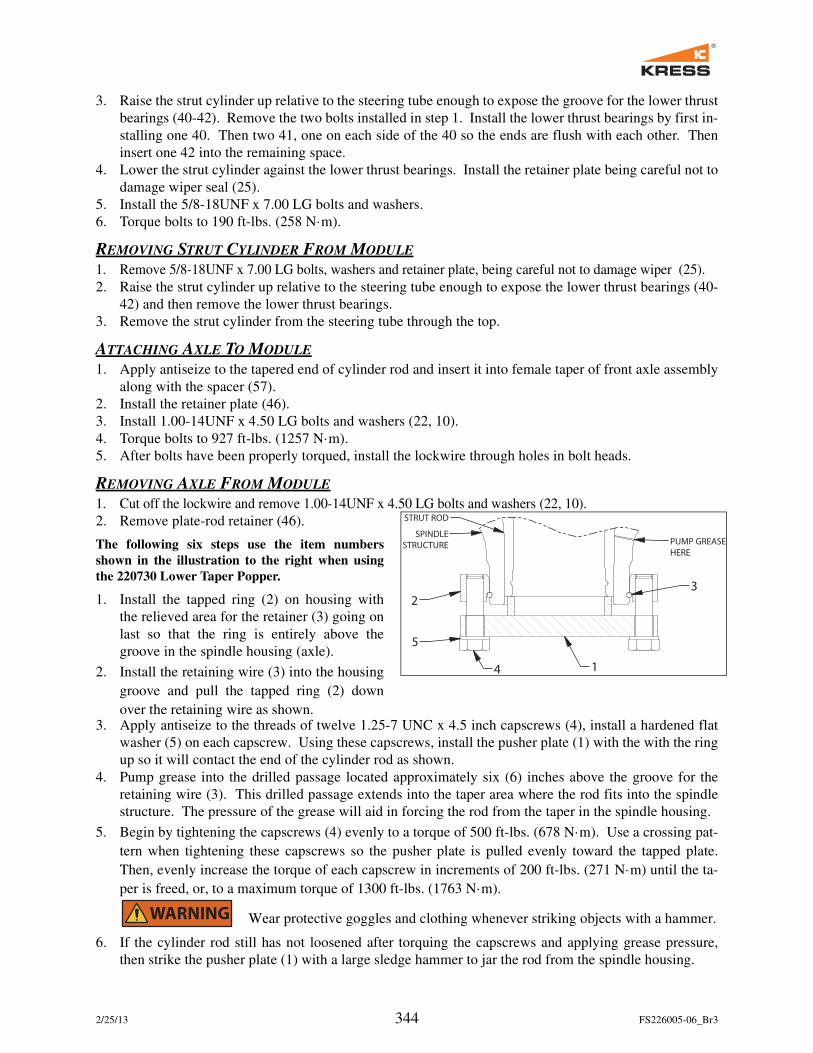
The following six steps use the item numbers
shown in the illustration to the right when using
the 220730 Lower Taper Popper.
1. Install the tapped ring (2) on housing with
the relieved area for the retainer (3) going on
last so that the ring is entirely above the
groove in the spindle housing (axle).
2. Install the retaining wire (3) into the housing
groove and pull the tapped ring (2) down
over the retaining wire as shown.3. Apply antiseize to the threads of twelve 1.25-7 UNC x 4.5 inch capscrews (4), install a hardened flat
washer (5) on each capscrew. Using these capscrews, install the pusher plate (1) with the with the ring
up so it will contact the end of the cylinder rod as shown.
4. Pump grease into the drilled passage located approximately six (6) inches above the groove for the
retaining wire (3). This drilled passage extends into the taper area where the rod fits into the spindle
structure. The pressure of the grease will aid in forcing the rod from the taper in the spindle housing.
5. Begin by tightening the capscrews (4) evenly to a torque of 500 ft-lbs. (678 N·m). Use a crossing pat-
tern when tightening these capscrews so the pusher plate is pulled evenly toward the tapped plate.
Then, evenly increase the torque of each capscrew in increments of 200 ft-lbs. (271 N·m) until the ta-
per is freed, or, to a maximum torque of 1300 ft-lbs. (1763 N·m).
Wear protective goggles and clothing whenever striking objects with a hammer.
6. If the cylinder rod still has not loosened after torquing the capscrews and applying grease pressure,
then strike the pusher plate (1) with a large sledge hammer to jar the rod from the spindle housing.
STRUT ROD
SPINDLE
STRUCTURE
1
2
4
5
3
PUMP GREASE
HERE
2/25/13 345 FS226005-06_Br3
NOTES
1. All bolt threads to be lubricated with anti-seize.
2. Be sure that entire inside of steering tube is sprayed with rust veto 2728.
3. Initial lubrication fill for steering tube after assembly: Fill grease through grease zerk (3) until grease
comes out of top dust seal (8).
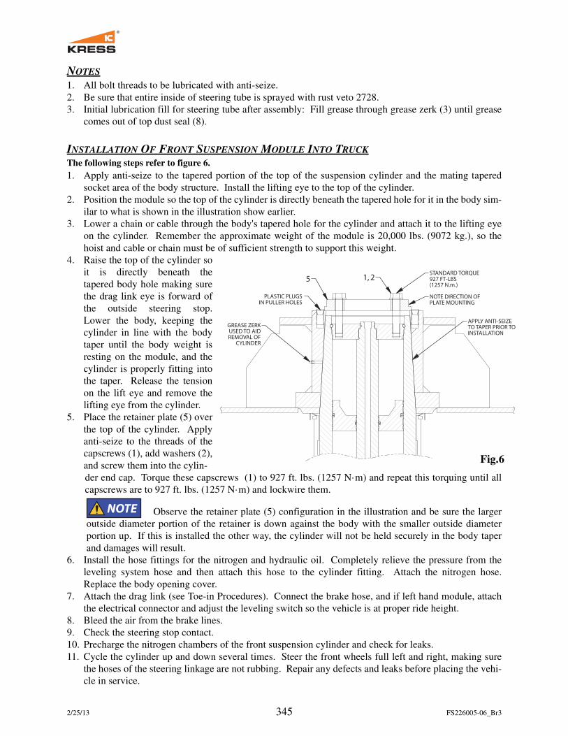
INSTALLATION OF FRONT SUSPENSION MODULE INTO TRUCK
The following steps refer to figure 6.
1. Apply anti-seize to the tapered portion of the top of the suspension cylinder and the mating tapered
socket area of the body structure. Install the lifting eye to the top of the cylinder.
2. Position the module so the top of the cylinder is directly beneath the tapered hole for it in the body sim-
ilar to what is shown in the illustration show earlier.
3. Lower a chain or cable through the body's tapered hole for the cylinder and attach it to the lifting eye
on the cylinder. Remember the approximate weight of the module is 20,000 lbs. (9072 kg.), so the
hoist and cable or chain must be of sufficient strength to support this weight.
4. Raise the top of the cylinder so
it is directly beneath the
tapered body hole making sure
the drag link eye is forward of
the outside steering stop.
Lower the body, keeping the
cylinder in line with the body
taper until the body weight is
resting on the module, and the
cylinder is properly fitting into
the taper. Release the tension
on the lift eye and remove the
lifting eye from the cylinder.
5. Place the retainer plate (5) over
the top of the cylinder. Apply
anti-seize to the threads of the
capscrews (1), add washers (2),
and screw them into the cylin-
der end cap. Torque these capscrews (1) to 927 ft. lbs. (1257 N·m) and repeat this torquing until all
capscrews are to 927 ft. lbs. (1257 N·m) and lockwire them.
Observe the retainer plate (5) configuration in the illustration and be sure the larger
outside diameter portion of the retainer is down against the body with the smaller outside diameter
portion up. If this is installed the other way, the cylinder will not be held securely in the body taper
and damages will result.
6. Install the hose fittings for the nitrogen and hydraulic oil. Completely relieve the pressure from the
leveling system hose and then attach this hose to the cylinder fitting. Attach the nitrogen hose.
Replace the body opening cover.
7. Attach the drag link (see Toe-in Procedures). Connect the brake hose, and if left hand module, attach
the electrical connector and adjust the leveling switch so the vehicle is at proper ride height.
8. Bleed the air from the brake lines.
9. Check the steering stop contact.
10. Precharge the nitrogen chambers of the front suspension cylinder and check for leaks.
11. Cycle the cylinder up and down several times. Steer the front wheels full left and right, making sure
the hoses of the steering linkage are not rubbing. Repair any defects and leaks before placing the vehi-
cle in service.
GREASE ZERKUSED TO AIDREMOVAL OF
CYLINDER
PLASTIC PLUGS IN PULLER HOLES
STANDARD TORQUE927 FT-LBS(1257 N.m.)
NOTE DIRECTION OFPLATE MOUNTING
APPLY ANTI-SEIZETO TAPER PRIOR TOINSTALLATION
5 1, 2
Fig. 6
2/25/13 346 FS226005-06_Br3
After the 1st LOAD is hauled, retorque the upper and lower retainers on both front
suspension cylinders. Torque bolts to 927 ft-lbs. (1257 N·m). After the 1st full shift of operation is com-
plete, retorque the upper and lower retainers on both front suspension cylinders. Torque bolts to 927 ft-lbs.
(1257 N·m).