Embed Size (px)
Citation preview

AXLE RATIO OPTIONS CLEAR DTC CODES
RUNTIME FUNCTIONS1 2 3 4 5 6 7 8 9
4 5 6 7 8 9 4 5 6 7 8 9
4 5 6 7 8 9 4 5 6 7 8 9
4 5 6 7 8 9 4 5 6 7 8 9
4 5 6 7 8 9 4 5 6 7 8 9
4 5 6 7 8 9 4 5 6 7 8 9
1
1
1
1
2
2
2a
2b
2c
Set switches 4–9 using the chart below for the axle ratio physically installed in the vehicle.
Set switches 4–9 using the chart below.
Set DIP switches 1–3 as shown.
Set DIP switches 1–3 as shown.
Set DIP switches 1–3 as shown.
Set switches 4–9 using the chart below.
Set switches 4–9 using the chart below.
Set switches 4–9 using the chart below.
one-touch lane change
daytime running lamps
auto sway bar system
1 2 3 4 5 6 7 8 9
4 5 6 7 8 9
on
4 5 6 7 8 9
oFF
4 5 6 7 8 9
on
4 5 6 7 8 9
oFF
low beams on
fog lights on european on
high beams on
off
turn signals on
1 2 3 4 5 6 7 8 9
1 2 3 4 5 6 7 8 9
extended idle center steering
By design, the Daytime Running Lamps will only function with the E-Brake in the OFF position and the vehicle in gear (auto trans only). To verify the function is correct and desired mode is set, pull the vehicle up to a reflective surface or have a by-stander verify function. Please take caution to keep the vehicle under control at all times.
Programming axle ratio is only required after physically changing the gears in the differentials. There is no performance increase by adjusting this value to anything besides what the vehicle has physically installed. Programming the incorrect ratio will cause some vehicles to go into “Limp-In” mode.
*The engine must be running with the E-brake engaged before inserting the ProCal. Use the dimmer switch to adjust idle set point.
Runtime functions do not program any values and require the ProCal to remain plugged in during their use.
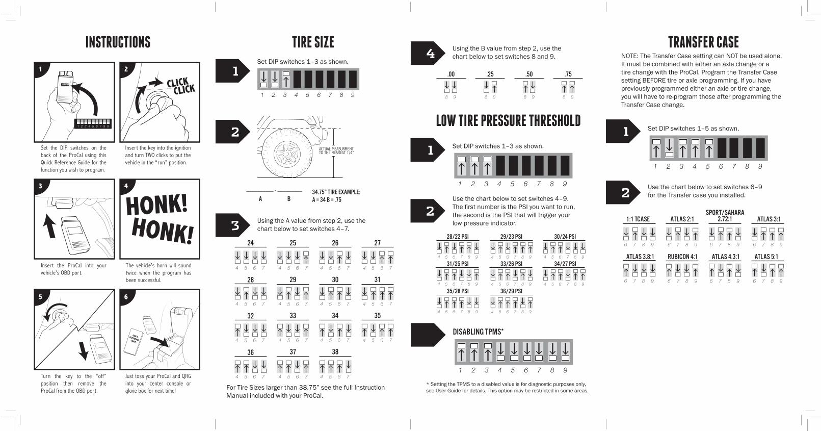
TIRE SIZE
LOW TIRE PRESSURE THRESHOLD
TRANSFER CASE
1 2 3 4 5 6 7 8 9
1 2 3 4 5 6 7 8 9
1 2 3 4 5 6 7 8 9
1 2 3 4 5 6 7 8 9
4 5 6 7 4 5 6 7 4 5 6 7 4 5 6 7
4 5 6 7 4 5 6 7 4 5 6 7
4 5 6 7 4 5 6 7 4 5 6 7 4 5 6 7
4 5 6 7 4 5 6 7 4 5 6 7 4 5 6 7
8 9 8 9 8 9 8 9
1
112
22
3
4Set DIP switches 1–3 as shown.
Set DIP switches 1–3 as shown.
Set DIP switches 1–5 as shown.
Use the chart below to set switches 4–9. The first number is the PSI you want to run, the second is the PSI that will trigger your low pressure indicator.
Use the chart below to set switches 6–9 for the Transfer case you installed.
* Setting the TPMS to a disabled value is for diagnostic purposes only, see User Guide for details. This option may be restricted in some areas.
A B34.75” Tire Example:A = 34 b = .75
Using the A value from step 2, use the chart below to set switches 4–7.
Using the B value from step 2, use the chart below to set switches 8 and 9.
4 5 6 7 8 9
4 5 6 7 8 9
4 5 6 7 8 9 4 5 6 7 8 9
4 5 6 7 8 9 4 5 6 7 8 9
4 5 6 7 8 9 4 5 6 7 8 9
28/22 PSI 29/23 PSI 30/24 PSI
31/25 PSI
35/28 PSI 36/29 PSI
33/26 PSI 34/27 PSI
DISABLING TpmS*
__________ . _________
INSTRUCTIONS
1
3 4
5 6
2
1 2 3 4 5 6 7 8 9 CLICKCLICK
HONK!HONK!
QUICKREFERENCEGUIDE
1 2 3 4 5 6 7 8 9
Set the DIP switches on the back of the ProCal using this Quick Reference Guide for the function you wish to program.
Inser t the ProCal into your vehicle’s OBD por t.
Turn the key to the “off” position then remove the ProCal from the OBD por t.
Just toss your ProCal and QRG into your center console or glove box for next time!
The vehicle’s horn will sound twice when the program has been successful.
Inser t the key into the ignition and turn TWO clicks to put the vehicle in the “run” position.
ACTUAL MEASURMENTTO THE NEAREST 1/4”
6 7 8 9 6 7 8 9 6 7 8 9 6 7 8 9
6 7 8 9 6 7 8 9 6 7 8 9 6 7 8 9
1:1 Tcase atlas 2:1 atlas 3:1
atlas 3.8:1 RUBICON 4:1 ATLAS 4.3:1 ATLAS 5:1
Sport/sahara2.72:1
NOTE: The Transfer Case setting can NOT be used alone. It must be combined with either an axle change or a tire change with the ProCal. Program the Transfer Case setting BEFORE tire or axle programming. If you have previously programmed either an axle or tire change, you will have to re-program those after programming the Transfer Case change.
For Tire Sizes larger than 38.75” see the full Instruction Manual included with your ProCal.