Embed Size (px)
Citation preview
RAX-1
REAR AXLE
D DRIVELINE/AXLE
CONTENTS
C
E
F
G
H
I
J
K
L
M
SECTION RAXA
B
RAX
Revision; 2004 April 2003 350Z
REAR AXLE
PRECAUTIONS .......................................................... 2Caution ..................................................................... 2
PREPARATION ........................................................... 3Special Service Tools (SST) ..................................... 3Commercial Service Tools ........................................ 4
NOISE, VIBRATION AND HARSHNESS (NVH) TROUBLESHOOTING ................................................ 5
NVH Troubleshooting Chart ..................................... 5WHEEL HUB .............................................................. 6
On-Vehicle Inspection and Service .......................... 6WHEEL BEARING INSPECTION ......................... 6
Removal and Installation .......................................... 6REMOVAL ............................................................. 6INSPECTION AFTER REMOVAL ......................... 7
INSTALLATION ..................................................... 7Disassembly and Assembly ...................................... 7
DISASSEMBLY ..................................................... 7INSPECTION AFTER DISASSEMBLY .................. 8ASSEMBLY ........................................................... 8INSPECTION AFTER ASSEMBLY ........................ 9
REAR DRIVE SHAFT ............................................... 10Removal and Installation ........................................ 10
REMOVAL ........................................................... 10INSPECTION AFTER REMOVAL ....................... 10INSTALLATION ................................................... 10
Disassembly and Assembly .................................... 11DISASSEMBLY ................................................... 11INSPECTION AFTER DISASSEMBLY ................ 12ASSEMBLY ......................................................... 13
SERVICE DATA ........................................................ 16Wheel Bearing ........................................................ 16Drive Shaft .............................................................. 16Tightening Torque ................................................... 16

RAX-2
PRECAUTIONS
Revision; 2004 April 2003 350Z
PRECAUTIONS PFP:00001
Caution ADS00037
Observe the following precautions when disassembling and servicing drive shaft.● Perform work in a location which is as dust-free as possible.● Before disassembling and servicing, clean the outside of parts.● Prevention of the entry of foreign objects must be taken into account during disassembly of the service
location.● Disassembled parts must be carefully reassembled in the correct order. If work is interrupted, a clean
cover must be placed over parts.● Paper shop cloths must be used. Fabric shop cloths must not be used because of the danger of lint adher-
ing to parts.● Disassembled parts (except for rubber parts) should be cleaned with kerosene which shall be removed by
blowing with air or wiping with paper shop cloths.

PREPARATION
RAX-3
C
E
F
G
H
I
J
K
L
M
A
B
RAX
Revision; 2004 April 2003 350Z
PREPARATION PFP:00002
Special Service Tools (SST) ADS00038
The actual shapes of Kent-Moore tools may differ from those of special service tools illustrated here.
Tool number (Kent-Moore No.)Tool name
Description
ST3322 0000( — )Drifta: 32 mm (1.26 in) dia.b: 21 mm (0.83 in) dia.
● Removing wheel hub
● Removing wheel bearing outer side inner race
● Inspection of wheel bearing rotating torque
ST3325 1000( — )Drift
Installing wheel hub
ST3530 0000( — )Drifta: 45 mm (1.77 in) dia.b: 59 mm (2.32 in) dia.
● Installing wheel hub
● Inspection of wheel bearing rotating torque
KV401 00900( — )Drifta: 52 mm (2.05 in) dia.b: —
Wheel bearing rotating torque inspection
KV381 00500( — )Drifta: 80 mm (3.15 in) dia.b: 60 mm (2.36 in) dia.
Installing drive shaft plug
KV381 02200( — )Drifta: 90 mm (3.54 in) dia.b: 31 mm (1.22 in) dia.
Installing drive shaft plug
ZZA0539D
ZZA0982D
ZZA0881D
ZZA0539D
ZZA0701D
ZZA0920D

RAX-4
PREPARATION
Revision; 2004 April 2003 350Z
Commercial Service Tools ADS00039
Tool name Description
Power tool
● Removing wheel nuts
● Removing brake caliper assembly
● Removing suspension links
● Removing drive shaft fixing bolts and nuts
PBIC0190E

NOISE, VIBRATION AND HARSHNESS (NVH) TROUBLESHOOTING
RAX-5
C
E
F
G
H
I
J
K
L
M
A
B
RAX
Revision; 2004 April 2003 350Z
NOISE, VIBRATION AND HARSHNESS (NVH) TROUBLESHOOTING PFP:00003
NVH Troubleshooting Chart ADS0003A
Use chart below to help you find the cause of the symptom. If necessary, repair or replace these parts.
×: Applicable
Reference page —
RA
X-1
2
—
RA
X-6
—
NV
H in
PR
sec
tion.
NV
H in
RF
D s
ectio
n.
NV
H in
FA
X a
nd F
SU
sec
tions
.
Ref
er to
RE
AR
AX
LE in
this
cha
rt.
NV
H in
WT
sec
tion.
NV
H in
WT
sec
tion.
Ref
er to
DR
IVE
SH
AF
T in
this
cha
rt.
NV
H in
BR
sec
tion.
NV
H in
PS
sec
tion.
Possible cause and SUSPECTED PARTS
Exc
essi
ve jo
int a
ngle
Join
t slid
ing
resi
stan
ce
Imba
lanc
e
Impr
oper
inst
alla
tion,
loos
enes
s
Par
ts in
terf
eren
ce
PR
OP
ELL
ER
SH
AF
T
DIF
FE
RE
NT
IAL
FR
ON
T A
XLE
AN
D F
RO
NT
SU
SP
EN
SIO
N
RE
AR
AX
LE
TIR
ES
RO
AD
WH
EE
L
DR
IVE
SH
AF
T
BR
AK
ES
ST
EE
RIN
G
Symptom
DRIVE SHAFT
Noise × × × × × × × × × ×
Shake × × × × × × × × ×
REAR AXLE
Noise × × × × × × × × × ×
Shake × × × × × × × × ×
Vibration × × × × × × ×
Shimmy × × × × × × ×
Judder × × × × × ×
Poor quality ride or handling × × × × ×

RAX-6
WHEEL HUB
Revision; 2004 April 2003 350Z
WHEEL HUB PFP:43202
On-Vehicle Inspection and Service ADS0003B
Make sure the mounting conditions (looseness, back lash) of each component and component status (wear,damage) are normal.
WHEEL BEARING INSPECTION● Move wheel hub in the axial direction by hand. Make sure there is no looseness of wheel bearing.
● Rotate wheel hub and make sure there is no unusual noise or other irregular conditions. If there are anyirregular conditions, replace wheel bearings.
Removal and Installation ADS0003C
REMOVAL1. Remove tire with power tool.2. Remove cotter pin. Then remove lock nut from drive shaft.3. Remove brake caliper with power tool. Hang it in a place where it will not interfere with work. Refer to BR-
38, "REAR DISC BRAKE (AD14VE TYPE)" , BR-44, "REAR DISC BRAKE (OPB13VB TYPE)" .NOTE:Avoid depressing brake pedal while brake caliper is removed.
4. Remove disc rotor and remove parking cable and parking brake shoe from back plate. Refer to PB-3,"PARKING BRAKE CONTROL" , PB-4, "PARKING BRAKE SHOE" .
5. Remove fixing bolts and nuts in axle side of radius rod, front lower link with power tool.6. Remove fixing bolt and nut in axle side of rear lower link with power tool. Then remove coil spring. Refer to
RSU-15, "REAR LOWER LINK & COIL SPRING" .7. Remove fixing bolt and nut in axle side of shock absorber with power tool. 8. Using a puller (suitable tool), remove axle from drive shaft.
CAUTION:● When removing axle, do not apply an excessive angle to drive shaft joint. Also be careful not to
excessively extend slide joint.
Standard valueAxial end play : 0.05 mm (0.002 in) or less
1. Drive shaft 2. Dust shield 3. Bushing
4. Axle 5. Back plate 6. Anchor block
7. Wheel bearing 8. Wheel hub 9. Cotter pin
SDIA1981E

WHEEL HUB
RAX-7
C
E
F
G
H
I
J
K
L
M
A
B
RAX
Revision; 2004 April 2003 350Z
● Do not allow drive shaft to hang down without support for counter shaft, wheel joints, and otherparts.
9. Remove suspension arm and cotter pin at axle, then loosen mounting nut.10. Use a ball joint remover (suitable tool) to remove suspension arm from axle. Be careful not to damage ball
joint boot.CAUTION:Tighten temporarily mounting nut to prevent damage to threads and to prevent ball joint remover(suitable tool) from coming off.
INSPECTION AFTER REMOVALBall Joint Inspection● Check for boot breakage, axial looseness, and torque of suspension arm ball joint. Refer to RSU-11,
"SUSPENSION ARM" .
INSTALLATION● Refer to RAX-6, "Removal and Installation" for tightening torque. Install in the reverse order of removal.
NOTE:Refer to component parts location and do not reuse non-reusable parts.
Disassembly and Assembly ADS0003D
DISASSEMBLYWheel BearingCAUTION:Do not disassemble if wheel bearing has no trouble.1. Remove wheel bearing fixing bolts and anchor block fixing nuts, and remove wheel hub and bearing
assembly, back plate and anchor block from axle.2. Using a drift (SST) and a puller (suitable tool), press wheel hub
out to remove from wheel bearing.
3. Using a drift (SST) and a puller (suitable tool), press wheel bear-ing outer side inner race out to remove from wheel hub.
SDIA1118E
SDIA1119E

RAX-8
WHEEL HUB
Revision; 2004 April 2003 350Z
Bushing● Using a suitable drift, remove each bushing from axle.
INSPECTION AFTER DISASSEMBLYCheck for deformity, cracks and damage of each parts, replace if necessary.
Wheel Hub● Inspect wheel hub for deformation, cracks, and other damage. If any irregular conditions are found,
replace wheel hub.
Axle● Inspect axle for deformation, cracks, and other damage. If any irregular conditions are found, replace
axle.
Back Plate● Inspect back plate for deformation, cracks, and other damage. If any irregular conditions are found,
replace back plate.
ASSEMBLYBushing● Using a suitable drift to install each bushing onto axle.
Wheel Bearing1. Press fit a wheel hub into wheel bearing with a drift (SST).
CAUTION:● Press fit a drift (SST) while holding it against wheel bear-
ing inner side inner race.● Wheel bearing cannot be reused. Do not attempt to reuse
it.NOTE:Final press load guideline 49,033 N (5,000 kg, 11,000 lb)
2. Install back plate and wheel hub and bearing assembly.3. Install anchor block onto axle.
SDIA0819E
SDIA0820E
SDIA1120E

WHEEL HUB
RAX-9
C
E
F
G
H
I
J
K
L
M
A
B
RAX
Revision; 2004 April 2003 350Z
INSPECTION AFTER ASSEMBLY1. With wheel bearing pressed into axle housing, apply 49,033 N (5,000 kg, 11,000 lb) to wheel hub and
rotate both clockwise and counterclockwise 10 times to minimize resistance.2. Attach spring scale in the position shown in illustration and pull
at a rate of 10 ± 2 rpm to measure rotating torque.
Standard valueRotating torque: Less than 1.88 N·m (0.19 kg-m, 17 in-lb)Spring scale reading: Less than 18.5 N (1.89 kg, 4.16 lb)
SDIA1131E

RAX-10
REAR DRIVE SHAFT
Revision; 2004 April 2003 350Z
REAR DRIVE SHAFT PFP:39600
Removal and Installation ADS0003E
REMOVAL1. Remove tire with power tool.2. Remove cotter pin. Then remove lock nut from drive shaft.3. Remove stabilizer connecting rod mounting bracket bolt and free stabilizer connecting rod.4. Remove fixing nuts and bolts between side flange and drive shaft with power tool.5. Using a puller (suitable tool), remove drive shaft from axle.
CAUTION:● When removing drive shaft, do not apply an excessive
angle to drive shaft joint. Also be careful not to exces-sively extend slide joint.
INSPECTION AFTER REMOVAL● Move joint up/down, left/right, and in the axial direction. Check
for any rough movement or significant looseness.● Check boot for cracks or other damage, and also for grease
leakage.● If a trouble is found, disassemble drive shaft, and then replace
with new one.
INSTALLATION● Refer to RAX-10, "Removal and Installation" for tightening torque. Install in the reverse order of removal.
NOTE:Refer to component parts location and do not reuse non-reusable parts.
1. Side flange 2. Cotter pin
SDIA1152E
SDIA0972J
RAA0030D

REAR DRIVE SHAFT
RAX-11
C
E
F
G
H
I
J
K
L
M
A
B
RAX
Revision; 2004 April 2003 350Z
Disassembly and Assembly ADS0003F
DISASSEMBLYFinal Drive Side1. Press shaft in a vice.
CAUTION:When retaining drive shaft in a vice, always use copper or aluminum plates between vise andshaft.
2. Remove boot bands.3. If plug needs to be removed, move boot to wheel side, and drive it out with a plastic hammer.4. Remove stopper ring with a flat-bladed screwdriver, and pull out
housing.
5. Remove snap ring, then remove ball cage/steel ball/inner raceassembly from shaft.
6. Remove boot from shaft.7. Remove old grease on housing with paper towels.
1. Plug 2. Housing 3. Snap ring
4. Ball cage/Steel ball/Inner race assembly
5. Stopper ring 6. Boot band
7. Boot 8. Shaft 9. Circular clip
10. Joint sub-assembly
SDIA1034E
SRA249A
SFA514A

RAX-12
REAR DRIVE SHAFT
Revision; 2004 April 2003 350Z
Wheel Side1. Place shaft in a vice.
CAUTION:When retaining drive shaft in a vice, always use copper or aluminum plates between vise andshaft.
2. Remove boot bands. Then remove boot from joint sub-assembly.3. Screw a drive shaft puller 30 mm (1.18 in) or more into threaded
part of joint sub-assembly. Pull joint sub-assembly out of shaft.CAUTION:● If joint sub-assembly cannot be removed after five or
more unsuccessful attempts, replace shaft and joint subassembly as a set.
● Align sliding hammer and drive shaft and remove themby pulling directly.
4. Remove boot from shaft.5. Remove circular clip from shaft.6. While rotating ball cage, remove old grease on joint sub-assem-
bly with paper towels.
INSPECTION AFTER DISASSEMBLYShaft● Replace shaft if there is any runout, cracking, or other damage.
Joint sub-assembly● Make sure there is no rough rotation or unusual axial looseness.● Make sure there is no foreign material inside joint.● Check joint sub-assembly for compression scars, cracks, on fractures.
CAUTION:If there are any irregular conditions of joint sub-assembly components, replace the entire jointsub-assembly.
Sliding Joint Side (Housing)● Make sure there are compression scars, cracks, factures or unusual wear of ball rolling surface.● Make sure there is no damage to shaft screws.● Make sure there is no deformation of boot installation parts.
Ball Cage● Make sure there are compression scars, cracks, factures of sliding surface.
Steel Ball● Make sure there are compression scars, cracks, factures or unusual wear.
Inner Race● Check ball sliding surface for compression scars, cracks, factures.● Make sure there is no damage to serrated part.
CAUTION:If there are any irregular conditions in the component, replace with a new set of housing, ballcage, steel ball, inner race.
SDIA0606E
REAR DRIVE SHAFT
RAX-13
C
E
F
G
H
I
J
K
L
M
A
B
RAX
Revision; 2004 April 2003 350Z
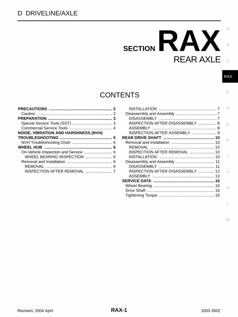
ASSEMBLYFinal Drive Side1. If plug has been removed, use a drift (SST) to press in a new
one.NOTE:Discard old plug; replace with new one.
2. Wind serrated part of shaft with tape. Install boot band and bootto shaft. Be careful not to damage boot.NOTE:Discard old boot band and boot; replace with new ones.
3. Remove protective tape wound around serrated part of shaft.
4. Install ball cage/steel ball/inner race assembly to shaft, andsecure them tightly with a snap ring.NOTE:Discard old snap ring; replace with new one.
5. Insert the amount grease (NISSAN genuine grease or equiva-lent) onto housing (* point) to the quantity mentioned below, andinstall it to shaft.
6. Install stopper ring to housing.7. After installed, pull shaft to check engagement between joint
sub-assembly and stopper ring.
SDIA1153E
SFA800
SDIA1125E
Reference value
Grease amount : 124 - 134 g (4.37 - 4.73 oz)
RAC0678D

RAX-14
REAR DRIVE SHAFT
Revision; 2004 April 2003 350Z
8. Install boot securely into grooves (indicated by * marks) shownin the figure.CAUTION:If there is grease on boot mounting surfaces (indicated by*marks) of shaft and housing, boot may come off. Removeall grease from surfaces.
9. Make sure boot installation length “L” is the length indicatedbelow. Insert a flat-bladed screwdriver or similar tool into smallerside of boot. Bleed air from boot to prevent boot deformation.
CAUTION:● Boot may break if boot installation length is less than standard value.● Take care not to touch the tip of screwdriver to inside of boot.10. Secure big and small ends of boot with new boot bands as
shown in the figure. NOTE:Discard old boot bands; replace with new ones.
11. After installing housing and shaft, rotate boot to check whetheror not the actual position is correct. If boot position is not correct,secure boot with new boot band again.
Wheel Side1. Insert the amount grease (NISSAN genuine grease or equiva-
lent) into joint sub-assembly serration hole until grease begins toooze from ball groove and serration hole. After insert grease,use a shop cloth to wipe off old grease that has oozed out.
2. Wind serrated part of shaft with tape. Install boot band and bootto shaft. Be careful not to damage boot.NOTE:Discard old boot band and boot; replace with new ones.
3. Remove protective tape wound around serrated part of shaft.
Standard valueBoot installation Length “L ” : 93.9 mm (3.697 in)
SDIA1126E
SFA395
SDIA1127E
SFA800

REAR DRIVE SHAFT
RAX-15
C
E
F
G
H
I
J
K
L
M
A
B
RAX
Revision; 2004 April 2003 350Z
4. Attach circular clip to shaft. At this time, circular clip must fitsecurely into shaft groove. Attach nut to joint sub-assembly.Use a wooden hammer to press-fit.NOTE:Discard old circular clip; replace with new one.
5. Insert the amount grease (NISSAN genuine grease or equiva-lent) listed below into housing from large end of boot.
6. Install boot securely into grooves (indicated by * marks) shownin the figure.CAUTION:If there is grease on boot mounting surfaces (indicated by*marks) of shaft and housing, boot may come off. Removeall grease from surfaces.
7. Make sure boot installation length “L” is the length indicatedbelow. Insert a flat-bladed screwdriver or similar tool into smallerside of boot. Bleed air from boot to prevent boot deformation.
CAUTION:● Boot may brake if boot installation length is than standard value.● Be careful that screwdriver tip does not contact inside surface of boot.
8. Secure big and small ends of boot with new boot bands asshown in the figure.NOTE:Discard old boot band; replace with new ones.
9. After installing joint sub-assembly and shaft, rotate boot to checkwhether or not the actual position is correct. If boot position isnot correct, secure boot with new boot bands again.
Reference valueGrease amount : 86 - 96 g (3.03 - 3.39 oz)
RAC0049D
Standard valueBoot installation length “L” :97 mm (3.82 in)
SDIA1128E
SFA395
RAX-16
SERVICE DATA
Revision; 2004 April 2003 350Z
SERVICE DATA PFP:00030
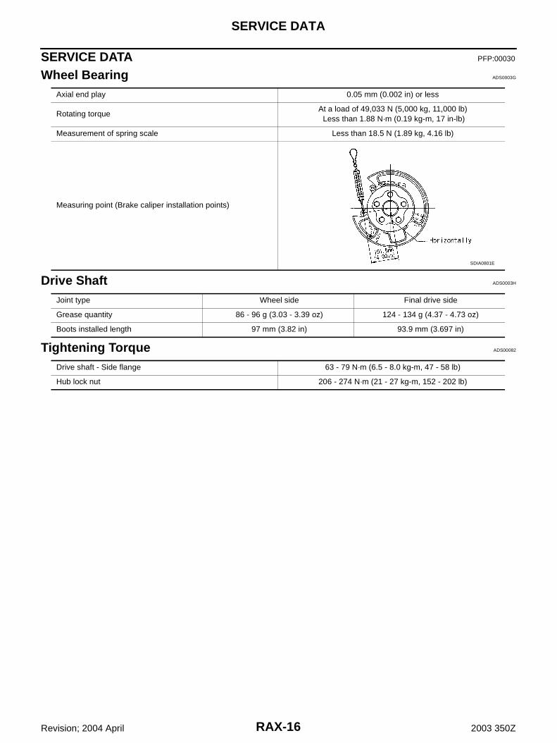
Wheel Bearing ADS0003G
Drive Shaft ADS0003H
Tightening Torque ADS00082
Axial end play 0.05 mm (0.002 in) or less
Rotating torqueAt a load of 49,033 N (5,000 kg, 11,000 lb) Less than 1.88 N·m (0.19 kg-m, 17 in-lb)
Measurement of spring scale Less than 18.5 N (1.89 kg, 4.16 lb)
Measuring point (Brake caliper installation points)
SDIA0801E
Joint type Wheel side Final drive side
Grease quantity 86 - 96 g (3.03 - 3.39 oz) 124 - 134 g (4.37 - 4.73 oz)
Boots installed length 97 mm (3.82 in) 93.9 mm (3.697 in)
Drive shaft - Side flange 63 - 79 N·m (6.5 - 8.0 kg-m, 47 - 58 lb)
Hub lock nut 206 - 274 N·m (21 - 27 kg-m, 152 - 202 lb)


![Optimizing Vehicle NVH Characteristics for Driveline ... · of the frequency range, driveline dynamics can influence the dynamic mesh forces of a rear axle [3], resulting in axle](https://img.dokumen.tips/doc/110x75/5b8a6b157f8b9a50388c2126/optimizing-vehicle-nvh-characteristics-for-driveline-of-the-frequency-range.jpg)