Embed Size (px)
Citation preview

RE 91610062014 Bosch Rexroth AG
Features Variable motor with axial tapered piston rotary group of
bent-axis design for hydrostatic drives in open and closed circuit
For use in mobile and stationary applications The wide control range enables the variable motor to
satisfy the requirement for high speed and high torque The displacement can be infinitely changed from Vg max
to Vg min = 0 The output speed is dependent on the flow of the pump
and the displacement of the motor The output torque increases with the pressure differen-
tial between the high and low-pressure side and with increasing displacement
Wide control range with hydrostatic transmissions Wide selection of control devices Cost savings through elimination of gear shifts and
possibility of using smaller pumps Compact robust motor with long service life High power density Good starting efficiency Version with 9-piston rotary group Good low speed characteristics High uniformity
Sizes 60 to 215 Nominal pressure 450 bar Maximum pressure 500 bar Open and closed circuits
Axial piston variable motorA6VM series 71
RE 91610Edition 062014Replaces 042013
InhaltOrdering code 2Hydraulic fluids 6Shaft seal 7Operating pressure range 8Technical data 9HP ndash Proportional hydraulic control 11EP ndash Proportional electric control 13HZ ndash Two-point hydraulic control 16EZ ndash Two-point electric control 17HA ndash Automatic high-pressure related control 18DA ndash Automatic speed-related control 23Electric travel direction valve (for DA HAR) 25Dimensions size 60 26Dimensions size 85 32Dimensions size 115 38Dimensions size 150 44Dimensions size 170 50Dimensions size 215 56Connector for solenoids 62Flushing and boost pressure valve 63Counterbalance valve BVD and BVE 65Speed sensor 69Setting range for displacement 70Installation instructions 72Project planning note 74Safety instructions 74
Bosch Rexroth AG RE 91610062014
2 A6VM series 71 | Axial piston variable motorOrdering code
Ordering code
01 02 03 04 05 06 07 08 09 10 11 12 13 14 15 16 17 18 19 20 21
A6V M 0 0 71 M W V 0 ndash
Axial piston unit01 Bent-axis design variable nominal pressure 450 bar maximum pressure 500 bar A6V
Operating mode02 Motor M
Size (NG)03 Geometric displacement see technical data on page 9 060 085 115 150 170 215
Control device 060 085 115 150 170 21504 Proportional control
hydraulicpositive control ΔpSt = 10 bar HP1
ΔpSt = 25 bar HP2
negative control ΔpSt = 10 bar HP5
ΔpSt = 25 bar HP6
Proportional controlelectrical
positive control U = 12 V DC EP1
U = 24 V DC EP2
negative control U = 12 V DC EP5
U = 24 V DC EP6
Two-point controlhydraulic
negative control ‒ ‒ ‒ HZ5
‒ ‒ ‒ HZ7
Two-point controlelectrical
negative control U = 12 V DC ‒ ‒ ‒ EZ5
U = 24 V DC ‒ ‒ ‒ EZ6
U = 12 V DC ‒ ‒ ‒ EZ7
U = 24 V DC ‒ ‒ ‒ EZ8
Automatic controlhigh-pressure relatedpositive control
with minimum pressure increase Δp le approx 10 bar
HA1
with pressure increase Δp = 100 bar HA2
Automatic controlspeed related negativecontrol pSt pHD = 5100
hydr travel direction valve DA0
electric travel direction valve+ electric Vg max circuit
U = 12 V DC DA1
U = 24 V DC DA2
Pressure controloverride 060 085 115 150 170 21505 Without pressure controloverride 00
Pressure control fixed setting only for HP5 HP6 EP5 and EP6 D1
Overrideof controlsHA1 and HA2
hydraulic remote control proportional T3
electric two-point U = 12 V DC U1
U = 24 V DC U2
electric and travel directionvalve electric
U = 12 V DC R1
U = 24 V DC R2
Connector for solenoids1) (see page 62)
06 Without connector (without solenoid only for hydraulic control) 0
DEUTSCH - molded connector 2-pin without suppressor diode P
= Available = On request ‒ = Not available
1) Connectors for other electric components can deviate
RE 91610062014 Bosch Rexroth AG
Axial piston variable motor | A6VM series 71 Ordering code
3
01 02 03 04 05 06 07 08 09 10 11 12 13 14 15 16 17 18 19 20 21
A6V M 0 0 71 M W V 0 ndash
2) The settings for the setting screws can be found in the table (see pages 70 and 71)
Additional function 107 Without additional function 0
Additional function 208 Without additional function 0
Response time damping (for selection see control)
09 Without damping (standard with HP and EP) 0Damping HP EP HP56D and EP56D HZ EZ HA with counterbalance valve BVDBVE 1
One-sided in inlet to large stroking chamber (HA) 4One-sided in outlet from large stroking chamber (DA) 7
Setting range for displacement2)
10 Vg max-setting screw Vg min-setting screw 060 085 115 150 170 215Without setting screw short (0-adjustable) A
medium B
long C
extra long ‒ ‒ D
Short short (0-adjustable) E
medium F
long G
extra long ‒ ‒ H
Medium short (0-adjustable) J
medium K
long L
extra long ‒ ‒ M
Series11 Series 7 index 1 71
Configuration of ports and fastening threads12 Metric port threads with O-ring sealing according to ISO 6149 M
Direction of rotation13 Viewed on drive shaft bidirectional W
Sealing material14 FKM (fluoroelastomer) V
Drive shaft bearing15 Standard bearing 0
Mounting flange 060 085 115 150 170 21516 ISO 3019-2 125-4 ‒ ‒ ‒ ‒ ‒ M4
140-4 ‒ ‒ ‒ ‒ ‒ N4
160-4 ‒ ‒ ‒ ‒ ‒ P4
180-4 ‒ ‒ ‒ ‒ R4
200-4 ‒ ‒ ‒ ‒ ‒ S4
= Available = On request ‒ = Not available
Bosch Rexroth AG RE 91610062014
4 A6VM series 71 | Axial piston variable motorOrdering code
3) Only possible in conjunction with HP EP and HA control Note the restrictions described on page 65
4) State ordering code for counterbalance valve separately in accor-dance with data sheet 95522 for BVD or 95525 for BVE Note the restrictions described on page 65
5) Not for EZ7 EZ8 and HZ7
01 02 03 04 05 06 07 08 09 10 11 12 13 14 15 16 17 18 19 20 21
A6V M 0 0 71 M W V 0 ndash
Drive shaft 060 085 115 150 170 21517 Splined shaft
ANSI B921a1 14 in 14T 1224 DP ‒ ‒ ‒ ‒ ‒ S7
1 124 in 17T 1224 DP ‒ ‒ ‒ ‒ ‒ S9
1 34 in 13T 816 DP ‒ ‒ ‒ ‒ T1
2 in 15T 816 DP ‒ ‒ ‒ T2
Splined shaft W35times2times16times9g ‒ ‒ ‒ ‒ ‒ Z8
DIN 5480 W40times2times18times9g ‒ ‒ ‒ ‒ Z9
W45times2times21times9g ‒ ‒ ‒ ‒ A1
W50times2times24times9g ‒ ‒ ‒ ‒ ‒ A2
Port plate for service lines 060 085 115 150 170 21518 SAE flange ports A and B at rear 1
SAE flange ports A and B at side opposite 2
Port plate with 1-stage pressure limitationvalves for mounting a counterbalance valve3)
BVD20 ‒ ‒ ‒ 7
BVD25 BVE25 ‒ ‒ 8
Valve (see pages 63 to 67) 060 085 115 150 170 21519 Without valve 0
With counterbalance valve BVDBVE mounted4) W
With flushing and boost pressure valve mountedFlushing on both sidesFlushing flow atΔp = pND ‒ pG = 25 bar and v = 10 mm2s(pND = low pressure pG = case pressure)Only possible with port plates 1 and 2
Flushing flow qv [lmin]
35 ‒ ‒ ‒ A
5 ‒ ‒ ‒ B
8 C
10 D
14 ‒ ‒ ‒ F
17 ‒ ‒ ‒ G
20 ‒ ‒ 5) H
25 ‒ ‒ 5) J
30 ‒ ‒ 5) K
35 ‒ ‒ ‒ L
40 ‒ ‒ ‒ M
= Available = On request ‒ = Not available
01 02 03 04 05 06 07 08 09 10 11 12 13 14 15 16 17 18 19 20 21
A6V M 0 0 71 M W V 0 ndash
RE 91610062014 Bosch Rexroth AG
Axial piston variable motor | A6VM series 71 Ordering code
5
Speed sensor (see page 69) 060 085 115 150 170 21520 Without speed sensor 0
Prepared with speed sensor DSMDSA U
With speed sensor DSMDSA mounted6) V
Standard special version
21 Standard version 0
Standard version with installation variants e g T ports against standard open and closed Y
Special version S
= Available = On request ‒ = Not available
Notes Note the project planning notes on page 74 Preservation
ndash up to 12 months as standard ndash up to 24 months long-term
(state in plain text when ordering)
01 02 03 04 05 06 07 08 09 10 11 12 13 14 15 16 17 18 19 20 21
A6V M 0 0 71 M W V 0 ndash
6) State ordering code for sensor separately in accordance with data sheet 95132 for DSM or 95133 for DSA and note the requirements relating to the electronics
Bosch Rexroth AG RE 91610062014
6 A6VM series 71 | Axial piston variable motorHydraulic fluids
Hydraulic fluids
The variable motor A6VM is designed for operation with mineral oil HLP according to DIN 51524 Application instructions and requirements for hydraulic fluids should be taken from the following data sheets before the start of project planning
90220 Hydraulic fluids based on mineral oils and related hydrocarbons
90221 Environmentally friendly hydraulic fluids 90222 Fire-resistant water-free hydraulic fluids
(HFDRHFDU)
Details regarding the selection of hydraulic fluidThe hydraulic fluid should be selected such that the operat-ing viscosity in the operating temperature range is within the optimum range (νopt see selection diagram)
NoteAt no point of the component may the temperature be higher than 115 degC The temperature difference specified in the table is to be taken into account when determining the viscosity in the bearingIf the above conditions cannot be maintained due to extreme operating parameters we recommend flushing the case at port U or using a flushing and boost pressure valve (see page 63)
Viscosity and temperature of hydraulic fluids
Viscosity Temperature Comment
Cold start νmax le 1600 mm2s θSt ge -40 degC t le 3 min n le 1000 rpm without load p le 50 bar
Permissible temperature difference ΔT le 25 K between axial piston unit and hydraulic fluid in the system
Warm-up phase ν lt 1600 to 400 mm2s θ = -40 degC to -25 degC at p le 07 times pnom n le 05 times nnom and t le 15 min
Continuous operation ν = 400 to 10 mm2s This corresponds for example on the VG 46 to a temperature range of +5 degC to +85 degC (see selection diagram)
θ = -25 degC to +103 degC measured at port TNote the permissible temperature range of the shaft seal(ΔT = approx 12 K between the bearingshaft seal and port T)
νopt = 36 to 16 mm2s Range of optimum operating viscosity and efficiency
Short-term operation νmin ge 7 mm2s t lt 3 min p lt 03 times pnom
Selection diagram
-40 -25 -10 10 30 50 90 1157007
10
4060
20
100
200
400600
10001600
VG 22VG 32VG 46VG 68VG 100
16
36
Range of optimum operating viscosity vopt
Optimum efficiency
Maximum permissible viscosity for cold start
Minimum permissible viscosity for short-term operation
Temperature t [degC]
Visc
osity
v [
mm
2 s]
Con
tinuo
us o
pera
tion
Warm-up phase
Minimum permissible temperature for cold start
RE 91610062014 Bosch Rexroth AG
Axial piston variable motor | A6VM series 71 Shaft seal
7
Filtration of the hydraulic fluidFiner filtration improves the cleanliness level of the hydrau-lic fluid which increases the service life of the axial piston unitA cleanliness level of at least 201815 is to be maintained according to ISO 4406At very high hydraulic fluid temperatures (90 degC to maxi-mum 103 degC measured at port T) a cleanliness level of at least 191714 according to ISO 4406 is necessary
Shaft seal
Permissible pressure loadingThe service life of the shaft seal will be influenced by thespeed of the axial piston unit and the leakage pressure in the housing (case pressure) Momentary pressure spikes (t lt 01 s) of up to 10 bar are permitted The service life of the shaft seal decreases with increasing frequency of pres-sure spikes and increasing mean differential pressureThe case pressure must be equal to or higher than theambient pressure
0
1
2
3
4
52000 4000 6000 8000 10000
NG170 215
NG85
NG60
NG115 150
NG170
NG60
NG85
NG115NG150NG215
Diff
eren
tial p
ress
ure Dp
[ba
r]
Rotational speed n [rpm]
The FKM shaft seal may be used for leakage temperatures from -25 degC to +115 degC For application cases below -25 degC an NBR shaft seal is required (permissible temperature range -40 degC to +90 degC)
Influence of case pressure on beginning of controlAn increase in case pressure affects the beginning of con-trol when using the following control options
HP HAT3 Increase DA Decrease
With the following settings an increase in case pressure will have no effect on the beginning of control HAR and HAU EP HAThe factory setting of the beginning of control is made at pabs = 2 bar case pressure
Flow direction
Direction of rotation viewed on drive shaft
cw ccw
A to B B to A
Bosch Rexroth AG RE 91610062014
8 A6VM series 71 | Axial piston variable motorOperating pressure range
Operating pressure range
Pressure at service line port A or B Definition
Nominal pressure pnom 450 bar absolute The nominal pressure corresponds to the maximum design pressure
Maximum pressure pmax 500 bar absolute The maximum pressure corresponds to the maximum operating pressure within the single operating period The sum of the single operating periods must not exceed the total operating period
Single operating period 10 s
Total operating period 300 h
Minimum pressure (high-pressure side) 25 bar absolute Minimum pressure at the high-pressure side (A or B) which is required in order to prevent damage to the axial piston unit
Minimum pressure ndash pump operating mode (inlet)
See the diagram below
To prevent damage to the axial piston motor in pump operating mode (change of high-pressure side with unchanged direction of rotation e g when braking) a minimum pressure must be guaranteed at the service line port (inlet) This minimum pressure is dependent on the speed and dis-placement of the axial piston unit (see characteristic curve)
Summation pressure pSu
(pressure A + pressure B)700 bar The summation pressure is the sum of the pressures at both service line
ports (A and B)
Rate of pressure change RA max Maximum permissible rate of pressure rise and reduction during a pressure change over the entire pressure rangeWith integrated pressure-relief valve 9000 bars
Without pressure-relief valve 16000 bars
Rate of pressure change RA max
pnom
∆t
∆p
Time t
Pres
sure
p
Pressure definition
Single operating period
Pres
sure
p
t1
t2tn
Minimum pressure (high-pressure side)
Maximum pressure pmax
Nominal pressure pnom
Time t
Total operating period = t1 + t2 + + tn
Minimum pressure ndash pump operating mode (inlet)
Inle
t pr
essu
re p
abs [
bar]
Rotational speed n nnom
Vg max
Vg x
03 Vg max
12
4
6
8
10
12
14
16
0 04 07 10 13 16
This diagram is valid only for the optimum viscosity range from nopt = 36 to 16 mm2s Please contact us if these conditions cannot be satisfied
NotesOperating pressure range valid when using hydraulic fluids based on mineral oils Values for other hydraulic fluids please contact us
RE 91610062014 Bosch Rexroth AG
Axial piston variable motor | A6VM series 71 Technical data
9
Technical data
Size NG 60 85 115 150 170 215
Displacement geometric per revolution Vg max cm3 620 852 1156 1521 1718 2165
Vg min cm3 0 0 0 0 0 0
Vg x cm3 37 51 69 91 65 82
Maximum speed1)
(complying with the maxi-mum permissible inlet flow)
at Vg max nnom rpm 4450 3900 3550 3250 3100 2900
at Vg lt Vg x (see diagram) nmax rpm 7200 6800 6150 5600 4900 4600
at Vg 0 nmax rpm 8400 8350 7350 6000 5750 5500
Inlet flow2) at nnom and Vg max qv max Lmin 275 332 410 494 533 628
Torque3) at Vg max and Δp = 450 bar T Nm 444 610 828 1089 1230 1550
Rotary stiffness Vg max to Vg2 cmin kNmrad 15 22 37 44 52 70
Vg2 to 0 (interpolated) cmin kNmrad 45 68 104 124 156 196
Moment of inertia for rotary group JGR kgm2 00043 00072 00110 00181 00213 00303
Maximum angular acceleration α radssup2 21000 17500 15500 11000 11000 10000
Case volume V L 08 10 15 17 23 28
Weight approx m kg 28 36 46 61 62 78
Permissible displacement in relation to speed
02 04 06 08 10 12 14 174
NG170 215
NG85 115 150
4)
10
08
06
038
02
0
NG60
158 162
Vg x
Vg x
Dis
plac
emen
t V
g
Vg
max
Rotational speed n nnom
Determining the operating characteristics
Inlet flow qv = Vg times n
[lmin]1000 times ηv
Rotational speed
n = qv times 1000 times ηv
[rpm]Vg
Torque T = Vg times Δp times ηmh
[Nm]20 times π
Power P = 2 π times T times n
= qv times Δp times ηt
[kW]60000 600
Key
Vg = Displacement per revolution [cm3]
Δp = Differential pressure [bar]
n = Rotational speed [rpm]
ηv = Volumetric efficiency
ηmh = Mechanical-hydraulic efficiency
ηt = Total efficiency (ηt = ηv bull ηmh)
Notes Theoretical values without efficiency levels and toler-
ances values rounded Operation above the maximum values or below the
minimum values may result in a loss of function a reduced service life or in the destruction of the axial piston unit Other permissible limit values such as speed variation reduced angular acceleration as a function of the frequency and the permissible angular acceleration at start (lower than the maximum angular acceleration) can be found in data sheet 90261
Transport and storage ndash θmin ge ndash50 degC ndash θopt = +5 degC to +20 degC
1) The values are valid ndash For the optimum viscosity range from νopt = 36 to 16 mm2s ndash with hydraulic fluid on the basis of mineral oil
2) Note inlet flow limitation due to counterbalance valve (see page 65)
3) Torque without radial force With radial force see page 10 4) Values in this range on request
Bosch Rexroth AG RE 91610062014
10 A6VM series 71 | Axial piston variable motorTechnical data
Permissible radial and axial forces of the drive shafts
Size NG 60 60 85 85 115 115 150 150 150
Drive shaft 1 14 in W35 1 12 in W40 1 34 in W40 1 34 in 2 in W45
Maximum radial force1) at distance a (from shaft collar)
a
FqFq max N 7620 10266 12463 12323 14902 16727 15948 17424 19534
a mm 240 200 270 225 335 225 335 335 250
with permissible torque Tmax Nm 310 444 595 610 828 828 890 1089 1089
≙ Permissible pressure Δp at Vg max pnom perm bar 315 450 440 450 450 450 370 450 450
Maximum axial force2)
plusmnFax+ Fax max N 0 0 0 0 0 0 0 0 0
minus Fax max N 500 500 710 710 900 900 1300 1300 1300
Permissible axial force per bar operating pressure
+ Fax permbar Nbar 75 75 96 96 113 113 133 133 133
Size NG 170 170 215 215
Drive shaft 2 in W45 2 in W50
Maximum radial force1) at distance a (from shaft collar)
a
FqFq max N 19370 21220 22602 25016
a mm 335 250 335 275
with permissible torque Tmax Nm 1230 1200 1445 1550
≙ Permissible pressure Δp at Vg max pnom perm bar 450 440 420 450
Maximum axial force2)
plusmnFax+ Fax max N 0 0 0 0
minus Fax max N 1120 1120 1250 1250
Permissible axial force per bar operating pressure
+ Fax permbar Nbar 151 151 170 170
Effect of radial force Fq on the service life of bearingsBy selecting a suitable direction of radial force Fq the load on the bearings caused by the internal rotary group forces can be reduced thus optimizing the service life of the bearings Recommended position of mating gear is depen-dent on direction of rotation Examples
Notes Influence of the direction of the permissible axial force
+ Fax max = Increased shelf life ndash Fax max = Reduced shelf life (to be avoided)
Special requirements apply in the case of belt drives Please contact us
Toothed gear output drive V-belt output drive
φopt = 45degφopt = 45deg
21
φopt = 70degφ opt = 70deg
2 1
1 Direction of rotation clockwise pressure at port B2 Direction of rotation counter-clockwise pressure at port A
1) For intermittent operation2) Maximum permissible axial force at standstill or depressurized ro-
tation of the axial piston unit
RE 91610062014 Bosch Rexroth AG
Axial piston variable motor | A6VM series 71 HP ndash Proportional hydraulic control
11
HP ndash Proportional hydraulic control
The proportional hydraulic control provides infinite adjust-ment of the displacement Control is proportional to the pilot pressure applied to port XHP1 HP2 positive control
Beginning of control at Vg min (minimum torque maxi-mum permissible speed at minimum pilot pressure)
End of control at Vg max (maximum torque minimum speed at maximum pilot pressure)
HP5 HP6 negative control Beginning of control at Vg max (maximum torque mini-
mum speed at minimum pilot pressure) End of control at Vg min (minimum torque maximum
permissible speed at maximum pilot pressure)
Note Maximum permissible pilot pressure pSt = 100 bar The control oil is internally taken from the high pressure
side of the motor (A or B) For reliable control an oper-ating pressure of at least 30 bar is required in A (B) If a control operation is performed at an operating pressure lt 30 bar an auxiliary pressure of at least 30 bar must be applied at port G via an external check valve For lower pressures please contact us Please note that pressures up to 500 bar can occur at port G
Please state the desired beginning of control in plain text when ordering e g beginning of control at 10 bar
The beginning of control and the HP charakteristic curve are influenced by the case pressure An increase in case pressure causes an increase in the beginning of control (see page 6) and thus a parallel shift of the charac-teristic
HP1 HP5 Increase in pilot pressure ΔpSt = 10 bar
HP1 positive controlA pilot pressure increase of 10 bar at port X results in an increase in displacement from Vg min to Vg maxHP5 negative controlA pilot pressure increase of 10 bar at port X results in a decrease in displacement from Vg max to Vg min
Beginning of control setting range 2 to 20 bar Standard setting
Beginning of control at 3 bar (end of control at 13 bar)
Characteristic curve
0 02 04 06 08 10Vg min Vg maxVg Vg max
HP5 HP135
30
25
20
151210
52B
egin
ning
of c
ontr
ol
sett
ing
rang
e
Displacement
Pilo
t pr
essu
re p
St [
bar]
Pilo
t pr
essu
re
incr
ease
HP2 HP6 Increase in pilot pressure DpSt = 25 bar
HP2 positive controlA pilot pressure increase of 25 bar at port X results in an increase in displacement from Vg min to Vg maxHP6 negative controlA pilot pressure increase of 25 bar at port X results in a decrease in displacement from Vg max to Vg min
Beginning of control setting range 5 to 35 bar Standard setting
Beginning of control at 10 bar (end of control at 35 bar)
Characteristic curve
70
60
50
403530
20
105
0 02 04 06 08 10Vg min Vg maxVg Vg max
HP6 HP2
Beg
inni
ng o
f co
ntro
l set
ting
ra
nge
Displacement
Pilo
t pr
essu
re p
St [
bar]
Pilo
t pr
essu
re
incr
ease
Bosch Rexroth AG RE 91610062014
12 A6VM series 71 | Axial piston variable motorHP ndash Proportional hydraulic control
Schematic HP1 HP2 Positive control
B
A
M1
T2
T1
G
X
Vg min
Vg max
U
Schematic HP5 HP6 negative control
T2
T1
M1
Vg min
Vg max
B
A
U
X
G
HP5D1 HP6D1Pressure control fixed settingThe pressure control overrides the HP control function If the load torque or a reduction in motor swivel angle causes the system pressure to reach the setpoint value of the pressure control the motor will swivel towards a larger displacement The increase in the displacement and the resulting reduc-tion in pressure cause the control deviation to decrease With the increase in displacement the motor develops more torque while the pressure remains constantSetting range of the pressure control valve 80 to 450 bar
Schematic HP5D1 HP6D1 negative control
T2
T1
M1
Vg min
Vg max
B
A
G
X
U
Response time dampingStandard for HP without dampingHP HP5D1 HP6D1 ndash with throttle pin on both sides sym-metrical
Size 60 85 115 150 170 215
Groove size [mm] 045 045 055 055 055 065
M1
RE 91610062014 Bosch Rexroth AG
Axial piston variable motor | A6VM series 71 EP ndash Proportional electric control
13
EP ndash Proportional electric control
The proportional electric control type EP provides infinite adjustment of the displacement proportional to the control current applied to the solenoidEP1 EP2 positive control
Beginning of control at Vg min (minimum torque maxi-mum permissible speed at minimum control current)
End of control at Vg max (maximum torque minimum speed at maximum control current)
EP5 EP6 negative control Beginning of control at Vg max (maximum torque mini-
mum speed at minimum control current) End of control at Vg min (minimum torque maximum
permissible speed at maximum control current)
Charakteristic curve
EP5 EP6 EP1 EP2
0 02 04 06 08 10
Vg min Vg Vg max Vg max
1600max
1400
1200
1000
800
600
400
200
800max
700
600
500
400
300
200
100
EP5EP1
(12 V)
EP6EP2
(24 V)
NoteThe control oil is internally taken from the high pressure side of the motor (A or B) For reliable control an operat-ing pressure of at least 30 bar is required in A (B) If a control operation is performed at an operating pressure lt 30 bar an auxiliary pressure of at least 30 bar must be applied at port G via an external check valve For lower pressures please contact us Please note that pressures up to 500 bar can occur at port G
Technical data solenoid EP1 EP5 EP2 EP6
Voltage 12 V (plusmn20 ) 24 V (plusmn20 )
Control current
Beginning of control 400 mA 200 mA
End of control 1200 mA 600 mA
Current limit 154 A 077 A
Nominal resistance (at 20 degC) 55 Ω 227 Ω
Dither frequency 100 Hz 100 Hz
Duty cycle 100 100
Type of protection see connector version on page 62
Various BODAS controllers with application software and amplifiers are available for controlling the proportional solenoidsFurther information can also be found on the internet at wwwboschrexrothcommobile-electronics
Bosch Rexroth AG RE 91610062014
14 A6VM series 71 | Axial piston variable motorEP ndash Proportional electric control
Schematic EP1 EP2 positive control
B
A
M1
T2
T1
G
Vg min
Vg max
U
Schematic EP5 EP6 negative control
U
T2
T1
M1
Vg min
Vg max
B
A
G
RE 91610062014 Bosch Rexroth AG
Axial piston variable motor | A6VM series 71 EP ndash Proportional electric control
15
EP5D1 EP6D1 Pressure control fixed settingThe pressure control overrides the EP control function If the load torque or a reduction in motor swivel angle causes the system pressure to reach the setpoint value of the pressure control the motor will swivel towards a larger displacementThe increase in the displacement and the resulting reduc-tion in pressure cause the control deviation to decrease With the increase in displacement the motor develops more torque while the pressure remains constantSetting range of the pressure control valve 80 to 450 bar
Schematic EP5D1 EP6D1 negative control
U
T2
T1
Vg min
Vg max
B
A
G
M1
Response time dampingStandard for EP without dampingEP EP5D1 EP6D1 ndash with throttle pin on both sides sym-metrical
Size 60 85 115 150 170 215
Groove size [mm] 045 045 055 055 055 065
M1
Bosch Rexroth AG RE 91610062014
16 A6VM series 71 | Axial piston variable motorHZ ndash Two-point hydraulic control
HZ ndash Two-point hydraulic control
The two-point hydraulic control type HZ allows the dis-placement to be set to either Vg min or Vg max by switching the pilot pressure at port X on or off
HZ5 HZ7 negative control Position at Vg max (without pilot pressure maximum
torque minimum speed) Position at Vg min (with pilot pressure gt 15 bar activated
minimum torque maximum permissible speed)
Characteristic curve HZ5 HZ7
Vg min Vg maxDisplacement
0
15
Pilo
t pr
essu
re p
S [b
ar]
100
Note Maximum permissible pilot pressure 100 bar The control oil is internally taken from the high pressure
side of the motor (A or B) For reliable control an oper-ating pressure of at least 30 bar is required in A (B) If a control operation is performed at an operating pressure lt 30 bar an auxiliary pressure of at least 30 bar must be applied at port G via an external check valve For lower pressures please contact us Please note that pressures up to 500 bar can occur at port G
Response time damping
HZ5 ndash with throttle pin on both sides symmetrical HZ7 ndash with throttle pin on both sides symmetricalSize 150 170 215 Size 60 85 115
Groove size [mm] 055 055 065 Groove size [mm] 030 030 030
M1
Schematic HZ5 Negative control size 150 to 215
T2
T1
M1
Vg min
Vg max
B
A
X
G
U
Schematic HZ7 Negative control size 60 to 115
T1U
T2
XG
Vg min
Vg max
B
A
RE 91610062014 Bosch Rexroth AG
Axial piston variable motor | A6VM series 71 EZ ndash Two-point electric control
17
EZ ndash Two-point electric control
The two-point electric control type EZ allows the displace-ment to be set to either Vg min or Vg max by switching the electric current to a switching solenoid on or off
NoteThe control oil is internally taken from the high pressure side of the motor (A or B) For reliable control an operat-ing pressure of at least 30 bar is required in A (B) If a control operation is performed at an operating pressure lt 30 bar an auxiliary pressure of at least 30 bar must be applied at port G via an external check valve For lower pressures please contact us Please note that pressures up to 500 bar can occur at port G
Sizes 150 to 215
Technical data solenoid with oslash37 EZ5 EZ6
Voltage 12 V (plusmn20 ) 24 V (plusmn20 )
Position Vg max de-energized de-energized
Position Vg min energized energized
Nominal resistance (at 20 degC) 55 Ω 217 Ω
Nominal power 262 W 265 W
Minimum required active current 132 A 067 A
Duty cycle 100 100
Type of protection see connector version on page 62
Schematic EZ5 EZ6 negative control
U
T2
T1
M1
Vg min
Vg max
B
A
G
Sizes 60 to 115
Technical data solenoid with oslash45 EZ7 EZ8
Voltage 12 V (plusmn20 ) 24 V (plusmn20 )
Position Vg max de-energized de-energized
Position Vg min energized energized
Nominal resistance (at 20 degC) 48 Ω 192 Ω
Nominal power 30 W 30 W
Minimum required active current 15 A 075 A
Duty cycle 100 100
Type of protection see connector version on page 62
Schematic EZ7 EZ8 negative control
T1U
T2
G
B
A
Vg min
Vg max
Response time dampingEZ5 EZ6 ndash with throttle pin on both sides symmetrical
Size 150 170 215
Groove size [mm] 055 055 065
M1
EZ7 EZ8 ndash with throttle pin on both sides symmetrical
Size 60 85 115
Groove size [mm] 030 030 030
Bosch Rexroth AG RE 91610062014
18 A6VM series 71 | Axial piston variable motorHA ndash Automatic high-pressure related control
HA ndash Automatic high-pressure related control
The automatic high-pressure related control type HA adjusts the displacement automatically depending on the operating pressureThe displacement of the A6VM motor with HA control is Vg min (maximum speed and minimum torque) The control device measures internally the operating pressure at A or B (no control line required) and upon reaching the set beginning of control the controller swivels the motor from Vg min to Vg max with increase of operating pressure The displacement is modulated between Vg min and Vg max thereby depending on load conditions
HA1 HA2 positive control Beginning of control at Vg min (minimum torque maxi-
mum speed) End of control at Vg max (maximum torque minimum
speed)
Note For safety reasons winch drives are not permissible
with beginning of control at Vg min (standard for HA) The control oil is internally taken from the high pressure
side of the motor (A or B) For reliable control an oper-ating pressure of at least 30 bar is required in A (B) If a control operation is performed at an operating pressure lt 30 bar an auxiliary pressure of at least 30 bar must be applied at port G via an external check valve For lower pressures please contact us Please note that pressures up to 500 bar can occur at port G
The beginning of control and the HAT3 charakteristic curve are influenced by case pressure An increase in case pressure causes an increase in the beginning of control (see page 6) and thus a parallel shift of the characteristic
Response time dampingHA ndash with one-sided throttle pin ndash inlet to large stroking chamber
Size 60 85 115 150 170 215
Groove size [mm] 045 045 055 055 055 065
M1
HA ndash with counterbalance valve BVD or BVE ndash with throttle screw
Size 60 85 115 150 170 215
Groove size [mm] 080 080 080 080 080 080
M1
RE 91610062014 Bosch Rexroth AG
Axial piston variable motor | A6VM series 71 HA ndash Automatic high-pressure related control
19
HA1 With minimum pressure increase positive controlAn operating pressure increase of Δp le approx 10 bar results in an increase in displacement from Vg min towards Vg maxBeginning of control setting range 80 to 350 barPlease state the desired beginning of control in plain text when ordering e g beginning of control at 300 bar
Charakteristic curve HA1
400
350
300
250
200
150
10080
50
0
Vg min Vg maxVg Vg max
0 02 04 06 08 10
Pres
sure
incr
ease
Δp
le a
ppro
x 1
0 ba
r
Ope
ratin
g pr
essu
re p
[ba
r]
Beg
inni
ng o
f con
trol
se
ttin
g ra
nge
Displacement
Schematic HA1
B
A
M1
T2
T1
Vg min
Vg max
G
U
X
HA2With pressure increase positive controlAn operating pressure increase of Dp approx 100 bar results in an increase in displacement from Vg min to Vg maxBeginning of control setting range 80 to 350 barPlease state the desired beginning of control in plain text when ordering e g beginning of control at 200 bar
Characteristic curve HA2
450
400
350
300
250
200
150
10080
50
0
Vg min Vg maxVg Vg max
0 02 04 06 08 10
Pres
sure
incr
ease
Δp
le a
ppro
x 1
00 b
ar
Ope
ratin
g pr
essu
re p
[ba
r]
Beg
inni
ng o
f con
trol
se
ttin
g ra
nge
Displacement
Schematic HA2
B
A
M1
T2
T1
G
X
Vg min
Vg max
U
Bosch Rexroth AG RE 91610062014
20 A6VM series 71 | Axial piston variable motorHA ndash Automatic high-pressure related control
HAT3 Hydraulic override remote control proportionalWith the HAT3 control the beginning of control can be influenced by applying a pilot pressure to port XFor each 1 bar of pilot pressure increase the beginning of control is reduced by 17 bar
Beginning of control setting 300 bar 300 bar
Pilot pressure at port X 0 bar 10 bar
Beginning of control at 300 bar 130 bar
NoteMaximum permissible pilot pressure 100 bar
Schematic HA1T3
B
A
M1
T2
T1
Vg min
Vg max
X
U
G
Schematic HA2T3
B
A
M1
T2
T1
G
X
Vg min
Vg max
U
RE 91610062014 Bosch Rexroth AG
Axial piston variable motor | A6VM series 71 HA ndash Automatic high-pressure related control
21
HAU1 HAU2Electric override two-pointWith the HAU1 or HAU2 control the beginning of control can be overridden by an electric signal to a switching sole-noid When the override solenoid is energized the variable motor swivels to maximum swivel angle without intermedi-ate position The beginning of control can be set between 80 and 300 bar (specify required setting in plain text when order-ing)
Technical data solenoid with oslash45 U1 U2
Voltage 12 V (plusmn20 ) 24 V (plusmn20 )
No override de-energized de-energized
Position Vg max energized energized
Nominal resistance (at 20 degC) 48 Ω 192 Ω
Nominal power 30 W 30 W
Minimum required active current 15 A 075 A
Duty cycle 100 100
Type of protection see connector version on page 62
Schematic HA1U1 HA1U2
G
B
A
M1
T2
T1
Vg min
Vg max
U
Schematic HA2U1 HA2U2
M1
T2
T1
B
A
Vg min
Vg max
G
U
Bosch Rexroth AG RE 91610062014
22 A6VM series 71 | Axial piston variable motorHA ndash Automatic high-pressure related control
HAR1 HAR2Electric overrideelectric travel direction valveWith the HAR1 or HAR2 control the beginning of control can be overridden by an electric signal to switching sole-noid b When the override solenoid is energized the vari-able motor swivels to maximum swivel angle without inter-mediate positionThe travel direction valve ensures that the preselected pressure side of the hydraulic motor (A or B) is always connected to the HA control and thus determines the swivel angle even if the high-pressure side changes (e g -travel drive during a downhill operation) This thereby prevents undesired jerky deceleration andor brak-ing characteristicsThe travel direction valve (see page 25) is either pressure spring or switched by energizing switching solenoid a depending on the direction of rotation (travel direction)
Electric override
Technical data solenoid b with oslash45 R1 R2
Voltage 12 V (plusmn20 ) 24 V (plusmn20 )
No override de-energized de-energized
Position Vg max energized energized
Nominal resistance (at 20 degC) 48 Ω 192 Ω
Nominal power 30 W 30 W
Minimum required active current 15 A 075 A
Duty cycle 100 100
Type of protection see connector version on page 62
Travel direction valve electric
Technical data solenoid a with oslash37 R1 R2
Voltage 12 V (plusmn20 ) 24 V (plusmn20 )
Direction of rotation
Operating pressure in
ccw B energized energized
cw A de-energized de-energized
Nominal resistance (at 20 degC) 55 Ω 217 Ω
Nominal power 262 W 265 W
Minimum required active current 132 A 067 A
Duty cycle 100 100
Type of protection see connector version on page 62
Schematic HA1R1 HA1R2
ab
B
A
M1
T2
T1
Vg min
Vg max
U
G
Schematic HA2R1 HA2R2
M1
T2
T1
G
B
A
Vg min
Vg max
U
ab
RE 91610062014 Bosch Rexroth AG
Axial piston variable motor | A6VM series 71 DA ndash Automatic speed-related control
23
DA ndash Automatic speed-related control
The variable motor A6VM with automatic speed-related control type DA is intended for use in hydrostatic travel drives in combination with the variable pump A4VG with DA controlA drive-speed-related pilot pressure signal is generated by the A4VG variable pump and that signal together with the operating pressure regulates the swivel angle of the hydraulic motorIncreasing pump speed ie increasing pilot pressure causes the motor to swivel to a smaller displacement (lower torque higher speed) depending on the operating pressureIf the operating pressure exceeds the pressure setpoint set on the controller the variable motor swivels to a larger displacement (higher torque lower speed)
Pressure ratio pStpHD = 5100
DA closed loop control is only suitable for certain types of drive systems and requires review of the engine and vehicle parameters to ensure that the motor is used correctly and that machine operation is safe and efficient We recommend that all DA applications be reviewed by a Bosch Rexroth application engineerDetailed information is available from our sales organiza-tion
NoteThe beginning of control and the DA charakteristic curve are influenced by case pressure An increase in case pres-sure causes an decrease in the beginning of control (see page 7) and thus a parallel shift of the characteristic
Response time dampingDA ndash with one-sided throttle pin ndash outlet to large stroking chamber
Size 60 85 115 150 170 215
Groove size [mm] 045 045 055 055 055 065
M1
DA0Hydraulic travel direction valve negative controlDepending on the direction of rotation (travel direction) the travel direction valve is switched by using pilot pres-sures connections X1 or X2
Direction of rotation
Operating pressure in
Pilot pressure in
cw A X1
ccw B X2
Schematic DA0
M1
T2
T1
Vg min
Vg max
B
A
G
X3
X2
X1
U
Bosch Rexroth AG RE 91610062014
24 A6VM series 71 | Axial piston variable motorDA ndash Automatic speed-related control
DA1 DA2Electric travel direction valve + electric Vg max circuit negative controlThe travel direction valve is either pressure spring or switched by energizing switching solenoid a depending on the direction of rotation (travel direction)When the switching solenoid b is energized the DA control is overridden and the motor swivels to maximum displace-ment (high torque lower speed) (electric Vg max-circuit)
Travel direction valve electric
Technical data solenoid a with oslash37 DA1 DA2
Voltage 12 V (plusmn20 ) 24 V (plusmn20 )
Direction of rotation
Operating pressure in
ccw B de-energized de-energized
cw A energized energized
Nominal resistance (at 20 degC) 55 Ω 217 Ω
Nominal power 262 W 265 W
Minimum required active current 132 A 067 A
Duty cycle 100 100
Type of protection see connector version on page 62
Electric override
Technical data solenoid b with oslash37 R1 R2
Voltage 12 V (plusmn20 ) 24 V (plusmn20 )
No override de-energized de-energized
Position Vg max energized energized
Nominal resistance (at 20 degC) 55 Ω 217 Ω
Nominal power 262 W 265 W
Minimum required active current 132 A 067 A
Duty cycle 100 100
Type of protection see connector version on page 62
Schematic DA1 DA2
T2
T1
M1
Vg min
Vg max
B
A
G
X3
a
b
X1
U
RE 91610062014 Bosch Rexroth AG
Axial piston variable motor | A6VM series 71 Electric travel direction valve (for DA HAR)
25
Electric travel direction valve (for DA HAR)
Application in travel drives in closed circuits The travel direction valve of the motor is actuated by an electric signal that also switches the swivel direction of the travel drive pump (e g A4VG with DA control valve)If the pump in the closed circuit is switched to the neutral position or into reverse the vehicle may experience jerky deceleration or braking depending on the vehicles mass and current travel speedWhen the travel direction valve of the pump (e g 43-direc-tional valve of the DA-control) is switched to
the neutral position the electric circuitry causes the previous signal on the travel direction valve on the motor to be retained
Reversing the travel direction valve causes the travel direction valve of the motor to switch to the other travel direction following a time delay (approx 08 s) with respect to the pump
As a result jerky deceleration or braking is prevented in both cases
Schematic - electric travel direction valve
K11
K12
K1
K21
K2
A3 B3
A2
V1
V NR
24 V DC
24 V DC
Solenoid a Pump
Solenoid b Pump
Solenoid a Motor
Travel direction valve
The shown diodes and relays are not included in the scope of delivery of the motor
Control DA1 DA
bab
a
HA1R HA2R control
a
b
Switching solenoid a on the travel direction valve
Bosch Rexroth AG RE 91610062014
26 A6VM series 71 | Axial piston variable motorDimensions size 60
Dimensions [mm]
Dimensions size 60
EP5 EP6 ndash Proportional electric control negative controlPort plate 2 mdash SAE flange ports A and B at side opposite
150
UT1
T2
G
M1
Y
Z
M1
G75
183108321)
725
84
max 146
1122)
203167
2123)
2430
3)
176
154
243
142)
160
45deg
135
45deg
150
508
238
19
0oslash1
25 -0
025
oslash73 23
125
deg
View Y
Flange ISO 3019-2
1) To shaft collar2) Center of gravity3) Port plate 1 mdash SAE flange ports A and B at rear
RE 91610062014 Bosch Rexroth AG
Axial piston variable motor | A6VM series 71 Dimensions size 60
27Dimensions [mm]
Location of the service line ports on the port plates (view Z)
2 SAE flange portA and B at side opposite
1 SAE flange portA and B at rear
2 SAE flange portA and B at side opposite only HZ7 EZ78
1 SAE flange portA and B at rear only HZ7 EZ78
B A
15254
16554
B A
152
AB
375 375
AB
165
Splined shaft SAE J744 Splined shaft DIN 5480
S7 ‒ 1 14 in 14T 1224DP1) Z8 ‒ W35times2times16times9g
28
40
716
-14U
NC
-2B
2)3)
oslash45
48
95
40
32
M12
x 1
753)
4)
95
28
oslash45
1) Involute spline acc to ANSI B921a 30deg pressure angle flat root side fit tolerance class 5
2) Thread according to ASME B11
3) For notes on tightening torques see instruction manual4) Center bore according to DIN 332 (thread according to DIN 13)
Bosch Rexroth AG RE 91610062014
28 A6VM series 71 | Axial piston variable motorDimensions size 60
Dimensions [mm]
Ports Standard Size1) pmax abs [bar]2) Status6)
A B Service line portFastening thread AB
SAE J5183)
DIN 1334 inM10 times 15 17 deep
500 O
T1 Drain port ISO 61495) M22 times 15 155 deep 3 X4)
T2 Drain port ISO 61495) M27 times 2 19 deep 3 O4)
G Synchronous control ISO 61495) M14 times 15 115 deep 500 X
U Bearing flushing ISO 61495) M18 times 15 145 deep 3 X
X Pilot signal (HP HZ HA1THA2T) ISO 61495) M14 times 15 115 deep 100 O
X Pilot signal (HA1 HA2) ISO 61495) M14 times 15 115 deep 3 X
X1 X2 Pilot signal (DA0) ISO 8434-1 SDSC-L8timesM12-F 40 O
X1 Pilot signal (DA1 DA2) ISO 61495) M14 times 15 115 deep 40 O
X3 Pilot signal (DA1 DA2) ISO 61495) M14 times 15 115 deep 40 X
M1 Measuring stroking chamber ISO 61495) M14 times 15 115 deep 500 X
1) For notes on tightening torques see instruction manual2) Momentary pressure spikes may occur depending on the application
Keep this in mind when selecting measuring devices and fittings3) Only dimensions according to SAE J518 metric fastening thread is
a deviation from standard
4) Depending on installation position T1 or T2 must be connected (see also installation instructions on page 72)
5) The spot face can be deeper than specified in the appropriate standard6) O = Must be connected (plugged on delivery)
X = Plugged (in normal operation)
RE 91610062014 Bosch Rexroth AG
Axial piston variable motor | A6VM series 71 Dimensions size 60
29Dimensions [mm]
EP1 EP2 ndash Electric proportional control positive control
EP5D1 EP6D1 ndash Electric proportional control negative control with pressure control fixed
GG
M1 M1
239
225
107
B A
154
243
176
M1M1
G
B A
G
HP1 HP2 ndash Hydraulic proportional control positive control
HP5 HP6 ndash Hydraulic proportional control negative control
M1M1
XG
159
139
107
XG
355 160
239
B A
M1
X G XG355 210
240
154
90 110
M1
B A
HP5D1 HP6D1 ndash Hydraulic proportional control negative control with pressure control fixed
355
154
215240
89 120
M1
GG X X
M1
B A
Bosch Rexroth AG RE 91610062014
30 A6VM series 71 | Axial piston variable motorDimensions size 60
Dimensions [mm]
HZ7 ndash Hydraulic two-point control negative control
EZ7 EZ8 ndash Electric two-point control negative control
2431
1)
14611
710
0
183
GX
1512151)
227
61 G
X
AB
124
G
AB
G
227
2431
1)
146
100
183
2151)
HA1 HA2 HA1T3 HA2T3 ndash Automatic high-pressure-related control positive control with override hydraulic remote con-trolled proportional
HA1U1 HA2U2 ndash Automatic high-pressure-related control positive control with override electric two-point
M1M1
XG
159
139
107
XG
355 160
239
B A
M1
B A
239
225
107
G
M1
G
HA1 and HA2 X plugged
HA1T and HA2T X open
HA1R1 HA2R2 ndash Automatic high-pressure-related control positive control with override electric and travel direction valve electric
225
a
b
GG
M1M1
B A
239
107
110
1) Port plate 1 ndash SAE flange ports A and B at rear
RE 91610062014 Bosch Rexroth AG
Axial piston variable motor | A6VM series 71 Dimensions size 60
31Dimensions [mm]
DA0 ndash Automatic speed-related control negative control with hydraulic travel direction valve
DA1 DA2 ndash Automatic speed-related control negative control with electric travel direction valve and electric Vg max circuit
M1
G X3X1 X2
178243
154
94 120
160
G X3X1 X2
M1
AB
G
M1
X3
M1
X1
154
202243
132
155
G
X1 X3
110 85
AB
b
a
X1 X2 pipe fitting SDSC ndash L8timesM12 ndash F according to ISO 8434-1
Use assembled fitting
Bosch Rexroth AG RE 91610062014
32 A6VM series 71 | Axial piston variable motorDimensions size 85
Dimensions [mm]
Dimensions size 85
EP5 EP6 ndash Proportional electric control negative controlPort plate 2 mdash SAE flange ports A and B at side opposite
T2
T1U
M1
45deg
Y
GG
M1
135
Z
11775
321)208
167
275
182
343)
132)
2712393)
1122)
233176
max 146
9180
125
deg
180
45deg
165
165
23-00
25oslash1
40 0
oslash83
572
278
25
View Y
Flange ISO 3019-2
1) To shaft collar2) Center of gravity3) Port plate 1 mdash SAE flange ports A and B at rear
RE 91610062014 Bosch Rexroth AG
Axial piston variable motor | A6VM series 71 Dimensions size 85
33Dimensions [mm]
Location of the service line ports on the port plates (view Z)
2 SAE flange portA and B at side opposite
1 SAE flange portA and B at rear
2 SAE flange portA and B at side opposite only HZ7 EZ78
1 SAE flange portA and B at rear only HZ7 EZ78
B A
164
B A
54177
54
AB
164
B A
4242177
Splined shaft SAE J744 Splined shaft DIN 5480
S9 ‒ 1 12 in 17T 1224DP1) Z9 ‒ W40times2times18times9g
28
44
716
-14U
NC
-2B
2)3)
oslash50
54
95
45
37
M16
x 2
3)4) 12
36
oslash50
1) Involute spline acc to ANSI B921a 30deg pressure angle flat root side fit tolerance class 5
2) Thread according to ASME B11
3) For notes on tightening torques see instruction manual4) Center bore according to DIN 332 (thread according to DIN 13)
Bosch Rexroth AG RE 91610062014
34 A6VM series 71 | Axial piston variable motorDimensions size 85
Dimensions [mm]
Ports Standard Size1) pmax abs [bar]2) Status6)
A B Service line portFastening thread AB
SAE J5183)
DIN 131 inM12 times 175 17 deep
500 O
T1 Drain port ISO 61495) M22 times 15 155 deep 3 X4)
T2 Drain port ISO 61495) M27 times 2 19 deep 3 O4)
G Synchronous control ISO 61495) M14 times 15 115 deep 500 X
U Bearing flushing ISO 61495) M18 times 15 145 deep 3 X
X Pilot signal (HP HZ HA1THA2T) ISO 61495) M14 times 15 115 deep 100 O
X Pilot signal (HA1 HA2) ISO 61495) M14 times 15 115 deep 3 X
X1 X2 Pilot signal (DA0) ISO 8434-1 SDSC-L8timesM12-F 40 O
X1 Pilot signal (DA1 DA2) ISO 61495) M14 times 15 115 deep 40 O
X3 Pilot signal (DA1 DA2) ISO 61495) M14 times 15 115 deep 40 X
M1 Measuring stroking chamber ISO 61495) M14 times 15 115 deep 500 X
1) For notes on tightening torques see instruction manual2) Momentary pressure spikes may occur depending on the application
Keep this in mind when selecting measuring devices and fittings3) Only dimensions according to SAE J518 metric fastening thread is
a deviation from standard
4) Depending on installation position T1 or T2 must be connected (see also installation instructions on page 72)
5) The spot face can be deeper than specified in the appropriate standard6) O = Must be connected (plugged on delivery)
X = Plugged (in normal operation)
RE 91610062014 Bosch Rexroth AG
Axial piston variable motor | A6VM series 71 Dimensions size 85
35Dimensions [mm]
EP1 EP2 ndash Electric proportional control positive control
EP5D1 EP6D1 ndash Electric proportional control negative control with pressure control fixed
G
M1
AB
238
113
G
266
M1
G
M1
AB
G
M1
167
182
271
HP1 HP2 ndash Hydraulic proportional control positive control
HP5 HP6 ndash Hydraulic proportional control negative control
266
G
AB
M1
X
172
113
M1
G
X183
152
355 M1
G XX
AB
M1
G355 238
268
116
9616
7
HP5D1 HP6D1 ndash Hydraulic proportional control negative control with pressure control fixed
G
AB
M1
X355
G X
M1
126
9516
7
243268
Bosch Rexroth AG RE 91610062014
36 A6VM series 71 | Axial piston variable motorDimensions size 85
Dimensions [mm]
HZ7 ndash Hydraulic two-point control negative control
EZ7 EZ8 ndash Electric two-point control negative control
GX
1712421)
61
AB
208254
112
2735
1)
161
132
G
X
124G
2421)
AB
208254
112
2735
1)
161
G
HA1 HA2 HA1T3 HA2T3 ndash Automatic high-pressure-related control positive control with override hydraulic remote con-trolled proportional
HA1U1 HA2U2 ndash Automatic high-pressure-related control positive control with override electric two-point
266
G
AB
M1
X
172
113
M1
G
X183
152
355
M1
AB
G
M1
113
G
266
239
HA1 and HA2 X plugged
HA1T and HA2T X open
HA1R1 HA2R2 ndash Automatic high-pressure-related control positive control with override electric and travel direction valve electric
AB
M1
G
M1
266
239
113
G
110
a
b
1) Port plate 1 ndash SAE flange ports A and B at rear
RE 91610062014 Bosch Rexroth AG
Axial piston variable motor | A6VM series 71 Dimensions size 85
37Dimensions [mm]
DA0 ndash Automatic speed-related control negative control with hydraulic travel direction valve
DA1 DA2 ndash Automatic speed-related control negative control with electric travel direction valve and electric Vg max circuit
M1
AB
160
X3
167
126
207271
100
M1
X1 X2 GX1
X3GX2
G
X3X1
167
161
230270
M1M1
A
138
110
B
85
G
X1X3 ba
X1 X2 pipe fitting SDSC ndash L8timesM12 ndash F according to ISO 8434-1
Use assembled fitting
Bosch Rexroth AG RE 91610062014
38 A6VM series 71 | Axial piston variable motorDimensions size 115
Dimensions [mm]
Dimensions size 115
EP5 EP6 ndash Proportional electric control negative controlPort plate 2 mdash SAE flange ports A and B at side opposite
25
GT1U
T2
M1
200
Y
Z
M1
G
126220
401)
75
102)
3038
3)
188
175
45deg 45deg
175
190
1901262)
2573)
290
253978
max 146
102
91oslash9
0
oslash160
0 -00
25
572
278 25
125
deg
View Y
Flange ISO 3019-2
1) To shaft collar2) Center of gravity3) Port plate 1 mdash SAE flange ports A and B at rear
RE 91610062014 Bosch Rexroth AG
Axial piston variable motor | A6VM series 71 Dimensions size 115
39Dimensions [mm]
Location of the service line ports on the port plates (view Z)
2 SAE flange portA and B at side opposite
1 SAE flange portA and B at rear
2 SAE flange portA and B at side opposite only HZ7 EZ78
1 SAE flange portA and B at rear only HZ7 EZ78
M1
AB
180
B A
65193
65 180
B A
4242
193
B A
Splined shaft SAE J744 Splined shaft DIN 5480
T1 ‒ 1 34 in 13T 813DP1) Z9 ‒ W40times2times18times9g
36
55
58-
11U
NC
-2B
2)3)
oslash60
67
12
45
37
M16
times 2
3)4)
36
oslash60
12
1) Involute spline acc to ANSI B921a 30deg pressure angle flat root side fit tolerance class 5
2) Thread according to ASME B11
3) For notes on tightening torques see instruction manual4) Center bore according to DIN 332 (thread according to DIN 13)
Bosch Rexroth AG RE 91610062014
40 A6VM series 71 | Axial piston variable motorDimensions size 115
Dimensions [mm]
Ports Standard Size1) pmax abs [bar]2) Status6)
A B Service line portFastening thread AB
SAE J5183)
DIN 131 inM12 times 175 17 deep
500 O
T1 Drain port ISO 61495) M27 times 2 19 deep 3 X4)
T2 Drain port ISO 61495) M33 times 2 19 deep 3 O4)
G Synchronous control ISO 61495) M14 times 15 115 deep 500 X
U Bearing flushing ISO 61495) M18 times 15 145 deep 3 X
X Pilot signal (HP HZ HA1THA2T) ISO 61495) M14 times 15 115 deep 100 O
X Pilot signal (HA1 HA2) ISO 61495) M14 times 15 115 deep 3 X
X1 X2 Pilot signal (DA0) ISO 8434-1 SDSC-L8timesM12-F 40 O
X1 Pilot signal (DA1 DA2) ISO 61495) M14 times 15 115 deep 40 O
X3 Pilot signal (DA1 DA2) ISO 61495) M14 times 15 115 deep 40 X
M1 Measuring stroking chamber ISO 61495) M14 times 15 115 deep 500 X
1) For notes on tightening torques see instruction manual2) Momentary pressure spikes may occur depending on the application
Keep this in mind when selecting measuring devices and fittings3) Only dimensions according to SAE J518 metric fastening thread is
a deviation from standard
4) Depending on installation position T1 or T2 must be connected (see also installation instructions on page 72)
5) The spot face can be deeper than specified in the appropriate standard6) O = Must be connected (plugged on delivery)
X = Plugged (in normal operation)
RE 91610062014 Bosch Rexroth AG
Axial piston variable motor | A6VM series 71 Dimensions size 115
41Dimensions [mm]
EP1 EP2 ndash Electric proportional control positive control
EP5D1 EP6D1 ndash Electric proportional control negative control with pressure control fixed
M1
121
281
249
G
M1
B A
G
G
188
175
G
290
B A
M1M1
HP1 HP2 ndash Hydraulic proportional control positive control
HP5 HP6 ndash Hydraulic proportional control negative control
405
G X
164
199
121
180
281
G
M1
X
M1
B A
GX257
M1
405
G
121
175
101
288
M1
X
AB
HP5D1 HP6D1 ndash Hydraulic proportional control negative control with pressure control fixed
G X
M1
XG
M1
133
175
101
290258405
B A
Bosch Rexroth AG RE 91610062014
42 A6VM series 71 | Axial piston variable motorDimensions size 115
Dimensions [mm]
HZ7 ndash Hydraulic two-point control negative control
EZ7 EZ8 ndash Electric two-point control negative control
143
182 G61X
2561)
121
17230
381)
220270
B A
G
X
2561)
30
G G124
121
381)
220
B A
172
270
HA1 HA2 HA1T3 HA2T3 ndash Automatic high-pressure-related control positive control with override hydraulic remote con-trolled proportional
HA1U1 HA2U2 ndash Automatic high-pressure-related control positive control with override electric two-point
405G X
164
199
121
180
281
G
M1
X
M1
B A
121
249
G
M1
G
M1
281
B A
HA1 and HA2 X plugged
HA1T and HA2T X open
HA1R1 HA2R2 ndash Automatic high-pressure-related control positive control with override electric and travel direction valve electric
112
121
249
G
M1
G
M1
281
B A
a
b
1) Port plate 1 ndash SAE flange ports A and B at rear
RE 91610062014 Bosch Rexroth AG
Axial piston variable motor | A6VM series 71 Dimensions size 115
43Dimensions [mm]
DA0 ndash Automatic speed-related control negative control with hydraulic travel direction valve
DA1 DA2 ndash Automatic speed-related control negative control with electric travel direction valve and electric Vg max circuit
G174
175
290
132
107
X3X1 X2X1 X2 G X3
M1M1
B A
216
112 238290
M1 M1
G
X3X1
G
X1
175
145
168
X3 ba
85
B A
X1 X2 pipe fitting SDSC ndash L8timesM12 ndash F according to ISO 8434-1
Use assembled fitting
Bosch Rexroth AG RE 91610062014
44 A6VM series 71 | Axial piston variable motorDimensions size 150
Dimensions [mm]
Dimensions size 150
EP5 EP6 ndash Proportional electric control negative controlPort plate 2 mdash SAE flange ports A and B at side opposite
M1
T1
T2
U
224
45deg
Y
Z
G G
M1
max 14939 28
9051392)
3212883)
112)
3342
3)
196
195
247401) 1405
75
109
100
125
deg
45deg
175
210
210
25
667
318
32
oslash94
oslash180
-00
250
View Y
Flange ISO 3019-2
1) To shaft collar2) Center of gravity3) Port plate 1 mdash SAE flange ports A and B at rear
RE 91610062014 Bosch Rexroth AG
Axial piston variable motor | A6VM series 71 Dimensions size 150
45Dimensions [mm]
Location of the service line ports on the port plates (view Z)
2 SAE flange portA and B at side opposite
1 SAE flange portA and B at rear
AB
204
B A
7676226
Splined shaft SAE J744 Splined shaft SAE J744
T1 ‒ 1 34 in 13T 816DP1) T2 ‒ 2 in 15T 816DP1)
36
53
58-
11U
NC
-2B
2)3)
oslash60
67
12
36
53
58-
11U
NC
-2B
2)3)
oslash60
67
12
Splined shaft DIN 5480
A1 ‒ W45times2times21times9g
50
42
M16
times 2
3)4)
36
oslash60
12
1) Involute spline acc to ANSI B921a 30deg pressure angle flat root side fit tolerance class 5
2) Thread according to ASME B113) For notes on tightening torques see instruction manual 4) Center bore according to DIN 332 (thread according to DIN 13)
Bosch Rexroth AG RE 91610062014
46 A6VM series 71 | Axial piston variable motorDimensions size 150
Dimensions [mm]
Ports Standard Size1) pmax abs [bar]2) Status6)
A B Service line portFastening thread AB
SAE J5183)
DIN 131 14 inM14 times 2 19 deep
500 O
T1 Drain port ISO 61495) M27 times 2 19 deep 3 X4)
T2 Drain port ISO 61495) M33 times 2 19 deep 3 O4)
G Synchronous control ISO 61495) M14 times 15 115 deep 500 X
U Bearing flushing ISO 61495) M22 times 15 155 deep 3 X
X Pilot signal (HP HZ HA1THA2T) ISO 61495) M14 times 15 115 deep 100 O
X Pilot signal (HA1 HA2) ISO 61495) M14 times 15 115 deep 3 X
X1 X2 Pilot signal (DA0) ISO 8434-1 SDSC-L8timesM12-F 40 O
X1 Pilot signal (DA1 DA2) ISO 61495) M14 times 15 115 deep 40 O
X3 Pilot signal (DA1 DA2) ISO 61495) M14 times 15 115 deep 40 X
M1 Measuring stroking chamber ISO 61495) M14 times 15 115 deep 500 X
1) For notes on tightening torques see instruction manual2) Momentary pressure spikes may occur depending on the application
Keep this in mind when selecting measuring devices and fittings3) Only dimensions according to SAE J518 metric fastening thread is
a deviation from standard
4) Depending on installation position T1 or T2 must be connected (see also installation instructions on page 72)
5) The spot face can be deeper than specified in the appropriate standard6) O = Must be connected (plugged on delivery)
X = Plugged (in normal operation)
RE 91610062014 Bosch Rexroth AG
Axial piston variable motor | A6VM series 71 Dimensions size 150
47Dimensions [mm]
EP1 EP2 ndash Electric proportional control positive control
EP5D1 EP6D1 ndash Electric proportional control negative control with pressure control fixed
132
315
264
G
M1
B A
M1
G
GG
196
195
321
M1 M1
B A
HP1 HP2 ndash Hydraulic proportional control positive control
HP5 HP6 ndash Hydraulic proportional control negative control
405XG
178
225
132
195
315
M1
XG
AB
M1
X G G X
M1
B A
M1
132
195
109
320289405
HP5D1 HP6D1 ndash Hydraulic proportional control negative control with pressure control fixed
X X
M1M1
B A
141
108
G
321290
G
195
405
Bosch Rexroth AG RE 91610062014
48 A6VM series 71 | Axial piston variable motorDimensions size 150
Dimensions [mm]
HZ5 ndash Hydraulic two-point control negative control
EZ5 EZ6 ndash Electric two-point control negative control
405
G
108
285
132
195
319
M1 M1
XG
B A
X
186
319
195
M1
G
B A
G
M1
HA1 HA2 HA1T3 HA2T3 ndash Automatic high-pressure-related control positive control with override hydraulic remote con-trolled proportional
HA1U1 HA2U2 ndash Automatic high-pressure-related control positive control with override electric two-point
405XG
178
225
132
195
315
M1 M1
XG
AB
132
315
264
M1
G
AB
G
M1
HA1 and HA2 X plugged
HA1T and HA2T X open
HA1R1 HA2R2 ndash Automatic high-pressure-related control positive control with override electric and travel direction valve electric
a
b112
132
315
264
M1
G
AB
G
M1
RE 91610062014 Bosch Rexroth AG
Axial piston variable motor | A6VM series 71 Dimensions size 150
49Dimensions [mm]
DA0 ndash Automatic speed-related control negative control with hydraulic travel direction valve
DA1 DA2 ndash Automatic speed-related control negative control with electric travel direction valve and electric Vg max circuit
174
X2X1G X3 G X3
195
140
247322
M1
115
B A
M1
X2
176
195
153
112
M1
G
85
B A
X1X3
M1
270322
G
X3X1ba
X1 X2 pipe fitting SDSC ndash L8timesM12 ndash F according to ISO 8434-1
Use assembled fitting
Bosch Rexroth AG RE 91610062014
50 A6VM series 71 | Axial piston variable motorDimensions size 170
Dimensions [mm]
Dimensions size 170
EP5 EP6 ndash Proportional electric control negative controlPort plate 2 mdash SAE flange ports A and B at side opposite
G
Y
T2
M1
T1U
Z
G
M1
oslash100
oslash180
-00
250
667
318 32
210
210
175
224
103
112
401)
75141
25412
5deg
1412)
9139 28
max 149
2953)
328
19743
3)
195
122)
34
45deg 45deg
25
View Y
Flange ISO 3019-2
1) To shaft collar2) Center of gravity3) Port plate 1 mdash SAE flange ports A and B at rear
RE 91610062014 Bosch Rexroth AG
Axial piston variable motor | A6VM series 71 Dimensions size 170
51Dimensions [mm]
Location of the service line ports on the port plates (view Z)
2 SAE flange portA and B at side opposite
1 SAE flange portA and B at rear
B A
20476
B A
22676
Splined shaft SAE J744 Splined shaft DIN 5480
T2 ‒ 2 in 15T 816DP1) A1 ‒ W45times2times21times9g
36
53
58-
11U
NC
-2B
2)3)
oslash70
67
12
50
42
M16
times 2
3)4)
36
oslash70
12
1) Involute spline acc to ANSI B921a 30deg pressure angle flat root side fit tolerance class 5
2) Thread according to ASME B11
3) For notes on tightening torques see instruction manual4) Center bore according to DIN 332 (thread according to DIN 13)
Bosch Rexroth AG RE 91610062014
52 A6VM series 71 | Axial piston variable motorDimensions size 170
Dimensions [mm]
Ports Standard Size1) pmax abs [bar]2) Status6)
A B Service line portFastening thread AB
SAE J5183)
DIN 131 14 inM14 times 2 19 deep
500 O
T1 Drain port ISO 61495) M27 times 2 19 deep 3 X4)
T2 Drain port ISO 61495) M33 times 2 19 deep 3 O4)
G Synchronous control ISO 61495) M14 times 15 115 deep 500 X
U Bearing flushing ISO 61495) M22 times 15 155 deep 3 X
X Pilot signal (HP HZ HA1THA2T) ISO 61495) M14 times 15 115 deep 100 O
X Pilot signal (HA1 HA2) ISO 61495) M14 times 15 115 deep 3 X
X1 X2 Pilot signal (DA0) ISO 8434-1 SDSC-L8timesM12-F 40 O
X1 Pilot signal (DA1 DA2) ISO 61495) M14 times 15 115 deep 40 O
X3 Pilot signal (DA1 DA2) ISO 61495) M14 times 15 115 deep 40 X
M1 Measuring stroking chamber ISO 61495) M14 times 15 115 deep 500 X
1) For notes on tightening torques see instruction manual2) Momentary pressure spikes may occur depending on the application
Keep this in mind when selecting measuring devices and fittings3) Only dimensions according to SAE J518 metric fastening thread is
a deviation from standard
4) Depending on installation position T1 or T2 must be connected (see also installation instructions on page 72)
5) The spot face can be deeper than specified in the appropriate standard6) O = Must be connected (plugged on delivery)
X = Plugged (in normal operation)
RE 91610062014 Bosch Rexroth AG
Axial piston variable motor | A6VM series 71 Dimensions size 170
53Dimensions [mm]
EP1 EP2 ndash Electric proportional control positive control
EP5D1 EP6D1 ndash Electric proportional control negative control with pressure control fixed
G
B A
M1
G
M1
322
133
266
195
197
328
G
M1M1
B A
G
HP1 HP2 ndash Hydraulic proportional control positive control
HP5 HP6 ndash Hydraulic proportional control negative control
405
181
133
197
322
232
XG
M1
GX
B A
M1
405
108
133
197
296326
X G
M1
B A
G X
M1
HP5D1 HP6D1 ndash Hydraulic proportional control negative control with pressure control fixed
328297
108
141
197
X XG G
M1
B A
405
M1
Bosch Rexroth AG RE 91610062014
54 A6VM series 71 | Axial piston variable motorDimensions size 170
Dimensions [mm]
HZ5 ndash Hydraulic two-point control negative control
EZ5 EZ6 ndash Electric two-point control negative control
197
107
133
405 291326
X G
M1
G
B A
X
M1
G
M1
G
B A
M1
197
187
326
HA1 HA2 HA1T3 HA2T3 ndash Automatic high-pressure-related control positive control with override hydraulic remote con-trolled proportional
HA1U1 HA2U2 ndash Automatic high-pressure-related control positive control with override electric two-point
405
181
133
197
322
232G
M1
G X
B A
X
M1 M1
B A
M1
G G
322
133
266
HA1 and HA2 X plugged
HA1T and HA2T X open
HA1R1 HA2R2 ndash Automatic high-pressure-related control positive control with override electric and travel direction valve electric
322
133
266
112
a
bG
M1
G
B A
M1
RE 91610062014 Bosch Rexroth AG
Axial piston variable motor | A6VM series 71 Dimensions size 170
55Dimensions [mm]
DA0 ndash Automatic speed-related control negative control with hydraulic travel direction valve
DA1 DA2 ndash Automatic speed-related control negative control with electric travel direction valve and electric Vg max circuit
X2X1G X3 G X3
M1
X1 X2
B A
M1
174
197
140
254328
115
B A
M1
G
X1X3
M1
G
X3X1
ab
176
197
153
277328
112 85
X1 X2 pipe fitting SDSC ndash L8timesM12 ndash F according to ISO 8434-1
Use assembled fitting
Bosch Rexroth AG RE 91610062014
56 A6VM series 71 | Axial piston variable motorDimensions size 215
Dimensions [mm]
Dimensions size 215
EP5 EP6 ndash Proportional electric control negative controlPort plate 2 mdash SAE flange ports A and B at side opposite
T2
M1
T1U
Y
125
deg
Z
G G
M1236
236
45deg 45deg
22
250
667
32318
29
oslash200
-0 -00
29
oslash108
75151
267401)
107
125
1472)
3143)
345
9639 32
max 149
209
192)
3646
53)
200
Flange ISO 3019-2
View Y
1) To shaft collar2) Center of gravity3) Port plate 1 mdash SAE flange ports A and B at rear
RE 91610062014 Bosch Rexroth AG
Axial piston variable motor | A6VM series 71 Dimensions size 215
57Dimensions [mm]
Location of the service line ports on the port plates (view Z)
2 SAE flange portA and B at side opposite
1 SAE flange portA and B at rear
216
B A
82
235
82
B A
Splined shaft SAE J744 Splined shaft DIN 5480
T2 ‒ 2 in 15T 816DP1) A2 ‒ W50times2times24times9g
36
53
58-
11U
NC
-2B
2)3)
oslash70
67
12
55
44
M16
times 2
3)4)
36
oslash70
12
1) Involute spline acc to ANSI B921a 30deg pressure angle flat root side fit tolerance class 5
2) Thread according to ASME B11
3) For notes on tightening torques see instruction manual4) Center bore according to DIN 332 (thread according to DIN 13)
Bosch Rexroth AG RE 91610062014
58 A6VM series 71 | Axial piston variable motorDimensions size 215
Dimensions [mm]
Ports Standard Size1) pmax abs [bar]2) Status6)
A B Service line portFastening thread AB
SAE J5183)
DIN 131 14 inM14 times 2 19 deep
500 O
T1 Drain port ISO 61495) M33 times 2 19 deep 3 X4)
T2 Drain port ISO 61495) M42 times 2 195 deep 3 O4)
G Synchronous control ISO 61495) M14 times 15 115 deep 500 X
U Bearing flushing ISO 61495) M22 times 15 155 deep 3 X
X Pilot signal (HP HZ HA1THA2T) ISO 61495) M14 times 15 115 deep 100 O
X Pilot signal (HA1 HA2) ISO 61495) M14 times 15 115 deep 3 X
X1 X2 Pilot signal (DA0) ISO 8434-1 SDSC-L8timesM12-F 40 O
X1 Pilot signal (DA1 DA2) ISO 61495) M14 times 15 115 deep 40 O
X3 Pilot signal (DA1 DA2) ISO 61495) M14 times 15 115 deep 40 X
M1 Measuring stroking chamber ISO 61495) M14 times 15 115 deep 500 X
1) For notes on tightening torques see instruction manual2) Momentary pressure spikes may occur depending on the application
Keep this in mind when selecting measuring devices and fittings3) Only dimensions according to SAE J518 metric fastening thread is
a deviation from standard
4) Depending on installation position T1 or T2 must be connected (see also installation instructions on page 72)
5) The spot face can be deeper than specified in the appropriate standard6) O = Must be connected (plugged on delivery)
X = Plugged (in normal operation)
RE 91610062014 Bosch Rexroth AG
Axial piston variable motor | A6VM series 71 Dimensions size 215
59Dimensions [mm]
EP1 EP2 ndash Electric proportional control positive control
EP5D1 EP6D1 ndash Electric proportional control negative control with pressure control fixed
339
140
275
M1
G
M1
G
B A
M1
B A
M1
G
209
200
345
G
HP1 HP2 ndash Hydraulic proportional control positive control
HP5 HP6 ndash Hydraulic proportional control negative control
M1
G
B A
X
M1
339
206
245
GX
190
405
140
M1
209
140
343
M1
B A
X G X312
113
G405
HP5D1 HP6D1 ndash Hydraulic proportional control negative control with pressure control fixed
M1
G
B A
M1
X
209
145
G X313
344405
112
Bosch Rexroth AG RE 91610062014
60 A6VM series 71 | Axial piston variable motorDimensions size 215
Dimensions [mm]
HZ5 ndash Hydraulic two-point control negative control
EZ5 EZ6 ndash Electric two-point control negative control
M1
XG
140
209
111
308343
M1
X G405
B A
M1
G
B A
M1
191
209
343
G
HA1 HA2 HA1T3 HA2T3 ndash Automatic high-pressure-related control positive control with override hydraulic remote con-trolled proportional
HA1U1 HA2U2 ndash Automatic high-pressure-related control positive control with override electric two-point
M1
G
B A
X
M1
339
206
245
GX
190
405
140
B A
M1
G
M1
339
276
140
G
HA1 and HA2 X plugged
HA1T and HA2T X open
HA1R1 HA2R2 ndash Automatic high-pressure-related control positive control with override electric and travel direction valve electric
M1
276
140
339
G
M1
B A
Ga
112
b
RE 91610062014 Bosch Rexroth AG
Axial piston variable motor | A6VM series 71 Dimensions size 215
61Dimensions [mm]
DA0 ndash Automatic speed-related control negative control with hydraulic travel direction valve
DA1 DA2 ndash Automatic speed-related control negative control with electric travel direction valve and electric Vg max circuit
M1
B A
X1 X2X3G X1 X2 X3G
M1
174 271345
209
144
119
209
180
157
294345
85112
M1
B A
M1
G
X1X3
G
X1 X3
ab
X1 X2 pipe fitting SDSC ndash L8timesM12 ndash F according to ISO 8434-1
Use assembled fitting
Bosch Rexroth AG RE 91610062014
62 A6VM series 71 | Axial piston variable motorConnector for solenoids
Connector for solenoids
DEUTSCH DT04-2P-EP04Molded connector 2-pin without bidirectional suppres-sor diode There is the following type of protection with mounted mating connector
IP67 (DINEN 60529) and IP69K (DIN 40050-9)
Circuit symbol
Mating connector DEUTSCH DT06-2S-EP04
Consisting of DT designation
1 housing DT06-2S-EP04
1 wedge W2S
2 sockets 0462-201-16141
The mating connector is not included in the scope of deliv-ery This can be supplied by Bosch Rexroth on request (material number R902601804)
NoteIf necessary you can change the connector orientation by turning the solenoid housingThe procedure can be taken from the instruction manual
RE 91610062014 Bosch Rexroth AG
Axial piston variable motor | A6VM series 71 Flushing and boost pressure valve
63
Flushing and boost pressure valve
The flushing and boost pressure valve is used to remove heat from the hydraulic circuitIn an open circuit it is used only for flushing the housingIn a closed circuit it ensures a minimum boost pressure level in addition to the case flushingHydraulic fluid is directed from the respective low pressure side into the motor housing This is then fed into the reser-voir together with the leakage The hydraulic fluid removed out of the closed circuit must be replaced by cooled hydraulic fluid from the boost pumpThe valve is mounted onto the port plate or integrated (depending on the control type and size)Cracking pressure of pressure retaining valve(observe when adjusting the primary valve)
Sizes 60 to 215 fixed setting 16 barSwitching pressure of flushing spool Dp
Sizes 60 to 115 (no flushing valve) 8plusmn1 bar Sizes 115 to 215 (medium and large flushing valve)
175plusmn15 barFlushing flow qv
Orifices can be used to adjust the flushing flows as required The following information is based on DpND = pND ndash pG = 25 bar and ν = 10 mm2s (pND = low pressure pG = case pressure)
Small flushing valve for sizes 60 to 115
Material number of orifice oslash [mm] qv [lmin] Code
R909651766 12 35 A
R909419695 14 5 B
R909419696 18 8 C
R909419697 20 10 D
R909444361 24 14 F
Medium flushing valve for size 115
Material number of orifice oslash [mm] qv [lmin] Code
R909431310 28 20 H
R909435172 35 25 J
R909449967 50 30 K
Large flushing valve for sizes 150 to 215
Material number of orifice oslash [mm] qv [lmin] Code
R909449998 18 8 C
R909431308 20 10 D
R909431309 25 17 G
R909431310 28 20 H
R902138235 31 25 J
R909435172 35 30 K
R909436622 40 35 L
R909449967 50 40 M
Schematic EP
G
T2
T1U
Sa
B
A
Vg min
Vg max
M1
Flushing spool
Pressure retain-ing valve
Flushing orifice
Notes Port Sa only for sizes 150 to 215 For a flushing flow greater than 35 l min it is recom-
mended that port Sa be connected in order to prevent an increase in case pressure An increased case pres-sure reduces the flushing flow
Bosch Rexroth AG RE 91610062014
64 A6VM series 71 | Axial piston variable motorFlushing and boost pressure valve
Dimensions [mm]
Dimensions of sizes 60 to 115 (small flushing valve)
A1 A4
HA1 HA2HP1 HP2EP1 EP2
HP5 HP6EP5 EP6DA
HZ7EZ7 EZ8
A3
A2
NG A1 A2 A3 A4
60 245 137 183 236
85 273 142 194 254
115 287 143 202 269
Dimensions for sizes 115 to 215 (large flushing valve)
Sa
Sa
Sa
Z
HA1 HA2HP1 HP2EP1 EP2
HP5 HP6 DAEP5 EP6HZ5 EZ5 EZ6
B4
A2B2
A3B
3
38
A1B1
NG A1 B1 A2 B2 A3 B3 B4
60 325 239 165 142 230 187 166
85 332 246 165 142 233 190 172
115 349 263 172 148 244 201 185
Dimensions of size 115 (medium flushing valve)
205
151
292
HA1 HA2HP1 HP2EP1 EP2
HP5 HP6EP5 EP6DA
NG Sa1)
150
M22 times 15 155 deep170
215
1) ISO 6149 ports plugged (in normal operation) For notes on tightening torques see instruction manual The spot face can be deeper than specified in the appropriate stan-dard
RE 91610062014 Bosch Rexroth AG
Axial piston variable motor | A6VM series 71 Counterbalance valve BVD and BVE
65
Counterbalance valve BVD and BVE
FunctionCounterbalance valves for travel drive and winch operations are designed to reduce the danger of overspeeding and cavitation of axial piston motors in open circuits Cavitation occurs if during braking when driving downhill or the load-lowering process the motor speed is greater than it should be for the given inlet flow causing the inlet pressure to collapseIf the pressure difference between the inflow and the out-flow drops below the value opening end of the piston in the counterbalance valve (see data sheet BVD ndash 95522 or BVE ndash 95525) the counterbalance spool will move to the closed position The cross-sectional area of the counterbalance valve return duct is then reduced creating a bottleneck in the return flow of the hydraulic fluid The pressure increases and brakes the motor until the rotational speed of the motor is again as it should be for the given inlet flow
Notes BVD available for sizes 60 to 215 and BVE available for
sizes 115 to 215 The counterbalance valve must be ordered additionally
We recommend ordering the counterbalance valve and the motor as a set Ordering example A6VM085HA1T30004A71MWV0N4S97W0-0 + BVD20F27S41BndashV03K16D0400S12
For safety reasons control systems with beginning of control at Vg min (z B HA) are not permissible for winch drives
The counterbalance valve does not replace the mechani-cal service brake and parking brake
Observe the detailed notes on the BVD counterbalance valve in data sheet 95522 and on the BVE counterbal-ance valve in data sheet 95525
For the design of the brake release valve we must know for the mechanical parking brake ndash the pressure at the start of opening ndash the volume of the counterbalance spool between
minimum travel (brake closed) and maximum travel (brake released with 21 bar)
ndash the required closing time for a warm device (oil vis-cosity approx 15 mm2s)
Permissible inlet flow or pressure when using DBV and BVDBVE
Without valve Limited values when using DBV and BVDBVE
Motor DBV1) BVD2)BVE3)
NG pnompmax [bar]
qV max [lmin]
NG pnompmax [bar]
qV [lmin]
Code NG pnompmax [bar]
qV [lmin]
Code
60 450500 276 22 350420 240 7 20 (BVD)
350420 220 7W
85 332
115 410 32 400
115 410 8 25 (BVDBVE)
320 8W
150 494
170 533
215 628 On request
1) Pressure-relief valve2) Counterbalance valve double-acting3) Counterbalance valve one-sided
Bosch Rexroth AG RE 91610062014
66 A6VM series 71 | Axial piston variable motorCounterbalance valve BVD and BVE
Counterbalance valve for travel drive BVDFApplication option
Travel drive for wheeled excavators (BVD and BVE)
Example schematic for travel drive on wheeled excavators
A6VM085HA1T30004A71MWV0N4S97W0-0 + BVD20F27S41BndashV03K16D0400S12
Bacute
A
M1
T2
T1
Vg min
Vg max
X
U
G
MB
MA
S
Gext
Gacute
Lacute
Aacute
B
Variable motor A6VMHA1T
Counterbalance valve BVD
Pump directional valve not included in the scope of delivery
Counterbalance valve for winches and track drives BVDW and BVEApplication option
Winch drives in cranes (BVD and BVE) Track drive in excavator crawlers (BVD)
Example schematic for winch drive in cranes
A6VM085HP5D10001A71MWV0N4S97W0-0 + BVE25W38S51ND-V100K00D4599T30S00-0
T2
T1
M1
Vg min
Vg max
B
A
G
X
U
MP1
VGVF
S
Gext
Mk
D
C
Dacute
Cacute
Gacute
Lacute
D1
D2
MB
MA
Variable motor A6VMHP5D
Winch with mechanical parking brake
Counterbalance valve BVE
Pump directional valve not included in the scope of delivery
RE 91610062014 Bosch Rexroth AG
Axial piston variable motor | A6VM series 71 Counterbalance valve BVD and BVE
67Dimensions [mm]
Dimensions
A6VMHA HP1 HP2 and EP1 EP2 A6VMHP5 HP6 and EP5 EP61)
MB (MA)
A BS
A8
B A
Gext
A2A1
A4A3
A6 A5A7
A2A9
MB (MA)
A4A1
0
Br
S
A8
A5 A6A7
B AA B
A6VM Counterbalance valve
NGplate Type Ports Dimensions
A B A1 A2 A3 A4 A5 A6 A7 A8 A9 A10
607 BVD2017 34 in 311 302 143 50 98 139 75 222 326 50
857 BVD2027 1 in 340 331 148 55 98 139 75 222 355 46
1157 BVD2028 1 in 362 353 152 59 98 139 84 234 377 41
1158 BVD2538 1 14 in 380 370 165 63 1205 175 84 238 395 56
1508 BVD2538 1 14 in 411 401 168 67 1205 175 84 238 426 53
1708 BVD2538 1 14 in 417 407 170 68 1205 175 84 238 432 51
2158 BVD2538 1 14 in 448 438 176 74 1205 175 84 299 463 46
1158 BVE2538 1 14 in 380 370 171 63 137 214 84 238 397 63
1508 BVE2538 1 14 in 411 401 175 67 137 214 84 238 423 59
1708 BVE2538 1 14 in 417 407 176 68 137 214 84 238 432 59
2158 BVE2538 1 14 in 448 438 182 74 137 214 84 299 463 52
Ports Version A6VM plate
Standard Size2) Pmax perm [bar]3) Status5)
A B Service line SAE J518 see table above 420 O
S Infeed BVD20 DIN 38524) M22 times 15 14 deep 30 X
BVD25 BVE25 DIN 38524) M27 times 2 16 deep 30 X
Br Brake release reduced high pressure
L 7 DIN 38524) M12 times 15 125 deep 30 O
8 DIN 38524) M12 times 15 12 deep 30 O
Gext Brake release high pressure S DIN 38524) M12 times 15 125 deep 420 X
MA MB Measuring pressure A and B ISO 61494) M18 times 15 145 deep 420 X
1) At the mounting version for the controls HP5 HP6 and EP5 EP6 the cast-in port designations A and B on the counterbalance valve BVD do not correspond with the connection drawing of the A6VM motor The designation of the ports on the installation drawing of the mo-tor is binding
2) For notes on tightening torques see instruction manual
3) Momentary pressure spikes may occur depending on the applica-tion Keep this in mind when selecting measuring devices and fit-tings
4) The spot face can be deeper than specified in the appropriate stan-dard
5) O = Must be connected (plugged on delivery) X = Plugged (in normal operation)
Bosch Rexroth AG RE 91610062014
68 A6VM series 71 | Axial piston variable motorCounterbalance valve BVD and BVE
Mounting the counterbalance valveWhen delivered the counterbalance valve is mounted to the motor with two tacking screws (transport lock) The tack-ing screws may not be removed while mounting the service lines If the counterbalance valve and motor are delivered separately the counterbalance valve must first be mounted to the motor port plate using the provided tacking screws The final mounting of the counterbalance valve on the motor is done with screw fitting of the SAE flange The screws to be used and the procedure mounting can be found in the instruction manual
RE 91610062014 Bosch Rexroth AG
Axial piston variable motor | A6VM series 71 Speed sensor
69
Speed sensor
Version A6VMU (prepared for speed sensor ie without sensor) is equipped with a spline on the rotary groupA signal proportional to motor speed can be generated with the fitted DSADSM speed sensor The DSADSM sensor registers the speed and direction of rotationOrdering code technical data dimensions and details on the connector plus safety instructions about the sensor can be found in the relevant data sheet (95132 for DSM 95133 for DSA)The sensor is mounted on the port provided for this pur-pose with a mounting bolt On deliveries without sensor the port is plugged with a pressure-resistant coverWe recommend ordering the A6VM variable motor complete with mounted sensor
Schematic EP
T2
T1UnU
Dimensions
V design with mounted speed sensor
A
C
B
Size 60 85 115 150 170 215
Number of teeth 54 58 67 72 75 80
A Insertion depth (tolerance -025) 184 184 184 184 184 184
B Contact surface 75 79 88 93 96 101
C 662 752 772 912 917 952
Bosch Rexroth AG RE 91610062014
70 A6VM series 71 | Axial piston variable motorSetting range for displacement
Setting range for displacement
60 85 115
Vg max (cm3rev) Vg min (cm3rev) Vg max (cm3rev) Vg min (cm3rev) Vg max (cm3rev) Vg min (cm3rev)
from to from to from to from to from to from to
A 620 620 00 150 852 852 00 315 1156 1156 00 240
without screw M10 times 60 R909154690
without screw M12 times 70 R909085976
without screw M12 times 70 R909085976
B 620 620 gt 150 305 852 852 gt 315 520 1156 1156 gt 240 475
without screw M10 times 70 R909153779
without screw M12 times 80 R909153075
without screw M12 times 80 R909153075
C 620 620 gt 305 430 852 852 gt 520 590 1156 1156 gt 475 710
without screw M10 times 80 R909154058
without screw M12 times 90 R909154041
without screw M12 times 90 R909154041
D x x x x 1156 1156 gt 710 800
without screw M12 times 100 R909153975
E lt 620 475 00 150 lt 852 555 00 315 lt 1156 935 00 240
M10 times 60 R909154690
M10 times 60 R909154690
M12 times 70 R909085976
M12 times 70 R909085976
M12 times 70 R909085976
M12 times 70 R909085976
F lt 620 475 gt 150 305 lt 852 555 gt 315 520 lt 1156 935 gt 240 475
M10 times 60 R909154690
M10 times 70 R909153779
M12 times 70 R909085976
M12 times 80 R909153075
M12 times 70 R909085976
M12 times 80 R909085976
G lt 620 475 gt 305 430 lt 852 555 gt 520 590 lt 1156 935 gt 475 71
M10 times 60 R909154690
M10 times 80 R909154058
M12 times 70 R909085976
M12 times 90 R909154041
M12 times 70 R909085976
M12 times 90 R909154041
H x x x times lt 1156 935 gt 710 800
M12 times 70 R909085976
M12 times 100 R909153975
J lt 475 330 00 150 lt 555 350 00 315 lt 935 710 00 240
M10 times 70 R909153779
M10 times 60 R909154690
M12 times 80 R909153075
M12 times 70 R909085976
M12 times 80 R909153075
M12 times 70 R909085976
K lt 475 330 gt 150 305 lt 555 350 gt 315 520 lt 935 710 gt 240 475
M10 times 70 R909153779
M10 times 70 R909153779
M12 times 80 R909153075
M12 times 80 R909153075
M12 times 80 R909153075
M12 times 80 R909153075
L lt 475 330 gt 305 430 lt 555 350 gt 520 590 lt 935 710 gt 475 710
M10 times 70 R909153779
M10 times 80 R909154058
M12 times 80 R909153075
M12 times 90 R909154041
M12 times 80 R909153075
M12 times 90 R909154041
M x x x x lt 935 710 gt 710 800
M12 times 80 R909153075
M12 times 100 R909153975
Specify exact settings for Vg min and Vg max in plain text when ordering
Vg min = cm3 Vg max = cm3
Theoretical maximum setting for Vg min = 07 times Vg max
for Vg max = 03 times Vg max
Settings that are not listed in the table may lead to damage Please contact us
RE 91610062014 Bosch Rexroth AG
Axial piston variable motor | A6VM series 71 Setting range for displacement
71
150 170 215
Vg max (cm3rev) Vg min (cm3rev) Vg max (cm3rev) Vg min (cm3rev) Vg max (cm3rev) Vg min (cm3rev)
from to from to from to from to from to from to
A 1521 1521 00 440 1718 1718 00 350 2165 2165 00 445
without screw M12 times 80 R909153075
without screw M12 times 80 R909153075
without screw M12 times 80 R909153075
B 1521 1521 gt 440 690 1718 1718 gt 350 635 2165 2165 gt 445 800
without screw M12 times 90 R909154041
without screw M12 times 90 R909154041
without screw M12 times 90 R909154041
C 1521 1521 gt 690 990 1718 1718 gt 635 980 2165 2165 gt 800 1150
without screw M12 times 100 R909153975
without screw M12 times 100 R909153975
without screw M12 times 100 R909153975
D 1521 1521 gt 990 1060 1718 1718 gt 980 1200 2165 2165 gt 1150 1500
without screw M12 times 110 R909154212
without screw M12 times 110 R909154212
without screw M12 times 110 R909154212
E lt 1521 1110 00 440 lt 1718 1390 00 350 lt 2165 1750 00 445
M12 times 80 R909153075
M12 times 80 R909153075
M12 times 80 R909153075
M10 times 80 R909153075
M12 times 80 R909153075
M12 times 80 R909153075
F lt 1521 1110 gt 440 690 lt 1718 1390 gt 350 635 lt 2165 1750 gt 445 800
M12 times 80 R909153075
M12 times 90 R909085976
M12 times 80 R909153075
M12 times 90 R909154041
M12 times 80 R909153075
M12 times 90 R909154041
G lt 1521 1110 gt 690 990 lt 1718 1390 gt 635 980 lt 2165 1750 gt 800 1150
M12 times 80 R909153075
M12 times 100 R909153975
M12 times 80 R909153075
M12 times 100 R909153975
M12 times 80 R909153075
M12 times 100 R909153975
H lt 1521 1110 gt 990 1060 lt 1718 1390 gt 980 1200 lt 2165 1750 gt 1150 1500
M12 times 80 R909153075
M12 times 110 R909154212
M12 times 80 R909153075
M12 times 110 R909154212
M12 times 80 R909153075
M12 times 110 R909154212
J lt 1110 870 00 440 lt 1390 1120 00 350 lt 1750 1410 00 445
M12 times 90 R909154041
M12 times 80 R909153075
M12 times 90 R909154041
M12 x 80 R909153075
M12 x 90 R909154041
M12 x 80 R909153075
K lt 1110 870 gt 440 690 lt 1390 1120 gt 350 635 lt 1750 1410 gt 445 800
M12 times 90 R909154041
M12 times 90 R909154041
M12 x 90 R909154041
M12 times 90 R909154041
M12 times 90 R909154041
M12 times 90 R909154041
L lt 1110 870 gt 690 990 lt 1390 1120 gt 635 980 lt 1750 1410 gt 800 1150
M12 times 90 R909154041
M12 times 100 R909153975
M12 times 90 R909154041
M12 times 100 R909153975
M12 times 90 R909154041
M12 times 100 R909153975
M lt 1110 870 gt 990 1060 lt 1390 1120 gt 980 1200 lt 1750 1410 gt 1150 1500
M12 times 90 R909154041
M12 times 110 R909154212
M12 times 90 R909154041
M12 times 110 R909154212
M12 times 90 R909154041
M12 times 110 R909154212
Specify exact settings for Vg min and Vg max in plain text when ordering
Vg min = cm3 Vg max = cm3
Theoretical maximum setting for Vg min = 07 times Vg max
for Vg max = 03 times Vg max
Settings that are not listed in the table may lead to damage Please contact us
Bosch Rexroth AG RE 91610062014
72 A6VM series 71 | Axial piston variable motorInstallation instructions
Installation instructions
GeneralDuring commissioning and operation the axial piston unit must be filled with hydraulic fluid and air bled This must also observed following a relatively long standstill as the axial piston unit may drain back to the reservoir via the hydraulic linesParticularly in the installation position drive shaft upwards filling and air bleeding must be carried out com-pletely as there is for example a danger of dry runningThe leakage in the motor housing must be directed to the reservoir via the highest available drain port (T1 T2)To achieve favorable noise values decouple all connecting lines using elastic elements and avoid above-reservoir installation In all operating conditions the drain line must flow into the reservoir below the minimum fluid level
NoteIn certain installation conditions an influence on the control charakteristic curves can be expected Gravity dead weight and case pressure can cause minor shifts in characteristics and changes in response time
Key
U Bearing flushing air bleed port
T1 T2 Drain port
ht min Minimum required immersion depth (200 mm)
hmin Minimum required spacing to reservoir bottom (100 mm)
Installation position See examples 1 to 8 below Additional installation positions are available upon requestRecommended installation position 1 and 2
Below-reservoir installation (standard)Below-reservoir installation means that the axial piston unit is installed outside of the reservoir below the minimum fluid level
Installation position Air bleed Filling
1
T2
T1U
ht min
hmin
T1
2
T2
T1 U
ht min
hmin
T2
3
T2
T1
U
ht min
hmin
T1
4
T2
T1
U
ht min
hmin
U T1
RE 91610062014 Bosch Rexroth AG
Axial piston variable motor | A6VM series 71 Installation instructions
73
Above-reservoir installationAbove-reservoir installation means that the axial piston unit is installed above the minimum fluid level of the reservoirRecommendation for installation position 8 (drive shaft upward) A check valve in the drain line (cracking pressure 05 bar) can prevent draining of the motor housing
Installation position Air bleed Filling
5
T2
T1U
L1
ht min
hmin
U (L1) T1 (L1)
6
T2
T1 U
L1
ht min
hmin
L1 T2 (L1)
7
T2T1
U
L1
ht min
hmin
L1 T1 (L1)
8
T2T1
UL1
05
bar
ht min
hmin
U T1 (L1)
NotePort L1 is not part of the motor and can be made available by the customer for straightforward filling and air bleed-ing
74
Bosch Rexroth AG RE 91610062014
Bosch Rexroth AGMobile ApplicationsGlockeraustraszlige 489275 Elchingen GermanyTel +49-7308-82-0infomaboschrexrothdewwwboschrexrothcom
copy This document as well as the data specifications and other information set forth in it are the exclusive property of Bosch Rexroth AG It may not be reproduced or given to third parties without its consent The data specified above only serve to describe the product No statements concerning a certain condition or suitability for a certain application can be derived from our information The information given does not release the user from the obligation of own judgment and verification It must be remembered that our products are subject to a natural process of wear and aging
A6VM series 71 | Axial piston variable motorProject planning note
Project planning note
The motor A6VM is designed to be used in open and closed circuits
The project planning installation and commissioning of the axial piston unit requires the involvement of quali-fied skilled person
Before using the axial piston unit please read the cor-responding instruction manual completely and thor-oughly If necessary these can be requested from Bosch Rexroth
Before finalizing your design request a binding installa-tion drawing
The data and notes contained herein must be adhered to
For safety reasons control systems with beginning of control at Vg min (eg HA) are not permissible for winch drives eg anchor winches
Depending on the operating conditions of the axial piston unit (operating pressure fluid temperature) the charakteristic curve may shift
Not all variants of the product are approved for use in safety functions according to ISO 13849 Please consult the responsible contact person at Bosch Rexroth if you require reliability parameters (eg MTTFd) for functional safety
Working ports ndash The ports and fastening threads are designed for the
specified maximum pressure The machine or system manufacturer must ensure that the connecting ele-ments and lines correspond to the specified applica-tion conditions (pressure flow hydraulic fluid tem-perature) with the necessary safety factors
ndash The working ports and function ports can only be used to accommodate hydraulic lines
Safety instructions
During and shortly after operation there is a risk of burns on the axial piston unit and especially on the solenoids Take appropriate safety measures (e g by wearing protective clothing)
Moving parts in control and regulation systems (eg valve spools) may in certain circumstances become stuck in an undefined position due to contamination (eg contaminated hydraulic fluid abrasion or residual dirt from components) As a result the hydraulic fluid flow or build-up of torque of the axial piston unit will no longer respond correctly to the operators commands Even the use of different filter cartridges (external or internal inlet filter) will not rule out a fault but merely minimize the risk The machinesystem manufacturer must test whether remedial measures are needed on the machine for the application concerned in order to set the consumer being driven to a safe position (eg safe stop) and if necessary to ensure it is properly imple-mented
If the axial piston motor is used in winch drives make sure that the technical limit values are not exceeded under all operating conditions If the axial piston motor is subjected to external overload (eg by exceeding the maximum permissible rotational speeds when lifting anchor while the ship is in motion) this could cause damage to the rotary group and in unfavorable cases to the axial piston motor bursting If necessary additional measures up to an including encapsulation are to be implemented by the machinesystem manufacturer
RE 91610062014 Bosch Rexroth AG
75 Axial piston variable motor | A6VM series 71
76
Bosch Rexroth AG RE 91610062014
Bosch Rexroth AGMobile ApplicationsGlockeraustraszlige 489275 Elchingen GermanyTel +49-7308-82-0infomaboschrexrothdewwwboschrexrothcom
copy This document as well as the data specifications and other information set forth in it are the exclusive property of Bosch Rexroth AG It may not be reproduced or given to third parties without its consent The data specified above only serve to describe the product No statements concerning a certain condition or suitability for a certain application can be derived from our information The information given does not release the user from the obligation of own judgment and verification It must be remembered that our products are subject to a natural process of wear and aging
A6VM series 71 | axial piston variable motor

Bosch Rexroth AG RE 91610062014
2 A6VM series 71 | Axial piston variable motorOrdering code
Ordering code
01 02 03 04 05 06 07 08 09 10 11 12 13 14 15 16 17 18 19 20 21
A6V M 0 0 71 M W V 0 ndash
Axial piston unit01 Bent-axis design variable nominal pressure 450 bar maximum pressure 500 bar A6V
Operating mode02 Motor M
Size (NG)03 Geometric displacement see technical data on page 9 060 085 115 150 170 215
Control device 060 085 115 150 170 21504 Proportional control
hydraulicpositive control ΔpSt = 10 bar HP1
ΔpSt = 25 bar HP2
negative control ΔpSt = 10 bar HP5
ΔpSt = 25 bar HP6
Proportional controlelectrical
positive control U = 12 V DC EP1
U = 24 V DC EP2
negative control U = 12 V DC EP5
U = 24 V DC EP6
Two-point controlhydraulic
negative control ‒ ‒ ‒ HZ5
‒ ‒ ‒ HZ7
Two-point controlelectrical
negative control U = 12 V DC ‒ ‒ ‒ EZ5
U = 24 V DC ‒ ‒ ‒ EZ6
U = 12 V DC ‒ ‒ ‒ EZ7
U = 24 V DC ‒ ‒ ‒ EZ8
Automatic controlhigh-pressure relatedpositive control
with minimum pressure increase Δp le approx 10 bar
HA1
with pressure increase Δp = 100 bar HA2
Automatic controlspeed related negativecontrol pSt pHD = 5100
hydr travel direction valve DA0
electric travel direction valve+ electric Vg max circuit
U = 12 V DC DA1
U = 24 V DC DA2
Pressure controloverride 060 085 115 150 170 21505 Without pressure controloverride 00
Pressure control fixed setting only for HP5 HP6 EP5 and EP6 D1
Overrideof controlsHA1 and HA2
hydraulic remote control proportional T3
electric two-point U = 12 V DC U1
U = 24 V DC U2
electric and travel directionvalve electric
U = 12 V DC R1
U = 24 V DC R2
Connector for solenoids1) (see page 62)
06 Without connector (without solenoid only for hydraulic control) 0
DEUTSCH - molded connector 2-pin without suppressor diode P
= Available = On request ‒ = Not available
1) Connectors for other electric components can deviate
RE 91610062014 Bosch Rexroth AG
Axial piston variable motor | A6VM series 71 Ordering code
3
01 02 03 04 05 06 07 08 09 10 11 12 13 14 15 16 17 18 19 20 21
A6V M 0 0 71 M W V 0 ndash
2) The settings for the setting screws can be found in the table (see pages 70 and 71)
Additional function 107 Without additional function 0
Additional function 208 Without additional function 0
Response time damping (for selection see control)
09 Without damping (standard with HP and EP) 0Damping HP EP HP56D and EP56D HZ EZ HA with counterbalance valve BVDBVE 1
One-sided in inlet to large stroking chamber (HA) 4One-sided in outlet from large stroking chamber (DA) 7
Setting range for displacement2)
10 Vg max-setting screw Vg min-setting screw 060 085 115 150 170 215Without setting screw short (0-adjustable) A
medium B
long C
extra long ‒ ‒ D
Short short (0-adjustable) E
medium F
long G
extra long ‒ ‒ H
Medium short (0-adjustable) J
medium K
long L
extra long ‒ ‒ M
Series11 Series 7 index 1 71
Configuration of ports and fastening threads12 Metric port threads with O-ring sealing according to ISO 6149 M
Direction of rotation13 Viewed on drive shaft bidirectional W
Sealing material14 FKM (fluoroelastomer) V
Drive shaft bearing15 Standard bearing 0
Mounting flange 060 085 115 150 170 21516 ISO 3019-2 125-4 ‒ ‒ ‒ ‒ ‒ M4
140-4 ‒ ‒ ‒ ‒ ‒ N4
160-4 ‒ ‒ ‒ ‒ ‒ P4
180-4 ‒ ‒ ‒ ‒ R4
200-4 ‒ ‒ ‒ ‒ ‒ S4
= Available = On request ‒ = Not available
Bosch Rexroth AG RE 91610062014
4 A6VM series 71 | Axial piston variable motorOrdering code
3) Only possible in conjunction with HP EP and HA control Note the restrictions described on page 65
4) State ordering code for counterbalance valve separately in accor-dance with data sheet 95522 for BVD or 95525 for BVE Note the restrictions described on page 65
5) Not for EZ7 EZ8 and HZ7
01 02 03 04 05 06 07 08 09 10 11 12 13 14 15 16 17 18 19 20 21
A6V M 0 0 71 M W V 0 ndash
Drive shaft 060 085 115 150 170 21517 Splined shaft
ANSI B921a1 14 in 14T 1224 DP ‒ ‒ ‒ ‒ ‒ S7
1 124 in 17T 1224 DP ‒ ‒ ‒ ‒ ‒ S9
1 34 in 13T 816 DP ‒ ‒ ‒ ‒ T1
2 in 15T 816 DP ‒ ‒ ‒ T2
Splined shaft W35times2times16times9g ‒ ‒ ‒ ‒ ‒ Z8
DIN 5480 W40times2times18times9g ‒ ‒ ‒ ‒ Z9
W45times2times21times9g ‒ ‒ ‒ ‒ A1
W50times2times24times9g ‒ ‒ ‒ ‒ ‒ A2
Port plate for service lines 060 085 115 150 170 21518 SAE flange ports A and B at rear 1
SAE flange ports A and B at side opposite 2
Port plate with 1-stage pressure limitationvalves for mounting a counterbalance valve3)
BVD20 ‒ ‒ ‒ 7
BVD25 BVE25 ‒ ‒ 8
Valve (see pages 63 to 67) 060 085 115 150 170 21519 Without valve 0
With counterbalance valve BVDBVE mounted4) W
With flushing and boost pressure valve mountedFlushing on both sidesFlushing flow atΔp = pND ‒ pG = 25 bar and v = 10 mm2s(pND = low pressure pG = case pressure)Only possible with port plates 1 and 2
Flushing flow qv [lmin]
35 ‒ ‒ ‒ A
5 ‒ ‒ ‒ B
8 C
10 D
14 ‒ ‒ ‒ F
17 ‒ ‒ ‒ G
20 ‒ ‒ 5) H
25 ‒ ‒ 5) J
30 ‒ ‒ 5) K
35 ‒ ‒ ‒ L
40 ‒ ‒ ‒ M
= Available = On request ‒ = Not available
01 02 03 04 05 06 07 08 09 10 11 12 13 14 15 16 17 18 19 20 21
A6V M 0 0 71 M W V 0 ndash
RE 91610062014 Bosch Rexroth AG
Axial piston variable motor | A6VM series 71 Ordering code
5
Speed sensor (see page 69) 060 085 115 150 170 21520 Without speed sensor 0
Prepared with speed sensor DSMDSA U
With speed sensor DSMDSA mounted6) V
Standard special version
21 Standard version 0
Standard version with installation variants e g T ports against standard open and closed Y
Special version S
= Available = On request ‒ = Not available
Notes Note the project planning notes on page 74 Preservation
ndash up to 12 months as standard ndash up to 24 months long-term
(state in plain text when ordering)
01 02 03 04 05 06 07 08 09 10 11 12 13 14 15 16 17 18 19 20 21
A6V M 0 0 71 M W V 0 ndash
6) State ordering code for sensor separately in accordance with data sheet 95132 for DSM or 95133 for DSA and note the requirements relating to the electronics
Bosch Rexroth AG RE 91610062014
6 A6VM series 71 | Axial piston variable motorHydraulic fluids
Hydraulic fluids
The variable motor A6VM is designed for operation with mineral oil HLP according to DIN 51524 Application instructions and requirements for hydraulic fluids should be taken from the following data sheets before the start of project planning
90220 Hydraulic fluids based on mineral oils and related hydrocarbons
90221 Environmentally friendly hydraulic fluids 90222 Fire-resistant water-free hydraulic fluids
(HFDRHFDU)
Details regarding the selection of hydraulic fluidThe hydraulic fluid should be selected such that the operat-ing viscosity in the operating temperature range is within the optimum range (νopt see selection diagram)
NoteAt no point of the component may the temperature be higher than 115 degC The temperature difference specified in the table is to be taken into account when determining the viscosity in the bearingIf the above conditions cannot be maintained due to extreme operating parameters we recommend flushing the case at port U or using a flushing and boost pressure valve (see page 63)
Viscosity and temperature of hydraulic fluids
Viscosity Temperature Comment
Cold start νmax le 1600 mm2s θSt ge -40 degC t le 3 min n le 1000 rpm without load p le 50 bar
Permissible temperature difference ΔT le 25 K between axial piston unit and hydraulic fluid in the system
Warm-up phase ν lt 1600 to 400 mm2s θ = -40 degC to -25 degC at p le 07 times pnom n le 05 times nnom and t le 15 min
Continuous operation ν = 400 to 10 mm2s This corresponds for example on the VG 46 to a temperature range of +5 degC to +85 degC (see selection diagram)
θ = -25 degC to +103 degC measured at port TNote the permissible temperature range of the shaft seal(ΔT = approx 12 K between the bearingshaft seal and port T)
νopt = 36 to 16 mm2s Range of optimum operating viscosity and efficiency
Short-term operation νmin ge 7 mm2s t lt 3 min p lt 03 times pnom
Selection diagram
-40 -25 -10 10 30 50 90 1157007
10
4060
20
100
200
400600
10001600
VG 22VG 32VG 46VG 68VG 100
16
36
Range of optimum operating viscosity vopt
Optimum efficiency
Maximum permissible viscosity for cold start
Minimum permissible viscosity for short-term operation
Temperature t [degC]
Visc
osity
v [
mm
2 s]
Con
tinuo
us o
pera
tion
Warm-up phase
Minimum permissible temperature for cold start
RE 91610062014 Bosch Rexroth AG
Axial piston variable motor | A6VM series 71 Shaft seal
7
Filtration of the hydraulic fluidFiner filtration improves the cleanliness level of the hydrau-lic fluid which increases the service life of the axial piston unitA cleanliness level of at least 201815 is to be maintained according to ISO 4406At very high hydraulic fluid temperatures (90 degC to maxi-mum 103 degC measured at port T) a cleanliness level of at least 191714 according to ISO 4406 is necessary
Shaft seal
Permissible pressure loadingThe service life of the shaft seal will be influenced by thespeed of the axial piston unit and the leakage pressure in the housing (case pressure) Momentary pressure spikes (t lt 01 s) of up to 10 bar are permitted The service life of the shaft seal decreases with increasing frequency of pres-sure spikes and increasing mean differential pressureThe case pressure must be equal to or higher than theambient pressure
0
1
2
3
4
52000 4000 6000 8000 10000
NG170 215
NG85
NG60
NG115 150
NG170
NG60
NG85
NG115NG150NG215
Diff
eren
tial p
ress
ure Dp
[ba
r]
Rotational speed n [rpm]
The FKM shaft seal may be used for leakage temperatures from -25 degC to +115 degC For application cases below -25 degC an NBR shaft seal is required (permissible temperature range -40 degC to +90 degC)
Influence of case pressure on beginning of controlAn increase in case pressure affects the beginning of con-trol when using the following control options
HP HAT3 Increase DA Decrease
With the following settings an increase in case pressure will have no effect on the beginning of control HAR and HAU EP HAThe factory setting of the beginning of control is made at pabs = 2 bar case pressure
Flow direction
Direction of rotation viewed on drive shaft
cw ccw
A to B B to A
Bosch Rexroth AG RE 91610062014
8 A6VM series 71 | Axial piston variable motorOperating pressure range
Operating pressure range
Pressure at service line port A or B Definition
Nominal pressure pnom 450 bar absolute The nominal pressure corresponds to the maximum design pressure
Maximum pressure pmax 500 bar absolute The maximum pressure corresponds to the maximum operating pressure within the single operating period The sum of the single operating periods must not exceed the total operating period
Single operating period 10 s
Total operating period 300 h
Minimum pressure (high-pressure side) 25 bar absolute Minimum pressure at the high-pressure side (A or B) which is required in order to prevent damage to the axial piston unit
Minimum pressure ndash pump operating mode (inlet)
See the diagram below
To prevent damage to the axial piston motor in pump operating mode (change of high-pressure side with unchanged direction of rotation e g when braking) a minimum pressure must be guaranteed at the service line port (inlet) This minimum pressure is dependent on the speed and dis-placement of the axial piston unit (see characteristic curve)
Summation pressure pSu
(pressure A + pressure B)700 bar The summation pressure is the sum of the pressures at both service line
ports (A and B)
Rate of pressure change RA max Maximum permissible rate of pressure rise and reduction during a pressure change over the entire pressure rangeWith integrated pressure-relief valve 9000 bars
Without pressure-relief valve 16000 bars
Rate of pressure change RA max
pnom
∆t
∆p
Time t
Pres
sure
p
Pressure definition
Single operating period
Pres
sure
p
t1
t2tn
Minimum pressure (high-pressure side)
Maximum pressure pmax
Nominal pressure pnom
Time t
Total operating period = t1 + t2 + + tn
Minimum pressure ndash pump operating mode (inlet)
Inle
t pr
essu
re p
abs [
bar]
Rotational speed n nnom
Vg max
Vg x
03 Vg max
12
4
6
8
10
12
14
16
0 04 07 10 13 16
This diagram is valid only for the optimum viscosity range from nopt = 36 to 16 mm2s Please contact us if these conditions cannot be satisfied
NotesOperating pressure range valid when using hydraulic fluids based on mineral oils Values for other hydraulic fluids please contact us
RE 91610062014 Bosch Rexroth AG
Axial piston variable motor | A6VM series 71 Technical data
9
Technical data
Size NG 60 85 115 150 170 215
Displacement geometric per revolution Vg max cm3 620 852 1156 1521 1718 2165
Vg min cm3 0 0 0 0 0 0
Vg x cm3 37 51 69 91 65 82
Maximum speed1)
(complying with the maxi-mum permissible inlet flow)
at Vg max nnom rpm 4450 3900 3550 3250 3100 2900
at Vg lt Vg x (see diagram) nmax rpm 7200 6800 6150 5600 4900 4600
at Vg 0 nmax rpm 8400 8350 7350 6000 5750 5500
Inlet flow2) at nnom and Vg max qv max Lmin 275 332 410 494 533 628
Torque3) at Vg max and Δp = 450 bar T Nm 444 610 828 1089 1230 1550
Rotary stiffness Vg max to Vg2 cmin kNmrad 15 22 37 44 52 70
Vg2 to 0 (interpolated) cmin kNmrad 45 68 104 124 156 196
Moment of inertia for rotary group JGR kgm2 00043 00072 00110 00181 00213 00303
Maximum angular acceleration α radssup2 21000 17500 15500 11000 11000 10000
Case volume V L 08 10 15 17 23 28
Weight approx m kg 28 36 46 61 62 78
Permissible displacement in relation to speed
02 04 06 08 10 12 14 174
NG170 215
NG85 115 150
4)
10
08
06
038
02
0
NG60
158 162
Vg x
Vg x
Dis
plac
emen
t V
g
Vg
max
Rotational speed n nnom
Determining the operating characteristics
Inlet flow qv = Vg times n
[lmin]1000 times ηv
Rotational speed
n = qv times 1000 times ηv
[rpm]Vg
Torque T = Vg times Δp times ηmh
[Nm]20 times π
Power P = 2 π times T times n
= qv times Δp times ηt
[kW]60000 600
Key
Vg = Displacement per revolution [cm3]
Δp = Differential pressure [bar]
n = Rotational speed [rpm]
ηv = Volumetric efficiency
ηmh = Mechanical-hydraulic efficiency
ηt = Total efficiency (ηt = ηv bull ηmh)
Notes Theoretical values without efficiency levels and toler-
ances values rounded Operation above the maximum values or below the
minimum values may result in a loss of function a reduced service life or in the destruction of the axial piston unit Other permissible limit values such as speed variation reduced angular acceleration as a function of the frequency and the permissible angular acceleration at start (lower than the maximum angular acceleration) can be found in data sheet 90261
Transport and storage ndash θmin ge ndash50 degC ndash θopt = +5 degC to +20 degC
1) The values are valid ndash For the optimum viscosity range from νopt = 36 to 16 mm2s ndash with hydraulic fluid on the basis of mineral oil
2) Note inlet flow limitation due to counterbalance valve (see page 65)
3) Torque without radial force With radial force see page 10 4) Values in this range on request
Bosch Rexroth AG RE 91610062014
10 A6VM series 71 | Axial piston variable motorTechnical data
Permissible radial and axial forces of the drive shafts
Size NG 60 60 85 85 115 115 150 150 150
Drive shaft 1 14 in W35 1 12 in W40 1 34 in W40 1 34 in 2 in W45
Maximum radial force1) at distance a (from shaft collar)
a
FqFq max N 7620 10266 12463 12323 14902 16727 15948 17424 19534
a mm 240 200 270 225 335 225 335 335 250
with permissible torque Tmax Nm 310 444 595 610 828 828 890 1089 1089
≙ Permissible pressure Δp at Vg max pnom perm bar 315 450 440 450 450 450 370 450 450
Maximum axial force2)
plusmnFax+ Fax max N 0 0 0 0 0 0 0 0 0
minus Fax max N 500 500 710 710 900 900 1300 1300 1300
Permissible axial force per bar operating pressure
+ Fax permbar Nbar 75 75 96 96 113 113 133 133 133
Size NG 170 170 215 215
Drive shaft 2 in W45 2 in W50
Maximum radial force1) at distance a (from shaft collar)
a
FqFq max N 19370 21220 22602 25016
a mm 335 250 335 275
with permissible torque Tmax Nm 1230 1200 1445 1550
≙ Permissible pressure Δp at Vg max pnom perm bar 450 440 420 450
Maximum axial force2)
plusmnFax+ Fax max N 0 0 0 0
minus Fax max N 1120 1120 1250 1250
Permissible axial force per bar operating pressure
+ Fax permbar Nbar 151 151 170 170
Effect of radial force Fq on the service life of bearingsBy selecting a suitable direction of radial force Fq the load on the bearings caused by the internal rotary group forces can be reduced thus optimizing the service life of the bearings Recommended position of mating gear is depen-dent on direction of rotation Examples
Notes Influence of the direction of the permissible axial force
+ Fax max = Increased shelf life ndash Fax max = Reduced shelf life (to be avoided)
Special requirements apply in the case of belt drives Please contact us
Toothed gear output drive V-belt output drive
φopt = 45degφopt = 45deg
21
φopt = 70degφ opt = 70deg
2 1
1 Direction of rotation clockwise pressure at port B2 Direction of rotation counter-clockwise pressure at port A
1) For intermittent operation2) Maximum permissible axial force at standstill or depressurized ro-
tation of the axial piston unit
RE 91610062014 Bosch Rexroth AG
Axial piston variable motor | A6VM series 71 HP ndash Proportional hydraulic control
11
HP ndash Proportional hydraulic control
The proportional hydraulic control provides infinite adjust-ment of the displacement Control is proportional to the pilot pressure applied to port XHP1 HP2 positive control
Beginning of control at Vg min (minimum torque maxi-mum permissible speed at minimum pilot pressure)
End of control at Vg max (maximum torque minimum speed at maximum pilot pressure)
HP5 HP6 negative control Beginning of control at Vg max (maximum torque mini-
mum speed at minimum pilot pressure) End of control at Vg min (minimum torque maximum
permissible speed at maximum pilot pressure)
Note Maximum permissible pilot pressure pSt = 100 bar The control oil is internally taken from the high pressure
side of the motor (A or B) For reliable control an oper-ating pressure of at least 30 bar is required in A (B) If a control operation is performed at an operating pressure lt 30 bar an auxiliary pressure of at least 30 bar must be applied at port G via an external check valve For lower pressures please contact us Please note that pressures up to 500 bar can occur at port G
Please state the desired beginning of control in plain text when ordering e g beginning of control at 10 bar
The beginning of control and the HP charakteristic curve are influenced by the case pressure An increase in case pressure causes an increase in the beginning of control (see page 6) and thus a parallel shift of the charac-teristic
HP1 HP5 Increase in pilot pressure ΔpSt = 10 bar
HP1 positive controlA pilot pressure increase of 10 bar at port X results in an increase in displacement from Vg min to Vg maxHP5 negative controlA pilot pressure increase of 10 bar at port X results in a decrease in displacement from Vg max to Vg min
Beginning of control setting range 2 to 20 bar Standard setting
Beginning of control at 3 bar (end of control at 13 bar)
Characteristic curve
0 02 04 06 08 10Vg min Vg maxVg Vg max
HP5 HP135
30
25
20
151210
52B
egin
ning
of c
ontr
ol
sett
ing
rang
e
Displacement
Pilo
t pr
essu
re p
St [
bar]
Pilo
t pr
essu
re
incr
ease
HP2 HP6 Increase in pilot pressure DpSt = 25 bar
HP2 positive controlA pilot pressure increase of 25 bar at port X results in an increase in displacement from Vg min to Vg maxHP6 negative controlA pilot pressure increase of 25 bar at port X results in a decrease in displacement from Vg max to Vg min
Beginning of control setting range 5 to 35 bar Standard setting
Beginning of control at 10 bar (end of control at 35 bar)
Characteristic curve
70
60
50
403530
20
105
0 02 04 06 08 10Vg min Vg maxVg Vg max
HP6 HP2
Beg
inni
ng o
f co
ntro
l set
ting
ra
nge
Displacement
Pilo
t pr
essu
re p
St [
bar]
Pilo
t pr
essu
re
incr
ease
Bosch Rexroth AG RE 91610062014
12 A6VM series 71 | Axial piston variable motorHP ndash Proportional hydraulic control
Schematic HP1 HP2 Positive control
B
A
M1
T2
T1
G
X
Vg min
Vg max
U
Schematic HP5 HP6 negative control
T2
T1
M1
Vg min
Vg max
B
A
U
X
G
HP5D1 HP6D1Pressure control fixed settingThe pressure control overrides the HP control function If the load torque or a reduction in motor swivel angle causes the system pressure to reach the setpoint value of the pressure control the motor will swivel towards a larger displacement The increase in the displacement and the resulting reduc-tion in pressure cause the control deviation to decrease With the increase in displacement the motor develops more torque while the pressure remains constantSetting range of the pressure control valve 80 to 450 bar
Schematic HP5D1 HP6D1 negative control
T2
T1
M1
Vg min
Vg max
B
A
G
X
U
Response time dampingStandard for HP without dampingHP HP5D1 HP6D1 ndash with throttle pin on both sides sym-metrical
Size 60 85 115 150 170 215
Groove size [mm] 045 045 055 055 055 065
M1
RE 91610062014 Bosch Rexroth AG
Axial piston variable motor | A6VM series 71 EP ndash Proportional electric control
13
EP ndash Proportional electric control
The proportional electric control type EP provides infinite adjustment of the displacement proportional to the control current applied to the solenoidEP1 EP2 positive control
Beginning of control at Vg min (minimum torque maxi-mum permissible speed at minimum control current)
End of control at Vg max (maximum torque minimum speed at maximum control current)
EP5 EP6 negative control Beginning of control at Vg max (maximum torque mini-
mum speed at minimum control current) End of control at Vg min (minimum torque maximum
permissible speed at maximum control current)
Charakteristic curve
EP5 EP6 EP1 EP2
0 02 04 06 08 10
Vg min Vg Vg max Vg max
1600max
1400
1200
1000
800
600
400
200
800max
700
600
500
400
300
200
100
EP5EP1
(12 V)
EP6EP2
(24 V)
NoteThe control oil is internally taken from the high pressure side of the motor (A or B) For reliable control an operat-ing pressure of at least 30 bar is required in A (B) If a control operation is performed at an operating pressure lt 30 bar an auxiliary pressure of at least 30 bar must be applied at port G via an external check valve For lower pressures please contact us Please note that pressures up to 500 bar can occur at port G
Technical data solenoid EP1 EP5 EP2 EP6
Voltage 12 V (plusmn20 ) 24 V (plusmn20 )
Control current
Beginning of control 400 mA 200 mA
End of control 1200 mA 600 mA
Current limit 154 A 077 A
Nominal resistance (at 20 degC) 55 Ω 227 Ω
Dither frequency 100 Hz 100 Hz
Duty cycle 100 100
Type of protection see connector version on page 62
Various BODAS controllers with application software and amplifiers are available for controlling the proportional solenoidsFurther information can also be found on the internet at wwwboschrexrothcommobile-electronics
Bosch Rexroth AG RE 91610062014
14 A6VM series 71 | Axial piston variable motorEP ndash Proportional electric control
Schematic EP1 EP2 positive control
B
A
M1
T2
T1
G
Vg min
Vg max
U
Schematic EP5 EP6 negative control
U
T2
T1
M1
Vg min
Vg max
B
A
G
RE 91610062014 Bosch Rexroth AG
Axial piston variable motor | A6VM series 71 EP ndash Proportional electric control
15
EP5D1 EP6D1 Pressure control fixed settingThe pressure control overrides the EP control function If the load torque or a reduction in motor swivel angle causes the system pressure to reach the setpoint value of the pressure control the motor will swivel towards a larger displacementThe increase in the displacement and the resulting reduc-tion in pressure cause the control deviation to decrease With the increase in displacement the motor develops more torque while the pressure remains constantSetting range of the pressure control valve 80 to 450 bar
Schematic EP5D1 EP6D1 negative control
U
T2
T1
Vg min
Vg max
B
A
G
M1
Response time dampingStandard for EP without dampingEP EP5D1 EP6D1 ndash with throttle pin on both sides sym-metrical
Size 60 85 115 150 170 215
Groove size [mm] 045 045 055 055 055 065
M1
Bosch Rexroth AG RE 91610062014
16 A6VM series 71 | Axial piston variable motorHZ ndash Two-point hydraulic control
HZ ndash Two-point hydraulic control
The two-point hydraulic control type HZ allows the dis-placement to be set to either Vg min or Vg max by switching the pilot pressure at port X on or off
HZ5 HZ7 negative control Position at Vg max (without pilot pressure maximum
torque minimum speed) Position at Vg min (with pilot pressure gt 15 bar activated
minimum torque maximum permissible speed)
Characteristic curve HZ5 HZ7
Vg min Vg maxDisplacement
0
15
Pilo
t pr
essu
re p
S [b
ar]
100
Note Maximum permissible pilot pressure 100 bar The control oil is internally taken from the high pressure
side of the motor (A or B) For reliable control an oper-ating pressure of at least 30 bar is required in A (B) If a control operation is performed at an operating pressure lt 30 bar an auxiliary pressure of at least 30 bar must be applied at port G via an external check valve For lower pressures please contact us Please note that pressures up to 500 bar can occur at port G
Response time damping
HZ5 ndash with throttle pin on both sides symmetrical HZ7 ndash with throttle pin on both sides symmetricalSize 150 170 215 Size 60 85 115
Groove size [mm] 055 055 065 Groove size [mm] 030 030 030
M1
Schematic HZ5 Negative control size 150 to 215
T2
T1
M1
Vg min
Vg max
B
A
X
G
U
Schematic HZ7 Negative control size 60 to 115
T1U
T2
XG
Vg min
Vg max
B
A
RE 91610062014 Bosch Rexroth AG
Axial piston variable motor | A6VM series 71 EZ ndash Two-point electric control
17
EZ ndash Two-point electric control
The two-point electric control type EZ allows the displace-ment to be set to either Vg min or Vg max by switching the electric current to a switching solenoid on or off
NoteThe control oil is internally taken from the high pressure side of the motor (A or B) For reliable control an operat-ing pressure of at least 30 bar is required in A (B) If a control operation is performed at an operating pressure lt 30 bar an auxiliary pressure of at least 30 bar must be applied at port G via an external check valve For lower pressures please contact us Please note that pressures up to 500 bar can occur at port G
Sizes 150 to 215
Technical data solenoid with oslash37 EZ5 EZ6
Voltage 12 V (plusmn20 ) 24 V (plusmn20 )
Position Vg max de-energized de-energized
Position Vg min energized energized
Nominal resistance (at 20 degC) 55 Ω 217 Ω
Nominal power 262 W 265 W
Minimum required active current 132 A 067 A
Duty cycle 100 100
Type of protection see connector version on page 62
Schematic EZ5 EZ6 negative control
U
T2
T1
M1
Vg min
Vg max
B
A
G
Sizes 60 to 115
Technical data solenoid with oslash45 EZ7 EZ8
Voltage 12 V (plusmn20 ) 24 V (plusmn20 )
Position Vg max de-energized de-energized
Position Vg min energized energized
Nominal resistance (at 20 degC) 48 Ω 192 Ω
Nominal power 30 W 30 W
Minimum required active current 15 A 075 A
Duty cycle 100 100
Type of protection see connector version on page 62
Schematic EZ7 EZ8 negative control
T1U
T2
G
B
A
Vg min
Vg max
Response time dampingEZ5 EZ6 ndash with throttle pin on both sides symmetrical
Size 150 170 215
Groove size [mm] 055 055 065
M1
EZ7 EZ8 ndash with throttle pin on both sides symmetrical
Size 60 85 115
Groove size [mm] 030 030 030
Bosch Rexroth AG RE 91610062014
18 A6VM series 71 | Axial piston variable motorHA ndash Automatic high-pressure related control
HA ndash Automatic high-pressure related control
The automatic high-pressure related control type HA adjusts the displacement automatically depending on the operating pressureThe displacement of the A6VM motor with HA control is Vg min (maximum speed and minimum torque) The control device measures internally the operating pressure at A or B (no control line required) and upon reaching the set beginning of control the controller swivels the motor from Vg min to Vg max with increase of operating pressure The displacement is modulated between Vg min and Vg max thereby depending on load conditions
HA1 HA2 positive control Beginning of control at Vg min (minimum torque maxi-
mum speed) End of control at Vg max (maximum torque minimum
speed)
Note For safety reasons winch drives are not permissible
with beginning of control at Vg min (standard for HA) The control oil is internally taken from the high pressure
side of the motor (A or B) For reliable control an oper-ating pressure of at least 30 bar is required in A (B) If a control operation is performed at an operating pressure lt 30 bar an auxiliary pressure of at least 30 bar must be applied at port G via an external check valve For lower pressures please contact us Please note that pressures up to 500 bar can occur at port G
The beginning of control and the HAT3 charakteristic curve are influenced by case pressure An increase in case pressure causes an increase in the beginning of control (see page 6) and thus a parallel shift of the characteristic
Response time dampingHA ndash with one-sided throttle pin ndash inlet to large stroking chamber
Size 60 85 115 150 170 215
Groove size [mm] 045 045 055 055 055 065
M1
HA ndash with counterbalance valve BVD or BVE ndash with throttle screw
Size 60 85 115 150 170 215
Groove size [mm] 080 080 080 080 080 080
M1
RE 91610062014 Bosch Rexroth AG
Axial piston variable motor | A6VM series 71 HA ndash Automatic high-pressure related control
19
HA1 With minimum pressure increase positive controlAn operating pressure increase of Δp le approx 10 bar results in an increase in displacement from Vg min towards Vg maxBeginning of control setting range 80 to 350 barPlease state the desired beginning of control in plain text when ordering e g beginning of control at 300 bar
Charakteristic curve HA1
400
350
300
250
200
150
10080
50
0
Vg min Vg maxVg Vg max
0 02 04 06 08 10
Pres
sure
incr
ease
Δp
le a
ppro
x 1
0 ba
r
Ope
ratin
g pr
essu
re p
[ba
r]
Beg
inni
ng o
f con
trol
se
ttin
g ra
nge
Displacement
Schematic HA1
B
A
M1
T2
T1
Vg min
Vg max
G
U
X
HA2With pressure increase positive controlAn operating pressure increase of Dp approx 100 bar results in an increase in displacement from Vg min to Vg maxBeginning of control setting range 80 to 350 barPlease state the desired beginning of control in plain text when ordering e g beginning of control at 200 bar
Characteristic curve HA2
450
400
350
300
250
200
150
10080
50
0
Vg min Vg maxVg Vg max
0 02 04 06 08 10
Pres
sure
incr
ease
Δp
le a
ppro
x 1
00 b
ar
Ope
ratin
g pr
essu
re p
[ba
r]
Beg
inni
ng o
f con
trol
se
ttin
g ra
nge
Displacement
Schematic HA2
B
A
M1
T2
T1
G
X
Vg min
Vg max
U
Bosch Rexroth AG RE 91610062014
20 A6VM series 71 | Axial piston variable motorHA ndash Automatic high-pressure related control
HAT3 Hydraulic override remote control proportionalWith the HAT3 control the beginning of control can be influenced by applying a pilot pressure to port XFor each 1 bar of pilot pressure increase the beginning of control is reduced by 17 bar
Beginning of control setting 300 bar 300 bar
Pilot pressure at port X 0 bar 10 bar
Beginning of control at 300 bar 130 bar
NoteMaximum permissible pilot pressure 100 bar
Schematic HA1T3
B
A
M1
T2
T1
Vg min
Vg max
X
U
G
Schematic HA2T3
B
A
M1
T2
T1
G
X
Vg min
Vg max
U
RE 91610062014 Bosch Rexroth AG
Axial piston variable motor | A6VM series 71 HA ndash Automatic high-pressure related control
21
HAU1 HAU2Electric override two-pointWith the HAU1 or HAU2 control the beginning of control can be overridden by an electric signal to a switching sole-noid When the override solenoid is energized the variable motor swivels to maximum swivel angle without intermedi-ate position The beginning of control can be set between 80 and 300 bar (specify required setting in plain text when order-ing)
Technical data solenoid with oslash45 U1 U2
Voltage 12 V (plusmn20 ) 24 V (plusmn20 )
No override de-energized de-energized
Position Vg max energized energized
Nominal resistance (at 20 degC) 48 Ω 192 Ω
Nominal power 30 W 30 W
Minimum required active current 15 A 075 A
Duty cycle 100 100
Type of protection see connector version on page 62
Schematic HA1U1 HA1U2
G
B
A
M1
T2
T1
Vg min
Vg max
U
Schematic HA2U1 HA2U2
M1
T2
T1
B
A
Vg min
Vg max
G
U
Bosch Rexroth AG RE 91610062014
22 A6VM series 71 | Axial piston variable motorHA ndash Automatic high-pressure related control
HAR1 HAR2Electric overrideelectric travel direction valveWith the HAR1 or HAR2 control the beginning of control can be overridden by an electric signal to switching sole-noid b When the override solenoid is energized the vari-able motor swivels to maximum swivel angle without inter-mediate positionThe travel direction valve ensures that the preselected pressure side of the hydraulic motor (A or B) is always connected to the HA control and thus determines the swivel angle even if the high-pressure side changes (e g -travel drive during a downhill operation) This thereby prevents undesired jerky deceleration andor brak-ing characteristicsThe travel direction valve (see page 25) is either pressure spring or switched by energizing switching solenoid a depending on the direction of rotation (travel direction)
Electric override
Technical data solenoid b with oslash45 R1 R2
Voltage 12 V (plusmn20 ) 24 V (plusmn20 )
No override de-energized de-energized
Position Vg max energized energized
Nominal resistance (at 20 degC) 48 Ω 192 Ω
Nominal power 30 W 30 W
Minimum required active current 15 A 075 A
Duty cycle 100 100
Type of protection see connector version on page 62
Travel direction valve electric
Technical data solenoid a with oslash37 R1 R2
Voltage 12 V (plusmn20 ) 24 V (plusmn20 )
Direction of rotation
Operating pressure in
ccw B energized energized
cw A de-energized de-energized
Nominal resistance (at 20 degC) 55 Ω 217 Ω
Nominal power 262 W 265 W
Minimum required active current 132 A 067 A
Duty cycle 100 100
Type of protection see connector version on page 62
Schematic HA1R1 HA1R2
ab
B
A
M1
T2
T1
Vg min
Vg max
U
G
Schematic HA2R1 HA2R2
M1
T2
T1
G
B
A
Vg min
Vg max
U
ab
RE 91610062014 Bosch Rexroth AG
Axial piston variable motor | A6VM series 71 DA ndash Automatic speed-related control
23
DA ndash Automatic speed-related control
The variable motor A6VM with automatic speed-related control type DA is intended for use in hydrostatic travel drives in combination with the variable pump A4VG with DA controlA drive-speed-related pilot pressure signal is generated by the A4VG variable pump and that signal together with the operating pressure regulates the swivel angle of the hydraulic motorIncreasing pump speed ie increasing pilot pressure causes the motor to swivel to a smaller displacement (lower torque higher speed) depending on the operating pressureIf the operating pressure exceeds the pressure setpoint set on the controller the variable motor swivels to a larger displacement (higher torque lower speed)
Pressure ratio pStpHD = 5100
DA closed loop control is only suitable for certain types of drive systems and requires review of the engine and vehicle parameters to ensure that the motor is used correctly and that machine operation is safe and efficient We recommend that all DA applications be reviewed by a Bosch Rexroth application engineerDetailed information is available from our sales organiza-tion
NoteThe beginning of control and the DA charakteristic curve are influenced by case pressure An increase in case pres-sure causes an decrease in the beginning of control (see page 7) and thus a parallel shift of the characteristic
Response time dampingDA ndash with one-sided throttle pin ndash outlet to large stroking chamber
Size 60 85 115 150 170 215
Groove size [mm] 045 045 055 055 055 065
M1
DA0Hydraulic travel direction valve negative controlDepending on the direction of rotation (travel direction) the travel direction valve is switched by using pilot pres-sures connections X1 or X2
Direction of rotation
Operating pressure in
Pilot pressure in
cw A X1
ccw B X2
Schematic DA0
M1
T2
T1
Vg min
Vg max
B
A
G
X3
X2
X1
U
Bosch Rexroth AG RE 91610062014
24 A6VM series 71 | Axial piston variable motorDA ndash Automatic speed-related control
DA1 DA2Electric travel direction valve + electric Vg max circuit negative controlThe travel direction valve is either pressure spring or switched by energizing switching solenoid a depending on the direction of rotation (travel direction)When the switching solenoid b is energized the DA control is overridden and the motor swivels to maximum displace-ment (high torque lower speed) (electric Vg max-circuit)
Travel direction valve electric
Technical data solenoid a with oslash37 DA1 DA2
Voltage 12 V (plusmn20 ) 24 V (plusmn20 )
Direction of rotation
Operating pressure in
ccw B de-energized de-energized
cw A energized energized
Nominal resistance (at 20 degC) 55 Ω 217 Ω
Nominal power 262 W 265 W
Minimum required active current 132 A 067 A
Duty cycle 100 100
Type of protection see connector version on page 62
Electric override
Technical data solenoid b with oslash37 R1 R2
Voltage 12 V (plusmn20 ) 24 V (plusmn20 )
No override de-energized de-energized
Position Vg max energized energized
Nominal resistance (at 20 degC) 55 Ω 217 Ω
Nominal power 262 W 265 W
Minimum required active current 132 A 067 A
Duty cycle 100 100
Type of protection see connector version on page 62
Schematic DA1 DA2
T2
T1
M1
Vg min
Vg max
B
A
G
X3
a
b
X1
U
RE 91610062014 Bosch Rexroth AG
Axial piston variable motor | A6VM series 71 Electric travel direction valve (for DA HAR)
25
Electric travel direction valve (for DA HAR)
Application in travel drives in closed circuits The travel direction valve of the motor is actuated by an electric signal that also switches the swivel direction of the travel drive pump (e g A4VG with DA control valve)If the pump in the closed circuit is switched to the neutral position or into reverse the vehicle may experience jerky deceleration or braking depending on the vehicles mass and current travel speedWhen the travel direction valve of the pump (e g 43-direc-tional valve of the DA-control) is switched to
the neutral position the electric circuitry causes the previous signal on the travel direction valve on the motor to be retained
Reversing the travel direction valve causes the travel direction valve of the motor to switch to the other travel direction following a time delay (approx 08 s) with respect to the pump
As a result jerky deceleration or braking is prevented in both cases
Schematic - electric travel direction valve
K11
K12
K1
K21
K2
A3 B3
A2
V1
V NR
24 V DC
24 V DC
Solenoid a Pump
Solenoid b Pump
Solenoid a Motor
Travel direction valve
The shown diodes and relays are not included in the scope of delivery of the motor
Control DA1 DA
bab
a
HA1R HA2R control
a
b
Switching solenoid a on the travel direction valve
Bosch Rexroth AG RE 91610062014
26 A6VM series 71 | Axial piston variable motorDimensions size 60
Dimensions [mm]
Dimensions size 60
EP5 EP6 ndash Proportional electric control negative controlPort plate 2 mdash SAE flange ports A and B at side opposite
150
UT1
T2
G
M1
Y
Z
M1
G75
183108321)
725
84
max 146
1122)
203167
2123)
2430
3)
176
154
243
142)
160
45deg
135
45deg
150
508
238
19
0oslash1
25 -0
025
oslash73 23
125
deg
View Y
Flange ISO 3019-2
1) To shaft collar2) Center of gravity3) Port plate 1 mdash SAE flange ports A and B at rear
RE 91610062014 Bosch Rexroth AG
Axial piston variable motor | A6VM series 71 Dimensions size 60
27Dimensions [mm]
Location of the service line ports on the port plates (view Z)
2 SAE flange portA and B at side opposite
1 SAE flange portA and B at rear
2 SAE flange portA and B at side opposite only HZ7 EZ78
1 SAE flange portA and B at rear only HZ7 EZ78
B A
15254
16554
B A
152
AB
375 375
AB
165
Splined shaft SAE J744 Splined shaft DIN 5480
S7 ‒ 1 14 in 14T 1224DP1) Z8 ‒ W35times2times16times9g
28
40
716
-14U
NC
-2B
2)3)
oslash45
48
95
40
32
M12
x 1
753)
4)
95
28
oslash45
1) Involute spline acc to ANSI B921a 30deg pressure angle flat root side fit tolerance class 5
2) Thread according to ASME B11
3) For notes on tightening torques see instruction manual4) Center bore according to DIN 332 (thread according to DIN 13)
Bosch Rexroth AG RE 91610062014
28 A6VM series 71 | Axial piston variable motorDimensions size 60
Dimensions [mm]
Ports Standard Size1) pmax abs [bar]2) Status6)
A B Service line portFastening thread AB
SAE J5183)
DIN 1334 inM10 times 15 17 deep
500 O
T1 Drain port ISO 61495) M22 times 15 155 deep 3 X4)
T2 Drain port ISO 61495) M27 times 2 19 deep 3 O4)
G Synchronous control ISO 61495) M14 times 15 115 deep 500 X
U Bearing flushing ISO 61495) M18 times 15 145 deep 3 X
X Pilot signal (HP HZ HA1THA2T) ISO 61495) M14 times 15 115 deep 100 O
X Pilot signal (HA1 HA2) ISO 61495) M14 times 15 115 deep 3 X
X1 X2 Pilot signal (DA0) ISO 8434-1 SDSC-L8timesM12-F 40 O
X1 Pilot signal (DA1 DA2) ISO 61495) M14 times 15 115 deep 40 O
X3 Pilot signal (DA1 DA2) ISO 61495) M14 times 15 115 deep 40 X
M1 Measuring stroking chamber ISO 61495) M14 times 15 115 deep 500 X
1) For notes on tightening torques see instruction manual2) Momentary pressure spikes may occur depending on the application
Keep this in mind when selecting measuring devices and fittings3) Only dimensions according to SAE J518 metric fastening thread is
a deviation from standard
4) Depending on installation position T1 or T2 must be connected (see also installation instructions on page 72)
5) The spot face can be deeper than specified in the appropriate standard6) O = Must be connected (plugged on delivery)
X = Plugged (in normal operation)
RE 91610062014 Bosch Rexroth AG
Axial piston variable motor | A6VM series 71 Dimensions size 60
29Dimensions [mm]
EP1 EP2 ndash Electric proportional control positive control
EP5D1 EP6D1 ndash Electric proportional control negative control with pressure control fixed
GG
M1 M1
239
225
107
B A
154
243
176
M1M1
G
B A
G
HP1 HP2 ndash Hydraulic proportional control positive control
HP5 HP6 ndash Hydraulic proportional control negative control
M1M1
XG
159
139
107
XG
355 160
239
B A
M1
X G XG355 210
240
154
90 110
M1
B A
HP5D1 HP6D1 ndash Hydraulic proportional control negative control with pressure control fixed
355
154
215240
89 120
M1
GG X X
M1
B A
Bosch Rexroth AG RE 91610062014
30 A6VM series 71 | Axial piston variable motorDimensions size 60
Dimensions [mm]
HZ7 ndash Hydraulic two-point control negative control
EZ7 EZ8 ndash Electric two-point control negative control
2431
1)
14611
710
0
183
GX
1512151)
227
61 G
X
AB
124
G
AB
G
227
2431
1)
146
100
183
2151)
HA1 HA2 HA1T3 HA2T3 ndash Automatic high-pressure-related control positive control with override hydraulic remote con-trolled proportional
HA1U1 HA2U2 ndash Automatic high-pressure-related control positive control with override electric two-point
M1M1
XG
159
139
107
XG
355 160
239
B A
M1
B A
239
225
107
G
M1
G
HA1 and HA2 X plugged
HA1T and HA2T X open
HA1R1 HA2R2 ndash Automatic high-pressure-related control positive control with override electric and travel direction valve electric
225
a
b
GG
M1M1
B A
239
107
110
1) Port plate 1 ndash SAE flange ports A and B at rear
RE 91610062014 Bosch Rexroth AG
Axial piston variable motor | A6VM series 71 Dimensions size 60
31Dimensions [mm]
DA0 ndash Automatic speed-related control negative control with hydraulic travel direction valve
DA1 DA2 ndash Automatic speed-related control negative control with electric travel direction valve and electric Vg max circuit
M1
G X3X1 X2
178243
154
94 120
160
G X3X1 X2
M1
AB
G
M1
X3
M1
X1
154
202243
132
155
G
X1 X3
110 85
AB
b
a
X1 X2 pipe fitting SDSC ndash L8timesM12 ndash F according to ISO 8434-1
Use assembled fitting
Bosch Rexroth AG RE 91610062014
32 A6VM series 71 | Axial piston variable motorDimensions size 85
Dimensions [mm]
Dimensions size 85
EP5 EP6 ndash Proportional electric control negative controlPort plate 2 mdash SAE flange ports A and B at side opposite
T2
T1U
M1
45deg
Y
GG
M1
135
Z
11775
321)208
167
275
182
343)
132)
2712393)
1122)
233176
max 146
9180
125
deg
180
45deg
165
165
23-00
25oslash1
40 0
oslash83
572
278
25
View Y
Flange ISO 3019-2
1) To shaft collar2) Center of gravity3) Port plate 1 mdash SAE flange ports A and B at rear
RE 91610062014 Bosch Rexroth AG
Axial piston variable motor | A6VM series 71 Dimensions size 85
33Dimensions [mm]
Location of the service line ports on the port plates (view Z)
2 SAE flange portA and B at side opposite
1 SAE flange portA and B at rear
2 SAE flange portA and B at side opposite only HZ7 EZ78
1 SAE flange portA and B at rear only HZ7 EZ78
B A
164
B A
54177
54
AB
164
B A
4242177
Splined shaft SAE J744 Splined shaft DIN 5480
S9 ‒ 1 12 in 17T 1224DP1) Z9 ‒ W40times2times18times9g
28
44
716
-14U
NC
-2B
2)3)
oslash50
54
95
45
37
M16
x 2
3)4) 12
36
oslash50
1) Involute spline acc to ANSI B921a 30deg pressure angle flat root side fit tolerance class 5
2) Thread according to ASME B11
3) For notes on tightening torques see instruction manual4) Center bore according to DIN 332 (thread according to DIN 13)
Bosch Rexroth AG RE 91610062014
34 A6VM series 71 | Axial piston variable motorDimensions size 85
Dimensions [mm]
Ports Standard Size1) pmax abs [bar]2) Status6)
A B Service line portFastening thread AB
SAE J5183)
DIN 131 inM12 times 175 17 deep
500 O
T1 Drain port ISO 61495) M22 times 15 155 deep 3 X4)
T2 Drain port ISO 61495) M27 times 2 19 deep 3 O4)
G Synchronous control ISO 61495) M14 times 15 115 deep 500 X
U Bearing flushing ISO 61495) M18 times 15 145 deep 3 X
X Pilot signal (HP HZ HA1THA2T) ISO 61495) M14 times 15 115 deep 100 O
X Pilot signal (HA1 HA2) ISO 61495) M14 times 15 115 deep 3 X
X1 X2 Pilot signal (DA0) ISO 8434-1 SDSC-L8timesM12-F 40 O
X1 Pilot signal (DA1 DA2) ISO 61495) M14 times 15 115 deep 40 O
X3 Pilot signal (DA1 DA2) ISO 61495) M14 times 15 115 deep 40 X
M1 Measuring stroking chamber ISO 61495) M14 times 15 115 deep 500 X
1) For notes on tightening torques see instruction manual2) Momentary pressure spikes may occur depending on the application
Keep this in mind when selecting measuring devices and fittings3) Only dimensions according to SAE J518 metric fastening thread is
a deviation from standard
4) Depending on installation position T1 or T2 must be connected (see also installation instructions on page 72)
5) The spot face can be deeper than specified in the appropriate standard6) O = Must be connected (plugged on delivery)
X = Plugged (in normal operation)
RE 91610062014 Bosch Rexroth AG
Axial piston variable motor | A6VM series 71 Dimensions size 85
35Dimensions [mm]
EP1 EP2 ndash Electric proportional control positive control
EP5D1 EP6D1 ndash Electric proportional control negative control with pressure control fixed
G
M1
AB
238
113
G
266
M1
G
M1
AB
G
M1
167
182
271
HP1 HP2 ndash Hydraulic proportional control positive control
HP5 HP6 ndash Hydraulic proportional control negative control
266
G
AB
M1
X
172
113
M1
G
X183
152
355 M1
G XX
AB
M1
G355 238
268
116
9616
7
HP5D1 HP6D1 ndash Hydraulic proportional control negative control with pressure control fixed
G
AB
M1
X355
G X
M1
126
9516
7
243268
Bosch Rexroth AG RE 91610062014
36 A6VM series 71 | Axial piston variable motorDimensions size 85
Dimensions [mm]
HZ7 ndash Hydraulic two-point control negative control
EZ7 EZ8 ndash Electric two-point control negative control
GX
1712421)
61
AB
208254
112
2735
1)
161
132
G
X
124G
2421)
AB
208254
112
2735
1)
161
G
HA1 HA2 HA1T3 HA2T3 ndash Automatic high-pressure-related control positive control with override hydraulic remote con-trolled proportional
HA1U1 HA2U2 ndash Automatic high-pressure-related control positive control with override electric two-point
266
G
AB
M1
X
172
113
M1
G
X183
152
355
M1
AB
G
M1
113
G
266
239
HA1 and HA2 X plugged
HA1T and HA2T X open
HA1R1 HA2R2 ndash Automatic high-pressure-related control positive control with override electric and travel direction valve electric
AB
M1
G
M1
266
239
113
G
110
a
b
1) Port plate 1 ndash SAE flange ports A and B at rear
RE 91610062014 Bosch Rexroth AG
Axial piston variable motor | A6VM series 71 Dimensions size 85
37Dimensions [mm]
DA0 ndash Automatic speed-related control negative control with hydraulic travel direction valve
DA1 DA2 ndash Automatic speed-related control negative control with electric travel direction valve and electric Vg max circuit
M1
AB
160
X3
167
126
207271
100
M1
X1 X2 GX1
X3GX2
G
X3X1
167
161
230270
M1M1
A
138
110
B
85
G
X1X3 ba
X1 X2 pipe fitting SDSC ndash L8timesM12 ndash F according to ISO 8434-1
Use assembled fitting
Bosch Rexroth AG RE 91610062014
38 A6VM series 71 | Axial piston variable motorDimensions size 115
Dimensions [mm]
Dimensions size 115
EP5 EP6 ndash Proportional electric control negative controlPort plate 2 mdash SAE flange ports A and B at side opposite
25
GT1U
T2
M1
200
Y
Z
M1
G
126220
401)
75
102)
3038
3)
188
175
45deg 45deg
175
190
1901262)
2573)
290
253978
max 146
102
91oslash9
0
oslash160
0 -00
25
572
278 25
125
deg
View Y
Flange ISO 3019-2
1) To shaft collar2) Center of gravity3) Port plate 1 mdash SAE flange ports A and B at rear
RE 91610062014 Bosch Rexroth AG
Axial piston variable motor | A6VM series 71 Dimensions size 115
39Dimensions [mm]
Location of the service line ports on the port plates (view Z)
2 SAE flange portA and B at side opposite
1 SAE flange portA and B at rear
2 SAE flange portA and B at side opposite only HZ7 EZ78
1 SAE flange portA and B at rear only HZ7 EZ78
M1
AB
180
B A
65193
65 180
B A
4242
193
B A
Splined shaft SAE J744 Splined shaft DIN 5480
T1 ‒ 1 34 in 13T 813DP1) Z9 ‒ W40times2times18times9g
36
55
58-
11U
NC
-2B
2)3)
oslash60
67
12
45
37
M16
times 2
3)4)
36
oslash60
12
1) Involute spline acc to ANSI B921a 30deg pressure angle flat root side fit tolerance class 5
2) Thread according to ASME B11
3) For notes on tightening torques see instruction manual4) Center bore according to DIN 332 (thread according to DIN 13)
Bosch Rexroth AG RE 91610062014
40 A6VM series 71 | Axial piston variable motorDimensions size 115
Dimensions [mm]
Ports Standard Size1) pmax abs [bar]2) Status6)
A B Service line portFastening thread AB
SAE J5183)
DIN 131 inM12 times 175 17 deep
500 O
T1 Drain port ISO 61495) M27 times 2 19 deep 3 X4)
T2 Drain port ISO 61495) M33 times 2 19 deep 3 O4)
G Synchronous control ISO 61495) M14 times 15 115 deep 500 X
U Bearing flushing ISO 61495) M18 times 15 145 deep 3 X
X Pilot signal (HP HZ HA1THA2T) ISO 61495) M14 times 15 115 deep 100 O
X Pilot signal (HA1 HA2) ISO 61495) M14 times 15 115 deep 3 X
X1 X2 Pilot signal (DA0) ISO 8434-1 SDSC-L8timesM12-F 40 O
X1 Pilot signal (DA1 DA2) ISO 61495) M14 times 15 115 deep 40 O
X3 Pilot signal (DA1 DA2) ISO 61495) M14 times 15 115 deep 40 X
M1 Measuring stroking chamber ISO 61495) M14 times 15 115 deep 500 X
1) For notes on tightening torques see instruction manual2) Momentary pressure spikes may occur depending on the application
Keep this in mind when selecting measuring devices and fittings3) Only dimensions according to SAE J518 metric fastening thread is
a deviation from standard
4) Depending on installation position T1 or T2 must be connected (see also installation instructions on page 72)
5) The spot face can be deeper than specified in the appropriate standard6) O = Must be connected (plugged on delivery)
X = Plugged (in normal operation)
RE 91610062014 Bosch Rexroth AG
Axial piston variable motor | A6VM series 71 Dimensions size 115
41Dimensions [mm]
EP1 EP2 ndash Electric proportional control positive control
EP5D1 EP6D1 ndash Electric proportional control negative control with pressure control fixed
M1
121
281
249
G
M1
B A
G
G
188
175
G
290
B A
M1M1
HP1 HP2 ndash Hydraulic proportional control positive control
HP5 HP6 ndash Hydraulic proportional control negative control
405
G X
164
199
121
180
281
G
M1
X
M1
B A
GX257
M1
405
G
121
175
101
288
M1
X
AB
HP5D1 HP6D1 ndash Hydraulic proportional control negative control with pressure control fixed
G X
M1
XG
M1
133
175
101
290258405
B A
Bosch Rexroth AG RE 91610062014
42 A6VM series 71 | Axial piston variable motorDimensions size 115
Dimensions [mm]
HZ7 ndash Hydraulic two-point control negative control
EZ7 EZ8 ndash Electric two-point control negative control
143
182 G61X
2561)
121
17230
381)
220270
B A
G
X
2561)
30
G G124
121
381)
220
B A
172
270
HA1 HA2 HA1T3 HA2T3 ndash Automatic high-pressure-related control positive control with override hydraulic remote con-trolled proportional
HA1U1 HA2U2 ndash Automatic high-pressure-related control positive control with override electric two-point
405G X
164
199
121
180
281
G
M1
X
M1
B A
121
249
G
M1
G
M1
281
B A
HA1 and HA2 X plugged
HA1T and HA2T X open
HA1R1 HA2R2 ndash Automatic high-pressure-related control positive control with override electric and travel direction valve electric
112
121
249
G
M1
G
M1
281
B A
a
b
1) Port plate 1 ndash SAE flange ports A and B at rear
RE 91610062014 Bosch Rexroth AG
Axial piston variable motor | A6VM series 71 Dimensions size 115
43Dimensions [mm]
DA0 ndash Automatic speed-related control negative control with hydraulic travel direction valve
DA1 DA2 ndash Automatic speed-related control negative control with electric travel direction valve and electric Vg max circuit
G174
175
290
132
107
X3X1 X2X1 X2 G X3
M1M1
B A
216
112 238290
M1 M1
G
X3X1
G
X1
175
145
168
X3 ba
85
B A
X1 X2 pipe fitting SDSC ndash L8timesM12 ndash F according to ISO 8434-1
Use assembled fitting
Bosch Rexroth AG RE 91610062014
44 A6VM series 71 | Axial piston variable motorDimensions size 150
Dimensions [mm]
Dimensions size 150
EP5 EP6 ndash Proportional electric control negative controlPort plate 2 mdash SAE flange ports A and B at side opposite
M1
T1
T2
U
224
45deg
Y
Z
G G
M1
max 14939 28
9051392)
3212883)
112)
3342
3)
196
195
247401) 1405
75
109
100
125
deg
45deg
175
210
210
25
667
318
32
oslash94
oslash180
-00
250
View Y
Flange ISO 3019-2
1) To shaft collar2) Center of gravity3) Port plate 1 mdash SAE flange ports A and B at rear
RE 91610062014 Bosch Rexroth AG
Axial piston variable motor | A6VM series 71 Dimensions size 150
45Dimensions [mm]
Location of the service line ports on the port plates (view Z)
2 SAE flange portA and B at side opposite
1 SAE flange portA and B at rear
AB
204
B A
7676226
Splined shaft SAE J744 Splined shaft SAE J744
T1 ‒ 1 34 in 13T 816DP1) T2 ‒ 2 in 15T 816DP1)
36
53
58-
11U
NC
-2B
2)3)
oslash60
67
12
36
53
58-
11U
NC
-2B
2)3)
oslash60
67
12
Splined shaft DIN 5480
A1 ‒ W45times2times21times9g
50
42
M16
times 2
3)4)
36
oslash60
12
1) Involute spline acc to ANSI B921a 30deg pressure angle flat root side fit tolerance class 5
2) Thread according to ASME B113) For notes on tightening torques see instruction manual 4) Center bore according to DIN 332 (thread according to DIN 13)
Bosch Rexroth AG RE 91610062014
46 A6VM series 71 | Axial piston variable motorDimensions size 150
Dimensions [mm]
Ports Standard Size1) pmax abs [bar]2) Status6)
A B Service line portFastening thread AB
SAE J5183)
DIN 131 14 inM14 times 2 19 deep
500 O
T1 Drain port ISO 61495) M27 times 2 19 deep 3 X4)
T2 Drain port ISO 61495) M33 times 2 19 deep 3 O4)
G Synchronous control ISO 61495) M14 times 15 115 deep 500 X
U Bearing flushing ISO 61495) M22 times 15 155 deep 3 X
X Pilot signal (HP HZ HA1THA2T) ISO 61495) M14 times 15 115 deep 100 O
X Pilot signal (HA1 HA2) ISO 61495) M14 times 15 115 deep 3 X
X1 X2 Pilot signal (DA0) ISO 8434-1 SDSC-L8timesM12-F 40 O
X1 Pilot signal (DA1 DA2) ISO 61495) M14 times 15 115 deep 40 O
X3 Pilot signal (DA1 DA2) ISO 61495) M14 times 15 115 deep 40 X
M1 Measuring stroking chamber ISO 61495) M14 times 15 115 deep 500 X
1) For notes on tightening torques see instruction manual2) Momentary pressure spikes may occur depending on the application
Keep this in mind when selecting measuring devices and fittings3) Only dimensions according to SAE J518 metric fastening thread is
a deviation from standard
4) Depending on installation position T1 or T2 must be connected (see also installation instructions on page 72)
5) The spot face can be deeper than specified in the appropriate standard6) O = Must be connected (plugged on delivery)
X = Plugged (in normal operation)
RE 91610062014 Bosch Rexroth AG
Axial piston variable motor | A6VM series 71 Dimensions size 150
47Dimensions [mm]
EP1 EP2 ndash Electric proportional control positive control
EP5D1 EP6D1 ndash Electric proportional control negative control with pressure control fixed
132
315
264
G
M1
B A
M1
G
GG
196
195
321
M1 M1
B A
HP1 HP2 ndash Hydraulic proportional control positive control
HP5 HP6 ndash Hydraulic proportional control negative control
405XG
178
225
132
195
315
M1
XG
AB
M1
X G G X
M1
B A
M1
132
195
109
320289405
HP5D1 HP6D1 ndash Hydraulic proportional control negative control with pressure control fixed
X X
M1M1
B A
141
108
G
321290
G
195
405
Bosch Rexroth AG RE 91610062014
48 A6VM series 71 | Axial piston variable motorDimensions size 150
Dimensions [mm]
HZ5 ndash Hydraulic two-point control negative control
EZ5 EZ6 ndash Electric two-point control negative control
405
G
108
285
132
195
319
M1 M1
XG
B A
X
186
319
195
M1
G
B A
G
M1
HA1 HA2 HA1T3 HA2T3 ndash Automatic high-pressure-related control positive control with override hydraulic remote con-trolled proportional
HA1U1 HA2U2 ndash Automatic high-pressure-related control positive control with override electric two-point
405XG
178
225
132
195
315
M1 M1
XG
AB
132
315
264
M1
G
AB
G
M1
HA1 and HA2 X plugged
HA1T and HA2T X open
HA1R1 HA2R2 ndash Automatic high-pressure-related control positive control with override electric and travel direction valve electric
a
b112
132
315
264
M1
G
AB
G
M1
RE 91610062014 Bosch Rexroth AG
Axial piston variable motor | A6VM series 71 Dimensions size 150
49Dimensions [mm]
DA0 ndash Automatic speed-related control negative control with hydraulic travel direction valve
DA1 DA2 ndash Automatic speed-related control negative control with electric travel direction valve and electric Vg max circuit
174
X2X1G X3 G X3
195
140
247322
M1
115
B A
M1
X2
176
195
153
112
M1
G
85
B A
X1X3
M1
270322
G
X3X1ba
X1 X2 pipe fitting SDSC ndash L8timesM12 ndash F according to ISO 8434-1
Use assembled fitting
Bosch Rexroth AG RE 91610062014
50 A6VM series 71 | Axial piston variable motorDimensions size 170
Dimensions [mm]
Dimensions size 170
EP5 EP6 ndash Proportional electric control negative controlPort plate 2 mdash SAE flange ports A and B at side opposite
G
Y
T2
M1
T1U
Z
G
M1
oslash100
oslash180
-00
250
667
318 32
210
210
175
224
103
112
401)
75141
25412
5deg
1412)
9139 28
max 149
2953)
328
19743
3)
195
122)
34
45deg 45deg
25
View Y
Flange ISO 3019-2
1) To shaft collar2) Center of gravity3) Port plate 1 mdash SAE flange ports A and B at rear
RE 91610062014 Bosch Rexroth AG
Axial piston variable motor | A6VM series 71 Dimensions size 170
51Dimensions [mm]
Location of the service line ports on the port plates (view Z)
2 SAE flange portA and B at side opposite
1 SAE flange portA and B at rear
B A
20476
B A
22676
Splined shaft SAE J744 Splined shaft DIN 5480
T2 ‒ 2 in 15T 816DP1) A1 ‒ W45times2times21times9g
36
53
58-
11U
NC
-2B
2)3)
oslash70
67
12
50
42
M16
times 2
3)4)
36
oslash70
12
1) Involute spline acc to ANSI B921a 30deg pressure angle flat root side fit tolerance class 5
2) Thread according to ASME B11
3) For notes on tightening torques see instruction manual4) Center bore according to DIN 332 (thread according to DIN 13)
Bosch Rexroth AG RE 91610062014
52 A6VM series 71 | Axial piston variable motorDimensions size 170
Dimensions [mm]
Ports Standard Size1) pmax abs [bar]2) Status6)
A B Service line portFastening thread AB
SAE J5183)
DIN 131 14 inM14 times 2 19 deep
500 O
T1 Drain port ISO 61495) M27 times 2 19 deep 3 X4)
T2 Drain port ISO 61495) M33 times 2 19 deep 3 O4)
G Synchronous control ISO 61495) M14 times 15 115 deep 500 X
U Bearing flushing ISO 61495) M22 times 15 155 deep 3 X
X Pilot signal (HP HZ HA1THA2T) ISO 61495) M14 times 15 115 deep 100 O
X Pilot signal (HA1 HA2) ISO 61495) M14 times 15 115 deep 3 X
X1 X2 Pilot signal (DA0) ISO 8434-1 SDSC-L8timesM12-F 40 O
X1 Pilot signal (DA1 DA2) ISO 61495) M14 times 15 115 deep 40 O
X3 Pilot signal (DA1 DA2) ISO 61495) M14 times 15 115 deep 40 X
M1 Measuring stroking chamber ISO 61495) M14 times 15 115 deep 500 X
1) For notes on tightening torques see instruction manual2) Momentary pressure spikes may occur depending on the application
Keep this in mind when selecting measuring devices and fittings3) Only dimensions according to SAE J518 metric fastening thread is
a deviation from standard
4) Depending on installation position T1 or T2 must be connected (see also installation instructions on page 72)
5) The spot face can be deeper than specified in the appropriate standard6) O = Must be connected (plugged on delivery)
X = Plugged (in normal operation)
RE 91610062014 Bosch Rexroth AG
Axial piston variable motor | A6VM series 71 Dimensions size 170
53Dimensions [mm]
EP1 EP2 ndash Electric proportional control positive control
EP5D1 EP6D1 ndash Electric proportional control negative control with pressure control fixed
G
B A
M1
G
M1
322
133
266
195
197
328
G
M1M1
B A
G
HP1 HP2 ndash Hydraulic proportional control positive control
HP5 HP6 ndash Hydraulic proportional control negative control
405
181
133
197
322
232
XG
M1
GX
B A
M1
405
108
133
197
296326
X G
M1
B A
G X
M1
HP5D1 HP6D1 ndash Hydraulic proportional control negative control with pressure control fixed
328297
108
141
197
X XG G
M1
B A
405
M1
Bosch Rexroth AG RE 91610062014
54 A6VM series 71 | Axial piston variable motorDimensions size 170
Dimensions [mm]
HZ5 ndash Hydraulic two-point control negative control
EZ5 EZ6 ndash Electric two-point control negative control
197
107
133
405 291326
X G
M1
G
B A
X
M1
G
M1
G
B A
M1
197
187
326
HA1 HA2 HA1T3 HA2T3 ndash Automatic high-pressure-related control positive control with override hydraulic remote con-trolled proportional
HA1U1 HA2U2 ndash Automatic high-pressure-related control positive control with override electric two-point
405
181
133
197
322
232G
M1
G X
B A
X
M1 M1
B A
M1
G G
322
133
266
HA1 and HA2 X plugged
HA1T and HA2T X open
HA1R1 HA2R2 ndash Automatic high-pressure-related control positive control with override electric and travel direction valve electric
322
133
266
112
a
bG
M1
G
B A
M1
RE 91610062014 Bosch Rexroth AG
Axial piston variable motor | A6VM series 71 Dimensions size 170
55Dimensions [mm]
DA0 ndash Automatic speed-related control negative control with hydraulic travel direction valve
DA1 DA2 ndash Automatic speed-related control negative control with electric travel direction valve and electric Vg max circuit
X2X1G X3 G X3
M1
X1 X2
B A
M1
174
197
140
254328
115
B A
M1
G
X1X3
M1
G
X3X1
ab
176
197
153
277328
112 85
X1 X2 pipe fitting SDSC ndash L8timesM12 ndash F according to ISO 8434-1
Use assembled fitting
Bosch Rexroth AG RE 91610062014
56 A6VM series 71 | Axial piston variable motorDimensions size 215
Dimensions [mm]
Dimensions size 215
EP5 EP6 ndash Proportional electric control negative controlPort plate 2 mdash SAE flange ports A and B at side opposite
T2
M1
T1U
Y
125
deg
Z
G G
M1236
236
45deg 45deg
22
250
667
32318
29
oslash200
-0 -00
29
oslash108
75151
267401)
107
125
1472)
3143)
345
9639 32
max 149
209
192)
3646
53)
200
Flange ISO 3019-2
View Y
1) To shaft collar2) Center of gravity3) Port plate 1 mdash SAE flange ports A and B at rear
RE 91610062014 Bosch Rexroth AG
Axial piston variable motor | A6VM series 71 Dimensions size 215
57Dimensions [mm]
Location of the service line ports on the port plates (view Z)
2 SAE flange portA and B at side opposite
1 SAE flange portA and B at rear
216
B A
82
235
82
B A
Splined shaft SAE J744 Splined shaft DIN 5480
T2 ‒ 2 in 15T 816DP1) A2 ‒ W50times2times24times9g
36
53
58-
11U
NC
-2B
2)3)
oslash70
67
12
55
44
M16
times 2
3)4)
36
oslash70
12
1) Involute spline acc to ANSI B921a 30deg pressure angle flat root side fit tolerance class 5
2) Thread according to ASME B11
3) For notes on tightening torques see instruction manual4) Center bore according to DIN 332 (thread according to DIN 13)
Bosch Rexroth AG RE 91610062014
58 A6VM series 71 | Axial piston variable motorDimensions size 215
Dimensions [mm]
Ports Standard Size1) pmax abs [bar]2) Status6)
A B Service line portFastening thread AB
SAE J5183)
DIN 131 14 inM14 times 2 19 deep
500 O
T1 Drain port ISO 61495) M33 times 2 19 deep 3 X4)
T2 Drain port ISO 61495) M42 times 2 195 deep 3 O4)
G Synchronous control ISO 61495) M14 times 15 115 deep 500 X
U Bearing flushing ISO 61495) M22 times 15 155 deep 3 X
X Pilot signal (HP HZ HA1THA2T) ISO 61495) M14 times 15 115 deep 100 O
X Pilot signal (HA1 HA2) ISO 61495) M14 times 15 115 deep 3 X
X1 X2 Pilot signal (DA0) ISO 8434-1 SDSC-L8timesM12-F 40 O
X1 Pilot signal (DA1 DA2) ISO 61495) M14 times 15 115 deep 40 O
X3 Pilot signal (DA1 DA2) ISO 61495) M14 times 15 115 deep 40 X
M1 Measuring stroking chamber ISO 61495) M14 times 15 115 deep 500 X
1) For notes on tightening torques see instruction manual2) Momentary pressure spikes may occur depending on the application
Keep this in mind when selecting measuring devices and fittings3) Only dimensions according to SAE J518 metric fastening thread is
a deviation from standard
4) Depending on installation position T1 or T2 must be connected (see also installation instructions on page 72)
5) The spot face can be deeper than specified in the appropriate standard6) O = Must be connected (plugged on delivery)
X = Plugged (in normal operation)
RE 91610062014 Bosch Rexroth AG
Axial piston variable motor | A6VM series 71 Dimensions size 215
59Dimensions [mm]
EP1 EP2 ndash Electric proportional control positive control
EP5D1 EP6D1 ndash Electric proportional control negative control with pressure control fixed
339
140
275
M1
G
M1
G
B A
M1
B A
M1
G
209
200
345
G
HP1 HP2 ndash Hydraulic proportional control positive control
HP5 HP6 ndash Hydraulic proportional control negative control
M1
G
B A
X
M1
339
206
245
GX
190
405
140
M1
209
140
343
M1
B A
X G X312
113
G405
HP5D1 HP6D1 ndash Hydraulic proportional control negative control with pressure control fixed
M1
G
B A
M1
X
209
145
G X313
344405
112
Bosch Rexroth AG RE 91610062014
60 A6VM series 71 | Axial piston variable motorDimensions size 215
Dimensions [mm]
HZ5 ndash Hydraulic two-point control negative control
EZ5 EZ6 ndash Electric two-point control negative control
M1
XG
140
209
111
308343
M1
X G405
B A
M1
G
B A
M1
191
209
343
G
HA1 HA2 HA1T3 HA2T3 ndash Automatic high-pressure-related control positive control with override hydraulic remote con-trolled proportional
HA1U1 HA2U2 ndash Automatic high-pressure-related control positive control with override electric two-point
M1
G
B A
X
M1
339
206
245
GX
190
405
140
B A
M1
G
M1
339
276
140
G
HA1 and HA2 X plugged
HA1T and HA2T X open
HA1R1 HA2R2 ndash Automatic high-pressure-related control positive control with override electric and travel direction valve electric
M1
276
140
339
G
M1
B A
Ga
112
b
RE 91610062014 Bosch Rexroth AG
Axial piston variable motor | A6VM series 71 Dimensions size 215
61Dimensions [mm]
DA0 ndash Automatic speed-related control negative control with hydraulic travel direction valve
DA1 DA2 ndash Automatic speed-related control negative control with electric travel direction valve and electric Vg max circuit
M1
B A
X1 X2X3G X1 X2 X3G
M1
174 271345
209
144
119
209
180
157
294345
85112
M1
B A
M1
G
X1X3
G
X1 X3
ab
X1 X2 pipe fitting SDSC ndash L8timesM12 ndash F according to ISO 8434-1
Use assembled fitting
Bosch Rexroth AG RE 91610062014
62 A6VM series 71 | Axial piston variable motorConnector for solenoids
Connector for solenoids
DEUTSCH DT04-2P-EP04Molded connector 2-pin without bidirectional suppres-sor diode There is the following type of protection with mounted mating connector
IP67 (DINEN 60529) and IP69K (DIN 40050-9)
Circuit symbol
Mating connector DEUTSCH DT06-2S-EP04
Consisting of DT designation
1 housing DT06-2S-EP04
1 wedge W2S
2 sockets 0462-201-16141
The mating connector is not included in the scope of deliv-ery This can be supplied by Bosch Rexroth on request (material number R902601804)
NoteIf necessary you can change the connector orientation by turning the solenoid housingThe procedure can be taken from the instruction manual
RE 91610062014 Bosch Rexroth AG
Axial piston variable motor | A6VM series 71 Flushing and boost pressure valve
63
Flushing and boost pressure valve
The flushing and boost pressure valve is used to remove heat from the hydraulic circuitIn an open circuit it is used only for flushing the housingIn a closed circuit it ensures a minimum boost pressure level in addition to the case flushingHydraulic fluid is directed from the respective low pressure side into the motor housing This is then fed into the reser-voir together with the leakage The hydraulic fluid removed out of the closed circuit must be replaced by cooled hydraulic fluid from the boost pumpThe valve is mounted onto the port plate or integrated (depending on the control type and size)Cracking pressure of pressure retaining valve(observe when adjusting the primary valve)
Sizes 60 to 215 fixed setting 16 barSwitching pressure of flushing spool Dp
Sizes 60 to 115 (no flushing valve) 8plusmn1 bar Sizes 115 to 215 (medium and large flushing valve)
175plusmn15 barFlushing flow qv
Orifices can be used to adjust the flushing flows as required The following information is based on DpND = pND ndash pG = 25 bar and ν = 10 mm2s (pND = low pressure pG = case pressure)
Small flushing valve for sizes 60 to 115
Material number of orifice oslash [mm] qv [lmin] Code
R909651766 12 35 A
R909419695 14 5 B
R909419696 18 8 C
R909419697 20 10 D
R909444361 24 14 F
Medium flushing valve for size 115
Material number of orifice oslash [mm] qv [lmin] Code
R909431310 28 20 H
R909435172 35 25 J
R909449967 50 30 K
Large flushing valve for sizes 150 to 215
Material number of orifice oslash [mm] qv [lmin] Code
R909449998 18 8 C
R909431308 20 10 D
R909431309 25 17 G
R909431310 28 20 H
R902138235 31 25 J
R909435172 35 30 K
R909436622 40 35 L
R909449967 50 40 M
Schematic EP
G
T2
T1U
Sa
B
A
Vg min
Vg max
M1
Flushing spool
Pressure retain-ing valve
Flushing orifice
Notes Port Sa only for sizes 150 to 215 For a flushing flow greater than 35 l min it is recom-
mended that port Sa be connected in order to prevent an increase in case pressure An increased case pres-sure reduces the flushing flow
Bosch Rexroth AG RE 91610062014
64 A6VM series 71 | Axial piston variable motorFlushing and boost pressure valve
Dimensions [mm]
Dimensions of sizes 60 to 115 (small flushing valve)
A1 A4
HA1 HA2HP1 HP2EP1 EP2
HP5 HP6EP5 EP6DA
HZ7EZ7 EZ8
A3
A2
NG A1 A2 A3 A4
60 245 137 183 236
85 273 142 194 254
115 287 143 202 269
Dimensions for sizes 115 to 215 (large flushing valve)
Sa
Sa
Sa
Z
HA1 HA2HP1 HP2EP1 EP2
HP5 HP6 DAEP5 EP6HZ5 EZ5 EZ6
B4
A2B2
A3B
3
38
A1B1
NG A1 B1 A2 B2 A3 B3 B4
60 325 239 165 142 230 187 166
85 332 246 165 142 233 190 172
115 349 263 172 148 244 201 185
Dimensions of size 115 (medium flushing valve)
205
151
292
HA1 HA2HP1 HP2EP1 EP2
HP5 HP6EP5 EP6DA
NG Sa1)
150
M22 times 15 155 deep170
215
1) ISO 6149 ports plugged (in normal operation) For notes on tightening torques see instruction manual The spot face can be deeper than specified in the appropriate stan-dard
RE 91610062014 Bosch Rexroth AG
Axial piston variable motor | A6VM series 71 Counterbalance valve BVD and BVE
65
Counterbalance valve BVD and BVE
FunctionCounterbalance valves for travel drive and winch operations are designed to reduce the danger of overspeeding and cavitation of axial piston motors in open circuits Cavitation occurs if during braking when driving downhill or the load-lowering process the motor speed is greater than it should be for the given inlet flow causing the inlet pressure to collapseIf the pressure difference between the inflow and the out-flow drops below the value opening end of the piston in the counterbalance valve (see data sheet BVD ndash 95522 or BVE ndash 95525) the counterbalance spool will move to the closed position The cross-sectional area of the counterbalance valve return duct is then reduced creating a bottleneck in the return flow of the hydraulic fluid The pressure increases and brakes the motor until the rotational speed of the motor is again as it should be for the given inlet flow
Notes BVD available for sizes 60 to 215 and BVE available for
sizes 115 to 215 The counterbalance valve must be ordered additionally
We recommend ordering the counterbalance valve and the motor as a set Ordering example A6VM085HA1T30004A71MWV0N4S97W0-0 + BVD20F27S41BndashV03K16D0400S12
For safety reasons control systems with beginning of control at Vg min (z B HA) are not permissible for winch drives
The counterbalance valve does not replace the mechani-cal service brake and parking brake
Observe the detailed notes on the BVD counterbalance valve in data sheet 95522 and on the BVE counterbal-ance valve in data sheet 95525
For the design of the brake release valve we must know for the mechanical parking brake ndash the pressure at the start of opening ndash the volume of the counterbalance spool between
minimum travel (brake closed) and maximum travel (brake released with 21 bar)
ndash the required closing time for a warm device (oil vis-cosity approx 15 mm2s)
Permissible inlet flow or pressure when using DBV and BVDBVE
Without valve Limited values when using DBV and BVDBVE
Motor DBV1) BVD2)BVE3)
NG pnompmax [bar]
qV max [lmin]
NG pnompmax [bar]
qV [lmin]
Code NG pnompmax [bar]
qV [lmin]
Code
60 450500 276 22 350420 240 7 20 (BVD)
350420 220 7W
85 332
115 410 32 400
115 410 8 25 (BVDBVE)
320 8W
150 494
170 533
215 628 On request
1) Pressure-relief valve2) Counterbalance valve double-acting3) Counterbalance valve one-sided
Bosch Rexroth AG RE 91610062014
66 A6VM series 71 | Axial piston variable motorCounterbalance valve BVD and BVE
Counterbalance valve for travel drive BVDFApplication option
Travel drive for wheeled excavators (BVD and BVE)
Example schematic for travel drive on wheeled excavators
A6VM085HA1T30004A71MWV0N4S97W0-0 + BVD20F27S41BndashV03K16D0400S12
Bacute
A
M1
T2
T1
Vg min
Vg max
X
U
G
MB
MA
S
Gext
Gacute
Lacute
Aacute
B
Variable motor A6VMHA1T
Counterbalance valve BVD
Pump directional valve not included in the scope of delivery
Counterbalance valve for winches and track drives BVDW and BVEApplication option
Winch drives in cranes (BVD and BVE) Track drive in excavator crawlers (BVD)
Example schematic for winch drive in cranes
A6VM085HP5D10001A71MWV0N4S97W0-0 + BVE25W38S51ND-V100K00D4599T30S00-0
T2
T1
M1
Vg min
Vg max
B
A
G
X
U
MP1
VGVF
S
Gext
Mk
D
C
Dacute
Cacute
Gacute
Lacute
D1
D2
MB
MA
Variable motor A6VMHP5D
Winch with mechanical parking brake
Counterbalance valve BVE
Pump directional valve not included in the scope of delivery
RE 91610062014 Bosch Rexroth AG
Axial piston variable motor | A6VM series 71 Counterbalance valve BVD and BVE
67Dimensions [mm]
Dimensions
A6VMHA HP1 HP2 and EP1 EP2 A6VMHP5 HP6 and EP5 EP61)
MB (MA)
A BS
A8
B A
Gext
A2A1
A4A3
A6 A5A7
A2A9
MB (MA)
A4A1
0
Br
S
A8
A5 A6A7
B AA B
A6VM Counterbalance valve
NGplate Type Ports Dimensions
A B A1 A2 A3 A4 A5 A6 A7 A8 A9 A10
607 BVD2017 34 in 311 302 143 50 98 139 75 222 326 50
857 BVD2027 1 in 340 331 148 55 98 139 75 222 355 46
1157 BVD2028 1 in 362 353 152 59 98 139 84 234 377 41
1158 BVD2538 1 14 in 380 370 165 63 1205 175 84 238 395 56
1508 BVD2538 1 14 in 411 401 168 67 1205 175 84 238 426 53
1708 BVD2538 1 14 in 417 407 170 68 1205 175 84 238 432 51
2158 BVD2538 1 14 in 448 438 176 74 1205 175 84 299 463 46
1158 BVE2538 1 14 in 380 370 171 63 137 214 84 238 397 63
1508 BVE2538 1 14 in 411 401 175 67 137 214 84 238 423 59
1708 BVE2538 1 14 in 417 407 176 68 137 214 84 238 432 59
2158 BVE2538 1 14 in 448 438 182 74 137 214 84 299 463 52
Ports Version A6VM plate
Standard Size2) Pmax perm [bar]3) Status5)
A B Service line SAE J518 see table above 420 O
S Infeed BVD20 DIN 38524) M22 times 15 14 deep 30 X
BVD25 BVE25 DIN 38524) M27 times 2 16 deep 30 X
Br Brake release reduced high pressure
L 7 DIN 38524) M12 times 15 125 deep 30 O
8 DIN 38524) M12 times 15 12 deep 30 O
Gext Brake release high pressure S DIN 38524) M12 times 15 125 deep 420 X
MA MB Measuring pressure A and B ISO 61494) M18 times 15 145 deep 420 X
1) At the mounting version for the controls HP5 HP6 and EP5 EP6 the cast-in port designations A and B on the counterbalance valve BVD do not correspond with the connection drawing of the A6VM motor The designation of the ports on the installation drawing of the mo-tor is binding
2) For notes on tightening torques see instruction manual
3) Momentary pressure spikes may occur depending on the applica-tion Keep this in mind when selecting measuring devices and fit-tings
4) The spot face can be deeper than specified in the appropriate stan-dard
5) O = Must be connected (plugged on delivery) X = Plugged (in normal operation)
Bosch Rexroth AG RE 91610062014
68 A6VM series 71 | Axial piston variable motorCounterbalance valve BVD and BVE
Mounting the counterbalance valveWhen delivered the counterbalance valve is mounted to the motor with two tacking screws (transport lock) The tack-ing screws may not be removed while mounting the service lines If the counterbalance valve and motor are delivered separately the counterbalance valve must first be mounted to the motor port plate using the provided tacking screws The final mounting of the counterbalance valve on the motor is done with screw fitting of the SAE flange The screws to be used and the procedure mounting can be found in the instruction manual
RE 91610062014 Bosch Rexroth AG
Axial piston variable motor | A6VM series 71 Speed sensor
69
Speed sensor
Version A6VMU (prepared for speed sensor ie without sensor) is equipped with a spline on the rotary groupA signal proportional to motor speed can be generated with the fitted DSADSM speed sensor The DSADSM sensor registers the speed and direction of rotationOrdering code technical data dimensions and details on the connector plus safety instructions about the sensor can be found in the relevant data sheet (95132 for DSM 95133 for DSA)The sensor is mounted on the port provided for this pur-pose with a mounting bolt On deliveries without sensor the port is plugged with a pressure-resistant coverWe recommend ordering the A6VM variable motor complete with mounted sensor
Schematic EP
T2
T1UnU
Dimensions
V design with mounted speed sensor
A
C
B
Size 60 85 115 150 170 215
Number of teeth 54 58 67 72 75 80
A Insertion depth (tolerance -025) 184 184 184 184 184 184
B Contact surface 75 79 88 93 96 101
C 662 752 772 912 917 952
Bosch Rexroth AG RE 91610062014
70 A6VM series 71 | Axial piston variable motorSetting range for displacement
Setting range for displacement
60 85 115
Vg max (cm3rev) Vg min (cm3rev) Vg max (cm3rev) Vg min (cm3rev) Vg max (cm3rev) Vg min (cm3rev)
from to from to from to from to from to from to
A 620 620 00 150 852 852 00 315 1156 1156 00 240
without screw M10 times 60 R909154690
without screw M12 times 70 R909085976
without screw M12 times 70 R909085976
B 620 620 gt 150 305 852 852 gt 315 520 1156 1156 gt 240 475
without screw M10 times 70 R909153779
without screw M12 times 80 R909153075
without screw M12 times 80 R909153075
C 620 620 gt 305 430 852 852 gt 520 590 1156 1156 gt 475 710
without screw M10 times 80 R909154058
without screw M12 times 90 R909154041
without screw M12 times 90 R909154041
D x x x x 1156 1156 gt 710 800
without screw M12 times 100 R909153975
E lt 620 475 00 150 lt 852 555 00 315 lt 1156 935 00 240
M10 times 60 R909154690
M10 times 60 R909154690
M12 times 70 R909085976
M12 times 70 R909085976
M12 times 70 R909085976
M12 times 70 R909085976
F lt 620 475 gt 150 305 lt 852 555 gt 315 520 lt 1156 935 gt 240 475
M10 times 60 R909154690
M10 times 70 R909153779
M12 times 70 R909085976
M12 times 80 R909153075
M12 times 70 R909085976
M12 times 80 R909085976
G lt 620 475 gt 305 430 lt 852 555 gt 520 590 lt 1156 935 gt 475 71
M10 times 60 R909154690
M10 times 80 R909154058
M12 times 70 R909085976
M12 times 90 R909154041
M12 times 70 R909085976
M12 times 90 R909154041
H x x x times lt 1156 935 gt 710 800
M12 times 70 R909085976
M12 times 100 R909153975
J lt 475 330 00 150 lt 555 350 00 315 lt 935 710 00 240
M10 times 70 R909153779
M10 times 60 R909154690
M12 times 80 R909153075
M12 times 70 R909085976
M12 times 80 R909153075
M12 times 70 R909085976
K lt 475 330 gt 150 305 lt 555 350 gt 315 520 lt 935 710 gt 240 475
M10 times 70 R909153779
M10 times 70 R909153779
M12 times 80 R909153075
M12 times 80 R909153075
M12 times 80 R909153075
M12 times 80 R909153075
L lt 475 330 gt 305 430 lt 555 350 gt 520 590 lt 935 710 gt 475 710
M10 times 70 R909153779
M10 times 80 R909154058
M12 times 80 R909153075
M12 times 90 R909154041
M12 times 80 R909153075
M12 times 90 R909154041
M x x x x lt 935 710 gt 710 800
M12 times 80 R909153075
M12 times 100 R909153975
Specify exact settings for Vg min and Vg max in plain text when ordering
Vg min = cm3 Vg max = cm3
Theoretical maximum setting for Vg min = 07 times Vg max
for Vg max = 03 times Vg max
Settings that are not listed in the table may lead to damage Please contact us
RE 91610062014 Bosch Rexroth AG
Axial piston variable motor | A6VM series 71 Setting range for displacement
71
150 170 215
Vg max (cm3rev) Vg min (cm3rev) Vg max (cm3rev) Vg min (cm3rev) Vg max (cm3rev) Vg min (cm3rev)
from to from to from to from to from to from to
A 1521 1521 00 440 1718 1718 00 350 2165 2165 00 445
without screw M12 times 80 R909153075
without screw M12 times 80 R909153075
without screw M12 times 80 R909153075
B 1521 1521 gt 440 690 1718 1718 gt 350 635 2165 2165 gt 445 800
without screw M12 times 90 R909154041
without screw M12 times 90 R909154041
without screw M12 times 90 R909154041
C 1521 1521 gt 690 990 1718 1718 gt 635 980 2165 2165 gt 800 1150
without screw M12 times 100 R909153975
without screw M12 times 100 R909153975
without screw M12 times 100 R909153975
D 1521 1521 gt 990 1060 1718 1718 gt 980 1200 2165 2165 gt 1150 1500
without screw M12 times 110 R909154212
without screw M12 times 110 R909154212
without screw M12 times 110 R909154212
E lt 1521 1110 00 440 lt 1718 1390 00 350 lt 2165 1750 00 445
M12 times 80 R909153075
M12 times 80 R909153075
M12 times 80 R909153075
M10 times 80 R909153075
M12 times 80 R909153075
M12 times 80 R909153075
F lt 1521 1110 gt 440 690 lt 1718 1390 gt 350 635 lt 2165 1750 gt 445 800
M12 times 80 R909153075
M12 times 90 R909085976
M12 times 80 R909153075
M12 times 90 R909154041
M12 times 80 R909153075
M12 times 90 R909154041
G lt 1521 1110 gt 690 990 lt 1718 1390 gt 635 980 lt 2165 1750 gt 800 1150
M12 times 80 R909153075
M12 times 100 R909153975
M12 times 80 R909153075
M12 times 100 R909153975
M12 times 80 R909153075
M12 times 100 R909153975
H lt 1521 1110 gt 990 1060 lt 1718 1390 gt 980 1200 lt 2165 1750 gt 1150 1500
M12 times 80 R909153075
M12 times 110 R909154212
M12 times 80 R909153075
M12 times 110 R909154212
M12 times 80 R909153075
M12 times 110 R909154212
J lt 1110 870 00 440 lt 1390 1120 00 350 lt 1750 1410 00 445
M12 times 90 R909154041
M12 times 80 R909153075
M12 times 90 R909154041
M12 x 80 R909153075
M12 x 90 R909154041
M12 x 80 R909153075
K lt 1110 870 gt 440 690 lt 1390 1120 gt 350 635 lt 1750 1410 gt 445 800
M12 times 90 R909154041
M12 times 90 R909154041
M12 x 90 R909154041
M12 times 90 R909154041
M12 times 90 R909154041
M12 times 90 R909154041
L lt 1110 870 gt 690 990 lt 1390 1120 gt 635 980 lt 1750 1410 gt 800 1150
M12 times 90 R909154041
M12 times 100 R909153975
M12 times 90 R909154041
M12 times 100 R909153975
M12 times 90 R909154041
M12 times 100 R909153975
M lt 1110 870 gt 990 1060 lt 1390 1120 gt 980 1200 lt 1750 1410 gt 1150 1500
M12 times 90 R909154041
M12 times 110 R909154212
M12 times 90 R909154041
M12 times 110 R909154212
M12 times 90 R909154041
M12 times 110 R909154212
Specify exact settings for Vg min and Vg max in plain text when ordering
Vg min = cm3 Vg max = cm3
Theoretical maximum setting for Vg min = 07 times Vg max
for Vg max = 03 times Vg max
Settings that are not listed in the table may lead to damage Please contact us
Bosch Rexroth AG RE 91610062014
72 A6VM series 71 | Axial piston variable motorInstallation instructions
Installation instructions
GeneralDuring commissioning and operation the axial piston unit must be filled with hydraulic fluid and air bled This must also observed following a relatively long standstill as the axial piston unit may drain back to the reservoir via the hydraulic linesParticularly in the installation position drive shaft upwards filling and air bleeding must be carried out com-pletely as there is for example a danger of dry runningThe leakage in the motor housing must be directed to the reservoir via the highest available drain port (T1 T2)To achieve favorable noise values decouple all connecting lines using elastic elements and avoid above-reservoir installation In all operating conditions the drain line must flow into the reservoir below the minimum fluid level
NoteIn certain installation conditions an influence on the control charakteristic curves can be expected Gravity dead weight and case pressure can cause minor shifts in characteristics and changes in response time
Key
U Bearing flushing air bleed port
T1 T2 Drain port
ht min Minimum required immersion depth (200 mm)
hmin Minimum required spacing to reservoir bottom (100 mm)
Installation position See examples 1 to 8 below Additional installation positions are available upon requestRecommended installation position 1 and 2
Below-reservoir installation (standard)Below-reservoir installation means that the axial piston unit is installed outside of the reservoir below the minimum fluid level
Installation position Air bleed Filling
1
T2
T1U
ht min
hmin
T1
2
T2
T1 U
ht min
hmin
T2
3
T2
T1
U
ht min
hmin
T1
4
T2
T1
U
ht min
hmin
U T1
RE 91610062014 Bosch Rexroth AG
Axial piston variable motor | A6VM series 71 Installation instructions
73
Above-reservoir installationAbove-reservoir installation means that the axial piston unit is installed above the minimum fluid level of the reservoirRecommendation for installation position 8 (drive shaft upward) A check valve in the drain line (cracking pressure 05 bar) can prevent draining of the motor housing
Installation position Air bleed Filling
5
T2
T1U
L1
ht min
hmin
U (L1) T1 (L1)
6
T2
T1 U
L1
ht min
hmin
L1 T2 (L1)
7
T2T1
U
L1
ht min
hmin
L1 T1 (L1)
8
T2T1
UL1
05
bar
ht min
hmin
U T1 (L1)
NotePort L1 is not part of the motor and can be made available by the customer for straightforward filling and air bleed-ing
74
Bosch Rexroth AG RE 91610062014
Bosch Rexroth AGMobile ApplicationsGlockeraustraszlige 489275 Elchingen GermanyTel +49-7308-82-0infomaboschrexrothdewwwboschrexrothcom
copy This document as well as the data specifications and other information set forth in it are the exclusive property of Bosch Rexroth AG It may not be reproduced or given to third parties without its consent The data specified above only serve to describe the product No statements concerning a certain condition or suitability for a certain application can be derived from our information The information given does not release the user from the obligation of own judgment and verification It must be remembered that our products are subject to a natural process of wear and aging
A6VM series 71 | Axial piston variable motorProject planning note
Project planning note
The motor A6VM is designed to be used in open and closed circuits
The project planning installation and commissioning of the axial piston unit requires the involvement of quali-fied skilled person
Before using the axial piston unit please read the cor-responding instruction manual completely and thor-oughly If necessary these can be requested from Bosch Rexroth
Before finalizing your design request a binding installa-tion drawing
The data and notes contained herein must be adhered to
For safety reasons control systems with beginning of control at Vg min (eg HA) are not permissible for winch drives eg anchor winches
Depending on the operating conditions of the axial piston unit (operating pressure fluid temperature) the charakteristic curve may shift
Not all variants of the product are approved for use in safety functions according to ISO 13849 Please consult the responsible contact person at Bosch Rexroth if you require reliability parameters (eg MTTFd) for functional safety
Working ports ndash The ports and fastening threads are designed for the
specified maximum pressure The machine or system manufacturer must ensure that the connecting ele-ments and lines correspond to the specified applica-tion conditions (pressure flow hydraulic fluid tem-perature) with the necessary safety factors
ndash The working ports and function ports can only be used to accommodate hydraulic lines
Safety instructions
During and shortly after operation there is a risk of burns on the axial piston unit and especially on the solenoids Take appropriate safety measures (e g by wearing protective clothing)
Moving parts in control and regulation systems (eg valve spools) may in certain circumstances become stuck in an undefined position due to contamination (eg contaminated hydraulic fluid abrasion or residual dirt from components) As a result the hydraulic fluid flow or build-up of torque of the axial piston unit will no longer respond correctly to the operators commands Even the use of different filter cartridges (external or internal inlet filter) will not rule out a fault but merely minimize the risk The machinesystem manufacturer must test whether remedial measures are needed on the machine for the application concerned in order to set the consumer being driven to a safe position (eg safe stop) and if necessary to ensure it is properly imple-mented
If the axial piston motor is used in winch drives make sure that the technical limit values are not exceeded under all operating conditions If the axial piston motor is subjected to external overload (eg by exceeding the maximum permissible rotational speeds when lifting anchor while the ship is in motion) this could cause damage to the rotary group and in unfavorable cases to the axial piston motor bursting If necessary additional measures up to an including encapsulation are to be implemented by the machinesystem manufacturer
RE 91610062014 Bosch Rexroth AG
75 Axial piston variable motor | A6VM series 71
76
Bosch Rexroth AG RE 91610062014
Bosch Rexroth AGMobile ApplicationsGlockeraustraszlige 489275 Elchingen GermanyTel +49-7308-82-0infomaboschrexrothdewwwboschrexrothcom
copy This document as well as the data specifications and other information set forth in it are the exclusive property of Bosch Rexroth AG It may not be reproduced or given to third parties without its consent The data specified above only serve to describe the product No statements concerning a certain condition or suitability for a certain application can be derived from our information The information given does not release the user from the obligation of own judgment and verification It must be remembered that our products are subject to a natural process of wear and aging
A6VM series 71 | axial piston variable motor

RE 91610062014 Bosch Rexroth AG
Axial piston variable motor | A6VM series 71 Ordering code
3
01 02 03 04 05 06 07 08 09 10 11 12 13 14 15 16 17 18 19 20 21
A6V M 0 0 71 M W V 0 ndash
2) The settings for the setting screws can be found in the table (see pages 70 and 71)
Additional function 107 Without additional function 0
Additional function 208 Without additional function 0
Response time damping (for selection see control)
09 Without damping (standard with HP and EP) 0Damping HP EP HP56D and EP56D HZ EZ HA with counterbalance valve BVDBVE 1
One-sided in inlet to large stroking chamber (HA) 4One-sided in outlet from large stroking chamber (DA) 7
Setting range for displacement2)
10 Vg max-setting screw Vg min-setting screw 060 085 115 150 170 215Without setting screw short (0-adjustable) A
medium B
long C
extra long ‒ ‒ D
Short short (0-adjustable) E
medium F
long G
extra long ‒ ‒ H
Medium short (0-adjustable) J
medium K
long L
extra long ‒ ‒ M
Series11 Series 7 index 1 71
Configuration of ports and fastening threads12 Metric port threads with O-ring sealing according to ISO 6149 M
Direction of rotation13 Viewed on drive shaft bidirectional W
Sealing material14 FKM (fluoroelastomer) V
Drive shaft bearing15 Standard bearing 0
Mounting flange 060 085 115 150 170 21516 ISO 3019-2 125-4 ‒ ‒ ‒ ‒ ‒ M4
140-4 ‒ ‒ ‒ ‒ ‒ N4
160-4 ‒ ‒ ‒ ‒ ‒ P4
180-4 ‒ ‒ ‒ ‒ R4
200-4 ‒ ‒ ‒ ‒ ‒ S4
= Available = On request ‒ = Not available
Bosch Rexroth AG RE 91610062014
4 A6VM series 71 | Axial piston variable motorOrdering code
3) Only possible in conjunction with HP EP and HA control Note the restrictions described on page 65
4) State ordering code for counterbalance valve separately in accor-dance with data sheet 95522 for BVD or 95525 for BVE Note the restrictions described on page 65
5) Not for EZ7 EZ8 and HZ7
01 02 03 04 05 06 07 08 09 10 11 12 13 14 15 16 17 18 19 20 21
A6V M 0 0 71 M W V 0 ndash
Drive shaft 060 085 115 150 170 21517 Splined shaft
ANSI B921a1 14 in 14T 1224 DP ‒ ‒ ‒ ‒ ‒ S7
1 124 in 17T 1224 DP ‒ ‒ ‒ ‒ ‒ S9
1 34 in 13T 816 DP ‒ ‒ ‒ ‒ T1
2 in 15T 816 DP ‒ ‒ ‒ T2
Splined shaft W35times2times16times9g ‒ ‒ ‒ ‒ ‒ Z8
DIN 5480 W40times2times18times9g ‒ ‒ ‒ ‒ Z9
W45times2times21times9g ‒ ‒ ‒ ‒ A1
W50times2times24times9g ‒ ‒ ‒ ‒ ‒ A2
Port plate for service lines 060 085 115 150 170 21518 SAE flange ports A and B at rear 1
SAE flange ports A and B at side opposite 2
Port plate with 1-stage pressure limitationvalves for mounting a counterbalance valve3)
BVD20 ‒ ‒ ‒ 7
BVD25 BVE25 ‒ ‒ 8
Valve (see pages 63 to 67) 060 085 115 150 170 21519 Without valve 0
With counterbalance valve BVDBVE mounted4) W
With flushing and boost pressure valve mountedFlushing on both sidesFlushing flow atΔp = pND ‒ pG = 25 bar and v = 10 mm2s(pND = low pressure pG = case pressure)Only possible with port plates 1 and 2
Flushing flow qv [lmin]
35 ‒ ‒ ‒ A
5 ‒ ‒ ‒ B
8 C
10 D
14 ‒ ‒ ‒ F
17 ‒ ‒ ‒ G
20 ‒ ‒ 5) H
25 ‒ ‒ 5) J
30 ‒ ‒ 5) K
35 ‒ ‒ ‒ L
40 ‒ ‒ ‒ M
= Available = On request ‒ = Not available
01 02 03 04 05 06 07 08 09 10 11 12 13 14 15 16 17 18 19 20 21
A6V M 0 0 71 M W V 0 ndash
RE 91610062014 Bosch Rexroth AG
Axial piston variable motor | A6VM series 71 Ordering code
5
Speed sensor (see page 69) 060 085 115 150 170 21520 Without speed sensor 0
Prepared with speed sensor DSMDSA U
With speed sensor DSMDSA mounted6) V
Standard special version
21 Standard version 0
Standard version with installation variants e g T ports against standard open and closed Y
Special version S
= Available = On request ‒ = Not available
Notes Note the project planning notes on page 74 Preservation
ndash up to 12 months as standard ndash up to 24 months long-term
(state in plain text when ordering)
01 02 03 04 05 06 07 08 09 10 11 12 13 14 15 16 17 18 19 20 21
A6V M 0 0 71 M W V 0 ndash
6) State ordering code for sensor separately in accordance with data sheet 95132 for DSM or 95133 for DSA and note the requirements relating to the electronics
Bosch Rexroth AG RE 91610062014
6 A6VM series 71 | Axial piston variable motorHydraulic fluids
Hydraulic fluids
The variable motor A6VM is designed for operation with mineral oil HLP according to DIN 51524 Application instructions and requirements for hydraulic fluids should be taken from the following data sheets before the start of project planning
90220 Hydraulic fluids based on mineral oils and related hydrocarbons
90221 Environmentally friendly hydraulic fluids 90222 Fire-resistant water-free hydraulic fluids
(HFDRHFDU)
Details regarding the selection of hydraulic fluidThe hydraulic fluid should be selected such that the operat-ing viscosity in the operating temperature range is within the optimum range (νopt see selection diagram)
NoteAt no point of the component may the temperature be higher than 115 degC The temperature difference specified in the table is to be taken into account when determining the viscosity in the bearingIf the above conditions cannot be maintained due to extreme operating parameters we recommend flushing the case at port U or using a flushing and boost pressure valve (see page 63)
Viscosity and temperature of hydraulic fluids
Viscosity Temperature Comment
Cold start νmax le 1600 mm2s θSt ge -40 degC t le 3 min n le 1000 rpm without load p le 50 bar
Permissible temperature difference ΔT le 25 K between axial piston unit and hydraulic fluid in the system
Warm-up phase ν lt 1600 to 400 mm2s θ = -40 degC to -25 degC at p le 07 times pnom n le 05 times nnom and t le 15 min
Continuous operation ν = 400 to 10 mm2s This corresponds for example on the VG 46 to a temperature range of +5 degC to +85 degC (see selection diagram)
θ = -25 degC to +103 degC measured at port TNote the permissible temperature range of the shaft seal(ΔT = approx 12 K between the bearingshaft seal and port T)
νopt = 36 to 16 mm2s Range of optimum operating viscosity and efficiency
Short-term operation νmin ge 7 mm2s t lt 3 min p lt 03 times pnom
Selection diagram
-40 -25 -10 10 30 50 90 1157007
10
4060
20
100
200
400600
10001600
VG 22VG 32VG 46VG 68VG 100
16
36
Range of optimum operating viscosity vopt
Optimum efficiency
Maximum permissible viscosity for cold start
Minimum permissible viscosity for short-term operation
Temperature t [degC]
Visc
osity
v [
mm
2 s]
Con
tinuo
us o
pera
tion
Warm-up phase
Minimum permissible temperature for cold start
RE 91610062014 Bosch Rexroth AG
Axial piston variable motor | A6VM series 71 Shaft seal
7
Filtration of the hydraulic fluidFiner filtration improves the cleanliness level of the hydrau-lic fluid which increases the service life of the axial piston unitA cleanliness level of at least 201815 is to be maintained according to ISO 4406At very high hydraulic fluid temperatures (90 degC to maxi-mum 103 degC measured at port T) a cleanliness level of at least 191714 according to ISO 4406 is necessary
Shaft seal
Permissible pressure loadingThe service life of the shaft seal will be influenced by thespeed of the axial piston unit and the leakage pressure in the housing (case pressure) Momentary pressure spikes (t lt 01 s) of up to 10 bar are permitted The service life of the shaft seal decreases with increasing frequency of pres-sure spikes and increasing mean differential pressureThe case pressure must be equal to or higher than theambient pressure
0
1
2
3
4
52000 4000 6000 8000 10000
NG170 215
NG85
NG60
NG115 150
NG170
NG60
NG85
NG115NG150NG215
Diff
eren
tial p
ress
ure Dp
[ba
r]
Rotational speed n [rpm]
The FKM shaft seal may be used for leakage temperatures from -25 degC to +115 degC For application cases below -25 degC an NBR shaft seal is required (permissible temperature range -40 degC to +90 degC)
Influence of case pressure on beginning of controlAn increase in case pressure affects the beginning of con-trol when using the following control options
HP HAT3 Increase DA Decrease
With the following settings an increase in case pressure will have no effect on the beginning of control HAR and HAU EP HAThe factory setting of the beginning of control is made at pabs = 2 bar case pressure
Flow direction
Direction of rotation viewed on drive shaft
cw ccw
A to B B to A
Bosch Rexroth AG RE 91610062014
8 A6VM series 71 | Axial piston variable motorOperating pressure range
Operating pressure range
Pressure at service line port A or B Definition
Nominal pressure pnom 450 bar absolute The nominal pressure corresponds to the maximum design pressure
Maximum pressure pmax 500 bar absolute The maximum pressure corresponds to the maximum operating pressure within the single operating period The sum of the single operating periods must not exceed the total operating period
Single operating period 10 s
Total operating period 300 h
Minimum pressure (high-pressure side) 25 bar absolute Minimum pressure at the high-pressure side (A or B) which is required in order to prevent damage to the axial piston unit
Minimum pressure ndash pump operating mode (inlet)
See the diagram below
To prevent damage to the axial piston motor in pump operating mode (change of high-pressure side with unchanged direction of rotation e g when braking) a minimum pressure must be guaranteed at the service line port (inlet) This minimum pressure is dependent on the speed and dis-placement of the axial piston unit (see characteristic curve)
Summation pressure pSu
(pressure A + pressure B)700 bar The summation pressure is the sum of the pressures at both service line
ports (A and B)
Rate of pressure change RA max Maximum permissible rate of pressure rise and reduction during a pressure change over the entire pressure rangeWith integrated pressure-relief valve 9000 bars
Without pressure-relief valve 16000 bars
Rate of pressure change RA max
pnom
∆t
∆p
Time t
Pres
sure
p
Pressure definition
Single operating period
Pres
sure
p
t1
t2tn
Minimum pressure (high-pressure side)
Maximum pressure pmax
Nominal pressure pnom
Time t
Total operating period = t1 + t2 + + tn
Minimum pressure ndash pump operating mode (inlet)
Inle
t pr
essu
re p
abs [
bar]
Rotational speed n nnom
Vg max
Vg x
03 Vg max
12
4
6
8
10
12
14
16
0 04 07 10 13 16
This diagram is valid only for the optimum viscosity range from nopt = 36 to 16 mm2s Please contact us if these conditions cannot be satisfied
NotesOperating pressure range valid when using hydraulic fluids based on mineral oils Values for other hydraulic fluids please contact us
RE 91610062014 Bosch Rexroth AG
Axial piston variable motor | A6VM series 71 Technical data
9
Technical data
Size NG 60 85 115 150 170 215
Displacement geometric per revolution Vg max cm3 620 852 1156 1521 1718 2165
Vg min cm3 0 0 0 0 0 0
Vg x cm3 37 51 69 91 65 82
Maximum speed1)
(complying with the maxi-mum permissible inlet flow)
at Vg max nnom rpm 4450 3900 3550 3250 3100 2900
at Vg lt Vg x (see diagram) nmax rpm 7200 6800 6150 5600 4900 4600
at Vg 0 nmax rpm 8400 8350 7350 6000 5750 5500
Inlet flow2) at nnom and Vg max qv max Lmin 275 332 410 494 533 628
Torque3) at Vg max and Δp = 450 bar T Nm 444 610 828 1089 1230 1550
Rotary stiffness Vg max to Vg2 cmin kNmrad 15 22 37 44 52 70
Vg2 to 0 (interpolated) cmin kNmrad 45 68 104 124 156 196
Moment of inertia for rotary group JGR kgm2 00043 00072 00110 00181 00213 00303
Maximum angular acceleration α radssup2 21000 17500 15500 11000 11000 10000
Case volume V L 08 10 15 17 23 28
Weight approx m kg 28 36 46 61 62 78
Permissible displacement in relation to speed
02 04 06 08 10 12 14 174
NG170 215
NG85 115 150
4)
10
08
06
038
02
0
NG60
158 162
Vg x
Vg x
Dis
plac
emen
t V
g
Vg
max
Rotational speed n nnom
Determining the operating characteristics
Inlet flow qv = Vg times n
[lmin]1000 times ηv
Rotational speed
n = qv times 1000 times ηv
[rpm]Vg
Torque T = Vg times Δp times ηmh
[Nm]20 times π
Power P = 2 π times T times n
= qv times Δp times ηt
[kW]60000 600
Key
Vg = Displacement per revolution [cm3]
Δp = Differential pressure [bar]
n = Rotational speed [rpm]
ηv = Volumetric efficiency
ηmh = Mechanical-hydraulic efficiency
ηt = Total efficiency (ηt = ηv bull ηmh)
Notes Theoretical values without efficiency levels and toler-
ances values rounded Operation above the maximum values or below the
minimum values may result in a loss of function a reduced service life or in the destruction of the axial piston unit Other permissible limit values such as speed variation reduced angular acceleration as a function of the frequency and the permissible angular acceleration at start (lower than the maximum angular acceleration) can be found in data sheet 90261
Transport and storage ndash θmin ge ndash50 degC ndash θopt = +5 degC to +20 degC
1) The values are valid ndash For the optimum viscosity range from νopt = 36 to 16 mm2s ndash with hydraulic fluid on the basis of mineral oil
2) Note inlet flow limitation due to counterbalance valve (see page 65)
3) Torque without radial force With radial force see page 10 4) Values in this range on request
Bosch Rexroth AG RE 91610062014
10 A6VM series 71 | Axial piston variable motorTechnical data
Permissible radial and axial forces of the drive shafts
Size NG 60 60 85 85 115 115 150 150 150
Drive shaft 1 14 in W35 1 12 in W40 1 34 in W40 1 34 in 2 in W45
Maximum radial force1) at distance a (from shaft collar)
a
FqFq max N 7620 10266 12463 12323 14902 16727 15948 17424 19534
a mm 240 200 270 225 335 225 335 335 250
with permissible torque Tmax Nm 310 444 595 610 828 828 890 1089 1089
≙ Permissible pressure Δp at Vg max pnom perm bar 315 450 440 450 450 450 370 450 450
Maximum axial force2)
plusmnFax+ Fax max N 0 0 0 0 0 0 0 0 0
minus Fax max N 500 500 710 710 900 900 1300 1300 1300
Permissible axial force per bar operating pressure
+ Fax permbar Nbar 75 75 96 96 113 113 133 133 133
Size NG 170 170 215 215
Drive shaft 2 in W45 2 in W50
Maximum radial force1) at distance a (from shaft collar)
a
FqFq max N 19370 21220 22602 25016
a mm 335 250 335 275
with permissible torque Tmax Nm 1230 1200 1445 1550
≙ Permissible pressure Δp at Vg max pnom perm bar 450 440 420 450
Maximum axial force2)
plusmnFax+ Fax max N 0 0 0 0
minus Fax max N 1120 1120 1250 1250
Permissible axial force per bar operating pressure
+ Fax permbar Nbar 151 151 170 170
Effect of radial force Fq on the service life of bearingsBy selecting a suitable direction of radial force Fq the load on the bearings caused by the internal rotary group forces can be reduced thus optimizing the service life of the bearings Recommended position of mating gear is depen-dent on direction of rotation Examples
Notes Influence of the direction of the permissible axial force
+ Fax max = Increased shelf life ndash Fax max = Reduced shelf life (to be avoided)
Special requirements apply in the case of belt drives Please contact us
Toothed gear output drive V-belt output drive
φopt = 45degφopt = 45deg
21
φopt = 70degφ opt = 70deg
2 1
1 Direction of rotation clockwise pressure at port B2 Direction of rotation counter-clockwise pressure at port A
1) For intermittent operation2) Maximum permissible axial force at standstill or depressurized ro-
tation of the axial piston unit
RE 91610062014 Bosch Rexroth AG
Axial piston variable motor | A6VM series 71 HP ndash Proportional hydraulic control
11
HP ndash Proportional hydraulic control
The proportional hydraulic control provides infinite adjust-ment of the displacement Control is proportional to the pilot pressure applied to port XHP1 HP2 positive control
Beginning of control at Vg min (minimum torque maxi-mum permissible speed at minimum pilot pressure)
End of control at Vg max (maximum torque minimum speed at maximum pilot pressure)
HP5 HP6 negative control Beginning of control at Vg max (maximum torque mini-
mum speed at minimum pilot pressure) End of control at Vg min (minimum torque maximum
permissible speed at maximum pilot pressure)
Note Maximum permissible pilot pressure pSt = 100 bar The control oil is internally taken from the high pressure
side of the motor (A or B) For reliable control an oper-ating pressure of at least 30 bar is required in A (B) If a control operation is performed at an operating pressure lt 30 bar an auxiliary pressure of at least 30 bar must be applied at port G via an external check valve For lower pressures please contact us Please note that pressures up to 500 bar can occur at port G
Please state the desired beginning of control in plain text when ordering e g beginning of control at 10 bar
The beginning of control and the HP charakteristic curve are influenced by the case pressure An increase in case pressure causes an increase in the beginning of control (see page 6) and thus a parallel shift of the charac-teristic
HP1 HP5 Increase in pilot pressure ΔpSt = 10 bar
HP1 positive controlA pilot pressure increase of 10 bar at port X results in an increase in displacement from Vg min to Vg maxHP5 negative controlA pilot pressure increase of 10 bar at port X results in a decrease in displacement from Vg max to Vg min
Beginning of control setting range 2 to 20 bar Standard setting
Beginning of control at 3 bar (end of control at 13 bar)
Characteristic curve
0 02 04 06 08 10Vg min Vg maxVg Vg max
HP5 HP135
30
25
20
151210
52B
egin
ning
of c
ontr
ol
sett
ing
rang
e
Displacement
Pilo
t pr
essu
re p
St [
bar]
Pilo
t pr
essu
re
incr
ease
HP2 HP6 Increase in pilot pressure DpSt = 25 bar
HP2 positive controlA pilot pressure increase of 25 bar at port X results in an increase in displacement from Vg min to Vg maxHP6 negative controlA pilot pressure increase of 25 bar at port X results in a decrease in displacement from Vg max to Vg min
Beginning of control setting range 5 to 35 bar Standard setting
Beginning of control at 10 bar (end of control at 35 bar)
Characteristic curve
70
60
50
403530
20
105
0 02 04 06 08 10Vg min Vg maxVg Vg max
HP6 HP2
Beg
inni
ng o
f co
ntro
l set
ting
ra
nge
Displacement
Pilo
t pr
essu
re p
St [
bar]
Pilo
t pr
essu
re
incr
ease
Bosch Rexroth AG RE 91610062014
12 A6VM series 71 | Axial piston variable motorHP ndash Proportional hydraulic control
Schematic HP1 HP2 Positive control
B
A
M1
T2
T1
G
X
Vg min
Vg max
U
Schematic HP5 HP6 negative control
T2
T1
M1
Vg min
Vg max
B
A
U
X
G
HP5D1 HP6D1Pressure control fixed settingThe pressure control overrides the HP control function If the load torque or a reduction in motor swivel angle causes the system pressure to reach the setpoint value of the pressure control the motor will swivel towards a larger displacement The increase in the displacement and the resulting reduc-tion in pressure cause the control deviation to decrease With the increase in displacement the motor develops more torque while the pressure remains constantSetting range of the pressure control valve 80 to 450 bar
Schematic HP5D1 HP6D1 negative control
T2
T1
M1
Vg min
Vg max
B
A
G
X
U
Response time dampingStandard for HP without dampingHP HP5D1 HP6D1 ndash with throttle pin on both sides sym-metrical
Size 60 85 115 150 170 215
Groove size [mm] 045 045 055 055 055 065
M1
RE 91610062014 Bosch Rexroth AG
Axial piston variable motor | A6VM series 71 EP ndash Proportional electric control
13
EP ndash Proportional electric control
The proportional electric control type EP provides infinite adjustment of the displacement proportional to the control current applied to the solenoidEP1 EP2 positive control
Beginning of control at Vg min (minimum torque maxi-mum permissible speed at minimum control current)
End of control at Vg max (maximum torque minimum speed at maximum control current)
EP5 EP6 negative control Beginning of control at Vg max (maximum torque mini-
mum speed at minimum control current) End of control at Vg min (minimum torque maximum
permissible speed at maximum control current)
Charakteristic curve
EP5 EP6 EP1 EP2
0 02 04 06 08 10
Vg min Vg Vg max Vg max
1600max
1400
1200
1000
800
600
400
200
800max
700
600
500
400
300
200
100
EP5EP1
(12 V)
EP6EP2
(24 V)
NoteThe control oil is internally taken from the high pressure side of the motor (A or B) For reliable control an operat-ing pressure of at least 30 bar is required in A (B) If a control operation is performed at an operating pressure lt 30 bar an auxiliary pressure of at least 30 bar must be applied at port G via an external check valve For lower pressures please contact us Please note that pressures up to 500 bar can occur at port G
Technical data solenoid EP1 EP5 EP2 EP6
Voltage 12 V (plusmn20 ) 24 V (plusmn20 )
Control current
Beginning of control 400 mA 200 mA
End of control 1200 mA 600 mA
Current limit 154 A 077 A
Nominal resistance (at 20 degC) 55 Ω 227 Ω
Dither frequency 100 Hz 100 Hz
Duty cycle 100 100
Type of protection see connector version on page 62
Various BODAS controllers with application software and amplifiers are available for controlling the proportional solenoidsFurther information can also be found on the internet at wwwboschrexrothcommobile-electronics
Bosch Rexroth AG RE 91610062014
14 A6VM series 71 | Axial piston variable motorEP ndash Proportional electric control
Schematic EP1 EP2 positive control
B
A
M1
T2
T1
G
Vg min
Vg max
U
Schematic EP5 EP6 negative control
U
T2
T1
M1
Vg min
Vg max
B
A
G
RE 91610062014 Bosch Rexroth AG
Axial piston variable motor | A6VM series 71 EP ndash Proportional electric control
15
EP5D1 EP6D1 Pressure control fixed settingThe pressure control overrides the EP control function If the load torque or a reduction in motor swivel angle causes the system pressure to reach the setpoint value of the pressure control the motor will swivel towards a larger displacementThe increase in the displacement and the resulting reduc-tion in pressure cause the control deviation to decrease With the increase in displacement the motor develops more torque while the pressure remains constantSetting range of the pressure control valve 80 to 450 bar
Schematic EP5D1 EP6D1 negative control
U
T2
T1
Vg min
Vg max
B
A
G
M1
Response time dampingStandard for EP without dampingEP EP5D1 EP6D1 ndash with throttle pin on both sides sym-metrical
Size 60 85 115 150 170 215
Groove size [mm] 045 045 055 055 055 065
M1
Bosch Rexroth AG RE 91610062014
16 A6VM series 71 | Axial piston variable motorHZ ndash Two-point hydraulic control
HZ ndash Two-point hydraulic control
The two-point hydraulic control type HZ allows the dis-placement to be set to either Vg min or Vg max by switching the pilot pressure at port X on or off
HZ5 HZ7 negative control Position at Vg max (without pilot pressure maximum
torque minimum speed) Position at Vg min (with pilot pressure gt 15 bar activated
minimum torque maximum permissible speed)
Characteristic curve HZ5 HZ7
Vg min Vg maxDisplacement
0
15
Pilo
t pr
essu
re p
S [b
ar]
100
Note Maximum permissible pilot pressure 100 bar The control oil is internally taken from the high pressure
side of the motor (A or B) For reliable control an oper-ating pressure of at least 30 bar is required in A (B) If a control operation is performed at an operating pressure lt 30 bar an auxiliary pressure of at least 30 bar must be applied at port G via an external check valve For lower pressures please contact us Please note that pressures up to 500 bar can occur at port G
Response time damping
HZ5 ndash with throttle pin on both sides symmetrical HZ7 ndash with throttle pin on both sides symmetricalSize 150 170 215 Size 60 85 115
Groove size [mm] 055 055 065 Groove size [mm] 030 030 030
M1
Schematic HZ5 Negative control size 150 to 215
T2
T1
M1
Vg min
Vg max
B
A
X
G
U
Schematic HZ7 Negative control size 60 to 115
T1U
T2
XG
Vg min
Vg max
B
A
RE 91610062014 Bosch Rexroth AG
Axial piston variable motor | A6VM series 71 EZ ndash Two-point electric control
17
EZ ndash Two-point electric control
The two-point electric control type EZ allows the displace-ment to be set to either Vg min or Vg max by switching the electric current to a switching solenoid on or off
NoteThe control oil is internally taken from the high pressure side of the motor (A or B) For reliable control an operat-ing pressure of at least 30 bar is required in A (B) If a control operation is performed at an operating pressure lt 30 bar an auxiliary pressure of at least 30 bar must be applied at port G via an external check valve For lower pressures please contact us Please note that pressures up to 500 bar can occur at port G
Sizes 150 to 215
Technical data solenoid with oslash37 EZ5 EZ6
Voltage 12 V (plusmn20 ) 24 V (plusmn20 )
Position Vg max de-energized de-energized
Position Vg min energized energized
Nominal resistance (at 20 degC) 55 Ω 217 Ω
Nominal power 262 W 265 W
Minimum required active current 132 A 067 A
Duty cycle 100 100
Type of protection see connector version on page 62
Schematic EZ5 EZ6 negative control
U
T2
T1
M1
Vg min
Vg max
B
A
G
Sizes 60 to 115
Technical data solenoid with oslash45 EZ7 EZ8
Voltage 12 V (plusmn20 ) 24 V (plusmn20 )
Position Vg max de-energized de-energized
Position Vg min energized energized
Nominal resistance (at 20 degC) 48 Ω 192 Ω
Nominal power 30 W 30 W
Minimum required active current 15 A 075 A
Duty cycle 100 100
Type of protection see connector version on page 62
Schematic EZ7 EZ8 negative control
T1U
T2
G
B
A
Vg min
Vg max
Response time dampingEZ5 EZ6 ndash with throttle pin on both sides symmetrical
Size 150 170 215
Groove size [mm] 055 055 065
M1
EZ7 EZ8 ndash with throttle pin on both sides symmetrical
Size 60 85 115
Groove size [mm] 030 030 030
Bosch Rexroth AG RE 91610062014
18 A6VM series 71 | Axial piston variable motorHA ndash Automatic high-pressure related control
HA ndash Automatic high-pressure related control
The automatic high-pressure related control type HA adjusts the displacement automatically depending on the operating pressureThe displacement of the A6VM motor with HA control is Vg min (maximum speed and minimum torque) The control device measures internally the operating pressure at A or B (no control line required) and upon reaching the set beginning of control the controller swivels the motor from Vg min to Vg max with increase of operating pressure The displacement is modulated between Vg min and Vg max thereby depending on load conditions
HA1 HA2 positive control Beginning of control at Vg min (minimum torque maxi-
mum speed) End of control at Vg max (maximum torque minimum
speed)
Note For safety reasons winch drives are not permissible
with beginning of control at Vg min (standard for HA) The control oil is internally taken from the high pressure
side of the motor (A or B) For reliable control an oper-ating pressure of at least 30 bar is required in A (B) If a control operation is performed at an operating pressure lt 30 bar an auxiliary pressure of at least 30 bar must be applied at port G via an external check valve For lower pressures please contact us Please note that pressures up to 500 bar can occur at port G
The beginning of control and the HAT3 charakteristic curve are influenced by case pressure An increase in case pressure causes an increase in the beginning of control (see page 6) and thus a parallel shift of the characteristic
Response time dampingHA ndash with one-sided throttle pin ndash inlet to large stroking chamber
Size 60 85 115 150 170 215
Groove size [mm] 045 045 055 055 055 065
M1
HA ndash with counterbalance valve BVD or BVE ndash with throttle screw
Size 60 85 115 150 170 215
Groove size [mm] 080 080 080 080 080 080
M1
RE 91610062014 Bosch Rexroth AG
Axial piston variable motor | A6VM series 71 HA ndash Automatic high-pressure related control
19
HA1 With minimum pressure increase positive controlAn operating pressure increase of Δp le approx 10 bar results in an increase in displacement from Vg min towards Vg maxBeginning of control setting range 80 to 350 barPlease state the desired beginning of control in plain text when ordering e g beginning of control at 300 bar
Charakteristic curve HA1
400
350
300
250
200
150
10080
50
0
Vg min Vg maxVg Vg max
0 02 04 06 08 10
Pres
sure
incr
ease
Δp
le a
ppro
x 1
0 ba
r
Ope
ratin
g pr
essu
re p
[ba
r]
Beg
inni
ng o
f con
trol
se
ttin
g ra
nge
Displacement
Schematic HA1
B
A
M1
T2
T1
Vg min
Vg max
G
U
X
HA2With pressure increase positive controlAn operating pressure increase of Dp approx 100 bar results in an increase in displacement from Vg min to Vg maxBeginning of control setting range 80 to 350 barPlease state the desired beginning of control in plain text when ordering e g beginning of control at 200 bar
Characteristic curve HA2
450
400
350
300
250
200
150
10080
50
0
Vg min Vg maxVg Vg max
0 02 04 06 08 10
Pres
sure
incr
ease
Δp
le a
ppro
x 1
00 b
ar
Ope
ratin
g pr
essu
re p
[ba
r]
Beg
inni
ng o
f con
trol
se
ttin
g ra
nge
Displacement
Schematic HA2
B
A
M1
T2
T1
G
X
Vg min
Vg max
U
Bosch Rexroth AG RE 91610062014
20 A6VM series 71 | Axial piston variable motorHA ndash Automatic high-pressure related control
HAT3 Hydraulic override remote control proportionalWith the HAT3 control the beginning of control can be influenced by applying a pilot pressure to port XFor each 1 bar of pilot pressure increase the beginning of control is reduced by 17 bar
Beginning of control setting 300 bar 300 bar
Pilot pressure at port X 0 bar 10 bar
Beginning of control at 300 bar 130 bar
NoteMaximum permissible pilot pressure 100 bar
Schematic HA1T3
B
A
M1
T2
T1
Vg min
Vg max
X
U
G
Schematic HA2T3
B
A
M1
T2
T1
G
X
Vg min
Vg max
U
RE 91610062014 Bosch Rexroth AG
Axial piston variable motor | A6VM series 71 HA ndash Automatic high-pressure related control
21
HAU1 HAU2Electric override two-pointWith the HAU1 or HAU2 control the beginning of control can be overridden by an electric signal to a switching sole-noid When the override solenoid is energized the variable motor swivels to maximum swivel angle without intermedi-ate position The beginning of control can be set between 80 and 300 bar (specify required setting in plain text when order-ing)
Technical data solenoid with oslash45 U1 U2
Voltage 12 V (plusmn20 ) 24 V (plusmn20 )
No override de-energized de-energized
Position Vg max energized energized
Nominal resistance (at 20 degC) 48 Ω 192 Ω
Nominal power 30 W 30 W
Minimum required active current 15 A 075 A
Duty cycle 100 100
Type of protection see connector version on page 62
Schematic HA1U1 HA1U2
G
B
A
M1
T2
T1
Vg min
Vg max
U
Schematic HA2U1 HA2U2
M1
T2
T1
B
A
Vg min
Vg max
G
U
Bosch Rexroth AG RE 91610062014
22 A6VM series 71 | Axial piston variable motorHA ndash Automatic high-pressure related control
HAR1 HAR2Electric overrideelectric travel direction valveWith the HAR1 or HAR2 control the beginning of control can be overridden by an electric signal to switching sole-noid b When the override solenoid is energized the vari-able motor swivels to maximum swivel angle without inter-mediate positionThe travel direction valve ensures that the preselected pressure side of the hydraulic motor (A or B) is always connected to the HA control and thus determines the swivel angle even if the high-pressure side changes (e g -travel drive during a downhill operation) This thereby prevents undesired jerky deceleration andor brak-ing characteristicsThe travel direction valve (see page 25) is either pressure spring or switched by energizing switching solenoid a depending on the direction of rotation (travel direction)
Electric override
Technical data solenoid b with oslash45 R1 R2
Voltage 12 V (plusmn20 ) 24 V (plusmn20 )
No override de-energized de-energized
Position Vg max energized energized
Nominal resistance (at 20 degC) 48 Ω 192 Ω
Nominal power 30 W 30 W
Minimum required active current 15 A 075 A
Duty cycle 100 100
Type of protection see connector version on page 62
Travel direction valve electric
Technical data solenoid a with oslash37 R1 R2
Voltage 12 V (plusmn20 ) 24 V (plusmn20 )
Direction of rotation
Operating pressure in
ccw B energized energized
cw A de-energized de-energized
Nominal resistance (at 20 degC) 55 Ω 217 Ω
Nominal power 262 W 265 W
Minimum required active current 132 A 067 A
Duty cycle 100 100
Type of protection see connector version on page 62
Schematic HA1R1 HA1R2
ab
B
A
M1
T2
T1
Vg min
Vg max
U
G
Schematic HA2R1 HA2R2
M1
T2
T1
G
B
A
Vg min
Vg max
U
ab
RE 91610062014 Bosch Rexroth AG
Axial piston variable motor | A6VM series 71 DA ndash Automatic speed-related control
23
DA ndash Automatic speed-related control
The variable motor A6VM with automatic speed-related control type DA is intended for use in hydrostatic travel drives in combination with the variable pump A4VG with DA controlA drive-speed-related pilot pressure signal is generated by the A4VG variable pump and that signal together with the operating pressure regulates the swivel angle of the hydraulic motorIncreasing pump speed ie increasing pilot pressure causes the motor to swivel to a smaller displacement (lower torque higher speed) depending on the operating pressureIf the operating pressure exceeds the pressure setpoint set on the controller the variable motor swivels to a larger displacement (higher torque lower speed)
Pressure ratio pStpHD = 5100
DA closed loop control is only suitable for certain types of drive systems and requires review of the engine and vehicle parameters to ensure that the motor is used correctly and that machine operation is safe and efficient We recommend that all DA applications be reviewed by a Bosch Rexroth application engineerDetailed information is available from our sales organiza-tion
NoteThe beginning of control and the DA charakteristic curve are influenced by case pressure An increase in case pres-sure causes an decrease in the beginning of control (see page 7) and thus a parallel shift of the characteristic
Response time dampingDA ndash with one-sided throttle pin ndash outlet to large stroking chamber
Size 60 85 115 150 170 215
Groove size [mm] 045 045 055 055 055 065
M1
DA0Hydraulic travel direction valve negative controlDepending on the direction of rotation (travel direction) the travel direction valve is switched by using pilot pres-sures connections X1 or X2
Direction of rotation
Operating pressure in
Pilot pressure in
cw A X1
ccw B X2
Schematic DA0
M1
T2
T1
Vg min
Vg max
B
A
G
X3
X2
X1
U
Bosch Rexroth AG RE 91610062014
24 A6VM series 71 | Axial piston variable motorDA ndash Automatic speed-related control
DA1 DA2Electric travel direction valve + electric Vg max circuit negative controlThe travel direction valve is either pressure spring or switched by energizing switching solenoid a depending on the direction of rotation (travel direction)When the switching solenoid b is energized the DA control is overridden and the motor swivels to maximum displace-ment (high torque lower speed) (electric Vg max-circuit)
Travel direction valve electric
Technical data solenoid a with oslash37 DA1 DA2
Voltage 12 V (plusmn20 ) 24 V (plusmn20 )
Direction of rotation
Operating pressure in
ccw B de-energized de-energized
cw A energized energized
Nominal resistance (at 20 degC) 55 Ω 217 Ω
Nominal power 262 W 265 W
Minimum required active current 132 A 067 A
Duty cycle 100 100
Type of protection see connector version on page 62
Electric override
Technical data solenoid b with oslash37 R1 R2
Voltage 12 V (plusmn20 ) 24 V (plusmn20 )
No override de-energized de-energized
Position Vg max energized energized
Nominal resistance (at 20 degC) 55 Ω 217 Ω
Nominal power 262 W 265 W
Minimum required active current 132 A 067 A
Duty cycle 100 100
Type of protection see connector version on page 62
Schematic DA1 DA2
T2
T1
M1
Vg min
Vg max
B
A
G
X3
a
b
X1
U
RE 91610062014 Bosch Rexroth AG
Axial piston variable motor | A6VM series 71 Electric travel direction valve (for DA HAR)
25
Electric travel direction valve (for DA HAR)
Application in travel drives in closed circuits The travel direction valve of the motor is actuated by an electric signal that also switches the swivel direction of the travel drive pump (e g A4VG with DA control valve)If the pump in the closed circuit is switched to the neutral position or into reverse the vehicle may experience jerky deceleration or braking depending on the vehicles mass and current travel speedWhen the travel direction valve of the pump (e g 43-direc-tional valve of the DA-control) is switched to
the neutral position the electric circuitry causes the previous signal on the travel direction valve on the motor to be retained
Reversing the travel direction valve causes the travel direction valve of the motor to switch to the other travel direction following a time delay (approx 08 s) with respect to the pump
As a result jerky deceleration or braking is prevented in both cases
Schematic - electric travel direction valve
K11
K12
K1
K21
K2
A3 B3
A2
V1
V NR
24 V DC
24 V DC
Solenoid a Pump
Solenoid b Pump
Solenoid a Motor
Travel direction valve
The shown diodes and relays are not included in the scope of delivery of the motor
Control DA1 DA
bab
a
HA1R HA2R control
a
b
Switching solenoid a on the travel direction valve
Bosch Rexroth AG RE 91610062014
26 A6VM series 71 | Axial piston variable motorDimensions size 60
Dimensions [mm]
Dimensions size 60
EP5 EP6 ndash Proportional electric control negative controlPort plate 2 mdash SAE flange ports A and B at side opposite
150
UT1
T2
G
M1
Y
Z
M1
G75
183108321)
725
84
max 146
1122)
203167
2123)
2430
3)
176
154
243
142)
160
45deg
135
45deg
150
508
238
19
0oslash1
25 -0
025
oslash73 23
125
deg
View Y
Flange ISO 3019-2
1) To shaft collar2) Center of gravity3) Port plate 1 mdash SAE flange ports A and B at rear
RE 91610062014 Bosch Rexroth AG
Axial piston variable motor | A6VM series 71 Dimensions size 60
27Dimensions [mm]
Location of the service line ports on the port plates (view Z)
2 SAE flange portA and B at side opposite
1 SAE flange portA and B at rear
2 SAE flange portA and B at side opposite only HZ7 EZ78
1 SAE flange portA and B at rear only HZ7 EZ78
B A
15254
16554
B A
152
AB
375 375
AB
165
Splined shaft SAE J744 Splined shaft DIN 5480
S7 ‒ 1 14 in 14T 1224DP1) Z8 ‒ W35times2times16times9g
28
40
716
-14U
NC
-2B
2)3)
oslash45
48
95
40
32
M12
x 1
753)
4)
95
28
oslash45
1) Involute spline acc to ANSI B921a 30deg pressure angle flat root side fit tolerance class 5
2) Thread according to ASME B11
3) For notes on tightening torques see instruction manual4) Center bore according to DIN 332 (thread according to DIN 13)
Bosch Rexroth AG RE 91610062014
28 A6VM series 71 | Axial piston variable motorDimensions size 60
Dimensions [mm]
Ports Standard Size1) pmax abs [bar]2) Status6)
A B Service line portFastening thread AB
SAE J5183)
DIN 1334 inM10 times 15 17 deep
500 O
T1 Drain port ISO 61495) M22 times 15 155 deep 3 X4)
T2 Drain port ISO 61495) M27 times 2 19 deep 3 O4)
G Synchronous control ISO 61495) M14 times 15 115 deep 500 X
U Bearing flushing ISO 61495) M18 times 15 145 deep 3 X
X Pilot signal (HP HZ HA1THA2T) ISO 61495) M14 times 15 115 deep 100 O
X Pilot signal (HA1 HA2) ISO 61495) M14 times 15 115 deep 3 X
X1 X2 Pilot signal (DA0) ISO 8434-1 SDSC-L8timesM12-F 40 O
X1 Pilot signal (DA1 DA2) ISO 61495) M14 times 15 115 deep 40 O
X3 Pilot signal (DA1 DA2) ISO 61495) M14 times 15 115 deep 40 X
M1 Measuring stroking chamber ISO 61495) M14 times 15 115 deep 500 X
1) For notes on tightening torques see instruction manual2) Momentary pressure spikes may occur depending on the application
Keep this in mind when selecting measuring devices and fittings3) Only dimensions according to SAE J518 metric fastening thread is
a deviation from standard
4) Depending on installation position T1 or T2 must be connected (see also installation instructions on page 72)
5) The spot face can be deeper than specified in the appropriate standard6) O = Must be connected (plugged on delivery)
X = Plugged (in normal operation)
RE 91610062014 Bosch Rexroth AG
Axial piston variable motor | A6VM series 71 Dimensions size 60
29Dimensions [mm]
EP1 EP2 ndash Electric proportional control positive control
EP5D1 EP6D1 ndash Electric proportional control negative control with pressure control fixed
GG
M1 M1
239
225
107
B A
154
243
176
M1M1
G
B A
G
HP1 HP2 ndash Hydraulic proportional control positive control
HP5 HP6 ndash Hydraulic proportional control negative control
M1M1
XG
159
139
107
XG
355 160
239
B A
M1
X G XG355 210
240
154
90 110
M1
B A
HP5D1 HP6D1 ndash Hydraulic proportional control negative control with pressure control fixed
355
154
215240
89 120
M1
GG X X
M1
B A
Bosch Rexroth AG RE 91610062014
30 A6VM series 71 | Axial piston variable motorDimensions size 60
Dimensions [mm]
HZ7 ndash Hydraulic two-point control negative control
EZ7 EZ8 ndash Electric two-point control negative control
2431
1)
14611
710
0
183
GX
1512151)
227
61 G
X
AB
124
G
AB
G
227
2431
1)
146
100
183
2151)
HA1 HA2 HA1T3 HA2T3 ndash Automatic high-pressure-related control positive control with override hydraulic remote con-trolled proportional
HA1U1 HA2U2 ndash Automatic high-pressure-related control positive control with override electric two-point
M1M1
XG
159
139
107
XG
355 160
239
B A
M1
B A
239
225
107
G
M1
G
HA1 and HA2 X plugged
HA1T and HA2T X open
HA1R1 HA2R2 ndash Automatic high-pressure-related control positive control with override electric and travel direction valve electric
225
a
b
GG
M1M1
B A
239
107
110
1) Port plate 1 ndash SAE flange ports A and B at rear
RE 91610062014 Bosch Rexroth AG
Axial piston variable motor | A6VM series 71 Dimensions size 60
31Dimensions [mm]
DA0 ndash Automatic speed-related control negative control with hydraulic travel direction valve
DA1 DA2 ndash Automatic speed-related control negative control with electric travel direction valve and electric Vg max circuit
M1
G X3X1 X2
178243
154
94 120
160
G X3X1 X2
M1
AB
G
M1
X3
M1
X1
154
202243
132
155
G
X1 X3
110 85
AB
b
a
X1 X2 pipe fitting SDSC ndash L8timesM12 ndash F according to ISO 8434-1
Use assembled fitting
Bosch Rexroth AG RE 91610062014
32 A6VM series 71 | Axial piston variable motorDimensions size 85
Dimensions [mm]
Dimensions size 85
EP5 EP6 ndash Proportional electric control negative controlPort plate 2 mdash SAE flange ports A and B at side opposite
T2
T1U
M1
45deg
Y
GG
M1
135
Z
11775
321)208
167
275
182
343)
132)
2712393)
1122)
233176
max 146
9180
125
deg
180
45deg
165
165
23-00
25oslash1
40 0
oslash83
572
278
25
View Y
Flange ISO 3019-2
1) To shaft collar2) Center of gravity3) Port plate 1 mdash SAE flange ports A and B at rear
RE 91610062014 Bosch Rexroth AG
Axial piston variable motor | A6VM series 71 Dimensions size 85
33Dimensions [mm]
Location of the service line ports on the port plates (view Z)
2 SAE flange portA and B at side opposite
1 SAE flange portA and B at rear
2 SAE flange portA and B at side opposite only HZ7 EZ78
1 SAE flange portA and B at rear only HZ7 EZ78
B A
164
B A
54177
54
AB
164
B A
4242177
Splined shaft SAE J744 Splined shaft DIN 5480
S9 ‒ 1 12 in 17T 1224DP1) Z9 ‒ W40times2times18times9g
28
44
716
-14U
NC
-2B
2)3)
oslash50
54
95
45
37
M16
x 2
3)4) 12
36
oslash50
1) Involute spline acc to ANSI B921a 30deg pressure angle flat root side fit tolerance class 5
2) Thread according to ASME B11
3) For notes on tightening torques see instruction manual4) Center bore according to DIN 332 (thread according to DIN 13)
Bosch Rexroth AG RE 91610062014
34 A6VM series 71 | Axial piston variable motorDimensions size 85
Dimensions [mm]
Ports Standard Size1) pmax abs [bar]2) Status6)
A B Service line portFastening thread AB
SAE J5183)
DIN 131 inM12 times 175 17 deep
500 O
T1 Drain port ISO 61495) M22 times 15 155 deep 3 X4)
T2 Drain port ISO 61495) M27 times 2 19 deep 3 O4)
G Synchronous control ISO 61495) M14 times 15 115 deep 500 X
U Bearing flushing ISO 61495) M18 times 15 145 deep 3 X
X Pilot signal (HP HZ HA1THA2T) ISO 61495) M14 times 15 115 deep 100 O
X Pilot signal (HA1 HA2) ISO 61495) M14 times 15 115 deep 3 X
X1 X2 Pilot signal (DA0) ISO 8434-1 SDSC-L8timesM12-F 40 O
X1 Pilot signal (DA1 DA2) ISO 61495) M14 times 15 115 deep 40 O
X3 Pilot signal (DA1 DA2) ISO 61495) M14 times 15 115 deep 40 X
M1 Measuring stroking chamber ISO 61495) M14 times 15 115 deep 500 X
1) For notes on tightening torques see instruction manual2) Momentary pressure spikes may occur depending on the application
Keep this in mind when selecting measuring devices and fittings3) Only dimensions according to SAE J518 metric fastening thread is
a deviation from standard
4) Depending on installation position T1 or T2 must be connected (see also installation instructions on page 72)
5) The spot face can be deeper than specified in the appropriate standard6) O = Must be connected (plugged on delivery)
X = Plugged (in normal operation)
RE 91610062014 Bosch Rexroth AG
Axial piston variable motor | A6VM series 71 Dimensions size 85
35Dimensions [mm]
EP1 EP2 ndash Electric proportional control positive control
EP5D1 EP6D1 ndash Electric proportional control negative control with pressure control fixed
G
M1
AB
238
113
G
266
M1
G
M1
AB
G
M1
167
182
271
HP1 HP2 ndash Hydraulic proportional control positive control
HP5 HP6 ndash Hydraulic proportional control negative control
266
G
AB
M1
X
172
113
M1
G
X183
152
355 M1
G XX
AB
M1
G355 238
268
116
9616
7
HP5D1 HP6D1 ndash Hydraulic proportional control negative control with pressure control fixed
G
AB
M1
X355
G X
M1
126
9516
7
243268
Bosch Rexroth AG RE 91610062014
36 A6VM series 71 | Axial piston variable motorDimensions size 85
Dimensions [mm]
HZ7 ndash Hydraulic two-point control negative control
EZ7 EZ8 ndash Electric two-point control negative control
GX
1712421)
61
AB
208254
112
2735
1)
161
132
G
X
124G
2421)
AB
208254
112
2735
1)
161
G
HA1 HA2 HA1T3 HA2T3 ndash Automatic high-pressure-related control positive control with override hydraulic remote con-trolled proportional
HA1U1 HA2U2 ndash Automatic high-pressure-related control positive control with override electric two-point
266
G
AB
M1
X
172
113
M1
G
X183
152
355
M1
AB
G
M1
113
G
266
239
HA1 and HA2 X plugged
HA1T and HA2T X open
HA1R1 HA2R2 ndash Automatic high-pressure-related control positive control with override electric and travel direction valve electric
AB
M1
G
M1
266
239
113
G
110
a
b
1) Port plate 1 ndash SAE flange ports A and B at rear
RE 91610062014 Bosch Rexroth AG
Axial piston variable motor | A6VM series 71 Dimensions size 85
37Dimensions [mm]
DA0 ndash Automatic speed-related control negative control with hydraulic travel direction valve
DA1 DA2 ndash Automatic speed-related control negative control with electric travel direction valve and electric Vg max circuit
M1
AB
160
X3
167
126
207271
100
M1
X1 X2 GX1
X3GX2
G
X3X1
167
161
230270
M1M1
A
138
110
B
85
G
X1X3 ba
X1 X2 pipe fitting SDSC ndash L8timesM12 ndash F according to ISO 8434-1
Use assembled fitting
Bosch Rexroth AG RE 91610062014
38 A6VM series 71 | Axial piston variable motorDimensions size 115
Dimensions [mm]
Dimensions size 115
EP5 EP6 ndash Proportional electric control negative controlPort plate 2 mdash SAE flange ports A and B at side opposite
25
GT1U
T2
M1
200
Y
Z
M1
G
126220
401)
75
102)
3038
3)
188
175
45deg 45deg
175
190
1901262)
2573)
290
253978
max 146
102
91oslash9
0
oslash160
0 -00
25
572
278 25
125
deg
View Y
Flange ISO 3019-2
1) To shaft collar2) Center of gravity3) Port plate 1 mdash SAE flange ports A and B at rear
RE 91610062014 Bosch Rexroth AG
Axial piston variable motor | A6VM series 71 Dimensions size 115
39Dimensions [mm]
Location of the service line ports on the port plates (view Z)
2 SAE flange portA and B at side opposite
1 SAE flange portA and B at rear
2 SAE flange portA and B at side opposite only HZ7 EZ78
1 SAE flange portA and B at rear only HZ7 EZ78
M1
AB
180
B A
65193
65 180
B A
4242
193
B A
Splined shaft SAE J744 Splined shaft DIN 5480
T1 ‒ 1 34 in 13T 813DP1) Z9 ‒ W40times2times18times9g
36
55
58-
11U
NC
-2B
2)3)
oslash60
67
12
45
37
M16
times 2
3)4)
36
oslash60
12
1) Involute spline acc to ANSI B921a 30deg pressure angle flat root side fit tolerance class 5
2) Thread according to ASME B11
3) For notes on tightening torques see instruction manual4) Center bore according to DIN 332 (thread according to DIN 13)
Bosch Rexroth AG RE 91610062014
40 A6VM series 71 | Axial piston variable motorDimensions size 115
Dimensions [mm]
Ports Standard Size1) pmax abs [bar]2) Status6)
A B Service line portFastening thread AB
SAE J5183)
DIN 131 inM12 times 175 17 deep
500 O
T1 Drain port ISO 61495) M27 times 2 19 deep 3 X4)
T2 Drain port ISO 61495) M33 times 2 19 deep 3 O4)
G Synchronous control ISO 61495) M14 times 15 115 deep 500 X
U Bearing flushing ISO 61495) M18 times 15 145 deep 3 X
X Pilot signal (HP HZ HA1THA2T) ISO 61495) M14 times 15 115 deep 100 O
X Pilot signal (HA1 HA2) ISO 61495) M14 times 15 115 deep 3 X
X1 X2 Pilot signal (DA0) ISO 8434-1 SDSC-L8timesM12-F 40 O
X1 Pilot signal (DA1 DA2) ISO 61495) M14 times 15 115 deep 40 O
X3 Pilot signal (DA1 DA2) ISO 61495) M14 times 15 115 deep 40 X
M1 Measuring stroking chamber ISO 61495) M14 times 15 115 deep 500 X
1) For notes on tightening torques see instruction manual2) Momentary pressure spikes may occur depending on the application
Keep this in mind when selecting measuring devices and fittings3) Only dimensions according to SAE J518 metric fastening thread is
a deviation from standard
4) Depending on installation position T1 or T2 must be connected (see also installation instructions on page 72)
5) The spot face can be deeper than specified in the appropriate standard6) O = Must be connected (plugged on delivery)
X = Plugged (in normal operation)
RE 91610062014 Bosch Rexroth AG
Axial piston variable motor | A6VM series 71 Dimensions size 115
41Dimensions [mm]
EP1 EP2 ndash Electric proportional control positive control
EP5D1 EP6D1 ndash Electric proportional control negative control with pressure control fixed
M1
121
281
249
G
M1
B A
G
G
188
175
G
290
B A
M1M1
HP1 HP2 ndash Hydraulic proportional control positive control
HP5 HP6 ndash Hydraulic proportional control negative control
405
G X
164
199
121
180
281
G
M1
X
M1
B A
GX257
M1
405
G
121
175
101
288
M1
X
AB
HP5D1 HP6D1 ndash Hydraulic proportional control negative control with pressure control fixed
G X
M1
XG
M1
133
175
101
290258405
B A
Bosch Rexroth AG RE 91610062014
42 A6VM series 71 | Axial piston variable motorDimensions size 115
Dimensions [mm]
HZ7 ndash Hydraulic two-point control negative control
EZ7 EZ8 ndash Electric two-point control negative control
143
182 G61X
2561)
121
17230
381)
220270
B A
G
X
2561)
30
G G124
121
381)
220
B A
172
270
HA1 HA2 HA1T3 HA2T3 ndash Automatic high-pressure-related control positive control with override hydraulic remote con-trolled proportional
HA1U1 HA2U2 ndash Automatic high-pressure-related control positive control with override electric two-point
405G X
164
199
121
180
281
G
M1
X
M1
B A
121
249
G
M1
G
M1
281
B A
HA1 and HA2 X plugged
HA1T and HA2T X open
HA1R1 HA2R2 ndash Automatic high-pressure-related control positive control with override electric and travel direction valve electric
112
121
249
G
M1
G
M1
281
B A
a
b
1) Port plate 1 ndash SAE flange ports A and B at rear
RE 91610062014 Bosch Rexroth AG
Axial piston variable motor | A6VM series 71 Dimensions size 115
43Dimensions [mm]
DA0 ndash Automatic speed-related control negative control with hydraulic travel direction valve
DA1 DA2 ndash Automatic speed-related control negative control with electric travel direction valve and electric Vg max circuit
G174
175
290
132
107
X3X1 X2X1 X2 G X3
M1M1
B A
216
112 238290
M1 M1
G
X3X1
G
X1
175
145
168
X3 ba
85
B A
X1 X2 pipe fitting SDSC ndash L8timesM12 ndash F according to ISO 8434-1
Use assembled fitting
Bosch Rexroth AG RE 91610062014
44 A6VM series 71 | Axial piston variable motorDimensions size 150
Dimensions [mm]
Dimensions size 150
EP5 EP6 ndash Proportional electric control negative controlPort plate 2 mdash SAE flange ports A and B at side opposite
M1
T1
T2
U
224
45deg
Y
Z
G G
M1
max 14939 28
9051392)
3212883)
112)
3342
3)
196
195
247401) 1405
75
109
100
125
deg
45deg
175
210
210
25
667
318
32
oslash94
oslash180
-00
250
View Y
Flange ISO 3019-2
1) To shaft collar2) Center of gravity3) Port plate 1 mdash SAE flange ports A and B at rear
RE 91610062014 Bosch Rexroth AG
Axial piston variable motor | A6VM series 71 Dimensions size 150
45Dimensions [mm]
Location of the service line ports on the port plates (view Z)
2 SAE flange portA and B at side opposite
1 SAE flange portA and B at rear
AB
204
B A
7676226
Splined shaft SAE J744 Splined shaft SAE J744
T1 ‒ 1 34 in 13T 816DP1) T2 ‒ 2 in 15T 816DP1)
36
53
58-
11U
NC
-2B
2)3)
oslash60
67
12
36
53
58-
11U
NC
-2B
2)3)
oslash60
67
12
Splined shaft DIN 5480
A1 ‒ W45times2times21times9g
50
42
M16
times 2
3)4)
36
oslash60
12
1) Involute spline acc to ANSI B921a 30deg pressure angle flat root side fit tolerance class 5
2) Thread according to ASME B113) For notes on tightening torques see instruction manual 4) Center bore according to DIN 332 (thread according to DIN 13)
Bosch Rexroth AG RE 91610062014
46 A6VM series 71 | Axial piston variable motorDimensions size 150
Dimensions [mm]
Ports Standard Size1) pmax abs [bar]2) Status6)
A B Service line portFastening thread AB
SAE J5183)
DIN 131 14 inM14 times 2 19 deep
500 O
T1 Drain port ISO 61495) M27 times 2 19 deep 3 X4)
T2 Drain port ISO 61495) M33 times 2 19 deep 3 O4)
G Synchronous control ISO 61495) M14 times 15 115 deep 500 X
U Bearing flushing ISO 61495) M22 times 15 155 deep 3 X
X Pilot signal (HP HZ HA1THA2T) ISO 61495) M14 times 15 115 deep 100 O
X Pilot signal (HA1 HA2) ISO 61495) M14 times 15 115 deep 3 X
X1 X2 Pilot signal (DA0) ISO 8434-1 SDSC-L8timesM12-F 40 O
X1 Pilot signal (DA1 DA2) ISO 61495) M14 times 15 115 deep 40 O
X3 Pilot signal (DA1 DA2) ISO 61495) M14 times 15 115 deep 40 X
M1 Measuring stroking chamber ISO 61495) M14 times 15 115 deep 500 X
1) For notes on tightening torques see instruction manual2) Momentary pressure spikes may occur depending on the application
Keep this in mind when selecting measuring devices and fittings3) Only dimensions according to SAE J518 metric fastening thread is
a deviation from standard
4) Depending on installation position T1 or T2 must be connected (see also installation instructions on page 72)
5) The spot face can be deeper than specified in the appropriate standard6) O = Must be connected (plugged on delivery)
X = Plugged (in normal operation)
RE 91610062014 Bosch Rexroth AG
Axial piston variable motor | A6VM series 71 Dimensions size 150
47Dimensions [mm]
EP1 EP2 ndash Electric proportional control positive control
EP5D1 EP6D1 ndash Electric proportional control negative control with pressure control fixed
132
315
264
G
M1
B A
M1
G
GG
196
195
321
M1 M1
B A
HP1 HP2 ndash Hydraulic proportional control positive control
HP5 HP6 ndash Hydraulic proportional control negative control
405XG
178
225
132
195
315
M1
XG
AB
M1
X G G X
M1
B A
M1
132
195
109
320289405
HP5D1 HP6D1 ndash Hydraulic proportional control negative control with pressure control fixed
X X
M1M1
B A
141
108
G
321290
G
195
405
Bosch Rexroth AG RE 91610062014
48 A6VM series 71 | Axial piston variable motorDimensions size 150
Dimensions [mm]
HZ5 ndash Hydraulic two-point control negative control
EZ5 EZ6 ndash Electric two-point control negative control
405
G
108
285
132
195
319
M1 M1
XG
B A
X
186
319
195
M1
G
B A
G
M1
HA1 HA2 HA1T3 HA2T3 ndash Automatic high-pressure-related control positive control with override hydraulic remote con-trolled proportional
HA1U1 HA2U2 ndash Automatic high-pressure-related control positive control with override electric two-point
405XG
178
225
132
195
315
M1 M1
XG
AB
132
315
264
M1
G
AB
G
M1
HA1 and HA2 X plugged
HA1T and HA2T X open
HA1R1 HA2R2 ndash Automatic high-pressure-related control positive control with override electric and travel direction valve electric
a
b112
132
315
264
M1
G
AB
G
M1
RE 91610062014 Bosch Rexroth AG
Axial piston variable motor | A6VM series 71 Dimensions size 150
49Dimensions [mm]
DA0 ndash Automatic speed-related control negative control with hydraulic travel direction valve
DA1 DA2 ndash Automatic speed-related control negative control with electric travel direction valve and electric Vg max circuit
174
X2X1G X3 G X3
195
140
247322
M1
115
B A
M1
X2
176
195
153
112
M1
G
85
B A
X1X3
M1
270322
G
X3X1ba
X1 X2 pipe fitting SDSC ndash L8timesM12 ndash F according to ISO 8434-1
Use assembled fitting
Bosch Rexroth AG RE 91610062014
50 A6VM series 71 | Axial piston variable motorDimensions size 170
Dimensions [mm]
Dimensions size 170
EP5 EP6 ndash Proportional electric control negative controlPort plate 2 mdash SAE flange ports A and B at side opposite
G
Y
T2
M1
T1U
Z
G
M1
oslash100
oslash180
-00
250
667
318 32
210
210
175
224
103
112
401)
75141
25412
5deg
1412)
9139 28
max 149
2953)
328
19743
3)
195
122)
34
45deg 45deg
25
View Y
Flange ISO 3019-2
1) To shaft collar2) Center of gravity3) Port plate 1 mdash SAE flange ports A and B at rear
RE 91610062014 Bosch Rexroth AG
Axial piston variable motor | A6VM series 71 Dimensions size 170
51Dimensions [mm]
Location of the service line ports on the port plates (view Z)
2 SAE flange portA and B at side opposite
1 SAE flange portA and B at rear
B A
20476
B A
22676
Splined shaft SAE J744 Splined shaft DIN 5480
T2 ‒ 2 in 15T 816DP1) A1 ‒ W45times2times21times9g
36
53
58-
11U
NC
-2B
2)3)
oslash70
67
12
50
42
M16
times 2
3)4)
36
oslash70
12
1) Involute spline acc to ANSI B921a 30deg pressure angle flat root side fit tolerance class 5
2) Thread according to ASME B11
3) For notes on tightening torques see instruction manual4) Center bore according to DIN 332 (thread according to DIN 13)
Bosch Rexroth AG RE 91610062014
52 A6VM series 71 | Axial piston variable motorDimensions size 170
Dimensions [mm]
Ports Standard Size1) pmax abs [bar]2) Status6)
A B Service line portFastening thread AB
SAE J5183)
DIN 131 14 inM14 times 2 19 deep
500 O
T1 Drain port ISO 61495) M27 times 2 19 deep 3 X4)
T2 Drain port ISO 61495) M33 times 2 19 deep 3 O4)
G Synchronous control ISO 61495) M14 times 15 115 deep 500 X
U Bearing flushing ISO 61495) M22 times 15 155 deep 3 X
X Pilot signal (HP HZ HA1THA2T) ISO 61495) M14 times 15 115 deep 100 O
X Pilot signal (HA1 HA2) ISO 61495) M14 times 15 115 deep 3 X
X1 X2 Pilot signal (DA0) ISO 8434-1 SDSC-L8timesM12-F 40 O
X1 Pilot signal (DA1 DA2) ISO 61495) M14 times 15 115 deep 40 O
X3 Pilot signal (DA1 DA2) ISO 61495) M14 times 15 115 deep 40 X
M1 Measuring stroking chamber ISO 61495) M14 times 15 115 deep 500 X
1) For notes on tightening torques see instruction manual2) Momentary pressure spikes may occur depending on the application
Keep this in mind when selecting measuring devices and fittings3) Only dimensions according to SAE J518 metric fastening thread is
a deviation from standard
4) Depending on installation position T1 or T2 must be connected (see also installation instructions on page 72)
5) The spot face can be deeper than specified in the appropriate standard6) O = Must be connected (plugged on delivery)
X = Plugged (in normal operation)
RE 91610062014 Bosch Rexroth AG
Axial piston variable motor | A6VM series 71 Dimensions size 170
53Dimensions [mm]
EP1 EP2 ndash Electric proportional control positive control
EP5D1 EP6D1 ndash Electric proportional control negative control with pressure control fixed
G
B A
M1
G
M1
322
133
266
195
197
328
G
M1M1
B A
G
HP1 HP2 ndash Hydraulic proportional control positive control
HP5 HP6 ndash Hydraulic proportional control negative control
405
181
133
197
322
232
XG
M1
GX
B A
M1
405
108
133
197
296326
X G
M1
B A
G X
M1
HP5D1 HP6D1 ndash Hydraulic proportional control negative control with pressure control fixed
328297
108
141
197
X XG G
M1
B A
405
M1
Bosch Rexroth AG RE 91610062014
54 A6VM series 71 | Axial piston variable motorDimensions size 170
Dimensions [mm]
HZ5 ndash Hydraulic two-point control negative control
EZ5 EZ6 ndash Electric two-point control negative control
197
107
133
405 291326
X G
M1
G
B A
X
M1
G
M1
G
B A
M1
197
187
326
HA1 HA2 HA1T3 HA2T3 ndash Automatic high-pressure-related control positive control with override hydraulic remote con-trolled proportional
HA1U1 HA2U2 ndash Automatic high-pressure-related control positive control with override electric two-point
405
181
133
197
322
232G
M1
G X
B A
X
M1 M1
B A
M1
G G
322
133
266
HA1 and HA2 X plugged
HA1T and HA2T X open
HA1R1 HA2R2 ndash Automatic high-pressure-related control positive control with override electric and travel direction valve electric
322
133
266
112
a
bG
M1
G
B A
M1
RE 91610062014 Bosch Rexroth AG
Axial piston variable motor | A6VM series 71 Dimensions size 170
55Dimensions [mm]
DA0 ndash Automatic speed-related control negative control with hydraulic travel direction valve
DA1 DA2 ndash Automatic speed-related control negative control with electric travel direction valve and electric Vg max circuit
X2X1G X3 G X3
M1
X1 X2
B A
M1
174
197
140
254328
115
B A
M1
G
X1X3
M1
G
X3X1
ab
176
197
153
277328
112 85
X1 X2 pipe fitting SDSC ndash L8timesM12 ndash F according to ISO 8434-1
Use assembled fitting
Bosch Rexroth AG RE 91610062014
56 A6VM series 71 | Axial piston variable motorDimensions size 215
Dimensions [mm]
Dimensions size 215
EP5 EP6 ndash Proportional electric control negative controlPort plate 2 mdash SAE flange ports A and B at side opposite
T2
M1
T1U
Y
125
deg
Z
G G
M1236
236
45deg 45deg
22
250
667
32318
29
oslash200
-0 -00
29
oslash108
75151
267401)
107
125
1472)
3143)
345
9639 32
max 149
209
192)
3646
53)
200
Flange ISO 3019-2
View Y
1) To shaft collar2) Center of gravity3) Port plate 1 mdash SAE flange ports A and B at rear
RE 91610062014 Bosch Rexroth AG
Axial piston variable motor | A6VM series 71 Dimensions size 215
57Dimensions [mm]
Location of the service line ports on the port plates (view Z)
2 SAE flange portA and B at side opposite
1 SAE flange portA and B at rear
216
B A
82
235
82
B A
Splined shaft SAE J744 Splined shaft DIN 5480
T2 ‒ 2 in 15T 816DP1) A2 ‒ W50times2times24times9g
36
53
58-
11U
NC
-2B
2)3)
oslash70
67
12
55
44
M16
times 2
3)4)
36
oslash70
12
1) Involute spline acc to ANSI B921a 30deg pressure angle flat root side fit tolerance class 5
2) Thread according to ASME B11
3) For notes on tightening torques see instruction manual4) Center bore according to DIN 332 (thread according to DIN 13)
Bosch Rexroth AG RE 91610062014
58 A6VM series 71 | Axial piston variable motorDimensions size 215
Dimensions [mm]
Ports Standard Size1) pmax abs [bar]2) Status6)
A B Service line portFastening thread AB
SAE J5183)
DIN 131 14 inM14 times 2 19 deep
500 O
T1 Drain port ISO 61495) M33 times 2 19 deep 3 X4)
T2 Drain port ISO 61495) M42 times 2 195 deep 3 O4)
G Synchronous control ISO 61495) M14 times 15 115 deep 500 X
U Bearing flushing ISO 61495) M22 times 15 155 deep 3 X
X Pilot signal (HP HZ HA1THA2T) ISO 61495) M14 times 15 115 deep 100 O
X Pilot signal (HA1 HA2) ISO 61495) M14 times 15 115 deep 3 X
X1 X2 Pilot signal (DA0) ISO 8434-1 SDSC-L8timesM12-F 40 O
X1 Pilot signal (DA1 DA2) ISO 61495) M14 times 15 115 deep 40 O
X3 Pilot signal (DA1 DA2) ISO 61495) M14 times 15 115 deep 40 X
M1 Measuring stroking chamber ISO 61495) M14 times 15 115 deep 500 X
1) For notes on tightening torques see instruction manual2) Momentary pressure spikes may occur depending on the application
Keep this in mind when selecting measuring devices and fittings3) Only dimensions according to SAE J518 metric fastening thread is
a deviation from standard
4) Depending on installation position T1 or T2 must be connected (see also installation instructions on page 72)
5) The spot face can be deeper than specified in the appropriate standard6) O = Must be connected (plugged on delivery)
X = Plugged (in normal operation)
RE 91610062014 Bosch Rexroth AG
Axial piston variable motor | A6VM series 71 Dimensions size 215
59Dimensions [mm]
EP1 EP2 ndash Electric proportional control positive control
EP5D1 EP6D1 ndash Electric proportional control negative control with pressure control fixed
339
140
275
M1
G
M1
G
B A
M1
B A
M1
G
209
200
345
G
HP1 HP2 ndash Hydraulic proportional control positive control
HP5 HP6 ndash Hydraulic proportional control negative control
M1
G
B A
X
M1
339
206
245
GX
190
405
140
M1
209
140
343
M1
B A
X G X312
113
G405
HP5D1 HP6D1 ndash Hydraulic proportional control negative control with pressure control fixed
M1
G
B A
M1
X
209
145
G X313
344405
112
Bosch Rexroth AG RE 91610062014
60 A6VM series 71 | Axial piston variable motorDimensions size 215
Dimensions [mm]
HZ5 ndash Hydraulic two-point control negative control
EZ5 EZ6 ndash Electric two-point control negative control
M1
XG
140
209
111
308343
M1
X G405
B A
M1
G
B A
M1
191
209
343
G
HA1 HA2 HA1T3 HA2T3 ndash Automatic high-pressure-related control positive control with override hydraulic remote con-trolled proportional
HA1U1 HA2U2 ndash Automatic high-pressure-related control positive control with override electric two-point
M1
G
B A
X
M1
339
206
245
GX
190
405
140
B A
M1
G
M1
339
276
140
G
HA1 and HA2 X plugged
HA1T and HA2T X open
HA1R1 HA2R2 ndash Automatic high-pressure-related control positive control with override electric and travel direction valve electric
M1
276
140
339
G
M1
B A
Ga
112
b
RE 91610062014 Bosch Rexroth AG
Axial piston variable motor | A6VM series 71 Dimensions size 215
61Dimensions [mm]
DA0 ndash Automatic speed-related control negative control with hydraulic travel direction valve
DA1 DA2 ndash Automatic speed-related control negative control with electric travel direction valve and electric Vg max circuit
M1
B A
X1 X2X3G X1 X2 X3G
M1
174 271345
209
144
119
209
180
157
294345
85112
M1
B A
M1
G
X1X3
G
X1 X3
ab
X1 X2 pipe fitting SDSC ndash L8timesM12 ndash F according to ISO 8434-1
Use assembled fitting
Bosch Rexroth AG RE 91610062014
62 A6VM series 71 | Axial piston variable motorConnector for solenoids
Connector for solenoids
DEUTSCH DT04-2P-EP04Molded connector 2-pin without bidirectional suppres-sor diode There is the following type of protection with mounted mating connector
IP67 (DINEN 60529) and IP69K (DIN 40050-9)
Circuit symbol
Mating connector DEUTSCH DT06-2S-EP04
Consisting of DT designation
1 housing DT06-2S-EP04
1 wedge W2S
2 sockets 0462-201-16141
The mating connector is not included in the scope of deliv-ery This can be supplied by Bosch Rexroth on request (material number R902601804)
NoteIf necessary you can change the connector orientation by turning the solenoid housingThe procedure can be taken from the instruction manual
RE 91610062014 Bosch Rexroth AG
Axial piston variable motor | A6VM series 71 Flushing and boost pressure valve
63
Flushing and boost pressure valve
The flushing and boost pressure valve is used to remove heat from the hydraulic circuitIn an open circuit it is used only for flushing the housingIn a closed circuit it ensures a minimum boost pressure level in addition to the case flushingHydraulic fluid is directed from the respective low pressure side into the motor housing This is then fed into the reser-voir together with the leakage The hydraulic fluid removed out of the closed circuit must be replaced by cooled hydraulic fluid from the boost pumpThe valve is mounted onto the port plate or integrated (depending on the control type and size)Cracking pressure of pressure retaining valve(observe when adjusting the primary valve)
Sizes 60 to 215 fixed setting 16 barSwitching pressure of flushing spool Dp
Sizes 60 to 115 (no flushing valve) 8plusmn1 bar Sizes 115 to 215 (medium and large flushing valve)
175plusmn15 barFlushing flow qv
Orifices can be used to adjust the flushing flows as required The following information is based on DpND = pND ndash pG = 25 bar and ν = 10 mm2s (pND = low pressure pG = case pressure)
Small flushing valve for sizes 60 to 115
Material number of orifice oslash [mm] qv [lmin] Code
R909651766 12 35 A
R909419695 14 5 B
R909419696 18 8 C
R909419697 20 10 D
R909444361 24 14 F
Medium flushing valve for size 115
Material number of orifice oslash [mm] qv [lmin] Code
R909431310 28 20 H
R909435172 35 25 J
R909449967 50 30 K
Large flushing valve for sizes 150 to 215
Material number of orifice oslash [mm] qv [lmin] Code
R909449998 18 8 C
R909431308 20 10 D
R909431309 25 17 G
R909431310 28 20 H
R902138235 31 25 J
R909435172 35 30 K
R909436622 40 35 L
R909449967 50 40 M
Schematic EP
G
T2
T1U
Sa
B
A
Vg min
Vg max
M1
Flushing spool
Pressure retain-ing valve
Flushing orifice
Notes Port Sa only for sizes 150 to 215 For a flushing flow greater than 35 l min it is recom-
mended that port Sa be connected in order to prevent an increase in case pressure An increased case pres-sure reduces the flushing flow
Bosch Rexroth AG RE 91610062014
64 A6VM series 71 | Axial piston variable motorFlushing and boost pressure valve
Dimensions [mm]
Dimensions of sizes 60 to 115 (small flushing valve)
A1 A4
HA1 HA2HP1 HP2EP1 EP2
HP5 HP6EP5 EP6DA
HZ7EZ7 EZ8
A3
A2
NG A1 A2 A3 A4
60 245 137 183 236
85 273 142 194 254
115 287 143 202 269
Dimensions for sizes 115 to 215 (large flushing valve)
Sa
Sa
Sa
Z
HA1 HA2HP1 HP2EP1 EP2
HP5 HP6 DAEP5 EP6HZ5 EZ5 EZ6
B4
A2B2
A3B
3
38
A1B1
NG A1 B1 A2 B2 A3 B3 B4
60 325 239 165 142 230 187 166
85 332 246 165 142 233 190 172
115 349 263 172 148 244 201 185
Dimensions of size 115 (medium flushing valve)
205
151
292
HA1 HA2HP1 HP2EP1 EP2
HP5 HP6EP5 EP6DA
NG Sa1)
150
M22 times 15 155 deep170
215
1) ISO 6149 ports plugged (in normal operation) For notes on tightening torques see instruction manual The spot face can be deeper than specified in the appropriate stan-dard
RE 91610062014 Bosch Rexroth AG
Axial piston variable motor | A6VM series 71 Counterbalance valve BVD and BVE
65
Counterbalance valve BVD and BVE
FunctionCounterbalance valves for travel drive and winch operations are designed to reduce the danger of overspeeding and cavitation of axial piston motors in open circuits Cavitation occurs if during braking when driving downhill or the load-lowering process the motor speed is greater than it should be for the given inlet flow causing the inlet pressure to collapseIf the pressure difference between the inflow and the out-flow drops below the value opening end of the piston in the counterbalance valve (see data sheet BVD ndash 95522 or BVE ndash 95525) the counterbalance spool will move to the closed position The cross-sectional area of the counterbalance valve return duct is then reduced creating a bottleneck in the return flow of the hydraulic fluid The pressure increases and brakes the motor until the rotational speed of the motor is again as it should be for the given inlet flow
Notes BVD available for sizes 60 to 215 and BVE available for
sizes 115 to 215 The counterbalance valve must be ordered additionally
We recommend ordering the counterbalance valve and the motor as a set Ordering example A6VM085HA1T30004A71MWV0N4S97W0-0 + BVD20F27S41BndashV03K16D0400S12
For safety reasons control systems with beginning of control at Vg min (z B HA) are not permissible for winch drives
The counterbalance valve does not replace the mechani-cal service brake and parking brake
Observe the detailed notes on the BVD counterbalance valve in data sheet 95522 and on the BVE counterbal-ance valve in data sheet 95525
For the design of the brake release valve we must know for the mechanical parking brake ndash the pressure at the start of opening ndash the volume of the counterbalance spool between
minimum travel (brake closed) and maximum travel (brake released with 21 bar)
ndash the required closing time for a warm device (oil vis-cosity approx 15 mm2s)
Permissible inlet flow or pressure when using DBV and BVDBVE
Without valve Limited values when using DBV and BVDBVE
Motor DBV1) BVD2)BVE3)
NG pnompmax [bar]
qV max [lmin]
NG pnompmax [bar]
qV [lmin]
Code NG pnompmax [bar]
qV [lmin]
Code
60 450500 276 22 350420 240 7 20 (BVD)
350420 220 7W
85 332
115 410 32 400
115 410 8 25 (BVDBVE)
320 8W
150 494
170 533
215 628 On request
1) Pressure-relief valve2) Counterbalance valve double-acting3) Counterbalance valve one-sided
Bosch Rexroth AG RE 91610062014
66 A6VM series 71 | Axial piston variable motorCounterbalance valve BVD and BVE
Counterbalance valve for travel drive BVDFApplication option
Travel drive for wheeled excavators (BVD and BVE)
Example schematic for travel drive on wheeled excavators
A6VM085HA1T30004A71MWV0N4S97W0-0 + BVD20F27S41BndashV03K16D0400S12
Bacute
A
M1
T2
T1
Vg min
Vg max
X
U
G
MB
MA
S
Gext
Gacute
Lacute
Aacute
B
Variable motor A6VMHA1T
Counterbalance valve BVD
Pump directional valve not included in the scope of delivery
Counterbalance valve for winches and track drives BVDW and BVEApplication option
Winch drives in cranes (BVD and BVE) Track drive in excavator crawlers (BVD)
Example schematic for winch drive in cranes
A6VM085HP5D10001A71MWV0N4S97W0-0 + BVE25W38S51ND-V100K00D4599T30S00-0
T2
T1
M1
Vg min
Vg max
B
A
G
X
U
MP1
VGVF
S
Gext
Mk
D
C
Dacute
Cacute
Gacute
Lacute
D1
D2
MB
MA
Variable motor A6VMHP5D
Winch with mechanical parking brake
Counterbalance valve BVE
Pump directional valve not included in the scope of delivery
RE 91610062014 Bosch Rexroth AG
Axial piston variable motor | A6VM series 71 Counterbalance valve BVD and BVE
67Dimensions [mm]
Dimensions
A6VMHA HP1 HP2 and EP1 EP2 A6VMHP5 HP6 and EP5 EP61)
MB (MA)
A BS
A8
B A
Gext
A2A1
A4A3
A6 A5A7
A2A9
MB (MA)
A4A1
0
Br
S
A8
A5 A6A7
B AA B
A6VM Counterbalance valve
NGplate Type Ports Dimensions
A B A1 A2 A3 A4 A5 A6 A7 A8 A9 A10
607 BVD2017 34 in 311 302 143 50 98 139 75 222 326 50
857 BVD2027 1 in 340 331 148 55 98 139 75 222 355 46
1157 BVD2028 1 in 362 353 152 59 98 139 84 234 377 41
1158 BVD2538 1 14 in 380 370 165 63 1205 175 84 238 395 56
1508 BVD2538 1 14 in 411 401 168 67 1205 175 84 238 426 53
1708 BVD2538 1 14 in 417 407 170 68 1205 175 84 238 432 51
2158 BVD2538 1 14 in 448 438 176 74 1205 175 84 299 463 46
1158 BVE2538 1 14 in 380 370 171 63 137 214 84 238 397 63
1508 BVE2538 1 14 in 411 401 175 67 137 214 84 238 423 59
1708 BVE2538 1 14 in 417 407 176 68 137 214 84 238 432 59
2158 BVE2538 1 14 in 448 438 182 74 137 214 84 299 463 52
Ports Version A6VM plate
Standard Size2) Pmax perm [bar]3) Status5)
A B Service line SAE J518 see table above 420 O
S Infeed BVD20 DIN 38524) M22 times 15 14 deep 30 X
BVD25 BVE25 DIN 38524) M27 times 2 16 deep 30 X
Br Brake release reduced high pressure
L 7 DIN 38524) M12 times 15 125 deep 30 O
8 DIN 38524) M12 times 15 12 deep 30 O
Gext Brake release high pressure S DIN 38524) M12 times 15 125 deep 420 X
MA MB Measuring pressure A and B ISO 61494) M18 times 15 145 deep 420 X
1) At the mounting version for the controls HP5 HP6 and EP5 EP6 the cast-in port designations A and B on the counterbalance valve BVD do not correspond with the connection drawing of the A6VM motor The designation of the ports on the installation drawing of the mo-tor is binding
2) For notes on tightening torques see instruction manual
3) Momentary pressure spikes may occur depending on the applica-tion Keep this in mind when selecting measuring devices and fit-tings
4) The spot face can be deeper than specified in the appropriate stan-dard
5) O = Must be connected (plugged on delivery) X = Plugged (in normal operation)
Bosch Rexroth AG RE 91610062014
68 A6VM series 71 | Axial piston variable motorCounterbalance valve BVD and BVE
Mounting the counterbalance valveWhen delivered the counterbalance valve is mounted to the motor with two tacking screws (transport lock) The tack-ing screws may not be removed while mounting the service lines If the counterbalance valve and motor are delivered separately the counterbalance valve must first be mounted to the motor port plate using the provided tacking screws The final mounting of the counterbalance valve on the motor is done with screw fitting of the SAE flange The screws to be used and the procedure mounting can be found in the instruction manual
RE 91610062014 Bosch Rexroth AG
Axial piston variable motor | A6VM series 71 Speed sensor
69
Speed sensor
Version A6VMU (prepared for speed sensor ie without sensor) is equipped with a spline on the rotary groupA signal proportional to motor speed can be generated with the fitted DSADSM speed sensor The DSADSM sensor registers the speed and direction of rotationOrdering code technical data dimensions and details on the connector plus safety instructions about the sensor can be found in the relevant data sheet (95132 for DSM 95133 for DSA)The sensor is mounted on the port provided for this pur-pose with a mounting bolt On deliveries without sensor the port is plugged with a pressure-resistant coverWe recommend ordering the A6VM variable motor complete with mounted sensor
Schematic EP
T2
T1UnU
Dimensions
V design with mounted speed sensor
A
C
B
Size 60 85 115 150 170 215
Number of teeth 54 58 67 72 75 80
A Insertion depth (tolerance -025) 184 184 184 184 184 184
B Contact surface 75 79 88 93 96 101
C 662 752 772 912 917 952
Bosch Rexroth AG RE 91610062014
70 A6VM series 71 | Axial piston variable motorSetting range for displacement
Setting range for displacement
60 85 115
Vg max (cm3rev) Vg min (cm3rev) Vg max (cm3rev) Vg min (cm3rev) Vg max (cm3rev) Vg min (cm3rev)
from to from to from to from to from to from to
A 620 620 00 150 852 852 00 315 1156 1156 00 240
without screw M10 times 60 R909154690
without screw M12 times 70 R909085976
without screw M12 times 70 R909085976
B 620 620 gt 150 305 852 852 gt 315 520 1156 1156 gt 240 475
without screw M10 times 70 R909153779
without screw M12 times 80 R909153075
without screw M12 times 80 R909153075
C 620 620 gt 305 430 852 852 gt 520 590 1156 1156 gt 475 710
without screw M10 times 80 R909154058
without screw M12 times 90 R909154041
without screw M12 times 90 R909154041
D x x x x 1156 1156 gt 710 800
without screw M12 times 100 R909153975
E lt 620 475 00 150 lt 852 555 00 315 lt 1156 935 00 240
M10 times 60 R909154690
M10 times 60 R909154690
M12 times 70 R909085976
M12 times 70 R909085976
M12 times 70 R909085976
M12 times 70 R909085976
F lt 620 475 gt 150 305 lt 852 555 gt 315 520 lt 1156 935 gt 240 475
M10 times 60 R909154690
M10 times 70 R909153779
M12 times 70 R909085976
M12 times 80 R909153075
M12 times 70 R909085976
M12 times 80 R909085976
G lt 620 475 gt 305 430 lt 852 555 gt 520 590 lt 1156 935 gt 475 71
M10 times 60 R909154690
M10 times 80 R909154058
M12 times 70 R909085976
M12 times 90 R909154041
M12 times 70 R909085976
M12 times 90 R909154041
H x x x times lt 1156 935 gt 710 800
M12 times 70 R909085976
M12 times 100 R909153975
J lt 475 330 00 150 lt 555 350 00 315 lt 935 710 00 240
M10 times 70 R909153779
M10 times 60 R909154690
M12 times 80 R909153075
M12 times 70 R909085976
M12 times 80 R909153075
M12 times 70 R909085976
K lt 475 330 gt 150 305 lt 555 350 gt 315 520 lt 935 710 gt 240 475
M10 times 70 R909153779
M10 times 70 R909153779
M12 times 80 R909153075
M12 times 80 R909153075
M12 times 80 R909153075
M12 times 80 R909153075
L lt 475 330 gt 305 430 lt 555 350 gt 520 590 lt 935 710 gt 475 710
M10 times 70 R909153779
M10 times 80 R909154058
M12 times 80 R909153075
M12 times 90 R909154041
M12 times 80 R909153075
M12 times 90 R909154041
M x x x x lt 935 710 gt 710 800
M12 times 80 R909153075
M12 times 100 R909153975
Specify exact settings for Vg min and Vg max in plain text when ordering
Vg min = cm3 Vg max = cm3
Theoretical maximum setting for Vg min = 07 times Vg max
for Vg max = 03 times Vg max
Settings that are not listed in the table may lead to damage Please contact us
RE 91610062014 Bosch Rexroth AG
Axial piston variable motor | A6VM series 71 Setting range for displacement
71
150 170 215
Vg max (cm3rev) Vg min (cm3rev) Vg max (cm3rev) Vg min (cm3rev) Vg max (cm3rev) Vg min (cm3rev)
from to from to from to from to from to from to
A 1521 1521 00 440 1718 1718 00 350 2165 2165 00 445
without screw M12 times 80 R909153075
without screw M12 times 80 R909153075
without screw M12 times 80 R909153075
B 1521 1521 gt 440 690 1718 1718 gt 350 635 2165 2165 gt 445 800
without screw M12 times 90 R909154041
without screw M12 times 90 R909154041
without screw M12 times 90 R909154041
C 1521 1521 gt 690 990 1718 1718 gt 635 980 2165 2165 gt 800 1150
without screw M12 times 100 R909153975
without screw M12 times 100 R909153975
without screw M12 times 100 R909153975
D 1521 1521 gt 990 1060 1718 1718 gt 980 1200 2165 2165 gt 1150 1500
without screw M12 times 110 R909154212
without screw M12 times 110 R909154212
without screw M12 times 110 R909154212
E lt 1521 1110 00 440 lt 1718 1390 00 350 lt 2165 1750 00 445
M12 times 80 R909153075
M12 times 80 R909153075
M12 times 80 R909153075
M10 times 80 R909153075
M12 times 80 R909153075
M12 times 80 R909153075
F lt 1521 1110 gt 440 690 lt 1718 1390 gt 350 635 lt 2165 1750 gt 445 800
M12 times 80 R909153075
M12 times 90 R909085976
M12 times 80 R909153075
M12 times 90 R909154041
M12 times 80 R909153075
M12 times 90 R909154041
G lt 1521 1110 gt 690 990 lt 1718 1390 gt 635 980 lt 2165 1750 gt 800 1150
M12 times 80 R909153075
M12 times 100 R909153975
M12 times 80 R909153075
M12 times 100 R909153975
M12 times 80 R909153075
M12 times 100 R909153975
H lt 1521 1110 gt 990 1060 lt 1718 1390 gt 980 1200 lt 2165 1750 gt 1150 1500
M12 times 80 R909153075
M12 times 110 R909154212
M12 times 80 R909153075
M12 times 110 R909154212
M12 times 80 R909153075
M12 times 110 R909154212
J lt 1110 870 00 440 lt 1390 1120 00 350 lt 1750 1410 00 445
M12 times 90 R909154041
M12 times 80 R909153075
M12 times 90 R909154041
M12 x 80 R909153075
M12 x 90 R909154041
M12 x 80 R909153075
K lt 1110 870 gt 440 690 lt 1390 1120 gt 350 635 lt 1750 1410 gt 445 800
M12 times 90 R909154041
M12 times 90 R909154041
M12 x 90 R909154041
M12 times 90 R909154041
M12 times 90 R909154041
M12 times 90 R909154041
L lt 1110 870 gt 690 990 lt 1390 1120 gt 635 980 lt 1750 1410 gt 800 1150
M12 times 90 R909154041
M12 times 100 R909153975
M12 times 90 R909154041
M12 times 100 R909153975
M12 times 90 R909154041
M12 times 100 R909153975
M lt 1110 870 gt 990 1060 lt 1390 1120 gt 980 1200 lt 1750 1410 gt 1150 1500
M12 times 90 R909154041
M12 times 110 R909154212
M12 times 90 R909154041
M12 times 110 R909154212
M12 times 90 R909154041
M12 times 110 R909154212
Specify exact settings for Vg min and Vg max in plain text when ordering
Vg min = cm3 Vg max = cm3
Theoretical maximum setting for Vg min = 07 times Vg max
for Vg max = 03 times Vg max
Settings that are not listed in the table may lead to damage Please contact us
Bosch Rexroth AG RE 91610062014
72 A6VM series 71 | Axial piston variable motorInstallation instructions
Installation instructions
GeneralDuring commissioning and operation the axial piston unit must be filled with hydraulic fluid and air bled This must also observed following a relatively long standstill as the axial piston unit may drain back to the reservoir via the hydraulic linesParticularly in the installation position drive shaft upwards filling and air bleeding must be carried out com-pletely as there is for example a danger of dry runningThe leakage in the motor housing must be directed to the reservoir via the highest available drain port (T1 T2)To achieve favorable noise values decouple all connecting lines using elastic elements and avoid above-reservoir installation In all operating conditions the drain line must flow into the reservoir below the minimum fluid level
NoteIn certain installation conditions an influence on the control charakteristic curves can be expected Gravity dead weight and case pressure can cause minor shifts in characteristics and changes in response time
Key
U Bearing flushing air bleed port
T1 T2 Drain port
ht min Minimum required immersion depth (200 mm)
hmin Minimum required spacing to reservoir bottom (100 mm)
Installation position See examples 1 to 8 below Additional installation positions are available upon requestRecommended installation position 1 and 2
Below-reservoir installation (standard)Below-reservoir installation means that the axial piston unit is installed outside of the reservoir below the minimum fluid level
Installation position Air bleed Filling
1
T2
T1U
ht min
hmin
T1
2
T2
T1 U
ht min
hmin
T2
3
T2
T1
U
ht min
hmin
T1
4
T2
T1
U
ht min
hmin
U T1
RE 91610062014 Bosch Rexroth AG
Axial piston variable motor | A6VM series 71 Installation instructions
73
Above-reservoir installationAbove-reservoir installation means that the axial piston unit is installed above the minimum fluid level of the reservoirRecommendation for installation position 8 (drive shaft upward) A check valve in the drain line (cracking pressure 05 bar) can prevent draining of the motor housing
Installation position Air bleed Filling
5
T2
T1U
L1
ht min
hmin
U (L1) T1 (L1)
6
T2
T1 U
L1
ht min
hmin
L1 T2 (L1)
7
T2T1
U
L1
ht min
hmin
L1 T1 (L1)
8
T2T1
UL1
05
bar
ht min
hmin
U T1 (L1)
NotePort L1 is not part of the motor and can be made available by the customer for straightforward filling and air bleed-ing
74
Bosch Rexroth AG RE 91610062014
Bosch Rexroth AGMobile ApplicationsGlockeraustraszlige 489275 Elchingen GermanyTel +49-7308-82-0infomaboschrexrothdewwwboschrexrothcom
copy This document as well as the data specifications and other information set forth in it are the exclusive property of Bosch Rexroth AG It may not be reproduced or given to third parties without its consent The data specified above only serve to describe the product No statements concerning a certain condition or suitability for a certain application can be derived from our information The information given does not release the user from the obligation of own judgment and verification It must be remembered that our products are subject to a natural process of wear and aging
A6VM series 71 | Axial piston variable motorProject planning note
Project planning note
The motor A6VM is designed to be used in open and closed circuits
The project planning installation and commissioning of the axial piston unit requires the involvement of quali-fied skilled person
Before using the axial piston unit please read the cor-responding instruction manual completely and thor-oughly If necessary these can be requested from Bosch Rexroth
Before finalizing your design request a binding installa-tion drawing
The data and notes contained herein must be adhered to
For safety reasons control systems with beginning of control at Vg min (eg HA) are not permissible for winch drives eg anchor winches
Depending on the operating conditions of the axial piston unit (operating pressure fluid temperature) the charakteristic curve may shift
Not all variants of the product are approved for use in safety functions according to ISO 13849 Please consult the responsible contact person at Bosch Rexroth if you require reliability parameters (eg MTTFd) for functional safety
Working ports ndash The ports and fastening threads are designed for the
specified maximum pressure The machine or system manufacturer must ensure that the connecting ele-ments and lines correspond to the specified applica-tion conditions (pressure flow hydraulic fluid tem-perature) with the necessary safety factors
ndash The working ports and function ports can only be used to accommodate hydraulic lines
Safety instructions
During and shortly after operation there is a risk of burns on the axial piston unit and especially on the solenoids Take appropriate safety measures (e g by wearing protective clothing)
Moving parts in control and regulation systems (eg valve spools) may in certain circumstances become stuck in an undefined position due to contamination (eg contaminated hydraulic fluid abrasion or residual dirt from components) As a result the hydraulic fluid flow or build-up of torque of the axial piston unit will no longer respond correctly to the operators commands Even the use of different filter cartridges (external or internal inlet filter) will not rule out a fault but merely minimize the risk The machinesystem manufacturer must test whether remedial measures are needed on the machine for the application concerned in order to set the consumer being driven to a safe position (eg safe stop) and if necessary to ensure it is properly imple-mented
If the axial piston motor is used in winch drives make sure that the technical limit values are not exceeded under all operating conditions If the axial piston motor is subjected to external overload (eg by exceeding the maximum permissible rotational speeds when lifting anchor while the ship is in motion) this could cause damage to the rotary group and in unfavorable cases to the axial piston motor bursting If necessary additional measures up to an including encapsulation are to be implemented by the machinesystem manufacturer
RE 91610062014 Bosch Rexroth AG
75 Axial piston variable motor | A6VM series 71
76
Bosch Rexroth AG RE 91610062014
Bosch Rexroth AGMobile ApplicationsGlockeraustraszlige 489275 Elchingen GermanyTel +49-7308-82-0infomaboschrexrothdewwwboschrexrothcom
copy This document as well as the data specifications and other information set forth in it are the exclusive property of Bosch Rexroth AG It may not be reproduced or given to third parties without its consent The data specified above only serve to describe the product No statements concerning a certain condition or suitability for a certain application can be derived from our information The information given does not release the user from the obligation of own judgment and verification It must be remembered that our products are subject to a natural process of wear and aging
A6VM series 71 | axial piston variable motor
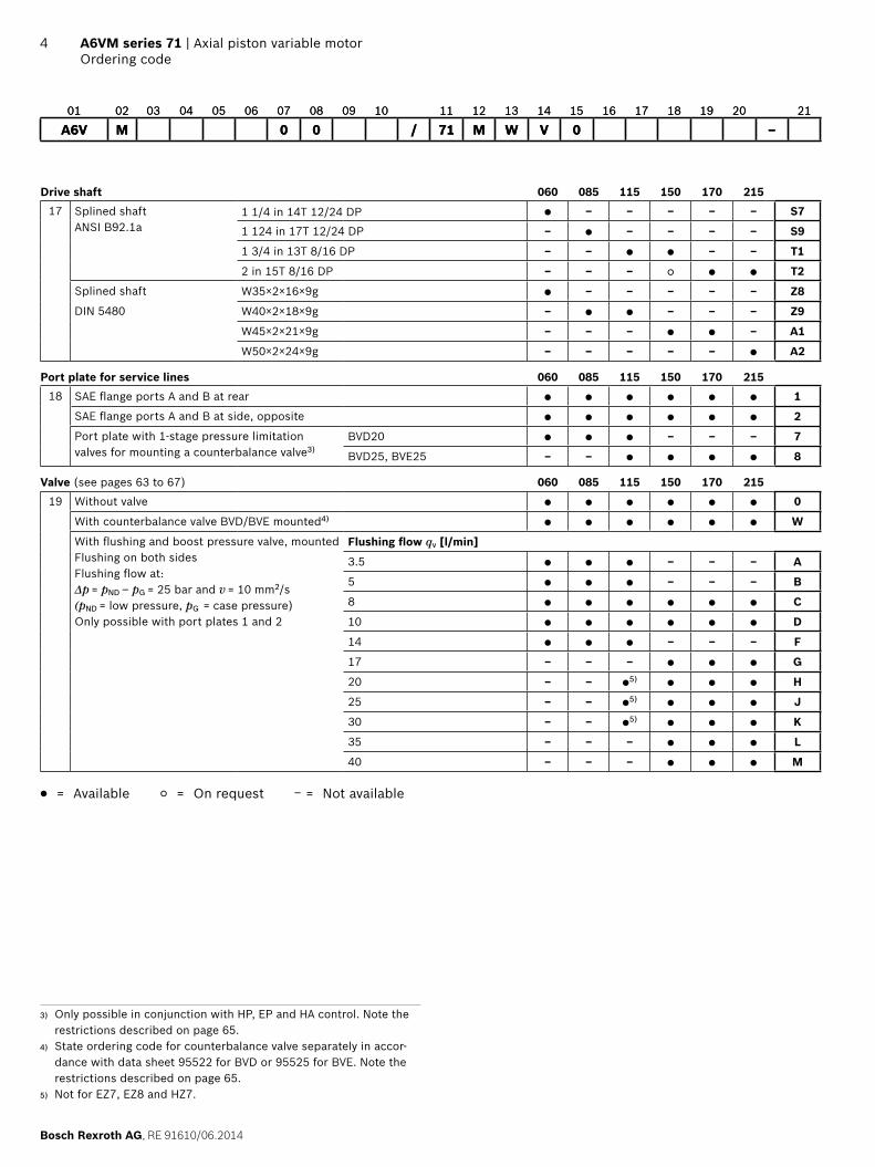
Bosch Rexroth AG RE 91610062014
4 A6VM series 71 | Axial piston variable motorOrdering code
3) Only possible in conjunction with HP EP and HA control Note the restrictions described on page 65
4) State ordering code for counterbalance valve separately in accor-dance with data sheet 95522 for BVD or 95525 for BVE Note the restrictions described on page 65
5) Not for EZ7 EZ8 and HZ7
01 02 03 04 05 06 07 08 09 10 11 12 13 14 15 16 17 18 19 20 21
A6V M 0 0 71 M W V 0 ndash
Drive shaft 060 085 115 150 170 21517 Splined shaft
ANSI B921a1 14 in 14T 1224 DP ‒ ‒ ‒ ‒ ‒ S7
1 124 in 17T 1224 DP ‒ ‒ ‒ ‒ ‒ S9
1 34 in 13T 816 DP ‒ ‒ ‒ ‒ T1
2 in 15T 816 DP ‒ ‒ ‒ T2
Splined shaft W35times2times16times9g ‒ ‒ ‒ ‒ ‒ Z8
DIN 5480 W40times2times18times9g ‒ ‒ ‒ ‒ Z9
W45times2times21times9g ‒ ‒ ‒ ‒ A1
W50times2times24times9g ‒ ‒ ‒ ‒ ‒ A2
Port plate for service lines 060 085 115 150 170 21518 SAE flange ports A and B at rear 1
SAE flange ports A and B at side opposite 2
Port plate with 1-stage pressure limitationvalves for mounting a counterbalance valve3)
BVD20 ‒ ‒ ‒ 7
BVD25 BVE25 ‒ ‒ 8
Valve (see pages 63 to 67) 060 085 115 150 170 21519 Without valve 0
With counterbalance valve BVDBVE mounted4) W
With flushing and boost pressure valve mountedFlushing on both sidesFlushing flow atΔp = pND ‒ pG = 25 bar and v = 10 mm2s(pND = low pressure pG = case pressure)Only possible with port plates 1 and 2
Flushing flow qv [lmin]
35 ‒ ‒ ‒ A
5 ‒ ‒ ‒ B
8 C
10 D
14 ‒ ‒ ‒ F
17 ‒ ‒ ‒ G
20 ‒ ‒ 5) H
25 ‒ ‒ 5) J
30 ‒ ‒ 5) K
35 ‒ ‒ ‒ L
40 ‒ ‒ ‒ M
= Available = On request ‒ = Not available
01 02 03 04 05 06 07 08 09 10 11 12 13 14 15 16 17 18 19 20 21
A6V M 0 0 71 M W V 0 ndash
RE 91610062014 Bosch Rexroth AG
Axial piston variable motor | A6VM series 71 Ordering code
5
Speed sensor (see page 69) 060 085 115 150 170 21520 Without speed sensor 0
Prepared with speed sensor DSMDSA U
With speed sensor DSMDSA mounted6) V
Standard special version
21 Standard version 0
Standard version with installation variants e g T ports against standard open and closed Y
Special version S
= Available = On request ‒ = Not available
Notes Note the project planning notes on page 74 Preservation
ndash up to 12 months as standard ndash up to 24 months long-term
(state in plain text when ordering)
01 02 03 04 05 06 07 08 09 10 11 12 13 14 15 16 17 18 19 20 21
A6V M 0 0 71 M W V 0 ndash
6) State ordering code for sensor separately in accordance with data sheet 95132 for DSM or 95133 for DSA and note the requirements relating to the electronics
Bosch Rexroth AG RE 91610062014
6 A6VM series 71 | Axial piston variable motorHydraulic fluids
Hydraulic fluids
The variable motor A6VM is designed for operation with mineral oil HLP according to DIN 51524 Application instructions and requirements for hydraulic fluids should be taken from the following data sheets before the start of project planning
90220 Hydraulic fluids based on mineral oils and related hydrocarbons
90221 Environmentally friendly hydraulic fluids 90222 Fire-resistant water-free hydraulic fluids
(HFDRHFDU)
Details regarding the selection of hydraulic fluidThe hydraulic fluid should be selected such that the operat-ing viscosity in the operating temperature range is within the optimum range (νopt see selection diagram)
NoteAt no point of the component may the temperature be higher than 115 degC The temperature difference specified in the table is to be taken into account when determining the viscosity in the bearingIf the above conditions cannot be maintained due to extreme operating parameters we recommend flushing the case at port U or using a flushing and boost pressure valve (see page 63)
Viscosity and temperature of hydraulic fluids
Viscosity Temperature Comment
Cold start νmax le 1600 mm2s θSt ge -40 degC t le 3 min n le 1000 rpm without load p le 50 bar
Permissible temperature difference ΔT le 25 K between axial piston unit and hydraulic fluid in the system
Warm-up phase ν lt 1600 to 400 mm2s θ = -40 degC to -25 degC at p le 07 times pnom n le 05 times nnom and t le 15 min
Continuous operation ν = 400 to 10 mm2s This corresponds for example on the VG 46 to a temperature range of +5 degC to +85 degC (see selection diagram)
θ = -25 degC to +103 degC measured at port TNote the permissible temperature range of the shaft seal(ΔT = approx 12 K between the bearingshaft seal and port T)
νopt = 36 to 16 mm2s Range of optimum operating viscosity and efficiency
Short-term operation νmin ge 7 mm2s t lt 3 min p lt 03 times pnom
Selection diagram
-40 -25 -10 10 30 50 90 1157007
10
4060
20
100
200
400600
10001600
VG 22VG 32VG 46VG 68VG 100
16
36
Range of optimum operating viscosity vopt
Optimum efficiency
Maximum permissible viscosity for cold start
Minimum permissible viscosity for short-term operation
Temperature t [degC]
Visc
osity
v [
mm
2 s]
Con
tinuo
us o
pera
tion
Warm-up phase
Minimum permissible temperature for cold start
RE 91610062014 Bosch Rexroth AG
Axial piston variable motor | A6VM series 71 Shaft seal
7
Filtration of the hydraulic fluidFiner filtration improves the cleanliness level of the hydrau-lic fluid which increases the service life of the axial piston unitA cleanliness level of at least 201815 is to be maintained according to ISO 4406At very high hydraulic fluid temperatures (90 degC to maxi-mum 103 degC measured at port T) a cleanliness level of at least 191714 according to ISO 4406 is necessary
Shaft seal
Permissible pressure loadingThe service life of the shaft seal will be influenced by thespeed of the axial piston unit and the leakage pressure in the housing (case pressure) Momentary pressure spikes (t lt 01 s) of up to 10 bar are permitted The service life of the shaft seal decreases with increasing frequency of pres-sure spikes and increasing mean differential pressureThe case pressure must be equal to or higher than theambient pressure
0
1
2
3
4
52000 4000 6000 8000 10000
NG170 215
NG85
NG60
NG115 150
NG170
NG60
NG85
NG115NG150NG215
Diff
eren
tial p
ress
ure Dp
[ba
r]
Rotational speed n [rpm]
The FKM shaft seal may be used for leakage temperatures from -25 degC to +115 degC For application cases below -25 degC an NBR shaft seal is required (permissible temperature range -40 degC to +90 degC)
Influence of case pressure on beginning of controlAn increase in case pressure affects the beginning of con-trol when using the following control options
HP HAT3 Increase DA Decrease
With the following settings an increase in case pressure will have no effect on the beginning of control HAR and HAU EP HAThe factory setting of the beginning of control is made at pabs = 2 bar case pressure
Flow direction
Direction of rotation viewed on drive shaft
cw ccw
A to B B to A
Bosch Rexroth AG RE 91610062014
8 A6VM series 71 | Axial piston variable motorOperating pressure range
Operating pressure range
Pressure at service line port A or B Definition
Nominal pressure pnom 450 bar absolute The nominal pressure corresponds to the maximum design pressure
Maximum pressure pmax 500 bar absolute The maximum pressure corresponds to the maximum operating pressure within the single operating period The sum of the single operating periods must not exceed the total operating period
Single operating period 10 s
Total operating period 300 h
Minimum pressure (high-pressure side) 25 bar absolute Minimum pressure at the high-pressure side (A or B) which is required in order to prevent damage to the axial piston unit
Minimum pressure ndash pump operating mode (inlet)
See the diagram below
To prevent damage to the axial piston motor in pump operating mode (change of high-pressure side with unchanged direction of rotation e g when braking) a minimum pressure must be guaranteed at the service line port (inlet) This minimum pressure is dependent on the speed and dis-placement of the axial piston unit (see characteristic curve)
Summation pressure pSu
(pressure A + pressure B)700 bar The summation pressure is the sum of the pressures at both service line
ports (A and B)
Rate of pressure change RA max Maximum permissible rate of pressure rise and reduction during a pressure change over the entire pressure rangeWith integrated pressure-relief valve 9000 bars
Without pressure-relief valve 16000 bars
Rate of pressure change RA max
pnom
∆t
∆p
Time t
Pres
sure
p
Pressure definition
Single operating period
Pres
sure
p
t1
t2tn
Minimum pressure (high-pressure side)
Maximum pressure pmax
Nominal pressure pnom
Time t
Total operating period = t1 + t2 + + tn
Minimum pressure ndash pump operating mode (inlet)
Inle
t pr
essu
re p
abs [
bar]
Rotational speed n nnom
Vg max
Vg x
03 Vg max
12
4
6
8
10
12
14
16
0 04 07 10 13 16
This diagram is valid only for the optimum viscosity range from nopt = 36 to 16 mm2s Please contact us if these conditions cannot be satisfied
NotesOperating pressure range valid when using hydraulic fluids based on mineral oils Values for other hydraulic fluids please contact us
RE 91610062014 Bosch Rexroth AG
Axial piston variable motor | A6VM series 71 Technical data
9
Technical data
Size NG 60 85 115 150 170 215
Displacement geometric per revolution Vg max cm3 620 852 1156 1521 1718 2165
Vg min cm3 0 0 0 0 0 0
Vg x cm3 37 51 69 91 65 82
Maximum speed1)
(complying with the maxi-mum permissible inlet flow)
at Vg max nnom rpm 4450 3900 3550 3250 3100 2900
at Vg lt Vg x (see diagram) nmax rpm 7200 6800 6150 5600 4900 4600
at Vg 0 nmax rpm 8400 8350 7350 6000 5750 5500
Inlet flow2) at nnom and Vg max qv max Lmin 275 332 410 494 533 628
Torque3) at Vg max and Δp = 450 bar T Nm 444 610 828 1089 1230 1550
Rotary stiffness Vg max to Vg2 cmin kNmrad 15 22 37 44 52 70
Vg2 to 0 (interpolated) cmin kNmrad 45 68 104 124 156 196
Moment of inertia for rotary group JGR kgm2 00043 00072 00110 00181 00213 00303
Maximum angular acceleration α radssup2 21000 17500 15500 11000 11000 10000
Case volume V L 08 10 15 17 23 28
Weight approx m kg 28 36 46 61 62 78
Permissible displacement in relation to speed
02 04 06 08 10 12 14 174
NG170 215
NG85 115 150
4)
10
08
06
038
02
0
NG60
158 162
Vg x
Vg x
Dis
plac
emen
t V
g
Vg
max
Rotational speed n nnom
Determining the operating characteristics
Inlet flow qv = Vg times n
[lmin]1000 times ηv
Rotational speed
n = qv times 1000 times ηv
[rpm]Vg
Torque T = Vg times Δp times ηmh
[Nm]20 times π
Power P = 2 π times T times n
= qv times Δp times ηt
[kW]60000 600
Key
Vg = Displacement per revolution [cm3]
Δp = Differential pressure [bar]
n = Rotational speed [rpm]
ηv = Volumetric efficiency
ηmh = Mechanical-hydraulic efficiency
ηt = Total efficiency (ηt = ηv bull ηmh)
Notes Theoretical values without efficiency levels and toler-
ances values rounded Operation above the maximum values or below the
minimum values may result in a loss of function a reduced service life or in the destruction of the axial piston unit Other permissible limit values such as speed variation reduced angular acceleration as a function of the frequency and the permissible angular acceleration at start (lower than the maximum angular acceleration) can be found in data sheet 90261
Transport and storage ndash θmin ge ndash50 degC ndash θopt = +5 degC to +20 degC
1) The values are valid ndash For the optimum viscosity range from νopt = 36 to 16 mm2s ndash with hydraulic fluid on the basis of mineral oil
2) Note inlet flow limitation due to counterbalance valve (see page 65)
3) Torque without radial force With radial force see page 10 4) Values in this range on request
Bosch Rexroth AG RE 91610062014
10 A6VM series 71 | Axial piston variable motorTechnical data
Permissible radial and axial forces of the drive shafts
Size NG 60 60 85 85 115 115 150 150 150
Drive shaft 1 14 in W35 1 12 in W40 1 34 in W40 1 34 in 2 in W45
Maximum radial force1) at distance a (from shaft collar)
a
FqFq max N 7620 10266 12463 12323 14902 16727 15948 17424 19534
a mm 240 200 270 225 335 225 335 335 250
with permissible torque Tmax Nm 310 444 595 610 828 828 890 1089 1089
≙ Permissible pressure Δp at Vg max pnom perm bar 315 450 440 450 450 450 370 450 450
Maximum axial force2)
plusmnFax+ Fax max N 0 0 0 0 0 0 0 0 0
minus Fax max N 500 500 710 710 900 900 1300 1300 1300
Permissible axial force per bar operating pressure
+ Fax permbar Nbar 75 75 96 96 113 113 133 133 133
Size NG 170 170 215 215
Drive shaft 2 in W45 2 in W50
Maximum radial force1) at distance a (from shaft collar)
a
FqFq max N 19370 21220 22602 25016
a mm 335 250 335 275
with permissible torque Tmax Nm 1230 1200 1445 1550
≙ Permissible pressure Δp at Vg max pnom perm bar 450 440 420 450
Maximum axial force2)
plusmnFax+ Fax max N 0 0 0 0
minus Fax max N 1120 1120 1250 1250
Permissible axial force per bar operating pressure
+ Fax permbar Nbar 151 151 170 170
Effect of radial force Fq on the service life of bearingsBy selecting a suitable direction of radial force Fq the load on the bearings caused by the internal rotary group forces can be reduced thus optimizing the service life of the bearings Recommended position of mating gear is depen-dent on direction of rotation Examples
Notes Influence of the direction of the permissible axial force
+ Fax max = Increased shelf life ndash Fax max = Reduced shelf life (to be avoided)
Special requirements apply in the case of belt drives Please contact us
Toothed gear output drive V-belt output drive
φopt = 45degφopt = 45deg
21
φopt = 70degφ opt = 70deg
2 1
1 Direction of rotation clockwise pressure at port B2 Direction of rotation counter-clockwise pressure at port A
1) For intermittent operation2) Maximum permissible axial force at standstill or depressurized ro-
tation of the axial piston unit
RE 91610062014 Bosch Rexroth AG
Axial piston variable motor | A6VM series 71 HP ndash Proportional hydraulic control
11
HP ndash Proportional hydraulic control
The proportional hydraulic control provides infinite adjust-ment of the displacement Control is proportional to the pilot pressure applied to port XHP1 HP2 positive control
Beginning of control at Vg min (minimum torque maxi-mum permissible speed at minimum pilot pressure)
End of control at Vg max (maximum torque minimum speed at maximum pilot pressure)
HP5 HP6 negative control Beginning of control at Vg max (maximum torque mini-
mum speed at minimum pilot pressure) End of control at Vg min (minimum torque maximum
permissible speed at maximum pilot pressure)
Note Maximum permissible pilot pressure pSt = 100 bar The control oil is internally taken from the high pressure
side of the motor (A or B) For reliable control an oper-ating pressure of at least 30 bar is required in A (B) If a control operation is performed at an operating pressure lt 30 bar an auxiliary pressure of at least 30 bar must be applied at port G via an external check valve For lower pressures please contact us Please note that pressures up to 500 bar can occur at port G
Please state the desired beginning of control in plain text when ordering e g beginning of control at 10 bar
The beginning of control and the HP charakteristic curve are influenced by the case pressure An increase in case pressure causes an increase in the beginning of control (see page 6) and thus a parallel shift of the charac-teristic
HP1 HP5 Increase in pilot pressure ΔpSt = 10 bar
HP1 positive controlA pilot pressure increase of 10 bar at port X results in an increase in displacement from Vg min to Vg maxHP5 negative controlA pilot pressure increase of 10 bar at port X results in a decrease in displacement from Vg max to Vg min
Beginning of control setting range 2 to 20 bar Standard setting
Beginning of control at 3 bar (end of control at 13 bar)
Characteristic curve
0 02 04 06 08 10Vg min Vg maxVg Vg max
HP5 HP135
30
25
20
151210
52B
egin
ning
of c
ontr
ol
sett
ing
rang
e
Displacement
Pilo
t pr
essu
re p
St [
bar]
Pilo
t pr
essu
re
incr
ease
HP2 HP6 Increase in pilot pressure DpSt = 25 bar
HP2 positive controlA pilot pressure increase of 25 bar at port X results in an increase in displacement from Vg min to Vg maxHP6 negative controlA pilot pressure increase of 25 bar at port X results in a decrease in displacement from Vg max to Vg min
Beginning of control setting range 5 to 35 bar Standard setting
Beginning of control at 10 bar (end of control at 35 bar)
Characteristic curve
70
60
50
403530
20
105
0 02 04 06 08 10Vg min Vg maxVg Vg max
HP6 HP2
Beg
inni
ng o
f co
ntro
l set
ting
ra
nge
Displacement
Pilo
t pr
essu
re p
St [
bar]
Pilo
t pr
essu
re
incr
ease
Bosch Rexroth AG RE 91610062014
12 A6VM series 71 | Axial piston variable motorHP ndash Proportional hydraulic control
Schematic HP1 HP2 Positive control
B
A
M1
T2
T1
G
X
Vg min
Vg max
U
Schematic HP5 HP6 negative control
T2
T1
M1
Vg min
Vg max
B
A
U
X
G
HP5D1 HP6D1Pressure control fixed settingThe pressure control overrides the HP control function If the load torque or a reduction in motor swivel angle causes the system pressure to reach the setpoint value of the pressure control the motor will swivel towards a larger displacement The increase in the displacement and the resulting reduc-tion in pressure cause the control deviation to decrease With the increase in displacement the motor develops more torque while the pressure remains constantSetting range of the pressure control valve 80 to 450 bar
Schematic HP5D1 HP6D1 negative control
T2
T1
M1
Vg min
Vg max
B
A
G
X
U
Response time dampingStandard for HP without dampingHP HP5D1 HP6D1 ndash with throttle pin on both sides sym-metrical
Size 60 85 115 150 170 215
Groove size [mm] 045 045 055 055 055 065
M1
RE 91610062014 Bosch Rexroth AG
Axial piston variable motor | A6VM series 71 EP ndash Proportional electric control
13
EP ndash Proportional electric control
The proportional electric control type EP provides infinite adjustment of the displacement proportional to the control current applied to the solenoidEP1 EP2 positive control
Beginning of control at Vg min (minimum torque maxi-mum permissible speed at minimum control current)
End of control at Vg max (maximum torque minimum speed at maximum control current)
EP5 EP6 negative control Beginning of control at Vg max (maximum torque mini-
mum speed at minimum control current) End of control at Vg min (minimum torque maximum
permissible speed at maximum control current)
Charakteristic curve
EP5 EP6 EP1 EP2
0 02 04 06 08 10
Vg min Vg Vg max Vg max
1600max
1400
1200
1000
800
600
400
200
800max
700
600
500
400
300
200
100
EP5EP1
(12 V)
EP6EP2
(24 V)
NoteThe control oil is internally taken from the high pressure side of the motor (A or B) For reliable control an operat-ing pressure of at least 30 bar is required in A (B) If a control operation is performed at an operating pressure lt 30 bar an auxiliary pressure of at least 30 bar must be applied at port G via an external check valve For lower pressures please contact us Please note that pressures up to 500 bar can occur at port G
Technical data solenoid EP1 EP5 EP2 EP6
Voltage 12 V (plusmn20 ) 24 V (plusmn20 )
Control current
Beginning of control 400 mA 200 mA
End of control 1200 mA 600 mA
Current limit 154 A 077 A
Nominal resistance (at 20 degC) 55 Ω 227 Ω
Dither frequency 100 Hz 100 Hz
Duty cycle 100 100
Type of protection see connector version on page 62
Various BODAS controllers with application software and amplifiers are available for controlling the proportional solenoidsFurther information can also be found on the internet at wwwboschrexrothcommobile-electronics
Bosch Rexroth AG RE 91610062014
14 A6VM series 71 | Axial piston variable motorEP ndash Proportional electric control
Schematic EP1 EP2 positive control
B
A
M1
T2
T1
G
Vg min
Vg max
U
Schematic EP5 EP6 negative control
U
T2
T1
M1
Vg min
Vg max
B
A
G
RE 91610062014 Bosch Rexroth AG
Axial piston variable motor | A6VM series 71 EP ndash Proportional electric control
15
EP5D1 EP6D1 Pressure control fixed settingThe pressure control overrides the EP control function If the load torque or a reduction in motor swivel angle causes the system pressure to reach the setpoint value of the pressure control the motor will swivel towards a larger displacementThe increase in the displacement and the resulting reduc-tion in pressure cause the control deviation to decrease With the increase in displacement the motor develops more torque while the pressure remains constantSetting range of the pressure control valve 80 to 450 bar
Schematic EP5D1 EP6D1 negative control
U
T2
T1
Vg min
Vg max
B
A
G
M1
Response time dampingStandard for EP without dampingEP EP5D1 EP6D1 ndash with throttle pin on both sides sym-metrical
Size 60 85 115 150 170 215
Groove size [mm] 045 045 055 055 055 065
M1
Bosch Rexroth AG RE 91610062014
16 A6VM series 71 | Axial piston variable motorHZ ndash Two-point hydraulic control
HZ ndash Two-point hydraulic control
The two-point hydraulic control type HZ allows the dis-placement to be set to either Vg min or Vg max by switching the pilot pressure at port X on or off
HZ5 HZ7 negative control Position at Vg max (without pilot pressure maximum
torque minimum speed) Position at Vg min (with pilot pressure gt 15 bar activated
minimum torque maximum permissible speed)
Characteristic curve HZ5 HZ7
Vg min Vg maxDisplacement
0
15
Pilo
t pr
essu
re p
S [b
ar]
100
Note Maximum permissible pilot pressure 100 bar The control oil is internally taken from the high pressure
side of the motor (A or B) For reliable control an oper-ating pressure of at least 30 bar is required in A (B) If a control operation is performed at an operating pressure lt 30 bar an auxiliary pressure of at least 30 bar must be applied at port G via an external check valve For lower pressures please contact us Please note that pressures up to 500 bar can occur at port G
Response time damping
HZ5 ndash with throttle pin on both sides symmetrical HZ7 ndash with throttle pin on both sides symmetricalSize 150 170 215 Size 60 85 115
Groove size [mm] 055 055 065 Groove size [mm] 030 030 030
M1
Schematic HZ5 Negative control size 150 to 215
T2
T1
M1
Vg min
Vg max
B
A
X
G
U
Schematic HZ7 Negative control size 60 to 115
T1U
T2
XG
Vg min
Vg max
B
A
RE 91610062014 Bosch Rexroth AG
Axial piston variable motor | A6VM series 71 EZ ndash Two-point electric control
17
EZ ndash Two-point electric control
The two-point electric control type EZ allows the displace-ment to be set to either Vg min or Vg max by switching the electric current to a switching solenoid on or off
NoteThe control oil is internally taken from the high pressure side of the motor (A or B) For reliable control an operat-ing pressure of at least 30 bar is required in A (B) If a control operation is performed at an operating pressure lt 30 bar an auxiliary pressure of at least 30 bar must be applied at port G via an external check valve For lower pressures please contact us Please note that pressures up to 500 bar can occur at port G
Sizes 150 to 215
Technical data solenoid with oslash37 EZ5 EZ6
Voltage 12 V (plusmn20 ) 24 V (plusmn20 )
Position Vg max de-energized de-energized
Position Vg min energized energized
Nominal resistance (at 20 degC) 55 Ω 217 Ω
Nominal power 262 W 265 W
Minimum required active current 132 A 067 A
Duty cycle 100 100
Type of protection see connector version on page 62
Schematic EZ5 EZ6 negative control
U
T2
T1
M1
Vg min
Vg max
B
A
G
Sizes 60 to 115
Technical data solenoid with oslash45 EZ7 EZ8
Voltage 12 V (plusmn20 ) 24 V (plusmn20 )
Position Vg max de-energized de-energized
Position Vg min energized energized
Nominal resistance (at 20 degC) 48 Ω 192 Ω
Nominal power 30 W 30 W
Minimum required active current 15 A 075 A
Duty cycle 100 100
Type of protection see connector version on page 62
Schematic EZ7 EZ8 negative control
T1U
T2
G
B
A
Vg min
Vg max
Response time dampingEZ5 EZ6 ndash with throttle pin on both sides symmetrical
Size 150 170 215
Groove size [mm] 055 055 065
M1
EZ7 EZ8 ndash with throttle pin on both sides symmetrical
Size 60 85 115
Groove size [mm] 030 030 030
Bosch Rexroth AG RE 91610062014
18 A6VM series 71 | Axial piston variable motorHA ndash Automatic high-pressure related control
HA ndash Automatic high-pressure related control
The automatic high-pressure related control type HA adjusts the displacement automatically depending on the operating pressureThe displacement of the A6VM motor with HA control is Vg min (maximum speed and minimum torque) The control device measures internally the operating pressure at A or B (no control line required) and upon reaching the set beginning of control the controller swivels the motor from Vg min to Vg max with increase of operating pressure The displacement is modulated between Vg min and Vg max thereby depending on load conditions
HA1 HA2 positive control Beginning of control at Vg min (minimum torque maxi-
mum speed) End of control at Vg max (maximum torque minimum
speed)
Note For safety reasons winch drives are not permissible
with beginning of control at Vg min (standard for HA) The control oil is internally taken from the high pressure
side of the motor (A or B) For reliable control an oper-ating pressure of at least 30 bar is required in A (B) If a control operation is performed at an operating pressure lt 30 bar an auxiliary pressure of at least 30 bar must be applied at port G via an external check valve For lower pressures please contact us Please note that pressures up to 500 bar can occur at port G
The beginning of control and the HAT3 charakteristic curve are influenced by case pressure An increase in case pressure causes an increase in the beginning of control (see page 6) and thus a parallel shift of the characteristic
Response time dampingHA ndash with one-sided throttle pin ndash inlet to large stroking chamber
Size 60 85 115 150 170 215
Groove size [mm] 045 045 055 055 055 065
M1
HA ndash with counterbalance valve BVD or BVE ndash with throttle screw
Size 60 85 115 150 170 215
Groove size [mm] 080 080 080 080 080 080
M1
RE 91610062014 Bosch Rexroth AG
Axial piston variable motor | A6VM series 71 HA ndash Automatic high-pressure related control
19
HA1 With minimum pressure increase positive controlAn operating pressure increase of Δp le approx 10 bar results in an increase in displacement from Vg min towards Vg maxBeginning of control setting range 80 to 350 barPlease state the desired beginning of control in plain text when ordering e g beginning of control at 300 bar
Charakteristic curve HA1
400
350
300
250
200
150
10080
50
0
Vg min Vg maxVg Vg max
0 02 04 06 08 10
Pres
sure
incr
ease
Δp
le a
ppro
x 1
0 ba
r
Ope
ratin
g pr
essu
re p
[ba
r]
Beg
inni
ng o
f con
trol
se
ttin
g ra
nge
Displacement
Schematic HA1
B
A
M1
T2
T1
Vg min
Vg max
G
U
X
HA2With pressure increase positive controlAn operating pressure increase of Dp approx 100 bar results in an increase in displacement from Vg min to Vg maxBeginning of control setting range 80 to 350 barPlease state the desired beginning of control in plain text when ordering e g beginning of control at 200 bar
Characteristic curve HA2
450
400
350
300
250
200
150
10080
50
0
Vg min Vg maxVg Vg max
0 02 04 06 08 10
Pres
sure
incr
ease
Δp
le a
ppro
x 1
00 b
ar
Ope
ratin
g pr
essu
re p
[ba
r]
Beg
inni
ng o
f con
trol
se
ttin
g ra
nge
Displacement
Schematic HA2
B
A
M1
T2
T1
G
X
Vg min
Vg max
U
Bosch Rexroth AG RE 91610062014
20 A6VM series 71 | Axial piston variable motorHA ndash Automatic high-pressure related control
HAT3 Hydraulic override remote control proportionalWith the HAT3 control the beginning of control can be influenced by applying a pilot pressure to port XFor each 1 bar of pilot pressure increase the beginning of control is reduced by 17 bar
Beginning of control setting 300 bar 300 bar
Pilot pressure at port X 0 bar 10 bar
Beginning of control at 300 bar 130 bar
NoteMaximum permissible pilot pressure 100 bar
Schematic HA1T3
B
A
M1
T2
T1
Vg min
Vg max
X
U
G
Schematic HA2T3
B
A
M1
T2
T1
G
X
Vg min
Vg max
U
RE 91610062014 Bosch Rexroth AG
Axial piston variable motor | A6VM series 71 HA ndash Automatic high-pressure related control
21
HAU1 HAU2Electric override two-pointWith the HAU1 or HAU2 control the beginning of control can be overridden by an electric signal to a switching sole-noid When the override solenoid is energized the variable motor swivels to maximum swivel angle without intermedi-ate position The beginning of control can be set between 80 and 300 bar (specify required setting in plain text when order-ing)
Technical data solenoid with oslash45 U1 U2
Voltage 12 V (plusmn20 ) 24 V (plusmn20 )
No override de-energized de-energized
Position Vg max energized energized
Nominal resistance (at 20 degC) 48 Ω 192 Ω
Nominal power 30 W 30 W
Minimum required active current 15 A 075 A
Duty cycle 100 100
Type of protection see connector version on page 62
Schematic HA1U1 HA1U2
G
B
A
M1
T2
T1
Vg min
Vg max
U
Schematic HA2U1 HA2U2
M1
T2
T1
B
A
Vg min
Vg max
G
U
Bosch Rexroth AG RE 91610062014
22 A6VM series 71 | Axial piston variable motorHA ndash Automatic high-pressure related control
HAR1 HAR2Electric overrideelectric travel direction valveWith the HAR1 or HAR2 control the beginning of control can be overridden by an electric signal to switching sole-noid b When the override solenoid is energized the vari-able motor swivels to maximum swivel angle without inter-mediate positionThe travel direction valve ensures that the preselected pressure side of the hydraulic motor (A or B) is always connected to the HA control and thus determines the swivel angle even if the high-pressure side changes (e g -travel drive during a downhill operation) This thereby prevents undesired jerky deceleration andor brak-ing characteristicsThe travel direction valve (see page 25) is either pressure spring or switched by energizing switching solenoid a depending on the direction of rotation (travel direction)
Electric override
Technical data solenoid b with oslash45 R1 R2
Voltage 12 V (plusmn20 ) 24 V (plusmn20 )
No override de-energized de-energized
Position Vg max energized energized
Nominal resistance (at 20 degC) 48 Ω 192 Ω
Nominal power 30 W 30 W
Minimum required active current 15 A 075 A
Duty cycle 100 100
Type of protection see connector version on page 62
Travel direction valve electric
Technical data solenoid a with oslash37 R1 R2
Voltage 12 V (plusmn20 ) 24 V (plusmn20 )
Direction of rotation
Operating pressure in
ccw B energized energized
cw A de-energized de-energized
Nominal resistance (at 20 degC) 55 Ω 217 Ω
Nominal power 262 W 265 W
Minimum required active current 132 A 067 A
Duty cycle 100 100
Type of protection see connector version on page 62
Schematic HA1R1 HA1R2
ab
B
A
M1
T2
T1
Vg min
Vg max
U
G
Schematic HA2R1 HA2R2
M1
T2
T1
G
B
A
Vg min
Vg max
U
ab
RE 91610062014 Bosch Rexroth AG
Axial piston variable motor | A6VM series 71 DA ndash Automatic speed-related control
23
DA ndash Automatic speed-related control
The variable motor A6VM with automatic speed-related control type DA is intended for use in hydrostatic travel drives in combination with the variable pump A4VG with DA controlA drive-speed-related pilot pressure signal is generated by the A4VG variable pump and that signal together with the operating pressure regulates the swivel angle of the hydraulic motorIncreasing pump speed ie increasing pilot pressure causes the motor to swivel to a smaller displacement (lower torque higher speed) depending on the operating pressureIf the operating pressure exceeds the pressure setpoint set on the controller the variable motor swivels to a larger displacement (higher torque lower speed)
Pressure ratio pStpHD = 5100
DA closed loop control is only suitable for certain types of drive systems and requires review of the engine and vehicle parameters to ensure that the motor is used correctly and that machine operation is safe and efficient We recommend that all DA applications be reviewed by a Bosch Rexroth application engineerDetailed information is available from our sales organiza-tion
NoteThe beginning of control and the DA charakteristic curve are influenced by case pressure An increase in case pres-sure causes an decrease in the beginning of control (see page 7) and thus a parallel shift of the characteristic
Response time dampingDA ndash with one-sided throttle pin ndash outlet to large stroking chamber
Size 60 85 115 150 170 215
Groove size [mm] 045 045 055 055 055 065
M1
DA0Hydraulic travel direction valve negative controlDepending on the direction of rotation (travel direction) the travel direction valve is switched by using pilot pres-sures connections X1 or X2
Direction of rotation
Operating pressure in
Pilot pressure in
cw A X1
ccw B X2
Schematic DA0
M1
T2
T1
Vg min
Vg max
B
A
G
X3
X2
X1
U
Bosch Rexroth AG RE 91610062014
24 A6VM series 71 | Axial piston variable motorDA ndash Automatic speed-related control
DA1 DA2Electric travel direction valve + electric Vg max circuit negative controlThe travel direction valve is either pressure spring or switched by energizing switching solenoid a depending on the direction of rotation (travel direction)When the switching solenoid b is energized the DA control is overridden and the motor swivels to maximum displace-ment (high torque lower speed) (electric Vg max-circuit)
Travel direction valve electric
Technical data solenoid a with oslash37 DA1 DA2
Voltage 12 V (plusmn20 ) 24 V (plusmn20 )
Direction of rotation
Operating pressure in
ccw B de-energized de-energized
cw A energized energized
Nominal resistance (at 20 degC) 55 Ω 217 Ω
Nominal power 262 W 265 W
Minimum required active current 132 A 067 A
Duty cycle 100 100
Type of protection see connector version on page 62
Electric override
Technical data solenoid b with oslash37 R1 R2
Voltage 12 V (plusmn20 ) 24 V (plusmn20 )
No override de-energized de-energized
Position Vg max energized energized
Nominal resistance (at 20 degC) 55 Ω 217 Ω
Nominal power 262 W 265 W
Minimum required active current 132 A 067 A
Duty cycle 100 100
Type of protection see connector version on page 62
Schematic DA1 DA2
T2
T1
M1
Vg min
Vg max
B
A
G
X3
a
b
X1
U
RE 91610062014 Bosch Rexroth AG
Axial piston variable motor | A6VM series 71 Electric travel direction valve (for DA HAR)
25
Electric travel direction valve (for DA HAR)
Application in travel drives in closed circuits The travel direction valve of the motor is actuated by an electric signal that also switches the swivel direction of the travel drive pump (e g A4VG with DA control valve)If the pump in the closed circuit is switched to the neutral position or into reverse the vehicle may experience jerky deceleration or braking depending on the vehicles mass and current travel speedWhen the travel direction valve of the pump (e g 43-direc-tional valve of the DA-control) is switched to
the neutral position the electric circuitry causes the previous signal on the travel direction valve on the motor to be retained
Reversing the travel direction valve causes the travel direction valve of the motor to switch to the other travel direction following a time delay (approx 08 s) with respect to the pump
As a result jerky deceleration or braking is prevented in both cases
Schematic - electric travel direction valve
K11
K12
K1
K21
K2
A3 B3
A2
V1
V NR
24 V DC
24 V DC
Solenoid a Pump
Solenoid b Pump
Solenoid a Motor
Travel direction valve
The shown diodes and relays are not included in the scope of delivery of the motor
Control DA1 DA
bab
a
HA1R HA2R control
a
b
Switching solenoid a on the travel direction valve
Bosch Rexroth AG RE 91610062014
26 A6VM series 71 | Axial piston variable motorDimensions size 60
Dimensions [mm]
Dimensions size 60
EP5 EP6 ndash Proportional electric control negative controlPort plate 2 mdash SAE flange ports A and B at side opposite
150
UT1
T2
G
M1
Y
Z
M1
G75
183108321)
725
84
max 146
1122)
203167
2123)
2430
3)
176
154
243
142)
160
45deg
135
45deg
150
508
238
19
0oslash1
25 -0
025
oslash73 23
125
deg
View Y
Flange ISO 3019-2
1) To shaft collar2) Center of gravity3) Port plate 1 mdash SAE flange ports A and B at rear
RE 91610062014 Bosch Rexroth AG
Axial piston variable motor | A6VM series 71 Dimensions size 60
27Dimensions [mm]
Location of the service line ports on the port plates (view Z)
2 SAE flange portA and B at side opposite
1 SAE flange portA and B at rear
2 SAE flange portA and B at side opposite only HZ7 EZ78
1 SAE flange portA and B at rear only HZ7 EZ78
B A
15254
16554
B A
152
AB
375 375
AB
165
Splined shaft SAE J744 Splined shaft DIN 5480
S7 ‒ 1 14 in 14T 1224DP1) Z8 ‒ W35times2times16times9g
28
40
716
-14U
NC
-2B
2)3)
oslash45
48
95
40
32
M12
x 1
753)
4)
95
28
oslash45
1) Involute spline acc to ANSI B921a 30deg pressure angle flat root side fit tolerance class 5
2) Thread according to ASME B11
3) For notes on tightening torques see instruction manual4) Center bore according to DIN 332 (thread according to DIN 13)
Bosch Rexroth AG RE 91610062014
28 A6VM series 71 | Axial piston variable motorDimensions size 60
Dimensions [mm]
Ports Standard Size1) pmax abs [bar]2) Status6)
A B Service line portFastening thread AB
SAE J5183)
DIN 1334 inM10 times 15 17 deep
500 O
T1 Drain port ISO 61495) M22 times 15 155 deep 3 X4)
T2 Drain port ISO 61495) M27 times 2 19 deep 3 O4)
G Synchronous control ISO 61495) M14 times 15 115 deep 500 X
U Bearing flushing ISO 61495) M18 times 15 145 deep 3 X
X Pilot signal (HP HZ HA1THA2T) ISO 61495) M14 times 15 115 deep 100 O
X Pilot signal (HA1 HA2) ISO 61495) M14 times 15 115 deep 3 X
X1 X2 Pilot signal (DA0) ISO 8434-1 SDSC-L8timesM12-F 40 O
X1 Pilot signal (DA1 DA2) ISO 61495) M14 times 15 115 deep 40 O
X3 Pilot signal (DA1 DA2) ISO 61495) M14 times 15 115 deep 40 X
M1 Measuring stroking chamber ISO 61495) M14 times 15 115 deep 500 X
1) For notes on tightening torques see instruction manual2) Momentary pressure spikes may occur depending on the application
Keep this in mind when selecting measuring devices and fittings3) Only dimensions according to SAE J518 metric fastening thread is
a deviation from standard
4) Depending on installation position T1 or T2 must be connected (see also installation instructions on page 72)
5) The spot face can be deeper than specified in the appropriate standard6) O = Must be connected (plugged on delivery)
X = Plugged (in normal operation)
RE 91610062014 Bosch Rexroth AG
Axial piston variable motor | A6VM series 71 Dimensions size 60
29Dimensions [mm]
EP1 EP2 ndash Electric proportional control positive control
EP5D1 EP6D1 ndash Electric proportional control negative control with pressure control fixed
GG
M1 M1
239
225
107
B A
154
243
176
M1M1
G
B A
G
HP1 HP2 ndash Hydraulic proportional control positive control
HP5 HP6 ndash Hydraulic proportional control negative control
M1M1
XG
159
139
107
XG
355 160
239
B A
M1
X G XG355 210
240
154
90 110
M1
B A
HP5D1 HP6D1 ndash Hydraulic proportional control negative control with pressure control fixed
355
154
215240
89 120
M1
GG X X
M1
B A
Bosch Rexroth AG RE 91610062014
30 A6VM series 71 | Axial piston variable motorDimensions size 60
Dimensions [mm]
HZ7 ndash Hydraulic two-point control negative control
EZ7 EZ8 ndash Electric two-point control negative control
2431
1)
14611
710
0
183
GX
1512151)
227
61 G
X
AB
124
G
AB
G
227
2431
1)
146
100
183
2151)
HA1 HA2 HA1T3 HA2T3 ndash Automatic high-pressure-related control positive control with override hydraulic remote con-trolled proportional
HA1U1 HA2U2 ndash Automatic high-pressure-related control positive control with override electric two-point
M1M1
XG
159
139
107
XG
355 160
239
B A
M1
B A
239
225
107
G
M1
G
HA1 and HA2 X plugged
HA1T and HA2T X open
HA1R1 HA2R2 ndash Automatic high-pressure-related control positive control with override electric and travel direction valve electric
225
a
b
GG
M1M1
B A
239
107
110
1) Port plate 1 ndash SAE flange ports A and B at rear
RE 91610062014 Bosch Rexroth AG
Axial piston variable motor | A6VM series 71 Dimensions size 60
31Dimensions [mm]
DA0 ndash Automatic speed-related control negative control with hydraulic travel direction valve
DA1 DA2 ndash Automatic speed-related control negative control with electric travel direction valve and electric Vg max circuit
M1
G X3X1 X2
178243
154
94 120
160
G X3X1 X2
M1
AB
G
M1
X3
M1
X1
154
202243
132
155
G
X1 X3
110 85
AB
b
a
X1 X2 pipe fitting SDSC ndash L8timesM12 ndash F according to ISO 8434-1
Use assembled fitting
Bosch Rexroth AG RE 91610062014
32 A6VM series 71 | Axial piston variable motorDimensions size 85
Dimensions [mm]
Dimensions size 85
EP5 EP6 ndash Proportional electric control negative controlPort plate 2 mdash SAE flange ports A and B at side opposite
T2
T1U
M1
45deg
Y
GG
M1
135
Z
11775
321)208
167
275
182
343)
132)
2712393)
1122)
233176
max 146
9180
125
deg
180
45deg
165
165
23-00
25oslash1
40 0
oslash83
572
278
25
View Y
Flange ISO 3019-2
1) To shaft collar2) Center of gravity3) Port plate 1 mdash SAE flange ports A and B at rear
RE 91610062014 Bosch Rexroth AG
Axial piston variable motor | A6VM series 71 Dimensions size 85
33Dimensions [mm]
Location of the service line ports on the port plates (view Z)
2 SAE flange portA and B at side opposite
1 SAE flange portA and B at rear
2 SAE flange portA and B at side opposite only HZ7 EZ78
1 SAE flange portA and B at rear only HZ7 EZ78
B A
164
B A
54177
54
AB
164
B A
4242177
Splined shaft SAE J744 Splined shaft DIN 5480
S9 ‒ 1 12 in 17T 1224DP1) Z9 ‒ W40times2times18times9g
28
44
716
-14U
NC
-2B
2)3)
oslash50
54
95
45
37
M16
x 2
3)4) 12
36
oslash50
1) Involute spline acc to ANSI B921a 30deg pressure angle flat root side fit tolerance class 5
2) Thread according to ASME B11
3) For notes on tightening torques see instruction manual4) Center bore according to DIN 332 (thread according to DIN 13)
Bosch Rexroth AG RE 91610062014
34 A6VM series 71 | Axial piston variable motorDimensions size 85
Dimensions [mm]
Ports Standard Size1) pmax abs [bar]2) Status6)
A B Service line portFastening thread AB
SAE J5183)
DIN 131 inM12 times 175 17 deep
500 O
T1 Drain port ISO 61495) M22 times 15 155 deep 3 X4)
T2 Drain port ISO 61495) M27 times 2 19 deep 3 O4)
G Synchronous control ISO 61495) M14 times 15 115 deep 500 X
U Bearing flushing ISO 61495) M18 times 15 145 deep 3 X
X Pilot signal (HP HZ HA1THA2T) ISO 61495) M14 times 15 115 deep 100 O
X Pilot signal (HA1 HA2) ISO 61495) M14 times 15 115 deep 3 X
X1 X2 Pilot signal (DA0) ISO 8434-1 SDSC-L8timesM12-F 40 O
X1 Pilot signal (DA1 DA2) ISO 61495) M14 times 15 115 deep 40 O
X3 Pilot signal (DA1 DA2) ISO 61495) M14 times 15 115 deep 40 X
M1 Measuring stroking chamber ISO 61495) M14 times 15 115 deep 500 X
1) For notes on tightening torques see instruction manual2) Momentary pressure spikes may occur depending on the application
Keep this in mind when selecting measuring devices and fittings3) Only dimensions according to SAE J518 metric fastening thread is
a deviation from standard
4) Depending on installation position T1 or T2 must be connected (see also installation instructions on page 72)
5) The spot face can be deeper than specified in the appropriate standard6) O = Must be connected (plugged on delivery)
X = Plugged (in normal operation)
RE 91610062014 Bosch Rexroth AG
Axial piston variable motor | A6VM series 71 Dimensions size 85
35Dimensions [mm]
EP1 EP2 ndash Electric proportional control positive control
EP5D1 EP6D1 ndash Electric proportional control negative control with pressure control fixed
G
M1
AB
238
113
G
266
M1
G
M1
AB
G
M1
167
182
271
HP1 HP2 ndash Hydraulic proportional control positive control
HP5 HP6 ndash Hydraulic proportional control negative control
266
G
AB
M1
X
172
113
M1
G
X183
152
355 M1
G XX
AB
M1
G355 238
268
116
9616
7
HP5D1 HP6D1 ndash Hydraulic proportional control negative control with pressure control fixed
G
AB
M1
X355
G X
M1
126
9516
7
243268
Bosch Rexroth AG RE 91610062014
36 A6VM series 71 | Axial piston variable motorDimensions size 85
Dimensions [mm]
HZ7 ndash Hydraulic two-point control negative control
EZ7 EZ8 ndash Electric two-point control negative control
GX
1712421)
61
AB
208254
112
2735
1)
161
132
G
X
124G
2421)
AB
208254
112
2735
1)
161
G
HA1 HA2 HA1T3 HA2T3 ndash Automatic high-pressure-related control positive control with override hydraulic remote con-trolled proportional
HA1U1 HA2U2 ndash Automatic high-pressure-related control positive control with override electric two-point
266
G
AB
M1
X
172
113
M1
G
X183
152
355
M1
AB
G
M1
113
G
266
239
HA1 and HA2 X plugged
HA1T and HA2T X open
HA1R1 HA2R2 ndash Automatic high-pressure-related control positive control with override electric and travel direction valve electric
AB
M1
G
M1
266
239
113
G
110
a
b
1) Port plate 1 ndash SAE flange ports A and B at rear
RE 91610062014 Bosch Rexroth AG
Axial piston variable motor | A6VM series 71 Dimensions size 85
37Dimensions [mm]
DA0 ndash Automatic speed-related control negative control with hydraulic travel direction valve
DA1 DA2 ndash Automatic speed-related control negative control with electric travel direction valve and electric Vg max circuit
M1
AB
160
X3
167
126
207271
100
M1
X1 X2 GX1
X3GX2
G
X3X1
167
161
230270
M1M1
A
138
110
B
85
G
X1X3 ba
X1 X2 pipe fitting SDSC ndash L8timesM12 ndash F according to ISO 8434-1
Use assembled fitting
Bosch Rexroth AG RE 91610062014
38 A6VM series 71 | Axial piston variable motorDimensions size 115
Dimensions [mm]
Dimensions size 115
EP5 EP6 ndash Proportional electric control negative controlPort plate 2 mdash SAE flange ports A and B at side opposite
25
GT1U
T2
M1
200
Y
Z
M1
G
126220
401)
75
102)
3038
3)
188
175
45deg 45deg
175
190
1901262)
2573)
290
253978
max 146
102
91oslash9
0
oslash160
0 -00
25
572
278 25
125
deg
View Y
Flange ISO 3019-2
1) To shaft collar2) Center of gravity3) Port plate 1 mdash SAE flange ports A and B at rear
RE 91610062014 Bosch Rexroth AG
Axial piston variable motor | A6VM series 71 Dimensions size 115
39Dimensions [mm]
Location of the service line ports on the port plates (view Z)
2 SAE flange portA and B at side opposite
1 SAE flange portA and B at rear
2 SAE flange portA and B at side opposite only HZ7 EZ78
1 SAE flange portA and B at rear only HZ7 EZ78
M1
AB
180
B A
65193
65 180
B A
4242
193
B A
Splined shaft SAE J744 Splined shaft DIN 5480
T1 ‒ 1 34 in 13T 813DP1) Z9 ‒ W40times2times18times9g
36
55
58-
11U
NC
-2B
2)3)
oslash60
67
12
45
37
M16
times 2
3)4)
36
oslash60
12
1) Involute spline acc to ANSI B921a 30deg pressure angle flat root side fit tolerance class 5
2) Thread according to ASME B11
3) For notes on tightening torques see instruction manual4) Center bore according to DIN 332 (thread according to DIN 13)
Bosch Rexroth AG RE 91610062014
40 A6VM series 71 | Axial piston variable motorDimensions size 115
Dimensions [mm]
Ports Standard Size1) pmax abs [bar]2) Status6)
A B Service line portFastening thread AB
SAE J5183)
DIN 131 inM12 times 175 17 deep
500 O
T1 Drain port ISO 61495) M27 times 2 19 deep 3 X4)
T2 Drain port ISO 61495) M33 times 2 19 deep 3 O4)
G Synchronous control ISO 61495) M14 times 15 115 deep 500 X
U Bearing flushing ISO 61495) M18 times 15 145 deep 3 X
X Pilot signal (HP HZ HA1THA2T) ISO 61495) M14 times 15 115 deep 100 O
X Pilot signal (HA1 HA2) ISO 61495) M14 times 15 115 deep 3 X
X1 X2 Pilot signal (DA0) ISO 8434-1 SDSC-L8timesM12-F 40 O
X1 Pilot signal (DA1 DA2) ISO 61495) M14 times 15 115 deep 40 O
X3 Pilot signal (DA1 DA2) ISO 61495) M14 times 15 115 deep 40 X
M1 Measuring stroking chamber ISO 61495) M14 times 15 115 deep 500 X
1) For notes on tightening torques see instruction manual2) Momentary pressure spikes may occur depending on the application
Keep this in mind when selecting measuring devices and fittings3) Only dimensions according to SAE J518 metric fastening thread is
a deviation from standard
4) Depending on installation position T1 or T2 must be connected (see also installation instructions on page 72)
5) The spot face can be deeper than specified in the appropriate standard6) O = Must be connected (plugged on delivery)
X = Plugged (in normal operation)
RE 91610062014 Bosch Rexroth AG
Axial piston variable motor | A6VM series 71 Dimensions size 115
41Dimensions [mm]
EP1 EP2 ndash Electric proportional control positive control
EP5D1 EP6D1 ndash Electric proportional control negative control with pressure control fixed
M1
121
281
249
G
M1
B A
G
G
188
175
G
290
B A
M1M1
HP1 HP2 ndash Hydraulic proportional control positive control
HP5 HP6 ndash Hydraulic proportional control negative control
405
G X
164
199
121
180
281
G
M1
X
M1
B A
GX257
M1
405
G
121
175
101
288
M1
X
AB
HP5D1 HP6D1 ndash Hydraulic proportional control negative control with pressure control fixed
G X
M1
XG
M1
133
175
101
290258405
B A
Bosch Rexroth AG RE 91610062014
42 A6VM series 71 | Axial piston variable motorDimensions size 115
Dimensions [mm]
HZ7 ndash Hydraulic two-point control negative control
EZ7 EZ8 ndash Electric two-point control negative control
143
182 G61X
2561)
121
17230
381)
220270
B A
G
X
2561)
30
G G124
121
381)
220
B A
172
270
HA1 HA2 HA1T3 HA2T3 ndash Automatic high-pressure-related control positive control with override hydraulic remote con-trolled proportional
HA1U1 HA2U2 ndash Automatic high-pressure-related control positive control with override electric two-point
405G X
164
199
121
180
281
G
M1
X
M1
B A
121
249
G
M1
G
M1
281
B A
HA1 and HA2 X plugged
HA1T and HA2T X open
HA1R1 HA2R2 ndash Automatic high-pressure-related control positive control with override electric and travel direction valve electric
112
121
249
G
M1
G
M1
281
B A
a
b
1) Port plate 1 ndash SAE flange ports A and B at rear
RE 91610062014 Bosch Rexroth AG
Axial piston variable motor | A6VM series 71 Dimensions size 115
43Dimensions [mm]
DA0 ndash Automatic speed-related control negative control with hydraulic travel direction valve
DA1 DA2 ndash Automatic speed-related control negative control with electric travel direction valve and electric Vg max circuit
G174
175
290
132
107
X3X1 X2X1 X2 G X3
M1M1
B A
216
112 238290
M1 M1
G
X3X1
G
X1
175
145
168
X3 ba
85
B A
X1 X2 pipe fitting SDSC ndash L8timesM12 ndash F according to ISO 8434-1
Use assembled fitting
Bosch Rexroth AG RE 91610062014
44 A6VM series 71 | Axial piston variable motorDimensions size 150
Dimensions [mm]
Dimensions size 150
EP5 EP6 ndash Proportional electric control negative controlPort plate 2 mdash SAE flange ports A and B at side opposite
M1
T1
T2
U
224
45deg
Y
Z
G G
M1
max 14939 28
9051392)
3212883)
112)
3342
3)
196
195
247401) 1405
75
109
100
125
deg
45deg
175
210
210
25
667
318
32
oslash94
oslash180
-00
250
View Y
Flange ISO 3019-2
1) To shaft collar2) Center of gravity3) Port plate 1 mdash SAE flange ports A and B at rear
RE 91610062014 Bosch Rexroth AG
Axial piston variable motor | A6VM series 71 Dimensions size 150
45Dimensions [mm]
Location of the service line ports on the port plates (view Z)
2 SAE flange portA and B at side opposite
1 SAE flange portA and B at rear
AB
204
B A
7676226
Splined shaft SAE J744 Splined shaft SAE J744
T1 ‒ 1 34 in 13T 816DP1) T2 ‒ 2 in 15T 816DP1)
36
53
58-
11U
NC
-2B
2)3)
oslash60
67
12
36
53
58-
11U
NC
-2B
2)3)
oslash60
67
12
Splined shaft DIN 5480
A1 ‒ W45times2times21times9g
50
42
M16
times 2
3)4)
36
oslash60
12
1) Involute spline acc to ANSI B921a 30deg pressure angle flat root side fit tolerance class 5
2) Thread according to ASME B113) For notes on tightening torques see instruction manual 4) Center bore according to DIN 332 (thread according to DIN 13)
Bosch Rexroth AG RE 91610062014
46 A6VM series 71 | Axial piston variable motorDimensions size 150
Dimensions [mm]
Ports Standard Size1) pmax abs [bar]2) Status6)
A B Service line portFastening thread AB
SAE J5183)
DIN 131 14 inM14 times 2 19 deep
500 O
T1 Drain port ISO 61495) M27 times 2 19 deep 3 X4)
T2 Drain port ISO 61495) M33 times 2 19 deep 3 O4)
G Synchronous control ISO 61495) M14 times 15 115 deep 500 X
U Bearing flushing ISO 61495) M22 times 15 155 deep 3 X
X Pilot signal (HP HZ HA1THA2T) ISO 61495) M14 times 15 115 deep 100 O
X Pilot signal (HA1 HA2) ISO 61495) M14 times 15 115 deep 3 X
X1 X2 Pilot signal (DA0) ISO 8434-1 SDSC-L8timesM12-F 40 O
X1 Pilot signal (DA1 DA2) ISO 61495) M14 times 15 115 deep 40 O
X3 Pilot signal (DA1 DA2) ISO 61495) M14 times 15 115 deep 40 X
M1 Measuring stroking chamber ISO 61495) M14 times 15 115 deep 500 X
1) For notes on tightening torques see instruction manual2) Momentary pressure spikes may occur depending on the application
Keep this in mind when selecting measuring devices and fittings3) Only dimensions according to SAE J518 metric fastening thread is
a deviation from standard
4) Depending on installation position T1 or T2 must be connected (see also installation instructions on page 72)
5) The spot face can be deeper than specified in the appropriate standard6) O = Must be connected (plugged on delivery)
X = Plugged (in normal operation)
RE 91610062014 Bosch Rexroth AG
Axial piston variable motor | A6VM series 71 Dimensions size 150
47Dimensions [mm]
EP1 EP2 ndash Electric proportional control positive control
EP5D1 EP6D1 ndash Electric proportional control negative control with pressure control fixed
132
315
264
G
M1
B A
M1
G
GG
196
195
321
M1 M1
B A
HP1 HP2 ndash Hydraulic proportional control positive control
HP5 HP6 ndash Hydraulic proportional control negative control
405XG
178
225
132
195
315
M1
XG
AB
M1
X G G X
M1
B A
M1
132
195
109
320289405
HP5D1 HP6D1 ndash Hydraulic proportional control negative control with pressure control fixed
X X
M1M1
B A
141
108
G
321290
G
195
405
Bosch Rexroth AG RE 91610062014
48 A6VM series 71 | Axial piston variable motorDimensions size 150
Dimensions [mm]
HZ5 ndash Hydraulic two-point control negative control
EZ5 EZ6 ndash Electric two-point control negative control
405
G
108
285
132
195
319
M1 M1
XG
B A
X
186
319
195
M1
G
B A
G
M1
HA1 HA2 HA1T3 HA2T3 ndash Automatic high-pressure-related control positive control with override hydraulic remote con-trolled proportional
HA1U1 HA2U2 ndash Automatic high-pressure-related control positive control with override electric two-point
405XG
178
225
132
195
315
M1 M1
XG
AB
132
315
264
M1
G
AB
G
M1
HA1 and HA2 X plugged
HA1T and HA2T X open
HA1R1 HA2R2 ndash Automatic high-pressure-related control positive control with override electric and travel direction valve electric
a
b112
132
315
264
M1
G
AB
G
M1
RE 91610062014 Bosch Rexroth AG
Axial piston variable motor | A6VM series 71 Dimensions size 150
49Dimensions [mm]
DA0 ndash Automatic speed-related control negative control with hydraulic travel direction valve
DA1 DA2 ndash Automatic speed-related control negative control with electric travel direction valve and electric Vg max circuit
174
X2X1G X3 G X3
195
140
247322
M1
115
B A
M1
X2
176
195
153
112
M1
G
85
B A
X1X3
M1
270322
G
X3X1ba
X1 X2 pipe fitting SDSC ndash L8timesM12 ndash F according to ISO 8434-1
Use assembled fitting
Bosch Rexroth AG RE 91610062014
50 A6VM series 71 | Axial piston variable motorDimensions size 170
Dimensions [mm]
Dimensions size 170
EP5 EP6 ndash Proportional electric control negative controlPort plate 2 mdash SAE flange ports A and B at side opposite
G
Y
T2
M1
T1U
Z
G
M1
oslash100
oslash180
-00
250
667
318 32
210
210
175
224
103
112
401)
75141
25412
5deg
1412)
9139 28
max 149
2953)
328
19743
3)
195
122)
34
45deg 45deg
25
View Y
Flange ISO 3019-2
1) To shaft collar2) Center of gravity3) Port plate 1 mdash SAE flange ports A and B at rear
RE 91610062014 Bosch Rexroth AG
Axial piston variable motor | A6VM series 71 Dimensions size 170
51Dimensions [mm]
Location of the service line ports on the port plates (view Z)
2 SAE flange portA and B at side opposite
1 SAE flange portA and B at rear
B A
20476
B A
22676
Splined shaft SAE J744 Splined shaft DIN 5480
T2 ‒ 2 in 15T 816DP1) A1 ‒ W45times2times21times9g
36
53
58-
11U
NC
-2B
2)3)
oslash70
67
12
50
42
M16
times 2
3)4)
36
oslash70
12
1) Involute spline acc to ANSI B921a 30deg pressure angle flat root side fit tolerance class 5
2) Thread according to ASME B11
3) For notes on tightening torques see instruction manual4) Center bore according to DIN 332 (thread according to DIN 13)
Bosch Rexroth AG RE 91610062014
52 A6VM series 71 | Axial piston variable motorDimensions size 170
Dimensions [mm]
Ports Standard Size1) pmax abs [bar]2) Status6)
A B Service line portFastening thread AB
SAE J5183)
DIN 131 14 inM14 times 2 19 deep
500 O
T1 Drain port ISO 61495) M27 times 2 19 deep 3 X4)
T2 Drain port ISO 61495) M33 times 2 19 deep 3 O4)
G Synchronous control ISO 61495) M14 times 15 115 deep 500 X
U Bearing flushing ISO 61495) M22 times 15 155 deep 3 X
X Pilot signal (HP HZ HA1THA2T) ISO 61495) M14 times 15 115 deep 100 O
X Pilot signal (HA1 HA2) ISO 61495) M14 times 15 115 deep 3 X
X1 X2 Pilot signal (DA0) ISO 8434-1 SDSC-L8timesM12-F 40 O
X1 Pilot signal (DA1 DA2) ISO 61495) M14 times 15 115 deep 40 O
X3 Pilot signal (DA1 DA2) ISO 61495) M14 times 15 115 deep 40 X
M1 Measuring stroking chamber ISO 61495) M14 times 15 115 deep 500 X
1) For notes on tightening torques see instruction manual2) Momentary pressure spikes may occur depending on the application
Keep this in mind when selecting measuring devices and fittings3) Only dimensions according to SAE J518 metric fastening thread is
a deviation from standard
4) Depending on installation position T1 or T2 must be connected (see also installation instructions on page 72)
5) The spot face can be deeper than specified in the appropriate standard6) O = Must be connected (plugged on delivery)
X = Plugged (in normal operation)
RE 91610062014 Bosch Rexroth AG
Axial piston variable motor | A6VM series 71 Dimensions size 170
53Dimensions [mm]
EP1 EP2 ndash Electric proportional control positive control
EP5D1 EP6D1 ndash Electric proportional control negative control with pressure control fixed
G
B A
M1
G
M1
322
133
266
195
197
328
G
M1M1
B A
G
HP1 HP2 ndash Hydraulic proportional control positive control
HP5 HP6 ndash Hydraulic proportional control negative control
405
181
133
197
322
232
XG
M1
GX
B A
M1
405
108
133
197
296326
X G
M1
B A
G X
M1
HP5D1 HP6D1 ndash Hydraulic proportional control negative control with pressure control fixed
328297
108
141
197
X XG G
M1
B A
405
M1
Bosch Rexroth AG RE 91610062014
54 A6VM series 71 | Axial piston variable motorDimensions size 170
Dimensions [mm]
HZ5 ndash Hydraulic two-point control negative control
EZ5 EZ6 ndash Electric two-point control negative control
197
107
133
405 291326
X G
M1
G
B A
X
M1
G
M1
G
B A
M1
197
187
326
HA1 HA2 HA1T3 HA2T3 ndash Automatic high-pressure-related control positive control with override hydraulic remote con-trolled proportional
HA1U1 HA2U2 ndash Automatic high-pressure-related control positive control with override electric two-point
405
181
133
197
322
232G
M1
G X
B A
X
M1 M1
B A
M1
G G
322
133
266
HA1 and HA2 X plugged
HA1T and HA2T X open
HA1R1 HA2R2 ndash Automatic high-pressure-related control positive control with override electric and travel direction valve electric
322
133
266
112
a
bG
M1
G
B A
M1
RE 91610062014 Bosch Rexroth AG
Axial piston variable motor | A6VM series 71 Dimensions size 170
55Dimensions [mm]
DA0 ndash Automatic speed-related control negative control with hydraulic travel direction valve
DA1 DA2 ndash Automatic speed-related control negative control with electric travel direction valve and electric Vg max circuit
X2X1G X3 G X3
M1
X1 X2
B A
M1
174
197
140
254328
115
B A
M1
G
X1X3
M1
G
X3X1
ab
176
197
153
277328
112 85
X1 X2 pipe fitting SDSC ndash L8timesM12 ndash F according to ISO 8434-1
Use assembled fitting
Bosch Rexroth AG RE 91610062014
56 A6VM series 71 | Axial piston variable motorDimensions size 215
Dimensions [mm]
Dimensions size 215
EP5 EP6 ndash Proportional electric control negative controlPort plate 2 mdash SAE flange ports A and B at side opposite
T2
M1
T1U
Y
125
deg
Z
G G
M1236
236
45deg 45deg
22
250
667
32318
29
oslash200
-0 -00
29
oslash108
75151
267401)
107
125
1472)
3143)
345
9639 32
max 149
209
192)
3646
53)
200
Flange ISO 3019-2
View Y
1) To shaft collar2) Center of gravity3) Port plate 1 mdash SAE flange ports A and B at rear
RE 91610062014 Bosch Rexroth AG
Axial piston variable motor | A6VM series 71 Dimensions size 215
57Dimensions [mm]
Location of the service line ports on the port plates (view Z)
2 SAE flange portA and B at side opposite
1 SAE flange portA and B at rear
216
B A
82
235
82
B A
Splined shaft SAE J744 Splined shaft DIN 5480
T2 ‒ 2 in 15T 816DP1) A2 ‒ W50times2times24times9g
36
53
58-
11U
NC
-2B
2)3)
oslash70
67
12
55
44
M16
times 2
3)4)
36
oslash70
12
1) Involute spline acc to ANSI B921a 30deg pressure angle flat root side fit tolerance class 5
2) Thread according to ASME B11
3) For notes on tightening torques see instruction manual4) Center bore according to DIN 332 (thread according to DIN 13)
Bosch Rexroth AG RE 91610062014
58 A6VM series 71 | Axial piston variable motorDimensions size 215
Dimensions [mm]
Ports Standard Size1) pmax abs [bar]2) Status6)
A B Service line portFastening thread AB
SAE J5183)
DIN 131 14 inM14 times 2 19 deep
500 O
T1 Drain port ISO 61495) M33 times 2 19 deep 3 X4)
T2 Drain port ISO 61495) M42 times 2 195 deep 3 O4)
G Synchronous control ISO 61495) M14 times 15 115 deep 500 X
U Bearing flushing ISO 61495) M22 times 15 155 deep 3 X
X Pilot signal (HP HZ HA1THA2T) ISO 61495) M14 times 15 115 deep 100 O
X Pilot signal (HA1 HA2) ISO 61495) M14 times 15 115 deep 3 X
X1 X2 Pilot signal (DA0) ISO 8434-1 SDSC-L8timesM12-F 40 O
X1 Pilot signal (DA1 DA2) ISO 61495) M14 times 15 115 deep 40 O
X3 Pilot signal (DA1 DA2) ISO 61495) M14 times 15 115 deep 40 X
M1 Measuring stroking chamber ISO 61495) M14 times 15 115 deep 500 X
1) For notes on tightening torques see instruction manual2) Momentary pressure spikes may occur depending on the application
Keep this in mind when selecting measuring devices and fittings3) Only dimensions according to SAE J518 metric fastening thread is
a deviation from standard
4) Depending on installation position T1 or T2 must be connected (see also installation instructions on page 72)
5) The spot face can be deeper than specified in the appropriate standard6) O = Must be connected (plugged on delivery)
X = Plugged (in normal operation)
RE 91610062014 Bosch Rexroth AG
Axial piston variable motor | A6VM series 71 Dimensions size 215
59Dimensions [mm]
EP1 EP2 ndash Electric proportional control positive control
EP5D1 EP6D1 ndash Electric proportional control negative control with pressure control fixed
339
140
275
M1
G
M1
G
B A
M1
B A
M1
G
209
200
345
G
HP1 HP2 ndash Hydraulic proportional control positive control
HP5 HP6 ndash Hydraulic proportional control negative control
M1
G
B A
X
M1
339
206
245
GX
190
405
140
M1
209
140
343
M1
B A
X G X312
113
G405
HP5D1 HP6D1 ndash Hydraulic proportional control negative control with pressure control fixed
M1
G
B A
M1
X
209
145
G X313
344405
112
Bosch Rexroth AG RE 91610062014
60 A6VM series 71 | Axial piston variable motorDimensions size 215
Dimensions [mm]
HZ5 ndash Hydraulic two-point control negative control
EZ5 EZ6 ndash Electric two-point control negative control
M1
XG
140
209
111
308343
M1
X G405
B A
M1
G
B A
M1
191
209
343
G
HA1 HA2 HA1T3 HA2T3 ndash Automatic high-pressure-related control positive control with override hydraulic remote con-trolled proportional
HA1U1 HA2U2 ndash Automatic high-pressure-related control positive control with override electric two-point
M1
G
B A
X
M1
339
206
245
GX
190
405
140
B A
M1
G
M1
339
276
140
G
HA1 and HA2 X plugged
HA1T and HA2T X open
HA1R1 HA2R2 ndash Automatic high-pressure-related control positive control with override electric and travel direction valve electric
M1
276
140
339
G
M1
B A
Ga
112
b
RE 91610062014 Bosch Rexroth AG
Axial piston variable motor | A6VM series 71 Dimensions size 215
61Dimensions [mm]
DA0 ndash Automatic speed-related control negative control with hydraulic travel direction valve
DA1 DA2 ndash Automatic speed-related control negative control with electric travel direction valve and electric Vg max circuit
M1
B A
X1 X2X3G X1 X2 X3G
M1
174 271345
209
144
119
209
180
157
294345
85112
M1
B A
M1
G
X1X3
G
X1 X3
ab
X1 X2 pipe fitting SDSC ndash L8timesM12 ndash F according to ISO 8434-1
Use assembled fitting
Bosch Rexroth AG RE 91610062014
62 A6VM series 71 | Axial piston variable motorConnector for solenoids
Connector for solenoids
DEUTSCH DT04-2P-EP04Molded connector 2-pin without bidirectional suppres-sor diode There is the following type of protection with mounted mating connector
IP67 (DINEN 60529) and IP69K (DIN 40050-9)
Circuit symbol
Mating connector DEUTSCH DT06-2S-EP04
Consisting of DT designation
1 housing DT06-2S-EP04
1 wedge W2S
2 sockets 0462-201-16141
The mating connector is not included in the scope of deliv-ery This can be supplied by Bosch Rexroth on request (material number R902601804)
NoteIf necessary you can change the connector orientation by turning the solenoid housingThe procedure can be taken from the instruction manual
RE 91610062014 Bosch Rexroth AG
Axial piston variable motor | A6VM series 71 Flushing and boost pressure valve
63
Flushing and boost pressure valve
The flushing and boost pressure valve is used to remove heat from the hydraulic circuitIn an open circuit it is used only for flushing the housingIn a closed circuit it ensures a minimum boost pressure level in addition to the case flushingHydraulic fluid is directed from the respective low pressure side into the motor housing This is then fed into the reser-voir together with the leakage The hydraulic fluid removed out of the closed circuit must be replaced by cooled hydraulic fluid from the boost pumpThe valve is mounted onto the port plate or integrated (depending on the control type and size)Cracking pressure of pressure retaining valve(observe when adjusting the primary valve)
Sizes 60 to 215 fixed setting 16 barSwitching pressure of flushing spool Dp
Sizes 60 to 115 (no flushing valve) 8plusmn1 bar Sizes 115 to 215 (medium and large flushing valve)
175plusmn15 barFlushing flow qv
Orifices can be used to adjust the flushing flows as required The following information is based on DpND = pND ndash pG = 25 bar and ν = 10 mm2s (pND = low pressure pG = case pressure)
Small flushing valve for sizes 60 to 115
Material number of orifice oslash [mm] qv [lmin] Code
R909651766 12 35 A
R909419695 14 5 B
R909419696 18 8 C
R909419697 20 10 D
R909444361 24 14 F
Medium flushing valve for size 115
Material number of orifice oslash [mm] qv [lmin] Code
R909431310 28 20 H
R909435172 35 25 J
R909449967 50 30 K
Large flushing valve for sizes 150 to 215
Material number of orifice oslash [mm] qv [lmin] Code
R909449998 18 8 C
R909431308 20 10 D
R909431309 25 17 G
R909431310 28 20 H
R902138235 31 25 J
R909435172 35 30 K
R909436622 40 35 L
R909449967 50 40 M
Schematic EP
G
T2
T1U
Sa
B
A
Vg min
Vg max
M1
Flushing spool
Pressure retain-ing valve
Flushing orifice
Notes Port Sa only for sizes 150 to 215 For a flushing flow greater than 35 l min it is recom-
mended that port Sa be connected in order to prevent an increase in case pressure An increased case pres-sure reduces the flushing flow
Bosch Rexroth AG RE 91610062014
64 A6VM series 71 | Axial piston variable motorFlushing and boost pressure valve
Dimensions [mm]
Dimensions of sizes 60 to 115 (small flushing valve)
A1 A4
HA1 HA2HP1 HP2EP1 EP2
HP5 HP6EP5 EP6DA
HZ7EZ7 EZ8
A3
A2
NG A1 A2 A3 A4
60 245 137 183 236
85 273 142 194 254
115 287 143 202 269
Dimensions for sizes 115 to 215 (large flushing valve)
Sa
Sa
Sa
Z
HA1 HA2HP1 HP2EP1 EP2
HP5 HP6 DAEP5 EP6HZ5 EZ5 EZ6
B4
A2B2
A3B
3
38
A1B1
NG A1 B1 A2 B2 A3 B3 B4
60 325 239 165 142 230 187 166
85 332 246 165 142 233 190 172
115 349 263 172 148 244 201 185
Dimensions of size 115 (medium flushing valve)
205
151
292
HA1 HA2HP1 HP2EP1 EP2
HP5 HP6EP5 EP6DA
NG Sa1)
150
M22 times 15 155 deep170
215
1) ISO 6149 ports plugged (in normal operation) For notes on tightening torques see instruction manual The spot face can be deeper than specified in the appropriate stan-dard
RE 91610062014 Bosch Rexroth AG
Axial piston variable motor | A6VM series 71 Counterbalance valve BVD and BVE
65
Counterbalance valve BVD and BVE
FunctionCounterbalance valves for travel drive and winch operations are designed to reduce the danger of overspeeding and cavitation of axial piston motors in open circuits Cavitation occurs if during braking when driving downhill or the load-lowering process the motor speed is greater than it should be for the given inlet flow causing the inlet pressure to collapseIf the pressure difference between the inflow and the out-flow drops below the value opening end of the piston in the counterbalance valve (see data sheet BVD ndash 95522 or BVE ndash 95525) the counterbalance spool will move to the closed position The cross-sectional area of the counterbalance valve return duct is then reduced creating a bottleneck in the return flow of the hydraulic fluid The pressure increases and brakes the motor until the rotational speed of the motor is again as it should be for the given inlet flow
Notes BVD available for sizes 60 to 215 and BVE available for
sizes 115 to 215 The counterbalance valve must be ordered additionally
We recommend ordering the counterbalance valve and the motor as a set Ordering example A6VM085HA1T30004A71MWV0N4S97W0-0 + BVD20F27S41BndashV03K16D0400S12
For safety reasons control systems with beginning of control at Vg min (z B HA) are not permissible for winch drives
The counterbalance valve does not replace the mechani-cal service brake and parking brake
Observe the detailed notes on the BVD counterbalance valve in data sheet 95522 and on the BVE counterbal-ance valve in data sheet 95525
For the design of the brake release valve we must know for the mechanical parking brake ndash the pressure at the start of opening ndash the volume of the counterbalance spool between
minimum travel (brake closed) and maximum travel (brake released with 21 bar)
ndash the required closing time for a warm device (oil vis-cosity approx 15 mm2s)
Permissible inlet flow or pressure when using DBV and BVDBVE
Without valve Limited values when using DBV and BVDBVE
Motor DBV1) BVD2)BVE3)
NG pnompmax [bar]
qV max [lmin]
NG pnompmax [bar]
qV [lmin]
Code NG pnompmax [bar]
qV [lmin]
Code
60 450500 276 22 350420 240 7 20 (BVD)
350420 220 7W
85 332
115 410 32 400
115 410 8 25 (BVDBVE)
320 8W
150 494
170 533
215 628 On request
1) Pressure-relief valve2) Counterbalance valve double-acting3) Counterbalance valve one-sided
Bosch Rexroth AG RE 91610062014
66 A6VM series 71 | Axial piston variable motorCounterbalance valve BVD and BVE
Counterbalance valve for travel drive BVDFApplication option
Travel drive for wheeled excavators (BVD and BVE)
Example schematic for travel drive on wheeled excavators
A6VM085HA1T30004A71MWV0N4S97W0-0 + BVD20F27S41BndashV03K16D0400S12
Bacute
A
M1
T2
T1
Vg min
Vg max
X
U
G
MB
MA
S
Gext
Gacute
Lacute
Aacute
B
Variable motor A6VMHA1T
Counterbalance valve BVD
Pump directional valve not included in the scope of delivery
Counterbalance valve for winches and track drives BVDW and BVEApplication option
Winch drives in cranes (BVD and BVE) Track drive in excavator crawlers (BVD)
Example schematic for winch drive in cranes
A6VM085HP5D10001A71MWV0N4S97W0-0 + BVE25W38S51ND-V100K00D4599T30S00-0
T2
T1
M1
Vg min
Vg max
B
A
G
X
U
MP1
VGVF
S
Gext
Mk
D
C
Dacute
Cacute
Gacute
Lacute
D1
D2
MB
MA
Variable motor A6VMHP5D
Winch with mechanical parking brake
Counterbalance valve BVE
Pump directional valve not included in the scope of delivery
RE 91610062014 Bosch Rexroth AG
Axial piston variable motor | A6VM series 71 Counterbalance valve BVD and BVE
67Dimensions [mm]
Dimensions
A6VMHA HP1 HP2 and EP1 EP2 A6VMHP5 HP6 and EP5 EP61)
MB (MA)
A BS
A8
B A
Gext
A2A1
A4A3
A6 A5A7
A2A9
MB (MA)
A4A1
0
Br
S
A8
A5 A6A7
B AA B
A6VM Counterbalance valve
NGplate Type Ports Dimensions
A B A1 A2 A3 A4 A5 A6 A7 A8 A9 A10
607 BVD2017 34 in 311 302 143 50 98 139 75 222 326 50
857 BVD2027 1 in 340 331 148 55 98 139 75 222 355 46
1157 BVD2028 1 in 362 353 152 59 98 139 84 234 377 41
1158 BVD2538 1 14 in 380 370 165 63 1205 175 84 238 395 56
1508 BVD2538 1 14 in 411 401 168 67 1205 175 84 238 426 53
1708 BVD2538 1 14 in 417 407 170 68 1205 175 84 238 432 51
2158 BVD2538 1 14 in 448 438 176 74 1205 175 84 299 463 46
1158 BVE2538 1 14 in 380 370 171 63 137 214 84 238 397 63
1508 BVE2538 1 14 in 411 401 175 67 137 214 84 238 423 59
1708 BVE2538 1 14 in 417 407 176 68 137 214 84 238 432 59
2158 BVE2538 1 14 in 448 438 182 74 137 214 84 299 463 52
Ports Version A6VM plate
Standard Size2) Pmax perm [bar]3) Status5)
A B Service line SAE J518 see table above 420 O
S Infeed BVD20 DIN 38524) M22 times 15 14 deep 30 X
BVD25 BVE25 DIN 38524) M27 times 2 16 deep 30 X
Br Brake release reduced high pressure
L 7 DIN 38524) M12 times 15 125 deep 30 O
8 DIN 38524) M12 times 15 12 deep 30 O
Gext Brake release high pressure S DIN 38524) M12 times 15 125 deep 420 X
MA MB Measuring pressure A and B ISO 61494) M18 times 15 145 deep 420 X
1) At the mounting version for the controls HP5 HP6 and EP5 EP6 the cast-in port designations A and B on the counterbalance valve BVD do not correspond with the connection drawing of the A6VM motor The designation of the ports on the installation drawing of the mo-tor is binding
2) For notes on tightening torques see instruction manual
3) Momentary pressure spikes may occur depending on the applica-tion Keep this in mind when selecting measuring devices and fit-tings
4) The spot face can be deeper than specified in the appropriate stan-dard
5) O = Must be connected (plugged on delivery) X = Plugged (in normal operation)
Bosch Rexroth AG RE 91610062014
68 A6VM series 71 | Axial piston variable motorCounterbalance valve BVD and BVE
Mounting the counterbalance valveWhen delivered the counterbalance valve is mounted to the motor with two tacking screws (transport lock) The tack-ing screws may not be removed while mounting the service lines If the counterbalance valve and motor are delivered separately the counterbalance valve must first be mounted to the motor port plate using the provided tacking screws The final mounting of the counterbalance valve on the motor is done with screw fitting of the SAE flange The screws to be used and the procedure mounting can be found in the instruction manual
RE 91610062014 Bosch Rexroth AG
Axial piston variable motor | A6VM series 71 Speed sensor
69
Speed sensor
Version A6VMU (prepared for speed sensor ie without sensor) is equipped with a spline on the rotary groupA signal proportional to motor speed can be generated with the fitted DSADSM speed sensor The DSADSM sensor registers the speed and direction of rotationOrdering code technical data dimensions and details on the connector plus safety instructions about the sensor can be found in the relevant data sheet (95132 for DSM 95133 for DSA)The sensor is mounted on the port provided for this pur-pose with a mounting bolt On deliveries without sensor the port is plugged with a pressure-resistant coverWe recommend ordering the A6VM variable motor complete with mounted sensor
Schematic EP
T2
T1UnU
Dimensions
V design with mounted speed sensor
A
C
B
Size 60 85 115 150 170 215
Number of teeth 54 58 67 72 75 80
A Insertion depth (tolerance -025) 184 184 184 184 184 184
B Contact surface 75 79 88 93 96 101
C 662 752 772 912 917 952
Bosch Rexroth AG RE 91610062014
70 A6VM series 71 | Axial piston variable motorSetting range for displacement
Setting range for displacement
60 85 115
Vg max (cm3rev) Vg min (cm3rev) Vg max (cm3rev) Vg min (cm3rev) Vg max (cm3rev) Vg min (cm3rev)
from to from to from to from to from to from to
A 620 620 00 150 852 852 00 315 1156 1156 00 240
without screw M10 times 60 R909154690
without screw M12 times 70 R909085976
without screw M12 times 70 R909085976
B 620 620 gt 150 305 852 852 gt 315 520 1156 1156 gt 240 475
without screw M10 times 70 R909153779
without screw M12 times 80 R909153075
without screw M12 times 80 R909153075
C 620 620 gt 305 430 852 852 gt 520 590 1156 1156 gt 475 710
without screw M10 times 80 R909154058
without screw M12 times 90 R909154041
without screw M12 times 90 R909154041
D x x x x 1156 1156 gt 710 800
without screw M12 times 100 R909153975
E lt 620 475 00 150 lt 852 555 00 315 lt 1156 935 00 240
M10 times 60 R909154690
M10 times 60 R909154690
M12 times 70 R909085976
M12 times 70 R909085976
M12 times 70 R909085976
M12 times 70 R909085976
F lt 620 475 gt 150 305 lt 852 555 gt 315 520 lt 1156 935 gt 240 475
M10 times 60 R909154690
M10 times 70 R909153779
M12 times 70 R909085976
M12 times 80 R909153075
M12 times 70 R909085976
M12 times 80 R909085976
G lt 620 475 gt 305 430 lt 852 555 gt 520 590 lt 1156 935 gt 475 71
M10 times 60 R909154690
M10 times 80 R909154058
M12 times 70 R909085976
M12 times 90 R909154041
M12 times 70 R909085976
M12 times 90 R909154041
H x x x times lt 1156 935 gt 710 800
M12 times 70 R909085976
M12 times 100 R909153975
J lt 475 330 00 150 lt 555 350 00 315 lt 935 710 00 240
M10 times 70 R909153779
M10 times 60 R909154690
M12 times 80 R909153075
M12 times 70 R909085976
M12 times 80 R909153075
M12 times 70 R909085976
K lt 475 330 gt 150 305 lt 555 350 gt 315 520 lt 935 710 gt 240 475
M10 times 70 R909153779
M10 times 70 R909153779
M12 times 80 R909153075
M12 times 80 R909153075
M12 times 80 R909153075
M12 times 80 R909153075
L lt 475 330 gt 305 430 lt 555 350 gt 520 590 lt 935 710 gt 475 710
M10 times 70 R909153779
M10 times 80 R909154058
M12 times 80 R909153075
M12 times 90 R909154041
M12 times 80 R909153075
M12 times 90 R909154041
M x x x x lt 935 710 gt 710 800
M12 times 80 R909153075
M12 times 100 R909153975
Specify exact settings for Vg min and Vg max in plain text when ordering
Vg min = cm3 Vg max = cm3
Theoretical maximum setting for Vg min = 07 times Vg max
for Vg max = 03 times Vg max
Settings that are not listed in the table may lead to damage Please contact us
RE 91610062014 Bosch Rexroth AG
Axial piston variable motor | A6VM series 71 Setting range for displacement
71
150 170 215
Vg max (cm3rev) Vg min (cm3rev) Vg max (cm3rev) Vg min (cm3rev) Vg max (cm3rev) Vg min (cm3rev)
from to from to from to from to from to from to
A 1521 1521 00 440 1718 1718 00 350 2165 2165 00 445
without screw M12 times 80 R909153075
without screw M12 times 80 R909153075
without screw M12 times 80 R909153075
B 1521 1521 gt 440 690 1718 1718 gt 350 635 2165 2165 gt 445 800
without screw M12 times 90 R909154041
without screw M12 times 90 R909154041
without screw M12 times 90 R909154041
C 1521 1521 gt 690 990 1718 1718 gt 635 980 2165 2165 gt 800 1150
without screw M12 times 100 R909153975
without screw M12 times 100 R909153975
without screw M12 times 100 R909153975
D 1521 1521 gt 990 1060 1718 1718 gt 980 1200 2165 2165 gt 1150 1500
without screw M12 times 110 R909154212
without screw M12 times 110 R909154212
without screw M12 times 110 R909154212
E lt 1521 1110 00 440 lt 1718 1390 00 350 lt 2165 1750 00 445
M12 times 80 R909153075
M12 times 80 R909153075
M12 times 80 R909153075
M10 times 80 R909153075
M12 times 80 R909153075
M12 times 80 R909153075
F lt 1521 1110 gt 440 690 lt 1718 1390 gt 350 635 lt 2165 1750 gt 445 800
M12 times 80 R909153075
M12 times 90 R909085976
M12 times 80 R909153075
M12 times 90 R909154041
M12 times 80 R909153075
M12 times 90 R909154041
G lt 1521 1110 gt 690 990 lt 1718 1390 gt 635 980 lt 2165 1750 gt 800 1150
M12 times 80 R909153075
M12 times 100 R909153975
M12 times 80 R909153075
M12 times 100 R909153975
M12 times 80 R909153075
M12 times 100 R909153975
H lt 1521 1110 gt 990 1060 lt 1718 1390 gt 980 1200 lt 2165 1750 gt 1150 1500
M12 times 80 R909153075
M12 times 110 R909154212
M12 times 80 R909153075
M12 times 110 R909154212
M12 times 80 R909153075
M12 times 110 R909154212
J lt 1110 870 00 440 lt 1390 1120 00 350 lt 1750 1410 00 445
M12 times 90 R909154041
M12 times 80 R909153075
M12 times 90 R909154041
M12 x 80 R909153075
M12 x 90 R909154041
M12 x 80 R909153075
K lt 1110 870 gt 440 690 lt 1390 1120 gt 350 635 lt 1750 1410 gt 445 800
M12 times 90 R909154041
M12 times 90 R909154041
M12 x 90 R909154041
M12 times 90 R909154041
M12 times 90 R909154041
M12 times 90 R909154041
L lt 1110 870 gt 690 990 lt 1390 1120 gt 635 980 lt 1750 1410 gt 800 1150
M12 times 90 R909154041
M12 times 100 R909153975
M12 times 90 R909154041
M12 times 100 R909153975
M12 times 90 R909154041
M12 times 100 R909153975
M lt 1110 870 gt 990 1060 lt 1390 1120 gt 980 1200 lt 1750 1410 gt 1150 1500
M12 times 90 R909154041
M12 times 110 R909154212
M12 times 90 R909154041
M12 times 110 R909154212
M12 times 90 R909154041
M12 times 110 R909154212
Specify exact settings for Vg min and Vg max in plain text when ordering
Vg min = cm3 Vg max = cm3
Theoretical maximum setting for Vg min = 07 times Vg max
for Vg max = 03 times Vg max
Settings that are not listed in the table may lead to damage Please contact us
Bosch Rexroth AG RE 91610062014
72 A6VM series 71 | Axial piston variable motorInstallation instructions
Installation instructions
GeneralDuring commissioning and operation the axial piston unit must be filled with hydraulic fluid and air bled This must also observed following a relatively long standstill as the axial piston unit may drain back to the reservoir via the hydraulic linesParticularly in the installation position drive shaft upwards filling and air bleeding must be carried out com-pletely as there is for example a danger of dry runningThe leakage in the motor housing must be directed to the reservoir via the highest available drain port (T1 T2)To achieve favorable noise values decouple all connecting lines using elastic elements and avoid above-reservoir installation In all operating conditions the drain line must flow into the reservoir below the minimum fluid level
NoteIn certain installation conditions an influence on the control charakteristic curves can be expected Gravity dead weight and case pressure can cause minor shifts in characteristics and changes in response time
Key
U Bearing flushing air bleed port
T1 T2 Drain port
ht min Minimum required immersion depth (200 mm)
hmin Minimum required spacing to reservoir bottom (100 mm)
Installation position See examples 1 to 8 below Additional installation positions are available upon requestRecommended installation position 1 and 2
Below-reservoir installation (standard)Below-reservoir installation means that the axial piston unit is installed outside of the reservoir below the minimum fluid level
Installation position Air bleed Filling
1
T2
T1U
ht min
hmin
T1
2
T2
T1 U
ht min
hmin
T2
3
T2
T1
U
ht min
hmin
T1
4
T2
T1
U
ht min
hmin
U T1
RE 91610062014 Bosch Rexroth AG
Axial piston variable motor | A6VM series 71 Installation instructions
73
Above-reservoir installationAbove-reservoir installation means that the axial piston unit is installed above the minimum fluid level of the reservoirRecommendation for installation position 8 (drive shaft upward) A check valve in the drain line (cracking pressure 05 bar) can prevent draining of the motor housing
Installation position Air bleed Filling
5
T2
T1U
L1
ht min
hmin
U (L1) T1 (L1)
6
T2
T1 U
L1
ht min
hmin
L1 T2 (L1)
7
T2T1
U
L1
ht min
hmin
L1 T1 (L1)
8
T2T1
UL1
05
bar
ht min
hmin
U T1 (L1)
NotePort L1 is not part of the motor and can be made available by the customer for straightforward filling and air bleed-ing
74
Bosch Rexroth AG RE 91610062014
Bosch Rexroth AGMobile ApplicationsGlockeraustraszlige 489275 Elchingen GermanyTel +49-7308-82-0infomaboschrexrothdewwwboschrexrothcom
copy This document as well as the data specifications and other information set forth in it are the exclusive property of Bosch Rexroth AG It may not be reproduced or given to third parties without its consent The data specified above only serve to describe the product No statements concerning a certain condition or suitability for a certain application can be derived from our information The information given does not release the user from the obligation of own judgment and verification It must be remembered that our products are subject to a natural process of wear and aging
A6VM series 71 | Axial piston variable motorProject planning note
Project planning note
The motor A6VM is designed to be used in open and closed circuits
The project planning installation and commissioning of the axial piston unit requires the involvement of quali-fied skilled person
Before using the axial piston unit please read the cor-responding instruction manual completely and thor-oughly If necessary these can be requested from Bosch Rexroth
Before finalizing your design request a binding installa-tion drawing
The data and notes contained herein must be adhered to
For safety reasons control systems with beginning of control at Vg min (eg HA) are not permissible for winch drives eg anchor winches
Depending on the operating conditions of the axial piston unit (operating pressure fluid temperature) the charakteristic curve may shift
Not all variants of the product are approved for use in safety functions according to ISO 13849 Please consult the responsible contact person at Bosch Rexroth if you require reliability parameters (eg MTTFd) for functional safety
Working ports ndash The ports and fastening threads are designed for the
specified maximum pressure The machine or system manufacturer must ensure that the connecting ele-ments and lines correspond to the specified applica-tion conditions (pressure flow hydraulic fluid tem-perature) with the necessary safety factors
ndash The working ports and function ports can only be used to accommodate hydraulic lines
Safety instructions
During and shortly after operation there is a risk of burns on the axial piston unit and especially on the solenoids Take appropriate safety measures (e g by wearing protective clothing)
Moving parts in control and regulation systems (eg valve spools) may in certain circumstances become stuck in an undefined position due to contamination (eg contaminated hydraulic fluid abrasion or residual dirt from components) As a result the hydraulic fluid flow or build-up of torque of the axial piston unit will no longer respond correctly to the operators commands Even the use of different filter cartridges (external or internal inlet filter) will not rule out a fault but merely minimize the risk The machinesystem manufacturer must test whether remedial measures are needed on the machine for the application concerned in order to set the consumer being driven to a safe position (eg safe stop) and if necessary to ensure it is properly imple-mented
If the axial piston motor is used in winch drives make sure that the technical limit values are not exceeded under all operating conditions If the axial piston motor is subjected to external overload (eg by exceeding the maximum permissible rotational speeds when lifting anchor while the ship is in motion) this could cause damage to the rotary group and in unfavorable cases to the axial piston motor bursting If necessary additional measures up to an including encapsulation are to be implemented by the machinesystem manufacturer
RE 91610062014 Bosch Rexroth AG
75 Axial piston variable motor | A6VM series 71
76
Bosch Rexroth AG RE 91610062014
Bosch Rexroth AGMobile ApplicationsGlockeraustraszlige 489275 Elchingen GermanyTel +49-7308-82-0infomaboschrexrothdewwwboschrexrothcom
copy This document as well as the data specifications and other information set forth in it are the exclusive property of Bosch Rexroth AG It may not be reproduced or given to third parties without its consent The data specified above only serve to describe the product No statements concerning a certain condition or suitability for a certain application can be derived from our information The information given does not release the user from the obligation of own judgment and verification It must be remembered that our products are subject to a natural process of wear and aging
A6VM series 71 | axial piston variable motor

RE 91610062014 Bosch Rexroth AG
Axial piston variable motor | A6VM series 71 Ordering code
5
Speed sensor (see page 69) 060 085 115 150 170 21520 Without speed sensor 0
Prepared with speed sensor DSMDSA U
With speed sensor DSMDSA mounted6) V
Standard special version
21 Standard version 0
Standard version with installation variants e g T ports against standard open and closed Y
Special version S
= Available = On request ‒ = Not available
Notes Note the project planning notes on page 74 Preservation
ndash up to 12 months as standard ndash up to 24 months long-term
(state in plain text when ordering)
01 02 03 04 05 06 07 08 09 10 11 12 13 14 15 16 17 18 19 20 21
A6V M 0 0 71 M W V 0 ndash
6) State ordering code for sensor separately in accordance with data sheet 95132 for DSM or 95133 for DSA and note the requirements relating to the electronics
Bosch Rexroth AG RE 91610062014
6 A6VM series 71 | Axial piston variable motorHydraulic fluids
Hydraulic fluids
The variable motor A6VM is designed for operation with mineral oil HLP according to DIN 51524 Application instructions and requirements for hydraulic fluids should be taken from the following data sheets before the start of project planning
90220 Hydraulic fluids based on mineral oils and related hydrocarbons
90221 Environmentally friendly hydraulic fluids 90222 Fire-resistant water-free hydraulic fluids
(HFDRHFDU)
Details regarding the selection of hydraulic fluidThe hydraulic fluid should be selected such that the operat-ing viscosity in the operating temperature range is within the optimum range (νopt see selection diagram)
NoteAt no point of the component may the temperature be higher than 115 degC The temperature difference specified in the table is to be taken into account when determining the viscosity in the bearingIf the above conditions cannot be maintained due to extreme operating parameters we recommend flushing the case at port U or using a flushing and boost pressure valve (see page 63)
Viscosity and temperature of hydraulic fluids
Viscosity Temperature Comment
Cold start νmax le 1600 mm2s θSt ge -40 degC t le 3 min n le 1000 rpm without load p le 50 bar
Permissible temperature difference ΔT le 25 K between axial piston unit and hydraulic fluid in the system
Warm-up phase ν lt 1600 to 400 mm2s θ = -40 degC to -25 degC at p le 07 times pnom n le 05 times nnom and t le 15 min
Continuous operation ν = 400 to 10 mm2s This corresponds for example on the VG 46 to a temperature range of +5 degC to +85 degC (see selection diagram)
θ = -25 degC to +103 degC measured at port TNote the permissible temperature range of the shaft seal(ΔT = approx 12 K between the bearingshaft seal and port T)
νopt = 36 to 16 mm2s Range of optimum operating viscosity and efficiency
Short-term operation νmin ge 7 mm2s t lt 3 min p lt 03 times pnom
Selection diagram
-40 -25 -10 10 30 50 90 1157007
10
4060
20
100
200
400600
10001600
VG 22VG 32VG 46VG 68VG 100
16
36
Range of optimum operating viscosity vopt
Optimum efficiency
Maximum permissible viscosity for cold start
Minimum permissible viscosity for short-term operation
Temperature t [degC]
Visc
osity
v [
mm
2 s]
Con
tinuo
us o
pera
tion
Warm-up phase
Minimum permissible temperature for cold start
RE 91610062014 Bosch Rexroth AG
Axial piston variable motor | A6VM series 71 Shaft seal
7
Filtration of the hydraulic fluidFiner filtration improves the cleanliness level of the hydrau-lic fluid which increases the service life of the axial piston unitA cleanliness level of at least 201815 is to be maintained according to ISO 4406At very high hydraulic fluid temperatures (90 degC to maxi-mum 103 degC measured at port T) a cleanliness level of at least 191714 according to ISO 4406 is necessary
Shaft seal
Permissible pressure loadingThe service life of the shaft seal will be influenced by thespeed of the axial piston unit and the leakage pressure in the housing (case pressure) Momentary pressure spikes (t lt 01 s) of up to 10 bar are permitted The service life of the shaft seal decreases with increasing frequency of pres-sure spikes and increasing mean differential pressureThe case pressure must be equal to or higher than theambient pressure
0
1
2
3
4
52000 4000 6000 8000 10000
NG170 215
NG85
NG60
NG115 150
NG170
NG60
NG85
NG115NG150NG215
Diff
eren
tial p
ress
ure Dp
[ba
r]
Rotational speed n [rpm]
The FKM shaft seal may be used for leakage temperatures from -25 degC to +115 degC For application cases below -25 degC an NBR shaft seal is required (permissible temperature range -40 degC to +90 degC)
Influence of case pressure on beginning of controlAn increase in case pressure affects the beginning of con-trol when using the following control options
HP HAT3 Increase DA Decrease
With the following settings an increase in case pressure will have no effect on the beginning of control HAR and HAU EP HAThe factory setting of the beginning of control is made at pabs = 2 bar case pressure
Flow direction
Direction of rotation viewed on drive shaft
cw ccw
A to B B to A
Bosch Rexroth AG RE 91610062014
8 A6VM series 71 | Axial piston variable motorOperating pressure range
Operating pressure range
Pressure at service line port A or B Definition
Nominal pressure pnom 450 bar absolute The nominal pressure corresponds to the maximum design pressure
Maximum pressure pmax 500 bar absolute The maximum pressure corresponds to the maximum operating pressure within the single operating period The sum of the single operating periods must not exceed the total operating period
Single operating period 10 s
Total operating period 300 h
Minimum pressure (high-pressure side) 25 bar absolute Minimum pressure at the high-pressure side (A or B) which is required in order to prevent damage to the axial piston unit
Minimum pressure ndash pump operating mode (inlet)
See the diagram below
To prevent damage to the axial piston motor in pump operating mode (change of high-pressure side with unchanged direction of rotation e g when braking) a minimum pressure must be guaranteed at the service line port (inlet) This minimum pressure is dependent on the speed and dis-placement of the axial piston unit (see characteristic curve)
Summation pressure pSu
(pressure A + pressure B)700 bar The summation pressure is the sum of the pressures at both service line
ports (A and B)
Rate of pressure change RA max Maximum permissible rate of pressure rise and reduction during a pressure change over the entire pressure rangeWith integrated pressure-relief valve 9000 bars
Without pressure-relief valve 16000 bars
Rate of pressure change RA max
pnom
∆t
∆p
Time t
Pres
sure
p
Pressure definition
Single operating period
Pres
sure
p
t1
t2tn
Minimum pressure (high-pressure side)
Maximum pressure pmax
Nominal pressure pnom
Time t
Total operating period = t1 + t2 + + tn
Minimum pressure ndash pump operating mode (inlet)
Inle
t pr
essu
re p
abs [
bar]
Rotational speed n nnom
Vg max
Vg x
03 Vg max
12
4
6
8
10
12
14
16
0 04 07 10 13 16
This diagram is valid only for the optimum viscosity range from nopt = 36 to 16 mm2s Please contact us if these conditions cannot be satisfied
NotesOperating pressure range valid when using hydraulic fluids based on mineral oils Values for other hydraulic fluids please contact us
RE 91610062014 Bosch Rexroth AG
Axial piston variable motor | A6VM series 71 Technical data
9
Technical data
Size NG 60 85 115 150 170 215
Displacement geometric per revolution Vg max cm3 620 852 1156 1521 1718 2165
Vg min cm3 0 0 0 0 0 0
Vg x cm3 37 51 69 91 65 82
Maximum speed1)
(complying with the maxi-mum permissible inlet flow)
at Vg max nnom rpm 4450 3900 3550 3250 3100 2900
at Vg lt Vg x (see diagram) nmax rpm 7200 6800 6150 5600 4900 4600
at Vg 0 nmax rpm 8400 8350 7350 6000 5750 5500
Inlet flow2) at nnom and Vg max qv max Lmin 275 332 410 494 533 628
Torque3) at Vg max and Δp = 450 bar T Nm 444 610 828 1089 1230 1550
Rotary stiffness Vg max to Vg2 cmin kNmrad 15 22 37 44 52 70
Vg2 to 0 (interpolated) cmin kNmrad 45 68 104 124 156 196
Moment of inertia for rotary group JGR kgm2 00043 00072 00110 00181 00213 00303
Maximum angular acceleration α radssup2 21000 17500 15500 11000 11000 10000
Case volume V L 08 10 15 17 23 28
Weight approx m kg 28 36 46 61 62 78
Permissible displacement in relation to speed
02 04 06 08 10 12 14 174
NG170 215
NG85 115 150
4)
10
08
06
038
02
0
NG60
158 162
Vg x
Vg x
Dis
plac
emen
t V
g
Vg
max
Rotational speed n nnom
Determining the operating characteristics
Inlet flow qv = Vg times n
[lmin]1000 times ηv
Rotational speed
n = qv times 1000 times ηv
[rpm]Vg
Torque T = Vg times Δp times ηmh
[Nm]20 times π
Power P = 2 π times T times n
= qv times Δp times ηt
[kW]60000 600
Key
Vg = Displacement per revolution [cm3]
Δp = Differential pressure [bar]
n = Rotational speed [rpm]
ηv = Volumetric efficiency
ηmh = Mechanical-hydraulic efficiency
ηt = Total efficiency (ηt = ηv bull ηmh)
Notes Theoretical values without efficiency levels and toler-
ances values rounded Operation above the maximum values or below the
minimum values may result in a loss of function a reduced service life or in the destruction of the axial piston unit Other permissible limit values such as speed variation reduced angular acceleration as a function of the frequency and the permissible angular acceleration at start (lower than the maximum angular acceleration) can be found in data sheet 90261
Transport and storage ndash θmin ge ndash50 degC ndash θopt = +5 degC to +20 degC
1) The values are valid ndash For the optimum viscosity range from νopt = 36 to 16 mm2s ndash with hydraulic fluid on the basis of mineral oil
2) Note inlet flow limitation due to counterbalance valve (see page 65)
3) Torque without radial force With radial force see page 10 4) Values in this range on request
Bosch Rexroth AG RE 91610062014
10 A6VM series 71 | Axial piston variable motorTechnical data
Permissible radial and axial forces of the drive shafts
Size NG 60 60 85 85 115 115 150 150 150
Drive shaft 1 14 in W35 1 12 in W40 1 34 in W40 1 34 in 2 in W45
Maximum radial force1) at distance a (from shaft collar)
a
FqFq max N 7620 10266 12463 12323 14902 16727 15948 17424 19534
a mm 240 200 270 225 335 225 335 335 250
with permissible torque Tmax Nm 310 444 595 610 828 828 890 1089 1089
≙ Permissible pressure Δp at Vg max pnom perm bar 315 450 440 450 450 450 370 450 450
Maximum axial force2)
plusmnFax+ Fax max N 0 0 0 0 0 0 0 0 0
minus Fax max N 500 500 710 710 900 900 1300 1300 1300
Permissible axial force per bar operating pressure
+ Fax permbar Nbar 75 75 96 96 113 113 133 133 133
Size NG 170 170 215 215
Drive shaft 2 in W45 2 in W50
Maximum radial force1) at distance a (from shaft collar)
a
FqFq max N 19370 21220 22602 25016
a mm 335 250 335 275
with permissible torque Tmax Nm 1230 1200 1445 1550
≙ Permissible pressure Δp at Vg max pnom perm bar 450 440 420 450
Maximum axial force2)
plusmnFax+ Fax max N 0 0 0 0
minus Fax max N 1120 1120 1250 1250
Permissible axial force per bar operating pressure
+ Fax permbar Nbar 151 151 170 170
Effect of radial force Fq on the service life of bearingsBy selecting a suitable direction of radial force Fq the load on the bearings caused by the internal rotary group forces can be reduced thus optimizing the service life of the bearings Recommended position of mating gear is depen-dent on direction of rotation Examples
Notes Influence of the direction of the permissible axial force
+ Fax max = Increased shelf life ndash Fax max = Reduced shelf life (to be avoided)
Special requirements apply in the case of belt drives Please contact us
Toothed gear output drive V-belt output drive
φopt = 45degφopt = 45deg
21
φopt = 70degφ opt = 70deg
2 1
1 Direction of rotation clockwise pressure at port B2 Direction of rotation counter-clockwise pressure at port A
1) For intermittent operation2) Maximum permissible axial force at standstill or depressurized ro-
tation of the axial piston unit
RE 91610062014 Bosch Rexroth AG
Axial piston variable motor | A6VM series 71 HP ndash Proportional hydraulic control
11
HP ndash Proportional hydraulic control
The proportional hydraulic control provides infinite adjust-ment of the displacement Control is proportional to the pilot pressure applied to port XHP1 HP2 positive control
Beginning of control at Vg min (minimum torque maxi-mum permissible speed at minimum pilot pressure)
End of control at Vg max (maximum torque minimum speed at maximum pilot pressure)
HP5 HP6 negative control Beginning of control at Vg max (maximum torque mini-
mum speed at minimum pilot pressure) End of control at Vg min (minimum torque maximum
permissible speed at maximum pilot pressure)
Note Maximum permissible pilot pressure pSt = 100 bar The control oil is internally taken from the high pressure
side of the motor (A or B) For reliable control an oper-ating pressure of at least 30 bar is required in A (B) If a control operation is performed at an operating pressure lt 30 bar an auxiliary pressure of at least 30 bar must be applied at port G via an external check valve For lower pressures please contact us Please note that pressures up to 500 bar can occur at port G
Please state the desired beginning of control in plain text when ordering e g beginning of control at 10 bar
The beginning of control and the HP charakteristic curve are influenced by the case pressure An increase in case pressure causes an increase in the beginning of control (see page 6) and thus a parallel shift of the charac-teristic
HP1 HP5 Increase in pilot pressure ΔpSt = 10 bar
HP1 positive controlA pilot pressure increase of 10 bar at port X results in an increase in displacement from Vg min to Vg maxHP5 negative controlA pilot pressure increase of 10 bar at port X results in a decrease in displacement from Vg max to Vg min
Beginning of control setting range 2 to 20 bar Standard setting
Beginning of control at 3 bar (end of control at 13 bar)
Characteristic curve
0 02 04 06 08 10Vg min Vg maxVg Vg max
HP5 HP135
30
25
20
151210
52B
egin
ning
of c
ontr
ol
sett
ing
rang
e
Displacement
Pilo
t pr
essu
re p
St [
bar]
Pilo
t pr
essu
re
incr
ease
HP2 HP6 Increase in pilot pressure DpSt = 25 bar
HP2 positive controlA pilot pressure increase of 25 bar at port X results in an increase in displacement from Vg min to Vg maxHP6 negative controlA pilot pressure increase of 25 bar at port X results in a decrease in displacement from Vg max to Vg min
Beginning of control setting range 5 to 35 bar Standard setting
Beginning of control at 10 bar (end of control at 35 bar)
Characteristic curve
70
60
50
403530
20
105
0 02 04 06 08 10Vg min Vg maxVg Vg max
HP6 HP2
Beg
inni
ng o
f co
ntro
l set
ting
ra
nge
Displacement
Pilo
t pr
essu
re p
St [
bar]
Pilo
t pr
essu
re
incr
ease
Bosch Rexroth AG RE 91610062014
12 A6VM series 71 | Axial piston variable motorHP ndash Proportional hydraulic control
Schematic HP1 HP2 Positive control
B
A
M1
T2
T1
G
X
Vg min
Vg max
U
Schematic HP5 HP6 negative control
T2
T1
M1
Vg min
Vg max
B
A
U
X
G
HP5D1 HP6D1Pressure control fixed settingThe pressure control overrides the HP control function If the load torque or a reduction in motor swivel angle causes the system pressure to reach the setpoint value of the pressure control the motor will swivel towards a larger displacement The increase in the displacement and the resulting reduc-tion in pressure cause the control deviation to decrease With the increase in displacement the motor develops more torque while the pressure remains constantSetting range of the pressure control valve 80 to 450 bar
Schematic HP5D1 HP6D1 negative control
T2
T1
M1
Vg min
Vg max
B
A
G
X
U
Response time dampingStandard for HP without dampingHP HP5D1 HP6D1 ndash with throttle pin on both sides sym-metrical
Size 60 85 115 150 170 215
Groove size [mm] 045 045 055 055 055 065
M1
RE 91610062014 Bosch Rexroth AG
Axial piston variable motor | A6VM series 71 EP ndash Proportional electric control
13
EP ndash Proportional electric control
The proportional electric control type EP provides infinite adjustment of the displacement proportional to the control current applied to the solenoidEP1 EP2 positive control
Beginning of control at Vg min (minimum torque maxi-mum permissible speed at minimum control current)
End of control at Vg max (maximum torque minimum speed at maximum control current)
EP5 EP6 negative control Beginning of control at Vg max (maximum torque mini-
mum speed at minimum control current) End of control at Vg min (minimum torque maximum
permissible speed at maximum control current)
Charakteristic curve
EP5 EP6 EP1 EP2
0 02 04 06 08 10
Vg min Vg Vg max Vg max
1600max
1400
1200
1000
800
600
400
200
800max
700
600
500
400
300
200
100
EP5EP1
(12 V)
EP6EP2
(24 V)
NoteThe control oil is internally taken from the high pressure side of the motor (A or B) For reliable control an operat-ing pressure of at least 30 bar is required in A (B) If a control operation is performed at an operating pressure lt 30 bar an auxiliary pressure of at least 30 bar must be applied at port G via an external check valve For lower pressures please contact us Please note that pressures up to 500 bar can occur at port G
Technical data solenoid EP1 EP5 EP2 EP6
Voltage 12 V (plusmn20 ) 24 V (plusmn20 )
Control current
Beginning of control 400 mA 200 mA
End of control 1200 mA 600 mA
Current limit 154 A 077 A
Nominal resistance (at 20 degC) 55 Ω 227 Ω
Dither frequency 100 Hz 100 Hz
Duty cycle 100 100
Type of protection see connector version on page 62
Various BODAS controllers with application software and amplifiers are available for controlling the proportional solenoidsFurther information can also be found on the internet at wwwboschrexrothcommobile-electronics
Bosch Rexroth AG RE 91610062014
14 A6VM series 71 | Axial piston variable motorEP ndash Proportional electric control
Schematic EP1 EP2 positive control
B
A
M1
T2
T1
G
Vg min
Vg max
U
Schematic EP5 EP6 negative control
U
T2
T1
M1
Vg min
Vg max
B
A
G
RE 91610062014 Bosch Rexroth AG
Axial piston variable motor | A6VM series 71 EP ndash Proportional electric control
15
EP5D1 EP6D1 Pressure control fixed settingThe pressure control overrides the EP control function If the load torque or a reduction in motor swivel angle causes the system pressure to reach the setpoint value of the pressure control the motor will swivel towards a larger displacementThe increase in the displacement and the resulting reduc-tion in pressure cause the control deviation to decrease With the increase in displacement the motor develops more torque while the pressure remains constantSetting range of the pressure control valve 80 to 450 bar
Schematic EP5D1 EP6D1 negative control
U
T2
T1
Vg min
Vg max
B
A
G
M1
Response time dampingStandard for EP without dampingEP EP5D1 EP6D1 ndash with throttle pin on both sides sym-metrical
Size 60 85 115 150 170 215
Groove size [mm] 045 045 055 055 055 065
M1
Bosch Rexroth AG RE 91610062014
16 A6VM series 71 | Axial piston variable motorHZ ndash Two-point hydraulic control
HZ ndash Two-point hydraulic control
The two-point hydraulic control type HZ allows the dis-placement to be set to either Vg min or Vg max by switching the pilot pressure at port X on or off
HZ5 HZ7 negative control Position at Vg max (without pilot pressure maximum
torque minimum speed) Position at Vg min (with pilot pressure gt 15 bar activated
minimum torque maximum permissible speed)
Characteristic curve HZ5 HZ7
Vg min Vg maxDisplacement
0
15
Pilo
t pr
essu
re p
S [b
ar]
100
Note Maximum permissible pilot pressure 100 bar The control oil is internally taken from the high pressure
side of the motor (A or B) For reliable control an oper-ating pressure of at least 30 bar is required in A (B) If a control operation is performed at an operating pressure lt 30 bar an auxiliary pressure of at least 30 bar must be applied at port G via an external check valve For lower pressures please contact us Please note that pressures up to 500 bar can occur at port G
Response time damping
HZ5 ndash with throttle pin on both sides symmetrical HZ7 ndash with throttle pin on both sides symmetricalSize 150 170 215 Size 60 85 115
Groove size [mm] 055 055 065 Groove size [mm] 030 030 030
M1
Schematic HZ5 Negative control size 150 to 215
T2
T1
M1
Vg min
Vg max
B
A
X
G
U
Schematic HZ7 Negative control size 60 to 115
T1U
T2
XG
Vg min
Vg max
B
A
RE 91610062014 Bosch Rexroth AG
Axial piston variable motor | A6VM series 71 EZ ndash Two-point electric control
17
EZ ndash Two-point electric control
The two-point electric control type EZ allows the displace-ment to be set to either Vg min or Vg max by switching the electric current to a switching solenoid on or off
NoteThe control oil is internally taken from the high pressure side of the motor (A or B) For reliable control an operat-ing pressure of at least 30 bar is required in A (B) If a control operation is performed at an operating pressure lt 30 bar an auxiliary pressure of at least 30 bar must be applied at port G via an external check valve For lower pressures please contact us Please note that pressures up to 500 bar can occur at port G
Sizes 150 to 215
Technical data solenoid with oslash37 EZ5 EZ6
Voltage 12 V (plusmn20 ) 24 V (plusmn20 )
Position Vg max de-energized de-energized
Position Vg min energized energized
Nominal resistance (at 20 degC) 55 Ω 217 Ω
Nominal power 262 W 265 W
Minimum required active current 132 A 067 A
Duty cycle 100 100
Type of protection see connector version on page 62
Schematic EZ5 EZ6 negative control
U
T2
T1
M1
Vg min
Vg max
B
A
G
Sizes 60 to 115
Technical data solenoid with oslash45 EZ7 EZ8
Voltage 12 V (plusmn20 ) 24 V (plusmn20 )
Position Vg max de-energized de-energized
Position Vg min energized energized
Nominal resistance (at 20 degC) 48 Ω 192 Ω
Nominal power 30 W 30 W
Minimum required active current 15 A 075 A
Duty cycle 100 100
Type of protection see connector version on page 62
Schematic EZ7 EZ8 negative control
T1U
T2
G
B
A
Vg min
Vg max
Response time dampingEZ5 EZ6 ndash with throttle pin on both sides symmetrical
Size 150 170 215
Groove size [mm] 055 055 065
M1
EZ7 EZ8 ndash with throttle pin on both sides symmetrical
Size 60 85 115
Groove size [mm] 030 030 030
Bosch Rexroth AG RE 91610062014
18 A6VM series 71 | Axial piston variable motorHA ndash Automatic high-pressure related control
HA ndash Automatic high-pressure related control
The automatic high-pressure related control type HA adjusts the displacement automatically depending on the operating pressureThe displacement of the A6VM motor with HA control is Vg min (maximum speed and minimum torque) The control device measures internally the operating pressure at A or B (no control line required) and upon reaching the set beginning of control the controller swivels the motor from Vg min to Vg max with increase of operating pressure The displacement is modulated between Vg min and Vg max thereby depending on load conditions
HA1 HA2 positive control Beginning of control at Vg min (minimum torque maxi-
mum speed) End of control at Vg max (maximum torque minimum
speed)
Note For safety reasons winch drives are not permissible
with beginning of control at Vg min (standard for HA) The control oil is internally taken from the high pressure
side of the motor (A or B) For reliable control an oper-ating pressure of at least 30 bar is required in A (B) If a control operation is performed at an operating pressure lt 30 bar an auxiliary pressure of at least 30 bar must be applied at port G via an external check valve For lower pressures please contact us Please note that pressures up to 500 bar can occur at port G
The beginning of control and the HAT3 charakteristic curve are influenced by case pressure An increase in case pressure causes an increase in the beginning of control (see page 6) and thus a parallel shift of the characteristic
Response time dampingHA ndash with one-sided throttle pin ndash inlet to large stroking chamber
Size 60 85 115 150 170 215
Groove size [mm] 045 045 055 055 055 065
M1
HA ndash with counterbalance valve BVD or BVE ndash with throttle screw
Size 60 85 115 150 170 215
Groove size [mm] 080 080 080 080 080 080
M1
RE 91610062014 Bosch Rexroth AG
Axial piston variable motor | A6VM series 71 HA ndash Automatic high-pressure related control
19
HA1 With minimum pressure increase positive controlAn operating pressure increase of Δp le approx 10 bar results in an increase in displacement from Vg min towards Vg maxBeginning of control setting range 80 to 350 barPlease state the desired beginning of control in plain text when ordering e g beginning of control at 300 bar
Charakteristic curve HA1
400
350
300
250
200
150
10080
50
0
Vg min Vg maxVg Vg max
0 02 04 06 08 10
Pres
sure
incr
ease
Δp
le a
ppro
x 1
0 ba
r
Ope
ratin
g pr
essu
re p
[ba
r]
Beg
inni
ng o
f con
trol
se
ttin
g ra
nge
Displacement
Schematic HA1
B
A
M1
T2
T1
Vg min
Vg max
G
U
X
HA2With pressure increase positive controlAn operating pressure increase of Dp approx 100 bar results in an increase in displacement from Vg min to Vg maxBeginning of control setting range 80 to 350 barPlease state the desired beginning of control in plain text when ordering e g beginning of control at 200 bar
Characteristic curve HA2
450
400
350
300
250
200
150
10080
50
0
Vg min Vg maxVg Vg max
0 02 04 06 08 10
Pres
sure
incr
ease
Δp
le a
ppro
x 1
00 b
ar
Ope
ratin
g pr
essu
re p
[ba
r]
Beg
inni
ng o
f con
trol
se
ttin
g ra
nge
Displacement
Schematic HA2
B
A
M1
T2
T1
G
X
Vg min
Vg max
U
Bosch Rexroth AG RE 91610062014
20 A6VM series 71 | Axial piston variable motorHA ndash Automatic high-pressure related control
HAT3 Hydraulic override remote control proportionalWith the HAT3 control the beginning of control can be influenced by applying a pilot pressure to port XFor each 1 bar of pilot pressure increase the beginning of control is reduced by 17 bar
Beginning of control setting 300 bar 300 bar
Pilot pressure at port X 0 bar 10 bar
Beginning of control at 300 bar 130 bar
NoteMaximum permissible pilot pressure 100 bar
Schematic HA1T3
B
A
M1
T2
T1
Vg min
Vg max
X
U
G
Schematic HA2T3
B
A
M1
T2
T1
G
X
Vg min
Vg max
U
RE 91610062014 Bosch Rexroth AG
Axial piston variable motor | A6VM series 71 HA ndash Automatic high-pressure related control
21
HAU1 HAU2Electric override two-pointWith the HAU1 or HAU2 control the beginning of control can be overridden by an electric signal to a switching sole-noid When the override solenoid is energized the variable motor swivels to maximum swivel angle without intermedi-ate position The beginning of control can be set between 80 and 300 bar (specify required setting in plain text when order-ing)
Technical data solenoid with oslash45 U1 U2
Voltage 12 V (plusmn20 ) 24 V (plusmn20 )
No override de-energized de-energized
Position Vg max energized energized
Nominal resistance (at 20 degC) 48 Ω 192 Ω
Nominal power 30 W 30 W
Minimum required active current 15 A 075 A
Duty cycle 100 100
Type of protection see connector version on page 62
Schematic HA1U1 HA1U2
G
B
A
M1
T2
T1
Vg min
Vg max
U
Schematic HA2U1 HA2U2
M1
T2
T1
B
A
Vg min
Vg max
G
U
Bosch Rexroth AG RE 91610062014
22 A6VM series 71 | Axial piston variable motorHA ndash Automatic high-pressure related control
HAR1 HAR2Electric overrideelectric travel direction valveWith the HAR1 or HAR2 control the beginning of control can be overridden by an electric signal to switching sole-noid b When the override solenoid is energized the vari-able motor swivels to maximum swivel angle without inter-mediate positionThe travel direction valve ensures that the preselected pressure side of the hydraulic motor (A or B) is always connected to the HA control and thus determines the swivel angle even if the high-pressure side changes (e g -travel drive during a downhill operation) This thereby prevents undesired jerky deceleration andor brak-ing characteristicsThe travel direction valve (see page 25) is either pressure spring or switched by energizing switching solenoid a depending on the direction of rotation (travel direction)
Electric override
Technical data solenoid b with oslash45 R1 R2
Voltage 12 V (plusmn20 ) 24 V (plusmn20 )
No override de-energized de-energized
Position Vg max energized energized
Nominal resistance (at 20 degC) 48 Ω 192 Ω
Nominal power 30 W 30 W
Minimum required active current 15 A 075 A
Duty cycle 100 100
Type of protection see connector version on page 62
Travel direction valve electric
Technical data solenoid a with oslash37 R1 R2
Voltage 12 V (plusmn20 ) 24 V (plusmn20 )
Direction of rotation
Operating pressure in
ccw B energized energized
cw A de-energized de-energized
Nominal resistance (at 20 degC) 55 Ω 217 Ω
Nominal power 262 W 265 W
Minimum required active current 132 A 067 A
Duty cycle 100 100
Type of protection see connector version on page 62
Schematic HA1R1 HA1R2
ab
B
A
M1
T2
T1
Vg min
Vg max
U
G
Schematic HA2R1 HA2R2
M1
T2
T1
G
B
A
Vg min
Vg max
U
ab
RE 91610062014 Bosch Rexroth AG
Axial piston variable motor | A6VM series 71 DA ndash Automatic speed-related control
23
DA ndash Automatic speed-related control
The variable motor A6VM with automatic speed-related control type DA is intended for use in hydrostatic travel drives in combination with the variable pump A4VG with DA controlA drive-speed-related pilot pressure signal is generated by the A4VG variable pump and that signal together with the operating pressure regulates the swivel angle of the hydraulic motorIncreasing pump speed ie increasing pilot pressure causes the motor to swivel to a smaller displacement (lower torque higher speed) depending on the operating pressureIf the operating pressure exceeds the pressure setpoint set on the controller the variable motor swivels to a larger displacement (higher torque lower speed)
Pressure ratio pStpHD = 5100
DA closed loop control is only suitable for certain types of drive systems and requires review of the engine and vehicle parameters to ensure that the motor is used correctly and that machine operation is safe and efficient We recommend that all DA applications be reviewed by a Bosch Rexroth application engineerDetailed information is available from our sales organiza-tion
NoteThe beginning of control and the DA charakteristic curve are influenced by case pressure An increase in case pres-sure causes an decrease in the beginning of control (see page 7) and thus a parallel shift of the characteristic
Response time dampingDA ndash with one-sided throttle pin ndash outlet to large stroking chamber
Size 60 85 115 150 170 215
Groove size [mm] 045 045 055 055 055 065
M1
DA0Hydraulic travel direction valve negative controlDepending on the direction of rotation (travel direction) the travel direction valve is switched by using pilot pres-sures connections X1 or X2
Direction of rotation
Operating pressure in
Pilot pressure in
cw A X1
ccw B X2
Schematic DA0
M1
T2
T1
Vg min
Vg max
B
A
G
X3
X2
X1
U
Bosch Rexroth AG RE 91610062014
24 A6VM series 71 | Axial piston variable motorDA ndash Automatic speed-related control
DA1 DA2Electric travel direction valve + electric Vg max circuit negative controlThe travel direction valve is either pressure spring or switched by energizing switching solenoid a depending on the direction of rotation (travel direction)When the switching solenoid b is energized the DA control is overridden and the motor swivels to maximum displace-ment (high torque lower speed) (electric Vg max-circuit)
Travel direction valve electric
Technical data solenoid a with oslash37 DA1 DA2
Voltage 12 V (plusmn20 ) 24 V (plusmn20 )
Direction of rotation
Operating pressure in
ccw B de-energized de-energized
cw A energized energized
Nominal resistance (at 20 degC) 55 Ω 217 Ω
Nominal power 262 W 265 W
Minimum required active current 132 A 067 A
Duty cycle 100 100
Type of protection see connector version on page 62
Electric override
Technical data solenoid b with oslash37 R1 R2
Voltage 12 V (plusmn20 ) 24 V (plusmn20 )
No override de-energized de-energized
Position Vg max energized energized
Nominal resistance (at 20 degC) 55 Ω 217 Ω
Nominal power 262 W 265 W
Minimum required active current 132 A 067 A
Duty cycle 100 100
Type of protection see connector version on page 62
Schematic DA1 DA2
T2
T1
M1
Vg min
Vg max
B
A
G
X3
a
b
X1
U
RE 91610062014 Bosch Rexroth AG
Axial piston variable motor | A6VM series 71 Electric travel direction valve (for DA HAR)
25
Electric travel direction valve (for DA HAR)
Application in travel drives in closed circuits The travel direction valve of the motor is actuated by an electric signal that also switches the swivel direction of the travel drive pump (e g A4VG with DA control valve)If the pump in the closed circuit is switched to the neutral position or into reverse the vehicle may experience jerky deceleration or braking depending on the vehicles mass and current travel speedWhen the travel direction valve of the pump (e g 43-direc-tional valve of the DA-control) is switched to
the neutral position the electric circuitry causes the previous signal on the travel direction valve on the motor to be retained
Reversing the travel direction valve causes the travel direction valve of the motor to switch to the other travel direction following a time delay (approx 08 s) with respect to the pump
As a result jerky deceleration or braking is prevented in both cases
Schematic - electric travel direction valve
K11
K12
K1
K21
K2
A3 B3
A2
V1
V NR
24 V DC
24 V DC
Solenoid a Pump
Solenoid b Pump
Solenoid a Motor
Travel direction valve
The shown diodes and relays are not included in the scope of delivery of the motor
Control DA1 DA
bab
a
HA1R HA2R control
a
b
Switching solenoid a on the travel direction valve
Bosch Rexroth AG RE 91610062014
26 A6VM series 71 | Axial piston variable motorDimensions size 60
Dimensions [mm]
Dimensions size 60
EP5 EP6 ndash Proportional electric control negative controlPort plate 2 mdash SAE flange ports A and B at side opposite
150
UT1
T2
G
M1
Y
Z
M1
G75
183108321)
725
84
max 146
1122)
203167
2123)
2430
3)
176
154
243
142)
160
45deg
135
45deg
150
508
238
19
0oslash1
25 -0
025
oslash73 23
125
deg
View Y
Flange ISO 3019-2
1) To shaft collar2) Center of gravity3) Port plate 1 mdash SAE flange ports A and B at rear
RE 91610062014 Bosch Rexroth AG
Axial piston variable motor | A6VM series 71 Dimensions size 60
27Dimensions [mm]
Location of the service line ports on the port plates (view Z)
2 SAE flange portA and B at side opposite
1 SAE flange portA and B at rear
2 SAE flange portA and B at side opposite only HZ7 EZ78
1 SAE flange portA and B at rear only HZ7 EZ78
B A
15254
16554
B A
152
AB
375 375
AB
165
Splined shaft SAE J744 Splined shaft DIN 5480
S7 ‒ 1 14 in 14T 1224DP1) Z8 ‒ W35times2times16times9g
28
40
716
-14U
NC
-2B
2)3)
oslash45
48
95
40
32
M12
x 1
753)
4)
95
28
oslash45
1) Involute spline acc to ANSI B921a 30deg pressure angle flat root side fit tolerance class 5
2) Thread according to ASME B11
3) For notes on tightening torques see instruction manual4) Center bore according to DIN 332 (thread according to DIN 13)
Bosch Rexroth AG RE 91610062014
28 A6VM series 71 | Axial piston variable motorDimensions size 60
Dimensions [mm]
Ports Standard Size1) pmax abs [bar]2) Status6)
A B Service line portFastening thread AB
SAE J5183)
DIN 1334 inM10 times 15 17 deep
500 O
T1 Drain port ISO 61495) M22 times 15 155 deep 3 X4)
T2 Drain port ISO 61495) M27 times 2 19 deep 3 O4)
G Synchronous control ISO 61495) M14 times 15 115 deep 500 X
U Bearing flushing ISO 61495) M18 times 15 145 deep 3 X
X Pilot signal (HP HZ HA1THA2T) ISO 61495) M14 times 15 115 deep 100 O
X Pilot signal (HA1 HA2) ISO 61495) M14 times 15 115 deep 3 X
X1 X2 Pilot signal (DA0) ISO 8434-1 SDSC-L8timesM12-F 40 O
X1 Pilot signal (DA1 DA2) ISO 61495) M14 times 15 115 deep 40 O
X3 Pilot signal (DA1 DA2) ISO 61495) M14 times 15 115 deep 40 X
M1 Measuring stroking chamber ISO 61495) M14 times 15 115 deep 500 X
1) For notes on tightening torques see instruction manual2) Momentary pressure spikes may occur depending on the application
Keep this in mind when selecting measuring devices and fittings3) Only dimensions according to SAE J518 metric fastening thread is
a deviation from standard
4) Depending on installation position T1 or T2 must be connected (see also installation instructions on page 72)
5) The spot face can be deeper than specified in the appropriate standard6) O = Must be connected (plugged on delivery)
X = Plugged (in normal operation)
RE 91610062014 Bosch Rexroth AG
Axial piston variable motor | A6VM series 71 Dimensions size 60
29Dimensions [mm]
EP1 EP2 ndash Electric proportional control positive control
EP5D1 EP6D1 ndash Electric proportional control negative control with pressure control fixed
GG
M1 M1
239
225
107
B A
154
243
176
M1M1
G
B A
G
HP1 HP2 ndash Hydraulic proportional control positive control
HP5 HP6 ndash Hydraulic proportional control negative control
M1M1
XG
159
139
107
XG
355 160
239
B A
M1
X G XG355 210
240
154
90 110
M1
B A
HP5D1 HP6D1 ndash Hydraulic proportional control negative control with pressure control fixed
355
154
215240
89 120
M1
GG X X
M1
B A
Bosch Rexroth AG RE 91610062014
30 A6VM series 71 | Axial piston variable motorDimensions size 60
Dimensions [mm]
HZ7 ndash Hydraulic two-point control negative control
EZ7 EZ8 ndash Electric two-point control negative control
2431
1)
14611
710
0
183
GX
1512151)
227
61 G
X
AB
124
G
AB
G
227
2431
1)
146
100
183
2151)
HA1 HA2 HA1T3 HA2T3 ndash Automatic high-pressure-related control positive control with override hydraulic remote con-trolled proportional
HA1U1 HA2U2 ndash Automatic high-pressure-related control positive control with override electric two-point
M1M1
XG
159
139
107
XG
355 160
239
B A
M1
B A
239
225
107
G
M1
G
HA1 and HA2 X plugged
HA1T and HA2T X open
HA1R1 HA2R2 ndash Automatic high-pressure-related control positive control with override electric and travel direction valve electric
225
a
b
GG
M1M1
B A
239
107
110
1) Port plate 1 ndash SAE flange ports A and B at rear
RE 91610062014 Bosch Rexroth AG
Axial piston variable motor | A6VM series 71 Dimensions size 60
31Dimensions [mm]
DA0 ndash Automatic speed-related control negative control with hydraulic travel direction valve
DA1 DA2 ndash Automatic speed-related control negative control with electric travel direction valve and electric Vg max circuit
M1
G X3X1 X2
178243
154
94 120
160
G X3X1 X2
M1
AB
G
M1
X3
M1
X1
154
202243
132
155
G
X1 X3
110 85
AB
b
a
X1 X2 pipe fitting SDSC ndash L8timesM12 ndash F according to ISO 8434-1
Use assembled fitting
Bosch Rexroth AG RE 91610062014
32 A6VM series 71 | Axial piston variable motorDimensions size 85
Dimensions [mm]
Dimensions size 85
EP5 EP6 ndash Proportional electric control negative controlPort plate 2 mdash SAE flange ports A and B at side opposite
T2
T1U
M1
45deg
Y
GG
M1
135
Z
11775
321)208
167
275
182
343)
132)
2712393)
1122)
233176
max 146
9180
125
deg
180
45deg
165
165
23-00
25oslash1
40 0
oslash83
572
278
25
View Y
Flange ISO 3019-2
1) To shaft collar2) Center of gravity3) Port plate 1 mdash SAE flange ports A and B at rear
RE 91610062014 Bosch Rexroth AG
Axial piston variable motor | A6VM series 71 Dimensions size 85
33Dimensions [mm]
Location of the service line ports on the port plates (view Z)
2 SAE flange portA and B at side opposite
1 SAE flange portA and B at rear
2 SAE flange portA and B at side opposite only HZ7 EZ78
1 SAE flange portA and B at rear only HZ7 EZ78
B A
164
B A
54177
54
AB
164
B A
4242177
Splined shaft SAE J744 Splined shaft DIN 5480
S9 ‒ 1 12 in 17T 1224DP1) Z9 ‒ W40times2times18times9g
28
44
716
-14U
NC
-2B
2)3)
oslash50
54
95
45
37
M16
x 2
3)4) 12
36
oslash50
1) Involute spline acc to ANSI B921a 30deg pressure angle flat root side fit tolerance class 5
2) Thread according to ASME B11
3) For notes on tightening torques see instruction manual4) Center bore according to DIN 332 (thread according to DIN 13)
Bosch Rexroth AG RE 91610062014
34 A6VM series 71 | Axial piston variable motorDimensions size 85
Dimensions [mm]
Ports Standard Size1) pmax abs [bar]2) Status6)
A B Service line portFastening thread AB
SAE J5183)
DIN 131 inM12 times 175 17 deep
500 O
T1 Drain port ISO 61495) M22 times 15 155 deep 3 X4)
T2 Drain port ISO 61495) M27 times 2 19 deep 3 O4)
G Synchronous control ISO 61495) M14 times 15 115 deep 500 X
U Bearing flushing ISO 61495) M18 times 15 145 deep 3 X
X Pilot signal (HP HZ HA1THA2T) ISO 61495) M14 times 15 115 deep 100 O
X Pilot signal (HA1 HA2) ISO 61495) M14 times 15 115 deep 3 X
X1 X2 Pilot signal (DA0) ISO 8434-1 SDSC-L8timesM12-F 40 O
X1 Pilot signal (DA1 DA2) ISO 61495) M14 times 15 115 deep 40 O
X3 Pilot signal (DA1 DA2) ISO 61495) M14 times 15 115 deep 40 X
M1 Measuring stroking chamber ISO 61495) M14 times 15 115 deep 500 X
1) For notes on tightening torques see instruction manual2) Momentary pressure spikes may occur depending on the application
Keep this in mind when selecting measuring devices and fittings3) Only dimensions according to SAE J518 metric fastening thread is
a deviation from standard
4) Depending on installation position T1 or T2 must be connected (see also installation instructions on page 72)
5) The spot face can be deeper than specified in the appropriate standard6) O = Must be connected (plugged on delivery)
X = Plugged (in normal operation)
RE 91610062014 Bosch Rexroth AG
Axial piston variable motor | A6VM series 71 Dimensions size 85
35Dimensions [mm]
EP1 EP2 ndash Electric proportional control positive control
EP5D1 EP6D1 ndash Electric proportional control negative control with pressure control fixed
G
M1
AB
238
113
G
266
M1
G
M1
AB
G
M1
167
182
271
HP1 HP2 ndash Hydraulic proportional control positive control
HP5 HP6 ndash Hydraulic proportional control negative control
266
G
AB
M1
X
172
113
M1
G
X183
152
355 M1
G XX
AB
M1
G355 238
268
116
9616
7
HP5D1 HP6D1 ndash Hydraulic proportional control negative control with pressure control fixed
G
AB
M1
X355
G X
M1
126
9516
7
243268
Bosch Rexroth AG RE 91610062014
36 A6VM series 71 | Axial piston variable motorDimensions size 85
Dimensions [mm]
HZ7 ndash Hydraulic two-point control negative control
EZ7 EZ8 ndash Electric two-point control negative control
GX
1712421)
61
AB
208254
112
2735
1)
161
132
G
X
124G
2421)
AB
208254
112
2735
1)
161
G
HA1 HA2 HA1T3 HA2T3 ndash Automatic high-pressure-related control positive control with override hydraulic remote con-trolled proportional
HA1U1 HA2U2 ndash Automatic high-pressure-related control positive control with override electric two-point
266
G
AB
M1
X
172
113
M1
G
X183
152
355
M1
AB
G
M1
113
G
266
239
HA1 and HA2 X plugged
HA1T and HA2T X open
HA1R1 HA2R2 ndash Automatic high-pressure-related control positive control with override electric and travel direction valve electric
AB
M1
G
M1
266
239
113
G
110
a
b
1) Port plate 1 ndash SAE flange ports A and B at rear
RE 91610062014 Bosch Rexroth AG
Axial piston variable motor | A6VM series 71 Dimensions size 85
37Dimensions [mm]
DA0 ndash Automatic speed-related control negative control with hydraulic travel direction valve
DA1 DA2 ndash Automatic speed-related control negative control with electric travel direction valve and electric Vg max circuit
M1
AB
160
X3
167
126
207271
100
M1
X1 X2 GX1
X3GX2
G
X3X1
167
161
230270
M1M1
A
138
110
B
85
G
X1X3 ba
X1 X2 pipe fitting SDSC ndash L8timesM12 ndash F according to ISO 8434-1
Use assembled fitting
Bosch Rexroth AG RE 91610062014
38 A6VM series 71 | Axial piston variable motorDimensions size 115
Dimensions [mm]
Dimensions size 115
EP5 EP6 ndash Proportional electric control negative controlPort plate 2 mdash SAE flange ports A and B at side opposite
25
GT1U
T2
M1
200
Y
Z
M1
G
126220
401)
75
102)
3038
3)
188
175
45deg 45deg
175
190
1901262)
2573)
290
253978
max 146
102
91oslash9
0
oslash160
0 -00
25
572
278 25
125
deg
View Y
Flange ISO 3019-2
1) To shaft collar2) Center of gravity3) Port plate 1 mdash SAE flange ports A and B at rear
RE 91610062014 Bosch Rexroth AG
Axial piston variable motor | A6VM series 71 Dimensions size 115
39Dimensions [mm]
Location of the service line ports on the port plates (view Z)
2 SAE flange portA and B at side opposite
1 SAE flange portA and B at rear
2 SAE flange portA and B at side opposite only HZ7 EZ78
1 SAE flange portA and B at rear only HZ7 EZ78
M1
AB
180
B A
65193
65 180
B A
4242
193
B A
Splined shaft SAE J744 Splined shaft DIN 5480
T1 ‒ 1 34 in 13T 813DP1) Z9 ‒ W40times2times18times9g
36
55
58-
11U
NC
-2B
2)3)
oslash60
67
12
45
37
M16
times 2
3)4)
36
oslash60
12
1) Involute spline acc to ANSI B921a 30deg pressure angle flat root side fit tolerance class 5
2) Thread according to ASME B11
3) For notes on tightening torques see instruction manual4) Center bore according to DIN 332 (thread according to DIN 13)
Bosch Rexroth AG RE 91610062014
40 A6VM series 71 | Axial piston variable motorDimensions size 115
Dimensions [mm]
Ports Standard Size1) pmax abs [bar]2) Status6)
A B Service line portFastening thread AB
SAE J5183)
DIN 131 inM12 times 175 17 deep
500 O
T1 Drain port ISO 61495) M27 times 2 19 deep 3 X4)
T2 Drain port ISO 61495) M33 times 2 19 deep 3 O4)
G Synchronous control ISO 61495) M14 times 15 115 deep 500 X
U Bearing flushing ISO 61495) M18 times 15 145 deep 3 X
X Pilot signal (HP HZ HA1THA2T) ISO 61495) M14 times 15 115 deep 100 O
X Pilot signal (HA1 HA2) ISO 61495) M14 times 15 115 deep 3 X
X1 X2 Pilot signal (DA0) ISO 8434-1 SDSC-L8timesM12-F 40 O
X1 Pilot signal (DA1 DA2) ISO 61495) M14 times 15 115 deep 40 O
X3 Pilot signal (DA1 DA2) ISO 61495) M14 times 15 115 deep 40 X
M1 Measuring stroking chamber ISO 61495) M14 times 15 115 deep 500 X
1) For notes on tightening torques see instruction manual2) Momentary pressure spikes may occur depending on the application
Keep this in mind when selecting measuring devices and fittings3) Only dimensions according to SAE J518 metric fastening thread is
a deviation from standard
4) Depending on installation position T1 or T2 must be connected (see also installation instructions on page 72)
5) The spot face can be deeper than specified in the appropriate standard6) O = Must be connected (plugged on delivery)
X = Plugged (in normal operation)
RE 91610062014 Bosch Rexroth AG
Axial piston variable motor | A6VM series 71 Dimensions size 115
41Dimensions [mm]
EP1 EP2 ndash Electric proportional control positive control
EP5D1 EP6D1 ndash Electric proportional control negative control with pressure control fixed
M1
121
281
249
G
M1
B A
G
G
188
175
G
290
B A
M1M1
HP1 HP2 ndash Hydraulic proportional control positive control
HP5 HP6 ndash Hydraulic proportional control negative control
405
G X
164
199
121
180
281
G
M1
X
M1
B A
GX257
M1
405
G
121
175
101
288
M1
X
AB
HP5D1 HP6D1 ndash Hydraulic proportional control negative control with pressure control fixed
G X
M1
XG
M1
133
175
101
290258405
B A
Bosch Rexroth AG RE 91610062014
42 A6VM series 71 | Axial piston variable motorDimensions size 115
Dimensions [mm]
HZ7 ndash Hydraulic two-point control negative control
EZ7 EZ8 ndash Electric two-point control negative control
143
182 G61X
2561)
121
17230
381)
220270
B A
G
X
2561)
30
G G124
121
381)
220
B A
172
270
HA1 HA2 HA1T3 HA2T3 ndash Automatic high-pressure-related control positive control with override hydraulic remote con-trolled proportional
HA1U1 HA2U2 ndash Automatic high-pressure-related control positive control with override electric two-point
405G X
164
199
121
180
281
G
M1
X
M1
B A
121
249
G
M1
G
M1
281
B A
HA1 and HA2 X plugged
HA1T and HA2T X open
HA1R1 HA2R2 ndash Automatic high-pressure-related control positive control with override electric and travel direction valve electric
112
121
249
G
M1
G
M1
281
B A
a
b
1) Port plate 1 ndash SAE flange ports A and B at rear
RE 91610062014 Bosch Rexroth AG
Axial piston variable motor | A6VM series 71 Dimensions size 115
43Dimensions [mm]
DA0 ndash Automatic speed-related control negative control with hydraulic travel direction valve
DA1 DA2 ndash Automatic speed-related control negative control with electric travel direction valve and electric Vg max circuit
G174
175
290
132
107
X3X1 X2X1 X2 G X3
M1M1
B A
216
112 238290
M1 M1
G
X3X1
G
X1
175
145
168
X3 ba
85
B A
X1 X2 pipe fitting SDSC ndash L8timesM12 ndash F according to ISO 8434-1
Use assembled fitting
Bosch Rexroth AG RE 91610062014
44 A6VM series 71 | Axial piston variable motorDimensions size 150
Dimensions [mm]
Dimensions size 150
EP5 EP6 ndash Proportional electric control negative controlPort plate 2 mdash SAE flange ports A and B at side opposite
M1
T1
T2
U
224
45deg
Y
Z
G G
M1
max 14939 28
9051392)
3212883)
112)
3342
3)
196
195
247401) 1405
75
109
100
125
deg
45deg
175
210
210
25
667
318
32
oslash94
oslash180
-00
250
View Y
Flange ISO 3019-2
1) To shaft collar2) Center of gravity3) Port plate 1 mdash SAE flange ports A and B at rear
RE 91610062014 Bosch Rexroth AG
Axial piston variable motor | A6VM series 71 Dimensions size 150
45Dimensions [mm]
Location of the service line ports on the port plates (view Z)
2 SAE flange portA and B at side opposite
1 SAE flange portA and B at rear
AB
204
B A
7676226
Splined shaft SAE J744 Splined shaft SAE J744
T1 ‒ 1 34 in 13T 816DP1) T2 ‒ 2 in 15T 816DP1)
36
53
58-
11U
NC
-2B
2)3)
oslash60
67
12
36
53
58-
11U
NC
-2B
2)3)
oslash60
67
12
Splined shaft DIN 5480
A1 ‒ W45times2times21times9g
50
42
M16
times 2
3)4)
36
oslash60
12
1) Involute spline acc to ANSI B921a 30deg pressure angle flat root side fit tolerance class 5
2) Thread according to ASME B113) For notes on tightening torques see instruction manual 4) Center bore according to DIN 332 (thread according to DIN 13)
Bosch Rexroth AG RE 91610062014
46 A6VM series 71 | Axial piston variable motorDimensions size 150
Dimensions [mm]
Ports Standard Size1) pmax abs [bar]2) Status6)
A B Service line portFastening thread AB
SAE J5183)
DIN 131 14 inM14 times 2 19 deep
500 O
T1 Drain port ISO 61495) M27 times 2 19 deep 3 X4)
T2 Drain port ISO 61495) M33 times 2 19 deep 3 O4)
G Synchronous control ISO 61495) M14 times 15 115 deep 500 X
U Bearing flushing ISO 61495) M22 times 15 155 deep 3 X
X Pilot signal (HP HZ HA1THA2T) ISO 61495) M14 times 15 115 deep 100 O
X Pilot signal (HA1 HA2) ISO 61495) M14 times 15 115 deep 3 X
X1 X2 Pilot signal (DA0) ISO 8434-1 SDSC-L8timesM12-F 40 O
X1 Pilot signal (DA1 DA2) ISO 61495) M14 times 15 115 deep 40 O
X3 Pilot signal (DA1 DA2) ISO 61495) M14 times 15 115 deep 40 X
M1 Measuring stroking chamber ISO 61495) M14 times 15 115 deep 500 X
1) For notes on tightening torques see instruction manual2) Momentary pressure spikes may occur depending on the application
Keep this in mind when selecting measuring devices and fittings3) Only dimensions according to SAE J518 metric fastening thread is
a deviation from standard
4) Depending on installation position T1 or T2 must be connected (see also installation instructions on page 72)
5) The spot face can be deeper than specified in the appropriate standard6) O = Must be connected (plugged on delivery)
X = Plugged (in normal operation)
RE 91610062014 Bosch Rexroth AG
Axial piston variable motor | A6VM series 71 Dimensions size 150
47Dimensions [mm]
EP1 EP2 ndash Electric proportional control positive control
EP5D1 EP6D1 ndash Electric proportional control negative control with pressure control fixed
132
315
264
G
M1
B A
M1
G
GG
196
195
321
M1 M1
B A
HP1 HP2 ndash Hydraulic proportional control positive control
HP5 HP6 ndash Hydraulic proportional control negative control
405XG
178
225
132
195
315
M1
XG
AB
M1
X G G X
M1
B A
M1
132
195
109
320289405
HP5D1 HP6D1 ndash Hydraulic proportional control negative control with pressure control fixed
X X
M1M1
B A
141
108
G
321290
G
195
405
Bosch Rexroth AG RE 91610062014
48 A6VM series 71 | Axial piston variable motorDimensions size 150
Dimensions [mm]
HZ5 ndash Hydraulic two-point control negative control
EZ5 EZ6 ndash Electric two-point control negative control
405
G
108
285
132
195
319
M1 M1
XG
B A
X
186
319
195
M1
G
B A
G
M1
HA1 HA2 HA1T3 HA2T3 ndash Automatic high-pressure-related control positive control with override hydraulic remote con-trolled proportional
HA1U1 HA2U2 ndash Automatic high-pressure-related control positive control with override electric two-point
405XG
178
225
132
195
315
M1 M1
XG
AB
132
315
264
M1
G
AB
G
M1
HA1 and HA2 X plugged
HA1T and HA2T X open
HA1R1 HA2R2 ndash Automatic high-pressure-related control positive control with override electric and travel direction valve electric
a
b112
132
315
264
M1
G
AB
G
M1
RE 91610062014 Bosch Rexroth AG
Axial piston variable motor | A6VM series 71 Dimensions size 150
49Dimensions [mm]
DA0 ndash Automatic speed-related control negative control with hydraulic travel direction valve
DA1 DA2 ndash Automatic speed-related control negative control with electric travel direction valve and electric Vg max circuit
174
X2X1G X3 G X3
195
140
247322
M1
115
B A
M1
X2
176
195
153
112
M1
G
85
B A
X1X3
M1
270322
G
X3X1ba
X1 X2 pipe fitting SDSC ndash L8timesM12 ndash F according to ISO 8434-1
Use assembled fitting
Bosch Rexroth AG RE 91610062014
50 A6VM series 71 | Axial piston variable motorDimensions size 170
Dimensions [mm]
Dimensions size 170
EP5 EP6 ndash Proportional electric control negative controlPort plate 2 mdash SAE flange ports A and B at side opposite
G
Y
T2
M1
T1U
Z
G
M1
oslash100
oslash180
-00
250
667
318 32
210
210
175
224
103
112
401)
75141
25412
5deg
1412)
9139 28
max 149
2953)
328
19743
3)
195
122)
34
45deg 45deg
25
View Y
Flange ISO 3019-2
1) To shaft collar2) Center of gravity3) Port plate 1 mdash SAE flange ports A and B at rear
RE 91610062014 Bosch Rexroth AG
Axial piston variable motor | A6VM series 71 Dimensions size 170
51Dimensions [mm]
Location of the service line ports on the port plates (view Z)
2 SAE flange portA and B at side opposite
1 SAE flange portA and B at rear
B A
20476
B A
22676
Splined shaft SAE J744 Splined shaft DIN 5480
T2 ‒ 2 in 15T 816DP1) A1 ‒ W45times2times21times9g
36
53
58-
11U
NC
-2B
2)3)
oslash70
67
12
50
42
M16
times 2
3)4)
36
oslash70
12
1) Involute spline acc to ANSI B921a 30deg pressure angle flat root side fit tolerance class 5
2) Thread according to ASME B11
3) For notes on tightening torques see instruction manual4) Center bore according to DIN 332 (thread according to DIN 13)
Bosch Rexroth AG RE 91610062014
52 A6VM series 71 | Axial piston variable motorDimensions size 170
Dimensions [mm]
Ports Standard Size1) pmax abs [bar]2) Status6)
A B Service line portFastening thread AB
SAE J5183)
DIN 131 14 inM14 times 2 19 deep
500 O
T1 Drain port ISO 61495) M27 times 2 19 deep 3 X4)
T2 Drain port ISO 61495) M33 times 2 19 deep 3 O4)
G Synchronous control ISO 61495) M14 times 15 115 deep 500 X
U Bearing flushing ISO 61495) M22 times 15 155 deep 3 X
X Pilot signal (HP HZ HA1THA2T) ISO 61495) M14 times 15 115 deep 100 O
X Pilot signal (HA1 HA2) ISO 61495) M14 times 15 115 deep 3 X
X1 X2 Pilot signal (DA0) ISO 8434-1 SDSC-L8timesM12-F 40 O
X1 Pilot signal (DA1 DA2) ISO 61495) M14 times 15 115 deep 40 O
X3 Pilot signal (DA1 DA2) ISO 61495) M14 times 15 115 deep 40 X
M1 Measuring stroking chamber ISO 61495) M14 times 15 115 deep 500 X
1) For notes on tightening torques see instruction manual2) Momentary pressure spikes may occur depending on the application
Keep this in mind when selecting measuring devices and fittings3) Only dimensions according to SAE J518 metric fastening thread is
a deviation from standard
4) Depending on installation position T1 or T2 must be connected (see also installation instructions on page 72)
5) The spot face can be deeper than specified in the appropriate standard6) O = Must be connected (plugged on delivery)
X = Plugged (in normal operation)
RE 91610062014 Bosch Rexroth AG
Axial piston variable motor | A6VM series 71 Dimensions size 170
53Dimensions [mm]
EP1 EP2 ndash Electric proportional control positive control
EP5D1 EP6D1 ndash Electric proportional control negative control with pressure control fixed
G
B A
M1
G
M1
322
133
266
195
197
328
G
M1M1
B A
G
HP1 HP2 ndash Hydraulic proportional control positive control
HP5 HP6 ndash Hydraulic proportional control negative control
405
181
133
197
322
232
XG
M1
GX
B A
M1
405
108
133
197
296326
X G
M1
B A
G X
M1
HP5D1 HP6D1 ndash Hydraulic proportional control negative control with pressure control fixed
328297
108
141
197
X XG G
M1
B A
405
M1
Bosch Rexroth AG RE 91610062014
54 A6VM series 71 | Axial piston variable motorDimensions size 170
Dimensions [mm]
HZ5 ndash Hydraulic two-point control negative control
EZ5 EZ6 ndash Electric two-point control negative control
197
107
133
405 291326
X G
M1
G
B A
X
M1
G
M1
G
B A
M1
197
187
326
HA1 HA2 HA1T3 HA2T3 ndash Automatic high-pressure-related control positive control with override hydraulic remote con-trolled proportional
HA1U1 HA2U2 ndash Automatic high-pressure-related control positive control with override electric two-point
405
181
133
197
322
232G
M1
G X
B A
X
M1 M1
B A
M1
G G
322
133
266
HA1 and HA2 X plugged
HA1T and HA2T X open
HA1R1 HA2R2 ndash Automatic high-pressure-related control positive control with override electric and travel direction valve electric
322
133
266
112
a
bG
M1
G
B A
M1
RE 91610062014 Bosch Rexroth AG
Axial piston variable motor | A6VM series 71 Dimensions size 170
55Dimensions [mm]
DA0 ndash Automatic speed-related control negative control with hydraulic travel direction valve
DA1 DA2 ndash Automatic speed-related control negative control with electric travel direction valve and electric Vg max circuit
X2X1G X3 G X3
M1
X1 X2
B A
M1
174
197
140
254328
115
B A
M1
G
X1X3
M1
G
X3X1
ab
176
197
153
277328
112 85
X1 X2 pipe fitting SDSC ndash L8timesM12 ndash F according to ISO 8434-1
Use assembled fitting
Bosch Rexroth AG RE 91610062014
56 A6VM series 71 | Axial piston variable motorDimensions size 215
Dimensions [mm]
Dimensions size 215
EP5 EP6 ndash Proportional electric control negative controlPort plate 2 mdash SAE flange ports A and B at side opposite
T2
M1
T1U
Y
125
deg
Z
G G
M1236
236
45deg 45deg
22
250
667
32318
29
oslash200
-0 -00
29
oslash108
75151
267401)
107
125
1472)
3143)
345
9639 32
max 149
209
192)
3646
53)
200
Flange ISO 3019-2
View Y
1) To shaft collar2) Center of gravity3) Port plate 1 mdash SAE flange ports A and B at rear
RE 91610062014 Bosch Rexroth AG
Axial piston variable motor | A6VM series 71 Dimensions size 215
57Dimensions [mm]
Location of the service line ports on the port plates (view Z)
2 SAE flange portA and B at side opposite
1 SAE flange portA and B at rear
216
B A
82
235
82
B A
Splined shaft SAE J744 Splined shaft DIN 5480
T2 ‒ 2 in 15T 816DP1) A2 ‒ W50times2times24times9g
36
53
58-
11U
NC
-2B
2)3)
oslash70
67
12
55
44
M16
times 2
3)4)
36
oslash70
12
1) Involute spline acc to ANSI B921a 30deg pressure angle flat root side fit tolerance class 5
2) Thread according to ASME B11
3) For notes on tightening torques see instruction manual4) Center bore according to DIN 332 (thread according to DIN 13)
Bosch Rexroth AG RE 91610062014
58 A6VM series 71 | Axial piston variable motorDimensions size 215
Dimensions [mm]
Ports Standard Size1) pmax abs [bar]2) Status6)
A B Service line portFastening thread AB
SAE J5183)
DIN 131 14 inM14 times 2 19 deep
500 O
T1 Drain port ISO 61495) M33 times 2 19 deep 3 X4)
T2 Drain port ISO 61495) M42 times 2 195 deep 3 O4)
G Synchronous control ISO 61495) M14 times 15 115 deep 500 X
U Bearing flushing ISO 61495) M22 times 15 155 deep 3 X
X Pilot signal (HP HZ HA1THA2T) ISO 61495) M14 times 15 115 deep 100 O
X Pilot signal (HA1 HA2) ISO 61495) M14 times 15 115 deep 3 X
X1 X2 Pilot signal (DA0) ISO 8434-1 SDSC-L8timesM12-F 40 O
X1 Pilot signal (DA1 DA2) ISO 61495) M14 times 15 115 deep 40 O
X3 Pilot signal (DA1 DA2) ISO 61495) M14 times 15 115 deep 40 X
M1 Measuring stroking chamber ISO 61495) M14 times 15 115 deep 500 X
1) For notes on tightening torques see instruction manual2) Momentary pressure spikes may occur depending on the application
Keep this in mind when selecting measuring devices and fittings3) Only dimensions according to SAE J518 metric fastening thread is
a deviation from standard
4) Depending on installation position T1 or T2 must be connected (see also installation instructions on page 72)
5) The spot face can be deeper than specified in the appropriate standard6) O = Must be connected (plugged on delivery)
X = Plugged (in normal operation)
RE 91610062014 Bosch Rexroth AG
Axial piston variable motor | A6VM series 71 Dimensions size 215
59Dimensions [mm]
EP1 EP2 ndash Electric proportional control positive control
EP5D1 EP6D1 ndash Electric proportional control negative control with pressure control fixed
339
140
275
M1
G
M1
G
B A
M1
B A
M1
G
209
200
345
G
HP1 HP2 ndash Hydraulic proportional control positive control
HP5 HP6 ndash Hydraulic proportional control negative control
M1
G
B A
X
M1
339
206
245
GX
190
405
140
M1
209
140
343
M1
B A
X G X312
113
G405
HP5D1 HP6D1 ndash Hydraulic proportional control negative control with pressure control fixed
M1
G
B A
M1
X
209
145
G X313
344405
112
Bosch Rexroth AG RE 91610062014
60 A6VM series 71 | Axial piston variable motorDimensions size 215
Dimensions [mm]
HZ5 ndash Hydraulic two-point control negative control
EZ5 EZ6 ndash Electric two-point control negative control
M1
XG
140
209
111
308343
M1
X G405
B A
M1
G
B A
M1
191
209
343
G
HA1 HA2 HA1T3 HA2T3 ndash Automatic high-pressure-related control positive control with override hydraulic remote con-trolled proportional
HA1U1 HA2U2 ndash Automatic high-pressure-related control positive control with override electric two-point
M1
G
B A
X
M1
339
206
245
GX
190
405
140
B A
M1
G
M1
339
276
140
G
HA1 and HA2 X plugged
HA1T and HA2T X open
HA1R1 HA2R2 ndash Automatic high-pressure-related control positive control with override electric and travel direction valve electric
M1
276
140
339
G
M1
B A
Ga
112
b
RE 91610062014 Bosch Rexroth AG
Axial piston variable motor | A6VM series 71 Dimensions size 215
61Dimensions [mm]
DA0 ndash Automatic speed-related control negative control with hydraulic travel direction valve
DA1 DA2 ndash Automatic speed-related control negative control with electric travel direction valve and electric Vg max circuit
M1
B A
X1 X2X3G X1 X2 X3G
M1
174 271345
209
144
119
209
180
157
294345
85112
M1
B A
M1
G
X1X3
G
X1 X3
ab
X1 X2 pipe fitting SDSC ndash L8timesM12 ndash F according to ISO 8434-1
Use assembled fitting
Bosch Rexroth AG RE 91610062014
62 A6VM series 71 | Axial piston variable motorConnector for solenoids
Connector for solenoids
DEUTSCH DT04-2P-EP04Molded connector 2-pin without bidirectional suppres-sor diode There is the following type of protection with mounted mating connector
IP67 (DINEN 60529) and IP69K (DIN 40050-9)
Circuit symbol
Mating connector DEUTSCH DT06-2S-EP04
Consisting of DT designation
1 housing DT06-2S-EP04
1 wedge W2S
2 sockets 0462-201-16141
The mating connector is not included in the scope of deliv-ery This can be supplied by Bosch Rexroth on request (material number R902601804)
NoteIf necessary you can change the connector orientation by turning the solenoid housingThe procedure can be taken from the instruction manual
RE 91610062014 Bosch Rexroth AG
Axial piston variable motor | A6VM series 71 Flushing and boost pressure valve
63
Flushing and boost pressure valve
The flushing and boost pressure valve is used to remove heat from the hydraulic circuitIn an open circuit it is used only for flushing the housingIn a closed circuit it ensures a minimum boost pressure level in addition to the case flushingHydraulic fluid is directed from the respective low pressure side into the motor housing This is then fed into the reser-voir together with the leakage The hydraulic fluid removed out of the closed circuit must be replaced by cooled hydraulic fluid from the boost pumpThe valve is mounted onto the port plate or integrated (depending on the control type and size)Cracking pressure of pressure retaining valve(observe when adjusting the primary valve)
Sizes 60 to 215 fixed setting 16 barSwitching pressure of flushing spool Dp
Sizes 60 to 115 (no flushing valve) 8plusmn1 bar Sizes 115 to 215 (medium and large flushing valve)
175plusmn15 barFlushing flow qv
Orifices can be used to adjust the flushing flows as required The following information is based on DpND = pND ndash pG = 25 bar and ν = 10 mm2s (pND = low pressure pG = case pressure)
Small flushing valve for sizes 60 to 115
Material number of orifice oslash [mm] qv [lmin] Code
R909651766 12 35 A
R909419695 14 5 B
R909419696 18 8 C
R909419697 20 10 D
R909444361 24 14 F
Medium flushing valve for size 115
Material number of orifice oslash [mm] qv [lmin] Code
R909431310 28 20 H
R909435172 35 25 J
R909449967 50 30 K
Large flushing valve for sizes 150 to 215
Material number of orifice oslash [mm] qv [lmin] Code
R909449998 18 8 C
R909431308 20 10 D
R909431309 25 17 G
R909431310 28 20 H
R902138235 31 25 J
R909435172 35 30 K
R909436622 40 35 L
R909449967 50 40 M
Schematic EP
G
T2
T1U
Sa
B
A
Vg min
Vg max
M1
Flushing spool
Pressure retain-ing valve
Flushing orifice
Notes Port Sa only for sizes 150 to 215 For a flushing flow greater than 35 l min it is recom-
mended that port Sa be connected in order to prevent an increase in case pressure An increased case pres-sure reduces the flushing flow
Bosch Rexroth AG RE 91610062014
64 A6VM series 71 | Axial piston variable motorFlushing and boost pressure valve
Dimensions [mm]
Dimensions of sizes 60 to 115 (small flushing valve)
A1 A4
HA1 HA2HP1 HP2EP1 EP2
HP5 HP6EP5 EP6DA
HZ7EZ7 EZ8
A3
A2
NG A1 A2 A3 A4
60 245 137 183 236
85 273 142 194 254
115 287 143 202 269
Dimensions for sizes 115 to 215 (large flushing valve)
Sa
Sa
Sa
Z
HA1 HA2HP1 HP2EP1 EP2
HP5 HP6 DAEP5 EP6HZ5 EZ5 EZ6
B4
A2B2
A3B
3
38
A1B1
NG A1 B1 A2 B2 A3 B3 B4
60 325 239 165 142 230 187 166
85 332 246 165 142 233 190 172
115 349 263 172 148 244 201 185
Dimensions of size 115 (medium flushing valve)
205
151
292
HA1 HA2HP1 HP2EP1 EP2
HP5 HP6EP5 EP6DA
NG Sa1)
150
M22 times 15 155 deep170
215
1) ISO 6149 ports plugged (in normal operation) For notes on tightening torques see instruction manual The spot face can be deeper than specified in the appropriate stan-dard
RE 91610062014 Bosch Rexroth AG
Axial piston variable motor | A6VM series 71 Counterbalance valve BVD and BVE
65
Counterbalance valve BVD and BVE
FunctionCounterbalance valves for travel drive and winch operations are designed to reduce the danger of overspeeding and cavitation of axial piston motors in open circuits Cavitation occurs if during braking when driving downhill or the load-lowering process the motor speed is greater than it should be for the given inlet flow causing the inlet pressure to collapseIf the pressure difference between the inflow and the out-flow drops below the value opening end of the piston in the counterbalance valve (see data sheet BVD ndash 95522 or BVE ndash 95525) the counterbalance spool will move to the closed position The cross-sectional area of the counterbalance valve return duct is then reduced creating a bottleneck in the return flow of the hydraulic fluid The pressure increases and brakes the motor until the rotational speed of the motor is again as it should be for the given inlet flow
Notes BVD available for sizes 60 to 215 and BVE available for
sizes 115 to 215 The counterbalance valve must be ordered additionally
We recommend ordering the counterbalance valve and the motor as a set Ordering example A6VM085HA1T30004A71MWV0N4S97W0-0 + BVD20F27S41BndashV03K16D0400S12
For safety reasons control systems with beginning of control at Vg min (z B HA) are not permissible for winch drives
The counterbalance valve does not replace the mechani-cal service brake and parking brake
Observe the detailed notes on the BVD counterbalance valve in data sheet 95522 and on the BVE counterbal-ance valve in data sheet 95525
For the design of the brake release valve we must know for the mechanical parking brake ndash the pressure at the start of opening ndash the volume of the counterbalance spool between
minimum travel (brake closed) and maximum travel (brake released with 21 bar)
ndash the required closing time for a warm device (oil vis-cosity approx 15 mm2s)
Permissible inlet flow or pressure when using DBV and BVDBVE
Without valve Limited values when using DBV and BVDBVE
Motor DBV1) BVD2)BVE3)
NG pnompmax [bar]
qV max [lmin]
NG pnompmax [bar]
qV [lmin]
Code NG pnompmax [bar]
qV [lmin]
Code
60 450500 276 22 350420 240 7 20 (BVD)
350420 220 7W
85 332
115 410 32 400
115 410 8 25 (BVDBVE)
320 8W
150 494
170 533
215 628 On request
1) Pressure-relief valve2) Counterbalance valve double-acting3) Counterbalance valve one-sided
Bosch Rexroth AG RE 91610062014
66 A6VM series 71 | Axial piston variable motorCounterbalance valve BVD and BVE
Counterbalance valve for travel drive BVDFApplication option
Travel drive for wheeled excavators (BVD and BVE)
Example schematic for travel drive on wheeled excavators
A6VM085HA1T30004A71MWV0N4S97W0-0 + BVD20F27S41BndashV03K16D0400S12
Bacute
A
M1
T2
T1
Vg min
Vg max
X
U
G
MB
MA
S
Gext
Gacute
Lacute
Aacute
B
Variable motor A6VMHA1T
Counterbalance valve BVD
Pump directional valve not included in the scope of delivery
Counterbalance valve for winches and track drives BVDW and BVEApplication option
Winch drives in cranes (BVD and BVE) Track drive in excavator crawlers (BVD)
Example schematic for winch drive in cranes
A6VM085HP5D10001A71MWV0N4S97W0-0 + BVE25W38S51ND-V100K00D4599T30S00-0
T2
T1
M1
Vg min
Vg max
B
A
G
X
U
MP1
VGVF
S
Gext
Mk
D
C
Dacute
Cacute
Gacute
Lacute
D1
D2
MB
MA
Variable motor A6VMHP5D
Winch with mechanical parking brake
Counterbalance valve BVE
Pump directional valve not included in the scope of delivery
RE 91610062014 Bosch Rexroth AG
Axial piston variable motor | A6VM series 71 Counterbalance valve BVD and BVE
67Dimensions [mm]
Dimensions
A6VMHA HP1 HP2 and EP1 EP2 A6VMHP5 HP6 and EP5 EP61)
MB (MA)
A BS
A8
B A
Gext
A2A1
A4A3
A6 A5A7
A2A9
MB (MA)
A4A1
0
Br
S
A8
A5 A6A7
B AA B
A6VM Counterbalance valve
NGplate Type Ports Dimensions
A B A1 A2 A3 A4 A5 A6 A7 A8 A9 A10
607 BVD2017 34 in 311 302 143 50 98 139 75 222 326 50
857 BVD2027 1 in 340 331 148 55 98 139 75 222 355 46
1157 BVD2028 1 in 362 353 152 59 98 139 84 234 377 41
1158 BVD2538 1 14 in 380 370 165 63 1205 175 84 238 395 56
1508 BVD2538 1 14 in 411 401 168 67 1205 175 84 238 426 53
1708 BVD2538 1 14 in 417 407 170 68 1205 175 84 238 432 51
2158 BVD2538 1 14 in 448 438 176 74 1205 175 84 299 463 46
1158 BVE2538 1 14 in 380 370 171 63 137 214 84 238 397 63
1508 BVE2538 1 14 in 411 401 175 67 137 214 84 238 423 59
1708 BVE2538 1 14 in 417 407 176 68 137 214 84 238 432 59
2158 BVE2538 1 14 in 448 438 182 74 137 214 84 299 463 52
Ports Version A6VM plate
Standard Size2) Pmax perm [bar]3) Status5)
A B Service line SAE J518 see table above 420 O
S Infeed BVD20 DIN 38524) M22 times 15 14 deep 30 X
BVD25 BVE25 DIN 38524) M27 times 2 16 deep 30 X
Br Brake release reduced high pressure
L 7 DIN 38524) M12 times 15 125 deep 30 O
8 DIN 38524) M12 times 15 12 deep 30 O
Gext Brake release high pressure S DIN 38524) M12 times 15 125 deep 420 X
MA MB Measuring pressure A and B ISO 61494) M18 times 15 145 deep 420 X
1) At the mounting version for the controls HP5 HP6 and EP5 EP6 the cast-in port designations A and B on the counterbalance valve BVD do not correspond with the connection drawing of the A6VM motor The designation of the ports on the installation drawing of the mo-tor is binding
2) For notes on tightening torques see instruction manual
3) Momentary pressure spikes may occur depending on the applica-tion Keep this in mind when selecting measuring devices and fit-tings
4) The spot face can be deeper than specified in the appropriate stan-dard
5) O = Must be connected (plugged on delivery) X = Plugged (in normal operation)
Bosch Rexroth AG RE 91610062014
68 A6VM series 71 | Axial piston variable motorCounterbalance valve BVD and BVE
Mounting the counterbalance valveWhen delivered the counterbalance valve is mounted to the motor with two tacking screws (transport lock) The tack-ing screws may not be removed while mounting the service lines If the counterbalance valve and motor are delivered separately the counterbalance valve must first be mounted to the motor port plate using the provided tacking screws The final mounting of the counterbalance valve on the motor is done with screw fitting of the SAE flange The screws to be used and the procedure mounting can be found in the instruction manual
RE 91610062014 Bosch Rexroth AG
Axial piston variable motor | A6VM series 71 Speed sensor
69
Speed sensor
Version A6VMU (prepared for speed sensor ie without sensor) is equipped with a spline on the rotary groupA signal proportional to motor speed can be generated with the fitted DSADSM speed sensor The DSADSM sensor registers the speed and direction of rotationOrdering code technical data dimensions and details on the connector plus safety instructions about the sensor can be found in the relevant data sheet (95132 for DSM 95133 for DSA)The sensor is mounted on the port provided for this pur-pose with a mounting bolt On deliveries without sensor the port is plugged with a pressure-resistant coverWe recommend ordering the A6VM variable motor complete with mounted sensor
Schematic EP
T2
T1UnU
Dimensions
V design with mounted speed sensor
A
C
B
Size 60 85 115 150 170 215
Number of teeth 54 58 67 72 75 80
A Insertion depth (tolerance -025) 184 184 184 184 184 184
B Contact surface 75 79 88 93 96 101
C 662 752 772 912 917 952
Bosch Rexroth AG RE 91610062014
70 A6VM series 71 | Axial piston variable motorSetting range for displacement
Setting range for displacement
60 85 115
Vg max (cm3rev) Vg min (cm3rev) Vg max (cm3rev) Vg min (cm3rev) Vg max (cm3rev) Vg min (cm3rev)
from to from to from to from to from to from to
A 620 620 00 150 852 852 00 315 1156 1156 00 240
without screw M10 times 60 R909154690
without screw M12 times 70 R909085976
without screw M12 times 70 R909085976
B 620 620 gt 150 305 852 852 gt 315 520 1156 1156 gt 240 475
without screw M10 times 70 R909153779
without screw M12 times 80 R909153075
without screw M12 times 80 R909153075
C 620 620 gt 305 430 852 852 gt 520 590 1156 1156 gt 475 710
without screw M10 times 80 R909154058
without screw M12 times 90 R909154041
without screw M12 times 90 R909154041
D x x x x 1156 1156 gt 710 800
without screw M12 times 100 R909153975
E lt 620 475 00 150 lt 852 555 00 315 lt 1156 935 00 240
M10 times 60 R909154690
M10 times 60 R909154690
M12 times 70 R909085976
M12 times 70 R909085976
M12 times 70 R909085976
M12 times 70 R909085976
F lt 620 475 gt 150 305 lt 852 555 gt 315 520 lt 1156 935 gt 240 475
M10 times 60 R909154690
M10 times 70 R909153779
M12 times 70 R909085976
M12 times 80 R909153075
M12 times 70 R909085976
M12 times 80 R909085976
G lt 620 475 gt 305 430 lt 852 555 gt 520 590 lt 1156 935 gt 475 71
M10 times 60 R909154690
M10 times 80 R909154058
M12 times 70 R909085976
M12 times 90 R909154041
M12 times 70 R909085976
M12 times 90 R909154041
H x x x times lt 1156 935 gt 710 800
M12 times 70 R909085976
M12 times 100 R909153975
J lt 475 330 00 150 lt 555 350 00 315 lt 935 710 00 240
M10 times 70 R909153779
M10 times 60 R909154690
M12 times 80 R909153075
M12 times 70 R909085976
M12 times 80 R909153075
M12 times 70 R909085976
K lt 475 330 gt 150 305 lt 555 350 gt 315 520 lt 935 710 gt 240 475
M10 times 70 R909153779
M10 times 70 R909153779
M12 times 80 R909153075
M12 times 80 R909153075
M12 times 80 R909153075
M12 times 80 R909153075
L lt 475 330 gt 305 430 lt 555 350 gt 520 590 lt 935 710 gt 475 710
M10 times 70 R909153779
M10 times 80 R909154058
M12 times 80 R909153075
M12 times 90 R909154041
M12 times 80 R909153075
M12 times 90 R909154041
M x x x x lt 935 710 gt 710 800
M12 times 80 R909153075
M12 times 100 R909153975
Specify exact settings for Vg min and Vg max in plain text when ordering
Vg min = cm3 Vg max = cm3
Theoretical maximum setting for Vg min = 07 times Vg max
for Vg max = 03 times Vg max
Settings that are not listed in the table may lead to damage Please contact us
RE 91610062014 Bosch Rexroth AG
Axial piston variable motor | A6VM series 71 Setting range for displacement
71
150 170 215
Vg max (cm3rev) Vg min (cm3rev) Vg max (cm3rev) Vg min (cm3rev) Vg max (cm3rev) Vg min (cm3rev)
from to from to from to from to from to from to
A 1521 1521 00 440 1718 1718 00 350 2165 2165 00 445
without screw M12 times 80 R909153075
without screw M12 times 80 R909153075
without screw M12 times 80 R909153075
B 1521 1521 gt 440 690 1718 1718 gt 350 635 2165 2165 gt 445 800
without screw M12 times 90 R909154041
without screw M12 times 90 R909154041
without screw M12 times 90 R909154041
C 1521 1521 gt 690 990 1718 1718 gt 635 980 2165 2165 gt 800 1150
without screw M12 times 100 R909153975
without screw M12 times 100 R909153975
without screw M12 times 100 R909153975
D 1521 1521 gt 990 1060 1718 1718 gt 980 1200 2165 2165 gt 1150 1500
without screw M12 times 110 R909154212
without screw M12 times 110 R909154212
without screw M12 times 110 R909154212
E lt 1521 1110 00 440 lt 1718 1390 00 350 lt 2165 1750 00 445
M12 times 80 R909153075
M12 times 80 R909153075
M12 times 80 R909153075
M10 times 80 R909153075
M12 times 80 R909153075
M12 times 80 R909153075
F lt 1521 1110 gt 440 690 lt 1718 1390 gt 350 635 lt 2165 1750 gt 445 800
M12 times 80 R909153075
M12 times 90 R909085976
M12 times 80 R909153075
M12 times 90 R909154041
M12 times 80 R909153075
M12 times 90 R909154041
G lt 1521 1110 gt 690 990 lt 1718 1390 gt 635 980 lt 2165 1750 gt 800 1150
M12 times 80 R909153075
M12 times 100 R909153975
M12 times 80 R909153075
M12 times 100 R909153975
M12 times 80 R909153075
M12 times 100 R909153975
H lt 1521 1110 gt 990 1060 lt 1718 1390 gt 980 1200 lt 2165 1750 gt 1150 1500
M12 times 80 R909153075
M12 times 110 R909154212
M12 times 80 R909153075
M12 times 110 R909154212
M12 times 80 R909153075
M12 times 110 R909154212
J lt 1110 870 00 440 lt 1390 1120 00 350 lt 1750 1410 00 445
M12 times 90 R909154041
M12 times 80 R909153075
M12 times 90 R909154041
M12 x 80 R909153075
M12 x 90 R909154041
M12 x 80 R909153075
K lt 1110 870 gt 440 690 lt 1390 1120 gt 350 635 lt 1750 1410 gt 445 800
M12 times 90 R909154041
M12 times 90 R909154041
M12 x 90 R909154041
M12 times 90 R909154041
M12 times 90 R909154041
M12 times 90 R909154041
L lt 1110 870 gt 690 990 lt 1390 1120 gt 635 980 lt 1750 1410 gt 800 1150
M12 times 90 R909154041
M12 times 100 R909153975
M12 times 90 R909154041
M12 times 100 R909153975
M12 times 90 R909154041
M12 times 100 R909153975
M lt 1110 870 gt 990 1060 lt 1390 1120 gt 980 1200 lt 1750 1410 gt 1150 1500
M12 times 90 R909154041
M12 times 110 R909154212
M12 times 90 R909154041
M12 times 110 R909154212
M12 times 90 R909154041
M12 times 110 R909154212
Specify exact settings for Vg min and Vg max in plain text when ordering
Vg min = cm3 Vg max = cm3
Theoretical maximum setting for Vg min = 07 times Vg max
for Vg max = 03 times Vg max
Settings that are not listed in the table may lead to damage Please contact us
Bosch Rexroth AG RE 91610062014
72 A6VM series 71 | Axial piston variable motorInstallation instructions
Installation instructions
GeneralDuring commissioning and operation the axial piston unit must be filled with hydraulic fluid and air bled This must also observed following a relatively long standstill as the axial piston unit may drain back to the reservoir via the hydraulic linesParticularly in the installation position drive shaft upwards filling and air bleeding must be carried out com-pletely as there is for example a danger of dry runningThe leakage in the motor housing must be directed to the reservoir via the highest available drain port (T1 T2)To achieve favorable noise values decouple all connecting lines using elastic elements and avoid above-reservoir installation In all operating conditions the drain line must flow into the reservoir below the minimum fluid level
NoteIn certain installation conditions an influence on the control charakteristic curves can be expected Gravity dead weight and case pressure can cause minor shifts in characteristics and changes in response time
Key
U Bearing flushing air bleed port
T1 T2 Drain port
ht min Minimum required immersion depth (200 mm)
hmin Minimum required spacing to reservoir bottom (100 mm)
Installation position See examples 1 to 8 below Additional installation positions are available upon requestRecommended installation position 1 and 2
Below-reservoir installation (standard)Below-reservoir installation means that the axial piston unit is installed outside of the reservoir below the minimum fluid level
Installation position Air bleed Filling
1
T2
T1U
ht min
hmin
T1
2
T2
T1 U
ht min
hmin
T2
3
T2
T1
U
ht min
hmin
T1
4
T2
T1
U
ht min
hmin
U T1
RE 91610062014 Bosch Rexroth AG
Axial piston variable motor | A6VM series 71 Installation instructions
73
Above-reservoir installationAbove-reservoir installation means that the axial piston unit is installed above the minimum fluid level of the reservoirRecommendation for installation position 8 (drive shaft upward) A check valve in the drain line (cracking pressure 05 bar) can prevent draining of the motor housing
Installation position Air bleed Filling
5
T2
T1U
L1
ht min
hmin
U (L1) T1 (L1)
6
T2
T1 U
L1
ht min
hmin
L1 T2 (L1)
7
T2T1
U
L1
ht min
hmin
L1 T1 (L1)
8
T2T1
UL1
05
bar
ht min
hmin
U T1 (L1)
NotePort L1 is not part of the motor and can be made available by the customer for straightforward filling and air bleed-ing
74
Bosch Rexroth AG RE 91610062014
Bosch Rexroth AGMobile ApplicationsGlockeraustraszlige 489275 Elchingen GermanyTel +49-7308-82-0infomaboschrexrothdewwwboschrexrothcom
copy This document as well as the data specifications and other information set forth in it are the exclusive property of Bosch Rexroth AG It may not be reproduced or given to third parties without its consent The data specified above only serve to describe the product No statements concerning a certain condition or suitability for a certain application can be derived from our information The information given does not release the user from the obligation of own judgment and verification It must be remembered that our products are subject to a natural process of wear and aging
A6VM series 71 | Axial piston variable motorProject planning note
Project planning note
The motor A6VM is designed to be used in open and closed circuits
The project planning installation and commissioning of the axial piston unit requires the involvement of quali-fied skilled person
Before using the axial piston unit please read the cor-responding instruction manual completely and thor-oughly If necessary these can be requested from Bosch Rexroth
Before finalizing your design request a binding installa-tion drawing
The data and notes contained herein must be adhered to
For safety reasons control systems with beginning of control at Vg min (eg HA) are not permissible for winch drives eg anchor winches
Depending on the operating conditions of the axial piston unit (operating pressure fluid temperature) the charakteristic curve may shift
Not all variants of the product are approved for use in safety functions according to ISO 13849 Please consult the responsible contact person at Bosch Rexroth if you require reliability parameters (eg MTTFd) for functional safety
Working ports ndash The ports and fastening threads are designed for the
specified maximum pressure The machine or system manufacturer must ensure that the connecting ele-ments and lines correspond to the specified applica-tion conditions (pressure flow hydraulic fluid tem-perature) with the necessary safety factors
ndash The working ports and function ports can only be used to accommodate hydraulic lines
Safety instructions
During and shortly after operation there is a risk of burns on the axial piston unit and especially on the solenoids Take appropriate safety measures (e g by wearing protective clothing)
Moving parts in control and regulation systems (eg valve spools) may in certain circumstances become stuck in an undefined position due to contamination (eg contaminated hydraulic fluid abrasion or residual dirt from components) As a result the hydraulic fluid flow or build-up of torque of the axial piston unit will no longer respond correctly to the operators commands Even the use of different filter cartridges (external or internal inlet filter) will not rule out a fault but merely minimize the risk The machinesystem manufacturer must test whether remedial measures are needed on the machine for the application concerned in order to set the consumer being driven to a safe position (eg safe stop) and if necessary to ensure it is properly imple-mented
If the axial piston motor is used in winch drives make sure that the technical limit values are not exceeded under all operating conditions If the axial piston motor is subjected to external overload (eg by exceeding the maximum permissible rotational speeds when lifting anchor while the ship is in motion) this could cause damage to the rotary group and in unfavorable cases to the axial piston motor bursting If necessary additional measures up to an including encapsulation are to be implemented by the machinesystem manufacturer
RE 91610062014 Bosch Rexroth AG
75 Axial piston variable motor | A6VM series 71
76
Bosch Rexroth AG RE 91610062014
Bosch Rexroth AGMobile ApplicationsGlockeraustraszlige 489275 Elchingen GermanyTel +49-7308-82-0infomaboschrexrothdewwwboschrexrothcom
copy This document as well as the data specifications and other information set forth in it are the exclusive property of Bosch Rexroth AG It may not be reproduced or given to third parties without its consent The data specified above only serve to describe the product No statements concerning a certain condition or suitability for a certain application can be derived from our information The information given does not release the user from the obligation of own judgment and verification It must be remembered that our products are subject to a natural process of wear and aging
A6VM series 71 | axial piston variable motor

Bosch Rexroth AG RE 91610062014
6 A6VM series 71 | Axial piston variable motorHydraulic fluids
Hydraulic fluids
The variable motor A6VM is designed for operation with mineral oil HLP according to DIN 51524 Application instructions and requirements for hydraulic fluids should be taken from the following data sheets before the start of project planning
90220 Hydraulic fluids based on mineral oils and related hydrocarbons
90221 Environmentally friendly hydraulic fluids 90222 Fire-resistant water-free hydraulic fluids
(HFDRHFDU)
Details regarding the selection of hydraulic fluidThe hydraulic fluid should be selected such that the operat-ing viscosity in the operating temperature range is within the optimum range (νopt see selection diagram)
NoteAt no point of the component may the temperature be higher than 115 degC The temperature difference specified in the table is to be taken into account when determining the viscosity in the bearingIf the above conditions cannot be maintained due to extreme operating parameters we recommend flushing the case at port U or using a flushing and boost pressure valve (see page 63)
Viscosity and temperature of hydraulic fluids
Viscosity Temperature Comment
Cold start νmax le 1600 mm2s θSt ge -40 degC t le 3 min n le 1000 rpm without load p le 50 bar
Permissible temperature difference ΔT le 25 K between axial piston unit and hydraulic fluid in the system
Warm-up phase ν lt 1600 to 400 mm2s θ = -40 degC to -25 degC at p le 07 times pnom n le 05 times nnom and t le 15 min
Continuous operation ν = 400 to 10 mm2s This corresponds for example on the VG 46 to a temperature range of +5 degC to +85 degC (see selection diagram)
θ = -25 degC to +103 degC measured at port TNote the permissible temperature range of the shaft seal(ΔT = approx 12 K between the bearingshaft seal and port T)
νopt = 36 to 16 mm2s Range of optimum operating viscosity and efficiency
Short-term operation νmin ge 7 mm2s t lt 3 min p lt 03 times pnom
Selection diagram
-40 -25 -10 10 30 50 90 1157007
10
4060
20
100
200
400600
10001600
VG 22VG 32VG 46VG 68VG 100
16
36
Range of optimum operating viscosity vopt
Optimum efficiency
Maximum permissible viscosity for cold start
Minimum permissible viscosity for short-term operation
Temperature t [degC]
Visc
osity
v [
mm
2 s]
Con
tinuo
us o
pera
tion
Warm-up phase
Minimum permissible temperature for cold start
RE 91610062014 Bosch Rexroth AG
Axial piston variable motor | A6VM series 71 Shaft seal
7
Filtration of the hydraulic fluidFiner filtration improves the cleanliness level of the hydrau-lic fluid which increases the service life of the axial piston unitA cleanliness level of at least 201815 is to be maintained according to ISO 4406At very high hydraulic fluid temperatures (90 degC to maxi-mum 103 degC measured at port T) a cleanliness level of at least 191714 according to ISO 4406 is necessary
Shaft seal
Permissible pressure loadingThe service life of the shaft seal will be influenced by thespeed of the axial piston unit and the leakage pressure in the housing (case pressure) Momentary pressure spikes (t lt 01 s) of up to 10 bar are permitted The service life of the shaft seal decreases with increasing frequency of pres-sure spikes and increasing mean differential pressureThe case pressure must be equal to or higher than theambient pressure
0
1
2
3
4
52000 4000 6000 8000 10000
NG170 215
NG85
NG60
NG115 150
NG170
NG60
NG85
NG115NG150NG215
Diff
eren
tial p
ress
ure Dp
[ba
r]
Rotational speed n [rpm]
The FKM shaft seal may be used for leakage temperatures from -25 degC to +115 degC For application cases below -25 degC an NBR shaft seal is required (permissible temperature range -40 degC to +90 degC)
Influence of case pressure on beginning of controlAn increase in case pressure affects the beginning of con-trol when using the following control options
HP HAT3 Increase DA Decrease
With the following settings an increase in case pressure will have no effect on the beginning of control HAR and HAU EP HAThe factory setting of the beginning of control is made at pabs = 2 bar case pressure
Flow direction
Direction of rotation viewed on drive shaft
cw ccw
A to B B to A
Bosch Rexroth AG RE 91610062014
8 A6VM series 71 | Axial piston variable motorOperating pressure range
Operating pressure range
Pressure at service line port A or B Definition
Nominal pressure pnom 450 bar absolute The nominal pressure corresponds to the maximum design pressure
Maximum pressure pmax 500 bar absolute The maximum pressure corresponds to the maximum operating pressure within the single operating period The sum of the single operating periods must not exceed the total operating period
Single operating period 10 s
Total operating period 300 h
Minimum pressure (high-pressure side) 25 bar absolute Minimum pressure at the high-pressure side (A or B) which is required in order to prevent damage to the axial piston unit
Minimum pressure ndash pump operating mode (inlet)
See the diagram below
To prevent damage to the axial piston motor in pump operating mode (change of high-pressure side with unchanged direction of rotation e g when braking) a minimum pressure must be guaranteed at the service line port (inlet) This minimum pressure is dependent on the speed and dis-placement of the axial piston unit (see characteristic curve)
Summation pressure pSu
(pressure A + pressure B)700 bar The summation pressure is the sum of the pressures at both service line
ports (A and B)
Rate of pressure change RA max Maximum permissible rate of pressure rise and reduction during a pressure change over the entire pressure rangeWith integrated pressure-relief valve 9000 bars
Without pressure-relief valve 16000 bars
Rate of pressure change RA max
pnom
∆t
∆p
Time t
Pres
sure
p
Pressure definition
Single operating period
Pres
sure
p
t1
t2tn
Minimum pressure (high-pressure side)
Maximum pressure pmax
Nominal pressure pnom
Time t
Total operating period = t1 + t2 + + tn
Minimum pressure ndash pump operating mode (inlet)
Inle
t pr
essu
re p
abs [
bar]
Rotational speed n nnom
Vg max
Vg x
03 Vg max
12
4
6
8
10
12
14
16
0 04 07 10 13 16
This diagram is valid only for the optimum viscosity range from nopt = 36 to 16 mm2s Please contact us if these conditions cannot be satisfied
NotesOperating pressure range valid when using hydraulic fluids based on mineral oils Values for other hydraulic fluids please contact us
RE 91610062014 Bosch Rexroth AG
Axial piston variable motor | A6VM series 71 Technical data
9
Technical data
Size NG 60 85 115 150 170 215
Displacement geometric per revolution Vg max cm3 620 852 1156 1521 1718 2165
Vg min cm3 0 0 0 0 0 0
Vg x cm3 37 51 69 91 65 82
Maximum speed1)
(complying with the maxi-mum permissible inlet flow)
at Vg max nnom rpm 4450 3900 3550 3250 3100 2900
at Vg lt Vg x (see diagram) nmax rpm 7200 6800 6150 5600 4900 4600
at Vg 0 nmax rpm 8400 8350 7350 6000 5750 5500
Inlet flow2) at nnom and Vg max qv max Lmin 275 332 410 494 533 628
Torque3) at Vg max and Δp = 450 bar T Nm 444 610 828 1089 1230 1550
Rotary stiffness Vg max to Vg2 cmin kNmrad 15 22 37 44 52 70
Vg2 to 0 (interpolated) cmin kNmrad 45 68 104 124 156 196
Moment of inertia for rotary group JGR kgm2 00043 00072 00110 00181 00213 00303
Maximum angular acceleration α radssup2 21000 17500 15500 11000 11000 10000
Case volume V L 08 10 15 17 23 28
Weight approx m kg 28 36 46 61 62 78
Permissible displacement in relation to speed
02 04 06 08 10 12 14 174
NG170 215
NG85 115 150
4)
10
08
06
038
02
0
NG60
158 162
Vg x
Vg x
Dis
plac
emen
t V
g
Vg
max
Rotational speed n nnom
Determining the operating characteristics
Inlet flow qv = Vg times n
[lmin]1000 times ηv
Rotational speed
n = qv times 1000 times ηv
[rpm]Vg
Torque T = Vg times Δp times ηmh
[Nm]20 times π
Power P = 2 π times T times n
= qv times Δp times ηt
[kW]60000 600
Key
Vg = Displacement per revolution [cm3]
Δp = Differential pressure [bar]
n = Rotational speed [rpm]
ηv = Volumetric efficiency
ηmh = Mechanical-hydraulic efficiency
ηt = Total efficiency (ηt = ηv bull ηmh)
Notes Theoretical values without efficiency levels and toler-
ances values rounded Operation above the maximum values or below the
minimum values may result in a loss of function a reduced service life or in the destruction of the axial piston unit Other permissible limit values such as speed variation reduced angular acceleration as a function of the frequency and the permissible angular acceleration at start (lower than the maximum angular acceleration) can be found in data sheet 90261
Transport and storage ndash θmin ge ndash50 degC ndash θopt = +5 degC to +20 degC
1) The values are valid ndash For the optimum viscosity range from νopt = 36 to 16 mm2s ndash with hydraulic fluid on the basis of mineral oil
2) Note inlet flow limitation due to counterbalance valve (see page 65)
3) Torque without radial force With radial force see page 10 4) Values in this range on request
Bosch Rexroth AG RE 91610062014
10 A6VM series 71 | Axial piston variable motorTechnical data
Permissible radial and axial forces of the drive shafts
Size NG 60 60 85 85 115 115 150 150 150
Drive shaft 1 14 in W35 1 12 in W40 1 34 in W40 1 34 in 2 in W45
Maximum radial force1) at distance a (from shaft collar)
a
FqFq max N 7620 10266 12463 12323 14902 16727 15948 17424 19534
a mm 240 200 270 225 335 225 335 335 250
with permissible torque Tmax Nm 310 444 595 610 828 828 890 1089 1089
≙ Permissible pressure Δp at Vg max pnom perm bar 315 450 440 450 450 450 370 450 450
Maximum axial force2)
plusmnFax+ Fax max N 0 0 0 0 0 0 0 0 0
minus Fax max N 500 500 710 710 900 900 1300 1300 1300
Permissible axial force per bar operating pressure
+ Fax permbar Nbar 75 75 96 96 113 113 133 133 133
Size NG 170 170 215 215
Drive shaft 2 in W45 2 in W50
Maximum radial force1) at distance a (from shaft collar)
a
FqFq max N 19370 21220 22602 25016
a mm 335 250 335 275
with permissible torque Tmax Nm 1230 1200 1445 1550
≙ Permissible pressure Δp at Vg max pnom perm bar 450 440 420 450
Maximum axial force2)
plusmnFax+ Fax max N 0 0 0 0
minus Fax max N 1120 1120 1250 1250
Permissible axial force per bar operating pressure
+ Fax permbar Nbar 151 151 170 170
Effect of radial force Fq on the service life of bearingsBy selecting a suitable direction of radial force Fq the load on the bearings caused by the internal rotary group forces can be reduced thus optimizing the service life of the bearings Recommended position of mating gear is depen-dent on direction of rotation Examples
Notes Influence of the direction of the permissible axial force
+ Fax max = Increased shelf life ndash Fax max = Reduced shelf life (to be avoided)
Special requirements apply in the case of belt drives Please contact us
Toothed gear output drive V-belt output drive
φopt = 45degφopt = 45deg
21
φopt = 70degφ opt = 70deg
2 1
1 Direction of rotation clockwise pressure at port B2 Direction of rotation counter-clockwise pressure at port A
1) For intermittent operation2) Maximum permissible axial force at standstill or depressurized ro-
tation of the axial piston unit
RE 91610062014 Bosch Rexroth AG
Axial piston variable motor | A6VM series 71 HP ndash Proportional hydraulic control
11
HP ndash Proportional hydraulic control
The proportional hydraulic control provides infinite adjust-ment of the displacement Control is proportional to the pilot pressure applied to port XHP1 HP2 positive control
Beginning of control at Vg min (minimum torque maxi-mum permissible speed at minimum pilot pressure)
End of control at Vg max (maximum torque minimum speed at maximum pilot pressure)
HP5 HP6 negative control Beginning of control at Vg max (maximum torque mini-
mum speed at minimum pilot pressure) End of control at Vg min (minimum torque maximum
permissible speed at maximum pilot pressure)
Note Maximum permissible pilot pressure pSt = 100 bar The control oil is internally taken from the high pressure
side of the motor (A or B) For reliable control an oper-ating pressure of at least 30 bar is required in A (B) If a control operation is performed at an operating pressure lt 30 bar an auxiliary pressure of at least 30 bar must be applied at port G via an external check valve For lower pressures please contact us Please note that pressures up to 500 bar can occur at port G
Please state the desired beginning of control in plain text when ordering e g beginning of control at 10 bar
The beginning of control and the HP charakteristic curve are influenced by the case pressure An increase in case pressure causes an increase in the beginning of control (see page 6) and thus a parallel shift of the charac-teristic
HP1 HP5 Increase in pilot pressure ΔpSt = 10 bar
HP1 positive controlA pilot pressure increase of 10 bar at port X results in an increase in displacement from Vg min to Vg maxHP5 negative controlA pilot pressure increase of 10 bar at port X results in a decrease in displacement from Vg max to Vg min
Beginning of control setting range 2 to 20 bar Standard setting
Beginning of control at 3 bar (end of control at 13 bar)
Characteristic curve
0 02 04 06 08 10Vg min Vg maxVg Vg max
HP5 HP135
30
25
20
151210
52B
egin
ning
of c
ontr
ol
sett
ing
rang
e
Displacement
Pilo
t pr
essu
re p
St [
bar]
Pilo
t pr
essu
re
incr
ease
HP2 HP6 Increase in pilot pressure DpSt = 25 bar
HP2 positive controlA pilot pressure increase of 25 bar at port X results in an increase in displacement from Vg min to Vg maxHP6 negative controlA pilot pressure increase of 25 bar at port X results in a decrease in displacement from Vg max to Vg min
Beginning of control setting range 5 to 35 bar Standard setting
Beginning of control at 10 bar (end of control at 35 bar)
Characteristic curve
70
60
50
403530
20
105
0 02 04 06 08 10Vg min Vg maxVg Vg max
HP6 HP2
Beg
inni
ng o
f co
ntro
l set
ting
ra
nge
Displacement
Pilo
t pr
essu
re p
St [
bar]
Pilo
t pr
essu
re
incr
ease
Bosch Rexroth AG RE 91610062014
12 A6VM series 71 | Axial piston variable motorHP ndash Proportional hydraulic control
Schematic HP1 HP2 Positive control
B
A
M1
T2
T1
G
X
Vg min
Vg max
U
Schematic HP5 HP6 negative control
T2
T1
M1
Vg min
Vg max
B
A
U
X
G
HP5D1 HP6D1Pressure control fixed settingThe pressure control overrides the HP control function If the load torque or a reduction in motor swivel angle causes the system pressure to reach the setpoint value of the pressure control the motor will swivel towards a larger displacement The increase in the displacement and the resulting reduc-tion in pressure cause the control deviation to decrease With the increase in displacement the motor develops more torque while the pressure remains constantSetting range of the pressure control valve 80 to 450 bar
Schematic HP5D1 HP6D1 negative control
T2
T1
M1
Vg min
Vg max
B
A
G
X
U
Response time dampingStandard for HP without dampingHP HP5D1 HP6D1 ndash with throttle pin on both sides sym-metrical
Size 60 85 115 150 170 215
Groove size [mm] 045 045 055 055 055 065
M1
RE 91610062014 Bosch Rexroth AG
Axial piston variable motor | A6VM series 71 EP ndash Proportional electric control
13
EP ndash Proportional electric control
The proportional electric control type EP provides infinite adjustment of the displacement proportional to the control current applied to the solenoidEP1 EP2 positive control
Beginning of control at Vg min (minimum torque maxi-mum permissible speed at minimum control current)
End of control at Vg max (maximum torque minimum speed at maximum control current)
EP5 EP6 negative control Beginning of control at Vg max (maximum torque mini-
mum speed at minimum control current) End of control at Vg min (minimum torque maximum
permissible speed at maximum control current)
Charakteristic curve
EP5 EP6 EP1 EP2
0 02 04 06 08 10
Vg min Vg Vg max Vg max
1600max
1400
1200
1000
800
600
400
200
800max
700
600
500
400
300
200
100
EP5EP1
(12 V)
EP6EP2
(24 V)
NoteThe control oil is internally taken from the high pressure side of the motor (A or B) For reliable control an operat-ing pressure of at least 30 bar is required in A (B) If a control operation is performed at an operating pressure lt 30 bar an auxiliary pressure of at least 30 bar must be applied at port G via an external check valve For lower pressures please contact us Please note that pressures up to 500 bar can occur at port G
Technical data solenoid EP1 EP5 EP2 EP6
Voltage 12 V (plusmn20 ) 24 V (plusmn20 )
Control current
Beginning of control 400 mA 200 mA
End of control 1200 mA 600 mA
Current limit 154 A 077 A
Nominal resistance (at 20 degC) 55 Ω 227 Ω
Dither frequency 100 Hz 100 Hz
Duty cycle 100 100
Type of protection see connector version on page 62
Various BODAS controllers with application software and amplifiers are available for controlling the proportional solenoidsFurther information can also be found on the internet at wwwboschrexrothcommobile-electronics
Bosch Rexroth AG RE 91610062014
14 A6VM series 71 | Axial piston variable motorEP ndash Proportional electric control
Schematic EP1 EP2 positive control
B
A
M1
T2
T1
G
Vg min
Vg max
U
Schematic EP5 EP6 negative control
U
T2
T1
M1
Vg min
Vg max
B
A
G
RE 91610062014 Bosch Rexroth AG
Axial piston variable motor | A6VM series 71 EP ndash Proportional electric control
15
EP5D1 EP6D1 Pressure control fixed settingThe pressure control overrides the EP control function If the load torque or a reduction in motor swivel angle causes the system pressure to reach the setpoint value of the pressure control the motor will swivel towards a larger displacementThe increase in the displacement and the resulting reduc-tion in pressure cause the control deviation to decrease With the increase in displacement the motor develops more torque while the pressure remains constantSetting range of the pressure control valve 80 to 450 bar
Schematic EP5D1 EP6D1 negative control
U
T2
T1
Vg min
Vg max
B
A
G
M1
Response time dampingStandard for EP without dampingEP EP5D1 EP6D1 ndash with throttle pin on both sides sym-metrical
Size 60 85 115 150 170 215
Groove size [mm] 045 045 055 055 055 065
M1
Bosch Rexroth AG RE 91610062014
16 A6VM series 71 | Axial piston variable motorHZ ndash Two-point hydraulic control
HZ ndash Two-point hydraulic control
The two-point hydraulic control type HZ allows the dis-placement to be set to either Vg min or Vg max by switching the pilot pressure at port X on or off
HZ5 HZ7 negative control Position at Vg max (without pilot pressure maximum
torque minimum speed) Position at Vg min (with pilot pressure gt 15 bar activated
minimum torque maximum permissible speed)
Characteristic curve HZ5 HZ7
Vg min Vg maxDisplacement
0
15
Pilo
t pr
essu
re p
S [b
ar]
100
Note Maximum permissible pilot pressure 100 bar The control oil is internally taken from the high pressure
side of the motor (A or B) For reliable control an oper-ating pressure of at least 30 bar is required in A (B) If a control operation is performed at an operating pressure lt 30 bar an auxiliary pressure of at least 30 bar must be applied at port G via an external check valve For lower pressures please contact us Please note that pressures up to 500 bar can occur at port G
Response time damping
HZ5 ndash with throttle pin on both sides symmetrical HZ7 ndash with throttle pin on both sides symmetricalSize 150 170 215 Size 60 85 115
Groove size [mm] 055 055 065 Groove size [mm] 030 030 030
M1
Schematic HZ5 Negative control size 150 to 215
T2
T1
M1
Vg min
Vg max
B
A
X
G
U
Schematic HZ7 Negative control size 60 to 115
T1U
T2
XG
Vg min
Vg max
B
A
RE 91610062014 Bosch Rexroth AG
Axial piston variable motor | A6VM series 71 EZ ndash Two-point electric control
17
EZ ndash Two-point electric control
The two-point electric control type EZ allows the displace-ment to be set to either Vg min or Vg max by switching the electric current to a switching solenoid on or off
NoteThe control oil is internally taken from the high pressure side of the motor (A or B) For reliable control an operat-ing pressure of at least 30 bar is required in A (B) If a control operation is performed at an operating pressure lt 30 bar an auxiliary pressure of at least 30 bar must be applied at port G via an external check valve For lower pressures please contact us Please note that pressures up to 500 bar can occur at port G
Sizes 150 to 215
Technical data solenoid with oslash37 EZ5 EZ6
Voltage 12 V (plusmn20 ) 24 V (plusmn20 )
Position Vg max de-energized de-energized
Position Vg min energized energized
Nominal resistance (at 20 degC) 55 Ω 217 Ω
Nominal power 262 W 265 W
Minimum required active current 132 A 067 A
Duty cycle 100 100
Type of protection see connector version on page 62
Schematic EZ5 EZ6 negative control
U
T2
T1
M1
Vg min
Vg max
B
A
G
Sizes 60 to 115
Technical data solenoid with oslash45 EZ7 EZ8
Voltage 12 V (plusmn20 ) 24 V (plusmn20 )
Position Vg max de-energized de-energized
Position Vg min energized energized
Nominal resistance (at 20 degC) 48 Ω 192 Ω
Nominal power 30 W 30 W
Minimum required active current 15 A 075 A
Duty cycle 100 100
Type of protection see connector version on page 62
Schematic EZ7 EZ8 negative control
T1U
T2
G
B
A
Vg min
Vg max
Response time dampingEZ5 EZ6 ndash with throttle pin on both sides symmetrical
Size 150 170 215
Groove size [mm] 055 055 065
M1
EZ7 EZ8 ndash with throttle pin on both sides symmetrical
Size 60 85 115
Groove size [mm] 030 030 030
Bosch Rexroth AG RE 91610062014
18 A6VM series 71 | Axial piston variable motorHA ndash Automatic high-pressure related control
HA ndash Automatic high-pressure related control
The automatic high-pressure related control type HA adjusts the displacement automatically depending on the operating pressureThe displacement of the A6VM motor with HA control is Vg min (maximum speed and minimum torque) The control device measures internally the operating pressure at A or B (no control line required) and upon reaching the set beginning of control the controller swivels the motor from Vg min to Vg max with increase of operating pressure The displacement is modulated between Vg min and Vg max thereby depending on load conditions
HA1 HA2 positive control Beginning of control at Vg min (minimum torque maxi-
mum speed) End of control at Vg max (maximum torque minimum
speed)
Note For safety reasons winch drives are not permissible
with beginning of control at Vg min (standard for HA) The control oil is internally taken from the high pressure
side of the motor (A or B) For reliable control an oper-ating pressure of at least 30 bar is required in A (B) If a control operation is performed at an operating pressure lt 30 bar an auxiliary pressure of at least 30 bar must be applied at port G via an external check valve For lower pressures please contact us Please note that pressures up to 500 bar can occur at port G
The beginning of control and the HAT3 charakteristic curve are influenced by case pressure An increase in case pressure causes an increase in the beginning of control (see page 6) and thus a parallel shift of the characteristic
Response time dampingHA ndash with one-sided throttle pin ndash inlet to large stroking chamber
Size 60 85 115 150 170 215
Groove size [mm] 045 045 055 055 055 065
M1
HA ndash with counterbalance valve BVD or BVE ndash with throttle screw
Size 60 85 115 150 170 215
Groove size [mm] 080 080 080 080 080 080
M1
RE 91610062014 Bosch Rexroth AG
Axial piston variable motor | A6VM series 71 HA ndash Automatic high-pressure related control
19
HA1 With minimum pressure increase positive controlAn operating pressure increase of Δp le approx 10 bar results in an increase in displacement from Vg min towards Vg maxBeginning of control setting range 80 to 350 barPlease state the desired beginning of control in plain text when ordering e g beginning of control at 300 bar
Charakteristic curve HA1
400
350
300
250
200
150
10080
50
0
Vg min Vg maxVg Vg max
0 02 04 06 08 10
Pres
sure
incr
ease
Δp
le a
ppro
x 1
0 ba
r
Ope
ratin
g pr
essu
re p
[ba
r]
Beg
inni
ng o
f con
trol
se
ttin
g ra
nge
Displacement
Schematic HA1
B
A
M1
T2
T1
Vg min
Vg max
G
U
X
HA2With pressure increase positive controlAn operating pressure increase of Dp approx 100 bar results in an increase in displacement from Vg min to Vg maxBeginning of control setting range 80 to 350 barPlease state the desired beginning of control in plain text when ordering e g beginning of control at 200 bar
Characteristic curve HA2
450
400
350
300
250
200
150
10080
50
0
Vg min Vg maxVg Vg max
0 02 04 06 08 10
Pres
sure
incr
ease
Δp
le a
ppro
x 1
00 b
ar
Ope
ratin
g pr
essu
re p
[ba
r]
Beg
inni
ng o
f con
trol
se
ttin
g ra
nge
Displacement
Schematic HA2
B
A
M1
T2
T1
G
X
Vg min
Vg max
U
Bosch Rexroth AG RE 91610062014
20 A6VM series 71 | Axial piston variable motorHA ndash Automatic high-pressure related control
HAT3 Hydraulic override remote control proportionalWith the HAT3 control the beginning of control can be influenced by applying a pilot pressure to port XFor each 1 bar of pilot pressure increase the beginning of control is reduced by 17 bar
Beginning of control setting 300 bar 300 bar
Pilot pressure at port X 0 bar 10 bar
Beginning of control at 300 bar 130 bar
NoteMaximum permissible pilot pressure 100 bar
Schematic HA1T3
B
A
M1
T2
T1
Vg min
Vg max
X
U
G
Schematic HA2T3
B
A
M1
T2
T1
G
X
Vg min
Vg max
U
RE 91610062014 Bosch Rexroth AG
Axial piston variable motor | A6VM series 71 HA ndash Automatic high-pressure related control
21
HAU1 HAU2Electric override two-pointWith the HAU1 or HAU2 control the beginning of control can be overridden by an electric signal to a switching sole-noid When the override solenoid is energized the variable motor swivels to maximum swivel angle without intermedi-ate position The beginning of control can be set between 80 and 300 bar (specify required setting in plain text when order-ing)
Technical data solenoid with oslash45 U1 U2
Voltage 12 V (plusmn20 ) 24 V (plusmn20 )
No override de-energized de-energized
Position Vg max energized energized
Nominal resistance (at 20 degC) 48 Ω 192 Ω
Nominal power 30 W 30 W
Minimum required active current 15 A 075 A
Duty cycle 100 100
Type of protection see connector version on page 62
Schematic HA1U1 HA1U2
G
B
A
M1
T2
T1
Vg min
Vg max
U
Schematic HA2U1 HA2U2
M1
T2
T1
B
A
Vg min
Vg max
G
U
Bosch Rexroth AG RE 91610062014
22 A6VM series 71 | Axial piston variable motorHA ndash Automatic high-pressure related control
HAR1 HAR2Electric overrideelectric travel direction valveWith the HAR1 or HAR2 control the beginning of control can be overridden by an electric signal to switching sole-noid b When the override solenoid is energized the vari-able motor swivels to maximum swivel angle without inter-mediate positionThe travel direction valve ensures that the preselected pressure side of the hydraulic motor (A or B) is always connected to the HA control and thus determines the swivel angle even if the high-pressure side changes (e g -travel drive during a downhill operation) This thereby prevents undesired jerky deceleration andor brak-ing characteristicsThe travel direction valve (see page 25) is either pressure spring or switched by energizing switching solenoid a depending on the direction of rotation (travel direction)
Electric override
Technical data solenoid b with oslash45 R1 R2
Voltage 12 V (plusmn20 ) 24 V (plusmn20 )
No override de-energized de-energized
Position Vg max energized energized
Nominal resistance (at 20 degC) 48 Ω 192 Ω
Nominal power 30 W 30 W
Minimum required active current 15 A 075 A
Duty cycle 100 100
Type of protection see connector version on page 62
Travel direction valve electric
Technical data solenoid a with oslash37 R1 R2
Voltage 12 V (plusmn20 ) 24 V (plusmn20 )
Direction of rotation
Operating pressure in
ccw B energized energized
cw A de-energized de-energized
Nominal resistance (at 20 degC) 55 Ω 217 Ω
Nominal power 262 W 265 W
Minimum required active current 132 A 067 A
Duty cycle 100 100
Type of protection see connector version on page 62
Schematic HA1R1 HA1R2
ab
B
A
M1
T2
T1
Vg min
Vg max
U
G
Schematic HA2R1 HA2R2
M1
T2
T1
G
B
A
Vg min
Vg max
U
ab
RE 91610062014 Bosch Rexroth AG
Axial piston variable motor | A6VM series 71 DA ndash Automatic speed-related control
23
DA ndash Automatic speed-related control
The variable motor A6VM with automatic speed-related control type DA is intended for use in hydrostatic travel drives in combination with the variable pump A4VG with DA controlA drive-speed-related pilot pressure signal is generated by the A4VG variable pump and that signal together with the operating pressure regulates the swivel angle of the hydraulic motorIncreasing pump speed ie increasing pilot pressure causes the motor to swivel to a smaller displacement (lower torque higher speed) depending on the operating pressureIf the operating pressure exceeds the pressure setpoint set on the controller the variable motor swivels to a larger displacement (higher torque lower speed)
Pressure ratio pStpHD = 5100
DA closed loop control is only suitable for certain types of drive systems and requires review of the engine and vehicle parameters to ensure that the motor is used correctly and that machine operation is safe and efficient We recommend that all DA applications be reviewed by a Bosch Rexroth application engineerDetailed information is available from our sales organiza-tion
NoteThe beginning of control and the DA charakteristic curve are influenced by case pressure An increase in case pres-sure causes an decrease in the beginning of control (see page 7) and thus a parallel shift of the characteristic
Response time dampingDA ndash with one-sided throttle pin ndash outlet to large stroking chamber
Size 60 85 115 150 170 215
Groove size [mm] 045 045 055 055 055 065
M1
DA0Hydraulic travel direction valve negative controlDepending on the direction of rotation (travel direction) the travel direction valve is switched by using pilot pres-sures connections X1 or X2
Direction of rotation
Operating pressure in
Pilot pressure in
cw A X1
ccw B X2
Schematic DA0
M1
T2
T1
Vg min
Vg max
B
A
G
X3
X2
X1
U
Bosch Rexroth AG RE 91610062014
24 A6VM series 71 | Axial piston variable motorDA ndash Automatic speed-related control
DA1 DA2Electric travel direction valve + electric Vg max circuit negative controlThe travel direction valve is either pressure spring or switched by energizing switching solenoid a depending on the direction of rotation (travel direction)When the switching solenoid b is energized the DA control is overridden and the motor swivels to maximum displace-ment (high torque lower speed) (electric Vg max-circuit)
Travel direction valve electric
Technical data solenoid a with oslash37 DA1 DA2
Voltage 12 V (plusmn20 ) 24 V (plusmn20 )
Direction of rotation
Operating pressure in
ccw B de-energized de-energized
cw A energized energized
Nominal resistance (at 20 degC) 55 Ω 217 Ω
Nominal power 262 W 265 W
Minimum required active current 132 A 067 A
Duty cycle 100 100
Type of protection see connector version on page 62
Electric override
Technical data solenoid b with oslash37 R1 R2
Voltage 12 V (plusmn20 ) 24 V (plusmn20 )
No override de-energized de-energized
Position Vg max energized energized
Nominal resistance (at 20 degC) 55 Ω 217 Ω
Nominal power 262 W 265 W
Minimum required active current 132 A 067 A
Duty cycle 100 100
Type of protection see connector version on page 62
Schematic DA1 DA2
T2
T1
M1
Vg min
Vg max
B
A
G
X3
a
b
X1
U
RE 91610062014 Bosch Rexroth AG
Axial piston variable motor | A6VM series 71 Electric travel direction valve (for DA HAR)
25
Electric travel direction valve (for DA HAR)
Application in travel drives in closed circuits The travel direction valve of the motor is actuated by an electric signal that also switches the swivel direction of the travel drive pump (e g A4VG with DA control valve)If the pump in the closed circuit is switched to the neutral position or into reverse the vehicle may experience jerky deceleration or braking depending on the vehicles mass and current travel speedWhen the travel direction valve of the pump (e g 43-direc-tional valve of the DA-control) is switched to
the neutral position the electric circuitry causes the previous signal on the travel direction valve on the motor to be retained
Reversing the travel direction valve causes the travel direction valve of the motor to switch to the other travel direction following a time delay (approx 08 s) with respect to the pump
As a result jerky deceleration or braking is prevented in both cases
Schematic - electric travel direction valve
K11
K12
K1
K21
K2
A3 B3
A2
V1
V NR
24 V DC
24 V DC
Solenoid a Pump
Solenoid b Pump
Solenoid a Motor
Travel direction valve
The shown diodes and relays are not included in the scope of delivery of the motor
Control DA1 DA
bab
a
HA1R HA2R control
a
b
Switching solenoid a on the travel direction valve
Bosch Rexroth AG RE 91610062014
26 A6VM series 71 | Axial piston variable motorDimensions size 60
Dimensions [mm]
Dimensions size 60
EP5 EP6 ndash Proportional electric control negative controlPort plate 2 mdash SAE flange ports A and B at side opposite
150
UT1
T2
G
M1
Y
Z
M1
G75
183108321)
725
84
max 146
1122)
203167
2123)
2430
3)
176
154
243
142)
160
45deg
135
45deg
150
508
238
19
0oslash1
25 -0
025
oslash73 23
125
deg
View Y
Flange ISO 3019-2
1) To shaft collar2) Center of gravity3) Port plate 1 mdash SAE flange ports A and B at rear
RE 91610062014 Bosch Rexroth AG
Axial piston variable motor | A6VM series 71 Dimensions size 60
27Dimensions [mm]
Location of the service line ports on the port plates (view Z)
2 SAE flange portA and B at side opposite
1 SAE flange portA and B at rear
2 SAE flange portA and B at side opposite only HZ7 EZ78
1 SAE flange portA and B at rear only HZ7 EZ78
B A
15254
16554
B A
152
AB
375 375
AB
165
Splined shaft SAE J744 Splined shaft DIN 5480
S7 ‒ 1 14 in 14T 1224DP1) Z8 ‒ W35times2times16times9g
28
40
716
-14U
NC
-2B
2)3)
oslash45
48
95
40
32
M12
x 1
753)
4)
95
28
oslash45
1) Involute spline acc to ANSI B921a 30deg pressure angle flat root side fit tolerance class 5
2) Thread according to ASME B11
3) For notes on tightening torques see instruction manual4) Center bore according to DIN 332 (thread according to DIN 13)
Bosch Rexroth AG RE 91610062014
28 A6VM series 71 | Axial piston variable motorDimensions size 60
Dimensions [mm]
Ports Standard Size1) pmax abs [bar]2) Status6)
A B Service line portFastening thread AB
SAE J5183)
DIN 1334 inM10 times 15 17 deep
500 O
T1 Drain port ISO 61495) M22 times 15 155 deep 3 X4)
T2 Drain port ISO 61495) M27 times 2 19 deep 3 O4)
G Synchronous control ISO 61495) M14 times 15 115 deep 500 X
U Bearing flushing ISO 61495) M18 times 15 145 deep 3 X
X Pilot signal (HP HZ HA1THA2T) ISO 61495) M14 times 15 115 deep 100 O
X Pilot signal (HA1 HA2) ISO 61495) M14 times 15 115 deep 3 X
X1 X2 Pilot signal (DA0) ISO 8434-1 SDSC-L8timesM12-F 40 O
X1 Pilot signal (DA1 DA2) ISO 61495) M14 times 15 115 deep 40 O
X3 Pilot signal (DA1 DA2) ISO 61495) M14 times 15 115 deep 40 X
M1 Measuring stroking chamber ISO 61495) M14 times 15 115 deep 500 X
1) For notes on tightening torques see instruction manual2) Momentary pressure spikes may occur depending on the application
Keep this in mind when selecting measuring devices and fittings3) Only dimensions according to SAE J518 metric fastening thread is
a deviation from standard
4) Depending on installation position T1 or T2 must be connected (see also installation instructions on page 72)
5) The spot face can be deeper than specified in the appropriate standard6) O = Must be connected (plugged on delivery)
X = Plugged (in normal operation)
RE 91610062014 Bosch Rexroth AG
Axial piston variable motor | A6VM series 71 Dimensions size 60
29Dimensions [mm]
EP1 EP2 ndash Electric proportional control positive control
EP5D1 EP6D1 ndash Electric proportional control negative control with pressure control fixed
GG
M1 M1
239
225
107
B A
154
243
176
M1M1
G
B A
G
HP1 HP2 ndash Hydraulic proportional control positive control
HP5 HP6 ndash Hydraulic proportional control negative control
M1M1
XG
159
139
107
XG
355 160
239
B A
M1
X G XG355 210
240
154
90 110
M1
B A
HP5D1 HP6D1 ndash Hydraulic proportional control negative control with pressure control fixed
355
154
215240
89 120
M1
GG X X
M1
B A
Bosch Rexroth AG RE 91610062014
30 A6VM series 71 | Axial piston variable motorDimensions size 60
Dimensions [mm]
HZ7 ndash Hydraulic two-point control negative control
EZ7 EZ8 ndash Electric two-point control negative control
2431
1)
14611
710
0
183
GX
1512151)
227
61 G
X
AB
124
G
AB
G
227
2431
1)
146
100
183
2151)
HA1 HA2 HA1T3 HA2T3 ndash Automatic high-pressure-related control positive control with override hydraulic remote con-trolled proportional
HA1U1 HA2U2 ndash Automatic high-pressure-related control positive control with override electric two-point
M1M1
XG
159
139
107
XG
355 160
239
B A
M1
B A
239
225
107
G
M1
G
HA1 and HA2 X plugged
HA1T and HA2T X open
HA1R1 HA2R2 ndash Automatic high-pressure-related control positive control with override electric and travel direction valve electric
225
a
b
GG
M1M1
B A
239
107
110
1) Port plate 1 ndash SAE flange ports A and B at rear
RE 91610062014 Bosch Rexroth AG
Axial piston variable motor | A6VM series 71 Dimensions size 60
31Dimensions [mm]
DA0 ndash Automatic speed-related control negative control with hydraulic travel direction valve
DA1 DA2 ndash Automatic speed-related control negative control with electric travel direction valve and electric Vg max circuit
M1
G X3X1 X2
178243
154
94 120
160
G X3X1 X2
M1
AB
G
M1
X3
M1
X1
154
202243
132
155
G
X1 X3
110 85
AB
b
a
X1 X2 pipe fitting SDSC ndash L8timesM12 ndash F according to ISO 8434-1
Use assembled fitting
Bosch Rexroth AG RE 91610062014
32 A6VM series 71 | Axial piston variable motorDimensions size 85
Dimensions [mm]
Dimensions size 85
EP5 EP6 ndash Proportional electric control negative controlPort plate 2 mdash SAE flange ports A and B at side opposite
T2
T1U
M1
45deg
Y
GG
M1
135
Z
11775
321)208
167
275
182
343)
132)
2712393)
1122)
233176
max 146
9180
125
deg
180
45deg
165
165
23-00
25oslash1
40 0
oslash83
572
278
25
View Y
Flange ISO 3019-2
1) To shaft collar2) Center of gravity3) Port plate 1 mdash SAE flange ports A and B at rear
RE 91610062014 Bosch Rexroth AG
Axial piston variable motor | A6VM series 71 Dimensions size 85
33Dimensions [mm]
Location of the service line ports on the port plates (view Z)
2 SAE flange portA and B at side opposite
1 SAE flange portA and B at rear
2 SAE flange portA and B at side opposite only HZ7 EZ78
1 SAE flange portA and B at rear only HZ7 EZ78
B A
164
B A
54177
54
AB
164
B A
4242177
Splined shaft SAE J744 Splined shaft DIN 5480
S9 ‒ 1 12 in 17T 1224DP1) Z9 ‒ W40times2times18times9g
28
44
716
-14U
NC
-2B
2)3)
oslash50
54
95
45
37
M16
x 2
3)4) 12
36
oslash50
1) Involute spline acc to ANSI B921a 30deg pressure angle flat root side fit tolerance class 5
2) Thread according to ASME B11
3) For notes on tightening torques see instruction manual4) Center bore according to DIN 332 (thread according to DIN 13)
Bosch Rexroth AG RE 91610062014
34 A6VM series 71 | Axial piston variable motorDimensions size 85
Dimensions [mm]
Ports Standard Size1) pmax abs [bar]2) Status6)
A B Service line portFastening thread AB
SAE J5183)
DIN 131 inM12 times 175 17 deep
500 O
T1 Drain port ISO 61495) M22 times 15 155 deep 3 X4)
T2 Drain port ISO 61495) M27 times 2 19 deep 3 O4)
G Synchronous control ISO 61495) M14 times 15 115 deep 500 X
U Bearing flushing ISO 61495) M18 times 15 145 deep 3 X
X Pilot signal (HP HZ HA1THA2T) ISO 61495) M14 times 15 115 deep 100 O
X Pilot signal (HA1 HA2) ISO 61495) M14 times 15 115 deep 3 X
X1 X2 Pilot signal (DA0) ISO 8434-1 SDSC-L8timesM12-F 40 O
X1 Pilot signal (DA1 DA2) ISO 61495) M14 times 15 115 deep 40 O
X3 Pilot signal (DA1 DA2) ISO 61495) M14 times 15 115 deep 40 X
M1 Measuring stroking chamber ISO 61495) M14 times 15 115 deep 500 X
1) For notes on tightening torques see instruction manual2) Momentary pressure spikes may occur depending on the application
Keep this in mind when selecting measuring devices and fittings3) Only dimensions according to SAE J518 metric fastening thread is
a deviation from standard
4) Depending on installation position T1 or T2 must be connected (see also installation instructions on page 72)
5) The spot face can be deeper than specified in the appropriate standard6) O = Must be connected (plugged on delivery)
X = Plugged (in normal operation)
RE 91610062014 Bosch Rexroth AG
Axial piston variable motor | A6VM series 71 Dimensions size 85
35Dimensions [mm]
EP1 EP2 ndash Electric proportional control positive control
EP5D1 EP6D1 ndash Electric proportional control negative control with pressure control fixed
G
M1
AB
238
113
G
266
M1
G
M1
AB
G
M1
167
182
271
HP1 HP2 ndash Hydraulic proportional control positive control
HP5 HP6 ndash Hydraulic proportional control negative control
266
G
AB
M1
X
172
113
M1
G
X183
152
355 M1
G XX
AB
M1
G355 238
268
116
9616
7
HP5D1 HP6D1 ndash Hydraulic proportional control negative control with pressure control fixed
G
AB
M1
X355
G X
M1
126
9516
7
243268
Bosch Rexroth AG RE 91610062014
36 A6VM series 71 | Axial piston variable motorDimensions size 85
Dimensions [mm]
HZ7 ndash Hydraulic two-point control negative control
EZ7 EZ8 ndash Electric two-point control negative control
GX
1712421)
61
AB
208254
112
2735
1)
161
132
G
X
124G
2421)
AB
208254
112
2735
1)
161
G
HA1 HA2 HA1T3 HA2T3 ndash Automatic high-pressure-related control positive control with override hydraulic remote con-trolled proportional
HA1U1 HA2U2 ndash Automatic high-pressure-related control positive control with override electric two-point
266
G
AB
M1
X
172
113
M1
G
X183
152
355
M1
AB
G
M1
113
G
266
239
HA1 and HA2 X plugged
HA1T and HA2T X open
HA1R1 HA2R2 ndash Automatic high-pressure-related control positive control with override electric and travel direction valve electric
AB
M1
G
M1
266
239
113
G
110
a
b
1) Port plate 1 ndash SAE flange ports A and B at rear
RE 91610062014 Bosch Rexroth AG
Axial piston variable motor | A6VM series 71 Dimensions size 85
37Dimensions [mm]
DA0 ndash Automatic speed-related control negative control with hydraulic travel direction valve
DA1 DA2 ndash Automatic speed-related control negative control with electric travel direction valve and electric Vg max circuit
M1
AB
160
X3
167
126
207271
100
M1
X1 X2 GX1
X3GX2
G
X3X1
167
161
230270
M1M1
A
138
110
B
85
G
X1X3 ba
X1 X2 pipe fitting SDSC ndash L8timesM12 ndash F according to ISO 8434-1
Use assembled fitting
Bosch Rexroth AG RE 91610062014
38 A6VM series 71 | Axial piston variable motorDimensions size 115
Dimensions [mm]
Dimensions size 115
EP5 EP6 ndash Proportional electric control negative controlPort plate 2 mdash SAE flange ports A and B at side opposite
25
GT1U
T2
M1
200
Y
Z
M1
G
126220
401)
75
102)
3038
3)
188
175
45deg 45deg
175
190
1901262)
2573)
290
253978
max 146
102
91oslash9
0
oslash160
0 -00
25
572
278 25
125
deg
View Y
Flange ISO 3019-2
1) To shaft collar2) Center of gravity3) Port plate 1 mdash SAE flange ports A and B at rear
RE 91610062014 Bosch Rexroth AG
Axial piston variable motor | A6VM series 71 Dimensions size 115
39Dimensions [mm]
Location of the service line ports on the port plates (view Z)
2 SAE flange portA and B at side opposite
1 SAE flange portA and B at rear
2 SAE flange portA and B at side opposite only HZ7 EZ78
1 SAE flange portA and B at rear only HZ7 EZ78
M1
AB
180
B A
65193
65 180
B A
4242
193
B A
Splined shaft SAE J744 Splined shaft DIN 5480
T1 ‒ 1 34 in 13T 813DP1) Z9 ‒ W40times2times18times9g
36
55
58-
11U
NC
-2B
2)3)
oslash60
67
12
45
37
M16
times 2
3)4)
36
oslash60
12
1) Involute spline acc to ANSI B921a 30deg pressure angle flat root side fit tolerance class 5
2) Thread according to ASME B11
3) For notes on tightening torques see instruction manual4) Center bore according to DIN 332 (thread according to DIN 13)
Bosch Rexroth AG RE 91610062014
40 A6VM series 71 | Axial piston variable motorDimensions size 115
Dimensions [mm]
Ports Standard Size1) pmax abs [bar]2) Status6)
A B Service line portFastening thread AB
SAE J5183)
DIN 131 inM12 times 175 17 deep
500 O
T1 Drain port ISO 61495) M27 times 2 19 deep 3 X4)
T2 Drain port ISO 61495) M33 times 2 19 deep 3 O4)
G Synchronous control ISO 61495) M14 times 15 115 deep 500 X
U Bearing flushing ISO 61495) M18 times 15 145 deep 3 X
X Pilot signal (HP HZ HA1THA2T) ISO 61495) M14 times 15 115 deep 100 O
X Pilot signal (HA1 HA2) ISO 61495) M14 times 15 115 deep 3 X
X1 X2 Pilot signal (DA0) ISO 8434-1 SDSC-L8timesM12-F 40 O
X1 Pilot signal (DA1 DA2) ISO 61495) M14 times 15 115 deep 40 O
X3 Pilot signal (DA1 DA2) ISO 61495) M14 times 15 115 deep 40 X
M1 Measuring stroking chamber ISO 61495) M14 times 15 115 deep 500 X
1) For notes on tightening torques see instruction manual2) Momentary pressure spikes may occur depending on the application
Keep this in mind when selecting measuring devices and fittings3) Only dimensions according to SAE J518 metric fastening thread is
a deviation from standard
4) Depending on installation position T1 or T2 must be connected (see also installation instructions on page 72)
5) The spot face can be deeper than specified in the appropriate standard6) O = Must be connected (plugged on delivery)
X = Plugged (in normal operation)
RE 91610062014 Bosch Rexroth AG
Axial piston variable motor | A6VM series 71 Dimensions size 115
41Dimensions [mm]
EP1 EP2 ndash Electric proportional control positive control
EP5D1 EP6D1 ndash Electric proportional control negative control with pressure control fixed
M1
121
281
249
G
M1
B A
G
G
188
175
G
290
B A
M1M1
HP1 HP2 ndash Hydraulic proportional control positive control
HP5 HP6 ndash Hydraulic proportional control negative control
405
G X
164
199
121
180
281
G
M1
X
M1
B A
GX257
M1
405
G
121
175
101
288
M1
X
AB
HP5D1 HP6D1 ndash Hydraulic proportional control negative control with pressure control fixed
G X
M1
XG
M1
133
175
101
290258405
B A
Bosch Rexroth AG RE 91610062014
42 A6VM series 71 | Axial piston variable motorDimensions size 115
Dimensions [mm]
HZ7 ndash Hydraulic two-point control negative control
EZ7 EZ8 ndash Electric two-point control negative control
143
182 G61X
2561)
121
17230
381)
220270
B A
G
X
2561)
30
G G124
121
381)
220
B A
172
270
HA1 HA2 HA1T3 HA2T3 ndash Automatic high-pressure-related control positive control with override hydraulic remote con-trolled proportional
HA1U1 HA2U2 ndash Automatic high-pressure-related control positive control with override electric two-point
405G X
164
199
121
180
281
G
M1
X
M1
B A
121
249
G
M1
G
M1
281
B A
HA1 and HA2 X plugged
HA1T and HA2T X open
HA1R1 HA2R2 ndash Automatic high-pressure-related control positive control with override electric and travel direction valve electric
112
121
249
G
M1
G
M1
281
B A
a
b
1) Port plate 1 ndash SAE flange ports A and B at rear
RE 91610062014 Bosch Rexroth AG
Axial piston variable motor | A6VM series 71 Dimensions size 115
43Dimensions [mm]
DA0 ndash Automatic speed-related control negative control with hydraulic travel direction valve
DA1 DA2 ndash Automatic speed-related control negative control with electric travel direction valve and electric Vg max circuit
G174
175
290
132
107
X3X1 X2X1 X2 G X3
M1M1
B A
216
112 238290
M1 M1
G
X3X1
G
X1
175
145
168
X3 ba
85
B A
X1 X2 pipe fitting SDSC ndash L8timesM12 ndash F according to ISO 8434-1
Use assembled fitting
Bosch Rexroth AG RE 91610062014
44 A6VM series 71 | Axial piston variable motorDimensions size 150
Dimensions [mm]
Dimensions size 150
EP5 EP6 ndash Proportional electric control negative controlPort plate 2 mdash SAE flange ports A and B at side opposite
M1
T1
T2
U
224
45deg
Y
Z
G G
M1
max 14939 28
9051392)
3212883)
112)
3342
3)
196
195
247401) 1405
75
109
100
125
deg
45deg
175
210
210
25
667
318
32
oslash94
oslash180
-00
250
View Y
Flange ISO 3019-2
1) To shaft collar2) Center of gravity3) Port plate 1 mdash SAE flange ports A and B at rear
RE 91610062014 Bosch Rexroth AG
Axial piston variable motor | A6VM series 71 Dimensions size 150
45Dimensions [mm]
Location of the service line ports on the port plates (view Z)
2 SAE flange portA and B at side opposite
1 SAE flange portA and B at rear
AB
204
B A
7676226
Splined shaft SAE J744 Splined shaft SAE J744
T1 ‒ 1 34 in 13T 816DP1) T2 ‒ 2 in 15T 816DP1)
36
53
58-
11U
NC
-2B
2)3)
oslash60
67
12
36
53
58-
11U
NC
-2B
2)3)
oslash60
67
12
Splined shaft DIN 5480
A1 ‒ W45times2times21times9g
50
42
M16
times 2
3)4)
36
oslash60
12
1) Involute spline acc to ANSI B921a 30deg pressure angle flat root side fit tolerance class 5
2) Thread according to ASME B113) For notes on tightening torques see instruction manual 4) Center bore according to DIN 332 (thread according to DIN 13)
Bosch Rexroth AG RE 91610062014
46 A6VM series 71 | Axial piston variable motorDimensions size 150
Dimensions [mm]
Ports Standard Size1) pmax abs [bar]2) Status6)
A B Service line portFastening thread AB
SAE J5183)
DIN 131 14 inM14 times 2 19 deep
500 O
T1 Drain port ISO 61495) M27 times 2 19 deep 3 X4)
T2 Drain port ISO 61495) M33 times 2 19 deep 3 O4)
G Synchronous control ISO 61495) M14 times 15 115 deep 500 X
U Bearing flushing ISO 61495) M22 times 15 155 deep 3 X
X Pilot signal (HP HZ HA1THA2T) ISO 61495) M14 times 15 115 deep 100 O
X Pilot signal (HA1 HA2) ISO 61495) M14 times 15 115 deep 3 X
X1 X2 Pilot signal (DA0) ISO 8434-1 SDSC-L8timesM12-F 40 O
X1 Pilot signal (DA1 DA2) ISO 61495) M14 times 15 115 deep 40 O
X3 Pilot signal (DA1 DA2) ISO 61495) M14 times 15 115 deep 40 X
M1 Measuring stroking chamber ISO 61495) M14 times 15 115 deep 500 X
1) For notes on tightening torques see instruction manual2) Momentary pressure spikes may occur depending on the application
Keep this in mind when selecting measuring devices and fittings3) Only dimensions according to SAE J518 metric fastening thread is
a deviation from standard
4) Depending on installation position T1 or T2 must be connected (see also installation instructions on page 72)
5) The spot face can be deeper than specified in the appropriate standard6) O = Must be connected (plugged on delivery)
X = Plugged (in normal operation)
RE 91610062014 Bosch Rexroth AG
Axial piston variable motor | A6VM series 71 Dimensions size 150
47Dimensions [mm]
EP1 EP2 ndash Electric proportional control positive control
EP5D1 EP6D1 ndash Electric proportional control negative control with pressure control fixed
132
315
264
G
M1
B A
M1
G
GG
196
195
321
M1 M1
B A
HP1 HP2 ndash Hydraulic proportional control positive control
HP5 HP6 ndash Hydraulic proportional control negative control
405XG
178
225
132
195
315
M1
XG
AB
M1
X G G X
M1
B A
M1
132
195
109
320289405
HP5D1 HP6D1 ndash Hydraulic proportional control negative control with pressure control fixed
X X
M1M1
B A
141
108
G
321290
G
195
405
Bosch Rexroth AG RE 91610062014
48 A6VM series 71 | Axial piston variable motorDimensions size 150
Dimensions [mm]
HZ5 ndash Hydraulic two-point control negative control
EZ5 EZ6 ndash Electric two-point control negative control
405
G
108
285
132
195
319
M1 M1
XG
B A
X
186
319
195
M1
G
B A
G
M1
HA1 HA2 HA1T3 HA2T3 ndash Automatic high-pressure-related control positive control with override hydraulic remote con-trolled proportional
HA1U1 HA2U2 ndash Automatic high-pressure-related control positive control with override electric two-point
405XG
178
225
132
195
315
M1 M1
XG
AB
132
315
264
M1
G
AB
G
M1
HA1 and HA2 X plugged
HA1T and HA2T X open
HA1R1 HA2R2 ndash Automatic high-pressure-related control positive control with override electric and travel direction valve electric
a
b112
132
315
264
M1
G
AB
G
M1
RE 91610062014 Bosch Rexroth AG
Axial piston variable motor | A6VM series 71 Dimensions size 150
49Dimensions [mm]
DA0 ndash Automatic speed-related control negative control with hydraulic travel direction valve
DA1 DA2 ndash Automatic speed-related control negative control with electric travel direction valve and electric Vg max circuit
174
X2X1G X3 G X3
195
140
247322
M1
115
B A
M1
X2
176
195
153
112
M1
G
85
B A
X1X3
M1
270322
G
X3X1ba
X1 X2 pipe fitting SDSC ndash L8timesM12 ndash F according to ISO 8434-1
Use assembled fitting
Bosch Rexroth AG RE 91610062014
50 A6VM series 71 | Axial piston variable motorDimensions size 170
Dimensions [mm]
Dimensions size 170
EP5 EP6 ndash Proportional electric control negative controlPort plate 2 mdash SAE flange ports A and B at side opposite
G
Y
T2
M1
T1U
Z
G
M1
oslash100
oslash180
-00
250
667
318 32
210
210
175
224
103
112
401)
75141
25412
5deg
1412)
9139 28
max 149
2953)
328
19743
3)
195
122)
34
45deg 45deg
25
View Y
Flange ISO 3019-2
1) To shaft collar2) Center of gravity3) Port plate 1 mdash SAE flange ports A and B at rear
RE 91610062014 Bosch Rexroth AG
Axial piston variable motor | A6VM series 71 Dimensions size 170
51Dimensions [mm]
Location of the service line ports on the port plates (view Z)
2 SAE flange portA and B at side opposite
1 SAE flange portA and B at rear
B A
20476
B A
22676
Splined shaft SAE J744 Splined shaft DIN 5480
T2 ‒ 2 in 15T 816DP1) A1 ‒ W45times2times21times9g
36
53
58-
11U
NC
-2B
2)3)
oslash70
67
12
50
42
M16
times 2
3)4)
36
oslash70
12
1) Involute spline acc to ANSI B921a 30deg pressure angle flat root side fit tolerance class 5
2) Thread according to ASME B11
3) For notes on tightening torques see instruction manual4) Center bore according to DIN 332 (thread according to DIN 13)
Bosch Rexroth AG RE 91610062014
52 A6VM series 71 | Axial piston variable motorDimensions size 170
Dimensions [mm]
Ports Standard Size1) pmax abs [bar]2) Status6)
A B Service line portFastening thread AB
SAE J5183)
DIN 131 14 inM14 times 2 19 deep
500 O
T1 Drain port ISO 61495) M27 times 2 19 deep 3 X4)
T2 Drain port ISO 61495) M33 times 2 19 deep 3 O4)
G Synchronous control ISO 61495) M14 times 15 115 deep 500 X
U Bearing flushing ISO 61495) M22 times 15 155 deep 3 X
X Pilot signal (HP HZ HA1THA2T) ISO 61495) M14 times 15 115 deep 100 O
X Pilot signal (HA1 HA2) ISO 61495) M14 times 15 115 deep 3 X
X1 X2 Pilot signal (DA0) ISO 8434-1 SDSC-L8timesM12-F 40 O
X1 Pilot signal (DA1 DA2) ISO 61495) M14 times 15 115 deep 40 O
X3 Pilot signal (DA1 DA2) ISO 61495) M14 times 15 115 deep 40 X
M1 Measuring stroking chamber ISO 61495) M14 times 15 115 deep 500 X
1) For notes on tightening torques see instruction manual2) Momentary pressure spikes may occur depending on the application
Keep this in mind when selecting measuring devices and fittings3) Only dimensions according to SAE J518 metric fastening thread is
a deviation from standard
4) Depending on installation position T1 or T2 must be connected (see also installation instructions on page 72)
5) The spot face can be deeper than specified in the appropriate standard6) O = Must be connected (plugged on delivery)
X = Plugged (in normal operation)
RE 91610062014 Bosch Rexroth AG
Axial piston variable motor | A6VM series 71 Dimensions size 170
53Dimensions [mm]
EP1 EP2 ndash Electric proportional control positive control
EP5D1 EP6D1 ndash Electric proportional control negative control with pressure control fixed
G
B A
M1
G
M1
322
133
266
195
197
328
G
M1M1
B A
G
HP1 HP2 ndash Hydraulic proportional control positive control
HP5 HP6 ndash Hydraulic proportional control negative control
405
181
133
197
322
232
XG
M1
GX
B A
M1
405
108
133
197
296326
X G
M1
B A
G X
M1
HP5D1 HP6D1 ndash Hydraulic proportional control negative control with pressure control fixed
328297
108
141
197
X XG G
M1
B A
405
M1
Bosch Rexroth AG RE 91610062014
54 A6VM series 71 | Axial piston variable motorDimensions size 170
Dimensions [mm]
HZ5 ndash Hydraulic two-point control negative control
EZ5 EZ6 ndash Electric two-point control negative control
197
107
133
405 291326
X G
M1
G
B A
X
M1
G
M1
G
B A
M1
197
187
326
HA1 HA2 HA1T3 HA2T3 ndash Automatic high-pressure-related control positive control with override hydraulic remote con-trolled proportional
HA1U1 HA2U2 ndash Automatic high-pressure-related control positive control with override electric two-point
405
181
133
197
322
232G
M1
G X
B A
X
M1 M1
B A
M1
G G
322
133
266
HA1 and HA2 X plugged
HA1T and HA2T X open
HA1R1 HA2R2 ndash Automatic high-pressure-related control positive control with override electric and travel direction valve electric
322
133
266
112
a
bG
M1
G
B A
M1
RE 91610062014 Bosch Rexroth AG
Axial piston variable motor | A6VM series 71 Dimensions size 170
55Dimensions [mm]
DA0 ndash Automatic speed-related control negative control with hydraulic travel direction valve
DA1 DA2 ndash Automatic speed-related control negative control with electric travel direction valve and electric Vg max circuit
X2X1G X3 G X3
M1
X1 X2
B A
M1
174
197
140
254328
115
B A
M1
G
X1X3
M1
G
X3X1
ab
176
197
153
277328
112 85
X1 X2 pipe fitting SDSC ndash L8timesM12 ndash F according to ISO 8434-1
Use assembled fitting
Bosch Rexroth AG RE 91610062014
56 A6VM series 71 | Axial piston variable motorDimensions size 215
Dimensions [mm]
Dimensions size 215
EP5 EP6 ndash Proportional electric control negative controlPort plate 2 mdash SAE flange ports A and B at side opposite
T2
M1
T1U
Y
125
deg
Z
G G
M1236
236
45deg 45deg
22
250
667
32318
29
oslash200
-0 -00
29
oslash108
75151
267401)
107
125
1472)
3143)
345
9639 32
max 149
209
192)
3646
53)
200
Flange ISO 3019-2
View Y
1) To shaft collar2) Center of gravity3) Port plate 1 mdash SAE flange ports A and B at rear
RE 91610062014 Bosch Rexroth AG
Axial piston variable motor | A6VM series 71 Dimensions size 215
57Dimensions [mm]
Location of the service line ports on the port plates (view Z)
2 SAE flange portA and B at side opposite
1 SAE flange portA and B at rear
216
B A
82
235
82
B A
Splined shaft SAE J744 Splined shaft DIN 5480
T2 ‒ 2 in 15T 816DP1) A2 ‒ W50times2times24times9g
36
53
58-
11U
NC
-2B
2)3)
oslash70
67
12
55
44
M16
times 2
3)4)
36
oslash70
12
1) Involute spline acc to ANSI B921a 30deg pressure angle flat root side fit tolerance class 5
2) Thread according to ASME B11
3) For notes on tightening torques see instruction manual4) Center bore according to DIN 332 (thread according to DIN 13)
Bosch Rexroth AG RE 91610062014
58 A6VM series 71 | Axial piston variable motorDimensions size 215
Dimensions [mm]
Ports Standard Size1) pmax abs [bar]2) Status6)
A B Service line portFastening thread AB
SAE J5183)
DIN 131 14 inM14 times 2 19 deep
500 O
T1 Drain port ISO 61495) M33 times 2 19 deep 3 X4)
T2 Drain port ISO 61495) M42 times 2 195 deep 3 O4)
G Synchronous control ISO 61495) M14 times 15 115 deep 500 X
U Bearing flushing ISO 61495) M22 times 15 155 deep 3 X
X Pilot signal (HP HZ HA1THA2T) ISO 61495) M14 times 15 115 deep 100 O
X Pilot signal (HA1 HA2) ISO 61495) M14 times 15 115 deep 3 X
X1 X2 Pilot signal (DA0) ISO 8434-1 SDSC-L8timesM12-F 40 O
X1 Pilot signal (DA1 DA2) ISO 61495) M14 times 15 115 deep 40 O
X3 Pilot signal (DA1 DA2) ISO 61495) M14 times 15 115 deep 40 X
M1 Measuring stroking chamber ISO 61495) M14 times 15 115 deep 500 X
1) For notes on tightening torques see instruction manual2) Momentary pressure spikes may occur depending on the application
Keep this in mind when selecting measuring devices and fittings3) Only dimensions according to SAE J518 metric fastening thread is
a deviation from standard
4) Depending on installation position T1 or T2 must be connected (see also installation instructions on page 72)
5) The spot face can be deeper than specified in the appropriate standard6) O = Must be connected (plugged on delivery)
X = Plugged (in normal operation)
RE 91610062014 Bosch Rexroth AG
Axial piston variable motor | A6VM series 71 Dimensions size 215
59Dimensions [mm]
EP1 EP2 ndash Electric proportional control positive control
EP5D1 EP6D1 ndash Electric proportional control negative control with pressure control fixed
339
140
275
M1
G
M1
G
B A
M1
B A
M1
G
209
200
345
G
HP1 HP2 ndash Hydraulic proportional control positive control
HP5 HP6 ndash Hydraulic proportional control negative control
M1
G
B A
X
M1
339
206
245
GX
190
405
140
M1
209
140
343
M1
B A
X G X312
113
G405
HP5D1 HP6D1 ndash Hydraulic proportional control negative control with pressure control fixed
M1
G
B A
M1
X
209
145
G X313
344405
112
Bosch Rexroth AG RE 91610062014
60 A6VM series 71 | Axial piston variable motorDimensions size 215
Dimensions [mm]
HZ5 ndash Hydraulic two-point control negative control
EZ5 EZ6 ndash Electric two-point control negative control
M1
XG
140
209
111
308343
M1
X G405
B A
M1
G
B A
M1
191
209
343
G
HA1 HA2 HA1T3 HA2T3 ndash Automatic high-pressure-related control positive control with override hydraulic remote con-trolled proportional
HA1U1 HA2U2 ndash Automatic high-pressure-related control positive control with override electric two-point
M1
G
B A
X
M1
339
206
245
GX
190
405
140
B A
M1
G
M1
339
276
140
G
HA1 and HA2 X plugged
HA1T and HA2T X open
HA1R1 HA2R2 ndash Automatic high-pressure-related control positive control with override electric and travel direction valve electric
M1
276
140
339
G
M1
B A
Ga
112
b
RE 91610062014 Bosch Rexroth AG
Axial piston variable motor | A6VM series 71 Dimensions size 215
61Dimensions [mm]
DA0 ndash Automatic speed-related control negative control with hydraulic travel direction valve
DA1 DA2 ndash Automatic speed-related control negative control with electric travel direction valve and electric Vg max circuit
M1
B A
X1 X2X3G X1 X2 X3G
M1
174 271345
209
144
119
209
180
157
294345
85112
M1
B A
M1
G
X1X3
G
X1 X3
ab
X1 X2 pipe fitting SDSC ndash L8timesM12 ndash F according to ISO 8434-1
Use assembled fitting
Bosch Rexroth AG RE 91610062014
62 A6VM series 71 | Axial piston variable motorConnector for solenoids
Connector for solenoids
DEUTSCH DT04-2P-EP04Molded connector 2-pin without bidirectional suppres-sor diode There is the following type of protection with mounted mating connector
IP67 (DINEN 60529) and IP69K (DIN 40050-9)
Circuit symbol
Mating connector DEUTSCH DT06-2S-EP04
Consisting of DT designation
1 housing DT06-2S-EP04
1 wedge W2S
2 sockets 0462-201-16141
The mating connector is not included in the scope of deliv-ery This can be supplied by Bosch Rexroth on request (material number R902601804)
NoteIf necessary you can change the connector orientation by turning the solenoid housingThe procedure can be taken from the instruction manual
RE 91610062014 Bosch Rexroth AG
Axial piston variable motor | A6VM series 71 Flushing and boost pressure valve
63
Flushing and boost pressure valve
The flushing and boost pressure valve is used to remove heat from the hydraulic circuitIn an open circuit it is used only for flushing the housingIn a closed circuit it ensures a minimum boost pressure level in addition to the case flushingHydraulic fluid is directed from the respective low pressure side into the motor housing This is then fed into the reser-voir together with the leakage The hydraulic fluid removed out of the closed circuit must be replaced by cooled hydraulic fluid from the boost pumpThe valve is mounted onto the port plate or integrated (depending on the control type and size)Cracking pressure of pressure retaining valve(observe when adjusting the primary valve)
Sizes 60 to 215 fixed setting 16 barSwitching pressure of flushing spool Dp
Sizes 60 to 115 (no flushing valve) 8plusmn1 bar Sizes 115 to 215 (medium and large flushing valve)
175plusmn15 barFlushing flow qv
Orifices can be used to adjust the flushing flows as required The following information is based on DpND = pND ndash pG = 25 bar and ν = 10 mm2s (pND = low pressure pG = case pressure)
Small flushing valve for sizes 60 to 115
Material number of orifice oslash [mm] qv [lmin] Code
R909651766 12 35 A
R909419695 14 5 B
R909419696 18 8 C
R909419697 20 10 D
R909444361 24 14 F
Medium flushing valve for size 115
Material number of orifice oslash [mm] qv [lmin] Code
R909431310 28 20 H
R909435172 35 25 J
R909449967 50 30 K
Large flushing valve for sizes 150 to 215
Material number of orifice oslash [mm] qv [lmin] Code
R909449998 18 8 C
R909431308 20 10 D
R909431309 25 17 G
R909431310 28 20 H
R902138235 31 25 J
R909435172 35 30 K
R909436622 40 35 L
R909449967 50 40 M
Schematic EP
G
T2
T1U
Sa
B
A
Vg min
Vg max
M1
Flushing spool
Pressure retain-ing valve
Flushing orifice
Notes Port Sa only for sizes 150 to 215 For a flushing flow greater than 35 l min it is recom-
mended that port Sa be connected in order to prevent an increase in case pressure An increased case pres-sure reduces the flushing flow
Bosch Rexroth AG RE 91610062014
64 A6VM series 71 | Axial piston variable motorFlushing and boost pressure valve
Dimensions [mm]
Dimensions of sizes 60 to 115 (small flushing valve)
A1 A4
HA1 HA2HP1 HP2EP1 EP2
HP5 HP6EP5 EP6DA
HZ7EZ7 EZ8
A3
A2
NG A1 A2 A3 A4
60 245 137 183 236
85 273 142 194 254
115 287 143 202 269
Dimensions for sizes 115 to 215 (large flushing valve)
Sa
Sa
Sa
Z
HA1 HA2HP1 HP2EP1 EP2
HP5 HP6 DAEP5 EP6HZ5 EZ5 EZ6
B4
A2B2
A3B
3
38
A1B1
NG A1 B1 A2 B2 A3 B3 B4
60 325 239 165 142 230 187 166
85 332 246 165 142 233 190 172
115 349 263 172 148 244 201 185
Dimensions of size 115 (medium flushing valve)
205
151
292
HA1 HA2HP1 HP2EP1 EP2
HP5 HP6EP5 EP6DA
NG Sa1)
150
M22 times 15 155 deep170
215
1) ISO 6149 ports plugged (in normal operation) For notes on tightening torques see instruction manual The spot face can be deeper than specified in the appropriate stan-dard
RE 91610062014 Bosch Rexroth AG
Axial piston variable motor | A6VM series 71 Counterbalance valve BVD and BVE
65
Counterbalance valve BVD and BVE
FunctionCounterbalance valves for travel drive and winch operations are designed to reduce the danger of overspeeding and cavitation of axial piston motors in open circuits Cavitation occurs if during braking when driving downhill or the load-lowering process the motor speed is greater than it should be for the given inlet flow causing the inlet pressure to collapseIf the pressure difference between the inflow and the out-flow drops below the value opening end of the piston in the counterbalance valve (see data sheet BVD ndash 95522 or BVE ndash 95525) the counterbalance spool will move to the closed position The cross-sectional area of the counterbalance valve return duct is then reduced creating a bottleneck in the return flow of the hydraulic fluid The pressure increases and brakes the motor until the rotational speed of the motor is again as it should be for the given inlet flow
Notes BVD available for sizes 60 to 215 and BVE available for
sizes 115 to 215 The counterbalance valve must be ordered additionally
We recommend ordering the counterbalance valve and the motor as a set Ordering example A6VM085HA1T30004A71MWV0N4S97W0-0 + BVD20F27S41BndashV03K16D0400S12
For safety reasons control systems with beginning of control at Vg min (z B HA) are not permissible for winch drives
The counterbalance valve does not replace the mechani-cal service brake and parking brake
Observe the detailed notes on the BVD counterbalance valve in data sheet 95522 and on the BVE counterbal-ance valve in data sheet 95525
For the design of the brake release valve we must know for the mechanical parking brake ndash the pressure at the start of opening ndash the volume of the counterbalance spool between
minimum travel (brake closed) and maximum travel (brake released with 21 bar)
ndash the required closing time for a warm device (oil vis-cosity approx 15 mm2s)
Permissible inlet flow or pressure when using DBV and BVDBVE
Without valve Limited values when using DBV and BVDBVE
Motor DBV1) BVD2)BVE3)
NG pnompmax [bar]
qV max [lmin]
NG pnompmax [bar]
qV [lmin]
Code NG pnompmax [bar]
qV [lmin]
Code
60 450500 276 22 350420 240 7 20 (BVD)
350420 220 7W
85 332
115 410 32 400
115 410 8 25 (BVDBVE)
320 8W
150 494
170 533
215 628 On request
1) Pressure-relief valve2) Counterbalance valve double-acting3) Counterbalance valve one-sided
Bosch Rexroth AG RE 91610062014
66 A6VM series 71 | Axial piston variable motorCounterbalance valve BVD and BVE
Counterbalance valve for travel drive BVDFApplication option
Travel drive for wheeled excavators (BVD and BVE)
Example schematic for travel drive on wheeled excavators
A6VM085HA1T30004A71MWV0N4S97W0-0 + BVD20F27S41BndashV03K16D0400S12
Bacute
A
M1
T2
T1
Vg min
Vg max
X
U
G
MB
MA
S
Gext
Gacute
Lacute
Aacute
B
Variable motor A6VMHA1T
Counterbalance valve BVD
Pump directional valve not included in the scope of delivery
Counterbalance valve for winches and track drives BVDW and BVEApplication option
Winch drives in cranes (BVD and BVE) Track drive in excavator crawlers (BVD)
Example schematic for winch drive in cranes
A6VM085HP5D10001A71MWV0N4S97W0-0 + BVE25W38S51ND-V100K00D4599T30S00-0
T2
T1
M1
Vg min
Vg max
B
A
G
X
U
MP1
VGVF
S
Gext
Mk
D
C
Dacute
Cacute
Gacute
Lacute
D1
D2
MB
MA
Variable motor A6VMHP5D
Winch with mechanical parking brake
Counterbalance valve BVE
Pump directional valve not included in the scope of delivery
RE 91610062014 Bosch Rexroth AG
Axial piston variable motor | A6VM series 71 Counterbalance valve BVD and BVE
67Dimensions [mm]
Dimensions
A6VMHA HP1 HP2 and EP1 EP2 A6VMHP5 HP6 and EP5 EP61)
MB (MA)
A BS
A8
B A
Gext
A2A1
A4A3
A6 A5A7
A2A9
MB (MA)
A4A1
0
Br
S
A8
A5 A6A7
B AA B
A6VM Counterbalance valve
NGplate Type Ports Dimensions
A B A1 A2 A3 A4 A5 A6 A7 A8 A9 A10
607 BVD2017 34 in 311 302 143 50 98 139 75 222 326 50
857 BVD2027 1 in 340 331 148 55 98 139 75 222 355 46
1157 BVD2028 1 in 362 353 152 59 98 139 84 234 377 41
1158 BVD2538 1 14 in 380 370 165 63 1205 175 84 238 395 56
1508 BVD2538 1 14 in 411 401 168 67 1205 175 84 238 426 53
1708 BVD2538 1 14 in 417 407 170 68 1205 175 84 238 432 51
2158 BVD2538 1 14 in 448 438 176 74 1205 175 84 299 463 46
1158 BVE2538 1 14 in 380 370 171 63 137 214 84 238 397 63
1508 BVE2538 1 14 in 411 401 175 67 137 214 84 238 423 59
1708 BVE2538 1 14 in 417 407 176 68 137 214 84 238 432 59
2158 BVE2538 1 14 in 448 438 182 74 137 214 84 299 463 52
Ports Version A6VM plate
Standard Size2) Pmax perm [bar]3) Status5)
A B Service line SAE J518 see table above 420 O
S Infeed BVD20 DIN 38524) M22 times 15 14 deep 30 X
BVD25 BVE25 DIN 38524) M27 times 2 16 deep 30 X
Br Brake release reduced high pressure
L 7 DIN 38524) M12 times 15 125 deep 30 O
8 DIN 38524) M12 times 15 12 deep 30 O
Gext Brake release high pressure S DIN 38524) M12 times 15 125 deep 420 X
MA MB Measuring pressure A and B ISO 61494) M18 times 15 145 deep 420 X
1) At the mounting version for the controls HP5 HP6 and EP5 EP6 the cast-in port designations A and B on the counterbalance valve BVD do not correspond with the connection drawing of the A6VM motor The designation of the ports on the installation drawing of the mo-tor is binding
2) For notes on tightening torques see instruction manual
3) Momentary pressure spikes may occur depending on the applica-tion Keep this in mind when selecting measuring devices and fit-tings
4) The spot face can be deeper than specified in the appropriate stan-dard
5) O = Must be connected (plugged on delivery) X = Plugged (in normal operation)
Bosch Rexroth AG RE 91610062014
68 A6VM series 71 | Axial piston variable motorCounterbalance valve BVD and BVE
Mounting the counterbalance valveWhen delivered the counterbalance valve is mounted to the motor with two tacking screws (transport lock) The tack-ing screws may not be removed while mounting the service lines If the counterbalance valve and motor are delivered separately the counterbalance valve must first be mounted to the motor port plate using the provided tacking screws The final mounting of the counterbalance valve on the motor is done with screw fitting of the SAE flange The screws to be used and the procedure mounting can be found in the instruction manual
RE 91610062014 Bosch Rexroth AG
Axial piston variable motor | A6VM series 71 Speed sensor
69
Speed sensor
Version A6VMU (prepared for speed sensor ie without sensor) is equipped with a spline on the rotary groupA signal proportional to motor speed can be generated with the fitted DSADSM speed sensor The DSADSM sensor registers the speed and direction of rotationOrdering code technical data dimensions and details on the connector plus safety instructions about the sensor can be found in the relevant data sheet (95132 for DSM 95133 for DSA)The sensor is mounted on the port provided for this pur-pose with a mounting bolt On deliveries without sensor the port is plugged with a pressure-resistant coverWe recommend ordering the A6VM variable motor complete with mounted sensor
Schematic EP
T2
T1UnU
Dimensions
V design with mounted speed sensor
A
C
B
Size 60 85 115 150 170 215
Number of teeth 54 58 67 72 75 80
A Insertion depth (tolerance -025) 184 184 184 184 184 184
B Contact surface 75 79 88 93 96 101
C 662 752 772 912 917 952
Bosch Rexroth AG RE 91610062014
70 A6VM series 71 | Axial piston variable motorSetting range for displacement
Setting range for displacement
60 85 115
Vg max (cm3rev) Vg min (cm3rev) Vg max (cm3rev) Vg min (cm3rev) Vg max (cm3rev) Vg min (cm3rev)
from to from to from to from to from to from to
A 620 620 00 150 852 852 00 315 1156 1156 00 240
without screw M10 times 60 R909154690
without screw M12 times 70 R909085976
without screw M12 times 70 R909085976
B 620 620 gt 150 305 852 852 gt 315 520 1156 1156 gt 240 475
without screw M10 times 70 R909153779
without screw M12 times 80 R909153075
without screw M12 times 80 R909153075
C 620 620 gt 305 430 852 852 gt 520 590 1156 1156 gt 475 710
without screw M10 times 80 R909154058
without screw M12 times 90 R909154041
without screw M12 times 90 R909154041
D x x x x 1156 1156 gt 710 800
without screw M12 times 100 R909153975
E lt 620 475 00 150 lt 852 555 00 315 lt 1156 935 00 240
M10 times 60 R909154690
M10 times 60 R909154690
M12 times 70 R909085976
M12 times 70 R909085976
M12 times 70 R909085976
M12 times 70 R909085976
F lt 620 475 gt 150 305 lt 852 555 gt 315 520 lt 1156 935 gt 240 475
M10 times 60 R909154690
M10 times 70 R909153779
M12 times 70 R909085976
M12 times 80 R909153075
M12 times 70 R909085976
M12 times 80 R909085976
G lt 620 475 gt 305 430 lt 852 555 gt 520 590 lt 1156 935 gt 475 71
M10 times 60 R909154690
M10 times 80 R909154058
M12 times 70 R909085976
M12 times 90 R909154041
M12 times 70 R909085976
M12 times 90 R909154041
H x x x times lt 1156 935 gt 710 800
M12 times 70 R909085976
M12 times 100 R909153975
J lt 475 330 00 150 lt 555 350 00 315 lt 935 710 00 240
M10 times 70 R909153779
M10 times 60 R909154690
M12 times 80 R909153075
M12 times 70 R909085976
M12 times 80 R909153075
M12 times 70 R909085976
K lt 475 330 gt 150 305 lt 555 350 gt 315 520 lt 935 710 gt 240 475
M10 times 70 R909153779
M10 times 70 R909153779
M12 times 80 R909153075
M12 times 80 R909153075
M12 times 80 R909153075
M12 times 80 R909153075
L lt 475 330 gt 305 430 lt 555 350 gt 520 590 lt 935 710 gt 475 710
M10 times 70 R909153779
M10 times 80 R909154058
M12 times 80 R909153075
M12 times 90 R909154041
M12 times 80 R909153075
M12 times 90 R909154041
M x x x x lt 935 710 gt 710 800
M12 times 80 R909153075
M12 times 100 R909153975
Specify exact settings for Vg min and Vg max in plain text when ordering
Vg min = cm3 Vg max = cm3
Theoretical maximum setting for Vg min = 07 times Vg max
for Vg max = 03 times Vg max
Settings that are not listed in the table may lead to damage Please contact us
RE 91610062014 Bosch Rexroth AG
Axial piston variable motor | A6VM series 71 Setting range for displacement
71
150 170 215
Vg max (cm3rev) Vg min (cm3rev) Vg max (cm3rev) Vg min (cm3rev) Vg max (cm3rev) Vg min (cm3rev)
from to from to from to from to from to from to
A 1521 1521 00 440 1718 1718 00 350 2165 2165 00 445
without screw M12 times 80 R909153075
without screw M12 times 80 R909153075
without screw M12 times 80 R909153075
B 1521 1521 gt 440 690 1718 1718 gt 350 635 2165 2165 gt 445 800
without screw M12 times 90 R909154041
without screw M12 times 90 R909154041
without screw M12 times 90 R909154041
C 1521 1521 gt 690 990 1718 1718 gt 635 980 2165 2165 gt 800 1150
without screw M12 times 100 R909153975
without screw M12 times 100 R909153975
without screw M12 times 100 R909153975
D 1521 1521 gt 990 1060 1718 1718 gt 980 1200 2165 2165 gt 1150 1500
without screw M12 times 110 R909154212
without screw M12 times 110 R909154212
without screw M12 times 110 R909154212
E lt 1521 1110 00 440 lt 1718 1390 00 350 lt 2165 1750 00 445
M12 times 80 R909153075
M12 times 80 R909153075
M12 times 80 R909153075
M10 times 80 R909153075
M12 times 80 R909153075
M12 times 80 R909153075
F lt 1521 1110 gt 440 690 lt 1718 1390 gt 350 635 lt 2165 1750 gt 445 800
M12 times 80 R909153075
M12 times 90 R909085976
M12 times 80 R909153075
M12 times 90 R909154041
M12 times 80 R909153075
M12 times 90 R909154041
G lt 1521 1110 gt 690 990 lt 1718 1390 gt 635 980 lt 2165 1750 gt 800 1150
M12 times 80 R909153075
M12 times 100 R909153975
M12 times 80 R909153075
M12 times 100 R909153975
M12 times 80 R909153075
M12 times 100 R909153975
H lt 1521 1110 gt 990 1060 lt 1718 1390 gt 980 1200 lt 2165 1750 gt 1150 1500
M12 times 80 R909153075
M12 times 110 R909154212
M12 times 80 R909153075
M12 times 110 R909154212
M12 times 80 R909153075
M12 times 110 R909154212
J lt 1110 870 00 440 lt 1390 1120 00 350 lt 1750 1410 00 445
M12 times 90 R909154041
M12 times 80 R909153075
M12 times 90 R909154041
M12 x 80 R909153075
M12 x 90 R909154041
M12 x 80 R909153075
K lt 1110 870 gt 440 690 lt 1390 1120 gt 350 635 lt 1750 1410 gt 445 800
M12 times 90 R909154041
M12 times 90 R909154041
M12 x 90 R909154041
M12 times 90 R909154041
M12 times 90 R909154041
M12 times 90 R909154041
L lt 1110 870 gt 690 990 lt 1390 1120 gt 635 980 lt 1750 1410 gt 800 1150
M12 times 90 R909154041
M12 times 100 R909153975
M12 times 90 R909154041
M12 times 100 R909153975
M12 times 90 R909154041
M12 times 100 R909153975
M lt 1110 870 gt 990 1060 lt 1390 1120 gt 980 1200 lt 1750 1410 gt 1150 1500
M12 times 90 R909154041
M12 times 110 R909154212
M12 times 90 R909154041
M12 times 110 R909154212
M12 times 90 R909154041
M12 times 110 R909154212
Specify exact settings for Vg min and Vg max in plain text when ordering
Vg min = cm3 Vg max = cm3
Theoretical maximum setting for Vg min = 07 times Vg max
for Vg max = 03 times Vg max
Settings that are not listed in the table may lead to damage Please contact us
Bosch Rexroth AG RE 91610062014
72 A6VM series 71 | Axial piston variable motorInstallation instructions
Installation instructions
GeneralDuring commissioning and operation the axial piston unit must be filled with hydraulic fluid and air bled This must also observed following a relatively long standstill as the axial piston unit may drain back to the reservoir via the hydraulic linesParticularly in the installation position drive shaft upwards filling and air bleeding must be carried out com-pletely as there is for example a danger of dry runningThe leakage in the motor housing must be directed to the reservoir via the highest available drain port (T1 T2)To achieve favorable noise values decouple all connecting lines using elastic elements and avoid above-reservoir installation In all operating conditions the drain line must flow into the reservoir below the minimum fluid level
NoteIn certain installation conditions an influence on the control charakteristic curves can be expected Gravity dead weight and case pressure can cause minor shifts in characteristics and changes in response time
Key
U Bearing flushing air bleed port
T1 T2 Drain port
ht min Minimum required immersion depth (200 mm)
hmin Minimum required spacing to reservoir bottom (100 mm)
Installation position See examples 1 to 8 below Additional installation positions are available upon requestRecommended installation position 1 and 2
Below-reservoir installation (standard)Below-reservoir installation means that the axial piston unit is installed outside of the reservoir below the minimum fluid level
Installation position Air bleed Filling
1
T2
T1U
ht min
hmin
T1
2
T2
T1 U
ht min
hmin
T2
3
T2
T1
U
ht min
hmin
T1
4
T2
T1
U
ht min
hmin
U T1
RE 91610062014 Bosch Rexroth AG
Axial piston variable motor | A6VM series 71 Installation instructions
73
Above-reservoir installationAbove-reservoir installation means that the axial piston unit is installed above the minimum fluid level of the reservoirRecommendation for installation position 8 (drive shaft upward) A check valve in the drain line (cracking pressure 05 bar) can prevent draining of the motor housing
Installation position Air bleed Filling
5
T2
T1U
L1
ht min
hmin
U (L1) T1 (L1)
6
T2
T1 U
L1
ht min
hmin
L1 T2 (L1)
7
T2T1
U
L1
ht min
hmin
L1 T1 (L1)
8
T2T1
UL1
05
bar
ht min
hmin
U T1 (L1)
NotePort L1 is not part of the motor and can be made available by the customer for straightforward filling and air bleed-ing
74
Bosch Rexroth AG RE 91610062014
Bosch Rexroth AGMobile ApplicationsGlockeraustraszlige 489275 Elchingen GermanyTel +49-7308-82-0infomaboschrexrothdewwwboschrexrothcom
copy This document as well as the data specifications and other information set forth in it are the exclusive property of Bosch Rexroth AG It may not be reproduced or given to third parties without its consent The data specified above only serve to describe the product No statements concerning a certain condition or suitability for a certain application can be derived from our information The information given does not release the user from the obligation of own judgment and verification It must be remembered that our products are subject to a natural process of wear and aging
A6VM series 71 | Axial piston variable motorProject planning note
Project planning note
The motor A6VM is designed to be used in open and closed circuits
The project planning installation and commissioning of the axial piston unit requires the involvement of quali-fied skilled person
Before using the axial piston unit please read the cor-responding instruction manual completely and thor-oughly If necessary these can be requested from Bosch Rexroth
Before finalizing your design request a binding installa-tion drawing
The data and notes contained herein must be adhered to
For safety reasons control systems with beginning of control at Vg min (eg HA) are not permissible for winch drives eg anchor winches
Depending on the operating conditions of the axial piston unit (operating pressure fluid temperature) the charakteristic curve may shift
Not all variants of the product are approved for use in safety functions according to ISO 13849 Please consult the responsible contact person at Bosch Rexroth if you require reliability parameters (eg MTTFd) for functional safety
Working ports ndash The ports and fastening threads are designed for the
specified maximum pressure The machine or system manufacturer must ensure that the connecting ele-ments and lines correspond to the specified applica-tion conditions (pressure flow hydraulic fluid tem-perature) with the necessary safety factors
ndash The working ports and function ports can only be used to accommodate hydraulic lines
Safety instructions
During and shortly after operation there is a risk of burns on the axial piston unit and especially on the solenoids Take appropriate safety measures (e g by wearing protective clothing)
Moving parts in control and regulation systems (eg valve spools) may in certain circumstances become stuck in an undefined position due to contamination (eg contaminated hydraulic fluid abrasion or residual dirt from components) As a result the hydraulic fluid flow or build-up of torque of the axial piston unit will no longer respond correctly to the operators commands Even the use of different filter cartridges (external or internal inlet filter) will not rule out a fault but merely minimize the risk The machinesystem manufacturer must test whether remedial measures are needed on the machine for the application concerned in order to set the consumer being driven to a safe position (eg safe stop) and if necessary to ensure it is properly imple-mented
If the axial piston motor is used in winch drives make sure that the technical limit values are not exceeded under all operating conditions If the axial piston motor is subjected to external overload (eg by exceeding the maximum permissible rotational speeds when lifting anchor while the ship is in motion) this could cause damage to the rotary group and in unfavorable cases to the axial piston motor bursting If necessary additional measures up to an including encapsulation are to be implemented by the machinesystem manufacturer
RE 91610062014 Bosch Rexroth AG
75 Axial piston variable motor | A6VM series 71
76
Bosch Rexroth AG RE 91610062014
Bosch Rexroth AGMobile ApplicationsGlockeraustraszlige 489275 Elchingen GermanyTel +49-7308-82-0infomaboschrexrothdewwwboschrexrothcom
copy This document as well as the data specifications and other information set forth in it are the exclusive property of Bosch Rexroth AG It may not be reproduced or given to third parties without its consent The data specified above only serve to describe the product No statements concerning a certain condition or suitability for a certain application can be derived from our information The information given does not release the user from the obligation of own judgment and verification It must be remembered that our products are subject to a natural process of wear and aging
A6VM series 71 | axial piston variable motor

RE 91610062014 Bosch Rexroth AG
Axial piston variable motor | A6VM series 71 Shaft seal
7
Filtration of the hydraulic fluidFiner filtration improves the cleanliness level of the hydrau-lic fluid which increases the service life of the axial piston unitA cleanliness level of at least 201815 is to be maintained according to ISO 4406At very high hydraulic fluid temperatures (90 degC to maxi-mum 103 degC measured at port T) a cleanliness level of at least 191714 according to ISO 4406 is necessary
Shaft seal
Permissible pressure loadingThe service life of the shaft seal will be influenced by thespeed of the axial piston unit and the leakage pressure in the housing (case pressure) Momentary pressure spikes (t lt 01 s) of up to 10 bar are permitted The service life of the shaft seal decreases with increasing frequency of pres-sure spikes and increasing mean differential pressureThe case pressure must be equal to or higher than theambient pressure
0
1
2
3
4
52000 4000 6000 8000 10000
NG170 215
NG85
NG60
NG115 150
NG170
NG60
NG85
NG115NG150NG215
Diff
eren
tial p
ress
ure Dp
[ba
r]
Rotational speed n [rpm]
The FKM shaft seal may be used for leakage temperatures from -25 degC to +115 degC For application cases below -25 degC an NBR shaft seal is required (permissible temperature range -40 degC to +90 degC)
Influence of case pressure on beginning of controlAn increase in case pressure affects the beginning of con-trol when using the following control options
HP HAT3 Increase DA Decrease
With the following settings an increase in case pressure will have no effect on the beginning of control HAR and HAU EP HAThe factory setting of the beginning of control is made at pabs = 2 bar case pressure
Flow direction
Direction of rotation viewed on drive shaft
cw ccw
A to B B to A
Bosch Rexroth AG RE 91610062014
8 A6VM series 71 | Axial piston variable motorOperating pressure range
Operating pressure range
Pressure at service line port A or B Definition
Nominal pressure pnom 450 bar absolute The nominal pressure corresponds to the maximum design pressure
Maximum pressure pmax 500 bar absolute The maximum pressure corresponds to the maximum operating pressure within the single operating period The sum of the single operating periods must not exceed the total operating period
Single operating period 10 s
Total operating period 300 h
Minimum pressure (high-pressure side) 25 bar absolute Minimum pressure at the high-pressure side (A or B) which is required in order to prevent damage to the axial piston unit
Minimum pressure ndash pump operating mode (inlet)
See the diagram below
To prevent damage to the axial piston motor in pump operating mode (change of high-pressure side with unchanged direction of rotation e g when braking) a minimum pressure must be guaranteed at the service line port (inlet) This minimum pressure is dependent on the speed and dis-placement of the axial piston unit (see characteristic curve)
Summation pressure pSu
(pressure A + pressure B)700 bar The summation pressure is the sum of the pressures at both service line
ports (A and B)
Rate of pressure change RA max Maximum permissible rate of pressure rise and reduction during a pressure change over the entire pressure rangeWith integrated pressure-relief valve 9000 bars
Without pressure-relief valve 16000 bars
Rate of pressure change RA max
pnom
∆t
∆p
Time t
Pres
sure
p
Pressure definition
Single operating period
Pres
sure
p
t1
t2tn
Minimum pressure (high-pressure side)
Maximum pressure pmax
Nominal pressure pnom
Time t
Total operating period = t1 + t2 + + tn
Minimum pressure ndash pump operating mode (inlet)
Inle
t pr
essu
re p
abs [
bar]
Rotational speed n nnom
Vg max
Vg x
03 Vg max
12
4
6
8
10
12
14
16
0 04 07 10 13 16
This diagram is valid only for the optimum viscosity range from nopt = 36 to 16 mm2s Please contact us if these conditions cannot be satisfied
NotesOperating pressure range valid when using hydraulic fluids based on mineral oils Values for other hydraulic fluids please contact us
RE 91610062014 Bosch Rexroth AG
Axial piston variable motor | A6VM series 71 Technical data
9
Technical data
Size NG 60 85 115 150 170 215
Displacement geometric per revolution Vg max cm3 620 852 1156 1521 1718 2165
Vg min cm3 0 0 0 0 0 0
Vg x cm3 37 51 69 91 65 82
Maximum speed1)
(complying with the maxi-mum permissible inlet flow)
at Vg max nnom rpm 4450 3900 3550 3250 3100 2900
at Vg lt Vg x (see diagram) nmax rpm 7200 6800 6150 5600 4900 4600
at Vg 0 nmax rpm 8400 8350 7350 6000 5750 5500
Inlet flow2) at nnom and Vg max qv max Lmin 275 332 410 494 533 628
Torque3) at Vg max and Δp = 450 bar T Nm 444 610 828 1089 1230 1550
Rotary stiffness Vg max to Vg2 cmin kNmrad 15 22 37 44 52 70
Vg2 to 0 (interpolated) cmin kNmrad 45 68 104 124 156 196
Moment of inertia for rotary group JGR kgm2 00043 00072 00110 00181 00213 00303
Maximum angular acceleration α radssup2 21000 17500 15500 11000 11000 10000
Case volume V L 08 10 15 17 23 28
Weight approx m kg 28 36 46 61 62 78
Permissible displacement in relation to speed
02 04 06 08 10 12 14 174
NG170 215
NG85 115 150
4)
10
08
06
038
02
0
NG60
158 162
Vg x
Vg x
Dis
plac
emen
t V
g
Vg
max
Rotational speed n nnom
Determining the operating characteristics
Inlet flow qv = Vg times n
[lmin]1000 times ηv
Rotational speed
n = qv times 1000 times ηv
[rpm]Vg
Torque T = Vg times Δp times ηmh
[Nm]20 times π
Power P = 2 π times T times n
= qv times Δp times ηt
[kW]60000 600
Key
Vg = Displacement per revolution [cm3]
Δp = Differential pressure [bar]
n = Rotational speed [rpm]
ηv = Volumetric efficiency
ηmh = Mechanical-hydraulic efficiency
ηt = Total efficiency (ηt = ηv bull ηmh)
Notes Theoretical values without efficiency levels and toler-
ances values rounded Operation above the maximum values or below the
minimum values may result in a loss of function a reduced service life or in the destruction of the axial piston unit Other permissible limit values such as speed variation reduced angular acceleration as a function of the frequency and the permissible angular acceleration at start (lower than the maximum angular acceleration) can be found in data sheet 90261
Transport and storage ndash θmin ge ndash50 degC ndash θopt = +5 degC to +20 degC
1) The values are valid ndash For the optimum viscosity range from νopt = 36 to 16 mm2s ndash with hydraulic fluid on the basis of mineral oil
2) Note inlet flow limitation due to counterbalance valve (see page 65)
3) Torque without radial force With radial force see page 10 4) Values in this range on request
Bosch Rexroth AG RE 91610062014
10 A6VM series 71 | Axial piston variable motorTechnical data
Permissible radial and axial forces of the drive shafts
Size NG 60 60 85 85 115 115 150 150 150
Drive shaft 1 14 in W35 1 12 in W40 1 34 in W40 1 34 in 2 in W45
Maximum radial force1) at distance a (from shaft collar)
a
FqFq max N 7620 10266 12463 12323 14902 16727 15948 17424 19534
a mm 240 200 270 225 335 225 335 335 250
with permissible torque Tmax Nm 310 444 595 610 828 828 890 1089 1089
≙ Permissible pressure Δp at Vg max pnom perm bar 315 450 440 450 450 450 370 450 450
Maximum axial force2)
plusmnFax+ Fax max N 0 0 0 0 0 0 0 0 0
minus Fax max N 500 500 710 710 900 900 1300 1300 1300
Permissible axial force per bar operating pressure
+ Fax permbar Nbar 75 75 96 96 113 113 133 133 133
Size NG 170 170 215 215
Drive shaft 2 in W45 2 in W50
Maximum radial force1) at distance a (from shaft collar)
a
FqFq max N 19370 21220 22602 25016
a mm 335 250 335 275
with permissible torque Tmax Nm 1230 1200 1445 1550
≙ Permissible pressure Δp at Vg max pnom perm bar 450 440 420 450
Maximum axial force2)
plusmnFax+ Fax max N 0 0 0 0
minus Fax max N 1120 1120 1250 1250
Permissible axial force per bar operating pressure
+ Fax permbar Nbar 151 151 170 170
Effect of radial force Fq on the service life of bearingsBy selecting a suitable direction of radial force Fq the load on the bearings caused by the internal rotary group forces can be reduced thus optimizing the service life of the bearings Recommended position of mating gear is depen-dent on direction of rotation Examples
Notes Influence of the direction of the permissible axial force
+ Fax max = Increased shelf life ndash Fax max = Reduced shelf life (to be avoided)
Special requirements apply in the case of belt drives Please contact us
Toothed gear output drive V-belt output drive
φopt = 45degφopt = 45deg
21
φopt = 70degφ opt = 70deg
2 1
1 Direction of rotation clockwise pressure at port B2 Direction of rotation counter-clockwise pressure at port A
1) For intermittent operation2) Maximum permissible axial force at standstill or depressurized ro-
tation of the axial piston unit
RE 91610062014 Bosch Rexroth AG
Axial piston variable motor | A6VM series 71 HP ndash Proportional hydraulic control
11
HP ndash Proportional hydraulic control
The proportional hydraulic control provides infinite adjust-ment of the displacement Control is proportional to the pilot pressure applied to port XHP1 HP2 positive control
Beginning of control at Vg min (minimum torque maxi-mum permissible speed at minimum pilot pressure)
End of control at Vg max (maximum torque minimum speed at maximum pilot pressure)
HP5 HP6 negative control Beginning of control at Vg max (maximum torque mini-
mum speed at minimum pilot pressure) End of control at Vg min (minimum torque maximum
permissible speed at maximum pilot pressure)
Note Maximum permissible pilot pressure pSt = 100 bar The control oil is internally taken from the high pressure
side of the motor (A or B) For reliable control an oper-ating pressure of at least 30 bar is required in A (B) If a control operation is performed at an operating pressure lt 30 bar an auxiliary pressure of at least 30 bar must be applied at port G via an external check valve For lower pressures please contact us Please note that pressures up to 500 bar can occur at port G
Please state the desired beginning of control in plain text when ordering e g beginning of control at 10 bar
The beginning of control and the HP charakteristic curve are influenced by the case pressure An increase in case pressure causes an increase in the beginning of control (see page 6) and thus a parallel shift of the charac-teristic
HP1 HP5 Increase in pilot pressure ΔpSt = 10 bar
HP1 positive controlA pilot pressure increase of 10 bar at port X results in an increase in displacement from Vg min to Vg maxHP5 negative controlA pilot pressure increase of 10 bar at port X results in a decrease in displacement from Vg max to Vg min
Beginning of control setting range 2 to 20 bar Standard setting
Beginning of control at 3 bar (end of control at 13 bar)
Characteristic curve
0 02 04 06 08 10Vg min Vg maxVg Vg max
HP5 HP135
30
25
20
151210
52B
egin
ning
of c
ontr
ol
sett
ing
rang
e
Displacement
Pilo
t pr
essu
re p
St [
bar]
Pilo
t pr
essu
re
incr
ease
HP2 HP6 Increase in pilot pressure DpSt = 25 bar
HP2 positive controlA pilot pressure increase of 25 bar at port X results in an increase in displacement from Vg min to Vg maxHP6 negative controlA pilot pressure increase of 25 bar at port X results in a decrease in displacement from Vg max to Vg min
Beginning of control setting range 5 to 35 bar Standard setting
Beginning of control at 10 bar (end of control at 35 bar)
Characteristic curve
70
60
50
403530
20
105
0 02 04 06 08 10Vg min Vg maxVg Vg max
HP6 HP2
Beg
inni
ng o
f co
ntro
l set
ting
ra
nge
Displacement
Pilo
t pr
essu
re p
St [
bar]
Pilo
t pr
essu
re
incr
ease
Bosch Rexroth AG RE 91610062014
12 A6VM series 71 | Axial piston variable motorHP ndash Proportional hydraulic control
Schematic HP1 HP2 Positive control
B
A
M1
T2
T1
G
X
Vg min
Vg max
U
Schematic HP5 HP6 negative control
T2
T1
M1
Vg min
Vg max
B
A
U
X
G
HP5D1 HP6D1Pressure control fixed settingThe pressure control overrides the HP control function If the load torque or a reduction in motor swivel angle causes the system pressure to reach the setpoint value of the pressure control the motor will swivel towards a larger displacement The increase in the displacement and the resulting reduc-tion in pressure cause the control deviation to decrease With the increase in displacement the motor develops more torque while the pressure remains constantSetting range of the pressure control valve 80 to 450 bar
Schematic HP5D1 HP6D1 negative control
T2
T1
M1
Vg min
Vg max
B
A
G
X
U
Response time dampingStandard for HP without dampingHP HP5D1 HP6D1 ndash with throttle pin on both sides sym-metrical
Size 60 85 115 150 170 215
Groove size [mm] 045 045 055 055 055 065
M1
RE 91610062014 Bosch Rexroth AG
Axial piston variable motor | A6VM series 71 EP ndash Proportional electric control
13
EP ndash Proportional electric control
The proportional electric control type EP provides infinite adjustment of the displacement proportional to the control current applied to the solenoidEP1 EP2 positive control
Beginning of control at Vg min (minimum torque maxi-mum permissible speed at minimum control current)
End of control at Vg max (maximum torque minimum speed at maximum control current)
EP5 EP6 negative control Beginning of control at Vg max (maximum torque mini-
mum speed at minimum control current) End of control at Vg min (minimum torque maximum
permissible speed at maximum control current)
Charakteristic curve
EP5 EP6 EP1 EP2
0 02 04 06 08 10
Vg min Vg Vg max Vg max
1600max
1400
1200
1000
800
600
400
200
800max
700
600
500
400
300
200
100
EP5EP1
(12 V)
EP6EP2
(24 V)
NoteThe control oil is internally taken from the high pressure side of the motor (A or B) For reliable control an operat-ing pressure of at least 30 bar is required in A (B) If a control operation is performed at an operating pressure lt 30 bar an auxiliary pressure of at least 30 bar must be applied at port G via an external check valve For lower pressures please contact us Please note that pressures up to 500 bar can occur at port G
Technical data solenoid EP1 EP5 EP2 EP6
Voltage 12 V (plusmn20 ) 24 V (plusmn20 )
Control current
Beginning of control 400 mA 200 mA
End of control 1200 mA 600 mA
Current limit 154 A 077 A
Nominal resistance (at 20 degC) 55 Ω 227 Ω
Dither frequency 100 Hz 100 Hz
Duty cycle 100 100
Type of protection see connector version on page 62
Various BODAS controllers with application software and amplifiers are available for controlling the proportional solenoidsFurther information can also be found on the internet at wwwboschrexrothcommobile-electronics
Bosch Rexroth AG RE 91610062014
14 A6VM series 71 | Axial piston variable motorEP ndash Proportional electric control
Schematic EP1 EP2 positive control
B
A
M1
T2
T1
G
Vg min
Vg max
U
Schematic EP5 EP6 negative control
U
T2
T1
M1
Vg min
Vg max
B
A
G
RE 91610062014 Bosch Rexroth AG
Axial piston variable motor | A6VM series 71 EP ndash Proportional electric control
15
EP5D1 EP6D1 Pressure control fixed settingThe pressure control overrides the EP control function If the load torque or a reduction in motor swivel angle causes the system pressure to reach the setpoint value of the pressure control the motor will swivel towards a larger displacementThe increase in the displacement and the resulting reduc-tion in pressure cause the control deviation to decrease With the increase in displacement the motor develops more torque while the pressure remains constantSetting range of the pressure control valve 80 to 450 bar
Schematic EP5D1 EP6D1 negative control
U
T2
T1
Vg min
Vg max
B
A
G
M1
Response time dampingStandard for EP without dampingEP EP5D1 EP6D1 ndash with throttle pin on both sides sym-metrical
Size 60 85 115 150 170 215
Groove size [mm] 045 045 055 055 055 065
M1
Bosch Rexroth AG RE 91610062014
16 A6VM series 71 | Axial piston variable motorHZ ndash Two-point hydraulic control
HZ ndash Two-point hydraulic control
The two-point hydraulic control type HZ allows the dis-placement to be set to either Vg min or Vg max by switching the pilot pressure at port X on or off
HZ5 HZ7 negative control Position at Vg max (without pilot pressure maximum
torque minimum speed) Position at Vg min (with pilot pressure gt 15 bar activated
minimum torque maximum permissible speed)
Characteristic curve HZ5 HZ7
Vg min Vg maxDisplacement
0
15
Pilo
t pr
essu
re p
S [b
ar]
100
Note Maximum permissible pilot pressure 100 bar The control oil is internally taken from the high pressure
side of the motor (A or B) For reliable control an oper-ating pressure of at least 30 bar is required in A (B) If a control operation is performed at an operating pressure lt 30 bar an auxiliary pressure of at least 30 bar must be applied at port G via an external check valve For lower pressures please contact us Please note that pressures up to 500 bar can occur at port G
Response time damping
HZ5 ndash with throttle pin on both sides symmetrical HZ7 ndash with throttle pin on both sides symmetricalSize 150 170 215 Size 60 85 115
Groove size [mm] 055 055 065 Groove size [mm] 030 030 030
M1
Schematic HZ5 Negative control size 150 to 215
T2
T1
M1
Vg min
Vg max
B
A
X
G
U
Schematic HZ7 Negative control size 60 to 115
T1U
T2
XG
Vg min
Vg max
B
A
RE 91610062014 Bosch Rexroth AG
Axial piston variable motor | A6VM series 71 EZ ndash Two-point electric control
17
EZ ndash Two-point electric control
The two-point electric control type EZ allows the displace-ment to be set to either Vg min or Vg max by switching the electric current to a switching solenoid on or off
NoteThe control oil is internally taken from the high pressure side of the motor (A or B) For reliable control an operat-ing pressure of at least 30 bar is required in A (B) If a control operation is performed at an operating pressure lt 30 bar an auxiliary pressure of at least 30 bar must be applied at port G via an external check valve For lower pressures please contact us Please note that pressures up to 500 bar can occur at port G
Sizes 150 to 215
Technical data solenoid with oslash37 EZ5 EZ6
Voltage 12 V (plusmn20 ) 24 V (plusmn20 )
Position Vg max de-energized de-energized
Position Vg min energized energized
Nominal resistance (at 20 degC) 55 Ω 217 Ω
Nominal power 262 W 265 W
Minimum required active current 132 A 067 A
Duty cycle 100 100
Type of protection see connector version on page 62
Schematic EZ5 EZ6 negative control
U
T2
T1
M1
Vg min
Vg max
B
A
G
Sizes 60 to 115
Technical data solenoid with oslash45 EZ7 EZ8
Voltage 12 V (plusmn20 ) 24 V (plusmn20 )
Position Vg max de-energized de-energized
Position Vg min energized energized
Nominal resistance (at 20 degC) 48 Ω 192 Ω
Nominal power 30 W 30 W
Minimum required active current 15 A 075 A
Duty cycle 100 100
Type of protection see connector version on page 62
Schematic EZ7 EZ8 negative control
T1U
T2
G
B
A
Vg min
Vg max
Response time dampingEZ5 EZ6 ndash with throttle pin on both sides symmetrical
Size 150 170 215
Groove size [mm] 055 055 065
M1
EZ7 EZ8 ndash with throttle pin on both sides symmetrical
Size 60 85 115
Groove size [mm] 030 030 030
Bosch Rexroth AG RE 91610062014
18 A6VM series 71 | Axial piston variable motorHA ndash Automatic high-pressure related control
HA ndash Automatic high-pressure related control
The automatic high-pressure related control type HA adjusts the displacement automatically depending on the operating pressureThe displacement of the A6VM motor with HA control is Vg min (maximum speed and minimum torque) The control device measures internally the operating pressure at A or B (no control line required) and upon reaching the set beginning of control the controller swivels the motor from Vg min to Vg max with increase of operating pressure The displacement is modulated between Vg min and Vg max thereby depending on load conditions
HA1 HA2 positive control Beginning of control at Vg min (minimum torque maxi-
mum speed) End of control at Vg max (maximum torque minimum
speed)
Note For safety reasons winch drives are not permissible
with beginning of control at Vg min (standard for HA) The control oil is internally taken from the high pressure
side of the motor (A or B) For reliable control an oper-ating pressure of at least 30 bar is required in A (B) If a control operation is performed at an operating pressure lt 30 bar an auxiliary pressure of at least 30 bar must be applied at port G via an external check valve For lower pressures please contact us Please note that pressures up to 500 bar can occur at port G
The beginning of control and the HAT3 charakteristic curve are influenced by case pressure An increase in case pressure causes an increase in the beginning of control (see page 6) and thus a parallel shift of the characteristic
Response time dampingHA ndash with one-sided throttle pin ndash inlet to large stroking chamber
Size 60 85 115 150 170 215
Groove size [mm] 045 045 055 055 055 065
M1
HA ndash with counterbalance valve BVD or BVE ndash with throttle screw
Size 60 85 115 150 170 215
Groove size [mm] 080 080 080 080 080 080
M1
RE 91610062014 Bosch Rexroth AG
Axial piston variable motor | A6VM series 71 HA ndash Automatic high-pressure related control
19
HA1 With minimum pressure increase positive controlAn operating pressure increase of Δp le approx 10 bar results in an increase in displacement from Vg min towards Vg maxBeginning of control setting range 80 to 350 barPlease state the desired beginning of control in plain text when ordering e g beginning of control at 300 bar
Charakteristic curve HA1
400
350
300
250
200
150
10080
50
0
Vg min Vg maxVg Vg max
0 02 04 06 08 10
Pres
sure
incr
ease
Δp
le a
ppro
x 1
0 ba
r
Ope
ratin
g pr
essu
re p
[ba
r]
Beg
inni
ng o
f con
trol
se
ttin
g ra
nge
Displacement
Schematic HA1
B
A
M1
T2
T1
Vg min
Vg max
G
U
X
HA2With pressure increase positive controlAn operating pressure increase of Dp approx 100 bar results in an increase in displacement from Vg min to Vg maxBeginning of control setting range 80 to 350 barPlease state the desired beginning of control in plain text when ordering e g beginning of control at 200 bar
Characteristic curve HA2
450
400
350
300
250
200
150
10080
50
0
Vg min Vg maxVg Vg max
0 02 04 06 08 10
Pres
sure
incr
ease
Δp
le a
ppro
x 1
00 b
ar
Ope
ratin
g pr
essu
re p
[ba
r]
Beg
inni
ng o
f con
trol
se
ttin
g ra
nge
Displacement
Schematic HA2
B
A
M1
T2
T1
G
X
Vg min
Vg max
U
Bosch Rexroth AG RE 91610062014
20 A6VM series 71 | Axial piston variable motorHA ndash Automatic high-pressure related control
HAT3 Hydraulic override remote control proportionalWith the HAT3 control the beginning of control can be influenced by applying a pilot pressure to port XFor each 1 bar of pilot pressure increase the beginning of control is reduced by 17 bar
Beginning of control setting 300 bar 300 bar
Pilot pressure at port X 0 bar 10 bar
Beginning of control at 300 bar 130 bar
NoteMaximum permissible pilot pressure 100 bar
Schematic HA1T3
B
A
M1
T2
T1
Vg min
Vg max
X
U
G
Schematic HA2T3
B
A
M1
T2
T1
G
X
Vg min
Vg max
U
RE 91610062014 Bosch Rexroth AG
Axial piston variable motor | A6VM series 71 HA ndash Automatic high-pressure related control
21
HAU1 HAU2Electric override two-pointWith the HAU1 or HAU2 control the beginning of control can be overridden by an electric signal to a switching sole-noid When the override solenoid is energized the variable motor swivels to maximum swivel angle without intermedi-ate position The beginning of control can be set between 80 and 300 bar (specify required setting in plain text when order-ing)
Technical data solenoid with oslash45 U1 U2
Voltage 12 V (plusmn20 ) 24 V (plusmn20 )
No override de-energized de-energized
Position Vg max energized energized
Nominal resistance (at 20 degC) 48 Ω 192 Ω
Nominal power 30 W 30 W
Minimum required active current 15 A 075 A
Duty cycle 100 100
Type of protection see connector version on page 62
Schematic HA1U1 HA1U2
G
B
A
M1
T2
T1
Vg min
Vg max
U
Schematic HA2U1 HA2U2
M1
T2
T1
B
A
Vg min
Vg max
G
U
Bosch Rexroth AG RE 91610062014
22 A6VM series 71 | Axial piston variable motorHA ndash Automatic high-pressure related control
HAR1 HAR2Electric overrideelectric travel direction valveWith the HAR1 or HAR2 control the beginning of control can be overridden by an electric signal to switching sole-noid b When the override solenoid is energized the vari-able motor swivels to maximum swivel angle without inter-mediate positionThe travel direction valve ensures that the preselected pressure side of the hydraulic motor (A or B) is always connected to the HA control and thus determines the swivel angle even if the high-pressure side changes (e g -travel drive during a downhill operation) This thereby prevents undesired jerky deceleration andor brak-ing characteristicsThe travel direction valve (see page 25) is either pressure spring or switched by energizing switching solenoid a depending on the direction of rotation (travel direction)
Electric override
Technical data solenoid b with oslash45 R1 R2
Voltage 12 V (plusmn20 ) 24 V (plusmn20 )
No override de-energized de-energized
Position Vg max energized energized
Nominal resistance (at 20 degC) 48 Ω 192 Ω
Nominal power 30 W 30 W
Minimum required active current 15 A 075 A
Duty cycle 100 100
Type of protection see connector version on page 62
Travel direction valve electric
Technical data solenoid a with oslash37 R1 R2
Voltage 12 V (plusmn20 ) 24 V (plusmn20 )
Direction of rotation
Operating pressure in
ccw B energized energized
cw A de-energized de-energized
Nominal resistance (at 20 degC) 55 Ω 217 Ω
Nominal power 262 W 265 W
Minimum required active current 132 A 067 A
Duty cycle 100 100
Type of protection see connector version on page 62
Schematic HA1R1 HA1R2
ab
B
A
M1
T2
T1
Vg min
Vg max
U
G
Schematic HA2R1 HA2R2
M1
T2
T1
G
B
A
Vg min
Vg max
U
ab
RE 91610062014 Bosch Rexroth AG
Axial piston variable motor | A6VM series 71 DA ndash Automatic speed-related control
23
DA ndash Automatic speed-related control
The variable motor A6VM with automatic speed-related control type DA is intended for use in hydrostatic travel drives in combination with the variable pump A4VG with DA controlA drive-speed-related pilot pressure signal is generated by the A4VG variable pump and that signal together with the operating pressure regulates the swivel angle of the hydraulic motorIncreasing pump speed ie increasing pilot pressure causes the motor to swivel to a smaller displacement (lower torque higher speed) depending on the operating pressureIf the operating pressure exceeds the pressure setpoint set on the controller the variable motor swivels to a larger displacement (higher torque lower speed)
Pressure ratio pStpHD = 5100
DA closed loop control is only suitable for certain types of drive systems and requires review of the engine and vehicle parameters to ensure that the motor is used correctly and that machine operation is safe and efficient We recommend that all DA applications be reviewed by a Bosch Rexroth application engineerDetailed information is available from our sales organiza-tion
NoteThe beginning of control and the DA charakteristic curve are influenced by case pressure An increase in case pres-sure causes an decrease in the beginning of control (see page 7) and thus a parallel shift of the characteristic
Response time dampingDA ndash with one-sided throttle pin ndash outlet to large stroking chamber
Size 60 85 115 150 170 215
Groove size [mm] 045 045 055 055 055 065
M1
DA0Hydraulic travel direction valve negative controlDepending on the direction of rotation (travel direction) the travel direction valve is switched by using pilot pres-sures connections X1 or X2
Direction of rotation
Operating pressure in
Pilot pressure in
cw A X1
ccw B X2
Schematic DA0
M1
T2
T1
Vg min
Vg max
B
A
G
X3
X2
X1
U
Bosch Rexroth AG RE 91610062014
24 A6VM series 71 | Axial piston variable motorDA ndash Automatic speed-related control
DA1 DA2Electric travel direction valve + electric Vg max circuit negative controlThe travel direction valve is either pressure spring or switched by energizing switching solenoid a depending on the direction of rotation (travel direction)When the switching solenoid b is energized the DA control is overridden and the motor swivels to maximum displace-ment (high torque lower speed) (electric Vg max-circuit)
Travel direction valve electric
Technical data solenoid a with oslash37 DA1 DA2
Voltage 12 V (plusmn20 ) 24 V (plusmn20 )
Direction of rotation
Operating pressure in
ccw B de-energized de-energized
cw A energized energized
Nominal resistance (at 20 degC) 55 Ω 217 Ω
Nominal power 262 W 265 W
Minimum required active current 132 A 067 A
Duty cycle 100 100
Type of protection see connector version on page 62
Electric override
Technical data solenoid b with oslash37 R1 R2
Voltage 12 V (plusmn20 ) 24 V (plusmn20 )
No override de-energized de-energized
Position Vg max energized energized
Nominal resistance (at 20 degC) 55 Ω 217 Ω
Nominal power 262 W 265 W
Minimum required active current 132 A 067 A
Duty cycle 100 100
Type of protection see connector version on page 62
Schematic DA1 DA2
T2
T1
M1
Vg min
Vg max
B
A
G
X3
a
b
X1
U
RE 91610062014 Bosch Rexroth AG
Axial piston variable motor | A6VM series 71 Electric travel direction valve (for DA HAR)
25
Electric travel direction valve (for DA HAR)
Application in travel drives in closed circuits The travel direction valve of the motor is actuated by an electric signal that also switches the swivel direction of the travel drive pump (e g A4VG with DA control valve)If the pump in the closed circuit is switched to the neutral position or into reverse the vehicle may experience jerky deceleration or braking depending on the vehicles mass and current travel speedWhen the travel direction valve of the pump (e g 43-direc-tional valve of the DA-control) is switched to
the neutral position the electric circuitry causes the previous signal on the travel direction valve on the motor to be retained
Reversing the travel direction valve causes the travel direction valve of the motor to switch to the other travel direction following a time delay (approx 08 s) with respect to the pump
As a result jerky deceleration or braking is prevented in both cases
Schematic - electric travel direction valve
K11
K12
K1
K21
K2
A3 B3
A2
V1
V NR
24 V DC
24 V DC
Solenoid a Pump
Solenoid b Pump
Solenoid a Motor
Travel direction valve
The shown diodes and relays are not included in the scope of delivery of the motor
Control DA1 DA
bab
a
HA1R HA2R control
a
b
Switching solenoid a on the travel direction valve
Bosch Rexroth AG RE 91610062014
26 A6VM series 71 | Axial piston variable motorDimensions size 60
Dimensions [mm]
Dimensions size 60
EP5 EP6 ndash Proportional electric control negative controlPort plate 2 mdash SAE flange ports A and B at side opposite
150
UT1
T2
G
M1
Y
Z
M1
G75
183108321)
725
84
max 146
1122)
203167
2123)
2430
3)
176
154
243
142)
160
45deg
135
45deg
150
508
238
19
0oslash1
25 -0
025
oslash73 23
125
deg
View Y
Flange ISO 3019-2
1) To shaft collar2) Center of gravity3) Port plate 1 mdash SAE flange ports A and B at rear
RE 91610062014 Bosch Rexroth AG
Axial piston variable motor | A6VM series 71 Dimensions size 60
27Dimensions [mm]
Location of the service line ports on the port plates (view Z)
2 SAE flange portA and B at side opposite
1 SAE flange portA and B at rear
2 SAE flange portA and B at side opposite only HZ7 EZ78
1 SAE flange portA and B at rear only HZ7 EZ78
B A
15254
16554
B A
152
AB
375 375
AB
165
Splined shaft SAE J744 Splined shaft DIN 5480
S7 ‒ 1 14 in 14T 1224DP1) Z8 ‒ W35times2times16times9g
28
40
716
-14U
NC
-2B
2)3)
oslash45
48
95
40
32
M12
x 1
753)
4)
95
28
oslash45
1) Involute spline acc to ANSI B921a 30deg pressure angle flat root side fit tolerance class 5
2) Thread according to ASME B11
3) For notes on tightening torques see instruction manual4) Center bore according to DIN 332 (thread according to DIN 13)
Bosch Rexroth AG RE 91610062014
28 A6VM series 71 | Axial piston variable motorDimensions size 60
Dimensions [mm]
Ports Standard Size1) pmax abs [bar]2) Status6)
A B Service line portFastening thread AB
SAE J5183)
DIN 1334 inM10 times 15 17 deep
500 O
T1 Drain port ISO 61495) M22 times 15 155 deep 3 X4)
T2 Drain port ISO 61495) M27 times 2 19 deep 3 O4)
G Synchronous control ISO 61495) M14 times 15 115 deep 500 X
U Bearing flushing ISO 61495) M18 times 15 145 deep 3 X
X Pilot signal (HP HZ HA1THA2T) ISO 61495) M14 times 15 115 deep 100 O
X Pilot signal (HA1 HA2) ISO 61495) M14 times 15 115 deep 3 X
X1 X2 Pilot signal (DA0) ISO 8434-1 SDSC-L8timesM12-F 40 O
X1 Pilot signal (DA1 DA2) ISO 61495) M14 times 15 115 deep 40 O
X3 Pilot signal (DA1 DA2) ISO 61495) M14 times 15 115 deep 40 X
M1 Measuring stroking chamber ISO 61495) M14 times 15 115 deep 500 X
1) For notes on tightening torques see instruction manual2) Momentary pressure spikes may occur depending on the application
Keep this in mind when selecting measuring devices and fittings3) Only dimensions according to SAE J518 metric fastening thread is
a deviation from standard
4) Depending on installation position T1 or T2 must be connected (see also installation instructions on page 72)
5) The spot face can be deeper than specified in the appropriate standard6) O = Must be connected (plugged on delivery)
X = Plugged (in normal operation)
RE 91610062014 Bosch Rexroth AG
Axial piston variable motor | A6VM series 71 Dimensions size 60
29Dimensions [mm]
EP1 EP2 ndash Electric proportional control positive control
EP5D1 EP6D1 ndash Electric proportional control negative control with pressure control fixed
GG
M1 M1
239
225
107
B A
154
243
176
M1M1
G
B A
G
HP1 HP2 ndash Hydraulic proportional control positive control
HP5 HP6 ndash Hydraulic proportional control negative control
M1M1
XG
159
139
107
XG
355 160
239
B A
M1
X G XG355 210
240
154
90 110
M1
B A
HP5D1 HP6D1 ndash Hydraulic proportional control negative control with pressure control fixed
355
154
215240
89 120
M1
GG X X
M1
B A
Bosch Rexroth AG RE 91610062014
30 A6VM series 71 | Axial piston variable motorDimensions size 60
Dimensions [mm]
HZ7 ndash Hydraulic two-point control negative control
EZ7 EZ8 ndash Electric two-point control negative control
2431
1)
14611
710
0
183
GX
1512151)
227
61 G
X
AB
124
G
AB
G
227
2431
1)
146
100
183
2151)
HA1 HA2 HA1T3 HA2T3 ndash Automatic high-pressure-related control positive control with override hydraulic remote con-trolled proportional
HA1U1 HA2U2 ndash Automatic high-pressure-related control positive control with override electric two-point
M1M1
XG
159
139
107
XG
355 160
239
B A
M1
B A
239
225
107
G
M1
G
HA1 and HA2 X plugged
HA1T and HA2T X open
HA1R1 HA2R2 ndash Automatic high-pressure-related control positive control with override electric and travel direction valve electric
225
a
b
GG
M1M1
B A
239
107
110
1) Port plate 1 ndash SAE flange ports A and B at rear
RE 91610062014 Bosch Rexroth AG
Axial piston variable motor | A6VM series 71 Dimensions size 60
31Dimensions [mm]
DA0 ndash Automatic speed-related control negative control with hydraulic travel direction valve
DA1 DA2 ndash Automatic speed-related control negative control with electric travel direction valve and electric Vg max circuit
M1
G X3X1 X2
178243
154
94 120
160
G X3X1 X2
M1
AB
G
M1
X3
M1
X1
154
202243
132
155
G
X1 X3
110 85
AB
b
a
X1 X2 pipe fitting SDSC ndash L8timesM12 ndash F according to ISO 8434-1
Use assembled fitting
Bosch Rexroth AG RE 91610062014
32 A6VM series 71 | Axial piston variable motorDimensions size 85
Dimensions [mm]
Dimensions size 85
EP5 EP6 ndash Proportional electric control negative controlPort plate 2 mdash SAE flange ports A and B at side opposite
T2
T1U
M1
45deg
Y
GG
M1
135
Z
11775
321)208
167
275
182
343)
132)
2712393)
1122)
233176
max 146
9180
125
deg
180
45deg
165
165
23-00
25oslash1
40 0
oslash83
572
278
25
View Y
Flange ISO 3019-2
1) To shaft collar2) Center of gravity3) Port plate 1 mdash SAE flange ports A and B at rear
RE 91610062014 Bosch Rexroth AG
Axial piston variable motor | A6VM series 71 Dimensions size 85
33Dimensions [mm]
Location of the service line ports on the port plates (view Z)
2 SAE flange portA and B at side opposite
1 SAE flange portA and B at rear
2 SAE flange portA and B at side opposite only HZ7 EZ78
1 SAE flange portA and B at rear only HZ7 EZ78
B A
164
B A
54177
54
AB
164
B A
4242177
Splined shaft SAE J744 Splined shaft DIN 5480
S9 ‒ 1 12 in 17T 1224DP1) Z9 ‒ W40times2times18times9g
28
44
716
-14U
NC
-2B
2)3)
oslash50
54
95
45
37
M16
x 2
3)4) 12
36
oslash50
1) Involute spline acc to ANSI B921a 30deg pressure angle flat root side fit tolerance class 5
2) Thread according to ASME B11
3) For notes on tightening torques see instruction manual4) Center bore according to DIN 332 (thread according to DIN 13)
Bosch Rexroth AG RE 91610062014
34 A6VM series 71 | Axial piston variable motorDimensions size 85
Dimensions [mm]
Ports Standard Size1) pmax abs [bar]2) Status6)
A B Service line portFastening thread AB
SAE J5183)
DIN 131 inM12 times 175 17 deep
500 O
T1 Drain port ISO 61495) M22 times 15 155 deep 3 X4)
T2 Drain port ISO 61495) M27 times 2 19 deep 3 O4)
G Synchronous control ISO 61495) M14 times 15 115 deep 500 X
U Bearing flushing ISO 61495) M18 times 15 145 deep 3 X
X Pilot signal (HP HZ HA1THA2T) ISO 61495) M14 times 15 115 deep 100 O
X Pilot signal (HA1 HA2) ISO 61495) M14 times 15 115 deep 3 X
X1 X2 Pilot signal (DA0) ISO 8434-1 SDSC-L8timesM12-F 40 O
X1 Pilot signal (DA1 DA2) ISO 61495) M14 times 15 115 deep 40 O
X3 Pilot signal (DA1 DA2) ISO 61495) M14 times 15 115 deep 40 X
M1 Measuring stroking chamber ISO 61495) M14 times 15 115 deep 500 X
1) For notes on tightening torques see instruction manual2) Momentary pressure spikes may occur depending on the application
Keep this in mind when selecting measuring devices and fittings3) Only dimensions according to SAE J518 metric fastening thread is
a deviation from standard
4) Depending on installation position T1 or T2 must be connected (see also installation instructions on page 72)
5) The spot face can be deeper than specified in the appropriate standard6) O = Must be connected (plugged on delivery)
X = Plugged (in normal operation)
RE 91610062014 Bosch Rexroth AG
Axial piston variable motor | A6VM series 71 Dimensions size 85
35Dimensions [mm]
EP1 EP2 ndash Electric proportional control positive control
EP5D1 EP6D1 ndash Electric proportional control negative control with pressure control fixed
G
M1
AB
238
113
G
266
M1
G
M1
AB
G
M1
167
182
271
HP1 HP2 ndash Hydraulic proportional control positive control
HP5 HP6 ndash Hydraulic proportional control negative control
266
G
AB
M1
X
172
113
M1
G
X183
152
355 M1
G XX
AB
M1
G355 238
268
116
9616
7
HP5D1 HP6D1 ndash Hydraulic proportional control negative control with pressure control fixed
G
AB
M1
X355
G X
M1
126
9516
7
243268
Bosch Rexroth AG RE 91610062014
36 A6VM series 71 | Axial piston variable motorDimensions size 85
Dimensions [mm]
HZ7 ndash Hydraulic two-point control negative control
EZ7 EZ8 ndash Electric two-point control negative control
GX
1712421)
61
AB
208254
112
2735
1)
161
132
G
X
124G
2421)
AB
208254
112
2735
1)
161
G
HA1 HA2 HA1T3 HA2T3 ndash Automatic high-pressure-related control positive control with override hydraulic remote con-trolled proportional
HA1U1 HA2U2 ndash Automatic high-pressure-related control positive control with override electric two-point
266
G
AB
M1
X
172
113
M1
G
X183
152
355
M1
AB
G
M1
113
G
266
239
HA1 and HA2 X plugged
HA1T and HA2T X open
HA1R1 HA2R2 ndash Automatic high-pressure-related control positive control with override electric and travel direction valve electric
AB
M1
G
M1
266
239
113
G
110
a
b
1) Port plate 1 ndash SAE flange ports A and B at rear
RE 91610062014 Bosch Rexroth AG
Axial piston variable motor | A6VM series 71 Dimensions size 85
37Dimensions [mm]
DA0 ndash Automatic speed-related control negative control with hydraulic travel direction valve
DA1 DA2 ndash Automatic speed-related control negative control with electric travel direction valve and electric Vg max circuit
M1
AB
160
X3
167
126
207271
100
M1
X1 X2 GX1
X3GX2
G
X3X1
167
161
230270
M1M1
A
138
110
B
85
G
X1X3 ba
X1 X2 pipe fitting SDSC ndash L8timesM12 ndash F according to ISO 8434-1
Use assembled fitting
Bosch Rexroth AG RE 91610062014
38 A6VM series 71 | Axial piston variable motorDimensions size 115
Dimensions [mm]
Dimensions size 115
EP5 EP6 ndash Proportional electric control negative controlPort plate 2 mdash SAE flange ports A and B at side opposite
25
GT1U
T2
M1
200
Y
Z
M1
G
126220
401)
75
102)
3038
3)
188
175
45deg 45deg
175
190
1901262)
2573)
290
253978
max 146
102
91oslash9
0
oslash160
0 -00
25
572
278 25
125
deg
View Y
Flange ISO 3019-2
1) To shaft collar2) Center of gravity3) Port plate 1 mdash SAE flange ports A and B at rear
RE 91610062014 Bosch Rexroth AG
Axial piston variable motor | A6VM series 71 Dimensions size 115
39Dimensions [mm]
Location of the service line ports on the port plates (view Z)
2 SAE flange portA and B at side opposite
1 SAE flange portA and B at rear
2 SAE flange portA and B at side opposite only HZ7 EZ78
1 SAE flange portA and B at rear only HZ7 EZ78
M1
AB
180
B A
65193
65 180
B A
4242
193
B A
Splined shaft SAE J744 Splined shaft DIN 5480
T1 ‒ 1 34 in 13T 813DP1) Z9 ‒ W40times2times18times9g
36
55
58-
11U
NC
-2B
2)3)
oslash60
67
12
45
37
M16
times 2
3)4)
36
oslash60
12
1) Involute spline acc to ANSI B921a 30deg pressure angle flat root side fit tolerance class 5
2) Thread according to ASME B11
3) For notes on tightening torques see instruction manual4) Center bore according to DIN 332 (thread according to DIN 13)
Bosch Rexroth AG RE 91610062014
40 A6VM series 71 | Axial piston variable motorDimensions size 115
Dimensions [mm]
Ports Standard Size1) pmax abs [bar]2) Status6)
A B Service line portFastening thread AB
SAE J5183)
DIN 131 inM12 times 175 17 deep
500 O
T1 Drain port ISO 61495) M27 times 2 19 deep 3 X4)
T2 Drain port ISO 61495) M33 times 2 19 deep 3 O4)
G Synchronous control ISO 61495) M14 times 15 115 deep 500 X
U Bearing flushing ISO 61495) M18 times 15 145 deep 3 X
X Pilot signal (HP HZ HA1THA2T) ISO 61495) M14 times 15 115 deep 100 O
X Pilot signal (HA1 HA2) ISO 61495) M14 times 15 115 deep 3 X
X1 X2 Pilot signal (DA0) ISO 8434-1 SDSC-L8timesM12-F 40 O
X1 Pilot signal (DA1 DA2) ISO 61495) M14 times 15 115 deep 40 O
X3 Pilot signal (DA1 DA2) ISO 61495) M14 times 15 115 deep 40 X
M1 Measuring stroking chamber ISO 61495) M14 times 15 115 deep 500 X
1) For notes on tightening torques see instruction manual2) Momentary pressure spikes may occur depending on the application
Keep this in mind when selecting measuring devices and fittings3) Only dimensions according to SAE J518 metric fastening thread is
a deviation from standard
4) Depending on installation position T1 or T2 must be connected (see also installation instructions on page 72)
5) The spot face can be deeper than specified in the appropriate standard6) O = Must be connected (plugged on delivery)
X = Plugged (in normal operation)
RE 91610062014 Bosch Rexroth AG
Axial piston variable motor | A6VM series 71 Dimensions size 115
41Dimensions [mm]
EP1 EP2 ndash Electric proportional control positive control
EP5D1 EP6D1 ndash Electric proportional control negative control with pressure control fixed
M1
121
281
249
G
M1
B A
G
G
188
175
G
290
B A
M1M1
HP1 HP2 ndash Hydraulic proportional control positive control
HP5 HP6 ndash Hydraulic proportional control negative control
405
G X
164
199
121
180
281
G
M1
X
M1
B A
GX257
M1
405
G
121
175
101
288
M1
X
AB
HP5D1 HP6D1 ndash Hydraulic proportional control negative control with pressure control fixed
G X
M1
XG
M1
133
175
101
290258405
B A
Bosch Rexroth AG RE 91610062014
42 A6VM series 71 | Axial piston variable motorDimensions size 115
Dimensions [mm]
HZ7 ndash Hydraulic two-point control negative control
EZ7 EZ8 ndash Electric two-point control negative control
143
182 G61X
2561)
121
17230
381)
220270
B A
G
X
2561)
30
G G124
121
381)
220
B A
172
270
HA1 HA2 HA1T3 HA2T3 ndash Automatic high-pressure-related control positive control with override hydraulic remote con-trolled proportional
HA1U1 HA2U2 ndash Automatic high-pressure-related control positive control with override electric two-point
405G X
164
199
121
180
281
G
M1
X
M1
B A
121
249
G
M1
G
M1
281
B A
HA1 and HA2 X plugged
HA1T and HA2T X open
HA1R1 HA2R2 ndash Automatic high-pressure-related control positive control with override electric and travel direction valve electric
112
121
249
G
M1
G
M1
281
B A
a
b
1) Port plate 1 ndash SAE flange ports A and B at rear
RE 91610062014 Bosch Rexroth AG
Axial piston variable motor | A6VM series 71 Dimensions size 115
43Dimensions [mm]
DA0 ndash Automatic speed-related control negative control with hydraulic travel direction valve
DA1 DA2 ndash Automatic speed-related control negative control with electric travel direction valve and electric Vg max circuit
G174
175
290
132
107
X3X1 X2X1 X2 G X3
M1M1
B A
216
112 238290
M1 M1
G
X3X1
G
X1
175
145
168
X3 ba
85
B A
X1 X2 pipe fitting SDSC ndash L8timesM12 ndash F according to ISO 8434-1
Use assembled fitting
Bosch Rexroth AG RE 91610062014
44 A6VM series 71 | Axial piston variable motorDimensions size 150
Dimensions [mm]
Dimensions size 150
EP5 EP6 ndash Proportional electric control negative controlPort plate 2 mdash SAE flange ports A and B at side opposite
M1
T1
T2
U
224
45deg
Y
Z
G G
M1
max 14939 28
9051392)
3212883)
112)
3342
3)
196
195
247401) 1405
75
109
100
125
deg
45deg
175
210
210
25
667
318
32
oslash94
oslash180
-00
250
View Y
Flange ISO 3019-2
1) To shaft collar2) Center of gravity3) Port plate 1 mdash SAE flange ports A and B at rear
RE 91610062014 Bosch Rexroth AG
Axial piston variable motor | A6VM series 71 Dimensions size 150
45Dimensions [mm]
Location of the service line ports on the port plates (view Z)
2 SAE flange portA and B at side opposite
1 SAE flange portA and B at rear
AB
204
B A
7676226
Splined shaft SAE J744 Splined shaft SAE J744
T1 ‒ 1 34 in 13T 816DP1) T2 ‒ 2 in 15T 816DP1)
36
53
58-
11U
NC
-2B
2)3)
oslash60
67
12
36
53
58-
11U
NC
-2B
2)3)
oslash60
67
12
Splined shaft DIN 5480
A1 ‒ W45times2times21times9g
50
42
M16
times 2
3)4)
36
oslash60
12
1) Involute spline acc to ANSI B921a 30deg pressure angle flat root side fit tolerance class 5
2) Thread according to ASME B113) For notes on tightening torques see instruction manual 4) Center bore according to DIN 332 (thread according to DIN 13)
Bosch Rexroth AG RE 91610062014
46 A6VM series 71 | Axial piston variable motorDimensions size 150
Dimensions [mm]
Ports Standard Size1) pmax abs [bar]2) Status6)
A B Service line portFastening thread AB
SAE J5183)
DIN 131 14 inM14 times 2 19 deep
500 O
T1 Drain port ISO 61495) M27 times 2 19 deep 3 X4)
T2 Drain port ISO 61495) M33 times 2 19 deep 3 O4)
G Synchronous control ISO 61495) M14 times 15 115 deep 500 X
U Bearing flushing ISO 61495) M22 times 15 155 deep 3 X
X Pilot signal (HP HZ HA1THA2T) ISO 61495) M14 times 15 115 deep 100 O
X Pilot signal (HA1 HA2) ISO 61495) M14 times 15 115 deep 3 X
X1 X2 Pilot signal (DA0) ISO 8434-1 SDSC-L8timesM12-F 40 O
X1 Pilot signal (DA1 DA2) ISO 61495) M14 times 15 115 deep 40 O
X3 Pilot signal (DA1 DA2) ISO 61495) M14 times 15 115 deep 40 X
M1 Measuring stroking chamber ISO 61495) M14 times 15 115 deep 500 X
1) For notes on tightening torques see instruction manual2) Momentary pressure spikes may occur depending on the application
Keep this in mind when selecting measuring devices and fittings3) Only dimensions according to SAE J518 metric fastening thread is
a deviation from standard
4) Depending on installation position T1 or T2 must be connected (see also installation instructions on page 72)
5) The spot face can be deeper than specified in the appropriate standard6) O = Must be connected (plugged on delivery)
X = Plugged (in normal operation)
RE 91610062014 Bosch Rexroth AG
Axial piston variable motor | A6VM series 71 Dimensions size 150
47Dimensions [mm]
EP1 EP2 ndash Electric proportional control positive control
EP5D1 EP6D1 ndash Electric proportional control negative control with pressure control fixed
132
315
264
G
M1
B A
M1
G
GG
196
195
321
M1 M1
B A
HP1 HP2 ndash Hydraulic proportional control positive control
HP5 HP6 ndash Hydraulic proportional control negative control
405XG
178
225
132
195
315
M1
XG
AB
M1
X G G X
M1
B A
M1
132
195
109
320289405
HP5D1 HP6D1 ndash Hydraulic proportional control negative control with pressure control fixed
X X
M1M1
B A
141
108
G
321290
G
195
405
Bosch Rexroth AG RE 91610062014
48 A6VM series 71 | Axial piston variable motorDimensions size 150
Dimensions [mm]
HZ5 ndash Hydraulic two-point control negative control
EZ5 EZ6 ndash Electric two-point control negative control
405
G
108
285
132
195
319
M1 M1
XG
B A
X
186
319
195
M1
G
B A
G
M1
HA1 HA2 HA1T3 HA2T3 ndash Automatic high-pressure-related control positive control with override hydraulic remote con-trolled proportional
HA1U1 HA2U2 ndash Automatic high-pressure-related control positive control with override electric two-point
405XG
178
225
132
195
315
M1 M1
XG
AB
132
315
264
M1
G
AB
G
M1
HA1 and HA2 X plugged
HA1T and HA2T X open
HA1R1 HA2R2 ndash Automatic high-pressure-related control positive control with override electric and travel direction valve electric
a
b112
132
315
264
M1
G
AB
G
M1
RE 91610062014 Bosch Rexroth AG
Axial piston variable motor | A6VM series 71 Dimensions size 150
49Dimensions [mm]
DA0 ndash Automatic speed-related control negative control with hydraulic travel direction valve
DA1 DA2 ndash Automatic speed-related control negative control with electric travel direction valve and electric Vg max circuit
174
X2X1G X3 G X3
195
140
247322
M1
115
B A
M1
X2
176
195
153
112
M1
G
85
B A
X1X3
M1
270322
G
X3X1ba
X1 X2 pipe fitting SDSC ndash L8timesM12 ndash F according to ISO 8434-1
Use assembled fitting
Bosch Rexroth AG RE 91610062014
50 A6VM series 71 | Axial piston variable motorDimensions size 170
Dimensions [mm]
Dimensions size 170
EP5 EP6 ndash Proportional electric control negative controlPort plate 2 mdash SAE flange ports A and B at side opposite
G
Y
T2
M1
T1U
Z
G
M1
oslash100
oslash180
-00
250
667
318 32
210
210
175
224
103
112
401)
75141
25412
5deg
1412)
9139 28
max 149
2953)
328
19743
3)
195
122)
34
45deg 45deg
25
View Y
Flange ISO 3019-2
1) To shaft collar2) Center of gravity3) Port plate 1 mdash SAE flange ports A and B at rear
RE 91610062014 Bosch Rexroth AG
Axial piston variable motor | A6VM series 71 Dimensions size 170
51Dimensions [mm]
Location of the service line ports on the port plates (view Z)
2 SAE flange portA and B at side opposite
1 SAE flange portA and B at rear
B A
20476
B A
22676
Splined shaft SAE J744 Splined shaft DIN 5480
T2 ‒ 2 in 15T 816DP1) A1 ‒ W45times2times21times9g
36
53
58-
11U
NC
-2B
2)3)
oslash70
67
12
50
42
M16
times 2
3)4)
36
oslash70
12
1) Involute spline acc to ANSI B921a 30deg pressure angle flat root side fit tolerance class 5
2) Thread according to ASME B11
3) For notes on tightening torques see instruction manual4) Center bore according to DIN 332 (thread according to DIN 13)
Bosch Rexroth AG RE 91610062014
52 A6VM series 71 | Axial piston variable motorDimensions size 170
Dimensions [mm]
Ports Standard Size1) pmax abs [bar]2) Status6)
A B Service line portFastening thread AB
SAE J5183)
DIN 131 14 inM14 times 2 19 deep
500 O
T1 Drain port ISO 61495) M27 times 2 19 deep 3 X4)
T2 Drain port ISO 61495) M33 times 2 19 deep 3 O4)
G Synchronous control ISO 61495) M14 times 15 115 deep 500 X
U Bearing flushing ISO 61495) M22 times 15 155 deep 3 X
X Pilot signal (HP HZ HA1THA2T) ISO 61495) M14 times 15 115 deep 100 O
X Pilot signal (HA1 HA2) ISO 61495) M14 times 15 115 deep 3 X
X1 X2 Pilot signal (DA0) ISO 8434-1 SDSC-L8timesM12-F 40 O
X1 Pilot signal (DA1 DA2) ISO 61495) M14 times 15 115 deep 40 O
X3 Pilot signal (DA1 DA2) ISO 61495) M14 times 15 115 deep 40 X
M1 Measuring stroking chamber ISO 61495) M14 times 15 115 deep 500 X
1) For notes on tightening torques see instruction manual2) Momentary pressure spikes may occur depending on the application
Keep this in mind when selecting measuring devices and fittings3) Only dimensions according to SAE J518 metric fastening thread is
a deviation from standard
4) Depending on installation position T1 or T2 must be connected (see also installation instructions on page 72)
5) The spot face can be deeper than specified in the appropriate standard6) O = Must be connected (plugged on delivery)
X = Plugged (in normal operation)
RE 91610062014 Bosch Rexroth AG
Axial piston variable motor | A6VM series 71 Dimensions size 170
53Dimensions [mm]
EP1 EP2 ndash Electric proportional control positive control
EP5D1 EP6D1 ndash Electric proportional control negative control with pressure control fixed
G
B A
M1
G
M1
322
133
266
195
197
328
G
M1M1
B A
G
HP1 HP2 ndash Hydraulic proportional control positive control
HP5 HP6 ndash Hydraulic proportional control negative control
405
181
133
197
322
232
XG
M1
GX
B A
M1
405
108
133
197
296326
X G
M1
B A
G X
M1
HP5D1 HP6D1 ndash Hydraulic proportional control negative control with pressure control fixed
328297
108
141
197
X XG G
M1
B A
405
M1
Bosch Rexroth AG RE 91610062014
54 A6VM series 71 | Axial piston variable motorDimensions size 170
Dimensions [mm]
HZ5 ndash Hydraulic two-point control negative control
EZ5 EZ6 ndash Electric two-point control negative control
197
107
133
405 291326
X G
M1
G
B A
X
M1
G
M1
G
B A
M1
197
187
326
HA1 HA2 HA1T3 HA2T3 ndash Automatic high-pressure-related control positive control with override hydraulic remote con-trolled proportional
HA1U1 HA2U2 ndash Automatic high-pressure-related control positive control with override electric two-point
405
181
133
197
322
232G
M1
G X
B A
X
M1 M1
B A
M1
G G
322
133
266
HA1 and HA2 X plugged
HA1T and HA2T X open
HA1R1 HA2R2 ndash Automatic high-pressure-related control positive control with override electric and travel direction valve electric
322
133
266
112
a
bG
M1
G
B A
M1
RE 91610062014 Bosch Rexroth AG
Axial piston variable motor | A6VM series 71 Dimensions size 170
55Dimensions [mm]
DA0 ndash Automatic speed-related control negative control with hydraulic travel direction valve
DA1 DA2 ndash Automatic speed-related control negative control with electric travel direction valve and electric Vg max circuit
X2X1G X3 G X3
M1
X1 X2
B A
M1
174
197
140
254328
115
B A
M1
G
X1X3
M1
G
X3X1
ab
176
197
153
277328
112 85
X1 X2 pipe fitting SDSC ndash L8timesM12 ndash F according to ISO 8434-1
Use assembled fitting
Bosch Rexroth AG RE 91610062014
56 A6VM series 71 | Axial piston variable motorDimensions size 215
Dimensions [mm]
Dimensions size 215
EP5 EP6 ndash Proportional electric control negative controlPort plate 2 mdash SAE flange ports A and B at side opposite
T2
M1
T1U
Y
125
deg
Z
G G
M1236
236
45deg 45deg
22
250
667
32318
29
oslash200
-0 -00
29
oslash108
75151
267401)
107
125
1472)
3143)
345
9639 32
max 149
209
192)
3646
53)
200
Flange ISO 3019-2
View Y
1) To shaft collar2) Center of gravity3) Port plate 1 mdash SAE flange ports A and B at rear
RE 91610062014 Bosch Rexroth AG
Axial piston variable motor | A6VM series 71 Dimensions size 215
57Dimensions [mm]
Location of the service line ports on the port plates (view Z)
2 SAE flange portA and B at side opposite
1 SAE flange portA and B at rear
216
B A
82
235
82
B A
Splined shaft SAE J744 Splined shaft DIN 5480
T2 ‒ 2 in 15T 816DP1) A2 ‒ W50times2times24times9g
36
53
58-
11U
NC
-2B
2)3)
oslash70
67
12
55
44
M16
times 2
3)4)
36
oslash70
12
1) Involute spline acc to ANSI B921a 30deg pressure angle flat root side fit tolerance class 5
2) Thread according to ASME B11
3) For notes on tightening torques see instruction manual4) Center bore according to DIN 332 (thread according to DIN 13)
Bosch Rexroth AG RE 91610062014
58 A6VM series 71 | Axial piston variable motorDimensions size 215
Dimensions [mm]
Ports Standard Size1) pmax abs [bar]2) Status6)
A B Service line portFastening thread AB
SAE J5183)
DIN 131 14 inM14 times 2 19 deep
500 O
T1 Drain port ISO 61495) M33 times 2 19 deep 3 X4)
T2 Drain port ISO 61495) M42 times 2 195 deep 3 O4)
G Synchronous control ISO 61495) M14 times 15 115 deep 500 X
U Bearing flushing ISO 61495) M22 times 15 155 deep 3 X
X Pilot signal (HP HZ HA1THA2T) ISO 61495) M14 times 15 115 deep 100 O
X Pilot signal (HA1 HA2) ISO 61495) M14 times 15 115 deep 3 X
X1 X2 Pilot signal (DA0) ISO 8434-1 SDSC-L8timesM12-F 40 O
X1 Pilot signal (DA1 DA2) ISO 61495) M14 times 15 115 deep 40 O
X3 Pilot signal (DA1 DA2) ISO 61495) M14 times 15 115 deep 40 X
M1 Measuring stroking chamber ISO 61495) M14 times 15 115 deep 500 X
1) For notes on tightening torques see instruction manual2) Momentary pressure spikes may occur depending on the application
Keep this in mind when selecting measuring devices and fittings3) Only dimensions according to SAE J518 metric fastening thread is
a deviation from standard
4) Depending on installation position T1 or T2 must be connected (see also installation instructions on page 72)
5) The spot face can be deeper than specified in the appropriate standard6) O = Must be connected (plugged on delivery)
X = Plugged (in normal operation)
RE 91610062014 Bosch Rexroth AG
Axial piston variable motor | A6VM series 71 Dimensions size 215
59Dimensions [mm]
EP1 EP2 ndash Electric proportional control positive control
EP5D1 EP6D1 ndash Electric proportional control negative control with pressure control fixed
339
140
275
M1
G
M1
G
B A
M1
B A
M1
G
209
200
345
G
HP1 HP2 ndash Hydraulic proportional control positive control
HP5 HP6 ndash Hydraulic proportional control negative control
M1
G
B A
X
M1
339
206
245
GX
190
405
140
M1
209
140
343
M1
B A
X G X312
113
G405
HP5D1 HP6D1 ndash Hydraulic proportional control negative control with pressure control fixed
M1
G
B A
M1
X
209
145
G X313
344405
112
Bosch Rexroth AG RE 91610062014
60 A6VM series 71 | Axial piston variable motorDimensions size 215
Dimensions [mm]
HZ5 ndash Hydraulic two-point control negative control
EZ5 EZ6 ndash Electric two-point control negative control
M1
XG
140
209
111
308343
M1
X G405
B A
M1
G
B A
M1
191
209
343
G
HA1 HA2 HA1T3 HA2T3 ndash Automatic high-pressure-related control positive control with override hydraulic remote con-trolled proportional
HA1U1 HA2U2 ndash Automatic high-pressure-related control positive control with override electric two-point
M1
G
B A
X
M1
339
206
245
GX
190
405
140
B A
M1
G
M1
339
276
140
G
HA1 and HA2 X plugged
HA1T and HA2T X open
HA1R1 HA2R2 ndash Automatic high-pressure-related control positive control with override electric and travel direction valve electric
M1
276
140
339
G
M1
B A
Ga
112
b
RE 91610062014 Bosch Rexroth AG
Axial piston variable motor | A6VM series 71 Dimensions size 215
61Dimensions [mm]
DA0 ndash Automatic speed-related control negative control with hydraulic travel direction valve
DA1 DA2 ndash Automatic speed-related control negative control with electric travel direction valve and electric Vg max circuit
M1
B A
X1 X2X3G X1 X2 X3G
M1
174 271345
209
144
119
209
180
157
294345
85112
M1
B A
M1
G
X1X3
G
X1 X3
ab
X1 X2 pipe fitting SDSC ndash L8timesM12 ndash F according to ISO 8434-1
Use assembled fitting
Bosch Rexroth AG RE 91610062014
62 A6VM series 71 | Axial piston variable motorConnector for solenoids
Connector for solenoids
DEUTSCH DT04-2P-EP04Molded connector 2-pin without bidirectional suppres-sor diode There is the following type of protection with mounted mating connector
IP67 (DINEN 60529) and IP69K (DIN 40050-9)
Circuit symbol
Mating connector DEUTSCH DT06-2S-EP04
Consisting of DT designation
1 housing DT06-2S-EP04
1 wedge W2S
2 sockets 0462-201-16141
The mating connector is not included in the scope of deliv-ery This can be supplied by Bosch Rexroth on request (material number R902601804)
NoteIf necessary you can change the connector orientation by turning the solenoid housingThe procedure can be taken from the instruction manual
RE 91610062014 Bosch Rexroth AG
Axial piston variable motor | A6VM series 71 Flushing and boost pressure valve
63
Flushing and boost pressure valve
The flushing and boost pressure valve is used to remove heat from the hydraulic circuitIn an open circuit it is used only for flushing the housingIn a closed circuit it ensures a minimum boost pressure level in addition to the case flushingHydraulic fluid is directed from the respective low pressure side into the motor housing This is then fed into the reser-voir together with the leakage The hydraulic fluid removed out of the closed circuit must be replaced by cooled hydraulic fluid from the boost pumpThe valve is mounted onto the port plate or integrated (depending on the control type and size)Cracking pressure of pressure retaining valve(observe when adjusting the primary valve)
Sizes 60 to 215 fixed setting 16 barSwitching pressure of flushing spool Dp
Sizes 60 to 115 (no flushing valve) 8plusmn1 bar Sizes 115 to 215 (medium and large flushing valve)
175plusmn15 barFlushing flow qv
Orifices can be used to adjust the flushing flows as required The following information is based on DpND = pND ndash pG = 25 bar and ν = 10 mm2s (pND = low pressure pG = case pressure)
Small flushing valve for sizes 60 to 115
Material number of orifice oslash [mm] qv [lmin] Code
R909651766 12 35 A
R909419695 14 5 B
R909419696 18 8 C
R909419697 20 10 D
R909444361 24 14 F
Medium flushing valve for size 115
Material number of orifice oslash [mm] qv [lmin] Code
R909431310 28 20 H
R909435172 35 25 J
R909449967 50 30 K
Large flushing valve for sizes 150 to 215
Material number of orifice oslash [mm] qv [lmin] Code
R909449998 18 8 C
R909431308 20 10 D
R909431309 25 17 G
R909431310 28 20 H
R902138235 31 25 J
R909435172 35 30 K
R909436622 40 35 L
R909449967 50 40 M
Schematic EP
G
T2
T1U
Sa
B
A
Vg min
Vg max
M1
Flushing spool
Pressure retain-ing valve
Flushing orifice
Notes Port Sa only for sizes 150 to 215 For a flushing flow greater than 35 l min it is recom-
mended that port Sa be connected in order to prevent an increase in case pressure An increased case pres-sure reduces the flushing flow
Bosch Rexroth AG RE 91610062014
64 A6VM series 71 | Axial piston variable motorFlushing and boost pressure valve
Dimensions [mm]
Dimensions of sizes 60 to 115 (small flushing valve)
A1 A4
HA1 HA2HP1 HP2EP1 EP2
HP5 HP6EP5 EP6DA
HZ7EZ7 EZ8
A3
A2
NG A1 A2 A3 A4
60 245 137 183 236
85 273 142 194 254
115 287 143 202 269
Dimensions for sizes 115 to 215 (large flushing valve)
Sa
Sa
Sa
Z
HA1 HA2HP1 HP2EP1 EP2
HP5 HP6 DAEP5 EP6HZ5 EZ5 EZ6
B4
A2B2
A3B
3
38
A1B1
NG A1 B1 A2 B2 A3 B3 B4
60 325 239 165 142 230 187 166
85 332 246 165 142 233 190 172
115 349 263 172 148 244 201 185
Dimensions of size 115 (medium flushing valve)
205
151
292
HA1 HA2HP1 HP2EP1 EP2
HP5 HP6EP5 EP6DA
NG Sa1)
150
M22 times 15 155 deep170
215
1) ISO 6149 ports plugged (in normal operation) For notes on tightening torques see instruction manual The spot face can be deeper than specified in the appropriate stan-dard
RE 91610062014 Bosch Rexroth AG
Axial piston variable motor | A6VM series 71 Counterbalance valve BVD and BVE
65
Counterbalance valve BVD and BVE
FunctionCounterbalance valves for travel drive and winch operations are designed to reduce the danger of overspeeding and cavitation of axial piston motors in open circuits Cavitation occurs if during braking when driving downhill or the load-lowering process the motor speed is greater than it should be for the given inlet flow causing the inlet pressure to collapseIf the pressure difference between the inflow and the out-flow drops below the value opening end of the piston in the counterbalance valve (see data sheet BVD ndash 95522 or BVE ndash 95525) the counterbalance spool will move to the closed position The cross-sectional area of the counterbalance valve return duct is then reduced creating a bottleneck in the return flow of the hydraulic fluid The pressure increases and brakes the motor until the rotational speed of the motor is again as it should be for the given inlet flow
Notes BVD available for sizes 60 to 215 and BVE available for
sizes 115 to 215 The counterbalance valve must be ordered additionally
We recommend ordering the counterbalance valve and the motor as a set Ordering example A6VM085HA1T30004A71MWV0N4S97W0-0 + BVD20F27S41BndashV03K16D0400S12
For safety reasons control systems with beginning of control at Vg min (z B HA) are not permissible for winch drives
The counterbalance valve does not replace the mechani-cal service brake and parking brake
Observe the detailed notes on the BVD counterbalance valve in data sheet 95522 and on the BVE counterbal-ance valve in data sheet 95525
For the design of the brake release valve we must know for the mechanical parking brake ndash the pressure at the start of opening ndash the volume of the counterbalance spool between
minimum travel (brake closed) and maximum travel (brake released with 21 bar)
ndash the required closing time for a warm device (oil vis-cosity approx 15 mm2s)
Permissible inlet flow or pressure when using DBV and BVDBVE
Without valve Limited values when using DBV and BVDBVE
Motor DBV1) BVD2)BVE3)
NG pnompmax [bar]
qV max [lmin]
NG pnompmax [bar]
qV [lmin]
Code NG pnompmax [bar]
qV [lmin]
Code
60 450500 276 22 350420 240 7 20 (BVD)
350420 220 7W
85 332
115 410 32 400
115 410 8 25 (BVDBVE)
320 8W
150 494
170 533
215 628 On request
1) Pressure-relief valve2) Counterbalance valve double-acting3) Counterbalance valve one-sided
Bosch Rexroth AG RE 91610062014
66 A6VM series 71 | Axial piston variable motorCounterbalance valve BVD and BVE
Counterbalance valve for travel drive BVDFApplication option
Travel drive for wheeled excavators (BVD and BVE)
Example schematic for travel drive on wheeled excavators
A6VM085HA1T30004A71MWV0N4S97W0-0 + BVD20F27S41BndashV03K16D0400S12
Bacute
A
M1
T2
T1
Vg min
Vg max
X
U
G
MB
MA
S
Gext
Gacute
Lacute
Aacute
B
Variable motor A6VMHA1T
Counterbalance valve BVD
Pump directional valve not included in the scope of delivery
Counterbalance valve for winches and track drives BVDW and BVEApplication option
Winch drives in cranes (BVD and BVE) Track drive in excavator crawlers (BVD)
Example schematic for winch drive in cranes
A6VM085HP5D10001A71MWV0N4S97W0-0 + BVE25W38S51ND-V100K00D4599T30S00-0
T2
T1
M1
Vg min
Vg max
B
A
G
X
U
MP1
VGVF
S
Gext
Mk
D
C
Dacute
Cacute
Gacute
Lacute
D1
D2
MB
MA
Variable motor A6VMHP5D
Winch with mechanical parking brake
Counterbalance valve BVE
Pump directional valve not included in the scope of delivery
RE 91610062014 Bosch Rexroth AG
Axial piston variable motor | A6VM series 71 Counterbalance valve BVD and BVE
67Dimensions [mm]
Dimensions
A6VMHA HP1 HP2 and EP1 EP2 A6VMHP5 HP6 and EP5 EP61)
MB (MA)
A BS
A8
B A
Gext
A2A1
A4A3
A6 A5A7
A2A9
MB (MA)
A4A1
0
Br
S
A8
A5 A6A7
B AA B
A6VM Counterbalance valve
NGplate Type Ports Dimensions
A B A1 A2 A3 A4 A5 A6 A7 A8 A9 A10
607 BVD2017 34 in 311 302 143 50 98 139 75 222 326 50
857 BVD2027 1 in 340 331 148 55 98 139 75 222 355 46
1157 BVD2028 1 in 362 353 152 59 98 139 84 234 377 41
1158 BVD2538 1 14 in 380 370 165 63 1205 175 84 238 395 56
1508 BVD2538 1 14 in 411 401 168 67 1205 175 84 238 426 53
1708 BVD2538 1 14 in 417 407 170 68 1205 175 84 238 432 51
2158 BVD2538 1 14 in 448 438 176 74 1205 175 84 299 463 46
1158 BVE2538 1 14 in 380 370 171 63 137 214 84 238 397 63
1508 BVE2538 1 14 in 411 401 175 67 137 214 84 238 423 59
1708 BVE2538 1 14 in 417 407 176 68 137 214 84 238 432 59
2158 BVE2538 1 14 in 448 438 182 74 137 214 84 299 463 52
Ports Version A6VM plate
Standard Size2) Pmax perm [bar]3) Status5)
A B Service line SAE J518 see table above 420 O
S Infeed BVD20 DIN 38524) M22 times 15 14 deep 30 X
BVD25 BVE25 DIN 38524) M27 times 2 16 deep 30 X
Br Brake release reduced high pressure
L 7 DIN 38524) M12 times 15 125 deep 30 O
8 DIN 38524) M12 times 15 12 deep 30 O
Gext Brake release high pressure S DIN 38524) M12 times 15 125 deep 420 X
MA MB Measuring pressure A and B ISO 61494) M18 times 15 145 deep 420 X
1) At the mounting version for the controls HP5 HP6 and EP5 EP6 the cast-in port designations A and B on the counterbalance valve BVD do not correspond with the connection drawing of the A6VM motor The designation of the ports on the installation drawing of the mo-tor is binding
2) For notes on tightening torques see instruction manual
3) Momentary pressure spikes may occur depending on the applica-tion Keep this in mind when selecting measuring devices and fit-tings
4) The spot face can be deeper than specified in the appropriate stan-dard
5) O = Must be connected (plugged on delivery) X = Plugged (in normal operation)
Bosch Rexroth AG RE 91610062014
68 A6VM series 71 | Axial piston variable motorCounterbalance valve BVD and BVE
Mounting the counterbalance valveWhen delivered the counterbalance valve is mounted to the motor with two tacking screws (transport lock) The tack-ing screws may not be removed while mounting the service lines If the counterbalance valve and motor are delivered separately the counterbalance valve must first be mounted to the motor port plate using the provided tacking screws The final mounting of the counterbalance valve on the motor is done with screw fitting of the SAE flange The screws to be used and the procedure mounting can be found in the instruction manual
RE 91610062014 Bosch Rexroth AG
Axial piston variable motor | A6VM series 71 Speed sensor
69
Speed sensor
Version A6VMU (prepared for speed sensor ie without sensor) is equipped with a spline on the rotary groupA signal proportional to motor speed can be generated with the fitted DSADSM speed sensor The DSADSM sensor registers the speed and direction of rotationOrdering code technical data dimensions and details on the connector plus safety instructions about the sensor can be found in the relevant data sheet (95132 for DSM 95133 for DSA)The sensor is mounted on the port provided for this pur-pose with a mounting bolt On deliveries without sensor the port is plugged with a pressure-resistant coverWe recommend ordering the A6VM variable motor complete with mounted sensor
Schematic EP
T2
T1UnU
Dimensions
V design with mounted speed sensor
A
C
B
Size 60 85 115 150 170 215
Number of teeth 54 58 67 72 75 80
A Insertion depth (tolerance -025) 184 184 184 184 184 184
B Contact surface 75 79 88 93 96 101
C 662 752 772 912 917 952
Bosch Rexroth AG RE 91610062014
70 A6VM series 71 | Axial piston variable motorSetting range for displacement
Setting range for displacement
60 85 115
Vg max (cm3rev) Vg min (cm3rev) Vg max (cm3rev) Vg min (cm3rev) Vg max (cm3rev) Vg min (cm3rev)
from to from to from to from to from to from to
A 620 620 00 150 852 852 00 315 1156 1156 00 240
without screw M10 times 60 R909154690
without screw M12 times 70 R909085976
without screw M12 times 70 R909085976
B 620 620 gt 150 305 852 852 gt 315 520 1156 1156 gt 240 475
without screw M10 times 70 R909153779
without screw M12 times 80 R909153075
without screw M12 times 80 R909153075
C 620 620 gt 305 430 852 852 gt 520 590 1156 1156 gt 475 710
without screw M10 times 80 R909154058
without screw M12 times 90 R909154041
without screw M12 times 90 R909154041
D x x x x 1156 1156 gt 710 800
without screw M12 times 100 R909153975
E lt 620 475 00 150 lt 852 555 00 315 lt 1156 935 00 240
M10 times 60 R909154690
M10 times 60 R909154690
M12 times 70 R909085976
M12 times 70 R909085976
M12 times 70 R909085976
M12 times 70 R909085976
F lt 620 475 gt 150 305 lt 852 555 gt 315 520 lt 1156 935 gt 240 475
M10 times 60 R909154690
M10 times 70 R909153779
M12 times 70 R909085976
M12 times 80 R909153075
M12 times 70 R909085976
M12 times 80 R909085976
G lt 620 475 gt 305 430 lt 852 555 gt 520 590 lt 1156 935 gt 475 71
M10 times 60 R909154690
M10 times 80 R909154058
M12 times 70 R909085976
M12 times 90 R909154041
M12 times 70 R909085976
M12 times 90 R909154041
H x x x times lt 1156 935 gt 710 800
M12 times 70 R909085976
M12 times 100 R909153975
J lt 475 330 00 150 lt 555 350 00 315 lt 935 710 00 240
M10 times 70 R909153779
M10 times 60 R909154690
M12 times 80 R909153075
M12 times 70 R909085976
M12 times 80 R909153075
M12 times 70 R909085976
K lt 475 330 gt 150 305 lt 555 350 gt 315 520 lt 935 710 gt 240 475
M10 times 70 R909153779
M10 times 70 R909153779
M12 times 80 R909153075
M12 times 80 R909153075
M12 times 80 R909153075
M12 times 80 R909153075
L lt 475 330 gt 305 430 lt 555 350 gt 520 590 lt 935 710 gt 475 710
M10 times 70 R909153779
M10 times 80 R909154058
M12 times 80 R909153075
M12 times 90 R909154041
M12 times 80 R909153075
M12 times 90 R909154041
M x x x x lt 935 710 gt 710 800
M12 times 80 R909153075
M12 times 100 R909153975
Specify exact settings for Vg min and Vg max in plain text when ordering
Vg min = cm3 Vg max = cm3
Theoretical maximum setting for Vg min = 07 times Vg max
for Vg max = 03 times Vg max
Settings that are not listed in the table may lead to damage Please contact us
RE 91610062014 Bosch Rexroth AG
Axial piston variable motor | A6VM series 71 Setting range for displacement
71
150 170 215
Vg max (cm3rev) Vg min (cm3rev) Vg max (cm3rev) Vg min (cm3rev) Vg max (cm3rev) Vg min (cm3rev)
from to from to from to from to from to from to
A 1521 1521 00 440 1718 1718 00 350 2165 2165 00 445
without screw M12 times 80 R909153075
without screw M12 times 80 R909153075
without screw M12 times 80 R909153075
B 1521 1521 gt 440 690 1718 1718 gt 350 635 2165 2165 gt 445 800
without screw M12 times 90 R909154041
without screw M12 times 90 R909154041
without screw M12 times 90 R909154041
C 1521 1521 gt 690 990 1718 1718 gt 635 980 2165 2165 gt 800 1150
without screw M12 times 100 R909153975
without screw M12 times 100 R909153975
without screw M12 times 100 R909153975
D 1521 1521 gt 990 1060 1718 1718 gt 980 1200 2165 2165 gt 1150 1500
without screw M12 times 110 R909154212
without screw M12 times 110 R909154212
without screw M12 times 110 R909154212
E lt 1521 1110 00 440 lt 1718 1390 00 350 lt 2165 1750 00 445
M12 times 80 R909153075
M12 times 80 R909153075
M12 times 80 R909153075
M10 times 80 R909153075
M12 times 80 R909153075
M12 times 80 R909153075
F lt 1521 1110 gt 440 690 lt 1718 1390 gt 350 635 lt 2165 1750 gt 445 800
M12 times 80 R909153075
M12 times 90 R909085976
M12 times 80 R909153075
M12 times 90 R909154041
M12 times 80 R909153075
M12 times 90 R909154041
G lt 1521 1110 gt 690 990 lt 1718 1390 gt 635 980 lt 2165 1750 gt 800 1150
M12 times 80 R909153075
M12 times 100 R909153975
M12 times 80 R909153075
M12 times 100 R909153975
M12 times 80 R909153075
M12 times 100 R909153975
H lt 1521 1110 gt 990 1060 lt 1718 1390 gt 980 1200 lt 2165 1750 gt 1150 1500
M12 times 80 R909153075
M12 times 110 R909154212
M12 times 80 R909153075
M12 times 110 R909154212
M12 times 80 R909153075
M12 times 110 R909154212
J lt 1110 870 00 440 lt 1390 1120 00 350 lt 1750 1410 00 445
M12 times 90 R909154041
M12 times 80 R909153075
M12 times 90 R909154041
M12 x 80 R909153075
M12 x 90 R909154041
M12 x 80 R909153075
K lt 1110 870 gt 440 690 lt 1390 1120 gt 350 635 lt 1750 1410 gt 445 800
M12 times 90 R909154041
M12 times 90 R909154041
M12 x 90 R909154041
M12 times 90 R909154041
M12 times 90 R909154041
M12 times 90 R909154041
L lt 1110 870 gt 690 990 lt 1390 1120 gt 635 980 lt 1750 1410 gt 800 1150
M12 times 90 R909154041
M12 times 100 R909153975
M12 times 90 R909154041
M12 times 100 R909153975
M12 times 90 R909154041
M12 times 100 R909153975
M lt 1110 870 gt 990 1060 lt 1390 1120 gt 980 1200 lt 1750 1410 gt 1150 1500
M12 times 90 R909154041
M12 times 110 R909154212
M12 times 90 R909154041
M12 times 110 R909154212
M12 times 90 R909154041
M12 times 110 R909154212
Specify exact settings for Vg min and Vg max in plain text when ordering
Vg min = cm3 Vg max = cm3
Theoretical maximum setting for Vg min = 07 times Vg max
for Vg max = 03 times Vg max
Settings that are not listed in the table may lead to damage Please contact us
Bosch Rexroth AG RE 91610062014
72 A6VM series 71 | Axial piston variable motorInstallation instructions
Installation instructions
GeneralDuring commissioning and operation the axial piston unit must be filled with hydraulic fluid and air bled This must also observed following a relatively long standstill as the axial piston unit may drain back to the reservoir via the hydraulic linesParticularly in the installation position drive shaft upwards filling and air bleeding must be carried out com-pletely as there is for example a danger of dry runningThe leakage in the motor housing must be directed to the reservoir via the highest available drain port (T1 T2)To achieve favorable noise values decouple all connecting lines using elastic elements and avoid above-reservoir installation In all operating conditions the drain line must flow into the reservoir below the minimum fluid level
NoteIn certain installation conditions an influence on the control charakteristic curves can be expected Gravity dead weight and case pressure can cause minor shifts in characteristics and changes in response time
Key
U Bearing flushing air bleed port
T1 T2 Drain port
ht min Minimum required immersion depth (200 mm)
hmin Minimum required spacing to reservoir bottom (100 mm)
Installation position See examples 1 to 8 below Additional installation positions are available upon requestRecommended installation position 1 and 2
Below-reservoir installation (standard)Below-reservoir installation means that the axial piston unit is installed outside of the reservoir below the minimum fluid level
Installation position Air bleed Filling
1
T2
T1U
ht min
hmin
T1
2
T2
T1 U
ht min
hmin
T2
3
T2
T1
U
ht min
hmin
T1
4
T2
T1
U
ht min
hmin
U T1
RE 91610062014 Bosch Rexroth AG
Axial piston variable motor | A6VM series 71 Installation instructions
73
Above-reservoir installationAbove-reservoir installation means that the axial piston unit is installed above the minimum fluid level of the reservoirRecommendation for installation position 8 (drive shaft upward) A check valve in the drain line (cracking pressure 05 bar) can prevent draining of the motor housing
Installation position Air bleed Filling
5
T2
T1U
L1
ht min
hmin
U (L1) T1 (L1)
6
T2
T1 U
L1
ht min
hmin
L1 T2 (L1)
7
T2T1
U
L1
ht min
hmin
L1 T1 (L1)
8
T2T1
UL1
05
bar
ht min
hmin
U T1 (L1)
NotePort L1 is not part of the motor and can be made available by the customer for straightforward filling and air bleed-ing
74
Bosch Rexroth AG RE 91610062014
Bosch Rexroth AGMobile ApplicationsGlockeraustraszlige 489275 Elchingen GermanyTel +49-7308-82-0infomaboschrexrothdewwwboschrexrothcom
copy This document as well as the data specifications and other information set forth in it are the exclusive property of Bosch Rexroth AG It may not be reproduced or given to third parties without its consent The data specified above only serve to describe the product No statements concerning a certain condition or suitability for a certain application can be derived from our information The information given does not release the user from the obligation of own judgment and verification It must be remembered that our products are subject to a natural process of wear and aging
A6VM series 71 | Axial piston variable motorProject planning note
Project planning note
The motor A6VM is designed to be used in open and closed circuits
The project planning installation and commissioning of the axial piston unit requires the involvement of quali-fied skilled person
Before using the axial piston unit please read the cor-responding instruction manual completely and thor-oughly If necessary these can be requested from Bosch Rexroth
Before finalizing your design request a binding installa-tion drawing
The data and notes contained herein must be adhered to
For safety reasons control systems with beginning of control at Vg min (eg HA) are not permissible for winch drives eg anchor winches
Depending on the operating conditions of the axial piston unit (operating pressure fluid temperature) the charakteristic curve may shift
Not all variants of the product are approved for use in safety functions according to ISO 13849 Please consult the responsible contact person at Bosch Rexroth if you require reliability parameters (eg MTTFd) for functional safety
Working ports ndash The ports and fastening threads are designed for the
specified maximum pressure The machine or system manufacturer must ensure that the connecting ele-ments and lines correspond to the specified applica-tion conditions (pressure flow hydraulic fluid tem-perature) with the necessary safety factors
ndash The working ports and function ports can only be used to accommodate hydraulic lines
Safety instructions
During and shortly after operation there is a risk of burns on the axial piston unit and especially on the solenoids Take appropriate safety measures (e g by wearing protective clothing)
Moving parts in control and regulation systems (eg valve spools) may in certain circumstances become stuck in an undefined position due to contamination (eg contaminated hydraulic fluid abrasion or residual dirt from components) As a result the hydraulic fluid flow or build-up of torque of the axial piston unit will no longer respond correctly to the operators commands Even the use of different filter cartridges (external or internal inlet filter) will not rule out a fault but merely minimize the risk The machinesystem manufacturer must test whether remedial measures are needed on the machine for the application concerned in order to set the consumer being driven to a safe position (eg safe stop) and if necessary to ensure it is properly imple-mented
If the axial piston motor is used in winch drives make sure that the technical limit values are not exceeded under all operating conditions If the axial piston motor is subjected to external overload (eg by exceeding the maximum permissible rotational speeds when lifting anchor while the ship is in motion) this could cause damage to the rotary group and in unfavorable cases to the axial piston motor bursting If necessary additional measures up to an including encapsulation are to be implemented by the machinesystem manufacturer
RE 91610062014 Bosch Rexroth AG
75 Axial piston variable motor | A6VM series 71
76
Bosch Rexroth AG RE 91610062014
Bosch Rexroth AGMobile ApplicationsGlockeraustraszlige 489275 Elchingen GermanyTel +49-7308-82-0infomaboschrexrothdewwwboschrexrothcom
copy This document as well as the data specifications and other information set forth in it are the exclusive property of Bosch Rexroth AG It may not be reproduced or given to third parties without its consent The data specified above only serve to describe the product No statements concerning a certain condition or suitability for a certain application can be derived from our information The information given does not release the user from the obligation of own judgment and verification It must be remembered that our products are subject to a natural process of wear and aging
A6VM series 71 | axial piston variable motor
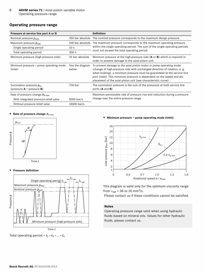
Bosch Rexroth AG RE 91610062014
8 A6VM series 71 | Axial piston variable motorOperating pressure range
Operating pressure range
Pressure at service line port A or B Definition
Nominal pressure pnom 450 bar absolute The nominal pressure corresponds to the maximum design pressure
Maximum pressure pmax 500 bar absolute The maximum pressure corresponds to the maximum operating pressure within the single operating period The sum of the single operating periods must not exceed the total operating period
Single operating period 10 s
Total operating period 300 h
Minimum pressure (high-pressure side) 25 bar absolute Minimum pressure at the high-pressure side (A or B) which is required in order to prevent damage to the axial piston unit
Minimum pressure ndash pump operating mode (inlet)
See the diagram below
To prevent damage to the axial piston motor in pump operating mode (change of high-pressure side with unchanged direction of rotation e g when braking) a minimum pressure must be guaranteed at the service line port (inlet) This minimum pressure is dependent on the speed and dis-placement of the axial piston unit (see characteristic curve)
Summation pressure pSu
(pressure A + pressure B)700 bar The summation pressure is the sum of the pressures at both service line
ports (A and B)
Rate of pressure change RA max Maximum permissible rate of pressure rise and reduction during a pressure change over the entire pressure rangeWith integrated pressure-relief valve 9000 bars
Without pressure-relief valve 16000 bars
Rate of pressure change RA max
pnom
∆t
∆p
Time t
Pres
sure
p
Pressure definition
Single operating period
Pres
sure
p
t1
t2tn
Minimum pressure (high-pressure side)
Maximum pressure pmax
Nominal pressure pnom
Time t
Total operating period = t1 + t2 + + tn
Minimum pressure ndash pump operating mode (inlet)
Inle
t pr
essu
re p
abs [
bar]
Rotational speed n nnom
Vg max
Vg x
03 Vg max
12
4
6
8
10
12
14
16
0 04 07 10 13 16
This diagram is valid only for the optimum viscosity range from nopt = 36 to 16 mm2s Please contact us if these conditions cannot be satisfied
NotesOperating pressure range valid when using hydraulic fluids based on mineral oils Values for other hydraulic fluids please contact us
RE 91610062014 Bosch Rexroth AG
Axial piston variable motor | A6VM series 71 Technical data
9
Technical data
Size NG 60 85 115 150 170 215
Displacement geometric per revolution Vg max cm3 620 852 1156 1521 1718 2165
Vg min cm3 0 0 0 0 0 0
Vg x cm3 37 51 69 91 65 82
Maximum speed1)
(complying with the maxi-mum permissible inlet flow)
at Vg max nnom rpm 4450 3900 3550 3250 3100 2900
at Vg lt Vg x (see diagram) nmax rpm 7200 6800 6150 5600 4900 4600
at Vg 0 nmax rpm 8400 8350 7350 6000 5750 5500
Inlet flow2) at nnom and Vg max qv max Lmin 275 332 410 494 533 628
Torque3) at Vg max and Δp = 450 bar T Nm 444 610 828 1089 1230 1550
Rotary stiffness Vg max to Vg2 cmin kNmrad 15 22 37 44 52 70
Vg2 to 0 (interpolated) cmin kNmrad 45 68 104 124 156 196
Moment of inertia for rotary group JGR kgm2 00043 00072 00110 00181 00213 00303
Maximum angular acceleration α radssup2 21000 17500 15500 11000 11000 10000
Case volume V L 08 10 15 17 23 28
Weight approx m kg 28 36 46 61 62 78
Permissible displacement in relation to speed
02 04 06 08 10 12 14 174
NG170 215
NG85 115 150
4)
10
08
06
038
02
0
NG60
158 162
Vg x
Vg x
Dis
plac
emen
t V
g
Vg
max
Rotational speed n nnom
Determining the operating characteristics
Inlet flow qv = Vg times n
[lmin]1000 times ηv
Rotational speed
n = qv times 1000 times ηv
[rpm]Vg
Torque T = Vg times Δp times ηmh
[Nm]20 times π
Power P = 2 π times T times n
= qv times Δp times ηt
[kW]60000 600
Key
Vg = Displacement per revolution [cm3]
Δp = Differential pressure [bar]
n = Rotational speed [rpm]
ηv = Volumetric efficiency
ηmh = Mechanical-hydraulic efficiency
ηt = Total efficiency (ηt = ηv bull ηmh)
Notes Theoretical values without efficiency levels and toler-
ances values rounded Operation above the maximum values or below the
minimum values may result in a loss of function a reduced service life or in the destruction of the axial piston unit Other permissible limit values such as speed variation reduced angular acceleration as a function of the frequency and the permissible angular acceleration at start (lower than the maximum angular acceleration) can be found in data sheet 90261
Transport and storage ndash θmin ge ndash50 degC ndash θopt = +5 degC to +20 degC
1) The values are valid ndash For the optimum viscosity range from νopt = 36 to 16 mm2s ndash with hydraulic fluid on the basis of mineral oil
2) Note inlet flow limitation due to counterbalance valve (see page 65)
3) Torque without radial force With radial force see page 10 4) Values in this range on request
Bosch Rexroth AG RE 91610062014
10 A6VM series 71 | Axial piston variable motorTechnical data
Permissible radial and axial forces of the drive shafts
Size NG 60 60 85 85 115 115 150 150 150
Drive shaft 1 14 in W35 1 12 in W40 1 34 in W40 1 34 in 2 in W45
Maximum radial force1) at distance a (from shaft collar)
a
FqFq max N 7620 10266 12463 12323 14902 16727 15948 17424 19534
a mm 240 200 270 225 335 225 335 335 250
with permissible torque Tmax Nm 310 444 595 610 828 828 890 1089 1089
≙ Permissible pressure Δp at Vg max pnom perm bar 315 450 440 450 450 450 370 450 450
Maximum axial force2)
plusmnFax+ Fax max N 0 0 0 0 0 0 0 0 0
minus Fax max N 500 500 710 710 900 900 1300 1300 1300
Permissible axial force per bar operating pressure
+ Fax permbar Nbar 75 75 96 96 113 113 133 133 133
Size NG 170 170 215 215
Drive shaft 2 in W45 2 in W50
Maximum radial force1) at distance a (from shaft collar)
a
FqFq max N 19370 21220 22602 25016
a mm 335 250 335 275
with permissible torque Tmax Nm 1230 1200 1445 1550
≙ Permissible pressure Δp at Vg max pnom perm bar 450 440 420 450
Maximum axial force2)
plusmnFax+ Fax max N 0 0 0 0
minus Fax max N 1120 1120 1250 1250
Permissible axial force per bar operating pressure
+ Fax permbar Nbar 151 151 170 170
Effect of radial force Fq on the service life of bearingsBy selecting a suitable direction of radial force Fq the load on the bearings caused by the internal rotary group forces can be reduced thus optimizing the service life of the bearings Recommended position of mating gear is depen-dent on direction of rotation Examples
Notes Influence of the direction of the permissible axial force
+ Fax max = Increased shelf life ndash Fax max = Reduced shelf life (to be avoided)
Special requirements apply in the case of belt drives Please contact us
Toothed gear output drive V-belt output drive
φopt = 45degφopt = 45deg
21
φopt = 70degφ opt = 70deg
2 1
1 Direction of rotation clockwise pressure at port B2 Direction of rotation counter-clockwise pressure at port A
1) For intermittent operation2) Maximum permissible axial force at standstill or depressurized ro-
tation of the axial piston unit
RE 91610062014 Bosch Rexroth AG
Axial piston variable motor | A6VM series 71 HP ndash Proportional hydraulic control
11
HP ndash Proportional hydraulic control
The proportional hydraulic control provides infinite adjust-ment of the displacement Control is proportional to the pilot pressure applied to port XHP1 HP2 positive control
Beginning of control at Vg min (minimum torque maxi-mum permissible speed at minimum pilot pressure)
End of control at Vg max (maximum torque minimum speed at maximum pilot pressure)
HP5 HP6 negative control Beginning of control at Vg max (maximum torque mini-
mum speed at minimum pilot pressure) End of control at Vg min (minimum torque maximum
permissible speed at maximum pilot pressure)
Note Maximum permissible pilot pressure pSt = 100 bar The control oil is internally taken from the high pressure
side of the motor (A or B) For reliable control an oper-ating pressure of at least 30 bar is required in A (B) If a control operation is performed at an operating pressure lt 30 bar an auxiliary pressure of at least 30 bar must be applied at port G via an external check valve For lower pressures please contact us Please note that pressures up to 500 bar can occur at port G
Please state the desired beginning of control in plain text when ordering e g beginning of control at 10 bar
The beginning of control and the HP charakteristic curve are influenced by the case pressure An increase in case pressure causes an increase in the beginning of control (see page 6) and thus a parallel shift of the charac-teristic
HP1 HP5 Increase in pilot pressure ΔpSt = 10 bar
HP1 positive controlA pilot pressure increase of 10 bar at port X results in an increase in displacement from Vg min to Vg maxHP5 negative controlA pilot pressure increase of 10 bar at port X results in a decrease in displacement from Vg max to Vg min
Beginning of control setting range 2 to 20 bar Standard setting
Beginning of control at 3 bar (end of control at 13 bar)
Characteristic curve
0 02 04 06 08 10Vg min Vg maxVg Vg max
HP5 HP135
30
25
20
151210
52B
egin
ning
of c
ontr
ol
sett
ing
rang
e
Displacement
Pilo
t pr
essu
re p
St [
bar]
Pilo
t pr
essu
re
incr
ease
HP2 HP6 Increase in pilot pressure DpSt = 25 bar
HP2 positive controlA pilot pressure increase of 25 bar at port X results in an increase in displacement from Vg min to Vg maxHP6 negative controlA pilot pressure increase of 25 bar at port X results in a decrease in displacement from Vg max to Vg min
Beginning of control setting range 5 to 35 bar Standard setting
Beginning of control at 10 bar (end of control at 35 bar)
Characteristic curve
70
60
50
403530
20
105
0 02 04 06 08 10Vg min Vg maxVg Vg max
HP6 HP2
Beg
inni
ng o
f co
ntro
l set
ting
ra
nge
Displacement
Pilo
t pr
essu
re p
St [
bar]
Pilo
t pr
essu
re
incr
ease
Bosch Rexroth AG RE 91610062014
12 A6VM series 71 | Axial piston variable motorHP ndash Proportional hydraulic control
Schematic HP1 HP2 Positive control
B
A
M1
T2
T1
G
X
Vg min
Vg max
U
Schematic HP5 HP6 negative control
T2
T1
M1
Vg min
Vg max
B
A
U
X
G
HP5D1 HP6D1Pressure control fixed settingThe pressure control overrides the HP control function If the load torque or a reduction in motor swivel angle causes the system pressure to reach the setpoint value of the pressure control the motor will swivel towards a larger displacement The increase in the displacement and the resulting reduc-tion in pressure cause the control deviation to decrease With the increase in displacement the motor develops more torque while the pressure remains constantSetting range of the pressure control valve 80 to 450 bar
Schematic HP5D1 HP6D1 negative control
T2
T1
M1
Vg min
Vg max
B
A
G
X
U
Response time dampingStandard for HP without dampingHP HP5D1 HP6D1 ndash with throttle pin on both sides sym-metrical
Size 60 85 115 150 170 215
Groove size [mm] 045 045 055 055 055 065
M1
RE 91610062014 Bosch Rexroth AG
Axial piston variable motor | A6VM series 71 EP ndash Proportional electric control
13
EP ndash Proportional electric control
The proportional electric control type EP provides infinite adjustment of the displacement proportional to the control current applied to the solenoidEP1 EP2 positive control
Beginning of control at Vg min (minimum torque maxi-mum permissible speed at minimum control current)
End of control at Vg max (maximum torque minimum speed at maximum control current)
EP5 EP6 negative control Beginning of control at Vg max (maximum torque mini-
mum speed at minimum control current) End of control at Vg min (minimum torque maximum
permissible speed at maximum control current)
Charakteristic curve
EP5 EP6 EP1 EP2
0 02 04 06 08 10
Vg min Vg Vg max Vg max
1600max
1400
1200
1000
800
600
400
200
800max
700
600
500
400
300
200
100
EP5EP1
(12 V)
EP6EP2
(24 V)
NoteThe control oil is internally taken from the high pressure side of the motor (A or B) For reliable control an operat-ing pressure of at least 30 bar is required in A (B) If a control operation is performed at an operating pressure lt 30 bar an auxiliary pressure of at least 30 bar must be applied at port G via an external check valve For lower pressures please contact us Please note that pressures up to 500 bar can occur at port G
Technical data solenoid EP1 EP5 EP2 EP6
Voltage 12 V (plusmn20 ) 24 V (plusmn20 )
Control current
Beginning of control 400 mA 200 mA
End of control 1200 mA 600 mA
Current limit 154 A 077 A
Nominal resistance (at 20 degC) 55 Ω 227 Ω
Dither frequency 100 Hz 100 Hz
Duty cycle 100 100
Type of protection see connector version on page 62
Various BODAS controllers with application software and amplifiers are available for controlling the proportional solenoidsFurther information can also be found on the internet at wwwboschrexrothcommobile-electronics
Bosch Rexroth AG RE 91610062014
14 A6VM series 71 | Axial piston variable motorEP ndash Proportional electric control
Schematic EP1 EP2 positive control
B
A
M1
T2
T1
G
Vg min
Vg max
U
Schematic EP5 EP6 negative control
U
T2
T1
M1
Vg min
Vg max
B
A
G
RE 91610062014 Bosch Rexroth AG
Axial piston variable motor | A6VM series 71 EP ndash Proportional electric control
15
EP5D1 EP6D1 Pressure control fixed settingThe pressure control overrides the EP control function If the load torque or a reduction in motor swivel angle causes the system pressure to reach the setpoint value of the pressure control the motor will swivel towards a larger displacementThe increase in the displacement and the resulting reduc-tion in pressure cause the control deviation to decrease With the increase in displacement the motor develops more torque while the pressure remains constantSetting range of the pressure control valve 80 to 450 bar
Schematic EP5D1 EP6D1 negative control
U
T2
T1
Vg min
Vg max
B
A
G
M1
Response time dampingStandard for EP without dampingEP EP5D1 EP6D1 ndash with throttle pin on both sides sym-metrical
Size 60 85 115 150 170 215
Groove size [mm] 045 045 055 055 055 065
M1
Bosch Rexroth AG RE 91610062014
16 A6VM series 71 | Axial piston variable motorHZ ndash Two-point hydraulic control
HZ ndash Two-point hydraulic control
The two-point hydraulic control type HZ allows the dis-placement to be set to either Vg min or Vg max by switching the pilot pressure at port X on or off
HZ5 HZ7 negative control Position at Vg max (without pilot pressure maximum
torque minimum speed) Position at Vg min (with pilot pressure gt 15 bar activated
minimum torque maximum permissible speed)
Characteristic curve HZ5 HZ7
Vg min Vg maxDisplacement
0
15
Pilo
t pr
essu
re p
S [b
ar]
100
Note Maximum permissible pilot pressure 100 bar The control oil is internally taken from the high pressure
side of the motor (A or B) For reliable control an oper-ating pressure of at least 30 bar is required in A (B) If a control operation is performed at an operating pressure lt 30 bar an auxiliary pressure of at least 30 bar must be applied at port G via an external check valve For lower pressures please contact us Please note that pressures up to 500 bar can occur at port G
Response time damping
HZ5 ndash with throttle pin on both sides symmetrical HZ7 ndash with throttle pin on both sides symmetricalSize 150 170 215 Size 60 85 115
Groove size [mm] 055 055 065 Groove size [mm] 030 030 030
M1
Schematic HZ5 Negative control size 150 to 215
T2
T1
M1
Vg min
Vg max
B
A
X
G
U
Schematic HZ7 Negative control size 60 to 115
T1U
T2
XG
Vg min
Vg max
B
A
RE 91610062014 Bosch Rexroth AG
Axial piston variable motor | A6VM series 71 EZ ndash Two-point electric control
17
EZ ndash Two-point electric control
The two-point electric control type EZ allows the displace-ment to be set to either Vg min or Vg max by switching the electric current to a switching solenoid on or off
NoteThe control oil is internally taken from the high pressure side of the motor (A or B) For reliable control an operat-ing pressure of at least 30 bar is required in A (B) If a control operation is performed at an operating pressure lt 30 bar an auxiliary pressure of at least 30 bar must be applied at port G via an external check valve For lower pressures please contact us Please note that pressures up to 500 bar can occur at port G
Sizes 150 to 215
Technical data solenoid with oslash37 EZ5 EZ6
Voltage 12 V (plusmn20 ) 24 V (plusmn20 )
Position Vg max de-energized de-energized
Position Vg min energized energized
Nominal resistance (at 20 degC) 55 Ω 217 Ω
Nominal power 262 W 265 W
Minimum required active current 132 A 067 A
Duty cycle 100 100
Type of protection see connector version on page 62
Schematic EZ5 EZ6 negative control
U
T2
T1
M1
Vg min
Vg max
B
A
G
Sizes 60 to 115
Technical data solenoid with oslash45 EZ7 EZ8
Voltage 12 V (plusmn20 ) 24 V (plusmn20 )
Position Vg max de-energized de-energized
Position Vg min energized energized
Nominal resistance (at 20 degC) 48 Ω 192 Ω
Nominal power 30 W 30 W
Minimum required active current 15 A 075 A
Duty cycle 100 100
Type of protection see connector version on page 62
Schematic EZ7 EZ8 negative control
T1U
T2
G
B
A
Vg min
Vg max
Response time dampingEZ5 EZ6 ndash with throttle pin on both sides symmetrical
Size 150 170 215
Groove size [mm] 055 055 065
M1
EZ7 EZ8 ndash with throttle pin on both sides symmetrical
Size 60 85 115
Groove size [mm] 030 030 030
Bosch Rexroth AG RE 91610062014
18 A6VM series 71 | Axial piston variable motorHA ndash Automatic high-pressure related control
HA ndash Automatic high-pressure related control
The automatic high-pressure related control type HA adjusts the displacement automatically depending on the operating pressureThe displacement of the A6VM motor with HA control is Vg min (maximum speed and minimum torque) The control device measures internally the operating pressure at A or B (no control line required) and upon reaching the set beginning of control the controller swivels the motor from Vg min to Vg max with increase of operating pressure The displacement is modulated between Vg min and Vg max thereby depending on load conditions
HA1 HA2 positive control Beginning of control at Vg min (minimum torque maxi-
mum speed) End of control at Vg max (maximum torque minimum
speed)
Note For safety reasons winch drives are not permissible
with beginning of control at Vg min (standard for HA) The control oil is internally taken from the high pressure
side of the motor (A or B) For reliable control an oper-ating pressure of at least 30 bar is required in A (B) If a control operation is performed at an operating pressure lt 30 bar an auxiliary pressure of at least 30 bar must be applied at port G via an external check valve For lower pressures please contact us Please note that pressures up to 500 bar can occur at port G
The beginning of control and the HAT3 charakteristic curve are influenced by case pressure An increase in case pressure causes an increase in the beginning of control (see page 6) and thus a parallel shift of the characteristic
Response time dampingHA ndash with one-sided throttle pin ndash inlet to large stroking chamber
Size 60 85 115 150 170 215
Groove size [mm] 045 045 055 055 055 065
M1
HA ndash with counterbalance valve BVD or BVE ndash with throttle screw
Size 60 85 115 150 170 215
Groove size [mm] 080 080 080 080 080 080
M1
RE 91610062014 Bosch Rexroth AG
Axial piston variable motor | A6VM series 71 HA ndash Automatic high-pressure related control
19
HA1 With minimum pressure increase positive controlAn operating pressure increase of Δp le approx 10 bar results in an increase in displacement from Vg min towards Vg maxBeginning of control setting range 80 to 350 barPlease state the desired beginning of control in plain text when ordering e g beginning of control at 300 bar
Charakteristic curve HA1
400
350
300
250
200
150
10080
50
0
Vg min Vg maxVg Vg max
0 02 04 06 08 10
Pres
sure
incr
ease
Δp
le a
ppro
x 1
0 ba
r
Ope
ratin
g pr
essu
re p
[ba
r]
Beg
inni
ng o
f con
trol
se
ttin
g ra
nge
Displacement
Schematic HA1
B
A
M1
T2
T1
Vg min
Vg max
G
U
X
HA2With pressure increase positive controlAn operating pressure increase of Dp approx 100 bar results in an increase in displacement from Vg min to Vg maxBeginning of control setting range 80 to 350 barPlease state the desired beginning of control in plain text when ordering e g beginning of control at 200 bar
Characteristic curve HA2
450
400
350
300
250
200
150
10080
50
0
Vg min Vg maxVg Vg max
0 02 04 06 08 10
Pres
sure
incr
ease
Δp
le a
ppro
x 1
00 b
ar
Ope
ratin
g pr
essu
re p
[ba
r]
Beg
inni
ng o
f con
trol
se
ttin
g ra
nge
Displacement
Schematic HA2
B
A
M1
T2
T1
G
X
Vg min
Vg max
U
Bosch Rexroth AG RE 91610062014
20 A6VM series 71 | Axial piston variable motorHA ndash Automatic high-pressure related control
HAT3 Hydraulic override remote control proportionalWith the HAT3 control the beginning of control can be influenced by applying a pilot pressure to port XFor each 1 bar of pilot pressure increase the beginning of control is reduced by 17 bar
Beginning of control setting 300 bar 300 bar
Pilot pressure at port X 0 bar 10 bar
Beginning of control at 300 bar 130 bar
NoteMaximum permissible pilot pressure 100 bar
Schematic HA1T3
B
A
M1
T2
T1
Vg min
Vg max
X
U
G
Schematic HA2T3
B
A
M1
T2
T1
G
X
Vg min
Vg max
U
RE 91610062014 Bosch Rexroth AG
Axial piston variable motor | A6VM series 71 HA ndash Automatic high-pressure related control
21
HAU1 HAU2Electric override two-pointWith the HAU1 or HAU2 control the beginning of control can be overridden by an electric signal to a switching sole-noid When the override solenoid is energized the variable motor swivels to maximum swivel angle without intermedi-ate position The beginning of control can be set between 80 and 300 bar (specify required setting in plain text when order-ing)
Technical data solenoid with oslash45 U1 U2
Voltage 12 V (plusmn20 ) 24 V (plusmn20 )
No override de-energized de-energized
Position Vg max energized energized
Nominal resistance (at 20 degC) 48 Ω 192 Ω
Nominal power 30 W 30 W
Minimum required active current 15 A 075 A
Duty cycle 100 100
Type of protection see connector version on page 62
Schematic HA1U1 HA1U2
G
B
A
M1
T2
T1
Vg min
Vg max
U
Schematic HA2U1 HA2U2
M1
T2
T1
B
A
Vg min
Vg max
G
U
Bosch Rexroth AG RE 91610062014
22 A6VM series 71 | Axial piston variable motorHA ndash Automatic high-pressure related control
HAR1 HAR2Electric overrideelectric travel direction valveWith the HAR1 or HAR2 control the beginning of control can be overridden by an electric signal to switching sole-noid b When the override solenoid is energized the vari-able motor swivels to maximum swivel angle without inter-mediate positionThe travel direction valve ensures that the preselected pressure side of the hydraulic motor (A or B) is always connected to the HA control and thus determines the swivel angle even if the high-pressure side changes (e g -travel drive during a downhill operation) This thereby prevents undesired jerky deceleration andor brak-ing characteristicsThe travel direction valve (see page 25) is either pressure spring or switched by energizing switching solenoid a depending on the direction of rotation (travel direction)
Electric override
Technical data solenoid b with oslash45 R1 R2
Voltage 12 V (plusmn20 ) 24 V (plusmn20 )
No override de-energized de-energized
Position Vg max energized energized
Nominal resistance (at 20 degC) 48 Ω 192 Ω
Nominal power 30 W 30 W
Minimum required active current 15 A 075 A
Duty cycle 100 100
Type of protection see connector version on page 62
Travel direction valve electric
Technical data solenoid a with oslash37 R1 R2
Voltage 12 V (plusmn20 ) 24 V (plusmn20 )
Direction of rotation
Operating pressure in
ccw B energized energized
cw A de-energized de-energized
Nominal resistance (at 20 degC) 55 Ω 217 Ω
Nominal power 262 W 265 W
Minimum required active current 132 A 067 A
Duty cycle 100 100
Type of protection see connector version on page 62
Schematic HA1R1 HA1R2
ab
B
A
M1
T2
T1
Vg min
Vg max
U
G
Schematic HA2R1 HA2R2
M1
T2
T1
G
B
A
Vg min
Vg max
U
ab
RE 91610062014 Bosch Rexroth AG
Axial piston variable motor | A6VM series 71 DA ndash Automatic speed-related control
23
DA ndash Automatic speed-related control
The variable motor A6VM with automatic speed-related control type DA is intended for use in hydrostatic travel drives in combination with the variable pump A4VG with DA controlA drive-speed-related pilot pressure signal is generated by the A4VG variable pump and that signal together with the operating pressure regulates the swivel angle of the hydraulic motorIncreasing pump speed ie increasing pilot pressure causes the motor to swivel to a smaller displacement (lower torque higher speed) depending on the operating pressureIf the operating pressure exceeds the pressure setpoint set on the controller the variable motor swivels to a larger displacement (higher torque lower speed)
Pressure ratio pStpHD = 5100
DA closed loop control is only suitable for certain types of drive systems and requires review of the engine and vehicle parameters to ensure that the motor is used correctly and that machine operation is safe and efficient We recommend that all DA applications be reviewed by a Bosch Rexroth application engineerDetailed information is available from our sales organiza-tion
NoteThe beginning of control and the DA charakteristic curve are influenced by case pressure An increase in case pres-sure causes an decrease in the beginning of control (see page 7) and thus a parallel shift of the characteristic
Response time dampingDA ndash with one-sided throttle pin ndash outlet to large stroking chamber
Size 60 85 115 150 170 215
Groove size [mm] 045 045 055 055 055 065
M1
DA0Hydraulic travel direction valve negative controlDepending on the direction of rotation (travel direction) the travel direction valve is switched by using pilot pres-sures connections X1 or X2
Direction of rotation
Operating pressure in
Pilot pressure in
cw A X1
ccw B X2
Schematic DA0
M1
T2
T1
Vg min
Vg max
B
A
G
X3
X2
X1
U
Bosch Rexroth AG RE 91610062014
24 A6VM series 71 | Axial piston variable motorDA ndash Automatic speed-related control
DA1 DA2Electric travel direction valve + electric Vg max circuit negative controlThe travel direction valve is either pressure spring or switched by energizing switching solenoid a depending on the direction of rotation (travel direction)When the switching solenoid b is energized the DA control is overridden and the motor swivels to maximum displace-ment (high torque lower speed) (electric Vg max-circuit)
Travel direction valve electric
Technical data solenoid a with oslash37 DA1 DA2
Voltage 12 V (plusmn20 ) 24 V (plusmn20 )
Direction of rotation
Operating pressure in
ccw B de-energized de-energized
cw A energized energized
Nominal resistance (at 20 degC) 55 Ω 217 Ω
Nominal power 262 W 265 W
Minimum required active current 132 A 067 A
Duty cycle 100 100
Type of protection see connector version on page 62
Electric override
Technical data solenoid b with oslash37 R1 R2
Voltage 12 V (plusmn20 ) 24 V (plusmn20 )
No override de-energized de-energized
Position Vg max energized energized
Nominal resistance (at 20 degC) 55 Ω 217 Ω
Nominal power 262 W 265 W
Minimum required active current 132 A 067 A
Duty cycle 100 100
Type of protection see connector version on page 62
Schematic DA1 DA2
T2
T1
M1
Vg min
Vg max
B
A
G
X3
a
b
X1
U
RE 91610062014 Bosch Rexroth AG
Axial piston variable motor | A6VM series 71 Electric travel direction valve (for DA HAR)
25
Electric travel direction valve (for DA HAR)
Application in travel drives in closed circuits The travel direction valve of the motor is actuated by an electric signal that also switches the swivel direction of the travel drive pump (e g A4VG with DA control valve)If the pump in the closed circuit is switched to the neutral position or into reverse the vehicle may experience jerky deceleration or braking depending on the vehicles mass and current travel speedWhen the travel direction valve of the pump (e g 43-direc-tional valve of the DA-control) is switched to
the neutral position the electric circuitry causes the previous signal on the travel direction valve on the motor to be retained
Reversing the travel direction valve causes the travel direction valve of the motor to switch to the other travel direction following a time delay (approx 08 s) with respect to the pump
As a result jerky deceleration or braking is prevented in both cases
Schematic - electric travel direction valve
K11
K12
K1
K21
K2
A3 B3
A2
V1
V NR
24 V DC
24 V DC
Solenoid a Pump
Solenoid b Pump
Solenoid a Motor
Travel direction valve
The shown diodes and relays are not included in the scope of delivery of the motor
Control DA1 DA
bab
a
HA1R HA2R control
a
b
Switching solenoid a on the travel direction valve
Bosch Rexroth AG RE 91610062014
26 A6VM series 71 | Axial piston variable motorDimensions size 60
Dimensions [mm]
Dimensions size 60
EP5 EP6 ndash Proportional electric control negative controlPort plate 2 mdash SAE flange ports A and B at side opposite
150
UT1
T2
G
M1
Y
Z
M1
G75
183108321)
725
84
max 146
1122)
203167
2123)
2430
3)
176
154
243
142)
160
45deg
135
45deg
150
508
238
19
0oslash1
25 -0
025
oslash73 23
125
deg
View Y
Flange ISO 3019-2
1) To shaft collar2) Center of gravity3) Port plate 1 mdash SAE flange ports A and B at rear
RE 91610062014 Bosch Rexroth AG
Axial piston variable motor | A6VM series 71 Dimensions size 60
27Dimensions [mm]
Location of the service line ports on the port plates (view Z)
2 SAE flange portA and B at side opposite
1 SAE flange portA and B at rear
2 SAE flange portA and B at side opposite only HZ7 EZ78
1 SAE flange portA and B at rear only HZ7 EZ78
B A
15254
16554
B A
152
AB
375 375
AB
165
Splined shaft SAE J744 Splined shaft DIN 5480
S7 ‒ 1 14 in 14T 1224DP1) Z8 ‒ W35times2times16times9g
28
40
716
-14U
NC
-2B
2)3)
oslash45
48
95
40
32
M12
x 1
753)
4)
95
28
oslash45
1) Involute spline acc to ANSI B921a 30deg pressure angle flat root side fit tolerance class 5
2) Thread according to ASME B11
3) For notes on tightening torques see instruction manual4) Center bore according to DIN 332 (thread according to DIN 13)
Bosch Rexroth AG RE 91610062014
28 A6VM series 71 | Axial piston variable motorDimensions size 60
Dimensions [mm]
Ports Standard Size1) pmax abs [bar]2) Status6)
A B Service line portFastening thread AB
SAE J5183)
DIN 1334 inM10 times 15 17 deep
500 O
T1 Drain port ISO 61495) M22 times 15 155 deep 3 X4)
T2 Drain port ISO 61495) M27 times 2 19 deep 3 O4)
G Synchronous control ISO 61495) M14 times 15 115 deep 500 X
U Bearing flushing ISO 61495) M18 times 15 145 deep 3 X
X Pilot signal (HP HZ HA1THA2T) ISO 61495) M14 times 15 115 deep 100 O
X Pilot signal (HA1 HA2) ISO 61495) M14 times 15 115 deep 3 X
X1 X2 Pilot signal (DA0) ISO 8434-1 SDSC-L8timesM12-F 40 O
X1 Pilot signal (DA1 DA2) ISO 61495) M14 times 15 115 deep 40 O
X3 Pilot signal (DA1 DA2) ISO 61495) M14 times 15 115 deep 40 X
M1 Measuring stroking chamber ISO 61495) M14 times 15 115 deep 500 X
1) For notes on tightening torques see instruction manual2) Momentary pressure spikes may occur depending on the application
Keep this in mind when selecting measuring devices and fittings3) Only dimensions according to SAE J518 metric fastening thread is
a deviation from standard
4) Depending on installation position T1 or T2 must be connected (see also installation instructions on page 72)
5) The spot face can be deeper than specified in the appropriate standard6) O = Must be connected (plugged on delivery)
X = Plugged (in normal operation)
RE 91610062014 Bosch Rexroth AG
Axial piston variable motor | A6VM series 71 Dimensions size 60
29Dimensions [mm]
EP1 EP2 ndash Electric proportional control positive control
EP5D1 EP6D1 ndash Electric proportional control negative control with pressure control fixed
GG
M1 M1
239
225
107
B A
154
243
176
M1M1
G
B A
G
HP1 HP2 ndash Hydraulic proportional control positive control
HP5 HP6 ndash Hydraulic proportional control negative control
M1M1
XG
159
139
107
XG
355 160
239
B A
M1
X G XG355 210
240
154
90 110
M1
B A
HP5D1 HP6D1 ndash Hydraulic proportional control negative control with pressure control fixed
355
154
215240
89 120
M1
GG X X
M1
B A
Bosch Rexroth AG RE 91610062014
30 A6VM series 71 | Axial piston variable motorDimensions size 60
Dimensions [mm]
HZ7 ndash Hydraulic two-point control negative control
EZ7 EZ8 ndash Electric two-point control negative control
2431
1)
14611
710
0
183
GX
1512151)
227
61 G
X
AB
124
G
AB
G
227
2431
1)
146
100
183
2151)
HA1 HA2 HA1T3 HA2T3 ndash Automatic high-pressure-related control positive control with override hydraulic remote con-trolled proportional
HA1U1 HA2U2 ndash Automatic high-pressure-related control positive control with override electric two-point
M1M1
XG
159
139
107
XG
355 160
239
B A
M1
B A
239
225
107
G
M1
G
HA1 and HA2 X plugged
HA1T and HA2T X open
HA1R1 HA2R2 ndash Automatic high-pressure-related control positive control with override electric and travel direction valve electric
225
a
b
GG
M1M1
B A
239
107
110
1) Port plate 1 ndash SAE flange ports A and B at rear
RE 91610062014 Bosch Rexroth AG
Axial piston variable motor | A6VM series 71 Dimensions size 60
31Dimensions [mm]
DA0 ndash Automatic speed-related control negative control with hydraulic travel direction valve
DA1 DA2 ndash Automatic speed-related control negative control with electric travel direction valve and electric Vg max circuit
M1
G X3X1 X2
178243
154
94 120
160
G X3X1 X2
M1
AB
G
M1
X3
M1
X1
154
202243
132
155
G
X1 X3
110 85
AB
b
a
X1 X2 pipe fitting SDSC ndash L8timesM12 ndash F according to ISO 8434-1
Use assembled fitting
Bosch Rexroth AG RE 91610062014
32 A6VM series 71 | Axial piston variable motorDimensions size 85
Dimensions [mm]
Dimensions size 85
EP5 EP6 ndash Proportional electric control negative controlPort plate 2 mdash SAE flange ports A and B at side opposite
T2
T1U
M1
45deg
Y
GG
M1
135
Z
11775
321)208
167
275
182
343)
132)
2712393)
1122)
233176
max 146
9180
125
deg
180
45deg
165
165
23-00
25oslash1
40 0
oslash83
572
278
25
View Y
Flange ISO 3019-2
1) To shaft collar2) Center of gravity3) Port plate 1 mdash SAE flange ports A and B at rear
RE 91610062014 Bosch Rexroth AG
Axial piston variable motor | A6VM series 71 Dimensions size 85
33Dimensions [mm]
Location of the service line ports on the port plates (view Z)
2 SAE flange portA and B at side opposite
1 SAE flange portA and B at rear
2 SAE flange portA and B at side opposite only HZ7 EZ78
1 SAE flange portA and B at rear only HZ7 EZ78
B A
164
B A
54177
54
AB
164
B A
4242177
Splined shaft SAE J744 Splined shaft DIN 5480
S9 ‒ 1 12 in 17T 1224DP1) Z9 ‒ W40times2times18times9g
28
44
716
-14U
NC
-2B
2)3)
oslash50
54
95
45
37
M16
x 2
3)4) 12
36
oslash50
1) Involute spline acc to ANSI B921a 30deg pressure angle flat root side fit tolerance class 5
2) Thread according to ASME B11
3) For notes on tightening torques see instruction manual4) Center bore according to DIN 332 (thread according to DIN 13)
Bosch Rexroth AG RE 91610062014
34 A6VM series 71 | Axial piston variable motorDimensions size 85
Dimensions [mm]
Ports Standard Size1) pmax abs [bar]2) Status6)
A B Service line portFastening thread AB
SAE J5183)
DIN 131 inM12 times 175 17 deep
500 O
T1 Drain port ISO 61495) M22 times 15 155 deep 3 X4)
T2 Drain port ISO 61495) M27 times 2 19 deep 3 O4)
G Synchronous control ISO 61495) M14 times 15 115 deep 500 X
U Bearing flushing ISO 61495) M18 times 15 145 deep 3 X
X Pilot signal (HP HZ HA1THA2T) ISO 61495) M14 times 15 115 deep 100 O
X Pilot signal (HA1 HA2) ISO 61495) M14 times 15 115 deep 3 X
X1 X2 Pilot signal (DA0) ISO 8434-1 SDSC-L8timesM12-F 40 O
X1 Pilot signal (DA1 DA2) ISO 61495) M14 times 15 115 deep 40 O
X3 Pilot signal (DA1 DA2) ISO 61495) M14 times 15 115 deep 40 X
M1 Measuring stroking chamber ISO 61495) M14 times 15 115 deep 500 X
1) For notes on tightening torques see instruction manual2) Momentary pressure spikes may occur depending on the application
Keep this in mind when selecting measuring devices and fittings3) Only dimensions according to SAE J518 metric fastening thread is
a deviation from standard
4) Depending on installation position T1 or T2 must be connected (see also installation instructions on page 72)
5) The spot face can be deeper than specified in the appropriate standard6) O = Must be connected (plugged on delivery)
X = Plugged (in normal operation)
RE 91610062014 Bosch Rexroth AG
Axial piston variable motor | A6VM series 71 Dimensions size 85
35Dimensions [mm]
EP1 EP2 ndash Electric proportional control positive control
EP5D1 EP6D1 ndash Electric proportional control negative control with pressure control fixed
G
M1
AB
238
113
G
266
M1
G
M1
AB
G
M1
167
182
271
HP1 HP2 ndash Hydraulic proportional control positive control
HP5 HP6 ndash Hydraulic proportional control negative control
266
G
AB
M1
X
172
113
M1
G
X183
152
355 M1
G XX
AB
M1
G355 238
268
116
9616
7
HP5D1 HP6D1 ndash Hydraulic proportional control negative control with pressure control fixed
G
AB
M1
X355
G X
M1
126
9516
7
243268
Bosch Rexroth AG RE 91610062014
36 A6VM series 71 | Axial piston variable motorDimensions size 85
Dimensions [mm]
HZ7 ndash Hydraulic two-point control negative control
EZ7 EZ8 ndash Electric two-point control negative control
GX
1712421)
61
AB
208254
112
2735
1)
161
132
G
X
124G
2421)
AB
208254
112
2735
1)
161
G
HA1 HA2 HA1T3 HA2T3 ndash Automatic high-pressure-related control positive control with override hydraulic remote con-trolled proportional
HA1U1 HA2U2 ndash Automatic high-pressure-related control positive control with override electric two-point
266
G
AB
M1
X
172
113
M1
G
X183
152
355
M1
AB
G
M1
113
G
266
239
HA1 and HA2 X plugged
HA1T and HA2T X open
HA1R1 HA2R2 ndash Automatic high-pressure-related control positive control with override electric and travel direction valve electric
AB
M1
G
M1
266
239
113
G
110
a
b
1) Port plate 1 ndash SAE flange ports A and B at rear
RE 91610062014 Bosch Rexroth AG
Axial piston variable motor | A6VM series 71 Dimensions size 85
37Dimensions [mm]
DA0 ndash Automatic speed-related control negative control with hydraulic travel direction valve
DA1 DA2 ndash Automatic speed-related control negative control with electric travel direction valve and electric Vg max circuit
M1
AB
160
X3
167
126
207271
100
M1
X1 X2 GX1
X3GX2
G
X3X1
167
161
230270
M1M1
A
138
110
B
85
G
X1X3 ba
X1 X2 pipe fitting SDSC ndash L8timesM12 ndash F according to ISO 8434-1
Use assembled fitting
Bosch Rexroth AG RE 91610062014
38 A6VM series 71 | Axial piston variable motorDimensions size 115
Dimensions [mm]
Dimensions size 115
EP5 EP6 ndash Proportional electric control negative controlPort plate 2 mdash SAE flange ports A and B at side opposite
25
GT1U
T2
M1
200
Y
Z
M1
G
126220
401)
75
102)
3038
3)
188
175
45deg 45deg
175
190
1901262)
2573)
290
253978
max 146
102
91oslash9
0
oslash160
0 -00
25
572
278 25
125
deg
View Y
Flange ISO 3019-2
1) To shaft collar2) Center of gravity3) Port plate 1 mdash SAE flange ports A and B at rear
RE 91610062014 Bosch Rexroth AG
Axial piston variable motor | A6VM series 71 Dimensions size 115
39Dimensions [mm]
Location of the service line ports on the port plates (view Z)
2 SAE flange portA and B at side opposite
1 SAE flange portA and B at rear
2 SAE flange portA and B at side opposite only HZ7 EZ78
1 SAE flange portA and B at rear only HZ7 EZ78
M1
AB
180
B A
65193
65 180
B A
4242
193
B A
Splined shaft SAE J744 Splined shaft DIN 5480
T1 ‒ 1 34 in 13T 813DP1) Z9 ‒ W40times2times18times9g
36
55
58-
11U
NC
-2B
2)3)
oslash60
67
12
45
37
M16
times 2
3)4)
36
oslash60
12
1) Involute spline acc to ANSI B921a 30deg pressure angle flat root side fit tolerance class 5
2) Thread according to ASME B11
3) For notes on tightening torques see instruction manual4) Center bore according to DIN 332 (thread according to DIN 13)
Bosch Rexroth AG RE 91610062014
40 A6VM series 71 | Axial piston variable motorDimensions size 115
Dimensions [mm]
Ports Standard Size1) pmax abs [bar]2) Status6)
A B Service line portFastening thread AB
SAE J5183)
DIN 131 inM12 times 175 17 deep
500 O
T1 Drain port ISO 61495) M27 times 2 19 deep 3 X4)
T2 Drain port ISO 61495) M33 times 2 19 deep 3 O4)
G Synchronous control ISO 61495) M14 times 15 115 deep 500 X
U Bearing flushing ISO 61495) M18 times 15 145 deep 3 X
X Pilot signal (HP HZ HA1THA2T) ISO 61495) M14 times 15 115 deep 100 O
X Pilot signal (HA1 HA2) ISO 61495) M14 times 15 115 deep 3 X
X1 X2 Pilot signal (DA0) ISO 8434-1 SDSC-L8timesM12-F 40 O
X1 Pilot signal (DA1 DA2) ISO 61495) M14 times 15 115 deep 40 O
X3 Pilot signal (DA1 DA2) ISO 61495) M14 times 15 115 deep 40 X
M1 Measuring stroking chamber ISO 61495) M14 times 15 115 deep 500 X
1) For notes on tightening torques see instruction manual2) Momentary pressure spikes may occur depending on the application
Keep this in mind when selecting measuring devices and fittings3) Only dimensions according to SAE J518 metric fastening thread is
a deviation from standard
4) Depending on installation position T1 or T2 must be connected (see also installation instructions on page 72)
5) The spot face can be deeper than specified in the appropriate standard6) O = Must be connected (plugged on delivery)
X = Plugged (in normal operation)
RE 91610062014 Bosch Rexroth AG
Axial piston variable motor | A6VM series 71 Dimensions size 115
41Dimensions [mm]
EP1 EP2 ndash Electric proportional control positive control
EP5D1 EP6D1 ndash Electric proportional control negative control with pressure control fixed
M1
121
281
249
G
M1
B A
G
G
188
175
G
290
B A
M1M1
HP1 HP2 ndash Hydraulic proportional control positive control
HP5 HP6 ndash Hydraulic proportional control negative control
405
G X
164
199
121
180
281
G
M1
X
M1
B A
GX257
M1
405
G
121
175
101
288
M1
X
AB
HP5D1 HP6D1 ndash Hydraulic proportional control negative control with pressure control fixed
G X
M1
XG
M1
133
175
101
290258405
B A
Bosch Rexroth AG RE 91610062014
42 A6VM series 71 | Axial piston variable motorDimensions size 115
Dimensions [mm]
HZ7 ndash Hydraulic two-point control negative control
EZ7 EZ8 ndash Electric two-point control negative control
143
182 G61X
2561)
121
17230
381)
220270
B A
G
X
2561)
30
G G124
121
381)
220
B A
172
270
HA1 HA2 HA1T3 HA2T3 ndash Automatic high-pressure-related control positive control with override hydraulic remote con-trolled proportional
HA1U1 HA2U2 ndash Automatic high-pressure-related control positive control with override electric two-point
405G X
164
199
121
180
281
G
M1
X
M1
B A
121
249
G
M1
G
M1
281
B A
HA1 and HA2 X plugged
HA1T and HA2T X open
HA1R1 HA2R2 ndash Automatic high-pressure-related control positive control with override electric and travel direction valve electric
112
121
249
G
M1
G
M1
281
B A
a
b
1) Port plate 1 ndash SAE flange ports A and B at rear
RE 91610062014 Bosch Rexroth AG
Axial piston variable motor | A6VM series 71 Dimensions size 115
43Dimensions [mm]
DA0 ndash Automatic speed-related control negative control with hydraulic travel direction valve
DA1 DA2 ndash Automatic speed-related control negative control with electric travel direction valve and electric Vg max circuit
G174
175
290
132
107
X3X1 X2X1 X2 G X3
M1M1
B A
216
112 238290
M1 M1
G
X3X1
G
X1
175
145
168
X3 ba
85
B A
X1 X2 pipe fitting SDSC ndash L8timesM12 ndash F according to ISO 8434-1
Use assembled fitting
Bosch Rexroth AG RE 91610062014
44 A6VM series 71 | Axial piston variable motorDimensions size 150
Dimensions [mm]
Dimensions size 150
EP5 EP6 ndash Proportional electric control negative controlPort plate 2 mdash SAE flange ports A and B at side opposite
M1
T1
T2
U
224
45deg
Y
Z
G G
M1
max 14939 28
9051392)
3212883)
112)
3342
3)
196
195
247401) 1405
75
109
100
125
deg
45deg
175
210
210
25
667
318
32
oslash94
oslash180
-00
250
View Y
Flange ISO 3019-2
1) To shaft collar2) Center of gravity3) Port plate 1 mdash SAE flange ports A and B at rear
RE 91610062014 Bosch Rexroth AG
Axial piston variable motor | A6VM series 71 Dimensions size 150
45Dimensions [mm]
Location of the service line ports on the port plates (view Z)
2 SAE flange portA and B at side opposite
1 SAE flange portA and B at rear
AB
204
B A
7676226
Splined shaft SAE J744 Splined shaft SAE J744
T1 ‒ 1 34 in 13T 816DP1) T2 ‒ 2 in 15T 816DP1)
36
53
58-
11U
NC
-2B
2)3)
oslash60
67
12
36
53
58-
11U
NC
-2B
2)3)
oslash60
67
12
Splined shaft DIN 5480
A1 ‒ W45times2times21times9g
50
42
M16
times 2
3)4)
36
oslash60
12
1) Involute spline acc to ANSI B921a 30deg pressure angle flat root side fit tolerance class 5
2) Thread according to ASME B113) For notes on tightening torques see instruction manual 4) Center bore according to DIN 332 (thread according to DIN 13)
Bosch Rexroth AG RE 91610062014
46 A6VM series 71 | Axial piston variable motorDimensions size 150
Dimensions [mm]
Ports Standard Size1) pmax abs [bar]2) Status6)
A B Service line portFastening thread AB
SAE J5183)
DIN 131 14 inM14 times 2 19 deep
500 O
T1 Drain port ISO 61495) M27 times 2 19 deep 3 X4)
T2 Drain port ISO 61495) M33 times 2 19 deep 3 O4)
G Synchronous control ISO 61495) M14 times 15 115 deep 500 X
U Bearing flushing ISO 61495) M22 times 15 155 deep 3 X
X Pilot signal (HP HZ HA1THA2T) ISO 61495) M14 times 15 115 deep 100 O
X Pilot signal (HA1 HA2) ISO 61495) M14 times 15 115 deep 3 X
X1 X2 Pilot signal (DA0) ISO 8434-1 SDSC-L8timesM12-F 40 O
X1 Pilot signal (DA1 DA2) ISO 61495) M14 times 15 115 deep 40 O
X3 Pilot signal (DA1 DA2) ISO 61495) M14 times 15 115 deep 40 X
M1 Measuring stroking chamber ISO 61495) M14 times 15 115 deep 500 X
1) For notes on tightening torques see instruction manual2) Momentary pressure spikes may occur depending on the application
Keep this in mind when selecting measuring devices and fittings3) Only dimensions according to SAE J518 metric fastening thread is
a deviation from standard
4) Depending on installation position T1 or T2 must be connected (see also installation instructions on page 72)
5) The spot face can be deeper than specified in the appropriate standard6) O = Must be connected (plugged on delivery)
X = Plugged (in normal operation)
RE 91610062014 Bosch Rexroth AG
Axial piston variable motor | A6VM series 71 Dimensions size 150
47Dimensions [mm]
EP1 EP2 ndash Electric proportional control positive control
EP5D1 EP6D1 ndash Electric proportional control negative control with pressure control fixed
132
315
264
G
M1
B A
M1
G
GG
196
195
321
M1 M1
B A
HP1 HP2 ndash Hydraulic proportional control positive control
HP5 HP6 ndash Hydraulic proportional control negative control
405XG
178
225
132
195
315
M1
XG
AB
M1
X G G X
M1
B A
M1
132
195
109
320289405
HP5D1 HP6D1 ndash Hydraulic proportional control negative control with pressure control fixed
X X
M1M1
B A
141
108
G
321290
G
195
405
Bosch Rexroth AG RE 91610062014
48 A6VM series 71 | Axial piston variable motorDimensions size 150
Dimensions [mm]
HZ5 ndash Hydraulic two-point control negative control
EZ5 EZ6 ndash Electric two-point control negative control
405
G
108
285
132
195
319
M1 M1
XG
B A
X
186
319
195
M1
G
B A
G
M1
HA1 HA2 HA1T3 HA2T3 ndash Automatic high-pressure-related control positive control with override hydraulic remote con-trolled proportional
HA1U1 HA2U2 ndash Automatic high-pressure-related control positive control with override electric two-point
405XG
178
225
132
195
315
M1 M1
XG
AB
132
315
264
M1
G
AB
G
M1
HA1 and HA2 X plugged
HA1T and HA2T X open
HA1R1 HA2R2 ndash Automatic high-pressure-related control positive control with override electric and travel direction valve electric
a
b112
132
315
264
M1
G
AB
G
M1
RE 91610062014 Bosch Rexroth AG
Axial piston variable motor | A6VM series 71 Dimensions size 150
49Dimensions [mm]
DA0 ndash Automatic speed-related control negative control with hydraulic travel direction valve
DA1 DA2 ndash Automatic speed-related control negative control with electric travel direction valve and electric Vg max circuit
174
X2X1G X3 G X3
195
140
247322
M1
115
B A
M1
X2
176
195
153
112
M1
G
85
B A
X1X3
M1
270322
G
X3X1ba
X1 X2 pipe fitting SDSC ndash L8timesM12 ndash F according to ISO 8434-1
Use assembled fitting
Bosch Rexroth AG RE 91610062014
50 A6VM series 71 | Axial piston variable motorDimensions size 170
Dimensions [mm]
Dimensions size 170
EP5 EP6 ndash Proportional electric control negative controlPort plate 2 mdash SAE flange ports A and B at side opposite
G
Y
T2
M1
T1U
Z
G
M1
oslash100
oslash180
-00
250
667
318 32
210
210
175
224
103
112
401)
75141
25412
5deg
1412)
9139 28
max 149
2953)
328
19743
3)
195
122)
34
45deg 45deg
25
View Y
Flange ISO 3019-2
1) To shaft collar2) Center of gravity3) Port plate 1 mdash SAE flange ports A and B at rear
RE 91610062014 Bosch Rexroth AG
Axial piston variable motor | A6VM series 71 Dimensions size 170
51Dimensions [mm]
Location of the service line ports on the port plates (view Z)
2 SAE flange portA and B at side opposite
1 SAE flange portA and B at rear
B A
20476
B A
22676
Splined shaft SAE J744 Splined shaft DIN 5480
T2 ‒ 2 in 15T 816DP1) A1 ‒ W45times2times21times9g
36
53
58-
11U
NC
-2B
2)3)
oslash70
67
12
50
42
M16
times 2
3)4)
36
oslash70
12
1) Involute spline acc to ANSI B921a 30deg pressure angle flat root side fit tolerance class 5
2) Thread according to ASME B11
3) For notes on tightening torques see instruction manual4) Center bore according to DIN 332 (thread according to DIN 13)
Bosch Rexroth AG RE 91610062014
52 A6VM series 71 | Axial piston variable motorDimensions size 170
Dimensions [mm]
Ports Standard Size1) pmax abs [bar]2) Status6)
A B Service line portFastening thread AB
SAE J5183)
DIN 131 14 inM14 times 2 19 deep
500 O
T1 Drain port ISO 61495) M27 times 2 19 deep 3 X4)
T2 Drain port ISO 61495) M33 times 2 19 deep 3 O4)
G Synchronous control ISO 61495) M14 times 15 115 deep 500 X
U Bearing flushing ISO 61495) M22 times 15 155 deep 3 X
X Pilot signal (HP HZ HA1THA2T) ISO 61495) M14 times 15 115 deep 100 O
X Pilot signal (HA1 HA2) ISO 61495) M14 times 15 115 deep 3 X
X1 X2 Pilot signal (DA0) ISO 8434-1 SDSC-L8timesM12-F 40 O
X1 Pilot signal (DA1 DA2) ISO 61495) M14 times 15 115 deep 40 O
X3 Pilot signal (DA1 DA2) ISO 61495) M14 times 15 115 deep 40 X
M1 Measuring stroking chamber ISO 61495) M14 times 15 115 deep 500 X
1) For notes on tightening torques see instruction manual2) Momentary pressure spikes may occur depending on the application
Keep this in mind when selecting measuring devices and fittings3) Only dimensions according to SAE J518 metric fastening thread is
a deviation from standard
4) Depending on installation position T1 or T2 must be connected (see also installation instructions on page 72)
5) The spot face can be deeper than specified in the appropriate standard6) O = Must be connected (plugged on delivery)
X = Plugged (in normal operation)
RE 91610062014 Bosch Rexroth AG
Axial piston variable motor | A6VM series 71 Dimensions size 170
53Dimensions [mm]
EP1 EP2 ndash Electric proportional control positive control
EP5D1 EP6D1 ndash Electric proportional control negative control with pressure control fixed
G
B A
M1
G
M1
322
133
266
195
197
328
G
M1M1
B A
G
HP1 HP2 ndash Hydraulic proportional control positive control
HP5 HP6 ndash Hydraulic proportional control negative control
405
181
133
197
322
232
XG
M1
GX
B A
M1
405
108
133
197
296326
X G
M1
B A
G X
M1
HP5D1 HP6D1 ndash Hydraulic proportional control negative control with pressure control fixed
328297
108
141
197
X XG G
M1
B A
405
M1
Bosch Rexroth AG RE 91610062014
54 A6VM series 71 | Axial piston variable motorDimensions size 170
Dimensions [mm]
HZ5 ndash Hydraulic two-point control negative control
EZ5 EZ6 ndash Electric two-point control negative control
197
107
133
405 291326
X G
M1
G
B A
X
M1
G
M1
G
B A
M1
197
187
326
HA1 HA2 HA1T3 HA2T3 ndash Automatic high-pressure-related control positive control with override hydraulic remote con-trolled proportional
HA1U1 HA2U2 ndash Automatic high-pressure-related control positive control with override electric two-point
405
181
133
197
322
232G
M1
G X
B A
X
M1 M1
B A
M1
G G
322
133
266
HA1 and HA2 X plugged
HA1T and HA2T X open
HA1R1 HA2R2 ndash Automatic high-pressure-related control positive control with override electric and travel direction valve electric
322
133
266
112
a
bG
M1
G
B A
M1
RE 91610062014 Bosch Rexroth AG
Axial piston variable motor | A6VM series 71 Dimensions size 170
55Dimensions [mm]
DA0 ndash Automatic speed-related control negative control with hydraulic travel direction valve
DA1 DA2 ndash Automatic speed-related control negative control with electric travel direction valve and electric Vg max circuit
X2X1G X3 G X3
M1
X1 X2
B A
M1
174
197
140
254328
115
B A
M1
G
X1X3
M1
G
X3X1
ab
176
197
153
277328
112 85
X1 X2 pipe fitting SDSC ndash L8timesM12 ndash F according to ISO 8434-1
Use assembled fitting
Bosch Rexroth AG RE 91610062014
56 A6VM series 71 | Axial piston variable motorDimensions size 215
Dimensions [mm]
Dimensions size 215
EP5 EP6 ndash Proportional electric control negative controlPort plate 2 mdash SAE flange ports A and B at side opposite
T2
M1
T1U
Y
125
deg
Z
G G
M1236
236
45deg 45deg
22
250
667
32318
29
oslash200
-0 -00
29
oslash108
75151
267401)
107
125
1472)
3143)
345
9639 32
max 149
209
192)
3646
53)
200
Flange ISO 3019-2
View Y
1) To shaft collar2) Center of gravity3) Port plate 1 mdash SAE flange ports A and B at rear
RE 91610062014 Bosch Rexroth AG
Axial piston variable motor | A6VM series 71 Dimensions size 215
57Dimensions [mm]
Location of the service line ports on the port plates (view Z)
2 SAE flange portA and B at side opposite
1 SAE flange portA and B at rear
216
B A
82
235
82
B A
Splined shaft SAE J744 Splined shaft DIN 5480
T2 ‒ 2 in 15T 816DP1) A2 ‒ W50times2times24times9g
36
53
58-
11U
NC
-2B
2)3)
oslash70
67
12
55
44
M16
times 2
3)4)
36
oslash70
12
1) Involute spline acc to ANSI B921a 30deg pressure angle flat root side fit tolerance class 5
2) Thread according to ASME B11
3) For notes on tightening torques see instruction manual4) Center bore according to DIN 332 (thread according to DIN 13)
Bosch Rexroth AG RE 91610062014
58 A6VM series 71 | Axial piston variable motorDimensions size 215
Dimensions [mm]
Ports Standard Size1) pmax abs [bar]2) Status6)
A B Service line portFastening thread AB
SAE J5183)
DIN 131 14 inM14 times 2 19 deep
500 O
T1 Drain port ISO 61495) M33 times 2 19 deep 3 X4)
T2 Drain port ISO 61495) M42 times 2 195 deep 3 O4)
G Synchronous control ISO 61495) M14 times 15 115 deep 500 X
U Bearing flushing ISO 61495) M22 times 15 155 deep 3 X
X Pilot signal (HP HZ HA1THA2T) ISO 61495) M14 times 15 115 deep 100 O
X Pilot signal (HA1 HA2) ISO 61495) M14 times 15 115 deep 3 X
X1 X2 Pilot signal (DA0) ISO 8434-1 SDSC-L8timesM12-F 40 O
X1 Pilot signal (DA1 DA2) ISO 61495) M14 times 15 115 deep 40 O
X3 Pilot signal (DA1 DA2) ISO 61495) M14 times 15 115 deep 40 X
M1 Measuring stroking chamber ISO 61495) M14 times 15 115 deep 500 X
1) For notes on tightening torques see instruction manual2) Momentary pressure spikes may occur depending on the application
Keep this in mind when selecting measuring devices and fittings3) Only dimensions according to SAE J518 metric fastening thread is
a deviation from standard
4) Depending on installation position T1 or T2 must be connected (see also installation instructions on page 72)
5) The spot face can be deeper than specified in the appropriate standard6) O = Must be connected (plugged on delivery)
X = Plugged (in normal operation)
RE 91610062014 Bosch Rexroth AG
Axial piston variable motor | A6VM series 71 Dimensions size 215
59Dimensions [mm]
EP1 EP2 ndash Electric proportional control positive control
EP5D1 EP6D1 ndash Electric proportional control negative control with pressure control fixed
339
140
275
M1
G
M1
G
B A
M1
B A
M1
G
209
200
345
G
HP1 HP2 ndash Hydraulic proportional control positive control
HP5 HP6 ndash Hydraulic proportional control negative control
M1
G
B A
X
M1
339
206
245
GX
190
405
140
M1
209
140
343
M1
B A
X G X312
113
G405
HP5D1 HP6D1 ndash Hydraulic proportional control negative control with pressure control fixed
M1
G
B A
M1
X
209
145
G X313
344405
112
Bosch Rexroth AG RE 91610062014
60 A6VM series 71 | Axial piston variable motorDimensions size 215
Dimensions [mm]
HZ5 ndash Hydraulic two-point control negative control
EZ5 EZ6 ndash Electric two-point control negative control
M1
XG
140
209
111
308343
M1
X G405
B A
M1
G
B A
M1
191
209
343
G
HA1 HA2 HA1T3 HA2T3 ndash Automatic high-pressure-related control positive control with override hydraulic remote con-trolled proportional
HA1U1 HA2U2 ndash Automatic high-pressure-related control positive control with override electric two-point
M1
G
B A
X
M1
339
206
245
GX
190
405
140
B A
M1
G
M1
339
276
140
G
HA1 and HA2 X plugged
HA1T and HA2T X open
HA1R1 HA2R2 ndash Automatic high-pressure-related control positive control with override electric and travel direction valve electric
M1
276
140
339
G
M1
B A
Ga
112
b
RE 91610062014 Bosch Rexroth AG
Axial piston variable motor | A6VM series 71 Dimensions size 215
61Dimensions [mm]
DA0 ndash Automatic speed-related control negative control with hydraulic travel direction valve
DA1 DA2 ndash Automatic speed-related control negative control with electric travel direction valve and electric Vg max circuit
M1
B A
X1 X2X3G X1 X2 X3G
M1
174 271345
209
144
119
209
180
157
294345
85112
M1
B A
M1
G
X1X3
G
X1 X3
ab
X1 X2 pipe fitting SDSC ndash L8timesM12 ndash F according to ISO 8434-1
Use assembled fitting
Bosch Rexroth AG RE 91610062014
62 A6VM series 71 | Axial piston variable motorConnector for solenoids
Connector for solenoids
DEUTSCH DT04-2P-EP04Molded connector 2-pin without bidirectional suppres-sor diode There is the following type of protection with mounted mating connector
IP67 (DINEN 60529) and IP69K (DIN 40050-9)
Circuit symbol
Mating connector DEUTSCH DT06-2S-EP04
Consisting of DT designation
1 housing DT06-2S-EP04
1 wedge W2S
2 sockets 0462-201-16141
The mating connector is not included in the scope of deliv-ery This can be supplied by Bosch Rexroth on request (material number R902601804)
NoteIf necessary you can change the connector orientation by turning the solenoid housingThe procedure can be taken from the instruction manual
RE 91610062014 Bosch Rexroth AG
Axial piston variable motor | A6VM series 71 Flushing and boost pressure valve
63
Flushing and boost pressure valve
The flushing and boost pressure valve is used to remove heat from the hydraulic circuitIn an open circuit it is used only for flushing the housingIn a closed circuit it ensures a minimum boost pressure level in addition to the case flushingHydraulic fluid is directed from the respective low pressure side into the motor housing This is then fed into the reser-voir together with the leakage The hydraulic fluid removed out of the closed circuit must be replaced by cooled hydraulic fluid from the boost pumpThe valve is mounted onto the port plate or integrated (depending on the control type and size)Cracking pressure of pressure retaining valve(observe when adjusting the primary valve)
Sizes 60 to 215 fixed setting 16 barSwitching pressure of flushing spool Dp
Sizes 60 to 115 (no flushing valve) 8plusmn1 bar Sizes 115 to 215 (medium and large flushing valve)
175plusmn15 barFlushing flow qv
Orifices can be used to adjust the flushing flows as required The following information is based on DpND = pND ndash pG = 25 bar and ν = 10 mm2s (pND = low pressure pG = case pressure)
Small flushing valve for sizes 60 to 115
Material number of orifice oslash [mm] qv [lmin] Code
R909651766 12 35 A
R909419695 14 5 B
R909419696 18 8 C
R909419697 20 10 D
R909444361 24 14 F
Medium flushing valve for size 115
Material number of orifice oslash [mm] qv [lmin] Code
R909431310 28 20 H
R909435172 35 25 J
R909449967 50 30 K
Large flushing valve for sizes 150 to 215
Material number of orifice oslash [mm] qv [lmin] Code
R909449998 18 8 C
R909431308 20 10 D
R909431309 25 17 G
R909431310 28 20 H
R902138235 31 25 J
R909435172 35 30 K
R909436622 40 35 L
R909449967 50 40 M
Schematic EP
G
T2
T1U
Sa
B
A
Vg min
Vg max
M1
Flushing spool
Pressure retain-ing valve
Flushing orifice
Notes Port Sa only for sizes 150 to 215 For a flushing flow greater than 35 l min it is recom-
mended that port Sa be connected in order to prevent an increase in case pressure An increased case pres-sure reduces the flushing flow
Bosch Rexroth AG RE 91610062014
64 A6VM series 71 | Axial piston variable motorFlushing and boost pressure valve
Dimensions [mm]
Dimensions of sizes 60 to 115 (small flushing valve)
A1 A4
HA1 HA2HP1 HP2EP1 EP2
HP5 HP6EP5 EP6DA
HZ7EZ7 EZ8
A3
A2
NG A1 A2 A3 A4
60 245 137 183 236
85 273 142 194 254
115 287 143 202 269
Dimensions for sizes 115 to 215 (large flushing valve)
Sa
Sa
Sa
Z
HA1 HA2HP1 HP2EP1 EP2
HP5 HP6 DAEP5 EP6HZ5 EZ5 EZ6
B4
A2B2
A3B
3
38
A1B1
NG A1 B1 A2 B2 A3 B3 B4
60 325 239 165 142 230 187 166
85 332 246 165 142 233 190 172
115 349 263 172 148 244 201 185
Dimensions of size 115 (medium flushing valve)
205
151
292
HA1 HA2HP1 HP2EP1 EP2
HP5 HP6EP5 EP6DA
NG Sa1)
150
M22 times 15 155 deep170
215
1) ISO 6149 ports plugged (in normal operation) For notes on tightening torques see instruction manual The spot face can be deeper than specified in the appropriate stan-dard
RE 91610062014 Bosch Rexroth AG
Axial piston variable motor | A6VM series 71 Counterbalance valve BVD and BVE
65
Counterbalance valve BVD and BVE
FunctionCounterbalance valves for travel drive and winch operations are designed to reduce the danger of overspeeding and cavitation of axial piston motors in open circuits Cavitation occurs if during braking when driving downhill or the load-lowering process the motor speed is greater than it should be for the given inlet flow causing the inlet pressure to collapseIf the pressure difference between the inflow and the out-flow drops below the value opening end of the piston in the counterbalance valve (see data sheet BVD ndash 95522 or BVE ndash 95525) the counterbalance spool will move to the closed position The cross-sectional area of the counterbalance valve return duct is then reduced creating a bottleneck in the return flow of the hydraulic fluid The pressure increases and brakes the motor until the rotational speed of the motor is again as it should be for the given inlet flow
Notes BVD available for sizes 60 to 215 and BVE available for
sizes 115 to 215 The counterbalance valve must be ordered additionally
We recommend ordering the counterbalance valve and the motor as a set Ordering example A6VM085HA1T30004A71MWV0N4S97W0-0 + BVD20F27S41BndashV03K16D0400S12
For safety reasons control systems with beginning of control at Vg min (z B HA) are not permissible for winch drives
The counterbalance valve does not replace the mechani-cal service brake and parking brake
Observe the detailed notes on the BVD counterbalance valve in data sheet 95522 and on the BVE counterbal-ance valve in data sheet 95525
For the design of the brake release valve we must know for the mechanical parking brake ndash the pressure at the start of opening ndash the volume of the counterbalance spool between
minimum travel (brake closed) and maximum travel (brake released with 21 bar)
ndash the required closing time for a warm device (oil vis-cosity approx 15 mm2s)
Permissible inlet flow or pressure when using DBV and BVDBVE
Without valve Limited values when using DBV and BVDBVE
Motor DBV1) BVD2)BVE3)
NG pnompmax [bar]
qV max [lmin]
NG pnompmax [bar]
qV [lmin]
Code NG pnompmax [bar]
qV [lmin]
Code
60 450500 276 22 350420 240 7 20 (BVD)
350420 220 7W
85 332
115 410 32 400
115 410 8 25 (BVDBVE)
320 8W
150 494
170 533
215 628 On request
1) Pressure-relief valve2) Counterbalance valve double-acting3) Counterbalance valve one-sided
Bosch Rexroth AG RE 91610062014
66 A6VM series 71 | Axial piston variable motorCounterbalance valve BVD and BVE
Counterbalance valve for travel drive BVDFApplication option
Travel drive for wheeled excavators (BVD and BVE)
Example schematic for travel drive on wheeled excavators
A6VM085HA1T30004A71MWV0N4S97W0-0 + BVD20F27S41BndashV03K16D0400S12
Bacute
A
M1
T2
T1
Vg min
Vg max
X
U
G
MB
MA
S
Gext
Gacute
Lacute
Aacute
B
Variable motor A6VMHA1T
Counterbalance valve BVD
Pump directional valve not included in the scope of delivery
Counterbalance valve for winches and track drives BVDW and BVEApplication option
Winch drives in cranes (BVD and BVE) Track drive in excavator crawlers (BVD)
Example schematic for winch drive in cranes
A6VM085HP5D10001A71MWV0N4S97W0-0 + BVE25W38S51ND-V100K00D4599T30S00-0
T2
T1
M1
Vg min
Vg max
B
A
G
X
U
MP1
VGVF
S
Gext
Mk
D
C
Dacute
Cacute
Gacute
Lacute
D1
D2
MB
MA
Variable motor A6VMHP5D
Winch with mechanical parking brake
Counterbalance valve BVE
Pump directional valve not included in the scope of delivery
RE 91610062014 Bosch Rexroth AG
Axial piston variable motor | A6VM series 71 Counterbalance valve BVD and BVE
67Dimensions [mm]
Dimensions
A6VMHA HP1 HP2 and EP1 EP2 A6VMHP5 HP6 and EP5 EP61)
MB (MA)
A BS
A8
B A
Gext
A2A1
A4A3
A6 A5A7
A2A9
MB (MA)
A4A1
0
Br
S
A8
A5 A6A7
B AA B
A6VM Counterbalance valve
NGplate Type Ports Dimensions
A B A1 A2 A3 A4 A5 A6 A7 A8 A9 A10
607 BVD2017 34 in 311 302 143 50 98 139 75 222 326 50
857 BVD2027 1 in 340 331 148 55 98 139 75 222 355 46
1157 BVD2028 1 in 362 353 152 59 98 139 84 234 377 41
1158 BVD2538 1 14 in 380 370 165 63 1205 175 84 238 395 56
1508 BVD2538 1 14 in 411 401 168 67 1205 175 84 238 426 53
1708 BVD2538 1 14 in 417 407 170 68 1205 175 84 238 432 51
2158 BVD2538 1 14 in 448 438 176 74 1205 175 84 299 463 46
1158 BVE2538 1 14 in 380 370 171 63 137 214 84 238 397 63
1508 BVE2538 1 14 in 411 401 175 67 137 214 84 238 423 59
1708 BVE2538 1 14 in 417 407 176 68 137 214 84 238 432 59
2158 BVE2538 1 14 in 448 438 182 74 137 214 84 299 463 52
Ports Version A6VM plate
Standard Size2) Pmax perm [bar]3) Status5)
A B Service line SAE J518 see table above 420 O
S Infeed BVD20 DIN 38524) M22 times 15 14 deep 30 X
BVD25 BVE25 DIN 38524) M27 times 2 16 deep 30 X
Br Brake release reduced high pressure
L 7 DIN 38524) M12 times 15 125 deep 30 O
8 DIN 38524) M12 times 15 12 deep 30 O
Gext Brake release high pressure S DIN 38524) M12 times 15 125 deep 420 X
MA MB Measuring pressure A and B ISO 61494) M18 times 15 145 deep 420 X
1) At the mounting version for the controls HP5 HP6 and EP5 EP6 the cast-in port designations A and B on the counterbalance valve BVD do not correspond with the connection drawing of the A6VM motor The designation of the ports on the installation drawing of the mo-tor is binding
2) For notes on tightening torques see instruction manual
3) Momentary pressure spikes may occur depending on the applica-tion Keep this in mind when selecting measuring devices and fit-tings
4) The spot face can be deeper than specified in the appropriate stan-dard
5) O = Must be connected (plugged on delivery) X = Plugged (in normal operation)
Bosch Rexroth AG RE 91610062014
68 A6VM series 71 | Axial piston variable motorCounterbalance valve BVD and BVE
Mounting the counterbalance valveWhen delivered the counterbalance valve is mounted to the motor with two tacking screws (transport lock) The tack-ing screws may not be removed while mounting the service lines If the counterbalance valve and motor are delivered separately the counterbalance valve must first be mounted to the motor port plate using the provided tacking screws The final mounting of the counterbalance valve on the motor is done with screw fitting of the SAE flange The screws to be used and the procedure mounting can be found in the instruction manual
RE 91610062014 Bosch Rexroth AG
Axial piston variable motor | A6VM series 71 Speed sensor
69
Speed sensor
Version A6VMU (prepared for speed sensor ie without sensor) is equipped with a spline on the rotary groupA signal proportional to motor speed can be generated with the fitted DSADSM speed sensor The DSADSM sensor registers the speed and direction of rotationOrdering code technical data dimensions and details on the connector plus safety instructions about the sensor can be found in the relevant data sheet (95132 for DSM 95133 for DSA)The sensor is mounted on the port provided for this pur-pose with a mounting bolt On deliveries without sensor the port is plugged with a pressure-resistant coverWe recommend ordering the A6VM variable motor complete with mounted sensor
Schematic EP
T2
T1UnU
Dimensions
V design with mounted speed sensor
A
C
B
Size 60 85 115 150 170 215
Number of teeth 54 58 67 72 75 80
A Insertion depth (tolerance -025) 184 184 184 184 184 184
B Contact surface 75 79 88 93 96 101
C 662 752 772 912 917 952
Bosch Rexroth AG RE 91610062014
70 A6VM series 71 | Axial piston variable motorSetting range for displacement
Setting range for displacement
60 85 115
Vg max (cm3rev) Vg min (cm3rev) Vg max (cm3rev) Vg min (cm3rev) Vg max (cm3rev) Vg min (cm3rev)
from to from to from to from to from to from to
A 620 620 00 150 852 852 00 315 1156 1156 00 240
without screw M10 times 60 R909154690
without screw M12 times 70 R909085976
without screw M12 times 70 R909085976
B 620 620 gt 150 305 852 852 gt 315 520 1156 1156 gt 240 475
without screw M10 times 70 R909153779
without screw M12 times 80 R909153075
without screw M12 times 80 R909153075
C 620 620 gt 305 430 852 852 gt 520 590 1156 1156 gt 475 710
without screw M10 times 80 R909154058
without screw M12 times 90 R909154041
without screw M12 times 90 R909154041
D x x x x 1156 1156 gt 710 800
without screw M12 times 100 R909153975
E lt 620 475 00 150 lt 852 555 00 315 lt 1156 935 00 240
M10 times 60 R909154690
M10 times 60 R909154690
M12 times 70 R909085976
M12 times 70 R909085976
M12 times 70 R909085976
M12 times 70 R909085976
F lt 620 475 gt 150 305 lt 852 555 gt 315 520 lt 1156 935 gt 240 475
M10 times 60 R909154690
M10 times 70 R909153779
M12 times 70 R909085976
M12 times 80 R909153075
M12 times 70 R909085976
M12 times 80 R909085976
G lt 620 475 gt 305 430 lt 852 555 gt 520 590 lt 1156 935 gt 475 71
M10 times 60 R909154690
M10 times 80 R909154058
M12 times 70 R909085976
M12 times 90 R909154041
M12 times 70 R909085976
M12 times 90 R909154041
H x x x times lt 1156 935 gt 710 800
M12 times 70 R909085976
M12 times 100 R909153975
J lt 475 330 00 150 lt 555 350 00 315 lt 935 710 00 240
M10 times 70 R909153779
M10 times 60 R909154690
M12 times 80 R909153075
M12 times 70 R909085976
M12 times 80 R909153075
M12 times 70 R909085976
K lt 475 330 gt 150 305 lt 555 350 gt 315 520 lt 935 710 gt 240 475
M10 times 70 R909153779
M10 times 70 R909153779
M12 times 80 R909153075
M12 times 80 R909153075
M12 times 80 R909153075
M12 times 80 R909153075
L lt 475 330 gt 305 430 lt 555 350 gt 520 590 lt 935 710 gt 475 710
M10 times 70 R909153779
M10 times 80 R909154058
M12 times 80 R909153075
M12 times 90 R909154041
M12 times 80 R909153075
M12 times 90 R909154041
M x x x x lt 935 710 gt 710 800
M12 times 80 R909153075
M12 times 100 R909153975
Specify exact settings for Vg min and Vg max in plain text when ordering
Vg min = cm3 Vg max = cm3
Theoretical maximum setting for Vg min = 07 times Vg max
for Vg max = 03 times Vg max
Settings that are not listed in the table may lead to damage Please contact us
RE 91610062014 Bosch Rexroth AG
Axial piston variable motor | A6VM series 71 Setting range for displacement
71
150 170 215
Vg max (cm3rev) Vg min (cm3rev) Vg max (cm3rev) Vg min (cm3rev) Vg max (cm3rev) Vg min (cm3rev)
from to from to from to from to from to from to
A 1521 1521 00 440 1718 1718 00 350 2165 2165 00 445
without screw M12 times 80 R909153075
without screw M12 times 80 R909153075
without screw M12 times 80 R909153075
B 1521 1521 gt 440 690 1718 1718 gt 350 635 2165 2165 gt 445 800
without screw M12 times 90 R909154041
without screw M12 times 90 R909154041
without screw M12 times 90 R909154041
C 1521 1521 gt 690 990 1718 1718 gt 635 980 2165 2165 gt 800 1150
without screw M12 times 100 R909153975
without screw M12 times 100 R909153975
without screw M12 times 100 R909153975
D 1521 1521 gt 990 1060 1718 1718 gt 980 1200 2165 2165 gt 1150 1500
without screw M12 times 110 R909154212
without screw M12 times 110 R909154212
without screw M12 times 110 R909154212
E lt 1521 1110 00 440 lt 1718 1390 00 350 lt 2165 1750 00 445
M12 times 80 R909153075
M12 times 80 R909153075
M12 times 80 R909153075
M10 times 80 R909153075
M12 times 80 R909153075
M12 times 80 R909153075
F lt 1521 1110 gt 440 690 lt 1718 1390 gt 350 635 lt 2165 1750 gt 445 800
M12 times 80 R909153075
M12 times 90 R909085976
M12 times 80 R909153075
M12 times 90 R909154041
M12 times 80 R909153075
M12 times 90 R909154041
G lt 1521 1110 gt 690 990 lt 1718 1390 gt 635 980 lt 2165 1750 gt 800 1150
M12 times 80 R909153075
M12 times 100 R909153975
M12 times 80 R909153075
M12 times 100 R909153975
M12 times 80 R909153075
M12 times 100 R909153975
H lt 1521 1110 gt 990 1060 lt 1718 1390 gt 980 1200 lt 2165 1750 gt 1150 1500
M12 times 80 R909153075
M12 times 110 R909154212
M12 times 80 R909153075
M12 times 110 R909154212
M12 times 80 R909153075
M12 times 110 R909154212
J lt 1110 870 00 440 lt 1390 1120 00 350 lt 1750 1410 00 445
M12 times 90 R909154041
M12 times 80 R909153075
M12 times 90 R909154041
M12 x 80 R909153075
M12 x 90 R909154041
M12 x 80 R909153075
K lt 1110 870 gt 440 690 lt 1390 1120 gt 350 635 lt 1750 1410 gt 445 800
M12 times 90 R909154041
M12 times 90 R909154041
M12 x 90 R909154041
M12 times 90 R909154041
M12 times 90 R909154041
M12 times 90 R909154041
L lt 1110 870 gt 690 990 lt 1390 1120 gt 635 980 lt 1750 1410 gt 800 1150
M12 times 90 R909154041
M12 times 100 R909153975
M12 times 90 R909154041
M12 times 100 R909153975
M12 times 90 R909154041
M12 times 100 R909153975
M lt 1110 870 gt 990 1060 lt 1390 1120 gt 980 1200 lt 1750 1410 gt 1150 1500
M12 times 90 R909154041
M12 times 110 R909154212
M12 times 90 R909154041
M12 times 110 R909154212
M12 times 90 R909154041
M12 times 110 R909154212
Specify exact settings for Vg min and Vg max in plain text when ordering
Vg min = cm3 Vg max = cm3
Theoretical maximum setting for Vg min = 07 times Vg max
for Vg max = 03 times Vg max
Settings that are not listed in the table may lead to damage Please contact us
Bosch Rexroth AG RE 91610062014
72 A6VM series 71 | Axial piston variable motorInstallation instructions
Installation instructions
GeneralDuring commissioning and operation the axial piston unit must be filled with hydraulic fluid and air bled This must also observed following a relatively long standstill as the axial piston unit may drain back to the reservoir via the hydraulic linesParticularly in the installation position drive shaft upwards filling and air bleeding must be carried out com-pletely as there is for example a danger of dry runningThe leakage in the motor housing must be directed to the reservoir via the highest available drain port (T1 T2)To achieve favorable noise values decouple all connecting lines using elastic elements and avoid above-reservoir installation In all operating conditions the drain line must flow into the reservoir below the minimum fluid level
NoteIn certain installation conditions an influence on the control charakteristic curves can be expected Gravity dead weight and case pressure can cause minor shifts in characteristics and changes in response time
Key
U Bearing flushing air bleed port
T1 T2 Drain port
ht min Minimum required immersion depth (200 mm)
hmin Minimum required spacing to reservoir bottom (100 mm)
Installation position See examples 1 to 8 below Additional installation positions are available upon requestRecommended installation position 1 and 2
Below-reservoir installation (standard)Below-reservoir installation means that the axial piston unit is installed outside of the reservoir below the minimum fluid level
Installation position Air bleed Filling
1
T2
T1U
ht min
hmin
T1
2
T2
T1 U
ht min
hmin
T2
3
T2
T1
U
ht min
hmin
T1
4
T2
T1
U
ht min
hmin
U T1
RE 91610062014 Bosch Rexroth AG
Axial piston variable motor | A6VM series 71 Installation instructions
73
Above-reservoir installationAbove-reservoir installation means that the axial piston unit is installed above the minimum fluid level of the reservoirRecommendation for installation position 8 (drive shaft upward) A check valve in the drain line (cracking pressure 05 bar) can prevent draining of the motor housing
Installation position Air bleed Filling
5
T2
T1U
L1
ht min
hmin
U (L1) T1 (L1)
6
T2
T1 U
L1
ht min
hmin
L1 T2 (L1)
7
T2T1
U
L1
ht min
hmin
L1 T1 (L1)
8
T2T1
UL1
05
bar
ht min
hmin
U T1 (L1)
NotePort L1 is not part of the motor and can be made available by the customer for straightforward filling and air bleed-ing
74
Bosch Rexroth AG RE 91610062014
Bosch Rexroth AGMobile ApplicationsGlockeraustraszlige 489275 Elchingen GermanyTel +49-7308-82-0infomaboschrexrothdewwwboschrexrothcom
copy This document as well as the data specifications and other information set forth in it are the exclusive property of Bosch Rexroth AG It may not be reproduced or given to third parties without its consent The data specified above only serve to describe the product No statements concerning a certain condition or suitability for a certain application can be derived from our information The information given does not release the user from the obligation of own judgment and verification It must be remembered that our products are subject to a natural process of wear and aging
A6VM series 71 | Axial piston variable motorProject planning note
Project planning note
The motor A6VM is designed to be used in open and closed circuits
The project planning installation and commissioning of the axial piston unit requires the involvement of quali-fied skilled person
Before using the axial piston unit please read the cor-responding instruction manual completely and thor-oughly If necessary these can be requested from Bosch Rexroth
Before finalizing your design request a binding installa-tion drawing
The data and notes contained herein must be adhered to
For safety reasons control systems with beginning of control at Vg min (eg HA) are not permissible for winch drives eg anchor winches
Depending on the operating conditions of the axial piston unit (operating pressure fluid temperature) the charakteristic curve may shift
Not all variants of the product are approved for use in safety functions according to ISO 13849 Please consult the responsible contact person at Bosch Rexroth if you require reliability parameters (eg MTTFd) for functional safety
Working ports ndash The ports and fastening threads are designed for the
specified maximum pressure The machine or system manufacturer must ensure that the connecting ele-ments and lines correspond to the specified applica-tion conditions (pressure flow hydraulic fluid tem-perature) with the necessary safety factors
ndash The working ports and function ports can only be used to accommodate hydraulic lines
Safety instructions
During and shortly after operation there is a risk of burns on the axial piston unit and especially on the solenoids Take appropriate safety measures (e g by wearing protective clothing)
Moving parts in control and regulation systems (eg valve spools) may in certain circumstances become stuck in an undefined position due to contamination (eg contaminated hydraulic fluid abrasion or residual dirt from components) As a result the hydraulic fluid flow or build-up of torque of the axial piston unit will no longer respond correctly to the operators commands Even the use of different filter cartridges (external or internal inlet filter) will not rule out a fault but merely minimize the risk The machinesystem manufacturer must test whether remedial measures are needed on the machine for the application concerned in order to set the consumer being driven to a safe position (eg safe stop) and if necessary to ensure it is properly imple-mented
If the axial piston motor is used in winch drives make sure that the technical limit values are not exceeded under all operating conditions If the axial piston motor is subjected to external overload (eg by exceeding the maximum permissible rotational speeds when lifting anchor while the ship is in motion) this could cause damage to the rotary group and in unfavorable cases to the axial piston motor bursting If necessary additional measures up to an including encapsulation are to be implemented by the machinesystem manufacturer
RE 91610062014 Bosch Rexroth AG
75 Axial piston variable motor | A6VM series 71
76
Bosch Rexroth AG RE 91610062014
Bosch Rexroth AGMobile ApplicationsGlockeraustraszlige 489275 Elchingen GermanyTel +49-7308-82-0infomaboschrexrothdewwwboschrexrothcom
copy This document as well as the data specifications and other information set forth in it are the exclusive property of Bosch Rexroth AG It may not be reproduced or given to third parties without its consent The data specified above only serve to describe the product No statements concerning a certain condition or suitability for a certain application can be derived from our information The information given does not release the user from the obligation of own judgment and verification It must be remembered that our products are subject to a natural process of wear and aging
A6VM series 71 | axial piston variable motor

RE 91610062014 Bosch Rexroth AG
Axial piston variable motor | A6VM series 71 Technical data
9
Technical data
Size NG 60 85 115 150 170 215
Displacement geometric per revolution Vg max cm3 620 852 1156 1521 1718 2165
Vg min cm3 0 0 0 0 0 0
Vg x cm3 37 51 69 91 65 82
Maximum speed1)
(complying with the maxi-mum permissible inlet flow)
at Vg max nnom rpm 4450 3900 3550 3250 3100 2900
at Vg lt Vg x (see diagram) nmax rpm 7200 6800 6150 5600 4900 4600
at Vg 0 nmax rpm 8400 8350 7350 6000 5750 5500
Inlet flow2) at nnom and Vg max qv max Lmin 275 332 410 494 533 628
Torque3) at Vg max and Δp = 450 bar T Nm 444 610 828 1089 1230 1550
Rotary stiffness Vg max to Vg2 cmin kNmrad 15 22 37 44 52 70
Vg2 to 0 (interpolated) cmin kNmrad 45 68 104 124 156 196
Moment of inertia for rotary group JGR kgm2 00043 00072 00110 00181 00213 00303
Maximum angular acceleration α radssup2 21000 17500 15500 11000 11000 10000
Case volume V L 08 10 15 17 23 28
Weight approx m kg 28 36 46 61 62 78
Permissible displacement in relation to speed
02 04 06 08 10 12 14 174
NG170 215
NG85 115 150
4)
10
08
06
038
02
0
NG60
158 162
Vg x
Vg x
Dis
plac
emen
t V
g
Vg
max
Rotational speed n nnom
Determining the operating characteristics
Inlet flow qv = Vg times n
[lmin]1000 times ηv
Rotational speed
n = qv times 1000 times ηv
[rpm]Vg
Torque T = Vg times Δp times ηmh
[Nm]20 times π
Power P = 2 π times T times n
= qv times Δp times ηt
[kW]60000 600
Key
Vg = Displacement per revolution [cm3]
Δp = Differential pressure [bar]
n = Rotational speed [rpm]
ηv = Volumetric efficiency
ηmh = Mechanical-hydraulic efficiency
ηt = Total efficiency (ηt = ηv bull ηmh)
Notes Theoretical values without efficiency levels and toler-
ances values rounded Operation above the maximum values or below the
minimum values may result in a loss of function a reduced service life or in the destruction of the axial piston unit Other permissible limit values such as speed variation reduced angular acceleration as a function of the frequency and the permissible angular acceleration at start (lower than the maximum angular acceleration) can be found in data sheet 90261
Transport and storage ndash θmin ge ndash50 degC ndash θopt = +5 degC to +20 degC
1) The values are valid ndash For the optimum viscosity range from νopt = 36 to 16 mm2s ndash with hydraulic fluid on the basis of mineral oil
2) Note inlet flow limitation due to counterbalance valve (see page 65)
3) Torque without radial force With radial force see page 10 4) Values in this range on request
Bosch Rexroth AG RE 91610062014
10 A6VM series 71 | Axial piston variable motorTechnical data
Permissible radial and axial forces of the drive shafts
Size NG 60 60 85 85 115 115 150 150 150
Drive shaft 1 14 in W35 1 12 in W40 1 34 in W40 1 34 in 2 in W45
Maximum radial force1) at distance a (from shaft collar)
a
FqFq max N 7620 10266 12463 12323 14902 16727 15948 17424 19534
a mm 240 200 270 225 335 225 335 335 250
with permissible torque Tmax Nm 310 444 595 610 828 828 890 1089 1089
≙ Permissible pressure Δp at Vg max pnom perm bar 315 450 440 450 450 450 370 450 450
Maximum axial force2)
plusmnFax+ Fax max N 0 0 0 0 0 0 0 0 0
minus Fax max N 500 500 710 710 900 900 1300 1300 1300
Permissible axial force per bar operating pressure
+ Fax permbar Nbar 75 75 96 96 113 113 133 133 133
Size NG 170 170 215 215
Drive shaft 2 in W45 2 in W50
Maximum radial force1) at distance a (from shaft collar)
a
FqFq max N 19370 21220 22602 25016
a mm 335 250 335 275
with permissible torque Tmax Nm 1230 1200 1445 1550
≙ Permissible pressure Δp at Vg max pnom perm bar 450 440 420 450
Maximum axial force2)
plusmnFax+ Fax max N 0 0 0 0
minus Fax max N 1120 1120 1250 1250
Permissible axial force per bar operating pressure
+ Fax permbar Nbar 151 151 170 170
Effect of radial force Fq on the service life of bearingsBy selecting a suitable direction of radial force Fq the load on the bearings caused by the internal rotary group forces can be reduced thus optimizing the service life of the bearings Recommended position of mating gear is depen-dent on direction of rotation Examples
Notes Influence of the direction of the permissible axial force
+ Fax max = Increased shelf life ndash Fax max = Reduced shelf life (to be avoided)
Special requirements apply in the case of belt drives Please contact us
Toothed gear output drive V-belt output drive
φopt = 45degφopt = 45deg
21
φopt = 70degφ opt = 70deg
2 1
1 Direction of rotation clockwise pressure at port B2 Direction of rotation counter-clockwise pressure at port A
1) For intermittent operation2) Maximum permissible axial force at standstill or depressurized ro-
tation of the axial piston unit
RE 91610062014 Bosch Rexroth AG
Axial piston variable motor | A6VM series 71 HP ndash Proportional hydraulic control
11
HP ndash Proportional hydraulic control
The proportional hydraulic control provides infinite adjust-ment of the displacement Control is proportional to the pilot pressure applied to port XHP1 HP2 positive control
Beginning of control at Vg min (minimum torque maxi-mum permissible speed at minimum pilot pressure)
End of control at Vg max (maximum torque minimum speed at maximum pilot pressure)
HP5 HP6 negative control Beginning of control at Vg max (maximum torque mini-
mum speed at minimum pilot pressure) End of control at Vg min (minimum torque maximum
permissible speed at maximum pilot pressure)
Note Maximum permissible pilot pressure pSt = 100 bar The control oil is internally taken from the high pressure
side of the motor (A or B) For reliable control an oper-ating pressure of at least 30 bar is required in A (B) If a control operation is performed at an operating pressure lt 30 bar an auxiliary pressure of at least 30 bar must be applied at port G via an external check valve For lower pressures please contact us Please note that pressures up to 500 bar can occur at port G
Please state the desired beginning of control in plain text when ordering e g beginning of control at 10 bar
The beginning of control and the HP charakteristic curve are influenced by the case pressure An increase in case pressure causes an increase in the beginning of control (see page 6) and thus a parallel shift of the charac-teristic
HP1 HP5 Increase in pilot pressure ΔpSt = 10 bar
HP1 positive controlA pilot pressure increase of 10 bar at port X results in an increase in displacement from Vg min to Vg maxHP5 negative controlA pilot pressure increase of 10 bar at port X results in a decrease in displacement from Vg max to Vg min
Beginning of control setting range 2 to 20 bar Standard setting
Beginning of control at 3 bar (end of control at 13 bar)
Characteristic curve
0 02 04 06 08 10Vg min Vg maxVg Vg max
HP5 HP135
30
25
20
151210
52B
egin
ning
of c
ontr
ol
sett
ing
rang
e
Displacement
Pilo
t pr
essu
re p
St [
bar]
Pilo
t pr
essu
re
incr
ease
HP2 HP6 Increase in pilot pressure DpSt = 25 bar
HP2 positive controlA pilot pressure increase of 25 bar at port X results in an increase in displacement from Vg min to Vg maxHP6 negative controlA pilot pressure increase of 25 bar at port X results in a decrease in displacement from Vg max to Vg min
Beginning of control setting range 5 to 35 bar Standard setting
Beginning of control at 10 bar (end of control at 35 bar)
Characteristic curve
70
60
50
403530
20
105
0 02 04 06 08 10Vg min Vg maxVg Vg max
HP6 HP2
Beg
inni
ng o
f co
ntro
l set
ting
ra
nge
Displacement
Pilo
t pr
essu
re p
St [
bar]
Pilo
t pr
essu
re
incr
ease
Bosch Rexroth AG RE 91610062014
12 A6VM series 71 | Axial piston variable motorHP ndash Proportional hydraulic control
Schematic HP1 HP2 Positive control
B
A
M1
T2
T1
G
X
Vg min
Vg max
U
Schematic HP5 HP6 negative control
T2
T1
M1
Vg min
Vg max
B
A
U
X
G
HP5D1 HP6D1Pressure control fixed settingThe pressure control overrides the HP control function If the load torque or a reduction in motor swivel angle causes the system pressure to reach the setpoint value of the pressure control the motor will swivel towards a larger displacement The increase in the displacement and the resulting reduc-tion in pressure cause the control deviation to decrease With the increase in displacement the motor develops more torque while the pressure remains constantSetting range of the pressure control valve 80 to 450 bar
Schematic HP5D1 HP6D1 negative control
T2
T1
M1
Vg min
Vg max
B
A
G
X
U
Response time dampingStandard for HP without dampingHP HP5D1 HP6D1 ndash with throttle pin on both sides sym-metrical
Size 60 85 115 150 170 215
Groove size [mm] 045 045 055 055 055 065
M1
RE 91610062014 Bosch Rexroth AG
Axial piston variable motor | A6VM series 71 EP ndash Proportional electric control
13
EP ndash Proportional electric control
The proportional electric control type EP provides infinite adjustment of the displacement proportional to the control current applied to the solenoidEP1 EP2 positive control
Beginning of control at Vg min (minimum torque maxi-mum permissible speed at minimum control current)
End of control at Vg max (maximum torque minimum speed at maximum control current)
EP5 EP6 negative control Beginning of control at Vg max (maximum torque mini-
mum speed at minimum control current) End of control at Vg min (minimum torque maximum
permissible speed at maximum control current)
Charakteristic curve
EP5 EP6 EP1 EP2
0 02 04 06 08 10
Vg min Vg Vg max Vg max
1600max
1400
1200
1000
800
600
400
200
800max
700
600
500
400
300
200
100
EP5EP1
(12 V)
EP6EP2
(24 V)
NoteThe control oil is internally taken from the high pressure side of the motor (A or B) For reliable control an operat-ing pressure of at least 30 bar is required in A (B) If a control operation is performed at an operating pressure lt 30 bar an auxiliary pressure of at least 30 bar must be applied at port G via an external check valve For lower pressures please contact us Please note that pressures up to 500 bar can occur at port G
Technical data solenoid EP1 EP5 EP2 EP6
Voltage 12 V (plusmn20 ) 24 V (plusmn20 )
Control current
Beginning of control 400 mA 200 mA
End of control 1200 mA 600 mA
Current limit 154 A 077 A
Nominal resistance (at 20 degC) 55 Ω 227 Ω
Dither frequency 100 Hz 100 Hz
Duty cycle 100 100
Type of protection see connector version on page 62
Various BODAS controllers with application software and amplifiers are available for controlling the proportional solenoidsFurther information can also be found on the internet at wwwboschrexrothcommobile-electronics
Bosch Rexroth AG RE 91610062014
14 A6VM series 71 | Axial piston variable motorEP ndash Proportional electric control
Schematic EP1 EP2 positive control
B
A
M1
T2
T1
G
Vg min
Vg max
U
Schematic EP5 EP6 negative control
U
T2
T1
M1
Vg min
Vg max
B
A
G
RE 91610062014 Bosch Rexroth AG
Axial piston variable motor | A6VM series 71 EP ndash Proportional electric control
15
EP5D1 EP6D1 Pressure control fixed settingThe pressure control overrides the EP control function If the load torque or a reduction in motor swivel angle causes the system pressure to reach the setpoint value of the pressure control the motor will swivel towards a larger displacementThe increase in the displacement and the resulting reduc-tion in pressure cause the control deviation to decrease With the increase in displacement the motor develops more torque while the pressure remains constantSetting range of the pressure control valve 80 to 450 bar
Schematic EP5D1 EP6D1 negative control
U
T2
T1
Vg min
Vg max
B
A
G
M1
Response time dampingStandard for EP without dampingEP EP5D1 EP6D1 ndash with throttle pin on both sides sym-metrical
Size 60 85 115 150 170 215
Groove size [mm] 045 045 055 055 055 065
M1
Bosch Rexroth AG RE 91610062014
16 A6VM series 71 | Axial piston variable motorHZ ndash Two-point hydraulic control
HZ ndash Two-point hydraulic control
The two-point hydraulic control type HZ allows the dis-placement to be set to either Vg min or Vg max by switching the pilot pressure at port X on or off
HZ5 HZ7 negative control Position at Vg max (without pilot pressure maximum
torque minimum speed) Position at Vg min (with pilot pressure gt 15 bar activated
minimum torque maximum permissible speed)
Characteristic curve HZ5 HZ7
Vg min Vg maxDisplacement
0
15
Pilo
t pr
essu
re p
S [b
ar]
100
Note Maximum permissible pilot pressure 100 bar The control oil is internally taken from the high pressure
side of the motor (A or B) For reliable control an oper-ating pressure of at least 30 bar is required in A (B) If a control operation is performed at an operating pressure lt 30 bar an auxiliary pressure of at least 30 bar must be applied at port G via an external check valve For lower pressures please contact us Please note that pressures up to 500 bar can occur at port G
Response time damping
HZ5 ndash with throttle pin on both sides symmetrical HZ7 ndash with throttle pin on both sides symmetricalSize 150 170 215 Size 60 85 115
Groove size [mm] 055 055 065 Groove size [mm] 030 030 030
M1
Schematic HZ5 Negative control size 150 to 215
T2
T1
M1
Vg min
Vg max
B
A
X
G
U
Schematic HZ7 Negative control size 60 to 115
T1U
T2
XG
Vg min
Vg max
B
A
RE 91610062014 Bosch Rexroth AG
Axial piston variable motor | A6VM series 71 EZ ndash Two-point electric control
17
EZ ndash Two-point electric control
The two-point electric control type EZ allows the displace-ment to be set to either Vg min or Vg max by switching the electric current to a switching solenoid on or off
NoteThe control oil is internally taken from the high pressure side of the motor (A or B) For reliable control an operat-ing pressure of at least 30 bar is required in A (B) If a control operation is performed at an operating pressure lt 30 bar an auxiliary pressure of at least 30 bar must be applied at port G via an external check valve For lower pressures please contact us Please note that pressures up to 500 bar can occur at port G
Sizes 150 to 215
Technical data solenoid with oslash37 EZ5 EZ6
Voltage 12 V (plusmn20 ) 24 V (plusmn20 )
Position Vg max de-energized de-energized
Position Vg min energized energized
Nominal resistance (at 20 degC) 55 Ω 217 Ω
Nominal power 262 W 265 W
Minimum required active current 132 A 067 A
Duty cycle 100 100
Type of protection see connector version on page 62
Schematic EZ5 EZ6 negative control
U
T2
T1
M1
Vg min
Vg max
B
A
G
Sizes 60 to 115
Technical data solenoid with oslash45 EZ7 EZ8
Voltage 12 V (plusmn20 ) 24 V (plusmn20 )
Position Vg max de-energized de-energized
Position Vg min energized energized
Nominal resistance (at 20 degC) 48 Ω 192 Ω
Nominal power 30 W 30 W
Minimum required active current 15 A 075 A
Duty cycle 100 100
Type of protection see connector version on page 62
Schematic EZ7 EZ8 negative control
T1U
T2
G
B
A
Vg min
Vg max
Response time dampingEZ5 EZ6 ndash with throttle pin on both sides symmetrical
Size 150 170 215
Groove size [mm] 055 055 065
M1
EZ7 EZ8 ndash with throttle pin on both sides symmetrical
Size 60 85 115
Groove size [mm] 030 030 030
Bosch Rexroth AG RE 91610062014
18 A6VM series 71 | Axial piston variable motorHA ndash Automatic high-pressure related control
HA ndash Automatic high-pressure related control
The automatic high-pressure related control type HA adjusts the displacement automatically depending on the operating pressureThe displacement of the A6VM motor with HA control is Vg min (maximum speed and minimum torque) The control device measures internally the operating pressure at A or B (no control line required) and upon reaching the set beginning of control the controller swivels the motor from Vg min to Vg max with increase of operating pressure The displacement is modulated between Vg min and Vg max thereby depending on load conditions
HA1 HA2 positive control Beginning of control at Vg min (minimum torque maxi-
mum speed) End of control at Vg max (maximum torque minimum
speed)
Note For safety reasons winch drives are not permissible
with beginning of control at Vg min (standard for HA) The control oil is internally taken from the high pressure
side of the motor (A or B) For reliable control an oper-ating pressure of at least 30 bar is required in A (B) If a control operation is performed at an operating pressure lt 30 bar an auxiliary pressure of at least 30 bar must be applied at port G via an external check valve For lower pressures please contact us Please note that pressures up to 500 bar can occur at port G
The beginning of control and the HAT3 charakteristic curve are influenced by case pressure An increase in case pressure causes an increase in the beginning of control (see page 6) and thus a parallel shift of the characteristic
Response time dampingHA ndash with one-sided throttle pin ndash inlet to large stroking chamber
Size 60 85 115 150 170 215
Groove size [mm] 045 045 055 055 055 065
M1
HA ndash with counterbalance valve BVD or BVE ndash with throttle screw
Size 60 85 115 150 170 215
Groove size [mm] 080 080 080 080 080 080
M1
RE 91610062014 Bosch Rexroth AG
Axial piston variable motor | A6VM series 71 HA ndash Automatic high-pressure related control
19
HA1 With minimum pressure increase positive controlAn operating pressure increase of Δp le approx 10 bar results in an increase in displacement from Vg min towards Vg maxBeginning of control setting range 80 to 350 barPlease state the desired beginning of control in plain text when ordering e g beginning of control at 300 bar
Charakteristic curve HA1
400
350
300
250
200
150
10080
50
0
Vg min Vg maxVg Vg max
0 02 04 06 08 10
Pres
sure
incr
ease
Δp
le a
ppro
x 1
0 ba
r
Ope
ratin
g pr
essu
re p
[ba
r]
Beg
inni
ng o
f con
trol
se
ttin
g ra
nge
Displacement
Schematic HA1
B
A
M1
T2
T1
Vg min
Vg max
G
U
X
HA2With pressure increase positive controlAn operating pressure increase of Dp approx 100 bar results in an increase in displacement from Vg min to Vg maxBeginning of control setting range 80 to 350 barPlease state the desired beginning of control in plain text when ordering e g beginning of control at 200 bar
Characteristic curve HA2
450
400
350
300
250
200
150
10080
50
0
Vg min Vg maxVg Vg max
0 02 04 06 08 10
Pres
sure
incr
ease
Δp
le a
ppro
x 1
00 b
ar
Ope
ratin
g pr
essu
re p
[ba
r]
Beg
inni
ng o
f con
trol
se
ttin
g ra
nge
Displacement
Schematic HA2
B
A
M1
T2
T1
G
X
Vg min
Vg max
U
Bosch Rexroth AG RE 91610062014
20 A6VM series 71 | Axial piston variable motorHA ndash Automatic high-pressure related control
HAT3 Hydraulic override remote control proportionalWith the HAT3 control the beginning of control can be influenced by applying a pilot pressure to port XFor each 1 bar of pilot pressure increase the beginning of control is reduced by 17 bar
Beginning of control setting 300 bar 300 bar
Pilot pressure at port X 0 bar 10 bar
Beginning of control at 300 bar 130 bar
NoteMaximum permissible pilot pressure 100 bar
Schematic HA1T3
B
A
M1
T2
T1
Vg min
Vg max
X
U
G
Schematic HA2T3
B
A
M1
T2
T1
G
X
Vg min
Vg max
U
RE 91610062014 Bosch Rexroth AG
Axial piston variable motor | A6VM series 71 HA ndash Automatic high-pressure related control
21
HAU1 HAU2Electric override two-pointWith the HAU1 or HAU2 control the beginning of control can be overridden by an electric signal to a switching sole-noid When the override solenoid is energized the variable motor swivels to maximum swivel angle without intermedi-ate position The beginning of control can be set between 80 and 300 bar (specify required setting in plain text when order-ing)
Technical data solenoid with oslash45 U1 U2
Voltage 12 V (plusmn20 ) 24 V (plusmn20 )
No override de-energized de-energized
Position Vg max energized energized
Nominal resistance (at 20 degC) 48 Ω 192 Ω
Nominal power 30 W 30 W
Minimum required active current 15 A 075 A
Duty cycle 100 100
Type of protection see connector version on page 62
Schematic HA1U1 HA1U2
G
B
A
M1
T2
T1
Vg min
Vg max
U
Schematic HA2U1 HA2U2
M1
T2
T1
B
A
Vg min
Vg max
G
U
Bosch Rexroth AG RE 91610062014
22 A6VM series 71 | Axial piston variable motorHA ndash Automatic high-pressure related control
HAR1 HAR2Electric overrideelectric travel direction valveWith the HAR1 or HAR2 control the beginning of control can be overridden by an electric signal to switching sole-noid b When the override solenoid is energized the vari-able motor swivels to maximum swivel angle without inter-mediate positionThe travel direction valve ensures that the preselected pressure side of the hydraulic motor (A or B) is always connected to the HA control and thus determines the swivel angle even if the high-pressure side changes (e g -travel drive during a downhill operation) This thereby prevents undesired jerky deceleration andor brak-ing characteristicsThe travel direction valve (see page 25) is either pressure spring or switched by energizing switching solenoid a depending on the direction of rotation (travel direction)
Electric override
Technical data solenoid b with oslash45 R1 R2
Voltage 12 V (plusmn20 ) 24 V (plusmn20 )
No override de-energized de-energized
Position Vg max energized energized
Nominal resistance (at 20 degC) 48 Ω 192 Ω
Nominal power 30 W 30 W
Minimum required active current 15 A 075 A
Duty cycle 100 100
Type of protection see connector version on page 62
Travel direction valve electric
Technical data solenoid a with oslash37 R1 R2
Voltage 12 V (plusmn20 ) 24 V (plusmn20 )
Direction of rotation
Operating pressure in
ccw B energized energized
cw A de-energized de-energized
Nominal resistance (at 20 degC) 55 Ω 217 Ω
Nominal power 262 W 265 W
Minimum required active current 132 A 067 A
Duty cycle 100 100
Type of protection see connector version on page 62
Schematic HA1R1 HA1R2
ab
B
A
M1
T2
T1
Vg min
Vg max
U
G
Schematic HA2R1 HA2R2
M1
T2
T1
G
B
A
Vg min
Vg max
U
ab
RE 91610062014 Bosch Rexroth AG
Axial piston variable motor | A6VM series 71 DA ndash Automatic speed-related control
23
DA ndash Automatic speed-related control
The variable motor A6VM with automatic speed-related control type DA is intended for use in hydrostatic travel drives in combination with the variable pump A4VG with DA controlA drive-speed-related pilot pressure signal is generated by the A4VG variable pump and that signal together with the operating pressure regulates the swivel angle of the hydraulic motorIncreasing pump speed ie increasing pilot pressure causes the motor to swivel to a smaller displacement (lower torque higher speed) depending on the operating pressureIf the operating pressure exceeds the pressure setpoint set on the controller the variable motor swivels to a larger displacement (higher torque lower speed)
Pressure ratio pStpHD = 5100
DA closed loop control is only suitable for certain types of drive systems and requires review of the engine and vehicle parameters to ensure that the motor is used correctly and that machine operation is safe and efficient We recommend that all DA applications be reviewed by a Bosch Rexroth application engineerDetailed information is available from our sales organiza-tion
NoteThe beginning of control and the DA charakteristic curve are influenced by case pressure An increase in case pres-sure causes an decrease in the beginning of control (see page 7) and thus a parallel shift of the characteristic
Response time dampingDA ndash with one-sided throttle pin ndash outlet to large stroking chamber
Size 60 85 115 150 170 215
Groove size [mm] 045 045 055 055 055 065
M1
DA0Hydraulic travel direction valve negative controlDepending on the direction of rotation (travel direction) the travel direction valve is switched by using pilot pres-sures connections X1 or X2
Direction of rotation
Operating pressure in
Pilot pressure in
cw A X1
ccw B X2
Schematic DA0
M1
T2
T1
Vg min
Vg max
B
A
G
X3
X2
X1
U
Bosch Rexroth AG RE 91610062014
24 A6VM series 71 | Axial piston variable motorDA ndash Automatic speed-related control
DA1 DA2Electric travel direction valve + electric Vg max circuit negative controlThe travel direction valve is either pressure spring or switched by energizing switching solenoid a depending on the direction of rotation (travel direction)When the switching solenoid b is energized the DA control is overridden and the motor swivels to maximum displace-ment (high torque lower speed) (electric Vg max-circuit)
Travel direction valve electric
Technical data solenoid a with oslash37 DA1 DA2
Voltage 12 V (plusmn20 ) 24 V (plusmn20 )
Direction of rotation
Operating pressure in
ccw B de-energized de-energized
cw A energized energized
Nominal resistance (at 20 degC) 55 Ω 217 Ω
Nominal power 262 W 265 W
Minimum required active current 132 A 067 A
Duty cycle 100 100
Type of protection see connector version on page 62
Electric override
Technical data solenoid b with oslash37 R1 R2
Voltage 12 V (plusmn20 ) 24 V (plusmn20 )
No override de-energized de-energized
Position Vg max energized energized
Nominal resistance (at 20 degC) 55 Ω 217 Ω
Nominal power 262 W 265 W
Minimum required active current 132 A 067 A
Duty cycle 100 100
Type of protection see connector version on page 62
Schematic DA1 DA2
T2
T1
M1
Vg min
Vg max
B
A
G
X3
a
b
X1
U
RE 91610062014 Bosch Rexroth AG
Axial piston variable motor | A6VM series 71 Electric travel direction valve (for DA HAR)
25
Electric travel direction valve (for DA HAR)
Application in travel drives in closed circuits The travel direction valve of the motor is actuated by an electric signal that also switches the swivel direction of the travel drive pump (e g A4VG with DA control valve)If the pump in the closed circuit is switched to the neutral position or into reverse the vehicle may experience jerky deceleration or braking depending on the vehicles mass and current travel speedWhen the travel direction valve of the pump (e g 43-direc-tional valve of the DA-control) is switched to
the neutral position the electric circuitry causes the previous signal on the travel direction valve on the motor to be retained
Reversing the travel direction valve causes the travel direction valve of the motor to switch to the other travel direction following a time delay (approx 08 s) with respect to the pump
As a result jerky deceleration or braking is prevented in both cases
Schematic - electric travel direction valve
K11
K12
K1
K21
K2
A3 B3
A2
V1
V NR
24 V DC
24 V DC
Solenoid a Pump
Solenoid b Pump
Solenoid a Motor
Travel direction valve
The shown diodes and relays are not included in the scope of delivery of the motor
Control DA1 DA
bab
a
HA1R HA2R control
a
b
Switching solenoid a on the travel direction valve
Bosch Rexroth AG RE 91610062014
26 A6VM series 71 | Axial piston variable motorDimensions size 60
Dimensions [mm]
Dimensions size 60
EP5 EP6 ndash Proportional electric control negative controlPort plate 2 mdash SAE flange ports A and B at side opposite
150
UT1
T2
G
M1
Y
Z
M1
G75
183108321)
725
84
max 146
1122)
203167
2123)
2430
3)
176
154
243
142)
160
45deg
135
45deg
150
508
238
19
0oslash1
25 -0
025
oslash73 23
125
deg
View Y
Flange ISO 3019-2
1) To shaft collar2) Center of gravity3) Port plate 1 mdash SAE flange ports A and B at rear
RE 91610062014 Bosch Rexroth AG
Axial piston variable motor | A6VM series 71 Dimensions size 60
27Dimensions [mm]
Location of the service line ports on the port plates (view Z)
2 SAE flange portA and B at side opposite
1 SAE flange portA and B at rear
2 SAE flange portA and B at side opposite only HZ7 EZ78
1 SAE flange portA and B at rear only HZ7 EZ78
B A
15254
16554
B A
152
AB
375 375
AB
165
Splined shaft SAE J744 Splined shaft DIN 5480
S7 ‒ 1 14 in 14T 1224DP1) Z8 ‒ W35times2times16times9g
28
40
716
-14U
NC
-2B
2)3)
oslash45
48
95
40
32
M12
x 1
753)
4)
95
28
oslash45
1) Involute spline acc to ANSI B921a 30deg pressure angle flat root side fit tolerance class 5
2) Thread according to ASME B11
3) For notes on tightening torques see instruction manual4) Center bore according to DIN 332 (thread according to DIN 13)
Bosch Rexroth AG RE 91610062014
28 A6VM series 71 | Axial piston variable motorDimensions size 60
Dimensions [mm]
Ports Standard Size1) pmax abs [bar]2) Status6)
A B Service line portFastening thread AB
SAE J5183)
DIN 1334 inM10 times 15 17 deep
500 O
T1 Drain port ISO 61495) M22 times 15 155 deep 3 X4)
T2 Drain port ISO 61495) M27 times 2 19 deep 3 O4)
G Synchronous control ISO 61495) M14 times 15 115 deep 500 X
U Bearing flushing ISO 61495) M18 times 15 145 deep 3 X
X Pilot signal (HP HZ HA1THA2T) ISO 61495) M14 times 15 115 deep 100 O
X Pilot signal (HA1 HA2) ISO 61495) M14 times 15 115 deep 3 X
X1 X2 Pilot signal (DA0) ISO 8434-1 SDSC-L8timesM12-F 40 O
X1 Pilot signal (DA1 DA2) ISO 61495) M14 times 15 115 deep 40 O
X3 Pilot signal (DA1 DA2) ISO 61495) M14 times 15 115 deep 40 X
M1 Measuring stroking chamber ISO 61495) M14 times 15 115 deep 500 X
1) For notes on tightening torques see instruction manual2) Momentary pressure spikes may occur depending on the application
Keep this in mind when selecting measuring devices and fittings3) Only dimensions according to SAE J518 metric fastening thread is
a deviation from standard
4) Depending on installation position T1 or T2 must be connected (see also installation instructions on page 72)
5) The spot face can be deeper than specified in the appropriate standard6) O = Must be connected (plugged on delivery)
X = Plugged (in normal operation)
RE 91610062014 Bosch Rexroth AG
Axial piston variable motor | A6VM series 71 Dimensions size 60
29Dimensions [mm]
EP1 EP2 ndash Electric proportional control positive control
EP5D1 EP6D1 ndash Electric proportional control negative control with pressure control fixed
GG
M1 M1
239
225
107
B A
154
243
176
M1M1
G
B A
G
HP1 HP2 ndash Hydraulic proportional control positive control
HP5 HP6 ndash Hydraulic proportional control negative control
M1M1
XG
159
139
107
XG
355 160
239
B A
M1
X G XG355 210
240
154
90 110
M1
B A
HP5D1 HP6D1 ndash Hydraulic proportional control negative control with pressure control fixed
355
154
215240
89 120
M1
GG X X
M1
B A
Bosch Rexroth AG RE 91610062014
30 A6VM series 71 | Axial piston variable motorDimensions size 60
Dimensions [mm]
HZ7 ndash Hydraulic two-point control negative control
EZ7 EZ8 ndash Electric two-point control negative control
2431
1)
14611
710
0
183
GX
1512151)
227
61 G
X
AB
124
G
AB
G
227
2431
1)
146
100
183
2151)
HA1 HA2 HA1T3 HA2T3 ndash Automatic high-pressure-related control positive control with override hydraulic remote con-trolled proportional
HA1U1 HA2U2 ndash Automatic high-pressure-related control positive control with override electric two-point
M1M1
XG
159
139
107
XG
355 160
239
B A
M1
B A
239
225
107
G
M1
G
HA1 and HA2 X plugged
HA1T and HA2T X open
HA1R1 HA2R2 ndash Automatic high-pressure-related control positive control with override electric and travel direction valve electric
225
a
b
GG
M1M1
B A
239
107
110
1) Port plate 1 ndash SAE flange ports A and B at rear
RE 91610062014 Bosch Rexroth AG
Axial piston variable motor | A6VM series 71 Dimensions size 60
31Dimensions [mm]
DA0 ndash Automatic speed-related control negative control with hydraulic travel direction valve
DA1 DA2 ndash Automatic speed-related control negative control with electric travel direction valve and electric Vg max circuit
M1
G X3X1 X2
178243
154
94 120
160
G X3X1 X2
M1
AB
G
M1
X3
M1
X1
154
202243
132
155
G
X1 X3
110 85
AB
b
a
X1 X2 pipe fitting SDSC ndash L8timesM12 ndash F according to ISO 8434-1
Use assembled fitting
Bosch Rexroth AG RE 91610062014
32 A6VM series 71 | Axial piston variable motorDimensions size 85
Dimensions [mm]
Dimensions size 85
EP5 EP6 ndash Proportional electric control negative controlPort plate 2 mdash SAE flange ports A and B at side opposite
T2
T1U
M1
45deg
Y
GG
M1
135
Z
11775
321)208
167
275
182
343)
132)
2712393)
1122)
233176
max 146
9180
125
deg
180
45deg
165
165
23-00
25oslash1
40 0
oslash83
572
278
25
View Y
Flange ISO 3019-2
1) To shaft collar2) Center of gravity3) Port plate 1 mdash SAE flange ports A and B at rear
RE 91610062014 Bosch Rexroth AG
Axial piston variable motor | A6VM series 71 Dimensions size 85
33Dimensions [mm]
Location of the service line ports on the port plates (view Z)
2 SAE flange portA and B at side opposite
1 SAE flange portA and B at rear
2 SAE flange portA and B at side opposite only HZ7 EZ78
1 SAE flange portA and B at rear only HZ7 EZ78
B A
164
B A
54177
54
AB
164
B A
4242177
Splined shaft SAE J744 Splined shaft DIN 5480
S9 ‒ 1 12 in 17T 1224DP1) Z9 ‒ W40times2times18times9g
28
44
716
-14U
NC
-2B
2)3)
oslash50
54
95
45
37
M16
x 2
3)4) 12
36
oslash50
1) Involute spline acc to ANSI B921a 30deg pressure angle flat root side fit tolerance class 5
2) Thread according to ASME B11
3) For notes on tightening torques see instruction manual4) Center bore according to DIN 332 (thread according to DIN 13)
Bosch Rexroth AG RE 91610062014
34 A6VM series 71 | Axial piston variable motorDimensions size 85
Dimensions [mm]
Ports Standard Size1) pmax abs [bar]2) Status6)
A B Service line portFastening thread AB
SAE J5183)
DIN 131 inM12 times 175 17 deep
500 O
T1 Drain port ISO 61495) M22 times 15 155 deep 3 X4)
T2 Drain port ISO 61495) M27 times 2 19 deep 3 O4)
G Synchronous control ISO 61495) M14 times 15 115 deep 500 X
U Bearing flushing ISO 61495) M18 times 15 145 deep 3 X
X Pilot signal (HP HZ HA1THA2T) ISO 61495) M14 times 15 115 deep 100 O
X Pilot signal (HA1 HA2) ISO 61495) M14 times 15 115 deep 3 X
X1 X2 Pilot signal (DA0) ISO 8434-1 SDSC-L8timesM12-F 40 O
X1 Pilot signal (DA1 DA2) ISO 61495) M14 times 15 115 deep 40 O
X3 Pilot signal (DA1 DA2) ISO 61495) M14 times 15 115 deep 40 X
M1 Measuring stroking chamber ISO 61495) M14 times 15 115 deep 500 X
1) For notes on tightening torques see instruction manual2) Momentary pressure spikes may occur depending on the application
Keep this in mind when selecting measuring devices and fittings3) Only dimensions according to SAE J518 metric fastening thread is
a deviation from standard
4) Depending on installation position T1 or T2 must be connected (see also installation instructions on page 72)
5) The spot face can be deeper than specified in the appropriate standard6) O = Must be connected (plugged on delivery)
X = Plugged (in normal operation)
RE 91610062014 Bosch Rexroth AG
Axial piston variable motor | A6VM series 71 Dimensions size 85
35Dimensions [mm]
EP1 EP2 ndash Electric proportional control positive control
EP5D1 EP6D1 ndash Electric proportional control negative control with pressure control fixed
G
M1
AB
238
113
G
266
M1
G
M1
AB
G
M1
167
182
271
HP1 HP2 ndash Hydraulic proportional control positive control
HP5 HP6 ndash Hydraulic proportional control negative control
266
G
AB
M1
X
172
113
M1
G
X183
152
355 M1
G XX
AB
M1
G355 238
268
116
9616
7
HP5D1 HP6D1 ndash Hydraulic proportional control negative control with pressure control fixed
G
AB
M1
X355
G X
M1
126
9516
7
243268
Bosch Rexroth AG RE 91610062014
36 A6VM series 71 | Axial piston variable motorDimensions size 85
Dimensions [mm]
HZ7 ndash Hydraulic two-point control negative control
EZ7 EZ8 ndash Electric two-point control negative control
GX
1712421)
61
AB
208254
112
2735
1)
161
132
G
X
124G
2421)
AB
208254
112
2735
1)
161
G
HA1 HA2 HA1T3 HA2T3 ndash Automatic high-pressure-related control positive control with override hydraulic remote con-trolled proportional
HA1U1 HA2U2 ndash Automatic high-pressure-related control positive control with override electric two-point
266
G
AB
M1
X
172
113
M1
G
X183
152
355
M1
AB
G
M1
113
G
266
239
HA1 and HA2 X plugged
HA1T and HA2T X open
HA1R1 HA2R2 ndash Automatic high-pressure-related control positive control with override electric and travel direction valve electric
AB
M1
G
M1
266
239
113
G
110
a
b
1) Port plate 1 ndash SAE flange ports A and B at rear
RE 91610062014 Bosch Rexroth AG
Axial piston variable motor | A6VM series 71 Dimensions size 85
37Dimensions [mm]
DA0 ndash Automatic speed-related control negative control with hydraulic travel direction valve
DA1 DA2 ndash Automatic speed-related control negative control with electric travel direction valve and electric Vg max circuit
M1
AB
160
X3
167
126
207271
100
M1
X1 X2 GX1
X3GX2
G
X3X1
167
161
230270
M1M1
A
138
110
B
85
G
X1X3 ba
X1 X2 pipe fitting SDSC ndash L8timesM12 ndash F according to ISO 8434-1
Use assembled fitting
Bosch Rexroth AG RE 91610062014
38 A6VM series 71 | Axial piston variable motorDimensions size 115
Dimensions [mm]
Dimensions size 115
EP5 EP6 ndash Proportional electric control negative controlPort plate 2 mdash SAE flange ports A and B at side opposite
25
GT1U
T2
M1
200
Y
Z
M1
G
126220
401)
75
102)
3038
3)
188
175
45deg 45deg
175
190
1901262)
2573)
290
253978
max 146
102
91oslash9
0
oslash160
0 -00
25
572
278 25
125
deg
View Y
Flange ISO 3019-2
1) To shaft collar2) Center of gravity3) Port plate 1 mdash SAE flange ports A and B at rear
RE 91610062014 Bosch Rexroth AG
Axial piston variable motor | A6VM series 71 Dimensions size 115
39Dimensions [mm]
Location of the service line ports on the port plates (view Z)
2 SAE flange portA and B at side opposite
1 SAE flange portA and B at rear
2 SAE flange portA and B at side opposite only HZ7 EZ78
1 SAE flange portA and B at rear only HZ7 EZ78
M1
AB
180
B A
65193
65 180
B A
4242
193
B A
Splined shaft SAE J744 Splined shaft DIN 5480
T1 ‒ 1 34 in 13T 813DP1) Z9 ‒ W40times2times18times9g
36
55
58-
11U
NC
-2B
2)3)
oslash60
67
12
45
37
M16
times 2
3)4)
36
oslash60
12
1) Involute spline acc to ANSI B921a 30deg pressure angle flat root side fit tolerance class 5
2) Thread according to ASME B11
3) For notes on tightening torques see instruction manual4) Center bore according to DIN 332 (thread according to DIN 13)
Bosch Rexroth AG RE 91610062014
40 A6VM series 71 | Axial piston variable motorDimensions size 115
Dimensions [mm]
Ports Standard Size1) pmax abs [bar]2) Status6)
A B Service line portFastening thread AB
SAE J5183)
DIN 131 inM12 times 175 17 deep
500 O
T1 Drain port ISO 61495) M27 times 2 19 deep 3 X4)
T2 Drain port ISO 61495) M33 times 2 19 deep 3 O4)
G Synchronous control ISO 61495) M14 times 15 115 deep 500 X
U Bearing flushing ISO 61495) M18 times 15 145 deep 3 X
X Pilot signal (HP HZ HA1THA2T) ISO 61495) M14 times 15 115 deep 100 O
X Pilot signal (HA1 HA2) ISO 61495) M14 times 15 115 deep 3 X
X1 X2 Pilot signal (DA0) ISO 8434-1 SDSC-L8timesM12-F 40 O
X1 Pilot signal (DA1 DA2) ISO 61495) M14 times 15 115 deep 40 O
X3 Pilot signal (DA1 DA2) ISO 61495) M14 times 15 115 deep 40 X
M1 Measuring stroking chamber ISO 61495) M14 times 15 115 deep 500 X
1) For notes on tightening torques see instruction manual2) Momentary pressure spikes may occur depending on the application
Keep this in mind when selecting measuring devices and fittings3) Only dimensions according to SAE J518 metric fastening thread is
a deviation from standard
4) Depending on installation position T1 or T2 must be connected (see also installation instructions on page 72)
5) The spot face can be deeper than specified in the appropriate standard6) O = Must be connected (plugged on delivery)
X = Plugged (in normal operation)
RE 91610062014 Bosch Rexroth AG
Axial piston variable motor | A6VM series 71 Dimensions size 115
41Dimensions [mm]
EP1 EP2 ndash Electric proportional control positive control
EP5D1 EP6D1 ndash Electric proportional control negative control with pressure control fixed
M1
121
281
249
G
M1
B A
G
G
188
175
G
290
B A
M1M1
HP1 HP2 ndash Hydraulic proportional control positive control
HP5 HP6 ndash Hydraulic proportional control negative control
405
G X
164
199
121
180
281
G
M1
X
M1
B A
GX257
M1
405
G
121
175
101
288
M1
X
AB
HP5D1 HP6D1 ndash Hydraulic proportional control negative control with pressure control fixed
G X
M1
XG
M1
133
175
101
290258405
B A
Bosch Rexroth AG RE 91610062014
42 A6VM series 71 | Axial piston variable motorDimensions size 115
Dimensions [mm]
HZ7 ndash Hydraulic two-point control negative control
EZ7 EZ8 ndash Electric two-point control negative control
143
182 G61X
2561)
121
17230
381)
220270
B A
G
X
2561)
30
G G124
121
381)
220
B A
172
270
HA1 HA2 HA1T3 HA2T3 ndash Automatic high-pressure-related control positive control with override hydraulic remote con-trolled proportional
HA1U1 HA2U2 ndash Automatic high-pressure-related control positive control with override electric two-point
405G X
164
199
121
180
281
G
M1
X
M1
B A
121
249
G
M1
G
M1
281
B A
HA1 and HA2 X plugged
HA1T and HA2T X open
HA1R1 HA2R2 ndash Automatic high-pressure-related control positive control with override electric and travel direction valve electric
112
121
249
G
M1
G
M1
281
B A
a
b
1) Port plate 1 ndash SAE flange ports A and B at rear
RE 91610062014 Bosch Rexroth AG
Axial piston variable motor | A6VM series 71 Dimensions size 115
43Dimensions [mm]
DA0 ndash Automatic speed-related control negative control with hydraulic travel direction valve
DA1 DA2 ndash Automatic speed-related control negative control with electric travel direction valve and electric Vg max circuit
G174
175
290
132
107
X3X1 X2X1 X2 G X3
M1M1
B A
216
112 238290
M1 M1
G
X3X1
G
X1
175
145
168
X3 ba
85
B A
X1 X2 pipe fitting SDSC ndash L8timesM12 ndash F according to ISO 8434-1
Use assembled fitting
Bosch Rexroth AG RE 91610062014
44 A6VM series 71 | Axial piston variable motorDimensions size 150
Dimensions [mm]
Dimensions size 150
EP5 EP6 ndash Proportional electric control negative controlPort plate 2 mdash SAE flange ports A and B at side opposite
M1
T1
T2
U
224
45deg
Y
Z
G G
M1
max 14939 28
9051392)
3212883)
112)
3342
3)
196
195
247401) 1405
75
109
100
125
deg
45deg
175
210
210
25
667
318
32
oslash94
oslash180
-00
250
View Y
Flange ISO 3019-2
1) To shaft collar2) Center of gravity3) Port plate 1 mdash SAE flange ports A and B at rear
RE 91610062014 Bosch Rexroth AG
Axial piston variable motor | A6VM series 71 Dimensions size 150
45Dimensions [mm]
Location of the service line ports on the port plates (view Z)
2 SAE flange portA and B at side opposite
1 SAE flange portA and B at rear
AB
204
B A
7676226
Splined shaft SAE J744 Splined shaft SAE J744
T1 ‒ 1 34 in 13T 816DP1) T2 ‒ 2 in 15T 816DP1)
36
53
58-
11U
NC
-2B
2)3)
oslash60
67
12
36
53
58-
11U
NC
-2B
2)3)
oslash60
67
12
Splined shaft DIN 5480
A1 ‒ W45times2times21times9g
50
42
M16
times 2
3)4)
36
oslash60
12
1) Involute spline acc to ANSI B921a 30deg pressure angle flat root side fit tolerance class 5
2) Thread according to ASME B113) For notes on tightening torques see instruction manual 4) Center bore according to DIN 332 (thread according to DIN 13)
Bosch Rexroth AG RE 91610062014
46 A6VM series 71 | Axial piston variable motorDimensions size 150
Dimensions [mm]
Ports Standard Size1) pmax abs [bar]2) Status6)
A B Service line portFastening thread AB
SAE J5183)
DIN 131 14 inM14 times 2 19 deep
500 O
T1 Drain port ISO 61495) M27 times 2 19 deep 3 X4)
T2 Drain port ISO 61495) M33 times 2 19 deep 3 O4)
G Synchronous control ISO 61495) M14 times 15 115 deep 500 X
U Bearing flushing ISO 61495) M22 times 15 155 deep 3 X
X Pilot signal (HP HZ HA1THA2T) ISO 61495) M14 times 15 115 deep 100 O
X Pilot signal (HA1 HA2) ISO 61495) M14 times 15 115 deep 3 X
X1 X2 Pilot signal (DA0) ISO 8434-1 SDSC-L8timesM12-F 40 O
X1 Pilot signal (DA1 DA2) ISO 61495) M14 times 15 115 deep 40 O
X3 Pilot signal (DA1 DA2) ISO 61495) M14 times 15 115 deep 40 X
M1 Measuring stroking chamber ISO 61495) M14 times 15 115 deep 500 X
1) For notes on tightening torques see instruction manual2) Momentary pressure spikes may occur depending on the application
Keep this in mind when selecting measuring devices and fittings3) Only dimensions according to SAE J518 metric fastening thread is
a deviation from standard
4) Depending on installation position T1 or T2 must be connected (see also installation instructions on page 72)
5) The spot face can be deeper than specified in the appropriate standard6) O = Must be connected (plugged on delivery)
X = Plugged (in normal operation)
RE 91610062014 Bosch Rexroth AG
Axial piston variable motor | A6VM series 71 Dimensions size 150
47Dimensions [mm]
EP1 EP2 ndash Electric proportional control positive control
EP5D1 EP6D1 ndash Electric proportional control negative control with pressure control fixed
132
315
264
G
M1
B A
M1
G
GG
196
195
321
M1 M1
B A
HP1 HP2 ndash Hydraulic proportional control positive control
HP5 HP6 ndash Hydraulic proportional control negative control
405XG
178
225
132
195
315
M1
XG
AB
M1
X G G X
M1
B A
M1
132
195
109
320289405
HP5D1 HP6D1 ndash Hydraulic proportional control negative control with pressure control fixed
X X
M1M1
B A
141
108
G
321290
G
195
405
Bosch Rexroth AG RE 91610062014
48 A6VM series 71 | Axial piston variable motorDimensions size 150
Dimensions [mm]
HZ5 ndash Hydraulic two-point control negative control
EZ5 EZ6 ndash Electric two-point control negative control
405
G
108
285
132
195
319
M1 M1
XG
B A
X
186
319
195
M1
G
B A
G
M1
HA1 HA2 HA1T3 HA2T3 ndash Automatic high-pressure-related control positive control with override hydraulic remote con-trolled proportional
HA1U1 HA2U2 ndash Automatic high-pressure-related control positive control with override electric two-point
405XG
178
225
132
195
315
M1 M1
XG
AB
132
315
264
M1
G
AB
G
M1
HA1 and HA2 X plugged
HA1T and HA2T X open
HA1R1 HA2R2 ndash Automatic high-pressure-related control positive control with override electric and travel direction valve electric
a
b112
132
315
264
M1
G
AB
G
M1
RE 91610062014 Bosch Rexroth AG
Axial piston variable motor | A6VM series 71 Dimensions size 150
49Dimensions [mm]
DA0 ndash Automatic speed-related control negative control with hydraulic travel direction valve
DA1 DA2 ndash Automatic speed-related control negative control with electric travel direction valve and electric Vg max circuit
174
X2X1G X3 G X3
195
140
247322
M1
115
B A
M1
X2
176
195
153
112
M1
G
85
B A
X1X3
M1
270322
G
X3X1ba
X1 X2 pipe fitting SDSC ndash L8timesM12 ndash F according to ISO 8434-1
Use assembled fitting
Bosch Rexroth AG RE 91610062014
50 A6VM series 71 | Axial piston variable motorDimensions size 170
Dimensions [mm]
Dimensions size 170
EP5 EP6 ndash Proportional electric control negative controlPort plate 2 mdash SAE flange ports A and B at side opposite
G
Y
T2
M1
T1U
Z
G
M1
oslash100
oslash180
-00
250
667
318 32
210
210
175
224
103
112
401)
75141
25412
5deg
1412)
9139 28
max 149
2953)
328
19743
3)
195
122)
34
45deg 45deg
25
View Y
Flange ISO 3019-2
1) To shaft collar2) Center of gravity3) Port plate 1 mdash SAE flange ports A and B at rear
RE 91610062014 Bosch Rexroth AG
Axial piston variable motor | A6VM series 71 Dimensions size 170
51Dimensions [mm]
Location of the service line ports on the port plates (view Z)
2 SAE flange portA and B at side opposite
1 SAE flange portA and B at rear
B A
20476
B A
22676
Splined shaft SAE J744 Splined shaft DIN 5480
T2 ‒ 2 in 15T 816DP1) A1 ‒ W45times2times21times9g
36
53
58-
11U
NC
-2B
2)3)
oslash70
67
12
50
42
M16
times 2
3)4)
36
oslash70
12
1) Involute spline acc to ANSI B921a 30deg pressure angle flat root side fit tolerance class 5
2) Thread according to ASME B11
3) For notes on tightening torques see instruction manual4) Center bore according to DIN 332 (thread according to DIN 13)
Bosch Rexroth AG RE 91610062014
52 A6VM series 71 | Axial piston variable motorDimensions size 170
Dimensions [mm]
Ports Standard Size1) pmax abs [bar]2) Status6)
A B Service line portFastening thread AB
SAE J5183)
DIN 131 14 inM14 times 2 19 deep
500 O
T1 Drain port ISO 61495) M27 times 2 19 deep 3 X4)
T2 Drain port ISO 61495) M33 times 2 19 deep 3 O4)
G Synchronous control ISO 61495) M14 times 15 115 deep 500 X
U Bearing flushing ISO 61495) M22 times 15 155 deep 3 X
X Pilot signal (HP HZ HA1THA2T) ISO 61495) M14 times 15 115 deep 100 O
X Pilot signal (HA1 HA2) ISO 61495) M14 times 15 115 deep 3 X
X1 X2 Pilot signal (DA0) ISO 8434-1 SDSC-L8timesM12-F 40 O
X1 Pilot signal (DA1 DA2) ISO 61495) M14 times 15 115 deep 40 O
X3 Pilot signal (DA1 DA2) ISO 61495) M14 times 15 115 deep 40 X
M1 Measuring stroking chamber ISO 61495) M14 times 15 115 deep 500 X
1) For notes on tightening torques see instruction manual2) Momentary pressure spikes may occur depending on the application
Keep this in mind when selecting measuring devices and fittings3) Only dimensions according to SAE J518 metric fastening thread is
a deviation from standard
4) Depending on installation position T1 or T2 must be connected (see also installation instructions on page 72)
5) The spot face can be deeper than specified in the appropriate standard6) O = Must be connected (plugged on delivery)
X = Plugged (in normal operation)
RE 91610062014 Bosch Rexroth AG
Axial piston variable motor | A6VM series 71 Dimensions size 170
53Dimensions [mm]
EP1 EP2 ndash Electric proportional control positive control
EP5D1 EP6D1 ndash Electric proportional control negative control with pressure control fixed
G
B A
M1
G
M1
322
133
266
195
197
328
G
M1M1
B A
G
HP1 HP2 ndash Hydraulic proportional control positive control
HP5 HP6 ndash Hydraulic proportional control negative control
405
181
133
197
322
232
XG
M1
GX
B A
M1
405
108
133
197
296326
X G
M1
B A
G X
M1
HP5D1 HP6D1 ndash Hydraulic proportional control negative control with pressure control fixed
328297
108
141
197
X XG G
M1
B A
405
M1
Bosch Rexroth AG RE 91610062014
54 A6VM series 71 | Axial piston variable motorDimensions size 170
Dimensions [mm]
HZ5 ndash Hydraulic two-point control negative control
EZ5 EZ6 ndash Electric two-point control negative control
197
107
133
405 291326
X G
M1
G
B A
X
M1
G
M1
G
B A
M1
197
187
326
HA1 HA2 HA1T3 HA2T3 ndash Automatic high-pressure-related control positive control with override hydraulic remote con-trolled proportional
HA1U1 HA2U2 ndash Automatic high-pressure-related control positive control with override electric two-point
405
181
133
197
322
232G
M1
G X
B A
X
M1 M1
B A
M1
G G
322
133
266
HA1 and HA2 X plugged
HA1T and HA2T X open
HA1R1 HA2R2 ndash Automatic high-pressure-related control positive control with override electric and travel direction valve electric
322
133
266
112
a
bG
M1
G
B A
M1
RE 91610062014 Bosch Rexroth AG
Axial piston variable motor | A6VM series 71 Dimensions size 170
55Dimensions [mm]
DA0 ndash Automatic speed-related control negative control with hydraulic travel direction valve
DA1 DA2 ndash Automatic speed-related control negative control with electric travel direction valve and electric Vg max circuit
X2X1G X3 G X3
M1
X1 X2
B A
M1
174
197
140
254328
115
B A
M1
G
X1X3
M1
G
X3X1
ab
176
197
153
277328
112 85
X1 X2 pipe fitting SDSC ndash L8timesM12 ndash F according to ISO 8434-1
Use assembled fitting
Bosch Rexroth AG RE 91610062014
56 A6VM series 71 | Axial piston variable motorDimensions size 215
Dimensions [mm]
Dimensions size 215
EP5 EP6 ndash Proportional electric control negative controlPort plate 2 mdash SAE flange ports A and B at side opposite
T2
M1
T1U
Y
125
deg
Z
G G
M1236
236
45deg 45deg
22
250
667
32318
29
oslash200
-0 -00
29
oslash108
75151
267401)
107
125
1472)
3143)
345
9639 32
max 149
209
192)
3646
53)
200
Flange ISO 3019-2
View Y
1) To shaft collar2) Center of gravity3) Port plate 1 mdash SAE flange ports A and B at rear
RE 91610062014 Bosch Rexroth AG
Axial piston variable motor | A6VM series 71 Dimensions size 215
57Dimensions [mm]
Location of the service line ports on the port plates (view Z)
2 SAE flange portA and B at side opposite
1 SAE flange portA and B at rear
216
B A
82
235
82
B A
Splined shaft SAE J744 Splined shaft DIN 5480
T2 ‒ 2 in 15T 816DP1) A2 ‒ W50times2times24times9g
36
53
58-
11U
NC
-2B
2)3)
oslash70
67
12
55
44
M16
times 2
3)4)
36
oslash70
12
1) Involute spline acc to ANSI B921a 30deg pressure angle flat root side fit tolerance class 5
2) Thread according to ASME B11
3) For notes on tightening torques see instruction manual4) Center bore according to DIN 332 (thread according to DIN 13)
Bosch Rexroth AG RE 91610062014
58 A6VM series 71 | Axial piston variable motorDimensions size 215
Dimensions [mm]
Ports Standard Size1) pmax abs [bar]2) Status6)
A B Service line portFastening thread AB
SAE J5183)
DIN 131 14 inM14 times 2 19 deep
500 O
T1 Drain port ISO 61495) M33 times 2 19 deep 3 X4)
T2 Drain port ISO 61495) M42 times 2 195 deep 3 O4)
G Synchronous control ISO 61495) M14 times 15 115 deep 500 X
U Bearing flushing ISO 61495) M22 times 15 155 deep 3 X
X Pilot signal (HP HZ HA1THA2T) ISO 61495) M14 times 15 115 deep 100 O
X Pilot signal (HA1 HA2) ISO 61495) M14 times 15 115 deep 3 X
X1 X2 Pilot signal (DA0) ISO 8434-1 SDSC-L8timesM12-F 40 O
X1 Pilot signal (DA1 DA2) ISO 61495) M14 times 15 115 deep 40 O
X3 Pilot signal (DA1 DA2) ISO 61495) M14 times 15 115 deep 40 X
M1 Measuring stroking chamber ISO 61495) M14 times 15 115 deep 500 X
1) For notes on tightening torques see instruction manual2) Momentary pressure spikes may occur depending on the application
Keep this in mind when selecting measuring devices and fittings3) Only dimensions according to SAE J518 metric fastening thread is
a deviation from standard
4) Depending on installation position T1 or T2 must be connected (see also installation instructions on page 72)
5) The spot face can be deeper than specified in the appropriate standard6) O = Must be connected (plugged on delivery)
X = Plugged (in normal operation)
RE 91610062014 Bosch Rexroth AG
Axial piston variable motor | A6VM series 71 Dimensions size 215
59Dimensions [mm]
EP1 EP2 ndash Electric proportional control positive control
EP5D1 EP6D1 ndash Electric proportional control negative control with pressure control fixed
339
140
275
M1
G
M1
G
B A
M1
B A
M1
G
209
200
345
G
HP1 HP2 ndash Hydraulic proportional control positive control
HP5 HP6 ndash Hydraulic proportional control negative control
M1
G
B A
X
M1
339
206
245
GX
190
405
140
M1
209
140
343
M1
B A
X G X312
113
G405
HP5D1 HP6D1 ndash Hydraulic proportional control negative control with pressure control fixed
M1
G
B A
M1
X
209
145
G X313
344405
112
Bosch Rexroth AG RE 91610062014
60 A6VM series 71 | Axial piston variable motorDimensions size 215
Dimensions [mm]
HZ5 ndash Hydraulic two-point control negative control
EZ5 EZ6 ndash Electric two-point control negative control
M1
XG
140
209
111
308343
M1
X G405
B A
M1
G
B A
M1
191
209
343
G
HA1 HA2 HA1T3 HA2T3 ndash Automatic high-pressure-related control positive control with override hydraulic remote con-trolled proportional
HA1U1 HA2U2 ndash Automatic high-pressure-related control positive control with override electric two-point
M1
G
B A
X
M1
339
206
245
GX
190
405
140
B A
M1
G
M1
339
276
140
G
HA1 and HA2 X plugged
HA1T and HA2T X open
HA1R1 HA2R2 ndash Automatic high-pressure-related control positive control with override electric and travel direction valve electric
M1
276
140
339
G
M1
B A
Ga
112
b
RE 91610062014 Bosch Rexroth AG
Axial piston variable motor | A6VM series 71 Dimensions size 215
61Dimensions [mm]
DA0 ndash Automatic speed-related control negative control with hydraulic travel direction valve
DA1 DA2 ndash Automatic speed-related control negative control with electric travel direction valve and electric Vg max circuit
M1
B A
X1 X2X3G X1 X2 X3G
M1
174 271345
209
144
119
209
180
157
294345
85112
M1
B A
M1
G
X1X3
G
X1 X3
ab
X1 X2 pipe fitting SDSC ndash L8timesM12 ndash F according to ISO 8434-1
Use assembled fitting
Bosch Rexroth AG RE 91610062014
62 A6VM series 71 | Axial piston variable motorConnector for solenoids
Connector for solenoids
DEUTSCH DT04-2P-EP04Molded connector 2-pin without bidirectional suppres-sor diode There is the following type of protection with mounted mating connector
IP67 (DINEN 60529) and IP69K (DIN 40050-9)
Circuit symbol
Mating connector DEUTSCH DT06-2S-EP04
Consisting of DT designation
1 housing DT06-2S-EP04
1 wedge W2S
2 sockets 0462-201-16141
The mating connector is not included in the scope of deliv-ery This can be supplied by Bosch Rexroth on request (material number R902601804)
NoteIf necessary you can change the connector orientation by turning the solenoid housingThe procedure can be taken from the instruction manual
RE 91610062014 Bosch Rexroth AG
Axial piston variable motor | A6VM series 71 Flushing and boost pressure valve
63
Flushing and boost pressure valve
The flushing and boost pressure valve is used to remove heat from the hydraulic circuitIn an open circuit it is used only for flushing the housingIn a closed circuit it ensures a minimum boost pressure level in addition to the case flushingHydraulic fluid is directed from the respective low pressure side into the motor housing This is then fed into the reser-voir together with the leakage The hydraulic fluid removed out of the closed circuit must be replaced by cooled hydraulic fluid from the boost pumpThe valve is mounted onto the port plate or integrated (depending on the control type and size)Cracking pressure of pressure retaining valve(observe when adjusting the primary valve)
Sizes 60 to 215 fixed setting 16 barSwitching pressure of flushing spool Dp
Sizes 60 to 115 (no flushing valve) 8plusmn1 bar Sizes 115 to 215 (medium and large flushing valve)
175plusmn15 barFlushing flow qv
Orifices can be used to adjust the flushing flows as required The following information is based on DpND = pND ndash pG = 25 bar and ν = 10 mm2s (pND = low pressure pG = case pressure)
Small flushing valve for sizes 60 to 115
Material number of orifice oslash [mm] qv [lmin] Code
R909651766 12 35 A
R909419695 14 5 B
R909419696 18 8 C
R909419697 20 10 D
R909444361 24 14 F
Medium flushing valve for size 115
Material number of orifice oslash [mm] qv [lmin] Code
R909431310 28 20 H
R909435172 35 25 J
R909449967 50 30 K
Large flushing valve for sizes 150 to 215
Material number of orifice oslash [mm] qv [lmin] Code
R909449998 18 8 C
R909431308 20 10 D
R909431309 25 17 G
R909431310 28 20 H
R902138235 31 25 J
R909435172 35 30 K
R909436622 40 35 L
R909449967 50 40 M
Schematic EP
G
T2
T1U
Sa
B
A
Vg min
Vg max
M1
Flushing spool
Pressure retain-ing valve
Flushing orifice
Notes Port Sa only for sizes 150 to 215 For a flushing flow greater than 35 l min it is recom-
mended that port Sa be connected in order to prevent an increase in case pressure An increased case pres-sure reduces the flushing flow
Bosch Rexroth AG RE 91610062014
64 A6VM series 71 | Axial piston variable motorFlushing and boost pressure valve
Dimensions [mm]
Dimensions of sizes 60 to 115 (small flushing valve)
A1 A4
HA1 HA2HP1 HP2EP1 EP2
HP5 HP6EP5 EP6DA
HZ7EZ7 EZ8
A3
A2
NG A1 A2 A3 A4
60 245 137 183 236
85 273 142 194 254
115 287 143 202 269
Dimensions for sizes 115 to 215 (large flushing valve)
Sa
Sa
Sa
Z
HA1 HA2HP1 HP2EP1 EP2
HP5 HP6 DAEP5 EP6HZ5 EZ5 EZ6
B4
A2B2
A3B
3
38
A1B1
NG A1 B1 A2 B2 A3 B3 B4
60 325 239 165 142 230 187 166
85 332 246 165 142 233 190 172
115 349 263 172 148 244 201 185
Dimensions of size 115 (medium flushing valve)
205
151
292
HA1 HA2HP1 HP2EP1 EP2
HP5 HP6EP5 EP6DA
NG Sa1)
150
M22 times 15 155 deep170
215
1) ISO 6149 ports plugged (in normal operation) For notes on tightening torques see instruction manual The spot face can be deeper than specified in the appropriate stan-dard
RE 91610062014 Bosch Rexroth AG
Axial piston variable motor | A6VM series 71 Counterbalance valve BVD and BVE
65
Counterbalance valve BVD and BVE
FunctionCounterbalance valves for travel drive and winch operations are designed to reduce the danger of overspeeding and cavitation of axial piston motors in open circuits Cavitation occurs if during braking when driving downhill or the load-lowering process the motor speed is greater than it should be for the given inlet flow causing the inlet pressure to collapseIf the pressure difference between the inflow and the out-flow drops below the value opening end of the piston in the counterbalance valve (see data sheet BVD ndash 95522 or BVE ndash 95525) the counterbalance spool will move to the closed position The cross-sectional area of the counterbalance valve return duct is then reduced creating a bottleneck in the return flow of the hydraulic fluid The pressure increases and brakes the motor until the rotational speed of the motor is again as it should be for the given inlet flow
Notes BVD available for sizes 60 to 215 and BVE available for
sizes 115 to 215 The counterbalance valve must be ordered additionally
We recommend ordering the counterbalance valve and the motor as a set Ordering example A6VM085HA1T30004A71MWV0N4S97W0-0 + BVD20F27S41BndashV03K16D0400S12
For safety reasons control systems with beginning of control at Vg min (z B HA) are not permissible for winch drives
The counterbalance valve does not replace the mechani-cal service brake and parking brake
Observe the detailed notes on the BVD counterbalance valve in data sheet 95522 and on the BVE counterbal-ance valve in data sheet 95525
For the design of the brake release valve we must know for the mechanical parking brake ndash the pressure at the start of opening ndash the volume of the counterbalance spool between
minimum travel (brake closed) and maximum travel (brake released with 21 bar)
ndash the required closing time for a warm device (oil vis-cosity approx 15 mm2s)
Permissible inlet flow or pressure when using DBV and BVDBVE
Without valve Limited values when using DBV and BVDBVE
Motor DBV1) BVD2)BVE3)
NG pnompmax [bar]
qV max [lmin]
NG pnompmax [bar]
qV [lmin]
Code NG pnompmax [bar]
qV [lmin]
Code
60 450500 276 22 350420 240 7 20 (BVD)
350420 220 7W
85 332
115 410 32 400
115 410 8 25 (BVDBVE)
320 8W
150 494
170 533
215 628 On request
1) Pressure-relief valve2) Counterbalance valve double-acting3) Counterbalance valve one-sided
Bosch Rexroth AG RE 91610062014
66 A6VM series 71 | Axial piston variable motorCounterbalance valve BVD and BVE
Counterbalance valve for travel drive BVDFApplication option
Travel drive for wheeled excavators (BVD and BVE)
Example schematic for travel drive on wheeled excavators
A6VM085HA1T30004A71MWV0N4S97W0-0 + BVD20F27S41BndashV03K16D0400S12
Bacute
A
M1
T2
T1
Vg min
Vg max
X
U
G
MB
MA
S
Gext
Gacute
Lacute
Aacute
B
Variable motor A6VMHA1T
Counterbalance valve BVD
Pump directional valve not included in the scope of delivery
Counterbalance valve for winches and track drives BVDW and BVEApplication option
Winch drives in cranes (BVD and BVE) Track drive in excavator crawlers (BVD)
Example schematic for winch drive in cranes
A6VM085HP5D10001A71MWV0N4S97W0-0 + BVE25W38S51ND-V100K00D4599T30S00-0
T2
T1
M1
Vg min
Vg max
B
A
G
X
U
MP1
VGVF
S
Gext
Mk
D
C
Dacute
Cacute
Gacute
Lacute
D1
D2
MB
MA
Variable motor A6VMHP5D
Winch with mechanical parking brake
Counterbalance valve BVE
Pump directional valve not included in the scope of delivery
RE 91610062014 Bosch Rexroth AG
Axial piston variable motor | A6VM series 71 Counterbalance valve BVD and BVE
67Dimensions [mm]
Dimensions
A6VMHA HP1 HP2 and EP1 EP2 A6VMHP5 HP6 and EP5 EP61)
MB (MA)
A BS
A8
B A
Gext
A2A1
A4A3
A6 A5A7
A2A9
MB (MA)
A4A1
0
Br
S
A8
A5 A6A7
B AA B
A6VM Counterbalance valve
NGplate Type Ports Dimensions
A B A1 A2 A3 A4 A5 A6 A7 A8 A9 A10
607 BVD2017 34 in 311 302 143 50 98 139 75 222 326 50
857 BVD2027 1 in 340 331 148 55 98 139 75 222 355 46
1157 BVD2028 1 in 362 353 152 59 98 139 84 234 377 41
1158 BVD2538 1 14 in 380 370 165 63 1205 175 84 238 395 56
1508 BVD2538 1 14 in 411 401 168 67 1205 175 84 238 426 53
1708 BVD2538 1 14 in 417 407 170 68 1205 175 84 238 432 51
2158 BVD2538 1 14 in 448 438 176 74 1205 175 84 299 463 46
1158 BVE2538 1 14 in 380 370 171 63 137 214 84 238 397 63
1508 BVE2538 1 14 in 411 401 175 67 137 214 84 238 423 59
1708 BVE2538 1 14 in 417 407 176 68 137 214 84 238 432 59
2158 BVE2538 1 14 in 448 438 182 74 137 214 84 299 463 52
Ports Version A6VM plate
Standard Size2) Pmax perm [bar]3) Status5)
A B Service line SAE J518 see table above 420 O
S Infeed BVD20 DIN 38524) M22 times 15 14 deep 30 X
BVD25 BVE25 DIN 38524) M27 times 2 16 deep 30 X
Br Brake release reduced high pressure
L 7 DIN 38524) M12 times 15 125 deep 30 O
8 DIN 38524) M12 times 15 12 deep 30 O
Gext Brake release high pressure S DIN 38524) M12 times 15 125 deep 420 X
MA MB Measuring pressure A and B ISO 61494) M18 times 15 145 deep 420 X
1) At the mounting version for the controls HP5 HP6 and EP5 EP6 the cast-in port designations A and B on the counterbalance valve BVD do not correspond with the connection drawing of the A6VM motor The designation of the ports on the installation drawing of the mo-tor is binding
2) For notes on tightening torques see instruction manual
3) Momentary pressure spikes may occur depending on the applica-tion Keep this in mind when selecting measuring devices and fit-tings
4) The spot face can be deeper than specified in the appropriate stan-dard
5) O = Must be connected (plugged on delivery) X = Plugged (in normal operation)
Bosch Rexroth AG RE 91610062014
68 A6VM series 71 | Axial piston variable motorCounterbalance valve BVD and BVE
Mounting the counterbalance valveWhen delivered the counterbalance valve is mounted to the motor with two tacking screws (transport lock) The tack-ing screws may not be removed while mounting the service lines If the counterbalance valve and motor are delivered separately the counterbalance valve must first be mounted to the motor port plate using the provided tacking screws The final mounting of the counterbalance valve on the motor is done with screw fitting of the SAE flange The screws to be used and the procedure mounting can be found in the instruction manual
RE 91610062014 Bosch Rexroth AG
Axial piston variable motor | A6VM series 71 Speed sensor
69
Speed sensor
Version A6VMU (prepared for speed sensor ie without sensor) is equipped with a spline on the rotary groupA signal proportional to motor speed can be generated with the fitted DSADSM speed sensor The DSADSM sensor registers the speed and direction of rotationOrdering code technical data dimensions and details on the connector plus safety instructions about the sensor can be found in the relevant data sheet (95132 for DSM 95133 for DSA)The sensor is mounted on the port provided for this pur-pose with a mounting bolt On deliveries without sensor the port is plugged with a pressure-resistant coverWe recommend ordering the A6VM variable motor complete with mounted sensor
Schematic EP
T2
T1UnU
Dimensions
V design with mounted speed sensor
A
C
B
Size 60 85 115 150 170 215
Number of teeth 54 58 67 72 75 80
A Insertion depth (tolerance -025) 184 184 184 184 184 184
B Contact surface 75 79 88 93 96 101
C 662 752 772 912 917 952
Bosch Rexroth AG RE 91610062014
70 A6VM series 71 | Axial piston variable motorSetting range for displacement
Setting range for displacement
60 85 115
Vg max (cm3rev) Vg min (cm3rev) Vg max (cm3rev) Vg min (cm3rev) Vg max (cm3rev) Vg min (cm3rev)
from to from to from to from to from to from to
A 620 620 00 150 852 852 00 315 1156 1156 00 240
without screw M10 times 60 R909154690
without screw M12 times 70 R909085976
without screw M12 times 70 R909085976
B 620 620 gt 150 305 852 852 gt 315 520 1156 1156 gt 240 475
without screw M10 times 70 R909153779
without screw M12 times 80 R909153075
without screw M12 times 80 R909153075
C 620 620 gt 305 430 852 852 gt 520 590 1156 1156 gt 475 710
without screw M10 times 80 R909154058
without screw M12 times 90 R909154041
without screw M12 times 90 R909154041
D x x x x 1156 1156 gt 710 800
without screw M12 times 100 R909153975
E lt 620 475 00 150 lt 852 555 00 315 lt 1156 935 00 240
M10 times 60 R909154690
M10 times 60 R909154690
M12 times 70 R909085976
M12 times 70 R909085976
M12 times 70 R909085976
M12 times 70 R909085976
F lt 620 475 gt 150 305 lt 852 555 gt 315 520 lt 1156 935 gt 240 475
M10 times 60 R909154690
M10 times 70 R909153779
M12 times 70 R909085976
M12 times 80 R909153075
M12 times 70 R909085976
M12 times 80 R909085976
G lt 620 475 gt 305 430 lt 852 555 gt 520 590 lt 1156 935 gt 475 71
M10 times 60 R909154690
M10 times 80 R909154058
M12 times 70 R909085976
M12 times 90 R909154041
M12 times 70 R909085976
M12 times 90 R909154041
H x x x times lt 1156 935 gt 710 800
M12 times 70 R909085976
M12 times 100 R909153975
J lt 475 330 00 150 lt 555 350 00 315 lt 935 710 00 240
M10 times 70 R909153779
M10 times 60 R909154690
M12 times 80 R909153075
M12 times 70 R909085976
M12 times 80 R909153075
M12 times 70 R909085976
K lt 475 330 gt 150 305 lt 555 350 gt 315 520 lt 935 710 gt 240 475
M10 times 70 R909153779
M10 times 70 R909153779
M12 times 80 R909153075
M12 times 80 R909153075
M12 times 80 R909153075
M12 times 80 R909153075
L lt 475 330 gt 305 430 lt 555 350 gt 520 590 lt 935 710 gt 475 710
M10 times 70 R909153779
M10 times 80 R909154058
M12 times 80 R909153075
M12 times 90 R909154041
M12 times 80 R909153075
M12 times 90 R909154041
M x x x x lt 935 710 gt 710 800
M12 times 80 R909153075
M12 times 100 R909153975
Specify exact settings for Vg min and Vg max in plain text when ordering
Vg min = cm3 Vg max = cm3
Theoretical maximum setting for Vg min = 07 times Vg max
for Vg max = 03 times Vg max
Settings that are not listed in the table may lead to damage Please contact us
RE 91610062014 Bosch Rexroth AG
Axial piston variable motor | A6VM series 71 Setting range for displacement
71
150 170 215
Vg max (cm3rev) Vg min (cm3rev) Vg max (cm3rev) Vg min (cm3rev) Vg max (cm3rev) Vg min (cm3rev)
from to from to from to from to from to from to
A 1521 1521 00 440 1718 1718 00 350 2165 2165 00 445
without screw M12 times 80 R909153075
without screw M12 times 80 R909153075
without screw M12 times 80 R909153075
B 1521 1521 gt 440 690 1718 1718 gt 350 635 2165 2165 gt 445 800
without screw M12 times 90 R909154041
without screw M12 times 90 R909154041
without screw M12 times 90 R909154041
C 1521 1521 gt 690 990 1718 1718 gt 635 980 2165 2165 gt 800 1150
without screw M12 times 100 R909153975
without screw M12 times 100 R909153975
without screw M12 times 100 R909153975
D 1521 1521 gt 990 1060 1718 1718 gt 980 1200 2165 2165 gt 1150 1500
without screw M12 times 110 R909154212
without screw M12 times 110 R909154212
without screw M12 times 110 R909154212
E lt 1521 1110 00 440 lt 1718 1390 00 350 lt 2165 1750 00 445
M12 times 80 R909153075
M12 times 80 R909153075
M12 times 80 R909153075
M10 times 80 R909153075
M12 times 80 R909153075
M12 times 80 R909153075
F lt 1521 1110 gt 440 690 lt 1718 1390 gt 350 635 lt 2165 1750 gt 445 800
M12 times 80 R909153075
M12 times 90 R909085976
M12 times 80 R909153075
M12 times 90 R909154041
M12 times 80 R909153075
M12 times 90 R909154041
G lt 1521 1110 gt 690 990 lt 1718 1390 gt 635 980 lt 2165 1750 gt 800 1150
M12 times 80 R909153075
M12 times 100 R909153975
M12 times 80 R909153075
M12 times 100 R909153975
M12 times 80 R909153075
M12 times 100 R909153975
H lt 1521 1110 gt 990 1060 lt 1718 1390 gt 980 1200 lt 2165 1750 gt 1150 1500
M12 times 80 R909153075
M12 times 110 R909154212
M12 times 80 R909153075
M12 times 110 R909154212
M12 times 80 R909153075
M12 times 110 R909154212
J lt 1110 870 00 440 lt 1390 1120 00 350 lt 1750 1410 00 445
M12 times 90 R909154041
M12 times 80 R909153075
M12 times 90 R909154041
M12 x 80 R909153075
M12 x 90 R909154041
M12 x 80 R909153075
K lt 1110 870 gt 440 690 lt 1390 1120 gt 350 635 lt 1750 1410 gt 445 800
M12 times 90 R909154041
M12 times 90 R909154041
M12 x 90 R909154041
M12 times 90 R909154041
M12 times 90 R909154041
M12 times 90 R909154041
L lt 1110 870 gt 690 990 lt 1390 1120 gt 635 980 lt 1750 1410 gt 800 1150
M12 times 90 R909154041
M12 times 100 R909153975
M12 times 90 R909154041
M12 times 100 R909153975
M12 times 90 R909154041
M12 times 100 R909153975
M lt 1110 870 gt 990 1060 lt 1390 1120 gt 980 1200 lt 1750 1410 gt 1150 1500
M12 times 90 R909154041
M12 times 110 R909154212
M12 times 90 R909154041
M12 times 110 R909154212
M12 times 90 R909154041
M12 times 110 R909154212
Specify exact settings for Vg min and Vg max in plain text when ordering
Vg min = cm3 Vg max = cm3
Theoretical maximum setting for Vg min = 07 times Vg max
for Vg max = 03 times Vg max
Settings that are not listed in the table may lead to damage Please contact us
Bosch Rexroth AG RE 91610062014
72 A6VM series 71 | Axial piston variable motorInstallation instructions
Installation instructions
GeneralDuring commissioning and operation the axial piston unit must be filled with hydraulic fluid and air bled This must also observed following a relatively long standstill as the axial piston unit may drain back to the reservoir via the hydraulic linesParticularly in the installation position drive shaft upwards filling and air bleeding must be carried out com-pletely as there is for example a danger of dry runningThe leakage in the motor housing must be directed to the reservoir via the highest available drain port (T1 T2)To achieve favorable noise values decouple all connecting lines using elastic elements and avoid above-reservoir installation In all operating conditions the drain line must flow into the reservoir below the minimum fluid level
NoteIn certain installation conditions an influence on the control charakteristic curves can be expected Gravity dead weight and case pressure can cause minor shifts in characteristics and changes in response time
Key
U Bearing flushing air bleed port
T1 T2 Drain port
ht min Minimum required immersion depth (200 mm)
hmin Minimum required spacing to reservoir bottom (100 mm)
Installation position See examples 1 to 8 below Additional installation positions are available upon requestRecommended installation position 1 and 2
Below-reservoir installation (standard)Below-reservoir installation means that the axial piston unit is installed outside of the reservoir below the minimum fluid level
Installation position Air bleed Filling
1
T2
T1U
ht min
hmin
T1
2
T2
T1 U
ht min
hmin
T2
3
T2
T1
U
ht min
hmin
T1
4
T2
T1
U
ht min
hmin
U T1
RE 91610062014 Bosch Rexroth AG
Axial piston variable motor | A6VM series 71 Installation instructions
73
Above-reservoir installationAbove-reservoir installation means that the axial piston unit is installed above the minimum fluid level of the reservoirRecommendation for installation position 8 (drive shaft upward) A check valve in the drain line (cracking pressure 05 bar) can prevent draining of the motor housing
Installation position Air bleed Filling
5
T2
T1U
L1
ht min
hmin
U (L1) T1 (L1)
6
T2
T1 U
L1
ht min
hmin
L1 T2 (L1)
7
T2T1
U
L1
ht min
hmin
L1 T1 (L1)
8
T2T1
UL1
05
bar
ht min
hmin
U T1 (L1)
NotePort L1 is not part of the motor and can be made available by the customer for straightforward filling and air bleed-ing
74
Bosch Rexroth AG RE 91610062014
Bosch Rexroth AGMobile ApplicationsGlockeraustraszlige 489275 Elchingen GermanyTel +49-7308-82-0infomaboschrexrothdewwwboschrexrothcom
copy This document as well as the data specifications and other information set forth in it are the exclusive property of Bosch Rexroth AG It may not be reproduced or given to third parties without its consent The data specified above only serve to describe the product No statements concerning a certain condition or suitability for a certain application can be derived from our information The information given does not release the user from the obligation of own judgment and verification It must be remembered that our products are subject to a natural process of wear and aging
A6VM series 71 | Axial piston variable motorProject planning note
Project planning note
The motor A6VM is designed to be used in open and closed circuits
The project planning installation and commissioning of the axial piston unit requires the involvement of quali-fied skilled person
Before using the axial piston unit please read the cor-responding instruction manual completely and thor-oughly If necessary these can be requested from Bosch Rexroth
Before finalizing your design request a binding installa-tion drawing
The data and notes contained herein must be adhered to
For safety reasons control systems with beginning of control at Vg min (eg HA) are not permissible for winch drives eg anchor winches
Depending on the operating conditions of the axial piston unit (operating pressure fluid temperature) the charakteristic curve may shift
Not all variants of the product are approved for use in safety functions according to ISO 13849 Please consult the responsible contact person at Bosch Rexroth if you require reliability parameters (eg MTTFd) for functional safety
Working ports ndash The ports and fastening threads are designed for the
specified maximum pressure The machine or system manufacturer must ensure that the connecting ele-ments and lines correspond to the specified applica-tion conditions (pressure flow hydraulic fluid tem-perature) with the necessary safety factors
ndash The working ports and function ports can only be used to accommodate hydraulic lines
Safety instructions
During and shortly after operation there is a risk of burns on the axial piston unit and especially on the solenoids Take appropriate safety measures (e g by wearing protective clothing)
Moving parts in control and regulation systems (eg valve spools) may in certain circumstances become stuck in an undefined position due to contamination (eg contaminated hydraulic fluid abrasion or residual dirt from components) As a result the hydraulic fluid flow or build-up of torque of the axial piston unit will no longer respond correctly to the operators commands Even the use of different filter cartridges (external or internal inlet filter) will not rule out a fault but merely minimize the risk The machinesystem manufacturer must test whether remedial measures are needed on the machine for the application concerned in order to set the consumer being driven to a safe position (eg safe stop) and if necessary to ensure it is properly imple-mented
If the axial piston motor is used in winch drives make sure that the technical limit values are not exceeded under all operating conditions If the axial piston motor is subjected to external overload (eg by exceeding the maximum permissible rotational speeds when lifting anchor while the ship is in motion) this could cause damage to the rotary group and in unfavorable cases to the axial piston motor bursting If necessary additional measures up to an including encapsulation are to be implemented by the machinesystem manufacturer
RE 91610062014 Bosch Rexroth AG
75 Axial piston variable motor | A6VM series 71
76
Bosch Rexroth AG RE 91610062014
Bosch Rexroth AGMobile ApplicationsGlockeraustraszlige 489275 Elchingen GermanyTel +49-7308-82-0infomaboschrexrothdewwwboschrexrothcom
copy This document as well as the data specifications and other information set forth in it are the exclusive property of Bosch Rexroth AG It may not be reproduced or given to third parties without its consent The data specified above only serve to describe the product No statements concerning a certain condition or suitability for a certain application can be derived from our information The information given does not release the user from the obligation of own judgment and verification It must be remembered that our products are subject to a natural process of wear and aging
A6VM series 71 | axial piston variable motor

Bosch Rexroth AG RE 91610062014
10 A6VM series 71 | Axial piston variable motorTechnical data
Permissible radial and axial forces of the drive shafts
Size NG 60 60 85 85 115 115 150 150 150
Drive shaft 1 14 in W35 1 12 in W40 1 34 in W40 1 34 in 2 in W45
Maximum radial force1) at distance a (from shaft collar)
a
FqFq max N 7620 10266 12463 12323 14902 16727 15948 17424 19534
a mm 240 200 270 225 335 225 335 335 250
with permissible torque Tmax Nm 310 444 595 610 828 828 890 1089 1089
≙ Permissible pressure Δp at Vg max pnom perm bar 315 450 440 450 450 450 370 450 450
Maximum axial force2)
plusmnFax+ Fax max N 0 0 0 0 0 0 0 0 0
minus Fax max N 500 500 710 710 900 900 1300 1300 1300
Permissible axial force per bar operating pressure
+ Fax permbar Nbar 75 75 96 96 113 113 133 133 133
Size NG 170 170 215 215
Drive shaft 2 in W45 2 in W50
Maximum radial force1) at distance a (from shaft collar)
a
FqFq max N 19370 21220 22602 25016
a mm 335 250 335 275
with permissible torque Tmax Nm 1230 1200 1445 1550
≙ Permissible pressure Δp at Vg max pnom perm bar 450 440 420 450
Maximum axial force2)
plusmnFax+ Fax max N 0 0 0 0
minus Fax max N 1120 1120 1250 1250
Permissible axial force per bar operating pressure
+ Fax permbar Nbar 151 151 170 170
Effect of radial force Fq on the service life of bearingsBy selecting a suitable direction of radial force Fq the load on the bearings caused by the internal rotary group forces can be reduced thus optimizing the service life of the bearings Recommended position of mating gear is depen-dent on direction of rotation Examples
Notes Influence of the direction of the permissible axial force
+ Fax max = Increased shelf life ndash Fax max = Reduced shelf life (to be avoided)
Special requirements apply in the case of belt drives Please contact us
Toothed gear output drive V-belt output drive
φopt = 45degφopt = 45deg
21
φopt = 70degφ opt = 70deg
2 1
1 Direction of rotation clockwise pressure at port B2 Direction of rotation counter-clockwise pressure at port A
1) For intermittent operation2) Maximum permissible axial force at standstill or depressurized ro-
tation of the axial piston unit
RE 91610062014 Bosch Rexroth AG
Axial piston variable motor | A6VM series 71 HP ndash Proportional hydraulic control
11
HP ndash Proportional hydraulic control
The proportional hydraulic control provides infinite adjust-ment of the displacement Control is proportional to the pilot pressure applied to port XHP1 HP2 positive control
Beginning of control at Vg min (minimum torque maxi-mum permissible speed at minimum pilot pressure)
End of control at Vg max (maximum torque minimum speed at maximum pilot pressure)
HP5 HP6 negative control Beginning of control at Vg max (maximum torque mini-
mum speed at minimum pilot pressure) End of control at Vg min (minimum torque maximum
permissible speed at maximum pilot pressure)
Note Maximum permissible pilot pressure pSt = 100 bar The control oil is internally taken from the high pressure
side of the motor (A or B) For reliable control an oper-ating pressure of at least 30 bar is required in A (B) If a control operation is performed at an operating pressure lt 30 bar an auxiliary pressure of at least 30 bar must be applied at port G via an external check valve For lower pressures please contact us Please note that pressures up to 500 bar can occur at port G
Please state the desired beginning of control in plain text when ordering e g beginning of control at 10 bar
The beginning of control and the HP charakteristic curve are influenced by the case pressure An increase in case pressure causes an increase in the beginning of control (see page 6) and thus a parallel shift of the charac-teristic
HP1 HP5 Increase in pilot pressure ΔpSt = 10 bar
HP1 positive controlA pilot pressure increase of 10 bar at port X results in an increase in displacement from Vg min to Vg maxHP5 negative controlA pilot pressure increase of 10 bar at port X results in a decrease in displacement from Vg max to Vg min
Beginning of control setting range 2 to 20 bar Standard setting
Beginning of control at 3 bar (end of control at 13 bar)
Characteristic curve
0 02 04 06 08 10Vg min Vg maxVg Vg max
HP5 HP135
30
25
20
151210
52B
egin
ning
of c
ontr
ol
sett
ing
rang
e
Displacement
Pilo
t pr
essu
re p
St [
bar]
Pilo
t pr
essu
re
incr
ease
HP2 HP6 Increase in pilot pressure DpSt = 25 bar
HP2 positive controlA pilot pressure increase of 25 bar at port X results in an increase in displacement from Vg min to Vg maxHP6 negative controlA pilot pressure increase of 25 bar at port X results in a decrease in displacement from Vg max to Vg min
Beginning of control setting range 5 to 35 bar Standard setting
Beginning of control at 10 bar (end of control at 35 bar)
Characteristic curve
70
60
50
403530
20
105
0 02 04 06 08 10Vg min Vg maxVg Vg max
HP6 HP2
Beg
inni
ng o
f co
ntro
l set
ting
ra
nge
Displacement
Pilo
t pr
essu
re p
St [
bar]
Pilo
t pr
essu
re
incr
ease
Bosch Rexroth AG RE 91610062014
12 A6VM series 71 | Axial piston variable motorHP ndash Proportional hydraulic control
Schematic HP1 HP2 Positive control
B
A
M1
T2
T1
G
X
Vg min
Vg max
U
Schematic HP5 HP6 negative control
T2
T1
M1
Vg min
Vg max
B
A
U
X
G
HP5D1 HP6D1Pressure control fixed settingThe pressure control overrides the HP control function If the load torque or a reduction in motor swivel angle causes the system pressure to reach the setpoint value of the pressure control the motor will swivel towards a larger displacement The increase in the displacement and the resulting reduc-tion in pressure cause the control deviation to decrease With the increase in displacement the motor develops more torque while the pressure remains constantSetting range of the pressure control valve 80 to 450 bar
Schematic HP5D1 HP6D1 negative control
T2
T1
M1
Vg min
Vg max
B
A
G
X
U
Response time dampingStandard for HP without dampingHP HP5D1 HP6D1 ndash with throttle pin on both sides sym-metrical
Size 60 85 115 150 170 215
Groove size [mm] 045 045 055 055 055 065
M1
RE 91610062014 Bosch Rexroth AG
Axial piston variable motor | A6VM series 71 EP ndash Proportional electric control
13
EP ndash Proportional electric control
The proportional electric control type EP provides infinite adjustment of the displacement proportional to the control current applied to the solenoidEP1 EP2 positive control
Beginning of control at Vg min (minimum torque maxi-mum permissible speed at minimum control current)
End of control at Vg max (maximum torque minimum speed at maximum control current)
EP5 EP6 negative control Beginning of control at Vg max (maximum torque mini-
mum speed at minimum control current) End of control at Vg min (minimum torque maximum
permissible speed at maximum control current)
Charakteristic curve
EP5 EP6 EP1 EP2
0 02 04 06 08 10
Vg min Vg Vg max Vg max
1600max
1400
1200
1000
800
600
400
200
800max
700
600
500
400
300
200
100
EP5EP1
(12 V)
EP6EP2
(24 V)
NoteThe control oil is internally taken from the high pressure side of the motor (A or B) For reliable control an operat-ing pressure of at least 30 bar is required in A (B) If a control operation is performed at an operating pressure lt 30 bar an auxiliary pressure of at least 30 bar must be applied at port G via an external check valve For lower pressures please contact us Please note that pressures up to 500 bar can occur at port G
Technical data solenoid EP1 EP5 EP2 EP6
Voltage 12 V (plusmn20 ) 24 V (plusmn20 )
Control current
Beginning of control 400 mA 200 mA
End of control 1200 mA 600 mA
Current limit 154 A 077 A
Nominal resistance (at 20 degC) 55 Ω 227 Ω
Dither frequency 100 Hz 100 Hz
Duty cycle 100 100
Type of protection see connector version on page 62
Various BODAS controllers with application software and amplifiers are available for controlling the proportional solenoidsFurther information can also be found on the internet at wwwboschrexrothcommobile-electronics
Bosch Rexroth AG RE 91610062014
14 A6VM series 71 | Axial piston variable motorEP ndash Proportional electric control
Schematic EP1 EP2 positive control
B
A
M1
T2
T1
G
Vg min
Vg max
U
Schematic EP5 EP6 negative control
U
T2
T1
M1
Vg min
Vg max
B
A
G
RE 91610062014 Bosch Rexroth AG
Axial piston variable motor | A6VM series 71 EP ndash Proportional electric control
15
EP5D1 EP6D1 Pressure control fixed settingThe pressure control overrides the EP control function If the load torque or a reduction in motor swivel angle causes the system pressure to reach the setpoint value of the pressure control the motor will swivel towards a larger displacementThe increase in the displacement and the resulting reduc-tion in pressure cause the control deviation to decrease With the increase in displacement the motor develops more torque while the pressure remains constantSetting range of the pressure control valve 80 to 450 bar
Schematic EP5D1 EP6D1 negative control
U
T2
T1
Vg min
Vg max
B
A
G
M1
Response time dampingStandard for EP without dampingEP EP5D1 EP6D1 ndash with throttle pin on both sides sym-metrical
Size 60 85 115 150 170 215
Groove size [mm] 045 045 055 055 055 065
M1
Bosch Rexroth AG RE 91610062014
16 A6VM series 71 | Axial piston variable motorHZ ndash Two-point hydraulic control
HZ ndash Two-point hydraulic control
The two-point hydraulic control type HZ allows the dis-placement to be set to either Vg min or Vg max by switching the pilot pressure at port X on or off
HZ5 HZ7 negative control Position at Vg max (without pilot pressure maximum
torque minimum speed) Position at Vg min (with pilot pressure gt 15 bar activated
minimum torque maximum permissible speed)
Characteristic curve HZ5 HZ7
Vg min Vg maxDisplacement
0
15
Pilo
t pr
essu
re p
S [b
ar]
100
Note Maximum permissible pilot pressure 100 bar The control oil is internally taken from the high pressure
side of the motor (A or B) For reliable control an oper-ating pressure of at least 30 bar is required in A (B) If a control operation is performed at an operating pressure lt 30 bar an auxiliary pressure of at least 30 bar must be applied at port G via an external check valve For lower pressures please contact us Please note that pressures up to 500 bar can occur at port G
Response time damping
HZ5 ndash with throttle pin on both sides symmetrical HZ7 ndash with throttle pin on both sides symmetricalSize 150 170 215 Size 60 85 115
Groove size [mm] 055 055 065 Groove size [mm] 030 030 030
M1
Schematic HZ5 Negative control size 150 to 215
T2
T1
M1
Vg min
Vg max
B
A
X
G
U
Schematic HZ7 Negative control size 60 to 115
T1U
T2
XG
Vg min
Vg max
B
A
RE 91610062014 Bosch Rexroth AG
Axial piston variable motor | A6VM series 71 EZ ndash Two-point electric control
17
EZ ndash Two-point electric control
The two-point electric control type EZ allows the displace-ment to be set to either Vg min or Vg max by switching the electric current to a switching solenoid on or off
NoteThe control oil is internally taken from the high pressure side of the motor (A or B) For reliable control an operat-ing pressure of at least 30 bar is required in A (B) If a control operation is performed at an operating pressure lt 30 bar an auxiliary pressure of at least 30 bar must be applied at port G via an external check valve For lower pressures please contact us Please note that pressures up to 500 bar can occur at port G
Sizes 150 to 215
Technical data solenoid with oslash37 EZ5 EZ6
Voltage 12 V (plusmn20 ) 24 V (plusmn20 )
Position Vg max de-energized de-energized
Position Vg min energized energized
Nominal resistance (at 20 degC) 55 Ω 217 Ω
Nominal power 262 W 265 W
Minimum required active current 132 A 067 A
Duty cycle 100 100
Type of protection see connector version on page 62
Schematic EZ5 EZ6 negative control
U
T2
T1
M1
Vg min
Vg max
B
A
G
Sizes 60 to 115
Technical data solenoid with oslash45 EZ7 EZ8
Voltage 12 V (plusmn20 ) 24 V (plusmn20 )
Position Vg max de-energized de-energized
Position Vg min energized energized
Nominal resistance (at 20 degC) 48 Ω 192 Ω
Nominal power 30 W 30 W
Minimum required active current 15 A 075 A
Duty cycle 100 100
Type of protection see connector version on page 62
Schematic EZ7 EZ8 negative control
T1U
T2
G
B
A
Vg min
Vg max
Response time dampingEZ5 EZ6 ndash with throttle pin on both sides symmetrical
Size 150 170 215
Groove size [mm] 055 055 065
M1
EZ7 EZ8 ndash with throttle pin on both sides symmetrical
Size 60 85 115
Groove size [mm] 030 030 030
Bosch Rexroth AG RE 91610062014
18 A6VM series 71 | Axial piston variable motorHA ndash Automatic high-pressure related control
HA ndash Automatic high-pressure related control
The automatic high-pressure related control type HA adjusts the displacement automatically depending on the operating pressureThe displacement of the A6VM motor with HA control is Vg min (maximum speed and minimum torque) The control device measures internally the operating pressure at A or B (no control line required) and upon reaching the set beginning of control the controller swivels the motor from Vg min to Vg max with increase of operating pressure The displacement is modulated between Vg min and Vg max thereby depending on load conditions
HA1 HA2 positive control Beginning of control at Vg min (minimum torque maxi-
mum speed) End of control at Vg max (maximum torque minimum
speed)
Note For safety reasons winch drives are not permissible
with beginning of control at Vg min (standard for HA) The control oil is internally taken from the high pressure
side of the motor (A or B) For reliable control an oper-ating pressure of at least 30 bar is required in A (B) If a control operation is performed at an operating pressure lt 30 bar an auxiliary pressure of at least 30 bar must be applied at port G via an external check valve For lower pressures please contact us Please note that pressures up to 500 bar can occur at port G
The beginning of control and the HAT3 charakteristic curve are influenced by case pressure An increase in case pressure causes an increase in the beginning of control (see page 6) and thus a parallel shift of the characteristic
Response time dampingHA ndash with one-sided throttle pin ndash inlet to large stroking chamber
Size 60 85 115 150 170 215
Groove size [mm] 045 045 055 055 055 065
M1
HA ndash with counterbalance valve BVD or BVE ndash with throttle screw
Size 60 85 115 150 170 215
Groove size [mm] 080 080 080 080 080 080
M1
RE 91610062014 Bosch Rexroth AG
Axial piston variable motor | A6VM series 71 HA ndash Automatic high-pressure related control
19
HA1 With minimum pressure increase positive controlAn operating pressure increase of Δp le approx 10 bar results in an increase in displacement from Vg min towards Vg maxBeginning of control setting range 80 to 350 barPlease state the desired beginning of control in plain text when ordering e g beginning of control at 300 bar
Charakteristic curve HA1
400
350
300
250
200
150
10080
50
0
Vg min Vg maxVg Vg max
0 02 04 06 08 10
Pres
sure
incr
ease
Δp
le a
ppro
x 1
0 ba
r
Ope
ratin
g pr
essu
re p
[ba
r]
Beg
inni
ng o
f con
trol
se
ttin
g ra
nge
Displacement
Schematic HA1
B
A
M1
T2
T1
Vg min
Vg max
G
U
X
HA2With pressure increase positive controlAn operating pressure increase of Dp approx 100 bar results in an increase in displacement from Vg min to Vg maxBeginning of control setting range 80 to 350 barPlease state the desired beginning of control in plain text when ordering e g beginning of control at 200 bar
Characteristic curve HA2
450
400
350
300
250
200
150
10080
50
0
Vg min Vg maxVg Vg max
0 02 04 06 08 10
Pres
sure
incr
ease
Δp
le a
ppro
x 1
00 b
ar
Ope
ratin
g pr
essu
re p
[ba
r]
Beg
inni
ng o
f con
trol
se
ttin
g ra
nge
Displacement
Schematic HA2
B
A
M1
T2
T1
G
X
Vg min
Vg max
U
Bosch Rexroth AG RE 91610062014
20 A6VM series 71 | Axial piston variable motorHA ndash Automatic high-pressure related control
HAT3 Hydraulic override remote control proportionalWith the HAT3 control the beginning of control can be influenced by applying a pilot pressure to port XFor each 1 bar of pilot pressure increase the beginning of control is reduced by 17 bar
Beginning of control setting 300 bar 300 bar
Pilot pressure at port X 0 bar 10 bar
Beginning of control at 300 bar 130 bar
NoteMaximum permissible pilot pressure 100 bar
Schematic HA1T3
B
A
M1
T2
T1
Vg min
Vg max
X
U
G
Schematic HA2T3
B
A
M1
T2
T1
G
X
Vg min
Vg max
U
RE 91610062014 Bosch Rexroth AG
Axial piston variable motor | A6VM series 71 HA ndash Automatic high-pressure related control
21
HAU1 HAU2Electric override two-pointWith the HAU1 or HAU2 control the beginning of control can be overridden by an electric signal to a switching sole-noid When the override solenoid is energized the variable motor swivels to maximum swivel angle without intermedi-ate position The beginning of control can be set between 80 and 300 bar (specify required setting in plain text when order-ing)
Technical data solenoid with oslash45 U1 U2
Voltage 12 V (plusmn20 ) 24 V (plusmn20 )
No override de-energized de-energized
Position Vg max energized energized
Nominal resistance (at 20 degC) 48 Ω 192 Ω
Nominal power 30 W 30 W
Minimum required active current 15 A 075 A
Duty cycle 100 100
Type of protection see connector version on page 62
Schematic HA1U1 HA1U2
G
B
A
M1
T2
T1
Vg min
Vg max
U
Schematic HA2U1 HA2U2
M1
T2
T1
B
A
Vg min
Vg max
G
U
Bosch Rexroth AG RE 91610062014
22 A6VM series 71 | Axial piston variable motorHA ndash Automatic high-pressure related control
HAR1 HAR2Electric overrideelectric travel direction valveWith the HAR1 or HAR2 control the beginning of control can be overridden by an electric signal to switching sole-noid b When the override solenoid is energized the vari-able motor swivels to maximum swivel angle without inter-mediate positionThe travel direction valve ensures that the preselected pressure side of the hydraulic motor (A or B) is always connected to the HA control and thus determines the swivel angle even if the high-pressure side changes (e g -travel drive during a downhill operation) This thereby prevents undesired jerky deceleration andor brak-ing characteristicsThe travel direction valve (see page 25) is either pressure spring or switched by energizing switching solenoid a depending on the direction of rotation (travel direction)
Electric override
Technical data solenoid b with oslash45 R1 R2
Voltage 12 V (plusmn20 ) 24 V (plusmn20 )
No override de-energized de-energized
Position Vg max energized energized
Nominal resistance (at 20 degC) 48 Ω 192 Ω
Nominal power 30 W 30 W
Minimum required active current 15 A 075 A
Duty cycle 100 100
Type of protection see connector version on page 62
Travel direction valve electric
Technical data solenoid a with oslash37 R1 R2
Voltage 12 V (plusmn20 ) 24 V (plusmn20 )
Direction of rotation
Operating pressure in
ccw B energized energized
cw A de-energized de-energized
Nominal resistance (at 20 degC) 55 Ω 217 Ω
Nominal power 262 W 265 W
Minimum required active current 132 A 067 A
Duty cycle 100 100
Type of protection see connector version on page 62
Schematic HA1R1 HA1R2
ab
B
A
M1
T2
T1
Vg min
Vg max
U
G
Schematic HA2R1 HA2R2
M1
T2
T1
G
B
A
Vg min
Vg max
U
ab
RE 91610062014 Bosch Rexroth AG
Axial piston variable motor | A6VM series 71 DA ndash Automatic speed-related control
23
DA ndash Automatic speed-related control
The variable motor A6VM with automatic speed-related control type DA is intended for use in hydrostatic travel drives in combination with the variable pump A4VG with DA controlA drive-speed-related pilot pressure signal is generated by the A4VG variable pump and that signal together with the operating pressure regulates the swivel angle of the hydraulic motorIncreasing pump speed ie increasing pilot pressure causes the motor to swivel to a smaller displacement (lower torque higher speed) depending on the operating pressureIf the operating pressure exceeds the pressure setpoint set on the controller the variable motor swivels to a larger displacement (higher torque lower speed)
Pressure ratio pStpHD = 5100
DA closed loop control is only suitable for certain types of drive systems and requires review of the engine and vehicle parameters to ensure that the motor is used correctly and that machine operation is safe and efficient We recommend that all DA applications be reviewed by a Bosch Rexroth application engineerDetailed information is available from our sales organiza-tion
NoteThe beginning of control and the DA charakteristic curve are influenced by case pressure An increase in case pres-sure causes an decrease in the beginning of control (see page 7) and thus a parallel shift of the characteristic
Response time dampingDA ndash with one-sided throttle pin ndash outlet to large stroking chamber
Size 60 85 115 150 170 215
Groove size [mm] 045 045 055 055 055 065
M1
DA0Hydraulic travel direction valve negative controlDepending on the direction of rotation (travel direction) the travel direction valve is switched by using pilot pres-sures connections X1 or X2
Direction of rotation
Operating pressure in
Pilot pressure in
cw A X1
ccw B X2
Schematic DA0
M1
T2
T1
Vg min
Vg max
B
A
G
X3
X2
X1
U
Bosch Rexroth AG RE 91610062014
24 A6VM series 71 | Axial piston variable motorDA ndash Automatic speed-related control
DA1 DA2Electric travel direction valve + electric Vg max circuit negative controlThe travel direction valve is either pressure spring or switched by energizing switching solenoid a depending on the direction of rotation (travel direction)When the switching solenoid b is energized the DA control is overridden and the motor swivels to maximum displace-ment (high torque lower speed) (electric Vg max-circuit)
Travel direction valve electric
Technical data solenoid a with oslash37 DA1 DA2
Voltage 12 V (plusmn20 ) 24 V (plusmn20 )
Direction of rotation
Operating pressure in
ccw B de-energized de-energized
cw A energized energized
Nominal resistance (at 20 degC) 55 Ω 217 Ω
Nominal power 262 W 265 W
Minimum required active current 132 A 067 A
Duty cycle 100 100
Type of protection see connector version on page 62
Electric override
Technical data solenoid b with oslash37 R1 R2
Voltage 12 V (plusmn20 ) 24 V (plusmn20 )
No override de-energized de-energized
Position Vg max energized energized
Nominal resistance (at 20 degC) 55 Ω 217 Ω
Nominal power 262 W 265 W
Minimum required active current 132 A 067 A
Duty cycle 100 100
Type of protection see connector version on page 62
Schematic DA1 DA2
T2
T1
M1
Vg min
Vg max
B
A
G
X3
a
b
X1
U
RE 91610062014 Bosch Rexroth AG
Axial piston variable motor | A6VM series 71 Electric travel direction valve (for DA HAR)
25
Electric travel direction valve (for DA HAR)
Application in travel drives in closed circuits The travel direction valve of the motor is actuated by an electric signal that also switches the swivel direction of the travel drive pump (e g A4VG with DA control valve)If the pump in the closed circuit is switched to the neutral position or into reverse the vehicle may experience jerky deceleration or braking depending on the vehicles mass and current travel speedWhen the travel direction valve of the pump (e g 43-direc-tional valve of the DA-control) is switched to
the neutral position the electric circuitry causes the previous signal on the travel direction valve on the motor to be retained
Reversing the travel direction valve causes the travel direction valve of the motor to switch to the other travel direction following a time delay (approx 08 s) with respect to the pump
As a result jerky deceleration or braking is prevented in both cases
Schematic - electric travel direction valve
K11
K12
K1
K21
K2
A3 B3
A2
V1
V NR
24 V DC
24 V DC
Solenoid a Pump
Solenoid b Pump
Solenoid a Motor
Travel direction valve
The shown diodes and relays are not included in the scope of delivery of the motor
Control DA1 DA
bab
a
HA1R HA2R control
a
b
Switching solenoid a on the travel direction valve
Bosch Rexroth AG RE 91610062014
26 A6VM series 71 | Axial piston variable motorDimensions size 60
Dimensions [mm]
Dimensions size 60
EP5 EP6 ndash Proportional electric control negative controlPort plate 2 mdash SAE flange ports A and B at side opposite
150
UT1
T2
G
M1
Y
Z
M1
G75
183108321)
725
84
max 146
1122)
203167
2123)
2430
3)
176
154
243
142)
160
45deg
135
45deg
150
508
238
19
0oslash1
25 -0
025
oslash73 23
125
deg
View Y
Flange ISO 3019-2
1) To shaft collar2) Center of gravity3) Port plate 1 mdash SAE flange ports A and B at rear
RE 91610062014 Bosch Rexroth AG
Axial piston variable motor | A6VM series 71 Dimensions size 60
27Dimensions [mm]
Location of the service line ports on the port plates (view Z)
2 SAE flange portA and B at side opposite
1 SAE flange portA and B at rear
2 SAE flange portA and B at side opposite only HZ7 EZ78
1 SAE flange portA and B at rear only HZ7 EZ78
B A
15254
16554
B A
152
AB
375 375
AB
165
Splined shaft SAE J744 Splined shaft DIN 5480
S7 ‒ 1 14 in 14T 1224DP1) Z8 ‒ W35times2times16times9g
28
40
716
-14U
NC
-2B
2)3)
oslash45
48
95
40
32
M12
x 1
753)
4)
95
28
oslash45
1) Involute spline acc to ANSI B921a 30deg pressure angle flat root side fit tolerance class 5
2) Thread according to ASME B11
3) For notes on tightening torques see instruction manual4) Center bore according to DIN 332 (thread according to DIN 13)
Bosch Rexroth AG RE 91610062014
28 A6VM series 71 | Axial piston variable motorDimensions size 60
Dimensions [mm]
Ports Standard Size1) pmax abs [bar]2) Status6)
A B Service line portFastening thread AB
SAE J5183)
DIN 1334 inM10 times 15 17 deep
500 O
T1 Drain port ISO 61495) M22 times 15 155 deep 3 X4)
T2 Drain port ISO 61495) M27 times 2 19 deep 3 O4)
G Synchronous control ISO 61495) M14 times 15 115 deep 500 X
U Bearing flushing ISO 61495) M18 times 15 145 deep 3 X
X Pilot signal (HP HZ HA1THA2T) ISO 61495) M14 times 15 115 deep 100 O
X Pilot signal (HA1 HA2) ISO 61495) M14 times 15 115 deep 3 X
X1 X2 Pilot signal (DA0) ISO 8434-1 SDSC-L8timesM12-F 40 O
X1 Pilot signal (DA1 DA2) ISO 61495) M14 times 15 115 deep 40 O
X3 Pilot signal (DA1 DA2) ISO 61495) M14 times 15 115 deep 40 X
M1 Measuring stroking chamber ISO 61495) M14 times 15 115 deep 500 X
1) For notes on tightening torques see instruction manual2) Momentary pressure spikes may occur depending on the application
Keep this in mind when selecting measuring devices and fittings3) Only dimensions according to SAE J518 metric fastening thread is
a deviation from standard
4) Depending on installation position T1 or T2 must be connected (see also installation instructions on page 72)
5) The spot face can be deeper than specified in the appropriate standard6) O = Must be connected (plugged on delivery)
X = Plugged (in normal operation)
RE 91610062014 Bosch Rexroth AG
Axial piston variable motor | A6VM series 71 Dimensions size 60
29Dimensions [mm]
EP1 EP2 ndash Electric proportional control positive control
EP5D1 EP6D1 ndash Electric proportional control negative control with pressure control fixed
GG
M1 M1
239
225
107
B A
154
243
176
M1M1
G
B A
G
HP1 HP2 ndash Hydraulic proportional control positive control
HP5 HP6 ndash Hydraulic proportional control negative control
M1M1
XG
159
139
107
XG
355 160
239
B A
M1
X G XG355 210
240
154
90 110
M1
B A
HP5D1 HP6D1 ndash Hydraulic proportional control negative control with pressure control fixed
355
154
215240
89 120
M1
GG X X
M1
B A
Bosch Rexroth AG RE 91610062014
30 A6VM series 71 | Axial piston variable motorDimensions size 60
Dimensions [mm]
HZ7 ndash Hydraulic two-point control negative control
EZ7 EZ8 ndash Electric two-point control negative control
2431
1)
14611
710
0
183
GX
1512151)
227
61 G
X
AB
124
G
AB
G
227
2431
1)
146
100
183
2151)
HA1 HA2 HA1T3 HA2T3 ndash Automatic high-pressure-related control positive control with override hydraulic remote con-trolled proportional
HA1U1 HA2U2 ndash Automatic high-pressure-related control positive control with override electric two-point
M1M1
XG
159
139
107
XG
355 160
239
B A
M1
B A
239
225
107
G
M1
G
HA1 and HA2 X plugged
HA1T and HA2T X open
HA1R1 HA2R2 ndash Automatic high-pressure-related control positive control with override electric and travel direction valve electric
225
a
b
GG
M1M1
B A
239
107
110
1) Port plate 1 ndash SAE flange ports A and B at rear
RE 91610062014 Bosch Rexroth AG
Axial piston variable motor | A6VM series 71 Dimensions size 60
31Dimensions [mm]
DA0 ndash Automatic speed-related control negative control with hydraulic travel direction valve
DA1 DA2 ndash Automatic speed-related control negative control with electric travel direction valve and electric Vg max circuit
M1
G X3X1 X2
178243
154
94 120
160
G X3X1 X2
M1
AB
G
M1
X3
M1
X1
154
202243
132
155
G
X1 X3
110 85
AB
b
a
X1 X2 pipe fitting SDSC ndash L8timesM12 ndash F according to ISO 8434-1
Use assembled fitting
Bosch Rexroth AG RE 91610062014
32 A6VM series 71 | Axial piston variable motorDimensions size 85
Dimensions [mm]
Dimensions size 85
EP5 EP6 ndash Proportional electric control negative controlPort plate 2 mdash SAE flange ports A and B at side opposite
T2
T1U
M1
45deg
Y
GG
M1
135
Z
11775
321)208
167
275
182
343)
132)
2712393)
1122)
233176
max 146
9180
125
deg
180
45deg
165
165
23-00
25oslash1
40 0
oslash83
572
278
25
View Y
Flange ISO 3019-2
1) To shaft collar2) Center of gravity3) Port plate 1 mdash SAE flange ports A and B at rear
RE 91610062014 Bosch Rexroth AG
Axial piston variable motor | A6VM series 71 Dimensions size 85
33Dimensions [mm]
Location of the service line ports on the port plates (view Z)
2 SAE flange portA and B at side opposite
1 SAE flange portA and B at rear
2 SAE flange portA and B at side opposite only HZ7 EZ78
1 SAE flange portA and B at rear only HZ7 EZ78
B A
164
B A
54177
54
AB
164
B A
4242177
Splined shaft SAE J744 Splined shaft DIN 5480
S9 ‒ 1 12 in 17T 1224DP1) Z9 ‒ W40times2times18times9g
28
44
716
-14U
NC
-2B
2)3)
oslash50
54
95
45
37
M16
x 2
3)4) 12
36
oslash50
1) Involute spline acc to ANSI B921a 30deg pressure angle flat root side fit tolerance class 5
2) Thread according to ASME B11
3) For notes on tightening torques see instruction manual4) Center bore according to DIN 332 (thread according to DIN 13)
Bosch Rexroth AG RE 91610062014
34 A6VM series 71 | Axial piston variable motorDimensions size 85
Dimensions [mm]
Ports Standard Size1) pmax abs [bar]2) Status6)
A B Service line portFastening thread AB
SAE J5183)
DIN 131 inM12 times 175 17 deep
500 O
T1 Drain port ISO 61495) M22 times 15 155 deep 3 X4)
T2 Drain port ISO 61495) M27 times 2 19 deep 3 O4)
G Synchronous control ISO 61495) M14 times 15 115 deep 500 X
U Bearing flushing ISO 61495) M18 times 15 145 deep 3 X
X Pilot signal (HP HZ HA1THA2T) ISO 61495) M14 times 15 115 deep 100 O
X Pilot signal (HA1 HA2) ISO 61495) M14 times 15 115 deep 3 X
X1 X2 Pilot signal (DA0) ISO 8434-1 SDSC-L8timesM12-F 40 O
X1 Pilot signal (DA1 DA2) ISO 61495) M14 times 15 115 deep 40 O
X3 Pilot signal (DA1 DA2) ISO 61495) M14 times 15 115 deep 40 X
M1 Measuring stroking chamber ISO 61495) M14 times 15 115 deep 500 X
1) For notes on tightening torques see instruction manual2) Momentary pressure spikes may occur depending on the application
Keep this in mind when selecting measuring devices and fittings3) Only dimensions according to SAE J518 metric fastening thread is
a deviation from standard
4) Depending on installation position T1 or T2 must be connected (see also installation instructions on page 72)
5) The spot face can be deeper than specified in the appropriate standard6) O = Must be connected (plugged on delivery)
X = Plugged (in normal operation)
RE 91610062014 Bosch Rexroth AG
Axial piston variable motor | A6VM series 71 Dimensions size 85
35Dimensions [mm]
EP1 EP2 ndash Electric proportional control positive control
EP5D1 EP6D1 ndash Electric proportional control negative control with pressure control fixed
G
M1
AB
238
113
G
266
M1
G
M1
AB
G
M1
167
182
271
HP1 HP2 ndash Hydraulic proportional control positive control
HP5 HP6 ndash Hydraulic proportional control negative control
266
G
AB
M1
X
172
113
M1
G
X183
152
355 M1
G XX
AB
M1
G355 238
268
116
9616
7
HP5D1 HP6D1 ndash Hydraulic proportional control negative control with pressure control fixed
G
AB
M1
X355
G X
M1
126
9516
7
243268
Bosch Rexroth AG RE 91610062014
36 A6VM series 71 | Axial piston variable motorDimensions size 85
Dimensions [mm]
HZ7 ndash Hydraulic two-point control negative control
EZ7 EZ8 ndash Electric two-point control negative control
GX
1712421)
61
AB
208254
112
2735
1)
161
132
G
X
124G
2421)
AB
208254
112
2735
1)
161
G
HA1 HA2 HA1T3 HA2T3 ndash Automatic high-pressure-related control positive control with override hydraulic remote con-trolled proportional
HA1U1 HA2U2 ndash Automatic high-pressure-related control positive control with override electric two-point
266
G
AB
M1
X
172
113
M1
G
X183
152
355
M1
AB
G
M1
113
G
266
239
HA1 and HA2 X plugged
HA1T and HA2T X open
HA1R1 HA2R2 ndash Automatic high-pressure-related control positive control with override electric and travel direction valve electric
AB
M1
G
M1
266
239
113
G
110
a
b
1) Port plate 1 ndash SAE flange ports A and B at rear
RE 91610062014 Bosch Rexroth AG
Axial piston variable motor | A6VM series 71 Dimensions size 85
37Dimensions [mm]
DA0 ndash Automatic speed-related control negative control with hydraulic travel direction valve
DA1 DA2 ndash Automatic speed-related control negative control with electric travel direction valve and electric Vg max circuit
M1
AB
160
X3
167
126
207271
100
M1
X1 X2 GX1
X3GX2
G
X3X1
167
161
230270
M1M1
A
138
110
B
85
G
X1X3 ba
X1 X2 pipe fitting SDSC ndash L8timesM12 ndash F according to ISO 8434-1
Use assembled fitting
Bosch Rexroth AG RE 91610062014
38 A6VM series 71 | Axial piston variable motorDimensions size 115
Dimensions [mm]
Dimensions size 115
EP5 EP6 ndash Proportional electric control negative controlPort plate 2 mdash SAE flange ports A and B at side opposite
25
GT1U
T2
M1
200
Y
Z
M1
G
126220
401)
75
102)
3038
3)
188
175
45deg 45deg
175
190
1901262)
2573)
290
253978
max 146
102
91oslash9
0
oslash160
0 -00
25
572
278 25
125
deg
View Y
Flange ISO 3019-2
1) To shaft collar2) Center of gravity3) Port plate 1 mdash SAE flange ports A and B at rear
RE 91610062014 Bosch Rexroth AG
Axial piston variable motor | A6VM series 71 Dimensions size 115
39Dimensions [mm]
Location of the service line ports on the port plates (view Z)
2 SAE flange portA and B at side opposite
1 SAE flange portA and B at rear
2 SAE flange portA and B at side opposite only HZ7 EZ78
1 SAE flange portA and B at rear only HZ7 EZ78
M1
AB
180
B A
65193
65 180
B A
4242
193
B A
Splined shaft SAE J744 Splined shaft DIN 5480
T1 ‒ 1 34 in 13T 813DP1) Z9 ‒ W40times2times18times9g
36
55
58-
11U
NC
-2B
2)3)
oslash60
67
12
45
37
M16
times 2
3)4)
36
oslash60
12
1) Involute spline acc to ANSI B921a 30deg pressure angle flat root side fit tolerance class 5
2) Thread according to ASME B11
3) For notes on tightening torques see instruction manual4) Center bore according to DIN 332 (thread according to DIN 13)
Bosch Rexroth AG RE 91610062014
40 A6VM series 71 | Axial piston variable motorDimensions size 115
Dimensions [mm]
Ports Standard Size1) pmax abs [bar]2) Status6)
A B Service line portFastening thread AB
SAE J5183)
DIN 131 inM12 times 175 17 deep
500 O
T1 Drain port ISO 61495) M27 times 2 19 deep 3 X4)
T2 Drain port ISO 61495) M33 times 2 19 deep 3 O4)
G Synchronous control ISO 61495) M14 times 15 115 deep 500 X
U Bearing flushing ISO 61495) M18 times 15 145 deep 3 X
X Pilot signal (HP HZ HA1THA2T) ISO 61495) M14 times 15 115 deep 100 O
X Pilot signal (HA1 HA2) ISO 61495) M14 times 15 115 deep 3 X
X1 X2 Pilot signal (DA0) ISO 8434-1 SDSC-L8timesM12-F 40 O
X1 Pilot signal (DA1 DA2) ISO 61495) M14 times 15 115 deep 40 O
X3 Pilot signal (DA1 DA2) ISO 61495) M14 times 15 115 deep 40 X
M1 Measuring stroking chamber ISO 61495) M14 times 15 115 deep 500 X
1) For notes on tightening torques see instruction manual2) Momentary pressure spikes may occur depending on the application
Keep this in mind when selecting measuring devices and fittings3) Only dimensions according to SAE J518 metric fastening thread is
a deviation from standard
4) Depending on installation position T1 or T2 must be connected (see also installation instructions on page 72)
5) The spot face can be deeper than specified in the appropriate standard6) O = Must be connected (plugged on delivery)
X = Plugged (in normal operation)
RE 91610062014 Bosch Rexroth AG
Axial piston variable motor | A6VM series 71 Dimensions size 115
41Dimensions [mm]
EP1 EP2 ndash Electric proportional control positive control
EP5D1 EP6D1 ndash Electric proportional control negative control with pressure control fixed
M1
121
281
249
G
M1
B A
G
G
188
175
G
290
B A
M1M1
HP1 HP2 ndash Hydraulic proportional control positive control
HP5 HP6 ndash Hydraulic proportional control negative control
405
G X
164
199
121
180
281
G
M1
X
M1
B A
GX257
M1
405
G
121
175
101
288
M1
X
AB
HP5D1 HP6D1 ndash Hydraulic proportional control negative control with pressure control fixed
G X
M1
XG
M1
133
175
101
290258405
B A
Bosch Rexroth AG RE 91610062014
42 A6VM series 71 | Axial piston variable motorDimensions size 115
Dimensions [mm]
HZ7 ndash Hydraulic two-point control negative control
EZ7 EZ8 ndash Electric two-point control negative control
143
182 G61X
2561)
121
17230
381)
220270
B A
G
X
2561)
30
G G124
121
381)
220
B A
172
270
HA1 HA2 HA1T3 HA2T3 ndash Automatic high-pressure-related control positive control with override hydraulic remote con-trolled proportional
HA1U1 HA2U2 ndash Automatic high-pressure-related control positive control with override electric two-point
405G X
164
199
121
180
281
G
M1
X
M1
B A
121
249
G
M1
G
M1
281
B A
HA1 and HA2 X plugged
HA1T and HA2T X open
HA1R1 HA2R2 ndash Automatic high-pressure-related control positive control with override electric and travel direction valve electric
112
121
249
G
M1
G
M1
281
B A
a
b
1) Port plate 1 ndash SAE flange ports A and B at rear
RE 91610062014 Bosch Rexroth AG
Axial piston variable motor | A6VM series 71 Dimensions size 115
43Dimensions [mm]
DA0 ndash Automatic speed-related control negative control with hydraulic travel direction valve
DA1 DA2 ndash Automatic speed-related control negative control with electric travel direction valve and electric Vg max circuit
G174
175
290
132
107
X3X1 X2X1 X2 G X3
M1M1
B A
216
112 238290
M1 M1
G
X3X1
G
X1
175
145
168
X3 ba
85
B A
X1 X2 pipe fitting SDSC ndash L8timesM12 ndash F according to ISO 8434-1
Use assembled fitting
Bosch Rexroth AG RE 91610062014
44 A6VM series 71 | Axial piston variable motorDimensions size 150
Dimensions [mm]
Dimensions size 150
EP5 EP6 ndash Proportional electric control negative controlPort plate 2 mdash SAE flange ports A and B at side opposite
M1
T1
T2
U
224
45deg
Y
Z
G G
M1
max 14939 28
9051392)
3212883)
112)
3342
3)
196
195
247401) 1405
75
109
100
125
deg
45deg
175
210
210
25
667
318
32
oslash94
oslash180
-00
250
View Y
Flange ISO 3019-2
1) To shaft collar2) Center of gravity3) Port plate 1 mdash SAE flange ports A and B at rear
RE 91610062014 Bosch Rexroth AG
Axial piston variable motor | A6VM series 71 Dimensions size 150
45Dimensions [mm]
Location of the service line ports on the port plates (view Z)
2 SAE flange portA and B at side opposite
1 SAE flange portA and B at rear
AB
204
B A
7676226
Splined shaft SAE J744 Splined shaft SAE J744
T1 ‒ 1 34 in 13T 816DP1) T2 ‒ 2 in 15T 816DP1)
36
53
58-
11U
NC
-2B
2)3)
oslash60
67
12
36
53
58-
11U
NC
-2B
2)3)
oslash60
67
12
Splined shaft DIN 5480
A1 ‒ W45times2times21times9g
50
42
M16
times 2
3)4)
36
oslash60
12
1) Involute spline acc to ANSI B921a 30deg pressure angle flat root side fit tolerance class 5
2) Thread according to ASME B113) For notes on tightening torques see instruction manual 4) Center bore according to DIN 332 (thread according to DIN 13)
Bosch Rexroth AG RE 91610062014
46 A6VM series 71 | Axial piston variable motorDimensions size 150
Dimensions [mm]
Ports Standard Size1) pmax abs [bar]2) Status6)
A B Service line portFastening thread AB
SAE J5183)
DIN 131 14 inM14 times 2 19 deep
500 O
T1 Drain port ISO 61495) M27 times 2 19 deep 3 X4)
T2 Drain port ISO 61495) M33 times 2 19 deep 3 O4)
G Synchronous control ISO 61495) M14 times 15 115 deep 500 X
U Bearing flushing ISO 61495) M22 times 15 155 deep 3 X
X Pilot signal (HP HZ HA1THA2T) ISO 61495) M14 times 15 115 deep 100 O
X Pilot signal (HA1 HA2) ISO 61495) M14 times 15 115 deep 3 X
X1 X2 Pilot signal (DA0) ISO 8434-1 SDSC-L8timesM12-F 40 O
X1 Pilot signal (DA1 DA2) ISO 61495) M14 times 15 115 deep 40 O
X3 Pilot signal (DA1 DA2) ISO 61495) M14 times 15 115 deep 40 X
M1 Measuring stroking chamber ISO 61495) M14 times 15 115 deep 500 X
1) For notes on tightening torques see instruction manual2) Momentary pressure spikes may occur depending on the application
Keep this in mind when selecting measuring devices and fittings3) Only dimensions according to SAE J518 metric fastening thread is
a deviation from standard
4) Depending on installation position T1 or T2 must be connected (see also installation instructions on page 72)
5) The spot face can be deeper than specified in the appropriate standard6) O = Must be connected (plugged on delivery)
X = Plugged (in normal operation)
RE 91610062014 Bosch Rexroth AG
Axial piston variable motor | A6VM series 71 Dimensions size 150
47Dimensions [mm]
EP1 EP2 ndash Electric proportional control positive control
EP5D1 EP6D1 ndash Electric proportional control negative control with pressure control fixed
132
315
264
G
M1
B A
M1
G
GG
196
195
321
M1 M1
B A
HP1 HP2 ndash Hydraulic proportional control positive control
HP5 HP6 ndash Hydraulic proportional control negative control
405XG
178
225
132
195
315
M1
XG
AB
M1
X G G X
M1
B A
M1
132
195
109
320289405
HP5D1 HP6D1 ndash Hydraulic proportional control negative control with pressure control fixed
X X
M1M1
B A
141
108
G
321290
G
195
405
Bosch Rexroth AG RE 91610062014
48 A6VM series 71 | Axial piston variable motorDimensions size 150
Dimensions [mm]
HZ5 ndash Hydraulic two-point control negative control
EZ5 EZ6 ndash Electric two-point control negative control
405
G
108
285
132
195
319
M1 M1
XG
B A
X
186
319
195
M1
G
B A
G
M1
HA1 HA2 HA1T3 HA2T3 ndash Automatic high-pressure-related control positive control with override hydraulic remote con-trolled proportional
HA1U1 HA2U2 ndash Automatic high-pressure-related control positive control with override electric two-point
405XG
178
225
132
195
315
M1 M1
XG
AB
132
315
264
M1
G
AB
G
M1
HA1 and HA2 X plugged
HA1T and HA2T X open
HA1R1 HA2R2 ndash Automatic high-pressure-related control positive control with override electric and travel direction valve electric
a
b112
132
315
264
M1
G
AB
G
M1
RE 91610062014 Bosch Rexroth AG
Axial piston variable motor | A6VM series 71 Dimensions size 150
49Dimensions [mm]
DA0 ndash Automatic speed-related control negative control with hydraulic travel direction valve
DA1 DA2 ndash Automatic speed-related control negative control with electric travel direction valve and electric Vg max circuit
174
X2X1G X3 G X3
195
140
247322
M1
115
B A
M1
X2
176
195
153
112
M1
G
85
B A
X1X3
M1
270322
G
X3X1ba
X1 X2 pipe fitting SDSC ndash L8timesM12 ndash F according to ISO 8434-1
Use assembled fitting
Bosch Rexroth AG RE 91610062014
50 A6VM series 71 | Axial piston variable motorDimensions size 170
Dimensions [mm]
Dimensions size 170
EP5 EP6 ndash Proportional electric control negative controlPort plate 2 mdash SAE flange ports A and B at side opposite
G
Y
T2
M1
T1U
Z
G
M1
oslash100
oslash180
-00
250
667
318 32
210
210
175
224
103
112
401)
75141
25412
5deg
1412)
9139 28
max 149
2953)
328
19743
3)
195
122)
34
45deg 45deg
25
View Y
Flange ISO 3019-2
1) To shaft collar2) Center of gravity3) Port plate 1 mdash SAE flange ports A and B at rear
RE 91610062014 Bosch Rexroth AG
Axial piston variable motor | A6VM series 71 Dimensions size 170
51Dimensions [mm]
Location of the service line ports on the port plates (view Z)
2 SAE flange portA and B at side opposite
1 SAE flange portA and B at rear
B A
20476
B A
22676
Splined shaft SAE J744 Splined shaft DIN 5480
T2 ‒ 2 in 15T 816DP1) A1 ‒ W45times2times21times9g
36
53
58-
11U
NC
-2B
2)3)
oslash70
67
12
50
42
M16
times 2
3)4)
36
oslash70
12
1) Involute spline acc to ANSI B921a 30deg pressure angle flat root side fit tolerance class 5
2) Thread according to ASME B11
3) For notes on tightening torques see instruction manual4) Center bore according to DIN 332 (thread according to DIN 13)
Bosch Rexroth AG RE 91610062014
52 A6VM series 71 | Axial piston variable motorDimensions size 170
Dimensions [mm]
Ports Standard Size1) pmax abs [bar]2) Status6)
A B Service line portFastening thread AB
SAE J5183)
DIN 131 14 inM14 times 2 19 deep
500 O
T1 Drain port ISO 61495) M27 times 2 19 deep 3 X4)
T2 Drain port ISO 61495) M33 times 2 19 deep 3 O4)
G Synchronous control ISO 61495) M14 times 15 115 deep 500 X
U Bearing flushing ISO 61495) M22 times 15 155 deep 3 X
X Pilot signal (HP HZ HA1THA2T) ISO 61495) M14 times 15 115 deep 100 O
X Pilot signal (HA1 HA2) ISO 61495) M14 times 15 115 deep 3 X
X1 X2 Pilot signal (DA0) ISO 8434-1 SDSC-L8timesM12-F 40 O
X1 Pilot signal (DA1 DA2) ISO 61495) M14 times 15 115 deep 40 O
X3 Pilot signal (DA1 DA2) ISO 61495) M14 times 15 115 deep 40 X
M1 Measuring stroking chamber ISO 61495) M14 times 15 115 deep 500 X
1) For notes on tightening torques see instruction manual2) Momentary pressure spikes may occur depending on the application
Keep this in mind when selecting measuring devices and fittings3) Only dimensions according to SAE J518 metric fastening thread is
a deviation from standard
4) Depending on installation position T1 or T2 must be connected (see also installation instructions on page 72)
5) The spot face can be deeper than specified in the appropriate standard6) O = Must be connected (plugged on delivery)
X = Plugged (in normal operation)
RE 91610062014 Bosch Rexroth AG
Axial piston variable motor | A6VM series 71 Dimensions size 170
53Dimensions [mm]
EP1 EP2 ndash Electric proportional control positive control
EP5D1 EP6D1 ndash Electric proportional control negative control with pressure control fixed
G
B A
M1
G
M1
322
133
266
195
197
328
G
M1M1
B A
G
HP1 HP2 ndash Hydraulic proportional control positive control
HP5 HP6 ndash Hydraulic proportional control negative control
405
181
133
197
322
232
XG
M1
GX
B A
M1
405
108
133
197
296326
X G
M1
B A
G X
M1
HP5D1 HP6D1 ndash Hydraulic proportional control negative control with pressure control fixed
328297
108
141
197
X XG G
M1
B A
405
M1
Bosch Rexroth AG RE 91610062014
54 A6VM series 71 | Axial piston variable motorDimensions size 170
Dimensions [mm]
HZ5 ndash Hydraulic two-point control negative control
EZ5 EZ6 ndash Electric two-point control negative control
197
107
133
405 291326
X G
M1
G
B A
X
M1
G
M1
G
B A
M1
197
187
326
HA1 HA2 HA1T3 HA2T3 ndash Automatic high-pressure-related control positive control with override hydraulic remote con-trolled proportional
HA1U1 HA2U2 ndash Automatic high-pressure-related control positive control with override electric two-point
405
181
133
197
322
232G
M1
G X
B A
X
M1 M1
B A
M1
G G
322
133
266
HA1 and HA2 X plugged
HA1T and HA2T X open
HA1R1 HA2R2 ndash Automatic high-pressure-related control positive control with override electric and travel direction valve electric
322
133
266
112
a
bG
M1
G
B A
M1
RE 91610062014 Bosch Rexroth AG
Axial piston variable motor | A6VM series 71 Dimensions size 170
55Dimensions [mm]
DA0 ndash Automatic speed-related control negative control with hydraulic travel direction valve
DA1 DA2 ndash Automatic speed-related control negative control with electric travel direction valve and electric Vg max circuit
X2X1G X3 G X3
M1
X1 X2
B A
M1
174
197
140
254328
115
B A
M1
G
X1X3
M1
G
X3X1
ab
176
197
153
277328
112 85
X1 X2 pipe fitting SDSC ndash L8timesM12 ndash F according to ISO 8434-1
Use assembled fitting
Bosch Rexroth AG RE 91610062014
56 A6VM series 71 | Axial piston variable motorDimensions size 215
Dimensions [mm]
Dimensions size 215
EP5 EP6 ndash Proportional electric control negative controlPort plate 2 mdash SAE flange ports A and B at side opposite
T2
M1
T1U
Y
125
deg
Z
G G
M1236
236
45deg 45deg
22
250
667
32318
29
oslash200
-0 -00
29
oslash108
75151
267401)
107
125
1472)
3143)
345
9639 32
max 149
209
192)
3646
53)
200
Flange ISO 3019-2
View Y
1) To shaft collar2) Center of gravity3) Port plate 1 mdash SAE flange ports A and B at rear
RE 91610062014 Bosch Rexroth AG
Axial piston variable motor | A6VM series 71 Dimensions size 215
57Dimensions [mm]
Location of the service line ports on the port plates (view Z)
2 SAE flange portA and B at side opposite
1 SAE flange portA and B at rear
216
B A
82
235
82
B A
Splined shaft SAE J744 Splined shaft DIN 5480
T2 ‒ 2 in 15T 816DP1) A2 ‒ W50times2times24times9g
36
53
58-
11U
NC
-2B
2)3)
oslash70
67
12
55
44
M16
times 2
3)4)
36
oslash70
12
1) Involute spline acc to ANSI B921a 30deg pressure angle flat root side fit tolerance class 5
2) Thread according to ASME B11
3) For notes on tightening torques see instruction manual4) Center bore according to DIN 332 (thread according to DIN 13)
Bosch Rexroth AG RE 91610062014
58 A6VM series 71 | Axial piston variable motorDimensions size 215
Dimensions [mm]
Ports Standard Size1) pmax abs [bar]2) Status6)
A B Service line portFastening thread AB
SAE J5183)
DIN 131 14 inM14 times 2 19 deep
500 O
T1 Drain port ISO 61495) M33 times 2 19 deep 3 X4)
T2 Drain port ISO 61495) M42 times 2 195 deep 3 O4)
G Synchronous control ISO 61495) M14 times 15 115 deep 500 X
U Bearing flushing ISO 61495) M22 times 15 155 deep 3 X
X Pilot signal (HP HZ HA1THA2T) ISO 61495) M14 times 15 115 deep 100 O
X Pilot signal (HA1 HA2) ISO 61495) M14 times 15 115 deep 3 X
X1 X2 Pilot signal (DA0) ISO 8434-1 SDSC-L8timesM12-F 40 O
X1 Pilot signal (DA1 DA2) ISO 61495) M14 times 15 115 deep 40 O
X3 Pilot signal (DA1 DA2) ISO 61495) M14 times 15 115 deep 40 X
M1 Measuring stroking chamber ISO 61495) M14 times 15 115 deep 500 X
1) For notes on tightening torques see instruction manual2) Momentary pressure spikes may occur depending on the application
Keep this in mind when selecting measuring devices and fittings3) Only dimensions according to SAE J518 metric fastening thread is
a deviation from standard
4) Depending on installation position T1 or T2 must be connected (see also installation instructions on page 72)
5) The spot face can be deeper than specified in the appropriate standard6) O = Must be connected (plugged on delivery)
X = Plugged (in normal operation)
RE 91610062014 Bosch Rexroth AG
Axial piston variable motor | A6VM series 71 Dimensions size 215
59Dimensions [mm]
EP1 EP2 ndash Electric proportional control positive control
EP5D1 EP6D1 ndash Electric proportional control negative control with pressure control fixed
339
140
275
M1
G
M1
G
B A
M1
B A
M1
G
209
200
345
G
HP1 HP2 ndash Hydraulic proportional control positive control
HP5 HP6 ndash Hydraulic proportional control negative control
M1
G
B A
X
M1
339
206
245
GX
190
405
140
M1
209
140
343
M1
B A
X G X312
113
G405
HP5D1 HP6D1 ndash Hydraulic proportional control negative control with pressure control fixed
M1
G
B A
M1
X
209
145
G X313
344405
112
Bosch Rexroth AG RE 91610062014
60 A6VM series 71 | Axial piston variable motorDimensions size 215
Dimensions [mm]
HZ5 ndash Hydraulic two-point control negative control
EZ5 EZ6 ndash Electric two-point control negative control
M1
XG
140
209
111
308343
M1
X G405
B A
M1
G
B A
M1
191
209
343
G
HA1 HA2 HA1T3 HA2T3 ndash Automatic high-pressure-related control positive control with override hydraulic remote con-trolled proportional
HA1U1 HA2U2 ndash Automatic high-pressure-related control positive control with override electric two-point
M1
G
B A
X
M1
339
206
245
GX
190
405
140
B A
M1
G
M1
339
276
140
G
HA1 and HA2 X plugged
HA1T and HA2T X open
HA1R1 HA2R2 ndash Automatic high-pressure-related control positive control with override electric and travel direction valve electric
M1
276
140
339
G
M1
B A
Ga
112
b
RE 91610062014 Bosch Rexroth AG
Axial piston variable motor | A6VM series 71 Dimensions size 215
61Dimensions [mm]
DA0 ndash Automatic speed-related control negative control with hydraulic travel direction valve
DA1 DA2 ndash Automatic speed-related control negative control with electric travel direction valve and electric Vg max circuit
M1
B A
X1 X2X3G X1 X2 X3G
M1
174 271345
209
144
119
209
180
157
294345
85112
M1
B A
M1
G
X1X3
G
X1 X3
ab
X1 X2 pipe fitting SDSC ndash L8timesM12 ndash F according to ISO 8434-1
Use assembled fitting
Bosch Rexroth AG RE 91610062014
62 A6VM series 71 | Axial piston variable motorConnector for solenoids
Connector for solenoids
DEUTSCH DT04-2P-EP04Molded connector 2-pin without bidirectional suppres-sor diode There is the following type of protection with mounted mating connector
IP67 (DINEN 60529) and IP69K (DIN 40050-9)
Circuit symbol
Mating connector DEUTSCH DT06-2S-EP04
Consisting of DT designation
1 housing DT06-2S-EP04
1 wedge W2S
2 sockets 0462-201-16141
The mating connector is not included in the scope of deliv-ery This can be supplied by Bosch Rexroth on request (material number R902601804)
NoteIf necessary you can change the connector orientation by turning the solenoid housingThe procedure can be taken from the instruction manual
RE 91610062014 Bosch Rexroth AG
Axial piston variable motor | A6VM series 71 Flushing and boost pressure valve
63
Flushing and boost pressure valve
The flushing and boost pressure valve is used to remove heat from the hydraulic circuitIn an open circuit it is used only for flushing the housingIn a closed circuit it ensures a minimum boost pressure level in addition to the case flushingHydraulic fluid is directed from the respective low pressure side into the motor housing This is then fed into the reser-voir together with the leakage The hydraulic fluid removed out of the closed circuit must be replaced by cooled hydraulic fluid from the boost pumpThe valve is mounted onto the port plate or integrated (depending on the control type and size)Cracking pressure of pressure retaining valve(observe when adjusting the primary valve)
Sizes 60 to 215 fixed setting 16 barSwitching pressure of flushing spool Dp
Sizes 60 to 115 (no flushing valve) 8plusmn1 bar Sizes 115 to 215 (medium and large flushing valve)
175plusmn15 barFlushing flow qv
Orifices can be used to adjust the flushing flows as required The following information is based on DpND = pND ndash pG = 25 bar and ν = 10 mm2s (pND = low pressure pG = case pressure)
Small flushing valve for sizes 60 to 115
Material number of orifice oslash [mm] qv [lmin] Code
R909651766 12 35 A
R909419695 14 5 B
R909419696 18 8 C
R909419697 20 10 D
R909444361 24 14 F
Medium flushing valve for size 115
Material number of orifice oslash [mm] qv [lmin] Code
R909431310 28 20 H
R909435172 35 25 J
R909449967 50 30 K
Large flushing valve for sizes 150 to 215
Material number of orifice oslash [mm] qv [lmin] Code
R909449998 18 8 C
R909431308 20 10 D
R909431309 25 17 G
R909431310 28 20 H
R902138235 31 25 J
R909435172 35 30 K
R909436622 40 35 L
R909449967 50 40 M
Schematic EP
G
T2
T1U
Sa
B
A
Vg min
Vg max
M1
Flushing spool
Pressure retain-ing valve
Flushing orifice
Notes Port Sa only for sizes 150 to 215 For a flushing flow greater than 35 l min it is recom-
mended that port Sa be connected in order to prevent an increase in case pressure An increased case pres-sure reduces the flushing flow
Bosch Rexroth AG RE 91610062014
64 A6VM series 71 | Axial piston variable motorFlushing and boost pressure valve
Dimensions [mm]
Dimensions of sizes 60 to 115 (small flushing valve)
A1 A4
HA1 HA2HP1 HP2EP1 EP2
HP5 HP6EP5 EP6DA
HZ7EZ7 EZ8
A3
A2
NG A1 A2 A3 A4
60 245 137 183 236
85 273 142 194 254
115 287 143 202 269
Dimensions for sizes 115 to 215 (large flushing valve)
Sa
Sa
Sa
Z
HA1 HA2HP1 HP2EP1 EP2
HP5 HP6 DAEP5 EP6HZ5 EZ5 EZ6
B4
A2B2
A3B
3
38
A1B1
NG A1 B1 A2 B2 A3 B3 B4
60 325 239 165 142 230 187 166
85 332 246 165 142 233 190 172
115 349 263 172 148 244 201 185
Dimensions of size 115 (medium flushing valve)
205
151
292
HA1 HA2HP1 HP2EP1 EP2
HP5 HP6EP5 EP6DA
NG Sa1)
150
M22 times 15 155 deep170
215
1) ISO 6149 ports plugged (in normal operation) For notes on tightening torques see instruction manual The spot face can be deeper than specified in the appropriate stan-dard
RE 91610062014 Bosch Rexroth AG
Axial piston variable motor | A6VM series 71 Counterbalance valve BVD and BVE
65
Counterbalance valve BVD and BVE
FunctionCounterbalance valves for travel drive and winch operations are designed to reduce the danger of overspeeding and cavitation of axial piston motors in open circuits Cavitation occurs if during braking when driving downhill or the load-lowering process the motor speed is greater than it should be for the given inlet flow causing the inlet pressure to collapseIf the pressure difference between the inflow and the out-flow drops below the value opening end of the piston in the counterbalance valve (see data sheet BVD ndash 95522 or BVE ndash 95525) the counterbalance spool will move to the closed position The cross-sectional area of the counterbalance valve return duct is then reduced creating a bottleneck in the return flow of the hydraulic fluid The pressure increases and brakes the motor until the rotational speed of the motor is again as it should be for the given inlet flow
Notes BVD available for sizes 60 to 215 and BVE available for
sizes 115 to 215 The counterbalance valve must be ordered additionally
We recommend ordering the counterbalance valve and the motor as a set Ordering example A6VM085HA1T30004A71MWV0N4S97W0-0 + BVD20F27S41BndashV03K16D0400S12
For safety reasons control systems with beginning of control at Vg min (z B HA) are not permissible for winch drives
The counterbalance valve does not replace the mechani-cal service brake and parking brake
Observe the detailed notes on the BVD counterbalance valve in data sheet 95522 and on the BVE counterbal-ance valve in data sheet 95525
For the design of the brake release valve we must know for the mechanical parking brake ndash the pressure at the start of opening ndash the volume of the counterbalance spool between
minimum travel (brake closed) and maximum travel (brake released with 21 bar)
ndash the required closing time for a warm device (oil vis-cosity approx 15 mm2s)
Permissible inlet flow or pressure when using DBV and BVDBVE
Without valve Limited values when using DBV and BVDBVE
Motor DBV1) BVD2)BVE3)
NG pnompmax [bar]
qV max [lmin]
NG pnompmax [bar]
qV [lmin]
Code NG pnompmax [bar]
qV [lmin]
Code
60 450500 276 22 350420 240 7 20 (BVD)
350420 220 7W
85 332
115 410 32 400
115 410 8 25 (BVDBVE)
320 8W
150 494
170 533
215 628 On request
1) Pressure-relief valve2) Counterbalance valve double-acting3) Counterbalance valve one-sided
Bosch Rexroth AG RE 91610062014
66 A6VM series 71 | Axial piston variable motorCounterbalance valve BVD and BVE
Counterbalance valve for travel drive BVDFApplication option
Travel drive for wheeled excavators (BVD and BVE)
Example schematic for travel drive on wheeled excavators
A6VM085HA1T30004A71MWV0N4S97W0-0 + BVD20F27S41BndashV03K16D0400S12
Bacute
A
M1
T2
T1
Vg min
Vg max
X
U
G
MB
MA
S
Gext
Gacute
Lacute
Aacute
B
Variable motor A6VMHA1T
Counterbalance valve BVD
Pump directional valve not included in the scope of delivery
Counterbalance valve for winches and track drives BVDW and BVEApplication option
Winch drives in cranes (BVD and BVE) Track drive in excavator crawlers (BVD)
Example schematic for winch drive in cranes
A6VM085HP5D10001A71MWV0N4S97W0-0 + BVE25W38S51ND-V100K00D4599T30S00-0
T2
T1
M1
Vg min
Vg max
B
A
G
X
U
MP1
VGVF
S
Gext
Mk
D
C
Dacute
Cacute
Gacute
Lacute
D1
D2
MB
MA
Variable motor A6VMHP5D
Winch with mechanical parking brake
Counterbalance valve BVE
Pump directional valve not included in the scope of delivery
RE 91610062014 Bosch Rexroth AG
Axial piston variable motor | A6VM series 71 Counterbalance valve BVD and BVE
67Dimensions [mm]
Dimensions
A6VMHA HP1 HP2 and EP1 EP2 A6VMHP5 HP6 and EP5 EP61)
MB (MA)
A BS
A8
B A
Gext
A2A1
A4A3
A6 A5A7
A2A9
MB (MA)
A4A1
0
Br
S
A8
A5 A6A7
B AA B
A6VM Counterbalance valve
NGplate Type Ports Dimensions
A B A1 A2 A3 A4 A5 A6 A7 A8 A9 A10
607 BVD2017 34 in 311 302 143 50 98 139 75 222 326 50
857 BVD2027 1 in 340 331 148 55 98 139 75 222 355 46
1157 BVD2028 1 in 362 353 152 59 98 139 84 234 377 41
1158 BVD2538 1 14 in 380 370 165 63 1205 175 84 238 395 56
1508 BVD2538 1 14 in 411 401 168 67 1205 175 84 238 426 53
1708 BVD2538 1 14 in 417 407 170 68 1205 175 84 238 432 51
2158 BVD2538 1 14 in 448 438 176 74 1205 175 84 299 463 46
1158 BVE2538 1 14 in 380 370 171 63 137 214 84 238 397 63
1508 BVE2538 1 14 in 411 401 175 67 137 214 84 238 423 59
1708 BVE2538 1 14 in 417 407 176 68 137 214 84 238 432 59
2158 BVE2538 1 14 in 448 438 182 74 137 214 84 299 463 52
Ports Version A6VM plate
Standard Size2) Pmax perm [bar]3) Status5)
A B Service line SAE J518 see table above 420 O
S Infeed BVD20 DIN 38524) M22 times 15 14 deep 30 X
BVD25 BVE25 DIN 38524) M27 times 2 16 deep 30 X
Br Brake release reduced high pressure
L 7 DIN 38524) M12 times 15 125 deep 30 O
8 DIN 38524) M12 times 15 12 deep 30 O
Gext Brake release high pressure S DIN 38524) M12 times 15 125 deep 420 X
MA MB Measuring pressure A and B ISO 61494) M18 times 15 145 deep 420 X
1) At the mounting version for the controls HP5 HP6 and EP5 EP6 the cast-in port designations A and B on the counterbalance valve BVD do not correspond with the connection drawing of the A6VM motor The designation of the ports on the installation drawing of the mo-tor is binding
2) For notes on tightening torques see instruction manual
3) Momentary pressure spikes may occur depending on the applica-tion Keep this in mind when selecting measuring devices and fit-tings
4) The spot face can be deeper than specified in the appropriate stan-dard
5) O = Must be connected (plugged on delivery) X = Plugged (in normal operation)
Bosch Rexroth AG RE 91610062014
68 A6VM series 71 | Axial piston variable motorCounterbalance valve BVD and BVE
Mounting the counterbalance valveWhen delivered the counterbalance valve is mounted to the motor with two tacking screws (transport lock) The tack-ing screws may not be removed while mounting the service lines If the counterbalance valve and motor are delivered separately the counterbalance valve must first be mounted to the motor port plate using the provided tacking screws The final mounting of the counterbalance valve on the motor is done with screw fitting of the SAE flange The screws to be used and the procedure mounting can be found in the instruction manual
RE 91610062014 Bosch Rexroth AG
Axial piston variable motor | A6VM series 71 Speed sensor
69
Speed sensor
Version A6VMU (prepared for speed sensor ie without sensor) is equipped with a spline on the rotary groupA signal proportional to motor speed can be generated with the fitted DSADSM speed sensor The DSADSM sensor registers the speed and direction of rotationOrdering code technical data dimensions and details on the connector plus safety instructions about the sensor can be found in the relevant data sheet (95132 for DSM 95133 for DSA)The sensor is mounted on the port provided for this pur-pose with a mounting bolt On deliveries without sensor the port is plugged with a pressure-resistant coverWe recommend ordering the A6VM variable motor complete with mounted sensor
Schematic EP
T2
T1UnU
Dimensions
V design with mounted speed sensor
A
C
B
Size 60 85 115 150 170 215
Number of teeth 54 58 67 72 75 80
A Insertion depth (tolerance -025) 184 184 184 184 184 184
B Contact surface 75 79 88 93 96 101
C 662 752 772 912 917 952
Bosch Rexroth AG RE 91610062014
70 A6VM series 71 | Axial piston variable motorSetting range for displacement
Setting range for displacement
60 85 115
Vg max (cm3rev) Vg min (cm3rev) Vg max (cm3rev) Vg min (cm3rev) Vg max (cm3rev) Vg min (cm3rev)
from to from to from to from to from to from to
A 620 620 00 150 852 852 00 315 1156 1156 00 240
without screw M10 times 60 R909154690
without screw M12 times 70 R909085976
without screw M12 times 70 R909085976
B 620 620 gt 150 305 852 852 gt 315 520 1156 1156 gt 240 475
without screw M10 times 70 R909153779
without screw M12 times 80 R909153075
without screw M12 times 80 R909153075
C 620 620 gt 305 430 852 852 gt 520 590 1156 1156 gt 475 710
without screw M10 times 80 R909154058
without screw M12 times 90 R909154041
without screw M12 times 90 R909154041
D x x x x 1156 1156 gt 710 800
without screw M12 times 100 R909153975
E lt 620 475 00 150 lt 852 555 00 315 lt 1156 935 00 240
M10 times 60 R909154690
M10 times 60 R909154690
M12 times 70 R909085976
M12 times 70 R909085976
M12 times 70 R909085976
M12 times 70 R909085976
F lt 620 475 gt 150 305 lt 852 555 gt 315 520 lt 1156 935 gt 240 475
M10 times 60 R909154690
M10 times 70 R909153779
M12 times 70 R909085976
M12 times 80 R909153075
M12 times 70 R909085976
M12 times 80 R909085976
G lt 620 475 gt 305 430 lt 852 555 gt 520 590 lt 1156 935 gt 475 71
M10 times 60 R909154690
M10 times 80 R909154058
M12 times 70 R909085976
M12 times 90 R909154041
M12 times 70 R909085976
M12 times 90 R909154041
H x x x times lt 1156 935 gt 710 800
M12 times 70 R909085976
M12 times 100 R909153975
J lt 475 330 00 150 lt 555 350 00 315 lt 935 710 00 240
M10 times 70 R909153779
M10 times 60 R909154690
M12 times 80 R909153075
M12 times 70 R909085976
M12 times 80 R909153075
M12 times 70 R909085976
K lt 475 330 gt 150 305 lt 555 350 gt 315 520 lt 935 710 gt 240 475
M10 times 70 R909153779
M10 times 70 R909153779
M12 times 80 R909153075
M12 times 80 R909153075
M12 times 80 R909153075
M12 times 80 R909153075
L lt 475 330 gt 305 430 lt 555 350 gt 520 590 lt 935 710 gt 475 710
M10 times 70 R909153779
M10 times 80 R909154058
M12 times 80 R909153075
M12 times 90 R909154041
M12 times 80 R909153075
M12 times 90 R909154041
M x x x x lt 935 710 gt 710 800
M12 times 80 R909153075
M12 times 100 R909153975
Specify exact settings for Vg min and Vg max in plain text when ordering
Vg min = cm3 Vg max = cm3
Theoretical maximum setting for Vg min = 07 times Vg max
for Vg max = 03 times Vg max
Settings that are not listed in the table may lead to damage Please contact us
RE 91610062014 Bosch Rexroth AG
Axial piston variable motor | A6VM series 71 Setting range for displacement
71
150 170 215
Vg max (cm3rev) Vg min (cm3rev) Vg max (cm3rev) Vg min (cm3rev) Vg max (cm3rev) Vg min (cm3rev)
from to from to from to from to from to from to
A 1521 1521 00 440 1718 1718 00 350 2165 2165 00 445
without screw M12 times 80 R909153075
without screw M12 times 80 R909153075
without screw M12 times 80 R909153075
B 1521 1521 gt 440 690 1718 1718 gt 350 635 2165 2165 gt 445 800
without screw M12 times 90 R909154041
without screw M12 times 90 R909154041
without screw M12 times 90 R909154041
C 1521 1521 gt 690 990 1718 1718 gt 635 980 2165 2165 gt 800 1150
without screw M12 times 100 R909153975
without screw M12 times 100 R909153975
without screw M12 times 100 R909153975
D 1521 1521 gt 990 1060 1718 1718 gt 980 1200 2165 2165 gt 1150 1500
without screw M12 times 110 R909154212
without screw M12 times 110 R909154212
without screw M12 times 110 R909154212
E lt 1521 1110 00 440 lt 1718 1390 00 350 lt 2165 1750 00 445
M12 times 80 R909153075
M12 times 80 R909153075
M12 times 80 R909153075
M10 times 80 R909153075
M12 times 80 R909153075
M12 times 80 R909153075
F lt 1521 1110 gt 440 690 lt 1718 1390 gt 350 635 lt 2165 1750 gt 445 800
M12 times 80 R909153075
M12 times 90 R909085976
M12 times 80 R909153075
M12 times 90 R909154041
M12 times 80 R909153075
M12 times 90 R909154041
G lt 1521 1110 gt 690 990 lt 1718 1390 gt 635 980 lt 2165 1750 gt 800 1150
M12 times 80 R909153075
M12 times 100 R909153975
M12 times 80 R909153075
M12 times 100 R909153975
M12 times 80 R909153075
M12 times 100 R909153975
H lt 1521 1110 gt 990 1060 lt 1718 1390 gt 980 1200 lt 2165 1750 gt 1150 1500
M12 times 80 R909153075
M12 times 110 R909154212
M12 times 80 R909153075
M12 times 110 R909154212
M12 times 80 R909153075
M12 times 110 R909154212
J lt 1110 870 00 440 lt 1390 1120 00 350 lt 1750 1410 00 445
M12 times 90 R909154041
M12 times 80 R909153075
M12 times 90 R909154041
M12 x 80 R909153075
M12 x 90 R909154041
M12 x 80 R909153075
K lt 1110 870 gt 440 690 lt 1390 1120 gt 350 635 lt 1750 1410 gt 445 800
M12 times 90 R909154041
M12 times 90 R909154041
M12 x 90 R909154041
M12 times 90 R909154041
M12 times 90 R909154041
M12 times 90 R909154041
L lt 1110 870 gt 690 990 lt 1390 1120 gt 635 980 lt 1750 1410 gt 800 1150
M12 times 90 R909154041
M12 times 100 R909153975
M12 times 90 R909154041
M12 times 100 R909153975
M12 times 90 R909154041
M12 times 100 R909153975
M lt 1110 870 gt 990 1060 lt 1390 1120 gt 980 1200 lt 1750 1410 gt 1150 1500
M12 times 90 R909154041
M12 times 110 R909154212
M12 times 90 R909154041
M12 times 110 R909154212
M12 times 90 R909154041
M12 times 110 R909154212
Specify exact settings for Vg min and Vg max in plain text when ordering
Vg min = cm3 Vg max = cm3
Theoretical maximum setting for Vg min = 07 times Vg max
for Vg max = 03 times Vg max
Settings that are not listed in the table may lead to damage Please contact us
Bosch Rexroth AG RE 91610062014
72 A6VM series 71 | Axial piston variable motorInstallation instructions
Installation instructions
GeneralDuring commissioning and operation the axial piston unit must be filled with hydraulic fluid and air bled This must also observed following a relatively long standstill as the axial piston unit may drain back to the reservoir via the hydraulic linesParticularly in the installation position drive shaft upwards filling and air bleeding must be carried out com-pletely as there is for example a danger of dry runningThe leakage in the motor housing must be directed to the reservoir via the highest available drain port (T1 T2)To achieve favorable noise values decouple all connecting lines using elastic elements and avoid above-reservoir installation In all operating conditions the drain line must flow into the reservoir below the minimum fluid level
NoteIn certain installation conditions an influence on the control charakteristic curves can be expected Gravity dead weight and case pressure can cause minor shifts in characteristics and changes in response time
Key
U Bearing flushing air bleed port
T1 T2 Drain port
ht min Minimum required immersion depth (200 mm)
hmin Minimum required spacing to reservoir bottom (100 mm)
Installation position See examples 1 to 8 below Additional installation positions are available upon requestRecommended installation position 1 and 2
Below-reservoir installation (standard)Below-reservoir installation means that the axial piston unit is installed outside of the reservoir below the minimum fluid level
Installation position Air bleed Filling
1
T2
T1U
ht min
hmin
T1
2
T2
T1 U
ht min
hmin
T2
3
T2
T1
U
ht min
hmin
T1
4
T2
T1
U
ht min
hmin
U T1
RE 91610062014 Bosch Rexroth AG
Axial piston variable motor | A6VM series 71 Installation instructions
73
Above-reservoir installationAbove-reservoir installation means that the axial piston unit is installed above the minimum fluid level of the reservoirRecommendation for installation position 8 (drive shaft upward) A check valve in the drain line (cracking pressure 05 bar) can prevent draining of the motor housing
Installation position Air bleed Filling
5
T2
T1U
L1
ht min
hmin
U (L1) T1 (L1)
6
T2
T1 U
L1
ht min
hmin
L1 T2 (L1)
7
T2T1
U
L1
ht min
hmin
L1 T1 (L1)
8
T2T1
UL1
05
bar
ht min
hmin
U T1 (L1)
NotePort L1 is not part of the motor and can be made available by the customer for straightforward filling and air bleed-ing
74
Bosch Rexroth AG RE 91610062014
Bosch Rexroth AGMobile ApplicationsGlockeraustraszlige 489275 Elchingen GermanyTel +49-7308-82-0infomaboschrexrothdewwwboschrexrothcom
copy This document as well as the data specifications and other information set forth in it are the exclusive property of Bosch Rexroth AG It may not be reproduced or given to third parties without its consent The data specified above only serve to describe the product No statements concerning a certain condition or suitability for a certain application can be derived from our information The information given does not release the user from the obligation of own judgment and verification It must be remembered that our products are subject to a natural process of wear and aging
A6VM series 71 | Axial piston variable motorProject planning note
Project planning note
The motor A6VM is designed to be used in open and closed circuits
The project planning installation and commissioning of the axial piston unit requires the involvement of quali-fied skilled person
Before using the axial piston unit please read the cor-responding instruction manual completely and thor-oughly If necessary these can be requested from Bosch Rexroth
Before finalizing your design request a binding installa-tion drawing
The data and notes contained herein must be adhered to
For safety reasons control systems with beginning of control at Vg min (eg HA) are not permissible for winch drives eg anchor winches
Depending on the operating conditions of the axial piston unit (operating pressure fluid temperature) the charakteristic curve may shift
Not all variants of the product are approved for use in safety functions according to ISO 13849 Please consult the responsible contact person at Bosch Rexroth if you require reliability parameters (eg MTTFd) for functional safety
Working ports ndash The ports and fastening threads are designed for the
specified maximum pressure The machine or system manufacturer must ensure that the connecting ele-ments and lines correspond to the specified applica-tion conditions (pressure flow hydraulic fluid tem-perature) with the necessary safety factors
ndash The working ports and function ports can only be used to accommodate hydraulic lines
Safety instructions
During and shortly after operation there is a risk of burns on the axial piston unit and especially on the solenoids Take appropriate safety measures (e g by wearing protective clothing)
Moving parts in control and regulation systems (eg valve spools) may in certain circumstances become stuck in an undefined position due to contamination (eg contaminated hydraulic fluid abrasion or residual dirt from components) As a result the hydraulic fluid flow or build-up of torque of the axial piston unit will no longer respond correctly to the operators commands Even the use of different filter cartridges (external or internal inlet filter) will not rule out a fault but merely minimize the risk The machinesystem manufacturer must test whether remedial measures are needed on the machine for the application concerned in order to set the consumer being driven to a safe position (eg safe stop) and if necessary to ensure it is properly imple-mented
If the axial piston motor is used in winch drives make sure that the technical limit values are not exceeded under all operating conditions If the axial piston motor is subjected to external overload (eg by exceeding the maximum permissible rotational speeds when lifting anchor while the ship is in motion) this could cause damage to the rotary group and in unfavorable cases to the axial piston motor bursting If necessary additional measures up to an including encapsulation are to be implemented by the machinesystem manufacturer
RE 91610062014 Bosch Rexroth AG
75 Axial piston variable motor | A6VM series 71
76
Bosch Rexroth AG RE 91610062014
Bosch Rexroth AGMobile ApplicationsGlockeraustraszlige 489275 Elchingen GermanyTel +49-7308-82-0infomaboschrexrothdewwwboschrexrothcom
copy This document as well as the data specifications and other information set forth in it are the exclusive property of Bosch Rexroth AG It may not be reproduced or given to third parties without its consent The data specified above only serve to describe the product No statements concerning a certain condition or suitability for a certain application can be derived from our information The information given does not release the user from the obligation of own judgment and verification It must be remembered that our products are subject to a natural process of wear and aging
A6VM series 71 | axial piston variable motor

RE 91610062014 Bosch Rexroth AG
Axial piston variable motor | A6VM series 71 HP ndash Proportional hydraulic control
11
HP ndash Proportional hydraulic control
The proportional hydraulic control provides infinite adjust-ment of the displacement Control is proportional to the pilot pressure applied to port XHP1 HP2 positive control
Beginning of control at Vg min (minimum torque maxi-mum permissible speed at minimum pilot pressure)
End of control at Vg max (maximum torque minimum speed at maximum pilot pressure)
HP5 HP6 negative control Beginning of control at Vg max (maximum torque mini-
mum speed at minimum pilot pressure) End of control at Vg min (minimum torque maximum
permissible speed at maximum pilot pressure)
Note Maximum permissible pilot pressure pSt = 100 bar The control oil is internally taken from the high pressure
side of the motor (A or B) For reliable control an oper-ating pressure of at least 30 bar is required in A (B) If a control operation is performed at an operating pressure lt 30 bar an auxiliary pressure of at least 30 bar must be applied at port G via an external check valve For lower pressures please contact us Please note that pressures up to 500 bar can occur at port G
Please state the desired beginning of control in plain text when ordering e g beginning of control at 10 bar
The beginning of control and the HP charakteristic curve are influenced by the case pressure An increase in case pressure causes an increase in the beginning of control (see page 6) and thus a parallel shift of the charac-teristic
HP1 HP5 Increase in pilot pressure ΔpSt = 10 bar
HP1 positive controlA pilot pressure increase of 10 bar at port X results in an increase in displacement from Vg min to Vg maxHP5 negative controlA pilot pressure increase of 10 bar at port X results in a decrease in displacement from Vg max to Vg min
Beginning of control setting range 2 to 20 bar Standard setting
Beginning of control at 3 bar (end of control at 13 bar)
Characteristic curve
0 02 04 06 08 10Vg min Vg maxVg Vg max
HP5 HP135
30
25
20
151210
52B
egin
ning
of c
ontr
ol
sett
ing
rang
e
Displacement
Pilo
t pr
essu
re p
St [
bar]
Pilo
t pr
essu
re
incr
ease
HP2 HP6 Increase in pilot pressure DpSt = 25 bar
HP2 positive controlA pilot pressure increase of 25 bar at port X results in an increase in displacement from Vg min to Vg maxHP6 negative controlA pilot pressure increase of 25 bar at port X results in a decrease in displacement from Vg max to Vg min
Beginning of control setting range 5 to 35 bar Standard setting
Beginning of control at 10 bar (end of control at 35 bar)
Characteristic curve
70
60
50
403530
20
105
0 02 04 06 08 10Vg min Vg maxVg Vg max
HP6 HP2
Beg
inni
ng o
f co
ntro
l set
ting
ra
nge
Displacement
Pilo
t pr
essu
re p
St [
bar]
Pilo
t pr
essu
re
incr
ease
Bosch Rexroth AG RE 91610062014
12 A6VM series 71 | Axial piston variable motorHP ndash Proportional hydraulic control
Schematic HP1 HP2 Positive control
B
A
M1
T2
T1
G
X
Vg min
Vg max
U
Schematic HP5 HP6 negative control
T2
T1
M1
Vg min
Vg max
B
A
U
X
G
HP5D1 HP6D1Pressure control fixed settingThe pressure control overrides the HP control function If the load torque or a reduction in motor swivel angle causes the system pressure to reach the setpoint value of the pressure control the motor will swivel towards a larger displacement The increase in the displacement and the resulting reduc-tion in pressure cause the control deviation to decrease With the increase in displacement the motor develops more torque while the pressure remains constantSetting range of the pressure control valve 80 to 450 bar
Schematic HP5D1 HP6D1 negative control
T2
T1
M1
Vg min
Vg max
B
A
G
X
U
Response time dampingStandard for HP without dampingHP HP5D1 HP6D1 ndash with throttle pin on both sides sym-metrical
Size 60 85 115 150 170 215
Groove size [mm] 045 045 055 055 055 065
M1
RE 91610062014 Bosch Rexroth AG
Axial piston variable motor | A6VM series 71 EP ndash Proportional electric control
13
EP ndash Proportional electric control
The proportional electric control type EP provides infinite adjustment of the displacement proportional to the control current applied to the solenoidEP1 EP2 positive control
Beginning of control at Vg min (minimum torque maxi-mum permissible speed at minimum control current)
End of control at Vg max (maximum torque minimum speed at maximum control current)
EP5 EP6 negative control Beginning of control at Vg max (maximum torque mini-
mum speed at minimum control current) End of control at Vg min (minimum torque maximum
permissible speed at maximum control current)
Charakteristic curve
EP5 EP6 EP1 EP2
0 02 04 06 08 10
Vg min Vg Vg max Vg max
1600max
1400
1200
1000
800
600
400
200
800max
700
600
500
400
300
200
100
EP5EP1
(12 V)
EP6EP2
(24 V)
NoteThe control oil is internally taken from the high pressure side of the motor (A or B) For reliable control an operat-ing pressure of at least 30 bar is required in A (B) If a control operation is performed at an operating pressure lt 30 bar an auxiliary pressure of at least 30 bar must be applied at port G via an external check valve For lower pressures please contact us Please note that pressures up to 500 bar can occur at port G
Technical data solenoid EP1 EP5 EP2 EP6
Voltage 12 V (plusmn20 ) 24 V (plusmn20 )
Control current
Beginning of control 400 mA 200 mA
End of control 1200 mA 600 mA
Current limit 154 A 077 A
Nominal resistance (at 20 degC) 55 Ω 227 Ω
Dither frequency 100 Hz 100 Hz
Duty cycle 100 100
Type of protection see connector version on page 62
Various BODAS controllers with application software and amplifiers are available for controlling the proportional solenoidsFurther information can also be found on the internet at wwwboschrexrothcommobile-electronics
Bosch Rexroth AG RE 91610062014
14 A6VM series 71 | Axial piston variable motorEP ndash Proportional electric control
Schematic EP1 EP2 positive control
B
A
M1
T2
T1
G
Vg min
Vg max
U
Schematic EP5 EP6 negative control
U
T2
T1
M1
Vg min
Vg max
B
A
G
RE 91610062014 Bosch Rexroth AG
Axial piston variable motor | A6VM series 71 EP ndash Proportional electric control
15
EP5D1 EP6D1 Pressure control fixed settingThe pressure control overrides the EP control function If the load torque or a reduction in motor swivel angle causes the system pressure to reach the setpoint value of the pressure control the motor will swivel towards a larger displacementThe increase in the displacement and the resulting reduc-tion in pressure cause the control deviation to decrease With the increase in displacement the motor develops more torque while the pressure remains constantSetting range of the pressure control valve 80 to 450 bar
Schematic EP5D1 EP6D1 negative control
U
T2
T1
Vg min
Vg max
B
A
G
M1
Response time dampingStandard for EP without dampingEP EP5D1 EP6D1 ndash with throttle pin on both sides sym-metrical
Size 60 85 115 150 170 215
Groove size [mm] 045 045 055 055 055 065
M1
Bosch Rexroth AG RE 91610062014
16 A6VM series 71 | Axial piston variable motorHZ ndash Two-point hydraulic control
HZ ndash Two-point hydraulic control
The two-point hydraulic control type HZ allows the dis-placement to be set to either Vg min or Vg max by switching the pilot pressure at port X on or off
HZ5 HZ7 negative control Position at Vg max (without pilot pressure maximum
torque minimum speed) Position at Vg min (with pilot pressure gt 15 bar activated
minimum torque maximum permissible speed)
Characteristic curve HZ5 HZ7
Vg min Vg maxDisplacement
0
15
Pilo
t pr
essu
re p
S [b
ar]
100
Note Maximum permissible pilot pressure 100 bar The control oil is internally taken from the high pressure
side of the motor (A or B) For reliable control an oper-ating pressure of at least 30 bar is required in A (B) If a control operation is performed at an operating pressure lt 30 bar an auxiliary pressure of at least 30 bar must be applied at port G via an external check valve For lower pressures please contact us Please note that pressures up to 500 bar can occur at port G
Response time damping
HZ5 ndash with throttle pin on both sides symmetrical HZ7 ndash with throttle pin on both sides symmetricalSize 150 170 215 Size 60 85 115
Groove size [mm] 055 055 065 Groove size [mm] 030 030 030
M1
Schematic HZ5 Negative control size 150 to 215
T2
T1
M1
Vg min
Vg max
B
A
X
G
U
Schematic HZ7 Negative control size 60 to 115
T1U
T2
XG
Vg min
Vg max
B
A
RE 91610062014 Bosch Rexroth AG
Axial piston variable motor | A6VM series 71 EZ ndash Two-point electric control
17
EZ ndash Two-point electric control
The two-point electric control type EZ allows the displace-ment to be set to either Vg min or Vg max by switching the electric current to a switching solenoid on or off
NoteThe control oil is internally taken from the high pressure side of the motor (A or B) For reliable control an operat-ing pressure of at least 30 bar is required in A (B) If a control operation is performed at an operating pressure lt 30 bar an auxiliary pressure of at least 30 bar must be applied at port G via an external check valve For lower pressures please contact us Please note that pressures up to 500 bar can occur at port G
Sizes 150 to 215
Technical data solenoid with oslash37 EZ5 EZ6
Voltage 12 V (plusmn20 ) 24 V (plusmn20 )
Position Vg max de-energized de-energized
Position Vg min energized energized
Nominal resistance (at 20 degC) 55 Ω 217 Ω
Nominal power 262 W 265 W
Minimum required active current 132 A 067 A
Duty cycle 100 100
Type of protection see connector version on page 62
Schematic EZ5 EZ6 negative control
U
T2
T1
M1
Vg min
Vg max
B
A
G
Sizes 60 to 115
Technical data solenoid with oslash45 EZ7 EZ8
Voltage 12 V (plusmn20 ) 24 V (plusmn20 )
Position Vg max de-energized de-energized
Position Vg min energized energized
Nominal resistance (at 20 degC) 48 Ω 192 Ω
Nominal power 30 W 30 W
Minimum required active current 15 A 075 A
Duty cycle 100 100
Type of protection see connector version on page 62
Schematic EZ7 EZ8 negative control
T1U
T2
G
B
A
Vg min
Vg max
Response time dampingEZ5 EZ6 ndash with throttle pin on both sides symmetrical
Size 150 170 215
Groove size [mm] 055 055 065
M1
EZ7 EZ8 ndash with throttle pin on both sides symmetrical
Size 60 85 115
Groove size [mm] 030 030 030
Bosch Rexroth AG RE 91610062014
18 A6VM series 71 | Axial piston variable motorHA ndash Automatic high-pressure related control
HA ndash Automatic high-pressure related control
The automatic high-pressure related control type HA adjusts the displacement automatically depending on the operating pressureThe displacement of the A6VM motor with HA control is Vg min (maximum speed and minimum torque) The control device measures internally the operating pressure at A or B (no control line required) and upon reaching the set beginning of control the controller swivels the motor from Vg min to Vg max with increase of operating pressure The displacement is modulated between Vg min and Vg max thereby depending on load conditions
HA1 HA2 positive control Beginning of control at Vg min (minimum torque maxi-
mum speed) End of control at Vg max (maximum torque minimum
speed)
Note For safety reasons winch drives are not permissible
with beginning of control at Vg min (standard for HA) The control oil is internally taken from the high pressure
side of the motor (A or B) For reliable control an oper-ating pressure of at least 30 bar is required in A (B) If a control operation is performed at an operating pressure lt 30 bar an auxiliary pressure of at least 30 bar must be applied at port G via an external check valve For lower pressures please contact us Please note that pressures up to 500 bar can occur at port G
The beginning of control and the HAT3 charakteristic curve are influenced by case pressure An increase in case pressure causes an increase in the beginning of control (see page 6) and thus a parallel shift of the characteristic
Response time dampingHA ndash with one-sided throttle pin ndash inlet to large stroking chamber
Size 60 85 115 150 170 215
Groove size [mm] 045 045 055 055 055 065
M1
HA ndash with counterbalance valve BVD or BVE ndash with throttle screw
Size 60 85 115 150 170 215
Groove size [mm] 080 080 080 080 080 080
M1
RE 91610062014 Bosch Rexroth AG
Axial piston variable motor | A6VM series 71 HA ndash Automatic high-pressure related control
19
HA1 With minimum pressure increase positive controlAn operating pressure increase of Δp le approx 10 bar results in an increase in displacement from Vg min towards Vg maxBeginning of control setting range 80 to 350 barPlease state the desired beginning of control in plain text when ordering e g beginning of control at 300 bar
Charakteristic curve HA1
400
350
300
250
200
150
10080
50
0
Vg min Vg maxVg Vg max
0 02 04 06 08 10
Pres
sure
incr
ease
Δp
le a
ppro
x 1
0 ba
r
Ope
ratin
g pr
essu
re p
[ba
r]
Beg
inni
ng o
f con
trol
se
ttin
g ra
nge
Displacement
Schematic HA1
B
A
M1
T2
T1
Vg min
Vg max
G
U
X
HA2With pressure increase positive controlAn operating pressure increase of Dp approx 100 bar results in an increase in displacement from Vg min to Vg maxBeginning of control setting range 80 to 350 barPlease state the desired beginning of control in plain text when ordering e g beginning of control at 200 bar
Characteristic curve HA2
450
400
350
300
250
200
150
10080
50
0
Vg min Vg maxVg Vg max
0 02 04 06 08 10
Pres
sure
incr
ease
Δp
le a
ppro
x 1
00 b
ar
Ope
ratin
g pr
essu
re p
[ba
r]
Beg
inni
ng o
f con
trol
se
ttin
g ra
nge
Displacement
Schematic HA2
B
A
M1
T2
T1
G
X
Vg min
Vg max
U
Bosch Rexroth AG RE 91610062014
20 A6VM series 71 | Axial piston variable motorHA ndash Automatic high-pressure related control
HAT3 Hydraulic override remote control proportionalWith the HAT3 control the beginning of control can be influenced by applying a pilot pressure to port XFor each 1 bar of pilot pressure increase the beginning of control is reduced by 17 bar
Beginning of control setting 300 bar 300 bar
Pilot pressure at port X 0 bar 10 bar
Beginning of control at 300 bar 130 bar
NoteMaximum permissible pilot pressure 100 bar
Schematic HA1T3
B
A
M1
T2
T1
Vg min
Vg max
X
U
G
Schematic HA2T3
B
A
M1
T2
T1
G
X
Vg min
Vg max
U
RE 91610062014 Bosch Rexroth AG
Axial piston variable motor | A6VM series 71 HA ndash Automatic high-pressure related control
21
HAU1 HAU2Electric override two-pointWith the HAU1 or HAU2 control the beginning of control can be overridden by an electric signal to a switching sole-noid When the override solenoid is energized the variable motor swivels to maximum swivel angle without intermedi-ate position The beginning of control can be set between 80 and 300 bar (specify required setting in plain text when order-ing)
Technical data solenoid with oslash45 U1 U2
Voltage 12 V (plusmn20 ) 24 V (plusmn20 )
No override de-energized de-energized
Position Vg max energized energized
Nominal resistance (at 20 degC) 48 Ω 192 Ω
Nominal power 30 W 30 W
Minimum required active current 15 A 075 A
Duty cycle 100 100
Type of protection see connector version on page 62
Schematic HA1U1 HA1U2
G
B
A
M1
T2
T1
Vg min
Vg max
U
Schematic HA2U1 HA2U2
M1
T2
T1
B
A
Vg min
Vg max
G
U
Bosch Rexroth AG RE 91610062014
22 A6VM series 71 | Axial piston variable motorHA ndash Automatic high-pressure related control
HAR1 HAR2Electric overrideelectric travel direction valveWith the HAR1 or HAR2 control the beginning of control can be overridden by an electric signal to switching sole-noid b When the override solenoid is energized the vari-able motor swivels to maximum swivel angle without inter-mediate positionThe travel direction valve ensures that the preselected pressure side of the hydraulic motor (A or B) is always connected to the HA control and thus determines the swivel angle even if the high-pressure side changes (e g -travel drive during a downhill operation) This thereby prevents undesired jerky deceleration andor brak-ing characteristicsThe travel direction valve (see page 25) is either pressure spring or switched by energizing switching solenoid a depending on the direction of rotation (travel direction)
Electric override
Technical data solenoid b with oslash45 R1 R2
Voltage 12 V (plusmn20 ) 24 V (plusmn20 )
No override de-energized de-energized
Position Vg max energized energized
Nominal resistance (at 20 degC) 48 Ω 192 Ω
Nominal power 30 W 30 W
Minimum required active current 15 A 075 A
Duty cycle 100 100
Type of protection see connector version on page 62
Travel direction valve electric
Technical data solenoid a with oslash37 R1 R2
Voltage 12 V (plusmn20 ) 24 V (plusmn20 )
Direction of rotation
Operating pressure in
ccw B energized energized
cw A de-energized de-energized
Nominal resistance (at 20 degC) 55 Ω 217 Ω
Nominal power 262 W 265 W
Minimum required active current 132 A 067 A
Duty cycle 100 100
Type of protection see connector version on page 62
Schematic HA1R1 HA1R2
ab
B
A
M1
T2
T1
Vg min
Vg max
U
G
Schematic HA2R1 HA2R2
M1
T2
T1
G
B
A
Vg min
Vg max
U
ab
RE 91610062014 Bosch Rexroth AG
Axial piston variable motor | A6VM series 71 DA ndash Automatic speed-related control
23
DA ndash Automatic speed-related control
The variable motor A6VM with automatic speed-related control type DA is intended for use in hydrostatic travel drives in combination with the variable pump A4VG with DA controlA drive-speed-related pilot pressure signal is generated by the A4VG variable pump and that signal together with the operating pressure regulates the swivel angle of the hydraulic motorIncreasing pump speed ie increasing pilot pressure causes the motor to swivel to a smaller displacement (lower torque higher speed) depending on the operating pressureIf the operating pressure exceeds the pressure setpoint set on the controller the variable motor swivels to a larger displacement (higher torque lower speed)
Pressure ratio pStpHD = 5100
DA closed loop control is only suitable for certain types of drive systems and requires review of the engine and vehicle parameters to ensure that the motor is used correctly and that machine operation is safe and efficient We recommend that all DA applications be reviewed by a Bosch Rexroth application engineerDetailed information is available from our sales organiza-tion
NoteThe beginning of control and the DA charakteristic curve are influenced by case pressure An increase in case pres-sure causes an decrease in the beginning of control (see page 7) and thus a parallel shift of the characteristic
Response time dampingDA ndash with one-sided throttle pin ndash outlet to large stroking chamber
Size 60 85 115 150 170 215
Groove size [mm] 045 045 055 055 055 065
M1
DA0Hydraulic travel direction valve negative controlDepending on the direction of rotation (travel direction) the travel direction valve is switched by using pilot pres-sures connections X1 or X2
Direction of rotation
Operating pressure in
Pilot pressure in
cw A X1
ccw B X2
Schematic DA0
M1
T2
T1
Vg min
Vg max
B
A
G
X3
X2
X1
U
Bosch Rexroth AG RE 91610062014
24 A6VM series 71 | Axial piston variable motorDA ndash Automatic speed-related control
DA1 DA2Electric travel direction valve + electric Vg max circuit negative controlThe travel direction valve is either pressure spring or switched by energizing switching solenoid a depending on the direction of rotation (travel direction)When the switching solenoid b is energized the DA control is overridden and the motor swivels to maximum displace-ment (high torque lower speed) (electric Vg max-circuit)
Travel direction valve electric
Technical data solenoid a with oslash37 DA1 DA2
Voltage 12 V (plusmn20 ) 24 V (plusmn20 )
Direction of rotation
Operating pressure in
ccw B de-energized de-energized
cw A energized energized
Nominal resistance (at 20 degC) 55 Ω 217 Ω
Nominal power 262 W 265 W
Minimum required active current 132 A 067 A
Duty cycle 100 100
Type of protection see connector version on page 62
Electric override
Technical data solenoid b with oslash37 R1 R2
Voltage 12 V (plusmn20 ) 24 V (plusmn20 )
No override de-energized de-energized
Position Vg max energized energized
Nominal resistance (at 20 degC) 55 Ω 217 Ω
Nominal power 262 W 265 W
Minimum required active current 132 A 067 A
Duty cycle 100 100
Type of protection see connector version on page 62
Schematic DA1 DA2
T2
T1
M1
Vg min
Vg max
B
A
G
X3
a
b
X1
U
RE 91610062014 Bosch Rexroth AG
Axial piston variable motor | A6VM series 71 Electric travel direction valve (for DA HAR)
25
Electric travel direction valve (for DA HAR)
Application in travel drives in closed circuits The travel direction valve of the motor is actuated by an electric signal that also switches the swivel direction of the travel drive pump (e g A4VG with DA control valve)If the pump in the closed circuit is switched to the neutral position or into reverse the vehicle may experience jerky deceleration or braking depending on the vehicles mass and current travel speedWhen the travel direction valve of the pump (e g 43-direc-tional valve of the DA-control) is switched to
the neutral position the electric circuitry causes the previous signal on the travel direction valve on the motor to be retained
Reversing the travel direction valve causes the travel direction valve of the motor to switch to the other travel direction following a time delay (approx 08 s) with respect to the pump
As a result jerky deceleration or braking is prevented in both cases
Schematic - electric travel direction valve
K11
K12
K1
K21
K2
A3 B3
A2
V1
V NR
24 V DC
24 V DC
Solenoid a Pump
Solenoid b Pump
Solenoid a Motor
Travel direction valve
The shown diodes and relays are not included in the scope of delivery of the motor
Control DA1 DA
bab
a
HA1R HA2R control
a
b
Switching solenoid a on the travel direction valve
Bosch Rexroth AG RE 91610062014
26 A6VM series 71 | Axial piston variable motorDimensions size 60
Dimensions [mm]
Dimensions size 60
EP5 EP6 ndash Proportional electric control negative controlPort plate 2 mdash SAE flange ports A and B at side opposite
150
UT1
T2
G
M1
Y
Z
M1
G75
183108321)
725
84
max 146
1122)
203167
2123)
2430
3)
176
154
243
142)
160
45deg
135
45deg
150
508
238
19
0oslash1
25 -0
025
oslash73 23
125
deg
View Y
Flange ISO 3019-2
1) To shaft collar2) Center of gravity3) Port plate 1 mdash SAE flange ports A and B at rear
RE 91610062014 Bosch Rexroth AG
Axial piston variable motor | A6VM series 71 Dimensions size 60
27Dimensions [mm]
Location of the service line ports on the port plates (view Z)
2 SAE flange portA and B at side opposite
1 SAE flange portA and B at rear
2 SAE flange portA and B at side opposite only HZ7 EZ78
1 SAE flange portA and B at rear only HZ7 EZ78
B A
15254
16554
B A
152
AB
375 375
AB
165
Splined shaft SAE J744 Splined shaft DIN 5480
S7 ‒ 1 14 in 14T 1224DP1) Z8 ‒ W35times2times16times9g
28
40
716
-14U
NC
-2B
2)3)
oslash45
48
95
40
32
M12
x 1
753)
4)
95
28
oslash45
1) Involute spline acc to ANSI B921a 30deg pressure angle flat root side fit tolerance class 5
2) Thread according to ASME B11
3) For notes on tightening torques see instruction manual4) Center bore according to DIN 332 (thread according to DIN 13)
Bosch Rexroth AG RE 91610062014
28 A6VM series 71 | Axial piston variable motorDimensions size 60
Dimensions [mm]
Ports Standard Size1) pmax abs [bar]2) Status6)
A B Service line portFastening thread AB
SAE J5183)
DIN 1334 inM10 times 15 17 deep
500 O
T1 Drain port ISO 61495) M22 times 15 155 deep 3 X4)
T2 Drain port ISO 61495) M27 times 2 19 deep 3 O4)
G Synchronous control ISO 61495) M14 times 15 115 deep 500 X
U Bearing flushing ISO 61495) M18 times 15 145 deep 3 X
X Pilot signal (HP HZ HA1THA2T) ISO 61495) M14 times 15 115 deep 100 O
X Pilot signal (HA1 HA2) ISO 61495) M14 times 15 115 deep 3 X
X1 X2 Pilot signal (DA0) ISO 8434-1 SDSC-L8timesM12-F 40 O
X1 Pilot signal (DA1 DA2) ISO 61495) M14 times 15 115 deep 40 O
X3 Pilot signal (DA1 DA2) ISO 61495) M14 times 15 115 deep 40 X
M1 Measuring stroking chamber ISO 61495) M14 times 15 115 deep 500 X
1) For notes on tightening torques see instruction manual2) Momentary pressure spikes may occur depending on the application
Keep this in mind when selecting measuring devices and fittings3) Only dimensions according to SAE J518 metric fastening thread is
a deviation from standard
4) Depending on installation position T1 or T2 must be connected (see also installation instructions on page 72)
5) The spot face can be deeper than specified in the appropriate standard6) O = Must be connected (plugged on delivery)
X = Plugged (in normal operation)
RE 91610062014 Bosch Rexroth AG
Axial piston variable motor | A6VM series 71 Dimensions size 60
29Dimensions [mm]
EP1 EP2 ndash Electric proportional control positive control
EP5D1 EP6D1 ndash Electric proportional control negative control with pressure control fixed
GG
M1 M1
239
225
107
B A
154
243
176
M1M1
G
B A
G
HP1 HP2 ndash Hydraulic proportional control positive control
HP5 HP6 ndash Hydraulic proportional control negative control
M1M1
XG
159
139
107
XG
355 160
239
B A
M1
X G XG355 210
240
154
90 110
M1
B A
HP5D1 HP6D1 ndash Hydraulic proportional control negative control with pressure control fixed
355
154
215240
89 120
M1
GG X X
M1
B A
Bosch Rexroth AG RE 91610062014
30 A6VM series 71 | Axial piston variable motorDimensions size 60
Dimensions [mm]
HZ7 ndash Hydraulic two-point control negative control
EZ7 EZ8 ndash Electric two-point control negative control
2431
1)
14611
710
0
183
GX
1512151)
227
61 G
X
AB
124
G
AB
G
227
2431
1)
146
100
183
2151)
HA1 HA2 HA1T3 HA2T3 ndash Automatic high-pressure-related control positive control with override hydraulic remote con-trolled proportional
HA1U1 HA2U2 ndash Automatic high-pressure-related control positive control with override electric two-point
M1M1
XG
159
139
107
XG
355 160
239
B A
M1
B A
239
225
107
G
M1
G
HA1 and HA2 X plugged
HA1T and HA2T X open
HA1R1 HA2R2 ndash Automatic high-pressure-related control positive control with override electric and travel direction valve electric
225
a
b
GG
M1M1
B A
239
107
110
1) Port plate 1 ndash SAE flange ports A and B at rear
RE 91610062014 Bosch Rexroth AG
Axial piston variable motor | A6VM series 71 Dimensions size 60
31Dimensions [mm]
DA0 ndash Automatic speed-related control negative control with hydraulic travel direction valve
DA1 DA2 ndash Automatic speed-related control negative control with electric travel direction valve and electric Vg max circuit
M1
G X3X1 X2
178243
154
94 120
160
G X3X1 X2
M1
AB
G
M1
X3
M1
X1
154
202243
132
155
G
X1 X3
110 85
AB
b
a
X1 X2 pipe fitting SDSC ndash L8timesM12 ndash F according to ISO 8434-1
Use assembled fitting
Bosch Rexroth AG RE 91610062014
32 A6VM series 71 | Axial piston variable motorDimensions size 85
Dimensions [mm]
Dimensions size 85
EP5 EP6 ndash Proportional electric control negative controlPort plate 2 mdash SAE flange ports A and B at side opposite
T2
T1U
M1
45deg
Y
GG
M1
135
Z
11775
321)208
167
275
182
343)
132)
2712393)
1122)
233176
max 146
9180
125
deg
180
45deg
165
165
23-00
25oslash1
40 0
oslash83
572
278
25
View Y
Flange ISO 3019-2
1) To shaft collar2) Center of gravity3) Port plate 1 mdash SAE flange ports A and B at rear
RE 91610062014 Bosch Rexroth AG
Axial piston variable motor | A6VM series 71 Dimensions size 85
33Dimensions [mm]
Location of the service line ports on the port plates (view Z)
2 SAE flange portA and B at side opposite
1 SAE flange portA and B at rear
2 SAE flange portA and B at side opposite only HZ7 EZ78
1 SAE flange portA and B at rear only HZ7 EZ78
B A
164
B A
54177
54
AB
164
B A
4242177
Splined shaft SAE J744 Splined shaft DIN 5480
S9 ‒ 1 12 in 17T 1224DP1) Z9 ‒ W40times2times18times9g
28
44
716
-14U
NC
-2B
2)3)
oslash50
54
95
45
37
M16
x 2
3)4) 12
36
oslash50
1) Involute spline acc to ANSI B921a 30deg pressure angle flat root side fit tolerance class 5
2) Thread according to ASME B11
3) For notes on tightening torques see instruction manual4) Center bore according to DIN 332 (thread according to DIN 13)
Bosch Rexroth AG RE 91610062014
34 A6VM series 71 | Axial piston variable motorDimensions size 85
Dimensions [mm]
Ports Standard Size1) pmax abs [bar]2) Status6)
A B Service line portFastening thread AB
SAE J5183)
DIN 131 inM12 times 175 17 deep
500 O
T1 Drain port ISO 61495) M22 times 15 155 deep 3 X4)
T2 Drain port ISO 61495) M27 times 2 19 deep 3 O4)
G Synchronous control ISO 61495) M14 times 15 115 deep 500 X
U Bearing flushing ISO 61495) M18 times 15 145 deep 3 X
X Pilot signal (HP HZ HA1THA2T) ISO 61495) M14 times 15 115 deep 100 O
X Pilot signal (HA1 HA2) ISO 61495) M14 times 15 115 deep 3 X
X1 X2 Pilot signal (DA0) ISO 8434-1 SDSC-L8timesM12-F 40 O
X1 Pilot signal (DA1 DA2) ISO 61495) M14 times 15 115 deep 40 O
X3 Pilot signal (DA1 DA2) ISO 61495) M14 times 15 115 deep 40 X
M1 Measuring stroking chamber ISO 61495) M14 times 15 115 deep 500 X
1) For notes on tightening torques see instruction manual2) Momentary pressure spikes may occur depending on the application
Keep this in mind when selecting measuring devices and fittings3) Only dimensions according to SAE J518 metric fastening thread is
a deviation from standard
4) Depending on installation position T1 or T2 must be connected (see also installation instructions on page 72)
5) The spot face can be deeper than specified in the appropriate standard6) O = Must be connected (plugged on delivery)
X = Plugged (in normal operation)
RE 91610062014 Bosch Rexroth AG
Axial piston variable motor | A6VM series 71 Dimensions size 85
35Dimensions [mm]
EP1 EP2 ndash Electric proportional control positive control
EP5D1 EP6D1 ndash Electric proportional control negative control with pressure control fixed
G
M1
AB
238
113
G
266
M1
G
M1
AB
G
M1
167
182
271
HP1 HP2 ndash Hydraulic proportional control positive control
HP5 HP6 ndash Hydraulic proportional control negative control
266
G
AB
M1
X
172
113
M1
G
X183
152
355 M1
G XX
AB
M1
G355 238
268
116
9616
7
HP5D1 HP6D1 ndash Hydraulic proportional control negative control with pressure control fixed
G
AB
M1
X355
G X
M1
126
9516
7
243268
Bosch Rexroth AG RE 91610062014
36 A6VM series 71 | Axial piston variable motorDimensions size 85
Dimensions [mm]
HZ7 ndash Hydraulic two-point control negative control
EZ7 EZ8 ndash Electric two-point control negative control
GX
1712421)
61
AB
208254
112
2735
1)
161
132
G
X
124G
2421)
AB
208254
112
2735
1)
161
G
HA1 HA2 HA1T3 HA2T3 ndash Automatic high-pressure-related control positive control with override hydraulic remote con-trolled proportional
HA1U1 HA2U2 ndash Automatic high-pressure-related control positive control with override electric two-point
266
G
AB
M1
X
172
113
M1
G
X183
152
355
M1
AB
G
M1
113
G
266
239
HA1 and HA2 X plugged
HA1T and HA2T X open
HA1R1 HA2R2 ndash Automatic high-pressure-related control positive control with override electric and travel direction valve electric
AB
M1
G
M1
266
239
113
G
110
a
b
1) Port plate 1 ndash SAE flange ports A and B at rear
RE 91610062014 Bosch Rexroth AG
Axial piston variable motor | A6VM series 71 Dimensions size 85
37Dimensions [mm]
DA0 ndash Automatic speed-related control negative control with hydraulic travel direction valve
DA1 DA2 ndash Automatic speed-related control negative control with electric travel direction valve and electric Vg max circuit
M1
AB
160
X3
167
126
207271
100
M1
X1 X2 GX1
X3GX2
G
X3X1
167
161
230270
M1M1
A
138
110
B
85
G
X1X3 ba
X1 X2 pipe fitting SDSC ndash L8timesM12 ndash F according to ISO 8434-1
Use assembled fitting
Bosch Rexroth AG RE 91610062014
38 A6VM series 71 | Axial piston variable motorDimensions size 115
Dimensions [mm]
Dimensions size 115
EP5 EP6 ndash Proportional electric control negative controlPort plate 2 mdash SAE flange ports A and B at side opposite
25
GT1U
T2
M1
200
Y
Z
M1
G
126220
401)
75
102)
3038
3)
188
175
45deg 45deg
175
190
1901262)
2573)
290
253978
max 146
102
91oslash9
0
oslash160
0 -00
25
572
278 25
125
deg
View Y
Flange ISO 3019-2
1) To shaft collar2) Center of gravity3) Port plate 1 mdash SAE flange ports A and B at rear
RE 91610062014 Bosch Rexroth AG
Axial piston variable motor | A6VM series 71 Dimensions size 115
39Dimensions [mm]
Location of the service line ports on the port plates (view Z)
2 SAE flange portA and B at side opposite
1 SAE flange portA and B at rear
2 SAE flange portA and B at side opposite only HZ7 EZ78
1 SAE flange portA and B at rear only HZ7 EZ78
M1
AB
180
B A
65193
65 180
B A
4242
193
B A
Splined shaft SAE J744 Splined shaft DIN 5480
T1 ‒ 1 34 in 13T 813DP1) Z9 ‒ W40times2times18times9g
36
55
58-
11U
NC
-2B
2)3)
oslash60
67
12
45
37
M16
times 2
3)4)
36
oslash60
12
1) Involute spline acc to ANSI B921a 30deg pressure angle flat root side fit tolerance class 5
2) Thread according to ASME B11
3) For notes on tightening torques see instruction manual4) Center bore according to DIN 332 (thread according to DIN 13)
Bosch Rexroth AG RE 91610062014
40 A6VM series 71 | Axial piston variable motorDimensions size 115
Dimensions [mm]
Ports Standard Size1) pmax abs [bar]2) Status6)
A B Service line portFastening thread AB
SAE J5183)
DIN 131 inM12 times 175 17 deep
500 O
T1 Drain port ISO 61495) M27 times 2 19 deep 3 X4)
T2 Drain port ISO 61495) M33 times 2 19 deep 3 O4)
G Synchronous control ISO 61495) M14 times 15 115 deep 500 X
U Bearing flushing ISO 61495) M18 times 15 145 deep 3 X
X Pilot signal (HP HZ HA1THA2T) ISO 61495) M14 times 15 115 deep 100 O
X Pilot signal (HA1 HA2) ISO 61495) M14 times 15 115 deep 3 X
X1 X2 Pilot signal (DA0) ISO 8434-1 SDSC-L8timesM12-F 40 O
X1 Pilot signal (DA1 DA2) ISO 61495) M14 times 15 115 deep 40 O
X3 Pilot signal (DA1 DA2) ISO 61495) M14 times 15 115 deep 40 X
M1 Measuring stroking chamber ISO 61495) M14 times 15 115 deep 500 X
1) For notes on tightening torques see instruction manual2) Momentary pressure spikes may occur depending on the application
Keep this in mind when selecting measuring devices and fittings3) Only dimensions according to SAE J518 metric fastening thread is
a deviation from standard
4) Depending on installation position T1 or T2 must be connected (see also installation instructions on page 72)
5) The spot face can be deeper than specified in the appropriate standard6) O = Must be connected (plugged on delivery)
X = Plugged (in normal operation)
RE 91610062014 Bosch Rexroth AG
Axial piston variable motor | A6VM series 71 Dimensions size 115
41Dimensions [mm]
EP1 EP2 ndash Electric proportional control positive control
EP5D1 EP6D1 ndash Electric proportional control negative control with pressure control fixed
M1
121
281
249
G
M1
B A
G
G
188
175
G
290
B A
M1M1
HP1 HP2 ndash Hydraulic proportional control positive control
HP5 HP6 ndash Hydraulic proportional control negative control
405
G X
164
199
121
180
281
G
M1
X
M1
B A
GX257
M1
405
G
121
175
101
288
M1
X
AB
HP5D1 HP6D1 ndash Hydraulic proportional control negative control with pressure control fixed
G X
M1
XG
M1
133
175
101
290258405
B A
Bosch Rexroth AG RE 91610062014
42 A6VM series 71 | Axial piston variable motorDimensions size 115
Dimensions [mm]
HZ7 ndash Hydraulic two-point control negative control
EZ7 EZ8 ndash Electric two-point control negative control
143
182 G61X
2561)
121
17230
381)
220270
B A
G
X
2561)
30
G G124
121
381)
220
B A
172
270
HA1 HA2 HA1T3 HA2T3 ndash Automatic high-pressure-related control positive control with override hydraulic remote con-trolled proportional
HA1U1 HA2U2 ndash Automatic high-pressure-related control positive control with override electric two-point
405G X
164
199
121
180
281
G
M1
X
M1
B A
121
249
G
M1
G
M1
281
B A
HA1 and HA2 X plugged
HA1T and HA2T X open
HA1R1 HA2R2 ndash Automatic high-pressure-related control positive control with override electric and travel direction valve electric
112
121
249
G
M1
G
M1
281
B A
a
b
1) Port plate 1 ndash SAE flange ports A and B at rear
RE 91610062014 Bosch Rexroth AG
Axial piston variable motor | A6VM series 71 Dimensions size 115
43Dimensions [mm]
DA0 ndash Automatic speed-related control negative control with hydraulic travel direction valve
DA1 DA2 ndash Automatic speed-related control negative control with electric travel direction valve and electric Vg max circuit
G174
175
290
132
107
X3X1 X2X1 X2 G X3
M1M1
B A
216
112 238290
M1 M1
G
X3X1
G
X1
175
145
168
X3 ba
85
B A
X1 X2 pipe fitting SDSC ndash L8timesM12 ndash F according to ISO 8434-1
Use assembled fitting
Bosch Rexroth AG RE 91610062014
44 A6VM series 71 | Axial piston variable motorDimensions size 150
Dimensions [mm]
Dimensions size 150
EP5 EP6 ndash Proportional electric control negative controlPort plate 2 mdash SAE flange ports A and B at side opposite
M1
T1
T2
U
224
45deg
Y
Z
G G
M1
max 14939 28
9051392)
3212883)
112)
3342
3)
196
195
247401) 1405
75
109
100
125
deg
45deg
175
210
210
25
667
318
32
oslash94
oslash180
-00
250
View Y
Flange ISO 3019-2
1) To shaft collar2) Center of gravity3) Port plate 1 mdash SAE flange ports A and B at rear
RE 91610062014 Bosch Rexroth AG
Axial piston variable motor | A6VM series 71 Dimensions size 150
45Dimensions [mm]
Location of the service line ports on the port plates (view Z)
2 SAE flange portA and B at side opposite
1 SAE flange portA and B at rear
AB
204
B A
7676226
Splined shaft SAE J744 Splined shaft SAE J744
T1 ‒ 1 34 in 13T 816DP1) T2 ‒ 2 in 15T 816DP1)
36
53
58-
11U
NC
-2B
2)3)
oslash60
67
12
36
53
58-
11U
NC
-2B
2)3)
oslash60
67
12
Splined shaft DIN 5480
A1 ‒ W45times2times21times9g
50
42
M16
times 2
3)4)
36
oslash60
12
1) Involute spline acc to ANSI B921a 30deg pressure angle flat root side fit tolerance class 5
2) Thread according to ASME B113) For notes on tightening torques see instruction manual 4) Center bore according to DIN 332 (thread according to DIN 13)
Bosch Rexroth AG RE 91610062014
46 A6VM series 71 | Axial piston variable motorDimensions size 150
Dimensions [mm]
Ports Standard Size1) pmax abs [bar]2) Status6)
A B Service line portFastening thread AB
SAE J5183)
DIN 131 14 inM14 times 2 19 deep
500 O
T1 Drain port ISO 61495) M27 times 2 19 deep 3 X4)
T2 Drain port ISO 61495) M33 times 2 19 deep 3 O4)
G Synchronous control ISO 61495) M14 times 15 115 deep 500 X
U Bearing flushing ISO 61495) M22 times 15 155 deep 3 X
X Pilot signal (HP HZ HA1THA2T) ISO 61495) M14 times 15 115 deep 100 O
X Pilot signal (HA1 HA2) ISO 61495) M14 times 15 115 deep 3 X
X1 X2 Pilot signal (DA0) ISO 8434-1 SDSC-L8timesM12-F 40 O
X1 Pilot signal (DA1 DA2) ISO 61495) M14 times 15 115 deep 40 O
X3 Pilot signal (DA1 DA2) ISO 61495) M14 times 15 115 deep 40 X
M1 Measuring stroking chamber ISO 61495) M14 times 15 115 deep 500 X
1) For notes on tightening torques see instruction manual2) Momentary pressure spikes may occur depending on the application
Keep this in mind when selecting measuring devices and fittings3) Only dimensions according to SAE J518 metric fastening thread is
a deviation from standard
4) Depending on installation position T1 or T2 must be connected (see also installation instructions on page 72)
5) The spot face can be deeper than specified in the appropriate standard6) O = Must be connected (plugged on delivery)
X = Plugged (in normal operation)
RE 91610062014 Bosch Rexroth AG
Axial piston variable motor | A6VM series 71 Dimensions size 150
47Dimensions [mm]
EP1 EP2 ndash Electric proportional control positive control
EP5D1 EP6D1 ndash Electric proportional control negative control with pressure control fixed
132
315
264
G
M1
B A
M1
G
GG
196
195
321
M1 M1
B A
HP1 HP2 ndash Hydraulic proportional control positive control
HP5 HP6 ndash Hydraulic proportional control negative control
405XG
178
225
132
195
315
M1
XG
AB
M1
X G G X
M1
B A
M1
132
195
109
320289405
HP5D1 HP6D1 ndash Hydraulic proportional control negative control with pressure control fixed
X X
M1M1
B A
141
108
G
321290
G
195
405
Bosch Rexroth AG RE 91610062014
48 A6VM series 71 | Axial piston variable motorDimensions size 150
Dimensions [mm]
HZ5 ndash Hydraulic two-point control negative control
EZ5 EZ6 ndash Electric two-point control negative control
405
G
108
285
132
195
319
M1 M1
XG
B A
X
186
319
195
M1
G
B A
G
M1
HA1 HA2 HA1T3 HA2T3 ndash Automatic high-pressure-related control positive control with override hydraulic remote con-trolled proportional
HA1U1 HA2U2 ndash Automatic high-pressure-related control positive control with override electric two-point
405XG
178
225
132
195
315
M1 M1
XG
AB
132
315
264
M1
G
AB
G
M1
HA1 and HA2 X plugged
HA1T and HA2T X open
HA1R1 HA2R2 ndash Automatic high-pressure-related control positive control with override electric and travel direction valve electric
a
b112
132
315
264
M1
G
AB
G
M1
RE 91610062014 Bosch Rexroth AG
Axial piston variable motor | A6VM series 71 Dimensions size 150
49Dimensions [mm]
DA0 ndash Automatic speed-related control negative control with hydraulic travel direction valve
DA1 DA2 ndash Automatic speed-related control negative control with electric travel direction valve and electric Vg max circuit
174
X2X1G X3 G X3
195
140
247322
M1
115
B A
M1
X2
176
195
153
112
M1
G
85
B A
X1X3
M1
270322
G
X3X1ba
X1 X2 pipe fitting SDSC ndash L8timesM12 ndash F according to ISO 8434-1
Use assembled fitting
Bosch Rexroth AG RE 91610062014
50 A6VM series 71 | Axial piston variable motorDimensions size 170
Dimensions [mm]
Dimensions size 170
EP5 EP6 ndash Proportional electric control negative controlPort plate 2 mdash SAE flange ports A and B at side opposite
G
Y
T2
M1
T1U
Z
G
M1
oslash100
oslash180
-00
250
667
318 32
210
210
175
224
103
112
401)
75141
25412
5deg
1412)
9139 28
max 149
2953)
328
19743
3)
195
122)
34
45deg 45deg
25
View Y
Flange ISO 3019-2
1) To shaft collar2) Center of gravity3) Port plate 1 mdash SAE flange ports A and B at rear
RE 91610062014 Bosch Rexroth AG
Axial piston variable motor | A6VM series 71 Dimensions size 170
51Dimensions [mm]
Location of the service line ports on the port plates (view Z)
2 SAE flange portA and B at side opposite
1 SAE flange portA and B at rear
B A
20476
B A
22676
Splined shaft SAE J744 Splined shaft DIN 5480
T2 ‒ 2 in 15T 816DP1) A1 ‒ W45times2times21times9g
36
53
58-
11U
NC
-2B
2)3)
oslash70
67
12
50
42
M16
times 2
3)4)
36
oslash70
12
1) Involute spline acc to ANSI B921a 30deg pressure angle flat root side fit tolerance class 5
2) Thread according to ASME B11
3) For notes on tightening torques see instruction manual4) Center bore according to DIN 332 (thread according to DIN 13)
Bosch Rexroth AG RE 91610062014
52 A6VM series 71 | Axial piston variable motorDimensions size 170
Dimensions [mm]
Ports Standard Size1) pmax abs [bar]2) Status6)
A B Service line portFastening thread AB
SAE J5183)
DIN 131 14 inM14 times 2 19 deep
500 O
T1 Drain port ISO 61495) M27 times 2 19 deep 3 X4)
T2 Drain port ISO 61495) M33 times 2 19 deep 3 O4)
G Synchronous control ISO 61495) M14 times 15 115 deep 500 X
U Bearing flushing ISO 61495) M22 times 15 155 deep 3 X
X Pilot signal (HP HZ HA1THA2T) ISO 61495) M14 times 15 115 deep 100 O
X Pilot signal (HA1 HA2) ISO 61495) M14 times 15 115 deep 3 X
X1 X2 Pilot signal (DA0) ISO 8434-1 SDSC-L8timesM12-F 40 O
X1 Pilot signal (DA1 DA2) ISO 61495) M14 times 15 115 deep 40 O
X3 Pilot signal (DA1 DA2) ISO 61495) M14 times 15 115 deep 40 X
M1 Measuring stroking chamber ISO 61495) M14 times 15 115 deep 500 X
1) For notes on tightening torques see instruction manual2) Momentary pressure spikes may occur depending on the application
Keep this in mind when selecting measuring devices and fittings3) Only dimensions according to SAE J518 metric fastening thread is
a deviation from standard
4) Depending on installation position T1 or T2 must be connected (see also installation instructions on page 72)
5) The spot face can be deeper than specified in the appropriate standard6) O = Must be connected (plugged on delivery)
X = Plugged (in normal operation)
RE 91610062014 Bosch Rexroth AG
Axial piston variable motor | A6VM series 71 Dimensions size 170
53Dimensions [mm]
EP1 EP2 ndash Electric proportional control positive control
EP5D1 EP6D1 ndash Electric proportional control negative control with pressure control fixed
G
B A
M1
G
M1
322
133
266
195
197
328
G
M1M1
B A
G
HP1 HP2 ndash Hydraulic proportional control positive control
HP5 HP6 ndash Hydraulic proportional control negative control
405
181
133
197
322
232
XG
M1
GX
B A
M1
405
108
133
197
296326
X G
M1
B A
G X
M1
HP5D1 HP6D1 ndash Hydraulic proportional control negative control with pressure control fixed
328297
108
141
197
X XG G
M1
B A
405
M1
Bosch Rexroth AG RE 91610062014
54 A6VM series 71 | Axial piston variable motorDimensions size 170
Dimensions [mm]
HZ5 ndash Hydraulic two-point control negative control
EZ5 EZ6 ndash Electric two-point control negative control
197
107
133
405 291326
X G
M1
G
B A
X
M1
G
M1
G
B A
M1
197
187
326
HA1 HA2 HA1T3 HA2T3 ndash Automatic high-pressure-related control positive control with override hydraulic remote con-trolled proportional
HA1U1 HA2U2 ndash Automatic high-pressure-related control positive control with override electric two-point
405
181
133
197
322
232G
M1
G X
B A
X
M1 M1
B A
M1
G G
322
133
266
HA1 and HA2 X plugged
HA1T and HA2T X open
HA1R1 HA2R2 ndash Automatic high-pressure-related control positive control with override electric and travel direction valve electric
322
133
266
112
a
bG
M1
G
B A
M1
RE 91610062014 Bosch Rexroth AG
Axial piston variable motor | A6VM series 71 Dimensions size 170
55Dimensions [mm]
DA0 ndash Automatic speed-related control negative control with hydraulic travel direction valve
DA1 DA2 ndash Automatic speed-related control negative control with electric travel direction valve and electric Vg max circuit
X2X1G X3 G X3
M1
X1 X2
B A
M1
174
197
140
254328
115
B A
M1
G
X1X3
M1
G
X3X1
ab
176
197
153
277328
112 85
X1 X2 pipe fitting SDSC ndash L8timesM12 ndash F according to ISO 8434-1
Use assembled fitting
Bosch Rexroth AG RE 91610062014
56 A6VM series 71 | Axial piston variable motorDimensions size 215
Dimensions [mm]
Dimensions size 215
EP5 EP6 ndash Proportional electric control negative controlPort plate 2 mdash SAE flange ports A and B at side opposite
T2
M1
T1U
Y
125
deg
Z
G G
M1236
236
45deg 45deg
22
250
667
32318
29
oslash200
-0 -00
29
oslash108
75151
267401)
107
125
1472)
3143)
345
9639 32
max 149
209
192)
3646
53)
200
Flange ISO 3019-2
View Y
1) To shaft collar2) Center of gravity3) Port plate 1 mdash SAE flange ports A and B at rear
RE 91610062014 Bosch Rexroth AG
Axial piston variable motor | A6VM series 71 Dimensions size 215
57Dimensions [mm]
Location of the service line ports on the port plates (view Z)
2 SAE flange portA and B at side opposite
1 SAE flange portA and B at rear
216
B A
82
235
82
B A
Splined shaft SAE J744 Splined shaft DIN 5480
T2 ‒ 2 in 15T 816DP1) A2 ‒ W50times2times24times9g
36
53
58-
11U
NC
-2B
2)3)
oslash70
67
12
55
44
M16
times 2
3)4)
36
oslash70
12
1) Involute spline acc to ANSI B921a 30deg pressure angle flat root side fit tolerance class 5
2) Thread according to ASME B11
3) For notes on tightening torques see instruction manual4) Center bore according to DIN 332 (thread according to DIN 13)
Bosch Rexroth AG RE 91610062014
58 A6VM series 71 | Axial piston variable motorDimensions size 215
Dimensions [mm]
Ports Standard Size1) pmax abs [bar]2) Status6)
A B Service line portFastening thread AB
SAE J5183)
DIN 131 14 inM14 times 2 19 deep
500 O
T1 Drain port ISO 61495) M33 times 2 19 deep 3 X4)
T2 Drain port ISO 61495) M42 times 2 195 deep 3 O4)
G Synchronous control ISO 61495) M14 times 15 115 deep 500 X
U Bearing flushing ISO 61495) M22 times 15 155 deep 3 X
X Pilot signal (HP HZ HA1THA2T) ISO 61495) M14 times 15 115 deep 100 O
X Pilot signal (HA1 HA2) ISO 61495) M14 times 15 115 deep 3 X
X1 X2 Pilot signal (DA0) ISO 8434-1 SDSC-L8timesM12-F 40 O
X1 Pilot signal (DA1 DA2) ISO 61495) M14 times 15 115 deep 40 O
X3 Pilot signal (DA1 DA2) ISO 61495) M14 times 15 115 deep 40 X
M1 Measuring stroking chamber ISO 61495) M14 times 15 115 deep 500 X
1) For notes on tightening torques see instruction manual2) Momentary pressure spikes may occur depending on the application
Keep this in mind when selecting measuring devices and fittings3) Only dimensions according to SAE J518 metric fastening thread is
a deviation from standard
4) Depending on installation position T1 or T2 must be connected (see also installation instructions on page 72)
5) The spot face can be deeper than specified in the appropriate standard6) O = Must be connected (plugged on delivery)
X = Plugged (in normal operation)
RE 91610062014 Bosch Rexroth AG
Axial piston variable motor | A6VM series 71 Dimensions size 215
59Dimensions [mm]
EP1 EP2 ndash Electric proportional control positive control
EP5D1 EP6D1 ndash Electric proportional control negative control with pressure control fixed
339
140
275
M1
G
M1
G
B A
M1
B A
M1
G
209
200
345
G
HP1 HP2 ndash Hydraulic proportional control positive control
HP5 HP6 ndash Hydraulic proportional control negative control
M1
G
B A
X
M1
339
206
245
GX
190
405
140
M1
209
140
343
M1
B A
X G X312
113
G405
HP5D1 HP6D1 ndash Hydraulic proportional control negative control with pressure control fixed
M1
G
B A
M1
X
209
145
G X313
344405
112
Bosch Rexroth AG RE 91610062014
60 A6VM series 71 | Axial piston variable motorDimensions size 215
Dimensions [mm]
HZ5 ndash Hydraulic two-point control negative control
EZ5 EZ6 ndash Electric two-point control negative control
M1
XG
140
209
111
308343
M1
X G405
B A
M1
G
B A
M1
191
209
343
G
HA1 HA2 HA1T3 HA2T3 ndash Automatic high-pressure-related control positive control with override hydraulic remote con-trolled proportional
HA1U1 HA2U2 ndash Automatic high-pressure-related control positive control with override electric two-point
M1
G
B A
X
M1
339
206
245
GX
190
405
140
B A
M1
G
M1
339
276
140
G
HA1 and HA2 X plugged
HA1T and HA2T X open
HA1R1 HA2R2 ndash Automatic high-pressure-related control positive control with override electric and travel direction valve electric
M1
276
140
339
G
M1
B A
Ga
112
b
RE 91610062014 Bosch Rexroth AG
Axial piston variable motor | A6VM series 71 Dimensions size 215
61Dimensions [mm]
DA0 ndash Automatic speed-related control negative control with hydraulic travel direction valve
DA1 DA2 ndash Automatic speed-related control negative control with electric travel direction valve and electric Vg max circuit
M1
B A
X1 X2X3G X1 X2 X3G
M1
174 271345
209
144
119
209
180
157
294345
85112
M1
B A
M1
G
X1X3
G
X1 X3
ab
X1 X2 pipe fitting SDSC ndash L8timesM12 ndash F according to ISO 8434-1
Use assembled fitting
Bosch Rexroth AG RE 91610062014
62 A6VM series 71 | Axial piston variable motorConnector for solenoids
Connector for solenoids
DEUTSCH DT04-2P-EP04Molded connector 2-pin without bidirectional suppres-sor diode There is the following type of protection with mounted mating connector
IP67 (DINEN 60529) and IP69K (DIN 40050-9)
Circuit symbol
Mating connector DEUTSCH DT06-2S-EP04
Consisting of DT designation
1 housing DT06-2S-EP04
1 wedge W2S
2 sockets 0462-201-16141
The mating connector is not included in the scope of deliv-ery This can be supplied by Bosch Rexroth on request (material number R902601804)
NoteIf necessary you can change the connector orientation by turning the solenoid housingThe procedure can be taken from the instruction manual
RE 91610062014 Bosch Rexroth AG
Axial piston variable motor | A6VM series 71 Flushing and boost pressure valve
63
Flushing and boost pressure valve
The flushing and boost pressure valve is used to remove heat from the hydraulic circuitIn an open circuit it is used only for flushing the housingIn a closed circuit it ensures a minimum boost pressure level in addition to the case flushingHydraulic fluid is directed from the respective low pressure side into the motor housing This is then fed into the reser-voir together with the leakage The hydraulic fluid removed out of the closed circuit must be replaced by cooled hydraulic fluid from the boost pumpThe valve is mounted onto the port plate or integrated (depending on the control type and size)Cracking pressure of pressure retaining valve(observe when adjusting the primary valve)
Sizes 60 to 215 fixed setting 16 barSwitching pressure of flushing spool Dp
Sizes 60 to 115 (no flushing valve) 8plusmn1 bar Sizes 115 to 215 (medium and large flushing valve)
175plusmn15 barFlushing flow qv
Orifices can be used to adjust the flushing flows as required The following information is based on DpND = pND ndash pG = 25 bar and ν = 10 mm2s (pND = low pressure pG = case pressure)
Small flushing valve for sizes 60 to 115
Material number of orifice oslash [mm] qv [lmin] Code
R909651766 12 35 A
R909419695 14 5 B
R909419696 18 8 C
R909419697 20 10 D
R909444361 24 14 F
Medium flushing valve for size 115
Material number of orifice oslash [mm] qv [lmin] Code
R909431310 28 20 H
R909435172 35 25 J
R909449967 50 30 K
Large flushing valve for sizes 150 to 215
Material number of orifice oslash [mm] qv [lmin] Code
R909449998 18 8 C
R909431308 20 10 D
R909431309 25 17 G
R909431310 28 20 H
R902138235 31 25 J
R909435172 35 30 K
R909436622 40 35 L
R909449967 50 40 M
Schematic EP
G
T2
T1U
Sa
B
A
Vg min
Vg max
M1
Flushing spool
Pressure retain-ing valve
Flushing orifice
Notes Port Sa only for sizes 150 to 215 For a flushing flow greater than 35 l min it is recom-
mended that port Sa be connected in order to prevent an increase in case pressure An increased case pres-sure reduces the flushing flow
Bosch Rexroth AG RE 91610062014
64 A6VM series 71 | Axial piston variable motorFlushing and boost pressure valve
Dimensions [mm]
Dimensions of sizes 60 to 115 (small flushing valve)
A1 A4
HA1 HA2HP1 HP2EP1 EP2
HP5 HP6EP5 EP6DA
HZ7EZ7 EZ8
A3
A2
NG A1 A2 A3 A4
60 245 137 183 236
85 273 142 194 254
115 287 143 202 269
Dimensions for sizes 115 to 215 (large flushing valve)
Sa
Sa
Sa
Z
HA1 HA2HP1 HP2EP1 EP2
HP5 HP6 DAEP5 EP6HZ5 EZ5 EZ6
B4
A2B2
A3B
3
38
A1B1
NG A1 B1 A2 B2 A3 B3 B4
60 325 239 165 142 230 187 166
85 332 246 165 142 233 190 172
115 349 263 172 148 244 201 185
Dimensions of size 115 (medium flushing valve)
205
151
292
HA1 HA2HP1 HP2EP1 EP2
HP5 HP6EP5 EP6DA
NG Sa1)
150
M22 times 15 155 deep170
215
1) ISO 6149 ports plugged (in normal operation) For notes on tightening torques see instruction manual The spot face can be deeper than specified in the appropriate stan-dard
RE 91610062014 Bosch Rexroth AG
Axial piston variable motor | A6VM series 71 Counterbalance valve BVD and BVE
65
Counterbalance valve BVD and BVE
FunctionCounterbalance valves for travel drive and winch operations are designed to reduce the danger of overspeeding and cavitation of axial piston motors in open circuits Cavitation occurs if during braking when driving downhill or the load-lowering process the motor speed is greater than it should be for the given inlet flow causing the inlet pressure to collapseIf the pressure difference between the inflow and the out-flow drops below the value opening end of the piston in the counterbalance valve (see data sheet BVD ndash 95522 or BVE ndash 95525) the counterbalance spool will move to the closed position The cross-sectional area of the counterbalance valve return duct is then reduced creating a bottleneck in the return flow of the hydraulic fluid The pressure increases and brakes the motor until the rotational speed of the motor is again as it should be for the given inlet flow
Notes BVD available for sizes 60 to 215 and BVE available for
sizes 115 to 215 The counterbalance valve must be ordered additionally
We recommend ordering the counterbalance valve and the motor as a set Ordering example A6VM085HA1T30004A71MWV0N4S97W0-0 + BVD20F27S41BndashV03K16D0400S12
For safety reasons control systems with beginning of control at Vg min (z B HA) are not permissible for winch drives
The counterbalance valve does not replace the mechani-cal service brake and parking brake
Observe the detailed notes on the BVD counterbalance valve in data sheet 95522 and on the BVE counterbal-ance valve in data sheet 95525
For the design of the brake release valve we must know for the mechanical parking brake ndash the pressure at the start of opening ndash the volume of the counterbalance spool between
minimum travel (brake closed) and maximum travel (brake released with 21 bar)
ndash the required closing time for a warm device (oil vis-cosity approx 15 mm2s)
Permissible inlet flow or pressure when using DBV and BVDBVE
Without valve Limited values when using DBV and BVDBVE
Motor DBV1) BVD2)BVE3)
NG pnompmax [bar]
qV max [lmin]
NG pnompmax [bar]
qV [lmin]
Code NG pnompmax [bar]
qV [lmin]
Code
60 450500 276 22 350420 240 7 20 (BVD)
350420 220 7W
85 332
115 410 32 400
115 410 8 25 (BVDBVE)
320 8W
150 494
170 533
215 628 On request
1) Pressure-relief valve2) Counterbalance valve double-acting3) Counterbalance valve one-sided
Bosch Rexroth AG RE 91610062014
66 A6VM series 71 | Axial piston variable motorCounterbalance valve BVD and BVE
Counterbalance valve for travel drive BVDFApplication option
Travel drive for wheeled excavators (BVD and BVE)
Example schematic for travel drive on wheeled excavators
A6VM085HA1T30004A71MWV0N4S97W0-0 + BVD20F27S41BndashV03K16D0400S12
Bacute
A
M1
T2
T1
Vg min
Vg max
X
U
G
MB
MA
S
Gext
Gacute
Lacute
Aacute
B
Variable motor A6VMHA1T
Counterbalance valve BVD
Pump directional valve not included in the scope of delivery
Counterbalance valve for winches and track drives BVDW and BVEApplication option
Winch drives in cranes (BVD and BVE) Track drive in excavator crawlers (BVD)
Example schematic for winch drive in cranes
A6VM085HP5D10001A71MWV0N4S97W0-0 + BVE25W38S51ND-V100K00D4599T30S00-0
T2
T1
M1
Vg min
Vg max
B
A
G
X
U
MP1
VGVF
S
Gext
Mk
D
C
Dacute
Cacute
Gacute
Lacute
D1
D2
MB
MA
Variable motor A6VMHP5D
Winch with mechanical parking brake
Counterbalance valve BVE
Pump directional valve not included in the scope of delivery
RE 91610062014 Bosch Rexroth AG
Axial piston variable motor | A6VM series 71 Counterbalance valve BVD and BVE
67Dimensions [mm]
Dimensions
A6VMHA HP1 HP2 and EP1 EP2 A6VMHP5 HP6 and EP5 EP61)
MB (MA)
A BS
A8
B A
Gext
A2A1
A4A3
A6 A5A7
A2A9
MB (MA)
A4A1
0
Br
S
A8
A5 A6A7
B AA B
A6VM Counterbalance valve
NGplate Type Ports Dimensions
A B A1 A2 A3 A4 A5 A6 A7 A8 A9 A10
607 BVD2017 34 in 311 302 143 50 98 139 75 222 326 50
857 BVD2027 1 in 340 331 148 55 98 139 75 222 355 46
1157 BVD2028 1 in 362 353 152 59 98 139 84 234 377 41
1158 BVD2538 1 14 in 380 370 165 63 1205 175 84 238 395 56
1508 BVD2538 1 14 in 411 401 168 67 1205 175 84 238 426 53
1708 BVD2538 1 14 in 417 407 170 68 1205 175 84 238 432 51
2158 BVD2538 1 14 in 448 438 176 74 1205 175 84 299 463 46
1158 BVE2538 1 14 in 380 370 171 63 137 214 84 238 397 63
1508 BVE2538 1 14 in 411 401 175 67 137 214 84 238 423 59
1708 BVE2538 1 14 in 417 407 176 68 137 214 84 238 432 59
2158 BVE2538 1 14 in 448 438 182 74 137 214 84 299 463 52
Ports Version A6VM plate
Standard Size2) Pmax perm [bar]3) Status5)
A B Service line SAE J518 see table above 420 O
S Infeed BVD20 DIN 38524) M22 times 15 14 deep 30 X
BVD25 BVE25 DIN 38524) M27 times 2 16 deep 30 X
Br Brake release reduced high pressure
L 7 DIN 38524) M12 times 15 125 deep 30 O
8 DIN 38524) M12 times 15 12 deep 30 O
Gext Brake release high pressure S DIN 38524) M12 times 15 125 deep 420 X
MA MB Measuring pressure A and B ISO 61494) M18 times 15 145 deep 420 X
1) At the mounting version for the controls HP5 HP6 and EP5 EP6 the cast-in port designations A and B on the counterbalance valve BVD do not correspond with the connection drawing of the A6VM motor The designation of the ports on the installation drawing of the mo-tor is binding
2) For notes on tightening torques see instruction manual
3) Momentary pressure spikes may occur depending on the applica-tion Keep this in mind when selecting measuring devices and fit-tings
4) The spot face can be deeper than specified in the appropriate stan-dard
5) O = Must be connected (plugged on delivery) X = Plugged (in normal operation)
Bosch Rexroth AG RE 91610062014
68 A6VM series 71 | Axial piston variable motorCounterbalance valve BVD and BVE
Mounting the counterbalance valveWhen delivered the counterbalance valve is mounted to the motor with two tacking screws (transport lock) The tack-ing screws may not be removed while mounting the service lines If the counterbalance valve and motor are delivered separately the counterbalance valve must first be mounted to the motor port plate using the provided tacking screws The final mounting of the counterbalance valve on the motor is done with screw fitting of the SAE flange The screws to be used and the procedure mounting can be found in the instruction manual
RE 91610062014 Bosch Rexroth AG
Axial piston variable motor | A6VM series 71 Speed sensor
69
Speed sensor
Version A6VMU (prepared for speed sensor ie without sensor) is equipped with a spline on the rotary groupA signal proportional to motor speed can be generated with the fitted DSADSM speed sensor The DSADSM sensor registers the speed and direction of rotationOrdering code technical data dimensions and details on the connector plus safety instructions about the sensor can be found in the relevant data sheet (95132 for DSM 95133 for DSA)The sensor is mounted on the port provided for this pur-pose with a mounting bolt On deliveries without sensor the port is plugged with a pressure-resistant coverWe recommend ordering the A6VM variable motor complete with mounted sensor
Schematic EP
T2
T1UnU
Dimensions
V design with mounted speed sensor
A
C
B
Size 60 85 115 150 170 215
Number of teeth 54 58 67 72 75 80
A Insertion depth (tolerance -025) 184 184 184 184 184 184
B Contact surface 75 79 88 93 96 101
C 662 752 772 912 917 952
Bosch Rexroth AG RE 91610062014
70 A6VM series 71 | Axial piston variable motorSetting range for displacement
Setting range for displacement
60 85 115
Vg max (cm3rev) Vg min (cm3rev) Vg max (cm3rev) Vg min (cm3rev) Vg max (cm3rev) Vg min (cm3rev)
from to from to from to from to from to from to
A 620 620 00 150 852 852 00 315 1156 1156 00 240
without screw M10 times 60 R909154690
without screw M12 times 70 R909085976
without screw M12 times 70 R909085976
B 620 620 gt 150 305 852 852 gt 315 520 1156 1156 gt 240 475
without screw M10 times 70 R909153779
without screw M12 times 80 R909153075
without screw M12 times 80 R909153075
C 620 620 gt 305 430 852 852 gt 520 590 1156 1156 gt 475 710
without screw M10 times 80 R909154058
without screw M12 times 90 R909154041
without screw M12 times 90 R909154041
D x x x x 1156 1156 gt 710 800
without screw M12 times 100 R909153975
E lt 620 475 00 150 lt 852 555 00 315 lt 1156 935 00 240
M10 times 60 R909154690
M10 times 60 R909154690
M12 times 70 R909085976
M12 times 70 R909085976
M12 times 70 R909085976
M12 times 70 R909085976
F lt 620 475 gt 150 305 lt 852 555 gt 315 520 lt 1156 935 gt 240 475
M10 times 60 R909154690
M10 times 70 R909153779
M12 times 70 R909085976
M12 times 80 R909153075
M12 times 70 R909085976
M12 times 80 R909085976
G lt 620 475 gt 305 430 lt 852 555 gt 520 590 lt 1156 935 gt 475 71
M10 times 60 R909154690
M10 times 80 R909154058
M12 times 70 R909085976
M12 times 90 R909154041
M12 times 70 R909085976
M12 times 90 R909154041
H x x x times lt 1156 935 gt 710 800
M12 times 70 R909085976
M12 times 100 R909153975
J lt 475 330 00 150 lt 555 350 00 315 lt 935 710 00 240
M10 times 70 R909153779
M10 times 60 R909154690
M12 times 80 R909153075
M12 times 70 R909085976
M12 times 80 R909153075
M12 times 70 R909085976
K lt 475 330 gt 150 305 lt 555 350 gt 315 520 lt 935 710 gt 240 475
M10 times 70 R909153779
M10 times 70 R909153779
M12 times 80 R909153075
M12 times 80 R909153075
M12 times 80 R909153075
M12 times 80 R909153075
L lt 475 330 gt 305 430 lt 555 350 gt 520 590 lt 935 710 gt 475 710
M10 times 70 R909153779
M10 times 80 R909154058
M12 times 80 R909153075
M12 times 90 R909154041
M12 times 80 R909153075
M12 times 90 R909154041
M x x x x lt 935 710 gt 710 800
M12 times 80 R909153075
M12 times 100 R909153975
Specify exact settings for Vg min and Vg max in plain text when ordering
Vg min = cm3 Vg max = cm3
Theoretical maximum setting for Vg min = 07 times Vg max
for Vg max = 03 times Vg max
Settings that are not listed in the table may lead to damage Please contact us
RE 91610062014 Bosch Rexroth AG
Axial piston variable motor | A6VM series 71 Setting range for displacement
71
150 170 215
Vg max (cm3rev) Vg min (cm3rev) Vg max (cm3rev) Vg min (cm3rev) Vg max (cm3rev) Vg min (cm3rev)
from to from to from to from to from to from to
A 1521 1521 00 440 1718 1718 00 350 2165 2165 00 445
without screw M12 times 80 R909153075
without screw M12 times 80 R909153075
without screw M12 times 80 R909153075
B 1521 1521 gt 440 690 1718 1718 gt 350 635 2165 2165 gt 445 800
without screw M12 times 90 R909154041
without screw M12 times 90 R909154041
without screw M12 times 90 R909154041
C 1521 1521 gt 690 990 1718 1718 gt 635 980 2165 2165 gt 800 1150
without screw M12 times 100 R909153975
without screw M12 times 100 R909153975
without screw M12 times 100 R909153975
D 1521 1521 gt 990 1060 1718 1718 gt 980 1200 2165 2165 gt 1150 1500
without screw M12 times 110 R909154212
without screw M12 times 110 R909154212
without screw M12 times 110 R909154212
E lt 1521 1110 00 440 lt 1718 1390 00 350 lt 2165 1750 00 445
M12 times 80 R909153075
M12 times 80 R909153075
M12 times 80 R909153075
M10 times 80 R909153075
M12 times 80 R909153075
M12 times 80 R909153075
F lt 1521 1110 gt 440 690 lt 1718 1390 gt 350 635 lt 2165 1750 gt 445 800
M12 times 80 R909153075
M12 times 90 R909085976
M12 times 80 R909153075
M12 times 90 R909154041
M12 times 80 R909153075
M12 times 90 R909154041
G lt 1521 1110 gt 690 990 lt 1718 1390 gt 635 980 lt 2165 1750 gt 800 1150
M12 times 80 R909153075
M12 times 100 R909153975
M12 times 80 R909153075
M12 times 100 R909153975
M12 times 80 R909153075
M12 times 100 R909153975
H lt 1521 1110 gt 990 1060 lt 1718 1390 gt 980 1200 lt 2165 1750 gt 1150 1500
M12 times 80 R909153075
M12 times 110 R909154212
M12 times 80 R909153075
M12 times 110 R909154212
M12 times 80 R909153075
M12 times 110 R909154212
J lt 1110 870 00 440 lt 1390 1120 00 350 lt 1750 1410 00 445
M12 times 90 R909154041
M12 times 80 R909153075
M12 times 90 R909154041
M12 x 80 R909153075
M12 x 90 R909154041
M12 x 80 R909153075
K lt 1110 870 gt 440 690 lt 1390 1120 gt 350 635 lt 1750 1410 gt 445 800
M12 times 90 R909154041
M12 times 90 R909154041
M12 x 90 R909154041
M12 times 90 R909154041
M12 times 90 R909154041
M12 times 90 R909154041
L lt 1110 870 gt 690 990 lt 1390 1120 gt 635 980 lt 1750 1410 gt 800 1150
M12 times 90 R909154041
M12 times 100 R909153975
M12 times 90 R909154041
M12 times 100 R909153975
M12 times 90 R909154041
M12 times 100 R909153975
M lt 1110 870 gt 990 1060 lt 1390 1120 gt 980 1200 lt 1750 1410 gt 1150 1500
M12 times 90 R909154041
M12 times 110 R909154212
M12 times 90 R909154041
M12 times 110 R909154212
M12 times 90 R909154041
M12 times 110 R909154212
Specify exact settings for Vg min and Vg max in plain text when ordering
Vg min = cm3 Vg max = cm3
Theoretical maximum setting for Vg min = 07 times Vg max
for Vg max = 03 times Vg max
Settings that are not listed in the table may lead to damage Please contact us
Bosch Rexroth AG RE 91610062014
72 A6VM series 71 | Axial piston variable motorInstallation instructions
Installation instructions
GeneralDuring commissioning and operation the axial piston unit must be filled with hydraulic fluid and air bled This must also observed following a relatively long standstill as the axial piston unit may drain back to the reservoir via the hydraulic linesParticularly in the installation position drive shaft upwards filling and air bleeding must be carried out com-pletely as there is for example a danger of dry runningThe leakage in the motor housing must be directed to the reservoir via the highest available drain port (T1 T2)To achieve favorable noise values decouple all connecting lines using elastic elements and avoid above-reservoir installation In all operating conditions the drain line must flow into the reservoir below the minimum fluid level
NoteIn certain installation conditions an influence on the control charakteristic curves can be expected Gravity dead weight and case pressure can cause minor shifts in characteristics and changes in response time
Key
U Bearing flushing air bleed port
T1 T2 Drain port
ht min Minimum required immersion depth (200 mm)
hmin Minimum required spacing to reservoir bottom (100 mm)
Installation position See examples 1 to 8 below Additional installation positions are available upon requestRecommended installation position 1 and 2
Below-reservoir installation (standard)Below-reservoir installation means that the axial piston unit is installed outside of the reservoir below the minimum fluid level
Installation position Air bleed Filling
1
T2
T1U
ht min
hmin
T1
2
T2
T1 U
ht min
hmin
T2
3
T2
T1
U
ht min
hmin
T1
4
T2
T1
U
ht min
hmin
U T1
RE 91610062014 Bosch Rexroth AG
Axial piston variable motor | A6VM series 71 Installation instructions
73
Above-reservoir installationAbove-reservoir installation means that the axial piston unit is installed above the minimum fluid level of the reservoirRecommendation for installation position 8 (drive shaft upward) A check valve in the drain line (cracking pressure 05 bar) can prevent draining of the motor housing
Installation position Air bleed Filling
5
T2
T1U
L1
ht min
hmin
U (L1) T1 (L1)
6
T2
T1 U
L1
ht min
hmin
L1 T2 (L1)
7
T2T1
U
L1
ht min
hmin
L1 T1 (L1)
8
T2T1
UL1
05
bar
ht min
hmin
U T1 (L1)
NotePort L1 is not part of the motor and can be made available by the customer for straightforward filling and air bleed-ing
74
Bosch Rexroth AG RE 91610062014
Bosch Rexroth AGMobile ApplicationsGlockeraustraszlige 489275 Elchingen GermanyTel +49-7308-82-0infomaboschrexrothdewwwboschrexrothcom
copy This document as well as the data specifications and other information set forth in it are the exclusive property of Bosch Rexroth AG It may not be reproduced or given to third parties without its consent The data specified above only serve to describe the product No statements concerning a certain condition or suitability for a certain application can be derived from our information The information given does not release the user from the obligation of own judgment and verification It must be remembered that our products are subject to a natural process of wear and aging
A6VM series 71 | Axial piston variable motorProject planning note
Project planning note
The motor A6VM is designed to be used in open and closed circuits
The project planning installation and commissioning of the axial piston unit requires the involvement of quali-fied skilled person
Before using the axial piston unit please read the cor-responding instruction manual completely and thor-oughly If necessary these can be requested from Bosch Rexroth
Before finalizing your design request a binding installa-tion drawing
The data and notes contained herein must be adhered to
For safety reasons control systems with beginning of control at Vg min (eg HA) are not permissible for winch drives eg anchor winches
Depending on the operating conditions of the axial piston unit (operating pressure fluid temperature) the charakteristic curve may shift
Not all variants of the product are approved for use in safety functions according to ISO 13849 Please consult the responsible contact person at Bosch Rexroth if you require reliability parameters (eg MTTFd) for functional safety
Working ports ndash The ports and fastening threads are designed for the
specified maximum pressure The machine or system manufacturer must ensure that the connecting ele-ments and lines correspond to the specified applica-tion conditions (pressure flow hydraulic fluid tem-perature) with the necessary safety factors
ndash The working ports and function ports can only be used to accommodate hydraulic lines
Safety instructions
During and shortly after operation there is a risk of burns on the axial piston unit and especially on the solenoids Take appropriate safety measures (e g by wearing protective clothing)
Moving parts in control and regulation systems (eg valve spools) may in certain circumstances become stuck in an undefined position due to contamination (eg contaminated hydraulic fluid abrasion or residual dirt from components) As a result the hydraulic fluid flow or build-up of torque of the axial piston unit will no longer respond correctly to the operators commands Even the use of different filter cartridges (external or internal inlet filter) will not rule out a fault but merely minimize the risk The machinesystem manufacturer must test whether remedial measures are needed on the machine for the application concerned in order to set the consumer being driven to a safe position (eg safe stop) and if necessary to ensure it is properly imple-mented
If the axial piston motor is used in winch drives make sure that the technical limit values are not exceeded under all operating conditions If the axial piston motor is subjected to external overload (eg by exceeding the maximum permissible rotational speeds when lifting anchor while the ship is in motion) this could cause damage to the rotary group and in unfavorable cases to the axial piston motor bursting If necessary additional measures up to an including encapsulation are to be implemented by the machinesystem manufacturer
RE 91610062014 Bosch Rexroth AG
75 Axial piston variable motor | A6VM series 71
76
Bosch Rexroth AG RE 91610062014
Bosch Rexroth AGMobile ApplicationsGlockeraustraszlige 489275 Elchingen GermanyTel +49-7308-82-0infomaboschrexrothdewwwboschrexrothcom
copy This document as well as the data specifications and other information set forth in it are the exclusive property of Bosch Rexroth AG It may not be reproduced or given to third parties without its consent The data specified above only serve to describe the product No statements concerning a certain condition or suitability for a certain application can be derived from our information The information given does not release the user from the obligation of own judgment and verification It must be remembered that our products are subject to a natural process of wear and aging
A6VM series 71 | axial piston variable motor

Bosch Rexroth AG RE 91610062014
12 A6VM series 71 | Axial piston variable motorHP ndash Proportional hydraulic control
Schematic HP1 HP2 Positive control
B
A
M1
T2
T1
G
X
Vg min
Vg max
U
Schematic HP5 HP6 negative control
T2
T1
M1
Vg min
Vg max
B
A
U
X
G
HP5D1 HP6D1Pressure control fixed settingThe pressure control overrides the HP control function If the load torque or a reduction in motor swivel angle causes the system pressure to reach the setpoint value of the pressure control the motor will swivel towards a larger displacement The increase in the displacement and the resulting reduc-tion in pressure cause the control deviation to decrease With the increase in displacement the motor develops more torque while the pressure remains constantSetting range of the pressure control valve 80 to 450 bar
Schematic HP5D1 HP6D1 negative control
T2
T1
M1
Vg min
Vg max
B
A
G
X
U
Response time dampingStandard for HP without dampingHP HP5D1 HP6D1 ndash with throttle pin on both sides sym-metrical
Size 60 85 115 150 170 215
Groove size [mm] 045 045 055 055 055 065
M1
RE 91610062014 Bosch Rexroth AG
Axial piston variable motor | A6VM series 71 EP ndash Proportional electric control
13
EP ndash Proportional electric control
The proportional electric control type EP provides infinite adjustment of the displacement proportional to the control current applied to the solenoidEP1 EP2 positive control
Beginning of control at Vg min (minimum torque maxi-mum permissible speed at minimum control current)
End of control at Vg max (maximum torque minimum speed at maximum control current)
EP5 EP6 negative control Beginning of control at Vg max (maximum torque mini-
mum speed at minimum control current) End of control at Vg min (minimum torque maximum
permissible speed at maximum control current)
Charakteristic curve
EP5 EP6 EP1 EP2
0 02 04 06 08 10
Vg min Vg Vg max Vg max
1600max
1400
1200
1000
800
600
400
200
800max
700
600
500
400
300
200
100
EP5EP1
(12 V)
EP6EP2
(24 V)
NoteThe control oil is internally taken from the high pressure side of the motor (A or B) For reliable control an operat-ing pressure of at least 30 bar is required in A (B) If a control operation is performed at an operating pressure lt 30 bar an auxiliary pressure of at least 30 bar must be applied at port G via an external check valve For lower pressures please contact us Please note that pressures up to 500 bar can occur at port G
Technical data solenoid EP1 EP5 EP2 EP6
Voltage 12 V (plusmn20 ) 24 V (plusmn20 )
Control current
Beginning of control 400 mA 200 mA
End of control 1200 mA 600 mA
Current limit 154 A 077 A
Nominal resistance (at 20 degC) 55 Ω 227 Ω
Dither frequency 100 Hz 100 Hz
Duty cycle 100 100
Type of protection see connector version on page 62
Various BODAS controllers with application software and amplifiers are available for controlling the proportional solenoidsFurther information can also be found on the internet at wwwboschrexrothcommobile-electronics
Bosch Rexroth AG RE 91610062014
14 A6VM series 71 | Axial piston variable motorEP ndash Proportional electric control
Schematic EP1 EP2 positive control
B
A
M1
T2
T1
G
Vg min
Vg max
U
Schematic EP5 EP6 negative control
U
T2
T1
M1
Vg min
Vg max
B
A
G
RE 91610062014 Bosch Rexroth AG
Axial piston variable motor | A6VM series 71 EP ndash Proportional electric control
15
EP5D1 EP6D1 Pressure control fixed settingThe pressure control overrides the EP control function If the load torque or a reduction in motor swivel angle causes the system pressure to reach the setpoint value of the pressure control the motor will swivel towards a larger displacementThe increase in the displacement and the resulting reduc-tion in pressure cause the control deviation to decrease With the increase in displacement the motor develops more torque while the pressure remains constantSetting range of the pressure control valve 80 to 450 bar
Schematic EP5D1 EP6D1 negative control
U
T2
T1
Vg min
Vg max
B
A
G
M1
Response time dampingStandard for EP without dampingEP EP5D1 EP6D1 ndash with throttle pin on both sides sym-metrical
Size 60 85 115 150 170 215
Groove size [mm] 045 045 055 055 055 065
M1
Bosch Rexroth AG RE 91610062014
16 A6VM series 71 | Axial piston variable motorHZ ndash Two-point hydraulic control
HZ ndash Two-point hydraulic control
The two-point hydraulic control type HZ allows the dis-placement to be set to either Vg min or Vg max by switching the pilot pressure at port X on or off
HZ5 HZ7 negative control Position at Vg max (without pilot pressure maximum
torque minimum speed) Position at Vg min (with pilot pressure gt 15 bar activated
minimum torque maximum permissible speed)
Characteristic curve HZ5 HZ7
Vg min Vg maxDisplacement
0
15
Pilo
t pr
essu
re p
S [b
ar]
100
Note Maximum permissible pilot pressure 100 bar The control oil is internally taken from the high pressure
side of the motor (A or B) For reliable control an oper-ating pressure of at least 30 bar is required in A (B) If a control operation is performed at an operating pressure lt 30 bar an auxiliary pressure of at least 30 bar must be applied at port G via an external check valve For lower pressures please contact us Please note that pressures up to 500 bar can occur at port G
Response time damping
HZ5 ndash with throttle pin on both sides symmetrical HZ7 ndash with throttle pin on both sides symmetricalSize 150 170 215 Size 60 85 115
Groove size [mm] 055 055 065 Groove size [mm] 030 030 030
M1
Schematic HZ5 Negative control size 150 to 215
T2
T1
M1
Vg min
Vg max
B
A
X
G
U
Schematic HZ7 Negative control size 60 to 115
T1U
T2
XG
Vg min
Vg max
B
A
RE 91610062014 Bosch Rexroth AG
Axial piston variable motor | A6VM series 71 EZ ndash Two-point electric control
17
EZ ndash Two-point electric control
The two-point electric control type EZ allows the displace-ment to be set to either Vg min or Vg max by switching the electric current to a switching solenoid on or off
NoteThe control oil is internally taken from the high pressure side of the motor (A or B) For reliable control an operat-ing pressure of at least 30 bar is required in A (B) If a control operation is performed at an operating pressure lt 30 bar an auxiliary pressure of at least 30 bar must be applied at port G via an external check valve For lower pressures please contact us Please note that pressures up to 500 bar can occur at port G
Sizes 150 to 215
Technical data solenoid with oslash37 EZ5 EZ6
Voltage 12 V (plusmn20 ) 24 V (plusmn20 )
Position Vg max de-energized de-energized
Position Vg min energized energized
Nominal resistance (at 20 degC) 55 Ω 217 Ω
Nominal power 262 W 265 W
Minimum required active current 132 A 067 A
Duty cycle 100 100
Type of protection see connector version on page 62
Schematic EZ5 EZ6 negative control
U
T2
T1
M1
Vg min
Vg max
B
A
G
Sizes 60 to 115
Technical data solenoid with oslash45 EZ7 EZ8
Voltage 12 V (plusmn20 ) 24 V (plusmn20 )
Position Vg max de-energized de-energized
Position Vg min energized energized
Nominal resistance (at 20 degC) 48 Ω 192 Ω
Nominal power 30 W 30 W
Minimum required active current 15 A 075 A
Duty cycle 100 100
Type of protection see connector version on page 62
Schematic EZ7 EZ8 negative control
T1U
T2
G
B
A
Vg min
Vg max
Response time dampingEZ5 EZ6 ndash with throttle pin on both sides symmetrical
Size 150 170 215
Groove size [mm] 055 055 065
M1
EZ7 EZ8 ndash with throttle pin on both sides symmetrical
Size 60 85 115
Groove size [mm] 030 030 030
Bosch Rexroth AG RE 91610062014
18 A6VM series 71 | Axial piston variable motorHA ndash Automatic high-pressure related control
HA ndash Automatic high-pressure related control
The automatic high-pressure related control type HA adjusts the displacement automatically depending on the operating pressureThe displacement of the A6VM motor with HA control is Vg min (maximum speed and minimum torque) The control device measures internally the operating pressure at A or B (no control line required) and upon reaching the set beginning of control the controller swivels the motor from Vg min to Vg max with increase of operating pressure The displacement is modulated between Vg min and Vg max thereby depending on load conditions
HA1 HA2 positive control Beginning of control at Vg min (minimum torque maxi-
mum speed) End of control at Vg max (maximum torque minimum
speed)
Note For safety reasons winch drives are not permissible
with beginning of control at Vg min (standard for HA) The control oil is internally taken from the high pressure
side of the motor (A or B) For reliable control an oper-ating pressure of at least 30 bar is required in A (B) If a control operation is performed at an operating pressure lt 30 bar an auxiliary pressure of at least 30 bar must be applied at port G via an external check valve For lower pressures please contact us Please note that pressures up to 500 bar can occur at port G
The beginning of control and the HAT3 charakteristic curve are influenced by case pressure An increase in case pressure causes an increase in the beginning of control (see page 6) and thus a parallel shift of the characteristic
Response time dampingHA ndash with one-sided throttle pin ndash inlet to large stroking chamber
Size 60 85 115 150 170 215
Groove size [mm] 045 045 055 055 055 065
M1
HA ndash with counterbalance valve BVD or BVE ndash with throttle screw
Size 60 85 115 150 170 215
Groove size [mm] 080 080 080 080 080 080
M1
RE 91610062014 Bosch Rexroth AG
Axial piston variable motor | A6VM series 71 HA ndash Automatic high-pressure related control
19
HA1 With minimum pressure increase positive controlAn operating pressure increase of Δp le approx 10 bar results in an increase in displacement from Vg min towards Vg maxBeginning of control setting range 80 to 350 barPlease state the desired beginning of control in plain text when ordering e g beginning of control at 300 bar
Charakteristic curve HA1
400
350
300
250
200
150
10080
50
0
Vg min Vg maxVg Vg max
0 02 04 06 08 10
Pres
sure
incr
ease
Δp
le a
ppro
x 1
0 ba
r
Ope
ratin
g pr
essu
re p
[ba
r]
Beg
inni
ng o
f con
trol
se
ttin
g ra
nge
Displacement
Schematic HA1
B
A
M1
T2
T1
Vg min
Vg max
G
U
X
HA2With pressure increase positive controlAn operating pressure increase of Dp approx 100 bar results in an increase in displacement from Vg min to Vg maxBeginning of control setting range 80 to 350 barPlease state the desired beginning of control in plain text when ordering e g beginning of control at 200 bar
Characteristic curve HA2
450
400
350
300
250
200
150
10080
50
0
Vg min Vg maxVg Vg max
0 02 04 06 08 10
Pres
sure
incr
ease
Δp
le a
ppro
x 1
00 b
ar
Ope
ratin
g pr
essu
re p
[ba
r]
Beg
inni
ng o
f con
trol
se
ttin
g ra
nge
Displacement
Schematic HA2
B
A
M1
T2
T1
G
X
Vg min
Vg max
U
Bosch Rexroth AG RE 91610062014
20 A6VM series 71 | Axial piston variable motorHA ndash Automatic high-pressure related control
HAT3 Hydraulic override remote control proportionalWith the HAT3 control the beginning of control can be influenced by applying a pilot pressure to port XFor each 1 bar of pilot pressure increase the beginning of control is reduced by 17 bar
Beginning of control setting 300 bar 300 bar
Pilot pressure at port X 0 bar 10 bar
Beginning of control at 300 bar 130 bar
NoteMaximum permissible pilot pressure 100 bar
Schematic HA1T3
B
A
M1
T2
T1
Vg min
Vg max
X
U
G
Schematic HA2T3
B
A
M1
T2
T1
G
X
Vg min
Vg max
U
RE 91610062014 Bosch Rexroth AG
Axial piston variable motor | A6VM series 71 HA ndash Automatic high-pressure related control
21
HAU1 HAU2Electric override two-pointWith the HAU1 or HAU2 control the beginning of control can be overridden by an electric signal to a switching sole-noid When the override solenoid is energized the variable motor swivels to maximum swivel angle without intermedi-ate position The beginning of control can be set between 80 and 300 bar (specify required setting in plain text when order-ing)
Technical data solenoid with oslash45 U1 U2
Voltage 12 V (plusmn20 ) 24 V (plusmn20 )
No override de-energized de-energized
Position Vg max energized energized
Nominal resistance (at 20 degC) 48 Ω 192 Ω
Nominal power 30 W 30 W
Minimum required active current 15 A 075 A
Duty cycle 100 100
Type of protection see connector version on page 62
Schematic HA1U1 HA1U2
G
B
A
M1
T2
T1
Vg min
Vg max
U
Schematic HA2U1 HA2U2
M1
T2
T1
B
A
Vg min
Vg max
G
U
Bosch Rexroth AG RE 91610062014
22 A6VM series 71 | Axial piston variable motorHA ndash Automatic high-pressure related control
HAR1 HAR2Electric overrideelectric travel direction valveWith the HAR1 or HAR2 control the beginning of control can be overridden by an electric signal to switching sole-noid b When the override solenoid is energized the vari-able motor swivels to maximum swivel angle without inter-mediate positionThe travel direction valve ensures that the preselected pressure side of the hydraulic motor (A or B) is always connected to the HA control and thus determines the swivel angle even if the high-pressure side changes (e g -travel drive during a downhill operation) This thereby prevents undesired jerky deceleration andor brak-ing characteristicsThe travel direction valve (see page 25) is either pressure spring or switched by energizing switching solenoid a depending on the direction of rotation (travel direction)
Electric override
Technical data solenoid b with oslash45 R1 R2
Voltage 12 V (plusmn20 ) 24 V (plusmn20 )
No override de-energized de-energized
Position Vg max energized energized
Nominal resistance (at 20 degC) 48 Ω 192 Ω
Nominal power 30 W 30 W
Minimum required active current 15 A 075 A
Duty cycle 100 100
Type of protection see connector version on page 62
Travel direction valve electric
Technical data solenoid a with oslash37 R1 R2
Voltage 12 V (plusmn20 ) 24 V (plusmn20 )
Direction of rotation
Operating pressure in
ccw B energized energized
cw A de-energized de-energized
Nominal resistance (at 20 degC) 55 Ω 217 Ω
Nominal power 262 W 265 W
Minimum required active current 132 A 067 A
Duty cycle 100 100
Type of protection see connector version on page 62
Schematic HA1R1 HA1R2
ab
B
A
M1
T2
T1
Vg min
Vg max
U
G
Schematic HA2R1 HA2R2
M1
T2
T1
G
B
A
Vg min
Vg max
U
ab
RE 91610062014 Bosch Rexroth AG
Axial piston variable motor | A6VM series 71 DA ndash Automatic speed-related control
23
DA ndash Automatic speed-related control
The variable motor A6VM with automatic speed-related control type DA is intended for use in hydrostatic travel drives in combination with the variable pump A4VG with DA controlA drive-speed-related pilot pressure signal is generated by the A4VG variable pump and that signal together with the operating pressure regulates the swivel angle of the hydraulic motorIncreasing pump speed ie increasing pilot pressure causes the motor to swivel to a smaller displacement (lower torque higher speed) depending on the operating pressureIf the operating pressure exceeds the pressure setpoint set on the controller the variable motor swivels to a larger displacement (higher torque lower speed)
Pressure ratio pStpHD = 5100
DA closed loop control is only suitable for certain types of drive systems and requires review of the engine and vehicle parameters to ensure that the motor is used correctly and that machine operation is safe and efficient We recommend that all DA applications be reviewed by a Bosch Rexroth application engineerDetailed information is available from our sales organiza-tion
NoteThe beginning of control and the DA charakteristic curve are influenced by case pressure An increase in case pres-sure causes an decrease in the beginning of control (see page 7) and thus a parallel shift of the characteristic
Response time dampingDA ndash with one-sided throttle pin ndash outlet to large stroking chamber
Size 60 85 115 150 170 215
Groove size [mm] 045 045 055 055 055 065
M1
DA0Hydraulic travel direction valve negative controlDepending on the direction of rotation (travel direction) the travel direction valve is switched by using pilot pres-sures connections X1 or X2
Direction of rotation
Operating pressure in
Pilot pressure in
cw A X1
ccw B X2
Schematic DA0
M1
T2
T1
Vg min
Vg max
B
A
G
X3
X2
X1
U
Bosch Rexroth AG RE 91610062014
24 A6VM series 71 | Axial piston variable motorDA ndash Automatic speed-related control
DA1 DA2Electric travel direction valve + electric Vg max circuit negative controlThe travel direction valve is either pressure spring or switched by energizing switching solenoid a depending on the direction of rotation (travel direction)When the switching solenoid b is energized the DA control is overridden and the motor swivels to maximum displace-ment (high torque lower speed) (electric Vg max-circuit)
Travel direction valve electric
Technical data solenoid a with oslash37 DA1 DA2
Voltage 12 V (plusmn20 ) 24 V (plusmn20 )
Direction of rotation
Operating pressure in
ccw B de-energized de-energized
cw A energized energized
Nominal resistance (at 20 degC) 55 Ω 217 Ω
Nominal power 262 W 265 W
Minimum required active current 132 A 067 A
Duty cycle 100 100
Type of protection see connector version on page 62
Electric override
Technical data solenoid b with oslash37 R1 R2
Voltage 12 V (plusmn20 ) 24 V (plusmn20 )
No override de-energized de-energized
Position Vg max energized energized
Nominal resistance (at 20 degC) 55 Ω 217 Ω
Nominal power 262 W 265 W
Minimum required active current 132 A 067 A
Duty cycle 100 100
Type of protection see connector version on page 62
Schematic DA1 DA2
T2
T1
M1
Vg min
Vg max
B
A
G
X3
a
b
X1
U
RE 91610062014 Bosch Rexroth AG
Axial piston variable motor | A6VM series 71 Electric travel direction valve (for DA HAR)
25
Electric travel direction valve (for DA HAR)
Application in travel drives in closed circuits The travel direction valve of the motor is actuated by an electric signal that also switches the swivel direction of the travel drive pump (e g A4VG with DA control valve)If the pump in the closed circuit is switched to the neutral position or into reverse the vehicle may experience jerky deceleration or braking depending on the vehicles mass and current travel speedWhen the travel direction valve of the pump (e g 43-direc-tional valve of the DA-control) is switched to
the neutral position the electric circuitry causes the previous signal on the travel direction valve on the motor to be retained
Reversing the travel direction valve causes the travel direction valve of the motor to switch to the other travel direction following a time delay (approx 08 s) with respect to the pump
As a result jerky deceleration or braking is prevented in both cases
Schematic - electric travel direction valve
K11
K12
K1
K21
K2
A3 B3
A2
V1
V NR
24 V DC
24 V DC
Solenoid a Pump
Solenoid b Pump
Solenoid a Motor
Travel direction valve
The shown diodes and relays are not included in the scope of delivery of the motor
Control DA1 DA
bab
a
HA1R HA2R control
a
b
Switching solenoid a on the travel direction valve
Bosch Rexroth AG RE 91610062014
26 A6VM series 71 | Axial piston variable motorDimensions size 60
Dimensions [mm]
Dimensions size 60
EP5 EP6 ndash Proportional electric control negative controlPort plate 2 mdash SAE flange ports A and B at side opposite
150
UT1
T2
G
M1
Y
Z
M1
G75
183108321)
725
84
max 146
1122)
203167
2123)
2430
3)
176
154
243
142)
160
45deg
135
45deg
150
508
238
19
0oslash1
25 -0
025
oslash73 23
125
deg
View Y
Flange ISO 3019-2
1) To shaft collar2) Center of gravity3) Port plate 1 mdash SAE flange ports A and B at rear
RE 91610062014 Bosch Rexroth AG
Axial piston variable motor | A6VM series 71 Dimensions size 60
27Dimensions [mm]
Location of the service line ports on the port plates (view Z)
2 SAE flange portA and B at side opposite
1 SAE flange portA and B at rear
2 SAE flange portA and B at side opposite only HZ7 EZ78
1 SAE flange portA and B at rear only HZ7 EZ78
B A
15254
16554
B A
152
AB
375 375
AB
165
Splined shaft SAE J744 Splined shaft DIN 5480
S7 ‒ 1 14 in 14T 1224DP1) Z8 ‒ W35times2times16times9g
28
40
716
-14U
NC
-2B
2)3)
oslash45
48
95
40
32
M12
x 1
753)
4)
95
28
oslash45
1) Involute spline acc to ANSI B921a 30deg pressure angle flat root side fit tolerance class 5
2) Thread according to ASME B11
3) For notes on tightening torques see instruction manual4) Center bore according to DIN 332 (thread according to DIN 13)
Bosch Rexroth AG RE 91610062014
28 A6VM series 71 | Axial piston variable motorDimensions size 60
Dimensions [mm]
Ports Standard Size1) pmax abs [bar]2) Status6)
A B Service line portFastening thread AB
SAE J5183)
DIN 1334 inM10 times 15 17 deep
500 O
T1 Drain port ISO 61495) M22 times 15 155 deep 3 X4)
T2 Drain port ISO 61495) M27 times 2 19 deep 3 O4)
G Synchronous control ISO 61495) M14 times 15 115 deep 500 X
U Bearing flushing ISO 61495) M18 times 15 145 deep 3 X
X Pilot signal (HP HZ HA1THA2T) ISO 61495) M14 times 15 115 deep 100 O
X Pilot signal (HA1 HA2) ISO 61495) M14 times 15 115 deep 3 X
X1 X2 Pilot signal (DA0) ISO 8434-1 SDSC-L8timesM12-F 40 O
X1 Pilot signal (DA1 DA2) ISO 61495) M14 times 15 115 deep 40 O
X3 Pilot signal (DA1 DA2) ISO 61495) M14 times 15 115 deep 40 X
M1 Measuring stroking chamber ISO 61495) M14 times 15 115 deep 500 X
1) For notes on tightening torques see instruction manual2) Momentary pressure spikes may occur depending on the application
Keep this in mind when selecting measuring devices and fittings3) Only dimensions according to SAE J518 metric fastening thread is
a deviation from standard
4) Depending on installation position T1 or T2 must be connected (see also installation instructions on page 72)
5) The spot face can be deeper than specified in the appropriate standard6) O = Must be connected (plugged on delivery)
X = Plugged (in normal operation)
RE 91610062014 Bosch Rexroth AG
Axial piston variable motor | A6VM series 71 Dimensions size 60
29Dimensions [mm]
EP1 EP2 ndash Electric proportional control positive control
EP5D1 EP6D1 ndash Electric proportional control negative control with pressure control fixed
GG
M1 M1
239
225
107
B A
154
243
176
M1M1
G
B A
G
HP1 HP2 ndash Hydraulic proportional control positive control
HP5 HP6 ndash Hydraulic proportional control negative control
M1M1
XG
159
139
107
XG
355 160
239
B A
M1
X G XG355 210
240
154
90 110
M1
B A
HP5D1 HP6D1 ndash Hydraulic proportional control negative control with pressure control fixed
355
154
215240
89 120
M1
GG X X
M1
B A
Bosch Rexroth AG RE 91610062014
30 A6VM series 71 | Axial piston variable motorDimensions size 60
Dimensions [mm]
HZ7 ndash Hydraulic two-point control negative control
EZ7 EZ8 ndash Electric two-point control negative control
2431
1)
14611
710
0
183
GX
1512151)
227
61 G
X
AB
124
G
AB
G
227
2431
1)
146
100
183
2151)
HA1 HA2 HA1T3 HA2T3 ndash Automatic high-pressure-related control positive control with override hydraulic remote con-trolled proportional
HA1U1 HA2U2 ndash Automatic high-pressure-related control positive control with override electric two-point
M1M1
XG
159
139
107
XG
355 160
239
B A
M1
B A
239
225
107
G
M1
G
HA1 and HA2 X plugged
HA1T and HA2T X open
HA1R1 HA2R2 ndash Automatic high-pressure-related control positive control with override electric and travel direction valve electric
225
a
b
GG
M1M1
B A
239
107
110
1) Port plate 1 ndash SAE flange ports A and B at rear
RE 91610062014 Bosch Rexroth AG
Axial piston variable motor | A6VM series 71 Dimensions size 60
31Dimensions [mm]
DA0 ndash Automatic speed-related control negative control with hydraulic travel direction valve
DA1 DA2 ndash Automatic speed-related control negative control with electric travel direction valve and electric Vg max circuit
M1
G X3X1 X2
178243
154
94 120
160
G X3X1 X2
M1
AB
G
M1
X3
M1
X1
154
202243
132
155
G
X1 X3
110 85
AB
b
a
X1 X2 pipe fitting SDSC ndash L8timesM12 ndash F according to ISO 8434-1
Use assembled fitting
Bosch Rexroth AG RE 91610062014
32 A6VM series 71 | Axial piston variable motorDimensions size 85
Dimensions [mm]
Dimensions size 85
EP5 EP6 ndash Proportional electric control negative controlPort plate 2 mdash SAE flange ports A and B at side opposite
T2
T1U
M1
45deg
Y
GG
M1
135
Z
11775
321)208
167
275
182
343)
132)
2712393)
1122)
233176
max 146
9180
125
deg
180
45deg
165
165
23-00
25oslash1
40 0
oslash83
572
278
25
View Y
Flange ISO 3019-2
1) To shaft collar2) Center of gravity3) Port plate 1 mdash SAE flange ports A and B at rear
RE 91610062014 Bosch Rexroth AG
Axial piston variable motor | A6VM series 71 Dimensions size 85
33Dimensions [mm]
Location of the service line ports on the port plates (view Z)
2 SAE flange portA and B at side opposite
1 SAE flange portA and B at rear
2 SAE flange portA and B at side opposite only HZ7 EZ78
1 SAE flange portA and B at rear only HZ7 EZ78
B A
164
B A
54177
54
AB
164
B A
4242177
Splined shaft SAE J744 Splined shaft DIN 5480
S9 ‒ 1 12 in 17T 1224DP1) Z9 ‒ W40times2times18times9g
28
44
716
-14U
NC
-2B
2)3)
oslash50
54
95
45
37
M16
x 2
3)4) 12
36
oslash50
1) Involute spline acc to ANSI B921a 30deg pressure angle flat root side fit tolerance class 5
2) Thread according to ASME B11
3) For notes on tightening torques see instruction manual4) Center bore according to DIN 332 (thread according to DIN 13)
Bosch Rexroth AG RE 91610062014
34 A6VM series 71 | Axial piston variable motorDimensions size 85
Dimensions [mm]
Ports Standard Size1) pmax abs [bar]2) Status6)
A B Service line portFastening thread AB
SAE J5183)
DIN 131 inM12 times 175 17 deep
500 O
T1 Drain port ISO 61495) M22 times 15 155 deep 3 X4)
T2 Drain port ISO 61495) M27 times 2 19 deep 3 O4)
G Synchronous control ISO 61495) M14 times 15 115 deep 500 X
U Bearing flushing ISO 61495) M18 times 15 145 deep 3 X
X Pilot signal (HP HZ HA1THA2T) ISO 61495) M14 times 15 115 deep 100 O
X Pilot signal (HA1 HA2) ISO 61495) M14 times 15 115 deep 3 X
X1 X2 Pilot signal (DA0) ISO 8434-1 SDSC-L8timesM12-F 40 O
X1 Pilot signal (DA1 DA2) ISO 61495) M14 times 15 115 deep 40 O
X3 Pilot signal (DA1 DA2) ISO 61495) M14 times 15 115 deep 40 X
M1 Measuring stroking chamber ISO 61495) M14 times 15 115 deep 500 X
1) For notes on tightening torques see instruction manual2) Momentary pressure spikes may occur depending on the application
Keep this in mind when selecting measuring devices and fittings3) Only dimensions according to SAE J518 metric fastening thread is
a deviation from standard
4) Depending on installation position T1 or T2 must be connected (see also installation instructions on page 72)
5) The spot face can be deeper than specified in the appropriate standard6) O = Must be connected (plugged on delivery)
X = Plugged (in normal operation)
RE 91610062014 Bosch Rexroth AG
Axial piston variable motor | A6VM series 71 Dimensions size 85
35Dimensions [mm]
EP1 EP2 ndash Electric proportional control positive control
EP5D1 EP6D1 ndash Electric proportional control negative control with pressure control fixed
G
M1
AB
238
113
G
266
M1
G
M1
AB
G
M1
167
182
271
HP1 HP2 ndash Hydraulic proportional control positive control
HP5 HP6 ndash Hydraulic proportional control negative control
266
G
AB
M1
X
172
113
M1
G
X183
152
355 M1
G XX
AB
M1
G355 238
268
116
9616
7
HP5D1 HP6D1 ndash Hydraulic proportional control negative control with pressure control fixed
G
AB
M1
X355
G X
M1
126
9516
7
243268
Bosch Rexroth AG RE 91610062014
36 A6VM series 71 | Axial piston variable motorDimensions size 85
Dimensions [mm]
HZ7 ndash Hydraulic two-point control negative control
EZ7 EZ8 ndash Electric two-point control negative control
GX
1712421)
61
AB
208254
112
2735
1)
161
132
G
X
124G
2421)
AB
208254
112
2735
1)
161
G
HA1 HA2 HA1T3 HA2T3 ndash Automatic high-pressure-related control positive control with override hydraulic remote con-trolled proportional
HA1U1 HA2U2 ndash Automatic high-pressure-related control positive control with override electric two-point
266
G
AB
M1
X
172
113
M1
G
X183
152
355
M1
AB
G
M1
113
G
266
239
HA1 and HA2 X plugged
HA1T and HA2T X open
HA1R1 HA2R2 ndash Automatic high-pressure-related control positive control with override electric and travel direction valve electric
AB
M1
G
M1
266
239
113
G
110
a
b
1) Port plate 1 ndash SAE flange ports A and B at rear
RE 91610062014 Bosch Rexroth AG
Axial piston variable motor | A6VM series 71 Dimensions size 85
37Dimensions [mm]
DA0 ndash Automatic speed-related control negative control with hydraulic travel direction valve
DA1 DA2 ndash Automatic speed-related control negative control with electric travel direction valve and electric Vg max circuit
M1
AB
160
X3
167
126
207271
100
M1
X1 X2 GX1
X3GX2
G
X3X1
167
161
230270
M1M1
A
138
110
B
85
G
X1X3 ba
X1 X2 pipe fitting SDSC ndash L8timesM12 ndash F according to ISO 8434-1
Use assembled fitting
Bosch Rexroth AG RE 91610062014
38 A6VM series 71 | Axial piston variable motorDimensions size 115
Dimensions [mm]
Dimensions size 115
EP5 EP6 ndash Proportional electric control negative controlPort plate 2 mdash SAE flange ports A and B at side opposite
25
GT1U
T2
M1
200
Y
Z
M1
G
126220
401)
75
102)
3038
3)
188
175
45deg 45deg
175
190
1901262)
2573)
290
253978
max 146
102
91oslash9
0
oslash160
0 -00
25
572
278 25
125
deg
View Y
Flange ISO 3019-2
1) To shaft collar2) Center of gravity3) Port plate 1 mdash SAE flange ports A and B at rear
RE 91610062014 Bosch Rexroth AG
Axial piston variable motor | A6VM series 71 Dimensions size 115
39Dimensions [mm]
Location of the service line ports on the port plates (view Z)
2 SAE flange portA and B at side opposite
1 SAE flange portA and B at rear
2 SAE flange portA and B at side opposite only HZ7 EZ78
1 SAE flange portA and B at rear only HZ7 EZ78
M1
AB
180
B A
65193
65 180
B A
4242
193
B A
Splined shaft SAE J744 Splined shaft DIN 5480
T1 ‒ 1 34 in 13T 813DP1) Z9 ‒ W40times2times18times9g
36
55
58-
11U
NC
-2B
2)3)
oslash60
67
12
45
37
M16
times 2
3)4)
36
oslash60
12
1) Involute spline acc to ANSI B921a 30deg pressure angle flat root side fit tolerance class 5
2) Thread according to ASME B11
3) For notes on tightening torques see instruction manual4) Center bore according to DIN 332 (thread according to DIN 13)
Bosch Rexroth AG RE 91610062014
40 A6VM series 71 | Axial piston variable motorDimensions size 115
Dimensions [mm]
Ports Standard Size1) pmax abs [bar]2) Status6)
A B Service line portFastening thread AB
SAE J5183)
DIN 131 inM12 times 175 17 deep
500 O
T1 Drain port ISO 61495) M27 times 2 19 deep 3 X4)
T2 Drain port ISO 61495) M33 times 2 19 deep 3 O4)
G Synchronous control ISO 61495) M14 times 15 115 deep 500 X
U Bearing flushing ISO 61495) M18 times 15 145 deep 3 X
X Pilot signal (HP HZ HA1THA2T) ISO 61495) M14 times 15 115 deep 100 O
X Pilot signal (HA1 HA2) ISO 61495) M14 times 15 115 deep 3 X
X1 X2 Pilot signal (DA0) ISO 8434-1 SDSC-L8timesM12-F 40 O
X1 Pilot signal (DA1 DA2) ISO 61495) M14 times 15 115 deep 40 O
X3 Pilot signal (DA1 DA2) ISO 61495) M14 times 15 115 deep 40 X
M1 Measuring stroking chamber ISO 61495) M14 times 15 115 deep 500 X
1) For notes on tightening torques see instruction manual2) Momentary pressure spikes may occur depending on the application
Keep this in mind when selecting measuring devices and fittings3) Only dimensions according to SAE J518 metric fastening thread is
a deviation from standard
4) Depending on installation position T1 or T2 must be connected (see also installation instructions on page 72)
5) The spot face can be deeper than specified in the appropriate standard6) O = Must be connected (plugged on delivery)
X = Plugged (in normal operation)
RE 91610062014 Bosch Rexroth AG
Axial piston variable motor | A6VM series 71 Dimensions size 115
41Dimensions [mm]
EP1 EP2 ndash Electric proportional control positive control
EP5D1 EP6D1 ndash Electric proportional control negative control with pressure control fixed
M1
121
281
249
G
M1
B A
G
G
188
175
G
290
B A
M1M1
HP1 HP2 ndash Hydraulic proportional control positive control
HP5 HP6 ndash Hydraulic proportional control negative control
405
G X
164
199
121
180
281
G
M1
X
M1
B A
GX257
M1
405
G
121
175
101
288
M1
X
AB
HP5D1 HP6D1 ndash Hydraulic proportional control negative control with pressure control fixed
G X
M1
XG
M1
133
175
101
290258405
B A
Bosch Rexroth AG RE 91610062014
42 A6VM series 71 | Axial piston variable motorDimensions size 115
Dimensions [mm]
HZ7 ndash Hydraulic two-point control negative control
EZ7 EZ8 ndash Electric two-point control negative control
143
182 G61X
2561)
121
17230
381)
220270
B A
G
X
2561)
30
G G124
121
381)
220
B A
172
270
HA1 HA2 HA1T3 HA2T3 ndash Automatic high-pressure-related control positive control with override hydraulic remote con-trolled proportional
HA1U1 HA2U2 ndash Automatic high-pressure-related control positive control with override electric two-point
405G X
164
199
121
180
281
G
M1
X
M1
B A
121
249
G
M1
G
M1
281
B A
HA1 and HA2 X plugged
HA1T and HA2T X open
HA1R1 HA2R2 ndash Automatic high-pressure-related control positive control with override electric and travel direction valve electric
112
121
249
G
M1
G
M1
281
B A
a
b
1) Port plate 1 ndash SAE flange ports A and B at rear
RE 91610062014 Bosch Rexroth AG
Axial piston variable motor | A6VM series 71 Dimensions size 115
43Dimensions [mm]
DA0 ndash Automatic speed-related control negative control with hydraulic travel direction valve
DA1 DA2 ndash Automatic speed-related control negative control with electric travel direction valve and electric Vg max circuit
G174
175
290
132
107
X3X1 X2X1 X2 G X3
M1M1
B A
216
112 238290
M1 M1
G
X3X1
G
X1
175
145
168
X3 ba
85
B A
X1 X2 pipe fitting SDSC ndash L8timesM12 ndash F according to ISO 8434-1
Use assembled fitting
Bosch Rexroth AG RE 91610062014
44 A6VM series 71 | Axial piston variable motorDimensions size 150
Dimensions [mm]
Dimensions size 150
EP5 EP6 ndash Proportional electric control negative controlPort plate 2 mdash SAE flange ports A and B at side opposite
M1
T1
T2
U
224
45deg
Y
Z
G G
M1
max 14939 28
9051392)
3212883)
112)
3342
3)
196
195
247401) 1405
75
109
100
125
deg
45deg
175
210
210
25
667
318
32
oslash94
oslash180
-00
250
View Y
Flange ISO 3019-2
1) To shaft collar2) Center of gravity3) Port plate 1 mdash SAE flange ports A and B at rear
RE 91610062014 Bosch Rexroth AG
Axial piston variable motor | A6VM series 71 Dimensions size 150
45Dimensions [mm]
Location of the service line ports on the port plates (view Z)
2 SAE flange portA and B at side opposite
1 SAE flange portA and B at rear
AB
204
B A
7676226
Splined shaft SAE J744 Splined shaft SAE J744
T1 ‒ 1 34 in 13T 816DP1) T2 ‒ 2 in 15T 816DP1)
36
53
58-
11U
NC
-2B
2)3)
oslash60
67
12
36
53
58-
11U
NC
-2B
2)3)
oslash60
67
12
Splined shaft DIN 5480
A1 ‒ W45times2times21times9g
50
42
M16
times 2
3)4)
36
oslash60
12
1) Involute spline acc to ANSI B921a 30deg pressure angle flat root side fit tolerance class 5
2) Thread according to ASME B113) For notes on tightening torques see instruction manual 4) Center bore according to DIN 332 (thread according to DIN 13)
Bosch Rexroth AG RE 91610062014
46 A6VM series 71 | Axial piston variable motorDimensions size 150
Dimensions [mm]
Ports Standard Size1) pmax abs [bar]2) Status6)
A B Service line portFastening thread AB
SAE J5183)
DIN 131 14 inM14 times 2 19 deep
500 O
T1 Drain port ISO 61495) M27 times 2 19 deep 3 X4)
T2 Drain port ISO 61495) M33 times 2 19 deep 3 O4)
G Synchronous control ISO 61495) M14 times 15 115 deep 500 X
U Bearing flushing ISO 61495) M22 times 15 155 deep 3 X
X Pilot signal (HP HZ HA1THA2T) ISO 61495) M14 times 15 115 deep 100 O
X Pilot signal (HA1 HA2) ISO 61495) M14 times 15 115 deep 3 X
X1 X2 Pilot signal (DA0) ISO 8434-1 SDSC-L8timesM12-F 40 O
X1 Pilot signal (DA1 DA2) ISO 61495) M14 times 15 115 deep 40 O
X3 Pilot signal (DA1 DA2) ISO 61495) M14 times 15 115 deep 40 X
M1 Measuring stroking chamber ISO 61495) M14 times 15 115 deep 500 X
1) For notes on tightening torques see instruction manual2) Momentary pressure spikes may occur depending on the application
Keep this in mind when selecting measuring devices and fittings3) Only dimensions according to SAE J518 metric fastening thread is
a deviation from standard
4) Depending on installation position T1 or T2 must be connected (see also installation instructions on page 72)
5) The spot face can be deeper than specified in the appropriate standard6) O = Must be connected (plugged on delivery)
X = Plugged (in normal operation)
RE 91610062014 Bosch Rexroth AG
Axial piston variable motor | A6VM series 71 Dimensions size 150
47Dimensions [mm]
EP1 EP2 ndash Electric proportional control positive control
EP5D1 EP6D1 ndash Electric proportional control negative control with pressure control fixed
132
315
264
G
M1
B A
M1
G
GG
196
195
321
M1 M1
B A
HP1 HP2 ndash Hydraulic proportional control positive control
HP5 HP6 ndash Hydraulic proportional control negative control
405XG
178
225
132
195
315
M1
XG
AB
M1
X G G X
M1
B A
M1
132
195
109
320289405
HP5D1 HP6D1 ndash Hydraulic proportional control negative control with pressure control fixed
X X
M1M1
B A
141
108
G
321290
G
195
405
Bosch Rexroth AG RE 91610062014
48 A6VM series 71 | Axial piston variable motorDimensions size 150
Dimensions [mm]
HZ5 ndash Hydraulic two-point control negative control
EZ5 EZ6 ndash Electric two-point control negative control
405
G
108
285
132
195
319
M1 M1
XG
B A
X
186
319
195
M1
G
B A
G
M1
HA1 HA2 HA1T3 HA2T3 ndash Automatic high-pressure-related control positive control with override hydraulic remote con-trolled proportional
HA1U1 HA2U2 ndash Automatic high-pressure-related control positive control with override electric two-point
405XG
178
225
132
195
315
M1 M1
XG
AB
132
315
264
M1
G
AB
G
M1
HA1 and HA2 X plugged
HA1T and HA2T X open
HA1R1 HA2R2 ndash Automatic high-pressure-related control positive control with override electric and travel direction valve electric
a
b112
132
315
264
M1
G
AB
G
M1
RE 91610062014 Bosch Rexroth AG
Axial piston variable motor | A6VM series 71 Dimensions size 150
49Dimensions [mm]
DA0 ndash Automatic speed-related control negative control with hydraulic travel direction valve
DA1 DA2 ndash Automatic speed-related control negative control with electric travel direction valve and electric Vg max circuit
174
X2X1G X3 G X3
195
140
247322
M1
115
B A
M1
X2
176
195
153
112
M1
G
85
B A
X1X3
M1
270322
G
X3X1ba
X1 X2 pipe fitting SDSC ndash L8timesM12 ndash F according to ISO 8434-1
Use assembled fitting
Bosch Rexroth AG RE 91610062014
50 A6VM series 71 | Axial piston variable motorDimensions size 170
Dimensions [mm]
Dimensions size 170
EP5 EP6 ndash Proportional electric control negative controlPort plate 2 mdash SAE flange ports A and B at side opposite
G
Y
T2
M1
T1U
Z
G
M1
oslash100
oslash180
-00
250
667
318 32
210
210
175
224
103
112
401)
75141
25412
5deg
1412)
9139 28
max 149
2953)
328
19743
3)
195
122)
34
45deg 45deg
25
View Y
Flange ISO 3019-2
1) To shaft collar2) Center of gravity3) Port plate 1 mdash SAE flange ports A and B at rear
RE 91610062014 Bosch Rexroth AG
Axial piston variable motor | A6VM series 71 Dimensions size 170
51Dimensions [mm]
Location of the service line ports on the port plates (view Z)
2 SAE flange portA and B at side opposite
1 SAE flange portA and B at rear
B A
20476
B A
22676
Splined shaft SAE J744 Splined shaft DIN 5480
T2 ‒ 2 in 15T 816DP1) A1 ‒ W45times2times21times9g
36
53
58-
11U
NC
-2B
2)3)
oslash70
67
12
50
42
M16
times 2
3)4)
36
oslash70
12
1) Involute spline acc to ANSI B921a 30deg pressure angle flat root side fit tolerance class 5
2) Thread according to ASME B11
3) For notes on tightening torques see instruction manual4) Center bore according to DIN 332 (thread according to DIN 13)
Bosch Rexroth AG RE 91610062014
52 A6VM series 71 | Axial piston variable motorDimensions size 170
Dimensions [mm]
Ports Standard Size1) pmax abs [bar]2) Status6)
A B Service line portFastening thread AB
SAE J5183)
DIN 131 14 inM14 times 2 19 deep
500 O
T1 Drain port ISO 61495) M27 times 2 19 deep 3 X4)
T2 Drain port ISO 61495) M33 times 2 19 deep 3 O4)
G Synchronous control ISO 61495) M14 times 15 115 deep 500 X
U Bearing flushing ISO 61495) M22 times 15 155 deep 3 X
X Pilot signal (HP HZ HA1THA2T) ISO 61495) M14 times 15 115 deep 100 O
X Pilot signal (HA1 HA2) ISO 61495) M14 times 15 115 deep 3 X
X1 X2 Pilot signal (DA0) ISO 8434-1 SDSC-L8timesM12-F 40 O
X1 Pilot signal (DA1 DA2) ISO 61495) M14 times 15 115 deep 40 O
X3 Pilot signal (DA1 DA2) ISO 61495) M14 times 15 115 deep 40 X
M1 Measuring stroking chamber ISO 61495) M14 times 15 115 deep 500 X
1) For notes on tightening torques see instruction manual2) Momentary pressure spikes may occur depending on the application
Keep this in mind when selecting measuring devices and fittings3) Only dimensions according to SAE J518 metric fastening thread is
a deviation from standard
4) Depending on installation position T1 or T2 must be connected (see also installation instructions on page 72)
5) The spot face can be deeper than specified in the appropriate standard6) O = Must be connected (plugged on delivery)
X = Plugged (in normal operation)
RE 91610062014 Bosch Rexroth AG
Axial piston variable motor | A6VM series 71 Dimensions size 170
53Dimensions [mm]
EP1 EP2 ndash Electric proportional control positive control
EP5D1 EP6D1 ndash Electric proportional control negative control with pressure control fixed
G
B A
M1
G
M1
322
133
266
195
197
328
G
M1M1
B A
G
HP1 HP2 ndash Hydraulic proportional control positive control
HP5 HP6 ndash Hydraulic proportional control negative control
405
181
133
197
322
232
XG
M1
GX
B A
M1
405
108
133
197
296326
X G
M1
B A
G X
M1
HP5D1 HP6D1 ndash Hydraulic proportional control negative control with pressure control fixed
328297
108
141
197
X XG G
M1
B A
405
M1
Bosch Rexroth AG RE 91610062014
54 A6VM series 71 | Axial piston variable motorDimensions size 170
Dimensions [mm]
HZ5 ndash Hydraulic two-point control negative control
EZ5 EZ6 ndash Electric two-point control negative control
197
107
133
405 291326
X G
M1
G
B A
X
M1
G
M1
G
B A
M1
197
187
326
HA1 HA2 HA1T3 HA2T3 ndash Automatic high-pressure-related control positive control with override hydraulic remote con-trolled proportional
HA1U1 HA2U2 ndash Automatic high-pressure-related control positive control with override electric two-point
405
181
133
197
322
232G
M1
G X
B A
X
M1 M1
B A
M1
G G
322
133
266
HA1 and HA2 X plugged
HA1T and HA2T X open
HA1R1 HA2R2 ndash Automatic high-pressure-related control positive control with override electric and travel direction valve electric
322
133
266
112
a
bG
M1
G
B A
M1
RE 91610062014 Bosch Rexroth AG
Axial piston variable motor | A6VM series 71 Dimensions size 170
55Dimensions [mm]
DA0 ndash Automatic speed-related control negative control with hydraulic travel direction valve
DA1 DA2 ndash Automatic speed-related control negative control with electric travel direction valve and electric Vg max circuit
X2X1G X3 G X3
M1
X1 X2
B A
M1
174
197
140
254328
115
B A
M1
G
X1X3
M1
G
X3X1
ab
176
197
153
277328
112 85
X1 X2 pipe fitting SDSC ndash L8timesM12 ndash F according to ISO 8434-1
Use assembled fitting
Bosch Rexroth AG RE 91610062014
56 A6VM series 71 | Axial piston variable motorDimensions size 215
Dimensions [mm]
Dimensions size 215
EP5 EP6 ndash Proportional electric control negative controlPort plate 2 mdash SAE flange ports A and B at side opposite
T2
M1
T1U
Y
125
deg
Z
G G
M1236
236
45deg 45deg
22
250
667
32318
29
oslash200
-0 -00
29
oslash108
75151
267401)
107
125
1472)
3143)
345
9639 32
max 149
209
192)
3646
53)
200
Flange ISO 3019-2
View Y
1) To shaft collar2) Center of gravity3) Port plate 1 mdash SAE flange ports A and B at rear
RE 91610062014 Bosch Rexroth AG
Axial piston variable motor | A6VM series 71 Dimensions size 215
57Dimensions [mm]
Location of the service line ports on the port plates (view Z)
2 SAE flange portA and B at side opposite
1 SAE flange portA and B at rear
216
B A
82
235
82
B A
Splined shaft SAE J744 Splined shaft DIN 5480
T2 ‒ 2 in 15T 816DP1) A2 ‒ W50times2times24times9g
36
53
58-
11U
NC
-2B
2)3)
oslash70
67
12
55
44
M16
times 2
3)4)
36
oslash70
12
1) Involute spline acc to ANSI B921a 30deg pressure angle flat root side fit tolerance class 5
2) Thread according to ASME B11
3) For notes on tightening torques see instruction manual4) Center bore according to DIN 332 (thread according to DIN 13)
Bosch Rexroth AG RE 91610062014
58 A6VM series 71 | Axial piston variable motorDimensions size 215
Dimensions [mm]
Ports Standard Size1) pmax abs [bar]2) Status6)
A B Service line portFastening thread AB
SAE J5183)
DIN 131 14 inM14 times 2 19 deep
500 O
T1 Drain port ISO 61495) M33 times 2 19 deep 3 X4)
T2 Drain port ISO 61495) M42 times 2 195 deep 3 O4)
G Synchronous control ISO 61495) M14 times 15 115 deep 500 X
U Bearing flushing ISO 61495) M22 times 15 155 deep 3 X
X Pilot signal (HP HZ HA1THA2T) ISO 61495) M14 times 15 115 deep 100 O
X Pilot signal (HA1 HA2) ISO 61495) M14 times 15 115 deep 3 X
X1 X2 Pilot signal (DA0) ISO 8434-1 SDSC-L8timesM12-F 40 O
X1 Pilot signal (DA1 DA2) ISO 61495) M14 times 15 115 deep 40 O
X3 Pilot signal (DA1 DA2) ISO 61495) M14 times 15 115 deep 40 X
M1 Measuring stroking chamber ISO 61495) M14 times 15 115 deep 500 X
1) For notes on tightening torques see instruction manual2) Momentary pressure spikes may occur depending on the application
Keep this in mind when selecting measuring devices and fittings3) Only dimensions according to SAE J518 metric fastening thread is
a deviation from standard
4) Depending on installation position T1 or T2 must be connected (see also installation instructions on page 72)
5) The spot face can be deeper than specified in the appropriate standard6) O = Must be connected (plugged on delivery)
X = Plugged (in normal operation)
RE 91610062014 Bosch Rexroth AG
Axial piston variable motor | A6VM series 71 Dimensions size 215
59Dimensions [mm]
EP1 EP2 ndash Electric proportional control positive control
EP5D1 EP6D1 ndash Electric proportional control negative control with pressure control fixed
339
140
275
M1
G
M1
G
B A
M1
B A
M1
G
209
200
345
G
HP1 HP2 ndash Hydraulic proportional control positive control
HP5 HP6 ndash Hydraulic proportional control negative control
M1
G
B A
X
M1
339
206
245
GX
190
405
140
M1
209
140
343
M1
B A
X G X312
113
G405
HP5D1 HP6D1 ndash Hydraulic proportional control negative control with pressure control fixed
M1
G
B A
M1
X
209
145
G X313
344405
112
Bosch Rexroth AG RE 91610062014
60 A6VM series 71 | Axial piston variable motorDimensions size 215
Dimensions [mm]
HZ5 ndash Hydraulic two-point control negative control
EZ5 EZ6 ndash Electric two-point control negative control
M1
XG
140
209
111
308343
M1
X G405
B A
M1
G
B A
M1
191
209
343
G
HA1 HA2 HA1T3 HA2T3 ndash Automatic high-pressure-related control positive control with override hydraulic remote con-trolled proportional
HA1U1 HA2U2 ndash Automatic high-pressure-related control positive control with override electric two-point
M1
G
B A
X
M1
339
206
245
GX
190
405
140
B A
M1
G
M1
339
276
140
G
HA1 and HA2 X plugged
HA1T and HA2T X open
HA1R1 HA2R2 ndash Automatic high-pressure-related control positive control with override electric and travel direction valve electric
M1
276
140
339
G
M1
B A
Ga
112
b
RE 91610062014 Bosch Rexroth AG
Axial piston variable motor | A6VM series 71 Dimensions size 215
61Dimensions [mm]
DA0 ndash Automatic speed-related control negative control with hydraulic travel direction valve
DA1 DA2 ndash Automatic speed-related control negative control with electric travel direction valve and electric Vg max circuit
M1
B A
X1 X2X3G X1 X2 X3G
M1
174 271345
209
144
119
209
180
157
294345
85112
M1
B A
M1
G
X1X3
G
X1 X3
ab
X1 X2 pipe fitting SDSC ndash L8timesM12 ndash F according to ISO 8434-1
Use assembled fitting
Bosch Rexroth AG RE 91610062014
62 A6VM series 71 | Axial piston variable motorConnector for solenoids
Connector for solenoids
DEUTSCH DT04-2P-EP04Molded connector 2-pin without bidirectional suppres-sor diode There is the following type of protection with mounted mating connector
IP67 (DINEN 60529) and IP69K (DIN 40050-9)
Circuit symbol
Mating connector DEUTSCH DT06-2S-EP04
Consisting of DT designation
1 housing DT06-2S-EP04
1 wedge W2S
2 sockets 0462-201-16141
The mating connector is not included in the scope of deliv-ery This can be supplied by Bosch Rexroth on request (material number R902601804)
NoteIf necessary you can change the connector orientation by turning the solenoid housingThe procedure can be taken from the instruction manual
RE 91610062014 Bosch Rexroth AG
Axial piston variable motor | A6VM series 71 Flushing and boost pressure valve
63
Flushing and boost pressure valve
The flushing and boost pressure valve is used to remove heat from the hydraulic circuitIn an open circuit it is used only for flushing the housingIn a closed circuit it ensures a minimum boost pressure level in addition to the case flushingHydraulic fluid is directed from the respective low pressure side into the motor housing This is then fed into the reser-voir together with the leakage The hydraulic fluid removed out of the closed circuit must be replaced by cooled hydraulic fluid from the boost pumpThe valve is mounted onto the port plate or integrated (depending on the control type and size)Cracking pressure of pressure retaining valve(observe when adjusting the primary valve)
Sizes 60 to 215 fixed setting 16 barSwitching pressure of flushing spool Dp
Sizes 60 to 115 (no flushing valve) 8plusmn1 bar Sizes 115 to 215 (medium and large flushing valve)
175plusmn15 barFlushing flow qv
Orifices can be used to adjust the flushing flows as required The following information is based on DpND = pND ndash pG = 25 bar and ν = 10 mm2s (pND = low pressure pG = case pressure)
Small flushing valve for sizes 60 to 115
Material number of orifice oslash [mm] qv [lmin] Code
R909651766 12 35 A
R909419695 14 5 B
R909419696 18 8 C
R909419697 20 10 D
R909444361 24 14 F
Medium flushing valve for size 115
Material number of orifice oslash [mm] qv [lmin] Code
R909431310 28 20 H
R909435172 35 25 J
R909449967 50 30 K
Large flushing valve for sizes 150 to 215
Material number of orifice oslash [mm] qv [lmin] Code
R909449998 18 8 C
R909431308 20 10 D
R909431309 25 17 G
R909431310 28 20 H
R902138235 31 25 J
R909435172 35 30 K
R909436622 40 35 L
R909449967 50 40 M
Schematic EP
G
T2
T1U
Sa
B
A
Vg min
Vg max
M1
Flushing spool
Pressure retain-ing valve
Flushing orifice
Notes Port Sa only for sizes 150 to 215 For a flushing flow greater than 35 l min it is recom-
mended that port Sa be connected in order to prevent an increase in case pressure An increased case pres-sure reduces the flushing flow
Bosch Rexroth AG RE 91610062014
64 A6VM series 71 | Axial piston variable motorFlushing and boost pressure valve
Dimensions [mm]
Dimensions of sizes 60 to 115 (small flushing valve)
A1 A4
HA1 HA2HP1 HP2EP1 EP2
HP5 HP6EP5 EP6DA
HZ7EZ7 EZ8
A3
A2
NG A1 A2 A3 A4
60 245 137 183 236
85 273 142 194 254
115 287 143 202 269
Dimensions for sizes 115 to 215 (large flushing valve)
Sa
Sa
Sa
Z
HA1 HA2HP1 HP2EP1 EP2
HP5 HP6 DAEP5 EP6HZ5 EZ5 EZ6
B4
A2B2
A3B
3
38
A1B1
NG A1 B1 A2 B2 A3 B3 B4
60 325 239 165 142 230 187 166
85 332 246 165 142 233 190 172
115 349 263 172 148 244 201 185
Dimensions of size 115 (medium flushing valve)
205
151
292
HA1 HA2HP1 HP2EP1 EP2
HP5 HP6EP5 EP6DA
NG Sa1)
150
M22 times 15 155 deep170
215
1) ISO 6149 ports plugged (in normal operation) For notes on tightening torques see instruction manual The spot face can be deeper than specified in the appropriate stan-dard
RE 91610062014 Bosch Rexroth AG
Axial piston variable motor | A6VM series 71 Counterbalance valve BVD and BVE
65
Counterbalance valve BVD and BVE
FunctionCounterbalance valves for travel drive and winch operations are designed to reduce the danger of overspeeding and cavitation of axial piston motors in open circuits Cavitation occurs if during braking when driving downhill or the load-lowering process the motor speed is greater than it should be for the given inlet flow causing the inlet pressure to collapseIf the pressure difference between the inflow and the out-flow drops below the value opening end of the piston in the counterbalance valve (see data sheet BVD ndash 95522 or BVE ndash 95525) the counterbalance spool will move to the closed position The cross-sectional area of the counterbalance valve return duct is then reduced creating a bottleneck in the return flow of the hydraulic fluid The pressure increases and brakes the motor until the rotational speed of the motor is again as it should be for the given inlet flow
Notes BVD available for sizes 60 to 215 and BVE available for
sizes 115 to 215 The counterbalance valve must be ordered additionally
We recommend ordering the counterbalance valve and the motor as a set Ordering example A6VM085HA1T30004A71MWV0N4S97W0-0 + BVD20F27S41BndashV03K16D0400S12
For safety reasons control systems with beginning of control at Vg min (z B HA) are not permissible for winch drives
The counterbalance valve does not replace the mechani-cal service brake and parking brake
Observe the detailed notes on the BVD counterbalance valve in data sheet 95522 and on the BVE counterbal-ance valve in data sheet 95525
For the design of the brake release valve we must know for the mechanical parking brake ndash the pressure at the start of opening ndash the volume of the counterbalance spool between
minimum travel (brake closed) and maximum travel (brake released with 21 bar)
ndash the required closing time for a warm device (oil vis-cosity approx 15 mm2s)
Permissible inlet flow or pressure when using DBV and BVDBVE
Without valve Limited values when using DBV and BVDBVE
Motor DBV1) BVD2)BVE3)
NG pnompmax [bar]
qV max [lmin]
NG pnompmax [bar]
qV [lmin]
Code NG pnompmax [bar]
qV [lmin]
Code
60 450500 276 22 350420 240 7 20 (BVD)
350420 220 7W
85 332
115 410 32 400
115 410 8 25 (BVDBVE)
320 8W
150 494
170 533
215 628 On request
1) Pressure-relief valve2) Counterbalance valve double-acting3) Counterbalance valve one-sided
Bosch Rexroth AG RE 91610062014
66 A6VM series 71 | Axial piston variable motorCounterbalance valve BVD and BVE
Counterbalance valve for travel drive BVDFApplication option
Travel drive for wheeled excavators (BVD and BVE)
Example schematic for travel drive on wheeled excavators
A6VM085HA1T30004A71MWV0N4S97W0-0 + BVD20F27S41BndashV03K16D0400S12
Bacute
A
M1
T2
T1
Vg min
Vg max
X
U
G
MB
MA
S
Gext
Gacute
Lacute
Aacute
B
Variable motor A6VMHA1T
Counterbalance valve BVD
Pump directional valve not included in the scope of delivery
Counterbalance valve for winches and track drives BVDW and BVEApplication option
Winch drives in cranes (BVD and BVE) Track drive in excavator crawlers (BVD)
Example schematic for winch drive in cranes
A6VM085HP5D10001A71MWV0N4S97W0-0 + BVE25W38S51ND-V100K00D4599T30S00-0
T2
T1
M1
Vg min
Vg max
B
A
G
X
U
MP1
VGVF
S
Gext
Mk
D
C
Dacute
Cacute
Gacute
Lacute
D1
D2
MB
MA
Variable motor A6VMHP5D
Winch with mechanical parking brake
Counterbalance valve BVE
Pump directional valve not included in the scope of delivery
RE 91610062014 Bosch Rexroth AG
Axial piston variable motor | A6VM series 71 Counterbalance valve BVD and BVE
67Dimensions [mm]
Dimensions
A6VMHA HP1 HP2 and EP1 EP2 A6VMHP5 HP6 and EP5 EP61)
MB (MA)
A BS
A8
B A
Gext
A2A1
A4A3
A6 A5A7
A2A9
MB (MA)
A4A1
0
Br
S
A8
A5 A6A7
B AA B
A6VM Counterbalance valve
NGplate Type Ports Dimensions
A B A1 A2 A3 A4 A5 A6 A7 A8 A9 A10
607 BVD2017 34 in 311 302 143 50 98 139 75 222 326 50
857 BVD2027 1 in 340 331 148 55 98 139 75 222 355 46
1157 BVD2028 1 in 362 353 152 59 98 139 84 234 377 41
1158 BVD2538 1 14 in 380 370 165 63 1205 175 84 238 395 56
1508 BVD2538 1 14 in 411 401 168 67 1205 175 84 238 426 53
1708 BVD2538 1 14 in 417 407 170 68 1205 175 84 238 432 51
2158 BVD2538 1 14 in 448 438 176 74 1205 175 84 299 463 46
1158 BVE2538 1 14 in 380 370 171 63 137 214 84 238 397 63
1508 BVE2538 1 14 in 411 401 175 67 137 214 84 238 423 59
1708 BVE2538 1 14 in 417 407 176 68 137 214 84 238 432 59
2158 BVE2538 1 14 in 448 438 182 74 137 214 84 299 463 52
Ports Version A6VM plate
Standard Size2) Pmax perm [bar]3) Status5)
A B Service line SAE J518 see table above 420 O
S Infeed BVD20 DIN 38524) M22 times 15 14 deep 30 X
BVD25 BVE25 DIN 38524) M27 times 2 16 deep 30 X
Br Brake release reduced high pressure
L 7 DIN 38524) M12 times 15 125 deep 30 O
8 DIN 38524) M12 times 15 12 deep 30 O
Gext Brake release high pressure S DIN 38524) M12 times 15 125 deep 420 X
MA MB Measuring pressure A and B ISO 61494) M18 times 15 145 deep 420 X
1) At the mounting version for the controls HP5 HP6 and EP5 EP6 the cast-in port designations A and B on the counterbalance valve BVD do not correspond with the connection drawing of the A6VM motor The designation of the ports on the installation drawing of the mo-tor is binding
2) For notes on tightening torques see instruction manual
3) Momentary pressure spikes may occur depending on the applica-tion Keep this in mind when selecting measuring devices and fit-tings
4) The spot face can be deeper than specified in the appropriate stan-dard
5) O = Must be connected (plugged on delivery) X = Plugged (in normal operation)
Bosch Rexroth AG RE 91610062014
68 A6VM series 71 | Axial piston variable motorCounterbalance valve BVD and BVE
Mounting the counterbalance valveWhen delivered the counterbalance valve is mounted to the motor with two tacking screws (transport lock) The tack-ing screws may not be removed while mounting the service lines If the counterbalance valve and motor are delivered separately the counterbalance valve must first be mounted to the motor port plate using the provided tacking screws The final mounting of the counterbalance valve on the motor is done with screw fitting of the SAE flange The screws to be used and the procedure mounting can be found in the instruction manual
RE 91610062014 Bosch Rexroth AG
Axial piston variable motor | A6VM series 71 Speed sensor
69
Speed sensor
Version A6VMU (prepared for speed sensor ie without sensor) is equipped with a spline on the rotary groupA signal proportional to motor speed can be generated with the fitted DSADSM speed sensor The DSADSM sensor registers the speed and direction of rotationOrdering code technical data dimensions and details on the connector plus safety instructions about the sensor can be found in the relevant data sheet (95132 for DSM 95133 for DSA)The sensor is mounted on the port provided for this pur-pose with a mounting bolt On deliveries without sensor the port is plugged with a pressure-resistant coverWe recommend ordering the A6VM variable motor complete with mounted sensor
Schematic EP
T2
T1UnU
Dimensions
V design with mounted speed sensor
A
C
B
Size 60 85 115 150 170 215
Number of teeth 54 58 67 72 75 80
A Insertion depth (tolerance -025) 184 184 184 184 184 184
B Contact surface 75 79 88 93 96 101
C 662 752 772 912 917 952
Bosch Rexroth AG RE 91610062014
70 A6VM series 71 | Axial piston variable motorSetting range for displacement
Setting range for displacement
60 85 115
Vg max (cm3rev) Vg min (cm3rev) Vg max (cm3rev) Vg min (cm3rev) Vg max (cm3rev) Vg min (cm3rev)
from to from to from to from to from to from to
A 620 620 00 150 852 852 00 315 1156 1156 00 240
without screw M10 times 60 R909154690
without screw M12 times 70 R909085976
without screw M12 times 70 R909085976
B 620 620 gt 150 305 852 852 gt 315 520 1156 1156 gt 240 475
without screw M10 times 70 R909153779
without screw M12 times 80 R909153075
without screw M12 times 80 R909153075
C 620 620 gt 305 430 852 852 gt 520 590 1156 1156 gt 475 710
without screw M10 times 80 R909154058
without screw M12 times 90 R909154041
without screw M12 times 90 R909154041
D x x x x 1156 1156 gt 710 800
without screw M12 times 100 R909153975
E lt 620 475 00 150 lt 852 555 00 315 lt 1156 935 00 240
M10 times 60 R909154690
M10 times 60 R909154690
M12 times 70 R909085976
M12 times 70 R909085976
M12 times 70 R909085976
M12 times 70 R909085976
F lt 620 475 gt 150 305 lt 852 555 gt 315 520 lt 1156 935 gt 240 475
M10 times 60 R909154690
M10 times 70 R909153779
M12 times 70 R909085976
M12 times 80 R909153075
M12 times 70 R909085976
M12 times 80 R909085976
G lt 620 475 gt 305 430 lt 852 555 gt 520 590 lt 1156 935 gt 475 71
M10 times 60 R909154690
M10 times 80 R909154058
M12 times 70 R909085976
M12 times 90 R909154041
M12 times 70 R909085976
M12 times 90 R909154041
H x x x times lt 1156 935 gt 710 800
M12 times 70 R909085976
M12 times 100 R909153975
J lt 475 330 00 150 lt 555 350 00 315 lt 935 710 00 240
M10 times 70 R909153779
M10 times 60 R909154690
M12 times 80 R909153075
M12 times 70 R909085976
M12 times 80 R909153075
M12 times 70 R909085976
K lt 475 330 gt 150 305 lt 555 350 gt 315 520 lt 935 710 gt 240 475
M10 times 70 R909153779
M10 times 70 R909153779
M12 times 80 R909153075
M12 times 80 R909153075
M12 times 80 R909153075
M12 times 80 R909153075
L lt 475 330 gt 305 430 lt 555 350 gt 520 590 lt 935 710 gt 475 710
M10 times 70 R909153779
M10 times 80 R909154058
M12 times 80 R909153075
M12 times 90 R909154041
M12 times 80 R909153075
M12 times 90 R909154041
M x x x x lt 935 710 gt 710 800
M12 times 80 R909153075
M12 times 100 R909153975
Specify exact settings for Vg min and Vg max in plain text when ordering
Vg min = cm3 Vg max = cm3
Theoretical maximum setting for Vg min = 07 times Vg max
for Vg max = 03 times Vg max
Settings that are not listed in the table may lead to damage Please contact us
RE 91610062014 Bosch Rexroth AG
Axial piston variable motor | A6VM series 71 Setting range for displacement
71
150 170 215
Vg max (cm3rev) Vg min (cm3rev) Vg max (cm3rev) Vg min (cm3rev) Vg max (cm3rev) Vg min (cm3rev)
from to from to from to from to from to from to
A 1521 1521 00 440 1718 1718 00 350 2165 2165 00 445
without screw M12 times 80 R909153075
without screw M12 times 80 R909153075
without screw M12 times 80 R909153075
B 1521 1521 gt 440 690 1718 1718 gt 350 635 2165 2165 gt 445 800
without screw M12 times 90 R909154041
without screw M12 times 90 R909154041
without screw M12 times 90 R909154041
C 1521 1521 gt 690 990 1718 1718 gt 635 980 2165 2165 gt 800 1150
without screw M12 times 100 R909153975
without screw M12 times 100 R909153975
without screw M12 times 100 R909153975
D 1521 1521 gt 990 1060 1718 1718 gt 980 1200 2165 2165 gt 1150 1500
without screw M12 times 110 R909154212
without screw M12 times 110 R909154212
without screw M12 times 110 R909154212
E lt 1521 1110 00 440 lt 1718 1390 00 350 lt 2165 1750 00 445
M12 times 80 R909153075
M12 times 80 R909153075
M12 times 80 R909153075
M10 times 80 R909153075
M12 times 80 R909153075
M12 times 80 R909153075
F lt 1521 1110 gt 440 690 lt 1718 1390 gt 350 635 lt 2165 1750 gt 445 800
M12 times 80 R909153075
M12 times 90 R909085976
M12 times 80 R909153075
M12 times 90 R909154041
M12 times 80 R909153075
M12 times 90 R909154041
G lt 1521 1110 gt 690 990 lt 1718 1390 gt 635 980 lt 2165 1750 gt 800 1150
M12 times 80 R909153075
M12 times 100 R909153975
M12 times 80 R909153075
M12 times 100 R909153975
M12 times 80 R909153075
M12 times 100 R909153975
H lt 1521 1110 gt 990 1060 lt 1718 1390 gt 980 1200 lt 2165 1750 gt 1150 1500
M12 times 80 R909153075
M12 times 110 R909154212
M12 times 80 R909153075
M12 times 110 R909154212
M12 times 80 R909153075
M12 times 110 R909154212
J lt 1110 870 00 440 lt 1390 1120 00 350 lt 1750 1410 00 445
M12 times 90 R909154041
M12 times 80 R909153075
M12 times 90 R909154041
M12 x 80 R909153075
M12 x 90 R909154041
M12 x 80 R909153075
K lt 1110 870 gt 440 690 lt 1390 1120 gt 350 635 lt 1750 1410 gt 445 800
M12 times 90 R909154041
M12 times 90 R909154041
M12 x 90 R909154041
M12 times 90 R909154041
M12 times 90 R909154041
M12 times 90 R909154041
L lt 1110 870 gt 690 990 lt 1390 1120 gt 635 980 lt 1750 1410 gt 800 1150
M12 times 90 R909154041
M12 times 100 R909153975
M12 times 90 R909154041
M12 times 100 R909153975
M12 times 90 R909154041
M12 times 100 R909153975
M lt 1110 870 gt 990 1060 lt 1390 1120 gt 980 1200 lt 1750 1410 gt 1150 1500
M12 times 90 R909154041
M12 times 110 R909154212
M12 times 90 R909154041
M12 times 110 R909154212
M12 times 90 R909154041
M12 times 110 R909154212
Specify exact settings for Vg min and Vg max in plain text when ordering
Vg min = cm3 Vg max = cm3
Theoretical maximum setting for Vg min = 07 times Vg max
for Vg max = 03 times Vg max
Settings that are not listed in the table may lead to damage Please contact us
Bosch Rexroth AG RE 91610062014
72 A6VM series 71 | Axial piston variable motorInstallation instructions
Installation instructions
GeneralDuring commissioning and operation the axial piston unit must be filled with hydraulic fluid and air bled This must also observed following a relatively long standstill as the axial piston unit may drain back to the reservoir via the hydraulic linesParticularly in the installation position drive shaft upwards filling and air bleeding must be carried out com-pletely as there is for example a danger of dry runningThe leakage in the motor housing must be directed to the reservoir via the highest available drain port (T1 T2)To achieve favorable noise values decouple all connecting lines using elastic elements and avoid above-reservoir installation In all operating conditions the drain line must flow into the reservoir below the minimum fluid level
NoteIn certain installation conditions an influence on the control charakteristic curves can be expected Gravity dead weight and case pressure can cause minor shifts in characteristics and changes in response time
Key
U Bearing flushing air bleed port
T1 T2 Drain port
ht min Minimum required immersion depth (200 mm)
hmin Minimum required spacing to reservoir bottom (100 mm)
Installation position See examples 1 to 8 below Additional installation positions are available upon requestRecommended installation position 1 and 2
Below-reservoir installation (standard)Below-reservoir installation means that the axial piston unit is installed outside of the reservoir below the minimum fluid level
Installation position Air bleed Filling
1
T2
T1U
ht min
hmin
T1
2
T2
T1 U
ht min
hmin
T2
3
T2
T1
U
ht min
hmin
T1
4
T2
T1
U
ht min
hmin
U T1
RE 91610062014 Bosch Rexroth AG
Axial piston variable motor | A6VM series 71 Installation instructions
73
Above-reservoir installationAbove-reservoir installation means that the axial piston unit is installed above the minimum fluid level of the reservoirRecommendation for installation position 8 (drive shaft upward) A check valve in the drain line (cracking pressure 05 bar) can prevent draining of the motor housing
Installation position Air bleed Filling
5
T2
T1U
L1
ht min
hmin
U (L1) T1 (L1)
6
T2
T1 U
L1
ht min
hmin
L1 T2 (L1)
7
T2T1
U
L1
ht min
hmin
L1 T1 (L1)
8
T2T1
UL1
05
bar
ht min
hmin
U T1 (L1)
NotePort L1 is not part of the motor and can be made available by the customer for straightforward filling and air bleed-ing
74
Bosch Rexroth AG RE 91610062014
Bosch Rexroth AGMobile ApplicationsGlockeraustraszlige 489275 Elchingen GermanyTel +49-7308-82-0infomaboschrexrothdewwwboschrexrothcom
copy This document as well as the data specifications and other information set forth in it are the exclusive property of Bosch Rexroth AG It may not be reproduced or given to third parties without its consent The data specified above only serve to describe the product No statements concerning a certain condition or suitability for a certain application can be derived from our information The information given does not release the user from the obligation of own judgment and verification It must be remembered that our products are subject to a natural process of wear and aging
A6VM series 71 | Axial piston variable motorProject planning note
Project planning note
The motor A6VM is designed to be used in open and closed circuits
The project planning installation and commissioning of the axial piston unit requires the involvement of quali-fied skilled person
Before using the axial piston unit please read the cor-responding instruction manual completely and thor-oughly If necessary these can be requested from Bosch Rexroth
Before finalizing your design request a binding installa-tion drawing
The data and notes contained herein must be adhered to
For safety reasons control systems with beginning of control at Vg min (eg HA) are not permissible for winch drives eg anchor winches
Depending on the operating conditions of the axial piston unit (operating pressure fluid temperature) the charakteristic curve may shift
Not all variants of the product are approved for use in safety functions according to ISO 13849 Please consult the responsible contact person at Bosch Rexroth if you require reliability parameters (eg MTTFd) for functional safety
Working ports ndash The ports and fastening threads are designed for the
specified maximum pressure The machine or system manufacturer must ensure that the connecting ele-ments and lines correspond to the specified applica-tion conditions (pressure flow hydraulic fluid tem-perature) with the necessary safety factors
ndash The working ports and function ports can only be used to accommodate hydraulic lines
Safety instructions
During and shortly after operation there is a risk of burns on the axial piston unit and especially on the solenoids Take appropriate safety measures (e g by wearing protective clothing)
Moving parts in control and regulation systems (eg valve spools) may in certain circumstances become stuck in an undefined position due to contamination (eg contaminated hydraulic fluid abrasion or residual dirt from components) As a result the hydraulic fluid flow or build-up of torque of the axial piston unit will no longer respond correctly to the operators commands Even the use of different filter cartridges (external or internal inlet filter) will not rule out a fault but merely minimize the risk The machinesystem manufacturer must test whether remedial measures are needed on the machine for the application concerned in order to set the consumer being driven to a safe position (eg safe stop) and if necessary to ensure it is properly imple-mented
If the axial piston motor is used in winch drives make sure that the technical limit values are not exceeded under all operating conditions If the axial piston motor is subjected to external overload (eg by exceeding the maximum permissible rotational speeds when lifting anchor while the ship is in motion) this could cause damage to the rotary group and in unfavorable cases to the axial piston motor bursting If necessary additional measures up to an including encapsulation are to be implemented by the machinesystem manufacturer
RE 91610062014 Bosch Rexroth AG
75 Axial piston variable motor | A6VM series 71
76
Bosch Rexroth AG RE 91610062014
Bosch Rexroth AGMobile ApplicationsGlockeraustraszlige 489275 Elchingen GermanyTel +49-7308-82-0infomaboschrexrothdewwwboschrexrothcom
copy This document as well as the data specifications and other information set forth in it are the exclusive property of Bosch Rexroth AG It may not be reproduced or given to third parties without its consent The data specified above only serve to describe the product No statements concerning a certain condition or suitability for a certain application can be derived from our information The information given does not release the user from the obligation of own judgment and verification It must be remembered that our products are subject to a natural process of wear and aging
A6VM series 71 | axial piston variable motor

RE 91610062014 Bosch Rexroth AG
Axial piston variable motor | A6VM series 71 EP ndash Proportional electric control
13
EP ndash Proportional electric control
The proportional electric control type EP provides infinite adjustment of the displacement proportional to the control current applied to the solenoidEP1 EP2 positive control
Beginning of control at Vg min (minimum torque maxi-mum permissible speed at minimum control current)
End of control at Vg max (maximum torque minimum speed at maximum control current)
EP5 EP6 negative control Beginning of control at Vg max (maximum torque mini-
mum speed at minimum control current) End of control at Vg min (minimum torque maximum
permissible speed at maximum control current)
Charakteristic curve
EP5 EP6 EP1 EP2
0 02 04 06 08 10
Vg min Vg Vg max Vg max
1600max
1400
1200
1000
800
600
400
200
800max
700
600
500
400
300
200
100
EP5EP1
(12 V)
EP6EP2
(24 V)
NoteThe control oil is internally taken from the high pressure side of the motor (A or B) For reliable control an operat-ing pressure of at least 30 bar is required in A (B) If a control operation is performed at an operating pressure lt 30 bar an auxiliary pressure of at least 30 bar must be applied at port G via an external check valve For lower pressures please contact us Please note that pressures up to 500 bar can occur at port G
Technical data solenoid EP1 EP5 EP2 EP6
Voltage 12 V (plusmn20 ) 24 V (plusmn20 )
Control current
Beginning of control 400 mA 200 mA
End of control 1200 mA 600 mA
Current limit 154 A 077 A
Nominal resistance (at 20 degC) 55 Ω 227 Ω
Dither frequency 100 Hz 100 Hz
Duty cycle 100 100
Type of protection see connector version on page 62
Various BODAS controllers with application software and amplifiers are available for controlling the proportional solenoidsFurther information can also be found on the internet at wwwboschrexrothcommobile-electronics
Bosch Rexroth AG RE 91610062014
14 A6VM series 71 | Axial piston variable motorEP ndash Proportional electric control
Schematic EP1 EP2 positive control
B
A
M1
T2
T1
G
Vg min
Vg max
U
Schematic EP5 EP6 negative control
U
T2
T1
M1
Vg min
Vg max
B
A
G
RE 91610062014 Bosch Rexroth AG
Axial piston variable motor | A6VM series 71 EP ndash Proportional electric control
15
EP5D1 EP6D1 Pressure control fixed settingThe pressure control overrides the EP control function If the load torque or a reduction in motor swivel angle causes the system pressure to reach the setpoint value of the pressure control the motor will swivel towards a larger displacementThe increase in the displacement and the resulting reduc-tion in pressure cause the control deviation to decrease With the increase in displacement the motor develops more torque while the pressure remains constantSetting range of the pressure control valve 80 to 450 bar
Schematic EP5D1 EP6D1 negative control
U
T2
T1
Vg min
Vg max
B
A
G
M1
Response time dampingStandard for EP without dampingEP EP5D1 EP6D1 ndash with throttle pin on both sides sym-metrical
Size 60 85 115 150 170 215
Groove size [mm] 045 045 055 055 055 065
M1
Bosch Rexroth AG RE 91610062014
16 A6VM series 71 | Axial piston variable motorHZ ndash Two-point hydraulic control
HZ ndash Two-point hydraulic control
The two-point hydraulic control type HZ allows the dis-placement to be set to either Vg min or Vg max by switching the pilot pressure at port X on or off
HZ5 HZ7 negative control Position at Vg max (without pilot pressure maximum
torque minimum speed) Position at Vg min (with pilot pressure gt 15 bar activated
minimum torque maximum permissible speed)
Characteristic curve HZ5 HZ7
Vg min Vg maxDisplacement
0
15
Pilo
t pr
essu
re p
S [b
ar]
100
Note Maximum permissible pilot pressure 100 bar The control oil is internally taken from the high pressure
side of the motor (A or B) For reliable control an oper-ating pressure of at least 30 bar is required in A (B) If a control operation is performed at an operating pressure lt 30 bar an auxiliary pressure of at least 30 bar must be applied at port G via an external check valve For lower pressures please contact us Please note that pressures up to 500 bar can occur at port G
Response time damping
HZ5 ndash with throttle pin on both sides symmetrical HZ7 ndash with throttle pin on both sides symmetricalSize 150 170 215 Size 60 85 115
Groove size [mm] 055 055 065 Groove size [mm] 030 030 030
M1
Schematic HZ5 Negative control size 150 to 215
T2
T1
M1
Vg min
Vg max
B
A
X
G
U
Schematic HZ7 Negative control size 60 to 115
T1U
T2
XG
Vg min
Vg max
B
A
RE 91610062014 Bosch Rexroth AG
Axial piston variable motor | A6VM series 71 EZ ndash Two-point electric control
17
EZ ndash Two-point electric control
The two-point electric control type EZ allows the displace-ment to be set to either Vg min or Vg max by switching the electric current to a switching solenoid on or off
NoteThe control oil is internally taken from the high pressure side of the motor (A or B) For reliable control an operat-ing pressure of at least 30 bar is required in A (B) If a control operation is performed at an operating pressure lt 30 bar an auxiliary pressure of at least 30 bar must be applied at port G via an external check valve For lower pressures please contact us Please note that pressures up to 500 bar can occur at port G
Sizes 150 to 215
Technical data solenoid with oslash37 EZ5 EZ6
Voltage 12 V (plusmn20 ) 24 V (plusmn20 )
Position Vg max de-energized de-energized
Position Vg min energized energized
Nominal resistance (at 20 degC) 55 Ω 217 Ω
Nominal power 262 W 265 W
Minimum required active current 132 A 067 A
Duty cycle 100 100
Type of protection see connector version on page 62
Schematic EZ5 EZ6 negative control
U
T2
T1
M1
Vg min
Vg max
B
A
G
Sizes 60 to 115
Technical data solenoid with oslash45 EZ7 EZ8
Voltage 12 V (plusmn20 ) 24 V (plusmn20 )
Position Vg max de-energized de-energized
Position Vg min energized energized
Nominal resistance (at 20 degC) 48 Ω 192 Ω
Nominal power 30 W 30 W
Minimum required active current 15 A 075 A
Duty cycle 100 100
Type of protection see connector version on page 62
Schematic EZ7 EZ8 negative control
T1U
T2
G
B
A
Vg min
Vg max
Response time dampingEZ5 EZ6 ndash with throttle pin on both sides symmetrical
Size 150 170 215
Groove size [mm] 055 055 065
M1
EZ7 EZ8 ndash with throttle pin on both sides symmetrical
Size 60 85 115
Groove size [mm] 030 030 030
Bosch Rexroth AG RE 91610062014
18 A6VM series 71 | Axial piston variable motorHA ndash Automatic high-pressure related control
HA ndash Automatic high-pressure related control
The automatic high-pressure related control type HA adjusts the displacement automatically depending on the operating pressureThe displacement of the A6VM motor with HA control is Vg min (maximum speed and minimum torque) The control device measures internally the operating pressure at A or B (no control line required) and upon reaching the set beginning of control the controller swivels the motor from Vg min to Vg max with increase of operating pressure The displacement is modulated between Vg min and Vg max thereby depending on load conditions
HA1 HA2 positive control Beginning of control at Vg min (minimum torque maxi-
mum speed) End of control at Vg max (maximum torque minimum
speed)
Note For safety reasons winch drives are not permissible
with beginning of control at Vg min (standard for HA) The control oil is internally taken from the high pressure
side of the motor (A or B) For reliable control an oper-ating pressure of at least 30 bar is required in A (B) If a control operation is performed at an operating pressure lt 30 bar an auxiliary pressure of at least 30 bar must be applied at port G via an external check valve For lower pressures please contact us Please note that pressures up to 500 bar can occur at port G
The beginning of control and the HAT3 charakteristic curve are influenced by case pressure An increase in case pressure causes an increase in the beginning of control (see page 6) and thus a parallel shift of the characteristic
Response time dampingHA ndash with one-sided throttle pin ndash inlet to large stroking chamber
Size 60 85 115 150 170 215
Groove size [mm] 045 045 055 055 055 065
M1
HA ndash with counterbalance valve BVD or BVE ndash with throttle screw
Size 60 85 115 150 170 215
Groove size [mm] 080 080 080 080 080 080
M1
RE 91610062014 Bosch Rexroth AG
Axial piston variable motor | A6VM series 71 HA ndash Automatic high-pressure related control
19
HA1 With minimum pressure increase positive controlAn operating pressure increase of Δp le approx 10 bar results in an increase in displacement from Vg min towards Vg maxBeginning of control setting range 80 to 350 barPlease state the desired beginning of control in plain text when ordering e g beginning of control at 300 bar
Charakteristic curve HA1
400
350
300
250
200
150
10080
50
0
Vg min Vg maxVg Vg max
0 02 04 06 08 10
Pres
sure
incr
ease
Δp
le a
ppro
x 1
0 ba
r
Ope
ratin
g pr
essu
re p
[ba
r]
Beg
inni
ng o
f con
trol
se
ttin
g ra
nge
Displacement
Schematic HA1
B
A
M1
T2
T1
Vg min
Vg max
G
U
X
HA2With pressure increase positive controlAn operating pressure increase of Dp approx 100 bar results in an increase in displacement from Vg min to Vg maxBeginning of control setting range 80 to 350 barPlease state the desired beginning of control in plain text when ordering e g beginning of control at 200 bar
Characteristic curve HA2
450
400
350
300
250
200
150
10080
50
0
Vg min Vg maxVg Vg max
0 02 04 06 08 10
Pres
sure
incr
ease
Δp
le a
ppro
x 1
00 b
ar
Ope
ratin
g pr
essu
re p
[ba
r]
Beg
inni
ng o
f con
trol
se
ttin
g ra
nge
Displacement
Schematic HA2
B
A
M1
T2
T1
G
X
Vg min
Vg max
U
Bosch Rexroth AG RE 91610062014
20 A6VM series 71 | Axial piston variable motorHA ndash Automatic high-pressure related control
HAT3 Hydraulic override remote control proportionalWith the HAT3 control the beginning of control can be influenced by applying a pilot pressure to port XFor each 1 bar of pilot pressure increase the beginning of control is reduced by 17 bar
Beginning of control setting 300 bar 300 bar
Pilot pressure at port X 0 bar 10 bar
Beginning of control at 300 bar 130 bar
NoteMaximum permissible pilot pressure 100 bar
Schematic HA1T3
B
A
M1
T2
T1
Vg min
Vg max
X
U
G
Schematic HA2T3
B
A
M1
T2
T1
G
X
Vg min
Vg max
U
RE 91610062014 Bosch Rexroth AG
Axial piston variable motor | A6VM series 71 HA ndash Automatic high-pressure related control
21
HAU1 HAU2Electric override two-pointWith the HAU1 or HAU2 control the beginning of control can be overridden by an electric signal to a switching sole-noid When the override solenoid is energized the variable motor swivels to maximum swivel angle without intermedi-ate position The beginning of control can be set between 80 and 300 bar (specify required setting in plain text when order-ing)
Technical data solenoid with oslash45 U1 U2
Voltage 12 V (plusmn20 ) 24 V (plusmn20 )
No override de-energized de-energized
Position Vg max energized energized
Nominal resistance (at 20 degC) 48 Ω 192 Ω
Nominal power 30 W 30 W
Minimum required active current 15 A 075 A
Duty cycle 100 100
Type of protection see connector version on page 62
Schematic HA1U1 HA1U2
G
B
A
M1
T2
T1
Vg min
Vg max
U
Schematic HA2U1 HA2U2
M1
T2
T1
B
A
Vg min
Vg max
G
U
Bosch Rexroth AG RE 91610062014
22 A6VM series 71 | Axial piston variable motorHA ndash Automatic high-pressure related control
HAR1 HAR2Electric overrideelectric travel direction valveWith the HAR1 or HAR2 control the beginning of control can be overridden by an electric signal to switching sole-noid b When the override solenoid is energized the vari-able motor swivels to maximum swivel angle without inter-mediate positionThe travel direction valve ensures that the preselected pressure side of the hydraulic motor (A or B) is always connected to the HA control and thus determines the swivel angle even if the high-pressure side changes (e g -travel drive during a downhill operation) This thereby prevents undesired jerky deceleration andor brak-ing characteristicsThe travel direction valve (see page 25) is either pressure spring or switched by energizing switching solenoid a depending on the direction of rotation (travel direction)
Electric override
Technical data solenoid b with oslash45 R1 R2
Voltage 12 V (plusmn20 ) 24 V (plusmn20 )
No override de-energized de-energized
Position Vg max energized energized
Nominal resistance (at 20 degC) 48 Ω 192 Ω
Nominal power 30 W 30 W
Minimum required active current 15 A 075 A
Duty cycle 100 100
Type of protection see connector version on page 62
Travel direction valve electric
Technical data solenoid a with oslash37 R1 R2
Voltage 12 V (plusmn20 ) 24 V (plusmn20 )
Direction of rotation
Operating pressure in
ccw B energized energized
cw A de-energized de-energized
Nominal resistance (at 20 degC) 55 Ω 217 Ω
Nominal power 262 W 265 W
Minimum required active current 132 A 067 A
Duty cycle 100 100
Type of protection see connector version on page 62
Schematic HA1R1 HA1R2
ab
B
A
M1
T2
T1
Vg min
Vg max
U
G
Schematic HA2R1 HA2R2
M1
T2
T1
G
B
A
Vg min
Vg max
U
ab
RE 91610062014 Bosch Rexroth AG
Axial piston variable motor | A6VM series 71 DA ndash Automatic speed-related control
23
DA ndash Automatic speed-related control
The variable motor A6VM with automatic speed-related control type DA is intended for use in hydrostatic travel drives in combination with the variable pump A4VG with DA controlA drive-speed-related pilot pressure signal is generated by the A4VG variable pump and that signal together with the operating pressure regulates the swivel angle of the hydraulic motorIncreasing pump speed ie increasing pilot pressure causes the motor to swivel to a smaller displacement (lower torque higher speed) depending on the operating pressureIf the operating pressure exceeds the pressure setpoint set on the controller the variable motor swivels to a larger displacement (higher torque lower speed)
Pressure ratio pStpHD = 5100
DA closed loop control is only suitable for certain types of drive systems and requires review of the engine and vehicle parameters to ensure that the motor is used correctly and that machine operation is safe and efficient We recommend that all DA applications be reviewed by a Bosch Rexroth application engineerDetailed information is available from our sales organiza-tion
NoteThe beginning of control and the DA charakteristic curve are influenced by case pressure An increase in case pres-sure causes an decrease in the beginning of control (see page 7) and thus a parallel shift of the characteristic
Response time dampingDA ndash with one-sided throttle pin ndash outlet to large stroking chamber
Size 60 85 115 150 170 215
Groove size [mm] 045 045 055 055 055 065
M1
DA0Hydraulic travel direction valve negative controlDepending on the direction of rotation (travel direction) the travel direction valve is switched by using pilot pres-sures connections X1 or X2
Direction of rotation
Operating pressure in
Pilot pressure in
cw A X1
ccw B X2
Schematic DA0
M1
T2
T1
Vg min
Vg max
B
A
G
X3
X2
X1
U
Bosch Rexroth AG RE 91610062014
24 A6VM series 71 | Axial piston variable motorDA ndash Automatic speed-related control
DA1 DA2Electric travel direction valve + electric Vg max circuit negative controlThe travel direction valve is either pressure spring or switched by energizing switching solenoid a depending on the direction of rotation (travel direction)When the switching solenoid b is energized the DA control is overridden and the motor swivels to maximum displace-ment (high torque lower speed) (electric Vg max-circuit)
Travel direction valve electric
Technical data solenoid a with oslash37 DA1 DA2
Voltage 12 V (plusmn20 ) 24 V (plusmn20 )
Direction of rotation
Operating pressure in
ccw B de-energized de-energized
cw A energized energized
Nominal resistance (at 20 degC) 55 Ω 217 Ω
Nominal power 262 W 265 W
Minimum required active current 132 A 067 A
Duty cycle 100 100
Type of protection see connector version on page 62
Electric override
Technical data solenoid b with oslash37 R1 R2
Voltage 12 V (plusmn20 ) 24 V (plusmn20 )
No override de-energized de-energized
Position Vg max energized energized
Nominal resistance (at 20 degC) 55 Ω 217 Ω
Nominal power 262 W 265 W
Minimum required active current 132 A 067 A
Duty cycle 100 100
Type of protection see connector version on page 62
Schematic DA1 DA2
T2
T1
M1
Vg min
Vg max
B
A
G
X3
a
b
X1
U
RE 91610062014 Bosch Rexroth AG
Axial piston variable motor | A6VM series 71 Electric travel direction valve (for DA HAR)
25
Electric travel direction valve (for DA HAR)
Application in travel drives in closed circuits The travel direction valve of the motor is actuated by an electric signal that also switches the swivel direction of the travel drive pump (e g A4VG with DA control valve)If the pump in the closed circuit is switched to the neutral position or into reverse the vehicle may experience jerky deceleration or braking depending on the vehicles mass and current travel speedWhen the travel direction valve of the pump (e g 43-direc-tional valve of the DA-control) is switched to
the neutral position the electric circuitry causes the previous signal on the travel direction valve on the motor to be retained
Reversing the travel direction valve causes the travel direction valve of the motor to switch to the other travel direction following a time delay (approx 08 s) with respect to the pump
As a result jerky deceleration or braking is prevented in both cases
Schematic - electric travel direction valve
K11
K12
K1
K21
K2
A3 B3
A2
V1
V NR
24 V DC
24 V DC
Solenoid a Pump
Solenoid b Pump
Solenoid a Motor
Travel direction valve
The shown diodes and relays are not included in the scope of delivery of the motor
Control DA1 DA
bab
a
HA1R HA2R control
a
b
Switching solenoid a on the travel direction valve
Bosch Rexroth AG RE 91610062014
26 A6VM series 71 | Axial piston variable motorDimensions size 60
Dimensions [mm]
Dimensions size 60
EP5 EP6 ndash Proportional electric control negative controlPort plate 2 mdash SAE flange ports A and B at side opposite
150
UT1
T2
G
M1
Y
Z
M1
G75
183108321)
725
84
max 146
1122)
203167
2123)
2430
3)
176
154
243
142)
160
45deg
135
45deg
150
508
238
19
0oslash1
25 -0
025
oslash73 23
125
deg
View Y
Flange ISO 3019-2
1) To shaft collar2) Center of gravity3) Port plate 1 mdash SAE flange ports A and B at rear
RE 91610062014 Bosch Rexroth AG
Axial piston variable motor | A6VM series 71 Dimensions size 60
27Dimensions [mm]
Location of the service line ports on the port plates (view Z)
2 SAE flange portA and B at side opposite
1 SAE flange portA and B at rear
2 SAE flange portA and B at side opposite only HZ7 EZ78
1 SAE flange portA and B at rear only HZ7 EZ78
B A
15254
16554
B A
152
AB
375 375
AB
165
Splined shaft SAE J744 Splined shaft DIN 5480
S7 ‒ 1 14 in 14T 1224DP1) Z8 ‒ W35times2times16times9g
28
40
716
-14U
NC
-2B
2)3)
oslash45
48
95
40
32
M12
x 1
753)
4)
95
28
oslash45
1) Involute spline acc to ANSI B921a 30deg pressure angle flat root side fit tolerance class 5
2) Thread according to ASME B11
3) For notes on tightening torques see instruction manual4) Center bore according to DIN 332 (thread according to DIN 13)
Bosch Rexroth AG RE 91610062014
28 A6VM series 71 | Axial piston variable motorDimensions size 60
Dimensions [mm]
Ports Standard Size1) pmax abs [bar]2) Status6)
A B Service line portFastening thread AB
SAE J5183)
DIN 1334 inM10 times 15 17 deep
500 O
T1 Drain port ISO 61495) M22 times 15 155 deep 3 X4)
T2 Drain port ISO 61495) M27 times 2 19 deep 3 O4)
G Synchronous control ISO 61495) M14 times 15 115 deep 500 X
U Bearing flushing ISO 61495) M18 times 15 145 deep 3 X
X Pilot signal (HP HZ HA1THA2T) ISO 61495) M14 times 15 115 deep 100 O
X Pilot signal (HA1 HA2) ISO 61495) M14 times 15 115 deep 3 X
X1 X2 Pilot signal (DA0) ISO 8434-1 SDSC-L8timesM12-F 40 O
X1 Pilot signal (DA1 DA2) ISO 61495) M14 times 15 115 deep 40 O
X3 Pilot signal (DA1 DA2) ISO 61495) M14 times 15 115 deep 40 X
M1 Measuring stroking chamber ISO 61495) M14 times 15 115 deep 500 X
1) For notes on tightening torques see instruction manual2) Momentary pressure spikes may occur depending on the application
Keep this in mind when selecting measuring devices and fittings3) Only dimensions according to SAE J518 metric fastening thread is
a deviation from standard
4) Depending on installation position T1 or T2 must be connected (see also installation instructions on page 72)
5) The spot face can be deeper than specified in the appropriate standard6) O = Must be connected (plugged on delivery)
X = Plugged (in normal operation)
RE 91610062014 Bosch Rexroth AG
Axial piston variable motor | A6VM series 71 Dimensions size 60
29Dimensions [mm]
EP1 EP2 ndash Electric proportional control positive control
EP5D1 EP6D1 ndash Electric proportional control negative control with pressure control fixed
GG
M1 M1
239
225
107
B A
154
243
176
M1M1
G
B A
G
HP1 HP2 ndash Hydraulic proportional control positive control
HP5 HP6 ndash Hydraulic proportional control negative control
M1M1
XG
159
139
107
XG
355 160
239
B A
M1
X G XG355 210
240
154
90 110
M1
B A
HP5D1 HP6D1 ndash Hydraulic proportional control negative control with pressure control fixed
355
154
215240
89 120
M1
GG X X
M1
B A
Bosch Rexroth AG RE 91610062014
30 A6VM series 71 | Axial piston variable motorDimensions size 60
Dimensions [mm]
HZ7 ndash Hydraulic two-point control negative control
EZ7 EZ8 ndash Electric two-point control negative control
2431
1)
14611
710
0
183
GX
1512151)
227
61 G
X
AB
124
G
AB
G
227
2431
1)
146
100
183
2151)
HA1 HA2 HA1T3 HA2T3 ndash Automatic high-pressure-related control positive control with override hydraulic remote con-trolled proportional
HA1U1 HA2U2 ndash Automatic high-pressure-related control positive control with override electric two-point
M1M1
XG
159
139
107
XG
355 160
239
B A
M1
B A
239
225
107
G
M1
G
HA1 and HA2 X plugged
HA1T and HA2T X open
HA1R1 HA2R2 ndash Automatic high-pressure-related control positive control with override electric and travel direction valve electric
225
a
b
GG
M1M1
B A
239
107
110
1) Port plate 1 ndash SAE flange ports A and B at rear
RE 91610062014 Bosch Rexroth AG
Axial piston variable motor | A6VM series 71 Dimensions size 60
31Dimensions [mm]
DA0 ndash Automatic speed-related control negative control with hydraulic travel direction valve
DA1 DA2 ndash Automatic speed-related control negative control with electric travel direction valve and electric Vg max circuit
M1
G X3X1 X2
178243
154
94 120
160
G X3X1 X2
M1
AB
G
M1
X3
M1
X1
154
202243
132
155
G
X1 X3
110 85
AB
b
a
X1 X2 pipe fitting SDSC ndash L8timesM12 ndash F according to ISO 8434-1
Use assembled fitting
Bosch Rexroth AG RE 91610062014
32 A6VM series 71 | Axial piston variable motorDimensions size 85
Dimensions [mm]
Dimensions size 85
EP5 EP6 ndash Proportional electric control negative controlPort plate 2 mdash SAE flange ports A and B at side opposite
T2
T1U
M1
45deg
Y
GG
M1
135
Z
11775
321)208
167
275
182
343)
132)
2712393)
1122)
233176
max 146
9180
125
deg
180
45deg
165
165
23-00
25oslash1
40 0
oslash83
572
278
25
View Y
Flange ISO 3019-2
1) To shaft collar2) Center of gravity3) Port plate 1 mdash SAE flange ports A and B at rear
RE 91610062014 Bosch Rexroth AG
Axial piston variable motor | A6VM series 71 Dimensions size 85
33Dimensions [mm]
Location of the service line ports on the port plates (view Z)
2 SAE flange portA and B at side opposite
1 SAE flange portA and B at rear
2 SAE flange portA and B at side opposite only HZ7 EZ78
1 SAE flange portA and B at rear only HZ7 EZ78
B A
164
B A
54177
54
AB
164
B A
4242177
Splined shaft SAE J744 Splined shaft DIN 5480
S9 ‒ 1 12 in 17T 1224DP1) Z9 ‒ W40times2times18times9g
28
44
716
-14U
NC
-2B
2)3)
oslash50
54
95
45
37
M16
x 2
3)4) 12
36
oslash50
1) Involute spline acc to ANSI B921a 30deg pressure angle flat root side fit tolerance class 5
2) Thread according to ASME B11
3) For notes on tightening torques see instruction manual4) Center bore according to DIN 332 (thread according to DIN 13)
Bosch Rexroth AG RE 91610062014
34 A6VM series 71 | Axial piston variable motorDimensions size 85
Dimensions [mm]
Ports Standard Size1) pmax abs [bar]2) Status6)
A B Service line portFastening thread AB
SAE J5183)
DIN 131 inM12 times 175 17 deep
500 O
T1 Drain port ISO 61495) M22 times 15 155 deep 3 X4)
T2 Drain port ISO 61495) M27 times 2 19 deep 3 O4)
G Synchronous control ISO 61495) M14 times 15 115 deep 500 X
U Bearing flushing ISO 61495) M18 times 15 145 deep 3 X
X Pilot signal (HP HZ HA1THA2T) ISO 61495) M14 times 15 115 deep 100 O
X Pilot signal (HA1 HA2) ISO 61495) M14 times 15 115 deep 3 X
X1 X2 Pilot signal (DA0) ISO 8434-1 SDSC-L8timesM12-F 40 O
X1 Pilot signal (DA1 DA2) ISO 61495) M14 times 15 115 deep 40 O
X3 Pilot signal (DA1 DA2) ISO 61495) M14 times 15 115 deep 40 X
M1 Measuring stroking chamber ISO 61495) M14 times 15 115 deep 500 X
1) For notes on tightening torques see instruction manual2) Momentary pressure spikes may occur depending on the application
Keep this in mind when selecting measuring devices and fittings3) Only dimensions according to SAE J518 metric fastening thread is
a deviation from standard
4) Depending on installation position T1 or T2 must be connected (see also installation instructions on page 72)
5) The spot face can be deeper than specified in the appropriate standard6) O = Must be connected (plugged on delivery)
X = Plugged (in normal operation)
RE 91610062014 Bosch Rexroth AG
Axial piston variable motor | A6VM series 71 Dimensions size 85
35Dimensions [mm]
EP1 EP2 ndash Electric proportional control positive control
EP5D1 EP6D1 ndash Electric proportional control negative control with pressure control fixed
G
M1
AB
238
113
G
266
M1
G
M1
AB
G
M1
167
182
271
HP1 HP2 ndash Hydraulic proportional control positive control
HP5 HP6 ndash Hydraulic proportional control negative control
266
G
AB
M1
X
172
113
M1
G
X183
152
355 M1
G XX
AB
M1
G355 238
268
116
9616
7
HP5D1 HP6D1 ndash Hydraulic proportional control negative control with pressure control fixed
G
AB
M1
X355
G X
M1
126
9516
7
243268
Bosch Rexroth AG RE 91610062014
36 A6VM series 71 | Axial piston variable motorDimensions size 85
Dimensions [mm]
HZ7 ndash Hydraulic two-point control negative control
EZ7 EZ8 ndash Electric two-point control negative control
GX
1712421)
61
AB
208254
112
2735
1)
161
132
G
X
124G
2421)
AB
208254
112
2735
1)
161
G
HA1 HA2 HA1T3 HA2T3 ndash Automatic high-pressure-related control positive control with override hydraulic remote con-trolled proportional
HA1U1 HA2U2 ndash Automatic high-pressure-related control positive control with override electric two-point
266
G
AB
M1
X
172
113
M1
G
X183
152
355
M1
AB
G
M1
113
G
266
239
HA1 and HA2 X plugged
HA1T and HA2T X open
HA1R1 HA2R2 ndash Automatic high-pressure-related control positive control with override electric and travel direction valve electric
AB
M1
G
M1
266
239
113
G
110
a
b
1) Port plate 1 ndash SAE flange ports A and B at rear
RE 91610062014 Bosch Rexroth AG
Axial piston variable motor | A6VM series 71 Dimensions size 85
37Dimensions [mm]
DA0 ndash Automatic speed-related control negative control with hydraulic travel direction valve
DA1 DA2 ndash Automatic speed-related control negative control with electric travel direction valve and electric Vg max circuit
M1
AB
160
X3
167
126
207271
100
M1
X1 X2 GX1
X3GX2
G
X3X1
167
161
230270
M1M1
A
138
110
B
85
G
X1X3 ba
X1 X2 pipe fitting SDSC ndash L8timesM12 ndash F according to ISO 8434-1
Use assembled fitting
Bosch Rexroth AG RE 91610062014
38 A6VM series 71 | Axial piston variable motorDimensions size 115
Dimensions [mm]
Dimensions size 115
EP5 EP6 ndash Proportional electric control negative controlPort plate 2 mdash SAE flange ports A and B at side opposite
25
GT1U
T2
M1
200
Y
Z
M1
G
126220
401)
75
102)
3038
3)
188
175
45deg 45deg
175
190
1901262)
2573)
290
253978
max 146
102
91oslash9
0
oslash160
0 -00
25
572
278 25
125
deg
View Y
Flange ISO 3019-2
1) To shaft collar2) Center of gravity3) Port plate 1 mdash SAE flange ports A and B at rear
RE 91610062014 Bosch Rexroth AG
Axial piston variable motor | A6VM series 71 Dimensions size 115
39Dimensions [mm]
Location of the service line ports on the port plates (view Z)
2 SAE flange portA and B at side opposite
1 SAE flange portA and B at rear
2 SAE flange portA and B at side opposite only HZ7 EZ78
1 SAE flange portA and B at rear only HZ7 EZ78
M1
AB
180
B A
65193
65 180
B A
4242
193
B A
Splined shaft SAE J744 Splined shaft DIN 5480
T1 ‒ 1 34 in 13T 813DP1) Z9 ‒ W40times2times18times9g
36
55
58-
11U
NC
-2B
2)3)
oslash60
67
12
45
37
M16
times 2
3)4)
36
oslash60
12
1) Involute spline acc to ANSI B921a 30deg pressure angle flat root side fit tolerance class 5
2) Thread according to ASME B11
3) For notes on tightening torques see instruction manual4) Center bore according to DIN 332 (thread according to DIN 13)
Bosch Rexroth AG RE 91610062014
40 A6VM series 71 | Axial piston variable motorDimensions size 115
Dimensions [mm]
Ports Standard Size1) pmax abs [bar]2) Status6)
A B Service line portFastening thread AB
SAE J5183)
DIN 131 inM12 times 175 17 deep
500 O
T1 Drain port ISO 61495) M27 times 2 19 deep 3 X4)
T2 Drain port ISO 61495) M33 times 2 19 deep 3 O4)
G Synchronous control ISO 61495) M14 times 15 115 deep 500 X
U Bearing flushing ISO 61495) M18 times 15 145 deep 3 X
X Pilot signal (HP HZ HA1THA2T) ISO 61495) M14 times 15 115 deep 100 O
X Pilot signal (HA1 HA2) ISO 61495) M14 times 15 115 deep 3 X
X1 X2 Pilot signal (DA0) ISO 8434-1 SDSC-L8timesM12-F 40 O
X1 Pilot signal (DA1 DA2) ISO 61495) M14 times 15 115 deep 40 O
X3 Pilot signal (DA1 DA2) ISO 61495) M14 times 15 115 deep 40 X
M1 Measuring stroking chamber ISO 61495) M14 times 15 115 deep 500 X
1) For notes on tightening torques see instruction manual2) Momentary pressure spikes may occur depending on the application
Keep this in mind when selecting measuring devices and fittings3) Only dimensions according to SAE J518 metric fastening thread is
a deviation from standard
4) Depending on installation position T1 or T2 must be connected (see also installation instructions on page 72)
5) The spot face can be deeper than specified in the appropriate standard6) O = Must be connected (plugged on delivery)
X = Plugged (in normal operation)
RE 91610062014 Bosch Rexroth AG
Axial piston variable motor | A6VM series 71 Dimensions size 115
41Dimensions [mm]
EP1 EP2 ndash Electric proportional control positive control
EP5D1 EP6D1 ndash Electric proportional control negative control with pressure control fixed
M1
121
281
249
G
M1
B A
G
G
188
175
G
290
B A
M1M1
HP1 HP2 ndash Hydraulic proportional control positive control
HP5 HP6 ndash Hydraulic proportional control negative control
405
G X
164
199
121
180
281
G
M1
X
M1
B A
GX257
M1
405
G
121
175
101
288
M1
X
AB
HP5D1 HP6D1 ndash Hydraulic proportional control negative control with pressure control fixed
G X
M1
XG
M1
133
175
101
290258405
B A
Bosch Rexroth AG RE 91610062014
42 A6VM series 71 | Axial piston variable motorDimensions size 115
Dimensions [mm]
HZ7 ndash Hydraulic two-point control negative control
EZ7 EZ8 ndash Electric two-point control negative control
143
182 G61X
2561)
121
17230
381)
220270
B A
G
X
2561)
30
G G124
121
381)
220
B A
172
270
HA1 HA2 HA1T3 HA2T3 ndash Automatic high-pressure-related control positive control with override hydraulic remote con-trolled proportional
HA1U1 HA2U2 ndash Automatic high-pressure-related control positive control with override electric two-point
405G X
164
199
121
180
281
G
M1
X
M1
B A
121
249
G
M1
G
M1
281
B A
HA1 and HA2 X plugged
HA1T and HA2T X open
HA1R1 HA2R2 ndash Automatic high-pressure-related control positive control with override electric and travel direction valve electric
112
121
249
G
M1
G
M1
281
B A
a
b
1) Port plate 1 ndash SAE flange ports A and B at rear
RE 91610062014 Bosch Rexroth AG
Axial piston variable motor | A6VM series 71 Dimensions size 115
43Dimensions [mm]
DA0 ndash Automatic speed-related control negative control with hydraulic travel direction valve
DA1 DA2 ndash Automatic speed-related control negative control with electric travel direction valve and electric Vg max circuit
G174
175
290
132
107
X3X1 X2X1 X2 G X3
M1M1
B A
216
112 238290
M1 M1
G
X3X1
G
X1
175
145
168
X3 ba
85
B A
X1 X2 pipe fitting SDSC ndash L8timesM12 ndash F according to ISO 8434-1
Use assembled fitting
Bosch Rexroth AG RE 91610062014
44 A6VM series 71 | Axial piston variable motorDimensions size 150
Dimensions [mm]
Dimensions size 150
EP5 EP6 ndash Proportional electric control negative controlPort plate 2 mdash SAE flange ports A and B at side opposite
M1
T1
T2
U
224
45deg
Y
Z
G G
M1
max 14939 28
9051392)
3212883)
112)
3342
3)
196
195
247401) 1405
75
109
100
125
deg
45deg
175
210
210
25
667
318
32
oslash94
oslash180
-00
250
View Y
Flange ISO 3019-2
1) To shaft collar2) Center of gravity3) Port plate 1 mdash SAE flange ports A and B at rear
RE 91610062014 Bosch Rexroth AG
Axial piston variable motor | A6VM series 71 Dimensions size 150
45Dimensions [mm]
Location of the service line ports on the port plates (view Z)
2 SAE flange portA and B at side opposite
1 SAE flange portA and B at rear
AB
204
B A
7676226
Splined shaft SAE J744 Splined shaft SAE J744
T1 ‒ 1 34 in 13T 816DP1) T2 ‒ 2 in 15T 816DP1)
36
53
58-
11U
NC
-2B
2)3)
oslash60
67
12
36
53
58-
11U
NC
-2B
2)3)
oslash60
67
12
Splined shaft DIN 5480
A1 ‒ W45times2times21times9g
50
42
M16
times 2
3)4)
36
oslash60
12
1) Involute spline acc to ANSI B921a 30deg pressure angle flat root side fit tolerance class 5
2) Thread according to ASME B113) For notes on tightening torques see instruction manual 4) Center bore according to DIN 332 (thread according to DIN 13)
Bosch Rexroth AG RE 91610062014
46 A6VM series 71 | Axial piston variable motorDimensions size 150
Dimensions [mm]
Ports Standard Size1) pmax abs [bar]2) Status6)
A B Service line portFastening thread AB
SAE J5183)
DIN 131 14 inM14 times 2 19 deep
500 O
T1 Drain port ISO 61495) M27 times 2 19 deep 3 X4)
T2 Drain port ISO 61495) M33 times 2 19 deep 3 O4)
G Synchronous control ISO 61495) M14 times 15 115 deep 500 X
U Bearing flushing ISO 61495) M22 times 15 155 deep 3 X
X Pilot signal (HP HZ HA1THA2T) ISO 61495) M14 times 15 115 deep 100 O
X Pilot signal (HA1 HA2) ISO 61495) M14 times 15 115 deep 3 X
X1 X2 Pilot signal (DA0) ISO 8434-1 SDSC-L8timesM12-F 40 O
X1 Pilot signal (DA1 DA2) ISO 61495) M14 times 15 115 deep 40 O
X3 Pilot signal (DA1 DA2) ISO 61495) M14 times 15 115 deep 40 X
M1 Measuring stroking chamber ISO 61495) M14 times 15 115 deep 500 X
1) For notes on tightening torques see instruction manual2) Momentary pressure spikes may occur depending on the application
Keep this in mind when selecting measuring devices and fittings3) Only dimensions according to SAE J518 metric fastening thread is
a deviation from standard
4) Depending on installation position T1 or T2 must be connected (see also installation instructions on page 72)
5) The spot face can be deeper than specified in the appropriate standard6) O = Must be connected (plugged on delivery)
X = Plugged (in normal operation)
RE 91610062014 Bosch Rexroth AG
Axial piston variable motor | A6VM series 71 Dimensions size 150
47Dimensions [mm]
EP1 EP2 ndash Electric proportional control positive control
EP5D1 EP6D1 ndash Electric proportional control negative control with pressure control fixed
132
315
264
G
M1
B A
M1
G
GG
196
195
321
M1 M1
B A
HP1 HP2 ndash Hydraulic proportional control positive control
HP5 HP6 ndash Hydraulic proportional control negative control
405XG
178
225
132
195
315
M1
XG
AB
M1
X G G X
M1
B A
M1
132
195
109
320289405
HP5D1 HP6D1 ndash Hydraulic proportional control negative control with pressure control fixed
X X
M1M1
B A
141
108
G
321290
G
195
405
Bosch Rexroth AG RE 91610062014
48 A6VM series 71 | Axial piston variable motorDimensions size 150
Dimensions [mm]
HZ5 ndash Hydraulic two-point control negative control
EZ5 EZ6 ndash Electric two-point control negative control
405
G
108
285
132
195
319
M1 M1
XG
B A
X
186
319
195
M1
G
B A
G
M1
HA1 HA2 HA1T3 HA2T3 ndash Automatic high-pressure-related control positive control with override hydraulic remote con-trolled proportional
HA1U1 HA2U2 ndash Automatic high-pressure-related control positive control with override electric two-point
405XG
178
225
132
195
315
M1 M1
XG
AB
132
315
264
M1
G
AB
G
M1
HA1 and HA2 X plugged
HA1T and HA2T X open
HA1R1 HA2R2 ndash Automatic high-pressure-related control positive control with override electric and travel direction valve electric
a
b112
132
315
264
M1
G
AB
G
M1
RE 91610062014 Bosch Rexroth AG
Axial piston variable motor | A6VM series 71 Dimensions size 150
49Dimensions [mm]
DA0 ndash Automatic speed-related control negative control with hydraulic travel direction valve
DA1 DA2 ndash Automatic speed-related control negative control with electric travel direction valve and electric Vg max circuit
174
X2X1G X3 G X3
195
140
247322
M1
115
B A
M1
X2
176
195
153
112
M1
G
85
B A
X1X3
M1
270322
G
X3X1ba
X1 X2 pipe fitting SDSC ndash L8timesM12 ndash F according to ISO 8434-1
Use assembled fitting
Bosch Rexroth AG RE 91610062014
50 A6VM series 71 | Axial piston variable motorDimensions size 170
Dimensions [mm]
Dimensions size 170
EP5 EP6 ndash Proportional electric control negative controlPort plate 2 mdash SAE flange ports A and B at side opposite
G
Y
T2
M1
T1U
Z
G
M1
oslash100
oslash180
-00
250
667
318 32
210
210
175
224
103
112
401)
75141
25412
5deg
1412)
9139 28
max 149
2953)
328
19743
3)
195
122)
34
45deg 45deg
25
View Y
Flange ISO 3019-2
1) To shaft collar2) Center of gravity3) Port plate 1 mdash SAE flange ports A and B at rear
RE 91610062014 Bosch Rexroth AG
Axial piston variable motor | A6VM series 71 Dimensions size 170
51Dimensions [mm]
Location of the service line ports on the port plates (view Z)
2 SAE flange portA and B at side opposite
1 SAE flange portA and B at rear
B A
20476
B A
22676
Splined shaft SAE J744 Splined shaft DIN 5480
T2 ‒ 2 in 15T 816DP1) A1 ‒ W45times2times21times9g
36
53
58-
11U
NC
-2B
2)3)
oslash70
67
12
50
42
M16
times 2
3)4)
36
oslash70
12
1) Involute spline acc to ANSI B921a 30deg pressure angle flat root side fit tolerance class 5
2) Thread according to ASME B11
3) For notes on tightening torques see instruction manual4) Center bore according to DIN 332 (thread according to DIN 13)
Bosch Rexroth AG RE 91610062014
52 A6VM series 71 | Axial piston variable motorDimensions size 170
Dimensions [mm]
Ports Standard Size1) pmax abs [bar]2) Status6)
A B Service line portFastening thread AB
SAE J5183)
DIN 131 14 inM14 times 2 19 deep
500 O
T1 Drain port ISO 61495) M27 times 2 19 deep 3 X4)
T2 Drain port ISO 61495) M33 times 2 19 deep 3 O4)
G Synchronous control ISO 61495) M14 times 15 115 deep 500 X
U Bearing flushing ISO 61495) M22 times 15 155 deep 3 X
X Pilot signal (HP HZ HA1THA2T) ISO 61495) M14 times 15 115 deep 100 O
X Pilot signal (HA1 HA2) ISO 61495) M14 times 15 115 deep 3 X
X1 X2 Pilot signal (DA0) ISO 8434-1 SDSC-L8timesM12-F 40 O
X1 Pilot signal (DA1 DA2) ISO 61495) M14 times 15 115 deep 40 O
X3 Pilot signal (DA1 DA2) ISO 61495) M14 times 15 115 deep 40 X
M1 Measuring stroking chamber ISO 61495) M14 times 15 115 deep 500 X
1) For notes on tightening torques see instruction manual2) Momentary pressure spikes may occur depending on the application
Keep this in mind when selecting measuring devices and fittings3) Only dimensions according to SAE J518 metric fastening thread is
a deviation from standard
4) Depending on installation position T1 or T2 must be connected (see also installation instructions on page 72)
5) The spot face can be deeper than specified in the appropriate standard6) O = Must be connected (plugged on delivery)
X = Plugged (in normal operation)
RE 91610062014 Bosch Rexroth AG
Axial piston variable motor | A6VM series 71 Dimensions size 170
53Dimensions [mm]
EP1 EP2 ndash Electric proportional control positive control
EP5D1 EP6D1 ndash Electric proportional control negative control with pressure control fixed
G
B A
M1
G
M1
322
133
266
195
197
328
G
M1M1
B A
G
HP1 HP2 ndash Hydraulic proportional control positive control
HP5 HP6 ndash Hydraulic proportional control negative control
405
181
133
197
322
232
XG
M1
GX
B A
M1
405
108
133
197
296326
X G
M1
B A
G X
M1
HP5D1 HP6D1 ndash Hydraulic proportional control negative control with pressure control fixed
328297
108
141
197
X XG G
M1
B A
405
M1
Bosch Rexroth AG RE 91610062014
54 A6VM series 71 | Axial piston variable motorDimensions size 170
Dimensions [mm]
HZ5 ndash Hydraulic two-point control negative control
EZ5 EZ6 ndash Electric two-point control negative control
197
107
133
405 291326
X G
M1
G
B A
X
M1
G
M1
G
B A
M1
197
187
326
HA1 HA2 HA1T3 HA2T3 ndash Automatic high-pressure-related control positive control with override hydraulic remote con-trolled proportional
HA1U1 HA2U2 ndash Automatic high-pressure-related control positive control with override electric two-point
405
181
133
197
322
232G
M1
G X
B A
X
M1 M1
B A
M1
G G
322
133
266
HA1 and HA2 X plugged
HA1T and HA2T X open
HA1R1 HA2R2 ndash Automatic high-pressure-related control positive control with override electric and travel direction valve electric
322
133
266
112
a
bG
M1
G
B A
M1
RE 91610062014 Bosch Rexroth AG
Axial piston variable motor | A6VM series 71 Dimensions size 170
55Dimensions [mm]
DA0 ndash Automatic speed-related control negative control with hydraulic travel direction valve
DA1 DA2 ndash Automatic speed-related control negative control with electric travel direction valve and electric Vg max circuit
X2X1G X3 G X3
M1
X1 X2
B A
M1
174
197
140
254328
115
B A
M1
G
X1X3
M1
G
X3X1
ab
176
197
153
277328
112 85
X1 X2 pipe fitting SDSC ndash L8timesM12 ndash F according to ISO 8434-1
Use assembled fitting
Bosch Rexroth AG RE 91610062014
56 A6VM series 71 | Axial piston variable motorDimensions size 215
Dimensions [mm]
Dimensions size 215
EP5 EP6 ndash Proportional electric control negative controlPort plate 2 mdash SAE flange ports A and B at side opposite
T2
M1
T1U
Y
125
deg
Z
G G
M1236
236
45deg 45deg
22
250
667
32318
29
oslash200
-0 -00
29
oslash108
75151
267401)
107
125
1472)
3143)
345
9639 32
max 149
209
192)
3646
53)
200
Flange ISO 3019-2
View Y
1) To shaft collar2) Center of gravity3) Port plate 1 mdash SAE flange ports A and B at rear
RE 91610062014 Bosch Rexroth AG
Axial piston variable motor | A6VM series 71 Dimensions size 215
57Dimensions [mm]
Location of the service line ports on the port plates (view Z)
2 SAE flange portA and B at side opposite
1 SAE flange portA and B at rear
216
B A
82
235
82
B A
Splined shaft SAE J744 Splined shaft DIN 5480
T2 ‒ 2 in 15T 816DP1) A2 ‒ W50times2times24times9g
36
53
58-
11U
NC
-2B
2)3)
oslash70
67
12
55
44
M16
times 2
3)4)
36
oslash70
12
1) Involute spline acc to ANSI B921a 30deg pressure angle flat root side fit tolerance class 5
2) Thread according to ASME B11
3) For notes on tightening torques see instruction manual4) Center bore according to DIN 332 (thread according to DIN 13)
Bosch Rexroth AG RE 91610062014
58 A6VM series 71 | Axial piston variable motorDimensions size 215
Dimensions [mm]
Ports Standard Size1) pmax abs [bar]2) Status6)
A B Service line portFastening thread AB
SAE J5183)
DIN 131 14 inM14 times 2 19 deep
500 O
T1 Drain port ISO 61495) M33 times 2 19 deep 3 X4)
T2 Drain port ISO 61495) M42 times 2 195 deep 3 O4)
G Synchronous control ISO 61495) M14 times 15 115 deep 500 X
U Bearing flushing ISO 61495) M22 times 15 155 deep 3 X
X Pilot signal (HP HZ HA1THA2T) ISO 61495) M14 times 15 115 deep 100 O
X Pilot signal (HA1 HA2) ISO 61495) M14 times 15 115 deep 3 X
X1 X2 Pilot signal (DA0) ISO 8434-1 SDSC-L8timesM12-F 40 O
X1 Pilot signal (DA1 DA2) ISO 61495) M14 times 15 115 deep 40 O
X3 Pilot signal (DA1 DA2) ISO 61495) M14 times 15 115 deep 40 X
M1 Measuring stroking chamber ISO 61495) M14 times 15 115 deep 500 X
1) For notes on tightening torques see instruction manual2) Momentary pressure spikes may occur depending on the application
Keep this in mind when selecting measuring devices and fittings3) Only dimensions according to SAE J518 metric fastening thread is
a deviation from standard
4) Depending on installation position T1 or T2 must be connected (see also installation instructions on page 72)
5) The spot face can be deeper than specified in the appropriate standard6) O = Must be connected (plugged on delivery)
X = Plugged (in normal operation)
RE 91610062014 Bosch Rexroth AG
Axial piston variable motor | A6VM series 71 Dimensions size 215
59Dimensions [mm]
EP1 EP2 ndash Electric proportional control positive control
EP5D1 EP6D1 ndash Electric proportional control negative control with pressure control fixed
339
140
275
M1
G
M1
G
B A
M1
B A
M1
G
209
200
345
G
HP1 HP2 ndash Hydraulic proportional control positive control
HP5 HP6 ndash Hydraulic proportional control negative control
M1
G
B A
X
M1
339
206
245
GX
190
405
140
M1
209
140
343
M1
B A
X G X312
113
G405
HP5D1 HP6D1 ndash Hydraulic proportional control negative control with pressure control fixed
M1
G
B A
M1
X
209
145
G X313
344405
112
Bosch Rexroth AG RE 91610062014
60 A6VM series 71 | Axial piston variable motorDimensions size 215
Dimensions [mm]
HZ5 ndash Hydraulic two-point control negative control
EZ5 EZ6 ndash Electric two-point control negative control
M1
XG
140
209
111
308343
M1
X G405
B A
M1
G
B A
M1
191
209
343
G
HA1 HA2 HA1T3 HA2T3 ndash Automatic high-pressure-related control positive control with override hydraulic remote con-trolled proportional
HA1U1 HA2U2 ndash Automatic high-pressure-related control positive control with override electric two-point
M1
G
B A
X
M1
339
206
245
GX
190
405
140
B A
M1
G
M1
339
276
140
G
HA1 and HA2 X plugged
HA1T and HA2T X open
HA1R1 HA2R2 ndash Automatic high-pressure-related control positive control with override electric and travel direction valve electric
M1
276
140
339
G
M1
B A
Ga
112
b
RE 91610062014 Bosch Rexroth AG
Axial piston variable motor | A6VM series 71 Dimensions size 215
61Dimensions [mm]
DA0 ndash Automatic speed-related control negative control with hydraulic travel direction valve
DA1 DA2 ndash Automatic speed-related control negative control with electric travel direction valve and electric Vg max circuit
M1
B A
X1 X2X3G X1 X2 X3G
M1
174 271345
209
144
119
209
180
157
294345
85112
M1
B A
M1
G
X1X3
G
X1 X3
ab
X1 X2 pipe fitting SDSC ndash L8timesM12 ndash F according to ISO 8434-1
Use assembled fitting
Bosch Rexroth AG RE 91610062014
62 A6VM series 71 | Axial piston variable motorConnector for solenoids
Connector for solenoids
DEUTSCH DT04-2P-EP04Molded connector 2-pin without bidirectional suppres-sor diode There is the following type of protection with mounted mating connector
IP67 (DINEN 60529) and IP69K (DIN 40050-9)
Circuit symbol
Mating connector DEUTSCH DT06-2S-EP04
Consisting of DT designation
1 housing DT06-2S-EP04
1 wedge W2S
2 sockets 0462-201-16141
The mating connector is not included in the scope of deliv-ery This can be supplied by Bosch Rexroth on request (material number R902601804)
NoteIf necessary you can change the connector orientation by turning the solenoid housingThe procedure can be taken from the instruction manual
RE 91610062014 Bosch Rexroth AG
Axial piston variable motor | A6VM series 71 Flushing and boost pressure valve
63
Flushing and boost pressure valve
The flushing and boost pressure valve is used to remove heat from the hydraulic circuitIn an open circuit it is used only for flushing the housingIn a closed circuit it ensures a minimum boost pressure level in addition to the case flushingHydraulic fluid is directed from the respective low pressure side into the motor housing This is then fed into the reser-voir together with the leakage The hydraulic fluid removed out of the closed circuit must be replaced by cooled hydraulic fluid from the boost pumpThe valve is mounted onto the port plate or integrated (depending on the control type and size)Cracking pressure of pressure retaining valve(observe when adjusting the primary valve)
Sizes 60 to 215 fixed setting 16 barSwitching pressure of flushing spool Dp
Sizes 60 to 115 (no flushing valve) 8plusmn1 bar Sizes 115 to 215 (medium and large flushing valve)
175plusmn15 barFlushing flow qv
Orifices can be used to adjust the flushing flows as required The following information is based on DpND = pND ndash pG = 25 bar and ν = 10 mm2s (pND = low pressure pG = case pressure)
Small flushing valve for sizes 60 to 115
Material number of orifice oslash [mm] qv [lmin] Code
R909651766 12 35 A
R909419695 14 5 B
R909419696 18 8 C
R909419697 20 10 D
R909444361 24 14 F
Medium flushing valve for size 115
Material number of orifice oslash [mm] qv [lmin] Code
R909431310 28 20 H
R909435172 35 25 J
R909449967 50 30 K
Large flushing valve for sizes 150 to 215
Material number of orifice oslash [mm] qv [lmin] Code
R909449998 18 8 C
R909431308 20 10 D
R909431309 25 17 G
R909431310 28 20 H
R902138235 31 25 J
R909435172 35 30 K
R909436622 40 35 L
R909449967 50 40 M
Schematic EP
G
T2
T1U
Sa
B
A
Vg min
Vg max
M1
Flushing spool
Pressure retain-ing valve
Flushing orifice
Notes Port Sa only for sizes 150 to 215 For a flushing flow greater than 35 l min it is recom-
mended that port Sa be connected in order to prevent an increase in case pressure An increased case pres-sure reduces the flushing flow
Bosch Rexroth AG RE 91610062014
64 A6VM series 71 | Axial piston variable motorFlushing and boost pressure valve
Dimensions [mm]
Dimensions of sizes 60 to 115 (small flushing valve)
A1 A4
HA1 HA2HP1 HP2EP1 EP2
HP5 HP6EP5 EP6DA
HZ7EZ7 EZ8
A3
A2
NG A1 A2 A3 A4
60 245 137 183 236
85 273 142 194 254
115 287 143 202 269
Dimensions for sizes 115 to 215 (large flushing valve)
Sa
Sa
Sa
Z
HA1 HA2HP1 HP2EP1 EP2
HP5 HP6 DAEP5 EP6HZ5 EZ5 EZ6
B4
A2B2
A3B
3
38
A1B1
NG A1 B1 A2 B2 A3 B3 B4
60 325 239 165 142 230 187 166
85 332 246 165 142 233 190 172
115 349 263 172 148 244 201 185
Dimensions of size 115 (medium flushing valve)
205
151
292
HA1 HA2HP1 HP2EP1 EP2
HP5 HP6EP5 EP6DA
NG Sa1)
150
M22 times 15 155 deep170
215
1) ISO 6149 ports plugged (in normal operation) For notes on tightening torques see instruction manual The spot face can be deeper than specified in the appropriate stan-dard
RE 91610062014 Bosch Rexroth AG
Axial piston variable motor | A6VM series 71 Counterbalance valve BVD and BVE
65
Counterbalance valve BVD and BVE
FunctionCounterbalance valves for travel drive and winch operations are designed to reduce the danger of overspeeding and cavitation of axial piston motors in open circuits Cavitation occurs if during braking when driving downhill or the load-lowering process the motor speed is greater than it should be for the given inlet flow causing the inlet pressure to collapseIf the pressure difference between the inflow and the out-flow drops below the value opening end of the piston in the counterbalance valve (see data sheet BVD ndash 95522 or BVE ndash 95525) the counterbalance spool will move to the closed position The cross-sectional area of the counterbalance valve return duct is then reduced creating a bottleneck in the return flow of the hydraulic fluid The pressure increases and brakes the motor until the rotational speed of the motor is again as it should be for the given inlet flow
Notes BVD available for sizes 60 to 215 and BVE available for
sizes 115 to 215 The counterbalance valve must be ordered additionally
We recommend ordering the counterbalance valve and the motor as a set Ordering example A6VM085HA1T30004A71MWV0N4S97W0-0 + BVD20F27S41BndashV03K16D0400S12
For safety reasons control systems with beginning of control at Vg min (z B HA) are not permissible for winch drives
The counterbalance valve does not replace the mechani-cal service brake and parking brake
Observe the detailed notes on the BVD counterbalance valve in data sheet 95522 and on the BVE counterbal-ance valve in data sheet 95525
For the design of the brake release valve we must know for the mechanical parking brake ndash the pressure at the start of opening ndash the volume of the counterbalance spool between
minimum travel (brake closed) and maximum travel (brake released with 21 bar)
ndash the required closing time for a warm device (oil vis-cosity approx 15 mm2s)
Permissible inlet flow or pressure when using DBV and BVDBVE
Without valve Limited values when using DBV and BVDBVE
Motor DBV1) BVD2)BVE3)
NG pnompmax [bar]
qV max [lmin]
NG pnompmax [bar]
qV [lmin]
Code NG pnompmax [bar]
qV [lmin]
Code
60 450500 276 22 350420 240 7 20 (BVD)
350420 220 7W
85 332
115 410 32 400
115 410 8 25 (BVDBVE)
320 8W
150 494
170 533
215 628 On request
1) Pressure-relief valve2) Counterbalance valve double-acting3) Counterbalance valve one-sided
Bosch Rexroth AG RE 91610062014
66 A6VM series 71 | Axial piston variable motorCounterbalance valve BVD and BVE
Counterbalance valve for travel drive BVDFApplication option
Travel drive for wheeled excavators (BVD and BVE)
Example schematic for travel drive on wheeled excavators
A6VM085HA1T30004A71MWV0N4S97W0-0 + BVD20F27S41BndashV03K16D0400S12
Bacute
A
M1
T2
T1
Vg min
Vg max
X
U
G
MB
MA
S
Gext
Gacute
Lacute
Aacute
B
Variable motor A6VMHA1T
Counterbalance valve BVD
Pump directional valve not included in the scope of delivery
Counterbalance valve for winches and track drives BVDW and BVEApplication option
Winch drives in cranes (BVD and BVE) Track drive in excavator crawlers (BVD)
Example schematic for winch drive in cranes
A6VM085HP5D10001A71MWV0N4S97W0-0 + BVE25W38S51ND-V100K00D4599T30S00-0
T2
T1
M1
Vg min
Vg max
B
A
G
X
U
MP1
VGVF
S
Gext
Mk
D
C
Dacute
Cacute
Gacute
Lacute
D1
D2
MB
MA
Variable motor A6VMHP5D
Winch with mechanical parking brake
Counterbalance valve BVE
Pump directional valve not included in the scope of delivery
RE 91610062014 Bosch Rexroth AG
Axial piston variable motor | A6VM series 71 Counterbalance valve BVD and BVE
67Dimensions [mm]
Dimensions
A6VMHA HP1 HP2 and EP1 EP2 A6VMHP5 HP6 and EP5 EP61)
MB (MA)
A BS
A8
B A
Gext
A2A1
A4A3
A6 A5A7
A2A9
MB (MA)
A4A1
0
Br
S
A8
A5 A6A7
B AA B
A6VM Counterbalance valve
NGplate Type Ports Dimensions
A B A1 A2 A3 A4 A5 A6 A7 A8 A9 A10
607 BVD2017 34 in 311 302 143 50 98 139 75 222 326 50
857 BVD2027 1 in 340 331 148 55 98 139 75 222 355 46
1157 BVD2028 1 in 362 353 152 59 98 139 84 234 377 41
1158 BVD2538 1 14 in 380 370 165 63 1205 175 84 238 395 56
1508 BVD2538 1 14 in 411 401 168 67 1205 175 84 238 426 53
1708 BVD2538 1 14 in 417 407 170 68 1205 175 84 238 432 51
2158 BVD2538 1 14 in 448 438 176 74 1205 175 84 299 463 46
1158 BVE2538 1 14 in 380 370 171 63 137 214 84 238 397 63
1508 BVE2538 1 14 in 411 401 175 67 137 214 84 238 423 59
1708 BVE2538 1 14 in 417 407 176 68 137 214 84 238 432 59
2158 BVE2538 1 14 in 448 438 182 74 137 214 84 299 463 52
Ports Version A6VM plate
Standard Size2) Pmax perm [bar]3) Status5)
A B Service line SAE J518 see table above 420 O
S Infeed BVD20 DIN 38524) M22 times 15 14 deep 30 X
BVD25 BVE25 DIN 38524) M27 times 2 16 deep 30 X
Br Brake release reduced high pressure
L 7 DIN 38524) M12 times 15 125 deep 30 O
8 DIN 38524) M12 times 15 12 deep 30 O
Gext Brake release high pressure S DIN 38524) M12 times 15 125 deep 420 X
MA MB Measuring pressure A and B ISO 61494) M18 times 15 145 deep 420 X
1) At the mounting version for the controls HP5 HP6 and EP5 EP6 the cast-in port designations A and B on the counterbalance valve BVD do not correspond with the connection drawing of the A6VM motor The designation of the ports on the installation drawing of the mo-tor is binding
2) For notes on tightening torques see instruction manual
3) Momentary pressure spikes may occur depending on the applica-tion Keep this in mind when selecting measuring devices and fit-tings
4) The spot face can be deeper than specified in the appropriate stan-dard
5) O = Must be connected (plugged on delivery) X = Plugged (in normal operation)
Bosch Rexroth AG RE 91610062014
68 A6VM series 71 | Axial piston variable motorCounterbalance valve BVD and BVE
Mounting the counterbalance valveWhen delivered the counterbalance valve is mounted to the motor with two tacking screws (transport lock) The tack-ing screws may not be removed while mounting the service lines If the counterbalance valve and motor are delivered separately the counterbalance valve must first be mounted to the motor port plate using the provided tacking screws The final mounting of the counterbalance valve on the motor is done with screw fitting of the SAE flange The screws to be used and the procedure mounting can be found in the instruction manual
RE 91610062014 Bosch Rexroth AG
Axial piston variable motor | A6VM series 71 Speed sensor
69
Speed sensor
Version A6VMU (prepared for speed sensor ie without sensor) is equipped with a spline on the rotary groupA signal proportional to motor speed can be generated with the fitted DSADSM speed sensor The DSADSM sensor registers the speed and direction of rotationOrdering code technical data dimensions and details on the connector plus safety instructions about the sensor can be found in the relevant data sheet (95132 for DSM 95133 for DSA)The sensor is mounted on the port provided for this pur-pose with a mounting bolt On deliveries without sensor the port is plugged with a pressure-resistant coverWe recommend ordering the A6VM variable motor complete with mounted sensor
Schematic EP
T2
T1UnU
Dimensions
V design with mounted speed sensor
A
C
B
Size 60 85 115 150 170 215
Number of teeth 54 58 67 72 75 80
A Insertion depth (tolerance -025) 184 184 184 184 184 184
B Contact surface 75 79 88 93 96 101
C 662 752 772 912 917 952
Bosch Rexroth AG RE 91610062014
70 A6VM series 71 | Axial piston variable motorSetting range for displacement
Setting range for displacement
60 85 115
Vg max (cm3rev) Vg min (cm3rev) Vg max (cm3rev) Vg min (cm3rev) Vg max (cm3rev) Vg min (cm3rev)
from to from to from to from to from to from to
A 620 620 00 150 852 852 00 315 1156 1156 00 240
without screw M10 times 60 R909154690
without screw M12 times 70 R909085976
without screw M12 times 70 R909085976
B 620 620 gt 150 305 852 852 gt 315 520 1156 1156 gt 240 475
without screw M10 times 70 R909153779
without screw M12 times 80 R909153075
without screw M12 times 80 R909153075
C 620 620 gt 305 430 852 852 gt 520 590 1156 1156 gt 475 710
without screw M10 times 80 R909154058
without screw M12 times 90 R909154041
without screw M12 times 90 R909154041
D x x x x 1156 1156 gt 710 800
without screw M12 times 100 R909153975
E lt 620 475 00 150 lt 852 555 00 315 lt 1156 935 00 240
M10 times 60 R909154690
M10 times 60 R909154690
M12 times 70 R909085976
M12 times 70 R909085976
M12 times 70 R909085976
M12 times 70 R909085976
F lt 620 475 gt 150 305 lt 852 555 gt 315 520 lt 1156 935 gt 240 475
M10 times 60 R909154690
M10 times 70 R909153779
M12 times 70 R909085976
M12 times 80 R909153075
M12 times 70 R909085976
M12 times 80 R909085976
G lt 620 475 gt 305 430 lt 852 555 gt 520 590 lt 1156 935 gt 475 71
M10 times 60 R909154690
M10 times 80 R909154058
M12 times 70 R909085976
M12 times 90 R909154041
M12 times 70 R909085976
M12 times 90 R909154041
H x x x times lt 1156 935 gt 710 800
M12 times 70 R909085976
M12 times 100 R909153975
J lt 475 330 00 150 lt 555 350 00 315 lt 935 710 00 240
M10 times 70 R909153779
M10 times 60 R909154690
M12 times 80 R909153075
M12 times 70 R909085976
M12 times 80 R909153075
M12 times 70 R909085976
K lt 475 330 gt 150 305 lt 555 350 gt 315 520 lt 935 710 gt 240 475
M10 times 70 R909153779
M10 times 70 R909153779
M12 times 80 R909153075
M12 times 80 R909153075
M12 times 80 R909153075
M12 times 80 R909153075
L lt 475 330 gt 305 430 lt 555 350 gt 520 590 lt 935 710 gt 475 710
M10 times 70 R909153779
M10 times 80 R909154058
M12 times 80 R909153075
M12 times 90 R909154041
M12 times 80 R909153075
M12 times 90 R909154041
M x x x x lt 935 710 gt 710 800
M12 times 80 R909153075
M12 times 100 R909153975
Specify exact settings for Vg min and Vg max in plain text when ordering
Vg min = cm3 Vg max = cm3
Theoretical maximum setting for Vg min = 07 times Vg max
for Vg max = 03 times Vg max
Settings that are not listed in the table may lead to damage Please contact us
RE 91610062014 Bosch Rexroth AG
Axial piston variable motor | A6VM series 71 Setting range for displacement
71
150 170 215
Vg max (cm3rev) Vg min (cm3rev) Vg max (cm3rev) Vg min (cm3rev) Vg max (cm3rev) Vg min (cm3rev)
from to from to from to from to from to from to
A 1521 1521 00 440 1718 1718 00 350 2165 2165 00 445
without screw M12 times 80 R909153075
without screw M12 times 80 R909153075
without screw M12 times 80 R909153075
B 1521 1521 gt 440 690 1718 1718 gt 350 635 2165 2165 gt 445 800
without screw M12 times 90 R909154041
without screw M12 times 90 R909154041
without screw M12 times 90 R909154041
C 1521 1521 gt 690 990 1718 1718 gt 635 980 2165 2165 gt 800 1150
without screw M12 times 100 R909153975
without screw M12 times 100 R909153975
without screw M12 times 100 R909153975
D 1521 1521 gt 990 1060 1718 1718 gt 980 1200 2165 2165 gt 1150 1500
without screw M12 times 110 R909154212
without screw M12 times 110 R909154212
without screw M12 times 110 R909154212
E lt 1521 1110 00 440 lt 1718 1390 00 350 lt 2165 1750 00 445
M12 times 80 R909153075
M12 times 80 R909153075
M12 times 80 R909153075
M10 times 80 R909153075
M12 times 80 R909153075
M12 times 80 R909153075
F lt 1521 1110 gt 440 690 lt 1718 1390 gt 350 635 lt 2165 1750 gt 445 800
M12 times 80 R909153075
M12 times 90 R909085976
M12 times 80 R909153075
M12 times 90 R909154041
M12 times 80 R909153075
M12 times 90 R909154041
G lt 1521 1110 gt 690 990 lt 1718 1390 gt 635 980 lt 2165 1750 gt 800 1150
M12 times 80 R909153075
M12 times 100 R909153975
M12 times 80 R909153075
M12 times 100 R909153975
M12 times 80 R909153075
M12 times 100 R909153975
H lt 1521 1110 gt 990 1060 lt 1718 1390 gt 980 1200 lt 2165 1750 gt 1150 1500
M12 times 80 R909153075
M12 times 110 R909154212
M12 times 80 R909153075
M12 times 110 R909154212
M12 times 80 R909153075
M12 times 110 R909154212
J lt 1110 870 00 440 lt 1390 1120 00 350 lt 1750 1410 00 445
M12 times 90 R909154041
M12 times 80 R909153075
M12 times 90 R909154041
M12 x 80 R909153075
M12 x 90 R909154041
M12 x 80 R909153075
K lt 1110 870 gt 440 690 lt 1390 1120 gt 350 635 lt 1750 1410 gt 445 800
M12 times 90 R909154041
M12 times 90 R909154041
M12 x 90 R909154041
M12 times 90 R909154041
M12 times 90 R909154041
M12 times 90 R909154041
L lt 1110 870 gt 690 990 lt 1390 1120 gt 635 980 lt 1750 1410 gt 800 1150
M12 times 90 R909154041
M12 times 100 R909153975
M12 times 90 R909154041
M12 times 100 R909153975
M12 times 90 R909154041
M12 times 100 R909153975
M lt 1110 870 gt 990 1060 lt 1390 1120 gt 980 1200 lt 1750 1410 gt 1150 1500
M12 times 90 R909154041
M12 times 110 R909154212
M12 times 90 R909154041
M12 times 110 R909154212
M12 times 90 R909154041
M12 times 110 R909154212
Specify exact settings for Vg min and Vg max in plain text when ordering
Vg min = cm3 Vg max = cm3
Theoretical maximum setting for Vg min = 07 times Vg max
for Vg max = 03 times Vg max
Settings that are not listed in the table may lead to damage Please contact us
Bosch Rexroth AG RE 91610062014
72 A6VM series 71 | Axial piston variable motorInstallation instructions
Installation instructions
GeneralDuring commissioning and operation the axial piston unit must be filled with hydraulic fluid and air bled This must also observed following a relatively long standstill as the axial piston unit may drain back to the reservoir via the hydraulic linesParticularly in the installation position drive shaft upwards filling and air bleeding must be carried out com-pletely as there is for example a danger of dry runningThe leakage in the motor housing must be directed to the reservoir via the highest available drain port (T1 T2)To achieve favorable noise values decouple all connecting lines using elastic elements and avoid above-reservoir installation In all operating conditions the drain line must flow into the reservoir below the minimum fluid level
NoteIn certain installation conditions an influence on the control charakteristic curves can be expected Gravity dead weight and case pressure can cause minor shifts in characteristics and changes in response time
Key
U Bearing flushing air bleed port
T1 T2 Drain port
ht min Minimum required immersion depth (200 mm)
hmin Minimum required spacing to reservoir bottom (100 mm)
Installation position See examples 1 to 8 below Additional installation positions are available upon requestRecommended installation position 1 and 2
Below-reservoir installation (standard)Below-reservoir installation means that the axial piston unit is installed outside of the reservoir below the minimum fluid level
Installation position Air bleed Filling
1
T2
T1U
ht min
hmin
T1
2
T2
T1 U
ht min
hmin
T2
3
T2
T1
U
ht min
hmin
T1
4
T2
T1
U
ht min
hmin
U T1
RE 91610062014 Bosch Rexroth AG
Axial piston variable motor | A6VM series 71 Installation instructions
73
Above-reservoir installationAbove-reservoir installation means that the axial piston unit is installed above the minimum fluid level of the reservoirRecommendation for installation position 8 (drive shaft upward) A check valve in the drain line (cracking pressure 05 bar) can prevent draining of the motor housing
Installation position Air bleed Filling
5
T2
T1U
L1
ht min
hmin
U (L1) T1 (L1)
6
T2
T1 U
L1
ht min
hmin
L1 T2 (L1)
7
T2T1
U
L1
ht min
hmin
L1 T1 (L1)
8
T2T1
UL1
05
bar
ht min
hmin
U T1 (L1)
NotePort L1 is not part of the motor and can be made available by the customer for straightforward filling and air bleed-ing
74
Bosch Rexroth AG RE 91610062014
Bosch Rexroth AGMobile ApplicationsGlockeraustraszlige 489275 Elchingen GermanyTel +49-7308-82-0infomaboschrexrothdewwwboschrexrothcom
copy This document as well as the data specifications and other information set forth in it are the exclusive property of Bosch Rexroth AG It may not be reproduced or given to third parties without its consent The data specified above only serve to describe the product No statements concerning a certain condition or suitability for a certain application can be derived from our information The information given does not release the user from the obligation of own judgment and verification It must be remembered that our products are subject to a natural process of wear and aging
A6VM series 71 | Axial piston variable motorProject planning note
Project planning note
The motor A6VM is designed to be used in open and closed circuits
The project planning installation and commissioning of the axial piston unit requires the involvement of quali-fied skilled person
Before using the axial piston unit please read the cor-responding instruction manual completely and thor-oughly If necessary these can be requested from Bosch Rexroth
Before finalizing your design request a binding installa-tion drawing
The data and notes contained herein must be adhered to
For safety reasons control systems with beginning of control at Vg min (eg HA) are not permissible for winch drives eg anchor winches
Depending on the operating conditions of the axial piston unit (operating pressure fluid temperature) the charakteristic curve may shift
Not all variants of the product are approved for use in safety functions according to ISO 13849 Please consult the responsible contact person at Bosch Rexroth if you require reliability parameters (eg MTTFd) for functional safety
Working ports ndash The ports and fastening threads are designed for the
specified maximum pressure The machine or system manufacturer must ensure that the connecting ele-ments and lines correspond to the specified applica-tion conditions (pressure flow hydraulic fluid tem-perature) with the necessary safety factors
ndash The working ports and function ports can only be used to accommodate hydraulic lines
Safety instructions
During and shortly after operation there is a risk of burns on the axial piston unit and especially on the solenoids Take appropriate safety measures (e g by wearing protective clothing)
Moving parts in control and regulation systems (eg valve spools) may in certain circumstances become stuck in an undefined position due to contamination (eg contaminated hydraulic fluid abrasion or residual dirt from components) As a result the hydraulic fluid flow or build-up of torque of the axial piston unit will no longer respond correctly to the operators commands Even the use of different filter cartridges (external or internal inlet filter) will not rule out a fault but merely minimize the risk The machinesystem manufacturer must test whether remedial measures are needed on the machine for the application concerned in order to set the consumer being driven to a safe position (eg safe stop) and if necessary to ensure it is properly imple-mented
If the axial piston motor is used in winch drives make sure that the technical limit values are not exceeded under all operating conditions If the axial piston motor is subjected to external overload (eg by exceeding the maximum permissible rotational speeds when lifting anchor while the ship is in motion) this could cause damage to the rotary group and in unfavorable cases to the axial piston motor bursting If necessary additional measures up to an including encapsulation are to be implemented by the machinesystem manufacturer
RE 91610062014 Bosch Rexroth AG
75 Axial piston variable motor | A6VM series 71
76
Bosch Rexroth AG RE 91610062014
Bosch Rexroth AGMobile ApplicationsGlockeraustraszlige 489275 Elchingen GermanyTel +49-7308-82-0infomaboschrexrothdewwwboschrexrothcom
copy This document as well as the data specifications and other information set forth in it are the exclusive property of Bosch Rexroth AG It may not be reproduced or given to third parties without its consent The data specified above only serve to describe the product No statements concerning a certain condition or suitability for a certain application can be derived from our information The information given does not release the user from the obligation of own judgment and verification It must be remembered that our products are subject to a natural process of wear and aging
A6VM series 71 | axial piston variable motor

Bosch Rexroth AG RE 91610062014
14 A6VM series 71 | Axial piston variable motorEP ndash Proportional electric control
Schematic EP1 EP2 positive control
B
A
M1
T2
T1
G
Vg min
Vg max
U
Schematic EP5 EP6 negative control
U
T2
T1
M1
Vg min
Vg max
B
A
G
RE 91610062014 Bosch Rexroth AG
Axial piston variable motor | A6VM series 71 EP ndash Proportional electric control
15
EP5D1 EP6D1 Pressure control fixed settingThe pressure control overrides the EP control function If the load torque or a reduction in motor swivel angle causes the system pressure to reach the setpoint value of the pressure control the motor will swivel towards a larger displacementThe increase in the displacement and the resulting reduc-tion in pressure cause the control deviation to decrease With the increase in displacement the motor develops more torque while the pressure remains constantSetting range of the pressure control valve 80 to 450 bar
Schematic EP5D1 EP6D1 negative control
U
T2
T1
Vg min
Vg max
B
A
G
M1
Response time dampingStandard for EP without dampingEP EP5D1 EP6D1 ndash with throttle pin on both sides sym-metrical
Size 60 85 115 150 170 215
Groove size [mm] 045 045 055 055 055 065
M1
Bosch Rexroth AG RE 91610062014
16 A6VM series 71 | Axial piston variable motorHZ ndash Two-point hydraulic control
HZ ndash Two-point hydraulic control
The two-point hydraulic control type HZ allows the dis-placement to be set to either Vg min or Vg max by switching the pilot pressure at port X on or off
HZ5 HZ7 negative control Position at Vg max (without pilot pressure maximum
torque minimum speed) Position at Vg min (with pilot pressure gt 15 bar activated
minimum torque maximum permissible speed)
Characteristic curve HZ5 HZ7
Vg min Vg maxDisplacement
0
15
Pilo
t pr
essu
re p
S [b
ar]
100
Note Maximum permissible pilot pressure 100 bar The control oil is internally taken from the high pressure
side of the motor (A or B) For reliable control an oper-ating pressure of at least 30 bar is required in A (B) If a control operation is performed at an operating pressure lt 30 bar an auxiliary pressure of at least 30 bar must be applied at port G via an external check valve For lower pressures please contact us Please note that pressures up to 500 bar can occur at port G
Response time damping
HZ5 ndash with throttle pin on both sides symmetrical HZ7 ndash with throttle pin on both sides symmetricalSize 150 170 215 Size 60 85 115
Groove size [mm] 055 055 065 Groove size [mm] 030 030 030
M1
Schematic HZ5 Negative control size 150 to 215
T2
T1
M1
Vg min
Vg max
B
A
X
G
U
Schematic HZ7 Negative control size 60 to 115
T1U
T2
XG
Vg min
Vg max
B
A
RE 91610062014 Bosch Rexroth AG
Axial piston variable motor | A6VM series 71 EZ ndash Two-point electric control
17
EZ ndash Two-point electric control
The two-point electric control type EZ allows the displace-ment to be set to either Vg min or Vg max by switching the electric current to a switching solenoid on or off
NoteThe control oil is internally taken from the high pressure side of the motor (A or B) For reliable control an operat-ing pressure of at least 30 bar is required in A (B) If a control operation is performed at an operating pressure lt 30 bar an auxiliary pressure of at least 30 bar must be applied at port G via an external check valve For lower pressures please contact us Please note that pressures up to 500 bar can occur at port G
Sizes 150 to 215
Technical data solenoid with oslash37 EZ5 EZ6
Voltage 12 V (plusmn20 ) 24 V (plusmn20 )
Position Vg max de-energized de-energized
Position Vg min energized energized
Nominal resistance (at 20 degC) 55 Ω 217 Ω
Nominal power 262 W 265 W
Minimum required active current 132 A 067 A
Duty cycle 100 100
Type of protection see connector version on page 62
Schematic EZ5 EZ6 negative control
U
T2
T1
M1
Vg min
Vg max
B
A
G
Sizes 60 to 115
Technical data solenoid with oslash45 EZ7 EZ8
Voltage 12 V (plusmn20 ) 24 V (plusmn20 )
Position Vg max de-energized de-energized
Position Vg min energized energized
Nominal resistance (at 20 degC) 48 Ω 192 Ω
Nominal power 30 W 30 W
Minimum required active current 15 A 075 A
Duty cycle 100 100
Type of protection see connector version on page 62
Schematic EZ7 EZ8 negative control
T1U
T2
G
B
A
Vg min
Vg max
Response time dampingEZ5 EZ6 ndash with throttle pin on both sides symmetrical
Size 150 170 215
Groove size [mm] 055 055 065
M1
EZ7 EZ8 ndash with throttle pin on both sides symmetrical
Size 60 85 115
Groove size [mm] 030 030 030
Bosch Rexroth AG RE 91610062014
18 A6VM series 71 | Axial piston variable motorHA ndash Automatic high-pressure related control
HA ndash Automatic high-pressure related control
The automatic high-pressure related control type HA adjusts the displacement automatically depending on the operating pressureThe displacement of the A6VM motor with HA control is Vg min (maximum speed and minimum torque) The control device measures internally the operating pressure at A or B (no control line required) and upon reaching the set beginning of control the controller swivels the motor from Vg min to Vg max with increase of operating pressure The displacement is modulated between Vg min and Vg max thereby depending on load conditions
HA1 HA2 positive control Beginning of control at Vg min (minimum torque maxi-
mum speed) End of control at Vg max (maximum torque minimum
speed)
Note For safety reasons winch drives are not permissible
with beginning of control at Vg min (standard for HA) The control oil is internally taken from the high pressure
side of the motor (A or B) For reliable control an oper-ating pressure of at least 30 bar is required in A (B) If a control operation is performed at an operating pressure lt 30 bar an auxiliary pressure of at least 30 bar must be applied at port G via an external check valve For lower pressures please contact us Please note that pressures up to 500 bar can occur at port G
The beginning of control and the HAT3 charakteristic curve are influenced by case pressure An increase in case pressure causes an increase in the beginning of control (see page 6) and thus a parallel shift of the characteristic
Response time dampingHA ndash with one-sided throttle pin ndash inlet to large stroking chamber
Size 60 85 115 150 170 215
Groove size [mm] 045 045 055 055 055 065
M1
HA ndash with counterbalance valve BVD or BVE ndash with throttle screw
Size 60 85 115 150 170 215
Groove size [mm] 080 080 080 080 080 080
M1
RE 91610062014 Bosch Rexroth AG
Axial piston variable motor | A6VM series 71 HA ndash Automatic high-pressure related control
19
HA1 With minimum pressure increase positive controlAn operating pressure increase of Δp le approx 10 bar results in an increase in displacement from Vg min towards Vg maxBeginning of control setting range 80 to 350 barPlease state the desired beginning of control in plain text when ordering e g beginning of control at 300 bar
Charakteristic curve HA1
400
350
300
250
200
150
10080
50
0
Vg min Vg maxVg Vg max
0 02 04 06 08 10
Pres
sure
incr
ease
Δp
le a
ppro
x 1
0 ba
r
Ope
ratin
g pr
essu
re p
[ba
r]
Beg
inni
ng o
f con
trol
se
ttin
g ra
nge
Displacement
Schematic HA1
B
A
M1
T2
T1
Vg min
Vg max
G
U
X
HA2With pressure increase positive controlAn operating pressure increase of Dp approx 100 bar results in an increase in displacement from Vg min to Vg maxBeginning of control setting range 80 to 350 barPlease state the desired beginning of control in plain text when ordering e g beginning of control at 200 bar
Characteristic curve HA2
450
400
350
300
250
200
150
10080
50
0
Vg min Vg maxVg Vg max
0 02 04 06 08 10
Pres
sure
incr
ease
Δp
le a
ppro
x 1
00 b
ar
Ope
ratin
g pr
essu
re p
[ba
r]
Beg
inni
ng o
f con
trol
se
ttin
g ra
nge
Displacement
Schematic HA2
B
A
M1
T2
T1
G
X
Vg min
Vg max
U
Bosch Rexroth AG RE 91610062014
20 A6VM series 71 | Axial piston variable motorHA ndash Automatic high-pressure related control
HAT3 Hydraulic override remote control proportionalWith the HAT3 control the beginning of control can be influenced by applying a pilot pressure to port XFor each 1 bar of pilot pressure increase the beginning of control is reduced by 17 bar
Beginning of control setting 300 bar 300 bar
Pilot pressure at port X 0 bar 10 bar
Beginning of control at 300 bar 130 bar
NoteMaximum permissible pilot pressure 100 bar
Schematic HA1T3
B
A
M1
T2
T1
Vg min
Vg max
X
U
G
Schematic HA2T3
B
A
M1
T2
T1
G
X
Vg min
Vg max
U
RE 91610062014 Bosch Rexroth AG
Axial piston variable motor | A6VM series 71 HA ndash Automatic high-pressure related control
21
HAU1 HAU2Electric override two-pointWith the HAU1 or HAU2 control the beginning of control can be overridden by an electric signal to a switching sole-noid When the override solenoid is energized the variable motor swivels to maximum swivel angle without intermedi-ate position The beginning of control can be set between 80 and 300 bar (specify required setting in plain text when order-ing)
Technical data solenoid with oslash45 U1 U2
Voltage 12 V (plusmn20 ) 24 V (plusmn20 )
No override de-energized de-energized
Position Vg max energized energized
Nominal resistance (at 20 degC) 48 Ω 192 Ω
Nominal power 30 W 30 W
Minimum required active current 15 A 075 A
Duty cycle 100 100
Type of protection see connector version on page 62
Schematic HA1U1 HA1U2
G
B
A
M1
T2
T1
Vg min
Vg max
U
Schematic HA2U1 HA2U2
M1
T2
T1
B
A
Vg min
Vg max
G
U
Bosch Rexroth AG RE 91610062014
22 A6VM series 71 | Axial piston variable motorHA ndash Automatic high-pressure related control
HAR1 HAR2Electric overrideelectric travel direction valveWith the HAR1 or HAR2 control the beginning of control can be overridden by an electric signal to switching sole-noid b When the override solenoid is energized the vari-able motor swivels to maximum swivel angle without inter-mediate positionThe travel direction valve ensures that the preselected pressure side of the hydraulic motor (A or B) is always connected to the HA control and thus determines the swivel angle even if the high-pressure side changes (e g -travel drive during a downhill operation) This thereby prevents undesired jerky deceleration andor brak-ing characteristicsThe travel direction valve (see page 25) is either pressure spring or switched by energizing switching solenoid a depending on the direction of rotation (travel direction)
Electric override
Technical data solenoid b with oslash45 R1 R2
Voltage 12 V (plusmn20 ) 24 V (plusmn20 )
No override de-energized de-energized
Position Vg max energized energized
Nominal resistance (at 20 degC) 48 Ω 192 Ω
Nominal power 30 W 30 W
Minimum required active current 15 A 075 A
Duty cycle 100 100
Type of protection see connector version on page 62
Travel direction valve electric
Technical data solenoid a with oslash37 R1 R2
Voltage 12 V (plusmn20 ) 24 V (plusmn20 )
Direction of rotation
Operating pressure in
ccw B energized energized
cw A de-energized de-energized
Nominal resistance (at 20 degC) 55 Ω 217 Ω
Nominal power 262 W 265 W
Minimum required active current 132 A 067 A
Duty cycle 100 100
Type of protection see connector version on page 62
Schematic HA1R1 HA1R2
ab
B
A
M1
T2
T1
Vg min
Vg max
U
G
Schematic HA2R1 HA2R2
M1
T2
T1
G
B
A
Vg min
Vg max
U
ab
RE 91610062014 Bosch Rexroth AG
Axial piston variable motor | A6VM series 71 DA ndash Automatic speed-related control
23
DA ndash Automatic speed-related control
The variable motor A6VM with automatic speed-related control type DA is intended for use in hydrostatic travel drives in combination with the variable pump A4VG with DA controlA drive-speed-related pilot pressure signal is generated by the A4VG variable pump and that signal together with the operating pressure regulates the swivel angle of the hydraulic motorIncreasing pump speed ie increasing pilot pressure causes the motor to swivel to a smaller displacement (lower torque higher speed) depending on the operating pressureIf the operating pressure exceeds the pressure setpoint set on the controller the variable motor swivels to a larger displacement (higher torque lower speed)
Pressure ratio pStpHD = 5100
DA closed loop control is only suitable for certain types of drive systems and requires review of the engine and vehicle parameters to ensure that the motor is used correctly and that machine operation is safe and efficient We recommend that all DA applications be reviewed by a Bosch Rexroth application engineerDetailed information is available from our sales organiza-tion
NoteThe beginning of control and the DA charakteristic curve are influenced by case pressure An increase in case pres-sure causes an decrease in the beginning of control (see page 7) and thus a parallel shift of the characteristic
Response time dampingDA ndash with one-sided throttle pin ndash outlet to large stroking chamber
Size 60 85 115 150 170 215
Groove size [mm] 045 045 055 055 055 065
M1
DA0Hydraulic travel direction valve negative controlDepending on the direction of rotation (travel direction) the travel direction valve is switched by using pilot pres-sures connections X1 or X2
Direction of rotation
Operating pressure in
Pilot pressure in
cw A X1
ccw B X2
Schematic DA0
M1
T2
T1
Vg min
Vg max
B
A
G
X3
X2
X1
U
Bosch Rexroth AG RE 91610062014
24 A6VM series 71 | Axial piston variable motorDA ndash Automatic speed-related control
DA1 DA2Electric travel direction valve + electric Vg max circuit negative controlThe travel direction valve is either pressure spring or switched by energizing switching solenoid a depending on the direction of rotation (travel direction)When the switching solenoid b is energized the DA control is overridden and the motor swivels to maximum displace-ment (high torque lower speed) (electric Vg max-circuit)
Travel direction valve electric
Technical data solenoid a with oslash37 DA1 DA2
Voltage 12 V (plusmn20 ) 24 V (plusmn20 )
Direction of rotation
Operating pressure in
ccw B de-energized de-energized
cw A energized energized
Nominal resistance (at 20 degC) 55 Ω 217 Ω
Nominal power 262 W 265 W
Minimum required active current 132 A 067 A
Duty cycle 100 100
Type of protection see connector version on page 62
Electric override
Technical data solenoid b with oslash37 R1 R2
Voltage 12 V (plusmn20 ) 24 V (plusmn20 )
No override de-energized de-energized
Position Vg max energized energized
Nominal resistance (at 20 degC) 55 Ω 217 Ω
Nominal power 262 W 265 W
Minimum required active current 132 A 067 A
Duty cycle 100 100
Type of protection see connector version on page 62
Schematic DA1 DA2
T2
T1
M1
Vg min
Vg max
B
A
G
X3
a
b
X1
U
RE 91610062014 Bosch Rexroth AG
Axial piston variable motor | A6VM series 71 Electric travel direction valve (for DA HAR)
25
Electric travel direction valve (for DA HAR)
Application in travel drives in closed circuits The travel direction valve of the motor is actuated by an electric signal that also switches the swivel direction of the travel drive pump (e g A4VG with DA control valve)If the pump in the closed circuit is switched to the neutral position or into reverse the vehicle may experience jerky deceleration or braking depending on the vehicles mass and current travel speedWhen the travel direction valve of the pump (e g 43-direc-tional valve of the DA-control) is switched to
the neutral position the electric circuitry causes the previous signal on the travel direction valve on the motor to be retained
Reversing the travel direction valve causes the travel direction valve of the motor to switch to the other travel direction following a time delay (approx 08 s) with respect to the pump
As a result jerky deceleration or braking is prevented in both cases
Schematic - electric travel direction valve
K11
K12
K1
K21
K2
A3 B3
A2
V1
V NR
24 V DC
24 V DC
Solenoid a Pump
Solenoid b Pump
Solenoid a Motor
Travel direction valve
The shown diodes and relays are not included in the scope of delivery of the motor
Control DA1 DA
bab
a
HA1R HA2R control
a
b
Switching solenoid a on the travel direction valve
Bosch Rexroth AG RE 91610062014
26 A6VM series 71 | Axial piston variable motorDimensions size 60
Dimensions [mm]
Dimensions size 60
EP5 EP6 ndash Proportional electric control negative controlPort plate 2 mdash SAE flange ports A and B at side opposite
150
UT1
T2
G
M1
Y
Z
M1
G75
183108321)
725
84
max 146
1122)
203167
2123)
2430
3)
176
154
243
142)
160
45deg
135
45deg
150
508
238
19
0oslash1
25 -0
025
oslash73 23
125
deg
View Y
Flange ISO 3019-2
1) To shaft collar2) Center of gravity3) Port plate 1 mdash SAE flange ports A and B at rear
RE 91610062014 Bosch Rexroth AG
Axial piston variable motor | A6VM series 71 Dimensions size 60
27Dimensions [mm]
Location of the service line ports on the port plates (view Z)
2 SAE flange portA and B at side opposite
1 SAE flange portA and B at rear
2 SAE flange portA and B at side opposite only HZ7 EZ78
1 SAE flange portA and B at rear only HZ7 EZ78
B A
15254
16554
B A
152
AB
375 375
AB
165
Splined shaft SAE J744 Splined shaft DIN 5480
S7 ‒ 1 14 in 14T 1224DP1) Z8 ‒ W35times2times16times9g
28
40
716
-14U
NC
-2B
2)3)
oslash45
48
95
40
32
M12
x 1
753)
4)
95
28
oslash45
1) Involute spline acc to ANSI B921a 30deg pressure angle flat root side fit tolerance class 5
2) Thread according to ASME B11
3) For notes on tightening torques see instruction manual4) Center bore according to DIN 332 (thread according to DIN 13)
Bosch Rexroth AG RE 91610062014
28 A6VM series 71 | Axial piston variable motorDimensions size 60
Dimensions [mm]
Ports Standard Size1) pmax abs [bar]2) Status6)
A B Service line portFastening thread AB
SAE J5183)
DIN 1334 inM10 times 15 17 deep
500 O
T1 Drain port ISO 61495) M22 times 15 155 deep 3 X4)
T2 Drain port ISO 61495) M27 times 2 19 deep 3 O4)
G Synchronous control ISO 61495) M14 times 15 115 deep 500 X
U Bearing flushing ISO 61495) M18 times 15 145 deep 3 X
X Pilot signal (HP HZ HA1THA2T) ISO 61495) M14 times 15 115 deep 100 O
X Pilot signal (HA1 HA2) ISO 61495) M14 times 15 115 deep 3 X
X1 X2 Pilot signal (DA0) ISO 8434-1 SDSC-L8timesM12-F 40 O
X1 Pilot signal (DA1 DA2) ISO 61495) M14 times 15 115 deep 40 O
X3 Pilot signal (DA1 DA2) ISO 61495) M14 times 15 115 deep 40 X
M1 Measuring stroking chamber ISO 61495) M14 times 15 115 deep 500 X
1) For notes on tightening torques see instruction manual2) Momentary pressure spikes may occur depending on the application
Keep this in mind when selecting measuring devices and fittings3) Only dimensions according to SAE J518 metric fastening thread is
a deviation from standard
4) Depending on installation position T1 or T2 must be connected (see also installation instructions on page 72)
5) The spot face can be deeper than specified in the appropriate standard6) O = Must be connected (plugged on delivery)
X = Plugged (in normal operation)
RE 91610062014 Bosch Rexroth AG
Axial piston variable motor | A6VM series 71 Dimensions size 60
29Dimensions [mm]
EP1 EP2 ndash Electric proportional control positive control
EP5D1 EP6D1 ndash Electric proportional control negative control with pressure control fixed
GG
M1 M1
239
225
107
B A
154
243
176
M1M1
G
B A
G
HP1 HP2 ndash Hydraulic proportional control positive control
HP5 HP6 ndash Hydraulic proportional control negative control
M1M1
XG
159
139
107
XG
355 160
239
B A
M1
X G XG355 210
240
154
90 110
M1
B A
HP5D1 HP6D1 ndash Hydraulic proportional control negative control with pressure control fixed
355
154
215240
89 120
M1
GG X X
M1
B A
Bosch Rexroth AG RE 91610062014
30 A6VM series 71 | Axial piston variable motorDimensions size 60
Dimensions [mm]
HZ7 ndash Hydraulic two-point control negative control
EZ7 EZ8 ndash Electric two-point control negative control
2431
1)
14611
710
0
183
GX
1512151)
227
61 G
X
AB
124
G
AB
G
227
2431
1)
146
100
183
2151)
HA1 HA2 HA1T3 HA2T3 ndash Automatic high-pressure-related control positive control with override hydraulic remote con-trolled proportional
HA1U1 HA2U2 ndash Automatic high-pressure-related control positive control with override electric two-point
M1M1
XG
159
139
107
XG
355 160
239
B A
M1
B A
239
225
107
G
M1
G
HA1 and HA2 X plugged
HA1T and HA2T X open
HA1R1 HA2R2 ndash Automatic high-pressure-related control positive control with override electric and travel direction valve electric
225
a
b
GG
M1M1
B A
239
107
110
1) Port plate 1 ndash SAE flange ports A and B at rear
RE 91610062014 Bosch Rexroth AG
Axial piston variable motor | A6VM series 71 Dimensions size 60
31Dimensions [mm]
DA0 ndash Automatic speed-related control negative control with hydraulic travel direction valve
DA1 DA2 ndash Automatic speed-related control negative control with electric travel direction valve and electric Vg max circuit
M1
G X3X1 X2
178243
154
94 120
160
G X3X1 X2
M1
AB
G
M1
X3
M1
X1
154
202243
132
155
G
X1 X3
110 85
AB
b
a
X1 X2 pipe fitting SDSC ndash L8timesM12 ndash F according to ISO 8434-1
Use assembled fitting
Bosch Rexroth AG RE 91610062014
32 A6VM series 71 | Axial piston variable motorDimensions size 85
Dimensions [mm]
Dimensions size 85
EP5 EP6 ndash Proportional electric control negative controlPort plate 2 mdash SAE flange ports A and B at side opposite
T2
T1U
M1
45deg
Y
GG
M1
135
Z
11775
321)208
167
275
182
343)
132)
2712393)
1122)
233176
max 146
9180
125
deg
180
45deg
165
165
23-00
25oslash1
40 0
oslash83
572
278
25
View Y
Flange ISO 3019-2
1) To shaft collar2) Center of gravity3) Port plate 1 mdash SAE flange ports A and B at rear
RE 91610062014 Bosch Rexroth AG
Axial piston variable motor | A6VM series 71 Dimensions size 85
33Dimensions [mm]
Location of the service line ports on the port plates (view Z)
2 SAE flange portA and B at side opposite
1 SAE flange portA and B at rear
2 SAE flange portA and B at side opposite only HZ7 EZ78
1 SAE flange portA and B at rear only HZ7 EZ78
B A
164
B A
54177
54
AB
164
B A
4242177
Splined shaft SAE J744 Splined shaft DIN 5480
S9 ‒ 1 12 in 17T 1224DP1) Z9 ‒ W40times2times18times9g
28
44
716
-14U
NC
-2B
2)3)
oslash50
54
95
45
37
M16
x 2
3)4) 12
36
oslash50
1) Involute spline acc to ANSI B921a 30deg pressure angle flat root side fit tolerance class 5
2) Thread according to ASME B11
3) For notes on tightening torques see instruction manual4) Center bore according to DIN 332 (thread according to DIN 13)
Bosch Rexroth AG RE 91610062014
34 A6VM series 71 | Axial piston variable motorDimensions size 85
Dimensions [mm]
Ports Standard Size1) pmax abs [bar]2) Status6)
A B Service line portFastening thread AB
SAE J5183)
DIN 131 inM12 times 175 17 deep
500 O
T1 Drain port ISO 61495) M22 times 15 155 deep 3 X4)
T2 Drain port ISO 61495) M27 times 2 19 deep 3 O4)
G Synchronous control ISO 61495) M14 times 15 115 deep 500 X
U Bearing flushing ISO 61495) M18 times 15 145 deep 3 X
X Pilot signal (HP HZ HA1THA2T) ISO 61495) M14 times 15 115 deep 100 O
X Pilot signal (HA1 HA2) ISO 61495) M14 times 15 115 deep 3 X
X1 X2 Pilot signal (DA0) ISO 8434-1 SDSC-L8timesM12-F 40 O
X1 Pilot signal (DA1 DA2) ISO 61495) M14 times 15 115 deep 40 O
X3 Pilot signal (DA1 DA2) ISO 61495) M14 times 15 115 deep 40 X
M1 Measuring stroking chamber ISO 61495) M14 times 15 115 deep 500 X
1) For notes on tightening torques see instruction manual2) Momentary pressure spikes may occur depending on the application
Keep this in mind when selecting measuring devices and fittings3) Only dimensions according to SAE J518 metric fastening thread is
a deviation from standard
4) Depending on installation position T1 or T2 must be connected (see also installation instructions on page 72)
5) The spot face can be deeper than specified in the appropriate standard6) O = Must be connected (plugged on delivery)
X = Plugged (in normal operation)
RE 91610062014 Bosch Rexroth AG
Axial piston variable motor | A6VM series 71 Dimensions size 85
35Dimensions [mm]
EP1 EP2 ndash Electric proportional control positive control
EP5D1 EP6D1 ndash Electric proportional control negative control with pressure control fixed
G
M1
AB
238
113
G
266
M1
G
M1
AB
G
M1
167
182
271
HP1 HP2 ndash Hydraulic proportional control positive control
HP5 HP6 ndash Hydraulic proportional control negative control
266
G
AB
M1
X
172
113
M1
G
X183
152
355 M1
G XX
AB
M1
G355 238
268
116
9616
7
HP5D1 HP6D1 ndash Hydraulic proportional control negative control with pressure control fixed
G
AB
M1
X355
G X
M1
126
9516
7
243268
Bosch Rexroth AG RE 91610062014
36 A6VM series 71 | Axial piston variable motorDimensions size 85
Dimensions [mm]
HZ7 ndash Hydraulic two-point control negative control
EZ7 EZ8 ndash Electric two-point control negative control
GX
1712421)
61
AB
208254
112
2735
1)
161
132
G
X
124G
2421)
AB
208254
112
2735
1)
161
G
HA1 HA2 HA1T3 HA2T3 ndash Automatic high-pressure-related control positive control with override hydraulic remote con-trolled proportional
HA1U1 HA2U2 ndash Automatic high-pressure-related control positive control with override electric two-point
266
G
AB
M1
X
172
113
M1
G
X183
152
355
M1
AB
G
M1
113
G
266
239
HA1 and HA2 X plugged
HA1T and HA2T X open
HA1R1 HA2R2 ndash Automatic high-pressure-related control positive control with override electric and travel direction valve electric
AB
M1
G
M1
266
239
113
G
110
a
b
1) Port plate 1 ndash SAE flange ports A and B at rear
RE 91610062014 Bosch Rexroth AG
Axial piston variable motor | A6VM series 71 Dimensions size 85
37Dimensions [mm]
DA0 ndash Automatic speed-related control negative control with hydraulic travel direction valve
DA1 DA2 ndash Automatic speed-related control negative control with electric travel direction valve and electric Vg max circuit
M1
AB
160
X3
167
126
207271
100
M1
X1 X2 GX1
X3GX2
G
X3X1
167
161
230270
M1M1
A
138
110
B
85
G
X1X3 ba
X1 X2 pipe fitting SDSC ndash L8timesM12 ndash F according to ISO 8434-1
Use assembled fitting
Bosch Rexroth AG RE 91610062014
38 A6VM series 71 | Axial piston variable motorDimensions size 115
Dimensions [mm]
Dimensions size 115
EP5 EP6 ndash Proportional electric control negative controlPort plate 2 mdash SAE flange ports A and B at side opposite
25
GT1U
T2
M1
200
Y
Z
M1
G
126220
401)
75
102)
3038
3)
188
175
45deg 45deg
175
190
1901262)
2573)
290
253978
max 146
102
91oslash9
0
oslash160
0 -00
25
572
278 25
125
deg
View Y
Flange ISO 3019-2
1) To shaft collar2) Center of gravity3) Port plate 1 mdash SAE flange ports A and B at rear
RE 91610062014 Bosch Rexroth AG
Axial piston variable motor | A6VM series 71 Dimensions size 115
39Dimensions [mm]
Location of the service line ports on the port plates (view Z)
2 SAE flange portA and B at side opposite
1 SAE flange portA and B at rear
2 SAE flange portA and B at side opposite only HZ7 EZ78
1 SAE flange portA and B at rear only HZ7 EZ78
M1
AB
180
B A
65193
65 180
B A
4242
193
B A
Splined shaft SAE J744 Splined shaft DIN 5480
T1 ‒ 1 34 in 13T 813DP1) Z9 ‒ W40times2times18times9g
36
55
58-
11U
NC
-2B
2)3)
oslash60
67
12
45
37
M16
times 2
3)4)
36
oslash60
12
1) Involute spline acc to ANSI B921a 30deg pressure angle flat root side fit tolerance class 5
2) Thread according to ASME B11
3) For notes on tightening torques see instruction manual4) Center bore according to DIN 332 (thread according to DIN 13)
Bosch Rexroth AG RE 91610062014
40 A6VM series 71 | Axial piston variable motorDimensions size 115
Dimensions [mm]
Ports Standard Size1) pmax abs [bar]2) Status6)
A B Service line portFastening thread AB
SAE J5183)
DIN 131 inM12 times 175 17 deep
500 O
T1 Drain port ISO 61495) M27 times 2 19 deep 3 X4)
T2 Drain port ISO 61495) M33 times 2 19 deep 3 O4)
G Synchronous control ISO 61495) M14 times 15 115 deep 500 X
U Bearing flushing ISO 61495) M18 times 15 145 deep 3 X
X Pilot signal (HP HZ HA1THA2T) ISO 61495) M14 times 15 115 deep 100 O
X Pilot signal (HA1 HA2) ISO 61495) M14 times 15 115 deep 3 X
X1 X2 Pilot signal (DA0) ISO 8434-1 SDSC-L8timesM12-F 40 O
X1 Pilot signal (DA1 DA2) ISO 61495) M14 times 15 115 deep 40 O
X3 Pilot signal (DA1 DA2) ISO 61495) M14 times 15 115 deep 40 X
M1 Measuring stroking chamber ISO 61495) M14 times 15 115 deep 500 X
1) For notes on tightening torques see instruction manual2) Momentary pressure spikes may occur depending on the application
Keep this in mind when selecting measuring devices and fittings3) Only dimensions according to SAE J518 metric fastening thread is
a deviation from standard
4) Depending on installation position T1 or T2 must be connected (see also installation instructions on page 72)
5) The spot face can be deeper than specified in the appropriate standard6) O = Must be connected (plugged on delivery)
X = Plugged (in normal operation)
RE 91610062014 Bosch Rexroth AG
Axial piston variable motor | A6VM series 71 Dimensions size 115
41Dimensions [mm]
EP1 EP2 ndash Electric proportional control positive control
EP5D1 EP6D1 ndash Electric proportional control negative control with pressure control fixed
M1
121
281
249
G
M1
B A
G
G
188
175
G
290
B A
M1M1
HP1 HP2 ndash Hydraulic proportional control positive control
HP5 HP6 ndash Hydraulic proportional control negative control
405
G X
164
199
121
180
281
G
M1
X
M1
B A
GX257
M1
405
G
121
175
101
288
M1
X
AB
HP5D1 HP6D1 ndash Hydraulic proportional control negative control with pressure control fixed
G X
M1
XG
M1
133
175
101
290258405
B A
Bosch Rexroth AG RE 91610062014
42 A6VM series 71 | Axial piston variable motorDimensions size 115
Dimensions [mm]
HZ7 ndash Hydraulic two-point control negative control
EZ7 EZ8 ndash Electric two-point control negative control
143
182 G61X
2561)
121
17230
381)
220270
B A
G
X
2561)
30
G G124
121
381)
220
B A
172
270
HA1 HA2 HA1T3 HA2T3 ndash Automatic high-pressure-related control positive control with override hydraulic remote con-trolled proportional
HA1U1 HA2U2 ndash Automatic high-pressure-related control positive control with override electric two-point
405G X
164
199
121
180
281
G
M1
X
M1
B A
121
249
G
M1
G
M1
281
B A
HA1 and HA2 X plugged
HA1T and HA2T X open
HA1R1 HA2R2 ndash Automatic high-pressure-related control positive control with override electric and travel direction valve electric
112
121
249
G
M1
G
M1
281
B A
a
b
1) Port plate 1 ndash SAE flange ports A and B at rear
RE 91610062014 Bosch Rexroth AG
Axial piston variable motor | A6VM series 71 Dimensions size 115
43Dimensions [mm]
DA0 ndash Automatic speed-related control negative control with hydraulic travel direction valve
DA1 DA2 ndash Automatic speed-related control negative control with electric travel direction valve and electric Vg max circuit
G174
175
290
132
107
X3X1 X2X1 X2 G X3
M1M1
B A
216
112 238290
M1 M1
G
X3X1
G
X1
175
145
168
X3 ba
85
B A
X1 X2 pipe fitting SDSC ndash L8timesM12 ndash F according to ISO 8434-1
Use assembled fitting
Bosch Rexroth AG RE 91610062014
44 A6VM series 71 | Axial piston variable motorDimensions size 150
Dimensions [mm]
Dimensions size 150
EP5 EP6 ndash Proportional electric control negative controlPort plate 2 mdash SAE flange ports A and B at side opposite
M1
T1
T2
U
224
45deg
Y
Z
G G
M1
max 14939 28
9051392)
3212883)
112)
3342
3)
196
195
247401) 1405
75
109
100
125
deg
45deg
175
210
210
25
667
318
32
oslash94
oslash180
-00
250
View Y
Flange ISO 3019-2
1) To shaft collar2) Center of gravity3) Port plate 1 mdash SAE flange ports A and B at rear
RE 91610062014 Bosch Rexroth AG
Axial piston variable motor | A6VM series 71 Dimensions size 150
45Dimensions [mm]
Location of the service line ports on the port plates (view Z)
2 SAE flange portA and B at side opposite
1 SAE flange portA and B at rear
AB
204
B A
7676226
Splined shaft SAE J744 Splined shaft SAE J744
T1 ‒ 1 34 in 13T 816DP1) T2 ‒ 2 in 15T 816DP1)
36
53
58-
11U
NC
-2B
2)3)
oslash60
67
12
36
53
58-
11U
NC
-2B
2)3)
oslash60
67
12
Splined shaft DIN 5480
A1 ‒ W45times2times21times9g
50
42
M16
times 2
3)4)
36
oslash60
12
1) Involute spline acc to ANSI B921a 30deg pressure angle flat root side fit tolerance class 5
2) Thread according to ASME B113) For notes on tightening torques see instruction manual 4) Center bore according to DIN 332 (thread according to DIN 13)
Bosch Rexroth AG RE 91610062014
46 A6VM series 71 | Axial piston variable motorDimensions size 150
Dimensions [mm]
Ports Standard Size1) pmax abs [bar]2) Status6)
A B Service line portFastening thread AB
SAE J5183)
DIN 131 14 inM14 times 2 19 deep
500 O
T1 Drain port ISO 61495) M27 times 2 19 deep 3 X4)
T2 Drain port ISO 61495) M33 times 2 19 deep 3 O4)
G Synchronous control ISO 61495) M14 times 15 115 deep 500 X
U Bearing flushing ISO 61495) M22 times 15 155 deep 3 X
X Pilot signal (HP HZ HA1THA2T) ISO 61495) M14 times 15 115 deep 100 O
X Pilot signal (HA1 HA2) ISO 61495) M14 times 15 115 deep 3 X
X1 X2 Pilot signal (DA0) ISO 8434-1 SDSC-L8timesM12-F 40 O
X1 Pilot signal (DA1 DA2) ISO 61495) M14 times 15 115 deep 40 O
X3 Pilot signal (DA1 DA2) ISO 61495) M14 times 15 115 deep 40 X
M1 Measuring stroking chamber ISO 61495) M14 times 15 115 deep 500 X
1) For notes on tightening torques see instruction manual2) Momentary pressure spikes may occur depending on the application
Keep this in mind when selecting measuring devices and fittings3) Only dimensions according to SAE J518 metric fastening thread is
a deviation from standard
4) Depending on installation position T1 or T2 must be connected (see also installation instructions on page 72)
5) The spot face can be deeper than specified in the appropriate standard6) O = Must be connected (plugged on delivery)
X = Plugged (in normal operation)
RE 91610062014 Bosch Rexroth AG
Axial piston variable motor | A6VM series 71 Dimensions size 150
47Dimensions [mm]
EP1 EP2 ndash Electric proportional control positive control
EP5D1 EP6D1 ndash Electric proportional control negative control with pressure control fixed
132
315
264
G
M1
B A
M1
G
GG
196
195
321
M1 M1
B A
HP1 HP2 ndash Hydraulic proportional control positive control
HP5 HP6 ndash Hydraulic proportional control negative control
405XG
178
225
132
195
315
M1
XG
AB
M1
X G G X
M1
B A
M1
132
195
109
320289405
HP5D1 HP6D1 ndash Hydraulic proportional control negative control with pressure control fixed
X X
M1M1
B A
141
108
G
321290
G
195
405
Bosch Rexroth AG RE 91610062014
48 A6VM series 71 | Axial piston variable motorDimensions size 150
Dimensions [mm]
HZ5 ndash Hydraulic two-point control negative control
EZ5 EZ6 ndash Electric two-point control negative control
405
G
108
285
132
195
319
M1 M1
XG
B A
X
186
319
195
M1
G
B A
G
M1
HA1 HA2 HA1T3 HA2T3 ndash Automatic high-pressure-related control positive control with override hydraulic remote con-trolled proportional
HA1U1 HA2U2 ndash Automatic high-pressure-related control positive control with override electric two-point
405XG
178
225
132
195
315
M1 M1
XG
AB
132
315
264
M1
G
AB
G
M1
HA1 and HA2 X plugged
HA1T and HA2T X open
HA1R1 HA2R2 ndash Automatic high-pressure-related control positive control with override electric and travel direction valve electric
a
b112
132
315
264
M1
G
AB
G
M1
RE 91610062014 Bosch Rexroth AG
Axial piston variable motor | A6VM series 71 Dimensions size 150
49Dimensions [mm]
DA0 ndash Automatic speed-related control negative control with hydraulic travel direction valve
DA1 DA2 ndash Automatic speed-related control negative control with electric travel direction valve and electric Vg max circuit
174
X2X1G X3 G X3
195
140
247322
M1
115
B A
M1
X2
176
195
153
112
M1
G
85
B A
X1X3
M1
270322
G
X3X1ba
X1 X2 pipe fitting SDSC ndash L8timesM12 ndash F according to ISO 8434-1
Use assembled fitting
Bosch Rexroth AG RE 91610062014
50 A6VM series 71 | Axial piston variable motorDimensions size 170
Dimensions [mm]
Dimensions size 170
EP5 EP6 ndash Proportional electric control negative controlPort plate 2 mdash SAE flange ports A and B at side opposite
G
Y
T2
M1
T1U
Z
G
M1
oslash100
oslash180
-00
250
667
318 32
210
210
175
224
103
112
401)
75141
25412
5deg
1412)
9139 28
max 149
2953)
328
19743
3)
195
122)
34
45deg 45deg
25
View Y
Flange ISO 3019-2
1) To shaft collar2) Center of gravity3) Port plate 1 mdash SAE flange ports A and B at rear
RE 91610062014 Bosch Rexroth AG
Axial piston variable motor | A6VM series 71 Dimensions size 170
51Dimensions [mm]
Location of the service line ports on the port plates (view Z)
2 SAE flange portA and B at side opposite
1 SAE flange portA and B at rear
B A
20476
B A
22676
Splined shaft SAE J744 Splined shaft DIN 5480
T2 ‒ 2 in 15T 816DP1) A1 ‒ W45times2times21times9g
36
53
58-
11U
NC
-2B
2)3)
oslash70
67
12
50
42
M16
times 2
3)4)
36
oslash70
12
1) Involute spline acc to ANSI B921a 30deg pressure angle flat root side fit tolerance class 5
2) Thread according to ASME B11
3) For notes on tightening torques see instruction manual4) Center bore according to DIN 332 (thread according to DIN 13)
Bosch Rexroth AG RE 91610062014
52 A6VM series 71 | Axial piston variable motorDimensions size 170
Dimensions [mm]
Ports Standard Size1) pmax abs [bar]2) Status6)
A B Service line portFastening thread AB
SAE J5183)
DIN 131 14 inM14 times 2 19 deep
500 O
T1 Drain port ISO 61495) M27 times 2 19 deep 3 X4)
T2 Drain port ISO 61495) M33 times 2 19 deep 3 O4)
G Synchronous control ISO 61495) M14 times 15 115 deep 500 X
U Bearing flushing ISO 61495) M22 times 15 155 deep 3 X
X Pilot signal (HP HZ HA1THA2T) ISO 61495) M14 times 15 115 deep 100 O
X Pilot signal (HA1 HA2) ISO 61495) M14 times 15 115 deep 3 X
X1 X2 Pilot signal (DA0) ISO 8434-1 SDSC-L8timesM12-F 40 O
X1 Pilot signal (DA1 DA2) ISO 61495) M14 times 15 115 deep 40 O
X3 Pilot signal (DA1 DA2) ISO 61495) M14 times 15 115 deep 40 X
M1 Measuring stroking chamber ISO 61495) M14 times 15 115 deep 500 X
1) For notes on tightening torques see instruction manual2) Momentary pressure spikes may occur depending on the application
Keep this in mind when selecting measuring devices and fittings3) Only dimensions according to SAE J518 metric fastening thread is
a deviation from standard
4) Depending on installation position T1 or T2 must be connected (see also installation instructions on page 72)
5) The spot face can be deeper than specified in the appropriate standard6) O = Must be connected (plugged on delivery)
X = Plugged (in normal operation)
RE 91610062014 Bosch Rexroth AG
Axial piston variable motor | A6VM series 71 Dimensions size 170
53Dimensions [mm]
EP1 EP2 ndash Electric proportional control positive control
EP5D1 EP6D1 ndash Electric proportional control negative control with pressure control fixed
G
B A
M1
G
M1
322
133
266
195
197
328
G
M1M1
B A
G
HP1 HP2 ndash Hydraulic proportional control positive control
HP5 HP6 ndash Hydraulic proportional control negative control
405
181
133
197
322
232
XG
M1
GX
B A
M1
405
108
133
197
296326
X G
M1
B A
G X
M1
HP5D1 HP6D1 ndash Hydraulic proportional control negative control with pressure control fixed
328297
108
141
197
X XG G
M1
B A
405
M1
Bosch Rexroth AG RE 91610062014
54 A6VM series 71 | Axial piston variable motorDimensions size 170
Dimensions [mm]
HZ5 ndash Hydraulic two-point control negative control
EZ5 EZ6 ndash Electric two-point control negative control
197
107
133
405 291326
X G
M1
G
B A
X
M1
G
M1
G
B A
M1
197
187
326
HA1 HA2 HA1T3 HA2T3 ndash Automatic high-pressure-related control positive control with override hydraulic remote con-trolled proportional
HA1U1 HA2U2 ndash Automatic high-pressure-related control positive control with override electric two-point
405
181
133
197
322
232G
M1
G X
B A
X
M1 M1
B A
M1
G G
322
133
266
HA1 and HA2 X plugged
HA1T and HA2T X open
HA1R1 HA2R2 ndash Automatic high-pressure-related control positive control with override electric and travel direction valve electric
322
133
266
112
a
bG
M1
G
B A
M1
RE 91610062014 Bosch Rexroth AG
Axial piston variable motor | A6VM series 71 Dimensions size 170
55Dimensions [mm]
DA0 ndash Automatic speed-related control negative control with hydraulic travel direction valve
DA1 DA2 ndash Automatic speed-related control negative control with electric travel direction valve and electric Vg max circuit
X2X1G X3 G X3
M1
X1 X2
B A
M1
174
197
140
254328
115
B A
M1
G
X1X3
M1
G
X3X1
ab
176
197
153
277328
112 85
X1 X2 pipe fitting SDSC ndash L8timesM12 ndash F according to ISO 8434-1
Use assembled fitting
Bosch Rexroth AG RE 91610062014
56 A6VM series 71 | Axial piston variable motorDimensions size 215
Dimensions [mm]
Dimensions size 215
EP5 EP6 ndash Proportional electric control negative controlPort plate 2 mdash SAE flange ports A and B at side opposite
T2
M1
T1U
Y
125
deg
Z
G G
M1236
236
45deg 45deg
22
250
667
32318
29
oslash200
-0 -00
29
oslash108
75151
267401)
107
125
1472)
3143)
345
9639 32
max 149
209
192)
3646
53)
200
Flange ISO 3019-2
View Y
1) To shaft collar2) Center of gravity3) Port plate 1 mdash SAE flange ports A and B at rear
RE 91610062014 Bosch Rexroth AG
Axial piston variable motor | A6VM series 71 Dimensions size 215
57Dimensions [mm]
Location of the service line ports on the port plates (view Z)
2 SAE flange portA and B at side opposite
1 SAE flange portA and B at rear
216
B A
82
235
82
B A
Splined shaft SAE J744 Splined shaft DIN 5480
T2 ‒ 2 in 15T 816DP1) A2 ‒ W50times2times24times9g
36
53
58-
11U
NC
-2B
2)3)
oslash70
67
12
55
44
M16
times 2
3)4)
36
oslash70
12
1) Involute spline acc to ANSI B921a 30deg pressure angle flat root side fit tolerance class 5
2) Thread according to ASME B11
3) For notes on tightening torques see instruction manual4) Center bore according to DIN 332 (thread according to DIN 13)
Bosch Rexroth AG RE 91610062014
58 A6VM series 71 | Axial piston variable motorDimensions size 215
Dimensions [mm]
Ports Standard Size1) pmax abs [bar]2) Status6)
A B Service line portFastening thread AB
SAE J5183)
DIN 131 14 inM14 times 2 19 deep
500 O
T1 Drain port ISO 61495) M33 times 2 19 deep 3 X4)
T2 Drain port ISO 61495) M42 times 2 195 deep 3 O4)
G Synchronous control ISO 61495) M14 times 15 115 deep 500 X
U Bearing flushing ISO 61495) M22 times 15 155 deep 3 X
X Pilot signal (HP HZ HA1THA2T) ISO 61495) M14 times 15 115 deep 100 O
X Pilot signal (HA1 HA2) ISO 61495) M14 times 15 115 deep 3 X
X1 X2 Pilot signal (DA0) ISO 8434-1 SDSC-L8timesM12-F 40 O
X1 Pilot signal (DA1 DA2) ISO 61495) M14 times 15 115 deep 40 O
X3 Pilot signal (DA1 DA2) ISO 61495) M14 times 15 115 deep 40 X
M1 Measuring stroking chamber ISO 61495) M14 times 15 115 deep 500 X
1) For notes on tightening torques see instruction manual2) Momentary pressure spikes may occur depending on the application
Keep this in mind when selecting measuring devices and fittings3) Only dimensions according to SAE J518 metric fastening thread is
a deviation from standard
4) Depending on installation position T1 or T2 must be connected (see also installation instructions on page 72)
5) The spot face can be deeper than specified in the appropriate standard6) O = Must be connected (plugged on delivery)
X = Plugged (in normal operation)
RE 91610062014 Bosch Rexroth AG
Axial piston variable motor | A6VM series 71 Dimensions size 215
59Dimensions [mm]
EP1 EP2 ndash Electric proportional control positive control
EP5D1 EP6D1 ndash Electric proportional control negative control with pressure control fixed
339
140
275
M1
G
M1
G
B A
M1
B A
M1
G
209
200
345
G
HP1 HP2 ndash Hydraulic proportional control positive control
HP5 HP6 ndash Hydraulic proportional control negative control
M1
G
B A
X
M1
339
206
245
GX
190
405
140
M1
209
140
343
M1
B A
X G X312
113
G405
HP5D1 HP6D1 ndash Hydraulic proportional control negative control with pressure control fixed
M1
G
B A
M1
X
209
145
G X313
344405
112
Bosch Rexroth AG RE 91610062014
60 A6VM series 71 | Axial piston variable motorDimensions size 215
Dimensions [mm]
HZ5 ndash Hydraulic two-point control negative control
EZ5 EZ6 ndash Electric two-point control negative control
M1
XG
140
209
111
308343
M1
X G405
B A
M1
G
B A
M1
191
209
343
G
HA1 HA2 HA1T3 HA2T3 ndash Automatic high-pressure-related control positive control with override hydraulic remote con-trolled proportional
HA1U1 HA2U2 ndash Automatic high-pressure-related control positive control with override electric two-point
M1
G
B A
X
M1
339
206
245
GX
190
405
140
B A
M1
G
M1
339
276
140
G
HA1 and HA2 X plugged
HA1T and HA2T X open
HA1R1 HA2R2 ndash Automatic high-pressure-related control positive control with override electric and travel direction valve electric
M1
276
140
339
G
M1
B A
Ga
112
b
RE 91610062014 Bosch Rexroth AG
Axial piston variable motor | A6VM series 71 Dimensions size 215
61Dimensions [mm]
DA0 ndash Automatic speed-related control negative control with hydraulic travel direction valve
DA1 DA2 ndash Automatic speed-related control negative control with electric travel direction valve and electric Vg max circuit
M1
B A
X1 X2X3G X1 X2 X3G
M1
174 271345
209
144
119
209
180
157
294345
85112
M1
B A
M1
G
X1X3
G
X1 X3
ab
X1 X2 pipe fitting SDSC ndash L8timesM12 ndash F according to ISO 8434-1
Use assembled fitting
Bosch Rexroth AG RE 91610062014
62 A6VM series 71 | Axial piston variable motorConnector for solenoids
Connector for solenoids
DEUTSCH DT04-2P-EP04Molded connector 2-pin without bidirectional suppres-sor diode There is the following type of protection with mounted mating connector
IP67 (DINEN 60529) and IP69K (DIN 40050-9)
Circuit symbol
Mating connector DEUTSCH DT06-2S-EP04
Consisting of DT designation
1 housing DT06-2S-EP04
1 wedge W2S
2 sockets 0462-201-16141
The mating connector is not included in the scope of deliv-ery This can be supplied by Bosch Rexroth on request (material number R902601804)
NoteIf necessary you can change the connector orientation by turning the solenoid housingThe procedure can be taken from the instruction manual
RE 91610062014 Bosch Rexroth AG
Axial piston variable motor | A6VM series 71 Flushing and boost pressure valve
63
Flushing and boost pressure valve
The flushing and boost pressure valve is used to remove heat from the hydraulic circuitIn an open circuit it is used only for flushing the housingIn a closed circuit it ensures a minimum boost pressure level in addition to the case flushingHydraulic fluid is directed from the respective low pressure side into the motor housing This is then fed into the reser-voir together with the leakage The hydraulic fluid removed out of the closed circuit must be replaced by cooled hydraulic fluid from the boost pumpThe valve is mounted onto the port plate or integrated (depending on the control type and size)Cracking pressure of pressure retaining valve(observe when adjusting the primary valve)
Sizes 60 to 215 fixed setting 16 barSwitching pressure of flushing spool Dp
Sizes 60 to 115 (no flushing valve) 8plusmn1 bar Sizes 115 to 215 (medium and large flushing valve)
175plusmn15 barFlushing flow qv
Orifices can be used to adjust the flushing flows as required The following information is based on DpND = pND ndash pG = 25 bar and ν = 10 mm2s (pND = low pressure pG = case pressure)
Small flushing valve for sizes 60 to 115
Material number of orifice oslash [mm] qv [lmin] Code
R909651766 12 35 A
R909419695 14 5 B
R909419696 18 8 C
R909419697 20 10 D
R909444361 24 14 F
Medium flushing valve for size 115
Material number of orifice oslash [mm] qv [lmin] Code
R909431310 28 20 H
R909435172 35 25 J
R909449967 50 30 K
Large flushing valve for sizes 150 to 215
Material number of orifice oslash [mm] qv [lmin] Code
R909449998 18 8 C
R909431308 20 10 D
R909431309 25 17 G
R909431310 28 20 H
R902138235 31 25 J
R909435172 35 30 K
R909436622 40 35 L
R909449967 50 40 M
Schematic EP
G
T2
T1U
Sa
B
A
Vg min
Vg max
M1
Flushing spool
Pressure retain-ing valve
Flushing orifice
Notes Port Sa only for sizes 150 to 215 For a flushing flow greater than 35 l min it is recom-
mended that port Sa be connected in order to prevent an increase in case pressure An increased case pres-sure reduces the flushing flow
Bosch Rexroth AG RE 91610062014
64 A6VM series 71 | Axial piston variable motorFlushing and boost pressure valve
Dimensions [mm]
Dimensions of sizes 60 to 115 (small flushing valve)
A1 A4
HA1 HA2HP1 HP2EP1 EP2
HP5 HP6EP5 EP6DA
HZ7EZ7 EZ8
A3
A2
NG A1 A2 A3 A4
60 245 137 183 236
85 273 142 194 254
115 287 143 202 269
Dimensions for sizes 115 to 215 (large flushing valve)
Sa
Sa
Sa
Z
HA1 HA2HP1 HP2EP1 EP2
HP5 HP6 DAEP5 EP6HZ5 EZ5 EZ6
B4
A2B2
A3B
3
38
A1B1
NG A1 B1 A2 B2 A3 B3 B4
60 325 239 165 142 230 187 166
85 332 246 165 142 233 190 172
115 349 263 172 148 244 201 185
Dimensions of size 115 (medium flushing valve)
205
151
292
HA1 HA2HP1 HP2EP1 EP2
HP5 HP6EP5 EP6DA
NG Sa1)
150
M22 times 15 155 deep170
215
1) ISO 6149 ports plugged (in normal operation) For notes on tightening torques see instruction manual The spot face can be deeper than specified in the appropriate stan-dard
RE 91610062014 Bosch Rexroth AG
Axial piston variable motor | A6VM series 71 Counterbalance valve BVD and BVE
65
Counterbalance valve BVD and BVE
FunctionCounterbalance valves for travel drive and winch operations are designed to reduce the danger of overspeeding and cavitation of axial piston motors in open circuits Cavitation occurs if during braking when driving downhill or the load-lowering process the motor speed is greater than it should be for the given inlet flow causing the inlet pressure to collapseIf the pressure difference between the inflow and the out-flow drops below the value opening end of the piston in the counterbalance valve (see data sheet BVD ndash 95522 or BVE ndash 95525) the counterbalance spool will move to the closed position The cross-sectional area of the counterbalance valve return duct is then reduced creating a bottleneck in the return flow of the hydraulic fluid The pressure increases and brakes the motor until the rotational speed of the motor is again as it should be for the given inlet flow
Notes BVD available for sizes 60 to 215 and BVE available for
sizes 115 to 215 The counterbalance valve must be ordered additionally
We recommend ordering the counterbalance valve and the motor as a set Ordering example A6VM085HA1T30004A71MWV0N4S97W0-0 + BVD20F27S41BndashV03K16D0400S12
For safety reasons control systems with beginning of control at Vg min (z B HA) are not permissible for winch drives
The counterbalance valve does not replace the mechani-cal service brake and parking brake
Observe the detailed notes on the BVD counterbalance valve in data sheet 95522 and on the BVE counterbal-ance valve in data sheet 95525
For the design of the brake release valve we must know for the mechanical parking brake ndash the pressure at the start of opening ndash the volume of the counterbalance spool between
minimum travel (brake closed) and maximum travel (brake released with 21 bar)
ndash the required closing time for a warm device (oil vis-cosity approx 15 mm2s)
Permissible inlet flow or pressure when using DBV and BVDBVE
Without valve Limited values when using DBV and BVDBVE
Motor DBV1) BVD2)BVE3)
NG pnompmax [bar]
qV max [lmin]
NG pnompmax [bar]
qV [lmin]
Code NG pnompmax [bar]
qV [lmin]
Code
60 450500 276 22 350420 240 7 20 (BVD)
350420 220 7W
85 332
115 410 32 400
115 410 8 25 (BVDBVE)
320 8W
150 494
170 533
215 628 On request
1) Pressure-relief valve2) Counterbalance valve double-acting3) Counterbalance valve one-sided
Bosch Rexroth AG RE 91610062014
66 A6VM series 71 | Axial piston variable motorCounterbalance valve BVD and BVE
Counterbalance valve for travel drive BVDFApplication option
Travel drive for wheeled excavators (BVD and BVE)
Example schematic for travel drive on wheeled excavators
A6VM085HA1T30004A71MWV0N4S97W0-0 + BVD20F27S41BndashV03K16D0400S12
Bacute
A
M1
T2
T1
Vg min
Vg max
X
U
G
MB
MA
S
Gext
Gacute
Lacute
Aacute
B
Variable motor A6VMHA1T
Counterbalance valve BVD
Pump directional valve not included in the scope of delivery
Counterbalance valve for winches and track drives BVDW and BVEApplication option
Winch drives in cranes (BVD and BVE) Track drive in excavator crawlers (BVD)
Example schematic for winch drive in cranes
A6VM085HP5D10001A71MWV0N4S97W0-0 + BVE25W38S51ND-V100K00D4599T30S00-0
T2
T1
M1
Vg min
Vg max
B
A
G
X
U
MP1
VGVF
S
Gext
Mk
D
C
Dacute
Cacute
Gacute
Lacute
D1
D2
MB
MA
Variable motor A6VMHP5D
Winch with mechanical parking brake
Counterbalance valve BVE
Pump directional valve not included in the scope of delivery
RE 91610062014 Bosch Rexroth AG
Axial piston variable motor | A6VM series 71 Counterbalance valve BVD and BVE
67Dimensions [mm]
Dimensions
A6VMHA HP1 HP2 and EP1 EP2 A6VMHP5 HP6 and EP5 EP61)
MB (MA)
A BS
A8
B A
Gext
A2A1
A4A3
A6 A5A7
A2A9
MB (MA)
A4A1
0
Br
S
A8
A5 A6A7
B AA B
A6VM Counterbalance valve
NGplate Type Ports Dimensions
A B A1 A2 A3 A4 A5 A6 A7 A8 A9 A10
607 BVD2017 34 in 311 302 143 50 98 139 75 222 326 50
857 BVD2027 1 in 340 331 148 55 98 139 75 222 355 46
1157 BVD2028 1 in 362 353 152 59 98 139 84 234 377 41
1158 BVD2538 1 14 in 380 370 165 63 1205 175 84 238 395 56
1508 BVD2538 1 14 in 411 401 168 67 1205 175 84 238 426 53
1708 BVD2538 1 14 in 417 407 170 68 1205 175 84 238 432 51
2158 BVD2538 1 14 in 448 438 176 74 1205 175 84 299 463 46
1158 BVE2538 1 14 in 380 370 171 63 137 214 84 238 397 63
1508 BVE2538 1 14 in 411 401 175 67 137 214 84 238 423 59
1708 BVE2538 1 14 in 417 407 176 68 137 214 84 238 432 59
2158 BVE2538 1 14 in 448 438 182 74 137 214 84 299 463 52
Ports Version A6VM plate
Standard Size2) Pmax perm [bar]3) Status5)
A B Service line SAE J518 see table above 420 O
S Infeed BVD20 DIN 38524) M22 times 15 14 deep 30 X
BVD25 BVE25 DIN 38524) M27 times 2 16 deep 30 X
Br Brake release reduced high pressure
L 7 DIN 38524) M12 times 15 125 deep 30 O
8 DIN 38524) M12 times 15 12 deep 30 O
Gext Brake release high pressure S DIN 38524) M12 times 15 125 deep 420 X
MA MB Measuring pressure A and B ISO 61494) M18 times 15 145 deep 420 X
1) At the mounting version for the controls HP5 HP6 and EP5 EP6 the cast-in port designations A and B on the counterbalance valve BVD do not correspond with the connection drawing of the A6VM motor The designation of the ports on the installation drawing of the mo-tor is binding
2) For notes on tightening torques see instruction manual
3) Momentary pressure spikes may occur depending on the applica-tion Keep this in mind when selecting measuring devices and fit-tings
4) The spot face can be deeper than specified in the appropriate stan-dard
5) O = Must be connected (plugged on delivery) X = Plugged (in normal operation)
Bosch Rexroth AG RE 91610062014
68 A6VM series 71 | Axial piston variable motorCounterbalance valve BVD and BVE
Mounting the counterbalance valveWhen delivered the counterbalance valve is mounted to the motor with two tacking screws (transport lock) The tack-ing screws may not be removed while mounting the service lines If the counterbalance valve and motor are delivered separately the counterbalance valve must first be mounted to the motor port plate using the provided tacking screws The final mounting of the counterbalance valve on the motor is done with screw fitting of the SAE flange The screws to be used and the procedure mounting can be found in the instruction manual
RE 91610062014 Bosch Rexroth AG
Axial piston variable motor | A6VM series 71 Speed sensor
69
Speed sensor
Version A6VMU (prepared for speed sensor ie without sensor) is equipped with a spline on the rotary groupA signal proportional to motor speed can be generated with the fitted DSADSM speed sensor The DSADSM sensor registers the speed and direction of rotationOrdering code technical data dimensions and details on the connector plus safety instructions about the sensor can be found in the relevant data sheet (95132 for DSM 95133 for DSA)The sensor is mounted on the port provided for this pur-pose with a mounting bolt On deliveries without sensor the port is plugged with a pressure-resistant coverWe recommend ordering the A6VM variable motor complete with mounted sensor
Schematic EP
T2
T1UnU
Dimensions
V design with mounted speed sensor
A
C
B
Size 60 85 115 150 170 215
Number of teeth 54 58 67 72 75 80
A Insertion depth (tolerance -025) 184 184 184 184 184 184
B Contact surface 75 79 88 93 96 101
C 662 752 772 912 917 952
Bosch Rexroth AG RE 91610062014
70 A6VM series 71 | Axial piston variable motorSetting range for displacement
Setting range for displacement
60 85 115
Vg max (cm3rev) Vg min (cm3rev) Vg max (cm3rev) Vg min (cm3rev) Vg max (cm3rev) Vg min (cm3rev)
from to from to from to from to from to from to
A 620 620 00 150 852 852 00 315 1156 1156 00 240
without screw M10 times 60 R909154690
without screw M12 times 70 R909085976
without screw M12 times 70 R909085976
B 620 620 gt 150 305 852 852 gt 315 520 1156 1156 gt 240 475
without screw M10 times 70 R909153779
without screw M12 times 80 R909153075
without screw M12 times 80 R909153075
C 620 620 gt 305 430 852 852 gt 520 590 1156 1156 gt 475 710
without screw M10 times 80 R909154058
without screw M12 times 90 R909154041
without screw M12 times 90 R909154041
D x x x x 1156 1156 gt 710 800
without screw M12 times 100 R909153975
E lt 620 475 00 150 lt 852 555 00 315 lt 1156 935 00 240
M10 times 60 R909154690
M10 times 60 R909154690
M12 times 70 R909085976
M12 times 70 R909085976
M12 times 70 R909085976
M12 times 70 R909085976
F lt 620 475 gt 150 305 lt 852 555 gt 315 520 lt 1156 935 gt 240 475
M10 times 60 R909154690
M10 times 70 R909153779
M12 times 70 R909085976
M12 times 80 R909153075
M12 times 70 R909085976
M12 times 80 R909085976
G lt 620 475 gt 305 430 lt 852 555 gt 520 590 lt 1156 935 gt 475 71
M10 times 60 R909154690
M10 times 80 R909154058
M12 times 70 R909085976
M12 times 90 R909154041
M12 times 70 R909085976
M12 times 90 R909154041
H x x x times lt 1156 935 gt 710 800
M12 times 70 R909085976
M12 times 100 R909153975
J lt 475 330 00 150 lt 555 350 00 315 lt 935 710 00 240
M10 times 70 R909153779
M10 times 60 R909154690
M12 times 80 R909153075
M12 times 70 R909085976
M12 times 80 R909153075
M12 times 70 R909085976
K lt 475 330 gt 150 305 lt 555 350 gt 315 520 lt 935 710 gt 240 475
M10 times 70 R909153779
M10 times 70 R909153779
M12 times 80 R909153075
M12 times 80 R909153075
M12 times 80 R909153075
M12 times 80 R909153075
L lt 475 330 gt 305 430 lt 555 350 gt 520 590 lt 935 710 gt 475 710
M10 times 70 R909153779
M10 times 80 R909154058
M12 times 80 R909153075
M12 times 90 R909154041
M12 times 80 R909153075
M12 times 90 R909154041
M x x x x lt 935 710 gt 710 800
M12 times 80 R909153075
M12 times 100 R909153975
Specify exact settings for Vg min and Vg max in plain text when ordering
Vg min = cm3 Vg max = cm3
Theoretical maximum setting for Vg min = 07 times Vg max
for Vg max = 03 times Vg max
Settings that are not listed in the table may lead to damage Please contact us
RE 91610062014 Bosch Rexroth AG
Axial piston variable motor | A6VM series 71 Setting range for displacement
71
150 170 215
Vg max (cm3rev) Vg min (cm3rev) Vg max (cm3rev) Vg min (cm3rev) Vg max (cm3rev) Vg min (cm3rev)
from to from to from to from to from to from to
A 1521 1521 00 440 1718 1718 00 350 2165 2165 00 445
without screw M12 times 80 R909153075
without screw M12 times 80 R909153075
without screw M12 times 80 R909153075
B 1521 1521 gt 440 690 1718 1718 gt 350 635 2165 2165 gt 445 800
without screw M12 times 90 R909154041
without screw M12 times 90 R909154041
without screw M12 times 90 R909154041
C 1521 1521 gt 690 990 1718 1718 gt 635 980 2165 2165 gt 800 1150
without screw M12 times 100 R909153975
without screw M12 times 100 R909153975
without screw M12 times 100 R909153975
D 1521 1521 gt 990 1060 1718 1718 gt 980 1200 2165 2165 gt 1150 1500
without screw M12 times 110 R909154212
without screw M12 times 110 R909154212
without screw M12 times 110 R909154212
E lt 1521 1110 00 440 lt 1718 1390 00 350 lt 2165 1750 00 445
M12 times 80 R909153075
M12 times 80 R909153075
M12 times 80 R909153075
M10 times 80 R909153075
M12 times 80 R909153075
M12 times 80 R909153075
F lt 1521 1110 gt 440 690 lt 1718 1390 gt 350 635 lt 2165 1750 gt 445 800
M12 times 80 R909153075
M12 times 90 R909085976
M12 times 80 R909153075
M12 times 90 R909154041
M12 times 80 R909153075
M12 times 90 R909154041
G lt 1521 1110 gt 690 990 lt 1718 1390 gt 635 980 lt 2165 1750 gt 800 1150
M12 times 80 R909153075
M12 times 100 R909153975
M12 times 80 R909153075
M12 times 100 R909153975
M12 times 80 R909153075
M12 times 100 R909153975
H lt 1521 1110 gt 990 1060 lt 1718 1390 gt 980 1200 lt 2165 1750 gt 1150 1500
M12 times 80 R909153075
M12 times 110 R909154212
M12 times 80 R909153075
M12 times 110 R909154212
M12 times 80 R909153075
M12 times 110 R909154212
J lt 1110 870 00 440 lt 1390 1120 00 350 lt 1750 1410 00 445
M12 times 90 R909154041
M12 times 80 R909153075
M12 times 90 R909154041
M12 x 80 R909153075
M12 x 90 R909154041
M12 x 80 R909153075
K lt 1110 870 gt 440 690 lt 1390 1120 gt 350 635 lt 1750 1410 gt 445 800
M12 times 90 R909154041
M12 times 90 R909154041
M12 x 90 R909154041
M12 times 90 R909154041
M12 times 90 R909154041
M12 times 90 R909154041
L lt 1110 870 gt 690 990 lt 1390 1120 gt 635 980 lt 1750 1410 gt 800 1150
M12 times 90 R909154041
M12 times 100 R909153975
M12 times 90 R909154041
M12 times 100 R909153975
M12 times 90 R909154041
M12 times 100 R909153975
M lt 1110 870 gt 990 1060 lt 1390 1120 gt 980 1200 lt 1750 1410 gt 1150 1500
M12 times 90 R909154041
M12 times 110 R909154212
M12 times 90 R909154041
M12 times 110 R909154212
M12 times 90 R909154041
M12 times 110 R909154212
Specify exact settings for Vg min and Vg max in plain text when ordering
Vg min = cm3 Vg max = cm3
Theoretical maximum setting for Vg min = 07 times Vg max
for Vg max = 03 times Vg max
Settings that are not listed in the table may lead to damage Please contact us
Bosch Rexroth AG RE 91610062014
72 A6VM series 71 | Axial piston variable motorInstallation instructions
Installation instructions
GeneralDuring commissioning and operation the axial piston unit must be filled with hydraulic fluid and air bled This must also observed following a relatively long standstill as the axial piston unit may drain back to the reservoir via the hydraulic linesParticularly in the installation position drive shaft upwards filling and air bleeding must be carried out com-pletely as there is for example a danger of dry runningThe leakage in the motor housing must be directed to the reservoir via the highest available drain port (T1 T2)To achieve favorable noise values decouple all connecting lines using elastic elements and avoid above-reservoir installation In all operating conditions the drain line must flow into the reservoir below the minimum fluid level
NoteIn certain installation conditions an influence on the control charakteristic curves can be expected Gravity dead weight and case pressure can cause minor shifts in characteristics and changes in response time
Key
U Bearing flushing air bleed port
T1 T2 Drain port
ht min Minimum required immersion depth (200 mm)
hmin Minimum required spacing to reservoir bottom (100 mm)
Installation position See examples 1 to 8 below Additional installation positions are available upon requestRecommended installation position 1 and 2
Below-reservoir installation (standard)Below-reservoir installation means that the axial piston unit is installed outside of the reservoir below the minimum fluid level
Installation position Air bleed Filling
1
T2
T1U
ht min
hmin
T1
2
T2
T1 U
ht min
hmin
T2
3
T2
T1
U
ht min
hmin
T1
4
T2
T1
U
ht min
hmin
U T1
RE 91610062014 Bosch Rexroth AG
Axial piston variable motor | A6VM series 71 Installation instructions
73
Above-reservoir installationAbove-reservoir installation means that the axial piston unit is installed above the minimum fluid level of the reservoirRecommendation for installation position 8 (drive shaft upward) A check valve in the drain line (cracking pressure 05 bar) can prevent draining of the motor housing
Installation position Air bleed Filling
5
T2
T1U
L1
ht min
hmin
U (L1) T1 (L1)
6
T2
T1 U
L1
ht min
hmin
L1 T2 (L1)
7
T2T1
U
L1
ht min
hmin
L1 T1 (L1)
8
T2T1
UL1
05
bar
ht min
hmin
U T1 (L1)
NotePort L1 is not part of the motor and can be made available by the customer for straightforward filling and air bleed-ing
74
Bosch Rexroth AG RE 91610062014
Bosch Rexroth AGMobile ApplicationsGlockeraustraszlige 489275 Elchingen GermanyTel +49-7308-82-0infomaboschrexrothdewwwboschrexrothcom
copy This document as well as the data specifications and other information set forth in it are the exclusive property of Bosch Rexroth AG It may not be reproduced or given to third parties without its consent The data specified above only serve to describe the product No statements concerning a certain condition or suitability for a certain application can be derived from our information The information given does not release the user from the obligation of own judgment and verification It must be remembered that our products are subject to a natural process of wear and aging
A6VM series 71 | Axial piston variable motorProject planning note
Project planning note
The motor A6VM is designed to be used in open and closed circuits
The project planning installation and commissioning of the axial piston unit requires the involvement of quali-fied skilled person
Before using the axial piston unit please read the cor-responding instruction manual completely and thor-oughly If necessary these can be requested from Bosch Rexroth
Before finalizing your design request a binding installa-tion drawing
The data and notes contained herein must be adhered to
For safety reasons control systems with beginning of control at Vg min (eg HA) are not permissible for winch drives eg anchor winches
Depending on the operating conditions of the axial piston unit (operating pressure fluid temperature) the charakteristic curve may shift
Not all variants of the product are approved for use in safety functions according to ISO 13849 Please consult the responsible contact person at Bosch Rexroth if you require reliability parameters (eg MTTFd) for functional safety
Working ports ndash The ports and fastening threads are designed for the
specified maximum pressure The machine or system manufacturer must ensure that the connecting ele-ments and lines correspond to the specified applica-tion conditions (pressure flow hydraulic fluid tem-perature) with the necessary safety factors
ndash The working ports and function ports can only be used to accommodate hydraulic lines
Safety instructions
During and shortly after operation there is a risk of burns on the axial piston unit and especially on the solenoids Take appropriate safety measures (e g by wearing protective clothing)
Moving parts in control and regulation systems (eg valve spools) may in certain circumstances become stuck in an undefined position due to contamination (eg contaminated hydraulic fluid abrasion or residual dirt from components) As a result the hydraulic fluid flow or build-up of torque of the axial piston unit will no longer respond correctly to the operators commands Even the use of different filter cartridges (external or internal inlet filter) will not rule out a fault but merely minimize the risk The machinesystem manufacturer must test whether remedial measures are needed on the machine for the application concerned in order to set the consumer being driven to a safe position (eg safe stop) and if necessary to ensure it is properly imple-mented
If the axial piston motor is used in winch drives make sure that the technical limit values are not exceeded under all operating conditions If the axial piston motor is subjected to external overload (eg by exceeding the maximum permissible rotational speeds when lifting anchor while the ship is in motion) this could cause damage to the rotary group and in unfavorable cases to the axial piston motor bursting If necessary additional measures up to an including encapsulation are to be implemented by the machinesystem manufacturer
RE 91610062014 Bosch Rexroth AG
75 Axial piston variable motor | A6VM series 71
76
Bosch Rexroth AG RE 91610062014
Bosch Rexroth AGMobile ApplicationsGlockeraustraszlige 489275 Elchingen GermanyTel +49-7308-82-0infomaboschrexrothdewwwboschrexrothcom
copy This document as well as the data specifications and other information set forth in it are the exclusive property of Bosch Rexroth AG It may not be reproduced or given to third parties without its consent The data specified above only serve to describe the product No statements concerning a certain condition or suitability for a certain application can be derived from our information The information given does not release the user from the obligation of own judgment and verification It must be remembered that our products are subject to a natural process of wear and aging
A6VM series 71 | axial piston variable motor

RE 91610062014 Bosch Rexroth AG
Axial piston variable motor | A6VM series 71 EP ndash Proportional electric control
15
EP5D1 EP6D1 Pressure control fixed settingThe pressure control overrides the EP control function If the load torque or a reduction in motor swivel angle causes the system pressure to reach the setpoint value of the pressure control the motor will swivel towards a larger displacementThe increase in the displacement and the resulting reduc-tion in pressure cause the control deviation to decrease With the increase in displacement the motor develops more torque while the pressure remains constantSetting range of the pressure control valve 80 to 450 bar
Schematic EP5D1 EP6D1 negative control
U
T2
T1
Vg min
Vg max
B
A
G
M1
Response time dampingStandard for EP without dampingEP EP5D1 EP6D1 ndash with throttle pin on both sides sym-metrical
Size 60 85 115 150 170 215
Groove size [mm] 045 045 055 055 055 065
M1
Bosch Rexroth AG RE 91610062014
16 A6VM series 71 | Axial piston variable motorHZ ndash Two-point hydraulic control
HZ ndash Two-point hydraulic control
The two-point hydraulic control type HZ allows the dis-placement to be set to either Vg min or Vg max by switching the pilot pressure at port X on or off
HZ5 HZ7 negative control Position at Vg max (without pilot pressure maximum
torque minimum speed) Position at Vg min (with pilot pressure gt 15 bar activated
minimum torque maximum permissible speed)
Characteristic curve HZ5 HZ7
Vg min Vg maxDisplacement
0
15
Pilo
t pr
essu
re p
S [b
ar]
100
Note Maximum permissible pilot pressure 100 bar The control oil is internally taken from the high pressure
side of the motor (A or B) For reliable control an oper-ating pressure of at least 30 bar is required in A (B) If a control operation is performed at an operating pressure lt 30 bar an auxiliary pressure of at least 30 bar must be applied at port G via an external check valve For lower pressures please contact us Please note that pressures up to 500 bar can occur at port G
Response time damping
HZ5 ndash with throttle pin on both sides symmetrical HZ7 ndash with throttle pin on both sides symmetricalSize 150 170 215 Size 60 85 115
Groove size [mm] 055 055 065 Groove size [mm] 030 030 030
M1
Schematic HZ5 Negative control size 150 to 215
T2
T1
M1
Vg min
Vg max
B
A
X
G
U
Schematic HZ7 Negative control size 60 to 115
T1U
T2
XG
Vg min
Vg max
B
A
RE 91610062014 Bosch Rexroth AG
Axial piston variable motor | A6VM series 71 EZ ndash Two-point electric control
17
EZ ndash Two-point electric control
The two-point electric control type EZ allows the displace-ment to be set to either Vg min or Vg max by switching the electric current to a switching solenoid on or off
NoteThe control oil is internally taken from the high pressure side of the motor (A or B) For reliable control an operat-ing pressure of at least 30 bar is required in A (B) If a control operation is performed at an operating pressure lt 30 bar an auxiliary pressure of at least 30 bar must be applied at port G via an external check valve For lower pressures please contact us Please note that pressures up to 500 bar can occur at port G
Sizes 150 to 215
Technical data solenoid with oslash37 EZ5 EZ6
Voltage 12 V (plusmn20 ) 24 V (plusmn20 )
Position Vg max de-energized de-energized
Position Vg min energized energized
Nominal resistance (at 20 degC) 55 Ω 217 Ω
Nominal power 262 W 265 W
Minimum required active current 132 A 067 A
Duty cycle 100 100
Type of protection see connector version on page 62
Schematic EZ5 EZ6 negative control
U
T2
T1
M1
Vg min
Vg max
B
A
G
Sizes 60 to 115
Technical data solenoid with oslash45 EZ7 EZ8
Voltage 12 V (plusmn20 ) 24 V (plusmn20 )
Position Vg max de-energized de-energized
Position Vg min energized energized
Nominal resistance (at 20 degC) 48 Ω 192 Ω
Nominal power 30 W 30 W
Minimum required active current 15 A 075 A
Duty cycle 100 100
Type of protection see connector version on page 62
Schematic EZ7 EZ8 negative control
T1U
T2
G
B
A
Vg min
Vg max
Response time dampingEZ5 EZ6 ndash with throttle pin on both sides symmetrical
Size 150 170 215
Groove size [mm] 055 055 065
M1
EZ7 EZ8 ndash with throttle pin on both sides symmetrical
Size 60 85 115
Groove size [mm] 030 030 030
Bosch Rexroth AG RE 91610062014
18 A6VM series 71 | Axial piston variable motorHA ndash Automatic high-pressure related control
HA ndash Automatic high-pressure related control
The automatic high-pressure related control type HA adjusts the displacement automatically depending on the operating pressureThe displacement of the A6VM motor with HA control is Vg min (maximum speed and minimum torque) The control device measures internally the operating pressure at A or B (no control line required) and upon reaching the set beginning of control the controller swivels the motor from Vg min to Vg max with increase of operating pressure The displacement is modulated between Vg min and Vg max thereby depending on load conditions
HA1 HA2 positive control Beginning of control at Vg min (minimum torque maxi-
mum speed) End of control at Vg max (maximum torque minimum
speed)
Note For safety reasons winch drives are not permissible
with beginning of control at Vg min (standard for HA) The control oil is internally taken from the high pressure
side of the motor (A or B) For reliable control an oper-ating pressure of at least 30 bar is required in A (B) If a control operation is performed at an operating pressure lt 30 bar an auxiliary pressure of at least 30 bar must be applied at port G via an external check valve For lower pressures please contact us Please note that pressures up to 500 bar can occur at port G
The beginning of control and the HAT3 charakteristic curve are influenced by case pressure An increase in case pressure causes an increase in the beginning of control (see page 6) and thus a parallel shift of the characteristic
Response time dampingHA ndash with one-sided throttle pin ndash inlet to large stroking chamber
Size 60 85 115 150 170 215
Groove size [mm] 045 045 055 055 055 065
M1
HA ndash with counterbalance valve BVD or BVE ndash with throttle screw
Size 60 85 115 150 170 215
Groove size [mm] 080 080 080 080 080 080
M1
RE 91610062014 Bosch Rexroth AG
Axial piston variable motor | A6VM series 71 HA ndash Automatic high-pressure related control
19
HA1 With minimum pressure increase positive controlAn operating pressure increase of Δp le approx 10 bar results in an increase in displacement from Vg min towards Vg maxBeginning of control setting range 80 to 350 barPlease state the desired beginning of control in plain text when ordering e g beginning of control at 300 bar
Charakteristic curve HA1
400
350
300
250
200
150
10080
50
0
Vg min Vg maxVg Vg max
0 02 04 06 08 10
Pres
sure
incr
ease
Δp
le a
ppro
x 1
0 ba
r
Ope
ratin
g pr
essu
re p
[ba
r]
Beg
inni
ng o
f con
trol
se
ttin
g ra
nge
Displacement
Schematic HA1
B
A
M1
T2
T1
Vg min
Vg max
G
U
X
HA2With pressure increase positive controlAn operating pressure increase of Dp approx 100 bar results in an increase in displacement from Vg min to Vg maxBeginning of control setting range 80 to 350 barPlease state the desired beginning of control in plain text when ordering e g beginning of control at 200 bar
Characteristic curve HA2
450
400
350
300
250
200
150
10080
50
0
Vg min Vg maxVg Vg max
0 02 04 06 08 10
Pres
sure
incr
ease
Δp
le a
ppro
x 1
00 b
ar
Ope
ratin
g pr
essu
re p
[ba
r]
Beg
inni
ng o
f con
trol
se
ttin
g ra
nge
Displacement
Schematic HA2
B
A
M1
T2
T1
G
X
Vg min
Vg max
U
Bosch Rexroth AG RE 91610062014
20 A6VM series 71 | Axial piston variable motorHA ndash Automatic high-pressure related control
HAT3 Hydraulic override remote control proportionalWith the HAT3 control the beginning of control can be influenced by applying a pilot pressure to port XFor each 1 bar of pilot pressure increase the beginning of control is reduced by 17 bar
Beginning of control setting 300 bar 300 bar
Pilot pressure at port X 0 bar 10 bar
Beginning of control at 300 bar 130 bar
NoteMaximum permissible pilot pressure 100 bar
Schematic HA1T3
B
A
M1
T2
T1
Vg min
Vg max
X
U
G
Schematic HA2T3
B
A
M1
T2
T1
G
X
Vg min
Vg max
U
RE 91610062014 Bosch Rexroth AG
Axial piston variable motor | A6VM series 71 HA ndash Automatic high-pressure related control
21
HAU1 HAU2Electric override two-pointWith the HAU1 or HAU2 control the beginning of control can be overridden by an electric signal to a switching sole-noid When the override solenoid is energized the variable motor swivels to maximum swivel angle without intermedi-ate position The beginning of control can be set between 80 and 300 bar (specify required setting in plain text when order-ing)
Technical data solenoid with oslash45 U1 U2
Voltage 12 V (plusmn20 ) 24 V (plusmn20 )
No override de-energized de-energized
Position Vg max energized energized
Nominal resistance (at 20 degC) 48 Ω 192 Ω
Nominal power 30 W 30 W
Minimum required active current 15 A 075 A
Duty cycle 100 100
Type of protection see connector version on page 62
Schematic HA1U1 HA1U2
G
B
A
M1
T2
T1
Vg min
Vg max
U
Schematic HA2U1 HA2U2
M1
T2
T1
B
A
Vg min
Vg max
G
U
Bosch Rexroth AG RE 91610062014
22 A6VM series 71 | Axial piston variable motorHA ndash Automatic high-pressure related control
HAR1 HAR2Electric overrideelectric travel direction valveWith the HAR1 or HAR2 control the beginning of control can be overridden by an electric signal to switching sole-noid b When the override solenoid is energized the vari-able motor swivels to maximum swivel angle without inter-mediate positionThe travel direction valve ensures that the preselected pressure side of the hydraulic motor (A or B) is always connected to the HA control and thus determines the swivel angle even if the high-pressure side changes (e g -travel drive during a downhill operation) This thereby prevents undesired jerky deceleration andor brak-ing characteristicsThe travel direction valve (see page 25) is either pressure spring or switched by energizing switching solenoid a depending on the direction of rotation (travel direction)
Electric override
Technical data solenoid b with oslash45 R1 R2
Voltage 12 V (plusmn20 ) 24 V (plusmn20 )
No override de-energized de-energized
Position Vg max energized energized
Nominal resistance (at 20 degC) 48 Ω 192 Ω
Nominal power 30 W 30 W
Minimum required active current 15 A 075 A
Duty cycle 100 100
Type of protection see connector version on page 62
Travel direction valve electric
Technical data solenoid a with oslash37 R1 R2
Voltage 12 V (plusmn20 ) 24 V (plusmn20 )
Direction of rotation
Operating pressure in
ccw B energized energized
cw A de-energized de-energized
Nominal resistance (at 20 degC) 55 Ω 217 Ω
Nominal power 262 W 265 W
Minimum required active current 132 A 067 A
Duty cycle 100 100
Type of protection see connector version on page 62
Schematic HA1R1 HA1R2
ab
B
A
M1
T2
T1
Vg min
Vg max
U
G
Schematic HA2R1 HA2R2
M1
T2
T1
G
B
A
Vg min
Vg max
U
ab
RE 91610062014 Bosch Rexroth AG
Axial piston variable motor | A6VM series 71 DA ndash Automatic speed-related control
23
DA ndash Automatic speed-related control
The variable motor A6VM with automatic speed-related control type DA is intended for use in hydrostatic travel drives in combination with the variable pump A4VG with DA controlA drive-speed-related pilot pressure signal is generated by the A4VG variable pump and that signal together with the operating pressure regulates the swivel angle of the hydraulic motorIncreasing pump speed ie increasing pilot pressure causes the motor to swivel to a smaller displacement (lower torque higher speed) depending on the operating pressureIf the operating pressure exceeds the pressure setpoint set on the controller the variable motor swivels to a larger displacement (higher torque lower speed)
Pressure ratio pStpHD = 5100
DA closed loop control is only suitable for certain types of drive systems and requires review of the engine and vehicle parameters to ensure that the motor is used correctly and that machine operation is safe and efficient We recommend that all DA applications be reviewed by a Bosch Rexroth application engineerDetailed information is available from our sales organiza-tion
NoteThe beginning of control and the DA charakteristic curve are influenced by case pressure An increase in case pres-sure causes an decrease in the beginning of control (see page 7) and thus a parallel shift of the characteristic
Response time dampingDA ndash with one-sided throttle pin ndash outlet to large stroking chamber
Size 60 85 115 150 170 215
Groove size [mm] 045 045 055 055 055 065
M1
DA0Hydraulic travel direction valve negative controlDepending on the direction of rotation (travel direction) the travel direction valve is switched by using pilot pres-sures connections X1 or X2
Direction of rotation
Operating pressure in
Pilot pressure in
cw A X1
ccw B X2
Schematic DA0
M1
T2
T1
Vg min
Vg max
B
A
G
X3
X2
X1
U
Bosch Rexroth AG RE 91610062014
24 A6VM series 71 | Axial piston variable motorDA ndash Automatic speed-related control
DA1 DA2Electric travel direction valve + electric Vg max circuit negative controlThe travel direction valve is either pressure spring or switched by energizing switching solenoid a depending on the direction of rotation (travel direction)When the switching solenoid b is energized the DA control is overridden and the motor swivels to maximum displace-ment (high torque lower speed) (electric Vg max-circuit)
Travel direction valve electric
Technical data solenoid a with oslash37 DA1 DA2
Voltage 12 V (plusmn20 ) 24 V (plusmn20 )
Direction of rotation
Operating pressure in
ccw B de-energized de-energized
cw A energized energized
Nominal resistance (at 20 degC) 55 Ω 217 Ω
Nominal power 262 W 265 W
Minimum required active current 132 A 067 A
Duty cycle 100 100
Type of protection see connector version on page 62
Electric override
Technical data solenoid b with oslash37 R1 R2
Voltage 12 V (plusmn20 ) 24 V (plusmn20 )
No override de-energized de-energized
Position Vg max energized energized
Nominal resistance (at 20 degC) 55 Ω 217 Ω
Nominal power 262 W 265 W
Minimum required active current 132 A 067 A
Duty cycle 100 100
Type of protection see connector version on page 62
Schematic DA1 DA2
T2
T1
M1
Vg min
Vg max
B
A
G
X3
a
b
X1
U
RE 91610062014 Bosch Rexroth AG
Axial piston variable motor | A6VM series 71 Electric travel direction valve (for DA HAR)
25
Electric travel direction valve (for DA HAR)
Application in travel drives in closed circuits The travel direction valve of the motor is actuated by an electric signal that also switches the swivel direction of the travel drive pump (e g A4VG with DA control valve)If the pump in the closed circuit is switched to the neutral position or into reverse the vehicle may experience jerky deceleration or braking depending on the vehicles mass and current travel speedWhen the travel direction valve of the pump (e g 43-direc-tional valve of the DA-control) is switched to
the neutral position the electric circuitry causes the previous signal on the travel direction valve on the motor to be retained
Reversing the travel direction valve causes the travel direction valve of the motor to switch to the other travel direction following a time delay (approx 08 s) with respect to the pump
As a result jerky deceleration or braking is prevented in both cases
Schematic - electric travel direction valve
K11
K12
K1
K21
K2
A3 B3
A2
V1
V NR
24 V DC
24 V DC
Solenoid a Pump
Solenoid b Pump
Solenoid a Motor
Travel direction valve
The shown diodes and relays are not included in the scope of delivery of the motor
Control DA1 DA
bab
a
HA1R HA2R control
a
b
Switching solenoid a on the travel direction valve
Bosch Rexroth AG RE 91610062014
26 A6VM series 71 | Axial piston variable motorDimensions size 60
Dimensions [mm]
Dimensions size 60
EP5 EP6 ndash Proportional electric control negative controlPort plate 2 mdash SAE flange ports A and B at side opposite
150
UT1
T2
G
M1
Y
Z
M1
G75
183108321)
725
84
max 146
1122)
203167
2123)
2430
3)
176
154
243
142)
160
45deg
135
45deg
150
508
238
19
0oslash1
25 -0
025
oslash73 23
125
deg
View Y
Flange ISO 3019-2
1) To shaft collar2) Center of gravity3) Port plate 1 mdash SAE flange ports A and B at rear
RE 91610062014 Bosch Rexroth AG
Axial piston variable motor | A6VM series 71 Dimensions size 60
27Dimensions [mm]
Location of the service line ports on the port plates (view Z)
2 SAE flange portA and B at side opposite
1 SAE flange portA and B at rear
2 SAE flange portA and B at side opposite only HZ7 EZ78
1 SAE flange portA and B at rear only HZ7 EZ78
B A
15254
16554
B A
152
AB
375 375
AB
165
Splined shaft SAE J744 Splined shaft DIN 5480
S7 ‒ 1 14 in 14T 1224DP1) Z8 ‒ W35times2times16times9g
28
40
716
-14U
NC
-2B
2)3)
oslash45
48
95
40
32
M12
x 1
753)
4)
95
28
oslash45
1) Involute spline acc to ANSI B921a 30deg pressure angle flat root side fit tolerance class 5
2) Thread according to ASME B11
3) For notes on tightening torques see instruction manual4) Center bore according to DIN 332 (thread according to DIN 13)
Bosch Rexroth AG RE 91610062014
28 A6VM series 71 | Axial piston variable motorDimensions size 60
Dimensions [mm]
Ports Standard Size1) pmax abs [bar]2) Status6)
A B Service line portFastening thread AB
SAE J5183)
DIN 1334 inM10 times 15 17 deep
500 O
T1 Drain port ISO 61495) M22 times 15 155 deep 3 X4)
T2 Drain port ISO 61495) M27 times 2 19 deep 3 O4)
G Synchronous control ISO 61495) M14 times 15 115 deep 500 X
U Bearing flushing ISO 61495) M18 times 15 145 deep 3 X
X Pilot signal (HP HZ HA1THA2T) ISO 61495) M14 times 15 115 deep 100 O
X Pilot signal (HA1 HA2) ISO 61495) M14 times 15 115 deep 3 X
X1 X2 Pilot signal (DA0) ISO 8434-1 SDSC-L8timesM12-F 40 O
X1 Pilot signal (DA1 DA2) ISO 61495) M14 times 15 115 deep 40 O
X3 Pilot signal (DA1 DA2) ISO 61495) M14 times 15 115 deep 40 X
M1 Measuring stroking chamber ISO 61495) M14 times 15 115 deep 500 X
1) For notes on tightening torques see instruction manual2) Momentary pressure spikes may occur depending on the application
Keep this in mind when selecting measuring devices and fittings3) Only dimensions according to SAE J518 metric fastening thread is
a deviation from standard
4) Depending on installation position T1 or T2 must be connected (see also installation instructions on page 72)
5) The spot face can be deeper than specified in the appropriate standard6) O = Must be connected (plugged on delivery)
X = Plugged (in normal operation)
RE 91610062014 Bosch Rexroth AG
Axial piston variable motor | A6VM series 71 Dimensions size 60
29Dimensions [mm]
EP1 EP2 ndash Electric proportional control positive control
EP5D1 EP6D1 ndash Electric proportional control negative control with pressure control fixed
GG
M1 M1
239
225
107
B A
154
243
176
M1M1
G
B A
G
HP1 HP2 ndash Hydraulic proportional control positive control
HP5 HP6 ndash Hydraulic proportional control negative control
M1M1
XG
159
139
107
XG
355 160
239
B A
M1
X G XG355 210
240
154
90 110
M1
B A
HP5D1 HP6D1 ndash Hydraulic proportional control negative control with pressure control fixed
355
154
215240
89 120
M1
GG X X
M1
B A
Bosch Rexroth AG RE 91610062014
30 A6VM series 71 | Axial piston variable motorDimensions size 60
Dimensions [mm]
HZ7 ndash Hydraulic two-point control negative control
EZ7 EZ8 ndash Electric two-point control negative control
2431
1)
14611
710
0
183
GX
1512151)
227
61 G
X
AB
124
G
AB
G
227
2431
1)
146
100
183
2151)
HA1 HA2 HA1T3 HA2T3 ndash Automatic high-pressure-related control positive control with override hydraulic remote con-trolled proportional
HA1U1 HA2U2 ndash Automatic high-pressure-related control positive control with override electric two-point
M1M1
XG
159
139
107
XG
355 160
239
B A
M1
B A
239
225
107
G
M1
G
HA1 and HA2 X plugged
HA1T and HA2T X open
HA1R1 HA2R2 ndash Automatic high-pressure-related control positive control with override electric and travel direction valve electric
225
a
b
GG
M1M1
B A
239
107
110
1) Port plate 1 ndash SAE flange ports A and B at rear
RE 91610062014 Bosch Rexroth AG
Axial piston variable motor | A6VM series 71 Dimensions size 60
31Dimensions [mm]
DA0 ndash Automatic speed-related control negative control with hydraulic travel direction valve
DA1 DA2 ndash Automatic speed-related control negative control with electric travel direction valve and electric Vg max circuit
M1
G X3X1 X2
178243
154
94 120
160
G X3X1 X2
M1
AB
G
M1
X3
M1
X1
154
202243
132
155
G
X1 X3
110 85
AB
b
a
X1 X2 pipe fitting SDSC ndash L8timesM12 ndash F according to ISO 8434-1
Use assembled fitting
Bosch Rexroth AG RE 91610062014
32 A6VM series 71 | Axial piston variable motorDimensions size 85
Dimensions [mm]
Dimensions size 85
EP5 EP6 ndash Proportional electric control negative controlPort plate 2 mdash SAE flange ports A and B at side opposite
T2
T1U
M1
45deg
Y
GG
M1
135
Z
11775
321)208
167
275
182
343)
132)
2712393)
1122)
233176
max 146
9180
125
deg
180
45deg
165
165
23-00
25oslash1
40 0
oslash83
572
278
25
View Y
Flange ISO 3019-2
1) To shaft collar2) Center of gravity3) Port plate 1 mdash SAE flange ports A and B at rear
RE 91610062014 Bosch Rexroth AG
Axial piston variable motor | A6VM series 71 Dimensions size 85
33Dimensions [mm]
Location of the service line ports on the port plates (view Z)
2 SAE flange portA and B at side opposite
1 SAE flange portA and B at rear
2 SAE flange portA and B at side opposite only HZ7 EZ78
1 SAE flange portA and B at rear only HZ7 EZ78
B A
164
B A
54177
54
AB
164
B A
4242177
Splined shaft SAE J744 Splined shaft DIN 5480
S9 ‒ 1 12 in 17T 1224DP1) Z9 ‒ W40times2times18times9g
28
44
716
-14U
NC
-2B
2)3)
oslash50
54
95
45
37
M16
x 2
3)4) 12
36
oslash50
1) Involute spline acc to ANSI B921a 30deg pressure angle flat root side fit tolerance class 5
2) Thread according to ASME B11
3) For notes on tightening torques see instruction manual4) Center bore according to DIN 332 (thread according to DIN 13)
Bosch Rexroth AG RE 91610062014
34 A6VM series 71 | Axial piston variable motorDimensions size 85
Dimensions [mm]
Ports Standard Size1) pmax abs [bar]2) Status6)
A B Service line portFastening thread AB
SAE J5183)
DIN 131 inM12 times 175 17 deep
500 O
T1 Drain port ISO 61495) M22 times 15 155 deep 3 X4)
T2 Drain port ISO 61495) M27 times 2 19 deep 3 O4)
G Synchronous control ISO 61495) M14 times 15 115 deep 500 X
U Bearing flushing ISO 61495) M18 times 15 145 deep 3 X
X Pilot signal (HP HZ HA1THA2T) ISO 61495) M14 times 15 115 deep 100 O
X Pilot signal (HA1 HA2) ISO 61495) M14 times 15 115 deep 3 X
X1 X2 Pilot signal (DA0) ISO 8434-1 SDSC-L8timesM12-F 40 O
X1 Pilot signal (DA1 DA2) ISO 61495) M14 times 15 115 deep 40 O
X3 Pilot signal (DA1 DA2) ISO 61495) M14 times 15 115 deep 40 X
M1 Measuring stroking chamber ISO 61495) M14 times 15 115 deep 500 X
1) For notes on tightening torques see instruction manual2) Momentary pressure spikes may occur depending on the application
Keep this in mind when selecting measuring devices and fittings3) Only dimensions according to SAE J518 metric fastening thread is
a deviation from standard
4) Depending on installation position T1 or T2 must be connected (see also installation instructions on page 72)
5) The spot face can be deeper than specified in the appropriate standard6) O = Must be connected (plugged on delivery)
X = Plugged (in normal operation)
RE 91610062014 Bosch Rexroth AG
Axial piston variable motor | A6VM series 71 Dimensions size 85
35Dimensions [mm]
EP1 EP2 ndash Electric proportional control positive control
EP5D1 EP6D1 ndash Electric proportional control negative control with pressure control fixed
G
M1
AB
238
113
G
266
M1
G
M1
AB
G
M1
167
182
271
HP1 HP2 ndash Hydraulic proportional control positive control
HP5 HP6 ndash Hydraulic proportional control negative control
266
G
AB
M1
X
172
113
M1
G
X183
152
355 M1
G XX
AB
M1
G355 238
268
116
9616
7
HP5D1 HP6D1 ndash Hydraulic proportional control negative control with pressure control fixed
G
AB
M1
X355
G X
M1
126
9516
7
243268
Bosch Rexroth AG RE 91610062014
36 A6VM series 71 | Axial piston variable motorDimensions size 85
Dimensions [mm]
HZ7 ndash Hydraulic two-point control negative control
EZ7 EZ8 ndash Electric two-point control negative control
GX
1712421)
61
AB
208254
112
2735
1)
161
132
G
X
124G
2421)
AB
208254
112
2735
1)
161
G
HA1 HA2 HA1T3 HA2T3 ndash Automatic high-pressure-related control positive control with override hydraulic remote con-trolled proportional
HA1U1 HA2U2 ndash Automatic high-pressure-related control positive control with override electric two-point
266
G
AB
M1
X
172
113
M1
G
X183
152
355
M1
AB
G
M1
113
G
266
239
HA1 and HA2 X plugged
HA1T and HA2T X open
HA1R1 HA2R2 ndash Automatic high-pressure-related control positive control with override electric and travel direction valve electric
AB
M1
G
M1
266
239
113
G
110
a
b
1) Port plate 1 ndash SAE flange ports A and B at rear
RE 91610062014 Bosch Rexroth AG
Axial piston variable motor | A6VM series 71 Dimensions size 85
37Dimensions [mm]
DA0 ndash Automatic speed-related control negative control with hydraulic travel direction valve
DA1 DA2 ndash Automatic speed-related control negative control with electric travel direction valve and electric Vg max circuit
M1
AB
160
X3
167
126
207271
100
M1
X1 X2 GX1
X3GX2
G
X3X1
167
161
230270
M1M1
A
138
110
B
85
G
X1X3 ba
X1 X2 pipe fitting SDSC ndash L8timesM12 ndash F according to ISO 8434-1
Use assembled fitting
Bosch Rexroth AG RE 91610062014
38 A6VM series 71 | Axial piston variable motorDimensions size 115
Dimensions [mm]
Dimensions size 115
EP5 EP6 ndash Proportional electric control negative controlPort plate 2 mdash SAE flange ports A and B at side opposite
25
GT1U
T2
M1
200
Y
Z
M1
G
126220
401)
75
102)
3038
3)
188
175
45deg 45deg
175
190
1901262)
2573)
290
253978
max 146
102
91oslash9
0
oslash160
0 -00
25
572
278 25
125
deg
View Y
Flange ISO 3019-2
1) To shaft collar2) Center of gravity3) Port plate 1 mdash SAE flange ports A and B at rear
RE 91610062014 Bosch Rexroth AG
Axial piston variable motor | A6VM series 71 Dimensions size 115
39Dimensions [mm]
Location of the service line ports on the port plates (view Z)
2 SAE flange portA and B at side opposite
1 SAE flange portA and B at rear
2 SAE flange portA and B at side opposite only HZ7 EZ78
1 SAE flange portA and B at rear only HZ7 EZ78
M1
AB
180
B A
65193
65 180
B A
4242
193
B A
Splined shaft SAE J744 Splined shaft DIN 5480
T1 ‒ 1 34 in 13T 813DP1) Z9 ‒ W40times2times18times9g
36
55
58-
11U
NC
-2B
2)3)
oslash60
67
12
45
37
M16
times 2
3)4)
36
oslash60
12
1) Involute spline acc to ANSI B921a 30deg pressure angle flat root side fit tolerance class 5
2) Thread according to ASME B11
3) For notes on tightening torques see instruction manual4) Center bore according to DIN 332 (thread according to DIN 13)
Bosch Rexroth AG RE 91610062014
40 A6VM series 71 | Axial piston variable motorDimensions size 115
Dimensions [mm]
Ports Standard Size1) pmax abs [bar]2) Status6)
A B Service line portFastening thread AB
SAE J5183)
DIN 131 inM12 times 175 17 deep
500 O
T1 Drain port ISO 61495) M27 times 2 19 deep 3 X4)
T2 Drain port ISO 61495) M33 times 2 19 deep 3 O4)
G Synchronous control ISO 61495) M14 times 15 115 deep 500 X
U Bearing flushing ISO 61495) M18 times 15 145 deep 3 X
X Pilot signal (HP HZ HA1THA2T) ISO 61495) M14 times 15 115 deep 100 O
X Pilot signal (HA1 HA2) ISO 61495) M14 times 15 115 deep 3 X
X1 X2 Pilot signal (DA0) ISO 8434-1 SDSC-L8timesM12-F 40 O
X1 Pilot signal (DA1 DA2) ISO 61495) M14 times 15 115 deep 40 O
X3 Pilot signal (DA1 DA2) ISO 61495) M14 times 15 115 deep 40 X
M1 Measuring stroking chamber ISO 61495) M14 times 15 115 deep 500 X
1) For notes on tightening torques see instruction manual2) Momentary pressure spikes may occur depending on the application
Keep this in mind when selecting measuring devices and fittings3) Only dimensions according to SAE J518 metric fastening thread is
a deviation from standard
4) Depending on installation position T1 or T2 must be connected (see also installation instructions on page 72)
5) The spot face can be deeper than specified in the appropriate standard6) O = Must be connected (plugged on delivery)
X = Plugged (in normal operation)
RE 91610062014 Bosch Rexroth AG
Axial piston variable motor | A6VM series 71 Dimensions size 115
41Dimensions [mm]
EP1 EP2 ndash Electric proportional control positive control
EP5D1 EP6D1 ndash Electric proportional control negative control with pressure control fixed
M1
121
281
249
G
M1
B A
G
G
188
175
G
290
B A
M1M1
HP1 HP2 ndash Hydraulic proportional control positive control
HP5 HP6 ndash Hydraulic proportional control negative control
405
G X
164
199
121
180
281
G
M1
X
M1
B A
GX257
M1
405
G
121
175
101
288
M1
X
AB
HP5D1 HP6D1 ndash Hydraulic proportional control negative control with pressure control fixed
G X
M1
XG
M1
133
175
101
290258405
B A
Bosch Rexroth AG RE 91610062014
42 A6VM series 71 | Axial piston variable motorDimensions size 115
Dimensions [mm]
HZ7 ndash Hydraulic two-point control negative control
EZ7 EZ8 ndash Electric two-point control negative control
143
182 G61X
2561)
121
17230
381)
220270
B A
G
X
2561)
30
G G124
121
381)
220
B A
172
270
HA1 HA2 HA1T3 HA2T3 ndash Automatic high-pressure-related control positive control with override hydraulic remote con-trolled proportional
HA1U1 HA2U2 ndash Automatic high-pressure-related control positive control with override electric two-point
405G X
164
199
121
180
281
G
M1
X
M1
B A
121
249
G
M1
G
M1
281
B A
HA1 and HA2 X plugged
HA1T and HA2T X open
HA1R1 HA2R2 ndash Automatic high-pressure-related control positive control with override electric and travel direction valve electric
112
121
249
G
M1
G
M1
281
B A
a
b
1) Port plate 1 ndash SAE flange ports A and B at rear
RE 91610062014 Bosch Rexroth AG
Axial piston variable motor | A6VM series 71 Dimensions size 115
43Dimensions [mm]
DA0 ndash Automatic speed-related control negative control with hydraulic travel direction valve
DA1 DA2 ndash Automatic speed-related control negative control with electric travel direction valve and electric Vg max circuit
G174
175
290
132
107
X3X1 X2X1 X2 G X3
M1M1
B A
216
112 238290
M1 M1
G
X3X1
G
X1
175
145
168
X3 ba
85
B A
X1 X2 pipe fitting SDSC ndash L8timesM12 ndash F according to ISO 8434-1
Use assembled fitting
Bosch Rexroth AG RE 91610062014
44 A6VM series 71 | Axial piston variable motorDimensions size 150
Dimensions [mm]
Dimensions size 150
EP5 EP6 ndash Proportional electric control negative controlPort plate 2 mdash SAE flange ports A and B at side opposite
M1
T1
T2
U
224
45deg
Y
Z
G G
M1
max 14939 28
9051392)
3212883)
112)
3342
3)
196
195
247401) 1405
75
109
100
125
deg
45deg
175
210
210
25
667
318
32
oslash94
oslash180
-00
250
View Y
Flange ISO 3019-2
1) To shaft collar2) Center of gravity3) Port plate 1 mdash SAE flange ports A and B at rear
RE 91610062014 Bosch Rexroth AG
Axial piston variable motor | A6VM series 71 Dimensions size 150
45Dimensions [mm]
Location of the service line ports on the port plates (view Z)
2 SAE flange portA and B at side opposite
1 SAE flange portA and B at rear
AB
204
B A
7676226
Splined shaft SAE J744 Splined shaft SAE J744
T1 ‒ 1 34 in 13T 816DP1) T2 ‒ 2 in 15T 816DP1)
36
53
58-
11U
NC
-2B
2)3)
oslash60
67
12
36
53
58-
11U
NC
-2B
2)3)
oslash60
67
12
Splined shaft DIN 5480
A1 ‒ W45times2times21times9g
50
42
M16
times 2
3)4)
36
oslash60
12
1) Involute spline acc to ANSI B921a 30deg pressure angle flat root side fit tolerance class 5
2) Thread according to ASME B113) For notes on tightening torques see instruction manual 4) Center bore according to DIN 332 (thread according to DIN 13)
Bosch Rexroth AG RE 91610062014
46 A6VM series 71 | Axial piston variable motorDimensions size 150
Dimensions [mm]
Ports Standard Size1) pmax abs [bar]2) Status6)
A B Service line portFastening thread AB
SAE J5183)
DIN 131 14 inM14 times 2 19 deep
500 O
T1 Drain port ISO 61495) M27 times 2 19 deep 3 X4)
T2 Drain port ISO 61495) M33 times 2 19 deep 3 O4)
G Synchronous control ISO 61495) M14 times 15 115 deep 500 X
U Bearing flushing ISO 61495) M22 times 15 155 deep 3 X
X Pilot signal (HP HZ HA1THA2T) ISO 61495) M14 times 15 115 deep 100 O
X Pilot signal (HA1 HA2) ISO 61495) M14 times 15 115 deep 3 X
X1 X2 Pilot signal (DA0) ISO 8434-1 SDSC-L8timesM12-F 40 O
X1 Pilot signal (DA1 DA2) ISO 61495) M14 times 15 115 deep 40 O
X3 Pilot signal (DA1 DA2) ISO 61495) M14 times 15 115 deep 40 X
M1 Measuring stroking chamber ISO 61495) M14 times 15 115 deep 500 X
1) For notes on tightening torques see instruction manual2) Momentary pressure spikes may occur depending on the application
Keep this in mind when selecting measuring devices and fittings3) Only dimensions according to SAE J518 metric fastening thread is
a deviation from standard
4) Depending on installation position T1 or T2 must be connected (see also installation instructions on page 72)
5) The spot face can be deeper than specified in the appropriate standard6) O = Must be connected (plugged on delivery)
X = Plugged (in normal operation)
RE 91610062014 Bosch Rexroth AG
Axial piston variable motor | A6VM series 71 Dimensions size 150
47Dimensions [mm]
EP1 EP2 ndash Electric proportional control positive control
EP5D1 EP6D1 ndash Electric proportional control negative control with pressure control fixed
132
315
264
G
M1
B A
M1
G
GG
196
195
321
M1 M1
B A
HP1 HP2 ndash Hydraulic proportional control positive control
HP5 HP6 ndash Hydraulic proportional control negative control
405XG
178
225
132
195
315
M1
XG
AB
M1
X G G X
M1
B A
M1
132
195
109
320289405
HP5D1 HP6D1 ndash Hydraulic proportional control negative control with pressure control fixed
X X
M1M1
B A
141
108
G
321290
G
195
405
Bosch Rexroth AG RE 91610062014
48 A6VM series 71 | Axial piston variable motorDimensions size 150
Dimensions [mm]
HZ5 ndash Hydraulic two-point control negative control
EZ5 EZ6 ndash Electric two-point control negative control
405
G
108
285
132
195
319
M1 M1
XG
B A
X
186
319
195
M1
G
B A
G
M1
HA1 HA2 HA1T3 HA2T3 ndash Automatic high-pressure-related control positive control with override hydraulic remote con-trolled proportional
HA1U1 HA2U2 ndash Automatic high-pressure-related control positive control with override electric two-point
405XG
178
225
132
195
315
M1 M1
XG
AB
132
315
264
M1
G
AB
G
M1
HA1 and HA2 X plugged
HA1T and HA2T X open
HA1R1 HA2R2 ndash Automatic high-pressure-related control positive control with override electric and travel direction valve electric
a
b112
132
315
264
M1
G
AB
G
M1
RE 91610062014 Bosch Rexroth AG
Axial piston variable motor | A6VM series 71 Dimensions size 150
49Dimensions [mm]
DA0 ndash Automatic speed-related control negative control with hydraulic travel direction valve
DA1 DA2 ndash Automatic speed-related control negative control with electric travel direction valve and electric Vg max circuit
174
X2X1G X3 G X3
195
140
247322
M1
115
B A
M1
X2
176
195
153
112
M1
G
85
B A
X1X3
M1
270322
G
X3X1ba
X1 X2 pipe fitting SDSC ndash L8timesM12 ndash F according to ISO 8434-1
Use assembled fitting
Bosch Rexroth AG RE 91610062014
50 A6VM series 71 | Axial piston variable motorDimensions size 170
Dimensions [mm]
Dimensions size 170
EP5 EP6 ndash Proportional electric control negative controlPort plate 2 mdash SAE flange ports A and B at side opposite
G
Y
T2
M1
T1U
Z
G
M1
oslash100
oslash180
-00
250
667
318 32
210
210
175
224
103
112
401)
75141
25412
5deg
1412)
9139 28
max 149
2953)
328
19743
3)
195
122)
34
45deg 45deg
25
View Y
Flange ISO 3019-2
1) To shaft collar2) Center of gravity3) Port plate 1 mdash SAE flange ports A and B at rear
RE 91610062014 Bosch Rexroth AG
Axial piston variable motor | A6VM series 71 Dimensions size 170
51Dimensions [mm]
Location of the service line ports on the port plates (view Z)
2 SAE flange portA and B at side opposite
1 SAE flange portA and B at rear
B A
20476
B A
22676
Splined shaft SAE J744 Splined shaft DIN 5480
T2 ‒ 2 in 15T 816DP1) A1 ‒ W45times2times21times9g
36
53
58-
11U
NC
-2B
2)3)
oslash70
67
12
50
42
M16
times 2
3)4)
36
oslash70
12
1) Involute spline acc to ANSI B921a 30deg pressure angle flat root side fit tolerance class 5
2) Thread according to ASME B11
3) For notes on tightening torques see instruction manual4) Center bore according to DIN 332 (thread according to DIN 13)
Bosch Rexroth AG RE 91610062014
52 A6VM series 71 | Axial piston variable motorDimensions size 170
Dimensions [mm]
Ports Standard Size1) pmax abs [bar]2) Status6)
A B Service line portFastening thread AB
SAE J5183)
DIN 131 14 inM14 times 2 19 deep
500 O
T1 Drain port ISO 61495) M27 times 2 19 deep 3 X4)
T2 Drain port ISO 61495) M33 times 2 19 deep 3 O4)
G Synchronous control ISO 61495) M14 times 15 115 deep 500 X
U Bearing flushing ISO 61495) M22 times 15 155 deep 3 X
X Pilot signal (HP HZ HA1THA2T) ISO 61495) M14 times 15 115 deep 100 O
X Pilot signal (HA1 HA2) ISO 61495) M14 times 15 115 deep 3 X
X1 X2 Pilot signal (DA0) ISO 8434-1 SDSC-L8timesM12-F 40 O
X1 Pilot signal (DA1 DA2) ISO 61495) M14 times 15 115 deep 40 O
X3 Pilot signal (DA1 DA2) ISO 61495) M14 times 15 115 deep 40 X
M1 Measuring stroking chamber ISO 61495) M14 times 15 115 deep 500 X
1) For notes on tightening torques see instruction manual2) Momentary pressure spikes may occur depending on the application
Keep this in mind when selecting measuring devices and fittings3) Only dimensions according to SAE J518 metric fastening thread is
a deviation from standard
4) Depending on installation position T1 or T2 must be connected (see also installation instructions on page 72)
5) The spot face can be deeper than specified in the appropriate standard6) O = Must be connected (plugged on delivery)
X = Plugged (in normal operation)
RE 91610062014 Bosch Rexroth AG
Axial piston variable motor | A6VM series 71 Dimensions size 170
53Dimensions [mm]
EP1 EP2 ndash Electric proportional control positive control
EP5D1 EP6D1 ndash Electric proportional control negative control with pressure control fixed
G
B A
M1
G
M1
322
133
266
195
197
328
G
M1M1
B A
G
HP1 HP2 ndash Hydraulic proportional control positive control
HP5 HP6 ndash Hydraulic proportional control negative control
405
181
133
197
322
232
XG
M1
GX
B A
M1
405
108
133
197
296326
X G
M1
B A
G X
M1
HP5D1 HP6D1 ndash Hydraulic proportional control negative control with pressure control fixed
328297
108
141
197
X XG G
M1
B A
405
M1
Bosch Rexroth AG RE 91610062014
54 A6VM series 71 | Axial piston variable motorDimensions size 170
Dimensions [mm]
HZ5 ndash Hydraulic two-point control negative control
EZ5 EZ6 ndash Electric two-point control negative control
197
107
133
405 291326
X G
M1
G
B A
X
M1
G
M1
G
B A
M1
197
187
326
HA1 HA2 HA1T3 HA2T3 ndash Automatic high-pressure-related control positive control with override hydraulic remote con-trolled proportional
HA1U1 HA2U2 ndash Automatic high-pressure-related control positive control with override electric two-point
405
181
133
197
322
232G
M1
G X
B A
X
M1 M1
B A
M1
G G
322
133
266
HA1 and HA2 X plugged
HA1T and HA2T X open
HA1R1 HA2R2 ndash Automatic high-pressure-related control positive control with override electric and travel direction valve electric
322
133
266
112
a
bG
M1
G
B A
M1
RE 91610062014 Bosch Rexroth AG
Axial piston variable motor | A6VM series 71 Dimensions size 170
55Dimensions [mm]
DA0 ndash Automatic speed-related control negative control with hydraulic travel direction valve
DA1 DA2 ndash Automatic speed-related control negative control with electric travel direction valve and electric Vg max circuit
X2X1G X3 G X3
M1
X1 X2
B A
M1
174
197
140
254328
115
B A
M1
G
X1X3
M1
G
X3X1
ab
176
197
153
277328
112 85
X1 X2 pipe fitting SDSC ndash L8timesM12 ndash F according to ISO 8434-1
Use assembled fitting
Bosch Rexroth AG RE 91610062014
56 A6VM series 71 | Axial piston variable motorDimensions size 215
Dimensions [mm]
Dimensions size 215
EP5 EP6 ndash Proportional electric control negative controlPort plate 2 mdash SAE flange ports A and B at side opposite
T2
M1
T1U
Y
125
deg
Z
G G
M1236
236
45deg 45deg
22
250
667
32318
29
oslash200
-0 -00
29
oslash108
75151
267401)
107
125
1472)
3143)
345
9639 32
max 149
209
192)
3646
53)
200
Flange ISO 3019-2
View Y
1) To shaft collar2) Center of gravity3) Port plate 1 mdash SAE flange ports A and B at rear
RE 91610062014 Bosch Rexroth AG
Axial piston variable motor | A6VM series 71 Dimensions size 215
57Dimensions [mm]
Location of the service line ports on the port plates (view Z)
2 SAE flange portA and B at side opposite
1 SAE flange portA and B at rear
216
B A
82
235
82
B A
Splined shaft SAE J744 Splined shaft DIN 5480
T2 ‒ 2 in 15T 816DP1) A2 ‒ W50times2times24times9g
36
53
58-
11U
NC
-2B
2)3)
oslash70
67
12
55
44
M16
times 2
3)4)
36
oslash70
12
1) Involute spline acc to ANSI B921a 30deg pressure angle flat root side fit tolerance class 5
2) Thread according to ASME B11
3) For notes on tightening torques see instruction manual4) Center bore according to DIN 332 (thread according to DIN 13)
Bosch Rexroth AG RE 91610062014
58 A6VM series 71 | Axial piston variable motorDimensions size 215
Dimensions [mm]
Ports Standard Size1) pmax abs [bar]2) Status6)
A B Service line portFastening thread AB
SAE J5183)
DIN 131 14 inM14 times 2 19 deep
500 O
T1 Drain port ISO 61495) M33 times 2 19 deep 3 X4)
T2 Drain port ISO 61495) M42 times 2 195 deep 3 O4)
G Synchronous control ISO 61495) M14 times 15 115 deep 500 X
U Bearing flushing ISO 61495) M22 times 15 155 deep 3 X
X Pilot signal (HP HZ HA1THA2T) ISO 61495) M14 times 15 115 deep 100 O
X Pilot signal (HA1 HA2) ISO 61495) M14 times 15 115 deep 3 X
X1 X2 Pilot signal (DA0) ISO 8434-1 SDSC-L8timesM12-F 40 O
X1 Pilot signal (DA1 DA2) ISO 61495) M14 times 15 115 deep 40 O
X3 Pilot signal (DA1 DA2) ISO 61495) M14 times 15 115 deep 40 X
M1 Measuring stroking chamber ISO 61495) M14 times 15 115 deep 500 X
1) For notes on tightening torques see instruction manual2) Momentary pressure spikes may occur depending on the application
Keep this in mind when selecting measuring devices and fittings3) Only dimensions according to SAE J518 metric fastening thread is
a deviation from standard
4) Depending on installation position T1 or T2 must be connected (see also installation instructions on page 72)
5) The spot face can be deeper than specified in the appropriate standard6) O = Must be connected (plugged on delivery)
X = Plugged (in normal operation)
RE 91610062014 Bosch Rexroth AG
Axial piston variable motor | A6VM series 71 Dimensions size 215
59Dimensions [mm]
EP1 EP2 ndash Electric proportional control positive control
EP5D1 EP6D1 ndash Electric proportional control negative control with pressure control fixed
339
140
275
M1
G
M1
G
B A
M1
B A
M1
G
209
200
345
G
HP1 HP2 ndash Hydraulic proportional control positive control
HP5 HP6 ndash Hydraulic proportional control negative control
M1
G
B A
X
M1
339
206
245
GX
190
405
140
M1
209
140
343
M1
B A
X G X312
113
G405
HP5D1 HP6D1 ndash Hydraulic proportional control negative control with pressure control fixed
M1
G
B A
M1
X
209
145
G X313
344405
112
Bosch Rexroth AG RE 91610062014
60 A6VM series 71 | Axial piston variable motorDimensions size 215
Dimensions [mm]
HZ5 ndash Hydraulic two-point control negative control
EZ5 EZ6 ndash Electric two-point control negative control
M1
XG
140
209
111
308343
M1
X G405
B A
M1
G
B A
M1
191
209
343
G
HA1 HA2 HA1T3 HA2T3 ndash Automatic high-pressure-related control positive control with override hydraulic remote con-trolled proportional
HA1U1 HA2U2 ndash Automatic high-pressure-related control positive control with override electric two-point
M1
G
B A
X
M1
339
206
245
GX
190
405
140
B A
M1
G
M1
339
276
140
G
HA1 and HA2 X plugged
HA1T and HA2T X open
HA1R1 HA2R2 ndash Automatic high-pressure-related control positive control with override electric and travel direction valve electric
M1
276
140
339
G
M1
B A
Ga
112
b
RE 91610062014 Bosch Rexroth AG
Axial piston variable motor | A6VM series 71 Dimensions size 215
61Dimensions [mm]
DA0 ndash Automatic speed-related control negative control with hydraulic travel direction valve
DA1 DA2 ndash Automatic speed-related control negative control with electric travel direction valve and electric Vg max circuit
M1
B A
X1 X2X3G X1 X2 X3G
M1
174 271345
209
144
119
209
180
157
294345
85112
M1
B A
M1
G
X1X3
G
X1 X3
ab
X1 X2 pipe fitting SDSC ndash L8timesM12 ndash F according to ISO 8434-1
Use assembled fitting
Bosch Rexroth AG RE 91610062014
62 A6VM series 71 | Axial piston variable motorConnector for solenoids
Connector for solenoids
DEUTSCH DT04-2P-EP04Molded connector 2-pin without bidirectional suppres-sor diode There is the following type of protection with mounted mating connector
IP67 (DINEN 60529) and IP69K (DIN 40050-9)
Circuit symbol
Mating connector DEUTSCH DT06-2S-EP04
Consisting of DT designation
1 housing DT06-2S-EP04
1 wedge W2S
2 sockets 0462-201-16141
The mating connector is not included in the scope of deliv-ery This can be supplied by Bosch Rexroth on request (material number R902601804)
NoteIf necessary you can change the connector orientation by turning the solenoid housingThe procedure can be taken from the instruction manual
RE 91610062014 Bosch Rexroth AG
Axial piston variable motor | A6VM series 71 Flushing and boost pressure valve
63
Flushing and boost pressure valve
The flushing and boost pressure valve is used to remove heat from the hydraulic circuitIn an open circuit it is used only for flushing the housingIn a closed circuit it ensures a minimum boost pressure level in addition to the case flushingHydraulic fluid is directed from the respective low pressure side into the motor housing This is then fed into the reser-voir together with the leakage The hydraulic fluid removed out of the closed circuit must be replaced by cooled hydraulic fluid from the boost pumpThe valve is mounted onto the port plate or integrated (depending on the control type and size)Cracking pressure of pressure retaining valve(observe when adjusting the primary valve)
Sizes 60 to 215 fixed setting 16 barSwitching pressure of flushing spool Dp
Sizes 60 to 115 (no flushing valve) 8plusmn1 bar Sizes 115 to 215 (medium and large flushing valve)
175plusmn15 barFlushing flow qv
Orifices can be used to adjust the flushing flows as required The following information is based on DpND = pND ndash pG = 25 bar and ν = 10 mm2s (pND = low pressure pG = case pressure)
Small flushing valve for sizes 60 to 115
Material number of orifice oslash [mm] qv [lmin] Code
R909651766 12 35 A
R909419695 14 5 B
R909419696 18 8 C
R909419697 20 10 D
R909444361 24 14 F
Medium flushing valve for size 115
Material number of orifice oslash [mm] qv [lmin] Code
R909431310 28 20 H
R909435172 35 25 J
R909449967 50 30 K
Large flushing valve for sizes 150 to 215
Material number of orifice oslash [mm] qv [lmin] Code
R909449998 18 8 C
R909431308 20 10 D
R909431309 25 17 G
R909431310 28 20 H
R902138235 31 25 J
R909435172 35 30 K
R909436622 40 35 L
R909449967 50 40 M
Schematic EP
G
T2
T1U
Sa
B
A
Vg min
Vg max
M1
Flushing spool
Pressure retain-ing valve
Flushing orifice
Notes Port Sa only for sizes 150 to 215 For a flushing flow greater than 35 l min it is recom-
mended that port Sa be connected in order to prevent an increase in case pressure An increased case pres-sure reduces the flushing flow
Bosch Rexroth AG RE 91610062014
64 A6VM series 71 | Axial piston variable motorFlushing and boost pressure valve
Dimensions [mm]
Dimensions of sizes 60 to 115 (small flushing valve)
A1 A4
HA1 HA2HP1 HP2EP1 EP2
HP5 HP6EP5 EP6DA
HZ7EZ7 EZ8
A3
A2
NG A1 A2 A3 A4
60 245 137 183 236
85 273 142 194 254
115 287 143 202 269
Dimensions for sizes 115 to 215 (large flushing valve)
Sa
Sa
Sa
Z
HA1 HA2HP1 HP2EP1 EP2
HP5 HP6 DAEP5 EP6HZ5 EZ5 EZ6
B4
A2B2
A3B
3
38
A1B1
NG A1 B1 A2 B2 A3 B3 B4
60 325 239 165 142 230 187 166
85 332 246 165 142 233 190 172
115 349 263 172 148 244 201 185
Dimensions of size 115 (medium flushing valve)
205
151
292
HA1 HA2HP1 HP2EP1 EP2
HP5 HP6EP5 EP6DA
NG Sa1)
150
M22 times 15 155 deep170
215
1) ISO 6149 ports plugged (in normal operation) For notes on tightening torques see instruction manual The spot face can be deeper than specified in the appropriate stan-dard
RE 91610062014 Bosch Rexroth AG
Axial piston variable motor | A6VM series 71 Counterbalance valve BVD and BVE
65
Counterbalance valve BVD and BVE
FunctionCounterbalance valves for travel drive and winch operations are designed to reduce the danger of overspeeding and cavitation of axial piston motors in open circuits Cavitation occurs if during braking when driving downhill or the load-lowering process the motor speed is greater than it should be for the given inlet flow causing the inlet pressure to collapseIf the pressure difference between the inflow and the out-flow drops below the value opening end of the piston in the counterbalance valve (see data sheet BVD ndash 95522 or BVE ndash 95525) the counterbalance spool will move to the closed position The cross-sectional area of the counterbalance valve return duct is then reduced creating a bottleneck in the return flow of the hydraulic fluid The pressure increases and brakes the motor until the rotational speed of the motor is again as it should be for the given inlet flow
Notes BVD available for sizes 60 to 215 and BVE available for
sizes 115 to 215 The counterbalance valve must be ordered additionally
We recommend ordering the counterbalance valve and the motor as a set Ordering example A6VM085HA1T30004A71MWV0N4S97W0-0 + BVD20F27S41BndashV03K16D0400S12
For safety reasons control systems with beginning of control at Vg min (z B HA) are not permissible for winch drives
The counterbalance valve does not replace the mechani-cal service brake and parking brake
Observe the detailed notes on the BVD counterbalance valve in data sheet 95522 and on the BVE counterbal-ance valve in data sheet 95525
For the design of the brake release valve we must know for the mechanical parking brake ndash the pressure at the start of opening ndash the volume of the counterbalance spool between
minimum travel (brake closed) and maximum travel (brake released with 21 bar)
ndash the required closing time for a warm device (oil vis-cosity approx 15 mm2s)
Permissible inlet flow or pressure when using DBV and BVDBVE
Without valve Limited values when using DBV and BVDBVE
Motor DBV1) BVD2)BVE3)
NG pnompmax [bar]
qV max [lmin]
NG pnompmax [bar]
qV [lmin]
Code NG pnompmax [bar]
qV [lmin]
Code
60 450500 276 22 350420 240 7 20 (BVD)
350420 220 7W
85 332
115 410 32 400
115 410 8 25 (BVDBVE)
320 8W
150 494
170 533
215 628 On request
1) Pressure-relief valve2) Counterbalance valve double-acting3) Counterbalance valve one-sided
Bosch Rexroth AG RE 91610062014
66 A6VM series 71 | Axial piston variable motorCounterbalance valve BVD and BVE
Counterbalance valve for travel drive BVDFApplication option
Travel drive for wheeled excavators (BVD and BVE)
Example schematic for travel drive on wheeled excavators
A6VM085HA1T30004A71MWV0N4S97W0-0 + BVD20F27S41BndashV03K16D0400S12
Bacute
A
M1
T2
T1
Vg min
Vg max
X
U
G
MB
MA
S
Gext
Gacute
Lacute
Aacute
B
Variable motor A6VMHA1T
Counterbalance valve BVD
Pump directional valve not included in the scope of delivery
Counterbalance valve for winches and track drives BVDW and BVEApplication option
Winch drives in cranes (BVD and BVE) Track drive in excavator crawlers (BVD)
Example schematic for winch drive in cranes
A6VM085HP5D10001A71MWV0N4S97W0-0 + BVE25W38S51ND-V100K00D4599T30S00-0
T2
T1
M1
Vg min
Vg max
B
A
G
X
U
MP1
VGVF
S
Gext
Mk
D
C
Dacute
Cacute
Gacute
Lacute
D1
D2
MB
MA
Variable motor A6VMHP5D
Winch with mechanical parking brake
Counterbalance valve BVE
Pump directional valve not included in the scope of delivery
RE 91610062014 Bosch Rexroth AG
Axial piston variable motor | A6VM series 71 Counterbalance valve BVD and BVE
67Dimensions [mm]
Dimensions
A6VMHA HP1 HP2 and EP1 EP2 A6VMHP5 HP6 and EP5 EP61)
MB (MA)
A BS
A8
B A
Gext
A2A1
A4A3
A6 A5A7
A2A9
MB (MA)
A4A1
0
Br
S
A8
A5 A6A7
B AA B
A6VM Counterbalance valve
NGplate Type Ports Dimensions
A B A1 A2 A3 A4 A5 A6 A7 A8 A9 A10
607 BVD2017 34 in 311 302 143 50 98 139 75 222 326 50
857 BVD2027 1 in 340 331 148 55 98 139 75 222 355 46
1157 BVD2028 1 in 362 353 152 59 98 139 84 234 377 41
1158 BVD2538 1 14 in 380 370 165 63 1205 175 84 238 395 56
1508 BVD2538 1 14 in 411 401 168 67 1205 175 84 238 426 53
1708 BVD2538 1 14 in 417 407 170 68 1205 175 84 238 432 51
2158 BVD2538 1 14 in 448 438 176 74 1205 175 84 299 463 46
1158 BVE2538 1 14 in 380 370 171 63 137 214 84 238 397 63
1508 BVE2538 1 14 in 411 401 175 67 137 214 84 238 423 59
1708 BVE2538 1 14 in 417 407 176 68 137 214 84 238 432 59
2158 BVE2538 1 14 in 448 438 182 74 137 214 84 299 463 52
Ports Version A6VM plate
Standard Size2) Pmax perm [bar]3) Status5)
A B Service line SAE J518 see table above 420 O
S Infeed BVD20 DIN 38524) M22 times 15 14 deep 30 X
BVD25 BVE25 DIN 38524) M27 times 2 16 deep 30 X
Br Brake release reduced high pressure
L 7 DIN 38524) M12 times 15 125 deep 30 O
8 DIN 38524) M12 times 15 12 deep 30 O
Gext Brake release high pressure S DIN 38524) M12 times 15 125 deep 420 X
MA MB Measuring pressure A and B ISO 61494) M18 times 15 145 deep 420 X
1) At the mounting version for the controls HP5 HP6 and EP5 EP6 the cast-in port designations A and B on the counterbalance valve BVD do not correspond with the connection drawing of the A6VM motor The designation of the ports on the installation drawing of the mo-tor is binding
2) For notes on tightening torques see instruction manual
3) Momentary pressure spikes may occur depending on the applica-tion Keep this in mind when selecting measuring devices and fit-tings
4) The spot face can be deeper than specified in the appropriate stan-dard
5) O = Must be connected (plugged on delivery) X = Plugged (in normal operation)
Bosch Rexroth AG RE 91610062014
68 A6VM series 71 | Axial piston variable motorCounterbalance valve BVD and BVE
Mounting the counterbalance valveWhen delivered the counterbalance valve is mounted to the motor with two tacking screws (transport lock) The tack-ing screws may not be removed while mounting the service lines If the counterbalance valve and motor are delivered separately the counterbalance valve must first be mounted to the motor port plate using the provided tacking screws The final mounting of the counterbalance valve on the motor is done with screw fitting of the SAE flange The screws to be used and the procedure mounting can be found in the instruction manual
RE 91610062014 Bosch Rexroth AG
Axial piston variable motor | A6VM series 71 Speed sensor
69
Speed sensor
Version A6VMU (prepared for speed sensor ie without sensor) is equipped with a spline on the rotary groupA signal proportional to motor speed can be generated with the fitted DSADSM speed sensor The DSADSM sensor registers the speed and direction of rotationOrdering code technical data dimensions and details on the connector plus safety instructions about the sensor can be found in the relevant data sheet (95132 for DSM 95133 for DSA)The sensor is mounted on the port provided for this pur-pose with a mounting bolt On deliveries without sensor the port is plugged with a pressure-resistant coverWe recommend ordering the A6VM variable motor complete with mounted sensor
Schematic EP
T2
T1UnU
Dimensions
V design with mounted speed sensor
A
C
B
Size 60 85 115 150 170 215
Number of teeth 54 58 67 72 75 80
A Insertion depth (tolerance -025) 184 184 184 184 184 184
B Contact surface 75 79 88 93 96 101
C 662 752 772 912 917 952
Bosch Rexroth AG RE 91610062014
70 A6VM series 71 | Axial piston variable motorSetting range for displacement
Setting range for displacement
60 85 115
Vg max (cm3rev) Vg min (cm3rev) Vg max (cm3rev) Vg min (cm3rev) Vg max (cm3rev) Vg min (cm3rev)
from to from to from to from to from to from to
A 620 620 00 150 852 852 00 315 1156 1156 00 240
without screw M10 times 60 R909154690
without screw M12 times 70 R909085976
without screw M12 times 70 R909085976
B 620 620 gt 150 305 852 852 gt 315 520 1156 1156 gt 240 475
without screw M10 times 70 R909153779
without screw M12 times 80 R909153075
without screw M12 times 80 R909153075
C 620 620 gt 305 430 852 852 gt 520 590 1156 1156 gt 475 710
without screw M10 times 80 R909154058
without screw M12 times 90 R909154041
without screw M12 times 90 R909154041
D x x x x 1156 1156 gt 710 800
without screw M12 times 100 R909153975
E lt 620 475 00 150 lt 852 555 00 315 lt 1156 935 00 240
M10 times 60 R909154690
M10 times 60 R909154690
M12 times 70 R909085976
M12 times 70 R909085976
M12 times 70 R909085976
M12 times 70 R909085976
F lt 620 475 gt 150 305 lt 852 555 gt 315 520 lt 1156 935 gt 240 475
M10 times 60 R909154690
M10 times 70 R909153779
M12 times 70 R909085976
M12 times 80 R909153075
M12 times 70 R909085976
M12 times 80 R909085976
G lt 620 475 gt 305 430 lt 852 555 gt 520 590 lt 1156 935 gt 475 71
M10 times 60 R909154690
M10 times 80 R909154058
M12 times 70 R909085976
M12 times 90 R909154041
M12 times 70 R909085976
M12 times 90 R909154041
H x x x times lt 1156 935 gt 710 800
M12 times 70 R909085976
M12 times 100 R909153975
J lt 475 330 00 150 lt 555 350 00 315 lt 935 710 00 240
M10 times 70 R909153779
M10 times 60 R909154690
M12 times 80 R909153075
M12 times 70 R909085976
M12 times 80 R909153075
M12 times 70 R909085976
K lt 475 330 gt 150 305 lt 555 350 gt 315 520 lt 935 710 gt 240 475
M10 times 70 R909153779
M10 times 70 R909153779
M12 times 80 R909153075
M12 times 80 R909153075
M12 times 80 R909153075
M12 times 80 R909153075
L lt 475 330 gt 305 430 lt 555 350 gt 520 590 lt 935 710 gt 475 710
M10 times 70 R909153779
M10 times 80 R909154058
M12 times 80 R909153075
M12 times 90 R909154041
M12 times 80 R909153075
M12 times 90 R909154041
M x x x x lt 935 710 gt 710 800
M12 times 80 R909153075
M12 times 100 R909153975
Specify exact settings for Vg min and Vg max in plain text when ordering
Vg min = cm3 Vg max = cm3
Theoretical maximum setting for Vg min = 07 times Vg max
for Vg max = 03 times Vg max
Settings that are not listed in the table may lead to damage Please contact us
RE 91610062014 Bosch Rexroth AG
Axial piston variable motor | A6VM series 71 Setting range for displacement
71
150 170 215
Vg max (cm3rev) Vg min (cm3rev) Vg max (cm3rev) Vg min (cm3rev) Vg max (cm3rev) Vg min (cm3rev)
from to from to from to from to from to from to
A 1521 1521 00 440 1718 1718 00 350 2165 2165 00 445
without screw M12 times 80 R909153075
without screw M12 times 80 R909153075
without screw M12 times 80 R909153075
B 1521 1521 gt 440 690 1718 1718 gt 350 635 2165 2165 gt 445 800
without screw M12 times 90 R909154041
without screw M12 times 90 R909154041
without screw M12 times 90 R909154041
C 1521 1521 gt 690 990 1718 1718 gt 635 980 2165 2165 gt 800 1150
without screw M12 times 100 R909153975
without screw M12 times 100 R909153975
without screw M12 times 100 R909153975
D 1521 1521 gt 990 1060 1718 1718 gt 980 1200 2165 2165 gt 1150 1500
without screw M12 times 110 R909154212
without screw M12 times 110 R909154212
without screw M12 times 110 R909154212
E lt 1521 1110 00 440 lt 1718 1390 00 350 lt 2165 1750 00 445
M12 times 80 R909153075
M12 times 80 R909153075
M12 times 80 R909153075
M10 times 80 R909153075
M12 times 80 R909153075
M12 times 80 R909153075
F lt 1521 1110 gt 440 690 lt 1718 1390 gt 350 635 lt 2165 1750 gt 445 800
M12 times 80 R909153075
M12 times 90 R909085976
M12 times 80 R909153075
M12 times 90 R909154041
M12 times 80 R909153075
M12 times 90 R909154041
G lt 1521 1110 gt 690 990 lt 1718 1390 gt 635 980 lt 2165 1750 gt 800 1150
M12 times 80 R909153075
M12 times 100 R909153975
M12 times 80 R909153075
M12 times 100 R909153975
M12 times 80 R909153075
M12 times 100 R909153975
H lt 1521 1110 gt 990 1060 lt 1718 1390 gt 980 1200 lt 2165 1750 gt 1150 1500
M12 times 80 R909153075
M12 times 110 R909154212
M12 times 80 R909153075
M12 times 110 R909154212
M12 times 80 R909153075
M12 times 110 R909154212
J lt 1110 870 00 440 lt 1390 1120 00 350 lt 1750 1410 00 445
M12 times 90 R909154041
M12 times 80 R909153075
M12 times 90 R909154041
M12 x 80 R909153075
M12 x 90 R909154041
M12 x 80 R909153075
K lt 1110 870 gt 440 690 lt 1390 1120 gt 350 635 lt 1750 1410 gt 445 800
M12 times 90 R909154041
M12 times 90 R909154041
M12 x 90 R909154041
M12 times 90 R909154041
M12 times 90 R909154041
M12 times 90 R909154041
L lt 1110 870 gt 690 990 lt 1390 1120 gt 635 980 lt 1750 1410 gt 800 1150
M12 times 90 R909154041
M12 times 100 R909153975
M12 times 90 R909154041
M12 times 100 R909153975
M12 times 90 R909154041
M12 times 100 R909153975
M lt 1110 870 gt 990 1060 lt 1390 1120 gt 980 1200 lt 1750 1410 gt 1150 1500
M12 times 90 R909154041
M12 times 110 R909154212
M12 times 90 R909154041
M12 times 110 R909154212
M12 times 90 R909154041
M12 times 110 R909154212
Specify exact settings for Vg min and Vg max in plain text when ordering
Vg min = cm3 Vg max = cm3
Theoretical maximum setting for Vg min = 07 times Vg max
for Vg max = 03 times Vg max
Settings that are not listed in the table may lead to damage Please contact us
Bosch Rexroth AG RE 91610062014
72 A6VM series 71 | Axial piston variable motorInstallation instructions
Installation instructions
GeneralDuring commissioning and operation the axial piston unit must be filled with hydraulic fluid and air bled This must also observed following a relatively long standstill as the axial piston unit may drain back to the reservoir via the hydraulic linesParticularly in the installation position drive shaft upwards filling and air bleeding must be carried out com-pletely as there is for example a danger of dry runningThe leakage in the motor housing must be directed to the reservoir via the highest available drain port (T1 T2)To achieve favorable noise values decouple all connecting lines using elastic elements and avoid above-reservoir installation In all operating conditions the drain line must flow into the reservoir below the minimum fluid level
NoteIn certain installation conditions an influence on the control charakteristic curves can be expected Gravity dead weight and case pressure can cause minor shifts in characteristics and changes in response time
Key
U Bearing flushing air bleed port
T1 T2 Drain port
ht min Minimum required immersion depth (200 mm)
hmin Minimum required spacing to reservoir bottom (100 mm)
Installation position See examples 1 to 8 below Additional installation positions are available upon requestRecommended installation position 1 and 2
Below-reservoir installation (standard)Below-reservoir installation means that the axial piston unit is installed outside of the reservoir below the minimum fluid level
Installation position Air bleed Filling
1
T2
T1U
ht min
hmin
T1
2
T2
T1 U
ht min
hmin
T2
3
T2
T1
U
ht min
hmin
T1
4
T2
T1
U
ht min
hmin
U T1
RE 91610062014 Bosch Rexroth AG
Axial piston variable motor | A6VM series 71 Installation instructions
73
Above-reservoir installationAbove-reservoir installation means that the axial piston unit is installed above the minimum fluid level of the reservoirRecommendation for installation position 8 (drive shaft upward) A check valve in the drain line (cracking pressure 05 bar) can prevent draining of the motor housing
Installation position Air bleed Filling
5
T2
T1U
L1
ht min
hmin
U (L1) T1 (L1)
6
T2
T1 U
L1
ht min
hmin
L1 T2 (L1)
7
T2T1
U
L1
ht min
hmin
L1 T1 (L1)
8
T2T1
UL1
05
bar
ht min
hmin
U T1 (L1)
NotePort L1 is not part of the motor and can be made available by the customer for straightforward filling and air bleed-ing
74
Bosch Rexroth AG RE 91610062014
Bosch Rexroth AGMobile ApplicationsGlockeraustraszlige 489275 Elchingen GermanyTel +49-7308-82-0infomaboschrexrothdewwwboschrexrothcom
copy This document as well as the data specifications and other information set forth in it are the exclusive property of Bosch Rexroth AG It may not be reproduced or given to third parties without its consent The data specified above only serve to describe the product No statements concerning a certain condition or suitability for a certain application can be derived from our information The information given does not release the user from the obligation of own judgment and verification It must be remembered that our products are subject to a natural process of wear and aging
A6VM series 71 | Axial piston variable motorProject planning note
Project planning note
The motor A6VM is designed to be used in open and closed circuits
The project planning installation and commissioning of the axial piston unit requires the involvement of quali-fied skilled person
Before using the axial piston unit please read the cor-responding instruction manual completely and thor-oughly If necessary these can be requested from Bosch Rexroth
Before finalizing your design request a binding installa-tion drawing
The data and notes contained herein must be adhered to
For safety reasons control systems with beginning of control at Vg min (eg HA) are not permissible for winch drives eg anchor winches
Depending on the operating conditions of the axial piston unit (operating pressure fluid temperature) the charakteristic curve may shift
Not all variants of the product are approved for use in safety functions according to ISO 13849 Please consult the responsible contact person at Bosch Rexroth if you require reliability parameters (eg MTTFd) for functional safety
Working ports ndash The ports and fastening threads are designed for the
specified maximum pressure The machine or system manufacturer must ensure that the connecting ele-ments and lines correspond to the specified applica-tion conditions (pressure flow hydraulic fluid tem-perature) with the necessary safety factors
ndash The working ports and function ports can only be used to accommodate hydraulic lines
Safety instructions
During and shortly after operation there is a risk of burns on the axial piston unit and especially on the solenoids Take appropriate safety measures (e g by wearing protective clothing)
Moving parts in control and regulation systems (eg valve spools) may in certain circumstances become stuck in an undefined position due to contamination (eg contaminated hydraulic fluid abrasion or residual dirt from components) As a result the hydraulic fluid flow or build-up of torque of the axial piston unit will no longer respond correctly to the operators commands Even the use of different filter cartridges (external or internal inlet filter) will not rule out a fault but merely minimize the risk The machinesystem manufacturer must test whether remedial measures are needed on the machine for the application concerned in order to set the consumer being driven to a safe position (eg safe stop) and if necessary to ensure it is properly imple-mented
If the axial piston motor is used in winch drives make sure that the technical limit values are not exceeded under all operating conditions If the axial piston motor is subjected to external overload (eg by exceeding the maximum permissible rotational speeds when lifting anchor while the ship is in motion) this could cause damage to the rotary group and in unfavorable cases to the axial piston motor bursting If necessary additional measures up to an including encapsulation are to be implemented by the machinesystem manufacturer
RE 91610062014 Bosch Rexroth AG
75 Axial piston variable motor | A6VM series 71
76
Bosch Rexroth AG RE 91610062014
Bosch Rexroth AGMobile ApplicationsGlockeraustraszlige 489275 Elchingen GermanyTel +49-7308-82-0infomaboschrexrothdewwwboschrexrothcom
copy This document as well as the data specifications and other information set forth in it are the exclusive property of Bosch Rexroth AG It may not be reproduced or given to third parties without its consent The data specified above only serve to describe the product No statements concerning a certain condition or suitability for a certain application can be derived from our information The information given does not release the user from the obligation of own judgment and verification It must be remembered that our products are subject to a natural process of wear and aging
A6VM series 71 | axial piston variable motor

Bosch Rexroth AG RE 91610062014
16 A6VM series 71 | Axial piston variable motorHZ ndash Two-point hydraulic control
HZ ndash Two-point hydraulic control
The two-point hydraulic control type HZ allows the dis-placement to be set to either Vg min or Vg max by switching the pilot pressure at port X on or off
HZ5 HZ7 negative control Position at Vg max (without pilot pressure maximum
torque minimum speed) Position at Vg min (with pilot pressure gt 15 bar activated
minimum torque maximum permissible speed)
Characteristic curve HZ5 HZ7
Vg min Vg maxDisplacement
0
15
Pilo
t pr
essu
re p
S [b
ar]
100
Note Maximum permissible pilot pressure 100 bar The control oil is internally taken from the high pressure
side of the motor (A or B) For reliable control an oper-ating pressure of at least 30 bar is required in A (B) If a control operation is performed at an operating pressure lt 30 bar an auxiliary pressure of at least 30 bar must be applied at port G via an external check valve For lower pressures please contact us Please note that pressures up to 500 bar can occur at port G
Response time damping
HZ5 ndash with throttle pin on both sides symmetrical HZ7 ndash with throttle pin on both sides symmetricalSize 150 170 215 Size 60 85 115
Groove size [mm] 055 055 065 Groove size [mm] 030 030 030
M1
Schematic HZ5 Negative control size 150 to 215
T2
T1
M1
Vg min
Vg max
B
A
X
G
U
Schematic HZ7 Negative control size 60 to 115
T1U
T2
XG
Vg min
Vg max
B
A
RE 91610062014 Bosch Rexroth AG
Axial piston variable motor | A6VM series 71 EZ ndash Two-point electric control
17
EZ ndash Two-point electric control
The two-point electric control type EZ allows the displace-ment to be set to either Vg min or Vg max by switching the electric current to a switching solenoid on or off
NoteThe control oil is internally taken from the high pressure side of the motor (A or B) For reliable control an operat-ing pressure of at least 30 bar is required in A (B) If a control operation is performed at an operating pressure lt 30 bar an auxiliary pressure of at least 30 bar must be applied at port G via an external check valve For lower pressures please contact us Please note that pressures up to 500 bar can occur at port G
Sizes 150 to 215
Technical data solenoid with oslash37 EZ5 EZ6
Voltage 12 V (plusmn20 ) 24 V (plusmn20 )
Position Vg max de-energized de-energized
Position Vg min energized energized
Nominal resistance (at 20 degC) 55 Ω 217 Ω
Nominal power 262 W 265 W
Minimum required active current 132 A 067 A
Duty cycle 100 100
Type of protection see connector version on page 62
Schematic EZ5 EZ6 negative control
U
T2
T1
M1
Vg min
Vg max
B
A
G
Sizes 60 to 115
Technical data solenoid with oslash45 EZ7 EZ8
Voltage 12 V (plusmn20 ) 24 V (plusmn20 )
Position Vg max de-energized de-energized
Position Vg min energized energized
Nominal resistance (at 20 degC) 48 Ω 192 Ω
Nominal power 30 W 30 W
Minimum required active current 15 A 075 A
Duty cycle 100 100
Type of protection see connector version on page 62
Schematic EZ7 EZ8 negative control
T1U
T2
G
B
A
Vg min
Vg max
Response time dampingEZ5 EZ6 ndash with throttle pin on both sides symmetrical
Size 150 170 215
Groove size [mm] 055 055 065
M1
EZ7 EZ8 ndash with throttle pin on both sides symmetrical
Size 60 85 115
Groove size [mm] 030 030 030
Bosch Rexroth AG RE 91610062014
18 A6VM series 71 | Axial piston variable motorHA ndash Automatic high-pressure related control
HA ndash Automatic high-pressure related control
The automatic high-pressure related control type HA adjusts the displacement automatically depending on the operating pressureThe displacement of the A6VM motor with HA control is Vg min (maximum speed and minimum torque) The control device measures internally the operating pressure at A or B (no control line required) and upon reaching the set beginning of control the controller swivels the motor from Vg min to Vg max with increase of operating pressure The displacement is modulated between Vg min and Vg max thereby depending on load conditions
HA1 HA2 positive control Beginning of control at Vg min (minimum torque maxi-
mum speed) End of control at Vg max (maximum torque minimum
speed)
Note For safety reasons winch drives are not permissible
with beginning of control at Vg min (standard for HA) The control oil is internally taken from the high pressure
side of the motor (A or B) For reliable control an oper-ating pressure of at least 30 bar is required in A (B) If a control operation is performed at an operating pressure lt 30 bar an auxiliary pressure of at least 30 bar must be applied at port G via an external check valve For lower pressures please contact us Please note that pressures up to 500 bar can occur at port G
The beginning of control and the HAT3 charakteristic curve are influenced by case pressure An increase in case pressure causes an increase in the beginning of control (see page 6) and thus a parallel shift of the characteristic
Response time dampingHA ndash with one-sided throttle pin ndash inlet to large stroking chamber
Size 60 85 115 150 170 215
Groove size [mm] 045 045 055 055 055 065
M1
HA ndash with counterbalance valve BVD or BVE ndash with throttle screw
Size 60 85 115 150 170 215
Groove size [mm] 080 080 080 080 080 080
M1
RE 91610062014 Bosch Rexroth AG
Axial piston variable motor | A6VM series 71 HA ndash Automatic high-pressure related control
19
HA1 With minimum pressure increase positive controlAn operating pressure increase of Δp le approx 10 bar results in an increase in displacement from Vg min towards Vg maxBeginning of control setting range 80 to 350 barPlease state the desired beginning of control in plain text when ordering e g beginning of control at 300 bar
Charakteristic curve HA1
400
350
300
250
200
150
10080
50
0
Vg min Vg maxVg Vg max
0 02 04 06 08 10
Pres
sure
incr
ease
Δp
le a
ppro
x 1
0 ba
r
Ope
ratin
g pr
essu
re p
[ba
r]
Beg
inni
ng o
f con
trol
se
ttin
g ra
nge
Displacement
Schematic HA1
B
A
M1
T2
T1
Vg min
Vg max
G
U
X
HA2With pressure increase positive controlAn operating pressure increase of Dp approx 100 bar results in an increase in displacement from Vg min to Vg maxBeginning of control setting range 80 to 350 barPlease state the desired beginning of control in plain text when ordering e g beginning of control at 200 bar
Characteristic curve HA2
450
400
350
300
250
200
150
10080
50
0
Vg min Vg maxVg Vg max
0 02 04 06 08 10
Pres
sure
incr
ease
Δp
le a
ppro
x 1
00 b
ar
Ope
ratin
g pr
essu
re p
[ba
r]
Beg
inni
ng o
f con
trol
se
ttin
g ra
nge
Displacement
Schematic HA2
B
A
M1
T2
T1
G
X
Vg min
Vg max
U
Bosch Rexroth AG RE 91610062014
20 A6VM series 71 | Axial piston variable motorHA ndash Automatic high-pressure related control
HAT3 Hydraulic override remote control proportionalWith the HAT3 control the beginning of control can be influenced by applying a pilot pressure to port XFor each 1 bar of pilot pressure increase the beginning of control is reduced by 17 bar
Beginning of control setting 300 bar 300 bar
Pilot pressure at port X 0 bar 10 bar
Beginning of control at 300 bar 130 bar
NoteMaximum permissible pilot pressure 100 bar
Schematic HA1T3
B
A
M1
T2
T1
Vg min
Vg max
X
U
G
Schematic HA2T3
B
A
M1
T2
T1
G
X
Vg min
Vg max
U
RE 91610062014 Bosch Rexroth AG
Axial piston variable motor | A6VM series 71 HA ndash Automatic high-pressure related control
21
HAU1 HAU2Electric override two-pointWith the HAU1 or HAU2 control the beginning of control can be overridden by an electric signal to a switching sole-noid When the override solenoid is energized the variable motor swivels to maximum swivel angle without intermedi-ate position The beginning of control can be set between 80 and 300 bar (specify required setting in plain text when order-ing)
Technical data solenoid with oslash45 U1 U2
Voltage 12 V (plusmn20 ) 24 V (plusmn20 )
No override de-energized de-energized
Position Vg max energized energized
Nominal resistance (at 20 degC) 48 Ω 192 Ω
Nominal power 30 W 30 W
Minimum required active current 15 A 075 A
Duty cycle 100 100
Type of protection see connector version on page 62
Schematic HA1U1 HA1U2
G
B
A
M1
T2
T1
Vg min
Vg max
U
Schematic HA2U1 HA2U2
M1
T2
T1
B
A
Vg min
Vg max
G
U
Bosch Rexroth AG RE 91610062014
22 A6VM series 71 | Axial piston variable motorHA ndash Automatic high-pressure related control
HAR1 HAR2Electric overrideelectric travel direction valveWith the HAR1 or HAR2 control the beginning of control can be overridden by an electric signal to switching sole-noid b When the override solenoid is energized the vari-able motor swivels to maximum swivel angle without inter-mediate positionThe travel direction valve ensures that the preselected pressure side of the hydraulic motor (A or B) is always connected to the HA control and thus determines the swivel angle even if the high-pressure side changes (e g -travel drive during a downhill operation) This thereby prevents undesired jerky deceleration andor brak-ing characteristicsThe travel direction valve (see page 25) is either pressure spring or switched by energizing switching solenoid a depending on the direction of rotation (travel direction)
Electric override
Technical data solenoid b with oslash45 R1 R2
Voltage 12 V (plusmn20 ) 24 V (plusmn20 )
No override de-energized de-energized
Position Vg max energized energized
Nominal resistance (at 20 degC) 48 Ω 192 Ω
Nominal power 30 W 30 W
Minimum required active current 15 A 075 A
Duty cycle 100 100
Type of protection see connector version on page 62
Travel direction valve electric
Technical data solenoid a with oslash37 R1 R2
Voltage 12 V (plusmn20 ) 24 V (plusmn20 )
Direction of rotation
Operating pressure in
ccw B energized energized
cw A de-energized de-energized
Nominal resistance (at 20 degC) 55 Ω 217 Ω
Nominal power 262 W 265 W
Minimum required active current 132 A 067 A
Duty cycle 100 100
Type of protection see connector version on page 62
Schematic HA1R1 HA1R2
ab
B
A
M1
T2
T1
Vg min
Vg max
U
G
Schematic HA2R1 HA2R2
M1
T2
T1
G
B
A
Vg min
Vg max
U
ab
RE 91610062014 Bosch Rexroth AG
Axial piston variable motor | A6VM series 71 DA ndash Automatic speed-related control
23
DA ndash Automatic speed-related control
The variable motor A6VM with automatic speed-related control type DA is intended for use in hydrostatic travel drives in combination with the variable pump A4VG with DA controlA drive-speed-related pilot pressure signal is generated by the A4VG variable pump and that signal together with the operating pressure regulates the swivel angle of the hydraulic motorIncreasing pump speed ie increasing pilot pressure causes the motor to swivel to a smaller displacement (lower torque higher speed) depending on the operating pressureIf the operating pressure exceeds the pressure setpoint set on the controller the variable motor swivels to a larger displacement (higher torque lower speed)
Pressure ratio pStpHD = 5100
DA closed loop control is only suitable for certain types of drive systems and requires review of the engine and vehicle parameters to ensure that the motor is used correctly and that machine operation is safe and efficient We recommend that all DA applications be reviewed by a Bosch Rexroth application engineerDetailed information is available from our sales organiza-tion
NoteThe beginning of control and the DA charakteristic curve are influenced by case pressure An increase in case pres-sure causes an decrease in the beginning of control (see page 7) and thus a parallel shift of the characteristic
Response time dampingDA ndash with one-sided throttle pin ndash outlet to large stroking chamber
Size 60 85 115 150 170 215
Groove size [mm] 045 045 055 055 055 065
M1
DA0Hydraulic travel direction valve negative controlDepending on the direction of rotation (travel direction) the travel direction valve is switched by using pilot pres-sures connections X1 or X2
Direction of rotation
Operating pressure in
Pilot pressure in
cw A X1
ccw B X2
Schematic DA0
M1
T2
T1
Vg min
Vg max
B
A
G
X3
X2
X1
U
Bosch Rexroth AG RE 91610062014
24 A6VM series 71 | Axial piston variable motorDA ndash Automatic speed-related control
DA1 DA2Electric travel direction valve + electric Vg max circuit negative controlThe travel direction valve is either pressure spring or switched by energizing switching solenoid a depending on the direction of rotation (travel direction)When the switching solenoid b is energized the DA control is overridden and the motor swivels to maximum displace-ment (high torque lower speed) (electric Vg max-circuit)
Travel direction valve electric
Technical data solenoid a with oslash37 DA1 DA2
Voltage 12 V (plusmn20 ) 24 V (plusmn20 )
Direction of rotation
Operating pressure in
ccw B de-energized de-energized
cw A energized energized
Nominal resistance (at 20 degC) 55 Ω 217 Ω
Nominal power 262 W 265 W
Minimum required active current 132 A 067 A
Duty cycle 100 100
Type of protection see connector version on page 62
Electric override
Technical data solenoid b with oslash37 R1 R2
Voltage 12 V (plusmn20 ) 24 V (plusmn20 )
No override de-energized de-energized
Position Vg max energized energized
Nominal resistance (at 20 degC) 55 Ω 217 Ω
Nominal power 262 W 265 W
Minimum required active current 132 A 067 A
Duty cycle 100 100
Type of protection see connector version on page 62
Schematic DA1 DA2
T2
T1
M1
Vg min
Vg max
B
A
G
X3
a
b
X1
U
RE 91610062014 Bosch Rexroth AG
Axial piston variable motor | A6VM series 71 Electric travel direction valve (for DA HAR)
25
Electric travel direction valve (for DA HAR)
Application in travel drives in closed circuits The travel direction valve of the motor is actuated by an electric signal that also switches the swivel direction of the travel drive pump (e g A4VG with DA control valve)If the pump in the closed circuit is switched to the neutral position or into reverse the vehicle may experience jerky deceleration or braking depending on the vehicles mass and current travel speedWhen the travel direction valve of the pump (e g 43-direc-tional valve of the DA-control) is switched to
the neutral position the electric circuitry causes the previous signal on the travel direction valve on the motor to be retained
Reversing the travel direction valve causes the travel direction valve of the motor to switch to the other travel direction following a time delay (approx 08 s) with respect to the pump
As a result jerky deceleration or braking is prevented in both cases
Schematic - electric travel direction valve
K11
K12
K1
K21
K2
A3 B3
A2
V1
V NR
24 V DC
24 V DC
Solenoid a Pump
Solenoid b Pump
Solenoid a Motor
Travel direction valve
The shown diodes and relays are not included in the scope of delivery of the motor
Control DA1 DA
bab
a
HA1R HA2R control
a
b
Switching solenoid a on the travel direction valve
Bosch Rexroth AG RE 91610062014
26 A6VM series 71 | Axial piston variable motorDimensions size 60
Dimensions [mm]
Dimensions size 60
EP5 EP6 ndash Proportional electric control negative controlPort plate 2 mdash SAE flange ports A and B at side opposite
150
UT1
T2
G
M1
Y
Z
M1
G75
183108321)
725
84
max 146
1122)
203167
2123)
2430
3)
176
154
243
142)
160
45deg
135
45deg
150
508
238
19
0oslash1
25 -0
025
oslash73 23
125
deg
View Y
Flange ISO 3019-2
1) To shaft collar2) Center of gravity3) Port plate 1 mdash SAE flange ports A and B at rear
RE 91610062014 Bosch Rexroth AG
Axial piston variable motor | A6VM series 71 Dimensions size 60
27Dimensions [mm]
Location of the service line ports on the port plates (view Z)
2 SAE flange portA and B at side opposite
1 SAE flange portA and B at rear
2 SAE flange portA and B at side opposite only HZ7 EZ78
1 SAE flange portA and B at rear only HZ7 EZ78
B A
15254
16554
B A
152
AB
375 375
AB
165
Splined shaft SAE J744 Splined shaft DIN 5480
S7 ‒ 1 14 in 14T 1224DP1) Z8 ‒ W35times2times16times9g
28
40
716
-14U
NC
-2B
2)3)
oslash45
48
95
40
32
M12
x 1
753)
4)
95
28
oslash45
1) Involute spline acc to ANSI B921a 30deg pressure angle flat root side fit tolerance class 5
2) Thread according to ASME B11
3) For notes on tightening torques see instruction manual4) Center bore according to DIN 332 (thread according to DIN 13)
Bosch Rexroth AG RE 91610062014
28 A6VM series 71 | Axial piston variable motorDimensions size 60
Dimensions [mm]
Ports Standard Size1) pmax abs [bar]2) Status6)
A B Service line portFastening thread AB
SAE J5183)
DIN 1334 inM10 times 15 17 deep
500 O
T1 Drain port ISO 61495) M22 times 15 155 deep 3 X4)
T2 Drain port ISO 61495) M27 times 2 19 deep 3 O4)
G Synchronous control ISO 61495) M14 times 15 115 deep 500 X
U Bearing flushing ISO 61495) M18 times 15 145 deep 3 X
X Pilot signal (HP HZ HA1THA2T) ISO 61495) M14 times 15 115 deep 100 O
X Pilot signal (HA1 HA2) ISO 61495) M14 times 15 115 deep 3 X
X1 X2 Pilot signal (DA0) ISO 8434-1 SDSC-L8timesM12-F 40 O
X1 Pilot signal (DA1 DA2) ISO 61495) M14 times 15 115 deep 40 O
X3 Pilot signal (DA1 DA2) ISO 61495) M14 times 15 115 deep 40 X
M1 Measuring stroking chamber ISO 61495) M14 times 15 115 deep 500 X
1) For notes on tightening torques see instruction manual2) Momentary pressure spikes may occur depending on the application
Keep this in mind when selecting measuring devices and fittings3) Only dimensions according to SAE J518 metric fastening thread is
a deviation from standard
4) Depending on installation position T1 or T2 must be connected (see also installation instructions on page 72)
5) The spot face can be deeper than specified in the appropriate standard6) O = Must be connected (plugged on delivery)
X = Plugged (in normal operation)
RE 91610062014 Bosch Rexroth AG
Axial piston variable motor | A6VM series 71 Dimensions size 60
29Dimensions [mm]
EP1 EP2 ndash Electric proportional control positive control
EP5D1 EP6D1 ndash Electric proportional control negative control with pressure control fixed
GG
M1 M1
239
225
107
B A
154
243
176
M1M1
G
B A
G
HP1 HP2 ndash Hydraulic proportional control positive control
HP5 HP6 ndash Hydraulic proportional control negative control
M1M1
XG
159
139
107
XG
355 160
239
B A
M1
X G XG355 210
240
154
90 110
M1
B A
HP5D1 HP6D1 ndash Hydraulic proportional control negative control with pressure control fixed
355
154
215240
89 120
M1
GG X X
M1
B A
Bosch Rexroth AG RE 91610062014
30 A6VM series 71 | Axial piston variable motorDimensions size 60
Dimensions [mm]
HZ7 ndash Hydraulic two-point control negative control
EZ7 EZ8 ndash Electric two-point control negative control
2431
1)
14611
710
0
183
GX
1512151)
227
61 G
X
AB
124
G
AB
G
227
2431
1)
146
100
183
2151)
HA1 HA2 HA1T3 HA2T3 ndash Automatic high-pressure-related control positive control with override hydraulic remote con-trolled proportional
HA1U1 HA2U2 ndash Automatic high-pressure-related control positive control with override electric two-point
M1M1
XG
159
139
107
XG
355 160
239
B A
M1
B A
239
225
107
G
M1
G
HA1 and HA2 X plugged
HA1T and HA2T X open
HA1R1 HA2R2 ndash Automatic high-pressure-related control positive control with override electric and travel direction valve electric
225
a
b
GG
M1M1
B A
239
107
110
1) Port plate 1 ndash SAE flange ports A and B at rear
RE 91610062014 Bosch Rexroth AG
Axial piston variable motor | A6VM series 71 Dimensions size 60
31Dimensions [mm]
DA0 ndash Automatic speed-related control negative control with hydraulic travel direction valve
DA1 DA2 ndash Automatic speed-related control negative control with electric travel direction valve and electric Vg max circuit
M1
G X3X1 X2
178243
154
94 120
160
G X3X1 X2
M1
AB
G
M1
X3
M1
X1
154
202243
132
155
G
X1 X3
110 85
AB
b
a
X1 X2 pipe fitting SDSC ndash L8timesM12 ndash F according to ISO 8434-1
Use assembled fitting
Bosch Rexroth AG RE 91610062014
32 A6VM series 71 | Axial piston variable motorDimensions size 85
Dimensions [mm]
Dimensions size 85
EP5 EP6 ndash Proportional electric control negative controlPort plate 2 mdash SAE flange ports A and B at side opposite
T2
T1U
M1
45deg
Y
GG
M1
135
Z
11775
321)208
167
275
182
343)
132)
2712393)
1122)
233176
max 146
9180
125
deg
180
45deg
165
165
23-00
25oslash1
40 0
oslash83
572
278
25
View Y
Flange ISO 3019-2
1) To shaft collar2) Center of gravity3) Port plate 1 mdash SAE flange ports A and B at rear
RE 91610062014 Bosch Rexroth AG
Axial piston variable motor | A6VM series 71 Dimensions size 85
33Dimensions [mm]
Location of the service line ports on the port plates (view Z)
2 SAE flange portA and B at side opposite
1 SAE flange portA and B at rear
2 SAE flange portA and B at side opposite only HZ7 EZ78
1 SAE flange portA and B at rear only HZ7 EZ78
B A
164
B A
54177
54
AB
164
B A
4242177
Splined shaft SAE J744 Splined shaft DIN 5480
S9 ‒ 1 12 in 17T 1224DP1) Z9 ‒ W40times2times18times9g
28
44
716
-14U
NC
-2B
2)3)
oslash50
54
95
45
37
M16
x 2
3)4) 12
36
oslash50
1) Involute spline acc to ANSI B921a 30deg pressure angle flat root side fit tolerance class 5
2) Thread according to ASME B11
3) For notes on tightening torques see instruction manual4) Center bore according to DIN 332 (thread according to DIN 13)
Bosch Rexroth AG RE 91610062014
34 A6VM series 71 | Axial piston variable motorDimensions size 85
Dimensions [mm]
Ports Standard Size1) pmax abs [bar]2) Status6)
A B Service line portFastening thread AB
SAE J5183)
DIN 131 inM12 times 175 17 deep
500 O
T1 Drain port ISO 61495) M22 times 15 155 deep 3 X4)
T2 Drain port ISO 61495) M27 times 2 19 deep 3 O4)
G Synchronous control ISO 61495) M14 times 15 115 deep 500 X
U Bearing flushing ISO 61495) M18 times 15 145 deep 3 X
X Pilot signal (HP HZ HA1THA2T) ISO 61495) M14 times 15 115 deep 100 O
X Pilot signal (HA1 HA2) ISO 61495) M14 times 15 115 deep 3 X
X1 X2 Pilot signal (DA0) ISO 8434-1 SDSC-L8timesM12-F 40 O
X1 Pilot signal (DA1 DA2) ISO 61495) M14 times 15 115 deep 40 O
X3 Pilot signal (DA1 DA2) ISO 61495) M14 times 15 115 deep 40 X
M1 Measuring stroking chamber ISO 61495) M14 times 15 115 deep 500 X
1) For notes on tightening torques see instruction manual2) Momentary pressure spikes may occur depending on the application
Keep this in mind when selecting measuring devices and fittings3) Only dimensions according to SAE J518 metric fastening thread is
a deviation from standard
4) Depending on installation position T1 or T2 must be connected (see also installation instructions on page 72)
5) The spot face can be deeper than specified in the appropriate standard6) O = Must be connected (plugged on delivery)
X = Plugged (in normal operation)
RE 91610062014 Bosch Rexroth AG
Axial piston variable motor | A6VM series 71 Dimensions size 85
35Dimensions [mm]
EP1 EP2 ndash Electric proportional control positive control
EP5D1 EP6D1 ndash Electric proportional control negative control with pressure control fixed
G
M1
AB
238
113
G
266
M1
G
M1
AB
G
M1
167
182
271
HP1 HP2 ndash Hydraulic proportional control positive control
HP5 HP6 ndash Hydraulic proportional control negative control
266
G
AB
M1
X
172
113
M1
G
X183
152
355 M1
G XX
AB
M1
G355 238
268
116
9616
7
HP5D1 HP6D1 ndash Hydraulic proportional control negative control with pressure control fixed
G
AB
M1
X355
G X
M1
126
9516
7
243268
Bosch Rexroth AG RE 91610062014
36 A6VM series 71 | Axial piston variable motorDimensions size 85
Dimensions [mm]
HZ7 ndash Hydraulic two-point control negative control
EZ7 EZ8 ndash Electric two-point control negative control
GX
1712421)
61
AB
208254
112
2735
1)
161
132
G
X
124G
2421)
AB
208254
112
2735
1)
161
G
HA1 HA2 HA1T3 HA2T3 ndash Automatic high-pressure-related control positive control with override hydraulic remote con-trolled proportional
HA1U1 HA2U2 ndash Automatic high-pressure-related control positive control with override electric two-point
266
G
AB
M1
X
172
113
M1
G
X183
152
355
M1
AB
G
M1
113
G
266
239
HA1 and HA2 X plugged
HA1T and HA2T X open
HA1R1 HA2R2 ndash Automatic high-pressure-related control positive control with override electric and travel direction valve electric
AB
M1
G
M1
266
239
113
G
110
a
b
1) Port plate 1 ndash SAE flange ports A and B at rear
RE 91610062014 Bosch Rexroth AG
Axial piston variable motor | A6VM series 71 Dimensions size 85
37Dimensions [mm]
DA0 ndash Automatic speed-related control negative control with hydraulic travel direction valve
DA1 DA2 ndash Automatic speed-related control negative control with electric travel direction valve and electric Vg max circuit
M1
AB
160
X3
167
126
207271
100
M1
X1 X2 GX1
X3GX2
G
X3X1
167
161
230270
M1M1
A
138
110
B
85
G
X1X3 ba
X1 X2 pipe fitting SDSC ndash L8timesM12 ndash F according to ISO 8434-1
Use assembled fitting
Bosch Rexroth AG RE 91610062014
38 A6VM series 71 | Axial piston variable motorDimensions size 115
Dimensions [mm]
Dimensions size 115
EP5 EP6 ndash Proportional electric control negative controlPort plate 2 mdash SAE flange ports A and B at side opposite
25
GT1U
T2
M1
200
Y
Z
M1
G
126220
401)
75
102)
3038
3)
188
175
45deg 45deg
175
190
1901262)
2573)
290
253978
max 146
102
91oslash9
0
oslash160
0 -00
25
572
278 25
125
deg
View Y
Flange ISO 3019-2
1) To shaft collar2) Center of gravity3) Port plate 1 mdash SAE flange ports A and B at rear
RE 91610062014 Bosch Rexroth AG
Axial piston variable motor | A6VM series 71 Dimensions size 115
39Dimensions [mm]
Location of the service line ports on the port plates (view Z)
2 SAE flange portA and B at side opposite
1 SAE flange portA and B at rear
2 SAE flange portA and B at side opposite only HZ7 EZ78
1 SAE flange portA and B at rear only HZ7 EZ78
M1
AB
180
B A
65193
65 180
B A
4242
193
B A
Splined shaft SAE J744 Splined shaft DIN 5480
T1 ‒ 1 34 in 13T 813DP1) Z9 ‒ W40times2times18times9g
36
55
58-
11U
NC
-2B
2)3)
oslash60
67
12
45
37
M16
times 2
3)4)
36
oslash60
12
1) Involute spline acc to ANSI B921a 30deg pressure angle flat root side fit tolerance class 5
2) Thread according to ASME B11
3) For notes on tightening torques see instruction manual4) Center bore according to DIN 332 (thread according to DIN 13)
Bosch Rexroth AG RE 91610062014
40 A6VM series 71 | Axial piston variable motorDimensions size 115
Dimensions [mm]
Ports Standard Size1) pmax abs [bar]2) Status6)
A B Service line portFastening thread AB
SAE J5183)
DIN 131 inM12 times 175 17 deep
500 O
T1 Drain port ISO 61495) M27 times 2 19 deep 3 X4)
T2 Drain port ISO 61495) M33 times 2 19 deep 3 O4)
G Synchronous control ISO 61495) M14 times 15 115 deep 500 X
U Bearing flushing ISO 61495) M18 times 15 145 deep 3 X
X Pilot signal (HP HZ HA1THA2T) ISO 61495) M14 times 15 115 deep 100 O
X Pilot signal (HA1 HA2) ISO 61495) M14 times 15 115 deep 3 X
X1 X2 Pilot signal (DA0) ISO 8434-1 SDSC-L8timesM12-F 40 O
X1 Pilot signal (DA1 DA2) ISO 61495) M14 times 15 115 deep 40 O
X3 Pilot signal (DA1 DA2) ISO 61495) M14 times 15 115 deep 40 X
M1 Measuring stroking chamber ISO 61495) M14 times 15 115 deep 500 X
1) For notes on tightening torques see instruction manual2) Momentary pressure spikes may occur depending on the application
Keep this in mind when selecting measuring devices and fittings3) Only dimensions according to SAE J518 metric fastening thread is
a deviation from standard
4) Depending on installation position T1 or T2 must be connected (see also installation instructions on page 72)
5) The spot face can be deeper than specified in the appropriate standard6) O = Must be connected (plugged on delivery)
X = Plugged (in normal operation)
RE 91610062014 Bosch Rexroth AG
Axial piston variable motor | A6VM series 71 Dimensions size 115
41Dimensions [mm]
EP1 EP2 ndash Electric proportional control positive control
EP5D1 EP6D1 ndash Electric proportional control negative control with pressure control fixed
M1
121
281
249
G
M1
B A
G
G
188
175
G
290
B A
M1M1
HP1 HP2 ndash Hydraulic proportional control positive control
HP5 HP6 ndash Hydraulic proportional control negative control
405
G X
164
199
121
180
281
G
M1
X
M1
B A
GX257
M1
405
G
121
175
101
288
M1
X
AB
HP5D1 HP6D1 ndash Hydraulic proportional control negative control with pressure control fixed
G X
M1
XG
M1
133
175
101
290258405
B A
Bosch Rexroth AG RE 91610062014
42 A6VM series 71 | Axial piston variable motorDimensions size 115
Dimensions [mm]
HZ7 ndash Hydraulic two-point control negative control
EZ7 EZ8 ndash Electric two-point control negative control
143
182 G61X
2561)
121
17230
381)
220270
B A
G
X
2561)
30
G G124
121
381)
220
B A
172
270
HA1 HA2 HA1T3 HA2T3 ndash Automatic high-pressure-related control positive control with override hydraulic remote con-trolled proportional
HA1U1 HA2U2 ndash Automatic high-pressure-related control positive control with override electric two-point
405G X
164
199
121
180
281
G
M1
X
M1
B A
121
249
G
M1
G
M1
281
B A
HA1 and HA2 X plugged
HA1T and HA2T X open
HA1R1 HA2R2 ndash Automatic high-pressure-related control positive control with override electric and travel direction valve electric
112
121
249
G
M1
G
M1
281
B A
a
b
1) Port plate 1 ndash SAE flange ports A and B at rear
RE 91610062014 Bosch Rexroth AG
Axial piston variable motor | A6VM series 71 Dimensions size 115
43Dimensions [mm]
DA0 ndash Automatic speed-related control negative control with hydraulic travel direction valve
DA1 DA2 ndash Automatic speed-related control negative control with electric travel direction valve and electric Vg max circuit
G174
175
290
132
107
X3X1 X2X1 X2 G X3
M1M1
B A
216
112 238290
M1 M1
G
X3X1
G
X1
175
145
168
X3 ba
85
B A
X1 X2 pipe fitting SDSC ndash L8timesM12 ndash F according to ISO 8434-1
Use assembled fitting
Bosch Rexroth AG RE 91610062014
44 A6VM series 71 | Axial piston variable motorDimensions size 150
Dimensions [mm]
Dimensions size 150
EP5 EP6 ndash Proportional electric control negative controlPort plate 2 mdash SAE flange ports A and B at side opposite
M1
T1
T2
U
224
45deg
Y
Z
G G
M1
max 14939 28
9051392)
3212883)
112)
3342
3)
196
195
247401) 1405
75
109
100
125
deg
45deg
175
210
210
25
667
318
32
oslash94
oslash180
-00
250
View Y
Flange ISO 3019-2
1) To shaft collar2) Center of gravity3) Port plate 1 mdash SAE flange ports A and B at rear
RE 91610062014 Bosch Rexroth AG
Axial piston variable motor | A6VM series 71 Dimensions size 150
45Dimensions [mm]
Location of the service line ports on the port plates (view Z)
2 SAE flange portA and B at side opposite
1 SAE flange portA and B at rear
AB
204
B A
7676226
Splined shaft SAE J744 Splined shaft SAE J744
T1 ‒ 1 34 in 13T 816DP1) T2 ‒ 2 in 15T 816DP1)
36
53
58-
11U
NC
-2B
2)3)
oslash60
67
12
36
53
58-
11U
NC
-2B
2)3)
oslash60
67
12
Splined shaft DIN 5480
A1 ‒ W45times2times21times9g
50
42
M16
times 2
3)4)
36
oslash60
12
1) Involute spline acc to ANSI B921a 30deg pressure angle flat root side fit tolerance class 5
2) Thread according to ASME B113) For notes on tightening torques see instruction manual 4) Center bore according to DIN 332 (thread according to DIN 13)
Bosch Rexroth AG RE 91610062014
46 A6VM series 71 | Axial piston variable motorDimensions size 150
Dimensions [mm]
Ports Standard Size1) pmax abs [bar]2) Status6)
A B Service line portFastening thread AB
SAE J5183)
DIN 131 14 inM14 times 2 19 deep
500 O
T1 Drain port ISO 61495) M27 times 2 19 deep 3 X4)
T2 Drain port ISO 61495) M33 times 2 19 deep 3 O4)
G Synchronous control ISO 61495) M14 times 15 115 deep 500 X
U Bearing flushing ISO 61495) M22 times 15 155 deep 3 X
X Pilot signal (HP HZ HA1THA2T) ISO 61495) M14 times 15 115 deep 100 O
X Pilot signal (HA1 HA2) ISO 61495) M14 times 15 115 deep 3 X
X1 X2 Pilot signal (DA0) ISO 8434-1 SDSC-L8timesM12-F 40 O
X1 Pilot signal (DA1 DA2) ISO 61495) M14 times 15 115 deep 40 O
X3 Pilot signal (DA1 DA2) ISO 61495) M14 times 15 115 deep 40 X
M1 Measuring stroking chamber ISO 61495) M14 times 15 115 deep 500 X
1) For notes on tightening torques see instruction manual2) Momentary pressure spikes may occur depending on the application
Keep this in mind when selecting measuring devices and fittings3) Only dimensions according to SAE J518 metric fastening thread is
a deviation from standard
4) Depending on installation position T1 or T2 must be connected (see also installation instructions on page 72)
5) The spot face can be deeper than specified in the appropriate standard6) O = Must be connected (plugged on delivery)
X = Plugged (in normal operation)
RE 91610062014 Bosch Rexroth AG
Axial piston variable motor | A6VM series 71 Dimensions size 150
47Dimensions [mm]
EP1 EP2 ndash Electric proportional control positive control
EP5D1 EP6D1 ndash Electric proportional control negative control with pressure control fixed
132
315
264
G
M1
B A
M1
G
GG
196
195
321
M1 M1
B A
HP1 HP2 ndash Hydraulic proportional control positive control
HP5 HP6 ndash Hydraulic proportional control negative control
405XG
178
225
132
195
315
M1
XG
AB
M1
X G G X
M1
B A
M1
132
195
109
320289405
HP5D1 HP6D1 ndash Hydraulic proportional control negative control with pressure control fixed
X X
M1M1
B A
141
108
G
321290
G
195
405
Bosch Rexroth AG RE 91610062014
48 A6VM series 71 | Axial piston variable motorDimensions size 150
Dimensions [mm]
HZ5 ndash Hydraulic two-point control negative control
EZ5 EZ6 ndash Electric two-point control negative control
405
G
108
285
132
195
319
M1 M1
XG
B A
X
186
319
195
M1
G
B A
G
M1
HA1 HA2 HA1T3 HA2T3 ndash Automatic high-pressure-related control positive control with override hydraulic remote con-trolled proportional
HA1U1 HA2U2 ndash Automatic high-pressure-related control positive control with override electric two-point
405XG
178
225
132
195
315
M1 M1
XG
AB
132
315
264
M1
G
AB
G
M1
HA1 and HA2 X plugged
HA1T and HA2T X open
HA1R1 HA2R2 ndash Automatic high-pressure-related control positive control with override electric and travel direction valve electric
a
b112
132
315
264
M1
G
AB
G
M1
RE 91610062014 Bosch Rexroth AG
Axial piston variable motor | A6VM series 71 Dimensions size 150
49Dimensions [mm]
DA0 ndash Automatic speed-related control negative control with hydraulic travel direction valve
DA1 DA2 ndash Automatic speed-related control negative control with electric travel direction valve and electric Vg max circuit
174
X2X1G X3 G X3
195
140
247322
M1
115
B A
M1
X2
176
195
153
112
M1
G
85
B A
X1X3
M1
270322
G
X3X1ba
X1 X2 pipe fitting SDSC ndash L8timesM12 ndash F according to ISO 8434-1
Use assembled fitting
Bosch Rexroth AG RE 91610062014
50 A6VM series 71 | Axial piston variable motorDimensions size 170
Dimensions [mm]
Dimensions size 170
EP5 EP6 ndash Proportional electric control negative controlPort plate 2 mdash SAE flange ports A and B at side opposite
G
Y
T2
M1
T1U
Z
G
M1
oslash100
oslash180
-00
250
667
318 32
210
210
175
224
103
112
401)
75141
25412
5deg
1412)
9139 28
max 149
2953)
328
19743
3)
195
122)
34
45deg 45deg
25
View Y
Flange ISO 3019-2
1) To shaft collar2) Center of gravity3) Port plate 1 mdash SAE flange ports A and B at rear
RE 91610062014 Bosch Rexroth AG
Axial piston variable motor | A6VM series 71 Dimensions size 170
51Dimensions [mm]
Location of the service line ports on the port plates (view Z)
2 SAE flange portA and B at side opposite
1 SAE flange portA and B at rear
B A
20476
B A
22676
Splined shaft SAE J744 Splined shaft DIN 5480
T2 ‒ 2 in 15T 816DP1) A1 ‒ W45times2times21times9g
36
53
58-
11U
NC
-2B
2)3)
oslash70
67
12
50
42
M16
times 2
3)4)
36
oslash70
12
1) Involute spline acc to ANSI B921a 30deg pressure angle flat root side fit tolerance class 5
2) Thread according to ASME B11
3) For notes on tightening torques see instruction manual4) Center bore according to DIN 332 (thread according to DIN 13)
Bosch Rexroth AG RE 91610062014
52 A6VM series 71 | Axial piston variable motorDimensions size 170
Dimensions [mm]
Ports Standard Size1) pmax abs [bar]2) Status6)
A B Service line portFastening thread AB
SAE J5183)
DIN 131 14 inM14 times 2 19 deep
500 O
T1 Drain port ISO 61495) M27 times 2 19 deep 3 X4)
T2 Drain port ISO 61495) M33 times 2 19 deep 3 O4)
G Synchronous control ISO 61495) M14 times 15 115 deep 500 X
U Bearing flushing ISO 61495) M22 times 15 155 deep 3 X
X Pilot signal (HP HZ HA1THA2T) ISO 61495) M14 times 15 115 deep 100 O
X Pilot signal (HA1 HA2) ISO 61495) M14 times 15 115 deep 3 X
X1 X2 Pilot signal (DA0) ISO 8434-1 SDSC-L8timesM12-F 40 O
X1 Pilot signal (DA1 DA2) ISO 61495) M14 times 15 115 deep 40 O
X3 Pilot signal (DA1 DA2) ISO 61495) M14 times 15 115 deep 40 X
M1 Measuring stroking chamber ISO 61495) M14 times 15 115 deep 500 X
1) For notes on tightening torques see instruction manual2) Momentary pressure spikes may occur depending on the application
Keep this in mind when selecting measuring devices and fittings3) Only dimensions according to SAE J518 metric fastening thread is
a deviation from standard
4) Depending on installation position T1 or T2 must be connected (see also installation instructions on page 72)
5) The spot face can be deeper than specified in the appropriate standard6) O = Must be connected (plugged on delivery)
X = Plugged (in normal operation)
RE 91610062014 Bosch Rexroth AG
Axial piston variable motor | A6VM series 71 Dimensions size 170
53Dimensions [mm]
EP1 EP2 ndash Electric proportional control positive control
EP5D1 EP6D1 ndash Electric proportional control negative control with pressure control fixed
G
B A
M1
G
M1
322
133
266
195
197
328
G
M1M1
B A
G
HP1 HP2 ndash Hydraulic proportional control positive control
HP5 HP6 ndash Hydraulic proportional control negative control
405
181
133
197
322
232
XG
M1
GX
B A
M1
405
108
133
197
296326
X G
M1
B A
G X
M1
HP5D1 HP6D1 ndash Hydraulic proportional control negative control with pressure control fixed
328297
108
141
197
X XG G
M1
B A
405
M1
Bosch Rexroth AG RE 91610062014
54 A6VM series 71 | Axial piston variable motorDimensions size 170
Dimensions [mm]
HZ5 ndash Hydraulic two-point control negative control
EZ5 EZ6 ndash Electric two-point control negative control
197
107
133
405 291326
X G
M1
G
B A
X
M1
G
M1
G
B A
M1
197
187
326
HA1 HA2 HA1T3 HA2T3 ndash Automatic high-pressure-related control positive control with override hydraulic remote con-trolled proportional
HA1U1 HA2U2 ndash Automatic high-pressure-related control positive control with override electric two-point
405
181
133
197
322
232G
M1
G X
B A
X
M1 M1
B A
M1
G G
322
133
266
HA1 and HA2 X plugged
HA1T and HA2T X open
HA1R1 HA2R2 ndash Automatic high-pressure-related control positive control with override electric and travel direction valve electric
322
133
266
112
a
bG
M1
G
B A
M1
RE 91610062014 Bosch Rexroth AG
Axial piston variable motor | A6VM series 71 Dimensions size 170
55Dimensions [mm]
DA0 ndash Automatic speed-related control negative control with hydraulic travel direction valve
DA1 DA2 ndash Automatic speed-related control negative control with electric travel direction valve and electric Vg max circuit
X2X1G X3 G X3
M1
X1 X2
B A
M1
174
197
140
254328
115
B A
M1
G
X1X3
M1
G
X3X1
ab
176
197
153
277328
112 85
X1 X2 pipe fitting SDSC ndash L8timesM12 ndash F according to ISO 8434-1
Use assembled fitting
Bosch Rexroth AG RE 91610062014
56 A6VM series 71 | Axial piston variable motorDimensions size 215
Dimensions [mm]
Dimensions size 215
EP5 EP6 ndash Proportional electric control negative controlPort plate 2 mdash SAE flange ports A and B at side opposite
T2
M1
T1U
Y
125
deg
Z
G G
M1236
236
45deg 45deg
22
250
667
32318
29
oslash200
-0 -00
29
oslash108
75151
267401)
107
125
1472)
3143)
345
9639 32
max 149
209
192)
3646
53)
200
Flange ISO 3019-2
View Y
1) To shaft collar2) Center of gravity3) Port plate 1 mdash SAE flange ports A and B at rear
RE 91610062014 Bosch Rexroth AG
Axial piston variable motor | A6VM series 71 Dimensions size 215
57Dimensions [mm]
Location of the service line ports on the port plates (view Z)
2 SAE flange portA and B at side opposite
1 SAE flange portA and B at rear
216
B A
82
235
82
B A
Splined shaft SAE J744 Splined shaft DIN 5480
T2 ‒ 2 in 15T 816DP1) A2 ‒ W50times2times24times9g
36
53
58-
11U
NC
-2B
2)3)
oslash70
67
12
55
44
M16
times 2
3)4)
36
oslash70
12
1) Involute spline acc to ANSI B921a 30deg pressure angle flat root side fit tolerance class 5
2) Thread according to ASME B11
3) For notes on tightening torques see instruction manual4) Center bore according to DIN 332 (thread according to DIN 13)
Bosch Rexroth AG RE 91610062014
58 A6VM series 71 | Axial piston variable motorDimensions size 215
Dimensions [mm]
Ports Standard Size1) pmax abs [bar]2) Status6)
A B Service line portFastening thread AB
SAE J5183)
DIN 131 14 inM14 times 2 19 deep
500 O
T1 Drain port ISO 61495) M33 times 2 19 deep 3 X4)
T2 Drain port ISO 61495) M42 times 2 195 deep 3 O4)
G Synchronous control ISO 61495) M14 times 15 115 deep 500 X
U Bearing flushing ISO 61495) M22 times 15 155 deep 3 X
X Pilot signal (HP HZ HA1THA2T) ISO 61495) M14 times 15 115 deep 100 O
X Pilot signal (HA1 HA2) ISO 61495) M14 times 15 115 deep 3 X
X1 X2 Pilot signal (DA0) ISO 8434-1 SDSC-L8timesM12-F 40 O
X1 Pilot signal (DA1 DA2) ISO 61495) M14 times 15 115 deep 40 O
X3 Pilot signal (DA1 DA2) ISO 61495) M14 times 15 115 deep 40 X
M1 Measuring stroking chamber ISO 61495) M14 times 15 115 deep 500 X
1) For notes on tightening torques see instruction manual2) Momentary pressure spikes may occur depending on the application
Keep this in mind when selecting measuring devices and fittings3) Only dimensions according to SAE J518 metric fastening thread is
a deviation from standard
4) Depending on installation position T1 or T2 must be connected (see also installation instructions on page 72)
5) The spot face can be deeper than specified in the appropriate standard6) O = Must be connected (plugged on delivery)
X = Plugged (in normal operation)
RE 91610062014 Bosch Rexroth AG
Axial piston variable motor | A6VM series 71 Dimensions size 215
59Dimensions [mm]
EP1 EP2 ndash Electric proportional control positive control
EP5D1 EP6D1 ndash Electric proportional control negative control with pressure control fixed
339
140
275
M1
G
M1
G
B A
M1
B A
M1
G
209
200
345
G
HP1 HP2 ndash Hydraulic proportional control positive control
HP5 HP6 ndash Hydraulic proportional control negative control
M1
G
B A
X
M1
339
206
245
GX
190
405
140
M1
209
140
343
M1
B A
X G X312
113
G405
HP5D1 HP6D1 ndash Hydraulic proportional control negative control with pressure control fixed
M1
G
B A
M1
X
209
145
G X313
344405
112
Bosch Rexroth AG RE 91610062014
60 A6VM series 71 | Axial piston variable motorDimensions size 215
Dimensions [mm]
HZ5 ndash Hydraulic two-point control negative control
EZ5 EZ6 ndash Electric two-point control negative control
M1
XG
140
209
111
308343
M1
X G405
B A
M1
G
B A
M1
191
209
343
G
HA1 HA2 HA1T3 HA2T3 ndash Automatic high-pressure-related control positive control with override hydraulic remote con-trolled proportional
HA1U1 HA2U2 ndash Automatic high-pressure-related control positive control with override electric two-point
M1
G
B A
X
M1
339
206
245
GX
190
405
140
B A
M1
G
M1
339
276
140
G
HA1 and HA2 X plugged
HA1T and HA2T X open
HA1R1 HA2R2 ndash Automatic high-pressure-related control positive control with override electric and travel direction valve electric
M1
276
140
339
G
M1
B A
Ga
112
b
RE 91610062014 Bosch Rexroth AG
Axial piston variable motor | A6VM series 71 Dimensions size 215
61Dimensions [mm]
DA0 ndash Automatic speed-related control negative control with hydraulic travel direction valve
DA1 DA2 ndash Automatic speed-related control negative control with electric travel direction valve and electric Vg max circuit
M1
B A
X1 X2X3G X1 X2 X3G
M1
174 271345
209
144
119
209
180
157
294345
85112
M1
B A
M1
G
X1X3
G
X1 X3
ab
X1 X2 pipe fitting SDSC ndash L8timesM12 ndash F according to ISO 8434-1
Use assembled fitting
Bosch Rexroth AG RE 91610062014
62 A6VM series 71 | Axial piston variable motorConnector for solenoids
Connector for solenoids
DEUTSCH DT04-2P-EP04Molded connector 2-pin without bidirectional suppres-sor diode There is the following type of protection with mounted mating connector
IP67 (DINEN 60529) and IP69K (DIN 40050-9)
Circuit symbol
Mating connector DEUTSCH DT06-2S-EP04
Consisting of DT designation
1 housing DT06-2S-EP04
1 wedge W2S
2 sockets 0462-201-16141
The mating connector is not included in the scope of deliv-ery This can be supplied by Bosch Rexroth on request (material number R902601804)
NoteIf necessary you can change the connector orientation by turning the solenoid housingThe procedure can be taken from the instruction manual
RE 91610062014 Bosch Rexroth AG
Axial piston variable motor | A6VM series 71 Flushing and boost pressure valve
63
Flushing and boost pressure valve
The flushing and boost pressure valve is used to remove heat from the hydraulic circuitIn an open circuit it is used only for flushing the housingIn a closed circuit it ensures a minimum boost pressure level in addition to the case flushingHydraulic fluid is directed from the respective low pressure side into the motor housing This is then fed into the reser-voir together with the leakage The hydraulic fluid removed out of the closed circuit must be replaced by cooled hydraulic fluid from the boost pumpThe valve is mounted onto the port plate or integrated (depending on the control type and size)Cracking pressure of pressure retaining valve(observe when adjusting the primary valve)
Sizes 60 to 215 fixed setting 16 barSwitching pressure of flushing spool Dp
Sizes 60 to 115 (no flushing valve) 8plusmn1 bar Sizes 115 to 215 (medium and large flushing valve)
175plusmn15 barFlushing flow qv
Orifices can be used to adjust the flushing flows as required The following information is based on DpND = pND ndash pG = 25 bar and ν = 10 mm2s (pND = low pressure pG = case pressure)
Small flushing valve for sizes 60 to 115
Material number of orifice oslash [mm] qv [lmin] Code
R909651766 12 35 A
R909419695 14 5 B
R909419696 18 8 C
R909419697 20 10 D
R909444361 24 14 F
Medium flushing valve for size 115
Material number of orifice oslash [mm] qv [lmin] Code
R909431310 28 20 H
R909435172 35 25 J
R909449967 50 30 K
Large flushing valve for sizes 150 to 215
Material number of orifice oslash [mm] qv [lmin] Code
R909449998 18 8 C
R909431308 20 10 D
R909431309 25 17 G
R909431310 28 20 H
R902138235 31 25 J
R909435172 35 30 K
R909436622 40 35 L
R909449967 50 40 M
Schematic EP
G
T2
T1U
Sa
B
A
Vg min
Vg max
M1
Flushing spool
Pressure retain-ing valve
Flushing orifice
Notes Port Sa only for sizes 150 to 215 For a flushing flow greater than 35 l min it is recom-
mended that port Sa be connected in order to prevent an increase in case pressure An increased case pres-sure reduces the flushing flow
Bosch Rexroth AG RE 91610062014
64 A6VM series 71 | Axial piston variable motorFlushing and boost pressure valve
Dimensions [mm]
Dimensions of sizes 60 to 115 (small flushing valve)
A1 A4
HA1 HA2HP1 HP2EP1 EP2
HP5 HP6EP5 EP6DA
HZ7EZ7 EZ8
A3
A2
NG A1 A2 A3 A4
60 245 137 183 236
85 273 142 194 254
115 287 143 202 269
Dimensions for sizes 115 to 215 (large flushing valve)
Sa
Sa
Sa
Z
HA1 HA2HP1 HP2EP1 EP2
HP5 HP6 DAEP5 EP6HZ5 EZ5 EZ6
B4
A2B2
A3B
3
38
A1B1
NG A1 B1 A2 B2 A3 B3 B4
60 325 239 165 142 230 187 166
85 332 246 165 142 233 190 172
115 349 263 172 148 244 201 185
Dimensions of size 115 (medium flushing valve)
205
151
292
HA1 HA2HP1 HP2EP1 EP2
HP5 HP6EP5 EP6DA
NG Sa1)
150
M22 times 15 155 deep170
215
1) ISO 6149 ports plugged (in normal operation) For notes on tightening torques see instruction manual The spot face can be deeper than specified in the appropriate stan-dard
RE 91610062014 Bosch Rexroth AG
Axial piston variable motor | A6VM series 71 Counterbalance valve BVD and BVE
65
Counterbalance valve BVD and BVE
FunctionCounterbalance valves for travel drive and winch operations are designed to reduce the danger of overspeeding and cavitation of axial piston motors in open circuits Cavitation occurs if during braking when driving downhill or the load-lowering process the motor speed is greater than it should be for the given inlet flow causing the inlet pressure to collapseIf the pressure difference between the inflow and the out-flow drops below the value opening end of the piston in the counterbalance valve (see data sheet BVD ndash 95522 or BVE ndash 95525) the counterbalance spool will move to the closed position The cross-sectional area of the counterbalance valve return duct is then reduced creating a bottleneck in the return flow of the hydraulic fluid The pressure increases and brakes the motor until the rotational speed of the motor is again as it should be for the given inlet flow
Notes BVD available for sizes 60 to 215 and BVE available for
sizes 115 to 215 The counterbalance valve must be ordered additionally
We recommend ordering the counterbalance valve and the motor as a set Ordering example A6VM085HA1T30004A71MWV0N4S97W0-0 + BVD20F27S41BndashV03K16D0400S12
For safety reasons control systems with beginning of control at Vg min (z B HA) are not permissible for winch drives
The counterbalance valve does not replace the mechani-cal service brake and parking brake
Observe the detailed notes on the BVD counterbalance valve in data sheet 95522 and on the BVE counterbal-ance valve in data sheet 95525
For the design of the brake release valve we must know for the mechanical parking brake ndash the pressure at the start of opening ndash the volume of the counterbalance spool between
minimum travel (brake closed) and maximum travel (brake released with 21 bar)
ndash the required closing time for a warm device (oil vis-cosity approx 15 mm2s)
Permissible inlet flow or pressure when using DBV and BVDBVE
Without valve Limited values when using DBV and BVDBVE
Motor DBV1) BVD2)BVE3)
NG pnompmax [bar]
qV max [lmin]
NG pnompmax [bar]
qV [lmin]
Code NG pnompmax [bar]
qV [lmin]
Code
60 450500 276 22 350420 240 7 20 (BVD)
350420 220 7W
85 332
115 410 32 400
115 410 8 25 (BVDBVE)
320 8W
150 494
170 533
215 628 On request
1) Pressure-relief valve2) Counterbalance valve double-acting3) Counterbalance valve one-sided
Bosch Rexroth AG RE 91610062014
66 A6VM series 71 | Axial piston variable motorCounterbalance valve BVD and BVE
Counterbalance valve for travel drive BVDFApplication option
Travel drive for wheeled excavators (BVD and BVE)
Example schematic for travel drive on wheeled excavators
A6VM085HA1T30004A71MWV0N4S97W0-0 + BVD20F27S41BndashV03K16D0400S12
Bacute
A
M1
T2
T1
Vg min
Vg max
X
U
G
MB
MA
S
Gext
Gacute
Lacute
Aacute
B
Variable motor A6VMHA1T
Counterbalance valve BVD
Pump directional valve not included in the scope of delivery
Counterbalance valve for winches and track drives BVDW and BVEApplication option
Winch drives in cranes (BVD and BVE) Track drive in excavator crawlers (BVD)
Example schematic for winch drive in cranes
A6VM085HP5D10001A71MWV0N4S97W0-0 + BVE25W38S51ND-V100K00D4599T30S00-0
T2
T1
M1
Vg min
Vg max
B
A
G
X
U
MP1
VGVF
S
Gext
Mk
D
C
Dacute
Cacute
Gacute
Lacute
D1
D2
MB
MA
Variable motor A6VMHP5D
Winch with mechanical parking brake
Counterbalance valve BVE
Pump directional valve not included in the scope of delivery
RE 91610062014 Bosch Rexroth AG
Axial piston variable motor | A6VM series 71 Counterbalance valve BVD and BVE
67Dimensions [mm]
Dimensions
A6VMHA HP1 HP2 and EP1 EP2 A6VMHP5 HP6 and EP5 EP61)
MB (MA)
A BS
A8
B A
Gext
A2A1
A4A3
A6 A5A7
A2A9
MB (MA)
A4A1
0
Br
S
A8
A5 A6A7
B AA B
A6VM Counterbalance valve
NGplate Type Ports Dimensions
A B A1 A2 A3 A4 A5 A6 A7 A8 A9 A10
607 BVD2017 34 in 311 302 143 50 98 139 75 222 326 50
857 BVD2027 1 in 340 331 148 55 98 139 75 222 355 46
1157 BVD2028 1 in 362 353 152 59 98 139 84 234 377 41
1158 BVD2538 1 14 in 380 370 165 63 1205 175 84 238 395 56
1508 BVD2538 1 14 in 411 401 168 67 1205 175 84 238 426 53
1708 BVD2538 1 14 in 417 407 170 68 1205 175 84 238 432 51
2158 BVD2538 1 14 in 448 438 176 74 1205 175 84 299 463 46
1158 BVE2538 1 14 in 380 370 171 63 137 214 84 238 397 63
1508 BVE2538 1 14 in 411 401 175 67 137 214 84 238 423 59
1708 BVE2538 1 14 in 417 407 176 68 137 214 84 238 432 59
2158 BVE2538 1 14 in 448 438 182 74 137 214 84 299 463 52
Ports Version A6VM plate
Standard Size2) Pmax perm [bar]3) Status5)
A B Service line SAE J518 see table above 420 O
S Infeed BVD20 DIN 38524) M22 times 15 14 deep 30 X
BVD25 BVE25 DIN 38524) M27 times 2 16 deep 30 X
Br Brake release reduced high pressure
L 7 DIN 38524) M12 times 15 125 deep 30 O
8 DIN 38524) M12 times 15 12 deep 30 O
Gext Brake release high pressure S DIN 38524) M12 times 15 125 deep 420 X
MA MB Measuring pressure A and B ISO 61494) M18 times 15 145 deep 420 X
1) At the mounting version for the controls HP5 HP6 and EP5 EP6 the cast-in port designations A and B on the counterbalance valve BVD do not correspond with the connection drawing of the A6VM motor The designation of the ports on the installation drawing of the mo-tor is binding
2) For notes on tightening torques see instruction manual
3) Momentary pressure spikes may occur depending on the applica-tion Keep this in mind when selecting measuring devices and fit-tings
4) The spot face can be deeper than specified in the appropriate stan-dard
5) O = Must be connected (plugged on delivery) X = Plugged (in normal operation)
Bosch Rexroth AG RE 91610062014
68 A6VM series 71 | Axial piston variable motorCounterbalance valve BVD and BVE
Mounting the counterbalance valveWhen delivered the counterbalance valve is mounted to the motor with two tacking screws (transport lock) The tack-ing screws may not be removed while mounting the service lines If the counterbalance valve and motor are delivered separately the counterbalance valve must first be mounted to the motor port plate using the provided tacking screws The final mounting of the counterbalance valve on the motor is done with screw fitting of the SAE flange The screws to be used and the procedure mounting can be found in the instruction manual
RE 91610062014 Bosch Rexroth AG
Axial piston variable motor | A6VM series 71 Speed sensor
69
Speed sensor
Version A6VMU (prepared for speed sensor ie without sensor) is equipped with a spline on the rotary groupA signal proportional to motor speed can be generated with the fitted DSADSM speed sensor The DSADSM sensor registers the speed and direction of rotationOrdering code technical data dimensions and details on the connector plus safety instructions about the sensor can be found in the relevant data sheet (95132 for DSM 95133 for DSA)The sensor is mounted on the port provided for this pur-pose with a mounting bolt On deliveries without sensor the port is plugged with a pressure-resistant coverWe recommend ordering the A6VM variable motor complete with mounted sensor
Schematic EP
T2
T1UnU
Dimensions
V design with mounted speed sensor
A
C
B
Size 60 85 115 150 170 215
Number of teeth 54 58 67 72 75 80
A Insertion depth (tolerance -025) 184 184 184 184 184 184
B Contact surface 75 79 88 93 96 101
C 662 752 772 912 917 952
Bosch Rexroth AG RE 91610062014
70 A6VM series 71 | Axial piston variable motorSetting range for displacement
Setting range for displacement
60 85 115
Vg max (cm3rev) Vg min (cm3rev) Vg max (cm3rev) Vg min (cm3rev) Vg max (cm3rev) Vg min (cm3rev)
from to from to from to from to from to from to
A 620 620 00 150 852 852 00 315 1156 1156 00 240
without screw M10 times 60 R909154690
without screw M12 times 70 R909085976
without screw M12 times 70 R909085976
B 620 620 gt 150 305 852 852 gt 315 520 1156 1156 gt 240 475
without screw M10 times 70 R909153779
without screw M12 times 80 R909153075
without screw M12 times 80 R909153075
C 620 620 gt 305 430 852 852 gt 520 590 1156 1156 gt 475 710
without screw M10 times 80 R909154058
without screw M12 times 90 R909154041
without screw M12 times 90 R909154041
D x x x x 1156 1156 gt 710 800
without screw M12 times 100 R909153975
E lt 620 475 00 150 lt 852 555 00 315 lt 1156 935 00 240
M10 times 60 R909154690
M10 times 60 R909154690
M12 times 70 R909085976
M12 times 70 R909085976
M12 times 70 R909085976
M12 times 70 R909085976
F lt 620 475 gt 150 305 lt 852 555 gt 315 520 lt 1156 935 gt 240 475
M10 times 60 R909154690
M10 times 70 R909153779
M12 times 70 R909085976
M12 times 80 R909153075
M12 times 70 R909085976
M12 times 80 R909085976
G lt 620 475 gt 305 430 lt 852 555 gt 520 590 lt 1156 935 gt 475 71
M10 times 60 R909154690
M10 times 80 R909154058
M12 times 70 R909085976
M12 times 90 R909154041
M12 times 70 R909085976
M12 times 90 R909154041
H x x x times lt 1156 935 gt 710 800
M12 times 70 R909085976
M12 times 100 R909153975
J lt 475 330 00 150 lt 555 350 00 315 lt 935 710 00 240
M10 times 70 R909153779
M10 times 60 R909154690
M12 times 80 R909153075
M12 times 70 R909085976
M12 times 80 R909153075
M12 times 70 R909085976
K lt 475 330 gt 150 305 lt 555 350 gt 315 520 lt 935 710 gt 240 475
M10 times 70 R909153779
M10 times 70 R909153779
M12 times 80 R909153075
M12 times 80 R909153075
M12 times 80 R909153075
M12 times 80 R909153075
L lt 475 330 gt 305 430 lt 555 350 gt 520 590 lt 935 710 gt 475 710
M10 times 70 R909153779
M10 times 80 R909154058
M12 times 80 R909153075
M12 times 90 R909154041
M12 times 80 R909153075
M12 times 90 R909154041
M x x x x lt 935 710 gt 710 800
M12 times 80 R909153075
M12 times 100 R909153975
Specify exact settings for Vg min and Vg max in plain text when ordering
Vg min = cm3 Vg max = cm3
Theoretical maximum setting for Vg min = 07 times Vg max
for Vg max = 03 times Vg max
Settings that are not listed in the table may lead to damage Please contact us
RE 91610062014 Bosch Rexroth AG
Axial piston variable motor | A6VM series 71 Setting range for displacement
71
150 170 215
Vg max (cm3rev) Vg min (cm3rev) Vg max (cm3rev) Vg min (cm3rev) Vg max (cm3rev) Vg min (cm3rev)
from to from to from to from to from to from to
A 1521 1521 00 440 1718 1718 00 350 2165 2165 00 445
without screw M12 times 80 R909153075
without screw M12 times 80 R909153075
without screw M12 times 80 R909153075
B 1521 1521 gt 440 690 1718 1718 gt 350 635 2165 2165 gt 445 800
without screw M12 times 90 R909154041
without screw M12 times 90 R909154041
without screw M12 times 90 R909154041
C 1521 1521 gt 690 990 1718 1718 gt 635 980 2165 2165 gt 800 1150
without screw M12 times 100 R909153975
without screw M12 times 100 R909153975
without screw M12 times 100 R909153975
D 1521 1521 gt 990 1060 1718 1718 gt 980 1200 2165 2165 gt 1150 1500
without screw M12 times 110 R909154212
without screw M12 times 110 R909154212
without screw M12 times 110 R909154212
E lt 1521 1110 00 440 lt 1718 1390 00 350 lt 2165 1750 00 445
M12 times 80 R909153075
M12 times 80 R909153075
M12 times 80 R909153075
M10 times 80 R909153075
M12 times 80 R909153075
M12 times 80 R909153075
F lt 1521 1110 gt 440 690 lt 1718 1390 gt 350 635 lt 2165 1750 gt 445 800
M12 times 80 R909153075
M12 times 90 R909085976
M12 times 80 R909153075
M12 times 90 R909154041
M12 times 80 R909153075
M12 times 90 R909154041
G lt 1521 1110 gt 690 990 lt 1718 1390 gt 635 980 lt 2165 1750 gt 800 1150
M12 times 80 R909153075
M12 times 100 R909153975
M12 times 80 R909153075
M12 times 100 R909153975
M12 times 80 R909153075
M12 times 100 R909153975
H lt 1521 1110 gt 990 1060 lt 1718 1390 gt 980 1200 lt 2165 1750 gt 1150 1500
M12 times 80 R909153075
M12 times 110 R909154212
M12 times 80 R909153075
M12 times 110 R909154212
M12 times 80 R909153075
M12 times 110 R909154212
J lt 1110 870 00 440 lt 1390 1120 00 350 lt 1750 1410 00 445
M12 times 90 R909154041
M12 times 80 R909153075
M12 times 90 R909154041
M12 x 80 R909153075
M12 x 90 R909154041
M12 x 80 R909153075
K lt 1110 870 gt 440 690 lt 1390 1120 gt 350 635 lt 1750 1410 gt 445 800
M12 times 90 R909154041
M12 times 90 R909154041
M12 x 90 R909154041
M12 times 90 R909154041
M12 times 90 R909154041
M12 times 90 R909154041
L lt 1110 870 gt 690 990 lt 1390 1120 gt 635 980 lt 1750 1410 gt 800 1150
M12 times 90 R909154041
M12 times 100 R909153975
M12 times 90 R909154041
M12 times 100 R909153975
M12 times 90 R909154041
M12 times 100 R909153975
M lt 1110 870 gt 990 1060 lt 1390 1120 gt 980 1200 lt 1750 1410 gt 1150 1500
M12 times 90 R909154041
M12 times 110 R909154212
M12 times 90 R909154041
M12 times 110 R909154212
M12 times 90 R909154041
M12 times 110 R909154212
Specify exact settings for Vg min and Vg max in plain text when ordering
Vg min = cm3 Vg max = cm3
Theoretical maximum setting for Vg min = 07 times Vg max
for Vg max = 03 times Vg max
Settings that are not listed in the table may lead to damage Please contact us
Bosch Rexroth AG RE 91610062014
72 A6VM series 71 | Axial piston variable motorInstallation instructions
Installation instructions
GeneralDuring commissioning and operation the axial piston unit must be filled with hydraulic fluid and air bled This must also observed following a relatively long standstill as the axial piston unit may drain back to the reservoir via the hydraulic linesParticularly in the installation position drive shaft upwards filling and air bleeding must be carried out com-pletely as there is for example a danger of dry runningThe leakage in the motor housing must be directed to the reservoir via the highest available drain port (T1 T2)To achieve favorable noise values decouple all connecting lines using elastic elements and avoid above-reservoir installation In all operating conditions the drain line must flow into the reservoir below the minimum fluid level
NoteIn certain installation conditions an influence on the control charakteristic curves can be expected Gravity dead weight and case pressure can cause minor shifts in characteristics and changes in response time
Key
U Bearing flushing air bleed port
T1 T2 Drain port
ht min Minimum required immersion depth (200 mm)
hmin Minimum required spacing to reservoir bottom (100 mm)
Installation position See examples 1 to 8 below Additional installation positions are available upon requestRecommended installation position 1 and 2
Below-reservoir installation (standard)Below-reservoir installation means that the axial piston unit is installed outside of the reservoir below the minimum fluid level
Installation position Air bleed Filling
1
T2
T1U
ht min
hmin
T1
2
T2
T1 U
ht min
hmin
T2
3
T2
T1
U
ht min
hmin
T1
4
T2
T1
U
ht min
hmin
U T1
RE 91610062014 Bosch Rexroth AG
Axial piston variable motor | A6VM series 71 Installation instructions
73
Above-reservoir installationAbove-reservoir installation means that the axial piston unit is installed above the minimum fluid level of the reservoirRecommendation for installation position 8 (drive shaft upward) A check valve in the drain line (cracking pressure 05 bar) can prevent draining of the motor housing
Installation position Air bleed Filling
5
T2
T1U
L1
ht min
hmin
U (L1) T1 (L1)
6
T2
T1 U
L1
ht min
hmin
L1 T2 (L1)
7
T2T1
U
L1
ht min
hmin
L1 T1 (L1)
8
T2T1
UL1
05
bar
ht min
hmin
U T1 (L1)
NotePort L1 is not part of the motor and can be made available by the customer for straightforward filling and air bleed-ing
74
Bosch Rexroth AG RE 91610062014
Bosch Rexroth AGMobile ApplicationsGlockeraustraszlige 489275 Elchingen GermanyTel +49-7308-82-0infomaboschrexrothdewwwboschrexrothcom
copy This document as well as the data specifications and other information set forth in it are the exclusive property of Bosch Rexroth AG It may not be reproduced or given to third parties without its consent The data specified above only serve to describe the product No statements concerning a certain condition or suitability for a certain application can be derived from our information The information given does not release the user from the obligation of own judgment and verification It must be remembered that our products are subject to a natural process of wear and aging
A6VM series 71 | Axial piston variable motorProject planning note
Project planning note
The motor A6VM is designed to be used in open and closed circuits
The project planning installation and commissioning of the axial piston unit requires the involvement of quali-fied skilled person
Before using the axial piston unit please read the cor-responding instruction manual completely and thor-oughly If necessary these can be requested from Bosch Rexroth
Before finalizing your design request a binding installa-tion drawing
The data and notes contained herein must be adhered to
For safety reasons control systems with beginning of control at Vg min (eg HA) are not permissible for winch drives eg anchor winches
Depending on the operating conditions of the axial piston unit (operating pressure fluid temperature) the charakteristic curve may shift
Not all variants of the product are approved for use in safety functions according to ISO 13849 Please consult the responsible contact person at Bosch Rexroth if you require reliability parameters (eg MTTFd) for functional safety
Working ports ndash The ports and fastening threads are designed for the
specified maximum pressure The machine or system manufacturer must ensure that the connecting ele-ments and lines correspond to the specified applica-tion conditions (pressure flow hydraulic fluid tem-perature) with the necessary safety factors
ndash The working ports and function ports can only be used to accommodate hydraulic lines
Safety instructions
During and shortly after operation there is a risk of burns on the axial piston unit and especially on the solenoids Take appropriate safety measures (e g by wearing protective clothing)
Moving parts in control and regulation systems (eg valve spools) may in certain circumstances become stuck in an undefined position due to contamination (eg contaminated hydraulic fluid abrasion or residual dirt from components) As a result the hydraulic fluid flow or build-up of torque of the axial piston unit will no longer respond correctly to the operators commands Even the use of different filter cartridges (external or internal inlet filter) will not rule out a fault but merely minimize the risk The machinesystem manufacturer must test whether remedial measures are needed on the machine for the application concerned in order to set the consumer being driven to a safe position (eg safe stop) and if necessary to ensure it is properly imple-mented
If the axial piston motor is used in winch drives make sure that the technical limit values are not exceeded under all operating conditions If the axial piston motor is subjected to external overload (eg by exceeding the maximum permissible rotational speeds when lifting anchor while the ship is in motion) this could cause damage to the rotary group and in unfavorable cases to the axial piston motor bursting If necessary additional measures up to an including encapsulation are to be implemented by the machinesystem manufacturer
RE 91610062014 Bosch Rexroth AG
75 Axial piston variable motor | A6VM series 71
76
Bosch Rexroth AG RE 91610062014
Bosch Rexroth AGMobile ApplicationsGlockeraustraszlige 489275 Elchingen GermanyTel +49-7308-82-0infomaboschrexrothdewwwboschrexrothcom
copy This document as well as the data specifications and other information set forth in it are the exclusive property of Bosch Rexroth AG It may not be reproduced or given to third parties without its consent The data specified above only serve to describe the product No statements concerning a certain condition or suitability for a certain application can be derived from our information The information given does not release the user from the obligation of own judgment and verification It must be remembered that our products are subject to a natural process of wear and aging
A6VM series 71 | axial piston variable motor

RE 91610062014 Bosch Rexroth AG
Axial piston variable motor | A6VM series 71 EZ ndash Two-point electric control
17
EZ ndash Two-point electric control
The two-point electric control type EZ allows the displace-ment to be set to either Vg min or Vg max by switching the electric current to a switching solenoid on or off
NoteThe control oil is internally taken from the high pressure side of the motor (A or B) For reliable control an operat-ing pressure of at least 30 bar is required in A (B) If a control operation is performed at an operating pressure lt 30 bar an auxiliary pressure of at least 30 bar must be applied at port G via an external check valve For lower pressures please contact us Please note that pressures up to 500 bar can occur at port G
Sizes 150 to 215
Technical data solenoid with oslash37 EZ5 EZ6
Voltage 12 V (plusmn20 ) 24 V (plusmn20 )
Position Vg max de-energized de-energized
Position Vg min energized energized
Nominal resistance (at 20 degC) 55 Ω 217 Ω
Nominal power 262 W 265 W
Minimum required active current 132 A 067 A
Duty cycle 100 100
Type of protection see connector version on page 62
Schematic EZ5 EZ6 negative control
U
T2
T1
M1
Vg min
Vg max
B
A
G
Sizes 60 to 115
Technical data solenoid with oslash45 EZ7 EZ8
Voltage 12 V (plusmn20 ) 24 V (plusmn20 )
Position Vg max de-energized de-energized
Position Vg min energized energized
Nominal resistance (at 20 degC) 48 Ω 192 Ω
Nominal power 30 W 30 W
Minimum required active current 15 A 075 A
Duty cycle 100 100
Type of protection see connector version on page 62
Schematic EZ7 EZ8 negative control
T1U
T2
G
B
A
Vg min
Vg max
Response time dampingEZ5 EZ6 ndash with throttle pin on both sides symmetrical
Size 150 170 215
Groove size [mm] 055 055 065
M1
EZ7 EZ8 ndash with throttle pin on both sides symmetrical
Size 60 85 115
Groove size [mm] 030 030 030
Bosch Rexroth AG RE 91610062014
18 A6VM series 71 | Axial piston variable motorHA ndash Automatic high-pressure related control
HA ndash Automatic high-pressure related control
The automatic high-pressure related control type HA adjusts the displacement automatically depending on the operating pressureThe displacement of the A6VM motor with HA control is Vg min (maximum speed and minimum torque) The control device measures internally the operating pressure at A or B (no control line required) and upon reaching the set beginning of control the controller swivels the motor from Vg min to Vg max with increase of operating pressure The displacement is modulated between Vg min and Vg max thereby depending on load conditions
HA1 HA2 positive control Beginning of control at Vg min (minimum torque maxi-
mum speed) End of control at Vg max (maximum torque minimum
speed)
Note For safety reasons winch drives are not permissible
with beginning of control at Vg min (standard for HA) The control oil is internally taken from the high pressure
side of the motor (A or B) For reliable control an oper-ating pressure of at least 30 bar is required in A (B) If a control operation is performed at an operating pressure lt 30 bar an auxiliary pressure of at least 30 bar must be applied at port G via an external check valve For lower pressures please contact us Please note that pressures up to 500 bar can occur at port G
The beginning of control and the HAT3 charakteristic curve are influenced by case pressure An increase in case pressure causes an increase in the beginning of control (see page 6) and thus a parallel shift of the characteristic
Response time dampingHA ndash with one-sided throttle pin ndash inlet to large stroking chamber
Size 60 85 115 150 170 215
Groove size [mm] 045 045 055 055 055 065
M1
HA ndash with counterbalance valve BVD or BVE ndash with throttle screw
Size 60 85 115 150 170 215
Groove size [mm] 080 080 080 080 080 080
M1
RE 91610062014 Bosch Rexroth AG
Axial piston variable motor | A6VM series 71 HA ndash Automatic high-pressure related control
19
HA1 With minimum pressure increase positive controlAn operating pressure increase of Δp le approx 10 bar results in an increase in displacement from Vg min towards Vg maxBeginning of control setting range 80 to 350 barPlease state the desired beginning of control in plain text when ordering e g beginning of control at 300 bar
Charakteristic curve HA1
400
350
300
250
200
150
10080
50
0
Vg min Vg maxVg Vg max
0 02 04 06 08 10
Pres
sure
incr
ease
Δp
le a
ppro
x 1
0 ba
r
Ope
ratin
g pr
essu
re p
[ba
r]
Beg
inni
ng o
f con
trol
se
ttin
g ra
nge
Displacement
Schematic HA1
B
A
M1
T2
T1
Vg min
Vg max
G
U
X
HA2With pressure increase positive controlAn operating pressure increase of Dp approx 100 bar results in an increase in displacement from Vg min to Vg maxBeginning of control setting range 80 to 350 barPlease state the desired beginning of control in plain text when ordering e g beginning of control at 200 bar
Characteristic curve HA2
450
400
350
300
250
200
150
10080
50
0
Vg min Vg maxVg Vg max
0 02 04 06 08 10
Pres
sure
incr
ease
Δp
le a
ppro
x 1
00 b
ar
Ope
ratin
g pr
essu
re p
[ba
r]
Beg
inni
ng o
f con
trol
se
ttin
g ra
nge
Displacement
Schematic HA2
B
A
M1
T2
T1
G
X
Vg min
Vg max
U
Bosch Rexroth AG RE 91610062014
20 A6VM series 71 | Axial piston variable motorHA ndash Automatic high-pressure related control
HAT3 Hydraulic override remote control proportionalWith the HAT3 control the beginning of control can be influenced by applying a pilot pressure to port XFor each 1 bar of pilot pressure increase the beginning of control is reduced by 17 bar
Beginning of control setting 300 bar 300 bar
Pilot pressure at port X 0 bar 10 bar
Beginning of control at 300 bar 130 bar
NoteMaximum permissible pilot pressure 100 bar
Schematic HA1T3
B
A
M1
T2
T1
Vg min
Vg max
X
U
G
Schematic HA2T3
B
A
M1
T2
T1
G
X
Vg min
Vg max
U
RE 91610062014 Bosch Rexroth AG
Axial piston variable motor | A6VM series 71 HA ndash Automatic high-pressure related control
21
HAU1 HAU2Electric override two-pointWith the HAU1 or HAU2 control the beginning of control can be overridden by an electric signal to a switching sole-noid When the override solenoid is energized the variable motor swivels to maximum swivel angle without intermedi-ate position The beginning of control can be set between 80 and 300 bar (specify required setting in plain text when order-ing)
Technical data solenoid with oslash45 U1 U2
Voltage 12 V (plusmn20 ) 24 V (plusmn20 )
No override de-energized de-energized
Position Vg max energized energized
Nominal resistance (at 20 degC) 48 Ω 192 Ω
Nominal power 30 W 30 W
Minimum required active current 15 A 075 A
Duty cycle 100 100
Type of protection see connector version on page 62
Schematic HA1U1 HA1U2
G
B
A
M1
T2
T1
Vg min
Vg max
U
Schematic HA2U1 HA2U2
M1
T2
T1
B
A
Vg min
Vg max
G
U
Bosch Rexroth AG RE 91610062014
22 A6VM series 71 | Axial piston variable motorHA ndash Automatic high-pressure related control
HAR1 HAR2Electric overrideelectric travel direction valveWith the HAR1 or HAR2 control the beginning of control can be overridden by an electric signal to switching sole-noid b When the override solenoid is energized the vari-able motor swivels to maximum swivel angle without inter-mediate positionThe travel direction valve ensures that the preselected pressure side of the hydraulic motor (A or B) is always connected to the HA control and thus determines the swivel angle even if the high-pressure side changes (e g -travel drive during a downhill operation) This thereby prevents undesired jerky deceleration andor brak-ing characteristicsThe travel direction valve (see page 25) is either pressure spring or switched by energizing switching solenoid a depending on the direction of rotation (travel direction)
Electric override
Technical data solenoid b with oslash45 R1 R2
Voltage 12 V (plusmn20 ) 24 V (plusmn20 )
No override de-energized de-energized
Position Vg max energized energized
Nominal resistance (at 20 degC) 48 Ω 192 Ω
Nominal power 30 W 30 W
Minimum required active current 15 A 075 A
Duty cycle 100 100
Type of protection see connector version on page 62
Travel direction valve electric
Technical data solenoid a with oslash37 R1 R2
Voltage 12 V (plusmn20 ) 24 V (plusmn20 )
Direction of rotation
Operating pressure in
ccw B energized energized
cw A de-energized de-energized
Nominal resistance (at 20 degC) 55 Ω 217 Ω
Nominal power 262 W 265 W
Minimum required active current 132 A 067 A
Duty cycle 100 100
Type of protection see connector version on page 62
Schematic HA1R1 HA1R2
ab
B
A
M1
T2
T1
Vg min
Vg max
U
G
Schematic HA2R1 HA2R2
M1
T2
T1
G
B
A
Vg min
Vg max
U
ab
RE 91610062014 Bosch Rexroth AG
Axial piston variable motor | A6VM series 71 DA ndash Automatic speed-related control
23
DA ndash Automatic speed-related control
The variable motor A6VM with automatic speed-related control type DA is intended for use in hydrostatic travel drives in combination with the variable pump A4VG with DA controlA drive-speed-related pilot pressure signal is generated by the A4VG variable pump and that signal together with the operating pressure regulates the swivel angle of the hydraulic motorIncreasing pump speed ie increasing pilot pressure causes the motor to swivel to a smaller displacement (lower torque higher speed) depending on the operating pressureIf the operating pressure exceeds the pressure setpoint set on the controller the variable motor swivels to a larger displacement (higher torque lower speed)
Pressure ratio pStpHD = 5100
DA closed loop control is only suitable for certain types of drive systems and requires review of the engine and vehicle parameters to ensure that the motor is used correctly and that machine operation is safe and efficient We recommend that all DA applications be reviewed by a Bosch Rexroth application engineerDetailed information is available from our sales organiza-tion
NoteThe beginning of control and the DA charakteristic curve are influenced by case pressure An increase in case pres-sure causes an decrease in the beginning of control (see page 7) and thus a parallel shift of the characteristic
Response time dampingDA ndash with one-sided throttle pin ndash outlet to large stroking chamber
Size 60 85 115 150 170 215
Groove size [mm] 045 045 055 055 055 065
M1
DA0Hydraulic travel direction valve negative controlDepending on the direction of rotation (travel direction) the travel direction valve is switched by using pilot pres-sures connections X1 or X2
Direction of rotation
Operating pressure in
Pilot pressure in
cw A X1
ccw B X2
Schematic DA0
M1
T2
T1
Vg min
Vg max
B
A
G
X3
X2
X1
U
Bosch Rexroth AG RE 91610062014
24 A6VM series 71 | Axial piston variable motorDA ndash Automatic speed-related control
DA1 DA2Electric travel direction valve + electric Vg max circuit negative controlThe travel direction valve is either pressure spring or switched by energizing switching solenoid a depending on the direction of rotation (travel direction)When the switching solenoid b is energized the DA control is overridden and the motor swivels to maximum displace-ment (high torque lower speed) (electric Vg max-circuit)
Travel direction valve electric
Technical data solenoid a with oslash37 DA1 DA2
Voltage 12 V (plusmn20 ) 24 V (plusmn20 )
Direction of rotation
Operating pressure in
ccw B de-energized de-energized
cw A energized energized
Nominal resistance (at 20 degC) 55 Ω 217 Ω
Nominal power 262 W 265 W
Minimum required active current 132 A 067 A
Duty cycle 100 100
Type of protection see connector version on page 62
Electric override
Technical data solenoid b with oslash37 R1 R2
Voltage 12 V (plusmn20 ) 24 V (plusmn20 )
No override de-energized de-energized
Position Vg max energized energized
Nominal resistance (at 20 degC) 55 Ω 217 Ω
Nominal power 262 W 265 W
Minimum required active current 132 A 067 A
Duty cycle 100 100
Type of protection see connector version on page 62
Schematic DA1 DA2
T2
T1
M1
Vg min
Vg max
B
A
G
X3
a
b
X1
U
RE 91610062014 Bosch Rexroth AG
Axial piston variable motor | A6VM series 71 Electric travel direction valve (for DA HAR)
25
Electric travel direction valve (for DA HAR)
Application in travel drives in closed circuits The travel direction valve of the motor is actuated by an electric signal that also switches the swivel direction of the travel drive pump (e g A4VG with DA control valve)If the pump in the closed circuit is switched to the neutral position or into reverse the vehicle may experience jerky deceleration or braking depending on the vehicles mass and current travel speedWhen the travel direction valve of the pump (e g 43-direc-tional valve of the DA-control) is switched to
the neutral position the electric circuitry causes the previous signal on the travel direction valve on the motor to be retained
Reversing the travel direction valve causes the travel direction valve of the motor to switch to the other travel direction following a time delay (approx 08 s) with respect to the pump
As a result jerky deceleration or braking is prevented in both cases
Schematic - electric travel direction valve
K11
K12
K1
K21
K2
A3 B3
A2
V1
V NR
24 V DC
24 V DC
Solenoid a Pump
Solenoid b Pump
Solenoid a Motor
Travel direction valve
The shown diodes and relays are not included in the scope of delivery of the motor
Control DA1 DA
bab
a
HA1R HA2R control
a
b
Switching solenoid a on the travel direction valve
Bosch Rexroth AG RE 91610062014
26 A6VM series 71 | Axial piston variable motorDimensions size 60
Dimensions [mm]
Dimensions size 60
EP5 EP6 ndash Proportional electric control negative controlPort plate 2 mdash SAE flange ports A and B at side opposite
150
UT1
T2
G
M1
Y
Z
M1
G75
183108321)
725
84
max 146
1122)
203167
2123)
2430
3)
176
154
243
142)
160
45deg
135
45deg
150
508
238
19
0oslash1
25 -0
025
oslash73 23
125
deg
View Y
Flange ISO 3019-2
1) To shaft collar2) Center of gravity3) Port plate 1 mdash SAE flange ports A and B at rear
RE 91610062014 Bosch Rexroth AG
Axial piston variable motor | A6VM series 71 Dimensions size 60
27Dimensions [mm]
Location of the service line ports on the port plates (view Z)
2 SAE flange portA and B at side opposite
1 SAE flange portA and B at rear
2 SAE flange portA and B at side opposite only HZ7 EZ78
1 SAE flange portA and B at rear only HZ7 EZ78
B A
15254
16554
B A
152
AB
375 375
AB
165
Splined shaft SAE J744 Splined shaft DIN 5480
S7 ‒ 1 14 in 14T 1224DP1) Z8 ‒ W35times2times16times9g
28
40
716
-14U
NC
-2B
2)3)
oslash45
48
95
40
32
M12
x 1
753)
4)
95
28
oslash45
1) Involute spline acc to ANSI B921a 30deg pressure angle flat root side fit tolerance class 5
2) Thread according to ASME B11
3) For notes on tightening torques see instruction manual4) Center bore according to DIN 332 (thread according to DIN 13)
Bosch Rexroth AG RE 91610062014
28 A6VM series 71 | Axial piston variable motorDimensions size 60
Dimensions [mm]
Ports Standard Size1) pmax abs [bar]2) Status6)
A B Service line portFastening thread AB
SAE J5183)
DIN 1334 inM10 times 15 17 deep
500 O
T1 Drain port ISO 61495) M22 times 15 155 deep 3 X4)
T2 Drain port ISO 61495) M27 times 2 19 deep 3 O4)
G Synchronous control ISO 61495) M14 times 15 115 deep 500 X
U Bearing flushing ISO 61495) M18 times 15 145 deep 3 X
X Pilot signal (HP HZ HA1THA2T) ISO 61495) M14 times 15 115 deep 100 O
X Pilot signal (HA1 HA2) ISO 61495) M14 times 15 115 deep 3 X
X1 X2 Pilot signal (DA0) ISO 8434-1 SDSC-L8timesM12-F 40 O
X1 Pilot signal (DA1 DA2) ISO 61495) M14 times 15 115 deep 40 O
X3 Pilot signal (DA1 DA2) ISO 61495) M14 times 15 115 deep 40 X
M1 Measuring stroking chamber ISO 61495) M14 times 15 115 deep 500 X
1) For notes on tightening torques see instruction manual2) Momentary pressure spikes may occur depending on the application
Keep this in mind when selecting measuring devices and fittings3) Only dimensions according to SAE J518 metric fastening thread is
a deviation from standard
4) Depending on installation position T1 or T2 must be connected (see also installation instructions on page 72)
5) The spot face can be deeper than specified in the appropriate standard6) O = Must be connected (plugged on delivery)
X = Plugged (in normal operation)
RE 91610062014 Bosch Rexroth AG
Axial piston variable motor | A6VM series 71 Dimensions size 60
29Dimensions [mm]
EP1 EP2 ndash Electric proportional control positive control
EP5D1 EP6D1 ndash Electric proportional control negative control with pressure control fixed
GG
M1 M1
239
225
107
B A
154
243
176
M1M1
G
B A
G
HP1 HP2 ndash Hydraulic proportional control positive control
HP5 HP6 ndash Hydraulic proportional control negative control
M1M1
XG
159
139
107
XG
355 160
239
B A
M1
X G XG355 210
240
154
90 110
M1
B A
HP5D1 HP6D1 ndash Hydraulic proportional control negative control with pressure control fixed
355
154
215240
89 120
M1
GG X X
M1
B A
Bosch Rexroth AG RE 91610062014
30 A6VM series 71 | Axial piston variable motorDimensions size 60
Dimensions [mm]
HZ7 ndash Hydraulic two-point control negative control
EZ7 EZ8 ndash Electric two-point control negative control
2431
1)
14611
710
0
183
GX
1512151)
227
61 G
X
AB
124
G
AB
G
227
2431
1)
146
100
183
2151)
HA1 HA2 HA1T3 HA2T3 ndash Automatic high-pressure-related control positive control with override hydraulic remote con-trolled proportional
HA1U1 HA2U2 ndash Automatic high-pressure-related control positive control with override electric two-point
M1M1
XG
159
139
107
XG
355 160
239
B A
M1
B A
239
225
107
G
M1
G
HA1 and HA2 X plugged
HA1T and HA2T X open
HA1R1 HA2R2 ndash Automatic high-pressure-related control positive control with override electric and travel direction valve electric
225
a
b
GG
M1M1
B A
239
107
110
1) Port plate 1 ndash SAE flange ports A and B at rear
RE 91610062014 Bosch Rexroth AG
Axial piston variable motor | A6VM series 71 Dimensions size 60
31Dimensions [mm]
DA0 ndash Automatic speed-related control negative control with hydraulic travel direction valve
DA1 DA2 ndash Automatic speed-related control negative control with electric travel direction valve and electric Vg max circuit
M1
G X3X1 X2
178243
154
94 120
160
G X3X1 X2
M1
AB
G
M1
X3
M1
X1
154
202243
132
155
G
X1 X3
110 85
AB
b
a
X1 X2 pipe fitting SDSC ndash L8timesM12 ndash F according to ISO 8434-1
Use assembled fitting
Bosch Rexroth AG RE 91610062014
32 A6VM series 71 | Axial piston variable motorDimensions size 85
Dimensions [mm]
Dimensions size 85
EP5 EP6 ndash Proportional electric control negative controlPort plate 2 mdash SAE flange ports A and B at side opposite
T2
T1U
M1
45deg
Y
GG
M1
135
Z
11775
321)208
167
275
182
343)
132)
2712393)
1122)
233176
max 146
9180
125
deg
180
45deg
165
165
23-00
25oslash1
40 0
oslash83
572
278
25
View Y
Flange ISO 3019-2
1) To shaft collar2) Center of gravity3) Port plate 1 mdash SAE flange ports A and B at rear
RE 91610062014 Bosch Rexroth AG
Axial piston variable motor | A6VM series 71 Dimensions size 85
33Dimensions [mm]
Location of the service line ports on the port plates (view Z)
2 SAE flange portA and B at side opposite
1 SAE flange portA and B at rear
2 SAE flange portA and B at side opposite only HZ7 EZ78
1 SAE flange portA and B at rear only HZ7 EZ78
B A
164
B A
54177
54
AB
164
B A
4242177
Splined shaft SAE J744 Splined shaft DIN 5480
S9 ‒ 1 12 in 17T 1224DP1) Z9 ‒ W40times2times18times9g
28
44
716
-14U
NC
-2B
2)3)
oslash50
54
95
45
37
M16
x 2
3)4) 12
36
oslash50
1) Involute spline acc to ANSI B921a 30deg pressure angle flat root side fit tolerance class 5
2) Thread according to ASME B11
3) For notes on tightening torques see instruction manual4) Center bore according to DIN 332 (thread according to DIN 13)
Bosch Rexroth AG RE 91610062014
34 A6VM series 71 | Axial piston variable motorDimensions size 85
Dimensions [mm]
Ports Standard Size1) pmax abs [bar]2) Status6)
A B Service line portFastening thread AB
SAE J5183)
DIN 131 inM12 times 175 17 deep
500 O
T1 Drain port ISO 61495) M22 times 15 155 deep 3 X4)
T2 Drain port ISO 61495) M27 times 2 19 deep 3 O4)
G Synchronous control ISO 61495) M14 times 15 115 deep 500 X
U Bearing flushing ISO 61495) M18 times 15 145 deep 3 X
X Pilot signal (HP HZ HA1THA2T) ISO 61495) M14 times 15 115 deep 100 O
X Pilot signal (HA1 HA2) ISO 61495) M14 times 15 115 deep 3 X
X1 X2 Pilot signal (DA0) ISO 8434-1 SDSC-L8timesM12-F 40 O
X1 Pilot signal (DA1 DA2) ISO 61495) M14 times 15 115 deep 40 O
X3 Pilot signal (DA1 DA2) ISO 61495) M14 times 15 115 deep 40 X
M1 Measuring stroking chamber ISO 61495) M14 times 15 115 deep 500 X
1) For notes on tightening torques see instruction manual2) Momentary pressure spikes may occur depending on the application
Keep this in mind when selecting measuring devices and fittings3) Only dimensions according to SAE J518 metric fastening thread is
a deviation from standard
4) Depending on installation position T1 or T2 must be connected (see also installation instructions on page 72)
5) The spot face can be deeper than specified in the appropriate standard6) O = Must be connected (plugged on delivery)
X = Plugged (in normal operation)
RE 91610062014 Bosch Rexroth AG
Axial piston variable motor | A6VM series 71 Dimensions size 85
35Dimensions [mm]
EP1 EP2 ndash Electric proportional control positive control
EP5D1 EP6D1 ndash Electric proportional control negative control with pressure control fixed
G
M1
AB
238
113
G
266
M1
G
M1
AB
G
M1
167
182
271
HP1 HP2 ndash Hydraulic proportional control positive control
HP5 HP6 ndash Hydraulic proportional control negative control
266
G
AB
M1
X
172
113
M1
G
X183
152
355 M1
G XX
AB
M1
G355 238
268
116
9616
7
HP5D1 HP6D1 ndash Hydraulic proportional control negative control with pressure control fixed
G
AB
M1
X355
G X
M1
126
9516
7
243268
Bosch Rexroth AG RE 91610062014
36 A6VM series 71 | Axial piston variable motorDimensions size 85
Dimensions [mm]
HZ7 ndash Hydraulic two-point control negative control
EZ7 EZ8 ndash Electric two-point control negative control
GX
1712421)
61
AB
208254
112
2735
1)
161
132
G
X
124G
2421)
AB
208254
112
2735
1)
161
G
HA1 HA2 HA1T3 HA2T3 ndash Automatic high-pressure-related control positive control with override hydraulic remote con-trolled proportional
HA1U1 HA2U2 ndash Automatic high-pressure-related control positive control with override electric two-point
266
G
AB
M1
X
172
113
M1
G
X183
152
355
M1
AB
G
M1
113
G
266
239
HA1 and HA2 X plugged
HA1T and HA2T X open
HA1R1 HA2R2 ndash Automatic high-pressure-related control positive control with override electric and travel direction valve electric
AB
M1
G
M1
266
239
113
G
110
a
b
1) Port plate 1 ndash SAE flange ports A and B at rear
RE 91610062014 Bosch Rexroth AG
Axial piston variable motor | A6VM series 71 Dimensions size 85
37Dimensions [mm]
DA0 ndash Automatic speed-related control negative control with hydraulic travel direction valve
DA1 DA2 ndash Automatic speed-related control negative control with electric travel direction valve and electric Vg max circuit
M1
AB
160
X3
167
126
207271
100
M1
X1 X2 GX1
X3GX2
G
X3X1
167
161
230270
M1M1
A
138
110
B
85
G
X1X3 ba
X1 X2 pipe fitting SDSC ndash L8timesM12 ndash F according to ISO 8434-1
Use assembled fitting
Bosch Rexroth AG RE 91610062014
38 A6VM series 71 | Axial piston variable motorDimensions size 115
Dimensions [mm]
Dimensions size 115
EP5 EP6 ndash Proportional electric control negative controlPort plate 2 mdash SAE flange ports A and B at side opposite
25
GT1U
T2
M1
200
Y
Z
M1
G
126220
401)
75
102)
3038
3)
188
175
45deg 45deg
175
190
1901262)
2573)
290
253978
max 146
102
91oslash9
0
oslash160
0 -00
25
572
278 25
125
deg
View Y
Flange ISO 3019-2
1) To shaft collar2) Center of gravity3) Port plate 1 mdash SAE flange ports A and B at rear
RE 91610062014 Bosch Rexroth AG
Axial piston variable motor | A6VM series 71 Dimensions size 115
39Dimensions [mm]
Location of the service line ports on the port plates (view Z)
2 SAE flange portA and B at side opposite
1 SAE flange portA and B at rear
2 SAE flange portA and B at side opposite only HZ7 EZ78
1 SAE flange portA and B at rear only HZ7 EZ78
M1
AB
180
B A
65193
65 180
B A
4242
193
B A
Splined shaft SAE J744 Splined shaft DIN 5480
T1 ‒ 1 34 in 13T 813DP1) Z9 ‒ W40times2times18times9g
36
55
58-
11U
NC
-2B
2)3)
oslash60
67
12
45
37
M16
times 2
3)4)
36
oslash60
12
1) Involute spline acc to ANSI B921a 30deg pressure angle flat root side fit tolerance class 5
2) Thread according to ASME B11
3) For notes on tightening torques see instruction manual4) Center bore according to DIN 332 (thread according to DIN 13)
Bosch Rexroth AG RE 91610062014
40 A6VM series 71 | Axial piston variable motorDimensions size 115
Dimensions [mm]
Ports Standard Size1) pmax abs [bar]2) Status6)
A B Service line portFastening thread AB
SAE J5183)
DIN 131 inM12 times 175 17 deep
500 O
T1 Drain port ISO 61495) M27 times 2 19 deep 3 X4)
T2 Drain port ISO 61495) M33 times 2 19 deep 3 O4)
G Synchronous control ISO 61495) M14 times 15 115 deep 500 X
U Bearing flushing ISO 61495) M18 times 15 145 deep 3 X
X Pilot signal (HP HZ HA1THA2T) ISO 61495) M14 times 15 115 deep 100 O
X Pilot signal (HA1 HA2) ISO 61495) M14 times 15 115 deep 3 X
X1 X2 Pilot signal (DA0) ISO 8434-1 SDSC-L8timesM12-F 40 O
X1 Pilot signal (DA1 DA2) ISO 61495) M14 times 15 115 deep 40 O
X3 Pilot signal (DA1 DA2) ISO 61495) M14 times 15 115 deep 40 X
M1 Measuring stroking chamber ISO 61495) M14 times 15 115 deep 500 X
1) For notes on tightening torques see instruction manual2) Momentary pressure spikes may occur depending on the application
Keep this in mind when selecting measuring devices and fittings3) Only dimensions according to SAE J518 metric fastening thread is
a deviation from standard
4) Depending on installation position T1 or T2 must be connected (see also installation instructions on page 72)
5) The spot face can be deeper than specified in the appropriate standard6) O = Must be connected (plugged on delivery)
X = Plugged (in normal operation)
RE 91610062014 Bosch Rexroth AG
Axial piston variable motor | A6VM series 71 Dimensions size 115
41Dimensions [mm]
EP1 EP2 ndash Electric proportional control positive control
EP5D1 EP6D1 ndash Electric proportional control negative control with pressure control fixed
M1
121
281
249
G
M1
B A
G
G
188
175
G
290
B A
M1M1
HP1 HP2 ndash Hydraulic proportional control positive control
HP5 HP6 ndash Hydraulic proportional control negative control
405
G X
164
199
121
180
281
G
M1
X
M1
B A
GX257
M1
405
G
121
175
101
288
M1
X
AB
HP5D1 HP6D1 ndash Hydraulic proportional control negative control with pressure control fixed
G X
M1
XG
M1
133
175
101
290258405
B A
Bosch Rexroth AG RE 91610062014
42 A6VM series 71 | Axial piston variable motorDimensions size 115
Dimensions [mm]
HZ7 ndash Hydraulic two-point control negative control
EZ7 EZ8 ndash Electric two-point control negative control
143
182 G61X
2561)
121
17230
381)
220270
B A
G
X
2561)
30
G G124
121
381)
220
B A
172
270
HA1 HA2 HA1T3 HA2T3 ndash Automatic high-pressure-related control positive control with override hydraulic remote con-trolled proportional
HA1U1 HA2U2 ndash Automatic high-pressure-related control positive control with override electric two-point
405G X
164
199
121
180
281
G
M1
X
M1
B A
121
249
G
M1
G
M1
281
B A
HA1 and HA2 X plugged
HA1T and HA2T X open
HA1R1 HA2R2 ndash Automatic high-pressure-related control positive control with override electric and travel direction valve electric
112
121
249
G
M1
G
M1
281
B A
a
b
1) Port plate 1 ndash SAE flange ports A and B at rear
RE 91610062014 Bosch Rexroth AG
Axial piston variable motor | A6VM series 71 Dimensions size 115
43Dimensions [mm]
DA0 ndash Automatic speed-related control negative control with hydraulic travel direction valve
DA1 DA2 ndash Automatic speed-related control negative control with electric travel direction valve and electric Vg max circuit
G174
175
290
132
107
X3X1 X2X1 X2 G X3
M1M1
B A
216
112 238290
M1 M1
G
X3X1
G
X1
175
145
168
X3 ba
85
B A
X1 X2 pipe fitting SDSC ndash L8timesM12 ndash F according to ISO 8434-1
Use assembled fitting
Bosch Rexroth AG RE 91610062014
44 A6VM series 71 | Axial piston variable motorDimensions size 150
Dimensions [mm]
Dimensions size 150
EP5 EP6 ndash Proportional electric control negative controlPort plate 2 mdash SAE flange ports A and B at side opposite
M1
T1
T2
U
224
45deg
Y
Z
G G
M1
max 14939 28
9051392)
3212883)
112)
3342
3)
196
195
247401) 1405
75
109
100
125
deg
45deg
175
210
210
25
667
318
32
oslash94
oslash180
-00
250
View Y
Flange ISO 3019-2
1) To shaft collar2) Center of gravity3) Port plate 1 mdash SAE flange ports A and B at rear
RE 91610062014 Bosch Rexroth AG
Axial piston variable motor | A6VM series 71 Dimensions size 150
45Dimensions [mm]
Location of the service line ports on the port plates (view Z)
2 SAE flange portA and B at side opposite
1 SAE flange portA and B at rear
AB
204
B A
7676226
Splined shaft SAE J744 Splined shaft SAE J744
T1 ‒ 1 34 in 13T 816DP1) T2 ‒ 2 in 15T 816DP1)
36
53
58-
11U
NC
-2B
2)3)
oslash60
67
12
36
53
58-
11U
NC
-2B
2)3)
oslash60
67
12
Splined shaft DIN 5480
A1 ‒ W45times2times21times9g
50
42
M16
times 2
3)4)
36
oslash60
12
1) Involute spline acc to ANSI B921a 30deg pressure angle flat root side fit tolerance class 5
2) Thread according to ASME B113) For notes on tightening torques see instruction manual 4) Center bore according to DIN 332 (thread according to DIN 13)
Bosch Rexroth AG RE 91610062014
46 A6VM series 71 | Axial piston variable motorDimensions size 150
Dimensions [mm]
Ports Standard Size1) pmax abs [bar]2) Status6)
A B Service line portFastening thread AB
SAE J5183)
DIN 131 14 inM14 times 2 19 deep
500 O
T1 Drain port ISO 61495) M27 times 2 19 deep 3 X4)
T2 Drain port ISO 61495) M33 times 2 19 deep 3 O4)
G Synchronous control ISO 61495) M14 times 15 115 deep 500 X
U Bearing flushing ISO 61495) M22 times 15 155 deep 3 X
X Pilot signal (HP HZ HA1THA2T) ISO 61495) M14 times 15 115 deep 100 O
X Pilot signal (HA1 HA2) ISO 61495) M14 times 15 115 deep 3 X
X1 X2 Pilot signal (DA0) ISO 8434-1 SDSC-L8timesM12-F 40 O
X1 Pilot signal (DA1 DA2) ISO 61495) M14 times 15 115 deep 40 O
X3 Pilot signal (DA1 DA2) ISO 61495) M14 times 15 115 deep 40 X
M1 Measuring stroking chamber ISO 61495) M14 times 15 115 deep 500 X
1) For notes on tightening torques see instruction manual2) Momentary pressure spikes may occur depending on the application
Keep this in mind when selecting measuring devices and fittings3) Only dimensions according to SAE J518 metric fastening thread is
a deviation from standard
4) Depending on installation position T1 or T2 must be connected (see also installation instructions on page 72)
5) The spot face can be deeper than specified in the appropriate standard6) O = Must be connected (plugged on delivery)
X = Plugged (in normal operation)
RE 91610062014 Bosch Rexroth AG
Axial piston variable motor | A6VM series 71 Dimensions size 150
47Dimensions [mm]
EP1 EP2 ndash Electric proportional control positive control
EP5D1 EP6D1 ndash Electric proportional control negative control with pressure control fixed
132
315
264
G
M1
B A
M1
G
GG
196
195
321
M1 M1
B A
HP1 HP2 ndash Hydraulic proportional control positive control
HP5 HP6 ndash Hydraulic proportional control negative control
405XG
178
225
132
195
315
M1
XG
AB
M1
X G G X
M1
B A
M1
132
195
109
320289405
HP5D1 HP6D1 ndash Hydraulic proportional control negative control with pressure control fixed
X X
M1M1
B A
141
108
G
321290
G
195
405
Bosch Rexroth AG RE 91610062014
48 A6VM series 71 | Axial piston variable motorDimensions size 150
Dimensions [mm]
HZ5 ndash Hydraulic two-point control negative control
EZ5 EZ6 ndash Electric two-point control negative control
405
G
108
285
132
195
319
M1 M1
XG
B A
X
186
319
195
M1
G
B A
G
M1
HA1 HA2 HA1T3 HA2T3 ndash Automatic high-pressure-related control positive control with override hydraulic remote con-trolled proportional
HA1U1 HA2U2 ndash Automatic high-pressure-related control positive control with override electric two-point
405XG
178
225
132
195
315
M1 M1
XG
AB
132
315
264
M1
G
AB
G
M1
HA1 and HA2 X plugged
HA1T and HA2T X open
HA1R1 HA2R2 ndash Automatic high-pressure-related control positive control with override electric and travel direction valve electric
a
b112
132
315
264
M1
G
AB
G
M1
RE 91610062014 Bosch Rexroth AG
Axial piston variable motor | A6VM series 71 Dimensions size 150
49Dimensions [mm]
DA0 ndash Automatic speed-related control negative control with hydraulic travel direction valve
DA1 DA2 ndash Automatic speed-related control negative control with electric travel direction valve and electric Vg max circuit
174
X2X1G X3 G X3
195
140
247322
M1
115
B A
M1
X2
176
195
153
112
M1
G
85
B A
X1X3
M1
270322
G
X3X1ba
X1 X2 pipe fitting SDSC ndash L8timesM12 ndash F according to ISO 8434-1
Use assembled fitting
Bosch Rexroth AG RE 91610062014
50 A6VM series 71 | Axial piston variable motorDimensions size 170
Dimensions [mm]
Dimensions size 170
EP5 EP6 ndash Proportional electric control negative controlPort plate 2 mdash SAE flange ports A and B at side opposite
G
Y
T2
M1
T1U
Z
G
M1
oslash100
oslash180
-00
250
667
318 32
210
210
175
224
103
112
401)
75141
25412
5deg
1412)
9139 28
max 149
2953)
328
19743
3)
195
122)
34
45deg 45deg
25
View Y
Flange ISO 3019-2
1) To shaft collar2) Center of gravity3) Port plate 1 mdash SAE flange ports A and B at rear
RE 91610062014 Bosch Rexroth AG
Axial piston variable motor | A6VM series 71 Dimensions size 170
51Dimensions [mm]
Location of the service line ports on the port plates (view Z)
2 SAE flange portA and B at side opposite
1 SAE flange portA and B at rear
B A
20476
B A
22676
Splined shaft SAE J744 Splined shaft DIN 5480
T2 ‒ 2 in 15T 816DP1) A1 ‒ W45times2times21times9g
36
53
58-
11U
NC
-2B
2)3)
oslash70
67
12
50
42
M16
times 2
3)4)
36
oslash70
12
1) Involute spline acc to ANSI B921a 30deg pressure angle flat root side fit tolerance class 5
2) Thread according to ASME B11
3) For notes on tightening torques see instruction manual4) Center bore according to DIN 332 (thread according to DIN 13)
Bosch Rexroth AG RE 91610062014
52 A6VM series 71 | Axial piston variable motorDimensions size 170
Dimensions [mm]
Ports Standard Size1) pmax abs [bar]2) Status6)
A B Service line portFastening thread AB
SAE J5183)
DIN 131 14 inM14 times 2 19 deep
500 O
T1 Drain port ISO 61495) M27 times 2 19 deep 3 X4)
T2 Drain port ISO 61495) M33 times 2 19 deep 3 O4)
G Synchronous control ISO 61495) M14 times 15 115 deep 500 X
U Bearing flushing ISO 61495) M22 times 15 155 deep 3 X
X Pilot signal (HP HZ HA1THA2T) ISO 61495) M14 times 15 115 deep 100 O
X Pilot signal (HA1 HA2) ISO 61495) M14 times 15 115 deep 3 X
X1 X2 Pilot signal (DA0) ISO 8434-1 SDSC-L8timesM12-F 40 O
X1 Pilot signal (DA1 DA2) ISO 61495) M14 times 15 115 deep 40 O
X3 Pilot signal (DA1 DA2) ISO 61495) M14 times 15 115 deep 40 X
M1 Measuring stroking chamber ISO 61495) M14 times 15 115 deep 500 X
1) For notes on tightening torques see instruction manual2) Momentary pressure spikes may occur depending on the application
Keep this in mind when selecting measuring devices and fittings3) Only dimensions according to SAE J518 metric fastening thread is
a deviation from standard
4) Depending on installation position T1 or T2 must be connected (see also installation instructions on page 72)
5) The spot face can be deeper than specified in the appropriate standard6) O = Must be connected (plugged on delivery)
X = Plugged (in normal operation)
RE 91610062014 Bosch Rexroth AG
Axial piston variable motor | A6VM series 71 Dimensions size 170
53Dimensions [mm]
EP1 EP2 ndash Electric proportional control positive control
EP5D1 EP6D1 ndash Electric proportional control negative control with pressure control fixed
G
B A
M1
G
M1
322
133
266
195
197
328
G
M1M1
B A
G
HP1 HP2 ndash Hydraulic proportional control positive control
HP5 HP6 ndash Hydraulic proportional control negative control
405
181
133
197
322
232
XG
M1
GX
B A
M1
405
108
133
197
296326
X G
M1
B A
G X
M1
HP5D1 HP6D1 ndash Hydraulic proportional control negative control with pressure control fixed
328297
108
141
197
X XG G
M1
B A
405
M1
Bosch Rexroth AG RE 91610062014
54 A6VM series 71 | Axial piston variable motorDimensions size 170
Dimensions [mm]
HZ5 ndash Hydraulic two-point control negative control
EZ5 EZ6 ndash Electric two-point control negative control
197
107
133
405 291326
X G
M1
G
B A
X
M1
G
M1
G
B A
M1
197
187
326
HA1 HA2 HA1T3 HA2T3 ndash Automatic high-pressure-related control positive control with override hydraulic remote con-trolled proportional
HA1U1 HA2U2 ndash Automatic high-pressure-related control positive control with override electric two-point
405
181
133
197
322
232G
M1
G X
B A
X
M1 M1
B A
M1
G G
322
133
266
HA1 and HA2 X plugged
HA1T and HA2T X open
HA1R1 HA2R2 ndash Automatic high-pressure-related control positive control with override electric and travel direction valve electric
322
133
266
112
a
bG
M1
G
B A
M1
RE 91610062014 Bosch Rexroth AG
Axial piston variable motor | A6VM series 71 Dimensions size 170
55Dimensions [mm]
DA0 ndash Automatic speed-related control negative control with hydraulic travel direction valve
DA1 DA2 ndash Automatic speed-related control negative control with electric travel direction valve and electric Vg max circuit
X2X1G X3 G X3
M1
X1 X2
B A
M1
174
197
140
254328
115
B A
M1
G
X1X3
M1
G
X3X1
ab
176
197
153
277328
112 85
X1 X2 pipe fitting SDSC ndash L8timesM12 ndash F according to ISO 8434-1
Use assembled fitting
Bosch Rexroth AG RE 91610062014
56 A6VM series 71 | Axial piston variable motorDimensions size 215
Dimensions [mm]
Dimensions size 215
EP5 EP6 ndash Proportional electric control negative controlPort plate 2 mdash SAE flange ports A and B at side opposite
T2
M1
T1U
Y
125
deg
Z
G G
M1236
236
45deg 45deg
22
250
667
32318
29
oslash200
-0 -00
29
oslash108
75151
267401)
107
125
1472)
3143)
345
9639 32
max 149
209
192)
3646
53)
200
Flange ISO 3019-2
View Y
1) To shaft collar2) Center of gravity3) Port plate 1 mdash SAE flange ports A and B at rear
RE 91610062014 Bosch Rexroth AG
Axial piston variable motor | A6VM series 71 Dimensions size 215
57Dimensions [mm]
Location of the service line ports on the port plates (view Z)
2 SAE flange portA and B at side opposite
1 SAE flange portA and B at rear
216
B A
82
235
82
B A
Splined shaft SAE J744 Splined shaft DIN 5480
T2 ‒ 2 in 15T 816DP1) A2 ‒ W50times2times24times9g
36
53
58-
11U
NC
-2B
2)3)
oslash70
67
12
55
44
M16
times 2
3)4)
36
oslash70
12
1) Involute spline acc to ANSI B921a 30deg pressure angle flat root side fit tolerance class 5
2) Thread according to ASME B11
3) For notes on tightening torques see instruction manual4) Center bore according to DIN 332 (thread according to DIN 13)
Bosch Rexroth AG RE 91610062014
58 A6VM series 71 | Axial piston variable motorDimensions size 215
Dimensions [mm]
Ports Standard Size1) pmax abs [bar]2) Status6)
A B Service line portFastening thread AB
SAE J5183)
DIN 131 14 inM14 times 2 19 deep
500 O
T1 Drain port ISO 61495) M33 times 2 19 deep 3 X4)
T2 Drain port ISO 61495) M42 times 2 195 deep 3 O4)
G Synchronous control ISO 61495) M14 times 15 115 deep 500 X
U Bearing flushing ISO 61495) M22 times 15 155 deep 3 X
X Pilot signal (HP HZ HA1THA2T) ISO 61495) M14 times 15 115 deep 100 O
X Pilot signal (HA1 HA2) ISO 61495) M14 times 15 115 deep 3 X
X1 X2 Pilot signal (DA0) ISO 8434-1 SDSC-L8timesM12-F 40 O
X1 Pilot signal (DA1 DA2) ISO 61495) M14 times 15 115 deep 40 O
X3 Pilot signal (DA1 DA2) ISO 61495) M14 times 15 115 deep 40 X
M1 Measuring stroking chamber ISO 61495) M14 times 15 115 deep 500 X
1) For notes on tightening torques see instruction manual2) Momentary pressure spikes may occur depending on the application
Keep this in mind when selecting measuring devices and fittings3) Only dimensions according to SAE J518 metric fastening thread is
a deviation from standard
4) Depending on installation position T1 or T2 must be connected (see also installation instructions on page 72)
5) The spot face can be deeper than specified in the appropriate standard6) O = Must be connected (plugged on delivery)
X = Plugged (in normal operation)
RE 91610062014 Bosch Rexroth AG
Axial piston variable motor | A6VM series 71 Dimensions size 215
59Dimensions [mm]
EP1 EP2 ndash Electric proportional control positive control
EP5D1 EP6D1 ndash Electric proportional control negative control with pressure control fixed
339
140
275
M1
G
M1
G
B A
M1
B A
M1
G
209
200
345
G
HP1 HP2 ndash Hydraulic proportional control positive control
HP5 HP6 ndash Hydraulic proportional control negative control
M1
G
B A
X
M1
339
206
245
GX
190
405
140
M1
209
140
343
M1
B A
X G X312
113
G405
HP5D1 HP6D1 ndash Hydraulic proportional control negative control with pressure control fixed
M1
G
B A
M1
X
209
145
G X313
344405
112
Bosch Rexroth AG RE 91610062014
60 A6VM series 71 | Axial piston variable motorDimensions size 215
Dimensions [mm]
HZ5 ndash Hydraulic two-point control negative control
EZ5 EZ6 ndash Electric two-point control negative control
M1
XG
140
209
111
308343
M1
X G405
B A
M1
G
B A
M1
191
209
343
G
HA1 HA2 HA1T3 HA2T3 ndash Automatic high-pressure-related control positive control with override hydraulic remote con-trolled proportional
HA1U1 HA2U2 ndash Automatic high-pressure-related control positive control with override electric two-point
M1
G
B A
X
M1
339
206
245
GX
190
405
140
B A
M1
G
M1
339
276
140
G
HA1 and HA2 X plugged
HA1T and HA2T X open
HA1R1 HA2R2 ndash Automatic high-pressure-related control positive control with override electric and travel direction valve electric
M1
276
140
339
G
M1
B A
Ga
112
b
RE 91610062014 Bosch Rexroth AG
Axial piston variable motor | A6VM series 71 Dimensions size 215
61Dimensions [mm]
DA0 ndash Automatic speed-related control negative control with hydraulic travel direction valve
DA1 DA2 ndash Automatic speed-related control negative control with electric travel direction valve and electric Vg max circuit
M1
B A
X1 X2X3G X1 X2 X3G
M1
174 271345
209
144
119
209
180
157
294345
85112
M1
B A
M1
G
X1X3
G
X1 X3
ab
X1 X2 pipe fitting SDSC ndash L8timesM12 ndash F according to ISO 8434-1
Use assembled fitting
Bosch Rexroth AG RE 91610062014
62 A6VM series 71 | Axial piston variable motorConnector for solenoids
Connector for solenoids
DEUTSCH DT04-2P-EP04Molded connector 2-pin without bidirectional suppres-sor diode There is the following type of protection with mounted mating connector
IP67 (DINEN 60529) and IP69K (DIN 40050-9)
Circuit symbol
Mating connector DEUTSCH DT06-2S-EP04
Consisting of DT designation
1 housing DT06-2S-EP04
1 wedge W2S
2 sockets 0462-201-16141
The mating connector is not included in the scope of deliv-ery This can be supplied by Bosch Rexroth on request (material number R902601804)
NoteIf necessary you can change the connector orientation by turning the solenoid housingThe procedure can be taken from the instruction manual
RE 91610062014 Bosch Rexroth AG
Axial piston variable motor | A6VM series 71 Flushing and boost pressure valve
63
Flushing and boost pressure valve
The flushing and boost pressure valve is used to remove heat from the hydraulic circuitIn an open circuit it is used only for flushing the housingIn a closed circuit it ensures a minimum boost pressure level in addition to the case flushingHydraulic fluid is directed from the respective low pressure side into the motor housing This is then fed into the reser-voir together with the leakage The hydraulic fluid removed out of the closed circuit must be replaced by cooled hydraulic fluid from the boost pumpThe valve is mounted onto the port plate or integrated (depending on the control type and size)Cracking pressure of pressure retaining valve(observe when adjusting the primary valve)
Sizes 60 to 215 fixed setting 16 barSwitching pressure of flushing spool Dp
Sizes 60 to 115 (no flushing valve) 8plusmn1 bar Sizes 115 to 215 (medium and large flushing valve)
175plusmn15 barFlushing flow qv
Orifices can be used to adjust the flushing flows as required The following information is based on DpND = pND ndash pG = 25 bar and ν = 10 mm2s (pND = low pressure pG = case pressure)
Small flushing valve for sizes 60 to 115
Material number of orifice oslash [mm] qv [lmin] Code
R909651766 12 35 A
R909419695 14 5 B
R909419696 18 8 C
R909419697 20 10 D
R909444361 24 14 F
Medium flushing valve for size 115
Material number of orifice oslash [mm] qv [lmin] Code
R909431310 28 20 H
R909435172 35 25 J
R909449967 50 30 K
Large flushing valve for sizes 150 to 215
Material number of orifice oslash [mm] qv [lmin] Code
R909449998 18 8 C
R909431308 20 10 D
R909431309 25 17 G
R909431310 28 20 H
R902138235 31 25 J
R909435172 35 30 K
R909436622 40 35 L
R909449967 50 40 M
Schematic EP
G
T2
T1U
Sa
B
A
Vg min
Vg max
M1
Flushing spool
Pressure retain-ing valve
Flushing orifice
Notes Port Sa only for sizes 150 to 215 For a flushing flow greater than 35 l min it is recom-
mended that port Sa be connected in order to prevent an increase in case pressure An increased case pres-sure reduces the flushing flow
Bosch Rexroth AG RE 91610062014
64 A6VM series 71 | Axial piston variable motorFlushing and boost pressure valve
Dimensions [mm]
Dimensions of sizes 60 to 115 (small flushing valve)
A1 A4
HA1 HA2HP1 HP2EP1 EP2
HP5 HP6EP5 EP6DA
HZ7EZ7 EZ8
A3
A2
NG A1 A2 A3 A4
60 245 137 183 236
85 273 142 194 254
115 287 143 202 269
Dimensions for sizes 115 to 215 (large flushing valve)
Sa
Sa
Sa
Z
HA1 HA2HP1 HP2EP1 EP2
HP5 HP6 DAEP5 EP6HZ5 EZ5 EZ6
B4
A2B2
A3B
3
38
A1B1
NG A1 B1 A2 B2 A3 B3 B4
60 325 239 165 142 230 187 166
85 332 246 165 142 233 190 172
115 349 263 172 148 244 201 185
Dimensions of size 115 (medium flushing valve)
205
151
292
HA1 HA2HP1 HP2EP1 EP2
HP5 HP6EP5 EP6DA
NG Sa1)
150
M22 times 15 155 deep170
215
1) ISO 6149 ports plugged (in normal operation) For notes on tightening torques see instruction manual The spot face can be deeper than specified in the appropriate stan-dard
RE 91610062014 Bosch Rexroth AG
Axial piston variable motor | A6VM series 71 Counterbalance valve BVD and BVE
65
Counterbalance valve BVD and BVE
FunctionCounterbalance valves for travel drive and winch operations are designed to reduce the danger of overspeeding and cavitation of axial piston motors in open circuits Cavitation occurs if during braking when driving downhill or the load-lowering process the motor speed is greater than it should be for the given inlet flow causing the inlet pressure to collapseIf the pressure difference between the inflow and the out-flow drops below the value opening end of the piston in the counterbalance valve (see data sheet BVD ndash 95522 or BVE ndash 95525) the counterbalance spool will move to the closed position The cross-sectional area of the counterbalance valve return duct is then reduced creating a bottleneck in the return flow of the hydraulic fluid The pressure increases and brakes the motor until the rotational speed of the motor is again as it should be for the given inlet flow
Notes BVD available for sizes 60 to 215 and BVE available for
sizes 115 to 215 The counterbalance valve must be ordered additionally
We recommend ordering the counterbalance valve and the motor as a set Ordering example A6VM085HA1T30004A71MWV0N4S97W0-0 + BVD20F27S41BndashV03K16D0400S12
For safety reasons control systems with beginning of control at Vg min (z B HA) are not permissible for winch drives
The counterbalance valve does not replace the mechani-cal service brake and parking brake
Observe the detailed notes on the BVD counterbalance valve in data sheet 95522 and on the BVE counterbal-ance valve in data sheet 95525
For the design of the brake release valve we must know for the mechanical parking brake ndash the pressure at the start of opening ndash the volume of the counterbalance spool between
minimum travel (brake closed) and maximum travel (brake released with 21 bar)
ndash the required closing time for a warm device (oil vis-cosity approx 15 mm2s)
Permissible inlet flow or pressure when using DBV and BVDBVE
Without valve Limited values when using DBV and BVDBVE
Motor DBV1) BVD2)BVE3)
NG pnompmax [bar]
qV max [lmin]
NG pnompmax [bar]
qV [lmin]
Code NG pnompmax [bar]
qV [lmin]
Code
60 450500 276 22 350420 240 7 20 (BVD)
350420 220 7W
85 332
115 410 32 400
115 410 8 25 (BVDBVE)
320 8W
150 494
170 533
215 628 On request
1) Pressure-relief valve2) Counterbalance valve double-acting3) Counterbalance valve one-sided
Bosch Rexroth AG RE 91610062014
66 A6VM series 71 | Axial piston variable motorCounterbalance valve BVD and BVE
Counterbalance valve for travel drive BVDFApplication option
Travel drive for wheeled excavators (BVD and BVE)
Example schematic for travel drive on wheeled excavators
A6VM085HA1T30004A71MWV0N4S97W0-0 + BVD20F27S41BndashV03K16D0400S12
Bacute
A
M1
T2
T1
Vg min
Vg max
X
U
G
MB
MA
S
Gext
Gacute
Lacute
Aacute
B
Variable motor A6VMHA1T
Counterbalance valve BVD
Pump directional valve not included in the scope of delivery
Counterbalance valve for winches and track drives BVDW and BVEApplication option
Winch drives in cranes (BVD and BVE) Track drive in excavator crawlers (BVD)
Example schematic for winch drive in cranes
A6VM085HP5D10001A71MWV0N4S97W0-0 + BVE25W38S51ND-V100K00D4599T30S00-0
T2
T1
M1
Vg min
Vg max
B
A
G
X
U
MP1
VGVF
S
Gext
Mk
D
C
Dacute
Cacute
Gacute
Lacute
D1
D2
MB
MA
Variable motor A6VMHP5D
Winch with mechanical parking brake
Counterbalance valve BVE
Pump directional valve not included in the scope of delivery
RE 91610062014 Bosch Rexroth AG
Axial piston variable motor | A6VM series 71 Counterbalance valve BVD and BVE
67Dimensions [mm]
Dimensions
A6VMHA HP1 HP2 and EP1 EP2 A6VMHP5 HP6 and EP5 EP61)
MB (MA)
A BS
A8
B A
Gext
A2A1
A4A3
A6 A5A7
A2A9
MB (MA)
A4A1
0
Br
S
A8
A5 A6A7
B AA B
A6VM Counterbalance valve
NGplate Type Ports Dimensions
A B A1 A2 A3 A4 A5 A6 A7 A8 A9 A10
607 BVD2017 34 in 311 302 143 50 98 139 75 222 326 50
857 BVD2027 1 in 340 331 148 55 98 139 75 222 355 46
1157 BVD2028 1 in 362 353 152 59 98 139 84 234 377 41
1158 BVD2538 1 14 in 380 370 165 63 1205 175 84 238 395 56
1508 BVD2538 1 14 in 411 401 168 67 1205 175 84 238 426 53
1708 BVD2538 1 14 in 417 407 170 68 1205 175 84 238 432 51
2158 BVD2538 1 14 in 448 438 176 74 1205 175 84 299 463 46
1158 BVE2538 1 14 in 380 370 171 63 137 214 84 238 397 63
1508 BVE2538 1 14 in 411 401 175 67 137 214 84 238 423 59
1708 BVE2538 1 14 in 417 407 176 68 137 214 84 238 432 59
2158 BVE2538 1 14 in 448 438 182 74 137 214 84 299 463 52
Ports Version A6VM plate
Standard Size2) Pmax perm [bar]3) Status5)
A B Service line SAE J518 see table above 420 O
S Infeed BVD20 DIN 38524) M22 times 15 14 deep 30 X
BVD25 BVE25 DIN 38524) M27 times 2 16 deep 30 X
Br Brake release reduced high pressure
L 7 DIN 38524) M12 times 15 125 deep 30 O
8 DIN 38524) M12 times 15 12 deep 30 O
Gext Brake release high pressure S DIN 38524) M12 times 15 125 deep 420 X
MA MB Measuring pressure A and B ISO 61494) M18 times 15 145 deep 420 X
1) At the mounting version for the controls HP5 HP6 and EP5 EP6 the cast-in port designations A and B on the counterbalance valve BVD do not correspond with the connection drawing of the A6VM motor The designation of the ports on the installation drawing of the mo-tor is binding
2) For notes on tightening torques see instruction manual
3) Momentary pressure spikes may occur depending on the applica-tion Keep this in mind when selecting measuring devices and fit-tings
4) The spot face can be deeper than specified in the appropriate stan-dard
5) O = Must be connected (plugged on delivery) X = Plugged (in normal operation)
Bosch Rexroth AG RE 91610062014
68 A6VM series 71 | Axial piston variable motorCounterbalance valve BVD and BVE
Mounting the counterbalance valveWhen delivered the counterbalance valve is mounted to the motor with two tacking screws (transport lock) The tack-ing screws may not be removed while mounting the service lines If the counterbalance valve and motor are delivered separately the counterbalance valve must first be mounted to the motor port plate using the provided tacking screws The final mounting of the counterbalance valve on the motor is done with screw fitting of the SAE flange The screws to be used and the procedure mounting can be found in the instruction manual
RE 91610062014 Bosch Rexroth AG
Axial piston variable motor | A6VM series 71 Speed sensor
69
Speed sensor
Version A6VMU (prepared for speed sensor ie without sensor) is equipped with a spline on the rotary groupA signal proportional to motor speed can be generated with the fitted DSADSM speed sensor The DSADSM sensor registers the speed and direction of rotationOrdering code technical data dimensions and details on the connector plus safety instructions about the sensor can be found in the relevant data sheet (95132 for DSM 95133 for DSA)The sensor is mounted on the port provided for this pur-pose with a mounting bolt On deliveries without sensor the port is plugged with a pressure-resistant coverWe recommend ordering the A6VM variable motor complete with mounted sensor
Schematic EP
T2
T1UnU
Dimensions
V design with mounted speed sensor
A
C
B
Size 60 85 115 150 170 215
Number of teeth 54 58 67 72 75 80
A Insertion depth (tolerance -025) 184 184 184 184 184 184
B Contact surface 75 79 88 93 96 101
C 662 752 772 912 917 952
Bosch Rexroth AG RE 91610062014
70 A6VM series 71 | Axial piston variable motorSetting range for displacement
Setting range for displacement
60 85 115
Vg max (cm3rev) Vg min (cm3rev) Vg max (cm3rev) Vg min (cm3rev) Vg max (cm3rev) Vg min (cm3rev)
from to from to from to from to from to from to
A 620 620 00 150 852 852 00 315 1156 1156 00 240
without screw M10 times 60 R909154690
without screw M12 times 70 R909085976
without screw M12 times 70 R909085976
B 620 620 gt 150 305 852 852 gt 315 520 1156 1156 gt 240 475
without screw M10 times 70 R909153779
without screw M12 times 80 R909153075
without screw M12 times 80 R909153075
C 620 620 gt 305 430 852 852 gt 520 590 1156 1156 gt 475 710
without screw M10 times 80 R909154058
without screw M12 times 90 R909154041
without screw M12 times 90 R909154041
D x x x x 1156 1156 gt 710 800
without screw M12 times 100 R909153975
E lt 620 475 00 150 lt 852 555 00 315 lt 1156 935 00 240
M10 times 60 R909154690
M10 times 60 R909154690
M12 times 70 R909085976
M12 times 70 R909085976
M12 times 70 R909085976
M12 times 70 R909085976
F lt 620 475 gt 150 305 lt 852 555 gt 315 520 lt 1156 935 gt 240 475
M10 times 60 R909154690
M10 times 70 R909153779
M12 times 70 R909085976
M12 times 80 R909153075
M12 times 70 R909085976
M12 times 80 R909085976
G lt 620 475 gt 305 430 lt 852 555 gt 520 590 lt 1156 935 gt 475 71
M10 times 60 R909154690
M10 times 80 R909154058
M12 times 70 R909085976
M12 times 90 R909154041
M12 times 70 R909085976
M12 times 90 R909154041
H x x x times lt 1156 935 gt 710 800
M12 times 70 R909085976
M12 times 100 R909153975
J lt 475 330 00 150 lt 555 350 00 315 lt 935 710 00 240
M10 times 70 R909153779
M10 times 60 R909154690
M12 times 80 R909153075
M12 times 70 R909085976
M12 times 80 R909153075
M12 times 70 R909085976
K lt 475 330 gt 150 305 lt 555 350 gt 315 520 lt 935 710 gt 240 475
M10 times 70 R909153779
M10 times 70 R909153779
M12 times 80 R909153075
M12 times 80 R909153075
M12 times 80 R909153075
M12 times 80 R909153075
L lt 475 330 gt 305 430 lt 555 350 gt 520 590 lt 935 710 gt 475 710
M10 times 70 R909153779
M10 times 80 R909154058
M12 times 80 R909153075
M12 times 90 R909154041
M12 times 80 R909153075
M12 times 90 R909154041
M x x x x lt 935 710 gt 710 800
M12 times 80 R909153075
M12 times 100 R909153975
Specify exact settings for Vg min and Vg max in plain text when ordering
Vg min = cm3 Vg max = cm3
Theoretical maximum setting for Vg min = 07 times Vg max
for Vg max = 03 times Vg max
Settings that are not listed in the table may lead to damage Please contact us
RE 91610062014 Bosch Rexroth AG
Axial piston variable motor | A6VM series 71 Setting range for displacement
71
150 170 215
Vg max (cm3rev) Vg min (cm3rev) Vg max (cm3rev) Vg min (cm3rev) Vg max (cm3rev) Vg min (cm3rev)
from to from to from to from to from to from to
A 1521 1521 00 440 1718 1718 00 350 2165 2165 00 445
without screw M12 times 80 R909153075
without screw M12 times 80 R909153075
without screw M12 times 80 R909153075
B 1521 1521 gt 440 690 1718 1718 gt 350 635 2165 2165 gt 445 800
without screw M12 times 90 R909154041
without screw M12 times 90 R909154041
without screw M12 times 90 R909154041
C 1521 1521 gt 690 990 1718 1718 gt 635 980 2165 2165 gt 800 1150
without screw M12 times 100 R909153975
without screw M12 times 100 R909153975
without screw M12 times 100 R909153975
D 1521 1521 gt 990 1060 1718 1718 gt 980 1200 2165 2165 gt 1150 1500
without screw M12 times 110 R909154212
without screw M12 times 110 R909154212
without screw M12 times 110 R909154212
E lt 1521 1110 00 440 lt 1718 1390 00 350 lt 2165 1750 00 445
M12 times 80 R909153075
M12 times 80 R909153075
M12 times 80 R909153075
M10 times 80 R909153075
M12 times 80 R909153075
M12 times 80 R909153075
F lt 1521 1110 gt 440 690 lt 1718 1390 gt 350 635 lt 2165 1750 gt 445 800
M12 times 80 R909153075
M12 times 90 R909085976
M12 times 80 R909153075
M12 times 90 R909154041
M12 times 80 R909153075
M12 times 90 R909154041
G lt 1521 1110 gt 690 990 lt 1718 1390 gt 635 980 lt 2165 1750 gt 800 1150
M12 times 80 R909153075
M12 times 100 R909153975
M12 times 80 R909153075
M12 times 100 R909153975
M12 times 80 R909153075
M12 times 100 R909153975
H lt 1521 1110 gt 990 1060 lt 1718 1390 gt 980 1200 lt 2165 1750 gt 1150 1500
M12 times 80 R909153075
M12 times 110 R909154212
M12 times 80 R909153075
M12 times 110 R909154212
M12 times 80 R909153075
M12 times 110 R909154212
J lt 1110 870 00 440 lt 1390 1120 00 350 lt 1750 1410 00 445
M12 times 90 R909154041
M12 times 80 R909153075
M12 times 90 R909154041
M12 x 80 R909153075
M12 x 90 R909154041
M12 x 80 R909153075
K lt 1110 870 gt 440 690 lt 1390 1120 gt 350 635 lt 1750 1410 gt 445 800
M12 times 90 R909154041
M12 times 90 R909154041
M12 x 90 R909154041
M12 times 90 R909154041
M12 times 90 R909154041
M12 times 90 R909154041
L lt 1110 870 gt 690 990 lt 1390 1120 gt 635 980 lt 1750 1410 gt 800 1150
M12 times 90 R909154041
M12 times 100 R909153975
M12 times 90 R909154041
M12 times 100 R909153975
M12 times 90 R909154041
M12 times 100 R909153975
M lt 1110 870 gt 990 1060 lt 1390 1120 gt 980 1200 lt 1750 1410 gt 1150 1500
M12 times 90 R909154041
M12 times 110 R909154212
M12 times 90 R909154041
M12 times 110 R909154212
M12 times 90 R909154041
M12 times 110 R909154212
Specify exact settings for Vg min and Vg max in plain text when ordering
Vg min = cm3 Vg max = cm3
Theoretical maximum setting for Vg min = 07 times Vg max
for Vg max = 03 times Vg max
Settings that are not listed in the table may lead to damage Please contact us
Bosch Rexroth AG RE 91610062014
72 A6VM series 71 | Axial piston variable motorInstallation instructions
Installation instructions
GeneralDuring commissioning and operation the axial piston unit must be filled with hydraulic fluid and air bled This must also observed following a relatively long standstill as the axial piston unit may drain back to the reservoir via the hydraulic linesParticularly in the installation position drive shaft upwards filling and air bleeding must be carried out com-pletely as there is for example a danger of dry runningThe leakage in the motor housing must be directed to the reservoir via the highest available drain port (T1 T2)To achieve favorable noise values decouple all connecting lines using elastic elements and avoid above-reservoir installation In all operating conditions the drain line must flow into the reservoir below the minimum fluid level
NoteIn certain installation conditions an influence on the control charakteristic curves can be expected Gravity dead weight and case pressure can cause minor shifts in characteristics and changes in response time
Key
U Bearing flushing air bleed port
T1 T2 Drain port
ht min Minimum required immersion depth (200 mm)
hmin Minimum required spacing to reservoir bottom (100 mm)
Installation position See examples 1 to 8 below Additional installation positions are available upon requestRecommended installation position 1 and 2
Below-reservoir installation (standard)Below-reservoir installation means that the axial piston unit is installed outside of the reservoir below the minimum fluid level
Installation position Air bleed Filling
1
T2
T1U
ht min
hmin
T1
2
T2
T1 U
ht min
hmin
T2
3
T2
T1
U
ht min
hmin
T1
4
T2
T1
U
ht min
hmin
U T1
RE 91610062014 Bosch Rexroth AG
Axial piston variable motor | A6VM series 71 Installation instructions
73
Above-reservoir installationAbove-reservoir installation means that the axial piston unit is installed above the minimum fluid level of the reservoirRecommendation for installation position 8 (drive shaft upward) A check valve in the drain line (cracking pressure 05 bar) can prevent draining of the motor housing
Installation position Air bleed Filling
5
T2
T1U
L1
ht min
hmin
U (L1) T1 (L1)
6
T2
T1 U
L1
ht min
hmin
L1 T2 (L1)
7
T2T1
U
L1
ht min
hmin
L1 T1 (L1)
8
T2T1
UL1
05
bar
ht min
hmin
U T1 (L1)
NotePort L1 is not part of the motor and can be made available by the customer for straightforward filling and air bleed-ing
74
Bosch Rexroth AG RE 91610062014
Bosch Rexroth AGMobile ApplicationsGlockeraustraszlige 489275 Elchingen GermanyTel +49-7308-82-0infomaboschrexrothdewwwboschrexrothcom
copy This document as well as the data specifications and other information set forth in it are the exclusive property of Bosch Rexroth AG It may not be reproduced or given to third parties without its consent The data specified above only serve to describe the product No statements concerning a certain condition or suitability for a certain application can be derived from our information The information given does not release the user from the obligation of own judgment and verification It must be remembered that our products are subject to a natural process of wear and aging
A6VM series 71 | Axial piston variable motorProject planning note
Project planning note
The motor A6VM is designed to be used in open and closed circuits
The project planning installation and commissioning of the axial piston unit requires the involvement of quali-fied skilled person
Before using the axial piston unit please read the cor-responding instruction manual completely and thor-oughly If necessary these can be requested from Bosch Rexroth
Before finalizing your design request a binding installa-tion drawing
The data and notes contained herein must be adhered to
For safety reasons control systems with beginning of control at Vg min (eg HA) are not permissible for winch drives eg anchor winches
Depending on the operating conditions of the axial piston unit (operating pressure fluid temperature) the charakteristic curve may shift
Not all variants of the product are approved for use in safety functions according to ISO 13849 Please consult the responsible contact person at Bosch Rexroth if you require reliability parameters (eg MTTFd) for functional safety
Working ports ndash The ports and fastening threads are designed for the
specified maximum pressure The machine or system manufacturer must ensure that the connecting ele-ments and lines correspond to the specified applica-tion conditions (pressure flow hydraulic fluid tem-perature) with the necessary safety factors
ndash The working ports and function ports can only be used to accommodate hydraulic lines
Safety instructions
During and shortly after operation there is a risk of burns on the axial piston unit and especially on the solenoids Take appropriate safety measures (e g by wearing protective clothing)
Moving parts in control and regulation systems (eg valve spools) may in certain circumstances become stuck in an undefined position due to contamination (eg contaminated hydraulic fluid abrasion or residual dirt from components) As a result the hydraulic fluid flow or build-up of torque of the axial piston unit will no longer respond correctly to the operators commands Even the use of different filter cartridges (external or internal inlet filter) will not rule out a fault but merely minimize the risk The machinesystem manufacturer must test whether remedial measures are needed on the machine for the application concerned in order to set the consumer being driven to a safe position (eg safe stop) and if necessary to ensure it is properly imple-mented
If the axial piston motor is used in winch drives make sure that the technical limit values are not exceeded under all operating conditions If the axial piston motor is subjected to external overload (eg by exceeding the maximum permissible rotational speeds when lifting anchor while the ship is in motion) this could cause damage to the rotary group and in unfavorable cases to the axial piston motor bursting If necessary additional measures up to an including encapsulation are to be implemented by the machinesystem manufacturer
RE 91610062014 Bosch Rexroth AG
75 Axial piston variable motor | A6VM series 71
76
Bosch Rexroth AG RE 91610062014
Bosch Rexroth AGMobile ApplicationsGlockeraustraszlige 489275 Elchingen GermanyTel +49-7308-82-0infomaboschrexrothdewwwboschrexrothcom
copy This document as well as the data specifications and other information set forth in it are the exclusive property of Bosch Rexroth AG It may not be reproduced or given to third parties without its consent The data specified above only serve to describe the product No statements concerning a certain condition or suitability for a certain application can be derived from our information The information given does not release the user from the obligation of own judgment and verification It must be remembered that our products are subject to a natural process of wear and aging
A6VM series 71 | axial piston variable motor

Bosch Rexroth AG RE 91610062014
18 A6VM series 71 | Axial piston variable motorHA ndash Automatic high-pressure related control
HA ndash Automatic high-pressure related control
The automatic high-pressure related control type HA adjusts the displacement automatically depending on the operating pressureThe displacement of the A6VM motor with HA control is Vg min (maximum speed and minimum torque) The control device measures internally the operating pressure at A or B (no control line required) and upon reaching the set beginning of control the controller swivels the motor from Vg min to Vg max with increase of operating pressure The displacement is modulated between Vg min and Vg max thereby depending on load conditions
HA1 HA2 positive control Beginning of control at Vg min (minimum torque maxi-
mum speed) End of control at Vg max (maximum torque minimum
speed)
Note For safety reasons winch drives are not permissible
with beginning of control at Vg min (standard for HA) The control oil is internally taken from the high pressure
side of the motor (A or B) For reliable control an oper-ating pressure of at least 30 bar is required in A (B) If a control operation is performed at an operating pressure lt 30 bar an auxiliary pressure of at least 30 bar must be applied at port G via an external check valve For lower pressures please contact us Please note that pressures up to 500 bar can occur at port G
The beginning of control and the HAT3 charakteristic curve are influenced by case pressure An increase in case pressure causes an increase in the beginning of control (see page 6) and thus a parallel shift of the characteristic
Response time dampingHA ndash with one-sided throttle pin ndash inlet to large stroking chamber
Size 60 85 115 150 170 215
Groove size [mm] 045 045 055 055 055 065
M1
HA ndash with counterbalance valve BVD or BVE ndash with throttle screw
Size 60 85 115 150 170 215
Groove size [mm] 080 080 080 080 080 080
M1
RE 91610062014 Bosch Rexroth AG
Axial piston variable motor | A6VM series 71 HA ndash Automatic high-pressure related control
19
HA1 With minimum pressure increase positive controlAn operating pressure increase of Δp le approx 10 bar results in an increase in displacement from Vg min towards Vg maxBeginning of control setting range 80 to 350 barPlease state the desired beginning of control in plain text when ordering e g beginning of control at 300 bar
Charakteristic curve HA1
400
350
300
250
200
150
10080
50
0
Vg min Vg maxVg Vg max
0 02 04 06 08 10
Pres
sure
incr
ease
Δp
le a
ppro
x 1
0 ba
r
Ope
ratin
g pr
essu
re p
[ba
r]
Beg
inni
ng o
f con
trol
se
ttin
g ra
nge
Displacement
Schematic HA1
B
A
M1
T2
T1
Vg min
Vg max
G
U
X
HA2With pressure increase positive controlAn operating pressure increase of Dp approx 100 bar results in an increase in displacement from Vg min to Vg maxBeginning of control setting range 80 to 350 barPlease state the desired beginning of control in plain text when ordering e g beginning of control at 200 bar
Characteristic curve HA2
450
400
350
300
250
200
150
10080
50
0
Vg min Vg maxVg Vg max
0 02 04 06 08 10
Pres
sure
incr
ease
Δp
le a
ppro
x 1
00 b
ar
Ope
ratin
g pr
essu
re p
[ba
r]
Beg
inni
ng o
f con
trol
se
ttin
g ra
nge
Displacement
Schematic HA2
B
A
M1
T2
T1
G
X
Vg min
Vg max
U
Bosch Rexroth AG RE 91610062014
20 A6VM series 71 | Axial piston variable motorHA ndash Automatic high-pressure related control
HAT3 Hydraulic override remote control proportionalWith the HAT3 control the beginning of control can be influenced by applying a pilot pressure to port XFor each 1 bar of pilot pressure increase the beginning of control is reduced by 17 bar
Beginning of control setting 300 bar 300 bar
Pilot pressure at port X 0 bar 10 bar
Beginning of control at 300 bar 130 bar
NoteMaximum permissible pilot pressure 100 bar
Schematic HA1T3
B
A
M1
T2
T1
Vg min
Vg max
X
U
G
Schematic HA2T3
B
A
M1
T2
T1
G
X
Vg min
Vg max
U
RE 91610062014 Bosch Rexroth AG
Axial piston variable motor | A6VM series 71 HA ndash Automatic high-pressure related control
21
HAU1 HAU2Electric override two-pointWith the HAU1 or HAU2 control the beginning of control can be overridden by an electric signal to a switching sole-noid When the override solenoid is energized the variable motor swivels to maximum swivel angle without intermedi-ate position The beginning of control can be set between 80 and 300 bar (specify required setting in plain text when order-ing)
Technical data solenoid with oslash45 U1 U2
Voltage 12 V (plusmn20 ) 24 V (plusmn20 )
No override de-energized de-energized
Position Vg max energized energized
Nominal resistance (at 20 degC) 48 Ω 192 Ω
Nominal power 30 W 30 W
Minimum required active current 15 A 075 A
Duty cycle 100 100
Type of protection see connector version on page 62
Schematic HA1U1 HA1U2
G
B
A
M1
T2
T1
Vg min
Vg max
U
Schematic HA2U1 HA2U2
M1
T2
T1
B
A
Vg min
Vg max
G
U
Bosch Rexroth AG RE 91610062014
22 A6VM series 71 | Axial piston variable motorHA ndash Automatic high-pressure related control
HAR1 HAR2Electric overrideelectric travel direction valveWith the HAR1 or HAR2 control the beginning of control can be overridden by an electric signal to switching sole-noid b When the override solenoid is energized the vari-able motor swivels to maximum swivel angle without inter-mediate positionThe travel direction valve ensures that the preselected pressure side of the hydraulic motor (A or B) is always connected to the HA control and thus determines the swivel angle even if the high-pressure side changes (e g -travel drive during a downhill operation) This thereby prevents undesired jerky deceleration andor brak-ing characteristicsThe travel direction valve (see page 25) is either pressure spring or switched by energizing switching solenoid a depending on the direction of rotation (travel direction)
Electric override
Technical data solenoid b with oslash45 R1 R2
Voltage 12 V (plusmn20 ) 24 V (plusmn20 )
No override de-energized de-energized
Position Vg max energized energized
Nominal resistance (at 20 degC) 48 Ω 192 Ω
Nominal power 30 W 30 W
Minimum required active current 15 A 075 A
Duty cycle 100 100
Type of protection see connector version on page 62
Travel direction valve electric
Technical data solenoid a with oslash37 R1 R2
Voltage 12 V (plusmn20 ) 24 V (plusmn20 )
Direction of rotation
Operating pressure in
ccw B energized energized
cw A de-energized de-energized
Nominal resistance (at 20 degC) 55 Ω 217 Ω
Nominal power 262 W 265 W
Minimum required active current 132 A 067 A
Duty cycle 100 100
Type of protection see connector version on page 62
Schematic HA1R1 HA1R2
ab
B
A
M1
T2
T1
Vg min
Vg max
U
G
Schematic HA2R1 HA2R2
M1
T2
T1
G
B
A
Vg min
Vg max
U
ab
RE 91610062014 Bosch Rexroth AG
Axial piston variable motor | A6VM series 71 DA ndash Automatic speed-related control
23
DA ndash Automatic speed-related control
The variable motor A6VM with automatic speed-related control type DA is intended for use in hydrostatic travel drives in combination with the variable pump A4VG with DA controlA drive-speed-related pilot pressure signal is generated by the A4VG variable pump and that signal together with the operating pressure regulates the swivel angle of the hydraulic motorIncreasing pump speed ie increasing pilot pressure causes the motor to swivel to a smaller displacement (lower torque higher speed) depending on the operating pressureIf the operating pressure exceeds the pressure setpoint set on the controller the variable motor swivels to a larger displacement (higher torque lower speed)
Pressure ratio pStpHD = 5100
DA closed loop control is only suitable for certain types of drive systems and requires review of the engine and vehicle parameters to ensure that the motor is used correctly and that machine operation is safe and efficient We recommend that all DA applications be reviewed by a Bosch Rexroth application engineerDetailed information is available from our sales organiza-tion
NoteThe beginning of control and the DA charakteristic curve are influenced by case pressure An increase in case pres-sure causes an decrease in the beginning of control (see page 7) and thus a parallel shift of the characteristic
Response time dampingDA ndash with one-sided throttle pin ndash outlet to large stroking chamber
Size 60 85 115 150 170 215
Groove size [mm] 045 045 055 055 055 065
M1
DA0Hydraulic travel direction valve negative controlDepending on the direction of rotation (travel direction) the travel direction valve is switched by using pilot pres-sures connections X1 or X2
Direction of rotation
Operating pressure in
Pilot pressure in
cw A X1
ccw B X2
Schematic DA0
M1
T2
T1
Vg min
Vg max
B
A
G
X3
X2
X1
U
Bosch Rexroth AG RE 91610062014
24 A6VM series 71 | Axial piston variable motorDA ndash Automatic speed-related control
DA1 DA2Electric travel direction valve + electric Vg max circuit negative controlThe travel direction valve is either pressure spring or switched by energizing switching solenoid a depending on the direction of rotation (travel direction)When the switching solenoid b is energized the DA control is overridden and the motor swivels to maximum displace-ment (high torque lower speed) (electric Vg max-circuit)
Travel direction valve electric
Technical data solenoid a with oslash37 DA1 DA2
Voltage 12 V (plusmn20 ) 24 V (plusmn20 )
Direction of rotation
Operating pressure in
ccw B de-energized de-energized
cw A energized energized
Nominal resistance (at 20 degC) 55 Ω 217 Ω
Nominal power 262 W 265 W
Minimum required active current 132 A 067 A
Duty cycle 100 100
Type of protection see connector version on page 62
Electric override
Technical data solenoid b with oslash37 R1 R2
Voltage 12 V (plusmn20 ) 24 V (plusmn20 )
No override de-energized de-energized
Position Vg max energized energized
Nominal resistance (at 20 degC) 55 Ω 217 Ω
Nominal power 262 W 265 W
Minimum required active current 132 A 067 A
Duty cycle 100 100
Type of protection see connector version on page 62
Schematic DA1 DA2
T2
T1
M1
Vg min
Vg max
B
A
G
X3
a
b
X1
U
RE 91610062014 Bosch Rexroth AG
Axial piston variable motor | A6VM series 71 Electric travel direction valve (for DA HAR)
25
Electric travel direction valve (for DA HAR)
Application in travel drives in closed circuits The travel direction valve of the motor is actuated by an electric signal that also switches the swivel direction of the travel drive pump (e g A4VG with DA control valve)If the pump in the closed circuit is switched to the neutral position or into reverse the vehicle may experience jerky deceleration or braking depending on the vehicles mass and current travel speedWhen the travel direction valve of the pump (e g 43-direc-tional valve of the DA-control) is switched to
the neutral position the electric circuitry causes the previous signal on the travel direction valve on the motor to be retained
Reversing the travel direction valve causes the travel direction valve of the motor to switch to the other travel direction following a time delay (approx 08 s) with respect to the pump
As a result jerky deceleration or braking is prevented in both cases
Schematic - electric travel direction valve
K11
K12
K1
K21
K2
A3 B3
A2
V1
V NR
24 V DC
24 V DC
Solenoid a Pump
Solenoid b Pump
Solenoid a Motor
Travel direction valve
The shown diodes and relays are not included in the scope of delivery of the motor
Control DA1 DA
bab
a
HA1R HA2R control
a
b
Switching solenoid a on the travel direction valve
Bosch Rexroth AG RE 91610062014
26 A6VM series 71 | Axial piston variable motorDimensions size 60
Dimensions [mm]
Dimensions size 60
EP5 EP6 ndash Proportional electric control negative controlPort plate 2 mdash SAE flange ports A and B at side opposite
150
UT1
T2
G
M1
Y
Z
M1
G75
183108321)
725
84
max 146
1122)
203167
2123)
2430
3)
176
154
243
142)
160
45deg
135
45deg
150
508
238
19
0oslash1
25 -0
025
oslash73 23
125
deg
View Y
Flange ISO 3019-2
1) To shaft collar2) Center of gravity3) Port plate 1 mdash SAE flange ports A and B at rear
RE 91610062014 Bosch Rexroth AG
Axial piston variable motor | A6VM series 71 Dimensions size 60
27Dimensions [mm]
Location of the service line ports on the port plates (view Z)
2 SAE flange portA and B at side opposite
1 SAE flange portA and B at rear
2 SAE flange portA and B at side opposite only HZ7 EZ78
1 SAE flange portA and B at rear only HZ7 EZ78
B A
15254
16554
B A
152
AB
375 375
AB
165
Splined shaft SAE J744 Splined shaft DIN 5480
S7 ‒ 1 14 in 14T 1224DP1) Z8 ‒ W35times2times16times9g
28
40
716
-14U
NC
-2B
2)3)
oslash45
48
95
40
32
M12
x 1
753)
4)
95
28
oslash45
1) Involute spline acc to ANSI B921a 30deg pressure angle flat root side fit tolerance class 5
2) Thread according to ASME B11
3) For notes on tightening torques see instruction manual4) Center bore according to DIN 332 (thread according to DIN 13)
Bosch Rexroth AG RE 91610062014
28 A6VM series 71 | Axial piston variable motorDimensions size 60
Dimensions [mm]
Ports Standard Size1) pmax abs [bar]2) Status6)
A B Service line portFastening thread AB
SAE J5183)
DIN 1334 inM10 times 15 17 deep
500 O
T1 Drain port ISO 61495) M22 times 15 155 deep 3 X4)
T2 Drain port ISO 61495) M27 times 2 19 deep 3 O4)
G Synchronous control ISO 61495) M14 times 15 115 deep 500 X
U Bearing flushing ISO 61495) M18 times 15 145 deep 3 X
X Pilot signal (HP HZ HA1THA2T) ISO 61495) M14 times 15 115 deep 100 O
X Pilot signal (HA1 HA2) ISO 61495) M14 times 15 115 deep 3 X
X1 X2 Pilot signal (DA0) ISO 8434-1 SDSC-L8timesM12-F 40 O
X1 Pilot signal (DA1 DA2) ISO 61495) M14 times 15 115 deep 40 O
X3 Pilot signal (DA1 DA2) ISO 61495) M14 times 15 115 deep 40 X
M1 Measuring stroking chamber ISO 61495) M14 times 15 115 deep 500 X
1) For notes on tightening torques see instruction manual2) Momentary pressure spikes may occur depending on the application
Keep this in mind when selecting measuring devices and fittings3) Only dimensions according to SAE J518 metric fastening thread is
a deviation from standard
4) Depending on installation position T1 or T2 must be connected (see also installation instructions on page 72)
5) The spot face can be deeper than specified in the appropriate standard6) O = Must be connected (plugged on delivery)
X = Plugged (in normal operation)
RE 91610062014 Bosch Rexroth AG
Axial piston variable motor | A6VM series 71 Dimensions size 60
29Dimensions [mm]
EP1 EP2 ndash Electric proportional control positive control
EP5D1 EP6D1 ndash Electric proportional control negative control with pressure control fixed
GG
M1 M1
239
225
107
B A
154
243
176
M1M1
G
B A
G
HP1 HP2 ndash Hydraulic proportional control positive control
HP5 HP6 ndash Hydraulic proportional control negative control
M1M1
XG
159
139
107
XG
355 160
239
B A
M1
X G XG355 210
240
154
90 110
M1
B A
HP5D1 HP6D1 ndash Hydraulic proportional control negative control with pressure control fixed
355
154
215240
89 120
M1
GG X X
M1
B A
Bosch Rexroth AG RE 91610062014
30 A6VM series 71 | Axial piston variable motorDimensions size 60
Dimensions [mm]
HZ7 ndash Hydraulic two-point control negative control
EZ7 EZ8 ndash Electric two-point control negative control
2431
1)
14611
710
0
183
GX
1512151)
227
61 G
X
AB
124
G
AB
G
227
2431
1)
146
100
183
2151)
HA1 HA2 HA1T3 HA2T3 ndash Automatic high-pressure-related control positive control with override hydraulic remote con-trolled proportional
HA1U1 HA2U2 ndash Automatic high-pressure-related control positive control with override electric two-point
M1M1
XG
159
139
107
XG
355 160
239
B A
M1
B A
239
225
107
G
M1
G
HA1 and HA2 X plugged
HA1T and HA2T X open
HA1R1 HA2R2 ndash Automatic high-pressure-related control positive control with override electric and travel direction valve electric
225
a
b
GG
M1M1
B A
239
107
110
1) Port plate 1 ndash SAE flange ports A and B at rear
RE 91610062014 Bosch Rexroth AG
Axial piston variable motor | A6VM series 71 Dimensions size 60
31Dimensions [mm]
DA0 ndash Automatic speed-related control negative control with hydraulic travel direction valve
DA1 DA2 ndash Automatic speed-related control negative control with electric travel direction valve and electric Vg max circuit
M1
G X3X1 X2
178243
154
94 120
160
G X3X1 X2
M1
AB
G
M1
X3
M1
X1
154
202243
132
155
G
X1 X3
110 85
AB
b
a
X1 X2 pipe fitting SDSC ndash L8timesM12 ndash F according to ISO 8434-1
Use assembled fitting
Bosch Rexroth AG RE 91610062014
32 A6VM series 71 | Axial piston variable motorDimensions size 85
Dimensions [mm]
Dimensions size 85
EP5 EP6 ndash Proportional electric control negative controlPort plate 2 mdash SAE flange ports A and B at side opposite
T2
T1U
M1
45deg
Y
GG
M1
135
Z
11775
321)208
167
275
182
343)
132)
2712393)
1122)
233176
max 146
9180
125
deg
180
45deg
165
165
23-00
25oslash1
40 0
oslash83
572
278
25
View Y
Flange ISO 3019-2
1) To shaft collar2) Center of gravity3) Port plate 1 mdash SAE flange ports A and B at rear
RE 91610062014 Bosch Rexroth AG
Axial piston variable motor | A6VM series 71 Dimensions size 85
33Dimensions [mm]
Location of the service line ports on the port plates (view Z)
2 SAE flange portA and B at side opposite
1 SAE flange portA and B at rear
2 SAE flange portA and B at side opposite only HZ7 EZ78
1 SAE flange portA and B at rear only HZ7 EZ78
B A
164
B A
54177
54
AB
164
B A
4242177
Splined shaft SAE J744 Splined shaft DIN 5480
S9 ‒ 1 12 in 17T 1224DP1) Z9 ‒ W40times2times18times9g
28
44
716
-14U
NC
-2B
2)3)
oslash50
54
95
45
37
M16
x 2
3)4) 12
36
oslash50
1) Involute spline acc to ANSI B921a 30deg pressure angle flat root side fit tolerance class 5
2) Thread according to ASME B11
3) For notes on tightening torques see instruction manual4) Center bore according to DIN 332 (thread according to DIN 13)
Bosch Rexroth AG RE 91610062014
34 A6VM series 71 | Axial piston variable motorDimensions size 85
Dimensions [mm]
Ports Standard Size1) pmax abs [bar]2) Status6)
A B Service line portFastening thread AB
SAE J5183)
DIN 131 inM12 times 175 17 deep
500 O
T1 Drain port ISO 61495) M22 times 15 155 deep 3 X4)
T2 Drain port ISO 61495) M27 times 2 19 deep 3 O4)
G Synchronous control ISO 61495) M14 times 15 115 deep 500 X
U Bearing flushing ISO 61495) M18 times 15 145 deep 3 X
X Pilot signal (HP HZ HA1THA2T) ISO 61495) M14 times 15 115 deep 100 O
X Pilot signal (HA1 HA2) ISO 61495) M14 times 15 115 deep 3 X
X1 X2 Pilot signal (DA0) ISO 8434-1 SDSC-L8timesM12-F 40 O
X1 Pilot signal (DA1 DA2) ISO 61495) M14 times 15 115 deep 40 O
X3 Pilot signal (DA1 DA2) ISO 61495) M14 times 15 115 deep 40 X
M1 Measuring stroking chamber ISO 61495) M14 times 15 115 deep 500 X
1) For notes on tightening torques see instruction manual2) Momentary pressure spikes may occur depending on the application
Keep this in mind when selecting measuring devices and fittings3) Only dimensions according to SAE J518 metric fastening thread is
a deviation from standard
4) Depending on installation position T1 or T2 must be connected (see also installation instructions on page 72)
5) The spot face can be deeper than specified in the appropriate standard6) O = Must be connected (plugged on delivery)
X = Plugged (in normal operation)
RE 91610062014 Bosch Rexroth AG
Axial piston variable motor | A6VM series 71 Dimensions size 85
35Dimensions [mm]
EP1 EP2 ndash Electric proportional control positive control
EP5D1 EP6D1 ndash Electric proportional control negative control with pressure control fixed
G
M1
AB
238
113
G
266
M1
G
M1
AB
G
M1
167
182
271
HP1 HP2 ndash Hydraulic proportional control positive control
HP5 HP6 ndash Hydraulic proportional control negative control
266
G
AB
M1
X
172
113
M1
G
X183
152
355 M1
G XX
AB
M1
G355 238
268
116
9616
7
HP5D1 HP6D1 ndash Hydraulic proportional control negative control with pressure control fixed
G
AB
M1
X355
G X
M1
126
9516
7
243268
Bosch Rexroth AG RE 91610062014
36 A6VM series 71 | Axial piston variable motorDimensions size 85
Dimensions [mm]
HZ7 ndash Hydraulic two-point control negative control
EZ7 EZ8 ndash Electric two-point control negative control
GX
1712421)
61
AB
208254
112
2735
1)
161
132
G
X
124G
2421)
AB
208254
112
2735
1)
161
G
HA1 HA2 HA1T3 HA2T3 ndash Automatic high-pressure-related control positive control with override hydraulic remote con-trolled proportional
HA1U1 HA2U2 ndash Automatic high-pressure-related control positive control with override electric two-point
266
G
AB
M1
X
172
113
M1
G
X183
152
355
M1
AB
G
M1
113
G
266
239
HA1 and HA2 X plugged
HA1T and HA2T X open
HA1R1 HA2R2 ndash Automatic high-pressure-related control positive control with override electric and travel direction valve electric
AB
M1
G
M1
266
239
113
G
110
a
b
1) Port plate 1 ndash SAE flange ports A and B at rear
RE 91610062014 Bosch Rexroth AG
Axial piston variable motor | A6VM series 71 Dimensions size 85
37Dimensions [mm]
DA0 ndash Automatic speed-related control negative control with hydraulic travel direction valve
DA1 DA2 ndash Automatic speed-related control negative control with electric travel direction valve and electric Vg max circuit
M1
AB
160
X3
167
126
207271
100
M1
X1 X2 GX1
X3GX2
G
X3X1
167
161
230270
M1M1
A
138
110
B
85
G
X1X3 ba
X1 X2 pipe fitting SDSC ndash L8timesM12 ndash F according to ISO 8434-1
Use assembled fitting
Bosch Rexroth AG RE 91610062014
38 A6VM series 71 | Axial piston variable motorDimensions size 115
Dimensions [mm]
Dimensions size 115
EP5 EP6 ndash Proportional electric control negative controlPort plate 2 mdash SAE flange ports A and B at side opposite
25
GT1U
T2
M1
200
Y
Z
M1
G
126220
401)
75
102)
3038
3)
188
175
45deg 45deg
175
190
1901262)
2573)
290
253978
max 146
102
91oslash9
0
oslash160
0 -00
25
572
278 25
125
deg
View Y
Flange ISO 3019-2
1) To shaft collar2) Center of gravity3) Port plate 1 mdash SAE flange ports A and B at rear
RE 91610062014 Bosch Rexroth AG
Axial piston variable motor | A6VM series 71 Dimensions size 115
39Dimensions [mm]
Location of the service line ports on the port plates (view Z)
2 SAE flange portA and B at side opposite
1 SAE flange portA and B at rear
2 SAE flange portA and B at side opposite only HZ7 EZ78
1 SAE flange portA and B at rear only HZ7 EZ78
M1
AB
180
B A
65193
65 180
B A
4242
193
B A
Splined shaft SAE J744 Splined shaft DIN 5480
T1 ‒ 1 34 in 13T 813DP1) Z9 ‒ W40times2times18times9g
36
55
58-
11U
NC
-2B
2)3)
oslash60
67
12
45
37
M16
times 2
3)4)
36
oslash60
12
1) Involute spline acc to ANSI B921a 30deg pressure angle flat root side fit tolerance class 5
2) Thread according to ASME B11
3) For notes on tightening torques see instruction manual4) Center bore according to DIN 332 (thread according to DIN 13)
Bosch Rexroth AG RE 91610062014
40 A6VM series 71 | Axial piston variable motorDimensions size 115
Dimensions [mm]
Ports Standard Size1) pmax abs [bar]2) Status6)
A B Service line portFastening thread AB
SAE J5183)
DIN 131 inM12 times 175 17 deep
500 O
T1 Drain port ISO 61495) M27 times 2 19 deep 3 X4)
T2 Drain port ISO 61495) M33 times 2 19 deep 3 O4)
G Synchronous control ISO 61495) M14 times 15 115 deep 500 X
U Bearing flushing ISO 61495) M18 times 15 145 deep 3 X
X Pilot signal (HP HZ HA1THA2T) ISO 61495) M14 times 15 115 deep 100 O
X Pilot signal (HA1 HA2) ISO 61495) M14 times 15 115 deep 3 X
X1 X2 Pilot signal (DA0) ISO 8434-1 SDSC-L8timesM12-F 40 O
X1 Pilot signal (DA1 DA2) ISO 61495) M14 times 15 115 deep 40 O
X3 Pilot signal (DA1 DA2) ISO 61495) M14 times 15 115 deep 40 X
M1 Measuring stroking chamber ISO 61495) M14 times 15 115 deep 500 X
1) For notes on tightening torques see instruction manual2) Momentary pressure spikes may occur depending on the application
Keep this in mind when selecting measuring devices and fittings3) Only dimensions according to SAE J518 metric fastening thread is
a deviation from standard
4) Depending on installation position T1 or T2 must be connected (see also installation instructions on page 72)
5) The spot face can be deeper than specified in the appropriate standard6) O = Must be connected (plugged on delivery)
X = Plugged (in normal operation)
RE 91610062014 Bosch Rexroth AG
Axial piston variable motor | A6VM series 71 Dimensions size 115
41Dimensions [mm]
EP1 EP2 ndash Electric proportional control positive control
EP5D1 EP6D1 ndash Electric proportional control negative control with pressure control fixed
M1
121
281
249
G
M1
B A
G
G
188
175
G
290
B A
M1M1
HP1 HP2 ndash Hydraulic proportional control positive control
HP5 HP6 ndash Hydraulic proportional control negative control
405
G X
164
199
121
180
281
G
M1
X
M1
B A
GX257
M1
405
G
121
175
101
288
M1
X
AB
HP5D1 HP6D1 ndash Hydraulic proportional control negative control with pressure control fixed
G X
M1
XG
M1
133
175
101
290258405
B A
Bosch Rexroth AG RE 91610062014
42 A6VM series 71 | Axial piston variable motorDimensions size 115
Dimensions [mm]
HZ7 ndash Hydraulic two-point control negative control
EZ7 EZ8 ndash Electric two-point control negative control
143
182 G61X
2561)
121
17230
381)
220270
B A
G
X
2561)
30
G G124
121
381)
220
B A
172
270
HA1 HA2 HA1T3 HA2T3 ndash Automatic high-pressure-related control positive control with override hydraulic remote con-trolled proportional
HA1U1 HA2U2 ndash Automatic high-pressure-related control positive control with override electric two-point
405G X
164
199
121
180
281
G
M1
X
M1
B A
121
249
G
M1
G
M1
281
B A
HA1 and HA2 X plugged
HA1T and HA2T X open
HA1R1 HA2R2 ndash Automatic high-pressure-related control positive control with override electric and travel direction valve electric
112
121
249
G
M1
G
M1
281
B A
a
b
1) Port plate 1 ndash SAE flange ports A and B at rear
RE 91610062014 Bosch Rexroth AG
Axial piston variable motor | A6VM series 71 Dimensions size 115
43Dimensions [mm]
DA0 ndash Automatic speed-related control negative control with hydraulic travel direction valve
DA1 DA2 ndash Automatic speed-related control negative control with electric travel direction valve and electric Vg max circuit
G174
175
290
132
107
X3X1 X2X1 X2 G X3
M1M1
B A
216
112 238290
M1 M1
G
X3X1
G
X1
175
145
168
X3 ba
85
B A
X1 X2 pipe fitting SDSC ndash L8timesM12 ndash F according to ISO 8434-1
Use assembled fitting
Bosch Rexroth AG RE 91610062014
44 A6VM series 71 | Axial piston variable motorDimensions size 150
Dimensions [mm]
Dimensions size 150
EP5 EP6 ndash Proportional electric control negative controlPort plate 2 mdash SAE flange ports A and B at side opposite
M1
T1
T2
U
224
45deg
Y
Z
G G
M1
max 14939 28
9051392)
3212883)
112)
3342
3)
196
195
247401) 1405
75
109
100
125
deg
45deg
175
210
210
25
667
318
32
oslash94
oslash180
-00
250
View Y
Flange ISO 3019-2
1) To shaft collar2) Center of gravity3) Port plate 1 mdash SAE flange ports A and B at rear
RE 91610062014 Bosch Rexroth AG
Axial piston variable motor | A6VM series 71 Dimensions size 150
45Dimensions [mm]
Location of the service line ports on the port plates (view Z)
2 SAE flange portA and B at side opposite
1 SAE flange portA and B at rear
AB
204
B A
7676226
Splined shaft SAE J744 Splined shaft SAE J744
T1 ‒ 1 34 in 13T 816DP1) T2 ‒ 2 in 15T 816DP1)
36
53
58-
11U
NC
-2B
2)3)
oslash60
67
12
36
53
58-
11U
NC
-2B
2)3)
oslash60
67
12
Splined shaft DIN 5480
A1 ‒ W45times2times21times9g
50
42
M16
times 2
3)4)
36
oslash60
12
1) Involute spline acc to ANSI B921a 30deg pressure angle flat root side fit tolerance class 5
2) Thread according to ASME B113) For notes on tightening torques see instruction manual 4) Center bore according to DIN 332 (thread according to DIN 13)
Bosch Rexroth AG RE 91610062014
46 A6VM series 71 | Axial piston variable motorDimensions size 150
Dimensions [mm]
Ports Standard Size1) pmax abs [bar]2) Status6)
A B Service line portFastening thread AB
SAE J5183)
DIN 131 14 inM14 times 2 19 deep
500 O
T1 Drain port ISO 61495) M27 times 2 19 deep 3 X4)
T2 Drain port ISO 61495) M33 times 2 19 deep 3 O4)
G Synchronous control ISO 61495) M14 times 15 115 deep 500 X
U Bearing flushing ISO 61495) M22 times 15 155 deep 3 X
X Pilot signal (HP HZ HA1THA2T) ISO 61495) M14 times 15 115 deep 100 O
X Pilot signal (HA1 HA2) ISO 61495) M14 times 15 115 deep 3 X
X1 X2 Pilot signal (DA0) ISO 8434-1 SDSC-L8timesM12-F 40 O
X1 Pilot signal (DA1 DA2) ISO 61495) M14 times 15 115 deep 40 O
X3 Pilot signal (DA1 DA2) ISO 61495) M14 times 15 115 deep 40 X
M1 Measuring stroking chamber ISO 61495) M14 times 15 115 deep 500 X
1) For notes on tightening torques see instruction manual2) Momentary pressure spikes may occur depending on the application
Keep this in mind when selecting measuring devices and fittings3) Only dimensions according to SAE J518 metric fastening thread is
a deviation from standard
4) Depending on installation position T1 or T2 must be connected (see also installation instructions on page 72)
5) The spot face can be deeper than specified in the appropriate standard6) O = Must be connected (plugged on delivery)
X = Plugged (in normal operation)
RE 91610062014 Bosch Rexroth AG
Axial piston variable motor | A6VM series 71 Dimensions size 150
47Dimensions [mm]
EP1 EP2 ndash Electric proportional control positive control
EP5D1 EP6D1 ndash Electric proportional control negative control with pressure control fixed
132
315
264
G
M1
B A
M1
G
GG
196
195
321
M1 M1
B A
HP1 HP2 ndash Hydraulic proportional control positive control
HP5 HP6 ndash Hydraulic proportional control negative control
405XG
178
225
132
195
315
M1
XG
AB
M1
X G G X
M1
B A
M1
132
195
109
320289405
HP5D1 HP6D1 ndash Hydraulic proportional control negative control with pressure control fixed
X X
M1M1
B A
141
108
G
321290
G
195
405
Bosch Rexroth AG RE 91610062014
48 A6VM series 71 | Axial piston variable motorDimensions size 150
Dimensions [mm]
HZ5 ndash Hydraulic two-point control negative control
EZ5 EZ6 ndash Electric two-point control negative control
405
G
108
285
132
195
319
M1 M1
XG
B A
X
186
319
195
M1
G
B A
G
M1
HA1 HA2 HA1T3 HA2T3 ndash Automatic high-pressure-related control positive control with override hydraulic remote con-trolled proportional
HA1U1 HA2U2 ndash Automatic high-pressure-related control positive control with override electric two-point
405XG
178
225
132
195
315
M1 M1
XG
AB
132
315
264
M1
G
AB
G
M1
HA1 and HA2 X plugged
HA1T and HA2T X open
HA1R1 HA2R2 ndash Automatic high-pressure-related control positive control with override electric and travel direction valve electric
a
b112
132
315
264
M1
G
AB
G
M1
RE 91610062014 Bosch Rexroth AG
Axial piston variable motor | A6VM series 71 Dimensions size 150
49Dimensions [mm]
DA0 ndash Automatic speed-related control negative control with hydraulic travel direction valve
DA1 DA2 ndash Automatic speed-related control negative control with electric travel direction valve and electric Vg max circuit
174
X2X1G X3 G X3
195
140
247322
M1
115
B A
M1
X2
176
195
153
112
M1
G
85
B A
X1X3
M1
270322
G
X3X1ba
X1 X2 pipe fitting SDSC ndash L8timesM12 ndash F according to ISO 8434-1
Use assembled fitting
Bosch Rexroth AG RE 91610062014
50 A6VM series 71 | Axial piston variable motorDimensions size 170
Dimensions [mm]
Dimensions size 170
EP5 EP6 ndash Proportional electric control negative controlPort plate 2 mdash SAE flange ports A and B at side opposite
G
Y
T2
M1
T1U
Z
G
M1
oslash100
oslash180
-00
250
667
318 32
210
210
175
224
103
112
401)
75141
25412
5deg
1412)
9139 28
max 149
2953)
328
19743
3)
195
122)
34
45deg 45deg
25
View Y
Flange ISO 3019-2
1) To shaft collar2) Center of gravity3) Port plate 1 mdash SAE flange ports A and B at rear
RE 91610062014 Bosch Rexroth AG
Axial piston variable motor | A6VM series 71 Dimensions size 170
51Dimensions [mm]
Location of the service line ports on the port plates (view Z)
2 SAE flange portA and B at side opposite
1 SAE flange portA and B at rear
B A
20476
B A
22676
Splined shaft SAE J744 Splined shaft DIN 5480
T2 ‒ 2 in 15T 816DP1) A1 ‒ W45times2times21times9g
36
53
58-
11U
NC
-2B
2)3)
oslash70
67
12
50
42
M16
times 2
3)4)
36
oslash70
12
1) Involute spline acc to ANSI B921a 30deg pressure angle flat root side fit tolerance class 5
2) Thread according to ASME B11
3) For notes on tightening torques see instruction manual4) Center bore according to DIN 332 (thread according to DIN 13)
Bosch Rexroth AG RE 91610062014
52 A6VM series 71 | Axial piston variable motorDimensions size 170
Dimensions [mm]
Ports Standard Size1) pmax abs [bar]2) Status6)
A B Service line portFastening thread AB
SAE J5183)
DIN 131 14 inM14 times 2 19 deep
500 O
T1 Drain port ISO 61495) M27 times 2 19 deep 3 X4)
T2 Drain port ISO 61495) M33 times 2 19 deep 3 O4)
G Synchronous control ISO 61495) M14 times 15 115 deep 500 X
U Bearing flushing ISO 61495) M22 times 15 155 deep 3 X
X Pilot signal (HP HZ HA1THA2T) ISO 61495) M14 times 15 115 deep 100 O
X Pilot signal (HA1 HA2) ISO 61495) M14 times 15 115 deep 3 X
X1 X2 Pilot signal (DA0) ISO 8434-1 SDSC-L8timesM12-F 40 O
X1 Pilot signal (DA1 DA2) ISO 61495) M14 times 15 115 deep 40 O
X3 Pilot signal (DA1 DA2) ISO 61495) M14 times 15 115 deep 40 X
M1 Measuring stroking chamber ISO 61495) M14 times 15 115 deep 500 X
1) For notes on tightening torques see instruction manual2) Momentary pressure spikes may occur depending on the application
Keep this in mind when selecting measuring devices and fittings3) Only dimensions according to SAE J518 metric fastening thread is
a deviation from standard
4) Depending on installation position T1 or T2 must be connected (see also installation instructions on page 72)
5) The spot face can be deeper than specified in the appropriate standard6) O = Must be connected (plugged on delivery)
X = Plugged (in normal operation)
RE 91610062014 Bosch Rexroth AG
Axial piston variable motor | A6VM series 71 Dimensions size 170
53Dimensions [mm]
EP1 EP2 ndash Electric proportional control positive control
EP5D1 EP6D1 ndash Electric proportional control negative control with pressure control fixed
G
B A
M1
G
M1
322
133
266
195
197
328
G
M1M1
B A
G
HP1 HP2 ndash Hydraulic proportional control positive control
HP5 HP6 ndash Hydraulic proportional control negative control
405
181
133
197
322
232
XG
M1
GX
B A
M1
405
108
133
197
296326
X G
M1
B A
G X
M1
HP5D1 HP6D1 ndash Hydraulic proportional control negative control with pressure control fixed
328297
108
141
197
X XG G
M1
B A
405
M1
Bosch Rexroth AG RE 91610062014
54 A6VM series 71 | Axial piston variable motorDimensions size 170
Dimensions [mm]
HZ5 ndash Hydraulic two-point control negative control
EZ5 EZ6 ndash Electric two-point control negative control
197
107
133
405 291326
X G
M1
G
B A
X
M1
G
M1
G
B A
M1
197
187
326
HA1 HA2 HA1T3 HA2T3 ndash Automatic high-pressure-related control positive control with override hydraulic remote con-trolled proportional
HA1U1 HA2U2 ndash Automatic high-pressure-related control positive control with override electric two-point
405
181
133
197
322
232G
M1
G X
B A
X
M1 M1
B A
M1
G G
322
133
266
HA1 and HA2 X plugged
HA1T and HA2T X open
HA1R1 HA2R2 ndash Automatic high-pressure-related control positive control with override electric and travel direction valve electric
322
133
266
112
a
bG
M1
G
B A
M1
RE 91610062014 Bosch Rexroth AG
Axial piston variable motor | A6VM series 71 Dimensions size 170
55Dimensions [mm]
DA0 ndash Automatic speed-related control negative control with hydraulic travel direction valve
DA1 DA2 ndash Automatic speed-related control negative control with electric travel direction valve and electric Vg max circuit
X2X1G X3 G X3
M1
X1 X2
B A
M1
174
197
140
254328
115
B A
M1
G
X1X3
M1
G
X3X1
ab
176
197
153
277328
112 85
X1 X2 pipe fitting SDSC ndash L8timesM12 ndash F according to ISO 8434-1
Use assembled fitting
Bosch Rexroth AG RE 91610062014
56 A6VM series 71 | Axial piston variable motorDimensions size 215
Dimensions [mm]
Dimensions size 215
EP5 EP6 ndash Proportional electric control negative controlPort plate 2 mdash SAE flange ports A and B at side opposite
T2
M1
T1U
Y
125
deg
Z
G G
M1236
236
45deg 45deg
22
250
667
32318
29
oslash200
-0 -00
29
oslash108
75151
267401)
107
125
1472)
3143)
345
9639 32
max 149
209
192)
3646
53)
200
Flange ISO 3019-2
View Y
1) To shaft collar2) Center of gravity3) Port plate 1 mdash SAE flange ports A and B at rear
RE 91610062014 Bosch Rexroth AG
Axial piston variable motor | A6VM series 71 Dimensions size 215
57Dimensions [mm]
Location of the service line ports on the port plates (view Z)
2 SAE flange portA and B at side opposite
1 SAE flange portA and B at rear
216
B A
82
235
82
B A
Splined shaft SAE J744 Splined shaft DIN 5480
T2 ‒ 2 in 15T 816DP1) A2 ‒ W50times2times24times9g
36
53
58-
11U
NC
-2B
2)3)
oslash70
67
12
55
44
M16
times 2
3)4)
36
oslash70
12
1) Involute spline acc to ANSI B921a 30deg pressure angle flat root side fit tolerance class 5
2) Thread according to ASME B11
3) For notes on tightening torques see instruction manual4) Center bore according to DIN 332 (thread according to DIN 13)
Bosch Rexroth AG RE 91610062014
58 A6VM series 71 | Axial piston variable motorDimensions size 215
Dimensions [mm]
Ports Standard Size1) pmax abs [bar]2) Status6)
A B Service line portFastening thread AB
SAE J5183)
DIN 131 14 inM14 times 2 19 deep
500 O
T1 Drain port ISO 61495) M33 times 2 19 deep 3 X4)
T2 Drain port ISO 61495) M42 times 2 195 deep 3 O4)
G Synchronous control ISO 61495) M14 times 15 115 deep 500 X
U Bearing flushing ISO 61495) M22 times 15 155 deep 3 X
X Pilot signal (HP HZ HA1THA2T) ISO 61495) M14 times 15 115 deep 100 O
X Pilot signal (HA1 HA2) ISO 61495) M14 times 15 115 deep 3 X
X1 X2 Pilot signal (DA0) ISO 8434-1 SDSC-L8timesM12-F 40 O
X1 Pilot signal (DA1 DA2) ISO 61495) M14 times 15 115 deep 40 O
X3 Pilot signal (DA1 DA2) ISO 61495) M14 times 15 115 deep 40 X
M1 Measuring stroking chamber ISO 61495) M14 times 15 115 deep 500 X
1) For notes on tightening torques see instruction manual2) Momentary pressure spikes may occur depending on the application
Keep this in mind when selecting measuring devices and fittings3) Only dimensions according to SAE J518 metric fastening thread is
a deviation from standard
4) Depending on installation position T1 or T2 must be connected (see also installation instructions on page 72)
5) The spot face can be deeper than specified in the appropriate standard6) O = Must be connected (plugged on delivery)
X = Plugged (in normal operation)
RE 91610062014 Bosch Rexroth AG
Axial piston variable motor | A6VM series 71 Dimensions size 215
59Dimensions [mm]
EP1 EP2 ndash Electric proportional control positive control
EP5D1 EP6D1 ndash Electric proportional control negative control with pressure control fixed
339
140
275
M1
G
M1
G
B A
M1
B A
M1
G
209
200
345
G
HP1 HP2 ndash Hydraulic proportional control positive control
HP5 HP6 ndash Hydraulic proportional control negative control
M1
G
B A
X
M1
339
206
245
GX
190
405
140
M1
209
140
343
M1
B A
X G X312
113
G405
HP5D1 HP6D1 ndash Hydraulic proportional control negative control with pressure control fixed
M1
G
B A
M1
X
209
145
G X313
344405
112
Bosch Rexroth AG RE 91610062014
60 A6VM series 71 | Axial piston variable motorDimensions size 215
Dimensions [mm]
HZ5 ndash Hydraulic two-point control negative control
EZ5 EZ6 ndash Electric two-point control negative control
M1
XG
140
209
111
308343
M1
X G405
B A
M1
G
B A
M1
191
209
343
G
HA1 HA2 HA1T3 HA2T3 ndash Automatic high-pressure-related control positive control with override hydraulic remote con-trolled proportional
HA1U1 HA2U2 ndash Automatic high-pressure-related control positive control with override electric two-point
M1
G
B A
X
M1
339
206
245
GX
190
405
140
B A
M1
G
M1
339
276
140
G
HA1 and HA2 X plugged
HA1T and HA2T X open
HA1R1 HA2R2 ndash Automatic high-pressure-related control positive control with override electric and travel direction valve electric
M1
276
140
339
G
M1
B A
Ga
112
b
RE 91610062014 Bosch Rexroth AG
Axial piston variable motor | A6VM series 71 Dimensions size 215
61Dimensions [mm]
DA0 ndash Automatic speed-related control negative control with hydraulic travel direction valve
DA1 DA2 ndash Automatic speed-related control negative control with electric travel direction valve and electric Vg max circuit
M1
B A
X1 X2X3G X1 X2 X3G
M1
174 271345
209
144
119
209
180
157
294345
85112
M1
B A
M1
G
X1X3
G
X1 X3
ab
X1 X2 pipe fitting SDSC ndash L8timesM12 ndash F according to ISO 8434-1
Use assembled fitting
Bosch Rexroth AG RE 91610062014
62 A6VM series 71 | Axial piston variable motorConnector for solenoids
Connector for solenoids
DEUTSCH DT04-2P-EP04Molded connector 2-pin without bidirectional suppres-sor diode There is the following type of protection with mounted mating connector
IP67 (DINEN 60529) and IP69K (DIN 40050-9)
Circuit symbol
Mating connector DEUTSCH DT06-2S-EP04
Consisting of DT designation
1 housing DT06-2S-EP04
1 wedge W2S
2 sockets 0462-201-16141
The mating connector is not included in the scope of deliv-ery This can be supplied by Bosch Rexroth on request (material number R902601804)
NoteIf necessary you can change the connector orientation by turning the solenoid housingThe procedure can be taken from the instruction manual
RE 91610062014 Bosch Rexroth AG
Axial piston variable motor | A6VM series 71 Flushing and boost pressure valve
63
Flushing and boost pressure valve
The flushing and boost pressure valve is used to remove heat from the hydraulic circuitIn an open circuit it is used only for flushing the housingIn a closed circuit it ensures a minimum boost pressure level in addition to the case flushingHydraulic fluid is directed from the respective low pressure side into the motor housing This is then fed into the reser-voir together with the leakage The hydraulic fluid removed out of the closed circuit must be replaced by cooled hydraulic fluid from the boost pumpThe valve is mounted onto the port plate or integrated (depending on the control type and size)Cracking pressure of pressure retaining valve(observe when adjusting the primary valve)
Sizes 60 to 215 fixed setting 16 barSwitching pressure of flushing spool Dp
Sizes 60 to 115 (no flushing valve) 8plusmn1 bar Sizes 115 to 215 (medium and large flushing valve)
175plusmn15 barFlushing flow qv
Orifices can be used to adjust the flushing flows as required The following information is based on DpND = pND ndash pG = 25 bar and ν = 10 mm2s (pND = low pressure pG = case pressure)
Small flushing valve for sizes 60 to 115
Material number of orifice oslash [mm] qv [lmin] Code
R909651766 12 35 A
R909419695 14 5 B
R909419696 18 8 C
R909419697 20 10 D
R909444361 24 14 F
Medium flushing valve for size 115
Material number of orifice oslash [mm] qv [lmin] Code
R909431310 28 20 H
R909435172 35 25 J
R909449967 50 30 K
Large flushing valve for sizes 150 to 215
Material number of orifice oslash [mm] qv [lmin] Code
R909449998 18 8 C
R909431308 20 10 D
R909431309 25 17 G
R909431310 28 20 H
R902138235 31 25 J
R909435172 35 30 K
R909436622 40 35 L
R909449967 50 40 M
Schematic EP
G
T2
T1U
Sa
B
A
Vg min
Vg max
M1
Flushing spool
Pressure retain-ing valve
Flushing orifice
Notes Port Sa only for sizes 150 to 215 For a flushing flow greater than 35 l min it is recom-
mended that port Sa be connected in order to prevent an increase in case pressure An increased case pres-sure reduces the flushing flow
Bosch Rexroth AG RE 91610062014
64 A6VM series 71 | Axial piston variable motorFlushing and boost pressure valve
Dimensions [mm]
Dimensions of sizes 60 to 115 (small flushing valve)
A1 A4
HA1 HA2HP1 HP2EP1 EP2
HP5 HP6EP5 EP6DA
HZ7EZ7 EZ8
A3
A2
NG A1 A2 A3 A4
60 245 137 183 236
85 273 142 194 254
115 287 143 202 269
Dimensions for sizes 115 to 215 (large flushing valve)
Sa
Sa
Sa
Z
HA1 HA2HP1 HP2EP1 EP2
HP5 HP6 DAEP5 EP6HZ5 EZ5 EZ6
B4
A2B2
A3B
3
38
A1B1
NG A1 B1 A2 B2 A3 B3 B4
60 325 239 165 142 230 187 166
85 332 246 165 142 233 190 172
115 349 263 172 148 244 201 185
Dimensions of size 115 (medium flushing valve)
205
151
292
HA1 HA2HP1 HP2EP1 EP2
HP5 HP6EP5 EP6DA
NG Sa1)
150
M22 times 15 155 deep170
215
1) ISO 6149 ports plugged (in normal operation) For notes on tightening torques see instruction manual The spot face can be deeper than specified in the appropriate stan-dard
RE 91610062014 Bosch Rexroth AG
Axial piston variable motor | A6VM series 71 Counterbalance valve BVD and BVE
65
Counterbalance valve BVD and BVE
FunctionCounterbalance valves for travel drive and winch operations are designed to reduce the danger of overspeeding and cavitation of axial piston motors in open circuits Cavitation occurs if during braking when driving downhill or the load-lowering process the motor speed is greater than it should be for the given inlet flow causing the inlet pressure to collapseIf the pressure difference between the inflow and the out-flow drops below the value opening end of the piston in the counterbalance valve (see data sheet BVD ndash 95522 or BVE ndash 95525) the counterbalance spool will move to the closed position The cross-sectional area of the counterbalance valve return duct is then reduced creating a bottleneck in the return flow of the hydraulic fluid The pressure increases and brakes the motor until the rotational speed of the motor is again as it should be for the given inlet flow
Notes BVD available for sizes 60 to 215 and BVE available for
sizes 115 to 215 The counterbalance valve must be ordered additionally
We recommend ordering the counterbalance valve and the motor as a set Ordering example A6VM085HA1T30004A71MWV0N4S97W0-0 + BVD20F27S41BndashV03K16D0400S12
For safety reasons control systems with beginning of control at Vg min (z B HA) are not permissible for winch drives
The counterbalance valve does not replace the mechani-cal service brake and parking brake
Observe the detailed notes on the BVD counterbalance valve in data sheet 95522 and on the BVE counterbal-ance valve in data sheet 95525
For the design of the brake release valve we must know for the mechanical parking brake ndash the pressure at the start of opening ndash the volume of the counterbalance spool between
minimum travel (brake closed) and maximum travel (brake released with 21 bar)
ndash the required closing time for a warm device (oil vis-cosity approx 15 mm2s)
Permissible inlet flow or pressure when using DBV and BVDBVE
Without valve Limited values when using DBV and BVDBVE
Motor DBV1) BVD2)BVE3)
NG pnompmax [bar]
qV max [lmin]
NG pnompmax [bar]
qV [lmin]
Code NG pnompmax [bar]
qV [lmin]
Code
60 450500 276 22 350420 240 7 20 (BVD)
350420 220 7W
85 332
115 410 32 400
115 410 8 25 (BVDBVE)
320 8W
150 494
170 533
215 628 On request
1) Pressure-relief valve2) Counterbalance valve double-acting3) Counterbalance valve one-sided
Bosch Rexroth AG RE 91610062014
66 A6VM series 71 | Axial piston variable motorCounterbalance valve BVD and BVE
Counterbalance valve for travel drive BVDFApplication option
Travel drive for wheeled excavators (BVD and BVE)
Example schematic for travel drive on wheeled excavators
A6VM085HA1T30004A71MWV0N4S97W0-0 + BVD20F27S41BndashV03K16D0400S12
Bacute
A
M1
T2
T1
Vg min
Vg max
X
U
G
MB
MA
S
Gext
Gacute
Lacute
Aacute
B
Variable motor A6VMHA1T
Counterbalance valve BVD
Pump directional valve not included in the scope of delivery
Counterbalance valve for winches and track drives BVDW and BVEApplication option
Winch drives in cranes (BVD and BVE) Track drive in excavator crawlers (BVD)
Example schematic for winch drive in cranes
A6VM085HP5D10001A71MWV0N4S97W0-0 + BVE25W38S51ND-V100K00D4599T30S00-0
T2
T1
M1
Vg min
Vg max
B
A
G
X
U
MP1
VGVF
S
Gext
Mk
D
C
Dacute
Cacute
Gacute
Lacute
D1
D2
MB
MA
Variable motor A6VMHP5D
Winch with mechanical parking brake
Counterbalance valve BVE
Pump directional valve not included in the scope of delivery
RE 91610062014 Bosch Rexroth AG
Axial piston variable motor | A6VM series 71 Counterbalance valve BVD and BVE
67Dimensions [mm]
Dimensions
A6VMHA HP1 HP2 and EP1 EP2 A6VMHP5 HP6 and EP5 EP61)
MB (MA)
A BS
A8
B A
Gext
A2A1
A4A3
A6 A5A7
A2A9
MB (MA)
A4A1
0
Br
S
A8
A5 A6A7
B AA B
A6VM Counterbalance valve
NGplate Type Ports Dimensions
A B A1 A2 A3 A4 A5 A6 A7 A8 A9 A10
607 BVD2017 34 in 311 302 143 50 98 139 75 222 326 50
857 BVD2027 1 in 340 331 148 55 98 139 75 222 355 46
1157 BVD2028 1 in 362 353 152 59 98 139 84 234 377 41
1158 BVD2538 1 14 in 380 370 165 63 1205 175 84 238 395 56
1508 BVD2538 1 14 in 411 401 168 67 1205 175 84 238 426 53
1708 BVD2538 1 14 in 417 407 170 68 1205 175 84 238 432 51
2158 BVD2538 1 14 in 448 438 176 74 1205 175 84 299 463 46
1158 BVE2538 1 14 in 380 370 171 63 137 214 84 238 397 63
1508 BVE2538 1 14 in 411 401 175 67 137 214 84 238 423 59
1708 BVE2538 1 14 in 417 407 176 68 137 214 84 238 432 59
2158 BVE2538 1 14 in 448 438 182 74 137 214 84 299 463 52
Ports Version A6VM plate
Standard Size2) Pmax perm [bar]3) Status5)
A B Service line SAE J518 see table above 420 O
S Infeed BVD20 DIN 38524) M22 times 15 14 deep 30 X
BVD25 BVE25 DIN 38524) M27 times 2 16 deep 30 X
Br Brake release reduced high pressure
L 7 DIN 38524) M12 times 15 125 deep 30 O
8 DIN 38524) M12 times 15 12 deep 30 O
Gext Brake release high pressure S DIN 38524) M12 times 15 125 deep 420 X
MA MB Measuring pressure A and B ISO 61494) M18 times 15 145 deep 420 X
1) At the mounting version for the controls HP5 HP6 and EP5 EP6 the cast-in port designations A and B on the counterbalance valve BVD do not correspond with the connection drawing of the A6VM motor The designation of the ports on the installation drawing of the mo-tor is binding
2) For notes on tightening torques see instruction manual
3) Momentary pressure spikes may occur depending on the applica-tion Keep this in mind when selecting measuring devices and fit-tings
4) The spot face can be deeper than specified in the appropriate stan-dard
5) O = Must be connected (plugged on delivery) X = Plugged (in normal operation)
Bosch Rexroth AG RE 91610062014
68 A6VM series 71 | Axial piston variable motorCounterbalance valve BVD and BVE
Mounting the counterbalance valveWhen delivered the counterbalance valve is mounted to the motor with two tacking screws (transport lock) The tack-ing screws may not be removed while mounting the service lines If the counterbalance valve and motor are delivered separately the counterbalance valve must first be mounted to the motor port plate using the provided tacking screws The final mounting of the counterbalance valve on the motor is done with screw fitting of the SAE flange The screws to be used and the procedure mounting can be found in the instruction manual
RE 91610062014 Bosch Rexroth AG
Axial piston variable motor | A6VM series 71 Speed sensor
69
Speed sensor
Version A6VMU (prepared for speed sensor ie without sensor) is equipped with a spline on the rotary groupA signal proportional to motor speed can be generated with the fitted DSADSM speed sensor The DSADSM sensor registers the speed and direction of rotationOrdering code technical data dimensions and details on the connector plus safety instructions about the sensor can be found in the relevant data sheet (95132 for DSM 95133 for DSA)The sensor is mounted on the port provided for this pur-pose with a mounting bolt On deliveries without sensor the port is plugged with a pressure-resistant coverWe recommend ordering the A6VM variable motor complete with mounted sensor
Schematic EP
T2
T1UnU
Dimensions
V design with mounted speed sensor
A
C
B
Size 60 85 115 150 170 215
Number of teeth 54 58 67 72 75 80
A Insertion depth (tolerance -025) 184 184 184 184 184 184
B Contact surface 75 79 88 93 96 101
C 662 752 772 912 917 952
Bosch Rexroth AG RE 91610062014
70 A6VM series 71 | Axial piston variable motorSetting range for displacement
Setting range for displacement
60 85 115
Vg max (cm3rev) Vg min (cm3rev) Vg max (cm3rev) Vg min (cm3rev) Vg max (cm3rev) Vg min (cm3rev)
from to from to from to from to from to from to
A 620 620 00 150 852 852 00 315 1156 1156 00 240
without screw M10 times 60 R909154690
without screw M12 times 70 R909085976
without screw M12 times 70 R909085976
B 620 620 gt 150 305 852 852 gt 315 520 1156 1156 gt 240 475
without screw M10 times 70 R909153779
without screw M12 times 80 R909153075
without screw M12 times 80 R909153075
C 620 620 gt 305 430 852 852 gt 520 590 1156 1156 gt 475 710
without screw M10 times 80 R909154058
without screw M12 times 90 R909154041
without screw M12 times 90 R909154041
D x x x x 1156 1156 gt 710 800
without screw M12 times 100 R909153975
E lt 620 475 00 150 lt 852 555 00 315 lt 1156 935 00 240
M10 times 60 R909154690
M10 times 60 R909154690
M12 times 70 R909085976
M12 times 70 R909085976
M12 times 70 R909085976
M12 times 70 R909085976
F lt 620 475 gt 150 305 lt 852 555 gt 315 520 lt 1156 935 gt 240 475
M10 times 60 R909154690
M10 times 70 R909153779
M12 times 70 R909085976
M12 times 80 R909153075
M12 times 70 R909085976
M12 times 80 R909085976
G lt 620 475 gt 305 430 lt 852 555 gt 520 590 lt 1156 935 gt 475 71
M10 times 60 R909154690
M10 times 80 R909154058
M12 times 70 R909085976
M12 times 90 R909154041
M12 times 70 R909085976
M12 times 90 R909154041
H x x x times lt 1156 935 gt 710 800
M12 times 70 R909085976
M12 times 100 R909153975
J lt 475 330 00 150 lt 555 350 00 315 lt 935 710 00 240
M10 times 70 R909153779
M10 times 60 R909154690
M12 times 80 R909153075
M12 times 70 R909085976
M12 times 80 R909153075
M12 times 70 R909085976
K lt 475 330 gt 150 305 lt 555 350 gt 315 520 lt 935 710 gt 240 475
M10 times 70 R909153779
M10 times 70 R909153779
M12 times 80 R909153075
M12 times 80 R909153075
M12 times 80 R909153075
M12 times 80 R909153075
L lt 475 330 gt 305 430 lt 555 350 gt 520 590 lt 935 710 gt 475 710
M10 times 70 R909153779
M10 times 80 R909154058
M12 times 80 R909153075
M12 times 90 R909154041
M12 times 80 R909153075
M12 times 90 R909154041
M x x x x lt 935 710 gt 710 800
M12 times 80 R909153075
M12 times 100 R909153975
Specify exact settings for Vg min and Vg max in plain text when ordering
Vg min = cm3 Vg max = cm3
Theoretical maximum setting for Vg min = 07 times Vg max
for Vg max = 03 times Vg max
Settings that are not listed in the table may lead to damage Please contact us
RE 91610062014 Bosch Rexroth AG
Axial piston variable motor | A6VM series 71 Setting range for displacement
71
150 170 215
Vg max (cm3rev) Vg min (cm3rev) Vg max (cm3rev) Vg min (cm3rev) Vg max (cm3rev) Vg min (cm3rev)
from to from to from to from to from to from to
A 1521 1521 00 440 1718 1718 00 350 2165 2165 00 445
without screw M12 times 80 R909153075
without screw M12 times 80 R909153075
without screw M12 times 80 R909153075
B 1521 1521 gt 440 690 1718 1718 gt 350 635 2165 2165 gt 445 800
without screw M12 times 90 R909154041
without screw M12 times 90 R909154041
without screw M12 times 90 R909154041
C 1521 1521 gt 690 990 1718 1718 gt 635 980 2165 2165 gt 800 1150
without screw M12 times 100 R909153975
without screw M12 times 100 R909153975
without screw M12 times 100 R909153975
D 1521 1521 gt 990 1060 1718 1718 gt 980 1200 2165 2165 gt 1150 1500
without screw M12 times 110 R909154212
without screw M12 times 110 R909154212
without screw M12 times 110 R909154212
E lt 1521 1110 00 440 lt 1718 1390 00 350 lt 2165 1750 00 445
M12 times 80 R909153075
M12 times 80 R909153075
M12 times 80 R909153075
M10 times 80 R909153075
M12 times 80 R909153075
M12 times 80 R909153075
F lt 1521 1110 gt 440 690 lt 1718 1390 gt 350 635 lt 2165 1750 gt 445 800
M12 times 80 R909153075
M12 times 90 R909085976
M12 times 80 R909153075
M12 times 90 R909154041
M12 times 80 R909153075
M12 times 90 R909154041
G lt 1521 1110 gt 690 990 lt 1718 1390 gt 635 980 lt 2165 1750 gt 800 1150
M12 times 80 R909153075
M12 times 100 R909153975
M12 times 80 R909153075
M12 times 100 R909153975
M12 times 80 R909153075
M12 times 100 R909153975
H lt 1521 1110 gt 990 1060 lt 1718 1390 gt 980 1200 lt 2165 1750 gt 1150 1500
M12 times 80 R909153075
M12 times 110 R909154212
M12 times 80 R909153075
M12 times 110 R909154212
M12 times 80 R909153075
M12 times 110 R909154212
J lt 1110 870 00 440 lt 1390 1120 00 350 lt 1750 1410 00 445
M12 times 90 R909154041
M12 times 80 R909153075
M12 times 90 R909154041
M12 x 80 R909153075
M12 x 90 R909154041
M12 x 80 R909153075
K lt 1110 870 gt 440 690 lt 1390 1120 gt 350 635 lt 1750 1410 gt 445 800
M12 times 90 R909154041
M12 times 90 R909154041
M12 x 90 R909154041
M12 times 90 R909154041
M12 times 90 R909154041
M12 times 90 R909154041
L lt 1110 870 gt 690 990 lt 1390 1120 gt 635 980 lt 1750 1410 gt 800 1150
M12 times 90 R909154041
M12 times 100 R909153975
M12 times 90 R909154041
M12 times 100 R909153975
M12 times 90 R909154041
M12 times 100 R909153975
M lt 1110 870 gt 990 1060 lt 1390 1120 gt 980 1200 lt 1750 1410 gt 1150 1500
M12 times 90 R909154041
M12 times 110 R909154212
M12 times 90 R909154041
M12 times 110 R909154212
M12 times 90 R909154041
M12 times 110 R909154212
Specify exact settings for Vg min and Vg max in plain text when ordering
Vg min = cm3 Vg max = cm3
Theoretical maximum setting for Vg min = 07 times Vg max
for Vg max = 03 times Vg max
Settings that are not listed in the table may lead to damage Please contact us
Bosch Rexroth AG RE 91610062014
72 A6VM series 71 | Axial piston variable motorInstallation instructions
Installation instructions
GeneralDuring commissioning and operation the axial piston unit must be filled with hydraulic fluid and air bled This must also observed following a relatively long standstill as the axial piston unit may drain back to the reservoir via the hydraulic linesParticularly in the installation position drive shaft upwards filling and air bleeding must be carried out com-pletely as there is for example a danger of dry runningThe leakage in the motor housing must be directed to the reservoir via the highest available drain port (T1 T2)To achieve favorable noise values decouple all connecting lines using elastic elements and avoid above-reservoir installation In all operating conditions the drain line must flow into the reservoir below the minimum fluid level
NoteIn certain installation conditions an influence on the control charakteristic curves can be expected Gravity dead weight and case pressure can cause minor shifts in characteristics and changes in response time
Key
U Bearing flushing air bleed port
T1 T2 Drain port
ht min Minimum required immersion depth (200 mm)
hmin Minimum required spacing to reservoir bottom (100 mm)
Installation position See examples 1 to 8 below Additional installation positions are available upon requestRecommended installation position 1 and 2
Below-reservoir installation (standard)Below-reservoir installation means that the axial piston unit is installed outside of the reservoir below the minimum fluid level
Installation position Air bleed Filling
1
T2
T1U
ht min
hmin
T1
2
T2
T1 U
ht min
hmin
T2
3
T2
T1
U
ht min
hmin
T1
4
T2
T1
U
ht min
hmin
U T1
RE 91610062014 Bosch Rexroth AG
Axial piston variable motor | A6VM series 71 Installation instructions
73
Above-reservoir installationAbove-reservoir installation means that the axial piston unit is installed above the minimum fluid level of the reservoirRecommendation for installation position 8 (drive shaft upward) A check valve in the drain line (cracking pressure 05 bar) can prevent draining of the motor housing
Installation position Air bleed Filling
5
T2
T1U
L1
ht min
hmin
U (L1) T1 (L1)
6
T2
T1 U
L1
ht min
hmin
L1 T2 (L1)
7
T2T1
U
L1
ht min
hmin
L1 T1 (L1)
8
T2T1
UL1
05
bar
ht min
hmin
U T1 (L1)
NotePort L1 is not part of the motor and can be made available by the customer for straightforward filling and air bleed-ing
74
Bosch Rexroth AG RE 91610062014
Bosch Rexroth AGMobile ApplicationsGlockeraustraszlige 489275 Elchingen GermanyTel +49-7308-82-0infomaboschrexrothdewwwboschrexrothcom
copy This document as well as the data specifications and other information set forth in it are the exclusive property of Bosch Rexroth AG It may not be reproduced or given to third parties without its consent The data specified above only serve to describe the product No statements concerning a certain condition or suitability for a certain application can be derived from our information The information given does not release the user from the obligation of own judgment and verification It must be remembered that our products are subject to a natural process of wear and aging
A6VM series 71 | Axial piston variable motorProject planning note
Project planning note
The motor A6VM is designed to be used in open and closed circuits
The project planning installation and commissioning of the axial piston unit requires the involvement of quali-fied skilled person
Before using the axial piston unit please read the cor-responding instruction manual completely and thor-oughly If necessary these can be requested from Bosch Rexroth
Before finalizing your design request a binding installa-tion drawing
The data and notes contained herein must be adhered to
For safety reasons control systems with beginning of control at Vg min (eg HA) are not permissible for winch drives eg anchor winches
Depending on the operating conditions of the axial piston unit (operating pressure fluid temperature) the charakteristic curve may shift
Not all variants of the product are approved for use in safety functions according to ISO 13849 Please consult the responsible contact person at Bosch Rexroth if you require reliability parameters (eg MTTFd) for functional safety
Working ports ndash The ports and fastening threads are designed for the
specified maximum pressure The machine or system manufacturer must ensure that the connecting ele-ments and lines correspond to the specified applica-tion conditions (pressure flow hydraulic fluid tem-perature) with the necessary safety factors
ndash The working ports and function ports can only be used to accommodate hydraulic lines
Safety instructions
During and shortly after operation there is a risk of burns on the axial piston unit and especially on the solenoids Take appropriate safety measures (e g by wearing protective clothing)
Moving parts in control and regulation systems (eg valve spools) may in certain circumstances become stuck in an undefined position due to contamination (eg contaminated hydraulic fluid abrasion or residual dirt from components) As a result the hydraulic fluid flow or build-up of torque of the axial piston unit will no longer respond correctly to the operators commands Even the use of different filter cartridges (external or internal inlet filter) will not rule out a fault but merely minimize the risk The machinesystem manufacturer must test whether remedial measures are needed on the machine for the application concerned in order to set the consumer being driven to a safe position (eg safe stop) and if necessary to ensure it is properly imple-mented
If the axial piston motor is used in winch drives make sure that the technical limit values are not exceeded under all operating conditions If the axial piston motor is subjected to external overload (eg by exceeding the maximum permissible rotational speeds when lifting anchor while the ship is in motion) this could cause damage to the rotary group and in unfavorable cases to the axial piston motor bursting If necessary additional measures up to an including encapsulation are to be implemented by the machinesystem manufacturer
RE 91610062014 Bosch Rexroth AG
75 Axial piston variable motor | A6VM series 71
76
Bosch Rexroth AG RE 91610062014
Bosch Rexroth AGMobile ApplicationsGlockeraustraszlige 489275 Elchingen GermanyTel +49-7308-82-0infomaboschrexrothdewwwboschrexrothcom
copy This document as well as the data specifications and other information set forth in it are the exclusive property of Bosch Rexroth AG It may not be reproduced or given to third parties without its consent The data specified above only serve to describe the product No statements concerning a certain condition or suitability for a certain application can be derived from our information The information given does not release the user from the obligation of own judgment and verification It must be remembered that our products are subject to a natural process of wear and aging
A6VM series 71 | axial piston variable motor

RE 91610062014 Bosch Rexroth AG
Axial piston variable motor | A6VM series 71 HA ndash Automatic high-pressure related control
19
HA1 With minimum pressure increase positive controlAn operating pressure increase of Δp le approx 10 bar results in an increase in displacement from Vg min towards Vg maxBeginning of control setting range 80 to 350 barPlease state the desired beginning of control in plain text when ordering e g beginning of control at 300 bar
Charakteristic curve HA1
400
350
300
250
200
150
10080
50
0
Vg min Vg maxVg Vg max
0 02 04 06 08 10
Pres
sure
incr
ease
Δp
le a
ppro
x 1
0 ba
r
Ope
ratin
g pr
essu
re p
[ba
r]
Beg
inni
ng o
f con
trol
se
ttin
g ra
nge
Displacement
Schematic HA1
B
A
M1
T2
T1
Vg min
Vg max
G
U
X
HA2With pressure increase positive controlAn operating pressure increase of Dp approx 100 bar results in an increase in displacement from Vg min to Vg maxBeginning of control setting range 80 to 350 barPlease state the desired beginning of control in plain text when ordering e g beginning of control at 200 bar
Characteristic curve HA2
450
400
350
300
250
200
150
10080
50
0
Vg min Vg maxVg Vg max
0 02 04 06 08 10
Pres
sure
incr
ease
Δp
le a
ppro
x 1
00 b
ar
Ope
ratin
g pr
essu
re p
[ba
r]
Beg
inni
ng o
f con
trol
se
ttin
g ra
nge
Displacement
Schematic HA2
B
A
M1
T2
T1
G
X
Vg min
Vg max
U
Bosch Rexroth AG RE 91610062014
20 A6VM series 71 | Axial piston variable motorHA ndash Automatic high-pressure related control
HAT3 Hydraulic override remote control proportionalWith the HAT3 control the beginning of control can be influenced by applying a pilot pressure to port XFor each 1 bar of pilot pressure increase the beginning of control is reduced by 17 bar
Beginning of control setting 300 bar 300 bar
Pilot pressure at port X 0 bar 10 bar
Beginning of control at 300 bar 130 bar
NoteMaximum permissible pilot pressure 100 bar
Schematic HA1T3
B
A
M1
T2
T1
Vg min
Vg max
X
U
G
Schematic HA2T3
B
A
M1
T2
T1
G
X
Vg min
Vg max
U
RE 91610062014 Bosch Rexroth AG
Axial piston variable motor | A6VM series 71 HA ndash Automatic high-pressure related control
21
HAU1 HAU2Electric override two-pointWith the HAU1 or HAU2 control the beginning of control can be overridden by an electric signal to a switching sole-noid When the override solenoid is energized the variable motor swivels to maximum swivel angle without intermedi-ate position The beginning of control can be set between 80 and 300 bar (specify required setting in plain text when order-ing)
Technical data solenoid with oslash45 U1 U2
Voltage 12 V (plusmn20 ) 24 V (plusmn20 )
No override de-energized de-energized
Position Vg max energized energized
Nominal resistance (at 20 degC) 48 Ω 192 Ω
Nominal power 30 W 30 W
Minimum required active current 15 A 075 A
Duty cycle 100 100
Type of protection see connector version on page 62
Schematic HA1U1 HA1U2
G
B
A
M1
T2
T1
Vg min
Vg max
U
Schematic HA2U1 HA2U2
M1
T2
T1
B
A
Vg min
Vg max
G
U
Bosch Rexroth AG RE 91610062014
22 A6VM series 71 | Axial piston variable motorHA ndash Automatic high-pressure related control
HAR1 HAR2Electric overrideelectric travel direction valveWith the HAR1 or HAR2 control the beginning of control can be overridden by an electric signal to switching sole-noid b When the override solenoid is energized the vari-able motor swivels to maximum swivel angle without inter-mediate positionThe travel direction valve ensures that the preselected pressure side of the hydraulic motor (A or B) is always connected to the HA control and thus determines the swivel angle even if the high-pressure side changes (e g -travel drive during a downhill operation) This thereby prevents undesired jerky deceleration andor brak-ing characteristicsThe travel direction valve (see page 25) is either pressure spring or switched by energizing switching solenoid a depending on the direction of rotation (travel direction)
Electric override
Technical data solenoid b with oslash45 R1 R2
Voltage 12 V (plusmn20 ) 24 V (plusmn20 )
No override de-energized de-energized
Position Vg max energized energized
Nominal resistance (at 20 degC) 48 Ω 192 Ω
Nominal power 30 W 30 W
Minimum required active current 15 A 075 A
Duty cycle 100 100
Type of protection see connector version on page 62
Travel direction valve electric
Technical data solenoid a with oslash37 R1 R2
Voltage 12 V (plusmn20 ) 24 V (plusmn20 )
Direction of rotation
Operating pressure in
ccw B energized energized
cw A de-energized de-energized
Nominal resistance (at 20 degC) 55 Ω 217 Ω
Nominal power 262 W 265 W
Minimum required active current 132 A 067 A
Duty cycle 100 100
Type of protection see connector version on page 62
Schematic HA1R1 HA1R2
ab
B
A
M1
T2
T1
Vg min
Vg max
U
G
Schematic HA2R1 HA2R2
M1
T2
T1
G
B
A
Vg min
Vg max
U
ab
RE 91610062014 Bosch Rexroth AG
Axial piston variable motor | A6VM series 71 DA ndash Automatic speed-related control
23
DA ndash Automatic speed-related control
The variable motor A6VM with automatic speed-related control type DA is intended for use in hydrostatic travel drives in combination with the variable pump A4VG with DA controlA drive-speed-related pilot pressure signal is generated by the A4VG variable pump and that signal together with the operating pressure regulates the swivel angle of the hydraulic motorIncreasing pump speed ie increasing pilot pressure causes the motor to swivel to a smaller displacement (lower torque higher speed) depending on the operating pressureIf the operating pressure exceeds the pressure setpoint set on the controller the variable motor swivels to a larger displacement (higher torque lower speed)
Pressure ratio pStpHD = 5100
DA closed loop control is only suitable for certain types of drive systems and requires review of the engine and vehicle parameters to ensure that the motor is used correctly and that machine operation is safe and efficient We recommend that all DA applications be reviewed by a Bosch Rexroth application engineerDetailed information is available from our sales organiza-tion
NoteThe beginning of control and the DA charakteristic curve are influenced by case pressure An increase in case pres-sure causes an decrease in the beginning of control (see page 7) and thus a parallel shift of the characteristic
Response time dampingDA ndash with one-sided throttle pin ndash outlet to large stroking chamber
Size 60 85 115 150 170 215
Groove size [mm] 045 045 055 055 055 065
M1
DA0Hydraulic travel direction valve negative controlDepending on the direction of rotation (travel direction) the travel direction valve is switched by using pilot pres-sures connections X1 or X2
Direction of rotation
Operating pressure in
Pilot pressure in
cw A X1
ccw B X2
Schematic DA0
M1
T2
T1
Vg min
Vg max
B
A
G
X3
X2
X1
U
Bosch Rexroth AG RE 91610062014
24 A6VM series 71 | Axial piston variable motorDA ndash Automatic speed-related control
DA1 DA2Electric travel direction valve + electric Vg max circuit negative controlThe travel direction valve is either pressure spring or switched by energizing switching solenoid a depending on the direction of rotation (travel direction)When the switching solenoid b is energized the DA control is overridden and the motor swivels to maximum displace-ment (high torque lower speed) (electric Vg max-circuit)
Travel direction valve electric
Technical data solenoid a with oslash37 DA1 DA2
Voltage 12 V (plusmn20 ) 24 V (plusmn20 )
Direction of rotation
Operating pressure in
ccw B de-energized de-energized
cw A energized energized
Nominal resistance (at 20 degC) 55 Ω 217 Ω
Nominal power 262 W 265 W
Minimum required active current 132 A 067 A
Duty cycle 100 100
Type of protection see connector version on page 62
Electric override
Technical data solenoid b with oslash37 R1 R2
Voltage 12 V (plusmn20 ) 24 V (plusmn20 )
No override de-energized de-energized
Position Vg max energized energized
Nominal resistance (at 20 degC) 55 Ω 217 Ω
Nominal power 262 W 265 W
Minimum required active current 132 A 067 A
Duty cycle 100 100
Type of protection see connector version on page 62
Schematic DA1 DA2
T2
T1
M1
Vg min
Vg max
B
A
G
X3
a
b
X1
U
RE 91610062014 Bosch Rexroth AG
Axial piston variable motor | A6VM series 71 Electric travel direction valve (for DA HAR)
25
Electric travel direction valve (for DA HAR)
Application in travel drives in closed circuits The travel direction valve of the motor is actuated by an electric signal that also switches the swivel direction of the travel drive pump (e g A4VG with DA control valve)If the pump in the closed circuit is switched to the neutral position or into reverse the vehicle may experience jerky deceleration or braking depending on the vehicles mass and current travel speedWhen the travel direction valve of the pump (e g 43-direc-tional valve of the DA-control) is switched to
the neutral position the electric circuitry causes the previous signal on the travel direction valve on the motor to be retained
Reversing the travel direction valve causes the travel direction valve of the motor to switch to the other travel direction following a time delay (approx 08 s) with respect to the pump
As a result jerky deceleration or braking is prevented in both cases
Schematic - electric travel direction valve
K11
K12
K1
K21
K2
A3 B3
A2
V1
V NR
24 V DC
24 V DC
Solenoid a Pump
Solenoid b Pump
Solenoid a Motor
Travel direction valve
The shown diodes and relays are not included in the scope of delivery of the motor
Control DA1 DA
bab
a
HA1R HA2R control
a
b
Switching solenoid a on the travel direction valve
Bosch Rexroth AG RE 91610062014
26 A6VM series 71 | Axial piston variable motorDimensions size 60
Dimensions [mm]
Dimensions size 60
EP5 EP6 ndash Proportional electric control negative controlPort plate 2 mdash SAE flange ports A and B at side opposite
150
UT1
T2
G
M1
Y
Z
M1
G75
183108321)
725
84
max 146
1122)
203167
2123)
2430
3)
176
154
243
142)
160
45deg
135
45deg
150
508
238
19
0oslash1
25 -0
025
oslash73 23
125
deg
View Y
Flange ISO 3019-2
1) To shaft collar2) Center of gravity3) Port plate 1 mdash SAE flange ports A and B at rear
RE 91610062014 Bosch Rexroth AG
Axial piston variable motor | A6VM series 71 Dimensions size 60
27Dimensions [mm]
Location of the service line ports on the port plates (view Z)
2 SAE flange portA and B at side opposite
1 SAE flange portA and B at rear
2 SAE flange portA and B at side opposite only HZ7 EZ78
1 SAE flange portA and B at rear only HZ7 EZ78
B A
15254
16554
B A
152
AB
375 375
AB
165
Splined shaft SAE J744 Splined shaft DIN 5480
S7 ‒ 1 14 in 14T 1224DP1) Z8 ‒ W35times2times16times9g
28
40
716
-14U
NC
-2B
2)3)
oslash45
48
95
40
32
M12
x 1
753)
4)
95
28
oslash45
1) Involute spline acc to ANSI B921a 30deg pressure angle flat root side fit tolerance class 5
2) Thread according to ASME B11
3) For notes on tightening torques see instruction manual4) Center bore according to DIN 332 (thread according to DIN 13)
Bosch Rexroth AG RE 91610062014
28 A6VM series 71 | Axial piston variable motorDimensions size 60
Dimensions [mm]
Ports Standard Size1) pmax abs [bar]2) Status6)
A B Service line portFastening thread AB
SAE J5183)
DIN 1334 inM10 times 15 17 deep
500 O
T1 Drain port ISO 61495) M22 times 15 155 deep 3 X4)
T2 Drain port ISO 61495) M27 times 2 19 deep 3 O4)
G Synchronous control ISO 61495) M14 times 15 115 deep 500 X
U Bearing flushing ISO 61495) M18 times 15 145 deep 3 X
X Pilot signal (HP HZ HA1THA2T) ISO 61495) M14 times 15 115 deep 100 O
X Pilot signal (HA1 HA2) ISO 61495) M14 times 15 115 deep 3 X
X1 X2 Pilot signal (DA0) ISO 8434-1 SDSC-L8timesM12-F 40 O
X1 Pilot signal (DA1 DA2) ISO 61495) M14 times 15 115 deep 40 O
X3 Pilot signal (DA1 DA2) ISO 61495) M14 times 15 115 deep 40 X
M1 Measuring stroking chamber ISO 61495) M14 times 15 115 deep 500 X
1) For notes on tightening torques see instruction manual2) Momentary pressure spikes may occur depending on the application
Keep this in mind when selecting measuring devices and fittings3) Only dimensions according to SAE J518 metric fastening thread is
a deviation from standard
4) Depending on installation position T1 or T2 must be connected (see also installation instructions on page 72)
5) The spot face can be deeper than specified in the appropriate standard6) O = Must be connected (plugged on delivery)
X = Plugged (in normal operation)
RE 91610062014 Bosch Rexroth AG
Axial piston variable motor | A6VM series 71 Dimensions size 60
29Dimensions [mm]
EP1 EP2 ndash Electric proportional control positive control
EP5D1 EP6D1 ndash Electric proportional control negative control with pressure control fixed
GG
M1 M1
239
225
107
B A
154
243
176
M1M1
G
B A
G
HP1 HP2 ndash Hydraulic proportional control positive control
HP5 HP6 ndash Hydraulic proportional control negative control
M1M1
XG
159
139
107
XG
355 160
239
B A
M1
X G XG355 210
240
154
90 110
M1
B A
HP5D1 HP6D1 ndash Hydraulic proportional control negative control with pressure control fixed
355
154
215240
89 120
M1
GG X X
M1
B A
Bosch Rexroth AG RE 91610062014
30 A6VM series 71 | Axial piston variable motorDimensions size 60
Dimensions [mm]
HZ7 ndash Hydraulic two-point control negative control
EZ7 EZ8 ndash Electric two-point control negative control
2431
1)
14611
710
0
183
GX
1512151)
227
61 G
X
AB
124
G
AB
G
227
2431
1)
146
100
183
2151)
HA1 HA2 HA1T3 HA2T3 ndash Automatic high-pressure-related control positive control with override hydraulic remote con-trolled proportional
HA1U1 HA2U2 ndash Automatic high-pressure-related control positive control with override electric two-point
M1M1
XG
159
139
107
XG
355 160
239
B A
M1
B A
239
225
107
G
M1
G
HA1 and HA2 X plugged
HA1T and HA2T X open
HA1R1 HA2R2 ndash Automatic high-pressure-related control positive control with override electric and travel direction valve electric
225
a
b
GG
M1M1
B A
239
107
110
1) Port plate 1 ndash SAE flange ports A and B at rear
RE 91610062014 Bosch Rexroth AG
Axial piston variable motor | A6VM series 71 Dimensions size 60
31Dimensions [mm]
DA0 ndash Automatic speed-related control negative control with hydraulic travel direction valve
DA1 DA2 ndash Automatic speed-related control negative control with electric travel direction valve and electric Vg max circuit
M1
G X3X1 X2
178243
154
94 120
160
G X3X1 X2
M1
AB
G
M1
X3
M1
X1
154
202243
132
155
G
X1 X3
110 85
AB
b
a
X1 X2 pipe fitting SDSC ndash L8timesM12 ndash F according to ISO 8434-1
Use assembled fitting
Bosch Rexroth AG RE 91610062014
32 A6VM series 71 | Axial piston variable motorDimensions size 85
Dimensions [mm]
Dimensions size 85
EP5 EP6 ndash Proportional electric control negative controlPort plate 2 mdash SAE flange ports A and B at side opposite
T2
T1U
M1
45deg
Y
GG
M1
135
Z
11775
321)208
167
275
182
343)
132)
2712393)
1122)
233176
max 146
9180
125
deg
180
45deg
165
165
23-00
25oslash1
40 0
oslash83
572
278
25
View Y
Flange ISO 3019-2
1) To shaft collar2) Center of gravity3) Port plate 1 mdash SAE flange ports A and B at rear
RE 91610062014 Bosch Rexroth AG
Axial piston variable motor | A6VM series 71 Dimensions size 85
33Dimensions [mm]
Location of the service line ports on the port plates (view Z)
2 SAE flange portA and B at side opposite
1 SAE flange portA and B at rear
2 SAE flange portA and B at side opposite only HZ7 EZ78
1 SAE flange portA and B at rear only HZ7 EZ78
B A
164
B A
54177
54
AB
164
B A
4242177
Splined shaft SAE J744 Splined shaft DIN 5480
S9 ‒ 1 12 in 17T 1224DP1) Z9 ‒ W40times2times18times9g
28
44
716
-14U
NC
-2B
2)3)
oslash50
54
95
45
37
M16
x 2
3)4) 12
36
oslash50
1) Involute spline acc to ANSI B921a 30deg pressure angle flat root side fit tolerance class 5
2) Thread according to ASME B11
3) For notes on tightening torques see instruction manual4) Center bore according to DIN 332 (thread according to DIN 13)
Bosch Rexroth AG RE 91610062014
34 A6VM series 71 | Axial piston variable motorDimensions size 85
Dimensions [mm]
Ports Standard Size1) pmax abs [bar]2) Status6)
A B Service line portFastening thread AB
SAE J5183)
DIN 131 inM12 times 175 17 deep
500 O
T1 Drain port ISO 61495) M22 times 15 155 deep 3 X4)
T2 Drain port ISO 61495) M27 times 2 19 deep 3 O4)
G Synchronous control ISO 61495) M14 times 15 115 deep 500 X
U Bearing flushing ISO 61495) M18 times 15 145 deep 3 X
X Pilot signal (HP HZ HA1THA2T) ISO 61495) M14 times 15 115 deep 100 O
X Pilot signal (HA1 HA2) ISO 61495) M14 times 15 115 deep 3 X
X1 X2 Pilot signal (DA0) ISO 8434-1 SDSC-L8timesM12-F 40 O
X1 Pilot signal (DA1 DA2) ISO 61495) M14 times 15 115 deep 40 O
X3 Pilot signal (DA1 DA2) ISO 61495) M14 times 15 115 deep 40 X
M1 Measuring stroking chamber ISO 61495) M14 times 15 115 deep 500 X
1) For notes on tightening torques see instruction manual2) Momentary pressure spikes may occur depending on the application
Keep this in mind when selecting measuring devices and fittings3) Only dimensions according to SAE J518 metric fastening thread is
a deviation from standard
4) Depending on installation position T1 or T2 must be connected (see also installation instructions on page 72)
5) The spot face can be deeper than specified in the appropriate standard6) O = Must be connected (plugged on delivery)
X = Plugged (in normal operation)
RE 91610062014 Bosch Rexroth AG
Axial piston variable motor | A6VM series 71 Dimensions size 85
35Dimensions [mm]
EP1 EP2 ndash Electric proportional control positive control
EP5D1 EP6D1 ndash Electric proportional control negative control with pressure control fixed
G
M1
AB
238
113
G
266
M1
G
M1
AB
G
M1
167
182
271
HP1 HP2 ndash Hydraulic proportional control positive control
HP5 HP6 ndash Hydraulic proportional control negative control
266
G
AB
M1
X
172
113
M1
G
X183
152
355 M1
G XX
AB
M1
G355 238
268
116
9616
7
HP5D1 HP6D1 ndash Hydraulic proportional control negative control with pressure control fixed
G
AB
M1
X355
G X
M1
126
9516
7
243268
Bosch Rexroth AG RE 91610062014
36 A6VM series 71 | Axial piston variable motorDimensions size 85
Dimensions [mm]
HZ7 ndash Hydraulic two-point control negative control
EZ7 EZ8 ndash Electric two-point control negative control
GX
1712421)
61
AB
208254
112
2735
1)
161
132
G
X
124G
2421)
AB
208254
112
2735
1)
161
G
HA1 HA2 HA1T3 HA2T3 ndash Automatic high-pressure-related control positive control with override hydraulic remote con-trolled proportional
HA1U1 HA2U2 ndash Automatic high-pressure-related control positive control with override electric two-point
266
G
AB
M1
X
172
113
M1
G
X183
152
355
M1
AB
G
M1
113
G
266
239
HA1 and HA2 X plugged
HA1T and HA2T X open
HA1R1 HA2R2 ndash Automatic high-pressure-related control positive control with override electric and travel direction valve electric
AB
M1
G
M1
266
239
113
G
110
a
b
1) Port plate 1 ndash SAE flange ports A and B at rear
RE 91610062014 Bosch Rexroth AG
Axial piston variable motor | A6VM series 71 Dimensions size 85
37Dimensions [mm]
DA0 ndash Automatic speed-related control negative control with hydraulic travel direction valve
DA1 DA2 ndash Automatic speed-related control negative control with electric travel direction valve and electric Vg max circuit
M1
AB
160
X3
167
126
207271
100
M1
X1 X2 GX1
X3GX2
G
X3X1
167
161
230270
M1M1
A
138
110
B
85
G
X1X3 ba
X1 X2 pipe fitting SDSC ndash L8timesM12 ndash F according to ISO 8434-1
Use assembled fitting
Bosch Rexroth AG RE 91610062014
38 A6VM series 71 | Axial piston variable motorDimensions size 115
Dimensions [mm]
Dimensions size 115
EP5 EP6 ndash Proportional electric control negative controlPort plate 2 mdash SAE flange ports A and B at side opposite
25
GT1U
T2
M1
200
Y
Z
M1
G
126220
401)
75
102)
3038
3)
188
175
45deg 45deg
175
190
1901262)
2573)
290
253978
max 146
102
91oslash9
0
oslash160
0 -00
25
572
278 25
125
deg
View Y
Flange ISO 3019-2
1) To shaft collar2) Center of gravity3) Port plate 1 mdash SAE flange ports A and B at rear
RE 91610062014 Bosch Rexroth AG
Axial piston variable motor | A6VM series 71 Dimensions size 115
39Dimensions [mm]
Location of the service line ports on the port plates (view Z)
2 SAE flange portA and B at side opposite
1 SAE flange portA and B at rear
2 SAE flange portA and B at side opposite only HZ7 EZ78
1 SAE flange portA and B at rear only HZ7 EZ78
M1
AB
180
B A
65193
65 180
B A
4242
193
B A
Splined shaft SAE J744 Splined shaft DIN 5480
T1 ‒ 1 34 in 13T 813DP1) Z9 ‒ W40times2times18times9g
36
55
58-
11U
NC
-2B
2)3)
oslash60
67
12
45
37
M16
times 2
3)4)
36
oslash60
12
1) Involute spline acc to ANSI B921a 30deg pressure angle flat root side fit tolerance class 5
2) Thread according to ASME B11
3) For notes on tightening torques see instruction manual4) Center bore according to DIN 332 (thread according to DIN 13)
Bosch Rexroth AG RE 91610062014
40 A6VM series 71 | Axial piston variable motorDimensions size 115
Dimensions [mm]
Ports Standard Size1) pmax abs [bar]2) Status6)
A B Service line portFastening thread AB
SAE J5183)
DIN 131 inM12 times 175 17 deep
500 O
T1 Drain port ISO 61495) M27 times 2 19 deep 3 X4)
T2 Drain port ISO 61495) M33 times 2 19 deep 3 O4)
G Synchronous control ISO 61495) M14 times 15 115 deep 500 X
U Bearing flushing ISO 61495) M18 times 15 145 deep 3 X
X Pilot signal (HP HZ HA1THA2T) ISO 61495) M14 times 15 115 deep 100 O
X Pilot signal (HA1 HA2) ISO 61495) M14 times 15 115 deep 3 X
X1 X2 Pilot signal (DA0) ISO 8434-1 SDSC-L8timesM12-F 40 O
X1 Pilot signal (DA1 DA2) ISO 61495) M14 times 15 115 deep 40 O
X3 Pilot signal (DA1 DA2) ISO 61495) M14 times 15 115 deep 40 X
M1 Measuring stroking chamber ISO 61495) M14 times 15 115 deep 500 X
1) For notes on tightening torques see instruction manual2) Momentary pressure spikes may occur depending on the application
Keep this in mind when selecting measuring devices and fittings3) Only dimensions according to SAE J518 metric fastening thread is
a deviation from standard
4) Depending on installation position T1 or T2 must be connected (see also installation instructions on page 72)
5) The spot face can be deeper than specified in the appropriate standard6) O = Must be connected (plugged on delivery)
X = Plugged (in normal operation)
RE 91610062014 Bosch Rexroth AG
Axial piston variable motor | A6VM series 71 Dimensions size 115
41Dimensions [mm]
EP1 EP2 ndash Electric proportional control positive control
EP5D1 EP6D1 ndash Electric proportional control negative control with pressure control fixed
M1
121
281
249
G
M1
B A
G
G
188
175
G
290
B A
M1M1
HP1 HP2 ndash Hydraulic proportional control positive control
HP5 HP6 ndash Hydraulic proportional control negative control
405
G X
164
199
121
180
281
G
M1
X
M1
B A
GX257
M1
405
G
121
175
101
288
M1
X
AB
HP5D1 HP6D1 ndash Hydraulic proportional control negative control with pressure control fixed
G X
M1
XG
M1
133
175
101
290258405
B A
Bosch Rexroth AG RE 91610062014
42 A6VM series 71 | Axial piston variable motorDimensions size 115
Dimensions [mm]
HZ7 ndash Hydraulic two-point control negative control
EZ7 EZ8 ndash Electric two-point control negative control
143
182 G61X
2561)
121
17230
381)
220270
B A
G
X
2561)
30
G G124
121
381)
220
B A
172
270
HA1 HA2 HA1T3 HA2T3 ndash Automatic high-pressure-related control positive control with override hydraulic remote con-trolled proportional
HA1U1 HA2U2 ndash Automatic high-pressure-related control positive control with override electric two-point
405G X
164
199
121
180
281
G
M1
X
M1
B A
121
249
G
M1
G
M1
281
B A
HA1 and HA2 X plugged
HA1T and HA2T X open
HA1R1 HA2R2 ndash Automatic high-pressure-related control positive control with override electric and travel direction valve electric
112
121
249
G
M1
G
M1
281
B A
a
b
1) Port plate 1 ndash SAE flange ports A and B at rear
RE 91610062014 Bosch Rexroth AG
Axial piston variable motor | A6VM series 71 Dimensions size 115
43Dimensions [mm]
DA0 ndash Automatic speed-related control negative control with hydraulic travel direction valve
DA1 DA2 ndash Automatic speed-related control negative control with electric travel direction valve and electric Vg max circuit
G174
175
290
132
107
X3X1 X2X1 X2 G X3
M1M1
B A
216
112 238290
M1 M1
G
X3X1
G
X1
175
145
168
X3 ba
85
B A
X1 X2 pipe fitting SDSC ndash L8timesM12 ndash F according to ISO 8434-1
Use assembled fitting
Bosch Rexroth AG RE 91610062014
44 A6VM series 71 | Axial piston variable motorDimensions size 150
Dimensions [mm]
Dimensions size 150
EP5 EP6 ndash Proportional electric control negative controlPort plate 2 mdash SAE flange ports A and B at side opposite
M1
T1
T2
U
224
45deg
Y
Z
G G
M1
max 14939 28
9051392)
3212883)
112)
3342
3)
196
195
247401) 1405
75
109
100
125
deg
45deg
175
210
210
25
667
318
32
oslash94
oslash180
-00
250
View Y
Flange ISO 3019-2
1) To shaft collar2) Center of gravity3) Port plate 1 mdash SAE flange ports A and B at rear
RE 91610062014 Bosch Rexroth AG
Axial piston variable motor | A6VM series 71 Dimensions size 150
45Dimensions [mm]
Location of the service line ports on the port plates (view Z)
2 SAE flange portA and B at side opposite
1 SAE flange portA and B at rear
AB
204
B A
7676226
Splined shaft SAE J744 Splined shaft SAE J744
T1 ‒ 1 34 in 13T 816DP1) T2 ‒ 2 in 15T 816DP1)
36
53
58-
11U
NC
-2B
2)3)
oslash60
67
12
36
53
58-
11U
NC
-2B
2)3)
oslash60
67
12
Splined shaft DIN 5480
A1 ‒ W45times2times21times9g
50
42
M16
times 2
3)4)
36
oslash60
12
1) Involute spline acc to ANSI B921a 30deg pressure angle flat root side fit tolerance class 5
2) Thread according to ASME B113) For notes on tightening torques see instruction manual 4) Center bore according to DIN 332 (thread according to DIN 13)
Bosch Rexroth AG RE 91610062014
46 A6VM series 71 | Axial piston variable motorDimensions size 150
Dimensions [mm]
Ports Standard Size1) pmax abs [bar]2) Status6)
A B Service line portFastening thread AB
SAE J5183)
DIN 131 14 inM14 times 2 19 deep
500 O
T1 Drain port ISO 61495) M27 times 2 19 deep 3 X4)
T2 Drain port ISO 61495) M33 times 2 19 deep 3 O4)
G Synchronous control ISO 61495) M14 times 15 115 deep 500 X
U Bearing flushing ISO 61495) M22 times 15 155 deep 3 X
X Pilot signal (HP HZ HA1THA2T) ISO 61495) M14 times 15 115 deep 100 O
X Pilot signal (HA1 HA2) ISO 61495) M14 times 15 115 deep 3 X
X1 X2 Pilot signal (DA0) ISO 8434-1 SDSC-L8timesM12-F 40 O
X1 Pilot signal (DA1 DA2) ISO 61495) M14 times 15 115 deep 40 O
X3 Pilot signal (DA1 DA2) ISO 61495) M14 times 15 115 deep 40 X
M1 Measuring stroking chamber ISO 61495) M14 times 15 115 deep 500 X
1) For notes on tightening torques see instruction manual2) Momentary pressure spikes may occur depending on the application
Keep this in mind when selecting measuring devices and fittings3) Only dimensions according to SAE J518 metric fastening thread is
a deviation from standard
4) Depending on installation position T1 or T2 must be connected (see also installation instructions on page 72)
5) The spot face can be deeper than specified in the appropriate standard6) O = Must be connected (plugged on delivery)
X = Plugged (in normal operation)
RE 91610062014 Bosch Rexroth AG
Axial piston variable motor | A6VM series 71 Dimensions size 150
47Dimensions [mm]
EP1 EP2 ndash Electric proportional control positive control
EP5D1 EP6D1 ndash Electric proportional control negative control with pressure control fixed
132
315
264
G
M1
B A
M1
G
GG
196
195
321
M1 M1
B A
HP1 HP2 ndash Hydraulic proportional control positive control
HP5 HP6 ndash Hydraulic proportional control negative control
405XG
178
225
132
195
315
M1
XG
AB
M1
X G G X
M1
B A
M1
132
195
109
320289405
HP5D1 HP6D1 ndash Hydraulic proportional control negative control with pressure control fixed
X X
M1M1
B A
141
108
G
321290
G
195
405
Bosch Rexroth AG RE 91610062014
48 A6VM series 71 | Axial piston variable motorDimensions size 150
Dimensions [mm]
HZ5 ndash Hydraulic two-point control negative control
EZ5 EZ6 ndash Electric two-point control negative control
405
G
108
285
132
195
319
M1 M1
XG
B A
X
186
319
195
M1
G
B A
G
M1
HA1 HA2 HA1T3 HA2T3 ndash Automatic high-pressure-related control positive control with override hydraulic remote con-trolled proportional
HA1U1 HA2U2 ndash Automatic high-pressure-related control positive control with override electric two-point
405XG
178
225
132
195
315
M1 M1
XG
AB
132
315
264
M1
G
AB
G
M1
HA1 and HA2 X plugged
HA1T and HA2T X open
HA1R1 HA2R2 ndash Automatic high-pressure-related control positive control with override electric and travel direction valve electric
a
b112
132
315
264
M1
G
AB
G
M1
RE 91610062014 Bosch Rexroth AG
Axial piston variable motor | A6VM series 71 Dimensions size 150
49Dimensions [mm]
DA0 ndash Automatic speed-related control negative control with hydraulic travel direction valve
DA1 DA2 ndash Automatic speed-related control negative control with electric travel direction valve and electric Vg max circuit
174
X2X1G X3 G X3
195
140
247322
M1
115
B A
M1
X2
176
195
153
112
M1
G
85
B A
X1X3
M1
270322
G
X3X1ba
X1 X2 pipe fitting SDSC ndash L8timesM12 ndash F according to ISO 8434-1
Use assembled fitting
Bosch Rexroth AG RE 91610062014
50 A6VM series 71 | Axial piston variable motorDimensions size 170
Dimensions [mm]
Dimensions size 170
EP5 EP6 ndash Proportional electric control negative controlPort plate 2 mdash SAE flange ports A and B at side opposite
G
Y
T2
M1
T1U
Z
G
M1
oslash100
oslash180
-00
250
667
318 32
210
210
175
224
103
112
401)
75141
25412
5deg
1412)
9139 28
max 149
2953)
328
19743
3)
195
122)
34
45deg 45deg
25
View Y
Flange ISO 3019-2
1) To shaft collar2) Center of gravity3) Port plate 1 mdash SAE flange ports A and B at rear
RE 91610062014 Bosch Rexroth AG
Axial piston variable motor | A6VM series 71 Dimensions size 170
51Dimensions [mm]
Location of the service line ports on the port plates (view Z)
2 SAE flange portA and B at side opposite
1 SAE flange portA and B at rear
B A
20476
B A
22676
Splined shaft SAE J744 Splined shaft DIN 5480
T2 ‒ 2 in 15T 816DP1) A1 ‒ W45times2times21times9g
36
53
58-
11U
NC
-2B
2)3)
oslash70
67
12
50
42
M16
times 2
3)4)
36
oslash70
12
1) Involute spline acc to ANSI B921a 30deg pressure angle flat root side fit tolerance class 5
2) Thread according to ASME B11
3) For notes on tightening torques see instruction manual4) Center bore according to DIN 332 (thread according to DIN 13)
Bosch Rexroth AG RE 91610062014
52 A6VM series 71 | Axial piston variable motorDimensions size 170
Dimensions [mm]
Ports Standard Size1) pmax abs [bar]2) Status6)
A B Service line portFastening thread AB
SAE J5183)
DIN 131 14 inM14 times 2 19 deep
500 O
T1 Drain port ISO 61495) M27 times 2 19 deep 3 X4)
T2 Drain port ISO 61495) M33 times 2 19 deep 3 O4)
G Synchronous control ISO 61495) M14 times 15 115 deep 500 X
U Bearing flushing ISO 61495) M22 times 15 155 deep 3 X
X Pilot signal (HP HZ HA1THA2T) ISO 61495) M14 times 15 115 deep 100 O
X Pilot signal (HA1 HA2) ISO 61495) M14 times 15 115 deep 3 X
X1 X2 Pilot signal (DA0) ISO 8434-1 SDSC-L8timesM12-F 40 O
X1 Pilot signal (DA1 DA2) ISO 61495) M14 times 15 115 deep 40 O
X3 Pilot signal (DA1 DA2) ISO 61495) M14 times 15 115 deep 40 X
M1 Measuring stroking chamber ISO 61495) M14 times 15 115 deep 500 X
1) For notes on tightening torques see instruction manual2) Momentary pressure spikes may occur depending on the application
Keep this in mind when selecting measuring devices and fittings3) Only dimensions according to SAE J518 metric fastening thread is
a deviation from standard
4) Depending on installation position T1 or T2 must be connected (see also installation instructions on page 72)
5) The spot face can be deeper than specified in the appropriate standard6) O = Must be connected (plugged on delivery)
X = Plugged (in normal operation)
RE 91610062014 Bosch Rexroth AG
Axial piston variable motor | A6VM series 71 Dimensions size 170
53Dimensions [mm]
EP1 EP2 ndash Electric proportional control positive control
EP5D1 EP6D1 ndash Electric proportional control negative control with pressure control fixed
G
B A
M1
G
M1
322
133
266
195
197
328
G
M1M1
B A
G
HP1 HP2 ndash Hydraulic proportional control positive control
HP5 HP6 ndash Hydraulic proportional control negative control
405
181
133
197
322
232
XG
M1
GX
B A
M1
405
108
133
197
296326
X G
M1
B A
G X
M1
HP5D1 HP6D1 ndash Hydraulic proportional control negative control with pressure control fixed
328297
108
141
197
X XG G
M1
B A
405
M1
Bosch Rexroth AG RE 91610062014
54 A6VM series 71 | Axial piston variable motorDimensions size 170
Dimensions [mm]
HZ5 ndash Hydraulic two-point control negative control
EZ5 EZ6 ndash Electric two-point control negative control
197
107
133
405 291326
X G
M1
G
B A
X
M1
G
M1
G
B A
M1
197
187
326
HA1 HA2 HA1T3 HA2T3 ndash Automatic high-pressure-related control positive control with override hydraulic remote con-trolled proportional
HA1U1 HA2U2 ndash Automatic high-pressure-related control positive control with override electric two-point
405
181
133
197
322
232G
M1
G X
B A
X
M1 M1
B A
M1
G G
322
133
266
HA1 and HA2 X plugged
HA1T and HA2T X open
HA1R1 HA2R2 ndash Automatic high-pressure-related control positive control with override electric and travel direction valve electric
322
133
266
112
a
bG
M1
G
B A
M1
RE 91610062014 Bosch Rexroth AG
Axial piston variable motor | A6VM series 71 Dimensions size 170
55Dimensions [mm]
DA0 ndash Automatic speed-related control negative control with hydraulic travel direction valve
DA1 DA2 ndash Automatic speed-related control negative control with electric travel direction valve and electric Vg max circuit
X2X1G X3 G X3
M1
X1 X2
B A
M1
174
197
140
254328
115
B A
M1
G
X1X3
M1
G
X3X1
ab
176
197
153
277328
112 85
X1 X2 pipe fitting SDSC ndash L8timesM12 ndash F according to ISO 8434-1
Use assembled fitting
Bosch Rexroth AG RE 91610062014
56 A6VM series 71 | Axial piston variable motorDimensions size 215
Dimensions [mm]
Dimensions size 215
EP5 EP6 ndash Proportional electric control negative controlPort plate 2 mdash SAE flange ports A and B at side opposite
T2
M1
T1U
Y
125
deg
Z
G G
M1236
236
45deg 45deg
22
250
667
32318
29
oslash200
-0 -00
29
oslash108
75151
267401)
107
125
1472)
3143)
345
9639 32
max 149
209
192)
3646
53)
200
Flange ISO 3019-2
View Y
1) To shaft collar2) Center of gravity3) Port plate 1 mdash SAE flange ports A and B at rear
RE 91610062014 Bosch Rexroth AG
Axial piston variable motor | A6VM series 71 Dimensions size 215
57Dimensions [mm]
Location of the service line ports on the port plates (view Z)
2 SAE flange portA and B at side opposite
1 SAE flange portA and B at rear
216
B A
82
235
82
B A
Splined shaft SAE J744 Splined shaft DIN 5480
T2 ‒ 2 in 15T 816DP1) A2 ‒ W50times2times24times9g
36
53
58-
11U
NC
-2B
2)3)
oslash70
67
12
55
44
M16
times 2
3)4)
36
oslash70
12
1) Involute spline acc to ANSI B921a 30deg pressure angle flat root side fit tolerance class 5
2) Thread according to ASME B11
3) For notes on tightening torques see instruction manual4) Center bore according to DIN 332 (thread according to DIN 13)
Bosch Rexroth AG RE 91610062014
58 A6VM series 71 | Axial piston variable motorDimensions size 215
Dimensions [mm]
Ports Standard Size1) pmax abs [bar]2) Status6)
A B Service line portFastening thread AB
SAE J5183)
DIN 131 14 inM14 times 2 19 deep
500 O
T1 Drain port ISO 61495) M33 times 2 19 deep 3 X4)
T2 Drain port ISO 61495) M42 times 2 195 deep 3 O4)
G Synchronous control ISO 61495) M14 times 15 115 deep 500 X
U Bearing flushing ISO 61495) M22 times 15 155 deep 3 X
X Pilot signal (HP HZ HA1THA2T) ISO 61495) M14 times 15 115 deep 100 O
X Pilot signal (HA1 HA2) ISO 61495) M14 times 15 115 deep 3 X
X1 X2 Pilot signal (DA0) ISO 8434-1 SDSC-L8timesM12-F 40 O
X1 Pilot signal (DA1 DA2) ISO 61495) M14 times 15 115 deep 40 O
X3 Pilot signal (DA1 DA2) ISO 61495) M14 times 15 115 deep 40 X
M1 Measuring stroking chamber ISO 61495) M14 times 15 115 deep 500 X
1) For notes on tightening torques see instruction manual2) Momentary pressure spikes may occur depending on the application
Keep this in mind when selecting measuring devices and fittings3) Only dimensions according to SAE J518 metric fastening thread is
a deviation from standard
4) Depending on installation position T1 or T2 must be connected (see also installation instructions on page 72)
5) The spot face can be deeper than specified in the appropriate standard6) O = Must be connected (plugged on delivery)
X = Plugged (in normal operation)
RE 91610062014 Bosch Rexroth AG
Axial piston variable motor | A6VM series 71 Dimensions size 215
59Dimensions [mm]
EP1 EP2 ndash Electric proportional control positive control
EP5D1 EP6D1 ndash Electric proportional control negative control with pressure control fixed
339
140
275
M1
G
M1
G
B A
M1
B A
M1
G
209
200
345
G
HP1 HP2 ndash Hydraulic proportional control positive control
HP5 HP6 ndash Hydraulic proportional control negative control
M1
G
B A
X
M1
339
206
245
GX
190
405
140
M1
209
140
343
M1
B A
X G X312
113
G405
HP5D1 HP6D1 ndash Hydraulic proportional control negative control with pressure control fixed
M1
G
B A
M1
X
209
145
G X313
344405
112
Bosch Rexroth AG RE 91610062014
60 A6VM series 71 | Axial piston variable motorDimensions size 215
Dimensions [mm]
HZ5 ndash Hydraulic two-point control negative control
EZ5 EZ6 ndash Electric two-point control negative control
M1
XG
140
209
111
308343
M1
X G405
B A
M1
G
B A
M1
191
209
343
G
HA1 HA2 HA1T3 HA2T3 ndash Automatic high-pressure-related control positive control with override hydraulic remote con-trolled proportional
HA1U1 HA2U2 ndash Automatic high-pressure-related control positive control with override electric two-point
M1
G
B A
X
M1
339
206
245
GX
190
405
140
B A
M1
G
M1
339
276
140
G
HA1 and HA2 X plugged
HA1T and HA2T X open
HA1R1 HA2R2 ndash Automatic high-pressure-related control positive control with override electric and travel direction valve electric
M1
276
140
339
G
M1
B A
Ga
112
b
RE 91610062014 Bosch Rexroth AG
Axial piston variable motor | A6VM series 71 Dimensions size 215
61Dimensions [mm]
DA0 ndash Automatic speed-related control negative control with hydraulic travel direction valve
DA1 DA2 ndash Automatic speed-related control negative control with electric travel direction valve and electric Vg max circuit
M1
B A
X1 X2X3G X1 X2 X3G
M1
174 271345
209
144
119
209
180
157
294345
85112
M1
B A
M1
G
X1X3
G
X1 X3
ab
X1 X2 pipe fitting SDSC ndash L8timesM12 ndash F according to ISO 8434-1
Use assembled fitting
Bosch Rexroth AG RE 91610062014
62 A6VM series 71 | Axial piston variable motorConnector for solenoids
Connector for solenoids
DEUTSCH DT04-2P-EP04Molded connector 2-pin without bidirectional suppres-sor diode There is the following type of protection with mounted mating connector
IP67 (DINEN 60529) and IP69K (DIN 40050-9)
Circuit symbol
Mating connector DEUTSCH DT06-2S-EP04
Consisting of DT designation
1 housing DT06-2S-EP04
1 wedge W2S
2 sockets 0462-201-16141
The mating connector is not included in the scope of deliv-ery This can be supplied by Bosch Rexroth on request (material number R902601804)
NoteIf necessary you can change the connector orientation by turning the solenoid housingThe procedure can be taken from the instruction manual
RE 91610062014 Bosch Rexroth AG
Axial piston variable motor | A6VM series 71 Flushing and boost pressure valve
63
Flushing and boost pressure valve
The flushing and boost pressure valve is used to remove heat from the hydraulic circuitIn an open circuit it is used only for flushing the housingIn a closed circuit it ensures a minimum boost pressure level in addition to the case flushingHydraulic fluid is directed from the respective low pressure side into the motor housing This is then fed into the reser-voir together with the leakage The hydraulic fluid removed out of the closed circuit must be replaced by cooled hydraulic fluid from the boost pumpThe valve is mounted onto the port plate or integrated (depending on the control type and size)Cracking pressure of pressure retaining valve(observe when adjusting the primary valve)
Sizes 60 to 215 fixed setting 16 barSwitching pressure of flushing spool Dp
Sizes 60 to 115 (no flushing valve) 8plusmn1 bar Sizes 115 to 215 (medium and large flushing valve)
175plusmn15 barFlushing flow qv
Orifices can be used to adjust the flushing flows as required The following information is based on DpND = pND ndash pG = 25 bar and ν = 10 mm2s (pND = low pressure pG = case pressure)
Small flushing valve for sizes 60 to 115
Material number of orifice oslash [mm] qv [lmin] Code
R909651766 12 35 A
R909419695 14 5 B
R909419696 18 8 C
R909419697 20 10 D
R909444361 24 14 F
Medium flushing valve for size 115
Material number of orifice oslash [mm] qv [lmin] Code
R909431310 28 20 H
R909435172 35 25 J
R909449967 50 30 K
Large flushing valve for sizes 150 to 215
Material number of orifice oslash [mm] qv [lmin] Code
R909449998 18 8 C
R909431308 20 10 D
R909431309 25 17 G
R909431310 28 20 H
R902138235 31 25 J
R909435172 35 30 K
R909436622 40 35 L
R909449967 50 40 M
Schematic EP
G
T2
T1U
Sa
B
A
Vg min
Vg max
M1
Flushing spool
Pressure retain-ing valve
Flushing orifice
Notes Port Sa only for sizes 150 to 215 For a flushing flow greater than 35 l min it is recom-
mended that port Sa be connected in order to prevent an increase in case pressure An increased case pres-sure reduces the flushing flow
Bosch Rexroth AG RE 91610062014
64 A6VM series 71 | Axial piston variable motorFlushing and boost pressure valve
Dimensions [mm]
Dimensions of sizes 60 to 115 (small flushing valve)
A1 A4
HA1 HA2HP1 HP2EP1 EP2
HP5 HP6EP5 EP6DA
HZ7EZ7 EZ8
A3
A2
NG A1 A2 A3 A4
60 245 137 183 236
85 273 142 194 254
115 287 143 202 269
Dimensions for sizes 115 to 215 (large flushing valve)
Sa
Sa
Sa
Z
HA1 HA2HP1 HP2EP1 EP2
HP5 HP6 DAEP5 EP6HZ5 EZ5 EZ6
B4
A2B2
A3B
3
38
A1B1
NG A1 B1 A2 B2 A3 B3 B4
60 325 239 165 142 230 187 166
85 332 246 165 142 233 190 172
115 349 263 172 148 244 201 185
Dimensions of size 115 (medium flushing valve)
205
151
292
HA1 HA2HP1 HP2EP1 EP2
HP5 HP6EP5 EP6DA
NG Sa1)
150
M22 times 15 155 deep170
215
1) ISO 6149 ports plugged (in normal operation) For notes on tightening torques see instruction manual The spot face can be deeper than specified in the appropriate stan-dard
RE 91610062014 Bosch Rexroth AG
Axial piston variable motor | A6VM series 71 Counterbalance valve BVD and BVE
65
Counterbalance valve BVD and BVE
FunctionCounterbalance valves for travel drive and winch operations are designed to reduce the danger of overspeeding and cavitation of axial piston motors in open circuits Cavitation occurs if during braking when driving downhill or the load-lowering process the motor speed is greater than it should be for the given inlet flow causing the inlet pressure to collapseIf the pressure difference between the inflow and the out-flow drops below the value opening end of the piston in the counterbalance valve (see data sheet BVD ndash 95522 or BVE ndash 95525) the counterbalance spool will move to the closed position The cross-sectional area of the counterbalance valve return duct is then reduced creating a bottleneck in the return flow of the hydraulic fluid The pressure increases and brakes the motor until the rotational speed of the motor is again as it should be for the given inlet flow
Notes BVD available for sizes 60 to 215 and BVE available for
sizes 115 to 215 The counterbalance valve must be ordered additionally
We recommend ordering the counterbalance valve and the motor as a set Ordering example A6VM085HA1T30004A71MWV0N4S97W0-0 + BVD20F27S41BndashV03K16D0400S12
For safety reasons control systems with beginning of control at Vg min (z B HA) are not permissible for winch drives
The counterbalance valve does not replace the mechani-cal service brake and parking brake
Observe the detailed notes on the BVD counterbalance valve in data sheet 95522 and on the BVE counterbal-ance valve in data sheet 95525
For the design of the brake release valve we must know for the mechanical parking brake ndash the pressure at the start of opening ndash the volume of the counterbalance spool between
minimum travel (brake closed) and maximum travel (brake released with 21 bar)
ndash the required closing time for a warm device (oil vis-cosity approx 15 mm2s)
Permissible inlet flow or pressure when using DBV and BVDBVE
Without valve Limited values when using DBV and BVDBVE
Motor DBV1) BVD2)BVE3)
NG pnompmax [bar]
qV max [lmin]
NG pnompmax [bar]
qV [lmin]
Code NG pnompmax [bar]
qV [lmin]
Code
60 450500 276 22 350420 240 7 20 (BVD)
350420 220 7W
85 332
115 410 32 400
115 410 8 25 (BVDBVE)
320 8W
150 494
170 533
215 628 On request
1) Pressure-relief valve2) Counterbalance valve double-acting3) Counterbalance valve one-sided
Bosch Rexroth AG RE 91610062014
66 A6VM series 71 | Axial piston variable motorCounterbalance valve BVD and BVE
Counterbalance valve for travel drive BVDFApplication option
Travel drive for wheeled excavators (BVD and BVE)
Example schematic for travel drive on wheeled excavators
A6VM085HA1T30004A71MWV0N4S97W0-0 + BVD20F27S41BndashV03K16D0400S12
Bacute
A
M1
T2
T1
Vg min
Vg max
X
U
G
MB
MA
S
Gext
Gacute
Lacute
Aacute
B
Variable motor A6VMHA1T
Counterbalance valve BVD
Pump directional valve not included in the scope of delivery
Counterbalance valve for winches and track drives BVDW and BVEApplication option
Winch drives in cranes (BVD and BVE) Track drive in excavator crawlers (BVD)
Example schematic for winch drive in cranes
A6VM085HP5D10001A71MWV0N4S97W0-0 + BVE25W38S51ND-V100K00D4599T30S00-0
T2
T1
M1
Vg min
Vg max
B
A
G
X
U
MP1
VGVF
S
Gext
Mk
D
C
Dacute
Cacute
Gacute
Lacute
D1
D2
MB
MA
Variable motor A6VMHP5D
Winch with mechanical parking brake
Counterbalance valve BVE
Pump directional valve not included in the scope of delivery
RE 91610062014 Bosch Rexroth AG
Axial piston variable motor | A6VM series 71 Counterbalance valve BVD and BVE
67Dimensions [mm]
Dimensions
A6VMHA HP1 HP2 and EP1 EP2 A6VMHP5 HP6 and EP5 EP61)
MB (MA)
A BS
A8
B A
Gext
A2A1
A4A3
A6 A5A7
A2A9
MB (MA)
A4A1
0
Br
S
A8
A5 A6A7
B AA B
A6VM Counterbalance valve
NGplate Type Ports Dimensions
A B A1 A2 A3 A4 A5 A6 A7 A8 A9 A10
607 BVD2017 34 in 311 302 143 50 98 139 75 222 326 50
857 BVD2027 1 in 340 331 148 55 98 139 75 222 355 46
1157 BVD2028 1 in 362 353 152 59 98 139 84 234 377 41
1158 BVD2538 1 14 in 380 370 165 63 1205 175 84 238 395 56
1508 BVD2538 1 14 in 411 401 168 67 1205 175 84 238 426 53
1708 BVD2538 1 14 in 417 407 170 68 1205 175 84 238 432 51
2158 BVD2538 1 14 in 448 438 176 74 1205 175 84 299 463 46
1158 BVE2538 1 14 in 380 370 171 63 137 214 84 238 397 63
1508 BVE2538 1 14 in 411 401 175 67 137 214 84 238 423 59
1708 BVE2538 1 14 in 417 407 176 68 137 214 84 238 432 59
2158 BVE2538 1 14 in 448 438 182 74 137 214 84 299 463 52
Ports Version A6VM plate
Standard Size2) Pmax perm [bar]3) Status5)
A B Service line SAE J518 see table above 420 O
S Infeed BVD20 DIN 38524) M22 times 15 14 deep 30 X
BVD25 BVE25 DIN 38524) M27 times 2 16 deep 30 X
Br Brake release reduced high pressure
L 7 DIN 38524) M12 times 15 125 deep 30 O
8 DIN 38524) M12 times 15 12 deep 30 O
Gext Brake release high pressure S DIN 38524) M12 times 15 125 deep 420 X
MA MB Measuring pressure A and B ISO 61494) M18 times 15 145 deep 420 X
1) At the mounting version for the controls HP5 HP6 and EP5 EP6 the cast-in port designations A and B on the counterbalance valve BVD do not correspond with the connection drawing of the A6VM motor The designation of the ports on the installation drawing of the mo-tor is binding
2) For notes on tightening torques see instruction manual
3) Momentary pressure spikes may occur depending on the applica-tion Keep this in mind when selecting measuring devices and fit-tings
4) The spot face can be deeper than specified in the appropriate stan-dard
5) O = Must be connected (plugged on delivery) X = Plugged (in normal operation)
Bosch Rexroth AG RE 91610062014
68 A6VM series 71 | Axial piston variable motorCounterbalance valve BVD and BVE
Mounting the counterbalance valveWhen delivered the counterbalance valve is mounted to the motor with two tacking screws (transport lock) The tack-ing screws may not be removed while mounting the service lines If the counterbalance valve and motor are delivered separately the counterbalance valve must first be mounted to the motor port plate using the provided tacking screws The final mounting of the counterbalance valve on the motor is done with screw fitting of the SAE flange The screws to be used and the procedure mounting can be found in the instruction manual
RE 91610062014 Bosch Rexroth AG
Axial piston variable motor | A6VM series 71 Speed sensor
69
Speed sensor
Version A6VMU (prepared for speed sensor ie without sensor) is equipped with a spline on the rotary groupA signal proportional to motor speed can be generated with the fitted DSADSM speed sensor The DSADSM sensor registers the speed and direction of rotationOrdering code technical data dimensions and details on the connector plus safety instructions about the sensor can be found in the relevant data sheet (95132 for DSM 95133 for DSA)The sensor is mounted on the port provided for this pur-pose with a mounting bolt On deliveries without sensor the port is plugged with a pressure-resistant coverWe recommend ordering the A6VM variable motor complete with mounted sensor
Schematic EP
T2
T1UnU
Dimensions
V design with mounted speed sensor
A
C
B
Size 60 85 115 150 170 215
Number of teeth 54 58 67 72 75 80
A Insertion depth (tolerance -025) 184 184 184 184 184 184
B Contact surface 75 79 88 93 96 101
C 662 752 772 912 917 952
Bosch Rexroth AG RE 91610062014
70 A6VM series 71 | Axial piston variable motorSetting range for displacement
Setting range for displacement
60 85 115
Vg max (cm3rev) Vg min (cm3rev) Vg max (cm3rev) Vg min (cm3rev) Vg max (cm3rev) Vg min (cm3rev)
from to from to from to from to from to from to
A 620 620 00 150 852 852 00 315 1156 1156 00 240
without screw M10 times 60 R909154690
without screw M12 times 70 R909085976
without screw M12 times 70 R909085976
B 620 620 gt 150 305 852 852 gt 315 520 1156 1156 gt 240 475
without screw M10 times 70 R909153779
without screw M12 times 80 R909153075
without screw M12 times 80 R909153075
C 620 620 gt 305 430 852 852 gt 520 590 1156 1156 gt 475 710
without screw M10 times 80 R909154058
without screw M12 times 90 R909154041
without screw M12 times 90 R909154041
D x x x x 1156 1156 gt 710 800
without screw M12 times 100 R909153975
E lt 620 475 00 150 lt 852 555 00 315 lt 1156 935 00 240
M10 times 60 R909154690
M10 times 60 R909154690
M12 times 70 R909085976
M12 times 70 R909085976
M12 times 70 R909085976
M12 times 70 R909085976
F lt 620 475 gt 150 305 lt 852 555 gt 315 520 lt 1156 935 gt 240 475
M10 times 60 R909154690
M10 times 70 R909153779
M12 times 70 R909085976
M12 times 80 R909153075
M12 times 70 R909085976
M12 times 80 R909085976
G lt 620 475 gt 305 430 lt 852 555 gt 520 590 lt 1156 935 gt 475 71
M10 times 60 R909154690
M10 times 80 R909154058
M12 times 70 R909085976
M12 times 90 R909154041
M12 times 70 R909085976
M12 times 90 R909154041
H x x x times lt 1156 935 gt 710 800
M12 times 70 R909085976
M12 times 100 R909153975
J lt 475 330 00 150 lt 555 350 00 315 lt 935 710 00 240
M10 times 70 R909153779
M10 times 60 R909154690
M12 times 80 R909153075
M12 times 70 R909085976
M12 times 80 R909153075
M12 times 70 R909085976
K lt 475 330 gt 150 305 lt 555 350 gt 315 520 lt 935 710 gt 240 475
M10 times 70 R909153779
M10 times 70 R909153779
M12 times 80 R909153075
M12 times 80 R909153075
M12 times 80 R909153075
M12 times 80 R909153075
L lt 475 330 gt 305 430 lt 555 350 gt 520 590 lt 935 710 gt 475 710
M10 times 70 R909153779
M10 times 80 R909154058
M12 times 80 R909153075
M12 times 90 R909154041
M12 times 80 R909153075
M12 times 90 R909154041
M x x x x lt 935 710 gt 710 800
M12 times 80 R909153075
M12 times 100 R909153975
Specify exact settings for Vg min and Vg max in plain text when ordering
Vg min = cm3 Vg max = cm3
Theoretical maximum setting for Vg min = 07 times Vg max
for Vg max = 03 times Vg max
Settings that are not listed in the table may lead to damage Please contact us
RE 91610062014 Bosch Rexroth AG
Axial piston variable motor | A6VM series 71 Setting range for displacement
71
150 170 215
Vg max (cm3rev) Vg min (cm3rev) Vg max (cm3rev) Vg min (cm3rev) Vg max (cm3rev) Vg min (cm3rev)
from to from to from to from to from to from to
A 1521 1521 00 440 1718 1718 00 350 2165 2165 00 445
without screw M12 times 80 R909153075
without screw M12 times 80 R909153075
without screw M12 times 80 R909153075
B 1521 1521 gt 440 690 1718 1718 gt 350 635 2165 2165 gt 445 800
without screw M12 times 90 R909154041
without screw M12 times 90 R909154041
without screw M12 times 90 R909154041
C 1521 1521 gt 690 990 1718 1718 gt 635 980 2165 2165 gt 800 1150
without screw M12 times 100 R909153975
without screw M12 times 100 R909153975
without screw M12 times 100 R909153975
D 1521 1521 gt 990 1060 1718 1718 gt 980 1200 2165 2165 gt 1150 1500
without screw M12 times 110 R909154212
without screw M12 times 110 R909154212
without screw M12 times 110 R909154212
E lt 1521 1110 00 440 lt 1718 1390 00 350 lt 2165 1750 00 445
M12 times 80 R909153075
M12 times 80 R909153075
M12 times 80 R909153075
M10 times 80 R909153075
M12 times 80 R909153075
M12 times 80 R909153075
F lt 1521 1110 gt 440 690 lt 1718 1390 gt 350 635 lt 2165 1750 gt 445 800
M12 times 80 R909153075
M12 times 90 R909085976
M12 times 80 R909153075
M12 times 90 R909154041
M12 times 80 R909153075
M12 times 90 R909154041
G lt 1521 1110 gt 690 990 lt 1718 1390 gt 635 980 lt 2165 1750 gt 800 1150
M12 times 80 R909153075
M12 times 100 R909153975
M12 times 80 R909153075
M12 times 100 R909153975
M12 times 80 R909153075
M12 times 100 R909153975
H lt 1521 1110 gt 990 1060 lt 1718 1390 gt 980 1200 lt 2165 1750 gt 1150 1500
M12 times 80 R909153075
M12 times 110 R909154212
M12 times 80 R909153075
M12 times 110 R909154212
M12 times 80 R909153075
M12 times 110 R909154212
J lt 1110 870 00 440 lt 1390 1120 00 350 lt 1750 1410 00 445
M12 times 90 R909154041
M12 times 80 R909153075
M12 times 90 R909154041
M12 x 80 R909153075
M12 x 90 R909154041
M12 x 80 R909153075
K lt 1110 870 gt 440 690 lt 1390 1120 gt 350 635 lt 1750 1410 gt 445 800
M12 times 90 R909154041
M12 times 90 R909154041
M12 x 90 R909154041
M12 times 90 R909154041
M12 times 90 R909154041
M12 times 90 R909154041
L lt 1110 870 gt 690 990 lt 1390 1120 gt 635 980 lt 1750 1410 gt 800 1150
M12 times 90 R909154041
M12 times 100 R909153975
M12 times 90 R909154041
M12 times 100 R909153975
M12 times 90 R909154041
M12 times 100 R909153975
M lt 1110 870 gt 990 1060 lt 1390 1120 gt 980 1200 lt 1750 1410 gt 1150 1500
M12 times 90 R909154041
M12 times 110 R909154212
M12 times 90 R909154041
M12 times 110 R909154212
M12 times 90 R909154041
M12 times 110 R909154212
Specify exact settings for Vg min and Vg max in plain text when ordering
Vg min = cm3 Vg max = cm3
Theoretical maximum setting for Vg min = 07 times Vg max
for Vg max = 03 times Vg max
Settings that are not listed in the table may lead to damage Please contact us
Bosch Rexroth AG RE 91610062014
72 A6VM series 71 | Axial piston variable motorInstallation instructions
Installation instructions
GeneralDuring commissioning and operation the axial piston unit must be filled with hydraulic fluid and air bled This must also observed following a relatively long standstill as the axial piston unit may drain back to the reservoir via the hydraulic linesParticularly in the installation position drive shaft upwards filling and air bleeding must be carried out com-pletely as there is for example a danger of dry runningThe leakage in the motor housing must be directed to the reservoir via the highest available drain port (T1 T2)To achieve favorable noise values decouple all connecting lines using elastic elements and avoid above-reservoir installation In all operating conditions the drain line must flow into the reservoir below the minimum fluid level
NoteIn certain installation conditions an influence on the control charakteristic curves can be expected Gravity dead weight and case pressure can cause minor shifts in characteristics and changes in response time
Key
U Bearing flushing air bleed port
T1 T2 Drain port
ht min Minimum required immersion depth (200 mm)
hmin Minimum required spacing to reservoir bottom (100 mm)
Installation position See examples 1 to 8 below Additional installation positions are available upon requestRecommended installation position 1 and 2
Below-reservoir installation (standard)Below-reservoir installation means that the axial piston unit is installed outside of the reservoir below the minimum fluid level
Installation position Air bleed Filling
1
T2
T1U
ht min
hmin
T1
2
T2
T1 U
ht min
hmin
T2
3
T2
T1
U
ht min
hmin
T1
4
T2
T1
U
ht min
hmin
U T1
RE 91610062014 Bosch Rexroth AG
Axial piston variable motor | A6VM series 71 Installation instructions
73
Above-reservoir installationAbove-reservoir installation means that the axial piston unit is installed above the minimum fluid level of the reservoirRecommendation for installation position 8 (drive shaft upward) A check valve in the drain line (cracking pressure 05 bar) can prevent draining of the motor housing
Installation position Air bleed Filling
5
T2
T1U
L1
ht min
hmin
U (L1) T1 (L1)
6
T2
T1 U
L1
ht min
hmin
L1 T2 (L1)
7
T2T1
U
L1
ht min
hmin
L1 T1 (L1)
8
T2T1
UL1
05
bar
ht min
hmin
U T1 (L1)
NotePort L1 is not part of the motor and can be made available by the customer for straightforward filling and air bleed-ing
74
Bosch Rexroth AG RE 91610062014
Bosch Rexroth AGMobile ApplicationsGlockeraustraszlige 489275 Elchingen GermanyTel +49-7308-82-0infomaboschrexrothdewwwboschrexrothcom
copy This document as well as the data specifications and other information set forth in it are the exclusive property of Bosch Rexroth AG It may not be reproduced or given to third parties without its consent The data specified above only serve to describe the product No statements concerning a certain condition or suitability for a certain application can be derived from our information The information given does not release the user from the obligation of own judgment and verification It must be remembered that our products are subject to a natural process of wear and aging
A6VM series 71 | Axial piston variable motorProject planning note
Project planning note
The motor A6VM is designed to be used in open and closed circuits
The project planning installation and commissioning of the axial piston unit requires the involvement of quali-fied skilled person
Before using the axial piston unit please read the cor-responding instruction manual completely and thor-oughly If necessary these can be requested from Bosch Rexroth
Before finalizing your design request a binding installa-tion drawing
The data and notes contained herein must be adhered to
For safety reasons control systems with beginning of control at Vg min (eg HA) are not permissible for winch drives eg anchor winches
Depending on the operating conditions of the axial piston unit (operating pressure fluid temperature) the charakteristic curve may shift
Not all variants of the product are approved for use in safety functions according to ISO 13849 Please consult the responsible contact person at Bosch Rexroth if you require reliability parameters (eg MTTFd) for functional safety
Working ports ndash The ports and fastening threads are designed for the
specified maximum pressure The machine or system manufacturer must ensure that the connecting ele-ments and lines correspond to the specified applica-tion conditions (pressure flow hydraulic fluid tem-perature) with the necessary safety factors
ndash The working ports and function ports can only be used to accommodate hydraulic lines
Safety instructions
During and shortly after operation there is a risk of burns on the axial piston unit and especially on the solenoids Take appropriate safety measures (e g by wearing protective clothing)
Moving parts in control and regulation systems (eg valve spools) may in certain circumstances become stuck in an undefined position due to contamination (eg contaminated hydraulic fluid abrasion or residual dirt from components) As a result the hydraulic fluid flow or build-up of torque of the axial piston unit will no longer respond correctly to the operators commands Even the use of different filter cartridges (external or internal inlet filter) will not rule out a fault but merely minimize the risk The machinesystem manufacturer must test whether remedial measures are needed on the machine for the application concerned in order to set the consumer being driven to a safe position (eg safe stop) and if necessary to ensure it is properly imple-mented
If the axial piston motor is used in winch drives make sure that the technical limit values are not exceeded under all operating conditions If the axial piston motor is subjected to external overload (eg by exceeding the maximum permissible rotational speeds when lifting anchor while the ship is in motion) this could cause damage to the rotary group and in unfavorable cases to the axial piston motor bursting If necessary additional measures up to an including encapsulation are to be implemented by the machinesystem manufacturer
RE 91610062014 Bosch Rexroth AG
75 Axial piston variable motor | A6VM series 71
76
Bosch Rexroth AG RE 91610062014
Bosch Rexroth AGMobile ApplicationsGlockeraustraszlige 489275 Elchingen GermanyTel +49-7308-82-0infomaboschrexrothdewwwboschrexrothcom
copy This document as well as the data specifications and other information set forth in it are the exclusive property of Bosch Rexroth AG It may not be reproduced or given to third parties without its consent The data specified above only serve to describe the product No statements concerning a certain condition or suitability for a certain application can be derived from our information The information given does not release the user from the obligation of own judgment and verification It must be remembered that our products are subject to a natural process of wear and aging
A6VM series 71 | axial piston variable motor

Bosch Rexroth AG RE 91610062014
20 A6VM series 71 | Axial piston variable motorHA ndash Automatic high-pressure related control
HAT3 Hydraulic override remote control proportionalWith the HAT3 control the beginning of control can be influenced by applying a pilot pressure to port XFor each 1 bar of pilot pressure increase the beginning of control is reduced by 17 bar
Beginning of control setting 300 bar 300 bar
Pilot pressure at port X 0 bar 10 bar
Beginning of control at 300 bar 130 bar
NoteMaximum permissible pilot pressure 100 bar
Schematic HA1T3
B
A
M1
T2
T1
Vg min
Vg max
X
U
G
Schematic HA2T3
B
A
M1
T2
T1
G
X
Vg min
Vg max
U
RE 91610062014 Bosch Rexroth AG
Axial piston variable motor | A6VM series 71 HA ndash Automatic high-pressure related control
21
HAU1 HAU2Electric override two-pointWith the HAU1 or HAU2 control the beginning of control can be overridden by an electric signal to a switching sole-noid When the override solenoid is energized the variable motor swivels to maximum swivel angle without intermedi-ate position The beginning of control can be set between 80 and 300 bar (specify required setting in plain text when order-ing)
Technical data solenoid with oslash45 U1 U2
Voltage 12 V (plusmn20 ) 24 V (plusmn20 )
No override de-energized de-energized
Position Vg max energized energized
Nominal resistance (at 20 degC) 48 Ω 192 Ω
Nominal power 30 W 30 W
Minimum required active current 15 A 075 A
Duty cycle 100 100
Type of protection see connector version on page 62
Schematic HA1U1 HA1U2
G
B
A
M1
T2
T1
Vg min
Vg max
U
Schematic HA2U1 HA2U2
M1
T2
T1
B
A
Vg min
Vg max
G
U
Bosch Rexroth AG RE 91610062014
22 A6VM series 71 | Axial piston variable motorHA ndash Automatic high-pressure related control
HAR1 HAR2Electric overrideelectric travel direction valveWith the HAR1 or HAR2 control the beginning of control can be overridden by an electric signal to switching sole-noid b When the override solenoid is energized the vari-able motor swivels to maximum swivel angle without inter-mediate positionThe travel direction valve ensures that the preselected pressure side of the hydraulic motor (A or B) is always connected to the HA control and thus determines the swivel angle even if the high-pressure side changes (e g -travel drive during a downhill operation) This thereby prevents undesired jerky deceleration andor brak-ing characteristicsThe travel direction valve (see page 25) is either pressure spring or switched by energizing switching solenoid a depending on the direction of rotation (travel direction)
Electric override
Technical data solenoid b with oslash45 R1 R2
Voltage 12 V (plusmn20 ) 24 V (plusmn20 )
No override de-energized de-energized
Position Vg max energized energized
Nominal resistance (at 20 degC) 48 Ω 192 Ω
Nominal power 30 W 30 W
Minimum required active current 15 A 075 A
Duty cycle 100 100
Type of protection see connector version on page 62
Travel direction valve electric
Technical data solenoid a with oslash37 R1 R2
Voltage 12 V (plusmn20 ) 24 V (plusmn20 )
Direction of rotation
Operating pressure in
ccw B energized energized
cw A de-energized de-energized
Nominal resistance (at 20 degC) 55 Ω 217 Ω
Nominal power 262 W 265 W
Minimum required active current 132 A 067 A
Duty cycle 100 100
Type of protection see connector version on page 62
Schematic HA1R1 HA1R2
ab
B
A
M1
T2
T1
Vg min
Vg max
U
G
Schematic HA2R1 HA2R2
M1
T2
T1
G
B
A
Vg min
Vg max
U
ab
RE 91610062014 Bosch Rexroth AG
Axial piston variable motor | A6VM series 71 DA ndash Automatic speed-related control
23
DA ndash Automatic speed-related control
The variable motor A6VM with automatic speed-related control type DA is intended for use in hydrostatic travel drives in combination with the variable pump A4VG with DA controlA drive-speed-related pilot pressure signal is generated by the A4VG variable pump and that signal together with the operating pressure regulates the swivel angle of the hydraulic motorIncreasing pump speed ie increasing pilot pressure causes the motor to swivel to a smaller displacement (lower torque higher speed) depending on the operating pressureIf the operating pressure exceeds the pressure setpoint set on the controller the variable motor swivels to a larger displacement (higher torque lower speed)
Pressure ratio pStpHD = 5100
DA closed loop control is only suitable for certain types of drive systems and requires review of the engine and vehicle parameters to ensure that the motor is used correctly and that machine operation is safe and efficient We recommend that all DA applications be reviewed by a Bosch Rexroth application engineerDetailed information is available from our sales organiza-tion
NoteThe beginning of control and the DA charakteristic curve are influenced by case pressure An increase in case pres-sure causes an decrease in the beginning of control (see page 7) and thus a parallel shift of the characteristic
Response time dampingDA ndash with one-sided throttle pin ndash outlet to large stroking chamber
Size 60 85 115 150 170 215
Groove size [mm] 045 045 055 055 055 065
M1
DA0Hydraulic travel direction valve negative controlDepending on the direction of rotation (travel direction) the travel direction valve is switched by using pilot pres-sures connections X1 or X2
Direction of rotation
Operating pressure in
Pilot pressure in
cw A X1
ccw B X2
Schematic DA0
M1
T2
T1
Vg min
Vg max
B
A
G
X3
X2
X1
U
Bosch Rexroth AG RE 91610062014
24 A6VM series 71 | Axial piston variable motorDA ndash Automatic speed-related control
DA1 DA2Electric travel direction valve + electric Vg max circuit negative controlThe travel direction valve is either pressure spring or switched by energizing switching solenoid a depending on the direction of rotation (travel direction)When the switching solenoid b is energized the DA control is overridden and the motor swivels to maximum displace-ment (high torque lower speed) (electric Vg max-circuit)
Travel direction valve electric
Technical data solenoid a with oslash37 DA1 DA2
Voltage 12 V (plusmn20 ) 24 V (plusmn20 )
Direction of rotation
Operating pressure in
ccw B de-energized de-energized
cw A energized energized
Nominal resistance (at 20 degC) 55 Ω 217 Ω
Nominal power 262 W 265 W
Minimum required active current 132 A 067 A
Duty cycle 100 100
Type of protection see connector version on page 62
Electric override
Technical data solenoid b with oslash37 R1 R2
Voltage 12 V (plusmn20 ) 24 V (plusmn20 )
No override de-energized de-energized
Position Vg max energized energized
Nominal resistance (at 20 degC) 55 Ω 217 Ω
Nominal power 262 W 265 W
Minimum required active current 132 A 067 A
Duty cycle 100 100
Type of protection see connector version on page 62
Schematic DA1 DA2
T2
T1
M1
Vg min
Vg max
B
A
G
X3
a
b
X1
U
RE 91610062014 Bosch Rexroth AG
Axial piston variable motor | A6VM series 71 Electric travel direction valve (for DA HAR)
25
Electric travel direction valve (for DA HAR)
Application in travel drives in closed circuits The travel direction valve of the motor is actuated by an electric signal that also switches the swivel direction of the travel drive pump (e g A4VG with DA control valve)If the pump in the closed circuit is switched to the neutral position or into reverse the vehicle may experience jerky deceleration or braking depending on the vehicles mass and current travel speedWhen the travel direction valve of the pump (e g 43-direc-tional valve of the DA-control) is switched to
the neutral position the electric circuitry causes the previous signal on the travel direction valve on the motor to be retained
Reversing the travel direction valve causes the travel direction valve of the motor to switch to the other travel direction following a time delay (approx 08 s) with respect to the pump
As a result jerky deceleration or braking is prevented in both cases
Schematic - electric travel direction valve
K11
K12
K1
K21
K2
A3 B3
A2
V1
V NR
24 V DC
24 V DC
Solenoid a Pump
Solenoid b Pump
Solenoid a Motor
Travel direction valve
The shown diodes and relays are not included in the scope of delivery of the motor
Control DA1 DA
bab
a
HA1R HA2R control
a
b
Switching solenoid a on the travel direction valve
Bosch Rexroth AG RE 91610062014
26 A6VM series 71 | Axial piston variable motorDimensions size 60
Dimensions [mm]
Dimensions size 60
EP5 EP6 ndash Proportional electric control negative controlPort plate 2 mdash SAE flange ports A and B at side opposite
150
UT1
T2
G
M1
Y
Z
M1
G75
183108321)
725
84
max 146
1122)
203167
2123)
2430
3)
176
154
243
142)
160
45deg
135
45deg
150
508
238
19
0oslash1
25 -0
025
oslash73 23
125
deg
View Y
Flange ISO 3019-2
1) To shaft collar2) Center of gravity3) Port plate 1 mdash SAE flange ports A and B at rear
RE 91610062014 Bosch Rexroth AG
Axial piston variable motor | A6VM series 71 Dimensions size 60
27Dimensions [mm]
Location of the service line ports on the port plates (view Z)
2 SAE flange portA and B at side opposite
1 SAE flange portA and B at rear
2 SAE flange portA and B at side opposite only HZ7 EZ78
1 SAE flange portA and B at rear only HZ7 EZ78
B A
15254
16554
B A
152
AB
375 375
AB
165
Splined shaft SAE J744 Splined shaft DIN 5480
S7 ‒ 1 14 in 14T 1224DP1) Z8 ‒ W35times2times16times9g
28
40
716
-14U
NC
-2B
2)3)
oslash45
48
95
40
32
M12
x 1
753)
4)
95
28
oslash45
1) Involute spline acc to ANSI B921a 30deg pressure angle flat root side fit tolerance class 5
2) Thread according to ASME B11
3) For notes on tightening torques see instruction manual4) Center bore according to DIN 332 (thread according to DIN 13)
Bosch Rexroth AG RE 91610062014
28 A6VM series 71 | Axial piston variable motorDimensions size 60
Dimensions [mm]
Ports Standard Size1) pmax abs [bar]2) Status6)
A B Service line portFastening thread AB
SAE J5183)
DIN 1334 inM10 times 15 17 deep
500 O
T1 Drain port ISO 61495) M22 times 15 155 deep 3 X4)
T2 Drain port ISO 61495) M27 times 2 19 deep 3 O4)
G Synchronous control ISO 61495) M14 times 15 115 deep 500 X
U Bearing flushing ISO 61495) M18 times 15 145 deep 3 X
X Pilot signal (HP HZ HA1THA2T) ISO 61495) M14 times 15 115 deep 100 O
X Pilot signal (HA1 HA2) ISO 61495) M14 times 15 115 deep 3 X
X1 X2 Pilot signal (DA0) ISO 8434-1 SDSC-L8timesM12-F 40 O
X1 Pilot signal (DA1 DA2) ISO 61495) M14 times 15 115 deep 40 O
X3 Pilot signal (DA1 DA2) ISO 61495) M14 times 15 115 deep 40 X
M1 Measuring stroking chamber ISO 61495) M14 times 15 115 deep 500 X
1) For notes on tightening torques see instruction manual2) Momentary pressure spikes may occur depending on the application
Keep this in mind when selecting measuring devices and fittings3) Only dimensions according to SAE J518 metric fastening thread is
a deviation from standard
4) Depending on installation position T1 or T2 must be connected (see also installation instructions on page 72)
5) The spot face can be deeper than specified in the appropriate standard6) O = Must be connected (plugged on delivery)
X = Plugged (in normal operation)
RE 91610062014 Bosch Rexroth AG
Axial piston variable motor | A6VM series 71 Dimensions size 60
29Dimensions [mm]
EP1 EP2 ndash Electric proportional control positive control
EP5D1 EP6D1 ndash Electric proportional control negative control with pressure control fixed
GG
M1 M1
239
225
107
B A
154
243
176
M1M1
G
B A
G
HP1 HP2 ndash Hydraulic proportional control positive control
HP5 HP6 ndash Hydraulic proportional control negative control
M1M1
XG
159
139
107
XG
355 160
239
B A
M1
X G XG355 210
240
154
90 110
M1
B A
HP5D1 HP6D1 ndash Hydraulic proportional control negative control with pressure control fixed
355
154
215240
89 120
M1
GG X X
M1
B A
Bosch Rexroth AG RE 91610062014
30 A6VM series 71 | Axial piston variable motorDimensions size 60
Dimensions [mm]
HZ7 ndash Hydraulic two-point control negative control
EZ7 EZ8 ndash Electric two-point control negative control
2431
1)
14611
710
0
183
GX
1512151)
227
61 G
X
AB
124
G
AB
G
227
2431
1)
146
100
183
2151)
HA1 HA2 HA1T3 HA2T3 ndash Automatic high-pressure-related control positive control with override hydraulic remote con-trolled proportional
HA1U1 HA2U2 ndash Automatic high-pressure-related control positive control with override electric two-point
M1M1
XG
159
139
107
XG
355 160
239
B A
M1
B A
239
225
107
G
M1
G
HA1 and HA2 X plugged
HA1T and HA2T X open
HA1R1 HA2R2 ndash Automatic high-pressure-related control positive control with override electric and travel direction valve electric
225
a
b
GG
M1M1
B A
239
107
110
1) Port plate 1 ndash SAE flange ports A and B at rear
RE 91610062014 Bosch Rexroth AG
Axial piston variable motor | A6VM series 71 Dimensions size 60
31Dimensions [mm]
DA0 ndash Automatic speed-related control negative control with hydraulic travel direction valve
DA1 DA2 ndash Automatic speed-related control negative control with electric travel direction valve and electric Vg max circuit
M1
G X3X1 X2
178243
154
94 120
160
G X3X1 X2
M1
AB
G
M1
X3
M1
X1
154
202243
132
155
G
X1 X3
110 85
AB
b
a
X1 X2 pipe fitting SDSC ndash L8timesM12 ndash F according to ISO 8434-1
Use assembled fitting
Bosch Rexroth AG RE 91610062014
32 A6VM series 71 | Axial piston variable motorDimensions size 85
Dimensions [mm]
Dimensions size 85
EP5 EP6 ndash Proportional electric control negative controlPort plate 2 mdash SAE flange ports A and B at side opposite
T2
T1U
M1
45deg
Y
GG
M1
135
Z
11775
321)208
167
275
182
343)
132)
2712393)
1122)
233176
max 146
9180
125
deg
180
45deg
165
165
23-00
25oslash1
40 0
oslash83
572
278
25
View Y
Flange ISO 3019-2
1) To shaft collar2) Center of gravity3) Port plate 1 mdash SAE flange ports A and B at rear
RE 91610062014 Bosch Rexroth AG
Axial piston variable motor | A6VM series 71 Dimensions size 85
33Dimensions [mm]
Location of the service line ports on the port plates (view Z)
2 SAE flange portA and B at side opposite
1 SAE flange portA and B at rear
2 SAE flange portA and B at side opposite only HZ7 EZ78
1 SAE flange portA and B at rear only HZ7 EZ78
B A
164
B A
54177
54
AB
164
B A
4242177
Splined shaft SAE J744 Splined shaft DIN 5480
S9 ‒ 1 12 in 17T 1224DP1) Z9 ‒ W40times2times18times9g
28
44
716
-14U
NC
-2B
2)3)
oslash50
54
95
45
37
M16
x 2
3)4) 12
36
oslash50
1) Involute spline acc to ANSI B921a 30deg pressure angle flat root side fit tolerance class 5
2) Thread according to ASME B11
3) For notes on tightening torques see instruction manual4) Center bore according to DIN 332 (thread according to DIN 13)
Bosch Rexroth AG RE 91610062014
34 A6VM series 71 | Axial piston variable motorDimensions size 85
Dimensions [mm]
Ports Standard Size1) pmax abs [bar]2) Status6)
A B Service line portFastening thread AB
SAE J5183)
DIN 131 inM12 times 175 17 deep
500 O
T1 Drain port ISO 61495) M22 times 15 155 deep 3 X4)
T2 Drain port ISO 61495) M27 times 2 19 deep 3 O4)
G Synchronous control ISO 61495) M14 times 15 115 deep 500 X
U Bearing flushing ISO 61495) M18 times 15 145 deep 3 X
X Pilot signal (HP HZ HA1THA2T) ISO 61495) M14 times 15 115 deep 100 O
X Pilot signal (HA1 HA2) ISO 61495) M14 times 15 115 deep 3 X
X1 X2 Pilot signal (DA0) ISO 8434-1 SDSC-L8timesM12-F 40 O
X1 Pilot signal (DA1 DA2) ISO 61495) M14 times 15 115 deep 40 O
X3 Pilot signal (DA1 DA2) ISO 61495) M14 times 15 115 deep 40 X
M1 Measuring stroking chamber ISO 61495) M14 times 15 115 deep 500 X
1) For notes on tightening torques see instruction manual2) Momentary pressure spikes may occur depending on the application
Keep this in mind when selecting measuring devices and fittings3) Only dimensions according to SAE J518 metric fastening thread is
a deviation from standard
4) Depending on installation position T1 or T2 must be connected (see also installation instructions on page 72)
5) The spot face can be deeper than specified in the appropriate standard6) O = Must be connected (plugged on delivery)
X = Plugged (in normal operation)
RE 91610062014 Bosch Rexroth AG
Axial piston variable motor | A6VM series 71 Dimensions size 85
35Dimensions [mm]
EP1 EP2 ndash Electric proportional control positive control
EP5D1 EP6D1 ndash Electric proportional control negative control with pressure control fixed
G
M1
AB
238
113
G
266
M1
G
M1
AB
G
M1
167
182
271
HP1 HP2 ndash Hydraulic proportional control positive control
HP5 HP6 ndash Hydraulic proportional control negative control
266
G
AB
M1
X
172
113
M1
G
X183
152
355 M1
G XX
AB
M1
G355 238
268
116
9616
7
HP5D1 HP6D1 ndash Hydraulic proportional control negative control with pressure control fixed
G
AB
M1
X355
G X
M1
126
9516
7
243268
Bosch Rexroth AG RE 91610062014
36 A6VM series 71 | Axial piston variable motorDimensions size 85
Dimensions [mm]
HZ7 ndash Hydraulic two-point control negative control
EZ7 EZ8 ndash Electric two-point control negative control
GX
1712421)
61
AB
208254
112
2735
1)
161
132
G
X
124G
2421)
AB
208254
112
2735
1)
161
G
HA1 HA2 HA1T3 HA2T3 ndash Automatic high-pressure-related control positive control with override hydraulic remote con-trolled proportional
HA1U1 HA2U2 ndash Automatic high-pressure-related control positive control with override electric two-point
266
G
AB
M1
X
172
113
M1
G
X183
152
355
M1
AB
G
M1
113
G
266
239
HA1 and HA2 X plugged
HA1T and HA2T X open
HA1R1 HA2R2 ndash Automatic high-pressure-related control positive control with override electric and travel direction valve electric
AB
M1
G
M1
266
239
113
G
110
a
b
1) Port plate 1 ndash SAE flange ports A and B at rear
RE 91610062014 Bosch Rexroth AG
Axial piston variable motor | A6VM series 71 Dimensions size 85
37Dimensions [mm]
DA0 ndash Automatic speed-related control negative control with hydraulic travel direction valve
DA1 DA2 ndash Automatic speed-related control negative control with electric travel direction valve and electric Vg max circuit
M1
AB
160
X3
167
126
207271
100
M1
X1 X2 GX1
X3GX2
G
X3X1
167
161
230270
M1M1
A
138
110
B
85
G
X1X3 ba
X1 X2 pipe fitting SDSC ndash L8timesM12 ndash F according to ISO 8434-1
Use assembled fitting
Bosch Rexroth AG RE 91610062014
38 A6VM series 71 | Axial piston variable motorDimensions size 115
Dimensions [mm]
Dimensions size 115
EP5 EP6 ndash Proportional electric control negative controlPort plate 2 mdash SAE flange ports A and B at side opposite
25
GT1U
T2
M1
200
Y
Z
M1
G
126220
401)
75
102)
3038
3)
188
175
45deg 45deg
175
190
1901262)
2573)
290
253978
max 146
102
91oslash9
0
oslash160
0 -00
25
572
278 25
125
deg
View Y
Flange ISO 3019-2
1) To shaft collar2) Center of gravity3) Port plate 1 mdash SAE flange ports A and B at rear
RE 91610062014 Bosch Rexroth AG
Axial piston variable motor | A6VM series 71 Dimensions size 115
39Dimensions [mm]
Location of the service line ports on the port plates (view Z)
2 SAE flange portA and B at side opposite
1 SAE flange portA and B at rear
2 SAE flange portA and B at side opposite only HZ7 EZ78
1 SAE flange portA and B at rear only HZ7 EZ78
M1
AB
180
B A
65193
65 180
B A
4242
193
B A
Splined shaft SAE J744 Splined shaft DIN 5480
T1 ‒ 1 34 in 13T 813DP1) Z9 ‒ W40times2times18times9g
36
55
58-
11U
NC
-2B
2)3)
oslash60
67
12
45
37
M16
times 2
3)4)
36
oslash60
12
1) Involute spline acc to ANSI B921a 30deg pressure angle flat root side fit tolerance class 5
2) Thread according to ASME B11
3) For notes on tightening torques see instruction manual4) Center bore according to DIN 332 (thread according to DIN 13)
Bosch Rexroth AG RE 91610062014
40 A6VM series 71 | Axial piston variable motorDimensions size 115
Dimensions [mm]
Ports Standard Size1) pmax abs [bar]2) Status6)
A B Service line portFastening thread AB
SAE J5183)
DIN 131 inM12 times 175 17 deep
500 O
T1 Drain port ISO 61495) M27 times 2 19 deep 3 X4)
T2 Drain port ISO 61495) M33 times 2 19 deep 3 O4)
G Synchronous control ISO 61495) M14 times 15 115 deep 500 X
U Bearing flushing ISO 61495) M18 times 15 145 deep 3 X
X Pilot signal (HP HZ HA1THA2T) ISO 61495) M14 times 15 115 deep 100 O
X Pilot signal (HA1 HA2) ISO 61495) M14 times 15 115 deep 3 X
X1 X2 Pilot signal (DA0) ISO 8434-1 SDSC-L8timesM12-F 40 O
X1 Pilot signal (DA1 DA2) ISO 61495) M14 times 15 115 deep 40 O
X3 Pilot signal (DA1 DA2) ISO 61495) M14 times 15 115 deep 40 X
M1 Measuring stroking chamber ISO 61495) M14 times 15 115 deep 500 X
1) For notes on tightening torques see instruction manual2) Momentary pressure spikes may occur depending on the application
Keep this in mind when selecting measuring devices and fittings3) Only dimensions according to SAE J518 metric fastening thread is
a deviation from standard
4) Depending on installation position T1 or T2 must be connected (see also installation instructions on page 72)
5) The spot face can be deeper than specified in the appropriate standard6) O = Must be connected (plugged on delivery)
X = Plugged (in normal operation)
RE 91610062014 Bosch Rexroth AG
Axial piston variable motor | A6VM series 71 Dimensions size 115
41Dimensions [mm]
EP1 EP2 ndash Electric proportional control positive control
EP5D1 EP6D1 ndash Electric proportional control negative control with pressure control fixed
M1
121
281
249
G
M1
B A
G
G
188
175
G
290
B A
M1M1
HP1 HP2 ndash Hydraulic proportional control positive control
HP5 HP6 ndash Hydraulic proportional control negative control
405
G X
164
199
121
180
281
G
M1
X
M1
B A
GX257
M1
405
G
121
175
101
288
M1
X
AB
HP5D1 HP6D1 ndash Hydraulic proportional control negative control with pressure control fixed
G X
M1
XG
M1
133
175
101
290258405
B A
Bosch Rexroth AG RE 91610062014
42 A6VM series 71 | Axial piston variable motorDimensions size 115
Dimensions [mm]
HZ7 ndash Hydraulic two-point control negative control
EZ7 EZ8 ndash Electric two-point control negative control
143
182 G61X
2561)
121
17230
381)
220270
B A
G
X
2561)
30
G G124
121
381)
220
B A
172
270
HA1 HA2 HA1T3 HA2T3 ndash Automatic high-pressure-related control positive control with override hydraulic remote con-trolled proportional
HA1U1 HA2U2 ndash Automatic high-pressure-related control positive control with override electric two-point
405G X
164
199
121
180
281
G
M1
X
M1
B A
121
249
G
M1
G
M1
281
B A
HA1 and HA2 X plugged
HA1T and HA2T X open
HA1R1 HA2R2 ndash Automatic high-pressure-related control positive control with override electric and travel direction valve electric
112
121
249
G
M1
G
M1
281
B A
a
b
1) Port plate 1 ndash SAE flange ports A and B at rear
RE 91610062014 Bosch Rexroth AG
Axial piston variable motor | A6VM series 71 Dimensions size 115
43Dimensions [mm]
DA0 ndash Automatic speed-related control negative control with hydraulic travel direction valve
DA1 DA2 ndash Automatic speed-related control negative control with electric travel direction valve and electric Vg max circuit
G174
175
290
132
107
X3X1 X2X1 X2 G X3
M1M1
B A
216
112 238290
M1 M1
G
X3X1
G
X1
175
145
168
X3 ba
85
B A
X1 X2 pipe fitting SDSC ndash L8timesM12 ndash F according to ISO 8434-1
Use assembled fitting
Bosch Rexroth AG RE 91610062014
44 A6VM series 71 | Axial piston variable motorDimensions size 150
Dimensions [mm]
Dimensions size 150
EP5 EP6 ndash Proportional electric control negative controlPort plate 2 mdash SAE flange ports A and B at side opposite
M1
T1
T2
U
224
45deg
Y
Z
G G
M1
max 14939 28
9051392)
3212883)
112)
3342
3)
196
195
247401) 1405
75
109
100
125
deg
45deg
175
210
210
25
667
318
32
oslash94
oslash180
-00
250
View Y
Flange ISO 3019-2
1) To shaft collar2) Center of gravity3) Port plate 1 mdash SAE flange ports A and B at rear
RE 91610062014 Bosch Rexroth AG
Axial piston variable motor | A6VM series 71 Dimensions size 150
45Dimensions [mm]
Location of the service line ports on the port plates (view Z)
2 SAE flange portA and B at side opposite
1 SAE flange portA and B at rear
AB
204
B A
7676226
Splined shaft SAE J744 Splined shaft SAE J744
T1 ‒ 1 34 in 13T 816DP1) T2 ‒ 2 in 15T 816DP1)
36
53
58-
11U
NC
-2B
2)3)
oslash60
67
12
36
53
58-
11U
NC
-2B
2)3)
oslash60
67
12
Splined shaft DIN 5480
A1 ‒ W45times2times21times9g
50
42
M16
times 2
3)4)
36
oslash60
12
1) Involute spline acc to ANSI B921a 30deg pressure angle flat root side fit tolerance class 5
2) Thread according to ASME B113) For notes on tightening torques see instruction manual 4) Center bore according to DIN 332 (thread according to DIN 13)
Bosch Rexroth AG RE 91610062014
46 A6VM series 71 | Axial piston variable motorDimensions size 150
Dimensions [mm]
Ports Standard Size1) pmax abs [bar]2) Status6)
A B Service line portFastening thread AB
SAE J5183)
DIN 131 14 inM14 times 2 19 deep
500 O
T1 Drain port ISO 61495) M27 times 2 19 deep 3 X4)
T2 Drain port ISO 61495) M33 times 2 19 deep 3 O4)
G Synchronous control ISO 61495) M14 times 15 115 deep 500 X
U Bearing flushing ISO 61495) M22 times 15 155 deep 3 X
X Pilot signal (HP HZ HA1THA2T) ISO 61495) M14 times 15 115 deep 100 O
X Pilot signal (HA1 HA2) ISO 61495) M14 times 15 115 deep 3 X
X1 X2 Pilot signal (DA0) ISO 8434-1 SDSC-L8timesM12-F 40 O
X1 Pilot signal (DA1 DA2) ISO 61495) M14 times 15 115 deep 40 O
X3 Pilot signal (DA1 DA2) ISO 61495) M14 times 15 115 deep 40 X
M1 Measuring stroking chamber ISO 61495) M14 times 15 115 deep 500 X
1) For notes on tightening torques see instruction manual2) Momentary pressure spikes may occur depending on the application
Keep this in mind when selecting measuring devices and fittings3) Only dimensions according to SAE J518 metric fastening thread is
a deviation from standard
4) Depending on installation position T1 or T2 must be connected (see also installation instructions on page 72)
5) The spot face can be deeper than specified in the appropriate standard6) O = Must be connected (plugged on delivery)
X = Plugged (in normal operation)
RE 91610062014 Bosch Rexroth AG
Axial piston variable motor | A6VM series 71 Dimensions size 150
47Dimensions [mm]
EP1 EP2 ndash Electric proportional control positive control
EP5D1 EP6D1 ndash Electric proportional control negative control with pressure control fixed
132
315
264
G
M1
B A
M1
G
GG
196
195
321
M1 M1
B A
HP1 HP2 ndash Hydraulic proportional control positive control
HP5 HP6 ndash Hydraulic proportional control negative control
405XG
178
225
132
195
315
M1
XG
AB
M1
X G G X
M1
B A
M1
132
195
109
320289405
HP5D1 HP6D1 ndash Hydraulic proportional control negative control with pressure control fixed
X X
M1M1
B A
141
108
G
321290
G
195
405
Bosch Rexroth AG RE 91610062014
48 A6VM series 71 | Axial piston variable motorDimensions size 150
Dimensions [mm]
HZ5 ndash Hydraulic two-point control negative control
EZ5 EZ6 ndash Electric two-point control negative control
405
G
108
285
132
195
319
M1 M1
XG
B A
X
186
319
195
M1
G
B A
G
M1
HA1 HA2 HA1T3 HA2T3 ndash Automatic high-pressure-related control positive control with override hydraulic remote con-trolled proportional
HA1U1 HA2U2 ndash Automatic high-pressure-related control positive control with override electric two-point
405XG
178
225
132
195
315
M1 M1
XG
AB
132
315
264
M1
G
AB
G
M1
HA1 and HA2 X plugged
HA1T and HA2T X open
HA1R1 HA2R2 ndash Automatic high-pressure-related control positive control with override electric and travel direction valve electric
a
b112
132
315
264
M1
G
AB
G
M1
RE 91610062014 Bosch Rexroth AG
Axial piston variable motor | A6VM series 71 Dimensions size 150
49Dimensions [mm]
DA0 ndash Automatic speed-related control negative control with hydraulic travel direction valve
DA1 DA2 ndash Automatic speed-related control negative control with electric travel direction valve and electric Vg max circuit
174
X2X1G X3 G X3
195
140
247322
M1
115
B A
M1
X2
176
195
153
112
M1
G
85
B A
X1X3
M1
270322
G
X3X1ba
X1 X2 pipe fitting SDSC ndash L8timesM12 ndash F according to ISO 8434-1
Use assembled fitting
Bosch Rexroth AG RE 91610062014
50 A6VM series 71 | Axial piston variable motorDimensions size 170
Dimensions [mm]
Dimensions size 170
EP5 EP6 ndash Proportional electric control negative controlPort plate 2 mdash SAE flange ports A and B at side opposite
G
Y
T2
M1
T1U
Z
G
M1
oslash100
oslash180
-00
250
667
318 32
210
210
175
224
103
112
401)
75141
25412
5deg
1412)
9139 28
max 149
2953)
328
19743
3)
195
122)
34
45deg 45deg
25
View Y
Flange ISO 3019-2
1) To shaft collar2) Center of gravity3) Port plate 1 mdash SAE flange ports A and B at rear
RE 91610062014 Bosch Rexroth AG
Axial piston variable motor | A6VM series 71 Dimensions size 170
51Dimensions [mm]
Location of the service line ports on the port plates (view Z)
2 SAE flange portA and B at side opposite
1 SAE flange portA and B at rear
B A
20476
B A
22676
Splined shaft SAE J744 Splined shaft DIN 5480
T2 ‒ 2 in 15T 816DP1) A1 ‒ W45times2times21times9g
36
53
58-
11U
NC
-2B
2)3)
oslash70
67
12
50
42
M16
times 2
3)4)
36
oslash70
12
1) Involute spline acc to ANSI B921a 30deg pressure angle flat root side fit tolerance class 5
2) Thread according to ASME B11
3) For notes on tightening torques see instruction manual4) Center bore according to DIN 332 (thread according to DIN 13)
Bosch Rexroth AG RE 91610062014
52 A6VM series 71 | Axial piston variable motorDimensions size 170
Dimensions [mm]
Ports Standard Size1) pmax abs [bar]2) Status6)
A B Service line portFastening thread AB
SAE J5183)
DIN 131 14 inM14 times 2 19 deep
500 O
T1 Drain port ISO 61495) M27 times 2 19 deep 3 X4)
T2 Drain port ISO 61495) M33 times 2 19 deep 3 O4)
G Synchronous control ISO 61495) M14 times 15 115 deep 500 X
U Bearing flushing ISO 61495) M22 times 15 155 deep 3 X
X Pilot signal (HP HZ HA1THA2T) ISO 61495) M14 times 15 115 deep 100 O
X Pilot signal (HA1 HA2) ISO 61495) M14 times 15 115 deep 3 X
X1 X2 Pilot signal (DA0) ISO 8434-1 SDSC-L8timesM12-F 40 O
X1 Pilot signal (DA1 DA2) ISO 61495) M14 times 15 115 deep 40 O
X3 Pilot signal (DA1 DA2) ISO 61495) M14 times 15 115 deep 40 X
M1 Measuring stroking chamber ISO 61495) M14 times 15 115 deep 500 X
1) For notes on tightening torques see instruction manual2) Momentary pressure spikes may occur depending on the application
Keep this in mind when selecting measuring devices and fittings3) Only dimensions according to SAE J518 metric fastening thread is
a deviation from standard
4) Depending on installation position T1 or T2 must be connected (see also installation instructions on page 72)
5) The spot face can be deeper than specified in the appropriate standard6) O = Must be connected (plugged on delivery)
X = Plugged (in normal operation)
RE 91610062014 Bosch Rexroth AG
Axial piston variable motor | A6VM series 71 Dimensions size 170
53Dimensions [mm]
EP1 EP2 ndash Electric proportional control positive control
EP5D1 EP6D1 ndash Electric proportional control negative control with pressure control fixed
G
B A
M1
G
M1
322
133
266
195
197
328
G
M1M1
B A
G
HP1 HP2 ndash Hydraulic proportional control positive control
HP5 HP6 ndash Hydraulic proportional control negative control
405
181
133
197
322
232
XG
M1
GX
B A
M1
405
108
133
197
296326
X G
M1
B A
G X
M1
HP5D1 HP6D1 ndash Hydraulic proportional control negative control with pressure control fixed
328297
108
141
197
X XG G
M1
B A
405
M1
Bosch Rexroth AG RE 91610062014
54 A6VM series 71 | Axial piston variable motorDimensions size 170
Dimensions [mm]
HZ5 ndash Hydraulic two-point control negative control
EZ5 EZ6 ndash Electric two-point control negative control
197
107
133
405 291326
X G
M1
G
B A
X
M1
G
M1
G
B A
M1
197
187
326
HA1 HA2 HA1T3 HA2T3 ndash Automatic high-pressure-related control positive control with override hydraulic remote con-trolled proportional
HA1U1 HA2U2 ndash Automatic high-pressure-related control positive control with override electric two-point
405
181
133
197
322
232G
M1
G X
B A
X
M1 M1
B A
M1
G G
322
133
266
HA1 and HA2 X plugged
HA1T and HA2T X open
HA1R1 HA2R2 ndash Automatic high-pressure-related control positive control with override electric and travel direction valve electric
322
133
266
112
a
bG
M1
G
B A
M1
RE 91610062014 Bosch Rexroth AG
Axial piston variable motor | A6VM series 71 Dimensions size 170
55Dimensions [mm]
DA0 ndash Automatic speed-related control negative control with hydraulic travel direction valve
DA1 DA2 ndash Automatic speed-related control negative control with electric travel direction valve and electric Vg max circuit
X2X1G X3 G X3
M1
X1 X2
B A
M1
174
197
140
254328
115
B A
M1
G
X1X3
M1
G
X3X1
ab
176
197
153
277328
112 85
X1 X2 pipe fitting SDSC ndash L8timesM12 ndash F according to ISO 8434-1
Use assembled fitting
Bosch Rexroth AG RE 91610062014
56 A6VM series 71 | Axial piston variable motorDimensions size 215
Dimensions [mm]
Dimensions size 215
EP5 EP6 ndash Proportional electric control negative controlPort plate 2 mdash SAE flange ports A and B at side opposite
T2
M1
T1U
Y
125
deg
Z
G G
M1236
236
45deg 45deg
22
250
667
32318
29
oslash200
-0 -00
29
oslash108
75151
267401)
107
125
1472)
3143)
345
9639 32
max 149
209
192)
3646
53)
200
Flange ISO 3019-2
View Y
1) To shaft collar2) Center of gravity3) Port plate 1 mdash SAE flange ports A and B at rear
RE 91610062014 Bosch Rexroth AG
Axial piston variable motor | A6VM series 71 Dimensions size 215
57Dimensions [mm]
Location of the service line ports on the port plates (view Z)
2 SAE flange portA and B at side opposite
1 SAE flange portA and B at rear
216
B A
82
235
82
B A
Splined shaft SAE J744 Splined shaft DIN 5480
T2 ‒ 2 in 15T 816DP1) A2 ‒ W50times2times24times9g
36
53
58-
11U
NC
-2B
2)3)
oslash70
67
12
55
44
M16
times 2
3)4)
36
oslash70
12
1) Involute spline acc to ANSI B921a 30deg pressure angle flat root side fit tolerance class 5
2) Thread according to ASME B11
3) For notes on tightening torques see instruction manual4) Center bore according to DIN 332 (thread according to DIN 13)
Bosch Rexroth AG RE 91610062014
58 A6VM series 71 | Axial piston variable motorDimensions size 215
Dimensions [mm]
Ports Standard Size1) pmax abs [bar]2) Status6)
A B Service line portFastening thread AB
SAE J5183)
DIN 131 14 inM14 times 2 19 deep
500 O
T1 Drain port ISO 61495) M33 times 2 19 deep 3 X4)
T2 Drain port ISO 61495) M42 times 2 195 deep 3 O4)
G Synchronous control ISO 61495) M14 times 15 115 deep 500 X
U Bearing flushing ISO 61495) M22 times 15 155 deep 3 X
X Pilot signal (HP HZ HA1THA2T) ISO 61495) M14 times 15 115 deep 100 O
X Pilot signal (HA1 HA2) ISO 61495) M14 times 15 115 deep 3 X
X1 X2 Pilot signal (DA0) ISO 8434-1 SDSC-L8timesM12-F 40 O
X1 Pilot signal (DA1 DA2) ISO 61495) M14 times 15 115 deep 40 O
X3 Pilot signal (DA1 DA2) ISO 61495) M14 times 15 115 deep 40 X
M1 Measuring stroking chamber ISO 61495) M14 times 15 115 deep 500 X
1) For notes on tightening torques see instruction manual2) Momentary pressure spikes may occur depending on the application
Keep this in mind when selecting measuring devices and fittings3) Only dimensions according to SAE J518 metric fastening thread is
a deviation from standard
4) Depending on installation position T1 or T2 must be connected (see also installation instructions on page 72)
5) The spot face can be deeper than specified in the appropriate standard6) O = Must be connected (plugged on delivery)
X = Plugged (in normal operation)
RE 91610062014 Bosch Rexroth AG
Axial piston variable motor | A6VM series 71 Dimensions size 215
59Dimensions [mm]
EP1 EP2 ndash Electric proportional control positive control
EP5D1 EP6D1 ndash Electric proportional control negative control with pressure control fixed
339
140
275
M1
G
M1
G
B A
M1
B A
M1
G
209
200
345
G
HP1 HP2 ndash Hydraulic proportional control positive control
HP5 HP6 ndash Hydraulic proportional control negative control
M1
G
B A
X
M1
339
206
245
GX
190
405
140
M1
209
140
343
M1
B A
X G X312
113
G405
HP5D1 HP6D1 ndash Hydraulic proportional control negative control with pressure control fixed
M1
G
B A
M1
X
209
145
G X313
344405
112
Bosch Rexroth AG RE 91610062014
60 A6VM series 71 | Axial piston variable motorDimensions size 215
Dimensions [mm]
HZ5 ndash Hydraulic two-point control negative control
EZ5 EZ6 ndash Electric two-point control negative control
M1
XG
140
209
111
308343
M1
X G405
B A
M1
G
B A
M1
191
209
343
G
HA1 HA2 HA1T3 HA2T3 ndash Automatic high-pressure-related control positive control with override hydraulic remote con-trolled proportional
HA1U1 HA2U2 ndash Automatic high-pressure-related control positive control with override electric two-point
M1
G
B A
X
M1
339
206
245
GX
190
405
140
B A
M1
G
M1
339
276
140
G
HA1 and HA2 X plugged
HA1T and HA2T X open
HA1R1 HA2R2 ndash Automatic high-pressure-related control positive control with override electric and travel direction valve electric
M1
276
140
339
G
M1
B A
Ga
112
b
RE 91610062014 Bosch Rexroth AG
Axial piston variable motor | A6VM series 71 Dimensions size 215
61Dimensions [mm]
DA0 ndash Automatic speed-related control negative control with hydraulic travel direction valve
DA1 DA2 ndash Automatic speed-related control negative control with electric travel direction valve and electric Vg max circuit
M1
B A
X1 X2X3G X1 X2 X3G
M1
174 271345
209
144
119
209
180
157
294345
85112
M1
B A
M1
G
X1X3
G
X1 X3
ab
X1 X2 pipe fitting SDSC ndash L8timesM12 ndash F according to ISO 8434-1
Use assembled fitting
Bosch Rexroth AG RE 91610062014
62 A6VM series 71 | Axial piston variable motorConnector for solenoids
Connector for solenoids
DEUTSCH DT04-2P-EP04Molded connector 2-pin without bidirectional suppres-sor diode There is the following type of protection with mounted mating connector
IP67 (DINEN 60529) and IP69K (DIN 40050-9)
Circuit symbol
Mating connector DEUTSCH DT06-2S-EP04
Consisting of DT designation
1 housing DT06-2S-EP04
1 wedge W2S
2 sockets 0462-201-16141
The mating connector is not included in the scope of deliv-ery This can be supplied by Bosch Rexroth on request (material number R902601804)
NoteIf necessary you can change the connector orientation by turning the solenoid housingThe procedure can be taken from the instruction manual
RE 91610062014 Bosch Rexroth AG
Axial piston variable motor | A6VM series 71 Flushing and boost pressure valve
63
Flushing and boost pressure valve
The flushing and boost pressure valve is used to remove heat from the hydraulic circuitIn an open circuit it is used only for flushing the housingIn a closed circuit it ensures a minimum boost pressure level in addition to the case flushingHydraulic fluid is directed from the respective low pressure side into the motor housing This is then fed into the reser-voir together with the leakage The hydraulic fluid removed out of the closed circuit must be replaced by cooled hydraulic fluid from the boost pumpThe valve is mounted onto the port plate or integrated (depending on the control type and size)Cracking pressure of pressure retaining valve(observe when adjusting the primary valve)
Sizes 60 to 215 fixed setting 16 barSwitching pressure of flushing spool Dp
Sizes 60 to 115 (no flushing valve) 8plusmn1 bar Sizes 115 to 215 (medium and large flushing valve)
175plusmn15 barFlushing flow qv
Orifices can be used to adjust the flushing flows as required The following information is based on DpND = pND ndash pG = 25 bar and ν = 10 mm2s (pND = low pressure pG = case pressure)
Small flushing valve for sizes 60 to 115
Material number of orifice oslash [mm] qv [lmin] Code
R909651766 12 35 A
R909419695 14 5 B
R909419696 18 8 C
R909419697 20 10 D
R909444361 24 14 F
Medium flushing valve for size 115
Material number of orifice oslash [mm] qv [lmin] Code
R909431310 28 20 H
R909435172 35 25 J
R909449967 50 30 K
Large flushing valve for sizes 150 to 215
Material number of orifice oslash [mm] qv [lmin] Code
R909449998 18 8 C
R909431308 20 10 D
R909431309 25 17 G
R909431310 28 20 H
R902138235 31 25 J
R909435172 35 30 K
R909436622 40 35 L
R909449967 50 40 M
Schematic EP
G
T2
T1U
Sa
B
A
Vg min
Vg max
M1
Flushing spool
Pressure retain-ing valve
Flushing orifice
Notes Port Sa only for sizes 150 to 215 For a flushing flow greater than 35 l min it is recom-
mended that port Sa be connected in order to prevent an increase in case pressure An increased case pres-sure reduces the flushing flow
Bosch Rexroth AG RE 91610062014
64 A6VM series 71 | Axial piston variable motorFlushing and boost pressure valve
Dimensions [mm]
Dimensions of sizes 60 to 115 (small flushing valve)
A1 A4
HA1 HA2HP1 HP2EP1 EP2
HP5 HP6EP5 EP6DA
HZ7EZ7 EZ8
A3
A2
NG A1 A2 A3 A4
60 245 137 183 236
85 273 142 194 254
115 287 143 202 269
Dimensions for sizes 115 to 215 (large flushing valve)
Sa
Sa
Sa
Z
HA1 HA2HP1 HP2EP1 EP2
HP5 HP6 DAEP5 EP6HZ5 EZ5 EZ6
B4
A2B2
A3B
3
38
A1B1
NG A1 B1 A2 B2 A3 B3 B4
60 325 239 165 142 230 187 166
85 332 246 165 142 233 190 172
115 349 263 172 148 244 201 185
Dimensions of size 115 (medium flushing valve)
205
151
292
HA1 HA2HP1 HP2EP1 EP2
HP5 HP6EP5 EP6DA
NG Sa1)
150
M22 times 15 155 deep170
215
1) ISO 6149 ports plugged (in normal operation) For notes on tightening torques see instruction manual The spot face can be deeper than specified in the appropriate stan-dard
RE 91610062014 Bosch Rexroth AG
Axial piston variable motor | A6VM series 71 Counterbalance valve BVD and BVE
65
Counterbalance valve BVD and BVE
FunctionCounterbalance valves for travel drive and winch operations are designed to reduce the danger of overspeeding and cavitation of axial piston motors in open circuits Cavitation occurs if during braking when driving downhill or the load-lowering process the motor speed is greater than it should be for the given inlet flow causing the inlet pressure to collapseIf the pressure difference between the inflow and the out-flow drops below the value opening end of the piston in the counterbalance valve (see data sheet BVD ndash 95522 or BVE ndash 95525) the counterbalance spool will move to the closed position The cross-sectional area of the counterbalance valve return duct is then reduced creating a bottleneck in the return flow of the hydraulic fluid The pressure increases and brakes the motor until the rotational speed of the motor is again as it should be for the given inlet flow
Notes BVD available for sizes 60 to 215 and BVE available for
sizes 115 to 215 The counterbalance valve must be ordered additionally
We recommend ordering the counterbalance valve and the motor as a set Ordering example A6VM085HA1T30004A71MWV0N4S97W0-0 + BVD20F27S41BndashV03K16D0400S12
For safety reasons control systems with beginning of control at Vg min (z B HA) are not permissible for winch drives
The counterbalance valve does not replace the mechani-cal service brake and parking brake
Observe the detailed notes on the BVD counterbalance valve in data sheet 95522 and on the BVE counterbal-ance valve in data sheet 95525
For the design of the brake release valve we must know for the mechanical parking brake ndash the pressure at the start of opening ndash the volume of the counterbalance spool between
minimum travel (brake closed) and maximum travel (brake released with 21 bar)
ndash the required closing time for a warm device (oil vis-cosity approx 15 mm2s)
Permissible inlet flow or pressure when using DBV and BVDBVE
Without valve Limited values when using DBV and BVDBVE
Motor DBV1) BVD2)BVE3)
NG pnompmax [bar]
qV max [lmin]
NG pnompmax [bar]
qV [lmin]
Code NG pnompmax [bar]
qV [lmin]
Code
60 450500 276 22 350420 240 7 20 (BVD)
350420 220 7W
85 332
115 410 32 400
115 410 8 25 (BVDBVE)
320 8W
150 494
170 533
215 628 On request
1) Pressure-relief valve2) Counterbalance valve double-acting3) Counterbalance valve one-sided
Bosch Rexroth AG RE 91610062014
66 A6VM series 71 | Axial piston variable motorCounterbalance valve BVD and BVE
Counterbalance valve for travel drive BVDFApplication option
Travel drive for wheeled excavators (BVD and BVE)
Example schematic for travel drive on wheeled excavators
A6VM085HA1T30004A71MWV0N4S97W0-0 + BVD20F27S41BndashV03K16D0400S12
Bacute
A
M1
T2
T1
Vg min
Vg max
X
U
G
MB
MA
S
Gext
Gacute
Lacute
Aacute
B
Variable motor A6VMHA1T
Counterbalance valve BVD
Pump directional valve not included in the scope of delivery
Counterbalance valve for winches and track drives BVDW and BVEApplication option
Winch drives in cranes (BVD and BVE) Track drive in excavator crawlers (BVD)
Example schematic for winch drive in cranes
A6VM085HP5D10001A71MWV0N4S97W0-0 + BVE25W38S51ND-V100K00D4599T30S00-0
T2
T1
M1
Vg min
Vg max
B
A
G
X
U
MP1
VGVF
S
Gext
Mk
D
C
Dacute
Cacute
Gacute
Lacute
D1
D2
MB
MA
Variable motor A6VMHP5D
Winch with mechanical parking brake
Counterbalance valve BVE
Pump directional valve not included in the scope of delivery
RE 91610062014 Bosch Rexroth AG
Axial piston variable motor | A6VM series 71 Counterbalance valve BVD and BVE
67Dimensions [mm]
Dimensions
A6VMHA HP1 HP2 and EP1 EP2 A6VMHP5 HP6 and EP5 EP61)
MB (MA)
A BS
A8
B A
Gext
A2A1
A4A3
A6 A5A7
A2A9
MB (MA)
A4A1
0
Br
S
A8
A5 A6A7
B AA B
A6VM Counterbalance valve
NGplate Type Ports Dimensions
A B A1 A2 A3 A4 A5 A6 A7 A8 A9 A10
607 BVD2017 34 in 311 302 143 50 98 139 75 222 326 50
857 BVD2027 1 in 340 331 148 55 98 139 75 222 355 46
1157 BVD2028 1 in 362 353 152 59 98 139 84 234 377 41
1158 BVD2538 1 14 in 380 370 165 63 1205 175 84 238 395 56
1508 BVD2538 1 14 in 411 401 168 67 1205 175 84 238 426 53
1708 BVD2538 1 14 in 417 407 170 68 1205 175 84 238 432 51
2158 BVD2538 1 14 in 448 438 176 74 1205 175 84 299 463 46
1158 BVE2538 1 14 in 380 370 171 63 137 214 84 238 397 63
1508 BVE2538 1 14 in 411 401 175 67 137 214 84 238 423 59
1708 BVE2538 1 14 in 417 407 176 68 137 214 84 238 432 59
2158 BVE2538 1 14 in 448 438 182 74 137 214 84 299 463 52
Ports Version A6VM plate
Standard Size2) Pmax perm [bar]3) Status5)
A B Service line SAE J518 see table above 420 O
S Infeed BVD20 DIN 38524) M22 times 15 14 deep 30 X
BVD25 BVE25 DIN 38524) M27 times 2 16 deep 30 X
Br Brake release reduced high pressure
L 7 DIN 38524) M12 times 15 125 deep 30 O
8 DIN 38524) M12 times 15 12 deep 30 O
Gext Brake release high pressure S DIN 38524) M12 times 15 125 deep 420 X
MA MB Measuring pressure A and B ISO 61494) M18 times 15 145 deep 420 X
1) At the mounting version for the controls HP5 HP6 and EP5 EP6 the cast-in port designations A and B on the counterbalance valve BVD do not correspond with the connection drawing of the A6VM motor The designation of the ports on the installation drawing of the mo-tor is binding
2) For notes on tightening torques see instruction manual
3) Momentary pressure spikes may occur depending on the applica-tion Keep this in mind when selecting measuring devices and fit-tings
4) The spot face can be deeper than specified in the appropriate stan-dard
5) O = Must be connected (plugged on delivery) X = Plugged (in normal operation)
Bosch Rexroth AG RE 91610062014
68 A6VM series 71 | Axial piston variable motorCounterbalance valve BVD and BVE
Mounting the counterbalance valveWhen delivered the counterbalance valve is mounted to the motor with two tacking screws (transport lock) The tack-ing screws may not be removed while mounting the service lines If the counterbalance valve and motor are delivered separately the counterbalance valve must first be mounted to the motor port plate using the provided tacking screws The final mounting of the counterbalance valve on the motor is done with screw fitting of the SAE flange The screws to be used and the procedure mounting can be found in the instruction manual
RE 91610062014 Bosch Rexroth AG
Axial piston variable motor | A6VM series 71 Speed sensor
69
Speed sensor
Version A6VMU (prepared for speed sensor ie without sensor) is equipped with a spline on the rotary groupA signal proportional to motor speed can be generated with the fitted DSADSM speed sensor The DSADSM sensor registers the speed and direction of rotationOrdering code technical data dimensions and details on the connector plus safety instructions about the sensor can be found in the relevant data sheet (95132 for DSM 95133 for DSA)The sensor is mounted on the port provided for this pur-pose with a mounting bolt On deliveries without sensor the port is plugged with a pressure-resistant coverWe recommend ordering the A6VM variable motor complete with mounted sensor
Schematic EP
T2
T1UnU
Dimensions
V design with mounted speed sensor
A
C
B
Size 60 85 115 150 170 215
Number of teeth 54 58 67 72 75 80
A Insertion depth (tolerance -025) 184 184 184 184 184 184
B Contact surface 75 79 88 93 96 101
C 662 752 772 912 917 952
Bosch Rexroth AG RE 91610062014
70 A6VM series 71 | Axial piston variable motorSetting range for displacement
Setting range for displacement
60 85 115
Vg max (cm3rev) Vg min (cm3rev) Vg max (cm3rev) Vg min (cm3rev) Vg max (cm3rev) Vg min (cm3rev)
from to from to from to from to from to from to
A 620 620 00 150 852 852 00 315 1156 1156 00 240
without screw M10 times 60 R909154690
without screw M12 times 70 R909085976
without screw M12 times 70 R909085976
B 620 620 gt 150 305 852 852 gt 315 520 1156 1156 gt 240 475
without screw M10 times 70 R909153779
without screw M12 times 80 R909153075
without screw M12 times 80 R909153075
C 620 620 gt 305 430 852 852 gt 520 590 1156 1156 gt 475 710
without screw M10 times 80 R909154058
without screw M12 times 90 R909154041
without screw M12 times 90 R909154041
D x x x x 1156 1156 gt 710 800
without screw M12 times 100 R909153975
E lt 620 475 00 150 lt 852 555 00 315 lt 1156 935 00 240
M10 times 60 R909154690
M10 times 60 R909154690
M12 times 70 R909085976
M12 times 70 R909085976
M12 times 70 R909085976
M12 times 70 R909085976
F lt 620 475 gt 150 305 lt 852 555 gt 315 520 lt 1156 935 gt 240 475
M10 times 60 R909154690
M10 times 70 R909153779
M12 times 70 R909085976
M12 times 80 R909153075
M12 times 70 R909085976
M12 times 80 R909085976
G lt 620 475 gt 305 430 lt 852 555 gt 520 590 lt 1156 935 gt 475 71
M10 times 60 R909154690
M10 times 80 R909154058
M12 times 70 R909085976
M12 times 90 R909154041
M12 times 70 R909085976
M12 times 90 R909154041
H x x x times lt 1156 935 gt 710 800
M12 times 70 R909085976
M12 times 100 R909153975
J lt 475 330 00 150 lt 555 350 00 315 lt 935 710 00 240
M10 times 70 R909153779
M10 times 60 R909154690
M12 times 80 R909153075
M12 times 70 R909085976
M12 times 80 R909153075
M12 times 70 R909085976
K lt 475 330 gt 150 305 lt 555 350 gt 315 520 lt 935 710 gt 240 475
M10 times 70 R909153779
M10 times 70 R909153779
M12 times 80 R909153075
M12 times 80 R909153075
M12 times 80 R909153075
M12 times 80 R909153075
L lt 475 330 gt 305 430 lt 555 350 gt 520 590 lt 935 710 gt 475 710
M10 times 70 R909153779
M10 times 80 R909154058
M12 times 80 R909153075
M12 times 90 R909154041
M12 times 80 R909153075
M12 times 90 R909154041
M x x x x lt 935 710 gt 710 800
M12 times 80 R909153075
M12 times 100 R909153975
Specify exact settings for Vg min and Vg max in plain text when ordering
Vg min = cm3 Vg max = cm3
Theoretical maximum setting for Vg min = 07 times Vg max
for Vg max = 03 times Vg max
Settings that are not listed in the table may lead to damage Please contact us
RE 91610062014 Bosch Rexroth AG
Axial piston variable motor | A6VM series 71 Setting range for displacement
71
150 170 215
Vg max (cm3rev) Vg min (cm3rev) Vg max (cm3rev) Vg min (cm3rev) Vg max (cm3rev) Vg min (cm3rev)
from to from to from to from to from to from to
A 1521 1521 00 440 1718 1718 00 350 2165 2165 00 445
without screw M12 times 80 R909153075
without screw M12 times 80 R909153075
without screw M12 times 80 R909153075
B 1521 1521 gt 440 690 1718 1718 gt 350 635 2165 2165 gt 445 800
without screw M12 times 90 R909154041
without screw M12 times 90 R909154041
without screw M12 times 90 R909154041
C 1521 1521 gt 690 990 1718 1718 gt 635 980 2165 2165 gt 800 1150
without screw M12 times 100 R909153975
without screw M12 times 100 R909153975
without screw M12 times 100 R909153975
D 1521 1521 gt 990 1060 1718 1718 gt 980 1200 2165 2165 gt 1150 1500
without screw M12 times 110 R909154212
without screw M12 times 110 R909154212
without screw M12 times 110 R909154212
E lt 1521 1110 00 440 lt 1718 1390 00 350 lt 2165 1750 00 445
M12 times 80 R909153075
M12 times 80 R909153075
M12 times 80 R909153075
M10 times 80 R909153075
M12 times 80 R909153075
M12 times 80 R909153075
F lt 1521 1110 gt 440 690 lt 1718 1390 gt 350 635 lt 2165 1750 gt 445 800
M12 times 80 R909153075
M12 times 90 R909085976
M12 times 80 R909153075
M12 times 90 R909154041
M12 times 80 R909153075
M12 times 90 R909154041
G lt 1521 1110 gt 690 990 lt 1718 1390 gt 635 980 lt 2165 1750 gt 800 1150
M12 times 80 R909153075
M12 times 100 R909153975
M12 times 80 R909153075
M12 times 100 R909153975
M12 times 80 R909153075
M12 times 100 R909153975
H lt 1521 1110 gt 990 1060 lt 1718 1390 gt 980 1200 lt 2165 1750 gt 1150 1500
M12 times 80 R909153075
M12 times 110 R909154212
M12 times 80 R909153075
M12 times 110 R909154212
M12 times 80 R909153075
M12 times 110 R909154212
J lt 1110 870 00 440 lt 1390 1120 00 350 lt 1750 1410 00 445
M12 times 90 R909154041
M12 times 80 R909153075
M12 times 90 R909154041
M12 x 80 R909153075
M12 x 90 R909154041
M12 x 80 R909153075
K lt 1110 870 gt 440 690 lt 1390 1120 gt 350 635 lt 1750 1410 gt 445 800
M12 times 90 R909154041
M12 times 90 R909154041
M12 x 90 R909154041
M12 times 90 R909154041
M12 times 90 R909154041
M12 times 90 R909154041
L lt 1110 870 gt 690 990 lt 1390 1120 gt 635 980 lt 1750 1410 gt 800 1150
M12 times 90 R909154041
M12 times 100 R909153975
M12 times 90 R909154041
M12 times 100 R909153975
M12 times 90 R909154041
M12 times 100 R909153975
M lt 1110 870 gt 990 1060 lt 1390 1120 gt 980 1200 lt 1750 1410 gt 1150 1500
M12 times 90 R909154041
M12 times 110 R909154212
M12 times 90 R909154041
M12 times 110 R909154212
M12 times 90 R909154041
M12 times 110 R909154212
Specify exact settings for Vg min and Vg max in plain text when ordering
Vg min = cm3 Vg max = cm3
Theoretical maximum setting for Vg min = 07 times Vg max
for Vg max = 03 times Vg max
Settings that are not listed in the table may lead to damage Please contact us
Bosch Rexroth AG RE 91610062014
72 A6VM series 71 | Axial piston variable motorInstallation instructions
Installation instructions
GeneralDuring commissioning and operation the axial piston unit must be filled with hydraulic fluid and air bled This must also observed following a relatively long standstill as the axial piston unit may drain back to the reservoir via the hydraulic linesParticularly in the installation position drive shaft upwards filling and air bleeding must be carried out com-pletely as there is for example a danger of dry runningThe leakage in the motor housing must be directed to the reservoir via the highest available drain port (T1 T2)To achieve favorable noise values decouple all connecting lines using elastic elements and avoid above-reservoir installation In all operating conditions the drain line must flow into the reservoir below the minimum fluid level
NoteIn certain installation conditions an influence on the control charakteristic curves can be expected Gravity dead weight and case pressure can cause minor shifts in characteristics and changes in response time
Key
U Bearing flushing air bleed port
T1 T2 Drain port
ht min Minimum required immersion depth (200 mm)
hmin Minimum required spacing to reservoir bottom (100 mm)
Installation position See examples 1 to 8 below Additional installation positions are available upon requestRecommended installation position 1 and 2
Below-reservoir installation (standard)Below-reservoir installation means that the axial piston unit is installed outside of the reservoir below the minimum fluid level
Installation position Air bleed Filling
1
T2
T1U
ht min
hmin
T1
2
T2
T1 U
ht min
hmin
T2
3
T2
T1
U
ht min
hmin
T1
4
T2
T1
U
ht min
hmin
U T1
RE 91610062014 Bosch Rexroth AG
Axial piston variable motor | A6VM series 71 Installation instructions
73
Above-reservoir installationAbove-reservoir installation means that the axial piston unit is installed above the minimum fluid level of the reservoirRecommendation for installation position 8 (drive shaft upward) A check valve in the drain line (cracking pressure 05 bar) can prevent draining of the motor housing
Installation position Air bleed Filling
5
T2
T1U
L1
ht min
hmin
U (L1) T1 (L1)
6
T2
T1 U
L1
ht min
hmin
L1 T2 (L1)
7
T2T1
U
L1
ht min
hmin
L1 T1 (L1)
8
T2T1
UL1
05
bar
ht min
hmin
U T1 (L1)
NotePort L1 is not part of the motor and can be made available by the customer for straightforward filling and air bleed-ing
74
Bosch Rexroth AG RE 91610062014
Bosch Rexroth AGMobile ApplicationsGlockeraustraszlige 489275 Elchingen GermanyTel +49-7308-82-0infomaboschrexrothdewwwboschrexrothcom
copy This document as well as the data specifications and other information set forth in it are the exclusive property of Bosch Rexroth AG It may not be reproduced or given to third parties without its consent The data specified above only serve to describe the product No statements concerning a certain condition or suitability for a certain application can be derived from our information The information given does not release the user from the obligation of own judgment and verification It must be remembered that our products are subject to a natural process of wear and aging
A6VM series 71 | Axial piston variable motorProject planning note
Project planning note
The motor A6VM is designed to be used in open and closed circuits
The project planning installation and commissioning of the axial piston unit requires the involvement of quali-fied skilled person
Before using the axial piston unit please read the cor-responding instruction manual completely and thor-oughly If necessary these can be requested from Bosch Rexroth
Before finalizing your design request a binding installa-tion drawing
The data and notes contained herein must be adhered to
For safety reasons control systems with beginning of control at Vg min (eg HA) are not permissible for winch drives eg anchor winches
Depending on the operating conditions of the axial piston unit (operating pressure fluid temperature) the charakteristic curve may shift
Not all variants of the product are approved for use in safety functions according to ISO 13849 Please consult the responsible contact person at Bosch Rexroth if you require reliability parameters (eg MTTFd) for functional safety
Working ports ndash The ports and fastening threads are designed for the
specified maximum pressure The machine or system manufacturer must ensure that the connecting ele-ments and lines correspond to the specified applica-tion conditions (pressure flow hydraulic fluid tem-perature) with the necessary safety factors
ndash The working ports and function ports can only be used to accommodate hydraulic lines
Safety instructions
During and shortly after operation there is a risk of burns on the axial piston unit and especially on the solenoids Take appropriate safety measures (e g by wearing protective clothing)
Moving parts in control and regulation systems (eg valve spools) may in certain circumstances become stuck in an undefined position due to contamination (eg contaminated hydraulic fluid abrasion or residual dirt from components) As a result the hydraulic fluid flow or build-up of torque of the axial piston unit will no longer respond correctly to the operators commands Even the use of different filter cartridges (external or internal inlet filter) will not rule out a fault but merely minimize the risk The machinesystem manufacturer must test whether remedial measures are needed on the machine for the application concerned in order to set the consumer being driven to a safe position (eg safe stop) and if necessary to ensure it is properly imple-mented
If the axial piston motor is used in winch drives make sure that the technical limit values are not exceeded under all operating conditions If the axial piston motor is subjected to external overload (eg by exceeding the maximum permissible rotational speeds when lifting anchor while the ship is in motion) this could cause damage to the rotary group and in unfavorable cases to the axial piston motor bursting If necessary additional measures up to an including encapsulation are to be implemented by the machinesystem manufacturer
RE 91610062014 Bosch Rexroth AG
75 Axial piston variable motor | A6VM series 71
76
Bosch Rexroth AG RE 91610062014
Bosch Rexroth AGMobile ApplicationsGlockeraustraszlige 489275 Elchingen GermanyTel +49-7308-82-0infomaboschrexrothdewwwboschrexrothcom
copy This document as well as the data specifications and other information set forth in it are the exclusive property of Bosch Rexroth AG It may not be reproduced or given to third parties without its consent The data specified above only serve to describe the product No statements concerning a certain condition or suitability for a certain application can be derived from our information The information given does not release the user from the obligation of own judgment and verification It must be remembered that our products are subject to a natural process of wear and aging
A6VM series 71 | axial piston variable motor

RE 91610062014 Bosch Rexroth AG
Axial piston variable motor | A6VM series 71 HA ndash Automatic high-pressure related control
21
HAU1 HAU2Electric override two-pointWith the HAU1 or HAU2 control the beginning of control can be overridden by an electric signal to a switching sole-noid When the override solenoid is energized the variable motor swivels to maximum swivel angle without intermedi-ate position The beginning of control can be set between 80 and 300 bar (specify required setting in plain text when order-ing)
Technical data solenoid with oslash45 U1 U2
Voltage 12 V (plusmn20 ) 24 V (plusmn20 )
No override de-energized de-energized
Position Vg max energized energized
Nominal resistance (at 20 degC) 48 Ω 192 Ω
Nominal power 30 W 30 W
Minimum required active current 15 A 075 A
Duty cycle 100 100
Type of protection see connector version on page 62
Schematic HA1U1 HA1U2
G
B
A
M1
T2
T1
Vg min
Vg max
U
Schematic HA2U1 HA2U2
M1
T2
T1
B
A
Vg min
Vg max
G
U
Bosch Rexroth AG RE 91610062014
22 A6VM series 71 | Axial piston variable motorHA ndash Automatic high-pressure related control
HAR1 HAR2Electric overrideelectric travel direction valveWith the HAR1 or HAR2 control the beginning of control can be overridden by an electric signal to switching sole-noid b When the override solenoid is energized the vari-able motor swivels to maximum swivel angle without inter-mediate positionThe travel direction valve ensures that the preselected pressure side of the hydraulic motor (A or B) is always connected to the HA control and thus determines the swivel angle even if the high-pressure side changes (e g -travel drive during a downhill operation) This thereby prevents undesired jerky deceleration andor brak-ing characteristicsThe travel direction valve (see page 25) is either pressure spring or switched by energizing switching solenoid a depending on the direction of rotation (travel direction)
Electric override
Technical data solenoid b with oslash45 R1 R2
Voltage 12 V (plusmn20 ) 24 V (plusmn20 )
No override de-energized de-energized
Position Vg max energized energized
Nominal resistance (at 20 degC) 48 Ω 192 Ω
Nominal power 30 W 30 W
Minimum required active current 15 A 075 A
Duty cycle 100 100
Type of protection see connector version on page 62
Travel direction valve electric
Technical data solenoid a with oslash37 R1 R2
Voltage 12 V (plusmn20 ) 24 V (plusmn20 )
Direction of rotation
Operating pressure in
ccw B energized energized
cw A de-energized de-energized
Nominal resistance (at 20 degC) 55 Ω 217 Ω
Nominal power 262 W 265 W
Minimum required active current 132 A 067 A
Duty cycle 100 100
Type of protection see connector version on page 62
Schematic HA1R1 HA1R2
ab
B
A
M1
T2
T1
Vg min
Vg max
U
G
Schematic HA2R1 HA2R2
M1
T2
T1
G
B
A
Vg min
Vg max
U
ab
RE 91610062014 Bosch Rexroth AG
Axial piston variable motor | A6VM series 71 DA ndash Automatic speed-related control
23
DA ndash Automatic speed-related control
The variable motor A6VM with automatic speed-related control type DA is intended for use in hydrostatic travel drives in combination with the variable pump A4VG with DA controlA drive-speed-related pilot pressure signal is generated by the A4VG variable pump and that signal together with the operating pressure regulates the swivel angle of the hydraulic motorIncreasing pump speed ie increasing pilot pressure causes the motor to swivel to a smaller displacement (lower torque higher speed) depending on the operating pressureIf the operating pressure exceeds the pressure setpoint set on the controller the variable motor swivels to a larger displacement (higher torque lower speed)
Pressure ratio pStpHD = 5100
DA closed loop control is only suitable for certain types of drive systems and requires review of the engine and vehicle parameters to ensure that the motor is used correctly and that machine operation is safe and efficient We recommend that all DA applications be reviewed by a Bosch Rexroth application engineerDetailed information is available from our sales organiza-tion
NoteThe beginning of control and the DA charakteristic curve are influenced by case pressure An increase in case pres-sure causes an decrease in the beginning of control (see page 7) and thus a parallel shift of the characteristic
Response time dampingDA ndash with one-sided throttle pin ndash outlet to large stroking chamber
Size 60 85 115 150 170 215
Groove size [mm] 045 045 055 055 055 065
M1
DA0Hydraulic travel direction valve negative controlDepending on the direction of rotation (travel direction) the travel direction valve is switched by using pilot pres-sures connections X1 or X2
Direction of rotation
Operating pressure in
Pilot pressure in
cw A X1
ccw B X2
Schematic DA0
M1
T2
T1
Vg min
Vg max
B
A
G
X3
X2
X1
U
Bosch Rexroth AG RE 91610062014
24 A6VM series 71 | Axial piston variable motorDA ndash Automatic speed-related control
DA1 DA2Electric travel direction valve + electric Vg max circuit negative controlThe travel direction valve is either pressure spring or switched by energizing switching solenoid a depending on the direction of rotation (travel direction)When the switching solenoid b is energized the DA control is overridden and the motor swivels to maximum displace-ment (high torque lower speed) (electric Vg max-circuit)
Travel direction valve electric
Technical data solenoid a with oslash37 DA1 DA2
Voltage 12 V (plusmn20 ) 24 V (plusmn20 )
Direction of rotation
Operating pressure in
ccw B de-energized de-energized
cw A energized energized
Nominal resistance (at 20 degC) 55 Ω 217 Ω
Nominal power 262 W 265 W
Minimum required active current 132 A 067 A
Duty cycle 100 100
Type of protection see connector version on page 62
Electric override
Technical data solenoid b with oslash37 R1 R2
Voltage 12 V (plusmn20 ) 24 V (plusmn20 )
No override de-energized de-energized
Position Vg max energized energized
Nominal resistance (at 20 degC) 55 Ω 217 Ω
Nominal power 262 W 265 W
Minimum required active current 132 A 067 A
Duty cycle 100 100
Type of protection see connector version on page 62
Schematic DA1 DA2
T2
T1
M1
Vg min
Vg max
B
A
G
X3
a
b
X1
U
RE 91610062014 Bosch Rexroth AG
Axial piston variable motor | A6VM series 71 Electric travel direction valve (for DA HAR)
25
Electric travel direction valve (for DA HAR)
Application in travel drives in closed circuits The travel direction valve of the motor is actuated by an electric signal that also switches the swivel direction of the travel drive pump (e g A4VG with DA control valve)If the pump in the closed circuit is switched to the neutral position or into reverse the vehicle may experience jerky deceleration or braking depending on the vehicles mass and current travel speedWhen the travel direction valve of the pump (e g 43-direc-tional valve of the DA-control) is switched to
the neutral position the electric circuitry causes the previous signal on the travel direction valve on the motor to be retained
Reversing the travel direction valve causes the travel direction valve of the motor to switch to the other travel direction following a time delay (approx 08 s) with respect to the pump
As a result jerky deceleration or braking is prevented in both cases
Schematic - electric travel direction valve
K11
K12
K1
K21
K2
A3 B3
A2
V1
V NR
24 V DC
24 V DC
Solenoid a Pump
Solenoid b Pump
Solenoid a Motor
Travel direction valve
The shown diodes and relays are not included in the scope of delivery of the motor
Control DA1 DA
bab
a
HA1R HA2R control
a
b
Switching solenoid a on the travel direction valve
Bosch Rexroth AG RE 91610062014
26 A6VM series 71 | Axial piston variable motorDimensions size 60
Dimensions [mm]
Dimensions size 60
EP5 EP6 ndash Proportional electric control negative controlPort plate 2 mdash SAE flange ports A and B at side opposite
150
UT1
T2
G
M1
Y
Z
M1
G75
183108321)
725
84
max 146
1122)
203167
2123)
2430
3)
176
154
243
142)
160
45deg
135
45deg
150
508
238
19
0oslash1
25 -0
025
oslash73 23
125
deg
View Y
Flange ISO 3019-2
1) To shaft collar2) Center of gravity3) Port plate 1 mdash SAE flange ports A and B at rear
RE 91610062014 Bosch Rexroth AG
Axial piston variable motor | A6VM series 71 Dimensions size 60
27Dimensions [mm]
Location of the service line ports on the port plates (view Z)
2 SAE flange portA and B at side opposite
1 SAE flange portA and B at rear
2 SAE flange portA and B at side opposite only HZ7 EZ78
1 SAE flange portA and B at rear only HZ7 EZ78
B A
15254
16554
B A
152
AB
375 375
AB
165
Splined shaft SAE J744 Splined shaft DIN 5480
S7 ‒ 1 14 in 14T 1224DP1) Z8 ‒ W35times2times16times9g
28
40
716
-14U
NC
-2B
2)3)
oslash45
48
95
40
32
M12
x 1
753)
4)
95
28
oslash45
1) Involute spline acc to ANSI B921a 30deg pressure angle flat root side fit tolerance class 5
2) Thread according to ASME B11
3) For notes on tightening torques see instruction manual4) Center bore according to DIN 332 (thread according to DIN 13)
Bosch Rexroth AG RE 91610062014
28 A6VM series 71 | Axial piston variable motorDimensions size 60
Dimensions [mm]
Ports Standard Size1) pmax abs [bar]2) Status6)
A B Service line portFastening thread AB
SAE J5183)
DIN 1334 inM10 times 15 17 deep
500 O
T1 Drain port ISO 61495) M22 times 15 155 deep 3 X4)
T2 Drain port ISO 61495) M27 times 2 19 deep 3 O4)
G Synchronous control ISO 61495) M14 times 15 115 deep 500 X
U Bearing flushing ISO 61495) M18 times 15 145 deep 3 X
X Pilot signal (HP HZ HA1THA2T) ISO 61495) M14 times 15 115 deep 100 O
X Pilot signal (HA1 HA2) ISO 61495) M14 times 15 115 deep 3 X
X1 X2 Pilot signal (DA0) ISO 8434-1 SDSC-L8timesM12-F 40 O
X1 Pilot signal (DA1 DA2) ISO 61495) M14 times 15 115 deep 40 O
X3 Pilot signal (DA1 DA2) ISO 61495) M14 times 15 115 deep 40 X
M1 Measuring stroking chamber ISO 61495) M14 times 15 115 deep 500 X
1) For notes on tightening torques see instruction manual2) Momentary pressure spikes may occur depending on the application
Keep this in mind when selecting measuring devices and fittings3) Only dimensions according to SAE J518 metric fastening thread is
a deviation from standard
4) Depending on installation position T1 or T2 must be connected (see also installation instructions on page 72)
5) The spot face can be deeper than specified in the appropriate standard6) O = Must be connected (plugged on delivery)
X = Plugged (in normal operation)
RE 91610062014 Bosch Rexroth AG
Axial piston variable motor | A6VM series 71 Dimensions size 60
29Dimensions [mm]
EP1 EP2 ndash Electric proportional control positive control
EP5D1 EP6D1 ndash Electric proportional control negative control with pressure control fixed
GG
M1 M1
239
225
107
B A
154
243
176
M1M1
G
B A
G
HP1 HP2 ndash Hydraulic proportional control positive control
HP5 HP6 ndash Hydraulic proportional control negative control
M1M1
XG
159
139
107
XG
355 160
239
B A
M1
X G XG355 210
240
154
90 110
M1
B A
HP5D1 HP6D1 ndash Hydraulic proportional control negative control with pressure control fixed
355
154
215240
89 120
M1
GG X X
M1
B A
Bosch Rexroth AG RE 91610062014
30 A6VM series 71 | Axial piston variable motorDimensions size 60
Dimensions [mm]
HZ7 ndash Hydraulic two-point control negative control
EZ7 EZ8 ndash Electric two-point control negative control
2431
1)
14611
710
0
183
GX
1512151)
227
61 G
X
AB
124
G
AB
G
227
2431
1)
146
100
183
2151)
HA1 HA2 HA1T3 HA2T3 ndash Automatic high-pressure-related control positive control with override hydraulic remote con-trolled proportional
HA1U1 HA2U2 ndash Automatic high-pressure-related control positive control with override electric two-point
M1M1
XG
159
139
107
XG
355 160
239
B A
M1
B A
239
225
107
G
M1
G
HA1 and HA2 X plugged
HA1T and HA2T X open
HA1R1 HA2R2 ndash Automatic high-pressure-related control positive control with override electric and travel direction valve electric
225
a
b
GG
M1M1
B A
239
107
110
1) Port plate 1 ndash SAE flange ports A and B at rear
RE 91610062014 Bosch Rexroth AG
Axial piston variable motor | A6VM series 71 Dimensions size 60
31Dimensions [mm]
DA0 ndash Automatic speed-related control negative control with hydraulic travel direction valve
DA1 DA2 ndash Automatic speed-related control negative control with electric travel direction valve and electric Vg max circuit
M1
G X3X1 X2
178243
154
94 120
160
G X3X1 X2
M1
AB
G
M1
X3
M1
X1
154
202243
132
155
G
X1 X3
110 85
AB
b
a
X1 X2 pipe fitting SDSC ndash L8timesM12 ndash F according to ISO 8434-1
Use assembled fitting
Bosch Rexroth AG RE 91610062014
32 A6VM series 71 | Axial piston variable motorDimensions size 85
Dimensions [mm]
Dimensions size 85
EP5 EP6 ndash Proportional electric control negative controlPort plate 2 mdash SAE flange ports A and B at side opposite
T2
T1U
M1
45deg
Y
GG
M1
135
Z
11775
321)208
167
275
182
343)
132)
2712393)
1122)
233176
max 146
9180
125
deg
180
45deg
165
165
23-00
25oslash1
40 0
oslash83
572
278
25
View Y
Flange ISO 3019-2
1) To shaft collar2) Center of gravity3) Port plate 1 mdash SAE flange ports A and B at rear
RE 91610062014 Bosch Rexroth AG
Axial piston variable motor | A6VM series 71 Dimensions size 85
33Dimensions [mm]
Location of the service line ports on the port plates (view Z)
2 SAE flange portA and B at side opposite
1 SAE flange portA and B at rear
2 SAE flange portA and B at side opposite only HZ7 EZ78
1 SAE flange portA and B at rear only HZ7 EZ78
B A
164
B A
54177
54
AB
164
B A
4242177
Splined shaft SAE J744 Splined shaft DIN 5480
S9 ‒ 1 12 in 17T 1224DP1) Z9 ‒ W40times2times18times9g
28
44
716
-14U
NC
-2B
2)3)
oslash50
54
95
45
37
M16
x 2
3)4) 12
36
oslash50
1) Involute spline acc to ANSI B921a 30deg pressure angle flat root side fit tolerance class 5
2) Thread according to ASME B11
3) For notes on tightening torques see instruction manual4) Center bore according to DIN 332 (thread according to DIN 13)
Bosch Rexroth AG RE 91610062014
34 A6VM series 71 | Axial piston variable motorDimensions size 85
Dimensions [mm]
Ports Standard Size1) pmax abs [bar]2) Status6)
A B Service line portFastening thread AB
SAE J5183)
DIN 131 inM12 times 175 17 deep
500 O
T1 Drain port ISO 61495) M22 times 15 155 deep 3 X4)
T2 Drain port ISO 61495) M27 times 2 19 deep 3 O4)
G Synchronous control ISO 61495) M14 times 15 115 deep 500 X
U Bearing flushing ISO 61495) M18 times 15 145 deep 3 X
X Pilot signal (HP HZ HA1THA2T) ISO 61495) M14 times 15 115 deep 100 O
X Pilot signal (HA1 HA2) ISO 61495) M14 times 15 115 deep 3 X
X1 X2 Pilot signal (DA0) ISO 8434-1 SDSC-L8timesM12-F 40 O
X1 Pilot signal (DA1 DA2) ISO 61495) M14 times 15 115 deep 40 O
X3 Pilot signal (DA1 DA2) ISO 61495) M14 times 15 115 deep 40 X
M1 Measuring stroking chamber ISO 61495) M14 times 15 115 deep 500 X
1) For notes on tightening torques see instruction manual2) Momentary pressure spikes may occur depending on the application
Keep this in mind when selecting measuring devices and fittings3) Only dimensions according to SAE J518 metric fastening thread is
a deviation from standard
4) Depending on installation position T1 or T2 must be connected (see also installation instructions on page 72)
5) The spot face can be deeper than specified in the appropriate standard6) O = Must be connected (plugged on delivery)
X = Plugged (in normal operation)
RE 91610062014 Bosch Rexroth AG
Axial piston variable motor | A6VM series 71 Dimensions size 85
35Dimensions [mm]
EP1 EP2 ndash Electric proportional control positive control
EP5D1 EP6D1 ndash Electric proportional control negative control with pressure control fixed
G
M1
AB
238
113
G
266
M1
G
M1
AB
G
M1
167
182
271
HP1 HP2 ndash Hydraulic proportional control positive control
HP5 HP6 ndash Hydraulic proportional control negative control
266
G
AB
M1
X
172
113
M1
G
X183
152
355 M1
G XX
AB
M1
G355 238
268
116
9616
7
HP5D1 HP6D1 ndash Hydraulic proportional control negative control with pressure control fixed
G
AB
M1
X355
G X
M1
126
9516
7
243268
Bosch Rexroth AG RE 91610062014
36 A6VM series 71 | Axial piston variable motorDimensions size 85
Dimensions [mm]
HZ7 ndash Hydraulic two-point control negative control
EZ7 EZ8 ndash Electric two-point control negative control
GX
1712421)
61
AB
208254
112
2735
1)
161
132
G
X
124G
2421)
AB
208254
112
2735
1)
161
G
HA1 HA2 HA1T3 HA2T3 ndash Automatic high-pressure-related control positive control with override hydraulic remote con-trolled proportional
HA1U1 HA2U2 ndash Automatic high-pressure-related control positive control with override electric two-point
266
G
AB
M1
X
172
113
M1
G
X183
152
355
M1
AB
G
M1
113
G
266
239
HA1 and HA2 X plugged
HA1T and HA2T X open
HA1R1 HA2R2 ndash Automatic high-pressure-related control positive control with override electric and travel direction valve electric
AB
M1
G
M1
266
239
113
G
110
a
b
1) Port plate 1 ndash SAE flange ports A and B at rear
RE 91610062014 Bosch Rexroth AG
Axial piston variable motor | A6VM series 71 Dimensions size 85
37Dimensions [mm]
DA0 ndash Automatic speed-related control negative control with hydraulic travel direction valve
DA1 DA2 ndash Automatic speed-related control negative control with electric travel direction valve and electric Vg max circuit
M1
AB
160
X3
167
126
207271
100
M1
X1 X2 GX1
X3GX2
G
X3X1
167
161
230270
M1M1
A
138
110
B
85
G
X1X3 ba
X1 X2 pipe fitting SDSC ndash L8timesM12 ndash F according to ISO 8434-1
Use assembled fitting
Bosch Rexroth AG RE 91610062014
38 A6VM series 71 | Axial piston variable motorDimensions size 115
Dimensions [mm]
Dimensions size 115
EP5 EP6 ndash Proportional electric control negative controlPort plate 2 mdash SAE flange ports A and B at side opposite
25
GT1U
T2
M1
200
Y
Z
M1
G
126220
401)
75
102)
3038
3)
188
175
45deg 45deg
175
190
1901262)
2573)
290
253978
max 146
102
91oslash9
0
oslash160
0 -00
25
572
278 25
125
deg
View Y
Flange ISO 3019-2
1) To shaft collar2) Center of gravity3) Port plate 1 mdash SAE flange ports A and B at rear
RE 91610062014 Bosch Rexroth AG
Axial piston variable motor | A6VM series 71 Dimensions size 115
39Dimensions [mm]
Location of the service line ports on the port plates (view Z)
2 SAE flange portA and B at side opposite
1 SAE flange portA and B at rear
2 SAE flange portA and B at side opposite only HZ7 EZ78
1 SAE flange portA and B at rear only HZ7 EZ78
M1
AB
180
B A
65193
65 180
B A
4242
193
B A
Splined shaft SAE J744 Splined shaft DIN 5480
T1 ‒ 1 34 in 13T 813DP1) Z9 ‒ W40times2times18times9g
36
55
58-
11U
NC
-2B
2)3)
oslash60
67
12
45
37
M16
times 2
3)4)
36
oslash60
12
1) Involute spline acc to ANSI B921a 30deg pressure angle flat root side fit tolerance class 5
2) Thread according to ASME B11
3) For notes on tightening torques see instruction manual4) Center bore according to DIN 332 (thread according to DIN 13)
Bosch Rexroth AG RE 91610062014
40 A6VM series 71 | Axial piston variable motorDimensions size 115
Dimensions [mm]
Ports Standard Size1) pmax abs [bar]2) Status6)
A B Service line portFastening thread AB
SAE J5183)
DIN 131 inM12 times 175 17 deep
500 O
T1 Drain port ISO 61495) M27 times 2 19 deep 3 X4)
T2 Drain port ISO 61495) M33 times 2 19 deep 3 O4)
G Synchronous control ISO 61495) M14 times 15 115 deep 500 X
U Bearing flushing ISO 61495) M18 times 15 145 deep 3 X
X Pilot signal (HP HZ HA1THA2T) ISO 61495) M14 times 15 115 deep 100 O
X Pilot signal (HA1 HA2) ISO 61495) M14 times 15 115 deep 3 X
X1 X2 Pilot signal (DA0) ISO 8434-1 SDSC-L8timesM12-F 40 O
X1 Pilot signal (DA1 DA2) ISO 61495) M14 times 15 115 deep 40 O
X3 Pilot signal (DA1 DA2) ISO 61495) M14 times 15 115 deep 40 X
M1 Measuring stroking chamber ISO 61495) M14 times 15 115 deep 500 X
1) For notes on tightening torques see instruction manual2) Momentary pressure spikes may occur depending on the application
Keep this in mind when selecting measuring devices and fittings3) Only dimensions according to SAE J518 metric fastening thread is
a deviation from standard
4) Depending on installation position T1 or T2 must be connected (see also installation instructions on page 72)
5) The spot face can be deeper than specified in the appropriate standard6) O = Must be connected (plugged on delivery)
X = Plugged (in normal operation)
RE 91610062014 Bosch Rexroth AG
Axial piston variable motor | A6VM series 71 Dimensions size 115
41Dimensions [mm]
EP1 EP2 ndash Electric proportional control positive control
EP5D1 EP6D1 ndash Electric proportional control negative control with pressure control fixed
M1
121
281
249
G
M1
B A
G
G
188
175
G
290
B A
M1M1
HP1 HP2 ndash Hydraulic proportional control positive control
HP5 HP6 ndash Hydraulic proportional control negative control
405
G X
164
199
121
180
281
G
M1
X
M1
B A
GX257
M1
405
G
121
175
101
288
M1
X
AB
HP5D1 HP6D1 ndash Hydraulic proportional control negative control with pressure control fixed
G X
M1
XG
M1
133
175
101
290258405
B A
Bosch Rexroth AG RE 91610062014
42 A6VM series 71 | Axial piston variable motorDimensions size 115
Dimensions [mm]
HZ7 ndash Hydraulic two-point control negative control
EZ7 EZ8 ndash Electric two-point control negative control
143
182 G61X
2561)
121
17230
381)
220270
B A
G
X
2561)
30
G G124
121
381)
220
B A
172
270
HA1 HA2 HA1T3 HA2T3 ndash Automatic high-pressure-related control positive control with override hydraulic remote con-trolled proportional
HA1U1 HA2U2 ndash Automatic high-pressure-related control positive control with override electric two-point
405G X
164
199
121
180
281
G
M1
X
M1
B A
121
249
G
M1
G
M1
281
B A
HA1 and HA2 X plugged
HA1T and HA2T X open
HA1R1 HA2R2 ndash Automatic high-pressure-related control positive control with override electric and travel direction valve electric
112
121
249
G
M1
G
M1
281
B A
a
b
1) Port plate 1 ndash SAE flange ports A and B at rear
RE 91610062014 Bosch Rexroth AG
Axial piston variable motor | A6VM series 71 Dimensions size 115
43Dimensions [mm]
DA0 ndash Automatic speed-related control negative control with hydraulic travel direction valve
DA1 DA2 ndash Automatic speed-related control negative control with electric travel direction valve and electric Vg max circuit
G174
175
290
132
107
X3X1 X2X1 X2 G X3
M1M1
B A
216
112 238290
M1 M1
G
X3X1
G
X1
175
145
168
X3 ba
85
B A
X1 X2 pipe fitting SDSC ndash L8timesM12 ndash F according to ISO 8434-1
Use assembled fitting
Bosch Rexroth AG RE 91610062014
44 A6VM series 71 | Axial piston variable motorDimensions size 150
Dimensions [mm]
Dimensions size 150
EP5 EP6 ndash Proportional electric control negative controlPort plate 2 mdash SAE flange ports A and B at side opposite
M1
T1
T2
U
224
45deg
Y
Z
G G
M1
max 14939 28
9051392)
3212883)
112)
3342
3)
196
195
247401) 1405
75
109
100
125
deg
45deg
175
210
210
25
667
318
32
oslash94
oslash180
-00
250
View Y
Flange ISO 3019-2
1) To shaft collar2) Center of gravity3) Port plate 1 mdash SAE flange ports A and B at rear
RE 91610062014 Bosch Rexroth AG
Axial piston variable motor | A6VM series 71 Dimensions size 150
45Dimensions [mm]
Location of the service line ports on the port plates (view Z)
2 SAE flange portA and B at side opposite
1 SAE flange portA and B at rear
AB
204
B A
7676226
Splined shaft SAE J744 Splined shaft SAE J744
T1 ‒ 1 34 in 13T 816DP1) T2 ‒ 2 in 15T 816DP1)
36
53
58-
11U
NC
-2B
2)3)
oslash60
67
12
36
53
58-
11U
NC
-2B
2)3)
oslash60
67
12
Splined shaft DIN 5480
A1 ‒ W45times2times21times9g
50
42
M16
times 2
3)4)
36
oslash60
12
1) Involute spline acc to ANSI B921a 30deg pressure angle flat root side fit tolerance class 5
2) Thread according to ASME B113) For notes on tightening torques see instruction manual 4) Center bore according to DIN 332 (thread according to DIN 13)
Bosch Rexroth AG RE 91610062014
46 A6VM series 71 | Axial piston variable motorDimensions size 150
Dimensions [mm]
Ports Standard Size1) pmax abs [bar]2) Status6)
A B Service line portFastening thread AB
SAE J5183)
DIN 131 14 inM14 times 2 19 deep
500 O
T1 Drain port ISO 61495) M27 times 2 19 deep 3 X4)
T2 Drain port ISO 61495) M33 times 2 19 deep 3 O4)
G Synchronous control ISO 61495) M14 times 15 115 deep 500 X
U Bearing flushing ISO 61495) M22 times 15 155 deep 3 X
X Pilot signal (HP HZ HA1THA2T) ISO 61495) M14 times 15 115 deep 100 O
X Pilot signal (HA1 HA2) ISO 61495) M14 times 15 115 deep 3 X
X1 X2 Pilot signal (DA0) ISO 8434-1 SDSC-L8timesM12-F 40 O
X1 Pilot signal (DA1 DA2) ISO 61495) M14 times 15 115 deep 40 O
X3 Pilot signal (DA1 DA2) ISO 61495) M14 times 15 115 deep 40 X
M1 Measuring stroking chamber ISO 61495) M14 times 15 115 deep 500 X
1) For notes on tightening torques see instruction manual2) Momentary pressure spikes may occur depending on the application
Keep this in mind when selecting measuring devices and fittings3) Only dimensions according to SAE J518 metric fastening thread is
a deviation from standard
4) Depending on installation position T1 or T2 must be connected (see also installation instructions on page 72)
5) The spot face can be deeper than specified in the appropriate standard6) O = Must be connected (plugged on delivery)
X = Plugged (in normal operation)
RE 91610062014 Bosch Rexroth AG
Axial piston variable motor | A6VM series 71 Dimensions size 150
47Dimensions [mm]
EP1 EP2 ndash Electric proportional control positive control
EP5D1 EP6D1 ndash Electric proportional control negative control with pressure control fixed
132
315
264
G
M1
B A
M1
G
GG
196
195
321
M1 M1
B A
HP1 HP2 ndash Hydraulic proportional control positive control
HP5 HP6 ndash Hydraulic proportional control negative control
405XG
178
225
132
195
315
M1
XG
AB
M1
X G G X
M1
B A
M1
132
195
109
320289405
HP5D1 HP6D1 ndash Hydraulic proportional control negative control with pressure control fixed
X X
M1M1
B A
141
108
G
321290
G
195
405
Bosch Rexroth AG RE 91610062014
48 A6VM series 71 | Axial piston variable motorDimensions size 150
Dimensions [mm]
HZ5 ndash Hydraulic two-point control negative control
EZ5 EZ6 ndash Electric two-point control negative control
405
G
108
285
132
195
319
M1 M1
XG
B A
X
186
319
195
M1
G
B A
G
M1
HA1 HA2 HA1T3 HA2T3 ndash Automatic high-pressure-related control positive control with override hydraulic remote con-trolled proportional
HA1U1 HA2U2 ndash Automatic high-pressure-related control positive control with override electric two-point
405XG
178
225
132
195
315
M1 M1
XG
AB
132
315
264
M1
G
AB
G
M1
HA1 and HA2 X plugged
HA1T and HA2T X open
HA1R1 HA2R2 ndash Automatic high-pressure-related control positive control with override electric and travel direction valve electric
a
b112
132
315
264
M1
G
AB
G
M1
RE 91610062014 Bosch Rexroth AG
Axial piston variable motor | A6VM series 71 Dimensions size 150
49Dimensions [mm]
DA0 ndash Automatic speed-related control negative control with hydraulic travel direction valve
DA1 DA2 ndash Automatic speed-related control negative control with electric travel direction valve and electric Vg max circuit
174
X2X1G X3 G X3
195
140
247322
M1
115
B A
M1
X2
176
195
153
112
M1
G
85
B A
X1X3
M1
270322
G
X3X1ba
X1 X2 pipe fitting SDSC ndash L8timesM12 ndash F according to ISO 8434-1
Use assembled fitting
Bosch Rexroth AG RE 91610062014
50 A6VM series 71 | Axial piston variable motorDimensions size 170
Dimensions [mm]
Dimensions size 170
EP5 EP6 ndash Proportional electric control negative controlPort plate 2 mdash SAE flange ports A and B at side opposite
G
Y
T2
M1
T1U
Z
G
M1
oslash100
oslash180
-00
250
667
318 32
210
210
175
224
103
112
401)
75141
25412
5deg
1412)
9139 28
max 149
2953)
328
19743
3)
195
122)
34
45deg 45deg
25
View Y
Flange ISO 3019-2
1) To shaft collar2) Center of gravity3) Port plate 1 mdash SAE flange ports A and B at rear
RE 91610062014 Bosch Rexroth AG
Axial piston variable motor | A6VM series 71 Dimensions size 170
51Dimensions [mm]
Location of the service line ports on the port plates (view Z)
2 SAE flange portA and B at side opposite
1 SAE flange portA and B at rear
B A
20476
B A
22676
Splined shaft SAE J744 Splined shaft DIN 5480
T2 ‒ 2 in 15T 816DP1) A1 ‒ W45times2times21times9g
36
53
58-
11U
NC
-2B
2)3)
oslash70
67
12
50
42
M16
times 2
3)4)
36
oslash70
12
1) Involute spline acc to ANSI B921a 30deg pressure angle flat root side fit tolerance class 5
2) Thread according to ASME B11
3) For notes on tightening torques see instruction manual4) Center bore according to DIN 332 (thread according to DIN 13)
Bosch Rexroth AG RE 91610062014
52 A6VM series 71 | Axial piston variable motorDimensions size 170
Dimensions [mm]
Ports Standard Size1) pmax abs [bar]2) Status6)
A B Service line portFastening thread AB
SAE J5183)
DIN 131 14 inM14 times 2 19 deep
500 O
T1 Drain port ISO 61495) M27 times 2 19 deep 3 X4)
T2 Drain port ISO 61495) M33 times 2 19 deep 3 O4)
G Synchronous control ISO 61495) M14 times 15 115 deep 500 X
U Bearing flushing ISO 61495) M22 times 15 155 deep 3 X
X Pilot signal (HP HZ HA1THA2T) ISO 61495) M14 times 15 115 deep 100 O
X Pilot signal (HA1 HA2) ISO 61495) M14 times 15 115 deep 3 X
X1 X2 Pilot signal (DA0) ISO 8434-1 SDSC-L8timesM12-F 40 O
X1 Pilot signal (DA1 DA2) ISO 61495) M14 times 15 115 deep 40 O
X3 Pilot signal (DA1 DA2) ISO 61495) M14 times 15 115 deep 40 X
M1 Measuring stroking chamber ISO 61495) M14 times 15 115 deep 500 X
1) For notes on tightening torques see instruction manual2) Momentary pressure spikes may occur depending on the application
Keep this in mind when selecting measuring devices and fittings3) Only dimensions according to SAE J518 metric fastening thread is
a deviation from standard
4) Depending on installation position T1 or T2 must be connected (see also installation instructions on page 72)
5) The spot face can be deeper than specified in the appropriate standard6) O = Must be connected (plugged on delivery)
X = Plugged (in normal operation)
RE 91610062014 Bosch Rexroth AG
Axial piston variable motor | A6VM series 71 Dimensions size 170
53Dimensions [mm]
EP1 EP2 ndash Electric proportional control positive control
EP5D1 EP6D1 ndash Electric proportional control negative control with pressure control fixed
G
B A
M1
G
M1
322
133
266
195
197
328
G
M1M1
B A
G
HP1 HP2 ndash Hydraulic proportional control positive control
HP5 HP6 ndash Hydraulic proportional control negative control
405
181
133
197
322
232
XG
M1
GX
B A
M1
405
108
133
197
296326
X G
M1
B A
G X
M1
HP5D1 HP6D1 ndash Hydraulic proportional control negative control with pressure control fixed
328297
108
141
197
X XG G
M1
B A
405
M1
Bosch Rexroth AG RE 91610062014
54 A6VM series 71 | Axial piston variable motorDimensions size 170
Dimensions [mm]
HZ5 ndash Hydraulic two-point control negative control
EZ5 EZ6 ndash Electric two-point control negative control
197
107
133
405 291326
X G
M1
G
B A
X
M1
G
M1
G
B A
M1
197
187
326
HA1 HA2 HA1T3 HA2T3 ndash Automatic high-pressure-related control positive control with override hydraulic remote con-trolled proportional
HA1U1 HA2U2 ndash Automatic high-pressure-related control positive control with override electric two-point
405
181
133
197
322
232G
M1
G X
B A
X
M1 M1
B A
M1
G G
322
133
266
HA1 and HA2 X plugged
HA1T and HA2T X open
HA1R1 HA2R2 ndash Automatic high-pressure-related control positive control with override electric and travel direction valve electric
322
133
266
112
a
bG
M1
G
B A
M1
RE 91610062014 Bosch Rexroth AG
Axial piston variable motor | A6VM series 71 Dimensions size 170
55Dimensions [mm]
DA0 ndash Automatic speed-related control negative control with hydraulic travel direction valve
DA1 DA2 ndash Automatic speed-related control negative control with electric travel direction valve and electric Vg max circuit
X2X1G X3 G X3
M1
X1 X2
B A
M1
174
197
140
254328
115
B A
M1
G
X1X3
M1
G
X3X1
ab
176
197
153
277328
112 85
X1 X2 pipe fitting SDSC ndash L8timesM12 ndash F according to ISO 8434-1
Use assembled fitting
Bosch Rexroth AG RE 91610062014
56 A6VM series 71 | Axial piston variable motorDimensions size 215
Dimensions [mm]
Dimensions size 215
EP5 EP6 ndash Proportional electric control negative controlPort plate 2 mdash SAE flange ports A and B at side opposite
T2
M1
T1U
Y
125
deg
Z
G G
M1236
236
45deg 45deg
22
250
667
32318
29
oslash200
-0 -00
29
oslash108
75151
267401)
107
125
1472)
3143)
345
9639 32
max 149
209
192)
3646
53)
200
Flange ISO 3019-2
View Y
1) To shaft collar2) Center of gravity3) Port plate 1 mdash SAE flange ports A and B at rear
RE 91610062014 Bosch Rexroth AG
Axial piston variable motor | A6VM series 71 Dimensions size 215
57Dimensions [mm]
Location of the service line ports on the port plates (view Z)
2 SAE flange portA and B at side opposite
1 SAE flange portA and B at rear
216
B A
82
235
82
B A
Splined shaft SAE J744 Splined shaft DIN 5480
T2 ‒ 2 in 15T 816DP1) A2 ‒ W50times2times24times9g
36
53
58-
11U
NC
-2B
2)3)
oslash70
67
12
55
44
M16
times 2
3)4)
36
oslash70
12
1) Involute spline acc to ANSI B921a 30deg pressure angle flat root side fit tolerance class 5
2) Thread according to ASME B11
3) For notes on tightening torques see instruction manual4) Center bore according to DIN 332 (thread according to DIN 13)
Bosch Rexroth AG RE 91610062014
58 A6VM series 71 | Axial piston variable motorDimensions size 215
Dimensions [mm]
Ports Standard Size1) pmax abs [bar]2) Status6)
A B Service line portFastening thread AB
SAE J5183)
DIN 131 14 inM14 times 2 19 deep
500 O
T1 Drain port ISO 61495) M33 times 2 19 deep 3 X4)
T2 Drain port ISO 61495) M42 times 2 195 deep 3 O4)
G Synchronous control ISO 61495) M14 times 15 115 deep 500 X
U Bearing flushing ISO 61495) M22 times 15 155 deep 3 X
X Pilot signal (HP HZ HA1THA2T) ISO 61495) M14 times 15 115 deep 100 O
X Pilot signal (HA1 HA2) ISO 61495) M14 times 15 115 deep 3 X
X1 X2 Pilot signal (DA0) ISO 8434-1 SDSC-L8timesM12-F 40 O
X1 Pilot signal (DA1 DA2) ISO 61495) M14 times 15 115 deep 40 O
X3 Pilot signal (DA1 DA2) ISO 61495) M14 times 15 115 deep 40 X
M1 Measuring stroking chamber ISO 61495) M14 times 15 115 deep 500 X
1) For notes on tightening torques see instruction manual2) Momentary pressure spikes may occur depending on the application
Keep this in mind when selecting measuring devices and fittings3) Only dimensions according to SAE J518 metric fastening thread is
a deviation from standard
4) Depending on installation position T1 or T2 must be connected (see also installation instructions on page 72)
5) The spot face can be deeper than specified in the appropriate standard6) O = Must be connected (plugged on delivery)
X = Plugged (in normal operation)
RE 91610062014 Bosch Rexroth AG
Axial piston variable motor | A6VM series 71 Dimensions size 215
59Dimensions [mm]
EP1 EP2 ndash Electric proportional control positive control
EP5D1 EP6D1 ndash Electric proportional control negative control with pressure control fixed
339
140
275
M1
G
M1
G
B A
M1
B A
M1
G
209
200
345
G
HP1 HP2 ndash Hydraulic proportional control positive control
HP5 HP6 ndash Hydraulic proportional control negative control
M1
G
B A
X
M1
339
206
245
GX
190
405
140
M1
209
140
343
M1
B A
X G X312
113
G405
HP5D1 HP6D1 ndash Hydraulic proportional control negative control with pressure control fixed
M1
G
B A
M1
X
209
145
G X313
344405
112
Bosch Rexroth AG RE 91610062014
60 A6VM series 71 | Axial piston variable motorDimensions size 215
Dimensions [mm]
HZ5 ndash Hydraulic two-point control negative control
EZ5 EZ6 ndash Electric two-point control negative control
M1
XG
140
209
111
308343
M1
X G405
B A
M1
G
B A
M1
191
209
343
G
HA1 HA2 HA1T3 HA2T3 ndash Automatic high-pressure-related control positive control with override hydraulic remote con-trolled proportional
HA1U1 HA2U2 ndash Automatic high-pressure-related control positive control with override electric two-point
M1
G
B A
X
M1
339
206
245
GX
190
405
140
B A
M1
G
M1
339
276
140
G
HA1 and HA2 X plugged
HA1T and HA2T X open
HA1R1 HA2R2 ndash Automatic high-pressure-related control positive control with override electric and travel direction valve electric
M1
276
140
339
G
M1
B A
Ga
112
b
RE 91610062014 Bosch Rexroth AG
Axial piston variable motor | A6VM series 71 Dimensions size 215
61Dimensions [mm]
DA0 ndash Automatic speed-related control negative control with hydraulic travel direction valve
DA1 DA2 ndash Automatic speed-related control negative control with electric travel direction valve and electric Vg max circuit
M1
B A
X1 X2X3G X1 X2 X3G
M1
174 271345
209
144
119
209
180
157
294345
85112
M1
B A
M1
G
X1X3
G
X1 X3
ab
X1 X2 pipe fitting SDSC ndash L8timesM12 ndash F according to ISO 8434-1
Use assembled fitting
Bosch Rexroth AG RE 91610062014
62 A6VM series 71 | Axial piston variable motorConnector for solenoids
Connector for solenoids
DEUTSCH DT04-2P-EP04Molded connector 2-pin without bidirectional suppres-sor diode There is the following type of protection with mounted mating connector
IP67 (DINEN 60529) and IP69K (DIN 40050-9)
Circuit symbol
Mating connector DEUTSCH DT06-2S-EP04
Consisting of DT designation
1 housing DT06-2S-EP04
1 wedge W2S
2 sockets 0462-201-16141
The mating connector is not included in the scope of deliv-ery This can be supplied by Bosch Rexroth on request (material number R902601804)
NoteIf necessary you can change the connector orientation by turning the solenoid housingThe procedure can be taken from the instruction manual
RE 91610062014 Bosch Rexroth AG
Axial piston variable motor | A6VM series 71 Flushing and boost pressure valve
63
Flushing and boost pressure valve
The flushing and boost pressure valve is used to remove heat from the hydraulic circuitIn an open circuit it is used only for flushing the housingIn a closed circuit it ensures a minimum boost pressure level in addition to the case flushingHydraulic fluid is directed from the respective low pressure side into the motor housing This is then fed into the reser-voir together with the leakage The hydraulic fluid removed out of the closed circuit must be replaced by cooled hydraulic fluid from the boost pumpThe valve is mounted onto the port plate or integrated (depending on the control type and size)Cracking pressure of pressure retaining valve(observe when adjusting the primary valve)
Sizes 60 to 215 fixed setting 16 barSwitching pressure of flushing spool Dp
Sizes 60 to 115 (no flushing valve) 8plusmn1 bar Sizes 115 to 215 (medium and large flushing valve)
175plusmn15 barFlushing flow qv
Orifices can be used to adjust the flushing flows as required The following information is based on DpND = pND ndash pG = 25 bar and ν = 10 mm2s (pND = low pressure pG = case pressure)
Small flushing valve for sizes 60 to 115
Material number of orifice oslash [mm] qv [lmin] Code
R909651766 12 35 A
R909419695 14 5 B
R909419696 18 8 C
R909419697 20 10 D
R909444361 24 14 F
Medium flushing valve for size 115
Material number of orifice oslash [mm] qv [lmin] Code
R909431310 28 20 H
R909435172 35 25 J
R909449967 50 30 K
Large flushing valve for sizes 150 to 215
Material number of orifice oslash [mm] qv [lmin] Code
R909449998 18 8 C
R909431308 20 10 D
R909431309 25 17 G
R909431310 28 20 H
R902138235 31 25 J
R909435172 35 30 K
R909436622 40 35 L
R909449967 50 40 M
Schematic EP
G
T2
T1U
Sa
B
A
Vg min
Vg max
M1
Flushing spool
Pressure retain-ing valve
Flushing orifice
Notes Port Sa only for sizes 150 to 215 For a flushing flow greater than 35 l min it is recom-
mended that port Sa be connected in order to prevent an increase in case pressure An increased case pres-sure reduces the flushing flow
Bosch Rexroth AG RE 91610062014
64 A6VM series 71 | Axial piston variable motorFlushing and boost pressure valve
Dimensions [mm]
Dimensions of sizes 60 to 115 (small flushing valve)
A1 A4
HA1 HA2HP1 HP2EP1 EP2
HP5 HP6EP5 EP6DA
HZ7EZ7 EZ8
A3
A2
NG A1 A2 A3 A4
60 245 137 183 236
85 273 142 194 254
115 287 143 202 269
Dimensions for sizes 115 to 215 (large flushing valve)
Sa
Sa
Sa
Z
HA1 HA2HP1 HP2EP1 EP2
HP5 HP6 DAEP5 EP6HZ5 EZ5 EZ6
B4
A2B2
A3B
3
38
A1B1
NG A1 B1 A2 B2 A3 B3 B4
60 325 239 165 142 230 187 166
85 332 246 165 142 233 190 172
115 349 263 172 148 244 201 185
Dimensions of size 115 (medium flushing valve)
205
151
292
HA1 HA2HP1 HP2EP1 EP2
HP5 HP6EP5 EP6DA
NG Sa1)
150
M22 times 15 155 deep170
215
1) ISO 6149 ports plugged (in normal operation) For notes on tightening torques see instruction manual The spot face can be deeper than specified in the appropriate stan-dard
RE 91610062014 Bosch Rexroth AG
Axial piston variable motor | A6VM series 71 Counterbalance valve BVD and BVE
65
Counterbalance valve BVD and BVE
FunctionCounterbalance valves for travel drive and winch operations are designed to reduce the danger of overspeeding and cavitation of axial piston motors in open circuits Cavitation occurs if during braking when driving downhill or the load-lowering process the motor speed is greater than it should be for the given inlet flow causing the inlet pressure to collapseIf the pressure difference between the inflow and the out-flow drops below the value opening end of the piston in the counterbalance valve (see data sheet BVD ndash 95522 or BVE ndash 95525) the counterbalance spool will move to the closed position The cross-sectional area of the counterbalance valve return duct is then reduced creating a bottleneck in the return flow of the hydraulic fluid The pressure increases and brakes the motor until the rotational speed of the motor is again as it should be for the given inlet flow
Notes BVD available for sizes 60 to 215 and BVE available for
sizes 115 to 215 The counterbalance valve must be ordered additionally
We recommend ordering the counterbalance valve and the motor as a set Ordering example A6VM085HA1T30004A71MWV0N4S97W0-0 + BVD20F27S41BndashV03K16D0400S12
For safety reasons control systems with beginning of control at Vg min (z B HA) are not permissible for winch drives
The counterbalance valve does not replace the mechani-cal service brake and parking brake
Observe the detailed notes on the BVD counterbalance valve in data sheet 95522 and on the BVE counterbal-ance valve in data sheet 95525
For the design of the brake release valve we must know for the mechanical parking brake ndash the pressure at the start of opening ndash the volume of the counterbalance spool between
minimum travel (brake closed) and maximum travel (brake released with 21 bar)
ndash the required closing time for a warm device (oil vis-cosity approx 15 mm2s)
Permissible inlet flow or pressure when using DBV and BVDBVE
Without valve Limited values when using DBV and BVDBVE
Motor DBV1) BVD2)BVE3)
NG pnompmax [bar]
qV max [lmin]
NG pnompmax [bar]
qV [lmin]
Code NG pnompmax [bar]
qV [lmin]
Code
60 450500 276 22 350420 240 7 20 (BVD)
350420 220 7W
85 332
115 410 32 400
115 410 8 25 (BVDBVE)
320 8W
150 494
170 533
215 628 On request
1) Pressure-relief valve2) Counterbalance valve double-acting3) Counterbalance valve one-sided
Bosch Rexroth AG RE 91610062014
66 A6VM series 71 | Axial piston variable motorCounterbalance valve BVD and BVE
Counterbalance valve for travel drive BVDFApplication option
Travel drive for wheeled excavators (BVD and BVE)
Example schematic for travel drive on wheeled excavators
A6VM085HA1T30004A71MWV0N4S97W0-0 + BVD20F27S41BndashV03K16D0400S12
Bacute
A
M1
T2
T1
Vg min
Vg max
X
U
G
MB
MA
S
Gext
Gacute
Lacute
Aacute
B
Variable motor A6VMHA1T
Counterbalance valve BVD
Pump directional valve not included in the scope of delivery
Counterbalance valve for winches and track drives BVDW and BVEApplication option
Winch drives in cranes (BVD and BVE) Track drive in excavator crawlers (BVD)
Example schematic for winch drive in cranes
A6VM085HP5D10001A71MWV0N4S97W0-0 + BVE25W38S51ND-V100K00D4599T30S00-0
T2
T1
M1
Vg min
Vg max
B
A
G
X
U
MP1
VGVF
S
Gext
Mk
D
C
Dacute
Cacute
Gacute
Lacute
D1
D2
MB
MA
Variable motor A6VMHP5D
Winch with mechanical parking brake
Counterbalance valve BVE
Pump directional valve not included in the scope of delivery
RE 91610062014 Bosch Rexroth AG
Axial piston variable motor | A6VM series 71 Counterbalance valve BVD and BVE
67Dimensions [mm]
Dimensions
A6VMHA HP1 HP2 and EP1 EP2 A6VMHP5 HP6 and EP5 EP61)
MB (MA)
A BS
A8
B A
Gext
A2A1
A4A3
A6 A5A7
A2A9
MB (MA)
A4A1
0
Br
S
A8
A5 A6A7
B AA B
A6VM Counterbalance valve
NGplate Type Ports Dimensions
A B A1 A2 A3 A4 A5 A6 A7 A8 A9 A10
607 BVD2017 34 in 311 302 143 50 98 139 75 222 326 50
857 BVD2027 1 in 340 331 148 55 98 139 75 222 355 46
1157 BVD2028 1 in 362 353 152 59 98 139 84 234 377 41
1158 BVD2538 1 14 in 380 370 165 63 1205 175 84 238 395 56
1508 BVD2538 1 14 in 411 401 168 67 1205 175 84 238 426 53
1708 BVD2538 1 14 in 417 407 170 68 1205 175 84 238 432 51
2158 BVD2538 1 14 in 448 438 176 74 1205 175 84 299 463 46
1158 BVE2538 1 14 in 380 370 171 63 137 214 84 238 397 63
1508 BVE2538 1 14 in 411 401 175 67 137 214 84 238 423 59
1708 BVE2538 1 14 in 417 407 176 68 137 214 84 238 432 59
2158 BVE2538 1 14 in 448 438 182 74 137 214 84 299 463 52
Ports Version A6VM plate
Standard Size2) Pmax perm [bar]3) Status5)
A B Service line SAE J518 see table above 420 O
S Infeed BVD20 DIN 38524) M22 times 15 14 deep 30 X
BVD25 BVE25 DIN 38524) M27 times 2 16 deep 30 X
Br Brake release reduced high pressure
L 7 DIN 38524) M12 times 15 125 deep 30 O
8 DIN 38524) M12 times 15 12 deep 30 O
Gext Brake release high pressure S DIN 38524) M12 times 15 125 deep 420 X
MA MB Measuring pressure A and B ISO 61494) M18 times 15 145 deep 420 X
1) At the mounting version for the controls HP5 HP6 and EP5 EP6 the cast-in port designations A and B on the counterbalance valve BVD do not correspond with the connection drawing of the A6VM motor The designation of the ports on the installation drawing of the mo-tor is binding
2) For notes on tightening torques see instruction manual
3) Momentary pressure spikes may occur depending on the applica-tion Keep this in mind when selecting measuring devices and fit-tings
4) The spot face can be deeper than specified in the appropriate stan-dard
5) O = Must be connected (plugged on delivery) X = Plugged (in normal operation)
Bosch Rexroth AG RE 91610062014
68 A6VM series 71 | Axial piston variable motorCounterbalance valve BVD and BVE
Mounting the counterbalance valveWhen delivered the counterbalance valve is mounted to the motor with two tacking screws (transport lock) The tack-ing screws may not be removed while mounting the service lines If the counterbalance valve and motor are delivered separately the counterbalance valve must first be mounted to the motor port plate using the provided tacking screws The final mounting of the counterbalance valve on the motor is done with screw fitting of the SAE flange The screws to be used and the procedure mounting can be found in the instruction manual
RE 91610062014 Bosch Rexroth AG
Axial piston variable motor | A6VM series 71 Speed sensor
69
Speed sensor
Version A6VMU (prepared for speed sensor ie without sensor) is equipped with a spline on the rotary groupA signal proportional to motor speed can be generated with the fitted DSADSM speed sensor The DSADSM sensor registers the speed and direction of rotationOrdering code technical data dimensions and details on the connector plus safety instructions about the sensor can be found in the relevant data sheet (95132 for DSM 95133 for DSA)The sensor is mounted on the port provided for this pur-pose with a mounting bolt On deliveries without sensor the port is plugged with a pressure-resistant coverWe recommend ordering the A6VM variable motor complete with mounted sensor
Schematic EP
T2
T1UnU
Dimensions
V design with mounted speed sensor
A
C
B
Size 60 85 115 150 170 215
Number of teeth 54 58 67 72 75 80
A Insertion depth (tolerance -025) 184 184 184 184 184 184
B Contact surface 75 79 88 93 96 101
C 662 752 772 912 917 952
Bosch Rexroth AG RE 91610062014
70 A6VM series 71 | Axial piston variable motorSetting range for displacement
Setting range for displacement
60 85 115
Vg max (cm3rev) Vg min (cm3rev) Vg max (cm3rev) Vg min (cm3rev) Vg max (cm3rev) Vg min (cm3rev)
from to from to from to from to from to from to
A 620 620 00 150 852 852 00 315 1156 1156 00 240
without screw M10 times 60 R909154690
without screw M12 times 70 R909085976
without screw M12 times 70 R909085976
B 620 620 gt 150 305 852 852 gt 315 520 1156 1156 gt 240 475
without screw M10 times 70 R909153779
without screw M12 times 80 R909153075
without screw M12 times 80 R909153075
C 620 620 gt 305 430 852 852 gt 520 590 1156 1156 gt 475 710
without screw M10 times 80 R909154058
without screw M12 times 90 R909154041
without screw M12 times 90 R909154041
D x x x x 1156 1156 gt 710 800
without screw M12 times 100 R909153975
E lt 620 475 00 150 lt 852 555 00 315 lt 1156 935 00 240
M10 times 60 R909154690
M10 times 60 R909154690
M12 times 70 R909085976
M12 times 70 R909085976
M12 times 70 R909085976
M12 times 70 R909085976
F lt 620 475 gt 150 305 lt 852 555 gt 315 520 lt 1156 935 gt 240 475
M10 times 60 R909154690
M10 times 70 R909153779
M12 times 70 R909085976
M12 times 80 R909153075
M12 times 70 R909085976
M12 times 80 R909085976
G lt 620 475 gt 305 430 lt 852 555 gt 520 590 lt 1156 935 gt 475 71
M10 times 60 R909154690
M10 times 80 R909154058
M12 times 70 R909085976
M12 times 90 R909154041
M12 times 70 R909085976
M12 times 90 R909154041
H x x x times lt 1156 935 gt 710 800
M12 times 70 R909085976
M12 times 100 R909153975
J lt 475 330 00 150 lt 555 350 00 315 lt 935 710 00 240
M10 times 70 R909153779
M10 times 60 R909154690
M12 times 80 R909153075
M12 times 70 R909085976
M12 times 80 R909153075
M12 times 70 R909085976
K lt 475 330 gt 150 305 lt 555 350 gt 315 520 lt 935 710 gt 240 475
M10 times 70 R909153779
M10 times 70 R909153779
M12 times 80 R909153075
M12 times 80 R909153075
M12 times 80 R909153075
M12 times 80 R909153075
L lt 475 330 gt 305 430 lt 555 350 gt 520 590 lt 935 710 gt 475 710
M10 times 70 R909153779
M10 times 80 R909154058
M12 times 80 R909153075
M12 times 90 R909154041
M12 times 80 R909153075
M12 times 90 R909154041
M x x x x lt 935 710 gt 710 800
M12 times 80 R909153075
M12 times 100 R909153975
Specify exact settings for Vg min and Vg max in plain text when ordering
Vg min = cm3 Vg max = cm3
Theoretical maximum setting for Vg min = 07 times Vg max
for Vg max = 03 times Vg max
Settings that are not listed in the table may lead to damage Please contact us
RE 91610062014 Bosch Rexroth AG
Axial piston variable motor | A6VM series 71 Setting range for displacement
71
150 170 215
Vg max (cm3rev) Vg min (cm3rev) Vg max (cm3rev) Vg min (cm3rev) Vg max (cm3rev) Vg min (cm3rev)
from to from to from to from to from to from to
A 1521 1521 00 440 1718 1718 00 350 2165 2165 00 445
without screw M12 times 80 R909153075
without screw M12 times 80 R909153075
without screw M12 times 80 R909153075
B 1521 1521 gt 440 690 1718 1718 gt 350 635 2165 2165 gt 445 800
without screw M12 times 90 R909154041
without screw M12 times 90 R909154041
without screw M12 times 90 R909154041
C 1521 1521 gt 690 990 1718 1718 gt 635 980 2165 2165 gt 800 1150
without screw M12 times 100 R909153975
without screw M12 times 100 R909153975
without screw M12 times 100 R909153975
D 1521 1521 gt 990 1060 1718 1718 gt 980 1200 2165 2165 gt 1150 1500
without screw M12 times 110 R909154212
without screw M12 times 110 R909154212
without screw M12 times 110 R909154212
E lt 1521 1110 00 440 lt 1718 1390 00 350 lt 2165 1750 00 445
M12 times 80 R909153075
M12 times 80 R909153075
M12 times 80 R909153075
M10 times 80 R909153075
M12 times 80 R909153075
M12 times 80 R909153075
F lt 1521 1110 gt 440 690 lt 1718 1390 gt 350 635 lt 2165 1750 gt 445 800
M12 times 80 R909153075
M12 times 90 R909085976
M12 times 80 R909153075
M12 times 90 R909154041
M12 times 80 R909153075
M12 times 90 R909154041
G lt 1521 1110 gt 690 990 lt 1718 1390 gt 635 980 lt 2165 1750 gt 800 1150
M12 times 80 R909153075
M12 times 100 R909153975
M12 times 80 R909153075
M12 times 100 R909153975
M12 times 80 R909153075
M12 times 100 R909153975
H lt 1521 1110 gt 990 1060 lt 1718 1390 gt 980 1200 lt 2165 1750 gt 1150 1500
M12 times 80 R909153075
M12 times 110 R909154212
M12 times 80 R909153075
M12 times 110 R909154212
M12 times 80 R909153075
M12 times 110 R909154212
J lt 1110 870 00 440 lt 1390 1120 00 350 lt 1750 1410 00 445
M12 times 90 R909154041
M12 times 80 R909153075
M12 times 90 R909154041
M12 x 80 R909153075
M12 x 90 R909154041
M12 x 80 R909153075
K lt 1110 870 gt 440 690 lt 1390 1120 gt 350 635 lt 1750 1410 gt 445 800
M12 times 90 R909154041
M12 times 90 R909154041
M12 x 90 R909154041
M12 times 90 R909154041
M12 times 90 R909154041
M12 times 90 R909154041
L lt 1110 870 gt 690 990 lt 1390 1120 gt 635 980 lt 1750 1410 gt 800 1150
M12 times 90 R909154041
M12 times 100 R909153975
M12 times 90 R909154041
M12 times 100 R909153975
M12 times 90 R909154041
M12 times 100 R909153975
M lt 1110 870 gt 990 1060 lt 1390 1120 gt 980 1200 lt 1750 1410 gt 1150 1500
M12 times 90 R909154041
M12 times 110 R909154212
M12 times 90 R909154041
M12 times 110 R909154212
M12 times 90 R909154041
M12 times 110 R909154212
Specify exact settings for Vg min and Vg max in plain text when ordering
Vg min = cm3 Vg max = cm3
Theoretical maximum setting for Vg min = 07 times Vg max
for Vg max = 03 times Vg max
Settings that are not listed in the table may lead to damage Please contact us
Bosch Rexroth AG RE 91610062014
72 A6VM series 71 | Axial piston variable motorInstallation instructions
Installation instructions
GeneralDuring commissioning and operation the axial piston unit must be filled with hydraulic fluid and air bled This must also observed following a relatively long standstill as the axial piston unit may drain back to the reservoir via the hydraulic linesParticularly in the installation position drive shaft upwards filling and air bleeding must be carried out com-pletely as there is for example a danger of dry runningThe leakage in the motor housing must be directed to the reservoir via the highest available drain port (T1 T2)To achieve favorable noise values decouple all connecting lines using elastic elements and avoid above-reservoir installation In all operating conditions the drain line must flow into the reservoir below the minimum fluid level
NoteIn certain installation conditions an influence on the control charakteristic curves can be expected Gravity dead weight and case pressure can cause minor shifts in characteristics and changes in response time
Key
U Bearing flushing air bleed port
T1 T2 Drain port
ht min Minimum required immersion depth (200 mm)
hmin Minimum required spacing to reservoir bottom (100 mm)
Installation position See examples 1 to 8 below Additional installation positions are available upon requestRecommended installation position 1 and 2
Below-reservoir installation (standard)Below-reservoir installation means that the axial piston unit is installed outside of the reservoir below the minimum fluid level
Installation position Air bleed Filling
1
T2
T1U
ht min
hmin
T1
2
T2
T1 U
ht min
hmin
T2
3
T2
T1
U
ht min
hmin
T1
4
T2
T1
U
ht min
hmin
U T1
RE 91610062014 Bosch Rexroth AG
Axial piston variable motor | A6VM series 71 Installation instructions
73
Above-reservoir installationAbove-reservoir installation means that the axial piston unit is installed above the minimum fluid level of the reservoirRecommendation for installation position 8 (drive shaft upward) A check valve in the drain line (cracking pressure 05 bar) can prevent draining of the motor housing
Installation position Air bleed Filling
5
T2
T1U
L1
ht min
hmin
U (L1) T1 (L1)
6
T2
T1 U
L1
ht min
hmin
L1 T2 (L1)
7
T2T1
U
L1
ht min
hmin
L1 T1 (L1)
8
T2T1
UL1
05
bar
ht min
hmin
U T1 (L1)
NotePort L1 is not part of the motor and can be made available by the customer for straightforward filling and air bleed-ing
74
Bosch Rexroth AG RE 91610062014
Bosch Rexroth AGMobile ApplicationsGlockeraustraszlige 489275 Elchingen GermanyTel +49-7308-82-0infomaboschrexrothdewwwboschrexrothcom
copy This document as well as the data specifications and other information set forth in it are the exclusive property of Bosch Rexroth AG It may not be reproduced or given to third parties without its consent The data specified above only serve to describe the product No statements concerning a certain condition or suitability for a certain application can be derived from our information The information given does not release the user from the obligation of own judgment and verification It must be remembered that our products are subject to a natural process of wear and aging
A6VM series 71 | Axial piston variable motorProject planning note
Project planning note
The motor A6VM is designed to be used in open and closed circuits
The project planning installation and commissioning of the axial piston unit requires the involvement of quali-fied skilled person
Before using the axial piston unit please read the cor-responding instruction manual completely and thor-oughly If necessary these can be requested from Bosch Rexroth
Before finalizing your design request a binding installa-tion drawing
The data and notes contained herein must be adhered to
For safety reasons control systems with beginning of control at Vg min (eg HA) are not permissible for winch drives eg anchor winches
Depending on the operating conditions of the axial piston unit (operating pressure fluid temperature) the charakteristic curve may shift
Not all variants of the product are approved for use in safety functions according to ISO 13849 Please consult the responsible contact person at Bosch Rexroth if you require reliability parameters (eg MTTFd) for functional safety
Working ports ndash The ports and fastening threads are designed for the
specified maximum pressure The machine or system manufacturer must ensure that the connecting ele-ments and lines correspond to the specified applica-tion conditions (pressure flow hydraulic fluid tem-perature) with the necessary safety factors
ndash The working ports and function ports can only be used to accommodate hydraulic lines
Safety instructions
During and shortly after operation there is a risk of burns on the axial piston unit and especially on the solenoids Take appropriate safety measures (e g by wearing protective clothing)
Moving parts in control and regulation systems (eg valve spools) may in certain circumstances become stuck in an undefined position due to contamination (eg contaminated hydraulic fluid abrasion or residual dirt from components) As a result the hydraulic fluid flow or build-up of torque of the axial piston unit will no longer respond correctly to the operators commands Even the use of different filter cartridges (external or internal inlet filter) will not rule out a fault but merely minimize the risk The machinesystem manufacturer must test whether remedial measures are needed on the machine for the application concerned in order to set the consumer being driven to a safe position (eg safe stop) and if necessary to ensure it is properly imple-mented
If the axial piston motor is used in winch drives make sure that the technical limit values are not exceeded under all operating conditions If the axial piston motor is subjected to external overload (eg by exceeding the maximum permissible rotational speeds when lifting anchor while the ship is in motion) this could cause damage to the rotary group and in unfavorable cases to the axial piston motor bursting If necessary additional measures up to an including encapsulation are to be implemented by the machinesystem manufacturer
RE 91610062014 Bosch Rexroth AG
75 Axial piston variable motor | A6VM series 71
76
Bosch Rexroth AG RE 91610062014
Bosch Rexroth AGMobile ApplicationsGlockeraustraszlige 489275 Elchingen GermanyTel +49-7308-82-0infomaboschrexrothdewwwboschrexrothcom
copy This document as well as the data specifications and other information set forth in it are the exclusive property of Bosch Rexroth AG It may not be reproduced or given to third parties without its consent The data specified above only serve to describe the product No statements concerning a certain condition or suitability for a certain application can be derived from our information The information given does not release the user from the obligation of own judgment and verification It must be remembered that our products are subject to a natural process of wear and aging
A6VM series 71 | axial piston variable motor

Bosch Rexroth AG RE 91610062014
22 A6VM series 71 | Axial piston variable motorHA ndash Automatic high-pressure related control
HAR1 HAR2Electric overrideelectric travel direction valveWith the HAR1 or HAR2 control the beginning of control can be overridden by an electric signal to switching sole-noid b When the override solenoid is energized the vari-able motor swivels to maximum swivel angle without inter-mediate positionThe travel direction valve ensures that the preselected pressure side of the hydraulic motor (A or B) is always connected to the HA control and thus determines the swivel angle even if the high-pressure side changes (e g -travel drive during a downhill operation) This thereby prevents undesired jerky deceleration andor brak-ing characteristicsThe travel direction valve (see page 25) is either pressure spring or switched by energizing switching solenoid a depending on the direction of rotation (travel direction)
Electric override
Technical data solenoid b with oslash45 R1 R2
Voltage 12 V (plusmn20 ) 24 V (plusmn20 )
No override de-energized de-energized
Position Vg max energized energized
Nominal resistance (at 20 degC) 48 Ω 192 Ω
Nominal power 30 W 30 W
Minimum required active current 15 A 075 A
Duty cycle 100 100
Type of protection see connector version on page 62
Travel direction valve electric
Technical data solenoid a with oslash37 R1 R2
Voltage 12 V (plusmn20 ) 24 V (plusmn20 )
Direction of rotation
Operating pressure in
ccw B energized energized
cw A de-energized de-energized
Nominal resistance (at 20 degC) 55 Ω 217 Ω
Nominal power 262 W 265 W
Minimum required active current 132 A 067 A
Duty cycle 100 100
Type of protection see connector version on page 62
Schematic HA1R1 HA1R2
ab
B
A
M1
T2
T1
Vg min
Vg max
U
G
Schematic HA2R1 HA2R2
M1
T2
T1
G
B
A
Vg min
Vg max
U
ab
RE 91610062014 Bosch Rexroth AG
Axial piston variable motor | A6VM series 71 DA ndash Automatic speed-related control
23
DA ndash Automatic speed-related control
The variable motor A6VM with automatic speed-related control type DA is intended for use in hydrostatic travel drives in combination with the variable pump A4VG with DA controlA drive-speed-related pilot pressure signal is generated by the A4VG variable pump and that signal together with the operating pressure regulates the swivel angle of the hydraulic motorIncreasing pump speed ie increasing pilot pressure causes the motor to swivel to a smaller displacement (lower torque higher speed) depending on the operating pressureIf the operating pressure exceeds the pressure setpoint set on the controller the variable motor swivels to a larger displacement (higher torque lower speed)
Pressure ratio pStpHD = 5100
DA closed loop control is only suitable for certain types of drive systems and requires review of the engine and vehicle parameters to ensure that the motor is used correctly and that machine operation is safe and efficient We recommend that all DA applications be reviewed by a Bosch Rexroth application engineerDetailed information is available from our sales organiza-tion
NoteThe beginning of control and the DA charakteristic curve are influenced by case pressure An increase in case pres-sure causes an decrease in the beginning of control (see page 7) and thus a parallel shift of the characteristic
Response time dampingDA ndash with one-sided throttle pin ndash outlet to large stroking chamber
Size 60 85 115 150 170 215
Groove size [mm] 045 045 055 055 055 065
M1
DA0Hydraulic travel direction valve negative controlDepending on the direction of rotation (travel direction) the travel direction valve is switched by using pilot pres-sures connections X1 or X2
Direction of rotation
Operating pressure in
Pilot pressure in
cw A X1
ccw B X2
Schematic DA0
M1
T2
T1
Vg min
Vg max
B
A
G
X3
X2
X1
U
Bosch Rexroth AG RE 91610062014
24 A6VM series 71 | Axial piston variable motorDA ndash Automatic speed-related control
DA1 DA2Electric travel direction valve + electric Vg max circuit negative controlThe travel direction valve is either pressure spring or switched by energizing switching solenoid a depending on the direction of rotation (travel direction)When the switching solenoid b is energized the DA control is overridden and the motor swivels to maximum displace-ment (high torque lower speed) (electric Vg max-circuit)
Travel direction valve electric
Technical data solenoid a with oslash37 DA1 DA2
Voltage 12 V (plusmn20 ) 24 V (plusmn20 )
Direction of rotation
Operating pressure in
ccw B de-energized de-energized
cw A energized energized
Nominal resistance (at 20 degC) 55 Ω 217 Ω
Nominal power 262 W 265 W
Minimum required active current 132 A 067 A
Duty cycle 100 100
Type of protection see connector version on page 62
Electric override
Technical data solenoid b with oslash37 R1 R2
Voltage 12 V (plusmn20 ) 24 V (plusmn20 )
No override de-energized de-energized
Position Vg max energized energized
Nominal resistance (at 20 degC) 55 Ω 217 Ω
Nominal power 262 W 265 W
Minimum required active current 132 A 067 A
Duty cycle 100 100
Type of protection see connector version on page 62
Schematic DA1 DA2
T2
T1
M1
Vg min
Vg max
B
A
G
X3
a
b
X1
U
RE 91610062014 Bosch Rexroth AG
Axial piston variable motor | A6VM series 71 Electric travel direction valve (for DA HAR)
25
Electric travel direction valve (for DA HAR)
Application in travel drives in closed circuits The travel direction valve of the motor is actuated by an electric signal that also switches the swivel direction of the travel drive pump (e g A4VG with DA control valve)If the pump in the closed circuit is switched to the neutral position or into reverse the vehicle may experience jerky deceleration or braking depending on the vehicles mass and current travel speedWhen the travel direction valve of the pump (e g 43-direc-tional valve of the DA-control) is switched to
the neutral position the electric circuitry causes the previous signal on the travel direction valve on the motor to be retained
Reversing the travel direction valve causes the travel direction valve of the motor to switch to the other travel direction following a time delay (approx 08 s) with respect to the pump
As a result jerky deceleration or braking is prevented in both cases
Schematic - electric travel direction valve
K11
K12
K1
K21
K2
A3 B3
A2
V1
V NR
24 V DC
24 V DC
Solenoid a Pump
Solenoid b Pump
Solenoid a Motor
Travel direction valve
The shown diodes and relays are not included in the scope of delivery of the motor
Control DA1 DA
bab
a
HA1R HA2R control
a
b
Switching solenoid a on the travel direction valve
Bosch Rexroth AG RE 91610062014
26 A6VM series 71 | Axial piston variable motorDimensions size 60
Dimensions [mm]
Dimensions size 60
EP5 EP6 ndash Proportional electric control negative controlPort plate 2 mdash SAE flange ports A and B at side opposite
150
UT1
T2
G
M1
Y
Z
M1
G75
183108321)
725
84
max 146
1122)
203167
2123)
2430
3)
176
154
243
142)
160
45deg
135
45deg
150
508
238
19
0oslash1
25 -0
025
oslash73 23
125
deg
View Y
Flange ISO 3019-2
1) To shaft collar2) Center of gravity3) Port plate 1 mdash SAE flange ports A and B at rear
RE 91610062014 Bosch Rexroth AG
Axial piston variable motor | A6VM series 71 Dimensions size 60
27Dimensions [mm]
Location of the service line ports on the port plates (view Z)
2 SAE flange portA and B at side opposite
1 SAE flange portA and B at rear
2 SAE flange portA and B at side opposite only HZ7 EZ78
1 SAE flange portA and B at rear only HZ7 EZ78
B A
15254
16554
B A
152
AB
375 375
AB
165
Splined shaft SAE J744 Splined shaft DIN 5480
S7 ‒ 1 14 in 14T 1224DP1) Z8 ‒ W35times2times16times9g
28
40
716
-14U
NC
-2B
2)3)
oslash45
48
95
40
32
M12
x 1
753)
4)
95
28
oslash45
1) Involute spline acc to ANSI B921a 30deg pressure angle flat root side fit tolerance class 5
2) Thread according to ASME B11
3) For notes on tightening torques see instruction manual4) Center bore according to DIN 332 (thread according to DIN 13)
Bosch Rexroth AG RE 91610062014
28 A6VM series 71 | Axial piston variable motorDimensions size 60
Dimensions [mm]
Ports Standard Size1) pmax abs [bar]2) Status6)
A B Service line portFastening thread AB
SAE J5183)
DIN 1334 inM10 times 15 17 deep
500 O
T1 Drain port ISO 61495) M22 times 15 155 deep 3 X4)
T2 Drain port ISO 61495) M27 times 2 19 deep 3 O4)
G Synchronous control ISO 61495) M14 times 15 115 deep 500 X
U Bearing flushing ISO 61495) M18 times 15 145 deep 3 X
X Pilot signal (HP HZ HA1THA2T) ISO 61495) M14 times 15 115 deep 100 O
X Pilot signal (HA1 HA2) ISO 61495) M14 times 15 115 deep 3 X
X1 X2 Pilot signal (DA0) ISO 8434-1 SDSC-L8timesM12-F 40 O
X1 Pilot signal (DA1 DA2) ISO 61495) M14 times 15 115 deep 40 O
X3 Pilot signal (DA1 DA2) ISO 61495) M14 times 15 115 deep 40 X
M1 Measuring stroking chamber ISO 61495) M14 times 15 115 deep 500 X
1) For notes on tightening torques see instruction manual2) Momentary pressure spikes may occur depending on the application
Keep this in mind when selecting measuring devices and fittings3) Only dimensions according to SAE J518 metric fastening thread is
a deviation from standard
4) Depending on installation position T1 or T2 must be connected (see also installation instructions on page 72)
5) The spot face can be deeper than specified in the appropriate standard6) O = Must be connected (plugged on delivery)
X = Plugged (in normal operation)
RE 91610062014 Bosch Rexroth AG
Axial piston variable motor | A6VM series 71 Dimensions size 60
29Dimensions [mm]
EP1 EP2 ndash Electric proportional control positive control
EP5D1 EP6D1 ndash Electric proportional control negative control with pressure control fixed
GG
M1 M1
239
225
107
B A
154
243
176
M1M1
G
B A
G
HP1 HP2 ndash Hydraulic proportional control positive control
HP5 HP6 ndash Hydraulic proportional control negative control
M1M1
XG
159
139
107
XG
355 160
239
B A
M1
X G XG355 210
240
154
90 110
M1
B A
HP5D1 HP6D1 ndash Hydraulic proportional control negative control with pressure control fixed
355
154
215240
89 120
M1
GG X X
M1
B A
Bosch Rexroth AG RE 91610062014
30 A6VM series 71 | Axial piston variable motorDimensions size 60
Dimensions [mm]
HZ7 ndash Hydraulic two-point control negative control
EZ7 EZ8 ndash Electric two-point control negative control
2431
1)
14611
710
0
183
GX
1512151)
227
61 G
X
AB
124
G
AB
G
227
2431
1)
146
100
183
2151)
HA1 HA2 HA1T3 HA2T3 ndash Automatic high-pressure-related control positive control with override hydraulic remote con-trolled proportional
HA1U1 HA2U2 ndash Automatic high-pressure-related control positive control with override electric two-point
M1M1
XG
159
139
107
XG
355 160
239
B A
M1
B A
239
225
107
G
M1
G
HA1 and HA2 X plugged
HA1T and HA2T X open
HA1R1 HA2R2 ndash Automatic high-pressure-related control positive control with override electric and travel direction valve electric
225
a
b
GG
M1M1
B A
239
107
110
1) Port plate 1 ndash SAE flange ports A and B at rear
RE 91610062014 Bosch Rexroth AG
Axial piston variable motor | A6VM series 71 Dimensions size 60
31Dimensions [mm]
DA0 ndash Automatic speed-related control negative control with hydraulic travel direction valve
DA1 DA2 ndash Automatic speed-related control negative control with electric travel direction valve and electric Vg max circuit
M1
G X3X1 X2
178243
154
94 120
160
G X3X1 X2
M1
AB
G
M1
X3
M1
X1
154
202243
132
155
G
X1 X3
110 85
AB
b
a
X1 X2 pipe fitting SDSC ndash L8timesM12 ndash F according to ISO 8434-1
Use assembled fitting
Bosch Rexroth AG RE 91610062014
32 A6VM series 71 | Axial piston variable motorDimensions size 85
Dimensions [mm]
Dimensions size 85
EP5 EP6 ndash Proportional electric control negative controlPort plate 2 mdash SAE flange ports A and B at side opposite
T2
T1U
M1
45deg
Y
GG
M1
135
Z
11775
321)208
167
275
182
343)
132)
2712393)
1122)
233176
max 146
9180
125
deg
180
45deg
165
165
23-00
25oslash1
40 0
oslash83
572
278
25
View Y
Flange ISO 3019-2
1) To shaft collar2) Center of gravity3) Port plate 1 mdash SAE flange ports A and B at rear
RE 91610062014 Bosch Rexroth AG
Axial piston variable motor | A6VM series 71 Dimensions size 85
33Dimensions [mm]
Location of the service line ports on the port plates (view Z)
2 SAE flange portA and B at side opposite
1 SAE flange portA and B at rear
2 SAE flange portA and B at side opposite only HZ7 EZ78
1 SAE flange portA and B at rear only HZ7 EZ78
B A
164
B A
54177
54
AB
164
B A
4242177
Splined shaft SAE J744 Splined shaft DIN 5480
S9 ‒ 1 12 in 17T 1224DP1) Z9 ‒ W40times2times18times9g
28
44
716
-14U
NC
-2B
2)3)
oslash50
54
95
45
37
M16
x 2
3)4) 12
36
oslash50
1) Involute spline acc to ANSI B921a 30deg pressure angle flat root side fit tolerance class 5
2) Thread according to ASME B11
3) For notes on tightening torques see instruction manual4) Center bore according to DIN 332 (thread according to DIN 13)
Bosch Rexroth AG RE 91610062014
34 A6VM series 71 | Axial piston variable motorDimensions size 85
Dimensions [mm]
Ports Standard Size1) pmax abs [bar]2) Status6)
A B Service line portFastening thread AB
SAE J5183)
DIN 131 inM12 times 175 17 deep
500 O
T1 Drain port ISO 61495) M22 times 15 155 deep 3 X4)
T2 Drain port ISO 61495) M27 times 2 19 deep 3 O4)
G Synchronous control ISO 61495) M14 times 15 115 deep 500 X
U Bearing flushing ISO 61495) M18 times 15 145 deep 3 X
X Pilot signal (HP HZ HA1THA2T) ISO 61495) M14 times 15 115 deep 100 O
X Pilot signal (HA1 HA2) ISO 61495) M14 times 15 115 deep 3 X
X1 X2 Pilot signal (DA0) ISO 8434-1 SDSC-L8timesM12-F 40 O
X1 Pilot signal (DA1 DA2) ISO 61495) M14 times 15 115 deep 40 O
X3 Pilot signal (DA1 DA2) ISO 61495) M14 times 15 115 deep 40 X
M1 Measuring stroking chamber ISO 61495) M14 times 15 115 deep 500 X
1) For notes on tightening torques see instruction manual2) Momentary pressure spikes may occur depending on the application
Keep this in mind when selecting measuring devices and fittings3) Only dimensions according to SAE J518 metric fastening thread is
a deviation from standard
4) Depending on installation position T1 or T2 must be connected (see also installation instructions on page 72)
5) The spot face can be deeper than specified in the appropriate standard6) O = Must be connected (plugged on delivery)
X = Plugged (in normal operation)
RE 91610062014 Bosch Rexroth AG
Axial piston variable motor | A6VM series 71 Dimensions size 85
35Dimensions [mm]
EP1 EP2 ndash Electric proportional control positive control
EP5D1 EP6D1 ndash Electric proportional control negative control with pressure control fixed
G
M1
AB
238
113
G
266
M1
G
M1
AB
G
M1
167
182
271
HP1 HP2 ndash Hydraulic proportional control positive control
HP5 HP6 ndash Hydraulic proportional control negative control
266
G
AB
M1
X
172
113
M1
G
X183
152
355 M1
G XX
AB
M1
G355 238
268
116
9616
7
HP5D1 HP6D1 ndash Hydraulic proportional control negative control with pressure control fixed
G
AB
M1
X355
G X
M1
126
9516
7
243268
Bosch Rexroth AG RE 91610062014
36 A6VM series 71 | Axial piston variable motorDimensions size 85
Dimensions [mm]
HZ7 ndash Hydraulic two-point control negative control
EZ7 EZ8 ndash Electric two-point control negative control
GX
1712421)
61
AB
208254
112
2735
1)
161
132
G
X
124G
2421)
AB
208254
112
2735
1)
161
G
HA1 HA2 HA1T3 HA2T3 ndash Automatic high-pressure-related control positive control with override hydraulic remote con-trolled proportional
HA1U1 HA2U2 ndash Automatic high-pressure-related control positive control with override electric two-point
266
G
AB
M1
X
172
113
M1
G
X183
152
355
M1
AB
G
M1
113
G
266
239
HA1 and HA2 X plugged
HA1T and HA2T X open
HA1R1 HA2R2 ndash Automatic high-pressure-related control positive control with override electric and travel direction valve electric
AB
M1
G
M1
266
239
113
G
110
a
b
1) Port plate 1 ndash SAE flange ports A and B at rear
RE 91610062014 Bosch Rexroth AG
Axial piston variable motor | A6VM series 71 Dimensions size 85
37Dimensions [mm]
DA0 ndash Automatic speed-related control negative control with hydraulic travel direction valve
DA1 DA2 ndash Automatic speed-related control negative control with electric travel direction valve and electric Vg max circuit
M1
AB
160
X3
167
126
207271
100
M1
X1 X2 GX1
X3GX2
G
X3X1
167
161
230270
M1M1
A
138
110
B
85
G
X1X3 ba
X1 X2 pipe fitting SDSC ndash L8timesM12 ndash F according to ISO 8434-1
Use assembled fitting
Bosch Rexroth AG RE 91610062014
38 A6VM series 71 | Axial piston variable motorDimensions size 115
Dimensions [mm]
Dimensions size 115
EP5 EP6 ndash Proportional electric control negative controlPort plate 2 mdash SAE flange ports A and B at side opposite
25
GT1U
T2
M1
200
Y
Z
M1
G
126220
401)
75
102)
3038
3)
188
175
45deg 45deg
175
190
1901262)
2573)
290
253978
max 146
102
91oslash9
0
oslash160
0 -00
25
572
278 25
125
deg
View Y
Flange ISO 3019-2
1) To shaft collar2) Center of gravity3) Port plate 1 mdash SAE flange ports A and B at rear
RE 91610062014 Bosch Rexroth AG
Axial piston variable motor | A6VM series 71 Dimensions size 115
39Dimensions [mm]
Location of the service line ports on the port plates (view Z)
2 SAE flange portA and B at side opposite
1 SAE flange portA and B at rear
2 SAE flange portA and B at side opposite only HZ7 EZ78
1 SAE flange portA and B at rear only HZ7 EZ78
M1
AB
180
B A
65193
65 180
B A
4242
193
B A
Splined shaft SAE J744 Splined shaft DIN 5480
T1 ‒ 1 34 in 13T 813DP1) Z9 ‒ W40times2times18times9g
36
55
58-
11U
NC
-2B
2)3)
oslash60
67
12
45
37
M16
times 2
3)4)
36
oslash60
12
1) Involute spline acc to ANSI B921a 30deg pressure angle flat root side fit tolerance class 5
2) Thread according to ASME B11
3) For notes on tightening torques see instruction manual4) Center bore according to DIN 332 (thread according to DIN 13)
Bosch Rexroth AG RE 91610062014
40 A6VM series 71 | Axial piston variable motorDimensions size 115
Dimensions [mm]
Ports Standard Size1) pmax abs [bar]2) Status6)
A B Service line portFastening thread AB
SAE J5183)
DIN 131 inM12 times 175 17 deep
500 O
T1 Drain port ISO 61495) M27 times 2 19 deep 3 X4)
T2 Drain port ISO 61495) M33 times 2 19 deep 3 O4)
G Synchronous control ISO 61495) M14 times 15 115 deep 500 X
U Bearing flushing ISO 61495) M18 times 15 145 deep 3 X
X Pilot signal (HP HZ HA1THA2T) ISO 61495) M14 times 15 115 deep 100 O
X Pilot signal (HA1 HA2) ISO 61495) M14 times 15 115 deep 3 X
X1 X2 Pilot signal (DA0) ISO 8434-1 SDSC-L8timesM12-F 40 O
X1 Pilot signal (DA1 DA2) ISO 61495) M14 times 15 115 deep 40 O
X3 Pilot signal (DA1 DA2) ISO 61495) M14 times 15 115 deep 40 X
M1 Measuring stroking chamber ISO 61495) M14 times 15 115 deep 500 X
1) For notes on tightening torques see instruction manual2) Momentary pressure spikes may occur depending on the application
Keep this in mind when selecting measuring devices and fittings3) Only dimensions according to SAE J518 metric fastening thread is
a deviation from standard
4) Depending on installation position T1 or T2 must be connected (see also installation instructions on page 72)
5) The spot face can be deeper than specified in the appropriate standard6) O = Must be connected (plugged on delivery)
X = Plugged (in normal operation)
RE 91610062014 Bosch Rexroth AG
Axial piston variable motor | A6VM series 71 Dimensions size 115
41Dimensions [mm]
EP1 EP2 ndash Electric proportional control positive control
EP5D1 EP6D1 ndash Electric proportional control negative control with pressure control fixed
M1
121
281
249
G
M1
B A
G
G
188
175
G
290
B A
M1M1
HP1 HP2 ndash Hydraulic proportional control positive control
HP5 HP6 ndash Hydraulic proportional control negative control
405
G X
164
199
121
180
281
G
M1
X
M1
B A
GX257
M1
405
G
121
175
101
288
M1
X
AB
HP5D1 HP6D1 ndash Hydraulic proportional control negative control with pressure control fixed
G X
M1
XG
M1
133
175
101
290258405
B A
Bosch Rexroth AG RE 91610062014
42 A6VM series 71 | Axial piston variable motorDimensions size 115
Dimensions [mm]
HZ7 ndash Hydraulic two-point control negative control
EZ7 EZ8 ndash Electric two-point control negative control
143
182 G61X
2561)
121
17230
381)
220270
B A
G
X
2561)
30
G G124
121
381)
220
B A
172
270
HA1 HA2 HA1T3 HA2T3 ndash Automatic high-pressure-related control positive control with override hydraulic remote con-trolled proportional
HA1U1 HA2U2 ndash Automatic high-pressure-related control positive control with override electric two-point
405G X
164
199
121
180
281
G
M1
X
M1
B A
121
249
G
M1
G
M1
281
B A
HA1 and HA2 X plugged
HA1T and HA2T X open
HA1R1 HA2R2 ndash Automatic high-pressure-related control positive control with override electric and travel direction valve electric
112
121
249
G
M1
G
M1
281
B A
a
b
1) Port plate 1 ndash SAE flange ports A and B at rear
RE 91610062014 Bosch Rexroth AG
Axial piston variable motor | A6VM series 71 Dimensions size 115
43Dimensions [mm]
DA0 ndash Automatic speed-related control negative control with hydraulic travel direction valve
DA1 DA2 ndash Automatic speed-related control negative control with electric travel direction valve and electric Vg max circuit
G174
175
290
132
107
X3X1 X2X1 X2 G X3
M1M1
B A
216
112 238290
M1 M1
G
X3X1
G
X1
175
145
168
X3 ba
85
B A
X1 X2 pipe fitting SDSC ndash L8timesM12 ndash F according to ISO 8434-1
Use assembled fitting
Bosch Rexroth AG RE 91610062014
44 A6VM series 71 | Axial piston variable motorDimensions size 150
Dimensions [mm]
Dimensions size 150
EP5 EP6 ndash Proportional electric control negative controlPort plate 2 mdash SAE flange ports A and B at side opposite
M1
T1
T2
U
224
45deg
Y
Z
G G
M1
max 14939 28
9051392)
3212883)
112)
3342
3)
196
195
247401) 1405
75
109
100
125
deg
45deg
175
210
210
25
667
318
32
oslash94
oslash180
-00
250
View Y
Flange ISO 3019-2
1) To shaft collar2) Center of gravity3) Port plate 1 mdash SAE flange ports A and B at rear
RE 91610062014 Bosch Rexroth AG
Axial piston variable motor | A6VM series 71 Dimensions size 150
45Dimensions [mm]
Location of the service line ports on the port plates (view Z)
2 SAE flange portA and B at side opposite
1 SAE flange portA and B at rear
AB
204
B A
7676226
Splined shaft SAE J744 Splined shaft SAE J744
T1 ‒ 1 34 in 13T 816DP1) T2 ‒ 2 in 15T 816DP1)
36
53
58-
11U
NC
-2B
2)3)
oslash60
67
12
36
53
58-
11U
NC
-2B
2)3)
oslash60
67
12
Splined shaft DIN 5480
A1 ‒ W45times2times21times9g
50
42
M16
times 2
3)4)
36
oslash60
12
1) Involute spline acc to ANSI B921a 30deg pressure angle flat root side fit tolerance class 5
2) Thread according to ASME B113) For notes on tightening torques see instruction manual 4) Center bore according to DIN 332 (thread according to DIN 13)
Bosch Rexroth AG RE 91610062014
46 A6VM series 71 | Axial piston variable motorDimensions size 150
Dimensions [mm]
Ports Standard Size1) pmax abs [bar]2) Status6)
A B Service line portFastening thread AB
SAE J5183)
DIN 131 14 inM14 times 2 19 deep
500 O
T1 Drain port ISO 61495) M27 times 2 19 deep 3 X4)
T2 Drain port ISO 61495) M33 times 2 19 deep 3 O4)
G Synchronous control ISO 61495) M14 times 15 115 deep 500 X
U Bearing flushing ISO 61495) M22 times 15 155 deep 3 X
X Pilot signal (HP HZ HA1THA2T) ISO 61495) M14 times 15 115 deep 100 O
X Pilot signal (HA1 HA2) ISO 61495) M14 times 15 115 deep 3 X
X1 X2 Pilot signal (DA0) ISO 8434-1 SDSC-L8timesM12-F 40 O
X1 Pilot signal (DA1 DA2) ISO 61495) M14 times 15 115 deep 40 O
X3 Pilot signal (DA1 DA2) ISO 61495) M14 times 15 115 deep 40 X
M1 Measuring stroking chamber ISO 61495) M14 times 15 115 deep 500 X
1) For notes on tightening torques see instruction manual2) Momentary pressure spikes may occur depending on the application
Keep this in mind when selecting measuring devices and fittings3) Only dimensions according to SAE J518 metric fastening thread is
a deviation from standard
4) Depending on installation position T1 or T2 must be connected (see also installation instructions on page 72)
5) The spot face can be deeper than specified in the appropriate standard6) O = Must be connected (plugged on delivery)
X = Plugged (in normal operation)
RE 91610062014 Bosch Rexroth AG
Axial piston variable motor | A6VM series 71 Dimensions size 150
47Dimensions [mm]
EP1 EP2 ndash Electric proportional control positive control
EP5D1 EP6D1 ndash Electric proportional control negative control with pressure control fixed
132
315
264
G
M1
B A
M1
G
GG
196
195
321
M1 M1
B A
HP1 HP2 ndash Hydraulic proportional control positive control
HP5 HP6 ndash Hydraulic proportional control negative control
405XG
178
225
132
195
315
M1
XG
AB
M1
X G G X
M1
B A
M1
132
195
109
320289405
HP5D1 HP6D1 ndash Hydraulic proportional control negative control with pressure control fixed
X X
M1M1
B A
141
108
G
321290
G
195
405
Bosch Rexroth AG RE 91610062014
48 A6VM series 71 | Axial piston variable motorDimensions size 150
Dimensions [mm]
HZ5 ndash Hydraulic two-point control negative control
EZ5 EZ6 ndash Electric two-point control negative control
405
G
108
285
132
195
319
M1 M1
XG
B A
X
186
319
195
M1
G
B A
G
M1
HA1 HA2 HA1T3 HA2T3 ndash Automatic high-pressure-related control positive control with override hydraulic remote con-trolled proportional
HA1U1 HA2U2 ndash Automatic high-pressure-related control positive control with override electric two-point
405XG
178
225
132
195
315
M1 M1
XG
AB
132
315
264
M1
G
AB
G
M1
HA1 and HA2 X plugged
HA1T and HA2T X open
HA1R1 HA2R2 ndash Automatic high-pressure-related control positive control with override electric and travel direction valve electric
a
b112
132
315
264
M1
G
AB
G
M1
RE 91610062014 Bosch Rexroth AG
Axial piston variable motor | A6VM series 71 Dimensions size 150
49Dimensions [mm]
DA0 ndash Automatic speed-related control negative control with hydraulic travel direction valve
DA1 DA2 ndash Automatic speed-related control negative control with electric travel direction valve and electric Vg max circuit
174
X2X1G X3 G X3
195
140
247322
M1
115
B A
M1
X2
176
195
153
112
M1
G
85
B A
X1X3
M1
270322
G
X3X1ba
X1 X2 pipe fitting SDSC ndash L8timesM12 ndash F according to ISO 8434-1
Use assembled fitting
Bosch Rexroth AG RE 91610062014
50 A6VM series 71 | Axial piston variable motorDimensions size 170
Dimensions [mm]
Dimensions size 170
EP5 EP6 ndash Proportional electric control negative controlPort plate 2 mdash SAE flange ports A and B at side opposite
G
Y
T2
M1
T1U
Z
G
M1
oslash100
oslash180
-00
250
667
318 32
210
210
175
224
103
112
401)
75141
25412
5deg
1412)
9139 28
max 149
2953)
328
19743
3)
195
122)
34
45deg 45deg
25
View Y
Flange ISO 3019-2
1) To shaft collar2) Center of gravity3) Port plate 1 mdash SAE flange ports A and B at rear
RE 91610062014 Bosch Rexroth AG
Axial piston variable motor | A6VM series 71 Dimensions size 170
51Dimensions [mm]
Location of the service line ports on the port plates (view Z)
2 SAE flange portA and B at side opposite
1 SAE flange portA and B at rear
B A
20476
B A
22676
Splined shaft SAE J744 Splined shaft DIN 5480
T2 ‒ 2 in 15T 816DP1) A1 ‒ W45times2times21times9g
36
53
58-
11U
NC
-2B
2)3)
oslash70
67
12
50
42
M16
times 2
3)4)
36
oslash70
12
1) Involute spline acc to ANSI B921a 30deg pressure angle flat root side fit tolerance class 5
2) Thread according to ASME B11
3) For notes on tightening torques see instruction manual4) Center bore according to DIN 332 (thread according to DIN 13)
Bosch Rexroth AG RE 91610062014
52 A6VM series 71 | Axial piston variable motorDimensions size 170
Dimensions [mm]
Ports Standard Size1) pmax abs [bar]2) Status6)
A B Service line portFastening thread AB
SAE J5183)
DIN 131 14 inM14 times 2 19 deep
500 O
T1 Drain port ISO 61495) M27 times 2 19 deep 3 X4)
T2 Drain port ISO 61495) M33 times 2 19 deep 3 O4)
G Synchronous control ISO 61495) M14 times 15 115 deep 500 X
U Bearing flushing ISO 61495) M22 times 15 155 deep 3 X
X Pilot signal (HP HZ HA1THA2T) ISO 61495) M14 times 15 115 deep 100 O
X Pilot signal (HA1 HA2) ISO 61495) M14 times 15 115 deep 3 X
X1 X2 Pilot signal (DA0) ISO 8434-1 SDSC-L8timesM12-F 40 O
X1 Pilot signal (DA1 DA2) ISO 61495) M14 times 15 115 deep 40 O
X3 Pilot signal (DA1 DA2) ISO 61495) M14 times 15 115 deep 40 X
M1 Measuring stroking chamber ISO 61495) M14 times 15 115 deep 500 X
1) For notes on tightening torques see instruction manual2) Momentary pressure spikes may occur depending on the application
Keep this in mind when selecting measuring devices and fittings3) Only dimensions according to SAE J518 metric fastening thread is
a deviation from standard
4) Depending on installation position T1 or T2 must be connected (see also installation instructions on page 72)
5) The spot face can be deeper than specified in the appropriate standard6) O = Must be connected (plugged on delivery)
X = Plugged (in normal operation)
RE 91610062014 Bosch Rexroth AG
Axial piston variable motor | A6VM series 71 Dimensions size 170
53Dimensions [mm]
EP1 EP2 ndash Electric proportional control positive control
EP5D1 EP6D1 ndash Electric proportional control negative control with pressure control fixed
G
B A
M1
G
M1
322
133
266
195
197
328
G
M1M1
B A
G
HP1 HP2 ndash Hydraulic proportional control positive control
HP5 HP6 ndash Hydraulic proportional control negative control
405
181
133
197
322
232
XG
M1
GX
B A
M1
405
108
133
197
296326
X G
M1
B A
G X
M1
HP5D1 HP6D1 ndash Hydraulic proportional control negative control with pressure control fixed
328297
108
141
197
X XG G
M1
B A
405
M1
Bosch Rexroth AG RE 91610062014
54 A6VM series 71 | Axial piston variable motorDimensions size 170
Dimensions [mm]
HZ5 ndash Hydraulic two-point control negative control
EZ5 EZ6 ndash Electric two-point control negative control
197
107
133
405 291326
X G
M1
G
B A
X
M1
G
M1
G
B A
M1
197
187
326
HA1 HA2 HA1T3 HA2T3 ndash Automatic high-pressure-related control positive control with override hydraulic remote con-trolled proportional
HA1U1 HA2U2 ndash Automatic high-pressure-related control positive control with override electric two-point
405
181
133
197
322
232G
M1
G X
B A
X
M1 M1
B A
M1
G G
322
133
266
HA1 and HA2 X plugged
HA1T and HA2T X open
HA1R1 HA2R2 ndash Automatic high-pressure-related control positive control with override electric and travel direction valve electric
322
133
266
112
a
bG
M1
G
B A
M1
RE 91610062014 Bosch Rexroth AG
Axial piston variable motor | A6VM series 71 Dimensions size 170
55Dimensions [mm]
DA0 ndash Automatic speed-related control negative control with hydraulic travel direction valve
DA1 DA2 ndash Automatic speed-related control negative control with electric travel direction valve and electric Vg max circuit
X2X1G X3 G X3
M1
X1 X2
B A
M1
174
197
140
254328
115
B A
M1
G
X1X3
M1
G
X3X1
ab
176
197
153
277328
112 85
X1 X2 pipe fitting SDSC ndash L8timesM12 ndash F according to ISO 8434-1
Use assembled fitting
Bosch Rexroth AG RE 91610062014
56 A6VM series 71 | Axial piston variable motorDimensions size 215
Dimensions [mm]
Dimensions size 215
EP5 EP6 ndash Proportional electric control negative controlPort plate 2 mdash SAE flange ports A and B at side opposite
T2
M1
T1U
Y
125
deg
Z
G G
M1236
236
45deg 45deg
22
250
667
32318
29
oslash200
-0 -00
29
oslash108
75151
267401)
107
125
1472)
3143)
345
9639 32
max 149
209
192)
3646
53)
200
Flange ISO 3019-2
View Y
1) To shaft collar2) Center of gravity3) Port plate 1 mdash SAE flange ports A and B at rear
RE 91610062014 Bosch Rexroth AG
Axial piston variable motor | A6VM series 71 Dimensions size 215
57Dimensions [mm]
Location of the service line ports on the port plates (view Z)
2 SAE flange portA and B at side opposite
1 SAE flange portA and B at rear
216
B A
82
235
82
B A
Splined shaft SAE J744 Splined shaft DIN 5480
T2 ‒ 2 in 15T 816DP1) A2 ‒ W50times2times24times9g
36
53
58-
11U
NC
-2B
2)3)
oslash70
67
12
55
44
M16
times 2
3)4)
36
oslash70
12
1) Involute spline acc to ANSI B921a 30deg pressure angle flat root side fit tolerance class 5
2) Thread according to ASME B11
3) For notes on tightening torques see instruction manual4) Center bore according to DIN 332 (thread according to DIN 13)
Bosch Rexroth AG RE 91610062014
58 A6VM series 71 | Axial piston variable motorDimensions size 215
Dimensions [mm]
Ports Standard Size1) pmax abs [bar]2) Status6)
A B Service line portFastening thread AB
SAE J5183)
DIN 131 14 inM14 times 2 19 deep
500 O
T1 Drain port ISO 61495) M33 times 2 19 deep 3 X4)
T2 Drain port ISO 61495) M42 times 2 195 deep 3 O4)
G Synchronous control ISO 61495) M14 times 15 115 deep 500 X
U Bearing flushing ISO 61495) M22 times 15 155 deep 3 X
X Pilot signal (HP HZ HA1THA2T) ISO 61495) M14 times 15 115 deep 100 O
X Pilot signal (HA1 HA2) ISO 61495) M14 times 15 115 deep 3 X
X1 X2 Pilot signal (DA0) ISO 8434-1 SDSC-L8timesM12-F 40 O
X1 Pilot signal (DA1 DA2) ISO 61495) M14 times 15 115 deep 40 O
X3 Pilot signal (DA1 DA2) ISO 61495) M14 times 15 115 deep 40 X
M1 Measuring stroking chamber ISO 61495) M14 times 15 115 deep 500 X
1) For notes on tightening torques see instruction manual2) Momentary pressure spikes may occur depending on the application
Keep this in mind when selecting measuring devices and fittings3) Only dimensions according to SAE J518 metric fastening thread is
a deviation from standard
4) Depending on installation position T1 or T2 must be connected (see also installation instructions on page 72)
5) The spot face can be deeper than specified in the appropriate standard6) O = Must be connected (plugged on delivery)
X = Plugged (in normal operation)
RE 91610062014 Bosch Rexroth AG
Axial piston variable motor | A6VM series 71 Dimensions size 215
59Dimensions [mm]
EP1 EP2 ndash Electric proportional control positive control
EP5D1 EP6D1 ndash Electric proportional control negative control with pressure control fixed
339
140
275
M1
G
M1
G
B A
M1
B A
M1
G
209
200
345
G
HP1 HP2 ndash Hydraulic proportional control positive control
HP5 HP6 ndash Hydraulic proportional control negative control
M1
G
B A
X
M1
339
206
245
GX
190
405
140
M1
209
140
343
M1
B A
X G X312
113
G405
HP5D1 HP6D1 ndash Hydraulic proportional control negative control with pressure control fixed
M1
G
B A
M1
X
209
145
G X313
344405
112
Bosch Rexroth AG RE 91610062014
60 A6VM series 71 | Axial piston variable motorDimensions size 215
Dimensions [mm]
HZ5 ndash Hydraulic two-point control negative control
EZ5 EZ6 ndash Electric two-point control negative control
M1
XG
140
209
111
308343
M1
X G405
B A
M1
G
B A
M1
191
209
343
G
HA1 HA2 HA1T3 HA2T3 ndash Automatic high-pressure-related control positive control with override hydraulic remote con-trolled proportional
HA1U1 HA2U2 ndash Automatic high-pressure-related control positive control with override electric two-point
M1
G
B A
X
M1
339
206
245
GX
190
405
140
B A
M1
G
M1
339
276
140
G
HA1 and HA2 X plugged
HA1T and HA2T X open
HA1R1 HA2R2 ndash Automatic high-pressure-related control positive control with override electric and travel direction valve electric
M1
276
140
339
G
M1
B A
Ga
112
b
RE 91610062014 Bosch Rexroth AG
Axial piston variable motor | A6VM series 71 Dimensions size 215
61Dimensions [mm]
DA0 ndash Automatic speed-related control negative control with hydraulic travel direction valve
DA1 DA2 ndash Automatic speed-related control negative control with electric travel direction valve and electric Vg max circuit
M1
B A
X1 X2X3G X1 X2 X3G
M1
174 271345
209
144
119
209
180
157
294345
85112
M1
B A
M1
G
X1X3
G
X1 X3
ab
X1 X2 pipe fitting SDSC ndash L8timesM12 ndash F according to ISO 8434-1
Use assembled fitting
Bosch Rexroth AG RE 91610062014
62 A6VM series 71 | Axial piston variable motorConnector for solenoids
Connector for solenoids
DEUTSCH DT04-2P-EP04Molded connector 2-pin without bidirectional suppres-sor diode There is the following type of protection with mounted mating connector
IP67 (DINEN 60529) and IP69K (DIN 40050-9)
Circuit symbol
Mating connector DEUTSCH DT06-2S-EP04
Consisting of DT designation
1 housing DT06-2S-EP04
1 wedge W2S
2 sockets 0462-201-16141
The mating connector is not included in the scope of deliv-ery This can be supplied by Bosch Rexroth on request (material number R902601804)
NoteIf necessary you can change the connector orientation by turning the solenoid housingThe procedure can be taken from the instruction manual
RE 91610062014 Bosch Rexroth AG
Axial piston variable motor | A6VM series 71 Flushing and boost pressure valve
63
Flushing and boost pressure valve
The flushing and boost pressure valve is used to remove heat from the hydraulic circuitIn an open circuit it is used only for flushing the housingIn a closed circuit it ensures a minimum boost pressure level in addition to the case flushingHydraulic fluid is directed from the respective low pressure side into the motor housing This is then fed into the reser-voir together with the leakage The hydraulic fluid removed out of the closed circuit must be replaced by cooled hydraulic fluid from the boost pumpThe valve is mounted onto the port plate or integrated (depending on the control type and size)Cracking pressure of pressure retaining valve(observe when adjusting the primary valve)
Sizes 60 to 215 fixed setting 16 barSwitching pressure of flushing spool Dp
Sizes 60 to 115 (no flushing valve) 8plusmn1 bar Sizes 115 to 215 (medium and large flushing valve)
175plusmn15 barFlushing flow qv
Orifices can be used to adjust the flushing flows as required The following information is based on DpND = pND ndash pG = 25 bar and ν = 10 mm2s (pND = low pressure pG = case pressure)
Small flushing valve for sizes 60 to 115
Material number of orifice oslash [mm] qv [lmin] Code
R909651766 12 35 A
R909419695 14 5 B
R909419696 18 8 C
R909419697 20 10 D
R909444361 24 14 F
Medium flushing valve for size 115
Material number of orifice oslash [mm] qv [lmin] Code
R909431310 28 20 H
R909435172 35 25 J
R909449967 50 30 K
Large flushing valve for sizes 150 to 215
Material number of orifice oslash [mm] qv [lmin] Code
R909449998 18 8 C
R909431308 20 10 D
R909431309 25 17 G
R909431310 28 20 H
R902138235 31 25 J
R909435172 35 30 K
R909436622 40 35 L
R909449967 50 40 M
Schematic EP
G
T2
T1U
Sa
B
A
Vg min
Vg max
M1
Flushing spool
Pressure retain-ing valve
Flushing orifice
Notes Port Sa only for sizes 150 to 215 For a flushing flow greater than 35 l min it is recom-
mended that port Sa be connected in order to prevent an increase in case pressure An increased case pres-sure reduces the flushing flow
Bosch Rexroth AG RE 91610062014
64 A6VM series 71 | Axial piston variable motorFlushing and boost pressure valve
Dimensions [mm]
Dimensions of sizes 60 to 115 (small flushing valve)
A1 A4
HA1 HA2HP1 HP2EP1 EP2
HP5 HP6EP5 EP6DA
HZ7EZ7 EZ8
A3
A2
NG A1 A2 A3 A4
60 245 137 183 236
85 273 142 194 254
115 287 143 202 269
Dimensions for sizes 115 to 215 (large flushing valve)
Sa
Sa
Sa
Z
HA1 HA2HP1 HP2EP1 EP2
HP5 HP6 DAEP5 EP6HZ5 EZ5 EZ6
B4
A2B2
A3B
3
38
A1B1
NG A1 B1 A2 B2 A3 B3 B4
60 325 239 165 142 230 187 166
85 332 246 165 142 233 190 172
115 349 263 172 148 244 201 185
Dimensions of size 115 (medium flushing valve)
205
151
292
HA1 HA2HP1 HP2EP1 EP2
HP5 HP6EP5 EP6DA
NG Sa1)
150
M22 times 15 155 deep170
215
1) ISO 6149 ports plugged (in normal operation) For notes on tightening torques see instruction manual The spot face can be deeper than specified in the appropriate stan-dard
RE 91610062014 Bosch Rexroth AG
Axial piston variable motor | A6VM series 71 Counterbalance valve BVD and BVE
65
Counterbalance valve BVD and BVE
FunctionCounterbalance valves for travel drive and winch operations are designed to reduce the danger of overspeeding and cavitation of axial piston motors in open circuits Cavitation occurs if during braking when driving downhill or the load-lowering process the motor speed is greater than it should be for the given inlet flow causing the inlet pressure to collapseIf the pressure difference between the inflow and the out-flow drops below the value opening end of the piston in the counterbalance valve (see data sheet BVD ndash 95522 or BVE ndash 95525) the counterbalance spool will move to the closed position The cross-sectional area of the counterbalance valve return duct is then reduced creating a bottleneck in the return flow of the hydraulic fluid The pressure increases and brakes the motor until the rotational speed of the motor is again as it should be for the given inlet flow
Notes BVD available for sizes 60 to 215 and BVE available for
sizes 115 to 215 The counterbalance valve must be ordered additionally
We recommend ordering the counterbalance valve and the motor as a set Ordering example A6VM085HA1T30004A71MWV0N4S97W0-0 + BVD20F27S41BndashV03K16D0400S12
For safety reasons control systems with beginning of control at Vg min (z B HA) are not permissible for winch drives
The counterbalance valve does not replace the mechani-cal service brake and parking brake
Observe the detailed notes on the BVD counterbalance valve in data sheet 95522 and on the BVE counterbal-ance valve in data sheet 95525
For the design of the brake release valve we must know for the mechanical parking brake ndash the pressure at the start of opening ndash the volume of the counterbalance spool between
minimum travel (brake closed) and maximum travel (brake released with 21 bar)
ndash the required closing time for a warm device (oil vis-cosity approx 15 mm2s)
Permissible inlet flow or pressure when using DBV and BVDBVE
Without valve Limited values when using DBV and BVDBVE
Motor DBV1) BVD2)BVE3)
NG pnompmax [bar]
qV max [lmin]
NG pnompmax [bar]
qV [lmin]
Code NG pnompmax [bar]
qV [lmin]
Code
60 450500 276 22 350420 240 7 20 (BVD)
350420 220 7W
85 332
115 410 32 400
115 410 8 25 (BVDBVE)
320 8W
150 494
170 533
215 628 On request
1) Pressure-relief valve2) Counterbalance valve double-acting3) Counterbalance valve one-sided
Bosch Rexroth AG RE 91610062014
66 A6VM series 71 | Axial piston variable motorCounterbalance valve BVD and BVE
Counterbalance valve for travel drive BVDFApplication option
Travel drive for wheeled excavators (BVD and BVE)
Example schematic for travel drive on wheeled excavators
A6VM085HA1T30004A71MWV0N4S97W0-0 + BVD20F27S41BndashV03K16D0400S12
Bacute
A
M1
T2
T1
Vg min
Vg max
X
U
G
MB
MA
S
Gext
Gacute
Lacute
Aacute
B
Variable motor A6VMHA1T
Counterbalance valve BVD
Pump directional valve not included in the scope of delivery
Counterbalance valve for winches and track drives BVDW and BVEApplication option
Winch drives in cranes (BVD and BVE) Track drive in excavator crawlers (BVD)
Example schematic for winch drive in cranes
A6VM085HP5D10001A71MWV0N4S97W0-0 + BVE25W38S51ND-V100K00D4599T30S00-0
T2
T1
M1
Vg min
Vg max
B
A
G
X
U
MP1
VGVF
S
Gext
Mk
D
C
Dacute
Cacute
Gacute
Lacute
D1
D2
MB
MA
Variable motor A6VMHP5D
Winch with mechanical parking brake
Counterbalance valve BVE
Pump directional valve not included in the scope of delivery
RE 91610062014 Bosch Rexroth AG
Axial piston variable motor | A6VM series 71 Counterbalance valve BVD and BVE
67Dimensions [mm]
Dimensions
A6VMHA HP1 HP2 and EP1 EP2 A6VMHP5 HP6 and EP5 EP61)
MB (MA)
A BS
A8
B A
Gext
A2A1
A4A3
A6 A5A7
A2A9
MB (MA)
A4A1
0
Br
S
A8
A5 A6A7
B AA B
A6VM Counterbalance valve
NGplate Type Ports Dimensions
A B A1 A2 A3 A4 A5 A6 A7 A8 A9 A10
607 BVD2017 34 in 311 302 143 50 98 139 75 222 326 50
857 BVD2027 1 in 340 331 148 55 98 139 75 222 355 46
1157 BVD2028 1 in 362 353 152 59 98 139 84 234 377 41
1158 BVD2538 1 14 in 380 370 165 63 1205 175 84 238 395 56
1508 BVD2538 1 14 in 411 401 168 67 1205 175 84 238 426 53
1708 BVD2538 1 14 in 417 407 170 68 1205 175 84 238 432 51
2158 BVD2538 1 14 in 448 438 176 74 1205 175 84 299 463 46
1158 BVE2538 1 14 in 380 370 171 63 137 214 84 238 397 63
1508 BVE2538 1 14 in 411 401 175 67 137 214 84 238 423 59
1708 BVE2538 1 14 in 417 407 176 68 137 214 84 238 432 59
2158 BVE2538 1 14 in 448 438 182 74 137 214 84 299 463 52
Ports Version A6VM plate
Standard Size2) Pmax perm [bar]3) Status5)
A B Service line SAE J518 see table above 420 O
S Infeed BVD20 DIN 38524) M22 times 15 14 deep 30 X
BVD25 BVE25 DIN 38524) M27 times 2 16 deep 30 X
Br Brake release reduced high pressure
L 7 DIN 38524) M12 times 15 125 deep 30 O
8 DIN 38524) M12 times 15 12 deep 30 O
Gext Brake release high pressure S DIN 38524) M12 times 15 125 deep 420 X
MA MB Measuring pressure A and B ISO 61494) M18 times 15 145 deep 420 X
1) At the mounting version for the controls HP5 HP6 and EP5 EP6 the cast-in port designations A and B on the counterbalance valve BVD do not correspond with the connection drawing of the A6VM motor The designation of the ports on the installation drawing of the mo-tor is binding
2) For notes on tightening torques see instruction manual
3) Momentary pressure spikes may occur depending on the applica-tion Keep this in mind when selecting measuring devices and fit-tings
4) The spot face can be deeper than specified in the appropriate stan-dard
5) O = Must be connected (plugged on delivery) X = Plugged (in normal operation)
Bosch Rexroth AG RE 91610062014
68 A6VM series 71 | Axial piston variable motorCounterbalance valve BVD and BVE
Mounting the counterbalance valveWhen delivered the counterbalance valve is mounted to the motor with two tacking screws (transport lock) The tack-ing screws may not be removed while mounting the service lines If the counterbalance valve and motor are delivered separately the counterbalance valve must first be mounted to the motor port plate using the provided tacking screws The final mounting of the counterbalance valve on the motor is done with screw fitting of the SAE flange The screws to be used and the procedure mounting can be found in the instruction manual
RE 91610062014 Bosch Rexroth AG
Axial piston variable motor | A6VM series 71 Speed sensor
69
Speed sensor
Version A6VMU (prepared for speed sensor ie without sensor) is equipped with a spline on the rotary groupA signal proportional to motor speed can be generated with the fitted DSADSM speed sensor The DSADSM sensor registers the speed and direction of rotationOrdering code technical data dimensions and details on the connector plus safety instructions about the sensor can be found in the relevant data sheet (95132 for DSM 95133 for DSA)The sensor is mounted on the port provided for this pur-pose with a mounting bolt On deliveries without sensor the port is plugged with a pressure-resistant coverWe recommend ordering the A6VM variable motor complete with mounted sensor
Schematic EP
T2
T1UnU
Dimensions
V design with mounted speed sensor
A
C
B
Size 60 85 115 150 170 215
Number of teeth 54 58 67 72 75 80
A Insertion depth (tolerance -025) 184 184 184 184 184 184
B Contact surface 75 79 88 93 96 101
C 662 752 772 912 917 952
Bosch Rexroth AG RE 91610062014
70 A6VM series 71 | Axial piston variable motorSetting range for displacement
Setting range for displacement
60 85 115
Vg max (cm3rev) Vg min (cm3rev) Vg max (cm3rev) Vg min (cm3rev) Vg max (cm3rev) Vg min (cm3rev)
from to from to from to from to from to from to
A 620 620 00 150 852 852 00 315 1156 1156 00 240
without screw M10 times 60 R909154690
without screw M12 times 70 R909085976
without screw M12 times 70 R909085976
B 620 620 gt 150 305 852 852 gt 315 520 1156 1156 gt 240 475
without screw M10 times 70 R909153779
without screw M12 times 80 R909153075
without screw M12 times 80 R909153075
C 620 620 gt 305 430 852 852 gt 520 590 1156 1156 gt 475 710
without screw M10 times 80 R909154058
without screw M12 times 90 R909154041
without screw M12 times 90 R909154041
D x x x x 1156 1156 gt 710 800
without screw M12 times 100 R909153975
E lt 620 475 00 150 lt 852 555 00 315 lt 1156 935 00 240
M10 times 60 R909154690
M10 times 60 R909154690
M12 times 70 R909085976
M12 times 70 R909085976
M12 times 70 R909085976
M12 times 70 R909085976
F lt 620 475 gt 150 305 lt 852 555 gt 315 520 lt 1156 935 gt 240 475
M10 times 60 R909154690
M10 times 70 R909153779
M12 times 70 R909085976
M12 times 80 R909153075
M12 times 70 R909085976
M12 times 80 R909085976
G lt 620 475 gt 305 430 lt 852 555 gt 520 590 lt 1156 935 gt 475 71
M10 times 60 R909154690
M10 times 80 R909154058
M12 times 70 R909085976
M12 times 90 R909154041
M12 times 70 R909085976
M12 times 90 R909154041
H x x x times lt 1156 935 gt 710 800
M12 times 70 R909085976
M12 times 100 R909153975
J lt 475 330 00 150 lt 555 350 00 315 lt 935 710 00 240
M10 times 70 R909153779
M10 times 60 R909154690
M12 times 80 R909153075
M12 times 70 R909085976
M12 times 80 R909153075
M12 times 70 R909085976
K lt 475 330 gt 150 305 lt 555 350 gt 315 520 lt 935 710 gt 240 475
M10 times 70 R909153779
M10 times 70 R909153779
M12 times 80 R909153075
M12 times 80 R909153075
M12 times 80 R909153075
M12 times 80 R909153075
L lt 475 330 gt 305 430 lt 555 350 gt 520 590 lt 935 710 gt 475 710
M10 times 70 R909153779
M10 times 80 R909154058
M12 times 80 R909153075
M12 times 90 R909154041
M12 times 80 R909153075
M12 times 90 R909154041
M x x x x lt 935 710 gt 710 800
M12 times 80 R909153075
M12 times 100 R909153975
Specify exact settings for Vg min and Vg max in plain text when ordering
Vg min = cm3 Vg max = cm3
Theoretical maximum setting for Vg min = 07 times Vg max
for Vg max = 03 times Vg max
Settings that are not listed in the table may lead to damage Please contact us
RE 91610062014 Bosch Rexroth AG
Axial piston variable motor | A6VM series 71 Setting range for displacement
71
150 170 215
Vg max (cm3rev) Vg min (cm3rev) Vg max (cm3rev) Vg min (cm3rev) Vg max (cm3rev) Vg min (cm3rev)
from to from to from to from to from to from to
A 1521 1521 00 440 1718 1718 00 350 2165 2165 00 445
without screw M12 times 80 R909153075
without screw M12 times 80 R909153075
without screw M12 times 80 R909153075
B 1521 1521 gt 440 690 1718 1718 gt 350 635 2165 2165 gt 445 800
without screw M12 times 90 R909154041
without screw M12 times 90 R909154041
without screw M12 times 90 R909154041
C 1521 1521 gt 690 990 1718 1718 gt 635 980 2165 2165 gt 800 1150
without screw M12 times 100 R909153975
without screw M12 times 100 R909153975
without screw M12 times 100 R909153975
D 1521 1521 gt 990 1060 1718 1718 gt 980 1200 2165 2165 gt 1150 1500
without screw M12 times 110 R909154212
without screw M12 times 110 R909154212
without screw M12 times 110 R909154212
E lt 1521 1110 00 440 lt 1718 1390 00 350 lt 2165 1750 00 445
M12 times 80 R909153075
M12 times 80 R909153075
M12 times 80 R909153075
M10 times 80 R909153075
M12 times 80 R909153075
M12 times 80 R909153075
F lt 1521 1110 gt 440 690 lt 1718 1390 gt 350 635 lt 2165 1750 gt 445 800
M12 times 80 R909153075
M12 times 90 R909085976
M12 times 80 R909153075
M12 times 90 R909154041
M12 times 80 R909153075
M12 times 90 R909154041
G lt 1521 1110 gt 690 990 lt 1718 1390 gt 635 980 lt 2165 1750 gt 800 1150
M12 times 80 R909153075
M12 times 100 R909153975
M12 times 80 R909153075
M12 times 100 R909153975
M12 times 80 R909153075
M12 times 100 R909153975
H lt 1521 1110 gt 990 1060 lt 1718 1390 gt 980 1200 lt 2165 1750 gt 1150 1500
M12 times 80 R909153075
M12 times 110 R909154212
M12 times 80 R909153075
M12 times 110 R909154212
M12 times 80 R909153075
M12 times 110 R909154212
J lt 1110 870 00 440 lt 1390 1120 00 350 lt 1750 1410 00 445
M12 times 90 R909154041
M12 times 80 R909153075
M12 times 90 R909154041
M12 x 80 R909153075
M12 x 90 R909154041
M12 x 80 R909153075
K lt 1110 870 gt 440 690 lt 1390 1120 gt 350 635 lt 1750 1410 gt 445 800
M12 times 90 R909154041
M12 times 90 R909154041
M12 x 90 R909154041
M12 times 90 R909154041
M12 times 90 R909154041
M12 times 90 R909154041
L lt 1110 870 gt 690 990 lt 1390 1120 gt 635 980 lt 1750 1410 gt 800 1150
M12 times 90 R909154041
M12 times 100 R909153975
M12 times 90 R909154041
M12 times 100 R909153975
M12 times 90 R909154041
M12 times 100 R909153975
M lt 1110 870 gt 990 1060 lt 1390 1120 gt 980 1200 lt 1750 1410 gt 1150 1500
M12 times 90 R909154041
M12 times 110 R909154212
M12 times 90 R909154041
M12 times 110 R909154212
M12 times 90 R909154041
M12 times 110 R909154212
Specify exact settings for Vg min and Vg max in plain text when ordering
Vg min = cm3 Vg max = cm3
Theoretical maximum setting for Vg min = 07 times Vg max
for Vg max = 03 times Vg max
Settings that are not listed in the table may lead to damage Please contact us
Bosch Rexroth AG RE 91610062014
72 A6VM series 71 | Axial piston variable motorInstallation instructions
Installation instructions
GeneralDuring commissioning and operation the axial piston unit must be filled with hydraulic fluid and air bled This must also observed following a relatively long standstill as the axial piston unit may drain back to the reservoir via the hydraulic linesParticularly in the installation position drive shaft upwards filling and air bleeding must be carried out com-pletely as there is for example a danger of dry runningThe leakage in the motor housing must be directed to the reservoir via the highest available drain port (T1 T2)To achieve favorable noise values decouple all connecting lines using elastic elements and avoid above-reservoir installation In all operating conditions the drain line must flow into the reservoir below the minimum fluid level
NoteIn certain installation conditions an influence on the control charakteristic curves can be expected Gravity dead weight and case pressure can cause minor shifts in characteristics and changes in response time
Key
U Bearing flushing air bleed port
T1 T2 Drain port
ht min Minimum required immersion depth (200 mm)
hmin Minimum required spacing to reservoir bottom (100 mm)
Installation position See examples 1 to 8 below Additional installation positions are available upon requestRecommended installation position 1 and 2
Below-reservoir installation (standard)Below-reservoir installation means that the axial piston unit is installed outside of the reservoir below the minimum fluid level
Installation position Air bleed Filling
1
T2
T1U
ht min
hmin
T1
2
T2
T1 U
ht min
hmin
T2
3
T2
T1
U
ht min
hmin
T1
4
T2
T1
U
ht min
hmin
U T1
RE 91610062014 Bosch Rexroth AG
Axial piston variable motor | A6VM series 71 Installation instructions
73
Above-reservoir installationAbove-reservoir installation means that the axial piston unit is installed above the minimum fluid level of the reservoirRecommendation for installation position 8 (drive shaft upward) A check valve in the drain line (cracking pressure 05 bar) can prevent draining of the motor housing
Installation position Air bleed Filling
5
T2
T1U
L1
ht min
hmin
U (L1) T1 (L1)
6
T2
T1 U
L1
ht min
hmin
L1 T2 (L1)
7
T2T1
U
L1
ht min
hmin
L1 T1 (L1)
8
T2T1
UL1
05
bar
ht min
hmin
U T1 (L1)
NotePort L1 is not part of the motor and can be made available by the customer for straightforward filling and air bleed-ing
74
Bosch Rexroth AG RE 91610062014
Bosch Rexroth AGMobile ApplicationsGlockeraustraszlige 489275 Elchingen GermanyTel +49-7308-82-0infomaboschrexrothdewwwboschrexrothcom
copy This document as well as the data specifications and other information set forth in it are the exclusive property of Bosch Rexroth AG It may not be reproduced or given to third parties without its consent The data specified above only serve to describe the product No statements concerning a certain condition or suitability for a certain application can be derived from our information The information given does not release the user from the obligation of own judgment and verification It must be remembered that our products are subject to a natural process of wear and aging
A6VM series 71 | Axial piston variable motorProject planning note
Project planning note
The motor A6VM is designed to be used in open and closed circuits
The project planning installation and commissioning of the axial piston unit requires the involvement of quali-fied skilled person
Before using the axial piston unit please read the cor-responding instruction manual completely and thor-oughly If necessary these can be requested from Bosch Rexroth
Before finalizing your design request a binding installa-tion drawing
The data and notes contained herein must be adhered to
For safety reasons control systems with beginning of control at Vg min (eg HA) are not permissible for winch drives eg anchor winches
Depending on the operating conditions of the axial piston unit (operating pressure fluid temperature) the charakteristic curve may shift
Not all variants of the product are approved for use in safety functions according to ISO 13849 Please consult the responsible contact person at Bosch Rexroth if you require reliability parameters (eg MTTFd) for functional safety
Working ports ndash The ports and fastening threads are designed for the
specified maximum pressure The machine or system manufacturer must ensure that the connecting ele-ments and lines correspond to the specified applica-tion conditions (pressure flow hydraulic fluid tem-perature) with the necessary safety factors
ndash The working ports and function ports can only be used to accommodate hydraulic lines
Safety instructions
During and shortly after operation there is a risk of burns on the axial piston unit and especially on the solenoids Take appropriate safety measures (e g by wearing protective clothing)
Moving parts in control and regulation systems (eg valve spools) may in certain circumstances become stuck in an undefined position due to contamination (eg contaminated hydraulic fluid abrasion or residual dirt from components) As a result the hydraulic fluid flow or build-up of torque of the axial piston unit will no longer respond correctly to the operators commands Even the use of different filter cartridges (external or internal inlet filter) will not rule out a fault but merely minimize the risk The machinesystem manufacturer must test whether remedial measures are needed on the machine for the application concerned in order to set the consumer being driven to a safe position (eg safe stop) and if necessary to ensure it is properly imple-mented
If the axial piston motor is used in winch drives make sure that the technical limit values are not exceeded under all operating conditions If the axial piston motor is subjected to external overload (eg by exceeding the maximum permissible rotational speeds when lifting anchor while the ship is in motion) this could cause damage to the rotary group and in unfavorable cases to the axial piston motor bursting If necessary additional measures up to an including encapsulation are to be implemented by the machinesystem manufacturer
RE 91610062014 Bosch Rexroth AG
75 Axial piston variable motor | A6VM series 71
76
Bosch Rexroth AG RE 91610062014
Bosch Rexroth AGMobile ApplicationsGlockeraustraszlige 489275 Elchingen GermanyTel +49-7308-82-0infomaboschrexrothdewwwboschrexrothcom
copy This document as well as the data specifications and other information set forth in it are the exclusive property of Bosch Rexroth AG It may not be reproduced or given to third parties without its consent The data specified above only serve to describe the product No statements concerning a certain condition or suitability for a certain application can be derived from our information The information given does not release the user from the obligation of own judgment and verification It must be remembered that our products are subject to a natural process of wear and aging
A6VM series 71 | axial piston variable motor

RE 91610062014 Bosch Rexroth AG
Axial piston variable motor | A6VM series 71 DA ndash Automatic speed-related control
23
DA ndash Automatic speed-related control
The variable motor A6VM with automatic speed-related control type DA is intended for use in hydrostatic travel drives in combination with the variable pump A4VG with DA controlA drive-speed-related pilot pressure signal is generated by the A4VG variable pump and that signal together with the operating pressure regulates the swivel angle of the hydraulic motorIncreasing pump speed ie increasing pilot pressure causes the motor to swivel to a smaller displacement (lower torque higher speed) depending on the operating pressureIf the operating pressure exceeds the pressure setpoint set on the controller the variable motor swivels to a larger displacement (higher torque lower speed)
Pressure ratio pStpHD = 5100
DA closed loop control is only suitable for certain types of drive systems and requires review of the engine and vehicle parameters to ensure that the motor is used correctly and that machine operation is safe and efficient We recommend that all DA applications be reviewed by a Bosch Rexroth application engineerDetailed information is available from our sales organiza-tion
NoteThe beginning of control and the DA charakteristic curve are influenced by case pressure An increase in case pres-sure causes an decrease in the beginning of control (see page 7) and thus a parallel shift of the characteristic
Response time dampingDA ndash with one-sided throttle pin ndash outlet to large stroking chamber
Size 60 85 115 150 170 215
Groove size [mm] 045 045 055 055 055 065
M1
DA0Hydraulic travel direction valve negative controlDepending on the direction of rotation (travel direction) the travel direction valve is switched by using pilot pres-sures connections X1 or X2
Direction of rotation
Operating pressure in
Pilot pressure in
cw A X1
ccw B X2
Schematic DA0
M1
T2
T1
Vg min
Vg max
B
A
G
X3
X2
X1
U
Bosch Rexroth AG RE 91610062014
24 A6VM series 71 | Axial piston variable motorDA ndash Automatic speed-related control
DA1 DA2Electric travel direction valve + electric Vg max circuit negative controlThe travel direction valve is either pressure spring or switched by energizing switching solenoid a depending on the direction of rotation (travel direction)When the switching solenoid b is energized the DA control is overridden and the motor swivels to maximum displace-ment (high torque lower speed) (electric Vg max-circuit)
Travel direction valve electric
Technical data solenoid a with oslash37 DA1 DA2
Voltage 12 V (plusmn20 ) 24 V (plusmn20 )
Direction of rotation
Operating pressure in
ccw B de-energized de-energized
cw A energized energized
Nominal resistance (at 20 degC) 55 Ω 217 Ω
Nominal power 262 W 265 W
Minimum required active current 132 A 067 A
Duty cycle 100 100
Type of protection see connector version on page 62
Electric override
Technical data solenoid b with oslash37 R1 R2
Voltage 12 V (plusmn20 ) 24 V (plusmn20 )
No override de-energized de-energized
Position Vg max energized energized
Nominal resistance (at 20 degC) 55 Ω 217 Ω
Nominal power 262 W 265 W
Minimum required active current 132 A 067 A
Duty cycle 100 100
Type of protection see connector version on page 62
Schematic DA1 DA2
T2
T1
M1
Vg min
Vg max
B
A
G
X3
a
b
X1
U
RE 91610062014 Bosch Rexroth AG
Axial piston variable motor | A6VM series 71 Electric travel direction valve (for DA HAR)
25
Electric travel direction valve (for DA HAR)
Application in travel drives in closed circuits The travel direction valve of the motor is actuated by an electric signal that also switches the swivel direction of the travel drive pump (e g A4VG with DA control valve)If the pump in the closed circuit is switched to the neutral position or into reverse the vehicle may experience jerky deceleration or braking depending on the vehicles mass and current travel speedWhen the travel direction valve of the pump (e g 43-direc-tional valve of the DA-control) is switched to
the neutral position the electric circuitry causes the previous signal on the travel direction valve on the motor to be retained
Reversing the travel direction valve causes the travel direction valve of the motor to switch to the other travel direction following a time delay (approx 08 s) with respect to the pump
As a result jerky deceleration or braking is prevented in both cases
Schematic - electric travel direction valve
K11
K12
K1
K21
K2
A3 B3
A2
V1
V NR
24 V DC
24 V DC
Solenoid a Pump
Solenoid b Pump
Solenoid a Motor
Travel direction valve
The shown diodes and relays are not included in the scope of delivery of the motor
Control DA1 DA
bab
a
HA1R HA2R control
a
b
Switching solenoid a on the travel direction valve
Bosch Rexroth AG RE 91610062014
26 A6VM series 71 | Axial piston variable motorDimensions size 60
Dimensions [mm]
Dimensions size 60
EP5 EP6 ndash Proportional electric control negative controlPort plate 2 mdash SAE flange ports A and B at side opposite
150
UT1
T2
G
M1
Y
Z
M1
G75
183108321)
725
84
max 146
1122)
203167
2123)
2430
3)
176
154
243
142)
160
45deg
135
45deg
150
508
238
19
0oslash1
25 -0
025
oslash73 23
125
deg
View Y
Flange ISO 3019-2
1) To shaft collar2) Center of gravity3) Port plate 1 mdash SAE flange ports A and B at rear
RE 91610062014 Bosch Rexroth AG
Axial piston variable motor | A6VM series 71 Dimensions size 60
27Dimensions [mm]
Location of the service line ports on the port plates (view Z)
2 SAE flange portA and B at side opposite
1 SAE flange portA and B at rear
2 SAE flange portA and B at side opposite only HZ7 EZ78
1 SAE flange portA and B at rear only HZ7 EZ78
B A
15254
16554
B A
152
AB
375 375
AB
165
Splined shaft SAE J744 Splined shaft DIN 5480
S7 ‒ 1 14 in 14T 1224DP1) Z8 ‒ W35times2times16times9g
28
40
716
-14U
NC
-2B
2)3)
oslash45
48
95
40
32
M12
x 1
753)
4)
95
28
oslash45
1) Involute spline acc to ANSI B921a 30deg pressure angle flat root side fit tolerance class 5
2) Thread according to ASME B11
3) For notes on tightening torques see instruction manual4) Center bore according to DIN 332 (thread according to DIN 13)
Bosch Rexroth AG RE 91610062014
28 A6VM series 71 | Axial piston variable motorDimensions size 60
Dimensions [mm]
Ports Standard Size1) pmax abs [bar]2) Status6)
A B Service line portFastening thread AB
SAE J5183)
DIN 1334 inM10 times 15 17 deep
500 O
T1 Drain port ISO 61495) M22 times 15 155 deep 3 X4)
T2 Drain port ISO 61495) M27 times 2 19 deep 3 O4)
G Synchronous control ISO 61495) M14 times 15 115 deep 500 X
U Bearing flushing ISO 61495) M18 times 15 145 deep 3 X
X Pilot signal (HP HZ HA1THA2T) ISO 61495) M14 times 15 115 deep 100 O
X Pilot signal (HA1 HA2) ISO 61495) M14 times 15 115 deep 3 X
X1 X2 Pilot signal (DA0) ISO 8434-1 SDSC-L8timesM12-F 40 O
X1 Pilot signal (DA1 DA2) ISO 61495) M14 times 15 115 deep 40 O
X3 Pilot signal (DA1 DA2) ISO 61495) M14 times 15 115 deep 40 X
M1 Measuring stroking chamber ISO 61495) M14 times 15 115 deep 500 X
1) For notes on tightening torques see instruction manual2) Momentary pressure spikes may occur depending on the application
Keep this in mind when selecting measuring devices and fittings3) Only dimensions according to SAE J518 metric fastening thread is
a deviation from standard
4) Depending on installation position T1 or T2 must be connected (see also installation instructions on page 72)
5) The spot face can be deeper than specified in the appropriate standard6) O = Must be connected (plugged on delivery)
X = Plugged (in normal operation)
RE 91610062014 Bosch Rexroth AG
Axial piston variable motor | A6VM series 71 Dimensions size 60
29Dimensions [mm]
EP1 EP2 ndash Electric proportional control positive control
EP5D1 EP6D1 ndash Electric proportional control negative control with pressure control fixed
GG
M1 M1
239
225
107
B A
154
243
176
M1M1
G
B A
G
HP1 HP2 ndash Hydraulic proportional control positive control
HP5 HP6 ndash Hydraulic proportional control negative control
M1M1
XG
159
139
107
XG
355 160
239
B A
M1
X G XG355 210
240
154
90 110
M1
B A
HP5D1 HP6D1 ndash Hydraulic proportional control negative control with pressure control fixed
355
154
215240
89 120
M1
GG X X
M1
B A
Bosch Rexroth AG RE 91610062014
30 A6VM series 71 | Axial piston variable motorDimensions size 60
Dimensions [mm]
HZ7 ndash Hydraulic two-point control negative control
EZ7 EZ8 ndash Electric two-point control negative control
2431
1)
14611
710
0
183
GX
1512151)
227
61 G
X
AB
124
G
AB
G
227
2431
1)
146
100
183
2151)
HA1 HA2 HA1T3 HA2T3 ndash Automatic high-pressure-related control positive control with override hydraulic remote con-trolled proportional
HA1U1 HA2U2 ndash Automatic high-pressure-related control positive control with override electric two-point
M1M1
XG
159
139
107
XG
355 160
239
B A
M1
B A
239
225
107
G
M1
G
HA1 and HA2 X plugged
HA1T and HA2T X open
HA1R1 HA2R2 ndash Automatic high-pressure-related control positive control with override electric and travel direction valve electric
225
a
b
GG
M1M1
B A
239
107
110
1) Port plate 1 ndash SAE flange ports A and B at rear
RE 91610062014 Bosch Rexroth AG
Axial piston variable motor | A6VM series 71 Dimensions size 60
31Dimensions [mm]
DA0 ndash Automatic speed-related control negative control with hydraulic travel direction valve
DA1 DA2 ndash Automatic speed-related control negative control with electric travel direction valve and electric Vg max circuit
M1
G X3X1 X2
178243
154
94 120
160
G X3X1 X2
M1
AB
G
M1
X3
M1
X1
154
202243
132
155
G
X1 X3
110 85
AB
b
a
X1 X2 pipe fitting SDSC ndash L8timesM12 ndash F according to ISO 8434-1
Use assembled fitting
Bosch Rexroth AG RE 91610062014
32 A6VM series 71 | Axial piston variable motorDimensions size 85
Dimensions [mm]
Dimensions size 85
EP5 EP6 ndash Proportional electric control negative controlPort plate 2 mdash SAE flange ports A and B at side opposite
T2
T1U
M1
45deg
Y
GG
M1
135
Z
11775
321)208
167
275
182
343)
132)
2712393)
1122)
233176
max 146
9180
125
deg
180
45deg
165
165
23-00
25oslash1
40 0
oslash83
572
278
25
View Y
Flange ISO 3019-2
1) To shaft collar2) Center of gravity3) Port plate 1 mdash SAE flange ports A and B at rear
RE 91610062014 Bosch Rexroth AG
Axial piston variable motor | A6VM series 71 Dimensions size 85
33Dimensions [mm]
Location of the service line ports on the port plates (view Z)
2 SAE flange portA and B at side opposite
1 SAE flange portA and B at rear
2 SAE flange portA and B at side opposite only HZ7 EZ78
1 SAE flange portA and B at rear only HZ7 EZ78
B A
164
B A
54177
54
AB
164
B A
4242177
Splined shaft SAE J744 Splined shaft DIN 5480
S9 ‒ 1 12 in 17T 1224DP1) Z9 ‒ W40times2times18times9g
28
44
716
-14U
NC
-2B
2)3)
oslash50
54
95
45
37
M16
x 2
3)4) 12
36
oslash50
1) Involute spline acc to ANSI B921a 30deg pressure angle flat root side fit tolerance class 5
2) Thread according to ASME B11
3) For notes on tightening torques see instruction manual4) Center bore according to DIN 332 (thread according to DIN 13)
Bosch Rexroth AG RE 91610062014
34 A6VM series 71 | Axial piston variable motorDimensions size 85
Dimensions [mm]
Ports Standard Size1) pmax abs [bar]2) Status6)
A B Service line portFastening thread AB
SAE J5183)
DIN 131 inM12 times 175 17 deep
500 O
T1 Drain port ISO 61495) M22 times 15 155 deep 3 X4)
T2 Drain port ISO 61495) M27 times 2 19 deep 3 O4)
G Synchronous control ISO 61495) M14 times 15 115 deep 500 X
U Bearing flushing ISO 61495) M18 times 15 145 deep 3 X
X Pilot signal (HP HZ HA1THA2T) ISO 61495) M14 times 15 115 deep 100 O
X Pilot signal (HA1 HA2) ISO 61495) M14 times 15 115 deep 3 X
X1 X2 Pilot signal (DA0) ISO 8434-1 SDSC-L8timesM12-F 40 O
X1 Pilot signal (DA1 DA2) ISO 61495) M14 times 15 115 deep 40 O
X3 Pilot signal (DA1 DA2) ISO 61495) M14 times 15 115 deep 40 X
M1 Measuring stroking chamber ISO 61495) M14 times 15 115 deep 500 X
1) For notes on tightening torques see instruction manual2) Momentary pressure spikes may occur depending on the application
Keep this in mind when selecting measuring devices and fittings3) Only dimensions according to SAE J518 metric fastening thread is
a deviation from standard
4) Depending on installation position T1 or T2 must be connected (see also installation instructions on page 72)
5) The spot face can be deeper than specified in the appropriate standard6) O = Must be connected (plugged on delivery)
X = Plugged (in normal operation)
RE 91610062014 Bosch Rexroth AG
Axial piston variable motor | A6VM series 71 Dimensions size 85
35Dimensions [mm]
EP1 EP2 ndash Electric proportional control positive control
EP5D1 EP6D1 ndash Electric proportional control negative control with pressure control fixed
G
M1
AB
238
113
G
266
M1
G
M1
AB
G
M1
167
182
271
HP1 HP2 ndash Hydraulic proportional control positive control
HP5 HP6 ndash Hydraulic proportional control negative control
266
G
AB
M1
X
172
113
M1
G
X183
152
355 M1
G XX
AB
M1
G355 238
268
116
9616
7
HP5D1 HP6D1 ndash Hydraulic proportional control negative control with pressure control fixed
G
AB
M1
X355
G X
M1
126
9516
7
243268
Bosch Rexroth AG RE 91610062014
36 A6VM series 71 | Axial piston variable motorDimensions size 85
Dimensions [mm]
HZ7 ndash Hydraulic two-point control negative control
EZ7 EZ8 ndash Electric two-point control negative control
GX
1712421)
61
AB
208254
112
2735
1)
161
132
G
X
124G
2421)
AB
208254
112
2735
1)
161
G
HA1 HA2 HA1T3 HA2T3 ndash Automatic high-pressure-related control positive control with override hydraulic remote con-trolled proportional
HA1U1 HA2U2 ndash Automatic high-pressure-related control positive control with override electric two-point
266
G
AB
M1
X
172
113
M1
G
X183
152
355
M1
AB
G
M1
113
G
266
239
HA1 and HA2 X plugged
HA1T and HA2T X open
HA1R1 HA2R2 ndash Automatic high-pressure-related control positive control with override electric and travel direction valve electric
AB
M1
G
M1
266
239
113
G
110
a
b
1) Port plate 1 ndash SAE flange ports A and B at rear
RE 91610062014 Bosch Rexroth AG
Axial piston variable motor | A6VM series 71 Dimensions size 85
37Dimensions [mm]
DA0 ndash Automatic speed-related control negative control with hydraulic travel direction valve
DA1 DA2 ndash Automatic speed-related control negative control with electric travel direction valve and electric Vg max circuit
M1
AB
160
X3
167
126
207271
100
M1
X1 X2 GX1
X3GX2
G
X3X1
167
161
230270
M1M1
A
138
110
B
85
G
X1X3 ba
X1 X2 pipe fitting SDSC ndash L8timesM12 ndash F according to ISO 8434-1
Use assembled fitting
Bosch Rexroth AG RE 91610062014
38 A6VM series 71 | Axial piston variable motorDimensions size 115
Dimensions [mm]
Dimensions size 115
EP5 EP6 ndash Proportional electric control negative controlPort plate 2 mdash SAE flange ports A and B at side opposite
25
GT1U
T2
M1
200
Y
Z
M1
G
126220
401)
75
102)
3038
3)
188
175
45deg 45deg
175
190
1901262)
2573)
290
253978
max 146
102
91oslash9
0
oslash160
0 -00
25
572
278 25
125
deg
View Y
Flange ISO 3019-2
1) To shaft collar2) Center of gravity3) Port plate 1 mdash SAE flange ports A and B at rear
RE 91610062014 Bosch Rexroth AG
Axial piston variable motor | A6VM series 71 Dimensions size 115
39Dimensions [mm]
Location of the service line ports on the port plates (view Z)
2 SAE flange portA and B at side opposite
1 SAE flange portA and B at rear
2 SAE flange portA and B at side opposite only HZ7 EZ78
1 SAE flange portA and B at rear only HZ7 EZ78
M1
AB
180
B A
65193
65 180
B A
4242
193
B A
Splined shaft SAE J744 Splined shaft DIN 5480
T1 ‒ 1 34 in 13T 813DP1) Z9 ‒ W40times2times18times9g
36
55
58-
11U
NC
-2B
2)3)
oslash60
67
12
45
37
M16
times 2
3)4)
36
oslash60
12
1) Involute spline acc to ANSI B921a 30deg pressure angle flat root side fit tolerance class 5
2) Thread according to ASME B11
3) For notes on tightening torques see instruction manual4) Center bore according to DIN 332 (thread according to DIN 13)
Bosch Rexroth AG RE 91610062014
40 A6VM series 71 | Axial piston variable motorDimensions size 115
Dimensions [mm]
Ports Standard Size1) pmax abs [bar]2) Status6)
A B Service line portFastening thread AB
SAE J5183)
DIN 131 inM12 times 175 17 deep
500 O
T1 Drain port ISO 61495) M27 times 2 19 deep 3 X4)
T2 Drain port ISO 61495) M33 times 2 19 deep 3 O4)
G Synchronous control ISO 61495) M14 times 15 115 deep 500 X
U Bearing flushing ISO 61495) M18 times 15 145 deep 3 X
X Pilot signal (HP HZ HA1THA2T) ISO 61495) M14 times 15 115 deep 100 O
X Pilot signal (HA1 HA2) ISO 61495) M14 times 15 115 deep 3 X
X1 X2 Pilot signal (DA0) ISO 8434-1 SDSC-L8timesM12-F 40 O
X1 Pilot signal (DA1 DA2) ISO 61495) M14 times 15 115 deep 40 O
X3 Pilot signal (DA1 DA2) ISO 61495) M14 times 15 115 deep 40 X
M1 Measuring stroking chamber ISO 61495) M14 times 15 115 deep 500 X
1) For notes on tightening torques see instruction manual2) Momentary pressure spikes may occur depending on the application
Keep this in mind when selecting measuring devices and fittings3) Only dimensions according to SAE J518 metric fastening thread is
a deviation from standard
4) Depending on installation position T1 or T2 must be connected (see also installation instructions on page 72)
5) The spot face can be deeper than specified in the appropriate standard6) O = Must be connected (plugged on delivery)
X = Plugged (in normal operation)
RE 91610062014 Bosch Rexroth AG
Axial piston variable motor | A6VM series 71 Dimensions size 115
41Dimensions [mm]
EP1 EP2 ndash Electric proportional control positive control
EP5D1 EP6D1 ndash Electric proportional control negative control with pressure control fixed
M1
121
281
249
G
M1
B A
G
G
188
175
G
290
B A
M1M1
HP1 HP2 ndash Hydraulic proportional control positive control
HP5 HP6 ndash Hydraulic proportional control negative control
405
G X
164
199
121
180
281
G
M1
X
M1
B A
GX257
M1
405
G
121
175
101
288
M1
X
AB
HP5D1 HP6D1 ndash Hydraulic proportional control negative control with pressure control fixed
G X
M1
XG
M1
133
175
101
290258405
B A
Bosch Rexroth AG RE 91610062014
42 A6VM series 71 | Axial piston variable motorDimensions size 115
Dimensions [mm]
HZ7 ndash Hydraulic two-point control negative control
EZ7 EZ8 ndash Electric two-point control negative control
143
182 G61X
2561)
121
17230
381)
220270
B A
G
X
2561)
30
G G124
121
381)
220
B A
172
270
HA1 HA2 HA1T3 HA2T3 ndash Automatic high-pressure-related control positive control with override hydraulic remote con-trolled proportional
HA1U1 HA2U2 ndash Automatic high-pressure-related control positive control with override electric two-point
405G X
164
199
121
180
281
G
M1
X
M1
B A
121
249
G
M1
G
M1
281
B A
HA1 and HA2 X plugged
HA1T and HA2T X open
HA1R1 HA2R2 ndash Automatic high-pressure-related control positive control with override electric and travel direction valve electric
112
121
249
G
M1
G
M1
281
B A
a
b
1) Port plate 1 ndash SAE flange ports A and B at rear
RE 91610062014 Bosch Rexroth AG
Axial piston variable motor | A6VM series 71 Dimensions size 115
43Dimensions [mm]
DA0 ndash Automatic speed-related control negative control with hydraulic travel direction valve
DA1 DA2 ndash Automatic speed-related control negative control with electric travel direction valve and electric Vg max circuit
G174
175
290
132
107
X3X1 X2X1 X2 G X3
M1M1
B A
216
112 238290
M1 M1
G
X3X1
G
X1
175
145
168
X3 ba
85
B A
X1 X2 pipe fitting SDSC ndash L8timesM12 ndash F according to ISO 8434-1
Use assembled fitting
Bosch Rexroth AG RE 91610062014
44 A6VM series 71 | Axial piston variable motorDimensions size 150
Dimensions [mm]
Dimensions size 150
EP5 EP6 ndash Proportional electric control negative controlPort plate 2 mdash SAE flange ports A and B at side opposite
M1
T1
T2
U
224
45deg
Y
Z
G G
M1
max 14939 28
9051392)
3212883)
112)
3342
3)
196
195
247401) 1405
75
109
100
125
deg
45deg
175
210
210
25
667
318
32
oslash94
oslash180
-00
250
View Y
Flange ISO 3019-2
1) To shaft collar2) Center of gravity3) Port plate 1 mdash SAE flange ports A and B at rear
RE 91610062014 Bosch Rexroth AG
Axial piston variable motor | A6VM series 71 Dimensions size 150
45Dimensions [mm]
Location of the service line ports on the port plates (view Z)
2 SAE flange portA and B at side opposite
1 SAE flange portA and B at rear
AB
204
B A
7676226
Splined shaft SAE J744 Splined shaft SAE J744
T1 ‒ 1 34 in 13T 816DP1) T2 ‒ 2 in 15T 816DP1)
36
53
58-
11U
NC
-2B
2)3)
oslash60
67
12
36
53
58-
11U
NC
-2B
2)3)
oslash60
67
12
Splined shaft DIN 5480
A1 ‒ W45times2times21times9g
50
42
M16
times 2
3)4)
36
oslash60
12
1) Involute spline acc to ANSI B921a 30deg pressure angle flat root side fit tolerance class 5
2) Thread according to ASME B113) For notes on tightening torques see instruction manual 4) Center bore according to DIN 332 (thread according to DIN 13)
Bosch Rexroth AG RE 91610062014
46 A6VM series 71 | Axial piston variable motorDimensions size 150
Dimensions [mm]
Ports Standard Size1) pmax abs [bar]2) Status6)
A B Service line portFastening thread AB
SAE J5183)
DIN 131 14 inM14 times 2 19 deep
500 O
T1 Drain port ISO 61495) M27 times 2 19 deep 3 X4)
T2 Drain port ISO 61495) M33 times 2 19 deep 3 O4)
G Synchronous control ISO 61495) M14 times 15 115 deep 500 X
U Bearing flushing ISO 61495) M22 times 15 155 deep 3 X
X Pilot signal (HP HZ HA1THA2T) ISO 61495) M14 times 15 115 deep 100 O
X Pilot signal (HA1 HA2) ISO 61495) M14 times 15 115 deep 3 X
X1 X2 Pilot signal (DA0) ISO 8434-1 SDSC-L8timesM12-F 40 O
X1 Pilot signal (DA1 DA2) ISO 61495) M14 times 15 115 deep 40 O
X3 Pilot signal (DA1 DA2) ISO 61495) M14 times 15 115 deep 40 X
M1 Measuring stroking chamber ISO 61495) M14 times 15 115 deep 500 X
1) For notes on tightening torques see instruction manual2) Momentary pressure spikes may occur depending on the application
Keep this in mind when selecting measuring devices and fittings3) Only dimensions according to SAE J518 metric fastening thread is
a deviation from standard
4) Depending on installation position T1 or T2 must be connected (see also installation instructions on page 72)
5) The spot face can be deeper than specified in the appropriate standard6) O = Must be connected (plugged on delivery)
X = Plugged (in normal operation)
RE 91610062014 Bosch Rexroth AG
Axial piston variable motor | A6VM series 71 Dimensions size 150
47Dimensions [mm]
EP1 EP2 ndash Electric proportional control positive control
EP5D1 EP6D1 ndash Electric proportional control negative control with pressure control fixed
132
315
264
G
M1
B A
M1
G
GG
196
195
321
M1 M1
B A
HP1 HP2 ndash Hydraulic proportional control positive control
HP5 HP6 ndash Hydraulic proportional control negative control
405XG
178
225
132
195
315
M1
XG
AB
M1
X G G X
M1
B A
M1
132
195
109
320289405
HP5D1 HP6D1 ndash Hydraulic proportional control negative control with pressure control fixed
X X
M1M1
B A
141
108
G
321290
G
195
405
Bosch Rexroth AG RE 91610062014
48 A6VM series 71 | Axial piston variable motorDimensions size 150
Dimensions [mm]
HZ5 ndash Hydraulic two-point control negative control
EZ5 EZ6 ndash Electric two-point control negative control
405
G
108
285
132
195
319
M1 M1
XG
B A
X
186
319
195
M1
G
B A
G
M1
HA1 HA2 HA1T3 HA2T3 ndash Automatic high-pressure-related control positive control with override hydraulic remote con-trolled proportional
HA1U1 HA2U2 ndash Automatic high-pressure-related control positive control with override electric two-point
405XG
178
225
132
195
315
M1 M1
XG
AB
132
315
264
M1
G
AB
G
M1
HA1 and HA2 X plugged
HA1T and HA2T X open
HA1R1 HA2R2 ndash Automatic high-pressure-related control positive control with override electric and travel direction valve electric
a
b112
132
315
264
M1
G
AB
G
M1
RE 91610062014 Bosch Rexroth AG
Axial piston variable motor | A6VM series 71 Dimensions size 150
49Dimensions [mm]
DA0 ndash Automatic speed-related control negative control with hydraulic travel direction valve
DA1 DA2 ndash Automatic speed-related control negative control with electric travel direction valve and electric Vg max circuit
174
X2X1G X3 G X3
195
140
247322
M1
115
B A
M1
X2
176
195
153
112
M1
G
85
B A
X1X3
M1
270322
G
X3X1ba
X1 X2 pipe fitting SDSC ndash L8timesM12 ndash F according to ISO 8434-1
Use assembled fitting
Bosch Rexroth AG RE 91610062014
50 A6VM series 71 | Axial piston variable motorDimensions size 170
Dimensions [mm]
Dimensions size 170
EP5 EP6 ndash Proportional electric control negative controlPort plate 2 mdash SAE flange ports A and B at side opposite
G
Y
T2
M1
T1U
Z
G
M1
oslash100
oslash180
-00
250
667
318 32
210
210
175
224
103
112
401)
75141
25412
5deg
1412)
9139 28
max 149
2953)
328
19743
3)
195
122)
34
45deg 45deg
25
View Y
Flange ISO 3019-2
1) To shaft collar2) Center of gravity3) Port plate 1 mdash SAE flange ports A and B at rear
RE 91610062014 Bosch Rexroth AG
Axial piston variable motor | A6VM series 71 Dimensions size 170
51Dimensions [mm]
Location of the service line ports on the port plates (view Z)
2 SAE flange portA and B at side opposite
1 SAE flange portA and B at rear
B A
20476
B A
22676
Splined shaft SAE J744 Splined shaft DIN 5480
T2 ‒ 2 in 15T 816DP1) A1 ‒ W45times2times21times9g
36
53
58-
11U
NC
-2B
2)3)
oslash70
67
12
50
42
M16
times 2
3)4)
36
oslash70
12
1) Involute spline acc to ANSI B921a 30deg pressure angle flat root side fit tolerance class 5
2) Thread according to ASME B11
3) For notes on tightening torques see instruction manual4) Center bore according to DIN 332 (thread according to DIN 13)
Bosch Rexroth AG RE 91610062014
52 A6VM series 71 | Axial piston variable motorDimensions size 170
Dimensions [mm]
Ports Standard Size1) pmax abs [bar]2) Status6)
A B Service line portFastening thread AB
SAE J5183)
DIN 131 14 inM14 times 2 19 deep
500 O
T1 Drain port ISO 61495) M27 times 2 19 deep 3 X4)
T2 Drain port ISO 61495) M33 times 2 19 deep 3 O4)
G Synchronous control ISO 61495) M14 times 15 115 deep 500 X
U Bearing flushing ISO 61495) M22 times 15 155 deep 3 X
X Pilot signal (HP HZ HA1THA2T) ISO 61495) M14 times 15 115 deep 100 O
X Pilot signal (HA1 HA2) ISO 61495) M14 times 15 115 deep 3 X
X1 X2 Pilot signal (DA0) ISO 8434-1 SDSC-L8timesM12-F 40 O
X1 Pilot signal (DA1 DA2) ISO 61495) M14 times 15 115 deep 40 O
X3 Pilot signal (DA1 DA2) ISO 61495) M14 times 15 115 deep 40 X
M1 Measuring stroking chamber ISO 61495) M14 times 15 115 deep 500 X
1) For notes on tightening torques see instruction manual2) Momentary pressure spikes may occur depending on the application
Keep this in mind when selecting measuring devices and fittings3) Only dimensions according to SAE J518 metric fastening thread is
a deviation from standard
4) Depending on installation position T1 or T2 must be connected (see also installation instructions on page 72)
5) The spot face can be deeper than specified in the appropriate standard6) O = Must be connected (plugged on delivery)
X = Plugged (in normal operation)
RE 91610062014 Bosch Rexroth AG
Axial piston variable motor | A6VM series 71 Dimensions size 170
53Dimensions [mm]
EP1 EP2 ndash Electric proportional control positive control
EP5D1 EP6D1 ndash Electric proportional control negative control with pressure control fixed
G
B A
M1
G
M1
322
133
266
195
197
328
G
M1M1
B A
G
HP1 HP2 ndash Hydraulic proportional control positive control
HP5 HP6 ndash Hydraulic proportional control negative control
405
181
133
197
322
232
XG
M1
GX
B A
M1
405
108
133
197
296326
X G
M1
B A
G X
M1
HP5D1 HP6D1 ndash Hydraulic proportional control negative control with pressure control fixed
328297
108
141
197
X XG G
M1
B A
405
M1
Bosch Rexroth AG RE 91610062014
54 A6VM series 71 | Axial piston variable motorDimensions size 170
Dimensions [mm]
HZ5 ndash Hydraulic two-point control negative control
EZ5 EZ6 ndash Electric two-point control negative control
197
107
133
405 291326
X G
M1
G
B A
X
M1
G
M1
G
B A
M1
197
187
326
HA1 HA2 HA1T3 HA2T3 ndash Automatic high-pressure-related control positive control with override hydraulic remote con-trolled proportional
HA1U1 HA2U2 ndash Automatic high-pressure-related control positive control with override electric two-point
405
181
133
197
322
232G
M1
G X
B A
X
M1 M1
B A
M1
G G
322
133
266
HA1 and HA2 X plugged
HA1T and HA2T X open
HA1R1 HA2R2 ndash Automatic high-pressure-related control positive control with override electric and travel direction valve electric
322
133
266
112
a
bG
M1
G
B A
M1
RE 91610062014 Bosch Rexroth AG
Axial piston variable motor | A6VM series 71 Dimensions size 170
55Dimensions [mm]
DA0 ndash Automatic speed-related control negative control with hydraulic travel direction valve
DA1 DA2 ndash Automatic speed-related control negative control with electric travel direction valve and electric Vg max circuit
X2X1G X3 G X3
M1
X1 X2
B A
M1
174
197
140
254328
115
B A
M1
G
X1X3
M1
G
X3X1
ab
176
197
153
277328
112 85
X1 X2 pipe fitting SDSC ndash L8timesM12 ndash F according to ISO 8434-1
Use assembled fitting
Bosch Rexroth AG RE 91610062014
56 A6VM series 71 | Axial piston variable motorDimensions size 215
Dimensions [mm]
Dimensions size 215
EP5 EP6 ndash Proportional electric control negative controlPort plate 2 mdash SAE flange ports A and B at side opposite
T2
M1
T1U
Y
125
deg
Z
G G
M1236
236
45deg 45deg
22
250
667
32318
29
oslash200
-0 -00
29
oslash108
75151
267401)
107
125
1472)
3143)
345
9639 32
max 149
209
192)
3646
53)
200
Flange ISO 3019-2
View Y
1) To shaft collar2) Center of gravity3) Port plate 1 mdash SAE flange ports A and B at rear
RE 91610062014 Bosch Rexroth AG
Axial piston variable motor | A6VM series 71 Dimensions size 215
57Dimensions [mm]
Location of the service line ports on the port plates (view Z)
2 SAE flange portA and B at side opposite
1 SAE flange portA and B at rear
216
B A
82
235
82
B A
Splined shaft SAE J744 Splined shaft DIN 5480
T2 ‒ 2 in 15T 816DP1) A2 ‒ W50times2times24times9g
36
53
58-
11U
NC
-2B
2)3)
oslash70
67
12
55
44
M16
times 2
3)4)
36
oslash70
12
1) Involute spline acc to ANSI B921a 30deg pressure angle flat root side fit tolerance class 5
2) Thread according to ASME B11
3) For notes on tightening torques see instruction manual4) Center bore according to DIN 332 (thread according to DIN 13)
Bosch Rexroth AG RE 91610062014
58 A6VM series 71 | Axial piston variable motorDimensions size 215
Dimensions [mm]
Ports Standard Size1) pmax abs [bar]2) Status6)
A B Service line portFastening thread AB
SAE J5183)
DIN 131 14 inM14 times 2 19 deep
500 O
T1 Drain port ISO 61495) M33 times 2 19 deep 3 X4)
T2 Drain port ISO 61495) M42 times 2 195 deep 3 O4)
G Synchronous control ISO 61495) M14 times 15 115 deep 500 X
U Bearing flushing ISO 61495) M22 times 15 155 deep 3 X
X Pilot signal (HP HZ HA1THA2T) ISO 61495) M14 times 15 115 deep 100 O
X Pilot signal (HA1 HA2) ISO 61495) M14 times 15 115 deep 3 X
X1 X2 Pilot signal (DA0) ISO 8434-1 SDSC-L8timesM12-F 40 O
X1 Pilot signal (DA1 DA2) ISO 61495) M14 times 15 115 deep 40 O
X3 Pilot signal (DA1 DA2) ISO 61495) M14 times 15 115 deep 40 X
M1 Measuring stroking chamber ISO 61495) M14 times 15 115 deep 500 X
1) For notes on tightening torques see instruction manual2) Momentary pressure spikes may occur depending on the application
Keep this in mind when selecting measuring devices and fittings3) Only dimensions according to SAE J518 metric fastening thread is
a deviation from standard
4) Depending on installation position T1 or T2 must be connected (see also installation instructions on page 72)
5) The spot face can be deeper than specified in the appropriate standard6) O = Must be connected (plugged on delivery)
X = Plugged (in normal operation)
RE 91610062014 Bosch Rexroth AG
Axial piston variable motor | A6VM series 71 Dimensions size 215
59Dimensions [mm]
EP1 EP2 ndash Electric proportional control positive control
EP5D1 EP6D1 ndash Electric proportional control negative control with pressure control fixed
339
140
275
M1
G
M1
G
B A
M1
B A
M1
G
209
200
345
G
HP1 HP2 ndash Hydraulic proportional control positive control
HP5 HP6 ndash Hydraulic proportional control negative control
M1
G
B A
X
M1
339
206
245
GX
190
405
140
M1
209
140
343
M1
B A
X G X312
113
G405
HP5D1 HP6D1 ndash Hydraulic proportional control negative control with pressure control fixed
M1
G
B A
M1
X
209
145
G X313
344405
112
Bosch Rexroth AG RE 91610062014
60 A6VM series 71 | Axial piston variable motorDimensions size 215
Dimensions [mm]
HZ5 ndash Hydraulic two-point control negative control
EZ5 EZ6 ndash Electric two-point control negative control
M1
XG
140
209
111
308343
M1
X G405
B A
M1
G
B A
M1
191
209
343
G
HA1 HA2 HA1T3 HA2T3 ndash Automatic high-pressure-related control positive control with override hydraulic remote con-trolled proportional
HA1U1 HA2U2 ndash Automatic high-pressure-related control positive control with override electric two-point
M1
G
B A
X
M1
339
206
245
GX
190
405
140
B A
M1
G
M1
339
276
140
G
HA1 and HA2 X plugged
HA1T and HA2T X open
HA1R1 HA2R2 ndash Automatic high-pressure-related control positive control with override electric and travel direction valve electric
M1
276
140
339
G
M1
B A
Ga
112
b
RE 91610062014 Bosch Rexroth AG
Axial piston variable motor | A6VM series 71 Dimensions size 215
61Dimensions [mm]
DA0 ndash Automatic speed-related control negative control with hydraulic travel direction valve
DA1 DA2 ndash Automatic speed-related control negative control with electric travel direction valve and electric Vg max circuit
M1
B A
X1 X2X3G X1 X2 X3G
M1
174 271345
209
144
119
209
180
157
294345
85112
M1
B A
M1
G
X1X3
G
X1 X3
ab
X1 X2 pipe fitting SDSC ndash L8timesM12 ndash F according to ISO 8434-1
Use assembled fitting
Bosch Rexroth AG RE 91610062014
62 A6VM series 71 | Axial piston variable motorConnector for solenoids
Connector for solenoids
DEUTSCH DT04-2P-EP04Molded connector 2-pin without bidirectional suppres-sor diode There is the following type of protection with mounted mating connector
IP67 (DINEN 60529) and IP69K (DIN 40050-9)
Circuit symbol
Mating connector DEUTSCH DT06-2S-EP04
Consisting of DT designation
1 housing DT06-2S-EP04
1 wedge W2S
2 sockets 0462-201-16141
The mating connector is not included in the scope of deliv-ery This can be supplied by Bosch Rexroth on request (material number R902601804)
NoteIf necessary you can change the connector orientation by turning the solenoid housingThe procedure can be taken from the instruction manual
RE 91610062014 Bosch Rexroth AG
Axial piston variable motor | A6VM series 71 Flushing and boost pressure valve
63
Flushing and boost pressure valve
The flushing and boost pressure valve is used to remove heat from the hydraulic circuitIn an open circuit it is used only for flushing the housingIn a closed circuit it ensures a minimum boost pressure level in addition to the case flushingHydraulic fluid is directed from the respective low pressure side into the motor housing This is then fed into the reser-voir together with the leakage The hydraulic fluid removed out of the closed circuit must be replaced by cooled hydraulic fluid from the boost pumpThe valve is mounted onto the port plate or integrated (depending on the control type and size)Cracking pressure of pressure retaining valve(observe when adjusting the primary valve)
Sizes 60 to 215 fixed setting 16 barSwitching pressure of flushing spool Dp
Sizes 60 to 115 (no flushing valve) 8plusmn1 bar Sizes 115 to 215 (medium and large flushing valve)
175plusmn15 barFlushing flow qv
Orifices can be used to adjust the flushing flows as required The following information is based on DpND = pND ndash pG = 25 bar and ν = 10 mm2s (pND = low pressure pG = case pressure)
Small flushing valve for sizes 60 to 115
Material number of orifice oslash [mm] qv [lmin] Code
R909651766 12 35 A
R909419695 14 5 B
R909419696 18 8 C
R909419697 20 10 D
R909444361 24 14 F
Medium flushing valve for size 115
Material number of orifice oslash [mm] qv [lmin] Code
R909431310 28 20 H
R909435172 35 25 J
R909449967 50 30 K
Large flushing valve for sizes 150 to 215
Material number of orifice oslash [mm] qv [lmin] Code
R909449998 18 8 C
R909431308 20 10 D
R909431309 25 17 G
R909431310 28 20 H
R902138235 31 25 J
R909435172 35 30 K
R909436622 40 35 L
R909449967 50 40 M
Schematic EP
G
T2
T1U
Sa
B
A
Vg min
Vg max
M1
Flushing spool
Pressure retain-ing valve
Flushing orifice
Notes Port Sa only for sizes 150 to 215 For a flushing flow greater than 35 l min it is recom-
mended that port Sa be connected in order to prevent an increase in case pressure An increased case pres-sure reduces the flushing flow
Bosch Rexroth AG RE 91610062014
64 A6VM series 71 | Axial piston variable motorFlushing and boost pressure valve
Dimensions [mm]
Dimensions of sizes 60 to 115 (small flushing valve)
A1 A4
HA1 HA2HP1 HP2EP1 EP2
HP5 HP6EP5 EP6DA
HZ7EZ7 EZ8
A3
A2
NG A1 A2 A3 A4
60 245 137 183 236
85 273 142 194 254
115 287 143 202 269
Dimensions for sizes 115 to 215 (large flushing valve)
Sa
Sa
Sa
Z
HA1 HA2HP1 HP2EP1 EP2
HP5 HP6 DAEP5 EP6HZ5 EZ5 EZ6
B4
A2B2
A3B
3
38
A1B1
NG A1 B1 A2 B2 A3 B3 B4
60 325 239 165 142 230 187 166
85 332 246 165 142 233 190 172
115 349 263 172 148 244 201 185
Dimensions of size 115 (medium flushing valve)
205
151
292
HA1 HA2HP1 HP2EP1 EP2
HP5 HP6EP5 EP6DA
NG Sa1)
150
M22 times 15 155 deep170
215
1) ISO 6149 ports plugged (in normal operation) For notes on tightening torques see instruction manual The spot face can be deeper than specified in the appropriate stan-dard
RE 91610062014 Bosch Rexroth AG
Axial piston variable motor | A6VM series 71 Counterbalance valve BVD and BVE
65
Counterbalance valve BVD and BVE
FunctionCounterbalance valves for travel drive and winch operations are designed to reduce the danger of overspeeding and cavitation of axial piston motors in open circuits Cavitation occurs if during braking when driving downhill or the load-lowering process the motor speed is greater than it should be for the given inlet flow causing the inlet pressure to collapseIf the pressure difference between the inflow and the out-flow drops below the value opening end of the piston in the counterbalance valve (see data sheet BVD ndash 95522 or BVE ndash 95525) the counterbalance spool will move to the closed position The cross-sectional area of the counterbalance valve return duct is then reduced creating a bottleneck in the return flow of the hydraulic fluid The pressure increases and brakes the motor until the rotational speed of the motor is again as it should be for the given inlet flow
Notes BVD available for sizes 60 to 215 and BVE available for
sizes 115 to 215 The counterbalance valve must be ordered additionally
We recommend ordering the counterbalance valve and the motor as a set Ordering example A6VM085HA1T30004A71MWV0N4S97W0-0 + BVD20F27S41BndashV03K16D0400S12
For safety reasons control systems with beginning of control at Vg min (z B HA) are not permissible for winch drives
The counterbalance valve does not replace the mechani-cal service brake and parking brake
Observe the detailed notes on the BVD counterbalance valve in data sheet 95522 and on the BVE counterbal-ance valve in data sheet 95525
For the design of the brake release valve we must know for the mechanical parking brake ndash the pressure at the start of opening ndash the volume of the counterbalance spool between
minimum travel (brake closed) and maximum travel (brake released with 21 bar)
ndash the required closing time for a warm device (oil vis-cosity approx 15 mm2s)
Permissible inlet flow or pressure when using DBV and BVDBVE
Without valve Limited values when using DBV and BVDBVE
Motor DBV1) BVD2)BVE3)
NG pnompmax [bar]
qV max [lmin]
NG pnompmax [bar]
qV [lmin]
Code NG pnompmax [bar]
qV [lmin]
Code
60 450500 276 22 350420 240 7 20 (BVD)
350420 220 7W
85 332
115 410 32 400
115 410 8 25 (BVDBVE)
320 8W
150 494
170 533
215 628 On request
1) Pressure-relief valve2) Counterbalance valve double-acting3) Counterbalance valve one-sided
Bosch Rexroth AG RE 91610062014
66 A6VM series 71 | Axial piston variable motorCounterbalance valve BVD and BVE
Counterbalance valve for travel drive BVDFApplication option
Travel drive for wheeled excavators (BVD and BVE)
Example schematic for travel drive on wheeled excavators
A6VM085HA1T30004A71MWV0N4S97W0-0 + BVD20F27S41BndashV03K16D0400S12
Bacute
A
M1
T2
T1
Vg min
Vg max
X
U
G
MB
MA
S
Gext
Gacute
Lacute
Aacute
B
Variable motor A6VMHA1T
Counterbalance valve BVD
Pump directional valve not included in the scope of delivery
Counterbalance valve for winches and track drives BVDW and BVEApplication option
Winch drives in cranes (BVD and BVE) Track drive in excavator crawlers (BVD)
Example schematic for winch drive in cranes
A6VM085HP5D10001A71MWV0N4S97W0-0 + BVE25W38S51ND-V100K00D4599T30S00-0
T2
T1
M1
Vg min
Vg max
B
A
G
X
U
MP1
VGVF
S
Gext
Mk
D
C
Dacute
Cacute
Gacute
Lacute
D1
D2
MB
MA
Variable motor A6VMHP5D
Winch with mechanical parking brake
Counterbalance valve BVE
Pump directional valve not included in the scope of delivery
RE 91610062014 Bosch Rexroth AG
Axial piston variable motor | A6VM series 71 Counterbalance valve BVD and BVE
67Dimensions [mm]
Dimensions
A6VMHA HP1 HP2 and EP1 EP2 A6VMHP5 HP6 and EP5 EP61)
MB (MA)
A BS
A8
B A
Gext
A2A1
A4A3
A6 A5A7
A2A9
MB (MA)
A4A1
0
Br
S
A8
A5 A6A7
B AA B
A6VM Counterbalance valve
NGplate Type Ports Dimensions
A B A1 A2 A3 A4 A5 A6 A7 A8 A9 A10
607 BVD2017 34 in 311 302 143 50 98 139 75 222 326 50
857 BVD2027 1 in 340 331 148 55 98 139 75 222 355 46
1157 BVD2028 1 in 362 353 152 59 98 139 84 234 377 41
1158 BVD2538 1 14 in 380 370 165 63 1205 175 84 238 395 56
1508 BVD2538 1 14 in 411 401 168 67 1205 175 84 238 426 53
1708 BVD2538 1 14 in 417 407 170 68 1205 175 84 238 432 51
2158 BVD2538 1 14 in 448 438 176 74 1205 175 84 299 463 46
1158 BVE2538 1 14 in 380 370 171 63 137 214 84 238 397 63
1508 BVE2538 1 14 in 411 401 175 67 137 214 84 238 423 59
1708 BVE2538 1 14 in 417 407 176 68 137 214 84 238 432 59
2158 BVE2538 1 14 in 448 438 182 74 137 214 84 299 463 52
Ports Version A6VM plate
Standard Size2) Pmax perm [bar]3) Status5)
A B Service line SAE J518 see table above 420 O
S Infeed BVD20 DIN 38524) M22 times 15 14 deep 30 X
BVD25 BVE25 DIN 38524) M27 times 2 16 deep 30 X
Br Brake release reduced high pressure
L 7 DIN 38524) M12 times 15 125 deep 30 O
8 DIN 38524) M12 times 15 12 deep 30 O
Gext Brake release high pressure S DIN 38524) M12 times 15 125 deep 420 X
MA MB Measuring pressure A and B ISO 61494) M18 times 15 145 deep 420 X
1) At the mounting version for the controls HP5 HP6 and EP5 EP6 the cast-in port designations A and B on the counterbalance valve BVD do not correspond with the connection drawing of the A6VM motor The designation of the ports on the installation drawing of the mo-tor is binding
2) For notes on tightening torques see instruction manual
3) Momentary pressure spikes may occur depending on the applica-tion Keep this in mind when selecting measuring devices and fit-tings
4) The spot face can be deeper than specified in the appropriate stan-dard
5) O = Must be connected (plugged on delivery) X = Plugged (in normal operation)
Bosch Rexroth AG RE 91610062014
68 A6VM series 71 | Axial piston variable motorCounterbalance valve BVD and BVE
Mounting the counterbalance valveWhen delivered the counterbalance valve is mounted to the motor with two tacking screws (transport lock) The tack-ing screws may not be removed while mounting the service lines If the counterbalance valve and motor are delivered separately the counterbalance valve must first be mounted to the motor port plate using the provided tacking screws The final mounting of the counterbalance valve on the motor is done with screw fitting of the SAE flange The screws to be used and the procedure mounting can be found in the instruction manual
RE 91610062014 Bosch Rexroth AG
Axial piston variable motor | A6VM series 71 Speed sensor
69
Speed sensor
Version A6VMU (prepared for speed sensor ie without sensor) is equipped with a spline on the rotary groupA signal proportional to motor speed can be generated with the fitted DSADSM speed sensor The DSADSM sensor registers the speed and direction of rotationOrdering code technical data dimensions and details on the connector plus safety instructions about the sensor can be found in the relevant data sheet (95132 for DSM 95133 for DSA)The sensor is mounted on the port provided for this pur-pose with a mounting bolt On deliveries without sensor the port is plugged with a pressure-resistant coverWe recommend ordering the A6VM variable motor complete with mounted sensor
Schematic EP
T2
T1UnU
Dimensions
V design with mounted speed sensor
A
C
B
Size 60 85 115 150 170 215
Number of teeth 54 58 67 72 75 80
A Insertion depth (tolerance -025) 184 184 184 184 184 184
B Contact surface 75 79 88 93 96 101
C 662 752 772 912 917 952
Bosch Rexroth AG RE 91610062014
70 A6VM series 71 | Axial piston variable motorSetting range for displacement
Setting range for displacement
60 85 115
Vg max (cm3rev) Vg min (cm3rev) Vg max (cm3rev) Vg min (cm3rev) Vg max (cm3rev) Vg min (cm3rev)
from to from to from to from to from to from to
A 620 620 00 150 852 852 00 315 1156 1156 00 240
without screw M10 times 60 R909154690
without screw M12 times 70 R909085976
without screw M12 times 70 R909085976
B 620 620 gt 150 305 852 852 gt 315 520 1156 1156 gt 240 475
without screw M10 times 70 R909153779
without screw M12 times 80 R909153075
without screw M12 times 80 R909153075
C 620 620 gt 305 430 852 852 gt 520 590 1156 1156 gt 475 710
without screw M10 times 80 R909154058
without screw M12 times 90 R909154041
without screw M12 times 90 R909154041
D x x x x 1156 1156 gt 710 800
without screw M12 times 100 R909153975
E lt 620 475 00 150 lt 852 555 00 315 lt 1156 935 00 240
M10 times 60 R909154690
M10 times 60 R909154690
M12 times 70 R909085976
M12 times 70 R909085976
M12 times 70 R909085976
M12 times 70 R909085976
F lt 620 475 gt 150 305 lt 852 555 gt 315 520 lt 1156 935 gt 240 475
M10 times 60 R909154690
M10 times 70 R909153779
M12 times 70 R909085976
M12 times 80 R909153075
M12 times 70 R909085976
M12 times 80 R909085976
G lt 620 475 gt 305 430 lt 852 555 gt 520 590 lt 1156 935 gt 475 71
M10 times 60 R909154690
M10 times 80 R909154058
M12 times 70 R909085976
M12 times 90 R909154041
M12 times 70 R909085976
M12 times 90 R909154041
H x x x times lt 1156 935 gt 710 800
M12 times 70 R909085976
M12 times 100 R909153975
J lt 475 330 00 150 lt 555 350 00 315 lt 935 710 00 240
M10 times 70 R909153779
M10 times 60 R909154690
M12 times 80 R909153075
M12 times 70 R909085976
M12 times 80 R909153075
M12 times 70 R909085976
K lt 475 330 gt 150 305 lt 555 350 gt 315 520 lt 935 710 gt 240 475
M10 times 70 R909153779
M10 times 70 R909153779
M12 times 80 R909153075
M12 times 80 R909153075
M12 times 80 R909153075
M12 times 80 R909153075
L lt 475 330 gt 305 430 lt 555 350 gt 520 590 lt 935 710 gt 475 710
M10 times 70 R909153779
M10 times 80 R909154058
M12 times 80 R909153075
M12 times 90 R909154041
M12 times 80 R909153075
M12 times 90 R909154041
M x x x x lt 935 710 gt 710 800
M12 times 80 R909153075
M12 times 100 R909153975
Specify exact settings for Vg min and Vg max in plain text when ordering
Vg min = cm3 Vg max = cm3
Theoretical maximum setting for Vg min = 07 times Vg max
for Vg max = 03 times Vg max
Settings that are not listed in the table may lead to damage Please contact us
RE 91610062014 Bosch Rexroth AG
Axial piston variable motor | A6VM series 71 Setting range for displacement
71
150 170 215
Vg max (cm3rev) Vg min (cm3rev) Vg max (cm3rev) Vg min (cm3rev) Vg max (cm3rev) Vg min (cm3rev)
from to from to from to from to from to from to
A 1521 1521 00 440 1718 1718 00 350 2165 2165 00 445
without screw M12 times 80 R909153075
without screw M12 times 80 R909153075
without screw M12 times 80 R909153075
B 1521 1521 gt 440 690 1718 1718 gt 350 635 2165 2165 gt 445 800
without screw M12 times 90 R909154041
without screw M12 times 90 R909154041
without screw M12 times 90 R909154041
C 1521 1521 gt 690 990 1718 1718 gt 635 980 2165 2165 gt 800 1150
without screw M12 times 100 R909153975
without screw M12 times 100 R909153975
without screw M12 times 100 R909153975
D 1521 1521 gt 990 1060 1718 1718 gt 980 1200 2165 2165 gt 1150 1500
without screw M12 times 110 R909154212
without screw M12 times 110 R909154212
without screw M12 times 110 R909154212
E lt 1521 1110 00 440 lt 1718 1390 00 350 lt 2165 1750 00 445
M12 times 80 R909153075
M12 times 80 R909153075
M12 times 80 R909153075
M10 times 80 R909153075
M12 times 80 R909153075
M12 times 80 R909153075
F lt 1521 1110 gt 440 690 lt 1718 1390 gt 350 635 lt 2165 1750 gt 445 800
M12 times 80 R909153075
M12 times 90 R909085976
M12 times 80 R909153075
M12 times 90 R909154041
M12 times 80 R909153075
M12 times 90 R909154041
G lt 1521 1110 gt 690 990 lt 1718 1390 gt 635 980 lt 2165 1750 gt 800 1150
M12 times 80 R909153075
M12 times 100 R909153975
M12 times 80 R909153075
M12 times 100 R909153975
M12 times 80 R909153075
M12 times 100 R909153975
H lt 1521 1110 gt 990 1060 lt 1718 1390 gt 980 1200 lt 2165 1750 gt 1150 1500
M12 times 80 R909153075
M12 times 110 R909154212
M12 times 80 R909153075
M12 times 110 R909154212
M12 times 80 R909153075
M12 times 110 R909154212
J lt 1110 870 00 440 lt 1390 1120 00 350 lt 1750 1410 00 445
M12 times 90 R909154041
M12 times 80 R909153075
M12 times 90 R909154041
M12 x 80 R909153075
M12 x 90 R909154041
M12 x 80 R909153075
K lt 1110 870 gt 440 690 lt 1390 1120 gt 350 635 lt 1750 1410 gt 445 800
M12 times 90 R909154041
M12 times 90 R909154041
M12 x 90 R909154041
M12 times 90 R909154041
M12 times 90 R909154041
M12 times 90 R909154041
L lt 1110 870 gt 690 990 lt 1390 1120 gt 635 980 lt 1750 1410 gt 800 1150
M12 times 90 R909154041
M12 times 100 R909153975
M12 times 90 R909154041
M12 times 100 R909153975
M12 times 90 R909154041
M12 times 100 R909153975
M lt 1110 870 gt 990 1060 lt 1390 1120 gt 980 1200 lt 1750 1410 gt 1150 1500
M12 times 90 R909154041
M12 times 110 R909154212
M12 times 90 R909154041
M12 times 110 R909154212
M12 times 90 R909154041
M12 times 110 R909154212
Specify exact settings for Vg min and Vg max in plain text when ordering
Vg min = cm3 Vg max = cm3
Theoretical maximum setting for Vg min = 07 times Vg max
for Vg max = 03 times Vg max
Settings that are not listed in the table may lead to damage Please contact us
Bosch Rexroth AG RE 91610062014
72 A6VM series 71 | Axial piston variable motorInstallation instructions
Installation instructions
GeneralDuring commissioning and operation the axial piston unit must be filled with hydraulic fluid and air bled This must also observed following a relatively long standstill as the axial piston unit may drain back to the reservoir via the hydraulic linesParticularly in the installation position drive shaft upwards filling and air bleeding must be carried out com-pletely as there is for example a danger of dry runningThe leakage in the motor housing must be directed to the reservoir via the highest available drain port (T1 T2)To achieve favorable noise values decouple all connecting lines using elastic elements and avoid above-reservoir installation In all operating conditions the drain line must flow into the reservoir below the minimum fluid level
NoteIn certain installation conditions an influence on the control charakteristic curves can be expected Gravity dead weight and case pressure can cause minor shifts in characteristics and changes in response time
Key
U Bearing flushing air bleed port
T1 T2 Drain port
ht min Minimum required immersion depth (200 mm)
hmin Minimum required spacing to reservoir bottom (100 mm)
Installation position See examples 1 to 8 below Additional installation positions are available upon requestRecommended installation position 1 and 2
Below-reservoir installation (standard)Below-reservoir installation means that the axial piston unit is installed outside of the reservoir below the minimum fluid level
Installation position Air bleed Filling
1
T2
T1U
ht min
hmin
T1
2
T2
T1 U
ht min
hmin
T2
3
T2
T1
U
ht min
hmin
T1
4
T2
T1
U
ht min
hmin
U T1
RE 91610062014 Bosch Rexroth AG
Axial piston variable motor | A6VM series 71 Installation instructions
73
Above-reservoir installationAbove-reservoir installation means that the axial piston unit is installed above the minimum fluid level of the reservoirRecommendation for installation position 8 (drive shaft upward) A check valve in the drain line (cracking pressure 05 bar) can prevent draining of the motor housing
Installation position Air bleed Filling
5
T2
T1U
L1
ht min
hmin
U (L1) T1 (L1)
6
T2
T1 U
L1
ht min
hmin
L1 T2 (L1)
7
T2T1
U
L1
ht min
hmin
L1 T1 (L1)
8
T2T1
UL1
05
bar
ht min
hmin
U T1 (L1)
NotePort L1 is not part of the motor and can be made available by the customer for straightforward filling and air bleed-ing
74
Bosch Rexroth AG RE 91610062014
Bosch Rexroth AGMobile ApplicationsGlockeraustraszlige 489275 Elchingen GermanyTel +49-7308-82-0infomaboschrexrothdewwwboschrexrothcom
copy This document as well as the data specifications and other information set forth in it are the exclusive property of Bosch Rexroth AG It may not be reproduced or given to third parties without its consent The data specified above only serve to describe the product No statements concerning a certain condition or suitability for a certain application can be derived from our information The information given does not release the user from the obligation of own judgment and verification It must be remembered that our products are subject to a natural process of wear and aging
A6VM series 71 | Axial piston variable motorProject planning note
Project planning note
The motor A6VM is designed to be used in open and closed circuits
The project planning installation and commissioning of the axial piston unit requires the involvement of quali-fied skilled person
Before using the axial piston unit please read the cor-responding instruction manual completely and thor-oughly If necessary these can be requested from Bosch Rexroth
Before finalizing your design request a binding installa-tion drawing
The data and notes contained herein must be adhered to
For safety reasons control systems with beginning of control at Vg min (eg HA) are not permissible for winch drives eg anchor winches
Depending on the operating conditions of the axial piston unit (operating pressure fluid temperature) the charakteristic curve may shift
Not all variants of the product are approved for use in safety functions according to ISO 13849 Please consult the responsible contact person at Bosch Rexroth if you require reliability parameters (eg MTTFd) for functional safety
Working ports ndash The ports and fastening threads are designed for the
specified maximum pressure The machine or system manufacturer must ensure that the connecting ele-ments and lines correspond to the specified applica-tion conditions (pressure flow hydraulic fluid tem-perature) with the necessary safety factors
ndash The working ports and function ports can only be used to accommodate hydraulic lines
Safety instructions
During and shortly after operation there is a risk of burns on the axial piston unit and especially on the solenoids Take appropriate safety measures (e g by wearing protective clothing)
Moving parts in control and regulation systems (eg valve spools) may in certain circumstances become stuck in an undefined position due to contamination (eg contaminated hydraulic fluid abrasion or residual dirt from components) As a result the hydraulic fluid flow or build-up of torque of the axial piston unit will no longer respond correctly to the operators commands Even the use of different filter cartridges (external or internal inlet filter) will not rule out a fault but merely minimize the risk The machinesystem manufacturer must test whether remedial measures are needed on the machine for the application concerned in order to set the consumer being driven to a safe position (eg safe stop) and if necessary to ensure it is properly imple-mented
If the axial piston motor is used in winch drives make sure that the technical limit values are not exceeded under all operating conditions If the axial piston motor is subjected to external overload (eg by exceeding the maximum permissible rotational speeds when lifting anchor while the ship is in motion) this could cause damage to the rotary group and in unfavorable cases to the axial piston motor bursting If necessary additional measures up to an including encapsulation are to be implemented by the machinesystem manufacturer
RE 91610062014 Bosch Rexroth AG
75 Axial piston variable motor | A6VM series 71
76
Bosch Rexroth AG RE 91610062014
Bosch Rexroth AGMobile ApplicationsGlockeraustraszlige 489275 Elchingen GermanyTel +49-7308-82-0infomaboschrexrothdewwwboschrexrothcom
copy This document as well as the data specifications and other information set forth in it are the exclusive property of Bosch Rexroth AG It may not be reproduced or given to third parties without its consent The data specified above only serve to describe the product No statements concerning a certain condition or suitability for a certain application can be derived from our information The information given does not release the user from the obligation of own judgment and verification It must be remembered that our products are subject to a natural process of wear and aging
A6VM series 71 | axial piston variable motor

Bosch Rexroth AG RE 91610062014
24 A6VM series 71 | Axial piston variable motorDA ndash Automatic speed-related control
DA1 DA2Electric travel direction valve + electric Vg max circuit negative controlThe travel direction valve is either pressure spring or switched by energizing switching solenoid a depending on the direction of rotation (travel direction)When the switching solenoid b is energized the DA control is overridden and the motor swivels to maximum displace-ment (high torque lower speed) (electric Vg max-circuit)
Travel direction valve electric
Technical data solenoid a with oslash37 DA1 DA2
Voltage 12 V (plusmn20 ) 24 V (plusmn20 )
Direction of rotation
Operating pressure in
ccw B de-energized de-energized
cw A energized energized
Nominal resistance (at 20 degC) 55 Ω 217 Ω
Nominal power 262 W 265 W
Minimum required active current 132 A 067 A
Duty cycle 100 100
Type of protection see connector version on page 62
Electric override
Technical data solenoid b with oslash37 R1 R2
Voltage 12 V (plusmn20 ) 24 V (plusmn20 )
No override de-energized de-energized
Position Vg max energized energized
Nominal resistance (at 20 degC) 55 Ω 217 Ω
Nominal power 262 W 265 W
Minimum required active current 132 A 067 A
Duty cycle 100 100
Type of protection see connector version on page 62
Schematic DA1 DA2
T2
T1
M1
Vg min
Vg max
B
A
G
X3
a
b
X1
U
RE 91610062014 Bosch Rexroth AG
Axial piston variable motor | A6VM series 71 Electric travel direction valve (for DA HAR)
25
Electric travel direction valve (for DA HAR)
Application in travel drives in closed circuits The travel direction valve of the motor is actuated by an electric signal that also switches the swivel direction of the travel drive pump (e g A4VG with DA control valve)If the pump in the closed circuit is switched to the neutral position or into reverse the vehicle may experience jerky deceleration or braking depending on the vehicles mass and current travel speedWhen the travel direction valve of the pump (e g 43-direc-tional valve of the DA-control) is switched to
the neutral position the electric circuitry causes the previous signal on the travel direction valve on the motor to be retained
Reversing the travel direction valve causes the travel direction valve of the motor to switch to the other travel direction following a time delay (approx 08 s) with respect to the pump
As a result jerky deceleration or braking is prevented in both cases
Schematic - electric travel direction valve
K11
K12
K1
K21
K2
A3 B3
A2
V1
V NR
24 V DC
24 V DC
Solenoid a Pump
Solenoid b Pump
Solenoid a Motor
Travel direction valve
The shown diodes and relays are not included in the scope of delivery of the motor
Control DA1 DA
bab
a
HA1R HA2R control
a
b
Switching solenoid a on the travel direction valve
Bosch Rexroth AG RE 91610062014
26 A6VM series 71 | Axial piston variable motorDimensions size 60
Dimensions [mm]
Dimensions size 60
EP5 EP6 ndash Proportional electric control negative controlPort plate 2 mdash SAE flange ports A and B at side opposite
150
UT1
T2
G
M1
Y
Z
M1
G75
183108321)
725
84
max 146
1122)
203167
2123)
2430
3)
176
154
243
142)
160
45deg
135
45deg
150
508
238
19
0oslash1
25 -0
025
oslash73 23
125
deg
View Y
Flange ISO 3019-2
1) To shaft collar2) Center of gravity3) Port plate 1 mdash SAE flange ports A and B at rear
RE 91610062014 Bosch Rexroth AG
Axial piston variable motor | A6VM series 71 Dimensions size 60
27Dimensions [mm]
Location of the service line ports on the port plates (view Z)
2 SAE flange portA and B at side opposite
1 SAE flange portA and B at rear
2 SAE flange portA and B at side opposite only HZ7 EZ78
1 SAE flange portA and B at rear only HZ7 EZ78
B A
15254
16554
B A
152
AB
375 375
AB
165
Splined shaft SAE J744 Splined shaft DIN 5480
S7 ‒ 1 14 in 14T 1224DP1) Z8 ‒ W35times2times16times9g
28
40
716
-14U
NC
-2B
2)3)
oslash45
48
95
40
32
M12
x 1
753)
4)
95
28
oslash45
1) Involute spline acc to ANSI B921a 30deg pressure angle flat root side fit tolerance class 5
2) Thread according to ASME B11
3) For notes on tightening torques see instruction manual4) Center bore according to DIN 332 (thread according to DIN 13)
Bosch Rexroth AG RE 91610062014
28 A6VM series 71 | Axial piston variable motorDimensions size 60
Dimensions [mm]
Ports Standard Size1) pmax abs [bar]2) Status6)
A B Service line portFastening thread AB
SAE J5183)
DIN 1334 inM10 times 15 17 deep
500 O
T1 Drain port ISO 61495) M22 times 15 155 deep 3 X4)
T2 Drain port ISO 61495) M27 times 2 19 deep 3 O4)
G Synchronous control ISO 61495) M14 times 15 115 deep 500 X
U Bearing flushing ISO 61495) M18 times 15 145 deep 3 X
X Pilot signal (HP HZ HA1THA2T) ISO 61495) M14 times 15 115 deep 100 O
X Pilot signal (HA1 HA2) ISO 61495) M14 times 15 115 deep 3 X
X1 X2 Pilot signal (DA0) ISO 8434-1 SDSC-L8timesM12-F 40 O
X1 Pilot signal (DA1 DA2) ISO 61495) M14 times 15 115 deep 40 O
X3 Pilot signal (DA1 DA2) ISO 61495) M14 times 15 115 deep 40 X
M1 Measuring stroking chamber ISO 61495) M14 times 15 115 deep 500 X
1) For notes on tightening torques see instruction manual2) Momentary pressure spikes may occur depending on the application
Keep this in mind when selecting measuring devices and fittings3) Only dimensions according to SAE J518 metric fastening thread is
a deviation from standard
4) Depending on installation position T1 or T2 must be connected (see also installation instructions on page 72)
5) The spot face can be deeper than specified in the appropriate standard6) O = Must be connected (plugged on delivery)
X = Plugged (in normal operation)
RE 91610062014 Bosch Rexroth AG
Axial piston variable motor | A6VM series 71 Dimensions size 60
29Dimensions [mm]
EP1 EP2 ndash Electric proportional control positive control
EP5D1 EP6D1 ndash Electric proportional control negative control with pressure control fixed
GG
M1 M1
239
225
107
B A
154
243
176
M1M1
G
B A
G
HP1 HP2 ndash Hydraulic proportional control positive control
HP5 HP6 ndash Hydraulic proportional control negative control
M1M1
XG
159
139
107
XG
355 160
239
B A
M1
X G XG355 210
240
154
90 110
M1
B A
HP5D1 HP6D1 ndash Hydraulic proportional control negative control with pressure control fixed
355
154
215240
89 120
M1
GG X X
M1
B A
Bosch Rexroth AG RE 91610062014
30 A6VM series 71 | Axial piston variable motorDimensions size 60
Dimensions [mm]
HZ7 ndash Hydraulic two-point control negative control
EZ7 EZ8 ndash Electric two-point control negative control
2431
1)
14611
710
0
183
GX
1512151)
227
61 G
X
AB
124
G
AB
G
227
2431
1)
146
100
183
2151)
HA1 HA2 HA1T3 HA2T3 ndash Automatic high-pressure-related control positive control with override hydraulic remote con-trolled proportional
HA1U1 HA2U2 ndash Automatic high-pressure-related control positive control with override electric two-point
M1M1
XG
159
139
107
XG
355 160
239
B A
M1
B A
239
225
107
G
M1
G
HA1 and HA2 X plugged
HA1T and HA2T X open
HA1R1 HA2R2 ndash Automatic high-pressure-related control positive control with override electric and travel direction valve electric
225
a
b
GG
M1M1
B A
239
107
110
1) Port plate 1 ndash SAE flange ports A and B at rear
RE 91610062014 Bosch Rexroth AG
Axial piston variable motor | A6VM series 71 Dimensions size 60
31Dimensions [mm]
DA0 ndash Automatic speed-related control negative control with hydraulic travel direction valve
DA1 DA2 ndash Automatic speed-related control negative control with electric travel direction valve and electric Vg max circuit
M1
G X3X1 X2
178243
154
94 120
160
G X3X1 X2
M1
AB
G
M1
X3
M1
X1
154
202243
132
155
G
X1 X3
110 85
AB
b
a
X1 X2 pipe fitting SDSC ndash L8timesM12 ndash F according to ISO 8434-1
Use assembled fitting
Bosch Rexroth AG RE 91610062014
32 A6VM series 71 | Axial piston variable motorDimensions size 85
Dimensions [mm]
Dimensions size 85
EP5 EP6 ndash Proportional electric control negative controlPort plate 2 mdash SAE flange ports A and B at side opposite
T2
T1U
M1
45deg
Y
GG
M1
135
Z
11775
321)208
167
275
182
343)
132)
2712393)
1122)
233176
max 146
9180
125
deg
180
45deg
165
165
23-00
25oslash1
40 0
oslash83
572
278
25
View Y
Flange ISO 3019-2
1) To shaft collar2) Center of gravity3) Port plate 1 mdash SAE flange ports A and B at rear
RE 91610062014 Bosch Rexroth AG
Axial piston variable motor | A6VM series 71 Dimensions size 85
33Dimensions [mm]
Location of the service line ports on the port plates (view Z)
2 SAE flange portA and B at side opposite
1 SAE flange portA and B at rear
2 SAE flange portA and B at side opposite only HZ7 EZ78
1 SAE flange portA and B at rear only HZ7 EZ78
B A
164
B A
54177
54
AB
164
B A
4242177
Splined shaft SAE J744 Splined shaft DIN 5480
S9 ‒ 1 12 in 17T 1224DP1) Z9 ‒ W40times2times18times9g
28
44
716
-14U
NC
-2B
2)3)
oslash50
54
95
45
37
M16
x 2
3)4) 12
36
oslash50
1) Involute spline acc to ANSI B921a 30deg pressure angle flat root side fit tolerance class 5
2) Thread according to ASME B11
3) For notes on tightening torques see instruction manual4) Center bore according to DIN 332 (thread according to DIN 13)
Bosch Rexroth AG RE 91610062014
34 A6VM series 71 | Axial piston variable motorDimensions size 85
Dimensions [mm]
Ports Standard Size1) pmax abs [bar]2) Status6)
A B Service line portFastening thread AB
SAE J5183)
DIN 131 inM12 times 175 17 deep
500 O
T1 Drain port ISO 61495) M22 times 15 155 deep 3 X4)
T2 Drain port ISO 61495) M27 times 2 19 deep 3 O4)
G Synchronous control ISO 61495) M14 times 15 115 deep 500 X
U Bearing flushing ISO 61495) M18 times 15 145 deep 3 X
X Pilot signal (HP HZ HA1THA2T) ISO 61495) M14 times 15 115 deep 100 O
X Pilot signal (HA1 HA2) ISO 61495) M14 times 15 115 deep 3 X
X1 X2 Pilot signal (DA0) ISO 8434-1 SDSC-L8timesM12-F 40 O
X1 Pilot signal (DA1 DA2) ISO 61495) M14 times 15 115 deep 40 O
X3 Pilot signal (DA1 DA2) ISO 61495) M14 times 15 115 deep 40 X
M1 Measuring stroking chamber ISO 61495) M14 times 15 115 deep 500 X
1) For notes on tightening torques see instruction manual2) Momentary pressure spikes may occur depending on the application
Keep this in mind when selecting measuring devices and fittings3) Only dimensions according to SAE J518 metric fastening thread is
a deviation from standard
4) Depending on installation position T1 or T2 must be connected (see also installation instructions on page 72)
5) The spot face can be deeper than specified in the appropriate standard6) O = Must be connected (plugged on delivery)
X = Plugged (in normal operation)
RE 91610062014 Bosch Rexroth AG
Axial piston variable motor | A6VM series 71 Dimensions size 85
35Dimensions [mm]
EP1 EP2 ndash Electric proportional control positive control
EP5D1 EP6D1 ndash Electric proportional control negative control with pressure control fixed
G
M1
AB
238
113
G
266
M1
G
M1
AB
G
M1
167
182
271
HP1 HP2 ndash Hydraulic proportional control positive control
HP5 HP6 ndash Hydraulic proportional control negative control
266
G
AB
M1
X
172
113
M1
G
X183
152
355 M1
G XX
AB
M1
G355 238
268
116
9616
7
HP5D1 HP6D1 ndash Hydraulic proportional control negative control with pressure control fixed
G
AB
M1
X355
G X
M1
126
9516
7
243268
Bosch Rexroth AG RE 91610062014
36 A6VM series 71 | Axial piston variable motorDimensions size 85
Dimensions [mm]
HZ7 ndash Hydraulic two-point control negative control
EZ7 EZ8 ndash Electric two-point control negative control
GX
1712421)
61
AB
208254
112
2735
1)
161
132
G
X
124G
2421)
AB
208254
112
2735
1)
161
G
HA1 HA2 HA1T3 HA2T3 ndash Automatic high-pressure-related control positive control with override hydraulic remote con-trolled proportional
HA1U1 HA2U2 ndash Automatic high-pressure-related control positive control with override electric two-point
266
G
AB
M1
X
172
113
M1
G
X183
152
355
M1
AB
G
M1
113
G
266
239
HA1 and HA2 X plugged
HA1T and HA2T X open
HA1R1 HA2R2 ndash Automatic high-pressure-related control positive control with override electric and travel direction valve electric
AB
M1
G
M1
266
239
113
G
110
a
b
1) Port plate 1 ndash SAE flange ports A and B at rear
RE 91610062014 Bosch Rexroth AG
Axial piston variable motor | A6VM series 71 Dimensions size 85
37Dimensions [mm]
DA0 ndash Automatic speed-related control negative control with hydraulic travel direction valve
DA1 DA2 ndash Automatic speed-related control negative control with electric travel direction valve and electric Vg max circuit
M1
AB
160
X3
167
126
207271
100
M1
X1 X2 GX1
X3GX2
G
X3X1
167
161
230270
M1M1
A
138
110
B
85
G
X1X3 ba
X1 X2 pipe fitting SDSC ndash L8timesM12 ndash F according to ISO 8434-1
Use assembled fitting
Bosch Rexroth AG RE 91610062014
38 A6VM series 71 | Axial piston variable motorDimensions size 115
Dimensions [mm]
Dimensions size 115
EP5 EP6 ndash Proportional electric control negative controlPort plate 2 mdash SAE flange ports A and B at side opposite
25
GT1U
T2
M1
200
Y
Z
M1
G
126220
401)
75
102)
3038
3)
188
175
45deg 45deg
175
190
1901262)
2573)
290
253978
max 146
102
91oslash9
0
oslash160
0 -00
25
572
278 25
125
deg
View Y
Flange ISO 3019-2
1) To shaft collar2) Center of gravity3) Port plate 1 mdash SAE flange ports A and B at rear
RE 91610062014 Bosch Rexroth AG
Axial piston variable motor | A6VM series 71 Dimensions size 115
39Dimensions [mm]
Location of the service line ports on the port plates (view Z)
2 SAE flange portA and B at side opposite
1 SAE flange portA and B at rear
2 SAE flange portA and B at side opposite only HZ7 EZ78
1 SAE flange portA and B at rear only HZ7 EZ78
M1
AB
180
B A
65193
65 180
B A
4242
193
B A
Splined shaft SAE J744 Splined shaft DIN 5480
T1 ‒ 1 34 in 13T 813DP1) Z9 ‒ W40times2times18times9g
36
55
58-
11U
NC
-2B
2)3)
oslash60
67
12
45
37
M16
times 2
3)4)
36
oslash60
12
1) Involute spline acc to ANSI B921a 30deg pressure angle flat root side fit tolerance class 5
2) Thread according to ASME B11
3) For notes on tightening torques see instruction manual4) Center bore according to DIN 332 (thread according to DIN 13)
Bosch Rexroth AG RE 91610062014
40 A6VM series 71 | Axial piston variable motorDimensions size 115
Dimensions [mm]
Ports Standard Size1) pmax abs [bar]2) Status6)
A B Service line portFastening thread AB
SAE J5183)
DIN 131 inM12 times 175 17 deep
500 O
T1 Drain port ISO 61495) M27 times 2 19 deep 3 X4)
T2 Drain port ISO 61495) M33 times 2 19 deep 3 O4)
G Synchronous control ISO 61495) M14 times 15 115 deep 500 X
U Bearing flushing ISO 61495) M18 times 15 145 deep 3 X
X Pilot signal (HP HZ HA1THA2T) ISO 61495) M14 times 15 115 deep 100 O
X Pilot signal (HA1 HA2) ISO 61495) M14 times 15 115 deep 3 X
X1 X2 Pilot signal (DA0) ISO 8434-1 SDSC-L8timesM12-F 40 O
X1 Pilot signal (DA1 DA2) ISO 61495) M14 times 15 115 deep 40 O
X3 Pilot signal (DA1 DA2) ISO 61495) M14 times 15 115 deep 40 X
M1 Measuring stroking chamber ISO 61495) M14 times 15 115 deep 500 X
1) For notes on tightening torques see instruction manual2) Momentary pressure spikes may occur depending on the application
Keep this in mind when selecting measuring devices and fittings3) Only dimensions according to SAE J518 metric fastening thread is
a deviation from standard
4) Depending on installation position T1 or T2 must be connected (see also installation instructions on page 72)
5) The spot face can be deeper than specified in the appropriate standard6) O = Must be connected (plugged on delivery)
X = Plugged (in normal operation)
RE 91610062014 Bosch Rexroth AG
Axial piston variable motor | A6VM series 71 Dimensions size 115
41Dimensions [mm]
EP1 EP2 ndash Electric proportional control positive control
EP5D1 EP6D1 ndash Electric proportional control negative control with pressure control fixed
M1
121
281
249
G
M1
B A
G
G
188
175
G
290
B A
M1M1
HP1 HP2 ndash Hydraulic proportional control positive control
HP5 HP6 ndash Hydraulic proportional control negative control
405
G X
164
199
121
180
281
G
M1
X
M1
B A
GX257
M1
405
G
121
175
101
288
M1
X
AB
HP5D1 HP6D1 ndash Hydraulic proportional control negative control with pressure control fixed
G X
M1
XG
M1
133
175
101
290258405
B A
Bosch Rexroth AG RE 91610062014
42 A6VM series 71 | Axial piston variable motorDimensions size 115
Dimensions [mm]
HZ7 ndash Hydraulic two-point control negative control
EZ7 EZ8 ndash Electric two-point control negative control
143
182 G61X
2561)
121
17230
381)
220270
B A
G
X
2561)
30
G G124
121
381)
220
B A
172
270
HA1 HA2 HA1T3 HA2T3 ndash Automatic high-pressure-related control positive control with override hydraulic remote con-trolled proportional
HA1U1 HA2U2 ndash Automatic high-pressure-related control positive control with override electric two-point
405G X
164
199
121
180
281
G
M1
X
M1
B A
121
249
G
M1
G
M1
281
B A
HA1 and HA2 X plugged
HA1T and HA2T X open
HA1R1 HA2R2 ndash Automatic high-pressure-related control positive control with override electric and travel direction valve electric
112
121
249
G
M1
G
M1
281
B A
a
b
1) Port plate 1 ndash SAE flange ports A and B at rear
RE 91610062014 Bosch Rexroth AG
Axial piston variable motor | A6VM series 71 Dimensions size 115
43Dimensions [mm]
DA0 ndash Automatic speed-related control negative control with hydraulic travel direction valve
DA1 DA2 ndash Automatic speed-related control negative control with electric travel direction valve and electric Vg max circuit
G174
175
290
132
107
X3X1 X2X1 X2 G X3
M1M1
B A
216
112 238290
M1 M1
G
X3X1
G
X1
175
145
168
X3 ba
85
B A
X1 X2 pipe fitting SDSC ndash L8timesM12 ndash F according to ISO 8434-1
Use assembled fitting
Bosch Rexroth AG RE 91610062014
44 A6VM series 71 | Axial piston variable motorDimensions size 150
Dimensions [mm]
Dimensions size 150
EP5 EP6 ndash Proportional electric control negative controlPort plate 2 mdash SAE flange ports A and B at side opposite
M1
T1
T2
U
224
45deg
Y
Z
G G
M1
max 14939 28
9051392)
3212883)
112)
3342
3)
196
195
247401) 1405
75
109
100
125
deg
45deg
175
210
210
25
667
318
32
oslash94
oslash180
-00
250
View Y
Flange ISO 3019-2
1) To shaft collar2) Center of gravity3) Port plate 1 mdash SAE flange ports A and B at rear
RE 91610062014 Bosch Rexroth AG
Axial piston variable motor | A6VM series 71 Dimensions size 150
45Dimensions [mm]
Location of the service line ports on the port plates (view Z)
2 SAE flange portA and B at side opposite
1 SAE flange portA and B at rear
AB
204
B A
7676226
Splined shaft SAE J744 Splined shaft SAE J744
T1 ‒ 1 34 in 13T 816DP1) T2 ‒ 2 in 15T 816DP1)
36
53
58-
11U
NC
-2B
2)3)
oslash60
67
12
36
53
58-
11U
NC
-2B
2)3)
oslash60
67
12
Splined shaft DIN 5480
A1 ‒ W45times2times21times9g
50
42
M16
times 2
3)4)
36
oslash60
12
1) Involute spline acc to ANSI B921a 30deg pressure angle flat root side fit tolerance class 5
2) Thread according to ASME B113) For notes on tightening torques see instruction manual 4) Center bore according to DIN 332 (thread according to DIN 13)
Bosch Rexroth AG RE 91610062014
46 A6VM series 71 | Axial piston variable motorDimensions size 150
Dimensions [mm]
Ports Standard Size1) pmax abs [bar]2) Status6)
A B Service line portFastening thread AB
SAE J5183)
DIN 131 14 inM14 times 2 19 deep
500 O
T1 Drain port ISO 61495) M27 times 2 19 deep 3 X4)
T2 Drain port ISO 61495) M33 times 2 19 deep 3 O4)
G Synchronous control ISO 61495) M14 times 15 115 deep 500 X
U Bearing flushing ISO 61495) M22 times 15 155 deep 3 X
X Pilot signal (HP HZ HA1THA2T) ISO 61495) M14 times 15 115 deep 100 O
X Pilot signal (HA1 HA2) ISO 61495) M14 times 15 115 deep 3 X
X1 X2 Pilot signal (DA0) ISO 8434-1 SDSC-L8timesM12-F 40 O
X1 Pilot signal (DA1 DA2) ISO 61495) M14 times 15 115 deep 40 O
X3 Pilot signal (DA1 DA2) ISO 61495) M14 times 15 115 deep 40 X
M1 Measuring stroking chamber ISO 61495) M14 times 15 115 deep 500 X
1) For notes on tightening torques see instruction manual2) Momentary pressure spikes may occur depending on the application
Keep this in mind when selecting measuring devices and fittings3) Only dimensions according to SAE J518 metric fastening thread is
a deviation from standard
4) Depending on installation position T1 or T2 must be connected (see also installation instructions on page 72)
5) The spot face can be deeper than specified in the appropriate standard6) O = Must be connected (plugged on delivery)
X = Plugged (in normal operation)
RE 91610062014 Bosch Rexroth AG
Axial piston variable motor | A6VM series 71 Dimensions size 150
47Dimensions [mm]
EP1 EP2 ndash Electric proportional control positive control
EP5D1 EP6D1 ndash Electric proportional control negative control with pressure control fixed
132
315
264
G
M1
B A
M1
G
GG
196
195
321
M1 M1
B A
HP1 HP2 ndash Hydraulic proportional control positive control
HP5 HP6 ndash Hydraulic proportional control negative control
405XG
178
225
132
195
315
M1
XG
AB
M1
X G G X
M1
B A
M1
132
195
109
320289405
HP5D1 HP6D1 ndash Hydraulic proportional control negative control with pressure control fixed
X X
M1M1
B A
141
108
G
321290
G
195
405
Bosch Rexroth AG RE 91610062014
48 A6VM series 71 | Axial piston variable motorDimensions size 150
Dimensions [mm]
HZ5 ndash Hydraulic two-point control negative control
EZ5 EZ6 ndash Electric two-point control negative control
405
G
108
285
132
195
319
M1 M1
XG
B A
X
186
319
195
M1
G
B A
G
M1
HA1 HA2 HA1T3 HA2T3 ndash Automatic high-pressure-related control positive control with override hydraulic remote con-trolled proportional
HA1U1 HA2U2 ndash Automatic high-pressure-related control positive control with override electric two-point
405XG
178
225
132
195
315
M1 M1
XG
AB
132
315
264
M1
G
AB
G
M1
HA1 and HA2 X plugged
HA1T and HA2T X open
HA1R1 HA2R2 ndash Automatic high-pressure-related control positive control with override electric and travel direction valve electric
a
b112
132
315
264
M1
G
AB
G
M1
RE 91610062014 Bosch Rexroth AG
Axial piston variable motor | A6VM series 71 Dimensions size 150
49Dimensions [mm]
DA0 ndash Automatic speed-related control negative control with hydraulic travel direction valve
DA1 DA2 ndash Automatic speed-related control negative control with electric travel direction valve and electric Vg max circuit
174
X2X1G X3 G X3
195
140
247322
M1
115
B A
M1
X2
176
195
153
112
M1
G
85
B A
X1X3
M1
270322
G
X3X1ba
X1 X2 pipe fitting SDSC ndash L8timesM12 ndash F according to ISO 8434-1
Use assembled fitting
Bosch Rexroth AG RE 91610062014
50 A6VM series 71 | Axial piston variable motorDimensions size 170
Dimensions [mm]
Dimensions size 170
EP5 EP6 ndash Proportional electric control negative controlPort plate 2 mdash SAE flange ports A and B at side opposite
G
Y
T2
M1
T1U
Z
G
M1
oslash100
oslash180
-00
250
667
318 32
210
210
175
224
103
112
401)
75141
25412
5deg
1412)
9139 28
max 149
2953)
328
19743
3)
195
122)
34
45deg 45deg
25
View Y
Flange ISO 3019-2
1) To shaft collar2) Center of gravity3) Port plate 1 mdash SAE flange ports A and B at rear
RE 91610062014 Bosch Rexroth AG
Axial piston variable motor | A6VM series 71 Dimensions size 170
51Dimensions [mm]
Location of the service line ports on the port plates (view Z)
2 SAE flange portA and B at side opposite
1 SAE flange portA and B at rear
B A
20476
B A
22676
Splined shaft SAE J744 Splined shaft DIN 5480
T2 ‒ 2 in 15T 816DP1) A1 ‒ W45times2times21times9g
36
53
58-
11U
NC
-2B
2)3)
oslash70
67
12
50
42
M16
times 2
3)4)
36
oslash70
12
1) Involute spline acc to ANSI B921a 30deg pressure angle flat root side fit tolerance class 5
2) Thread according to ASME B11
3) For notes on tightening torques see instruction manual4) Center bore according to DIN 332 (thread according to DIN 13)
Bosch Rexroth AG RE 91610062014
52 A6VM series 71 | Axial piston variable motorDimensions size 170
Dimensions [mm]
Ports Standard Size1) pmax abs [bar]2) Status6)
A B Service line portFastening thread AB
SAE J5183)
DIN 131 14 inM14 times 2 19 deep
500 O
T1 Drain port ISO 61495) M27 times 2 19 deep 3 X4)
T2 Drain port ISO 61495) M33 times 2 19 deep 3 O4)
G Synchronous control ISO 61495) M14 times 15 115 deep 500 X
U Bearing flushing ISO 61495) M22 times 15 155 deep 3 X
X Pilot signal (HP HZ HA1THA2T) ISO 61495) M14 times 15 115 deep 100 O
X Pilot signal (HA1 HA2) ISO 61495) M14 times 15 115 deep 3 X
X1 X2 Pilot signal (DA0) ISO 8434-1 SDSC-L8timesM12-F 40 O
X1 Pilot signal (DA1 DA2) ISO 61495) M14 times 15 115 deep 40 O
X3 Pilot signal (DA1 DA2) ISO 61495) M14 times 15 115 deep 40 X
M1 Measuring stroking chamber ISO 61495) M14 times 15 115 deep 500 X
1) For notes on tightening torques see instruction manual2) Momentary pressure spikes may occur depending on the application
Keep this in mind when selecting measuring devices and fittings3) Only dimensions according to SAE J518 metric fastening thread is
a deviation from standard
4) Depending on installation position T1 or T2 must be connected (see also installation instructions on page 72)
5) The spot face can be deeper than specified in the appropriate standard6) O = Must be connected (plugged on delivery)
X = Plugged (in normal operation)
RE 91610062014 Bosch Rexroth AG
Axial piston variable motor | A6VM series 71 Dimensions size 170
53Dimensions [mm]
EP1 EP2 ndash Electric proportional control positive control
EP5D1 EP6D1 ndash Electric proportional control negative control with pressure control fixed
G
B A
M1
G
M1
322
133
266
195
197
328
G
M1M1
B A
G
HP1 HP2 ndash Hydraulic proportional control positive control
HP5 HP6 ndash Hydraulic proportional control negative control
405
181
133
197
322
232
XG
M1
GX
B A
M1
405
108
133
197
296326
X G
M1
B A
G X
M1
HP5D1 HP6D1 ndash Hydraulic proportional control negative control with pressure control fixed
328297
108
141
197
X XG G
M1
B A
405
M1
Bosch Rexroth AG RE 91610062014
54 A6VM series 71 | Axial piston variable motorDimensions size 170
Dimensions [mm]
HZ5 ndash Hydraulic two-point control negative control
EZ5 EZ6 ndash Electric two-point control negative control
197
107
133
405 291326
X G
M1
G
B A
X
M1
G
M1
G
B A
M1
197
187
326
HA1 HA2 HA1T3 HA2T3 ndash Automatic high-pressure-related control positive control with override hydraulic remote con-trolled proportional
HA1U1 HA2U2 ndash Automatic high-pressure-related control positive control with override electric two-point
405
181
133
197
322
232G
M1
G X
B A
X
M1 M1
B A
M1
G G
322
133
266
HA1 and HA2 X plugged
HA1T and HA2T X open
HA1R1 HA2R2 ndash Automatic high-pressure-related control positive control with override electric and travel direction valve electric
322
133
266
112
a
bG
M1
G
B A
M1
RE 91610062014 Bosch Rexroth AG
Axial piston variable motor | A6VM series 71 Dimensions size 170
55Dimensions [mm]
DA0 ndash Automatic speed-related control negative control with hydraulic travel direction valve
DA1 DA2 ndash Automatic speed-related control negative control with electric travel direction valve and electric Vg max circuit
X2X1G X3 G X3
M1
X1 X2
B A
M1
174
197
140
254328
115
B A
M1
G
X1X3
M1
G
X3X1
ab
176
197
153
277328
112 85
X1 X2 pipe fitting SDSC ndash L8timesM12 ndash F according to ISO 8434-1
Use assembled fitting
Bosch Rexroth AG RE 91610062014
56 A6VM series 71 | Axial piston variable motorDimensions size 215
Dimensions [mm]
Dimensions size 215
EP5 EP6 ndash Proportional electric control negative controlPort plate 2 mdash SAE flange ports A and B at side opposite
T2
M1
T1U
Y
125
deg
Z
G G
M1236
236
45deg 45deg
22
250
667
32318
29
oslash200
-0 -00
29
oslash108
75151
267401)
107
125
1472)
3143)
345
9639 32
max 149
209
192)
3646
53)
200
Flange ISO 3019-2
View Y
1) To shaft collar2) Center of gravity3) Port plate 1 mdash SAE flange ports A and B at rear
RE 91610062014 Bosch Rexroth AG
Axial piston variable motor | A6VM series 71 Dimensions size 215
57Dimensions [mm]
Location of the service line ports on the port plates (view Z)
2 SAE flange portA and B at side opposite
1 SAE flange portA and B at rear
216
B A
82
235
82
B A
Splined shaft SAE J744 Splined shaft DIN 5480
T2 ‒ 2 in 15T 816DP1) A2 ‒ W50times2times24times9g
36
53
58-
11U
NC
-2B
2)3)
oslash70
67
12
55
44
M16
times 2
3)4)
36
oslash70
12
1) Involute spline acc to ANSI B921a 30deg pressure angle flat root side fit tolerance class 5
2) Thread according to ASME B11
3) For notes on tightening torques see instruction manual4) Center bore according to DIN 332 (thread according to DIN 13)
Bosch Rexroth AG RE 91610062014
58 A6VM series 71 | Axial piston variable motorDimensions size 215
Dimensions [mm]
Ports Standard Size1) pmax abs [bar]2) Status6)
A B Service line portFastening thread AB
SAE J5183)
DIN 131 14 inM14 times 2 19 deep
500 O
T1 Drain port ISO 61495) M33 times 2 19 deep 3 X4)
T2 Drain port ISO 61495) M42 times 2 195 deep 3 O4)
G Synchronous control ISO 61495) M14 times 15 115 deep 500 X
U Bearing flushing ISO 61495) M22 times 15 155 deep 3 X
X Pilot signal (HP HZ HA1THA2T) ISO 61495) M14 times 15 115 deep 100 O
X Pilot signal (HA1 HA2) ISO 61495) M14 times 15 115 deep 3 X
X1 X2 Pilot signal (DA0) ISO 8434-1 SDSC-L8timesM12-F 40 O
X1 Pilot signal (DA1 DA2) ISO 61495) M14 times 15 115 deep 40 O
X3 Pilot signal (DA1 DA2) ISO 61495) M14 times 15 115 deep 40 X
M1 Measuring stroking chamber ISO 61495) M14 times 15 115 deep 500 X
1) For notes on tightening torques see instruction manual2) Momentary pressure spikes may occur depending on the application
Keep this in mind when selecting measuring devices and fittings3) Only dimensions according to SAE J518 metric fastening thread is
a deviation from standard
4) Depending on installation position T1 or T2 must be connected (see also installation instructions on page 72)
5) The spot face can be deeper than specified in the appropriate standard6) O = Must be connected (plugged on delivery)
X = Plugged (in normal operation)
RE 91610062014 Bosch Rexroth AG
Axial piston variable motor | A6VM series 71 Dimensions size 215
59Dimensions [mm]
EP1 EP2 ndash Electric proportional control positive control
EP5D1 EP6D1 ndash Electric proportional control negative control with pressure control fixed
339
140
275
M1
G
M1
G
B A
M1
B A
M1
G
209
200
345
G
HP1 HP2 ndash Hydraulic proportional control positive control
HP5 HP6 ndash Hydraulic proportional control negative control
M1
G
B A
X
M1
339
206
245
GX
190
405
140
M1
209
140
343
M1
B A
X G X312
113
G405
HP5D1 HP6D1 ndash Hydraulic proportional control negative control with pressure control fixed
M1
G
B A
M1
X
209
145
G X313
344405
112
Bosch Rexroth AG RE 91610062014
60 A6VM series 71 | Axial piston variable motorDimensions size 215
Dimensions [mm]
HZ5 ndash Hydraulic two-point control negative control
EZ5 EZ6 ndash Electric two-point control negative control
M1
XG
140
209
111
308343
M1
X G405
B A
M1
G
B A
M1
191
209
343
G
HA1 HA2 HA1T3 HA2T3 ndash Automatic high-pressure-related control positive control with override hydraulic remote con-trolled proportional
HA1U1 HA2U2 ndash Automatic high-pressure-related control positive control with override electric two-point
M1
G
B A
X
M1
339
206
245
GX
190
405
140
B A
M1
G
M1
339
276
140
G
HA1 and HA2 X plugged
HA1T and HA2T X open
HA1R1 HA2R2 ndash Automatic high-pressure-related control positive control with override electric and travel direction valve electric
M1
276
140
339
G
M1
B A
Ga
112
b
RE 91610062014 Bosch Rexroth AG
Axial piston variable motor | A6VM series 71 Dimensions size 215
61Dimensions [mm]
DA0 ndash Automatic speed-related control negative control with hydraulic travel direction valve
DA1 DA2 ndash Automatic speed-related control negative control with electric travel direction valve and electric Vg max circuit
M1
B A
X1 X2X3G X1 X2 X3G
M1
174 271345
209
144
119
209
180
157
294345
85112
M1
B A
M1
G
X1X3
G
X1 X3
ab
X1 X2 pipe fitting SDSC ndash L8timesM12 ndash F according to ISO 8434-1
Use assembled fitting
Bosch Rexroth AG RE 91610062014
62 A6VM series 71 | Axial piston variable motorConnector for solenoids
Connector for solenoids
DEUTSCH DT04-2P-EP04Molded connector 2-pin without bidirectional suppres-sor diode There is the following type of protection with mounted mating connector
IP67 (DINEN 60529) and IP69K (DIN 40050-9)
Circuit symbol
Mating connector DEUTSCH DT06-2S-EP04
Consisting of DT designation
1 housing DT06-2S-EP04
1 wedge W2S
2 sockets 0462-201-16141
The mating connector is not included in the scope of deliv-ery This can be supplied by Bosch Rexroth on request (material number R902601804)
NoteIf necessary you can change the connector orientation by turning the solenoid housingThe procedure can be taken from the instruction manual
RE 91610062014 Bosch Rexroth AG
Axial piston variable motor | A6VM series 71 Flushing and boost pressure valve
63
Flushing and boost pressure valve
The flushing and boost pressure valve is used to remove heat from the hydraulic circuitIn an open circuit it is used only for flushing the housingIn a closed circuit it ensures a minimum boost pressure level in addition to the case flushingHydraulic fluid is directed from the respective low pressure side into the motor housing This is then fed into the reser-voir together with the leakage The hydraulic fluid removed out of the closed circuit must be replaced by cooled hydraulic fluid from the boost pumpThe valve is mounted onto the port plate or integrated (depending on the control type and size)Cracking pressure of pressure retaining valve(observe when adjusting the primary valve)
Sizes 60 to 215 fixed setting 16 barSwitching pressure of flushing spool Dp
Sizes 60 to 115 (no flushing valve) 8plusmn1 bar Sizes 115 to 215 (medium and large flushing valve)
175plusmn15 barFlushing flow qv
Orifices can be used to adjust the flushing flows as required The following information is based on DpND = pND ndash pG = 25 bar and ν = 10 mm2s (pND = low pressure pG = case pressure)
Small flushing valve for sizes 60 to 115
Material number of orifice oslash [mm] qv [lmin] Code
R909651766 12 35 A
R909419695 14 5 B
R909419696 18 8 C
R909419697 20 10 D
R909444361 24 14 F
Medium flushing valve for size 115
Material number of orifice oslash [mm] qv [lmin] Code
R909431310 28 20 H
R909435172 35 25 J
R909449967 50 30 K
Large flushing valve for sizes 150 to 215
Material number of orifice oslash [mm] qv [lmin] Code
R909449998 18 8 C
R909431308 20 10 D
R909431309 25 17 G
R909431310 28 20 H
R902138235 31 25 J
R909435172 35 30 K
R909436622 40 35 L
R909449967 50 40 M
Schematic EP
G
T2
T1U
Sa
B
A
Vg min
Vg max
M1
Flushing spool
Pressure retain-ing valve
Flushing orifice
Notes Port Sa only for sizes 150 to 215 For a flushing flow greater than 35 l min it is recom-
mended that port Sa be connected in order to prevent an increase in case pressure An increased case pres-sure reduces the flushing flow
Bosch Rexroth AG RE 91610062014
64 A6VM series 71 | Axial piston variable motorFlushing and boost pressure valve
Dimensions [mm]
Dimensions of sizes 60 to 115 (small flushing valve)
A1 A4
HA1 HA2HP1 HP2EP1 EP2
HP5 HP6EP5 EP6DA
HZ7EZ7 EZ8
A3
A2
NG A1 A2 A3 A4
60 245 137 183 236
85 273 142 194 254
115 287 143 202 269
Dimensions for sizes 115 to 215 (large flushing valve)
Sa
Sa
Sa
Z
HA1 HA2HP1 HP2EP1 EP2
HP5 HP6 DAEP5 EP6HZ5 EZ5 EZ6
B4
A2B2
A3B
3
38
A1B1
NG A1 B1 A2 B2 A3 B3 B4
60 325 239 165 142 230 187 166
85 332 246 165 142 233 190 172
115 349 263 172 148 244 201 185
Dimensions of size 115 (medium flushing valve)
205
151
292
HA1 HA2HP1 HP2EP1 EP2
HP5 HP6EP5 EP6DA
NG Sa1)
150
M22 times 15 155 deep170
215
1) ISO 6149 ports plugged (in normal operation) For notes on tightening torques see instruction manual The spot face can be deeper than specified in the appropriate stan-dard
RE 91610062014 Bosch Rexroth AG
Axial piston variable motor | A6VM series 71 Counterbalance valve BVD and BVE
65
Counterbalance valve BVD and BVE
FunctionCounterbalance valves for travel drive and winch operations are designed to reduce the danger of overspeeding and cavitation of axial piston motors in open circuits Cavitation occurs if during braking when driving downhill or the load-lowering process the motor speed is greater than it should be for the given inlet flow causing the inlet pressure to collapseIf the pressure difference between the inflow and the out-flow drops below the value opening end of the piston in the counterbalance valve (see data sheet BVD ndash 95522 or BVE ndash 95525) the counterbalance spool will move to the closed position The cross-sectional area of the counterbalance valve return duct is then reduced creating a bottleneck in the return flow of the hydraulic fluid The pressure increases and brakes the motor until the rotational speed of the motor is again as it should be for the given inlet flow
Notes BVD available for sizes 60 to 215 and BVE available for
sizes 115 to 215 The counterbalance valve must be ordered additionally
We recommend ordering the counterbalance valve and the motor as a set Ordering example A6VM085HA1T30004A71MWV0N4S97W0-0 + BVD20F27S41BndashV03K16D0400S12
For safety reasons control systems with beginning of control at Vg min (z B HA) are not permissible for winch drives
The counterbalance valve does not replace the mechani-cal service brake and parking brake
Observe the detailed notes on the BVD counterbalance valve in data sheet 95522 and on the BVE counterbal-ance valve in data sheet 95525
For the design of the brake release valve we must know for the mechanical parking brake ndash the pressure at the start of opening ndash the volume of the counterbalance spool between
minimum travel (brake closed) and maximum travel (brake released with 21 bar)
ndash the required closing time for a warm device (oil vis-cosity approx 15 mm2s)
Permissible inlet flow or pressure when using DBV and BVDBVE
Without valve Limited values when using DBV and BVDBVE
Motor DBV1) BVD2)BVE3)
NG pnompmax [bar]
qV max [lmin]
NG pnompmax [bar]
qV [lmin]
Code NG pnompmax [bar]
qV [lmin]
Code
60 450500 276 22 350420 240 7 20 (BVD)
350420 220 7W
85 332
115 410 32 400
115 410 8 25 (BVDBVE)
320 8W
150 494
170 533
215 628 On request
1) Pressure-relief valve2) Counterbalance valve double-acting3) Counterbalance valve one-sided
Bosch Rexroth AG RE 91610062014
66 A6VM series 71 | Axial piston variable motorCounterbalance valve BVD and BVE
Counterbalance valve for travel drive BVDFApplication option
Travel drive for wheeled excavators (BVD and BVE)
Example schematic for travel drive on wheeled excavators
A6VM085HA1T30004A71MWV0N4S97W0-0 + BVD20F27S41BndashV03K16D0400S12
Bacute
A
M1
T2
T1
Vg min
Vg max
X
U
G
MB
MA
S
Gext
Gacute
Lacute
Aacute
B
Variable motor A6VMHA1T
Counterbalance valve BVD
Pump directional valve not included in the scope of delivery
Counterbalance valve for winches and track drives BVDW and BVEApplication option
Winch drives in cranes (BVD and BVE) Track drive in excavator crawlers (BVD)
Example schematic for winch drive in cranes
A6VM085HP5D10001A71MWV0N4S97W0-0 + BVE25W38S51ND-V100K00D4599T30S00-0
T2
T1
M1
Vg min
Vg max
B
A
G
X
U
MP1
VGVF
S
Gext
Mk
D
C
Dacute
Cacute
Gacute
Lacute
D1
D2
MB
MA
Variable motor A6VMHP5D
Winch with mechanical parking brake
Counterbalance valve BVE
Pump directional valve not included in the scope of delivery
RE 91610062014 Bosch Rexroth AG
Axial piston variable motor | A6VM series 71 Counterbalance valve BVD and BVE
67Dimensions [mm]
Dimensions
A6VMHA HP1 HP2 and EP1 EP2 A6VMHP5 HP6 and EP5 EP61)
MB (MA)
A BS
A8
B A
Gext
A2A1
A4A3
A6 A5A7
A2A9
MB (MA)
A4A1
0
Br
S
A8
A5 A6A7
B AA B
A6VM Counterbalance valve
NGplate Type Ports Dimensions
A B A1 A2 A3 A4 A5 A6 A7 A8 A9 A10
607 BVD2017 34 in 311 302 143 50 98 139 75 222 326 50
857 BVD2027 1 in 340 331 148 55 98 139 75 222 355 46
1157 BVD2028 1 in 362 353 152 59 98 139 84 234 377 41
1158 BVD2538 1 14 in 380 370 165 63 1205 175 84 238 395 56
1508 BVD2538 1 14 in 411 401 168 67 1205 175 84 238 426 53
1708 BVD2538 1 14 in 417 407 170 68 1205 175 84 238 432 51
2158 BVD2538 1 14 in 448 438 176 74 1205 175 84 299 463 46
1158 BVE2538 1 14 in 380 370 171 63 137 214 84 238 397 63
1508 BVE2538 1 14 in 411 401 175 67 137 214 84 238 423 59
1708 BVE2538 1 14 in 417 407 176 68 137 214 84 238 432 59
2158 BVE2538 1 14 in 448 438 182 74 137 214 84 299 463 52
Ports Version A6VM plate
Standard Size2) Pmax perm [bar]3) Status5)
A B Service line SAE J518 see table above 420 O
S Infeed BVD20 DIN 38524) M22 times 15 14 deep 30 X
BVD25 BVE25 DIN 38524) M27 times 2 16 deep 30 X
Br Brake release reduced high pressure
L 7 DIN 38524) M12 times 15 125 deep 30 O
8 DIN 38524) M12 times 15 12 deep 30 O
Gext Brake release high pressure S DIN 38524) M12 times 15 125 deep 420 X
MA MB Measuring pressure A and B ISO 61494) M18 times 15 145 deep 420 X
1) At the mounting version for the controls HP5 HP6 and EP5 EP6 the cast-in port designations A and B on the counterbalance valve BVD do not correspond with the connection drawing of the A6VM motor The designation of the ports on the installation drawing of the mo-tor is binding
2) For notes on tightening torques see instruction manual
3) Momentary pressure spikes may occur depending on the applica-tion Keep this in mind when selecting measuring devices and fit-tings
4) The spot face can be deeper than specified in the appropriate stan-dard
5) O = Must be connected (plugged on delivery) X = Plugged (in normal operation)
Bosch Rexroth AG RE 91610062014
68 A6VM series 71 | Axial piston variable motorCounterbalance valve BVD and BVE
Mounting the counterbalance valveWhen delivered the counterbalance valve is mounted to the motor with two tacking screws (transport lock) The tack-ing screws may not be removed while mounting the service lines If the counterbalance valve and motor are delivered separately the counterbalance valve must first be mounted to the motor port plate using the provided tacking screws The final mounting of the counterbalance valve on the motor is done with screw fitting of the SAE flange The screws to be used and the procedure mounting can be found in the instruction manual
RE 91610062014 Bosch Rexroth AG
Axial piston variable motor | A6VM series 71 Speed sensor
69
Speed sensor
Version A6VMU (prepared for speed sensor ie without sensor) is equipped with a spline on the rotary groupA signal proportional to motor speed can be generated with the fitted DSADSM speed sensor The DSADSM sensor registers the speed and direction of rotationOrdering code technical data dimensions and details on the connector plus safety instructions about the sensor can be found in the relevant data sheet (95132 for DSM 95133 for DSA)The sensor is mounted on the port provided for this pur-pose with a mounting bolt On deliveries without sensor the port is plugged with a pressure-resistant coverWe recommend ordering the A6VM variable motor complete with mounted sensor
Schematic EP
T2
T1UnU
Dimensions
V design with mounted speed sensor
A
C
B
Size 60 85 115 150 170 215
Number of teeth 54 58 67 72 75 80
A Insertion depth (tolerance -025) 184 184 184 184 184 184
B Contact surface 75 79 88 93 96 101
C 662 752 772 912 917 952
Bosch Rexroth AG RE 91610062014
70 A6VM series 71 | Axial piston variable motorSetting range for displacement
Setting range for displacement
60 85 115
Vg max (cm3rev) Vg min (cm3rev) Vg max (cm3rev) Vg min (cm3rev) Vg max (cm3rev) Vg min (cm3rev)
from to from to from to from to from to from to
A 620 620 00 150 852 852 00 315 1156 1156 00 240
without screw M10 times 60 R909154690
without screw M12 times 70 R909085976
without screw M12 times 70 R909085976
B 620 620 gt 150 305 852 852 gt 315 520 1156 1156 gt 240 475
without screw M10 times 70 R909153779
without screw M12 times 80 R909153075
without screw M12 times 80 R909153075
C 620 620 gt 305 430 852 852 gt 520 590 1156 1156 gt 475 710
without screw M10 times 80 R909154058
without screw M12 times 90 R909154041
without screw M12 times 90 R909154041
D x x x x 1156 1156 gt 710 800
without screw M12 times 100 R909153975
E lt 620 475 00 150 lt 852 555 00 315 lt 1156 935 00 240
M10 times 60 R909154690
M10 times 60 R909154690
M12 times 70 R909085976
M12 times 70 R909085976
M12 times 70 R909085976
M12 times 70 R909085976
F lt 620 475 gt 150 305 lt 852 555 gt 315 520 lt 1156 935 gt 240 475
M10 times 60 R909154690
M10 times 70 R909153779
M12 times 70 R909085976
M12 times 80 R909153075
M12 times 70 R909085976
M12 times 80 R909085976
G lt 620 475 gt 305 430 lt 852 555 gt 520 590 lt 1156 935 gt 475 71
M10 times 60 R909154690
M10 times 80 R909154058
M12 times 70 R909085976
M12 times 90 R909154041
M12 times 70 R909085976
M12 times 90 R909154041
H x x x times lt 1156 935 gt 710 800
M12 times 70 R909085976
M12 times 100 R909153975
J lt 475 330 00 150 lt 555 350 00 315 lt 935 710 00 240
M10 times 70 R909153779
M10 times 60 R909154690
M12 times 80 R909153075
M12 times 70 R909085976
M12 times 80 R909153075
M12 times 70 R909085976
K lt 475 330 gt 150 305 lt 555 350 gt 315 520 lt 935 710 gt 240 475
M10 times 70 R909153779
M10 times 70 R909153779
M12 times 80 R909153075
M12 times 80 R909153075
M12 times 80 R909153075
M12 times 80 R909153075
L lt 475 330 gt 305 430 lt 555 350 gt 520 590 lt 935 710 gt 475 710
M10 times 70 R909153779
M10 times 80 R909154058
M12 times 80 R909153075
M12 times 90 R909154041
M12 times 80 R909153075
M12 times 90 R909154041
M x x x x lt 935 710 gt 710 800
M12 times 80 R909153075
M12 times 100 R909153975
Specify exact settings for Vg min and Vg max in plain text when ordering
Vg min = cm3 Vg max = cm3
Theoretical maximum setting for Vg min = 07 times Vg max
for Vg max = 03 times Vg max
Settings that are not listed in the table may lead to damage Please contact us
RE 91610062014 Bosch Rexroth AG
Axial piston variable motor | A6VM series 71 Setting range for displacement
71
150 170 215
Vg max (cm3rev) Vg min (cm3rev) Vg max (cm3rev) Vg min (cm3rev) Vg max (cm3rev) Vg min (cm3rev)
from to from to from to from to from to from to
A 1521 1521 00 440 1718 1718 00 350 2165 2165 00 445
without screw M12 times 80 R909153075
without screw M12 times 80 R909153075
without screw M12 times 80 R909153075
B 1521 1521 gt 440 690 1718 1718 gt 350 635 2165 2165 gt 445 800
without screw M12 times 90 R909154041
without screw M12 times 90 R909154041
without screw M12 times 90 R909154041
C 1521 1521 gt 690 990 1718 1718 gt 635 980 2165 2165 gt 800 1150
without screw M12 times 100 R909153975
without screw M12 times 100 R909153975
without screw M12 times 100 R909153975
D 1521 1521 gt 990 1060 1718 1718 gt 980 1200 2165 2165 gt 1150 1500
without screw M12 times 110 R909154212
without screw M12 times 110 R909154212
without screw M12 times 110 R909154212
E lt 1521 1110 00 440 lt 1718 1390 00 350 lt 2165 1750 00 445
M12 times 80 R909153075
M12 times 80 R909153075
M12 times 80 R909153075
M10 times 80 R909153075
M12 times 80 R909153075
M12 times 80 R909153075
F lt 1521 1110 gt 440 690 lt 1718 1390 gt 350 635 lt 2165 1750 gt 445 800
M12 times 80 R909153075
M12 times 90 R909085976
M12 times 80 R909153075
M12 times 90 R909154041
M12 times 80 R909153075
M12 times 90 R909154041
G lt 1521 1110 gt 690 990 lt 1718 1390 gt 635 980 lt 2165 1750 gt 800 1150
M12 times 80 R909153075
M12 times 100 R909153975
M12 times 80 R909153075
M12 times 100 R909153975
M12 times 80 R909153075
M12 times 100 R909153975
H lt 1521 1110 gt 990 1060 lt 1718 1390 gt 980 1200 lt 2165 1750 gt 1150 1500
M12 times 80 R909153075
M12 times 110 R909154212
M12 times 80 R909153075
M12 times 110 R909154212
M12 times 80 R909153075
M12 times 110 R909154212
J lt 1110 870 00 440 lt 1390 1120 00 350 lt 1750 1410 00 445
M12 times 90 R909154041
M12 times 80 R909153075
M12 times 90 R909154041
M12 x 80 R909153075
M12 x 90 R909154041
M12 x 80 R909153075
K lt 1110 870 gt 440 690 lt 1390 1120 gt 350 635 lt 1750 1410 gt 445 800
M12 times 90 R909154041
M12 times 90 R909154041
M12 x 90 R909154041
M12 times 90 R909154041
M12 times 90 R909154041
M12 times 90 R909154041
L lt 1110 870 gt 690 990 lt 1390 1120 gt 635 980 lt 1750 1410 gt 800 1150
M12 times 90 R909154041
M12 times 100 R909153975
M12 times 90 R909154041
M12 times 100 R909153975
M12 times 90 R909154041
M12 times 100 R909153975
M lt 1110 870 gt 990 1060 lt 1390 1120 gt 980 1200 lt 1750 1410 gt 1150 1500
M12 times 90 R909154041
M12 times 110 R909154212
M12 times 90 R909154041
M12 times 110 R909154212
M12 times 90 R909154041
M12 times 110 R909154212
Specify exact settings for Vg min and Vg max in plain text when ordering
Vg min = cm3 Vg max = cm3
Theoretical maximum setting for Vg min = 07 times Vg max
for Vg max = 03 times Vg max
Settings that are not listed in the table may lead to damage Please contact us
Bosch Rexroth AG RE 91610062014
72 A6VM series 71 | Axial piston variable motorInstallation instructions
Installation instructions
GeneralDuring commissioning and operation the axial piston unit must be filled with hydraulic fluid and air bled This must also observed following a relatively long standstill as the axial piston unit may drain back to the reservoir via the hydraulic linesParticularly in the installation position drive shaft upwards filling and air bleeding must be carried out com-pletely as there is for example a danger of dry runningThe leakage in the motor housing must be directed to the reservoir via the highest available drain port (T1 T2)To achieve favorable noise values decouple all connecting lines using elastic elements and avoid above-reservoir installation In all operating conditions the drain line must flow into the reservoir below the minimum fluid level
NoteIn certain installation conditions an influence on the control charakteristic curves can be expected Gravity dead weight and case pressure can cause minor shifts in characteristics and changes in response time
Key
U Bearing flushing air bleed port
T1 T2 Drain port
ht min Minimum required immersion depth (200 mm)
hmin Minimum required spacing to reservoir bottom (100 mm)
Installation position See examples 1 to 8 below Additional installation positions are available upon requestRecommended installation position 1 and 2
Below-reservoir installation (standard)Below-reservoir installation means that the axial piston unit is installed outside of the reservoir below the minimum fluid level
Installation position Air bleed Filling
1
T2
T1U
ht min
hmin
T1
2
T2
T1 U
ht min
hmin
T2
3
T2
T1
U
ht min
hmin
T1
4
T2
T1
U
ht min
hmin
U T1
RE 91610062014 Bosch Rexroth AG
Axial piston variable motor | A6VM series 71 Installation instructions
73
Above-reservoir installationAbove-reservoir installation means that the axial piston unit is installed above the minimum fluid level of the reservoirRecommendation for installation position 8 (drive shaft upward) A check valve in the drain line (cracking pressure 05 bar) can prevent draining of the motor housing
Installation position Air bleed Filling
5
T2
T1U
L1
ht min
hmin
U (L1) T1 (L1)
6
T2
T1 U
L1
ht min
hmin
L1 T2 (L1)
7
T2T1
U
L1
ht min
hmin
L1 T1 (L1)
8
T2T1
UL1
05
bar
ht min
hmin
U T1 (L1)
NotePort L1 is not part of the motor and can be made available by the customer for straightforward filling and air bleed-ing
74
Bosch Rexroth AG RE 91610062014
Bosch Rexroth AGMobile ApplicationsGlockeraustraszlige 489275 Elchingen GermanyTel +49-7308-82-0infomaboschrexrothdewwwboschrexrothcom
copy This document as well as the data specifications and other information set forth in it are the exclusive property of Bosch Rexroth AG It may not be reproduced or given to third parties without its consent The data specified above only serve to describe the product No statements concerning a certain condition or suitability for a certain application can be derived from our information The information given does not release the user from the obligation of own judgment and verification It must be remembered that our products are subject to a natural process of wear and aging
A6VM series 71 | Axial piston variable motorProject planning note
Project planning note
The motor A6VM is designed to be used in open and closed circuits
The project planning installation and commissioning of the axial piston unit requires the involvement of quali-fied skilled person
Before using the axial piston unit please read the cor-responding instruction manual completely and thor-oughly If necessary these can be requested from Bosch Rexroth
Before finalizing your design request a binding installa-tion drawing
The data and notes contained herein must be adhered to
For safety reasons control systems with beginning of control at Vg min (eg HA) are not permissible for winch drives eg anchor winches
Depending on the operating conditions of the axial piston unit (operating pressure fluid temperature) the charakteristic curve may shift
Not all variants of the product are approved for use in safety functions according to ISO 13849 Please consult the responsible contact person at Bosch Rexroth if you require reliability parameters (eg MTTFd) for functional safety
Working ports ndash The ports and fastening threads are designed for the
specified maximum pressure The machine or system manufacturer must ensure that the connecting ele-ments and lines correspond to the specified applica-tion conditions (pressure flow hydraulic fluid tem-perature) with the necessary safety factors
ndash The working ports and function ports can only be used to accommodate hydraulic lines
Safety instructions
During and shortly after operation there is a risk of burns on the axial piston unit and especially on the solenoids Take appropriate safety measures (e g by wearing protective clothing)
Moving parts in control and regulation systems (eg valve spools) may in certain circumstances become stuck in an undefined position due to contamination (eg contaminated hydraulic fluid abrasion or residual dirt from components) As a result the hydraulic fluid flow or build-up of torque of the axial piston unit will no longer respond correctly to the operators commands Even the use of different filter cartridges (external or internal inlet filter) will not rule out a fault but merely minimize the risk The machinesystem manufacturer must test whether remedial measures are needed on the machine for the application concerned in order to set the consumer being driven to a safe position (eg safe stop) and if necessary to ensure it is properly imple-mented
If the axial piston motor is used in winch drives make sure that the technical limit values are not exceeded under all operating conditions If the axial piston motor is subjected to external overload (eg by exceeding the maximum permissible rotational speeds when lifting anchor while the ship is in motion) this could cause damage to the rotary group and in unfavorable cases to the axial piston motor bursting If necessary additional measures up to an including encapsulation are to be implemented by the machinesystem manufacturer
RE 91610062014 Bosch Rexroth AG
75 Axial piston variable motor | A6VM series 71
76
Bosch Rexroth AG RE 91610062014
Bosch Rexroth AGMobile ApplicationsGlockeraustraszlige 489275 Elchingen GermanyTel +49-7308-82-0infomaboschrexrothdewwwboschrexrothcom
copy This document as well as the data specifications and other information set forth in it are the exclusive property of Bosch Rexroth AG It may not be reproduced or given to third parties without its consent The data specified above only serve to describe the product No statements concerning a certain condition or suitability for a certain application can be derived from our information The information given does not release the user from the obligation of own judgment and verification It must be remembered that our products are subject to a natural process of wear and aging
A6VM series 71 | axial piston variable motor

RE 91610062014 Bosch Rexroth AG
Axial piston variable motor | A6VM series 71 Electric travel direction valve (for DA HAR)
25
Electric travel direction valve (for DA HAR)
Application in travel drives in closed circuits The travel direction valve of the motor is actuated by an electric signal that also switches the swivel direction of the travel drive pump (e g A4VG with DA control valve)If the pump in the closed circuit is switched to the neutral position or into reverse the vehicle may experience jerky deceleration or braking depending on the vehicles mass and current travel speedWhen the travel direction valve of the pump (e g 43-direc-tional valve of the DA-control) is switched to
the neutral position the electric circuitry causes the previous signal on the travel direction valve on the motor to be retained
Reversing the travel direction valve causes the travel direction valve of the motor to switch to the other travel direction following a time delay (approx 08 s) with respect to the pump
As a result jerky deceleration or braking is prevented in both cases
Schematic - electric travel direction valve
K11
K12
K1
K21
K2
A3 B3
A2
V1
V NR
24 V DC
24 V DC
Solenoid a Pump
Solenoid b Pump
Solenoid a Motor
Travel direction valve
The shown diodes and relays are not included in the scope of delivery of the motor
Control DA1 DA
bab
a
HA1R HA2R control
a
b
Switching solenoid a on the travel direction valve
Bosch Rexroth AG RE 91610062014
26 A6VM series 71 | Axial piston variable motorDimensions size 60
Dimensions [mm]
Dimensions size 60
EP5 EP6 ndash Proportional electric control negative controlPort plate 2 mdash SAE flange ports A and B at side opposite
150
UT1
T2
G
M1
Y
Z
M1
G75
183108321)
725
84
max 146
1122)
203167
2123)
2430
3)
176
154
243
142)
160
45deg
135
45deg
150
508
238
19
0oslash1
25 -0
025
oslash73 23
125
deg
View Y
Flange ISO 3019-2
1) To shaft collar2) Center of gravity3) Port plate 1 mdash SAE flange ports A and B at rear
RE 91610062014 Bosch Rexroth AG
Axial piston variable motor | A6VM series 71 Dimensions size 60
27Dimensions [mm]
Location of the service line ports on the port plates (view Z)
2 SAE flange portA and B at side opposite
1 SAE flange portA and B at rear
2 SAE flange portA and B at side opposite only HZ7 EZ78
1 SAE flange portA and B at rear only HZ7 EZ78
B A
15254
16554
B A
152
AB
375 375
AB
165
Splined shaft SAE J744 Splined shaft DIN 5480
S7 ‒ 1 14 in 14T 1224DP1) Z8 ‒ W35times2times16times9g
28
40
716
-14U
NC
-2B
2)3)
oslash45
48
95
40
32
M12
x 1
753)
4)
95
28
oslash45
1) Involute spline acc to ANSI B921a 30deg pressure angle flat root side fit tolerance class 5
2) Thread according to ASME B11
3) For notes on tightening torques see instruction manual4) Center bore according to DIN 332 (thread according to DIN 13)
Bosch Rexroth AG RE 91610062014
28 A6VM series 71 | Axial piston variable motorDimensions size 60
Dimensions [mm]
Ports Standard Size1) pmax abs [bar]2) Status6)
A B Service line portFastening thread AB
SAE J5183)
DIN 1334 inM10 times 15 17 deep
500 O
T1 Drain port ISO 61495) M22 times 15 155 deep 3 X4)
T2 Drain port ISO 61495) M27 times 2 19 deep 3 O4)
G Synchronous control ISO 61495) M14 times 15 115 deep 500 X
U Bearing flushing ISO 61495) M18 times 15 145 deep 3 X
X Pilot signal (HP HZ HA1THA2T) ISO 61495) M14 times 15 115 deep 100 O
X Pilot signal (HA1 HA2) ISO 61495) M14 times 15 115 deep 3 X
X1 X2 Pilot signal (DA0) ISO 8434-1 SDSC-L8timesM12-F 40 O
X1 Pilot signal (DA1 DA2) ISO 61495) M14 times 15 115 deep 40 O
X3 Pilot signal (DA1 DA2) ISO 61495) M14 times 15 115 deep 40 X
M1 Measuring stroking chamber ISO 61495) M14 times 15 115 deep 500 X
1) For notes on tightening torques see instruction manual2) Momentary pressure spikes may occur depending on the application
Keep this in mind when selecting measuring devices and fittings3) Only dimensions according to SAE J518 metric fastening thread is
a deviation from standard
4) Depending on installation position T1 or T2 must be connected (see also installation instructions on page 72)
5) The spot face can be deeper than specified in the appropriate standard6) O = Must be connected (plugged on delivery)
X = Plugged (in normal operation)
RE 91610062014 Bosch Rexroth AG
Axial piston variable motor | A6VM series 71 Dimensions size 60
29Dimensions [mm]
EP1 EP2 ndash Electric proportional control positive control
EP5D1 EP6D1 ndash Electric proportional control negative control with pressure control fixed
GG
M1 M1
239
225
107
B A
154
243
176
M1M1
G
B A
G
HP1 HP2 ndash Hydraulic proportional control positive control
HP5 HP6 ndash Hydraulic proportional control negative control
M1M1
XG
159
139
107
XG
355 160
239
B A
M1
X G XG355 210
240
154
90 110
M1
B A
HP5D1 HP6D1 ndash Hydraulic proportional control negative control with pressure control fixed
355
154
215240
89 120
M1
GG X X
M1
B A
Bosch Rexroth AG RE 91610062014
30 A6VM series 71 | Axial piston variable motorDimensions size 60
Dimensions [mm]
HZ7 ndash Hydraulic two-point control negative control
EZ7 EZ8 ndash Electric two-point control negative control
2431
1)
14611
710
0
183
GX
1512151)
227
61 G
X
AB
124
G
AB
G
227
2431
1)
146
100
183
2151)
HA1 HA2 HA1T3 HA2T3 ndash Automatic high-pressure-related control positive control with override hydraulic remote con-trolled proportional
HA1U1 HA2U2 ndash Automatic high-pressure-related control positive control with override electric two-point
M1M1
XG
159
139
107
XG
355 160
239
B A
M1
B A
239
225
107
G
M1
G
HA1 and HA2 X plugged
HA1T and HA2T X open
HA1R1 HA2R2 ndash Automatic high-pressure-related control positive control with override electric and travel direction valve electric
225
a
b
GG
M1M1
B A
239
107
110
1) Port plate 1 ndash SAE flange ports A and B at rear
RE 91610062014 Bosch Rexroth AG
Axial piston variable motor | A6VM series 71 Dimensions size 60
31Dimensions [mm]
DA0 ndash Automatic speed-related control negative control with hydraulic travel direction valve
DA1 DA2 ndash Automatic speed-related control negative control with electric travel direction valve and electric Vg max circuit
M1
G X3X1 X2
178243
154
94 120
160
G X3X1 X2
M1
AB
G
M1
X3
M1
X1
154
202243
132
155
G
X1 X3
110 85
AB
b
a
X1 X2 pipe fitting SDSC ndash L8timesM12 ndash F according to ISO 8434-1
Use assembled fitting
Bosch Rexroth AG RE 91610062014
32 A6VM series 71 | Axial piston variable motorDimensions size 85
Dimensions [mm]
Dimensions size 85
EP5 EP6 ndash Proportional electric control negative controlPort plate 2 mdash SAE flange ports A and B at side opposite
T2
T1U
M1
45deg
Y
GG
M1
135
Z
11775
321)208
167
275
182
343)
132)
2712393)
1122)
233176
max 146
9180
125
deg
180
45deg
165
165
23-00
25oslash1
40 0
oslash83
572
278
25
View Y
Flange ISO 3019-2
1) To shaft collar2) Center of gravity3) Port plate 1 mdash SAE flange ports A and B at rear
RE 91610062014 Bosch Rexroth AG
Axial piston variable motor | A6VM series 71 Dimensions size 85
33Dimensions [mm]
Location of the service line ports on the port plates (view Z)
2 SAE flange portA and B at side opposite
1 SAE flange portA and B at rear
2 SAE flange portA and B at side opposite only HZ7 EZ78
1 SAE flange portA and B at rear only HZ7 EZ78
B A
164
B A
54177
54
AB
164
B A
4242177
Splined shaft SAE J744 Splined shaft DIN 5480
S9 ‒ 1 12 in 17T 1224DP1) Z9 ‒ W40times2times18times9g
28
44
716
-14U
NC
-2B
2)3)
oslash50
54
95
45
37
M16
x 2
3)4) 12
36
oslash50
1) Involute spline acc to ANSI B921a 30deg pressure angle flat root side fit tolerance class 5
2) Thread according to ASME B11
3) For notes on tightening torques see instruction manual4) Center bore according to DIN 332 (thread according to DIN 13)
Bosch Rexroth AG RE 91610062014
34 A6VM series 71 | Axial piston variable motorDimensions size 85
Dimensions [mm]
Ports Standard Size1) pmax abs [bar]2) Status6)
A B Service line portFastening thread AB
SAE J5183)
DIN 131 inM12 times 175 17 deep
500 O
T1 Drain port ISO 61495) M22 times 15 155 deep 3 X4)
T2 Drain port ISO 61495) M27 times 2 19 deep 3 O4)
G Synchronous control ISO 61495) M14 times 15 115 deep 500 X
U Bearing flushing ISO 61495) M18 times 15 145 deep 3 X
X Pilot signal (HP HZ HA1THA2T) ISO 61495) M14 times 15 115 deep 100 O
X Pilot signal (HA1 HA2) ISO 61495) M14 times 15 115 deep 3 X
X1 X2 Pilot signal (DA0) ISO 8434-1 SDSC-L8timesM12-F 40 O
X1 Pilot signal (DA1 DA2) ISO 61495) M14 times 15 115 deep 40 O
X3 Pilot signal (DA1 DA2) ISO 61495) M14 times 15 115 deep 40 X
M1 Measuring stroking chamber ISO 61495) M14 times 15 115 deep 500 X
1) For notes on tightening torques see instruction manual2) Momentary pressure spikes may occur depending on the application
Keep this in mind when selecting measuring devices and fittings3) Only dimensions according to SAE J518 metric fastening thread is
a deviation from standard
4) Depending on installation position T1 or T2 must be connected (see also installation instructions on page 72)
5) The spot face can be deeper than specified in the appropriate standard6) O = Must be connected (plugged on delivery)
X = Plugged (in normal operation)
RE 91610062014 Bosch Rexroth AG
Axial piston variable motor | A6VM series 71 Dimensions size 85
35Dimensions [mm]
EP1 EP2 ndash Electric proportional control positive control
EP5D1 EP6D1 ndash Electric proportional control negative control with pressure control fixed
G
M1
AB
238
113
G
266
M1
G
M1
AB
G
M1
167
182
271
HP1 HP2 ndash Hydraulic proportional control positive control
HP5 HP6 ndash Hydraulic proportional control negative control
266
G
AB
M1
X
172
113
M1
G
X183
152
355 M1
G XX
AB
M1
G355 238
268
116
9616
7
HP5D1 HP6D1 ndash Hydraulic proportional control negative control with pressure control fixed
G
AB
M1
X355
G X
M1
126
9516
7
243268
Bosch Rexroth AG RE 91610062014
36 A6VM series 71 | Axial piston variable motorDimensions size 85
Dimensions [mm]
HZ7 ndash Hydraulic two-point control negative control
EZ7 EZ8 ndash Electric two-point control negative control
GX
1712421)
61
AB
208254
112
2735
1)
161
132
G
X
124G
2421)
AB
208254
112
2735
1)
161
G
HA1 HA2 HA1T3 HA2T3 ndash Automatic high-pressure-related control positive control with override hydraulic remote con-trolled proportional
HA1U1 HA2U2 ndash Automatic high-pressure-related control positive control with override electric two-point
266
G
AB
M1
X
172
113
M1
G
X183
152
355
M1
AB
G
M1
113
G
266
239
HA1 and HA2 X plugged
HA1T and HA2T X open
HA1R1 HA2R2 ndash Automatic high-pressure-related control positive control with override electric and travel direction valve electric
AB
M1
G
M1
266
239
113
G
110
a
b
1) Port plate 1 ndash SAE flange ports A and B at rear
RE 91610062014 Bosch Rexroth AG
Axial piston variable motor | A6VM series 71 Dimensions size 85
37Dimensions [mm]
DA0 ndash Automatic speed-related control negative control with hydraulic travel direction valve
DA1 DA2 ndash Automatic speed-related control negative control with electric travel direction valve and electric Vg max circuit
M1
AB
160
X3
167
126
207271
100
M1
X1 X2 GX1
X3GX2
G
X3X1
167
161
230270
M1M1
A
138
110
B
85
G
X1X3 ba
X1 X2 pipe fitting SDSC ndash L8timesM12 ndash F according to ISO 8434-1
Use assembled fitting
Bosch Rexroth AG RE 91610062014
38 A6VM series 71 | Axial piston variable motorDimensions size 115
Dimensions [mm]
Dimensions size 115
EP5 EP6 ndash Proportional electric control negative controlPort plate 2 mdash SAE flange ports A and B at side opposite
25
GT1U
T2
M1
200
Y
Z
M1
G
126220
401)
75
102)
3038
3)
188
175
45deg 45deg
175
190
1901262)
2573)
290
253978
max 146
102
91oslash9
0
oslash160
0 -00
25
572
278 25
125
deg
View Y
Flange ISO 3019-2
1) To shaft collar2) Center of gravity3) Port plate 1 mdash SAE flange ports A and B at rear
RE 91610062014 Bosch Rexroth AG
Axial piston variable motor | A6VM series 71 Dimensions size 115
39Dimensions [mm]
Location of the service line ports on the port plates (view Z)
2 SAE flange portA and B at side opposite
1 SAE flange portA and B at rear
2 SAE flange portA and B at side opposite only HZ7 EZ78
1 SAE flange portA and B at rear only HZ7 EZ78
M1
AB
180
B A
65193
65 180
B A
4242
193
B A
Splined shaft SAE J744 Splined shaft DIN 5480
T1 ‒ 1 34 in 13T 813DP1) Z9 ‒ W40times2times18times9g
36
55
58-
11U
NC
-2B
2)3)
oslash60
67
12
45
37
M16
times 2
3)4)
36
oslash60
12
1) Involute spline acc to ANSI B921a 30deg pressure angle flat root side fit tolerance class 5
2) Thread according to ASME B11
3) For notes on tightening torques see instruction manual4) Center bore according to DIN 332 (thread according to DIN 13)
Bosch Rexroth AG RE 91610062014
40 A6VM series 71 | Axial piston variable motorDimensions size 115
Dimensions [mm]
Ports Standard Size1) pmax abs [bar]2) Status6)
A B Service line portFastening thread AB
SAE J5183)
DIN 131 inM12 times 175 17 deep
500 O
T1 Drain port ISO 61495) M27 times 2 19 deep 3 X4)
T2 Drain port ISO 61495) M33 times 2 19 deep 3 O4)
G Synchronous control ISO 61495) M14 times 15 115 deep 500 X
U Bearing flushing ISO 61495) M18 times 15 145 deep 3 X
X Pilot signal (HP HZ HA1THA2T) ISO 61495) M14 times 15 115 deep 100 O
X Pilot signal (HA1 HA2) ISO 61495) M14 times 15 115 deep 3 X
X1 X2 Pilot signal (DA0) ISO 8434-1 SDSC-L8timesM12-F 40 O
X1 Pilot signal (DA1 DA2) ISO 61495) M14 times 15 115 deep 40 O
X3 Pilot signal (DA1 DA2) ISO 61495) M14 times 15 115 deep 40 X
M1 Measuring stroking chamber ISO 61495) M14 times 15 115 deep 500 X
1) For notes on tightening torques see instruction manual2) Momentary pressure spikes may occur depending on the application
Keep this in mind when selecting measuring devices and fittings3) Only dimensions according to SAE J518 metric fastening thread is
a deviation from standard
4) Depending on installation position T1 or T2 must be connected (see also installation instructions on page 72)
5) The spot face can be deeper than specified in the appropriate standard6) O = Must be connected (plugged on delivery)
X = Plugged (in normal operation)
RE 91610062014 Bosch Rexroth AG
Axial piston variable motor | A6VM series 71 Dimensions size 115
41Dimensions [mm]
EP1 EP2 ndash Electric proportional control positive control
EP5D1 EP6D1 ndash Electric proportional control negative control with pressure control fixed
M1
121
281
249
G
M1
B A
G
G
188
175
G
290
B A
M1M1
HP1 HP2 ndash Hydraulic proportional control positive control
HP5 HP6 ndash Hydraulic proportional control negative control
405
G X
164
199
121
180
281
G
M1
X
M1
B A
GX257
M1
405
G
121
175
101
288
M1
X
AB
HP5D1 HP6D1 ndash Hydraulic proportional control negative control with pressure control fixed
G X
M1
XG
M1
133
175
101
290258405
B A
Bosch Rexroth AG RE 91610062014
42 A6VM series 71 | Axial piston variable motorDimensions size 115
Dimensions [mm]
HZ7 ndash Hydraulic two-point control negative control
EZ7 EZ8 ndash Electric two-point control negative control
143
182 G61X
2561)
121
17230
381)
220270
B A
G
X
2561)
30
G G124
121
381)
220
B A
172
270
HA1 HA2 HA1T3 HA2T3 ndash Automatic high-pressure-related control positive control with override hydraulic remote con-trolled proportional
HA1U1 HA2U2 ndash Automatic high-pressure-related control positive control with override electric two-point
405G X
164
199
121
180
281
G
M1
X
M1
B A
121
249
G
M1
G
M1
281
B A
HA1 and HA2 X plugged
HA1T and HA2T X open
HA1R1 HA2R2 ndash Automatic high-pressure-related control positive control with override electric and travel direction valve electric
112
121
249
G
M1
G
M1
281
B A
a
b
1) Port plate 1 ndash SAE flange ports A and B at rear
RE 91610062014 Bosch Rexroth AG
Axial piston variable motor | A6VM series 71 Dimensions size 115
43Dimensions [mm]
DA0 ndash Automatic speed-related control negative control with hydraulic travel direction valve
DA1 DA2 ndash Automatic speed-related control negative control with electric travel direction valve and electric Vg max circuit
G174
175
290
132
107
X3X1 X2X1 X2 G X3
M1M1
B A
216
112 238290
M1 M1
G
X3X1
G
X1
175
145
168
X3 ba
85
B A
X1 X2 pipe fitting SDSC ndash L8timesM12 ndash F according to ISO 8434-1
Use assembled fitting
Bosch Rexroth AG RE 91610062014
44 A6VM series 71 | Axial piston variable motorDimensions size 150
Dimensions [mm]
Dimensions size 150
EP5 EP6 ndash Proportional electric control negative controlPort plate 2 mdash SAE flange ports A and B at side opposite
M1
T1
T2
U
224
45deg
Y
Z
G G
M1
max 14939 28
9051392)
3212883)
112)
3342
3)
196
195
247401) 1405
75
109
100
125
deg
45deg
175
210
210
25
667
318
32
oslash94
oslash180
-00
250
View Y
Flange ISO 3019-2
1) To shaft collar2) Center of gravity3) Port plate 1 mdash SAE flange ports A and B at rear
RE 91610062014 Bosch Rexroth AG
Axial piston variable motor | A6VM series 71 Dimensions size 150
45Dimensions [mm]
Location of the service line ports on the port plates (view Z)
2 SAE flange portA and B at side opposite
1 SAE flange portA and B at rear
AB
204
B A
7676226
Splined shaft SAE J744 Splined shaft SAE J744
T1 ‒ 1 34 in 13T 816DP1) T2 ‒ 2 in 15T 816DP1)
36
53
58-
11U
NC
-2B
2)3)
oslash60
67
12
36
53
58-
11U
NC
-2B
2)3)
oslash60
67
12
Splined shaft DIN 5480
A1 ‒ W45times2times21times9g
50
42
M16
times 2
3)4)
36
oslash60
12
1) Involute spline acc to ANSI B921a 30deg pressure angle flat root side fit tolerance class 5
2) Thread according to ASME B113) For notes on tightening torques see instruction manual 4) Center bore according to DIN 332 (thread according to DIN 13)
Bosch Rexroth AG RE 91610062014
46 A6VM series 71 | Axial piston variable motorDimensions size 150
Dimensions [mm]
Ports Standard Size1) pmax abs [bar]2) Status6)
A B Service line portFastening thread AB
SAE J5183)
DIN 131 14 inM14 times 2 19 deep
500 O
T1 Drain port ISO 61495) M27 times 2 19 deep 3 X4)
T2 Drain port ISO 61495) M33 times 2 19 deep 3 O4)
G Synchronous control ISO 61495) M14 times 15 115 deep 500 X
U Bearing flushing ISO 61495) M22 times 15 155 deep 3 X
X Pilot signal (HP HZ HA1THA2T) ISO 61495) M14 times 15 115 deep 100 O
X Pilot signal (HA1 HA2) ISO 61495) M14 times 15 115 deep 3 X
X1 X2 Pilot signal (DA0) ISO 8434-1 SDSC-L8timesM12-F 40 O
X1 Pilot signal (DA1 DA2) ISO 61495) M14 times 15 115 deep 40 O
X3 Pilot signal (DA1 DA2) ISO 61495) M14 times 15 115 deep 40 X
M1 Measuring stroking chamber ISO 61495) M14 times 15 115 deep 500 X
1) For notes on tightening torques see instruction manual2) Momentary pressure spikes may occur depending on the application
Keep this in mind when selecting measuring devices and fittings3) Only dimensions according to SAE J518 metric fastening thread is
a deviation from standard
4) Depending on installation position T1 or T2 must be connected (see also installation instructions on page 72)
5) The spot face can be deeper than specified in the appropriate standard6) O = Must be connected (plugged on delivery)
X = Plugged (in normal operation)
RE 91610062014 Bosch Rexroth AG
Axial piston variable motor | A6VM series 71 Dimensions size 150
47Dimensions [mm]
EP1 EP2 ndash Electric proportional control positive control
EP5D1 EP6D1 ndash Electric proportional control negative control with pressure control fixed
132
315
264
G
M1
B A
M1
G
GG
196
195
321
M1 M1
B A
HP1 HP2 ndash Hydraulic proportional control positive control
HP5 HP6 ndash Hydraulic proportional control negative control
405XG
178
225
132
195
315
M1
XG
AB
M1
X G G X
M1
B A
M1
132
195
109
320289405
HP5D1 HP6D1 ndash Hydraulic proportional control negative control with pressure control fixed
X X
M1M1
B A
141
108
G
321290
G
195
405
Bosch Rexroth AG RE 91610062014
48 A6VM series 71 | Axial piston variable motorDimensions size 150
Dimensions [mm]
HZ5 ndash Hydraulic two-point control negative control
EZ5 EZ6 ndash Electric two-point control negative control
405
G
108
285
132
195
319
M1 M1
XG
B A
X
186
319
195
M1
G
B A
G
M1
HA1 HA2 HA1T3 HA2T3 ndash Automatic high-pressure-related control positive control with override hydraulic remote con-trolled proportional
HA1U1 HA2U2 ndash Automatic high-pressure-related control positive control with override electric two-point
405XG
178
225
132
195
315
M1 M1
XG
AB
132
315
264
M1
G
AB
G
M1
HA1 and HA2 X plugged
HA1T and HA2T X open
HA1R1 HA2R2 ndash Automatic high-pressure-related control positive control with override electric and travel direction valve electric
a
b112
132
315
264
M1
G
AB
G
M1
RE 91610062014 Bosch Rexroth AG
Axial piston variable motor | A6VM series 71 Dimensions size 150
49Dimensions [mm]
DA0 ndash Automatic speed-related control negative control with hydraulic travel direction valve
DA1 DA2 ndash Automatic speed-related control negative control with electric travel direction valve and electric Vg max circuit
174
X2X1G X3 G X3
195
140
247322
M1
115
B A
M1
X2
176
195
153
112
M1
G
85
B A
X1X3
M1
270322
G
X3X1ba
X1 X2 pipe fitting SDSC ndash L8timesM12 ndash F according to ISO 8434-1
Use assembled fitting
Bosch Rexroth AG RE 91610062014
50 A6VM series 71 | Axial piston variable motorDimensions size 170
Dimensions [mm]
Dimensions size 170
EP5 EP6 ndash Proportional electric control negative controlPort plate 2 mdash SAE flange ports A and B at side opposite
G
Y
T2
M1
T1U
Z
G
M1
oslash100
oslash180
-00
250
667
318 32
210
210
175
224
103
112
401)
75141
25412
5deg
1412)
9139 28
max 149
2953)
328
19743
3)
195
122)
34
45deg 45deg
25
View Y
Flange ISO 3019-2
1) To shaft collar2) Center of gravity3) Port plate 1 mdash SAE flange ports A and B at rear
RE 91610062014 Bosch Rexroth AG
Axial piston variable motor | A6VM series 71 Dimensions size 170
51Dimensions [mm]
Location of the service line ports on the port plates (view Z)
2 SAE flange portA and B at side opposite
1 SAE flange portA and B at rear
B A
20476
B A
22676
Splined shaft SAE J744 Splined shaft DIN 5480
T2 ‒ 2 in 15T 816DP1) A1 ‒ W45times2times21times9g
36
53
58-
11U
NC
-2B
2)3)
oslash70
67
12
50
42
M16
times 2
3)4)
36
oslash70
12
1) Involute spline acc to ANSI B921a 30deg pressure angle flat root side fit tolerance class 5
2) Thread according to ASME B11
3) For notes on tightening torques see instruction manual4) Center bore according to DIN 332 (thread according to DIN 13)
Bosch Rexroth AG RE 91610062014
52 A6VM series 71 | Axial piston variable motorDimensions size 170
Dimensions [mm]
Ports Standard Size1) pmax abs [bar]2) Status6)
A B Service line portFastening thread AB
SAE J5183)
DIN 131 14 inM14 times 2 19 deep
500 O
T1 Drain port ISO 61495) M27 times 2 19 deep 3 X4)
T2 Drain port ISO 61495) M33 times 2 19 deep 3 O4)
G Synchronous control ISO 61495) M14 times 15 115 deep 500 X
U Bearing flushing ISO 61495) M22 times 15 155 deep 3 X
X Pilot signal (HP HZ HA1THA2T) ISO 61495) M14 times 15 115 deep 100 O
X Pilot signal (HA1 HA2) ISO 61495) M14 times 15 115 deep 3 X
X1 X2 Pilot signal (DA0) ISO 8434-1 SDSC-L8timesM12-F 40 O
X1 Pilot signal (DA1 DA2) ISO 61495) M14 times 15 115 deep 40 O
X3 Pilot signal (DA1 DA2) ISO 61495) M14 times 15 115 deep 40 X
M1 Measuring stroking chamber ISO 61495) M14 times 15 115 deep 500 X
1) For notes on tightening torques see instruction manual2) Momentary pressure spikes may occur depending on the application
Keep this in mind when selecting measuring devices and fittings3) Only dimensions according to SAE J518 metric fastening thread is
a deviation from standard
4) Depending on installation position T1 or T2 must be connected (see also installation instructions on page 72)
5) The spot face can be deeper than specified in the appropriate standard6) O = Must be connected (plugged on delivery)
X = Plugged (in normal operation)
RE 91610062014 Bosch Rexroth AG
Axial piston variable motor | A6VM series 71 Dimensions size 170
53Dimensions [mm]
EP1 EP2 ndash Electric proportional control positive control
EP5D1 EP6D1 ndash Electric proportional control negative control with pressure control fixed
G
B A
M1
G
M1
322
133
266
195
197
328
G
M1M1
B A
G
HP1 HP2 ndash Hydraulic proportional control positive control
HP5 HP6 ndash Hydraulic proportional control negative control
405
181
133
197
322
232
XG
M1
GX
B A
M1
405
108
133
197
296326
X G
M1
B A
G X
M1
HP5D1 HP6D1 ndash Hydraulic proportional control negative control with pressure control fixed
328297
108
141
197
X XG G
M1
B A
405
M1
Bosch Rexroth AG RE 91610062014
54 A6VM series 71 | Axial piston variable motorDimensions size 170
Dimensions [mm]
HZ5 ndash Hydraulic two-point control negative control
EZ5 EZ6 ndash Electric two-point control negative control
197
107
133
405 291326
X G
M1
G
B A
X
M1
G
M1
G
B A
M1
197
187
326
HA1 HA2 HA1T3 HA2T3 ndash Automatic high-pressure-related control positive control with override hydraulic remote con-trolled proportional
HA1U1 HA2U2 ndash Automatic high-pressure-related control positive control with override electric two-point
405
181
133
197
322
232G
M1
G X
B A
X
M1 M1
B A
M1
G G
322
133
266
HA1 and HA2 X plugged
HA1T and HA2T X open
HA1R1 HA2R2 ndash Automatic high-pressure-related control positive control with override electric and travel direction valve electric
322
133
266
112
a
bG
M1
G
B A
M1
RE 91610062014 Bosch Rexroth AG
Axial piston variable motor | A6VM series 71 Dimensions size 170
55Dimensions [mm]
DA0 ndash Automatic speed-related control negative control with hydraulic travel direction valve
DA1 DA2 ndash Automatic speed-related control negative control with electric travel direction valve and electric Vg max circuit
X2X1G X3 G X3
M1
X1 X2
B A
M1
174
197
140
254328
115
B A
M1
G
X1X3
M1
G
X3X1
ab
176
197
153
277328
112 85
X1 X2 pipe fitting SDSC ndash L8timesM12 ndash F according to ISO 8434-1
Use assembled fitting
Bosch Rexroth AG RE 91610062014
56 A6VM series 71 | Axial piston variable motorDimensions size 215
Dimensions [mm]
Dimensions size 215
EP5 EP6 ndash Proportional electric control negative controlPort plate 2 mdash SAE flange ports A and B at side opposite
T2
M1
T1U
Y
125
deg
Z
G G
M1236
236
45deg 45deg
22
250
667
32318
29
oslash200
-0 -00
29
oslash108
75151
267401)
107
125
1472)
3143)
345
9639 32
max 149
209
192)
3646
53)
200
Flange ISO 3019-2
View Y
1) To shaft collar2) Center of gravity3) Port plate 1 mdash SAE flange ports A and B at rear
RE 91610062014 Bosch Rexroth AG
Axial piston variable motor | A6VM series 71 Dimensions size 215
57Dimensions [mm]
Location of the service line ports on the port plates (view Z)
2 SAE flange portA and B at side opposite
1 SAE flange portA and B at rear
216
B A
82
235
82
B A
Splined shaft SAE J744 Splined shaft DIN 5480
T2 ‒ 2 in 15T 816DP1) A2 ‒ W50times2times24times9g
36
53
58-
11U
NC
-2B
2)3)
oslash70
67
12
55
44
M16
times 2
3)4)
36
oslash70
12
1) Involute spline acc to ANSI B921a 30deg pressure angle flat root side fit tolerance class 5
2) Thread according to ASME B11
3) For notes on tightening torques see instruction manual4) Center bore according to DIN 332 (thread according to DIN 13)
Bosch Rexroth AG RE 91610062014
58 A6VM series 71 | Axial piston variable motorDimensions size 215
Dimensions [mm]
Ports Standard Size1) pmax abs [bar]2) Status6)
A B Service line portFastening thread AB
SAE J5183)
DIN 131 14 inM14 times 2 19 deep
500 O
T1 Drain port ISO 61495) M33 times 2 19 deep 3 X4)
T2 Drain port ISO 61495) M42 times 2 195 deep 3 O4)
G Synchronous control ISO 61495) M14 times 15 115 deep 500 X
U Bearing flushing ISO 61495) M22 times 15 155 deep 3 X
X Pilot signal (HP HZ HA1THA2T) ISO 61495) M14 times 15 115 deep 100 O
X Pilot signal (HA1 HA2) ISO 61495) M14 times 15 115 deep 3 X
X1 X2 Pilot signal (DA0) ISO 8434-1 SDSC-L8timesM12-F 40 O
X1 Pilot signal (DA1 DA2) ISO 61495) M14 times 15 115 deep 40 O
X3 Pilot signal (DA1 DA2) ISO 61495) M14 times 15 115 deep 40 X
M1 Measuring stroking chamber ISO 61495) M14 times 15 115 deep 500 X
1) For notes on tightening torques see instruction manual2) Momentary pressure spikes may occur depending on the application
Keep this in mind when selecting measuring devices and fittings3) Only dimensions according to SAE J518 metric fastening thread is
a deviation from standard
4) Depending on installation position T1 or T2 must be connected (see also installation instructions on page 72)
5) The spot face can be deeper than specified in the appropriate standard6) O = Must be connected (plugged on delivery)
X = Plugged (in normal operation)
RE 91610062014 Bosch Rexroth AG
Axial piston variable motor | A6VM series 71 Dimensions size 215
59Dimensions [mm]
EP1 EP2 ndash Electric proportional control positive control
EP5D1 EP6D1 ndash Electric proportional control negative control with pressure control fixed
339
140
275
M1
G
M1
G
B A
M1
B A
M1
G
209
200
345
G
HP1 HP2 ndash Hydraulic proportional control positive control
HP5 HP6 ndash Hydraulic proportional control negative control
M1
G
B A
X
M1
339
206
245
GX
190
405
140
M1
209
140
343
M1
B A
X G X312
113
G405
HP5D1 HP6D1 ndash Hydraulic proportional control negative control with pressure control fixed
M1
G
B A
M1
X
209
145
G X313
344405
112
Bosch Rexroth AG RE 91610062014
60 A6VM series 71 | Axial piston variable motorDimensions size 215
Dimensions [mm]
HZ5 ndash Hydraulic two-point control negative control
EZ5 EZ6 ndash Electric two-point control negative control
M1
XG
140
209
111
308343
M1
X G405
B A
M1
G
B A
M1
191
209
343
G
HA1 HA2 HA1T3 HA2T3 ndash Automatic high-pressure-related control positive control with override hydraulic remote con-trolled proportional
HA1U1 HA2U2 ndash Automatic high-pressure-related control positive control with override electric two-point
M1
G
B A
X
M1
339
206
245
GX
190
405
140
B A
M1
G
M1
339
276
140
G
HA1 and HA2 X plugged
HA1T and HA2T X open
HA1R1 HA2R2 ndash Automatic high-pressure-related control positive control with override electric and travel direction valve electric
M1
276
140
339
G
M1
B A
Ga
112
b
RE 91610062014 Bosch Rexroth AG
Axial piston variable motor | A6VM series 71 Dimensions size 215
61Dimensions [mm]
DA0 ndash Automatic speed-related control negative control with hydraulic travel direction valve
DA1 DA2 ndash Automatic speed-related control negative control with electric travel direction valve and electric Vg max circuit
M1
B A
X1 X2X3G X1 X2 X3G
M1
174 271345
209
144
119
209
180
157
294345
85112
M1
B A
M1
G
X1X3
G
X1 X3
ab
X1 X2 pipe fitting SDSC ndash L8timesM12 ndash F according to ISO 8434-1
Use assembled fitting
Bosch Rexroth AG RE 91610062014
62 A6VM series 71 | Axial piston variable motorConnector for solenoids
Connector for solenoids
DEUTSCH DT04-2P-EP04Molded connector 2-pin without bidirectional suppres-sor diode There is the following type of protection with mounted mating connector
IP67 (DINEN 60529) and IP69K (DIN 40050-9)
Circuit symbol
Mating connector DEUTSCH DT06-2S-EP04
Consisting of DT designation
1 housing DT06-2S-EP04
1 wedge W2S
2 sockets 0462-201-16141
The mating connector is not included in the scope of deliv-ery This can be supplied by Bosch Rexroth on request (material number R902601804)
NoteIf necessary you can change the connector orientation by turning the solenoid housingThe procedure can be taken from the instruction manual
RE 91610062014 Bosch Rexroth AG
Axial piston variable motor | A6VM series 71 Flushing and boost pressure valve
63
Flushing and boost pressure valve
The flushing and boost pressure valve is used to remove heat from the hydraulic circuitIn an open circuit it is used only for flushing the housingIn a closed circuit it ensures a minimum boost pressure level in addition to the case flushingHydraulic fluid is directed from the respective low pressure side into the motor housing This is then fed into the reser-voir together with the leakage The hydraulic fluid removed out of the closed circuit must be replaced by cooled hydraulic fluid from the boost pumpThe valve is mounted onto the port plate or integrated (depending on the control type and size)Cracking pressure of pressure retaining valve(observe when adjusting the primary valve)
Sizes 60 to 215 fixed setting 16 barSwitching pressure of flushing spool Dp
Sizes 60 to 115 (no flushing valve) 8plusmn1 bar Sizes 115 to 215 (medium and large flushing valve)
175plusmn15 barFlushing flow qv
Orifices can be used to adjust the flushing flows as required The following information is based on DpND = pND ndash pG = 25 bar and ν = 10 mm2s (pND = low pressure pG = case pressure)
Small flushing valve for sizes 60 to 115
Material number of orifice oslash [mm] qv [lmin] Code
R909651766 12 35 A
R909419695 14 5 B
R909419696 18 8 C
R909419697 20 10 D
R909444361 24 14 F
Medium flushing valve for size 115
Material number of orifice oslash [mm] qv [lmin] Code
R909431310 28 20 H
R909435172 35 25 J
R909449967 50 30 K
Large flushing valve for sizes 150 to 215
Material number of orifice oslash [mm] qv [lmin] Code
R909449998 18 8 C
R909431308 20 10 D
R909431309 25 17 G
R909431310 28 20 H
R902138235 31 25 J
R909435172 35 30 K
R909436622 40 35 L
R909449967 50 40 M
Schematic EP
G
T2
T1U
Sa
B
A
Vg min
Vg max
M1
Flushing spool
Pressure retain-ing valve
Flushing orifice
Notes Port Sa only for sizes 150 to 215 For a flushing flow greater than 35 l min it is recom-
mended that port Sa be connected in order to prevent an increase in case pressure An increased case pres-sure reduces the flushing flow
Bosch Rexroth AG RE 91610062014
64 A6VM series 71 | Axial piston variable motorFlushing and boost pressure valve
Dimensions [mm]
Dimensions of sizes 60 to 115 (small flushing valve)
A1 A4
HA1 HA2HP1 HP2EP1 EP2
HP5 HP6EP5 EP6DA
HZ7EZ7 EZ8
A3
A2
NG A1 A2 A3 A4
60 245 137 183 236
85 273 142 194 254
115 287 143 202 269
Dimensions for sizes 115 to 215 (large flushing valve)
Sa
Sa
Sa
Z
HA1 HA2HP1 HP2EP1 EP2
HP5 HP6 DAEP5 EP6HZ5 EZ5 EZ6
B4
A2B2
A3B
3
38
A1B1
NG A1 B1 A2 B2 A3 B3 B4
60 325 239 165 142 230 187 166
85 332 246 165 142 233 190 172
115 349 263 172 148 244 201 185
Dimensions of size 115 (medium flushing valve)
205
151
292
HA1 HA2HP1 HP2EP1 EP2
HP5 HP6EP5 EP6DA
NG Sa1)
150
M22 times 15 155 deep170
215
1) ISO 6149 ports plugged (in normal operation) For notes on tightening torques see instruction manual The spot face can be deeper than specified in the appropriate stan-dard
RE 91610062014 Bosch Rexroth AG
Axial piston variable motor | A6VM series 71 Counterbalance valve BVD and BVE
65
Counterbalance valve BVD and BVE
FunctionCounterbalance valves for travel drive and winch operations are designed to reduce the danger of overspeeding and cavitation of axial piston motors in open circuits Cavitation occurs if during braking when driving downhill or the load-lowering process the motor speed is greater than it should be for the given inlet flow causing the inlet pressure to collapseIf the pressure difference between the inflow and the out-flow drops below the value opening end of the piston in the counterbalance valve (see data sheet BVD ndash 95522 or BVE ndash 95525) the counterbalance spool will move to the closed position The cross-sectional area of the counterbalance valve return duct is then reduced creating a bottleneck in the return flow of the hydraulic fluid The pressure increases and brakes the motor until the rotational speed of the motor is again as it should be for the given inlet flow
Notes BVD available for sizes 60 to 215 and BVE available for
sizes 115 to 215 The counterbalance valve must be ordered additionally
We recommend ordering the counterbalance valve and the motor as a set Ordering example A6VM085HA1T30004A71MWV0N4S97W0-0 + BVD20F27S41BndashV03K16D0400S12
For safety reasons control systems with beginning of control at Vg min (z B HA) are not permissible for winch drives
The counterbalance valve does not replace the mechani-cal service brake and parking brake
Observe the detailed notes on the BVD counterbalance valve in data sheet 95522 and on the BVE counterbal-ance valve in data sheet 95525
For the design of the brake release valve we must know for the mechanical parking brake ndash the pressure at the start of opening ndash the volume of the counterbalance spool between
minimum travel (brake closed) and maximum travel (brake released with 21 bar)
ndash the required closing time for a warm device (oil vis-cosity approx 15 mm2s)
Permissible inlet flow or pressure when using DBV and BVDBVE
Without valve Limited values when using DBV and BVDBVE
Motor DBV1) BVD2)BVE3)
NG pnompmax [bar]
qV max [lmin]
NG pnompmax [bar]
qV [lmin]
Code NG pnompmax [bar]
qV [lmin]
Code
60 450500 276 22 350420 240 7 20 (BVD)
350420 220 7W
85 332
115 410 32 400
115 410 8 25 (BVDBVE)
320 8W
150 494
170 533
215 628 On request
1) Pressure-relief valve2) Counterbalance valve double-acting3) Counterbalance valve one-sided
Bosch Rexroth AG RE 91610062014
66 A6VM series 71 | Axial piston variable motorCounterbalance valve BVD and BVE
Counterbalance valve for travel drive BVDFApplication option
Travel drive for wheeled excavators (BVD and BVE)
Example schematic for travel drive on wheeled excavators
A6VM085HA1T30004A71MWV0N4S97W0-0 + BVD20F27S41BndashV03K16D0400S12
Bacute
A
M1
T2
T1
Vg min
Vg max
X
U
G
MB
MA
S
Gext
Gacute
Lacute
Aacute
B
Variable motor A6VMHA1T
Counterbalance valve BVD
Pump directional valve not included in the scope of delivery
Counterbalance valve for winches and track drives BVDW and BVEApplication option
Winch drives in cranes (BVD and BVE) Track drive in excavator crawlers (BVD)
Example schematic for winch drive in cranes
A6VM085HP5D10001A71MWV0N4S97W0-0 + BVE25W38S51ND-V100K00D4599T30S00-0
T2
T1
M1
Vg min
Vg max
B
A
G
X
U
MP1
VGVF
S
Gext
Mk
D
C
Dacute
Cacute
Gacute
Lacute
D1
D2
MB
MA
Variable motor A6VMHP5D
Winch with mechanical parking brake
Counterbalance valve BVE
Pump directional valve not included in the scope of delivery
RE 91610062014 Bosch Rexroth AG
Axial piston variable motor | A6VM series 71 Counterbalance valve BVD and BVE
67Dimensions [mm]
Dimensions
A6VMHA HP1 HP2 and EP1 EP2 A6VMHP5 HP6 and EP5 EP61)
MB (MA)
A BS
A8
B A
Gext
A2A1
A4A3
A6 A5A7
A2A9
MB (MA)
A4A1
0
Br
S
A8
A5 A6A7
B AA B
A6VM Counterbalance valve
NGplate Type Ports Dimensions
A B A1 A2 A3 A4 A5 A6 A7 A8 A9 A10
607 BVD2017 34 in 311 302 143 50 98 139 75 222 326 50
857 BVD2027 1 in 340 331 148 55 98 139 75 222 355 46
1157 BVD2028 1 in 362 353 152 59 98 139 84 234 377 41
1158 BVD2538 1 14 in 380 370 165 63 1205 175 84 238 395 56
1508 BVD2538 1 14 in 411 401 168 67 1205 175 84 238 426 53
1708 BVD2538 1 14 in 417 407 170 68 1205 175 84 238 432 51
2158 BVD2538 1 14 in 448 438 176 74 1205 175 84 299 463 46
1158 BVE2538 1 14 in 380 370 171 63 137 214 84 238 397 63
1508 BVE2538 1 14 in 411 401 175 67 137 214 84 238 423 59
1708 BVE2538 1 14 in 417 407 176 68 137 214 84 238 432 59
2158 BVE2538 1 14 in 448 438 182 74 137 214 84 299 463 52
Ports Version A6VM plate
Standard Size2) Pmax perm [bar]3) Status5)
A B Service line SAE J518 see table above 420 O
S Infeed BVD20 DIN 38524) M22 times 15 14 deep 30 X
BVD25 BVE25 DIN 38524) M27 times 2 16 deep 30 X
Br Brake release reduced high pressure
L 7 DIN 38524) M12 times 15 125 deep 30 O
8 DIN 38524) M12 times 15 12 deep 30 O
Gext Brake release high pressure S DIN 38524) M12 times 15 125 deep 420 X
MA MB Measuring pressure A and B ISO 61494) M18 times 15 145 deep 420 X
1) At the mounting version for the controls HP5 HP6 and EP5 EP6 the cast-in port designations A and B on the counterbalance valve BVD do not correspond with the connection drawing of the A6VM motor The designation of the ports on the installation drawing of the mo-tor is binding
2) For notes on tightening torques see instruction manual
3) Momentary pressure spikes may occur depending on the applica-tion Keep this in mind when selecting measuring devices and fit-tings
4) The spot face can be deeper than specified in the appropriate stan-dard
5) O = Must be connected (plugged on delivery) X = Plugged (in normal operation)
Bosch Rexroth AG RE 91610062014
68 A6VM series 71 | Axial piston variable motorCounterbalance valve BVD and BVE
Mounting the counterbalance valveWhen delivered the counterbalance valve is mounted to the motor with two tacking screws (transport lock) The tack-ing screws may not be removed while mounting the service lines If the counterbalance valve and motor are delivered separately the counterbalance valve must first be mounted to the motor port plate using the provided tacking screws The final mounting of the counterbalance valve on the motor is done with screw fitting of the SAE flange The screws to be used and the procedure mounting can be found in the instruction manual
RE 91610062014 Bosch Rexroth AG
Axial piston variable motor | A6VM series 71 Speed sensor
69
Speed sensor
Version A6VMU (prepared for speed sensor ie without sensor) is equipped with a spline on the rotary groupA signal proportional to motor speed can be generated with the fitted DSADSM speed sensor The DSADSM sensor registers the speed and direction of rotationOrdering code technical data dimensions and details on the connector plus safety instructions about the sensor can be found in the relevant data sheet (95132 for DSM 95133 for DSA)The sensor is mounted on the port provided for this pur-pose with a mounting bolt On deliveries without sensor the port is plugged with a pressure-resistant coverWe recommend ordering the A6VM variable motor complete with mounted sensor
Schematic EP
T2
T1UnU
Dimensions
V design with mounted speed sensor
A
C
B
Size 60 85 115 150 170 215
Number of teeth 54 58 67 72 75 80
A Insertion depth (tolerance -025) 184 184 184 184 184 184
B Contact surface 75 79 88 93 96 101
C 662 752 772 912 917 952
Bosch Rexroth AG RE 91610062014
70 A6VM series 71 | Axial piston variable motorSetting range for displacement
Setting range for displacement
60 85 115
Vg max (cm3rev) Vg min (cm3rev) Vg max (cm3rev) Vg min (cm3rev) Vg max (cm3rev) Vg min (cm3rev)
from to from to from to from to from to from to
A 620 620 00 150 852 852 00 315 1156 1156 00 240
without screw M10 times 60 R909154690
without screw M12 times 70 R909085976
without screw M12 times 70 R909085976
B 620 620 gt 150 305 852 852 gt 315 520 1156 1156 gt 240 475
without screw M10 times 70 R909153779
without screw M12 times 80 R909153075
without screw M12 times 80 R909153075
C 620 620 gt 305 430 852 852 gt 520 590 1156 1156 gt 475 710
without screw M10 times 80 R909154058
without screw M12 times 90 R909154041
without screw M12 times 90 R909154041
D x x x x 1156 1156 gt 710 800
without screw M12 times 100 R909153975
E lt 620 475 00 150 lt 852 555 00 315 lt 1156 935 00 240
M10 times 60 R909154690
M10 times 60 R909154690
M12 times 70 R909085976
M12 times 70 R909085976
M12 times 70 R909085976
M12 times 70 R909085976
F lt 620 475 gt 150 305 lt 852 555 gt 315 520 lt 1156 935 gt 240 475
M10 times 60 R909154690
M10 times 70 R909153779
M12 times 70 R909085976
M12 times 80 R909153075
M12 times 70 R909085976
M12 times 80 R909085976
G lt 620 475 gt 305 430 lt 852 555 gt 520 590 lt 1156 935 gt 475 71
M10 times 60 R909154690
M10 times 80 R909154058
M12 times 70 R909085976
M12 times 90 R909154041
M12 times 70 R909085976
M12 times 90 R909154041
H x x x times lt 1156 935 gt 710 800
M12 times 70 R909085976
M12 times 100 R909153975
J lt 475 330 00 150 lt 555 350 00 315 lt 935 710 00 240
M10 times 70 R909153779
M10 times 60 R909154690
M12 times 80 R909153075
M12 times 70 R909085976
M12 times 80 R909153075
M12 times 70 R909085976
K lt 475 330 gt 150 305 lt 555 350 gt 315 520 lt 935 710 gt 240 475
M10 times 70 R909153779
M10 times 70 R909153779
M12 times 80 R909153075
M12 times 80 R909153075
M12 times 80 R909153075
M12 times 80 R909153075
L lt 475 330 gt 305 430 lt 555 350 gt 520 590 lt 935 710 gt 475 710
M10 times 70 R909153779
M10 times 80 R909154058
M12 times 80 R909153075
M12 times 90 R909154041
M12 times 80 R909153075
M12 times 90 R909154041
M x x x x lt 935 710 gt 710 800
M12 times 80 R909153075
M12 times 100 R909153975
Specify exact settings for Vg min and Vg max in plain text when ordering
Vg min = cm3 Vg max = cm3
Theoretical maximum setting for Vg min = 07 times Vg max
for Vg max = 03 times Vg max
Settings that are not listed in the table may lead to damage Please contact us
RE 91610062014 Bosch Rexroth AG
Axial piston variable motor | A6VM series 71 Setting range for displacement
71
150 170 215
Vg max (cm3rev) Vg min (cm3rev) Vg max (cm3rev) Vg min (cm3rev) Vg max (cm3rev) Vg min (cm3rev)
from to from to from to from to from to from to
A 1521 1521 00 440 1718 1718 00 350 2165 2165 00 445
without screw M12 times 80 R909153075
without screw M12 times 80 R909153075
without screw M12 times 80 R909153075
B 1521 1521 gt 440 690 1718 1718 gt 350 635 2165 2165 gt 445 800
without screw M12 times 90 R909154041
without screw M12 times 90 R909154041
without screw M12 times 90 R909154041
C 1521 1521 gt 690 990 1718 1718 gt 635 980 2165 2165 gt 800 1150
without screw M12 times 100 R909153975
without screw M12 times 100 R909153975
without screw M12 times 100 R909153975
D 1521 1521 gt 990 1060 1718 1718 gt 980 1200 2165 2165 gt 1150 1500
without screw M12 times 110 R909154212
without screw M12 times 110 R909154212
without screw M12 times 110 R909154212
E lt 1521 1110 00 440 lt 1718 1390 00 350 lt 2165 1750 00 445
M12 times 80 R909153075
M12 times 80 R909153075
M12 times 80 R909153075
M10 times 80 R909153075
M12 times 80 R909153075
M12 times 80 R909153075
F lt 1521 1110 gt 440 690 lt 1718 1390 gt 350 635 lt 2165 1750 gt 445 800
M12 times 80 R909153075
M12 times 90 R909085976
M12 times 80 R909153075
M12 times 90 R909154041
M12 times 80 R909153075
M12 times 90 R909154041
G lt 1521 1110 gt 690 990 lt 1718 1390 gt 635 980 lt 2165 1750 gt 800 1150
M12 times 80 R909153075
M12 times 100 R909153975
M12 times 80 R909153075
M12 times 100 R909153975
M12 times 80 R909153075
M12 times 100 R909153975
H lt 1521 1110 gt 990 1060 lt 1718 1390 gt 980 1200 lt 2165 1750 gt 1150 1500
M12 times 80 R909153075
M12 times 110 R909154212
M12 times 80 R909153075
M12 times 110 R909154212
M12 times 80 R909153075
M12 times 110 R909154212
J lt 1110 870 00 440 lt 1390 1120 00 350 lt 1750 1410 00 445
M12 times 90 R909154041
M12 times 80 R909153075
M12 times 90 R909154041
M12 x 80 R909153075
M12 x 90 R909154041
M12 x 80 R909153075
K lt 1110 870 gt 440 690 lt 1390 1120 gt 350 635 lt 1750 1410 gt 445 800
M12 times 90 R909154041
M12 times 90 R909154041
M12 x 90 R909154041
M12 times 90 R909154041
M12 times 90 R909154041
M12 times 90 R909154041
L lt 1110 870 gt 690 990 lt 1390 1120 gt 635 980 lt 1750 1410 gt 800 1150
M12 times 90 R909154041
M12 times 100 R909153975
M12 times 90 R909154041
M12 times 100 R909153975
M12 times 90 R909154041
M12 times 100 R909153975
M lt 1110 870 gt 990 1060 lt 1390 1120 gt 980 1200 lt 1750 1410 gt 1150 1500
M12 times 90 R909154041
M12 times 110 R909154212
M12 times 90 R909154041
M12 times 110 R909154212
M12 times 90 R909154041
M12 times 110 R909154212
Specify exact settings for Vg min and Vg max in plain text when ordering
Vg min = cm3 Vg max = cm3
Theoretical maximum setting for Vg min = 07 times Vg max
for Vg max = 03 times Vg max
Settings that are not listed in the table may lead to damage Please contact us
Bosch Rexroth AG RE 91610062014
72 A6VM series 71 | Axial piston variable motorInstallation instructions
Installation instructions
GeneralDuring commissioning and operation the axial piston unit must be filled with hydraulic fluid and air bled This must also observed following a relatively long standstill as the axial piston unit may drain back to the reservoir via the hydraulic linesParticularly in the installation position drive shaft upwards filling and air bleeding must be carried out com-pletely as there is for example a danger of dry runningThe leakage in the motor housing must be directed to the reservoir via the highest available drain port (T1 T2)To achieve favorable noise values decouple all connecting lines using elastic elements and avoid above-reservoir installation In all operating conditions the drain line must flow into the reservoir below the minimum fluid level
NoteIn certain installation conditions an influence on the control charakteristic curves can be expected Gravity dead weight and case pressure can cause minor shifts in characteristics and changes in response time
Key
U Bearing flushing air bleed port
T1 T2 Drain port
ht min Minimum required immersion depth (200 mm)
hmin Minimum required spacing to reservoir bottom (100 mm)
Installation position See examples 1 to 8 below Additional installation positions are available upon requestRecommended installation position 1 and 2
Below-reservoir installation (standard)Below-reservoir installation means that the axial piston unit is installed outside of the reservoir below the minimum fluid level
Installation position Air bleed Filling
1
T2
T1U
ht min
hmin
T1
2
T2
T1 U
ht min
hmin
T2
3
T2
T1
U
ht min
hmin
T1
4
T2
T1
U
ht min
hmin
U T1
RE 91610062014 Bosch Rexroth AG
Axial piston variable motor | A6VM series 71 Installation instructions
73
Above-reservoir installationAbove-reservoir installation means that the axial piston unit is installed above the minimum fluid level of the reservoirRecommendation for installation position 8 (drive shaft upward) A check valve in the drain line (cracking pressure 05 bar) can prevent draining of the motor housing
Installation position Air bleed Filling
5
T2
T1U
L1
ht min
hmin
U (L1) T1 (L1)
6
T2
T1 U
L1
ht min
hmin
L1 T2 (L1)
7
T2T1
U
L1
ht min
hmin
L1 T1 (L1)
8
T2T1
UL1
05
bar
ht min
hmin
U T1 (L1)
NotePort L1 is not part of the motor and can be made available by the customer for straightforward filling and air bleed-ing
74
Bosch Rexroth AG RE 91610062014
Bosch Rexroth AGMobile ApplicationsGlockeraustraszlige 489275 Elchingen GermanyTel +49-7308-82-0infomaboschrexrothdewwwboschrexrothcom
copy This document as well as the data specifications and other information set forth in it are the exclusive property of Bosch Rexroth AG It may not be reproduced or given to third parties without its consent The data specified above only serve to describe the product No statements concerning a certain condition or suitability for a certain application can be derived from our information The information given does not release the user from the obligation of own judgment and verification It must be remembered that our products are subject to a natural process of wear and aging
A6VM series 71 | Axial piston variable motorProject planning note
Project planning note
The motor A6VM is designed to be used in open and closed circuits
The project planning installation and commissioning of the axial piston unit requires the involvement of quali-fied skilled person
Before using the axial piston unit please read the cor-responding instruction manual completely and thor-oughly If necessary these can be requested from Bosch Rexroth
Before finalizing your design request a binding installa-tion drawing
The data and notes contained herein must be adhered to
For safety reasons control systems with beginning of control at Vg min (eg HA) are not permissible for winch drives eg anchor winches
Depending on the operating conditions of the axial piston unit (operating pressure fluid temperature) the charakteristic curve may shift
Not all variants of the product are approved for use in safety functions according to ISO 13849 Please consult the responsible contact person at Bosch Rexroth if you require reliability parameters (eg MTTFd) for functional safety
Working ports ndash The ports and fastening threads are designed for the
specified maximum pressure The machine or system manufacturer must ensure that the connecting ele-ments and lines correspond to the specified applica-tion conditions (pressure flow hydraulic fluid tem-perature) with the necessary safety factors
ndash The working ports and function ports can only be used to accommodate hydraulic lines
Safety instructions
During and shortly after operation there is a risk of burns on the axial piston unit and especially on the solenoids Take appropriate safety measures (e g by wearing protective clothing)
Moving parts in control and regulation systems (eg valve spools) may in certain circumstances become stuck in an undefined position due to contamination (eg contaminated hydraulic fluid abrasion or residual dirt from components) As a result the hydraulic fluid flow or build-up of torque of the axial piston unit will no longer respond correctly to the operators commands Even the use of different filter cartridges (external or internal inlet filter) will not rule out a fault but merely minimize the risk The machinesystem manufacturer must test whether remedial measures are needed on the machine for the application concerned in order to set the consumer being driven to a safe position (eg safe stop) and if necessary to ensure it is properly imple-mented
If the axial piston motor is used in winch drives make sure that the technical limit values are not exceeded under all operating conditions If the axial piston motor is subjected to external overload (eg by exceeding the maximum permissible rotational speeds when lifting anchor while the ship is in motion) this could cause damage to the rotary group and in unfavorable cases to the axial piston motor bursting If necessary additional measures up to an including encapsulation are to be implemented by the machinesystem manufacturer
RE 91610062014 Bosch Rexroth AG
75 Axial piston variable motor | A6VM series 71
76
Bosch Rexroth AG RE 91610062014
Bosch Rexroth AGMobile ApplicationsGlockeraustraszlige 489275 Elchingen GermanyTel +49-7308-82-0infomaboschrexrothdewwwboschrexrothcom
copy This document as well as the data specifications and other information set forth in it are the exclusive property of Bosch Rexroth AG It may not be reproduced or given to third parties without its consent The data specified above only serve to describe the product No statements concerning a certain condition or suitability for a certain application can be derived from our information The information given does not release the user from the obligation of own judgment and verification It must be remembered that our products are subject to a natural process of wear and aging
A6VM series 71 | axial piston variable motor
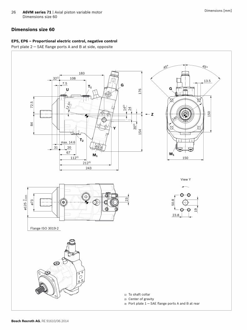
Bosch Rexroth AG RE 91610062014
26 A6VM series 71 | Axial piston variable motorDimensions size 60
Dimensions [mm]
Dimensions size 60
EP5 EP6 ndash Proportional electric control negative controlPort plate 2 mdash SAE flange ports A and B at side opposite
150
UT1
T2
G
M1
Y
Z
M1
G75
183108321)
725
84
max 146
1122)
203167
2123)
2430
3)
176
154
243
142)
160
45deg
135
45deg
150
508
238
19
0oslash1
25 -0
025
oslash73 23
125
deg
View Y
Flange ISO 3019-2
1) To shaft collar2) Center of gravity3) Port plate 1 mdash SAE flange ports A and B at rear
RE 91610062014 Bosch Rexroth AG
Axial piston variable motor | A6VM series 71 Dimensions size 60
27Dimensions [mm]
Location of the service line ports on the port plates (view Z)
2 SAE flange portA and B at side opposite
1 SAE flange portA and B at rear
2 SAE flange portA and B at side opposite only HZ7 EZ78
1 SAE flange portA and B at rear only HZ7 EZ78
B A
15254
16554
B A
152
AB
375 375
AB
165
Splined shaft SAE J744 Splined shaft DIN 5480
S7 ‒ 1 14 in 14T 1224DP1) Z8 ‒ W35times2times16times9g
28
40
716
-14U
NC
-2B
2)3)
oslash45
48
95
40
32
M12
x 1
753)
4)
95
28
oslash45
1) Involute spline acc to ANSI B921a 30deg pressure angle flat root side fit tolerance class 5
2) Thread according to ASME B11
3) For notes on tightening torques see instruction manual4) Center bore according to DIN 332 (thread according to DIN 13)
Bosch Rexroth AG RE 91610062014
28 A6VM series 71 | Axial piston variable motorDimensions size 60
Dimensions [mm]
Ports Standard Size1) pmax abs [bar]2) Status6)
A B Service line portFastening thread AB
SAE J5183)
DIN 1334 inM10 times 15 17 deep
500 O
T1 Drain port ISO 61495) M22 times 15 155 deep 3 X4)
T2 Drain port ISO 61495) M27 times 2 19 deep 3 O4)
G Synchronous control ISO 61495) M14 times 15 115 deep 500 X
U Bearing flushing ISO 61495) M18 times 15 145 deep 3 X
X Pilot signal (HP HZ HA1THA2T) ISO 61495) M14 times 15 115 deep 100 O
X Pilot signal (HA1 HA2) ISO 61495) M14 times 15 115 deep 3 X
X1 X2 Pilot signal (DA0) ISO 8434-1 SDSC-L8timesM12-F 40 O
X1 Pilot signal (DA1 DA2) ISO 61495) M14 times 15 115 deep 40 O
X3 Pilot signal (DA1 DA2) ISO 61495) M14 times 15 115 deep 40 X
M1 Measuring stroking chamber ISO 61495) M14 times 15 115 deep 500 X
1) For notes on tightening torques see instruction manual2) Momentary pressure spikes may occur depending on the application
Keep this in mind when selecting measuring devices and fittings3) Only dimensions according to SAE J518 metric fastening thread is
a deviation from standard
4) Depending on installation position T1 or T2 must be connected (see also installation instructions on page 72)
5) The spot face can be deeper than specified in the appropriate standard6) O = Must be connected (plugged on delivery)
X = Plugged (in normal operation)
RE 91610062014 Bosch Rexroth AG
Axial piston variable motor | A6VM series 71 Dimensions size 60
29Dimensions [mm]
EP1 EP2 ndash Electric proportional control positive control
EP5D1 EP6D1 ndash Electric proportional control negative control with pressure control fixed
GG
M1 M1
239
225
107
B A
154
243
176
M1M1
G
B A
G
HP1 HP2 ndash Hydraulic proportional control positive control
HP5 HP6 ndash Hydraulic proportional control negative control
M1M1
XG
159
139
107
XG
355 160
239
B A
M1
X G XG355 210
240
154
90 110
M1
B A
HP5D1 HP6D1 ndash Hydraulic proportional control negative control with pressure control fixed
355
154
215240
89 120
M1
GG X X
M1
B A
Bosch Rexroth AG RE 91610062014
30 A6VM series 71 | Axial piston variable motorDimensions size 60
Dimensions [mm]
HZ7 ndash Hydraulic two-point control negative control
EZ7 EZ8 ndash Electric two-point control negative control
2431
1)
14611
710
0
183
GX
1512151)
227
61 G
X
AB
124
G
AB
G
227
2431
1)
146
100
183
2151)
HA1 HA2 HA1T3 HA2T3 ndash Automatic high-pressure-related control positive control with override hydraulic remote con-trolled proportional
HA1U1 HA2U2 ndash Automatic high-pressure-related control positive control with override electric two-point
M1M1
XG
159
139
107
XG
355 160
239
B A
M1
B A
239
225
107
G
M1
G
HA1 and HA2 X plugged
HA1T and HA2T X open
HA1R1 HA2R2 ndash Automatic high-pressure-related control positive control with override electric and travel direction valve electric
225
a
b
GG
M1M1
B A
239
107
110
1) Port plate 1 ndash SAE flange ports A and B at rear
RE 91610062014 Bosch Rexroth AG
Axial piston variable motor | A6VM series 71 Dimensions size 60
31Dimensions [mm]
DA0 ndash Automatic speed-related control negative control with hydraulic travel direction valve
DA1 DA2 ndash Automatic speed-related control negative control with electric travel direction valve and electric Vg max circuit
M1
G X3X1 X2
178243
154
94 120
160
G X3X1 X2
M1
AB
G
M1
X3
M1
X1
154
202243
132
155
G
X1 X3
110 85
AB
b
a
X1 X2 pipe fitting SDSC ndash L8timesM12 ndash F according to ISO 8434-1
Use assembled fitting
Bosch Rexroth AG RE 91610062014
32 A6VM series 71 | Axial piston variable motorDimensions size 85
Dimensions [mm]
Dimensions size 85
EP5 EP6 ndash Proportional electric control negative controlPort plate 2 mdash SAE flange ports A and B at side opposite
T2
T1U
M1
45deg
Y
GG
M1
135
Z
11775
321)208
167
275
182
343)
132)
2712393)
1122)
233176
max 146
9180
125
deg
180
45deg
165
165
23-00
25oslash1
40 0
oslash83
572
278
25
View Y
Flange ISO 3019-2
1) To shaft collar2) Center of gravity3) Port plate 1 mdash SAE flange ports A and B at rear
RE 91610062014 Bosch Rexroth AG
Axial piston variable motor | A6VM series 71 Dimensions size 85
33Dimensions [mm]
Location of the service line ports on the port plates (view Z)
2 SAE flange portA and B at side opposite
1 SAE flange portA and B at rear
2 SAE flange portA and B at side opposite only HZ7 EZ78
1 SAE flange portA and B at rear only HZ7 EZ78
B A
164
B A
54177
54
AB
164
B A
4242177
Splined shaft SAE J744 Splined shaft DIN 5480
S9 ‒ 1 12 in 17T 1224DP1) Z9 ‒ W40times2times18times9g
28
44
716
-14U
NC
-2B
2)3)
oslash50
54
95
45
37
M16
x 2
3)4) 12
36
oslash50
1) Involute spline acc to ANSI B921a 30deg pressure angle flat root side fit tolerance class 5
2) Thread according to ASME B11
3) For notes on tightening torques see instruction manual4) Center bore according to DIN 332 (thread according to DIN 13)
Bosch Rexroth AG RE 91610062014
34 A6VM series 71 | Axial piston variable motorDimensions size 85
Dimensions [mm]
Ports Standard Size1) pmax abs [bar]2) Status6)
A B Service line portFastening thread AB
SAE J5183)
DIN 131 inM12 times 175 17 deep
500 O
T1 Drain port ISO 61495) M22 times 15 155 deep 3 X4)
T2 Drain port ISO 61495) M27 times 2 19 deep 3 O4)
G Synchronous control ISO 61495) M14 times 15 115 deep 500 X
U Bearing flushing ISO 61495) M18 times 15 145 deep 3 X
X Pilot signal (HP HZ HA1THA2T) ISO 61495) M14 times 15 115 deep 100 O
X Pilot signal (HA1 HA2) ISO 61495) M14 times 15 115 deep 3 X
X1 X2 Pilot signal (DA0) ISO 8434-1 SDSC-L8timesM12-F 40 O
X1 Pilot signal (DA1 DA2) ISO 61495) M14 times 15 115 deep 40 O
X3 Pilot signal (DA1 DA2) ISO 61495) M14 times 15 115 deep 40 X
M1 Measuring stroking chamber ISO 61495) M14 times 15 115 deep 500 X
1) For notes on tightening torques see instruction manual2) Momentary pressure spikes may occur depending on the application
Keep this in mind when selecting measuring devices and fittings3) Only dimensions according to SAE J518 metric fastening thread is
a deviation from standard
4) Depending on installation position T1 or T2 must be connected (see also installation instructions on page 72)
5) The spot face can be deeper than specified in the appropriate standard6) O = Must be connected (plugged on delivery)
X = Plugged (in normal operation)
RE 91610062014 Bosch Rexroth AG
Axial piston variable motor | A6VM series 71 Dimensions size 85
35Dimensions [mm]
EP1 EP2 ndash Electric proportional control positive control
EP5D1 EP6D1 ndash Electric proportional control negative control with pressure control fixed
G
M1
AB
238
113
G
266
M1
G
M1
AB
G
M1
167
182
271
HP1 HP2 ndash Hydraulic proportional control positive control
HP5 HP6 ndash Hydraulic proportional control negative control
266
G
AB
M1
X
172
113
M1
G
X183
152
355 M1
G XX
AB
M1
G355 238
268
116
9616
7
HP5D1 HP6D1 ndash Hydraulic proportional control negative control with pressure control fixed
G
AB
M1
X355
G X
M1
126
9516
7
243268
Bosch Rexroth AG RE 91610062014
36 A6VM series 71 | Axial piston variable motorDimensions size 85
Dimensions [mm]
HZ7 ndash Hydraulic two-point control negative control
EZ7 EZ8 ndash Electric two-point control negative control
GX
1712421)
61
AB
208254
112
2735
1)
161
132
G
X
124G
2421)
AB
208254
112
2735
1)
161
G
HA1 HA2 HA1T3 HA2T3 ndash Automatic high-pressure-related control positive control with override hydraulic remote con-trolled proportional
HA1U1 HA2U2 ndash Automatic high-pressure-related control positive control with override electric two-point
266
G
AB
M1
X
172
113
M1
G
X183
152
355
M1
AB
G
M1
113
G
266
239
HA1 and HA2 X plugged
HA1T and HA2T X open
HA1R1 HA2R2 ndash Automatic high-pressure-related control positive control with override electric and travel direction valve electric
AB
M1
G
M1
266
239
113
G
110
a
b
1) Port plate 1 ndash SAE flange ports A and B at rear
RE 91610062014 Bosch Rexroth AG
Axial piston variable motor | A6VM series 71 Dimensions size 85
37Dimensions [mm]
DA0 ndash Automatic speed-related control negative control with hydraulic travel direction valve
DA1 DA2 ndash Automatic speed-related control negative control with electric travel direction valve and electric Vg max circuit
M1
AB
160
X3
167
126
207271
100
M1
X1 X2 GX1
X3GX2
G
X3X1
167
161
230270
M1M1
A
138
110
B
85
G
X1X3 ba
X1 X2 pipe fitting SDSC ndash L8timesM12 ndash F according to ISO 8434-1
Use assembled fitting
Bosch Rexroth AG RE 91610062014
38 A6VM series 71 | Axial piston variable motorDimensions size 115
Dimensions [mm]
Dimensions size 115
EP5 EP6 ndash Proportional electric control negative controlPort plate 2 mdash SAE flange ports A and B at side opposite
25
GT1U
T2
M1
200
Y
Z
M1
G
126220
401)
75
102)
3038
3)
188
175
45deg 45deg
175
190
1901262)
2573)
290
253978
max 146
102
91oslash9
0
oslash160
0 -00
25
572
278 25
125
deg
View Y
Flange ISO 3019-2
1) To shaft collar2) Center of gravity3) Port plate 1 mdash SAE flange ports A and B at rear
RE 91610062014 Bosch Rexroth AG
Axial piston variable motor | A6VM series 71 Dimensions size 115
39Dimensions [mm]
Location of the service line ports on the port plates (view Z)
2 SAE flange portA and B at side opposite
1 SAE flange portA and B at rear
2 SAE flange portA and B at side opposite only HZ7 EZ78
1 SAE flange portA and B at rear only HZ7 EZ78
M1
AB
180
B A
65193
65 180
B A
4242
193
B A
Splined shaft SAE J744 Splined shaft DIN 5480
T1 ‒ 1 34 in 13T 813DP1) Z9 ‒ W40times2times18times9g
36
55
58-
11U
NC
-2B
2)3)
oslash60
67
12
45
37
M16
times 2
3)4)
36
oslash60
12
1) Involute spline acc to ANSI B921a 30deg pressure angle flat root side fit tolerance class 5
2) Thread according to ASME B11
3) For notes on tightening torques see instruction manual4) Center bore according to DIN 332 (thread according to DIN 13)
Bosch Rexroth AG RE 91610062014
40 A6VM series 71 | Axial piston variable motorDimensions size 115
Dimensions [mm]
Ports Standard Size1) pmax abs [bar]2) Status6)
A B Service line portFastening thread AB
SAE J5183)
DIN 131 inM12 times 175 17 deep
500 O
T1 Drain port ISO 61495) M27 times 2 19 deep 3 X4)
T2 Drain port ISO 61495) M33 times 2 19 deep 3 O4)
G Synchronous control ISO 61495) M14 times 15 115 deep 500 X
U Bearing flushing ISO 61495) M18 times 15 145 deep 3 X
X Pilot signal (HP HZ HA1THA2T) ISO 61495) M14 times 15 115 deep 100 O
X Pilot signal (HA1 HA2) ISO 61495) M14 times 15 115 deep 3 X
X1 X2 Pilot signal (DA0) ISO 8434-1 SDSC-L8timesM12-F 40 O
X1 Pilot signal (DA1 DA2) ISO 61495) M14 times 15 115 deep 40 O
X3 Pilot signal (DA1 DA2) ISO 61495) M14 times 15 115 deep 40 X
M1 Measuring stroking chamber ISO 61495) M14 times 15 115 deep 500 X
1) For notes on tightening torques see instruction manual2) Momentary pressure spikes may occur depending on the application
Keep this in mind when selecting measuring devices and fittings3) Only dimensions according to SAE J518 metric fastening thread is
a deviation from standard
4) Depending on installation position T1 or T2 must be connected (see also installation instructions on page 72)
5) The spot face can be deeper than specified in the appropriate standard6) O = Must be connected (plugged on delivery)
X = Plugged (in normal operation)
RE 91610062014 Bosch Rexroth AG
Axial piston variable motor | A6VM series 71 Dimensions size 115
41Dimensions [mm]
EP1 EP2 ndash Electric proportional control positive control
EP5D1 EP6D1 ndash Electric proportional control negative control with pressure control fixed
M1
121
281
249
G
M1
B A
G
G
188
175
G
290
B A
M1M1
HP1 HP2 ndash Hydraulic proportional control positive control
HP5 HP6 ndash Hydraulic proportional control negative control
405
G X
164
199
121
180
281
G
M1
X
M1
B A
GX257
M1
405
G
121
175
101
288
M1
X
AB
HP5D1 HP6D1 ndash Hydraulic proportional control negative control with pressure control fixed
G X
M1
XG
M1
133
175
101
290258405
B A
Bosch Rexroth AG RE 91610062014
42 A6VM series 71 | Axial piston variable motorDimensions size 115
Dimensions [mm]
HZ7 ndash Hydraulic two-point control negative control
EZ7 EZ8 ndash Electric two-point control negative control
143
182 G61X
2561)
121
17230
381)
220270
B A
G
X
2561)
30
G G124
121
381)
220
B A
172
270
HA1 HA2 HA1T3 HA2T3 ndash Automatic high-pressure-related control positive control with override hydraulic remote con-trolled proportional
HA1U1 HA2U2 ndash Automatic high-pressure-related control positive control with override electric two-point
405G X
164
199
121
180
281
G
M1
X
M1
B A
121
249
G
M1
G
M1
281
B A
HA1 and HA2 X plugged
HA1T and HA2T X open
HA1R1 HA2R2 ndash Automatic high-pressure-related control positive control with override electric and travel direction valve electric
112
121
249
G
M1
G
M1
281
B A
a
b
1) Port plate 1 ndash SAE flange ports A and B at rear
RE 91610062014 Bosch Rexroth AG
Axial piston variable motor | A6VM series 71 Dimensions size 115
43Dimensions [mm]
DA0 ndash Automatic speed-related control negative control with hydraulic travel direction valve
DA1 DA2 ndash Automatic speed-related control negative control with electric travel direction valve and electric Vg max circuit
G174
175
290
132
107
X3X1 X2X1 X2 G X3
M1M1
B A
216
112 238290
M1 M1
G
X3X1
G
X1
175
145
168
X3 ba
85
B A
X1 X2 pipe fitting SDSC ndash L8timesM12 ndash F according to ISO 8434-1
Use assembled fitting
Bosch Rexroth AG RE 91610062014
44 A6VM series 71 | Axial piston variable motorDimensions size 150
Dimensions [mm]
Dimensions size 150
EP5 EP6 ndash Proportional electric control negative controlPort plate 2 mdash SAE flange ports A and B at side opposite
M1
T1
T2
U
224
45deg
Y
Z
G G
M1
max 14939 28
9051392)
3212883)
112)
3342
3)
196
195
247401) 1405
75
109
100
125
deg
45deg
175
210
210
25
667
318
32
oslash94
oslash180
-00
250
View Y
Flange ISO 3019-2
1) To shaft collar2) Center of gravity3) Port plate 1 mdash SAE flange ports A and B at rear
RE 91610062014 Bosch Rexroth AG
Axial piston variable motor | A6VM series 71 Dimensions size 150
45Dimensions [mm]
Location of the service line ports on the port plates (view Z)
2 SAE flange portA and B at side opposite
1 SAE flange portA and B at rear
AB
204
B A
7676226
Splined shaft SAE J744 Splined shaft SAE J744
T1 ‒ 1 34 in 13T 816DP1) T2 ‒ 2 in 15T 816DP1)
36
53
58-
11U
NC
-2B
2)3)
oslash60
67
12
36
53
58-
11U
NC
-2B
2)3)
oslash60
67
12
Splined shaft DIN 5480
A1 ‒ W45times2times21times9g
50
42
M16
times 2
3)4)
36
oslash60
12
1) Involute spline acc to ANSI B921a 30deg pressure angle flat root side fit tolerance class 5
2) Thread according to ASME B113) For notes on tightening torques see instruction manual 4) Center bore according to DIN 332 (thread according to DIN 13)
Bosch Rexroth AG RE 91610062014
46 A6VM series 71 | Axial piston variable motorDimensions size 150
Dimensions [mm]
Ports Standard Size1) pmax abs [bar]2) Status6)
A B Service line portFastening thread AB
SAE J5183)
DIN 131 14 inM14 times 2 19 deep
500 O
T1 Drain port ISO 61495) M27 times 2 19 deep 3 X4)
T2 Drain port ISO 61495) M33 times 2 19 deep 3 O4)
G Synchronous control ISO 61495) M14 times 15 115 deep 500 X
U Bearing flushing ISO 61495) M22 times 15 155 deep 3 X
X Pilot signal (HP HZ HA1THA2T) ISO 61495) M14 times 15 115 deep 100 O
X Pilot signal (HA1 HA2) ISO 61495) M14 times 15 115 deep 3 X
X1 X2 Pilot signal (DA0) ISO 8434-1 SDSC-L8timesM12-F 40 O
X1 Pilot signal (DA1 DA2) ISO 61495) M14 times 15 115 deep 40 O
X3 Pilot signal (DA1 DA2) ISO 61495) M14 times 15 115 deep 40 X
M1 Measuring stroking chamber ISO 61495) M14 times 15 115 deep 500 X
1) For notes on tightening torques see instruction manual2) Momentary pressure spikes may occur depending on the application
Keep this in mind when selecting measuring devices and fittings3) Only dimensions according to SAE J518 metric fastening thread is
a deviation from standard
4) Depending on installation position T1 or T2 must be connected (see also installation instructions on page 72)
5) The spot face can be deeper than specified in the appropriate standard6) O = Must be connected (plugged on delivery)
X = Plugged (in normal operation)
RE 91610062014 Bosch Rexroth AG
Axial piston variable motor | A6VM series 71 Dimensions size 150
47Dimensions [mm]
EP1 EP2 ndash Electric proportional control positive control
EP5D1 EP6D1 ndash Electric proportional control negative control with pressure control fixed
132
315
264
G
M1
B A
M1
G
GG
196
195
321
M1 M1
B A
HP1 HP2 ndash Hydraulic proportional control positive control
HP5 HP6 ndash Hydraulic proportional control negative control
405XG
178
225
132
195
315
M1
XG
AB
M1
X G G X
M1
B A
M1
132
195
109
320289405
HP5D1 HP6D1 ndash Hydraulic proportional control negative control with pressure control fixed
X X
M1M1
B A
141
108
G
321290
G
195
405
Bosch Rexroth AG RE 91610062014
48 A6VM series 71 | Axial piston variable motorDimensions size 150
Dimensions [mm]
HZ5 ndash Hydraulic two-point control negative control
EZ5 EZ6 ndash Electric two-point control negative control
405
G
108
285
132
195
319
M1 M1
XG
B A
X
186
319
195
M1
G
B A
G
M1
HA1 HA2 HA1T3 HA2T3 ndash Automatic high-pressure-related control positive control with override hydraulic remote con-trolled proportional
HA1U1 HA2U2 ndash Automatic high-pressure-related control positive control with override electric two-point
405XG
178
225
132
195
315
M1 M1
XG
AB
132
315
264
M1
G
AB
G
M1
HA1 and HA2 X plugged
HA1T and HA2T X open
HA1R1 HA2R2 ndash Automatic high-pressure-related control positive control with override electric and travel direction valve electric
a
b112
132
315
264
M1
G
AB
G
M1
RE 91610062014 Bosch Rexroth AG
Axial piston variable motor | A6VM series 71 Dimensions size 150
49Dimensions [mm]
DA0 ndash Automatic speed-related control negative control with hydraulic travel direction valve
DA1 DA2 ndash Automatic speed-related control negative control with electric travel direction valve and electric Vg max circuit
174
X2X1G X3 G X3
195
140
247322
M1
115
B A
M1
X2
176
195
153
112
M1
G
85
B A
X1X3
M1
270322
G
X3X1ba
X1 X2 pipe fitting SDSC ndash L8timesM12 ndash F according to ISO 8434-1
Use assembled fitting
Bosch Rexroth AG RE 91610062014
50 A6VM series 71 | Axial piston variable motorDimensions size 170
Dimensions [mm]
Dimensions size 170
EP5 EP6 ndash Proportional electric control negative controlPort plate 2 mdash SAE flange ports A and B at side opposite
G
Y
T2
M1
T1U
Z
G
M1
oslash100
oslash180
-00
250
667
318 32
210
210
175
224
103
112
401)
75141
25412
5deg
1412)
9139 28
max 149
2953)
328
19743
3)
195
122)
34
45deg 45deg
25
View Y
Flange ISO 3019-2
1) To shaft collar2) Center of gravity3) Port plate 1 mdash SAE flange ports A and B at rear
RE 91610062014 Bosch Rexroth AG
Axial piston variable motor | A6VM series 71 Dimensions size 170
51Dimensions [mm]
Location of the service line ports on the port plates (view Z)
2 SAE flange portA and B at side opposite
1 SAE flange portA and B at rear
B A
20476
B A
22676
Splined shaft SAE J744 Splined shaft DIN 5480
T2 ‒ 2 in 15T 816DP1) A1 ‒ W45times2times21times9g
36
53
58-
11U
NC
-2B
2)3)
oslash70
67
12
50
42
M16
times 2
3)4)
36
oslash70
12
1) Involute spline acc to ANSI B921a 30deg pressure angle flat root side fit tolerance class 5
2) Thread according to ASME B11
3) For notes on tightening torques see instruction manual4) Center bore according to DIN 332 (thread according to DIN 13)
Bosch Rexroth AG RE 91610062014
52 A6VM series 71 | Axial piston variable motorDimensions size 170
Dimensions [mm]
Ports Standard Size1) pmax abs [bar]2) Status6)
A B Service line portFastening thread AB
SAE J5183)
DIN 131 14 inM14 times 2 19 deep
500 O
T1 Drain port ISO 61495) M27 times 2 19 deep 3 X4)
T2 Drain port ISO 61495) M33 times 2 19 deep 3 O4)
G Synchronous control ISO 61495) M14 times 15 115 deep 500 X
U Bearing flushing ISO 61495) M22 times 15 155 deep 3 X
X Pilot signal (HP HZ HA1THA2T) ISO 61495) M14 times 15 115 deep 100 O
X Pilot signal (HA1 HA2) ISO 61495) M14 times 15 115 deep 3 X
X1 X2 Pilot signal (DA0) ISO 8434-1 SDSC-L8timesM12-F 40 O
X1 Pilot signal (DA1 DA2) ISO 61495) M14 times 15 115 deep 40 O
X3 Pilot signal (DA1 DA2) ISO 61495) M14 times 15 115 deep 40 X
M1 Measuring stroking chamber ISO 61495) M14 times 15 115 deep 500 X
1) For notes on tightening torques see instruction manual2) Momentary pressure spikes may occur depending on the application
Keep this in mind when selecting measuring devices and fittings3) Only dimensions according to SAE J518 metric fastening thread is
a deviation from standard
4) Depending on installation position T1 or T2 must be connected (see also installation instructions on page 72)
5) The spot face can be deeper than specified in the appropriate standard6) O = Must be connected (plugged on delivery)
X = Plugged (in normal operation)
RE 91610062014 Bosch Rexroth AG
Axial piston variable motor | A6VM series 71 Dimensions size 170
53Dimensions [mm]
EP1 EP2 ndash Electric proportional control positive control
EP5D1 EP6D1 ndash Electric proportional control negative control with pressure control fixed
G
B A
M1
G
M1
322
133
266
195
197
328
G
M1M1
B A
G
HP1 HP2 ndash Hydraulic proportional control positive control
HP5 HP6 ndash Hydraulic proportional control negative control
405
181
133
197
322
232
XG
M1
GX
B A
M1
405
108
133
197
296326
X G
M1
B A
G X
M1
HP5D1 HP6D1 ndash Hydraulic proportional control negative control with pressure control fixed
328297
108
141
197
X XG G
M1
B A
405
M1
Bosch Rexroth AG RE 91610062014
54 A6VM series 71 | Axial piston variable motorDimensions size 170
Dimensions [mm]
HZ5 ndash Hydraulic two-point control negative control
EZ5 EZ6 ndash Electric two-point control negative control
197
107
133
405 291326
X G
M1
G
B A
X
M1
G
M1
G
B A
M1
197
187
326
HA1 HA2 HA1T3 HA2T3 ndash Automatic high-pressure-related control positive control with override hydraulic remote con-trolled proportional
HA1U1 HA2U2 ndash Automatic high-pressure-related control positive control with override electric two-point
405
181
133
197
322
232G
M1
G X
B A
X
M1 M1
B A
M1
G G
322
133
266
HA1 and HA2 X plugged
HA1T and HA2T X open
HA1R1 HA2R2 ndash Automatic high-pressure-related control positive control with override electric and travel direction valve electric
322
133
266
112
a
bG
M1
G
B A
M1
RE 91610062014 Bosch Rexroth AG
Axial piston variable motor | A6VM series 71 Dimensions size 170
55Dimensions [mm]
DA0 ndash Automatic speed-related control negative control with hydraulic travel direction valve
DA1 DA2 ndash Automatic speed-related control negative control with electric travel direction valve and electric Vg max circuit
X2X1G X3 G X3
M1
X1 X2
B A
M1
174
197
140
254328
115
B A
M1
G
X1X3
M1
G
X3X1
ab
176
197
153
277328
112 85
X1 X2 pipe fitting SDSC ndash L8timesM12 ndash F according to ISO 8434-1
Use assembled fitting
Bosch Rexroth AG RE 91610062014
56 A6VM series 71 | Axial piston variable motorDimensions size 215
Dimensions [mm]
Dimensions size 215
EP5 EP6 ndash Proportional electric control negative controlPort plate 2 mdash SAE flange ports A and B at side opposite
T2
M1
T1U
Y
125
deg
Z
G G
M1236
236
45deg 45deg
22
250
667
32318
29
oslash200
-0 -00
29
oslash108
75151
267401)
107
125
1472)
3143)
345
9639 32
max 149
209
192)
3646
53)
200
Flange ISO 3019-2
View Y
1) To shaft collar2) Center of gravity3) Port plate 1 mdash SAE flange ports A and B at rear
RE 91610062014 Bosch Rexroth AG
Axial piston variable motor | A6VM series 71 Dimensions size 215
57Dimensions [mm]
Location of the service line ports on the port plates (view Z)
2 SAE flange portA and B at side opposite
1 SAE flange portA and B at rear
216
B A
82
235
82
B A
Splined shaft SAE J744 Splined shaft DIN 5480
T2 ‒ 2 in 15T 816DP1) A2 ‒ W50times2times24times9g
36
53
58-
11U
NC
-2B
2)3)
oslash70
67
12
55
44
M16
times 2
3)4)
36
oslash70
12
1) Involute spline acc to ANSI B921a 30deg pressure angle flat root side fit tolerance class 5
2) Thread according to ASME B11
3) For notes on tightening torques see instruction manual4) Center bore according to DIN 332 (thread according to DIN 13)
Bosch Rexroth AG RE 91610062014
58 A6VM series 71 | Axial piston variable motorDimensions size 215
Dimensions [mm]
Ports Standard Size1) pmax abs [bar]2) Status6)
A B Service line portFastening thread AB
SAE J5183)
DIN 131 14 inM14 times 2 19 deep
500 O
T1 Drain port ISO 61495) M33 times 2 19 deep 3 X4)
T2 Drain port ISO 61495) M42 times 2 195 deep 3 O4)
G Synchronous control ISO 61495) M14 times 15 115 deep 500 X
U Bearing flushing ISO 61495) M22 times 15 155 deep 3 X
X Pilot signal (HP HZ HA1THA2T) ISO 61495) M14 times 15 115 deep 100 O
X Pilot signal (HA1 HA2) ISO 61495) M14 times 15 115 deep 3 X
X1 X2 Pilot signal (DA0) ISO 8434-1 SDSC-L8timesM12-F 40 O
X1 Pilot signal (DA1 DA2) ISO 61495) M14 times 15 115 deep 40 O
X3 Pilot signal (DA1 DA2) ISO 61495) M14 times 15 115 deep 40 X
M1 Measuring stroking chamber ISO 61495) M14 times 15 115 deep 500 X
1) For notes on tightening torques see instruction manual2) Momentary pressure spikes may occur depending on the application
Keep this in mind when selecting measuring devices and fittings3) Only dimensions according to SAE J518 metric fastening thread is
a deviation from standard
4) Depending on installation position T1 or T2 must be connected (see also installation instructions on page 72)
5) The spot face can be deeper than specified in the appropriate standard6) O = Must be connected (plugged on delivery)
X = Plugged (in normal operation)
RE 91610062014 Bosch Rexroth AG
Axial piston variable motor | A6VM series 71 Dimensions size 215
59Dimensions [mm]
EP1 EP2 ndash Electric proportional control positive control
EP5D1 EP6D1 ndash Electric proportional control negative control with pressure control fixed
339
140
275
M1
G
M1
G
B A
M1
B A
M1
G
209
200
345
G
HP1 HP2 ndash Hydraulic proportional control positive control
HP5 HP6 ndash Hydraulic proportional control negative control
M1
G
B A
X
M1
339
206
245
GX
190
405
140
M1
209
140
343
M1
B A
X G X312
113
G405
HP5D1 HP6D1 ndash Hydraulic proportional control negative control with pressure control fixed
M1
G
B A
M1
X
209
145
G X313
344405
112
Bosch Rexroth AG RE 91610062014
60 A6VM series 71 | Axial piston variable motorDimensions size 215
Dimensions [mm]
HZ5 ndash Hydraulic two-point control negative control
EZ5 EZ6 ndash Electric two-point control negative control
M1
XG
140
209
111
308343
M1
X G405
B A
M1
G
B A
M1
191
209
343
G
HA1 HA2 HA1T3 HA2T3 ndash Automatic high-pressure-related control positive control with override hydraulic remote con-trolled proportional
HA1U1 HA2U2 ndash Automatic high-pressure-related control positive control with override electric two-point
M1
G
B A
X
M1
339
206
245
GX
190
405
140
B A
M1
G
M1
339
276
140
G
HA1 and HA2 X plugged
HA1T and HA2T X open
HA1R1 HA2R2 ndash Automatic high-pressure-related control positive control with override electric and travel direction valve electric
M1
276
140
339
G
M1
B A
Ga
112
b
RE 91610062014 Bosch Rexroth AG
Axial piston variable motor | A6VM series 71 Dimensions size 215
61Dimensions [mm]
DA0 ndash Automatic speed-related control negative control with hydraulic travel direction valve
DA1 DA2 ndash Automatic speed-related control negative control with electric travel direction valve and electric Vg max circuit
M1
B A
X1 X2X3G X1 X2 X3G
M1
174 271345
209
144
119
209
180
157
294345
85112
M1
B A
M1
G
X1X3
G
X1 X3
ab
X1 X2 pipe fitting SDSC ndash L8timesM12 ndash F according to ISO 8434-1
Use assembled fitting
Bosch Rexroth AG RE 91610062014
62 A6VM series 71 | Axial piston variable motorConnector for solenoids
Connector for solenoids
DEUTSCH DT04-2P-EP04Molded connector 2-pin without bidirectional suppres-sor diode There is the following type of protection with mounted mating connector
IP67 (DINEN 60529) and IP69K (DIN 40050-9)
Circuit symbol
Mating connector DEUTSCH DT06-2S-EP04
Consisting of DT designation
1 housing DT06-2S-EP04
1 wedge W2S
2 sockets 0462-201-16141
The mating connector is not included in the scope of deliv-ery This can be supplied by Bosch Rexroth on request (material number R902601804)
NoteIf necessary you can change the connector orientation by turning the solenoid housingThe procedure can be taken from the instruction manual
RE 91610062014 Bosch Rexroth AG
Axial piston variable motor | A6VM series 71 Flushing and boost pressure valve
63
Flushing and boost pressure valve
The flushing and boost pressure valve is used to remove heat from the hydraulic circuitIn an open circuit it is used only for flushing the housingIn a closed circuit it ensures a minimum boost pressure level in addition to the case flushingHydraulic fluid is directed from the respective low pressure side into the motor housing This is then fed into the reser-voir together with the leakage The hydraulic fluid removed out of the closed circuit must be replaced by cooled hydraulic fluid from the boost pumpThe valve is mounted onto the port plate or integrated (depending on the control type and size)Cracking pressure of pressure retaining valve(observe when adjusting the primary valve)
Sizes 60 to 215 fixed setting 16 barSwitching pressure of flushing spool Dp
Sizes 60 to 115 (no flushing valve) 8plusmn1 bar Sizes 115 to 215 (medium and large flushing valve)
175plusmn15 barFlushing flow qv
Orifices can be used to adjust the flushing flows as required The following information is based on DpND = pND ndash pG = 25 bar and ν = 10 mm2s (pND = low pressure pG = case pressure)
Small flushing valve for sizes 60 to 115
Material number of orifice oslash [mm] qv [lmin] Code
R909651766 12 35 A
R909419695 14 5 B
R909419696 18 8 C
R909419697 20 10 D
R909444361 24 14 F
Medium flushing valve for size 115
Material number of orifice oslash [mm] qv [lmin] Code
R909431310 28 20 H
R909435172 35 25 J
R909449967 50 30 K
Large flushing valve for sizes 150 to 215
Material number of orifice oslash [mm] qv [lmin] Code
R909449998 18 8 C
R909431308 20 10 D
R909431309 25 17 G
R909431310 28 20 H
R902138235 31 25 J
R909435172 35 30 K
R909436622 40 35 L
R909449967 50 40 M
Schematic EP
G
T2
T1U
Sa
B
A
Vg min
Vg max
M1
Flushing spool
Pressure retain-ing valve
Flushing orifice
Notes Port Sa only for sizes 150 to 215 For a flushing flow greater than 35 l min it is recom-
mended that port Sa be connected in order to prevent an increase in case pressure An increased case pres-sure reduces the flushing flow
Bosch Rexroth AG RE 91610062014
64 A6VM series 71 | Axial piston variable motorFlushing and boost pressure valve
Dimensions [mm]
Dimensions of sizes 60 to 115 (small flushing valve)
A1 A4
HA1 HA2HP1 HP2EP1 EP2
HP5 HP6EP5 EP6DA
HZ7EZ7 EZ8
A3
A2
NG A1 A2 A3 A4
60 245 137 183 236
85 273 142 194 254
115 287 143 202 269
Dimensions for sizes 115 to 215 (large flushing valve)
Sa
Sa
Sa
Z
HA1 HA2HP1 HP2EP1 EP2
HP5 HP6 DAEP5 EP6HZ5 EZ5 EZ6
B4
A2B2
A3B
3
38
A1B1
NG A1 B1 A2 B2 A3 B3 B4
60 325 239 165 142 230 187 166
85 332 246 165 142 233 190 172
115 349 263 172 148 244 201 185
Dimensions of size 115 (medium flushing valve)
205
151
292
HA1 HA2HP1 HP2EP1 EP2
HP5 HP6EP5 EP6DA
NG Sa1)
150
M22 times 15 155 deep170
215
1) ISO 6149 ports plugged (in normal operation) For notes on tightening torques see instruction manual The spot face can be deeper than specified in the appropriate stan-dard
RE 91610062014 Bosch Rexroth AG
Axial piston variable motor | A6VM series 71 Counterbalance valve BVD and BVE
65
Counterbalance valve BVD and BVE
FunctionCounterbalance valves for travel drive and winch operations are designed to reduce the danger of overspeeding and cavitation of axial piston motors in open circuits Cavitation occurs if during braking when driving downhill or the load-lowering process the motor speed is greater than it should be for the given inlet flow causing the inlet pressure to collapseIf the pressure difference between the inflow and the out-flow drops below the value opening end of the piston in the counterbalance valve (see data sheet BVD ndash 95522 or BVE ndash 95525) the counterbalance spool will move to the closed position The cross-sectional area of the counterbalance valve return duct is then reduced creating a bottleneck in the return flow of the hydraulic fluid The pressure increases and brakes the motor until the rotational speed of the motor is again as it should be for the given inlet flow
Notes BVD available for sizes 60 to 215 and BVE available for
sizes 115 to 215 The counterbalance valve must be ordered additionally
We recommend ordering the counterbalance valve and the motor as a set Ordering example A6VM085HA1T30004A71MWV0N4S97W0-0 + BVD20F27S41BndashV03K16D0400S12
For safety reasons control systems with beginning of control at Vg min (z B HA) are not permissible for winch drives
The counterbalance valve does not replace the mechani-cal service brake and parking brake
Observe the detailed notes on the BVD counterbalance valve in data sheet 95522 and on the BVE counterbal-ance valve in data sheet 95525
For the design of the brake release valve we must know for the mechanical parking brake ndash the pressure at the start of opening ndash the volume of the counterbalance spool between
minimum travel (brake closed) and maximum travel (brake released with 21 bar)
ndash the required closing time for a warm device (oil vis-cosity approx 15 mm2s)
Permissible inlet flow or pressure when using DBV and BVDBVE
Without valve Limited values when using DBV and BVDBVE
Motor DBV1) BVD2)BVE3)
NG pnompmax [bar]
qV max [lmin]
NG pnompmax [bar]
qV [lmin]
Code NG pnompmax [bar]
qV [lmin]
Code
60 450500 276 22 350420 240 7 20 (BVD)
350420 220 7W
85 332
115 410 32 400
115 410 8 25 (BVDBVE)
320 8W
150 494
170 533
215 628 On request
1) Pressure-relief valve2) Counterbalance valve double-acting3) Counterbalance valve one-sided
Bosch Rexroth AG RE 91610062014
66 A6VM series 71 | Axial piston variable motorCounterbalance valve BVD and BVE
Counterbalance valve for travel drive BVDFApplication option
Travel drive for wheeled excavators (BVD and BVE)
Example schematic for travel drive on wheeled excavators
A6VM085HA1T30004A71MWV0N4S97W0-0 + BVD20F27S41BndashV03K16D0400S12
Bacute
A
M1
T2
T1
Vg min
Vg max
X
U
G
MB
MA
S
Gext
Gacute
Lacute
Aacute
B
Variable motor A6VMHA1T
Counterbalance valve BVD
Pump directional valve not included in the scope of delivery
Counterbalance valve for winches and track drives BVDW and BVEApplication option
Winch drives in cranes (BVD and BVE) Track drive in excavator crawlers (BVD)
Example schematic for winch drive in cranes
A6VM085HP5D10001A71MWV0N4S97W0-0 + BVE25W38S51ND-V100K00D4599T30S00-0
T2
T1
M1
Vg min
Vg max
B
A
G
X
U
MP1
VGVF
S
Gext
Mk
D
C
Dacute
Cacute
Gacute
Lacute
D1
D2
MB
MA
Variable motor A6VMHP5D
Winch with mechanical parking brake
Counterbalance valve BVE
Pump directional valve not included in the scope of delivery
RE 91610062014 Bosch Rexroth AG
Axial piston variable motor | A6VM series 71 Counterbalance valve BVD and BVE
67Dimensions [mm]
Dimensions
A6VMHA HP1 HP2 and EP1 EP2 A6VMHP5 HP6 and EP5 EP61)
MB (MA)
A BS
A8
B A
Gext
A2A1
A4A3
A6 A5A7
A2A9
MB (MA)
A4A1
0
Br
S
A8
A5 A6A7
B AA B
A6VM Counterbalance valve
NGplate Type Ports Dimensions
A B A1 A2 A3 A4 A5 A6 A7 A8 A9 A10
607 BVD2017 34 in 311 302 143 50 98 139 75 222 326 50
857 BVD2027 1 in 340 331 148 55 98 139 75 222 355 46
1157 BVD2028 1 in 362 353 152 59 98 139 84 234 377 41
1158 BVD2538 1 14 in 380 370 165 63 1205 175 84 238 395 56
1508 BVD2538 1 14 in 411 401 168 67 1205 175 84 238 426 53
1708 BVD2538 1 14 in 417 407 170 68 1205 175 84 238 432 51
2158 BVD2538 1 14 in 448 438 176 74 1205 175 84 299 463 46
1158 BVE2538 1 14 in 380 370 171 63 137 214 84 238 397 63
1508 BVE2538 1 14 in 411 401 175 67 137 214 84 238 423 59
1708 BVE2538 1 14 in 417 407 176 68 137 214 84 238 432 59
2158 BVE2538 1 14 in 448 438 182 74 137 214 84 299 463 52
Ports Version A6VM plate
Standard Size2) Pmax perm [bar]3) Status5)
A B Service line SAE J518 see table above 420 O
S Infeed BVD20 DIN 38524) M22 times 15 14 deep 30 X
BVD25 BVE25 DIN 38524) M27 times 2 16 deep 30 X
Br Brake release reduced high pressure
L 7 DIN 38524) M12 times 15 125 deep 30 O
8 DIN 38524) M12 times 15 12 deep 30 O
Gext Brake release high pressure S DIN 38524) M12 times 15 125 deep 420 X
MA MB Measuring pressure A and B ISO 61494) M18 times 15 145 deep 420 X
1) At the mounting version for the controls HP5 HP6 and EP5 EP6 the cast-in port designations A and B on the counterbalance valve BVD do not correspond with the connection drawing of the A6VM motor The designation of the ports on the installation drawing of the mo-tor is binding
2) For notes on tightening torques see instruction manual
3) Momentary pressure spikes may occur depending on the applica-tion Keep this in mind when selecting measuring devices and fit-tings
4) The spot face can be deeper than specified in the appropriate stan-dard
5) O = Must be connected (plugged on delivery) X = Plugged (in normal operation)
Bosch Rexroth AG RE 91610062014
68 A6VM series 71 | Axial piston variable motorCounterbalance valve BVD and BVE
Mounting the counterbalance valveWhen delivered the counterbalance valve is mounted to the motor with two tacking screws (transport lock) The tack-ing screws may not be removed while mounting the service lines If the counterbalance valve and motor are delivered separately the counterbalance valve must first be mounted to the motor port plate using the provided tacking screws The final mounting of the counterbalance valve on the motor is done with screw fitting of the SAE flange The screws to be used and the procedure mounting can be found in the instruction manual
RE 91610062014 Bosch Rexroth AG
Axial piston variable motor | A6VM series 71 Speed sensor
69
Speed sensor
Version A6VMU (prepared for speed sensor ie without sensor) is equipped with a spline on the rotary groupA signal proportional to motor speed can be generated with the fitted DSADSM speed sensor The DSADSM sensor registers the speed and direction of rotationOrdering code technical data dimensions and details on the connector plus safety instructions about the sensor can be found in the relevant data sheet (95132 for DSM 95133 for DSA)The sensor is mounted on the port provided for this pur-pose with a mounting bolt On deliveries without sensor the port is plugged with a pressure-resistant coverWe recommend ordering the A6VM variable motor complete with mounted sensor
Schematic EP
T2
T1UnU
Dimensions
V design with mounted speed sensor
A
C
B
Size 60 85 115 150 170 215
Number of teeth 54 58 67 72 75 80
A Insertion depth (tolerance -025) 184 184 184 184 184 184
B Contact surface 75 79 88 93 96 101
C 662 752 772 912 917 952
Bosch Rexroth AG RE 91610062014
70 A6VM series 71 | Axial piston variable motorSetting range for displacement
Setting range for displacement
60 85 115
Vg max (cm3rev) Vg min (cm3rev) Vg max (cm3rev) Vg min (cm3rev) Vg max (cm3rev) Vg min (cm3rev)
from to from to from to from to from to from to
A 620 620 00 150 852 852 00 315 1156 1156 00 240
without screw M10 times 60 R909154690
without screw M12 times 70 R909085976
without screw M12 times 70 R909085976
B 620 620 gt 150 305 852 852 gt 315 520 1156 1156 gt 240 475
without screw M10 times 70 R909153779
without screw M12 times 80 R909153075
without screw M12 times 80 R909153075
C 620 620 gt 305 430 852 852 gt 520 590 1156 1156 gt 475 710
without screw M10 times 80 R909154058
without screw M12 times 90 R909154041
without screw M12 times 90 R909154041
D x x x x 1156 1156 gt 710 800
without screw M12 times 100 R909153975
E lt 620 475 00 150 lt 852 555 00 315 lt 1156 935 00 240
M10 times 60 R909154690
M10 times 60 R909154690
M12 times 70 R909085976
M12 times 70 R909085976
M12 times 70 R909085976
M12 times 70 R909085976
F lt 620 475 gt 150 305 lt 852 555 gt 315 520 lt 1156 935 gt 240 475
M10 times 60 R909154690
M10 times 70 R909153779
M12 times 70 R909085976
M12 times 80 R909153075
M12 times 70 R909085976
M12 times 80 R909085976
G lt 620 475 gt 305 430 lt 852 555 gt 520 590 lt 1156 935 gt 475 71
M10 times 60 R909154690
M10 times 80 R909154058
M12 times 70 R909085976
M12 times 90 R909154041
M12 times 70 R909085976
M12 times 90 R909154041
H x x x times lt 1156 935 gt 710 800
M12 times 70 R909085976
M12 times 100 R909153975
J lt 475 330 00 150 lt 555 350 00 315 lt 935 710 00 240
M10 times 70 R909153779
M10 times 60 R909154690
M12 times 80 R909153075
M12 times 70 R909085976
M12 times 80 R909153075
M12 times 70 R909085976
K lt 475 330 gt 150 305 lt 555 350 gt 315 520 lt 935 710 gt 240 475
M10 times 70 R909153779
M10 times 70 R909153779
M12 times 80 R909153075
M12 times 80 R909153075
M12 times 80 R909153075
M12 times 80 R909153075
L lt 475 330 gt 305 430 lt 555 350 gt 520 590 lt 935 710 gt 475 710
M10 times 70 R909153779
M10 times 80 R909154058
M12 times 80 R909153075
M12 times 90 R909154041
M12 times 80 R909153075
M12 times 90 R909154041
M x x x x lt 935 710 gt 710 800
M12 times 80 R909153075
M12 times 100 R909153975
Specify exact settings for Vg min and Vg max in plain text when ordering
Vg min = cm3 Vg max = cm3
Theoretical maximum setting for Vg min = 07 times Vg max
for Vg max = 03 times Vg max
Settings that are not listed in the table may lead to damage Please contact us
RE 91610062014 Bosch Rexroth AG
Axial piston variable motor | A6VM series 71 Setting range for displacement
71
150 170 215
Vg max (cm3rev) Vg min (cm3rev) Vg max (cm3rev) Vg min (cm3rev) Vg max (cm3rev) Vg min (cm3rev)
from to from to from to from to from to from to
A 1521 1521 00 440 1718 1718 00 350 2165 2165 00 445
without screw M12 times 80 R909153075
without screw M12 times 80 R909153075
without screw M12 times 80 R909153075
B 1521 1521 gt 440 690 1718 1718 gt 350 635 2165 2165 gt 445 800
without screw M12 times 90 R909154041
without screw M12 times 90 R909154041
without screw M12 times 90 R909154041
C 1521 1521 gt 690 990 1718 1718 gt 635 980 2165 2165 gt 800 1150
without screw M12 times 100 R909153975
without screw M12 times 100 R909153975
without screw M12 times 100 R909153975
D 1521 1521 gt 990 1060 1718 1718 gt 980 1200 2165 2165 gt 1150 1500
without screw M12 times 110 R909154212
without screw M12 times 110 R909154212
without screw M12 times 110 R909154212
E lt 1521 1110 00 440 lt 1718 1390 00 350 lt 2165 1750 00 445
M12 times 80 R909153075
M12 times 80 R909153075
M12 times 80 R909153075
M10 times 80 R909153075
M12 times 80 R909153075
M12 times 80 R909153075
F lt 1521 1110 gt 440 690 lt 1718 1390 gt 350 635 lt 2165 1750 gt 445 800
M12 times 80 R909153075
M12 times 90 R909085976
M12 times 80 R909153075
M12 times 90 R909154041
M12 times 80 R909153075
M12 times 90 R909154041
G lt 1521 1110 gt 690 990 lt 1718 1390 gt 635 980 lt 2165 1750 gt 800 1150
M12 times 80 R909153075
M12 times 100 R909153975
M12 times 80 R909153075
M12 times 100 R909153975
M12 times 80 R909153075
M12 times 100 R909153975
H lt 1521 1110 gt 990 1060 lt 1718 1390 gt 980 1200 lt 2165 1750 gt 1150 1500
M12 times 80 R909153075
M12 times 110 R909154212
M12 times 80 R909153075
M12 times 110 R909154212
M12 times 80 R909153075
M12 times 110 R909154212
J lt 1110 870 00 440 lt 1390 1120 00 350 lt 1750 1410 00 445
M12 times 90 R909154041
M12 times 80 R909153075
M12 times 90 R909154041
M12 x 80 R909153075
M12 x 90 R909154041
M12 x 80 R909153075
K lt 1110 870 gt 440 690 lt 1390 1120 gt 350 635 lt 1750 1410 gt 445 800
M12 times 90 R909154041
M12 times 90 R909154041
M12 x 90 R909154041
M12 times 90 R909154041
M12 times 90 R909154041
M12 times 90 R909154041
L lt 1110 870 gt 690 990 lt 1390 1120 gt 635 980 lt 1750 1410 gt 800 1150
M12 times 90 R909154041
M12 times 100 R909153975
M12 times 90 R909154041
M12 times 100 R909153975
M12 times 90 R909154041
M12 times 100 R909153975
M lt 1110 870 gt 990 1060 lt 1390 1120 gt 980 1200 lt 1750 1410 gt 1150 1500
M12 times 90 R909154041
M12 times 110 R909154212
M12 times 90 R909154041
M12 times 110 R909154212
M12 times 90 R909154041
M12 times 110 R909154212
Specify exact settings for Vg min and Vg max in plain text when ordering
Vg min = cm3 Vg max = cm3
Theoretical maximum setting for Vg min = 07 times Vg max
for Vg max = 03 times Vg max
Settings that are not listed in the table may lead to damage Please contact us
Bosch Rexroth AG RE 91610062014
72 A6VM series 71 | Axial piston variable motorInstallation instructions
Installation instructions
GeneralDuring commissioning and operation the axial piston unit must be filled with hydraulic fluid and air bled This must also observed following a relatively long standstill as the axial piston unit may drain back to the reservoir via the hydraulic linesParticularly in the installation position drive shaft upwards filling and air bleeding must be carried out com-pletely as there is for example a danger of dry runningThe leakage in the motor housing must be directed to the reservoir via the highest available drain port (T1 T2)To achieve favorable noise values decouple all connecting lines using elastic elements and avoid above-reservoir installation In all operating conditions the drain line must flow into the reservoir below the minimum fluid level
NoteIn certain installation conditions an influence on the control charakteristic curves can be expected Gravity dead weight and case pressure can cause minor shifts in characteristics and changes in response time
Key
U Bearing flushing air bleed port
T1 T2 Drain port
ht min Minimum required immersion depth (200 mm)
hmin Minimum required spacing to reservoir bottom (100 mm)
Installation position See examples 1 to 8 below Additional installation positions are available upon requestRecommended installation position 1 and 2
Below-reservoir installation (standard)Below-reservoir installation means that the axial piston unit is installed outside of the reservoir below the minimum fluid level
Installation position Air bleed Filling
1
T2
T1U
ht min
hmin
T1
2
T2
T1 U
ht min
hmin
T2
3
T2
T1
U
ht min
hmin
T1
4
T2
T1
U
ht min
hmin
U T1
RE 91610062014 Bosch Rexroth AG
Axial piston variable motor | A6VM series 71 Installation instructions
73
Above-reservoir installationAbove-reservoir installation means that the axial piston unit is installed above the minimum fluid level of the reservoirRecommendation for installation position 8 (drive shaft upward) A check valve in the drain line (cracking pressure 05 bar) can prevent draining of the motor housing
Installation position Air bleed Filling
5
T2
T1U
L1
ht min
hmin
U (L1) T1 (L1)
6
T2
T1 U
L1
ht min
hmin
L1 T2 (L1)
7
T2T1
U
L1
ht min
hmin
L1 T1 (L1)
8
T2T1
UL1
05
bar
ht min
hmin
U T1 (L1)
NotePort L1 is not part of the motor and can be made available by the customer for straightforward filling and air bleed-ing
74
Bosch Rexroth AG RE 91610062014
Bosch Rexroth AGMobile ApplicationsGlockeraustraszlige 489275 Elchingen GermanyTel +49-7308-82-0infomaboschrexrothdewwwboschrexrothcom
copy This document as well as the data specifications and other information set forth in it are the exclusive property of Bosch Rexroth AG It may not be reproduced or given to third parties without its consent The data specified above only serve to describe the product No statements concerning a certain condition or suitability for a certain application can be derived from our information The information given does not release the user from the obligation of own judgment and verification It must be remembered that our products are subject to a natural process of wear and aging
A6VM series 71 | Axial piston variable motorProject planning note
Project planning note
The motor A6VM is designed to be used in open and closed circuits
The project planning installation and commissioning of the axial piston unit requires the involvement of quali-fied skilled person
Before using the axial piston unit please read the cor-responding instruction manual completely and thor-oughly If necessary these can be requested from Bosch Rexroth
Before finalizing your design request a binding installa-tion drawing
The data and notes contained herein must be adhered to
For safety reasons control systems with beginning of control at Vg min (eg HA) are not permissible for winch drives eg anchor winches
Depending on the operating conditions of the axial piston unit (operating pressure fluid temperature) the charakteristic curve may shift
Not all variants of the product are approved for use in safety functions according to ISO 13849 Please consult the responsible contact person at Bosch Rexroth if you require reliability parameters (eg MTTFd) for functional safety
Working ports ndash The ports and fastening threads are designed for the
specified maximum pressure The machine or system manufacturer must ensure that the connecting ele-ments and lines correspond to the specified applica-tion conditions (pressure flow hydraulic fluid tem-perature) with the necessary safety factors
ndash The working ports and function ports can only be used to accommodate hydraulic lines
Safety instructions
During and shortly after operation there is a risk of burns on the axial piston unit and especially on the solenoids Take appropriate safety measures (e g by wearing protective clothing)
Moving parts in control and regulation systems (eg valve spools) may in certain circumstances become stuck in an undefined position due to contamination (eg contaminated hydraulic fluid abrasion or residual dirt from components) As a result the hydraulic fluid flow or build-up of torque of the axial piston unit will no longer respond correctly to the operators commands Even the use of different filter cartridges (external or internal inlet filter) will not rule out a fault but merely minimize the risk The machinesystem manufacturer must test whether remedial measures are needed on the machine for the application concerned in order to set the consumer being driven to a safe position (eg safe stop) and if necessary to ensure it is properly imple-mented
If the axial piston motor is used in winch drives make sure that the technical limit values are not exceeded under all operating conditions If the axial piston motor is subjected to external overload (eg by exceeding the maximum permissible rotational speeds when lifting anchor while the ship is in motion) this could cause damage to the rotary group and in unfavorable cases to the axial piston motor bursting If necessary additional measures up to an including encapsulation are to be implemented by the machinesystem manufacturer
RE 91610062014 Bosch Rexroth AG
75 Axial piston variable motor | A6VM series 71
76
Bosch Rexroth AG RE 91610062014
Bosch Rexroth AGMobile ApplicationsGlockeraustraszlige 489275 Elchingen GermanyTel +49-7308-82-0infomaboschrexrothdewwwboschrexrothcom
copy This document as well as the data specifications and other information set forth in it are the exclusive property of Bosch Rexroth AG It may not be reproduced or given to third parties without its consent The data specified above only serve to describe the product No statements concerning a certain condition or suitability for a certain application can be derived from our information The information given does not release the user from the obligation of own judgment and verification It must be remembered that our products are subject to a natural process of wear and aging
A6VM series 71 | axial piston variable motor

RE 91610062014 Bosch Rexroth AG
Axial piston variable motor | A6VM series 71 Dimensions size 60
27Dimensions [mm]
Location of the service line ports on the port plates (view Z)
2 SAE flange portA and B at side opposite
1 SAE flange portA and B at rear
2 SAE flange portA and B at side opposite only HZ7 EZ78
1 SAE flange portA and B at rear only HZ7 EZ78
B A
15254
16554
B A
152
AB
375 375
AB
165
Splined shaft SAE J744 Splined shaft DIN 5480
S7 ‒ 1 14 in 14T 1224DP1) Z8 ‒ W35times2times16times9g
28
40
716
-14U
NC
-2B
2)3)
oslash45
48
95
40
32
M12
x 1
753)
4)
95
28
oslash45
1) Involute spline acc to ANSI B921a 30deg pressure angle flat root side fit tolerance class 5
2) Thread according to ASME B11
3) For notes on tightening torques see instruction manual4) Center bore according to DIN 332 (thread according to DIN 13)
Bosch Rexroth AG RE 91610062014
28 A6VM series 71 | Axial piston variable motorDimensions size 60
Dimensions [mm]
Ports Standard Size1) pmax abs [bar]2) Status6)
A B Service line portFastening thread AB
SAE J5183)
DIN 1334 inM10 times 15 17 deep
500 O
T1 Drain port ISO 61495) M22 times 15 155 deep 3 X4)
T2 Drain port ISO 61495) M27 times 2 19 deep 3 O4)
G Synchronous control ISO 61495) M14 times 15 115 deep 500 X
U Bearing flushing ISO 61495) M18 times 15 145 deep 3 X
X Pilot signal (HP HZ HA1THA2T) ISO 61495) M14 times 15 115 deep 100 O
X Pilot signal (HA1 HA2) ISO 61495) M14 times 15 115 deep 3 X
X1 X2 Pilot signal (DA0) ISO 8434-1 SDSC-L8timesM12-F 40 O
X1 Pilot signal (DA1 DA2) ISO 61495) M14 times 15 115 deep 40 O
X3 Pilot signal (DA1 DA2) ISO 61495) M14 times 15 115 deep 40 X
M1 Measuring stroking chamber ISO 61495) M14 times 15 115 deep 500 X
1) For notes on tightening torques see instruction manual2) Momentary pressure spikes may occur depending on the application
Keep this in mind when selecting measuring devices and fittings3) Only dimensions according to SAE J518 metric fastening thread is
a deviation from standard
4) Depending on installation position T1 or T2 must be connected (see also installation instructions on page 72)
5) The spot face can be deeper than specified in the appropriate standard6) O = Must be connected (plugged on delivery)
X = Plugged (in normal operation)
RE 91610062014 Bosch Rexroth AG
Axial piston variable motor | A6VM series 71 Dimensions size 60
29Dimensions [mm]
EP1 EP2 ndash Electric proportional control positive control
EP5D1 EP6D1 ndash Electric proportional control negative control with pressure control fixed
GG
M1 M1
239
225
107
B A
154
243
176
M1M1
G
B A
G
HP1 HP2 ndash Hydraulic proportional control positive control
HP5 HP6 ndash Hydraulic proportional control negative control
M1M1
XG
159
139
107
XG
355 160
239
B A
M1
X G XG355 210
240
154
90 110
M1
B A
HP5D1 HP6D1 ndash Hydraulic proportional control negative control with pressure control fixed
355
154
215240
89 120
M1
GG X X
M1
B A
Bosch Rexroth AG RE 91610062014
30 A6VM series 71 | Axial piston variable motorDimensions size 60
Dimensions [mm]
HZ7 ndash Hydraulic two-point control negative control
EZ7 EZ8 ndash Electric two-point control negative control
2431
1)
14611
710
0
183
GX
1512151)
227
61 G
X
AB
124
G
AB
G
227
2431
1)
146
100
183
2151)
HA1 HA2 HA1T3 HA2T3 ndash Automatic high-pressure-related control positive control with override hydraulic remote con-trolled proportional
HA1U1 HA2U2 ndash Automatic high-pressure-related control positive control with override electric two-point
M1M1
XG
159
139
107
XG
355 160
239
B A
M1
B A
239
225
107
G
M1
G
HA1 and HA2 X plugged
HA1T and HA2T X open
HA1R1 HA2R2 ndash Automatic high-pressure-related control positive control with override electric and travel direction valve electric
225
a
b
GG
M1M1
B A
239
107
110
1) Port plate 1 ndash SAE flange ports A and B at rear
RE 91610062014 Bosch Rexroth AG
Axial piston variable motor | A6VM series 71 Dimensions size 60
31Dimensions [mm]
DA0 ndash Automatic speed-related control negative control with hydraulic travel direction valve
DA1 DA2 ndash Automatic speed-related control negative control with electric travel direction valve and electric Vg max circuit
M1
G X3X1 X2
178243
154
94 120
160
G X3X1 X2
M1
AB
G
M1
X3
M1
X1
154
202243
132
155
G
X1 X3
110 85
AB
b
a
X1 X2 pipe fitting SDSC ndash L8timesM12 ndash F according to ISO 8434-1
Use assembled fitting
Bosch Rexroth AG RE 91610062014
32 A6VM series 71 | Axial piston variable motorDimensions size 85
Dimensions [mm]
Dimensions size 85
EP5 EP6 ndash Proportional electric control negative controlPort plate 2 mdash SAE flange ports A and B at side opposite
T2
T1U
M1
45deg
Y
GG
M1
135
Z
11775
321)208
167
275
182
343)
132)
2712393)
1122)
233176
max 146
9180
125
deg
180
45deg
165
165
23-00
25oslash1
40 0
oslash83
572
278
25
View Y
Flange ISO 3019-2
1) To shaft collar2) Center of gravity3) Port plate 1 mdash SAE flange ports A and B at rear
RE 91610062014 Bosch Rexroth AG
Axial piston variable motor | A6VM series 71 Dimensions size 85
33Dimensions [mm]
Location of the service line ports on the port plates (view Z)
2 SAE flange portA and B at side opposite
1 SAE flange portA and B at rear
2 SAE flange portA and B at side opposite only HZ7 EZ78
1 SAE flange portA and B at rear only HZ7 EZ78
B A
164
B A
54177
54
AB
164
B A
4242177
Splined shaft SAE J744 Splined shaft DIN 5480
S9 ‒ 1 12 in 17T 1224DP1) Z9 ‒ W40times2times18times9g
28
44
716
-14U
NC
-2B
2)3)
oslash50
54
95
45
37
M16
x 2
3)4) 12
36
oslash50
1) Involute spline acc to ANSI B921a 30deg pressure angle flat root side fit tolerance class 5
2) Thread according to ASME B11
3) For notes on tightening torques see instruction manual4) Center bore according to DIN 332 (thread according to DIN 13)
Bosch Rexroth AG RE 91610062014
34 A6VM series 71 | Axial piston variable motorDimensions size 85
Dimensions [mm]
Ports Standard Size1) pmax abs [bar]2) Status6)
A B Service line portFastening thread AB
SAE J5183)
DIN 131 inM12 times 175 17 deep
500 O
T1 Drain port ISO 61495) M22 times 15 155 deep 3 X4)
T2 Drain port ISO 61495) M27 times 2 19 deep 3 O4)
G Synchronous control ISO 61495) M14 times 15 115 deep 500 X
U Bearing flushing ISO 61495) M18 times 15 145 deep 3 X
X Pilot signal (HP HZ HA1THA2T) ISO 61495) M14 times 15 115 deep 100 O
X Pilot signal (HA1 HA2) ISO 61495) M14 times 15 115 deep 3 X
X1 X2 Pilot signal (DA0) ISO 8434-1 SDSC-L8timesM12-F 40 O
X1 Pilot signal (DA1 DA2) ISO 61495) M14 times 15 115 deep 40 O
X3 Pilot signal (DA1 DA2) ISO 61495) M14 times 15 115 deep 40 X
M1 Measuring stroking chamber ISO 61495) M14 times 15 115 deep 500 X
1) For notes on tightening torques see instruction manual2) Momentary pressure spikes may occur depending on the application
Keep this in mind when selecting measuring devices and fittings3) Only dimensions according to SAE J518 metric fastening thread is
a deviation from standard
4) Depending on installation position T1 or T2 must be connected (see also installation instructions on page 72)
5) The spot face can be deeper than specified in the appropriate standard6) O = Must be connected (plugged on delivery)
X = Plugged (in normal operation)
RE 91610062014 Bosch Rexroth AG
Axial piston variable motor | A6VM series 71 Dimensions size 85
35Dimensions [mm]
EP1 EP2 ndash Electric proportional control positive control
EP5D1 EP6D1 ndash Electric proportional control negative control with pressure control fixed
G
M1
AB
238
113
G
266
M1
G
M1
AB
G
M1
167
182
271
HP1 HP2 ndash Hydraulic proportional control positive control
HP5 HP6 ndash Hydraulic proportional control negative control
266
G
AB
M1
X
172
113
M1
G
X183
152
355 M1
G XX
AB
M1
G355 238
268
116
9616
7
HP5D1 HP6D1 ndash Hydraulic proportional control negative control with pressure control fixed
G
AB
M1
X355
G X
M1
126
9516
7
243268
Bosch Rexroth AG RE 91610062014
36 A6VM series 71 | Axial piston variable motorDimensions size 85
Dimensions [mm]
HZ7 ndash Hydraulic two-point control negative control
EZ7 EZ8 ndash Electric two-point control negative control
GX
1712421)
61
AB
208254
112
2735
1)
161
132
G
X
124G
2421)
AB
208254
112
2735
1)
161
G
HA1 HA2 HA1T3 HA2T3 ndash Automatic high-pressure-related control positive control with override hydraulic remote con-trolled proportional
HA1U1 HA2U2 ndash Automatic high-pressure-related control positive control with override electric two-point
266
G
AB
M1
X
172
113
M1
G
X183
152
355
M1
AB
G
M1
113
G
266
239
HA1 and HA2 X plugged
HA1T and HA2T X open
HA1R1 HA2R2 ndash Automatic high-pressure-related control positive control with override electric and travel direction valve electric
AB
M1
G
M1
266
239
113
G
110
a
b
1) Port plate 1 ndash SAE flange ports A and B at rear
RE 91610062014 Bosch Rexroth AG
Axial piston variable motor | A6VM series 71 Dimensions size 85
37Dimensions [mm]
DA0 ndash Automatic speed-related control negative control with hydraulic travel direction valve
DA1 DA2 ndash Automatic speed-related control negative control with electric travel direction valve and electric Vg max circuit
M1
AB
160
X3
167
126
207271
100
M1
X1 X2 GX1
X3GX2
G
X3X1
167
161
230270
M1M1
A
138
110
B
85
G
X1X3 ba
X1 X2 pipe fitting SDSC ndash L8timesM12 ndash F according to ISO 8434-1
Use assembled fitting
Bosch Rexroth AG RE 91610062014
38 A6VM series 71 | Axial piston variable motorDimensions size 115
Dimensions [mm]
Dimensions size 115
EP5 EP6 ndash Proportional electric control negative controlPort plate 2 mdash SAE flange ports A and B at side opposite
25
GT1U
T2
M1
200
Y
Z
M1
G
126220
401)
75
102)
3038
3)
188
175
45deg 45deg
175
190
1901262)
2573)
290
253978
max 146
102
91oslash9
0
oslash160
0 -00
25
572
278 25
125
deg
View Y
Flange ISO 3019-2
1) To shaft collar2) Center of gravity3) Port plate 1 mdash SAE flange ports A and B at rear
RE 91610062014 Bosch Rexroth AG
Axial piston variable motor | A6VM series 71 Dimensions size 115
39Dimensions [mm]
Location of the service line ports on the port plates (view Z)
2 SAE flange portA and B at side opposite
1 SAE flange portA and B at rear
2 SAE flange portA and B at side opposite only HZ7 EZ78
1 SAE flange portA and B at rear only HZ7 EZ78
M1
AB
180
B A
65193
65 180
B A
4242
193
B A
Splined shaft SAE J744 Splined shaft DIN 5480
T1 ‒ 1 34 in 13T 813DP1) Z9 ‒ W40times2times18times9g
36
55
58-
11U
NC
-2B
2)3)
oslash60
67
12
45
37
M16
times 2
3)4)
36
oslash60
12
1) Involute spline acc to ANSI B921a 30deg pressure angle flat root side fit tolerance class 5
2) Thread according to ASME B11
3) For notes on tightening torques see instruction manual4) Center bore according to DIN 332 (thread according to DIN 13)
Bosch Rexroth AG RE 91610062014
40 A6VM series 71 | Axial piston variable motorDimensions size 115
Dimensions [mm]
Ports Standard Size1) pmax abs [bar]2) Status6)
A B Service line portFastening thread AB
SAE J5183)
DIN 131 inM12 times 175 17 deep
500 O
T1 Drain port ISO 61495) M27 times 2 19 deep 3 X4)
T2 Drain port ISO 61495) M33 times 2 19 deep 3 O4)
G Synchronous control ISO 61495) M14 times 15 115 deep 500 X
U Bearing flushing ISO 61495) M18 times 15 145 deep 3 X
X Pilot signal (HP HZ HA1THA2T) ISO 61495) M14 times 15 115 deep 100 O
X Pilot signal (HA1 HA2) ISO 61495) M14 times 15 115 deep 3 X
X1 X2 Pilot signal (DA0) ISO 8434-1 SDSC-L8timesM12-F 40 O
X1 Pilot signal (DA1 DA2) ISO 61495) M14 times 15 115 deep 40 O
X3 Pilot signal (DA1 DA2) ISO 61495) M14 times 15 115 deep 40 X
M1 Measuring stroking chamber ISO 61495) M14 times 15 115 deep 500 X
1) For notes on tightening torques see instruction manual2) Momentary pressure spikes may occur depending on the application
Keep this in mind when selecting measuring devices and fittings3) Only dimensions according to SAE J518 metric fastening thread is
a deviation from standard
4) Depending on installation position T1 or T2 must be connected (see also installation instructions on page 72)
5) The spot face can be deeper than specified in the appropriate standard6) O = Must be connected (plugged on delivery)
X = Plugged (in normal operation)
RE 91610062014 Bosch Rexroth AG
Axial piston variable motor | A6VM series 71 Dimensions size 115
41Dimensions [mm]
EP1 EP2 ndash Electric proportional control positive control
EP5D1 EP6D1 ndash Electric proportional control negative control with pressure control fixed
M1
121
281
249
G
M1
B A
G
G
188
175
G
290
B A
M1M1
HP1 HP2 ndash Hydraulic proportional control positive control
HP5 HP6 ndash Hydraulic proportional control negative control
405
G X
164
199
121
180
281
G
M1
X
M1
B A
GX257
M1
405
G
121
175
101
288
M1
X
AB
HP5D1 HP6D1 ndash Hydraulic proportional control negative control with pressure control fixed
G X
M1
XG
M1
133
175
101
290258405
B A
Bosch Rexroth AG RE 91610062014
42 A6VM series 71 | Axial piston variable motorDimensions size 115
Dimensions [mm]
HZ7 ndash Hydraulic two-point control negative control
EZ7 EZ8 ndash Electric two-point control negative control
143
182 G61X
2561)
121
17230
381)
220270
B A
G
X
2561)
30
G G124
121
381)
220
B A
172
270
HA1 HA2 HA1T3 HA2T3 ndash Automatic high-pressure-related control positive control with override hydraulic remote con-trolled proportional
HA1U1 HA2U2 ndash Automatic high-pressure-related control positive control with override electric two-point
405G X
164
199
121
180
281
G
M1
X
M1
B A
121
249
G
M1
G
M1
281
B A
HA1 and HA2 X plugged
HA1T and HA2T X open
HA1R1 HA2R2 ndash Automatic high-pressure-related control positive control with override electric and travel direction valve electric
112
121
249
G
M1
G
M1
281
B A
a
b
1) Port plate 1 ndash SAE flange ports A and B at rear
RE 91610062014 Bosch Rexroth AG
Axial piston variable motor | A6VM series 71 Dimensions size 115
43Dimensions [mm]
DA0 ndash Automatic speed-related control negative control with hydraulic travel direction valve
DA1 DA2 ndash Automatic speed-related control negative control with electric travel direction valve and electric Vg max circuit
G174
175
290
132
107
X3X1 X2X1 X2 G X3
M1M1
B A
216
112 238290
M1 M1
G
X3X1
G
X1
175
145
168
X3 ba
85
B A
X1 X2 pipe fitting SDSC ndash L8timesM12 ndash F according to ISO 8434-1
Use assembled fitting
Bosch Rexroth AG RE 91610062014
44 A6VM series 71 | Axial piston variable motorDimensions size 150
Dimensions [mm]
Dimensions size 150
EP5 EP6 ndash Proportional electric control negative controlPort plate 2 mdash SAE flange ports A and B at side opposite
M1
T1
T2
U
224
45deg
Y
Z
G G
M1
max 14939 28
9051392)
3212883)
112)
3342
3)
196
195
247401) 1405
75
109
100
125
deg
45deg
175
210
210
25
667
318
32
oslash94
oslash180
-00
250
View Y
Flange ISO 3019-2
1) To shaft collar2) Center of gravity3) Port plate 1 mdash SAE flange ports A and B at rear
RE 91610062014 Bosch Rexroth AG
Axial piston variable motor | A6VM series 71 Dimensions size 150
45Dimensions [mm]
Location of the service line ports on the port plates (view Z)
2 SAE flange portA and B at side opposite
1 SAE flange portA and B at rear
AB
204
B A
7676226
Splined shaft SAE J744 Splined shaft SAE J744
T1 ‒ 1 34 in 13T 816DP1) T2 ‒ 2 in 15T 816DP1)
36
53
58-
11U
NC
-2B
2)3)
oslash60
67
12
36
53
58-
11U
NC
-2B
2)3)
oslash60
67
12
Splined shaft DIN 5480
A1 ‒ W45times2times21times9g
50
42
M16
times 2
3)4)
36
oslash60
12
1) Involute spline acc to ANSI B921a 30deg pressure angle flat root side fit tolerance class 5
2) Thread according to ASME B113) For notes on tightening torques see instruction manual 4) Center bore according to DIN 332 (thread according to DIN 13)
Bosch Rexroth AG RE 91610062014
46 A6VM series 71 | Axial piston variable motorDimensions size 150
Dimensions [mm]
Ports Standard Size1) pmax abs [bar]2) Status6)
A B Service line portFastening thread AB
SAE J5183)
DIN 131 14 inM14 times 2 19 deep
500 O
T1 Drain port ISO 61495) M27 times 2 19 deep 3 X4)
T2 Drain port ISO 61495) M33 times 2 19 deep 3 O4)
G Synchronous control ISO 61495) M14 times 15 115 deep 500 X
U Bearing flushing ISO 61495) M22 times 15 155 deep 3 X
X Pilot signal (HP HZ HA1THA2T) ISO 61495) M14 times 15 115 deep 100 O
X Pilot signal (HA1 HA2) ISO 61495) M14 times 15 115 deep 3 X
X1 X2 Pilot signal (DA0) ISO 8434-1 SDSC-L8timesM12-F 40 O
X1 Pilot signal (DA1 DA2) ISO 61495) M14 times 15 115 deep 40 O
X3 Pilot signal (DA1 DA2) ISO 61495) M14 times 15 115 deep 40 X
M1 Measuring stroking chamber ISO 61495) M14 times 15 115 deep 500 X
1) For notes on tightening torques see instruction manual2) Momentary pressure spikes may occur depending on the application
Keep this in mind when selecting measuring devices and fittings3) Only dimensions according to SAE J518 metric fastening thread is
a deviation from standard
4) Depending on installation position T1 or T2 must be connected (see also installation instructions on page 72)
5) The spot face can be deeper than specified in the appropriate standard6) O = Must be connected (plugged on delivery)
X = Plugged (in normal operation)
RE 91610062014 Bosch Rexroth AG
Axial piston variable motor | A6VM series 71 Dimensions size 150
47Dimensions [mm]
EP1 EP2 ndash Electric proportional control positive control
EP5D1 EP6D1 ndash Electric proportional control negative control with pressure control fixed
132
315
264
G
M1
B A
M1
G
GG
196
195
321
M1 M1
B A
HP1 HP2 ndash Hydraulic proportional control positive control
HP5 HP6 ndash Hydraulic proportional control negative control
405XG
178
225
132
195
315
M1
XG
AB
M1
X G G X
M1
B A
M1
132
195
109
320289405
HP5D1 HP6D1 ndash Hydraulic proportional control negative control with pressure control fixed
X X
M1M1
B A
141
108
G
321290
G
195
405
Bosch Rexroth AG RE 91610062014
48 A6VM series 71 | Axial piston variable motorDimensions size 150
Dimensions [mm]
HZ5 ndash Hydraulic two-point control negative control
EZ5 EZ6 ndash Electric two-point control negative control
405
G
108
285
132
195
319
M1 M1
XG
B A
X
186
319
195
M1
G
B A
G
M1
HA1 HA2 HA1T3 HA2T3 ndash Automatic high-pressure-related control positive control with override hydraulic remote con-trolled proportional
HA1U1 HA2U2 ndash Automatic high-pressure-related control positive control with override electric two-point
405XG
178
225
132
195
315
M1 M1
XG
AB
132
315
264
M1
G
AB
G
M1
HA1 and HA2 X plugged
HA1T and HA2T X open
HA1R1 HA2R2 ndash Automatic high-pressure-related control positive control with override electric and travel direction valve electric
a
b112
132
315
264
M1
G
AB
G
M1
RE 91610062014 Bosch Rexroth AG
Axial piston variable motor | A6VM series 71 Dimensions size 150
49Dimensions [mm]
DA0 ndash Automatic speed-related control negative control with hydraulic travel direction valve
DA1 DA2 ndash Automatic speed-related control negative control with electric travel direction valve and electric Vg max circuit
174
X2X1G X3 G X3
195
140
247322
M1
115
B A
M1
X2
176
195
153
112
M1
G
85
B A
X1X3
M1
270322
G
X3X1ba
X1 X2 pipe fitting SDSC ndash L8timesM12 ndash F according to ISO 8434-1
Use assembled fitting
Bosch Rexroth AG RE 91610062014
50 A6VM series 71 | Axial piston variable motorDimensions size 170
Dimensions [mm]
Dimensions size 170
EP5 EP6 ndash Proportional electric control negative controlPort plate 2 mdash SAE flange ports A and B at side opposite
G
Y
T2
M1
T1U
Z
G
M1
oslash100
oslash180
-00
250
667
318 32
210
210
175
224
103
112
401)
75141
25412
5deg
1412)
9139 28
max 149
2953)
328
19743
3)
195
122)
34
45deg 45deg
25
View Y
Flange ISO 3019-2
1) To shaft collar2) Center of gravity3) Port plate 1 mdash SAE flange ports A and B at rear
RE 91610062014 Bosch Rexroth AG
Axial piston variable motor | A6VM series 71 Dimensions size 170
51Dimensions [mm]
Location of the service line ports on the port plates (view Z)
2 SAE flange portA and B at side opposite
1 SAE flange portA and B at rear
B A
20476
B A
22676
Splined shaft SAE J744 Splined shaft DIN 5480
T2 ‒ 2 in 15T 816DP1) A1 ‒ W45times2times21times9g
36
53
58-
11U
NC
-2B
2)3)
oslash70
67
12
50
42
M16
times 2
3)4)
36
oslash70
12
1) Involute spline acc to ANSI B921a 30deg pressure angle flat root side fit tolerance class 5
2) Thread according to ASME B11
3) For notes on tightening torques see instruction manual4) Center bore according to DIN 332 (thread according to DIN 13)
Bosch Rexroth AG RE 91610062014
52 A6VM series 71 | Axial piston variable motorDimensions size 170
Dimensions [mm]
Ports Standard Size1) pmax abs [bar]2) Status6)
A B Service line portFastening thread AB
SAE J5183)
DIN 131 14 inM14 times 2 19 deep
500 O
T1 Drain port ISO 61495) M27 times 2 19 deep 3 X4)
T2 Drain port ISO 61495) M33 times 2 19 deep 3 O4)
G Synchronous control ISO 61495) M14 times 15 115 deep 500 X
U Bearing flushing ISO 61495) M22 times 15 155 deep 3 X
X Pilot signal (HP HZ HA1THA2T) ISO 61495) M14 times 15 115 deep 100 O
X Pilot signal (HA1 HA2) ISO 61495) M14 times 15 115 deep 3 X
X1 X2 Pilot signal (DA0) ISO 8434-1 SDSC-L8timesM12-F 40 O
X1 Pilot signal (DA1 DA2) ISO 61495) M14 times 15 115 deep 40 O
X3 Pilot signal (DA1 DA2) ISO 61495) M14 times 15 115 deep 40 X
M1 Measuring stroking chamber ISO 61495) M14 times 15 115 deep 500 X
1) For notes on tightening torques see instruction manual2) Momentary pressure spikes may occur depending on the application
Keep this in mind when selecting measuring devices and fittings3) Only dimensions according to SAE J518 metric fastening thread is
a deviation from standard
4) Depending on installation position T1 or T2 must be connected (see also installation instructions on page 72)
5) The spot face can be deeper than specified in the appropriate standard6) O = Must be connected (plugged on delivery)
X = Plugged (in normal operation)
RE 91610062014 Bosch Rexroth AG
Axial piston variable motor | A6VM series 71 Dimensions size 170
53Dimensions [mm]
EP1 EP2 ndash Electric proportional control positive control
EP5D1 EP6D1 ndash Electric proportional control negative control with pressure control fixed
G
B A
M1
G
M1
322
133
266
195
197
328
G
M1M1
B A
G
HP1 HP2 ndash Hydraulic proportional control positive control
HP5 HP6 ndash Hydraulic proportional control negative control
405
181
133
197
322
232
XG
M1
GX
B A
M1
405
108
133
197
296326
X G
M1
B A
G X
M1
HP5D1 HP6D1 ndash Hydraulic proportional control negative control with pressure control fixed
328297
108
141
197
X XG G
M1
B A
405
M1
Bosch Rexroth AG RE 91610062014
54 A6VM series 71 | Axial piston variable motorDimensions size 170
Dimensions [mm]
HZ5 ndash Hydraulic two-point control negative control
EZ5 EZ6 ndash Electric two-point control negative control
197
107
133
405 291326
X G
M1
G
B A
X
M1
G
M1
G
B A
M1
197
187
326
HA1 HA2 HA1T3 HA2T3 ndash Automatic high-pressure-related control positive control with override hydraulic remote con-trolled proportional
HA1U1 HA2U2 ndash Automatic high-pressure-related control positive control with override electric two-point
405
181
133
197
322
232G
M1
G X
B A
X
M1 M1
B A
M1
G G
322
133
266
HA1 and HA2 X plugged
HA1T and HA2T X open
HA1R1 HA2R2 ndash Automatic high-pressure-related control positive control with override electric and travel direction valve electric
322
133
266
112
a
bG
M1
G
B A
M1
RE 91610062014 Bosch Rexroth AG
Axial piston variable motor | A6VM series 71 Dimensions size 170
55Dimensions [mm]
DA0 ndash Automatic speed-related control negative control with hydraulic travel direction valve
DA1 DA2 ndash Automatic speed-related control negative control with electric travel direction valve and electric Vg max circuit
X2X1G X3 G X3
M1
X1 X2
B A
M1
174
197
140
254328
115
B A
M1
G
X1X3
M1
G
X3X1
ab
176
197
153
277328
112 85
X1 X2 pipe fitting SDSC ndash L8timesM12 ndash F according to ISO 8434-1
Use assembled fitting
Bosch Rexroth AG RE 91610062014
56 A6VM series 71 | Axial piston variable motorDimensions size 215
Dimensions [mm]
Dimensions size 215
EP5 EP6 ndash Proportional electric control negative controlPort plate 2 mdash SAE flange ports A and B at side opposite
T2
M1
T1U
Y
125
deg
Z
G G
M1236
236
45deg 45deg
22
250
667
32318
29
oslash200
-0 -00
29
oslash108
75151
267401)
107
125
1472)
3143)
345
9639 32
max 149
209
192)
3646
53)
200
Flange ISO 3019-2
View Y
1) To shaft collar2) Center of gravity3) Port plate 1 mdash SAE flange ports A and B at rear
RE 91610062014 Bosch Rexroth AG
Axial piston variable motor | A6VM series 71 Dimensions size 215
57Dimensions [mm]
Location of the service line ports on the port plates (view Z)
2 SAE flange portA and B at side opposite
1 SAE flange portA and B at rear
216
B A
82
235
82
B A
Splined shaft SAE J744 Splined shaft DIN 5480
T2 ‒ 2 in 15T 816DP1) A2 ‒ W50times2times24times9g
36
53
58-
11U
NC
-2B
2)3)
oslash70
67
12
55
44
M16
times 2
3)4)
36
oslash70
12
1) Involute spline acc to ANSI B921a 30deg pressure angle flat root side fit tolerance class 5
2) Thread according to ASME B11
3) For notes on tightening torques see instruction manual4) Center bore according to DIN 332 (thread according to DIN 13)
Bosch Rexroth AG RE 91610062014
58 A6VM series 71 | Axial piston variable motorDimensions size 215
Dimensions [mm]
Ports Standard Size1) pmax abs [bar]2) Status6)
A B Service line portFastening thread AB
SAE J5183)
DIN 131 14 inM14 times 2 19 deep
500 O
T1 Drain port ISO 61495) M33 times 2 19 deep 3 X4)
T2 Drain port ISO 61495) M42 times 2 195 deep 3 O4)
G Synchronous control ISO 61495) M14 times 15 115 deep 500 X
U Bearing flushing ISO 61495) M22 times 15 155 deep 3 X
X Pilot signal (HP HZ HA1THA2T) ISO 61495) M14 times 15 115 deep 100 O
X Pilot signal (HA1 HA2) ISO 61495) M14 times 15 115 deep 3 X
X1 X2 Pilot signal (DA0) ISO 8434-1 SDSC-L8timesM12-F 40 O
X1 Pilot signal (DA1 DA2) ISO 61495) M14 times 15 115 deep 40 O
X3 Pilot signal (DA1 DA2) ISO 61495) M14 times 15 115 deep 40 X
M1 Measuring stroking chamber ISO 61495) M14 times 15 115 deep 500 X
1) For notes on tightening torques see instruction manual2) Momentary pressure spikes may occur depending on the application
Keep this in mind when selecting measuring devices and fittings3) Only dimensions according to SAE J518 metric fastening thread is
a deviation from standard
4) Depending on installation position T1 or T2 must be connected (see also installation instructions on page 72)
5) The spot face can be deeper than specified in the appropriate standard6) O = Must be connected (plugged on delivery)
X = Plugged (in normal operation)
RE 91610062014 Bosch Rexroth AG
Axial piston variable motor | A6VM series 71 Dimensions size 215
59Dimensions [mm]
EP1 EP2 ndash Electric proportional control positive control
EP5D1 EP6D1 ndash Electric proportional control negative control with pressure control fixed
339
140
275
M1
G
M1
G
B A
M1
B A
M1
G
209
200
345
G
HP1 HP2 ndash Hydraulic proportional control positive control
HP5 HP6 ndash Hydraulic proportional control negative control
M1
G
B A
X
M1
339
206
245
GX
190
405
140
M1
209
140
343
M1
B A
X G X312
113
G405
HP5D1 HP6D1 ndash Hydraulic proportional control negative control with pressure control fixed
M1
G
B A
M1
X
209
145
G X313
344405
112
Bosch Rexroth AG RE 91610062014
60 A6VM series 71 | Axial piston variable motorDimensions size 215
Dimensions [mm]
HZ5 ndash Hydraulic two-point control negative control
EZ5 EZ6 ndash Electric two-point control negative control
M1
XG
140
209
111
308343
M1
X G405
B A
M1
G
B A
M1
191
209
343
G
HA1 HA2 HA1T3 HA2T3 ndash Automatic high-pressure-related control positive control with override hydraulic remote con-trolled proportional
HA1U1 HA2U2 ndash Automatic high-pressure-related control positive control with override electric two-point
M1
G
B A
X
M1
339
206
245
GX
190
405
140
B A
M1
G
M1
339
276
140
G
HA1 and HA2 X plugged
HA1T and HA2T X open
HA1R1 HA2R2 ndash Automatic high-pressure-related control positive control with override electric and travel direction valve electric
M1
276
140
339
G
M1
B A
Ga
112
b
RE 91610062014 Bosch Rexroth AG
Axial piston variable motor | A6VM series 71 Dimensions size 215
61Dimensions [mm]
DA0 ndash Automatic speed-related control negative control with hydraulic travel direction valve
DA1 DA2 ndash Automatic speed-related control negative control with electric travel direction valve and electric Vg max circuit
M1
B A
X1 X2X3G X1 X2 X3G
M1
174 271345
209
144
119
209
180
157
294345
85112
M1
B A
M1
G
X1X3
G
X1 X3
ab
X1 X2 pipe fitting SDSC ndash L8timesM12 ndash F according to ISO 8434-1
Use assembled fitting
Bosch Rexroth AG RE 91610062014
62 A6VM series 71 | Axial piston variable motorConnector for solenoids
Connector for solenoids
DEUTSCH DT04-2P-EP04Molded connector 2-pin without bidirectional suppres-sor diode There is the following type of protection with mounted mating connector
IP67 (DINEN 60529) and IP69K (DIN 40050-9)
Circuit symbol
Mating connector DEUTSCH DT06-2S-EP04
Consisting of DT designation
1 housing DT06-2S-EP04
1 wedge W2S
2 sockets 0462-201-16141
The mating connector is not included in the scope of deliv-ery This can be supplied by Bosch Rexroth on request (material number R902601804)
NoteIf necessary you can change the connector orientation by turning the solenoid housingThe procedure can be taken from the instruction manual
RE 91610062014 Bosch Rexroth AG
Axial piston variable motor | A6VM series 71 Flushing and boost pressure valve
63
Flushing and boost pressure valve
The flushing and boost pressure valve is used to remove heat from the hydraulic circuitIn an open circuit it is used only for flushing the housingIn a closed circuit it ensures a minimum boost pressure level in addition to the case flushingHydraulic fluid is directed from the respective low pressure side into the motor housing This is then fed into the reser-voir together with the leakage The hydraulic fluid removed out of the closed circuit must be replaced by cooled hydraulic fluid from the boost pumpThe valve is mounted onto the port plate or integrated (depending on the control type and size)Cracking pressure of pressure retaining valve(observe when adjusting the primary valve)
Sizes 60 to 215 fixed setting 16 barSwitching pressure of flushing spool Dp
Sizes 60 to 115 (no flushing valve) 8plusmn1 bar Sizes 115 to 215 (medium and large flushing valve)
175plusmn15 barFlushing flow qv
Orifices can be used to adjust the flushing flows as required The following information is based on DpND = pND ndash pG = 25 bar and ν = 10 mm2s (pND = low pressure pG = case pressure)
Small flushing valve for sizes 60 to 115
Material number of orifice oslash [mm] qv [lmin] Code
R909651766 12 35 A
R909419695 14 5 B
R909419696 18 8 C
R909419697 20 10 D
R909444361 24 14 F
Medium flushing valve for size 115
Material number of orifice oslash [mm] qv [lmin] Code
R909431310 28 20 H
R909435172 35 25 J
R909449967 50 30 K
Large flushing valve for sizes 150 to 215
Material number of orifice oslash [mm] qv [lmin] Code
R909449998 18 8 C
R909431308 20 10 D
R909431309 25 17 G
R909431310 28 20 H
R902138235 31 25 J
R909435172 35 30 K
R909436622 40 35 L
R909449967 50 40 M
Schematic EP
G
T2
T1U
Sa
B
A
Vg min
Vg max
M1
Flushing spool
Pressure retain-ing valve
Flushing orifice
Notes Port Sa only for sizes 150 to 215 For a flushing flow greater than 35 l min it is recom-
mended that port Sa be connected in order to prevent an increase in case pressure An increased case pres-sure reduces the flushing flow
Bosch Rexroth AG RE 91610062014
64 A6VM series 71 | Axial piston variable motorFlushing and boost pressure valve
Dimensions [mm]
Dimensions of sizes 60 to 115 (small flushing valve)
A1 A4
HA1 HA2HP1 HP2EP1 EP2
HP5 HP6EP5 EP6DA
HZ7EZ7 EZ8
A3
A2
NG A1 A2 A3 A4
60 245 137 183 236
85 273 142 194 254
115 287 143 202 269
Dimensions for sizes 115 to 215 (large flushing valve)
Sa
Sa
Sa
Z
HA1 HA2HP1 HP2EP1 EP2
HP5 HP6 DAEP5 EP6HZ5 EZ5 EZ6
B4
A2B2
A3B
3
38
A1B1
NG A1 B1 A2 B2 A3 B3 B4
60 325 239 165 142 230 187 166
85 332 246 165 142 233 190 172
115 349 263 172 148 244 201 185
Dimensions of size 115 (medium flushing valve)
205
151
292
HA1 HA2HP1 HP2EP1 EP2
HP5 HP6EP5 EP6DA
NG Sa1)
150
M22 times 15 155 deep170
215
1) ISO 6149 ports plugged (in normal operation) For notes on tightening torques see instruction manual The spot face can be deeper than specified in the appropriate stan-dard
RE 91610062014 Bosch Rexroth AG
Axial piston variable motor | A6VM series 71 Counterbalance valve BVD and BVE
65
Counterbalance valve BVD and BVE
FunctionCounterbalance valves for travel drive and winch operations are designed to reduce the danger of overspeeding and cavitation of axial piston motors in open circuits Cavitation occurs if during braking when driving downhill or the load-lowering process the motor speed is greater than it should be for the given inlet flow causing the inlet pressure to collapseIf the pressure difference between the inflow and the out-flow drops below the value opening end of the piston in the counterbalance valve (see data sheet BVD ndash 95522 or BVE ndash 95525) the counterbalance spool will move to the closed position The cross-sectional area of the counterbalance valve return duct is then reduced creating a bottleneck in the return flow of the hydraulic fluid The pressure increases and brakes the motor until the rotational speed of the motor is again as it should be for the given inlet flow
Notes BVD available for sizes 60 to 215 and BVE available for
sizes 115 to 215 The counterbalance valve must be ordered additionally
We recommend ordering the counterbalance valve and the motor as a set Ordering example A6VM085HA1T30004A71MWV0N4S97W0-0 + BVD20F27S41BndashV03K16D0400S12
For safety reasons control systems with beginning of control at Vg min (z B HA) are not permissible for winch drives
The counterbalance valve does not replace the mechani-cal service brake and parking brake
Observe the detailed notes on the BVD counterbalance valve in data sheet 95522 and on the BVE counterbal-ance valve in data sheet 95525
For the design of the brake release valve we must know for the mechanical parking brake ndash the pressure at the start of opening ndash the volume of the counterbalance spool between
minimum travel (brake closed) and maximum travel (brake released with 21 bar)
ndash the required closing time for a warm device (oil vis-cosity approx 15 mm2s)
Permissible inlet flow or pressure when using DBV and BVDBVE
Without valve Limited values when using DBV and BVDBVE
Motor DBV1) BVD2)BVE3)
NG pnompmax [bar]
qV max [lmin]
NG pnompmax [bar]
qV [lmin]
Code NG pnompmax [bar]
qV [lmin]
Code
60 450500 276 22 350420 240 7 20 (BVD)
350420 220 7W
85 332
115 410 32 400
115 410 8 25 (BVDBVE)
320 8W
150 494
170 533
215 628 On request
1) Pressure-relief valve2) Counterbalance valve double-acting3) Counterbalance valve one-sided
Bosch Rexroth AG RE 91610062014
66 A6VM series 71 | Axial piston variable motorCounterbalance valve BVD and BVE
Counterbalance valve for travel drive BVDFApplication option
Travel drive for wheeled excavators (BVD and BVE)
Example schematic for travel drive on wheeled excavators
A6VM085HA1T30004A71MWV0N4S97W0-0 + BVD20F27S41BndashV03K16D0400S12
Bacute
A
M1
T2
T1
Vg min
Vg max
X
U
G
MB
MA
S
Gext
Gacute
Lacute
Aacute
B
Variable motor A6VMHA1T
Counterbalance valve BVD
Pump directional valve not included in the scope of delivery
Counterbalance valve for winches and track drives BVDW and BVEApplication option
Winch drives in cranes (BVD and BVE) Track drive in excavator crawlers (BVD)
Example schematic for winch drive in cranes
A6VM085HP5D10001A71MWV0N4S97W0-0 + BVE25W38S51ND-V100K00D4599T30S00-0
T2
T1
M1
Vg min
Vg max
B
A
G
X
U
MP1
VGVF
S
Gext
Mk
D
C
Dacute
Cacute
Gacute
Lacute
D1
D2
MB
MA
Variable motor A6VMHP5D
Winch with mechanical parking brake
Counterbalance valve BVE
Pump directional valve not included in the scope of delivery
RE 91610062014 Bosch Rexroth AG
Axial piston variable motor | A6VM series 71 Counterbalance valve BVD and BVE
67Dimensions [mm]
Dimensions
A6VMHA HP1 HP2 and EP1 EP2 A6VMHP5 HP6 and EP5 EP61)
MB (MA)
A BS
A8
B A
Gext
A2A1
A4A3
A6 A5A7
A2A9
MB (MA)
A4A1
0
Br
S
A8
A5 A6A7
B AA B
A6VM Counterbalance valve
NGplate Type Ports Dimensions
A B A1 A2 A3 A4 A5 A6 A7 A8 A9 A10
607 BVD2017 34 in 311 302 143 50 98 139 75 222 326 50
857 BVD2027 1 in 340 331 148 55 98 139 75 222 355 46
1157 BVD2028 1 in 362 353 152 59 98 139 84 234 377 41
1158 BVD2538 1 14 in 380 370 165 63 1205 175 84 238 395 56
1508 BVD2538 1 14 in 411 401 168 67 1205 175 84 238 426 53
1708 BVD2538 1 14 in 417 407 170 68 1205 175 84 238 432 51
2158 BVD2538 1 14 in 448 438 176 74 1205 175 84 299 463 46
1158 BVE2538 1 14 in 380 370 171 63 137 214 84 238 397 63
1508 BVE2538 1 14 in 411 401 175 67 137 214 84 238 423 59
1708 BVE2538 1 14 in 417 407 176 68 137 214 84 238 432 59
2158 BVE2538 1 14 in 448 438 182 74 137 214 84 299 463 52
Ports Version A6VM plate
Standard Size2) Pmax perm [bar]3) Status5)
A B Service line SAE J518 see table above 420 O
S Infeed BVD20 DIN 38524) M22 times 15 14 deep 30 X
BVD25 BVE25 DIN 38524) M27 times 2 16 deep 30 X
Br Brake release reduced high pressure
L 7 DIN 38524) M12 times 15 125 deep 30 O
8 DIN 38524) M12 times 15 12 deep 30 O
Gext Brake release high pressure S DIN 38524) M12 times 15 125 deep 420 X
MA MB Measuring pressure A and B ISO 61494) M18 times 15 145 deep 420 X
1) At the mounting version for the controls HP5 HP6 and EP5 EP6 the cast-in port designations A and B on the counterbalance valve BVD do not correspond with the connection drawing of the A6VM motor The designation of the ports on the installation drawing of the mo-tor is binding
2) For notes on tightening torques see instruction manual
3) Momentary pressure spikes may occur depending on the applica-tion Keep this in mind when selecting measuring devices and fit-tings
4) The spot face can be deeper than specified in the appropriate stan-dard
5) O = Must be connected (plugged on delivery) X = Plugged (in normal operation)
Bosch Rexroth AG RE 91610062014
68 A6VM series 71 | Axial piston variable motorCounterbalance valve BVD and BVE
Mounting the counterbalance valveWhen delivered the counterbalance valve is mounted to the motor with two tacking screws (transport lock) The tack-ing screws may not be removed while mounting the service lines If the counterbalance valve and motor are delivered separately the counterbalance valve must first be mounted to the motor port plate using the provided tacking screws The final mounting of the counterbalance valve on the motor is done with screw fitting of the SAE flange The screws to be used and the procedure mounting can be found in the instruction manual
RE 91610062014 Bosch Rexroth AG
Axial piston variable motor | A6VM series 71 Speed sensor
69
Speed sensor
Version A6VMU (prepared for speed sensor ie without sensor) is equipped with a spline on the rotary groupA signal proportional to motor speed can be generated with the fitted DSADSM speed sensor The DSADSM sensor registers the speed and direction of rotationOrdering code technical data dimensions and details on the connector plus safety instructions about the sensor can be found in the relevant data sheet (95132 for DSM 95133 for DSA)The sensor is mounted on the port provided for this pur-pose with a mounting bolt On deliveries without sensor the port is plugged with a pressure-resistant coverWe recommend ordering the A6VM variable motor complete with mounted sensor
Schematic EP
T2
T1UnU
Dimensions
V design with mounted speed sensor
A
C
B
Size 60 85 115 150 170 215
Number of teeth 54 58 67 72 75 80
A Insertion depth (tolerance -025) 184 184 184 184 184 184
B Contact surface 75 79 88 93 96 101
C 662 752 772 912 917 952
Bosch Rexroth AG RE 91610062014
70 A6VM series 71 | Axial piston variable motorSetting range for displacement
Setting range for displacement
60 85 115
Vg max (cm3rev) Vg min (cm3rev) Vg max (cm3rev) Vg min (cm3rev) Vg max (cm3rev) Vg min (cm3rev)
from to from to from to from to from to from to
A 620 620 00 150 852 852 00 315 1156 1156 00 240
without screw M10 times 60 R909154690
without screw M12 times 70 R909085976
without screw M12 times 70 R909085976
B 620 620 gt 150 305 852 852 gt 315 520 1156 1156 gt 240 475
without screw M10 times 70 R909153779
without screw M12 times 80 R909153075
without screw M12 times 80 R909153075
C 620 620 gt 305 430 852 852 gt 520 590 1156 1156 gt 475 710
without screw M10 times 80 R909154058
without screw M12 times 90 R909154041
without screw M12 times 90 R909154041
D x x x x 1156 1156 gt 710 800
without screw M12 times 100 R909153975
E lt 620 475 00 150 lt 852 555 00 315 lt 1156 935 00 240
M10 times 60 R909154690
M10 times 60 R909154690
M12 times 70 R909085976
M12 times 70 R909085976
M12 times 70 R909085976
M12 times 70 R909085976
F lt 620 475 gt 150 305 lt 852 555 gt 315 520 lt 1156 935 gt 240 475
M10 times 60 R909154690
M10 times 70 R909153779
M12 times 70 R909085976
M12 times 80 R909153075
M12 times 70 R909085976
M12 times 80 R909085976
G lt 620 475 gt 305 430 lt 852 555 gt 520 590 lt 1156 935 gt 475 71
M10 times 60 R909154690
M10 times 80 R909154058
M12 times 70 R909085976
M12 times 90 R909154041
M12 times 70 R909085976
M12 times 90 R909154041
H x x x times lt 1156 935 gt 710 800
M12 times 70 R909085976
M12 times 100 R909153975
J lt 475 330 00 150 lt 555 350 00 315 lt 935 710 00 240
M10 times 70 R909153779
M10 times 60 R909154690
M12 times 80 R909153075
M12 times 70 R909085976
M12 times 80 R909153075
M12 times 70 R909085976
K lt 475 330 gt 150 305 lt 555 350 gt 315 520 lt 935 710 gt 240 475
M10 times 70 R909153779
M10 times 70 R909153779
M12 times 80 R909153075
M12 times 80 R909153075
M12 times 80 R909153075
M12 times 80 R909153075
L lt 475 330 gt 305 430 lt 555 350 gt 520 590 lt 935 710 gt 475 710
M10 times 70 R909153779
M10 times 80 R909154058
M12 times 80 R909153075
M12 times 90 R909154041
M12 times 80 R909153075
M12 times 90 R909154041
M x x x x lt 935 710 gt 710 800
M12 times 80 R909153075
M12 times 100 R909153975
Specify exact settings for Vg min and Vg max in plain text when ordering
Vg min = cm3 Vg max = cm3
Theoretical maximum setting for Vg min = 07 times Vg max
for Vg max = 03 times Vg max
Settings that are not listed in the table may lead to damage Please contact us
RE 91610062014 Bosch Rexroth AG
Axial piston variable motor | A6VM series 71 Setting range for displacement
71
150 170 215
Vg max (cm3rev) Vg min (cm3rev) Vg max (cm3rev) Vg min (cm3rev) Vg max (cm3rev) Vg min (cm3rev)
from to from to from to from to from to from to
A 1521 1521 00 440 1718 1718 00 350 2165 2165 00 445
without screw M12 times 80 R909153075
without screw M12 times 80 R909153075
without screw M12 times 80 R909153075
B 1521 1521 gt 440 690 1718 1718 gt 350 635 2165 2165 gt 445 800
without screw M12 times 90 R909154041
without screw M12 times 90 R909154041
without screw M12 times 90 R909154041
C 1521 1521 gt 690 990 1718 1718 gt 635 980 2165 2165 gt 800 1150
without screw M12 times 100 R909153975
without screw M12 times 100 R909153975
without screw M12 times 100 R909153975
D 1521 1521 gt 990 1060 1718 1718 gt 980 1200 2165 2165 gt 1150 1500
without screw M12 times 110 R909154212
without screw M12 times 110 R909154212
without screw M12 times 110 R909154212
E lt 1521 1110 00 440 lt 1718 1390 00 350 lt 2165 1750 00 445
M12 times 80 R909153075
M12 times 80 R909153075
M12 times 80 R909153075
M10 times 80 R909153075
M12 times 80 R909153075
M12 times 80 R909153075
F lt 1521 1110 gt 440 690 lt 1718 1390 gt 350 635 lt 2165 1750 gt 445 800
M12 times 80 R909153075
M12 times 90 R909085976
M12 times 80 R909153075
M12 times 90 R909154041
M12 times 80 R909153075
M12 times 90 R909154041
G lt 1521 1110 gt 690 990 lt 1718 1390 gt 635 980 lt 2165 1750 gt 800 1150
M12 times 80 R909153075
M12 times 100 R909153975
M12 times 80 R909153075
M12 times 100 R909153975
M12 times 80 R909153075
M12 times 100 R909153975
H lt 1521 1110 gt 990 1060 lt 1718 1390 gt 980 1200 lt 2165 1750 gt 1150 1500
M12 times 80 R909153075
M12 times 110 R909154212
M12 times 80 R909153075
M12 times 110 R909154212
M12 times 80 R909153075
M12 times 110 R909154212
J lt 1110 870 00 440 lt 1390 1120 00 350 lt 1750 1410 00 445
M12 times 90 R909154041
M12 times 80 R909153075
M12 times 90 R909154041
M12 x 80 R909153075
M12 x 90 R909154041
M12 x 80 R909153075
K lt 1110 870 gt 440 690 lt 1390 1120 gt 350 635 lt 1750 1410 gt 445 800
M12 times 90 R909154041
M12 times 90 R909154041
M12 x 90 R909154041
M12 times 90 R909154041
M12 times 90 R909154041
M12 times 90 R909154041
L lt 1110 870 gt 690 990 lt 1390 1120 gt 635 980 lt 1750 1410 gt 800 1150
M12 times 90 R909154041
M12 times 100 R909153975
M12 times 90 R909154041
M12 times 100 R909153975
M12 times 90 R909154041
M12 times 100 R909153975
M lt 1110 870 gt 990 1060 lt 1390 1120 gt 980 1200 lt 1750 1410 gt 1150 1500
M12 times 90 R909154041
M12 times 110 R909154212
M12 times 90 R909154041
M12 times 110 R909154212
M12 times 90 R909154041
M12 times 110 R909154212
Specify exact settings for Vg min and Vg max in plain text when ordering
Vg min = cm3 Vg max = cm3
Theoretical maximum setting for Vg min = 07 times Vg max
for Vg max = 03 times Vg max
Settings that are not listed in the table may lead to damage Please contact us
Bosch Rexroth AG RE 91610062014
72 A6VM series 71 | Axial piston variable motorInstallation instructions
Installation instructions
GeneralDuring commissioning and operation the axial piston unit must be filled with hydraulic fluid and air bled This must also observed following a relatively long standstill as the axial piston unit may drain back to the reservoir via the hydraulic linesParticularly in the installation position drive shaft upwards filling and air bleeding must be carried out com-pletely as there is for example a danger of dry runningThe leakage in the motor housing must be directed to the reservoir via the highest available drain port (T1 T2)To achieve favorable noise values decouple all connecting lines using elastic elements and avoid above-reservoir installation In all operating conditions the drain line must flow into the reservoir below the minimum fluid level
NoteIn certain installation conditions an influence on the control charakteristic curves can be expected Gravity dead weight and case pressure can cause minor shifts in characteristics and changes in response time
Key
U Bearing flushing air bleed port
T1 T2 Drain port
ht min Minimum required immersion depth (200 mm)
hmin Minimum required spacing to reservoir bottom (100 mm)
Installation position See examples 1 to 8 below Additional installation positions are available upon requestRecommended installation position 1 and 2
Below-reservoir installation (standard)Below-reservoir installation means that the axial piston unit is installed outside of the reservoir below the minimum fluid level
Installation position Air bleed Filling
1
T2
T1U
ht min
hmin
T1
2
T2
T1 U
ht min
hmin
T2
3
T2
T1
U
ht min
hmin
T1
4
T2
T1
U
ht min
hmin
U T1
RE 91610062014 Bosch Rexroth AG
Axial piston variable motor | A6VM series 71 Installation instructions
73
Above-reservoir installationAbove-reservoir installation means that the axial piston unit is installed above the minimum fluid level of the reservoirRecommendation for installation position 8 (drive shaft upward) A check valve in the drain line (cracking pressure 05 bar) can prevent draining of the motor housing
Installation position Air bleed Filling
5
T2
T1U
L1
ht min
hmin
U (L1) T1 (L1)
6
T2
T1 U
L1
ht min
hmin
L1 T2 (L1)
7
T2T1
U
L1
ht min
hmin
L1 T1 (L1)
8
T2T1
UL1
05
bar
ht min
hmin
U T1 (L1)
NotePort L1 is not part of the motor and can be made available by the customer for straightforward filling and air bleed-ing
74
Bosch Rexroth AG RE 91610062014
Bosch Rexroth AGMobile ApplicationsGlockeraustraszlige 489275 Elchingen GermanyTel +49-7308-82-0infomaboschrexrothdewwwboschrexrothcom
copy This document as well as the data specifications and other information set forth in it are the exclusive property of Bosch Rexroth AG It may not be reproduced or given to third parties without its consent The data specified above only serve to describe the product No statements concerning a certain condition or suitability for a certain application can be derived from our information The information given does not release the user from the obligation of own judgment and verification It must be remembered that our products are subject to a natural process of wear and aging
A6VM series 71 | Axial piston variable motorProject planning note
Project planning note
The motor A6VM is designed to be used in open and closed circuits
The project planning installation and commissioning of the axial piston unit requires the involvement of quali-fied skilled person
Before using the axial piston unit please read the cor-responding instruction manual completely and thor-oughly If necessary these can be requested from Bosch Rexroth
Before finalizing your design request a binding installa-tion drawing
The data and notes contained herein must be adhered to
For safety reasons control systems with beginning of control at Vg min (eg HA) are not permissible for winch drives eg anchor winches
Depending on the operating conditions of the axial piston unit (operating pressure fluid temperature) the charakteristic curve may shift
Not all variants of the product are approved for use in safety functions according to ISO 13849 Please consult the responsible contact person at Bosch Rexroth if you require reliability parameters (eg MTTFd) for functional safety
Working ports ndash The ports and fastening threads are designed for the
specified maximum pressure The machine or system manufacturer must ensure that the connecting ele-ments and lines correspond to the specified applica-tion conditions (pressure flow hydraulic fluid tem-perature) with the necessary safety factors
ndash The working ports and function ports can only be used to accommodate hydraulic lines
Safety instructions
During and shortly after operation there is a risk of burns on the axial piston unit and especially on the solenoids Take appropriate safety measures (e g by wearing protective clothing)
Moving parts in control and regulation systems (eg valve spools) may in certain circumstances become stuck in an undefined position due to contamination (eg contaminated hydraulic fluid abrasion or residual dirt from components) As a result the hydraulic fluid flow or build-up of torque of the axial piston unit will no longer respond correctly to the operators commands Even the use of different filter cartridges (external or internal inlet filter) will not rule out a fault but merely minimize the risk The machinesystem manufacturer must test whether remedial measures are needed on the machine for the application concerned in order to set the consumer being driven to a safe position (eg safe stop) and if necessary to ensure it is properly imple-mented
If the axial piston motor is used in winch drives make sure that the technical limit values are not exceeded under all operating conditions If the axial piston motor is subjected to external overload (eg by exceeding the maximum permissible rotational speeds when lifting anchor while the ship is in motion) this could cause damage to the rotary group and in unfavorable cases to the axial piston motor bursting If necessary additional measures up to an including encapsulation are to be implemented by the machinesystem manufacturer
RE 91610062014 Bosch Rexroth AG
75 Axial piston variable motor | A6VM series 71
76
Bosch Rexroth AG RE 91610062014
Bosch Rexroth AGMobile ApplicationsGlockeraustraszlige 489275 Elchingen GermanyTel +49-7308-82-0infomaboschrexrothdewwwboschrexrothcom
copy This document as well as the data specifications and other information set forth in it are the exclusive property of Bosch Rexroth AG It may not be reproduced or given to third parties without its consent The data specified above only serve to describe the product No statements concerning a certain condition or suitability for a certain application can be derived from our information The information given does not release the user from the obligation of own judgment and verification It must be remembered that our products are subject to a natural process of wear and aging
A6VM series 71 | axial piston variable motor

Bosch Rexroth AG RE 91610062014
28 A6VM series 71 | Axial piston variable motorDimensions size 60
Dimensions [mm]
Ports Standard Size1) pmax abs [bar]2) Status6)
A B Service line portFastening thread AB
SAE J5183)
DIN 1334 inM10 times 15 17 deep
500 O
T1 Drain port ISO 61495) M22 times 15 155 deep 3 X4)
T2 Drain port ISO 61495) M27 times 2 19 deep 3 O4)
G Synchronous control ISO 61495) M14 times 15 115 deep 500 X
U Bearing flushing ISO 61495) M18 times 15 145 deep 3 X
X Pilot signal (HP HZ HA1THA2T) ISO 61495) M14 times 15 115 deep 100 O
X Pilot signal (HA1 HA2) ISO 61495) M14 times 15 115 deep 3 X
X1 X2 Pilot signal (DA0) ISO 8434-1 SDSC-L8timesM12-F 40 O
X1 Pilot signal (DA1 DA2) ISO 61495) M14 times 15 115 deep 40 O
X3 Pilot signal (DA1 DA2) ISO 61495) M14 times 15 115 deep 40 X
M1 Measuring stroking chamber ISO 61495) M14 times 15 115 deep 500 X
1) For notes on tightening torques see instruction manual2) Momentary pressure spikes may occur depending on the application
Keep this in mind when selecting measuring devices and fittings3) Only dimensions according to SAE J518 metric fastening thread is
a deviation from standard
4) Depending on installation position T1 or T2 must be connected (see also installation instructions on page 72)
5) The spot face can be deeper than specified in the appropriate standard6) O = Must be connected (plugged on delivery)
X = Plugged (in normal operation)
RE 91610062014 Bosch Rexroth AG
Axial piston variable motor | A6VM series 71 Dimensions size 60
29Dimensions [mm]
EP1 EP2 ndash Electric proportional control positive control
EP5D1 EP6D1 ndash Electric proportional control negative control with pressure control fixed
GG
M1 M1
239
225
107
B A
154
243
176
M1M1
G
B A
G
HP1 HP2 ndash Hydraulic proportional control positive control
HP5 HP6 ndash Hydraulic proportional control negative control
M1M1
XG
159
139
107
XG
355 160
239
B A
M1
X G XG355 210
240
154
90 110
M1
B A
HP5D1 HP6D1 ndash Hydraulic proportional control negative control with pressure control fixed
355
154
215240
89 120
M1
GG X X
M1
B A
Bosch Rexroth AG RE 91610062014
30 A6VM series 71 | Axial piston variable motorDimensions size 60
Dimensions [mm]
HZ7 ndash Hydraulic two-point control negative control
EZ7 EZ8 ndash Electric two-point control negative control
2431
1)
14611
710
0
183
GX
1512151)
227
61 G
X
AB
124
G
AB
G
227
2431
1)
146
100
183
2151)
HA1 HA2 HA1T3 HA2T3 ndash Automatic high-pressure-related control positive control with override hydraulic remote con-trolled proportional
HA1U1 HA2U2 ndash Automatic high-pressure-related control positive control with override electric two-point
M1M1
XG
159
139
107
XG
355 160
239
B A
M1
B A
239
225
107
G
M1
G
HA1 and HA2 X plugged
HA1T and HA2T X open
HA1R1 HA2R2 ndash Automatic high-pressure-related control positive control with override electric and travel direction valve electric
225
a
b
GG
M1M1
B A
239
107
110
1) Port plate 1 ndash SAE flange ports A and B at rear
RE 91610062014 Bosch Rexroth AG
Axial piston variable motor | A6VM series 71 Dimensions size 60
31Dimensions [mm]
DA0 ndash Automatic speed-related control negative control with hydraulic travel direction valve
DA1 DA2 ndash Automatic speed-related control negative control with electric travel direction valve and electric Vg max circuit
M1
G X3X1 X2
178243
154
94 120
160
G X3X1 X2
M1
AB
G
M1
X3
M1
X1
154
202243
132
155
G
X1 X3
110 85
AB
b
a
X1 X2 pipe fitting SDSC ndash L8timesM12 ndash F according to ISO 8434-1
Use assembled fitting
Bosch Rexroth AG RE 91610062014
32 A6VM series 71 | Axial piston variable motorDimensions size 85
Dimensions [mm]
Dimensions size 85
EP5 EP6 ndash Proportional electric control negative controlPort plate 2 mdash SAE flange ports A and B at side opposite
T2
T1U
M1
45deg
Y
GG
M1
135
Z
11775
321)208
167
275
182
343)
132)
2712393)
1122)
233176
max 146
9180
125
deg
180
45deg
165
165
23-00
25oslash1
40 0
oslash83
572
278
25
View Y
Flange ISO 3019-2
1) To shaft collar2) Center of gravity3) Port plate 1 mdash SAE flange ports A and B at rear
RE 91610062014 Bosch Rexroth AG
Axial piston variable motor | A6VM series 71 Dimensions size 85
33Dimensions [mm]
Location of the service line ports on the port plates (view Z)
2 SAE flange portA and B at side opposite
1 SAE flange portA and B at rear
2 SAE flange portA and B at side opposite only HZ7 EZ78
1 SAE flange portA and B at rear only HZ7 EZ78
B A
164
B A
54177
54
AB
164
B A
4242177
Splined shaft SAE J744 Splined shaft DIN 5480
S9 ‒ 1 12 in 17T 1224DP1) Z9 ‒ W40times2times18times9g
28
44
716
-14U
NC
-2B
2)3)
oslash50
54
95
45
37
M16
x 2
3)4) 12
36
oslash50
1) Involute spline acc to ANSI B921a 30deg pressure angle flat root side fit tolerance class 5
2) Thread according to ASME B11
3) For notes on tightening torques see instruction manual4) Center bore according to DIN 332 (thread according to DIN 13)
Bosch Rexroth AG RE 91610062014
34 A6VM series 71 | Axial piston variable motorDimensions size 85
Dimensions [mm]
Ports Standard Size1) pmax abs [bar]2) Status6)
A B Service line portFastening thread AB
SAE J5183)
DIN 131 inM12 times 175 17 deep
500 O
T1 Drain port ISO 61495) M22 times 15 155 deep 3 X4)
T2 Drain port ISO 61495) M27 times 2 19 deep 3 O4)
G Synchronous control ISO 61495) M14 times 15 115 deep 500 X
U Bearing flushing ISO 61495) M18 times 15 145 deep 3 X
X Pilot signal (HP HZ HA1THA2T) ISO 61495) M14 times 15 115 deep 100 O
X Pilot signal (HA1 HA2) ISO 61495) M14 times 15 115 deep 3 X
X1 X2 Pilot signal (DA0) ISO 8434-1 SDSC-L8timesM12-F 40 O
X1 Pilot signal (DA1 DA2) ISO 61495) M14 times 15 115 deep 40 O
X3 Pilot signal (DA1 DA2) ISO 61495) M14 times 15 115 deep 40 X
M1 Measuring stroking chamber ISO 61495) M14 times 15 115 deep 500 X
1) For notes on tightening torques see instruction manual2) Momentary pressure spikes may occur depending on the application
Keep this in mind when selecting measuring devices and fittings3) Only dimensions according to SAE J518 metric fastening thread is
a deviation from standard
4) Depending on installation position T1 or T2 must be connected (see also installation instructions on page 72)
5) The spot face can be deeper than specified in the appropriate standard6) O = Must be connected (plugged on delivery)
X = Plugged (in normal operation)
RE 91610062014 Bosch Rexroth AG
Axial piston variable motor | A6VM series 71 Dimensions size 85
35Dimensions [mm]
EP1 EP2 ndash Electric proportional control positive control
EP5D1 EP6D1 ndash Electric proportional control negative control with pressure control fixed
G
M1
AB
238
113
G
266
M1
G
M1
AB
G
M1
167
182
271
HP1 HP2 ndash Hydraulic proportional control positive control
HP5 HP6 ndash Hydraulic proportional control negative control
266
G
AB
M1
X
172
113
M1
G
X183
152
355 M1
G XX
AB
M1
G355 238
268
116
9616
7
HP5D1 HP6D1 ndash Hydraulic proportional control negative control with pressure control fixed
G
AB
M1
X355
G X
M1
126
9516
7
243268
Bosch Rexroth AG RE 91610062014
36 A6VM series 71 | Axial piston variable motorDimensions size 85
Dimensions [mm]
HZ7 ndash Hydraulic two-point control negative control
EZ7 EZ8 ndash Electric two-point control negative control
GX
1712421)
61
AB
208254
112
2735
1)
161
132
G
X
124G
2421)
AB
208254
112
2735
1)
161
G
HA1 HA2 HA1T3 HA2T3 ndash Automatic high-pressure-related control positive control with override hydraulic remote con-trolled proportional
HA1U1 HA2U2 ndash Automatic high-pressure-related control positive control with override electric two-point
266
G
AB
M1
X
172
113
M1
G
X183
152
355
M1
AB
G
M1
113
G
266
239
HA1 and HA2 X plugged
HA1T and HA2T X open
HA1R1 HA2R2 ndash Automatic high-pressure-related control positive control with override electric and travel direction valve electric
AB
M1
G
M1
266
239
113
G
110
a
b
1) Port plate 1 ndash SAE flange ports A and B at rear
RE 91610062014 Bosch Rexroth AG
Axial piston variable motor | A6VM series 71 Dimensions size 85
37Dimensions [mm]
DA0 ndash Automatic speed-related control negative control with hydraulic travel direction valve
DA1 DA2 ndash Automatic speed-related control negative control with electric travel direction valve and electric Vg max circuit
M1
AB
160
X3
167
126
207271
100
M1
X1 X2 GX1
X3GX2
G
X3X1
167
161
230270
M1M1
A
138
110
B
85
G
X1X3 ba
X1 X2 pipe fitting SDSC ndash L8timesM12 ndash F according to ISO 8434-1
Use assembled fitting
Bosch Rexroth AG RE 91610062014
38 A6VM series 71 | Axial piston variable motorDimensions size 115
Dimensions [mm]
Dimensions size 115
EP5 EP6 ndash Proportional electric control negative controlPort plate 2 mdash SAE flange ports A and B at side opposite
25
GT1U
T2
M1
200
Y
Z
M1
G
126220
401)
75
102)
3038
3)
188
175
45deg 45deg
175
190
1901262)
2573)
290
253978
max 146
102
91oslash9
0
oslash160
0 -00
25
572
278 25
125
deg
View Y
Flange ISO 3019-2
1) To shaft collar2) Center of gravity3) Port plate 1 mdash SAE flange ports A and B at rear
RE 91610062014 Bosch Rexroth AG
Axial piston variable motor | A6VM series 71 Dimensions size 115
39Dimensions [mm]
Location of the service line ports on the port plates (view Z)
2 SAE flange portA and B at side opposite
1 SAE flange portA and B at rear
2 SAE flange portA and B at side opposite only HZ7 EZ78
1 SAE flange portA and B at rear only HZ7 EZ78
M1
AB
180
B A
65193
65 180
B A
4242
193
B A
Splined shaft SAE J744 Splined shaft DIN 5480
T1 ‒ 1 34 in 13T 813DP1) Z9 ‒ W40times2times18times9g
36
55
58-
11U
NC
-2B
2)3)
oslash60
67
12
45
37
M16
times 2
3)4)
36
oslash60
12
1) Involute spline acc to ANSI B921a 30deg pressure angle flat root side fit tolerance class 5
2) Thread according to ASME B11
3) For notes on tightening torques see instruction manual4) Center bore according to DIN 332 (thread according to DIN 13)
Bosch Rexroth AG RE 91610062014
40 A6VM series 71 | Axial piston variable motorDimensions size 115
Dimensions [mm]
Ports Standard Size1) pmax abs [bar]2) Status6)
A B Service line portFastening thread AB
SAE J5183)
DIN 131 inM12 times 175 17 deep
500 O
T1 Drain port ISO 61495) M27 times 2 19 deep 3 X4)
T2 Drain port ISO 61495) M33 times 2 19 deep 3 O4)
G Synchronous control ISO 61495) M14 times 15 115 deep 500 X
U Bearing flushing ISO 61495) M18 times 15 145 deep 3 X
X Pilot signal (HP HZ HA1THA2T) ISO 61495) M14 times 15 115 deep 100 O
X Pilot signal (HA1 HA2) ISO 61495) M14 times 15 115 deep 3 X
X1 X2 Pilot signal (DA0) ISO 8434-1 SDSC-L8timesM12-F 40 O
X1 Pilot signal (DA1 DA2) ISO 61495) M14 times 15 115 deep 40 O
X3 Pilot signal (DA1 DA2) ISO 61495) M14 times 15 115 deep 40 X
M1 Measuring stroking chamber ISO 61495) M14 times 15 115 deep 500 X
1) For notes on tightening torques see instruction manual2) Momentary pressure spikes may occur depending on the application
Keep this in mind when selecting measuring devices and fittings3) Only dimensions according to SAE J518 metric fastening thread is
a deviation from standard
4) Depending on installation position T1 or T2 must be connected (see also installation instructions on page 72)
5) The spot face can be deeper than specified in the appropriate standard6) O = Must be connected (plugged on delivery)
X = Plugged (in normal operation)
RE 91610062014 Bosch Rexroth AG
Axial piston variable motor | A6VM series 71 Dimensions size 115
41Dimensions [mm]
EP1 EP2 ndash Electric proportional control positive control
EP5D1 EP6D1 ndash Electric proportional control negative control with pressure control fixed
M1
121
281
249
G
M1
B A
G
G
188
175
G
290
B A
M1M1
HP1 HP2 ndash Hydraulic proportional control positive control
HP5 HP6 ndash Hydraulic proportional control negative control
405
G X
164
199
121
180
281
G
M1
X
M1
B A
GX257
M1
405
G
121
175
101
288
M1
X
AB
HP5D1 HP6D1 ndash Hydraulic proportional control negative control with pressure control fixed
G X
M1
XG
M1
133
175
101
290258405
B A
Bosch Rexroth AG RE 91610062014
42 A6VM series 71 | Axial piston variable motorDimensions size 115
Dimensions [mm]
HZ7 ndash Hydraulic two-point control negative control
EZ7 EZ8 ndash Electric two-point control negative control
143
182 G61X
2561)
121
17230
381)
220270
B A
G
X
2561)
30
G G124
121
381)
220
B A
172
270
HA1 HA2 HA1T3 HA2T3 ndash Automatic high-pressure-related control positive control with override hydraulic remote con-trolled proportional
HA1U1 HA2U2 ndash Automatic high-pressure-related control positive control with override electric two-point
405G X
164
199
121
180
281
G
M1
X
M1
B A
121
249
G
M1
G
M1
281
B A
HA1 and HA2 X plugged
HA1T and HA2T X open
HA1R1 HA2R2 ndash Automatic high-pressure-related control positive control with override electric and travel direction valve electric
112
121
249
G
M1
G
M1
281
B A
a
b
1) Port plate 1 ndash SAE flange ports A and B at rear
RE 91610062014 Bosch Rexroth AG
Axial piston variable motor | A6VM series 71 Dimensions size 115
43Dimensions [mm]
DA0 ndash Automatic speed-related control negative control with hydraulic travel direction valve
DA1 DA2 ndash Automatic speed-related control negative control with electric travel direction valve and electric Vg max circuit
G174
175
290
132
107
X3X1 X2X1 X2 G X3
M1M1
B A
216
112 238290
M1 M1
G
X3X1
G
X1
175
145
168
X3 ba
85
B A
X1 X2 pipe fitting SDSC ndash L8timesM12 ndash F according to ISO 8434-1
Use assembled fitting
Bosch Rexroth AG RE 91610062014
44 A6VM series 71 | Axial piston variable motorDimensions size 150
Dimensions [mm]
Dimensions size 150
EP5 EP6 ndash Proportional electric control negative controlPort plate 2 mdash SAE flange ports A and B at side opposite
M1
T1
T2
U
224
45deg
Y
Z
G G
M1
max 14939 28
9051392)
3212883)
112)
3342
3)
196
195
247401) 1405
75
109
100
125
deg
45deg
175
210
210
25
667
318
32
oslash94
oslash180
-00
250
View Y
Flange ISO 3019-2
1) To shaft collar2) Center of gravity3) Port plate 1 mdash SAE flange ports A and B at rear
RE 91610062014 Bosch Rexroth AG
Axial piston variable motor | A6VM series 71 Dimensions size 150
45Dimensions [mm]
Location of the service line ports on the port plates (view Z)
2 SAE flange portA and B at side opposite
1 SAE flange portA and B at rear
AB
204
B A
7676226
Splined shaft SAE J744 Splined shaft SAE J744
T1 ‒ 1 34 in 13T 816DP1) T2 ‒ 2 in 15T 816DP1)
36
53
58-
11U
NC
-2B
2)3)
oslash60
67
12
36
53
58-
11U
NC
-2B
2)3)
oslash60
67
12
Splined shaft DIN 5480
A1 ‒ W45times2times21times9g
50
42
M16
times 2
3)4)
36
oslash60
12
1) Involute spline acc to ANSI B921a 30deg pressure angle flat root side fit tolerance class 5
2) Thread according to ASME B113) For notes on tightening torques see instruction manual 4) Center bore according to DIN 332 (thread according to DIN 13)
Bosch Rexroth AG RE 91610062014
46 A6VM series 71 | Axial piston variable motorDimensions size 150
Dimensions [mm]
Ports Standard Size1) pmax abs [bar]2) Status6)
A B Service line portFastening thread AB
SAE J5183)
DIN 131 14 inM14 times 2 19 deep
500 O
T1 Drain port ISO 61495) M27 times 2 19 deep 3 X4)
T2 Drain port ISO 61495) M33 times 2 19 deep 3 O4)
G Synchronous control ISO 61495) M14 times 15 115 deep 500 X
U Bearing flushing ISO 61495) M22 times 15 155 deep 3 X
X Pilot signal (HP HZ HA1THA2T) ISO 61495) M14 times 15 115 deep 100 O
X Pilot signal (HA1 HA2) ISO 61495) M14 times 15 115 deep 3 X
X1 X2 Pilot signal (DA0) ISO 8434-1 SDSC-L8timesM12-F 40 O
X1 Pilot signal (DA1 DA2) ISO 61495) M14 times 15 115 deep 40 O
X3 Pilot signal (DA1 DA2) ISO 61495) M14 times 15 115 deep 40 X
M1 Measuring stroking chamber ISO 61495) M14 times 15 115 deep 500 X
1) For notes on tightening torques see instruction manual2) Momentary pressure spikes may occur depending on the application
Keep this in mind when selecting measuring devices and fittings3) Only dimensions according to SAE J518 metric fastening thread is
a deviation from standard
4) Depending on installation position T1 or T2 must be connected (see also installation instructions on page 72)
5) The spot face can be deeper than specified in the appropriate standard6) O = Must be connected (plugged on delivery)
X = Plugged (in normal operation)
RE 91610062014 Bosch Rexroth AG
Axial piston variable motor | A6VM series 71 Dimensions size 150
47Dimensions [mm]
EP1 EP2 ndash Electric proportional control positive control
EP5D1 EP6D1 ndash Electric proportional control negative control with pressure control fixed
132
315
264
G
M1
B A
M1
G
GG
196
195
321
M1 M1
B A
HP1 HP2 ndash Hydraulic proportional control positive control
HP5 HP6 ndash Hydraulic proportional control negative control
405XG
178
225
132
195
315
M1
XG
AB
M1
X G G X
M1
B A
M1
132
195
109
320289405
HP5D1 HP6D1 ndash Hydraulic proportional control negative control with pressure control fixed
X X
M1M1
B A
141
108
G
321290
G
195
405
Bosch Rexroth AG RE 91610062014
48 A6VM series 71 | Axial piston variable motorDimensions size 150
Dimensions [mm]
HZ5 ndash Hydraulic two-point control negative control
EZ5 EZ6 ndash Electric two-point control negative control
405
G
108
285
132
195
319
M1 M1
XG
B A
X
186
319
195
M1
G
B A
G
M1
HA1 HA2 HA1T3 HA2T3 ndash Automatic high-pressure-related control positive control with override hydraulic remote con-trolled proportional
HA1U1 HA2U2 ndash Automatic high-pressure-related control positive control with override electric two-point
405XG
178
225
132
195
315
M1 M1
XG
AB
132
315
264
M1
G
AB
G
M1
HA1 and HA2 X plugged
HA1T and HA2T X open
HA1R1 HA2R2 ndash Automatic high-pressure-related control positive control with override electric and travel direction valve electric
a
b112
132
315
264
M1
G
AB
G
M1
RE 91610062014 Bosch Rexroth AG
Axial piston variable motor | A6VM series 71 Dimensions size 150
49Dimensions [mm]
DA0 ndash Automatic speed-related control negative control with hydraulic travel direction valve
DA1 DA2 ndash Automatic speed-related control negative control with electric travel direction valve and electric Vg max circuit
174
X2X1G X3 G X3
195
140
247322
M1
115
B A
M1
X2
176
195
153
112
M1
G
85
B A
X1X3
M1
270322
G
X3X1ba
X1 X2 pipe fitting SDSC ndash L8timesM12 ndash F according to ISO 8434-1
Use assembled fitting
Bosch Rexroth AG RE 91610062014
50 A6VM series 71 | Axial piston variable motorDimensions size 170
Dimensions [mm]
Dimensions size 170
EP5 EP6 ndash Proportional electric control negative controlPort plate 2 mdash SAE flange ports A and B at side opposite
G
Y
T2
M1
T1U
Z
G
M1
oslash100
oslash180
-00
250
667
318 32
210
210
175
224
103
112
401)
75141
25412
5deg
1412)
9139 28
max 149
2953)
328
19743
3)
195
122)
34
45deg 45deg
25
View Y
Flange ISO 3019-2
1) To shaft collar2) Center of gravity3) Port plate 1 mdash SAE flange ports A and B at rear
RE 91610062014 Bosch Rexroth AG
Axial piston variable motor | A6VM series 71 Dimensions size 170
51Dimensions [mm]
Location of the service line ports on the port plates (view Z)
2 SAE flange portA and B at side opposite
1 SAE flange portA and B at rear
B A
20476
B A
22676
Splined shaft SAE J744 Splined shaft DIN 5480
T2 ‒ 2 in 15T 816DP1) A1 ‒ W45times2times21times9g
36
53
58-
11U
NC
-2B
2)3)
oslash70
67
12
50
42
M16
times 2
3)4)
36
oslash70
12
1) Involute spline acc to ANSI B921a 30deg pressure angle flat root side fit tolerance class 5
2) Thread according to ASME B11
3) For notes on tightening torques see instruction manual4) Center bore according to DIN 332 (thread according to DIN 13)
Bosch Rexroth AG RE 91610062014
52 A6VM series 71 | Axial piston variable motorDimensions size 170
Dimensions [mm]
Ports Standard Size1) pmax abs [bar]2) Status6)
A B Service line portFastening thread AB
SAE J5183)
DIN 131 14 inM14 times 2 19 deep
500 O
T1 Drain port ISO 61495) M27 times 2 19 deep 3 X4)
T2 Drain port ISO 61495) M33 times 2 19 deep 3 O4)
G Synchronous control ISO 61495) M14 times 15 115 deep 500 X
U Bearing flushing ISO 61495) M22 times 15 155 deep 3 X
X Pilot signal (HP HZ HA1THA2T) ISO 61495) M14 times 15 115 deep 100 O
X Pilot signal (HA1 HA2) ISO 61495) M14 times 15 115 deep 3 X
X1 X2 Pilot signal (DA0) ISO 8434-1 SDSC-L8timesM12-F 40 O
X1 Pilot signal (DA1 DA2) ISO 61495) M14 times 15 115 deep 40 O
X3 Pilot signal (DA1 DA2) ISO 61495) M14 times 15 115 deep 40 X
M1 Measuring stroking chamber ISO 61495) M14 times 15 115 deep 500 X
1) For notes on tightening torques see instruction manual2) Momentary pressure spikes may occur depending on the application
Keep this in mind when selecting measuring devices and fittings3) Only dimensions according to SAE J518 metric fastening thread is
a deviation from standard
4) Depending on installation position T1 or T2 must be connected (see also installation instructions on page 72)
5) The spot face can be deeper than specified in the appropriate standard6) O = Must be connected (plugged on delivery)
X = Plugged (in normal operation)
RE 91610062014 Bosch Rexroth AG
Axial piston variable motor | A6VM series 71 Dimensions size 170
53Dimensions [mm]
EP1 EP2 ndash Electric proportional control positive control
EP5D1 EP6D1 ndash Electric proportional control negative control with pressure control fixed
G
B A
M1
G
M1
322
133
266
195
197
328
G
M1M1
B A
G
HP1 HP2 ndash Hydraulic proportional control positive control
HP5 HP6 ndash Hydraulic proportional control negative control
405
181
133
197
322
232
XG
M1
GX
B A
M1
405
108
133
197
296326
X G
M1
B A
G X
M1
HP5D1 HP6D1 ndash Hydraulic proportional control negative control with pressure control fixed
328297
108
141
197
X XG G
M1
B A
405
M1
Bosch Rexroth AG RE 91610062014
54 A6VM series 71 | Axial piston variable motorDimensions size 170
Dimensions [mm]
HZ5 ndash Hydraulic two-point control negative control
EZ5 EZ6 ndash Electric two-point control negative control
197
107
133
405 291326
X G
M1
G
B A
X
M1
G
M1
G
B A
M1
197
187
326
HA1 HA2 HA1T3 HA2T3 ndash Automatic high-pressure-related control positive control with override hydraulic remote con-trolled proportional
HA1U1 HA2U2 ndash Automatic high-pressure-related control positive control with override electric two-point
405
181
133
197
322
232G
M1
G X
B A
X
M1 M1
B A
M1
G G
322
133
266
HA1 and HA2 X plugged
HA1T and HA2T X open
HA1R1 HA2R2 ndash Automatic high-pressure-related control positive control with override electric and travel direction valve electric
322
133
266
112
a
bG
M1
G
B A
M1
RE 91610062014 Bosch Rexroth AG
Axial piston variable motor | A6VM series 71 Dimensions size 170
55Dimensions [mm]
DA0 ndash Automatic speed-related control negative control with hydraulic travel direction valve
DA1 DA2 ndash Automatic speed-related control negative control with electric travel direction valve and electric Vg max circuit
X2X1G X3 G X3
M1
X1 X2
B A
M1
174
197
140
254328
115
B A
M1
G
X1X3
M1
G
X3X1
ab
176
197
153
277328
112 85
X1 X2 pipe fitting SDSC ndash L8timesM12 ndash F according to ISO 8434-1
Use assembled fitting
Bosch Rexroth AG RE 91610062014
56 A6VM series 71 | Axial piston variable motorDimensions size 215
Dimensions [mm]
Dimensions size 215
EP5 EP6 ndash Proportional electric control negative controlPort plate 2 mdash SAE flange ports A and B at side opposite
T2
M1
T1U
Y
125
deg
Z
G G
M1236
236
45deg 45deg
22
250
667
32318
29
oslash200
-0 -00
29
oslash108
75151
267401)
107
125
1472)
3143)
345
9639 32
max 149
209
192)
3646
53)
200
Flange ISO 3019-2
View Y
1) To shaft collar2) Center of gravity3) Port plate 1 mdash SAE flange ports A and B at rear
RE 91610062014 Bosch Rexroth AG
Axial piston variable motor | A6VM series 71 Dimensions size 215
57Dimensions [mm]
Location of the service line ports on the port plates (view Z)
2 SAE flange portA and B at side opposite
1 SAE flange portA and B at rear
216
B A
82
235
82
B A
Splined shaft SAE J744 Splined shaft DIN 5480
T2 ‒ 2 in 15T 816DP1) A2 ‒ W50times2times24times9g
36
53
58-
11U
NC
-2B
2)3)
oslash70
67
12
55
44
M16
times 2
3)4)
36
oslash70
12
1) Involute spline acc to ANSI B921a 30deg pressure angle flat root side fit tolerance class 5
2) Thread according to ASME B11
3) For notes on tightening torques see instruction manual4) Center bore according to DIN 332 (thread according to DIN 13)
Bosch Rexroth AG RE 91610062014
58 A6VM series 71 | Axial piston variable motorDimensions size 215
Dimensions [mm]
Ports Standard Size1) pmax abs [bar]2) Status6)
A B Service line portFastening thread AB
SAE J5183)
DIN 131 14 inM14 times 2 19 deep
500 O
T1 Drain port ISO 61495) M33 times 2 19 deep 3 X4)
T2 Drain port ISO 61495) M42 times 2 195 deep 3 O4)
G Synchronous control ISO 61495) M14 times 15 115 deep 500 X
U Bearing flushing ISO 61495) M22 times 15 155 deep 3 X
X Pilot signal (HP HZ HA1THA2T) ISO 61495) M14 times 15 115 deep 100 O
X Pilot signal (HA1 HA2) ISO 61495) M14 times 15 115 deep 3 X
X1 X2 Pilot signal (DA0) ISO 8434-1 SDSC-L8timesM12-F 40 O
X1 Pilot signal (DA1 DA2) ISO 61495) M14 times 15 115 deep 40 O
X3 Pilot signal (DA1 DA2) ISO 61495) M14 times 15 115 deep 40 X
M1 Measuring stroking chamber ISO 61495) M14 times 15 115 deep 500 X
1) For notes on tightening torques see instruction manual2) Momentary pressure spikes may occur depending on the application
Keep this in mind when selecting measuring devices and fittings3) Only dimensions according to SAE J518 metric fastening thread is
a deviation from standard
4) Depending on installation position T1 or T2 must be connected (see also installation instructions on page 72)
5) The spot face can be deeper than specified in the appropriate standard6) O = Must be connected (plugged on delivery)
X = Plugged (in normal operation)
RE 91610062014 Bosch Rexroth AG
Axial piston variable motor | A6VM series 71 Dimensions size 215
59Dimensions [mm]
EP1 EP2 ndash Electric proportional control positive control
EP5D1 EP6D1 ndash Electric proportional control negative control with pressure control fixed
339
140
275
M1
G
M1
G
B A
M1
B A
M1
G
209
200
345
G
HP1 HP2 ndash Hydraulic proportional control positive control
HP5 HP6 ndash Hydraulic proportional control negative control
M1
G
B A
X
M1
339
206
245
GX
190
405
140
M1
209
140
343
M1
B A
X G X312
113
G405
HP5D1 HP6D1 ndash Hydraulic proportional control negative control with pressure control fixed
M1
G
B A
M1
X
209
145
G X313
344405
112
Bosch Rexroth AG RE 91610062014
60 A6VM series 71 | Axial piston variable motorDimensions size 215
Dimensions [mm]
HZ5 ndash Hydraulic two-point control negative control
EZ5 EZ6 ndash Electric two-point control negative control
M1
XG
140
209
111
308343
M1
X G405
B A
M1
G
B A
M1
191
209
343
G
HA1 HA2 HA1T3 HA2T3 ndash Automatic high-pressure-related control positive control with override hydraulic remote con-trolled proportional
HA1U1 HA2U2 ndash Automatic high-pressure-related control positive control with override electric two-point
M1
G
B A
X
M1
339
206
245
GX
190
405
140
B A
M1
G
M1
339
276
140
G
HA1 and HA2 X plugged
HA1T and HA2T X open
HA1R1 HA2R2 ndash Automatic high-pressure-related control positive control with override electric and travel direction valve electric
M1
276
140
339
G
M1
B A
Ga
112
b
RE 91610062014 Bosch Rexroth AG
Axial piston variable motor | A6VM series 71 Dimensions size 215
61Dimensions [mm]
DA0 ndash Automatic speed-related control negative control with hydraulic travel direction valve
DA1 DA2 ndash Automatic speed-related control negative control with electric travel direction valve and electric Vg max circuit
M1
B A
X1 X2X3G X1 X2 X3G
M1
174 271345
209
144
119
209
180
157
294345
85112
M1
B A
M1
G
X1X3
G
X1 X3
ab
X1 X2 pipe fitting SDSC ndash L8timesM12 ndash F according to ISO 8434-1
Use assembled fitting
Bosch Rexroth AG RE 91610062014
62 A6VM series 71 | Axial piston variable motorConnector for solenoids
Connector for solenoids
DEUTSCH DT04-2P-EP04Molded connector 2-pin without bidirectional suppres-sor diode There is the following type of protection with mounted mating connector
IP67 (DINEN 60529) and IP69K (DIN 40050-9)
Circuit symbol
Mating connector DEUTSCH DT06-2S-EP04
Consisting of DT designation
1 housing DT06-2S-EP04
1 wedge W2S
2 sockets 0462-201-16141
The mating connector is not included in the scope of deliv-ery This can be supplied by Bosch Rexroth on request (material number R902601804)
NoteIf necessary you can change the connector orientation by turning the solenoid housingThe procedure can be taken from the instruction manual
RE 91610062014 Bosch Rexroth AG
Axial piston variable motor | A6VM series 71 Flushing and boost pressure valve
63
Flushing and boost pressure valve
The flushing and boost pressure valve is used to remove heat from the hydraulic circuitIn an open circuit it is used only for flushing the housingIn a closed circuit it ensures a minimum boost pressure level in addition to the case flushingHydraulic fluid is directed from the respective low pressure side into the motor housing This is then fed into the reser-voir together with the leakage The hydraulic fluid removed out of the closed circuit must be replaced by cooled hydraulic fluid from the boost pumpThe valve is mounted onto the port plate or integrated (depending on the control type and size)Cracking pressure of pressure retaining valve(observe when adjusting the primary valve)
Sizes 60 to 215 fixed setting 16 barSwitching pressure of flushing spool Dp
Sizes 60 to 115 (no flushing valve) 8plusmn1 bar Sizes 115 to 215 (medium and large flushing valve)
175plusmn15 barFlushing flow qv
Orifices can be used to adjust the flushing flows as required The following information is based on DpND = pND ndash pG = 25 bar and ν = 10 mm2s (pND = low pressure pG = case pressure)
Small flushing valve for sizes 60 to 115
Material number of orifice oslash [mm] qv [lmin] Code
R909651766 12 35 A
R909419695 14 5 B
R909419696 18 8 C
R909419697 20 10 D
R909444361 24 14 F
Medium flushing valve for size 115
Material number of orifice oslash [mm] qv [lmin] Code
R909431310 28 20 H
R909435172 35 25 J
R909449967 50 30 K
Large flushing valve for sizes 150 to 215
Material number of orifice oslash [mm] qv [lmin] Code
R909449998 18 8 C
R909431308 20 10 D
R909431309 25 17 G
R909431310 28 20 H
R902138235 31 25 J
R909435172 35 30 K
R909436622 40 35 L
R909449967 50 40 M
Schematic EP
G
T2
T1U
Sa
B
A
Vg min
Vg max
M1
Flushing spool
Pressure retain-ing valve
Flushing orifice
Notes Port Sa only for sizes 150 to 215 For a flushing flow greater than 35 l min it is recom-
mended that port Sa be connected in order to prevent an increase in case pressure An increased case pres-sure reduces the flushing flow
Bosch Rexroth AG RE 91610062014
64 A6VM series 71 | Axial piston variable motorFlushing and boost pressure valve
Dimensions [mm]
Dimensions of sizes 60 to 115 (small flushing valve)
A1 A4
HA1 HA2HP1 HP2EP1 EP2
HP5 HP6EP5 EP6DA
HZ7EZ7 EZ8
A3
A2
NG A1 A2 A3 A4
60 245 137 183 236
85 273 142 194 254
115 287 143 202 269
Dimensions for sizes 115 to 215 (large flushing valve)
Sa
Sa
Sa
Z
HA1 HA2HP1 HP2EP1 EP2
HP5 HP6 DAEP5 EP6HZ5 EZ5 EZ6
B4
A2B2
A3B
3
38
A1B1
NG A1 B1 A2 B2 A3 B3 B4
60 325 239 165 142 230 187 166
85 332 246 165 142 233 190 172
115 349 263 172 148 244 201 185
Dimensions of size 115 (medium flushing valve)
205
151
292
HA1 HA2HP1 HP2EP1 EP2
HP5 HP6EP5 EP6DA
NG Sa1)
150
M22 times 15 155 deep170
215
1) ISO 6149 ports plugged (in normal operation) For notes on tightening torques see instruction manual The spot face can be deeper than specified in the appropriate stan-dard
RE 91610062014 Bosch Rexroth AG
Axial piston variable motor | A6VM series 71 Counterbalance valve BVD and BVE
65
Counterbalance valve BVD and BVE
FunctionCounterbalance valves for travel drive and winch operations are designed to reduce the danger of overspeeding and cavitation of axial piston motors in open circuits Cavitation occurs if during braking when driving downhill or the load-lowering process the motor speed is greater than it should be for the given inlet flow causing the inlet pressure to collapseIf the pressure difference between the inflow and the out-flow drops below the value opening end of the piston in the counterbalance valve (see data sheet BVD ndash 95522 or BVE ndash 95525) the counterbalance spool will move to the closed position The cross-sectional area of the counterbalance valve return duct is then reduced creating a bottleneck in the return flow of the hydraulic fluid The pressure increases and brakes the motor until the rotational speed of the motor is again as it should be for the given inlet flow
Notes BVD available for sizes 60 to 215 and BVE available for
sizes 115 to 215 The counterbalance valve must be ordered additionally
We recommend ordering the counterbalance valve and the motor as a set Ordering example A6VM085HA1T30004A71MWV0N4S97W0-0 + BVD20F27S41BndashV03K16D0400S12
For safety reasons control systems with beginning of control at Vg min (z B HA) are not permissible for winch drives
The counterbalance valve does not replace the mechani-cal service brake and parking brake
Observe the detailed notes on the BVD counterbalance valve in data sheet 95522 and on the BVE counterbal-ance valve in data sheet 95525
For the design of the brake release valve we must know for the mechanical parking brake ndash the pressure at the start of opening ndash the volume of the counterbalance spool between
minimum travel (brake closed) and maximum travel (brake released with 21 bar)
ndash the required closing time for a warm device (oil vis-cosity approx 15 mm2s)
Permissible inlet flow or pressure when using DBV and BVDBVE
Without valve Limited values when using DBV and BVDBVE
Motor DBV1) BVD2)BVE3)
NG pnompmax [bar]
qV max [lmin]
NG pnompmax [bar]
qV [lmin]
Code NG pnompmax [bar]
qV [lmin]
Code
60 450500 276 22 350420 240 7 20 (BVD)
350420 220 7W
85 332
115 410 32 400
115 410 8 25 (BVDBVE)
320 8W
150 494
170 533
215 628 On request
1) Pressure-relief valve2) Counterbalance valve double-acting3) Counterbalance valve one-sided
Bosch Rexroth AG RE 91610062014
66 A6VM series 71 | Axial piston variable motorCounterbalance valve BVD and BVE
Counterbalance valve for travel drive BVDFApplication option
Travel drive for wheeled excavators (BVD and BVE)
Example schematic for travel drive on wheeled excavators
A6VM085HA1T30004A71MWV0N4S97W0-0 + BVD20F27S41BndashV03K16D0400S12
Bacute
A
M1
T2
T1
Vg min
Vg max
X
U
G
MB
MA
S
Gext
Gacute
Lacute
Aacute
B
Variable motor A6VMHA1T
Counterbalance valve BVD
Pump directional valve not included in the scope of delivery
Counterbalance valve for winches and track drives BVDW and BVEApplication option
Winch drives in cranes (BVD and BVE) Track drive in excavator crawlers (BVD)
Example schematic for winch drive in cranes
A6VM085HP5D10001A71MWV0N4S97W0-0 + BVE25W38S51ND-V100K00D4599T30S00-0
T2
T1
M1
Vg min
Vg max
B
A
G
X
U
MP1
VGVF
S
Gext
Mk
D
C
Dacute
Cacute
Gacute
Lacute
D1
D2
MB
MA
Variable motor A6VMHP5D
Winch with mechanical parking brake
Counterbalance valve BVE
Pump directional valve not included in the scope of delivery
RE 91610062014 Bosch Rexroth AG
Axial piston variable motor | A6VM series 71 Counterbalance valve BVD and BVE
67Dimensions [mm]
Dimensions
A6VMHA HP1 HP2 and EP1 EP2 A6VMHP5 HP6 and EP5 EP61)
MB (MA)
A BS
A8
B A
Gext
A2A1
A4A3
A6 A5A7
A2A9
MB (MA)
A4A1
0
Br
S
A8
A5 A6A7
B AA B
A6VM Counterbalance valve
NGplate Type Ports Dimensions
A B A1 A2 A3 A4 A5 A6 A7 A8 A9 A10
607 BVD2017 34 in 311 302 143 50 98 139 75 222 326 50
857 BVD2027 1 in 340 331 148 55 98 139 75 222 355 46
1157 BVD2028 1 in 362 353 152 59 98 139 84 234 377 41
1158 BVD2538 1 14 in 380 370 165 63 1205 175 84 238 395 56
1508 BVD2538 1 14 in 411 401 168 67 1205 175 84 238 426 53
1708 BVD2538 1 14 in 417 407 170 68 1205 175 84 238 432 51
2158 BVD2538 1 14 in 448 438 176 74 1205 175 84 299 463 46
1158 BVE2538 1 14 in 380 370 171 63 137 214 84 238 397 63
1508 BVE2538 1 14 in 411 401 175 67 137 214 84 238 423 59
1708 BVE2538 1 14 in 417 407 176 68 137 214 84 238 432 59
2158 BVE2538 1 14 in 448 438 182 74 137 214 84 299 463 52
Ports Version A6VM plate
Standard Size2) Pmax perm [bar]3) Status5)
A B Service line SAE J518 see table above 420 O
S Infeed BVD20 DIN 38524) M22 times 15 14 deep 30 X
BVD25 BVE25 DIN 38524) M27 times 2 16 deep 30 X
Br Brake release reduced high pressure
L 7 DIN 38524) M12 times 15 125 deep 30 O
8 DIN 38524) M12 times 15 12 deep 30 O
Gext Brake release high pressure S DIN 38524) M12 times 15 125 deep 420 X
MA MB Measuring pressure A and B ISO 61494) M18 times 15 145 deep 420 X
1) At the mounting version for the controls HP5 HP6 and EP5 EP6 the cast-in port designations A and B on the counterbalance valve BVD do not correspond with the connection drawing of the A6VM motor The designation of the ports on the installation drawing of the mo-tor is binding
2) For notes on tightening torques see instruction manual
3) Momentary pressure spikes may occur depending on the applica-tion Keep this in mind when selecting measuring devices and fit-tings
4) The spot face can be deeper than specified in the appropriate stan-dard
5) O = Must be connected (plugged on delivery) X = Plugged (in normal operation)
Bosch Rexroth AG RE 91610062014
68 A6VM series 71 | Axial piston variable motorCounterbalance valve BVD and BVE
Mounting the counterbalance valveWhen delivered the counterbalance valve is mounted to the motor with two tacking screws (transport lock) The tack-ing screws may not be removed while mounting the service lines If the counterbalance valve and motor are delivered separately the counterbalance valve must first be mounted to the motor port plate using the provided tacking screws The final mounting of the counterbalance valve on the motor is done with screw fitting of the SAE flange The screws to be used and the procedure mounting can be found in the instruction manual
RE 91610062014 Bosch Rexroth AG
Axial piston variable motor | A6VM series 71 Speed sensor
69
Speed sensor
Version A6VMU (prepared for speed sensor ie without sensor) is equipped with a spline on the rotary groupA signal proportional to motor speed can be generated with the fitted DSADSM speed sensor The DSADSM sensor registers the speed and direction of rotationOrdering code technical data dimensions and details on the connector plus safety instructions about the sensor can be found in the relevant data sheet (95132 for DSM 95133 for DSA)The sensor is mounted on the port provided for this pur-pose with a mounting bolt On deliveries without sensor the port is plugged with a pressure-resistant coverWe recommend ordering the A6VM variable motor complete with mounted sensor
Schematic EP
T2
T1UnU
Dimensions
V design with mounted speed sensor
A
C
B
Size 60 85 115 150 170 215
Number of teeth 54 58 67 72 75 80
A Insertion depth (tolerance -025) 184 184 184 184 184 184
B Contact surface 75 79 88 93 96 101
C 662 752 772 912 917 952
Bosch Rexroth AG RE 91610062014
70 A6VM series 71 | Axial piston variable motorSetting range for displacement
Setting range for displacement
60 85 115
Vg max (cm3rev) Vg min (cm3rev) Vg max (cm3rev) Vg min (cm3rev) Vg max (cm3rev) Vg min (cm3rev)
from to from to from to from to from to from to
A 620 620 00 150 852 852 00 315 1156 1156 00 240
without screw M10 times 60 R909154690
without screw M12 times 70 R909085976
without screw M12 times 70 R909085976
B 620 620 gt 150 305 852 852 gt 315 520 1156 1156 gt 240 475
without screw M10 times 70 R909153779
without screw M12 times 80 R909153075
without screw M12 times 80 R909153075
C 620 620 gt 305 430 852 852 gt 520 590 1156 1156 gt 475 710
without screw M10 times 80 R909154058
without screw M12 times 90 R909154041
without screw M12 times 90 R909154041
D x x x x 1156 1156 gt 710 800
without screw M12 times 100 R909153975
E lt 620 475 00 150 lt 852 555 00 315 lt 1156 935 00 240
M10 times 60 R909154690
M10 times 60 R909154690
M12 times 70 R909085976
M12 times 70 R909085976
M12 times 70 R909085976
M12 times 70 R909085976
F lt 620 475 gt 150 305 lt 852 555 gt 315 520 lt 1156 935 gt 240 475
M10 times 60 R909154690
M10 times 70 R909153779
M12 times 70 R909085976
M12 times 80 R909153075
M12 times 70 R909085976
M12 times 80 R909085976
G lt 620 475 gt 305 430 lt 852 555 gt 520 590 lt 1156 935 gt 475 71
M10 times 60 R909154690
M10 times 80 R909154058
M12 times 70 R909085976
M12 times 90 R909154041
M12 times 70 R909085976
M12 times 90 R909154041
H x x x times lt 1156 935 gt 710 800
M12 times 70 R909085976
M12 times 100 R909153975
J lt 475 330 00 150 lt 555 350 00 315 lt 935 710 00 240
M10 times 70 R909153779
M10 times 60 R909154690
M12 times 80 R909153075
M12 times 70 R909085976
M12 times 80 R909153075
M12 times 70 R909085976
K lt 475 330 gt 150 305 lt 555 350 gt 315 520 lt 935 710 gt 240 475
M10 times 70 R909153779
M10 times 70 R909153779
M12 times 80 R909153075
M12 times 80 R909153075
M12 times 80 R909153075
M12 times 80 R909153075
L lt 475 330 gt 305 430 lt 555 350 gt 520 590 lt 935 710 gt 475 710
M10 times 70 R909153779
M10 times 80 R909154058
M12 times 80 R909153075
M12 times 90 R909154041
M12 times 80 R909153075
M12 times 90 R909154041
M x x x x lt 935 710 gt 710 800
M12 times 80 R909153075
M12 times 100 R909153975
Specify exact settings for Vg min and Vg max in plain text when ordering
Vg min = cm3 Vg max = cm3
Theoretical maximum setting for Vg min = 07 times Vg max
for Vg max = 03 times Vg max
Settings that are not listed in the table may lead to damage Please contact us
RE 91610062014 Bosch Rexroth AG
Axial piston variable motor | A6VM series 71 Setting range for displacement
71
150 170 215
Vg max (cm3rev) Vg min (cm3rev) Vg max (cm3rev) Vg min (cm3rev) Vg max (cm3rev) Vg min (cm3rev)
from to from to from to from to from to from to
A 1521 1521 00 440 1718 1718 00 350 2165 2165 00 445
without screw M12 times 80 R909153075
without screw M12 times 80 R909153075
without screw M12 times 80 R909153075
B 1521 1521 gt 440 690 1718 1718 gt 350 635 2165 2165 gt 445 800
without screw M12 times 90 R909154041
without screw M12 times 90 R909154041
without screw M12 times 90 R909154041
C 1521 1521 gt 690 990 1718 1718 gt 635 980 2165 2165 gt 800 1150
without screw M12 times 100 R909153975
without screw M12 times 100 R909153975
without screw M12 times 100 R909153975
D 1521 1521 gt 990 1060 1718 1718 gt 980 1200 2165 2165 gt 1150 1500
without screw M12 times 110 R909154212
without screw M12 times 110 R909154212
without screw M12 times 110 R909154212
E lt 1521 1110 00 440 lt 1718 1390 00 350 lt 2165 1750 00 445
M12 times 80 R909153075
M12 times 80 R909153075
M12 times 80 R909153075
M10 times 80 R909153075
M12 times 80 R909153075
M12 times 80 R909153075
F lt 1521 1110 gt 440 690 lt 1718 1390 gt 350 635 lt 2165 1750 gt 445 800
M12 times 80 R909153075
M12 times 90 R909085976
M12 times 80 R909153075
M12 times 90 R909154041
M12 times 80 R909153075
M12 times 90 R909154041
G lt 1521 1110 gt 690 990 lt 1718 1390 gt 635 980 lt 2165 1750 gt 800 1150
M12 times 80 R909153075
M12 times 100 R909153975
M12 times 80 R909153075
M12 times 100 R909153975
M12 times 80 R909153075
M12 times 100 R909153975
H lt 1521 1110 gt 990 1060 lt 1718 1390 gt 980 1200 lt 2165 1750 gt 1150 1500
M12 times 80 R909153075
M12 times 110 R909154212
M12 times 80 R909153075
M12 times 110 R909154212
M12 times 80 R909153075
M12 times 110 R909154212
J lt 1110 870 00 440 lt 1390 1120 00 350 lt 1750 1410 00 445
M12 times 90 R909154041
M12 times 80 R909153075
M12 times 90 R909154041
M12 x 80 R909153075
M12 x 90 R909154041
M12 x 80 R909153075
K lt 1110 870 gt 440 690 lt 1390 1120 gt 350 635 lt 1750 1410 gt 445 800
M12 times 90 R909154041
M12 times 90 R909154041
M12 x 90 R909154041
M12 times 90 R909154041
M12 times 90 R909154041
M12 times 90 R909154041
L lt 1110 870 gt 690 990 lt 1390 1120 gt 635 980 lt 1750 1410 gt 800 1150
M12 times 90 R909154041
M12 times 100 R909153975
M12 times 90 R909154041
M12 times 100 R909153975
M12 times 90 R909154041
M12 times 100 R909153975
M lt 1110 870 gt 990 1060 lt 1390 1120 gt 980 1200 lt 1750 1410 gt 1150 1500
M12 times 90 R909154041
M12 times 110 R909154212
M12 times 90 R909154041
M12 times 110 R909154212
M12 times 90 R909154041
M12 times 110 R909154212
Specify exact settings for Vg min and Vg max in plain text when ordering
Vg min = cm3 Vg max = cm3
Theoretical maximum setting for Vg min = 07 times Vg max
for Vg max = 03 times Vg max
Settings that are not listed in the table may lead to damage Please contact us
Bosch Rexroth AG RE 91610062014
72 A6VM series 71 | Axial piston variable motorInstallation instructions
Installation instructions
GeneralDuring commissioning and operation the axial piston unit must be filled with hydraulic fluid and air bled This must also observed following a relatively long standstill as the axial piston unit may drain back to the reservoir via the hydraulic linesParticularly in the installation position drive shaft upwards filling and air bleeding must be carried out com-pletely as there is for example a danger of dry runningThe leakage in the motor housing must be directed to the reservoir via the highest available drain port (T1 T2)To achieve favorable noise values decouple all connecting lines using elastic elements and avoid above-reservoir installation In all operating conditions the drain line must flow into the reservoir below the minimum fluid level
NoteIn certain installation conditions an influence on the control charakteristic curves can be expected Gravity dead weight and case pressure can cause minor shifts in characteristics and changes in response time
Key
U Bearing flushing air bleed port
T1 T2 Drain port
ht min Minimum required immersion depth (200 mm)
hmin Minimum required spacing to reservoir bottom (100 mm)
Installation position See examples 1 to 8 below Additional installation positions are available upon requestRecommended installation position 1 and 2
Below-reservoir installation (standard)Below-reservoir installation means that the axial piston unit is installed outside of the reservoir below the minimum fluid level
Installation position Air bleed Filling
1
T2
T1U
ht min
hmin
T1
2
T2
T1 U
ht min
hmin
T2
3
T2
T1
U
ht min
hmin
T1
4
T2
T1
U
ht min
hmin
U T1
RE 91610062014 Bosch Rexroth AG
Axial piston variable motor | A6VM series 71 Installation instructions
73
Above-reservoir installationAbove-reservoir installation means that the axial piston unit is installed above the minimum fluid level of the reservoirRecommendation for installation position 8 (drive shaft upward) A check valve in the drain line (cracking pressure 05 bar) can prevent draining of the motor housing
Installation position Air bleed Filling
5
T2
T1U
L1
ht min
hmin
U (L1) T1 (L1)
6
T2
T1 U
L1
ht min
hmin
L1 T2 (L1)
7
T2T1
U
L1
ht min
hmin
L1 T1 (L1)
8
T2T1
UL1
05
bar
ht min
hmin
U T1 (L1)
NotePort L1 is not part of the motor and can be made available by the customer for straightforward filling and air bleed-ing
74
Bosch Rexroth AG RE 91610062014
Bosch Rexroth AGMobile ApplicationsGlockeraustraszlige 489275 Elchingen GermanyTel +49-7308-82-0infomaboschrexrothdewwwboschrexrothcom
copy This document as well as the data specifications and other information set forth in it are the exclusive property of Bosch Rexroth AG It may not be reproduced or given to third parties without its consent The data specified above only serve to describe the product No statements concerning a certain condition or suitability for a certain application can be derived from our information The information given does not release the user from the obligation of own judgment and verification It must be remembered that our products are subject to a natural process of wear and aging
A6VM series 71 | Axial piston variable motorProject planning note
Project planning note
The motor A6VM is designed to be used in open and closed circuits
The project planning installation and commissioning of the axial piston unit requires the involvement of quali-fied skilled person
Before using the axial piston unit please read the cor-responding instruction manual completely and thor-oughly If necessary these can be requested from Bosch Rexroth
Before finalizing your design request a binding installa-tion drawing
The data and notes contained herein must be adhered to
For safety reasons control systems with beginning of control at Vg min (eg HA) are not permissible for winch drives eg anchor winches
Depending on the operating conditions of the axial piston unit (operating pressure fluid temperature) the charakteristic curve may shift
Not all variants of the product are approved for use in safety functions according to ISO 13849 Please consult the responsible contact person at Bosch Rexroth if you require reliability parameters (eg MTTFd) for functional safety
Working ports ndash The ports and fastening threads are designed for the
specified maximum pressure The machine or system manufacturer must ensure that the connecting ele-ments and lines correspond to the specified applica-tion conditions (pressure flow hydraulic fluid tem-perature) with the necessary safety factors
ndash The working ports and function ports can only be used to accommodate hydraulic lines
Safety instructions
During and shortly after operation there is a risk of burns on the axial piston unit and especially on the solenoids Take appropriate safety measures (e g by wearing protective clothing)
Moving parts in control and regulation systems (eg valve spools) may in certain circumstances become stuck in an undefined position due to contamination (eg contaminated hydraulic fluid abrasion or residual dirt from components) As a result the hydraulic fluid flow or build-up of torque of the axial piston unit will no longer respond correctly to the operators commands Even the use of different filter cartridges (external or internal inlet filter) will not rule out a fault but merely minimize the risk The machinesystem manufacturer must test whether remedial measures are needed on the machine for the application concerned in order to set the consumer being driven to a safe position (eg safe stop) and if necessary to ensure it is properly imple-mented
If the axial piston motor is used in winch drives make sure that the technical limit values are not exceeded under all operating conditions If the axial piston motor is subjected to external overload (eg by exceeding the maximum permissible rotational speeds when lifting anchor while the ship is in motion) this could cause damage to the rotary group and in unfavorable cases to the axial piston motor bursting If necessary additional measures up to an including encapsulation are to be implemented by the machinesystem manufacturer
RE 91610062014 Bosch Rexroth AG
75 Axial piston variable motor | A6VM series 71
76
Bosch Rexroth AG RE 91610062014
Bosch Rexroth AGMobile ApplicationsGlockeraustraszlige 489275 Elchingen GermanyTel +49-7308-82-0infomaboschrexrothdewwwboschrexrothcom
copy This document as well as the data specifications and other information set forth in it are the exclusive property of Bosch Rexroth AG It may not be reproduced or given to third parties without its consent The data specified above only serve to describe the product No statements concerning a certain condition or suitability for a certain application can be derived from our information The information given does not release the user from the obligation of own judgment and verification It must be remembered that our products are subject to a natural process of wear and aging
A6VM series 71 | axial piston variable motor

RE 91610062014 Bosch Rexroth AG
Axial piston variable motor | A6VM series 71 Dimensions size 60
29Dimensions [mm]
EP1 EP2 ndash Electric proportional control positive control
EP5D1 EP6D1 ndash Electric proportional control negative control with pressure control fixed
GG
M1 M1
239
225
107
B A
154
243
176
M1M1
G
B A
G
HP1 HP2 ndash Hydraulic proportional control positive control
HP5 HP6 ndash Hydraulic proportional control negative control
M1M1
XG
159
139
107
XG
355 160
239
B A
M1
X G XG355 210
240
154
90 110
M1
B A
HP5D1 HP6D1 ndash Hydraulic proportional control negative control with pressure control fixed
355
154
215240
89 120
M1
GG X X
M1
B A
Bosch Rexroth AG RE 91610062014
30 A6VM series 71 | Axial piston variable motorDimensions size 60
Dimensions [mm]
HZ7 ndash Hydraulic two-point control negative control
EZ7 EZ8 ndash Electric two-point control negative control
2431
1)
14611
710
0
183
GX
1512151)
227
61 G
X
AB
124
G
AB
G
227
2431
1)
146
100
183
2151)
HA1 HA2 HA1T3 HA2T3 ndash Automatic high-pressure-related control positive control with override hydraulic remote con-trolled proportional
HA1U1 HA2U2 ndash Automatic high-pressure-related control positive control with override electric two-point
M1M1
XG
159
139
107
XG
355 160
239
B A
M1
B A
239
225
107
G
M1
G
HA1 and HA2 X plugged
HA1T and HA2T X open
HA1R1 HA2R2 ndash Automatic high-pressure-related control positive control with override electric and travel direction valve electric
225
a
b
GG
M1M1
B A
239
107
110
1) Port plate 1 ndash SAE flange ports A and B at rear
RE 91610062014 Bosch Rexroth AG
Axial piston variable motor | A6VM series 71 Dimensions size 60
31Dimensions [mm]
DA0 ndash Automatic speed-related control negative control with hydraulic travel direction valve
DA1 DA2 ndash Automatic speed-related control negative control with electric travel direction valve and electric Vg max circuit
M1
G X3X1 X2
178243
154
94 120
160
G X3X1 X2
M1
AB
G
M1
X3
M1
X1
154
202243
132
155
G
X1 X3
110 85
AB
b
a
X1 X2 pipe fitting SDSC ndash L8timesM12 ndash F according to ISO 8434-1
Use assembled fitting
Bosch Rexroth AG RE 91610062014
32 A6VM series 71 | Axial piston variable motorDimensions size 85
Dimensions [mm]
Dimensions size 85
EP5 EP6 ndash Proportional electric control negative controlPort plate 2 mdash SAE flange ports A and B at side opposite
T2
T1U
M1
45deg
Y
GG
M1
135
Z
11775
321)208
167
275
182
343)
132)
2712393)
1122)
233176
max 146
9180
125
deg
180
45deg
165
165
23-00
25oslash1
40 0
oslash83
572
278
25
View Y
Flange ISO 3019-2
1) To shaft collar2) Center of gravity3) Port plate 1 mdash SAE flange ports A and B at rear
RE 91610062014 Bosch Rexroth AG
Axial piston variable motor | A6VM series 71 Dimensions size 85
33Dimensions [mm]
Location of the service line ports on the port plates (view Z)
2 SAE flange portA and B at side opposite
1 SAE flange portA and B at rear
2 SAE flange portA and B at side opposite only HZ7 EZ78
1 SAE flange portA and B at rear only HZ7 EZ78
B A
164
B A
54177
54
AB
164
B A
4242177
Splined shaft SAE J744 Splined shaft DIN 5480
S9 ‒ 1 12 in 17T 1224DP1) Z9 ‒ W40times2times18times9g
28
44
716
-14U
NC
-2B
2)3)
oslash50
54
95
45
37
M16
x 2
3)4) 12
36
oslash50
1) Involute spline acc to ANSI B921a 30deg pressure angle flat root side fit tolerance class 5
2) Thread according to ASME B11
3) For notes on tightening torques see instruction manual4) Center bore according to DIN 332 (thread according to DIN 13)
Bosch Rexroth AG RE 91610062014
34 A6VM series 71 | Axial piston variable motorDimensions size 85
Dimensions [mm]
Ports Standard Size1) pmax abs [bar]2) Status6)
A B Service line portFastening thread AB
SAE J5183)
DIN 131 inM12 times 175 17 deep
500 O
T1 Drain port ISO 61495) M22 times 15 155 deep 3 X4)
T2 Drain port ISO 61495) M27 times 2 19 deep 3 O4)
G Synchronous control ISO 61495) M14 times 15 115 deep 500 X
U Bearing flushing ISO 61495) M18 times 15 145 deep 3 X
X Pilot signal (HP HZ HA1THA2T) ISO 61495) M14 times 15 115 deep 100 O
X Pilot signal (HA1 HA2) ISO 61495) M14 times 15 115 deep 3 X
X1 X2 Pilot signal (DA0) ISO 8434-1 SDSC-L8timesM12-F 40 O
X1 Pilot signal (DA1 DA2) ISO 61495) M14 times 15 115 deep 40 O
X3 Pilot signal (DA1 DA2) ISO 61495) M14 times 15 115 deep 40 X
M1 Measuring stroking chamber ISO 61495) M14 times 15 115 deep 500 X
1) For notes on tightening torques see instruction manual2) Momentary pressure spikes may occur depending on the application
Keep this in mind when selecting measuring devices and fittings3) Only dimensions according to SAE J518 metric fastening thread is
a deviation from standard
4) Depending on installation position T1 or T2 must be connected (see also installation instructions on page 72)
5) The spot face can be deeper than specified in the appropriate standard6) O = Must be connected (plugged on delivery)
X = Plugged (in normal operation)
RE 91610062014 Bosch Rexroth AG
Axial piston variable motor | A6VM series 71 Dimensions size 85
35Dimensions [mm]
EP1 EP2 ndash Electric proportional control positive control
EP5D1 EP6D1 ndash Electric proportional control negative control with pressure control fixed
G
M1
AB
238
113
G
266
M1
G
M1
AB
G
M1
167
182
271
HP1 HP2 ndash Hydraulic proportional control positive control
HP5 HP6 ndash Hydraulic proportional control negative control
266
G
AB
M1
X
172
113
M1
G
X183
152
355 M1
G XX
AB
M1
G355 238
268
116
9616
7
HP5D1 HP6D1 ndash Hydraulic proportional control negative control with pressure control fixed
G
AB
M1
X355
G X
M1
126
9516
7
243268
Bosch Rexroth AG RE 91610062014
36 A6VM series 71 | Axial piston variable motorDimensions size 85
Dimensions [mm]
HZ7 ndash Hydraulic two-point control negative control
EZ7 EZ8 ndash Electric two-point control negative control
GX
1712421)
61
AB
208254
112
2735
1)
161
132
G
X
124G
2421)
AB
208254
112
2735
1)
161
G
HA1 HA2 HA1T3 HA2T3 ndash Automatic high-pressure-related control positive control with override hydraulic remote con-trolled proportional
HA1U1 HA2U2 ndash Automatic high-pressure-related control positive control with override electric two-point
266
G
AB
M1
X
172
113
M1
G
X183
152
355
M1
AB
G
M1
113
G
266
239
HA1 and HA2 X plugged
HA1T and HA2T X open
HA1R1 HA2R2 ndash Automatic high-pressure-related control positive control with override electric and travel direction valve electric
AB
M1
G
M1
266
239
113
G
110
a
b
1) Port plate 1 ndash SAE flange ports A and B at rear
RE 91610062014 Bosch Rexroth AG
Axial piston variable motor | A6VM series 71 Dimensions size 85
37Dimensions [mm]
DA0 ndash Automatic speed-related control negative control with hydraulic travel direction valve
DA1 DA2 ndash Automatic speed-related control negative control with electric travel direction valve and electric Vg max circuit
M1
AB
160
X3
167
126
207271
100
M1
X1 X2 GX1
X3GX2
G
X3X1
167
161
230270
M1M1
A
138
110
B
85
G
X1X3 ba
X1 X2 pipe fitting SDSC ndash L8timesM12 ndash F according to ISO 8434-1
Use assembled fitting
Bosch Rexroth AG RE 91610062014
38 A6VM series 71 | Axial piston variable motorDimensions size 115
Dimensions [mm]
Dimensions size 115
EP5 EP6 ndash Proportional electric control negative controlPort plate 2 mdash SAE flange ports A and B at side opposite
25
GT1U
T2
M1
200
Y
Z
M1
G
126220
401)
75
102)
3038
3)
188
175
45deg 45deg
175
190
1901262)
2573)
290
253978
max 146
102
91oslash9
0
oslash160
0 -00
25
572
278 25
125
deg
View Y
Flange ISO 3019-2
1) To shaft collar2) Center of gravity3) Port plate 1 mdash SAE flange ports A and B at rear
RE 91610062014 Bosch Rexroth AG
Axial piston variable motor | A6VM series 71 Dimensions size 115
39Dimensions [mm]
Location of the service line ports on the port plates (view Z)
2 SAE flange portA and B at side opposite
1 SAE flange portA and B at rear
2 SAE flange portA and B at side opposite only HZ7 EZ78
1 SAE flange portA and B at rear only HZ7 EZ78
M1
AB
180
B A
65193
65 180
B A
4242
193
B A
Splined shaft SAE J744 Splined shaft DIN 5480
T1 ‒ 1 34 in 13T 813DP1) Z9 ‒ W40times2times18times9g
36
55
58-
11U
NC
-2B
2)3)
oslash60
67
12
45
37
M16
times 2
3)4)
36
oslash60
12
1) Involute spline acc to ANSI B921a 30deg pressure angle flat root side fit tolerance class 5
2) Thread according to ASME B11
3) For notes on tightening torques see instruction manual4) Center bore according to DIN 332 (thread according to DIN 13)
Bosch Rexroth AG RE 91610062014
40 A6VM series 71 | Axial piston variable motorDimensions size 115
Dimensions [mm]
Ports Standard Size1) pmax abs [bar]2) Status6)
A B Service line portFastening thread AB
SAE J5183)
DIN 131 inM12 times 175 17 deep
500 O
T1 Drain port ISO 61495) M27 times 2 19 deep 3 X4)
T2 Drain port ISO 61495) M33 times 2 19 deep 3 O4)
G Synchronous control ISO 61495) M14 times 15 115 deep 500 X
U Bearing flushing ISO 61495) M18 times 15 145 deep 3 X
X Pilot signal (HP HZ HA1THA2T) ISO 61495) M14 times 15 115 deep 100 O
X Pilot signal (HA1 HA2) ISO 61495) M14 times 15 115 deep 3 X
X1 X2 Pilot signal (DA0) ISO 8434-1 SDSC-L8timesM12-F 40 O
X1 Pilot signal (DA1 DA2) ISO 61495) M14 times 15 115 deep 40 O
X3 Pilot signal (DA1 DA2) ISO 61495) M14 times 15 115 deep 40 X
M1 Measuring stroking chamber ISO 61495) M14 times 15 115 deep 500 X
1) For notes on tightening torques see instruction manual2) Momentary pressure spikes may occur depending on the application
Keep this in mind when selecting measuring devices and fittings3) Only dimensions according to SAE J518 metric fastening thread is
a deviation from standard
4) Depending on installation position T1 or T2 must be connected (see also installation instructions on page 72)
5) The spot face can be deeper than specified in the appropriate standard6) O = Must be connected (plugged on delivery)
X = Plugged (in normal operation)
RE 91610062014 Bosch Rexroth AG
Axial piston variable motor | A6VM series 71 Dimensions size 115
41Dimensions [mm]
EP1 EP2 ndash Electric proportional control positive control
EP5D1 EP6D1 ndash Electric proportional control negative control with pressure control fixed
M1
121
281
249
G
M1
B A
G
G
188
175
G
290
B A
M1M1
HP1 HP2 ndash Hydraulic proportional control positive control
HP5 HP6 ndash Hydraulic proportional control negative control
405
G X
164
199
121
180
281
G
M1
X
M1
B A
GX257
M1
405
G
121
175
101
288
M1
X
AB
HP5D1 HP6D1 ndash Hydraulic proportional control negative control with pressure control fixed
G X
M1
XG
M1
133
175
101
290258405
B A
Bosch Rexroth AG RE 91610062014
42 A6VM series 71 | Axial piston variable motorDimensions size 115
Dimensions [mm]
HZ7 ndash Hydraulic two-point control negative control
EZ7 EZ8 ndash Electric two-point control negative control
143
182 G61X
2561)
121
17230
381)
220270
B A
G
X
2561)
30
G G124
121
381)
220
B A
172
270
HA1 HA2 HA1T3 HA2T3 ndash Automatic high-pressure-related control positive control with override hydraulic remote con-trolled proportional
HA1U1 HA2U2 ndash Automatic high-pressure-related control positive control with override electric two-point
405G X
164
199
121
180
281
G
M1
X
M1
B A
121
249
G
M1
G
M1
281
B A
HA1 and HA2 X plugged
HA1T and HA2T X open
HA1R1 HA2R2 ndash Automatic high-pressure-related control positive control with override electric and travel direction valve electric
112
121
249
G
M1
G
M1
281
B A
a
b
1) Port plate 1 ndash SAE flange ports A and B at rear
RE 91610062014 Bosch Rexroth AG
Axial piston variable motor | A6VM series 71 Dimensions size 115
43Dimensions [mm]
DA0 ndash Automatic speed-related control negative control with hydraulic travel direction valve
DA1 DA2 ndash Automatic speed-related control negative control with electric travel direction valve and electric Vg max circuit
G174
175
290
132
107
X3X1 X2X1 X2 G X3
M1M1
B A
216
112 238290
M1 M1
G
X3X1
G
X1
175
145
168
X3 ba
85
B A
X1 X2 pipe fitting SDSC ndash L8timesM12 ndash F according to ISO 8434-1
Use assembled fitting
Bosch Rexroth AG RE 91610062014
44 A6VM series 71 | Axial piston variable motorDimensions size 150
Dimensions [mm]
Dimensions size 150
EP5 EP6 ndash Proportional electric control negative controlPort plate 2 mdash SAE flange ports A and B at side opposite
M1
T1
T2
U
224
45deg
Y
Z
G G
M1
max 14939 28
9051392)
3212883)
112)
3342
3)
196
195
247401) 1405
75
109
100
125
deg
45deg
175
210
210
25
667
318
32
oslash94
oslash180
-00
250
View Y
Flange ISO 3019-2
1) To shaft collar2) Center of gravity3) Port plate 1 mdash SAE flange ports A and B at rear
RE 91610062014 Bosch Rexroth AG
Axial piston variable motor | A6VM series 71 Dimensions size 150
45Dimensions [mm]
Location of the service line ports on the port plates (view Z)
2 SAE flange portA and B at side opposite
1 SAE flange portA and B at rear
AB
204
B A
7676226
Splined shaft SAE J744 Splined shaft SAE J744
T1 ‒ 1 34 in 13T 816DP1) T2 ‒ 2 in 15T 816DP1)
36
53
58-
11U
NC
-2B
2)3)
oslash60
67
12
36
53
58-
11U
NC
-2B
2)3)
oslash60
67
12
Splined shaft DIN 5480
A1 ‒ W45times2times21times9g
50
42
M16
times 2
3)4)
36
oslash60
12
1) Involute spline acc to ANSI B921a 30deg pressure angle flat root side fit tolerance class 5
2) Thread according to ASME B113) For notes on tightening torques see instruction manual 4) Center bore according to DIN 332 (thread according to DIN 13)
Bosch Rexroth AG RE 91610062014
46 A6VM series 71 | Axial piston variable motorDimensions size 150
Dimensions [mm]
Ports Standard Size1) pmax abs [bar]2) Status6)
A B Service line portFastening thread AB
SAE J5183)
DIN 131 14 inM14 times 2 19 deep
500 O
T1 Drain port ISO 61495) M27 times 2 19 deep 3 X4)
T2 Drain port ISO 61495) M33 times 2 19 deep 3 O4)
G Synchronous control ISO 61495) M14 times 15 115 deep 500 X
U Bearing flushing ISO 61495) M22 times 15 155 deep 3 X
X Pilot signal (HP HZ HA1THA2T) ISO 61495) M14 times 15 115 deep 100 O
X Pilot signal (HA1 HA2) ISO 61495) M14 times 15 115 deep 3 X
X1 X2 Pilot signal (DA0) ISO 8434-1 SDSC-L8timesM12-F 40 O
X1 Pilot signal (DA1 DA2) ISO 61495) M14 times 15 115 deep 40 O
X3 Pilot signal (DA1 DA2) ISO 61495) M14 times 15 115 deep 40 X
M1 Measuring stroking chamber ISO 61495) M14 times 15 115 deep 500 X
1) For notes on tightening torques see instruction manual2) Momentary pressure spikes may occur depending on the application
Keep this in mind when selecting measuring devices and fittings3) Only dimensions according to SAE J518 metric fastening thread is
a deviation from standard
4) Depending on installation position T1 or T2 must be connected (see also installation instructions on page 72)
5) The spot face can be deeper than specified in the appropriate standard6) O = Must be connected (plugged on delivery)
X = Plugged (in normal operation)
RE 91610062014 Bosch Rexroth AG
Axial piston variable motor | A6VM series 71 Dimensions size 150
47Dimensions [mm]
EP1 EP2 ndash Electric proportional control positive control
EP5D1 EP6D1 ndash Electric proportional control negative control with pressure control fixed
132
315
264
G
M1
B A
M1
G
GG
196
195
321
M1 M1
B A
HP1 HP2 ndash Hydraulic proportional control positive control
HP5 HP6 ndash Hydraulic proportional control negative control
405XG
178
225
132
195
315
M1
XG
AB
M1
X G G X
M1
B A
M1
132
195
109
320289405
HP5D1 HP6D1 ndash Hydraulic proportional control negative control with pressure control fixed
X X
M1M1
B A
141
108
G
321290
G
195
405
Bosch Rexroth AG RE 91610062014
48 A6VM series 71 | Axial piston variable motorDimensions size 150
Dimensions [mm]
HZ5 ndash Hydraulic two-point control negative control
EZ5 EZ6 ndash Electric two-point control negative control
405
G
108
285
132
195
319
M1 M1
XG
B A
X
186
319
195
M1
G
B A
G
M1
HA1 HA2 HA1T3 HA2T3 ndash Automatic high-pressure-related control positive control with override hydraulic remote con-trolled proportional
HA1U1 HA2U2 ndash Automatic high-pressure-related control positive control with override electric two-point
405XG
178
225
132
195
315
M1 M1
XG
AB
132
315
264
M1
G
AB
G
M1
HA1 and HA2 X plugged
HA1T and HA2T X open
HA1R1 HA2R2 ndash Automatic high-pressure-related control positive control with override electric and travel direction valve electric
a
b112
132
315
264
M1
G
AB
G
M1
RE 91610062014 Bosch Rexroth AG
Axial piston variable motor | A6VM series 71 Dimensions size 150
49Dimensions [mm]
DA0 ndash Automatic speed-related control negative control with hydraulic travel direction valve
DA1 DA2 ndash Automatic speed-related control negative control with electric travel direction valve and electric Vg max circuit
174
X2X1G X3 G X3
195
140
247322
M1
115
B A
M1
X2
176
195
153
112
M1
G
85
B A
X1X3
M1
270322
G
X3X1ba
X1 X2 pipe fitting SDSC ndash L8timesM12 ndash F according to ISO 8434-1
Use assembled fitting
Bosch Rexroth AG RE 91610062014
50 A6VM series 71 | Axial piston variable motorDimensions size 170
Dimensions [mm]
Dimensions size 170
EP5 EP6 ndash Proportional electric control negative controlPort plate 2 mdash SAE flange ports A and B at side opposite
G
Y
T2
M1
T1U
Z
G
M1
oslash100
oslash180
-00
250
667
318 32
210
210
175
224
103
112
401)
75141
25412
5deg
1412)
9139 28
max 149
2953)
328
19743
3)
195
122)
34
45deg 45deg
25
View Y
Flange ISO 3019-2
1) To shaft collar2) Center of gravity3) Port plate 1 mdash SAE flange ports A and B at rear
RE 91610062014 Bosch Rexroth AG
Axial piston variable motor | A6VM series 71 Dimensions size 170
51Dimensions [mm]
Location of the service line ports on the port plates (view Z)
2 SAE flange portA and B at side opposite
1 SAE flange portA and B at rear
B A
20476
B A
22676
Splined shaft SAE J744 Splined shaft DIN 5480
T2 ‒ 2 in 15T 816DP1) A1 ‒ W45times2times21times9g
36
53
58-
11U
NC
-2B
2)3)
oslash70
67
12
50
42
M16
times 2
3)4)
36
oslash70
12
1) Involute spline acc to ANSI B921a 30deg pressure angle flat root side fit tolerance class 5
2) Thread according to ASME B11
3) For notes on tightening torques see instruction manual4) Center bore according to DIN 332 (thread according to DIN 13)
Bosch Rexroth AG RE 91610062014
52 A6VM series 71 | Axial piston variable motorDimensions size 170
Dimensions [mm]
Ports Standard Size1) pmax abs [bar]2) Status6)
A B Service line portFastening thread AB
SAE J5183)
DIN 131 14 inM14 times 2 19 deep
500 O
T1 Drain port ISO 61495) M27 times 2 19 deep 3 X4)
T2 Drain port ISO 61495) M33 times 2 19 deep 3 O4)
G Synchronous control ISO 61495) M14 times 15 115 deep 500 X
U Bearing flushing ISO 61495) M22 times 15 155 deep 3 X
X Pilot signal (HP HZ HA1THA2T) ISO 61495) M14 times 15 115 deep 100 O
X Pilot signal (HA1 HA2) ISO 61495) M14 times 15 115 deep 3 X
X1 X2 Pilot signal (DA0) ISO 8434-1 SDSC-L8timesM12-F 40 O
X1 Pilot signal (DA1 DA2) ISO 61495) M14 times 15 115 deep 40 O
X3 Pilot signal (DA1 DA2) ISO 61495) M14 times 15 115 deep 40 X
M1 Measuring stroking chamber ISO 61495) M14 times 15 115 deep 500 X
1) For notes on tightening torques see instruction manual2) Momentary pressure spikes may occur depending on the application
Keep this in mind when selecting measuring devices and fittings3) Only dimensions according to SAE J518 metric fastening thread is
a deviation from standard
4) Depending on installation position T1 or T2 must be connected (see also installation instructions on page 72)
5) The spot face can be deeper than specified in the appropriate standard6) O = Must be connected (plugged on delivery)
X = Plugged (in normal operation)
RE 91610062014 Bosch Rexroth AG
Axial piston variable motor | A6VM series 71 Dimensions size 170
53Dimensions [mm]
EP1 EP2 ndash Electric proportional control positive control
EP5D1 EP6D1 ndash Electric proportional control negative control with pressure control fixed
G
B A
M1
G
M1
322
133
266
195
197
328
G
M1M1
B A
G
HP1 HP2 ndash Hydraulic proportional control positive control
HP5 HP6 ndash Hydraulic proportional control negative control
405
181
133
197
322
232
XG
M1
GX
B A
M1
405
108
133
197
296326
X G
M1
B A
G X
M1
HP5D1 HP6D1 ndash Hydraulic proportional control negative control with pressure control fixed
328297
108
141
197
X XG G
M1
B A
405
M1
Bosch Rexroth AG RE 91610062014
54 A6VM series 71 | Axial piston variable motorDimensions size 170
Dimensions [mm]
HZ5 ndash Hydraulic two-point control negative control
EZ5 EZ6 ndash Electric two-point control negative control
197
107
133
405 291326
X G
M1
G
B A
X
M1
G
M1
G
B A
M1
197
187
326
HA1 HA2 HA1T3 HA2T3 ndash Automatic high-pressure-related control positive control with override hydraulic remote con-trolled proportional
HA1U1 HA2U2 ndash Automatic high-pressure-related control positive control with override electric two-point
405
181
133
197
322
232G
M1
G X
B A
X
M1 M1
B A
M1
G G
322
133
266
HA1 and HA2 X plugged
HA1T and HA2T X open
HA1R1 HA2R2 ndash Automatic high-pressure-related control positive control with override electric and travel direction valve electric
322
133
266
112
a
bG
M1
G
B A
M1
RE 91610062014 Bosch Rexroth AG
Axial piston variable motor | A6VM series 71 Dimensions size 170
55Dimensions [mm]
DA0 ndash Automatic speed-related control negative control with hydraulic travel direction valve
DA1 DA2 ndash Automatic speed-related control negative control with electric travel direction valve and electric Vg max circuit
X2X1G X3 G X3
M1
X1 X2
B A
M1
174
197
140
254328
115
B A
M1
G
X1X3
M1
G
X3X1
ab
176
197
153
277328
112 85
X1 X2 pipe fitting SDSC ndash L8timesM12 ndash F according to ISO 8434-1
Use assembled fitting
Bosch Rexroth AG RE 91610062014
56 A6VM series 71 | Axial piston variable motorDimensions size 215
Dimensions [mm]
Dimensions size 215
EP5 EP6 ndash Proportional electric control negative controlPort plate 2 mdash SAE flange ports A and B at side opposite
T2
M1
T1U
Y
125
deg
Z
G G
M1236
236
45deg 45deg
22
250
667
32318
29
oslash200
-0 -00
29
oslash108
75151
267401)
107
125
1472)
3143)
345
9639 32
max 149
209
192)
3646
53)
200
Flange ISO 3019-2
View Y
1) To shaft collar2) Center of gravity3) Port plate 1 mdash SAE flange ports A and B at rear
RE 91610062014 Bosch Rexroth AG
Axial piston variable motor | A6VM series 71 Dimensions size 215
57Dimensions [mm]
Location of the service line ports on the port plates (view Z)
2 SAE flange portA and B at side opposite
1 SAE flange portA and B at rear
216
B A
82
235
82
B A
Splined shaft SAE J744 Splined shaft DIN 5480
T2 ‒ 2 in 15T 816DP1) A2 ‒ W50times2times24times9g
36
53
58-
11U
NC
-2B
2)3)
oslash70
67
12
55
44
M16
times 2
3)4)
36
oslash70
12
1) Involute spline acc to ANSI B921a 30deg pressure angle flat root side fit tolerance class 5
2) Thread according to ASME B11
3) For notes on tightening torques see instruction manual4) Center bore according to DIN 332 (thread according to DIN 13)
Bosch Rexroth AG RE 91610062014
58 A6VM series 71 | Axial piston variable motorDimensions size 215
Dimensions [mm]
Ports Standard Size1) pmax abs [bar]2) Status6)
A B Service line portFastening thread AB
SAE J5183)
DIN 131 14 inM14 times 2 19 deep
500 O
T1 Drain port ISO 61495) M33 times 2 19 deep 3 X4)
T2 Drain port ISO 61495) M42 times 2 195 deep 3 O4)
G Synchronous control ISO 61495) M14 times 15 115 deep 500 X
U Bearing flushing ISO 61495) M22 times 15 155 deep 3 X
X Pilot signal (HP HZ HA1THA2T) ISO 61495) M14 times 15 115 deep 100 O
X Pilot signal (HA1 HA2) ISO 61495) M14 times 15 115 deep 3 X
X1 X2 Pilot signal (DA0) ISO 8434-1 SDSC-L8timesM12-F 40 O
X1 Pilot signal (DA1 DA2) ISO 61495) M14 times 15 115 deep 40 O
X3 Pilot signal (DA1 DA2) ISO 61495) M14 times 15 115 deep 40 X
M1 Measuring stroking chamber ISO 61495) M14 times 15 115 deep 500 X
1) For notes on tightening torques see instruction manual2) Momentary pressure spikes may occur depending on the application
Keep this in mind when selecting measuring devices and fittings3) Only dimensions according to SAE J518 metric fastening thread is
a deviation from standard
4) Depending on installation position T1 or T2 must be connected (see also installation instructions on page 72)
5) The spot face can be deeper than specified in the appropriate standard6) O = Must be connected (plugged on delivery)
X = Plugged (in normal operation)
RE 91610062014 Bosch Rexroth AG
Axial piston variable motor | A6VM series 71 Dimensions size 215
59Dimensions [mm]
EP1 EP2 ndash Electric proportional control positive control
EP5D1 EP6D1 ndash Electric proportional control negative control with pressure control fixed
339
140
275
M1
G
M1
G
B A
M1
B A
M1
G
209
200
345
G
HP1 HP2 ndash Hydraulic proportional control positive control
HP5 HP6 ndash Hydraulic proportional control negative control
M1
G
B A
X
M1
339
206
245
GX
190
405
140
M1
209
140
343
M1
B A
X G X312
113
G405
HP5D1 HP6D1 ndash Hydraulic proportional control negative control with pressure control fixed
M1
G
B A
M1
X
209
145
G X313
344405
112
Bosch Rexroth AG RE 91610062014
60 A6VM series 71 | Axial piston variable motorDimensions size 215
Dimensions [mm]
HZ5 ndash Hydraulic two-point control negative control
EZ5 EZ6 ndash Electric two-point control negative control
M1
XG
140
209
111
308343
M1
X G405
B A
M1
G
B A
M1
191
209
343
G
HA1 HA2 HA1T3 HA2T3 ndash Automatic high-pressure-related control positive control with override hydraulic remote con-trolled proportional
HA1U1 HA2U2 ndash Automatic high-pressure-related control positive control with override electric two-point
M1
G
B A
X
M1
339
206
245
GX
190
405
140
B A
M1
G
M1
339
276
140
G
HA1 and HA2 X plugged
HA1T and HA2T X open
HA1R1 HA2R2 ndash Automatic high-pressure-related control positive control with override electric and travel direction valve electric
M1
276
140
339
G
M1
B A
Ga
112
b
RE 91610062014 Bosch Rexroth AG
Axial piston variable motor | A6VM series 71 Dimensions size 215
61Dimensions [mm]
DA0 ndash Automatic speed-related control negative control with hydraulic travel direction valve
DA1 DA2 ndash Automatic speed-related control negative control with electric travel direction valve and electric Vg max circuit
M1
B A
X1 X2X3G X1 X2 X3G
M1
174 271345
209
144
119
209
180
157
294345
85112
M1
B A
M1
G
X1X3
G
X1 X3
ab
X1 X2 pipe fitting SDSC ndash L8timesM12 ndash F according to ISO 8434-1
Use assembled fitting
Bosch Rexroth AG RE 91610062014
62 A6VM series 71 | Axial piston variable motorConnector for solenoids
Connector for solenoids
DEUTSCH DT04-2P-EP04Molded connector 2-pin without bidirectional suppres-sor diode There is the following type of protection with mounted mating connector
IP67 (DINEN 60529) and IP69K (DIN 40050-9)
Circuit symbol
Mating connector DEUTSCH DT06-2S-EP04
Consisting of DT designation
1 housing DT06-2S-EP04
1 wedge W2S
2 sockets 0462-201-16141
The mating connector is not included in the scope of deliv-ery This can be supplied by Bosch Rexroth on request (material number R902601804)
NoteIf necessary you can change the connector orientation by turning the solenoid housingThe procedure can be taken from the instruction manual
RE 91610062014 Bosch Rexroth AG
Axial piston variable motor | A6VM series 71 Flushing and boost pressure valve
63
Flushing and boost pressure valve
The flushing and boost pressure valve is used to remove heat from the hydraulic circuitIn an open circuit it is used only for flushing the housingIn a closed circuit it ensures a minimum boost pressure level in addition to the case flushingHydraulic fluid is directed from the respective low pressure side into the motor housing This is then fed into the reser-voir together with the leakage The hydraulic fluid removed out of the closed circuit must be replaced by cooled hydraulic fluid from the boost pumpThe valve is mounted onto the port plate or integrated (depending on the control type and size)Cracking pressure of pressure retaining valve(observe when adjusting the primary valve)
Sizes 60 to 215 fixed setting 16 barSwitching pressure of flushing spool Dp
Sizes 60 to 115 (no flushing valve) 8plusmn1 bar Sizes 115 to 215 (medium and large flushing valve)
175plusmn15 barFlushing flow qv
Orifices can be used to adjust the flushing flows as required The following information is based on DpND = pND ndash pG = 25 bar and ν = 10 mm2s (pND = low pressure pG = case pressure)
Small flushing valve for sizes 60 to 115
Material number of orifice oslash [mm] qv [lmin] Code
R909651766 12 35 A
R909419695 14 5 B
R909419696 18 8 C
R909419697 20 10 D
R909444361 24 14 F
Medium flushing valve for size 115
Material number of orifice oslash [mm] qv [lmin] Code
R909431310 28 20 H
R909435172 35 25 J
R909449967 50 30 K
Large flushing valve for sizes 150 to 215
Material number of orifice oslash [mm] qv [lmin] Code
R909449998 18 8 C
R909431308 20 10 D
R909431309 25 17 G
R909431310 28 20 H
R902138235 31 25 J
R909435172 35 30 K
R909436622 40 35 L
R909449967 50 40 M
Schematic EP
G
T2
T1U
Sa
B
A
Vg min
Vg max
M1
Flushing spool
Pressure retain-ing valve
Flushing orifice
Notes Port Sa only for sizes 150 to 215 For a flushing flow greater than 35 l min it is recom-
mended that port Sa be connected in order to prevent an increase in case pressure An increased case pres-sure reduces the flushing flow
Bosch Rexroth AG RE 91610062014
64 A6VM series 71 | Axial piston variable motorFlushing and boost pressure valve
Dimensions [mm]
Dimensions of sizes 60 to 115 (small flushing valve)
A1 A4
HA1 HA2HP1 HP2EP1 EP2
HP5 HP6EP5 EP6DA
HZ7EZ7 EZ8
A3
A2
NG A1 A2 A3 A4
60 245 137 183 236
85 273 142 194 254
115 287 143 202 269
Dimensions for sizes 115 to 215 (large flushing valve)
Sa
Sa
Sa
Z
HA1 HA2HP1 HP2EP1 EP2
HP5 HP6 DAEP5 EP6HZ5 EZ5 EZ6
B4
A2B2
A3B
3
38
A1B1
NG A1 B1 A2 B2 A3 B3 B4
60 325 239 165 142 230 187 166
85 332 246 165 142 233 190 172
115 349 263 172 148 244 201 185
Dimensions of size 115 (medium flushing valve)
205
151
292
HA1 HA2HP1 HP2EP1 EP2
HP5 HP6EP5 EP6DA
NG Sa1)
150
M22 times 15 155 deep170
215
1) ISO 6149 ports plugged (in normal operation) For notes on tightening torques see instruction manual The spot face can be deeper than specified in the appropriate stan-dard
RE 91610062014 Bosch Rexroth AG
Axial piston variable motor | A6VM series 71 Counterbalance valve BVD and BVE
65
Counterbalance valve BVD and BVE
FunctionCounterbalance valves for travel drive and winch operations are designed to reduce the danger of overspeeding and cavitation of axial piston motors in open circuits Cavitation occurs if during braking when driving downhill or the load-lowering process the motor speed is greater than it should be for the given inlet flow causing the inlet pressure to collapseIf the pressure difference between the inflow and the out-flow drops below the value opening end of the piston in the counterbalance valve (see data sheet BVD ndash 95522 or BVE ndash 95525) the counterbalance spool will move to the closed position The cross-sectional area of the counterbalance valve return duct is then reduced creating a bottleneck in the return flow of the hydraulic fluid The pressure increases and brakes the motor until the rotational speed of the motor is again as it should be for the given inlet flow
Notes BVD available for sizes 60 to 215 and BVE available for
sizes 115 to 215 The counterbalance valve must be ordered additionally
We recommend ordering the counterbalance valve and the motor as a set Ordering example A6VM085HA1T30004A71MWV0N4S97W0-0 + BVD20F27S41BndashV03K16D0400S12
For safety reasons control systems with beginning of control at Vg min (z B HA) are not permissible for winch drives
The counterbalance valve does not replace the mechani-cal service brake and parking brake
Observe the detailed notes on the BVD counterbalance valve in data sheet 95522 and on the BVE counterbal-ance valve in data sheet 95525
For the design of the brake release valve we must know for the mechanical parking brake ndash the pressure at the start of opening ndash the volume of the counterbalance spool between
minimum travel (brake closed) and maximum travel (brake released with 21 bar)
ndash the required closing time for a warm device (oil vis-cosity approx 15 mm2s)
Permissible inlet flow or pressure when using DBV and BVDBVE
Without valve Limited values when using DBV and BVDBVE
Motor DBV1) BVD2)BVE3)
NG pnompmax [bar]
qV max [lmin]
NG pnompmax [bar]
qV [lmin]
Code NG pnompmax [bar]
qV [lmin]
Code
60 450500 276 22 350420 240 7 20 (BVD)
350420 220 7W
85 332
115 410 32 400
115 410 8 25 (BVDBVE)
320 8W
150 494
170 533
215 628 On request
1) Pressure-relief valve2) Counterbalance valve double-acting3) Counterbalance valve one-sided
Bosch Rexroth AG RE 91610062014
66 A6VM series 71 | Axial piston variable motorCounterbalance valve BVD and BVE
Counterbalance valve for travel drive BVDFApplication option
Travel drive for wheeled excavators (BVD and BVE)
Example schematic for travel drive on wheeled excavators
A6VM085HA1T30004A71MWV0N4S97W0-0 + BVD20F27S41BndashV03K16D0400S12
Bacute
A
M1
T2
T1
Vg min
Vg max
X
U
G
MB
MA
S
Gext
Gacute
Lacute
Aacute
B
Variable motor A6VMHA1T
Counterbalance valve BVD
Pump directional valve not included in the scope of delivery
Counterbalance valve for winches and track drives BVDW and BVEApplication option
Winch drives in cranes (BVD and BVE) Track drive in excavator crawlers (BVD)
Example schematic for winch drive in cranes
A6VM085HP5D10001A71MWV0N4S97W0-0 + BVE25W38S51ND-V100K00D4599T30S00-0
T2
T1
M1
Vg min
Vg max
B
A
G
X
U
MP1
VGVF
S
Gext
Mk
D
C
Dacute
Cacute
Gacute
Lacute
D1
D2
MB
MA
Variable motor A6VMHP5D
Winch with mechanical parking brake
Counterbalance valve BVE
Pump directional valve not included in the scope of delivery
RE 91610062014 Bosch Rexroth AG
Axial piston variable motor | A6VM series 71 Counterbalance valve BVD and BVE
67Dimensions [mm]
Dimensions
A6VMHA HP1 HP2 and EP1 EP2 A6VMHP5 HP6 and EP5 EP61)
MB (MA)
A BS
A8
B A
Gext
A2A1
A4A3
A6 A5A7
A2A9
MB (MA)
A4A1
0
Br
S
A8
A5 A6A7
B AA B
A6VM Counterbalance valve
NGplate Type Ports Dimensions
A B A1 A2 A3 A4 A5 A6 A7 A8 A9 A10
607 BVD2017 34 in 311 302 143 50 98 139 75 222 326 50
857 BVD2027 1 in 340 331 148 55 98 139 75 222 355 46
1157 BVD2028 1 in 362 353 152 59 98 139 84 234 377 41
1158 BVD2538 1 14 in 380 370 165 63 1205 175 84 238 395 56
1508 BVD2538 1 14 in 411 401 168 67 1205 175 84 238 426 53
1708 BVD2538 1 14 in 417 407 170 68 1205 175 84 238 432 51
2158 BVD2538 1 14 in 448 438 176 74 1205 175 84 299 463 46
1158 BVE2538 1 14 in 380 370 171 63 137 214 84 238 397 63
1508 BVE2538 1 14 in 411 401 175 67 137 214 84 238 423 59
1708 BVE2538 1 14 in 417 407 176 68 137 214 84 238 432 59
2158 BVE2538 1 14 in 448 438 182 74 137 214 84 299 463 52
Ports Version A6VM plate
Standard Size2) Pmax perm [bar]3) Status5)
A B Service line SAE J518 see table above 420 O
S Infeed BVD20 DIN 38524) M22 times 15 14 deep 30 X
BVD25 BVE25 DIN 38524) M27 times 2 16 deep 30 X
Br Brake release reduced high pressure
L 7 DIN 38524) M12 times 15 125 deep 30 O
8 DIN 38524) M12 times 15 12 deep 30 O
Gext Brake release high pressure S DIN 38524) M12 times 15 125 deep 420 X
MA MB Measuring pressure A and B ISO 61494) M18 times 15 145 deep 420 X
1) At the mounting version for the controls HP5 HP6 and EP5 EP6 the cast-in port designations A and B on the counterbalance valve BVD do not correspond with the connection drawing of the A6VM motor The designation of the ports on the installation drawing of the mo-tor is binding
2) For notes on tightening torques see instruction manual
3) Momentary pressure spikes may occur depending on the applica-tion Keep this in mind when selecting measuring devices and fit-tings
4) The spot face can be deeper than specified in the appropriate stan-dard
5) O = Must be connected (plugged on delivery) X = Plugged (in normal operation)
Bosch Rexroth AG RE 91610062014
68 A6VM series 71 | Axial piston variable motorCounterbalance valve BVD and BVE
Mounting the counterbalance valveWhen delivered the counterbalance valve is mounted to the motor with two tacking screws (transport lock) The tack-ing screws may not be removed while mounting the service lines If the counterbalance valve and motor are delivered separately the counterbalance valve must first be mounted to the motor port plate using the provided tacking screws The final mounting of the counterbalance valve on the motor is done with screw fitting of the SAE flange The screws to be used and the procedure mounting can be found in the instruction manual
RE 91610062014 Bosch Rexroth AG
Axial piston variable motor | A6VM series 71 Speed sensor
69
Speed sensor
Version A6VMU (prepared for speed sensor ie without sensor) is equipped with a spline on the rotary groupA signal proportional to motor speed can be generated with the fitted DSADSM speed sensor The DSADSM sensor registers the speed and direction of rotationOrdering code technical data dimensions and details on the connector plus safety instructions about the sensor can be found in the relevant data sheet (95132 for DSM 95133 for DSA)The sensor is mounted on the port provided for this pur-pose with a mounting bolt On deliveries without sensor the port is plugged with a pressure-resistant coverWe recommend ordering the A6VM variable motor complete with mounted sensor
Schematic EP
T2
T1UnU
Dimensions
V design with mounted speed sensor
A
C
B
Size 60 85 115 150 170 215
Number of teeth 54 58 67 72 75 80
A Insertion depth (tolerance -025) 184 184 184 184 184 184
B Contact surface 75 79 88 93 96 101
C 662 752 772 912 917 952
Bosch Rexroth AG RE 91610062014
70 A6VM series 71 | Axial piston variable motorSetting range for displacement
Setting range for displacement
60 85 115
Vg max (cm3rev) Vg min (cm3rev) Vg max (cm3rev) Vg min (cm3rev) Vg max (cm3rev) Vg min (cm3rev)
from to from to from to from to from to from to
A 620 620 00 150 852 852 00 315 1156 1156 00 240
without screw M10 times 60 R909154690
without screw M12 times 70 R909085976
without screw M12 times 70 R909085976
B 620 620 gt 150 305 852 852 gt 315 520 1156 1156 gt 240 475
without screw M10 times 70 R909153779
without screw M12 times 80 R909153075
without screw M12 times 80 R909153075
C 620 620 gt 305 430 852 852 gt 520 590 1156 1156 gt 475 710
without screw M10 times 80 R909154058
without screw M12 times 90 R909154041
without screw M12 times 90 R909154041
D x x x x 1156 1156 gt 710 800
without screw M12 times 100 R909153975
E lt 620 475 00 150 lt 852 555 00 315 lt 1156 935 00 240
M10 times 60 R909154690
M10 times 60 R909154690
M12 times 70 R909085976
M12 times 70 R909085976
M12 times 70 R909085976
M12 times 70 R909085976
F lt 620 475 gt 150 305 lt 852 555 gt 315 520 lt 1156 935 gt 240 475
M10 times 60 R909154690
M10 times 70 R909153779
M12 times 70 R909085976
M12 times 80 R909153075
M12 times 70 R909085976
M12 times 80 R909085976
G lt 620 475 gt 305 430 lt 852 555 gt 520 590 lt 1156 935 gt 475 71
M10 times 60 R909154690
M10 times 80 R909154058
M12 times 70 R909085976
M12 times 90 R909154041
M12 times 70 R909085976
M12 times 90 R909154041
H x x x times lt 1156 935 gt 710 800
M12 times 70 R909085976
M12 times 100 R909153975
J lt 475 330 00 150 lt 555 350 00 315 lt 935 710 00 240
M10 times 70 R909153779
M10 times 60 R909154690
M12 times 80 R909153075
M12 times 70 R909085976
M12 times 80 R909153075
M12 times 70 R909085976
K lt 475 330 gt 150 305 lt 555 350 gt 315 520 lt 935 710 gt 240 475
M10 times 70 R909153779
M10 times 70 R909153779
M12 times 80 R909153075
M12 times 80 R909153075
M12 times 80 R909153075
M12 times 80 R909153075
L lt 475 330 gt 305 430 lt 555 350 gt 520 590 lt 935 710 gt 475 710
M10 times 70 R909153779
M10 times 80 R909154058
M12 times 80 R909153075
M12 times 90 R909154041
M12 times 80 R909153075
M12 times 90 R909154041
M x x x x lt 935 710 gt 710 800
M12 times 80 R909153075
M12 times 100 R909153975
Specify exact settings for Vg min and Vg max in plain text when ordering
Vg min = cm3 Vg max = cm3
Theoretical maximum setting for Vg min = 07 times Vg max
for Vg max = 03 times Vg max
Settings that are not listed in the table may lead to damage Please contact us
RE 91610062014 Bosch Rexroth AG
Axial piston variable motor | A6VM series 71 Setting range for displacement
71
150 170 215
Vg max (cm3rev) Vg min (cm3rev) Vg max (cm3rev) Vg min (cm3rev) Vg max (cm3rev) Vg min (cm3rev)
from to from to from to from to from to from to
A 1521 1521 00 440 1718 1718 00 350 2165 2165 00 445
without screw M12 times 80 R909153075
without screw M12 times 80 R909153075
without screw M12 times 80 R909153075
B 1521 1521 gt 440 690 1718 1718 gt 350 635 2165 2165 gt 445 800
without screw M12 times 90 R909154041
without screw M12 times 90 R909154041
without screw M12 times 90 R909154041
C 1521 1521 gt 690 990 1718 1718 gt 635 980 2165 2165 gt 800 1150
without screw M12 times 100 R909153975
without screw M12 times 100 R909153975
without screw M12 times 100 R909153975
D 1521 1521 gt 990 1060 1718 1718 gt 980 1200 2165 2165 gt 1150 1500
without screw M12 times 110 R909154212
without screw M12 times 110 R909154212
without screw M12 times 110 R909154212
E lt 1521 1110 00 440 lt 1718 1390 00 350 lt 2165 1750 00 445
M12 times 80 R909153075
M12 times 80 R909153075
M12 times 80 R909153075
M10 times 80 R909153075
M12 times 80 R909153075
M12 times 80 R909153075
F lt 1521 1110 gt 440 690 lt 1718 1390 gt 350 635 lt 2165 1750 gt 445 800
M12 times 80 R909153075
M12 times 90 R909085976
M12 times 80 R909153075
M12 times 90 R909154041
M12 times 80 R909153075
M12 times 90 R909154041
G lt 1521 1110 gt 690 990 lt 1718 1390 gt 635 980 lt 2165 1750 gt 800 1150
M12 times 80 R909153075
M12 times 100 R909153975
M12 times 80 R909153075
M12 times 100 R909153975
M12 times 80 R909153075
M12 times 100 R909153975
H lt 1521 1110 gt 990 1060 lt 1718 1390 gt 980 1200 lt 2165 1750 gt 1150 1500
M12 times 80 R909153075
M12 times 110 R909154212
M12 times 80 R909153075
M12 times 110 R909154212
M12 times 80 R909153075
M12 times 110 R909154212
J lt 1110 870 00 440 lt 1390 1120 00 350 lt 1750 1410 00 445
M12 times 90 R909154041
M12 times 80 R909153075
M12 times 90 R909154041
M12 x 80 R909153075
M12 x 90 R909154041
M12 x 80 R909153075
K lt 1110 870 gt 440 690 lt 1390 1120 gt 350 635 lt 1750 1410 gt 445 800
M12 times 90 R909154041
M12 times 90 R909154041
M12 x 90 R909154041
M12 times 90 R909154041
M12 times 90 R909154041
M12 times 90 R909154041
L lt 1110 870 gt 690 990 lt 1390 1120 gt 635 980 lt 1750 1410 gt 800 1150
M12 times 90 R909154041
M12 times 100 R909153975
M12 times 90 R909154041
M12 times 100 R909153975
M12 times 90 R909154041
M12 times 100 R909153975
M lt 1110 870 gt 990 1060 lt 1390 1120 gt 980 1200 lt 1750 1410 gt 1150 1500
M12 times 90 R909154041
M12 times 110 R909154212
M12 times 90 R909154041
M12 times 110 R909154212
M12 times 90 R909154041
M12 times 110 R909154212
Specify exact settings for Vg min and Vg max in plain text when ordering
Vg min = cm3 Vg max = cm3
Theoretical maximum setting for Vg min = 07 times Vg max
for Vg max = 03 times Vg max
Settings that are not listed in the table may lead to damage Please contact us
Bosch Rexroth AG RE 91610062014
72 A6VM series 71 | Axial piston variable motorInstallation instructions
Installation instructions
GeneralDuring commissioning and operation the axial piston unit must be filled with hydraulic fluid and air bled This must also observed following a relatively long standstill as the axial piston unit may drain back to the reservoir via the hydraulic linesParticularly in the installation position drive shaft upwards filling and air bleeding must be carried out com-pletely as there is for example a danger of dry runningThe leakage in the motor housing must be directed to the reservoir via the highest available drain port (T1 T2)To achieve favorable noise values decouple all connecting lines using elastic elements and avoid above-reservoir installation In all operating conditions the drain line must flow into the reservoir below the minimum fluid level
NoteIn certain installation conditions an influence on the control charakteristic curves can be expected Gravity dead weight and case pressure can cause minor shifts in characteristics and changes in response time
Key
U Bearing flushing air bleed port
T1 T2 Drain port
ht min Minimum required immersion depth (200 mm)
hmin Minimum required spacing to reservoir bottom (100 mm)
Installation position See examples 1 to 8 below Additional installation positions are available upon requestRecommended installation position 1 and 2
Below-reservoir installation (standard)Below-reservoir installation means that the axial piston unit is installed outside of the reservoir below the minimum fluid level
Installation position Air bleed Filling
1
T2
T1U
ht min
hmin
T1
2
T2
T1 U
ht min
hmin
T2
3
T2
T1
U
ht min
hmin
T1
4
T2
T1
U
ht min
hmin
U T1
RE 91610062014 Bosch Rexroth AG
Axial piston variable motor | A6VM series 71 Installation instructions
73
Above-reservoir installationAbove-reservoir installation means that the axial piston unit is installed above the minimum fluid level of the reservoirRecommendation for installation position 8 (drive shaft upward) A check valve in the drain line (cracking pressure 05 bar) can prevent draining of the motor housing
Installation position Air bleed Filling
5
T2
T1U
L1
ht min
hmin
U (L1) T1 (L1)
6
T2
T1 U
L1
ht min
hmin
L1 T2 (L1)
7
T2T1
U
L1
ht min
hmin
L1 T1 (L1)
8
T2T1
UL1
05
bar
ht min
hmin
U T1 (L1)
NotePort L1 is not part of the motor and can be made available by the customer for straightforward filling and air bleed-ing
74
Bosch Rexroth AG RE 91610062014
Bosch Rexroth AGMobile ApplicationsGlockeraustraszlige 489275 Elchingen GermanyTel +49-7308-82-0infomaboschrexrothdewwwboschrexrothcom
copy This document as well as the data specifications and other information set forth in it are the exclusive property of Bosch Rexroth AG It may not be reproduced or given to third parties without its consent The data specified above only serve to describe the product No statements concerning a certain condition or suitability for a certain application can be derived from our information The information given does not release the user from the obligation of own judgment and verification It must be remembered that our products are subject to a natural process of wear and aging
A6VM series 71 | Axial piston variable motorProject planning note
Project planning note
The motor A6VM is designed to be used in open and closed circuits
The project planning installation and commissioning of the axial piston unit requires the involvement of quali-fied skilled person
Before using the axial piston unit please read the cor-responding instruction manual completely and thor-oughly If necessary these can be requested from Bosch Rexroth
Before finalizing your design request a binding installa-tion drawing
The data and notes contained herein must be adhered to
For safety reasons control systems with beginning of control at Vg min (eg HA) are not permissible for winch drives eg anchor winches
Depending on the operating conditions of the axial piston unit (operating pressure fluid temperature) the charakteristic curve may shift
Not all variants of the product are approved for use in safety functions according to ISO 13849 Please consult the responsible contact person at Bosch Rexroth if you require reliability parameters (eg MTTFd) for functional safety
Working ports ndash The ports and fastening threads are designed for the
specified maximum pressure The machine or system manufacturer must ensure that the connecting ele-ments and lines correspond to the specified applica-tion conditions (pressure flow hydraulic fluid tem-perature) with the necessary safety factors
ndash The working ports and function ports can only be used to accommodate hydraulic lines
Safety instructions
During and shortly after operation there is a risk of burns on the axial piston unit and especially on the solenoids Take appropriate safety measures (e g by wearing protective clothing)
Moving parts in control and regulation systems (eg valve spools) may in certain circumstances become stuck in an undefined position due to contamination (eg contaminated hydraulic fluid abrasion or residual dirt from components) As a result the hydraulic fluid flow or build-up of torque of the axial piston unit will no longer respond correctly to the operators commands Even the use of different filter cartridges (external or internal inlet filter) will not rule out a fault but merely minimize the risk The machinesystem manufacturer must test whether remedial measures are needed on the machine for the application concerned in order to set the consumer being driven to a safe position (eg safe stop) and if necessary to ensure it is properly imple-mented
If the axial piston motor is used in winch drives make sure that the technical limit values are not exceeded under all operating conditions If the axial piston motor is subjected to external overload (eg by exceeding the maximum permissible rotational speeds when lifting anchor while the ship is in motion) this could cause damage to the rotary group and in unfavorable cases to the axial piston motor bursting If necessary additional measures up to an including encapsulation are to be implemented by the machinesystem manufacturer
RE 91610062014 Bosch Rexroth AG
75 Axial piston variable motor | A6VM series 71
76
Bosch Rexroth AG RE 91610062014
Bosch Rexroth AGMobile ApplicationsGlockeraustraszlige 489275 Elchingen GermanyTel +49-7308-82-0infomaboschrexrothdewwwboschrexrothcom
copy This document as well as the data specifications and other information set forth in it are the exclusive property of Bosch Rexroth AG It may not be reproduced or given to third parties without its consent The data specified above only serve to describe the product No statements concerning a certain condition or suitability for a certain application can be derived from our information The information given does not release the user from the obligation of own judgment and verification It must be remembered that our products are subject to a natural process of wear and aging
A6VM series 71 | axial piston variable motor

Bosch Rexroth AG RE 91610062014
30 A6VM series 71 | Axial piston variable motorDimensions size 60
Dimensions [mm]
HZ7 ndash Hydraulic two-point control negative control
EZ7 EZ8 ndash Electric two-point control negative control
2431
1)
14611
710
0
183
GX
1512151)
227
61 G
X
AB
124
G
AB
G
227
2431
1)
146
100
183
2151)
HA1 HA2 HA1T3 HA2T3 ndash Automatic high-pressure-related control positive control with override hydraulic remote con-trolled proportional
HA1U1 HA2U2 ndash Automatic high-pressure-related control positive control with override electric two-point
M1M1
XG
159
139
107
XG
355 160
239
B A
M1
B A
239
225
107
G
M1
G
HA1 and HA2 X plugged
HA1T and HA2T X open
HA1R1 HA2R2 ndash Automatic high-pressure-related control positive control with override electric and travel direction valve electric
225
a
b
GG
M1M1
B A
239
107
110
1) Port plate 1 ndash SAE flange ports A and B at rear
RE 91610062014 Bosch Rexroth AG
Axial piston variable motor | A6VM series 71 Dimensions size 60
31Dimensions [mm]
DA0 ndash Automatic speed-related control negative control with hydraulic travel direction valve
DA1 DA2 ndash Automatic speed-related control negative control with electric travel direction valve and electric Vg max circuit
M1
G X3X1 X2
178243
154
94 120
160
G X3X1 X2
M1
AB
G
M1
X3
M1
X1
154
202243
132
155
G
X1 X3
110 85
AB
b
a
X1 X2 pipe fitting SDSC ndash L8timesM12 ndash F according to ISO 8434-1
Use assembled fitting
Bosch Rexroth AG RE 91610062014
32 A6VM series 71 | Axial piston variable motorDimensions size 85
Dimensions [mm]
Dimensions size 85
EP5 EP6 ndash Proportional electric control negative controlPort plate 2 mdash SAE flange ports A and B at side opposite
T2
T1U
M1
45deg
Y
GG
M1
135
Z
11775
321)208
167
275
182
343)
132)
2712393)
1122)
233176
max 146
9180
125
deg
180
45deg
165
165
23-00
25oslash1
40 0
oslash83
572
278
25
View Y
Flange ISO 3019-2
1) To shaft collar2) Center of gravity3) Port plate 1 mdash SAE flange ports A and B at rear
RE 91610062014 Bosch Rexroth AG
Axial piston variable motor | A6VM series 71 Dimensions size 85
33Dimensions [mm]
Location of the service line ports on the port plates (view Z)
2 SAE flange portA and B at side opposite
1 SAE flange portA and B at rear
2 SAE flange portA and B at side opposite only HZ7 EZ78
1 SAE flange portA and B at rear only HZ7 EZ78
B A
164
B A
54177
54
AB
164
B A
4242177
Splined shaft SAE J744 Splined shaft DIN 5480
S9 ‒ 1 12 in 17T 1224DP1) Z9 ‒ W40times2times18times9g
28
44
716
-14U
NC
-2B
2)3)
oslash50
54
95
45
37
M16
x 2
3)4) 12
36
oslash50
1) Involute spline acc to ANSI B921a 30deg pressure angle flat root side fit tolerance class 5
2) Thread according to ASME B11
3) For notes on tightening torques see instruction manual4) Center bore according to DIN 332 (thread according to DIN 13)
Bosch Rexroth AG RE 91610062014
34 A6VM series 71 | Axial piston variable motorDimensions size 85
Dimensions [mm]
Ports Standard Size1) pmax abs [bar]2) Status6)
A B Service line portFastening thread AB
SAE J5183)
DIN 131 inM12 times 175 17 deep
500 O
T1 Drain port ISO 61495) M22 times 15 155 deep 3 X4)
T2 Drain port ISO 61495) M27 times 2 19 deep 3 O4)
G Synchronous control ISO 61495) M14 times 15 115 deep 500 X
U Bearing flushing ISO 61495) M18 times 15 145 deep 3 X
X Pilot signal (HP HZ HA1THA2T) ISO 61495) M14 times 15 115 deep 100 O
X Pilot signal (HA1 HA2) ISO 61495) M14 times 15 115 deep 3 X
X1 X2 Pilot signal (DA0) ISO 8434-1 SDSC-L8timesM12-F 40 O
X1 Pilot signal (DA1 DA2) ISO 61495) M14 times 15 115 deep 40 O
X3 Pilot signal (DA1 DA2) ISO 61495) M14 times 15 115 deep 40 X
M1 Measuring stroking chamber ISO 61495) M14 times 15 115 deep 500 X
1) For notes on tightening torques see instruction manual2) Momentary pressure spikes may occur depending on the application
Keep this in mind when selecting measuring devices and fittings3) Only dimensions according to SAE J518 metric fastening thread is
a deviation from standard
4) Depending on installation position T1 or T2 must be connected (see also installation instructions on page 72)
5) The spot face can be deeper than specified in the appropriate standard6) O = Must be connected (plugged on delivery)
X = Plugged (in normal operation)
RE 91610062014 Bosch Rexroth AG
Axial piston variable motor | A6VM series 71 Dimensions size 85
35Dimensions [mm]
EP1 EP2 ndash Electric proportional control positive control
EP5D1 EP6D1 ndash Electric proportional control negative control with pressure control fixed
G
M1
AB
238
113
G
266
M1
G
M1
AB
G
M1
167
182
271
HP1 HP2 ndash Hydraulic proportional control positive control
HP5 HP6 ndash Hydraulic proportional control negative control
266
G
AB
M1
X
172
113
M1
G
X183
152
355 M1
G XX
AB
M1
G355 238
268
116
9616
7
HP5D1 HP6D1 ndash Hydraulic proportional control negative control with pressure control fixed
G
AB
M1
X355
G X
M1
126
9516
7
243268
Bosch Rexroth AG RE 91610062014
36 A6VM series 71 | Axial piston variable motorDimensions size 85
Dimensions [mm]
HZ7 ndash Hydraulic two-point control negative control
EZ7 EZ8 ndash Electric two-point control negative control
GX
1712421)
61
AB
208254
112
2735
1)
161
132
G
X
124G
2421)
AB
208254
112
2735
1)
161
G
HA1 HA2 HA1T3 HA2T3 ndash Automatic high-pressure-related control positive control with override hydraulic remote con-trolled proportional
HA1U1 HA2U2 ndash Automatic high-pressure-related control positive control with override electric two-point
266
G
AB
M1
X
172
113
M1
G
X183
152
355
M1
AB
G
M1
113
G
266
239
HA1 and HA2 X plugged
HA1T and HA2T X open
HA1R1 HA2R2 ndash Automatic high-pressure-related control positive control with override electric and travel direction valve electric
AB
M1
G
M1
266
239
113
G
110
a
b
1) Port plate 1 ndash SAE flange ports A and B at rear
RE 91610062014 Bosch Rexroth AG
Axial piston variable motor | A6VM series 71 Dimensions size 85
37Dimensions [mm]
DA0 ndash Automatic speed-related control negative control with hydraulic travel direction valve
DA1 DA2 ndash Automatic speed-related control negative control with electric travel direction valve and electric Vg max circuit
M1
AB
160
X3
167
126
207271
100
M1
X1 X2 GX1
X3GX2
G
X3X1
167
161
230270
M1M1
A
138
110
B
85
G
X1X3 ba
X1 X2 pipe fitting SDSC ndash L8timesM12 ndash F according to ISO 8434-1
Use assembled fitting
Bosch Rexroth AG RE 91610062014
38 A6VM series 71 | Axial piston variable motorDimensions size 115
Dimensions [mm]
Dimensions size 115
EP5 EP6 ndash Proportional electric control negative controlPort plate 2 mdash SAE flange ports A and B at side opposite
25
GT1U
T2
M1
200
Y
Z
M1
G
126220
401)
75
102)
3038
3)
188
175
45deg 45deg
175
190
1901262)
2573)
290
253978
max 146
102
91oslash9
0
oslash160
0 -00
25
572
278 25
125
deg
View Y
Flange ISO 3019-2
1) To shaft collar2) Center of gravity3) Port plate 1 mdash SAE flange ports A and B at rear
RE 91610062014 Bosch Rexroth AG
Axial piston variable motor | A6VM series 71 Dimensions size 115
39Dimensions [mm]
Location of the service line ports on the port plates (view Z)
2 SAE flange portA and B at side opposite
1 SAE flange portA and B at rear
2 SAE flange portA and B at side opposite only HZ7 EZ78
1 SAE flange portA and B at rear only HZ7 EZ78
M1
AB
180
B A
65193
65 180
B A
4242
193
B A
Splined shaft SAE J744 Splined shaft DIN 5480
T1 ‒ 1 34 in 13T 813DP1) Z9 ‒ W40times2times18times9g
36
55
58-
11U
NC
-2B
2)3)
oslash60
67
12
45
37
M16
times 2
3)4)
36
oslash60
12
1) Involute spline acc to ANSI B921a 30deg pressure angle flat root side fit tolerance class 5
2) Thread according to ASME B11
3) For notes on tightening torques see instruction manual4) Center bore according to DIN 332 (thread according to DIN 13)
Bosch Rexroth AG RE 91610062014
40 A6VM series 71 | Axial piston variable motorDimensions size 115
Dimensions [mm]
Ports Standard Size1) pmax abs [bar]2) Status6)
A B Service line portFastening thread AB
SAE J5183)
DIN 131 inM12 times 175 17 deep
500 O
T1 Drain port ISO 61495) M27 times 2 19 deep 3 X4)
T2 Drain port ISO 61495) M33 times 2 19 deep 3 O4)
G Synchronous control ISO 61495) M14 times 15 115 deep 500 X
U Bearing flushing ISO 61495) M18 times 15 145 deep 3 X
X Pilot signal (HP HZ HA1THA2T) ISO 61495) M14 times 15 115 deep 100 O
X Pilot signal (HA1 HA2) ISO 61495) M14 times 15 115 deep 3 X
X1 X2 Pilot signal (DA0) ISO 8434-1 SDSC-L8timesM12-F 40 O
X1 Pilot signal (DA1 DA2) ISO 61495) M14 times 15 115 deep 40 O
X3 Pilot signal (DA1 DA2) ISO 61495) M14 times 15 115 deep 40 X
M1 Measuring stroking chamber ISO 61495) M14 times 15 115 deep 500 X
1) For notes on tightening torques see instruction manual2) Momentary pressure spikes may occur depending on the application
Keep this in mind when selecting measuring devices and fittings3) Only dimensions according to SAE J518 metric fastening thread is
a deviation from standard
4) Depending on installation position T1 or T2 must be connected (see also installation instructions on page 72)
5) The spot face can be deeper than specified in the appropriate standard6) O = Must be connected (plugged on delivery)
X = Plugged (in normal operation)
RE 91610062014 Bosch Rexroth AG
Axial piston variable motor | A6VM series 71 Dimensions size 115
41Dimensions [mm]
EP1 EP2 ndash Electric proportional control positive control
EP5D1 EP6D1 ndash Electric proportional control negative control with pressure control fixed
M1
121
281
249
G
M1
B A
G
G
188
175
G
290
B A
M1M1
HP1 HP2 ndash Hydraulic proportional control positive control
HP5 HP6 ndash Hydraulic proportional control negative control
405
G X
164
199
121
180
281
G
M1
X
M1
B A
GX257
M1
405
G
121
175
101
288
M1
X
AB
HP5D1 HP6D1 ndash Hydraulic proportional control negative control with pressure control fixed
G X
M1
XG
M1
133
175
101
290258405
B A
Bosch Rexroth AG RE 91610062014
42 A6VM series 71 | Axial piston variable motorDimensions size 115
Dimensions [mm]
HZ7 ndash Hydraulic two-point control negative control
EZ7 EZ8 ndash Electric two-point control negative control
143
182 G61X
2561)
121
17230
381)
220270
B A
G
X
2561)
30
G G124
121
381)
220
B A
172
270
HA1 HA2 HA1T3 HA2T3 ndash Automatic high-pressure-related control positive control with override hydraulic remote con-trolled proportional
HA1U1 HA2U2 ndash Automatic high-pressure-related control positive control with override electric two-point
405G X
164
199
121
180
281
G
M1
X
M1
B A
121
249
G
M1
G
M1
281
B A
HA1 and HA2 X plugged
HA1T and HA2T X open
HA1R1 HA2R2 ndash Automatic high-pressure-related control positive control with override electric and travel direction valve electric
112
121
249
G
M1
G
M1
281
B A
a
b
1) Port plate 1 ndash SAE flange ports A and B at rear
RE 91610062014 Bosch Rexroth AG
Axial piston variable motor | A6VM series 71 Dimensions size 115
43Dimensions [mm]
DA0 ndash Automatic speed-related control negative control with hydraulic travel direction valve
DA1 DA2 ndash Automatic speed-related control negative control with electric travel direction valve and electric Vg max circuit
G174
175
290
132
107
X3X1 X2X1 X2 G X3
M1M1
B A
216
112 238290
M1 M1
G
X3X1
G
X1
175
145
168
X3 ba
85
B A
X1 X2 pipe fitting SDSC ndash L8timesM12 ndash F according to ISO 8434-1
Use assembled fitting
Bosch Rexroth AG RE 91610062014
44 A6VM series 71 | Axial piston variable motorDimensions size 150
Dimensions [mm]
Dimensions size 150
EP5 EP6 ndash Proportional electric control negative controlPort plate 2 mdash SAE flange ports A and B at side opposite
M1
T1
T2
U
224
45deg
Y
Z
G G
M1
max 14939 28
9051392)
3212883)
112)
3342
3)
196
195
247401) 1405
75
109
100
125
deg
45deg
175
210
210
25
667
318
32
oslash94
oslash180
-00
250
View Y
Flange ISO 3019-2
1) To shaft collar2) Center of gravity3) Port plate 1 mdash SAE flange ports A and B at rear
RE 91610062014 Bosch Rexroth AG
Axial piston variable motor | A6VM series 71 Dimensions size 150
45Dimensions [mm]
Location of the service line ports on the port plates (view Z)
2 SAE flange portA and B at side opposite
1 SAE flange portA and B at rear
AB
204
B A
7676226
Splined shaft SAE J744 Splined shaft SAE J744
T1 ‒ 1 34 in 13T 816DP1) T2 ‒ 2 in 15T 816DP1)
36
53
58-
11U
NC
-2B
2)3)
oslash60
67
12
36
53
58-
11U
NC
-2B
2)3)
oslash60
67
12
Splined shaft DIN 5480
A1 ‒ W45times2times21times9g
50
42
M16
times 2
3)4)
36
oslash60
12
1) Involute spline acc to ANSI B921a 30deg pressure angle flat root side fit tolerance class 5
2) Thread according to ASME B113) For notes on tightening torques see instruction manual 4) Center bore according to DIN 332 (thread according to DIN 13)
Bosch Rexroth AG RE 91610062014
46 A6VM series 71 | Axial piston variable motorDimensions size 150
Dimensions [mm]
Ports Standard Size1) pmax abs [bar]2) Status6)
A B Service line portFastening thread AB
SAE J5183)
DIN 131 14 inM14 times 2 19 deep
500 O
T1 Drain port ISO 61495) M27 times 2 19 deep 3 X4)
T2 Drain port ISO 61495) M33 times 2 19 deep 3 O4)
G Synchronous control ISO 61495) M14 times 15 115 deep 500 X
U Bearing flushing ISO 61495) M22 times 15 155 deep 3 X
X Pilot signal (HP HZ HA1THA2T) ISO 61495) M14 times 15 115 deep 100 O
X Pilot signal (HA1 HA2) ISO 61495) M14 times 15 115 deep 3 X
X1 X2 Pilot signal (DA0) ISO 8434-1 SDSC-L8timesM12-F 40 O
X1 Pilot signal (DA1 DA2) ISO 61495) M14 times 15 115 deep 40 O
X3 Pilot signal (DA1 DA2) ISO 61495) M14 times 15 115 deep 40 X
M1 Measuring stroking chamber ISO 61495) M14 times 15 115 deep 500 X
1) For notes on tightening torques see instruction manual2) Momentary pressure spikes may occur depending on the application
Keep this in mind when selecting measuring devices and fittings3) Only dimensions according to SAE J518 metric fastening thread is
a deviation from standard
4) Depending on installation position T1 or T2 must be connected (see also installation instructions on page 72)
5) The spot face can be deeper than specified in the appropriate standard6) O = Must be connected (plugged on delivery)
X = Plugged (in normal operation)
RE 91610062014 Bosch Rexroth AG
Axial piston variable motor | A6VM series 71 Dimensions size 150
47Dimensions [mm]
EP1 EP2 ndash Electric proportional control positive control
EP5D1 EP6D1 ndash Electric proportional control negative control with pressure control fixed
132
315
264
G
M1
B A
M1
G
GG
196
195
321
M1 M1
B A
HP1 HP2 ndash Hydraulic proportional control positive control
HP5 HP6 ndash Hydraulic proportional control negative control
405XG
178
225
132
195
315
M1
XG
AB
M1
X G G X
M1
B A
M1
132
195
109
320289405
HP5D1 HP6D1 ndash Hydraulic proportional control negative control with pressure control fixed
X X
M1M1
B A
141
108
G
321290
G
195
405
Bosch Rexroth AG RE 91610062014
48 A6VM series 71 | Axial piston variable motorDimensions size 150
Dimensions [mm]
HZ5 ndash Hydraulic two-point control negative control
EZ5 EZ6 ndash Electric two-point control negative control
405
G
108
285
132
195
319
M1 M1
XG
B A
X
186
319
195
M1
G
B A
G
M1
HA1 HA2 HA1T3 HA2T3 ndash Automatic high-pressure-related control positive control with override hydraulic remote con-trolled proportional
HA1U1 HA2U2 ndash Automatic high-pressure-related control positive control with override electric two-point
405XG
178
225
132
195
315
M1 M1
XG
AB
132
315
264
M1
G
AB
G
M1
HA1 and HA2 X plugged
HA1T and HA2T X open
HA1R1 HA2R2 ndash Automatic high-pressure-related control positive control with override electric and travel direction valve electric
a
b112
132
315
264
M1
G
AB
G
M1
RE 91610062014 Bosch Rexroth AG
Axial piston variable motor | A6VM series 71 Dimensions size 150
49Dimensions [mm]
DA0 ndash Automatic speed-related control negative control with hydraulic travel direction valve
DA1 DA2 ndash Automatic speed-related control negative control with electric travel direction valve and electric Vg max circuit
174
X2X1G X3 G X3
195
140
247322
M1
115
B A
M1
X2
176
195
153
112
M1
G
85
B A
X1X3
M1
270322
G
X3X1ba
X1 X2 pipe fitting SDSC ndash L8timesM12 ndash F according to ISO 8434-1
Use assembled fitting
Bosch Rexroth AG RE 91610062014
50 A6VM series 71 | Axial piston variable motorDimensions size 170
Dimensions [mm]
Dimensions size 170
EP5 EP6 ndash Proportional electric control negative controlPort plate 2 mdash SAE flange ports A and B at side opposite
G
Y
T2
M1
T1U
Z
G
M1
oslash100
oslash180
-00
250
667
318 32
210
210
175
224
103
112
401)
75141
25412
5deg
1412)
9139 28
max 149
2953)
328
19743
3)
195
122)
34
45deg 45deg
25
View Y
Flange ISO 3019-2
1) To shaft collar2) Center of gravity3) Port plate 1 mdash SAE flange ports A and B at rear
RE 91610062014 Bosch Rexroth AG
Axial piston variable motor | A6VM series 71 Dimensions size 170
51Dimensions [mm]
Location of the service line ports on the port plates (view Z)
2 SAE flange portA and B at side opposite
1 SAE flange portA and B at rear
B A
20476
B A
22676
Splined shaft SAE J744 Splined shaft DIN 5480
T2 ‒ 2 in 15T 816DP1) A1 ‒ W45times2times21times9g
36
53
58-
11U
NC
-2B
2)3)
oslash70
67
12
50
42
M16
times 2
3)4)
36
oslash70
12
1) Involute spline acc to ANSI B921a 30deg pressure angle flat root side fit tolerance class 5
2) Thread according to ASME B11
3) For notes on tightening torques see instruction manual4) Center bore according to DIN 332 (thread according to DIN 13)
Bosch Rexroth AG RE 91610062014
52 A6VM series 71 | Axial piston variable motorDimensions size 170
Dimensions [mm]
Ports Standard Size1) pmax abs [bar]2) Status6)
A B Service line portFastening thread AB
SAE J5183)
DIN 131 14 inM14 times 2 19 deep
500 O
T1 Drain port ISO 61495) M27 times 2 19 deep 3 X4)
T2 Drain port ISO 61495) M33 times 2 19 deep 3 O4)
G Synchronous control ISO 61495) M14 times 15 115 deep 500 X
U Bearing flushing ISO 61495) M22 times 15 155 deep 3 X
X Pilot signal (HP HZ HA1THA2T) ISO 61495) M14 times 15 115 deep 100 O
X Pilot signal (HA1 HA2) ISO 61495) M14 times 15 115 deep 3 X
X1 X2 Pilot signal (DA0) ISO 8434-1 SDSC-L8timesM12-F 40 O
X1 Pilot signal (DA1 DA2) ISO 61495) M14 times 15 115 deep 40 O
X3 Pilot signal (DA1 DA2) ISO 61495) M14 times 15 115 deep 40 X
M1 Measuring stroking chamber ISO 61495) M14 times 15 115 deep 500 X
1) For notes on tightening torques see instruction manual2) Momentary pressure spikes may occur depending on the application
Keep this in mind when selecting measuring devices and fittings3) Only dimensions according to SAE J518 metric fastening thread is
a deviation from standard
4) Depending on installation position T1 or T2 must be connected (see also installation instructions on page 72)
5) The spot face can be deeper than specified in the appropriate standard6) O = Must be connected (plugged on delivery)
X = Plugged (in normal operation)
RE 91610062014 Bosch Rexroth AG
Axial piston variable motor | A6VM series 71 Dimensions size 170
53Dimensions [mm]
EP1 EP2 ndash Electric proportional control positive control
EP5D1 EP6D1 ndash Electric proportional control negative control with pressure control fixed
G
B A
M1
G
M1
322
133
266
195
197
328
G
M1M1
B A
G
HP1 HP2 ndash Hydraulic proportional control positive control
HP5 HP6 ndash Hydraulic proportional control negative control
405
181
133
197
322
232
XG
M1
GX
B A
M1
405
108
133
197
296326
X G
M1
B A
G X
M1
HP5D1 HP6D1 ndash Hydraulic proportional control negative control with pressure control fixed
328297
108
141
197
X XG G
M1
B A
405
M1
Bosch Rexroth AG RE 91610062014
54 A6VM series 71 | Axial piston variable motorDimensions size 170
Dimensions [mm]
HZ5 ndash Hydraulic two-point control negative control
EZ5 EZ6 ndash Electric two-point control negative control
197
107
133
405 291326
X G
M1
G
B A
X
M1
G
M1
G
B A
M1
197
187
326
HA1 HA2 HA1T3 HA2T3 ndash Automatic high-pressure-related control positive control with override hydraulic remote con-trolled proportional
HA1U1 HA2U2 ndash Automatic high-pressure-related control positive control with override electric two-point
405
181
133
197
322
232G
M1
G X
B A
X
M1 M1
B A
M1
G G
322
133
266
HA1 and HA2 X plugged
HA1T and HA2T X open
HA1R1 HA2R2 ndash Automatic high-pressure-related control positive control with override electric and travel direction valve electric
322
133
266
112
a
bG
M1
G
B A
M1
RE 91610062014 Bosch Rexroth AG
Axial piston variable motor | A6VM series 71 Dimensions size 170
55Dimensions [mm]
DA0 ndash Automatic speed-related control negative control with hydraulic travel direction valve
DA1 DA2 ndash Automatic speed-related control negative control with electric travel direction valve and electric Vg max circuit
X2X1G X3 G X3
M1
X1 X2
B A
M1
174
197
140
254328
115
B A
M1
G
X1X3
M1
G
X3X1
ab
176
197
153
277328
112 85
X1 X2 pipe fitting SDSC ndash L8timesM12 ndash F according to ISO 8434-1
Use assembled fitting
Bosch Rexroth AG RE 91610062014
56 A6VM series 71 | Axial piston variable motorDimensions size 215
Dimensions [mm]
Dimensions size 215
EP5 EP6 ndash Proportional electric control negative controlPort plate 2 mdash SAE flange ports A and B at side opposite
T2
M1
T1U
Y
125
deg
Z
G G
M1236
236
45deg 45deg
22
250
667
32318
29
oslash200
-0 -00
29
oslash108
75151
267401)
107
125
1472)
3143)
345
9639 32
max 149
209
192)
3646
53)
200
Flange ISO 3019-2
View Y
1) To shaft collar2) Center of gravity3) Port plate 1 mdash SAE flange ports A and B at rear
RE 91610062014 Bosch Rexroth AG
Axial piston variable motor | A6VM series 71 Dimensions size 215
57Dimensions [mm]
Location of the service line ports on the port plates (view Z)
2 SAE flange portA and B at side opposite
1 SAE flange portA and B at rear
216
B A
82
235
82
B A
Splined shaft SAE J744 Splined shaft DIN 5480
T2 ‒ 2 in 15T 816DP1) A2 ‒ W50times2times24times9g
36
53
58-
11U
NC
-2B
2)3)
oslash70
67
12
55
44
M16
times 2
3)4)
36
oslash70
12
1) Involute spline acc to ANSI B921a 30deg pressure angle flat root side fit tolerance class 5
2) Thread according to ASME B11
3) For notes on tightening torques see instruction manual4) Center bore according to DIN 332 (thread according to DIN 13)
Bosch Rexroth AG RE 91610062014
58 A6VM series 71 | Axial piston variable motorDimensions size 215
Dimensions [mm]
Ports Standard Size1) pmax abs [bar]2) Status6)
A B Service line portFastening thread AB
SAE J5183)
DIN 131 14 inM14 times 2 19 deep
500 O
T1 Drain port ISO 61495) M33 times 2 19 deep 3 X4)
T2 Drain port ISO 61495) M42 times 2 195 deep 3 O4)
G Synchronous control ISO 61495) M14 times 15 115 deep 500 X
U Bearing flushing ISO 61495) M22 times 15 155 deep 3 X
X Pilot signal (HP HZ HA1THA2T) ISO 61495) M14 times 15 115 deep 100 O
X Pilot signal (HA1 HA2) ISO 61495) M14 times 15 115 deep 3 X
X1 X2 Pilot signal (DA0) ISO 8434-1 SDSC-L8timesM12-F 40 O
X1 Pilot signal (DA1 DA2) ISO 61495) M14 times 15 115 deep 40 O
X3 Pilot signal (DA1 DA2) ISO 61495) M14 times 15 115 deep 40 X
M1 Measuring stroking chamber ISO 61495) M14 times 15 115 deep 500 X
1) For notes on tightening torques see instruction manual2) Momentary pressure spikes may occur depending on the application
Keep this in mind when selecting measuring devices and fittings3) Only dimensions according to SAE J518 metric fastening thread is
a deviation from standard
4) Depending on installation position T1 or T2 must be connected (see also installation instructions on page 72)
5) The spot face can be deeper than specified in the appropriate standard6) O = Must be connected (plugged on delivery)
X = Plugged (in normal operation)
RE 91610062014 Bosch Rexroth AG
Axial piston variable motor | A6VM series 71 Dimensions size 215
59Dimensions [mm]
EP1 EP2 ndash Electric proportional control positive control
EP5D1 EP6D1 ndash Electric proportional control negative control with pressure control fixed
339
140
275
M1
G
M1
G
B A
M1
B A
M1
G
209
200
345
G
HP1 HP2 ndash Hydraulic proportional control positive control
HP5 HP6 ndash Hydraulic proportional control negative control
M1
G
B A
X
M1
339
206
245
GX
190
405
140
M1
209
140
343
M1
B A
X G X312
113
G405
HP5D1 HP6D1 ndash Hydraulic proportional control negative control with pressure control fixed
M1
G
B A
M1
X
209
145
G X313
344405
112
Bosch Rexroth AG RE 91610062014
60 A6VM series 71 | Axial piston variable motorDimensions size 215
Dimensions [mm]
HZ5 ndash Hydraulic two-point control negative control
EZ5 EZ6 ndash Electric two-point control negative control
M1
XG
140
209
111
308343
M1
X G405
B A
M1
G
B A
M1
191
209
343
G
HA1 HA2 HA1T3 HA2T3 ndash Automatic high-pressure-related control positive control with override hydraulic remote con-trolled proportional
HA1U1 HA2U2 ndash Automatic high-pressure-related control positive control with override electric two-point
M1
G
B A
X
M1
339
206
245
GX
190
405
140
B A
M1
G
M1
339
276
140
G
HA1 and HA2 X plugged
HA1T and HA2T X open
HA1R1 HA2R2 ndash Automatic high-pressure-related control positive control with override electric and travel direction valve electric
M1
276
140
339
G
M1
B A
Ga
112
b
RE 91610062014 Bosch Rexroth AG
Axial piston variable motor | A6VM series 71 Dimensions size 215
61Dimensions [mm]
DA0 ndash Automatic speed-related control negative control with hydraulic travel direction valve
DA1 DA2 ndash Automatic speed-related control negative control with electric travel direction valve and electric Vg max circuit
M1
B A
X1 X2X3G X1 X2 X3G
M1
174 271345
209
144
119
209
180
157
294345
85112
M1
B A
M1
G
X1X3
G
X1 X3
ab
X1 X2 pipe fitting SDSC ndash L8timesM12 ndash F according to ISO 8434-1
Use assembled fitting
Bosch Rexroth AG RE 91610062014
62 A6VM series 71 | Axial piston variable motorConnector for solenoids
Connector for solenoids
DEUTSCH DT04-2P-EP04Molded connector 2-pin without bidirectional suppres-sor diode There is the following type of protection with mounted mating connector
IP67 (DINEN 60529) and IP69K (DIN 40050-9)
Circuit symbol
Mating connector DEUTSCH DT06-2S-EP04
Consisting of DT designation
1 housing DT06-2S-EP04
1 wedge W2S
2 sockets 0462-201-16141
The mating connector is not included in the scope of deliv-ery This can be supplied by Bosch Rexroth on request (material number R902601804)
NoteIf necessary you can change the connector orientation by turning the solenoid housingThe procedure can be taken from the instruction manual
RE 91610062014 Bosch Rexroth AG
Axial piston variable motor | A6VM series 71 Flushing and boost pressure valve
63
Flushing and boost pressure valve
The flushing and boost pressure valve is used to remove heat from the hydraulic circuitIn an open circuit it is used only for flushing the housingIn a closed circuit it ensures a minimum boost pressure level in addition to the case flushingHydraulic fluid is directed from the respective low pressure side into the motor housing This is then fed into the reser-voir together with the leakage The hydraulic fluid removed out of the closed circuit must be replaced by cooled hydraulic fluid from the boost pumpThe valve is mounted onto the port plate or integrated (depending on the control type and size)Cracking pressure of pressure retaining valve(observe when adjusting the primary valve)
Sizes 60 to 215 fixed setting 16 barSwitching pressure of flushing spool Dp
Sizes 60 to 115 (no flushing valve) 8plusmn1 bar Sizes 115 to 215 (medium and large flushing valve)
175plusmn15 barFlushing flow qv
Orifices can be used to adjust the flushing flows as required The following information is based on DpND = pND ndash pG = 25 bar and ν = 10 mm2s (pND = low pressure pG = case pressure)
Small flushing valve for sizes 60 to 115
Material number of orifice oslash [mm] qv [lmin] Code
R909651766 12 35 A
R909419695 14 5 B
R909419696 18 8 C
R909419697 20 10 D
R909444361 24 14 F
Medium flushing valve for size 115
Material number of orifice oslash [mm] qv [lmin] Code
R909431310 28 20 H
R909435172 35 25 J
R909449967 50 30 K
Large flushing valve for sizes 150 to 215
Material number of orifice oslash [mm] qv [lmin] Code
R909449998 18 8 C
R909431308 20 10 D
R909431309 25 17 G
R909431310 28 20 H
R902138235 31 25 J
R909435172 35 30 K
R909436622 40 35 L
R909449967 50 40 M
Schematic EP
G
T2
T1U
Sa
B
A
Vg min
Vg max
M1
Flushing spool
Pressure retain-ing valve
Flushing orifice
Notes Port Sa only for sizes 150 to 215 For a flushing flow greater than 35 l min it is recom-
mended that port Sa be connected in order to prevent an increase in case pressure An increased case pres-sure reduces the flushing flow
Bosch Rexroth AG RE 91610062014
64 A6VM series 71 | Axial piston variable motorFlushing and boost pressure valve
Dimensions [mm]
Dimensions of sizes 60 to 115 (small flushing valve)
A1 A4
HA1 HA2HP1 HP2EP1 EP2
HP5 HP6EP5 EP6DA
HZ7EZ7 EZ8
A3
A2
NG A1 A2 A3 A4
60 245 137 183 236
85 273 142 194 254
115 287 143 202 269
Dimensions for sizes 115 to 215 (large flushing valve)
Sa
Sa
Sa
Z
HA1 HA2HP1 HP2EP1 EP2
HP5 HP6 DAEP5 EP6HZ5 EZ5 EZ6
B4
A2B2
A3B
3
38
A1B1
NG A1 B1 A2 B2 A3 B3 B4
60 325 239 165 142 230 187 166
85 332 246 165 142 233 190 172
115 349 263 172 148 244 201 185
Dimensions of size 115 (medium flushing valve)
205
151
292
HA1 HA2HP1 HP2EP1 EP2
HP5 HP6EP5 EP6DA
NG Sa1)
150
M22 times 15 155 deep170
215
1) ISO 6149 ports plugged (in normal operation) For notes on tightening torques see instruction manual The spot face can be deeper than specified in the appropriate stan-dard
RE 91610062014 Bosch Rexroth AG
Axial piston variable motor | A6VM series 71 Counterbalance valve BVD and BVE
65
Counterbalance valve BVD and BVE
FunctionCounterbalance valves for travel drive and winch operations are designed to reduce the danger of overspeeding and cavitation of axial piston motors in open circuits Cavitation occurs if during braking when driving downhill or the load-lowering process the motor speed is greater than it should be for the given inlet flow causing the inlet pressure to collapseIf the pressure difference between the inflow and the out-flow drops below the value opening end of the piston in the counterbalance valve (see data sheet BVD ndash 95522 or BVE ndash 95525) the counterbalance spool will move to the closed position The cross-sectional area of the counterbalance valve return duct is then reduced creating a bottleneck in the return flow of the hydraulic fluid The pressure increases and brakes the motor until the rotational speed of the motor is again as it should be for the given inlet flow
Notes BVD available for sizes 60 to 215 and BVE available for
sizes 115 to 215 The counterbalance valve must be ordered additionally
We recommend ordering the counterbalance valve and the motor as a set Ordering example A6VM085HA1T30004A71MWV0N4S97W0-0 + BVD20F27S41BndashV03K16D0400S12
For safety reasons control systems with beginning of control at Vg min (z B HA) are not permissible for winch drives
The counterbalance valve does not replace the mechani-cal service brake and parking brake
Observe the detailed notes on the BVD counterbalance valve in data sheet 95522 and on the BVE counterbal-ance valve in data sheet 95525
For the design of the brake release valve we must know for the mechanical parking brake ndash the pressure at the start of opening ndash the volume of the counterbalance spool between
minimum travel (brake closed) and maximum travel (brake released with 21 bar)
ndash the required closing time for a warm device (oil vis-cosity approx 15 mm2s)
Permissible inlet flow or pressure when using DBV and BVDBVE
Without valve Limited values when using DBV and BVDBVE
Motor DBV1) BVD2)BVE3)
NG pnompmax [bar]
qV max [lmin]
NG pnompmax [bar]
qV [lmin]
Code NG pnompmax [bar]
qV [lmin]
Code
60 450500 276 22 350420 240 7 20 (BVD)
350420 220 7W
85 332
115 410 32 400
115 410 8 25 (BVDBVE)
320 8W
150 494
170 533
215 628 On request
1) Pressure-relief valve2) Counterbalance valve double-acting3) Counterbalance valve one-sided
Bosch Rexroth AG RE 91610062014
66 A6VM series 71 | Axial piston variable motorCounterbalance valve BVD and BVE
Counterbalance valve for travel drive BVDFApplication option
Travel drive for wheeled excavators (BVD and BVE)
Example schematic for travel drive on wheeled excavators
A6VM085HA1T30004A71MWV0N4S97W0-0 + BVD20F27S41BndashV03K16D0400S12
Bacute
A
M1
T2
T1
Vg min
Vg max
X
U
G
MB
MA
S
Gext
Gacute
Lacute
Aacute
B
Variable motor A6VMHA1T
Counterbalance valve BVD
Pump directional valve not included in the scope of delivery
Counterbalance valve for winches and track drives BVDW and BVEApplication option
Winch drives in cranes (BVD and BVE) Track drive in excavator crawlers (BVD)
Example schematic for winch drive in cranes
A6VM085HP5D10001A71MWV0N4S97W0-0 + BVE25W38S51ND-V100K00D4599T30S00-0
T2
T1
M1
Vg min
Vg max
B
A
G
X
U
MP1
VGVF
S
Gext
Mk
D
C
Dacute
Cacute
Gacute
Lacute
D1
D2
MB
MA
Variable motor A6VMHP5D
Winch with mechanical parking brake
Counterbalance valve BVE
Pump directional valve not included in the scope of delivery
RE 91610062014 Bosch Rexroth AG
Axial piston variable motor | A6VM series 71 Counterbalance valve BVD and BVE
67Dimensions [mm]
Dimensions
A6VMHA HP1 HP2 and EP1 EP2 A6VMHP5 HP6 and EP5 EP61)
MB (MA)
A BS
A8
B A
Gext
A2A1
A4A3
A6 A5A7
A2A9
MB (MA)
A4A1
0
Br
S
A8
A5 A6A7
B AA B
A6VM Counterbalance valve
NGplate Type Ports Dimensions
A B A1 A2 A3 A4 A5 A6 A7 A8 A9 A10
607 BVD2017 34 in 311 302 143 50 98 139 75 222 326 50
857 BVD2027 1 in 340 331 148 55 98 139 75 222 355 46
1157 BVD2028 1 in 362 353 152 59 98 139 84 234 377 41
1158 BVD2538 1 14 in 380 370 165 63 1205 175 84 238 395 56
1508 BVD2538 1 14 in 411 401 168 67 1205 175 84 238 426 53
1708 BVD2538 1 14 in 417 407 170 68 1205 175 84 238 432 51
2158 BVD2538 1 14 in 448 438 176 74 1205 175 84 299 463 46
1158 BVE2538 1 14 in 380 370 171 63 137 214 84 238 397 63
1508 BVE2538 1 14 in 411 401 175 67 137 214 84 238 423 59
1708 BVE2538 1 14 in 417 407 176 68 137 214 84 238 432 59
2158 BVE2538 1 14 in 448 438 182 74 137 214 84 299 463 52
Ports Version A6VM plate
Standard Size2) Pmax perm [bar]3) Status5)
A B Service line SAE J518 see table above 420 O
S Infeed BVD20 DIN 38524) M22 times 15 14 deep 30 X
BVD25 BVE25 DIN 38524) M27 times 2 16 deep 30 X
Br Brake release reduced high pressure
L 7 DIN 38524) M12 times 15 125 deep 30 O
8 DIN 38524) M12 times 15 12 deep 30 O
Gext Brake release high pressure S DIN 38524) M12 times 15 125 deep 420 X
MA MB Measuring pressure A and B ISO 61494) M18 times 15 145 deep 420 X
1) At the mounting version for the controls HP5 HP6 and EP5 EP6 the cast-in port designations A and B on the counterbalance valve BVD do not correspond with the connection drawing of the A6VM motor The designation of the ports on the installation drawing of the mo-tor is binding
2) For notes on tightening torques see instruction manual
3) Momentary pressure spikes may occur depending on the applica-tion Keep this in mind when selecting measuring devices and fit-tings
4) The spot face can be deeper than specified in the appropriate stan-dard
5) O = Must be connected (plugged on delivery) X = Plugged (in normal operation)
Bosch Rexroth AG RE 91610062014
68 A6VM series 71 | Axial piston variable motorCounterbalance valve BVD and BVE
Mounting the counterbalance valveWhen delivered the counterbalance valve is mounted to the motor with two tacking screws (transport lock) The tack-ing screws may not be removed while mounting the service lines If the counterbalance valve and motor are delivered separately the counterbalance valve must first be mounted to the motor port plate using the provided tacking screws The final mounting of the counterbalance valve on the motor is done with screw fitting of the SAE flange The screws to be used and the procedure mounting can be found in the instruction manual
RE 91610062014 Bosch Rexroth AG
Axial piston variable motor | A6VM series 71 Speed sensor
69
Speed sensor
Version A6VMU (prepared for speed sensor ie without sensor) is equipped with a spline on the rotary groupA signal proportional to motor speed can be generated with the fitted DSADSM speed sensor The DSADSM sensor registers the speed and direction of rotationOrdering code technical data dimensions and details on the connector plus safety instructions about the sensor can be found in the relevant data sheet (95132 for DSM 95133 for DSA)The sensor is mounted on the port provided for this pur-pose with a mounting bolt On deliveries without sensor the port is plugged with a pressure-resistant coverWe recommend ordering the A6VM variable motor complete with mounted sensor
Schematic EP
T2
T1UnU
Dimensions
V design with mounted speed sensor
A
C
B
Size 60 85 115 150 170 215
Number of teeth 54 58 67 72 75 80
A Insertion depth (tolerance -025) 184 184 184 184 184 184
B Contact surface 75 79 88 93 96 101
C 662 752 772 912 917 952
Bosch Rexroth AG RE 91610062014
70 A6VM series 71 | Axial piston variable motorSetting range for displacement
Setting range for displacement
60 85 115
Vg max (cm3rev) Vg min (cm3rev) Vg max (cm3rev) Vg min (cm3rev) Vg max (cm3rev) Vg min (cm3rev)
from to from to from to from to from to from to
A 620 620 00 150 852 852 00 315 1156 1156 00 240
without screw M10 times 60 R909154690
without screw M12 times 70 R909085976
without screw M12 times 70 R909085976
B 620 620 gt 150 305 852 852 gt 315 520 1156 1156 gt 240 475
without screw M10 times 70 R909153779
without screw M12 times 80 R909153075
without screw M12 times 80 R909153075
C 620 620 gt 305 430 852 852 gt 520 590 1156 1156 gt 475 710
without screw M10 times 80 R909154058
without screw M12 times 90 R909154041
without screw M12 times 90 R909154041
D x x x x 1156 1156 gt 710 800
without screw M12 times 100 R909153975
E lt 620 475 00 150 lt 852 555 00 315 lt 1156 935 00 240
M10 times 60 R909154690
M10 times 60 R909154690
M12 times 70 R909085976
M12 times 70 R909085976
M12 times 70 R909085976
M12 times 70 R909085976
F lt 620 475 gt 150 305 lt 852 555 gt 315 520 lt 1156 935 gt 240 475
M10 times 60 R909154690
M10 times 70 R909153779
M12 times 70 R909085976
M12 times 80 R909153075
M12 times 70 R909085976
M12 times 80 R909085976
G lt 620 475 gt 305 430 lt 852 555 gt 520 590 lt 1156 935 gt 475 71
M10 times 60 R909154690
M10 times 80 R909154058
M12 times 70 R909085976
M12 times 90 R909154041
M12 times 70 R909085976
M12 times 90 R909154041
H x x x times lt 1156 935 gt 710 800
M12 times 70 R909085976
M12 times 100 R909153975
J lt 475 330 00 150 lt 555 350 00 315 lt 935 710 00 240
M10 times 70 R909153779
M10 times 60 R909154690
M12 times 80 R909153075
M12 times 70 R909085976
M12 times 80 R909153075
M12 times 70 R909085976
K lt 475 330 gt 150 305 lt 555 350 gt 315 520 lt 935 710 gt 240 475
M10 times 70 R909153779
M10 times 70 R909153779
M12 times 80 R909153075
M12 times 80 R909153075
M12 times 80 R909153075
M12 times 80 R909153075
L lt 475 330 gt 305 430 lt 555 350 gt 520 590 lt 935 710 gt 475 710
M10 times 70 R909153779
M10 times 80 R909154058
M12 times 80 R909153075
M12 times 90 R909154041
M12 times 80 R909153075
M12 times 90 R909154041
M x x x x lt 935 710 gt 710 800
M12 times 80 R909153075
M12 times 100 R909153975
Specify exact settings for Vg min and Vg max in plain text when ordering
Vg min = cm3 Vg max = cm3
Theoretical maximum setting for Vg min = 07 times Vg max
for Vg max = 03 times Vg max
Settings that are not listed in the table may lead to damage Please contact us
RE 91610062014 Bosch Rexroth AG
Axial piston variable motor | A6VM series 71 Setting range for displacement
71
150 170 215
Vg max (cm3rev) Vg min (cm3rev) Vg max (cm3rev) Vg min (cm3rev) Vg max (cm3rev) Vg min (cm3rev)
from to from to from to from to from to from to
A 1521 1521 00 440 1718 1718 00 350 2165 2165 00 445
without screw M12 times 80 R909153075
without screw M12 times 80 R909153075
without screw M12 times 80 R909153075
B 1521 1521 gt 440 690 1718 1718 gt 350 635 2165 2165 gt 445 800
without screw M12 times 90 R909154041
without screw M12 times 90 R909154041
without screw M12 times 90 R909154041
C 1521 1521 gt 690 990 1718 1718 gt 635 980 2165 2165 gt 800 1150
without screw M12 times 100 R909153975
without screw M12 times 100 R909153975
without screw M12 times 100 R909153975
D 1521 1521 gt 990 1060 1718 1718 gt 980 1200 2165 2165 gt 1150 1500
without screw M12 times 110 R909154212
without screw M12 times 110 R909154212
without screw M12 times 110 R909154212
E lt 1521 1110 00 440 lt 1718 1390 00 350 lt 2165 1750 00 445
M12 times 80 R909153075
M12 times 80 R909153075
M12 times 80 R909153075
M10 times 80 R909153075
M12 times 80 R909153075
M12 times 80 R909153075
F lt 1521 1110 gt 440 690 lt 1718 1390 gt 350 635 lt 2165 1750 gt 445 800
M12 times 80 R909153075
M12 times 90 R909085976
M12 times 80 R909153075
M12 times 90 R909154041
M12 times 80 R909153075
M12 times 90 R909154041
G lt 1521 1110 gt 690 990 lt 1718 1390 gt 635 980 lt 2165 1750 gt 800 1150
M12 times 80 R909153075
M12 times 100 R909153975
M12 times 80 R909153075
M12 times 100 R909153975
M12 times 80 R909153075
M12 times 100 R909153975
H lt 1521 1110 gt 990 1060 lt 1718 1390 gt 980 1200 lt 2165 1750 gt 1150 1500
M12 times 80 R909153075
M12 times 110 R909154212
M12 times 80 R909153075
M12 times 110 R909154212
M12 times 80 R909153075
M12 times 110 R909154212
J lt 1110 870 00 440 lt 1390 1120 00 350 lt 1750 1410 00 445
M12 times 90 R909154041
M12 times 80 R909153075
M12 times 90 R909154041
M12 x 80 R909153075
M12 x 90 R909154041
M12 x 80 R909153075
K lt 1110 870 gt 440 690 lt 1390 1120 gt 350 635 lt 1750 1410 gt 445 800
M12 times 90 R909154041
M12 times 90 R909154041
M12 x 90 R909154041
M12 times 90 R909154041
M12 times 90 R909154041
M12 times 90 R909154041
L lt 1110 870 gt 690 990 lt 1390 1120 gt 635 980 lt 1750 1410 gt 800 1150
M12 times 90 R909154041
M12 times 100 R909153975
M12 times 90 R909154041
M12 times 100 R909153975
M12 times 90 R909154041
M12 times 100 R909153975
M lt 1110 870 gt 990 1060 lt 1390 1120 gt 980 1200 lt 1750 1410 gt 1150 1500
M12 times 90 R909154041
M12 times 110 R909154212
M12 times 90 R909154041
M12 times 110 R909154212
M12 times 90 R909154041
M12 times 110 R909154212
Specify exact settings for Vg min and Vg max in plain text when ordering
Vg min = cm3 Vg max = cm3
Theoretical maximum setting for Vg min = 07 times Vg max
for Vg max = 03 times Vg max
Settings that are not listed in the table may lead to damage Please contact us
Bosch Rexroth AG RE 91610062014
72 A6VM series 71 | Axial piston variable motorInstallation instructions
Installation instructions
GeneralDuring commissioning and operation the axial piston unit must be filled with hydraulic fluid and air bled This must also observed following a relatively long standstill as the axial piston unit may drain back to the reservoir via the hydraulic linesParticularly in the installation position drive shaft upwards filling and air bleeding must be carried out com-pletely as there is for example a danger of dry runningThe leakage in the motor housing must be directed to the reservoir via the highest available drain port (T1 T2)To achieve favorable noise values decouple all connecting lines using elastic elements and avoid above-reservoir installation In all operating conditions the drain line must flow into the reservoir below the minimum fluid level
NoteIn certain installation conditions an influence on the control charakteristic curves can be expected Gravity dead weight and case pressure can cause minor shifts in characteristics and changes in response time
Key
U Bearing flushing air bleed port
T1 T2 Drain port
ht min Minimum required immersion depth (200 mm)
hmin Minimum required spacing to reservoir bottom (100 mm)
Installation position See examples 1 to 8 below Additional installation positions are available upon requestRecommended installation position 1 and 2
Below-reservoir installation (standard)Below-reservoir installation means that the axial piston unit is installed outside of the reservoir below the minimum fluid level
Installation position Air bleed Filling
1
T2
T1U
ht min
hmin
T1
2
T2
T1 U
ht min
hmin
T2
3
T2
T1
U
ht min
hmin
T1
4
T2
T1
U
ht min
hmin
U T1
RE 91610062014 Bosch Rexroth AG
Axial piston variable motor | A6VM series 71 Installation instructions
73
Above-reservoir installationAbove-reservoir installation means that the axial piston unit is installed above the minimum fluid level of the reservoirRecommendation for installation position 8 (drive shaft upward) A check valve in the drain line (cracking pressure 05 bar) can prevent draining of the motor housing
Installation position Air bleed Filling
5
T2
T1U
L1
ht min
hmin
U (L1) T1 (L1)
6
T2
T1 U
L1
ht min
hmin
L1 T2 (L1)
7
T2T1
U
L1
ht min
hmin
L1 T1 (L1)
8
T2T1
UL1
05
bar
ht min
hmin
U T1 (L1)
NotePort L1 is not part of the motor and can be made available by the customer for straightforward filling and air bleed-ing
74
Bosch Rexroth AG RE 91610062014
Bosch Rexroth AGMobile ApplicationsGlockeraustraszlige 489275 Elchingen GermanyTel +49-7308-82-0infomaboschrexrothdewwwboschrexrothcom
copy This document as well as the data specifications and other information set forth in it are the exclusive property of Bosch Rexroth AG It may not be reproduced or given to third parties without its consent The data specified above only serve to describe the product No statements concerning a certain condition or suitability for a certain application can be derived from our information The information given does not release the user from the obligation of own judgment and verification It must be remembered that our products are subject to a natural process of wear and aging
A6VM series 71 | Axial piston variable motorProject planning note
Project planning note
The motor A6VM is designed to be used in open and closed circuits
The project planning installation and commissioning of the axial piston unit requires the involvement of quali-fied skilled person
Before using the axial piston unit please read the cor-responding instruction manual completely and thor-oughly If necessary these can be requested from Bosch Rexroth
Before finalizing your design request a binding installa-tion drawing
The data and notes contained herein must be adhered to
For safety reasons control systems with beginning of control at Vg min (eg HA) are not permissible for winch drives eg anchor winches
Depending on the operating conditions of the axial piston unit (operating pressure fluid temperature) the charakteristic curve may shift
Not all variants of the product are approved for use in safety functions according to ISO 13849 Please consult the responsible contact person at Bosch Rexroth if you require reliability parameters (eg MTTFd) for functional safety
Working ports ndash The ports and fastening threads are designed for the
specified maximum pressure The machine or system manufacturer must ensure that the connecting ele-ments and lines correspond to the specified applica-tion conditions (pressure flow hydraulic fluid tem-perature) with the necessary safety factors
ndash The working ports and function ports can only be used to accommodate hydraulic lines
Safety instructions
During and shortly after operation there is a risk of burns on the axial piston unit and especially on the solenoids Take appropriate safety measures (e g by wearing protective clothing)
Moving parts in control and regulation systems (eg valve spools) may in certain circumstances become stuck in an undefined position due to contamination (eg contaminated hydraulic fluid abrasion or residual dirt from components) As a result the hydraulic fluid flow or build-up of torque of the axial piston unit will no longer respond correctly to the operators commands Even the use of different filter cartridges (external or internal inlet filter) will not rule out a fault but merely minimize the risk The machinesystem manufacturer must test whether remedial measures are needed on the machine for the application concerned in order to set the consumer being driven to a safe position (eg safe stop) and if necessary to ensure it is properly imple-mented
If the axial piston motor is used in winch drives make sure that the technical limit values are not exceeded under all operating conditions If the axial piston motor is subjected to external overload (eg by exceeding the maximum permissible rotational speeds when lifting anchor while the ship is in motion) this could cause damage to the rotary group and in unfavorable cases to the axial piston motor bursting If necessary additional measures up to an including encapsulation are to be implemented by the machinesystem manufacturer
RE 91610062014 Bosch Rexroth AG
75 Axial piston variable motor | A6VM series 71
76
Bosch Rexroth AG RE 91610062014
Bosch Rexroth AGMobile ApplicationsGlockeraustraszlige 489275 Elchingen GermanyTel +49-7308-82-0infomaboschrexrothdewwwboschrexrothcom
copy This document as well as the data specifications and other information set forth in it are the exclusive property of Bosch Rexroth AG It may not be reproduced or given to third parties without its consent The data specified above only serve to describe the product No statements concerning a certain condition or suitability for a certain application can be derived from our information The information given does not release the user from the obligation of own judgment and verification It must be remembered that our products are subject to a natural process of wear and aging
A6VM series 71 | axial piston variable motor

RE 91610062014 Bosch Rexroth AG
Axial piston variable motor | A6VM series 71 Dimensions size 60
31Dimensions [mm]
DA0 ndash Automatic speed-related control negative control with hydraulic travel direction valve
DA1 DA2 ndash Automatic speed-related control negative control with electric travel direction valve and electric Vg max circuit
M1
G X3X1 X2
178243
154
94 120
160
G X3X1 X2
M1
AB
G
M1
X3
M1
X1
154
202243
132
155
G
X1 X3
110 85
AB
b
a
X1 X2 pipe fitting SDSC ndash L8timesM12 ndash F according to ISO 8434-1
Use assembled fitting
Bosch Rexroth AG RE 91610062014
32 A6VM series 71 | Axial piston variable motorDimensions size 85
Dimensions [mm]
Dimensions size 85
EP5 EP6 ndash Proportional electric control negative controlPort plate 2 mdash SAE flange ports A and B at side opposite
T2
T1U
M1
45deg
Y
GG
M1
135
Z
11775
321)208
167
275
182
343)
132)
2712393)
1122)
233176
max 146
9180
125
deg
180
45deg
165
165
23-00
25oslash1
40 0
oslash83
572
278
25
View Y
Flange ISO 3019-2
1) To shaft collar2) Center of gravity3) Port plate 1 mdash SAE flange ports A and B at rear
RE 91610062014 Bosch Rexroth AG
Axial piston variable motor | A6VM series 71 Dimensions size 85
33Dimensions [mm]
Location of the service line ports on the port plates (view Z)
2 SAE flange portA and B at side opposite
1 SAE flange portA and B at rear
2 SAE flange portA and B at side opposite only HZ7 EZ78
1 SAE flange portA and B at rear only HZ7 EZ78
B A
164
B A
54177
54
AB
164
B A
4242177
Splined shaft SAE J744 Splined shaft DIN 5480
S9 ‒ 1 12 in 17T 1224DP1) Z9 ‒ W40times2times18times9g
28
44
716
-14U
NC
-2B
2)3)
oslash50
54
95
45
37
M16
x 2
3)4) 12
36
oslash50
1) Involute spline acc to ANSI B921a 30deg pressure angle flat root side fit tolerance class 5
2) Thread according to ASME B11
3) For notes on tightening torques see instruction manual4) Center bore according to DIN 332 (thread according to DIN 13)
Bosch Rexroth AG RE 91610062014
34 A6VM series 71 | Axial piston variable motorDimensions size 85
Dimensions [mm]
Ports Standard Size1) pmax abs [bar]2) Status6)
A B Service line portFastening thread AB
SAE J5183)
DIN 131 inM12 times 175 17 deep
500 O
T1 Drain port ISO 61495) M22 times 15 155 deep 3 X4)
T2 Drain port ISO 61495) M27 times 2 19 deep 3 O4)
G Synchronous control ISO 61495) M14 times 15 115 deep 500 X
U Bearing flushing ISO 61495) M18 times 15 145 deep 3 X
X Pilot signal (HP HZ HA1THA2T) ISO 61495) M14 times 15 115 deep 100 O
X Pilot signal (HA1 HA2) ISO 61495) M14 times 15 115 deep 3 X
X1 X2 Pilot signal (DA0) ISO 8434-1 SDSC-L8timesM12-F 40 O
X1 Pilot signal (DA1 DA2) ISO 61495) M14 times 15 115 deep 40 O
X3 Pilot signal (DA1 DA2) ISO 61495) M14 times 15 115 deep 40 X
M1 Measuring stroking chamber ISO 61495) M14 times 15 115 deep 500 X
1) For notes on tightening torques see instruction manual2) Momentary pressure spikes may occur depending on the application
Keep this in mind when selecting measuring devices and fittings3) Only dimensions according to SAE J518 metric fastening thread is
a deviation from standard
4) Depending on installation position T1 or T2 must be connected (see also installation instructions on page 72)
5) The spot face can be deeper than specified in the appropriate standard6) O = Must be connected (plugged on delivery)
X = Plugged (in normal operation)
RE 91610062014 Bosch Rexroth AG
Axial piston variable motor | A6VM series 71 Dimensions size 85
35Dimensions [mm]
EP1 EP2 ndash Electric proportional control positive control
EP5D1 EP6D1 ndash Electric proportional control negative control with pressure control fixed
G
M1
AB
238
113
G
266
M1
G
M1
AB
G
M1
167
182
271
HP1 HP2 ndash Hydraulic proportional control positive control
HP5 HP6 ndash Hydraulic proportional control negative control
266
G
AB
M1
X
172
113
M1
G
X183
152
355 M1
G XX
AB
M1
G355 238
268
116
9616
7
HP5D1 HP6D1 ndash Hydraulic proportional control negative control with pressure control fixed
G
AB
M1
X355
G X
M1
126
9516
7
243268
Bosch Rexroth AG RE 91610062014
36 A6VM series 71 | Axial piston variable motorDimensions size 85
Dimensions [mm]
HZ7 ndash Hydraulic two-point control negative control
EZ7 EZ8 ndash Electric two-point control negative control
GX
1712421)
61
AB
208254
112
2735
1)
161
132
G
X
124G
2421)
AB
208254
112
2735
1)
161
G
HA1 HA2 HA1T3 HA2T3 ndash Automatic high-pressure-related control positive control with override hydraulic remote con-trolled proportional
HA1U1 HA2U2 ndash Automatic high-pressure-related control positive control with override electric two-point
266
G
AB
M1
X
172
113
M1
G
X183
152
355
M1
AB
G
M1
113
G
266
239
HA1 and HA2 X plugged
HA1T and HA2T X open
HA1R1 HA2R2 ndash Automatic high-pressure-related control positive control with override electric and travel direction valve electric
AB
M1
G
M1
266
239
113
G
110
a
b
1) Port plate 1 ndash SAE flange ports A and B at rear
RE 91610062014 Bosch Rexroth AG
Axial piston variable motor | A6VM series 71 Dimensions size 85
37Dimensions [mm]
DA0 ndash Automatic speed-related control negative control with hydraulic travel direction valve
DA1 DA2 ndash Automatic speed-related control negative control with electric travel direction valve and electric Vg max circuit
M1
AB
160
X3
167
126
207271
100
M1
X1 X2 GX1
X3GX2
G
X3X1
167
161
230270
M1M1
A
138
110
B
85
G
X1X3 ba
X1 X2 pipe fitting SDSC ndash L8timesM12 ndash F according to ISO 8434-1
Use assembled fitting
Bosch Rexroth AG RE 91610062014
38 A6VM series 71 | Axial piston variable motorDimensions size 115
Dimensions [mm]
Dimensions size 115
EP5 EP6 ndash Proportional electric control negative controlPort plate 2 mdash SAE flange ports A and B at side opposite
25
GT1U
T2
M1
200
Y
Z
M1
G
126220
401)
75
102)
3038
3)
188
175
45deg 45deg
175
190
1901262)
2573)
290
253978
max 146
102
91oslash9
0
oslash160
0 -00
25
572
278 25
125
deg
View Y
Flange ISO 3019-2
1) To shaft collar2) Center of gravity3) Port plate 1 mdash SAE flange ports A and B at rear
RE 91610062014 Bosch Rexroth AG
Axial piston variable motor | A6VM series 71 Dimensions size 115
39Dimensions [mm]
Location of the service line ports on the port plates (view Z)
2 SAE flange portA and B at side opposite
1 SAE flange portA and B at rear
2 SAE flange portA and B at side opposite only HZ7 EZ78
1 SAE flange portA and B at rear only HZ7 EZ78
M1
AB
180
B A
65193
65 180
B A
4242
193
B A
Splined shaft SAE J744 Splined shaft DIN 5480
T1 ‒ 1 34 in 13T 813DP1) Z9 ‒ W40times2times18times9g
36
55
58-
11U
NC
-2B
2)3)
oslash60
67
12
45
37
M16
times 2
3)4)
36
oslash60
12
1) Involute spline acc to ANSI B921a 30deg pressure angle flat root side fit tolerance class 5
2) Thread according to ASME B11
3) For notes on tightening torques see instruction manual4) Center bore according to DIN 332 (thread according to DIN 13)
Bosch Rexroth AG RE 91610062014
40 A6VM series 71 | Axial piston variable motorDimensions size 115
Dimensions [mm]
Ports Standard Size1) pmax abs [bar]2) Status6)
A B Service line portFastening thread AB
SAE J5183)
DIN 131 inM12 times 175 17 deep
500 O
T1 Drain port ISO 61495) M27 times 2 19 deep 3 X4)
T2 Drain port ISO 61495) M33 times 2 19 deep 3 O4)
G Synchronous control ISO 61495) M14 times 15 115 deep 500 X
U Bearing flushing ISO 61495) M18 times 15 145 deep 3 X
X Pilot signal (HP HZ HA1THA2T) ISO 61495) M14 times 15 115 deep 100 O
X Pilot signal (HA1 HA2) ISO 61495) M14 times 15 115 deep 3 X
X1 X2 Pilot signal (DA0) ISO 8434-1 SDSC-L8timesM12-F 40 O
X1 Pilot signal (DA1 DA2) ISO 61495) M14 times 15 115 deep 40 O
X3 Pilot signal (DA1 DA2) ISO 61495) M14 times 15 115 deep 40 X
M1 Measuring stroking chamber ISO 61495) M14 times 15 115 deep 500 X
1) For notes on tightening torques see instruction manual2) Momentary pressure spikes may occur depending on the application
Keep this in mind when selecting measuring devices and fittings3) Only dimensions according to SAE J518 metric fastening thread is
a deviation from standard
4) Depending on installation position T1 or T2 must be connected (see also installation instructions on page 72)
5) The spot face can be deeper than specified in the appropriate standard6) O = Must be connected (plugged on delivery)
X = Plugged (in normal operation)
RE 91610062014 Bosch Rexroth AG
Axial piston variable motor | A6VM series 71 Dimensions size 115
41Dimensions [mm]
EP1 EP2 ndash Electric proportional control positive control
EP5D1 EP6D1 ndash Electric proportional control negative control with pressure control fixed
M1
121
281
249
G
M1
B A
G
G
188
175
G
290
B A
M1M1
HP1 HP2 ndash Hydraulic proportional control positive control
HP5 HP6 ndash Hydraulic proportional control negative control
405
G X
164
199
121
180
281
G
M1
X
M1
B A
GX257
M1
405
G
121
175
101
288
M1
X
AB
HP5D1 HP6D1 ndash Hydraulic proportional control negative control with pressure control fixed
G X
M1
XG
M1
133
175
101
290258405
B A
Bosch Rexroth AG RE 91610062014
42 A6VM series 71 | Axial piston variable motorDimensions size 115
Dimensions [mm]
HZ7 ndash Hydraulic two-point control negative control
EZ7 EZ8 ndash Electric two-point control negative control
143
182 G61X
2561)
121
17230
381)
220270
B A
G
X
2561)
30
G G124
121
381)
220
B A
172
270
HA1 HA2 HA1T3 HA2T3 ndash Automatic high-pressure-related control positive control with override hydraulic remote con-trolled proportional
HA1U1 HA2U2 ndash Automatic high-pressure-related control positive control with override electric two-point
405G X
164
199
121
180
281
G
M1
X
M1
B A
121
249
G
M1
G
M1
281
B A
HA1 and HA2 X plugged
HA1T and HA2T X open
HA1R1 HA2R2 ndash Automatic high-pressure-related control positive control with override electric and travel direction valve electric
112
121
249
G
M1
G
M1
281
B A
a
b
1) Port plate 1 ndash SAE flange ports A and B at rear
RE 91610062014 Bosch Rexroth AG
Axial piston variable motor | A6VM series 71 Dimensions size 115
43Dimensions [mm]
DA0 ndash Automatic speed-related control negative control with hydraulic travel direction valve
DA1 DA2 ndash Automatic speed-related control negative control with electric travel direction valve and electric Vg max circuit
G174
175
290
132
107
X3X1 X2X1 X2 G X3
M1M1
B A
216
112 238290
M1 M1
G
X3X1
G
X1
175
145
168
X3 ba
85
B A
X1 X2 pipe fitting SDSC ndash L8timesM12 ndash F according to ISO 8434-1
Use assembled fitting
Bosch Rexroth AG RE 91610062014
44 A6VM series 71 | Axial piston variable motorDimensions size 150
Dimensions [mm]
Dimensions size 150
EP5 EP6 ndash Proportional electric control negative controlPort plate 2 mdash SAE flange ports A and B at side opposite
M1
T1
T2
U
224
45deg
Y
Z
G G
M1
max 14939 28
9051392)
3212883)
112)
3342
3)
196
195
247401) 1405
75
109
100
125
deg
45deg
175
210
210
25
667
318
32
oslash94
oslash180
-00
250
View Y
Flange ISO 3019-2
1) To shaft collar2) Center of gravity3) Port plate 1 mdash SAE flange ports A and B at rear
RE 91610062014 Bosch Rexroth AG
Axial piston variable motor | A6VM series 71 Dimensions size 150
45Dimensions [mm]
Location of the service line ports on the port plates (view Z)
2 SAE flange portA and B at side opposite
1 SAE flange portA and B at rear
AB
204
B A
7676226
Splined shaft SAE J744 Splined shaft SAE J744
T1 ‒ 1 34 in 13T 816DP1) T2 ‒ 2 in 15T 816DP1)
36
53
58-
11U
NC
-2B
2)3)
oslash60
67
12
36
53
58-
11U
NC
-2B
2)3)
oslash60
67
12
Splined shaft DIN 5480
A1 ‒ W45times2times21times9g
50
42
M16
times 2
3)4)
36
oslash60
12
1) Involute spline acc to ANSI B921a 30deg pressure angle flat root side fit tolerance class 5
2) Thread according to ASME B113) For notes on tightening torques see instruction manual 4) Center bore according to DIN 332 (thread according to DIN 13)
Bosch Rexroth AG RE 91610062014
46 A6VM series 71 | Axial piston variable motorDimensions size 150
Dimensions [mm]
Ports Standard Size1) pmax abs [bar]2) Status6)
A B Service line portFastening thread AB
SAE J5183)
DIN 131 14 inM14 times 2 19 deep
500 O
T1 Drain port ISO 61495) M27 times 2 19 deep 3 X4)
T2 Drain port ISO 61495) M33 times 2 19 deep 3 O4)
G Synchronous control ISO 61495) M14 times 15 115 deep 500 X
U Bearing flushing ISO 61495) M22 times 15 155 deep 3 X
X Pilot signal (HP HZ HA1THA2T) ISO 61495) M14 times 15 115 deep 100 O
X Pilot signal (HA1 HA2) ISO 61495) M14 times 15 115 deep 3 X
X1 X2 Pilot signal (DA0) ISO 8434-1 SDSC-L8timesM12-F 40 O
X1 Pilot signal (DA1 DA2) ISO 61495) M14 times 15 115 deep 40 O
X3 Pilot signal (DA1 DA2) ISO 61495) M14 times 15 115 deep 40 X
M1 Measuring stroking chamber ISO 61495) M14 times 15 115 deep 500 X
1) For notes on tightening torques see instruction manual2) Momentary pressure spikes may occur depending on the application
Keep this in mind when selecting measuring devices and fittings3) Only dimensions according to SAE J518 metric fastening thread is
a deviation from standard
4) Depending on installation position T1 or T2 must be connected (see also installation instructions on page 72)
5) The spot face can be deeper than specified in the appropriate standard6) O = Must be connected (plugged on delivery)
X = Plugged (in normal operation)
RE 91610062014 Bosch Rexroth AG
Axial piston variable motor | A6VM series 71 Dimensions size 150
47Dimensions [mm]
EP1 EP2 ndash Electric proportional control positive control
EP5D1 EP6D1 ndash Electric proportional control negative control with pressure control fixed
132
315
264
G
M1
B A
M1
G
GG
196
195
321
M1 M1
B A
HP1 HP2 ndash Hydraulic proportional control positive control
HP5 HP6 ndash Hydraulic proportional control negative control
405XG
178
225
132
195
315
M1
XG
AB
M1
X G G X
M1
B A
M1
132
195
109
320289405
HP5D1 HP6D1 ndash Hydraulic proportional control negative control with pressure control fixed
X X
M1M1
B A
141
108
G
321290
G
195
405
Bosch Rexroth AG RE 91610062014
48 A6VM series 71 | Axial piston variable motorDimensions size 150
Dimensions [mm]
HZ5 ndash Hydraulic two-point control negative control
EZ5 EZ6 ndash Electric two-point control negative control
405
G
108
285
132
195
319
M1 M1
XG
B A
X
186
319
195
M1
G
B A
G
M1
HA1 HA2 HA1T3 HA2T3 ndash Automatic high-pressure-related control positive control with override hydraulic remote con-trolled proportional
HA1U1 HA2U2 ndash Automatic high-pressure-related control positive control with override electric two-point
405XG
178
225
132
195
315
M1 M1
XG
AB
132
315
264
M1
G
AB
G
M1
HA1 and HA2 X plugged
HA1T and HA2T X open
HA1R1 HA2R2 ndash Automatic high-pressure-related control positive control with override electric and travel direction valve electric
a
b112
132
315
264
M1
G
AB
G
M1
RE 91610062014 Bosch Rexroth AG
Axial piston variable motor | A6VM series 71 Dimensions size 150
49Dimensions [mm]
DA0 ndash Automatic speed-related control negative control with hydraulic travel direction valve
DA1 DA2 ndash Automatic speed-related control negative control with electric travel direction valve and electric Vg max circuit
174
X2X1G X3 G X3
195
140
247322
M1
115
B A
M1
X2
176
195
153
112
M1
G
85
B A
X1X3
M1
270322
G
X3X1ba
X1 X2 pipe fitting SDSC ndash L8timesM12 ndash F according to ISO 8434-1
Use assembled fitting
Bosch Rexroth AG RE 91610062014
50 A6VM series 71 | Axial piston variable motorDimensions size 170
Dimensions [mm]
Dimensions size 170
EP5 EP6 ndash Proportional electric control negative controlPort plate 2 mdash SAE flange ports A and B at side opposite
G
Y
T2
M1
T1U
Z
G
M1
oslash100
oslash180
-00
250
667
318 32
210
210
175
224
103
112
401)
75141
25412
5deg
1412)
9139 28
max 149
2953)
328
19743
3)
195
122)
34
45deg 45deg
25
View Y
Flange ISO 3019-2
1) To shaft collar2) Center of gravity3) Port plate 1 mdash SAE flange ports A and B at rear
RE 91610062014 Bosch Rexroth AG
Axial piston variable motor | A6VM series 71 Dimensions size 170
51Dimensions [mm]
Location of the service line ports on the port plates (view Z)
2 SAE flange portA and B at side opposite
1 SAE flange portA and B at rear
B A
20476
B A
22676
Splined shaft SAE J744 Splined shaft DIN 5480
T2 ‒ 2 in 15T 816DP1) A1 ‒ W45times2times21times9g
36
53
58-
11U
NC
-2B
2)3)
oslash70
67
12
50
42
M16
times 2
3)4)
36
oslash70
12
1) Involute spline acc to ANSI B921a 30deg pressure angle flat root side fit tolerance class 5
2) Thread according to ASME B11
3) For notes on tightening torques see instruction manual4) Center bore according to DIN 332 (thread according to DIN 13)
Bosch Rexroth AG RE 91610062014
52 A6VM series 71 | Axial piston variable motorDimensions size 170
Dimensions [mm]
Ports Standard Size1) pmax abs [bar]2) Status6)
A B Service line portFastening thread AB
SAE J5183)
DIN 131 14 inM14 times 2 19 deep
500 O
T1 Drain port ISO 61495) M27 times 2 19 deep 3 X4)
T2 Drain port ISO 61495) M33 times 2 19 deep 3 O4)
G Synchronous control ISO 61495) M14 times 15 115 deep 500 X
U Bearing flushing ISO 61495) M22 times 15 155 deep 3 X
X Pilot signal (HP HZ HA1THA2T) ISO 61495) M14 times 15 115 deep 100 O
X Pilot signal (HA1 HA2) ISO 61495) M14 times 15 115 deep 3 X
X1 X2 Pilot signal (DA0) ISO 8434-1 SDSC-L8timesM12-F 40 O
X1 Pilot signal (DA1 DA2) ISO 61495) M14 times 15 115 deep 40 O
X3 Pilot signal (DA1 DA2) ISO 61495) M14 times 15 115 deep 40 X
M1 Measuring stroking chamber ISO 61495) M14 times 15 115 deep 500 X
1) For notes on tightening torques see instruction manual2) Momentary pressure spikes may occur depending on the application
Keep this in mind when selecting measuring devices and fittings3) Only dimensions according to SAE J518 metric fastening thread is
a deviation from standard
4) Depending on installation position T1 or T2 must be connected (see also installation instructions on page 72)
5) The spot face can be deeper than specified in the appropriate standard6) O = Must be connected (plugged on delivery)
X = Plugged (in normal operation)
RE 91610062014 Bosch Rexroth AG
Axial piston variable motor | A6VM series 71 Dimensions size 170
53Dimensions [mm]
EP1 EP2 ndash Electric proportional control positive control
EP5D1 EP6D1 ndash Electric proportional control negative control with pressure control fixed
G
B A
M1
G
M1
322
133
266
195
197
328
G
M1M1
B A
G
HP1 HP2 ndash Hydraulic proportional control positive control
HP5 HP6 ndash Hydraulic proportional control negative control
405
181
133
197
322
232
XG
M1
GX
B A
M1
405
108
133
197
296326
X G
M1
B A
G X
M1
HP5D1 HP6D1 ndash Hydraulic proportional control negative control with pressure control fixed
328297
108
141
197
X XG G
M1
B A
405
M1
Bosch Rexroth AG RE 91610062014
54 A6VM series 71 | Axial piston variable motorDimensions size 170
Dimensions [mm]
HZ5 ndash Hydraulic two-point control negative control
EZ5 EZ6 ndash Electric two-point control negative control
197
107
133
405 291326
X G
M1
G
B A
X
M1
G
M1
G
B A
M1
197
187
326
HA1 HA2 HA1T3 HA2T3 ndash Automatic high-pressure-related control positive control with override hydraulic remote con-trolled proportional
HA1U1 HA2U2 ndash Automatic high-pressure-related control positive control with override electric two-point
405
181
133
197
322
232G
M1
G X
B A
X
M1 M1
B A
M1
G G
322
133
266
HA1 and HA2 X plugged
HA1T and HA2T X open
HA1R1 HA2R2 ndash Automatic high-pressure-related control positive control with override electric and travel direction valve electric
322
133
266
112
a
bG
M1
G
B A
M1
RE 91610062014 Bosch Rexroth AG
Axial piston variable motor | A6VM series 71 Dimensions size 170
55Dimensions [mm]
DA0 ndash Automatic speed-related control negative control with hydraulic travel direction valve
DA1 DA2 ndash Automatic speed-related control negative control with electric travel direction valve and electric Vg max circuit
X2X1G X3 G X3
M1
X1 X2
B A
M1
174
197
140
254328
115
B A
M1
G
X1X3
M1
G
X3X1
ab
176
197
153
277328
112 85
X1 X2 pipe fitting SDSC ndash L8timesM12 ndash F according to ISO 8434-1
Use assembled fitting
Bosch Rexroth AG RE 91610062014
56 A6VM series 71 | Axial piston variable motorDimensions size 215
Dimensions [mm]
Dimensions size 215
EP5 EP6 ndash Proportional electric control negative controlPort plate 2 mdash SAE flange ports A and B at side opposite
T2
M1
T1U
Y
125
deg
Z
G G
M1236
236
45deg 45deg
22
250
667
32318
29
oslash200
-0 -00
29
oslash108
75151
267401)
107
125
1472)
3143)
345
9639 32
max 149
209
192)
3646
53)
200
Flange ISO 3019-2
View Y
1) To shaft collar2) Center of gravity3) Port plate 1 mdash SAE flange ports A and B at rear
RE 91610062014 Bosch Rexroth AG
Axial piston variable motor | A6VM series 71 Dimensions size 215
57Dimensions [mm]
Location of the service line ports on the port plates (view Z)
2 SAE flange portA and B at side opposite
1 SAE flange portA and B at rear
216
B A
82
235
82
B A
Splined shaft SAE J744 Splined shaft DIN 5480
T2 ‒ 2 in 15T 816DP1) A2 ‒ W50times2times24times9g
36
53
58-
11U
NC
-2B
2)3)
oslash70
67
12
55
44
M16
times 2
3)4)
36
oslash70
12
1) Involute spline acc to ANSI B921a 30deg pressure angle flat root side fit tolerance class 5
2) Thread according to ASME B11
3) For notes on tightening torques see instruction manual4) Center bore according to DIN 332 (thread according to DIN 13)
Bosch Rexroth AG RE 91610062014
58 A6VM series 71 | Axial piston variable motorDimensions size 215
Dimensions [mm]
Ports Standard Size1) pmax abs [bar]2) Status6)
A B Service line portFastening thread AB
SAE J5183)
DIN 131 14 inM14 times 2 19 deep
500 O
T1 Drain port ISO 61495) M33 times 2 19 deep 3 X4)
T2 Drain port ISO 61495) M42 times 2 195 deep 3 O4)
G Synchronous control ISO 61495) M14 times 15 115 deep 500 X
U Bearing flushing ISO 61495) M22 times 15 155 deep 3 X
X Pilot signal (HP HZ HA1THA2T) ISO 61495) M14 times 15 115 deep 100 O
X Pilot signal (HA1 HA2) ISO 61495) M14 times 15 115 deep 3 X
X1 X2 Pilot signal (DA0) ISO 8434-1 SDSC-L8timesM12-F 40 O
X1 Pilot signal (DA1 DA2) ISO 61495) M14 times 15 115 deep 40 O
X3 Pilot signal (DA1 DA2) ISO 61495) M14 times 15 115 deep 40 X
M1 Measuring stroking chamber ISO 61495) M14 times 15 115 deep 500 X
1) For notes on tightening torques see instruction manual2) Momentary pressure spikes may occur depending on the application
Keep this in mind when selecting measuring devices and fittings3) Only dimensions according to SAE J518 metric fastening thread is
a deviation from standard
4) Depending on installation position T1 or T2 must be connected (see also installation instructions on page 72)
5) The spot face can be deeper than specified in the appropriate standard6) O = Must be connected (plugged on delivery)
X = Plugged (in normal operation)
RE 91610062014 Bosch Rexroth AG
Axial piston variable motor | A6VM series 71 Dimensions size 215
59Dimensions [mm]
EP1 EP2 ndash Electric proportional control positive control
EP5D1 EP6D1 ndash Electric proportional control negative control with pressure control fixed
339
140
275
M1
G
M1
G
B A
M1
B A
M1
G
209
200
345
G
HP1 HP2 ndash Hydraulic proportional control positive control
HP5 HP6 ndash Hydraulic proportional control negative control
M1
G
B A
X
M1
339
206
245
GX
190
405
140
M1
209
140
343
M1
B A
X G X312
113
G405
HP5D1 HP6D1 ndash Hydraulic proportional control negative control with pressure control fixed
M1
G
B A
M1
X
209
145
G X313
344405
112
Bosch Rexroth AG RE 91610062014
60 A6VM series 71 | Axial piston variable motorDimensions size 215
Dimensions [mm]
HZ5 ndash Hydraulic two-point control negative control
EZ5 EZ6 ndash Electric two-point control negative control
M1
XG
140
209
111
308343
M1
X G405
B A
M1
G
B A
M1
191
209
343
G
HA1 HA2 HA1T3 HA2T3 ndash Automatic high-pressure-related control positive control with override hydraulic remote con-trolled proportional
HA1U1 HA2U2 ndash Automatic high-pressure-related control positive control with override electric two-point
M1
G
B A
X
M1
339
206
245
GX
190
405
140
B A
M1
G
M1
339
276
140
G
HA1 and HA2 X plugged
HA1T and HA2T X open
HA1R1 HA2R2 ndash Automatic high-pressure-related control positive control with override electric and travel direction valve electric
M1
276
140
339
G
M1
B A
Ga
112
b
RE 91610062014 Bosch Rexroth AG
Axial piston variable motor | A6VM series 71 Dimensions size 215
61Dimensions [mm]
DA0 ndash Automatic speed-related control negative control with hydraulic travel direction valve
DA1 DA2 ndash Automatic speed-related control negative control with electric travel direction valve and electric Vg max circuit
M1
B A
X1 X2X3G X1 X2 X3G
M1
174 271345
209
144
119
209
180
157
294345
85112
M1
B A
M1
G
X1X3
G
X1 X3
ab
X1 X2 pipe fitting SDSC ndash L8timesM12 ndash F according to ISO 8434-1
Use assembled fitting
Bosch Rexroth AG RE 91610062014
62 A6VM series 71 | Axial piston variable motorConnector for solenoids
Connector for solenoids
DEUTSCH DT04-2P-EP04Molded connector 2-pin without bidirectional suppres-sor diode There is the following type of protection with mounted mating connector
IP67 (DINEN 60529) and IP69K (DIN 40050-9)
Circuit symbol
Mating connector DEUTSCH DT06-2S-EP04
Consisting of DT designation
1 housing DT06-2S-EP04
1 wedge W2S
2 sockets 0462-201-16141
The mating connector is not included in the scope of deliv-ery This can be supplied by Bosch Rexroth on request (material number R902601804)
NoteIf necessary you can change the connector orientation by turning the solenoid housingThe procedure can be taken from the instruction manual
RE 91610062014 Bosch Rexroth AG
Axial piston variable motor | A6VM series 71 Flushing and boost pressure valve
63
Flushing and boost pressure valve
The flushing and boost pressure valve is used to remove heat from the hydraulic circuitIn an open circuit it is used only for flushing the housingIn a closed circuit it ensures a minimum boost pressure level in addition to the case flushingHydraulic fluid is directed from the respective low pressure side into the motor housing This is then fed into the reser-voir together with the leakage The hydraulic fluid removed out of the closed circuit must be replaced by cooled hydraulic fluid from the boost pumpThe valve is mounted onto the port plate or integrated (depending on the control type and size)Cracking pressure of pressure retaining valve(observe when adjusting the primary valve)
Sizes 60 to 215 fixed setting 16 barSwitching pressure of flushing spool Dp
Sizes 60 to 115 (no flushing valve) 8plusmn1 bar Sizes 115 to 215 (medium and large flushing valve)
175plusmn15 barFlushing flow qv
Orifices can be used to adjust the flushing flows as required The following information is based on DpND = pND ndash pG = 25 bar and ν = 10 mm2s (pND = low pressure pG = case pressure)
Small flushing valve for sizes 60 to 115
Material number of orifice oslash [mm] qv [lmin] Code
R909651766 12 35 A
R909419695 14 5 B
R909419696 18 8 C
R909419697 20 10 D
R909444361 24 14 F
Medium flushing valve for size 115
Material number of orifice oslash [mm] qv [lmin] Code
R909431310 28 20 H
R909435172 35 25 J
R909449967 50 30 K
Large flushing valve for sizes 150 to 215
Material number of orifice oslash [mm] qv [lmin] Code
R909449998 18 8 C
R909431308 20 10 D
R909431309 25 17 G
R909431310 28 20 H
R902138235 31 25 J
R909435172 35 30 K
R909436622 40 35 L
R909449967 50 40 M
Schematic EP
G
T2
T1U
Sa
B
A
Vg min
Vg max
M1
Flushing spool
Pressure retain-ing valve
Flushing orifice
Notes Port Sa only for sizes 150 to 215 For a flushing flow greater than 35 l min it is recom-
mended that port Sa be connected in order to prevent an increase in case pressure An increased case pres-sure reduces the flushing flow
Bosch Rexroth AG RE 91610062014
64 A6VM series 71 | Axial piston variable motorFlushing and boost pressure valve
Dimensions [mm]
Dimensions of sizes 60 to 115 (small flushing valve)
A1 A4
HA1 HA2HP1 HP2EP1 EP2
HP5 HP6EP5 EP6DA
HZ7EZ7 EZ8
A3
A2
NG A1 A2 A3 A4
60 245 137 183 236
85 273 142 194 254
115 287 143 202 269
Dimensions for sizes 115 to 215 (large flushing valve)
Sa
Sa
Sa
Z
HA1 HA2HP1 HP2EP1 EP2
HP5 HP6 DAEP5 EP6HZ5 EZ5 EZ6
B4
A2B2
A3B
3
38
A1B1
NG A1 B1 A2 B2 A3 B3 B4
60 325 239 165 142 230 187 166
85 332 246 165 142 233 190 172
115 349 263 172 148 244 201 185
Dimensions of size 115 (medium flushing valve)
205
151
292
HA1 HA2HP1 HP2EP1 EP2
HP5 HP6EP5 EP6DA
NG Sa1)
150
M22 times 15 155 deep170
215
1) ISO 6149 ports plugged (in normal operation) For notes on tightening torques see instruction manual The spot face can be deeper than specified in the appropriate stan-dard
RE 91610062014 Bosch Rexroth AG
Axial piston variable motor | A6VM series 71 Counterbalance valve BVD and BVE
65
Counterbalance valve BVD and BVE
FunctionCounterbalance valves for travel drive and winch operations are designed to reduce the danger of overspeeding and cavitation of axial piston motors in open circuits Cavitation occurs if during braking when driving downhill or the load-lowering process the motor speed is greater than it should be for the given inlet flow causing the inlet pressure to collapseIf the pressure difference between the inflow and the out-flow drops below the value opening end of the piston in the counterbalance valve (see data sheet BVD ndash 95522 or BVE ndash 95525) the counterbalance spool will move to the closed position The cross-sectional area of the counterbalance valve return duct is then reduced creating a bottleneck in the return flow of the hydraulic fluid The pressure increases and brakes the motor until the rotational speed of the motor is again as it should be for the given inlet flow
Notes BVD available for sizes 60 to 215 and BVE available for
sizes 115 to 215 The counterbalance valve must be ordered additionally
We recommend ordering the counterbalance valve and the motor as a set Ordering example A6VM085HA1T30004A71MWV0N4S97W0-0 + BVD20F27S41BndashV03K16D0400S12
For safety reasons control systems with beginning of control at Vg min (z B HA) are not permissible for winch drives
The counterbalance valve does not replace the mechani-cal service brake and parking brake
Observe the detailed notes on the BVD counterbalance valve in data sheet 95522 and on the BVE counterbal-ance valve in data sheet 95525
For the design of the brake release valve we must know for the mechanical parking brake ndash the pressure at the start of opening ndash the volume of the counterbalance spool between
minimum travel (brake closed) and maximum travel (brake released with 21 bar)
ndash the required closing time for a warm device (oil vis-cosity approx 15 mm2s)
Permissible inlet flow or pressure when using DBV and BVDBVE
Without valve Limited values when using DBV and BVDBVE
Motor DBV1) BVD2)BVE3)
NG pnompmax [bar]
qV max [lmin]
NG pnompmax [bar]
qV [lmin]
Code NG pnompmax [bar]
qV [lmin]
Code
60 450500 276 22 350420 240 7 20 (BVD)
350420 220 7W
85 332
115 410 32 400
115 410 8 25 (BVDBVE)
320 8W
150 494
170 533
215 628 On request
1) Pressure-relief valve2) Counterbalance valve double-acting3) Counterbalance valve one-sided
Bosch Rexroth AG RE 91610062014
66 A6VM series 71 | Axial piston variable motorCounterbalance valve BVD and BVE
Counterbalance valve for travel drive BVDFApplication option
Travel drive for wheeled excavators (BVD and BVE)
Example schematic for travel drive on wheeled excavators
A6VM085HA1T30004A71MWV0N4S97W0-0 + BVD20F27S41BndashV03K16D0400S12
Bacute
A
M1
T2
T1
Vg min
Vg max
X
U
G
MB
MA
S
Gext
Gacute
Lacute
Aacute
B
Variable motor A6VMHA1T
Counterbalance valve BVD
Pump directional valve not included in the scope of delivery
Counterbalance valve for winches and track drives BVDW and BVEApplication option
Winch drives in cranes (BVD and BVE) Track drive in excavator crawlers (BVD)
Example schematic for winch drive in cranes
A6VM085HP5D10001A71MWV0N4S97W0-0 + BVE25W38S51ND-V100K00D4599T30S00-0
T2
T1
M1
Vg min
Vg max
B
A
G
X
U
MP1
VGVF
S
Gext
Mk
D
C
Dacute
Cacute
Gacute
Lacute
D1
D2
MB
MA
Variable motor A6VMHP5D
Winch with mechanical parking brake
Counterbalance valve BVE
Pump directional valve not included in the scope of delivery
RE 91610062014 Bosch Rexroth AG
Axial piston variable motor | A6VM series 71 Counterbalance valve BVD and BVE
67Dimensions [mm]
Dimensions
A6VMHA HP1 HP2 and EP1 EP2 A6VMHP5 HP6 and EP5 EP61)
MB (MA)
A BS
A8
B A
Gext
A2A1
A4A3
A6 A5A7
A2A9
MB (MA)
A4A1
0
Br
S
A8
A5 A6A7
B AA B
A6VM Counterbalance valve
NGplate Type Ports Dimensions
A B A1 A2 A3 A4 A5 A6 A7 A8 A9 A10
607 BVD2017 34 in 311 302 143 50 98 139 75 222 326 50
857 BVD2027 1 in 340 331 148 55 98 139 75 222 355 46
1157 BVD2028 1 in 362 353 152 59 98 139 84 234 377 41
1158 BVD2538 1 14 in 380 370 165 63 1205 175 84 238 395 56
1508 BVD2538 1 14 in 411 401 168 67 1205 175 84 238 426 53
1708 BVD2538 1 14 in 417 407 170 68 1205 175 84 238 432 51
2158 BVD2538 1 14 in 448 438 176 74 1205 175 84 299 463 46
1158 BVE2538 1 14 in 380 370 171 63 137 214 84 238 397 63
1508 BVE2538 1 14 in 411 401 175 67 137 214 84 238 423 59
1708 BVE2538 1 14 in 417 407 176 68 137 214 84 238 432 59
2158 BVE2538 1 14 in 448 438 182 74 137 214 84 299 463 52
Ports Version A6VM plate
Standard Size2) Pmax perm [bar]3) Status5)
A B Service line SAE J518 see table above 420 O
S Infeed BVD20 DIN 38524) M22 times 15 14 deep 30 X
BVD25 BVE25 DIN 38524) M27 times 2 16 deep 30 X
Br Brake release reduced high pressure
L 7 DIN 38524) M12 times 15 125 deep 30 O
8 DIN 38524) M12 times 15 12 deep 30 O
Gext Brake release high pressure S DIN 38524) M12 times 15 125 deep 420 X
MA MB Measuring pressure A and B ISO 61494) M18 times 15 145 deep 420 X
1) At the mounting version for the controls HP5 HP6 and EP5 EP6 the cast-in port designations A and B on the counterbalance valve BVD do not correspond with the connection drawing of the A6VM motor The designation of the ports on the installation drawing of the mo-tor is binding
2) For notes on tightening torques see instruction manual
3) Momentary pressure spikes may occur depending on the applica-tion Keep this in mind when selecting measuring devices and fit-tings
4) The spot face can be deeper than specified in the appropriate stan-dard
5) O = Must be connected (plugged on delivery) X = Plugged (in normal operation)
Bosch Rexroth AG RE 91610062014
68 A6VM series 71 | Axial piston variable motorCounterbalance valve BVD and BVE
Mounting the counterbalance valveWhen delivered the counterbalance valve is mounted to the motor with two tacking screws (transport lock) The tack-ing screws may not be removed while mounting the service lines If the counterbalance valve and motor are delivered separately the counterbalance valve must first be mounted to the motor port plate using the provided tacking screws The final mounting of the counterbalance valve on the motor is done with screw fitting of the SAE flange The screws to be used and the procedure mounting can be found in the instruction manual
RE 91610062014 Bosch Rexroth AG
Axial piston variable motor | A6VM series 71 Speed sensor
69
Speed sensor
Version A6VMU (prepared for speed sensor ie without sensor) is equipped with a spline on the rotary groupA signal proportional to motor speed can be generated with the fitted DSADSM speed sensor The DSADSM sensor registers the speed and direction of rotationOrdering code technical data dimensions and details on the connector plus safety instructions about the sensor can be found in the relevant data sheet (95132 for DSM 95133 for DSA)The sensor is mounted on the port provided for this pur-pose with a mounting bolt On deliveries without sensor the port is plugged with a pressure-resistant coverWe recommend ordering the A6VM variable motor complete with mounted sensor
Schematic EP
T2
T1UnU
Dimensions
V design with mounted speed sensor
A
C
B
Size 60 85 115 150 170 215
Number of teeth 54 58 67 72 75 80
A Insertion depth (tolerance -025) 184 184 184 184 184 184
B Contact surface 75 79 88 93 96 101
C 662 752 772 912 917 952
Bosch Rexroth AG RE 91610062014
70 A6VM series 71 | Axial piston variable motorSetting range for displacement
Setting range for displacement
60 85 115
Vg max (cm3rev) Vg min (cm3rev) Vg max (cm3rev) Vg min (cm3rev) Vg max (cm3rev) Vg min (cm3rev)
from to from to from to from to from to from to
A 620 620 00 150 852 852 00 315 1156 1156 00 240
without screw M10 times 60 R909154690
without screw M12 times 70 R909085976
without screw M12 times 70 R909085976
B 620 620 gt 150 305 852 852 gt 315 520 1156 1156 gt 240 475
without screw M10 times 70 R909153779
without screw M12 times 80 R909153075
without screw M12 times 80 R909153075
C 620 620 gt 305 430 852 852 gt 520 590 1156 1156 gt 475 710
without screw M10 times 80 R909154058
without screw M12 times 90 R909154041
without screw M12 times 90 R909154041
D x x x x 1156 1156 gt 710 800
without screw M12 times 100 R909153975
E lt 620 475 00 150 lt 852 555 00 315 lt 1156 935 00 240
M10 times 60 R909154690
M10 times 60 R909154690
M12 times 70 R909085976
M12 times 70 R909085976
M12 times 70 R909085976
M12 times 70 R909085976
F lt 620 475 gt 150 305 lt 852 555 gt 315 520 lt 1156 935 gt 240 475
M10 times 60 R909154690
M10 times 70 R909153779
M12 times 70 R909085976
M12 times 80 R909153075
M12 times 70 R909085976
M12 times 80 R909085976
G lt 620 475 gt 305 430 lt 852 555 gt 520 590 lt 1156 935 gt 475 71
M10 times 60 R909154690
M10 times 80 R909154058
M12 times 70 R909085976
M12 times 90 R909154041
M12 times 70 R909085976
M12 times 90 R909154041
H x x x times lt 1156 935 gt 710 800
M12 times 70 R909085976
M12 times 100 R909153975
J lt 475 330 00 150 lt 555 350 00 315 lt 935 710 00 240
M10 times 70 R909153779
M10 times 60 R909154690
M12 times 80 R909153075
M12 times 70 R909085976
M12 times 80 R909153075
M12 times 70 R909085976
K lt 475 330 gt 150 305 lt 555 350 gt 315 520 lt 935 710 gt 240 475
M10 times 70 R909153779
M10 times 70 R909153779
M12 times 80 R909153075
M12 times 80 R909153075
M12 times 80 R909153075
M12 times 80 R909153075
L lt 475 330 gt 305 430 lt 555 350 gt 520 590 lt 935 710 gt 475 710
M10 times 70 R909153779
M10 times 80 R909154058
M12 times 80 R909153075
M12 times 90 R909154041
M12 times 80 R909153075
M12 times 90 R909154041
M x x x x lt 935 710 gt 710 800
M12 times 80 R909153075
M12 times 100 R909153975
Specify exact settings for Vg min and Vg max in plain text when ordering
Vg min = cm3 Vg max = cm3
Theoretical maximum setting for Vg min = 07 times Vg max
for Vg max = 03 times Vg max
Settings that are not listed in the table may lead to damage Please contact us
RE 91610062014 Bosch Rexroth AG
Axial piston variable motor | A6VM series 71 Setting range for displacement
71
150 170 215
Vg max (cm3rev) Vg min (cm3rev) Vg max (cm3rev) Vg min (cm3rev) Vg max (cm3rev) Vg min (cm3rev)
from to from to from to from to from to from to
A 1521 1521 00 440 1718 1718 00 350 2165 2165 00 445
without screw M12 times 80 R909153075
without screw M12 times 80 R909153075
without screw M12 times 80 R909153075
B 1521 1521 gt 440 690 1718 1718 gt 350 635 2165 2165 gt 445 800
without screw M12 times 90 R909154041
without screw M12 times 90 R909154041
without screw M12 times 90 R909154041
C 1521 1521 gt 690 990 1718 1718 gt 635 980 2165 2165 gt 800 1150
without screw M12 times 100 R909153975
without screw M12 times 100 R909153975
without screw M12 times 100 R909153975
D 1521 1521 gt 990 1060 1718 1718 gt 980 1200 2165 2165 gt 1150 1500
without screw M12 times 110 R909154212
without screw M12 times 110 R909154212
without screw M12 times 110 R909154212
E lt 1521 1110 00 440 lt 1718 1390 00 350 lt 2165 1750 00 445
M12 times 80 R909153075
M12 times 80 R909153075
M12 times 80 R909153075
M10 times 80 R909153075
M12 times 80 R909153075
M12 times 80 R909153075
F lt 1521 1110 gt 440 690 lt 1718 1390 gt 350 635 lt 2165 1750 gt 445 800
M12 times 80 R909153075
M12 times 90 R909085976
M12 times 80 R909153075
M12 times 90 R909154041
M12 times 80 R909153075
M12 times 90 R909154041
G lt 1521 1110 gt 690 990 lt 1718 1390 gt 635 980 lt 2165 1750 gt 800 1150
M12 times 80 R909153075
M12 times 100 R909153975
M12 times 80 R909153075
M12 times 100 R909153975
M12 times 80 R909153075
M12 times 100 R909153975
H lt 1521 1110 gt 990 1060 lt 1718 1390 gt 980 1200 lt 2165 1750 gt 1150 1500
M12 times 80 R909153075
M12 times 110 R909154212
M12 times 80 R909153075
M12 times 110 R909154212
M12 times 80 R909153075
M12 times 110 R909154212
J lt 1110 870 00 440 lt 1390 1120 00 350 lt 1750 1410 00 445
M12 times 90 R909154041
M12 times 80 R909153075
M12 times 90 R909154041
M12 x 80 R909153075
M12 x 90 R909154041
M12 x 80 R909153075
K lt 1110 870 gt 440 690 lt 1390 1120 gt 350 635 lt 1750 1410 gt 445 800
M12 times 90 R909154041
M12 times 90 R909154041
M12 x 90 R909154041
M12 times 90 R909154041
M12 times 90 R909154041
M12 times 90 R909154041
L lt 1110 870 gt 690 990 lt 1390 1120 gt 635 980 lt 1750 1410 gt 800 1150
M12 times 90 R909154041
M12 times 100 R909153975
M12 times 90 R909154041
M12 times 100 R909153975
M12 times 90 R909154041
M12 times 100 R909153975
M lt 1110 870 gt 990 1060 lt 1390 1120 gt 980 1200 lt 1750 1410 gt 1150 1500
M12 times 90 R909154041
M12 times 110 R909154212
M12 times 90 R909154041
M12 times 110 R909154212
M12 times 90 R909154041
M12 times 110 R909154212
Specify exact settings for Vg min and Vg max in plain text when ordering
Vg min = cm3 Vg max = cm3
Theoretical maximum setting for Vg min = 07 times Vg max
for Vg max = 03 times Vg max
Settings that are not listed in the table may lead to damage Please contact us
Bosch Rexroth AG RE 91610062014
72 A6VM series 71 | Axial piston variable motorInstallation instructions
Installation instructions
GeneralDuring commissioning and operation the axial piston unit must be filled with hydraulic fluid and air bled This must also observed following a relatively long standstill as the axial piston unit may drain back to the reservoir via the hydraulic linesParticularly in the installation position drive shaft upwards filling and air bleeding must be carried out com-pletely as there is for example a danger of dry runningThe leakage in the motor housing must be directed to the reservoir via the highest available drain port (T1 T2)To achieve favorable noise values decouple all connecting lines using elastic elements and avoid above-reservoir installation In all operating conditions the drain line must flow into the reservoir below the minimum fluid level
NoteIn certain installation conditions an influence on the control charakteristic curves can be expected Gravity dead weight and case pressure can cause minor shifts in characteristics and changes in response time
Key
U Bearing flushing air bleed port
T1 T2 Drain port
ht min Minimum required immersion depth (200 mm)
hmin Minimum required spacing to reservoir bottom (100 mm)
Installation position See examples 1 to 8 below Additional installation positions are available upon requestRecommended installation position 1 and 2
Below-reservoir installation (standard)Below-reservoir installation means that the axial piston unit is installed outside of the reservoir below the minimum fluid level
Installation position Air bleed Filling
1
T2
T1U
ht min
hmin
T1
2
T2
T1 U
ht min
hmin
T2
3
T2
T1
U
ht min
hmin
T1
4
T2
T1
U
ht min
hmin
U T1
RE 91610062014 Bosch Rexroth AG
Axial piston variable motor | A6VM series 71 Installation instructions
73
Above-reservoir installationAbove-reservoir installation means that the axial piston unit is installed above the minimum fluid level of the reservoirRecommendation for installation position 8 (drive shaft upward) A check valve in the drain line (cracking pressure 05 bar) can prevent draining of the motor housing
Installation position Air bleed Filling
5
T2
T1U
L1
ht min
hmin
U (L1) T1 (L1)
6
T2
T1 U
L1
ht min
hmin
L1 T2 (L1)
7
T2T1
U
L1
ht min
hmin
L1 T1 (L1)
8
T2T1
UL1
05
bar
ht min
hmin
U T1 (L1)
NotePort L1 is not part of the motor and can be made available by the customer for straightforward filling and air bleed-ing
74
Bosch Rexroth AG RE 91610062014
Bosch Rexroth AGMobile ApplicationsGlockeraustraszlige 489275 Elchingen GermanyTel +49-7308-82-0infomaboschrexrothdewwwboschrexrothcom
copy This document as well as the data specifications and other information set forth in it are the exclusive property of Bosch Rexroth AG It may not be reproduced or given to third parties without its consent The data specified above only serve to describe the product No statements concerning a certain condition or suitability for a certain application can be derived from our information The information given does not release the user from the obligation of own judgment and verification It must be remembered that our products are subject to a natural process of wear and aging
A6VM series 71 | Axial piston variable motorProject planning note
Project planning note
The motor A6VM is designed to be used in open and closed circuits
The project planning installation and commissioning of the axial piston unit requires the involvement of quali-fied skilled person
Before using the axial piston unit please read the cor-responding instruction manual completely and thor-oughly If necessary these can be requested from Bosch Rexroth
Before finalizing your design request a binding installa-tion drawing
The data and notes contained herein must be adhered to
For safety reasons control systems with beginning of control at Vg min (eg HA) are not permissible for winch drives eg anchor winches
Depending on the operating conditions of the axial piston unit (operating pressure fluid temperature) the charakteristic curve may shift
Not all variants of the product are approved for use in safety functions according to ISO 13849 Please consult the responsible contact person at Bosch Rexroth if you require reliability parameters (eg MTTFd) for functional safety
Working ports ndash The ports and fastening threads are designed for the
specified maximum pressure The machine or system manufacturer must ensure that the connecting ele-ments and lines correspond to the specified applica-tion conditions (pressure flow hydraulic fluid tem-perature) with the necessary safety factors
ndash The working ports and function ports can only be used to accommodate hydraulic lines
Safety instructions
During and shortly after operation there is a risk of burns on the axial piston unit and especially on the solenoids Take appropriate safety measures (e g by wearing protective clothing)
Moving parts in control and regulation systems (eg valve spools) may in certain circumstances become stuck in an undefined position due to contamination (eg contaminated hydraulic fluid abrasion or residual dirt from components) As a result the hydraulic fluid flow or build-up of torque of the axial piston unit will no longer respond correctly to the operators commands Even the use of different filter cartridges (external or internal inlet filter) will not rule out a fault but merely minimize the risk The machinesystem manufacturer must test whether remedial measures are needed on the machine for the application concerned in order to set the consumer being driven to a safe position (eg safe stop) and if necessary to ensure it is properly imple-mented
If the axial piston motor is used in winch drives make sure that the technical limit values are not exceeded under all operating conditions If the axial piston motor is subjected to external overload (eg by exceeding the maximum permissible rotational speeds when lifting anchor while the ship is in motion) this could cause damage to the rotary group and in unfavorable cases to the axial piston motor bursting If necessary additional measures up to an including encapsulation are to be implemented by the machinesystem manufacturer
RE 91610062014 Bosch Rexroth AG
75 Axial piston variable motor | A6VM series 71
76
Bosch Rexroth AG RE 91610062014
Bosch Rexroth AGMobile ApplicationsGlockeraustraszlige 489275 Elchingen GermanyTel +49-7308-82-0infomaboschrexrothdewwwboschrexrothcom
copy This document as well as the data specifications and other information set forth in it are the exclusive property of Bosch Rexroth AG It may not be reproduced or given to third parties without its consent The data specified above only serve to describe the product No statements concerning a certain condition or suitability for a certain application can be derived from our information The information given does not release the user from the obligation of own judgment and verification It must be remembered that our products are subject to a natural process of wear and aging
A6VM series 71 | axial piston variable motor
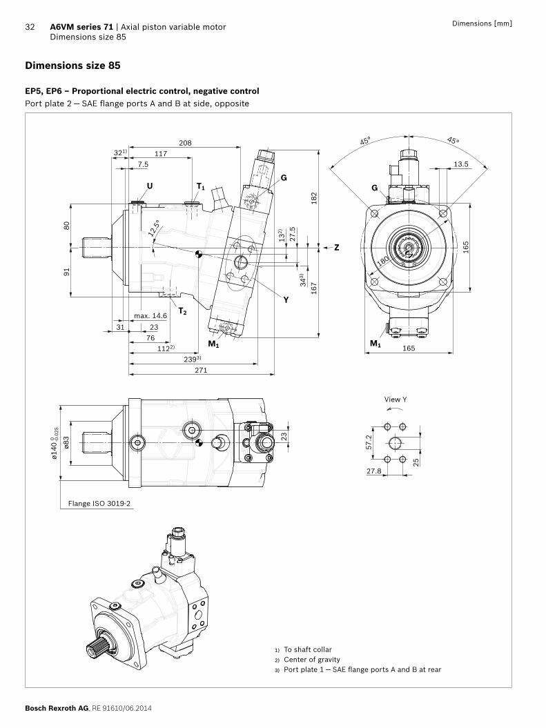
Bosch Rexroth AG RE 91610062014
32 A6VM series 71 | Axial piston variable motorDimensions size 85
Dimensions [mm]
Dimensions size 85
EP5 EP6 ndash Proportional electric control negative controlPort plate 2 mdash SAE flange ports A and B at side opposite
T2
T1U
M1
45deg
Y
GG
M1
135
Z
11775
321)208
167
275
182
343)
132)
2712393)
1122)
233176
max 146
9180
125
deg
180
45deg
165
165
23-00
25oslash1
40 0
oslash83
572
278
25
View Y
Flange ISO 3019-2
1) To shaft collar2) Center of gravity3) Port plate 1 mdash SAE flange ports A and B at rear
RE 91610062014 Bosch Rexroth AG
Axial piston variable motor | A6VM series 71 Dimensions size 85
33Dimensions [mm]
Location of the service line ports on the port plates (view Z)
2 SAE flange portA and B at side opposite
1 SAE flange portA and B at rear
2 SAE flange portA and B at side opposite only HZ7 EZ78
1 SAE flange portA and B at rear only HZ7 EZ78
B A
164
B A
54177
54
AB
164
B A
4242177
Splined shaft SAE J744 Splined shaft DIN 5480
S9 ‒ 1 12 in 17T 1224DP1) Z9 ‒ W40times2times18times9g
28
44
716
-14U
NC
-2B
2)3)
oslash50
54
95
45
37
M16
x 2
3)4) 12
36
oslash50
1) Involute spline acc to ANSI B921a 30deg pressure angle flat root side fit tolerance class 5
2) Thread according to ASME B11
3) For notes on tightening torques see instruction manual4) Center bore according to DIN 332 (thread according to DIN 13)
Bosch Rexroth AG RE 91610062014
34 A6VM series 71 | Axial piston variable motorDimensions size 85
Dimensions [mm]
Ports Standard Size1) pmax abs [bar]2) Status6)
A B Service line portFastening thread AB
SAE J5183)
DIN 131 inM12 times 175 17 deep
500 O
T1 Drain port ISO 61495) M22 times 15 155 deep 3 X4)
T2 Drain port ISO 61495) M27 times 2 19 deep 3 O4)
G Synchronous control ISO 61495) M14 times 15 115 deep 500 X
U Bearing flushing ISO 61495) M18 times 15 145 deep 3 X
X Pilot signal (HP HZ HA1THA2T) ISO 61495) M14 times 15 115 deep 100 O
X Pilot signal (HA1 HA2) ISO 61495) M14 times 15 115 deep 3 X
X1 X2 Pilot signal (DA0) ISO 8434-1 SDSC-L8timesM12-F 40 O
X1 Pilot signal (DA1 DA2) ISO 61495) M14 times 15 115 deep 40 O
X3 Pilot signal (DA1 DA2) ISO 61495) M14 times 15 115 deep 40 X
M1 Measuring stroking chamber ISO 61495) M14 times 15 115 deep 500 X
1) For notes on tightening torques see instruction manual2) Momentary pressure spikes may occur depending on the application
Keep this in mind when selecting measuring devices and fittings3) Only dimensions according to SAE J518 metric fastening thread is
a deviation from standard
4) Depending on installation position T1 or T2 must be connected (see also installation instructions on page 72)
5) The spot face can be deeper than specified in the appropriate standard6) O = Must be connected (plugged on delivery)
X = Plugged (in normal operation)
RE 91610062014 Bosch Rexroth AG
Axial piston variable motor | A6VM series 71 Dimensions size 85
35Dimensions [mm]
EP1 EP2 ndash Electric proportional control positive control
EP5D1 EP6D1 ndash Electric proportional control negative control with pressure control fixed
G
M1
AB
238
113
G
266
M1
G
M1
AB
G
M1
167
182
271
HP1 HP2 ndash Hydraulic proportional control positive control
HP5 HP6 ndash Hydraulic proportional control negative control
266
G
AB
M1
X
172
113
M1
G
X183
152
355 M1
G XX
AB
M1
G355 238
268
116
9616
7
HP5D1 HP6D1 ndash Hydraulic proportional control negative control with pressure control fixed
G
AB
M1
X355
G X
M1
126
9516
7
243268
Bosch Rexroth AG RE 91610062014
36 A6VM series 71 | Axial piston variable motorDimensions size 85
Dimensions [mm]
HZ7 ndash Hydraulic two-point control negative control
EZ7 EZ8 ndash Electric two-point control negative control
GX
1712421)
61
AB
208254
112
2735
1)
161
132
G
X
124G
2421)
AB
208254
112
2735
1)
161
G
HA1 HA2 HA1T3 HA2T3 ndash Automatic high-pressure-related control positive control with override hydraulic remote con-trolled proportional
HA1U1 HA2U2 ndash Automatic high-pressure-related control positive control with override electric two-point
266
G
AB
M1
X
172
113
M1
G
X183
152
355
M1
AB
G
M1
113
G
266
239
HA1 and HA2 X plugged
HA1T and HA2T X open
HA1R1 HA2R2 ndash Automatic high-pressure-related control positive control with override electric and travel direction valve electric
AB
M1
G
M1
266
239
113
G
110
a
b
1) Port plate 1 ndash SAE flange ports A and B at rear
RE 91610062014 Bosch Rexroth AG
Axial piston variable motor | A6VM series 71 Dimensions size 85
37Dimensions [mm]
DA0 ndash Automatic speed-related control negative control with hydraulic travel direction valve
DA1 DA2 ndash Automatic speed-related control negative control with electric travel direction valve and electric Vg max circuit
M1
AB
160
X3
167
126
207271
100
M1
X1 X2 GX1
X3GX2
G
X3X1
167
161
230270
M1M1
A
138
110
B
85
G
X1X3 ba
X1 X2 pipe fitting SDSC ndash L8timesM12 ndash F according to ISO 8434-1
Use assembled fitting
Bosch Rexroth AG RE 91610062014
38 A6VM series 71 | Axial piston variable motorDimensions size 115
Dimensions [mm]
Dimensions size 115
EP5 EP6 ndash Proportional electric control negative controlPort plate 2 mdash SAE flange ports A and B at side opposite
25
GT1U
T2
M1
200
Y
Z
M1
G
126220
401)
75
102)
3038
3)
188
175
45deg 45deg
175
190
1901262)
2573)
290
253978
max 146
102
91oslash9
0
oslash160
0 -00
25
572
278 25
125
deg
View Y
Flange ISO 3019-2
1) To shaft collar2) Center of gravity3) Port plate 1 mdash SAE flange ports A and B at rear
RE 91610062014 Bosch Rexroth AG
Axial piston variable motor | A6VM series 71 Dimensions size 115
39Dimensions [mm]
Location of the service line ports on the port plates (view Z)
2 SAE flange portA and B at side opposite
1 SAE flange portA and B at rear
2 SAE flange portA and B at side opposite only HZ7 EZ78
1 SAE flange portA and B at rear only HZ7 EZ78
M1
AB
180
B A
65193
65 180
B A
4242
193
B A
Splined shaft SAE J744 Splined shaft DIN 5480
T1 ‒ 1 34 in 13T 813DP1) Z9 ‒ W40times2times18times9g
36
55
58-
11U
NC
-2B
2)3)
oslash60
67
12
45
37
M16
times 2
3)4)
36
oslash60
12
1) Involute spline acc to ANSI B921a 30deg pressure angle flat root side fit tolerance class 5
2) Thread according to ASME B11
3) For notes on tightening torques see instruction manual4) Center bore according to DIN 332 (thread according to DIN 13)
Bosch Rexroth AG RE 91610062014
40 A6VM series 71 | Axial piston variable motorDimensions size 115
Dimensions [mm]
Ports Standard Size1) pmax abs [bar]2) Status6)
A B Service line portFastening thread AB
SAE J5183)
DIN 131 inM12 times 175 17 deep
500 O
T1 Drain port ISO 61495) M27 times 2 19 deep 3 X4)
T2 Drain port ISO 61495) M33 times 2 19 deep 3 O4)
G Synchronous control ISO 61495) M14 times 15 115 deep 500 X
U Bearing flushing ISO 61495) M18 times 15 145 deep 3 X
X Pilot signal (HP HZ HA1THA2T) ISO 61495) M14 times 15 115 deep 100 O
X Pilot signal (HA1 HA2) ISO 61495) M14 times 15 115 deep 3 X
X1 X2 Pilot signal (DA0) ISO 8434-1 SDSC-L8timesM12-F 40 O
X1 Pilot signal (DA1 DA2) ISO 61495) M14 times 15 115 deep 40 O
X3 Pilot signal (DA1 DA2) ISO 61495) M14 times 15 115 deep 40 X
M1 Measuring stroking chamber ISO 61495) M14 times 15 115 deep 500 X
1) For notes on tightening torques see instruction manual2) Momentary pressure spikes may occur depending on the application
Keep this in mind when selecting measuring devices and fittings3) Only dimensions according to SAE J518 metric fastening thread is
a deviation from standard
4) Depending on installation position T1 or T2 must be connected (see also installation instructions on page 72)
5) The spot face can be deeper than specified in the appropriate standard6) O = Must be connected (plugged on delivery)
X = Plugged (in normal operation)
RE 91610062014 Bosch Rexroth AG
Axial piston variable motor | A6VM series 71 Dimensions size 115
41Dimensions [mm]
EP1 EP2 ndash Electric proportional control positive control
EP5D1 EP6D1 ndash Electric proportional control negative control with pressure control fixed
M1
121
281
249
G
M1
B A
G
G
188
175
G
290
B A
M1M1
HP1 HP2 ndash Hydraulic proportional control positive control
HP5 HP6 ndash Hydraulic proportional control negative control
405
G X
164
199
121
180
281
G
M1
X
M1
B A
GX257
M1
405
G
121
175
101
288
M1
X
AB
HP5D1 HP6D1 ndash Hydraulic proportional control negative control with pressure control fixed
G X
M1
XG
M1
133
175
101
290258405
B A
Bosch Rexroth AG RE 91610062014
42 A6VM series 71 | Axial piston variable motorDimensions size 115
Dimensions [mm]
HZ7 ndash Hydraulic two-point control negative control
EZ7 EZ8 ndash Electric two-point control negative control
143
182 G61X
2561)
121
17230
381)
220270
B A
G
X
2561)
30
G G124
121
381)
220
B A
172
270
HA1 HA2 HA1T3 HA2T3 ndash Automatic high-pressure-related control positive control with override hydraulic remote con-trolled proportional
HA1U1 HA2U2 ndash Automatic high-pressure-related control positive control with override electric two-point
405G X
164
199
121
180
281
G
M1
X
M1
B A
121
249
G
M1
G
M1
281
B A
HA1 and HA2 X plugged
HA1T and HA2T X open
HA1R1 HA2R2 ndash Automatic high-pressure-related control positive control with override electric and travel direction valve electric
112
121
249
G
M1
G
M1
281
B A
a
b
1) Port plate 1 ndash SAE flange ports A and B at rear
RE 91610062014 Bosch Rexroth AG
Axial piston variable motor | A6VM series 71 Dimensions size 115
43Dimensions [mm]
DA0 ndash Automatic speed-related control negative control with hydraulic travel direction valve
DA1 DA2 ndash Automatic speed-related control negative control with electric travel direction valve and electric Vg max circuit
G174
175
290
132
107
X3X1 X2X1 X2 G X3
M1M1
B A
216
112 238290
M1 M1
G
X3X1
G
X1
175
145
168
X3 ba
85
B A
X1 X2 pipe fitting SDSC ndash L8timesM12 ndash F according to ISO 8434-1
Use assembled fitting
Bosch Rexroth AG RE 91610062014
44 A6VM series 71 | Axial piston variable motorDimensions size 150
Dimensions [mm]
Dimensions size 150
EP5 EP6 ndash Proportional electric control negative controlPort plate 2 mdash SAE flange ports A and B at side opposite
M1
T1
T2
U
224
45deg
Y
Z
G G
M1
max 14939 28
9051392)
3212883)
112)
3342
3)
196
195
247401) 1405
75
109
100
125
deg
45deg
175
210
210
25
667
318
32
oslash94
oslash180
-00
250
View Y
Flange ISO 3019-2
1) To shaft collar2) Center of gravity3) Port plate 1 mdash SAE flange ports A and B at rear
RE 91610062014 Bosch Rexroth AG
Axial piston variable motor | A6VM series 71 Dimensions size 150
45Dimensions [mm]
Location of the service line ports on the port plates (view Z)
2 SAE flange portA and B at side opposite
1 SAE flange portA and B at rear
AB
204
B A
7676226
Splined shaft SAE J744 Splined shaft SAE J744
T1 ‒ 1 34 in 13T 816DP1) T2 ‒ 2 in 15T 816DP1)
36
53
58-
11U
NC
-2B
2)3)
oslash60
67
12
36
53
58-
11U
NC
-2B
2)3)
oslash60
67
12
Splined shaft DIN 5480
A1 ‒ W45times2times21times9g
50
42
M16
times 2
3)4)
36
oslash60
12
1) Involute spline acc to ANSI B921a 30deg pressure angle flat root side fit tolerance class 5
2) Thread according to ASME B113) For notes on tightening torques see instruction manual 4) Center bore according to DIN 332 (thread according to DIN 13)
Bosch Rexroth AG RE 91610062014
46 A6VM series 71 | Axial piston variable motorDimensions size 150
Dimensions [mm]
Ports Standard Size1) pmax abs [bar]2) Status6)
A B Service line portFastening thread AB
SAE J5183)
DIN 131 14 inM14 times 2 19 deep
500 O
T1 Drain port ISO 61495) M27 times 2 19 deep 3 X4)
T2 Drain port ISO 61495) M33 times 2 19 deep 3 O4)
G Synchronous control ISO 61495) M14 times 15 115 deep 500 X
U Bearing flushing ISO 61495) M22 times 15 155 deep 3 X
X Pilot signal (HP HZ HA1THA2T) ISO 61495) M14 times 15 115 deep 100 O
X Pilot signal (HA1 HA2) ISO 61495) M14 times 15 115 deep 3 X
X1 X2 Pilot signal (DA0) ISO 8434-1 SDSC-L8timesM12-F 40 O
X1 Pilot signal (DA1 DA2) ISO 61495) M14 times 15 115 deep 40 O
X3 Pilot signal (DA1 DA2) ISO 61495) M14 times 15 115 deep 40 X
M1 Measuring stroking chamber ISO 61495) M14 times 15 115 deep 500 X
1) For notes on tightening torques see instruction manual2) Momentary pressure spikes may occur depending on the application
Keep this in mind when selecting measuring devices and fittings3) Only dimensions according to SAE J518 metric fastening thread is
a deviation from standard
4) Depending on installation position T1 or T2 must be connected (see also installation instructions on page 72)
5) The spot face can be deeper than specified in the appropriate standard6) O = Must be connected (plugged on delivery)
X = Plugged (in normal operation)
RE 91610062014 Bosch Rexroth AG
Axial piston variable motor | A6VM series 71 Dimensions size 150
47Dimensions [mm]
EP1 EP2 ndash Electric proportional control positive control
EP5D1 EP6D1 ndash Electric proportional control negative control with pressure control fixed
132
315
264
G
M1
B A
M1
G
GG
196
195
321
M1 M1
B A
HP1 HP2 ndash Hydraulic proportional control positive control
HP5 HP6 ndash Hydraulic proportional control negative control
405XG
178
225
132
195
315
M1
XG
AB
M1
X G G X
M1
B A
M1
132
195
109
320289405
HP5D1 HP6D1 ndash Hydraulic proportional control negative control with pressure control fixed
X X
M1M1
B A
141
108
G
321290
G
195
405
Bosch Rexroth AG RE 91610062014
48 A6VM series 71 | Axial piston variable motorDimensions size 150
Dimensions [mm]
HZ5 ndash Hydraulic two-point control negative control
EZ5 EZ6 ndash Electric two-point control negative control
405
G
108
285
132
195
319
M1 M1
XG
B A
X
186
319
195
M1
G
B A
G
M1
HA1 HA2 HA1T3 HA2T3 ndash Automatic high-pressure-related control positive control with override hydraulic remote con-trolled proportional
HA1U1 HA2U2 ndash Automatic high-pressure-related control positive control with override electric two-point
405XG
178
225
132
195
315
M1 M1
XG
AB
132
315
264
M1
G
AB
G
M1
HA1 and HA2 X plugged
HA1T and HA2T X open
HA1R1 HA2R2 ndash Automatic high-pressure-related control positive control with override electric and travel direction valve electric
a
b112
132
315
264
M1
G
AB
G
M1
RE 91610062014 Bosch Rexroth AG
Axial piston variable motor | A6VM series 71 Dimensions size 150
49Dimensions [mm]
DA0 ndash Automatic speed-related control negative control with hydraulic travel direction valve
DA1 DA2 ndash Automatic speed-related control negative control with electric travel direction valve and electric Vg max circuit
174
X2X1G X3 G X3
195
140
247322
M1
115
B A
M1
X2
176
195
153
112
M1
G
85
B A
X1X3
M1
270322
G
X3X1ba
X1 X2 pipe fitting SDSC ndash L8timesM12 ndash F according to ISO 8434-1
Use assembled fitting
Bosch Rexroth AG RE 91610062014
50 A6VM series 71 | Axial piston variable motorDimensions size 170
Dimensions [mm]
Dimensions size 170
EP5 EP6 ndash Proportional electric control negative controlPort plate 2 mdash SAE flange ports A and B at side opposite
G
Y
T2
M1
T1U
Z
G
M1
oslash100
oslash180
-00
250
667
318 32
210
210
175
224
103
112
401)
75141
25412
5deg
1412)
9139 28
max 149
2953)
328
19743
3)
195
122)
34
45deg 45deg
25
View Y
Flange ISO 3019-2
1) To shaft collar2) Center of gravity3) Port plate 1 mdash SAE flange ports A and B at rear
RE 91610062014 Bosch Rexroth AG
Axial piston variable motor | A6VM series 71 Dimensions size 170
51Dimensions [mm]
Location of the service line ports on the port plates (view Z)
2 SAE flange portA and B at side opposite
1 SAE flange portA and B at rear
B A
20476
B A
22676
Splined shaft SAE J744 Splined shaft DIN 5480
T2 ‒ 2 in 15T 816DP1) A1 ‒ W45times2times21times9g
36
53
58-
11U
NC
-2B
2)3)
oslash70
67
12
50
42
M16
times 2
3)4)
36
oslash70
12
1) Involute spline acc to ANSI B921a 30deg pressure angle flat root side fit tolerance class 5
2) Thread according to ASME B11
3) For notes on tightening torques see instruction manual4) Center bore according to DIN 332 (thread according to DIN 13)
Bosch Rexroth AG RE 91610062014
52 A6VM series 71 | Axial piston variable motorDimensions size 170
Dimensions [mm]
Ports Standard Size1) pmax abs [bar]2) Status6)
A B Service line portFastening thread AB
SAE J5183)
DIN 131 14 inM14 times 2 19 deep
500 O
T1 Drain port ISO 61495) M27 times 2 19 deep 3 X4)
T2 Drain port ISO 61495) M33 times 2 19 deep 3 O4)
G Synchronous control ISO 61495) M14 times 15 115 deep 500 X
U Bearing flushing ISO 61495) M22 times 15 155 deep 3 X
X Pilot signal (HP HZ HA1THA2T) ISO 61495) M14 times 15 115 deep 100 O
X Pilot signal (HA1 HA2) ISO 61495) M14 times 15 115 deep 3 X
X1 X2 Pilot signal (DA0) ISO 8434-1 SDSC-L8timesM12-F 40 O
X1 Pilot signal (DA1 DA2) ISO 61495) M14 times 15 115 deep 40 O
X3 Pilot signal (DA1 DA2) ISO 61495) M14 times 15 115 deep 40 X
M1 Measuring stroking chamber ISO 61495) M14 times 15 115 deep 500 X
1) For notes on tightening torques see instruction manual2) Momentary pressure spikes may occur depending on the application
Keep this in mind when selecting measuring devices and fittings3) Only dimensions according to SAE J518 metric fastening thread is
a deviation from standard
4) Depending on installation position T1 or T2 must be connected (see also installation instructions on page 72)
5) The spot face can be deeper than specified in the appropriate standard6) O = Must be connected (plugged on delivery)
X = Plugged (in normal operation)
RE 91610062014 Bosch Rexroth AG
Axial piston variable motor | A6VM series 71 Dimensions size 170
53Dimensions [mm]
EP1 EP2 ndash Electric proportional control positive control
EP5D1 EP6D1 ndash Electric proportional control negative control with pressure control fixed
G
B A
M1
G
M1
322
133
266
195
197
328
G
M1M1
B A
G
HP1 HP2 ndash Hydraulic proportional control positive control
HP5 HP6 ndash Hydraulic proportional control negative control
405
181
133
197
322
232
XG
M1
GX
B A
M1
405
108
133
197
296326
X G
M1
B A
G X
M1
HP5D1 HP6D1 ndash Hydraulic proportional control negative control with pressure control fixed
328297
108
141
197
X XG G
M1
B A
405
M1
Bosch Rexroth AG RE 91610062014
54 A6VM series 71 | Axial piston variable motorDimensions size 170
Dimensions [mm]
HZ5 ndash Hydraulic two-point control negative control
EZ5 EZ6 ndash Electric two-point control negative control
197
107
133
405 291326
X G
M1
G
B A
X
M1
G
M1
G
B A
M1
197
187
326
HA1 HA2 HA1T3 HA2T3 ndash Automatic high-pressure-related control positive control with override hydraulic remote con-trolled proportional
HA1U1 HA2U2 ndash Automatic high-pressure-related control positive control with override electric two-point
405
181
133
197
322
232G
M1
G X
B A
X
M1 M1
B A
M1
G G
322
133
266
HA1 and HA2 X plugged
HA1T and HA2T X open
HA1R1 HA2R2 ndash Automatic high-pressure-related control positive control with override electric and travel direction valve electric
322
133
266
112
a
bG
M1
G
B A
M1
RE 91610062014 Bosch Rexroth AG
Axial piston variable motor | A6VM series 71 Dimensions size 170
55Dimensions [mm]
DA0 ndash Automatic speed-related control negative control with hydraulic travel direction valve
DA1 DA2 ndash Automatic speed-related control negative control with electric travel direction valve and electric Vg max circuit
X2X1G X3 G X3
M1
X1 X2
B A
M1
174
197
140
254328
115
B A
M1
G
X1X3
M1
G
X3X1
ab
176
197
153
277328
112 85
X1 X2 pipe fitting SDSC ndash L8timesM12 ndash F according to ISO 8434-1
Use assembled fitting
Bosch Rexroth AG RE 91610062014
56 A6VM series 71 | Axial piston variable motorDimensions size 215
Dimensions [mm]
Dimensions size 215
EP5 EP6 ndash Proportional electric control negative controlPort plate 2 mdash SAE flange ports A and B at side opposite
T2
M1
T1U
Y
125
deg
Z
G G
M1236
236
45deg 45deg
22
250
667
32318
29
oslash200
-0 -00
29
oslash108
75151
267401)
107
125
1472)
3143)
345
9639 32
max 149
209
192)
3646
53)
200
Flange ISO 3019-2
View Y
1) To shaft collar2) Center of gravity3) Port plate 1 mdash SAE flange ports A and B at rear
RE 91610062014 Bosch Rexroth AG
Axial piston variable motor | A6VM series 71 Dimensions size 215
57Dimensions [mm]
Location of the service line ports on the port plates (view Z)
2 SAE flange portA and B at side opposite
1 SAE flange portA and B at rear
216
B A
82
235
82
B A
Splined shaft SAE J744 Splined shaft DIN 5480
T2 ‒ 2 in 15T 816DP1) A2 ‒ W50times2times24times9g
36
53
58-
11U
NC
-2B
2)3)
oslash70
67
12
55
44
M16
times 2
3)4)
36
oslash70
12
1) Involute spline acc to ANSI B921a 30deg pressure angle flat root side fit tolerance class 5
2) Thread according to ASME B11
3) For notes on tightening torques see instruction manual4) Center bore according to DIN 332 (thread according to DIN 13)
Bosch Rexroth AG RE 91610062014
58 A6VM series 71 | Axial piston variable motorDimensions size 215
Dimensions [mm]
Ports Standard Size1) pmax abs [bar]2) Status6)
A B Service line portFastening thread AB
SAE J5183)
DIN 131 14 inM14 times 2 19 deep
500 O
T1 Drain port ISO 61495) M33 times 2 19 deep 3 X4)
T2 Drain port ISO 61495) M42 times 2 195 deep 3 O4)
G Synchronous control ISO 61495) M14 times 15 115 deep 500 X
U Bearing flushing ISO 61495) M22 times 15 155 deep 3 X
X Pilot signal (HP HZ HA1THA2T) ISO 61495) M14 times 15 115 deep 100 O
X Pilot signal (HA1 HA2) ISO 61495) M14 times 15 115 deep 3 X
X1 X2 Pilot signal (DA0) ISO 8434-1 SDSC-L8timesM12-F 40 O
X1 Pilot signal (DA1 DA2) ISO 61495) M14 times 15 115 deep 40 O
X3 Pilot signal (DA1 DA2) ISO 61495) M14 times 15 115 deep 40 X
M1 Measuring stroking chamber ISO 61495) M14 times 15 115 deep 500 X
1) For notes on tightening torques see instruction manual2) Momentary pressure spikes may occur depending on the application
Keep this in mind when selecting measuring devices and fittings3) Only dimensions according to SAE J518 metric fastening thread is
a deviation from standard
4) Depending on installation position T1 or T2 must be connected (see also installation instructions on page 72)
5) The spot face can be deeper than specified in the appropriate standard6) O = Must be connected (plugged on delivery)
X = Plugged (in normal operation)
RE 91610062014 Bosch Rexroth AG
Axial piston variable motor | A6VM series 71 Dimensions size 215
59Dimensions [mm]
EP1 EP2 ndash Electric proportional control positive control
EP5D1 EP6D1 ndash Electric proportional control negative control with pressure control fixed
339
140
275
M1
G
M1
G
B A
M1
B A
M1
G
209
200
345
G
HP1 HP2 ndash Hydraulic proportional control positive control
HP5 HP6 ndash Hydraulic proportional control negative control
M1
G
B A
X
M1
339
206
245
GX
190
405
140
M1
209
140
343
M1
B A
X G X312
113
G405
HP5D1 HP6D1 ndash Hydraulic proportional control negative control with pressure control fixed
M1
G
B A
M1
X
209
145
G X313
344405
112
Bosch Rexroth AG RE 91610062014
60 A6VM series 71 | Axial piston variable motorDimensions size 215
Dimensions [mm]
HZ5 ndash Hydraulic two-point control negative control
EZ5 EZ6 ndash Electric two-point control negative control
M1
XG
140
209
111
308343
M1
X G405
B A
M1
G
B A
M1
191
209
343
G
HA1 HA2 HA1T3 HA2T3 ndash Automatic high-pressure-related control positive control with override hydraulic remote con-trolled proportional
HA1U1 HA2U2 ndash Automatic high-pressure-related control positive control with override electric two-point
M1
G
B A
X
M1
339
206
245
GX
190
405
140
B A
M1
G
M1
339
276
140
G
HA1 and HA2 X plugged
HA1T and HA2T X open
HA1R1 HA2R2 ndash Automatic high-pressure-related control positive control with override electric and travel direction valve electric
M1
276
140
339
G
M1
B A
Ga
112
b
RE 91610062014 Bosch Rexroth AG
Axial piston variable motor | A6VM series 71 Dimensions size 215
61Dimensions [mm]
DA0 ndash Automatic speed-related control negative control with hydraulic travel direction valve
DA1 DA2 ndash Automatic speed-related control negative control with electric travel direction valve and electric Vg max circuit
M1
B A
X1 X2X3G X1 X2 X3G
M1
174 271345
209
144
119
209
180
157
294345
85112
M1
B A
M1
G
X1X3
G
X1 X3
ab
X1 X2 pipe fitting SDSC ndash L8timesM12 ndash F according to ISO 8434-1
Use assembled fitting
Bosch Rexroth AG RE 91610062014
62 A6VM series 71 | Axial piston variable motorConnector for solenoids
Connector for solenoids
DEUTSCH DT04-2P-EP04Molded connector 2-pin without bidirectional suppres-sor diode There is the following type of protection with mounted mating connector
IP67 (DINEN 60529) and IP69K (DIN 40050-9)
Circuit symbol
Mating connector DEUTSCH DT06-2S-EP04
Consisting of DT designation
1 housing DT06-2S-EP04
1 wedge W2S
2 sockets 0462-201-16141
The mating connector is not included in the scope of deliv-ery This can be supplied by Bosch Rexroth on request (material number R902601804)
NoteIf necessary you can change the connector orientation by turning the solenoid housingThe procedure can be taken from the instruction manual
RE 91610062014 Bosch Rexroth AG
Axial piston variable motor | A6VM series 71 Flushing and boost pressure valve
63
Flushing and boost pressure valve
The flushing and boost pressure valve is used to remove heat from the hydraulic circuitIn an open circuit it is used only for flushing the housingIn a closed circuit it ensures a minimum boost pressure level in addition to the case flushingHydraulic fluid is directed from the respective low pressure side into the motor housing This is then fed into the reser-voir together with the leakage The hydraulic fluid removed out of the closed circuit must be replaced by cooled hydraulic fluid from the boost pumpThe valve is mounted onto the port plate or integrated (depending on the control type and size)Cracking pressure of pressure retaining valve(observe when adjusting the primary valve)
Sizes 60 to 215 fixed setting 16 barSwitching pressure of flushing spool Dp
Sizes 60 to 115 (no flushing valve) 8plusmn1 bar Sizes 115 to 215 (medium and large flushing valve)
175plusmn15 barFlushing flow qv
Orifices can be used to adjust the flushing flows as required The following information is based on DpND = pND ndash pG = 25 bar and ν = 10 mm2s (pND = low pressure pG = case pressure)
Small flushing valve for sizes 60 to 115
Material number of orifice oslash [mm] qv [lmin] Code
R909651766 12 35 A
R909419695 14 5 B
R909419696 18 8 C
R909419697 20 10 D
R909444361 24 14 F
Medium flushing valve for size 115
Material number of orifice oslash [mm] qv [lmin] Code
R909431310 28 20 H
R909435172 35 25 J
R909449967 50 30 K
Large flushing valve for sizes 150 to 215
Material number of orifice oslash [mm] qv [lmin] Code
R909449998 18 8 C
R909431308 20 10 D
R909431309 25 17 G
R909431310 28 20 H
R902138235 31 25 J
R909435172 35 30 K
R909436622 40 35 L
R909449967 50 40 M
Schematic EP
G
T2
T1U
Sa
B
A
Vg min
Vg max
M1
Flushing spool
Pressure retain-ing valve
Flushing orifice
Notes Port Sa only for sizes 150 to 215 For a flushing flow greater than 35 l min it is recom-
mended that port Sa be connected in order to prevent an increase in case pressure An increased case pres-sure reduces the flushing flow
Bosch Rexroth AG RE 91610062014
64 A6VM series 71 | Axial piston variable motorFlushing and boost pressure valve
Dimensions [mm]
Dimensions of sizes 60 to 115 (small flushing valve)
A1 A4
HA1 HA2HP1 HP2EP1 EP2
HP5 HP6EP5 EP6DA
HZ7EZ7 EZ8
A3
A2
NG A1 A2 A3 A4
60 245 137 183 236
85 273 142 194 254
115 287 143 202 269
Dimensions for sizes 115 to 215 (large flushing valve)
Sa
Sa
Sa
Z
HA1 HA2HP1 HP2EP1 EP2
HP5 HP6 DAEP5 EP6HZ5 EZ5 EZ6
B4
A2B2
A3B
3
38
A1B1
NG A1 B1 A2 B2 A3 B3 B4
60 325 239 165 142 230 187 166
85 332 246 165 142 233 190 172
115 349 263 172 148 244 201 185
Dimensions of size 115 (medium flushing valve)
205
151
292
HA1 HA2HP1 HP2EP1 EP2
HP5 HP6EP5 EP6DA
NG Sa1)
150
M22 times 15 155 deep170
215
1) ISO 6149 ports plugged (in normal operation) For notes on tightening torques see instruction manual The spot face can be deeper than specified in the appropriate stan-dard
RE 91610062014 Bosch Rexroth AG
Axial piston variable motor | A6VM series 71 Counterbalance valve BVD and BVE
65
Counterbalance valve BVD and BVE
FunctionCounterbalance valves for travel drive and winch operations are designed to reduce the danger of overspeeding and cavitation of axial piston motors in open circuits Cavitation occurs if during braking when driving downhill or the load-lowering process the motor speed is greater than it should be for the given inlet flow causing the inlet pressure to collapseIf the pressure difference between the inflow and the out-flow drops below the value opening end of the piston in the counterbalance valve (see data sheet BVD ndash 95522 or BVE ndash 95525) the counterbalance spool will move to the closed position The cross-sectional area of the counterbalance valve return duct is then reduced creating a bottleneck in the return flow of the hydraulic fluid The pressure increases and brakes the motor until the rotational speed of the motor is again as it should be for the given inlet flow
Notes BVD available for sizes 60 to 215 and BVE available for
sizes 115 to 215 The counterbalance valve must be ordered additionally
We recommend ordering the counterbalance valve and the motor as a set Ordering example A6VM085HA1T30004A71MWV0N4S97W0-0 + BVD20F27S41BndashV03K16D0400S12
For safety reasons control systems with beginning of control at Vg min (z B HA) are not permissible for winch drives
The counterbalance valve does not replace the mechani-cal service brake and parking brake
Observe the detailed notes on the BVD counterbalance valve in data sheet 95522 and on the BVE counterbal-ance valve in data sheet 95525
For the design of the brake release valve we must know for the mechanical parking brake ndash the pressure at the start of opening ndash the volume of the counterbalance spool between
minimum travel (brake closed) and maximum travel (brake released with 21 bar)
ndash the required closing time for a warm device (oil vis-cosity approx 15 mm2s)
Permissible inlet flow or pressure when using DBV and BVDBVE
Without valve Limited values when using DBV and BVDBVE
Motor DBV1) BVD2)BVE3)
NG pnompmax [bar]
qV max [lmin]
NG pnompmax [bar]
qV [lmin]
Code NG pnompmax [bar]
qV [lmin]
Code
60 450500 276 22 350420 240 7 20 (BVD)
350420 220 7W
85 332
115 410 32 400
115 410 8 25 (BVDBVE)
320 8W
150 494
170 533
215 628 On request
1) Pressure-relief valve2) Counterbalance valve double-acting3) Counterbalance valve one-sided
Bosch Rexroth AG RE 91610062014
66 A6VM series 71 | Axial piston variable motorCounterbalance valve BVD and BVE
Counterbalance valve for travel drive BVDFApplication option
Travel drive for wheeled excavators (BVD and BVE)
Example schematic for travel drive on wheeled excavators
A6VM085HA1T30004A71MWV0N4S97W0-0 + BVD20F27S41BndashV03K16D0400S12
Bacute
A
M1
T2
T1
Vg min
Vg max
X
U
G
MB
MA
S
Gext
Gacute
Lacute
Aacute
B
Variable motor A6VMHA1T
Counterbalance valve BVD
Pump directional valve not included in the scope of delivery
Counterbalance valve for winches and track drives BVDW and BVEApplication option
Winch drives in cranes (BVD and BVE) Track drive in excavator crawlers (BVD)
Example schematic for winch drive in cranes
A6VM085HP5D10001A71MWV0N4S97W0-0 + BVE25W38S51ND-V100K00D4599T30S00-0
T2
T1
M1
Vg min
Vg max
B
A
G
X
U
MP1
VGVF
S
Gext
Mk
D
C
Dacute
Cacute
Gacute
Lacute
D1
D2
MB
MA
Variable motor A6VMHP5D
Winch with mechanical parking brake
Counterbalance valve BVE
Pump directional valve not included in the scope of delivery
RE 91610062014 Bosch Rexroth AG
Axial piston variable motor | A6VM series 71 Counterbalance valve BVD and BVE
67Dimensions [mm]
Dimensions
A6VMHA HP1 HP2 and EP1 EP2 A6VMHP5 HP6 and EP5 EP61)
MB (MA)
A BS
A8
B A
Gext
A2A1
A4A3
A6 A5A7
A2A9
MB (MA)
A4A1
0
Br
S
A8
A5 A6A7
B AA B
A6VM Counterbalance valve
NGplate Type Ports Dimensions
A B A1 A2 A3 A4 A5 A6 A7 A8 A9 A10
607 BVD2017 34 in 311 302 143 50 98 139 75 222 326 50
857 BVD2027 1 in 340 331 148 55 98 139 75 222 355 46
1157 BVD2028 1 in 362 353 152 59 98 139 84 234 377 41
1158 BVD2538 1 14 in 380 370 165 63 1205 175 84 238 395 56
1508 BVD2538 1 14 in 411 401 168 67 1205 175 84 238 426 53
1708 BVD2538 1 14 in 417 407 170 68 1205 175 84 238 432 51
2158 BVD2538 1 14 in 448 438 176 74 1205 175 84 299 463 46
1158 BVE2538 1 14 in 380 370 171 63 137 214 84 238 397 63
1508 BVE2538 1 14 in 411 401 175 67 137 214 84 238 423 59
1708 BVE2538 1 14 in 417 407 176 68 137 214 84 238 432 59
2158 BVE2538 1 14 in 448 438 182 74 137 214 84 299 463 52
Ports Version A6VM plate
Standard Size2) Pmax perm [bar]3) Status5)
A B Service line SAE J518 see table above 420 O
S Infeed BVD20 DIN 38524) M22 times 15 14 deep 30 X
BVD25 BVE25 DIN 38524) M27 times 2 16 deep 30 X
Br Brake release reduced high pressure
L 7 DIN 38524) M12 times 15 125 deep 30 O
8 DIN 38524) M12 times 15 12 deep 30 O
Gext Brake release high pressure S DIN 38524) M12 times 15 125 deep 420 X
MA MB Measuring pressure A and B ISO 61494) M18 times 15 145 deep 420 X
1) At the mounting version for the controls HP5 HP6 and EP5 EP6 the cast-in port designations A and B on the counterbalance valve BVD do not correspond with the connection drawing of the A6VM motor The designation of the ports on the installation drawing of the mo-tor is binding
2) For notes on tightening torques see instruction manual
3) Momentary pressure spikes may occur depending on the applica-tion Keep this in mind when selecting measuring devices and fit-tings
4) The spot face can be deeper than specified in the appropriate stan-dard
5) O = Must be connected (plugged on delivery) X = Plugged (in normal operation)
Bosch Rexroth AG RE 91610062014
68 A6VM series 71 | Axial piston variable motorCounterbalance valve BVD and BVE
Mounting the counterbalance valveWhen delivered the counterbalance valve is mounted to the motor with two tacking screws (transport lock) The tack-ing screws may not be removed while mounting the service lines If the counterbalance valve and motor are delivered separately the counterbalance valve must first be mounted to the motor port plate using the provided tacking screws The final mounting of the counterbalance valve on the motor is done with screw fitting of the SAE flange The screws to be used and the procedure mounting can be found in the instruction manual
RE 91610062014 Bosch Rexroth AG
Axial piston variable motor | A6VM series 71 Speed sensor
69
Speed sensor
Version A6VMU (prepared for speed sensor ie without sensor) is equipped with a spline on the rotary groupA signal proportional to motor speed can be generated with the fitted DSADSM speed sensor The DSADSM sensor registers the speed and direction of rotationOrdering code technical data dimensions and details on the connector plus safety instructions about the sensor can be found in the relevant data sheet (95132 for DSM 95133 for DSA)The sensor is mounted on the port provided for this pur-pose with a mounting bolt On deliveries without sensor the port is plugged with a pressure-resistant coverWe recommend ordering the A6VM variable motor complete with mounted sensor
Schematic EP
T2
T1UnU
Dimensions
V design with mounted speed sensor
A
C
B
Size 60 85 115 150 170 215
Number of teeth 54 58 67 72 75 80
A Insertion depth (tolerance -025) 184 184 184 184 184 184
B Contact surface 75 79 88 93 96 101
C 662 752 772 912 917 952
Bosch Rexroth AG RE 91610062014
70 A6VM series 71 | Axial piston variable motorSetting range for displacement
Setting range for displacement
60 85 115
Vg max (cm3rev) Vg min (cm3rev) Vg max (cm3rev) Vg min (cm3rev) Vg max (cm3rev) Vg min (cm3rev)
from to from to from to from to from to from to
A 620 620 00 150 852 852 00 315 1156 1156 00 240
without screw M10 times 60 R909154690
without screw M12 times 70 R909085976
without screw M12 times 70 R909085976
B 620 620 gt 150 305 852 852 gt 315 520 1156 1156 gt 240 475
without screw M10 times 70 R909153779
without screw M12 times 80 R909153075
without screw M12 times 80 R909153075
C 620 620 gt 305 430 852 852 gt 520 590 1156 1156 gt 475 710
without screw M10 times 80 R909154058
without screw M12 times 90 R909154041
without screw M12 times 90 R909154041
D x x x x 1156 1156 gt 710 800
without screw M12 times 100 R909153975
E lt 620 475 00 150 lt 852 555 00 315 lt 1156 935 00 240
M10 times 60 R909154690
M10 times 60 R909154690
M12 times 70 R909085976
M12 times 70 R909085976
M12 times 70 R909085976
M12 times 70 R909085976
F lt 620 475 gt 150 305 lt 852 555 gt 315 520 lt 1156 935 gt 240 475
M10 times 60 R909154690
M10 times 70 R909153779
M12 times 70 R909085976
M12 times 80 R909153075
M12 times 70 R909085976
M12 times 80 R909085976
G lt 620 475 gt 305 430 lt 852 555 gt 520 590 lt 1156 935 gt 475 71
M10 times 60 R909154690
M10 times 80 R909154058
M12 times 70 R909085976
M12 times 90 R909154041
M12 times 70 R909085976
M12 times 90 R909154041
H x x x times lt 1156 935 gt 710 800
M12 times 70 R909085976
M12 times 100 R909153975
J lt 475 330 00 150 lt 555 350 00 315 lt 935 710 00 240
M10 times 70 R909153779
M10 times 60 R909154690
M12 times 80 R909153075
M12 times 70 R909085976
M12 times 80 R909153075
M12 times 70 R909085976
K lt 475 330 gt 150 305 lt 555 350 gt 315 520 lt 935 710 gt 240 475
M10 times 70 R909153779
M10 times 70 R909153779
M12 times 80 R909153075
M12 times 80 R909153075
M12 times 80 R909153075
M12 times 80 R909153075
L lt 475 330 gt 305 430 lt 555 350 gt 520 590 lt 935 710 gt 475 710
M10 times 70 R909153779
M10 times 80 R909154058
M12 times 80 R909153075
M12 times 90 R909154041
M12 times 80 R909153075
M12 times 90 R909154041
M x x x x lt 935 710 gt 710 800
M12 times 80 R909153075
M12 times 100 R909153975
Specify exact settings for Vg min and Vg max in plain text when ordering
Vg min = cm3 Vg max = cm3
Theoretical maximum setting for Vg min = 07 times Vg max
for Vg max = 03 times Vg max
Settings that are not listed in the table may lead to damage Please contact us
RE 91610062014 Bosch Rexroth AG
Axial piston variable motor | A6VM series 71 Setting range for displacement
71
150 170 215
Vg max (cm3rev) Vg min (cm3rev) Vg max (cm3rev) Vg min (cm3rev) Vg max (cm3rev) Vg min (cm3rev)
from to from to from to from to from to from to
A 1521 1521 00 440 1718 1718 00 350 2165 2165 00 445
without screw M12 times 80 R909153075
without screw M12 times 80 R909153075
without screw M12 times 80 R909153075
B 1521 1521 gt 440 690 1718 1718 gt 350 635 2165 2165 gt 445 800
without screw M12 times 90 R909154041
without screw M12 times 90 R909154041
without screw M12 times 90 R909154041
C 1521 1521 gt 690 990 1718 1718 gt 635 980 2165 2165 gt 800 1150
without screw M12 times 100 R909153975
without screw M12 times 100 R909153975
without screw M12 times 100 R909153975
D 1521 1521 gt 990 1060 1718 1718 gt 980 1200 2165 2165 gt 1150 1500
without screw M12 times 110 R909154212
without screw M12 times 110 R909154212
without screw M12 times 110 R909154212
E lt 1521 1110 00 440 lt 1718 1390 00 350 lt 2165 1750 00 445
M12 times 80 R909153075
M12 times 80 R909153075
M12 times 80 R909153075
M10 times 80 R909153075
M12 times 80 R909153075
M12 times 80 R909153075
F lt 1521 1110 gt 440 690 lt 1718 1390 gt 350 635 lt 2165 1750 gt 445 800
M12 times 80 R909153075
M12 times 90 R909085976
M12 times 80 R909153075
M12 times 90 R909154041
M12 times 80 R909153075
M12 times 90 R909154041
G lt 1521 1110 gt 690 990 lt 1718 1390 gt 635 980 lt 2165 1750 gt 800 1150
M12 times 80 R909153075
M12 times 100 R909153975
M12 times 80 R909153075
M12 times 100 R909153975
M12 times 80 R909153075
M12 times 100 R909153975
H lt 1521 1110 gt 990 1060 lt 1718 1390 gt 980 1200 lt 2165 1750 gt 1150 1500
M12 times 80 R909153075
M12 times 110 R909154212
M12 times 80 R909153075
M12 times 110 R909154212
M12 times 80 R909153075
M12 times 110 R909154212
J lt 1110 870 00 440 lt 1390 1120 00 350 lt 1750 1410 00 445
M12 times 90 R909154041
M12 times 80 R909153075
M12 times 90 R909154041
M12 x 80 R909153075
M12 x 90 R909154041
M12 x 80 R909153075
K lt 1110 870 gt 440 690 lt 1390 1120 gt 350 635 lt 1750 1410 gt 445 800
M12 times 90 R909154041
M12 times 90 R909154041
M12 x 90 R909154041
M12 times 90 R909154041
M12 times 90 R909154041
M12 times 90 R909154041
L lt 1110 870 gt 690 990 lt 1390 1120 gt 635 980 lt 1750 1410 gt 800 1150
M12 times 90 R909154041
M12 times 100 R909153975
M12 times 90 R909154041
M12 times 100 R909153975
M12 times 90 R909154041
M12 times 100 R909153975
M lt 1110 870 gt 990 1060 lt 1390 1120 gt 980 1200 lt 1750 1410 gt 1150 1500
M12 times 90 R909154041
M12 times 110 R909154212
M12 times 90 R909154041
M12 times 110 R909154212
M12 times 90 R909154041
M12 times 110 R909154212
Specify exact settings for Vg min and Vg max in plain text when ordering
Vg min = cm3 Vg max = cm3
Theoretical maximum setting for Vg min = 07 times Vg max
for Vg max = 03 times Vg max
Settings that are not listed in the table may lead to damage Please contact us
Bosch Rexroth AG RE 91610062014
72 A6VM series 71 | Axial piston variable motorInstallation instructions
Installation instructions
GeneralDuring commissioning and operation the axial piston unit must be filled with hydraulic fluid and air bled This must also observed following a relatively long standstill as the axial piston unit may drain back to the reservoir via the hydraulic linesParticularly in the installation position drive shaft upwards filling and air bleeding must be carried out com-pletely as there is for example a danger of dry runningThe leakage in the motor housing must be directed to the reservoir via the highest available drain port (T1 T2)To achieve favorable noise values decouple all connecting lines using elastic elements and avoid above-reservoir installation In all operating conditions the drain line must flow into the reservoir below the minimum fluid level
NoteIn certain installation conditions an influence on the control charakteristic curves can be expected Gravity dead weight and case pressure can cause minor shifts in characteristics and changes in response time
Key
U Bearing flushing air bleed port
T1 T2 Drain port
ht min Minimum required immersion depth (200 mm)
hmin Minimum required spacing to reservoir bottom (100 mm)
Installation position See examples 1 to 8 below Additional installation positions are available upon requestRecommended installation position 1 and 2
Below-reservoir installation (standard)Below-reservoir installation means that the axial piston unit is installed outside of the reservoir below the minimum fluid level
Installation position Air bleed Filling
1
T2
T1U
ht min
hmin
T1
2
T2
T1 U
ht min
hmin
T2
3
T2
T1
U
ht min
hmin
T1
4
T2
T1
U
ht min
hmin
U T1
RE 91610062014 Bosch Rexroth AG
Axial piston variable motor | A6VM series 71 Installation instructions
73
Above-reservoir installationAbove-reservoir installation means that the axial piston unit is installed above the minimum fluid level of the reservoirRecommendation for installation position 8 (drive shaft upward) A check valve in the drain line (cracking pressure 05 bar) can prevent draining of the motor housing
Installation position Air bleed Filling
5
T2
T1U
L1
ht min
hmin
U (L1) T1 (L1)
6
T2
T1 U
L1
ht min
hmin
L1 T2 (L1)
7
T2T1
U
L1
ht min
hmin
L1 T1 (L1)
8
T2T1
UL1
05
bar
ht min
hmin
U T1 (L1)
NotePort L1 is not part of the motor and can be made available by the customer for straightforward filling and air bleed-ing
74
Bosch Rexroth AG RE 91610062014
Bosch Rexroth AGMobile ApplicationsGlockeraustraszlige 489275 Elchingen GermanyTel +49-7308-82-0infomaboschrexrothdewwwboschrexrothcom
copy This document as well as the data specifications and other information set forth in it are the exclusive property of Bosch Rexroth AG It may not be reproduced or given to third parties without its consent The data specified above only serve to describe the product No statements concerning a certain condition or suitability for a certain application can be derived from our information The information given does not release the user from the obligation of own judgment and verification It must be remembered that our products are subject to a natural process of wear and aging
A6VM series 71 | Axial piston variable motorProject planning note
Project planning note
The motor A6VM is designed to be used in open and closed circuits
The project planning installation and commissioning of the axial piston unit requires the involvement of quali-fied skilled person
Before using the axial piston unit please read the cor-responding instruction manual completely and thor-oughly If necessary these can be requested from Bosch Rexroth
Before finalizing your design request a binding installa-tion drawing
The data and notes contained herein must be adhered to
For safety reasons control systems with beginning of control at Vg min (eg HA) are not permissible for winch drives eg anchor winches
Depending on the operating conditions of the axial piston unit (operating pressure fluid temperature) the charakteristic curve may shift
Not all variants of the product are approved for use in safety functions according to ISO 13849 Please consult the responsible contact person at Bosch Rexroth if you require reliability parameters (eg MTTFd) for functional safety
Working ports ndash The ports and fastening threads are designed for the
specified maximum pressure The machine or system manufacturer must ensure that the connecting ele-ments and lines correspond to the specified applica-tion conditions (pressure flow hydraulic fluid tem-perature) with the necessary safety factors
ndash The working ports and function ports can only be used to accommodate hydraulic lines
Safety instructions
During and shortly after operation there is a risk of burns on the axial piston unit and especially on the solenoids Take appropriate safety measures (e g by wearing protective clothing)
Moving parts in control and regulation systems (eg valve spools) may in certain circumstances become stuck in an undefined position due to contamination (eg contaminated hydraulic fluid abrasion or residual dirt from components) As a result the hydraulic fluid flow or build-up of torque of the axial piston unit will no longer respond correctly to the operators commands Even the use of different filter cartridges (external or internal inlet filter) will not rule out a fault but merely minimize the risk The machinesystem manufacturer must test whether remedial measures are needed on the machine for the application concerned in order to set the consumer being driven to a safe position (eg safe stop) and if necessary to ensure it is properly imple-mented
If the axial piston motor is used in winch drives make sure that the technical limit values are not exceeded under all operating conditions If the axial piston motor is subjected to external overload (eg by exceeding the maximum permissible rotational speeds when lifting anchor while the ship is in motion) this could cause damage to the rotary group and in unfavorable cases to the axial piston motor bursting If necessary additional measures up to an including encapsulation are to be implemented by the machinesystem manufacturer
RE 91610062014 Bosch Rexroth AG
75 Axial piston variable motor | A6VM series 71
76
Bosch Rexroth AG RE 91610062014
Bosch Rexroth AGMobile ApplicationsGlockeraustraszlige 489275 Elchingen GermanyTel +49-7308-82-0infomaboschrexrothdewwwboschrexrothcom
copy This document as well as the data specifications and other information set forth in it are the exclusive property of Bosch Rexroth AG It may not be reproduced or given to third parties without its consent The data specified above only serve to describe the product No statements concerning a certain condition or suitability for a certain application can be derived from our information The information given does not release the user from the obligation of own judgment and verification It must be remembered that our products are subject to a natural process of wear and aging
A6VM series 71 | axial piston variable motor

RE 91610062014 Bosch Rexroth AG
Axial piston variable motor | A6VM series 71 Dimensions size 85
33Dimensions [mm]
Location of the service line ports on the port plates (view Z)
2 SAE flange portA and B at side opposite
1 SAE flange portA and B at rear
2 SAE flange portA and B at side opposite only HZ7 EZ78
1 SAE flange portA and B at rear only HZ7 EZ78
B A
164
B A
54177
54
AB
164
B A
4242177
Splined shaft SAE J744 Splined shaft DIN 5480
S9 ‒ 1 12 in 17T 1224DP1) Z9 ‒ W40times2times18times9g
28
44
716
-14U
NC
-2B
2)3)
oslash50
54
95
45
37
M16
x 2
3)4) 12
36
oslash50
1) Involute spline acc to ANSI B921a 30deg pressure angle flat root side fit tolerance class 5
2) Thread according to ASME B11
3) For notes on tightening torques see instruction manual4) Center bore according to DIN 332 (thread according to DIN 13)
Bosch Rexroth AG RE 91610062014
34 A6VM series 71 | Axial piston variable motorDimensions size 85
Dimensions [mm]
Ports Standard Size1) pmax abs [bar]2) Status6)
A B Service line portFastening thread AB
SAE J5183)
DIN 131 inM12 times 175 17 deep
500 O
T1 Drain port ISO 61495) M22 times 15 155 deep 3 X4)
T2 Drain port ISO 61495) M27 times 2 19 deep 3 O4)
G Synchronous control ISO 61495) M14 times 15 115 deep 500 X
U Bearing flushing ISO 61495) M18 times 15 145 deep 3 X
X Pilot signal (HP HZ HA1THA2T) ISO 61495) M14 times 15 115 deep 100 O
X Pilot signal (HA1 HA2) ISO 61495) M14 times 15 115 deep 3 X
X1 X2 Pilot signal (DA0) ISO 8434-1 SDSC-L8timesM12-F 40 O
X1 Pilot signal (DA1 DA2) ISO 61495) M14 times 15 115 deep 40 O
X3 Pilot signal (DA1 DA2) ISO 61495) M14 times 15 115 deep 40 X
M1 Measuring stroking chamber ISO 61495) M14 times 15 115 deep 500 X
1) For notes on tightening torques see instruction manual2) Momentary pressure spikes may occur depending on the application
Keep this in mind when selecting measuring devices and fittings3) Only dimensions according to SAE J518 metric fastening thread is
a deviation from standard
4) Depending on installation position T1 or T2 must be connected (see also installation instructions on page 72)
5) The spot face can be deeper than specified in the appropriate standard6) O = Must be connected (plugged on delivery)
X = Plugged (in normal operation)
RE 91610062014 Bosch Rexroth AG
Axial piston variable motor | A6VM series 71 Dimensions size 85
35Dimensions [mm]
EP1 EP2 ndash Electric proportional control positive control
EP5D1 EP6D1 ndash Electric proportional control negative control with pressure control fixed
G
M1
AB
238
113
G
266
M1
G
M1
AB
G
M1
167
182
271
HP1 HP2 ndash Hydraulic proportional control positive control
HP5 HP6 ndash Hydraulic proportional control negative control
266
G
AB
M1
X
172
113
M1
G
X183
152
355 M1
G XX
AB
M1
G355 238
268
116
9616
7
HP5D1 HP6D1 ndash Hydraulic proportional control negative control with pressure control fixed
G
AB
M1
X355
G X
M1
126
9516
7
243268
Bosch Rexroth AG RE 91610062014
36 A6VM series 71 | Axial piston variable motorDimensions size 85
Dimensions [mm]
HZ7 ndash Hydraulic two-point control negative control
EZ7 EZ8 ndash Electric two-point control negative control
GX
1712421)
61
AB
208254
112
2735
1)
161
132
G
X
124G
2421)
AB
208254
112
2735
1)
161
G
HA1 HA2 HA1T3 HA2T3 ndash Automatic high-pressure-related control positive control with override hydraulic remote con-trolled proportional
HA1U1 HA2U2 ndash Automatic high-pressure-related control positive control with override electric two-point
266
G
AB
M1
X
172
113
M1
G
X183
152
355
M1
AB
G
M1
113
G
266
239
HA1 and HA2 X plugged
HA1T and HA2T X open
HA1R1 HA2R2 ndash Automatic high-pressure-related control positive control with override electric and travel direction valve electric
AB
M1
G
M1
266
239
113
G
110
a
b
1) Port plate 1 ndash SAE flange ports A and B at rear
RE 91610062014 Bosch Rexroth AG
Axial piston variable motor | A6VM series 71 Dimensions size 85
37Dimensions [mm]
DA0 ndash Automatic speed-related control negative control with hydraulic travel direction valve
DA1 DA2 ndash Automatic speed-related control negative control with electric travel direction valve and electric Vg max circuit
M1
AB
160
X3
167
126
207271
100
M1
X1 X2 GX1
X3GX2
G
X3X1
167
161
230270
M1M1
A
138
110
B
85
G
X1X3 ba
X1 X2 pipe fitting SDSC ndash L8timesM12 ndash F according to ISO 8434-1
Use assembled fitting
Bosch Rexroth AG RE 91610062014
38 A6VM series 71 | Axial piston variable motorDimensions size 115
Dimensions [mm]
Dimensions size 115
EP5 EP6 ndash Proportional electric control negative controlPort plate 2 mdash SAE flange ports A and B at side opposite
25
GT1U
T2
M1
200
Y
Z
M1
G
126220
401)
75
102)
3038
3)
188
175
45deg 45deg
175
190
1901262)
2573)
290
253978
max 146
102
91oslash9
0
oslash160
0 -00
25
572
278 25
125
deg
View Y
Flange ISO 3019-2
1) To shaft collar2) Center of gravity3) Port plate 1 mdash SAE flange ports A and B at rear
RE 91610062014 Bosch Rexroth AG
Axial piston variable motor | A6VM series 71 Dimensions size 115
39Dimensions [mm]
Location of the service line ports on the port plates (view Z)
2 SAE flange portA and B at side opposite
1 SAE flange portA and B at rear
2 SAE flange portA and B at side opposite only HZ7 EZ78
1 SAE flange portA and B at rear only HZ7 EZ78
M1
AB
180
B A
65193
65 180
B A
4242
193
B A
Splined shaft SAE J744 Splined shaft DIN 5480
T1 ‒ 1 34 in 13T 813DP1) Z9 ‒ W40times2times18times9g
36
55
58-
11U
NC
-2B
2)3)
oslash60
67
12
45
37
M16
times 2
3)4)
36
oslash60
12
1) Involute spline acc to ANSI B921a 30deg pressure angle flat root side fit tolerance class 5
2) Thread according to ASME B11
3) For notes on tightening torques see instruction manual4) Center bore according to DIN 332 (thread according to DIN 13)
Bosch Rexroth AG RE 91610062014
40 A6VM series 71 | Axial piston variable motorDimensions size 115
Dimensions [mm]
Ports Standard Size1) pmax abs [bar]2) Status6)
A B Service line portFastening thread AB
SAE J5183)
DIN 131 inM12 times 175 17 deep
500 O
T1 Drain port ISO 61495) M27 times 2 19 deep 3 X4)
T2 Drain port ISO 61495) M33 times 2 19 deep 3 O4)
G Synchronous control ISO 61495) M14 times 15 115 deep 500 X
U Bearing flushing ISO 61495) M18 times 15 145 deep 3 X
X Pilot signal (HP HZ HA1THA2T) ISO 61495) M14 times 15 115 deep 100 O
X Pilot signal (HA1 HA2) ISO 61495) M14 times 15 115 deep 3 X
X1 X2 Pilot signal (DA0) ISO 8434-1 SDSC-L8timesM12-F 40 O
X1 Pilot signal (DA1 DA2) ISO 61495) M14 times 15 115 deep 40 O
X3 Pilot signal (DA1 DA2) ISO 61495) M14 times 15 115 deep 40 X
M1 Measuring stroking chamber ISO 61495) M14 times 15 115 deep 500 X
1) For notes on tightening torques see instruction manual2) Momentary pressure spikes may occur depending on the application
Keep this in mind when selecting measuring devices and fittings3) Only dimensions according to SAE J518 metric fastening thread is
a deviation from standard
4) Depending on installation position T1 or T2 must be connected (see also installation instructions on page 72)
5) The spot face can be deeper than specified in the appropriate standard6) O = Must be connected (plugged on delivery)
X = Plugged (in normal operation)
RE 91610062014 Bosch Rexroth AG
Axial piston variable motor | A6VM series 71 Dimensions size 115
41Dimensions [mm]
EP1 EP2 ndash Electric proportional control positive control
EP5D1 EP6D1 ndash Electric proportional control negative control with pressure control fixed
M1
121
281
249
G
M1
B A
G
G
188
175
G
290
B A
M1M1
HP1 HP2 ndash Hydraulic proportional control positive control
HP5 HP6 ndash Hydraulic proportional control negative control
405
G X
164
199
121
180
281
G
M1
X
M1
B A
GX257
M1
405
G
121
175
101
288
M1
X
AB
HP5D1 HP6D1 ndash Hydraulic proportional control negative control with pressure control fixed
G X
M1
XG
M1
133
175
101
290258405
B A
Bosch Rexroth AG RE 91610062014
42 A6VM series 71 | Axial piston variable motorDimensions size 115
Dimensions [mm]
HZ7 ndash Hydraulic two-point control negative control
EZ7 EZ8 ndash Electric two-point control negative control
143
182 G61X
2561)
121
17230
381)
220270
B A
G
X
2561)
30
G G124
121
381)
220
B A
172
270
HA1 HA2 HA1T3 HA2T3 ndash Automatic high-pressure-related control positive control with override hydraulic remote con-trolled proportional
HA1U1 HA2U2 ndash Automatic high-pressure-related control positive control with override electric two-point
405G X
164
199
121
180
281
G
M1
X
M1
B A
121
249
G
M1
G
M1
281
B A
HA1 and HA2 X plugged
HA1T and HA2T X open
HA1R1 HA2R2 ndash Automatic high-pressure-related control positive control with override electric and travel direction valve electric
112
121
249
G
M1
G
M1
281
B A
a
b
1) Port plate 1 ndash SAE flange ports A and B at rear
RE 91610062014 Bosch Rexroth AG
Axial piston variable motor | A6VM series 71 Dimensions size 115
43Dimensions [mm]
DA0 ndash Automatic speed-related control negative control with hydraulic travel direction valve
DA1 DA2 ndash Automatic speed-related control negative control with electric travel direction valve and electric Vg max circuit
G174
175
290
132
107
X3X1 X2X1 X2 G X3
M1M1
B A
216
112 238290
M1 M1
G
X3X1
G
X1
175
145
168
X3 ba
85
B A
X1 X2 pipe fitting SDSC ndash L8timesM12 ndash F according to ISO 8434-1
Use assembled fitting
Bosch Rexroth AG RE 91610062014
44 A6VM series 71 | Axial piston variable motorDimensions size 150
Dimensions [mm]
Dimensions size 150
EP5 EP6 ndash Proportional electric control negative controlPort plate 2 mdash SAE flange ports A and B at side opposite
M1
T1
T2
U
224
45deg
Y
Z
G G
M1
max 14939 28
9051392)
3212883)
112)
3342
3)
196
195
247401) 1405
75
109
100
125
deg
45deg
175
210
210
25
667
318
32
oslash94
oslash180
-00
250
View Y
Flange ISO 3019-2
1) To shaft collar2) Center of gravity3) Port plate 1 mdash SAE flange ports A and B at rear
RE 91610062014 Bosch Rexroth AG
Axial piston variable motor | A6VM series 71 Dimensions size 150
45Dimensions [mm]
Location of the service line ports on the port plates (view Z)
2 SAE flange portA and B at side opposite
1 SAE flange portA and B at rear
AB
204
B A
7676226
Splined shaft SAE J744 Splined shaft SAE J744
T1 ‒ 1 34 in 13T 816DP1) T2 ‒ 2 in 15T 816DP1)
36
53
58-
11U
NC
-2B
2)3)
oslash60
67
12
36
53
58-
11U
NC
-2B
2)3)
oslash60
67
12
Splined shaft DIN 5480
A1 ‒ W45times2times21times9g
50
42
M16
times 2
3)4)
36
oslash60
12
1) Involute spline acc to ANSI B921a 30deg pressure angle flat root side fit tolerance class 5
2) Thread according to ASME B113) For notes on tightening torques see instruction manual 4) Center bore according to DIN 332 (thread according to DIN 13)
Bosch Rexroth AG RE 91610062014
46 A6VM series 71 | Axial piston variable motorDimensions size 150
Dimensions [mm]
Ports Standard Size1) pmax abs [bar]2) Status6)
A B Service line portFastening thread AB
SAE J5183)
DIN 131 14 inM14 times 2 19 deep
500 O
T1 Drain port ISO 61495) M27 times 2 19 deep 3 X4)
T2 Drain port ISO 61495) M33 times 2 19 deep 3 O4)
G Synchronous control ISO 61495) M14 times 15 115 deep 500 X
U Bearing flushing ISO 61495) M22 times 15 155 deep 3 X
X Pilot signal (HP HZ HA1THA2T) ISO 61495) M14 times 15 115 deep 100 O
X Pilot signal (HA1 HA2) ISO 61495) M14 times 15 115 deep 3 X
X1 X2 Pilot signal (DA0) ISO 8434-1 SDSC-L8timesM12-F 40 O
X1 Pilot signal (DA1 DA2) ISO 61495) M14 times 15 115 deep 40 O
X3 Pilot signal (DA1 DA2) ISO 61495) M14 times 15 115 deep 40 X
M1 Measuring stroking chamber ISO 61495) M14 times 15 115 deep 500 X
1) For notes on tightening torques see instruction manual2) Momentary pressure spikes may occur depending on the application
Keep this in mind when selecting measuring devices and fittings3) Only dimensions according to SAE J518 metric fastening thread is
a deviation from standard
4) Depending on installation position T1 or T2 must be connected (see also installation instructions on page 72)
5) The spot face can be deeper than specified in the appropriate standard6) O = Must be connected (plugged on delivery)
X = Plugged (in normal operation)
RE 91610062014 Bosch Rexroth AG
Axial piston variable motor | A6VM series 71 Dimensions size 150
47Dimensions [mm]
EP1 EP2 ndash Electric proportional control positive control
EP5D1 EP6D1 ndash Electric proportional control negative control with pressure control fixed
132
315
264
G
M1
B A
M1
G
GG
196
195
321
M1 M1
B A
HP1 HP2 ndash Hydraulic proportional control positive control
HP5 HP6 ndash Hydraulic proportional control negative control
405XG
178
225
132
195
315
M1
XG
AB
M1
X G G X
M1
B A
M1
132
195
109
320289405
HP5D1 HP6D1 ndash Hydraulic proportional control negative control with pressure control fixed
X X
M1M1
B A
141
108
G
321290
G
195
405
Bosch Rexroth AG RE 91610062014
48 A6VM series 71 | Axial piston variable motorDimensions size 150
Dimensions [mm]
HZ5 ndash Hydraulic two-point control negative control
EZ5 EZ6 ndash Electric two-point control negative control
405
G
108
285
132
195
319
M1 M1
XG
B A
X
186
319
195
M1
G
B A
G
M1
HA1 HA2 HA1T3 HA2T3 ndash Automatic high-pressure-related control positive control with override hydraulic remote con-trolled proportional
HA1U1 HA2U2 ndash Automatic high-pressure-related control positive control with override electric two-point
405XG
178
225
132
195
315
M1 M1
XG
AB
132
315
264
M1
G
AB
G
M1
HA1 and HA2 X plugged
HA1T and HA2T X open
HA1R1 HA2R2 ndash Automatic high-pressure-related control positive control with override electric and travel direction valve electric
a
b112
132
315
264
M1
G
AB
G
M1
RE 91610062014 Bosch Rexroth AG
Axial piston variable motor | A6VM series 71 Dimensions size 150
49Dimensions [mm]
DA0 ndash Automatic speed-related control negative control with hydraulic travel direction valve
DA1 DA2 ndash Automatic speed-related control negative control with electric travel direction valve and electric Vg max circuit
174
X2X1G X3 G X3
195
140
247322
M1
115
B A
M1
X2
176
195
153
112
M1
G
85
B A
X1X3
M1
270322
G
X3X1ba
X1 X2 pipe fitting SDSC ndash L8timesM12 ndash F according to ISO 8434-1
Use assembled fitting
Bosch Rexroth AG RE 91610062014
50 A6VM series 71 | Axial piston variable motorDimensions size 170
Dimensions [mm]
Dimensions size 170
EP5 EP6 ndash Proportional electric control negative controlPort plate 2 mdash SAE flange ports A and B at side opposite
G
Y
T2
M1
T1U
Z
G
M1
oslash100
oslash180
-00
250
667
318 32
210
210
175
224
103
112
401)
75141
25412
5deg
1412)
9139 28
max 149
2953)
328
19743
3)
195
122)
34
45deg 45deg
25
View Y
Flange ISO 3019-2
1) To shaft collar2) Center of gravity3) Port plate 1 mdash SAE flange ports A and B at rear
RE 91610062014 Bosch Rexroth AG
Axial piston variable motor | A6VM series 71 Dimensions size 170
51Dimensions [mm]
Location of the service line ports on the port plates (view Z)
2 SAE flange portA and B at side opposite
1 SAE flange portA and B at rear
B A
20476
B A
22676
Splined shaft SAE J744 Splined shaft DIN 5480
T2 ‒ 2 in 15T 816DP1) A1 ‒ W45times2times21times9g
36
53
58-
11U
NC
-2B
2)3)
oslash70
67
12
50
42
M16
times 2
3)4)
36
oslash70
12
1) Involute spline acc to ANSI B921a 30deg pressure angle flat root side fit tolerance class 5
2) Thread according to ASME B11
3) For notes on tightening torques see instruction manual4) Center bore according to DIN 332 (thread according to DIN 13)
Bosch Rexroth AG RE 91610062014
52 A6VM series 71 | Axial piston variable motorDimensions size 170
Dimensions [mm]
Ports Standard Size1) pmax abs [bar]2) Status6)
A B Service line portFastening thread AB
SAE J5183)
DIN 131 14 inM14 times 2 19 deep
500 O
T1 Drain port ISO 61495) M27 times 2 19 deep 3 X4)
T2 Drain port ISO 61495) M33 times 2 19 deep 3 O4)
G Synchronous control ISO 61495) M14 times 15 115 deep 500 X
U Bearing flushing ISO 61495) M22 times 15 155 deep 3 X
X Pilot signal (HP HZ HA1THA2T) ISO 61495) M14 times 15 115 deep 100 O
X Pilot signal (HA1 HA2) ISO 61495) M14 times 15 115 deep 3 X
X1 X2 Pilot signal (DA0) ISO 8434-1 SDSC-L8timesM12-F 40 O
X1 Pilot signal (DA1 DA2) ISO 61495) M14 times 15 115 deep 40 O
X3 Pilot signal (DA1 DA2) ISO 61495) M14 times 15 115 deep 40 X
M1 Measuring stroking chamber ISO 61495) M14 times 15 115 deep 500 X
1) For notes on tightening torques see instruction manual2) Momentary pressure spikes may occur depending on the application
Keep this in mind when selecting measuring devices and fittings3) Only dimensions according to SAE J518 metric fastening thread is
a deviation from standard
4) Depending on installation position T1 or T2 must be connected (see also installation instructions on page 72)
5) The spot face can be deeper than specified in the appropriate standard6) O = Must be connected (plugged on delivery)
X = Plugged (in normal operation)
RE 91610062014 Bosch Rexroth AG
Axial piston variable motor | A6VM series 71 Dimensions size 170
53Dimensions [mm]
EP1 EP2 ndash Electric proportional control positive control
EP5D1 EP6D1 ndash Electric proportional control negative control with pressure control fixed
G
B A
M1
G
M1
322
133
266
195
197
328
G
M1M1
B A
G
HP1 HP2 ndash Hydraulic proportional control positive control
HP5 HP6 ndash Hydraulic proportional control negative control
405
181
133
197
322
232
XG
M1
GX
B A
M1
405
108
133
197
296326
X G
M1
B A
G X
M1
HP5D1 HP6D1 ndash Hydraulic proportional control negative control with pressure control fixed
328297
108
141
197
X XG G
M1
B A
405
M1
Bosch Rexroth AG RE 91610062014
54 A6VM series 71 | Axial piston variable motorDimensions size 170
Dimensions [mm]
HZ5 ndash Hydraulic two-point control negative control
EZ5 EZ6 ndash Electric two-point control negative control
197
107
133
405 291326
X G
M1
G
B A
X
M1
G
M1
G
B A
M1
197
187
326
HA1 HA2 HA1T3 HA2T3 ndash Automatic high-pressure-related control positive control with override hydraulic remote con-trolled proportional
HA1U1 HA2U2 ndash Automatic high-pressure-related control positive control with override electric two-point
405
181
133
197
322
232G
M1
G X
B A
X
M1 M1
B A
M1
G G
322
133
266
HA1 and HA2 X plugged
HA1T and HA2T X open
HA1R1 HA2R2 ndash Automatic high-pressure-related control positive control with override electric and travel direction valve electric
322
133
266
112
a
bG
M1
G
B A
M1
RE 91610062014 Bosch Rexroth AG
Axial piston variable motor | A6VM series 71 Dimensions size 170
55Dimensions [mm]
DA0 ndash Automatic speed-related control negative control with hydraulic travel direction valve
DA1 DA2 ndash Automatic speed-related control negative control with electric travel direction valve and electric Vg max circuit
X2X1G X3 G X3
M1
X1 X2
B A
M1
174
197
140
254328
115
B A
M1
G
X1X3
M1
G
X3X1
ab
176
197
153
277328
112 85
X1 X2 pipe fitting SDSC ndash L8timesM12 ndash F according to ISO 8434-1
Use assembled fitting
Bosch Rexroth AG RE 91610062014
56 A6VM series 71 | Axial piston variable motorDimensions size 215
Dimensions [mm]
Dimensions size 215
EP5 EP6 ndash Proportional electric control negative controlPort plate 2 mdash SAE flange ports A and B at side opposite
T2
M1
T1U
Y
125
deg
Z
G G
M1236
236
45deg 45deg
22
250
667
32318
29
oslash200
-0 -00
29
oslash108
75151
267401)
107
125
1472)
3143)
345
9639 32
max 149
209
192)
3646
53)
200
Flange ISO 3019-2
View Y
1) To shaft collar2) Center of gravity3) Port plate 1 mdash SAE flange ports A and B at rear
RE 91610062014 Bosch Rexroth AG
Axial piston variable motor | A6VM series 71 Dimensions size 215
57Dimensions [mm]
Location of the service line ports on the port plates (view Z)
2 SAE flange portA and B at side opposite
1 SAE flange portA and B at rear
216
B A
82
235
82
B A
Splined shaft SAE J744 Splined shaft DIN 5480
T2 ‒ 2 in 15T 816DP1) A2 ‒ W50times2times24times9g
36
53
58-
11U
NC
-2B
2)3)
oslash70
67
12
55
44
M16
times 2
3)4)
36
oslash70
12
1) Involute spline acc to ANSI B921a 30deg pressure angle flat root side fit tolerance class 5
2) Thread according to ASME B11
3) For notes on tightening torques see instruction manual4) Center bore according to DIN 332 (thread according to DIN 13)
Bosch Rexroth AG RE 91610062014
58 A6VM series 71 | Axial piston variable motorDimensions size 215
Dimensions [mm]
Ports Standard Size1) pmax abs [bar]2) Status6)
A B Service line portFastening thread AB
SAE J5183)
DIN 131 14 inM14 times 2 19 deep
500 O
T1 Drain port ISO 61495) M33 times 2 19 deep 3 X4)
T2 Drain port ISO 61495) M42 times 2 195 deep 3 O4)
G Synchronous control ISO 61495) M14 times 15 115 deep 500 X
U Bearing flushing ISO 61495) M22 times 15 155 deep 3 X
X Pilot signal (HP HZ HA1THA2T) ISO 61495) M14 times 15 115 deep 100 O
X Pilot signal (HA1 HA2) ISO 61495) M14 times 15 115 deep 3 X
X1 X2 Pilot signal (DA0) ISO 8434-1 SDSC-L8timesM12-F 40 O
X1 Pilot signal (DA1 DA2) ISO 61495) M14 times 15 115 deep 40 O
X3 Pilot signal (DA1 DA2) ISO 61495) M14 times 15 115 deep 40 X
M1 Measuring stroking chamber ISO 61495) M14 times 15 115 deep 500 X
1) For notes on tightening torques see instruction manual2) Momentary pressure spikes may occur depending on the application
Keep this in mind when selecting measuring devices and fittings3) Only dimensions according to SAE J518 metric fastening thread is
a deviation from standard
4) Depending on installation position T1 or T2 must be connected (see also installation instructions on page 72)
5) The spot face can be deeper than specified in the appropriate standard6) O = Must be connected (plugged on delivery)
X = Plugged (in normal operation)
RE 91610062014 Bosch Rexroth AG
Axial piston variable motor | A6VM series 71 Dimensions size 215
59Dimensions [mm]
EP1 EP2 ndash Electric proportional control positive control
EP5D1 EP6D1 ndash Electric proportional control negative control with pressure control fixed
339
140
275
M1
G
M1
G
B A
M1
B A
M1
G
209
200
345
G
HP1 HP2 ndash Hydraulic proportional control positive control
HP5 HP6 ndash Hydraulic proportional control negative control
M1
G
B A
X
M1
339
206
245
GX
190
405
140
M1
209
140
343
M1
B A
X G X312
113
G405
HP5D1 HP6D1 ndash Hydraulic proportional control negative control with pressure control fixed
M1
G
B A
M1
X
209
145
G X313
344405
112
Bosch Rexroth AG RE 91610062014
60 A6VM series 71 | Axial piston variable motorDimensions size 215
Dimensions [mm]
HZ5 ndash Hydraulic two-point control negative control
EZ5 EZ6 ndash Electric two-point control negative control
M1
XG
140
209
111
308343
M1
X G405
B A
M1
G
B A
M1
191
209
343
G
HA1 HA2 HA1T3 HA2T3 ndash Automatic high-pressure-related control positive control with override hydraulic remote con-trolled proportional
HA1U1 HA2U2 ndash Automatic high-pressure-related control positive control with override electric two-point
M1
G
B A
X
M1
339
206
245
GX
190
405
140
B A
M1
G
M1
339
276
140
G
HA1 and HA2 X plugged
HA1T and HA2T X open
HA1R1 HA2R2 ndash Automatic high-pressure-related control positive control with override electric and travel direction valve electric
M1
276
140
339
G
M1
B A
Ga
112
b
RE 91610062014 Bosch Rexroth AG
Axial piston variable motor | A6VM series 71 Dimensions size 215
61Dimensions [mm]
DA0 ndash Automatic speed-related control negative control with hydraulic travel direction valve
DA1 DA2 ndash Automatic speed-related control negative control with electric travel direction valve and electric Vg max circuit
M1
B A
X1 X2X3G X1 X2 X3G
M1
174 271345
209
144
119
209
180
157
294345
85112
M1
B A
M1
G
X1X3
G
X1 X3
ab
X1 X2 pipe fitting SDSC ndash L8timesM12 ndash F according to ISO 8434-1
Use assembled fitting
Bosch Rexroth AG RE 91610062014
62 A6VM series 71 | Axial piston variable motorConnector for solenoids
Connector for solenoids
DEUTSCH DT04-2P-EP04Molded connector 2-pin without bidirectional suppres-sor diode There is the following type of protection with mounted mating connector
IP67 (DINEN 60529) and IP69K (DIN 40050-9)
Circuit symbol
Mating connector DEUTSCH DT06-2S-EP04
Consisting of DT designation
1 housing DT06-2S-EP04
1 wedge W2S
2 sockets 0462-201-16141
The mating connector is not included in the scope of deliv-ery This can be supplied by Bosch Rexroth on request (material number R902601804)
NoteIf necessary you can change the connector orientation by turning the solenoid housingThe procedure can be taken from the instruction manual
RE 91610062014 Bosch Rexroth AG
Axial piston variable motor | A6VM series 71 Flushing and boost pressure valve
63
Flushing and boost pressure valve
The flushing and boost pressure valve is used to remove heat from the hydraulic circuitIn an open circuit it is used only for flushing the housingIn a closed circuit it ensures a minimum boost pressure level in addition to the case flushingHydraulic fluid is directed from the respective low pressure side into the motor housing This is then fed into the reser-voir together with the leakage The hydraulic fluid removed out of the closed circuit must be replaced by cooled hydraulic fluid from the boost pumpThe valve is mounted onto the port plate or integrated (depending on the control type and size)Cracking pressure of pressure retaining valve(observe when adjusting the primary valve)
Sizes 60 to 215 fixed setting 16 barSwitching pressure of flushing spool Dp
Sizes 60 to 115 (no flushing valve) 8plusmn1 bar Sizes 115 to 215 (medium and large flushing valve)
175plusmn15 barFlushing flow qv
Orifices can be used to adjust the flushing flows as required The following information is based on DpND = pND ndash pG = 25 bar and ν = 10 mm2s (pND = low pressure pG = case pressure)
Small flushing valve for sizes 60 to 115
Material number of orifice oslash [mm] qv [lmin] Code
R909651766 12 35 A
R909419695 14 5 B
R909419696 18 8 C
R909419697 20 10 D
R909444361 24 14 F
Medium flushing valve for size 115
Material number of orifice oslash [mm] qv [lmin] Code
R909431310 28 20 H
R909435172 35 25 J
R909449967 50 30 K
Large flushing valve for sizes 150 to 215
Material number of orifice oslash [mm] qv [lmin] Code
R909449998 18 8 C
R909431308 20 10 D
R909431309 25 17 G
R909431310 28 20 H
R902138235 31 25 J
R909435172 35 30 K
R909436622 40 35 L
R909449967 50 40 M
Schematic EP
G
T2
T1U
Sa
B
A
Vg min
Vg max
M1
Flushing spool
Pressure retain-ing valve
Flushing orifice
Notes Port Sa only for sizes 150 to 215 For a flushing flow greater than 35 l min it is recom-
mended that port Sa be connected in order to prevent an increase in case pressure An increased case pres-sure reduces the flushing flow
Bosch Rexroth AG RE 91610062014
64 A6VM series 71 | Axial piston variable motorFlushing and boost pressure valve
Dimensions [mm]
Dimensions of sizes 60 to 115 (small flushing valve)
A1 A4
HA1 HA2HP1 HP2EP1 EP2
HP5 HP6EP5 EP6DA
HZ7EZ7 EZ8
A3
A2
NG A1 A2 A3 A4
60 245 137 183 236
85 273 142 194 254
115 287 143 202 269
Dimensions for sizes 115 to 215 (large flushing valve)
Sa
Sa
Sa
Z
HA1 HA2HP1 HP2EP1 EP2
HP5 HP6 DAEP5 EP6HZ5 EZ5 EZ6
B4
A2B2
A3B
3
38
A1B1
NG A1 B1 A2 B2 A3 B3 B4
60 325 239 165 142 230 187 166
85 332 246 165 142 233 190 172
115 349 263 172 148 244 201 185
Dimensions of size 115 (medium flushing valve)
205
151
292
HA1 HA2HP1 HP2EP1 EP2
HP5 HP6EP5 EP6DA
NG Sa1)
150
M22 times 15 155 deep170
215
1) ISO 6149 ports plugged (in normal operation) For notes on tightening torques see instruction manual The spot face can be deeper than specified in the appropriate stan-dard
RE 91610062014 Bosch Rexroth AG
Axial piston variable motor | A6VM series 71 Counterbalance valve BVD and BVE
65
Counterbalance valve BVD and BVE
FunctionCounterbalance valves for travel drive and winch operations are designed to reduce the danger of overspeeding and cavitation of axial piston motors in open circuits Cavitation occurs if during braking when driving downhill or the load-lowering process the motor speed is greater than it should be for the given inlet flow causing the inlet pressure to collapseIf the pressure difference between the inflow and the out-flow drops below the value opening end of the piston in the counterbalance valve (see data sheet BVD ndash 95522 or BVE ndash 95525) the counterbalance spool will move to the closed position The cross-sectional area of the counterbalance valve return duct is then reduced creating a bottleneck in the return flow of the hydraulic fluid The pressure increases and brakes the motor until the rotational speed of the motor is again as it should be for the given inlet flow
Notes BVD available for sizes 60 to 215 and BVE available for
sizes 115 to 215 The counterbalance valve must be ordered additionally
We recommend ordering the counterbalance valve and the motor as a set Ordering example A6VM085HA1T30004A71MWV0N4S97W0-0 + BVD20F27S41BndashV03K16D0400S12
For safety reasons control systems with beginning of control at Vg min (z B HA) are not permissible for winch drives
The counterbalance valve does not replace the mechani-cal service brake and parking brake
Observe the detailed notes on the BVD counterbalance valve in data sheet 95522 and on the BVE counterbal-ance valve in data sheet 95525
For the design of the brake release valve we must know for the mechanical parking brake ndash the pressure at the start of opening ndash the volume of the counterbalance spool between
minimum travel (brake closed) and maximum travel (brake released with 21 bar)
ndash the required closing time for a warm device (oil vis-cosity approx 15 mm2s)
Permissible inlet flow or pressure when using DBV and BVDBVE
Without valve Limited values when using DBV and BVDBVE
Motor DBV1) BVD2)BVE3)
NG pnompmax [bar]
qV max [lmin]
NG pnompmax [bar]
qV [lmin]
Code NG pnompmax [bar]
qV [lmin]
Code
60 450500 276 22 350420 240 7 20 (BVD)
350420 220 7W
85 332
115 410 32 400
115 410 8 25 (BVDBVE)
320 8W
150 494
170 533
215 628 On request
1) Pressure-relief valve2) Counterbalance valve double-acting3) Counterbalance valve one-sided
Bosch Rexroth AG RE 91610062014
66 A6VM series 71 | Axial piston variable motorCounterbalance valve BVD and BVE
Counterbalance valve for travel drive BVDFApplication option
Travel drive for wheeled excavators (BVD and BVE)
Example schematic for travel drive on wheeled excavators
A6VM085HA1T30004A71MWV0N4S97W0-0 + BVD20F27S41BndashV03K16D0400S12
Bacute
A
M1
T2
T1
Vg min
Vg max
X
U
G
MB
MA
S
Gext
Gacute
Lacute
Aacute
B
Variable motor A6VMHA1T
Counterbalance valve BVD
Pump directional valve not included in the scope of delivery
Counterbalance valve for winches and track drives BVDW and BVEApplication option
Winch drives in cranes (BVD and BVE) Track drive in excavator crawlers (BVD)
Example schematic for winch drive in cranes
A6VM085HP5D10001A71MWV0N4S97W0-0 + BVE25W38S51ND-V100K00D4599T30S00-0
T2
T1
M1
Vg min
Vg max
B
A
G
X
U
MP1
VGVF
S
Gext
Mk
D
C
Dacute
Cacute
Gacute
Lacute
D1
D2
MB
MA
Variable motor A6VMHP5D
Winch with mechanical parking brake
Counterbalance valve BVE
Pump directional valve not included in the scope of delivery
RE 91610062014 Bosch Rexroth AG
Axial piston variable motor | A6VM series 71 Counterbalance valve BVD and BVE
67Dimensions [mm]
Dimensions
A6VMHA HP1 HP2 and EP1 EP2 A6VMHP5 HP6 and EP5 EP61)
MB (MA)
A BS
A8
B A
Gext
A2A1
A4A3
A6 A5A7
A2A9
MB (MA)
A4A1
0
Br
S
A8
A5 A6A7
B AA B
A6VM Counterbalance valve
NGplate Type Ports Dimensions
A B A1 A2 A3 A4 A5 A6 A7 A8 A9 A10
607 BVD2017 34 in 311 302 143 50 98 139 75 222 326 50
857 BVD2027 1 in 340 331 148 55 98 139 75 222 355 46
1157 BVD2028 1 in 362 353 152 59 98 139 84 234 377 41
1158 BVD2538 1 14 in 380 370 165 63 1205 175 84 238 395 56
1508 BVD2538 1 14 in 411 401 168 67 1205 175 84 238 426 53
1708 BVD2538 1 14 in 417 407 170 68 1205 175 84 238 432 51
2158 BVD2538 1 14 in 448 438 176 74 1205 175 84 299 463 46
1158 BVE2538 1 14 in 380 370 171 63 137 214 84 238 397 63
1508 BVE2538 1 14 in 411 401 175 67 137 214 84 238 423 59
1708 BVE2538 1 14 in 417 407 176 68 137 214 84 238 432 59
2158 BVE2538 1 14 in 448 438 182 74 137 214 84 299 463 52
Ports Version A6VM plate
Standard Size2) Pmax perm [bar]3) Status5)
A B Service line SAE J518 see table above 420 O
S Infeed BVD20 DIN 38524) M22 times 15 14 deep 30 X
BVD25 BVE25 DIN 38524) M27 times 2 16 deep 30 X
Br Brake release reduced high pressure
L 7 DIN 38524) M12 times 15 125 deep 30 O
8 DIN 38524) M12 times 15 12 deep 30 O
Gext Brake release high pressure S DIN 38524) M12 times 15 125 deep 420 X
MA MB Measuring pressure A and B ISO 61494) M18 times 15 145 deep 420 X
1) At the mounting version for the controls HP5 HP6 and EP5 EP6 the cast-in port designations A and B on the counterbalance valve BVD do not correspond with the connection drawing of the A6VM motor The designation of the ports on the installation drawing of the mo-tor is binding
2) For notes on tightening torques see instruction manual
3) Momentary pressure spikes may occur depending on the applica-tion Keep this in mind when selecting measuring devices and fit-tings
4) The spot face can be deeper than specified in the appropriate stan-dard
5) O = Must be connected (plugged on delivery) X = Plugged (in normal operation)
Bosch Rexroth AG RE 91610062014
68 A6VM series 71 | Axial piston variable motorCounterbalance valve BVD and BVE
Mounting the counterbalance valveWhen delivered the counterbalance valve is mounted to the motor with two tacking screws (transport lock) The tack-ing screws may not be removed while mounting the service lines If the counterbalance valve and motor are delivered separately the counterbalance valve must first be mounted to the motor port plate using the provided tacking screws The final mounting of the counterbalance valve on the motor is done with screw fitting of the SAE flange The screws to be used and the procedure mounting can be found in the instruction manual
RE 91610062014 Bosch Rexroth AG
Axial piston variable motor | A6VM series 71 Speed sensor
69
Speed sensor
Version A6VMU (prepared for speed sensor ie without sensor) is equipped with a spline on the rotary groupA signal proportional to motor speed can be generated with the fitted DSADSM speed sensor The DSADSM sensor registers the speed and direction of rotationOrdering code technical data dimensions and details on the connector plus safety instructions about the sensor can be found in the relevant data sheet (95132 for DSM 95133 for DSA)The sensor is mounted on the port provided for this pur-pose with a mounting bolt On deliveries without sensor the port is plugged with a pressure-resistant coverWe recommend ordering the A6VM variable motor complete with mounted sensor
Schematic EP
T2
T1UnU
Dimensions
V design with mounted speed sensor
A
C
B
Size 60 85 115 150 170 215
Number of teeth 54 58 67 72 75 80
A Insertion depth (tolerance -025) 184 184 184 184 184 184
B Contact surface 75 79 88 93 96 101
C 662 752 772 912 917 952
Bosch Rexroth AG RE 91610062014
70 A6VM series 71 | Axial piston variable motorSetting range for displacement
Setting range for displacement
60 85 115
Vg max (cm3rev) Vg min (cm3rev) Vg max (cm3rev) Vg min (cm3rev) Vg max (cm3rev) Vg min (cm3rev)
from to from to from to from to from to from to
A 620 620 00 150 852 852 00 315 1156 1156 00 240
without screw M10 times 60 R909154690
without screw M12 times 70 R909085976
without screw M12 times 70 R909085976
B 620 620 gt 150 305 852 852 gt 315 520 1156 1156 gt 240 475
without screw M10 times 70 R909153779
without screw M12 times 80 R909153075
without screw M12 times 80 R909153075
C 620 620 gt 305 430 852 852 gt 520 590 1156 1156 gt 475 710
without screw M10 times 80 R909154058
without screw M12 times 90 R909154041
without screw M12 times 90 R909154041
D x x x x 1156 1156 gt 710 800
without screw M12 times 100 R909153975
E lt 620 475 00 150 lt 852 555 00 315 lt 1156 935 00 240
M10 times 60 R909154690
M10 times 60 R909154690
M12 times 70 R909085976
M12 times 70 R909085976
M12 times 70 R909085976
M12 times 70 R909085976
F lt 620 475 gt 150 305 lt 852 555 gt 315 520 lt 1156 935 gt 240 475
M10 times 60 R909154690
M10 times 70 R909153779
M12 times 70 R909085976
M12 times 80 R909153075
M12 times 70 R909085976
M12 times 80 R909085976
G lt 620 475 gt 305 430 lt 852 555 gt 520 590 lt 1156 935 gt 475 71
M10 times 60 R909154690
M10 times 80 R909154058
M12 times 70 R909085976
M12 times 90 R909154041
M12 times 70 R909085976
M12 times 90 R909154041
H x x x times lt 1156 935 gt 710 800
M12 times 70 R909085976
M12 times 100 R909153975
J lt 475 330 00 150 lt 555 350 00 315 lt 935 710 00 240
M10 times 70 R909153779
M10 times 60 R909154690
M12 times 80 R909153075
M12 times 70 R909085976
M12 times 80 R909153075
M12 times 70 R909085976
K lt 475 330 gt 150 305 lt 555 350 gt 315 520 lt 935 710 gt 240 475
M10 times 70 R909153779
M10 times 70 R909153779
M12 times 80 R909153075
M12 times 80 R909153075
M12 times 80 R909153075
M12 times 80 R909153075
L lt 475 330 gt 305 430 lt 555 350 gt 520 590 lt 935 710 gt 475 710
M10 times 70 R909153779
M10 times 80 R909154058
M12 times 80 R909153075
M12 times 90 R909154041
M12 times 80 R909153075
M12 times 90 R909154041
M x x x x lt 935 710 gt 710 800
M12 times 80 R909153075
M12 times 100 R909153975
Specify exact settings for Vg min and Vg max in plain text when ordering
Vg min = cm3 Vg max = cm3
Theoretical maximum setting for Vg min = 07 times Vg max
for Vg max = 03 times Vg max
Settings that are not listed in the table may lead to damage Please contact us
RE 91610062014 Bosch Rexroth AG
Axial piston variable motor | A6VM series 71 Setting range for displacement
71
150 170 215
Vg max (cm3rev) Vg min (cm3rev) Vg max (cm3rev) Vg min (cm3rev) Vg max (cm3rev) Vg min (cm3rev)
from to from to from to from to from to from to
A 1521 1521 00 440 1718 1718 00 350 2165 2165 00 445
without screw M12 times 80 R909153075
without screw M12 times 80 R909153075
without screw M12 times 80 R909153075
B 1521 1521 gt 440 690 1718 1718 gt 350 635 2165 2165 gt 445 800
without screw M12 times 90 R909154041
without screw M12 times 90 R909154041
without screw M12 times 90 R909154041
C 1521 1521 gt 690 990 1718 1718 gt 635 980 2165 2165 gt 800 1150
without screw M12 times 100 R909153975
without screw M12 times 100 R909153975
without screw M12 times 100 R909153975
D 1521 1521 gt 990 1060 1718 1718 gt 980 1200 2165 2165 gt 1150 1500
without screw M12 times 110 R909154212
without screw M12 times 110 R909154212
without screw M12 times 110 R909154212
E lt 1521 1110 00 440 lt 1718 1390 00 350 lt 2165 1750 00 445
M12 times 80 R909153075
M12 times 80 R909153075
M12 times 80 R909153075
M10 times 80 R909153075
M12 times 80 R909153075
M12 times 80 R909153075
F lt 1521 1110 gt 440 690 lt 1718 1390 gt 350 635 lt 2165 1750 gt 445 800
M12 times 80 R909153075
M12 times 90 R909085976
M12 times 80 R909153075
M12 times 90 R909154041
M12 times 80 R909153075
M12 times 90 R909154041
G lt 1521 1110 gt 690 990 lt 1718 1390 gt 635 980 lt 2165 1750 gt 800 1150
M12 times 80 R909153075
M12 times 100 R909153975
M12 times 80 R909153075
M12 times 100 R909153975
M12 times 80 R909153075
M12 times 100 R909153975
H lt 1521 1110 gt 990 1060 lt 1718 1390 gt 980 1200 lt 2165 1750 gt 1150 1500
M12 times 80 R909153075
M12 times 110 R909154212
M12 times 80 R909153075
M12 times 110 R909154212
M12 times 80 R909153075
M12 times 110 R909154212
J lt 1110 870 00 440 lt 1390 1120 00 350 lt 1750 1410 00 445
M12 times 90 R909154041
M12 times 80 R909153075
M12 times 90 R909154041
M12 x 80 R909153075
M12 x 90 R909154041
M12 x 80 R909153075
K lt 1110 870 gt 440 690 lt 1390 1120 gt 350 635 lt 1750 1410 gt 445 800
M12 times 90 R909154041
M12 times 90 R909154041
M12 x 90 R909154041
M12 times 90 R909154041
M12 times 90 R909154041
M12 times 90 R909154041
L lt 1110 870 gt 690 990 lt 1390 1120 gt 635 980 lt 1750 1410 gt 800 1150
M12 times 90 R909154041
M12 times 100 R909153975
M12 times 90 R909154041
M12 times 100 R909153975
M12 times 90 R909154041
M12 times 100 R909153975
M lt 1110 870 gt 990 1060 lt 1390 1120 gt 980 1200 lt 1750 1410 gt 1150 1500
M12 times 90 R909154041
M12 times 110 R909154212
M12 times 90 R909154041
M12 times 110 R909154212
M12 times 90 R909154041
M12 times 110 R909154212
Specify exact settings for Vg min and Vg max in plain text when ordering
Vg min = cm3 Vg max = cm3
Theoretical maximum setting for Vg min = 07 times Vg max
for Vg max = 03 times Vg max
Settings that are not listed in the table may lead to damage Please contact us
Bosch Rexroth AG RE 91610062014
72 A6VM series 71 | Axial piston variable motorInstallation instructions
Installation instructions
GeneralDuring commissioning and operation the axial piston unit must be filled with hydraulic fluid and air bled This must also observed following a relatively long standstill as the axial piston unit may drain back to the reservoir via the hydraulic linesParticularly in the installation position drive shaft upwards filling and air bleeding must be carried out com-pletely as there is for example a danger of dry runningThe leakage in the motor housing must be directed to the reservoir via the highest available drain port (T1 T2)To achieve favorable noise values decouple all connecting lines using elastic elements and avoid above-reservoir installation In all operating conditions the drain line must flow into the reservoir below the minimum fluid level
NoteIn certain installation conditions an influence on the control charakteristic curves can be expected Gravity dead weight and case pressure can cause minor shifts in characteristics and changes in response time
Key
U Bearing flushing air bleed port
T1 T2 Drain port
ht min Minimum required immersion depth (200 mm)
hmin Minimum required spacing to reservoir bottom (100 mm)
Installation position See examples 1 to 8 below Additional installation positions are available upon requestRecommended installation position 1 and 2
Below-reservoir installation (standard)Below-reservoir installation means that the axial piston unit is installed outside of the reservoir below the minimum fluid level
Installation position Air bleed Filling
1
T2
T1U
ht min
hmin
T1
2
T2
T1 U
ht min
hmin
T2
3
T2
T1
U
ht min
hmin
T1
4
T2
T1
U
ht min
hmin
U T1
RE 91610062014 Bosch Rexroth AG
Axial piston variable motor | A6VM series 71 Installation instructions
73
Above-reservoir installationAbove-reservoir installation means that the axial piston unit is installed above the minimum fluid level of the reservoirRecommendation for installation position 8 (drive shaft upward) A check valve in the drain line (cracking pressure 05 bar) can prevent draining of the motor housing
Installation position Air bleed Filling
5
T2
T1U
L1
ht min
hmin
U (L1) T1 (L1)
6
T2
T1 U
L1
ht min
hmin
L1 T2 (L1)
7
T2T1
U
L1
ht min
hmin
L1 T1 (L1)
8
T2T1
UL1
05
bar
ht min
hmin
U T1 (L1)
NotePort L1 is not part of the motor and can be made available by the customer for straightforward filling and air bleed-ing
74
Bosch Rexroth AG RE 91610062014
Bosch Rexroth AGMobile ApplicationsGlockeraustraszlige 489275 Elchingen GermanyTel +49-7308-82-0infomaboschrexrothdewwwboschrexrothcom
copy This document as well as the data specifications and other information set forth in it are the exclusive property of Bosch Rexroth AG It may not be reproduced or given to third parties without its consent The data specified above only serve to describe the product No statements concerning a certain condition or suitability for a certain application can be derived from our information The information given does not release the user from the obligation of own judgment and verification It must be remembered that our products are subject to a natural process of wear and aging
A6VM series 71 | Axial piston variable motorProject planning note
Project planning note
The motor A6VM is designed to be used in open and closed circuits
The project planning installation and commissioning of the axial piston unit requires the involvement of quali-fied skilled person
Before using the axial piston unit please read the cor-responding instruction manual completely and thor-oughly If necessary these can be requested from Bosch Rexroth
Before finalizing your design request a binding installa-tion drawing
The data and notes contained herein must be adhered to
For safety reasons control systems with beginning of control at Vg min (eg HA) are not permissible for winch drives eg anchor winches
Depending on the operating conditions of the axial piston unit (operating pressure fluid temperature) the charakteristic curve may shift
Not all variants of the product are approved for use in safety functions according to ISO 13849 Please consult the responsible contact person at Bosch Rexroth if you require reliability parameters (eg MTTFd) for functional safety
Working ports ndash The ports and fastening threads are designed for the
specified maximum pressure The machine or system manufacturer must ensure that the connecting ele-ments and lines correspond to the specified applica-tion conditions (pressure flow hydraulic fluid tem-perature) with the necessary safety factors
ndash The working ports and function ports can only be used to accommodate hydraulic lines
Safety instructions
During and shortly after operation there is a risk of burns on the axial piston unit and especially on the solenoids Take appropriate safety measures (e g by wearing protective clothing)
Moving parts in control and regulation systems (eg valve spools) may in certain circumstances become stuck in an undefined position due to contamination (eg contaminated hydraulic fluid abrasion or residual dirt from components) As a result the hydraulic fluid flow or build-up of torque of the axial piston unit will no longer respond correctly to the operators commands Even the use of different filter cartridges (external or internal inlet filter) will not rule out a fault but merely minimize the risk The machinesystem manufacturer must test whether remedial measures are needed on the machine for the application concerned in order to set the consumer being driven to a safe position (eg safe stop) and if necessary to ensure it is properly imple-mented
If the axial piston motor is used in winch drives make sure that the technical limit values are not exceeded under all operating conditions If the axial piston motor is subjected to external overload (eg by exceeding the maximum permissible rotational speeds when lifting anchor while the ship is in motion) this could cause damage to the rotary group and in unfavorable cases to the axial piston motor bursting If necessary additional measures up to an including encapsulation are to be implemented by the machinesystem manufacturer
RE 91610062014 Bosch Rexroth AG
75 Axial piston variable motor | A6VM series 71
76
Bosch Rexroth AG RE 91610062014
Bosch Rexroth AGMobile ApplicationsGlockeraustraszlige 489275 Elchingen GermanyTel +49-7308-82-0infomaboschrexrothdewwwboschrexrothcom
copy This document as well as the data specifications and other information set forth in it are the exclusive property of Bosch Rexroth AG It may not be reproduced or given to third parties without its consent The data specified above only serve to describe the product No statements concerning a certain condition or suitability for a certain application can be derived from our information The information given does not release the user from the obligation of own judgment and verification It must be remembered that our products are subject to a natural process of wear and aging
A6VM series 71 | axial piston variable motor

Bosch Rexroth AG RE 91610062014
34 A6VM series 71 | Axial piston variable motorDimensions size 85
Dimensions [mm]
Ports Standard Size1) pmax abs [bar]2) Status6)
A B Service line portFastening thread AB
SAE J5183)
DIN 131 inM12 times 175 17 deep
500 O
T1 Drain port ISO 61495) M22 times 15 155 deep 3 X4)
T2 Drain port ISO 61495) M27 times 2 19 deep 3 O4)
G Synchronous control ISO 61495) M14 times 15 115 deep 500 X
U Bearing flushing ISO 61495) M18 times 15 145 deep 3 X
X Pilot signal (HP HZ HA1THA2T) ISO 61495) M14 times 15 115 deep 100 O
X Pilot signal (HA1 HA2) ISO 61495) M14 times 15 115 deep 3 X
X1 X2 Pilot signal (DA0) ISO 8434-1 SDSC-L8timesM12-F 40 O
X1 Pilot signal (DA1 DA2) ISO 61495) M14 times 15 115 deep 40 O
X3 Pilot signal (DA1 DA2) ISO 61495) M14 times 15 115 deep 40 X
M1 Measuring stroking chamber ISO 61495) M14 times 15 115 deep 500 X
1) For notes on tightening torques see instruction manual2) Momentary pressure spikes may occur depending on the application
Keep this in mind when selecting measuring devices and fittings3) Only dimensions according to SAE J518 metric fastening thread is
a deviation from standard
4) Depending on installation position T1 or T2 must be connected (see also installation instructions on page 72)
5) The spot face can be deeper than specified in the appropriate standard6) O = Must be connected (plugged on delivery)
X = Plugged (in normal operation)
RE 91610062014 Bosch Rexroth AG
Axial piston variable motor | A6VM series 71 Dimensions size 85
35Dimensions [mm]
EP1 EP2 ndash Electric proportional control positive control
EP5D1 EP6D1 ndash Electric proportional control negative control with pressure control fixed
G
M1
AB
238
113
G
266
M1
G
M1
AB
G
M1
167
182
271
HP1 HP2 ndash Hydraulic proportional control positive control
HP5 HP6 ndash Hydraulic proportional control negative control
266
G
AB
M1
X
172
113
M1
G
X183
152
355 M1
G XX
AB
M1
G355 238
268
116
9616
7
HP5D1 HP6D1 ndash Hydraulic proportional control negative control with pressure control fixed
G
AB
M1
X355
G X
M1
126
9516
7
243268
Bosch Rexroth AG RE 91610062014
36 A6VM series 71 | Axial piston variable motorDimensions size 85
Dimensions [mm]
HZ7 ndash Hydraulic two-point control negative control
EZ7 EZ8 ndash Electric two-point control negative control
GX
1712421)
61
AB
208254
112
2735
1)
161
132
G
X
124G
2421)
AB
208254
112
2735
1)
161
G
HA1 HA2 HA1T3 HA2T3 ndash Automatic high-pressure-related control positive control with override hydraulic remote con-trolled proportional
HA1U1 HA2U2 ndash Automatic high-pressure-related control positive control with override electric two-point
266
G
AB
M1
X
172
113
M1
G
X183
152
355
M1
AB
G
M1
113
G
266
239
HA1 and HA2 X plugged
HA1T and HA2T X open
HA1R1 HA2R2 ndash Automatic high-pressure-related control positive control with override electric and travel direction valve electric
AB
M1
G
M1
266
239
113
G
110
a
b
1) Port plate 1 ndash SAE flange ports A and B at rear
RE 91610062014 Bosch Rexroth AG
Axial piston variable motor | A6VM series 71 Dimensions size 85
37Dimensions [mm]
DA0 ndash Automatic speed-related control negative control with hydraulic travel direction valve
DA1 DA2 ndash Automatic speed-related control negative control with electric travel direction valve and electric Vg max circuit
M1
AB
160
X3
167
126
207271
100
M1
X1 X2 GX1
X3GX2
G
X3X1
167
161
230270
M1M1
A
138
110
B
85
G
X1X3 ba
X1 X2 pipe fitting SDSC ndash L8timesM12 ndash F according to ISO 8434-1
Use assembled fitting
Bosch Rexroth AG RE 91610062014
38 A6VM series 71 | Axial piston variable motorDimensions size 115
Dimensions [mm]
Dimensions size 115
EP5 EP6 ndash Proportional electric control negative controlPort plate 2 mdash SAE flange ports A and B at side opposite
25
GT1U
T2
M1
200
Y
Z
M1
G
126220
401)
75
102)
3038
3)
188
175
45deg 45deg
175
190
1901262)
2573)
290
253978
max 146
102
91oslash9
0
oslash160
0 -00
25
572
278 25
125
deg
View Y
Flange ISO 3019-2
1) To shaft collar2) Center of gravity3) Port plate 1 mdash SAE flange ports A and B at rear
RE 91610062014 Bosch Rexroth AG
Axial piston variable motor | A6VM series 71 Dimensions size 115
39Dimensions [mm]
Location of the service line ports on the port plates (view Z)
2 SAE flange portA and B at side opposite
1 SAE flange portA and B at rear
2 SAE flange portA and B at side opposite only HZ7 EZ78
1 SAE flange portA and B at rear only HZ7 EZ78
M1
AB
180
B A
65193
65 180
B A
4242
193
B A
Splined shaft SAE J744 Splined shaft DIN 5480
T1 ‒ 1 34 in 13T 813DP1) Z9 ‒ W40times2times18times9g
36
55
58-
11U
NC
-2B
2)3)
oslash60
67
12
45
37
M16
times 2
3)4)
36
oslash60
12
1) Involute spline acc to ANSI B921a 30deg pressure angle flat root side fit tolerance class 5
2) Thread according to ASME B11
3) For notes on tightening torques see instruction manual4) Center bore according to DIN 332 (thread according to DIN 13)
Bosch Rexroth AG RE 91610062014
40 A6VM series 71 | Axial piston variable motorDimensions size 115
Dimensions [mm]
Ports Standard Size1) pmax abs [bar]2) Status6)
A B Service line portFastening thread AB
SAE J5183)
DIN 131 inM12 times 175 17 deep
500 O
T1 Drain port ISO 61495) M27 times 2 19 deep 3 X4)
T2 Drain port ISO 61495) M33 times 2 19 deep 3 O4)
G Synchronous control ISO 61495) M14 times 15 115 deep 500 X
U Bearing flushing ISO 61495) M18 times 15 145 deep 3 X
X Pilot signal (HP HZ HA1THA2T) ISO 61495) M14 times 15 115 deep 100 O
X Pilot signal (HA1 HA2) ISO 61495) M14 times 15 115 deep 3 X
X1 X2 Pilot signal (DA0) ISO 8434-1 SDSC-L8timesM12-F 40 O
X1 Pilot signal (DA1 DA2) ISO 61495) M14 times 15 115 deep 40 O
X3 Pilot signal (DA1 DA2) ISO 61495) M14 times 15 115 deep 40 X
M1 Measuring stroking chamber ISO 61495) M14 times 15 115 deep 500 X
1) For notes on tightening torques see instruction manual2) Momentary pressure spikes may occur depending on the application
Keep this in mind when selecting measuring devices and fittings3) Only dimensions according to SAE J518 metric fastening thread is
a deviation from standard
4) Depending on installation position T1 or T2 must be connected (see also installation instructions on page 72)
5) The spot face can be deeper than specified in the appropriate standard6) O = Must be connected (plugged on delivery)
X = Plugged (in normal operation)
RE 91610062014 Bosch Rexroth AG
Axial piston variable motor | A6VM series 71 Dimensions size 115
41Dimensions [mm]
EP1 EP2 ndash Electric proportional control positive control
EP5D1 EP6D1 ndash Electric proportional control negative control with pressure control fixed
M1
121
281
249
G
M1
B A
G
G
188
175
G
290
B A
M1M1
HP1 HP2 ndash Hydraulic proportional control positive control
HP5 HP6 ndash Hydraulic proportional control negative control
405
G X
164
199
121
180
281
G
M1
X
M1
B A
GX257
M1
405
G
121
175
101
288
M1
X
AB
HP5D1 HP6D1 ndash Hydraulic proportional control negative control with pressure control fixed
G X
M1
XG
M1
133
175
101
290258405
B A
Bosch Rexroth AG RE 91610062014
42 A6VM series 71 | Axial piston variable motorDimensions size 115
Dimensions [mm]
HZ7 ndash Hydraulic two-point control negative control
EZ7 EZ8 ndash Electric two-point control negative control
143
182 G61X
2561)
121
17230
381)
220270
B A
G
X
2561)
30
G G124
121
381)
220
B A
172
270
HA1 HA2 HA1T3 HA2T3 ndash Automatic high-pressure-related control positive control with override hydraulic remote con-trolled proportional
HA1U1 HA2U2 ndash Automatic high-pressure-related control positive control with override electric two-point
405G X
164
199
121
180
281
G
M1
X
M1
B A
121
249
G
M1
G
M1
281
B A
HA1 and HA2 X plugged
HA1T and HA2T X open
HA1R1 HA2R2 ndash Automatic high-pressure-related control positive control with override electric and travel direction valve electric
112
121
249
G
M1
G
M1
281
B A
a
b
1) Port plate 1 ndash SAE flange ports A and B at rear
RE 91610062014 Bosch Rexroth AG
Axial piston variable motor | A6VM series 71 Dimensions size 115
43Dimensions [mm]
DA0 ndash Automatic speed-related control negative control with hydraulic travel direction valve
DA1 DA2 ndash Automatic speed-related control negative control with electric travel direction valve and electric Vg max circuit
G174
175
290
132
107
X3X1 X2X1 X2 G X3
M1M1
B A
216
112 238290
M1 M1
G
X3X1
G
X1
175
145
168
X3 ba
85
B A
X1 X2 pipe fitting SDSC ndash L8timesM12 ndash F according to ISO 8434-1
Use assembled fitting
Bosch Rexroth AG RE 91610062014
44 A6VM series 71 | Axial piston variable motorDimensions size 150
Dimensions [mm]
Dimensions size 150
EP5 EP6 ndash Proportional electric control negative controlPort plate 2 mdash SAE flange ports A and B at side opposite
M1
T1
T2
U
224
45deg
Y
Z
G G
M1
max 14939 28
9051392)
3212883)
112)
3342
3)
196
195
247401) 1405
75
109
100
125
deg
45deg
175
210
210
25
667
318
32
oslash94
oslash180
-00
250
View Y
Flange ISO 3019-2
1) To shaft collar2) Center of gravity3) Port plate 1 mdash SAE flange ports A and B at rear
RE 91610062014 Bosch Rexroth AG
Axial piston variable motor | A6VM series 71 Dimensions size 150
45Dimensions [mm]
Location of the service line ports on the port plates (view Z)
2 SAE flange portA and B at side opposite
1 SAE flange portA and B at rear
AB
204
B A
7676226
Splined shaft SAE J744 Splined shaft SAE J744
T1 ‒ 1 34 in 13T 816DP1) T2 ‒ 2 in 15T 816DP1)
36
53
58-
11U
NC
-2B
2)3)
oslash60
67
12
36
53
58-
11U
NC
-2B
2)3)
oslash60
67
12
Splined shaft DIN 5480
A1 ‒ W45times2times21times9g
50
42
M16
times 2
3)4)
36
oslash60
12
1) Involute spline acc to ANSI B921a 30deg pressure angle flat root side fit tolerance class 5
2) Thread according to ASME B113) For notes on tightening torques see instruction manual 4) Center bore according to DIN 332 (thread according to DIN 13)
Bosch Rexroth AG RE 91610062014
46 A6VM series 71 | Axial piston variable motorDimensions size 150
Dimensions [mm]
Ports Standard Size1) pmax abs [bar]2) Status6)
A B Service line portFastening thread AB
SAE J5183)
DIN 131 14 inM14 times 2 19 deep
500 O
T1 Drain port ISO 61495) M27 times 2 19 deep 3 X4)
T2 Drain port ISO 61495) M33 times 2 19 deep 3 O4)
G Synchronous control ISO 61495) M14 times 15 115 deep 500 X
U Bearing flushing ISO 61495) M22 times 15 155 deep 3 X
X Pilot signal (HP HZ HA1THA2T) ISO 61495) M14 times 15 115 deep 100 O
X Pilot signal (HA1 HA2) ISO 61495) M14 times 15 115 deep 3 X
X1 X2 Pilot signal (DA0) ISO 8434-1 SDSC-L8timesM12-F 40 O
X1 Pilot signal (DA1 DA2) ISO 61495) M14 times 15 115 deep 40 O
X3 Pilot signal (DA1 DA2) ISO 61495) M14 times 15 115 deep 40 X
M1 Measuring stroking chamber ISO 61495) M14 times 15 115 deep 500 X
1) For notes on tightening torques see instruction manual2) Momentary pressure spikes may occur depending on the application
Keep this in mind when selecting measuring devices and fittings3) Only dimensions according to SAE J518 metric fastening thread is
a deviation from standard
4) Depending on installation position T1 or T2 must be connected (see also installation instructions on page 72)
5) The spot face can be deeper than specified in the appropriate standard6) O = Must be connected (plugged on delivery)
X = Plugged (in normal operation)
RE 91610062014 Bosch Rexroth AG
Axial piston variable motor | A6VM series 71 Dimensions size 150
47Dimensions [mm]
EP1 EP2 ndash Electric proportional control positive control
EP5D1 EP6D1 ndash Electric proportional control negative control with pressure control fixed
132
315
264
G
M1
B A
M1
G
GG
196
195
321
M1 M1
B A
HP1 HP2 ndash Hydraulic proportional control positive control
HP5 HP6 ndash Hydraulic proportional control negative control
405XG
178
225
132
195
315
M1
XG
AB
M1
X G G X
M1
B A
M1
132
195
109
320289405
HP5D1 HP6D1 ndash Hydraulic proportional control negative control with pressure control fixed
X X
M1M1
B A
141
108
G
321290
G
195
405
Bosch Rexroth AG RE 91610062014
48 A6VM series 71 | Axial piston variable motorDimensions size 150
Dimensions [mm]
HZ5 ndash Hydraulic two-point control negative control
EZ5 EZ6 ndash Electric two-point control negative control
405
G
108
285
132
195
319
M1 M1
XG
B A
X
186
319
195
M1
G
B A
G
M1
HA1 HA2 HA1T3 HA2T3 ndash Automatic high-pressure-related control positive control with override hydraulic remote con-trolled proportional
HA1U1 HA2U2 ndash Automatic high-pressure-related control positive control with override electric two-point
405XG
178
225
132
195
315
M1 M1
XG
AB
132
315
264
M1
G
AB
G
M1
HA1 and HA2 X plugged
HA1T and HA2T X open
HA1R1 HA2R2 ndash Automatic high-pressure-related control positive control with override electric and travel direction valve electric
a
b112
132
315
264
M1
G
AB
G
M1
RE 91610062014 Bosch Rexroth AG
Axial piston variable motor | A6VM series 71 Dimensions size 150
49Dimensions [mm]
DA0 ndash Automatic speed-related control negative control with hydraulic travel direction valve
DA1 DA2 ndash Automatic speed-related control negative control with electric travel direction valve and electric Vg max circuit
174
X2X1G X3 G X3
195
140
247322
M1
115
B A
M1
X2
176
195
153
112
M1
G
85
B A
X1X3
M1
270322
G
X3X1ba
X1 X2 pipe fitting SDSC ndash L8timesM12 ndash F according to ISO 8434-1
Use assembled fitting
Bosch Rexroth AG RE 91610062014
50 A6VM series 71 | Axial piston variable motorDimensions size 170
Dimensions [mm]
Dimensions size 170
EP5 EP6 ndash Proportional electric control negative controlPort plate 2 mdash SAE flange ports A and B at side opposite
G
Y
T2
M1
T1U
Z
G
M1
oslash100
oslash180
-00
250
667
318 32
210
210
175
224
103
112
401)
75141
25412
5deg
1412)
9139 28
max 149
2953)
328
19743
3)
195
122)
34
45deg 45deg
25
View Y
Flange ISO 3019-2
1) To shaft collar2) Center of gravity3) Port plate 1 mdash SAE flange ports A and B at rear
RE 91610062014 Bosch Rexroth AG
Axial piston variable motor | A6VM series 71 Dimensions size 170
51Dimensions [mm]
Location of the service line ports on the port plates (view Z)
2 SAE flange portA and B at side opposite
1 SAE flange portA and B at rear
B A
20476
B A
22676
Splined shaft SAE J744 Splined shaft DIN 5480
T2 ‒ 2 in 15T 816DP1) A1 ‒ W45times2times21times9g
36
53
58-
11U
NC
-2B
2)3)
oslash70
67
12
50
42
M16
times 2
3)4)
36
oslash70
12
1) Involute spline acc to ANSI B921a 30deg pressure angle flat root side fit tolerance class 5
2) Thread according to ASME B11
3) For notes on tightening torques see instruction manual4) Center bore according to DIN 332 (thread according to DIN 13)
Bosch Rexroth AG RE 91610062014
52 A6VM series 71 | Axial piston variable motorDimensions size 170
Dimensions [mm]
Ports Standard Size1) pmax abs [bar]2) Status6)
A B Service line portFastening thread AB
SAE J5183)
DIN 131 14 inM14 times 2 19 deep
500 O
T1 Drain port ISO 61495) M27 times 2 19 deep 3 X4)
T2 Drain port ISO 61495) M33 times 2 19 deep 3 O4)
G Synchronous control ISO 61495) M14 times 15 115 deep 500 X
U Bearing flushing ISO 61495) M22 times 15 155 deep 3 X
X Pilot signal (HP HZ HA1THA2T) ISO 61495) M14 times 15 115 deep 100 O
X Pilot signal (HA1 HA2) ISO 61495) M14 times 15 115 deep 3 X
X1 X2 Pilot signal (DA0) ISO 8434-1 SDSC-L8timesM12-F 40 O
X1 Pilot signal (DA1 DA2) ISO 61495) M14 times 15 115 deep 40 O
X3 Pilot signal (DA1 DA2) ISO 61495) M14 times 15 115 deep 40 X
M1 Measuring stroking chamber ISO 61495) M14 times 15 115 deep 500 X
1) For notes on tightening torques see instruction manual2) Momentary pressure spikes may occur depending on the application
Keep this in mind when selecting measuring devices and fittings3) Only dimensions according to SAE J518 metric fastening thread is
a deviation from standard
4) Depending on installation position T1 or T2 must be connected (see also installation instructions on page 72)
5) The spot face can be deeper than specified in the appropriate standard6) O = Must be connected (plugged on delivery)
X = Plugged (in normal operation)
RE 91610062014 Bosch Rexroth AG
Axial piston variable motor | A6VM series 71 Dimensions size 170
53Dimensions [mm]
EP1 EP2 ndash Electric proportional control positive control
EP5D1 EP6D1 ndash Electric proportional control negative control with pressure control fixed
G
B A
M1
G
M1
322
133
266
195
197
328
G
M1M1
B A
G
HP1 HP2 ndash Hydraulic proportional control positive control
HP5 HP6 ndash Hydraulic proportional control negative control
405
181
133
197
322
232
XG
M1
GX
B A
M1
405
108
133
197
296326
X G
M1
B A
G X
M1
HP5D1 HP6D1 ndash Hydraulic proportional control negative control with pressure control fixed
328297
108
141
197
X XG G
M1
B A
405
M1
Bosch Rexroth AG RE 91610062014
54 A6VM series 71 | Axial piston variable motorDimensions size 170
Dimensions [mm]
HZ5 ndash Hydraulic two-point control negative control
EZ5 EZ6 ndash Electric two-point control negative control
197
107
133
405 291326
X G
M1
G
B A
X
M1
G
M1
G
B A
M1
197
187
326
HA1 HA2 HA1T3 HA2T3 ndash Automatic high-pressure-related control positive control with override hydraulic remote con-trolled proportional
HA1U1 HA2U2 ndash Automatic high-pressure-related control positive control with override electric two-point
405
181
133
197
322
232G
M1
G X
B A
X
M1 M1
B A
M1
G G
322
133
266
HA1 and HA2 X plugged
HA1T and HA2T X open
HA1R1 HA2R2 ndash Automatic high-pressure-related control positive control with override electric and travel direction valve electric
322
133
266
112
a
bG
M1
G
B A
M1
RE 91610062014 Bosch Rexroth AG
Axial piston variable motor | A6VM series 71 Dimensions size 170
55Dimensions [mm]
DA0 ndash Automatic speed-related control negative control with hydraulic travel direction valve
DA1 DA2 ndash Automatic speed-related control negative control with electric travel direction valve and electric Vg max circuit
X2X1G X3 G X3
M1
X1 X2
B A
M1
174
197
140
254328
115
B A
M1
G
X1X3
M1
G
X3X1
ab
176
197
153
277328
112 85
X1 X2 pipe fitting SDSC ndash L8timesM12 ndash F according to ISO 8434-1
Use assembled fitting
Bosch Rexroth AG RE 91610062014
56 A6VM series 71 | Axial piston variable motorDimensions size 215
Dimensions [mm]
Dimensions size 215
EP5 EP6 ndash Proportional electric control negative controlPort plate 2 mdash SAE flange ports A and B at side opposite
T2
M1
T1U
Y
125
deg
Z
G G
M1236
236
45deg 45deg
22
250
667
32318
29
oslash200
-0 -00
29
oslash108
75151
267401)
107
125
1472)
3143)
345
9639 32
max 149
209
192)
3646
53)
200
Flange ISO 3019-2
View Y
1) To shaft collar2) Center of gravity3) Port plate 1 mdash SAE flange ports A and B at rear
RE 91610062014 Bosch Rexroth AG
Axial piston variable motor | A6VM series 71 Dimensions size 215
57Dimensions [mm]
Location of the service line ports on the port plates (view Z)
2 SAE flange portA and B at side opposite
1 SAE flange portA and B at rear
216
B A
82
235
82
B A
Splined shaft SAE J744 Splined shaft DIN 5480
T2 ‒ 2 in 15T 816DP1) A2 ‒ W50times2times24times9g
36
53
58-
11U
NC
-2B
2)3)
oslash70
67
12
55
44
M16
times 2
3)4)
36
oslash70
12
1) Involute spline acc to ANSI B921a 30deg pressure angle flat root side fit tolerance class 5
2) Thread according to ASME B11
3) For notes on tightening torques see instruction manual4) Center bore according to DIN 332 (thread according to DIN 13)
Bosch Rexroth AG RE 91610062014
58 A6VM series 71 | Axial piston variable motorDimensions size 215
Dimensions [mm]
Ports Standard Size1) pmax abs [bar]2) Status6)
A B Service line portFastening thread AB
SAE J5183)
DIN 131 14 inM14 times 2 19 deep
500 O
T1 Drain port ISO 61495) M33 times 2 19 deep 3 X4)
T2 Drain port ISO 61495) M42 times 2 195 deep 3 O4)
G Synchronous control ISO 61495) M14 times 15 115 deep 500 X
U Bearing flushing ISO 61495) M22 times 15 155 deep 3 X
X Pilot signal (HP HZ HA1THA2T) ISO 61495) M14 times 15 115 deep 100 O
X Pilot signal (HA1 HA2) ISO 61495) M14 times 15 115 deep 3 X
X1 X2 Pilot signal (DA0) ISO 8434-1 SDSC-L8timesM12-F 40 O
X1 Pilot signal (DA1 DA2) ISO 61495) M14 times 15 115 deep 40 O
X3 Pilot signal (DA1 DA2) ISO 61495) M14 times 15 115 deep 40 X
M1 Measuring stroking chamber ISO 61495) M14 times 15 115 deep 500 X
1) For notes on tightening torques see instruction manual2) Momentary pressure spikes may occur depending on the application
Keep this in mind when selecting measuring devices and fittings3) Only dimensions according to SAE J518 metric fastening thread is
a deviation from standard
4) Depending on installation position T1 or T2 must be connected (see also installation instructions on page 72)
5) The spot face can be deeper than specified in the appropriate standard6) O = Must be connected (plugged on delivery)
X = Plugged (in normal operation)
RE 91610062014 Bosch Rexroth AG
Axial piston variable motor | A6VM series 71 Dimensions size 215
59Dimensions [mm]
EP1 EP2 ndash Electric proportional control positive control
EP5D1 EP6D1 ndash Electric proportional control negative control with pressure control fixed
339
140
275
M1
G
M1
G
B A
M1
B A
M1
G
209
200
345
G
HP1 HP2 ndash Hydraulic proportional control positive control
HP5 HP6 ndash Hydraulic proportional control negative control
M1
G
B A
X
M1
339
206
245
GX
190
405
140
M1
209
140
343
M1
B A
X G X312
113
G405
HP5D1 HP6D1 ndash Hydraulic proportional control negative control with pressure control fixed
M1
G
B A
M1
X
209
145
G X313
344405
112
Bosch Rexroth AG RE 91610062014
60 A6VM series 71 | Axial piston variable motorDimensions size 215
Dimensions [mm]
HZ5 ndash Hydraulic two-point control negative control
EZ5 EZ6 ndash Electric two-point control negative control
M1
XG
140
209
111
308343
M1
X G405
B A
M1
G
B A
M1
191
209
343
G
HA1 HA2 HA1T3 HA2T3 ndash Automatic high-pressure-related control positive control with override hydraulic remote con-trolled proportional
HA1U1 HA2U2 ndash Automatic high-pressure-related control positive control with override electric two-point
M1
G
B A
X
M1
339
206
245
GX
190
405
140
B A
M1
G
M1
339
276
140
G
HA1 and HA2 X plugged
HA1T and HA2T X open
HA1R1 HA2R2 ndash Automatic high-pressure-related control positive control with override electric and travel direction valve electric
M1
276
140
339
G
M1
B A
Ga
112
b
RE 91610062014 Bosch Rexroth AG
Axial piston variable motor | A6VM series 71 Dimensions size 215
61Dimensions [mm]
DA0 ndash Automatic speed-related control negative control with hydraulic travel direction valve
DA1 DA2 ndash Automatic speed-related control negative control with electric travel direction valve and electric Vg max circuit
M1
B A
X1 X2X3G X1 X2 X3G
M1
174 271345
209
144
119
209
180
157
294345
85112
M1
B A
M1
G
X1X3
G
X1 X3
ab
X1 X2 pipe fitting SDSC ndash L8timesM12 ndash F according to ISO 8434-1
Use assembled fitting
Bosch Rexroth AG RE 91610062014
62 A6VM series 71 | Axial piston variable motorConnector for solenoids
Connector for solenoids
DEUTSCH DT04-2P-EP04Molded connector 2-pin without bidirectional suppres-sor diode There is the following type of protection with mounted mating connector
IP67 (DINEN 60529) and IP69K (DIN 40050-9)
Circuit symbol
Mating connector DEUTSCH DT06-2S-EP04
Consisting of DT designation
1 housing DT06-2S-EP04
1 wedge W2S
2 sockets 0462-201-16141
The mating connector is not included in the scope of deliv-ery This can be supplied by Bosch Rexroth on request (material number R902601804)
NoteIf necessary you can change the connector orientation by turning the solenoid housingThe procedure can be taken from the instruction manual
RE 91610062014 Bosch Rexroth AG
Axial piston variable motor | A6VM series 71 Flushing and boost pressure valve
63
Flushing and boost pressure valve
The flushing and boost pressure valve is used to remove heat from the hydraulic circuitIn an open circuit it is used only for flushing the housingIn a closed circuit it ensures a minimum boost pressure level in addition to the case flushingHydraulic fluid is directed from the respective low pressure side into the motor housing This is then fed into the reser-voir together with the leakage The hydraulic fluid removed out of the closed circuit must be replaced by cooled hydraulic fluid from the boost pumpThe valve is mounted onto the port plate or integrated (depending on the control type and size)Cracking pressure of pressure retaining valve(observe when adjusting the primary valve)
Sizes 60 to 215 fixed setting 16 barSwitching pressure of flushing spool Dp
Sizes 60 to 115 (no flushing valve) 8plusmn1 bar Sizes 115 to 215 (medium and large flushing valve)
175plusmn15 barFlushing flow qv
Orifices can be used to adjust the flushing flows as required The following information is based on DpND = pND ndash pG = 25 bar and ν = 10 mm2s (pND = low pressure pG = case pressure)
Small flushing valve for sizes 60 to 115
Material number of orifice oslash [mm] qv [lmin] Code
R909651766 12 35 A
R909419695 14 5 B
R909419696 18 8 C
R909419697 20 10 D
R909444361 24 14 F
Medium flushing valve for size 115
Material number of orifice oslash [mm] qv [lmin] Code
R909431310 28 20 H
R909435172 35 25 J
R909449967 50 30 K
Large flushing valve for sizes 150 to 215
Material number of orifice oslash [mm] qv [lmin] Code
R909449998 18 8 C
R909431308 20 10 D
R909431309 25 17 G
R909431310 28 20 H
R902138235 31 25 J
R909435172 35 30 K
R909436622 40 35 L
R909449967 50 40 M
Schematic EP
G
T2
T1U
Sa
B
A
Vg min
Vg max
M1
Flushing spool
Pressure retain-ing valve
Flushing orifice
Notes Port Sa only for sizes 150 to 215 For a flushing flow greater than 35 l min it is recom-
mended that port Sa be connected in order to prevent an increase in case pressure An increased case pres-sure reduces the flushing flow
Bosch Rexroth AG RE 91610062014
64 A6VM series 71 | Axial piston variable motorFlushing and boost pressure valve
Dimensions [mm]
Dimensions of sizes 60 to 115 (small flushing valve)
A1 A4
HA1 HA2HP1 HP2EP1 EP2
HP5 HP6EP5 EP6DA
HZ7EZ7 EZ8
A3
A2
NG A1 A2 A3 A4
60 245 137 183 236
85 273 142 194 254
115 287 143 202 269
Dimensions for sizes 115 to 215 (large flushing valve)
Sa
Sa
Sa
Z
HA1 HA2HP1 HP2EP1 EP2
HP5 HP6 DAEP5 EP6HZ5 EZ5 EZ6
B4
A2B2
A3B
3
38
A1B1
NG A1 B1 A2 B2 A3 B3 B4
60 325 239 165 142 230 187 166
85 332 246 165 142 233 190 172
115 349 263 172 148 244 201 185
Dimensions of size 115 (medium flushing valve)
205
151
292
HA1 HA2HP1 HP2EP1 EP2
HP5 HP6EP5 EP6DA
NG Sa1)
150
M22 times 15 155 deep170
215
1) ISO 6149 ports plugged (in normal operation) For notes on tightening torques see instruction manual The spot face can be deeper than specified in the appropriate stan-dard
RE 91610062014 Bosch Rexroth AG
Axial piston variable motor | A6VM series 71 Counterbalance valve BVD and BVE
65
Counterbalance valve BVD and BVE
FunctionCounterbalance valves for travel drive and winch operations are designed to reduce the danger of overspeeding and cavitation of axial piston motors in open circuits Cavitation occurs if during braking when driving downhill or the load-lowering process the motor speed is greater than it should be for the given inlet flow causing the inlet pressure to collapseIf the pressure difference between the inflow and the out-flow drops below the value opening end of the piston in the counterbalance valve (see data sheet BVD ndash 95522 or BVE ndash 95525) the counterbalance spool will move to the closed position The cross-sectional area of the counterbalance valve return duct is then reduced creating a bottleneck in the return flow of the hydraulic fluid The pressure increases and brakes the motor until the rotational speed of the motor is again as it should be for the given inlet flow
Notes BVD available for sizes 60 to 215 and BVE available for
sizes 115 to 215 The counterbalance valve must be ordered additionally
We recommend ordering the counterbalance valve and the motor as a set Ordering example A6VM085HA1T30004A71MWV0N4S97W0-0 + BVD20F27S41BndashV03K16D0400S12
For safety reasons control systems with beginning of control at Vg min (z B HA) are not permissible for winch drives
The counterbalance valve does not replace the mechani-cal service brake and parking brake
Observe the detailed notes on the BVD counterbalance valve in data sheet 95522 and on the BVE counterbal-ance valve in data sheet 95525
For the design of the brake release valve we must know for the mechanical parking brake ndash the pressure at the start of opening ndash the volume of the counterbalance spool between
minimum travel (brake closed) and maximum travel (brake released with 21 bar)
ndash the required closing time for a warm device (oil vis-cosity approx 15 mm2s)
Permissible inlet flow or pressure when using DBV and BVDBVE
Without valve Limited values when using DBV and BVDBVE
Motor DBV1) BVD2)BVE3)
NG pnompmax [bar]
qV max [lmin]
NG pnompmax [bar]
qV [lmin]
Code NG pnompmax [bar]
qV [lmin]
Code
60 450500 276 22 350420 240 7 20 (BVD)
350420 220 7W
85 332
115 410 32 400
115 410 8 25 (BVDBVE)
320 8W
150 494
170 533
215 628 On request
1) Pressure-relief valve2) Counterbalance valve double-acting3) Counterbalance valve one-sided
Bosch Rexroth AG RE 91610062014
66 A6VM series 71 | Axial piston variable motorCounterbalance valve BVD and BVE
Counterbalance valve for travel drive BVDFApplication option
Travel drive for wheeled excavators (BVD and BVE)
Example schematic for travel drive on wheeled excavators
A6VM085HA1T30004A71MWV0N4S97W0-0 + BVD20F27S41BndashV03K16D0400S12
Bacute
A
M1
T2
T1
Vg min
Vg max
X
U
G
MB
MA
S
Gext
Gacute
Lacute
Aacute
B
Variable motor A6VMHA1T
Counterbalance valve BVD
Pump directional valve not included in the scope of delivery
Counterbalance valve for winches and track drives BVDW and BVEApplication option
Winch drives in cranes (BVD and BVE) Track drive in excavator crawlers (BVD)
Example schematic for winch drive in cranes
A6VM085HP5D10001A71MWV0N4S97W0-0 + BVE25W38S51ND-V100K00D4599T30S00-0
T2
T1
M1
Vg min
Vg max
B
A
G
X
U
MP1
VGVF
S
Gext
Mk
D
C
Dacute
Cacute
Gacute
Lacute
D1
D2
MB
MA
Variable motor A6VMHP5D
Winch with mechanical parking brake
Counterbalance valve BVE
Pump directional valve not included in the scope of delivery
RE 91610062014 Bosch Rexroth AG
Axial piston variable motor | A6VM series 71 Counterbalance valve BVD and BVE
67Dimensions [mm]
Dimensions
A6VMHA HP1 HP2 and EP1 EP2 A6VMHP5 HP6 and EP5 EP61)
MB (MA)
A BS
A8
B A
Gext
A2A1
A4A3
A6 A5A7
A2A9
MB (MA)
A4A1
0
Br
S
A8
A5 A6A7
B AA B
A6VM Counterbalance valve
NGplate Type Ports Dimensions
A B A1 A2 A3 A4 A5 A6 A7 A8 A9 A10
607 BVD2017 34 in 311 302 143 50 98 139 75 222 326 50
857 BVD2027 1 in 340 331 148 55 98 139 75 222 355 46
1157 BVD2028 1 in 362 353 152 59 98 139 84 234 377 41
1158 BVD2538 1 14 in 380 370 165 63 1205 175 84 238 395 56
1508 BVD2538 1 14 in 411 401 168 67 1205 175 84 238 426 53
1708 BVD2538 1 14 in 417 407 170 68 1205 175 84 238 432 51
2158 BVD2538 1 14 in 448 438 176 74 1205 175 84 299 463 46
1158 BVE2538 1 14 in 380 370 171 63 137 214 84 238 397 63
1508 BVE2538 1 14 in 411 401 175 67 137 214 84 238 423 59
1708 BVE2538 1 14 in 417 407 176 68 137 214 84 238 432 59
2158 BVE2538 1 14 in 448 438 182 74 137 214 84 299 463 52
Ports Version A6VM plate
Standard Size2) Pmax perm [bar]3) Status5)
A B Service line SAE J518 see table above 420 O
S Infeed BVD20 DIN 38524) M22 times 15 14 deep 30 X
BVD25 BVE25 DIN 38524) M27 times 2 16 deep 30 X
Br Brake release reduced high pressure
L 7 DIN 38524) M12 times 15 125 deep 30 O
8 DIN 38524) M12 times 15 12 deep 30 O
Gext Brake release high pressure S DIN 38524) M12 times 15 125 deep 420 X
MA MB Measuring pressure A and B ISO 61494) M18 times 15 145 deep 420 X
1) At the mounting version for the controls HP5 HP6 and EP5 EP6 the cast-in port designations A and B on the counterbalance valve BVD do not correspond with the connection drawing of the A6VM motor The designation of the ports on the installation drawing of the mo-tor is binding
2) For notes on tightening torques see instruction manual
3) Momentary pressure spikes may occur depending on the applica-tion Keep this in mind when selecting measuring devices and fit-tings
4) The spot face can be deeper than specified in the appropriate stan-dard
5) O = Must be connected (plugged on delivery) X = Plugged (in normal operation)
Bosch Rexroth AG RE 91610062014
68 A6VM series 71 | Axial piston variable motorCounterbalance valve BVD and BVE
Mounting the counterbalance valveWhen delivered the counterbalance valve is mounted to the motor with two tacking screws (transport lock) The tack-ing screws may not be removed while mounting the service lines If the counterbalance valve and motor are delivered separately the counterbalance valve must first be mounted to the motor port plate using the provided tacking screws The final mounting of the counterbalance valve on the motor is done with screw fitting of the SAE flange The screws to be used and the procedure mounting can be found in the instruction manual
RE 91610062014 Bosch Rexroth AG
Axial piston variable motor | A6VM series 71 Speed sensor
69
Speed sensor
Version A6VMU (prepared for speed sensor ie without sensor) is equipped with a spline on the rotary groupA signal proportional to motor speed can be generated with the fitted DSADSM speed sensor The DSADSM sensor registers the speed and direction of rotationOrdering code technical data dimensions and details on the connector plus safety instructions about the sensor can be found in the relevant data sheet (95132 for DSM 95133 for DSA)The sensor is mounted on the port provided for this pur-pose with a mounting bolt On deliveries without sensor the port is plugged with a pressure-resistant coverWe recommend ordering the A6VM variable motor complete with mounted sensor
Schematic EP
T2
T1UnU
Dimensions
V design with mounted speed sensor
A
C
B
Size 60 85 115 150 170 215
Number of teeth 54 58 67 72 75 80
A Insertion depth (tolerance -025) 184 184 184 184 184 184
B Contact surface 75 79 88 93 96 101
C 662 752 772 912 917 952
Bosch Rexroth AG RE 91610062014
70 A6VM series 71 | Axial piston variable motorSetting range for displacement
Setting range for displacement
60 85 115
Vg max (cm3rev) Vg min (cm3rev) Vg max (cm3rev) Vg min (cm3rev) Vg max (cm3rev) Vg min (cm3rev)
from to from to from to from to from to from to
A 620 620 00 150 852 852 00 315 1156 1156 00 240
without screw M10 times 60 R909154690
without screw M12 times 70 R909085976
without screw M12 times 70 R909085976
B 620 620 gt 150 305 852 852 gt 315 520 1156 1156 gt 240 475
without screw M10 times 70 R909153779
without screw M12 times 80 R909153075
without screw M12 times 80 R909153075
C 620 620 gt 305 430 852 852 gt 520 590 1156 1156 gt 475 710
without screw M10 times 80 R909154058
without screw M12 times 90 R909154041
without screw M12 times 90 R909154041
D x x x x 1156 1156 gt 710 800
without screw M12 times 100 R909153975
E lt 620 475 00 150 lt 852 555 00 315 lt 1156 935 00 240
M10 times 60 R909154690
M10 times 60 R909154690
M12 times 70 R909085976
M12 times 70 R909085976
M12 times 70 R909085976
M12 times 70 R909085976
F lt 620 475 gt 150 305 lt 852 555 gt 315 520 lt 1156 935 gt 240 475
M10 times 60 R909154690
M10 times 70 R909153779
M12 times 70 R909085976
M12 times 80 R909153075
M12 times 70 R909085976
M12 times 80 R909085976
G lt 620 475 gt 305 430 lt 852 555 gt 520 590 lt 1156 935 gt 475 71
M10 times 60 R909154690
M10 times 80 R909154058
M12 times 70 R909085976
M12 times 90 R909154041
M12 times 70 R909085976
M12 times 90 R909154041
H x x x times lt 1156 935 gt 710 800
M12 times 70 R909085976
M12 times 100 R909153975
J lt 475 330 00 150 lt 555 350 00 315 lt 935 710 00 240
M10 times 70 R909153779
M10 times 60 R909154690
M12 times 80 R909153075
M12 times 70 R909085976
M12 times 80 R909153075
M12 times 70 R909085976
K lt 475 330 gt 150 305 lt 555 350 gt 315 520 lt 935 710 gt 240 475
M10 times 70 R909153779
M10 times 70 R909153779
M12 times 80 R909153075
M12 times 80 R909153075
M12 times 80 R909153075
M12 times 80 R909153075
L lt 475 330 gt 305 430 lt 555 350 gt 520 590 lt 935 710 gt 475 710
M10 times 70 R909153779
M10 times 80 R909154058
M12 times 80 R909153075
M12 times 90 R909154041
M12 times 80 R909153075
M12 times 90 R909154041
M x x x x lt 935 710 gt 710 800
M12 times 80 R909153075
M12 times 100 R909153975
Specify exact settings for Vg min and Vg max in plain text when ordering
Vg min = cm3 Vg max = cm3
Theoretical maximum setting for Vg min = 07 times Vg max
for Vg max = 03 times Vg max
Settings that are not listed in the table may lead to damage Please contact us
RE 91610062014 Bosch Rexroth AG
Axial piston variable motor | A6VM series 71 Setting range for displacement
71
150 170 215
Vg max (cm3rev) Vg min (cm3rev) Vg max (cm3rev) Vg min (cm3rev) Vg max (cm3rev) Vg min (cm3rev)
from to from to from to from to from to from to
A 1521 1521 00 440 1718 1718 00 350 2165 2165 00 445
without screw M12 times 80 R909153075
without screw M12 times 80 R909153075
without screw M12 times 80 R909153075
B 1521 1521 gt 440 690 1718 1718 gt 350 635 2165 2165 gt 445 800
without screw M12 times 90 R909154041
without screw M12 times 90 R909154041
without screw M12 times 90 R909154041
C 1521 1521 gt 690 990 1718 1718 gt 635 980 2165 2165 gt 800 1150
without screw M12 times 100 R909153975
without screw M12 times 100 R909153975
without screw M12 times 100 R909153975
D 1521 1521 gt 990 1060 1718 1718 gt 980 1200 2165 2165 gt 1150 1500
without screw M12 times 110 R909154212
without screw M12 times 110 R909154212
without screw M12 times 110 R909154212
E lt 1521 1110 00 440 lt 1718 1390 00 350 lt 2165 1750 00 445
M12 times 80 R909153075
M12 times 80 R909153075
M12 times 80 R909153075
M10 times 80 R909153075
M12 times 80 R909153075
M12 times 80 R909153075
F lt 1521 1110 gt 440 690 lt 1718 1390 gt 350 635 lt 2165 1750 gt 445 800
M12 times 80 R909153075
M12 times 90 R909085976
M12 times 80 R909153075
M12 times 90 R909154041
M12 times 80 R909153075
M12 times 90 R909154041
G lt 1521 1110 gt 690 990 lt 1718 1390 gt 635 980 lt 2165 1750 gt 800 1150
M12 times 80 R909153075
M12 times 100 R909153975
M12 times 80 R909153075
M12 times 100 R909153975
M12 times 80 R909153075
M12 times 100 R909153975
H lt 1521 1110 gt 990 1060 lt 1718 1390 gt 980 1200 lt 2165 1750 gt 1150 1500
M12 times 80 R909153075
M12 times 110 R909154212
M12 times 80 R909153075
M12 times 110 R909154212
M12 times 80 R909153075
M12 times 110 R909154212
J lt 1110 870 00 440 lt 1390 1120 00 350 lt 1750 1410 00 445
M12 times 90 R909154041
M12 times 80 R909153075
M12 times 90 R909154041
M12 x 80 R909153075
M12 x 90 R909154041
M12 x 80 R909153075
K lt 1110 870 gt 440 690 lt 1390 1120 gt 350 635 lt 1750 1410 gt 445 800
M12 times 90 R909154041
M12 times 90 R909154041
M12 x 90 R909154041
M12 times 90 R909154041
M12 times 90 R909154041
M12 times 90 R909154041
L lt 1110 870 gt 690 990 lt 1390 1120 gt 635 980 lt 1750 1410 gt 800 1150
M12 times 90 R909154041
M12 times 100 R909153975
M12 times 90 R909154041
M12 times 100 R909153975
M12 times 90 R909154041
M12 times 100 R909153975
M lt 1110 870 gt 990 1060 lt 1390 1120 gt 980 1200 lt 1750 1410 gt 1150 1500
M12 times 90 R909154041
M12 times 110 R909154212
M12 times 90 R909154041
M12 times 110 R909154212
M12 times 90 R909154041
M12 times 110 R909154212
Specify exact settings for Vg min and Vg max in plain text when ordering
Vg min = cm3 Vg max = cm3
Theoretical maximum setting for Vg min = 07 times Vg max
for Vg max = 03 times Vg max
Settings that are not listed in the table may lead to damage Please contact us
Bosch Rexroth AG RE 91610062014
72 A6VM series 71 | Axial piston variable motorInstallation instructions
Installation instructions
GeneralDuring commissioning and operation the axial piston unit must be filled with hydraulic fluid and air bled This must also observed following a relatively long standstill as the axial piston unit may drain back to the reservoir via the hydraulic linesParticularly in the installation position drive shaft upwards filling and air bleeding must be carried out com-pletely as there is for example a danger of dry runningThe leakage in the motor housing must be directed to the reservoir via the highest available drain port (T1 T2)To achieve favorable noise values decouple all connecting lines using elastic elements and avoid above-reservoir installation In all operating conditions the drain line must flow into the reservoir below the minimum fluid level
NoteIn certain installation conditions an influence on the control charakteristic curves can be expected Gravity dead weight and case pressure can cause minor shifts in characteristics and changes in response time
Key
U Bearing flushing air bleed port
T1 T2 Drain port
ht min Minimum required immersion depth (200 mm)
hmin Minimum required spacing to reservoir bottom (100 mm)
Installation position See examples 1 to 8 below Additional installation positions are available upon requestRecommended installation position 1 and 2
Below-reservoir installation (standard)Below-reservoir installation means that the axial piston unit is installed outside of the reservoir below the minimum fluid level
Installation position Air bleed Filling
1
T2
T1U
ht min
hmin
T1
2
T2
T1 U
ht min
hmin
T2
3
T2
T1
U
ht min
hmin
T1
4
T2
T1
U
ht min
hmin
U T1
RE 91610062014 Bosch Rexroth AG
Axial piston variable motor | A6VM series 71 Installation instructions
73
Above-reservoir installationAbove-reservoir installation means that the axial piston unit is installed above the minimum fluid level of the reservoirRecommendation for installation position 8 (drive shaft upward) A check valve in the drain line (cracking pressure 05 bar) can prevent draining of the motor housing
Installation position Air bleed Filling
5
T2
T1U
L1
ht min
hmin
U (L1) T1 (L1)
6
T2
T1 U
L1
ht min
hmin
L1 T2 (L1)
7
T2T1
U
L1
ht min
hmin
L1 T1 (L1)
8
T2T1
UL1
05
bar
ht min
hmin
U T1 (L1)
NotePort L1 is not part of the motor and can be made available by the customer for straightforward filling and air bleed-ing
74
Bosch Rexroth AG RE 91610062014
Bosch Rexroth AGMobile ApplicationsGlockeraustraszlige 489275 Elchingen GermanyTel +49-7308-82-0infomaboschrexrothdewwwboschrexrothcom
copy This document as well as the data specifications and other information set forth in it are the exclusive property of Bosch Rexroth AG It may not be reproduced or given to third parties without its consent The data specified above only serve to describe the product No statements concerning a certain condition or suitability for a certain application can be derived from our information The information given does not release the user from the obligation of own judgment and verification It must be remembered that our products are subject to a natural process of wear and aging
A6VM series 71 | Axial piston variable motorProject planning note
Project planning note
The motor A6VM is designed to be used in open and closed circuits
The project planning installation and commissioning of the axial piston unit requires the involvement of quali-fied skilled person
Before using the axial piston unit please read the cor-responding instruction manual completely and thor-oughly If necessary these can be requested from Bosch Rexroth
Before finalizing your design request a binding installa-tion drawing
The data and notes contained herein must be adhered to
For safety reasons control systems with beginning of control at Vg min (eg HA) are not permissible for winch drives eg anchor winches
Depending on the operating conditions of the axial piston unit (operating pressure fluid temperature) the charakteristic curve may shift
Not all variants of the product are approved for use in safety functions according to ISO 13849 Please consult the responsible contact person at Bosch Rexroth if you require reliability parameters (eg MTTFd) for functional safety
Working ports ndash The ports and fastening threads are designed for the
specified maximum pressure The machine or system manufacturer must ensure that the connecting ele-ments and lines correspond to the specified applica-tion conditions (pressure flow hydraulic fluid tem-perature) with the necessary safety factors
ndash The working ports and function ports can only be used to accommodate hydraulic lines
Safety instructions
During and shortly after operation there is a risk of burns on the axial piston unit and especially on the solenoids Take appropriate safety measures (e g by wearing protective clothing)
Moving parts in control and regulation systems (eg valve spools) may in certain circumstances become stuck in an undefined position due to contamination (eg contaminated hydraulic fluid abrasion or residual dirt from components) As a result the hydraulic fluid flow or build-up of torque of the axial piston unit will no longer respond correctly to the operators commands Even the use of different filter cartridges (external or internal inlet filter) will not rule out a fault but merely minimize the risk The machinesystem manufacturer must test whether remedial measures are needed on the machine for the application concerned in order to set the consumer being driven to a safe position (eg safe stop) and if necessary to ensure it is properly imple-mented
If the axial piston motor is used in winch drives make sure that the technical limit values are not exceeded under all operating conditions If the axial piston motor is subjected to external overload (eg by exceeding the maximum permissible rotational speeds when lifting anchor while the ship is in motion) this could cause damage to the rotary group and in unfavorable cases to the axial piston motor bursting If necessary additional measures up to an including encapsulation are to be implemented by the machinesystem manufacturer
RE 91610062014 Bosch Rexroth AG
75 Axial piston variable motor | A6VM series 71
76
Bosch Rexroth AG RE 91610062014
Bosch Rexroth AGMobile ApplicationsGlockeraustraszlige 489275 Elchingen GermanyTel +49-7308-82-0infomaboschrexrothdewwwboschrexrothcom
copy This document as well as the data specifications and other information set forth in it are the exclusive property of Bosch Rexroth AG It may not be reproduced or given to third parties without its consent The data specified above only serve to describe the product No statements concerning a certain condition or suitability for a certain application can be derived from our information The information given does not release the user from the obligation of own judgment and verification It must be remembered that our products are subject to a natural process of wear and aging
A6VM series 71 | axial piston variable motor

RE 91610062014 Bosch Rexroth AG
Axial piston variable motor | A6VM series 71 Dimensions size 85
35Dimensions [mm]
EP1 EP2 ndash Electric proportional control positive control
EP5D1 EP6D1 ndash Electric proportional control negative control with pressure control fixed
G
M1
AB
238
113
G
266
M1
G
M1
AB
G
M1
167
182
271
HP1 HP2 ndash Hydraulic proportional control positive control
HP5 HP6 ndash Hydraulic proportional control negative control
266
G
AB
M1
X
172
113
M1
G
X183
152
355 M1
G XX
AB
M1
G355 238
268
116
9616
7
HP5D1 HP6D1 ndash Hydraulic proportional control negative control with pressure control fixed
G
AB
M1
X355
G X
M1
126
9516
7
243268
Bosch Rexroth AG RE 91610062014
36 A6VM series 71 | Axial piston variable motorDimensions size 85
Dimensions [mm]
HZ7 ndash Hydraulic two-point control negative control
EZ7 EZ8 ndash Electric two-point control negative control
GX
1712421)
61
AB
208254
112
2735
1)
161
132
G
X
124G
2421)
AB
208254
112
2735
1)
161
G
HA1 HA2 HA1T3 HA2T3 ndash Automatic high-pressure-related control positive control with override hydraulic remote con-trolled proportional
HA1U1 HA2U2 ndash Automatic high-pressure-related control positive control with override electric two-point
266
G
AB
M1
X
172
113
M1
G
X183
152
355
M1
AB
G
M1
113
G
266
239
HA1 and HA2 X plugged
HA1T and HA2T X open
HA1R1 HA2R2 ndash Automatic high-pressure-related control positive control with override electric and travel direction valve electric
AB
M1
G
M1
266
239
113
G
110
a
b
1) Port plate 1 ndash SAE flange ports A and B at rear
RE 91610062014 Bosch Rexroth AG
Axial piston variable motor | A6VM series 71 Dimensions size 85
37Dimensions [mm]
DA0 ndash Automatic speed-related control negative control with hydraulic travel direction valve
DA1 DA2 ndash Automatic speed-related control negative control with electric travel direction valve and electric Vg max circuit
M1
AB
160
X3
167
126
207271
100
M1
X1 X2 GX1
X3GX2
G
X3X1
167
161
230270
M1M1
A
138
110
B
85
G
X1X3 ba
X1 X2 pipe fitting SDSC ndash L8timesM12 ndash F according to ISO 8434-1
Use assembled fitting
Bosch Rexroth AG RE 91610062014
38 A6VM series 71 | Axial piston variable motorDimensions size 115
Dimensions [mm]
Dimensions size 115
EP5 EP6 ndash Proportional electric control negative controlPort plate 2 mdash SAE flange ports A and B at side opposite
25
GT1U
T2
M1
200
Y
Z
M1
G
126220
401)
75
102)
3038
3)
188
175
45deg 45deg
175
190
1901262)
2573)
290
253978
max 146
102
91oslash9
0
oslash160
0 -00
25
572
278 25
125
deg
View Y
Flange ISO 3019-2
1) To shaft collar2) Center of gravity3) Port plate 1 mdash SAE flange ports A and B at rear
RE 91610062014 Bosch Rexroth AG
Axial piston variable motor | A6VM series 71 Dimensions size 115
39Dimensions [mm]
Location of the service line ports on the port plates (view Z)
2 SAE flange portA and B at side opposite
1 SAE flange portA and B at rear
2 SAE flange portA and B at side opposite only HZ7 EZ78
1 SAE flange portA and B at rear only HZ7 EZ78
M1
AB
180
B A
65193
65 180
B A
4242
193
B A
Splined shaft SAE J744 Splined shaft DIN 5480
T1 ‒ 1 34 in 13T 813DP1) Z9 ‒ W40times2times18times9g
36
55
58-
11U
NC
-2B
2)3)
oslash60
67
12
45
37
M16
times 2
3)4)
36
oslash60
12
1) Involute spline acc to ANSI B921a 30deg pressure angle flat root side fit tolerance class 5
2) Thread according to ASME B11
3) For notes on tightening torques see instruction manual4) Center bore according to DIN 332 (thread according to DIN 13)
Bosch Rexroth AG RE 91610062014
40 A6VM series 71 | Axial piston variable motorDimensions size 115
Dimensions [mm]
Ports Standard Size1) pmax abs [bar]2) Status6)
A B Service line portFastening thread AB
SAE J5183)
DIN 131 inM12 times 175 17 deep
500 O
T1 Drain port ISO 61495) M27 times 2 19 deep 3 X4)
T2 Drain port ISO 61495) M33 times 2 19 deep 3 O4)
G Synchronous control ISO 61495) M14 times 15 115 deep 500 X
U Bearing flushing ISO 61495) M18 times 15 145 deep 3 X
X Pilot signal (HP HZ HA1THA2T) ISO 61495) M14 times 15 115 deep 100 O
X Pilot signal (HA1 HA2) ISO 61495) M14 times 15 115 deep 3 X
X1 X2 Pilot signal (DA0) ISO 8434-1 SDSC-L8timesM12-F 40 O
X1 Pilot signal (DA1 DA2) ISO 61495) M14 times 15 115 deep 40 O
X3 Pilot signal (DA1 DA2) ISO 61495) M14 times 15 115 deep 40 X
M1 Measuring stroking chamber ISO 61495) M14 times 15 115 deep 500 X
1) For notes on tightening torques see instruction manual2) Momentary pressure spikes may occur depending on the application
Keep this in mind when selecting measuring devices and fittings3) Only dimensions according to SAE J518 metric fastening thread is
a deviation from standard
4) Depending on installation position T1 or T2 must be connected (see also installation instructions on page 72)
5) The spot face can be deeper than specified in the appropriate standard6) O = Must be connected (plugged on delivery)
X = Plugged (in normal operation)
RE 91610062014 Bosch Rexroth AG
Axial piston variable motor | A6VM series 71 Dimensions size 115
41Dimensions [mm]
EP1 EP2 ndash Electric proportional control positive control
EP5D1 EP6D1 ndash Electric proportional control negative control with pressure control fixed
M1
121
281
249
G
M1
B A
G
G
188
175
G
290
B A
M1M1
HP1 HP2 ndash Hydraulic proportional control positive control
HP5 HP6 ndash Hydraulic proportional control negative control
405
G X
164
199
121
180
281
G
M1
X
M1
B A
GX257
M1
405
G
121
175
101
288
M1
X
AB
HP5D1 HP6D1 ndash Hydraulic proportional control negative control with pressure control fixed
G X
M1
XG
M1
133
175
101
290258405
B A
Bosch Rexroth AG RE 91610062014
42 A6VM series 71 | Axial piston variable motorDimensions size 115
Dimensions [mm]
HZ7 ndash Hydraulic two-point control negative control
EZ7 EZ8 ndash Electric two-point control negative control
143
182 G61X
2561)
121
17230
381)
220270
B A
G
X
2561)
30
G G124
121
381)
220
B A
172
270
HA1 HA2 HA1T3 HA2T3 ndash Automatic high-pressure-related control positive control with override hydraulic remote con-trolled proportional
HA1U1 HA2U2 ndash Automatic high-pressure-related control positive control with override electric two-point
405G X
164
199
121
180
281
G
M1
X
M1
B A
121
249
G
M1
G
M1
281
B A
HA1 and HA2 X plugged
HA1T and HA2T X open
HA1R1 HA2R2 ndash Automatic high-pressure-related control positive control with override electric and travel direction valve electric
112
121
249
G
M1
G
M1
281
B A
a
b
1) Port plate 1 ndash SAE flange ports A and B at rear
RE 91610062014 Bosch Rexroth AG
Axial piston variable motor | A6VM series 71 Dimensions size 115
43Dimensions [mm]
DA0 ndash Automatic speed-related control negative control with hydraulic travel direction valve
DA1 DA2 ndash Automatic speed-related control negative control with electric travel direction valve and electric Vg max circuit
G174
175
290
132
107
X3X1 X2X1 X2 G X3
M1M1
B A
216
112 238290
M1 M1
G
X3X1
G
X1
175
145
168
X3 ba
85
B A
X1 X2 pipe fitting SDSC ndash L8timesM12 ndash F according to ISO 8434-1
Use assembled fitting
Bosch Rexroth AG RE 91610062014
44 A6VM series 71 | Axial piston variable motorDimensions size 150
Dimensions [mm]
Dimensions size 150
EP5 EP6 ndash Proportional electric control negative controlPort plate 2 mdash SAE flange ports A and B at side opposite
M1
T1
T2
U
224
45deg
Y
Z
G G
M1
max 14939 28
9051392)
3212883)
112)
3342
3)
196
195
247401) 1405
75
109
100
125
deg
45deg
175
210
210
25
667
318
32
oslash94
oslash180
-00
250
View Y
Flange ISO 3019-2
1) To shaft collar2) Center of gravity3) Port plate 1 mdash SAE flange ports A and B at rear
RE 91610062014 Bosch Rexroth AG
Axial piston variable motor | A6VM series 71 Dimensions size 150
45Dimensions [mm]
Location of the service line ports on the port plates (view Z)
2 SAE flange portA and B at side opposite
1 SAE flange portA and B at rear
AB
204
B A
7676226
Splined shaft SAE J744 Splined shaft SAE J744
T1 ‒ 1 34 in 13T 816DP1) T2 ‒ 2 in 15T 816DP1)
36
53
58-
11U
NC
-2B
2)3)
oslash60
67
12
36
53
58-
11U
NC
-2B
2)3)
oslash60
67
12
Splined shaft DIN 5480
A1 ‒ W45times2times21times9g
50
42
M16
times 2
3)4)
36
oslash60
12
1) Involute spline acc to ANSI B921a 30deg pressure angle flat root side fit tolerance class 5
2) Thread according to ASME B113) For notes on tightening torques see instruction manual 4) Center bore according to DIN 332 (thread according to DIN 13)
Bosch Rexroth AG RE 91610062014
46 A6VM series 71 | Axial piston variable motorDimensions size 150
Dimensions [mm]
Ports Standard Size1) pmax abs [bar]2) Status6)
A B Service line portFastening thread AB
SAE J5183)
DIN 131 14 inM14 times 2 19 deep
500 O
T1 Drain port ISO 61495) M27 times 2 19 deep 3 X4)
T2 Drain port ISO 61495) M33 times 2 19 deep 3 O4)
G Synchronous control ISO 61495) M14 times 15 115 deep 500 X
U Bearing flushing ISO 61495) M22 times 15 155 deep 3 X
X Pilot signal (HP HZ HA1THA2T) ISO 61495) M14 times 15 115 deep 100 O
X Pilot signal (HA1 HA2) ISO 61495) M14 times 15 115 deep 3 X
X1 X2 Pilot signal (DA0) ISO 8434-1 SDSC-L8timesM12-F 40 O
X1 Pilot signal (DA1 DA2) ISO 61495) M14 times 15 115 deep 40 O
X3 Pilot signal (DA1 DA2) ISO 61495) M14 times 15 115 deep 40 X
M1 Measuring stroking chamber ISO 61495) M14 times 15 115 deep 500 X
1) For notes on tightening torques see instruction manual2) Momentary pressure spikes may occur depending on the application
Keep this in mind when selecting measuring devices and fittings3) Only dimensions according to SAE J518 metric fastening thread is
a deviation from standard
4) Depending on installation position T1 or T2 must be connected (see also installation instructions on page 72)
5) The spot face can be deeper than specified in the appropriate standard6) O = Must be connected (plugged on delivery)
X = Plugged (in normal operation)
RE 91610062014 Bosch Rexroth AG
Axial piston variable motor | A6VM series 71 Dimensions size 150
47Dimensions [mm]
EP1 EP2 ndash Electric proportional control positive control
EP5D1 EP6D1 ndash Electric proportional control negative control with pressure control fixed
132
315
264
G
M1
B A
M1
G
GG
196
195
321
M1 M1
B A
HP1 HP2 ndash Hydraulic proportional control positive control
HP5 HP6 ndash Hydraulic proportional control negative control
405XG
178
225
132
195
315
M1
XG
AB
M1
X G G X
M1
B A
M1
132
195
109
320289405
HP5D1 HP6D1 ndash Hydraulic proportional control negative control with pressure control fixed
X X
M1M1
B A
141
108
G
321290
G
195
405
Bosch Rexroth AG RE 91610062014
48 A6VM series 71 | Axial piston variable motorDimensions size 150
Dimensions [mm]
HZ5 ndash Hydraulic two-point control negative control
EZ5 EZ6 ndash Electric two-point control negative control
405
G
108
285
132
195
319
M1 M1
XG
B A
X
186
319
195
M1
G
B A
G
M1
HA1 HA2 HA1T3 HA2T3 ndash Automatic high-pressure-related control positive control with override hydraulic remote con-trolled proportional
HA1U1 HA2U2 ndash Automatic high-pressure-related control positive control with override electric two-point
405XG
178
225
132
195
315
M1 M1
XG
AB
132
315
264
M1
G
AB
G
M1
HA1 and HA2 X plugged
HA1T and HA2T X open
HA1R1 HA2R2 ndash Automatic high-pressure-related control positive control with override electric and travel direction valve electric
a
b112
132
315
264
M1
G
AB
G
M1
RE 91610062014 Bosch Rexroth AG
Axial piston variable motor | A6VM series 71 Dimensions size 150
49Dimensions [mm]
DA0 ndash Automatic speed-related control negative control with hydraulic travel direction valve
DA1 DA2 ndash Automatic speed-related control negative control with electric travel direction valve and electric Vg max circuit
174
X2X1G X3 G X3
195
140
247322
M1
115
B A
M1
X2
176
195
153
112
M1
G
85
B A
X1X3
M1
270322
G
X3X1ba
X1 X2 pipe fitting SDSC ndash L8timesM12 ndash F according to ISO 8434-1
Use assembled fitting
Bosch Rexroth AG RE 91610062014
50 A6VM series 71 | Axial piston variable motorDimensions size 170
Dimensions [mm]
Dimensions size 170
EP5 EP6 ndash Proportional electric control negative controlPort plate 2 mdash SAE flange ports A and B at side opposite
G
Y
T2
M1
T1U
Z
G
M1
oslash100
oslash180
-00
250
667
318 32
210
210
175
224
103
112
401)
75141
25412
5deg
1412)
9139 28
max 149
2953)
328
19743
3)
195
122)
34
45deg 45deg
25
View Y
Flange ISO 3019-2
1) To shaft collar2) Center of gravity3) Port plate 1 mdash SAE flange ports A and B at rear
RE 91610062014 Bosch Rexroth AG
Axial piston variable motor | A6VM series 71 Dimensions size 170
51Dimensions [mm]
Location of the service line ports on the port plates (view Z)
2 SAE flange portA and B at side opposite
1 SAE flange portA and B at rear
B A
20476
B A
22676
Splined shaft SAE J744 Splined shaft DIN 5480
T2 ‒ 2 in 15T 816DP1) A1 ‒ W45times2times21times9g
36
53
58-
11U
NC
-2B
2)3)
oslash70
67
12
50
42
M16
times 2
3)4)
36
oslash70
12
1) Involute spline acc to ANSI B921a 30deg pressure angle flat root side fit tolerance class 5
2) Thread according to ASME B11
3) For notes on tightening torques see instruction manual4) Center bore according to DIN 332 (thread according to DIN 13)
Bosch Rexroth AG RE 91610062014
52 A6VM series 71 | Axial piston variable motorDimensions size 170
Dimensions [mm]
Ports Standard Size1) pmax abs [bar]2) Status6)
A B Service line portFastening thread AB
SAE J5183)
DIN 131 14 inM14 times 2 19 deep
500 O
T1 Drain port ISO 61495) M27 times 2 19 deep 3 X4)
T2 Drain port ISO 61495) M33 times 2 19 deep 3 O4)
G Synchronous control ISO 61495) M14 times 15 115 deep 500 X
U Bearing flushing ISO 61495) M22 times 15 155 deep 3 X
X Pilot signal (HP HZ HA1THA2T) ISO 61495) M14 times 15 115 deep 100 O
X Pilot signal (HA1 HA2) ISO 61495) M14 times 15 115 deep 3 X
X1 X2 Pilot signal (DA0) ISO 8434-1 SDSC-L8timesM12-F 40 O
X1 Pilot signal (DA1 DA2) ISO 61495) M14 times 15 115 deep 40 O
X3 Pilot signal (DA1 DA2) ISO 61495) M14 times 15 115 deep 40 X
M1 Measuring stroking chamber ISO 61495) M14 times 15 115 deep 500 X
1) For notes on tightening torques see instruction manual2) Momentary pressure spikes may occur depending on the application
Keep this in mind when selecting measuring devices and fittings3) Only dimensions according to SAE J518 metric fastening thread is
a deviation from standard
4) Depending on installation position T1 or T2 must be connected (see also installation instructions on page 72)
5) The spot face can be deeper than specified in the appropriate standard6) O = Must be connected (plugged on delivery)
X = Plugged (in normal operation)
RE 91610062014 Bosch Rexroth AG
Axial piston variable motor | A6VM series 71 Dimensions size 170
53Dimensions [mm]
EP1 EP2 ndash Electric proportional control positive control
EP5D1 EP6D1 ndash Electric proportional control negative control with pressure control fixed
G
B A
M1
G
M1
322
133
266
195
197
328
G
M1M1
B A
G
HP1 HP2 ndash Hydraulic proportional control positive control
HP5 HP6 ndash Hydraulic proportional control negative control
405
181
133
197
322
232
XG
M1
GX
B A
M1
405
108
133
197
296326
X G
M1
B A
G X
M1
HP5D1 HP6D1 ndash Hydraulic proportional control negative control with pressure control fixed
328297
108
141
197
X XG G
M1
B A
405
M1
Bosch Rexroth AG RE 91610062014
54 A6VM series 71 | Axial piston variable motorDimensions size 170
Dimensions [mm]
HZ5 ndash Hydraulic two-point control negative control
EZ5 EZ6 ndash Electric two-point control negative control
197
107
133
405 291326
X G
M1
G
B A
X
M1
G
M1
G
B A
M1
197
187
326
HA1 HA2 HA1T3 HA2T3 ndash Automatic high-pressure-related control positive control with override hydraulic remote con-trolled proportional
HA1U1 HA2U2 ndash Automatic high-pressure-related control positive control with override electric two-point
405
181
133
197
322
232G
M1
G X
B A
X
M1 M1
B A
M1
G G
322
133
266
HA1 and HA2 X plugged
HA1T and HA2T X open
HA1R1 HA2R2 ndash Automatic high-pressure-related control positive control with override electric and travel direction valve electric
322
133
266
112
a
bG
M1
G
B A
M1
RE 91610062014 Bosch Rexroth AG
Axial piston variable motor | A6VM series 71 Dimensions size 170
55Dimensions [mm]
DA0 ndash Automatic speed-related control negative control with hydraulic travel direction valve
DA1 DA2 ndash Automatic speed-related control negative control with electric travel direction valve and electric Vg max circuit
X2X1G X3 G X3
M1
X1 X2
B A
M1
174
197
140
254328
115
B A
M1
G
X1X3
M1
G
X3X1
ab
176
197
153
277328
112 85
X1 X2 pipe fitting SDSC ndash L8timesM12 ndash F according to ISO 8434-1
Use assembled fitting
Bosch Rexroth AG RE 91610062014
56 A6VM series 71 | Axial piston variable motorDimensions size 215
Dimensions [mm]
Dimensions size 215
EP5 EP6 ndash Proportional electric control negative controlPort plate 2 mdash SAE flange ports A and B at side opposite
T2
M1
T1U
Y
125
deg
Z
G G
M1236
236
45deg 45deg
22
250
667
32318
29
oslash200
-0 -00
29
oslash108
75151
267401)
107
125
1472)
3143)
345
9639 32
max 149
209
192)
3646
53)
200
Flange ISO 3019-2
View Y
1) To shaft collar2) Center of gravity3) Port plate 1 mdash SAE flange ports A and B at rear
RE 91610062014 Bosch Rexroth AG
Axial piston variable motor | A6VM series 71 Dimensions size 215
57Dimensions [mm]
Location of the service line ports on the port plates (view Z)
2 SAE flange portA and B at side opposite
1 SAE flange portA and B at rear
216
B A
82
235
82
B A
Splined shaft SAE J744 Splined shaft DIN 5480
T2 ‒ 2 in 15T 816DP1) A2 ‒ W50times2times24times9g
36
53
58-
11U
NC
-2B
2)3)
oslash70
67
12
55
44
M16
times 2
3)4)
36
oslash70
12
1) Involute spline acc to ANSI B921a 30deg pressure angle flat root side fit tolerance class 5
2) Thread according to ASME B11
3) For notes on tightening torques see instruction manual4) Center bore according to DIN 332 (thread according to DIN 13)
Bosch Rexroth AG RE 91610062014
58 A6VM series 71 | Axial piston variable motorDimensions size 215
Dimensions [mm]
Ports Standard Size1) pmax abs [bar]2) Status6)
A B Service line portFastening thread AB
SAE J5183)
DIN 131 14 inM14 times 2 19 deep
500 O
T1 Drain port ISO 61495) M33 times 2 19 deep 3 X4)
T2 Drain port ISO 61495) M42 times 2 195 deep 3 O4)
G Synchronous control ISO 61495) M14 times 15 115 deep 500 X
U Bearing flushing ISO 61495) M22 times 15 155 deep 3 X
X Pilot signal (HP HZ HA1THA2T) ISO 61495) M14 times 15 115 deep 100 O
X Pilot signal (HA1 HA2) ISO 61495) M14 times 15 115 deep 3 X
X1 X2 Pilot signal (DA0) ISO 8434-1 SDSC-L8timesM12-F 40 O
X1 Pilot signal (DA1 DA2) ISO 61495) M14 times 15 115 deep 40 O
X3 Pilot signal (DA1 DA2) ISO 61495) M14 times 15 115 deep 40 X
M1 Measuring stroking chamber ISO 61495) M14 times 15 115 deep 500 X
1) For notes on tightening torques see instruction manual2) Momentary pressure spikes may occur depending on the application
Keep this in mind when selecting measuring devices and fittings3) Only dimensions according to SAE J518 metric fastening thread is
a deviation from standard
4) Depending on installation position T1 or T2 must be connected (see also installation instructions on page 72)
5) The spot face can be deeper than specified in the appropriate standard6) O = Must be connected (plugged on delivery)
X = Plugged (in normal operation)
RE 91610062014 Bosch Rexroth AG
Axial piston variable motor | A6VM series 71 Dimensions size 215
59Dimensions [mm]
EP1 EP2 ndash Electric proportional control positive control
EP5D1 EP6D1 ndash Electric proportional control negative control with pressure control fixed
339
140
275
M1
G
M1
G
B A
M1
B A
M1
G
209
200
345
G
HP1 HP2 ndash Hydraulic proportional control positive control
HP5 HP6 ndash Hydraulic proportional control negative control
M1
G
B A
X
M1
339
206
245
GX
190
405
140
M1
209
140
343
M1
B A
X G X312
113
G405
HP5D1 HP6D1 ndash Hydraulic proportional control negative control with pressure control fixed
M1
G
B A
M1
X
209
145
G X313
344405
112
Bosch Rexroth AG RE 91610062014
60 A6VM series 71 | Axial piston variable motorDimensions size 215
Dimensions [mm]
HZ5 ndash Hydraulic two-point control negative control
EZ5 EZ6 ndash Electric two-point control negative control
M1
XG
140
209
111
308343
M1
X G405
B A
M1
G
B A
M1
191
209
343
G
HA1 HA2 HA1T3 HA2T3 ndash Automatic high-pressure-related control positive control with override hydraulic remote con-trolled proportional
HA1U1 HA2U2 ndash Automatic high-pressure-related control positive control with override electric two-point
M1
G
B A
X
M1
339
206
245
GX
190
405
140
B A
M1
G
M1
339
276
140
G
HA1 and HA2 X plugged
HA1T and HA2T X open
HA1R1 HA2R2 ndash Automatic high-pressure-related control positive control with override electric and travel direction valve electric
M1
276
140
339
G
M1
B A
Ga
112
b
RE 91610062014 Bosch Rexroth AG
Axial piston variable motor | A6VM series 71 Dimensions size 215
61Dimensions [mm]
DA0 ndash Automatic speed-related control negative control with hydraulic travel direction valve
DA1 DA2 ndash Automatic speed-related control negative control with electric travel direction valve and electric Vg max circuit
M1
B A
X1 X2X3G X1 X2 X3G
M1
174 271345
209
144
119
209
180
157
294345
85112
M1
B A
M1
G
X1X3
G
X1 X3
ab
X1 X2 pipe fitting SDSC ndash L8timesM12 ndash F according to ISO 8434-1
Use assembled fitting
Bosch Rexroth AG RE 91610062014
62 A6VM series 71 | Axial piston variable motorConnector for solenoids
Connector for solenoids
DEUTSCH DT04-2P-EP04Molded connector 2-pin without bidirectional suppres-sor diode There is the following type of protection with mounted mating connector
IP67 (DINEN 60529) and IP69K (DIN 40050-9)
Circuit symbol
Mating connector DEUTSCH DT06-2S-EP04
Consisting of DT designation
1 housing DT06-2S-EP04
1 wedge W2S
2 sockets 0462-201-16141
The mating connector is not included in the scope of deliv-ery This can be supplied by Bosch Rexroth on request (material number R902601804)
NoteIf necessary you can change the connector orientation by turning the solenoid housingThe procedure can be taken from the instruction manual
RE 91610062014 Bosch Rexroth AG
Axial piston variable motor | A6VM series 71 Flushing and boost pressure valve
63
Flushing and boost pressure valve
The flushing and boost pressure valve is used to remove heat from the hydraulic circuitIn an open circuit it is used only for flushing the housingIn a closed circuit it ensures a minimum boost pressure level in addition to the case flushingHydraulic fluid is directed from the respective low pressure side into the motor housing This is then fed into the reser-voir together with the leakage The hydraulic fluid removed out of the closed circuit must be replaced by cooled hydraulic fluid from the boost pumpThe valve is mounted onto the port plate or integrated (depending on the control type and size)Cracking pressure of pressure retaining valve(observe when adjusting the primary valve)
Sizes 60 to 215 fixed setting 16 barSwitching pressure of flushing spool Dp
Sizes 60 to 115 (no flushing valve) 8plusmn1 bar Sizes 115 to 215 (medium and large flushing valve)
175plusmn15 barFlushing flow qv
Orifices can be used to adjust the flushing flows as required The following information is based on DpND = pND ndash pG = 25 bar and ν = 10 mm2s (pND = low pressure pG = case pressure)
Small flushing valve for sizes 60 to 115
Material number of orifice oslash [mm] qv [lmin] Code
R909651766 12 35 A
R909419695 14 5 B
R909419696 18 8 C
R909419697 20 10 D
R909444361 24 14 F
Medium flushing valve for size 115
Material number of orifice oslash [mm] qv [lmin] Code
R909431310 28 20 H
R909435172 35 25 J
R909449967 50 30 K
Large flushing valve for sizes 150 to 215
Material number of orifice oslash [mm] qv [lmin] Code
R909449998 18 8 C
R909431308 20 10 D
R909431309 25 17 G
R909431310 28 20 H
R902138235 31 25 J
R909435172 35 30 K
R909436622 40 35 L
R909449967 50 40 M
Schematic EP
G
T2
T1U
Sa
B
A
Vg min
Vg max
M1
Flushing spool
Pressure retain-ing valve
Flushing orifice
Notes Port Sa only for sizes 150 to 215 For a flushing flow greater than 35 l min it is recom-
mended that port Sa be connected in order to prevent an increase in case pressure An increased case pres-sure reduces the flushing flow
Bosch Rexroth AG RE 91610062014
64 A6VM series 71 | Axial piston variable motorFlushing and boost pressure valve
Dimensions [mm]
Dimensions of sizes 60 to 115 (small flushing valve)
A1 A4
HA1 HA2HP1 HP2EP1 EP2
HP5 HP6EP5 EP6DA
HZ7EZ7 EZ8
A3
A2
NG A1 A2 A3 A4
60 245 137 183 236
85 273 142 194 254
115 287 143 202 269
Dimensions for sizes 115 to 215 (large flushing valve)
Sa
Sa
Sa
Z
HA1 HA2HP1 HP2EP1 EP2
HP5 HP6 DAEP5 EP6HZ5 EZ5 EZ6
B4
A2B2
A3B
3
38
A1B1
NG A1 B1 A2 B2 A3 B3 B4
60 325 239 165 142 230 187 166
85 332 246 165 142 233 190 172
115 349 263 172 148 244 201 185
Dimensions of size 115 (medium flushing valve)
205
151
292
HA1 HA2HP1 HP2EP1 EP2
HP5 HP6EP5 EP6DA
NG Sa1)
150
M22 times 15 155 deep170
215
1) ISO 6149 ports plugged (in normal operation) For notes on tightening torques see instruction manual The spot face can be deeper than specified in the appropriate stan-dard
RE 91610062014 Bosch Rexroth AG
Axial piston variable motor | A6VM series 71 Counterbalance valve BVD and BVE
65
Counterbalance valve BVD and BVE
FunctionCounterbalance valves for travel drive and winch operations are designed to reduce the danger of overspeeding and cavitation of axial piston motors in open circuits Cavitation occurs if during braking when driving downhill or the load-lowering process the motor speed is greater than it should be for the given inlet flow causing the inlet pressure to collapseIf the pressure difference between the inflow and the out-flow drops below the value opening end of the piston in the counterbalance valve (see data sheet BVD ndash 95522 or BVE ndash 95525) the counterbalance spool will move to the closed position The cross-sectional area of the counterbalance valve return duct is then reduced creating a bottleneck in the return flow of the hydraulic fluid The pressure increases and brakes the motor until the rotational speed of the motor is again as it should be for the given inlet flow
Notes BVD available for sizes 60 to 215 and BVE available for
sizes 115 to 215 The counterbalance valve must be ordered additionally
We recommend ordering the counterbalance valve and the motor as a set Ordering example A6VM085HA1T30004A71MWV0N4S97W0-0 + BVD20F27S41BndashV03K16D0400S12
For safety reasons control systems with beginning of control at Vg min (z B HA) are not permissible for winch drives
The counterbalance valve does not replace the mechani-cal service brake and parking brake
Observe the detailed notes on the BVD counterbalance valve in data sheet 95522 and on the BVE counterbal-ance valve in data sheet 95525
For the design of the brake release valve we must know for the mechanical parking brake ndash the pressure at the start of opening ndash the volume of the counterbalance spool between
minimum travel (brake closed) and maximum travel (brake released with 21 bar)
ndash the required closing time for a warm device (oil vis-cosity approx 15 mm2s)
Permissible inlet flow or pressure when using DBV and BVDBVE
Without valve Limited values when using DBV and BVDBVE
Motor DBV1) BVD2)BVE3)
NG pnompmax [bar]
qV max [lmin]
NG pnompmax [bar]
qV [lmin]
Code NG pnompmax [bar]
qV [lmin]
Code
60 450500 276 22 350420 240 7 20 (BVD)
350420 220 7W
85 332
115 410 32 400
115 410 8 25 (BVDBVE)
320 8W
150 494
170 533
215 628 On request
1) Pressure-relief valve2) Counterbalance valve double-acting3) Counterbalance valve one-sided
Bosch Rexroth AG RE 91610062014
66 A6VM series 71 | Axial piston variable motorCounterbalance valve BVD and BVE
Counterbalance valve for travel drive BVDFApplication option
Travel drive for wheeled excavators (BVD and BVE)
Example schematic for travel drive on wheeled excavators
A6VM085HA1T30004A71MWV0N4S97W0-0 + BVD20F27S41BndashV03K16D0400S12
Bacute
A
M1
T2
T1
Vg min
Vg max
X
U
G
MB
MA
S
Gext
Gacute
Lacute
Aacute
B
Variable motor A6VMHA1T
Counterbalance valve BVD
Pump directional valve not included in the scope of delivery
Counterbalance valve for winches and track drives BVDW and BVEApplication option
Winch drives in cranes (BVD and BVE) Track drive in excavator crawlers (BVD)
Example schematic for winch drive in cranes
A6VM085HP5D10001A71MWV0N4S97W0-0 + BVE25W38S51ND-V100K00D4599T30S00-0
T2
T1
M1
Vg min
Vg max
B
A
G
X
U
MP1
VGVF
S
Gext
Mk
D
C
Dacute
Cacute
Gacute
Lacute
D1
D2
MB
MA
Variable motor A6VMHP5D
Winch with mechanical parking brake
Counterbalance valve BVE
Pump directional valve not included in the scope of delivery
RE 91610062014 Bosch Rexroth AG
Axial piston variable motor | A6VM series 71 Counterbalance valve BVD and BVE
67Dimensions [mm]
Dimensions
A6VMHA HP1 HP2 and EP1 EP2 A6VMHP5 HP6 and EP5 EP61)
MB (MA)
A BS
A8
B A
Gext
A2A1
A4A3
A6 A5A7
A2A9
MB (MA)
A4A1
0
Br
S
A8
A5 A6A7
B AA B
A6VM Counterbalance valve
NGplate Type Ports Dimensions
A B A1 A2 A3 A4 A5 A6 A7 A8 A9 A10
607 BVD2017 34 in 311 302 143 50 98 139 75 222 326 50
857 BVD2027 1 in 340 331 148 55 98 139 75 222 355 46
1157 BVD2028 1 in 362 353 152 59 98 139 84 234 377 41
1158 BVD2538 1 14 in 380 370 165 63 1205 175 84 238 395 56
1508 BVD2538 1 14 in 411 401 168 67 1205 175 84 238 426 53
1708 BVD2538 1 14 in 417 407 170 68 1205 175 84 238 432 51
2158 BVD2538 1 14 in 448 438 176 74 1205 175 84 299 463 46
1158 BVE2538 1 14 in 380 370 171 63 137 214 84 238 397 63
1508 BVE2538 1 14 in 411 401 175 67 137 214 84 238 423 59
1708 BVE2538 1 14 in 417 407 176 68 137 214 84 238 432 59
2158 BVE2538 1 14 in 448 438 182 74 137 214 84 299 463 52
Ports Version A6VM plate
Standard Size2) Pmax perm [bar]3) Status5)
A B Service line SAE J518 see table above 420 O
S Infeed BVD20 DIN 38524) M22 times 15 14 deep 30 X
BVD25 BVE25 DIN 38524) M27 times 2 16 deep 30 X
Br Brake release reduced high pressure
L 7 DIN 38524) M12 times 15 125 deep 30 O
8 DIN 38524) M12 times 15 12 deep 30 O
Gext Brake release high pressure S DIN 38524) M12 times 15 125 deep 420 X
MA MB Measuring pressure A and B ISO 61494) M18 times 15 145 deep 420 X
1) At the mounting version for the controls HP5 HP6 and EP5 EP6 the cast-in port designations A and B on the counterbalance valve BVD do not correspond with the connection drawing of the A6VM motor The designation of the ports on the installation drawing of the mo-tor is binding
2) For notes on tightening torques see instruction manual
3) Momentary pressure spikes may occur depending on the applica-tion Keep this in mind when selecting measuring devices and fit-tings
4) The spot face can be deeper than specified in the appropriate stan-dard
5) O = Must be connected (plugged on delivery) X = Plugged (in normal operation)
Bosch Rexroth AG RE 91610062014
68 A6VM series 71 | Axial piston variable motorCounterbalance valve BVD and BVE
Mounting the counterbalance valveWhen delivered the counterbalance valve is mounted to the motor with two tacking screws (transport lock) The tack-ing screws may not be removed while mounting the service lines If the counterbalance valve and motor are delivered separately the counterbalance valve must first be mounted to the motor port plate using the provided tacking screws The final mounting of the counterbalance valve on the motor is done with screw fitting of the SAE flange The screws to be used and the procedure mounting can be found in the instruction manual
RE 91610062014 Bosch Rexroth AG
Axial piston variable motor | A6VM series 71 Speed sensor
69
Speed sensor
Version A6VMU (prepared for speed sensor ie without sensor) is equipped with a spline on the rotary groupA signal proportional to motor speed can be generated with the fitted DSADSM speed sensor The DSADSM sensor registers the speed and direction of rotationOrdering code technical data dimensions and details on the connector plus safety instructions about the sensor can be found in the relevant data sheet (95132 for DSM 95133 for DSA)The sensor is mounted on the port provided for this pur-pose with a mounting bolt On deliveries without sensor the port is plugged with a pressure-resistant coverWe recommend ordering the A6VM variable motor complete with mounted sensor
Schematic EP
T2
T1UnU
Dimensions
V design with mounted speed sensor
A
C
B
Size 60 85 115 150 170 215
Number of teeth 54 58 67 72 75 80
A Insertion depth (tolerance -025) 184 184 184 184 184 184
B Contact surface 75 79 88 93 96 101
C 662 752 772 912 917 952
Bosch Rexroth AG RE 91610062014
70 A6VM series 71 | Axial piston variable motorSetting range for displacement
Setting range for displacement
60 85 115
Vg max (cm3rev) Vg min (cm3rev) Vg max (cm3rev) Vg min (cm3rev) Vg max (cm3rev) Vg min (cm3rev)
from to from to from to from to from to from to
A 620 620 00 150 852 852 00 315 1156 1156 00 240
without screw M10 times 60 R909154690
without screw M12 times 70 R909085976
without screw M12 times 70 R909085976
B 620 620 gt 150 305 852 852 gt 315 520 1156 1156 gt 240 475
without screw M10 times 70 R909153779
without screw M12 times 80 R909153075
without screw M12 times 80 R909153075
C 620 620 gt 305 430 852 852 gt 520 590 1156 1156 gt 475 710
without screw M10 times 80 R909154058
without screw M12 times 90 R909154041
without screw M12 times 90 R909154041
D x x x x 1156 1156 gt 710 800
without screw M12 times 100 R909153975
E lt 620 475 00 150 lt 852 555 00 315 lt 1156 935 00 240
M10 times 60 R909154690
M10 times 60 R909154690
M12 times 70 R909085976
M12 times 70 R909085976
M12 times 70 R909085976
M12 times 70 R909085976
F lt 620 475 gt 150 305 lt 852 555 gt 315 520 lt 1156 935 gt 240 475
M10 times 60 R909154690
M10 times 70 R909153779
M12 times 70 R909085976
M12 times 80 R909153075
M12 times 70 R909085976
M12 times 80 R909085976
G lt 620 475 gt 305 430 lt 852 555 gt 520 590 lt 1156 935 gt 475 71
M10 times 60 R909154690
M10 times 80 R909154058
M12 times 70 R909085976
M12 times 90 R909154041
M12 times 70 R909085976
M12 times 90 R909154041
H x x x times lt 1156 935 gt 710 800
M12 times 70 R909085976
M12 times 100 R909153975
J lt 475 330 00 150 lt 555 350 00 315 lt 935 710 00 240
M10 times 70 R909153779
M10 times 60 R909154690
M12 times 80 R909153075
M12 times 70 R909085976
M12 times 80 R909153075
M12 times 70 R909085976
K lt 475 330 gt 150 305 lt 555 350 gt 315 520 lt 935 710 gt 240 475
M10 times 70 R909153779
M10 times 70 R909153779
M12 times 80 R909153075
M12 times 80 R909153075
M12 times 80 R909153075
M12 times 80 R909153075
L lt 475 330 gt 305 430 lt 555 350 gt 520 590 lt 935 710 gt 475 710
M10 times 70 R909153779
M10 times 80 R909154058
M12 times 80 R909153075
M12 times 90 R909154041
M12 times 80 R909153075
M12 times 90 R909154041
M x x x x lt 935 710 gt 710 800
M12 times 80 R909153075
M12 times 100 R909153975
Specify exact settings for Vg min and Vg max in plain text when ordering
Vg min = cm3 Vg max = cm3
Theoretical maximum setting for Vg min = 07 times Vg max
for Vg max = 03 times Vg max
Settings that are not listed in the table may lead to damage Please contact us
RE 91610062014 Bosch Rexroth AG
Axial piston variable motor | A6VM series 71 Setting range for displacement
71
150 170 215
Vg max (cm3rev) Vg min (cm3rev) Vg max (cm3rev) Vg min (cm3rev) Vg max (cm3rev) Vg min (cm3rev)
from to from to from to from to from to from to
A 1521 1521 00 440 1718 1718 00 350 2165 2165 00 445
without screw M12 times 80 R909153075
without screw M12 times 80 R909153075
without screw M12 times 80 R909153075
B 1521 1521 gt 440 690 1718 1718 gt 350 635 2165 2165 gt 445 800
without screw M12 times 90 R909154041
without screw M12 times 90 R909154041
without screw M12 times 90 R909154041
C 1521 1521 gt 690 990 1718 1718 gt 635 980 2165 2165 gt 800 1150
without screw M12 times 100 R909153975
without screw M12 times 100 R909153975
without screw M12 times 100 R909153975
D 1521 1521 gt 990 1060 1718 1718 gt 980 1200 2165 2165 gt 1150 1500
without screw M12 times 110 R909154212
without screw M12 times 110 R909154212
without screw M12 times 110 R909154212
E lt 1521 1110 00 440 lt 1718 1390 00 350 lt 2165 1750 00 445
M12 times 80 R909153075
M12 times 80 R909153075
M12 times 80 R909153075
M10 times 80 R909153075
M12 times 80 R909153075
M12 times 80 R909153075
F lt 1521 1110 gt 440 690 lt 1718 1390 gt 350 635 lt 2165 1750 gt 445 800
M12 times 80 R909153075
M12 times 90 R909085976
M12 times 80 R909153075
M12 times 90 R909154041
M12 times 80 R909153075
M12 times 90 R909154041
G lt 1521 1110 gt 690 990 lt 1718 1390 gt 635 980 lt 2165 1750 gt 800 1150
M12 times 80 R909153075
M12 times 100 R909153975
M12 times 80 R909153075
M12 times 100 R909153975
M12 times 80 R909153075
M12 times 100 R909153975
H lt 1521 1110 gt 990 1060 lt 1718 1390 gt 980 1200 lt 2165 1750 gt 1150 1500
M12 times 80 R909153075
M12 times 110 R909154212
M12 times 80 R909153075
M12 times 110 R909154212
M12 times 80 R909153075
M12 times 110 R909154212
J lt 1110 870 00 440 lt 1390 1120 00 350 lt 1750 1410 00 445
M12 times 90 R909154041
M12 times 80 R909153075
M12 times 90 R909154041
M12 x 80 R909153075
M12 x 90 R909154041
M12 x 80 R909153075
K lt 1110 870 gt 440 690 lt 1390 1120 gt 350 635 lt 1750 1410 gt 445 800
M12 times 90 R909154041
M12 times 90 R909154041
M12 x 90 R909154041
M12 times 90 R909154041
M12 times 90 R909154041
M12 times 90 R909154041
L lt 1110 870 gt 690 990 lt 1390 1120 gt 635 980 lt 1750 1410 gt 800 1150
M12 times 90 R909154041
M12 times 100 R909153975
M12 times 90 R909154041
M12 times 100 R909153975
M12 times 90 R909154041
M12 times 100 R909153975
M lt 1110 870 gt 990 1060 lt 1390 1120 gt 980 1200 lt 1750 1410 gt 1150 1500
M12 times 90 R909154041
M12 times 110 R909154212
M12 times 90 R909154041
M12 times 110 R909154212
M12 times 90 R909154041
M12 times 110 R909154212
Specify exact settings for Vg min and Vg max in plain text when ordering
Vg min = cm3 Vg max = cm3
Theoretical maximum setting for Vg min = 07 times Vg max
for Vg max = 03 times Vg max
Settings that are not listed in the table may lead to damage Please contact us
Bosch Rexroth AG RE 91610062014
72 A6VM series 71 | Axial piston variable motorInstallation instructions
Installation instructions
GeneralDuring commissioning and operation the axial piston unit must be filled with hydraulic fluid and air bled This must also observed following a relatively long standstill as the axial piston unit may drain back to the reservoir via the hydraulic linesParticularly in the installation position drive shaft upwards filling and air bleeding must be carried out com-pletely as there is for example a danger of dry runningThe leakage in the motor housing must be directed to the reservoir via the highest available drain port (T1 T2)To achieve favorable noise values decouple all connecting lines using elastic elements and avoid above-reservoir installation In all operating conditions the drain line must flow into the reservoir below the minimum fluid level
NoteIn certain installation conditions an influence on the control charakteristic curves can be expected Gravity dead weight and case pressure can cause minor shifts in characteristics and changes in response time
Key
U Bearing flushing air bleed port
T1 T2 Drain port
ht min Minimum required immersion depth (200 mm)
hmin Minimum required spacing to reservoir bottom (100 mm)
Installation position See examples 1 to 8 below Additional installation positions are available upon requestRecommended installation position 1 and 2
Below-reservoir installation (standard)Below-reservoir installation means that the axial piston unit is installed outside of the reservoir below the minimum fluid level
Installation position Air bleed Filling
1
T2
T1U
ht min
hmin
T1
2
T2
T1 U
ht min
hmin
T2
3
T2
T1
U
ht min
hmin
T1
4
T2
T1
U
ht min
hmin
U T1
RE 91610062014 Bosch Rexroth AG
Axial piston variable motor | A6VM series 71 Installation instructions
73
Above-reservoir installationAbove-reservoir installation means that the axial piston unit is installed above the minimum fluid level of the reservoirRecommendation for installation position 8 (drive shaft upward) A check valve in the drain line (cracking pressure 05 bar) can prevent draining of the motor housing
Installation position Air bleed Filling
5
T2
T1U
L1
ht min
hmin
U (L1) T1 (L1)
6
T2
T1 U
L1
ht min
hmin
L1 T2 (L1)
7
T2T1
U
L1
ht min
hmin
L1 T1 (L1)
8
T2T1
UL1
05
bar
ht min
hmin
U T1 (L1)
NotePort L1 is not part of the motor and can be made available by the customer for straightforward filling and air bleed-ing
74
Bosch Rexroth AG RE 91610062014
Bosch Rexroth AGMobile ApplicationsGlockeraustraszlige 489275 Elchingen GermanyTel +49-7308-82-0infomaboschrexrothdewwwboschrexrothcom
copy This document as well as the data specifications and other information set forth in it are the exclusive property of Bosch Rexroth AG It may not be reproduced or given to third parties without its consent The data specified above only serve to describe the product No statements concerning a certain condition or suitability for a certain application can be derived from our information The information given does not release the user from the obligation of own judgment and verification It must be remembered that our products are subject to a natural process of wear and aging
A6VM series 71 | Axial piston variable motorProject planning note
Project planning note
The motor A6VM is designed to be used in open and closed circuits
The project planning installation and commissioning of the axial piston unit requires the involvement of quali-fied skilled person
Before using the axial piston unit please read the cor-responding instruction manual completely and thor-oughly If necessary these can be requested from Bosch Rexroth
Before finalizing your design request a binding installa-tion drawing
The data and notes contained herein must be adhered to
For safety reasons control systems with beginning of control at Vg min (eg HA) are not permissible for winch drives eg anchor winches
Depending on the operating conditions of the axial piston unit (operating pressure fluid temperature) the charakteristic curve may shift
Not all variants of the product are approved for use in safety functions according to ISO 13849 Please consult the responsible contact person at Bosch Rexroth if you require reliability parameters (eg MTTFd) for functional safety
Working ports ndash The ports and fastening threads are designed for the
specified maximum pressure The machine or system manufacturer must ensure that the connecting ele-ments and lines correspond to the specified applica-tion conditions (pressure flow hydraulic fluid tem-perature) with the necessary safety factors
ndash The working ports and function ports can only be used to accommodate hydraulic lines
Safety instructions
During and shortly after operation there is a risk of burns on the axial piston unit and especially on the solenoids Take appropriate safety measures (e g by wearing protective clothing)
Moving parts in control and regulation systems (eg valve spools) may in certain circumstances become stuck in an undefined position due to contamination (eg contaminated hydraulic fluid abrasion or residual dirt from components) As a result the hydraulic fluid flow or build-up of torque of the axial piston unit will no longer respond correctly to the operators commands Even the use of different filter cartridges (external or internal inlet filter) will not rule out a fault but merely minimize the risk The machinesystem manufacturer must test whether remedial measures are needed on the machine for the application concerned in order to set the consumer being driven to a safe position (eg safe stop) and if necessary to ensure it is properly imple-mented
If the axial piston motor is used in winch drives make sure that the technical limit values are not exceeded under all operating conditions If the axial piston motor is subjected to external overload (eg by exceeding the maximum permissible rotational speeds when lifting anchor while the ship is in motion) this could cause damage to the rotary group and in unfavorable cases to the axial piston motor bursting If necessary additional measures up to an including encapsulation are to be implemented by the machinesystem manufacturer
RE 91610062014 Bosch Rexroth AG
75 Axial piston variable motor | A6VM series 71
76
Bosch Rexroth AG RE 91610062014
Bosch Rexroth AGMobile ApplicationsGlockeraustraszlige 489275 Elchingen GermanyTel +49-7308-82-0infomaboschrexrothdewwwboschrexrothcom
copy This document as well as the data specifications and other information set forth in it are the exclusive property of Bosch Rexroth AG It may not be reproduced or given to third parties without its consent The data specified above only serve to describe the product No statements concerning a certain condition or suitability for a certain application can be derived from our information The information given does not release the user from the obligation of own judgment and verification It must be remembered that our products are subject to a natural process of wear and aging
A6VM series 71 | axial piston variable motor

Bosch Rexroth AG RE 91610062014
36 A6VM series 71 | Axial piston variable motorDimensions size 85
Dimensions [mm]
HZ7 ndash Hydraulic two-point control negative control
EZ7 EZ8 ndash Electric two-point control negative control
GX
1712421)
61
AB
208254
112
2735
1)
161
132
G
X
124G
2421)
AB
208254
112
2735
1)
161
G
HA1 HA2 HA1T3 HA2T3 ndash Automatic high-pressure-related control positive control with override hydraulic remote con-trolled proportional
HA1U1 HA2U2 ndash Automatic high-pressure-related control positive control with override electric two-point
266
G
AB
M1
X
172
113
M1
G
X183
152
355
M1
AB
G
M1
113
G
266
239
HA1 and HA2 X plugged
HA1T and HA2T X open
HA1R1 HA2R2 ndash Automatic high-pressure-related control positive control with override electric and travel direction valve electric
AB
M1
G
M1
266
239
113
G
110
a
b
1) Port plate 1 ndash SAE flange ports A and B at rear
RE 91610062014 Bosch Rexroth AG
Axial piston variable motor | A6VM series 71 Dimensions size 85
37Dimensions [mm]
DA0 ndash Automatic speed-related control negative control with hydraulic travel direction valve
DA1 DA2 ndash Automatic speed-related control negative control with electric travel direction valve and electric Vg max circuit
M1
AB
160
X3
167
126
207271
100
M1
X1 X2 GX1
X3GX2
G
X3X1
167
161
230270
M1M1
A
138
110
B
85
G
X1X3 ba
X1 X2 pipe fitting SDSC ndash L8timesM12 ndash F according to ISO 8434-1
Use assembled fitting
Bosch Rexroth AG RE 91610062014
38 A6VM series 71 | Axial piston variable motorDimensions size 115
Dimensions [mm]
Dimensions size 115
EP5 EP6 ndash Proportional electric control negative controlPort plate 2 mdash SAE flange ports A and B at side opposite
25
GT1U
T2
M1
200
Y
Z
M1
G
126220
401)
75
102)
3038
3)
188
175
45deg 45deg
175
190
1901262)
2573)
290
253978
max 146
102
91oslash9
0
oslash160
0 -00
25
572
278 25
125
deg
View Y
Flange ISO 3019-2
1) To shaft collar2) Center of gravity3) Port plate 1 mdash SAE flange ports A and B at rear
RE 91610062014 Bosch Rexroth AG
Axial piston variable motor | A6VM series 71 Dimensions size 115
39Dimensions [mm]
Location of the service line ports on the port plates (view Z)
2 SAE flange portA and B at side opposite
1 SAE flange portA and B at rear
2 SAE flange portA and B at side opposite only HZ7 EZ78
1 SAE flange portA and B at rear only HZ7 EZ78
M1
AB
180
B A
65193
65 180
B A
4242
193
B A
Splined shaft SAE J744 Splined shaft DIN 5480
T1 ‒ 1 34 in 13T 813DP1) Z9 ‒ W40times2times18times9g
36
55
58-
11U
NC
-2B
2)3)
oslash60
67
12
45
37
M16
times 2
3)4)
36
oslash60
12
1) Involute spline acc to ANSI B921a 30deg pressure angle flat root side fit tolerance class 5
2) Thread according to ASME B11
3) For notes on tightening torques see instruction manual4) Center bore according to DIN 332 (thread according to DIN 13)
Bosch Rexroth AG RE 91610062014
40 A6VM series 71 | Axial piston variable motorDimensions size 115
Dimensions [mm]
Ports Standard Size1) pmax abs [bar]2) Status6)
A B Service line portFastening thread AB
SAE J5183)
DIN 131 inM12 times 175 17 deep
500 O
T1 Drain port ISO 61495) M27 times 2 19 deep 3 X4)
T2 Drain port ISO 61495) M33 times 2 19 deep 3 O4)
G Synchronous control ISO 61495) M14 times 15 115 deep 500 X
U Bearing flushing ISO 61495) M18 times 15 145 deep 3 X
X Pilot signal (HP HZ HA1THA2T) ISO 61495) M14 times 15 115 deep 100 O
X Pilot signal (HA1 HA2) ISO 61495) M14 times 15 115 deep 3 X
X1 X2 Pilot signal (DA0) ISO 8434-1 SDSC-L8timesM12-F 40 O
X1 Pilot signal (DA1 DA2) ISO 61495) M14 times 15 115 deep 40 O
X3 Pilot signal (DA1 DA2) ISO 61495) M14 times 15 115 deep 40 X
M1 Measuring stroking chamber ISO 61495) M14 times 15 115 deep 500 X
1) For notes on tightening torques see instruction manual2) Momentary pressure spikes may occur depending on the application
Keep this in mind when selecting measuring devices and fittings3) Only dimensions according to SAE J518 metric fastening thread is
a deviation from standard
4) Depending on installation position T1 or T2 must be connected (see also installation instructions on page 72)
5) The spot face can be deeper than specified in the appropriate standard6) O = Must be connected (plugged on delivery)
X = Plugged (in normal operation)
RE 91610062014 Bosch Rexroth AG
Axial piston variable motor | A6VM series 71 Dimensions size 115
41Dimensions [mm]
EP1 EP2 ndash Electric proportional control positive control
EP5D1 EP6D1 ndash Electric proportional control negative control with pressure control fixed
M1
121
281
249
G
M1
B A
G
G
188
175
G
290
B A
M1M1
HP1 HP2 ndash Hydraulic proportional control positive control
HP5 HP6 ndash Hydraulic proportional control negative control
405
G X
164
199
121
180
281
G
M1
X
M1
B A
GX257
M1
405
G
121
175
101
288
M1
X
AB
HP5D1 HP6D1 ndash Hydraulic proportional control negative control with pressure control fixed
G X
M1
XG
M1
133
175
101
290258405
B A
Bosch Rexroth AG RE 91610062014
42 A6VM series 71 | Axial piston variable motorDimensions size 115
Dimensions [mm]
HZ7 ndash Hydraulic two-point control negative control
EZ7 EZ8 ndash Electric two-point control negative control
143
182 G61X
2561)
121
17230
381)
220270
B A
G
X
2561)
30
G G124
121
381)
220
B A
172
270
HA1 HA2 HA1T3 HA2T3 ndash Automatic high-pressure-related control positive control with override hydraulic remote con-trolled proportional
HA1U1 HA2U2 ndash Automatic high-pressure-related control positive control with override electric two-point
405G X
164
199
121
180
281
G
M1
X
M1
B A
121
249
G
M1
G
M1
281
B A
HA1 and HA2 X plugged
HA1T and HA2T X open
HA1R1 HA2R2 ndash Automatic high-pressure-related control positive control with override electric and travel direction valve electric
112
121
249
G
M1
G
M1
281
B A
a
b
1) Port plate 1 ndash SAE flange ports A and B at rear
RE 91610062014 Bosch Rexroth AG
Axial piston variable motor | A6VM series 71 Dimensions size 115
43Dimensions [mm]
DA0 ndash Automatic speed-related control negative control with hydraulic travel direction valve
DA1 DA2 ndash Automatic speed-related control negative control with electric travel direction valve and electric Vg max circuit
G174
175
290
132
107
X3X1 X2X1 X2 G X3
M1M1
B A
216
112 238290
M1 M1
G
X3X1
G
X1
175
145
168
X3 ba
85
B A
X1 X2 pipe fitting SDSC ndash L8timesM12 ndash F according to ISO 8434-1
Use assembled fitting
Bosch Rexroth AG RE 91610062014
44 A6VM series 71 | Axial piston variable motorDimensions size 150
Dimensions [mm]
Dimensions size 150
EP5 EP6 ndash Proportional electric control negative controlPort plate 2 mdash SAE flange ports A and B at side opposite
M1
T1
T2
U
224
45deg
Y
Z
G G
M1
max 14939 28
9051392)
3212883)
112)
3342
3)
196
195
247401) 1405
75
109
100
125
deg
45deg
175
210
210
25
667
318
32
oslash94
oslash180
-00
250
View Y
Flange ISO 3019-2
1) To shaft collar2) Center of gravity3) Port plate 1 mdash SAE flange ports A and B at rear
RE 91610062014 Bosch Rexroth AG
Axial piston variable motor | A6VM series 71 Dimensions size 150
45Dimensions [mm]
Location of the service line ports on the port plates (view Z)
2 SAE flange portA and B at side opposite
1 SAE flange portA and B at rear
AB
204
B A
7676226
Splined shaft SAE J744 Splined shaft SAE J744
T1 ‒ 1 34 in 13T 816DP1) T2 ‒ 2 in 15T 816DP1)
36
53
58-
11U
NC
-2B
2)3)
oslash60
67
12
36
53
58-
11U
NC
-2B
2)3)
oslash60
67
12
Splined shaft DIN 5480
A1 ‒ W45times2times21times9g
50
42
M16
times 2
3)4)
36
oslash60
12
1) Involute spline acc to ANSI B921a 30deg pressure angle flat root side fit tolerance class 5
2) Thread according to ASME B113) For notes on tightening torques see instruction manual 4) Center bore according to DIN 332 (thread according to DIN 13)
Bosch Rexroth AG RE 91610062014
46 A6VM series 71 | Axial piston variable motorDimensions size 150
Dimensions [mm]
Ports Standard Size1) pmax abs [bar]2) Status6)
A B Service line portFastening thread AB
SAE J5183)
DIN 131 14 inM14 times 2 19 deep
500 O
T1 Drain port ISO 61495) M27 times 2 19 deep 3 X4)
T2 Drain port ISO 61495) M33 times 2 19 deep 3 O4)
G Synchronous control ISO 61495) M14 times 15 115 deep 500 X
U Bearing flushing ISO 61495) M22 times 15 155 deep 3 X
X Pilot signal (HP HZ HA1THA2T) ISO 61495) M14 times 15 115 deep 100 O
X Pilot signal (HA1 HA2) ISO 61495) M14 times 15 115 deep 3 X
X1 X2 Pilot signal (DA0) ISO 8434-1 SDSC-L8timesM12-F 40 O
X1 Pilot signal (DA1 DA2) ISO 61495) M14 times 15 115 deep 40 O
X3 Pilot signal (DA1 DA2) ISO 61495) M14 times 15 115 deep 40 X
M1 Measuring stroking chamber ISO 61495) M14 times 15 115 deep 500 X
1) For notes on tightening torques see instruction manual2) Momentary pressure spikes may occur depending on the application
Keep this in mind when selecting measuring devices and fittings3) Only dimensions according to SAE J518 metric fastening thread is
a deviation from standard
4) Depending on installation position T1 or T2 must be connected (see also installation instructions on page 72)
5) The spot face can be deeper than specified in the appropriate standard6) O = Must be connected (plugged on delivery)
X = Plugged (in normal operation)
RE 91610062014 Bosch Rexroth AG
Axial piston variable motor | A6VM series 71 Dimensions size 150
47Dimensions [mm]
EP1 EP2 ndash Electric proportional control positive control
EP5D1 EP6D1 ndash Electric proportional control negative control with pressure control fixed
132
315
264
G
M1
B A
M1
G
GG
196
195
321
M1 M1
B A
HP1 HP2 ndash Hydraulic proportional control positive control
HP5 HP6 ndash Hydraulic proportional control negative control
405XG
178
225
132
195
315
M1
XG
AB
M1
X G G X
M1
B A
M1
132
195
109
320289405
HP5D1 HP6D1 ndash Hydraulic proportional control negative control with pressure control fixed
X X
M1M1
B A
141
108
G
321290
G
195
405
Bosch Rexroth AG RE 91610062014
48 A6VM series 71 | Axial piston variable motorDimensions size 150
Dimensions [mm]
HZ5 ndash Hydraulic two-point control negative control
EZ5 EZ6 ndash Electric two-point control negative control
405
G
108
285
132
195
319
M1 M1
XG
B A
X
186
319
195
M1
G
B A
G
M1
HA1 HA2 HA1T3 HA2T3 ndash Automatic high-pressure-related control positive control with override hydraulic remote con-trolled proportional
HA1U1 HA2U2 ndash Automatic high-pressure-related control positive control with override electric two-point
405XG
178
225
132
195
315
M1 M1
XG
AB
132
315
264
M1
G
AB
G
M1
HA1 and HA2 X plugged
HA1T and HA2T X open
HA1R1 HA2R2 ndash Automatic high-pressure-related control positive control with override electric and travel direction valve electric
a
b112
132
315
264
M1
G
AB
G
M1
RE 91610062014 Bosch Rexroth AG
Axial piston variable motor | A6VM series 71 Dimensions size 150
49Dimensions [mm]
DA0 ndash Automatic speed-related control negative control with hydraulic travel direction valve
DA1 DA2 ndash Automatic speed-related control negative control with electric travel direction valve and electric Vg max circuit
174
X2X1G X3 G X3
195
140
247322
M1
115
B A
M1
X2
176
195
153
112
M1
G
85
B A
X1X3
M1
270322
G
X3X1ba
X1 X2 pipe fitting SDSC ndash L8timesM12 ndash F according to ISO 8434-1
Use assembled fitting
Bosch Rexroth AG RE 91610062014
50 A6VM series 71 | Axial piston variable motorDimensions size 170
Dimensions [mm]
Dimensions size 170
EP5 EP6 ndash Proportional electric control negative controlPort plate 2 mdash SAE flange ports A and B at side opposite
G
Y
T2
M1
T1U
Z
G
M1
oslash100
oslash180
-00
250
667
318 32
210
210
175
224
103
112
401)
75141
25412
5deg
1412)
9139 28
max 149
2953)
328
19743
3)
195
122)
34
45deg 45deg
25
View Y
Flange ISO 3019-2
1) To shaft collar2) Center of gravity3) Port plate 1 mdash SAE flange ports A and B at rear
RE 91610062014 Bosch Rexroth AG
Axial piston variable motor | A6VM series 71 Dimensions size 170
51Dimensions [mm]
Location of the service line ports on the port plates (view Z)
2 SAE flange portA and B at side opposite
1 SAE flange portA and B at rear
B A
20476
B A
22676
Splined shaft SAE J744 Splined shaft DIN 5480
T2 ‒ 2 in 15T 816DP1) A1 ‒ W45times2times21times9g
36
53
58-
11U
NC
-2B
2)3)
oslash70
67
12
50
42
M16
times 2
3)4)
36
oslash70
12
1) Involute spline acc to ANSI B921a 30deg pressure angle flat root side fit tolerance class 5
2) Thread according to ASME B11
3) For notes on tightening torques see instruction manual4) Center bore according to DIN 332 (thread according to DIN 13)
Bosch Rexroth AG RE 91610062014
52 A6VM series 71 | Axial piston variable motorDimensions size 170
Dimensions [mm]
Ports Standard Size1) pmax abs [bar]2) Status6)
A B Service line portFastening thread AB
SAE J5183)
DIN 131 14 inM14 times 2 19 deep
500 O
T1 Drain port ISO 61495) M27 times 2 19 deep 3 X4)
T2 Drain port ISO 61495) M33 times 2 19 deep 3 O4)
G Synchronous control ISO 61495) M14 times 15 115 deep 500 X
U Bearing flushing ISO 61495) M22 times 15 155 deep 3 X
X Pilot signal (HP HZ HA1THA2T) ISO 61495) M14 times 15 115 deep 100 O
X Pilot signal (HA1 HA2) ISO 61495) M14 times 15 115 deep 3 X
X1 X2 Pilot signal (DA0) ISO 8434-1 SDSC-L8timesM12-F 40 O
X1 Pilot signal (DA1 DA2) ISO 61495) M14 times 15 115 deep 40 O
X3 Pilot signal (DA1 DA2) ISO 61495) M14 times 15 115 deep 40 X
M1 Measuring stroking chamber ISO 61495) M14 times 15 115 deep 500 X
1) For notes on tightening torques see instruction manual2) Momentary pressure spikes may occur depending on the application
Keep this in mind when selecting measuring devices and fittings3) Only dimensions according to SAE J518 metric fastening thread is
a deviation from standard
4) Depending on installation position T1 or T2 must be connected (see also installation instructions on page 72)
5) The spot face can be deeper than specified in the appropriate standard6) O = Must be connected (plugged on delivery)
X = Plugged (in normal operation)
RE 91610062014 Bosch Rexroth AG
Axial piston variable motor | A6VM series 71 Dimensions size 170
53Dimensions [mm]
EP1 EP2 ndash Electric proportional control positive control
EP5D1 EP6D1 ndash Electric proportional control negative control with pressure control fixed
G
B A
M1
G
M1
322
133
266
195
197
328
G
M1M1
B A
G
HP1 HP2 ndash Hydraulic proportional control positive control
HP5 HP6 ndash Hydraulic proportional control negative control
405
181
133
197
322
232
XG
M1
GX
B A
M1
405
108
133
197
296326
X G
M1
B A
G X
M1
HP5D1 HP6D1 ndash Hydraulic proportional control negative control with pressure control fixed
328297
108
141
197
X XG G
M1
B A
405
M1
Bosch Rexroth AG RE 91610062014
54 A6VM series 71 | Axial piston variable motorDimensions size 170
Dimensions [mm]
HZ5 ndash Hydraulic two-point control negative control
EZ5 EZ6 ndash Electric two-point control negative control
197
107
133
405 291326
X G
M1
G
B A
X
M1
G
M1
G
B A
M1
197
187
326
HA1 HA2 HA1T3 HA2T3 ndash Automatic high-pressure-related control positive control with override hydraulic remote con-trolled proportional
HA1U1 HA2U2 ndash Automatic high-pressure-related control positive control with override electric two-point
405
181
133
197
322
232G
M1
G X
B A
X
M1 M1
B A
M1
G G
322
133
266
HA1 and HA2 X plugged
HA1T and HA2T X open
HA1R1 HA2R2 ndash Automatic high-pressure-related control positive control with override electric and travel direction valve electric
322
133
266
112
a
bG
M1
G
B A
M1
RE 91610062014 Bosch Rexroth AG
Axial piston variable motor | A6VM series 71 Dimensions size 170
55Dimensions [mm]
DA0 ndash Automatic speed-related control negative control with hydraulic travel direction valve
DA1 DA2 ndash Automatic speed-related control negative control with electric travel direction valve and electric Vg max circuit
X2X1G X3 G X3
M1
X1 X2
B A
M1
174
197
140
254328
115
B A
M1
G
X1X3
M1
G
X3X1
ab
176
197
153
277328
112 85
X1 X2 pipe fitting SDSC ndash L8timesM12 ndash F according to ISO 8434-1
Use assembled fitting
Bosch Rexroth AG RE 91610062014
56 A6VM series 71 | Axial piston variable motorDimensions size 215
Dimensions [mm]
Dimensions size 215
EP5 EP6 ndash Proportional electric control negative controlPort plate 2 mdash SAE flange ports A and B at side opposite
T2
M1
T1U
Y
125
deg
Z
G G
M1236
236
45deg 45deg
22
250
667
32318
29
oslash200
-0 -00
29
oslash108
75151
267401)
107
125
1472)
3143)
345
9639 32
max 149
209
192)
3646
53)
200
Flange ISO 3019-2
View Y
1) To shaft collar2) Center of gravity3) Port plate 1 mdash SAE flange ports A and B at rear
RE 91610062014 Bosch Rexroth AG
Axial piston variable motor | A6VM series 71 Dimensions size 215
57Dimensions [mm]
Location of the service line ports on the port plates (view Z)
2 SAE flange portA and B at side opposite
1 SAE flange portA and B at rear
216
B A
82
235
82
B A
Splined shaft SAE J744 Splined shaft DIN 5480
T2 ‒ 2 in 15T 816DP1) A2 ‒ W50times2times24times9g
36
53
58-
11U
NC
-2B
2)3)
oslash70
67
12
55
44
M16
times 2
3)4)
36
oslash70
12
1) Involute spline acc to ANSI B921a 30deg pressure angle flat root side fit tolerance class 5
2) Thread according to ASME B11
3) For notes on tightening torques see instruction manual4) Center bore according to DIN 332 (thread according to DIN 13)
Bosch Rexroth AG RE 91610062014
58 A6VM series 71 | Axial piston variable motorDimensions size 215
Dimensions [mm]
Ports Standard Size1) pmax abs [bar]2) Status6)
A B Service line portFastening thread AB
SAE J5183)
DIN 131 14 inM14 times 2 19 deep
500 O
T1 Drain port ISO 61495) M33 times 2 19 deep 3 X4)
T2 Drain port ISO 61495) M42 times 2 195 deep 3 O4)
G Synchronous control ISO 61495) M14 times 15 115 deep 500 X
U Bearing flushing ISO 61495) M22 times 15 155 deep 3 X
X Pilot signal (HP HZ HA1THA2T) ISO 61495) M14 times 15 115 deep 100 O
X Pilot signal (HA1 HA2) ISO 61495) M14 times 15 115 deep 3 X
X1 X2 Pilot signal (DA0) ISO 8434-1 SDSC-L8timesM12-F 40 O
X1 Pilot signal (DA1 DA2) ISO 61495) M14 times 15 115 deep 40 O
X3 Pilot signal (DA1 DA2) ISO 61495) M14 times 15 115 deep 40 X
M1 Measuring stroking chamber ISO 61495) M14 times 15 115 deep 500 X
1) For notes on tightening torques see instruction manual2) Momentary pressure spikes may occur depending on the application
Keep this in mind when selecting measuring devices and fittings3) Only dimensions according to SAE J518 metric fastening thread is
a deviation from standard
4) Depending on installation position T1 or T2 must be connected (see also installation instructions on page 72)
5) The spot face can be deeper than specified in the appropriate standard6) O = Must be connected (plugged on delivery)
X = Plugged (in normal operation)
RE 91610062014 Bosch Rexroth AG
Axial piston variable motor | A6VM series 71 Dimensions size 215
59Dimensions [mm]
EP1 EP2 ndash Electric proportional control positive control
EP5D1 EP6D1 ndash Electric proportional control negative control with pressure control fixed
339
140
275
M1
G
M1
G
B A
M1
B A
M1
G
209
200
345
G
HP1 HP2 ndash Hydraulic proportional control positive control
HP5 HP6 ndash Hydraulic proportional control negative control
M1
G
B A
X
M1
339
206
245
GX
190
405
140
M1
209
140
343
M1
B A
X G X312
113
G405
HP5D1 HP6D1 ndash Hydraulic proportional control negative control with pressure control fixed
M1
G
B A
M1
X
209
145
G X313
344405
112
Bosch Rexroth AG RE 91610062014
60 A6VM series 71 | Axial piston variable motorDimensions size 215
Dimensions [mm]
HZ5 ndash Hydraulic two-point control negative control
EZ5 EZ6 ndash Electric two-point control negative control
M1
XG
140
209
111
308343
M1
X G405
B A
M1
G
B A
M1
191
209
343
G
HA1 HA2 HA1T3 HA2T3 ndash Automatic high-pressure-related control positive control with override hydraulic remote con-trolled proportional
HA1U1 HA2U2 ndash Automatic high-pressure-related control positive control with override electric two-point
M1
G
B A
X
M1
339
206
245
GX
190
405
140
B A
M1
G
M1
339
276
140
G
HA1 and HA2 X plugged
HA1T and HA2T X open
HA1R1 HA2R2 ndash Automatic high-pressure-related control positive control with override electric and travel direction valve electric
M1
276
140
339
G
M1
B A
Ga
112
b
RE 91610062014 Bosch Rexroth AG
Axial piston variable motor | A6VM series 71 Dimensions size 215
61Dimensions [mm]
DA0 ndash Automatic speed-related control negative control with hydraulic travel direction valve
DA1 DA2 ndash Automatic speed-related control negative control with electric travel direction valve and electric Vg max circuit
M1
B A
X1 X2X3G X1 X2 X3G
M1
174 271345
209
144
119
209
180
157
294345
85112
M1
B A
M1
G
X1X3
G
X1 X3
ab
X1 X2 pipe fitting SDSC ndash L8timesM12 ndash F according to ISO 8434-1
Use assembled fitting
Bosch Rexroth AG RE 91610062014
62 A6VM series 71 | Axial piston variable motorConnector for solenoids
Connector for solenoids
DEUTSCH DT04-2P-EP04Molded connector 2-pin without bidirectional suppres-sor diode There is the following type of protection with mounted mating connector
IP67 (DINEN 60529) and IP69K (DIN 40050-9)
Circuit symbol
Mating connector DEUTSCH DT06-2S-EP04
Consisting of DT designation
1 housing DT06-2S-EP04
1 wedge W2S
2 sockets 0462-201-16141
The mating connector is not included in the scope of deliv-ery This can be supplied by Bosch Rexroth on request (material number R902601804)
NoteIf necessary you can change the connector orientation by turning the solenoid housingThe procedure can be taken from the instruction manual
RE 91610062014 Bosch Rexroth AG
Axial piston variable motor | A6VM series 71 Flushing and boost pressure valve
63
Flushing and boost pressure valve
The flushing and boost pressure valve is used to remove heat from the hydraulic circuitIn an open circuit it is used only for flushing the housingIn a closed circuit it ensures a minimum boost pressure level in addition to the case flushingHydraulic fluid is directed from the respective low pressure side into the motor housing This is then fed into the reser-voir together with the leakage The hydraulic fluid removed out of the closed circuit must be replaced by cooled hydraulic fluid from the boost pumpThe valve is mounted onto the port plate or integrated (depending on the control type and size)Cracking pressure of pressure retaining valve(observe when adjusting the primary valve)
Sizes 60 to 215 fixed setting 16 barSwitching pressure of flushing spool Dp
Sizes 60 to 115 (no flushing valve) 8plusmn1 bar Sizes 115 to 215 (medium and large flushing valve)
175plusmn15 barFlushing flow qv
Orifices can be used to adjust the flushing flows as required The following information is based on DpND = pND ndash pG = 25 bar and ν = 10 mm2s (pND = low pressure pG = case pressure)
Small flushing valve for sizes 60 to 115
Material number of orifice oslash [mm] qv [lmin] Code
R909651766 12 35 A
R909419695 14 5 B
R909419696 18 8 C
R909419697 20 10 D
R909444361 24 14 F
Medium flushing valve for size 115
Material number of orifice oslash [mm] qv [lmin] Code
R909431310 28 20 H
R909435172 35 25 J
R909449967 50 30 K
Large flushing valve for sizes 150 to 215
Material number of orifice oslash [mm] qv [lmin] Code
R909449998 18 8 C
R909431308 20 10 D
R909431309 25 17 G
R909431310 28 20 H
R902138235 31 25 J
R909435172 35 30 K
R909436622 40 35 L
R909449967 50 40 M
Schematic EP
G
T2
T1U
Sa
B
A
Vg min
Vg max
M1
Flushing spool
Pressure retain-ing valve
Flushing orifice
Notes Port Sa only for sizes 150 to 215 For a flushing flow greater than 35 l min it is recom-
mended that port Sa be connected in order to prevent an increase in case pressure An increased case pres-sure reduces the flushing flow
Bosch Rexroth AG RE 91610062014
64 A6VM series 71 | Axial piston variable motorFlushing and boost pressure valve
Dimensions [mm]
Dimensions of sizes 60 to 115 (small flushing valve)
A1 A4
HA1 HA2HP1 HP2EP1 EP2
HP5 HP6EP5 EP6DA
HZ7EZ7 EZ8
A3
A2
NG A1 A2 A3 A4
60 245 137 183 236
85 273 142 194 254
115 287 143 202 269
Dimensions for sizes 115 to 215 (large flushing valve)
Sa
Sa
Sa
Z
HA1 HA2HP1 HP2EP1 EP2
HP5 HP6 DAEP5 EP6HZ5 EZ5 EZ6
B4
A2B2
A3B
3
38
A1B1
NG A1 B1 A2 B2 A3 B3 B4
60 325 239 165 142 230 187 166
85 332 246 165 142 233 190 172
115 349 263 172 148 244 201 185
Dimensions of size 115 (medium flushing valve)
205
151
292
HA1 HA2HP1 HP2EP1 EP2
HP5 HP6EP5 EP6DA
NG Sa1)
150
M22 times 15 155 deep170
215
1) ISO 6149 ports plugged (in normal operation) For notes on tightening torques see instruction manual The spot face can be deeper than specified in the appropriate stan-dard
RE 91610062014 Bosch Rexroth AG
Axial piston variable motor | A6VM series 71 Counterbalance valve BVD and BVE
65
Counterbalance valve BVD and BVE
FunctionCounterbalance valves for travel drive and winch operations are designed to reduce the danger of overspeeding and cavitation of axial piston motors in open circuits Cavitation occurs if during braking when driving downhill or the load-lowering process the motor speed is greater than it should be for the given inlet flow causing the inlet pressure to collapseIf the pressure difference between the inflow and the out-flow drops below the value opening end of the piston in the counterbalance valve (see data sheet BVD ndash 95522 or BVE ndash 95525) the counterbalance spool will move to the closed position The cross-sectional area of the counterbalance valve return duct is then reduced creating a bottleneck in the return flow of the hydraulic fluid The pressure increases and brakes the motor until the rotational speed of the motor is again as it should be for the given inlet flow
Notes BVD available for sizes 60 to 215 and BVE available for
sizes 115 to 215 The counterbalance valve must be ordered additionally
We recommend ordering the counterbalance valve and the motor as a set Ordering example A6VM085HA1T30004A71MWV0N4S97W0-0 + BVD20F27S41BndashV03K16D0400S12
For safety reasons control systems with beginning of control at Vg min (z B HA) are not permissible for winch drives
The counterbalance valve does not replace the mechani-cal service brake and parking brake
Observe the detailed notes on the BVD counterbalance valve in data sheet 95522 and on the BVE counterbal-ance valve in data sheet 95525
For the design of the brake release valve we must know for the mechanical parking brake ndash the pressure at the start of opening ndash the volume of the counterbalance spool between
minimum travel (brake closed) and maximum travel (brake released with 21 bar)
ndash the required closing time for a warm device (oil vis-cosity approx 15 mm2s)
Permissible inlet flow or pressure when using DBV and BVDBVE
Without valve Limited values when using DBV and BVDBVE
Motor DBV1) BVD2)BVE3)
NG pnompmax [bar]
qV max [lmin]
NG pnompmax [bar]
qV [lmin]
Code NG pnompmax [bar]
qV [lmin]
Code
60 450500 276 22 350420 240 7 20 (BVD)
350420 220 7W
85 332
115 410 32 400
115 410 8 25 (BVDBVE)
320 8W
150 494
170 533
215 628 On request
1) Pressure-relief valve2) Counterbalance valve double-acting3) Counterbalance valve one-sided
Bosch Rexroth AG RE 91610062014
66 A6VM series 71 | Axial piston variable motorCounterbalance valve BVD and BVE
Counterbalance valve for travel drive BVDFApplication option
Travel drive for wheeled excavators (BVD and BVE)
Example schematic for travel drive on wheeled excavators
A6VM085HA1T30004A71MWV0N4S97W0-0 + BVD20F27S41BndashV03K16D0400S12
Bacute
A
M1
T2
T1
Vg min
Vg max
X
U
G
MB
MA
S
Gext
Gacute
Lacute
Aacute
B
Variable motor A6VMHA1T
Counterbalance valve BVD
Pump directional valve not included in the scope of delivery
Counterbalance valve for winches and track drives BVDW and BVEApplication option
Winch drives in cranes (BVD and BVE) Track drive in excavator crawlers (BVD)
Example schematic for winch drive in cranes
A6VM085HP5D10001A71MWV0N4S97W0-0 + BVE25W38S51ND-V100K00D4599T30S00-0
T2
T1
M1
Vg min
Vg max
B
A
G
X
U
MP1
VGVF
S
Gext
Mk
D
C
Dacute
Cacute
Gacute
Lacute
D1
D2
MB
MA
Variable motor A6VMHP5D
Winch with mechanical parking brake
Counterbalance valve BVE
Pump directional valve not included in the scope of delivery
RE 91610062014 Bosch Rexroth AG
Axial piston variable motor | A6VM series 71 Counterbalance valve BVD and BVE
67Dimensions [mm]
Dimensions
A6VMHA HP1 HP2 and EP1 EP2 A6VMHP5 HP6 and EP5 EP61)
MB (MA)
A BS
A8
B A
Gext
A2A1
A4A3
A6 A5A7
A2A9
MB (MA)
A4A1
0
Br
S
A8
A5 A6A7
B AA B
A6VM Counterbalance valve
NGplate Type Ports Dimensions
A B A1 A2 A3 A4 A5 A6 A7 A8 A9 A10
607 BVD2017 34 in 311 302 143 50 98 139 75 222 326 50
857 BVD2027 1 in 340 331 148 55 98 139 75 222 355 46
1157 BVD2028 1 in 362 353 152 59 98 139 84 234 377 41
1158 BVD2538 1 14 in 380 370 165 63 1205 175 84 238 395 56
1508 BVD2538 1 14 in 411 401 168 67 1205 175 84 238 426 53
1708 BVD2538 1 14 in 417 407 170 68 1205 175 84 238 432 51
2158 BVD2538 1 14 in 448 438 176 74 1205 175 84 299 463 46
1158 BVE2538 1 14 in 380 370 171 63 137 214 84 238 397 63
1508 BVE2538 1 14 in 411 401 175 67 137 214 84 238 423 59
1708 BVE2538 1 14 in 417 407 176 68 137 214 84 238 432 59
2158 BVE2538 1 14 in 448 438 182 74 137 214 84 299 463 52
Ports Version A6VM plate
Standard Size2) Pmax perm [bar]3) Status5)
A B Service line SAE J518 see table above 420 O
S Infeed BVD20 DIN 38524) M22 times 15 14 deep 30 X
BVD25 BVE25 DIN 38524) M27 times 2 16 deep 30 X
Br Brake release reduced high pressure
L 7 DIN 38524) M12 times 15 125 deep 30 O
8 DIN 38524) M12 times 15 12 deep 30 O
Gext Brake release high pressure S DIN 38524) M12 times 15 125 deep 420 X
MA MB Measuring pressure A and B ISO 61494) M18 times 15 145 deep 420 X
1) At the mounting version for the controls HP5 HP6 and EP5 EP6 the cast-in port designations A and B on the counterbalance valve BVD do not correspond with the connection drawing of the A6VM motor The designation of the ports on the installation drawing of the mo-tor is binding
2) For notes on tightening torques see instruction manual
3) Momentary pressure spikes may occur depending on the applica-tion Keep this in mind when selecting measuring devices and fit-tings
4) The spot face can be deeper than specified in the appropriate stan-dard
5) O = Must be connected (plugged on delivery) X = Plugged (in normal operation)
Bosch Rexroth AG RE 91610062014
68 A6VM series 71 | Axial piston variable motorCounterbalance valve BVD and BVE
Mounting the counterbalance valveWhen delivered the counterbalance valve is mounted to the motor with two tacking screws (transport lock) The tack-ing screws may not be removed while mounting the service lines If the counterbalance valve and motor are delivered separately the counterbalance valve must first be mounted to the motor port plate using the provided tacking screws The final mounting of the counterbalance valve on the motor is done with screw fitting of the SAE flange The screws to be used and the procedure mounting can be found in the instruction manual
RE 91610062014 Bosch Rexroth AG
Axial piston variable motor | A6VM series 71 Speed sensor
69
Speed sensor
Version A6VMU (prepared for speed sensor ie without sensor) is equipped with a spline on the rotary groupA signal proportional to motor speed can be generated with the fitted DSADSM speed sensor The DSADSM sensor registers the speed and direction of rotationOrdering code technical data dimensions and details on the connector plus safety instructions about the sensor can be found in the relevant data sheet (95132 for DSM 95133 for DSA)The sensor is mounted on the port provided for this pur-pose with a mounting bolt On deliveries without sensor the port is plugged with a pressure-resistant coverWe recommend ordering the A6VM variable motor complete with mounted sensor
Schematic EP
T2
T1UnU
Dimensions
V design with mounted speed sensor
A
C
B
Size 60 85 115 150 170 215
Number of teeth 54 58 67 72 75 80
A Insertion depth (tolerance -025) 184 184 184 184 184 184
B Contact surface 75 79 88 93 96 101
C 662 752 772 912 917 952
Bosch Rexroth AG RE 91610062014
70 A6VM series 71 | Axial piston variable motorSetting range for displacement
Setting range for displacement
60 85 115
Vg max (cm3rev) Vg min (cm3rev) Vg max (cm3rev) Vg min (cm3rev) Vg max (cm3rev) Vg min (cm3rev)
from to from to from to from to from to from to
A 620 620 00 150 852 852 00 315 1156 1156 00 240
without screw M10 times 60 R909154690
without screw M12 times 70 R909085976
without screw M12 times 70 R909085976
B 620 620 gt 150 305 852 852 gt 315 520 1156 1156 gt 240 475
without screw M10 times 70 R909153779
without screw M12 times 80 R909153075
without screw M12 times 80 R909153075
C 620 620 gt 305 430 852 852 gt 520 590 1156 1156 gt 475 710
without screw M10 times 80 R909154058
without screw M12 times 90 R909154041
without screw M12 times 90 R909154041
D x x x x 1156 1156 gt 710 800
without screw M12 times 100 R909153975
E lt 620 475 00 150 lt 852 555 00 315 lt 1156 935 00 240
M10 times 60 R909154690
M10 times 60 R909154690
M12 times 70 R909085976
M12 times 70 R909085976
M12 times 70 R909085976
M12 times 70 R909085976
F lt 620 475 gt 150 305 lt 852 555 gt 315 520 lt 1156 935 gt 240 475
M10 times 60 R909154690
M10 times 70 R909153779
M12 times 70 R909085976
M12 times 80 R909153075
M12 times 70 R909085976
M12 times 80 R909085976
G lt 620 475 gt 305 430 lt 852 555 gt 520 590 lt 1156 935 gt 475 71
M10 times 60 R909154690
M10 times 80 R909154058
M12 times 70 R909085976
M12 times 90 R909154041
M12 times 70 R909085976
M12 times 90 R909154041
H x x x times lt 1156 935 gt 710 800
M12 times 70 R909085976
M12 times 100 R909153975
J lt 475 330 00 150 lt 555 350 00 315 lt 935 710 00 240
M10 times 70 R909153779
M10 times 60 R909154690
M12 times 80 R909153075
M12 times 70 R909085976
M12 times 80 R909153075
M12 times 70 R909085976
K lt 475 330 gt 150 305 lt 555 350 gt 315 520 lt 935 710 gt 240 475
M10 times 70 R909153779
M10 times 70 R909153779
M12 times 80 R909153075
M12 times 80 R909153075
M12 times 80 R909153075
M12 times 80 R909153075
L lt 475 330 gt 305 430 lt 555 350 gt 520 590 lt 935 710 gt 475 710
M10 times 70 R909153779
M10 times 80 R909154058
M12 times 80 R909153075
M12 times 90 R909154041
M12 times 80 R909153075
M12 times 90 R909154041
M x x x x lt 935 710 gt 710 800
M12 times 80 R909153075
M12 times 100 R909153975
Specify exact settings for Vg min and Vg max in plain text when ordering
Vg min = cm3 Vg max = cm3
Theoretical maximum setting for Vg min = 07 times Vg max
for Vg max = 03 times Vg max
Settings that are not listed in the table may lead to damage Please contact us
RE 91610062014 Bosch Rexroth AG
Axial piston variable motor | A6VM series 71 Setting range for displacement
71
150 170 215
Vg max (cm3rev) Vg min (cm3rev) Vg max (cm3rev) Vg min (cm3rev) Vg max (cm3rev) Vg min (cm3rev)
from to from to from to from to from to from to
A 1521 1521 00 440 1718 1718 00 350 2165 2165 00 445
without screw M12 times 80 R909153075
without screw M12 times 80 R909153075
without screw M12 times 80 R909153075
B 1521 1521 gt 440 690 1718 1718 gt 350 635 2165 2165 gt 445 800
without screw M12 times 90 R909154041
without screw M12 times 90 R909154041
without screw M12 times 90 R909154041
C 1521 1521 gt 690 990 1718 1718 gt 635 980 2165 2165 gt 800 1150
without screw M12 times 100 R909153975
without screw M12 times 100 R909153975
without screw M12 times 100 R909153975
D 1521 1521 gt 990 1060 1718 1718 gt 980 1200 2165 2165 gt 1150 1500
without screw M12 times 110 R909154212
without screw M12 times 110 R909154212
without screw M12 times 110 R909154212
E lt 1521 1110 00 440 lt 1718 1390 00 350 lt 2165 1750 00 445
M12 times 80 R909153075
M12 times 80 R909153075
M12 times 80 R909153075
M10 times 80 R909153075
M12 times 80 R909153075
M12 times 80 R909153075
F lt 1521 1110 gt 440 690 lt 1718 1390 gt 350 635 lt 2165 1750 gt 445 800
M12 times 80 R909153075
M12 times 90 R909085976
M12 times 80 R909153075
M12 times 90 R909154041
M12 times 80 R909153075
M12 times 90 R909154041
G lt 1521 1110 gt 690 990 lt 1718 1390 gt 635 980 lt 2165 1750 gt 800 1150
M12 times 80 R909153075
M12 times 100 R909153975
M12 times 80 R909153075
M12 times 100 R909153975
M12 times 80 R909153075
M12 times 100 R909153975
H lt 1521 1110 gt 990 1060 lt 1718 1390 gt 980 1200 lt 2165 1750 gt 1150 1500
M12 times 80 R909153075
M12 times 110 R909154212
M12 times 80 R909153075
M12 times 110 R909154212
M12 times 80 R909153075
M12 times 110 R909154212
J lt 1110 870 00 440 lt 1390 1120 00 350 lt 1750 1410 00 445
M12 times 90 R909154041
M12 times 80 R909153075
M12 times 90 R909154041
M12 x 80 R909153075
M12 x 90 R909154041
M12 x 80 R909153075
K lt 1110 870 gt 440 690 lt 1390 1120 gt 350 635 lt 1750 1410 gt 445 800
M12 times 90 R909154041
M12 times 90 R909154041
M12 x 90 R909154041
M12 times 90 R909154041
M12 times 90 R909154041
M12 times 90 R909154041
L lt 1110 870 gt 690 990 lt 1390 1120 gt 635 980 lt 1750 1410 gt 800 1150
M12 times 90 R909154041
M12 times 100 R909153975
M12 times 90 R909154041
M12 times 100 R909153975
M12 times 90 R909154041
M12 times 100 R909153975
M lt 1110 870 gt 990 1060 lt 1390 1120 gt 980 1200 lt 1750 1410 gt 1150 1500
M12 times 90 R909154041
M12 times 110 R909154212
M12 times 90 R909154041
M12 times 110 R909154212
M12 times 90 R909154041
M12 times 110 R909154212
Specify exact settings for Vg min and Vg max in plain text when ordering
Vg min = cm3 Vg max = cm3
Theoretical maximum setting for Vg min = 07 times Vg max
for Vg max = 03 times Vg max
Settings that are not listed in the table may lead to damage Please contact us
Bosch Rexroth AG RE 91610062014
72 A6VM series 71 | Axial piston variable motorInstallation instructions
Installation instructions
GeneralDuring commissioning and operation the axial piston unit must be filled with hydraulic fluid and air bled This must also observed following a relatively long standstill as the axial piston unit may drain back to the reservoir via the hydraulic linesParticularly in the installation position drive shaft upwards filling and air bleeding must be carried out com-pletely as there is for example a danger of dry runningThe leakage in the motor housing must be directed to the reservoir via the highest available drain port (T1 T2)To achieve favorable noise values decouple all connecting lines using elastic elements and avoid above-reservoir installation In all operating conditions the drain line must flow into the reservoir below the minimum fluid level
NoteIn certain installation conditions an influence on the control charakteristic curves can be expected Gravity dead weight and case pressure can cause minor shifts in characteristics and changes in response time
Key
U Bearing flushing air bleed port
T1 T2 Drain port
ht min Minimum required immersion depth (200 mm)
hmin Minimum required spacing to reservoir bottom (100 mm)
Installation position See examples 1 to 8 below Additional installation positions are available upon requestRecommended installation position 1 and 2
Below-reservoir installation (standard)Below-reservoir installation means that the axial piston unit is installed outside of the reservoir below the minimum fluid level
Installation position Air bleed Filling
1
T2
T1U
ht min
hmin
T1
2
T2
T1 U
ht min
hmin
T2
3
T2
T1
U
ht min
hmin
T1
4
T2
T1
U
ht min
hmin
U T1
RE 91610062014 Bosch Rexroth AG
Axial piston variable motor | A6VM series 71 Installation instructions
73
Above-reservoir installationAbove-reservoir installation means that the axial piston unit is installed above the minimum fluid level of the reservoirRecommendation for installation position 8 (drive shaft upward) A check valve in the drain line (cracking pressure 05 bar) can prevent draining of the motor housing
Installation position Air bleed Filling
5
T2
T1U
L1
ht min
hmin
U (L1) T1 (L1)
6
T2
T1 U
L1
ht min
hmin
L1 T2 (L1)
7
T2T1
U
L1
ht min
hmin
L1 T1 (L1)
8
T2T1
UL1
05
bar
ht min
hmin
U T1 (L1)
NotePort L1 is not part of the motor and can be made available by the customer for straightforward filling and air bleed-ing
74
Bosch Rexroth AG RE 91610062014
Bosch Rexroth AGMobile ApplicationsGlockeraustraszlige 489275 Elchingen GermanyTel +49-7308-82-0infomaboschrexrothdewwwboschrexrothcom
copy This document as well as the data specifications and other information set forth in it are the exclusive property of Bosch Rexroth AG It may not be reproduced or given to third parties without its consent The data specified above only serve to describe the product No statements concerning a certain condition or suitability for a certain application can be derived from our information The information given does not release the user from the obligation of own judgment and verification It must be remembered that our products are subject to a natural process of wear and aging
A6VM series 71 | Axial piston variable motorProject planning note
Project planning note
The motor A6VM is designed to be used in open and closed circuits
The project planning installation and commissioning of the axial piston unit requires the involvement of quali-fied skilled person
Before using the axial piston unit please read the cor-responding instruction manual completely and thor-oughly If necessary these can be requested from Bosch Rexroth
Before finalizing your design request a binding installa-tion drawing
The data and notes contained herein must be adhered to
For safety reasons control systems with beginning of control at Vg min (eg HA) are not permissible for winch drives eg anchor winches
Depending on the operating conditions of the axial piston unit (operating pressure fluid temperature) the charakteristic curve may shift
Not all variants of the product are approved for use in safety functions according to ISO 13849 Please consult the responsible contact person at Bosch Rexroth if you require reliability parameters (eg MTTFd) for functional safety
Working ports ndash The ports and fastening threads are designed for the
specified maximum pressure The machine or system manufacturer must ensure that the connecting ele-ments and lines correspond to the specified applica-tion conditions (pressure flow hydraulic fluid tem-perature) with the necessary safety factors
ndash The working ports and function ports can only be used to accommodate hydraulic lines
Safety instructions
During and shortly after operation there is a risk of burns on the axial piston unit and especially on the solenoids Take appropriate safety measures (e g by wearing protective clothing)
Moving parts in control and regulation systems (eg valve spools) may in certain circumstances become stuck in an undefined position due to contamination (eg contaminated hydraulic fluid abrasion or residual dirt from components) As a result the hydraulic fluid flow or build-up of torque of the axial piston unit will no longer respond correctly to the operators commands Even the use of different filter cartridges (external or internal inlet filter) will not rule out a fault but merely minimize the risk The machinesystem manufacturer must test whether remedial measures are needed on the machine for the application concerned in order to set the consumer being driven to a safe position (eg safe stop) and if necessary to ensure it is properly imple-mented
If the axial piston motor is used in winch drives make sure that the technical limit values are not exceeded under all operating conditions If the axial piston motor is subjected to external overload (eg by exceeding the maximum permissible rotational speeds when lifting anchor while the ship is in motion) this could cause damage to the rotary group and in unfavorable cases to the axial piston motor bursting If necessary additional measures up to an including encapsulation are to be implemented by the machinesystem manufacturer
RE 91610062014 Bosch Rexroth AG
75 Axial piston variable motor | A6VM series 71
76
Bosch Rexroth AG RE 91610062014
Bosch Rexroth AGMobile ApplicationsGlockeraustraszlige 489275 Elchingen GermanyTel +49-7308-82-0infomaboschrexrothdewwwboschrexrothcom
copy This document as well as the data specifications and other information set forth in it are the exclusive property of Bosch Rexroth AG It may not be reproduced or given to third parties without its consent The data specified above only serve to describe the product No statements concerning a certain condition or suitability for a certain application can be derived from our information The information given does not release the user from the obligation of own judgment and verification It must be remembered that our products are subject to a natural process of wear and aging
A6VM series 71 | axial piston variable motor

RE 91610062014 Bosch Rexroth AG
Axial piston variable motor | A6VM series 71 Dimensions size 85
37Dimensions [mm]
DA0 ndash Automatic speed-related control negative control with hydraulic travel direction valve
DA1 DA2 ndash Automatic speed-related control negative control with electric travel direction valve and electric Vg max circuit
M1
AB
160
X3
167
126
207271
100
M1
X1 X2 GX1
X3GX2
G
X3X1
167
161
230270
M1M1
A
138
110
B
85
G
X1X3 ba
X1 X2 pipe fitting SDSC ndash L8timesM12 ndash F according to ISO 8434-1
Use assembled fitting
Bosch Rexroth AG RE 91610062014
38 A6VM series 71 | Axial piston variable motorDimensions size 115
Dimensions [mm]
Dimensions size 115
EP5 EP6 ndash Proportional electric control negative controlPort plate 2 mdash SAE flange ports A and B at side opposite
25
GT1U
T2
M1
200
Y
Z
M1
G
126220
401)
75
102)
3038
3)
188
175
45deg 45deg
175
190
1901262)
2573)
290
253978
max 146
102
91oslash9
0
oslash160
0 -00
25
572
278 25
125
deg
View Y
Flange ISO 3019-2
1) To shaft collar2) Center of gravity3) Port plate 1 mdash SAE flange ports A and B at rear
RE 91610062014 Bosch Rexroth AG
Axial piston variable motor | A6VM series 71 Dimensions size 115
39Dimensions [mm]
Location of the service line ports on the port plates (view Z)
2 SAE flange portA and B at side opposite
1 SAE flange portA and B at rear
2 SAE flange portA and B at side opposite only HZ7 EZ78
1 SAE flange portA and B at rear only HZ7 EZ78
M1
AB
180
B A
65193
65 180
B A
4242
193
B A
Splined shaft SAE J744 Splined shaft DIN 5480
T1 ‒ 1 34 in 13T 813DP1) Z9 ‒ W40times2times18times9g
36
55
58-
11U
NC
-2B
2)3)
oslash60
67
12
45
37
M16
times 2
3)4)
36
oslash60
12
1) Involute spline acc to ANSI B921a 30deg pressure angle flat root side fit tolerance class 5
2) Thread according to ASME B11
3) For notes on tightening torques see instruction manual4) Center bore according to DIN 332 (thread according to DIN 13)
Bosch Rexroth AG RE 91610062014
40 A6VM series 71 | Axial piston variable motorDimensions size 115
Dimensions [mm]
Ports Standard Size1) pmax abs [bar]2) Status6)
A B Service line portFastening thread AB
SAE J5183)
DIN 131 inM12 times 175 17 deep
500 O
T1 Drain port ISO 61495) M27 times 2 19 deep 3 X4)
T2 Drain port ISO 61495) M33 times 2 19 deep 3 O4)
G Synchronous control ISO 61495) M14 times 15 115 deep 500 X
U Bearing flushing ISO 61495) M18 times 15 145 deep 3 X
X Pilot signal (HP HZ HA1THA2T) ISO 61495) M14 times 15 115 deep 100 O
X Pilot signal (HA1 HA2) ISO 61495) M14 times 15 115 deep 3 X
X1 X2 Pilot signal (DA0) ISO 8434-1 SDSC-L8timesM12-F 40 O
X1 Pilot signal (DA1 DA2) ISO 61495) M14 times 15 115 deep 40 O
X3 Pilot signal (DA1 DA2) ISO 61495) M14 times 15 115 deep 40 X
M1 Measuring stroking chamber ISO 61495) M14 times 15 115 deep 500 X
1) For notes on tightening torques see instruction manual2) Momentary pressure spikes may occur depending on the application
Keep this in mind when selecting measuring devices and fittings3) Only dimensions according to SAE J518 metric fastening thread is
a deviation from standard
4) Depending on installation position T1 or T2 must be connected (see also installation instructions on page 72)
5) The spot face can be deeper than specified in the appropriate standard6) O = Must be connected (plugged on delivery)
X = Plugged (in normal operation)
RE 91610062014 Bosch Rexroth AG
Axial piston variable motor | A6VM series 71 Dimensions size 115
41Dimensions [mm]
EP1 EP2 ndash Electric proportional control positive control
EP5D1 EP6D1 ndash Electric proportional control negative control with pressure control fixed
M1
121
281
249
G
M1
B A
G
G
188
175
G
290
B A
M1M1
HP1 HP2 ndash Hydraulic proportional control positive control
HP5 HP6 ndash Hydraulic proportional control negative control
405
G X
164
199
121
180
281
G
M1
X
M1
B A
GX257
M1
405
G
121
175
101
288
M1
X
AB
HP5D1 HP6D1 ndash Hydraulic proportional control negative control with pressure control fixed
G X
M1
XG
M1
133
175
101
290258405
B A
Bosch Rexroth AG RE 91610062014
42 A6VM series 71 | Axial piston variable motorDimensions size 115
Dimensions [mm]
HZ7 ndash Hydraulic two-point control negative control
EZ7 EZ8 ndash Electric two-point control negative control
143
182 G61X
2561)
121
17230
381)
220270
B A
G
X
2561)
30
G G124
121
381)
220
B A
172
270
HA1 HA2 HA1T3 HA2T3 ndash Automatic high-pressure-related control positive control with override hydraulic remote con-trolled proportional
HA1U1 HA2U2 ndash Automatic high-pressure-related control positive control with override electric two-point
405G X
164
199
121
180
281
G
M1
X
M1
B A
121
249
G
M1
G
M1
281
B A
HA1 and HA2 X plugged
HA1T and HA2T X open
HA1R1 HA2R2 ndash Automatic high-pressure-related control positive control with override electric and travel direction valve electric
112
121
249
G
M1
G
M1
281
B A
a
b
1) Port plate 1 ndash SAE flange ports A and B at rear
RE 91610062014 Bosch Rexroth AG
Axial piston variable motor | A6VM series 71 Dimensions size 115
43Dimensions [mm]
DA0 ndash Automatic speed-related control negative control with hydraulic travel direction valve
DA1 DA2 ndash Automatic speed-related control negative control with electric travel direction valve and electric Vg max circuit
G174
175
290
132
107
X3X1 X2X1 X2 G X3
M1M1
B A
216
112 238290
M1 M1
G
X3X1
G
X1
175
145
168
X3 ba
85
B A
X1 X2 pipe fitting SDSC ndash L8timesM12 ndash F according to ISO 8434-1
Use assembled fitting
Bosch Rexroth AG RE 91610062014
44 A6VM series 71 | Axial piston variable motorDimensions size 150
Dimensions [mm]
Dimensions size 150
EP5 EP6 ndash Proportional electric control negative controlPort plate 2 mdash SAE flange ports A and B at side opposite
M1
T1
T2
U
224
45deg
Y
Z
G G
M1
max 14939 28
9051392)
3212883)
112)
3342
3)
196
195
247401) 1405
75
109
100
125
deg
45deg
175
210
210
25
667
318
32
oslash94
oslash180
-00
250
View Y
Flange ISO 3019-2
1) To shaft collar2) Center of gravity3) Port plate 1 mdash SAE flange ports A and B at rear
RE 91610062014 Bosch Rexroth AG
Axial piston variable motor | A6VM series 71 Dimensions size 150
45Dimensions [mm]
Location of the service line ports on the port plates (view Z)
2 SAE flange portA and B at side opposite
1 SAE flange portA and B at rear
AB
204
B A
7676226
Splined shaft SAE J744 Splined shaft SAE J744
T1 ‒ 1 34 in 13T 816DP1) T2 ‒ 2 in 15T 816DP1)
36
53
58-
11U
NC
-2B
2)3)
oslash60
67
12
36
53
58-
11U
NC
-2B
2)3)
oslash60
67
12
Splined shaft DIN 5480
A1 ‒ W45times2times21times9g
50
42
M16
times 2
3)4)
36
oslash60
12
1) Involute spline acc to ANSI B921a 30deg pressure angle flat root side fit tolerance class 5
2) Thread according to ASME B113) For notes on tightening torques see instruction manual 4) Center bore according to DIN 332 (thread according to DIN 13)
Bosch Rexroth AG RE 91610062014
46 A6VM series 71 | Axial piston variable motorDimensions size 150
Dimensions [mm]
Ports Standard Size1) pmax abs [bar]2) Status6)
A B Service line portFastening thread AB
SAE J5183)
DIN 131 14 inM14 times 2 19 deep
500 O
T1 Drain port ISO 61495) M27 times 2 19 deep 3 X4)
T2 Drain port ISO 61495) M33 times 2 19 deep 3 O4)
G Synchronous control ISO 61495) M14 times 15 115 deep 500 X
U Bearing flushing ISO 61495) M22 times 15 155 deep 3 X
X Pilot signal (HP HZ HA1THA2T) ISO 61495) M14 times 15 115 deep 100 O
X Pilot signal (HA1 HA2) ISO 61495) M14 times 15 115 deep 3 X
X1 X2 Pilot signal (DA0) ISO 8434-1 SDSC-L8timesM12-F 40 O
X1 Pilot signal (DA1 DA2) ISO 61495) M14 times 15 115 deep 40 O
X3 Pilot signal (DA1 DA2) ISO 61495) M14 times 15 115 deep 40 X
M1 Measuring stroking chamber ISO 61495) M14 times 15 115 deep 500 X
1) For notes on tightening torques see instruction manual2) Momentary pressure spikes may occur depending on the application
Keep this in mind when selecting measuring devices and fittings3) Only dimensions according to SAE J518 metric fastening thread is
a deviation from standard
4) Depending on installation position T1 or T2 must be connected (see also installation instructions on page 72)
5) The spot face can be deeper than specified in the appropriate standard6) O = Must be connected (plugged on delivery)
X = Plugged (in normal operation)
RE 91610062014 Bosch Rexroth AG
Axial piston variable motor | A6VM series 71 Dimensions size 150
47Dimensions [mm]
EP1 EP2 ndash Electric proportional control positive control
EP5D1 EP6D1 ndash Electric proportional control negative control with pressure control fixed
132
315
264
G
M1
B A
M1
G
GG
196
195
321
M1 M1
B A
HP1 HP2 ndash Hydraulic proportional control positive control
HP5 HP6 ndash Hydraulic proportional control negative control
405XG
178
225
132
195
315
M1
XG
AB
M1
X G G X
M1
B A
M1
132
195
109
320289405
HP5D1 HP6D1 ndash Hydraulic proportional control negative control with pressure control fixed
X X
M1M1
B A
141
108
G
321290
G
195
405
Bosch Rexroth AG RE 91610062014
48 A6VM series 71 | Axial piston variable motorDimensions size 150
Dimensions [mm]
HZ5 ndash Hydraulic two-point control negative control
EZ5 EZ6 ndash Electric two-point control negative control
405
G
108
285
132
195
319
M1 M1
XG
B A
X
186
319
195
M1
G
B A
G
M1
HA1 HA2 HA1T3 HA2T3 ndash Automatic high-pressure-related control positive control with override hydraulic remote con-trolled proportional
HA1U1 HA2U2 ndash Automatic high-pressure-related control positive control with override electric two-point
405XG
178
225
132
195
315
M1 M1
XG
AB
132
315
264
M1
G
AB
G
M1
HA1 and HA2 X plugged
HA1T and HA2T X open
HA1R1 HA2R2 ndash Automatic high-pressure-related control positive control with override electric and travel direction valve electric
a
b112
132
315
264
M1
G
AB
G
M1
RE 91610062014 Bosch Rexroth AG
Axial piston variable motor | A6VM series 71 Dimensions size 150
49Dimensions [mm]
DA0 ndash Automatic speed-related control negative control with hydraulic travel direction valve
DA1 DA2 ndash Automatic speed-related control negative control with electric travel direction valve and electric Vg max circuit
174
X2X1G X3 G X3
195
140
247322
M1
115
B A
M1
X2
176
195
153
112
M1
G
85
B A
X1X3
M1
270322
G
X3X1ba
X1 X2 pipe fitting SDSC ndash L8timesM12 ndash F according to ISO 8434-1
Use assembled fitting
Bosch Rexroth AG RE 91610062014
50 A6VM series 71 | Axial piston variable motorDimensions size 170
Dimensions [mm]
Dimensions size 170
EP5 EP6 ndash Proportional electric control negative controlPort plate 2 mdash SAE flange ports A and B at side opposite
G
Y
T2
M1
T1U
Z
G
M1
oslash100
oslash180
-00
250
667
318 32
210
210
175
224
103
112
401)
75141
25412
5deg
1412)
9139 28
max 149
2953)
328
19743
3)
195
122)
34
45deg 45deg
25
View Y
Flange ISO 3019-2
1) To shaft collar2) Center of gravity3) Port plate 1 mdash SAE flange ports A and B at rear
RE 91610062014 Bosch Rexroth AG
Axial piston variable motor | A6VM series 71 Dimensions size 170
51Dimensions [mm]
Location of the service line ports on the port plates (view Z)
2 SAE flange portA and B at side opposite
1 SAE flange portA and B at rear
B A
20476
B A
22676
Splined shaft SAE J744 Splined shaft DIN 5480
T2 ‒ 2 in 15T 816DP1) A1 ‒ W45times2times21times9g
36
53
58-
11U
NC
-2B
2)3)
oslash70
67
12
50
42
M16
times 2
3)4)
36
oslash70
12
1) Involute spline acc to ANSI B921a 30deg pressure angle flat root side fit tolerance class 5
2) Thread according to ASME B11
3) For notes on tightening torques see instruction manual4) Center bore according to DIN 332 (thread according to DIN 13)
Bosch Rexroth AG RE 91610062014
52 A6VM series 71 | Axial piston variable motorDimensions size 170
Dimensions [mm]
Ports Standard Size1) pmax abs [bar]2) Status6)
A B Service line portFastening thread AB
SAE J5183)
DIN 131 14 inM14 times 2 19 deep
500 O
T1 Drain port ISO 61495) M27 times 2 19 deep 3 X4)
T2 Drain port ISO 61495) M33 times 2 19 deep 3 O4)
G Synchronous control ISO 61495) M14 times 15 115 deep 500 X
U Bearing flushing ISO 61495) M22 times 15 155 deep 3 X
X Pilot signal (HP HZ HA1THA2T) ISO 61495) M14 times 15 115 deep 100 O
X Pilot signal (HA1 HA2) ISO 61495) M14 times 15 115 deep 3 X
X1 X2 Pilot signal (DA0) ISO 8434-1 SDSC-L8timesM12-F 40 O
X1 Pilot signal (DA1 DA2) ISO 61495) M14 times 15 115 deep 40 O
X3 Pilot signal (DA1 DA2) ISO 61495) M14 times 15 115 deep 40 X
M1 Measuring stroking chamber ISO 61495) M14 times 15 115 deep 500 X
1) For notes on tightening torques see instruction manual2) Momentary pressure spikes may occur depending on the application
Keep this in mind when selecting measuring devices and fittings3) Only dimensions according to SAE J518 metric fastening thread is
a deviation from standard
4) Depending on installation position T1 or T2 must be connected (see also installation instructions on page 72)
5) The spot face can be deeper than specified in the appropriate standard6) O = Must be connected (plugged on delivery)
X = Plugged (in normal operation)
RE 91610062014 Bosch Rexroth AG
Axial piston variable motor | A6VM series 71 Dimensions size 170
53Dimensions [mm]
EP1 EP2 ndash Electric proportional control positive control
EP5D1 EP6D1 ndash Electric proportional control negative control with pressure control fixed
G
B A
M1
G
M1
322
133
266
195
197
328
G
M1M1
B A
G
HP1 HP2 ndash Hydraulic proportional control positive control
HP5 HP6 ndash Hydraulic proportional control negative control
405
181
133
197
322
232
XG
M1
GX
B A
M1
405
108
133
197
296326
X G
M1
B A
G X
M1
HP5D1 HP6D1 ndash Hydraulic proportional control negative control with pressure control fixed
328297
108
141
197
X XG G
M1
B A
405
M1
Bosch Rexroth AG RE 91610062014
54 A6VM series 71 | Axial piston variable motorDimensions size 170
Dimensions [mm]
HZ5 ndash Hydraulic two-point control negative control
EZ5 EZ6 ndash Electric two-point control negative control
197
107
133
405 291326
X G
M1
G
B A
X
M1
G
M1
G
B A
M1
197
187
326
HA1 HA2 HA1T3 HA2T3 ndash Automatic high-pressure-related control positive control with override hydraulic remote con-trolled proportional
HA1U1 HA2U2 ndash Automatic high-pressure-related control positive control with override electric two-point
405
181
133
197
322
232G
M1
G X
B A
X
M1 M1
B A
M1
G G
322
133
266
HA1 and HA2 X plugged
HA1T and HA2T X open
HA1R1 HA2R2 ndash Automatic high-pressure-related control positive control with override electric and travel direction valve electric
322
133
266
112
a
bG
M1
G
B A
M1
RE 91610062014 Bosch Rexroth AG
Axial piston variable motor | A6VM series 71 Dimensions size 170
55Dimensions [mm]
DA0 ndash Automatic speed-related control negative control with hydraulic travel direction valve
DA1 DA2 ndash Automatic speed-related control negative control with electric travel direction valve and electric Vg max circuit
X2X1G X3 G X3
M1
X1 X2
B A
M1
174
197
140
254328
115
B A
M1
G
X1X3
M1
G
X3X1
ab
176
197
153
277328
112 85
X1 X2 pipe fitting SDSC ndash L8timesM12 ndash F according to ISO 8434-1
Use assembled fitting
Bosch Rexroth AG RE 91610062014
56 A6VM series 71 | Axial piston variable motorDimensions size 215
Dimensions [mm]
Dimensions size 215
EP5 EP6 ndash Proportional electric control negative controlPort plate 2 mdash SAE flange ports A and B at side opposite
T2
M1
T1U
Y
125
deg
Z
G G
M1236
236
45deg 45deg
22
250
667
32318
29
oslash200
-0 -00
29
oslash108
75151
267401)
107
125
1472)
3143)
345
9639 32
max 149
209
192)
3646
53)
200
Flange ISO 3019-2
View Y
1) To shaft collar2) Center of gravity3) Port plate 1 mdash SAE flange ports A and B at rear
RE 91610062014 Bosch Rexroth AG
Axial piston variable motor | A6VM series 71 Dimensions size 215
57Dimensions [mm]
Location of the service line ports on the port plates (view Z)
2 SAE flange portA and B at side opposite
1 SAE flange portA and B at rear
216
B A
82
235
82
B A
Splined shaft SAE J744 Splined shaft DIN 5480
T2 ‒ 2 in 15T 816DP1) A2 ‒ W50times2times24times9g
36
53
58-
11U
NC
-2B
2)3)
oslash70
67
12
55
44
M16
times 2
3)4)
36
oslash70
12
1) Involute spline acc to ANSI B921a 30deg pressure angle flat root side fit tolerance class 5
2) Thread according to ASME B11
3) For notes on tightening torques see instruction manual4) Center bore according to DIN 332 (thread according to DIN 13)
Bosch Rexroth AG RE 91610062014
58 A6VM series 71 | Axial piston variable motorDimensions size 215
Dimensions [mm]
Ports Standard Size1) pmax abs [bar]2) Status6)
A B Service line portFastening thread AB
SAE J5183)
DIN 131 14 inM14 times 2 19 deep
500 O
T1 Drain port ISO 61495) M33 times 2 19 deep 3 X4)
T2 Drain port ISO 61495) M42 times 2 195 deep 3 O4)
G Synchronous control ISO 61495) M14 times 15 115 deep 500 X
U Bearing flushing ISO 61495) M22 times 15 155 deep 3 X
X Pilot signal (HP HZ HA1THA2T) ISO 61495) M14 times 15 115 deep 100 O
X Pilot signal (HA1 HA2) ISO 61495) M14 times 15 115 deep 3 X
X1 X2 Pilot signal (DA0) ISO 8434-1 SDSC-L8timesM12-F 40 O
X1 Pilot signal (DA1 DA2) ISO 61495) M14 times 15 115 deep 40 O
X3 Pilot signal (DA1 DA2) ISO 61495) M14 times 15 115 deep 40 X
M1 Measuring stroking chamber ISO 61495) M14 times 15 115 deep 500 X
1) For notes on tightening torques see instruction manual2) Momentary pressure spikes may occur depending on the application
Keep this in mind when selecting measuring devices and fittings3) Only dimensions according to SAE J518 metric fastening thread is
a deviation from standard
4) Depending on installation position T1 or T2 must be connected (see also installation instructions on page 72)
5) The spot face can be deeper than specified in the appropriate standard6) O = Must be connected (plugged on delivery)
X = Plugged (in normal operation)
RE 91610062014 Bosch Rexroth AG
Axial piston variable motor | A6VM series 71 Dimensions size 215
59Dimensions [mm]
EP1 EP2 ndash Electric proportional control positive control
EP5D1 EP6D1 ndash Electric proportional control negative control with pressure control fixed
339
140
275
M1
G
M1
G
B A
M1
B A
M1
G
209
200
345
G
HP1 HP2 ndash Hydraulic proportional control positive control
HP5 HP6 ndash Hydraulic proportional control negative control
M1
G
B A
X
M1
339
206
245
GX
190
405
140
M1
209
140
343
M1
B A
X G X312
113
G405
HP5D1 HP6D1 ndash Hydraulic proportional control negative control with pressure control fixed
M1
G
B A
M1
X
209
145
G X313
344405
112
Bosch Rexroth AG RE 91610062014
60 A6VM series 71 | Axial piston variable motorDimensions size 215
Dimensions [mm]
HZ5 ndash Hydraulic two-point control negative control
EZ5 EZ6 ndash Electric two-point control negative control
M1
XG
140
209
111
308343
M1
X G405
B A
M1
G
B A
M1
191
209
343
G
HA1 HA2 HA1T3 HA2T3 ndash Automatic high-pressure-related control positive control with override hydraulic remote con-trolled proportional
HA1U1 HA2U2 ndash Automatic high-pressure-related control positive control with override electric two-point
M1
G
B A
X
M1
339
206
245
GX
190
405
140
B A
M1
G
M1
339
276
140
G
HA1 and HA2 X plugged
HA1T and HA2T X open
HA1R1 HA2R2 ndash Automatic high-pressure-related control positive control with override electric and travel direction valve electric
M1
276
140
339
G
M1
B A
Ga
112
b
RE 91610062014 Bosch Rexroth AG
Axial piston variable motor | A6VM series 71 Dimensions size 215
61Dimensions [mm]
DA0 ndash Automatic speed-related control negative control with hydraulic travel direction valve
DA1 DA2 ndash Automatic speed-related control negative control with electric travel direction valve and electric Vg max circuit
M1
B A
X1 X2X3G X1 X2 X3G
M1
174 271345
209
144
119
209
180
157
294345
85112
M1
B A
M1
G
X1X3
G
X1 X3
ab
X1 X2 pipe fitting SDSC ndash L8timesM12 ndash F according to ISO 8434-1
Use assembled fitting
Bosch Rexroth AG RE 91610062014
62 A6VM series 71 | Axial piston variable motorConnector for solenoids
Connector for solenoids
DEUTSCH DT04-2P-EP04Molded connector 2-pin without bidirectional suppres-sor diode There is the following type of protection with mounted mating connector
IP67 (DINEN 60529) and IP69K (DIN 40050-9)
Circuit symbol
Mating connector DEUTSCH DT06-2S-EP04
Consisting of DT designation
1 housing DT06-2S-EP04
1 wedge W2S
2 sockets 0462-201-16141
The mating connector is not included in the scope of deliv-ery This can be supplied by Bosch Rexroth on request (material number R902601804)
NoteIf necessary you can change the connector orientation by turning the solenoid housingThe procedure can be taken from the instruction manual
RE 91610062014 Bosch Rexroth AG
Axial piston variable motor | A6VM series 71 Flushing and boost pressure valve
63
Flushing and boost pressure valve
The flushing and boost pressure valve is used to remove heat from the hydraulic circuitIn an open circuit it is used only for flushing the housingIn a closed circuit it ensures a minimum boost pressure level in addition to the case flushingHydraulic fluid is directed from the respective low pressure side into the motor housing This is then fed into the reser-voir together with the leakage The hydraulic fluid removed out of the closed circuit must be replaced by cooled hydraulic fluid from the boost pumpThe valve is mounted onto the port plate or integrated (depending on the control type and size)Cracking pressure of pressure retaining valve(observe when adjusting the primary valve)
Sizes 60 to 215 fixed setting 16 barSwitching pressure of flushing spool Dp
Sizes 60 to 115 (no flushing valve) 8plusmn1 bar Sizes 115 to 215 (medium and large flushing valve)
175plusmn15 barFlushing flow qv
Orifices can be used to adjust the flushing flows as required The following information is based on DpND = pND ndash pG = 25 bar and ν = 10 mm2s (pND = low pressure pG = case pressure)
Small flushing valve for sizes 60 to 115
Material number of orifice oslash [mm] qv [lmin] Code
R909651766 12 35 A
R909419695 14 5 B
R909419696 18 8 C
R909419697 20 10 D
R909444361 24 14 F
Medium flushing valve for size 115
Material number of orifice oslash [mm] qv [lmin] Code
R909431310 28 20 H
R909435172 35 25 J
R909449967 50 30 K
Large flushing valve for sizes 150 to 215
Material number of orifice oslash [mm] qv [lmin] Code
R909449998 18 8 C
R909431308 20 10 D
R909431309 25 17 G
R909431310 28 20 H
R902138235 31 25 J
R909435172 35 30 K
R909436622 40 35 L
R909449967 50 40 M
Schematic EP
G
T2
T1U
Sa
B
A
Vg min
Vg max
M1
Flushing spool
Pressure retain-ing valve
Flushing orifice
Notes Port Sa only for sizes 150 to 215 For a flushing flow greater than 35 l min it is recom-
mended that port Sa be connected in order to prevent an increase in case pressure An increased case pres-sure reduces the flushing flow
Bosch Rexroth AG RE 91610062014
64 A6VM series 71 | Axial piston variable motorFlushing and boost pressure valve
Dimensions [mm]
Dimensions of sizes 60 to 115 (small flushing valve)
A1 A4
HA1 HA2HP1 HP2EP1 EP2
HP5 HP6EP5 EP6DA
HZ7EZ7 EZ8
A3
A2
NG A1 A2 A3 A4
60 245 137 183 236
85 273 142 194 254
115 287 143 202 269
Dimensions for sizes 115 to 215 (large flushing valve)
Sa
Sa
Sa
Z
HA1 HA2HP1 HP2EP1 EP2
HP5 HP6 DAEP5 EP6HZ5 EZ5 EZ6
B4
A2B2
A3B
3
38
A1B1
NG A1 B1 A2 B2 A3 B3 B4
60 325 239 165 142 230 187 166
85 332 246 165 142 233 190 172
115 349 263 172 148 244 201 185
Dimensions of size 115 (medium flushing valve)
205
151
292
HA1 HA2HP1 HP2EP1 EP2
HP5 HP6EP5 EP6DA
NG Sa1)
150
M22 times 15 155 deep170
215
1) ISO 6149 ports plugged (in normal operation) For notes on tightening torques see instruction manual The spot face can be deeper than specified in the appropriate stan-dard
RE 91610062014 Bosch Rexroth AG
Axial piston variable motor | A6VM series 71 Counterbalance valve BVD and BVE
65
Counterbalance valve BVD and BVE
FunctionCounterbalance valves for travel drive and winch operations are designed to reduce the danger of overspeeding and cavitation of axial piston motors in open circuits Cavitation occurs if during braking when driving downhill or the load-lowering process the motor speed is greater than it should be for the given inlet flow causing the inlet pressure to collapseIf the pressure difference between the inflow and the out-flow drops below the value opening end of the piston in the counterbalance valve (see data sheet BVD ndash 95522 or BVE ndash 95525) the counterbalance spool will move to the closed position The cross-sectional area of the counterbalance valve return duct is then reduced creating a bottleneck in the return flow of the hydraulic fluid The pressure increases and brakes the motor until the rotational speed of the motor is again as it should be for the given inlet flow
Notes BVD available for sizes 60 to 215 and BVE available for
sizes 115 to 215 The counterbalance valve must be ordered additionally
We recommend ordering the counterbalance valve and the motor as a set Ordering example A6VM085HA1T30004A71MWV0N4S97W0-0 + BVD20F27S41BndashV03K16D0400S12
For safety reasons control systems with beginning of control at Vg min (z B HA) are not permissible for winch drives
The counterbalance valve does not replace the mechani-cal service brake and parking brake
Observe the detailed notes on the BVD counterbalance valve in data sheet 95522 and on the BVE counterbal-ance valve in data sheet 95525
For the design of the brake release valve we must know for the mechanical parking brake ndash the pressure at the start of opening ndash the volume of the counterbalance spool between
minimum travel (brake closed) and maximum travel (brake released with 21 bar)
ndash the required closing time for a warm device (oil vis-cosity approx 15 mm2s)
Permissible inlet flow or pressure when using DBV and BVDBVE
Without valve Limited values when using DBV and BVDBVE
Motor DBV1) BVD2)BVE3)
NG pnompmax [bar]
qV max [lmin]
NG pnompmax [bar]
qV [lmin]
Code NG pnompmax [bar]
qV [lmin]
Code
60 450500 276 22 350420 240 7 20 (BVD)
350420 220 7W
85 332
115 410 32 400
115 410 8 25 (BVDBVE)
320 8W
150 494
170 533
215 628 On request
1) Pressure-relief valve2) Counterbalance valve double-acting3) Counterbalance valve one-sided
Bosch Rexroth AG RE 91610062014
66 A6VM series 71 | Axial piston variable motorCounterbalance valve BVD and BVE
Counterbalance valve for travel drive BVDFApplication option
Travel drive for wheeled excavators (BVD and BVE)
Example schematic for travel drive on wheeled excavators
A6VM085HA1T30004A71MWV0N4S97W0-0 + BVD20F27S41BndashV03K16D0400S12
Bacute
A
M1
T2
T1
Vg min
Vg max
X
U
G
MB
MA
S
Gext
Gacute
Lacute
Aacute
B
Variable motor A6VMHA1T
Counterbalance valve BVD
Pump directional valve not included in the scope of delivery
Counterbalance valve for winches and track drives BVDW and BVEApplication option
Winch drives in cranes (BVD and BVE) Track drive in excavator crawlers (BVD)
Example schematic for winch drive in cranes
A6VM085HP5D10001A71MWV0N4S97W0-0 + BVE25W38S51ND-V100K00D4599T30S00-0
T2
T1
M1
Vg min
Vg max
B
A
G
X
U
MP1
VGVF
S
Gext
Mk
D
C
Dacute
Cacute
Gacute
Lacute
D1
D2
MB
MA
Variable motor A6VMHP5D
Winch with mechanical parking brake
Counterbalance valve BVE
Pump directional valve not included in the scope of delivery
RE 91610062014 Bosch Rexroth AG
Axial piston variable motor | A6VM series 71 Counterbalance valve BVD and BVE
67Dimensions [mm]
Dimensions
A6VMHA HP1 HP2 and EP1 EP2 A6VMHP5 HP6 and EP5 EP61)
MB (MA)
A BS
A8
B A
Gext
A2A1
A4A3
A6 A5A7
A2A9
MB (MA)
A4A1
0
Br
S
A8
A5 A6A7
B AA B
A6VM Counterbalance valve
NGplate Type Ports Dimensions
A B A1 A2 A3 A4 A5 A6 A7 A8 A9 A10
607 BVD2017 34 in 311 302 143 50 98 139 75 222 326 50
857 BVD2027 1 in 340 331 148 55 98 139 75 222 355 46
1157 BVD2028 1 in 362 353 152 59 98 139 84 234 377 41
1158 BVD2538 1 14 in 380 370 165 63 1205 175 84 238 395 56
1508 BVD2538 1 14 in 411 401 168 67 1205 175 84 238 426 53
1708 BVD2538 1 14 in 417 407 170 68 1205 175 84 238 432 51
2158 BVD2538 1 14 in 448 438 176 74 1205 175 84 299 463 46
1158 BVE2538 1 14 in 380 370 171 63 137 214 84 238 397 63
1508 BVE2538 1 14 in 411 401 175 67 137 214 84 238 423 59
1708 BVE2538 1 14 in 417 407 176 68 137 214 84 238 432 59
2158 BVE2538 1 14 in 448 438 182 74 137 214 84 299 463 52
Ports Version A6VM plate
Standard Size2) Pmax perm [bar]3) Status5)
A B Service line SAE J518 see table above 420 O
S Infeed BVD20 DIN 38524) M22 times 15 14 deep 30 X
BVD25 BVE25 DIN 38524) M27 times 2 16 deep 30 X
Br Brake release reduced high pressure
L 7 DIN 38524) M12 times 15 125 deep 30 O
8 DIN 38524) M12 times 15 12 deep 30 O
Gext Brake release high pressure S DIN 38524) M12 times 15 125 deep 420 X
MA MB Measuring pressure A and B ISO 61494) M18 times 15 145 deep 420 X
1) At the mounting version for the controls HP5 HP6 and EP5 EP6 the cast-in port designations A and B on the counterbalance valve BVD do not correspond with the connection drawing of the A6VM motor The designation of the ports on the installation drawing of the mo-tor is binding
2) For notes on tightening torques see instruction manual
3) Momentary pressure spikes may occur depending on the applica-tion Keep this in mind when selecting measuring devices and fit-tings
4) The spot face can be deeper than specified in the appropriate stan-dard
5) O = Must be connected (plugged on delivery) X = Plugged (in normal operation)
Bosch Rexroth AG RE 91610062014
68 A6VM series 71 | Axial piston variable motorCounterbalance valve BVD and BVE
Mounting the counterbalance valveWhen delivered the counterbalance valve is mounted to the motor with two tacking screws (transport lock) The tack-ing screws may not be removed while mounting the service lines If the counterbalance valve and motor are delivered separately the counterbalance valve must first be mounted to the motor port plate using the provided tacking screws The final mounting of the counterbalance valve on the motor is done with screw fitting of the SAE flange The screws to be used and the procedure mounting can be found in the instruction manual
RE 91610062014 Bosch Rexroth AG
Axial piston variable motor | A6VM series 71 Speed sensor
69
Speed sensor
Version A6VMU (prepared for speed sensor ie without sensor) is equipped with a spline on the rotary groupA signal proportional to motor speed can be generated with the fitted DSADSM speed sensor The DSADSM sensor registers the speed and direction of rotationOrdering code technical data dimensions and details on the connector plus safety instructions about the sensor can be found in the relevant data sheet (95132 for DSM 95133 for DSA)The sensor is mounted on the port provided for this pur-pose with a mounting bolt On deliveries without sensor the port is plugged with a pressure-resistant coverWe recommend ordering the A6VM variable motor complete with mounted sensor
Schematic EP
T2
T1UnU
Dimensions
V design with mounted speed sensor
A
C
B
Size 60 85 115 150 170 215
Number of teeth 54 58 67 72 75 80
A Insertion depth (tolerance -025) 184 184 184 184 184 184
B Contact surface 75 79 88 93 96 101
C 662 752 772 912 917 952
Bosch Rexroth AG RE 91610062014
70 A6VM series 71 | Axial piston variable motorSetting range for displacement
Setting range for displacement
60 85 115
Vg max (cm3rev) Vg min (cm3rev) Vg max (cm3rev) Vg min (cm3rev) Vg max (cm3rev) Vg min (cm3rev)
from to from to from to from to from to from to
A 620 620 00 150 852 852 00 315 1156 1156 00 240
without screw M10 times 60 R909154690
without screw M12 times 70 R909085976
without screw M12 times 70 R909085976
B 620 620 gt 150 305 852 852 gt 315 520 1156 1156 gt 240 475
without screw M10 times 70 R909153779
without screw M12 times 80 R909153075
without screw M12 times 80 R909153075
C 620 620 gt 305 430 852 852 gt 520 590 1156 1156 gt 475 710
without screw M10 times 80 R909154058
without screw M12 times 90 R909154041
without screw M12 times 90 R909154041
D x x x x 1156 1156 gt 710 800
without screw M12 times 100 R909153975
E lt 620 475 00 150 lt 852 555 00 315 lt 1156 935 00 240
M10 times 60 R909154690
M10 times 60 R909154690
M12 times 70 R909085976
M12 times 70 R909085976
M12 times 70 R909085976
M12 times 70 R909085976
F lt 620 475 gt 150 305 lt 852 555 gt 315 520 lt 1156 935 gt 240 475
M10 times 60 R909154690
M10 times 70 R909153779
M12 times 70 R909085976
M12 times 80 R909153075
M12 times 70 R909085976
M12 times 80 R909085976
G lt 620 475 gt 305 430 lt 852 555 gt 520 590 lt 1156 935 gt 475 71
M10 times 60 R909154690
M10 times 80 R909154058
M12 times 70 R909085976
M12 times 90 R909154041
M12 times 70 R909085976
M12 times 90 R909154041
H x x x times lt 1156 935 gt 710 800
M12 times 70 R909085976
M12 times 100 R909153975
J lt 475 330 00 150 lt 555 350 00 315 lt 935 710 00 240
M10 times 70 R909153779
M10 times 60 R909154690
M12 times 80 R909153075
M12 times 70 R909085976
M12 times 80 R909153075
M12 times 70 R909085976
K lt 475 330 gt 150 305 lt 555 350 gt 315 520 lt 935 710 gt 240 475
M10 times 70 R909153779
M10 times 70 R909153779
M12 times 80 R909153075
M12 times 80 R909153075
M12 times 80 R909153075
M12 times 80 R909153075
L lt 475 330 gt 305 430 lt 555 350 gt 520 590 lt 935 710 gt 475 710
M10 times 70 R909153779
M10 times 80 R909154058
M12 times 80 R909153075
M12 times 90 R909154041
M12 times 80 R909153075
M12 times 90 R909154041
M x x x x lt 935 710 gt 710 800
M12 times 80 R909153075
M12 times 100 R909153975
Specify exact settings for Vg min and Vg max in plain text when ordering
Vg min = cm3 Vg max = cm3
Theoretical maximum setting for Vg min = 07 times Vg max
for Vg max = 03 times Vg max
Settings that are not listed in the table may lead to damage Please contact us
RE 91610062014 Bosch Rexroth AG
Axial piston variable motor | A6VM series 71 Setting range for displacement
71
150 170 215
Vg max (cm3rev) Vg min (cm3rev) Vg max (cm3rev) Vg min (cm3rev) Vg max (cm3rev) Vg min (cm3rev)
from to from to from to from to from to from to
A 1521 1521 00 440 1718 1718 00 350 2165 2165 00 445
without screw M12 times 80 R909153075
without screw M12 times 80 R909153075
without screw M12 times 80 R909153075
B 1521 1521 gt 440 690 1718 1718 gt 350 635 2165 2165 gt 445 800
without screw M12 times 90 R909154041
without screw M12 times 90 R909154041
without screw M12 times 90 R909154041
C 1521 1521 gt 690 990 1718 1718 gt 635 980 2165 2165 gt 800 1150
without screw M12 times 100 R909153975
without screw M12 times 100 R909153975
without screw M12 times 100 R909153975
D 1521 1521 gt 990 1060 1718 1718 gt 980 1200 2165 2165 gt 1150 1500
without screw M12 times 110 R909154212
without screw M12 times 110 R909154212
without screw M12 times 110 R909154212
E lt 1521 1110 00 440 lt 1718 1390 00 350 lt 2165 1750 00 445
M12 times 80 R909153075
M12 times 80 R909153075
M12 times 80 R909153075
M10 times 80 R909153075
M12 times 80 R909153075
M12 times 80 R909153075
F lt 1521 1110 gt 440 690 lt 1718 1390 gt 350 635 lt 2165 1750 gt 445 800
M12 times 80 R909153075
M12 times 90 R909085976
M12 times 80 R909153075
M12 times 90 R909154041
M12 times 80 R909153075
M12 times 90 R909154041
G lt 1521 1110 gt 690 990 lt 1718 1390 gt 635 980 lt 2165 1750 gt 800 1150
M12 times 80 R909153075
M12 times 100 R909153975
M12 times 80 R909153075
M12 times 100 R909153975
M12 times 80 R909153075
M12 times 100 R909153975
H lt 1521 1110 gt 990 1060 lt 1718 1390 gt 980 1200 lt 2165 1750 gt 1150 1500
M12 times 80 R909153075
M12 times 110 R909154212
M12 times 80 R909153075
M12 times 110 R909154212
M12 times 80 R909153075
M12 times 110 R909154212
J lt 1110 870 00 440 lt 1390 1120 00 350 lt 1750 1410 00 445
M12 times 90 R909154041
M12 times 80 R909153075
M12 times 90 R909154041
M12 x 80 R909153075
M12 x 90 R909154041
M12 x 80 R909153075
K lt 1110 870 gt 440 690 lt 1390 1120 gt 350 635 lt 1750 1410 gt 445 800
M12 times 90 R909154041
M12 times 90 R909154041
M12 x 90 R909154041
M12 times 90 R909154041
M12 times 90 R909154041
M12 times 90 R909154041
L lt 1110 870 gt 690 990 lt 1390 1120 gt 635 980 lt 1750 1410 gt 800 1150
M12 times 90 R909154041
M12 times 100 R909153975
M12 times 90 R909154041
M12 times 100 R909153975
M12 times 90 R909154041
M12 times 100 R909153975
M lt 1110 870 gt 990 1060 lt 1390 1120 gt 980 1200 lt 1750 1410 gt 1150 1500
M12 times 90 R909154041
M12 times 110 R909154212
M12 times 90 R909154041
M12 times 110 R909154212
M12 times 90 R909154041
M12 times 110 R909154212
Specify exact settings for Vg min and Vg max in plain text when ordering
Vg min = cm3 Vg max = cm3
Theoretical maximum setting for Vg min = 07 times Vg max
for Vg max = 03 times Vg max
Settings that are not listed in the table may lead to damage Please contact us
Bosch Rexroth AG RE 91610062014
72 A6VM series 71 | Axial piston variable motorInstallation instructions
Installation instructions
GeneralDuring commissioning and operation the axial piston unit must be filled with hydraulic fluid and air bled This must also observed following a relatively long standstill as the axial piston unit may drain back to the reservoir via the hydraulic linesParticularly in the installation position drive shaft upwards filling and air bleeding must be carried out com-pletely as there is for example a danger of dry runningThe leakage in the motor housing must be directed to the reservoir via the highest available drain port (T1 T2)To achieve favorable noise values decouple all connecting lines using elastic elements and avoid above-reservoir installation In all operating conditions the drain line must flow into the reservoir below the minimum fluid level
NoteIn certain installation conditions an influence on the control charakteristic curves can be expected Gravity dead weight and case pressure can cause minor shifts in characteristics and changes in response time
Key
U Bearing flushing air bleed port
T1 T2 Drain port
ht min Minimum required immersion depth (200 mm)
hmin Minimum required spacing to reservoir bottom (100 mm)
Installation position See examples 1 to 8 below Additional installation positions are available upon requestRecommended installation position 1 and 2
Below-reservoir installation (standard)Below-reservoir installation means that the axial piston unit is installed outside of the reservoir below the minimum fluid level
Installation position Air bleed Filling
1
T2
T1U
ht min
hmin
T1
2
T2
T1 U
ht min
hmin
T2
3
T2
T1
U
ht min
hmin
T1
4
T2
T1
U
ht min
hmin
U T1
RE 91610062014 Bosch Rexroth AG
Axial piston variable motor | A6VM series 71 Installation instructions
73
Above-reservoir installationAbove-reservoir installation means that the axial piston unit is installed above the minimum fluid level of the reservoirRecommendation for installation position 8 (drive shaft upward) A check valve in the drain line (cracking pressure 05 bar) can prevent draining of the motor housing
Installation position Air bleed Filling
5
T2
T1U
L1
ht min
hmin
U (L1) T1 (L1)
6
T2
T1 U
L1
ht min
hmin
L1 T2 (L1)
7
T2T1
U
L1
ht min
hmin
L1 T1 (L1)
8
T2T1
UL1
05
bar
ht min
hmin
U T1 (L1)
NotePort L1 is not part of the motor and can be made available by the customer for straightforward filling and air bleed-ing
74
Bosch Rexroth AG RE 91610062014
Bosch Rexroth AGMobile ApplicationsGlockeraustraszlige 489275 Elchingen GermanyTel +49-7308-82-0infomaboschrexrothdewwwboschrexrothcom
copy This document as well as the data specifications and other information set forth in it are the exclusive property of Bosch Rexroth AG It may not be reproduced or given to third parties without its consent The data specified above only serve to describe the product No statements concerning a certain condition or suitability for a certain application can be derived from our information The information given does not release the user from the obligation of own judgment and verification It must be remembered that our products are subject to a natural process of wear and aging
A6VM series 71 | Axial piston variable motorProject planning note
Project planning note
The motor A6VM is designed to be used in open and closed circuits
The project planning installation and commissioning of the axial piston unit requires the involvement of quali-fied skilled person
Before using the axial piston unit please read the cor-responding instruction manual completely and thor-oughly If necessary these can be requested from Bosch Rexroth
Before finalizing your design request a binding installa-tion drawing
The data and notes contained herein must be adhered to
For safety reasons control systems with beginning of control at Vg min (eg HA) are not permissible for winch drives eg anchor winches
Depending on the operating conditions of the axial piston unit (operating pressure fluid temperature) the charakteristic curve may shift
Not all variants of the product are approved for use in safety functions according to ISO 13849 Please consult the responsible contact person at Bosch Rexroth if you require reliability parameters (eg MTTFd) for functional safety
Working ports ndash The ports and fastening threads are designed for the
specified maximum pressure The machine or system manufacturer must ensure that the connecting ele-ments and lines correspond to the specified applica-tion conditions (pressure flow hydraulic fluid tem-perature) with the necessary safety factors
ndash The working ports and function ports can only be used to accommodate hydraulic lines
Safety instructions
During and shortly after operation there is a risk of burns on the axial piston unit and especially on the solenoids Take appropriate safety measures (e g by wearing protective clothing)
Moving parts in control and regulation systems (eg valve spools) may in certain circumstances become stuck in an undefined position due to contamination (eg contaminated hydraulic fluid abrasion or residual dirt from components) As a result the hydraulic fluid flow or build-up of torque of the axial piston unit will no longer respond correctly to the operators commands Even the use of different filter cartridges (external or internal inlet filter) will not rule out a fault but merely minimize the risk The machinesystem manufacturer must test whether remedial measures are needed on the machine for the application concerned in order to set the consumer being driven to a safe position (eg safe stop) and if necessary to ensure it is properly imple-mented
If the axial piston motor is used in winch drives make sure that the technical limit values are not exceeded under all operating conditions If the axial piston motor is subjected to external overload (eg by exceeding the maximum permissible rotational speeds when lifting anchor while the ship is in motion) this could cause damage to the rotary group and in unfavorable cases to the axial piston motor bursting If necessary additional measures up to an including encapsulation are to be implemented by the machinesystem manufacturer
RE 91610062014 Bosch Rexroth AG
75 Axial piston variable motor | A6VM series 71
76
Bosch Rexroth AG RE 91610062014
Bosch Rexroth AGMobile ApplicationsGlockeraustraszlige 489275 Elchingen GermanyTel +49-7308-82-0infomaboschrexrothdewwwboschrexrothcom
copy This document as well as the data specifications and other information set forth in it are the exclusive property of Bosch Rexroth AG It may not be reproduced or given to third parties without its consent The data specified above only serve to describe the product No statements concerning a certain condition or suitability for a certain application can be derived from our information The information given does not release the user from the obligation of own judgment and verification It must be remembered that our products are subject to a natural process of wear and aging
A6VM series 71 | axial piston variable motor

Bosch Rexroth AG RE 91610062014
38 A6VM series 71 | Axial piston variable motorDimensions size 115
Dimensions [mm]
Dimensions size 115
EP5 EP6 ndash Proportional electric control negative controlPort plate 2 mdash SAE flange ports A and B at side opposite
25
GT1U
T2
M1
200
Y
Z
M1
G
126220
401)
75
102)
3038
3)
188
175
45deg 45deg
175
190
1901262)
2573)
290
253978
max 146
102
91oslash9
0
oslash160
0 -00
25
572
278 25
125
deg
View Y
Flange ISO 3019-2
1) To shaft collar2) Center of gravity3) Port plate 1 mdash SAE flange ports A and B at rear
RE 91610062014 Bosch Rexroth AG
Axial piston variable motor | A6VM series 71 Dimensions size 115
39Dimensions [mm]
Location of the service line ports on the port plates (view Z)
2 SAE flange portA and B at side opposite
1 SAE flange portA and B at rear
2 SAE flange portA and B at side opposite only HZ7 EZ78
1 SAE flange portA and B at rear only HZ7 EZ78
M1
AB
180
B A
65193
65 180
B A
4242
193
B A
Splined shaft SAE J744 Splined shaft DIN 5480
T1 ‒ 1 34 in 13T 813DP1) Z9 ‒ W40times2times18times9g
36
55
58-
11U
NC
-2B
2)3)
oslash60
67
12
45
37
M16
times 2
3)4)
36
oslash60
12
1) Involute spline acc to ANSI B921a 30deg pressure angle flat root side fit tolerance class 5
2) Thread according to ASME B11
3) For notes on tightening torques see instruction manual4) Center bore according to DIN 332 (thread according to DIN 13)
Bosch Rexroth AG RE 91610062014
40 A6VM series 71 | Axial piston variable motorDimensions size 115
Dimensions [mm]
Ports Standard Size1) pmax abs [bar]2) Status6)
A B Service line portFastening thread AB
SAE J5183)
DIN 131 inM12 times 175 17 deep
500 O
T1 Drain port ISO 61495) M27 times 2 19 deep 3 X4)
T2 Drain port ISO 61495) M33 times 2 19 deep 3 O4)
G Synchronous control ISO 61495) M14 times 15 115 deep 500 X
U Bearing flushing ISO 61495) M18 times 15 145 deep 3 X
X Pilot signal (HP HZ HA1THA2T) ISO 61495) M14 times 15 115 deep 100 O
X Pilot signal (HA1 HA2) ISO 61495) M14 times 15 115 deep 3 X
X1 X2 Pilot signal (DA0) ISO 8434-1 SDSC-L8timesM12-F 40 O
X1 Pilot signal (DA1 DA2) ISO 61495) M14 times 15 115 deep 40 O
X3 Pilot signal (DA1 DA2) ISO 61495) M14 times 15 115 deep 40 X
M1 Measuring stroking chamber ISO 61495) M14 times 15 115 deep 500 X
1) For notes on tightening torques see instruction manual2) Momentary pressure spikes may occur depending on the application
Keep this in mind when selecting measuring devices and fittings3) Only dimensions according to SAE J518 metric fastening thread is
a deviation from standard
4) Depending on installation position T1 or T2 must be connected (see also installation instructions on page 72)
5) The spot face can be deeper than specified in the appropriate standard6) O = Must be connected (plugged on delivery)
X = Plugged (in normal operation)
RE 91610062014 Bosch Rexroth AG
Axial piston variable motor | A6VM series 71 Dimensions size 115
41Dimensions [mm]
EP1 EP2 ndash Electric proportional control positive control
EP5D1 EP6D1 ndash Electric proportional control negative control with pressure control fixed
M1
121
281
249
G
M1
B A
G
G
188
175
G
290
B A
M1M1
HP1 HP2 ndash Hydraulic proportional control positive control
HP5 HP6 ndash Hydraulic proportional control negative control
405
G X
164
199
121
180
281
G
M1
X
M1
B A
GX257
M1
405
G
121
175
101
288
M1
X
AB
HP5D1 HP6D1 ndash Hydraulic proportional control negative control with pressure control fixed
G X
M1
XG
M1
133
175
101
290258405
B A
Bosch Rexroth AG RE 91610062014
42 A6VM series 71 | Axial piston variable motorDimensions size 115
Dimensions [mm]
HZ7 ndash Hydraulic two-point control negative control
EZ7 EZ8 ndash Electric two-point control negative control
143
182 G61X
2561)
121
17230
381)
220270
B A
G
X
2561)
30
G G124
121
381)
220
B A
172
270
HA1 HA2 HA1T3 HA2T3 ndash Automatic high-pressure-related control positive control with override hydraulic remote con-trolled proportional
HA1U1 HA2U2 ndash Automatic high-pressure-related control positive control with override electric two-point
405G X
164
199
121
180
281
G
M1
X
M1
B A
121
249
G
M1
G
M1
281
B A
HA1 and HA2 X plugged
HA1T and HA2T X open
HA1R1 HA2R2 ndash Automatic high-pressure-related control positive control with override electric and travel direction valve electric
112
121
249
G
M1
G
M1
281
B A
a
b
1) Port plate 1 ndash SAE flange ports A and B at rear
RE 91610062014 Bosch Rexroth AG
Axial piston variable motor | A6VM series 71 Dimensions size 115
43Dimensions [mm]
DA0 ndash Automatic speed-related control negative control with hydraulic travel direction valve
DA1 DA2 ndash Automatic speed-related control negative control with electric travel direction valve and electric Vg max circuit
G174
175
290
132
107
X3X1 X2X1 X2 G X3
M1M1
B A
216
112 238290
M1 M1
G
X3X1
G
X1
175
145
168
X3 ba
85
B A
X1 X2 pipe fitting SDSC ndash L8timesM12 ndash F according to ISO 8434-1
Use assembled fitting
Bosch Rexroth AG RE 91610062014
44 A6VM series 71 | Axial piston variable motorDimensions size 150
Dimensions [mm]
Dimensions size 150
EP5 EP6 ndash Proportional electric control negative controlPort plate 2 mdash SAE flange ports A and B at side opposite
M1
T1
T2
U
224
45deg
Y
Z
G G
M1
max 14939 28
9051392)
3212883)
112)
3342
3)
196
195
247401) 1405
75
109
100
125
deg
45deg
175
210
210
25
667
318
32
oslash94
oslash180
-00
250
View Y
Flange ISO 3019-2
1) To shaft collar2) Center of gravity3) Port plate 1 mdash SAE flange ports A and B at rear
RE 91610062014 Bosch Rexroth AG
Axial piston variable motor | A6VM series 71 Dimensions size 150
45Dimensions [mm]
Location of the service line ports on the port plates (view Z)
2 SAE flange portA and B at side opposite
1 SAE flange portA and B at rear
AB
204
B A
7676226
Splined shaft SAE J744 Splined shaft SAE J744
T1 ‒ 1 34 in 13T 816DP1) T2 ‒ 2 in 15T 816DP1)
36
53
58-
11U
NC
-2B
2)3)
oslash60
67
12
36
53
58-
11U
NC
-2B
2)3)
oslash60
67
12
Splined shaft DIN 5480
A1 ‒ W45times2times21times9g
50
42
M16
times 2
3)4)
36
oslash60
12
1) Involute spline acc to ANSI B921a 30deg pressure angle flat root side fit tolerance class 5
2) Thread according to ASME B113) For notes on tightening torques see instruction manual 4) Center bore according to DIN 332 (thread according to DIN 13)
Bosch Rexroth AG RE 91610062014
46 A6VM series 71 | Axial piston variable motorDimensions size 150
Dimensions [mm]
Ports Standard Size1) pmax abs [bar]2) Status6)
A B Service line portFastening thread AB
SAE J5183)
DIN 131 14 inM14 times 2 19 deep
500 O
T1 Drain port ISO 61495) M27 times 2 19 deep 3 X4)
T2 Drain port ISO 61495) M33 times 2 19 deep 3 O4)
G Synchronous control ISO 61495) M14 times 15 115 deep 500 X
U Bearing flushing ISO 61495) M22 times 15 155 deep 3 X
X Pilot signal (HP HZ HA1THA2T) ISO 61495) M14 times 15 115 deep 100 O
X Pilot signal (HA1 HA2) ISO 61495) M14 times 15 115 deep 3 X
X1 X2 Pilot signal (DA0) ISO 8434-1 SDSC-L8timesM12-F 40 O
X1 Pilot signal (DA1 DA2) ISO 61495) M14 times 15 115 deep 40 O
X3 Pilot signal (DA1 DA2) ISO 61495) M14 times 15 115 deep 40 X
M1 Measuring stroking chamber ISO 61495) M14 times 15 115 deep 500 X
1) For notes on tightening torques see instruction manual2) Momentary pressure spikes may occur depending on the application
Keep this in mind when selecting measuring devices and fittings3) Only dimensions according to SAE J518 metric fastening thread is
a deviation from standard
4) Depending on installation position T1 or T2 must be connected (see also installation instructions on page 72)
5) The spot face can be deeper than specified in the appropriate standard6) O = Must be connected (plugged on delivery)
X = Plugged (in normal operation)
RE 91610062014 Bosch Rexroth AG
Axial piston variable motor | A6VM series 71 Dimensions size 150
47Dimensions [mm]
EP1 EP2 ndash Electric proportional control positive control
EP5D1 EP6D1 ndash Electric proportional control negative control with pressure control fixed
132
315
264
G
M1
B A
M1
G
GG
196
195
321
M1 M1
B A
HP1 HP2 ndash Hydraulic proportional control positive control
HP5 HP6 ndash Hydraulic proportional control negative control
405XG
178
225
132
195
315
M1
XG
AB
M1
X G G X
M1
B A
M1
132
195
109
320289405
HP5D1 HP6D1 ndash Hydraulic proportional control negative control with pressure control fixed
X X
M1M1
B A
141
108
G
321290
G
195
405
Bosch Rexroth AG RE 91610062014
48 A6VM series 71 | Axial piston variable motorDimensions size 150
Dimensions [mm]
HZ5 ndash Hydraulic two-point control negative control
EZ5 EZ6 ndash Electric two-point control negative control
405
G
108
285
132
195
319
M1 M1
XG
B A
X
186
319
195
M1
G
B A
G
M1
HA1 HA2 HA1T3 HA2T3 ndash Automatic high-pressure-related control positive control with override hydraulic remote con-trolled proportional
HA1U1 HA2U2 ndash Automatic high-pressure-related control positive control with override electric two-point
405XG
178
225
132
195
315
M1 M1
XG
AB
132
315
264
M1
G
AB
G
M1
HA1 and HA2 X plugged
HA1T and HA2T X open
HA1R1 HA2R2 ndash Automatic high-pressure-related control positive control with override electric and travel direction valve electric
a
b112
132
315
264
M1
G
AB
G
M1
RE 91610062014 Bosch Rexroth AG
Axial piston variable motor | A6VM series 71 Dimensions size 150
49Dimensions [mm]
DA0 ndash Automatic speed-related control negative control with hydraulic travel direction valve
DA1 DA2 ndash Automatic speed-related control negative control with electric travel direction valve and electric Vg max circuit
174
X2X1G X3 G X3
195
140
247322
M1
115
B A
M1
X2
176
195
153
112
M1
G
85
B A
X1X3
M1
270322
G
X3X1ba
X1 X2 pipe fitting SDSC ndash L8timesM12 ndash F according to ISO 8434-1
Use assembled fitting
Bosch Rexroth AG RE 91610062014
50 A6VM series 71 | Axial piston variable motorDimensions size 170
Dimensions [mm]
Dimensions size 170
EP5 EP6 ndash Proportional electric control negative controlPort plate 2 mdash SAE flange ports A and B at side opposite
G
Y
T2
M1
T1U
Z
G
M1
oslash100
oslash180
-00
250
667
318 32
210
210
175
224
103
112
401)
75141
25412
5deg
1412)
9139 28
max 149
2953)
328
19743
3)
195
122)
34
45deg 45deg
25
View Y
Flange ISO 3019-2
1) To shaft collar2) Center of gravity3) Port plate 1 mdash SAE flange ports A and B at rear
RE 91610062014 Bosch Rexroth AG
Axial piston variable motor | A6VM series 71 Dimensions size 170
51Dimensions [mm]
Location of the service line ports on the port plates (view Z)
2 SAE flange portA and B at side opposite
1 SAE flange portA and B at rear
B A
20476
B A
22676
Splined shaft SAE J744 Splined shaft DIN 5480
T2 ‒ 2 in 15T 816DP1) A1 ‒ W45times2times21times9g
36
53
58-
11U
NC
-2B
2)3)
oslash70
67
12
50
42
M16
times 2
3)4)
36
oslash70
12
1) Involute spline acc to ANSI B921a 30deg pressure angle flat root side fit tolerance class 5
2) Thread according to ASME B11
3) For notes on tightening torques see instruction manual4) Center bore according to DIN 332 (thread according to DIN 13)
Bosch Rexroth AG RE 91610062014
52 A6VM series 71 | Axial piston variable motorDimensions size 170
Dimensions [mm]
Ports Standard Size1) pmax abs [bar]2) Status6)
A B Service line portFastening thread AB
SAE J5183)
DIN 131 14 inM14 times 2 19 deep
500 O
T1 Drain port ISO 61495) M27 times 2 19 deep 3 X4)
T2 Drain port ISO 61495) M33 times 2 19 deep 3 O4)
G Synchronous control ISO 61495) M14 times 15 115 deep 500 X
U Bearing flushing ISO 61495) M22 times 15 155 deep 3 X
X Pilot signal (HP HZ HA1THA2T) ISO 61495) M14 times 15 115 deep 100 O
X Pilot signal (HA1 HA2) ISO 61495) M14 times 15 115 deep 3 X
X1 X2 Pilot signal (DA0) ISO 8434-1 SDSC-L8timesM12-F 40 O
X1 Pilot signal (DA1 DA2) ISO 61495) M14 times 15 115 deep 40 O
X3 Pilot signal (DA1 DA2) ISO 61495) M14 times 15 115 deep 40 X
M1 Measuring stroking chamber ISO 61495) M14 times 15 115 deep 500 X
1) For notes on tightening torques see instruction manual2) Momentary pressure spikes may occur depending on the application
Keep this in mind when selecting measuring devices and fittings3) Only dimensions according to SAE J518 metric fastening thread is
a deviation from standard
4) Depending on installation position T1 or T2 must be connected (see also installation instructions on page 72)
5) The spot face can be deeper than specified in the appropriate standard6) O = Must be connected (plugged on delivery)
X = Plugged (in normal operation)
RE 91610062014 Bosch Rexroth AG
Axial piston variable motor | A6VM series 71 Dimensions size 170
53Dimensions [mm]
EP1 EP2 ndash Electric proportional control positive control
EP5D1 EP6D1 ndash Electric proportional control negative control with pressure control fixed
G
B A
M1
G
M1
322
133
266
195
197
328
G
M1M1
B A
G
HP1 HP2 ndash Hydraulic proportional control positive control
HP5 HP6 ndash Hydraulic proportional control negative control
405
181
133
197
322
232
XG
M1
GX
B A
M1
405
108
133
197
296326
X G
M1
B A
G X
M1
HP5D1 HP6D1 ndash Hydraulic proportional control negative control with pressure control fixed
328297
108
141
197
X XG G
M1
B A
405
M1
Bosch Rexroth AG RE 91610062014
54 A6VM series 71 | Axial piston variable motorDimensions size 170
Dimensions [mm]
HZ5 ndash Hydraulic two-point control negative control
EZ5 EZ6 ndash Electric two-point control negative control
197
107
133
405 291326
X G
M1
G
B A
X
M1
G
M1
G
B A
M1
197
187
326
HA1 HA2 HA1T3 HA2T3 ndash Automatic high-pressure-related control positive control with override hydraulic remote con-trolled proportional
HA1U1 HA2U2 ndash Automatic high-pressure-related control positive control with override electric two-point
405
181
133
197
322
232G
M1
G X
B A
X
M1 M1
B A
M1
G G
322
133
266
HA1 and HA2 X plugged
HA1T and HA2T X open
HA1R1 HA2R2 ndash Automatic high-pressure-related control positive control with override electric and travel direction valve electric
322
133
266
112
a
bG
M1
G
B A
M1
RE 91610062014 Bosch Rexroth AG
Axial piston variable motor | A6VM series 71 Dimensions size 170
55Dimensions [mm]
DA0 ndash Automatic speed-related control negative control with hydraulic travel direction valve
DA1 DA2 ndash Automatic speed-related control negative control with electric travel direction valve and electric Vg max circuit
X2X1G X3 G X3
M1
X1 X2
B A
M1
174
197
140
254328
115
B A
M1
G
X1X3
M1
G
X3X1
ab
176
197
153
277328
112 85
X1 X2 pipe fitting SDSC ndash L8timesM12 ndash F according to ISO 8434-1
Use assembled fitting
Bosch Rexroth AG RE 91610062014
56 A6VM series 71 | Axial piston variable motorDimensions size 215
Dimensions [mm]
Dimensions size 215
EP5 EP6 ndash Proportional electric control negative controlPort plate 2 mdash SAE flange ports A and B at side opposite
T2
M1
T1U
Y
125
deg
Z
G G
M1236
236
45deg 45deg
22
250
667
32318
29
oslash200
-0 -00
29
oslash108
75151
267401)
107
125
1472)
3143)
345
9639 32
max 149
209
192)
3646
53)
200
Flange ISO 3019-2
View Y
1) To shaft collar2) Center of gravity3) Port plate 1 mdash SAE flange ports A and B at rear
RE 91610062014 Bosch Rexroth AG
Axial piston variable motor | A6VM series 71 Dimensions size 215
57Dimensions [mm]
Location of the service line ports on the port plates (view Z)
2 SAE flange portA and B at side opposite
1 SAE flange portA and B at rear
216
B A
82
235
82
B A
Splined shaft SAE J744 Splined shaft DIN 5480
T2 ‒ 2 in 15T 816DP1) A2 ‒ W50times2times24times9g
36
53
58-
11U
NC
-2B
2)3)
oslash70
67
12
55
44
M16
times 2
3)4)
36
oslash70
12
1) Involute spline acc to ANSI B921a 30deg pressure angle flat root side fit tolerance class 5
2) Thread according to ASME B11
3) For notes on tightening torques see instruction manual4) Center bore according to DIN 332 (thread according to DIN 13)
Bosch Rexroth AG RE 91610062014
58 A6VM series 71 | Axial piston variable motorDimensions size 215
Dimensions [mm]
Ports Standard Size1) pmax abs [bar]2) Status6)
A B Service line portFastening thread AB
SAE J5183)
DIN 131 14 inM14 times 2 19 deep
500 O
T1 Drain port ISO 61495) M33 times 2 19 deep 3 X4)
T2 Drain port ISO 61495) M42 times 2 195 deep 3 O4)
G Synchronous control ISO 61495) M14 times 15 115 deep 500 X
U Bearing flushing ISO 61495) M22 times 15 155 deep 3 X
X Pilot signal (HP HZ HA1THA2T) ISO 61495) M14 times 15 115 deep 100 O
X Pilot signal (HA1 HA2) ISO 61495) M14 times 15 115 deep 3 X
X1 X2 Pilot signal (DA0) ISO 8434-1 SDSC-L8timesM12-F 40 O
X1 Pilot signal (DA1 DA2) ISO 61495) M14 times 15 115 deep 40 O
X3 Pilot signal (DA1 DA2) ISO 61495) M14 times 15 115 deep 40 X
M1 Measuring stroking chamber ISO 61495) M14 times 15 115 deep 500 X
1) For notes on tightening torques see instruction manual2) Momentary pressure spikes may occur depending on the application
Keep this in mind when selecting measuring devices and fittings3) Only dimensions according to SAE J518 metric fastening thread is
a deviation from standard
4) Depending on installation position T1 or T2 must be connected (see also installation instructions on page 72)
5) The spot face can be deeper than specified in the appropriate standard6) O = Must be connected (plugged on delivery)
X = Plugged (in normal operation)
RE 91610062014 Bosch Rexroth AG
Axial piston variable motor | A6VM series 71 Dimensions size 215
59Dimensions [mm]
EP1 EP2 ndash Electric proportional control positive control
EP5D1 EP6D1 ndash Electric proportional control negative control with pressure control fixed
339
140
275
M1
G
M1
G
B A
M1
B A
M1
G
209
200
345
G
HP1 HP2 ndash Hydraulic proportional control positive control
HP5 HP6 ndash Hydraulic proportional control negative control
M1
G
B A
X
M1
339
206
245
GX
190
405
140
M1
209
140
343
M1
B A
X G X312
113
G405
HP5D1 HP6D1 ndash Hydraulic proportional control negative control with pressure control fixed
M1
G
B A
M1
X
209
145
G X313
344405
112
Bosch Rexroth AG RE 91610062014
60 A6VM series 71 | Axial piston variable motorDimensions size 215
Dimensions [mm]
HZ5 ndash Hydraulic two-point control negative control
EZ5 EZ6 ndash Electric two-point control negative control
M1
XG
140
209
111
308343
M1
X G405
B A
M1
G
B A
M1
191
209
343
G
HA1 HA2 HA1T3 HA2T3 ndash Automatic high-pressure-related control positive control with override hydraulic remote con-trolled proportional
HA1U1 HA2U2 ndash Automatic high-pressure-related control positive control with override electric two-point
M1
G
B A
X
M1
339
206
245
GX
190
405
140
B A
M1
G
M1
339
276
140
G
HA1 and HA2 X plugged
HA1T and HA2T X open
HA1R1 HA2R2 ndash Automatic high-pressure-related control positive control with override electric and travel direction valve electric
M1
276
140
339
G
M1
B A
Ga
112
b
RE 91610062014 Bosch Rexroth AG
Axial piston variable motor | A6VM series 71 Dimensions size 215
61Dimensions [mm]
DA0 ndash Automatic speed-related control negative control with hydraulic travel direction valve
DA1 DA2 ndash Automatic speed-related control negative control with electric travel direction valve and electric Vg max circuit
M1
B A
X1 X2X3G X1 X2 X3G
M1
174 271345
209
144
119
209
180
157
294345
85112
M1
B A
M1
G
X1X3
G
X1 X3
ab
X1 X2 pipe fitting SDSC ndash L8timesM12 ndash F according to ISO 8434-1
Use assembled fitting
Bosch Rexroth AG RE 91610062014
62 A6VM series 71 | Axial piston variable motorConnector for solenoids
Connector for solenoids
DEUTSCH DT04-2P-EP04Molded connector 2-pin without bidirectional suppres-sor diode There is the following type of protection with mounted mating connector
IP67 (DINEN 60529) and IP69K (DIN 40050-9)
Circuit symbol
Mating connector DEUTSCH DT06-2S-EP04
Consisting of DT designation
1 housing DT06-2S-EP04
1 wedge W2S
2 sockets 0462-201-16141
The mating connector is not included in the scope of deliv-ery This can be supplied by Bosch Rexroth on request (material number R902601804)
NoteIf necessary you can change the connector orientation by turning the solenoid housingThe procedure can be taken from the instruction manual
RE 91610062014 Bosch Rexroth AG
Axial piston variable motor | A6VM series 71 Flushing and boost pressure valve
63
Flushing and boost pressure valve
The flushing and boost pressure valve is used to remove heat from the hydraulic circuitIn an open circuit it is used only for flushing the housingIn a closed circuit it ensures a minimum boost pressure level in addition to the case flushingHydraulic fluid is directed from the respective low pressure side into the motor housing This is then fed into the reser-voir together with the leakage The hydraulic fluid removed out of the closed circuit must be replaced by cooled hydraulic fluid from the boost pumpThe valve is mounted onto the port plate or integrated (depending on the control type and size)Cracking pressure of pressure retaining valve(observe when adjusting the primary valve)
Sizes 60 to 215 fixed setting 16 barSwitching pressure of flushing spool Dp
Sizes 60 to 115 (no flushing valve) 8plusmn1 bar Sizes 115 to 215 (medium and large flushing valve)
175plusmn15 barFlushing flow qv
Orifices can be used to adjust the flushing flows as required The following information is based on DpND = pND ndash pG = 25 bar and ν = 10 mm2s (pND = low pressure pG = case pressure)
Small flushing valve for sizes 60 to 115
Material number of orifice oslash [mm] qv [lmin] Code
R909651766 12 35 A
R909419695 14 5 B
R909419696 18 8 C
R909419697 20 10 D
R909444361 24 14 F
Medium flushing valve for size 115
Material number of orifice oslash [mm] qv [lmin] Code
R909431310 28 20 H
R909435172 35 25 J
R909449967 50 30 K
Large flushing valve for sizes 150 to 215
Material number of orifice oslash [mm] qv [lmin] Code
R909449998 18 8 C
R909431308 20 10 D
R909431309 25 17 G
R909431310 28 20 H
R902138235 31 25 J
R909435172 35 30 K
R909436622 40 35 L
R909449967 50 40 M
Schematic EP
G
T2
T1U
Sa
B
A
Vg min
Vg max
M1
Flushing spool
Pressure retain-ing valve
Flushing orifice
Notes Port Sa only for sizes 150 to 215 For a flushing flow greater than 35 l min it is recom-
mended that port Sa be connected in order to prevent an increase in case pressure An increased case pres-sure reduces the flushing flow
Bosch Rexroth AG RE 91610062014
64 A6VM series 71 | Axial piston variable motorFlushing and boost pressure valve
Dimensions [mm]
Dimensions of sizes 60 to 115 (small flushing valve)
A1 A4
HA1 HA2HP1 HP2EP1 EP2
HP5 HP6EP5 EP6DA
HZ7EZ7 EZ8
A3
A2
NG A1 A2 A3 A4
60 245 137 183 236
85 273 142 194 254
115 287 143 202 269
Dimensions for sizes 115 to 215 (large flushing valve)
Sa
Sa
Sa
Z
HA1 HA2HP1 HP2EP1 EP2
HP5 HP6 DAEP5 EP6HZ5 EZ5 EZ6
B4
A2B2
A3B
3
38
A1B1
NG A1 B1 A2 B2 A3 B3 B4
60 325 239 165 142 230 187 166
85 332 246 165 142 233 190 172
115 349 263 172 148 244 201 185
Dimensions of size 115 (medium flushing valve)
205
151
292
HA1 HA2HP1 HP2EP1 EP2
HP5 HP6EP5 EP6DA
NG Sa1)
150
M22 times 15 155 deep170
215
1) ISO 6149 ports plugged (in normal operation) For notes on tightening torques see instruction manual The spot face can be deeper than specified in the appropriate stan-dard
RE 91610062014 Bosch Rexroth AG
Axial piston variable motor | A6VM series 71 Counterbalance valve BVD and BVE
65
Counterbalance valve BVD and BVE
FunctionCounterbalance valves for travel drive and winch operations are designed to reduce the danger of overspeeding and cavitation of axial piston motors in open circuits Cavitation occurs if during braking when driving downhill or the load-lowering process the motor speed is greater than it should be for the given inlet flow causing the inlet pressure to collapseIf the pressure difference between the inflow and the out-flow drops below the value opening end of the piston in the counterbalance valve (see data sheet BVD ndash 95522 or BVE ndash 95525) the counterbalance spool will move to the closed position The cross-sectional area of the counterbalance valve return duct is then reduced creating a bottleneck in the return flow of the hydraulic fluid The pressure increases and brakes the motor until the rotational speed of the motor is again as it should be for the given inlet flow
Notes BVD available for sizes 60 to 215 and BVE available for
sizes 115 to 215 The counterbalance valve must be ordered additionally
We recommend ordering the counterbalance valve and the motor as a set Ordering example A6VM085HA1T30004A71MWV0N4S97W0-0 + BVD20F27S41BndashV03K16D0400S12
For safety reasons control systems with beginning of control at Vg min (z B HA) are not permissible for winch drives
The counterbalance valve does not replace the mechani-cal service brake and parking brake
Observe the detailed notes on the BVD counterbalance valve in data sheet 95522 and on the BVE counterbal-ance valve in data sheet 95525
For the design of the brake release valve we must know for the mechanical parking brake ndash the pressure at the start of opening ndash the volume of the counterbalance spool between
minimum travel (brake closed) and maximum travel (brake released with 21 bar)
ndash the required closing time for a warm device (oil vis-cosity approx 15 mm2s)
Permissible inlet flow or pressure when using DBV and BVDBVE
Without valve Limited values when using DBV and BVDBVE
Motor DBV1) BVD2)BVE3)
NG pnompmax [bar]
qV max [lmin]
NG pnompmax [bar]
qV [lmin]
Code NG pnompmax [bar]
qV [lmin]
Code
60 450500 276 22 350420 240 7 20 (BVD)
350420 220 7W
85 332
115 410 32 400
115 410 8 25 (BVDBVE)
320 8W
150 494
170 533
215 628 On request
1) Pressure-relief valve2) Counterbalance valve double-acting3) Counterbalance valve one-sided
Bosch Rexroth AG RE 91610062014
66 A6VM series 71 | Axial piston variable motorCounterbalance valve BVD and BVE
Counterbalance valve for travel drive BVDFApplication option
Travel drive for wheeled excavators (BVD and BVE)
Example schematic for travel drive on wheeled excavators
A6VM085HA1T30004A71MWV0N4S97W0-0 + BVD20F27S41BndashV03K16D0400S12
Bacute
A
M1
T2
T1
Vg min
Vg max
X
U
G
MB
MA
S
Gext
Gacute
Lacute
Aacute
B
Variable motor A6VMHA1T
Counterbalance valve BVD
Pump directional valve not included in the scope of delivery
Counterbalance valve for winches and track drives BVDW and BVEApplication option
Winch drives in cranes (BVD and BVE) Track drive in excavator crawlers (BVD)
Example schematic for winch drive in cranes
A6VM085HP5D10001A71MWV0N4S97W0-0 + BVE25W38S51ND-V100K00D4599T30S00-0
T2
T1
M1
Vg min
Vg max
B
A
G
X
U
MP1
VGVF
S
Gext
Mk
D
C
Dacute
Cacute
Gacute
Lacute
D1
D2
MB
MA
Variable motor A6VMHP5D
Winch with mechanical parking brake
Counterbalance valve BVE
Pump directional valve not included in the scope of delivery
RE 91610062014 Bosch Rexroth AG
Axial piston variable motor | A6VM series 71 Counterbalance valve BVD and BVE
67Dimensions [mm]
Dimensions
A6VMHA HP1 HP2 and EP1 EP2 A6VMHP5 HP6 and EP5 EP61)
MB (MA)
A BS
A8
B A
Gext
A2A1
A4A3
A6 A5A7
A2A9
MB (MA)
A4A1
0
Br
S
A8
A5 A6A7
B AA B
A6VM Counterbalance valve
NGplate Type Ports Dimensions
A B A1 A2 A3 A4 A5 A6 A7 A8 A9 A10
607 BVD2017 34 in 311 302 143 50 98 139 75 222 326 50
857 BVD2027 1 in 340 331 148 55 98 139 75 222 355 46
1157 BVD2028 1 in 362 353 152 59 98 139 84 234 377 41
1158 BVD2538 1 14 in 380 370 165 63 1205 175 84 238 395 56
1508 BVD2538 1 14 in 411 401 168 67 1205 175 84 238 426 53
1708 BVD2538 1 14 in 417 407 170 68 1205 175 84 238 432 51
2158 BVD2538 1 14 in 448 438 176 74 1205 175 84 299 463 46
1158 BVE2538 1 14 in 380 370 171 63 137 214 84 238 397 63
1508 BVE2538 1 14 in 411 401 175 67 137 214 84 238 423 59
1708 BVE2538 1 14 in 417 407 176 68 137 214 84 238 432 59
2158 BVE2538 1 14 in 448 438 182 74 137 214 84 299 463 52
Ports Version A6VM plate
Standard Size2) Pmax perm [bar]3) Status5)
A B Service line SAE J518 see table above 420 O
S Infeed BVD20 DIN 38524) M22 times 15 14 deep 30 X
BVD25 BVE25 DIN 38524) M27 times 2 16 deep 30 X
Br Brake release reduced high pressure
L 7 DIN 38524) M12 times 15 125 deep 30 O
8 DIN 38524) M12 times 15 12 deep 30 O
Gext Brake release high pressure S DIN 38524) M12 times 15 125 deep 420 X
MA MB Measuring pressure A and B ISO 61494) M18 times 15 145 deep 420 X
1) At the mounting version for the controls HP5 HP6 and EP5 EP6 the cast-in port designations A and B on the counterbalance valve BVD do not correspond with the connection drawing of the A6VM motor The designation of the ports on the installation drawing of the mo-tor is binding
2) For notes on tightening torques see instruction manual
3) Momentary pressure spikes may occur depending on the applica-tion Keep this in mind when selecting measuring devices and fit-tings
4) The spot face can be deeper than specified in the appropriate stan-dard
5) O = Must be connected (plugged on delivery) X = Plugged (in normal operation)
Bosch Rexroth AG RE 91610062014
68 A6VM series 71 | Axial piston variable motorCounterbalance valve BVD and BVE
Mounting the counterbalance valveWhen delivered the counterbalance valve is mounted to the motor with two tacking screws (transport lock) The tack-ing screws may not be removed while mounting the service lines If the counterbalance valve and motor are delivered separately the counterbalance valve must first be mounted to the motor port plate using the provided tacking screws The final mounting of the counterbalance valve on the motor is done with screw fitting of the SAE flange The screws to be used and the procedure mounting can be found in the instruction manual
RE 91610062014 Bosch Rexroth AG
Axial piston variable motor | A6VM series 71 Speed sensor
69
Speed sensor
Version A6VMU (prepared for speed sensor ie without sensor) is equipped with a spline on the rotary groupA signal proportional to motor speed can be generated with the fitted DSADSM speed sensor The DSADSM sensor registers the speed and direction of rotationOrdering code technical data dimensions and details on the connector plus safety instructions about the sensor can be found in the relevant data sheet (95132 for DSM 95133 for DSA)The sensor is mounted on the port provided for this pur-pose with a mounting bolt On deliveries without sensor the port is plugged with a pressure-resistant coverWe recommend ordering the A6VM variable motor complete with mounted sensor
Schematic EP
T2
T1UnU
Dimensions
V design with mounted speed sensor
A
C
B
Size 60 85 115 150 170 215
Number of teeth 54 58 67 72 75 80
A Insertion depth (tolerance -025) 184 184 184 184 184 184
B Contact surface 75 79 88 93 96 101
C 662 752 772 912 917 952
Bosch Rexroth AG RE 91610062014
70 A6VM series 71 | Axial piston variable motorSetting range for displacement
Setting range for displacement
60 85 115
Vg max (cm3rev) Vg min (cm3rev) Vg max (cm3rev) Vg min (cm3rev) Vg max (cm3rev) Vg min (cm3rev)
from to from to from to from to from to from to
A 620 620 00 150 852 852 00 315 1156 1156 00 240
without screw M10 times 60 R909154690
without screw M12 times 70 R909085976
without screw M12 times 70 R909085976
B 620 620 gt 150 305 852 852 gt 315 520 1156 1156 gt 240 475
without screw M10 times 70 R909153779
without screw M12 times 80 R909153075
without screw M12 times 80 R909153075
C 620 620 gt 305 430 852 852 gt 520 590 1156 1156 gt 475 710
without screw M10 times 80 R909154058
without screw M12 times 90 R909154041
without screw M12 times 90 R909154041
D x x x x 1156 1156 gt 710 800
without screw M12 times 100 R909153975
E lt 620 475 00 150 lt 852 555 00 315 lt 1156 935 00 240
M10 times 60 R909154690
M10 times 60 R909154690
M12 times 70 R909085976
M12 times 70 R909085976
M12 times 70 R909085976
M12 times 70 R909085976
F lt 620 475 gt 150 305 lt 852 555 gt 315 520 lt 1156 935 gt 240 475
M10 times 60 R909154690
M10 times 70 R909153779
M12 times 70 R909085976
M12 times 80 R909153075
M12 times 70 R909085976
M12 times 80 R909085976
G lt 620 475 gt 305 430 lt 852 555 gt 520 590 lt 1156 935 gt 475 71
M10 times 60 R909154690
M10 times 80 R909154058
M12 times 70 R909085976
M12 times 90 R909154041
M12 times 70 R909085976
M12 times 90 R909154041
H x x x times lt 1156 935 gt 710 800
M12 times 70 R909085976
M12 times 100 R909153975
J lt 475 330 00 150 lt 555 350 00 315 lt 935 710 00 240
M10 times 70 R909153779
M10 times 60 R909154690
M12 times 80 R909153075
M12 times 70 R909085976
M12 times 80 R909153075
M12 times 70 R909085976
K lt 475 330 gt 150 305 lt 555 350 gt 315 520 lt 935 710 gt 240 475
M10 times 70 R909153779
M10 times 70 R909153779
M12 times 80 R909153075
M12 times 80 R909153075
M12 times 80 R909153075
M12 times 80 R909153075
L lt 475 330 gt 305 430 lt 555 350 gt 520 590 lt 935 710 gt 475 710
M10 times 70 R909153779
M10 times 80 R909154058
M12 times 80 R909153075
M12 times 90 R909154041
M12 times 80 R909153075
M12 times 90 R909154041
M x x x x lt 935 710 gt 710 800
M12 times 80 R909153075
M12 times 100 R909153975
Specify exact settings for Vg min and Vg max in plain text when ordering
Vg min = cm3 Vg max = cm3
Theoretical maximum setting for Vg min = 07 times Vg max
for Vg max = 03 times Vg max
Settings that are not listed in the table may lead to damage Please contact us
RE 91610062014 Bosch Rexroth AG
Axial piston variable motor | A6VM series 71 Setting range for displacement
71
150 170 215
Vg max (cm3rev) Vg min (cm3rev) Vg max (cm3rev) Vg min (cm3rev) Vg max (cm3rev) Vg min (cm3rev)
from to from to from to from to from to from to
A 1521 1521 00 440 1718 1718 00 350 2165 2165 00 445
without screw M12 times 80 R909153075
without screw M12 times 80 R909153075
without screw M12 times 80 R909153075
B 1521 1521 gt 440 690 1718 1718 gt 350 635 2165 2165 gt 445 800
without screw M12 times 90 R909154041
without screw M12 times 90 R909154041
without screw M12 times 90 R909154041
C 1521 1521 gt 690 990 1718 1718 gt 635 980 2165 2165 gt 800 1150
without screw M12 times 100 R909153975
without screw M12 times 100 R909153975
without screw M12 times 100 R909153975
D 1521 1521 gt 990 1060 1718 1718 gt 980 1200 2165 2165 gt 1150 1500
without screw M12 times 110 R909154212
without screw M12 times 110 R909154212
without screw M12 times 110 R909154212
E lt 1521 1110 00 440 lt 1718 1390 00 350 lt 2165 1750 00 445
M12 times 80 R909153075
M12 times 80 R909153075
M12 times 80 R909153075
M10 times 80 R909153075
M12 times 80 R909153075
M12 times 80 R909153075
F lt 1521 1110 gt 440 690 lt 1718 1390 gt 350 635 lt 2165 1750 gt 445 800
M12 times 80 R909153075
M12 times 90 R909085976
M12 times 80 R909153075
M12 times 90 R909154041
M12 times 80 R909153075
M12 times 90 R909154041
G lt 1521 1110 gt 690 990 lt 1718 1390 gt 635 980 lt 2165 1750 gt 800 1150
M12 times 80 R909153075
M12 times 100 R909153975
M12 times 80 R909153075
M12 times 100 R909153975
M12 times 80 R909153075
M12 times 100 R909153975
H lt 1521 1110 gt 990 1060 lt 1718 1390 gt 980 1200 lt 2165 1750 gt 1150 1500
M12 times 80 R909153075
M12 times 110 R909154212
M12 times 80 R909153075
M12 times 110 R909154212
M12 times 80 R909153075
M12 times 110 R909154212
J lt 1110 870 00 440 lt 1390 1120 00 350 lt 1750 1410 00 445
M12 times 90 R909154041
M12 times 80 R909153075
M12 times 90 R909154041
M12 x 80 R909153075
M12 x 90 R909154041
M12 x 80 R909153075
K lt 1110 870 gt 440 690 lt 1390 1120 gt 350 635 lt 1750 1410 gt 445 800
M12 times 90 R909154041
M12 times 90 R909154041
M12 x 90 R909154041
M12 times 90 R909154041
M12 times 90 R909154041
M12 times 90 R909154041
L lt 1110 870 gt 690 990 lt 1390 1120 gt 635 980 lt 1750 1410 gt 800 1150
M12 times 90 R909154041
M12 times 100 R909153975
M12 times 90 R909154041
M12 times 100 R909153975
M12 times 90 R909154041
M12 times 100 R909153975
M lt 1110 870 gt 990 1060 lt 1390 1120 gt 980 1200 lt 1750 1410 gt 1150 1500
M12 times 90 R909154041
M12 times 110 R909154212
M12 times 90 R909154041
M12 times 110 R909154212
M12 times 90 R909154041
M12 times 110 R909154212
Specify exact settings for Vg min and Vg max in plain text when ordering
Vg min = cm3 Vg max = cm3
Theoretical maximum setting for Vg min = 07 times Vg max
for Vg max = 03 times Vg max
Settings that are not listed in the table may lead to damage Please contact us
Bosch Rexroth AG RE 91610062014
72 A6VM series 71 | Axial piston variable motorInstallation instructions
Installation instructions
GeneralDuring commissioning and operation the axial piston unit must be filled with hydraulic fluid and air bled This must also observed following a relatively long standstill as the axial piston unit may drain back to the reservoir via the hydraulic linesParticularly in the installation position drive shaft upwards filling and air bleeding must be carried out com-pletely as there is for example a danger of dry runningThe leakage in the motor housing must be directed to the reservoir via the highest available drain port (T1 T2)To achieve favorable noise values decouple all connecting lines using elastic elements and avoid above-reservoir installation In all operating conditions the drain line must flow into the reservoir below the minimum fluid level
NoteIn certain installation conditions an influence on the control charakteristic curves can be expected Gravity dead weight and case pressure can cause minor shifts in characteristics and changes in response time
Key
U Bearing flushing air bleed port
T1 T2 Drain port
ht min Minimum required immersion depth (200 mm)
hmin Minimum required spacing to reservoir bottom (100 mm)
Installation position See examples 1 to 8 below Additional installation positions are available upon requestRecommended installation position 1 and 2
Below-reservoir installation (standard)Below-reservoir installation means that the axial piston unit is installed outside of the reservoir below the minimum fluid level
Installation position Air bleed Filling
1
T2
T1U
ht min
hmin
T1
2
T2
T1 U
ht min
hmin
T2
3
T2
T1
U
ht min
hmin
T1
4
T2
T1
U
ht min
hmin
U T1
RE 91610062014 Bosch Rexroth AG
Axial piston variable motor | A6VM series 71 Installation instructions
73
Above-reservoir installationAbove-reservoir installation means that the axial piston unit is installed above the minimum fluid level of the reservoirRecommendation for installation position 8 (drive shaft upward) A check valve in the drain line (cracking pressure 05 bar) can prevent draining of the motor housing
Installation position Air bleed Filling
5
T2
T1U
L1
ht min
hmin
U (L1) T1 (L1)
6
T2
T1 U
L1
ht min
hmin
L1 T2 (L1)
7
T2T1
U
L1
ht min
hmin
L1 T1 (L1)
8
T2T1
UL1
05
bar
ht min
hmin
U T1 (L1)
NotePort L1 is not part of the motor and can be made available by the customer for straightforward filling and air bleed-ing
74
Bosch Rexroth AG RE 91610062014
Bosch Rexroth AGMobile ApplicationsGlockeraustraszlige 489275 Elchingen GermanyTel +49-7308-82-0infomaboschrexrothdewwwboschrexrothcom
copy This document as well as the data specifications and other information set forth in it are the exclusive property of Bosch Rexroth AG It may not be reproduced or given to third parties without its consent The data specified above only serve to describe the product No statements concerning a certain condition or suitability for a certain application can be derived from our information The information given does not release the user from the obligation of own judgment and verification It must be remembered that our products are subject to a natural process of wear and aging
A6VM series 71 | Axial piston variable motorProject planning note
Project planning note
The motor A6VM is designed to be used in open and closed circuits
The project planning installation and commissioning of the axial piston unit requires the involvement of quali-fied skilled person
Before using the axial piston unit please read the cor-responding instruction manual completely and thor-oughly If necessary these can be requested from Bosch Rexroth
Before finalizing your design request a binding installa-tion drawing
The data and notes contained herein must be adhered to
For safety reasons control systems with beginning of control at Vg min (eg HA) are not permissible for winch drives eg anchor winches
Depending on the operating conditions of the axial piston unit (operating pressure fluid temperature) the charakteristic curve may shift
Not all variants of the product are approved for use in safety functions according to ISO 13849 Please consult the responsible contact person at Bosch Rexroth if you require reliability parameters (eg MTTFd) for functional safety
Working ports ndash The ports and fastening threads are designed for the
specified maximum pressure The machine or system manufacturer must ensure that the connecting ele-ments and lines correspond to the specified applica-tion conditions (pressure flow hydraulic fluid tem-perature) with the necessary safety factors
ndash The working ports and function ports can only be used to accommodate hydraulic lines
Safety instructions
During and shortly after operation there is a risk of burns on the axial piston unit and especially on the solenoids Take appropriate safety measures (e g by wearing protective clothing)
Moving parts in control and regulation systems (eg valve spools) may in certain circumstances become stuck in an undefined position due to contamination (eg contaminated hydraulic fluid abrasion or residual dirt from components) As a result the hydraulic fluid flow or build-up of torque of the axial piston unit will no longer respond correctly to the operators commands Even the use of different filter cartridges (external or internal inlet filter) will not rule out a fault but merely minimize the risk The machinesystem manufacturer must test whether remedial measures are needed on the machine for the application concerned in order to set the consumer being driven to a safe position (eg safe stop) and if necessary to ensure it is properly imple-mented
If the axial piston motor is used in winch drives make sure that the technical limit values are not exceeded under all operating conditions If the axial piston motor is subjected to external overload (eg by exceeding the maximum permissible rotational speeds when lifting anchor while the ship is in motion) this could cause damage to the rotary group and in unfavorable cases to the axial piston motor bursting If necessary additional measures up to an including encapsulation are to be implemented by the machinesystem manufacturer
RE 91610062014 Bosch Rexroth AG
75 Axial piston variable motor | A6VM series 71
76
Bosch Rexroth AG RE 91610062014
Bosch Rexroth AGMobile ApplicationsGlockeraustraszlige 489275 Elchingen GermanyTel +49-7308-82-0infomaboschrexrothdewwwboschrexrothcom
copy This document as well as the data specifications and other information set forth in it are the exclusive property of Bosch Rexroth AG It may not be reproduced or given to third parties without its consent The data specified above only serve to describe the product No statements concerning a certain condition or suitability for a certain application can be derived from our information The information given does not release the user from the obligation of own judgment and verification It must be remembered that our products are subject to a natural process of wear and aging
A6VM series 71 | axial piston variable motor

RE 91610062014 Bosch Rexroth AG
Axial piston variable motor | A6VM series 71 Dimensions size 115
39Dimensions [mm]
Location of the service line ports on the port plates (view Z)
2 SAE flange portA and B at side opposite
1 SAE flange portA and B at rear
2 SAE flange portA and B at side opposite only HZ7 EZ78
1 SAE flange portA and B at rear only HZ7 EZ78
M1
AB
180
B A
65193
65 180
B A
4242
193
B A
Splined shaft SAE J744 Splined shaft DIN 5480
T1 ‒ 1 34 in 13T 813DP1) Z9 ‒ W40times2times18times9g
36
55
58-
11U
NC
-2B
2)3)
oslash60
67
12
45
37
M16
times 2
3)4)
36
oslash60
12
1) Involute spline acc to ANSI B921a 30deg pressure angle flat root side fit tolerance class 5
2) Thread according to ASME B11
3) For notes on tightening torques see instruction manual4) Center bore according to DIN 332 (thread according to DIN 13)
Bosch Rexroth AG RE 91610062014
40 A6VM series 71 | Axial piston variable motorDimensions size 115
Dimensions [mm]
Ports Standard Size1) pmax abs [bar]2) Status6)
A B Service line portFastening thread AB
SAE J5183)
DIN 131 inM12 times 175 17 deep
500 O
T1 Drain port ISO 61495) M27 times 2 19 deep 3 X4)
T2 Drain port ISO 61495) M33 times 2 19 deep 3 O4)
G Synchronous control ISO 61495) M14 times 15 115 deep 500 X
U Bearing flushing ISO 61495) M18 times 15 145 deep 3 X
X Pilot signal (HP HZ HA1THA2T) ISO 61495) M14 times 15 115 deep 100 O
X Pilot signal (HA1 HA2) ISO 61495) M14 times 15 115 deep 3 X
X1 X2 Pilot signal (DA0) ISO 8434-1 SDSC-L8timesM12-F 40 O
X1 Pilot signal (DA1 DA2) ISO 61495) M14 times 15 115 deep 40 O
X3 Pilot signal (DA1 DA2) ISO 61495) M14 times 15 115 deep 40 X
M1 Measuring stroking chamber ISO 61495) M14 times 15 115 deep 500 X
1) For notes on tightening torques see instruction manual2) Momentary pressure spikes may occur depending on the application
Keep this in mind when selecting measuring devices and fittings3) Only dimensions according to SAE J518 metric fastening thread is
a deviation from standard
4) Depending on installation position T1 or T2 must be connected (see also installation instructions on page 72)
5) The spot face can be deeper than specified in the appropriate standard6) O = Must be connected (plugged on delivery)
X = Plugged (in normal operation)
RE 91610062014 Bosch Rexroth AG
Axial piston variable motor | A6VM series 71 Dimensions size 115
41Dimensions [mm]
EP1 EP2 ndash Electric proportional control positive control
EP5D1 EP6D1 ndash Electric proportional control negative control with pressure control fixed
M1
121
281
249
G
M1
B A
G
G
188
175
G
290
B A
M1M1
HP1 HP2 ndash Hydraulic proportional control positive control
HP5 HP6 ndash Hydraulic proportional control negative control
405
G X
164
199
121
180
281
G
M1
X
M1
B A
GX257
M1
405
G
121
175
101
288
M1
X
AB
HP5D1 HP6D1 ndash Hydraulic proportional control negative control with pressure control fixed
G X
M1
XG
M1
133
175
101
290258405
B A
Bosch Rexroth AG RE 91610062014
42 A6VM series 71 | Axial piston variable motorDimensions size 115
Dimensions [mm]
HZ7 ndash Hydraulic two-point control negative control
EZ7 EZ8 ndash Electric two-point control negative control
143
182 G61X
2561)
121
17230
381)
220270
B A
G
X
2561)
30
G G124
121
381)
220
B A
172
270
HA1 HA2 HA1T3 HA2T3 ndash Automatic high-pressure-related control positive control with override hydraulic remote con-trolled proportional
HA1U1 HA2U2 ndash Automatic high-pressure-related control positive control with override electric two-point
405G X
164
199
121
180
281
G
M1
X
M1
B A
121
249
G
M1
G
M1
281
B A
HA1 and HA2 X plugged
HA1T and HA2T X open
HA1R1 HA2R2 ndash Automatic high-pressure-related control positive control with override electric and travel direction valve electric
112
121
249
G
M1
G
M1
281
B A
a
b
1) Port plate 1 ndash SAE flange ports A and B at rear
RE 91610062014 Bosch Rexroth AG
Axial piston variable motor | A6VM series 71 Dimensions size 115
43Dimensions [mm]
DA0 ndash Automatic speed-related control negative control with hydraulic travel direction valve
DA1 DA2 ndash Automatic speed-related control negative control with electric travel direction valve and electric Vg max circuit
G174
175
290
132
107
X3X1 X2X1 X2 G X3
M1M1
B A
216
112 238290
M1 M1
G
X3X1
G
X1
175
145
168
X3 ba
85
B A
X1 X2 pipe fitting SDSC ndash L8timesM12 ndash F according to ISO 8434-1
Use assembled fitting
Bosch Rexroth AG RE 91610062014
44 A6VM series 71 | Axial piston variable motorDimensions size 150
Dimensions [mm]
Dimensions size 150
EP5 EP6 ndash Proportional electric control negative controlPort plate 2 mdash SAE flange ports A and B at side opposite
M1
T1
T2
U
224
45deg
Y
Z
G G
M1
max 14939 28
9051392)
3212883)
112)
3342
3)
196
195
247401) 1405
75
109
100
125
deg
45deg
175
210
210
25
667
318
32
oslash94
oslash180
-00
250
View Y
Flange ISO 3019-2
1) To shaft collar2) Center of gravity3) Port plate 1 mdash SAE flange ports A and B at rear
RE 91610062014 Bosch Rexroth AG
Axial piston variable motor | A6VM series 71 Dimensions size 150
45Dimensions [mm]
Location of the service line ports on the port plates (view Z)
2 SAE flange portA and B at side opposite
1 SAE flange portA and B at rear
AB
204
B A
7676226
Splined shaft SAE J744 Splined shaft SAE J744
T1 ‒ 1 34 in 13T 816DP1) T2 ‒ 2 in 15T 816DP1)
36
53
58-
11U
NC
-2B
2)3)
oslash60
67
12
36
53
58-
11U
NC
-2B
2)3)
oslash60
67
12
Splined shaft DIN 5480
A1 ‒ W45times2times21times9g
50
42
M16
times 2
3)4)
36
oslash60
12
1) Involute spline acc to ANSI B921a 30deg pressure angle flat root side fit tolerance class 5
2) Thread according to ASME B113) For notes on tightening torques see instruction manual 4) Center bore according to DIN 332 (thread according to DIN 13)
Bosch Rexroth AG RE 91610062014
46 A6VM series 71 | Axial piston variable motorDimensions size 150
Dimensions [mm]
Ports Standard Size1) pmax abs [bar]2) Status6)
A B Service line portFastening thread AB
SAE J5183)
DIN 131 14 inM14 times 2 19 deep
500 O
T1 Drain port ISO 61495) M27 times 2 19 deep 3 X4)
T2 Drain port ISO 61495) M33 times 2 19 deep 3 O4)
G Synchronous control ISO 61495) M14 times 15 115 deep 500 X
U Bearing flushing ISO 61495) M22 times 15 155 deep 3 X
X Pilot signal (HP HZ HA1THA2T) ISO 61495) M14 times 15 115 deep 100 O
X Pilot signal (HA1 HA2) ISO 61495) M14 times 15 115 deep 3 X
X1 X2 Pilot signal (DA0) ISO 8434-1 SDSC-L8timesM12-F 40 O
X1 Pilot signal (DA1 DA2) ISO 61495) M14 times 15 115 deep 40 O
X3 Pilot signal (DA1 DA2) ISO 61495) M14 times 15 115 deep 40 X
M1 Measuring stroking chamber ISO 61495) M14 times 15 115 deep 500 X
1) For notes on tightening torques see instruction manual2) Momentary pressure spikes may occur depending on the application
Keep this in mind when selecting measuring devices and fittings3) Only dimensions according to SAE J518 metric fastening thread is
a deviation from standard
4) Depending on installation position T1 or T2 must be connected (see also installation instructions on page 72)
5) The spot face can be deeper than specified in the appropriate standard6) O = Must be connected (plugged on delivery)
X = Plugged (in normal operation)
RE 91610062014 Bosch Rexroth AG
Axial piston variable motor | A6VM series 71 Dimensions size 150
47Dimensions [mm]
EP1 EP2 ndash Electric proportional control positive control
EP5D1 EP6D1 ndash Electric proportional control negative control with pressure control fixed
132
315
264
G
M1
B A
M1
G
GG
196
195
321
M1 M1
B A
HP1 HP2 ndash Hydraulic proportional control positive control
HP5 HP6 ndash Hydraulic proportional control negative control
405XG
178
225
132
195
315
M1
XG
AB
M1
X G G X
M1
B A
M1
132
195
109
320289405
HP5D1 HP6D1 ndash Hydraulic proportional control negative control with pressure control fixed
X X
M1M1
B A
141
108
G
321290
G
195
405
Bosch Rexroth AG RE 91610062014
48 A6VM series 71 | Axial piston variable motorDimensions size 150
Dimensions [mm]
HZ5 ndash Hydraulic two-point control negative control
EZ5 EZ6 ndash Electric two-point control negative control
405
G
108
285
132
195
319
M1 M1
XG
B A
X
186
319
195
M1
G
B A
G
M1
HA1 HA2 HA1T3 HA2T3 ndash Automatic high-pressure-related control positive control with override hydraulic remote con-trolled proportional
HA1U1 HA2U2 ndash Automatic high-pressure-related control positive control with override electric two-point
405XG
178
225
132
195
315
M1 M1
XG
AB
132
315
264
M1
G
AB
G
M1
HA1 and HA2 X plugged
HA1T and HA2T X open
HA1R1 HA2R2 ndash Automatic high-pressure-related control positive control with override electric and travel direction valve electric
a
b112
132
315
264
M1
G
AB
G
M1
RE 91610062014 Bosch Rexroth AG
Axial piston variable motor | A6VM series 71 Dimensions size 150
49Dimensions [mm]
DA0 ndash Automatic speed-related control negative control with hydraulic travel direction valve
DA1 DA2 ndash Automatic speed-related control negative control with electric travel direction valve and electric Vg max circuit
174
X2X1G X3 G X3
195
140
247322
M1
115
B A
M1
X2
176
195
153
112
M1
G
85
B A
X1X3
M1
270322
G
X3X1ba
X1 X2 pipe fitting SDSC ndash L8timesM12 ndash F according to ISO 8434-1
Use assembled fitting
Bosch Rexroth AG RE 91610062014
50 A6VM series 71 | Axial piston variable motorDimensions size 170
Dimensions [mm]
Dimensions size 170
EP5 EP6 ndash Proportional electric control negative controlPort plate 2 mdash SAE flange ports A and B at side opposite
G
Y
T2
M1
T1U
Z
G
M1
oslash100
oslash180
-00
250
667
318 32
210
210
175
224
103
112
401)
75141
25412
5deg
1412)
9139 28
max 149
2953)
328
19743
3)
195
122)
34
45deg 45deg
25
View Y
Flange ISO 3019-2
1) To shaft collar2) Center of gravity3) Port plate 1 mdash SAE flange ports A and B at rear
RE 91610062014 Bosch Rexroth AG
Axial piston variable motor | A6VM series 71 Dimensions size 170
51Dimensions [mm]
Location of the service line ports on the port plates (view Z)
2 SAE flange portA and B at side opposite
1 SAE flange portA and B at rear
B A
20476
B A
22676
Splined shaft SAE J744 Splined shaft DIN 5480
T2 ‒ 2 in 15T 816DP1) A1 ‒ W45times2times21times9g
36
53
58-
11U
NC
-2B
2)3)
oslash70
67
12
50
42
M16
times 2
3)4)
36
oslash70
12
1) Involute spline acc to ANSI B921a 30deg pressure angle flat root side fit tolerance class 5
2) Thread according to ASME B11
3) For notes on tightening torques see instruction manual4) Center bore according to DIN 332 (thread according to DIN 13)
Bosch Rexroth AG RE 91610062014
52 A6VM series 71 | Axial piston variable motorDimensions size 170
Dimensions [mm]
Ports Standard Size1) pmax abs [bar]2) Status6)
A B Service line portFastening thread AB
SAE J5183)
DIN 131 14 inM14 times 2 19 deep
500 O
T1 Drain port ISO 61495) M27 times 2 19 deep 3 X4)
T2 Drain port ISO 61495) M33 times 2 19 deep 3 O4)
G Synchronous control ISO 61495) M14 times 15 115 deep 500 X
U Bearing flushing ISO 61495) M22 times 15 155 deep 3 X
X Pilot signal (HP HZ HA1THA2T) ISO 61495) M14 times 15 115 deep 100 O
X Pilot signal (HA1 HA2) ISO 61495) M14 times 15 115 deep 3 X
X1 X2 Pilot signal (DA0) ISO 8434-1 SDSC-L8timesM12-F 40 O
X1 Pilot signal (DA1 DA2) ISO 61495) M14 times 15 115 deep 40 O
X3 Pilot signal (DA1 DA2) ISO 61495) M14 times 15 115 deep 40 X
M1 Measuring stroking chamber ISO 61495) M14 times 15 115 deep 500 X
1) For notes on tightening torques see instruction manual2) Momentary pressure spikes may occur depending on the application
Keep this in mind when selecting measuring devices and fittings3) Only dimensions according to SAE J518 metric fastening thread is
a deviation from standard
4) Depending on installation position T1 or T2 must be connected (see also installation instructions on page 72)
5) The spot face can be deeper than specified in the appropriate standard6) O = Must be connected (plugged on delivery)
X = Plugged (in normal operation)
RE 91610062014 Bosch Rexroth AG
Axial piston variable motor | A6VM series 71 Dimensions size 170
53Dimensions [mm]
EP1 EP2 ndash Electric proportional control positive control
EP5D1 EP6D1 ndash Electric proportional control negative control with pressure control fixed
G
B A
M1
G
M1
322
133
266
195
197
328
G
M1M1
B A
G
HP1 HP2 ndash Hydraulic proportional control positive control
HP5 HP6 ndash Hydraulic proportional control negative control
405
181
133
197
322
232
XG
M1
GX
B A
M1
405
108
133
197
296326
X G
M1
B A
G X
M1
HP5D1 HP6D1 ndash Hydraulic proportional control negative control with pressure control fixed
328297
108
141
197
X XG G
M1
B A
405
M1
Bosch Rexroth AG RE 91610062014
54 A6VM series 71 | Axial piston variable motorDimensions size 170
Dimensions [mm]
HZ5 ndash Hydraulic two-point control negative control
EZ5 EZ6 ndash Electric two-point control negative control
197
107
133
405 291326
X G
M1
G
B A
X
M1
G
M1
G
B A
M1
197
187
326
HA1 HA2 HA1T3 HA2T3 ndash Automatic high-pressure-related control positive control with override hydraulic remote con-trolled proportional
HA1U1 HA2U2 ndash Automatic high-pressure-related control positive control with override electric two-point
405
181
133
197
322
232G
M1
G X
B A
X
M1 M1
B A
M1
G G
322
133
266
HA1 and HA2 X plugged
HA1T and HA2T X open
HA1R1 HA2R2 ndash Automatic high-pressure-related control positive control with override electric and travel direction valve electric
322
133
266
112
a
bG
M1
G
B A
M1
RE 91610062014 Bosch Rexroth AG
Axial piston variable motor | A6VM series 71 Dimensions size 170
55Dimensions [mm]
DA0 ndash Automatic speed-related control negative control with hydraulic travel direction valve
DA1 DA2 ndash Automatic speed-related control negative control with electric travel direction valve and electric Vg max circuit
X2X1G X3 G X3
M1
X1 X2
B A
M1
174
197
140
254328
115
B A
M1
G
X1X3
M1
G
X3X1
ab
176
197
153
277328
112 85
X1 X2 pipe fitting SDSC ndash L8timesM12 ndash F according to ISO 8434-1
Use assembled fitting
Bosch Rexroth AG RE 91610062014
56 A6VM series 71 | Axial piston variable motorDimensions size 215
Dimensions [mm]
Dimensions size 215
EP5 EP6 ndash Proportional electric control negative controlPort plate 2 mdash SAE flange ports A and B at side opposite
T2
M1
T1U
Y
125
deg
Z
G G
M1236
236
45deg 45deg
22
250
667
32318
29
oslash200
-0 -00
29
oslash108
75151
267401)
107
125
1472)
3143)
345
9639 32
max 149
209
192)
3646
53)
200
Flange ISO 3019-2
View Y
1) To shaft collar2) Center of gravity3) Port plate 1 mdash SAE flange ports A and B at rear
RE 91610062014 Bosch Rexroth AG
Axial piston variable motor | A6VM series 71 Dimensions size 215
57Dimensions [mm]
Location of the service line ports on the port plates (view Z)
2 SAE flange portA and B at side opposite
1 SAE flange portA and B at rear
216
B A
82
235
82
B A
Splined shaft SAE J744 Splined shaft DIN 5480
T2 ‒ 2 in 15T 816DP1) A2 ‒ W50times2times24times9g
36
53
58-
11U
NC
-2B
2)3)
oslash70
67
12
55
44
M16
times 2
3)4)
36
oslash70
12
1) Involute spline acc to ANSI B921a 30deg pressure angle flat root side fit tolerance class 5
2) Thread according to ASME B11
3) For notes on tightening torques see instruction manual4) Center bore according to DIN 332 (thread according to DIN 13)
Bosch Rexroth AG RE 91610062014
58 A6VM series 71 | Axial piston variable motorDimensions size 215
Dimensions [mm]
Ports Standard Size1) pmax abs [bar]2) Status6)
A B Service line portFastening thread AB
SAE J5183)
DIN 131 14 inM14 times 2 19 deep
500 O
T1 Drain port ISO 61495) M33 times 2 19 deep 3 X4)
T2 Drain port ISO 61495) M42 times 2 195 deep 3 O4)
G Synchronous control ISO 61495) M14 times 15 115 deep 500 X
U Bearing flushing ISO 61495) M22 times 15 155 deep 3 X
X Pilot signal (HP HZ HA1THA2T) ISO 61495) M14 times 15 115 deep 100 O
X Pilot signal (HA1 HA2) ISO 61495) M14 times 15 115 deep 3 X
X1 X2 Pilot signal (DA0) ISO 8434-1 SDSC-L8timesM12-F 40 O
X1 Pilot signal (DA1 DA2) ISO 61495) M14 times 15 115 deep 40 O
X3 Pilot signal (DA1 DA2) ISO 61495) M14 times 15 115 deep 40 X
M1 Measuring stroking chamber ISO 61495) M14 times 15 115 deep 500 X
1) For notes on tightening torques see instruction manual2) Momentary pressure spikes may occur depending on the application
Keep this in mind when selecting measuring devices and fittings3) Only dimensions according to SAE J518 metric fastening thread is
a deviation from standard
4) Depending on installation position T1 or T2 must be connected (see also installation instructions on page 72)
5) The spot face can be deeper than specified in the appropriate standard6) O = Must be connected (plugged on delivery)
X = Plugged (in normal operation)
RE 91610062014 Bosch Rexroth AG
Axial piston variable motor | A6VM series 71 Dimensions size 215
59Dimensions [mm]
EP1 EP2 ndash Electric proportional control positive control
EP5D1 EP6D1 ndash Electric proportional control negative control with pressure control fixed
339
140
275
M1
G
M1
G
B A
M1
B A
M1
G
209
200
345
G
HP1 HP2 ndash Hydraulic proportional control positive control
HP5 HP6 ndash Hydraulic proportional control negative control
M1
G
B A
X
M1
339
206
245
GX
190
405
140
M1
209
140
343
M1
B A
X G X312
113
G405
HP5D1 HP6D1 ndash Hydraulic proportional control negative control with pressure control fixed
M1
G
B A
M1
X
209
145
G X313
344405
112
Bosch Rexroth AG RE 91610062014
60 A6VM series 71 | Axial piston variable motorDimensions size 215
Dimensions [mm]
HZ5 ndash Hydraulic two-point control negative control
EZ5 EZ6 ndash Electric two-point control negative control
M1
XG
140
209
111
308343
M1
X G405
B A
M1
G
B A
M1
191
209
343
G
HA1 HA2 HA1T3 HA2T3 ndash Automatic high-pressure-related control positive control with override hydraulic remote con-trolled proportional
HA1U1 HA2U2 ndash Automatic high-pressure-related control positive control with override electric two-point
M1
G
B A
X
M1
339
206
245
GX
190
405
140
B A
M1
G
M1
339
276
140
G
HA1 and HA2 X plugged
HA1T and HA2T X open
HA1R1 HA2R2 ndash Automatic high-pressure-related control positive control with override electric and travel direction valve electric
M1
276
140
339
G
M1
B A
Ga
112
b
RE 91610062014 Bosch Rexroth AG
Axial piston variable motor | A6VM series 71 Dimensions size 215
61Dimensions [mm]
DA0 ndash Automatic speed-related control negative control with hydraulic travel direction valve
DA1 DA2 ndash Automatic speed-related control negative control with electric travel direction valve and electric Vg max circuit
M1
B A
X1 X2X3G X1 X2 X3G
M1
174 271345
209
144
119
209
180
157
294345
85112
M1
B A
M1
G
X1X3
G
X1 X3
ab
X1 X2 pipe fitting SDSC ndash L8timesM12 ndash F according to ISO 8434-1
Use assembled fitting
Bosch Rexroth AG RE 91610062014
62 A6VM series 71 | Axial piston variable motorConnector for solenoids
Connector for solenoids
DEUTSCH DT04-2P-EP04Molded connector 2-pin without bidirectional suppres-sor diode There is the following type of protection with mounted mating connector
IP67 (DINEN 60529) and IP69K (DIN 40050-9)
Circuit symbol
Mating connector DEUTSCH DT06-2S-EP04
Consisting of DT designation
1 housing DT06-2S-EP04
1 wedge W2S
2 sockets 0462-201-16141
The mating connector is not included in the scope of deliv-ery This can be supplied by Bosch Rexroth on request (material number R902601804)
NoteIf necessary you can change the connector orientation by turning the solenoid housingThe procedure can be taken from the instruction manual
RE 91610062014 Bosch Rexroth AG
Axial piston variable motor | A6VM series 71 Flushing and boost pressure valve
63
Flushing and boost pressure valve
The flushing and boost pressure valve is used to remove heat from the hydraulic circuitIn an open circuit it is used only for flushing the housingIn a closed circuit it ensures a minimum boost pressure level in addition to the case flushingHydraulic fluid is directed from the respective low pressure side into the motor housing This is then fed into the reser-voir together with the leakage The hydraulic fluid removed out of the closed circuit must be replaced by cooled hydraulic fluid from the boost pumpThe valve is mounted onto the port plate or integrated (depending on the control type and size)Cracking pressure of pressure retaining valve(observe when adjusting the primary valve)
Sizes 60 to 215 fixed setting 16 barSwitching pressure of flushing spool Dp
Sizes 60 to 115 (no flushing valve) 8plusmn1 bar Sizes 115 to 215 (medium and large flushing valve)
175plusmn15 barFlushing flow qv
Orifices can be used to adjust the flushing flows as required The following information is based on DpND = pND ndash pG = 25 bar and ν = 10 mm2s (pND = low pressure pG = case pressure)
Small flushing valve for sizes 60 to 115
Material number of orifice oslash [mm] qv [lmin] Code
R909651766 12 35 A
R909419695 14 5 B
R909419696 18 8 C
R909419697 20 10 D
R909444361 24 14 F
Medium flushing valve for size 115
Material number of orifice oslash [mm] qv [lmin] Code
R909431310 28 20 H
R909435172 35 25 J
R909449967 50 30 K
Large flushing valve for sizes 150 to 215
Material number of orifice oslash [mm] qv [lmin] Code
R909449998 18 8 C
R909431308 20 10 D
R909431309 25 17 G
R909431310 28 20 H
R902138235 31 25 J
R909435172 35 30 K
R909436622 40 35 L
R909449967 50 40 M
Schematic EP
G
T2
T1U
Sa
B
A
Vg min
Vg max
M1
Flushing spool
Pressure retain-ing valve
Flushing orifice
Notes Port Sa only for sizes 150 to 215 For a flushing flow greater than 35 l min it is recom-
mended that port Sa be connected in order to prevent an increase in case pressure An increased case pres-sure reduces the flushing flow
Bosch Rexroth AG RE 91610062014
64 A6VM series 71 | Axial piston variable motorFlushing and boost pressure valve
Dimensions [mm]
Dimensions of sizes 60 to 115 (small flushing valve)
A1 A4
HA1 HA2HP1 HP2EP1 EP2
HP5 HP6EP5 EP6DA
HZ7EZ7 EZ8
A3
A2
NG A1 A2 A3 A4
60 245 137 183 236
85 273 142 194 254
115 287 143 202 269
Dimensions for sizes 115 to 215 (large flushing valve)
Sa
Sa
Sa
Z
HA1 HA2HP1 HP2EP1 EP2
HP5 HP6 DAEP5 EP6HZ5 EZ5 EZ6
B4
A2B2
A3B
3
38
A1B1
NG A1 B1 A2 B2 A3 B3 B4
60 325 239 165 142 230 187 166
85 332 246 165 142 233 190 172
115 349 263 172 148 244 201 185
Dimensions of size 115 (medium flushing valve)
205
151
292
HA1 HA2HP1 HP2EP1 EP2
HP5 HP6EP5 EP6DA
NG Sa1)
150
M22 times 15 155 deep170
215
1) ISO 6149 ports plugged (in normal operation) For notes on tightening torques see instruction manual The spot face can be deeper than specified in the appropriate stan-dard
RE 91610062014 Bosch Rexroth AG
Axial piston variable motor | A6VM series 71 Counterbalance valve BVD and BVE
65
Counterbalance valve BVD and BVE
FunctionCounterbalance valves for travel drive and winch operations are designed to reduce the danger of overspeeding and cavitation of axial piston motors in open circuits Cavitation occurs if during braking when driving downhill or the load-lowering process the motor speed is greater than it should be for the given inlet flow causing the inlet pressure to collapseIf the pressure difference between the inflow and the out-flow drops below the value opening end of the piston in the counterbalance valve (see data sheet BVD ndash 95522 or BVE ndash 95525) the counterbalance spool will move to the closed position The cross-sectional area of the counterbalance valve return duct is then reduced creating a bottleneck in the return flow of the hydraulic fluid The pressure increases and brakes the motor until the rotational speed of the motor is again as it should be for the given inlet flow
Notes BVD available for sizes 60 to 215 and BVE available for
sizes 115 to 215 The counterbalance valve must be ordered additionally
We recommend ordering the counterbalance valve and the motor as a set Ordering example A6VM085HA1T30004A71MWV0N4S97W0-0 + BVD20F27S41BndashV03K16D0400S12
For safety reasons control systems with beginning of control at Vg min (z B HA) are not permissible for winch drives
The counterbalance valve does not replace the mechani-cal service brake and parking brake
Observe the detailed notes on the BVD counterbalance valve in data sheet 95522 and on the BVE counterbal-ance valve in data sheet 95525
For the design of the brake release valve we must know for the mechanical parking brake ndash the pressure at the start of opening ndash the volume of the counterbalance spool between
minimum travel (brake closed) and maximum travel (brake released with 21 bar)
ndash the required closing time for a warm device (oil vis-cosity approx 15 mm2s)
Permissible inlet flow or pressure when using DBV and BVDBVE
Without valve Limited values when using DBV and BVDBVE
Motor DBV1) BVD2)BVE3)
NG pnompmax [bar]
qV max [lmin]
NG pnompmax [bar]
qV [lmin]
Code NG pnompmax [bar]
qV [lmin]
Code
60 450500 276 22 350420 240 7 20 (BVD)
350420 220 7W
85 332
115 410 32 400
115 410 8 25 (BVDBVE)
320 8W
150 494
170 533
215 628 On request
1) Pressure-relief valve2) Counterbalance valve double-acting3) Counterbalance valve one-sided
Bosch Rexroth AG RE 91610062014
66 A6VM series 71 | Axial piston variable motorCounterbalance valve BVD and BVE
Counterbalance valve for travel drive BVDFApplication option
Travel drive for wheeled excavators (BVD and BVE)
Example schematic for travel drive on wheeled excavators
A6VM085HA1T30004A71MWV0N4S97W0-0 + BVD20F27S41BndashV03K16D0400S12
Bacute
A
M1
T2
T1
Vg min
Vg max
X
U
G
MB
MA
S
Gext
Gacute
Lacute
Aacute
B
Variable motor A6VMHA1T
Counterbalance valve BVD
Pump directional valve not included in the scope of delivery
Counterbalance valve for winches and track drives BVDW and BVEApplication option
Winch drives in cranes (BVD and BVE) Track drive in excavator crawlers (BVD)
Example schematic for winch drive in cranes
A6VM085HP5D10001A71MWV0N4S97W0-0 + BVE25W38S51ND-V100K00D4599T30S00-0
T2
T1
M1
Vg min
Vg max
B
A
G
X
U
MP1
VGVF
S
Gext
Mk
D
C
Dacute
Cacute
Gacute
Lacute
D1
D2
MB
MA
Variable motor A6VMHP5D
Winch with mechanical parking brake
Counterbalance valve BVE
Pump directional valve not included in the scope of delivery
RE 91610062014 Bosch Rexroth AG
Axial piston variable motor | A6VM series 71 Counterbalance valve BVD and BVE
67Dimensions [mm]
Dimensions
A6VMHA HP1 HP2 and EP1 EP2 A6VMHP5 HP6 and EP5 EP61)
MB (MA)
A BS
A8
B A
Gext
A2A1
A4A3
A6 A5A7
A2A9
MB (MA)
A4A1
0
Br
S
A8
A5 A6A7
B AA B
A6VM Counterbalance valve
NGplate Type Ports Dimensions
A B A1 A2 A3 A4 A5 A6 A7 A8 A9 A10
607 BVD2017 34 in 311 302 143 50 98 139 75 222 326 50
857 BVD2027 1 in 340 331 148 55 98 139 75 222 355 46
1157 BVD2028 1 in 362 353 152 59 98 139 84 234 377 41
1158 BVD2538 1 14 in 380 370 165 63 1205 175 84 238 395 56
1508 BVD2538 1 14 in 411 401 168 67 1205 175 84 238 426 53
1708 BVD2538 1 14 in 417 407 170 68 1205 175 84 238 432 51
2158 BVD2538 1 14 in 448 438 176 74 1205 175 84 299 463 46
1158 BVE2538 1 14 in 380 370 171 63 137 214 84 238 397 63
1508 BVE2538 1 14 in 411 401 175 67 137 214 84 238 423 59
1708 BVE2538 1 14 in 417 407 176 68 137 214 84 238 432 59
2158 BVE2538 1 14 in 448 438 182 74 137 214 84 299 463 52
Ports Version A6VM plate
Standard Size2) Pmax perm [bar]3) Status5)
A B Service line SAE J518 see table above 420 O
S Infeed BVD20 DIN 38524) M22 times 15 14 deep 30 X
BVD25 BVE25 DIN 38524) M27 times 2 16 deep 30 X
Br Brake release reduced high pressure
L 7 DIN 38524) M12 times 15 125 deep 30 O
8 DIN 38524) M12 times 15 12 deep 30 O
Gext Brake release high pressure S DIN 38524) M12 times 15 125 deep 420 X
MA MB Measuring pressure A and B ISO 61494) M18 times 15 145 deep 420 X
1) At the mounting version for the controls HP5 HP6 and EP5 EP6 the cast-in port designations A and B on the counterbalance valve BVD do not correspond with the connection drawing of the A6VM motor The designation of the ports on the installation drawing of the mo-tor is binding
2) For notes on tightening torques see instruction manual
3) Momentary pressure spikes may occur depending on the applica-tion Keep this in mind when selecting measuring devices and fit-tings
4) The spot face can be deeper than specified in the appropriate stan-dard
5) O = Must be connected (plugged on delivery) X = Plugged (in normal operation)
Bosch Rexroth AG RE 91610062014
68 A6VM series 71 | Axial piston variable motorCounterbalance valve BVD and BVE
Mounting the counterbalance valveWhen delivered the counterbalance valve is mounted to the motor with two tacking screws (transport lock) The tack-ing screws may not be removed while mounting the service lines If the counterbalance valve and motor are delivered separately the counterbalance valve must first be mounted to the motor port plate using the provided tacking screws The final mounting of the counterbalance valve on the motor is done with screw fitting of the SAE flange The screws to be used and the procedure mounting can be found in the instruction manual
RE 91610062014 Bosch Rexroth AG
Axial piston variable motor | A6VM series 71 Speed sensor
69
Speed sensor
Version A6VMU (prepared for speed sensor ie without sensor) is equipped with a spline on the rotary groupA signal proportional to motor speed can be generated with the fitted DSADSM speed sensor The DSADSM sensor registers the speed and direction of rotationOrdering code technical data dimensions and details on the connector plus safety instructions about the sensor can be found in the relevant data sheet (95132 for DSM 95133 for DSA)The sensor is mounted on the port provided for this pur-pose with a mounting bolt On deliveries without sensor the port is plugged with a pressure-resistant coverWe recommend ordering the A6VM variable motor complete with mounted sensor
Schematic EP
T2
T1UnU
Dimensions
V design with mounted speed sensor
A
C
B
Size 60 85 115 150 170 215
Number of teeth 54 58 67 72 75 80
A Insertion depth (tolerance -025) 184 184 184 184 184 184
B Contact surface 75 79 88 93 96 101
C 662 752 772 912 917 952
Bosch Rexroth AG RE 91610062014
70 A6VM series 71 | Axial piston variable motorSetting range for displacement
Setting range for displacement
60 85 115
Vg max (cm3rev) Vg min (cm3rev) Vg max (cm3rev) Vg min (cm3rev) Vg max (cm3rev) Vg min (cm3rev)
from to from to from to from to from to from to
A 620 620 00 150 852 852 00 315 1156 1156 00 240
without screw M10 times 60 R909154690
without screw M12 times 70 R909085976
without screw M12 times 70 R909085976
B 620 620 gt 150 305 852 852 gt 315 520 1156 1156 gt 240 475
without screw M10 times 70 R909153779
without screw M12 times 80 R909153075
without screw M12 times 80 R909153075
C 620 620 gt 305 430 852 852 gt 520 590 1156 1156 gt 475 710
without screw M10 times 80 R909154058
without screw M12 times 90 R909154041
without screw M12 times 90 R909154041
D x x x x 1156 1156 gt 710 800
without screw M12 times 100 R909153975
E lt 620 475 00 150 lt 852 555 00 315 lt 1156 935 00 240
M10 times 60 R909154690
M10 times 60 R909154690
M12 times 70 R909085976
M12 times 70 R909085976
M12 times 70 R909085976
M12 times 70 R909085976
F lt 620 475 gt 150 305 lt 852 555 gt 315 520 lt 1156 935 gt 240 475
M10 times 60 R909154690
M10 times 70 R909153779
M12 times 70 R909085976
M12 times 80 R909153075
M12 times 70 R909085976
M12 times 80 R909085976
G lt 620 475 gt 305 430 lt 852 555 gt 520 590 lt 1156 935 gt 475 71
M10 times 60 R909154690
M10 times 80 R909154058
M12 times 70 R909085976
M12 times 90 R909154041
M12 times 70 R909085976
M12 times 90 R909154041
H x x x times lt 1156 935 gt 710 800
M12 times 70 R909085976
M12 times 100 R909153975
J lt 475 330 00 150 lt 555 350 00 315 lt 935 710 00 240
M10 times 70 R909153779
M10 times 60 R909154690
M12 times 80 R909153075
M12 times 70 R909085976
M12 times 80 R909153075
M12 times 70 R909085976
K lt 475 330 gt 150 305 lt 555 350 gt 315 520 lt 935 710 gt 240 475
M10 times 70 R909153779
M10 times 70 R909153779
M12 times 80 R909153075
M12 times 80 R909153075
M12 times 80 R909153075
M12 times 80 R909153075
L lt 475 330 gt 305 430 lt 555 350 gt 520 590 lt 935 710 gt 475 710
M10 times 70 R909153779
M10 times 80 R909154058
M12 times 80 R909153075
M12 times 90 R909154041
M12 times 80 R909153075
M12 times 90 R909154041
M x x x x lt 935 710 gt 710 800
M12 times 80 R909153075
M12 times 100 R909153975
Specify exact settings for Vg min and Vg max in plain text when ordering
Vg min = cm3 Vg max = cm3
Theoretical maximum setting for Vg min = 07 times Vg max
for Vg max = 03 times Vg max
Settings that are not listed in the table may lead to damage Please contact us
RE 91610062014 Bosch Rexroth AG
Axial piston variable motor | A6VM series 71 Setting range for displacement
71
150 170 215
Vg max (cm3rev) Vg min (cm3rev) Vg max (cm3rev) Vg min (cm3rev) Vg max (cm3rev) Vg min (cm3rev)
from to from to from to from to from to from to
A 1521 1521 00 440 1718 1718 00 350 2165 2165 00 445
without screw M12 times 80 R909153075
without screw M12 times 80 R909153075
without screw M12 times 80 R909153075
B 1521 1521 gt 440 690 1718 1718 gt 350 635 2165 2165 gt 445 800
without screw M12 times 90 R909154041
without screw M12 times 90 R909154041
without screw M12 times 90 R909154041
C 1521 1521 gt 690 990 1718 1718 gt 635 980 2165 2165 gt 800 1150
without screw M12 times 100 R909153975
without screw M12 times 100 R909153975
without screw M12 times 100 R909153975
D 1521 1521 gt 990 1060 1718 1718 gt 980 1200 2165 2165 gt 1150 1500
without screw M12 times 110 R909154212
without screw M12 times 110 R909154212
without screw M12 times 110 R909154212
E lt 1521 1110 00 440 lt 1718 1390 00 350 lt 2165 1750 00 445
M12 times 80 R909153075
M12 times 80 R909153075
M12 times 80 R909153075
M10 times 80 R909153075
M12 times 80 R909153075
M12 times 80 R909153075
F lt 1521 1110 gt 440 690 lt 1718 1390 gt 350 635 lt 2165 1750 gt 445 800
M12 times 80 R909153075
M12 times 90 R909085976
M12 times 80 R909153075
M12 times 90 R909154041
M12 times 80 R909153075
M12 times 90 R909154041
G lt 1521 1110 gt 690 990 lt 1718 1390 gt 635 980 lt 2165 1750 gt 800 1150
M12 times 80 R909153075
M12 times 100 R909153975
M12 times 80 R909153075
M12 times 100 R909153975
M12 times 80 R909153075
M12 times 100 R909153975
H lt 1521 1110 gt 990 1060 lt 1718 1390 gt 980 1200 lt 2165 1750 gt 1150 1500
M12 times 80 R909153075
M12 times 110 R909154212
M12 times 80 R909153075
M12 times 110 R909154212
M12 times 80 R909153075
M12 times 110 R909154212
J lt 1110 870 00 440 lt 1390 1120 00 350 lt 1750 1410 00 445
M12 times 90 R909154041
M12 times 80 R909153075
M12 times 90 R909154041
M12 x 80 R909153075
M12 x 90 R909154041
M12 x 80 R909153075
K lt 1110 870 gt 440 690 lt 1390 1120 gt 350 635 lt 1750 1410 gt 445 800
M12 times 90 R909154041
M12 times 90 R909154041
M12 x 90 R909154041
M12 times 90 R909154041
M12 times 90 R909154041
M12 times 90 R909154041
L lt 1110 870 gt 690 990 lt 1390 1120 gt 635 980 lt 1750 1410 gt 800 1150
M12 times 90 R909154041
M12 times 100 R909153975
M12 times 90 R909154041
M12 times 100 R909153975
M12 times 90 R909154041
M12 times 100 R909153975
M lt 1110 870 gt 990 1060 lt 1390 1120 gt 980 1200 lt 1750 1410 gt 1150 1500
M12 times 90 R909154041
M12 times 110 R909154212
M12 times 90 R909154041
M12 times 110 R909154212
M12 times 90 R909154041
M12 times 110 R909154212
Specify exact settings for Vg min and Vg max in plain text when ordering
Vg min = cm3 Vg max = cm3
Theoretical maximum setting for Vg min = 07 times Vg max
for Vg max = 03 times Vg max
Settings that are not listed in the table may lead to damage Please contact us
Bosch Rexroth AG RE 91610062014
72 A6VM series 71 | Axial piston variable motorInstallation instructions
Installation instructions
GeneralDuring commissioning and operation the axial piston unit must be filled with hydraulic fluid and air bled This must also observed following a relatively long standstill as the axial piston unit may drain back to the reservoir via the hydraulic linesParticularly in the installation position drive shaft upwards filling and air bleeding must be carried out com-pletely as there is for example a danger of dry runningThe leakage in the motor housing must be directed to the reservoir via the highest available drain port (T1 T2)To achieve favorable noise values decouple all connecting lines using elastic elements and avoid above-reservoir installation In all operating conditions the drain line must flow into the reservoir below the minimum fluid level
NoteIn certain installation conditions an influence on the control charakteristic curves can be expected Gravity dead weight and case pressure can cause minor shifts in characteristics and changes in response time
Key
U Bearing flushing air bleed port
T1 T2 Drain port
ht min Minimum required immersion depth (200 mm)
hmin Minimum required spacing to reservoir bottom (100 mm)
Installation position See examples 1 to 8 below Additional installation positions are available upon requestRecommended installation position 1 and 2
Below-reservoir installation (standard)Below-reservoir installation means that the axial piston unit is installed outside of the reservoir below the minimum fluid level
Installation position Air bleed Filling
1
T2
T1U
ht min
hmin
T1
2
T2
T1 U
ht min
hmin
T2
3
T2
T1
U
ht min
hmin
T1
4
T2
T1
U
ht min
hmin
U T1
RE 91610062014 Bosch Rexroth AG
Axial piston variable motor | A6VM series 71 Installation instructions
73
Above-reservoir installationAbove-reservoir installation means that the axial piston unit is installed above the minimum fluid level of the reservoirRecommendation for installation position 8 (drive shaft upward) A check valve in the drain line (cracking pressure 05 bar) can prevent draining of the motor housing
Installation position Air bleed Filling
5
T2
T1U
L1
ht min
hmin
U (L1) T1 (L1)
6
T2
T1 U
L1
ht min
hmin
L1 T2 (L1)
7
T2T1
U
L1
ht min
hmin
L1 T1 (L1)
8
T2T1
UL1
05
bar
ht min
hmin
U T1 (L1)
NotePort L1 is not part of the motor and can be made available by the customer for straightforward filling and air bleed-ing
74
Bosch Rexroth AG RE 91610062014
Bosch Rexroth AGMobile ApplicationsGlockeraustraszlige 489275 Elchingen GermanyTel +49-7308-82-0infomaboschrexrothdewwwboschrexrothcom
copy This document as well as the data specifications and other information set forth in it are the exclusive property of Bosch Rexroth AG It may not be reproduced or given to third parties without its consent The data specified above only serve to describe the product No statements concerning a certain condition or suitability for a certain application can be derived from our information The information given does not release the user from the obligation of own judgment and verification It must be remembered that our products are subject to a natural process of wear and aging
A6VM series 71 | Axial piston variable motorProject planning note
Project planning note
The motor A6VM is designed to be used in open and closed circuits
The project planning installation and commissioning of the axial piston unit requires the involvement of quali-fied skilled person
Before using the axial piston unit please read the cor-responding instruction manual completely and thor-oughly If necessary these can be requested from Bosch Rexroth
Before finalizing your design request a binding installa-tion drawing
The data and notes contained herein must be adhered to
For safety reasons control systems with beginning of control at Vg min (eg HA) are not permissible for winch drives eg anchor winches
Depending on the operating conditions of the axial piston unit (operating pressure fluid temperature) the charakteristic curve may shift
Not all variants of the product are approved for use in safety functions according to ISO 13849 Please consult the responsible contact person at Bosch Rexroth if you require reliability parameters (eg MTTFd) for functional safety
Working ports ndash The ports and fastening threads are designed for the
specified maximum pressure The machine or system manufacturer must ensure that the connecting ele-ments and lines correspond to the specified applica-tion conditions (pressure flow hydraulic fluid tem-perature) with the necessary safety factors
ndash The working ports and function ports can only be used to accommodate hydraulic lines
Safety instructions
During and shortly after operation there is a risk of burns on the axial piston unit and especially on the solenoids Take appropriate safety measures (e g by wearing protective clothing)
Moving parts in control and regulation systems (eg valve spools) may in certain circumstances become stuck in an undefined position due to contamination (eg contaminated hydraulic fluid abrasion or residual dirt from components) As a result the hydraulic fluid flow or build-up of torque of the axial piston unit will no longer respond correctly to the operators commands Even the use of different filter cartridges (external or internal inlet filter) will not rule out a fault but merely minimize the risk The machinesystem manufacturer must test whether remedial measures are needed on the machine for the application concerned in order to set the consumer being driven to a safe position (eg safe stop) and if necessary to ensure it is properly imple-mented
If the axial piston motor is used in winch drives make sure that the technical limit values are not exceeded under all operating conditions If the axial piston motor is subjected to external overload (eg by exceeding the maximum permissible rotational speeds when lifting anchor while the ship is in motion) this could cause damage to the rotary group and in unfavorable cases to the axial piston motor bursting If necessary additional measures up to an including encapsulation are to be implemented by the machinesystem manufacturer
RE 91610062014 Bosch Rexroth AG
75 Axial piston variable motor | A6VM series 71
76
Bosch Rexroth AG RE 91610062014
Bosch Rexroth AGMobile ApplicationsGlockeraustraszlige 489275 Elchingen GermanyTel +49-7308-82-0infomaboschrexrothdewwwboschrexrothcom
copy This document as well as the data specifications and other information set forth in it are the exclusive property of Bosch Rexroth AG It may not be reproduced or given to third parties without its consent The data specified above only serve to describe the product No statements concerning a certain condition or suitability for a certain application can be derived from our information The information given does not release the user from the obligation of own judgment and verification It must be remembered that our products are subject to a natural process of wear and aging
A6VM series 71 | axial piston variable motor

Bosch Rexroth AG RE 91610062014
40 A6VM series 71 | Axial piston variable motorDimensions size 115
Dimensions [mm]
Ports Standard Size1) pmax abs [bar]2) Status6)
A B Service line portFastening thread AB
SAE J5183)
DIN 131 inM12 times 175 17 deep
500 O
T1 Drain port ISO 61495) M27 times 2 19 deep 3 X4)
T2 Drain port ISO 61495) M33 times 2 19 deep 3 O4)
G Synchronous control ISO 61495) M14 times 15 115 deep 500 X
U Bearing flushing ISO 61495) M18 times 15 145 deep 3 X
X Pilot signal (HP HZ HA1THA2T) ISO 61495) M14 times 15 115 deep 100 O
X Pilot signal (HA1 HA2) ISO 61495) M14 times 15 115 deep 3 X
X1 X2 Pilot signal (DA0) ISO 8434-1 SDSC-L8timesM12-F 40 O
X1 Pilot signal (DA1 DA2) ISO 61495) M14 times 15 115 deep 40 O
X3 Pilot signal (DA1 DA2) ISO 61495) M14 times 15 115 deep 40 X
M1 Measuring stroking chamber ISO 61495) M14 times 15 115 deep 500 X
1) For notes on tightening torques see instruction manual2) Momentary pressure spikes may occur depending on the application
Keep this in mind when selecting measuring devices and fittings3) Only dimensions according to SAE J518 metric fastening thread is
a deviation from standard
4) Depending on installation position T1 or T2 must be connected (see also installation instructions on page 72)
5) The spot face can be deeper than specified in the appropriate standard6) O = Must be connected (plugged on delivery)
X = Plugged (in normal operation)
RE 91610062014 Bosch Rexroth AG
Axial piston variable motor | A6VM series 71 Dimensions size 115
41Dimensions [mm]
EP1 EP2 ndash Electric proportional control positive control
EP5D1 EP6D1 ndash Electric proportional control negative control with pressure control fixed
M1
121
281
249
G
M1
B A
G
G
188
175
G
290
B A
M1M1
HP1 HP2 ndash Hydraulic proportional control positive control
HP5 HP6 ndash Hydraulic proportional control negative control
405
G X
164
199
121
180
281
G
M1
X
M1
B A
GX257
M1
405
G
121
175
101
288
M1
X
AB
HP5D1 HP6D1 ndash Hydraulic proportional control negative control with pressure control fixed
G X
M1
XG
M1
133
175
101
290258405
B A
Bosch Rexroth AG RE 91610062014
42 A6VM series 71 | Axial piston variable motorDimensions size 115
Dimensions [mm]
HZ7 ndash Hydraulic two-point control negative control
EZ7 EZ8 ndash Electric two-point control negative control
143
182 G61X
2561)
121
17230
381)
220270
B A
G
X
2561)
30
G G124
121
381)
220
B A
172
270
HA1 HA2 HA1T3 HA2T3 ndash Automatic high-pressure-related control positive control with override hydraulic remote con-trolled proportional
HA1U1 HA2U2 ndash Automatic high-pressure-related control positive control with override electric two-point
405G X
164
199
121
180
281
G
M1
X
M1
B A
121
249
G
M1
G
M1
281
B A
HA1 and HA2 X plugged
HA1T and HA2T X open
HA1R1 HA2R2 ndash Automatic high-pressure-related control positive control with override electric and travel direction valve electric
112
121
249
G
M1
G
M1
281
B A
a
b
1) Port plate 1 ndash SAE flange ports A and B at rear
RE 91610062014 Bosch Rexroth AG
Axial piston variable motor | A6VM series 71 Dimensions size 115
43Dimensions [mm]
DA0 ndash Automatic speed-related control negative control with hydraulic travel direction valve
DA1 DA2 ndash Automatic speed-related control negative control with electric travel direction valve and electric Vg max circuit
G174
175
290
132
107
X3X1 X2X1 X2 G X3
M1M1
B A
216
112 238290
M1 M1
G
X3X1
G
X1
175
145
168
X3 ba
85
B A
X1 X2 pipe fitting SDSC ndash L8timesM12 ndash F according to ISO 8434-1
Use assembled fitting
Bosch Rexroth AG RE 91610062014
44 A6VM series 71 | Axial piston variable motorDimensions size 150
Dimensions [mm]
Dimensions size 150
EP5 EP6 ndash Proportional electric control negative controlPort plate 2 mdash SAE flange ports A and B at side opposite
M1
T1
T2
U
224
45deg
Y
Z
G G
M1
max 14939 28
9051392)
3212883)
112)
3342
3)
196
195
247401) 1405
75
109
100
125
deg
45deg
175
210
210
25
667
318
32
oslash94
oslash180
-00
250
View Y
Flange ISO 3019-2
1) To shaft collar2) Center of gravity3) Port plate 1 mdash SAE flange ports A and B at rear
RE 91610062014 Bosch Rexroth AG
Axial piston variable motor | A6VM series 71 Dimensions size 150
45Dimensions [mm]
Location of the service line ports on the port plates (view Z)
2 SAE flange portA and B at side opposite
1 SAE flange portA and B at rear
AB
204
B A
7676226
Splined shaft SAE J744 Splined shaft SAE J744
T1 ‒ 1 34 in 13T 816DP1) T2 ‒ 2 in 15T 816DP1)
36
53
58-
11U
NC
-2B
2)3)
oslash60
67
12
36
53
58-
11U
NC
-2B
2)3)
oslash60
67
12
Splined shaft DIN 5480
A1 ‒ W45times2times21times9g
50
42
M16
times 2
3)4)
36
oslash60
12
1) Involute spline acc to ANSI B921a 30deg pressure angle flat root side fit tolerance class 5
2) Thread according to ASME B113) For notes on tightening torques see instruction manual 4) Center bore according to DIN 332 (thread according to DIN 13)
Bosch Rexroth AG RE 91610062014
46 A6VM series 71 | Axial piston variable motorDimensions size 150
Dimensions [mm]
Ports Standard Size1) pmax abs [bar]2) Status6)
A B Service line portFastening thread AB
SAE J5183)
DIN 131 14 inM14 times 2 19 deep
500 O
T1 Drain port ISO 61495) M27 times 2 19 deep 3 X4)
T2 Drain port ISO 61495) M33 times 2 19 deep 3 O4)
G Synchronous control ISO 61495) M14 times 15 115 deep 500 X
U Bearing flushing ISO 61495) M22 times 15 155 deep 3 X
X Pilot signal (HP HZ HA1THA2T) ISO 61495) M14 times 15 115 deep 100 O
X Pilot signal (HA1 HA2) ISO 61495) M14 times 15 115 deep 3 X
X1 X2 Pilot signal (DA0) ISO 8434-1 SDSC-L8timesM12-F 40 O
X1 Pilot signal (DA1 DA2) ISO 61495) M14 times 15 115 deep 40 O
X3 Pilot signal (DA1 DA2) ISO 61495) M14 times 15 115 deep 40 X
M1 Measuring stroking chamber ISO 61495) M14 times 15 115 deep 500 X
1) For notes on tightening torques see instruction manual2) Momentary pressure spikes may occur depending on the application
Keep this in mind when selecting measuring devices and fittings3) Only dimensions according to SAE J518 metric fastening thread is
a deviation from standard
4) Depending on installation position T1 or T2 must be connected (see also installation instructions on page 72)
5) The spot face can be deeper than specified in the appropriate standard6) O = Must be connected (plugged on delivery)
X = Plugged (in normal operation)
RE 91610062014 Bosch Rexroth AG
Axial piston variable motor | A6VM series 71 Dimensions size 150
47Dimensions [mm]
EP1 EP2 ndash Electric proportional control positive control
EP5D1 EP6D1 ndash Electric proportional control negative control with pressure control fixed
132
315
264
G
M1
B A
M1
G
GG
196
195
321
M1 M1
B A
HP1 HP2 ndash Hydraulic proportional control positive control
HP5 HP6 ndash Hydraulic proportional control negative control
405XG
178
225
132
195
315
M1
XG
AB
M1
X G G X
M1
B A
M1
132
195
109
320289405
HP5D1 HP6D1 ndash Hydraulic proportional control negative control with pressure control fixed
X X
M1M1
B A
141
108
G
321290
G
195
405
Bosch Rexroth AG RE 91610062014
48 A6VM series 71 | Axial piston variable motorDimensions size 150
Dimensions [mm]
HZ5 ndash Hydraulic two-point control negative control
EZ5 EZ6 ndash Electric two-point control negative control
405
G
108
285
132
195
319
M1 M1
XG
B A
X
186
319
195
M1
G
B A
G
M1
HA1 HA2 HA1T3 HA2T3 ndash Automatic high-pressure-related control positive control with override hydraulic remote con-trolled proportional
HA1U1 HA2U2 ndash Automatic high-pressure-related control positive control with override electric two-point
405XG
178
225
132
195
315
M1 M1
XG
AB
132
315
264
M1
G
AB
G
M1
HA1 and HA2 X plugged
HA1T and HA2T X open
HA1R1 HA2R2 ndash Automatic high-pressure-related control positive control with override electric and travel direction valve electric
a
b112
132
315
264
M1
G
AB
G
M1
RE 91610062014 Bosch Rexroth AG
Axial piston variable motor | A6VM series 71 Dimensions size 150
49Dimensions [mm]
DA0 ndash Automatic speed-related control negative control with hydraulic travel direction valve
DA1 DA2 ndash Automatic speed-related control negative control with electric travel direction valve and electric Vg max circuit
174
X2X1G X3 G X3
195
140
247322
M1
115
B A
M1
X2
176
195
153
112
M1
G
85
B A
X1X3
M1
270322
G
X3X1ba
X1 X2 pipe fitting SDSC ndash L8timesM12 ndash F according to ISO 8434-1
Use assembled fitting
Bosch Rexroth AG RE 91610062014
50 A6VM series 71 | Axial piston variable motorDimensions size 170
Dimensions [mm]
Dimensions size 170
EP5 EP6 ndash Proportional electric control negative controlPort plate 2 mdash SAE flange ports A and B at side opposite
G
Y
T2
M1
T1U
Z
G
M1
oslash100
oslash180
-00
250
667
318 32
210
210
175
224
103
112
401)
75141
25412
5deg
1412)
9139 28
max 149
2953)
328
19743
3)
195
122)
34
45deg 45deg
25
View Y
Flange ISO 3019-2
1) To shaft collar2) Center of gravity3) Port plate 1 mdash SAE flange ports A and B at rear
RE 91610062014 Bosch Rexroth AG
Axial piston variable motor | A6VM series 71 Dimensions size 170
51Dimensions [mm]
Location of the service line ports on the port plates (view Z)
2 SAE flange portA and B at side opposite
1 SAE flange portA and B at rear
B A
20476
B A
22676
Splined shaft SAE J744 Splined shaft DIN 5480
T2 ‒ 2 in 15T 816DP1) A1 ‒ W45times2times21times9g
36
53
58-
11U
NC
-2B
2)3)
oslash70
67
12
50
42
M16
times 2
3)4)
36
oslash70
12
1) Involute spline acc to ANSI B921a 30deg pressure angle flat root side fit tolerance class 5
2) Thread according to ASME B11
3) For notes on tightening torques see instruction manual4) Center bore according to DIN 332 (thread according to DIN 13)
Bosch Rexroth AG RE 91610062014
52 A6VM series 71 | Axial piston variable motorDimensions size 170
Dimensions [mm]
Ports Standard Size1) pmax abs [bar]2) Status6)
A B Service line portFastening thread AB
SAE J5183)
DIN 131 14 inM14 times 2 19 deep
500 O
T1 Drain port ISO 61495) M27 times 2 19 deep 3 X4)
T2 Drain port ISO 61495) M33 times 2 19 deep 3 O4)
G Synchronous control ISO 61495) M14 times 15 115 deep 500 X
U Bearing flushing ISO 61495) M22 times 15 155 deep 3 X
X Pilot signal (HP HZ HA1THA2T) ISO 61495) M14 times 15 115 deep 100 O
X Pilot signal (HA1 HA2) ISO 61495) M14 times 15 115 deep 3 X
X1 X2 Pilot signal (DA0) ISO 8434-1 SDSC-L8timesM12-F 40 O
X1 Pilot signal (DA1 DA2) ISO 61495) M14 times 15 115 deep 40 O
X3 Pilot signal (DA1 DA2) ISO 61495) M14 times 15 115 deep 40 X
M1 Measuring stroking chamber ISO 61495) M14 times 15 115 deep 500 X
1) For notes on tightening torques see instruction manual2) Momentary pressure spikes may occur depending on the application
Keep this in mind when selecting measuring devices and fittings3) Only dimensions according to SAE J518 metric fastening thread is
a deviation from standard
4) Depending on installation position T1 or T2 must be connected (see also installation instructions on page 72)
5) The spot face can be deeper than specified in the appropriate standard6) O = Must be connected (plugged on delivery)
X = Plugged (in normal operation)
RE 91610062014 Bosch Rexroth AG
Axial piston variable motor | A6VM series 71 Dimensions size 170
53Dimensions [mm]
EP1 EP2 ndash Electric proportional control positive control
EP5D1 EP6D1 ndash Electric proportional control negative control with pressure control fixed
G
B A
M1
G
M1
322
133
266
195
197
328
G
M1M1
B A
G
HP1 HP2 ndash Hydraulic proportional control positive control
HP5 HP6 ndash Hydraulic proportional control negative control
405
181
133
197
322
232
XG
M1
GX
B A
M1
405
108
133
197
296326
X G
M1
B A
G X
M1
HP5D1 HP6D1 ndash Hydraulic proportional control negative control with pressure control fixed
328297
108
141
197
X XG G
M1
B A
405
M1
Bosch Rexroth AG RE 91610062014
54 A6VM series 71 | Axial piston variable motorDimensions size 170
Dimensions [mm]
HZ5 ndash Hydraulic two-point control negative control
EZ5 EZ6 ndash Electric two-point control negative control
197
107
133
405 291326
X G
M1
G
B A
X
M1
G
M1
G
B A
M1
197
187
326
HA1 HA2 HA1T3 HA2T3 ndash Automatic high-pressure-related control positive control with override hydraulic remote con-trolled proportional
HA1U1 HA2U2 ndash Automatic high-pressure-related control positive control with override electric two-point
405
181
133
197
322
232G
M1
G X
B A
X
M1 M1
B A
M1
G G
322
133
266
HA1 and HA2 X plugged
HA1T and HA2T X open
HA1R1 HA2R2 ndash Automatic high-pressure-related control positive control with override electric and travel direction valve electric
322
133
266
112
a
bG
M1
G
B A
M1
RE 91610062014 Bosch Rexroth AG
Axial piston variable motor | A6VM series 71 Dimensions size 170
55Dimensions [mm]
DA0 ndash Automatic speed-related control negative control with hydraulic travel direction valve
DA1 DA2 ndash Automatic speed-related control negative control with electric travel direction valve and electric Vg max circuit
X2X1G X3 G X3
M1
X1 X2
B A
M1
174
197
140
254328
115
B A
M1
G
X1X3
M1
G
X3X1
ab
176
197
153
277328
112 85
X1 X2 pipe fitting SDSC ndash L8timesM12 ndash F according to ISO 8434-1
Use assembled fitting
Bosch Rexroth AG RE 91610062014
56 A6VM series 71 | Axial piston variable motorDimensions size 215
Dimensions [mm]
Dimensions size 215
EP5 EP6 ndash Proportional electric control negative controlPort plate 2 mdash SAE flange ports A and B at side opposite
T2
M1
T1U
Y
125
deg
Z
G G
M1236
236
45deg 45deg
22
250
667
32318
29
oslash200
-0 -00
29
oslash108
75151
267401)
107
125
1472)
3143)
345
9639 32
max 149
209
192)
3646
53)
200
Flange ISO 3019-2
View Y
1) To shaft collar2) Center of gravity3) Port plate 1 mdash SAE flange ports A and B at rear
RE 91610062014 Bosch Rexroth AG
Axial piston variable motor | A6VM series 71 Dimensions size 215
57Dimensions [mm]
Location of the service line ports on the port plates (view Z)
2 SAE flange portA and B at side opposite
1 SAE flange portA and B at rear
216
B A
82
235
82
B A
Splined shaft SAE J744 Splined shaft DIN 5480
T2 ‒ 2 in 15T 816DP1) A2 ‒ W50times2times24times9g
36
53
58-
11U
NC
-2B
2)3)
oslash70
67
12
55
44
M16
times 2
3)4)
36
oslash70
12
1) Involute spline acc to ANSI B921a 30deg pressure angle flat root side fit tolerance class 5
2) Thread according to ASME B11
3) For notes on tightening torques see instruction manual4) Center bore according to DIN 332 (thread according to DIN 13)
Bosch Rexroth AG RE 91610062014
58 A6VM series 71 | Axial piston variable motorDimensions size 215
Dimensions [mm]
Ports Standard Size1) pmax abs [bar]2) Status6)
A B Service line portFastening thread AB
SAE J5183)
DIN 131 14 inM14 times 2 19 deep
500 O
T1 Drain port ISO 61495) M33 times 2 19 deep 3 X4)
T2 Drain port ISO 61495) M42 times 2 195 deep 3 O4)
G Synchronous control ISO 61495) M14 times 15 115 deep 500 X
U Bearing flushing ISO 61495) M22 times 15 155 deep 3 X
X Pilot signal (HP HZ HA1THA2T) ISO 61495) M14 times 15 115 deep 100 O
X Pilot signal (HA1 HA2) ISO 61495) M14 times 15 115 deep 3 X
X1 X2 Pilot signal (DA0) ISO 8434-1 SDSC-L8timesM12-F 40 O
X1 Pilot signal (DA1 DA2) ISO 61495) M14 times 15 115 deep 40 O
X3 Pilot signal (DA1 DA2) ISO 61495) M14 times 15 115 deep 40 X
M1 Measuring stroking chamber ISO 61495) M14 times 15 115 deep 500 X
1) For notes on tightening torques see instruction manual2) Momentary pressure spikes may occur depending on the application
Keep this in mind when selecting measuring devices and fittings3) Only dimensions according to SAE J518 metric fastening thread is
a deviation from standard
4) Depending on installation position T1 or T2 must be connected (see also installation instructions on page 72)
5) The spot face can be deeper than specified in the appropriate standard6) O = Must be connected (plugged on delivery)
X = Plugged (in normal operation)
RE 91610062014 Bosch Rexroth AG
Axial piston variable motor | A6VM series 71 Dimensions size 215
59Dimensions [mm]
EP1 EP2 ndash Electric proportional control positive control
EP5D1 EP6D1 ndash Electric proportional control negative control with pressure control fixed
339
140
275
M1
G
M1
G
B A
M1
B A
M1
G
209
200
345
G
HP1 HP2 ndash Hydraulic proportional control positive control
HP5 HP6 ndash Hydraulic proportional control negative control
M1
G
B A
X
M1
339
206
245
GX
190
405
140
M1
209
140
343
M1
B A
X G X312
113
G405
HP5D1 HP6D1 ndash Hydraulic proportional control negative control with pressure control fixed
M1
G
B A
M1
X
209
145
G X313
344405
112
Bosch Rexroth AG RE 91610062014
60 A6VM series 71 | Axial piston variable motorDimensions size 215
Dimensions [mm]
HZ5 ndash Hydraulic two-point control negative control
EZ5 EZ6 ndash Electric two-point control negative control
M1
XG
140
209
111
308343
M1
X G405
B A
M1
G
B A
M1
191
209
343
G
HA1 HA2 HA1T3 HA2T3 ndash Automatic high-pressure-related control positive control with override hydraulic remote con-trolled proportional
HA1U1 HA2U2 ndash Automatic high-pressure-related control positive control with override electric two-point
M1
G
B A
X
M1
339
206
245
GX
190
405
140
B A
M1
G
M1
339
276
140
G
HA1 and HA2 X plugged
HA1T and HA2T X open
HA1R1 HA2R2 ndash Automatic high-pressure-related control positive control with override electric and travel direction valve electric
M1
276
140
339
G
M1
B A
Ga
112
b
RE 91610062014 Bosch Rexroth AG
Axial piston variable motor | A6VM series 71 Dimensions size 215
61Dimensions [mm]
DA0 ndash Automatic speed-related control negative control with hydraulic travel direction valve
DA1 DA2 ndash Automatic speed-related control negative control with electric travel direction valve and electric Vg max circuit
M1
B A
X1 X2X3G X1 X2 X3G
M1
174 271345
209
144
119
209
180
157
294345
85112
M1
B A
M1
G
X1X3
G
X1 X3
ab
X1 X2 pipe fitting SDSC ndash L8timesM12 ndash F according to ISO 8434-1
Use assembled fitting
Bosch Rexroth AG RE 91610062014
62 A6VM series 71 | Axial piston variable motorConnector for solenoids
Connector for solenoids
DEUTSCH DT04-2P-EP04Molded connector 2-pin without bidirectional suppres-sor diode There is the following type of protection with mounted mating connector
IP67 (DINEN 60529) and IP69K (DIN 40050-9)
Circuit symbol
Mating connector DEUTSCH DT06-2S-EP04
Consisting of DT designation
1 housing DT06-2S-EP04
1 wedge W2S
2 sockets 0462-201-16141
The mating connector is not included in the scope of deliv-ery This can be supplied by Bosch Rexroth on request (material number R902601804)
NoteIf necessary you can change the connector orientation by turning the solenoid housingThe procedure can be taken from the instruction manual
RE 91610062014 Bosch Rexroth AG
Axial piston variable motor | A6VM series 71 Flushing and boost pressure valve
63
Flushing and boost pressure valve
The flushing and boost pressure valve is used to remove heat from the hydraulic circuitIn an open circuit it is used only for flushing the housingIn a closed circuit it ensures a minimum boost pressure level in addition to the case flushingHydraulic fluid is directed from the respective low pressure side into the motor housing This is then fed into the reser-voir together with the leakage The hydraulic fluid removed out of the closed circuit must be replaced by cooled hydraulic fluid from the boost pumpThe valve is mounted onto the port plate or integrated (depending on the control type and size)Cracking pressure of pressure retaining valve(observe when adjusting the primary valve)
Sizes 60 to 215 fixed setting 16 barSwitching pressure of flushing spool Dp
Sizes 60 to 115 (no flushing valve) 8plusmn1 bar Sizes 115 to 215 (medium and large flushing valve)
175plusmn15 barFlushing flow qv
Orifices can be used to adjust the flushing flows as required The following information is based on DpND = pND ndash pG = 25 bar and ν = 10 mm2s (pND = low pressure pG = case pressure)
Small flushing valve for sizes 60 to 115
Material number of orifice oslash [mm] qv [lmin] Code
R909651766 12 35 A
R909419695 14 5 B
R909419696 18 8 C
R909419697 20 10 D
R909444361 24 14 F
Medium flushing valve for size 115
Material number of orifice oslash [mm] qv [lmin] Code
R909431310 28 20 H
R909435172 35 25 J
R909449967 50 30 K
Large flushing valve for sizes 150 to 215
Material number of orifice oslash [mm] qv [lmin] Code
R909449998 18 8 C
R909431308 20 10 D
R909431309 25 17 G
R909431310 28 20 H
R902138235 31 25 J
R909435172 35 30 K
R909436622 40 35 L
R909449967 50 40 M
Schematic EP
G
T2
T1U
Sa
B
A
Vg min
Vg max
M1
Flushing spool
Pressure retain-ing valve
Flushing orifice
Notes Port Sa only for sizes 150 to 215 For a flushing flow greater than 35 l min it is recom-
mended that port Sa be connected in order to prevent an increase in case pressure An increased case pres-sure reduces the flushing flow
Bosch Rexroth AG RE 91610062014
64 A6VM series 71 | Axial piston variable motorFlushing and boost pressure valve
Dimensions [mm]
Dimensions of sizes 60 to 115 (small flushing valve)
A1 A4
HA1 HA2HP1 HP2EP1 EP2
HP5 HP6EP5 EP6DA
HZ7EZ7 EZ8
A3
A2
NG A1 A2 A3 A4
60 245 137 183 236
85 273 142 194 254
115 287 143 202 269
Dimensions for sizes 115 to 215 (large flushing valve)
Sa
Sa
Sa
Z
HA1 HA2HP1 HP2EP1 EP2
HP5 HP6 DAEP5 EP6HZ5 EZ5 EZ6
B4
A2B2
A3B
3
38
A1B1
NG A1 B1 A2 B2 A3 B3 B4
60 325 239 165 142 230 187 166
85 332 246 165 142 233 190 172
115 349 263 172 148 244 201 185
Dimensions of size 115 (medium flushing valve)
205
151
292
HA1 HA2HP1 HP2EP1 EP2
HP5 HP6EP5 EP6DA
NG Sa1)
150
M22 times 15 155 deep170
215
1) ISO 6149 ports plugged (in normal operation) For notes on tightening torques see instruction manual The spot face can be deeper than specified in the appropriate stan-dard
RE 91610062014 Bosch Rexroth AG
Axial piston variable motor | A6VM series 71 Counterbalance valve BVD and BVE
65
Counterbalance valve BVD and BVE
FunctionCounterbalance valves for travel drive and winch operations are designed to reduce the danger of overspeeding and cavitation of axial piston motors in open circuits Cavitation occurs if during braking when driving downhill or the load-lowering process the motor speed is greater than it should be for the given inlet flow causing the inlet pressure to collapseIf the pressure difference between the inflow and the out-flow drops below the value opening end of the piston in the counterbalance valve (see data sheet BVD ndash 95522 or BVE ndash 95525) the counterbalance spool will move to the closed position The cross-sectional area of the counterbalance valve return duct is then reduced creating a bottleneck in the return flow of the hydraulic fluid The pressure increases and brakes the motor until the rotational speed of the motor is again as it should be for the given inlet flow
Notes BVD available for sizes 60 to 215 and BVE available for
sizes 115 to 215 The counterbalance valve must be ordered additionally
We recommend ordering the counterbalance valve and the motor as a set Ordering example A6VM085HA1T30004A71MWV0N4S97W0-0 + BVD20F27S41BndashV03K16D0400S12
For safety reasons control systems with beginning of control at Vg min (z B HA) are not permissible for winch drives
The counterbalance valve does not replace the mechani-cal service brake and parking brake
Observe the detailed notes on the BVD counterbalance valve in data sheet 95522 and on the BVE counterbal-ance valve in data sheet 95525
For the design of the brake release valve we must know for the mechanical parking brake ndash the pressure at the start of opening ndash the volume of the counterbalance spool between
minimum travel (brake closed) and maximum travel (brake released with 21 bar)
ndash the required closing time for a warm device (oil vis-cosity approx 15 mm2s)
Permissible inlet flow or pressure when using DBV and BVDBVE
Without valve Limited values when using DBV and BVDBVE
Motor DBV1) BVD2)BVE3)
NG pnompmax [bar]
qV max [lmin]
NG pnompmax [bar]
qV [lmin]
Code NG pnompmax [bar]
qV [lmin]
Code
60 450500 276 22 350420 240 7 20 (BVD)
350420 220 7W
85 332
115 410 32 400
115 410 8 25 (BVDBVE)
320 8W
150 494
170 533
215 628 On request
1) Pressure-relief valve2) Counterbalance valve double-acting3) Counterbalance valve one-sided
Bosch Rexroth AG RE 91610062014
66 A6VM series 71 | Axial piston variable motorCounterbalance valve BVD and BVE
Counterbalance valve for travel drive BVDFApplication option
Travel drive for wheeled excavators (BVD and BVE)
Example schematic for travel drive on wheeled excavators
A6VM085HA1T30004A71MWV0N4S97W0-0 + BVD20F27S41BndashV03K16D0400S12
Bacute
A
M1
T2
T1
Vg min
Vg max
X
U
G
MB
MA
S
Gext
Gacute
Lacute
Aacute
B
Variable motor A6VMHA1T
Counterbalance valve BVD
Pump directional valve not included in the scope of delivery
Counterbalance valve for winches and track drives BVDW and BVEApplication option
Winch drives in cranes (BVD and BVE) Track drive in excavator crawlers (BVD)
Example schematic for winch drive in cranes
A6VM085HP5D10001A71MWV0N4S97W0-0 + BVE25W38S51ND-V100K00D4599T30S00-0
T2
T1
M1
Vg min
Vg max
B
A
G
X
U
MP1
VGVF
S
Gext
Mk
D
C
Dacute
Cacute
Gacute
Lacute
D1
D2
MB
MA
Variable motor A6VMHP5D
Winch with mechanical parking brake
Counterbalance valve BVE
Pump directional valve not included in the scope of delivery
RE 91610062014 Bosch Rexroth AG
Axial piston variable motor | A6VM series 71 Counterbalance valve BVD and BVE
67Dimensions [mm]
Dimensions
A6VMHA HP1 HP2 and EP1 EP2 A6VMHP5 HP6 and EP5 EP61)
MB (MA)
A BS
A8
B A
Gext
A2A1
A4A3
A6 A5A7
A2A9
MB (MA)
A4A1
0
Br
S
A8
A5 A6A7
B AA B
A6VM Counterbalance valve
NGplate Type Ports Dimensions
A B A1 A2 A3 A4 A5 A6 A7 A8 A9 A10
607 BVD2017 34 in 311 302 143 50 98 139 75 222 326 50
857 BVD2027 1 in 340 331 148 55 98 139 75 222 355 46
1157 BVD2028 1 in 362 353 152 59 98 139 84 234 377 41
1158 BVD2538 1 14 in 380 370 165 63 1205 175 84 238 395 56
1508 BVD2538 1 14 in 411 401 168 67 1205 175 84 238 426 53
1708 BVD2538 1 14 in 417 407 170 68 1205 175 84 238 432 51
2158 BVD2538 1 14 in 448 438 176 74 1205 175 84 299 463 46
1158 BVE2538 1 14 in 380 370 171 63 137 214 84 238 397 63
1508 BVE2538 1 14 in 411 401 175 67 137 214 84 238 423 59
1708 BVE2538 1 14 in 417 407 176 68 137 214 84 238 432 59
2158 BVE2538 1 14 in 448 438 182 74 137 214 84 299 463 52
Ports Version A6VM plate
Standard Size2) Pmax perm [bar]3) Status5)
A B Service line SAE J518 see table above 420 O
S Infeed BVD20 DIN 38524) M22 times 15 14 deep 30 X
BVD25 BVE25 DIN 38524) M27 times 2 16 deep 30 X
Br Brake release reduced high pressure
L 7 DIN 38524) M12 times 15 125 deep 30 O
8 DIN 38524) M12 times 15 12 deep 30 O
Gext Brake release high pressure S DIN 38524) M12 times 15 125 deep 420 X
MA MB Measuring pressure A and B ISO 61494) M18 times 15 145 deep 420 X
1) At the mounting version for the controls HP5 HP6 and EP5 EP6 the cast-in port designations A and B on the counterbalance valve BVD do not correspond with the connection drawing of the A6VM motor The designation of the ports on the installation drawing of the mo-tor is binding
2) For notes on tightening torques see instruction manual
3) Momentary pressure spikes may occur depending on the applica-tion Keep this in mind when selecting measuring devices and fit-tings
4) The spot face can be deeper than specified in the appropriate stan-dard
5) O = Must be connected (plugged on delivery) X = Plugged (in normal operation)
Bosch Rexroth AG RE 91610062014
68 A6VM series 71 | Axial piston variable motorCounterbalance valve BVD and BVE
Mounting the counterbalance valveWhen delivered the counterbalance valve is mounted to the motor with two tacking screws (transport lock) The tack-ing screws may not be removed while mounting the service lines If the counterbalance valve and motor are delivered separately the counterbalance valve must first be mounted to the motor port plate using the provided tacking screws The final mounting of the counterbalance valve on the motor is done with screw fitting of the SAE flange The screws to be used and the procedure mounting can be found in the instruction manual
RE 91610062014 Bosch Rexroth AG
Axial piston variable motor | A6VM series 71 Speed sensor
69
Speed sensor
Version A6VMU (prepared for speed sensor ie without sensor) is equipped with a spline on the rotary groupA signal proportional to motor speed can be generated with the fitted DSADSM speed sensor The DSADSM sensor registers the speed and direction of rotationOrdering code technical data dimensions and details on the connector plus safety instructions about the sensor can be found in the relevant data sheet (95132 for DSM 95133 for DSA)The sensor is mounted on the port provided for this pur-pose with a mounting bolt On deliveries without sensor the port is plugged with a pressure-resistant coverWe recommend ordering the A6VM variable motor complete with mounted sensor
Schematic EP
T2
T1UnU
Dimensions
V design with mounted speed sensor
A
C
B
Size 60 85 115 150 170 215
Number of teeth 54 58 67 72 75 80
A Insertion depth (tolerance -025) 184 184 184 184 184 184
B Contact surface 75 79 88 93 96 101
C 662 752 772 912 917 952
Bosch Rexroth AG RE 91610062014
70 A6VM series 71 | Axial piston variable motorSetting range for displacement
Setting range for displacement
60 85 115
Vg max (cm3rev) Vg min (cm3rev) Vg max (cm3rev) Vg min (cm3rev) Vg max (cm3rev) Vg min (cm3rev)
from to from to from to from to from to from to
A 620 620 00 150 852 852 00 315 1156 1156 00 240
without screw M10 times 60 R909154690
without screw M12 times 70 R909085976
without screw M12 times 70 R909085976
B 620 620 gt 150 305 852 852 gt 315 520 1156 1156 gt 240 475
without screw M10 times 70 R909153779
without screw M12 times 80 R909153075
without screw M12 times 80 R909153075
C 620 620 gt 305 430 852 852 gt 520 590 1156 1156 gt 475 710
without screw M10 times 80 R909154058
without screw M12 times 90 R909154041
without screw M12 times 90 R909154041
D x x x x 1156 1156 gt 710 800
without screw M12 times 100 R909153975
E lt 620 475 00 150 lt 852 555 00 315 lt 1156 935 00 240
M10 times 60 R909154690
M10 times 60 R909154690
M12 times 70 R909085976
M12 times 70 R909085976
M12 times 70 R909085976
M12 times 70 R909085976
F lt 620 475 gt 150 305 lt 852 555 gt 315 520 lt 1156 935 gt 240 475
M10 times 60 R909154690
M10 times 70 R909153779
M12 times 70 R909085976
M12 times 80 R909153075
M12 times 70 R909085976
M12 times 80 R909085976
G lt 620 475 gt 305 430 lt 852 555 gt 520 590 lt 1156 935 gt 475 71
M10 times 60 R909154690
M10 times 80 R909154058
M12 times 70 R909085976
M12 times 90 R909154041
M12 times 70 R909085976
M12 times 90 R909154041
H x x x times lt 1156 935 gt 710 800
M12 times 70 R909085976
M12 times 100 R909153975
J lt 475 330 00 150 lt 555 350 00 315 lt 935 710 00 240
M10 times 70 R909153779
M10 times 60 R909154690
M12 times 80 R909153075
M12 times 70 R909085976
M12 times 80 R909153075
M12 times 70 R909085976
K lt 475 330 gt 150 305 lt 555 350 gt 315 520 lt 935 710 gt 240 475
M10 times 70 R909153779
M10 times 70 R909153779
M12 times 80 R909153075
M12 times 80 R909153075
M12 times 80 R909153075
M12 times 80 R909153075
L lt 475 330 gt 305 430 lt 555 350 gt 520 590 lt 935 710 gt 475 710
M10 times 70 R909153779
M10 times 80 R909154058
M12 times 80 R909153075
M12 times 90 R909154041
M12 times 80 R909153075
M12 times 90 R909154041
M x x x x lt 935 710 gt 710 800
M12 times 80 R909153075
M12 times 100 R909153975
Specify exact settings for Vg min and Vg max in plain text when ordering
Vg min = cm3 Vg max = cm3
Theoretical maximum setting for Vg min = 07 times Vg max
for Vg max = 03 times Vg max
Settings that are not listed in the table may lead to damage Please contact us
RE 91610062014 Bosch Rexroth AG
Axial piston variable motor | A6VM series 71 Setting range for displacement
71
150 170 215
Vg max (cm3rev) Vg min (cm3rev) Vg max (cm3rev) Vg min (cm3rev) Vg max (cm3rev) Vg min (cm3rev)
from to from to from to from to from to from to
A 1521 1521 00 440 1718 1718 00 350 2165 2165 00 445
without screw M12 times 80 R909153075
without screw M12 times 80 R909153075
without screw M12 times 80 R909153075
B 1521 1521 gt 440 690 1718 1718 gt 350 635 2165 2165 gt 445 800
without screw M12 times 90 R909154041
without screw M12 times 90 R909154041
without screw M12 times 90 R909154041
C 1521 1521 gt 690 990 1718 1718 gt 635 980 2165 2165 gt 800 1150
without screw M12 times 100 R909153975
without screw M12 times 100 R909153975
without screw M12 times 100 R909153975
D 1521 1521 gt 990 1060 1718 1718 gt 980 1200 2165 2165 gt 1150 1500
without screw M12 times 110 R909154212
without screw M12 times 110 R909154212
without screw M12 times 110 R909154212
E lt 1521 1110 00 440 lt 1718 1390 00 350 lt 2165 1750 00 445
M12 times 80 R909153075
M12 times 80 R909153075
M12 times 80 R909153075
M10 times 80 R909153075
M12 times 80 R909153075
M12 times 80 R909153075
F lt 1521 1110 gt 440 690 lt 1718 1390 gt 350 635 lt 2165 1750 gt 445 800
M12 times 80 R909153075
M12 times 90 R909085976
M12 times 80 R909153075
M12 times 90 R909154041
M12 times 80 R909153075
M12 times 90 R909154041
G lt 1521 1110 gt 690 990 lt 1718 1390 gt 635 980 lt 2165 1750 gt 800 1150
M12 times 80 R909153075
M12 times 100 R909153975
M12 times 80 R909153075
M12 times 100 R909153975
M12 times 80 R909153075
M12 times 100 R909153975
H lt 1521 1110 gt 990 1060 lt 1718 1390 gt 980 1200 lt 2165 1750 gt 1150 1500
M12 times 80 R909153075
M12 times 110 R909154212
M12 times 80 R909153075
M12 times 110 R909154212
M12 times 80 R909153075
M12 times 110 R909154212
J lt 1110 870 00 440 lt 1390 1120 00 350 lt 1750 1410 00 445
M12 times 90 R909154041
M12 times 80 R909153075
M12 times 90 R909154041
M12 x 80 R909153075
M12 x 90 R909154041
M12 x 80 R909153075
K lt 1110 870 gt 440 690 lt 1390 1120 gt 350 635 lt 1750 1410 gt 445 800
M12 times 90 R909154041
M12 times 90 R909154041
M12 x 90 R909154041
M12 times 90 R909154041
M12 times 90 R909154041
M12 times 90 R909154041
L lt 1110 870 gt 690 990 lt 1390 1120 gt 635 980 lt 1750 1410 gt 800 1150
M12 times 90 R909154041
M12 times 100 R909153975
M12 times 90 R909154041
M12 times 100 R909153975
M12 times 90 R909154041
M12 times 100 R909153975
M lt 1110 870 gt 990 1060 lt 1390 1120 gt 980 1200 lt 1750 1410 gt 1150 1500
M12 times 90 R909154041
M12 times 110 R909154212
M12 times 90 R909154041
M12 times 110 R909154212
M12 times 90 R909154041
M12 times 110 R909154212
Specify exact settings for Vg min and Vg max in plain text when ordering
Vg min = cm3 Vg max = cm3
Theoretical maximum setting for Vg min = 07 times Vg max
for Vg max = 03 times Vg max
Settings that are not listed in the table may lead to damage Please contact us
Bosch Rexroth AG RE 91610062014
72 A6VM series 71 | Axial piston variable motorInstallation instructions
Installation instructions
GeneralDuring commissioning and operation the axial piston unit must be filled with hydraulic fluid and air bled This must also observed following a relatively long standstill as the axial piston unit may drain back to the reservoir via the hydraulic linesParticularly in the installation position drive shaft upwards filling and air bleeding must be carried out com-pletely as there is for example a danger of dry runningThe leakage in the motor housing must be directed to the reservoir via the highest available drain port (T1 T2)To achieve favorable noise values decouple all connecting lines using elastic elements and avoid above-reservoir installation In all operating conditions the drain line must flow into the reservoir below the minimum fluid level
NoteIn certain installation conditions an influence on the control charakteristic curves can be expected Gravity dead weight and case pressure can cause minor shifts in characteristics and changes in response time
Key
U Bearing flushing air bleed port
T1 T2 Drain port
ht min Minimum required immersion depth (200 mm)
hmin Minimum required spacing to reservoir bottom (100 mm)
Installation position See examples 1 to 8 below Additional installation positions are available upon requestRecommended installation position 1 and 2
Below-reservoir installation (standard)Below-reservoir installation means that the axial piston unit is installed outside of the reservoir below the minimum fluid level
Installation position Air bleed Filling
1
T2
T1U
ht min
hmin
T1
2
T2
T1 U
ht min
hmin
T2
3
T2
T1
U
ht min
hmin
T1
4
T2
T1
U
ht min
hmin
U T1
RE 91610062014 Bosch Rexroth AG
Axial piston variable motor | A6VM series 71 Installation instructions
73
Above-reservoir installationAbove-reservoir installation means that the axial piston unit is installed above the minimum fluid level of the reservoirRecommendation for installation position 8 (drive shaft upward) A check valve in the drain line (cracking pressure 05 bar) can prevent draining of the motor housing
Installation position Air bleed Filling
5
T2
T1U
L1
ht min
hmin
U (L1) T1 (L1)
6
T2
T1 U
L1
ht min
hmin
L1 T2 (L1)
7
T2T1
U
L1
ht min
hmin
L1 T1 (L1)
8
T2T1
UL1
05
bar
ht min
hmin
U T1 (L1)
NotePort L1 is not part of the motor and can be made available by the customer for straightforward filling and air bleed-ing
74
Bosch Rexroth AG RE 91610062014
Bosch Rexroth AGMobile ApplicationsGlockeraustraszlige 489275 Elchingen GermanyTel +49-7308-82-0infomaboschrexrothdewwwboschrexrothcom
copy This document as well as the data specifications and other information set forth in it are the exclusive property of Bosch Rexroth AG It may not be reproduced or given to third parties without its consent The data specified above only serve to describe the product No statements concerning a certain condition or suitability for a certain application can be derived from our information The information given does not release the user from the obligation of own judgment and verification It must be remembered that our products are subject to a natural process of wear and aging
A6VM series 71 | Axial piston variable motorProject planning note
Project planning note
The motor A6VM is designed to be used in open and closed circuits
The project planning installation and commissioning of the axial piston unit requires the involvement of quali-fied skilled person
Before using the axial piston unit please read the cor-responding instruction manual completely and thor-oughly If necessary these can be requested from Bosch Rexroth
Before finalizing your design request a binding installa-tion drawing
The data and notes contained herein must be adhered to
For safety reasons control systems with beginning of control at Vg min (eg HA) are not permissible for winch drives eg anchor winches
Depending on the operating conditions of the axial piston unit (operating pressure fluid temperature) the charakteristic curve may shift
Not all variants of the product are approved for use in safety functions according to ISO 13849 Please consult the responsible contact person at Bosch Rexroth if you require reliability parameters (eg MTTFd) for functional safety
Working ports ndash The ports and fastening threads are designed for the
specified maximum pressure The machine or system manufacturer must ensure that the connecting ele-ments and lines correspond to the specified applica-tion conditions (pressure flow hydraulic fluid tem-perature) with the necessary safety factors
ndash The working ports and function ports can only be used to accommodate hydraulic lines
Safety instructions
During and shortly after operation there is a risk of burns on the axial piston unit and especially on the solenoids Take appropriate safety measures (e g by wearing protective clothing)
Moving parts in control and regulation systems (eg valve spools) may in certain circumstances become stuck in an undefined position due to contamination (eg contaminated hydraulic fluid abrasion or residual dirt from components) As a result the hydraulic fluid flow or build-up of torque of the axial piston unit will no longer respond correctly to the operators commands Even the use of different filter cartridges (external or internal inlet filter) will not rule out a fault but merely minimize the risk The machinesystem manufacturer must test whether remedial measures are needed on the machine for the application concerned in order to set the consumer being driven to a safe position (eg safe stop) and if necessary to ensure it is properly imple-mented
If the axial piston motor is used in winch drives make sure that the technical limit values are not exceeded under all operating conditions If the axial piston motor is subjected to external overload (eg by exceeding the maximum permissible rotational speeds when lifting anchor while the ship is in motion) this could cause damage to the rotary group and in unfavorable cases to the axial piston motor bursting If necessary additional measures up to an including encapsulation are to be implemented by the machinesystem manufacturer
RE 91610062014 Bosch Rexroth AG
75 Axial piston variable motor | A6VM series 71
76
Bosch Rexroth AG RE 91610062014
Bosch Rexroth AGMobile ApplicationsGlockeraustraszlige 489275 Elchingen GermanyTel +49-7308-82-0infomaboschrexrothdewwwboschrexrothcom
copy This document as well as the data specifications and other information set forth in it are the exclusive property of Bosch Rexroth AG It may not be reproduced or given to third parties without its consent The data specified above only serve to describe the product No statements concerning a certain condition or suitability for a certain application can be derived from our information The information given does not release the user from the obligation of own judgment and verification It must be remembered that our products are subject to a natural process of wear and aging
A6VM series 71 | axial piston variable motor

RE 91610062014 Bosch Rexroth AG
Axial piston variable motor | A6VM series 71 Dimensions size 115
41Dimensions [mm]
EP1 EP2 ndash Electric proportional control positive control
EP5D1 EP6D1 ndash Electric proportional control negative control with pressure control fixed
M1
121
281
249
G
M1
B A
G
G
188
175
G
290
B A
M1M1
HP1 HP2 ndash Hydraulic proportional control positive control
HP5 HP6 ndash Hydraulic proportional control negative control
405
G X
164
199
121
180
281
G
M1
X
M1
B A
GX257
M1
405
G
121
175
101
288
M1
X
AB
HP5D1 HP6D1 ndash Hydraulic proportional control negative control with pressure control fixed
G X
M1
XG
M1
133
175
101
290258405
B A
Bosch Rexroth AG RE 91610062014
42 A6VM series 71 | Axial piston variable motorDimensions size 115
Dimensions [mm]
HZ7 ndash Hydraulic two-point control negative control
EZ7 EZ8 ndash Electric two-point control negative control
143
182 G61X
2561)
121
17230
381)
220270
B A
G
X
2561)
30
G G124
121
381)
220
B A
172
270
HA1 HA2 HA1T3 HA2T3 ndash Automatic high-pressure-related control positive control with override hydraulic remote con-trolled proportional
HA1U1 HA2U2 ndash Automatic high-pressure-related control positive control with override electric two-point
405G X
164
199
121
180
281
G
M1
X
M1
B A
121
249
G
M1
G
M1
281
B A
HA1 and HA2 X plugged
HA1T and HA2T X open
HA1R1 HA2R2 ndash Automatic high-pressure-related control positive control with override electric and travel direction valve electric
112
121
249
G
M1
G
M1
281
B A
a
b
1) Port plate 1 ndash SAE flange ports A and B at rear
RE 91610062014 Bosch Rexroth AG
Axial piston variable motor | A6VM series 71 Dimensions size 115
43Dimensions [mm]
DA0 ndash Automatic speed-related control negative control with hydraulic travel direction valve
DA1 DA2 ndash Automatic speed-related control negative control with electric travel direction valve and electric Vg max circuit
G174
175
290
132
107
X3X1 X2X1 X2 G X3
M1M1
B A
216
112 238290
M1 M1
G
X3X1
G
X1
175
145
168
X3 ba
85
B A
X1 X2 pipe fitting SDSC ndash L8timesM12 ndash F according to ISO 8434-1
Use assembled fitting
Bosch Rexroth AG RE 91610062014
44 A6VM series 71 | Axial piston variable motorDimensions size 150
Dimensions [mm]
Dimensions size 150
EP5 EP6 ndash Proportional electric control negative controlPort plate 2 mdash SAE flange ports A and B at side opposite
M1
T1
T2
U
224
45deg
Y
Z
G G
M1
max 14939 28
9051392)
3212883)
112)
3342
3)
196
195
247401) 1405
75
109
100
125
deg
45deg
175
210
210
25
667
318
32
oslash94
oslash180
-00
250
View Y
Flange ISO 3019-2
1) To shaft collar2) Center of gravity3) Port plate 1 mdash SAE flange ports A and B at rear
RE 91610062014 Bosch Rexroth AG
Axial piston variable motor | A6VM series 71 Dimensions size 150
45Dimensions [mm]
Location of the service line ports on the port plates (view Z)
2 SAE flange portA and B at side opposite
1 SAE flange portA and B at rear
AB
204
B A
7676226
Splined shaft SAE J744 Splined shaft SAE J744
T1 ‒ 1 34 in 13T 816DP1) T2 ‒ 2 in 15T 816DP1)
36
53
58-
11U
NC
-2B
2)3)
oslash60
67
12
36
53
58-
11U
NC
-2B
2)3)
oslash60
67
12
Splined shaft DIN 5480
A1 ‒ W45times2times21times9g
50
42
M16
times 2
3)4)
36
oslash60
12
1) Involute spline acc to ANSI B921a 30deg pressure angle flat root side fit tolerance class 5
2) Thread according to ASME B113) For notes on tightening torques see instruction manual 4) Center bore according to DIN 332 (thread according to DIN 13)
Bosch Rexroth AG RE 91610062014
46 A6VM series 71 | Axial piston variable motorDimensions size 150
Dimensions [mm]
Ports Standard Size1) pmax abs [bar]2) Status6)
A B Service line portFastening thread AB
SAE J5183)
DIN 131 14 inM14 times 2 19 deep
500 O
T1 Drain port ISO 61495) M27 times 2 19 deep 3 X4)
T2 Drain port ISO 61495) M33 times 2 19 deep 3 O4)
G Synchronous control ISO 61495) M14 times 15 115 deep 500 X
U Bearing flushing ISO 61495) M22 times 15 155 deep 3 X
X Pilot signal (HP HZ HA1THA2T) ISO 61495) M14 times 15 115 deep 100 O
X Pilot signal (HA1 HA2) ISO 61495) M14 times 15 115 deep 3 X
X1 X2 Pilot signal (DA0) ISO 8434-1 SDSC-L8timesM12-F 40 O
X1 Pilot signal (DA1 DA2) ISO 61495) M14 times 15 115 deep 40 O
X3 Pilot signal (DA1 DA2) ISO 61495) M14 times 15 115 deep 40 X
M1 Measuring stroking chamber ISO 61495) M14 times 15 115 deep 500 X
1) For notes on tightening torques see instruction manual2) Momentary pressure spikes may occur depending on the application
Keep this in mind when selecting measuring devices and fittings3) Only dimensions according to SAE J518 metric fastening thread is
a deviation from standard
4) Depending on installation position T1 or T2 must be connected (see also installation instructions on page 72)
5) The spot face can be deeper than specified in the appropriate standard6) O = Must be connected (plugged on delivery)
X = Plugged (in normal operation)
RE 91610062014 Bosch Rexroth AG
Axial piston variable motor | A6VM series 71 Dimensions size 150
47Dimensions [mm]
EP1 EP2 ndash Electric proportional control positive control
EP5D1 EP6D1 ndash Electric proportional control negative control with pressure control fixed
132
315
264
G
M1
B A
M1
G
GG
196
195
321
M1 M1
B A
HP1 HP2 ndash Hydraulic proportional control positive control
HP5 HP6 ndash Hydraulic proportional control negative control
405XG
178
225
132
195
315
M1
XG
AB
M1
X G G X
M1
B A
M1
132
195
109
320289405
HP5D1 HP6D1 ndash Hydraulic proportional control negative control with pressure control fixed
X X
M1M1
B A
141
108
G
321290
G
195
405
Bosch Rexroth AG RE 91610062014
48 A6VM series 71 | Axial piston variable motorDimensions size 150
Dimensions [mm]
HZ5 ndash Hydraulic two-point control negative control
EZ5 EZ6 ndash Electric two-point control negative control
405
G
108
285
132
195
319
M1 M1
XG
B A
X
186
319
195
M1
G
B A
G
M1
HA1 HA2 HA1T3 HA2T3 ndash Automatic high-pressure-related control positive control with override hydraulic remote con-trolled proportional
HA1U1 HA2U2 ndash Automatic high-pressure-related control positive control with override electric two-point
405XG
178
225
132
195
315
M1 M1
XG
AB
132
315
264
M1
G
AB
G
M1
HA1 and HA2 X plugged
HA1T and HA2T X open
HA1R1 HA2R2 ndash Automatic high-pressure-related control positive control with override electric and travel direction valve electric
a
b112
132
315
264
M1
G
AB
G
M1
RE 91610062014 Bosch Rexroth AG
Axial piston variable motor | A6VM series 71 Dimensions size 150
49Dimensions [mm]
DA0 ndash Automatic speed-related control negative control with hydraulic travel direction valve
DA1 DA2 ndash Automatic speed-related control negative control with electric travel direction valve and electric Vg max circuit
174
X2X1G X3 G X3
195
140
247322
M1
115
B A
M1
X2
176
195
153
112
M1
G
85
B A
X1X3
M1
270322
G
X3X1ba
X1 X2 pipe fitting SDSC ndash L8timesM12 ndash F according to ISO 8434-1
Use assembled fitting
Bosch Rexroth AG RE 91610062014
50 A6VM series 71 | Axial piston variable motorDimensions size 170
Dimensions [mm]
Dimensions size 170
EP5 EP6 ndash Proportional electric control negative controlPort plate 2 mdash SAE flange ports A and B at side opposite
G
Y
T2
M1
T1U
Z
G
M1
oslash100
oslash180
-00
250
667
318 32
210
210
175
224
103
112
401)
75141
25412
5deg
1412)
9139 28
max 149
2953)
328
19743
3)
195
122)
34
45deg 45deg
25
View Y
Flange ISO 3019-2
1) To shaft collar2) Center of gravity3) Port plate 1 mdash SAE flange ports A and B at rear
RE 91610062014 Bosch Rexroth AG
Axial piston variable motor | A6VM series 71 Dimensions size 170
51Dimensions [mm]
Location of the service line ports on the port plates (view Z)
2 SAE flange portA and B at side opposite
1 SAE flange portA and B at rear
B A
20476
B A
22676
Splined shaft SAE J744 Splined shaft DIN 5480
T2 ‒ 2 in 15T 816DP1) A1 ‒ W45times2times21times9g
36
53
58-
11U
NC
-2B
2)3)
oslash70
67
12
50
42
M16
times 2
3)4)
36
oslash70
12
1) Involute spline acc to ANSI B921a 30deg pressure angle flat root side fit tolerance class 5
2) Thread according to ASME B11
3) For notes on tightening torques see instruction manual4) Center bore according to DIN 332 (thread according to DIN 13)
Bosch Rexroth AG RE 91610062014
52 A6VM series 71 | Axial piston variable motorDimensions size 170
Dimensions [mm]
Ports Standard Size1) pmax abs [bar]2) Status6)
A B Service line portFastening thread AB
SAE J5183)
DIN 131 14 inM14 times 2 19 deep
500 O
T1 Drain port ISO 61495) M27 times 2 19 deep 3 X4)
T2 Drain port ISO 61495) M33 times 2 19 deep 3 O4)
G Synchronous control ISO 61495) M14 times 15 115 deep 500 X
U Bearing flushing ISO 61495) M22 times 15 155 deep 3 X
X Pilot signal (HP HZ HA1THA2T) ISO 61495) M14 times 15 115 deep 100 O
X Pilot signal (HA1 HA2) ISO 61495) M14 times 15 115 deep 3 X
X1 X2 Pilot signal (DA0) ISO 8434-1 SDSC-L8timesM12-F 40 O
X1 Pilot signal (DA1 DA2) ISO 61495) M14 times 15 115 deep 40 O
X3 Pilot signal (DA1 DA2) ISO 61495) M14 times 15 115 deep 40 X
M1 Measuring stroking chamber ISO 61495) M14 times 15 115 deep 500 X
1) For notes on tightening torques see instruction manual2) Momentary pressure spikes may occur depending on the application
Keep this in mind when selecting measuring devices and fittings3) Only dimensions according to SAE J518 metric fastening thread is
a deviation from standard
4) Depending on installation position T1 or T2 must be connected (see also installation instructions on page 72)
5) The spot face can be deeper than specified in the appropriate standard6) O = Must be connected (plugged on delivery)
X = Plugged (in normal operation)
RE 91610062014 Bosch Rexroth AG
Axial piston variable motor | A6VM series 71 Dimensions size 170
53Dimensions [mm]
EP1 EP2 ndash Electric proportional control positive control
EP5D1 EP6D1 ndash Electric proportional control negative control with pressure control fixed
G
B A
M1
G
M1
322
133
266
195
197
328
G
M1M1
B A
G
HP1 HP2 ndash Hydraulic proportional control positive control
HP5 HP6 ndash Hydraulic proportional control negative control
405
181
133
197
322
232
XG
M1
GX
B A
M1
405
108
133
197
296326
X G
M1
B A
G X
M1
HP5D1 HP6D1 ndash Hydraulic proportional control negative control with pressure control fixed
328297
108
141
197
X XG G
M1
B A
405
M1
Bosch Rexroth AG RE 91610062014
54 A6VM series 71 | Axial piston variable motorDimensions size 170
Dimensions [mm]
HZ5 ndash Hydraulic two-point control negative control
EZ5 EZ6 ndash Electric two-point control negative control
197
107
133
405 291326
X G
M1
G
B A
X
M1
G
M1
G
B A
M1
197
187
326
HA1 HA2 HA1T3 HA2T3 ndash Automatic high-pressure-related control positive control with override hydraulic remote con-trolled proportional
HA1U1 HA2U2 ndash Automatic high-pressure-related control positive control with override electric two-point
405
181
133
197
322
232G
M1
G X
B A
X
M1 M1
B A
M1
G G
322
133
266
HA1 and HA2 X plugged
HA1T and HA2T X open
HA1R1 HA2R2 ndash Automatic high-pressure-related control positive control with override electric and travel direction valve electric
322
133
266
112
a
bG
M1
G
B A
M1
RE 91610062014 Bosch Rexroth AG
Axial piston variable motor | A6VM series 71 Dimensions size 170
55Dimensions [mm]
DA0 ndash Automatic speed-related control negative control with hydraulic travel direction valve
DA1 DA2 ndash Automatic speed-related control negative control with electric travel direction valve and electric Vg max circuit
X2X1G X3 G X3
M1
X1 X2
B A
M1
174
197
140
254328
115
B A
M1
G
X1X3
M1
G
X3X1
ab
176
197
153
277328
112 85
X1 X2 pipe fitting SDSC ndash L8timesM12 ndash F according to ISO 8434-1
Use assembled fitting
Bosch Rexroth AG RE 91610062014
56 A6VM series 71 | Axial piston variable motorDimensions size 215
Dimensions [mm]
Dimensions size 215
EP5 EP6 ndash Proportional electric control negative controlPort plate 2 mdash SAE flange ports A and B at side opposite
T2
M1
T1U
Y
125
deg
Z
G G
M1236
236
45deg 45deg
22
250
667
32318
29
oslash200
-0 -00
29
oslash108
75151
267401)
107
125
1472)
3143)
345
9639 32
max 149
209
192)
3646
53)
200
Flange ISO 3019-2
View Y
1) To shaft collar2) Center of gravity3) Port plate 1 mdash SAE flange ports A and B at rear
RE 91610062014 Bosch Rexroth AG
Axial piston variable motor | A6VM series 71 Dimensions size 215
57Dimensions [mm]
Location of the service line ports on the port plates (view Z)
2 SAE flange portA and B at side opposite
1 SAE flange portA and B at rear
216
B A
82
235
82
B A
Splined shaft SAE J744 Splined shaft DIN 5480
T2 ‒ 2 in 15T 816DP1) A2 ‒ W50times2times24times9g
36
53
58-
11U
NC
-2B
2)3)
oslash70
67
12
55
44
M16
times 2
3)4)
36
oslash70
12
1) Involute spline acc to ANSI B921a 30deg pressure angle flat root side fit tolerance class 5
2) Thread according to ASME B11
3) For notes on tightening torques see instruction manual4) Center bore according to DIN 332 (thread according to DIN 13)
Bosch Rexroth AG RE 91610062014
58 A6VM series 71 | Axial piston variable motorDimensions size 215
Dimensions [mm]
Ports Standard Size1) pmax abs [bar]2) Status6)
A B Service line portFastening thread AB
SAE J5183)
DIN 131 14 inM14 times 2 19 deep
500 O
T1 Drain port ISO 61495) M33 times 2 19 deep 3 X4)
T2 Drain port ISO 61495) M42 times 2 195 deep 3 O4)
G Synchronous control ISO 61495) M14 times 15 115 deep 500 X
U Bearing flushing ISO 61495) M22 times 15 155 deep 3 X
X Pilot signal (HP HZ HA1THA2T) ISO 61495) M14 times 15 115 deep 100 O
X Pilot signal (HA1 HA2) ISO 61495) M14 times 15 115 deep 3 X
X1 X2 Pilot signal (DA0) ISO 8434-1 SDSC-L8timesM12-F 40 O
X1 Pilot signal (DA1 DA2) ISO 61495) M14 times 15 115 deep 40 O
X3 Pilot signal (DA1 DA2) ISO 61495) M14 times 15 115 deep 40 X
M1 Measuring stroking chamber ISO 61495) M14 times 15 115 deep 500 X
1) For notes on tightening torques see instruction manual2) Momentary pressure spikes may occur depending on the application
Keep this in mind when selecting measuring devices and fittings3) Only dimensions according to SAE J518 metric fastening thread is
a deviation from standard
4) Depending on installation position T1 or T2 must be connected (see also installation instructions on page 72)
5) The spot face can be deeper than specified in the appropriate standard6) O = Must be connected (plugged on delivery)
X = Plugged (in normal operation)
RE 91610062014 Bosch Rexroth AG
Axial piston variable motor | A6VM series 71 Dimensions size 215
59Dimensions [mm]
EP1 EP2 ndash Electric proportional control positive control
EP5D1 EP6D1 ndash Electric proportional control negative control with pressure control fixed
339
140
275
M1
G
M1
G
B A
M1
B A
M1
G
209
200
345
G
HP1 HP2 ndash Hydraulic proportional control positive control
HP5 HP6 ndash Hydraulic proportional control negative control
M1
G
B A
X
M1
339
206
245
GX
190
405
140
M1
209
140
343
M1
B A
X G X312
113
G405
HP5D1 HP6D1 ndash Hydraulic proportional control negative control with pressure control fixed
M1
G
B A
M1
X
209
145
G X313
344405
112
Bosch Rexroth AG RE 91610062014
60 A6VM series 71 | Axial piston variable motorDimensions size 215
Dimensions [mm]
HZ5 ndash Hydraulic two-point control negative control
EZ5 EZ6 ndash Electric two-point control negative control
M1
XG
140
209
111
308343
M1
X G405
B A
M1
G
B A
M1
191
209
343
G
HA1 HA2 HA1T3 HA2T3 ndash Automatic high-pressure-related control positive control with override hydraulic remote con-trolled proportional
HA1U1 HA2U2 ndash Automatic high-pressure-related control positive control with override electric two-point
M1
G
B A
X
M1
339
206
245
GX
190
405
140
B A
M1
G
M1
339
276
140
G
HA1 and HA2 X plugged
HA1T and HA2T X open
HA1R1 HA2R2 ndash Automatic high-pressure-related control positive control with override electric and travel direction valve electric
M1
276
140
339
G
M1
B A
Ga
112
b
RE 91610062014 Bosch Rexroth AG
Axial piston variable motor | A6VM series 71 Dimensions size 215
61Dimensions [mm]
DA0 ndash Automatic speed-related control negative control with hydraulic travel direction valve
DA1 DA2 ndash Automatic speed-related control negative control with electric travel direction valve and electric Vg max circuit
M1
B A
X1 X2X3G X1 X2 X3G
M1
174 271345
209
144
119
209
180
157
294345
85112
M1
B A
M1
G
X1X3
G
X1 X3
ab
X1 X2 pipe fitting SDSC ndash L8timesM12 ndash F according to ISO 8434-1
Use assembled fitting
Bosch Rexroth AG RE 91610062014
62 A6VM series 71 | Axial piston variable motorConnector for solenoids
Connector for solenoids
DEUTSCH DT04-2P-EP04Molded connector 2-pin without bidirectional suppres-sor diode There is the following type of protection with mounted mating connector
IP67 (DINEN 60529) and IP69K (DIN 40050-9)
Circuit symbol
Mating connector DEUTSCH DT06-2S-EP04
Consisting of DT designation
1 housing DT06-2S-EP04
1 wedge W2S
2 sockets 0462-201-16141
The mating connector is not included in the scope of deliv-ery This can be supplied by Bosch Rexroth on request (material number R902601804)
NoteIf necessary you can change the connector orientation by turning the solenoid housingThe procedure can be taken from the instruction manual
RE 91610062014 Bosch Rexroth AG
Axial piston variable motor | A6VM series 71 Flushing and boost pressure valve
63
Flushing and boost pressure valve
The flushing and boost pressure valve is used to remove heat from the hydraulic circuitIn an open circuit it is used only for flushing the housingIn a closed circuit it ensures a minimum boost pressure level in addition to the case flushingHydraulic fluid is directed from the respective low pressure side into the motor housing This is then fed into the reser-voir together with the leakage The hydraulic fluid removed out of the closed circuit must be replaced by cooled hydraulic fluid from the boost pumpThe valve is mounted onto the port plate or integrated (depending on the control type and size)Cracking pressure of pressure retaining valve(observe when adjusting the primary valve)
Sizes 60 to 215 fixed setting 16 barSwitching pressure of flushing spool Dp
Sizes 60 to 115 (no flushing valve) 8plusmn1 bar Sizes 115 to 215 (medium and large flushing valve)
175plusmn15 barFlushing flow qv
Orifices can be used to adjust the flushing flows as required The following information is based on DpND = pND ndash pG = 25 bar and ν = 10 mm2s (pND = low pressure pG = case pressure)
Small flushing valve for sizes 60 to 115
Material number of orifice oslash [mm] qv [lmin] Code
R909651766 12 35 A
R909419695 14 5 B
R909419696 18 8 C
R909419697 20 10 D
R909444361 24 14 F
Medium flushing valve for size 115
Material number of orifice oslash [mm] qv [lmin] Code
R909431310 28 20 H
R909435172 35 25 J
R909449967 50 30 K
Large flushing valve for sizes 150 to 215
Material number of orifice oslash [mm] qv [lmin] Code
R909449998 18 8 C
R909431308 20 10 D
R909431309 25 17 G
R909431310 28 20 H
R902138235 31 25 J
R909435172 35 30 K
R909436622 40 35 L
R909449967 50 40 M
Schematic EP
G
T2
T1U
Sa
B
A
Vg min
Vg max
M1
Flushing spool
Pressure retain-ing valve
Flushing orifice
Notes Port Sa only for sizes 150 to 215 For a flushing flow greater than 35 l min it is recom-
mended that port Sa be connected in order to prevent an increase in case pressure An increased case pres-sure reduces the flushing flow
Bosch Rexroth AG RE 91610062014
64 A6VM series 71 | Axial piston variable motorFlushing and boost pressure valve
Dimensions [mm]
Dimensions of sizes 60 to 115 (small flushing valve)
A1 A4
HA1 HA2HP1 HP2EP1 EP2
HP5 HP6EP5 EP6DA
HZ7EZ7 EZ8
A3
A2
NG A1 A2 A3 A4
60 245 137 183 236
85 273 142 194 254
115 287 143 202 269
Dimensions for sizes 115 to 215 (large flushing valve)
Sa
Sa
Sa
Z
HA1 HA2HP1 HP2EP1 EP2
HP5 HP6 DAEP5 EP6HZ5 EZ5 EZ6
B4
A2B2
A3B
3
38
A1B1
NG A1 B1 A2 B2 A3 B3 B4
60 325 239 165 142 230 187 166
85 332 246 165 142 233 190 172
115 349 263 172 148 244 201 185
Dimensions of size 115 (medium flushing valve)
205
151
292
HA1 HA2HP1 HP2EP1 EP2
HP5 HP6EP5 EP6DA
NG Sa1)
150
M22 times 15 155 deep170
215
1) ISO 6149 ports plugged (in normal operation) For notes on tightening torques see instruction manual The spot face can be deeper than specified in the appropriate stan-dard
RE 91610062014 Bosch Rexroth AG
Axial piston variable motor | A6VM series 71 Counterbalance valve BVD and BVE
65
Counterbalance valve BVD and BVE
FunctionCounterbalance valves for travel drive and winch operations are designed to reduce the danger of overspeeding and cavitation of axial piston motors in open circuits Cavitation occurs if during braking when driving downhill or the load-lowering process the motor speed is greater than it should be for the given inlet flow causing the inlet pressure to collapseIf the pressure difference between the inflow and the out-flow drops below the value opening end of the piston in the counterbalance valve (see data sheet BVD ndash 95522 or BVE ndash 95525) the counterbalance spool will move to the closed position The cross-sectional area of the counterbalance valve return duct is then reduced creating a bottleneck in the return flow of the hydraulic fluid The pressure increases and brakes the motor until the rotational speed of the motor is again as it should be for the given inlet flow
Notes BVD available for sizes 60 to 215 and BVE available for
sizes 115 to 215 The counterbalance valve must be ordered additionally
We recommend ordering the counterbalance valve and the motor as a set Ordering example A6VM085HA1T30004A71MWV0N4S97W0-0 + BVD20F27S41BndashV03K16D0400S12
For safety reasons control systems with beginning of control at Vg min (z B HA) are not permissible for winch drives
The counterbalance valve does not replace the mechani-cal service brake and parking brake
Observe the detailed notes on the BVD counterbalance valve in data sheet 95522 and on the BVE counterbal-ance valve in data sheet 95525
For the design of the brake release valve we must know for the mechanical parking brake ndash the pressure at the start of opening ndash the volume of the counterbalance spool between
minimum travel (brake closed) and maximum travel (brake released with 21 bar)
ndash the required closing time for a warm device (oil vis-cosity approx 15 mm2s)
Permissible inlet flow or pressure when using DBV and BVDBVE
Without valve Limited values when using DBV and BVDBVE
Motor DBV1) BVD2)BVE3)
NG pnompmax [bar]
qV max [lmin]
NG pnompmax [bar]
qV [lmin]
Code NG pnompmax [bar]
qV [lmin]
Code
60 450500 276 22 350420 240 7 20 (BVD)
350420 220 7W
85 332
115 410 32 400
115 410 8 25 (BVDBVE)
320 8W
150 494
170 533
215 628 On request
1) Pressure-relief valve2) Counterbalance valve double-acting3) Counterbalance valve one-sided
Bosch Rexroth AG RE 91610062014
66 A6VM series 71 | Axial piston variable motorCounterbalance valve BVD and BVE
Counterbalance valve for travel drive BVDFApplication option
Travel drive for wheeled excavators (BVD and BVE)
Example schematic for travel drive on wheeled excavators
A6VM085HA1T30004A71MWV0N4S97W0-0 + BVD20F27S41BndashV03K16D0400S12
Bacute
A
M1
T2
T1
Vg min
Vg max
X
U
G
MB
MA
S
Gext
Gacute
Lacute
Aacute
B
Variable motor A6VMHA1T
Counterbalance valve BVD
Pump directional valve not included in the scope of delivery
Counterbalance valve for winches and track drives BVDW and BVEApplication option
Winch drives in cranes (BVD and BVE) Track drive in excavator crawlers (BVD)
Example schematic for winch drive in cranes
A6VM085HP5D10001A71MWV0N4S97W0-0 + BVE25W38S51ND-V100K00D4599T30S00-0
T2
T1
M1
Vg min
Vg max
B
A
G
X
U
MP1
VGVF
S
Gext
Mk
D
C
Dacute
Cacute
Gacute
Lacute
D1
D2
MB
MA
Variable motor A6VMHP5D
Winch with mechanical parking brake
Counterbalance valve BVE
Pump directional valve not included in the scope of delivery
RE 91610062014 Bosch Rexroth AG
Axial piston variable motor | A6VM series 71 Counterbalance valve BVD and BVE
67Dimensions [mm]
Dimensions
A6VMHA HP1 HP2 and EP1 EP2 A6VMHP5 HP6 and EP5 EP61)
MB (MA)
A BS
A8
B A
Gext
A2A1
A4A3
A6 A5A7
A2A9
MB (MA)
A4A1
0
Br
S
A8
A5 A6A7
B AA B
A6VM Counterbalance valve
NGplate Type Ports Dimensions
A B A1 A2 A3 A4 A5 A6 A7 A8 A9 A10
607 BVD2017 34 in 311 302 143 50 98 139 75 222 326 50
857 BVD2027 1 in 340 331 148 55 98 139 75 222 355 46
1157 BVD2028 1 in 362 353 152 59 98 139 84 234 377 41
1158 BVD2538 1 14 in 380 370 165 63 1205 175 84 238 395 56
1508 BVD2538 1 14 in 411 401 168 67 1205 175 84 238 426 53
1708 BVD2538 1 14 in 417 407 170 68 1205 175 84 238 432 51
2158 BVD2538 1 14 in 448 438 176 74 1205 175 84 299 463 46
1158 BVE2538 1 14 in 380 370 171 63 137 214 84 238 397 63
1508 BVE2538 1 14 in 411 401 175 67 137 214 84 238 423 59
1708 BVE2538 1 14 in 417 407 176 68 137 214 84 238 432 59
2158 BVE2538 1 14 in 448 438 182 74 137 214 84 299 463 52
Ports Version A6VM plate
Standard Size2) Pmax perm [bar]3) Status5)
A B Service line SAE J518 see table above 420 O
S Infeed BVD20 DIN 38524) M22 times 15 14 deep 30 X
BVD25 BVE25 DIN 38524) M27 times 2 16 deep 30 X
Br Brake release reduced high pressure
L 7 DIN 38524) M12 times 15 125 deep 30 O
8 DIN 38524) M12 times 15 12 deep 30 O
Gext Brake release high pressure S DIN 38524) M12 times 15 125 deep 420 X
MA MB Measuring pressure A and B ISO 61494) M18 times 15 145 deep 420 X
1) At the mounting version for the controls HP5 HP6 and EP5 EP6 the cast-in port designations A and B on the counterbalance valve BVD do not correspond with the connection drawing of the A6VM motor The designation of the ports on the installation drawing of the mo-tor is binding
2) For notes on tightening torques see instruction manual
3) Momentary pressure spikes may occur depending on the applica-tion Keep this in mind when selecting measuring devices and fit-tings
4) The spot face can be deeper than specified in the appropriate stan-dard
5) O = Must be connected (plugged on delivery) X = Plugged (in normal operation)
Bosch Rexroth AG RE 91610062014
68 A6VM series 71 | Axial piston variable motorCounterbalance valve BVD and BVE
Mounting the counterbalance valveWhen delivered the counterbalance valve is mounted to the motor with two tacking screws (transport lock) The tack-ing screws may not be removed while mounting the service lines If the counterbalance valve and motor are delivered separately the counterbalance valve must first be mounted to the motor port plate using the provided tacking screws The final mounting of the counterbalance valve on the motor is done with screw fitting of the SAE flange The screws to be used and the procedure mounting can be found in the instruction manual
RE 91610062014 Bosch Rexroth AG
Axial piston variable motor | A6VM series 71 Speed sensor
69
Speed sensor
Version A6VMU (prepared for speed sensor ie without sensor) is equipped with a spline on the rotary groupA signal proportional to motor speed can be generated with the fitted DSADSM speed sensor The DSADSM sensor registers the speed and direction of rotationOrdering code technical data dimensions and details on the connector plus safety instructions about the sensor can be found in the relevant data sheet (95132 for DSM 95133 for DSA)The sensor is mounted on the port provided for this pur-pose with a mounting bolt On deliveries without sensor the port is plugged with a pressure-resistant coverWe recommend ordering the A6VM variable motor complete with mounted sensor
Schematic EP
T2
T1UnU
Dimensions
V design with mounted speed sensor
A
C
B
Size 60 85 115 150 170 215
Number of teeth 54 58 67 72 75 80
A Insertion depth (tolerance -025) 184 184 184 184 184 184
B Contact surface 75 79 88 93 96 101
C 662 752 772 912 917 952
Bosch Rexroth AG RE 91610062014
70 A6VM series 71 | Axial piston variable motorSetting range for displacement
Setting range for displacement
60 85 115
Vg max (cm3rev) Vg min (cm3rev) Vg max (cm3rev) Vg min (cm3rev) Vg max (cm3rev) Vg min (cm3rev)
from to from to from to from to from to from to
A 620 620 00 150 852 852 00 315 1156 1156 00 240
without screw M10 times 60 R909154690
without screw M12 times 70 R909085976
without screw M12 times 70 R909085976
B 620 620 gt 150 305 852 852 gt 315 520 1156 1156 gt 240 475
without screw M10 times 70 R909153779
without screw M12 times 80 R909153075
without screw M12 times 80 R909153075
C 620 620 gt 305 430 852 852 gt 520 590 1156 1156 gt 475 710
without screw M10 times 80 R909154058
without screw M12 times 90 R909154041
without screw M12 times 90 R909154041
D x x x x 1156 1156 gt 710 800
without screw M12 times 100 R909153975
E lt 620 475 00 150 lt 852 555 00 315 lt 1156 935 00 240
M10 times 60 R909154690
M10 times 60 R909154690
M12 times 70 R909085976
M12 times 70 R909085976
M12 times 70 R909085976
M12 times 70 R909085976
F lt 620 475 gt 150 305 lt 852 555 gt 315 520 lt 1156 935 gt 240 475
M10 times 60 R909154690
M10 times 70 R909153779
M12 times 70 R909085976
M12 times 80 R909153075
M12 times 70 R909085976
M12 times 80 R909085976
G lt 620 475 gt 305 430 lt 852 555 gt 520 590 lt 1156 935 gt 475 71
M10 times 60 R909154690
M10 times 80 R909154058
M12 times 70 R909085976
M12 times 90 R909154041
M12 times 70 R909085976
M12 times 90 R909154041
H x x x times lt 1156 935 gt 710 800
M12 times 70 R909085976
M12 times 100 R909153975
J lt 475 330 00 150 lt 555 350 00 315 lt 935 710 00 240
M10 times 70 R909153779
M10 times 60 R909154690
M12 times 80 R909153075
M12 times 70 R909085976
M12 times 80 R909153075
M12 times 70 R909085976
K lt 475 330 gt 150 305 lt 555 350 gt 315 520 lt 935 710 gt 240 475
M10 times 70 R909153779
M10 times 70 R909153779
M12 times 80 R909153075
M12 times 80 R909153075
M12 times 80 R909153075
M12 times 80 R909153075
L lt 475 330 gt 305 430 lt 555 350 gt 520 590 lt 935 710 gt 475 710
M10 times 70 R909153779
M10 times 80 R909154058
M12 times 80 R909153075
M12 times 90 R909154041
M12 times 80 R909153075
M12 times 90 R909154041
M x x x x lt 935 710 gt 710 800
M12 times 80 R909153075
M12 times 100 R909153975
Specify exact settings for Vg min and Vg max in plain text when ordering
Vg min = cm3 Vg max = cm3
Theoretical maximum setting for Vg min = 07 times Vg max
for Vg max = 03 times Vg max
Settings that are not listed in the table may lead to damage Please contact us
RE 91610062014 Bosch Rexroth AG
Axial piston variable motor | A6VM series 71 Setting range for displacement
71
150 170 215
Vg max (cm3rev) Vg min (cm3rev) Vg max (cm3rev) Vg min (cm3rev) Vg max (cm3rev) Vg min (cm3rev)
from to from to from to from to from to from to
A 1521 1521 00 440 1718 1718 00 350 2165 2165 00 445
without screw M12 times 80 R909153075
without screw M12 times 80 R909153075
without screw M12 times 80 R909153075
B 1521 1521 gt 440 690 1718 1718 gt 350 635 2165 2165 gt 445 800
without screw M12 times 90 R909154041
without screw M12 times 90 R909154041
without screw M12 times 90 R909154041
C 1521 1521 gt 690 990 1718 1718 gt 635 980 2165 2165 gt 800 1150
without screw M12 times 100 R909153975
without screw M12 times 100 R909153975
without screw M12 times 100 R909153975
D 1521 1521 gt 990 1060 1718 1718 gt 980 1200 2165 2165 gt 1150 1500
without screw M12 times 110 R909154212
without screw M12 times 110 R909154212
without screw M12 times 110 R909154212
E lt 1521 1110 00 440 lt 1718 1390 00 350 lt 2165 1750 00 445
M12 times 80 R909153075
M12 times 80 R909153075
M12 times 80 R909153075
M10 times 80 R909153075
M12 times 80 R909153075
M12 times 80 R909153075
F lt 1521 1110 gt 440 690 lt 1718 1390 gt 350 635 lt 2165 1750 gt 445 800
M12 times 80 R909153075
M12 times 90 R909085976
M12 times 80 R909153075
M12 times 90 R909154041
M12 times 80 R909153075
M12 times 90 R909154041
G lt 1521 1110 gt 690 990 lt 1718 1390 gt 635 980 lt 2165 1750 gt 800 1150
M12 times 80 R909153075
M12 times 100 R909153975
M12 times 80 R909153075
M12 times 100 R909153975
M12 times 80 R909153075
M12 times 100 R909153975
H lt 1521 1110 gt 990 1060 lt 1718 1390 gt 980 1200 lt 2165 1750 gt 1150 1500
M12 times 80 R909153075
M12 times 110 R909154212
M12 times 80 R909153075
M12 times 110 R909154212
M12 times 80 R909153075
M12 times 110 R909154212
J lt 1110 870 00 440 lt 1390 1120 00 350 lt 1750 1410 00 445
M12 times 90 R909154041
M12 times 80 R909153075
M12 times 90 R909154041
M12 x 80 R909153075
M12 x 90 R909154041
M12 x 80 R909153075
K lt 1110 870 gt 440 690 lt 1390 1120 gt 350 635 lt 1750 1410 gt 445 800
M12 times 90 R909154041
M12 times 90 R909154041
M12 x 90 R909154041
M12 times 90 R909154041
M12 times 90 R909154041
M12 times 90 R909154041
L lt 1110 870 gt 690 990 lt 1390 1120 gt 635 980 lt 1750 1410 gt 800 1150
M12 times 90 R909154041
M12 times 100 R909153975
M12 times 90 R909154041
M12 times 100 R909153975
M12 times 90 R909154041
M12 times 100 R909153975
M lt 1110 870 gt 990 1060 lt 1390 1120 gt 980 1200 lt 1750 1410 gt 1150 1500
M12 times 90 R909154041
M12 times 110 R909154212
M12 times 90 R909154041
M12 times 110 R909154212
M12 times 90 R909154041
M12 times 110 R909154212
Specify exact settings for Vg min and Vg max in plain text when ordering
Vg min = cm3 Vg max = cm3
Theoretical maximum setting for Vg min = 07 times Vg max
for Vg max = 03 times Vg max
Settings that are not listed in the table may lead to damage Please contact us
Bosch Rexroth AG RE 91610062014
72 A6VM series 71 | Axial piston variable motorInstallation instructions
Installation instructions
GeneralDuring commissioning and operation the axial piston unit must be filled with hydraulic fluid and air bled This must also observed following a relatively long standstill as the axial piston unit may drain back to the reservoir via the hydraulic linesParticularly in the installation position drive shaft upwards filling and air bleeding must be carried out com-pletely as there is for example a danger of dry runningThe leakage in the motor housing must be directed to the reservoir via the highest available drain port (T1 T2)To achieve favorable noise values decouple all connecting lines using elastic elements and avoid above-reservoir installation In all operating conditions the drain line must flow into the reservoir below the minimum fluid level
NoteIn certain installation conditions an influence on the control charakteristic curves can be expected Gravity dead weight and case pressure can cause minor shifts in characteristics and changes in response time
Key
U Bearing flushing air bleed port
T1 T2 Drain port
ht min Minimum required immersion depth (200 mm)
hmin Minimum required spacing to reservoir bottom (100 mm)
Installation position See examples 1 to 8 below Additional installation positions are available upon requestRecommended installation position 1 and 2
Below-reservoir installation (standard)Below-reservoir installation means that the axial piston unit is installed outside of the reservoir below the minimum fluid level
Installation position Air bleed Filling
1
T2
T1U
ht min
hmin
T1
2
T2
T1 U
ht min
hmin
T2
3
T2
T1
U
ht min
hmin
T1
4
T2
T1
U
ht min
hmin
U T1
RE 91610062014 Bosch Rexroth AG
Axial piston variable motor | A6VM series 71 Installation instructions
73
Above-reservoir installationAbove-reservoir installation means that the axial piston unit is installed above the minimum fluid level of the reservoirRecommendation for installation position 8 (drive shaft upward) A check valve in the drain line (cracking pressure 05 bar) can prevent draining of the motor housing
Installation position Air bleed Filling
5
T2
T1U
L1
ht min
hmin
U (L1) T1 (L1)
6
T2
T1 U
L1
ht min
hmin
L1 T2 (L1)
7
T2T1
U
L1
ht min
hmin
L1 T1 (L1)
8
T2T1
UL1
05
bar
ht min
hmin
U T1 (L1)
NotePort L1 is not part of the motor and can be made available by the customer for straightforward filling and air bleed-ing
74
Bosch Rexroth AG RE 91610062014
Bosch Rexroth AGMobile ApplicationsGlockeraustraszlige 489275 Elchingen GermanyTel +49-7308-82-0infomaboschrexrothdewwwboschrexrothcom
copy This document as well as the data specifications and other information set forth in it are the exclusive property of Bosch Rexroth AG It may not be reproduced or given to third parties without its consent The data specified above only serve to describe the product No statements concerning a certain condition or suitability for a certain application can be derived from our information The information given does not release the user from the obligation of own judgment and verification It must be remembered that our products are subject to a natural process of wear and aging
A6VM series 71 | Axial piston variable motorProject planning note
Project planning note
The motor A6VM is designed to be used in open and closed circuits
The project planning installation and commissioning of the axial piston unit requires the involvement of quali-fied skilled person
Before using the axial piston unit please read the cor-responding instruction manual completely and thor-oughly If necessary these can be requested from Bosch Rexroth
Before finalizing your design request a binding installa-tion drawing
The data and notes contained herein must be adhered to
For safety reasons control systems with beginning of control at Vg min (eg HA) are not permissible for winch drives eg anchor winches
Depending on the operating conditions of the axial piston unit (operating pressure fluid temperature) the charakteristic curve may shift
Not all variants of the product are approved for use in safety functions according to ISO 13849 Please consult the responsible contact person at Bosch Rexroth if you require reliability parameters (eg MTTFd) for functional safety
Working ports ndash The ports and fastening threads are designed for the
specified maximum pressure The machine or system manufacturer must ensure that the connecting ele-ments and lines correspond to the specified applica-tion conditions (pressure flow hydraulic fluid tem-perature) with the necessary safety factors
ndash The working ports and function ports can only be used to accommodate hydraulic lines
Safety instructions
During and shortly after operation there is a risk of burns on the axial piston unit and especially on the solenoids Take appropriate safety measures (e g by wearing protective clothing)
Moving parts in control and regulation systems (eg valve spools) may in certain circumstances become stuck in an undefined position due to contamination (eg contaminated hydraulic fluid abrasion or residual dirt from components) As a result the hydraulic fluid flow or build-up of torque of the axial piston unit will no longer respond correctly to the operators commands Even the use of different filter cartridges (external or internal inlet filter) will not rule out a fault but merely minimize the risk The machinesystem manufacturer must test whether remedial measures are needed on the machine for the application concerned in order to set the consumer being driven to a safe position (eg safe stop) and if necessary to ensure it is properly imple-mented
If the axial piston motor is used in winch drives make sure that the technical limit values are not exceeded under all operating conditions If the axial piston motor is subjected to external overload (eg by exceeding the maximum permissible rotational speeds when lifting anchor while the ship is in motion) this could cause damage to the rotary group and in unfavorable cases to the axial piston motor bursting If necessary additional measures up to an including encapsulation are to be implemented by the machinesystem manufacturer
RE 91610062014 Bosch Rexroth AG
75 Axial piston variable motor | A6VM series 71
76
Bosch Rexroth AG RE 91610062014
Bosch Rexroth AGMobile ApplicationsGlockeraustraszlige 489275 Elchingen GermanyTel +49-7308-82-0infomaboschrexrothdewwwboschrexrothcom
copy This document as well as the data specifications and other information set forth in it are the exclusive property of Bosch Rexroth AG It may not be reproduced or given to third parties without its consent The data specified above only serve to describe the product No statements concerning a certain condition or suitability for a certain application can be derived from our information The information given does not release the user from the obligation of own judgment and verification It must be remembered that our products are subject to a natural process of wear and aging
A6VM series 71 | axial piston variable motor

Bosch Rexroth AG RE 91610062014
42 A6VM series 71 | Axial piston variable motorDimensions size 115
Dimensions [mm]
HZ7 ndash Hydraulic two-point control negative control
EZ7 EZ8 ndash Electric two-point control negative control
143
182 G61X
2561)
121
17230
381)
220270
B A
G
X
2561)
30
G G124
121
381)
220
B A
172
270
HA1 HA2 HA1T3 HA2T3 ndash Automatic high-pressure-related control positive control with override hydraulic remote con-trolled proportional
HA1U1 HA2U2 ndash Automatic high-pressure-related control positive control with override electric two-point
405G X
164
199
121
180
281
G
M1
X
M1
B A
121
249
G
M1
G
M1
281
B A
HA1 and HA2 X plugged
HA1T and HA2T X open
HA1R1 HA2R2 ndash Automatic high-pressure-related control positive control with override electric and travel direction valve electric
112
121
249
G
M1
G
M1
281
B A
a
b
1) Port plate 1 ndash SAE flange ports A and B at rear
RE 91610062014 Bosch Rexroth AG
Axial piston variable motor | A6VM series 71 Dimensions size 115
43Dimensions [mm]
DA0 ndash Automatic speed-related control negative control with hydraulic travel direction valve
DA1 DA2 ndash Automatic speed-related control negative control with electric travel direction valve and electric Vg max circuit
G174
175
290
132
107
X3X1 X2X1 X2 G X3
M1M1
B A
216
112 238290
M1 M1
G
X3X1
G
X1
175
145
168
X3 ba
85
B A
X1 X2 pipe fitting SDSC ndash L8timesM12 ndash F according to ISO 8434-1
Use assembled fitting
Bosch Rexroth AG RE 91610062014
44 A6VM series 71 | Axial piston variable motorDimensions size 150
Dimensions [mm]
Dimensions size 150
EP5 EP6 ndash Proportional electric control negative controlPort plate 2 mdash SAE flange ports A and B at side opposite
M1
T1
T2
U
224
45deg
Y
Z
G G
M1
max 14939 28
9051392)
3212883)
112)
3342
3)
196
195
247401) 1405
75
109
100
125
deg
45deg
175
210
210
25
667
318
32
oslash94
oslash180
-00
250
View Y
Flange ISO 3019-2
1) To shaft collar2) Center of gravity3) Port plate 1 mdash SAE flange ports A and B at rear
RE 91610062014 Bosch Rexroth AG
Axial piston variable motor | A6VM series 71 Dimensions size 150
45Dimensions [mm]
Location of the service line ports on the port plates (view Z)
2 SAE flange portA and B at side opposite
1 SAE flange portA and B at rear
AB
204
B A
7676226
Splined shaft SAE J744 Splined shaft SAE J744
T1 ‒ 1 34 in 13T 816DP1) T2 ‒ 2 in 15T 816DP1)
36
53
58-
11U
NC
-2B
2)3)
oslash60
67
12
36
53
58-
11U
NC
-2B
2)3)
oslash60
67
12
Splined shaft DIN 5480
A1 ‒ W45times2times21times9g
50
42
M16
times 2
3)4)
36
oslash60
12
1) Involute spline acc to ANSI B921a 30deg pressure angle flat root side fit tolerance class 5
2) Thread according to ASME B113) For notes on tightening torques see instruction manual 4) Center bore according to DIN 332 (thread according to DIN 13)
Bosch Rexroth AG RE 91610062014
46 A6VM series 71 | Axial piston variable motorDimensions size 150
Dimensions [mm]
Ports Standard Size1) pmax abs [bar]2) Status6)
A B Service line portFastening thread AB
SAE J5183)
DIN 131 14 inM14 times 2 19 deep
500 O
T1 Drain port ISO 61495) M27 times 2 19 deep 3 X4)
T2 Drain port ISO 61495) M33 times 2 19 deep 3 O4)
G Synchronous control ISO 61495) M14 times 15 115 deep 500 X
U Bearing flushing ISO 61495) M22 times 15 155 deep 3 X
X Pilot signal (HP HZ HA1THA2T) ISO 61495) M14 times 15 115 deep 100 O
X Pilot signal (HA1 HA2) ISO 61495) M14 times 15 115 deep 3 X
X1 X2 Pilot signal (DA0) ISO 8434-1 SDSC-L8timesM12-F 40 O
X1 Pilot signal (DA1 DA2) ISO 61495) M14 times 15 115 deep 40 O
X3 Pilot signal (DA1 DA2) ISO 61495) M14 times 15 115 deep 40 X
M1 Measuring stroking chamber ISO 61495) M14 times 15 115 deep 500 X
1) For notes on tightening torques see instruction manual2) Momentary pressure spikes may occur depending on the application
Keep this in mind when selecting measuring devices and fittings3) Only dimensions according to SAE J518 metric fastening thread is
a deviation from standard
4) Depending on installation position T1 or T2 must be connected (see also installation instructions on page 72)
5) The spot face can be deeper than specified in the appropriate standard6) O = Must be connected (plugged on delivery)
X = Plugged (in normal operation)
RE 91610062014 Bosch Rexroth AG
Axial piston variable motor | A6VM series 71 Dimensions size 150
47Dimensions [mm]
EP1 EP2 ndash Electric proportional control positive control
EP5D1 EP6D1 ndash Electric proportional control negative control with pressure control fixed
132
315
264
G
M1
B A
M1
G
GG
196
195
321
M1 M1
B A
HP1 HP2 ndash Hydraulic proportional control positive control
HP5 HP6 ndash Hydraulic proportional control negative control
405XG
178
225
132
195
315
M1
XG
AB
M1
X G G X
M1
B A
M1
132
195
109
320289405
HP5D1 HP6D1 ndash Hydraulic proportional control negative control with pressure control fixed
X X
M1M1
B A
141
108
G
321290
G
195
405
Bosch Rexroth AG RE 91610062014
48 A6VM series 71 | Axial piston variable motorDimensions size 150
Dimensions [mm]
HZ5 ndash Hydraulic two-point control negative control
EZ5 EZ6 ndash Electric two-point control negative control
405
G
108
285
132
195
319
M1 M1
XG
B A
X
186
319
195
M1
G
B A
G
M1
HA1 HA2 HA1T3 HA2T3 ndash Automatic high-pressure-related control positive control with override hydraulic remote con-trolled proportional
HA1U1 HA2U2 ndash Automatic high-pressure-related control positive control with override electric two-point
405XG
178
225
132
195
315
M1 M1
XG
AB
132
315
264
M1
G
AB
G
M1
HA1 and HA2 X plugged
HA1T and HA2T X open
HA1R1 HA2R2 ndash Automatic high-pressure-related control positive control with override electric and travel direction valve electric
a
b112
132
315
264
M1
G
AB
G
M1
RE 91610062014 Bosch Rexroth AG
Axial piston variable motor | A6VM series 71 Dimensions size 150
49Dimensions [mm]
DA0 ndash Automatic speed-related control negative control with hydraulic travel direction valve
DA1 DA2 ndash Automatic speed-related control negative control with electric travel direction valve and electric Vg max circuit
174
X2X1G X3 G X3
195
140
247322
M1
115
B A
M1
X2
176
195
153
112
M1
G
85
B A
X1X3
M1
270322
G
X3X1ba
X1 X2 pipe fitting SDSC ndash L8timesM12 ndash F according to ISO 8434-1
Use assembled fitting
Bosch Rexroth AG RE 91610062014
50 A6VM series 71 | Axial piston variable motorDimensions size 170
Dimensions [mm]
Dimensions size 170
EP5 EP6 ndash Proportional electric control negative controlPort plate 2 mdash SAE flange ports A and B at side opposite
G
Y
T2
M1
T1U
Z
G
M1
oslash100
oslash180
-00
250
667
318 32
210
210
175
224
103
112
401)
75141
25412
5deg
1412)
9139 28
max 149
2953)
328
19743
3)
195
122)
34
45deg 45deg
25
View Y
Flange ISO 3019-2
1) To shaft collar2) Center of gravity3) Port plate 1 mdash SAE flange ports A and B at rear
RE 91610062014 Bosch Rexroth AG
Axial piston variable motor | A6VM series 71 Dimensions size 170
51Dimensions [mm]
Location of the service line ports on the port plates (view Z)
2 SAE flange portA and B at side opposite
1 SAE flange portA and B at rear
B A
20476
B A
22676
Splined shaft SAE J744 Splined shaft DIN 5480
T2 ‒ 2 in 15T 816DP1) A1 ‒ W45times2times21times9g
36
53
58-
11U
NC
-2B
2)3)
oslash70
67
12
50
42
M16
times 2
3)4)
36
oslash70
12
1) Involute spline acc to ANSI B921a 30deg pressure angle flat root side fit tolerance class 5
2) Thread according to ASME B11
3) For notes on tightening torques see instruction manual4) Center bore according to DIN 332 (thread according to DIN 13)
Bosch Rexroth AG RE 91610062014
52 A6VM series 71 | Axial piston variable motorDimensions size 170
Dimensions [mm]
Ports Standard Size1) pmax abs [bar]2) Status6)
A B Service line portFastening thread AB
SAE J5183)
DIN 131 14 inM14 times 2 19 deep
500 O
T1 Drain port ISO 61495) M27 times 2 19 deep 3 X4)
T2 Drain port ISO 61495) M33 times 2 19 deep 3 O4)
G Synchronous control ISO 61495) M14 times 15 115 deep 500 X
U Bearing flushing ISO 61495) M22 times 15 155 deep 3 X
X Pilot signal (HP HZ HA1THA2T) ISO 61495) M14 times 15 115 deep 100 O
X Pilot signal (HA1 HA2) ISO 61495) M14 times 15 115 deep 3 X
X1 X2 Pilot signal (DA0) ISO 8434-1 SDSC-L8timesM12-F 40 O
X1 Pilot signal (DA1 DA2) ISO 61495) M14 times 15 115 deep 40 O
X3 Pilot signal (DA1 DA2) ISO 61495) M14 times 15 115 deep 40 X
M1 Measuring stroking chamber ISO 61495) M14 times 15 115 deep 500 X
1) For notes on tightening torques see instruction manual2) Momentary pressure spikes may occur depending on the application
Keep this in mind when selecting measuring devices and fittings3) Only dimensions according to SAE J518 metric fastening thread is
a deviation from standard
4) Depending on installation position T1 or T2 must be connected (see also installation instructions on page 72)
5) The spot face can be deeper than specified in the appropriate standard6) O = Must be connected (plugged on delivery)
X = Plugged (in normal operation)
RE 91610062014 Bosch Rexroth AG
Axial piston variable motor | A6VM series 71 Dimensions size 170
53Dimensions [mm]
EP1 EP2 ndash Electric proportional control positive control
EP5D1 EP6D1 ndash Electric proportional control negative control with pressure control fixed
G
B A
M1
G
M1
322
133
266
195
197
328
G
M1M1
B A
G
HP1 HP2 ndash Hydraulic proportional control positive control
HP5 HP6 ndash Hydraulic proportional control negative control
405
181
133
197
322
232
XG
M1
GX
B A
M1
405
108
133
197
296326
X G
M1
B A
G X
M1
HP5D1 HP6D1 ndash Hydraulic proportional control negative control with pressure control fixed
328297
108
141
197
X XG G
M1
B A
405
M1
Bosch Rexroth AG RE 91610062014
54 A6VM series 71 | Axial piston variable motorDimensions size 170
Dimensions [mm]
HZ5 ndash Hydraulic two-point control negative control
EZ5 EZ6 ndash Electric two-point control negative control
197
107
133
405 291326
X G
M1
G
B A
X
M1
G
M1
G
B A
M1
197
187
326
HA1 HA2 HA1T3 HA2T3 ndash Automatic high-pressure-related control positive control with override hydraulic remote con-trolled proportional
HA1U1 HA2U2 ndash Automatic high-pressure-related control positive control with override electric two-point
405
181
133
197
322
232G
M1
G X
B A
X
M1 M1
B A
M1
G G
322
133
266
HA1 and HA2 X plugged
HA1T and HA2T X open
HA1R1 HA2R2 ndash Automatic high-pressure-related control positive control with override electric and travel direction valve electric
322
133
266
112
a
bG
M1
G
B A
M1
RE 91610062014 Bosch Rexroth AG
Axial piston variable motor | A6VM series 71 Dimensions size 170
55Dimensions [mm]
DA0 ndash Automatic speed-related control negative control with hydraulic travel direction valve
DA1 DA2 ndash Automatic speed-related control negative control with electric travel direction valve and electric Vg max circuit
X2X1G X3 G X3
M1
X1 X2
B A
M1
174
197
140
254328
115
B A
M1
G
X1X3
M1
G
X3X1
ab
176
197
153
277328
112 85
X1 X2 pipe fitting SDSC ndash L8timesM12 ndash F according to ISO 8434-1
Use assembled fitting
Bosch Rexroth AG RE 91610062014
56 A6VM series 71 | Axial piston variable motorDimensions size 215
Dimensions [mm]
Dimensions size 215
EP5 EP6 ndash Proportional electric control negative controlPort plate 2 mdash SAE flange ports A and B at side opposite
T2
M1
T1U
Y
125
deg
Z
G G
M1236
236
45deg 45deg
22
250
667
32318
29
oslash200
-0 -00
29
oslash108
75151
267401)
107
125
1472)
3143)
345
9639 32
max 149
209
192)
3646
53)
200
Flange ISO 3019-2
View Y
1) To shaft collar2) Center of gravity3) Port plate 1 mdash SAE flange ports A and B at rear
RE 91610062014 Bosch Rexroth AG
Axial piston variable motor | A6VM series 71 Dimensions size 215
57Dimensions [mm]
Location of the service line ports on the port plates (view Z)
2 SAE flange portA and B at side opposite
1 SAE flange portA and B at rear
216
B A
82
235
82
B A
Splined shaft SAE J744 Splined shaft DIN 5480
T2 ‒ 2 in 15T 816DP1) A2 ‒ W50times2times24times9g
36
53
58-
11U
NC
-2B
2)3)
oslash70
67
12
55
44
M16
times 2
3)4)
36
oslash70
12
1) Involute spline acc to ANSI B921a 30deg pressure angle flat root side fit tolerance class 5
2) Thread according to ASME B11
3) For notes on tightening torques see instruction manual4) Center bore according to DIN 332 (thread according to DIN 13)
Bosch Rexroth AG RE 91610062014
58 A6VM series 71 | Axial piston variable motorDimensions size 215
Dimensions [mm]
Ports Standard Size1) pmax abs [bar]2) Status6)
A B Service line portFastening thread AB
SAE J5183)
DIN 131 14 inM14 times 2 19 deep
500 O
T1 Drain port ISO 61495) M33 times 2 19 deep 3 X4)
T2 Drain port ISO 61495) M42 times 2 195 deep 3 O4)
G Synchronous control ISO 61495) M14 times 15 115 deep 500 X
U Bearing flushing ISO 61495) M22 times 15 155 deep 3 X
X Pilot signal (HP HZ HA1THA2T) ISO 61495) M14 times 15 115 deep 100 O
X Pilot signal (HA1 HA2) ISO 61495) M14 times 15 115 deep 3 X
X1 X2 Pilot signal (DA0) ISO 8434-1 SDSC-L8timesM12-F 40 O
X1 Pilot signal (DA1 DA2) ISO 61495) M14 times 15 115 deep 40 O
X3 Pilot signal (DA1 DA2) ISO 61495) M14 times 15 115 deep 40 X
M1 Measuring stroking chamber ISO 61495) M14 times 15 115 deep 500 X
1) For notes on tightening torques see instruction manual2) Momentary pressure spikes may occur depending on the application
Keep this in mind when selecting measuring devices and fittings3) Only dimensions according to SAE J518 metric fastening thread is
a deviation from standard
4) Depending on installation position T1 or T2 must be connected (see also installation instructions on page 72)
5) The spot face can be deeper than specified in the appropriate standard6) O = Must be connected (plugged on delivery)
X = Plugged (in normal operation)
RE 91610062014 Bosch Rexroth AG
Axial piston variable motor | A6VM series 71 Dimensions size 215
59Dimensions [mm]
EP1 EP2 ndash Electric proportional control positive control
EP5D1 EP6D1 ndash Electric proportional control negative control with pressure control fixed
339
140
275
M1
G
M1
G
B A
M1
B A
M1
G
209
200
345
G
HP1 HP2 ndash Hydraulic proportional control positive control
HP5 HP6 ndash Hydraulic proportional control negative control
M1
G
B A
X
M1
339
206
245
GX
190
405
140
M1
209
140
343
M1
B A
X G X312
113
G405
HP5D1 HP6D1 ndash Hydraulic proportional control negative control with pressure control fixed
M1
G
B A
M1
X
209
145
G X313
344405
112
Bosch Rexroth AG RE 91610062014
60 A6VM series 71 | Axial piston variable motorDimensions size 215
Dimensions [mm]
HZ5 ndash Hydraulic two-point control negative control
EZ5 EZ6 ndash Electric two-point control negative control
M1
XG
140
209
111
308343
M1
X G405
B A
M1
G
B A
M1
191
209
343
G
HA1 HA2 HA1T3 HA2T3 ndash Automatic high-pressure-related control positive control with override hydraulic remote con-trolled proportional
HA1U1 HA2U2 ndash Automatic high-pressure-related control positive control with override electric two-point
M1
G
B A
X
M1
339
206
245
GX
190
405
140
B A
M1
G
M1
339
276
140
G
HA1 and HA2 X plugged
HA1T and HA2T X open
HA1R1 HA2R2 ndash Automatic high-pressure-related control positive control with override electric and travel direction valve electric
M1
276
140
339
G
M1
B A
Ga
112
b
RE 91610062014 Bosch Rexroth AG
Axial piston variable motor | A6VM series 71 Dimensions size 215
61Dimensions [mm]
DA0 ndash Automatic speed-related control negative control with hydraulic travel direction valve
DA1 DA2 ndash Automatic speed-related control negative control with electric travel direction valve and electric Vg max circuit
M1
B A
X1 X2X3G X1 X2 X3G
M1
174 271345
209
144
119
209
180
157
294345
85112
M1
B A
M1
G
X1X3
G
X1 X3
ab
X1 X2 pipe fitting SDSC ndash L8timesM12 ndash F according to ISO 8434-1
Use assembled fitting
Bosch Rexroth AG RE 91610062014
62 A6VM series 71 | Axial piston variable motorConnector for solenoids
Connector for solenoids
DEUTSCH DT04-2P-EP04Molded connector 2-pin without bidirectional suppres-sor diode There is the following type of protection with mounted mating connector
IP67 (DINEN 60529) and IP69K (DIN 40050-9)
Circuit symbol
Mating connector DEUTSCH DT06-2S-EP04
Consisting of DT designation
1 housing DT06-2S-EP04
1 wedge W2S
2 sockets 0462-201-16141
The mating connector is not included in the scope of deliv-ery This can be supplied by Bosch Rexroth on request (material number R902601804)
NoteIf necessary you can change the connector orientation by turning the solenoid housingThe procedure can be taken from the instruction manual
RE 91610062014 Bosch Rexroth AG
Axial piston variable motor | A6VM series 71 Flushing and boost pressure valve
63
Flushing and boost pressure valve
The flushing and boost pressure valve is used to remove heat from the hydraulic circuitIn an open circuit it is used only for flushing the housingIn a closed circuit it ensures a minimum boost pressure level in addition to the case flushingHydraulic fluid is directed from the respective low pressure side into the motor housing This is then fed into the reser-voir together with the leakage The hydraulic fluid removed out of the closed circuit must be replaced by cooled hydraulic fluid from the boost pumpThe valve is mounted onto the port plate or integrated (depending on the control type and size)Cracking pressure of pressure retaining valve(observe when adjusting the primary valve)
Sizes 60 to 215 fixed setting 16 barSwitching pressure of flushing spool Dp
Sizes 60 to 115 (no flushing valve) 8plusmn1 bar Sizes 115 to 215 (medium and large flushing valve)
175plusmn15 barFlushing flow qv
Orifices can be used to adjust the flushing flows as required The following information is based on DpND = pND ndash pG = 25 bar and ν = 10 mm2s (pND = low pressure pG = case pressure)
Small flushing valve for sizes 60 to 115
Material number of orifice oslash [mm] qv [lmin] Code
R909651766 12 35 A
R909419695 14 5 B
R909419696 18 8 C
R909419697 20 10 D
R909444361 24 14 F
Medium flushing valve for size 115
Material number of orifice oslash [mm] qv [lmin] Code
R909431310 28 20 H
R909435172 35 25 J
R909449967 50 30 K
Large flushing valve for sizes 150 to 215
Material number of orifice oslash [mm] qv [lmin] Code
R909449998 18 8 C
R909431308 20 10 D
R909431309 25 17 G
R909431310 28 20 H
R902138235 31 25 J
R909435172 35 30 K
R909436622 40 35 L
R909449967 50 40 M
Schematic EP
G
T2
T1U
Sa
B
A
Vg min
Vg max
M1
Flushing spool
Pressure retain-ing valve
Flushing orifice
Notes Port Sa only for sizes 150 to 215 For a flushing flow greater than 35 l min it is recom-
mended that port Sa be connected in order to prevent an increase in case pressure An increased case pres-sure reduces the flushing flow
Bosch Rexroth AG RE 91610062014
64 A6VM series 71 | Axial piston variable motorFlushing and boost pressure valve
Dimensions [mm]
Dimensions of sizes 60 to 115 (small flushing valve)
A1 A4
HA1 HA2HP1 HP2EP1 EP2
HP5 HP6EP5 EP6DA
HZ7EZ7 EZ8
A3
A2
NG A1 A2 A3 A4
60 245 137 183 236
85 273 142 194 254
115 287 143 202 269
Dimensions for sizes 115 to 215 (large flushing valve)
Sa
Sa
Sa
Z
HA1 HA2HP1 HP2EP1 EP2
HP5 HP6 DAEP5 EP6HZ5 EZ5 EZ6
B4
A2B2
A3B
3
38
A1B1
NG A1 B1 A2 B2 A3 B3 B4
60 325 239 165 142 230 187 166
85 332 246 165 142 233 190 172
115 349 263 172 148 244 201 185
Dimensions of size 115 (medium flushing valve)
205
151
292
HA1 HA2HP1 HP2EP1 EP2
HP5 HP6EP5 EP6DA
NG Sa1)
150
M22 times 15 155 deep170
215
1) ISO 6149 ports plugged (in normal operation) For notes on tightening torques see instruction manual The spot face can be deeper than specified in the appropriate stan-dard
RE 91610062014 Bosch Rexroth AG
Axial piston variable motor | A6VM series 71 Counterbalance valve BVD and BVE
65
Counterbalance valve BVD and BVE
FunctionCounterbalance valves for travel drive and winch operations are designed to reduce the danger of overspeeding and cavitation of axial piston motors in open circuits Cavitation occurs if during braking when driving downhill or the load-lowering process the motor speed is greater than it should be for the given inlet flow causing the inlet pressure to collapseIf the pressure difference between the inflow and the out-flow drops below the value opening end of the piston in the counterbalance valve (see data sheet BVD ndash 95522 or BVE ndash 95525) the counterbalance spool will move to the closed position The cross-sectional area of the counterbalance valve return duct is then reduced creating a bottleneck in the return flow of the hydraulic fluid The pressure increases and brakes the motor until the rotational speed of the motor is again as it should be for the given inlet flow
Notes BVD available for sizes 60 to 215 and BVE available for
sizes 115 to 215 The counterbalance valve must be ordered additionally
We recommend ordering the counterbalance valve and the motor as a set Ordering example A6VM085HA1T30004A71MWV0N4S97W0-0 + BVD20F27S41BndashV03K16D0400S12
For safety reasons control systems with beginning of control at Vg min (z B HA) are not permissible for winch drives
The counterbalance valve does not replace the mechani-cal service brake and parking brake
Observe the detailed notes on the BVD counterbalance valve in data sheet 95522 and on the BVE counterbal-ance valve in data sheet 95525
For the design of the brake release valve we must know for the mechanical parking brake ndash the pressure at the start of opening ndash the volume of the counterbalance spool between
minimum travel (brake closed) and maximum travel (brake released with 21 bar)
ndash the required closing time for a warm device (oil vis-cosity approx 15 mm2s)
Permissible inlet flow or pressure when using DBV and BVDBVE
Without valve Limited values when using DBV and BVDBVE
Motor DBV1) BVD2)BVE3)
NG pnompmax [bar]
qV max [lmin]
NG pnompmax [bar]
qV [lmin]
Code NG pnompmax [bar]
qV [lmin]
Code
60 450500 276 22 350420 240 7 20 (BVD)
350420 220 7W
85 332
115 410 32 400
115 410 8 25 (BVDBVE)
320 8W
150 494
170 533
215 628 On request
1) Pressure-relief valve2) Counterbalance valve double-acting3) Counterbalance valve one-sided
Bosch Rexroth AG RE 91610062014
66 A6VM series 71 | Axial piston variable motorCounterbalance valve BVD and BVE
Counterbalance valve for travel drive BVDFApplication option
Travel drive for wheeled excavators (BVD and BVE)
Example schematic for travel drive on wheeled excavators
A6VM085HA1T30004A71MWV0N4S97W0-0 + BVD20F27S41BndashV03K16D0400S12
Bacute
A
M1
T2
T1
Vg min
Vg max
X
U
G
MB
MA
S
Gext
Gacute
Lacute
Aacute
B
Variable motor A6VMHA1T
Counterbalance valve BVD
Pump directional valve not included in the scope of delivery
Counterbalance valve for winches and track drives BVDW and BVEApplication option
Winch drives in cranes (BVD and BVE) Track drive in excavator crawlers (BVD)
Example schematic for winch drive in cranes
A6VM085HP5D10001A71MWV0N4S97W0-0 + BVE25W38S51ND-V100K00D4599T30S00-0
T2
T1
M1
Vg min
Vg max
B
A
G
X
U
MP1
VGVF
S
Gext
Mk
D
C
Dacute
Cacute
Gacute
Lacute
D1
D2
MB
MA
Variable motor A6VMHP5D
Winch with mechanical parking brake
Counterbalance valve BVE
Pump directional valve not included in the scope of delivery
RE 91610062014 Bosch Rexroth AG
Axial piston variable motor | A6VM series 71 Counterbalance valve BVD and BVE
67Dimensions [mm]
Dimensions
A6VMHA HP1 HP2 and EP1 EP2 A6VMHP5 HP6 and EP5 EP61)
MB (MA)
A BS
A8
B A
Gext
A2A1
A4A3
A6 A5A7
A2A9
MB (MA)
A4A1
0
Br
S
A8
A5 A6A7
B AA B
A6VM Counterbalance valve
NGplate Type Ports Dimensions
A B A1 A2 A3 A4 A5 A6 A7 A8 A9 A10
607 BVD2017 34 in 311 302 143 50 98 139 75 222 326 50
857 BVD2027 1 in 340 331 148 55 98 139 75 222 355 46
1157 BVD2028 1 in 362 353 152 59 98 139 84 234 377 41
1158 BVD2538 1 14 in 380 370 165 63 1205 175 84 238 395 56
1508 BVD2538 1 14 in 411 401 168 67 1205 175 84 238 426 53
1708 BVD2538 1 14 in 417 407 170 68 1205 175 84 238 432 51
2158 BVD2538 1 14 in 448 438 176 74 1205 175 84 299 463 46
1158 BVE2538 1 14 in 380 370 171 63 137 214 84 238 397 63
1508 BVE2538 1 14 in 411 401 175 67 137 214 84 238 423 59
1708 BVE2538 1 14 in 417 407 176 68 137 214 84 238 432 59
2158 BVE2538 1 14 in 448 438 182 74 137 214 84 299 463 52
Ports Version A6VM plate
Standard Size2) Pmax perm [bar]3) Status5)
A B Service line SAE J518 see table above 420 O
S Infeed BVD20 DIN 38524) M22 times 15 14 deep 30 X
BVD25 BVE25 DIN 38524) M27 times 2 16 deep 30 X
Br Brake release reduced high pressure
L 7 DIN 38524) M12 times 15 125 deep 30 O
8 DIN 38524) M12 times 15 12 deep 30 O
Gext Brake release high pressure S DIN 38524) M12 times 15 125 deep 420 X
MA MB Measuring pressure A and B ISO 61494) M18 times 15 145 deep 420 X
1) At the mounting version for the controls HP5 HP6 and EP5 EP6 the cast-in port designations A and B on the counterbalance valve BVD do not correspond with the connection drawing of the A6VM motor The designation of the ports on the installation drawing of the mo-tor is binding
2) For notes on tightening torques see instruction manual
3) Momentary pressure spikes may occur depending on the applica-tion Keep this in mind when selecting measuring devices and fit-tings
4) The spot face can be deeper than specified in the appropriate stan-dard
5) O = Must be connected (plugged on delivery) X = Plugged (in normal operation)
Bosch Rexroth AG RE 91610062014
68 A6VM series 71 | Axial piston variable motorCounterbalance valve BVD and BVE
Mounting the counterbalance valveWhen delivered the counterbalance valve is mounted to the motor with two tacking screws (transport lock) The tack-ing screws may not be removed while mounting the service lines If the counterbalance valve and motor are delivered separately the counterbalance valve must first be mounted to the motor port plate using the provided tacking screws The final mounting of the counterbalance valve on the motor is done with screw fitting of the SAE flange The screws to be used and the procedure mounting can be found in the instruction manual
RE 91610062014 Bosch Rexroth AG
Axial piston variable motor | A6VM series 71 Speed sensor
69
Speed sensor
Version A6VMU (prepared for speed sensor ie without sensor) is equipped with a spline on the rotary groupA signal proportional to motor speed can be generated with the fitted DSADSM speed sensor The DSADSM sensor registers the speed and direction of rotationOrdering code technical data dimensions and details on the connector plus safety instructions about the sensor can be found in the relevant data sheet (95132 for DSM 95133 for DSA)The sensor is mounted on the port provided for this pur-pose with a mounting bolt On deliveries without sensor the port is plugged with a pressure-resistant coverWe recommend ordering the A6VM variable motor complete with mounted sensor
Schematic EP
T2
T1UnU
Dimensions
V design with mounted speed sensor
A
C
B
Size 60 85 115 150 170 215
Number of teeth 54 58 67 72 75 80
A Insertion depth (tolerance -025) 184 184 184 184 184 184
B Contact surface 75 79 88 93 96 101
C 662 752 772 912 917 952
Bosch Rexroth AG RE 91610062014
70 A6VM series 71 | Axial piston variable motorSetting range for displacement
Setting range for displacement
60 85 115
Vg max (cm3rev) Vg min (cm3rev) Vg max (cm3rev) Vg min (cm3rev) Vg max (cm3rev) Vg min (cm3rev)
from to from to from to from to from to from to
A 620 620 00 150 852 852 00 315 1156 1156 00 240
without screw M10 times 60 R909154690
without screw M12 times 70 R909085976
without screw M12 times 70 R909085976
B 620 620 gt 150 305 852 852 gt 315 520 1156 1156 gt 240 475
without screw M10 times 70 R909153779
without screw M12 times 80 R909153075
without screw M12 times 80 R909153075
C 620 620 gt 305 430 852 852 gt 520 590 1156 1156 gt 475 710
without screw M10 times 80 R909154058
without screw M12 times 90 R909154041
without screw M12 times 90 R909154041
D x x x x 1156 1156 gt 710 800
without screw M12 times 100 R909153975
E lt 620 475 00 150 lt 852 555 00 315 lt 1156 935 00 240
M10 times 60 R909154690
M10 times 60 R909154690
M12 times 70 R909085976
M12 times 70 R909085976
M12 times 70 R909085976
M12 times 70 R909085976
F lt 620 475 gt 150 305 lt 852 555 gt 315 520 lt 1156 935 gt 240 475
M10 times 60 R909154690
M10 times 70 R909153779
M12 times 70 R909085976
M12 times 80 R909153075
M12 times 70 R909085976
M12 times 80 R909085976
G lt 620 475 gt 305 430 lt 852 555 gt 520 590 lt 1156 935 gt 475 71
M10 times 60 R909154690
M10 times 80 R909154058
M12 times 70 R909085976
M12 times 90 R909154041
M12 times 70 R909085976
M12 times 90 R909154041
H x x x times lt 1156 935 gt 710 800
M12 times 70 R909085976
M12 times 100 R909153975
J lt 475 330 00 150 lt 555 350 00 315 lt 935 710 00 240
M10 times 70 R909153779
M10 times 60 R909154690
M12 times 80 R909153075
M12 times 70 R909085976
M12 times 80 R909153075
M12 times 70 R909085976
K lt 475 330 gt 150 305 lt 555 350 gt 315 520 lt 935 710 gt 240 475
M10 times 70 R909153779
M10 times 70 R909153779
M12 times 80 R909153075
M12 times 80 R909153075
M12 times 80 R909153075
M12 times 80 R909153075
L lt 475 330 gt 305 430 lt 555 350 gt 520 590 lt 935 710 gt 475 710
M10 times 70 R909153779
M10 times 80 R909154058
M12 times 80 R909153075
M12 times 90 R909154041
M12 times 80 R909153075
M12 times 90 R909154041
M x x x x lt 935 710 gt 710 800
M12 times 80 R909153075
M12 times 100 R909153975
Specify exact settings for Vg min and Vg max in plain text when ordering
Vg min = cm3 Vg max = cm3
Theoretical maximum setting for Vg min = 07 times Vg max
for Vg max = 03 times Vg max
Settings that are not listed in the table may lead to damage Please contact us
RE 91610062014 Bosch Rexroth AG
Axial piston variable motor | A6VM series 71 Setting range for displacement
71
150 170 215
Vg max (cm3rev) Vg min (cm3rev) Vg max (cm3rev) Vg min (cm3rev) Vg max (cm3rev) Vg min (cm3rev)
from to from to from to from to from to from to
A 1521 1521 00 440 1718 1718 00 350 2165 2165 00 445
without screw M12 times 80 R909153075
without screw M12 times 80 R909153075
without screw M12 times 80 R909153075
B 1521 1521 gt 440 690 1718 1718 gt 350 635 2165 2165 gt 445 800
without screw M12 times 90 R909154041
without screw M12 times 90 R909154041
without screw M12 times 90 R909154041
C 1521 1521 gt 690 990 1718 1718 gt 635 980 2165 2165 gt 800 1150
without screw M12 times 100 R909153975
without screw M12 times 100 R909153975
without screw M12 times 100 R909153975
D 1521 1521 gt 990 1060 1718 1718 gt 980 1200 2165 2165 gt 1150 1500
without screw M12 times 110 R909154212
without screw M12 times 110 R909154212
without screw M12 times 110 R909154212
E lt 1521 1110 00 440 lt 1718 1390 00 350 lt 2165 1750 00 445
M12 times 80 R909153075
M12 times 80 R909153075
M12 times 80 R909153075
M10 times 80 R909153075
M12 times 80 R909153075
M12 times 80 R909153075
F lt 1521 1110 gt 440 690 lt 1718 1390 gt 350 635 lt 2165 1750 gt 445 800
M12 times 80 R909153075
M12 times 90 R909085976
M12 times 80 R909153075
M12 times 90 R909154041
M12 times 80 R909153075
M12 times 90 R909154041
G lt 1521 1110 gt 690 990 lt 1718 1390 gt 635 980 lt 2165 1750 gt 800 1150
M12 times 80 R909153075
M12 times 100 R909153975
M12 times 80 R909153075
M12 times 100 R909153975
M12 times 80 R909153075
M12 times 100 R909153975
H lt 1521 1110 gt 990 1060 lt 1718 1390 gt 980 1200 lt 2165 1750 gt 1150 1500
M12 times 80 R909153075
M12 times 110 R909154212
M12 times 80 R909153075
M12 times 110 R909154212
M12 times 80 R909153075
M12 times 110 R909154212
J lt 1110 870 00 440 lt 1390 1120 00 350 lt 1750 1410 00 445
M12 times 90 R909154041
M12 times 80 R909153075
M12 times 90 R909154041
M12 x 80 R909153075
M12 x 90 R909154041
M12 x 80 R909153075
K lt 1110 870 gt 440 690 lt 1390 1120 gt 350 635 lt 1750 1410 gt 445 800
M12 times 90 R909154041
M12 times 90 R909154041
M12 x 90 R909154041
M12 times 90 R909154041
M12 times 90 R909154041
M12 times 90 R909154041
L lt 1110 870 gt 690 990 lt 1390 1120 gt 635 980 lt 1750 1410 gt 800 1150
M12 times 90 R909154041
M12 times 100 R909153975
M12 times 90 R909154041
M12 times 100 R909153975
M12 times 90 R909154041
M12 times 100 R909153975
M lt 1110 870 gt 990 1060 lt 1390 1120 gt 980 1200 lt 1750 1410 gt 1150 1500
M12 times 90 R909154041
M12 times 110 R909154212
M12 times 90 R909154041
M12 times 110 R909154212
M12 times 90 R909154041
M12 times 110 R909154212
Specify exact settings for Vg min and Vg max in plain text when ordering
Vg min = cm3 Vg max = cm3
Theoretical maximum setting for Vg min = 07 times Vg max
for Vg max = 03 times Vg max
Settings that are not listed in the table may lead to damage Please contact us
Bosch Rexroth AG RE 91610062014
72 A6VM series 71 | Axial piston variable motorInstallation instructions
Installation instructions
GeneralDuring commissioning and operation the axial piston unit must be filled with hydraulic fluid and air bled This must also observed following a relatively long standstill as the axial piston unit may drain back to the reservoir via the hydraulic linesParticularly in the installation position drive shaft upwards filling and air bleeding must be carried out com-pletely as there is for example a danger of dry runningThe leakage in the motor housing must be directed to the reservoir via the highest available drain port (T1 T2)To achieve favorable noise values decouple all connecting lines using elastic elements and avoid above-reservoir installation In all operating conditions the drain line must flow into the reservoir below the minimum fluid level
NoteIn certain installation conditions an influence on the control charakteristic curves can be expected Gravity dead weight and case pressure can cause minor shifts in characteristics and changes in response time
Key
U Bearing flushing air bleed port
T1 T2 Drain port
ht min Minimum required immersion depth (200 mm)
hmin Minimum required spacing to reservoir bottom (100 mm)
Installation position See examples 1 to 8 below Additional installation positions are available upon requestRecommended installation position 1 and 2
Below-reservoir installation (standard)Below-reservoir installation means that the axial piston unit is installed outside of the reservoir below the minimum fluid level
Installation position Air bleed Filling
1
T2
T1U
ht min
hmin
T1
2
T2
T1 U
ht min
hmin
T2
3
T2
T1
U
ht min
hmin
T1
4
T2
T1
U
ht min
hmin
U T1
RE 91610062014 Bosch Rexroth AG
Axial piston variable motor | A6VM series 71 Installation instructions
73
Above-reservoir installationAbove-reservoir installation means that the axial piston unit is installed above the minimum fluid level of the reservoirRecommendation for installation position 8 (drive shaft upward) A check valve in the drain line (cracking pressure 05 bar) can prevent draining of the motor housing
Installation position Air bleed Filling
5
T2
T1U
L1
ht min
hmin
U (L1) T1 (L1)
6
T2
T1 U
L1
ht min
hmin
L1 T2 (L1)
7
T2T1
U
L1
ht min
hmin
L1 T1 (L1)
8
T2T1
UL1
05
bar
ht min
hmin
U T1 (L1)
NotePort L1 is not part of the motor and can be made available by the customer for straightforward filling and air bleed-ing
74
Bosch Rexroth AG RE 91610062014
Bosch Rexroth AGMobile ApplicationsGlockeraustraszlige 489275 Elchingen GermanyTel +49-7308-82-0infomaboschrexrothdewwwboschrexrothcom
copy This document as well as the data specifications and other information set forth in it are the exclusive property of Bosch Rexroth AG It may not be reproduced or given to third parties without its consent The data specified above only serve to describe the product No statements concerning a certain condition or suitability for a certain application can be derived from our information The information given does not release the user from the obligation of own judgment and verification It must be remembered that our products are subject to a natural process of wear and aging
A6VM series 71 | Axial piston variable motorProject planning note
Project planning note
The motor A6VM is designed to be used in open and closed circuits
The project planning installation and commissioning of the axial piston unit requires the involvement of quali-fied skilled person
Before using the axial piston unit please read the cor-responding instruction manual completely and thor-oughly If necessary these can be requested from Bosch Rexroth
Before finalizing your design request a binding installa-tion drawing
The data and notes contained herein must be adhered to
For safety reasons control systems with beginning of control at Vg min (eg HA) are not permissible for winch drives eg anchor winches
Depending on the operating conditions of the axial piston unit (operating pressure fluid temperature) the charakteristic curve may shift
Not all variants of the product are approved for use in safety functions according to ISO 13849 Please consult the responsible contact person at Bosch Rexroth if you require reliability parameters (eg MTTFd) for functional safety
Working ports ndash The ports and fastening threads are designed for the
specified maximum pressure The machine or system manufacturer must ensure that the connecting ele-ments and lines correspond to the specified applica-tion conditions (pressure flow hydraulic fluid tem-perature) with the necessary safety factors
ndash The working ports and function ports can only be used to accommodate hydraulic lines
Safety instructions
During and shortly after operation there is a risk of burns on the axial piston unit and especially on the solenoids Take appropriate safety measures (e g by wearing protective clothing)
Moving parts in control and regulation systems (eg valve spools) may in certain circumstances become stuck in an undefined position due to contamination (eg contaminated hydraulic fluid abrasion or residual dirt from components) As a result the hydraulic fluid flow or build-up of torque of the axial piston unit will no longer respond correctly to the operators commands Even the use of different filter cartridges (external or internal inlet filter) will not rule out a fault but merely minimize the risk The machinesystem manufacturer must test whether remedial measures are needed on the machine for the application concerned in order to set the consumer being driven to a safe position (eg safe stop) and if necessary to ensure it is properly imple-mented
If the axial piston motor is used in winch drives make sure that the technical limit values are not exceeded under all operating conditions If the axial piston motor is subjected to external overload (eg by exceeding the maximum permissible rotational speeds when lifting anchor while the ship is in motion) this could cause damage to the rotary group and in unfavorable cases to the axial piston motor bursting If necessary additional measures up to an including encapsulation are to be implemented by the machinesystem manufacturer
RE 91610062014 Bosch Rexroth AG
75 Axial piston variable motor | A6VM series 71
76
Bosch Rexroth AG RE 91610062014
Bosch Rexroth AGMobile ApplicationsGlockeraustraszlige 489275 Elchingen GermanyTel +49-7308-82-0infomaboschrexrothdewwwboschrexrothcom
copy This document as well as the data specifications and other information set forth in it are the exclusive property of Bosch Rexroth AG It may not be reproduced or given to third parties without its consent The data specified above only serve to describe the product No statements concerning a certain condition or suitability for a certain application can be derived from our information The information given does not release the user from the obligation of own judgment and verification It must be remembered that our products are subject to a natural process of wear and aging
A6VM series 71 | axial piston variable motor

RE 91610062014 Bosch Rexroth AG
Axial piston variable motor | A6VM series 71 Dimensions size 115
43Dimensions [mm]
DA0 ndash Automatic speed-related control negative control with hydraulic travel direction valve
DA1 DA2 ndash Automatic speed-related control negative control with electric travel direction valve and electric Vg max circuit
G174
175
290
132
107
X3X1 X2X1 X2 G X3
M1M1
B A
216
112 238290
M1 M1
G
X3X1
G
X1
175
145
168
X3 ba
85
B A
X1 X2 pipe fitting SDSC ndash L8timesM12 ndash F according to ISO 8434-1
Use assembled fitting
Bosch Rexroth AG RE 91610062014
44 A6VM series 71 | Axial piston variable motorDimensions size 150
Dimensions [mm]
Dimensions size 150
EP5 EP6 ndash Proportional electric control negative controlPort plate 2 mdash SAE flange ports A and B at side opposite
M1
T1
T2
U
224
45deg
Y
Z
G G
M1
max 14939 28
9051392)
3212883)
112)
3342
3)
196
195
247401) 1405
75
109
100
125
deg
45deg
175
210
210
25
667
318
32
oslash94
oslash180
-00
250
View Y
Flange ISO 3019-2
1) To shaft collar2) Center of gravity3) Port plate 1 mdash SAE flange ports A and B at rear
RE 91610062014 Bosch Rexroth AG
Axial piston variable motor | A6VM series 71 Dimensions size 150
45Dimensions [mm]
Location of the service line ports on the port plates (view Z)
2 SAE flange portA and B at side opposite
1 SAE flange portA and B at rear
AB
204
B A
7676226
Splined shaft SAE J744 Splined shaft SAE J744
T1 ‒ 1 34 in 13T 816DP1) T2 ‒ 2 in 15T 816DP1)
36
53
58-
11U
NC
-2B
2)3)
oslash60
67
12
36
53
58-
11U
NC
-2B
2)3)
oslash60
67
12
Splined shaft DIN 5480
A1 ‒ W45times2times21times9g
50
42
M16
times 2
3)4)
36
oslash60
12
1) Involute spline acc to ANSI B921a 30deg pressure angle flat root side fit tolerance class 5
2) Thread according to ASME B113) For notes on tightening torques see instruction manual 4) Center bore according to DIN 332 (thread according to DIN 13)
Bosch Rexroth AG RE 91610062014
46 A6VM series 71 | Axial piston variable motorDimensions size 150
Dimensions [mm]
Ports Standard Size1) pmax abs [bar]2) Status6)
A B Service line portFastening thread AB
SAE J5183)
DIN 131 14 inM14 times 2 19 deep
500 O
T1 Drain port ISO 61495) M27 times 2 19 deep 3 X4)
T2 Drain port ISO 61495) M33 times 2 19 deep 3 O4)
G Synchronous control ISO 61495) M14 times 15 115 deep 500 X
U Bearing flushing ISO 61495) M22 times 15 155 deep 3 X
X Pilot signal (HP HZ HA1THA2T) ISO 61495) M14 times 15 115 deep 100 O
X Pilot signal (HA1 HA2) ISO 61495) M14 times 15 115 deep 3 X
X1 X2 Pilot signal (DA0) ISO 8434-1 SDSC-L8timesM12-F 40 O
X1 Pilot signal (DA1 DA2) ISO 61495) M14 times 15 115 deep 40 O
X3 Pilot signal (DA1 DA2) ISO 61495) M14 times 15 115 deep 40 X
M1 Measuring stroking chamber ISO 61495) M14 times 15 115 deep 500 X
1) For notes on tightening torques see instruction manual2) Momentary pressure spikes may occur depending on the application
Keep this in mind when selecting measuring devices and fittings3) Only dimensions according to SAE J518 metric fastening thread is
a deviation from standard
4) Depending on installation position T1 or T2 must be connected (see also installation instructions on page 72)
5) The spot face can be deeper than specified in the appropriate standard6) O = Must be connected (plugged on delivery)
X = Plugged (in normal operation)
RE 91610062014 Bosch Rexroth AG
Axial piston variable motor | A6VM series 71 Dimensions size 150
47Dimensions [mm]
EP1 EP2 ndash Electric proportional control positive control
EP5D1 EP6D1 ndash Electric proportional control negative control with pressure control fixed
132
315
264
G
M1
B A
M1
G
GG
196
195
321
M1 M1
B A
HP1 HP2 ndash Hydraulic proportional control positive control
HP5 HP6 ndash Hydraulic proportional control negative control
405XG
178
225
132
195
315
M1
XG
AB
M1
X G G X
M1
B A
M1
132
195
109
320289405
HP5D1 HP6D1 ndash Hydraulic proportional control negative control with pressure control fixed
X X
M1M1
B A
141
108
G
321290
G
195
405
Bosch Rexroth AG RE 91610062014
48 A6VM series 71 | Axial piston variable motorDimensions size 150
Dimensions [mm]
HZ5 ndash Hydraulic two-point control negative control
EZ5 EZ6 ndash Electric two-point control negative control
405
G
108
285
132
195
319
M1 M1
XG
B A
X
186
319
195
M1
G
B A
G
M1
HA1 HA2 HA1T3 HA2T3 ndash Automatic high-pressure-related control positive control with override hydraulic remote con-trolled proportional
HA1U1 HA2U2 ndash Automatic high-pressure-related control positive control with override electric two-point
405XG
178
225
132
195
315
M1 M1
XG
AB
132
315
264
M1
G
AB
G
M1
HA1 and HA2 X plugged
HA1T and HA2T X open
HA1R1 HA2R2 ndash Automatic high-pressure-related control positive control with override electric and travel direction valve electric
a
b112
132
315
264
M1
G
AB
G
M1
RE 91610062014 Bosch Rexroth AG
Axial piston variable motor | A6VM series 71 Dimensions size 150
49Dimensions [mm]
DA0 ndash Automatic speed-related control negative control with hydraulic travel direction valve
DA1 DA2 ndash Automatic speed-related control negative control with electric travel direction valve and electric Vg max circuit
174
X2X1G X3 G X3
195
140
247322
M1
115
B A
M1
X2
176
195
153
112
M1
G
85
B A
X1X3
M1
270322
G
X3X1ba
X1 X2 pipe fitting SDSC ndash L8timesM12 ndash F according to ISO 8434-1
Use assembled fitting
Bosch Rexroth AG RE 91610062014
50 A6VM series 71 | Axial piston variable motorDimensions size 170
Dimensions [mm]
Dimensions size 170
EP5 EP6 ndash Proportional electric control negative controlPort plate 2 mdash SAE flange ports A and B at side opposite
G
Y
T2
M1
T1U
Z
G
M1
oslash100
oslash180
-00
250
667
318 32
210
210
175
224
103
112
401)
75141
25412
5deg
1412)
9139 28
max 149
2953)
328
19743
3)
195
122)
34
45deg 45deg
25
View Y
Flange ISO 3019-2
1) To shaft collar2) Center of gravity3) Port plate 1 mdash SAE flange ports A and B at rear
RE 91610062014 Bosch Rexroth AG
Axial piston variable motor | A6VM series 71 Dimensions size 170
51Dimensions [mm]
Location of the service line ports on the port plates (view Z)
2 SAE flange portA and B at side opposite
1 SAE flange portA and B at rear
B A
20476
B A
22676
Splined shaft SAE J744 Splined shaft DIN 5480
T2 ‒ 2 in 15T 816DP1) A1 ‒ W45times2times21times9g
36
53
58-
11U
NC
-2B
2)3)
oslash70
67
12
50
42
M16
times 2
3)4)
36
oslash70
12
1) Involute spline acc to ANSI B921a 30deg pressure angle flat root side fit tolerance class 5
2) Thread according to ASME B11
3) For notes on tightening torques see instruction manual4) Center bore according to DIN 332 (thread according to DIN 13)
Bosch Rexroth AG RE 91610062014
52 A6VM series 71 | Axial piston variable motorDimensions size 170
Dimensions [mm]
Ports Standard Size1) pmax abs [bar]2) Status6)
A B Service line portFastening thread AB
SAE J5183)
DIN 131 14 inM14 times 2 19 deep
500 O
T1 Drain port ISO 61495) M27 times 2 19 deep 3 X4)
T2 Drain port ISO 61495) M33 times 2 19 deep 3 O4)
G Synchronous control ISO 61495) M14 times 15 115 deep 500 X
U Bearing flushing ISO 61495) M22 times 15 155 deep 3 X
X Pilot signal (HP HZ HA1THA2T) ISO 61495) M14 times 15 115 deep 100 O
X Pilot signal (HA1 HA2) ISO 61495) M14 times 15 115 deep 3 X
X1 X2 Pilot signal (DA0) ISO 8434-1 SDSC-L8timesM12-F 40 O
X1 Pilot signal (DA1 DA2) ISO 61495) M14 times 15 115 deep 40 O
X3 Pilot signal (DA1 DA2) ISO 61495) M14 times 15 115 deep 40 X
M1 Measuring stroking chamber ISO 61495) M14 times 15 115 deep 500 X
1) For notes on tightening torques see instruction manual2) Momentary pressure spikes may occur depending on the application
Keep this in mind when selecting measuring devices and fittings3) Only dimensions according to SAE J518 metric fastening thread is
a deviation from standard
4) Depending on installation position T1 or T2 must be connected (see also installation instructions on page 72)
5) The spot face can be deeper than specified in the appropriate standard6) O = Must be connected (plugged on delivery)
X = Plugged (in normal operation)
RE 91610062014 Bosch Rexroth AG
Axial piston variable motor | A6VM series 71 Dimensions size 170
53Dimensions [mm]
EP1 EP2 ndash Electric proportional control positive control
EP5D1 EP6D1 ndash Electric proportional control negative control with pressure control fixed
G
B A
M1
G
M1
322
133
266
195
197
328
G
M1M1
B A
G
HP1 HP2 ndash Hydraulic proportional control positive control
HP5 HP6 ndash Hydraulic proportional control negative control
405
181
133
197
322
232
XG
M1
GX
B A
M1
405
108
133
197
296326
X G
M1
B A
G X
M1
HP5D1 HP6D1 ndash Hydraulic proportional control negative control with pressure control fixed
328297
108
141
197
X XG G
M1
B A
405
M1
Bosch Rexroth AG RE 91610062014
54 A6VM series 71 | Axial piston variable motorDimensions size 170
Dimensions [mm]
HZ5 ndash Hydraulic two-point control negative control
EZ5 EZ6 ndash Electric two-point control negative control
197
107
133
405 291326
X G
M1
G
B A
X
M1
G
M1
G
B A
M1
197
187
326
HA1 HA2 HA1T3 HA2T3 ndash Automatic high-pressure-related control positive control with override hydraulic remote con-trolled proportional
HA1U1 HA2U2 ndash Automatic high-pressure-related control positive control with override electric two-point
405
181
133
197
322
232G
M1
G X
B A
X
M1 M1
B A
M1
G G
322
133
266
HA1 and HA2 X plugged
HA1T and HA2T X open
HA1R1 HA2R2 ndash Automatic high-pressure-related control positive control with override electric and travel direction valve electric
322
133
266
112
a
bG
M1
G
B A
M1
RE 91610062014 Bosch Rexroth AG
Axial piston variable motor | A6VM series 71 Dimensions size 170
55Dimensions [mm]
DA0 ndash Automatic speed-related control negative control with hydraulic travel direction valve
DA1 DA2 ndash Automatic speed-related control negative control with electric travel direction valve and electric Vg max circuit
X2X1G X3 G X3
M1
X1 X2
B A
M1
174
197
140
254328
115
B A
M1
G
X1X3
M1
G
X3X1
ab
176
197
153
277328
112 85
X1 X2 pipe fitting SDSC ndash L8timesM12 ndash F according to ISO 8434-1
Use assembled fitting
Bosch Rexroth AG RE 91610062014
56 A6VM series 71 | Axial piston variable motorDimensions size 215
Dimensions [mm]
Dimensions size 215
EP5 EP6 ndash Proportional electric control negative controlPort plate 2 mdash SAE flange ports A and B at side opposite
T2
M1
T1U
Y
125
deg
Z
G G
M1236
236
45deg 45deg
22
250
667
32318
29
oslash200
-0 -00
29
oslash108
75151
267401)
107
125
1472)
3143)
345
9639 32
max 149
209
192)
3646
53)
200
Flange ISO 3019-2
View Y
1) To shaft collar2) Center of gravity3) Port plate 1 mdash SAE flange ports A and B at rear
RE 91610062014 Bosch Rexroth AG
Axial piston variable motor | A6VM series 71 Dimensions size 215
57Dimensions [mm]
Location of the service line ports on the port plates (view Z)
2 SAE flange portA and B at side opposite
1 SAE flange portA and B at rear
216
B A
82
235
82
B A
Splined shaft SAE J744 Splined shaft DIN 5480
T2 ‒ 2 in 15T 816DP1) A2 ‒ W50times2times24times9g
36
53
58-
11U
NC
-2B
2)3)
oslash70
67
12
55
44
M16
times 2
3)4)
36
oslash70
12
1) Involute spline acc to ANSI B921a 30deg pressure angle flat root side fit tolerance class 5
2) Thread according to ASME B11
3) For notes on tightening torques see instruction manual4) Center bore according to DIN 332 (thread according to DIN 13)
Bosch Rexroth AG RE 91610062014
58 A6VM series 71 | Axial piston variable motorDimensions size 215
Dimensions [mm]
Ports Standard Size1) pmax abs [bar]2) Status6)
A B Service line portFastening thread AB
SAE J5183)
DIN 131 14 inM14 times 2 19 deep
500 O
T1 Drain port ISO 61495) M33 times 2 19 deep 3 X4)
T2 Drain port ISO 61495) M42 times 2 195 deep 3 O4)
G Synchronous control ISO 61495) M14 times 15 115 deep 500 X
U Bearing flushing ISO 61495) M22 times 15 155 deep 3 X
X Pilot signal (HP HZ HA1THA2T) ISO 61495) M14 times 15 115 deep 100 O
X Pilot signal (HA1 HA2) ISO 61495) M14 times 15 115 deep 3 X
X1 X2 Pilot signal (DA0) ISO 8434-1 SDSC-L8timesM12-F 40 O
X1 Pilot signal (DA1 DA2) ISO 61495) M14 times 15 115 deep 40 O
X3 Pilot signal (DA1 DA2) ISO 61495) M14 times 15 115 deep 40 X
M1 Measuring stroking chamber ISO 61495) M14 times 15 115 deep 500 X
1) For notes on tightening torques see instruction manual2) Momentary pressure spikes may occur depending on the application
Keep this in mind when selecting measuring devices and fittings3) Only dimensions according to SAE J518 metric fastening thread is
a deviation from standard
4) Depending on installation position T1 or T2 must be connected (see also installation instructions on page 72)
5) The spot face can be deeper than specified in the appropriate standard6) O = Must be connected (plugged on delivery)
X = Plugged (in normal operation)
RE 91610062014 Bosch Rexroth AG
Axial piston variable motor | A6VM series 71 Dimensions size 215
59Dimensions [mm]
EP1 EP2 ndash Electric proportional control positive control
EP5D1 EP6D1 ndash Electric proportional control negative control with pressure control fixed
339
140
275
M1
G
M1
G
B A
M1
B A
M1
G
209
200
345
G
HP1 HP2 ndash Hydraulic proportional control positive control
HP5 HP6 ndash Hydraulic proportional control negative control
M1
G
B A
X
M1
339
206
245
GX
190
405
140
M1
209
140
343
M1
B A
X G X312
113
G405
HP5D1 HP6D1 ndash Hydraulic proportional control negative control with pressure control fixed
M1
G
B A
M1
X
209
145
G X313
344405
112
Bosch Rexroth AG RE 91610062014
60 A6VM series 71 | Axial piston variable motorDimensions size 215
Dimensions [mm]
HZ5 ndash Hydraulic two-point control negative control
EZ5 EZ6 ndash Electric two-point control negative control
M1
XG
140
209
111
308343
M1
X G405
B A
M1
G
B A
M1
191
209
343
G
HA1 HA2 HA1T3 HA2T3 ndash Automatic high-pressure-related control positive control with override hydraulic remote con-trolled proportional
HA1U1 HA2U2 ndash Automatic high-pressure-related control positive control with override electric two-point
M1
G
B A
X
M1
339
206
245
GX
190
405
140
B A
M1
G
M1
339
276
140
G
HA1 and HA2 X plugged
HA1T and HA2T X open
HA1R1 HA2R2 ndash Automatic high-pressure-related control positive control with override electric and travel direction valve electric
M1
276
140
339
G
M1
B A
Ga
112
b
RE 91610062014 Bosch Rexroth AG
Axial piston variable motor | A6VM series 71 Dimensions size 215
61Dimensions [mm]
DA0 ndash Automatic speed-related control negative control with hydraulic travel direction valve
DA1 DA2 ndash Automatic speed-related control negative control with electric travel direction valve and electric Vg max circuit
M1
B A
X1 X2X3G X1 X2 X3G
M1
174 271345
209
144
119
209
180
157
294345
85112
M1
B A
M1
G
X1X3
G
X1 X3
ab
X1 X2 pipe fitting SDSC ndash L8timesM12 ndash F according to ISO 8434-1
Use assembled fitting
Bosch Rexroth AG RE 91610062014
62 A6VM series 71 | Axial piston variable motorConnector for solenoids
Connector for solenoids
DEUTSCH DT04-2P-EP04Molded connector 2-pin without bidirectional suppres-sor diode There is the following type of protection with mounted mating connector
IP67 (DINEN 60529) and IP69K (DIN 40050-9)
Circuit symbol
Mating connector DEUTSCH DT06-2S-EP04
Consisting of DT designation
1 housing DT06-2S-EP04
1 wedge W2S
2 sockets 0462-201-16141
The mating connector is not included in the scope of deliv-ery This can be supplied by Bosch Rexroth on request (material number R902601804)
NoteIf necessary you can change the connector orientation by turning the solenoid housingThe procedure can be taken from the instruction manual
RE 91610062014 Bosch Rexroth AG
Axial piston variable motor | A6VM series 71 Flushing and boost pressure valve
63
Flushing and boost pressure valve
The flushing and boost pressure valve is used to remove heat from the hydraulic circuitIn an open circuit it is used only for flushing the housingIn a closed circuit it ensures a minimum boost pressure level in addition to the case flushingHydraulic fluid is directed from the respective low pressure side into the motor housing This is then fed into the reser-voir together with the leakage The hydraulic fluid removed out of the closed circuit must be replaced by cooled hydraulic fluid from the boost pumpThe valve is mounted onto the port plate or integrated (depending on the control type and size)Cracking pressure of pressure retaining valve(observe when adjusting the primary valve)
Sizes 60 to 215 fixed setting 16 barSwitching pressure of flushing spool Dp
Sizes 60 to 115 (no flushing valve) 8plusmn1 bar Sizes 115 to 215 (medium and large flushing valve)
175plusmn15 barFlushing flow qv
Orifices can be used to adjust the flushing flows as required The following information is based on DpND = pND ndash pG = 25 bar and ν = 10 mm2s (pND = low pressure pG = case pressure)
Small flushing valve for sizes 60 to 115
Material number of orifice oslash [mm] qv [lmin] Code
R909651766 12 35 A
R909419695 14 5 B
R909419696 18 8 C
R909419697 20 10 D
R909444361 24 14 F
Medium flushing valve for size 115
Material number of orifice oslash [mm] qv [lmin] Code
R909431310 28 20 H
R909435172 35 25 J
R909449967 50 30 K
Large flushing valve for sizes 150 to 215
Material number of orifice oslash [mm] qv [lmin] Code
R909449998 18 8 C
R909431308 20 10 D
R909431309 25 17 G
R909431310 28 20 H
R902138235 31 25 J
R909435172 35 30 K
R909436622 40 35 L
R909449967 50 40 M
Schematic EP
G
T2
T1U
Sa
B
A
Vg min
Vg max
M1
Flushing spool
Pressure retain-ing valve
Flushing orifice
Notes Port Sa only for sizes 150 to 215 For a flushing flow greater than 35 l min it is recom-
mended that port Sa be connected in order to prevent an increase in case pressure An increased case pres-sure reduces the flushing flow
Bosch Rexroth AG RE 91610062014
64 A6VM series 71 | Axial piston variable motorFlushing and boost pressure valve
Dimensions [mm]
Dimensions of sizes 60 to 115 (small flushing valve)
A1 A4
HA1 HA2HP1 HP2EP1 EP2
HP5 HP6EP5 EP6DA
HZ7EZ7 EZ8
A3
A2
NG A1 A2 A3 A4
60 245 137 183 236
85 273 142 194 254
115 287 143 202 269
Dimensions for sizes 115 to 215 (large flushing valve)
Sa
Sa
Sa
Z
HA1 HA2HP1 HP2EP1 EP2
HP5 HP6 DAEP5 EP6HZ5 EZ5 EZ6
B4
A2B2
A3B
3
38
A1B1
NG A1 B1 A2 B2 A3 B3 B4
60 325 239 165 142 230 187 166
85 332 246 165 142 233 190 172
115 349 263 172 148 244 201 185
Dimensions of size 115 (medium flushing valve)
205
151
292
HA1 HA2HP1 HP2EP1 EP2
HP5 HP6EP5 EP6DA
NG Sa1)
150
M22 times 15 155 deep170
215
1) ISO 6149 ports plugged (in normal operation) For notes on tightening torques see instruction manual The spot face can be deeper than specified in the appropriate stan-dard
RE 91610062014 Bosch Rexroth AG
Axial piston variable motor | A6VM series 71 Counterbalance valve BVD and BVE
65
Counterbalance valve BVD and BVE
FunctionCounterbalance valves for travel drive and winch operations are designed to reduce the danger of overspeeding and cavitation of axial piston motors in open circuits Cavitation occurs if during braking when driving downhill or the load-lowering process the motor speed is greater than it should be for the given inlet flow causing the inlet pressure to collapseIf the pressure difference between the inflow and the out-flow drops below the value opening end of the piston in the counterbalance valve (see data sheet BVD ndash 95522 or BVE ndash 95525) the counterbalance spool will move to the closed position The cross-sectional area of the counterbalance valve return duct is then reduced creating a bottleneck in the return flow of the hydraulic fluid The pressure increases and brakes the motor until the rotational speed of the motor is again as it should be for the given inlet flow
Notes BVD available for sizes 60 to 215 and BVE available for
sizes 115 to 215 The counterbalance valve must be ordered additionally
We recommend ordering the counterbalance valve and the motor as a set Ordering example A6VM085HA1T30004A71MWV0N4S97W0-0 + BVD20F27S41BndashV03K16D0400S12
For safety reasons control systems with beginning of control at Vg min (z B HA) are not permissible for winch drives
The counterbalance valve does not replace the mechani-cal service brake and parking brake
Observe the detailed notes on the BVD counterbalance valve in data sheet 95522 and on the BVE counterbal-ance valve in data sheet 95525
For the design of the brake release valve we must know for the mechanical parking brake ndash the pressure at the start of opening ndash the volume of the counterbalance spool between
minimum travel (brake closed) and maximum travel (brake released with 21 bar)
ndash the required closing time for a warm device (oil vis-cosity approx 15 mm2s)
Permissible inlet flow or pressure when using DBV and BVDBVE
Without valve Limited values when using DBV and BVDBVE
Motor DBV1) BVD2)BVE3)
NG pnompmax [bar]
qV max [lmin]
NG pnompmax [bar]
qV [lmin]
Code NG pnompmax [bar]
qV [lmin]
Code
60 450500 276 22 350420 240 7 20 (BVD)
350420 220 7W
85 332
115 410 32 400
115 410 8 25 (BVDBVE)
320 8W
150 494
170 533
215 628 On request
1) Pressure-relief valve2) Counterbalance valve double-acting3) Counterbalance valve one-sided
Bosch Rexroth AG RE 91610062014
66 A6VM series 71 | Axial piston variable motorCounterbalance valve BVD and BVE
Counterbalance valve for travel drive BVDFApplication option
Travel drive for wheeled excavators (BVD and BVE)
Example schematic for travel drive on wheeled excavators
A6VM085HA1T30004A71MWV0N4S97W0-0 + BVD20F27S41BndashV03K16D0400S12
Bacute
A
M1
T2
T1
Vg min
Vg max
X
U
G
MB
MA
S
Gext
Gacute
Lacute
Aacute
B
Variable motor A6VMHA1T
Counterbalance valve BVD
Pump directional valve not included in the scope of delivery
Counterbalance valve for winches and track drives BVDW and BVEApplication option
Winch drives in cranes (BVD and BVE) Track drive in excavator crawlers (BVD)
Example schematic for winch drive in cranes
A6VM085HP5D10001A71MWV0N4S97W0-0 + BVE25W38S51ND-V100K00D4599T30S00-0
T2
T1
M1
Vg min
Vg max
B
A
G
X
U
MP1
VGVF
S
Gext
Mk
D
C
Dacute
Cacute
Gacute
Lacute
D1
D2
MB
MA
Variable motor A6VMHP5D
Winch with mechanical parking brake
Counterbalance valve BVE
Pump directional valve not included in the scope of delivery
RE 91610062014 Bosch Rexroth AG
Axial piston variable motor | A6VM series 71 Counterbalance valve BVD and BVE
67Dimensions [mm]
Dimensions
A6VMHA HP1 HP2 and EP1 EP2 A6VMHP5 HP6 and EP5 EP61)
MB (MA)
A BS
A8
B A
Gext
A2A1
A4A3
A6 A5A7
A2A9
MB (MA)
A4A1
0
Br
S
A8
A5 A6A7
B AA B
A6VM Counterbalance valve
NGplate Type Ports Dimensions
A B A1 A2 A3 A4 A5 A6 A7 A8 A9 A10
607 BVD2017 34 in 311 302 143 50 98 139 75 222 326 50
857 BVD2027 1 in 340 331 148 55 98 139 75 222 355 46
1157 BVD2028 1 in 362 353 152 59 98 139 84 234 377 41
1158 BVD2538 1 14 in 380 370 165 63 1205 175 84 238 395 56
1508 BVD2538 1 14 in 411 401 168 67 1205 175 84 238 426 53
1708 BVD2538 1 14 in 417 407 170 68 1205 175 84 238 432 51
2158 BVD2538 1 14 in 448 438 176 74 1205 175 84 299 463 46
1158 BVE2538 1 14 in 380 370 171 63 137 214 84 238 397 63
1508 BVE2538 1 14 in 411 401 175 67 137 214 84 238 423 59
1708 BVE2538 1 14 in 417 407 176 68 137 214 84 238 432 59
2158 BVE2538 1 14 in 448 438 182 74 137 214 84 299 463 52
Ports Version A6VM plate
Standard Size2) Pmax perm [bar]3) Status5)
A B Service line SAE J518 see table above 420 O
S Infeed BVD20 DIN 38524) M22 times 15 14 deep 30 X
BVD25 BVE25 DIN 38524) M27 times 2 16 deep 30 X
Br Brake release reduced high pressure
L 7 DIN 38524) M12 times 15 125 deep 30 O
8 DIN 38524) M12 times 15 12 deep 30 O
Gext Brake release high pressure S DIN 38524) M12 times 15 125 deep 420 X
MA MB Measuring pressure A and B ISO 61494) M18 times 15 145 deep 420 X
1) At the mounting version for the controls HP5 HP6 and EP5 EP6 the cast-in port designations A and B on the counterbalance valve BVD do not correspond with the connection drawing of the A6VM motor The designation of the ports on the installation drawing of the mo-tor is binding
2) For notes on tightening torques see instruction manual
3) Momentary pressure spikes may occur depending on the applica-tion Keep this in mind when selecting measuring devices and fit-tings
4) The spot face can be deeper than specified in the appropriate stan-dard
5) O = Must be connected (plugged on delivery) X = Plugged (in normal operation)
Bosch Rexroth AG RE 91610062014
68 A6VM series 71 | Axial piston variable motorCounterbalance valve BVD and BVE
Mounting the counterbalance valveWhen delivered the counterbalance valve is mounted to the motor with two tacking screws (transport lock) The tack-ing screws may not be removed while mounting the service lines If the counterbalance valve and motor are delivered separately the counterbalance valve must first be mounted to the motor port plate using the provided tacking screws The final mounting of the counterbalance valve on the motor is done with screw fitting of the SAE flange The screws to be used and the procedure mounting can be found in the instruction manual
RE 91610062014 Bosch Rexroth AG
Axial piston variable motor | A6VM series 71 Speed sensor
69
Speed sensor
Version A6VMU (prepared for speed sensor ie without sensor) is equipped with a spline on the rotary groupA signal proportional to motor speed can be generated with the fitted DSADSM speed sensor The DSADSM sensor registers the speed and direction of rotationOrdering code technical data dimensions and details on the connector plus safety instructions about the sensor can be found in the relevant data sheet (95132 for DSM 95133 for DSA)The sensor is mounted on the port provided for this pur-pose with a mounting bolt On deliveries without sensor the port is plugged with a pressure-resistant coverWe recommend ordering the A6VM variable motor complete with mounted sensor
Schematic EP
T2
T1UnU
Dimensions
V design with mounted speed sensor
A
C
B
Size 60 85 115 150 170 215
Number of teeth 54 58 67 72 75 80
A Insertion depth (tolerance -025) 184 184 184 184 184 184
B Contact surface 75 79 88 93 96 101
C 662 752 772 912 917 952
Bosch Rexroth AG RE 91610062014
70 A6VM series 71 | Axial piston variable motorSetting range for displacement
Setting range for displacement
60 85 115
Vg max (cm3rev) Vg min (cm3rev) Vg max (cm3rev) Vg min (cm3rev) Vg max (cm3rev) Vg min (cm3rev)
from to from to from to from to from to from to
A 620 620 00 150 852 852 00 315 1156 1156 00 240
without screw M10 times 60 R909154690
without screw M12 times 70 R909085976
without screw M12 times 70 R909085976
B 620 620 gt 150 305 852 852 gt 315 520 1156 1156 gt 240 475
without screw M10 times 70 R909153779
without screw M12 times 80 R909153075
without screw M12 times 80 R909153075
C 620 620 gt 305 430 852 852 gt 520 590 1156 1156 gt 475 710
without screw M10 times 80 R909154058
without screw M12 times 90 R909154041
without screw M12 times 90 R909154041
D x x x x 1156 1156 gt 710 800
without screw M12 times 100 R909153975
E lt 620 475 00 150 lt 852 555 00 315 lt 1156 935 00 240
M10 times 60 R909154690
M10 times 60 R909154690
M12 times 70 R909085976
M12 times 70 R909085976
M12 times 70 R909085976
M12 times 70 R909085976
F lt 620 475 gt 150 305 lt 852 555 gt 315 520 lt 1156 935 gt 240 475
M10 times 60 R909154690
M10 times 70 R909153779
M12 times 70 R909085976
M12 times 80 R909153075
M12 times 70 R909085976
M12 times 80 R909085976
G lt 620 475 gt 305 430 lt 852 555 gt 520 590 lt 1156 935 gt 475 71
M10 times 60 R909154690
M10 times 80 R909154058
M12 times 70 R909085976
M12 times 90 R909154041
M12 times 70 R909085976
M12 times 90 R909154041
H x x x times lt 1156 935 gt 710 800
M12 times 70 R909085976
M12 times 100 R909153975
J lt 475 330 00 150 lt 555 350 00 315 lt 935 710 00 240
M10 times 70 R909153779
M10 times 60 R909154690
M12 times 80 R909153075
M12 times 70 R909085976
M12 times 80 R909153075
M12 times 70 R909085976
K lt 475 330 gt 150 305 lt 555 350 gt 315 520 lt 935 710 gt 240 475
M10 times 70 R909153779
M10 times 70 R909153779
M12 times 80 R909153075
M12 times 80 R909153075
M12 times 80 R909153075
M12 times 80 R909153075
L lt 475 330 gt 305 430 lt 555 350 gt 520 590 lt 935 710 gt 475 710
M10 times 70 R909153779
M10 times 80 R909154058
M12 times 80 R909153075
M12 times 90 R909154041
M12 times 80 R909153075
M12 times 90 R909154041
M x x x x lt 935 710 gt 710 800
M12 times 80 R909153075
M12 times 100 R909153975
Specify exact settings for Vg min and Vg max in plain text when ordering
Vg min = cm3 Vg max = cm3
Theoretical maximum setting for Vg min = 07 times Vg max
for Vg max = 03 times Vg max
Settings that are not listed in the table may lead to damage Please contact us
RE 91610062014 Bosch Rexroth AG
Axial piston variable motor | A6VM series 71 Setting range for displacement
71
150 170 215
Vg max (cm3rev) Vg min (cm3rev) Vg max (cm3rev) Vg min (cm3rev) Vg max (cm3rev) Vg min (cm3rev)
from to from to from to from to from to from to
A 1521 1521 00 440 1718 1718 00 350 2165 2165 00 445
without screw M12 times 80 R909153075
without screw M12 times 80 R909153075
without screw M12 times 80 R909153075
B 1521 1521 gt 440 690 1718 1718 gt 350 635 2165 2165 gt 445 800
without screw M12 times 90 R909154041
without screw M12 times 90 R909154041
without screw M12 times 90 R909154041
C 1521 1521 gt 690 990 1718 1718 gt 635 980 2165 2165 gt 800 1150
without screw M12 times 100 R909153975
without screw M12 times 100 R909153975
without screw M12 times 100 R909153975
D 1521 1521 gt 990 1060 1718 1718 gt 980 1200 2165 2165 gt 1150 1500
without screw M12 times 110 R909154212
without screw M12 times 110 R909154212
without screw M12 times 110 R909154212
E lt 1521 1110 00 440 lt 1718 1390 00 350 lt 2165 1750 00 445
M12 times 80 R909153075
M12 times 80 R909153075
M12 times 80 R909153075
M10 times 80 R909153075
M12 times 80 R909153075
M12 times 80 R909153075
F lt 1521 1110 gt 440 690 lt 1718 1390 gt 350 635 lt 2165 1750 gt 445 800
M12 times 80 R909153075
M12 times 90 R909085976
M12 times 80 R909153075
M12 times 90 R909154041
M12 times 80 R909153075
M12 times 90 R909154041
G lt 1521 1110 gt 690 990 lt 1718 1390 gt 635 980 lt 2165 1750 gt 800 1150
M12 times 80 R909153075
M12 times 100 R909153975
M12 times 80 R909153075
M12 times 100 R909153975
M12 times 80 R909153075
M12 times 100 R909153975
H lt 1521 1110 gt 990 1060 lt 1718 1390 gt 980 1200 lt 2165 1750 gt 1150 1500
M12 times 80 R909153075
M12 times 110 R909154212
M12 times 80 R909153075
M12 times 110 R909154212
M12 times 80 R909153075
M12 times 110 R909154212
J lt 1110 870 00 440 lt 1390 1120 00 350 lt 1750 1410 00 445
M12 times 90 R909154041
M12 times 80 R909153075
M12 times 90 R909154041
M12 x 80 R909153075
M12 x 90 R909154041
M12 x 80 R909153075
K lt 1110 870 gt 440 690 lt 1390 1120 gt 350 635 lt 1750 1410 gt 445 800
M12 times 90 R909154041
M12 times 90 R909154041
M12 x 90 R909154041
M12 times 90 R909154041
M12 times 90 R909154041
M12 times 90 R909154041
L lt 1110 870 gt 690 990 lt 1390 1120 gt 635 980 lt 1750 1410 gt 800 1150
M12 times 90 R909154041
M12 times 100 R909153975
M12 times 90 R909154041
M12 times 100 R909153975
M12 times 90 R909154041
M12 times 100 R909153975
M lt 1110 870 gt 990 1060 lt 1390 1120 gt 980 1200 lt 1750 1410 gt 1150 1500
M12 times 90 R909154041
M12 times 110 R909154212
M12 times 90 R909154041
M12 times 110 R909154212
M12 times 90 R909154041
M12 times 110 R909154212
Specify exact settings for Vg min and Vg max in plain text when ordering
Vg min = cm3 Vg max = cm3
Theoretical maximum setting for Vg min = 07 times Vg max
for Vg max = 03 times Vg max
Settings that are not listed in the table may lead to damage Please contact us
Bosch Rexroth AG RE 91610062014
72 A6VM series 71 | Axial piston variable motorInstallation instructions
Installation instructions
GeneralDuring commissioning and operation the axial piston unit must be filled with hydraulic fluid and air bled This must also observed following a relatively long standstill as the axial piston unit may drain back to the reservoir via the hydraulic linesParticularly in the installation position drive shaft upwards filling and air bleeding must be carried out com-pletely as there is for example a danger of dry runningThe leakage in the motor housing must be directed to the reservoir via the highest available drain port (T1 T2)To achieve favorable noise values decouple all connecting lines using elastic elements and avoid above-reservoir installation In all operating conditions the drain line must flow into the reservoir below the minimum fluid level
NoteIn certain installation conditions an influence on the control charakteristic curves can be expected Gravity dead weight and case pressure can cause minor shifts in characteristics and changes in response time
Key
U Bearing flushing air bleed port
T1 T2 Drain port
ht min Minimum required immersion depth (200 mm)
hmin Minimum required spacing to reservoir bottom (100 mm)
Installation position See examples 1 to 8 below Additional installation positions are available upon requestRecommended installation position 1 and 2
Below-reservoir installation (standard)Below-reservoir installation means that the axial piston unit is installed outside of the reservoir below the minimum fluid level
Installation position Air bleed Filling
1
T2
T1U
ht min
hmin
T1
2
T2
T1 U
ht min
hmin
T2
3
T2
T1
U
ht min
hmin
T1
4
T2
T1
U
ht min
hmin
U T1
RE 91610062014 Bosch Rexroth AG
Axial piston variable motor | A6VM series 71 Installation instructions
73
Above-reservoir installationAbove-reservoir installation means that the axial piston unit is installed above the minimum fluid level of the reservoirRecommendation for installation position 8 (drive shaft upward) A check valve in the drain line (cracking pressure 05 bar) can prevent draining of the motor housing
Installation position Air bleed Filling
5
T2
T1U
L1
ht min
hmin
U (L1) T1 (L1)
6
T2
T1 U
L1
ht min
hmin
L1 T2 (L1)
7
T2T1
U
L1
ht min
hmin
L1 T1 (L1)
8
T2T1
UL1
05
bar
ht min
hmin
U T1 (L1)
NotePort L1 is not part of the motor and can be made available by the customer for straightforward filling and air bleed-ing
74
Bosch Rexroth AG RE 91610062014
Bosch Rexroth AGMobile ApplicationsGlockeraustraszlige 489275 Elchingen GermanyTel +49-7308-82-0infomaboschrexrothdewwwboschrexrothcom
copy This document as well as the data specifications and other information set forth in it are the exclusive property of Bosch Rexroth AG It may not be reproduced or given to third parties without its consent The data specified above only serve to describe the product No statements concerning a certain condition or suitability for a certain application can be derived from our information The information given does not release the user from the obligation of own judgment and verification It must be remembered that our products are subject to a natural process of wear and aging
A6VM series 71 | Axial piston variable motorProject planning note
Project planning note
The motor A6VM is designed to be used in open and closed circuits
The project planning installation and commissioning of the axial piston unit requires the involvement of quali-fied skilled person
Before using the axial piston unit please read the cor-responding instruction manual completely and thor-oughly If necessary these can be requested from Bosch Rexroth
Before finalizing your design request a binding installa-tion drawing
The data and notes contained herein must be adhered to
For safety reasons control systems with beginning of control at Vg min (eg HA) are not permissible for winch drives eg anchor winches
Depending on the operating conditions of the axial piston unit (operating pressure fluid temperature) the charakteristic curve may shift
Not all variants of the product are approved for use in safety functions according to ISO 13849 Please consult the responsible contact person at Bosch Rexroth if you require reliability parameters (eg MTTFd) for functional safety
Working ports ndash The ports and fastening threads are designed for the
specified maximum pressure The machine or system manufacturer must ensure that the connecting ele-ments and lines correspond to the specified applica-tion conditions (pressure flow hydraulic fluid tem-perature) with the necessary safety factors
ndash The working ports and function ports can only be used to accommodate hydraulic lines
Safety instructions
During and shortly after operation there is a risk of burns on the axial piston unit and especially on the solenoids Take appropriate safety measures (e g by wearing protective clothing)
Moving parts in control and regulation systems (eg valve spools) may in certain circumstances become stuck in an undefined position due to contamination (eg contaminated hydraulic fluid abrasion or residual dirt from components) As a result the hydraulic fluid flow or build-up of torque of the axial piston unit will no longer respond correctly to the operators commands Even the use of different filter cartridges (external or internal inlet filter) will not rule out a fault but merely minimize the risk The machinesystem manufacturer must test whether remedial measures are needed on the machine for the application concerned in order to set the consumer being driven to a safe position (eg safe stop) and if necessary to ensure it is properly imple-mented
If the axial piston motor is used in winch drives make sure that the technical limit values are not exceeded under all operating conditions If the axial piston motor is subjected to external overload (eg by exceeding the maximum permissible rotational speeds when lifting anchor while the ship is in motion) this could cause damage to the rotary group and in unfavorable cases to the axial piston motor bursting If necessary additional measures up to an including encapsulation are to be implemented by the machinesystem manufacturer
RE 91610062014 Bosch Rexroth AG
75 Axial piston variable motor | A6VM series 71
76
Bosch Rexroth AG RE 91610062014
Bosch Rexroth AGMobile ApplicationsGlockeraustraszlige 489275 Elchingen GermanyTel +49-7308-82-0infomaboschrexrothdewwwboschrexrothcom
copy This document as well as the data specifications and other information set forth in it are the exclusive property of Bosch Rexroth AG It may not be reproduced or given to third parties without its consent The data specified above only serve to describe the product No statements concerning a certain condition or suitability for a certain application can be derived from our information The information given does not release the user from the obligation of own judgment and verification It must be remembered that our products are subject to a natural process of wear and aging
A6VM series 71 | axial piston variable motor

Bosch Rexroth AG RE 91610062014
44 A6VM series 71 | Axial piston variable motorDimensions size 150
Dimensions [mm]
Dimensions size 150
EP5 EP6 ndash Proportional electric control negative controlPort plate 2 mdash SAE flange ports A and B at side opposite
M1
T1
T2
U
224
45deg
Y
Z
G G
M1
max 14939 28
9051392)
3212883)
112)
3342
3)
196
195
247401) 1405
75
109
100
125
deg
45deg
175
210
210
25
667
318
32
oslash94
oslash180
-00
250
View Y
Flange ISO 3019-2
1) To shaft collar2) Center of gravity3) Port plate 1 mdash SAE flange ports A and B at rear
RE 91610062014 Bosch Rexroth AG
Axial piston variable motor | A6VM series 71 Dimensions size 150
45Dimensions [mm]
Location of the service line ports on the port plates (view Z)
2 SAE flange portA and B at side opposite
1 SAE flange portA and B at rear
AB
204
B A
7676226
Splined shaft SAE J744 Splined shaft SAE J744
T1 ‒ 1 34 in 13T 816DP1) T2 ‒ 2 in 15T 816DP1)
36
53
58-
11U
NC
-2B
2)3)
oslash60
67
12
36
53
58-
11U
NC
-2B
2)3)
oslash60
67
12
Splined shaft DIN 5480
A1 ‒ W45times2times21times9g
50
42
M16
times 2
3)4)
36
oslash60
12
1) Involute spline acc to ANSI B921a 30deg pressure angle flat root side fit tolerance class 5
2) Thread according to ASME B113) For notes on tightening torques see instruction manual 4) Center bore according to DIN 332 (thread according to DIN 13)
Bosch Rexroth AG RE 91610062014
46 A6VM series 71 | Axial piston variable motorDimensions size 150
Dimensions [mm]
Ports Standard Size1) pmax abs [bar]2) Status6)
A B Service line portFastening thread AB
SAE J5183)
DIN 131 14 inM14 times 2 19 deep
500 O
T1 Drain port ISO 61495) M27 times 2 19 deep 3 X4)
T2 Drain port ISO 61495) M33 times 2 19 deep 3 O4)
G Synchronous control ISO 61495) M14 times 15 115 deep 500 X
U Bearing flushing ISO 61495) M22 times 15 155 deep 3 X
X Pilot signal (HP HZ HA1THA2T) ISO 61495) M14 times 15 115 deep 100 O
X Pilot signal (HA1 HA2) ISO 61495) M14 times 15 115 deep 3 X
X1 X2 Pilot signal (DA0) ISO 8434-1 SDSC-L8timesM12-F 40 O
X1 Pilot signal (DA1 DA2) ISO 61495) M14 times 15 115 deep 40 O
X3 Pilot signal (DA1 DA2) ISO 61495) M14 times 15 115 deep 40 X
M1 Measuring stroking chamber ISO 61495) M14 times 15 115 deep 500 X
1) For notes on tightening torques see instruction manual2) Momentary pressure spikes may occur depending on the application
Keep this in mind when selecting measuring devices and fittings3) Only dimensions according to SAE J518 metric fastening thread is
a deviation from standard
4) Depending on installation position T1 or T2 must be connected (see also installation instructions on page 72)
5) The spot face can be deeper than specified in the appropriate standard6) O = Must be connected (plugged on delivery)
X = Plugged (in normal operation)
RE 91610062014 Bosch Rexroth AG
Axial piston variable motor | A6VM series 71 Dimensions size 150
47Dimensions [mm]
EP1 EP2 ndash Electric proportional control positive control
EP5D1 EP6D1 ndash Electric proportional control negative control with pressure control fixed
132
315
264
G
M1
B A
M1
G
GG
196
195
321
M1 M1
B A
HP1 HP2 ndash Hydraulic proportional control positive control
HP5 HP6 ndash Hydraulic proportional control negative control
405XG
178
225
132
195
315
M1
XG
AB
M1
X G G X
M1
B A
M1
132
195
109
320289405
HP5D1 HP6D1 ndash Hydraulic proportional control negative control with pressure control fixed
X X
M1M1
B A
141
108
G
321290
G
195
405
Bosch Rexroth AG RE 91610062014
48 A6VM series 71 | Axial piston variable motorDimensions size 150
Dimensions [mm]
HZ5 ndash Hydraulic two-point control negative control
EZ5 EZ6 ndash Electric two-point control negative control
405
G
108
285
132
195
319
M1 M1
XG
B A
X
186
319
195
M1
G
B A
G
M1
HA1 HA2 HA1T3 HA2T3 ndash Automatic high-pressure-related control positive control with override hydraulic remote con-trolled proportional
HA1U1 HA2U2 ndash Automatic high-pressure-related control positive control with override electric two-point
405XG
178
225
132
195
315
M1 M1
XG
AB
132
315
264
M1
G
AB
G
M1
HA1 and HA2 X plugged
HA1T and HA2T X open
HA1R1 HA2R2 ndash Automatic high-pressure-related control positive control with override electric and travel direction valve electric
a
b112
132
315
264
M1
G
AB
G
M1
RE 91610062014 Bosch Rexroth AG
Axial piston variable motor | A6VM series 71 Dimensions size 150
49Dimensions [mm]
DA0 ndash Automatic speed-related control negative control with hydraulic travel direction valve
DA1 DA2 ndash Automatic speed-related control negative control with electric travel direction valve and electric Vg max circuit
174
X2X1G X3 G X3
195
140
247322
M1
115
B A
M1
X2
176
195
153
112
M1
G
85
B A
X1X3
M1
270322
G
X3X1ba
X1 X2 pipe fitting SDSC ndash L8timesM12 ndash F according to ISO 8434-1
Use assembled fitting
Bosch Rexroth AG RE 91610062014
50 A6VM series 71 | Axial piston variable motorDimensions size 170
Dimensions [mm]
Dimensions size 170
EP5 EP6 ndash Proportional electric control negative controlPort plate 2 mdash SAE flange ports A and B at side opposite
G
Y
T2
M1
T1U
Z
G
M1
oslash100
oslash180
-00
250
667
318 32
210
210
175
224
103
112
401)
75141
25412
5deg
1412)
9139 28
max 149
2953)
328
19743
3)
195
122)
34
45deg 45deg
25
View Y
Flange ISO 3019-2
1) To shaft collar2) Center of gravity3) Port plate 1 mdash SAE flange ports A and B at rear
RE 91610062014 Bosch Rexroth AG
Axial piston variable motor | A6VM series 71 Dimensions size 170
51Dimensions [mm]
Location of the service line ports on the port plates (view Z)
2 SAE flange portA and B at side opposite
1 SAE flange portA and B at rear
B A
20476
B A
22676
Splined shaft SAE J744 Splined shaft DIN 5480
T2 ‒ 2 in 15T 816DP1) A1 ‒ W45times2times21times9g
36
53
58-
11U
NC
-2B
2)3)
oslash70
67
12
50
42
M16
times 2
3)4)
36
oslash70
12
1) Involute spline acc to ANSI B921a 30deg pressure angle flat root side fit tolerance class 5
2) Thread according to ASME B11
3) For notes on tightening torques see instruction manual4) Center bore according to DIN 332 (thread according to DIN 13)
Bosch Rexroth AG RE 91610062014
52 A6VM series 71 | Axial piston variable motorDimensions size 170
Dimensions [mm]
Ports Standard Size1) pmax abs [bar]2) Status6)
A B Service line portFastening thread AB
SAE J5183)
DIN 131 14 inM14 times 2 19 deep
500 O
T1 Drain port ISO 61495) M27 times 2 19 deep 3 X4)
T2 Drain port ISO 61495) M33 times 2 19 deep 3 O4)
G Synchronous control ISO 61495) M14 times 15 115 deep 500 X
U Bearing flushing ISO 61495) M22 times 15 155 deep 3 X
X Pilot signal (HP HZ HA1THA2T) ISO 61495) M14 times 15 115 deep 100 O
X Pilot signal (HA1 HA2) ISO 61495) M14 times 15 115 deep 3 X
X1 X2 Pilot signal (DA0) ISO 8434-1 SDSC-L8timesM12-F 40 O
X1 Pilot signal (DA1 DA2) ISO 61495) M14 times 15 115 deep 40 O
X3 Pilot signal (DA1 DA2) ISO 61495) M14 times 15 115 deep 40 X
M1 Measuring stroking chamber ISO 61495) M14 times 15 115 deep 500 X
1) For notes on tightening torques see instruction manual2) Momentary pressure spikes may occur depending on the application
Keep this in mind when selecting measuring devices and fittings3) Only dimensions according to SAE J518 metric fastening thread is
a deviation from standard
4) Depending on installation position T1 or T2 must be connected (see also installation instructions on page 72)
5) The spot face can be deeper than specified in the appropriate standard6) O = Must be connected (plugged on delivery)
X = Plugged (in normal operation)
RE 91610062014 Bosch Rexroth AG
Axial piston variable motor | A6VM series 71 Dimensions size 170
53Dimensions [mm]
EP1 EP2 ndash Electric proportional control positive control
EP5D1 EP6D1 ndash Electric proportional control negative control with pressure control fixed
G
B A
M1
G
M1
322
133
266
195
197
328
G
M1M1
B A
G
HP1 HP2 ndash Hydraulic proportional control positive control
HP5 HP6 ndash Hydraulic proportional control negative control
405
181
133
197
322
232
XG
M1
GX
B A
M1
405
108
133
197
296326
X G
M1
B A
G X
M1
HP5D1 HP6D1 ndash Hydraulic proportional control negative control with pressure control fixed
328297
108
141
197
X XG G
M1
B A
405
M1
Bosch Rexroth AG RE 91610062014
54 A6VM series 71 | Axial piston variable motorDimensions size 170
Dimensions [mm]
HZ5 ndash Hydraulic two-point control negative control
EZ5 EZ6 ndash Electric two-point control negative control
197
107
133
405 291326
X G
M1
G
B A
X
M1
G
M1
G
B A
M1
197
187
326
HA1 HA2 HA1T3 HA2T3 ndash Automatic high-pressure-related control positive control with override hydraulic remote con-trolled proportional
HA1U1 HA2U2 ndash Automatic high-pressure-related control positive control with override electric two-point
405
181
133
197
322
232G
M1
G X
B A
X
M1 M1
B A
M1
G G
322
133
266
HA1 and HA2 X plugged
HA1T and HA2T X open
HA1R1 HA2R2 ndash Automatic high-pressure-related control positive control with override electric and travel direction valve electric
322
133
266
112
a
bG
M1
G
B A
M1
RE 91610062014 Bosch Rexroth AG
Axial piston variable motor | A6VM series 71 Dimensions size 170
55Dimensions [mm]
DA0 ndash Automatic speed-related control negative control with hydraulic travel direction valve
DA1 DA2 ndash Automatic speed-related control negative control with electric travel direction valve and electric Vg max circuit
X2X1G X3 G X3
M1
X1 X2
B A
M1
174
197
140
254328
115
B A
M1
G
X1X3
M1
G
X3X1
ab
176
197
153
277328
112 85
X1 X2 pipe fitting SDSC ndash L8timesM12 ndash F according to ISO 8434-1
Use assembled fitting
Bosch Rexroth AG RE 91610062014
56 A6VM series 71 | Axial piston variable motorDimensions size 215
Dimensions [mm]
Dimensions size 215
EP5 EP6 ndash Proportional electric control negative controlPort plate 2 mdash SAE flange ports A and B at side opposite
T2
M1
T1U
Y
125
deg
Z
G G
M1236
236
45deg 45deg
22
250
667
32318
29
oslash200
-0 -00
29
oslash108
75151
267401)
107
125
1472)
3143)
345
9639 32
max 149
209
192)
3646
53)
200
Flange ISO 3019-2
View Y
1) To shaft collar2) Center of gravity3) Port plate 1 mdash SAE flange ports A and B at rear
RE 91610062014 Bosch Rexroth AG
Axial piston variable motor | A6VM series 71 Dimensions size 215
57Dimensions [mm]
Location of the service line ports on the port plates (view Z)
2 SAE flange portA and B at side opposite
1 SAE flange portA and B at rear
216
B A
82
235
82
B A
Splined shaft SAE J744 Splined shaft DIN 5480
T2 ‒ 2 in 15T 816DP1) A2 ‒ W50times2times24times9g
36
53
58-
11U
NC
-2B
2)3)
oslash70
67
12
55
44
M16
times 2
3)4)
36
oslash70
12
1) Involute spline acc to ANSI B921a 30deg pressure angle flat root side fit tolerance class 5
2) Thread according to ASME B11
3) For notes on tightening torques see instruction manual4) Center bore according to DIN 332 (thread according to DIN 13)
Bosch Rexroth AG RE 91610062014
58 A6VM series 71 | Axial piston variable motorDimensions size 215
Dimensions [mm]
Ports Standard Size1) pmax abs [bar]2) Status6)
A B Service line portFastening thread AB
SAE J5183)
DIN 131 14 inM14 times 2 19 deep
500 O
T1 Drain port ISO 61495) M33 times 2 19 deep 3 X4)
T2 Drain port ISO 61495) M42 times 2 195 deep 3 O4)
G Synchronous control ISO 61495) M14 times 15 115 deep 500 X
U Bearing flushing ISO 61495) M22 times 15 155 deep 3 X
X Pilot signal (HP HZ HA1THA2T) ISO 61495) M14 times 15 115 deep 100 O
X Pilot signal (HA1 HA2) ISO 61495) M14 times 15 115 deep 3 X
X1 X2 Pilot signal (DA0) ISO 8434-1 SDSC-L8timesM12-F 40 O
X1 Pilot signal (DA1 DA2) ISO 61495) M14 times 15 115 deep 40 O
X3 Pilot signal (DA1 DA2) ISO 61495) M14 times 15 115 deep 40 X
M1 Measuring stroking chamber ISO 61495) M14 times 15 115 deep 500 X
1) For notes on tightening torques see instruction manual2) Momentary pressure spikes may occur depending on the application
Keep this in mind when selecting measuring devices and fittings3) Only dimensions according to SAE J518 metric fastening thread is
a deviation from standard
4) Depending on installation position T1 or T2 must be connected (see also installation instructions on page 72)
5) The spot face can be deeper than specified in the appropriate standard6) O = Must be connected (plugged on delivery)
X = Plugged (in normal operation)
RE 91610062014 Bosch Rexroth AG
Axial piston variable motor | A6VM series 71 Dimensions size 215
59Dimensions [mm]
EP1 EP2 ndash Electric proportional control positive control
EP5D1 EP6D1 ndash Electric proportional control negative control with pressure control fixed
339
140
275
M1
G
M1
G
B A
M1
B A
M1
G
209
200
345
G
HP1 HP2 ndash Hydraulic proportional control positive control
HP5 HP6 ndash Hydraulic proportional control negative control
M1
G
B A
X
M1
339
206
245
GX
190
405
140
M1
209
140
343
M1
B A
X G X312
113
G405
HP5D1 HP6D1 ndash Hydraulic proportional control negative control with pressure control fixed
M1
G
B A
M1
X
209
145
G X313
344405
112
Bosch Rexroth AG RE 91610062014
60 A6VM series 71 | Axial piston variable motorDimensions size 215
Dimensions [mm]
HZ5 ndash Hydraulic two-point control negative control
EZ5 EZ6 ndash Electric two-point control negative control
M1
XG
140
209
111
308343
M1
X G405
B A
M1
G
B A
M1
191
209
343
G
HA1 HA2 HA1T3 HA2T3 ndash Automatic high-pressure-related control positive control with override hydraulic remote con-trolled proportional
HA1U1 HA2U2 ndash Automatic high-pressure-related control positive control with override electric two-point
M1
G
B A
X
M1
339
206
245
GX
190
405
140
B A
M1
G
M1
339
276
140
G
HA1 and HA2 X plugged
HA1T and HA2T X open
HA1R1 HA2R2 ndash Automatic high-pressure-related control positive control with override electric and travel direction valve electric
M1
276
140
339
G
M1
B A
Ga
112
b
RE 91610062014 Bosch Rexroth AG
Axial piston variable motor | A6VM series 71 Dimensions size 215
61Dimensions [mm]
DA0 ndash Automatic speed-related control negative control with hydraulic travel direction valve
DA1 DA2 ndash Automatic speed-related control negative control with electric travel direction valve and electric Vg max circuit
M1
B A
X1 X2X3G X1 X2 X3G
M1
174 271345
209
144
119
209
180
157
294345
85112
M1
B A
M1
G
X1X3
G
X1 X3
ab
X1 X2 pipe fitting SDSC ndash L8timesM12 ndash F according to ISO 8434-1
Use assembled fitting
Bosch Rexroth AG RE 91610062014
62 A6VM series 71 | Axial piston variable motorConnector for solenoids
Connector for solenoids
DEUTSCH DT04-2P-EP04Molded connector 2-pin without bidirectional suppres-sor diode There is the following type of protection with mounted mating connector
IP67 (DINEN 60529) and IP69K (DIN 40050-9)
Circuit symbol
Mating connector DEUTSCH DT06-2S-EP04
Consisting of DT designation
1 housing DT06-2S-EP04
1 wedge W2S
2 sockets 0462-201-16141
The mating connector is not included in the scope of deliv-ery This can be supplied by Bosch Rexroth on request (material number R902601804)
NoteIf necessary you can change the connector orientation by turning the solenoid housingThe procedure can be taken from the instruction manual
RE 91610062014 Bosch Rexroth AG
Axial piston variable motor | A6VM series 71 Flushing and boost pressure valve
63
Flushing and boost pressure valve
The flushing and boost pressure valve is used to remove heat from the hydraulic circuitIn an open circuit it is used only for flushing the housingIn a closed circuit it ensures a minimum boost pressure level in addition to the case flushingHydraulic fluid is directed from the respective low pressure side into the motor housing This is then fed into the reser-voir together with the leakage The hydraulic fluid removed out of the closed circuit must be replaced by cooled hydraulic fluid from the boost pumpThe valve is mounted onto the port plate or integrated (depending on the control type and size)Cracking pressure of pressure retaining valve(observe when adjusting the primary valve)
Sizes 60 to 215 fixed setting 16 barSwitching pressure of flushing spool Dp
Sizes 60 to 115 (no flushing valve) 8plusmn1 bar Sizes 115 to 215 (medium and large flushing valve)
175plusmn15 barFlushing flow qv
Orifices can be used to adjust the flushing flows as required The following information is based on DpND = pND ndash pG = 25 bar and ν = 10 mm2s (pND = low pressure pG = case pressure)
Small flushing valve for sizes 60 to 115
Material number of orifice oslash [mm] qv [lmin] Code
R909651766 12 35 A
R909419695 14 5 B
R909419696 18 8 C
R909419697 20 10 D
R909444361 24 14 F
Medium flushing valve for size 115
Material number of orifice oslash [mm] qv [lmin] Code
R909431310 28 20 H
R909435172 35 25 J
R909449967 50 30 K
Large flushing valve for sizes 150 to 215
Material number of orifice oslash [mm] qv [lmin] Code
R909449998 18 8 C
R909431308 20 10 D
R909431309 25 17 G
R909431310 28 20 H
R902138235 31 25 J
R909435172 35 30 K
R909436622 40 35 L
R909449967 50 40 M
Schematic EP
G
T2
T1U
Sa
B
A
Vg min
Vg max
M1
Flushing spool
Pressure retain-ing valve
Flushing orifice
Notes Port Sa only for sizes 150 to 215 For a flushing flow greater than 35 l min it is recom-
mended that port Sa be connected in order to prevent an increase in case pressure An increased case pres-sure reduces the flushing flow
Bosch Rexroth AG RE 91610062014
64 A6VM series 71 | Axial piston variable motorFlushing and boost pressure valve
Dimensions [mm]
Dimensions of sizes 60 to 115 (small flushing valve)
A1 A4
HA1 HA2HP1 HP2EP1 EP2
HP5 HP6EP5 EP6DA
HZ7EZ7 EZ8
A3
A2
NG A1 A2 A3 A4
60 245 137 183 236
85 273 142 194 254
115 287 143 202 269
Dimensions for sizes 115 to 215 (large flushing valve)
Sa
Sa
Sa
Z
HA1 HA2HP1 HP2EP1 EP2
HP5 HP6 DAEP5 EP6HZ5 EZ5 EZ6
B4
A2B2
A3B
3
38
A1B1
NG A1 B1 A2 B2 A3 B3 B4
60 325 239 165 142 230 187 166
85 332 246 165 142 233 190 172
115 349 263 172 148 244 201 185
Dimensions of size 115 (medium flushing valve)
205
151
292
HA1 HA2HP1 HP2EP1 EP2
HP5 HP6EP5 EP6DA
NG Sa1)
150
M22 times 15 155 deep170
215
1) ISO 6149 ports plugged (in normal operation) For notes on tightening torques see instruction manual The spot face can be deeper than specified in the appropriate stan-dard
RE 91610062014 Bosch Rexroth AG
Axial piston variable motor | A6VM series 71 Counterbalance valve BVD and BVE
65
Counterbalance valve BVD and BVE
FunctionCounterbalance valves for travel drive and winch operations are designed to reduce the danger of overspeeding and cavitation of axial piston motors in open circuits Cavitation occurs if during braking when driving downhill or the load-lowering process the motor speed is greater than it should be for the given inlet flow causing the inlet pressure to collapseIf the pressure difference between the inflow and the out-flow drops below the value opening end of the piston in the counterbalance valve (see data sheet BVD ndash 95522 or BVE ndash 95525) the counterbalance spool will move to the closed position The cross-sectional area of the counterbalance valve return duct is then reduced creating a bottleneck in the return flow of the hydraulic fluid The pressure increases and brakes the motor until the rotational speed of the motor is again as it should be for the given inlet flow
Notes BVD available for sizes 60 to 215 and BVE available for
sizes 115 to 215 The counterbalance valve must be ordered additionally
We recommend ordering the counterbalance valve and the motor as a set Ordering example A6VM085HA1T30004A71MWV0N4S97W0-0 + BVD20F27S41BndashV03K16D0400S12
For safety reasons control systems with beginning of control at Vg min (z B HA) are not permissible for winch drives
The counterbalance valve does not replace the mechani-cal service brake and parking brake
Observe the detailed notes on the BVD counterbalance valve in data sheet 95522 and on the BVE counterbal-ance valve in data sheet 95525
For the design of the brake release valve we must know for the mechanical parking brake ndash the pressure at the start of opening ndash the volume of the counterbalance spool between
minimum travel (brake closed) and maximum travel (brake released with 21 bar)
ndash the required closing time for a warm device (oil vis-cosity approx 15 mm2s)
Permissible inlet flow or pressure when using DBV and BVDBVE
Without valve Limited values when using DBV and BVDBVE
Motor DBV1) BVD2)BVE3)
NG pnompmax [bar]
qV max [lmin]
NG pnompmax [bar]
qV [lmin]
Code NG pnompmax [bar]
qV [lmin]
Code
60 450500 276 22 350420 240 7 20 (BVD)
350420 220 7W
85 332
115 410 32 400
115 410 8 25 (BVDBVE)
320 8W
150 494
170 533
215 628 On request
1) Pressure-relief valve2) Counterbalance valve double-acting3) Counterbalance valve one-sided
Bosch Rexroth AG RE 91610062014
66 A6VM series 71 | Axial piston variable motorCounterbalance valve BVD and BVE
Counterbalance valve for travel drive BVDFApplication option
Travel drive for wheeled excavators (BVD and BVE)
Example schematic for travel drive on wheeled excavators
A6VM085HA1T30004A71MWV0N4S97W0-0 + BVD20F27S41BndashV03K16D0400S12
Bacute
A
M1
T2
T1
Vg min
Vg max
X
U
G
MB
MA
S
Gext
Gacute
Lacute
Aacute
B
Variable motor A6VMHA1T
Counterbalance valve BVD
Pump directional valve not included in the scope of delivery
Counterbalance valve for winches and track drives BVDW and BVEApplication option
Winch drives in cranes (BVD and BVE) Track drive in excavator crawlers (BVD)
Example schematic for winch drive in cranes
A6VM085HP5D10001A71MWV0N4S97W0-0 + BVE25W38S51ND-V100K00D4599T30S00-0
T2
T1
M1
Vg min
Vg max
B
A
G
X
U
MP1
VGVF
S
Gext
Mk
D
C
Dacute
Cacute
Gacute
Lacute
D1
D2
MB
MA
Variable motor A6VMHP5D
Winch with mechanical parking brake
Counterbalance valve BVE
Pump directional valve not included in the scope of delivery
RE 91610062014 Bosch Rexroth AG
Axial piston variable motor | A6VM series 71 Counterbalance valve BVD and BVE
67Dimensions [mm]
Dimensions
A6VMHA HP1 HP2 and EP1 EP2 A6VMHP5 HP6 and EP5 EP61)
MB (MA)
A BS
A8
B A
Gext
A2A1
A4A3
A6 A5A7
A2A9
MB (MA)
A4A1
0
Br
S
A8
A5 A6A7
B AA B
A6VM Counterbalance valve
NGplate Type Ports Dimensions
A B A1 A2 A3 A4 A5 A6 A7 A8 A9 A10
607 BVD2017 34 in 311 302 143 50 98 139 75 222 326 50
857 BVD2027 1 in 340 331 148 55 98 139 75 222 355 46
1157 BVD2028 1 in 362 353 152 59 98 139 84 234 377 41
1158 BVD2538 1 14 in 380 370 165 63 1205 175 84 238 395 56
1508 BVD2538 1 14 in 411 401 168 67 1205 175 84 238 426 53
1708 BVD2538 1 14 in 417 407 170 68 1205 175 84 238 432 51
2158 BVD2538 1 14 in 448 438 176 74 1205 175 84 299 463 46
1158 BVE2538 1 14 in 380 370 171 63 137 214 84 238 397 63
1508 BVE2538 1 14 in 411 401 175 67 137 214 84 238 423 59
1708 BVE2538 1 14 in 417 407 176 68 137 214 84 238 432 59
2158 BVE2538 1 14 in 448 438 182 74 137 214 84 299 463 52
Ports Version A6VM plate
Standard Size2) Pmax perm [bar]3) Status5)
A B Service line SAE J518 see table above 420 O
S Infeed BVD20 DIN 38524) M22 times 15 14 deep 30 X
BVD25 BVE25 DIN 38524) M27 times 2 16 deep 30 X
Br Brake release reduced high pressure
L 7 DIN 38524) M12 times 15 125 deep 30 O
8 DIN 38524) M12 times 15 12 deep 30 O
Gext Brake release high pressure S DIN 38524) M12 times 15 125 deep 420 X
MA MB Measuring pressure A and B ISO 61494) M18 times 15 145 deep 420 X
1) At the mounting version for the controls HP5 HP6 and EP5 EP6 the cast-in port designations A and B on the counterbalance valve BVD do not correspond with the connection drawing of the A6VM motor The designation of the ports on the installation drawing of the mo-tor is binding
2) For notes on tightening torques see instruction manual
3) Momentary pressure spikes may occur depending on the applica-tion Keep this in mind when selecting measuring devices and fit-tings
4) The spot face can be deeper than specified in the appropriate stan-dard
5) O = Must be connected (plugged on delivery) X = Plugged (in normal operation)
Bosch Rexroth AG RE 91610062014
68 A6VM series 71 | Axial piston variable motorCounterbalance valve BVD and BVE
Mounting the counterbalance valveWhen delivered the counterbalance valve is mounted to the motor with two tacking screws (transport lock) The tack-ing screws may not be removed while mounting the service lines If the counterbalance valve and motor are delivered separately the counterbalance valve must first be mounted to the motor port plate using the provided tacking screws The final mounting of the counterbalance valve on the motor is done with screw fitting of the SAE flange The screws to be used and the procedure mounting can be found in the instruction manual
RE 91610062014 Bosch Rexroth AG
Axial piston variable motor | A6VM series 71 Speed sensor
69
Speed sensor
Version A6VMU (prepared for speed sensor ie without sensor) is equipped with a spline on the rotary groupA signal proportional to motor speed can be generated with the fitted DSADSM speed sensor The DSADSM sensor registers the speed and direction of rotationOrdering code technical data dimensions and details on the connector plus safety instructions about the sensor can be found in the relevant data sheet (95132 for DSM 95133 for DSA)The sensor is mounted on the port provided for this pur-pose with a mounting bolt On deliveries without sensor the port is plugged with a pressure-resistant coverWe recommend ordering the A6VM variable motor complete with mounted sensor
Schematic EP
T2
T1UnU
Dimensions
V design with mounted speed sensor
A
C
B
Size 60 85 115 150 170 215
Number of teeth 54 58 67 72 75 80
A Insertion depth (tolerance -025) 184 184 184 184 184 184
B Contact surface 75 79 88 93 96 101
C 662 752 772 912 917 952
Bosch Rexroth AG RE 91610062014
70 A6VM series 71 | Axial piston variable motorSetting range for displacement
Setting range for displacement
60 85 115
Vg max (cm3rev) Vg min (cm3rev) Vg max (cm3rev) Vg min (cm3rev) Vg max (cm3rev) Vg min (cm3rev)
from to from to from to from to from to from to
A 620 620 00 150 852 852 00 315 1156 1156 00 240
without screw M10 times 60 R909154690
without screw M12 times 70 R909085976
without screw M12 times 70 R909085976
B 620 620 gt 150 305 852 852 gt 315 520 1156 1156 gt 240 475
without screw M10 times 70 R909153779
without screw M12 times 80 R909153075
without screw M12 times 80 R909153075
C 620 620 gt 305 430 852 852 gt 520 590 1156 1156 gt 475 710
without screw M10 times 80 R909154058
without screw M12 times 90 R909154041
without screw M12 times 90 R909154041
D x x x x 1156 1156 gt 710 800
without screw M12 times 100 R909153975
E lt 620 475 00 150 lt 852 555 00 315 lt 1156 935 00 240
M10 times 60 R909154690
M10 times 60 R909154690
M12 times 70 R909085976
M12 times 70 R909085976
M12 times 70 R909085976
M12 times 70 R909085976
F lt 620 475 gt 150 305 lt 852 555 gt 315 520 lt 1156 935 gt 240 475
M10 times 60 R909154690
M10 times 70 R909153779
M12 times 70 R909085976
M12 times 80 R909153075
M12 times 70 R909085976
M12 times 80 R909085976
G lt 620 475 gt 305 430 lt 852 555 gt 520 590 lt 1156 935 gt 475 71
M10 times 60 R909154690
M10 times 80 R909154058
M12 times 70 R909085976
M12 times 90 R909154041
M12 times 70 R909085976
M12 times 90 R909154041
H x x x times lt 1156 935 gt 710 800
M12 times 70 R909085976
M12 times 100 R909153975
J lt 475 330 00 150 lt 555 350 00 315 lt 935 710 00 240
M10 times 70 R909153779
M10 times 60 R909154690
M12 times 80 R909153075
M12 times 70 R909085976
M12 times 80 R909153075
M12 times 70 R909085976
K lt 475 330 gt 150 305 lt 555 350 gt 315 520 lt 935 710 gt 240 475
M10 times 70 R909153779
M10 times 70 R909153779
M12 times 80 R909153075
M12 times 80 R909153075
M12 times 80 R909153075
M12 times 80 R909153075
L lt 475 330 gt 305 430 lt 555 350 gt 520 590 lt 935 710 gt 475 710
M10 times 70 R909153779
M10 times 80 R909154058
M12 times 80 R909153075
M12 times 90 R909154041
M12 times 80 R909153075
M12 times 90 R909154041
M x x x x lt 935 710 gt 710 800
M12 times 80 R909153075
M12 times 100 R909153975
Specify exact settings for Vg min and Vg max in plain text when ordering
Vg min = cm3 Vg max = cm3
Theoretical maximum setting for Vg min = 07 times Vg max
for Vg max = 03 times Vg max
Settings that are not listed in the table may lead to damage Please contact us
RE 91610062014 Bosch Rexroth AG
Axial piston variable motor | A6VM series 71 Setting range for displacement
71
150 170 215
Vg max (cm3rev) Vg min (cm3rev) Vg max (cm3rev) Vg min (cm3rev) Vg max (cm3rev) Vg min (cm3rev)
from to from to from to from to from to from to
A 1521 1521 00 440 1718 1718 00 350 2165 2165 00 445
without screw M12 times 80 R909153075
without screw M12 times 80 R909153075
without screw M12 times 80 R909153075
B 1521 1521 gt 440 690 1718 1718 gt 350 635 2165 2165 gt 445 800
without screw M12 times 90 R909154041
without screw M12 times 90 R909154041
without screw M12 times 90 R909154041
C 1521 1521 gt 690 990 1718 1718 gt 635 980 2165 2165 gt 800 1150
without screw M12 times 100 R909153975
without screw M12 times 100 R909153975
without screw M12 times 100 R909153975
D 1521 1521 gt 990 1060 1718 1718 gt 980 1200 2165 2165 gt 1150 1500
without screw M12 times 110 R909154212
without screw M12 times 110 R909154212
without screw M12 times 110 R909154212
E lt 1521 1110 00 440 lt 1718 1390 00 350 lt 2165 1750 00 445
M12 times 80 R909153075
M12 times 80 R909153075
M12 times 80 R909153075
M10 times 80 R909153075
M12 times 80 R909153075
M12 times 80 R909153075
F lt 1521 1110 gt 440 690 lt 1718 1390 gt 350 635 lt 2165 1750 gt 445 800
M12 times 80 R909153075
M12 times 90 R909085976
M12 times 80 R909153075
M12 times 90 R909154041
M12 times 80 R909153075
M12 times 90 R909154041
G lt 1521 1110 gt 690 990 lt 1718 1390 gt 635 980 lt 2165 1750 gt 800 1150
M12 times 80 R909153075
M12 times 100 R909153975
M12 times 80 R909153075
M12 times 100 R909153975
M12 times 80 R909153075
M12 times 100 R909153975
H lt 1521 1110 gt 990 1060 lt 1718 1390 gt 980 1200 lt 2165 1750 gt 1150 1500
M12 times 80 R909153075
M12 times 110 R909154212
M12 times 80 R909153075
M12 times 110 R909154212
M12 times 80 R909153075
M12 times 110 R909154212
J lt 1110 870 00 440 lt 1390 1120 00 350 lt 1750 1410 00 445
M12 times 90 R909154041
M12 times 80 R909153075
M12 times 90 R909154041
M12 x 80 R909153075
M12 x 90 R909154041
M12 x 80 R909153075
K lt 1110 870 gt 440 690 lt 1390 1120 gt 350 635 lt 1750 1410 gt 445 800
M12 times 90 R909154041
M12 times 90 R909154041
M12 x 90 R909154041
M12 times 90 R909154041
M12 times 90 R909154041
M12 times 90 R909154041
L lt 1110 870 gt 690 990 lt 1390 1120 gt 635 980 lt 1750 1410 gt 800 1150
M12 times 90 R909154041
M12 times 100 R909153975
M12 times 90 R909154041
M12 times 100 R909153975
M12 times 90 R909154041
M12 times 100 R909153975
M lt 1110 870 gt 990 1060 lt 1390 1120 gt 980 1200 lt 1750 1410 gt 1150 1500
M12 times 90 R909154041
M12 times 110 R909154212
M12 times 90 R909154041
M12 times 110 R909154212
M12 times 90 R909154041
M12 times 110 R909154212
Specify exact settings for Vg min and Vg max in plain text when ordering
Vg min = cm3 Vg max = cm3
Theoretical maximum setting for Vg min = 07 times Vg max
for Vg max = 03 times Vg max
Settings that are not listed in the table may lead to damage Please contact us
Bosch Rexroth AG RE 91610062014
72 A6VM series 71 | Axial piston variable motorInstallation instructions
Installation instructions
GeneralDuring commissioning and operation the axial piston unit must be filled with hydraulic fluid and air bled This must also observed following a relatively long standstill as the axial piston unit may drain back to the reservoir via the hydraulic linesParticularly in the installation position drive shaft upwards filling and air bleeding must be carried out com-pletely as there is for example a danger of dry runningThe leakage in the motor housing must be directed to the reservoir via the highest available drain port (T1 T2)To achieve favorable noise values decouple all connecting lines using elastic elements and avoid above-reservoir installation In all operating conditions the drain line must flow into the reservoir below the minimum fluid level
NoteIn certain installation conditions an influence on the control charakteristic curves can be expected Gravity dead weight and case pressure can cause minor shifts in characteristics and changes in response time
Key
U Bearing flushing air bleed port
T1 T2 Drain port
ht min Minimum required immersion depth (200 mm)
hmin Minimum required spacing to reservoir bottom (100 mm)
Installation position See examples 1 to 8 below Additional installation positions are available upon requestRecommended installation position 1 and 2
Below-reservoir installation (standard)Below-reservoir installation means that the axial piston unit is installed outside of the reservoir below the minimum fluid level
Installation position Air bleed Filling
1
T2
T1U
ht min
hmin
T1
2
T2
T1 U
ht min
hmin
T2
3
T2
T1
U
ht min
hmin
T1
4
T2
T1
U
ht min
hmin
U T1
RE 91610062014 Bosch Rexroth AG
Axial piston variable motor | A6VM series 71 Installation instructions
73
Above-reservoir installationAbove-reservoir installation means that the axial piston unit is installed above the minimum fluid level of the reservoirRecommendation for installation position 8 (drive shaft upward) A check valve in the drain line (cracking pressure 05 bar) can prevent draining of the motor housing
Installation position Air bleed Filling
5
T2
T1U
L1
ht min
hmin
U (L1) T1 (L1)
6
T2
T1 U
L1
ht min
hmin
L1 T2 (L1)
7
T2T1
U
L1
ht min
hmin
L1 T1 (L1)
8
T2T1
UL1
05
bar
ht min
hmin
U T1 (L1)
NotePort L1 is not part of the motor and can be made available by the customer for straightforward filling and air bleed-ing
74
Bosch Rexroth AG RE 91610062014
Bosch Rexroth AGMobile ApplicationsGlockeraustraszlige 489275 Elchingen GermanyTel +49-7308-82-0infomaboschrexrothdewwwboschrexrothcom
copy This document as well as the data specifications and other information set forth in it are the exclusive property of Bosch Rexroth AG It may not be reproduced or given to third parties without its consent The data specified above only serve to describe the product No statements concerning a certain condition or suitability for a certain application can be derived from our information The information given does not release the user from the obligation of own judgment and verification It must be remembered that our products are subject to a natural process of wear and aging
A6VM series 71 | Axial piston variable motorProject planning note
Project planning note
The motor A6VM is designed to be used in open and closed circuits
The project planning installation and commissioning of the axial piston unit requires the involvement of quali-fied skilled person
Before using the axial piston unit please read the cor-responding instruction manual completely and thor-oughly If necessary these can be requested from Bosch Rexroth
Before finalizing your design request a binding installa-tion drawing
The data and notes contained herein must be adhered to
For safety reasons control systems with beginning of control at Vg min (eg HA) are not permissible for winch drives eg anchor winches
Depending on the operating conditions of the axial piston unit (operating pressure fluid temperature) the charakteristic curve may shift
Not all variants of the product are approved for use in safety functions according to ISO 13849 Please consult the responsible contact person at Bosch Rexroth if you require reliability parameters (eg MTTFd) for functional safety
Working ports ndash The ports and fastening threads are designed for the
specified maximum pressure The machine or system manufacturer must ensure that the connecting ele-ments and lines correspond to the specified applica-tion conditions (pressure flow hydraulic fluid tem-perature) with the necessary safety factors
ndash The working ports and function ports can only be used to accommodate hydraulic lines
Safety instructions
During and shortly after operation there is a risk of burns on the axial piston unit and especially on the solenoids Take appropriate safety measures (e g by wearing protective clothing)
Moving parts in control and regulation systems (eg valve spools) may in certain circumstances become stuck in an undefined position due to contamination (eg contaminated hydraulic fluid abrasion or residual dirt from components) As a result the hydraulic fluid flow or build-up of torque of the axial piston unit will no longer respond correctly to the operators commands Even the use of different filter cartridges (external or internal inlet filter) will not rule out a fault but merely minimize the risk The machinesystem manufacturer must test whether remedial measures are needed on the machine for the application concerned in order to set the consumer being driven to a safe position (eg safe stop) and if necessary to ensure it is properly imple-mented
If the axial piston motor is used in winch drives make sure that the technical limit values are not exceeded under all operating conditions If the axial piston motor is subjected to external overload (eg by exceeding the maximum permissible rotational speeds when lifting anchor while the ship is in motion) this could cause damage to the rotary group and in unfavorable cases to the axial piston motor bursting If necessary additional measures up to an including encapsulation are to be implemented by the machinesystem manufacturer
RE 91610062014 Bosch Rexroth AG
75 Axial piston variable motor | A6VM series 71
76
Bosch Rexroth AG RE 91610062014
Bosch Rexroth AGMobile ApplicationsGlockeraustraszlige 489275 Elchingen GermanyTel +49-7308-82-0infomaboschrexrothdewwwboschrexrothcom
copy This document as well as the data specifications and other information set forth in it are the exclusive property of Bosch Rexroth AG It may not be reproduced or given to third parties without its consent The data specified above only serve to describe the product No statements concerning a certain condition or suitability for a certain application can be derived from our information The information given does not release the user from the obligation of own judgment and verification It must be remembered that our products are subject to a natural process of wear and aging
A6VM series 71 | axial piston variable motor

RE 91610062014 Bosch Rexroth AG
Axial piston variable motor | A6VM series 71 Dimensions size 150
45Dimensions [mm]
Location of the service line ports on the port plates (view Z)
2 SAE flange portA and B at side opposite
1 SAE flange portA and B at rear
AB
204
B A
7676226
Splined shaft SAE J744 Splined shaft SAE J744
T1 ‒ 1 34 in 13T 816DP1) T2 ‒ 2 in 15T 816DP1)
36
53
58-
11U
NC
-2B
2)3)
oslash60
67
12
36
53
58-
11U
NC
-2B
2)3)
oslash60
67
12
Splined shaft DIN 5480
A1 ‒ W45times2times21times9g
50
42
M16
times 2
3)4)
36
oslash60
12
1) Involute spline acc to ANSI B921a 30deg pressure angle flat root side fit tolerance class 5
2) Thread according to ASME B113) For notes on tightening torques see instruction manual 4) Center bore according to DIN 332 (thread according to DIN 13)
Bosch Rexroth AG RE 91610062014
46 A6VM series 71 | Axial piston variable motorDimensions size 150
Dimensions [mm]
Ports Standard Size1) pmax abs [bar]2) Status6)
A B Service line portFastening thread AB
SAE J5183)
DIN 131 14 inM14 times 2 19 deep
500 O
T1 Drain port ISO 61495) M27 times 2 19 deep 3 X4)
T2 Drain port ISO 61495) M33 times 2 19 deep 3 O4)
G Synchronous control ISO 61495) M14 times 15 115 deep 500 X
U Bearing flushing ISO 61495) M22 times 15 155 deep 3 X
X Pilot signal (HP HZ HA1THA2T) ISO 61495) M14 times 15 115 deep 100 O
X Pilot signal (HA1 HA2) ISO 61495) M14 times 15 115 deep 3 X
X1 X2 Pilot signal (DA0) ISO 8434-1 SDSC-L8timesM12-F 40 O
X1 Pilot signal (DA1 DA2) ISO 61495) M14 times 15 115 deep 40 O
X3 Pilot signal (DA1 DA2) ISO 61495) M14 times 15 115 deep 40 X
M1 Measuring stroking chamber ISO 61495) M14 times 15 115 deep 500 X
1) For notes on tightening torques see instruction manual2) Momentary pressure spikes may occur depending on the application
Keep this in mind when selecting measuring devices and fittings3) Only dimensions according to SAE J518 metric fastening thread is
a deviation from standard
4) Depending on installation position T1 or T2 must be connected (see also installation instructions on page 72)
5) The spot face can be deeper than specified in the appropriate standard6) O = Must be connected (plugged on delivery)
X = Plugged (in normal operation)
RE 91610062014 Bosch Rexroth AG
Axial piston variable motor | A6VM series 71 Dimensions size 150
47Dimensions [mm]
EP1 EP2 ndash Electric proportional control positive control
EP5D1 EP6D1 ndash Electric proportional control negative control with pressure control fixed
132
315
264
G
M1
B A
M1
G
GG
196
195
321
M1 M1
B A
HP1 HP2 ndash Hydraulic proportional control positive control
HP5 HP6 ndash Hydraulic proportional control negative control
405XG
178
225
132
195
315
M1
XG
AB
M1
X G G X
M1
B A
M1
132
195
109
320289405
HP5D1 HP6D1 ndash Hydraulic proportional control negative control with pressure control fixed
X X
M1M1
B A
141
108
G
321290
G
195
405
Bosch Rexroth AG RE 91610062014
48 A6VM series 71 | Axial piston variable motorDimensions size 150
Dimensions [mm]
HZ5 ndash Hydraulic two-point control negative control
EZ5 EZ6 ndash Electric two-point control negative control
405
G
108
285
132
195
319
M1 M1
XG
B A
X
186
319
195
M1
G
B A
G
M1
HA1 HA2 HA1T3 HA2T3 ndash Automatic high-pressure-related control positive control with override hydraulic remote con-trolled proportional
HA1U1 HA2U2 ndash Automatic high-pressure-related control positive control with override electric two-point
405XG
178
225
132
195
315
M1 M1
XG
AB
132
315
264
M1
G
AB
G
M1
HA1 and HA2 X plugged
HA1T and HA2T X open
HA1R1 HA2R2 ndash Automatic high-pressure-related control positive control with override electric and travel direction valve electric
a
b112
132
315
264
M1
G
AB
G
M1
RE 91610062014 Bosch Rexroth AG
Axial piston variable motor | A6VM series 71 Dimensions size 150
49Dimensions [mm]
DA0 ndash Automatic speed-related control negative control with hydraulic travel direction valve
DA1 DA2 ndash Automatic speed-related control negative control with electric travel direction valve and electric Vg max circuit
174
X2X1G X3 G X3
195
140
247322
M1
115
B A
M1
X2
176
195
153
112
M1
G
85
B A
X1X3
M1
270322
G
X3X1ba
X1 X2 pipe fitting SDSC ndash L8timesM12 ndash F according to ISO 8434-1
Use assembled fitting
Bosch Rexroth AG RE 91610062014
50 A6VM series 71 | Axial piston variable motorDimensions size 170
Dimensions [mm]
Dimensions size 170
EP5 EP6 ndash Proportional electric control negative controlPort plate 2 mdash SAE flange ports A and B at side opposite
G
Y
T2
M1
T1U
Z
G
M1
oslash100
oslash180
-00
250
667
318 32
210
210
175
224
103
112
401)
75141
25412
5deg
1412)
9139 28
max 149
2953)
328
19743
3)
195
122)
34
45deg 45deg
25
View Y
Flange ISO 3019-2
1) To shaft collar2) Center of gravity3) Port plate 1 mdash SAE flange ports A and B at rear
RE 91610062014 Bosch Rexroth AG
Axial piston variable motor | A6VM series 71 Dimensions size 170
51Dimensions [mm]
Location of the service line ports on the port plates (view Z)
2 SAE flange portA and B at side opposite
1 SAE flange portA and B at rear
B A
20476
B A
22676
Splined shaft SAE J744 Splined shaft DIN 5480
T2 ‒ 2 in 15T 816DP1) A1 ‒ W45times2times21times9g
36
53
58-
11U
NC
-2B
2)3)
oslash70
67
12
50
42
M16
times 2
3)4)
36
oslash70
12
1) Involute spline acc to ANSI B921a 30deg pressure angle flat root side fit tolerance class 5
2) Thread according to ASME B11
3) For notes on tightening torques see instruction manual4) Center bore according to DIN 332 (thread according to DIN 13)
Bosch Rexroth AG RE 91610062014
52 A6VM series 71 | Axial piston variable motorDimensions size 170
Dimensions [mm]
Ports Standard Size1) pmax abs [bar]2) Status6)
A B Service line portFastening thread AB
SAE J5183)
DIN 131 14 inM14 times 2 19 deep
500 O
T1 Drain port ISO 61495) M27 times 2 19 deep 3 X4)
T2 Drain port ISO 61495) M33 times 2 19 deep 3 O4)
G Synchronous control ISO 61495) M14 times 15 115 deep 500 X
U Bearing flushing ISO 61495) M22 times 15 155 deep 3 X
X Pilot signal (HP HZ HA1THA2T) ISO 61495) M14 times 15 115 deep 100 O
X Pilot signal (HA1 HA2) ISO 61495) M14 times 15 115 deep 3 X
X1 X2 Pilot signal (DA0) ISO 8434-1 SDSC-L8timesM12-F 40 O
X1 Pilot signal (DA1 DA2) ISO 61495) M14 times 15 115 deep 40 O
X3 Pilot signal (DA1 DA2) ISO 61495) M14 times 15 115 deep 40 X
M1 Measuring stroking chamber ISO 61495) M14 times 15 115 deep 500 X
1) For notes on tightening torques see instruction manual2) Momentary pressure spikes may occur depending on the application
Keep this in mind when selecting measuring devices and fittings3) Only dimensions according to SAE J518 metric fastening thread is
a deviation from standard
4) Depending on installation position T1 or T2 must be connected (see also installation instructions on page 72)
5) The spot face can be deeper than specified in the appropriate standard6) O = Must be connected (plugged on delivery)
X = Plugged (in normal operation)
RE 91610062014 Bosch Rexroth AG
Axial piston variable motor | A6VM series 71 Dimensions size 170
53Dimensions [mm]
EP1 EP2 ndash Electric proportional control positive control
EP5D1 EP6D1 ndash Electric proportional control negative control with pressure control fixed
G
B A
M1
G
M1
322
133
266
195
197
328
G
M1M1
B A
G
HP1 HP2 ndash Hydraulic proportional control positive control
HP5 HP6 ndash Hydraulic proportional control negative control
405
181
133
197
322
232
XG
M1
GX
B A
M1
405
108
133
197
296326
X G
M1
B A
G X
M1
HP5D1 HP6D1 ndash Hydraulic proportional control negative control with pressure control fixed
328297
108
141
197
X XG G
M1
B A
405
M1
Bosch Rexroth AG RE 91610062014
54 A6VM series 71 | Axial piston variable motorDimensions size 170
Dimensions [mm]
HZ5 ndash Hydraulic two-point control negative control
EZ5 EZ6 ndash Electric two-point control negative control
197
107
133
405 291326
X G
M1
G
B A
X
M1
G
M1
G
B A
M1
197
187
326
HA1 HA2 HA1T3 HA2T3 ndash Automatic high-pressure-related control positive control with override hydraulic remote con-trolled proportional
HA1U1 HA2U2 ndash Automatic high-pressure-related control positive control with override electric two-point
405
181
133
197
322
232G
M1
G X
B A
X
M1 M1
B A
M1
G G
322
133
266
HA1 and HA2 X plugged
HA1T and HA2T X open
HA1R1 HA2R2 ndash Automatic high-pressure-related control positive control with override electric and travel direction valve electric
322
133
266
112
a
bG
M1
G
B A
M1
RE 91610062014 Bosch Rexroth AG
Axial piston variable motor | A6VM series 71 Dimensions size 170
55Dimensions [mm]
DA0 ndash Automatic speed-related control negative control with hydraulic travel direction valve
DA1 DA2 ndash Automatic speed-related control negative control with electric travel direction valve and electric Vg max circuit
X2X1G X3 G X3
M1
X1 X2
B A
M1
174
197
140
254328
115
B A
M1
G
X1X3
M1
G
X3X1
ab
176
197
153
277328
112 85
X1 X2 pipe fitting SDSC ndash L8timesM12 ndash F according to ISO 8434-1
Use assembled fitting
Bosch Rexroth AG RE 91610062014
56 A6VM series 71 | Axial piston variable motorDimensions size 215
Dimensions [mm]
Dimensions size 215
EP5 EP6 ndash Proportional electric control negative controlPort plate 2 mdash SAE flange ports A and B at side opposite
T2
M1
T1U
Y
125
deg
Z
G G
M1236
236
45deg 45deg
22
250
667
32318
29
oslash200
-0 -00
29
oslash108
75151
267401)
107
125
1472)
3143)
345
9639 32
max 149
209
192)
3646
53)
200
Flange ISO 3019-2
View Y
1) To shaft collar2) Center of gravity3) Port plate 1 mdash SAE flange ports A and B at rear
RE 91610062014 Bosch Rexroth AG
Axial piston variable motor | A6VM series 71 Dimensions size 215
57Dimensions [mm]
Location of the service line ports on the port plates (view Z)
2 SAE flange portA and B at side opposite
1 SAE flange portA and B at rear
216
B A
82
235
82
B A
Splined shaft SAE J744 Splined shaft DIN 5480
T2 ‒ 2 in 15T 816DP1) A2 ‒ W50times2times24times9g
36
53
58-
11U
NC
-2B
2)3)
oslash70
67
12
55
44
M16
times 2
3)4)
36
oslash70
12
1) Involute spline acc to ANSI B921a 30deg pressure angle flat root side fit tolerance class 5
2) Thread according to ASME B11
3) For notes on tightening torques see instruction manual4) Center bore according to DIN 332 (thread according to DIN 13)
Bosch Rexroth AG RE 91610062014
58 A6VM series 71 | Axial piston variable motorDimensions size 215
Dimensions [mm]
Ports Standard Size1) pmax abs [bar]2) Status6)
A B Service line portFastening thread AB
SAE J5183)
DIN 131 14 inM14 times 2 19 deep
500 O
T1 Drain port ISO 61495) M33 times 2 19 deep 3 X4)
T2 Drain port ISO 61495) M42 times 2 195 deep 3 O4)
G Synchronous control ISO 61495) M14 times 15 115 deep 500 X
U Bearing flushing ISO 61495) M22 times 15 155 deep 3 X
X Pilot signal (HP HZ HA1THA2T) ISO 61495) M14 times 15 115 deep 100 O
X Pilot signal (HA1 HA2) ISO 61495) M14 times 15 115 deep 3 X
X1 X2 Pilot signal (DA0) ISO 8434-1 SDSC-L8timesM12-F 40 O
X1 Pilot signal (DA1 DA2) ISO 61495) M14 times 15 115 deep 40 O
X3 Pilot signal (DA1 DA2) ISO 61495) M14 times 15 115 deep 40 X
M1 Measuring stroking chamber ISO 61495) M14 times 15 115 deep 500 X
1) For notes on tightening torques see instruction manual2) Momentary pressure spikes may occur depending on the application
Keep this in mind when selecting measuring devices and fittings3) Only dimensions according to SAE J518 metric fastening thread is
a deviation from standard
4) Depending on installation position T1 or T2 must be connected (see also installation instructions on page 72)
5) The spot face can be deeper than specified in the appropriate standard6) O = Must be connected (plugged on delivery)
X = Plugged (in normal operation)
RE 91610062014 Bosch Rexroth AG
Axial piston variable motor | A6VM series 71 Dimensions size 215
59Dimensions [mm]
EP1 EP2 ndash Electric proportional control positive control
EP5D1 EP6D1 ndash Electric proportional control negative control with pressure control fixed
339
140
275
M1
G
M1
G
B A
M1
B A
M1
G
209
200
345
G
HP1 HP2 ndash Hydraulic proportional control positive control
HP5 HP6 ndash Hydraulic proportional control negative control
M1
G
B A
X
M1
339
206
245
GX
190
405
140
M1
209
140
343
M1
B A
X G X312
113
G405
HP5D1 HP6D1 ndash Hydraulic proportional control negative control with pressure control fixed
M1
G
B A
M1
X
209
145
G X313
344405
112
Bosch Rexroth AG RE 91610062014
60 A6VM series 71 | Axial piston variable motorDimensions size 215
Dimensions [mm]
HZ5 ndash Hydraulic two-point control negative control
EZ5 EZ6 ndash Electric two-point control negative control
M1
XG
140
209
111
308343
M1
X G405
B A
M1
G
B A
M1
191
209
343
G
HA1 HA2 HA1T3 HA2T3 ndash Automatic high-pressure-related control positive control with override hydraulic remote con-trolled proportional
HA1U1 HA2U2 ndash Automatic high-pressure-related control positive control with override electric two-point
M1
G
B A
X
M1
339
206
245
GX
190
405
140
B A
M1
G
M1
339
276
140
G
HA1 and HA2 X plugged
HA1T and HA2T X open
HA1R1 HA2R2 ndash Automatic high-pressure-related control positive control with override electric and travel direction valve electric
M1
276
140
339
G
M1
B A
Ga
112
b
RE 91610062014 Bosch Rexroth AG
Axial piston variable motor | A6VM series 71 Dimensions size 215
61Dimensions [mm]
DA0 ndash Automatic speed-related control negative control with hydraulic travel direction valve
DA1 DA2 ndash Automatic speed-related control negative control with electric travel direction valve and electric Vg max circuit
M1
B A
X1 X2X3G X1 X2 X3G
M1
174 271345
209
144
119
209
180
157
294345
85112
M1
B A
M1
G
X1X3
G
X1 X3
ab
X1 X2 pipe fitting SDSC ndash L8timesM12 ndash F according to ISO 8434-1
Use assembled fitting
Bosch Rexroth AG RE 91610062014
62 A6VM series 71 | Axial piston variable motorConnector for solenoids
Connector for solenoids
DEUTSCH DT04-2P-EP04Molded connector 2-pin without bidirectional suppres-sor diode There is the following type of protection with mounted mating connector
IP67 (DINEN 60529) and IP69K (DIN 40050-9)
Circuit symbol
Mating connector DEUTSCH DT06-2S-EP04
Consisting of DT designation
1 housing DT06-2S-EP04
1 wedge W2S
2 sockets 0462-201-16141
The mating connector is not included in the scope of deliv-ery This can be supplied by Bosch Rexroth on request (material number R902601804)
NoteIf necessary you can change the connector orientation by turning the solenoid housingThe procedure can be taken from the instruction manual
RE 91610062014 Bosch Rexroth AG
Axial piston variable motor | A6VM series 71 Flushing and boost pressure valve
63
Flushing and boost pressure valve
The flushing and boost pressure valve is used to remove heat from the hydraulic circuitIn an open circuit it is used only for flushing the housingIn a closed circuit it ensures a minimum boost pressure level in addition to the case flushingHydraulic fluid is directed from the respective low pressure side into the motor housing This is then fed into the reser-voir together with the leakage The hydraulic fluid removed out of the closed circuit must be replaced by cooled hydraulic fluid from the boost pumpThe valve is mounted onto the port plate or integrated (depending on the control type and size)Cracking pressure of pressure retaining valve(observe when adjusting the primary valve)
Sizes 60 to 215 fixed setting 16 barSwitching pressure of flushing spool Dp
Sizes 60 to 115 (no flushing valve) 8plusmn1 bar Sizes 115 to 215 (medium and large flushing valve)
175plusmn15 barFlushing flow qv
Orifices can be used to adjust the flushing flows as required The following information is based on DpND = pND ndash pG = 25 bar and ν = 10 mm2s (pND = low pressure pG = case pressure)
Small flushing valve for sizes 60 to 115
Material number of orifice oslash [mm] qv [lmin] Code
R909651766 12 35 A
R909419695 14 5 B
R909419696 18 8 C
R909419697 20 10 D
R909444361 24 14 F
Medium flushing valve for size 115
Material number of orifice oslash [mm] qv [lmin] Code
R909431310 28 20 H
R909435172 35 25 J
R909449967 50 30 K
Large flushing valve for sizes 150 to 215
Material number of orifice oslash [mm] qv [lmin] Code
R909449998 18 8 C
R909431308 20 10 D
R909431309 25 17 G
R909431310 28 20 H
R902138235 31 25 J
R909435172 35 30 K
R909436622 40 35 L
R909449967 50 40 M
Schematic EP
G
T2
T1U
Sa
B
A
Vg min
Vg max
M1
Flushing spool
Pressure retain-ing valve
Flushing orifice
Notes Port Sa only for sizes 150 to 215 For a flushing flow greater than 35 l min it is recom-
mended that port Sa be connected in order to prevent an increase in case pressure An increased case pres-sure reduces the flushing flow
Bosch Rexroth AG RE 91610062014
64 A6VM series 71 | Axial piston variable motorFlushing and boost pressure valve
Dimensions [mm]
Dimensions of sizes 60 to 115 (small flushing valve)
A1 A4
HA1 HA2HP1 HP2EP1 EP2
HP5 HP6EP5 EP6DA
HZ7EZ7 EZ8
A3
A2
NG A1 A2 A3 A4
60 245 137 183 236
85 273 142 194 254
115 287 143 202 269
Dimensions for sizes 115 to 215 (large flushing valve)
Sa
Sa
Sa
Z
HA1 HA2HP1 HP2EP1 EP2
HP5 HP6 DAEP5 EP6HZ5 EZ5 EZ6
B4
A2B2
A3B
3
38
A1B1
NG A1 B1 A2 B2 A3 B3 B4
60 325 239 165 142 230 187 166
85 332 246 165 142 233 190 172
115 349 263 172 148 244 201 185
Dimensions of size 115 (medium flushing valve)
205
151
292
HA1 HA2HP1 HP2EP1 EP2
HP5 HP6EP5 EP6DA
NG Sa1)
150
M22 times 15 155 deep170
215
1) ISO 6149 ports plugged (in normal operation) For notes on tightening torques see instruction manual The spot face can be deeper than specified in the appropriate stan-dard
RE 91610062014 Bosch Rexroth AG
Axial piston variable motor | A6VM series 71 Counterbalance valve BVD and BVE
65
Counterbalance valve BVD and BVE
FunctionCounterbalance valves for travel drive and winch operations are designed to reduce the danger of overspeeding and cavitation of axial piston motors in open circuits Cavitation occurs if during braking when driving downhill or the load-lowering process the motor speed is greater than it should be for the given inlet flow causing the inlet pressure to collapseIf the pressure difference between the inflow and the out-flow drops below the value opening end of the piston in the counterbalance valve (see data sheet BVD ndash 95522 or BVE ndash 95525) the counterbalance spool will move to the closed position The cross-sectional area of the counterbalance valve return duct is then reduced creating a bottleneck in the return flow of the hydraulic fluid The pressure increases and brakes the motor until the rotational speed of the motor is again as it should be for the given inlet flow
Notes BVD available for sizes 60 to 215 and BVE available for
sizes 115 to 215 The counterbalance valve must be ordered additionally
We recommend ordering the counterbalance valve and the motor as a set Ordering example A6VM085HA1T30004A71MWV0N4S97W0-0 + BVD20F27S41BndashV03K16D0400S12
For safety reasons control systems with beginning of control at Vg min (z B HA) are not permissible for winch drives
The counterbalance valve does not replace the mechani-cal service brake and parking brake
Observe the detailed notes on the BVD counterbalance valve in data sheet 95522 and on the BVE counterbal-ance valve in data sheet 95525
For the design of the brake release valve we must know for the mechanical parking brake ndash the pressure at the start of opening ndash the volume of the counterbalance spool between
minimum travel (brake closed) and maximum travel (brake released with 21 bar)
ndash the required closing time for a warm device (oil vis-cosity approx 15 mm2s)
Permissible inlet flow or pressure when using DBV and BVDBVE
Without valve Limited values when using DBV and BVDBVE
Motor DBV1) BVD2)BVE3)
NG pnompmax [bar]
qV max [lmin]
NG pnompmax [bar]
qV [lmin]
Code NG pnompmax [bar]
qV [lmin]
Code
60 450500 276 22 350420 240 7 20 (BVD)
350420 220 7W
85 332
115 410 32 400
115 410 8 25 (BVDBVE)
320 8W
150 494
170 533
215 628 On request
1) Pressure-relief valve2) Counterbalance valve double-acting3) Counterbalance valve one-sided
Bosch Rexroth AG RE 91610062014
66 A6VM series 71 | Axial piston variable motorCounterbalance valve BVD and BVE
Counterbalance valve for travel drive BVDFApplication option
Travel drive for wheeled excavators (BVD and BVE)
Example schematic for travel drive on wheeled excavators
A6VM085HA1T30004A71MWV0N4S97W0-0 + BVD20F27S41BndashV03K16D0400S12
Bacute
A
M1
T2
T1
Vg min
Vg max
X
U
G
MB
MA
S
Gext
Gacute
Lacute
Aacute
B
Variable motor A6VMHA1T
Counterbalance valve BVD
Pump directional valve not included in the scope of delivery
Counterbalance valve for winches and track drives BVDW and BVEApplication option
Winch drives in cranes (BVD and BVE) Track drive in excavator crawlers (BVD)
Example schematic for winch drive in cranes
A6VM085HP5D10001A71MWV0N4S97W0-0 + BVE25W38S51ND-V100K00D4599T30S00-0
T2
T1
M1
Vg min
Vg max
B
A
G
X
U
MP1
VGVF
S
Gext
Mk
D
C
Dacute
Cacute
Gacute
Lacute
D1
D2
MB
MA
Variable motor A6VMHP5D
Winch with mechanical parking brake
Counterbalance valve BVE
Pump directional valve not included in the scope of delivery
RE 91610062014 Bosch Rexroth AG
Axial piston variable motor | A6VM series 71 Counterbalance valve BVD and BVE
67Dimensions [mm]
Dimensions
A6VMHA HP1 HP2 and EP1 EP2 A6VMHP5 HP6 and EP5 EP61)
MB (MA)
A BS
A8
B A
Gext
A2A1
A4A3
A6 A5A7
A2A9
MB (MA)
A4A1
0
Br
S
A8
A5 A6A7
B AA B
A6VM Counterbalance valve
NGplate Type Ports Dimensions
A B A1 A2 A3 A4 A5 A6 A7 A8 A9 A10
607 BVD2017 34 in 311 302 143 50 98 139 75 222 326 50
857 BVD2027 1 in 340 331 148 55 98 139 75 222 355 46
1157 BVD2028 1 in 362 353 152 59 98 139 84 234 377 41
1158 BVD2538 1 14 in 380 370 165 63 1205 175 84 238 395 56
1508 BVD2538 1 14 in 411 401 168 67 1205 175 84 238 426 53
1708 BVD2538 1 14 in 417 407 170 68 1205 175 84 238 432 51
2158 BVD2538 1 14 in 448 438 176 74 1205 175 84 299 463 46
1158 BVE2538 1 14 in 380 370 171 63 137 214 84 238 397 63
1508 BVE2538 1 14 in 411 401 175 67 137 214 84 238 423 59
1708 BVE2538 1 14 in 417 407 176 68 137 214 84 238 432 59
2158 BVE2538 1 14 in 448 438 182 74 137 214 84 299 463 52
Ports Version A6VM plate
Standard Size2) Pmax perm [bar]3) Status5)
A B Service line SAE J518 see table above 420 O
S Infeed BVD20 DIN 38524) M22 times 15 14 deep 30 X
BVD25 BVE25 DIN 38524) M27 times 2 16 deep 30 X
Br Brake release reduced high pressure
L 7 DIN 38524) M12 times 15 125 deep 30 O
8 DIN 38524) M12 times 15 12 deep 30 O
Gext Brake release high pressure S DIN 38524) M12 times 15 125 deep 420 X
MA MB Measuring pressure A and B ISO 61494) M18 times 15 145 deep 420 X
1) At the mounting version for the controls HP5 HP6 and EP5 EP6 the cast-in port designations A and B on the counterbalance valve BVD do not correspond with the connection drawing of the A6VM motor The designation of the ports on the installation drawing of the mo-tor is binding
2) For notes on tightening torques see instruction manual
3) Momentary pressure spikes may occur depending on the applica-tion Keep this in mind when selecting measuring devices and fit-tings
4) The spot face can be deeper than specified in the appropriate stan-dard
5) O = Must be connected (plugged on delivery) X = Plugged (in normal operation)
Bosch Rexroth AG RE 91610062014
68 A6VM series 71 | Axial piston variable motorCounterbalance valve BVD and BVE
Mounting the counterbalance valveWhen delivered the counterbalance valve is mounted to the motor with two tacking screws (transport lock) The tack-ing screws may not be removed while mounting the service lines If the counterbalance valve and motor are delivered separately the counterbalance valve must first be mounted to the motor port plate using the provided tacking screws The final mounting of the counterbalance valve on the motor is done with screw fitting of the SAE flange The screws to be used and the procedure mounting can be found in the instruction manual
RE 91610062014 Bosch Rexroth AG
Axial piston variable motor | A6VM series 71 Speed sensor
69
Speed sensor
Version A6VMU (prepared for speed sensor ie without sensor) is equipped with a spline on the rotary groupA signal proportional to motor speed can be generated with the fitted DSADSM speed sensor The DSADSM sensor registers the speed and direction of rotationOrdering code technical data dimensions and details on the connector plus safety instructions about the sensor can be found in the relevant data sheet (95132 for DSM 95133 for DSA)The sensor is mounted on the port provided for this pur-pose with a mounting bolt On deliveries without sensor the port is plugged with a pressure-resistant coverWe recommend ordering the A6VM variable motor complete with mounted sensor
Schematic EP
T2
T1UnU
Dimensions
V design with mounted speed sensor
A
C
B
Size 60 85 115 150 170 215
Number of teeth 54 58 67 72 75 80
A Insertion depth (tolerance -025) 184 184 184 184 184 184
B Contact surface 75 79 88 93 96 101
C 662 752 772 912 917 952
Bosch Rexroth AG RE 91610062014
70 A6VM series 71 | Axial piston variable motorSetting range for displacement
Setting range for displacement
60 85 115
Vg max (cm3rev) Vg min (cm3rev) Vg max (cm3rev) Vg min (cm3rev) Vg max (cm3rev) Vg min (cm3rev)
from to from to from to from to from to from to
A 620 620 00 150 852 852 00 315 1156 1156 00 240
without screw M10 times 60 R909154690
without screw M12 times 70 R909085976
without screw M12 times 70 R909085976
B 620 620 gt 150 305 852 852 gt 315 520 1156 1156 gt 240 475
without screw M10 times 70 R909153779
without screw M12 times 80 R909153075
without screw M12 times 80 R909153075
C 620 620 gt 305 430 852 852 gt 520 590 1156 1156 gt 475 710
without screw M10 times 80 R909154058
without screw M12 times 90 R909154041
without screw M12 times 90 R909154041
D x x x x 1156 1156 gt 710 800
without screw M12 times 100 R909153975
E lt 620 475 00 150 lt 852 555 00 315 lt 1156 935 00 240
M10 times 60 R909154690
M10 times 60 R909154690
M12 times 70 R909085976
M12 times 70 R909085976
M12 times 70 R909085976
M12 times 70 R909085976
F lt 620 475 gt 150 305 lt 852 555 gt 315 520 lt 1156 935 gt 240 475
M10 times 60 R909154690
M10 times 70 R909153779
M12 times 70 R909085976
M12 times 80 R909153075
M12 times 70 R909085976
M12 times 80 R909085976
G lt 620 475 gt 305 430 lt 852 555 gt 520 590 lt 1156 935 gt 475 71
M10 times 60 R909154690
M10 times 80 R909154058
M12 times 70 R909085976
M12 times 90 R909154041
M12 times 70 R909085976
M12 times 90 R909154041
H x x x times lt 1156 935 gt 710 800
M12 times 70 R909085976
M12 times 100 R909153975
J lt 475 330 00 150 lt 555 350 00 315 lt 935 710 00 240
M10 times 70 R909153779
M10 times 60 R909154690
M12 times 80 R909153075
M12 times 70 R909085976
M12 times 80 R909153075
M12 times 70 R909085976
K lt 475 330 gt 150 305 lt 555 350 gt 315 520 lt 935 710 gt 240 475
M10 times 70 R909153779
M10 times 70 R909153779
M12 times 80 R909153075
M12 times 80 R909153075
M12 times 80 R909153075
M12 times 80 R909153075
L lt 475 330 gt 305 430 lt 555 350 gt 520 590 lt 935 710 gt 475 710
M10 times 70 R909153779
M10 times 80 R909154058
M12 times 80 R909153075
M12 times 90 R909154041
M12 times 80 R909153075
M12 times 90 R909154041
M x x x x lt 935 710 gt 710 800
M12 times 80 R909153075
M12 times 100 R909153975
Specify exact settings for Vg min and Vg max in plain text when ordering
Vg min = cm3 Vg max = cm3
Theoretical maximum setting for Vg min = 07 times Vg max
for Vg max = 03 times Vg max
Settings that are not listed in the table may lead to damage Please contact us
RE 91610062014 Bosch Rexroth AG
Axial piston variable motor | A6VM series 71 Setting range for displacement
71
150 170 215
Vg max (cm3rev) Vg min (cm3rev) Vg max (cm3rev) Vg min (cm3rev) Vg max (cm3rev) Vg min (cm3rev)
from to from to from to from to from to from to
A 1521 1521 00 440 1718 1718 00 350 2165 2165 00 445
without screw M12 times 80 R909153075
without screw M12 times 80 R909153075
without screw M12 times 80 R909153075
B 1521 1521 gt 440 690 1718 1718 gt 350 635 2165 2165 gt 445 800
without screw M12 times 90 R909154041
without screw M12 times 90 R909154041
without screw M12 times 90 R909154041
C 1521 1521 gt 690 990 1718 1718 gt 635 980 2165 2165 gt 800 1150
without screw M12 times 100 R909153975
without screw M12 times 100 R909153975
without screw M12 times 100 R909153975
D 1521 1521 gt 990 1060 1718 1718 gt 980 1200 2165 2165 gt 1150 1500
without screw M12 times 110 R909154212
without screw M12 times 110 R909154212
without screw M12 times 110 R909154212
E lt 1521 1110 00 440 lt 1718 1390 00 350 lt 2165 1750 00 445
M12 times 80 R909153075
M12 times 80 R909153075
M12 times 80 R909153075
M10 times 80 R909153075
M12 times 80 R909153075
M12 times 80 R909153075
F lt 1521 1110 gt 440 690 lt 1718 1390 gt 350 635 lt 2165 1750 gt 445 800
M12 times 80 R909153075
M12 times 90 R909085976
M12 times 80 R909153075
M12 times 90 R909154041
M12 times 80 R909153075
M12 times 90 R909154041
G lt 1521 1110 gt 690 990 lt 1718 1390 gt 635 980 lt 2165 1750 gt 800 1150
M12 times 80 R909153075
M12 times 100 R909153975
M12 times 80 R909153075
M12 times 100 R909153975
M12 times 80 R909153075
M12 times 100 R909153975
H lt 1521 1110 gt 990 1060 lt 1718 1390 gt 980 1200 lt 2165 1750 gt 1150 1500
M12 times 80 R909153075
M12 times 110 R909154212
M12 times 80 R909153075
M12 times 110 R909154212
M12 times 80 R909153075
M12 times 110 R909154212
J lt 1110 870 00 440 lt 1390 1120 00 350 lt 1750 1410 00 445
M12 times 90 R909154041
M12 times 80 R909153075
M12 times 90 R909154041
M12 x 80 R909153075
M12 x 90 R909154041
M12 x 80 R909153075
K lt 1110 870 gt 440 690 lt 1390 1120 gt 350 635 lt 1750 1410 gt 445 800
M12 times 90 R909154041
M12 times 90 R909154041
M12 x 90 R909154041
M12 times 90 R909154041
M12 times 90 R909154041
M12 times 90 R909154041
L lt 1110 870 gt 690 990 lt 1390 1120 gt 635 980 lt 1750 1410 gt 800 1150
M12 times 90 R909154041
M12 times 100 R909153975
M12 times 90 R909154041
M12 times 100 R909153975
M12 times 90 R909154041
M12 times 100 R909153975
M lt 1110 870 gt 990 1060 lt 1390 1120 gt 980 1200 lt 1750 1410 gt 1150 1500
M12 times 90 R909154041
M12 times 110 R909154212
M12 times 90 R909154041
M12 times 110 R909154212
M12 times 90 R909154041
M12 times 110 R909154212
Specify exact settings for Vg min and Vg max in plain text when ordering
Vg min = cm3 Vg max = cm3
Theoretical maximum setting for Vg min = 07 times Vg max
for Vg max = 03 times Vg max
Settings that are not listed in the table may lead to damage Please contact us
Bosch Rexroth AG RE 91610062014
72 A6VM series 71 | Axial piston variable motorInstallation instructions
Installation instructions
GeneralDuring commissioning and operation the axial piston unit must be filled with hydraulic fluid and air bled This must also observed following a relatively long standstill as the axial piston unit may drain back to the reservoir via the hydraulic linesParticularly in the installation position drive shaft upwards filling and air bleeding must be carried out com-pletely as there is for example a danger of dry runningThe leakage in the motor housing must be directed to the reservoir via the highest available drain port (T1 T2)To achieve favorable noise values decouple all connecting lines using elastic elements and avoid above-reservoir installation In all operating conditions the drain line must flow into the reservoir below the minimum fluid level
NoteIn certain installation conditions an influence on the control charakteristic curves can be expected Gravity dead weight and case pressure can cause minor shifts in characteristics and changes in response time
Key
U Bearing flushing air bleed port
T1 T2 Drain port
ht min Minimum required immersion depth (200 mm)
hmin Minimum required spacing to reservoir bottom (100 mm)
Installation position See examples 1 to 8 below Additional installation positions are available upon requestRecommended installation position 1 and 2
Below-reservoir installation (standard)Below-reservoir installation means that the axial piston unit is installed outside of the reservoir below the minimum fluid level
Installation position Air bleed Filling
1
T2
T1U
ht min
hmin
T1
2
T2
T1 U
ht min
hmin
T2
3
T2
T1
U
ht min
hmin
T1
4
T2
T1
U
ht min
hmin
U T1
RE 91610062014 Bosch Rexroth AG
Axial piston variable motor | A6VM series 71 Installation instructions
73
Above-reservoir installationAbove-reservoir installation means that the axial piston unit is installed above the minimum fluid level of the reservoirRecommendation for installation position 8 (drive shaft upward) A check valve in the drain line (cracking pressure 05 bar) can prevent draining of the motor housing
Installation position Air bleed Filling
5
T2
T1U
L1
ht min
hmin
U (L1) T1 (L1)
6
T2
T1 U
L1
ht min
hmin
L1 T2 (L1)
7
T2T1
U
L1
ht min
hmin
L1 T1 (L1)
8
T2T1
UL1
05
bar
ht min
hmin
U T1 (L1)
NotePort L1 is not part of the motor and can be made available by the customer for straightforward filling and air bleed-ing
74
Bosch Rexroth AG RE 91610062014
Bosch Rexroth AGMobile ApplicationsGlockeraustraszlige 489275 Elchingen GermanyTel +49-7308-82-0infomaboschrexrothdewwwboschrexrothcom
copy This document as well as the data specifications and other information set forth in it are the exclusive property of Bosch Rexroth AG It may not be reproduced or given to third parties without its consent The data specified above only serve to describe the product No statements concerning a certain condition or suitability for a certain application can be derived from our information The information given does not release the user from the obligation of own judgment and verification It must be remembered that our products are subject to a natural process of wear and aging
A6VM series 71 | Axial piston variable motorProject planning note
Project planning note
The motor A6VM is designed to be used in open and closed circuits
The project planning installation and commissioning of the axial piston unit requires the involvement of quali-fied skilled person
Before using the axial piston unit please read the cor-responding instruction manual completely and thor-oughly If necessary these can be requested from Bosch Rexroth
Before finalizing your design request a binding installa-tion drawing
The data and notes contained herein must be adhered to
For safety reasons control systems with beginning of control at Vg min (eg HA) are not permissible for winch drives eg anchor winches
Depending on the operating conditions of the axial piston unit (operating pressure fluid temperature) the charakteristic curve may shift
Not all variants of the product are approved for use in safety functions according to ISO 13849 Please consult the responsible contact person at Bosch Rexroth if you require reliability parameters (eg MTTFd) for functional safety
Working ports ndash The ports and fastening threads are designed for the
specified maximum pressure The machine or system manufacturer must ensure that the connecting ele-ments and lines correspond to the specified applica-tion conditions (pressure flow hydraulic fluid tem-perature) with the necessary safety factors
ndash The working ports and function ports can only be used to accommodate hydraulic lines
Safety instructions
During and shortly after operation there is a risk of burns on the axial piston unit and especially on the solenoids Take appropriate safety measures (e g by wearing protective clothing)
Moving parts in control and regulation systems (eg valve spools) may in certain circumstances become stuck in an undefined position due to contamination (eg contaminated hydraulic fluid abrasion or residual dirt from components) As a result the hydraulic fluid flow or build-up of torque of the axial piston unit will no longer respond correctly to the operators commands Even the use of different filter cartridges (external or internal inlet filter) will not rule out a fault but merely minimize the risk The machinesystem manufacturer must test whether remedial measures are needed on the machine for the application concerned in order to set the consumer being driven to a safe position (eg safe stop) and if necessary to ensure it is properly imple-mented
If the axial piston motor is used in winch drives make sure that the technical limit values are not exceeded under all operating conditions If the axial piston motor is subjected to external overload (eg by exceeding the maximum permissible rotational speeds when lifting anchor while the ship is in motion) this could cause damage to the rotary group and in unfavorable cases to the axial piston motor bursting If necessary additional measures up to an including encapsulation are to be implemented by the machinesystem manufacturer
RE 91610062014 Bosch Rexroth AG
75 Axial piston variable motor | A6VM series 71
76
Bosch Rexroth AG RE 91610062014
Bosch Rexroth AGMobile ApplicationsGlockeraustraszlige 489275 Elchingen GermanyTel +49-7308-82-0infomaboschrexrothdewwwboschrexrothcom
copy This document as well as the data specifications and other information set forth in it are the exclusive property of Bosch Rexroth AG It may not be reproduced or given to third parties without its consent The data specified above only serve to describe the product No statements concerning a certain condition or suitability for a certain application can be derived from our information The information given does not release the user from the obligation of own judgment and verification It must be remembered that our products are subject to a natural process of wear and aging
A6VM series 71 | axial piston variable motor

Bosch Rexroth AG RE 91610062014
46 A6VM series 71 | Axial piston variable motorDimensions size 150
Dimensions [mm]
Ports Standard Size1) pmax abs [bar]2) Status6)
A B Service line portFastening thread AB
SAE J5183)
DIN 131 14 inM14 times 2 19 deep
500 O
T1 Drain port ISO 61495) M27 times 2 19 deep 3 X4)
T2 Drain port ISO 61495) M33 times 2 19 deep 3 O4)
G Synchronous control ISO 61495) M14 times 15 115 deep 500 X
U Bearing flushing ISO 61495) M22 times 15 155 deep 3 X
X Pilot signal (HP HZ HA1THA2T) ISO 61495) M14 times 15 115 deep 100 O
X Pilot signal (HA1 HA2) ISO 61495) M14 times 15 115 deep 3 X
X1 X2 Pilot signal (DA0) ISO 8434-1 SDSC-L8timesM12-F 40 O
X1 Pilot signal (DA1 DA2) ISO 61495) M14 times 15 115 deep 40 O
X3 Pilot signal (DA1 DA2) ISO 61495) M14 times 15 115 deep 40 X
M1 Measuring stroking chamber ISO 61495) M14 times 15 115 deep 500 X
1) For notes on tightening torques see instruction manual2) Momentary pressure spikes may occur depending on the application
Keep this in mind when selecting measuring devices and fittings3) Only dimensions according to SAE J518 metric fastening thread is
a deviation from standard
4) Depending on installation position T1 or T2 must be connected (see also installation instructions on page 72)
5) The spot face can be deeper than specified in the appropriate standard6) O = Must be connected (plugged on delivery)
X = Plugged (in normal operation)
RE 91610062014 Bosch Rexroth AG
Axial piston variable motor | A6VM series 71 Dimensions size 150
47Dimensions [mm]
EP1 EP2 ndash Electric proportional control positive control
EP5D1 EP6D1 ndash Electric proportional control negative control with pressure control fixed
132
315
264
G
M1
B A
M1
G
GG
196
195
321
M1 M1
B A
HP1 HP2 ndash Hydraulic proportional control positive control
HP5 HP6 ndash Hydraulic proportional control negative control
405XG
178
225
132
195
315
M1
XG
AB
M1
X G G X
M1
B A
M1
132
195
109
320289405
HP5D1 HP6D1 ndash Hydraulic proportional control negative control with pressure control fixed
X X
M1M1
B A
141
108
G
321290
G
195
405
Bosch Rexroth AG RE 91610062014
48 A6VM series 71 | Axial piston variable motorDimensions size 150
Dimensions [mm]
HZ5 ndash Hydraulic two-point control negative control
EZ5 EZ6 ndash Electric two-point control negative control
405
G
108
285
132
195
319
M1 M1
XG
B A
X
186
319
195
M1
G
B A
G
M1
HA1 HA2 HA1T3 HA2T3 ndash Automatic high-pressure-related control positive control with override hydraulic remote con-trolled proportional
HA1U1 HA2U2 ndash Automatic high-pressure-related control positive control with override electric two-point
405XG
178
225
132
195
315
M1 M1
XG
AB
132
315
264
M1
G
AB
G
M1
HA1 and HA2 X plugged
HA1T and HA2T X open
HA1R1 HA2R2 ndash Automatic high-pressure-related control positive control with override electric and travel direction valve electric
a
b112
132
315
264
M1
G
AB
G
M1
RE 91610062014 Bosch Rexroth AG
Axial piston variable motor | A6VM series 71 Dimensions size 150
49Dimensions [mm]
DA0 ndash Automatic speed-related control negative control with hydraulic travel direction valve
DA1 DA2 ndash Automatic speed-related control negative control with electric travel direction valve and electric Vg max circuit
174
X2X1G X3 G X3
195
140
247322
M1
115
B A
M1
X2
176
195
153
112
M1
G
85
B A
X1X3
M1
270322
G
X3X1ba
X1 X2 pipe fitting SDSC ndash L8timesM12 ndash F according to ISO 8434-1
Use assembled fitting
Bosch Rexroth AG RE 91610062014
50 A6VM series 71 | Axial piston variable motorDimensions size 170
Dimensions [mm]
Dimensions size 170
EP5 EP6 ndash Proportional electric control negative controlPort plate 2 mdash SAE flange ports A and B at side opposite
G
Y
T2
M1
T1U
Z
G
M1
oslash100
oslash180
-00
250
667
318 32
210
210
175
224
103
112
401)
75141
25412
5deg
1412)
9139 28
max 149
2953)
328
19743
3)
195
122)
34
45deg 45deg
25
View Y
Flange ISO 3019-2
1) To shaft collar2) Center of gravity3) Port plate 1 mdash SAE flange ports A and B at rear
RE 91610062014 Bosch Rexroth AG
Axial piston variable motor | A6VM series 71 Dimensions size 170
51Dimensions [mm]
Location of the service line ports on the port plates (view Z)
2 SAE flange portA and B at side opposite
1 SAE flange portA and B at rear
B A
20476
B A
22676
Splined shaft SAE J744 Splined shaft DIN 5480
T2 ‒ 2 in 15T 816DP1) A1 ‒ W45times2times21times9g
36
53
58-
11U
NC
-2B
2)3)
oslash70
67
12
50
42
M16
times 2
3)4)
36
oslash70
12
1) Involute spline acc to ANSI B921a 30deg pressure angle flat root side fit tolerance class 5
2) Thread according to ASME B11
3) For notes on tightening torques see instruction manual4) Center bore according to DIN 332 (thread according to DIN 13)
Bosch Rexroth AG RE 91610062014
52 A6VM series 71 | Axial piston variable motorDimensions size 170
Dimensions [mm]
Ports Standard Size1) pmax abs [bar]2) Status6)
A B Service line portFastening thread AB
SAE J5183)
DIN 131 14 inM14 times 2 19 deep
500 O
T1 Drain port ISO 61495) M27 times 2 19 deep 3 X4)
T2 Drain port ISO 61495) M33 times 2 19 deep 3 O4)
G Synchronous control ISO 61495) M14 times 15 115 deep 500 X
U Bearing flushing ISO 61495) M22 times 15 155 deep 3 X
X Pilot signal (HP HZ HA1THA2T) ISO 61495) M14 times 15 115 deep 100 O
X Pilot signal (HA1 HA2) ISO 61495) M14 times 15 115 deep 3 X
X1 X2 Pilot signal (DA0) ISO 8434-1 SDSC-L8timesM12-F 40 O
X1 Pilot signal (DA1 DA2) ISO 61495) M14 times 15 115 deep 40 O
X3 Pilot signal (DA1 DA2) ISO 61495) M14 times 15 115 deep 40 X
M1 Measuring stroking chamber ISO 61495) M14 times 15 115 deep 500 X
1) For notes on tightening torques see instruction manual2) Momentary pressure spikes may occur depending on the application
Keep this in mind when selecting measuring devices and fittings3) Only dimensions according to SAE J518 metric fastening thread is
a deviation from standard
4) Depending on installation position T1 or T2 must be connected (see also installation instructions on page 72)
5) The spot face can be deeper than specified in the appropriate standard6) O = Must be connected (plugged on delivery)
X = Plugged (in normal operation)
RE 91610062014 Bosch Rexroth AG
Axial piston variable motor | A6VM series 71 Dimensions size 170
53Dimensions [mm]
EP1 EP2 ndash Electric proportional control positive control
EP5D1 EP6D1 ndash Electric proportional control negative control with pressure control fixed
G
B A
M1
G
M1
322
133
266
195
197
328
G
M1M1
B A
G
HP1 HP2 ndash Hydraulic proportional control positive control
HP5 HP6 ndash Hydraulic proportional control negative control
405
181
133
197
322
232
XG
M1
GX
B A
M1
405
108
133
197
296326
X G
M1
B A
G X
M1
HP5D1 HP6D1 ndash Hydraulic proportional control negative control with pressure control fixed
328297
108
141
197
X XG G
M1
B A
405
M1
Bosch Rexroth AG RE 91610062014
54 A6VM series 71 | Axial piston variable motorDimensions size 170
Dimensions [mm]
HZ5 ndash Hydraulic two-point control negative control
EZ5 EZ6 ndash Electric two-point control negative control
197
107
133
405 291326
X G
M1
G
B A
X
M1
G
M1
G
B A
M1
197
187
326
HA1 HA2 HA1T3 HA2T3 ndash Automatic high-pressure-related control positive control with override hydraulic remote con-trolled proportional
HA1U1 HA2U2 ndash Automatic high-pressure-related control positive control with override electric two-point
405
181
133
197
322
232G
M1
G X
B A
X
M1 M1
B A
M1
G G
322
133
266
HA1 and HA2 X plugged
HA1T and HA2T X open
HA1R1 HA2R2 ndash Automatic high-pressure-related control positive control with override electric and travel direction valve electric
322
133
266
112
a
bG
M1
G
B A
M1
RE 91610062014 Bosch Rexroth AG
Axial piston variable motor | A6VM series 71 Dimensions size 170
55Dimensions [mm]
DA0 ndash Automatic speed-related control negative control with hydraulic travel direction valve
DA1 DA2 ndash Automatic speed-related control negative control with electric travel direction valve and electric Vg max circuit
X2X1G X3 G X3
M1
X1 X2
B A
M1
174
197
140
254328
115
B A
M1
G
X1X3
M1
G
X3X1
ab
176
197
153
277328
112 85
X1 X2 pipe fitting SDSC ndash L8timesM12 ndash F according to ISO 8434-1
Use assembled fitting
Bosch Rexroth AG RE 91610062014
56 A6VM series 71 | Axial piston variable motorDimensions size 215
Dimensions [mm]
Dimensions size 215
EP5 EP6 ndash Proportional electric control negative controlPort plate 2 mdash SAE flange ports A and B at side opposite
T2
M1
T1U
Y
125
deg
Z
G G
M1236
236
45deg 45deg
22
250
667
32318
29
oslash200
-0 -00
29
oslash108
75151
267401)
107
125
1472)
3143)
345
9639 32
max 149
209
192)
3646
53)
200
Flange ISO 3019-2
View Y
1) To shaft collar2) Center of gravity3) Port plate 1 mdash SAE flange ports A and B at rear
RE 91610062014 Bosch Rexroth AG
Axial piston variable motor | A6VM series 71 Dimensions size 215
57Dimensions [mm]
Location of the service line ports on the port plates (view Z)
2 SAE flange portA and B at side opposite
1 SAE flange portA and B at rear
216
B A
82
235
82
B A
Splined shaft SAE J744 Splined shaft DIN 5480
T2 ‒ 2 in 15T 816DP1) A2 ‒ W50times2times24times9g
36
53
58-
11U
NC
-2B
2)3)
oslash70
67
12
55
44
M16
times 2
3)4)
36
oslash70
12
1) Involute spline acc to ANSI B921a 30deg pressure angle flat root side fit tolerance class 5
2) Thread according to ASME B11
3) For notes on tightening torques see instruction manual4) Center bore according to DIN 332 (thread according to DIN 13)
Bosch Rexroth AG RE 91610062014
58 A6VM series 71 | Axial piston variable motorDimensions size 215
Dimensions [mm]
Ports Standard Size1) pmax abs [bar]2) Status6)
A B Service line portFastening thread AB
SAE J5183)
DIN 131 14 inM14 times 2 19 deep
500 O
T1 Drain port ISO 61495) M33 times 2 19 deep 3 X4)
T2 Drain port ISO 61495) M42 times 2 195 deep 3 O4)
G Synchronous control ISO 61495) M14 times 15 115 deep 500 X
U Bearing flushing ISO 61495) M22 times 15 155 deep 3 X
X Pilot signal (HP HZ HA1THA2T) ISO 61495) M14 times 15 115 deep 100 O
X Pilot signal (HA1 HA2) ISO 61495) M14 times 15 115 deep 3 X
X1 X2 Pilot signal (DA0) ISO 8434-1 SDSC-L8timesM12-F 40 O
X1 Pilot signal (DA1 DA2) ISO 61495) M14 times 15 115 deep 40 O
X3 Pilot signal (DA1 DA2) ISO 61495) M14 times 15 115 deep 40 X
M1 Measuring stroking chamber ISO 61495) M14 times 15 115 deep 500 X
1) For notes on tightening torques see instruction manual2) Momentary pressure spikes may occur depending on the application
Keep this in mind when selecting measuring devices and fittings3) Only dimensions according to SAE J518 metric fastening thread is
a deviation from standard
4) Depending on installation position T1 or T2 must be connected (see also installation instructions on page 72)
5) The spot face can be deeper than specified in the appropriate standard6) O = Must be connected (plugged on delivery)
X = Plugged (in normal operation)
RE 91610062014 Bosch Rexroth AG
Axial piston variable motor | A6VM series 71 Dimensions size 215
59Dimensions [mm]
EP1 EP2 ndash Electric proportional control positive control
EP5D1 EP6D1 ndash Electric proportional control negative control with pressure control fixed
339
140
275
M1
G
M1
G
B A
M1
B A
M1
G
209
200
345
G
HP1 HP2 ndash Hydraulic proportional control positive control
HP5 HP6 ndash Hydraulic proportional control negative control
M1
G
B A
X
M1
339
206
245
GX
190
405
140
M1
209
140
343
M1
B A
X G X312
113
G405
HP5D1 HP6D1 ndash Hydraulic proportional control negative control with pressure control fixed
M1
G
B A
M1
X
209
145
G X313
344405
112
Bosch Rexroth AG RE 91610062014
60 A6VM series 71 | Axial piston variable motorDimensions size 215
Dimensions [mm]
HZ5 ndash Hydraulic two-point control negative control
EZ5 EZ6 ndash Electric two-point control negative control
M1
XG
140
209
111
308343
M1
X G405
B A
M1
G
B A
M1
191
209
343
G
HA1 HA2 HA1T3 HA2T3 ndash Automatic high-pressure-related control positive control with override hydraulic remote con-trolled proportional
HA1U1 HA2U2 ndash Automatic high-pressure-related control positive control with override electric two-point
M1
G
B A
X
M1
339
206
245
GX
190
405
140
B A
M1
G
M1
339
276
140
G
HA1 and HA2 X plugged
HA1T and HA2T X open
HA1R1 HA2R2 ndash Automatic high-pressure-related control positive control with override electric and travel direction valve electric
M1
276
140
339
G
M1
B A
Ga
112
b
RE 91610062014 Bosch Rexroth AG
Axial piston variable motor | A6VM series 71 Dimensions size 215
61Dimensions [mm]
DA0 ndash Automatic speed-related control negative control with hydraulic travel direction valve
DA1 DA2 ndash Automatic speed-related control negative control with electric travel direction valve and electric Vg max circuit
M1
B A
X1 X2X3G X1 X2 X3G
M1
174 271345
209
144
119
209
180
157
294345
85112
M1
B A
M1
G
X1X3
G
X1 X3
ab
X1 X2 pipe fitting SDSC ndash L8timesM12 ndash F according to ISO 8434-1
Use assembled fitting
Bosch Rexroth AG RE 91610062014
62 A6VM series 71 | Axial piston variable motorConnector for solenoids
Connector for solenoids
DEUTSCH DT04-2P-EP04Molded connector 2-pin without bidirectional suppres-sor diode There is the following type of protection with mounted mating connector
IP67 (DINEN 60529) and IP69K (DIN 40050-9)
Circuit symbol
Mating connector DEUTSCH DT06-2S-EP04
Consisting of DT designation
1 housing DT06-2S-EP04
1 wedge W2S
2 sockets 0462-201-16141
The mating connector is not included in the scope of deliv-ery This can be supplied by Bosch Rexroth on request (material number R902601804)
NoteIf necessary you can change the connector orientation by turning the solenoid housingThe procedure can be taken from the instruction manual
RE 91610062014 Bosch Rexroth AG
Axial piston variable motor | A6VM series 71 Flushing and boost pressure valve
63
Flushing and boost pressure valve
The flushing and boost pressure valve is used to remove heat from the hydraulic circuitIn an open circuit it is used only for flushing the housingIn a closed circuit it ensures a minimum boost pressure level in addition to the case flushingHydraulic fluid is directed from the respective low pressure side into the motor housing This is then fed into the reser-voir together with the leakage The hydraulic fluid removed out of the closed circuit must be replaced by cooled hydraulic fluid from the boost pumpThe valve is mounted onto the port plate or integrated (depending on the control type and size)Cracking pressure of pressure retaining valve(observe when adjusting the primary valve)
Sizes 60 to 215 fixed setting 16 barSwitching pressure of flushing spool Dp
Sizes 60 to 115 (no flushing valve) 8plusmn1 bar Sizes 115 to 215 (medium and large flushing valve)
175plusmn15 barFlushing flow qv
Orifices can be used to adjust the flushing flows as required The following information is based on DpND = pND ndash pG = 25 bar and ν = 10 mm2s (pND = low pressure pG = case pressure)
Small flushing valve for sizes 60 to 115
Material number of orifice oslash [mm] qv [lmin] Code
R909651766 12 35 A
R909419695 14 5 B
R909419696 18 8 C
R909419697 20 10 D
R909444361 24 14 F
Medium flushing valve for size 115
Material number of orifice oslash [mm] qv [lmin] Code
R909431310 28 20 H
R909435172 35 25 J
R909449967 50 30 K
Large flushing valve for sizes 150 to 215
Material number of orifice oslash [mm] qv [lmin] Code
R909449998 18 8 C
R909431308 20 10 D
R909431309 25 17 G
R909431310 28 20 H
R902138235 31 25 J
R909435172 35 30 K
R909436622 40 35 L
R909449967 50 40 M
Schematic EP
G
T2
T1U
Sa
B
A
Vg min
Vg max
M1
Flushing spool
Pressure retain-ing valve
Flushing orifice
Notes Port Sa only for sizes 150 to 215 For a flushing flow greater than 35 l min it is recom-
mended that port Sa be connected in order to prevent an increase in case pressure An increased case pres-sure reduces the flushing flow
Bosch Rexroth AG RE 91610062014
64 A6VM series 71 | Axial piston variable motorFlushing and boost pressure valve
Dimensions [mm]
Dimensions of sizes 60 to 115 (small flushing valve)
A1 A4
HA1 HA2HP1 HP2EP1 EP2
HP5 HP6EP5 EP6DA
HZ7EZ7 EZ8
A3
A2
NG A1 A2 A3 A4
60 245 137 183 236
85 273 142 194 254
115 287 143 202 269
Dimensions for sizes 115 to 215 (large flushing valve)
Sa
Sa
Sa
Z
HA1 HA2HP1 HP2EP1 EP2
HP5 HP6 DAEP5 EP6HZ5 EZ5 EZ6
B4
A2B2
A3B
3
38
A1B1
NG A1 B1 A2 B2 A3 B3 B4
60 325 239 165 142 230 187 166
85 332 246 165 142 233 190 172
115 349 263 172 148 244 201 185
Dimensions of size 115 (medium flushing valve)
205
151
292
HA1 HA2HP1 HP2EP1 EP2
HP5 HP6EP5 EP6DA
NG Sa1)
150
M22 times 15 155 deep170
215
1) ISO 6149 ports plugged (in normal operation) For notes on tightening torques see instruction manual The spot face can be deeper than specified in the appropriate stan-dard
RE 91610062014 Bosch Rexroth AG
Axial piston variable motor | A6VM series 71 Counterbalance valve BVD and BVE
65
Counterbalance valve BVD and BVE
FunctionCounterbalance valves for travel drive and winch operations are designed to reduce the danger of overspeeding and cavitation of axial piston motors in open circuits Cavitation occurs if during braking when driving downhill or the load-lowering process the motor speed is greater than it should be for the given inlet flow causing the inlet pressure to collapseIf the pressure difference between the inflow and the out-flow drops below the value opening end of the piston in the counterbalance valve (see data sheet BVD ndash 95522 or BVE ndash 95525) the counterbalance spool will move to the closed position The cross-sectional area of the counterbalance valve return duct is then reduced creating a bottleneck in the return flow of the hydraulic fluid The pressure increases and brakes the motor until the rotational speed of the motor is again as it should be for the given inlet flow
Notes BVD available for sizes 60 to 215 and BVE available for
sizes 115 to 215 The counterbalance valve must be ordered additionally
We recommend ordering the counterbalance valve and the motor as a set Ordering example A6VM085HA1T30004A71MWV0N4S97W0-0 + BVD20F27S41BndashV03K16D0400S12
For safety reasons control systems with beginning of control at Vg min (z B HA) are not permissible for winch drives
The counterbalance valve does not replace the mechani-cal service brake and parking brake
Observe the detailed notes on the BVD counterbalance valve in data sheet 95522 and on the BVE counterbal-ance valve in data sheet 95525
For the design of the brake release valve we must know for the mechanical parking brake ndash the pressure at the start of opening ndash the volume of the counterbalance spool between
minimum travel (brake closed) and maximum travel (brake released with 21 bar)
ndash the required closing time for a warm device (oil vis-cosity approx 15 mm2s)
Permissible inlet flow or pressure when using DBV and BVDBVE
Without valve Limited values when using DBV and BVDBVE
Motor DBV1) BVD2)BVE3)
NG pnompmax [bar]
qV max [lmin]
NG pnompmax [bar]
qV [lmin]
Code NG pnompmax [bar]
qV [lmin]
Code
60 450500 276 22 350420 240 7 20 (BVD)
350420 220 7W
85 332
115 410 32 400
115 410 8 25 (BVDBVE)
320 8W
150 494
170 533
215 628 On request
1) Pressure-relief valve2) Counterbalance valve double-acting3) Counterbalance valve one-sided
Bosch Rexroth AG RE 91610062014
66 A6VM series 71 | Axial piston variable motorCounterbalance valve BVD and BVE
Counterbalance valve for travel drive BVDFApplication option
Travel drive for wheeled excavators (BVD and BVE)
Example schematic for travel drive on wheeled excavators
A6VM085HA1T30004A71MWV0N4S97W0-0 + BVD20F27S41BndashV03K16D0400S12
Bacute
A
M1
T2
T1
Vg min
Vg max
X
U
G
MB
MA
S
Gext
Gacute
Lacute
Aacute
B
Variable motor A6VMHA1T
Counterbalance valve BVD
Pump directional valve not included in the scope of delivery
Counterbalance valve for winches and track drives BVDW and BVEApplication option
Winch drives in cranes (BVD and BVE) Track drive in excavator crawlers (BVD)
Example schematic for winch drive in cranes
A6VM085HP5D10001A71MWV0N4S97W0-0 + BVE25W38S51ND-V100K00D4599T30S00-0
T2
T1
M1
Vg min
Vg max
B
A
G
X
U
MP1
VGVF
S
Gext
Mk
D
C
Dacute
Cacute
Gacute
Lacute
D1
D2
MB
MA
Variable motor A6VMHP5D
Winch with mechanical parking brake
Counterbalance valve BVE
Pump directional valve not included in the scope of delivery
RE 91610062014 Bosch Rexroth AG
Axial piston variable motor | A6VM series 71 Counterbalance valve BVD and BVE
67Dimensions [mm]
Dimensions
A6VMHA HP1 HP2 and EP1 EP2 A6VMHP5 HP6 and EP5 EP61)
MB (MA)
A BS
A8
B A
Gext
A2A1
A4A3
A6 A5A7
A2A9
MB (MA)
A4A1
0
Br
S
A8
A5 A6A7
B AA B
A6VM Counterbalance valve
NGplate Type Ports Dimensions
A B A1 A2 A3 A4 A5 A6 A7 A8 A9 A10
607 BVD2017 34 in 311 302 143 50 98 139 75 222 326 50
857 BVD2027 1 in 340 331 148 55 98 139 75 222 355 46
1157 BVD2028 1 in 362 353 152 59 98 139 84 234 377 41
1158 BVD2538 1 14 in 380 370 165 63 1205 175 84 238 395 56
1508 BVD2538 1 14 in 411 401 168 67 1205 175 84 238 426 53
1708 BVD2538 1 14 in 417 407 170 68 1205 175 84 238 432 51
2158 BVD2538 1 14 in 448 438 176 74 1205 175 84 299 463 46
1158 BVE2538 1 14 in 380 370 171 63 137 214 84 238 397 63
1508 BVE2538 1 14 in 411 401 175 67 137 214 84 238 423 59
1708 BVE2538 1 14 in 417 407 176 68 137 214 84 238 432 59
2158 BVE2538 1 14 in 448 438 182 74 137 214 84 299 463 52
Ports Version A6VM plate
Standard Size2) Pmax perm [bar]3) Status5)
A B Service line SAE J518 see table above 420 O
S Infeed BVD20 DIN 38524) M22 times 15 14 deep 30 X
BVD25 BVE25 DIN 38524) M27 times 2 16 deep 30 X
Br Brake release reduced high pressure
L 7 DIN 38524) M12 times 15 125 deep 30 O
8 DIN 38524) M12 times 15 12 deep 30 O
Gext Brake release high pressure S DIN 38524) M12 times 15 125 deep 420 X
MA MB Measuring pressure A and B ISO 61494) M18 times 15 145 deep 420 X
1) At the mounting version for the controls HP5 HP6 and EP5 EP6 the cast-in port designations A and B on the counterbalance valve BVD do not correspond with the connection drawing of the A6VM motor The designation of the ports on the installation drawing of the mo-tor is binding
2) For notes on tightening torques see instruction manual
3) Momentary pressure spikes may occur depending on the applica-tion Keep this in mind when selecting measuring devices and fit-tings
4) The spot face can be deeper than specified in the appropriate stan-dard
5) O = Must be connected (plugged on delivery) X = Plugged (in normal operation)
Bosch Rexroth AG RE 91610062014
68 A6VM series 71 | Axial piston variable motorCounterbalance valve BVD and BVE
Mounting the counterbalance valveWhen delivered the counterbalance valve is mounted to the motor with two tacking screws (transport lock) The tack-ing screws may not be removed while mounting the service lines If the counterbalance valve and motor are delivered separately the counterbalance valve must first be mounted to the motor port plate using the provided tacking screws The final mounting of the counterbalance valve on the motor is done with screw fitting of the SAE flange The screws to be used and the procedure mounting can be found in the instruction manual
RE 91610062014 Bosch Rexroth AG
Axial piston variable motor | A6VM series 71 Speed sensor
69
Speed sensor
Version A6VMU (prepared for speed sensor ie without sensor) is equipped with a spline on the rotary groupA signal proportional to motor speed can be generated with the fitted DSADSM speed sensor The DSADSM sensor registers the speed and direction of rotationOrdering code technical data dimensions and details on the connector plus safety instructions about the sensor can be found in the relevant data sheet (95132 for DSM 95133 for DSA)The sensor is mounted on the port provided for this pur-pose with a mounting bolt On deliveries without sensor the port is plugged with a pressure-resistant coverWe recommend ordering the A6VM variable motor complete with mounted sensor
Schematic EP
T2
T1UnU
Dimensions
V design with mounted speed sensor
A
C
B
Size 60 85 115 150 170 215
Number of teeth 54 58 67 72 75 80
A Insertion depth (tolerance -025) 184 184 184 184 184 184
B Contact surface 75 79 88 93 96 101
C 662 752 772 912 917 952
Bosch Rexroth AG RE 91610062014
70 A6VM series 71 | Axial piston variable motorSetting range for displacement
Setting range for displacement
60 85 115
Vg max (cm3rev) Vg min (cm3rev) Vg max (cm3rev) Vg min (cm3rev) Vg max (cm3rev) Vg min (cm3rev)
from to from to from to from to from to from to
A 620 620 00 150 852 852 00 315 1156 1156 00 240
without screw M10 times 60 R909154690
without screw M12 times 70 R909085976
without screw M12 times 70 R909085976
B 620 620 gt 150 305 852 852 gt 315 520 1156 1156 gt 240 475
without screw M10 times 70 R909153779
without screw M12 times 80 R909153075
without screw M12 times 80 R909153075
C 620 620 gt 305 430 852 852 gt 520 590 1156 1156 gt 475 710
without screw M10 times 80 R909154058
without screw M12 times 90 R909154041
without screw M12 times 90 R909154041
D x x x x 1156 1156 gt 710 800
without screw M12 times 100 R909153975
E lt 620 475 00 150 lt 852 555 00 315 lt 1156 935 00 240
M10 times 60 R909154690
M10 times 60 R909154690
M12 times 70 R909085976
M12 times 70 R909085976
M12 times 70 R909085976
M12 times 70 R909085976
F lt 620 475 gt 150 305 lt 852 555 gt 315 520 lt 1156 935 gt 240 475
M10 times 60 R909154690
M10 times 70 R909153779
M12 times 70 R909085976
M12 times 80 R909153075
M12 times 70 R909085976
M12 times 80 R909085976
G lt 620 475 gt 305 430 lt 852 555 gt 520 590 lt 1156 935 gt 475 71
M10 times 60 R909154690
M10 times 80 R909154058
M12 times 70 R909085976
M12 times 90 R909154041
M12 times 70 R909085976
M12 times 90 R909154041
H x x x times lt 1156 935 gt 710 800
M12 times 70 R909085976
M12 times 100 R909153975
J lt 475 330 00 150 lt 555 350 00 315 lt 935 710 00 240
M10 times 70 R909153779
M10 times 60 R909154690
M12 times 80 R909153075
M12 times 70 R909085976
M12 times 80 R909153075
M12 times 70 R909085976
K lt 475 330 gt 150 305 lt 555 350 gt 315 520 lt 935 710 gt 240 475
M10 times 70 R909153779
M10 times 70 R909153779
M12 times 80 R909153075
M12 times 80 R909153075
M12 times 80 R909153075
M12 times 80 R909153075
L lt 475 330 gt 305 430 lt 555 350 gt 520 590 lt 935 710 gt 475 710
M10 times 70 R909153779
M10 times 80 R909154058
M12 times 80 R909153075
M12 times 90 R909154041
M12 times 80 R909153075
M12 times 90 R909154041
M x x x x lt 935 710 gt 710 800
M12 times 80 R909153075
M12 times 100 R909153975
Specify exact settings for Vg min and Vg max in plain text when ordering
Vg min = cm3 Vg max = cm3
Theoretical maximum setting for Vg min = 07 times Vg max
for Vg max = 03 times Vg max
Settings that are not listed in the table may lead to damage Please contact us
RE 91610062014 Bosch Rexroth AG
Axial piston variable motor | A6VM series 71 Setting range for displacement
71
150 170 215
Vg max (cm3rev) Vg min (cm3rev) Vg max (cm3rev) Vg min (cm3rev) Vg max (cm3rev) Vg min (cm3rev)
from to from to from to from to from to from to
A 1521 1521 00 440 1718 1718 00 350 2165 2165 00 445
without screw M12 times 80 R909153075
without screw M12 times 80 R909153075
without screw M12 times 80 R909153075
B 1521 1521 gt 440 690 1718 1718 gt 350 635 2165 2165 gt 445 800
without screw M12 times 90 R909154041
without screw M12 times 90 R909154041
without screw M12 times 90 R909154041
C 1521 1521 gt 690 990 1718 1718 gt 635 980 2165 2165 gt 800 1150
without screw M12 times 100 R909153975
without screw M12 times 100 R909153975
without screw M12 times 100 R909153975
D 1521 1521 gt 990 1060 1718 1718 gt 980 1200 2165 2165 gt 1150 1500
without screw M12 times 110 R909154212
without screw M12 times 110 R909154212
without screw M12 times 110 R909154212
E lt 1521 1110 00 440 lt 1718 1390 00 350 lt 2165 1750 00 445
M12 times 80 R909153075
M12 times 80 R909153075
M12 times 80 R909153075
M10 times 80 R909153075
M12 times 80 R909153075
M12 times 80 R909153075
F lt 1521 1110 gt 440 690 lt 1718 1390 gt 350 635 lt 2165 1750 gt 445 800
M12 times 80 R909153075
M12 times 90 R909085976
M12 times 80 R909153075
M12 times 90 R909154041
M12 times 80 R909153075
M12 times 90 R909154041
G lt 1521 1110 gt 690 990 lt 1718 1390 gt 635 980 lt 2165 1750 gt 800 1150
M12 times 80 R909153075
M12 times 100 R909153975
M12 times 80 R909153075
M12 times 100 R909153975
M12 times 80 R909153075
M12 times 100 R909153975
H lt 1521 1110 gt 990 1060 lt 1718 1390 gt 980 1200 lt 2165 1750 gt 1150 1500
M12 times 80 R909153075
M12 times 110 R909154212
M12 times 80 R909153075
M12 times 110 R909154212
M12 times 80 R909153075
M12 times 110 R909154212
J lt 1110 870 00 440 lt 1390 1120 00 350 lt 1750 1410 00 445
M12 times 90 R909154041
M12 times 80 R909153075
M12 times 90 R909154041
M12 x 80 R909153075
M12 x 90 R909154041
M12 x 80 R909153075
K lt 1110 870 gt 440 690 lt 1390 1120 gt 350 635 lt 1750 1410 gt 445 800
M12 times 90 R909154041
M12 times 90 R909154041
M12 x 90 R909154041
M12 times 90 R909154041
M12 times 90 R909154041
M12 times 90 R909154041
L lt 1110 870 gt 690 990 lt 1390 1120 gt 635 980 lt 1750 1410 gt 800 1150
M12 times 90 R909154041
M12 times 100 R909153975
M12 times 90 R909154041
M12 times 100 R909153975
M12 times 90 R909154041
M12 times 100 R909153975
M lt 1110 870 gt 990 1060 lt 1390 1120 gt 980 1200 lt 1750 1410 gt 1150 1500
M12 times 90 R909154041
M12 times 110 R909154212
M12 times 90 R909154041
M12 times 110 R909154212
M12 times 90 R909154041
M12 times 110 R909154212
Specify exact settings for Vg min and Vg max in plain text when ordering
Vg min = cm3 Vg max = cm3
Theoretical maximum setting for Vg min = 07 times Vg max
for Vg max = 03 times Vg max
Settings that are not listed in the table may lead to damage Please contact us
Bosch Rexroth AG RE 91610062014
72 A6VM series 71 | Axial piston variable motorInstallation instructions
Installation instructions
GeneralDuring commissioning and operation the axial piston unit must be filled with hydraulic fluid and air bled This must also observed following a relatively long standstill as the axial piston unit may drain back to the reservoir via the hydraulic linesParticularly in the installation position drive shaft upwards filling and air bleeding must be carried out com-pletely as there is for example a danger of dry runningThe leakage in the motor housing must be directed to the reservoir via the highest available drain port (T1 T2)To achieve favorable noise values decouple all connecting lines using elastic elements and avoid above-reservoir installation In all operating conditions the drain line must flow into the reservoir below the minimum fluid level
NoteIn certain installation conditions an influence on the control charakteristic curves can be expected Gravity dead weight and case pressure can cause minor shifts in characteristics and changes in response time
Key
U Bearing flushing air bleed port
T1 T2 Drain port
ht min Minimum required immersion depth (200 mm)
hmin Minimum required spacing to reservoir bottom (100 mm)
Installation position See examples 1 to 8 below Additional installation positions are available upon requestRecommended installation position 1 and 2
Below-reservoir installation (standard)Below-reservoir installation means that the axial piston unit is installed outside of the reservoir below the minimum fluid level
Installation position Air bleed Filling
1
T2
T1U
ht min
hmin
T1
2
T2
T1 U
ht min
hmin
T2
3
T2
T1
U
ht min
hmin
T1
4
T2
T1
U
ht min
hmin
U T1
RE 91610062014 Bosch Rexroth AG
Axial piston variable motor | A6VM series 71 Installation instructions
73
Above-reservoir installationAbove-reservoir installation means that the axial piston unit is installed above the minimum fluid level of the reservoirRecommendation for installation position 8 (drive shaft upward) A check valve in the drain line (cracking pressure 05 bar) can prevent draining of the motor housing
Installation position Air bleed Filling
5
T2
T1U
L1
ht min
hmin
U (L1) T1 (L1)
6
T2
T1 U
L1
ht min
hmin
L1 T2 (L1)
7
T2T1
U
L1
ht min
hmin
L1 T1 (L1)
8
T2T1
UL1
05
bar
ht min
hmin
U T1 (L1)
NotePort L1 is not part of the motor and can be made available by the customer for straightforward filling and air bleed-ing
74
Bosch Rexroth AG RE 91610062014
Bosch Rexroth AGMobile ApplicationsGlockeraustraszlige 489275 Elchingen GermanyTel +49-7308-82-0infomaboschrexrothdewwwboschrexrothcom
copy This document as well as the data specifications and other information set forth in it are the exclusive property of Bosch Rexroth AG It may not be reproduced or given to third parties without its consent The data specified above only serve to describe the product No statements concerning a certain condition or suitability for a certain application can be derived from our information The information given does not release the user from the obligation of own judgment and verification It must be remembered that our products are subject to a natural process of wear and aging
A6VM series 71 | Axial piston variable motorProject planning note
Project planning note
The motor A6VM is designed to be used in open and closed circuits
The project planning installation and commissioning of the axial piston unit requires the involvement of quali-fied skilled person
Before using the axial piston unit please read the cor-responding instruction manual completely and thor-oughly If necessary these can be requested from Bosch Rexroth
Before finalizing your design request a binding installa-tion drawing
The data and notes contained herein must be adhered to
For safety reasons control systems with beginning of control at Vg min (eg HA) are not permissible for winch drives eg anchor winches
Depending on the operating conditions of the axial piston unit (operating pressure fluid temperature) the charakteristic curve may shift
Not all variants of the product are approved for use in safety functions according to ISO 13849 Please consult the responsible contact person at Bosch Rexroth if you require reliability parameters (eg MTTFd) for functional safety
Working ports ndash The ports and fastening threads are designed for the
specified maximum pressure The machine or system manufacturer must ensure that the connecting ele-ments and lines correspond to the specified applica-tion conditions (pressure flow hydraulic fluid tem-perature) with the necessary safety factors
ndash The working ports and function ports can only be used to accommodate hydraulic lines
Safety instructions
During and shortly after operation there is a risk of burns on the axial piston unit and especially on the solenoids Take appropriate safety measures (e g by wearing protective clothing)
Moving parts in control and regulation systems (eg valve spools) may in certain circumstances become stuck in an undefined position due to contamination (eg contaminated hydraulic fluid abrasion or residual dirt from components) As a result the hydraulic fluid flow or build-up of torque of the axial piston unit will no longer respond correctly to the operators commands Even the use of different filter cartridges (external or internal inlet filter) will not rule out a fault but merely minimize the risk The machinesystem manufacturer must test whether remedial measures are needed on the machine for the application concerned in order to set the consumer being driven to a safe position (eg safe stop) and if necessary to ensure it is properly imple-mented
If the axial piston motor is used in winch drives make sure that the technical limit values are not exceeded under all operating conditions If the axial piston motor is subjected to external overload (eg by exceeding the maximum permissible rotational speeds when lifting anchor while the ship is in motion) this could cause damage to the rotary group and in unfavorable cases to the axial piston motor bursting If necessary additional measures up to an including encapsulation are to be implemented by the machinesystem manufacturer
RE 91610062014 Bosch Rexroth AG
75 Axial piston variable motor | A6VM series 71
76
Bosch Rexroth AG RE 91610062014
Bosch Rexroth AGMobile ApplicationsGlockeraustraszlige 489275 Elchingen GermanyTel +49-7308-82-0infomaboschrexrothdewwwboschrexrothcom
copy This document as well as the data specifications and other information set forth in it are the exclusive property of Bosch Rexroth AG It may not be reproduced or given to third parties without its consent The data specified above only serve to describe the product No statements concerning a certain condition or suitability for a certain application can be derived from our information The information given does not release the user from the obligation of own judgment and verification It must be remembered that our products are subject to a natural process of wear and aging
A6VM series 71 | axial piston variable motor

RE 91610062014 Bosch Rexroth AG
Axial piston variable motor | A6VM series 71 Dimensions size 150
47Dimensions [mm]
EP1 EP2 ndash Electric proportional control positive control
EP5D1 EP6D1 ndash Electric proportional control negative control with pressure control fixed
132
315
264
G
M1
B A
M1
G
GG
196
195
321
M1 M1
B A
HP1 HP2 ndash Hydraulic proportional control positive control
HP5 HP6 ndash Hydraulic proportional control negative control
405XG
178
225
132
195
315
M1
XG
AB
M1
X G G X
M1
B A
M1
132
195
109
320289405
HP5D1 HP6D1 ndash Hydraulic proportional control negative control with pressure control fixed
X X
M1M1
B A
141
108
G
321290
G
195
405
Bosch Rexroth AG RE 91610062014
48 A6VM series 71 | Axial piston variable motorDimensions size 150
Dimensions [mm]
HZ5 ndash Hydraulic two-point control negative control
EZ5 EZ6 ndash Electric two-point control negative control
405
G
108
285
132
195
319
M1 M1
XG
B A
X
186
319
195
M1
G
B A
G
M1
HA1 HA2 HA1T3 HA2T3 ndash Automatic high-pressure-related control positive control with override hydraulic remote con-trolled proportional
HA1U1 HA2U2 ndash Automatic high-pressure-related control positive control with override electric two-point
405XG
178
225
132
195
315
M1 M1
XG
AB
132
315
264
M1
G
AB
G
M1
HA1 and HA2 X plugged
HA1T and HA2T X open
HA1R1 HA2R2 ndash Automatic high-pressure-related control positive control with override electric and travel direction valve electric
a
b112
132
315
264
M1
G
AB
G
M1
RE 91610062014 Bosch Rexroth AG
Axial piston variable motor | A6VM series 71 Dimensions size 150
49Dimensions [mm]
DA0 ndash Automatic speed-related control negative control with hydraulic travel direction valve
DA1 DA2 ndash Automatic speed-related control negative control with electric travel direction valve and electric Vg max circuit
174
X2X1G X3 G X3
195
140
247322
M1
115
B A
M1
X2
176
195
153
112
M1
G
85
B A
X1X3
M1
270322
G
X3X1ba
X1 X2 pipe fitting SDSC ndash L8timesM12 ndash F according to ISO 8434-1
Use assembled fitting
Bosch Rexroth AG RE 91610062014
50 A6VM series 71 | Axial piston variable motorDimensions size 170
Dimensions [mm]
Dimensions size 170
EP5 EP6 ndash Proportional electric control negative controlPort plate 2 mdash SAE flange ports A and B at side opposite
G
Y
T2
M1
T1U
Z
G
M1
oslash100
oslash180
-00
250
667
318 32
210
210
175
224
103
112
401)
75141
25412
5deg
1412)
9139 28
max 149
2953)
328
19743
3)
195
122)
34
45deg 45deg
25
View Y
Flange ISO 3019-2
1) To shaft collar2) Center of gravity3) Port plate 1 mdash SAE flange ports A and B at rear
RE 91610062014 Bosch Rexroth AG
Axial piston variable motor | A6VM series 71 Dimensions size 170
51Dimensions [mm]
Location of the service line ports on the port plates (view Z)
2 SAE flange portA and B at side opposite
1 SAE flange portA and B at rear
B A
20476
B A
22676
Splined shaft SAE J744 Splined shaft DIN 5480
T2 ‒ 2 in 15T 816DP1) A1 ‒ W45times2times21times9g
36
53
58-
11U
NC
-2B
2)3)
oslash70
67
12
50
42
M16
times 2
3)4)
36
oslash70
12
1) Involute spline acc to ANSI B921a 30deg pressure angle flat root side fit tolerance class 5
2) Thread according to ASME B11
3) For notes on tightening torques see instruction manual4) Center bore according to DIN 332 (thread according to DIN 13)
Bosch Rexroth AG RE 91610062014
52 A6VM series 71 | Axial piston variable motorDimensions size 170
Dimensions [mm]
Ports Standard Size1) pmax abs [bar]2) Status6)
A B Service line portFastening thread AB
SAE J5183)
DIN 131 14 inM14 times 2 19 deep
500 O
T1 Drain port ISO 61495) M27 times 2 19 deep 3 X4)
T2 Drain port ISO 61495) M33 times 2 19 deep 3 O4)
G Synchronous control ISO 61495) M14 times 15 115 deep 500 X
U Bearing flushing ISO 61495) M22 times 15 155 deep 3 X
X Pilot signal (HP HZ HA1THA2T) ISO 61495) M14 times 15 115 deep 100 O
X Pilot signal (HA1 HA2) ISO 61495) M14 times 15 115 deep 3 X
X1 X2 Pilot signal (DA0) ISO 8434-1 SDSC-L8timesM12-F 40 O
X1 Pilot signal (DA1 DA2) ISO 61495) M14 times 15 115 deep 40 O
X3 Pilot signal (DA1 DA2) ISO 61495) M14 times 15 115 deep 40 X
M1 Measuring stroking chamber ISO 61495) M14 times 15 115 deep 500 X
1) For notes on tightening torques see instruction manual2) Momentary pressure spikes may occur depending on the application
Keep this in mind when selecting measuring devices and fittings3) Only dimensions according to SAE J518 metric fastening thread is
a deviation from standard
4) Depending on installation position T1 or T2 must be connected (see also installation instructions on page 72)
5) The spot face can be deeper than specified in the appropriate standard6) O = Must be connected (plugged on delivery)
X = Plugged (in normal operation)
RE 91610062014 Bosch Rexroth AG
Axial piston variable motor | A6VM series 71 Dimensions size 170
53Dimensions [mm]
EP1 EP2 ndash Electric proportional control positive control
EP5D1 EP6D1 ndash Electric proportional control negative control with pressure control fixed
G
B A
M1
G
M1
322
133
266
195
197
328
G
M1M1
B A
G
HP1 HP2 ndash Hydraulic proportional control positive control
HP5 HP6 ndash Hydraulic proportional control negative control
405
181
133
197
322
232
XG
M1
GX
B A
M1
405
108
133
197
296326
X G
M1
B A
G X
M1
HP5D1 HP6D1 ndash Hydraulic proportional control negative control with pressure control fixed
328297
108
141
197
X XG G
M1
B A
405
M1
Bosch Rexroth AG RE 91610062014
54 A6VM series 71 | Axial piston variable motorDimensions size 170
Dimensions [mm]
HZ5 ndash Hydraulic two-point control negative control
EZ5 EZ6 ndash Electric two-point control negative control
197
107
133
405 291326
X G
M1
G
B A
X
M1
G
M1
G
B A
M1
197
187
326
HA1 HA2 HA1T3 HA2T3 ndash Automatic high-pressure-related control positive control with override hydraulic remote con-trolled proportional
HA1U1 HA2U2 ndash Automatic high-pressure-related control positive control with override electric two-point
405
181
133
197
322
232G
M1
G X
B A
X
M1 M1
B A
M1
G G
322
133
266
HA1 and HA2 X plugged
HA1T and HA2T X open
HA1R1 HA2R2 ndash Automatic high-pressure-related control positive control with override electric and travel direction valve electric
322
133
266
112
a
bG
M1
G
B A
M1
RE 91610062014 Bosch Rexroth AG
Axial piston variable motor | A6VM series 71 Dimensions size 170
55Dimensions [mm]
DA0 ndash Automatic speed-related control negative control with hydraulic travel direction valve
DA1 DA2 ndash Automatic speed-related control negative control with electric travel direction valve and electric Vg max circuit
X2X1G X3 G X3
M1
X1 X2
B A
M1
174
197
140
254328
115
B A
M1
G
X1X3
M1
G
X3X1
ab
176
197
153
277328
112 85
X1 X2 pipe fitting SDSC ndash L8timesM12 ndash F according to ISO 8434-1
Use assembled fitting
Bosch Rexroth AG RE 91610062014
56 A6VM series 71 | Axial piston variable motorDimensions size 215
Dimensions [mm]
Dimensions size 215
EP5 EP6 ndash Proportional electric control negative controlPort plate 2 mdash SAE flange ports A and B at side opposite
T2
M1
T1U
Y
125
deg
Z
G G
M1236
236
45deg 45deg
22
250
667
32318
29
oslash200
-0 -00
29
oslash108
75151
267401)
107
125
1472)
3143)
345
9639 32
max 149
209
192)
3646
53)
200
Flange ISO 3019-2
View Y
1) To shaft collar2) Center of gravity3) Port plate 1 mdash SAE flange ports A and B at rear
RE 91610062014 Bosch Rexroth AG
Axial piston variable motor | A6VM series 71 Dimensions size 215
57Dimensions [mm]
Location of the service line ports on the port plates (view Z)
2 SAE flange portA and B at side opposite
1 SAE flange portA and B at rear
216
B A
82
235
82
B A
Splined shaft SAE J744 Splined shaft DIN 5480
T2 ‒ 2 in 15T 816DP1) A2 ‒ W50times2times24times9g
36
53
58-
11U
NC
-2B
2)3)
oslash70
67
12
55
44
M16
times 2
3)4)
36
oslash70
12
1) Involute spline acc to ANSI B921a 30deg pressure angle flat root side fit tolerance class 5
2) Thread according to ASME B11
3) For notes on tightening torques see instruction manual4) Center bore according to DIN 332 (thread according to DIN 13)
Bosch Rexroth AG RE 91610062014
58 A6VM series 71 | Axial piston variable motorDimensions size 215
Dimensions [mm]
Ports Standard Size1) pmax abs [bar]2) Status6)
A B Service line portFastening thread AB
SAE J5183)
DIN 131 14 inM14 times 2 19 deep
500 O
T1 Drain port ISO 61495) M33 times 2 19 deep 3 X4)
T2 Drain port ISO 61495) M42 times 2 195 deep 3 O4)
G Synchronous control ISO 61495) M14 times 15 115 deep 500 X
U Bearing flushing ISO 61495) M22 times 15 155 deep 3 X
X Pilot signal (HP HZ HA1THA2T) ISO 61495) M14 times 15 115 deep 100 O
X Pilot signal (HA1 HA2) ISO 61495) M14 times 15 115 deep 3 X
X1 X2 Pilot signal (DA0) ISO 8434-1 SDSC-L8timesM12-F 40 O
X1 Pilot signal (DA1 DA2) ISO 61495) M14 times 15 115 deep 40 O
X3 Pilot signal (DA1 DA2) ISO 61495) M14 times 15 115 deep 40 X
M1 Measuring stroking chamber ISO 61495) M14 times 15 115 deep 500 X
1) For notes on tightening torques see instruction manual2) Momentary pressure spikes may occur depending on the application
Keep this in mind when selecting measuring devices and fittings3) Only dimensions according to SAE J518 metric fastening thread is
a deviation from standard
4) Depending on installation position T1 or T2 must be connected (see also installation instructions on page 72)
5) The spot face can be deeper than specified in the appropriate standard6) O = Must be connected (plugged on delivery)
X = Plugged (in normal operation)
RE 91610062014 Bosch Rexroth AG
Axial piston variable motor | A6VM series 71 Dimensions size 215
59Dimensions [mm]
EP1 EP2 ndash Electric proportional control positive control
EP5D1 EP6D1 ndash Electric proportional control negative control with pressure control fixed
339
140
275
M1
G
M1
G
B A
M1
B A
M1
G
209
200
345
G
HP1 HP2 ndash Hydraulic proportional control positive control
HP5 HP6 ndash Hydraulic proportional control negative control
M1
G
B A
X
M1
339
206
245
GX
190
405
140
M1
209
140
343
M1
B A
X G X312
113
G405
HP5D1 HP6D1 ndash Hydraulic proportional control negative control with pressure control fixed
M1
G
B A
M1
X
209
145
G X313
344405
112
Bosch Rexroth AG RE 91610062014
60 A6VM series 71 | Axial piston variable motorDimensions size 215
Dimensions [mm]
HZ5 ndash Hydraulic two-point control negative control
EZ5 EZ6 ndash Electric two-point control negative control
M1
XG
140
209
111
308343
M1
X G405
B A
M1
G
B A
M1
191
209
343
G
HA1 HA2 HA1T3 HA2T3 ndash Automatic high-pressure-related control positive control with override hydraulic remote con-trolled proportional
HA1U1 HA2U2 ndash Automatic high-pressure-related control positive control with override electric two-point
M1
G
B A
X
M1
339
206
245
GX
190
405
140
B A
M1
G
M1
339
276
140
G
HA1 and HA2 X plugged
HA1T and HA2T X open
HA1R1 HA2R2 ndash Automatic high-pressure-related control positive control with override electric and travel direction valve electric
M1
276
140
339
G
M1
B A
Ga
112
b
RE 91610062014 Bosch Rexroth AG
Axial piston variable motor | A6VM series 71 Dimensions size 215
61Dimensions [mm]
DA0 ndash Automatic speed-related control negative control with hydraulic travel direction valve
DA1 DA2 ndash Automatic speed-related control negative control with electric travel direction valve and electric Vg max circuit
M1
B A
X1 X2X3G X1 X2 X3G
M1
174 271345
209
144
119
209
180
157
294345
85112
M1
B A
M1
G
X1X3
G
X1 X3
ab
X1 X2 pipe fitting SDSC ndash L8timesM12 ndash F according to ISO 8434-1
Use assembled fitting
Bosch Rexroth AG RE 91610062014
62 A6VM series 71 | Axial piston variable motorConnector for solenoids
Connector for solenoids
DEUTSCH DT04-2P-EP04Molded connector 2-pin without bidirectional suppres-sor diode There is the following type of protection with mounted mating connector
IP67 (DINEN 60529) and IP69K (DIN 40050-9)
Circuit symbol
Mating connector DEUTSCH DT06-2S-EP04
Consisting of DT designation
1 housing DT06-2S-EP04
1 wedge W2S
2 sockets 0462-201-16141
The mating connector is not included in the scope of deliv-ery This can be supplied by Bosch Rexroth on request (material number R902601804)
NoteIf necessary you can change the connector orientation by turning the solenoid housingThe procedure can be taken from the instruction manual
RE 91610062014 Bosch Rexroth AG
Axial piston variable motor | A6VM series 71 Flushing and boost pressure valve
63
Flushing and boost pressure valve
The flushing and boost pressure valve is used to remove heat from the hydraulic circuitIn an open circuit it is used only for flushing the housingIn a closed circuit it ensures a minimum boost pressure level in addition to the case flushingHydraulic fluid is directed from the respective low pressure side into the motor housing This is then fed into the reser-voir together with the leakage The hydraulic fluid removed out of the closed circuit must be replaced by cooled hydraulic fluid from the boost pumpThe valve is mounted onto the port plate or integrated (depending on the control type and size)Cracking pressure of pressure retaining valve(observe when adjusting the primary valve)
Sizes 60 to 215 fixed setting 16 barSwitching pressure of flushing spool Dp
Sizes 60 to 115 (no flushing valve) 8plusmn1 bar Sizes 115 to 215 (medium and large flushing valve)
175plusmn15 barFlushing flow qv
Orifices can be used to adjust the flushing flows as required The following information is based on DpND = pND ndash pG = 25 bar and ν = 10 mm2s (pND = low pressure pG = case pressure)
Small flushing valve for sizes 60 to 115
Material number of orifice oslash [mm] qv [lmin] Code
R909651766 12 35 A
R909419695 14 5 B
R909419696 18 8 C
R909419697 20 10 D
R909444361 24 14 F
Medium flushing valve for size 115
Material number of orifice oslash [mm] qv [lmin] Code
R909431310 28 20 H
R909435172 35 25 J
R909449967 50 30 K
Large flushing valve for sizes 150 to 215
Material number of orifice oslash [mm] qv [lmin] Code
R909449998 18 8 C
R909431308 20 10 D
R909431309 25 17 G
R909431310 28 20 H
R902138235 31 25 J
R909435172 35 30 K
R909436622 40 35 L
R909449967 50 40 M
Schematic EP
G
T2
T1U
Sa
B
A
Vg min
Vg max
M1
Flushing spool
Pressure retain-ing valve
Flushing orifice
Notes Port Sa only for sizes 150 to 215 For a flushing flow greater than 35 l min it is recom-
mended that port Sa be connected in order to prevent an increase in case pressure An increased case pres-sure reduces the flushing flow
Bosch Rexroth AG RE 91610062014
64 A6VM series 71 | Axial piston variable motorFlushing and boost pressure valve
Dimensions [mm]
Dimensions of sizes 60 to 115 (small flushing valve)
A1 A4
HA1 HA2HP1 HP2EP1 EP2
HP5 HP6EP5 EP6DA
HZ7EZ7 EZ8
A3
A2
NG A1 A2 A3 A4
60 245 137 183 236
85 273 142 194 254
115 287 143 202 269
Dimensions for sizes 115 to 215 (large flushing valve)
Sa
Sa
Sa
Z
HA1 HA2HP1 HP2EP1 EP2
HP5 HP6 DAEP5 EP6HZ5 EZ5 EZ6
B4
A2B2
A3B
3
38
A1B1
NG A1 B1 A2 B2 A3 B3 B4
60 325 239 165 142 230 187 166
85 332 246 165 142 233 190 172
115 349 263 172 148 244 201 185
Dimensions of size 115 (medium flushing valve)
205
151
292
HA1 HA2HP1 HP2EP1 EP2
HP5 HP6EP5 EP6DA
NG Sa1)
150
M22 times 15 155 deep170
215
1) ISO 6149 ports plugged (in normal operation) For notes on tightening torques see instruction manual The spot face can be deeper than specified in the appropriate stan-dard
RE 91610062014 Bosch Rexroth AG
Axial piston variable motor | A6VM series 71 Counterbalance valve BVD and BVE
65
Counterbalance valve BVD and BVE
FunctionCounterbalance valves for travel drive and winch operations are designed to reduce the danger of overspeeding and cavitation of axial piston motors in open circuits Cavitation occurs if during braking when driving downhill or the load-lowering process the motor speed is greater than it should be for the given inlet flow causing the inlet pressure to collapseIf the pressure difference between the inflow and the out-flow drops below the value opening end of the piston in the counterbalance valve (see data sheet BVD ndash 95522 or BVE ndash 95525) the counterbalance spool will move to the closed position The cross-sectional area of the counterbalance valve return duct is then reduced creating a bottleneck in the return flow of the hydraulic fluid The pressure increases and brakes the motor until the rotational speed of the motor is again as it should be for the given inlet flow
Notes BVD available for sizes 60 to 215 and BVE available for
sizes 115 to 215 The counterbalance valve must be ordered additionally
We recommend ordering the counterbalance valve and the motor as a set Ordering example A6VM085HA1T30004A71MWV0N4S97W0-0 + BVD20F27S41BndashV03K16D0400S12
For safety reasons control systems with beginning of control at Vg min (z B HA) are not permissible for winch drives
The counterbalance valve does not replace the mechani-cal service brake and parking brake
Observe the detailed notes on the BVD counterbalance valve in data sheet 95522 and on the BVE counterbal-ance valve in data sheet 95525
For the design of the brake release valve we must know for the mechanical parking brake ndash the pressure at the start of opening ndash the volume of the counterbalance spool between
minimum travel (brake closed) and maximum travel (brake released with 21 bar)
ndash the required closing time for a warm device (oil vis-cosity approx 15 mm2s)
Permissible inlet flow or pressure when using DBV and BVDBVE
Without valve Limited values when using DBV and BVDBVE
Motor DBV1) BVD2)BVE3)
NG pnompmax [bar]
qV max [lmin]
NG pnompmax [bar]
qV [lmin]
Code NG pnompmax [bar]
qV [lmin]
Code
60 450500 276 22 350420 240 7 20 (BVD)
350420 220 7W
85 332
115 410 32 400
115 410 8 25 (BVDBVE)
320 8W
150 494
170 533
215 628 On request
1) Pressure-relief valve2) Counterbalance valve double-acting3) Counterbalance valve one-sided
Bosch Rexroth AG RE 91610062014
66 A6VM series 71 | Axial piston variable motorCounterbalance valve BVD and BVE
Counterbalance valve for travel drive BVDFApplication option
Travel drive for wheeled excavators (BVD and BVE)
Example schematic for travel drive on wheeled excavators
A6VM085HA1T30004A71MWV0N4S97W0-0 + BVD20F27S41BndashV03K16D0400S12
Bacute
A
M1
T2
T1
Vg min
Vg max
X
U
G
MB
MA
S
Gext
Gacute
Lacute
Aacute
B
Variable motor A6VMHA1T
Counterbalance valve BVD
Pump directional valve not included in the scope of delivery
Counterbalance valve for winches and track drives BVDW and BVEApplication option
Winch drives in cranes (BVD and BVE) Track drive in excavator crawlers (BVD)
Example schematic for winch drive in cranes
A6VM085HP5D10001A71MWV0N4S97W0-0 + BVE25W38S51ND-V100K00D4599T30S00-0
T2
T1
M1
Vg min
Vg max
B
A
G
X
U
MP1
VGVF
S
Gext
Mk
D
C
Dacute
Cacute
Gacute
Lacute
D1
D2
MB
MA
Variable motor A6VMHP5D
Winch with mechanical parking brake
Counterbalance valve BVE
Pump directional valve not included in the scope of delivery
RE 91610062014 Bosch Rexroth AG
Axial piston variable motor | A6VM series 71 Counterbalance valve BVD and BVE
67Dimensions [mm]
Dimensions
A6VMHA HP1 HP2 and EP1 EP2 A6VMHP5 HP6 and EP5 EP61)
MB (MA)
A BS
A8
B A
Gext
A2A1
A4A3
A6 A5A7
A2A9
MB (MA)
A4A1
0
Br
S
A8
A5 A6A7
B AA B
A6VM Counterbalance valve
NGplate Type Ports Dimensions
A B A1 A2 A3 A4 A5 A6 A7 A8 A9 A10
607 BVD2017 34 in 311 302 143 50 98 139 75 222 326 50
857 BVD2027 1 in 340 331 148 55 98 139 75 222 355 46
1157 BVD2028 1 in 362 353 152 59 98 139 84 234 377 41
1158 BVD2538 1 14 in 380 370 165 63 1205 175 84 238 395 56
1508 BVD2538 1 14 in 411 401 168 67 1205 175 84 238 426 53
1708 BVD2538 1 14 in 417 407 170 68 1205 175 84 238 432 51
2158 BVD2538 1 14 in 448 438 176 74 1205 175 84 299 463 46
1158 BVE2538 1 14 in 380 370 171 63 137 214 84 238 397 63
1508 BVE2538 1 14 in 411 401 175 67 137 214 84 238 423 59
1708 BVE2538 1 14 in 417 407 176 68 137 214 84 238 432 59
2158 BVE2538 1 14 in 448 438 182 74 137 214 84 299 463 52
Ports Version A6VM plate
Standard Size2) Pmax perm [bar]3) Status5)
A B Service line SAE J518 see table above 420 O
S Infeed BVD20 DIN 38524) M22 times 15 14 deep 30 X
BVD25 BVE25 DIN 38524) M27 times 2 16 deep 30 X
Br Brake release reduced high pressure
L 7 DIN 38524) M12 times 15 125 deep 30 O
8 DIN 38524) M12 times 15 12 deep 30 O
Gext Brake release high pressure S DIN 38524) M12 times 15 125 deep 420 X
MA MB Measuring pressure A and B ISO 61494) M18 times 15 145 deep 420 X
1) At the mounting version for the controls HP5 HP6 and EP5 EP6 the cast-in port designations A and B on the counterbalance valve BVD do not correspond with the connection drawing of the A6VM motor The designation of the ports on the installation drawing of the mo-tor is binding
2) For notes on tightening torques see instruction manual
3) Momentary pressure spikes may occur depending on the applica-tion Keep this in mind when selecting measuring devices and fit-tings
4) The spot face can be deeper than specified in the appropriate stan-dard
5) O = Must be connected (plugged on delivery) X = Plugged (in normal operation)
Bosch Rexroth AG RE 91610062014
68 A6VM series 71 | Axial piston variable motorCounterbalance valve BVD and BVE
Mounting the counterbalance valveWhen delivered the counterbalance valve is mounted to the motor with two tacking screws (transport lock) The tack-ing screws may not be removed while mounting the service lines If the counterbalance valve and motor are delivered separately the counterbalance valve must first be mounted to the motor port plate using the provided tacking screws The final mounting of the counterbalance valve on the motor is done with screw fitting of the SAE flange The screws to be used and the procedure mounting can be found in the instruction manual
RE 91610062014 Bosch Rexroth AG
Axial piston variable motor | A6VM series 71 Speed sensor
69
Speed sensor
Version A6VMU (prepared for speed sensor ie without sensor) is equipped with a spline on the rotary groupA signal proportional to motor speed can be generated with the fitted DSADSM speed sensor The DSADSM sensor registers the speed and direction of rotationOrdering code technical data dimensions and details on the connector plus safety instructions about the sensor can be found in the relevant data sheet (95132 for DSM 95133 for DSA)The sensor is mounted on the port provided for this pur-pose with a mounting bolt On deliveries without sensor the port is plugged with a pressure-resistant coverWe recommend ordering the A6VM variable motor complete with mounted sensor
Schematic EP
T2
T1UnU
Dimensions
V design with mounted speed sensor
A
C
B
Size 60 85 115 150 170 215
Number of teeth 54 58 67 72 75 80
A Insertion depth (tolerance -025) 184 184 184 184 184 184
B Contact surface 75 79 88 93 96 101
C 662 752 772 912 917 952
Bosch Rexroth AG RE 91610062014
70 A6VM series 71 | Axial piston variable motorSetting range for displacement
Setting range for displacement
60 85 115
Vg max (cm3rev) Vg min (cm3rev) Vg max (cm3rev) Vg min (cm3rev) Vg max (cm3rev) Vg min (cm3rev)
from to from to from to from to from to from to
A 620 620 00 150 852 852 00 315 1156 1156 00 240
without screw M10 times 60 R909154690
without screw M12 times 70 R909085976
without screw M12 times 70 R909085976
B 620 620 gt 150 305 852 852 gt 315 520 1156 1156 gt 240 475
without screw M10 times 70 R909153779
without screw M12 times 80 R909153075
without screw M12 times 80 R909153075
C 620 620 gt 305 430 852 852 gt 520 590 1156 1156 gt 475 710
without screw M10 times 80 R909154058
without screw M12 times 90 R909154041
without screw M12 times 90 R909154041
D x x x x 1156 1156 gt 710 800
without screw M12 times 100 R909153975
E lt 620 475 00 150 lt 852 555 00 315 lt 1156 935 00 240
M10 times 60 R909154690
M10 times 60 R909154690
M12 times 70 R909085976
M12 times 70 R909085976
M12 times 70 R909085976
M12 times 70 R909085976
F lt 620 475 gt 150 305 lt 852 555 gt 315 520 lt 1156 935 gt 240 475
M10 times 60 R909154690
M10 times 70 R909153779
M12 times 70 R909085976
M12 times 80 R909153075
M12 times 70 R909085976
M12 times 80 R909085976
G lt 620 475 gt 305 430 lt 852 555 gt 520 590 lt 1156 935 gt 475 71
M10 times 60 R909154690
M10 times 80 R909154058
M12 times 70 R909085976
M12 times 90 R909154041
M12 times 70 R909085976
M12 times 90 R909154041
H x x x times lt 1156 935 gt 710 800
M12 times 70 R909085976
M12 times 100 R909153975
J lt 475 330 00 150 lt 555 350 00 315 lt 935 710 00 240
M10 times 70 R909153779
M10 times 60 R909154690
M12 times 80 R909153075
M12 times 70 R909085976
M12 times 80 R909153075
M12 times 70 R909085976
K lt 475 330 gt 150 305 lt 555 350 gt 315 520 lt 935 710 gt 240 475
M10 times 70 R909153779
M10 times 70 R909153779
M12 times 80 R909153075
M12 times 80 R909153075
M12 times 80 R909153075
M12 times 80 R909153075
L lt 475 330 gt 305 430 lt 555 350 gt 520 590 lt 935 710 gt 475 710
M10 times 70 R909153779
M10 times 80 R909154058
M12 times 80 R909153075
M12 times 90 R909154041
M12 times 80 R909153075
M12 times 90 R909154041
M x x x x lt 935 710 gt 710 800
M12 times 80 R909153075
M12 times 100 R909153975
Specify exact settings for Vg min and Vg max in plain text when ordering
Vg min = cm3 Vg max = cm3
Theoretical maximum setting for Vg min = 07 times Vg max
for Vg max = 03 times Vg max
Settings that are not listed in the table may lead to damage Please contact us
RE 91610062014 Bosch Rexroth AG
Axial piston variable motor | A6VM series 71 Setting range for displacement
71
150 170 215
Vg max (cm3rev) Vg min (cm3rev) Vg max (cm3rev) Vg min (cm3rev) Vg max (cm3rev) Vg min (cm3rev)
from to from to from to from to from to from to
A 1521 1521 00 440 1718 1718 00 350 2165 2165 00 445
without screw M12 times 80 R909153075
without screw M12 times 80 R909153075
without screw M12 times 80 R909153075
B 1521 1521 gt 440 690 1718 1718 gt 350 635 2165 2165 gt 445 800
without screw M12 times 90 R909154041
without screw M12 times 90 R909154041
without screw M12 times 90 R909154041
C 1521 1521 gt 690 990 1718 1718 gt 635 980 2165 2165 gt 800 1150
without screw M12 times 100 R909153975
without screw M12 times 100 R909153975
without screw M12 times 100 R909153975
D 1521 1521 gt 990 1060 1718 1718 gt 980 1200 2165 2165 gt 1150 1500
without screw M12 times 110 R909154212
without screw M12 times 110 R909154212
without screw M12 times 110 R909154212
E lt 1521 1110 00 440 lt 1718 1390 00 350 lt 2165 1750 00 445
M12 times 80 R909153075
M12 times 80 R909153075
M12 times 80 R909153075
M10 times 80 R909153075
M12 times 80 R909153075
M12 times 80 R909153075
F lt 1521 1110 gt 440 690 lt 1718 1390 gt 350 635 lt 2165 1750 gt 445 800
M12 times 80 R909153075
M12 times 90 R909085976
M12 times 80 R909153075
M12 times 90 R909154041
M12 times 80 R909153075
M12 times 90 R909154041
G lt 1521 1110 gt 690 990 lt 1718 1390 gt 635 980 lt 2165 1750 gt 800 1150
M12 times 80 R909153075
M12 times 100 R909153975
M12 times 80 R909153075
M12 times 100 R909153975
M12 times 80 R909153075
M12 times 100 R909153975
H lt 1521 1110 gt 990 1060 lt 1718 1390 gt 980 1200 lt 2165 1750 gt 1150 1500
M12 times 80 R909153075
M12 times 110 R909154212
M12 times 80 R909153075
M12 times 110 R909154212
M12 times 80 R909153075
M12 times 110 R909154212
J lt 1110 870 00 440 lt 1390 1120 00 350 lt 1750 1410 00 445
M12 times 90 R909154041
M12 times 80 R909153075
M12 times 90 R909154041
M12 x 80 R909153075
M12 x 90 R909154041
M12 x 80 R909153075
K lt 1110 870 gt 440 690 lt 1390 1120 gt 350 635 lt 1750 1410 gt 445 800
M12 times 90 R909154041
M12 times 90 R909154041
M12 x 90 R909154041
M12 times 90 R909154041
M12 times 90 R909154041
M12 times 90 R909154041
L lt 1110 870 gt 690 990 lt 1390 1120 gt 635 980 lt 1750 1410 gt 800 1150
M12 times 90 R909154041
M12 times 100 R909153975
M12 times 90 R909154041
M12 times 100 R909153975
M12 times 90 R909154041
M12 times 100 R909153975
M lt 1110 870 gt 990 1060 lt 1390 1120 gt 980 1200 lt 1750 1410 gt 1150 1500
M12 times 90 R909154041
M12 times 110 R909154212
M12 times 90 R909154041
M12 times 110 R909154212
M12 times 90 R909154041
M12 times 110 R909154212
Specify exact settings for Vg min and Vg max in plain text when ordering
Vg min = cm3 Vg max = cm3
Theoretical maximum setting for Vg min = 07 times Vg max
for Vg max = 03 times Vg max
Settings that are not listed in the table may lead to damage Please contact us
Bosch Rexroth AG RE 91610062014
72 A6VM series 71 | Axial piston variable motorInstallation instructions
Installation instructions
GeneralDuring commissioning and operation the axial piston unit must be filled with hydraulic fluid and air bled This must also observed following a relatively long standstill as the axial piston unit may drain back to the reservoir via the hydraulic linesParticularly in the installation position drive shaft upwards filling and air bleeding must be carried out com-pletely as there is for example a danger of dry runningThe leakage in the motor housing must be directed to the reservoir via the highest available drain port (T1 T2)To achieve favorable noise values decouple all connecting lines using elastic elements and avoid above-reservoir installation In all operating conditions the drain line must flow into the reservoir below the minimum fluid level
NoteIn certain installation conditions an influence on the control charakteristic curves can be expected Gravity dead weight and case pressure can cause minor shifts in characteristics and changes in response time
Key
U Bearing flushing air bleed port
T1 T2 Drain port
ht min Minimum required immersion depth (200 mm)
hmin Minimum required spacing to reservoir bottom (100 mm)
Installation position See examples 1 to 8 below Additional installation positions are available upon requestRecommended installation position 1 and 2
Below-reservoir installation (standard)Below-reservoir installation means that the axial piston unit is installed outside of the reservoir below the minimum fluid level
Installation position Air bleed Filling
1
T2
T1U
ht min
hmin
T1
2
T2
T1 U
ht min
hmin
T2
3
T2
T1
U
ht min
hmin
T1
4
T2
T1
U
ht min
hmin
U T1
RE 91610062014 Bosch Rexroth AG
Axial piston variable motor | A6VM series 71 Installation instructions
73
Above-reservoir installationAbove-reservoir installation means that the axial piston unit is installed above the minimum fluid level of the reservoirRecommendation for installation position 8 (drive shaft upward) A check valve in the drain line (cracking pressure 05 bar) can prevent draining of the motor housing
Installation position Air bleed Filling
5
T2
T1U
L1
ht min
hmin
U (L1) T1 (L1)
6
T2
T1 U
L1
ht min
hmin
L1 T2 (L1)
7
T2T1
U
L1
ht min
hmin
L1 T1 (L1)
8
T2T1
UL1
05
bar
ht min
hmin
U T1 (L1)
NotePort L1 is not part of the motor and can be made available by the customer for straightforward filling and air bleed-ing
74
Bosch Rexroth AG RE 91610062014
Bosch Rexroth AGMobile ApplicationsGlockeraustraszlige 489275 Elchingen GermanyTel +49-7308-82-0infomaboschrexrothdewwwboschrexrothcom
copy This document as well as the data specifications and other information set forth in it are the exclusive property of Bosch Rexroth AG It may not be reproduced or given to third parties without its consent The data specified above only serve to describe the product No statements concerning a certain condition or suitability for a certain application can be derived from our information The information given does not release the user from the obligation of own judgment and verification It must be remembered that our products are subject to a natural process of wear and aging
A6VM series 71 | Axial piston variable motorProject planning note
Project planning note
The motor A6VM is designed to be used in open and closed circuits
The project planning installation and commissioning of the axial piston unit requires the involvement of quali-fied skilled person
Before using the axial piston unit please read the cor-responding instruction manual completely and thor-oughly If necessary these can be requested from Bosch Rexroth
Before finalizing your design request a binding installa-tion drawing
The data and notes contained herein must be adhered to
For safety reasons control systems with beginning of control at Vg min (eg HA) are not permissible for winch drives eg anchor winches
Depending on the operating conditions of the axial piston unit (operating pressure fluid temperature) the charakteristic curve may shift
Not all variants of the product are approved for use in safety functions according to ISO 13849 Please consult the responsible contact person at Bosch Rexroth if you require reliability parameters (eg MTTFd) for functional safety
Working ports ndash The ports and fastening threads are designed for the
specified maximum pressure The machine or system manufacturer must ensure that the connecting ele-ments and lines correspond to the specified applica-tion conditions (pressure flow hydraulic fluid tem-perature) with the necessary safety factors
ndash The working ports and function ports can only be used to accommodate hydraulic lines
Safety instructions
During and shortly after operation there is a risk of burns on the axial piston unit and especially on the solenoids Take appropriate safety measures (e g by wearing protective clothing)
Moving parts in control and regulation systems (eg valve spools) may in certain circumstances become stuck in an undefined position due to contamination (eg contaminated hydraulic fluid abrasion or residual dirt from components) As a result the hydraulic fluid flow or build-up of torque of the axial piston unit will no longer respond correctly to the operators commands Even the use of different filter cartridges (external or internal inlet filter) will not rule out a fault but merely minimize the risk The machinesystem manufacturer must test whether remedial measures are needed on the machine for the application concerned in order to set the consumer being driven to a safe position (eg safe stop) and if necessary to ensure it is properly imple-mented
If the axial piston motor is used in winch drives make sure that the technical limit values are not exceeded under all operating conditions If the axial piston motor is subjected to external overload (eg by exceeding the maximum permissible rotational speeds when lifting anchor while the ship is in motion) this could cause damage to the rotary group and in unfavorable cases to the axial piston motor bursting If necessary additional measures up to an including encapsulation are to be implemented by the machinesystem manufacturer
RE 91610062014 Bosch Rexroth AG
75 Axial piston variable motor | A6VM series 71
76
Bosch Rexroth AG RE 91610062014
Bosch Rexroth AGMobile ApplicationsGlockeraustraszlige 489275 Elchingen GermanyTel +49-7308-82-0infomaboschrexrothdewwwboschrexrothcom
copy This document as well as the data specifications and other information set forth in it are the exclusive property of Bosch Rexroth AG It may not be reproduced or given to third parties without its consent The data specified above only serve to describe the product No statements concerning a certain condition or suitability for a certain application can be derived from our information The information given does not release the user from the obligation of own judgment and verification It must be remembered that our products are subject to a natural process of wear and aging
A6VM series 71 | axial piston variable motor

Bosch Rexroth AG RE 91610062014
48 A6VM series 71 | Axial piston variable motorDimensions size 150
Dimensions [mm]
HZ5 ndash Hydraulic two-point control negative control
EZ5 EZ6 ndash Electric two-point control negative control
405
G
108
285
132
195
319
M1 M1
XG
B A
X
186
319
195
M1
G
B A
G
M1
HA1 HA2 HA1T3 HA2T3 ndash Automatic high-pressure-related control positive control with override hydraulic remote con-trolled proportional
HA1U1 HA2U2 ndash Automatic high-pressure-related control positive control with override electric two-point
405XG
178
225
132
195
315
M1 M1
XG
AB
132
315
264
M1
G
AB
G
M1
HA1 and HA2 X plugged
HA1T and HA2T X open
HA1R1 HA2R2 ndash Automatic high-pressure-related control positive control with override electric and travel direction valve electric
a
b112
132
315
264
M1
G
AB
G
M1
RE 91610062014 Bosch Rexroth AG
Axial piston variable motor | A6VM series 71 Dimensions size 150
49Dimensions [mm]
DA0 ndash Automatic speed-related control negative control with hydraulic travel direction valve
DA1 DA2 ndash Automatic speed-related control negative control with electric travel direction valve and electric Vg max circuit
174
X2X1G X3 G X3
195
140
247322
M1
115
B A
M1
X2
176
195
153
112
M1
G
85
B A
X1X3
M1
270322
G
X3X1ba
X1 X2 pipe fitting SDSC ndash L8timesM12 ndash F according to ISO 8434-1
Use assembled fitting
Bosch Rexroth AG RE 91610062014
50 A6VM series 71 | Axial piston variable motorDimensions size 170
Dimensions [mm]
Dimensions size 170
EP5 EP6 ndash Proportional electric control negative controlPort plate 2 mdash SAE flange ports A and B at side opposite
G
Y
T2
M1
T1U
Z
G
M1
oslash100
oslash180
-00
250
667
318 32
210
210
175
224
103
112
401)
75141
25412
5deg
1412)
9139 28
max 149
2953)
328
19743
3)
195
122)
34
45deg 45deg
25
View Y
Flange ISO 3019-2
1) To shaft collar2) Center of gravity3) Port plate 1 mdash SAE flange ports A and B at rear
RE 91610062014 Bosch Rexroth AG
Axial piston variable motor | A6VM series 71 Dimensions size 170
51Dimensions [mm]
Location of the service line ports on the port plates (view Z)
2 SAE flange portA and B at side opposite
1 SAE flange portA and B at rear
B A
20476
B A
22676
Splined shaft SAE J744 Splined shaft DIN 5480
T2 ‒ 2 in 15T 816DP1) A1 ‒ W45times2times21times9g
36
53
58-
11U
NC
-2B
2)3)
oslash70
67
12
50
42
M16
times 2
3)4)
36
oslash70
12
1) Involute spline acc to ANSI B921a 30deg pressure angle flat root side fit tolerance class 5
2) Thread according to ASME B11
3) For notes on tightening torques see instruction manual4) Center bore according to DIN 332 (thread according to DIN 13)
Bosch Rexroth AG RE 91610062014
52 A6VM series 71 | Axial piston variable motorDimensions size 170
Dimensions [mm]
Ports Standard Size1) pmax abs [bar]2) Status6)
A B Service line portFastening thread AB
SAE J5183)
DIN 131 14 inM14 times 2 19 deep
500 O
T1 Drain port ISO 61495) M27 times 2 19 deep 3 X4)
T2 Drain port ISO 61495) M33 times 2 19 deep 3 O4)
G Synchronous control ISO 61495) M14 times 15 115 deep 500 X
U Bearing flushing ISO 61495) M22 times 15 155 deep 3 X
X Pilot signal (HP HZ HA1THA2T) ISO 61495) M14 times 15 115 deep 100 O
X Pilot signal (HA1 HA2) ISO 61495) M14 times 15 115 deep 3 X
X1 X2 Pilot signal (DA0) ISO 8434-1 SDSC-L8timesM12-F 40 O
X1 Pilot signal (DA1 DA2) ISO 61495) M14 times 15 115 deep 40 O
X3 Pilot signal (DA1 DA2) ISO 61495) M14 times 15 115 deep 40 X
M1 Measuring stroking chamber ISO 61495) M14 times 15 115 deep 500 X
1) For notes on tightening torques see instruction manual2) Momentary pressure spikes may occur depending on the application
Keep this in mind when selecting measuring devices and fittings3) Only dimensions according to SAE J518 metric fastening thread is
a deviation from standard
4) Depending on installation position T1 or T2 must be connected (see also installation instructions on page 72)
5) The spot face can be deeper than specified in the appropriate standard6) O = Must be connected (plugged on delivery)
X = Plugged (in normal operation)
RE 91610062014 Bosch Rexroth AG
Axial piston variable motor | A6VM series 71 Dimensions size 170
53Dimensions [mm]
EP1 EP2 ndash Electric proportional control positive control
EP5D1 EP6D1 ndash Electric proportional control negative control with pressure control fixed
G
B A
M1
G
M1
322
133
266
195
197
328
G
M1M1
B A
G
HP1 HP2 ndash Hydraulic proportional control positive control
HP5 HP6 ndash Hydraulic proportional control negative control
405
181
133
197
322
232
XG
M1
GX
B A
M1
405
108
133
197
296326
X G
M1
B A
G X
M1
HP5D1 HP6D1 ndash Hydraulic proportional control negative control with pressure control fixed
328297
108
141
197
X XG G
M1
B A
405
M1
Bosch Rexroth AG RE 91610062014
54 A6VM series 71 | Axial piston variable motorDimensions size 170
Dimensions [mm]
HZ5 ndash Hydraulic two-point control negative control
EZ5 EZ6 ndash Electric two-point control negative control
197
107
133
405 291326
X G
M1
G
B A
X
M1
G
M1
G
B A
M1
197
187
326
HA1 HA2 HA1T3 HA2T3 ndash Automatic high-pressure-related control positive control with override hydraulic remote con-trolled proportional
HA1U1 HA2U2 ndash Automatic high-pressure-related control positive control with override electric two-point
405
181
133
197
322
232G
M1
G X
B A
X
M1 M1
B A
M1
G G
322
133
266
HA1 and HA2 X plugged
HA1T and HA2T X open
HA1R1 HA2R2 ndash Automatic high-pressure-related control positive control with override electric and travel direction valve electric
322
133
266
112
a
bG
M1
G
B A
M1
RE 91610062014 Bosch Rexroth AG
Axial piston variable motor | A6VM series 71 Dimensions size 170
55Dimensions [mm]
DA0 ndash Automatic speed-related control negative control with hydraulic travel direction valve
DA1 DA2 ndash Automatic speed-related control negative control with electric travel direction valve and electric Vg max circuit
X2X1G X3 G X3
M1
X1 X2
B A
M1
174
197
140
254328
115
B A
M1
G
X1X3
M1
G
X3X1
ab
176
197
153
277328
112 85
X1 X2 pipe fitting SDSC ndash L8timesM12 ndash F according to ISO 8434-1
Use assembled fitting
Bosch Rexroth AG RE 91610062014
56 A6VM series 71 | Axial piston variable motorDimensions size 215
Dimensions [mm]
Dimensions size 215
EP5 EP6 ndash Proportional electric control negative controlPort plate 2 mdash SAE flange ports A and B at side opposite
T2
M1
T1U
Y
125
deg
Z
G G
M1236
236
45deg 45deg
22
250
667
32318
29
oslash200
-0 -00
29
oslash108
75151
267401)
107
125
1472)
3143)
345
9639 32
max 149
209
192)
3646
53)
200
Flange ISO 3019-2
View Y
1) To shaft collar2) Center of gravity3) Port plate 1 mdash SAE flange ports A and B at rear
RE 91610062014 Bosch Rexroth AG
Axial piston variable motor | A6VM series 71 Dimensions size 215
57Dimensions [mm]
Location of the service line ports on the port plates (view Z)
2 SAE flange portA and B at side opposite
1 SAE flange portA and B at rear
216
B A
82
235
82
B A
Splined shaft SAE J744 Splined shaft DIN 5480
T2 ‒ 2 in 15T 816DP1) A2 ‒ W50times2times24times9g
36
53
58-
11U
NC
-2B
2)3)
oslash70
67
12
55
44
M16
times 2
3)4)
36
oslash70
12
1) Involute spline acc to ANSI B921a 30deg pressure angle flat root side fit tolerance class 5
2) Thread according to ASME B11
3) For notes on tightening torques see instruction manual4) Center bore according to DIN 332 (thread according to DIN 13)
Bosch Rexroth AG RE 91610062014
58 A6VM series 71 | Axial piston variable motorDimensions size 215
Dimensions [mm]
Ports Standard Size1) pmax abs [bar]2) Status6)
A B Service line portFastening thread AB
SAE J5183)
DIN 131 14 inM14 times 2 19 deep
500 O
T1 Drain port ISO 61495) M33 times 2 19 deep 3 X4)
T2 Drain port ISO 61495) M42 times 2 195 deep 3 O4)
G Synchronous control ISO 61495) M14 times 15 115 deep 500 X
U Bearing flushing ISO 61495) M22 times 15 155 deep 3 X
X Pilot signal (HP HZ HA1THA2T) ISO 61495) M14 times 15 115 deep 100 O
X Pilot signal (HA1 HA2) ISO 61495) M14 times 15 115 deep 3 X
X1 X2 Pilot signal (DA0) ISO 8434-1 SDSC-L8timesM12-F 40 O
X1 Pilot signal (DA1 DA2) ISO 61495) M14 times 15 115 deep 40 O
X3 Pilot signal (DA1 DA2) ISO 61495) M14 times 15 115 deep 40 X
M1 Measuring stroking chamber ISO 61495) M14 times 15 115 deep 500 X
1) For notes on tightening torques see instruction manual2) Momentary pressure spikes may occur depending on the application
Keep this in mind when selecting measuring devices and fittings3) Only dimensions according to SAE J518 metric fastening thread is
a deviation from standard
4) Depending on installation position T1 or T2 must be connected (see also installation instructions on page 72)
5) The spot face can be deeper than specified in the appropriate standard6) O = Must be connected (plugged on delivery)
X = Plugged (in normal operation)
RE 91610062014 Bosch Rexroth AG
Axial piston variable motor | A6VM series 71 Dimensions size 215
59Dimensions [mm]
EP1 EP2 ndash Electric proportional control positive control
EP5D1 EP6D1 ndash Electric proportional control negative control with pressure control fixed
339
140
275
M1
G
M1
G
B A
M1
B A
M1
G
209
200
345
G
HP1 HP2 ndash Hydraulic proportional control positive control
HP5 HP6 ndash Hydraulic proportional control negative control
M1
G
B A
X
M1
339
206
245
GX
190
405
140
M1
209
140
343
M1
B A
X G X312
113
G405
HP5D1 HP6D1 ndash Hydraulic proportional control negative control with pressure control fixed
M1
G
B A
M1
X
209
145
G X313
344405
112
Bosch Rexroth AG RE 91610062014
60 A6VM series 71 | Axial piston variable motorDimensions size 215
Dimensions [mm]
HZ5 ndash Hydraulic two-point control negative control
EZ5 EZ6 ndash Electric two-point control negative control
M1
XG
140
209
111
308343
M1
X G405
B A
M1
G
B A
M1
191
209
343
G
HA1 HA2 HA1T3 HA2T3 ndash Automatic high-pressure-related control positive control with override hydraulic remote con-trolled proportional
HA1U1 HA2U2 ndash Automatic high-pressure-related control positive control with override electric two-point
M1
G
B A
X
M1
339
206
245
GX
190
405
140
B A
M1
G
M1
339
276
140
G
HA1 and HA2 X plugged
HA1T and HA2T X open
HA1R1 HA2R2 ndash Automatic high-pressure-related control positive control with override electric and travel direction valve electric
M1
276
140
339
G
M1
B A
Ga
112
b
RE 91610062014 Bosch Rexroth AG
Axial piston variable motor | A6VM series 71 Dimensions size 215
61Dimensions [mm]
DA0 ndash Automatic speed-related control negative control with hydraulic travel direction valve
DA1 DA2 ndash Automatic speed-related control negative control with electric travel direction valve and electric Vg max circuit
M1
B A
X1 X2X3G X1 X2 X3G
M1
174 271345
209
144
119
209
180
157
294345
85112
M1
B A
M1
G
X1X3
G
X1 X3
ab
X1 X2 pipe fitting SDSC ndash L8timesM12 ndash F according to ISO 8434-1
Use assembled fitting
Bosch Rexroth AG RE 91610062014
62 A6VM series 71 | Axial piston variable motorConnector for solenoids
Connector for solenoids
DEUTSCH DT04-2P-EP04Molded connector 2-pin without bidirectional suppres-sor diode There is the following type of protection with mounted mating connector
IP67 (DINEN 60529) and IP69K (DIN 40050-9)
Circuit symbol
Mating connector DEUTSCH DT06-2S-EP04
Consisting of DT designation
1 housing DT06-2S-EP04
1 wedge W2S
2 sockets 0462-201-16141
The mating connector is not included in the scope of deliv-ery This can be supplied by Bosch Rexroth on request (material number R902601804)
NoteIf necessary you can change the connector orientation by turning the solenoid housingThe procedure can be taken from the instruction manual
RE 91610062014 Bosch Rexroth AG
Axial piston variable motor | A6VM series 71 Flushing and boost pressure valve
63
Flushing and boost pressure valve
The flushing and boost pressure valve is used to remove heat from the hydraulic circuitIn an open circuit it is used only for flushing the housingIn a closed circuit it ensures a minimum boost pressure level in addition to the case flushingHydraulic fluid is directed from the respective low pressure side into the motor housing This is then fed into the reser-voir together with the leakage The hydraulic fluid removed out of the closed circuit must be replaced by cooled hydraulic fluid from the boost pumpThe valve is mounted onto the port plate or integrated (depending on the control type and size)Cracking pressure of pressure retaining valve(observe when adjusting the primary valve)
Sizes 60 to 215 fixed setting 16 barSwitching pressure of flushing spool Dp
Sizes 60 to 115 (no flushing valve) 8plusmn1 bar Sizes 115 to 215 (medium and large flushing valve)
175plusmn15 barFlushing flow qv
Orifices can be used to adjust the flushing flows as required The following information is based on DpND = pND ndash pG = 25 bar and ν = 10 mm2s (pND = low pressure pG = case pressure)
Small flushing valve for sizes 60 to 115
Material number of orifice oslash [mm] qv [lmin] Code
R909651766 12 35 A
R909419695 14 5 B
R909419696 18 8 C
R909419697 20 10 D
R909444361 24 14 F
Medium flushing valve for size 115
Material number of orifice oslash [mm] qv [lmin] Code
R909431310 28 20 H
R909435172 35 25 J
R909449967 50 30 K
Large flushing valve for sizes 150 to 215
Material number of orifice oslash [mm] qv [lmin] Code
R909449998 18 8 C
R909431308 20 10 D
R909431309 25 17 G
R909431310 28 20 H
R902138235 31 25 J
R909435172 35 30 K
R909436622 40 35 L
R909449967 50 40 M
Schematic EP
G
T2
T1U
Sa
B
A
Vg min
Vg max
M1
Flushing spool
Pressure retain-ing valve
Flushing orifice
Notes Port Sa only for sizes 150 to 215 For a flushing flow greater than 35 l min it is recom-
mended that port Sa be connected in order to prevent an increase in case pressure An increased case pres-sure reduces the flushing flow
Bosch Rexroth AG RE 91610062014
64 A6VM series 71 | Axial piston variable motorFlushing and boost pressure valve
Dimensions [mm]
Dimensions of sizes 60 to 115 (small flushing valve)
A1 A4
HA1 HA2HP1 HP2EP1 EP2
HP5 HP6EP5 EP6DA
HZ7EZ7 EZ8
A3
A2
NG A1 A2 A3 A4
60 245 137 183 236
85 273 142 194 254
115 287 143 202 269
Dimensions for sizes 115 to 215 (large flushing valve)
Sa
Sa
Sa
Z
HA1 HA2HP1 HP2EP1 EP2
HP5 HP6 DAEP5 EP6HZ5 EZ5 EZ6
B4
A2B2
A3B
3
38
A1B1
NG A1 B1 A2 B2 A3 B3 B4
60 325 239 165 142 230 187 166
85 332 246 165 142 233 190 172
115 349 263 172 148 244 201 185
Dimensions of size 115 (medium flushing valve)
205
151
292
HA1 HA2HP1 HP2EP1 EP2
HP5 HP6EP5 EP6DA
NG Sa1)
150
M22 times 15 155 deep170
215
1) ISO 6149 ports plugged (in normal operation) For notes on tightening torques see instruction manual The spot face can be deeper than specified in the appropriate stan-dard
RE 91610062014 Bosch Rexroth AG
Axial piston variable motor | A6VM series 71 Counterbalance valve BVD and BVE
65
Counterbalance valve BVD and BVE
FunctionCounterbalance valves for travel drive and winch operations are designed to reduce the danger of overspeeding and cavitation of axial piston motors in open circuits Cavitation occurs if during braking when driving downhill or the load-lowering process the motor speed is greater than it should be for the given inlet flow causing the inlet pressure to collapseIf the pressure difference between the inflow and the out-flow drops below the value opening end of the piston in the counterbalance valve (see data sheet BVD ndash 95522 or BVE ndash 95525) the counterbalance spool will move to the closed position The cross-sectional area of the counterbalance valve return duct is then reduced creating a bottleneck in the return flow of the hydraulic fluid The pressure increases and brakes the motor until the rotational speed of the motor is again as it should be for the given inlet flow
Notes BVD available for sizes 60 to 215 and BVE available for
sizes 115 to 215 The counterbalance valve must be ordered additionally
We recommend ordering the counterbalance valve and the motor as a set Ordering example A6VM085HA1T30004A71MWV0N4S97W0-0 + BVD20F27S41BndashV03K16D0400S12
For safety reasons control systems with beginning of control at Vg min (z B HA) are not permissible for winch drives
The counterbalance valve does not replace the mechani-cal service brake and parking brake
Observe the detailed notes on the BVD counterbalance valve in data sheet 95522 and on the BVE counterbal-ance valve in data sheet 95525
For the design of the brake release valve we must know for the mechanical parking brake ndash the pressure at the start of opening ndash the volume of the counterbalance spool between
minimum travel (brake closed) and maximum travel (brake released with 21 bar)
ndash the required closing time for a warm device (oil vis-cosity approx 15 mm2s)
Permissible inlet flow or pressure when using DBV and BVDBVE
Without valve Limited values when using DBV and BVDBVE
Motor DBV1) BVD2)BVE3)
NG pnompmax [bar]
qV max [lmin]
NG pnompmax [bar]
qV [lmin]
Code NG pnompmax [bar]
qV [lmin]
Code
60 450500 276 22 350420 240 7 20 (BVD)
350420 220 7W
85 332
115 410 32 400
115 410 8 25 (BVDBVE)
320 8W
150 494
170 533
215 628 On request
1) Pressure-relief valve2) Counterbalance valve double-acting3) Counterbalance valve one-sided
Bosch Rexroth AG RE 91610062014
66 A6VM series 71 | Axial piston variable motorCounterbalance valve BVD and BVE
Counterbalance valve for travel drive BVDFApplication option
Travel drive for wheeled excavators (BVD and BVE)
Example schematic for travel drive on wheeled excavators
A6VM085HA1T30004A71MWV0N4S97W0-0 + BVD20F27S41BndashV03K16D0400S12
Bacute
A
M1
T2
T1
Vg min
Vg max
X
U
G
MB
MA
S
Gext
Gacute
Lacute
Aacute
B
Variable motor A6VMHA1T
Counterbalance valve BVD
Pump directional valve not included in the scope of delivery
Counterbalance valve for winches and track drives BVDW and BVEApplication option
Winch drives in cranes (BVD and BVE) Track drive in excavator crawlers (BVD)
Example schematic for winch drive in cranes
A6VM085HP5D10001A71MWV0N4S97W0-0 + BVE25W38S51ND-V100K00D4599T30S00-0
T2
T1
M1
Vg min
Vg max
B
A
G
X
U
MP1
VGVF
S
Gext
Mk
D
C
Dacute
Cacute
Gacute
Lacute
D1
D2
MB
MA
Variable motor A6VMHP5D
Winch with mechanical parking brake
Counterbalance valve BVE
Pump directional valve not included in the scope of delivery
RE 91610062014 Bosch Rexroth AG
Axial piston variable motor | A6VM series 71 Counterbalance valve BVD and BVE
67Dimensions [mm]
Dimensions
A6VMHA HP1 HP2 and EP1 EP2 A6VMHP5 HP6 and EP5 EP61)
MB (MA)
A BS
A8
B A
Gext
A2A1
A4A3
A6 A5A7
A2A9
MB (MA)
A4A1
0
Br
S
A8
A5 A6A7
B AA B
A6VM Counterbalance valve
NGplate Type Ports Dimensions
A B A1 A2 A3 A4 A5 A6 A7 A8 A9 A10
607 BVD2017 34 in 311 302 143 50 98 139 75 222 326 50
857 BVD2027 1 in 340 331 148 55 98 139 75 222 355 46
1157 BVD2028 1 in 362 353 152 59 98 139 84 234 377 41
1158 BVD2538 1 14 in 380 370 165 63 1205 175 84 238 395 56
1508 BVD2538 1 14 in 411 401 168 67 1205 175 84 238 426 53
1708 BVD2538 1 14 in 417 407 170 68 1205 175 84 238 432 51
2158 BVD2538 1 14 in 448 438 176 74 1205 175 84 299 463 46
1158 BVE2538 1 14 in 380 370 171 63 137 214 84 238 397 63
1508 BVE2538 1 14 in 411 401 175 67 137 214 84 238 423 59
1708 BVE2538 1 14 in 417 407 176 68 137 214 84 238 432 59
2158 BVE2538 1 14 in 448 438 182 74 137 214 84 299 463 52
Ports Version A6VM plate
Standard Size2) Pmax perm [bar]3) Status5)
A B Service line SAE J518 see table above 420 O
S Infeed BVD20 DIN 38524) M22 times 15 14 deep 30 X
BVD25 BVE25 DIN 38524) M27 times 2 16 deep 30 X
Br Brake release reduced high pressure
L 7 DIN 38524) M12 times 15 125 deep 30 O
8 DIN 38524) M12 times 15 12 deep 30 O
Gext Brake release high pressure S DIN 38524) M12 times 15 125 deep 420 X
MA MB Measuring pressure A and B ISO 61494) M18 times 15 145 deep 420 X
1) At the mounting version for the controls HP5 HP6 and EP5 EP6 the cast-in port designations A and B on the counterbalance valve BVD do not correspond with the connection drawing of the A6VM motor The designation of the ports on the installation drawing of the mo-tor is binding
2) For notes on tightening torques see instruction manual
3) Momentary pressure spikes may occur depending on the applica-tion Keep this in mind when selecting measuring devices and fit-tings
4) The spot face can be deeper than specified in the appropriate stan-dard
5) O = Must be connected (plugged on delivery) X = Plugged (in normal operation)
Bosch Rexroth AG RE 91610062014
68 A6VM series 71 | Axial piston variable motorCounterbalance valve BVD and BVE
Mounting the counterbalance valveWhen delivered the counterbalance valve is mounted to the motor with two tacking screws (transport lock) The tack-ing screws may not be removed while mounting the service lines If the counterbalance valve and motor are delivered separately the counterbalance valve must first be mounted to the motor port plate using the provided tacking screws The final mounting of the counterbalance valve on the motor is done with screw fitting of the SAE flange The screws to be used and the procedure mounting can be found in the instruction manual
RE 91610062014 Bosch Rexroth AG
Axial piston variable motor | A6VM series 71 Speed sensor
69
Speed sensor
Version A6VMU (prepared for speed sensor ie without sensor) is equipped with a spline on the rotary groupA signal proportional to motor speed can be generated with the fitted DSADSM speed sensor The DSADSM sensor registers the speed and direction of rotationOrdering code technical data dimensions and details on the connector plus safety instructions about the sensor can be found in the relevant data sheet (95132 for DSM 95133 for DSA)The sensor is mounted on the port provided for this pur-pose with a mounting bolt On deliveries without sensor the port is plugged with a pressure-resistant coverWe recommend ordering the A6VM variable motor complete with mounted sensor
Schematic EP
T2
T1UnU
Dimensions
V design with mounted speed sensor
A
C
B
Size 60 85 115 150 170 215
Number of teeth 54 58 67 72 75 80
A Insertion depth (tolerance -025) 184 184 184 184 184 184
B Contact surface 75 79 88 93 96 101
C 662 752 772 912 917 952
Bosch Rexroth AG RE 91610062014
70 A6VM series 71 | Axial piston variable motorSetting range for displacement
Setting range for displacement
60 85 115
Vg max (cm3rev) Vg min (cm3rev) Vg max (cm3rev) Vg min (cm3rev) Vg max (cm3rev) Vg min (cm3rev)
from to from to from to from to from to from to
A 620 620 00 150 852 852 00 315 1156 1156 00 240
without screw M10 times 60 R909154690
without screw M12 times 70 R909085976
without screw M12 times 70 R909085976
B 620 620 gt 150 305 852 852 gt 315 520 1156 1156 gt 240 475
without screw M10 times 70 R909153779
without screw M12 times 80 R909153075
without screw M12 times 80 R909153075
C 620 620 gt 305 430 852 852 gt 520 590 1156 1156 gt 475 710
without screw M10 times 80 R909154058
without screw M12 times 90 R909154041
without screw M12 times 90 R909154041
D x x x x 1156 1156 gt 710 800
without screw M12 times 100 R909153975
E lt 620 475 00 150 lt 852 555 00 315 lt 1156 935 00 240
M10 times 60 R909154690
M10 times 60 R909154690
M12 times 70 R909085976
M12 times 70 R909085976
M12 times 70 R909085976
M12 times 70 R909085976
F lt 620 475 gt 150 305 lt 852 555 gt 315 520 lt 1156 935 gt 240 475
M10 times 60 R909154690
M10 times 70 R909153779
M12 times 70 R909085976
M12 times 80 R909153075
M12 times 70 R909085976
M12 times 80 R909085976
G lt 620 475 gt 305 430 lt 852 555 gt 520 590 lt 1156 935 gt 475 71
M10 times 60 R909154690
M10 times 80 R909154058
M12 times 70 R909085976
M12 times 90 R909154041
M12 times 70 R909085976
M12 times 90 R909154041
H x x x times lt 1156 935 gt 710 800
M12 times 70 R909085976
M12 times 100 R909153975
J lt 475 330 00 150 lt 555 350 00 315 lt 935 710 00 240
M10 times 70 R909153779
M10 times 60 R909154690
M12 times 80 R909153075
M12 times 70 R909085976
M12 times 80 R909153075
M12 times 70 R909085976
K lt 475 330 gt 150 305 lt 555 350 gt 315 520 lt 935 710 gt 240 475
M10 times 70 R909153779
M10 times 70 R909153779
M12 times 80 R909153075
M12 times 80 R909153075
M12 times 80 R909153075
M12 times 80 R909153075
L lt 475 330 gt 305 430 lt 555 350 gt 520 590 lt 935 710 gt 475 710
M10 times 70 R909153779
M10 times 80 R909154058
M12 times 80 R909153075
M12 times 90 R909154041
M12 times 80 R909153075
M12 times 90 R909154041
M x x x x lt 935 710 gt 710 800
M12 times 80 R909153075
M12 times 100 R909153975
Specify exact settings for Vg min and Vg max in plain text when ordering
Vg min = cm3 Vg max = cm3
Theoretical maximum setting for Vg min = 07 times Vg max
for Vg max = 03 times Vg max
Settings that are not listed in the table may lead to damage Please contact us
RE 91610062014 Bosch Rexroth AG
Axial piston variable motor | A6VM series 71 Setting range for displacement
71
150 170 215
Vg max (cm3rev) Vg min (cm3rev) Vg max (cm3rev) Vg min (cm3rev) Vg max (cm3rev) Vg min (cm3rev)
from to from to from to from to from to from to
A 1521 1521 00 440 1718 1718 00 350 2165 2165 00 445
without screw M12 times 80 R909153075
without screw M12 times 80 R909153075
without screw M12 times 80 R909153075
B 1521 1521 gt 440 690 1718 1718 gt 350 635 2165 2165 gt 445 800
without screw M12 times 90 R909154041
without screw M12 times 90 R909154041
without screw M12 times 90 R909154041
C 1521 1521 gt 690 990 1718 1718 gt 635 980 2165 2165 gt 800 1150
without screw M12 times 100 R909153975
without screw M12 times 100 R909153975
without screw M12 times 100 R909153975
D 1521 1521 gt 990 1060 1718 1718 gt 980 1200 2165 2165 gt 1150 1500
without screw M12 times 110 R909154212
without screw M12 times 110 R909154212
without screw M12 times 110 R909154212
E lt 1521 1110 00 440 lt 1718 1390 00 350 lt 2165 1750 00 445
M12 times 80 R909153075
M12 times 80 R909153075
M12 times 80 R909153075
M10 times 80 R909153075
M12 times 80 R909153075
M12 times 80 R909153075
F lt 1521 1110 gt 440 690 lt 1718 1390 gt 350 635 lt 2165 1750 gt 445 800
M12 times 80 R909153075
M12 times 90 R909085976
M12 times 80 R909153075
M12 times 90 R909154041
M12 times 80 R909153075
M12 times 90 R909154041
G lt 1521 1110 gt 690 990 lt 1718 1390 gt 635 980 lt 2165 1750 gt 800 1150
M12 times 80 R909153075
M12 times 100 R909153975
M12 times 80 R909153075
M12 times 100 R909153975
M12 times 80 R909153075
M12 times 100 R909153975
H lt 1521 1110 gt 990 1060 lt 1718 1390 gt 980 1200 lt 2165 1750 gt 1150 1500
M12 times 80 R909153075
M12 times 110 R909154212
M12 times 80 R909153075
M12 times 110 R909154212
M12 times 80 R909153075
M12 times 110 R909154212
J lt 1110 870 00 440 lt 1390 1120 00 350 lt 1750 1410 00 445
M12 times 90 R909154041
M12 times 80 R909153075
M12 times 90 R909154041
M12 x 80 R909153075
M12 x 90 R909154041
M12 x 80 R909153075
K lt 1110 870 gt 440 690 lt 1390 1120 gt 350 635 lt 1750 1410 gt 445 800
M12 times 90 R909154041
M12 times 90 R909154041
M12 x 90 R909154041
M12 times 90 R909154041
M12 times 90 R909154041
M12 times 90 R909154041
L lt 1110 870 gt 690 990 lt 1390 1120 gt 635 980 lt 1750 1410 gt 800 1150
M12 times 90 R909154041
M12 times 100 R909153975
M12 times 90 R909154041
M12 times 100 R909153975
M12 times 90 R909154041
M12 times 100 R909153975
M lt 1110 870 gt 990 1060 lt 1390 1120 gt 980 1200 lt 1750 1410 gt 1150 1500
M12 times 90 R909154041
M12 times 110 R909154212
M12 times 90 R909154041
M12 times 110 R909154212
M12 times 90 R909154041
M12 times 110 R909154212
Specify exact settings for Vg min and Vg max in plain text when ordering
Vg min = cm3 Vg max = cm3
Theoretical maximum setting for Vg min = 07 times Vg max
for Vg max = 03 times Vg max
Settings that are not listed in the table may lead to damage Please contact us
Bosch Rexroth AG RE 91610062014
72 A6VM series 71 | Axial piston variable motorInstallation instructions
Installation instructions
GeneralDuring commissioning and operation the axial piston unit must be filled with hydraulic fluid and air bled This must also observed following a relatively long standstill as the axial piston unit may drain back to the reservoir via the hydraulic linesParticularly in the installation position drive shaft upwards filling and air bleeding must be carried out com-pletely as there is for example a danger of dry runningThe leakage in the motor housing must be directed to the reservoir via the highest available drain port (T1 T2)To achieve favorable noise values decouple all connecting lines using elastic elements and avoid above-reservoir installation In all operating conditions the drain line must flow into the reservoir below the minimum fluid level
NoteIn certain installation conditions an influence on the control charakteristic curves can be expected Gravity dead weight and case pressure can cause minor shifts in characteristics and changes in response time
Key
U Bearing flushing air bleed port
T1 T2 Drain port
ht min Minimum required immersion depth (200 mm)
hmin Minimum required spacing to reservoir bottom (100 mm)
Installation position See examples 1 to 8 below Additional installation positions are available upon requestRecommended installation position 1 and 2
Below-reservoir installation (standard)Below-reservoir installation means that the axial piston unit is installed outside of the reservoir below the minimum fluid level
Installation position Air bleed Filling
1
T2
T1U
ht min
hmin
T1
2
T2
T1 U
ht min
hmin
T2
3
T2
T1
U
ht min
hmin
T1
4
T2
T1
U
ht min
hmin
U T1
RE 91610062014 Bosch Rexroth AG
Axial piston variable motor | A6VM series 71 Installation instructions
73
Above-reservoir installationAbove-reservoir installation means that the axial piston unit is installed above the minimum fluid level of the reservoirRecommendation for installation position 8 (drive shaft upward) A check valve in the drain line (cracking pressure 05 bar) can prevent draining of the motor housing
Installation position Air bleed Filling
5
T2
T1U
L1
ht min
hmin
U (L1) T1 (L1)
6
T2
T1 U
L1
ht min
hmin
L1 T2 (L1)
7
T2T1
U
L1
ht min
hmin
L1 T1 (L1)
8
T2T1
UL1
05
bar
ht min
hmin
U T1 (L1)
NotePort L1 is not part of the motor and can be made available by the customer for straightforward filling and air bleed-ing
74
Bosch Rexroth AG RE 91610062014
Bosch Rexroth AGMobile ApplicationsGlockeraustraszlige 489275 Elchingen GermanyTel +49-7308-82-0infomaboschrexrothdewwwboschrexrothcom
copy This document as well as the data specifications and other information set forth in it are the exclusive property of Bosch Rexroth AG It may not be reproduced or given to third parties without its consent The data specified above only serve to describe the product No statements concerning a certain condition or suitability for a certain application can be derived from our information The information given does not release the user from the obligation of own judgment and verification It must be remembered that our products are subject to a natural process of wear and aging
A6VM series 71 | Axial piston variable motorProject planning note
Project planning note
The motor A6VM is designed to be used in open and closed circuits
The project planning installation and commissioning of the axial piston unit requires the involvement of quali-fied skilled person
Before using the axial piston unit please read the cor-responding instruction manual completely and thor-oughly If necessary these can be requested from Bosch Rexroth
Before finalizing your design request a binding installa-tion drawing
The data and notes contained herein must be adhered to
For safety reasons control systems with beginning of control at Vg min (eg HA) are not permissible for winch drives eg anchor winches
Depending on the operating conditions of the axial piston unit (operating pressure fluid temperature) the charakteristic curve may shift
Not all variants of the product are approved for use in safety functions according to ISO 13849 Please consult the responsible contact person at Bosch Rexroth if you require reliability parameters (eg MTTFd) for functional safety
Working ports ndash The ports and fastening threads are designed for the
specified maximum pressure The machine or system manufacturer must ensure that the connecting ele-ments and lines correspond to the specified applica-tion conditions (pressure flow hydraulic fluid tem-perature) with the necessary safety factors
ndash The working ports and function ports can only be used to accommodate hydraulic lines
Safety instructions
During and shortly after operation there is a risk of burns on the axial piston unit and especially on the solenoids Take appropriate safety measures (e g by wearing protective clothing)
Moving parts in control and regulation systems (eg valve spools) may in certain circumstances become stuck in an undefined position due to contamination (eg contaminated hydraulic fluid abrasion or residual dirt from components) As a result the hydraulic fluid flow or build-up of torque of the axial piston unit will no longer respond correctly to the operators commands Even the use of different filter cartridges (external or internal inlet filter) will not rule out a fault but merely minimize the risk The machinesystem manufacturer must test whether remedial measures are needed on the machine for the application concerned in order to set the consumer being driven to a safe position (eg safe stop) and if necessary to ensure it is properly imple-mented
If the axial piston motor is used in winch drives make sure that the technical limit values are not exceeded under all operating conditions If the axial piston motor is subjected to external overload (eg by exceeding the maximum permissible rotational speeds when lifting anchor while the ship is in motion) this could cause damage to the rotary group and in unfavorable cases to the axial piston motor bursting If necessary additional measures up to an including encapsulation are to be implemented by the machinesystem manufacturer
RE 91610062014 Bosch Rexroth AG
75 Axial piston variable motor | A6VM series 71
76
Bosch Rexroth AG RE 91610062014
Bosch Rexroth AGMobile ApplicationsGlockeraustraszlige 489275 Elchingen GermanyTel +49-7308-82-0infomaboschrexrothdewwwboschrexrothcom
copy This document as well as the data specifications and other information set forth in it are the exclusive property of Bosch Rexroth AG It may not be reproduced or given to third parties without its consent The data specified above only serve to describe the product No statements concerning a certain condition or suitability for a certain application can be derived from our information The information given does not release the user from the obligation of own judgment and verification It must be remembered that our products are subject to a natural process of wear and aging
A6VM series 71 | axial piston variable motor

RE 91610062014 Bosch Rexroth AG
Axial piston variable motor | A6VM series 71 Dimensions size 150
49Dimensions [mm]
DA0 ndash Automatic speed-related control negative control with hydraulic travel direction valve
DA1 DA2 ndash Automatic speed-related control negative control with electric travel direction valve and electric Vg max circuit
174
X2X1G X3 G X3
195
140
247322
M1
115
B A
M1
X2
176
195
153
112
M1
G
85
B A
X1X3
M1
270322
G
X3X1ba
X1 X2 pipe fitting SDSC ndash L8timesM12 ndash F according to ISO 8434-1
Use assembled fitting
Bosch Rexroth AG RE 91610062014
50 A6VM series 71 | Axial piston variable motorDimensions size 170
Dimensions [mm]
Dimensions size 170
EP5 EP6 ndash Proportional electric control negative controlPort plate 2 mdash SAE flange ports A and B at side opposite
G
Y
T2
M1
T1U
Z
G
M1
oslash100
oslash180
-00
250
667
318 32
210
210
175
224
103
112
401)
75141
25412
5deg
1412)
9139 28
max 149
2953)
328
19743
3)
195
122)
34
45deg 45deg
25
View Y
Flange ISO 3019-2
1) To shaft collar2) Center of gravity3) Port plate 1 mdash SAE flange ports A and B at rear
RE 91610062014 Bosch Rexroth AG
Axial piston variable motor | A6VM series 71 Dimensions size 170
51Dimensions [mm]
Location of the service line ports on the port plates (view Z)
2 SAE flange portA and B at side opposite
1 SAE flange portA and B at rear
B A
20476
B A
22676
Splined shaft SAE J744 Splined shaft DIN 5480
T2 ‒ 2 in 15T 816DP1) A1 ‒ W45times2times21times9g
36
53
58-
11U
NC
-2B
2)3)
oslash70
67
12
50
42
M16
times 2
3)4)
36
oslash70
12
1) Involute spline acc to ANSI B921a 30deg pressure angle flat root side fit tolerance class 5
2) Thread according to ASME B11
3) For notes on tightening torques see instruction manual4) Center bore according to DIN 332 (thread according to DIN 13)
Bosch Rexroth AG RE 91610062014
52 A6VM series 71 | Axial piston variable motorDimensions size 170
Dimensions [mm]
Ports Standard Size1) pmax abs [bar]2) Status6)
A B Service line portFastening thread AB
SAE J5183)
DIN 131 14 inM14 times 2 19 deep
500 O
T1 Drain port ISO 61495) M27 times 2 19 deep 3 X4)
T2 Drain port ISO 61495) M33 times 2 19 deep 3 O4)
G Synchronous control ISO 61495) M14 times 15 115 deep 500 X
U Bearing flushing ISO 61495) M22 times 15 155 deep 3 X
X Pilot signal (HP HZ HA1THA2T) ISO 61495) M14 times 15 115 deep 100 O
X Pilot signal (HA1 HA2) ISO 61495) M14 times 15 115 deep 3 X
X1 X2 Pilot signal (DA0) ISO 8434-1 SDSC-L8timesM12-F 40 O
X1 Pilot signal (DA1 DA2) ISO 61495) M14 times 15 115 deep 40 O
X3 Pilot signal (DA1 DA2) ISO 61495) M14 times 15 115 deep 40 X
M1 Measuring stroking chamber ISO 61495) M14 times 15 115 deep 500 X
1) For notes on tightening torques see instruction manual2) Momentary pressure spikes may occur depending on the application
Keep this in mind when selecting measuring devices and fittings3) Only dimensions according to SAE J518 metric fastening thread is
a deviation from standard
4) Depending on installation position T1 or T2 must be connected (see also installation instructions on page 72)
5) The spot face can be deeper than specified in the appropriate standard6) O = Must be connected (plugged on delivery)
X = Plugged (in normal operation)
RE 91610062014 Bosch Rexroth AG
Axial piston variable motor | A6VM series 71 Dimensions size 170
53Dimensions [mm]
EP1 EP2 ndash Electric proportional control positive control
EP5D1 EP6D1 ndash Electric proportional control negative control with pressure control fixed
G
B A
M1
G
M1
322
133
266
195
197
328
G
M1M1
B A
G
HP1 HP2 ndash Hydraulic proportional control positive control
HP5 HP6 ndash Hydraulic proportional control negative control
405
181
133
197
322
232
XG
M1
GX
B A
M1
405
108
133
197
296326
X G
M1
B A
G X
M1
HP5D1 HP6D1 ndash Hydraulic proportional control negative control with pressure control fixed
328297
108
141
197
X XG G
M1
B A
405
M1
Bosch Rexroth AG RE 91610062014
54 A6VM series 71 | Axial piston variable motorDimensions size 170
Dimensions [mm]
HZ5 ndash Hydraulic two-point control negative control
EZ5 EZ6 ndash Electric two-point control negative control
197
107
133
405 291326
X G
M1
G
B A
X
M1
G
M1
G
B A
M1
197
187
326
HA1 HA2 HA1T3 HA2T3 ndash Automatic high-pressure-related control positive control with override hydraulic remote con-trolled proportional
HA1U1 HA2U2 ndash Automatic high-pressure-related control positive control with override electric two-point
405
181
133
197
322
232G
M1
G X
B A
X
M1 M1
B A
M1
G G
322
133
266
HA1 and HA2 X plugged
HA1T and HA2T X open
HA1R1 HA2R2 ndash Automatic high-pressure-related control positive control with override electric and travel direction valve electric
322
133
266
112
a
bG
M1
G
B A
M1
RE 91610062014 Bosch Rexroth AG
Axial piston variable motor | A6VM series 71 Dimensions size 170
55Dimensions [mm]
DA0 ndash Automatic speed-related control negative control with hydraulic travel direction valve
DA1 DA2 ndash Automatic speed-related control negative control with electric travel direction valve and electric Vg max circuit
X2X1G X3 G X3
M1
X1 X2
B A
M1
174
197
140
254328
115
B A
M1
G
X1X3
M1
G
X3X1
ab
176
197
153
277328
112 85
X1 X2 pipe fitting SDSC ndash L8timesM12 ndash F according to ISO 8434-1
Use assembled fitting
Bosch Rexroth AG RE 91610062014
56 A6VM series 71 | Axial piston variable motorDimensions size 215
Dimensions [mm]
Dimensions size 215
EP5 EP6 ndash Proportional electric control negative controlPort plate 2 mdash SAE flange ports A and B at side opposite
T2
M1
T1U
Y
125
deg
Z
G G
M1236
236
45deg 45deg
22
250
667
32318
29
oslash200
-0 -00
29
oslash108
75151
267401)
107
125
1472)
3143)
345
9639 32
max 149
209
192)
3646
53)
200
Flange ISO 3019-2
View Y
1) To shaft collar2) Center of gravity3) Port plate 1 mdash SAE flange ports A and B at rear
RE 91610062014 Bosch Rexroth AG
Axial piston variable motor | A6VM series 71 Dimensions size 215
57Dimensions [mm]
Location of the service line ports on the port plates (view Z)
2 SAE flange portA and B at side opposite
1 SAE flange portA and B at rear
216
B A
82
235
82
B A
Splined shaft SAE J744 Splined shaft DIN 5480
T2 ‒ 2 in 15T 816DP1) A2 ‒ W50times2times24times9g
36
53
58-
11U
NC
-2B
2)3)
oslash70
67
12
55
44
M16
times 2
3)4)
36
oslash70
12
1) Involute spline acc to ANSI B921a 30deg pressure angle flat root side fit tolerance class 5
2) Thread according to ASME B11
3) For notes on tightening torques see instruction manual4) Center bore according to DIN 332 (thread according to DIN 13)
Bosch Rexroth AG RE 91610062014
58 A6VM series 71 | Axial piston variable motorDimensions size 215
Dimensions [mm]
Ports Standard Size1) pmax abs [bar]2) Status6)
A B Service line portFastening thread AB
SAE J5183)
DIN 131 14 inM14 times 2 19 deep
500 O
T1 Drain port ISO 61495) M33 times 2 19 deep 3 X4)
T2 Drain port ISO 61495) M42 times 2 195 deep 3 O4)
G Synchronous control ISO 61495) M14 times 15 115 deep 500 X
U Bearing flushing ISO 61495) M22 times 15 155 deep 3 X
X Pilot signal (HP HZ HA1THA2T) ISO 61495) M14 times 15 115 deep 100 O
X Pilot signal (HA1 HA2) ISO 61495) M14 times 15 115 deep 3 X
X1 X2 Pilot signal (DA0) ISO 8434-1 SDSC-L8timesM12-F 40 O
X1 Pilot signal (DA1 DA2) ISO 61495) M14 times 15 115 deep 40 O
X3 Pilot signal (DA1 DA2) ISO 61495) M14 times 15 115 deep 40 X
M1 Measuring stroking chamber ISO 61495) M14 times 15 115 deep 500 X
1) For notes on tightening torques see instruction manual2) Momentary pressure spikes may occur depending on the application
Keep this in mind when selecting measuring devices and fittings3) Only dimensions according to SAE J518 metric fastening thread is
a deviation from standard
4) Depending on installation position T1 or T2 must be connected (see also installation instructions on page 72)
5) The spot face can be deeper than specified in the appropriate standard6) O = Must be connected (plugged on delivery)
X = Plugged (in normal operation)
RE 91610062014 Bosch Rexroth AG
Axial piston variable motor | A6VM series 71 Dimensions size 215
59Dimensions [mm]
EP1 EP2 ndash Electric proportional control positive control
EP5D1 EP6D1 ndash Electric proportional control negative control with pressure control fixed
339
140
275
M1
G
M1
G
B A
M1
B A
M1
G
209
200
345
G
HP1 HP2 ndash Hydraulic proportional control positive control
HP5 HP6 ndash Hydraulic proportional control negative control
M1
G
B A
X
M1
339
206
245
GX
190
405
140
M1
209
140
343
M1
B A
X G X312
113
G405
HP5D1 HP6D1 ndash Hydraulic proportional control negative control with pressure control fixed
M1
G
B A
M1
X
209
145
G X313
344405
112
Bosch Rexroth AG RE 91610062014
60 A6VM series 71 | Axial piston variable motorDimensions size 215
Dimensions [mm]
HZ5 ndash Hydraulic two-point control negative control
EZ5 EZ6 ndash Electric two-point control negative control
M1
XG
140
209
111
308343
M1
X G405
B A
M1
G
B A
M1
191
209
343
G
HA1 HA2 HA1T3 HA2T3 ndash Automatic high-pressure-related control positive control with override hydraulic remote con-trolled proportional
HA1U1 HA2U2 ndash Automatic high-pressure-related control positive control with override electric two-point
M1
G
B A
X
M1
339
206
245
GX
190
405
140
B A
M1
G
M1
339
276
140
G
HA1 and HA2 X plugged
HA1T and HA2T X open
HA1R1 HA2R2 ndash Automatic high-pressure-related control positive control with override electric and travel direction valve electric
M1
276
140
339
G
M1
B A
Ga
112
b
RE 91610062014 Bosch Rexroth AG
Axial piston variable motor | A6VM series 71 Dimensions size 215
61Dimensions [mm]
DA0 ndash Automatic speed-related control negative control with hydraulic travel direction valve
DA1 DA2 ndash Automatic speed-related control negative control with electric travel direction valve and electric Vg max circuit
M1
B A
X1 X2X3G X1 X2 X3G
M1
174 271345
209
144
119
209
180
157
294345
85112
M1
B A
M1
G
X1X3
G
X1 X3
ab
X1 X2 pipe fitting SDSC ndash L8timesM12 ndash F according to ISO 8434-1
Use assembled fitting
Bosch Rexroth AG RE 91610062014
62 A6VM series 71 | Axial piston variable motorConnector for solenoids
Connector for solenoids
DEUTSCH DT04-2P-EP04Molded connector 2-pin without bidirectional suppres-sor diode There is the following type of protection with mounted mating connector
IP67 (DINEN 60529) and IP69K (DIN 40050-9)
Circuit symbol
Mating connector DEUTSCH DT06-2S-EP04
Consisting of DT designation
1 housing DT06-2S-EP04
1 wedge W2S
2 sockets 0462-201-16141
The mating connector is not included in the scope of deliv-ery This can be supplied by Bosch Rexroth on request (material number R902601804)
NoteIf necessary you can change the connector orientation by turning the solenoid housingThe procedure can be taken from the instruction manual
RE 91610062014 Bosch Rexroth AG
Axial piston variable motor | A6VM series 71 Flushing and boost pressure valve
63
Flushing and boost pressure valve
The flushing and boost pressure valve is used to remove heat from the hydraulic circuitIn an open circuit it is used only for flushing the housingIn a closed circuit it ensures a minimum boost pressure level in addition to the case flushingHydraulic fluid is directed from the respective low pressure side into the motor housing This is then fed into the reser-voir together with the leakage The hydraulic fluid removed out of the closed circuit must be replaced by cooled hydraulic fluid from the boost pumpThe valve is mounted onto the port plate or integrated (depending on the control type and size)Cracking pressure of pressure retaining valve(observe when adjusting the primary valve)
Sizes 60 to 215 fixed setting 16 barSwitching pressure of flushing spool Dp
Sizes 60 to 115 (no flushing valve) 8plusmn1 bar Sizes 115 to 215 (medium and large flushing valve)
175plusmn15 barFlushing flow qv
Orifices can be used to adjust the flushing flows as required The following information is based on DpND = pND ndash pG = 25 bar and ν = 10 mm2s (pND = low pressure pG = case pressure)
Small flushing valve for sizes 60 to 115
Material number of orifice oslash [mm] qv [lmin] Code
R909651766 12 35 A
R909419695 14 5 B
R909419696 18 8 C
R909419697 20 10 D
R909444361 24 14 F
Medium flushing valve for size 115
Material number of orifice oslash [mm] qv [lmin] Code
R909431310 28 20 H
R909435172 35 25 J
R909449967 50 30 K
Large flushing valve for sizes 150 to 215
Material number of orifice oslash [mm] qv [lmin] Code
R909449998 18 8 C
R909431308 20 10 D
R909431309 25 17 G
R909431310 28 20 H
R902138235 31 25 J
R909435172 35 30 K
R909436622 40 35 L
R909449967 50 40 M
Schematic EP
G
T2
T1U
Sa
B
A
Vg min
Vg max
M1
Flushing spool
Pressure retain-ing valve
Flushing orifice
Notes Port Sa only for sizes 150 to 215 For a flushing flow greater than 35 l min it is recom-
mended that port Sa be connected in order to prevent an increase in case pressure An increased case pres-sure reduces the flushing flow
Bosch Rexroth AG RE 91610062014
64 A6VM series 71 | Axial piston variable motorFlushing and boost pressure valve
Dimensions [mm]
Dimensions of sizes 60 to 115 (small flushing valve)
A1 A4
HA1 HA2HP1 HP2EP1 EP2
HP5 HP6EP5 EP6DA
HZ7EZ7 EZ8
A3
A2
NG A1 A2 A3 A4
60 245 137 183 236
85 273 142 194 254
115 287 143 202 269
Dimensions for sizes 115 to 215 (large flushing valve)
Sa
Sa
Sa
Z
HA1 HA2HP1 HP2EP1 EP2
HP5 HP6 DAEP5 EP6HZ5 EZ5 EZ6
B4
A2B2
A3B
3
38
A1B1
NG A1 B1 A2 B2 A3 B3 B4
60 325 239 165 142 230 187 166
85 332 246 165 142 233 190 172
115 349 263 172 148 244 201 185
Dimensions of size 115 (medium flushing valve)
205
151
292
HA1 HA2HP1 HP2EP1 EP2
HP5 HP6EP5 EP6DA
NG Sa1)
150
M22 times 15 155 deep170
215
1) ISO 6149 ports plugged (in normal operation) For notes on tightening torques see instruction manual The spot face can be deeper than specified in the appropriate stan-dard
RE 91610062014 Bosch Rexroth AG
Axial piston variable motor | A6VM series 71 Counterbalance valve BVD and BVE
65
Counterbalance valve BVD and BVE
FunctionCounterbalance valves for travel drive and winch operations are designed to reduce the danger of overspeeding and cavitation of axial piston motors in open circuits Cavitation occurs if during braking when driving downhill or the load-lowering process the motor speed is greater than it should be for the given inlet flow causing the inlet pressure to collapseIf the pressure difference between the inflow and the out-flow drops below the value opening end of the piston in the counterbalance valve (see data sheet BVD ndash 95522 or BVE ndash 95525) the counterbalance spool will move to the closed position The cross-sectional area of the counterbalance valve return duct is then reduced creating a bottleneck in the return flow of the hydraulic fluid The pressure increases and brakes the motor until the rotational speed of the motor is again as it should be for the given inlet flow
Notes BVD available for sizes 60 to 215 and BVE available for
sizes 115 to 215 The counterbalance valve must be ordered additionally
We recommend ordering the counterbalance valve and the motor as a set Ordering example A6VM085HA1T30004A71MWV0N4S97W0-0 + BVD20F27S41BndashV03K16D0400S12
For safety reasons control systems with beginning of control at Vg min (z B HA) are not permissible for winch drives
The counterbalance valve does not replace the mechani-cal service brake and parking brake
Observe the detailed notes on the BVD counterbalance valve in data sheet 95522 and on the BVE counterbal-ance valve in data sheet 95525
For the design of the brake release valve we must know for the mechanical parking brake ndash the pressure at the start of opening ndash the volume of the counterbalance spool between
minimum travel (brake closed) and maximum travel (brake released with 21 bar)
ndash the required closing time for a warm device (oil vis-cosity approx 15 mm2s)
Permissible inlet flow or pressure when using DBV and BVDBVE
Without valve Limited values when using DBV and BVDBVE
Motor DBV1) BVD2)BVE3)
NG pnompmax [bar]
qV max [lmin]
NG pnompmax [bar]
qV [lmin]
Code NG pnompmax [bar]
qV [lmin]
Code
60 450500 276 22 350420 240 7 20 (BVD)
350420 220 7W
85 332
115 410 32 400
115 410 8 25 (BVDBVE)
320 8W
150 494
170 533
215 628 On request
1) Pressure-relief valve2) Counterbalance valve double-acting3) Counterbalance valve one-sided
Bosch Rexroth AG RE 91610062014
66 A6VM series 71 | Axial piston variable motorCounterbalance valve BVD and BVE
Counterbalance valve for travel drive BVDFApplication option
Travel drive for wheeled excavators (BVD and BVE)
Example schematic for travel drive on wheeled excavators
A6VM085HA1T30004A71MWV0N4S97W0-0 + BVD20F27S41BndashV03K16D0400S12
Bacute
A
M1
T2
T1
Vg min
Vg max
X
U
G
MB
MA
S
Gext
Gacute
Lacute
Aacute
B
Variable motor A6VMHA1T
Counterbalance valve BVD
Pump directional valve not included in the scope of delivery
Counterbalance valve for winches and track drives BVDW and BVEApplication option
Winch drives in cranes (BVD and BVE) Track drive in excavator crawlers (BVD)
Example schematic for winch drive in cranes
A6VM085HP5D10001A71MWV0N4S97W0-0 + BVE25W38S51ND-V100K00D4599T30S00-0
T2
T1
M1
Vg min
Vg max
B
A
G
X
U
MP1
VGVF
S
Gext
Mk
D
C
Dacute
Cacute
Gacute
Lacute
D1
D2
MB
MA
Variable motor A6VMHP5D
Winch with mechanical parking brake
Counterbalance valve BVE
Pump directional valve not included in the scope of delivery
RE 91610062014 Bosch Rexroth AG
Axial piston variable motor | A6VM series 71 Counterbalance valve BVD and BVE
67Dimensions [mm]
Dimensions
A6VMHA HP1 HP2 and EP1 EP2 A6VMHP5 HP6 and EP5 EP61)
MB (MA)
A BS
A8
B A
Gext
A2A1
A4A3
A6 A5A7
A2A9
MB (MA)
A4A1
0
Br
S
A8
A5 A6A7
B AA B
A6VM Counterbalance valve
NGplate Type Ports Dimensions
A B A1 A2 A3 A4 A5 A6 A7 A8 A9 A10
607 BVD2017 34 in 311 302 143 50 98 139 75 222 326 50
857 BVD2027 1 in 340 331 148 55 98 139 75 222 355 46
1157 BVD2028 1 in 362 353 152 59 98 139 84 234 377 41
1158 BVD2538 1 14 in 380 370 165 63 1205 175 84 238 395 56
1508 BVD2538 1 14 in 411 401 168 67 1205 175 84 238 426 53
1708 BVD2538 1 14 in 417 407 170 68 1205 175 84 238 432 51
2158 BVD2538 1 14 in 448 438 176 74 1205 175 84 299 463 46
1158 BVE2538 1 14 in 380 370 171 63 137 214 84 238 397 63
1508 BVE2538 1 14 in 411 401 175 67 137 214 84 238 423 59
1708 BVE2538 1 14 in 417 407 176 68 137 214 84 238 432 59
2158 BVE2538 1 14 in 448 438 182 74 137 214 84 299 463 52
Ports Version A6VM plate
Standard Size2) Pmax perm [bar]3) Status5)
A B Service line SAE J518 see table above 420 O
S Infeed BVD20 DIN 38524) M22 times 15 14 deep 30 X
BVD25 BVE25 DIN 38524) M27 times 2 16 deep 30 X
Br Brake release reduced high pressure
L 7 DIN 38524) M12 times 15 125 deep 30 O
8 DIN 38524) M12 times 15 12 deep 30 O
Gext Brake release high pressure S DIN 38524) M12 times 15 125 deep 420 X
MA MB Measuring pressure A and B ISO 61494) M18 times 15 145 deep 420 X
1) At the mounting version for the controls HP5 HP6 and EP5 EP6 the cast-in port designations A and B on the counterbalance valve BVD do not correspond with the connection drawing of the A6VM motor The designation of the ports on the installation drawing of the mo-tor is binding
2) For notes on tightening torques see instruction manual
3) Momentary pressure spikes may occur depending on the applica-tion Keep this in mind when selecting measuring devices and fit-tings
4) The spot face can be deeper than specified in the appropriate stan-dard
5) O = Must be connected (plugged on delivery) X = Plugged (in normal operation)
Bosch Rexroth AG RE 91610062014
68 A6VM series 71 | Axial piston variable motorCounterbalance valve BVD and BVE
Mounting the counterbalance valveWhen delivered the counterbalance valve is mounted to the motor with two tacking screws (transport lock) The tack-ing screws may not be removed while mounting the service lines If the counterbalance valve and motor are delivered separately the counterbalance valve must first be mounted to the motor port plate using the provided tacking screws The final mounting of the counterbalance valve on the motor is done with screw fitting of the SAE flange The screws to be used and the procedure mounting can be found in the instruction manual
RE 91610062014 Bosch Rexroth AG
Axial piston variable motor | A6VM series 71 Speed sensor
69
Speed sensor
Version A6VMU (prepared for speed sensor ie without sensor) is equipped with a spline on the rotary groupA signal proportional to motor speed can be generated with the fitted DSADSM speed sensor The DSADSM sensor registers the speed and direction of rotationOrdering code technical data dimensions and details on the connector plus safety instructions about the sensor can be found in the relevant data sheet (95132 for DSM 95133 for DSA)The sensor is mounted on the port provided for this pur-pose with a mounting bolt On deliveries without sensor the port is plugged with a pressure-resistant coverWe recommend ordering the A6VM variable motor complete with mounted sensor
Schematic EP
T2
T1UnU
Dimensions
V design with mounted speed sensor
A
C
B
Size 60 85 115 150 170 215
Number of teeth 54 58 67 72 75 80
A Insertion depth (tolerance -025) 184 184 184 184 184 184
B Contact surface 75 79 88 93 96 101
C 662 752 772 912 917 952
Bosch Rexroth AG RE 91610062014
70 A6VM series 71 | Axial piston variable motorSetting range for displacement
Setting range for displacement
60 85 115
Vg max (cm3rev) Vg min (cm3rev) Vg max (cm3rev) Vg min (cm3rev) Vg max (cm3rev) Vg min (cm3rev)
from to from to from to from to from to from to
A 620 620 00 150 852 852 00 315 1156 1156 00 240
without screw M10 times 60 R909154690
without screw M12 times 70 R909085976
without screw M12 times 70 R909085976
B 620 620 gt 150 305 852 852 gt 315 520 1156 1156 gt 240 475
without screw M10 times 70 R909153779
without screw M12 times 80 R909153075
without screw M12 times 80 R909153075
C 620 620 gt 305 430 852 852 gt 520 590 1156 1156 gt 475 710
without screw M10 times 80 R909154058
without screw M12 times 90 R909154041
without screw M12 times 90 R909154041
D x x x x 1156 1156 gt 710 800
without screw M12 times 100 R909153975
E lt 620 475 00 150 lt 852 555 00 315 lt 1156 935 00 240
M10 times 60 R909154690
M10 times 60 R909154690
M12 times 70 R909085976
M12 times 70 R909085976
M12 times 70 R909085976
M12 times 70 R909085976
F lt 620 475 gt 150 305 lt 852 555 gt 315 520 lt 1156 935 gt 240 475
M10 times 60 R909154690
M10 times 70 R909153779
M12 times 70 R909085976
M12 times 80 R909153075
M12 times 70 R909085976
M12 times 80 R909085976
G lt 620 475 gt 305 430 lt 852 555 gt 520 590 lt 1156 935 gt 475 71
M10 times 60 R909154690
M10 times 80 R909154058
M12 times 70 R909085976
M12 times 90 R909154041
M12 times 70 R909085976
M12 times 90 R909154041
H x x x times lt 1156 935 gt 710 800
M12 times 70 R909085976
M12 times 100 R909153975
J lt 475 330 00 150 lt 555 350 00 315 lt 935 710 00 240
M10 times 70 R909153779
M10 times 60 R909154690
M12 times 80 R909153075
M12 times 70 R909085976
M12 times 80 R909153075
M12 times 70 R909085976
K lt 475 330 gt 150 305 lt 555 350 gt 315 520 lt 935 710 gt 240 475
M10 times 70 R909153779
M10 times 70 R909153779
M12 times 80 R909153075
M12 times 80 R909153075
M12 times 80 R909153075
M12 times 80 R909153075
L lt 475 330 gt 305 430 lt 555 350 gt 520 590 lt 935 710 gt 475 710
M10 times 70 R909153779
M10 times 80 R909154058
M12 times 80 R909153075
M12 times 90 R909154041
M12 times 80 R909153075
M12 times 90 R909154041
M x x x x lt 935 710 gt 710 800
M12 times 80 R909153075
M12 times 100 R909153975
Specify exact settings for Vg min and Vg max in plain text when ordering
Vg min = cm3 Vg max = cm3
Theoretical maximum setting for Vg min = 07 times Vg max
for Vg max = 03 times Vg max
Settings that are not listed in the table may lead to damage Please contact us
RE 91610062014 Bosch Rexroth AG
Axial piston variable motor | A6VM series 71 Setting range for displacement
71
150 170 215
Vg max (cm3rev) Vg min (cm3rev) Vg max (cm3rev) Vg min (cm3rev) Vg max (cm3rev) Vg min (cm3rev)
from to from to from to from to from to from to
A 1521 1521 00 440 1718 1718 00 350 2165 2165 00 445
without screw M12 times 80 R909153075
without screw M12 times 80 R909153075
without screw M12 times 80 R909153075
B 1521 1521 gt 440 690 1718 1718 gt 350 635 2165 2165 gt 445 800
without screw M12 times 90 R909154041
without screw M12 times 90 R909154041
without screw M12 times 90 R909154041
C 1521 1521 gt 690 990 1718 1718 gt 635 980 2165 2165 gt 800 1150
without screw M12 times 100 R909153975
without screw M12 times 100 R909153975
without screw M12 times 100 R909153975
D 1521 1521 gt 990 1060 1718 1718 gt 980 1200 2165 2165 gt 1150 1500
without screw M12 times 110 R909154212
without screw M12 times 110 R909154212
without screw M12 times 110 R909154212
E lt 1521 1110 00 440 lt 1718 1390 00 350 lt 2165 1750 00 445
M12 times 80 R909153075
M12 times 80 R909153075
M12 times 80 R909153075
M10 times 80 R909153075
M12 times 80 R909153075
M12 times 80 R909153075
F lt 1521 1110 gt 440 690 lt 1718 1390 gt 350 635 lt 2165 1750 gt 445 800
M12 times 80 R909153075
M12 times 90 R909085976
M12 times 80 R909153075
M12 times 90 R909154041
M12 times 80 R909153075
M12 times 90 R909154041
G lt 1521 1110 gt 690 990 lt 1718 1390 gt 635 980 lt 2165 1750 gt 800 1150
M12 times 80 R909153075
M12 times 100 R909153975
M12 times 80 R909153075
M12 times 100 R909153975
M12 times 80 R909153075
M12 times 100 R909153975
H lt 1521 1110 gt 990 1060 lt 1718 1390 gt 980 1200 lt 2165 1750 gt 1150 1500
M12 times 80 R909153075
M12 times 110 R909154212
M12 times 80 R909153075
M12 times 110 R909154212
M12 times 80 R909153075
M12 times 110 R909154212
J lt 1110 870 00 440 lt 1390 1120 00 350 lt 1750 1410 00 445
M12 times 90 R909154041
M12 times 80 R909153075
M12 times 90 R909154041
M12 x 80 R909153075
M12 x 90 R909154041
M12 x 80 R909153075
K lt 1110 870 gt 440 690 lt 1390 1120 gt 350 635 lt 1750 1410 gt 445 800
M12 times 90 R909154041
M12 times 90 R909154041
M12 x 90 R909154041
M12 times 90 R909154041
M12 times 90 R909154041
M12 times 90 R909154041
L lt 1110 870 gt 690 990 lt 1390 1120 gt 635 980 lt 1750 1410 gt 800 1150
M12 times 90 R909154041
M12 times 100 R909153975
M12 times 90 R909154041
M12 times 100 R909153975
M12 times 90 R909154041
M12 times 100 R909153975
M lt 1110 870 gt 990 1060 lt 1390 1120 gt 980 1200 lt 1750 1410 gt 1150 1500
M12 times 90 R909154041
M12 times 110 R909154212
M12 times 90 R909154041
M12 times 110 R909154212
M12 times 90 R909154041
M12 times 110 R909154212
Specify exact settings for Vg min and Vg max in plain text when ordering
Vg min = cm3 Vg max = cm3
Theoretical maximum setting for Vg min = 07 times Vg max
for Vg max = 03 times Vg max
Settings that are not listed in the table may lead to damage Please contact us
Bosch Rexroth AG RE 91610062014
72 A6VM series 71 | Axial piston variable motorInstallation instructions
Installation instructions
GeneralDuring commissioning and operation the axial piston unit must be filled with hydraulic fluid and air bled This must also observed following a relatively long standstill as the axial piston unit may drain back to the reservoir via the hydraulic linesParticularly in the installation position drive shaft upwards filling and air bleeding must be carried out com-pletely as there is for example a danger of dry runningThe leakage in the motor housing must be directed to the reservoir via the highest available drain port (T1 T2)To achieve favorable noise values decouple all connecting lines using elastic elements and avoid above-reservoir installation In all operating conditions the drain line must flow into the reservoir below the minimum fluid level
NoteIn certain installation conditions an influence on the control charakteristic curves can be expected Gravity dead weight and case pressure can cause minor shifts in characteristics and changes in response time
Key
U Bearing flushing air bleed port
T1 T2 Drain port
ht min Minimum required immersion depth (200 mm)
hmin Minimum required spacing to reservoir bottom (100 mm)
Installation position See examples 1 to 8 below Additional installation positions are available upon requestRecommended installation position 1 and 2
Below-reservoir installation (standard)Below-reservoir installation means that the axial piston unit is installed outside of the reservoir below the minimum fluid level
Installation position Air bleed Filling
1
T2
T1U
ht min
hmin
T1
2
T2
T1 U
ht min
hmin
T2
3
T2
T1
U
ht min
hmin
T1
4
T2
T1
U
ht min
hmin
U T1
RE 91610062014 Bosch Rexroth AG
Axial piston variable motor | A6VM series 71 Installation instructions
73
Above-reservoir installationAbove-reservoir installation means that the axial piston unit is installed above the minimum fluid level of the reservoirRecommendation for installation position 8 (drive shaft upward) A check valve in the drain line (cracking pressure 05 bar) can prevent draining of the motor housing
Installation position Air bleed Filling
5
T2
T1U
L1
ht min
hmin
U (L1) T1 (L1)
6
T2
T1 U
L1
ht min
hmin
L1 T2 (L1)
7
T2T1
U
L1
ht min
hmin
L1 T1 (L1)
8
T2T1
UL1
05
bar
ht min
hmin
U T1 (L1)
NotePort L1 is not part of the motor and can be made available by the customer for straightforward filling and air bleed-ing
74
Bosch Rexroth AG RE 91610062014
Bosch Rexroth AGMobile ApplicationsGlockeraustraszlige 489275 Elchingen GermanyTel +49-7308-82-0infomaboschrexrothdewwwboschrexrothcom
copy This document as well as the data specifications and other information set forth in it are the exclusive property of Bosch Rexroth AG It may not be reproduced or given to third parties without its consent The data specified above only serve to describe the product No statements concerning a certain condition or suitability for a certain application can be derived from our information The information given does not release the user from the obligation of own judgment and verification It must be remembered that our products are subject to a natural process of wear and aging
A6VM series 71 | Axial piston variable motorProject planning note
Project planning note
The motor A6VM is designed to be used in open and closed circuits
The project planning installation and commissioning of the axial piston unit requires the involvement of quali-fied skilled person
Before using the axial piston unit please read the cor-responding instruction manual completely and thor-oughly If necessary these can be requested from Bosch Rexroth
Before finalizing your design request a binding installa-tion drawing
The data and notes contained herein must be adhered to
For safety reasons control systems with beginning of control at Vg min (eg HA) are not permissible for winch drives eg anchor winches
Depending on the operating conditions of the axial piston unit (operating pressure fluid temperature) the charakteristic curve may shift
Not all variants of the product are approved for use in safety functions according to ISO 13849 Please consult the responsible contact person at Bosch Rexroth if you require reliability parameters (eg MTTFd) for functional safety
Working ports ndash The ports and fastening threads are designed for the
specified maximum pressure The machine or system manufacturer must ensure that the connecting ele-ments and lines correspond to the specified applica-tion conditions (pressure flow hydraulic fluid tem-perature) with the necessary safety factors
ndash The working ports and function ports can only be used to accommodate hydraulic lines
Safety instructions
During and shortly after operation there is a risk of burns on the axial piston unit and especially on the solenoids Take appropriate safety measures (e g by wearing protective clothing)
Moving parts in control and regulation systems (eg valve spools) may in certain circumstances become stuck in an undefined position due to contamination (eg contaminated hydraulic fluid abrasion or residual dirt from components) As a result the hydraulic fluid flow or build-up of torque of the axial piston unit will no longer respond correctly to the operators commands Even the use of different filter cartridges (external or internal inlet filter) will not rule out a fault but merely minimize the risk The machinesystem manufacturer must test whether remedial measures are needed on the machine for the application concerned in order to set the consumer being driven to a safe position (eg safe stop) and if necessary to ensure it is properly imple-mented
If the axial piston motor is used in winch drives make sure that the technical limit values are not exceeded under all operating conditions If the axial piston motor is subjected to external overload (eg by exceeding the maximum permissible rotational speeds when lifting anchor while the ship is in motion) this could cause damage to the rotary group and in unfavorable cases to the axial piston motor bursting If necessary additional measures up to an including encapsulation are to be implemented by the machinesystem manufacturer
RE 91610062014 Bosch Rexroth AG
75 Axial piston variable motor | A6VM series 71
76
Bosch Rexroth AG RE 91610062014
Bosch Rexroth AGMobile ApplicationsGlockeraustraszlige 489275 Elchingen GermanyTel +49-7308-82-0infomaboschrexrothdewwwboschrexrothcom
copy This document as well as the data specifications and other information set forth in it are the exclusive property of Bosch Rexroth AG It may not be reproduced or given to third parties without its consent The data specified above only serve to describe the product No statements concerning a certain condition or suitability for a certain application can be derived from our information The information given does not release the user from the obligation of own judgment and verification It must be remembered that our products are subject to a natural process of wear and aging
A6VM series 71 | axial piston variable motor

Bosch Rexroth AG RE 91610062014
50 A6VM series 71 | Axial piston variable motorDimensions size 170
Dimensions [mm]
Dimensions size 170
EP5 EP6 ndash Proportional electric control negative controlPort plate 2 mdash SAE flange ports A and B at side opposite
G
Y
T2
M1
T1U
Z
G
M1
oslash100
oslash180
-00
250
667
318 32
210
210
175
224
103
112
401)
75141
25412
5deg
1412)
9139 28
max 149
2953)
328
19743
3)
195
122)
34
45deg 45deg
25
View Y
Flange ISO 3019-2
1) To shaft collar2) Center of gravity3) Port plate 1 mdash SAE flange ports A and B at rear
RE 91610062014 Bosch Rexroth AG
Axial piston variable motor | A6VM series 71 Dimensions size 170
51Dimensions [mm]
Location of the service line ports on the port plates (view Z)
2 SAE flange portA and B at side opposite
1 SAE flange portA and B at rear
B A
20476
B A
22676
Splined shaft SAE J744 Splined shaft DIN 5480
T2 ‒ 2 in 15T 816DP1) A1 ‒ W45times2times21times9g
36
53
58-
11U
NC
-2B
2)3)
oslash70
67
12
50
42
M16
times 2
3)4)
36
oslash70
12
1) Involute spline acc to ANSI B921a 30deg pressure angle flat root side fit tolerance class 5
2) Thread according to ASME B11
3) For notes on tightening torques see instruction manual4) Center bore according to DIN 332 (thread according to DIN 13)
Bosch Rexroth AG RE 91610062014
52 A6VM series 71 | Axial piston variable motorDimensions size 170
Dimensions [mm]
Ports Standard Size1) pmax abs [bar]2) Status6)
A B Service line portFastening thread AB
SAE J5183)
DIN 131 14 inM14 times 2 19 deep
500 O
T1 Drain port ISO 61495) M27 times 2 19 deep 3 X4)
T2 Drain port ISO 61495) M33 times 2 19 deep 3 O4)
G Synchronous control ISO 61495) M14 times 15 115 deep 500 X
U Bearing flushing ISO 61495) M22 times 15 155 deep 3 X
X Pilot signal (HP HZ HA1THA2T) ISO 61495) M14 times 15 115 deep 100 O
X Pilot signal (HA1 HA2) ISO 61495) M14 times 15 115 deep 3 X
X1 X2 Pilot signal (DA0) ISO 8434-1 SDSC-L8timesM12-F 40 O
X1 Pilot signal (DA1 DA2) ISO 61495) M14 times 15 115 deep 40 O
X3 Pilot signal (DA1 DA2) ISO 61495) M14 times 15 115 deep 40 X
M1 Measuring stroking chamber ISO 61495) M14 times 15 115 deep 500 X
1) For notes on tightening torques see instruction manual2) Momentary pressure spikes may occur depending on the application
Keep this in mind when selecting measuring devices and fittings3) Only dimensions according to SAE J518 metric fastening thread is
a deviation from standard
4) Depending on installation position T1 or T2 must be connected (see also installation instructions on page 72)
5) The spot face can be deeper than specified in the appropriate standard6) O = Must be connected (plugged on delivery)
X = Plugged (in normal operation)
RE 91610062014 Bosch Rexroth AG
Axial piston variable motor | A6VM series 71 Dimensions size 170
53Dimensions [mm]
EP1 EP2 ndash Electric proportional control positive control
EP5D1 EP6D1 ndash Electric proportional control negative control with pressure control fixed
G
B A
M1
G
M1
322
133
266
195
197
328
G
M1M1
B A
G
HP1 HP2 ndash Hydraulic proportional control positive control
HP5 HP6 ndash Hydraulic proportional control negative control
405
181
133
197
322
232
XG
M1
GX
B A
M1
405
108
133
197
296326
X G
M1
B A
G X
M1
HP5D1 HP6D1 ndash Hydraulic proportional control negative control with pressure control fixed
328297
108
141
197
X XG G
M1
B A
405
M1
Bosch Rexroth AG RE 91610062014
54 A6VM series 71 | Axial piston variable motorDimensions size 170
Dimensions [mm]
HZ5 ndash Hydraulic two-point control negative control
EZ5 EZ6 ndash Electric two-point control negative control
197
107
133
405 291326
X G
M1
G
B A
X
M1
G
M1
G
B A
M1
197
187
326
HA1 HA2 HA1T3 HA2T3 ndash Automatic high-pressure-related control positive control with override hydraulic remote con-trolled proportional
HA1U1 HA2U2 ndash Automatic high-pressure-related control positive control with override electric two-point
405
181
133
197
322
232G
M1
G X
B A
X
M1 M1
B A
M1
G G
322
133
266
HA1 and HA2 X plugged
HA1T and HA2T X open
HA1R1 HA2R2 ndash Automatic high-pressure-related control positive control with override electric and travel direction valve electric
322
133
266
112
a
bG
M1
G
B A
M1
RE 91610062014 Bosch Rexroth AG
Axial piston variable motor | A6VM series 71 Dimensions size 170
55Dimensions [mm]
DA0 ndash Automatic speed-related control negative control with hydraulic travel direction valve
DA1 DA2 ndash Automatic speed-related control negative control with electric travel direction valve and electric Vg max circuit
X2X1G X3 G X3
M1
X1 X2
B A
M1
174
197
140
254328
115
B A
M1
G
X1X3
M1
G
X3X1
ab
176
197
153
277328
112 85
X1 X2 pipe fitting SDSC ndash L8timesM12 ndash F according to ISO 8434-1
Use assembled fitting
Bosch Rexroth AG RE 91610062014
56 A6VM series 71 | Axial piston variable motorDimensions size 215
Dimensions [mm]
Dimensions size 215
EP5 EP6 ndash Proportional electric control negative controlPort plate 2 mdash SAE flange ports A and B at side opposite
T2
M1
T1U
Y
125
deg
Z
G G
M1236
236
45deg 45deg
22
250
667
32318
29
oslash200
-0 -00
29
oslash108
75151
267401)
107
125
1472)
3143)
345
9639 32
max 149
209
192)
3646
53)
200
Flange ISO 3019-2
View Y
1) To shaft collar2) Center of gravity3) Port plate 1 mdash SAE flange ports A and B at rear
RE 91610062014 Bosch Rexroth AG
Axial piston variable motor | A6VM series 71 Dimensions size 215
57Dimensions [mm]
Location of the service line ports on the port plates (view Z)
2 SAE flange portA and B at side opposite
1 SAE flange portA and B at rear
216
B A
82
235
82
B A
Splined shaft SAE J744 Splined shaft DIN 5480
T2 ‒ 2 in 15T 816DP1) A2 ‒ W50times2times24times9g
36
53
58-
11U
NC
-2B
2)3)
oslash70
67
12
55
44
M16
times 2
3)4)
36
oslash70
12
1) Involute spline acc to ANSI B921a 30deg pressure angle flat root side fit tolerance class 5
2) Thread according to ASME B11
3) For notes on tightening torques see instruction manual4) Center bore according to DIN 332 (thread according to DIN 13)
Bosch Rexroth AG RE 91610062014
58 A6VM series 71 | Axial piston variable motorDimensions size 215
Dimensions [mm]
Ports Standard Size1) pmax abs [bar]2) Status6)
A B Service line portFastening thread AB
SAE J5183)
DIN 131 14 inM14 times 2 19 deep
500 O
T1 Drain port ISO 61495) M33 times 2 19 deep 3 X4)
T2 Drain port ISO 61495) M42 times 2 195 deep 3 O4)
G Synchronous control ISO 61495) M14 times 15 115 deep 500 X
U Bearing flushing ISO 61495) M22 times 15 155 deep 3 X
X Pilot signal (HP HZ HA1THA2T) ISO 61495) M14 times 15 115 deep 100 O
X Pilot signal (HA1 HA2) ISO 61495) M14 times 15 115 deep 3 X
X1 X2 Pilot signal (DA0) ISO 8434-1 SDSC-L8timesM12-F 40 O
X1 Pilot signal (DA1 DA2) ISO 61495) M14 times 15 115 deep 40 O
X3 Pilot signal (DA1 DA2) ISO 61495) M14 times 15 115 deep 40 X
M1 Measuring stroking chamber ISO 61495) M14 times 15 115 deep 500 X
1) For notes on tightening torques see instruction manual2) Momentary pressure spikes may occur depending on the application
Keep this in mind when selecting measuring devices and fittings3) Only dimensions according to SAE J518 metric fastening thread is
a deviation from standard
4) Depending on installation position T1 or T2 must be connected (see also installation instructions on page 72)
5) The spot face can be deeper than specified in the appropriate standard6) O = Must be connected (plugged on delivery)
X = Plugged (in normal operation)
RE 91610062014 Bosch Rexroth AG
Axial piston variable motor | A6VM series 71 Dimensions size 215
59Dimensions [mm]
EP1 EP2 ndash Electric proportional control positive control
EP5D1 EP6D1 ndash Electric proportional control negative control with pressure control fixed
339
140
275
M1
G
M1
G
B A
M1
B A
M1
G
209
200
345
G
HP1 HP2 ndash Hydraulic proportional control positive control
HP5 HP6 ndash Hydraulic proportional control negative control
M1
G
B A
X
M1
339
206
245
GX
190
405
140
M1
209
140
343
M1
B A
X G X312
113
G405
HP5D1 HP6D1 ndash Hydraulic proportional control negative control with pressure control fixed
M1
G
B A
M1
X
209
145
G X313
344405
112
Bosch Rexroth AG RE 91610062014
60 A6VM series 71 | Axial piston variable motorDimensions size 215
Dimensions [mm]
HZ5 ndash Hydraulic two-point control negative control
EZ5 EZ6 ndash Electric two-point control negative control
M1
XG
140
209
111
308343
M1
X G405
B A
M1
G
B A
M1
191
209
343
G
HA1 HA2 HA1T3 HA2T3 ndash Automatic high-pressure-related control positive control with override hydraulic remote con-trolled proportional
HA1U1 HA2U2 ndash Automatic high-pressure-related control positive control with override electric two-point
M1
G
B A
X
M1
339
206
245
GX
190
405
140
B A
M1
G
M1
339
276
140
G
HA1 and HA2 X plugged
HA1T and HA2T X open
HA1R1 HA2R2 ndash Automatic high-pressure-related control positive control with override electric and travel direction valve electric
M1
276
140
339
G
M1
B A
Ga
112
b
RE 91610062014 Bosch Rexroth AG
Axial piston variable motor | A6VM series 71 Dimensions size 215
61Dimensions [mm]
DA0 ndash Automatic speed-related control negative control with hydraulic travel direction valve
DA1 DA2 ndash Automatic speed-related control negative control with electric travel direction valve and electric Vg max circuit
M1
B A
X1 X2X3G X1 X2 X3G
M1
174 271345
209
144
119
209
180
157
294345
85112
M1
B A
M1
G
X1X3
G
X1 X3
ab
X1 X2 pipe fitting SDSC ndash L8timesM12 ndash F according to ISO 8434-1
Use assembled fitting
Bosch Rexroth AG RE 91610062014
62 A6VM series 71 | Axial piston variable motorConnector for solenoids
Connector for solenoids
DEUTSCH DT04-2P-EP04Molded connector 2-pin without bidirectional suppres-sor diode There is the following type of protection with mounted mating connector
IP67 (DINEN 60529) and IP69K (DIN 40050-9)
Circuit symbol
Mating connector DEUTSCH DT06-2S-EP04
Consisting of DT designation
1 housing DT06-2S-EP04
1 wedge W2S
2 sockets 0462-201-16141
The mating connector is not included in the scope of deliv-ery This can be supplied by Bosch Rexroth on request (material number R902601804)
NoteIf necessary you can change the connector orientation by turning the solenoid housingThe procedure can be taken from the instruction manual
RE 91610062014 Bosch Rexroth AG
Axial piston variable motor | A6VM series 71 Flushing and boost pressure valve
63
Flushing and boost pressure valve
The flushing and boost pressure valve is used to remove heat from the hydraulic circuitIn an open circuit it is used only for flushing the housingIn a closed circuit it ensures a minimum boost pressure level in addition to the case flushingHydraulic fluid is directed from the respective low pressure side into the motor housing This is then fed into the reser-voir together with the leakage The hydraulic fluid removed out of the closed circuit must be replaced by cooled hydraulic fluid from the boost pumpThe valve is mounted onto the port plate or integrated (depending on the control type and size)Cracking pressure of pressure retaining valve(observe when adjusting the primary valve)
Sizes 60 to 215 fixed setting 16 barSwitching pressure of flushing spool Dp
Sizes 60 to 115 (no flushing valve) 8plusmn1 bar Sizes 115 to 215 (medium and large flushing valve)
175plusmn15 barFlushing flow qv
Orifices can be used to adjust the flushing flows as required The following information is based on DpND = pND ndash pG = 25 bar and ν = 10 mm2s (pND = low pressure pG = case pressure)
Small flushing valve for sizes 60 to 115
Material number of orifice oslash [mm] qv [lmin] Code
R909651766 12 35 A
R909419695 14 5 B
R909419696 18 8 C
R909419697 20 10 D
R909444361 24 14 F
Medium flushing valve for size 115
Material number of orifice oslash [mm] qv [lmin] Code
R909431310 28 20 H
R909435172 35 25 J
R909449967 50 30 K
Large flushing valve for sizes 150 to 215
Material number of orifice oslash [mm] qv [lmin] Code
R909449998 18 8 C
R909431308 20 10 D
R909431309 25 17 G
R909431310 28 20 H
R902138235 31 25 J
R909435172 35 30 K
R909436622 40 35 L
R909449967 50 40 M
Schematic EP
G
T2
T1U
Sa
B
A
Vg min
Vg max
M1
Flushing spool
Pressure retain-ing valve
Flushing orifice
Notes Port Sa only for sizes 150 to 215 For a flushing flow greater than 35 l min it is recom-
mended that port Sa be connected in order to prevent an increase in case pressure An increased case pres-sure reduces the flushing flow
Bosch Rexroth AG RE 91610062014
64 A6VM series 71 | Axial piston variable motorFlushing and boost pressure valve
Dimensions [mm]
Dimensions of sizes 60 to 115 (small flushing valve)
A1 A4
HA1 HA2HP1 HP2EP1 EP2
HP5 HP6EP5 EP6DA
HZ7EZ7 EZ8
A3
A2
NG A1 A2 A3 A4
60 245 137 183 236
85 273 142 194 254
115 287 143 202 269
Dimensions for sizes 115 to 215 (large flushing valve)
Sa
Sa
Sa
Z
HA1 HA2HP1 HP2EP1 EP2
HP5 HP6 DAEP5 EP6HZ5 EZ5 EZ6
B4
A2B2
A3B
3
38
A1B1
NG A1 B1 A2 B2 A3 B3 B4
60 325 239 165 142 230 187 166
85 332 246 165 142 233 190 172
115 349 263 172 148 244 201 185
Dimensions of size 115 (medium flushing valve)
205
151
292
HA1 HA2HP1 HP2EP1 EP2
HP5 HP6EP5 EP6DA
NG Sa1)
150
M22 times 15 155 deep170
215
1) ISO 6149 ports plugged (in normal operation) For notes on tightening torques see instruction manual The spot face can be deeper than specified in the appropriate stan-dard
RE 91610062014 Bosch Rexroth AG
Axial piston variable motor | A6VM series 71 Counterbalance valve BVD and BVE
65
Counterbalance valve BVD and BVE
FunctionCounterbalance valves for travel drive and winch operations are designed to reduce the danger of overspeeding and cavitation of axial piston motors in open circuits Cavitation occurs if during braking when driving downhill or the load-lowering process the motor speed is greater than it should be for the given inlet flow causing the inlet pressure to collapseIf the pressure difference between the inflow and the out-flow drops below the value opening end of the piston in the counterbalance valve (see data sheet BVD ndash 95522 or BVE ndash 95525) the counterbalance spool will move to the closed position The cross-sectional area of the counterbalance valve return duct is then reduced creating a bottleneck in the return flow of the hydraulic fluid The pressure increases and brakes the motor until the rotational speed of the motor is again as it should be for the given inlet flow
Notes BVD available for sizes 60 to 215 and BVE available for
sizes 115 to 215 The counterbalance valve must be ordered additionally
We recommend ordering the counterbalance valve and the motor as a set Ordering example A6VM085HA1T30004A71MWV0N4S97W0-0 + BVD20F27S41BndashV03K16D0400S12
For safety reasons control systems with beginning of control at Vg min (z B HA) are not permissible for winch drives
The counterbalance valve does not replace the mechani-cal service brake and parking brake
Observe the detailed notes on the BVD counterbalance valve in data sheet 95522 and on the BVE counterbal-ance valve in data sheet 95525
For the design of the brake release valve we must know for the mechanical parking brake ndash the pressure at the start of opening ndash the volume of the counterbalance spool between
minimum travel (brake closed) and maximum travel (brake released with 21 bar)
ndash the required closing time for a warm device (oil vis-cosity approx 15 mm2s)
Permissible inlet flow or pressure when using DBV and BVDBVE
Without valve Limited values when using DBV and BVDBVE
Motor DBV1) BVD2)BVE3)
NG pnompmax [bar]
qV max [lmin]
NG pnompmax [bar]
qV [lmin]
Code NG pnompmax [bar]
qV [lmin]
Code
60 450500 276 22 350420 240 7 20 (BVD)
350420 220 7W
85 332
115 410 32 400
115 410 8 25 (BVDBVE)
320 8W
150 494
170 533
215 628 On request
1) Pressure-relief valve2) Counterbalance valve double-acting3) Counterbalance valve one-sided
Bosch Rexroth AG RE 91610062014
66 A6VM series 71 | Axial piston variable motorCounterbalance valve BVD and BVE
Counterbalance valve for travel drive BVDFApplication option
Travel drive for wheeled excavators (BVD and BVE)
Example schematic for travel drive on wheeled excavators
A6VM085HA1T30004A71MWV0N4S97W0-0 + BVD20F27S41BndashV03K16D0400S12
Bacute
A
M1
T2
T1
Vg min
Vg max
X
U
G
MB
MA
S
Gext
Gacute
Lacute
Aacute
B
Variable motor A6VMHA1T
Counterbalance valve BVD
Pump directional valve not included in the scope of delivery
Counterbalance valve for winches and track drives BVDW and BVEApplication option
Winch drives in cranes (BVD and BVE) Track drive in excavator crawlers (BVD)
Example schematic for winch drive in cranes
A6VM085HP5D10001A71MWV0N4S97W0-0 + BVE25W38S51ND-V100K00D4599T30S00-0
T2
T1
M1
Vg min
Vg max
B
A
G
X
U
MP1
VGVF
S
Gext
Mk
D
C
Dacute
Cacute
Gacute
Lacute
D1
D2
MB
MA
Variable motor A6VMHP5D
Winch with mechanical parking brake
Counterbalance valve BVE
Pump directional valve not included in the scope of delivery
RE 91610062014 Bosch Rexroth AG
Axial piston variable motor | A6VM series 71 Counterbalance valve BVD and BVE
67Dimensions [mm]
Dimensions
A6VMHA HP1 HP2 and EP1 EP2 A6VMHP5 HP6 and EP5 EP61)
MB (MA)
A BS
A8
B A
Gext
A2A1
A4A3
A6 A5A7
A2A9
MB (MA)
A4A1
0
Br
S
A8
A5 A6A7
B AA B
A6VM Counterbalance valve
NGplate Type Ports Dimensions
A B A1 A2 A3 A4 A5 A6 A7 A8 A9 A10
607 BVD2017 34 in 311 302 143 50 98 139 75 222 326 50
857 BVD2027 1 in 340 331 148 55 98 139 75 222 355 46
1157 BVD2028 1 in 362 353 152 59 98 139 84 234 377 41
1158 BVD2538 1 14 in 380 370 165 63 1205 175 84 238 395 56
1508 BVD2538 1 14 in 411 401 168 67 1205 175 84 238 426 53
1708 BVD2538 1 14 in 417 407 170 68 1205 175 84 238 432 51
2158 BVD2538 1 14 in 448 438 176 74 1205 175 84 299 463 46
1158 BVE2538 1 14 in 380 370 171 63 137 214 84 238 397 63
1508 BVE2538 1 14 in 411 401 175 67 137 214 84 238 423 59
1708 BVE2538 1 14 in 417 407 176 68 137 214 84 238 432 59
2158 BVE2538 1 14 in 448 438 182 74 137 214 84 299 463 52
Ports Version A6VM plate
Standard Size2) Pmax perm [bar]3) Status5)
A B Service line SAE J518 see table above 420 O
S Infeed BVD20 DIN 38524) M22 times 15 14 deep 30 X
BVD25 BVE25 DIN 38524) M27 times 2 16 deep 30 X
Br Brake release reduced high pressure
L 7 DIN 38524) M12 times 15 125 deep 30 O
8 DIN 38524) M12 times 15 12 deep 30 O
Gext Brake release high pressure S DIN 38524) M12 times 15 125 deep 420 X
MA MB Measuring pressure A and B ISO 61494) M18 times 15 145 deep 420 X
1) At the mounting version for the controls HP5 HP6 and EP5 EP6 the cast-in port designations A and B on the counterbalance valve BVD do not correspond with the connection drawing of the A6VM motor The designation of the ports on the installation drawing of the mo-tor is binding
2) For notes on tightening torques see instruction manual
3) Momentary pressure spikes may occur depending on the applica-tion Keep this in mind when selecting measuring devices and fit-tings
4) The spot face can be deeper than specified in the appropriate stan-dard
5) O = Must be connected (plugged on delivery) X = Plugged (in normal operation)
Bosch Rexroth AG RE 91610062014
68 A6VM series 71 | Axial piston variable motorCounterbalance valve BVD and BVE
Mounting the counterbalance valveWhen delivered the counterbalance valve is mounted to the motor with two tacking screws (transport lock) The tack-ing screws may not be removed while mounting the service lines If the counterbalance valve and motor are delivered separately the counterbalance valve must first be mounted to the motor port plate using the provided tacking screws The final mounting of the counterbalance valve on the motor is done with screw fitting of the SAE flange The screws to be used and the procedure mounting can be found in the instruction manual
RE 91610062014 Bosch Rexroth AG
Axial piston variable motor | A6VM series 71 Speed sensor
69
Speed sensor
Version A6VMU (prepared for speed sensor ie without sensor) is equipped with a spline on the rotary groupA signal proportional to motor speed can be generated with the fitted DSADSM speed sensor The DSADSM sensor registers the speed and direction of rotationOrdering code technical data dimensions and details on the connector plus safety instructions about the sensor can be found in the relevant data sheet (95132 for DSM 95133 for DSA)The sensor is mounted on the port provided for this pur-pose with a mounting bolt On deliveries without sensor the port is plugged with a pressure-resistant coverWe recommend ordering the A6VM variable motor complete with mounted sensor
Schematic EP
T2
T1UnU
Dimensions
V design with mounted speed sensor
A
C
B
Size 60 85 115 150 170 215
Number of teeth 54 58 67 72 75 80
A Insertion depth (tolerance -025) 184 184 184 184 184 184
B Contact surface 75 79 88 93 96 101
C 662 752 772 912 917 952
Bosch Rexroth AG RE 91610062014
70 A6VM series 71 | Axial piston variable motorSetting range for displacement
Setting range for displacement
60 85 115
Vg max (cm3rev) Vg min (cm3rev) Vg max (cm3rev) Vg min (cm3rev) Vg max (cm3rev) Vg min (cm3rev)
from to from to from to from to from to from to
A 620 620 00 150 852 852 00 315 1156 1156 00 240
without screw M10 times 60 R909154690
without screw M12 times 70 R909085976
without screw M12 times 70 R909085976
B 620 620 gt 150 305 852 852 gt 315 520 1156 1156 gt 240 475
without screw M10 times 70 R909153779
without screw M12 times 80 R909153075
without screw M12 times 80 R909153075
C 620 620 gt 305 430 852 852 gt 520 590 1156 1156 gt 475 710
without screw M10 times 80 R909154058
without screw M12 times 90 R909154041
without screw M12 times 90 R909154041
D x x x x 1156 1156 gt 710 800
without screw M12 times 100 R909153975
E lt 620 475 00 150 lt 852 555 00 315 lt 1156 935 00 240
M10 times 60 R909154690
M10 times 60 R909154690
M12 times 70 R909085976
M12 times 70 R909085976
M12 times 70 R909085976
M12 times 70 R909085976
F lt 620 475 gt 150 305 lt 852 555 gt 315 520 lt 1156 935 gt 240 475
M10 times 60 R909154690
M10 times 70 R909153779
M12 times 70 R909085976
M12 times 80 R909153075
M12 times 70 R909085976
M12 times 80 R909085976
G lt 620 475 gt 305 430 lt 852 555 gt 520 590 lt 1156 935 gt 475 71
M10 times 60 R909154690
M10 times 80 R909154058
M12 times 70 R909085976
M12 times 90 R909154041
M12 times 70 R909085976
M12 times 90 R909154041
H x x x times lt 1156 935 gt 710 800
M12 times 70 R909085976
M12 times 100 R909153975
J lt 475 330 00 150 lt 555 350 00 315 lt 935 710 00 240
M10 times 70 R909153779
M10 times 60 R909154690
M12 times 80 R909153075
M12 times 70 R909085976
M12 times 80 R909153075
M12 times 70 R909085976
K lt 475 330 gt 150 305 lt 555 350 gt 315 520 lt 935 710 gt 240 475
M10 times 70 R909153779
M10 times 70 R909153779
M12 times 80 R909153075
M12 times 80 R909153075
M12 times 80 R909153075
M12 times 80 R909153075
L lt 475 330 gt 305 430 lt 555 350 gt 520 590 lt 935 710 gt 475 710
M10 times 70 R909153779
M10 times 80 R909154058
M12 times 80 R909153075
M12 times 90 R909154041
M12 times 80 R909153075
M12 times 90 R909154041
M x x x x lt 935 710 gt 710 800
M12 times 80 R909153075
M12 times 100 R909153975
Specify exact settings for Vg min and Vg max in plain text when ordering
Vg min = cm3 Vg max = cm3
Theoretical maximum setting for Vg min = 07 times Vg max
for Vg max = 03 times Vg max
Settings that are not listed in the table may lead to damage Please contact us
RE 91610062014 Bosch Rexroth AG
Axial piston variable motor | A6VM series 71 Setting range for displacement
71
150 170 215
Vg max (cm3rev) Vg min (cm3rev) Vg max (cm3rev) Vg min (cm3rev) Vg max (cm3rev) Vg min (cm3rev)
from to from to from to from to from to from to
A 1521 1521 00 440 1718 1718 00 350 2165 2165 00 445
without screw M12 times 80 R909153075
without screw M12 times 80 R909153075
without screw M12 times 80 R909153075
B 1521 1521 gt 440 690 1718 1718 gt 350 635 2165 2165 gt 445 800
without screw M12 times 90 R909154041
without screw M12 times 90 R909154041
without screw M12 times 90 R909154041
C 1521 1521 gt 690 990 1718 1718 gt 635 980 2165 2165 gt 800 1150
without screw M12 times 100 R909153975
without screw M12 times 100 R909153975
without screw M12 times 100 R909153975
D 1521 1521 gt 990 1060 1718 1718 gt 980 1200 2165 2165 gt 1150 1500
without screw M12 times 110 R909154212
without screw M12 times 110 R909154212
without screw M12 times 110 R909154212
E lt 1521 1110 00 440 lt 1718 1390 00 350 lt 2165 1750 00 445
M12 times 80 R909153075
M12 times 80 R909153075
M12 times 80 R909153075
M10 times 80 R909153075
M12 times 80 R909153075
M12 times 80 R909153075
F lt 1521 1110 gt 440 690 lt 1718 1390 gt 350 635 lt 2165 1750 gt 445 800
M12 times 80 R909153075
M12 times 90 R909085976
M12 times 80 R909153075
M12 times 90 R909154041
M12 times 80 R909153075
M12 times 90 R909154041
G lt 1521 1110 gt 690 990 lt 1718 1390 gt 635 980 lt 2165 1750 gt 800 1150
M12 times 80 R909153075
M12 times 100 R909153975
M12 times 80 R909153075
M12 times 100 R909153975
M12 times 80 R909153075
M12 times 100 R909153975
H lt 1521 1110 gt 990 1060 lt 1718 1390 gt 980 1200 lt 2165 1750 gt 1150 1500
M12 times 80 R909153075
M12 times 110 R909154212
M12 times 80 R909153075
M12 times 110 R909154212
M12 times 80 R909153075
M12 times 110 R909154212
J lt 1110 870 00 440 lt 1390 1120 00 350 lt 1750 1410 00 445
M12 times 90 R909154041
M12 times 80 R909153075
M12 times 90 R909154041
M12 x 80 R909153075
M12 x 90 R909154041
M12 x 80 R909153075
K lt 1110 870 gt 440 690 lt 1390 1120 gt 350 635 lt 1750 1410 gt 445 800
M12 times 90 R909154041
M12 times 90 R909154041
M12 x 90 R909154041
M12 times 90 R909154041
M12 times 90 R909154041
M12 times 90 R909154041
L lt 1110 870 gt 690 990 lt 1390 1120 gt 635 980 lt 1750 1410 gt 800 1150
M12 times 90 R909154041
M12 times 100 R909153975
M12 times 90 R909154041
M12 times 100 R909153975
M12 times 90 R909154041
M12 times 100 R909153975
M lt 1110 870 gt 990 1060 lt 1390 1120 gt 980 1200 lt 1750 1410 gt 1150 1500
M12 times 90 R909154041
M12 times 110 R909154212
M12 times 90 R909154041
M12 times 110 R909154212
M12 times 90 R909154041
M12 times 110 R909154212
Specify exact settings for Vg min and Vg max in plain text when ordering
Vg min = cm3 Vg max = cm3
Theoretical maximum setting for Vg min = 07 times Vg max
for Vg max = 03 times Vg max
Settings that are not listed in the table may lead to damage Please contact us
Bosch Rexroth AG RE 91610062014
72 A6VM series 71 | Axial piston variable motorInstallation instructions
Installation instructions
GeneralDuring commissioning and operation the axial piston unit must be filled with hydraulic fluid and air bled This must also observed following a relatively long standstill as the axial piston unit may drain back to the reservoir via the hydraulic linesParticularly in the installation position drive shaft upwards filling and air bleeding must be carried out com-pletely as there is for example a danger of dry runningThe leakage in the motor housing must be directed to the reservoir via the highest available drain port (T1 T2)To achieve favorable noise values decouple all connecting lines using elastic elements and avoid above-reservoir installation In all operating conditions the drain line must flow into the reservoir below the minimum fluid level
NoteIn certain installation conditions an influence on the control charakteristic curves can be expected Gravity dead weight and case pressure can cause minor shifts in characteristics and changes in response time
Key
U Bearing flushing air bleed port
T1 T2 Drain port
ht min Minimum required immersion depth (200 mm)
hmin Minimum required spacing to reservoir bottom (100 mm)
Installation position See examples 1 to 8 below Additional installation positions are available upon requestRecommended installation position 1 and 2
Below-reservoir installation (standard)Below-reservoir installation means that the axial piston unit is installed outside of the reservoir below the minimum fluid level
Installation position Air bleed Filling
1
T2
T1U
ht min
hmin
T1
2
T2
T1 U
ht min
hmin
T2
3
T2
T1
U
ht min
hmin
T1
4
T2
T1
U
ht min
hmin
U T1
RE 91610062014 Bosch Rexroth AG
Axial piston variable motor | A6VM series 71 Installation instructions
73
Above-reservoir installationAbove-reservoir installation means that the axial piston unit is installed above the minimum fluid level of the reservoirRecommendation for installation position 8 (drive shaft upward) A check valve in the drain line (cracking pressure 05 bar) can prevent draining of the motor housing
Installation position Air bleed Filling
5
T2
T1U
L1
ht min
hmin
U (L1) T1 (L1)
6
T2
T1 U
L1
ht min
hmin
L1 T2 (L1)
7
T2T1
U
L1
ht min
hmin
L1 T1 (L1)
8
T2T1
UL1
05
bar
ht min
hmin
U T1 (L1)
NotePort L1 is not part of the motor and can be made available by the customer for straightforward filling and air bleed-ing
74
Bosch Rexroth AG RE 91610062014
Bosch Rexroth AGMobile ApplicationsGlockeraustraszlige 489275 Elchingen GermanyTel +49-7308-82-0infomaboschrexrothdewwwboschrexrothcom
copy This document as well as the data specifications and other information set forth in it are the exclusive property of Bosch Rexroth AG It may not be reproduced or given to third parties without its consent The data specified above only serve to describe the product No statements concerning a certain condition or suitability for a certain application can be derived from our information The information given does not release the user from the obligation of own judgment and verification It must be remembered that our products are subject to a natural process of wear and aging
A6VM series 71 | Axial piston variable motorProject planning note
Project planning note
The motor A6VM is designed to be used in open and closed circuits
The project planning installation and commissioning of the axial piston unit requires the involvement of quali-fied skilled person
Before using the axial piston unit please read the cor-responding instruction manual completely and thor-oughly If necessary these can be requested from Bosch Rexroth
Before finalizing your design request a binding installa-tion drawing
The data and notes contained herein must be adhered to
For safety reasons control systems with beginning of control at Vg min (eg HA) are not permissible for winch drives eg anchor winches
Depending on the operating conditions of the axial piston unit (operating pressure fluid temperature) the charakteristic curve may shift
Not all variants of the product are approved for use in safety functions according to ISO 13849 Please consult the responsible contact person at Bosch Rexroth if you require reliability parameters (eg MTTFd) for functional safety
Working ports ndash The ports and fastening threads are designed for the
specified maximum pressure The machine or system manufacturer must ensure that the connecting ele-ments and lines correspond to the specified applica-tion conditions (pressure flow hydraulic fluid tem-perature) with the necessary safety factors
ndash The working ports and function ports can only be used to accommodate hydraulic lines
Safety instructions
During and shortly after operation there is a risk of burns on the axial piston unit and especially on the solenoids Take appropriate safety measures (e g by wearing protective clothing)
Moving parts in control and regulation systems (eg valve spools) may in certain circumstances become stuck in an undefined position due to contamination (eg contaminated hydraulic fluid abrasion or residual dirt from components) As a result the hydraulic fluid flow or build-up of torque of the axial piston unit will no longer respond correctly to the operators commands Even the use of different filter cartridges (external or internal inlet filter) will not rule out a fault but merely minimize the risk The machinesystem manufacturer must test whether remedial measures are needed on the machine for the application concerned in order to set the consumer being driven to a safe position (eg safe stop) and if necessary to ensure it is properly imple-mented
If the axial piston motor is used in winch drives make sure that the technical limit values are not exceeded under all operating conditions If the axial piston motor is subjected to external overload (eg by exceeding the maximum permissible rotational speeds when lifting anchor while the ship is in motion) this could cause damage to the rotary group and in unfavorable cases to the axial piston motor bursting If necessary additional measures up to an including encapsulation are to be implemented by the machinesystem manufacturer
RE 91610062014 Bosch Rexroth AG
75 Axial piston variable motor | A6VM series 71
76
Bosch Rexroth AG RE 91610062014
Bosch Rexroth AGMobile ApplicationsGlockeraustraszlige 489275 Elchingen GermanyTel +49-7308-82-0infomaboschrexrothdewwwboschrexrothcom
copy This document as well as the data specifications and other information set forth in it are the exclusive property of Bosch Rexroth AG It may not be reproduced or given to third parties without its consent The data specified above only serve to describe the product No statements concerning a certain condition or suitability for a certain application can be derived from our information The information given does not release the user from the obligation of own judgment and verification It must be remembered that our products are subject to a natural process of wear and aging
A6VM series 71 | axial piston variable motor
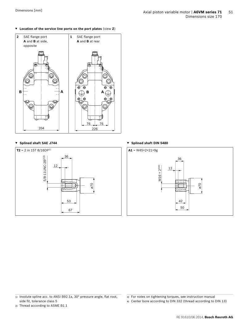
RE 91610062014 Bosch Rexroth AG
Axial piston variable motor | A6VM series 71 Dimensions size 170
51Dimensions [mm]
Location of the service line ports on the port plates (view Z)
2 SAE flange portA and B at side opposite
1 SAE flange portA and B at rear
B A
20476
B A
22676
Splined shaft SAE J744 Splined shaft DIN 5480
T2 ‒ 2 in 15T 816DP1) A1 ‒ W45times2times21times9g
36
53
58-
11U
NC
-2B
2)3)
oslash70
67
12
50
42
M16
times 2
3)4)
36
oslash70
12
1) Involute spline acc to ANSI B921a 30deg pressure angle flat root side fit tolerance class 5
2) Thread according to ASME B11
3) For notes on tightening torques see instruction manual4) Center bore according to DIN 332 (thread according to DIN 13)
Bosch Rexroth AG RE 91610062014
52 A6VM series 71 | Axial piston variable motorDimensions size 170
Dimensions [mm]
Ports Standard Size1) pmax abs [bar]2) Status6)
A B Service line portFastening thread AB
SAE J5183)
DIN 131 14 inM14 times 2 19 deep
500 O
T1 Drain port ISO 61495) M27 times 2 19 deep 3 X4)
T2 Drain port ISO 61495) M33 times 2 19 deep 3 O4)
G Synchronous control ISO 61495) M14 times 15 115 deep 500 X
U Bearing flushing ISO 61495) M22 times 15 155 deep 3 X
X Pilot signal (HP HZ HA1THA2T) ISO 61495) M14 times 15 115 deep 100 O
X Pilot signal (HA1 HA2) ISO 61495) M14 times 15 115 deep 3 X
X1 X2 Pilot signal (DA0) ISO 8434-1 SDSC-L8timesM12-F 40 O
X1 Pilot signal (DA1 DA2) ISO 61495) M14 times 15 115 deep 40 O
X3 Pilot signal (DA1 DA2) ISO 61495) M14 times 15 115 deep 40 X
M1 Measuring stroking chamber ISO 61495) M14 times 15 115 deep 500 X
1) For notes on tightening torques see instruction manual2) Momentary pressure spikes may occur depending on the application
Keep this in mind when selecting measuring devices and fittings3) Only dimensions according to SAE J518 metric fastening thread is
a deviation from standard
4) Depending on installation position T1 or T2 must be connected (see also installation instructions on page 72)
5) The spot face can be deeper than specified in the appropriate standard6) O = Must be connected (plugged on delivery)
X = Plugged (in normal operation)
RE 91610062014 Bosch Rexroth AG
Axial piston variable motor | A6VM series 71 Dimensions size 170
53Dimensions [mm]
EP1 EP2 ndash Electric proportional control positive control
EP5D1 EP6D1 ndash Electric proportional control negative control with pressure control fixed
G
B A
M1
G
M1
322
133
266
195
197
328
G
M1M1
B A
G
HP1 HP2 ndash Hydraulic proportional control positive control
HP5 HP6 ndash Hydraulic proportional control negative control
405
181
133
197
322
232
XG
M1
GX
B A
M1
405
108
133
197
296326
X G
M1
B A
G X
M1
HP5D1 HP6D1 ndash Hydraulic proportional control negative control with pressure control fixed
328297
108
141
197
X XG G
M1
B A
405
M1
Bosch Rexroth AG RE 91610062014
54 A6VM series 71 | Axial piston variable motorDimensions size 170
Dimensions [mm]
HZ5 ndash Hydraulic two-point control negative control
EZ5 EZ6 ndash Electric two-point control negative control
197
107
133
405 291326
X G
M1
G
B A
X
M1
G
M1
G
B A
M1
197
187
326
HA1 HA2 HA1T3 HA2T3 ndash Automatic high-pressure-related control positive control with override hydraulic remote con-trolled proportional
HA1U1 HA2U2 ndash Automatic high-pressure-related control positive control with override electric two-point
405
181
133
197
322
232G
M1
G X
B A
X
M1 M1
B A
M1
G G
322
133
266
HA1 and HA2 X plugged
HA1T and HA2T X open
HA1R1 HA2R2 ndash Automatic high-pressure-related control positive control with override electric and travel direction valve electric
322
133
266
112
a
bG
M1
G
B A
M1
RE 91610062014 Bosch Rexroth AG
Axial piston variable motor | A6VM series 71 Dimensions size 170
55Dimensions [mm]
DA0 ndash Automatic speed-related control negative control with hydraulic travel direction valve
DA1 DA2 ndash Automatic speed-related control negative control with electric travel direction valve and electric Vg max circuit
X2X1G X3 G X3
M1
X1 X2
B A
M1
174
197
140
254328
115
B A
M1
G
X1X3
M1
G
X3X1
ab
176
197
153
277328
112 85
X1 X2 pipe fitting SDSC ndash L8timesM12 ndash F according to ISO 8434-1
Use assembled fitting
Bosch Rexroth AG RE 91610062014
56 A6VM series 71 | Axial piston variable motorDimensions size 215
Dimensions [mm]
Dimensions size 215
EP5 EP6 ndash Proportional electric control negative controlPort plate 2 mdash SAE flange ports A and B at side opposite
T2
M1
T1U
Y
125
deg
Z
G G
M1236
236
45deg 45deg
22
250
667
32318
29
oslash200
-0 -00
29
oslash108
75151
267401)
107
125
1472)
3143)
345
9639 32
max 149
209
192)
3646
53)
200
Flange ISO 3019-2
View Y
1) To shaft collar2) Center of gravity3) Port plate 1 mdash SAE flange ports A and B at rear
RE 91610062014 Bosch Rexroth AG
Axial piston variable motor | A6VM series 71 Dimensions size 215
57Dimensions [mm]
Location of the service line ports on the port plates (view Z)
2 SAE flange portA and B at side opposite
1 SAE flange portA and B at rear
216
B A
82
235
82
B A
Splined shaft SAE J744 Splined shaft DIN 5480
T2 ‒ 2 in 15T 816DP1) A2 ‒ W50times2times24times9g
36
53
58-
11U
NC
-2B
2)3)
oslash70
67
12
55
44
M16
times 2
3)4)
36
oslash70
12
1) Involute spline acc to ANSI B921a 30deg pressure angle flat root side fit tolerance class 5
2) Thread according to ASME B11
3) For notes on tightening torques see instruction manual4) Center bore according to DIN 332 (thread according to DIN 13)
Bosch Rexroth AG RE 91610062014
58 A6VM series 71 | Axial piston variable motorDimensions size 215
Dimensions [mm]
Ports Standard Size1) pmax abs [bar]2) Status6)
A B Service line portFastening thread AB
SAE J5183)
DIN 131 14 inM14 times 2 19 deep
500 O
T1 Drain port ISO 61495) M33 times 2 19 deep 3 X4)
T2 Drain port ISO 61495) M42 times 2 195 deep 3 O4)
G Synchronous control ISO 61495) M14 times 15 115 deep 500 X
U Bearing flushing ISO 61495) M22 times 15 155 deep 3 X
X Pilot signal (HP HZ HA1THA2T) ISO 61495) M14 times 15 115 deep 100 O
X Pilot signal (HA1 HA2) ISO 61495) M14 times 15 115 deep 3 X
X1 X2 Pilot signal (DA0) ISO 8434-1 SDSC-L8timesM12-F 40 O
X1 Pilot signal (DA1 DA2) ISO 61495) M14 times 15 115 deep 40 O
X3 Pilot signal (DA1 DA2) ISO 61495) M14 times 15 115 deep 40 X
M1 Measuring stroking chamber ISO 61495) M14 times 15 115 deep 500 X
1) For notes on tightening torques see instruction manual2) Momentary pressure spikes may occur depending on the application
Keep this in mind when selecting measuring devices and fittings3) Only dimensions according to SAE J518 metric fastening thread is
a deviation from standard
4) Depending on installation position T1 or T2 must be connected (see also installation instructions on page 72)
5) The spot face can be deeper than specified in the appropriate standard6) O = Must be connected (plugged on delivery)
X = Plugged (in normal operation)
RE 91610062014 Bosch Rexroth AG
Axial piston variable motor | A6VM series 71 Dimensions size 215
59Dimensions [mm]
EP1 EP2 ndash Electric proportional control positive control
EP5D1 EP6D1 ndash Electric proportional control negative control with pressure control fixed
339
140
275
M1
G
M1
G
B A
M1
B A
M1
G
209
200
345
G
HP1 HP2 ndash Hydraulic proportional control positive control
HP5 HP6 ndash Hydraulic proportional control negative control
M1
G
B A
X
M1
339
206
245
GX
190
405
140
M1
209
140
343
M1
B A
X G X312
113
G405
HP5D1 HP6D1 ndash Hydraulic proportional control negative control with pressure control fixed
M1
G
B A
M1
X
209
145
G X313
344405
112
Bosch Rexroth AG RE 91610062014
60 A6VM series 71 | Axial piston variable motorDimensions size 215
Dimensions [mm]
HZ5 ndash Hydraulic two-point control negative control
EZ5 EZ6 ndash Electric two-point control negative control
M1
XG
140
209
111
308343
M1
X G405
B A
M1
G
B A
M1
191
209
343
G
HA1 HA2 HA1T3 HA2T3 ndash Automatic high-pressure-related control positive control with override hydraulic remote con-trolled proportional
HA1U1 HA2U2 ndash Automatic high-pressure-related control positive control with override electric two-point
M1
G
B A
X
M1
339
206
245
GX
190
405
140
B A
M1
G
M1
339
276
140
G
HA1 and HA2 X plugged
HA1T and HA2T X open
HA1R1 HA2R2 ndash Automatic high-pressure-related control positive control with override electric and travel direction valve electric
M1
276
140
339
G
M1
B A
Ga
112
b
RE 91610062014 Bosch Rexroth AG
Axial piston variable motor | A6VM series 71 Dimensions size 215
61Dimensions [mm]
DA0 ndash Automatic speed-related control negative control with hydraulic travel direction valve
DA1 DA2 ndash Automatic speed-related control negative control with electric travel direction valve and electric Vg max circuit
M1
B A
X1 X2X3G X1 X2 X3G
M1
174 271345
209
144
119
209
180
157
294345
85112
M1
B A
M1
G
X1X3
G
X1 X3
ab
X1 X2 pipe fitting SDSC ndash L8timesM12 ndash F according to ISO 8434-1
Use assembled fitting
Bosch Rexroth AG RE 91610062014
62 A6VM series 71 | Axial piston variable motorConnector for solenoids
Connector for solenoids
DEUTSCH DT04-2P-EP04Molded connector 2-pin without bidirectional suppres-sor diode There is the following type of protection with mounted mating connector
IP67 (DINEN 60529) and IP69K (DIN 40050-9)
Circuit symbol
Mating connector DEUTSCH DT06-2S-EP04
Consisting of DT designation
1 housing DT06-2S-EP04
1 wedge W2S
2 sockets 0462-201-16141
The mating connector is not included in the scope of deliv-ery This can be supplied by Bosch Rexroth on request (material number R902601804)
NoteIf necessary you can change the connector orientation by turning the solenoid housingThe procedure can be taken from the instruction manual
RE 91610062014 Bosch Rexroth AG
Axial piston variable motor | A6VM series 71 Flushing and boost pressure valve
63
Flushing and boost pressure valve
The flushing and boost pressure valve is used to remove heat from the hydraulic circuitIn an open circuit it is used only for flushing the housingIn a closed circuit it ensures a minimum boost pressure level in addition to the case flushingHydraulic fluid is directed from the respective low pressure side into the motor housing This is then fed into the reser-voir together with the leakage The hydraulic fluid removed out of the closed circuit must be replaced by cooled hydraulic fluid from the boost pumpThe valve is mounted onto the port plate or integrated (depending on the control type and size)Cracking pressure of pressure retaining valve(observe when adjusting the primary valve)
Sizes 60 to 215 fixed setting 16 barSwitching pressure of flushing spool Dp
Sizes 60 to 115 (no flushing valve) 8plusmn1 bar Sizes 115 to 215 (medium and large flushing valve)
175plusmn15 barFlushing flow qv
Orifices can be used to adjust the flushing flows as required The following information is based on DpND = pND ndash pG = 25 bar and ν = 10 mm2s (pND = low pressure pG = case pressure)
Small flushing valve for sizes 60 to 115
Material number of orifice oslash [mm] qv [lmin] Code
R909651766 12 35 A
R909419695 14 5 B
R909419696 18 8 C
R909419697 20 10 D
R909444361 24 14 F
Medium flushing valve for size 115
Material number of orifice oslash [mm] qv [lmin] Code
R909431310 28 20 H
R909435172 35 25 J
R909449967 50 30 K
Large flushing valve for sizes 150 to 215
Material number of orifice oslash [mm] qv [lmin] Code
R909449998 18 8 C
R909431308 20 10 D
R909431309 25 17 G
R909431310 28 20 H
R902138235 31 25 J
R909435172 35 30 K
R909436622 40 35 L
R909449967 50 40 M
Schematic EP
G
T2
T1U
Sa
B
A
Vg min
Vg max
M1
Flushing spool
Pressure retain-ing valve
Flushing orifice
Notes Port Sa only for sizes 150 to 215 For a flushing flow greater than 35 l min it is recom-
mended that port Sa be connected in order to prevent an increase in case pressure An increased case pres-sure reduces the flushing flow
Bosch Rexroth AG RE 91610062014
64 A6VM series 71 | Axial piston variable motorFlushing and boost pressure valve
Dimensions [mm]
Dimensions of sizes 60 to 115 (small flushing valve)
A1 A4
HA1 HA2HP1 HP2EP1 EP2
HP5 HP6EP5 EP6DA
HZ7EZ7 EZ8
A3
A2
NG A1 A2 A3 A4
60 245 137 183 236
85 273 142 194 254
115 287 143 202 269
Dimensions for sizes 115 to 215 (large flushing valve)
Sa
Sa
Sa
Z
HA1 HA2HP1 HP2EP1 EP2
HP5 HP6 DAEP5 EP6HZ5 EZ5 EZ6
B4
A2B2
A3B
3
38
A1B1
NG A1 B1 A2 B2 A3 B3 B4
60 325 239 165 142 230 187 166
85 332 246 165 142 233 190 172
115 349 263 172 148 244 201 185
Dimensions of size 115 (medium flushing valve)
205
151
292
HA1 HA2HP1 HP2EP1 EP2
HP5 HP6EP5 EP6DA
NG Sa1)
150
M22 times 15 155 deep170
215
1) ISO 6149 ports plugged (in normal operation) For notes on tightening torques see instruction manual The spot face can be deeper than specified in the appropriate stan-dard
RE 91610062014 Bosch Rexroth AG
Axial piston variable motor | A6VM series 71 Counterbalance valve BVD and BVE
65
Counterbalance valve BVD and BVE
FunctionCounterbalance valves for travel drive and winch operations are designed to reduce the danger of overspeeding and cavitation of axial piston motors in open circuits Cavitation occurs if during braking when driving downhill or the load-lowering process the motor speed is greater than it should be for the given inlet flow causing the inlet pressure to collapseIf the pressure difference between the inflow and the out-flow drops below the value opening end of the piston in the counterbalance valve (see data sheet BVD ndash 95522 or BVE ndash 95525) the counterbalance spool will move to the closed position The cross-sectional area of the counterbalance valve return duct is then reduced creating a bottleneck in the return flow of the hydraulic fluid The pressure increases and brakes the motor until the rotational speed of the motor is again as it should be for the given inlet flow
Notes BVD available for sizes 60 to 215 and BVE available for
sizes 115 to 215 The counterbalance valve must be ordered additionally
We recommend ordering the counterbalance valve and the motor as a set Ordering example A6VM085HA1T30004A71MWV0N4S97W0-0 + BVD20F27S41BndashV03K16D0400S12
For safety reasons control systems with beginning of control at Vg min (z B HA) are not permissible for winch drives
The counterbalance valve does not replace the mechani-cal service brake and parking brake
Observe the detailed notes on the BVD counterbalance valve in data sheet 95522 and on the BVE counterbal-ance valve in data sheet 95525
For the design of the brake release valve we must know for the mechanical parking brake ndash the pressure at the start of opening ndash the volume of the counterbalance spool between
minimum travel (brake closed) and maximum travel (brake released with 21 bar)
ndash the required closing time for a warm device (oil vis-cosity approx 15 mm2s)
Permissible inlet flow or pressure when using DBV and BVDBVE
Without valve Limited values when using DBV and BVDBVE
Motor DBV1) BVD2)BVE3)
NG pnompmax [bar]
qV max [lmin]
NG pnompmax [bar]
qV [lmin]
Code NG pnompmax [bar]
qV [lmin]
Code
60 450500 276 22 350420 240 7 20 (BVD)
350420 220 7W
85 332
115 410 32 400
115 410 8 25 (BVDBVE)
320 8W
150 494
170 533
215 628 On request
1) Pressure-relief valve2) Counterbalance valve double-acting3) Counterbalance valve one-sided
Bosch Rexroth AG RE 91610062014
66 A6VM series 71 | Axial piston variable motorCounterbalance valve BVD and BVE
Counterbalance valve for travel drive BVDFApplication option
Travel drive for wheeled excavators (BVD and BVE)
Example schematic for travel drive on wheeled excavators
A6VM085HA1T30004A71MWV0N4S97W0-0 + BVD20F27S41BndashV03K16D0400S12
Bacute
A
M1
T2
T1
Vg min
Vg max
X
U
G
MB
MA
S
Gext
Gacute
Lacute
Aacute
B
Variable motor A6VMHA1T
Counterbalance valve BVD
Pump directional valve not included in the scope of delivery
Counterbalance valve for winches and track drives BVDW and BVEApplication option
Winch drives in cranes (BVD and BVE) Track drive in excavator crawlers (BVD)
Example schematic for winch drive in cranes
A6VM085HP5D10001A71MWV0N4S97W0-0 + BVE25W38S51ND-V100K00D4599T30S00-0
T2
T1
M1
Vg min
Vg max
B
A
G
X
U
MP1
VGVF
S
Gext
Mk
D
C
Dacute
Cacute
Gacute
Lacute
D1
D2
MB
MA
Variable motor A6VMHP5D
Winch with mechanical parking brake
Counterbalance valve BVE
Pump directional valve not included in the scope of delivery
RE 91610062014 Bosch Rexroth AG
Axial piston variable motor | A6VM series 71 Counterbalance valve BVD and BVE
67Dimensions [mm]
Dimensions
A6VMHA HP1 HP2 and EP1 EP2 A6VMHP5 HP6 and EP5 EP61)
MB (MA)
A BS
A8
B A
Gext
A2A1
A4A3
A6 A5A7
A2A9
MB (MA)
A4A1
0
Br
S
A8
A5 A6A7
B AA B
A6VM Counterbalance valve
NGplate Type Ports Dimensions
A B A1 A2 A3 A4 A5 A6 A7 A8 A9 A10
607 BVD2017 34 in 311 302 143 50 98 139 75 222 326 50
857 BVD2027 1 in 340 331 148 55 98 139 75 222 355 46
1157 BVD2028 1 in 362 353 152 59 98 139 84 234 377 41
1158 BVD2538 1 14 in 380 370 165 63 1205 175 84 238 395 56
1508 BVD2538 1 14 in 411 401 168 67 1205 175 84 238 426 53
1708 BVD2538 1 14 in 417 407 170 68 1205 175 84 238 432 51
2158 BVD2538 1 14 in 448 438 176 74 1205 175 84 299 463 46
1158 BVE2538 1 14 in 380 370 171 63 137 214 84 238 397 63
1508 BVE2538 1 14 in 411 401 175 67 137 214 84 238 423 59
1708 BVE2538 1 14 in 417 407 176 68 137 214 84 238 432 59
2158 BVE2538 1 14 in 448 438 182 74 137 214 84 299 463 52
Ports Version A6VM plate
Standard Size2) Pmax perm [bar]3) Status5)
A B Service line SAE J518 see table above 420 O
S Infeed BVD20 DIN 38524) M22 times 15 14 deep 30 X
BVD25 BVE25 DIN 38524) M27 times 2 16 deep 30 X
Br Brake release reduced high pressure
L 7 DIN 38524) M12 times 15 125 deep 30 O
8 DIN 38524) M12 times 15 12 deep 30 O
Gext Brake release high pressure S DIN 38524) M12 times 15 125 deep 420 X
MA MB Measuring pressure A and B ISO 61494) M18 times 15 145 deep 420 X
1) At the mounting version for the controls HP5 HP6 and EP5 EP6 the cast-in port designations A and B on the counterbalance valve BVD do not correspond with the connection drawing of the A6VM motor The designation of the ports on the installation drawing of the mo-tor is binding
2) For notes on tightening torques see instruction manual
3) Momentary pressure spikes may occur depending on the applica-tion Keep this in mind when selecting measuring devices and fit-tings
4) The spot face can be deeper than specified in the appropriate stan-dard
5) O = Must be connected (plugged on delivery) X = Plugged (in normal operation)
Bosch Rexroth AG RE 91610062014
68 A6VM series 71 | Axial piston variable motorCounterbalance valve BVD and BVE
Mounting the counterbalance valveWhen delivered the counterbalance valve is mounted to the motor with two tacking screws (transport lock) The tack-ing screws may not be removed while mounting the service lines If the counterbalance valve and motor are delivered separately the counterbalance valve must first be mounted to the motor port plate using the provided tacking screws The final mounting of the counterbalance valve on the motor is done with screw fitting of the SAE flange The screws to be used and the procedure mounting can be found in the instruction manual
RE 91610062014 Bosch Rexroth AG
Axial piston variable motor | A6VM series 71 Speed sensor
69
Speed sensor
Version A6VMU (prepared for speed sensor ie without sensor) is equipped with a spline on the rotary groupA signal proportional to motor speed can be generated with the fitted DSADSM speed sensor The DSADSM sensor registers the speed and direction of rotationOrdering code technical data dimensions and details on the connector plus safety instructions about the sensor can be found in the relevant data sheet (95132 for DSM 95133 for DSA)The sensor is mounted on the port provided for this pur-pose with a mounting bolt On deliveries without sensor the port is plugged with a pressure-resistant coverWe recommend ordering the A6VM variable motor complete with mounted sensor
Schematic EP
T2
T1UnU
Dimensions
V design with mounted speed sensor
A
C
B
Size 60 85 115 150 170 215
Number of teeth 54 58 67 72 75 80
A Insertion depth (tolerance -025) 184 184 184 184 184 184
B Contact surface 75 79 88 93 96 101
C 662 752 772 912 917 952
Bosch Rexroth AG RE 91610062014
70 A6VM series 71 | Axial piston variable motorSetting range for displacement
Setting range for displacement
60 85 115
Vg max (cm3rev) Vg min (cm3rev) Vg max (cm3rev) Vg min (cm3rev) Vg max (cm3rev) Vg min (cm3rev)
from to from to from to from to from to from to
A 620 620 00 150 852 852 00 315 1156 1156 00 240
without screw M10 times 60 R909154690
without screw M12 times 70 R909085976
without screw M12 times 70 R909085976
B 620 620 gt 150 305 852 852 gt 315 520 1156 1156 gt 240 475
without screw M10 times 70 R909153779
without screw M12 times 80 R909153075
without screw M12 times 80 R909153075
C 620 620 gt 305 430 852 852 gt 520 590 1156 1156 gt 475 710
without screw M10 times 80 R909154058
without screw M12 times 90 R909154041
without screw M12 times 90 R909154041
D x x x x 1156 1156 gt 710 800
without screw M12 times 100 R909153975
E lt 620 475 00 150 lt 852 555 00 315 lt 1156 935 00 240
M10 times 60 R909154690
M10 times 60 R909154690
M12 times 70 R909085976
M12 times 70 R909085976
M12 times 70 R909085976
M12 times 70 R909085976
F lt 620 475 gt 150 305 lt 852 555 gt 315 520 lt 1156 935 gt 240 475
M10 times 60 R909154690
M10 times 70 R909153779
M12 times 70 R909085976
M12 times 80 R909153075
M12 times 70 R909085976
M12 times 80 R909085976
G lt 620 475 gt 305 430 lt 852 555 gt 520 590 lt 1156 935 gt 475 71
M10 times 60 R909154690
M10 times 80 R909154058
M12 times 70 R909085976
M12 times 90 R909154041
M12 times 70 R909085976
M12 times 90 R909154041
H x x x times lt 1156 935 gt 710 800
M12 times 70 R909085976
M12 times 100 R909153975
J lt 475 330 00 150 lt 555 350 00 315 lt 935 710 00 240
M10 times 70 R909153779
M10 times 60 R909154690
M12 times 80 R909153075
M12 times 70 R909085976
M12 times 80 R909153075
M12 times 70 R909085976
K lt 475 330 gt 150 305 lt 555 350 gt 315 520 lt 935 710 gt 240 475
M10 times 70 R909153779
M10 times 70 R909153779
M12 times 80 R909153075
M12 times 80 R909153075
M12 times 80 R909153075
M12 times 80 R909153075
L lt 475 330 gt 305 430 lt 555 350 gt 520 590 lt 935 710 gt 475 710
M10 times 70 R909153779
M10 times 80 R909154058
M12 times 80 R909153075
M12 times 90 R909154041
M12 times 80 R909153075
M12 times 90 R909154041
M x x x x lt 935 710 gt 710 800
M12 times 80 R909153075
M12 times 100 R909153975
Specify exact settings for Vg min and Vg max in plain text when ordering
Vg min = cm3 Vg max = cm3
Theoretical maximum setting for Vg min = 07 times Vg max
for Vg max = 03 times Vg max
Settings that are not listed in the table may lead to damage Please contact us
RE 91610062014 Bosch Rexroth AG
Axial piston variable motor | A6VM series 71 Setting range for displacement
71
150 170 215
Vg max (cm3rev) Vg min (cm3rev) Vg max (cm3rev) Vg min (cm3rev) Vg max (cm3rev) Vg min (cm3rev)
from to from to from to from to from to from to
A 1521 1521 00 440 1718 1718 00 350 2165 2165 00 445
without screw M12 times 80 R909153075
without screw M12 times 80 R909153075
without screw M12 times 80 R909153075
B 1521 1521 gt 440 690 1718 1718 gt 350 635 2165 2165 gt 445 800
without screw M12 times 90 R909154041
without screw M12 times 90 R909154041
without screw M12 times 90 R909154041
C 1521 1521 gt 690 990 1718 1718 gt 635 980 2165 2165 gt 800 1150
without screw M12 times 100 R909153975
without screw M12 times 100 R909153975
without screw M12 times 100 R909153975
D 1521 1521 gt 990 1060 1718 1718 gt 980 1200 2165 2165 gt 1150 1500
without screw M12 times 110 R909154212
without screw M12 times 110 R909154212
without screw M12 times 110 R909154212
E lt 1521 1110 00 440 lt 1718 1390 00 350 lt 2165 1750 00 445
M12 times 80 R909153075
M12 times 80 R909153075
M12 times 80 R909153075
M10 times 80 R909153075
M12 times 80 R909153075
M12 times 80 R909153075
F lt 1521 1110 gt 440 690 lt 1718 1390 gt 350 635 lt 2165 1750 gt 445 800
M12 times 80 R909153075
M12 times 90 R909085976
M12 times 80 R909153075
M12 times 90 R909154041
M12 times 80 R909153075
M12 times 90 R909154041
G lt 1521 1110 gt 690 990 lt 1718 1390 gt 635 980 lt 2165 1750 gt 800 1150
M12 times 80 R909153075
M12 times 100 R909153975
M12 times 80 R909153075
M12 times 100 R909153975
M12 times 80 R909153075
M12 times 100 R909153975
H lt 1521 1110 gt 990 1060 lt 1718 1390 gt 980 1200 lt 2165 1750 gt 1150 1500
M12 times 80 R909153075
M12 times 110 R909154212
M12 times 80 R909153075
M12 times 110 R909154212
M12 times 80 R909153075
M12 times 110 R909154212
J lt 1110 870 00 440 lt 1390 1120 00 350 lt 1750 1410 00 445
M12 times 90 R909154041
M12 times 80 R909153075
M12 times 90 R909154041
M12 x 80 R909153075
M12 x 90 R909154041
M12 x 80 R909153075
K lt 1110 870 gt 440 690 lt 1390 1120 gt 350 635 lt 1750 1410 gt 445 800
M12 times 90 R909154041
M12 times 90 R909154041
M12 x 90 R909154041
M12 times 90 R909154041
M12 times 90 R909154041
M12 times 90 R909154041
L lt 1110 870 gt 690 990 lt 1390 1120 gt 635 980 lt 1750 1410 gt 800 1150
M12 times 90 R909154041
M12 times 100 R909153975
M12 times 90 R909154041
M12 times 100 R909153975
M12 times 90 R909154041
M12 times 100 R909153975
M lt 1110 870 gt 990 1060 lt 1390 1120 gt 980 1200 lt 1750 1410 gt 1150 1500
M12 times 90 R909154041
M12 times 110 R909154212
M12 times 90 R909154041
M12 times 110 R909154212
M12 times 90 R909154041
M12 times 110 R909154212
Specify exact settings for Vg min and Vg max in plain text when ordering
Vg min = cm3 Vg max = cm3
Theoretical maximum setting for Vg min = 07 times Vg max
for Vg max = 03 times Vg max
Settings that are not listed in the table may lead to damage Please contact us
Bosch Rexroth AG RE 91610062014
72 A6VM series 71 | Axial piston variable motorInstallation instructions
Installation instructions
GeneralDuring commissioning and operation the axial piston unit must be filled with hydraulic fluid and air bled This must also observed following a relatively long standstill as the axial piston unit may drain back to the reservoir via the hydraulic linesParticularly in the installation position drive shaft upwards filling and air bleeding must be carried out com-pletely as there is for example a danger of dry runningThe leakage in the motor housing must be directed to the reservoir via the highest available drain port (T1 T2)To achieve favorable noise values decouple all connecting lines using elastic elements and avoid above-reservoir installation In all operating conditions the drain line must flow into the reservoir below the minimum fluid level
NoteIn certain installation conditions an influence on the control charakteristic curves can be expected Gravity dead weight and case pressure can cause minor shifts in characteristics and changes in response time
Key
U Bearing flushing air bleed port
T1 T2 Drain port
ht min Minimum required immersion depth (200 mm)
hmin Minimum required spacing to reservoir bottom (100 mm)
Installation position See examples 1 to 8 below Additional installation positions are available upon requestRecommended installation position 1 and 2
Below-reservoir installation (standard)Below-reservoir installation means that the axial piston unit is installed outside of the reservoir below the minimum fluid level
Installation position Air bleed Filling
1
T2
T1U
ht min
hmin
T1
2
T2
T1 U
ht min
hmin
T2
3
T2
T1
U
ht min
hmin
T1
4
T2
T1
U
ht min
hmin
U T1
RE 91610062014 Bosch Rexroth AG
Axial piston variable motor | A6VM series 71 Installation instructions
73
Above-reservoir installationAbove-reservoir installation means that the axial piston unit is installed above the minimum fluid level of the reservoirRecommendation for installation position 8 (drive shaft upward) A check valve in the drain line (cracking pressure 05 bar) can prevent draining of the motor housing
Installation position Air bleed Filling
5
T2
T1U
L1
ht min
hmin
U (L1) T1 (L1)
6
T2
T1 U
L1
ht min
hmin
L1 T2 (L1)
7
T2T1
U
L1
ht min
hmin
L1 T1 (L1)
8
T2T1
UL1
05
bar
ht min
hmin
U T1 (L1)
NotePort L1 is not part of the motor and can be made available by the customer for straightforward filling and air bleed-ing
74
Bosch Rexroth AG RE 91610062014
Bosch Rexroth AGMobile ApplicationsGlockeraustraszlige 489275 Elchingen GermanyTel +49-7308-82-0infomaboschrexrothdewwwboschrexrothcom
copy This document as well as the data specifications and other information set forth in it are the exclusive property of Bosch Rexroth AG It may not be reproduced or given to third parties without its consent The data specified above only serve to describe the product No statements concerning a certain condition or suitability for a certain application can be derived from our information The information given does not release the user from the obligation of own judgment and verification It must be remembered that our products are subject to a natural process of wear and aging
A6VM series 71 | Axial piston variable motorProject planning note
Project planning note
The motor A6VM is designed to be used in open and closed circuits
The project planning installation and commissioning of the axial piston unit requires the involvement of quali-fied skilled person
Before using the axial piston unit please read the cor-responding instruction manual completely and thor-oughly If necessary these can be requested from Bosch Rexroth
Before finalizing your design request a binding installa-tion drawing
The data and notes contained herein must be adhered to
For safety reasons control systems with beginning of control at Vg min (eg HA) are not permissible for winch drives eg anchor winches
Depending on the operating conditions of the axial piston unit (operating pressure fluid temperature) the charakteristic curve may shift
Not all variants of the product are approved for use in safety functions according to ISO 13849 Please consult the responsible contact person at Bosch Rexroth if you require reliability parameters (eg MTTFd) for functional safety
Working ports ndash The ports and fastening threads are designed for the
specified maximum pressure The machine or system manufacturer must ensure that the connecting ele-ments and lines correspond to the specified applica-tion conditions (pressure flow hydraulic fluid tem-perature) with the necessary safety factors
ndash The working ports and function ports can only be used to accommodate hydraulic lines
Safety instructions
During and shortly after operation there is a risk of burns on the axial piston unit and especially on the solenoids Take appropriate safety measures (e g by wearing protective clothing)
Moving parts in control and regulation systems (eg valve spools) may in certain circumstances become stuck in an undefined position due to contamination (eg contaminated hydraulic fluid abrasion or residual dirt from components) As a result the hydraulic fluid flow or build-up of torque of the axial piston unit will no longer respond correctly to the operators commands Even the use of different filter cartridges (external or internal inlet filter) will not rule out a fault but merely minimize the risk The machinesystem manufacturer must test whether remedial measures are needed on the machine for the application concerned in order to set the consumer being driven to a safe position (eg safe stop) and if necessary to ensure it is properly imple-mented
If the axial piston motor is used in winch drives make sure that the technical limit values are not exceeded under all operating conditions If the axial piston motor is subjected to external overload (eg by exceeding the maximum permissible rotational speeds when lifting anchor while the ship is in motion) this could cause damage to the rotary group and in unfavorable cases to the axial piston motor bursting If necessary additional measures up to an including encapsulation are to be implemented by the machinesystem manufacturer
RE 91610062014 Bosch Rexroth AG
75 Axial piston variable motor | A6VM series 71
76
Bosch Rexroth AG RE 91610062014
Bosch Rexroth AGMobile ApplicationsGlockeraustraszlige 489275 Elchingen GermanyTel +49-7308-82-0infomaboschrexrothdewwwboschrexrothcom
copy This document as well as the data specifications and other information set forth in it are the exclusive property of Bosch Rexroth AG It may not be reproduced or given to third parties without its consent The data specified above only serve to describe the product No statements concerning a certain condition or suitability for a certain application can be derived from our information The information given does not release the user from the obligation of own judgment and verification It must be remembered that our products are subject to a natural process of wear and aging
A6VM series 71 | axial piston variable motor

Bosch Rexroth AG RE 91610062014
52 A6VM series 71 | Axial piston variable motorDimensions size 170
Dimensions [mm]
Ports Standard Size1) pmax abs [bar]2) Status6)
A B Service line portFastening thread AB
SAE J5183)
DIN 131 14 inM14 times 2 19 deep
500 O
T1 Drain port ISO 61495) M27 times 2 19 deep 3 X4)
T2 Drain port ISO 61495) M33 times 2 19 deep 3 O4)
G Synchronous control ISO 61495) M14 times 15 115 deep 500 X
U Bearing flushing ISO 61495) M22 times 15 155 deep 3 X
X Pilot signal (HP HZ HA1THA2T) ISO 61495) M14 times 15 115 deep 100 O
X Pilot signal (HA1 HA2) ISO 61495) M14 times 15 115 deep 3 X
X1 X2 Pilot signal (DA0) ISO 8434-1 SDSC-L8timesM12-F 40 O
X1 Pilot signal (DA1 DA2) ISO 61495) M14 times 15 115 deep 40 O
X3 Pilot signal (DA1 DA2) ISO 61495) M14 times 15 115 deep 40 X
M1 Measuring stroking chamber ISO 61495) M14 times 15 115 deep 500 X
1) For notes on tightening torques see instruction manual2) Momentary pressure spikes may occur depending on the application
Keep this in mind when selecting measuring devices and fittings3) Only dimensions according to SAE J518 metric fastening thread is
a deviation from standard
4) Depending on installation position T1 or T2 must be connected (see also installation instructions on page 72)
5) The spot face can be deeper than specified in the appropriate standard6) O = Must be connected (plugged on delivery)
X = Plugged (in normal operation)
RE 91610062014 Bosch Rexroth AG
Axial piston variable motor | A6VM series 71 Dimensions size 170
53Dimensions [mm]
EP1 EP2 ndash Electric proportional control positive control
EP5D1 EP6D1 ndash Electric proportional control negative control with pressure control fixed
G
B A
M1
G
M1
322
133
266
195
197
328
G
M1M1
B A
G
HP1 HP2 ndash Hydraulic proportional control positive control
HP5 HP6 ndash Hydraulic proportional control negative control
405
181
133
197
322
232
XG
M1
GX
B A
M1
405
108
133
197
296326
X G
M1
B A
G X
M1
HP5D1 HP6D1 ndash Hydraulic proportional control negative control with pressure control fixed
328297
108
141
197
X XG G
M1
B A
405
M1
Bosch Rexroth AG RE 91610062014
54 A6VM series 71 | Axial piston variable motorDimensions size 170
Dimensions [mm]
HZ5 ndash Hydraulic two-point control negative control
EZ5 EZ6 ndash Electric two-point control negative control
197
107
133
405 291326
X G
M1
G
B A
X
M1
G
M1
G
B A
M1
197
187
326
HA1 HA2 HA1T3 HA2T3 ndash Automatic high-pressure-related control positive control with override hydraulic remote con-trolled proportional
HA1U1 HA2U2 ndash Automatic high-pressure-related control positive control with override electric two-point
405
181
133
197
322
232G
M1
G X
B A
X
M1 M1
B A
M1
G G
322
133
266
HA1 and HA2 X plugged
HA1T and HA2T X open
HA1R1 HA2R2 ndash Automatic high-pressure-related control positive control with override electric and travel direction valve electric
322
133
266
112
a
bG
M1
G
B A
M1
RE 91610062014 Bosch Rexroth AG
Axial piston variable motor | A6VM series 71 Dimensions size 170
55Dimensions [mm]
DA0 ndash Automatic speed-related control negative control with hydraulic travel direction valve
DA1 DA2 ndash Automatic speed-related control negative control with electric travel direction valve and electric Vg max circuit
X2X1G X3 G X3
M1
X1 X2
B A
M1
174
197
140
254328
115
B A
M1
G
X1X3
M1
G
X3X1
ab
176
197
153
277328
112 85
X1 X2 pipe fitting SDSC ndash L8timesM12 ndash F according to ISO 8434-1
Use assembled fitting
Bosch Rexroth AG RE 91610062014
56 A6VM series 71 | Axial piston variable motorDimensions size 215
Dimensions [mm]
Dimensions size 215
EP5 EP6 ndash Proportional electric control negative controlPort plate 2 mdash SAE flange ports A and B at side opposite
T2
M1
T1U
Y
125
deg
Z
G G
M1236
236
45deg 45deg
22
250
667
32318
29
oslash200
-0 -00
29
oslash108
75151
267401)
107
125
1472)
3143)
345
9639 32
max 149
209
192)
3646
53)
200
Flange ISO 3019-2
View Y
1) To shaft collar2) Center of gravity3) Port plate 1 mdash SAE flange ports A and B at rear
RE 91610062014 Bosch Rexroth AG
Axial piston variable motor | A6VM series 71 Dimensions size 215
57Dimensions [mm]
Location of the service line ports on the port plates (view Z)
2 SAE flange portA and B at side opposite
1 SAE flange portA and B at rear
216
B A
82
235
82
B A
Splined shaft SAE J744 Splined shaft DIN 5480
T2 ‒ 2 in 15T 816DP1) A2 ‒ W50times2times24times9g
36
53
58-
11U
NC
-2B
2)3)
oslash70
67
12
55
44
M16
times 2
3)4)
36
oslash70
12
1) Involute spline acc to ANSI B921a 30deg pressure angle flat root side fit tolerance class 5
2) Thread according to ASME B11
3) For notes on tightening torques see instruction manual4) Center bore according to DIN 332 (thread according to DIN 13)
Bosch Rexroth AG RE 91610062014
58 A6VM series 71 | Axial piston variable motorDimensions size 215
Dimensions [mm]
Ports Standard Size1) pmax abs [bar]2) Status6)
A B Service line portFastening thread AB
SAE J5183)
DIN 131 14 inM14 times 2 19 deep
500 O
T1 Drain port ISO 61495) M33 times 2 19 deep 3 X4)
T2 Drain port ISO 61495) M42 times 2 195 deep 3 O4)
G Synchronous control ISO 61495) M14 times 15 115 deep 500 X
U Bearing flushing ISO 61495) M22 times 15 155 deep 3 X
X Pilot signal (HP HZ HA1THA2T) ISO 61495) M14 times 15 115 deep 100 O
X Pilot signal (HA1 HA2) ISO 61495) M14 times 15 115 deep 3 X
X1 X2 Pilot signal (DA0) ISO 8434-1 SDSC-L8timesM12-F 40 O
X1 Pilot signal (DA1 DA2) ISO 61495) M14 times 15 115 deep 40 O
X3 Pilot signal (DA1 DA2) ISO 61495) M14 times 15 115 deep 40 X
M1 Measuring stroking chamber ISO 61495) M14 times 15 115 deep 500 X
1) For notes on tightening torques see instruction manual2) Momentary pressure spikes may occur depending on the application
Keep this in mind when selecting measuring devices and fittings3) Only dimensions according to SAE J518 metric fastening thread is
a deviation from standard
4) Depending on installation position T1 or T2 must be connected (see also installation instructions on page 72)
5) The spot face can be deeper than specified in the appropriate standard6) O = Must be connected (plugged on delivery)
X = Plugged (in normal operation)
RE 91610062014 Bosch Rexroth AG
Axial piston variable motor | A6VM series 71 Dimensions size 215
59Dimensions [mm]
EP1 EP2 ndash Electric proportional control positive control
EP5D1 EP6D1 ndash Electric proportional control negative control with pressure control fixed
339
140
275
M1
G
M1
G
B A
M1
B A
M1
G
209
200
345
G
HP1 HP2 ndash Hydraulic proportional control positive control
HP5 HP6 ndash Hydraulic proportional control negative control
M1
G
B A
X
M1
339
206
245
GX
190
405
140
M1
209
140
343
M1
B A
X G X312
113
G405
HP5D1 HP6D1 ndash Hydraulic proportional control negative control with pressure control fixed
M1
G
B A
M1
X
209
145
G X313
344405
112
Bosch Rexroth AG RE 91610062014
60 A6VM series 71 | Axial piston variable motorDimensions size 215
Dimensions [mm]
HZ5 ndash Hydraulic two-point control negative control
EZ5 EZ6 ndash Electric two-point control negative control
M1
XG
140
209
111
308343
M1
X G405
B A
M1
G
B A
M1
191
209
343
G
HA1 HA2 HA1T3 HA2T3 ndash Automatic high-pressure-related control positive control with override hydraulic remote con-trolled proportional
HA1U1 HA2U2 ndash Automatic high-pressure-related control positive control with override electric two-point
M1
G
B A
X
M1
339
206
245
GX
190
405
140
B A
M1
G
M1
339
276
140
G
HA1 and HA2 X plugged
HA1T and HA2T X open
HA1R1 HA2R2 ndash Automatic high-pressure-related control positive control with override electric and travel direction valve electric
M1
276
140
339
G
M1
B A
Ga
112
b
RE 91610062014 Bosch Rexroth AG
Axial piston variable motor | A6VM series 71 Dimensions size 215
61Dimensions [mm]
DA0 ndash Automatic speed-related control negative control with hydraulic travel direction valve
DA1 DA2 ndash Automatic speed-related control negative control with electric travel direction valve and electric Vg max circuit
M1
B A
X1 X2X3G X1 X2 X3G
M1
174 271345
209
144
119
209
180
157
294345
85112
M1
B A
M1
G
X1X3
G
X1 X3
ab
X1 X2 pipe fitting SDSC ndash L8timesM12 ndash F according to ISO 8434-1
Use assembled fitting
Bosch Rexroth AG RE 91610062014
62 A6VM series 71 | Axial piston variable motorConnector for solenoids
Connector for solenoids
DEUTSCH DT04-2P-EP04Molded connector 2-pin without bidirectional suppres-sor diode There is the following type of protection with mounted mating connector
IP67 (DINEN 60529) and IP69K (DIN 40050-9)
Circuit symbol
Mating connector DEUTSCH DT06-2S-EP04
Consisting of DT designation
1 housing DT06-2S-EP04
1 wedge W2S
2 sockets 0462-201-16141
The mating connector is not included in the scope of deliv-ery This can be supplied by Bosch Rexroth on request (material number R902601804)
NoteIf necessary you can change the connector orientation by turning the solenoid housingThe procedure can be taken from the instruction manual
RE 91610062014 Bosch Rexroth AG
Axial piston variable motor | A6VM series 71 Flushing and boost pressure valve
63
Flushing and boost pressure valve
The flushing and boost pressure valve is used to remove heat from the hydraulic circuitIn an open circuit it is used only for flushing the housingIn a closed circuit it ensures a minimum boost pressure level in addition to the case flushingHydraulic fluid is directed from the respective low pressure side into the motor housing This is then fed into the reser-voir together with the leakage The hydraulic fluid removed out of the closed circuit must be replaced by cooled hydraulic fluid from the boost pumpThe valve is mounted onto the port plate or integrated (depending on the control type and size)Cracking pressure of pressure retaining valve(observe when adjusting the primary valve)
Sizes 60 to 215 fixed setting 16 barSwitching pressure of flushing spool Dp
Sizes 60 to 115 (no flushing valve) 8plusmn1 bar Sizes 115 to 215 (medium and large flushing valve)
175plusmn15 barFlushing flow qv
Orifices can be used to adjust the flushing flows as required The following information is based on DpND = pND ndash pG = 25 bar and ν = 10 mm2s (pND = low pressure pG = case pressure)
Small flushing valve for sizes 60 to 115
Material number of orifice oslash [mm] qv [lmin] Code
R909651766 12 35 A
R909419695 14 5 B
R909419696 18 8 C
R909419697 20 10 D
R909444361 24 14 F
Medium flushing valve for size 115
Material number of orifice oslash [mm] qv [lmin] Code
R909431310 28 20 H
R909435172 35 25 J
R909449967 50 30 K
Large flushing valve for sizes 150 to 215
Material number of orifice oslash [mm] qv [lmin] Code
R909449998 18 8 C
R909431308 20 10 D
R909431309 25 17 G
R909431310 28 20 H
R902138235 31 25 J
R909435172 35 30 K
R909436622 40 35 L
R909449967 50 40 M
Schematic EP
G
T2
T1U
Sa
B
A
Vg min
Vg max
M1
Flushing spool
Pressure retain-ing valve
Flushing orifice
Notes Port Sa only for sizes 150 to 215 For a flushing flow greater than 35 l min it is recom-
mended that port Sa be connected in order to prevent an increase in case pressure An increased case pres-sure reduces the flushing flow
Bosch Rexroth AG RE 91610062014
64 A6VM series 71 | Axial piston variable motorFlushing and boost pressure valve
Dimensions [mm]
Dimensions of sizes 60 to 115 (small flushing valve)
A1 A4
HA1 HA2HP1 HP2EP1 EP2
HP5 HP6EP5 EP6DA
HZ7EZ7 EZ8
A3
A2
NG A1 A2 A3 A4
60 245 137 183 236
85 273 142 194 254
115 287 143 202 269
Dimensions for sizes 115 to 215 (large flushing valve)
Sa
Sa
Sa
Z
HA1 HA2HP1 HP2EP1 EP2
HP5 HP6 DAEP5 EP6HZ5 EZ5 EZ6
B4
A2B2
A3B
3
38
A1B1
NG A1 B1 A2 B2 A3 B3 B4
60 325 239 165 142 230 187 166
85 332 246 165 142 233 190 172
115 349 263 172 148 244 201 185
Dimensions of size 115 (medium flushing valve)
205
151
292
HA1 HA2HP1 HP2EP1 EP2
HP5 HP6EP5 EP6DA
NG Sa1)
150
M22 times 15 155 deep170
215
1) ISO 6149 ports plugged (in normal operation) For notes on tightening torques see instruction manual The spot face can be deeper than specified in the appropriate stan-dard
RE 91610062014 Bosch Rexroth AG
Axial piston variable motor | A6VM series 71 Counterbalance valve BVD and BVE
65
Counterbalance valve BVD and BVE
FunctionCounterbalance valves for travel drive and winch operations are designed to reduce the danger of overspeeding and cavitation of axial piston motors in open circuits Cavitation occurs if during braking when driving downhill or the load-lowering process the motor speed is greater than it should be for the given inlet flow causing the inlet pressure to collapseIf the pressure difference between the inflow and the out-flow drops below the value opening end of the piston in the counterbalance valve (see data sheet BVD ndash 95522 or BVE ndash 95525) the counterbalance spool will move to the closed position The cross-sectional area of the counterbalance valve return duct is then reduced creating a bottleneck in the return flow of the hydraulic fluid The pressure increases and brakes the motor until the rotational speed of the motor is again as it should be for the given inlet flow
Notes BVD available for sizes 60 to 215 and BVE available for
sizes 115 to 215 The counterbalance valve must be ordered additionally
We recommend ordering the counterbalance valve and the motor as a set Ordering example A6VM085HA1T30004A71MWV0N4S97W0-0 + BVD20F27S41BndashV03K16D0400S12
For safety reasons control systems with beginning of control at Vg min (z B HA) are not permissible for winch drives
The counterbalance valve does not replace the mechani-cal service brake and parking brake
Observe the detailed notes on the BVD counterbalance valve in data sheet 95522 and on the BVE counterbal-ance valve in data sheet 95525
For the design of the brake release valve we must know for the mechanical parking brake ndash the pressure at the start of opening ndash the volume of the counterbalance spool between
minimum travel (brake closed) and maximum travel (brake released with 21 bar)
ndash the required closing time for a warm device (oil vis-cosity approx 15 mm2s)
Permissible inlet flow or pressure when using DBV and BVDBVE
Without valve Limited values when using DBV and BVDBVE
Motor DBV1) BVD2)BVE3)
NG pnompmax [bar]
qV max [lmin]
NG pnompmax [bar]
qV [lmin]
Code NG pnompmax [bar]
qV [lmin]
Code
60 450500 276 22 350420 240 7 20 (BVD)
350420 220 7W
85 332
115 410 32 400
115 410 8 25 (BVDBVE)
320 8W
150 494
170 533
215 628 On request
1) Pressure-relief valve2) Counterbalance valve double-acting3) Counterbalance valve one-sided
Bosch Rexroth AG RE 91610062014
66 A6VM series 71 | Axial piston variable motorCounterbalance valve BVD and BVE
Counterbalance valve for travel drive BVDFApplication option
Travel drive for wheeled excavators (BVD and BVE)
Example schematic for travel drive on wheeled excavators
A6VM085HA1T30004A71MWV0N4S97W0-0 + BVD20F27S41BndashV03K16D0400S12
Bacute
A
M1
T2
T1
Vg min
Vg max
X
U
G
MB
MA
S
Gext
Gacute
Lacute
Aacute
B
Variable motor A6VMHA1T
Counterbalance valve BVD
Pump directional valve not included in the scope of delivery
Counterbalance valve for winches and track drives BVDW and BVEApplication option
Winch drives in cranes (BVD and BVE) Track drive in excavator crawlers (BVD)
Example schematic for winch drive in cranes
A6VM085HP5D10001A71MWV0N4S97W0-0 + BVE25W38S51ND-V100K00D4599T30S00-0
T2
T1
M1
Vg min
Vg max
B
A
G
X
U
MP1
VGVF
S
Gext
Mk
D
C
Dacute
Cacute
Gacute
Lacute
D1
D2
MB
MA
Variable motor A6VMHP5D
Winch with mechanical parking brake
Counterbalance valve BVE
Pump directional valve not included in the scope of delivery
RE 91610062014 Bosch Rexroth AG
Axial piston variable motor | A6VM series 71 Counterbalance valve BVD and BVE
67Dimensions [mm]
Dimensions
A6VMHA HP1 HP2 and EP1 EP2 A6VMHP5 HP6 and EP5 EP61)
MB (MA)
A BS
A8
B A
Gext
A2A1
A4A3
A6 A5A7
A2A9
MB (MA)
A4A1
0
Br
S
A8
A5 A6A7
B AA B
A6VM Counterbalance valve
NGplate Type Ports Dimensions
A B A1 A2 A3 A4 A5 A6 A7 A8 A9 A10
607 BVD2017 34 in 311 302 143 50 98 139 75 222 326 50
857 BVD2027 1 in 340 331 148 55 98 139 75 222 355 46
1157 BVD2028 1 in 362 353 152 59 98 139 84 234 377 41
1158 BVD2538 1 14 in 380 370 165 63 1205 175 84 238 395 56
1508 BVD2538 1 14 in 411 401 168 67 1205 175 84 238 426 53
1708 BVD2538 1 14 in 417 407 170 68 1205 175 84 238 432 51
2158 BVD2538 1 14 in 448 438 176 74 1205 175 84 299 463 46
1158 BVE2538 1 14 in 380 370 171 63 137 214 84 238 397 63
1508 BVE2538 1 14 in 411 401 175 67 137 214 84 238 423 59
1708 BVE2538 1 14 in 417 407 176 68 137 214 84 238 432 59
2158 BVE2538 1 14 in 448 438 182 74 137 214 84 299 463 52
Ports Version A6VM plate
Standard Size2) Pmax perm [bar]3) Status5)
A B Service line SAE J518 see table above 420 O
S Infeed BVD20 DIN 38524) M22 times 15 14 deep 30 X
BVD25 BVE25 DIN 38524) M27 times 2 16 deep 30 X
Br Brake release reduced high pressure
L 7 DIN 38524) M12 times 15 125 deep 30 O
8 DIN 38524) M12 times 15 12 deep 30 O
Gext Brake release high pressure S DIN 38524) M12 times 15 125 deep 420 X
MA MB Measuring pressure A and B ISO 61494) M18 times 15 145 deep 420 X
1) At the mounting version for the controls HP5 HP6 and EP5 EP6 the cast-in port designations A and B on the counterbalance valve BVD do not correspond with the connection drawing of the A6VM motor The designation of the ports on the installation drawing of the mo-tor is binding
2) For notes on tightening torques see instruction manual
3) Momentary pressure spikes may occur depending on the applica-tion Keep this in mind when selecting measuring devices and fit-tings
4) The spot face can be deeper than specified in the appropriate stan-dard
5) O = Must be connected (plugged on delivery) X = Plugged (in normal operation)
Bosch Rexroth AG RE 91610062014
68 A6VM series 71 | Axial piston variable motorCounterbalance valve BVD and BVE
Mounting the counterbalance valveWhen delivered the counterbalance valve is mounted to the motor with two tacking screws (transport lock) The tack-ing screws may not be removed while mounting the service lines If the counterbalance valve and motor are delivered separately the counterbalance valve must first be mounted to the motor port plate using the provided tacking screws The final mounting of the counterbalance valve on the motor is done with screw fitting of the SAE flange The screws to be used and the procedure mounting can be found in the instruction manual
RE 91610062014 Bosch Rexroth AG
Axial piston variable motor | A6VM series 71 Speed sensor
69
Speed sensor
Version A6VMU (prepared for speed sensor ie without sensor) is equipped with a spline on the rotary groupA signal proportional to motor speed can be generated with the fitted DSADSM speed sensor The DSADSM sensor registers the speed and direction of rotationOrdering code technical data dimensions and details on the connector plus safety instructions about the sensor can be found in the relevant data sheet (95132 for DSM 95133 for DSA)The sensor is mounted on the port provided for this pur-pose with a mounting bolt On deliveries without sensor the port is plugged with a pressure-resistant coverWe recommend ordering the A6VM variable motor complete with mounted sensor
Schematic EP
T2
T1UnU
Dimensions
V design with mounted speed sensor
A
C
B
Size 60 85 115 150 170 215
Number of teeth 54 58 67 72 75 80
A Insertion depth (tolerance -025) 184 184 184 184 184 184
B Contact surface 75 79 88 93 96 101
C 662 752 772 912 917 952
Bosch Rexroth AG RE 91610062014
70 A6VM series 71 | Axial piston variable motorSetting range for displacement
Setting range for displacement
60 85 115
Vg max (cm3rev) Vg min (cm3rev) Vg max (cm3rev) Vg min (cm3rev) Vg max (cm3rev) Vg min (cm3rev)
from to from to from to from to from to from to
A 620 620 00 150 852 852 00 315 1156 1156 00 240
without screw M10 times 60 R909154690
without screw M12 times 70 R909085976
without screw M12 times 70 R909085976
B 620 620 gt 150 305 852 852 gt 315 520 1156 1156 gt 240 475
without screw M10 times 70 R909153779
without screw M12 times 80 R909153075
without screw M12 times 80 R909153075
C 620 620 gt 305 430 852 852 gt 520 590 1156 1156 gt 475 710
without screw M10 times 80 R909154058
without screw M12 times 90 R909154041
without screw M12 times 90 R909154041
D x x x x 1156 1156 gt 710 800
without screw M12 times 100 R909153975
E lt 620 475 00 150 lt 852 555 00 315 lt 1156 935 00 240
M10 times 60 R909154690
M10 times 60 R909154690
M12 times 70 R909085976
M12 times 70 R909085976
M12 times 70 R909085976
M12 times 70 R909085976
F lt 620 475 gt 150 305 lt 852 555 gt 315 520 lt 1156 935 gt 240 475
M10 times 60 R909154690
M10 times 70 R909153779
M12 times 70 R909085976
M12 times 80 R909153075
M12 times 70 R909085976
M12 times 80 R909085976
G lt 620 475 gt 305 430 lt 852 555 gt 520 590 lt 1156 935 gt 475 71
M10 times 60 R909154690
M10 times 80 R909154058
M12 times 70 R909085976
M12 times 90 R909154041
M12 times 70 R909085976
M12 times 90 R909154041
H x x x times lt 1156 935 gt 710 800
M12 times 70 R909085976
M12 times 100 R909153975
J lt 475 330 00 150 lt 555 350 00 315 lt 935 710 00 240
M10 times 70 R909153779
M10 times 60 R909154690
M12 times 80 R909153075
M12 times 70 R909085976
M12 times 80 R909153075
M12 times 70 R909085976
K lt 475 330 gt 150 305 lt 555 350 gt 315 520 lt 935 710 gt 240 475
M10 times 70 R909153779
M10 times 70 R909153779
M12 times 80 R909153075
M12 times 80 R909153075
M12 times 80 R909153075
M12 times 80 R909153075
L lt 475 330 gt 305 430 lt 555 350 gt 520 590 lt 935 710 gt 475 710
M10 times 70 R909153779
M10 times 80 R909154058
M12 times 80 R909153075
M12 times 90 R909154041
M12 times 80 R909153075
M12 times 90 R909154041
M x x x x lt 935 710 gt 710 800
M12 times 80 R909153075
M12 times 100 R909153975
Specify exact settings for Vg min and Vg max in plain text when ordering
Vg min = cm3 Vg max = cm3
Theoretical maximum setting for Vg min = 07 times Vg max
for Vg max = 03 times Vg max
Settings that are not listed in the table may lead to damage Please contact us
RE 91610062014 Bosch Rexroth AG
Axial piston variable motor | A6VM series 71 Setting range for displacement
71
150 170 215
Vg max (cm3rev) Vg min (cm3rev) Vg max (cm3rev) Vg min (cm3rev) Vg max (cm3rev) Vg min (cm3rev)
from to from to from to from to from to from to
A 1521 1521 00 440 1718 1718 00 350 2165 2165 00 445
without screw M12 times 80 R909153075
without screw M12 times 80 R909153075
without screw M12 times 80 R909153075
B 1521 1521 gt 440 690 1718 1718 gt 350 635 2165 2165 gt 445 800
without screw M12 times 90 R909154041
without screw M12 times 90 R909154041
without screw M12 times 90 R909154041
C 1521 1521 gt 690 990 1718 1718 gt 635 980 2165 2165 gt 800 1150
without screw M12 times 100 R909153975
without screw M12 times 100 R909153975
without screw M12 times 100 R909153975
D 1521 1521 gt 990 1060 1718 1718 gt 980 1200 2165 2165 gt 1150 1500
without screw M12 times 110 R909154212
without screw M12 times 110 R909154212
without screw M12 times 110 R909154212
E lt 1521 1110 00 440 lt 1718 1390 00 350 lt 2165 1750 00 445
M12 times 80 R909153075
M12 times 80 R909153075
M12 times 80 R909153075
M10 times 80 R909153075
M12 times 80 R909153075
M12 times 80 R909153075
F lt 1521 1110 gt 440 690 lt 1718 1390 gt 350 635 lt 2165 1750 gt 445 800
M12 times 80 R909153075
M12 times 90 R909085976
M12 times 80 R909153075
M12 times 90 R909154041
M12 times 80 R909153075
M12 times 90 R909154041
G lt 1521 1110 gt 690 990 lt 1718 1390 gt 635 980 lt 2165 1750 gt 800 1150
M12 times 80 R909153075
M12 times 100 R909153975
M12 times 80 R909153075
M12 times 100 R909153975
M12 times 80 R909153075
M12 times 100 R909153975
H lt 1521 1110 gt 990 1060 lt 1718 1390 gt 980 1200 lt 2165 1750 gt 1150 1500
M12 times 80 R909153075
M12 times 110 R909154212
M12 times 80 R909153075
M12 times 110 R909154212
M12 times 80 R909153075
M12 times 110 R909154212
J lt 1110 870 00 440 lt 1390 1120 00 350 lt 1750 1410 00 445
M12 times 90 R909154041
M12 times 80 R909153075
M12 times 90 R909154041
M12 x 80 R909153075
M12 x 90 R909154041
M12 x 80 R909153075
K lt 1110 870 gt 440 690 lt 1390 1120 gt 350 635 lt 1750 1410 gt 445 800
M12 times 90 R909154041
M12 times 90 R909154041
M12 x 90 R909154041
M12 times 90 R909154041
M12 times 90 R909154041
M12 times 90 R909154041
L lt 1110 870 gt 690 990 lt 1390 1120 gt 635 980 lt 1750 1410 gt 800 1150
M12 times 90 R909154041
M12 times 100 R909153975
M12 times 90 R909154041
M12 times 100 R909153975
M12 times 90 R909154041
M12 times 100 R909153975
M lt 1110 870 gt 990 1060 lt 1390 1120 gt 980 1200 lt 1750 1410 gt 1150 1500
M12 times 90 R909154041
M12 times 110 R909154212
M12 times 90 R909154041
M12 times 110 R909154212
M12 times 90 R909154041
M12 times 110 R909154212
Specify exact settings for Vg min and Vg max in plain text when ordering
Vg min = cm3 Vg max = cm3
Theoretical maximum setting for Vg min = 07 times Vg max
for Vg max = 03 times Vg max
Settings that are not listed in the table may lead to damage Please contact us
Bosch Rexroth AG RE 91610062014
72 A6VM series 71 | Axial piston variable motorInstallation instructions
Installation instructions
GeneralDuring commissioning and operation the axial piston unit must be filled with hydraulic fluid and air bled This must also observed following a relatively long standstill as the axial piston unit may drain back to the reservoir via the hydraulic linesParticularly in the installation position drive shaft upwards filling and air bleeding must be carried out com-pletely as there is for example a danger of dry runningThe leakage in the motor housing must be directed to the reservoir via the highest available drain port (T1 T2)To achieve favorable noise values decouple all connecting lines using elastic elements and avoid above-reservoir installation In all operating conditions the drain line must flow into the reservoir below the minimum fluid level
NoteIn certain installation conditions an influence on the control charakteristic curves can be expected Gravity dead weight and case pressure can cause minor shifts in characteristics and changes in response time
Key
U Bearing flushing air bleed port
T1 T2 Drain port
ht min Minimum required immersion depth (200 mm)
hmin Minimum required spacing to reservoir bottom (100 mm)
Installation position See examples 1 to 8 below Additional installation positions are available upon requestRecommended installation position 1 and 2
Below-reservoir installation (standard)Below-reservoir installation means that the axial piston unit is installed outside of the reservoir below the minimum fluid level
Installation position Air bleed Filling
1
T2
T1U
ht min
hmin
T1
2
T2
T1 U
ht min
hmin
T2
3
T2
T1
U
ht min
hmin
T1
4
T2
T1
U
ht min
hmin
U T1
RE 91610062014 Bosch Rexroth AG
Axial piston variable motor | A6VM series 71 Installation instructions
73
Above-reservoir installationAbove-reservoir installation means that the axial piston unit is installed above the minimum fluid level of the reservoirRecommendation for installation position 8 (drive shaft upward) A check valve in the drain line (cracking pressure 05 bar) can prevent draining of the motor housing
Installation position Air bleed Filling
5
T2
T1U
L1
ht min
hmin
U (L1) T1 (L1)
6
T2
T1 U
L1
ht min
hmin
L1 T2 (L1)
7
T2T1
U
L1
ht min
hmin
L1 T1 (L1)
8
T2T1
UL1
05
bar
ht min
hmin
U T1 (L1)
NotePort L1 is not part of the motor and can be made available by the customer for straightforward filling and air bleed-ing
74
Bosch Rexroth AG RE 91610062014
Bosch Rexroth AGMobile ApplicationsGlockeraustraszlige 489275 Elchingen GermanyTel +49-7308-82-0infomaboschrexrothdewwwboschrexrothcom
copy This document as well as the data specifications and other information set forth in it are the exclusive property of Bosch Rexroth AG It may not be reproduced or given to third parties without its consent The data specified above only serve to describe the product No statements concerning a certain condition or suitability for a certain application can be derived from our information The information given does not release the user from the obligation of own judgment and verification It must be remembered that our products are subject to a natural process of wear and aging
A6VM series 71 | Axial piston variable motorProject planning note
Project planning note
The motor A6VM is designed to be used in open and closed circuits
The project planning installation and commissioning of the axial piston unit requires the involvement of quali-fied skilled person
Before using the axial piston unit please read the cor-responding instruction manual completely and thor-oughly If necessary these can be requested from Bosch Rexroth
Before finalizing your design request a binding installa-tion drawing
The data and notes contained herein must be adhered to
For safety reasons control systems with beginning of control at Vg min (eg HA) are not permissible for winch drives eg anchor winches
Depending on the operating conditions of the axial piston unit (operating pressure fluid temperature) the charakteristic curve may shift
Not all variants of the product are approved for use in safety functions according to ISO 13849 Please consult the responsible contact person at Bosch Rexroth if you require reliability parameters (eg MTTFd) for functional safety
Working ports ndash The ports and fastening threads are designed for the
specified maximum pressure The machine or system manufacturer must ensure that the connecting ele-ments and lines correspond to the specified applica-tion conditions (pressure flow hydraulic fluid tem-perature) with the necessary safety factors
ndash The working ports and function ports can only be used to accommodate hydraulic lines
Safety instructions
During and shortly after operation there is a risk of burns on the axial piston unit and especially on the solenoids Take appropriate safety measures (e g by wearing protective clothing)
Moving parts in control and regulation systems (eg valve spools) may in certain circumstances become stuck in an undefined position due to contamination (eg contaminated hydraulic fluid abrasion or residual dirt from components) As a result the hydraulic fluid flow or build-up of torque of the axial piston unit will no longer respond correctly to the operators commands Even the use of different filter cartridges (external or internal inlet filter) will not rule out a fault but merely minimize the risk The machinesystem manufacturer must test whether remedial measures are needed on the machine for the application concerned in order to set the consumer being driven to a safe position (eg safe stop) and if necessary to ensure it is properly imple-mented
If the axial piston motor is used in winch drives make sure that the technical limit values are not exceeded under all operating conditions If the axial piston motor is subjected to external overload (eg by exceeding the maximum permissible rotational speeds when lifting anchor while the ship is in motion) this could cause damage to the rotary group and in unfavorable cases to the axial piston motor bursting If necessary additional measures up to an including encapsulation are to be implemented by the machinesystem manufacturer
RE 91610062014 Bosch Rexroth AG
75 Axial piston variable motor | A6VM series 71
76
Bosch Rexroth AG RE 91610062014
Bosch Rexroth AGMobile ApplicationsGlockeraustraszlige 489275 Elchingen GermanyTel +49-7308-82-0infomaboschrexrothdewwwboschrexrothcom
copy This document as well as the data specifications and other information set forth in it are the exclusive property of Bosch Rexroth AG It may not be reproduced or given to third parties without its consent The data specified above only serve to describe the product No statements concerning a certain condition or suitability for a certain application can be derived from our information The information given does not release the user from the obligation of own judgment and verification It must be remembered that our products are subject to a natural process of wear and aging
A6VM series 71 | axial piston variable motor
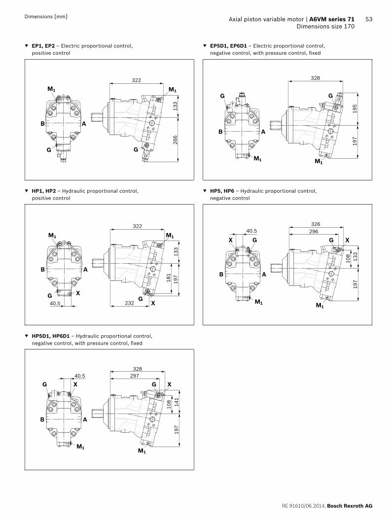
RE 91610062014 Bosch Rexroth AG
Axial piston variable motor | A6VM series 71 Dimensions size 170
53Dimensions [mm]
EP1 EP2 ndash Electric proportional control positive control
EP5D1 EP6D1 ndash Electric proportional control negative control with pressure control fixed
G
B A
M1
G
M1
322
133
266
195
197
328
G
M1M1
B A
G
HP1 HP2 ndash Hydraulic proportional control positive control
HP5 HP6 ndash Hydraulic proportional control negative control
405
181
133
197
322
232
XG
M1
GX
B A
M1
405
108
133
197
296326
X G
M1
B A
G X
M1
HP5D1 HP6D1 ndash Hydraulic proportional control negative control with pressure control fixed
328297
108
141
197
X XG G
M1
B A
405
M1
Bosch Rexroth AG RE 91610062014
54 A6VM series 71 | Axial piston variable motorDimensions size 170
Dimensions [mm]
HZ5 ndash Hydraulic two-point control negative control
EZ5 EZ6 ndash Electric two-point control negative control
197
107
133
405 291326
X G
M1
G
B A
X
M1
G
M1
G
B A
M1
197
187
326
HA1 HA2 HA1T3 HA2T3 ndash Automatic high-pressure-related control positive control with override hydraulic remote con-trolled proportional
HA1U1 HA2U2 ndash Automatic high-pressure-related control positive control with override electric two-point
405
181
133
197
322
232G
M1
G X
B A
X
M1 M1
B A
M1
G G
322
133
266
HA1 and HA2 X plugged
HA1T and HA2T X open
HA1R1 HA2R2 ndash Automatic high-pressure-related control positive control with override electric and travel direction valve electric
322
133
266
112
a
bG
M1
G
B A
M1
RE 91610062014 Bosch Rexroth AG
Axial piston variable motor | A6VM series 71 Dimensions size 170
55Dimensions [mm]
DA0 ndash Automatic speed-related control negative control with hydraulic travel direction valve
DA1 DA2 ndash Automatic speed-related control negative control with electric travel direction valve and electric Vg max circuit
X2X1G X3 G X3
M1
X1 X2
B A
M1
174
197
140
254328
115
B A
M1
G
X1X3
M1
G
X3X1
ab
176
197
153
277328
112 85
X1 X2 pipe fitting SDSC ndash L8timesM12 ndash F according to ISO 8434-1
Use assembled fitting
Bosch Rexroth AG RE 91610062014
56 A6VM series 71 | Axial piston variable motorDimensions size 215
Dimensions [mm]
Dimensions size 215
EP5 EP6 ndash Proportional electric control negative controlPort plate 2 mdash SAE flange ports A and B at side opposite
T2
M1
T1U
Y
125
deg
Z
G G
M1236
236
45deg 45deg
22
250
667
32318
29
oslash200
-0 -00
29
oslash108
75151
267401)
107
125
1472)
3143)
345
9639 32
max 149
209
192)
3646
53)
200
Flange ISO 3019-2
View Y
1) To shaft collar2) Center of gravity3) Port plate 1 mdash SAE flange ports A and B at rear
RE 91610062014 Bosch Rexroth AG
Axial piston variable motor | A6VM series 71 Dimensions size 215
57Dimensions [mm]
Location of the service line ports on the port plates (view Z)
2 SAE flange portA and B at side opposite
1 SAE flange portA and B at rear
216
B A
82
235
82
B A
Splined shaft SAE J744 Splined shaft DIN 5480
T2 ‒ 2 in 15T 816DP1) A2 ‒ W50times2times24times9g
36
53
58-
11U
NC
-2B
2)3)
oslash70
67
12
55
44
M16
times 2
3)4)
36
oslash70
12
1) Involute spline acc to ANSI B921a 30deg pressure angle flat root side fit tolerance class 5
2) Thread according to ASME B11
3) For notes on tightening torques see instruction manual4) Center bore according to DIN 332 (thread according to DIN 13)
Bosch Rexroth AG RE 91610062014
58 A6VM series 71 | Axial piston variable motorDimensions size 215
Dimensions [mm]
Ports Standard Size1) pmax abs [bar]2) Status6)
A B Service line portFastening thread AB
SAE J5183)
DIN 131 14 inM14 times 2 19 deep
500 O
T1 Drain port ISO 61495) M33 times 2 19 deep 3 X4)
T2 Drain port ISO 61495) M42 times 2 195 deep 3 O4)
G Synchronous control ISO 61495) M14 times 15 115 deep 500 X
U Bearing flushing ISO 61495) M22 times 15 155 deep 3 X
X Pilot signal (HP HZ HA1THA2T) ISO 61495) M14 times 15 115 deep 100 O
X Pilot signal (HA1 HA2) ISO 61495) M14 times 15 115 deep 3 X
X1 X2 Pilot signal (DA0) ISO 8434-1 SDSC-L8timesM12-F 40 O
X1 Pilot signal (DA1 DA2) ISO 61495) M14 times 15 115 deep 40 O
X3 Pilot signal (DA1 DA2) ISO 61495) M14 times 15 115 deep 40 X
M1 Measuring stroking chamber ISO 61495) M14 times 15 115 deep 500 X
1) For notes on tightening torques see instruction manual2) Momentary pressure spikes may occur depending on the application
Keep this in mind when selecting measuring devices and fittings3) Only dimensions according to SAE J518 metric fastening thread is
a deviation from standard
4) Depending on installation position T1 or T2 must be connected (see also installation instructions on page 72)
5) The spot face can be deeper than specified in the appropriate standard6) O = Must be connected (plugged on delivery)
X = Plugged (in normal operation)
RE 91610062014 Bosch Rexroth AG
Axial piston variable motor | A6VM series 71 Dimensions size 215
59Dimensions [mm]
EP1 EP2 ndash Electric proportional control positive control
EP5D1 EP6D1 ndash Electric proportional control negative control with pressure control fixed
339
140
275
M1
G
M1
G
B A
M1
B A
M1
G
209
200
345
G
HP1 HP2 ndash Hydraulic proportional control positive control
HP5 HP6 ndash Hydraulic proportional control negative control
M1
G
B A
X
M1
339
206
245
GX
190
405
140
M1
209
140
343
M1
B A
X G X312
113
G405
HP5D1 HP6D1 ndash Hydraulic proportional control negative control with pressure control fixed
M1
G
B A
M1
X
209
145
G X313
344405
112
Bosch Rexroth AG RE 91610062014
60 A6VM series 71 | Axial piston variable motorDimensions size 215
Dimensions [mm]
HZ5 ndash Hydraulic two-point control negative control
EZ5 EZ6 ndash Electric two-point control negative control
M1
XG
140
209
111
308343
M1
X G405
B A
M1
G
B A
M1
191
209
343
G
HA1 HA2 HA1T3 HA2T3 ndash Automatic high-pressure-related control positive control with override hydraulic remote con-trolled proportional
HA1U1 HA2U2 ndash Automatic high-pressure-related control positive control with override electric two-point
M1
G
B A
X
M1
339
206
245
GX
190
405
140
B A
M1
G
M1
339
276
140
G
HA1 and HA2 X plugged
HA1T and HA2T X open
HA1R1 HA2R2 ndash Automatic high-pressure-related control positive control with override electric and travel direction valve electric
M1
276
140
339
G
M1
B A
Ga
112
b
RE 91610062014 Bosch Rexroth AG
Axial piston variable motor | A6VM series 71 Dimensions size 215
61Dimensions [mm]
DA0 ndash Automatic speed-related control negative control with hydraulic travel direction valve
DA1 DA2 ndash Automatic speed-related control negative control with electric travel direction valve and electric Vg max circuit
M1
B A
X1 X2X3G X1 X2 X3G
M1
174 271345
209
144
119
209
180
157
294345
85112
M1
B A
M1
G
X1X3
G
X1 X3
ab
X1 X2 pipe fitting SDSC ndash L8timesM12 ndash F according to ISO 8434-1
Use assembled fitting
Bosch Rexroth AG RE 91610062014
62 A6VM series 71 | Axial piston variable motorConnector for solenoids
Connector for solenoids
DEUTSCH DT04-2P-EP04Molded connector 2-pin without bidirectional suppres-sor diode There is the following type of protection with mounted mating connector
IP67 (DINEN 60529) and IP69K (DIN 40050-9)
Circuit symbol
Mating connector DEUTSCH DT06-2S-EP04
Consisting of DT designation
1 housing DT06-2S-EP04
1 wedge W2S
2 sockets 0462-201-16141
The mating connector is not included in the scope of deliv-ery This can be supplied by Bosch Rexroth on request (material number R902601804)
NoteIf necessary you can change the connector orientation by turning the solenoid housingThe procedure can be taken from the instruction manual
RE 91610062014 Bosch Rexroth AG
Axial piston variable motor | A6VM series 71 Flushing and boost pressure valve
63
Flushing and boost pressure valve
The flushing and boost pressure valve is used to remove heat from the hydraulic circuitIn an open circuit it is used only for flushing the housingIn a closed circuit it ensures a minimum boost pressure level in addition to the case flushingHydraulic fluid is directed from the respective low pressure side into the motor housing This is then fed into the reser-voir together with the leakage The hydraulic fluid removed out of the closed circuit must be replaced by cooled hydraulic fluid from the boost pumpThe valve is mounted onto the port plate or integrated (depending on the control type and size)Cracking pressure of pressure retaining valve(observe when adjusting the primary valve)
Sizes 60 to 215 fixed setting 16 barSwitching pressure of flushing spool Dp
Sizes 60 to 115 (no flushing valve) 8plusmn1 bar Sizes 115 to 215 (medium and large flushing valve)
175plusmn15 barFlushing flow qv
Orifices can be used to adjust the flushing flows as required The following information is based on DpND = pND ndash pG = 25 bar and ν = 10 mm2s (pND = low pressure pG = case pressure)
Small flushing valve for sizes 60 to 115
Material number of orifice oslash [mm] qv [lmin] Code
R909651766 12 35 A
R909419695 14 5 B
R909419696 18 8 C
R909419697 20 10 D
R909444361 24 14 F
Medium flushing valve for size 115
Material number of orifice oslash [mm] qv [lmin] Code
R909431310 28 20 H
R909435172 35 25 J
R909449967 50 30 K
Large flushing valve for sizes 150 to 215
Material number of orifice oslash [mm] qv [lmin] Code
R909449998 18 8 C
R909431308 20 10 D
R909431309 25 17 G
R909431310 28 20 H
R902138235 31 25 J
R909435172 35 30 K
R909436622 40 35 L
R909449967 50 40 M
Schematic EP
G
T2
T1U
Sa
B
A
Vg min
Vg max
M1
Flushing spool
Pressure retain-ing valve
Flushing orifice
Notes Port Sa only for sizes 150 to 215 For a flushing flow greater than 35 l min it is recom-
mended that port Sa be connected in order to prevent an increase in case pressure An increased case pres-sure reduces the flushing flow
Bosch Rexroth AG RE 91610062014
64 A6VM series 71 | Axial piston variable motorFlushing and boost pressure valve
Dimensions [mm]
Dimensions of sizes 60 to 115 (small flushing valve)
A1 A4
HA1 HA2HP1 HP2EP1 EP2
HP5 HP6EP5 EP6DA
HZ7EZ7 EZ8
A3
A2
NG A1 A2 A3 A4
60 245 137 183 236
85 273 142 194 254
115 287 143 202 269
Dimensions for sizes 115 to 215 (large flushing valve)
Sa
Sa
Sa
Z
HA1 HA2HP1 HP2EP1 EP2
HP5 HP6 DAEP5 EP6HZ5 EZ5 EZ6
B4
A2B2
A3B
3
38
A1B1
NG A1 B1 A2 B2 A3 B3 B4
60 325 239 165 142 230 187 166
85 332 246 165 142 233 190 172
115 349 263 172 148 244 201 185
Dimensions of size 115 (medium flushing valve)
205
151
292
HA1 HA2HP1 HP2EP1 EP2
HP5 HP6EP5 EP6DA
NG Sa1)
150
M22 times 15 155 deep170
215
1) ISO 6149 ports plugged (in normal operation) For notes on tightening torques see instruction manual The spot face can be deeper than specified in the appropriate stan-dard
RE 91610062014 Bosch Rexroth AG
Axial piston variable motor | A6VM series 71 Counterbalance valve BVD and BVE
65
Counterbalance valve BVD and BVE
FunctionCounterbalance valves for travel drive and winch operations are designed to reduce the danger of overspeeding and cavitation of axial piston motors in open circuits Cavitation occurs if during braking when driving downhill or the load-lowering process the motor speed is greater than it should be for the given inlet flow causing the inlet pressure to collapseIf the pressure difference between the inflow and the out-flow drops below the value opening end of the piston in the counterbalance valve (see data sheet BVD ndash 95522 or BVE ndash 95525) the counterbalance spool will move to the closed position The cross-sectional area of the counterbalance valve return duct is then reduced creating a bottleneck in the return flow of the hydraulic fluid The pressure increases and brakes the motor until the rotational speed of the motor is again as it should be for the given inlet flow
Notes BVD available for sizes 60 to 215 and BVE available for
sizes 115 to 215 The counterbalance valve must be ordered additionally
We recommend ordering the counterbalance valve and the motor as a set Ordering example A6VM085HA1T30004A71MWV0N4S97W0-0 + BVD20F27S41BndashV03K16D0400S12
For safety reasons control systems with beginning of control at Vg min (z B HA) are not permissible for winch drives
The counterbalance valve does not replace the mechani-cal service brake and parking brake
Observe the detailed notes on the BVD counterbalance valve in data sheet 95522 and on the BVE counterbal-ance valve in data sheet 95525
For the design of the brake release valve we must know for the mechanical parking brake ndash the pressure at the start of opening ndash the volume of the counterbalance spool between
minimum travel (brake closed) and maximum travel (brake released with 21 bar)
ndash the required closing time for a warm device (oil vis-cosity approx 15 mm2s)
Permissible inlet flow or pressure when using DBV and BVDBVE
Without valve Limited values when using DBV and BVDBVE
Motor DBV1) BVD2)BVE3)
NG pnompmax [bar]
qV max [lmin]
NG pnompmax [bar]
qV [lmin]
Code NG pnompmax [bar]
qV [lmin]
Code
60 450500 276 22 350420 240 7 20 (BVD)
350420 220 7W
85 332
115 410 32 400
115 410 8 25 (BVDBVE)
320 8W
150 494
170 533
215 628 On request
1) Pressure-relief valve2) Counterbalance valve double-acting3) Counterbalance valve one-sided
Bosch Rexroth AG RE 91610062014
66 A6VM series 71 | Axial piston variable motorCounterbalance valve BVD and BVE
Counterbalance valve for travel drive BVDFApplication option
Travel drive for wheeled excavators (BVD and BVE)
Example schematic for travel drive on wheeled excavators
A6VM085HA1T30004A71MWV0N4S97W0-0 + BVD20F27S41BndashV03K16D0400S12
Bacute
A
M1
T2
T1
Vg min
Vg max
X
U
G
MB
MA
S
Gext
Gacute
Lacute
Aacute
B
Variable motor A6VMHA1T
Counterbalance valve BVD
Pump directional valve not included in the scope of delivery
Counterbalance valve for winches and track drives BVDW and BVEApplication option
Winch drives in cranes (BVD and BVE) Track drive in excavator crawlers (BVD)
Example schematic for winch drive in cranes
A6VM085HP5D10001A71MWV0N4S97W0-0 + BVE25W38S51ND-V100K00D4599T30S00-0
T2
T1
M1
Vg min
Vg max
B
A
G
X
U
MP1
VGVF
S
Gext
Mk
D
C
Dacute
Cacute
Gacute
Lacute
D1
D2
MB
MA
Variable motor A6VMHP5D
Winch with mechanical parking brake
Counterbalance valve BVE
Pump directional valve not included in the scope of delivery
RE 91610062014 Bosch Rexroth AG
Axial piston variable motor | A6VM series 71 Counterbalance valve BVD and BVE
67Dimensions [mm]
Dimensions
A6VMHA HP1 HP2 and EP1 EP2 A6VMHP5 HP6 and EP5 EP61)
MB (MA)
A BS
A8
B A
Gext
A2A1
A4A3
A6 A5A7
A2A9
MB (MA)
A4A1
0
Br
S
A8
A5 A6A7
B AA B
A6VM Counterbalance valve
NGplate Type Ports Dimensions
A B A1 A2 A3 A4 A5 A6 A7 A8 A9 A10
607 BVD2017 34 in 311 302 143 50 98 139 75 222 326 50
857 BVD2027 1 in 340 331 148 55 98 139 75 222 355 46
1157 BVD2028 1 in 362 353 152 59 98 139 84 234 377 41
1158 BVD2538 1 14 in 380 370 165 63 1205 175 84 238 395 56
1508 BVD2538 1 14 in 411 401 168 67 1205 175 84 238 426 53
1708 BVD2538 1 14 in 417 407 170 68 1205 175 84 238 432 51
2158 BVD2538 1 14 in 448 438 176 74 1205 175 84 299 463 46
1158 BVE2538 1 14 in 380 370 171 63 137 214 84 238 397 63
1508 BVE2538 1 14 in 411 401 175 67 137 214 84 238 423 59
1708 BVE2538 1 14 in 417 407 176 68 137 214 84 238 432 59
2158 BVE2538 1 14 in 448 438 182 74 137 214 84 299 463 52
Ports Version A6VM plate
Standard Size2) Pmax perm [bar]3) Status5)
A B Service line SAE J518 see table above 420 O
S Infeed BVD20 DIN 38524) M22 times 15 14 deep 30 X
BVD25 BVE25 DIN 38524) M27 times 2 16 deep 30 X
Br Brake release reduced high pressure
L 7 DIN 38524) M12 times 15 125 deep 30 O
8 DIN 38524) M12 times 15 12 deep 30 O
Gext Brake release high pressure S DIN 38524) M12 times 15 125 deep 420 X
MA MB Measuring pressure A and B ISO 61494) M18 times 15 145 deep 420 X
1) At the mounting version for the controls HP5 HP6 and EP5 EP6 the cast-in port designations A and B on the counterbalance valve BVD do not correspond with the connection drawing of the A6VM motor The designation of the ports on the installation drawing of the mo-tor is binding
2) For notes on tightening torques see instruction manual
3) Momentary pressure spikes may occur depending on the applica-tion Keep this in mind when selecting measuring devices and fit-tings
4) The spot face can be deeper than specified in the appropriate stan-dard
5) O = Must be connected (plugged on delivery) X = Plugged (in normal operation)
Bosch Rexroth AG RE 91610062014
68 A6VM series 71 | Axial piston variable motorCounterbalance valve BVD and BVE
Mounting the counterbalance valveWhen delivered the counterbalance valve is mounted to the motor with two tacking screws (transport lock) The tack-ing screws may not be removed while mounting the service lines If the counterbalance valve and motor are delivered separately the counterbalance valve must first be mounted to the motor port plate using the provided tacking screws The final mounting of the counterbalance valve on the motor is done with screw fitting of the SAE flange The screws to be used and the procedure mounting can be found in the instruction manual
RE 91610062014 Bosch Rexroth AG
Axial piston variable motor | A6VM series 71 Speed sensor
69
Speed sensor
Version A6VMU (prepared for speed sensor ie without sensor) is equipped with a spline on the rotary groupA signal proportional to motor speed can be generated with the fitted DSADSM speed sensor The DSADSM sensor registers the speed and direction of rotationOrdering code technical data dimensions and details on the connector plus safety instructions about the sensor can be found in the relevant data sheet (95132 for DSM 95133 for DSA)The sensor is mounted on the port provided for this pur-pose with a mounting bolt On deliveries without sensor the port is plugged with a pressure-resistant coverWe recommend ordering the A6VM variable motor complete with mounted sensor
Schematic EP
T2
T1UnU
Dimensions
V design with mounted speed sensor
A
C
B
Size 60 85 115 150 170 215
Number of teeth 54 58 67 72 75 80
A Insertion depth (tolerance -025) 184 184 184 184 184 184
B Contact surface 75 79 88 93 96 101
C 662 752 772 912 917 952
Bosch Rexroth AG RE 91610062014
70 A6VM series 71 | Axial piston variable motorSetting range for displacement
Setting range for displacement
60 85 115
Vg max (cm3rev) Vg min (cm3rev) Vg max (cm3rev) Vg min (cm3rev) Vg max (cm3rev) Vg min (cm3rev)
from to from to from to from to from to from to
A 620 620 00 150 852 852 00 315 1156 1156 00 240
without screw M10 times 60 R909154690
without screw M12 times 70 R909085976
without screw M12 times 70 R909085976
B 620 620 gt 150 305 852 852 gt 315 520 1156 1156 gt 240 475
without screw M10 times 70 R909153779
without screw M12 times 80 R909153075
without screw M12 times 80 R909153075
C 620 620 gt 305 430 852 852 gt 520 590 1156 1156 gt 475 710
without screw M10 times 80 R909154058
without screw M12 times 90 R909154041
without screw M12 times 90 R909154041
D x x x x 1156 1156 gt 710 800
without screw M12 times 100 R909153975
E lt 620 475 00 150 lt 852 555 00 315 lt 1156 935 00 240
M10 times 60 R909154690
M10 times 60 R909154690
M12 times 70 R909085976
M12 times 70 R909085976
M12 times 70 R909085976
M12 times 70 R909085976
F lt 620 475 gt 150 305 lt 852 555 gt 315 520 lt 1156 935 gt 240 475
M10 times 60 R909154690
M10 times 70 R909153779
M12 times 70 R909085976
M12 times 80 R909153075
M12 times 70 R909085976
M12 times 80 R909085976
G lt 620 475 gt 305 430 lt 852 555 gt 520 590 lt 1156 935 gt 475 71
M10 times 60 R909154690
M10 times 80 R909154058
M12 times 70 R909085976
M12 times 90 R909154041
M12 times 70 R909085976
M12 times 90 R909154041
H x x x times lt 1156 935 gt 710 800
M12 times 70 R909085976
M12 times 100 R909153975
J lt 475 330 00 150 lt 555 350 00 315 lt 935 710 00 240
M10 times 70 R909153779
M10 times 60 R909154690
M12 times 80 R909153075
M12 times 70 R909085976
M12 times 80 R909153075
M12 times 70 R909085976
K lt 475 330 gt 150 305 lt 555 350 gt 315 520 lt 935 710 gt 240 475
M10 times 70 R909153779
M10 times 70 R909153779
M12 times 80 R909153075
M12 times 80 R909153075
M12 times 80 R909153075
M12 times 80 R909153075
L lt 475 330 gt 305 430 lt 555 350 gt 520 590 lt 935 710 gt 475 710
M10 times 70 R909153779
M10 times 80 R909154058
M12 times 80 R909153075
M12 times 90 R909154041
M12 times 80 R909153075
M12 times 90 R909154041
M x x x x lt 935 710 gt 710 800
M12 times 80 R909153075
M12 times 100 R909153975
Specify exact settings for Vg min and Vg max in plain text when ordering
Vg min = cm3 Vg max = cm3
Theoretical maximum setting for Vg min = 07 times Vg max
for Vg max = 03 times Vg max
Settings that are not listed in the table may lead to damage Please contact us
RE 91610062014 Bosch Rexroth AG
Axial piston variable motor | A6VM series 71 Setting range for displacement
71
150 170 215
Vg max (cm3rev) Vg min (cm3rev) Vg max (cm3rev) Vg min (cm3rev) Vg max (cm3rev) Vg min (cm3rev)
from to from to from to from to from to from to
A 1521 1521 00 440 1718 1718 00 350 2165 2165 00 445
without screw M12 times 80 R909153075
without screw M12 times 80 R909153075
without screw M12 times 80 R909153075
B 1521 1521 gt 440 690 1718 1718 gt 350 635 2165 2165 gt 445 800
without screw M12 times 90 R909154041
without screw M12 times 90 R909154041
without screw M12 times 90 R909154041
C 1521 1521 gt 690 990 1718 1718 gt 635 980 2165 2165 gt 800 1150
without screw M12 times 100 R909153975
without screw M12 times 100 R909153975
without screw M12 times 100 R909153975
D 1521 1521 gt 990 1060 1718 1718 gt 980 1200 2165 2165 gt 1150 1500
without screw M12 times 110 R909154212
without screw M12 times 110 R909154212
without screw M12 times 110 R909154212
E lt 1521 1110 00 440 lt 1718 1390 00 350 lt 2165 1750 00 445
M12 times 80 R909153075
M12 times 80 R909153075
M12 times 80 R909153075
M10 times 80 R909153075
M12 times 80 R909153075
M12 times 80 R909153075
F lt 1521 1110 gt 440 690 lt 1718 1390 gt 350 635 lt 2165 1750 gt 445 800
M12 times 80 R909153075
M12 times 90 R909085976
M12 times 80 R909153075
M12 times 90 R909154041
M12 times 80 R909153075
M12 times 90 R909154041
G lt 1521 1110 gt 690 990 lt 1718 1390 gt 635 980 lt 2165 1750 gt 800 1150
M12 times 80 R909153075
M12 times 100 R909153975
M12 times 80 R909153075
M12 times 100 R909153975
M12 times 80 R909153075
M12 times 100 R909153975
H lt 1521 1110 gt 990 1060 lt 1718 1390 gt 980 1200 lt 2165 1750 gt 1150 1500
M12 times 80 R909153075
M12 times 110 R909154212
M12 times 80 R909153075
M12 times 110 R909154212
M12 times 80 R909153075
M12 times 110 R909154212
J lt 1110 870 00 440 lt 1390 1120 00 350 lt 1750 1410 00 445
M12 times 90 R909154041
M12 times 80 R909153075
M12 times 90 R909154041
M12 x 80 R909153075
M12 x 90 R909154041
M12 x 80 R909153075
K lt 1110 870 gt 440 690 lt 1390 1120 gt 350 635 lt 1750 1410 gt 445 800
M12 times 90 R909154041
M12 times 90 R909154041
M12 x 90 R909154041
M12 times 90 R909154041
M12 times 90 R909154041
M12 times 90 R909154041
L lt 1110 870 gt 690 990 lt 1390 1120 gt 635 980 lt 1750 1410 gt 800 1150
M12 times 90 R909154041
M12 times 100 R909153975
M12 times 90 R909154041
M12 times 100 R909153975
M12 times 90 R909154041
M12 times 100 R909153975
M lt 1110 870 gt 990 1060 lt 1390 1120 gt 980 1200 lt 1750 1410 gt 1150 1500
M12 times 90 R909154041
M12 times 110 R909154212
M12 times 90 R909154041
M12 times 110 R909154212
M12 times 90 R909154041
M12 times 110 R909154212
Specify exact settings for Vg min and Vg max in plain text when ordering
Vg min = cm3 Vg max = cm3
Theoretical maximum setting for Vg min = 07 times Vg max
for Vg max = 03 times Vg max
Settings that are not listed in the table may lead to damage Please contact us
Bosch Rexroth AG RE 91610062014
72 A6VM series 71 | Axial piston variable motorInstallation instructions
Installation instructions
GeneralDuring commissioning and operation the axial piston unit must be filled with hydraulic fluid and air bled This must also observed following a relatively long standstill as the axial piston unit may drain back to the reservoir via the hydraulic linesParticularly in the installation position drive shaft upwards filling and air bleeding must be carried out com-pletely as there is for example a danger of dry runningThe leakage in the motor housing must be directed to the reservoir via the highest available drain port (T1 T2)To achieve favorable noise values decouple all connecting lines using elastic elements and avoid above-reservoir installation In all operating conditions the drain line must flow into the reservoir below the minimum fluid level
NoteIn certain installation conditions an influence on the control charakteristic curves can be expected Gravity dead weight and case pressure can cause minor shifts in characteristics and changes in response time
Key
U Bearing flushing air bleed port
T1 T2 Drain port
ht min Minimum required immersion depth (200 mm)
hmin Minimum required spacing to reservoir bottom (100 mm)
Installation position See examples 1 to 8 below Additional installation positions are available upon requestRecommended installation position 1 and 2
Below-reservoir installation (standard)Below-reservoir installation means that the axial piston unit is installed outside of the reservoir below the minimum fluid level
Installation position Air bleed Filling
1
T2
T1U
ht min
hmin
T1
2
T2
T1 U
ht min
hmin
T2
3
T2
T1
U
ht min
hmin
T1
4
T2
T1
U
ht min
hmin
U T1
RE 91610062014 Bosch Rexroth AG
Axial piston variable motor | A6VM series 71 Installation instructions
73
Above-reservoir installationAbove-reservoir installation means that the axial piston unit is installed above the minimum fluid level of the reservoirRecommendation for installation position 8 (drive shaft upward) A check valve in the drain line (cracking pressure 05 bar) can prevent draining of the motor housing
Installation position Air bleed Filling
5
T2
T1U
L1
ht min
hmin
U (L1) T1 (L1)
6
T2
T1 U
L1
ht min
hmin
L1 T2 (L1)
7
T2T1
U
L1
ht min
hmin
L1 T1 (L1)
8
T2T1
UL1
05
bar
ht min
hmin
U T1 (L1)
NotePort L1 is not part of the motor and can be made available by the customer for straightforward filling and air bleed-ing
74
Bosch Rexroth AG RE 91610062014
Bosch Rexroth AGMobile ApplicationsGlockeraustraszlige 489275 Elchingen GermanyTel +49-7308-82-0infomaboschrexrothdewwwboschrexrothcom
copy This document as well as the data specifications and other information set forth in it are the exclusive property of Bosch Rexroth AG It may not be reproduced or given to third parties without its consent The data specified above only serve to describe the product No statements concerning a certain condition or suitability for a certain application can be derived from our information The information given does not release the user from the obligation of own judgment and verification It must be remembered that our products are subject to a natural process of wear and aging
A6VM series 71 | Axial piston variable motorProject planning note
Project planning note
The motor A6VM is designed to be used in open and closed circuits
The project planning installation and commissioning of the axial piston unit requires the involvement of quali-fied skilled person
Before using the axial piston unit please read the cor-responding instruction manual completely and thor-oughly If necessary these can be requested from Bosch Rexroth
Before finalizing your design request a binding installa-tion drawing
The data and notes contained herein must be adhered to
For safety reasons control systems with beginning of control at Vg min (eg HA) are not permissible for winch drives eg anchor winches
Depending on the operating conditions of the axial piston unit (operating pressure fluid temperature) the charakteristic curve may shift
Not all variants of the product are approved for use in safety functions according to ISO 13849 Please consult the responsible contact person at Bosch Rexroth if you require reliability parameters (eg MTTFd) for functional safety
Working ports ndash The ports and fastening threads are designed for the
specified maximum pressure The machine or system manufacturer must ensure that the connecting ele-ments and lines correspond to the specified applica-tion conditions (pressure flow hydraulic fluid tem-perature) with the necessary safety factors
ndash The working ports and function ports can only be used to accommodate hydraulic lines
Safety instructions
During and shortly after operation there is a risk of burns on the axial piston unit and especially on the solenoids Take appropriate safety measures (e g by wearing protective clothing)
Moving parts in control and regulation systems (eg valve spools) may in certain circumstances become stuck in an undefined position due to contamination (eg contaminated hydraulic fluid abrasion or residual dirt from components) As a result the hydraulic fluid flow or build-up of torque of the axial piston unit will no longer respond correctly to the operators commands Even the use of different filter cartridges (external or internal inlet filter) will not rule out a fault but merely minimize the risk The machinesystem manufacturer must test whether remedial measures are needed on the machine for the application concerned in order to set the consumer being driven to a safe position (eg safe stop) and if necessary to ensure it is properly imple-mented
If the axial piston motor is used in winch drives make sure that the technical limit values are not exceeded under all operating conditions If the axial piston motor is subjected to external overload (eg by exceeding the maximum permissible rotational speeds when lifting anchor while the ship is in motion) this could cause damage to the rotary group and in unfavorable cases to the axial piston motor bursting If necessary additional measures up to an including encapsulation are to be implemented by the machinesystem manufacturer
RE 91610062014 Bosch Rexroth AG
75 Axial piston variable motor | A6VM series 71
76
Bosch Rexroth AG RE 91610062014
Bosch Rexroth AGMobile ApplicationsGlockeraustraszlige 489275 Elchingen GermanyTel +49-7308-82-0infomaboschrexrothdewwwboschrexrothcom
copy This document as well as the data specifications and other information set forth in it are the exclusive property of Bosch Rexroth AG It may not be reproduced or given to third parties without its consent The data specified above only serve to describe the product No statements concerning a certain condition or suitability for a certain application can be derived from our information The information given does not release the user from the obligation of own judgment and verification It must be remembered that our products are subject to a natural process of wear and aging
A6VM series 71 | axial piston variable motor

Bosch Rexroth AG RE 91610062014
54 A6VM series 71 | Axial piston variable motorDimensions size 170
Dimensions [mm]
HZ5 ndash Hydraulic two-point control negative control
EZ5 EZ6 ndash Electric two-point control negative control
197
107
133
405 291326
X G
M1
G
B A
X
M1
G
M1
G
B A
M1
197
187
326
HA1 HA2 HA1T3 HA2T3 ndash Automatic high-pressure-related control positive control with override hydraulic remote con-trolled proportional
HA1U1 HA2U2 ndash Automatic high-pressure-related control positive control with override electric two-point
405
181
133
197
322
232G
M1
G X
B A
X
M1 M1
B A
M1
G G
322
133
266
HA1 and HA2 X plugged
HA1T and HA2T X open
HA1R1 HA2R2 ndash Automatic high-pressure-related control positive control with override electric and travel direction valve electric
322
133
266
112
a
bG
M1
G
B A
M1
RE 91610062014 Bosch Rexroth AG
Axial piston variable motor | A6VM series 71 Dimensions size 170
55Dimensions [mm]
DA0 ndash Automatic speed-related control negative control with hydraulic travel direction valve
DA1 DA2 ndash Automatic speed-related control negative control with electric travel direction valve and electric Vg max circuit
X2X1G X3 G X3
M1
X1 X2
B A
M1
174
197
140
254328
115
B A
M1
G
X1X3
M1
G
X3X1
ab
176
197
153
277328
112 85
X1 X2 pipe fitting SDSC ndash L8timesM12 ndash F according to ISO 8434-1
Use assembled fitting
Bosch Rexroth AG RE 91610062014
56 A6VM series 71 | Axial piston variable motorDimensions size 215
Dimensions [mm]
Dimensions size 215
EP5 EP6 ndash Proportional electric control negative controlPort plate 2 mdash SAE flange ports A and B at side opposite
T2
M1
T1U
Y
125
deg
Z
G G
M1236
236
45deg 45deg
22
250
667
32318
29
oslash200
-0 -00
29
oslash108
75151
267401)
107
125
1472)
3143)
345
9639 32
max 149
209
192)
3646
53)
200
Flange ISO 3019-2
View Y
1) To shaft collar2) Center of gravity3) Port plate 1 mdash SAE flange ports A and B at rear
RE 91610062014 Bosch Rexroth AG
Axial piston variable motor | A6VM series 71 Dimensions size 215
57Dimensions [mm]
Location of the service line ports on the port plates (view Z)
2 SAE flange portA and B at side opposite
1 SAE flange portA and B at rear
216
B A
82
235
82
B A
Splined shaft SAE J744 Splined shaft DIN 5480
T2 ‒ 2 in 15T 816DP1) A2 ‒ W50times2times24times9g
36
53
58-
11U
NC
-2B
2)3)
oslash70
67
12
55
44
M16
times 2
3)4)
36
oslash70
12
1) Involute spline acc to ANSI B921a 30deg pressure angle flat root side fit tolerance class 5
2) Thread according to ASME B11
3) For notes on tightening torques see instruction manual4) Center bore according to DIN 332 (thread according to DIN 13)
Bosch Rexroth AG RE 91610062014
58 A6VM series 71 | Axial piston variable motorDimensions size 215
Dimensions [mm]
Ports Standard Size1) pmax abs [bar]2) Status6)
A B Service line portFastening thread AB
SAE J5183)
DIN 131 14 inM14 times 2 19 deep
500 O
T1 Drain port ISO 61495) M33 times 2 19 deep 3 X4)
T2 Drain port ISO 61495) M42 times 2 195 deep 3 O4)
G Synchronous control ISO 61495) M14 times 15 115 deep 500 X
U Bearing flushing ISO 61495) M22 times 15 155 deep 3 X
X Pilot signal (HP HZ HA1THA2T) ISO 61495) M14 times 15 115 deep 100 O
X Pilot signal (HA1 HA2) ISO 61495) M14 times 15 115 deep 3 X
X1 X2 Pilot signal (DA0) ISO 8434-1 SDSC-L8timesM12-F 40 O
X1 Pilot signal (DA1 DA2) ISO 61495) M14 times 15 115 deep 40 O
X3 Pilot signal (DA1 DA2) ISO 61495) M14 times 15 115 deep 40 X
M1 Measuring stroking chamber ISO 61495) M14 times 15 115 deep 500 X
1) For notes on tightening torques see instruction manual2) Momentary pressure spikes may occur depending on the application
Keep this in mind when selecting measuring devices and fittings3) Only dimensions according to SAE J518 metric fastening thread is
a deviation from standard
4) Depending on installation position T1 or T2 must be connected (see also installation instructions on page 72)
5) The spot face can be deeper than specified in the appropriate standard6) O = Must be connected (plugged on delivery)
X = Plugged (in normal operation)
RE 91610062014 Bosch Rexroth AG
Axial piston variable motor | A6VM series 71 Dimensions size 215
59Dimensions [mm]
EP1 EP2 ndash Electric proportional control positive control
EP5D1 EP6D1 ndash Electric proportional control negative control with pressure control fixed
339
140
275
M1
G
M1
G
B A
M1
B A
M1
G
209
200
345
G
HP1 HP2 ndash Hydraulic proportional control positive control
HP5 HP6 ndash Hydraulic proportional control negative control
M1
G
B A
X
M1
339
206
245
GX
190
405
140
M1
209
140
343
M1
B A
X G X312
113
G405
HP5D1 HP6D1 ndash Hydraulic proportional control negative control with pressure control fixed
M1
G
B A
M1
X
209
145
G X313
344405
112
Bosch Rexroth AG RE 91610062014
60 A6VM series 71 | Axial piston variable motorDimensions size 215
Dimensions [mm]
HZ5 ndash Hydraulic two-point control negative control
EZ5 EZ6 ndash Electric two-point control negative control
M1
XG
140
209
111
308343
M1
X G405
B A
M1
G
B A
M1
191
209
343
G
HA1 HA2 HA1T3 HA2T3 ndash Automatic high-pressure-related control positive control with override hydraulic remote con-trolled proportional
HA1U1 HA2U2 ndash Automatic high-pressure-related control positive control with override electric two-point
M1
G
B A
X
M1
339
206
245
GX
190
405
140
B A
M1
G
M1
339
276
140
G
HA1 and HA2 X plugged
HA1T and HA2T X open
HA1R1 HA2R2 ndash Automatic high-pressure-related control positive control with override electric and travel direction valve electric
M1
276
140
339
G
M1
B A
Ga
112
b
RE 91610062014 Bosch Rexroth AG
Axial piston variable motor | A6VM series 71 Dimensions size 215
61Dimensions [mm]
DA0 ndash Automatic speed-related control negative control with hydraulic travel direction valve
DA1 DA2 ndash Automatic speed-related control negative control with electric travel direction valve and electric Vg max circuit
M1
B A
X1 X2X3G X1 X2 X3G
M1
174 271345
209
144
119
209
180
157
294345
85112
M1
B A
M1
G
X1X3
G
X1 X3
ab
X1 X2 pipe fitting SDSC ndash L8timesM12 ndash F according to ISO 8434-1
Use assembled fitting
Bosch Rexroth AG RE 91610062014
62 A6VM series 71 | Axial piston variable motorConnector for solenoids
Connector for solenoids
DEUTSCH DT04-2P-EP04Molded connector 2-pin without bidirectional suppres-sor diode There is the following type of protection with mounted mating connector
IP67 (DINEN 60529) and IP69K (DIN 40050-9)
Circuit symbol
Mating connector DEUTSCH DT06-2S-EP04
Consisting of DT designation
1 housing DT06-2S-EP04
1 wedge W2S
2 sockets 0462-201-16141
The mating connector is not included in the scope of deliv-ery This can be supplied by Bosch Rexroth on request (material number R902601804)
NoteIf necessary you can change the connector orientation by turning the solenoid housingThe procedure can be taken from the instruction manual
RE 91610062014 Bosch Rexroth AG
Axial piston variable motor | A6VM series 71 Flushing and boost pressure valve
63
Flushing and boost pressure valve
The flushing and boost pressure valve is used to remove heat from the hydraulic circuitIn an open circuit it is used only for flushing the housingIn a closed circuit it ensures a minimum boost pressure level in addition to the case flushingHydraulic fluid is directed from the respective low pressure side into the motor housing This is then fed into the reser-voir together with the leakage The hydraulic fluid removed out of the closed circuit must be replaced by cooled hydraulic fluid from the boost pumpThe valve is mounted onto the port plate or integrated (depending on the control type and size)Cracking pressure of pressure retaining valve(observe when adjusting the primary valve)
Sizes 60 to 215 fixed setting 16 barSwitching pressure of flushing spool Dp
Sizes 60 to 115 (no flushing valve) 8plusmn1 bar Sizes 115 to 215 (medium and large flushing valve)
175plusmn15 barFlushing flow qv
Orifices can be used to adjust the flushing flows as required The following information is based on DpND = pND ndash pG = 25 bar and ν = 10 mm2s (pND = low pressure pG = case pressure)
Small flushing valve for sizes 60 to 115
Material number of orifice oslash [mm] qv [lmin] Code
R909651766 12 35 A
R909419695 14 5 B
R909419696 18 8 C
R909419697 20 10 D
R909444361 24 14 F
Medium flushing valve for size 115
Material number of orifice oslash [mm] qv [lmin] Code
R909431310 28 20 H
R909435172 35 25 J
R909449967 50 30 K
Large flushing valve for sizes 150 to 215
Material number of orifice oslash [mm] qv [lmin] Code
R909449998 18 8 C
R909431308 20 10 D
R909431309 25 17 G
R909431310 28 20 H
R902138235 31 25 J
R909435172 35 30 K
R909436622 40 35 L
R909449967 50 40 M
Schematic EP
G
T2
T1U
Sa
B
A
Vg min
Vg max
M1
Flushing spool
Pressure retain-ing valve
Flushing orifice
Notes Port Sa only for sizes 150 to 215 For a flushing flow greater than 35 l min it is recom-
mended that port Sa be connected in order to prevent an increase in case pressure An increased case pres-sure reduces the flushing flow
Bosch Rexroth AG RE 91610062014
64 A6VM series 71 | Axial piston variable motorFlushing and boost pressure valve
Dimensions [mm]
Dimensions of sizes 60 to 115 (small flushing valve)
A1 A4
HA1 HA2HP1 HP2EP1 EP2
HP5 HP6EP5 EP6DA
HZ7EZ7 EZ8
A3
A2
NG A1 A2 A3 A4
60 245 137 183 236
85 273 142 194 254
115 287 143 202 269
Dimensions for sizes 115 to 215 (large flushing valve)
Sa
Sa
Sa
Z
HA1 HA2HP1 HP2EP1 EP2
HP5 HP6 DAEP5 EP6HZ5 EZ5 EZ6
B4
A2B2
A3B
3
38
A1B1
NG A1 B1 A2 B2 A3 B3 B4
60 325 239 165 142 230 187 166
85 332 246 165 142 233 190 172
115 349 263 172 148 244 201 185
Dimensions of size 115 (medium flushing valve)
205
151
292
HA1 HA2HP1 HP2EP1 EP2
HP5 HP6EP5 EP6DA
NG Sa1)
150
M22 times 15 155 deep170
215
1) ISO 6149 ports plugged (in normal operation) For notes on tightening torques see instruction manual The spot face can be deeper than specified in the appropriate stan-dard
RE 91610062014 Bosch Rexroth AG
Axial piston variable motor | A6VM series 71 Counterbalance valve BVD and BVE
65
Counterbalance valve BVD and BVE
FunctionCounterbalance valves for travel drive and winch operations are designed to reduce the danger of overspeeding and cavitation of axial piston motors in open circuits Cavitation occurs if during braking when driving downhill or the load-lowering process the motor speed is greater than it should be for the given inlet flow causing the inlet pressure to collapseIf the pressure difference between the inflow and the out-flow drops below the value opening end of the piston in the counterbalance valve (see data sheet BVD ndash 95522 or BVE ndash 95525) the counterbalance spool will move to the closed position The cross-sectional area of the counterbalance valve return duct is then reduced creating a bottleneck in the return flow of the hydraulic fluid The pressure increases and brakes the motor until the rotational speed of the motor is again as it should be for the given inlet flow
Notes BVD available for sizes 60 to 215 and BVE available for
sizes 115 to 215 The counterbalance valve must be ordered additionally
We recommend ordering the counterbalance valve and the motor as a set Ordering example A6VM085HA1T30004A71MWV0N4S97W0-0 + BVD20F27S41BndashV03K16D0400S12
For safety reasons control systems with beginning of control at Vg min (z B HA) are not permissible for winch drives
The counterbalance valve does not replace the mechani-cal service brake and parking brake
Observe the detailed notes on the BVD counterbalance valve in data sheet 95522 and on the BVE counterbal-ance valve in data sheet 95525
For the design of the brake release valve we must know for the mechanical parking brake ndash the pressure at the start of opening ndash the volume of the counterbalance spool between
minimum travel (brake closed) and maximum travel (brake released with 21 bar)
ndash the required closing time for a warm device (oil vis-cosity approx 15 mm2s)
Permissible inlet flow or pressure when using DBV and BVDBVE
Without valve Limited values when using DBV and BVDBVE
Motor DBV1) BVD2)BVE3)
NG pnompmax [bar]
qV max [lmin]
NG pnompmax [bar]
qV [lmin]
Code NG pnompmax [bar]
qV [lmin]
Code
60 450500 276 22 350420 240 7 20 (BVD)
350420 220 7W
85 332
115 410 32 400
115 410 8 25 (BVDBVE)
320 8W
150 494
170 533
215 628 On request
1) Pressure-relief valve2) Counterbalance valve double-acting3) Counterbalance valve one-sided
Bosch Rexroth AG RE 91610062014
66 A6VM series 71 | Axial piston variable motorCounterbalance valve BVD and BVE
Counterbalance valve for travel drive BVDFApplication option
Travel drive for wheeled excavators (BVD and BVE)
Example schematic for travel drive on wheeled excavators
A6VM085HA1T30004A71MWV0N4S97W0-0 + BVD20F27S41BndashV03K16D0400S12
Bacute
A
M1
T2
T1
Vg min
Vg max
X
U
G
MB
MA
S
Gext
Gacute
Lacute
Aacute
B
Variable motor A6VMHA1T
Counterbalance valve BVD
Pump directional valve not included in the scope of delivery
Counterbalance valve for winches and track drives BVDW and BVEApplication option
Winch drives in cranes (BVD and BVE) Track drive in excavator crawlers (BVD)
Example schematic for winch drive in cranes
A6VM085HP5D10001A71MWV0N4S97W0-0 + BVE25W38S51ND-V100K00D4599T30S00-0
T2
T1
M1
Vg min
Vg max
B
A
G
X
U
MP1
VGVF
S
Gext
Mk
D
C
Dacute
Cacute
Gacute
Lacute
D1
D2
MB
MA
Variable motor A6VMHP5D
Winch with mechanical parking brake
Counterbalance valve BVE
Pump directional valve not included in the scope of delivery
RE 91610062014 Bosch Rexroth AG
Axial piston variable motor | A6VM series 71 Counterbalance valve BVD and BVE
67Dimensions [mm]
Dimensions
A6VMHA HP1 HP2 and EP1 EP2 A6VMHP5 HP6 and EP5 EP61)
MB (MA)
A BS
A8
B A
Gext
A2A1
A4A3
A6 A5A7
A2A9
MB (MA)
A4A1
0
Br
S
A8
A5 A6A7
B AA B
A6VM Counterbalance valve
NGplate Type Ports Dimensions
A B A1 A2 A3 A4 A5 A6 A7 A8 A9 A10
607 BVD2017 34 in 311 302 143 50 98 139 75 222 326 50
857 BVD2027 1 in 340 331 148 55 98 139 75 222 355 46
1157 BVD2028 1 in 362 353 152 59 98 139 84 234 377 41
1158 BVD2538 1 14 in 380 370 165 63 1205 175 84 238 395 56
1508 BVD2538 1 14 in 411 401 168 67 1205 175 84 238 426 53
1708 BVD2538 1 14 in 417 407 170 68 1205 175 84 238 432 51
2158 BVD2538 1 14 in 448 438 176 74 1205 175 84 299 463 46
1158 BVE2538 1 14 in 380 370 171 63 137 214 84 238 397 63
1508 BVE2538 1 14 in 411 401 175 67 137 214 84 238 423 59
1708 BVE2538 1 14 in 417 407 176 68 137 214 84 238 432 59
2158 BVE2538 1 14 in 448 438 182 74 137 214 84 299 463 52
Ports Version A6VM plate
Standard Size2) Pmax perm [bar]3) Status5)
A B Service line SAE J518 see table above 420 O
S Infeed BVD20 DIN 38524) M22 times 15 14 deep 30 X
BVD25 BVE25 DIN 38524) M27 times 2 16 deep 30 X
Br Brake release reduced high pressure
L 7 DIN 38524) M12 times 15 125 deep 30 O
8 DIN 38524) M12 times 15 12 deep 30 O
Gext Brake release high pressure S DIN 38524) M12 times 15 125 deep 420 X
MA MB Measuring pressure A and B ISO 61494) M18 times 15 145 deep 420 X
1) At the mounting version for the controls HP5 HP6 and EP5 EP6 the cast-in port designations A and B on the counterbalance valve BVD do not correspond with the connection drawing of the A6VM motor The designation of the ports on the installation drawing of the mo-tor is binding
2) For notes on tightening torques see instruction manual
3) Momentary pressure spikes may occur depending on the applica-tion Keep this in mind when selecting measuring devices and fit-tings
4) The spot face can be deeper than specified in the appropriate stan-dard
5) O = Must be connected (plugged on delivery) X = Plugged (in normal operation)
Bosch Rexroth AG RE 91610062014
68 A6VM series 71 | Axial piston variable motorCounterbalance valve BVD and BVE
Mounting the counterbalance valveWhen delivered the counterbalance valve is mounted to the motor with two tacking screws (transport lock) The tack-ing screws may not be removed while mounting the service lines If the counterbalance valve and motor are delivered separately the counterbalance valve must first be mounted to the motor port plate using the provided tacking screws The final mounting of the counterbalance valve on the motor is done with screw fitting of the SAE flange The screws to be used and the procedure mounting can be found in the instruction manual
RE 91610062014 Bosch Rexroth AG
Axial piston variable motor | A6VM series 71 Speed sensor
69
Speed sensor
Version A6VMU (prepared for speed sensor ie without sensor) is equipped with a spline on the rotary groupA signal proportional to motor speed can be generated with the fitted DSADSM speed sensor The DSADSM sensor registers the speed and direction of rotationOrdering code technical data dimensions and details on the connector plus safety instructions about the sensor can be found in the relevant data sheet (95132 for DSM 95133 for DSA)The sensor is mounted on the port provided for this pur-pose with a mounting bolt On deliveries without sensor the port is plugged with a pressure-resistant coverWe recommend ordering the A6VM variable motor complete with mounted sensor
Schematic EP
T2
T1UnU
Dimensions
V design with mounted speed sensor
A
C
B
Size 60 85 115 150 170 215
Number of teeth 54 58 67 72 75 80
A Insertion depth (tolerance -025) 184 184 184 184 184 184
B Contact surface 75 79 88 93 96 101
C 662 752 772 912 917 952
Bosch Rexroth AG RE 91610062014
70 A6VM series 71 | Axial piston variable motorSetting range for displacement
Setting range for displacement
60 85 115
Vg max (cm3rev) Vg min (cm3rev) Vg max (cm3rev) Vg min (cm3rev) Vg max (cm3rev) Vg min (cm3rev)
from to from to from to from to from to from to
A 620 620 00 150 852 852 00 315 1156 1156 00 240
without screw M10 times 60 R909154690
without screw M12 times 70 R909085976
without screw M12 times 70 R909085976
B 620 620 gt 150 305 852 852 gt 315 520 1156 1156 gt 240 475
without screw M10 times 70 R909153779
without screw M12 times 80 R909153075
without screw M12 times 80 R909153075
C 620 620 gt 305 430 852 852 gt 520 590 1156 1156 gt 475 710
without screw M10 times 80 R909154058
without screw M12 times 90 R909154041
without screw M12 times 90 R909154041
D x x x x 1156 1156 gt 710 800
without screw M12 times 100 R909153975
E lt 620 475 00 150 lt 852 555 00 315 lt 1156 935 00 240
M10 times 60 R909154690
M10 times 60 R909154690
M12 times 70 R909085976
M12 times 70 R909085976
M12 times 70 R909085976
M12 times 70 R909085976
F lt 620 475 gt 150 305 lt 852 555 gt 315 520 lt 1156 935 gt 240 475
M10 times 60 R909154690
M10 times 70 R909153779
M12 times 70 R909085976
M12 times 80 R909153075
M12 times 70 R909085976
M12 times 80 R909085976
G lt 620 475 gt 305 430 lt 852 555 gt 520 590 lt 1156 935 gt 475 71
M10 times 60 R909154690
M10 times 80 R909154058
M12 times 70 R909085976
M12 times 90 R909154041
M12 times 70 R909085976
M12 times 90 R909154041
H x x x times lt 1156 935 gt 710 800
M12 times 70 R909085976
M12 times 100 R909153975
J lt 475 330 00 150 lt 555 350 00 315 lt 935 710 00 240
M10 times 70 R909153779
M10 times 60 R909154690
M12 times 80 R909153075
M12 times 70 R909085976
M12 times 80 R909153075
M12 times 70 R909085976
K lt 475 330 gt 150 305 lt 555 350 gt 315 520 lt 935 710 gt 240 475
M10 times 70 R909153779
M10 times 70 R909153779
M12 times 80 R909153075
M12 times 80 R909153075
M12 times 80 R909153075
M12 times 80 R909153075
L lt 475 330 gt 305 430 lt 555 350 gt 520 590 lt 935 710 gt 475 710
M10 times 70 R909153779
M10 times 80 R909154058
M12 times 80 R909153075
M12 times 90 R909154041
M12 times 80 R909153075
M12 times 90 R909154041
M x x x x lt 935 710 gt 710 800
M12 times 80 R909153075
M12 times 100 R909153975
Specify exact settings for Vg min and Vg max in plain text when ordering
Vg min = cm3 Vg max = cm3
Theoretical maximum setting for Vg min = 07 times Vg max
for Vg max = 03 times Vg max
Settings that are not listed in the table may lead to damage Please contact us
RE 91610062014 Bosch Rexroth AG
Axial piston variable motor | A6VM series 71 Setting range for displacement
71
150 170 215
Vg max (cm3rev) Vg min (cm3rev) Vg max (cm3rev) Vg min (cm3rev) Vg max (cm3rev) Vg min (cm3rev)
from to from to from to from to from to from to
A 1521 1521 00 440 1718 1718 00 350 2165 2165 00 445
without screw M12 times 80 R909153075
without screw M12 times 80 R909153075
without screw M12 times 80 R909153075
B 1521 1521 gt 440 690 1718 1718 gt 350 635 2165 2165 gt 445 800
without screw M12 times 90 R909154041
without screw M12 times 90 R909154041
without screw M12 times 90 R909154041
C 1521 1521 gt 690 990 1718 1718 gt 635 980 2165 2165 gt 800 1150
without screw M12 times 100 R909153975
without screw M12 times 100 R909153975
without screw M12 times 100 R909153975
D 1521 1521 gt 990 1060 1718 1718 gt 980 1200 2165 2165 gt 1150 1500
without screw M12 times 110 R909154212
without screw M12 times 110 R909154212
without screw M12 times 110 R909154212
E lt 1521 1110 00 440 lt 1718 1390 00 350 lt 2165 1750 00 445
M12 times 80 R909153075
M12 times 80 R909153075
M12 times 80 R909153075
M10 times 80 R909153075
M12 times 80 R909153075
M12 times 80 R909153075
F lt 1521 1110 gt 440 690 lt 1718 1390 gt 350 635 lt 2165 1750 gt 445 800
M12 times 80 R909153075
M12 times 90 R909085976
M12 times 80 R909153075
M12 times 90 R909154041
M12 times 80 R909153075
M12 times 90 R909154041
G lt 1521 1110 gt 690 990 lt 1718 1390 gt 635 980 lt 2165 1750 gt 800 1150
M12 times 80 R909153075
M12 times 100 R909153975
M12 times 80 R909153075
M12 times 100 R909153975
M12 times 80 R909153075
M12 times 100 R909153975
H lt 1521 1110 gt 990 1060 lt 1718 1390 gt 980 1200 lt 2165 1750 gt 1150 1500
M12 times 80 R909153075
M12 times 110 R909154212
M12 times 80 R909153075
M12 times 110 R909154212
M12 times 80 R909153075
M12 times 110 R909154212
J lt 1110 870 00 440 lt 1390 1120 00 350 lt 1750 1410 00 445
M12 times 90 R909154041
M12 times 80 R909153075
M12 times 90 R909154041
M12 x 80 R909153075
M12 x 90 R909154041
M12 x 80 R909153075
K lt 1110 870 gt 440 690 lt 1390 1120 gt 350 635 lt 1750 1410 gt 445 800
M12 times 90 R909154041
M12 times 90 R909154041
M12 x 90 R909154041
M12 times 90 R909154041
M12 times 90 R909154041
M12 times 90 R909154041
L lt 1110 870 gt 690 990 lt 1390 1120 gt 635 980 lt 1750 1410 gt 800 1150
M12 times 90 R909154041
M12 times 100 R909153975
M12 times 90 R909154041
M12 times 100 R909153975
M12 times 90 R909154041
M12 times 100 R909153975
M lt 1110 870 gt 990 1060 lt 1390 1120 gt 980 1200 lt 1750 1410 gt 1150 1500
M12 times 90 R909154041
M12 times 110 R909154212
M12 times 90 R909154041
M12 times 110 R909154212
M12 times 90 R909154041
M12 times 110 R909154212
Specify exact settings for Vg min and Vg max in plain text when ordering
Vg min = cm3 Vg max = cm3
Theoretical maximum setting for Vg min = 07 times Vg max
for Vg max = 03 times Vg max
Settings that are not listed in the table may lead to damage Please contact us
Bosch Rexroth AG RE 91610062014
72 A6VM series 71 | Axial piston variable motorInstallation instructions
Installation instructions
GeneralDuring commissioning and operation the axial piston unit must be filled with hydraulic fluid and air bled This must also observed following a relatively long standstill as the axial piston unit may drain back to the reservoir via the hydraulic linesParticularly in the installation position drive shaft upwards filling and air bleeding must be carried out com-pletely as there is for example a danger of dry runningThe leakage in the motor housing must be directed to the reservoir via the highest available drain port (T1 T2)To achieve favorable noise values decouple all connecting lines using elastic elements and avoid above-reservoir installation In all operating conditions the drain line must flow into the reservoir below the minimum fluid level
NoteIn certain installation conditions an influence on the control charakteristic curves can be expected Gravity dead weight and case pressure can cause minor shifts in characteristics and changes in response time
Key
U Bearing flushing air bleed port
T1 T2 Drain port
ht min Minimum required immersion depth (200 mm)
hmin Minimum required spacing to reservoir bottom (100 mm)
Installation position See examples 1 to 8 below Additional installation positions are available upon requestRecommended installation position 1 and 2
Below-reservoir installation (standard)Below-reservoir installation means that the axial piston unit is installed outside of the reservoir below the minimum fluid level
Installation position Air bleed Filling
1
T2
T1U
ht min
hmin
T1
2
T2
T1 U
ht min
hmin
T2
3
T2
T1
U
ht min
hmin
T1
4
T2
T1
U
ht min
hmin
U T1
RE 91610062014 Bosch Rexroth AG
Axial piston variable motor | A6VM series 71 Installation instructions
73
Above-reservoir installationAbove-reservoir installation means that the axial piston unit is installed above the minimum fluid level of the reservoirRecommendation for installation position 8 (drive shaft upward) A check valve in the drain line (cracking pressure 05 bar) can prevent draining of the motor housing
Installation position Air bleed Filling
5
T2
T1U
L1
ht min
hmin
U (L1) T1 (L1)
6
T2
T1 U
L1
ht min
hmin
L1 T2 (L1)
7
T2T1
U
L1
ht min
hmin
L1 T1 (L1)
8
T2T1
UL1
05
bar
ht min
hmin
U T1 (L1)
NotePort L1 is not part of the motor and can be made available by the customer for straightforward filling and air bleed-ing
74
Bosch Rexroth AG RE 91610062014
Bosch Rexroth AGMobile ApplicationsGlockeraustraszlige 489275 Elchingen GermanyTel +49-7308-82-0infomaboschrexrothdewwwboschrexrothcom
copy This document as well as the data specifications and other information set forth in it are the exclusive property of Bosch Rexroth AG It may not be reproduced or given to third parties without its consent The data specified above only serve to describe the product No statements concerning a certain condition or suitability for a certain application can be derived from our information The information given does not release the user from the obligation of own judgment and verification It must be remembered that our products are subject to a natural process of wear and aging
A6VM series 71 | Axial piston variable motorProject planning note
Project planning note
The motor A6VM is designed to be used in open and closed circuits
The project planning installation and commissioning of the axial piston unit requires the involvement of quali-fied skilled person
Before using the axial piston unit please read the cor-responding instruction manual completely and thor-oughly If necessary these can be requested from Bosch Rexroth
Before finalizing your design request a binding installa-tion drawing
The data and notes contained herein must be adhered to
For safety reasons control systems with beginning of control at Vg min (eg HA) are not permissible for winch drives eg anchor winches
Depending on the operating conditions of the axial piston unit (operating pressure fluid temperature) the charakteristic curve may shift
Not all variants of the product are approved for use in safety functions according to ISO 13849 Please consult the responsible contact person at Bosch Rexroth if you require reliability parameters (eg MTTFd) for functional safety
Working ports ndash The ports and fastening threads are designed for the
specified maximum pressure The machine or system manufacturer must ensure that the connecting ele-ments and lines correspond to the specified applica-tion conditions (pressure flow hydraulic fluid tem-perature) with the necessary safety factors
ndash The working ports and function ports can only be used to accommodate hydraulic lines
Safety instructions
During and shortly after operation there is a risk of burns on the axial piston unit and especially on the solenoids Take appropriate safety measures (e g by wearing protective clothing)
Moving parts in control and regulation systems (eg valve spools) may in certain circumstances become stuck in an undefined position due to contamination (eg contaminated hydraulic fluid abrasion or residual dirt from components) As a result the hydraulic fluid flow or build-up of torque of the axial piston unit will no longer respond correctly to the operators commands Even the use of different filter cartridges (external or internal inlet filter) will not rule out a fault but merely minimize the risk The machinesystem manufacturer must test whether remedial measures are needed on the machine for the application concerned in order to set the consumer being driven to a safe position (eg safe stop) and if necessary to ensure it is properly imple-mented
If the axial piston motor is used in winch drives make sure that the technical limit values are not exceeded under all operating conditions If the axial piston motor is subjected to external overload (eg by exceeding the maximum permissible rotational speeds when lifting anchor while the ship is in motion) this could cause damage to the rotary group and in unfavorable cases to the axial piston motor bursting If necessary additional measures up to an including encapsulation are to be implemented by the machinesystem manufacturer
RE 91610062014 Bosch Rexroth AG
75 Axial piston variable motor | A6VM series 71
76
Bosch Rexroth AG RE 91610062014
Bosch Rexroth AGMobile ApplicationsGlockeraustraszlige 489275 Elchingen GermanyTel +49-7308-82-0infomaboschrexrothdewwwboschrexrothcom
copy This document as well as the data specifications and other information set forth in it are the exclusive property of Bosch Rexroth AG It may not be reproduced or given to third parties without its consent The data specified above only serve to describe the product No statements concerning a certain condition or suitability for a certain application can be derived from our information The information given does not release the user from the obligation of own judgment and verification It must be remembered that our products are subject to a natural process of wear and aging
A6VM series 71 | axial piston variable motor

RE 91610062014 Bosch Rexroth AG
Axial piston variable motor | A6VM series 71 Dimensions size 170
55Dimensions [mm]
DA0 ndash Automatic speed-related control negative control with hydraulic travel direction valve
DA1 DA2 ndash Automatic speed-related control negative control with electric travel direction valve and electric Vg max circuit
X2X1G X3 G X3
M1
X1 X2
B A
M1
174
197
140
254328
115
B A
M1
G
X1X3
M1
G
X3X1
ab
176
197
153
277328
112 85
X1 X2 pipe fitting SDSC ndash L8timesM12 ndash F according to ISO 8434-1
Use assembled fitting
Bosch Rexroth AG RE 91610062014
56 A6VM series 71 | Axial piston variable motorDimensions size 215
Dimensions [mm]
Dimensions size 215
EP5 EP6 ndash Proportional electric control negative controlPort plate 2 mdash SAE flange ports A and B at side opposite
T2
M1
T1U
Y
125
deg
Z
G G
M1236
236
45deg 45deg
22
250
667
32318
29
oslash200
-0 -00
29
oslash108
75151
267401)
107
125
1472)
3143)
345
9639 32
max 149
209
192)
3646
53)
200
Flange ISO 3019-2
View Y
1) To shaft collar2) Center of gravity3) Port plate 1 mdash SAE flange ports A and B at rear
RE 91610062014 Bosch Rexroth AG
Axial piston variable motor | A6VM series 71 Dimensions size 215
57Dimensions [mm]
Location of the service line ports on the port plates (view Z)
2 SAE flange portA and B at side opposite
1 SAE flange portA and B at rear
216
B A
82
235
82
B A
Splined shaft SAE J744 Splined shaft DIN 5480
T2 ‒ 2 in 15T 816DP1) A2 ‒ W50times2times24times9g
36
53
58-
11U
NC
-2B
2)3)
oslash70
67
12
55
44
M16
times 2
3)4)
36
oslash70
12
1) Involute spline acc to ANSI B921a 30deg pressure angle flat root side fit tolerance class 5
2) Thread according to ASME B11
3) For notes on tightening torques see instruction manual4) Center bore according to DIN 332 (thread according to DIN 13)
Bosch Rexroth AG RE 91610062014
58 A6VM series 71 | Axial piston variable motorDimensions size 215
Dimensions [mm]
Ports Standard Size1) pmax abs [bar]2) Status6)
A B Service line portFastening thread AB
SAE J5183)
DIN 131 14 inM14 times 2 19 deep
500 O
T1 Drain port ISO 61495) M33 times 2 19 deep 3 X4)
T2 Drain port ISO 61495) M42 times 2 195 deep 3 O4)
G Synchronous control ISO 61495) M14 times 15 115 deep 500 X
U Bearing flushing ISO 61495) M22 times 15 155 deep 3 X
X Pilot signal (HP HZ HA1THA2T) ISO 61495) M14 times 15 115 deep 100 O
X Pilot signal (HA1 HA2) ISO 61495) M14 times 15 115 deep 3 X
X1 X2 Pilot signal (DA0) ISO 8434-1 SDSC-L8timesM12-F 40 O
X1 Pilot signal (DA1 DA2) ISO 61495) M14 times 15 115 deep 40 O
X3 Pilot signal (DA1 DA2) ISO 61495) M14 times 15 115 deep 40 X
M1 Measuring stroking chamber ISO 61495) M14 times 15 115 deep 500 X
1) For notes on tightening torques see instruction manual2) Momentary pressure spikes may occur depending on the application
Keep this in mind when selecting measuring devices and fittings3) Only dimensions according to SAE J518 metric fastening thread is
a deviation from standard
4) Depending on installation position T1 or T2 must be connected (see also installation instructions on page 72)
5) The spot face can be deeper than specified in the appropriate standard6) O = Must be connected (plugged on delivery)
X = Plugged (in normal operation)
RE 91610062014 Bosch Rexroth AG
Axial piston variable motor | A6VM series 71 Dimensions size 215
59Dimensions [mm]
EP1 EP2 ndash Electric proportional control positive control
EP5D1 EP6D1 ndash Electric proportional control negative control with pressure control fixed
339
140
275
M1
G
M1
G
B A
M1
B A
M1
G
209
200
345
G
HP1 HP2 ndash Hydraulic proportional control positive control
HP5 HP6 ndash Hydraulic proportional control negative control
M1
G
B A
X
M1
339
206
245
GX
190
405
140
M1
209
140
343
M1
B A
X G X312
113
G405
HP5D1 HP6D1 ndash Hydraulic proportional control negative control with pressure control fixed
M1
G
B A
M1
X
209
145
G X313
344405
112
Bosch Rexroth AG RE 91610062014
60 A6VM series 71 | Axial piston variable motorDimensions size 215
Dimensions [mm]
HZ5 ndash Hydraulic two-point control negative control
EZ5 EZ6 ndash Electric two-point control negative control
M1
XG
140
209
111
308343
M1
X G405
B A
M1
G
B A
M1
191
209
343
G
HA1 HA2 HA1T3 HA2T3 ndash Automatic high-pressure-related control positive control with override hydraulic remote con-trolled proportional
HA1U1 HA2U2 ndash Automatic high-pressure-related control positive control with override electric two-point
M1
G
B A
X
M1
339
206
245
GX
190
405
140
B A
M1
G
M1
339
276
140
G
HA1 and HA2 X plugged
HA1T and HA2T X open
HA1R1 HA2R2 ndash Automatic high-pressure-related control positive control with override electric and travel direction valve electric
M1
276
140
339
G
M1
B A
Ga
112
b
RE 91610062014 Bosch Rexroth AG
Axial piston variable motor | A6VM series 71 Dimensions size 215
61Dimensions [mm]
DA0 ndash Automatic speed-related control negative control with hydraulic travel direction valve
DA1 DA2 ndash Automatic speed-related control negative control with electric travel direction valve and electric Vg max circuit
M1
B A
X1 X2X3G X1 X2 X3G
M1
174 271345
209
144
119
209
180
157
294345
85112
M1
B A
M1
G
X1X3
G
X1 X3
ab
X1 X2 pipe fitting SDSC ndash L8timesM12 ndash F according to ISO 8434-1
Use assembled fitting
Bosch Rexroth AG RE 91610062014
62 A6VM series 71 | Axial piston variable motorConnector for solenoids
Connector for solenoids
DEUTSCH DT04-2P-EP04Molded connector 2-pin without bidirectional suppres-sor diode There is the following type of protection with mounted mating connector
IP67 (DINEN 60529) and IP69K (DIN 40050-9)
Circuit symbol
Mating connector DEUTSCH DT06-2S-EP04
Consisting of DT designation
1 housing DT06-2S-EP04
1 wedge W2S
2 sockets 0462-201-16141
The mating connector is not included in the scope of deliv-ery This can be supplied by Bosch Rexroth on request (material number R902601804)
NoteIf necessary you can change the connector orientation by turning the solenoid housingThe procedure can be taken from the instruction manual
RE 91610062014 Bosch Rexroth AG
Axial piston variable motor | A6VM series 71 Flushing and boost pressure valve
63
Flushing and boost pressure valve
The flushing and boost pressure valve is used to remove heat from the hydraulic circuitIn an open circuit it is used only for flushing the housingIn a closed circuit it ensures a minimum boost pressure level in addition to the case flushingHydraulic fluid is directed from the respective low pressure side into the motor housing This is then fed into the reser-voir together with the leakage The hydraulic fluid removed out of the closed circuit must be replaced by cooled hydraulic fluid from the boost pumpThe valve is mounted onto the port plate or integrated (depending on the control type and size)Cracking pressure of pressure retaining valve(observe when adjusting the primary valve)
Sizes 60 to 215 fixed setting 16 barSwitching pressure of flushing spool Dp
Sizes 60 to 115 (no flushing valve) 8plusmn1 bar Sizes 115 to 215 (medium and large flushing valve)
175plusmn15 barFlushing flow qv
Orifices can be used to adjust the flushing flows as required The following information is based on DpND = pND ndash pG = 25 bar and ν = 10 mm2s (pND = low pressure pG = case pressure)
Small flushing valve for sizes 60 to 115
Material number of orifice oslash [mm] qv [lmin] Code
R909651766 12 35 A
R909419695 14 5 B
R909419696 18 8 C
R909419697 20 10 D
R909444361 24 14 F
Medium flushing valve for size 115
Material number of orifice oslash [mm] qv [lmin] Code
R909431310 28 20 H
R909435172 35 25 J
R909449967 50 30 K
Large flushing valve for sizes 150 to 215
Material number of orifice oslash [mm] qv [lmin] Code
R909449998 18 8 C
R909431308 20 10 D
R909431309 25 17 G
R909431310 28 20 H
R902138235 31 25 J
R909435172 35 30 K
R909436622 40 35 L
R909449967 50 40 M
Schematic EP
G
T2
T1U
Sa
B
A
Vg min
Vg max
M1
Flushing spool
Pressure retain-ing valve
Flushing orifice
Notes Port Sa only for sizes 150 to 215 For a flushing flow greater than 35 l min it is recom-
mended that port Sa be connected in order to prevent an increase in case pressure An increased case pres-sure reduces the flushing flow
Bosch Rexroth AG RE 91610062014
64 A6VM series 71 | Axial piston variable motorFlushing and boost pressure valve
Dimensions [mm]
Dimensions of sizes 60 to 115 (small flushing valve)
A1 A4
HA1 HA2HP1 HP2EP1 EP2
HP5 HP6EP5 EP6DA
HZ7EZ7 EZ8
A3
A2
NG A1 A2 A3 A4
60 245 137 183 236
85 273 142 194 254
115 287 143 202 269
Dimensions for sizes 115 to 215 (large flushing valve)
Sa
Sa
Sa
Z
HA1 HA2HP1 HP2EP1 EP2
HP5 HP6 DAEP5 EP6HZ5 EZ5 EZ6
B4
A2B2
A3B
3
38
A1B1
NG A1 B1 A2 B2 A3 B3 B4
60 325 239 165 142 230 187 166
85 332 246 165 142 233 190 172
115 349 263 172 148 244 201 185
Dimensions of size 115 (medium flushing valve)
205
151
292
HA1 HA2HP1 HP2EP1 EP2
HP5 HP6EP5 EP6DA
NG Sa1)
150
M22 times 15 155 deep170
215
1) ISO 6149 ports plugged (in normal operation) For notes on tightening torques see instruction manual The spot face can be deeper than specified in the appropriate stan-dard
RE 91610062014 Bosch Rexroth AG
Axial piston variable motor | A6VM series 71 Counterbalance valve BVD and BVE
65
Counterbalance valve BVD and BVE
FunctionCounterbalance valves for travel drive and winch operations are designed to reduce the danger of overspeeding and cavitation of axial piston motors in open circuits Cavitation occurs if during braking when driving downhill or the load-lowering process the motor speed is greater than it should be for the given inlet flow causing the inlet pressure to collapseIf the pressure difference between the inflow and the out-flow drops below the value opening end of the piston in the counterbalance valve (see data sheet BVD ndash 95522 or BVE ndash 95525) the counterbalance spool will move to the closed position The cross-sectional area of the counterbalance valve return duct is then reduced creating a bottleneck in the return flow of the hydraulic fluid The pressure increases and brakes the motor until the rotational speed of the motor is again as it should be for the given inlet flow
Notes BVD available for sizes 60 to 215 and BVE available for
sizes 115 to 215 The counterbalance valve must be ordered additionally
We recommend ordering the counterbalance valve and the motor as a set Ordering example A6VM085HA1T30004A71MWV0N4S97W0-0 + BVD20F27S41BndashV03K16D0400S12
For safety reasons control systems with beginning of control at Vg min (z B HA) are not permissible for winch drives
The counterbalance valve does not replace the mechani-cal service brake and parking brake
Observe the detailed notes on the BVD counterbalance valve in data sheet 95522 and on the BVE counterbal-ance valve in data sheet 95525
For the design of the brake release valve we must know for the mechanical parking brake ndash the pressure at the start of opening ndash the volume of the counterbalance spool between
minimum travel (brake closed) and maximum travel (brake released with 21 bar)
ndash the required closing time for a warm device (oil vis-cosity approx 15 mm2s)
Permissible inlet flow or pressure when using DBV and BVDBVE
Without valve Limited values when using DBV and BVDBVE
Motor DBV1) BVD2)BVE3)
NG pnompmax [bar]
qV max [lmin]
NG pnompmax [bar]
qV [lmin]
Code NG pnompmax [bar]
qV [lmin]
Code
60 450500 276 22 350420 240 7 20 (BVD)
350420 220 7W
85 332
115 410 32 400
115 410 8 25 (BVDBVE)
320 8W
150 494
170 533
215 628 On request
1) Pressure-relief valve2) Counterbalance valve double-acting3) Counterbalance valve one-sided
Bosch Rexroth AG RE 91610062014
66 A6VM series 71 | Axial piston variable motorCounterbalance valve BVD and BVE
Counterbalance valve for travel drive BVDFApplication option
Travel drive for wheeled excavators (BVD and BVE)
Example schematic for travel drive on wheeled excavators
A6VM085HA1T30004A71MWV0N4S97W0-0 + BVD20F27S41BndashV03K16D0400S12
Bacute
A
M1
T2
T1
Vg min
Vg max
X
U
G
MB
MA
S
Gext
Gacute
Lacute
Aacute
B
Variable motor A6VMHA1T
Counterbalance valve BVD
Pump directional valve not included in the scope of delivery
Counterbalance valve for winches and track drives BVDW and BVEApplication option
Winch drives in cranes (BVD and BVE) Track drive in excavator crawlers (BVD)
Example schematic for winch drive in cranes
A6VM085HP5D10001A71MWV0N4S97W0-0 + BVE25W38S51ND-V100K00D4599T30S00-0
T2
T1
M1
Vg min
Vg max
B
A
G
X
U
MP1
VGVF
S
Gext
Mk
D
C
Dacute
Cacute
Gacute
Lacute
D1
D2
MB
MA
Variable motor A6VMHP5D
Winch with mechanical parking brake
Counterbalance valve BVE
Pump directional valve not included in the scope of delivery
RE 91610062014 Bosch Rexroth AG
Axial piston variable motor | A6VM series 71 Counterbalance valve BVD and BVE
67Dimensions [mm]
Dimensions
A6VMHA HP1 HP2 and EP1 EP2 A6VMHP5 HP6 and EP5 EP61)
MB (MA)
A BS
A8
B A
Gext
A2A1
A4A3
A6 A5A7
A2A9
MB (MA)
A4A1
0
Br
S
A8
A5 A6A7
B AA B
A6VM Counterbalance valve
NGplate Type Ports Dimensions
A B A1 A2 A3 A4 A5 A6 A7 A8 A9 A10
607 BVD2017 34 in 311 302 143 50 98 139 75 222 326 50
857 BVD2027 1 in 340 331 148 55 98 139 75 222 355 46
1157 BVD2028 1 in 362 353 152 59 98 139 84 234 377 41
1158 BVD2538 1 14 in 380 370 165 63 1205 175 84 238 395 56
1508 BVD2538 1 14 in 411 401 168 67 1205 175 84 238 426 53
1708 BVD2538 1 14 in 417 407 170 68 1205 175 84 238 432 51
2158 BVD2538 1 14 in 448 438 176 74 1205 175 84 299 463 46
1158 BVE2538 1 14 in 380 370 171 63 137 214 84 238 397 63
1508 BVE2538 1 14 in 411 401 175 67 137 214 84 238 423 59
1708 BVE2538 1 14 in 417 407 176 68 137 214 84 238 432 59
2158 BVE2538 1 14 in 448 438 182 74 137 214 84 299 463 52
Ports Version A6VM plate
Standard Size2) Pmax perm [bar]3) Status5)
A B Service line SAE J518 see table above 420 O
S Infeed BVD20 DIN 38524) M22 times 15 14 deep 30 X
BVD25 BVE25 DIN 38524) M27 times 2 16 deep 30 X
Br Brake release reduced high pressure
L 7 DIN 38524) M12 times 15 125 deep 30 O
8 DIN 38524) M12 times 15 12 deep 30 O
Gext Brake release high pressure S DIN 38524) M12 times 15 125 deep 420 X
MA MB Measuring pressure A and B ISO 61494) M18 times 15 145 deep 420 X
1) At the mounting version for the controls HP5 HP6 and EP5 EP6 the cast-in port designations A and B on the counterbalance valve BVD do not correspond with the connection drawing of the A6VM motor The designation of the ports on the installation drawing of the mo-tor is binding
2) For notes on tightening torques see instruction manual
3) Momentary pressure spikes may occur depending on the applica-tion Keep this in mind when selecting measuring devices and fit-tings
4) The spot face can be deeper than specified in the appropriate stan-dard
5) O = Must be connected (plugged on delivery) X = Plugged (in normal operation)
Bosch Rexroth AG RE 91610062014
68 A6VM series 71 | Axial piston variable motorCounterbalance valve BVD and BVE
Mounting the counterbalance valveWhen delivered the counterbalance valve is mounted to the motor with two tacking screws (transport lock) The tack-ing screws may not be removed while mounting the service lines If the counterbalance valve and motor are delivered separately the counterbalance valve must first be mounted to the motor port plate using the provided tacking screws The final mounting of the counterbalance valve on the motor is done with screw fitting of the SAE flange The screws to be used and the procedure mounting can be found in the instruction manual
RE 91610062014 Bosch Rexroth AG
Axial piston variable motor | A6VM series 71 Speed sensor
69
Speed sensor
Version A6VMU (prepared for speed sensor ie without sensor) is equipped with a spline on the rotary groupA signal proportional to motor speed can be generated with the fitted DSADSM speed sensor The DSADSM sensor registers the speed and direction of rotationOrdering code technical data dimensions and details on the connector plus safety instructions about the sensor can be found in the relevant data sheet (95132 for DSM 95133 for DSA)The sensor is mounted on the port provided for this pur-pose with a mounting bolt On deliveries without sensor the port is plugged with a pressure-resistant coverWe recommend ordering the A6VM variable motor complete with mounted sensor
Schematic EP
T2
T1UnU
Dimensions
V design with mounted speed sensor
A
C
B
Size 60 85 115 150 170 215
Number of teeth 54 58 67 72 75 80
A Insertion depth (tolerance -025) 184 184 184 184 184 184
B Contact surface 75 79 88 93 96 101
C 662 752 772 912 917 952
Bosch Rexroth AG RE 91610062014
70 A6VM series 71 | Axial piston variable motorSetting range for displacement
Setting range for displacement
60 85 115
Vg max (cm3rev) Vg min (cm3rev) Vg max (cm3rev) Vg min (cm3rev) Vg max (cm3rev) Vg min (cm3rev)
from to from to from to from to from to from to
A 620 620 00 150 852 852 00 315 1156 1156 00 240
without screw M10 times 60 R909154690
without screw M12 times 70 R909085976
without screw M12 times 70 R909085976
B 620 620 gt 150 305 852 852 gt 315 520 1156 1156 gt 240 475
without screw M10 times 70 R909153779
without screw M12 times 80 R909153075
without screw M12 times 80 R909153075
C 620 620 gt 305 430 852 852 gt 520 590 1156 1156 gt 475 710
without screw M10 times 80 R909154058
without screw M12 times 90 R909154041
without screw M12 times 90 R909154041
D x x x x 1156 1156 gt 710 800
without screw M12 times 100 R909153975
E lt 620 475 00 150 lt 852 555 00 315 lt 1156 935 00 240
M10 times 60 R909154690
M10 times 60 R909154690
M12 times 70 R909085976
M12 times 70 R909085976
M12 times 70 R909085976
M12 times 70 R909085976
F lt 620 475 gt 150 305 lt 852 555 gt 315 520 lt 1156 935 gt 240 475
M10 times 60 R909154690
M10 times 70 R909153779
M12 times 70 R909085976
M12 times 80 R909153075
M12 times 70 R909085976
M12 times 80 R909085976
G lt 620 475 gt 305 430 lt 852 555 gt 520 590 lt 1156 935 gt 475 71
M10 times 60 R909154690
M10 times 80 R909154058
M12 times 70 R909085976
M12 times 90 R909154041
M12 times 70 R909085976
M12 times 90 R909154041
H x x x times lt 1156 935 gt 710 800
M12 times 70 R909085976
M12 times 100 R909153975
J lt 475 330 00 150 lt 555 350 00 315 lt 935 710 00 240
M10 times 70 R909153779
M10 times 60 R909154690
M12 times 80 R909153075
M12 times 70 R909085976
M12 times 80 R909153075
M12 times 70 R909085976
K lt 475 330 gt 150 305 lt 555 350 gt 315 520 lt 935 710 gt 240 475
M10 times 70 R909153779
M10 times 70 R909153779
M12 times 80 R909153075
M12 times 80 R909153075
M12 times 80 R909153075
M12 times 80 R909153075
L lt 475 330 gt 305 430 lt 555 350 gt 520 590 lt 935 710 gt 475 710
M10 times 70 R909153779
M10 times 80 R909154058
M12 times 80 R909153075
M12 times 90 R909154041
M12 times 80 R909153075
M12 times 90 R909154041
M x x x x lt 935 710 gt 710 800
M12 times 80 R909153075
M12 times 100 R909153975
Specify exact settings for Vg min and Vg max in plain text when ordering
Vg min = cm3 Vg max = cm3
Theoretical maximum setting for Vg min = 07 times Vg max
for Vg max = 03 times Vg max
Settings that are not listed in the table may lead to damage Please contact us
RE 91610062014 Bosch Rexroth AG
Axial piston variable motor | A6VM series 71 Setting range for displacement
71
150 170 215
Vg max (cm3rev) Vg min (cm3rev) Vg max (cm3rev) Vg min (cm3rev) Vg max (cm3rev) Vg min (cm3rev)
from to from to from to from to from to from to
A 1521 1521 00 440 1718 1718 00 350 2165 2165 00 445
without screw M12 times 80 R909153075
without screw M12 times 80 R909153075
without screw M12 times 80 R909153075
B 1521 1521 gt 440 690 1718 1718 gt 350 635 2165 2165 gt 445 800
without screw M12 times 90 R909154041
without screw M12 times 90 R909154041
without screw M12 times 90 R909154041
C 1521 1521 gt 690 990 1718 1718 gt 635 980 2165 2165 gt 800 1150
without screw M12 times 100 R909153975
without screw M12 times 100 R909153975
without screw M12 times 100 R909153975
D 1521 1521 gt 990 1060 1718 1718 gt 980 1200 2165 2165 gt 1150 1500
without screw M12 times 110 R909154212
without screw M12 times 110 R909154212
without screw M12 times 110 R909154212
E lt 1521 1110 00 440 lt 1718 1390 00 350 lt 2165 1750 00 445
M12 times 80 R909153075
M12 times 80 R909153075
M12 times 80 R909153075
M10 times 80 R909153075
M12 times 80 R909153075
M12 times 80 R909153075
F lt 1521 1110 gt 440 690 lt 1718 1390 gt 350 635 lt 2165 1750 gt 445 800
M12 times 80 R909153075
M12 times 90 R909085976
M12 times 80 R909153075
M12 times 90 R909154041
M12 times 80 R909153075
M12 times 90 R909154041
G lt 1521 1110 gt 690 990 lt 1718 1390 gt 635 980 lt 2165 1750 gt 800 1150
M12 times 80 R909153075
M12 times 100 R909153975
M12 times 80 R909153075
M12 times 100 R909153975
M12 times 80 R909153075
M12 times 100 R909153975
H lt 1521 1110 gt 990 1060 lt 1718 1390 gt 980 1200 lt 2165 1750 gt 1150 1500
M12 times 80 R909153075
M12 times 110 R909154212
M12 times 80 R909153075
M12 times 110 R909154212
M12 times 80 R909153075
M12 times 110 R909154212
J lt 1110 870 00 440 lt 1390 1120 00 350 lt 1750 1410 00 445
M12 times 90 R909154041
M12 times 80 R909153075
M12 times 90 R909154041
M12 x 80 R909153075
M12 x 90 R909154041
M12 x 80 R909153075
K lt 1110 870 gt 440 690 lt 1390 1120 gt 350 635 lt 1750 1410 gt 445 800
M12 times 90 R909154041
M12 times 90 R909154041
M12 x 90 R909154041
M12 times 90 R909154041
M12 times 90 R909154041
M12 times 90 R909154041
L lt 1110 870 gt 690 990 lt 1390 1120 gt 635 980 lt 1750 1410 gt 800 1150
M12 times 90 R909154041
M12 times 100 R909153975
M12 times 90 R909154041
M12 times 100 R909153975
M12 times 90 R909154041
M12 times 100 R909153975
M lt 1110 870 gt 990 1060 lt 1390 1120 gt 980 1200 lt 1750 1410 gt 1150 1500
M12 times 90 R909154041
M12 times 110 R909154212
M12 times 90 R909154041
M12 times 110 R909154212
M12 times 90 R909154041
M12 times 110 R909154212
Specify exact settings for Vg min and Vg max in plain text when ordering
Vg min = cm3 Vg max = cm3
Theoretical maximum setting for Vg min = 07 times Vg max
for Vg max = 03 times Vg max
Settings that are not listed in the table may lead to damage Please contact us
Bosch Rexroth AG RE 91610062014
72 A6VM series 71 | Axial piston variable motorInstallation instructions
Installation instructions
GeneralDuring commissioning and operation the axial piston unit must be filled with hydraulic fluid and air bled This must also observed following a relatively long standstill as the axial piston unit may drain back to the reservoir via the hydraulic linesParticularly in the installation position drive shaft upwards filling and air bleeding must be carried out com-pletely as there is for example a danger of dry runningThe leakage in the motor housing must be directed to the reservoir via the highest available drain port (T1 T2)To achieve favorable noise values decouple all connecting lines using elastic elements and avoid above-reservoir installation In all operating conditions the drain line must flow into the reservoir below the minimum fluid level
NoteIn certain installation conditions an influence on the control charakteristic curves can be expected Gravity dead weight and case pressure can cause minor shifts in characteristics and changes in response time
Key
U Bearing flushing air bleed port
T1 T2 Drain port
ht min Minimum required immersion depth (200 mm)
hmin Minimum required spacing to reservoir bottom (100 mm)
Installation position See examples 1 to 8 below Additional installation positions are available upon requestRecommended installation position 1 and 2
Below-reservoir installation (standard)Below-reservoir installation means that the axial piston unit is installed outside of the reservoir below the minimum fluid level
Installation position Air bleed Filling
1
T2
T1U
ht min
hmin
T1
2
T2
T1 U
ht min
hmin
T2
3
T2
T1
U
ht min
hmin
T1
4
T2
T1
U
ht min
hmin
U T1
RE 91610062014 Bosch Rexroth AG
Axial piston variable motor | A6VM series 71 Installation instructions
73
Above-reservoir installationAbove-reservoir installation means that the axial piston unit is installed above the minimum fluid level of the reservoirRecommendation for installation position 8 (drive shaft upward) A check valve in the drain line (cracking pressure 05 bar) can prevent draining of the motor housing
Installation position Air bleed Filling
5
T2
T1U
L1
ht min
hmin
U (L1) T1 (L1)
6
T2
T1 U
L1
ht min
hmin
L1 T2 (L1)
7
T2T1
U
L1
ht min
hmin
L1 T1 (L1)
8
T2T1
UL1
05
bar
ht min
hmin
U T1 (L1)
NotePort L1 is not part of the motor and can be made available by the customer for straightforward filling and air bleed-ing
74
Bosch Rexroth AG RE 91610062014
Bosch Rexroth AGMobile ApplicationsGlockeraustraszlige 489275 Elchingen GermanyTel +49-7308-82-0infomaboschrexrothdewwwboschrexrothcom
copy This document as well as the data specifications and other information set forth in it are the exclusive property of Bosch Rexroth AG It may not be reproduced or given to third parties without its consent The data specified above only serve to describe the product No statements concerning a certain condition or suitability for a certain application can be derived from our information The information given does not release the user from the obligation of own judgment and verification It must be remembered that our products are subject to a natural process of wear and aging
A6VM series 71 | Axial piston variable motorProject planning note
Project planning note
The motor A6VM is designed to be used in open and closed circuits
The project planning installation and commissioning of the axial piston unit requires the involvement of quali-fied skilled person
Before using the axial piston unit please read the cor-responding instruction manual completely and thor-oughly If necessary these can be requested from Bosch Rexroth
Before finalizing your design request a binding installa-tion drawing
The data and notes contained herein must be adhered to
For safety reasons control systems with beginning of control at Vg min (eg HA) are not permissible for winch drives eg anchor winches
Depending on the operating conditions of the axial piston unit (operating pressure fluid temperature) the charakteristic curve may shift
Not all variants of the product are approved for use in safety functions according to ISO 13849 Please consult the responsible contact person at Bosch Rexroth if you require reliability parameters (eg MTTFd) for functional safety
Working ports ndash The ports and fastening threads are designed for the
specified maximum pressure The machine or system manufacturer must ensure that the connecting ele-ments and lines correspond to the specified applica-tion conditions (pressure flow hydraulic fluid tem-perature) with the necessary safety factors
ndash The working ports and function ports can only be used to accommodate hydraulic lines
Safety instructions
During and shortly after operation there is a risk of burns on the axial piston unit and especially on the solenoids Take appropriate safety measures (e g by wearing protective clothing)
Moving parts in control and regulation systems (eg valve spools) may in certain circumstances become stuck in an undefined position due to contamination (eg contaminated hydraulic fluid abrasion or residual dirt from components) As a result the hydraulic fluid flow or build-up of torque of the axial piston unit will no longer respond correctly to the operators commands Even the use of different filter cartridges (external or internal inlet filter) will not rule out a fault but merely minimize the risk The machinesystem manufacturer must test whether remedial measures are needed on the machine for the application concerned in order to set the consumer being driven to a safe position (eg safe stop) and if necessary to ensure it is properly imple-mented
If the axial piston motor is used in winch drives make sure that the technical limit values are not exceeded under all operating conditions If the axial piston motor is subjected to external overload (eg by exceeding the maximum permissible rotational speeds when lifting anchor while the ship is in motion) this could cause damage to the rotary group and in unfavorable cases to the axial piston motor bursting If necessary additional measures up to an including encapsulation are to be implemented by the machinesystem manufacturer
RE 91610062014 Bosch Rexroth AG
75 Axial piston variable motor | A6VM series 71
76
Bosch Rexroth AG RE 91610062014
Bosch Rexroth AGMobile ApplicationsGlockeraustraszlige 489275 Elchingen GermanyTel +49-7308-82-0infomaboschrexrothdewwwboschrexrothcom
copy This document as well as the data specifications and other information set forth in it are the exclusive property of Bosch Rexroth AG It may not be reproduced or given to third parties without its consent The data specified above only serve to describe the product No statements concerning a certain condition or suitability for a certain application can be derived from our information The information given does not release the user from the obligation of own judgment and verification It must be remembered that our products are subject to a natural process of wear and aging
A6VM series 71 | axial piston variable motor

Bosch Rexroth AG RE 91610062014
56 A6VM series 71 | Axial piston variable motorDimensions size 215
Dimensions [mm]
Dimensions size 215
EP5 EP6 ndash Proportional electric control negative controlPort plate 2 mdash SAE flange ports A and B at side opposite
T2
M1
T1U
Y
125
deg
Z
G G
M1236
236
45deg 45deg
22
250
667
32318
29
oslash200
-0 -00
29
oslash108
75151
267401)
107
125
1472)
3143)
345
9639 32
max 149
209
192)
3646
53)
200
Flange ISO 3019-2
View Y
1) To shaft collar2) Center of gravity3) Port plate 1 mdash SAE flange ports A and B at rear
RE 91610062014 Bosch Rexroth AG
Axial piston variable motor | A6VM series 71 Dimensions size 215
57Dimensions [mm]
Location of the service line ports on the port plates (view Z)
2 SAE flange portA and B at side opposite
1 SAE flange portA and B at rear
216
B A
82
235
82
B A
Splined shaft SAE J744 Splined shaft DIN 5480
T2 ‒ 2 in 15T 816DP1) A2 ‒ W50times2times24times9g
36
53
58-
11U
NC
-2B
2)3)
oslash70
67
12
55
44
M16
times 2
3)4)
36
oslash70
12
1) Involute spline acc to ANSI B921a 30deg pressure angle flat root side fit tolerance class 5
2) Thread according to ASME B11
3) For notes on tightening torques see instruction manual4) Center bore according to DIN 332 (thread according to DIN 13)
Bosch Rexroth AG RE 91610062014
58 A6VM series 71 | Axial piston variable motorDimensions size 215
Dimensions [mm]
Ports Standard Size1) pmax abs [bar]2) Status6)
A B Service line portFastening thread AB
SAE J5183)
DIN 131 14 inM14 times 2 19 deep
500 O
T1 Drain port ISO 61495) M33 times 2 19 deep 3 X4)
T2 Drain port ISO 61495) M42 times 2 195 deep 3 O4)
G Synchronous control ISO 61495) M14 times 15 115 deep 500 X
U Bearing flushing ISO 61495) M22 times 15 155 deep 3 X
X Pilot signal (HP HZ HA1THA2T) ISO 61495) M14 times 15 115 deep 100 O
X Pilot signal (HA1 HA2) ISO 61495) M14 times 15 115 deep 3 X
X1 X2 Pilot signal (DA0) ISO 8434-1 SDSC-L8timesM12-F 40 O
X1 Pilot signal (DA1 DA2) ISO 61495) M14 times 15 115 deep 40 O
X3 Pilot signal (DA1 DA2) ISO 61495) M14 times 15 115 deep 40 X
M1 Measuring stroking chamber ISO 61495) M14 times 15 115 deep 500 X
1) For notes on tightening torques see instruction manual2) Momentary pressure spikes may occur depending on the application
Keep this in mind when selecting measuring devices and fittings3) Only dimensions according to SAE J518 metric fastening thread is
a deviation from standard
4) Depending on installation position T1 or T2 must be connected (see also installation instructions on page 72)
5) The spot face can be deeper than specified in the appropriate standard6) O = Must be connected (plugged on delivery)
X = Plugged (in normal operation)
RE 91610062014 Bosch Rexroth AG
Axial piston variable motor | A6VM series 71 Dimensions size 215
59Dimensions [mm]
EP1 EP2 ndash Electric proportional control positive control
EP5D1 EP6D1 ndash Electric proportional control negative control with pressure control fixed
339
140
275
M1
G
M1
G
B A
M1
B A
M1
G
209
200
345
G
HP1 HP2 ndash Hydraulic proportional control positive control
HP5 HP6 ndash Hydraulic proportional control negative control
M1
G
B A
X
M1
339
206
245
GX
190
405
140
M1
209
140
343
M1
B A
X G X312
113
G405
HP5D1 HP6D1 ndash Hydraulic proportional control negative control with pressure control fixed
M1
G
B A
M1
X
209
145
G X313
344405
112
Bosch Rexroth AG RE 91610062014
60 A6VM series 71 | Axial piston variable motorDimensions size 215
Dimensions [mm]
HZ5 ndash Hydraulic two-point control negative control
EZ5 EZ6 ndash Electric two-point control negative control
M1
XG
140
209
111
308343
M1
X G405
B A
M1
G
B A
M1
191
209
343
G
HA1 HA2 HA1T3 HA2T3 ndash Automatic high-pressure-related control positive control with override hydraulic remote con-trolled proportional
HA1U1 HA2U2 ndash Automatic high-pressure-related control positive control with override electric two-point
M1
G
B A
X
M1
339
206
245
GX
190
405
140
B A
M1
G
M1
339
276
140
G
HA1 and HA2 X plugged
HA1T and HA2T X open
HA1R1 HA2R2 ndash Automatic high-pressure-related control positive control with override electric and travel direction valve electric
M1
276
140
339
G
M1
B A
Ga
112
b
RE 91610062014 Bosch Rexroth AG
Axial piston variable motor | A6VM series 71 Dimensions size 215
61Dimensions [mm]
DA0 ndash Automatic speed-related control negative control with hydraulic travel direction valve
DA1 DA2 ndash Automatic speed-related control negative control with electric travel direction valve and electric Vg max circuit
M1
B A
X1 X2X3G X1 X2 X3G
M1
174 271345
209
144
119
209
180
157
294345
85112
M1
B A
M1
G
X1X3
G
X1 X3
ab
X1 X2 pipe fitting SDSC ndash L8timesM12 ndash F according to ISO 8434-1
Use assembled fitting
Bosch Rexroth AG RE 91610062014
62 A6VM series 71 | Axial piston variable motorConnector for solenoids
Connector for solenoids
DEUTSCH DT04-2P-EP04Molded connector 2-pin without bidirectional suppres-sor diode There is the following type of protection with mounted mating connector
IP67 (DINEN 60529) and IP69K (DIN 40050-9)
Circuit symbol
Mating connector DEUTSCH DT06-2S-EP04
Consisting of DT designation
1 housing DT06-2S-EP04
1 wedge W2S
2 sockets 0462-201-16141
The mating connector is not included in the scope of deliv-ery This can be supplied by Bosch Rexroth on request (material number R902601804)
NoteIf necessary you can change the connector orientation by turning the solenoid housingThe procedure can be taken from the instruction manual
RE 91610062014 Bosch Rexroth AG
Axial piston variable motor | A6VM series 71 Flushing and boost pressure valve
63
Flushing and boost pressure valve
The flushing and boost pressure valve is used to remove heat from the hydraulic circuitIn an open circuit it is used only for flushing the housingIn a closed circuit it ensures a minimum boost pressure level in addition to the case flushingHydraulic fluid is directed from the respective low pressure side into the motor housing This is then fed into the reser-voir together with the leakage The hydraulic fluid removed out of the closed circuit must be replaced by cooled hydraulic fluid from the boost pumpThe valve is mounted onto the port plate or integrated (depending on the control type and size)Cracking pressure of pressure retaining valve(observe when adjusting the primary valve)
Sizes 60 to 215 fixed setting 16 barSwitching pressure of flushing spool Dp
Sizes 60 to 115 (no flushing valve) 8plusmn1 bar Sizes 115 to 215 (medium and large flushing valve)
175plusmn15 barFlushing flow qv
Orifices can be used to adjust the flushing flows as required The following information is based on DpND = pND ndash pG = 25 bar and ν = 10 mm2s (pND = low pressure pG = case pressure)
Small flushing valve for sizes 60 to 115
Material number of orifice oslash [mm] qv [lmin] Code
R909651766 12 35 A
R909419695 14 5 B
R909419696 18 8 C
R909419697 20 10 D
R909444361 24 14 F
Medium flushing valve for size 115
Material number of orifice oslash [mm] qv [lmin] Code
R909431310 28 20 H
R909435172 35 25 J
R909449967 50 30 K
Large flushing valve for sizes 150 to 215
Material number of orifice oslash [mm] qv [lmin] Code
R909449998 18 8 C
R909431308 20 10 D
R909431309 25 17 G
R909431310 28 20 H
R902138235 31 25 J
R909435172 35 30 K
R909436622 40 35 L
R909449967 50 40 M
Schematic EP
G
T2
T1U
Sa
B
A
Vg min
Vg max
M1
Flushing spool
Pressure retain-ing valve
Flushing orifice
Notes Port Sa only for sizes 150 to 215 For a flushing flow greater than 35 l min it is recom-
mended that port Sa be connected in order to prevent an increase in case pressure An increased case pres-sure reduces the flushing flow
Bosch Rexroth AG RE 91610062014
64 A6VM series 71 | Axial piston variable motorFlushing and boost pressure valve
Dimensions [mm]
Dimensions of sizes 60 to 115 (small flushing valve)
A1 A4
HA1 HA2HP1 HP2EP1 EP2
HP5 HP6EP5 EP6DA
HZ7EZ7 EZ8
A3
A2
NG A1 A2 A3 A4
60 245 137 183 236
85 273 142 194 254
115 287 143 202 269
Dimensions for sizes 115 to 215 (large flushing valve)
Sa
Sa
Sa
Z
HA1 HA2HP1 HP2EP1 EP2
HP5 HP6 DAEP5 EP6HZ5 EZ5 EZ6
B4
A2B2
A3B
3
38
A1B1
NG A1 B1 A2 B2 A3 B3 B4
60 325 239 165 142 230 187 166
85 332 246 165 142 233 190 172
115 349 263 172 148 244 201 185
Dimensions of size 115 (medium flushing valve)
205
151
292
HA1 HA2HP1 HP2EP1 EP2
HP5 HP6EP5 EP6DA
NG Sa1)
150
M22 times 15 155 deep170
215
1) ISO 6149 ports plugged (in normal operation) For notes on tightening torques see instruction manual The spot face can be deeper than specified in the appropriate stan-dard
RE 91610062014 Bosch Rexroth AG
Axial piston variable motor | A6VM series 71 Counterbalance valve BVD and BVE
65
Counterbalance valve BVD and BVE
FunctionCounterbalance valves for travel drive and winch operations are designed to reduce the danger of overspeeding and cavitation of axial piston motors in open circuits Cavitation occurs if during braking when driving downhill or the load-lowering process the motor speed is greater than it should be for the given inlet flow causing the inlet pressure to collapseIf the pressure difference between the inflow and the out-flow drops below the value opening end of the piston in the counterbalance valve (see data sheet BVD ndash 95522 or BVE ndash 95525) the counterbalance spool will move to the closed position The cross-sectional area of the counterbalance valve return duct is then reduced creating a bottleneck in the return flow of the hydraulic fluid The pressure increases and brakes the motor until the rotational speed of the motor is again as it should be for the given inlet flow
Notes BVD available for sizes 60 to 215 and BVE available for
sizes 115 to 215 The counterbalance valve must be ordered additionally
We recommend ordering the counterbalance valve and the motor as a set Ordering example A6VM085HA1T30004A71MWV0N4S97W0-0 + BVD20F27S41BndashV03K16D0400S12
For safety reasons control systems with beginning of control at Vg min (z B HA) are not permissible for winch drives
The counterbalance valve does not replace the mechani-cal service brake and parking brake
Observe the detailed notes on the BVD counterbalance valve in data sheet 95522 and on the BVE counterbal-ance valve in data sheet 95525
For the design of the brake release valve we must know for the mechanical parking brake ndash the pressure at the start of opening ndash the volume of the counterbalance spool between
minimum travel (brake closed) and maximum travel (brake released with 21 bar)
ndash the required closing time for a warm device (oil vis-cosity approx 15 mm2s)
Permissible inlet flow or pressure when using DBV and BVDBVE
Without valve Limited values when using DBV and BVDBVE
Motor DBV1) BVD2)BVE3)
NG pnompmax [bar]
qV max [lmin]
NG pnompmax [bar]
qV [lmin]
Code NG pnompmax [bar]
qV [lmin]
Code
60 450500 276 22 350420 240 7 20 (BVD)
350420 220 7W
85 332
115 410 32 400
115 410 8 25 (BVDBVE)
320 8W
150 494
170 533
215 628 On request
1) Pressure-relief valve2) Counterbalance valve double-acting3) Counterbalance valve one-sided
Bosch Rexroth AG RE 91610062014
66 A6VM series 71 | Axial piston variable motorCounterbalance valve BVD and BVE
Counterbalance valve for travel drive BVDFApplication option
Travel drive for wheeled excavators (BVD and BVE)
Example schematic for travel drive on wheeled excavators
A6VM085HA1T30004A71MWV0N4S97W0-0 + BVD20F27S41BndashV03K16D0400S12
Bacute
A
M1
T2
T1
Vg min
Vg max
X
U
G
MB
MA
S
Gext
Gacute
Lacute
Aacute
B
Variable motor A6VMHA1T
Counterbalance valve BVD
Pump directional valve not included in the scope of delivery
Counterbalance valve for winches and track drives BVDW and BVEApplication option
Winch drives in cranes (BVD and BVE) Track drive in excavator crawlers (BVD)
Example schematic for winch drive in cranes
A6VM085HP5D10001A71MWV0N4S97W0-0 + BVE25W38S51ND-V100K00D4599T30S00-0
T2
T1
M1
Vg min
Vg max
B
A
G
X
U
MP1
VGVF
S
Gext
Mk
D
C
Dacute
Cacute
Gacute
Lacute
D1
D2
MB
MA
Variable motor A6VMHP5D
Winch with mechanical parking brake
Counterbalance valve BVE
Pump directional valve not included in the scope of delivery
RE 91610062014 Bosch Rexroth AG
Axial piston variable motor | A6VM series 71 Counterbalance valve BVD and BVE
67Dimensions [mm]
Dimensions
A6VMHA HP1 HP2 and EP1 EP2 A6VMHP5 HP6 and EP5 EP61)
MB (MA)
A BS
A8
B A
Gext
A2A1
A4A3
A6 A5A7
A2A9
MB (MA)
A4A1
0
Br
S
A8
A5 A6A7
B AA B
A6VM Counterbalance valve
NGplate Type Ports Dimensions
A B A1 A2 A3 A4 A5 A6 A7 A8 A9 A10
607 BVD2017 34 in 311 302 143 50 98 139 75 222 326 50
857 BVD2027 1 in 340 331 148 55 98 139 75 222 355 46
1157 BVD2028 1 in 362 353 152 59 98 139 84 234 377 41
1158 BVD2538 1 14 in 380 370 165 63 1205 175 84 238 395 56
1508 BVD2538 1 14 in 411 401 168 67 1205 175 84 238 426 53
1708 BVD2538 1 14 in 417 407 170 68 1205 175 84 238 432 51
2158 BVD2538 1 14 in 448 438 176 74 1205 175 84 299 463 46
1158 BVE2538 1 14 in 380 370 171 63 137 214 84 238 397 63
1508 BVE2538 1 14 in 411 401 175 67 137 214 84 238 423 59
1708 BVE2538 1 14 in 417 407 176 68 137 214 84 238 432 59
2158 BVE2538 1 14 in 448 438 182 74 137 214 84 299 463 52
Ports Version A6VM plate
Standard Size2) Pmax perm [bar]3) Status5)
A B Service line SAE J518 see table above 420 O
S Infeed BVD20 DIN 38524) M22 times 15 14 deep 30 X
BVD25 BVE25 DIN 38524) M27 times 2 16 deep 30 X
Br Brake release reduced high pressure
L 7 DIN 38524) M12 times 15 125 deep 30 O
8 DIN 38524) M12 times 15 12 deep 30 O
Gext Brake release high pressure S DIN 38524) M12 times 15 125 deep 420 X
MA MB Measuring pressure A and B ISO 61494) M18 times 15 145 deep 420 X
1) At the mounting version for the controls HP5 HP6 and EP5 EP6 the cast-in port designations A and B on the counterbalance valve BVD do not correspond with the connection drawing of the A6VM motor The designation of the ports on the installation drawing of the mo-tor is binding
2) For notes on tightening torques see instruction manual
3) Momentary pressure spikes may occur depending on the applica-tion Keep this in mind when selecting measuring devices and fit-tings
4) The spot face can be deeper than specified in the appropriate stan-dard
5) O = Must be connected (plugged on delivery) X = Plugged (in normal operation)
Bosch Rexroth AG RE 91610062014
68 A6VM series 71 | Axial piston variable motorCounterbalance valve BVD and BVE
Mounting the counterbalance valveWhen delivered the counterbalance valve is mounted to the motor with two tacking screws (transport lock) The tack-ing screws may not be removed while mounting the service lines If the counterbalance valve and motor are delivered separately the counterbalance valve must first be mounted to the motor port plate using the provided tacking screws The final mounting of the counterbalance valve on the motor is done with screw fitting of the SAE flange The screws to be used and the procedure mounting can be found in the instruction manual
RE 91610062014 Bosch Rexroth AG
Axial piston variable motor | A6VM series 71 Speed sensor
69
Speed sensor
Version A6VMU (prepared for speed sensor ie without sensor) is equipped with a spline on the rotary groupA signal proportional to motor speed can be generated with the fitted DSADSM speed sensor The DSADSM sensor registers the speed and direction of rotationOrdering code technical data dimensions and details on the connector plus safety instructions about the sensor can be found in the relevant data sheet (95132 for DSM 95133 for DSA)The sensor is mounted on the port provided for this pur-pose with a mounting bolt On deliveries without sensor the port is plugged with a pressure-resistant coverWe recommend ordering the A6VM variable motor complete with mounted sensor
Schematic EP
T2
T1UnU
Dimensions
V design with mounted speed sensor
A
C
B
Size 60 85 115 150 170 215
Number of teeth 54 58 67 72 75 80
A Insertion depth (tolerance -025) 184 184 184 184 184 184
B Contact surface 75 79 88 93 96 101
C 662 752 772 912 917 952
Bosch Rexroth AG RE 91610062014
70 A6VM series 71 | Axial piston variable motorSetting range for displacement
Setting range for displacement
60 85 115
Vg max (cm3rev) Vg min (cm3rev) Vg max (cm3rev) Vg min (cm3rev) Vg max (cm3rev) Vg min (cm3rev)
from to from to from to from to from to from to
A 620 620 00 150 852 852 00 315 1156 1156 00 240
without screw M10 times 60 R909154690
without screw M12 times 70 R909085976
without screw M12 times 70 R909085976
B 620 620 gt 150 305 852 852 gt 315 520 1156 1156 gt 240 475
without screw M10 times 70 R909153779
without screw M12 times 80 R909153075
without screw M12 times 80 R909153075
C 620 620 gt 305 430 852 852 gt 520 590 1156 1156 gt 475 710
without screw M10 times 80 R909154058
without screw M12 times 90 R909154041
without screw M12 times 90 R909154041
D x x x x 1156 1156 gt 710 800
without screw M12 times 100 R909153975
E lt 620 475 00 150 lt 852 555 00 315 lt 1156 935 00 240
M10 times 60 R909154690
M10 times 60 R909154690
M12 times 70 R909085976
M12 times 70 R909085976
M12 times 70 R909085976
M12 times 70 R909085976
F lt 620 475 gt 150 305 lt 852 555 gt 315 520 lt 1156 935 gt 240 475
M10 times 60 R909154690
M10 times 70 R909153779
M12 times 70 R909085976
M12 times 80 R909153075
M12 times 70 R909085976
M12 times 80 R909085976
G lt 620 475 gt 305 430 lt 852 555 gt 520 590 lt 1156 935 gt 475 71
M10 times 60 R909154690
M10 times 80 R909154058
M12 times 70 R909085976
M12 times 90 R909154041
M12 times 70 R909085976
M12 times 90 R909154041
H x x x times lt 1156 935 gt 710 800
M12 times 70 R909085976
M12 times 100 R909153975
J lt 475 330 00 150 lt 555 350 00 315 lt 935 710 00 240
M10 times 70 R909153779
M10 times 60 R909154690
M12 times 80 R909153075
M12 times 70 R909085976
M12 times 80 R909153075
M12 times 70 R909085976
K lt 475 330 gt 150 305 lt 555 350 gt 315 520 lt 935 710 gt 240 475
M10 times 70 R909153779
M10 times 70 R909153779
M12 times 80 R909153075
M12 times 80 R909153075
M12 times 80 R909153075
M12 times 80 R909153075
L lt 475 330 gt 305 430 lt 555 350 gt 520 590 lt 935 710 gt 475 710
M10 times 70 R909153779
M10 times 80 R909154058
M12 times 80 R909153075
M12 times 90 R909154041
M12 times 80 R909153075
M12 times 90 R909154041
M x x x x lt 935 710 gt 710 800
M12 times 80 R909153075
M12 times 100 R909153975
Specify exact settings for Vg min and Vg max in plain text when ordering
Vg min = cm3 Vg max = cm3
Theoretical maximum setting for Vg min = 07 times Vg max
for Vg max = 03 times Vg max
Settings that are not listed in the table may lead to damage Please contact us
RE 91610062014 Bosch Rexroth AG
Axial piston variable motor | A6VM series 71 Setting range for displacement
71
150 170 215
Vg max (cm3rev) Vg min (cm3rev) Vg max (cm3rev) Vg min (cm3rev) Vg max (cm3rev) Vg min (cm3rev)
from to from to from to from to from to from to
A 1521 1521 00 440 1718 1718 00 350 2165 2165 00 445
without screw M12 times 80 R909153075
without screw M12 times 80 R909153075
without screw M12 times 80 R909153075
B 1521 1521 gt 440 690 1718 1718 gt 350 635 2165 2165 gt 445 800
without screw M12 times 90 R909154041
without screw M12 times 90 R909154041
without screw M12 times 90 R909154041
C 1521 1521 gt 690 990 1718 1718 gt 635 980 2165 2165 gt 800 1150
without screw M12 times 100 R909153975
without screw M12 times 100 R909153975
without screw M12 times 100 R909153975
D 1521 1521 gt 990 1060 1718 1718 gt 980 1200 2165 2165 gt 1150 1500
without screw M12 times 110 R909154212
without screw M12 times 110 R909154212
without screw M12 times 110 R909154212
E lt 1521 1110 00 440 lt 1718 1390 00 350 lt 2165 1750 00 445
M12 times 80 R909153075
M12 times 80 R909153075
M12 times 80 R909153075
M10 times 80 R909153075
M12 times 80 R909153075
M12 times 80 R909153075
F lt 1521 1110 gt 440 690 lt 1718 1390 gt 350 635 lt 2165 1750 gt 445 800
M12 times 80 R909153075
M12 times 90 R909085976
M12 times 80 R909153075
M12 times 90 R909154041
M12 times 80 R909153075
M12 times 90 R909154041
G lt 1521 1110 gt 690 990 lt 1718 1390 gt 635 980 lt 2165 1750 gt 800 1150
M12 times 80 R909153075
M12 times 100 R909153975
M12 times 80 R909153075
M12 times 100 R909153975
M12 times 80 R909153075
M12 times 100 R909153975
H lt 1521 1110 gt 990 1060 lt 1718 1390 gt 980 1200 lt 2165 1750 gt 1150 1500
M12 times 80 R909153075
M12 times 110 R909154212
M12 times 80 R909153075
M12 times 110 R909154212
M12 times 80 R909153075
M12 times 110 R909154212
J lt 1110 870 00 440 lt 1390 1120 00 350 lt 1750 1410 00 445
M12 times 90 R909154041
M12 times 80 R909153075
M12 times 90 R909154041
M12 x 80 R909153075
M12 x 90 R909154041
M12 x 80 R909153075
K lt 1110 870 gt 440 690 lt 1390 1120 gt 350 635 lt 1750 1410 gt 445 800
M12 times 90 R909154041
M12 times 90 R909154041
M12 x 90 R909154041
M12 times 90 R909154041
M12 times 90 R909154041
M12 times 90 R909154041
L lt 1110 870 gt 690 990 lt 1390 1120 gt 635 980 lt 1750 1410 gt 800 1150
M12 times 90 R909154041
M12 times 100 R909153975
M12 times 90 R909154041
M12 times 100 R909153975
M12 times 90 R909154041
M12 times 100 R909153975
M lt 1110 870 gt 990 1060 lt 1390 1120 gt 980 1200 lt 1750 1410 gt 1150 1500
M12 times 90 R909154041
M12 times 110 R909154212
M12 times 90 R909154041
M12 times 110 R909154212
M12 times 90 R909154041
M12 times 110 R909154212
Specify exact settings for Vg min and Vg max in plain text when ordering
Vg min = cm3 Vg max = cm3
Theoretical maximum setting for Vg min = 07 times Vg max
for Vg max = 03 times Vg max
Settings that are not listed in the table may lead to damage Please contact us
Bosch Rexroth AG RE 91610062014
72 A6VM series 71 | Axial piston variable motorInstallation instructions
Installation instructions
GeneralDuring commissioning and operation the axial piston unit must be filled with hydraulic fluid and air bled This must also observed following a relatively long standstill as the axial piston unit may drain back to the reservoir via the hydraulic linesParticularly in the installation position drive shaft upwards filling and air bleeding must be carried out com-pletely as there is for example a danger of dry runningThe leakage in the motor housing must be directed to the reservoir via the highest available drain port (T1 T2)To achieve favorable noise values decouple all connecting lines using elastic elements and avoid above-reservoir installation In all operating conditions the drain line must flow into the reservoir below the minimum fluid level
NoteIn certain installation conditions an influence on the control charakteristic curves can be expected Gravity dead weight and case pressure can cause minor shifts in characteristics and changes in response time
Key
U Bearing flushing air bleed port
T1 T2 Drain port
ht min Minimum required immersion depth (200 mm)
hmin Minimum required spacing to reservoir bottom (100 mm)
Installation position See examples 1 to 8 below Additional installation positions are available upon requestRecommended installation position 1 and 2
Below-reservoir installation (standard)Below-reservoir installation means that the axial piston unit is installed outside of the reservoir below the minimum fluid level
Installation position Air bleed Filling
1
T2
T1U
ht min
hmin
T1
2
T2
T1 U
ht min
hmin
T2
3
T2
T1
U
ht min
hmin
T1
4
T2
T1
U
ht min
hmin
U T1
RE 91610062014 Bosch Rexroth AG
Axial piston variable motor | A6VM series 71 Installation instructions
73
Above-reservoir installationAbove-reservoir installation means that the axial piston unit is installed above the minimum fluid level of the reservoirRecommendation for installation position 8 (drive shaft upward) A check valve in the drain line (cracking pressure 05 bar) can prevent draining of the motor housing
Installation position Air bleed Filling
5
T2
T1U
L1
ht min
hmin
U (L1) T1 (L1)
6
T2
T1 U
L1
ht min
hmin
L1 T2 (L1)
7
T2T1
U
L1
ht min
hmin
L1 T1 (L1)
8
T2T1
UL1
05
bar
ht min
hmin
U T1 (L1)
NotePort L1 is not part of the motor and can be made available by the customer for straightforward filling and air bleed-ing
74
Bosch Rexroth AG RE 91610062014
Bosch Rexroth AGMobile ApplicationsGlockeraustraszlige 489275 Elchingen GermanyTel +49-7308-82-0infomaboschrexrothdewwwboschrexrothcom
copy This document as well as the data specifications and other information set forth in it are the exclusive property of Bosch Rexroth AG It may not be reproduced or given to third parties without its consent The data specified above only serve to describe the product No statements concerning a certain condition or suitability for a certain application can be derived from our information The information given does not release the user from the obligation of own judgment and verification It must be remembered that our products are subject to a natural process of wear and aging
A6VM series 71 | Axial piston variable motorProject planning note
Project planning note
The motor A6VM is designed to be used in open and closed circuits
The project planning installation and commissioning of the axial piston unit requires the involvement of quali-fied skilled person
Before using the axial piston unit please read the cor-responding instruction manual completely and thor-oughly If necessary these can be requested from Bosch Rexroth
Before finalizing your design request a binding installa-tion drawing
The data and notes contained herein must be adhered to
For safety reasons control systems with beginning of control at Vg min (eg HA) are not permissible for winch drives eg anchor winches
Depending on the operating conditions of the axial piston unit (operating pressure fluid temperature) the charakteristic curve may shift
Not all variants of the product are approved for use in safety functions according to ISO 13849 Please consult the responsible contact person at Bosch Rexroth if you require reliability parameters (eg MTTFd) for functional safety
Working ports ndash The ports and fastening threads are designed for the
specified maximum pressure The machine or system manufacturer must ensure that the connecting ele-ments and lines correspond to the specified applica-tion conditions (pressure flow hydraulic fluid tem-perature) with the necessary safety factors
ndash The working ports and function ports can only be used to accommodate hydraulic lines
Safety instructions
During and shortly after operation there is a risk of burns on the axial piston unit and especially on the solenoids Take appropriate safety measures (e g by wearing protective clothing)
Moving parts in control and regulation systems (eg valve spools) may in certain circumstances become stuck in an undefined position due to contamination (eg contaminated hydraulic fluid abrasion or residual dirt from components) As a result the hydraulic fluid flow or build-up of torque of the axial piston unit will no longer respond correctly to the operators commands Even the use of different filter cartridges (external or internal inlet filter) will not rule out a fault but merely minimize the risk The machinesystem manufacturer must test whether remedial measures are needed on the machine for the application concerned in order to set the consumer being driven to a safe position (eg safe stop) and if necessary to ensure it is properly imple-mented
If the axial piston motor is used in winch drives make sure that the technical limit values are not exceeded under all operating conditions If the axial piston motor is subjected to external overload (eg by exceeding the maximum permissible rotational speeds when lifting anchor while the ship is in motion) this could cause damage to the rotary group and in unfavorable cases to the axial piston motor bursting If necessary additional measures up to an including encapsulation are to be implemented by the machinesystem manufacturer
RE 91610062014 Bosch Rexroth AG
75 Axial piston variable motor | A6VM series 71
76
Bosch Rexroth AG RE 91610062014
Bosch Rexroth AGMobile ApplicationsGlockeraustraszlige 489275 Elchingen GermanyTel +49-7308-82-0infomaboschrexrothdewwwboschrexrothcom
copy This document as well as the data specifications and other information set forth in it are the exclusive property of Bosch Rexroth AG It may not be reproduced or given to third parties without its consent The data specified above only serve to describe the product No statements concerning a certain condition or suitability for a certain application can be derived from our information The information given does not release the user from the obligation of own judgment and verification It must be remembered that our products are subject to a natural process of wear and aging
A6VM series 71 | axial piston variable motor

RE 91610062014 Bosch Rexroth AG
Axial piston variable motor | A6VM series 71 Dimensions size 215
57Dimensions [mm]
Location of the service line ports on the port plates (view Z)
2 SAE flange portA and B at side opposite
1 SAE flange portA and B at rear
216
B A
82
235
82
B A
Splined shaft SAE J744 Splined shaft DIN 5480
T2 ‒ 2 in 15T 816DP1) A2 ‒ W50times2times24times9g
36
53
58-
11U
NC
-2B
2)3)
oslash70
67
12
55
44
M16
times 2
3)4)
36
oslash70
12
1) Involute spline acc to ANSI B921a 30deg pressure angle flat root side fit tolerance class 5
2) Thread according to ASME B11
3) For notes on tightening torques see instruction manual4) Center bore according to DIN 332 (thread according to DIN 13)
Bosch Rexroth AG RE 91610062014
58 A6VM series 71 | Axial piston variable motorDimensions size 215
Dimensions [mm]
Ports Standard Size1) pmax abs [bar]2) Status6)
A B Service line portFastening thread AB
SAE J5183)
DIN 131 14 inM14 times 2 19 deep
500 O
T1 Drain port ISO 61495) M33 times 2 19 deep 3 X4)
T2 Drain port ISO 61495) M42 times 2 195 deep 3 O4)
G Synchronous control ISO 61495) M14 times 15 115 deep 500 X
U Bearing flushing ISO 61495) M22 times 15 155 deep 3 X
X Pilot signal (HP HZ HA1THA2T) ISO 61495) M14 times 15 115 deep 100 O
X Pilot signal (HA1 HA2) ISO 61495) M14 times 15 115 deep 3 X
X1 X2 Pilot signal (DA0) ISO 8434-1 SDSC-L8timesM12-F 40 O
X1 Pilot signal (DA1 DA2) ISO 61495) M14 times 15 115 deep 40 O
X3 Pilot signal (DA1 DA2) ISO 61495) M14 times 15 115 deep 40 X
M1 Measuring stroking chamber ISO 61495) M14 times 15 115 deep 500 X
1) For notes on tightening torques see instruction manual2) Momentary pressure spikes may occur depending on the application
Keep this in mind when selecting measuring devices and fittings3) Only dimensions according to SAE J518 metric fastening thread is
a deviation from standard
4) Depending on installation position T1 or T2 must be connected (see also installation instructions on page 72)
5) The spot face can be deeper than specified in the appropriate standard6) O = Must be connected (plugged on delivery)
X = Plugged (in normal operation)
RE 91610062014 Bosch Rexroth AG
Axial piston variable motor | A6VM series 71 Dimensions size 215
59Dimensions [mm]
EP1 EP2 ndash Electric proportional control positive control
EP5D1 EP6D1 ndash Electric proportional control negative control with pressure control fixed
339
140
275
M1
G
M1
G
B A
M1
B A
M1
G
209
200
345
G
HP1 HP2 ndash Hydraulic proportional control positive control
HP5 HP6 ndash Hydraulic proportional control negative control
M1
G
B A
X
M1
339
206
245
GX
190
405
140
M1
209
140
343
M1
B A
X G X312
113
G405
HP5D1 HP6D1 ndash Hydraulic proportional control negative control with pressure control fixed
M1
G
B A
M1
X
209
145
G X313
344405
112
Bosch Rexroth AG RE 91610062014
60 A6VM series 71 | Axial piston variable motorDimensions size 215
Dimensions [mm]
HZ5 ndash Hydraulic two-point control negative control
EZ5 EZ6 ndash Electric two-point control negative control
M1
XG
140
209
111
308343
M1
X G405
B A
M1
G
B A
M1
191
209
343
G
HA1 HA2 HA1T3 HA2T3 ndash Automatic high-pressure-related control positive control with override hydraulic remote con-trolled proportional
HA1U1 HA2U2 ndash Automatic high-pressure-related control positive control with override electric two-point
M1
G
B A
X
M1
339
206
245
GX
190
405
140
B A
M1
G
M1
339
276
140
G
HA1 and HA2 X plugged
HA1T and HA2T X open
HA1R1 HA2R2 ndash Automatic high-pressure-related control positive control with override electric and travel direction valve electric
M1
276
140
339
G
M1
B A
Ga
112
b
RE 91610062014 Bosch Rexroth AG
Axial piston variable motor | A6VM series 71 Dimensions size 215
61Dimensions [mm]
DA0 ndash Automatic speed-related control negative control with hydraulic travel direction valve
DA1 DA2 ndash Automatic speed-related control negative control with electric travel direction valve and electric Vg max circuit
M1
B A
X1 X2X3G X1 X2 X3G
M1
174 271345
209
144
119
209
180
157
294345
85112
M1
B A
M1
G
X1X3
G
X1 X3
ab
X1 X2 pipe fitting SDSC ndash L8timesM12 ndash F according to ISO 8434-1
Use assembled fitting
Bosch Rexroth AG RE 91610062014
62 A6VM series 71 | Axial piston variable motorConnector for solenoids
Connector for solenoids
DEUTSCH DT04-2P-EP04Molded connector 2-pin without bidirectional suppres-sor diode There is the following type of protection with mounted mating connector
IP67 (DINEN 60529) and IP69K (DIN 40050-9)
Circuit symbol
Mating connector DEUTSCH DT06-2S-EP04
Consisting of DT designation
1 housing DT06-2S-EP04
1 wedge W2S
2 sockets 0462-201-16141
The mating connector is not included in the scope of deliv-ery This can be supplied by Bosch Rexroth on request (material number R902601804)
NoteIf necessary you can change the connector orientation by turning the solenoid housingThe procedure can be taken from the instruction manual
RE 91610062014 Bosch Rexroth AG
Axial piston variable motor | A6VM series 71 Flushing and boost pressure valve
63
Flushing and boost pressure valve
The flushing and boost pressure valve is used to remove heat from the hydraulic circuitIn an open circuit it is used only for flushing the housingIn a closed circuit it ensures a minimum boost pressure level in addition to the case flushingHydraulic fluid is directed from the respective low pressure side into the motor housing This is then fed into the reser-voir together with the leakage The hydraulic fluid removed out of the closed circuit must be replaced by cooled hydraulic fluid from the boost pumpThe valve is mounted onto the port plate or integrated (depending on the control type and size)Cracking pressure of pressure retaining valve(observe when adjusting the primary valve)
Sizes 60 to 215 fixed setting 16 barSwitching pressure of flushing spool Dp
Sizes 60 to 115 (no flushing valve) 8plusmn1 bar Sizes 115 to 215 (medium and large flushing valve)
175plusmn15 barFlushing flow qv
Orifices can be used to adjust the flushing flows as required The following information is based on DpND = pND ndash pG = 25 bar and ν = 10 mm2s (pND = low pressure pG = case pressure)
Small flushing valve for sizes 60 to 115
Material number of orifice oslash [mm] qv [lmin] Code
R909651766 12 35 A
R909419695 14 5 B
R909419696 18 8 C
R909419697 20 10 D
R909444361 24 14 F
Medium flushing valve for size 115
Material number of orifice oslash [mm] qv [lmin] Code
R909431310 28 20 H
R909435172 35 25 J
R909449967 50 30 K
Large flushing valve for sizes 150 to 215
Material number of orifice oslash [mm] qv [lmin] Code
R909449998 18 8 C
R909431308 20 10 D
R909431309 25 17 G
R909431310 28 20 H
R902138235 31 25 J
R909435172 35 30 K
R909436622 40 35 L
R909449967 50 40 M
Schematic EP
G
T2
T1U
Sa
B
A
Vg min
Vg max
M1
Flushing spool
Pressure retain-ing valve
Flushing orifice
Notes Port Sa only for sizes 150 to 215 For a flushing flow greater than 35 l min it is recom-
mended that port Sa be connected in order to prevent an increase in case pressure An increased case pres-sure reduces the flushing flow
Bosch Rexroth AG RE 91610062014
64 A6VM series 71 | Axial piston variable motorFlushing and boost pressure valve
Dimensions [mm]
Dimensions of sizes 60 to 115 (small flushing valve)
A1 A4
HA1 HA2HP1 HP2EP1 EP2
HP5 HP6EP5 EP6DA
HZ7EZ7 EZ8
A3
A2
NG A1 A2 A3 A4
60 245 137 183 236
85 273 142 194 254
115 287 143 202 269
Dimensions for sizes 115 to 215 (large flushing valve)
Sa
Sa
Sa
Z
HA1 HA2HP1 HP2EP1 EP2
HP5 HP6 DAEP5 EP6HZ5 EZ5 EZ6
B4
A2B2
A3B
3
38
A1B1
NG A1 B1 A2 B2 A3 B3 B4
60 325 239 165 142 230 187 166
85 332 246 165 142 233 190 172
115 349 263 172 148 244 201 185
Dimensions of size 115 (medium flushing valve)
205
151
292
HA1 HA2HP1 HP2EP1 EP2
HP5 HP6EP5 EP6DA
NG Sa1)
150
M22 times 15 155 deep170
215
1) ISO 6149 ports plugged (in normal operation) For notes on tightening torques see instruction manual The spot face can be deeper than specified in the appropriate stan-dard
RE 91610062014 Bosch Rexroth AG
Axial piston variable motor | A6VM series 71 Counterbalance valve BVD and BVE
65
Counterbalance valve BVD and BVE
FunctionCounterbalance valves for travel drive and winch operations are designed to reduce the danger of overspeeding and cavitation of axial piston motors in open circuits Cavitation occurs if during braking when driving downhill or the load-lowering process the motor speed is greater than it should be for the given inlet flow causing the inlet pressure to collapseIf the pressure difference between the inflow and the out-flow drops below the value opening end of the piston in the counterbalance valve (see data sheet BVD ndash 95522 or BVE ndash 95525) the counterbalance spool will move to the closed position The cross-sectional area of the counterbalance valve return duct is then reduced creating a bottleneck in the return flow of the hydraulic fluid The pressure increases and brakes the motor until the rotational speed of the motor is again as it should be for the given inlet flow
Notes BVD available for sizes 60 to 215 and BVE available for
sizes 115 to 215 The counterbalance valve must be ordered additionally
We recommend ordering the counterbalance valve and the motor as a set Ordering example A6VM085HA1T30004A71MWV0N4S97W0-0 + BVD20F27S41BndashV03K16D0400S12
For safety reasons control systems with beginning of control at Vg min (z B HA) are not permissible for winch drives
The counterbalance valve does not replace the mechani-cal service brake and parking brake
Observe the detailed notes on the BVD counterbalance valve in data sheet 95522 and on the BVE counterbal-ance valve in data sheet 95525
For the design of the brake release valve we must know for the mechanical parking brake ndash the pressure at the start of opening ndash the volume of the counterbalance spool between
minimum travel (brake closed) and maximum travel (brake released with 21 bar)
ndash the required closing time for a warm device (oil vis-cosity approx 15 mm2s)
Permissible inlet flow or pressure when using DBV and BVDBVE
Without valve Limited values when using DBV and BVDBVE
Motor DBV1) BVD2)BVE3)
NG pnompmax [bar]
qV max [lmin]
NG pnompmax [bar]
qV [lmin]
Code NG pnompmax [bar]
qV [lmin]
Code
60 450500 276 22 350420 240 7 20 (BVD)
350420 220 7W
85 332
115 410 32 400
115 410 8 25 (BVDBVE)
320 8W
150 494
170 533
215 628 On request
1) Pressure-relief valve2) Counterbalance valve double-acting3) Counterbalance valve one-sided
Bosch Rexroth AG RE 91610062014
66 A6VM series 71 | Axial piston variable motorCounterbalance valve BVD and BVE
Counterbalance valve for travel drive BVDFApplication option
Travel drive for wheeled excavators (BVD and BVE)
Example schematic for travel drive on wheeled excavators
A6VM085HA1T30004A71MWV0N4S97W0-0 + BVD20F27S41BndashV03K16D0400S12
Bacute
A
M1
T2
T1
Vg min
Vg max
X
U
G
MB
MA
S
Gext
Gacute
Lacute
Aacute
B
Variable motor A6VMHA1T
Counterbalance valve BVD
Pump directional valve not included in the scope of delivery
Counterbalance valve for winches and track drives BVDW and BVEApplication option
Winch drives in cranes (BVD and BVE) Track drive in excavator crawlers (BVD)
Example schematic for winch drive in cranes
A6VM085HP5D10001A71MWV0N4S97W0-0 + BVE25W38S51ND-V100K00D4599T30S00-0
T2
T1
M1
Vg min
Vg max
B
A
G
X
U
MP1
VGVF
S
Gext
Mk
D
C
Dacute
Cacute
Gacute
Lacute
D1
D2
MB
MA
Variable motor A6VMHP5D
Winch with mechanical parking brake
Counterbalance valve BVE
Pump directional valve not included in the scope of delivery
RE 91610062014 Bosch Rexroth AG
Axial piston variable motor | A6VM series 71 Counterbalance valve BVD and BVE
67Dimensions [mm]
Dimensions
A6VMHA HP1 HP2 and EP1 EP2 A6VMHP5 HP6 and EP5 EP61)
MB (MA)
A BS
A8
B A
Gext
A2A1
A4A3
A6 A5A7
A2A9
MB (MA)
A4A1
0
Br
S
A8
A5 A6A7
B AA B
A6VM Counterbalance valve
NGplate Type Ports Dimensions
A B A1 A2 A3 A4 A5 A6 A7 A8 A9 A10
607 BVD2017 34 in 311 302 143 50 98 139 75 222 326 50
857 BVD2027 1 in 340 331 148 55 98 139 75 222 355 46
1157 BVD2028 1 in 362 353 152 59 98 139 84 234 377 41
1158 BVD2538 1 14 in 380 370 165 63 1205 175 84 238 395 56
1508 BVD2538 1 14 in 411 401 168 67 1205 175 84 238 426 53
1708 BVD2538 1 14 in 417 407 170 68 1205 175 84 238 432 51
2158 BVD2538 1 14 in 448 438 176 74 1205 175 84 299 463 46
1158 BVE2538 1 14 in 380 370 171 63 137 214 84 238 397 63
1508 BVE2538 1 14 in 411 401 175 67 137 214 84 238 423 59
1708 BVE2538 1 14 in 417 407 176 68 137 214 84 238 432 59
2158 BVE2538 1 14 in 448 438 182 74 137 214 84 299 463 52
Ports Version A6VM plate
Standard Size2) Pmax perm [bar]3) Status5)
A B Service line SAE J518 see table above 420 O
S Infeed BVD20 DIN 38524) M22 times 15 14 deep 30 X
BVD25 BVE25 DIN 38524) M27 times 2 16 deep 30 X
Br Brake release reduced high pressure
L 7 DIN 38524) M12 times 15 125 deep 30 O
8 DIN 38524) M12 times 15 12 deep 30 O
Gext Brake release high pressure S DIN 38524) M12 times 15 125 deep 420 X
MA MB Measuring pressure A and B ISO 61494) M18 times 15 145 deep 420 X
1) At the mounting version for the controls HP5 HP6 and EP5 EP6 the cast-in port designations A and B on the counterbalance valve BVD do not correspond with the connection drawing of the A6VM motor The designation of the ports on the installation drawing of the mo-tor is binding
2) For notes on tightening torques see instruction manual
3) Momentary pressure spikes may occur depending on the applica-tion Keep this in mind when selecting measuring devices and fit-tings
4) The spot face can be deeper than specified in the appropriate stan-dard
5) O = Must be connected (plugged on delivery) X = Plugged (in normal operation)
Bosch Rexroth AG RE 91610062014
68 A6VM series 71 | Axial piston variable motorCounterbalance valve BVD and BVE
Mounting the counterbalance valveWhen delivered the counterbalance valve is mounted to the motor with two tacking screws (transport lock) The tack-ing screws may not be removed while mounting the service lines If the counterbalance valve and motor are delivered separately the counterbalance valve must first be mounted to the motor port plate using the provided tacking screws The final mounting of the counterbalance valve on the motor is done with screw fitting of the SAE flange The screws to be used and the procedure mounting can be found in the instruction manual
RE 91610062014 Bosch Rexroth AG
Axial piston variable motor | A6VM series 71 Speed sensor
69
Speed sensor
Version A6VMU (prepared for speed sensor ie without sensor) is equipped with a spline on the rotary groupA signal proportional to motor speed can be generated with the fitted DSADSM speed sensor The DSADSM sensor registers the speed and direction of rotationOrdering code technical data dimensions and details on the connector plus safety instructions about the sensor can be found in the relevant data sheet (95132 for DSM 95133 for DSA)The sensor is mounted on the port provided for this pur-pose with a mounting bolt On deliveries without sensor the port is plugged with a pressure-resistant coverWe recommend ordering the A6VM variable motor complete with mounted sensor
Schematic EP
T2
T1UnU
Dimensions
V design with mounted speed sensor
A
C
B
Size 60 85 115 150 170 215
Number of teeth 54 58 67 72 75 80
A Insertion depth (tolerance -025) 184 184 184 184 184 184
B Contact surface 75 79 88 93 96 101
C 662 752 772 912 917 952
Bosch Rexroth AG RE 91610062014
70 A6VM series 71 | Axial piston variable motorSetting range for displacement
Setting range for displacement
60 85 115
Vg max (cm3rev) Vg min (cm3rev) Vg max (cm3rev) Vg min (cm3rev) Vg max (cm3rev) Vg min (cm3rev)
from to from to from to from to from to from to
A 620 620 00 150 852 852 00 315 1156 1156 00 240
without screw M10 times 60 R909154690
without screw M12 times 70 R909085976
without screw M12 times 70 R909085976
B 620 620 gt 150 305 852 852 gt 315 520 1156 1156 gt 240 475
without screw M10 times 70 R909153779
without screw M12 times 80 R909153075
without screw M12 times 80 R909153075
C 620 620 gt 305 430 852 852 gt 520 590 1156 1156 gt 475 710
without screw M10 times 80 R909154058
without screw M12 times 90 R909154041
without screw M12 times 90 R909154041
D x x x x 1156 1156 gt 710 800
without screw M12 times 100 R909153975
E lt 620 475 00 150 lt 852 555 00 315 lt 1156 935 00 240
M10 times 60 R909154690
M10 times 60 R909154690
M12 times 70 R909085976
M12 times 70 R909085976
M12 times 70 R909085976
M12 times 70 R909085976
F lt 620 475 gt 150 305 lt 852 555 gt 315 520 lt 1156 935 gt 240 475
M10 times 60 R909154690
M10 times 70 R909153779
M12 times 70 R909085976
M12 times 80 R909153075
M12 times 70 R909085976
M12 times 80 R909085976
G lt 620 475 gt 305 430 lt 852 555 gt 520 590 lt 1156 935 gt 475 71
M10 times 60 R909154690
M10 times 80 R909154058
M12 times 70 R909085976
M12 times 90 R909154041
M12 times 70 R909085976
M12 times 90 R909154041
H x x x times lt 1156 935 gt 710 800
M12 times 70 R909085976
M12 times 100 R909153975
J lt 475 330 00 150 lt 555 350 00 315 lt 935 710 00 240
M10 times 70 R909153779
M10 times 60 R909154690
M12 times 80 R909153075
M12 times 70 R909085976
M12 times 80 R909153075
M12 times 70 R909085976
K lt 475 330 gt 150 305 lt 555 350 gt 315 520 lt 935 710 gt 240 475
M10 times 70 R909153779
M10 times 70 R909153779
M12 times 80 R909153075
M12 times 80 R909153075
M12 times 80 R909153075
M12 times 80 R909153075
L lt 475 330 gt 305 430 lt 555 350 gt 520 590 lt 935 710 gt 475 710
M10 times 70 R909153779
M10 times 80 R909154058
M12 times 80 R909153075
M12 times 90 R909154041
M12 times 80 R909153075
M12 times 90 R909154041
M x x x x lt 935 710 gt 710 800
M12 times 80 R909153075
M12 times 100 R909153975
Specify exact settings for Vg min and Vg max in plain text when ordering
Vg min = cm3 Vg max = cm3
Theoretical maximum setting for Vg min = 07 times Vg max
for Vg max = 03 times Vg max
Settings that are not listed in the table may lead to damage Please contact us
RE 91610062014 Bosch Rexroth AG
Axial piston variable motor | A6VM series 71 Setting range for displacement
71
150 170 215
Vg max (cm3rev) Vg min (cm3rev) Vg max (cm3rev) Vg min (cm3rev) Vg max (cm3rev) Vg min (cm3rev)
from to from to from to from to from to from to
A 1521 1521 00 440 1718 1718 00 350 2165 2165 00 445
without screw M12 times 80 R909153075
without screw M12 times 80 R909153075
without screw M12 times 80 R909153075
B 1521 1521 gt 440 690 1718 1718 gt 350 635 2165 2165 gt 445 800
without screw M12 times 90 R909154041
without screw M12 times 90 R909154041
without screw M12 times 90 R909154041
C 1521 1521 gt 690 990 1718 1718 gt 635 980 2165 2165 gt 800 1150
without screw M12 times 100 R909153975
without screw M12 times 100 R909153975
without screw M12 times 100 R909153975
D 1521 1521 gt 990 1060 1718 1718 gt 980 1200 2165 2165 gt 1150 1500
without screw M12 times 110 R909154212
without screw M12 times 110 R909154212
without screw M12 times 110 R909154212
E lt 1521 1110 00 440 lt 1718 1390 00 350 lt 2165 1750 00 445
M12 times 80 R909153075
M12 times 80 R909153075
M12 times 80 R909153075
M10 times 80 R909153075
M12 times 80 R909153075
M12 times 80 R909153075
F lt 1521 1110 gt 440 690 lt 1718 1390 gt 350 635 lt 2165 1750 gt 445 800
M12 times 80 R909153075
M12 times 90 R909085976
M12 times 80 R909153075
M12 times 90 R909154041
M12 times 80 R909153075
M12 times 90 R909154041
G lt 1521 1110 gt 690 990 lt 1718 1390 gt 635 980 lt 2165 1750 gt 800 1150
M12 times 80 R909153075
M12 times 100 R909153975
M12 times 80 R909153075
M12 times 100 R909153975
M12 times 80 R909153075
M12 times 100 R909153975
H lt 1521 1110 gt 990 1060 lt 1718 1390 gt 980 1200 lt 2165 1750 gt 1150 1500
M12 times 80 R909153075
M12 times 110 R909154212
M12 times 80 R909153075
M12 times 110 R909154212
M12 times 80 R909153075
M12 times 110 R909154212
J lt 1110 870 00 440 lt 1390 1120 00 350 lt 1750 1410 00 445
M12 times 90 R909154041
M12 times 80 R909153075
M12 times 90 R909154041
M12 x 80 R909153075
M12 x 90 R909154041
M12 x 80 R909153075
K lt 1110 870 gt 440 690 lt 1390 1120 gt 350 635 lt 1750 1410 gt 445 800
M12 times 90 R909154041
M12 times 90 R909154041
M12 x 90 R909154041
M12 times 90 R909154041
M12 times 90 R909154041
M12 times 90 R909154041
L lt 1110 870 gt 690 990 lt 1390 1120 gt 635 980 lt 1750 1410 gt 800 1150
M12 times 90 R909154041
M12 times 100 R909153975
M12 times 90 R909154041
M12 times 100 R909153975
M12 times 90 R909154041
M12 times 100 R909153975
M lt 1110 870 gt 990 1060 lt 1390 1120 gt 980 1200 lt 1750 1410 gt 1150 1500
M12 times 90 R909154041
M12 times 110 R909154212
M12 times 90 R909154041
M12 times 110 R909154212
M12 times 90 R909154041
M12 times 110 R909154212
Specify exact settings for Vg min and Vg max in plain text when ordering
Vg min = cm3 Vg max = cm3
Theoretical maximum setting for Vg min = 07 times Vg max
for Vg max = 03 times Vg max
Settings that are not listed in the table may lead to damage Please contact us
Bosch Rexroth AG RE 91610062014
72 A6VM series 71 | Axial piston variable motorInstallation instructions
Installation instructions
GeneralDuring commissioning and operation the axial piston unit must be filled with hydraulic fluid and air bled This must also observed following a relatively long standstill as the axial piston unit may drain back to the reservoir via the hydraulic linesParticularly in the installation position drive shaft upwards filling and air bleeding must be carried out com-pletely as there is for example a danger of dry runningThe leakage in the motor housing must be directed to the reservoir via the highest available drain port (T1 T2)To achieve favorable noise values decouple all connecting lines using elastic elements and avoid above-reservoir installation In all operating conditions the drain line must flow into the reservoir below the minimum fluid level
NoteIn certain installation conditions an influence on the control charakteristic curves can be expected Gravity dead weight and case pressure can cause minor shifts in characteristics and changes in response time
Key
U Bearing flushing air bleed port
T1 T2 Drain port
ht min Minimum required immersion depth (200 mm)
hmin Minimum required spacing to reservoir bottom (100 mm)
Installation position See examples 1 to 8 below Additional installation positions are available upon requestRecommended installation position 1 and 2
Below-reservoir installation (standard)Below-reservoir installation means that the axial piston unit is installed outside of the reservoir below the minimum fluid level
Installation position Air bleed Filling
1
T2
T1U
ht min
hmin
T1
2
T2
T1 U
ht min
hmin
T2
3
T2
T1
U
ht min
hmin
T1
4
T2
T1
U
ht min
hmin
U T1
RE 91610062014 Bosch Rexroth AG
Axial piston variable motor | A6VM series 71 Installation instructions
73
Above-reservoir installationAbove-reservoir installation means that the axial piston unit is installed above the minimum fluid level of the reservoirRecommendation for installation position 8 (drive shaft upward) A check valve in the drain line (cracking pressure 05 bar) can prevent draining of the motor housing
Installation position Air bleed Filling
5
T2
T1U
L1
ht min
hmin
U (L1) T1 (L1)
6
T2
T1 U
L1
ht min
hmin
L1 T2 (L1)
7
T2T1
U
L1
ht min
hmin
L1 T1 (L1)
8
T2T1
UL1
05
bar
ht min
hmin
U T1 (L1)
NotePort L1 is not part of the motor and can be made available by the customer for straightforward filling and air bleed-ing
74
Bosch Rexroth AG RE 91610062014
Bosch Rexroth AGMobile ApplicationsGlockeraustraszlige 489275 Elchingen GermanyTel +49-7308-82-0infomaboschrexrothdewwwboschrexrothcom
copy This document as well as the data specifications and other information set forth in it are the exclusive property of Bosch Rexroth AG It may not be reproduced or given to third parties without its consent The data specified above only serve to describe the product No statements concerning a certain condition or suitability for a certain application can be derived from our information The information given does not release the user from the obligation of own judgment and verification It must be remembered that our products are subject to a natural process of wear and aging
A6VM series 71 | Axial piston variable motorProject planning note
Project planning note
The motor A6VM is designed to be used in open and closed circuits
The project planning installation and commissioning of the axial piston unit requires the involvement of quali-fied skilled person
Before using the axial piston unit please read the cor-responding instruction manual completely and thor-oughly If necessary these can be requested from Bosch Rexroth
Before finalizing your design request a binding installa-tion drawing
The data and notes contained herein must be adhered to
For safety reasons control systems with beginning of control at Vg min (eg HA) are not permissible for winch drives eg anchor winches
Depending on the operating conditions of the axial piston unit (operating pressure fluid temperature) the charakteristic curve may shift
Not all variants of the product are approved for use in safety functions according to ISO 13849 Please consult the responsible contact person at Bosch Rexroth if you require reliability parameters (eg MTTFd) for functional safety
Working ports ndash The ports and fastening threads are designed for the
specified maximum pressure The machine or system manufacturer must ensure that the connecting ele-ments and lines correspond to the specified applica-tion conditions (pressure flow hydraulic fluid tem-perature) with the necessary safety factors
ndash The working ports and function ports can only be used to accommodate hydraulic lines
Safety instructions
During and shortly after operation there is a risk of burns on the axial piston unit and especially on the solenoids Take appropriate safety measures (e g by wearing protective clothing)
Moving parts in control and regulation systems (eg valve spools) may in certain circumstances become stuck in an undefined position due to contamination (eg contaminated hydraulic fluid abrasion or residual dirt from components) As a result the hydraulic fluid flow or build-up of torque of the axial piston unit will no longer respond correctly to the operators commands Even the use of different filter cartridges (external or internal inlet filter) will not rule out a fault but merely minimize the risk The machinesystem manufacturer must test whether remedial measures are needed on the machine for the application concerned in order to set the consumer being driven to a safe position (eg safe stop) and if necessary to ensure it is properly imple-mented
If the axial piston motor is used in winch drives make sure that the technical limit values are not exceeded under all operating conditions If the axial piston motor is subjected to external overload (eg by exceeding the maximum permissible rotational speeds when lifting anchor while the ship is in motion) this could cause damage to the rotary group and in unfavorable cases to the axial piston motor bursting If necessary additional measures up to an including encapsulation are to be implemented by the machinesystem manufacturer
RE 91610062014 Bosch Rexroth AG
75 Axial piston variable motor | A6VM series 71
76
Bosch Rexroth AG RE 91610062014
Bosch Rexroth AGMobile ApplicationsGlockeraustraszlige 489275 Elchingen GermanyTel +49-7308-82-0infomaboschrexrothdewwwboschrexrothcom
copy This document as well as the data specifications and other information set forth in it are the exclusive property of Bosch Rexroth AG It may not be reproduced or given to third parties without its consent The data specified above only serve to describe the product No statements concerning a certain condition or suitability for a certain application can be derived from our information The information given does not release the user from the obligation of own judgment and verification It must be remembered that our products are subject to a natural process of wear and aging
A6VM series 71 | axial piston variable motor
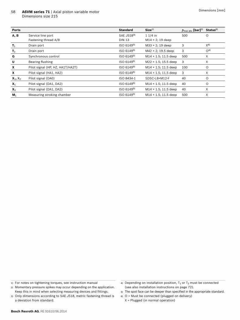
Bosch Rexroth AG RE 91610062014
58 A6VM series 71 | Axial piston variable motorDimensions size 215
Dimensions [mm]
Ports Standard Size1) pmax abs [bar]2) Status6)
A B Service line portFastening thread AB
SAE J5183)
DIN 131 14 inM14 times 2 19 deep
500 O
T1 Drain port ISO 61495) M33 times 2 19 deep 3 X4)
T2 Drain port ISO 61495) M42 times 2 195 deep 3 O4)
G Synchronous control ISO 61495) M14 times 15 115 deep 500 X
U Bearing flushing ISO 61495) M22 times 15 155 deep 3 X
X Pilot signal (HP HZ HA1THA2T) ISO 61495) M14 times 15 115 deep 100 O
X Pilot signal (HA1 HA2) ISO 61495) M14 times 15 115 deep 3 X
X1 X2 Pilot signal (DA0) ISO 8434-1 SDSC-L8timesM12-F 40 O
X1 Pilot signal (DA1 DA2) ISO 61495) M14 times 15 115 deep 40 O
X3 Pilot signal (DA1 DA2) ISO 61495) M14 times 15 115 deep 40 X
M1 Measuring stroking chamber ISO 61495) M14 times 15 115 deep 500 X
1) For notes on tightening torques see instruction manual2) Momentary pressure spikes may occur depending on the application
Keep this in mind when selecting measuring devices and fittings3) Only dimensions according to SAE J518 metric fastening thread is
a deviation from standard
4) Depending on installation position T1 or T2 must be connected (see also installation instructions on page 72)
5) The spot face can be deeper than specified in the appropriate standard6) O = Must be connected (plugged on delivery)
X = Plugged (in normal operation)
RE 91610062014 Bosch Rexroth AG
Axial piston variable motor | A6VM series 71 Dimensions size 215
59Dimensions [mm]
EP1 EP2 ndash Electric proportional control positive control
EP5D1 EP6D1 ndash Electric proportional control negative control with pressure control fixed
339
140
275
M1
G
M1
G
B A
M1
B A
M1
G
209
200
345
G
HP1 HP2 ndash Hydraulic proportional control positive control
HP5 HP6 ndash Hydraulic proportional control negative control
M1
G
B A
X
M1
339
206
245
GX
190
405
140
M1
209
140
343
M1
B A
X G X312
113
G405
HP5D1 HP6D1 ndash Hydraulic proportional control negative control with pressure control fixed
M1
G
B A
M1
X
209
145
G X313
344405
112
Bosch Rexroth AG RE 91610062014
60 A6VM series 71 | Axial piston variable motorDimensions size 215
Dimensions [mm]
HZ5 ndash Hydraulic two-point control negative control
EZ5 EZ6 ndash Electric two-point control negative control
M1
XG
140
209
111
308343
M1
X G405
B A
M1
G
B A
M1
191
209
343
G
HA1 HA2 HA1T3 HA2T3 ndash Automatic high-pressure-related control positive control with override hydraulic remote con-trolled proportional
HA1U1 HA2U2 ndash Automatic high-pressure-related control positive control with override electric two-point
M1
G
B A
X
M1
339
206
245
GX
190
405
140
B A
M1
G
M1
339
276
140
G
HA1 and HA2 X plugged
HA1T and HA2T X open
HA1R1 HA2R2 ndash Automatic high-pressure-related control positive control with override electric and travel direction valve electric
M1
276
140
339
G
M1
B A
Ga
112
b
RE 91610062014 Bosch Rexroth AG
Axial piston variable motor | A6VM series 71 Dimensions size 215
61Dimensions [mm]
DA0 ndash Automatic speed-related control negative control with hydraulic travel direction valve
DA1 DA2 ndash Automatic speed-related control negative control with electric travel direction valve and electric Vg max circuit
M1
B A
X1 X2X3G X1 X2 X3G
M1
174 271345
209
144
119
209
180
157
294345
85112
M1
B A
M1
G
X1X3
G
X1 X3
ab
X1 X2 pipe fitting SDSC ndash L8timesM12 ndash F according to ISO 8434-1
Use assembled fitting
Bosch Rexroth AG RE 91610062014
62 A6VM series 71 | Axial piston variable motorConnector for solenoids
Connector for solenoids
DEUTSCH DT04-2P-EP04Molded connector 2-pin without bidirectional suppres-sor diode There is the following type of protection with mounted mating connector
IP67 (DINEN 60529) and IP69K (DIN 40050-9)
Circuit symbol
Mating connector DEUTSCH DT06-2S-EP04
Consisting of DT designation
1 housing DT06-2S-EP04
1 wedge W2S
2 sockets 0462-201-16141
The mating connector is not included in the scope of deliv-ery This can be supplied by Bosch Rexroth on request (material number R902601804)
NoteIf necessary you can change the connector orientation by turning the solenoid housingThe procedure can be taken from the instruction manual
RE 91610062014 Bosch Rexroth AG
Axial piston variable motor | A6VM series 71 Flushing and boost pressure valve
63
Flushing and boost pressure valve
The flushing and boost pressure valve is used to remove heat from the hydraulic circuitIn an open circuit it is used only for flushing the housingIn a closed circuit it ensures a minimum boost pressure level in addition to the case flushingHydraulic fluid is directed from the respective low pressure side into the motor housing This is then fed into the reser-voir together with the leakage The hydraulic fluid removed out of the closed circuit must be replaced by cooled hydraulic fluid from the boost pumpThe valve is mounted onto the port plate or integrated (depending on the control type and size)Cracking pressure of pressure retaining valve(observe when adjusting the primary valve)
Sizes 60 to 215 fixed setting 16 barSwitching pressure of flushing spool Dp
Sizes 60 to 115 (no flushing valve) 8plusmn1 bar Sizes 115 to 215 (medium and large flushing valve)
175plusmn15 barFlushing flow qv
Orifices can be used to adjust the flushing flows as required The following information is based on DpND = pND ndash pG = 25 bar and ν = 10 mm2s (pND = low pressure pG = case pressure)
Small flushing valve for sizes 60 to 115
Material number of orifice oslash [mm] qv [lmin] Code
R909651766 12 35 A
R909419695 14 5 B
R909419696 18 8 C
R909419697 20 10 D
R909444361 24 14 F
Medium flushing valve for size 115
Material number of orifice oslash [mm] qv [lmin] Code
R909431310 28 20 H
R909435172 35 25 J
R909449967 50 30 K
Large flushing valve for sizes 150 to 215
Material number of orifice oslash [mm] qv [lmin] Code
R909449998 18 8 C
R909431308 20 10 D
R909431309 25 17 G
R909431310 28 20 H
R902138235 31 25 J
R909435172 35 30 K
R909436622 40 35 L
R909449967 50 40 M
Schematic EP
G
T2
T1U
Sa
B
A
Vg min
Vg max
M1
Flushing spool
Pressure retain-ing valve
Flushing orifice
Notes Port Sa only for sizes 150 to 215 For a flushing flow greater than 35 l min it is recom-
mended that port Sa be connected in order to prevent an increase in case pressure An increased case pres-sure reduces the flushing flow
Bosch Rexroth AG RE 91610062014
64 A6VM series 71 | Axial piston variable motorFlushing and boost pressure valve
Dimensions [mm]
Dimensions of sizes 60 to 115 (small flushing valve)
A1 A4
HA1 HA2HP1 HP2EP1 EP2
HP5 HP6EP5 EP6DA
HZ7EZ7 EZ8
A3
A2
NG A1 A2 A3 A4
60 245 137 183 236
85 273 142 194 254
115 287 143 202 269
Dimensions for sizes 115 to 215 (large flushing valve)
Sa
Sa
Sa
Z
HA1 HA2HP1 HP2EP1 EP2
HP5 HP6 DAEP5 EP6HZ5 EZ5 EZ6
B4
A2B2
A3B
3
38
A1B1
NG A1 B1 A2 B2 A3 B3 B4
60 325 239 165 142 230 187 166
85 332 246 165 142 233 190 172
115 349 263 172 148 244 201 185
Dimensions of size 115 (medium flushing valve)
205
151
292
HA1 HA2HP1 HP2EP1 EP2
HP5 HP6EP5 EP6DA
NG Sa1)
150
M22 times 15 155 deep170
215
1) ISO 6149 ports plugged (in normal operation) For notes on tightening torques see instruction manual The spot face can be deeper than specified in the appropriate stan-dard
RE 91610062014 Bosch Rexroth AG
Axial piston variable motor | A6VM series 71 Counterbalance valve BVD and BVE
65
Counterbalance valve BVD and BVE
FunctionCounterbalance valves for travel drive and winch operations are designed to reduce the danger of overspeeding and cavitation of axial piston motors in open circuits Cavitation occurs if during braking when driving downhill or the load-lowering process the motor speed is greater than it should be for the given inlet flow causing the inlet pressure to collapseIf the pressure difference between the inflow and the out-flow drops below the value opening end of the piston in the counterbalance valve (see data sheet BVD ndash 95522 or BVE ndash 95525) the counterbalance spool will move to the closed position The cross-sectional area of the counterbalance valve return duct is then reduced creating a bottleneck in the return flow of the hydraulic fluid The pressure increases and brakes the motor until the rotational speed of the motor is again as it should be for the given inlet flow
Notes BVD available for sizes 60 to 215 and BVE available for
sizes 115 to 215 The counterbalance valve must be ordered additionally
We recommend ordering the counterbalance valve and the motor as a set Ordering example A6VM085HA1T30004A71MWV0N4S97W0-0 + BVD20F27S41BndashV03K16D0400S12
For safety reasons control systems with beginning of control at Vg min (z B HA) are not permissible for winch drives
The counterbalance valve does not replace the mechani-cal service brake and parking brake
Observe the detailed notes on the BVD counterbalance valve in data sheet 95522 and on the BVE counterbal-ance valve in data sheet 95525
For the design of the brake release valve we must know for the mechanical parking brake ndash the pressure at the start of opening ndash the volume of the counterbalance spool between
minimum travel (brake closed) and maximum travel (brake released with 21 bar)
ndash the required closing time for a warm device (oil vis-cosity approx 15 mm2s)
Permissible inlet flow or pressure when using DBV and BVDBVE
Without valve Limited values when using DBV and BVDBVE
Motor DBV1) BVD2)BVE3)
NG pnompmax [bar]
qV max [lmin]
NG pnompmax [bar]
qV [lmin]
Code NG pnompmax [bar]
qV [lmin]
Code
60 450500 276 22 350420 240 7 20 (BVD)
350420 220 7W
85 332
115 410 32 400
115 410 8 25 (BVDBVE)
320 8W
150 494
170 533
215 628 On request
1) Pressure-relief valve2) Counterbalance valve double-acting3) Counterbalance valve one-sided
Bosch Rexroth AG RE 91610062014
66 A6VM series 71 | Axial piston variable motorCounterbalance valve BVD and BVE
Counterbalance valve for travel drive BVDFApplication option
Travel drive for wheeled excavators (BVD and BVE)
Example schematic for travel drive on wheeled excavators
A6VM085HA1T30004A71MWV0N4S97W0-0 + BVD20F27S41BndashV03K16D0400S12
Bacute
A
M1
T2
T1
Vg min
Vg max
X
U
G
MB
MA
S
Gext
Gacute
Lacute
Aacute
B
Variable motor A6VMHA1T
Counterbalance valve BVD
Pump directional valve not included in the scope of delivery
Counterbalance valve for winches and track drives BVDW and BVEApplication option
Winch drives in cranes (BVD and BVE) Track drive in excavator crawlers (BVD)
Example schematic for winch drive in cranes
A6VM085HP5D10001A71MWV0N4S97W0-0 + BVE25W38S51ND-V100K00D4599T30S00-0
T2
T1
M1
Vg min
Vg max
B
A
G
X
U
MP1
VGVF
S
Gext
Mk
D
C
Dacute
Cacute
Gacute
Lacute
D1
D2
MB
MA
Variable motor A6VMHP5D
Winch with mechanical parking brake
Counterbalance valve BVE
Pump directional valve not included in the scope of delivery
RE 91610062014 Bosch Rexroth AG
Axial piston variable motor | A6VM series 71 Counterbalance valve BVD and BVE
67Dimensions [mm]
Dimensions
A6VMHA HP1 HP2 and EP1 EP2 A6VMHP5 HP6 and EP5 EP61)
MB (MA)
A BS
A8
B A
Gext
A2A1
A4A3
A6 A5A7
A2A9
MB (MA)
A4A1
0
Br
S
A8
A5 A6A7
B AA B
A6VM Counterbalance valve
NGplate Type Ports Dimensions
A B A1 A2 A3 A4 A5 A6 A7 A8 A9 A10
607 BVD2017 34 in 311 302 143 50 98 139 75 222 326 50
857 BVD2027 1 in 340 331 148 55 98 139 75 222 355 46
1157 BVD2028 1 in 362 353 152 59 98 139 84 234 377 41
1158 BVD2538 1 14 in 380 370 165 63 1205 175 84 238 395 56
1508 BVD2538 1 14 in 411 401 168 67 1205 175 84 238 426 53
1708 BVD2538 1 14 in 417 407 170 68 1205 175 84 238 432 51
2158 BVD2538 1 14 in 448 438 176 74 1205 175 84 299 463 46
1158 BVE2538 1 14 in 380 370 171 63 137 214 84 238 397 63
1508 BVE2538 1 14 in 411 401 175 67 137 214 84 238 423 59
1708 BVE2538 1 14 in 417 407 176 68 137 214 84 238 432 59
2158 BVE2538 1 14 in 448 438 182 74 137 214 84 299 463 52
Ports Version A6VM plate
Standard Size2) Pmax perm [bar]3) Status5)
A B Service line SAE J518 see table above 420 O
S Infeed BVD20 DIN 38524) M22 times 15 14 deep 30 X
BVD25 BVE25 DIN 38524) M27 times 2 16 deep 30 X
Br Brake release reduced high pressure
L 7 DIN 38524) M12 times 15 125 deep 30 O
8 DIN 38524) M12 times 15 12 deep 30 O
Gext Brake release high pressure S DIN 38524) M12 times 15 125 deep 420 X
MA MB Measuring pressure A and B ISO 61494) M18 times 15 145 deep 420 X
1) At the mounting version for the controls HP5 HP6 and EP5 EP6 the cast-in port designations A and B on the counterbalance valve BVD do not correspond with the connection drawing of the A6VM motor The designation of the ports on the installation drawing of the mo-tor is binding
2) For notes on tightening torques see instruction manual
3) Momentary pressure spikes may occur depending on the applica-tion Keep this in mind when selecting measuring devices and fit-tings
4) The spot face can be deeper than specified in the appropriate stan-dard
5) O = Must be connected (plugged on delivery) X = Plugged (in normal operation)
Bosch Rexroth AG RE 91610062014
68 A6VM series 71 | Axial piston variable motorCounterbalance valve BVD and BVE
Mounting the counterbalance valveWhen delivered the counterbalance valve is mounted to the motor with two tacking screws (transport lock) The tack-ing screws may not be removed while mounting the service lines If the counterbalance valve and motor are delivered separately the counterbalance valve must first be mounted to the motor port plate using the provided tacking screws The final mounting of the counterbalance valve on the motor is done with screw fitting of the SAE flange The screws to be used and the procedure mounting can be found in the instruction manual
RE 91610062014 Bosch Rexroth AG
Axial piston variable motor | A6VM series 71 Speed sensor
69
Speed sensor
Version A6VMU (prepared for speed sensor ie without sensor) is equipped with a spline on the rotary groupA signal proportional to motor speed can be generated with the fitted DSADSM speed sensor The DSADSM sensor registers the speed and direction of rotationOrdering code technical data dimensions and details on the connector plus safety instructions about the sensor can be found in the relevant data sheet (95132 for DSM 95133 for DSA)The sensor is mounted on the port provided for this pur-pose with a mounting bolt On deliveries without sensor the port is plugged with a pressure-resistant coverWe recommend ordering the A6VM variable motor complete with mounted sensor
Schematic EP
T2
T1UnU
Dimensions
V design with mounted speed sensor
A
C
B
Size 60 85 115 150 170 215
Number of teeth 54 58 67 72 75 80
A Insertion depth (tolerance -025) 184 184 184 184 184 184
B Contact surface 75 79 88 93 96 101
C 662 752 772 912 917 952
Bosch Rexroth AG RE 91610062014
70 A6VM series 71 | Axial piston variable motorSetting range for displacement
Setting range for displacement
60 85 115
Vg max (cm3rev) Vg min (cm3rev) Vg max (cm3rev) Vg min (cm3rev) Vg max (cm3rev) Vg min (cm3rev)
from to from to from to from to from to from to
A 620 620 00 150 852 852 00 315 1156 1156 00 240
without screw M10 times 60 R909154690
without screw M12 times 70 R909085976
without screw M12 times 70 R909085976
B 620 620 gt 150 305 852 852 gt 315 520 1156 1156 gt 240 475
without screw M10 times 70 R909153779
without screw M12 times 80 R909153075
without screw M12 times 80 R909153075
C 620 620 gt 305 430 852 852 gt 520 590 1156 1156 gt 475 710
without screw M10 times 80 R909154058
without screw M12 times 90 R909154041
without screw M12 times 90 R909154041
D x x x x 1156 1156 gt 710 800
without screw M12 times 100 R909153975
E lt 620 475 00 150 lt 852 555 00 315 lt 1156 935 00 240
M10 times 60 R909154690
M10 times 60 R909154690
M12 times 70 R909085976
M12 times 70 R909085976
M12 times 70 R909085976
M12 times 70 R909085976
F lt 620 475 gt 150 305 lt 852 555 gt 315 520 lt 1156 935 gt 240 475
M10 times 60 R909154690
M10 times 70 R909153779
M12 times 70 R909085976
M12 times 80 R909153075
M12 times 70 R909085976
M12 times 80 R909085976
G lt 620 475 gt 305 430 lt 852 555 gt 520 590 lt 1156 935 gt 475 71
M10 times 60 R909154690
M10 times 80 R909154058
M12 times 70 R909085976
M12 times 90 R909154041
M12 times 70 R909085976
M12 times 90 R909154041
H x x x times lt 1156 935 gt 710 800
M12 times 70 R909085976
M12 times 100 R909153975
J lt 475 330 00 150 lt 555 350 00 315 lt 935 710 00 240
M10 times 70 R909153779
M10 times 60 R909154690
M12 times 80 R909153075
M12 times 70 R909085976
M12 times 80 R909153075
M12 times 70 R909085976
K lt 475 330 gt 150 305 lt 555 350 gt 315 520 lt 935 710 gt 240 475
M10 times 70 R909153779
M10 times 70 R909153779
M12 times 80 R909153075
M12 times 80 R909153075
M12 times 80 R909153075
M12 times 80 R909153075
L lt 475 330 gt 305 430 lt 555 350 gt 520 590 lt 935 710 gt 475 710
M10 times 70 R909153779
M10 times 80 R909154058
M12 times 80 R909153075
M12 times 90 R909154041
M12 times 80 R909153075
M12 times 90 R909154041
M x x x x lt 935 710 gt 710 800
M12 times 80 R909153075
M12 times 100 R909153975
Specify exact settings for Vg min and Vg max in plain text when ordering
Vg min = cm3 Vg max = cm3
Theoretical maximum setting for Vg min = 07 times Vg max
for Vg max = 03 times Vg max
Settings that are not listed in the table may lead to damage Please contact us
RE 91610062014 Bosch Rexroth AG
Axial piston variable motor | A6VM series 71 Setting range for displacement
71
150 170 215
Vg max (cm3rev) Vg min (cm3rev) Vg max (cm3rev) Vg min (cm3rev) Vg max (cm3rev) Vg min (cm3rev)
from to from to from to from to from to from to
A 1521 1521 00 440 1718 1718 00 350 2165 2165 00 445
without screw M12 times 80 R909153075
without screw M12 times 80 R909153075
without screw M12 times 80 R909153075
B 1521 1521 gt 440 690 1718 1718 gt 350 635 2165 2165 gt 445 800
without screw M12 times 90 R909154041
without screw M12 times 90 R909154041
without screw M12 times 90 R909154041
C 1521 1521 gt 690 990 1718 1718 gt 635 980 2165 2165 gt 800 1150
without screw M12 times 100 R909153975
without screw M12 times 100 R909153975
without screw M12 times 100 R909153975
D 1521 1521 gt 990 1060 1718 1718 gt 980 1200 2165 2165 gt 1150 1500
without screw M12 times 110 R909154212
without screw M12 times 110 R909154212
without screw M12 times 110 R909154212
E lt 1521 1110 00 440 lt 1718 1390 00 350 lt 2165 1750 00 445
M12 times 80 R909153075
M12 times 80 R909153075
M12 times 80 R909153075
M10 times 80 R909153075
M12 times 80 R909153075
M12 times 80 R909153075
F lt 1521 1110 gt 440 690 lt 1718 1390 gt 350 635 lt 2165 1750 gt 445 800
M12 times 80 R909153075
M12 times 90 R909085976
M12 times 80 R909153075
M12 times 90 R909154041
M12 times 80 R909153075
M12 times 90 R909154041
G lt 1521 1110 gt 690 990 lt 1718 1390 gt 635 980 lt 2165 1750 gt 800 1150
M12 times 80 R909153075
M12 times 100 R909153975
M12 times 80 R909153075
M12 times 100 R909153975
M12 times 80 R909153075
M12 times 100 R909153975
H lt 1521 1110 gt 990 1060 lt 1718 1390 gt 980 1200 lt 2165 1750 gt 1150 1500
M12 times 80 R909153075
M12 times 110 R909154212
M12 times 80 R909153075
M12 times 110 R909154212
M12 times 80 R909153075
M12 times 110 R909154212
J lt 1110 870 00 440 lt 1390 1120 00 350 lt 1750 1410 00 445
M12 times 90 R909154041
M12 times 80 R909153075
M12 times 90 R909154041
M12 x 80 R909153075
M12 x 90 R909154041
M12 x 80 R909153075
K lt 1110 870 gt 440 690 lt 1390 1120 gt 350 635 lt 1750 1410 gt 445 800
M12 times 90 R909154041
M12 times 90 R909154041
M12 x 90 R909154041
M12 times 90 R909154041
M12 times 90 R909154041
M12 times 90 R909154041
L lt 1110 870 gt 690 990 lt 1390 1120 gt 635 980 lt 1750 1410 gt 800 1150
M12 times 90 R909154041
M12 times 100 R909153975
M12 times 90 R909154041
M12 times 100 R909153975
M12 times 90 R909154041
M12 times 100 R909153975
M lt 1110 870 gt 990 1060 lt 1390 1120 gt 980 1200 lt 1750 1410 gt 1150 1500
M12 times 90 R909154041
M12 times 110 R909154212
M12 times 90 R909154041
M12 times 110 R909154212
M12 times 90 R909154041
M12 times 110 R909154212
Specify exact settings for Vg min and Vg max in plain text when ordering
Vg min = cm3 Vg max = cm3
Theoretical maximum setting for Vg min = 07 times Vg max
for Vg max = 03 times Vg max
Settings that are not listed in the table may lead to damage Please contact us
Bosch Rexroth AG RE 91610062014
72 A6VM series 71 | Axial piston variable motorInstallation instructions
Installation instructions
GeneralDuring commissioning and operation the axial piston unit must be filled with hydraulic fluid and air bled This must also observed following a relatively long standstill as the axial piston unit may drain back to the reservoir via the hydraulic linesParticularly in the installation position drive shaft upwards filling and air bleeding must be carried out com-pletely as there is for example a danger of dry runningThe leakage in the motor housing must be directed to the reservoir via the highest available drain port (T1 T2)To achieve favorable noise values decouple all connecting lines using elastic elements and avoid above-reservoir installation In all operating conditions the drain line must flow into the reservoir below the minimum fluid level
NoteIn certain installation conditions an influence on the control charakteristic curves can be expected Gravity dead weight and case pressure can cause minor shifts in characteristics and changes in response time
Key
U Bearing flushing air bleed port
T1 T2 Drain port
ht min Minimum required immersion depth (200 mm)
hmin Minimum required spacing to reservoir bottom (100 mm)
Installation position See examples 1 to 8 below Additional installation positions are available upon requestRecommended installation position 1 and 2
Below-reservoir installation (standard)Below-reservoir installation means that the axial piston unit is installed outside of the reservoir below the minimum fluid level
Installation position Air bleed Filling
1
T2
T1U
ht min
hmin
T1
2
T2
T1 U
ht min
hmin
T2
3
T2
T1
U
ht min
hmin
T1
4
T2
T1
U
ht min
hmin
U T1
RE 91610062014 Bosch Rexroth AG
Axial piston variable motor | A6VM series 71 Installation instructions
73
Above-reservoir installationAbove-reservoir installation means that the axial piston unit is installed above the minimum fluid level of the reservoirRecommendation for installation position 8 (drive shaft upward) A check valve in the drain line (cracking pressure 05 bar) can prevent draining of the motor housing
Installation position Air bleed Filling
5
T2
T1U
L1
ht min
hmin
U (L1) T1 (L1)
6
T2
T1 U
L1
ht min
hmin
L1 T2 (L1)
7
T2T1
U
L1
ht min
hmin
L1 T1 (L1)
8
T2T1
UL1
05
bar
ht min
hmin
U T1 (L1)
NotePort L1 is not part of the motor and can be made available by the customer for straightforward filling and air bleed-ing
74
Bosch Rexroth AG RE 91610062014
Bosch Rexroth AGMobile ApplicationsGlockeraustraszlige 489275 Elchingen GermanyTel +49-7308-82-0infomaboschrexrothdewwwboschrexrothcom
copy This document as well as the data specifications and other information set forth in it are the exclusive property of Bosch Rexroth AG It may not be reproduced or given to third parties without its consent The data specified above only serve to describe the product No statements concerning a certain condition or suitability for a certain application can be derived from our information The information given does not release the user from the obligation of own judgment and verification It must be remembered that our products are subject to a natural process of wear and aging
A6VM series 71 | Axial piston variable motorProject planning note
Project planning note
The motor A6VM is designed to be used in open and closed circuits
The project planning installation and commissioning of the axial piston unit requires the involvement of quali-fied skilled person
Before using the axial piston unit please read the cor-responding instruction manual completely and thor-oughly If necessary these can be requested from Bosch Rexroth
Before finalizing your design request a binding installa-tion drawing
The data and notes contained herein must be adhered to
For safety reasons control systems with beginning of control at Vg min (eg HA) are not permissible for winch drives eg anchor winches
Depending on the operating conditions of the axial piston unit (operating pressure fluid temperature) the charakteristic curve may shift
Not all variants of the product are approved for use in safety functions according to ISO 13849 Please consult the responsible contact person at Bosch Rexroth if you require reliability parameters (eg MTTFd) for functional safety
Working ports ndash The ports and fastening threads are designed for the
specified maximum pressure The machine or system manufacturer must ensure that the connecting ele-ments and lines correspond to the specified applica-tion conditions (pressure flow hydraulic fluid tem-perature) with the necessary safety factors
ndash The working ports and function ports can only be used to accommodate hydraulic lines
Safety instructions
During and shortly after operation there is a risk of burns on the axial piston unit and especially on the solenoids Take appropriate safety measures (e g by wearing protective clothing)
Moving parts in control and regulation systems (eg valve spools) may in certain circumstances become stuck in an undefined position due to contamination (eg contaminated hydraulic fluid abrasion or residual dirt from components) As a result the hydraulic fluid flow or build-up of torque of the axial piston unit will no longer respond correctly to the operators commands Even the use of different filter cartridges (external or internal inlet filter) will not rule out a fault but merely minimize the risk The machinesystem manufacturer must test whether remedial measures are needed on the machine for the application concerned in order to set the consumer being driven to a safe position (eg safe stop) and if necessary to ensure it is properly imple-mented
If the axial piston motor is used in winch drives make sure that the technical limit values are not exceeded under all operating conditions If the axial piston motor is subjected to external overload (eg by exceeding the maximum permissible rotational speeds when lifting anchor while the ship is in motion) this could cause damage to the rotary group and in unfavorable cases to the axial piston motor bursting If necessary additional measures up to an including encapsulation are to be implemented by the machinesystem manufacturer
RE 91610062014 Bosch Rexroth AG
75 Axial piston variable motor | A6VM series 71
76
Bosch Rexroth AG RE 91610062014
Bosch Rexroth AGMobile ApplicationsGlockeraustraszlige 489275 Elchingen GermanyTel +49-7308-82-0infomaboschrexrothdewwwboschrexrothcom
copy This document as well as the data specifications and other information set forth in it are the exclusive property of Bosch Rexroth AG It may not be reproduced or given to third parties without its consent The data specified above only serve to describe the product No statements concerning a certain condition or suitability for a certain application can be derived from our information The information given does not release the user from the obligation of own judgment and verification It must be remembered that our products are subject to a natural process of wear and aging
A6VM series 71 | axial piston variable motor

RE 91610062014 Bosch Rexroth AG
Axial piston variable motor | A6VM series 71 Dimensions size 215
59Dimensions [mm]
EP1 EP2 ndash Electric proportional control positive control
EP5D1 EP6D1 ndash Electric proportional control negative control with pressure control fixed
339
140
275
M1
G
M1
G
B A
M1
B A
M1
G
209
200
345
G
HP1 HP2 ndash Hydraulic proportional control positive control
HP5 HP6 ndash Hydraulic proportional control negative control
M1
G
B A
X
M1
339
206
245
GX
190
405
140
M1
209
140
343
M1
B A
X G X312
113
G405
HP5D1 HP6D1 ndash Hydraulic proportional control negative control with pressure control fixed
M1
G
B A
M1
X
209
145
G X313
344405
112
Bosch Rexroth AG RE 91610062014
60 A6VM series 71 | Axial piston variable motorDimensions size 215
Dimensions [mm]
HZ5 ndash Hydraulic two-point control negative control
EZ5 EZ6 ndash Electric two-point control negative control
M1
XG
140
209
111
308343
M1
X G405
B A
M1
G
B A
M1
191
209
343
G
HA1 HA2 HA1T3 HA2T3 ndash Automatic high-pressure-related control positive control with override hydraulic remote con-trolled proportional
HA1U1 HA2U2 ndash Automatic high-pressure-related control positive control with override electric two-point
M1
G
B A
X
M1
339
206
245
GX
190
405
140
B A
M1
G
M1
339
276
140
G
HA1 and HA2 X plugged
HA1T and HA2T X open
HA1R1 HA2R2 ndash Automatic high-pressure-related control positive control with override electric and travel direction valve electric
M1
276
140
339
G
M1
B A
Ga
112
b
RE 91610062014 Bosch Rexroth AG
Axial piston variable motor | A6VM series 71 Dimensions size 215
61Dimensions [mm]
DA0 ndash Automatic speed-related control negative control with hydraulic travel direction valve
DA1 DA2 ndash Automatic speed-related control negative control with electric travel direction valve and electric Vg max circuit
M1
B A
X1 X2X3G X1 X2 X3G
M1
174 271345
209
144
119
209
180
157
294345
85112
M1
B A
M1
G
X1X3
G
X1 X3
ab
X1 X2 pipe fitting SDSC ndash L8timesM12 ndash F according to ISO 8434-1
Use assembled fitting
Bosch Rexroth AG RE 91610062014
62 A6VM series 71 | Axial piston variable motorConnector for solenoids
Connector for solenoids
DEUTSCH DT04-2P-EP04Molded connector 2-pin without bidirectional suppres-sor diode There is the following type of protection with mounted mating connector
IP67 (DINEN 60529) and IP69K (DIN 40050-9)
Circuit symbol
Mating connector DEUTSCH DT06-2S-EP04
Consisting of DT designation
1 housing DT06-2S-EP04
1 wedge W2S
2 sockets 0462-201-16141
The mating connector is not included in the scope of deliv-ery This can be supplied by Bosch Rexroth on request (material number R902601804)
NoteIf necessary you can change the connector orientation by turning the solenoid housingThe procedure can be taken from the instruction manual
RE 91610062014 Bosch Rexroth AG
Axial piston variable motor | A6VM series 71 Flushing and boost pressure valve
63
Flushing and boost pressure valve
The flushing and boost pressure valve is used to remove heat from the hydraulic circuitIn an open circuit it is used only for flushing the housingIn a closed circuit it ensures a minimum boost pressure level in addition to the case flushingHydraulic fluid is directed from the respective low pressure side into the motor housing This is then fed into the reser-voir together with the leakage The hydraulic fluid removed out of the closed circuit must be replaced by cooled hydraulic fluid from the boost pumpThe valve is mounted onto the port plate or integrated (depending on the control type and size)Cracking pressure of pressure retaining valve(observe when adjusting the primary valve)
Sizes 60 to 215 fixed setting 16 barSwitching pressure of flushing spool Dp
Sizes 60 to 115 (no flushing valve) 8plusmn1 bar Sizes 115 to 215 (medium and large flushing valve)
175plusmn15 barFlushing flow qv
Orifices can be used to adjust the flushing flows as required The following information is based on DpND = pND ndash pG = 25 bar and ν = 10 mm2s (pND = low pressure pG = case pressure)
Small flushing valve for sizes 60 to 115
Material number of orifice oslash [mm] qv [lmin] Code
R909651766 12 35 A
R909419695 14 5 B
R909419696 18 8 C
R909419697 20 10 D
R909444361 24 14 F
Medium flushing valve for size 115
Material number of orifice oslash [mm] qv [lmin] Code
R909431310 28 20 H
R909435172 35 25 J
R909449967 50 30 K
Large flushing valve for sizes 150 to 215
Material number of orifice oslash [mm] qv [lmin] Code
R909449998 18 8 C
R909431308 20 10 D
R909431309 25 17 G
R909431310 28 20 H
R902138235 31 25 J
R909435172 35 30 K
R909436622 40 35 L
R909449967 50 40 M
Schematic EP
G
T2
T1U
Sa
B
A
Vg min
Vg max
M1
Flushing spool
Pressure retain-ing valve
Flushing orifice
Notes Port Sa only for sizes 150 to 215 For a flushing flow greater than 35 l min it is recom-
mended that port Sa be connected in order to prevent an increase in case pressure An increased case pres-sure reduces the flushing flow
Bosch Rexroth AG RE 91610062014
64 A6VM series 71 | Axial piston variable motorFlushing and boost pressure valve
Dimensions [mm]
Dimensions of sizes 60 to 115 (small flushing valve)
A1 A4
HA1 HA2HP1 HP2EP1 EP2
HP5 HP6EP5 EP6DA
HZ7EZ7 EZ8
A3
A2
NG A1 A2 A3 A4
60 245 137 183 236
85 273 142 194 254
115 287 143 202 269
Dimensions for sizes 115 to 215 (large flushing valve)
Sa
Sa
Sa
Z
HA1 HA2HP1 HP2EP1 EP2
HP5 HP6 DAEP5 EP6HZ5 EZ5 EZ6
B4
A2B2
A3B
3
38
A1B1
NG A1 B1 A2 B2 A3 B3 B4
60 325 239 165 142 230 187 166
85 332 246 165 142 233 190 172
115 349 263 172 148 244 201 185
Dimensions of size 115 (medium flushing valve)
205
151
292
HA1 HA2HP1 HP2EP1 EP2
HP5 HP6EP5 EP6DA
NG Sa1)
150
M22 times 15 155 deep170
215
1) ISO 6149 ports plugged (in normal operation) For notes on tightening torques see instruction manual The spot face can be deeper than specified in the appropriate stan-dard
RE 91610062014 Bosch Rexroth AG
Axial piston variable motor | A6VM series 71 Counterbalance valve BVD and BVE
65
Counterbalance valve BVD and BVE
FunctionCounterbalance valves for travel drive and winch operations are designed to reduce the danger of overspeeding and cavitation of axial piston motors in open circuits Cavitation occurs if during braking when driving downhill or the load-lowering process the motor speed is greater than it should be for the given inlet flow causing the inlet pressure to collapseIf the pressure difference between the inflow and the out-flow drops below the value opening end of the piston in the counterbalance valve (see data sheet BVD ndash 95522 or BVE ndash 95525) the counterbalance spool will move to the closed position The cross-sectional area of the counterbalance valve return duct is then reduced creating a bottleneck in the return flow of the hydraulic fluid The pressure increases and brakes the motor until the rotational speed of the motor is again as it should be for the given inlet flow
Notes BVD available for sizes 60 to 215 and BVE available for
sizes 115 to 215 The counterbalance valve must be ordered additionally
We recommend ordering the counterbalance valve and the motor as a set Ordering example A6VM085HA1T30004A71MWV0N4S97W0-0 + BVD20F27S41BndashV03K16D0400S12
For safety reasons control systems with beginning of control at Vg min (z B HA) are not permissible for winch drives
The counterbalance valve does not replace the mechani-cal service brake and parking brake
Observe the detailed notes on the BVD counterbalance valve in data sheet 95522 and on the BVE counterbal-ance valve in data sheet 95525
For the design of the brake release valve we must know for the mechanical parking brake ndash the pressure at the start of opening ndash the volume of the counterbalance spool between
minimum travel (brake closed) and maximum travel (brake released with 21 bar)
ndash the required closing time for a warm device (oil vis-cosity approx 15 mm2s)
Permissible inlet flow or pressure when using DBV and BVDBVE
Without valve Limited values when using DBV and BVDBVE
Motor DBV1) BVD2)BVE3)
NG pnompmax [bar]
qV max [lmin]
NG pnompmax [bar]
qV [lmin]
Code NG pnompmax [bar]
qV [lmin]
Code
60 450500 276 22 350420 240 7 20 (BVD)
350420 220 7W
85 332
115 410 32 400
115 410 8 25 (BVDBVE)
320 8W
150 494
170 533
215 628 On request
1) Pressure-relief valve2) Counterbalance valve double-acting3) Counterbalance valve one-sided
Bosch Rexroth AG RE 91610062014
66 A6VM series 71 | Axial piston variable motorCounterbalance valve BVD and BVE
Counterbalance valve for travel drive BVDFApplication option
Travel drive for wheeled excavators (BVD and BVE)
Example schematic for travel drive on wheeled excavators
A6VM085HA1T30004A71MWV0N4S97W0-0 + BVD20F27S41BndashV03K16D0400S12
Bacute
A
M1
T2
T1
Vg min
Vg max
X
U
G
MB
MA
S
Gext
Gacute
Lacute
Aacute
B
Variable motor A6VMHA1T
Counterbalance valve BVD
Pump directional valve not included in the scope of delivery
Counterbalance valve for winches and track drives BVDW and BVEApplication option
Winch drives in cranes (BVD and BVE) Track drive in excavator crawlers (BVD)
Example schematic for winch drive in cranes
A6VM085HP5D10001A71MWV0N4S97W0-0 + BVE25W38S51ND-V100K00D4599T30S00-0
T2
T1
M1
Vg min
Vg max
B
A
G
X
U
MP1
VGVF
S
Gext
Mk
D
C
Dacute
Cacute
Gacute
Lacute
D1
D2
MB
MA
Variable motor A6VMHP5D
Winch with mechanical parking brake
Counterbalance valve BVE
Pump directional valve not included in the scope of delivery
RE 91610062014 Bosch Rexroth AG
Axial piston variable motor | A6VM series 71 Counterbalance valve BVD and BVE
67Dimensions [mm]
Dimensions
A6VMHA HP1 HP2 and EP1 EP2 A6VMHP5 HP6 and EP5 EP61)
MB (MA)
A BS
A8
B A
Gext
A2A1
A4A3
A6 A5A7
A2A9
MB (MA)
A4A1
0
Br
S
A8
A5 A6A7
B AA B
A6VM Counterbalance valve
NGplate Type Ports Dimensions
A B A1 A2 A3 A4 A5 A6 A7 A8 A9 A10
607 BVD2017 34 in 311 302 143 50 98 139 75 222 326 50
857 BVD2027 1 in 340 331 148 55 98 139 75 222 355 46
1157 BVD2028 1 in 362 353 152 59 98 139 84 234 377 41
1158 BVD2538 1 14 in 380 370 165 63 1205 175 84 238 395 56
1508 BVD2538 1 14 in 411 401 168 67 1205 175 84 238 426 53
1708 BVD2538 1 14 in 417 407 170 68 1205 175 84 238 432 51
2158 BVD2538 1 14 in 448 438 176 74 1205 175 84 299 463 46
1158 BVE2538 1 14 in 380 370 171 63 137 214 84 238 397 63
1508 BVE2538 1 14 in 411 401 175 67 137 214 84 238 423 59
1708 BVE2538 1 14 in 417 407 176 68 137 214 84 238 432 59
2158 BVE2538 1 14 in 448 438 182 74 137 214 84 299 463 52
Ports Version A6VM plate
Standard Size2) Pmax perm [bar]3) Status5)
A B Service line SAE J518 see table above 420 O
S Infeed BVD20 DIN 38524) M22 times 15 14 deep 30 X
BVD25 BVE25 DIN 38524) M27 times 2 16 deep 30 X
Br Brake release reduced high pressure
L 7 DIN 38524) M12 times 15 125 deep 30 O
8 DIN 38524) M12 times 15 12 deep 30 O
Gext Brake release high pressure S DIN 38524) M12 times 15 125 deep 420 X
MA MB Measuring pressure A and B ISO 61494) M18 times 15 145 deep 420 X
1) At the mounting version for the controls HP5 HP6 and EP5 EP6 the cast-in port designations A and B on the counterbalance valve BVD do not correspond with the connection drawing of the A6VM motor The designation of the ports on the installation drawing of the mo-tor is binding
2) For notes on tightening torques see instruction manual
3) Momentary pressure spikes may occur depending on the applica-tion Keep this in mind when selecting measuring devices and fit-tings
4) The spot face can be deeper than specified in the appropriate stan-dard
5) O = Must be connected (plugged on delivery) X = Plugged (in normal operation)
Bosch Rexroth AG RE 91610062014
68 A6VM series 71 | Axial piston variable motorCounterbalance valve BVD and BVE
Mounting the counterbalance valveWhen delivered the counterbalance valve is mounted to the motor with two tacking screws (transport lock) The tack-ing screws may not be removed while mounting the service lines If the counterbalance valve and motor are delivered separately the counterbalance valve must first be mounted to the motor port plate using the provided tacking screws The final mounting of the counterbalance valve on the motor is done with screw fitting of the SAE flange The screws to be used and the procedure mounting can be found in the instruction manual
RE 91610062014 Bosch Rexroth AG
Axial piston variable motor | A6VM series 71 Speed sensor
69
Speed sensor
Version A6VMU (prepared for speed sensor ie without sensor) is equipped with a spline on the rotary groupA signal proportional to motor speed can be generated with the fitted DSADSM speed sensor The DSADSM sensor registers the speed and direction of rotationOrdering code technical data dimensions and details on the connector plus safety instructions about the sensor can be found in the relevant data sheet (95132 for DSM 95133 for DSA)The sensor is mounted on the port provided for this pur-pose with a mounting bolt On deliveries without sensor the port is plugged with a pressure-resistant coverWe recommend ordering the A6VM variable motor complete with mounted sensor
Schematic EP
T2
T1UnU
Dimensions
V design with mounted speed sensor
A
C
B
Size 60 85 115 150 170 215
Number of teeth 54 58 67 72 75 80
A Insertion depth (tolerance -025) 184 184 184 184 184 184
B Contact surface 75 79 88 93 96 101
C 662 752 772 912 917 952
Bosch Rexroth AG RE 91610062014
70 A6VM series 71 | Axial piston variable motorSetting range for displacement
Setting range for displacement
60 85 115
Vg max (cm3rev) Vg min (cm3rev) Vg max (cm3rev) Vg min (cm3rev) Vg max (cm3rev) Vg min (cm3rev)
from to from to from to from to from to from to
A 620 620 00 150 852 852 00 315 1156 1156 00 240
without screw M10 times 60 R909154690
without screw M12 times 70 R909085976
without screw M12 times 70 R909085976
B 620 620 gt 150 305 852 852 gt 315 520 1156 1156 gt 240 475
without screw M10 times 70 R909153779
without screw M12 times 80 R909153075
without screw M12 times 80 R909153075
C 620 620 gt 305 430 852 852 gt 520 590 1156 1156 gt 475 710
without screw M10 times 80 R909154058
without screw M12 times 90 R909154041
without screw M12 times 90 R909154041
D x x x x 1156 1156 gt 710 800
without screw M12 times 100 R909153975
E lt 620 475 00 150 lt 852 555 00 315 lt 1156 935 00 240
M10 times 60 R909154690
M10 times 60 R909154690
M12 times 70 R909085976
M12 times 70 R909085976
M12 times 70 R909085976
M12 times 70 R909085976
F lt 620 475 gt 150 305 lt 852 555 gt 315 520 lt 1156 935 gt 240 475
M10 times 60 R909154690
M10 times 70 R909153779
M12 times 70 R909085976
M12 times 80 R909153075
M12 times 70 R909085976
M12 times 80 R909085976
G lt 620 475 gt 305 430 lt 852 555 gt 520 590 lt 1156 935 gt 475 71
M10 times 60 R909154690
M10 times 80 R909154058
M12 times 70 R909085976
M12 times 90 R909154041
M12 times 70 R909085976
M12 times 90 R909154041
H x x x times lt 1156 935 gt 710 800
M12 times 70 R909085976
M12 times 100 R909153975
J lt 475 330 00 150 lt 555 350 00 315 lt 935 710 00 240
M10 times 70 R909153779
M10 times 60 R909154690
M12 times 80 R909153075
M12 times 70 R909085976
M12 times 80 R909153075
M12 times 70 R909085976
K lt 475 330 gt 150 305 lt 555 350 gt 315 520 lt 935 710 gt 240 475
M10 times 70 R909153779
M10 times 70 R909153779
M12 times 80 R909153075
M12 times 80 R909153075
M12 times 80 R909153075
M12 times 80 R909153075
L lt 475 330 gt 305 430 lt 555 350 gt 520 590 lt 935 710 gt 475 710
M10 times 70 R909153779
M10 times 80 R909154058
M12 times 80 R909153075
M12 times 90 R909154041
M12 times 80 R909153075
M12 times 90 R909154041
M x x x x lt 935 710 gt 710 800
M12 times 80 R909153075
M12 times 100 R909153975
Specify exact settings for Vg min and Vg max in plain text when ordering
Vg min = cm3 Vg max = cm3
Theoretical maximum setting for Vg min = 07 times Vg max
for Vg max = 03 times Vg max
Settings that are not listed in the table may lead to damage Please contact us
RE 91610062014 Bosch Rexroth AG
Axial piston variable motor | A6VM series 71 Setting range for displacement
71
150 170 215
Vg max (cm3rev) Vg min (cm3rev) Vg max (cm3rev) Vg min (cm3rev) Vg max (cm3rev) Vg min (cm3rev)
from to from to from to from to from to from to
A 1521 1521 00 440 1718 1718 00 350 2165 2165 00 445
without screw M12 times 80 R909153075
without screw M12 times 80 R909153075
without screw M12 times 80 R909153075
B 1521 1521 gt 440 690 1718 1718 gt 350 635 2165 2165 gt 445 800
without screw M12 times 90 R909154041
without screw M12 times 90 R909154041
without screw M12 times 90 R909154041
C 1521 1521 gt 690 990 1718 1718 gt 635 980 2165 2165 gt 800 1150
without screw M12 times 100 R909153975
without screw M12 times 100 R909153975
without screw M12 times 100 R909153975
D 1521 1521 gt 990 1060 1718 1718 gt 980 1200 2165 2165 gt 1150 1500
without screw M12 times 110 R909154212
without screw M12 times 110 R909154212
without screw M12 times 110 R909154212
E lt 1521 1110 00 440 lt 1718 1390 00 350 lt 2165 1750 00 445
M12 times 80 R909153075
M12 times 80 R909153075
M12 times 80 R909153075
M10 times 80 R909153075
M12 times 80 R909153075
M12 times 80 R909153075
F lt 1521 1110 gt 440 690 lt 1718 1390 gt 350 635 lt 2165 1750 gt 445 800
M12 times 80 R909153075
M12 times 90 R909085976
M12 times 80 R909153075
M12 times 90 R909154041
M12 times 80 R909153075
M12 times 90 R909154041
G lt 1521 1110 gt 690 990 lt 1718 1390 gt 635 980 lt 2165 1750 gt 800 1150
M12 times 80 R909153075
M12 times 100 R909153975
M12 times 80 R909153075
M12 times 100 R909153975
M12 times 80 R909153075
M12 times 100 R909153975
H lt 1521 1110 gt 990 1060 lt 1718 1390 gt 980 1200 lt 2165 1750 gt 1150 1500
M12 times 80 R909153075
M12 times 110 R909154212
M12 times 80 R909153075
M12 times 110 R909154212
M12 times 80 R909153075
M12 times 110 R909154212
J lt 1110 870 00 440 lt 1390 1120 00 350 lt 1750 1410 00 445
M12 times 90 R909154041
M12 times 80 R909153075
M12 times 90 R909154041
M12 x 80 R909153075
M12 x 90 R909154041
M12 x 80 R909153075
K lt 1110 870 gt 440 690 lt 1390 1120 gt 350 635 lt 1750 1410 gt 445 800
M12 times 90 R909154041
M12 times 90 R909154041
M12 x 90 R909154041
M12 times 90 R909154041
M12 times 90 R909154041
M12 times 90 R909154041
L lt 1110 870 gt 690 990 lt 1390 1120 gt 635 980 lt 1750 1410 gt 800 1150
M12 times 90 R909154041
M12 times 100 R909153975
M12 times 90 R909154041
M12 times 100 R909153975
M12 times 90 R909154041
M12 times 100 R909153975
M lt 1110 870 gt 990 1060 lt 1390 1120 gt 980 1200 lt 1750 1410 gt 1150 1500
M12 times 90 R909154041
M12 times 110 R909154212
M12 times 90 R909154041
M12 times 110 R909154212
M12 times 90 R909154041
M12 times 110 R909154212
Specify exact settings for Vg min and Vg max in plain text when ordering
Vg min = cm3 Vg max = cm3
Theoretical maximum setting for Vg min = 07 times Vg max
for Vg max = 03 times Vg max
Settings that are not listed in the table may lead to damage Please contact us
Bosch Rexroth AG RE 91610062014
72 A6VM series 71 | Axial piston variable motorInstallation instructions
Installation instructions
GeneralDuring commissioning and operation the axial piston unit must be filled with hydraulic fluid and air bled This must also observed following a relatively long standstill as the axial piston unit may drain back to the reservoir via the hydraulic linesParticularly in the installation position drive shaft upwards filling and air bleeding must be carried out com-pletely as there is for example a danger of dry runningThe leakage in the motor housing must be directed to the reservoir via the highest available drain port (T1 T2)To achieve favorable noise values decouple all connecting lines using elastic elements and avoid above-reservoir installation In all operating conditions the drain line must flow into the reservoir below the minimum fluid level
NoteIn certain installation conditions an influence on the control charakteristic curves can be expected Gravity dead weight and case pressure can cause minor shifts in characteristics and changes in response time
Key
U Bearing flushing air bleed port
T1 T2 Drain port
ht min Minimum required immersion depth (200 mm)
hmin Minimum required spacing to reservoir bottom (100 mm)
Installation position See examples 1 to 8 below Additional installation positions are available upon requestRecommended installation position 1 and 2
Below-reservoir installation (standard)Below-reservoir installation means that the axial piston unit is installed outside of the reservoir below the minimum fluid level
Installation position Air bleed Filling
1
T2
T1U
ht min
hmin
T1
2
T2
T1 U
ht min
hmin
T2
3
T2
T1
U
ht min
hmin
T1
4
T2
T1
U
ht min
hmin
U T1
RE 91610062014 Bosch Rexroth AG
Axial piston variable motor | A6VM series 71 Installation instructions
73
Above-reservoir installationAbove-reservoir installation means that the axial piston unit is installed above the minimum fluid level of the reservoirRecommendation for installation position 8 (drive shaft upward) A check valve in the drain line (cracking pressure 05 bar) can prevent draining of the motor housing
Installation position Air bleed Filling
5
T2
T1U
L1
ht min
hmin
U (L1) T1 (L1)
6
T2
T1 U
L1
ht min
hmin
L1 T2 (L1)
7
T2T1
U
L1
ht min
hmin
L1 T1 (L1)
8
T2T1
UL1
05
bar
ht min
hmin
U T1 (L1)
NotePort L1 is not part of the motor and can be made available by the customer for straightforward filling and air bleed-ing
74
Bosch Rexroth AG RE 91610062014
Bosch Rexroth AGMobile ApplicationsGlockeraustraszlige 489275 Elchingen GermanyTel +49-7308-82-0infomaboschrexrothdewwwboschrexrothcom
copy This document as well as the data specifications and other information set forth in it are the exclusive property of Bosch Rexroth AG It may not be reproduced or given to third parties without its consent The data specified above only serve to describe the product No statements concerning a certain condition or suitability for a certain application can be derived from our information The information given does not release the user from the obligation of own judgment and verification It must be remembered that our products are subject to a natural process of wear and aging
A6VM series 71 | Axial piston variable motorProject planning note
Project planning note
The motor A6VM is designed to be used in open and closed circuits
The project planning installation and commissioning of the axial piston unit requires the involvement of quali-fied skilled person
Before using the axial piston unit please read the cor-responding instruction manual completely and thor-oughly If necessary these can be requested from Bosch Rexroth
Before finalizing your design request a binding installa-tion drawing
The data and notes contained herein must be adhered to
For safety reasons control systems with beginning of control at Vg min (eg HA) are not permissible for winch drives eg anchor winches
Depending on the operating conditions of the axial piston unit (operating pressure fluid temperature) the charakteristic curve may shift
Not all variants of the product are approved for use in safety functions according to ISO 13849 Please consult the responsible contact person at Bosch Rexroth if you require reliability parameters (eg MTTFd) for functional safety
Working ports ndash The ports and fastening threads are designed for the
specified maximum pressure The machine or system manufacturer must ensure that the connecting ele-ments and lines correspond to the specified applica-tion conditions (pressure flow hydraulic fluid tem-perature) with the necessary safety factors
ndash The working ports and function ports can only be used to accommodate hydraulic lines
Safety instructions
During and shortly after operation there is a risk of burns on the axial piston unit and especially on the solenoids Take appropriate safety measures (e g by wearing protective clothing)
Moving parts in control and regulation systems (eg valve spools) may in certain circumstances become stuck in an undefined position due to contamination (eg contaminated hydraulic fluid abrasion or residual dirt from components) As a result the hydraulic fluid flow or build-up of torque of the axial piston unit will no longer respond correctly to the operators commands Even the use of different filter cartridges (external or internal inlet filter) will not rule out a fault but merely minimize the risk The machinesystem manufacturer must test whether remedial measures are needed on the machine for the application concerned in order to set the consumer being driven to a safe position (eg safe stop) and if necessary to ensure it is properly imple-mented
If the axial piston motor is used in winch drives make sure that the technical limit values are not exceeded under all operating conditions If the axial piston motor is subjected to external overload (eg by exceeding the maximum permissible rotational speeds when lifting anchor while the ship is in motion) this could cause damage to the rotary group and in unfavorable cases to the axial piston motor bursting If necessary additional measures up to an including encapsulation are to be implemented by the machinesystem manufacturer
RE 91610062014 Bosch Rexroth AG
75 Axial piston variable motor | A6VM series 71
76
Bosch Rexroth AG RE 91610062014
Bosch Rexroth AGMobile ApplicationsGlockeraustraszlige 489275 Elchingen GermanyTel +49-7308-82-0infomaboschrexrothdewwwboschrexrothcom
copy This document as well as the data specifications and other information set forth in it are the exclusive property of Bosch Rexroth AG It may not be reproduced or given to third parties without its consent The data specified above only serve to describe the product No statements concerning a certain condition or suitability for a certain application can be derived from our information The information given does not release the user from the obligation of own judgment and verification It must be remembered that our products are subject to a natural process of wear and aging
A6VM series 71 | axial piston variable motor

Bosch Rexroth AG RE 91610062014
60 A6VM series 71 | Axial piston variable motorDimensions size 215
Dimensions [mm]
HZ5 ndash Hydraulic two-point control negative control
EZ5 EZ6 ndash Electric two-point control negative control
M1
XG
140
209
111
308343
M1
X G405
B A
M1
G
B A
M1
191
209
343
G
HA1 HA2 HA1T3 HA2T3 ndash Automatic high-pressure-related control positive control with override hydraulic remote con-trolled proportional
HA1U1 HA2U2 ndash Automatic high-pressure-related control positive control with override electric two-point
M1
G
B A
X
M1
339
206
245
GX
190
405
140
B A
M1
G
M1
339
276
140
G
HA1 and HA2 X plugged
HA1T and HA2T X open
HA1R1 HA2R2 ndash Automatic high-pressure-related control positive control with override electric and travel direction valve electric
M1
276
140
339
G
M1
B A
Ga
112
b
RE 91610062014 Bosch Rexroth AG
Axial piston variable motor | A6VM series 71 Dimensions size 215
61Dimensions [mm]
DA0 ndash Automatic speed-related control negative control with hydraulic travel direction valve
DA1 DA2 ndash Automatic speed-related control negative control with electric travel direction valve and electric Vg max circuit
M1
B A
X1 X2X3G X1 X2 X3G
M1
174 271345
209
144
119
209
180
157
294345
85112
M1
B A
M1
G
X1X3
G
X1 X3
ab
X1 X2 pipe fitting SDSC ndash L8timesM12 ndash F according to ISO 8434-1
Use assembled fitting
Bosch Rexroth AG RE 91610062014
62 A6VM series 71 | Axial piston variable motorConnector for solenoids
Connector for solenoids
DEUTSCH DT04-2P-EP04Molded connector 2-pin without bidirectional suppres-sor diode There is the following type of protection with mounted mating connector
IP67 (DINEN 60529) and IP69K (DIN 40050-9)
Circuit symbol
Mating connector DEUTSCH DT06-2S-EP04
Consisting of DT designation
1 housing DT06-2S-EP04
1 wedge W2S
2 sockets 0462-201-16141
The mating connector is not included in the scope of deliv-ery This can be supplied by Bosch Rexroth on request (material number R902601804)
NoteIf necessary you can change the connector orientation by turning the solenoid housingThe procedure can be taken from the instruction manual
RE 91610062014 Bosch Rexroth AG
Axial piston variable motor | A6VM series 71 Flushing and boost pressure valve
63
Flushing and boost pressure valve
The flushing and boost pressure valve is used to remove heat from the hydraulic circuitIn an open circuit it is used only for flushing the housingIn a closed circuit it ensures a minimum boost pressure level in addition to the case flushingHydraulic fluid is directed from the respective low pressure side into the motor housing This is then fed into the reser-voir together with the leakage The hydraulic fluid removed out of the closed circuit must be replaced by cooled hydraulic fluid from the boost pumpThe valve is mounted onto the port plate or integrated (depending on the control type and size)Cracking pressure of pressure retaining valve(observe when adjusting the primary valve)
Sizes 60 to 215 fixed setting 16 barSwitching pressure of flushing spool Dp
Sizes 60 to 115 (no flushing valve) 8plusmn1 bar Sizes 115 to 215 (medium and large flushing valve)
175plusmn15 barFlushing flow qv
Orifices can be used to adjust the flushing flows as required The following information is based on DpND = pND ndash pG = 25 bar and ν = 10 mm2s (pND = low pressure pG = case pressure)
Small flushing valve for sizes 60 to 115
Material number of orifice oslash [mm] qv [lmin] Code
R909651766 12 35 A
R909419695 14 5 B
R909419696 18 8 C
R909419697 20 10 D
R909444361 24 14 F
Medium flushing valve for size 115
Material number of orifice oslash [mm] qv [lmin] Code
R909431310 28 20 H
R909435172 35 25 J
R909449967 50 30 K
Large flushing valve for sizes 150 to 215
Material number of orifice oslash [mm] qv [lmin] Code
R909449998 18 8 C
R909431308 20 10 D
R909431309 25 17 G
R909431310 28 20 H
R902138235 31 25 J
R909435172 35 30 K
R909436622 40 35 L
R909449967 50 40 M
Schematic EP
G
T2
T1U
Sa
B
A
Vg min
Vg max
M1
Flushing spool
Pressure retain-ing valve
Flushing orifice
Notes Port Sa only for sizes 150 to 215 For a flushing flow greater than 35 l min it is recom-
mended that port Sa be connected in order to prevent an increase in case pressure An increased case pres-sure reduces the flushing flow
Bosch Rexroth AG RE 91610062014
64 A6VM series 71 | Axial piston variable motorFlushing and boost pressure valve
Dimensions [mm]
Dimensions of sizes 60 to 115 (small flushing valve)
A1 A4
HA1 HA2HP1 HP2EP1 EP2
HP5 HP6EP5 EP6DA
HZ7EZ7 EZ8
A3
A2
NG A1 A2 A3 A4
60 245 137 183 236
85 273 142 194 254
115 287 143 202 269
Dimensions for sizes 115 to 215 (large flushing valve)
Sa
Sa
Sa
Z
HA1 HA2HP1 HP2EP1 EP2
HP5 HP6 DAEP5 EP6HZ5 EZ5 EZ6
B4
A2B2
A3B
3
38
A1B1
NG A1 B1 A2 B2 A3 B3 B4
60 325 239 165 142 230 187 166
85 332 246 165 142 233 190 172
115 349 263 172 148 244 201 185
Dimensions of size 115 (medium flushing valve)
205
151
292
HA1 HA2HP1 HP2EP1 EP2
HP5 HP6EP5 EP6DA
NG Sa1)
150
M22 times 15 155 deep170
215
1) ISO 6149 ports plugged (in normal operation) For notes on tightening torques see instruction manual The spot face can be deeper than specified in the appropriate stan-dard
RE 91610062014 Bosch Rexroth AG
Axial piston variable motor | A6VM series 71 Counterbalance valve BVD and BVE
65
Counterbalance valve BVD and BVE
FunctionCounterbalance valves for travel drive and winch operations are designed to reduce the danger of overspeeding and cavitation of axial piston motors in open circuits Cavitation occurs if during braking when driving downhill or the load-lowering process the motor speed is greater than it should be for the given inlet flow causing the inlet pressure to collapseIf the pressure difference between the inflow and the out-flow drops below the value opening end of the piston in the counterbalance valve (see data sheet BVD ndash 95522 or BVE ndash 95525) the counterbalance spool will move to the closed position The cross-sectional area of the counterbalance valve return duct is then reduced creating a bottleneck in the return flow of the hydraulic fluid The pressure increases and brakes the motor until the rotational speed of the motor is again as it should be for the given inlet flow
Notes BVD available for sizes 60 to 215 and BVE available for
sizes 115 to 215 The counterbalance valve must be ordered additionally
We recommend ordering the counterbalance valve and the motor as a set Ordering example A6VM085HA1T30004A71MWV0N4S97W0-0 + BVD20F27S41BndashV03K16D0400S12
For safety reasons control systems with beginning of control at Vg min (z B HA) are not permissible for winch drives
The counterbalance valve does not replace the mechani-cal service brake and parking brake
Observe the detailed notes on the BVD counterbalance valve in data sheet 95522 and on the BVE counterbal-ance valve in data sheet 95525
For the design of the brake release valve we must know for the mechanical parking brake ndash the pressure at the start of opening ndash the volume of the counterbalance spool between
minimum travel (brake closed) and maximum travel (brake released with 21 bar)
ndash the required closing time for a warm device (oil vis-cosity approx 15 mm2s)
Permissible inlet flow or pressure when using DBV and BVDBVE
Without valve Limited values when using DBV and BVDBVE
Motor DBV1) BVD2)BVE3)
NG pnompmax [bar]
qV max [lmin]
NG pnompmax [bar]
qV [lmin]
Code NG pnompmax [bar]
qV [lmin]
Code
60 450500 276 22 350420 240 7 20 (BVD)
350420 220 7W
85 332
115 410 32 400
115 410 8 25 (BVDBVE)
320 8W
150 494
170 533
215 628 On request
1) Pressure-relief valve2) Counterbalance valve double-acting3) Counterbalance valve one-sided
Bosch Rexroth AG RE 91610062014
66 A6VM series 71 | Axial piston variable motorCounterbalance valve BVD and BVE
Counterbalance valve for travel drive BVDFApplication option
Travel drive for wheeled excavators (BVD and BVE)
Example schematic for travel drive on wheeled excavators
A6VM085HA1T30004A71MWV0N4S97W0-0 + BVD20F27S41BndashV03K16D0400S12
Bacute
A
M1
T2
T1
Vg min
Vg max
X
U
G
MB
MA
S
Gext
Gacute
Lacute
Aacute
B
Variable motor A6VMHA1T
Counterbalance valve BVD
Pump directional valve not included in the scope of delivery
Counterbalance valve for winches and track drives BVDW and BVEApplication option
Winch drives in cranes (BVD and BVE) Track drive in excavator crawlers (BVD)
Example schematic for winch drive in cranes
A6VM085HP5D10001A71MWV0N4S97W0-0 + BVE25W38S51ND-V100K00D4599T30S00-0
T2
T1
M1
Vg min
Vg max
B
A
G
X
U
MP1
VGVF
S
Gext
Mk
D
C
Dacute
Cacute
Gacute
Lacute
D1
D2
MB
MA
Variable motor A6VMHP5D
Winch with mechanical parking brake
Counterbalance valve BVE
Pump directional valve not included in the scope of delivery
RE 91610062014 Bosch Rexroth AG
Axial piston variable motor | A6VM series 71 Counterbalance valve BVD and BVE
67Dimensions [mm]
Dimensions
A6VMHA HP1 HP2 and EP1 EP2 A6VMHP5 HP6 and EP5 EP61)
MB (MA)
A BS
A8
B A
Gext
A2A1
A4A3
A6 A5A7
A2A9
MB (MA)
A4A1
0
Br
S
A8
A5 A6A7
B AA B
A6VM Counterbalance valve
NGplate Type Ports Dimensions
A B A1 A2 A3 A4 A5 A6 A7 A8 A9 A10
607 BVD2017 34 in 311 302 143 50 98 139 75 222 326 50
857 BVD2027 1 in 340 331 148 55 98 139 75 222 355 46
1157 BVD2028 1 in 362 353 152 59 98 139 84 234 377 41
1158 BVD2538 1 14 in 380 370 165 63 1205 175 84 238 395 56
1508 BVD2538 1 14 in 411 401 168 67 1205 175 84 238 426 53
1708 BVD2538 1 14 in 417 407 170 68 1205 175 84 238 432 51
2158 BVD2538 1 14 in 448 438 176 74 1205 175 84 299 463 46
1158 BVE2538 1 14 in 380 370 171 63 137 214 84 238 397 63
1508 BVE2538 1 14 in 411 401 175 67 137 214 84 238 423 59
1708 BVE2538 1 14 in 417 407 176 68 137 214 84 238 432 59
2158 BVE2538 1 14 in 448 438 182 74 137 214 84 299 463 52
Ports Version A6VM plate
Standard Size2) Pmax perm [bar]3) Status5)
A B Service line SAE J518 see table above 420 O
S Infeed BVD20 DIN 38524) M22 times 15 14 deep 30 X
BVD25 BVE25 DIN 38524) M27 times 2 16 deep 30 X
Br Brake release reduced high pressure
L 7 DIN 38524) M12 times 15 125 deep 30 O
8 DIN 38524) M12 times 15 12 deep 30 O
Gext Brake release high pressure S DIN 38524) M12 times 15 125 deep 420 X
MA MB Measuring pressure A and B ISO 61494) M18 times 15 145 deep 420 X
1) At the mounting version for the controls HP5 HP6 and EP5 EP6 the cast-in port designations A and B on the counterbalance valve BVD do not correspond with the connection drawing of the A6VM motor The designation of the ports on the installation drawing of the mo-tor is binding
2) For notes on tightening torques see instruction manual
3) Momentary pressure spikes may occur depending on the applica-tion Keep this in mind when selecting measuring devices and fit-tings
4) The spot face can be deeper than specified in the appropriate stan-dard
5) O = Must be connected (plugged on delivery) X = Plugged (in normal operation)
Bosch Rexroth AG RE 91610062014
68 A6VM series 71 | Axial piston variable motorCounterbalance valve BVD and BVE
Mounting the counterbalance valveWhen delivered the counterbalance valve is mounted to the motor with two tacking screws (transport lock) The tack-ing screws may not be removed while mounting the service lines If the counterbalance valve and motor are delivered separately the counterbalance valve must first be mounted to the motor port plate using the provided tacking screws The final mounting of the counterbalance valve on the motor is done with screw fitting of the SAE flange The screws to be used and the procedure mounting can be found in the instruction manual
RE 91610062014 Bosch Rexroth AG
Axial piston variable motor | A6VM series 71 Speed sensor
69
Speed sensor
Version A6VMU (prepared for speed sensor ie without sensor) is equipped with a spline on the rotary groupA signal proportional to motor speed can be generated with the fitted DSADSM speed sensor The DSADSM sensor registers the speed and direction of rotationOrdering code technical data dimensions and details on the connector plus safety instructions about the sensor can be found in the relevant data sheet (95132 for DSM 95133 for DSA)The sensor is mounted on the port provided for this pur-pose with a mounting bolt On deliveries without sensor the port is plugged with a pressure-resistant coverWe recommend ordering the A6VM variable motor complete with mounted sensor
Schematic EP
T2
T1UnU
Dimensions
V design with mounted speed sensor
A
C
B
Size 60 85 115 150 170 215
Number of teeth 54 58 67 72 75 80
A Insertion depth (tolerance -025) 184 184 184 184 184 184
B Contact surface 75 79 88 93 96 101
C 662 752 772 912 917 952
Bosch Rexroth AG RE 91610062014
70 A6VM series 71 | Axial piston variable motorSetting range for displacement
Setting range for displacement
60 85 115
Vg max (cm3rev) Vg min (cm3rev) Vg max (cm3rev) Vg min (cm3rev) Vg max (cm3rev) Vg min (cm3rev)
from to from to from to from to from to from to
A 620 620 00 150 852 852 00 315 1156 1156 00 240
without screw M10 times 60 R909154690
without screw M12 times 70 R909085976
without screw M12 times 70 R909085976
B 620 620 gt 150 305 852 852 gt 315 520 1156 1156 gt 240 475
without screw M10 times 70 R909153779
without screw M12 times 80 R909153075
without screw M12 times 80 R909153075
C 620 620 gt 305 430 852 852 gt 520 590 1156 1156 gt 475 710
without screw M10 times 80 R909154058
without screw M12 times 90 R909154041
without screw M12 times 90 R909154041
D x x x x 1156 1156 gt 710 800
without screw M12 times 100 R909153975
E lt 620 475 00 150 lt 852 555 00 315 lt 1156 935 00 240
M10 times 60 R909154690
M10 times 60 R909154690
M12 times 70 R909085976
M12 times 70 R909085976
M12 times 70 R909085976
M12 times 70 R909085976
F lt 620 475 gt 150 305 lt 852 555 gt 315 520 lt 1156 935 gt 240 475
M10 times 60 R909154690
M10 times 70 R909153779
M12 times 70 R909085976
M12 times 80 R909153075
M12 times 70 R909085976
M12 times 80 R909085976
G lt 620 475 gt 305 430 lt 852 555 gt 520 590 lt 1156 935 gt 475 71
M10 times 60 R909154690
M10 times 80 R909154058
M12 times 70 R909085976
M12 times 90 R909154041
M12 times 70 R909085976
M12 times 90 R909154041
H x x x times lt 1156 935 gt 710 800
M12 times 70 R909085976
M12 times 100 R909153975
J lt 475 330 00 150 lt 555 350 00 315 lt 935 710 00 240
M10 times 70 R909153779
M10 times 60 R909154690
M12 times 80 R909153075
M12 times 70 R909085976
M12 times 80 R909153075
M12 times 70 R909085976
K lt 475 330 gt 150 305 lt 555 350 gt 315 520 lt 935 710 gt 240 475
M10 times 70 R909153779
M10 times 70 R909153779
M12 times 80 R909153075
M12 times 80 R909153075
M12 times 80 R909153075
M12 times 80 R909153075
L lt 475 330 gt 305 430 lt 555 350 gt 520 590 lt 935 710 gt 475 710
M10 times 70 R909153779
M10 times 80 R909154058
M12 times 80 R909153075
M12 times 90 R909154041
M12 times 80 R909153075
M12 times 90 R909154041
M x x x x lt 935 710 gt 710 800
M12 times 80 R909153075
M12 times 100 R909153975
Specify exact settings for Vg min and Vg max in plain text when ordering
Vg min = cm3 Vg max = cm3
Theoretical maximum setting for Vg min = 07 times Vg max
for Vg max = 03 times Vg max
Settings that are not listed in the table may lead to damage Please contact us
RE 91610062014 Bosch Rexroth AG
Axial piston variable motor | A6VM series 71 Setting range for displacement
71
150 170 215
Vg max (cm3rev) Vg min (cm3rev) Vg max (cm3rev) Vg min (cm3rev) Vg max (cm3rev) Vg min (cm3rev)
from to from to from to from to from to from to
A 1521 1521 00 440 1718 1718 00 350 2165 2165 00 445
without screw M12 times 80 R909153075
without screw M12 times 80 R909153075
without screw M12 times 80 R909153075
B 1521 1521 gt 440 690 1718 1718 gt 350 635 2165 2165 gt 445 800
without screw M12 times 90 R909154041
without screw M12 times 90 R909154041
without screw M12 times 90 R909154041
C 1521 1521 gt 690 990 1718 1718 gt 635 980 2165 2165 gt 800 1150
without screw M12 times 100 R909153975
without screw M12 times 100 R909153975
without screw M12 times 100 R909153975
D 1521 1521 gt 990 1060 1718 1718 gt 980 1200 2165 2165 gt 1150 1500
without screw M12 times 110 R909154212
without screw M12 times 110 R909154212
without screw M12 times 110 R909154212
E lt 1521 1110 00 440 lt 1718 1390 00 350 lt 2165 1750 00 445
M12 times 80 R909153075
M12 times 80 R909153075
M12 times 80 R909153075
M10 times 80 R909153075
M12 times 80 R909153075
M12 times 80 R909153075
F lt 1521 1110 gt 440 690 lt 1718 1390 gt 350 635 lt 2165 1750 gt 445 800
M12 times 80 R909153075
M12 times 90 R909085976
M12 times 80 R909153075
M12 times 90 R909154041
M12 times 80 R909153075
M12 times 90 R909154041
G lt 1521 1110 gt 690 990 lt 1718 1390 gt 635 980 lt 2165 1750 gt 800 1150
M12 times 80 R909153075
M12 times 100 R909153975
M12 times 80 R909153075
M12 times 100 R909153975
M12 times 80 R909153075
M12 times 100 R909153975
H lt 1521 1110 gt 990 1060 lt 1718 1390 gt 980 1200 lt 2165 1750 gt 1150 1500
M12 times 80 R909153075
M12 times 110 R909154212
M12 times 80 R909153075
M12 times 110 R909154212
M12 times 80 R909153075
M12 times 110 R909154212
J lt 1110 870 00 440 lt 1390 1120 00 350 lt 1750 1410 00 445
M12 times 90 R909154041
M12 times 80 R909153075
M12 times 90 R909154041
M12 x 80 R909153075
M12 x 90 R909154041
M12 x 80 R909153075
K lt 1110 870 gt 440 690 lt 1390 1120 gt 350 635 lt 1750 1410 gt 445 800
M12 times 90 R909154041
M12 times 90 R909154041
M12 x 90 R909154041
M12 times 90 R909154041
M12 times 90 R909154041
M12 times 90 R909154041
L lt 1110 870 gt 690 990 lt 1390 1120 gt 635 980 lt 1750 1410 gt 800 1150
M12 times 90 R909154041
M12 times 100 R909153975
M12 times 90 R909154041
M12 times 100 R909153975
M12 times 90 R909154041
M12 times 100 R909153975
M lt 1110 870 gt 990 1060 lt 1390 1120 gt 980 1200 lt 1750 1410 gt 1150 1500
M12 times 90 R909154041
M12 times 110 R909154212
M12 times 90 R909154041
M12 times 110 R909154212
M12 times 90 R909154041
M12 times 110 R909154212
Specify exact settings for Vg min and Vg max in plain text when ordering
Vg min = cm3 Vg max = cm3
Theoretical maximum setting for Vg min = 07 times Vg max
for Vg max = 03 times Vg max
Settings that are not listed in the table may lead to damage Please contact us
Bosch Rexroth AG RE 91610062014
72 A6VM series 71 | Axial piston variable motorInstallation instructions
Installation instructions
GeneralDuring commissioning and operation the axial piston unit must be filled with hydraulic fluid and air bled This must also observed following a relatively long standstill as the axial piston unit may drain back to the reservoir via the hydraulic linesParticularly in the installation position drive shaft upwards filling and air bleeding must be carried out com-pletely as there is for example a danger of dry runningThe leakage in the motor housing must be directed to the reservoir via the highest available drain port (T1 T2)To achieve favorable noise values decouple all connecting lines using elastic elements and avoid above-reservoir installation In all operating conditions the drain line must flow into the reservoir below the minimum fluid level
NoteIn certain installation conditions an influence on the control charakteristic curves can be expected Gravity dead weight and case pressure can cause minor shifts in characteristics and changes in response time
Key
U Bearing flushing air bleed port
T1 T2 Drain port
ht min Minimum required immersion depth (200 mm)
hmin Minimum required spacing to reservoir bottom (100 mm)
Installation position See examples 1 to 8 below Additional installation positions are available upon requestRecommended installation position 1 and 2
Below-reservoir installation (standard)Below-reservoir installation means that the axial piston unit is installed outside of the reservoir below the minimum fluid level
Installation position Air bleed Filling
1
T2
T1U
ht min
hmin
T1
2
T2
T1 U
ht min
hmin
T2
3
T2
T1
U
ht min
hmin
T1
4
T2
T1
U
ht min
hmin
U T1
RE 91610062014 Bosch Rexroth AG
Axial piston variable motor | A6VM series 71 Installation instructions
73
Above-reservoir installationAbove-reservoir installation means that the axial piston unit is installed above the minimum fluid level of the reservoirRecommendation for installation position 8 (drive shaft upward) A check valve in the drain line (cracking pressure 05 bar) can prevent draining of the motor housing
Installation position Air bleed Filling
5
T2
T1U
L1
ht min
hmin
U (L1) T1 (L1)
6
T2
T1 U
L1
ht min
hmin
L1 T2 (L1)
7
T2T1
U
L1
ht min
hmin
L1 T1 (L1)
8
T2T1
UL1
05
bar
ht min
hmin
U T1 (L1)
NotePort L1 is not part of the motor and can be made available by the customer for straightforward filling and air bleed-ing
74
Bosch Rexroth AG RE 91610062014
Bosch Rexroth AGMobile ApplicationsGlockeraustraszlige 489275 Elchingen GermanyTel +49-7308-82-0infomaboschrexrothdewwwboschrexrothcom
copy This document as well as the data specifications and other information set forth in it are the exclusive property of Bosch Rexroth AG It may not be reproduced or given to third parties without its consent The data specified above only serve to describe the product No statements concerning a certain condition or suitability for a certain application can be derived from our information The information given does not release the user from the obligation of own judgment and verification It must be remembered that our products are subject to a natural process of wear and aging
A6VM series 71 | Axial piston variable motorProject planning note
Project planning note
The motor A6VM is designed to be used in open and closed circuits
The project planning installation and commissioning of the axial piston unit requires the involvement of quali-fied skilled person
Before using the axial piston unit please read the cor-responding instruction manual completely and thor-oughly If necessary these can be requested from Bosch Rexroth
Before finalizing your design request a binding installa-tion drawing
The data and notes contained herein must be adhered to
For safety reasons control systems with beginning of control at Vg min (eg HA) are not permissible for winch drives eg anchor winches
Depending on the operating conditions of the axial piston unit (operating pressure fluid temperature) the charakteristic curve may shift
Not all variants of the product are approved for use in safety functions according to ISO 13849 Please consult the responsible contact person at Bosch Rexroth if you require reliability parameters (eg MTTFd) for functional safety
Working ports ndash The ports and fastening threads are designed for the
specified maximum pressure The machine or system manufacturer must ensure that the connecting ele-ments and lines correspond to the specified applica-tion conditions (pressure flow hydraulic fluid tem-perature) with the necessary safety factors
ndash The working ports and function ports can only be used to accommodate hydraulic lines
Safety instructions
During and shortly after operation there is a risk of burns on the axial piston unit and especially on the solenoids Take appropriate safety measures (e g by wearing protective clothing)
Moving parts in control and regulation systems (eg valve spools) may in certain circumstances become stuck in an undefined position due to contamination (eg contaminated hydraulic fluid abrasion or residual dirt from components) As a result the hydraulic fluid flow or build-up of torque of the axial piston unit will no longer respond correctly to the operators commands Even the use of different filter cartridges (external or internal inlet filter) will not rule out a fault but merely minimize the risk The machinesystem manufacturer must test whether remedial measures are needed on the machine for the application concerned in order to set the consumer being driven to a safe position (eg safe stop) and if necessary to ensure it is properly imple-mented
If the axial piston motor is used in winch drives make sure that the technical limit values are not exceeded under all operating conditions If the axial piston motor is subjected to external overload (eg by exceeding the maximum permissible rotational speeds when lifting anchor while the ship is in motion) this could cause damage to the rotary group and in unfavorable cases to the axial piston motor bursting If necessary additional measures up to an including encapsulation are to be implemented by the machinesystem manufacturer
RE 91610062014 Bosch Rexroth AG
75 Axial piston variable motor | A6VM series 71
76
Bosch Rexroth AG RE 91610062014
Bosch Rexroth AGMobile ApplicationsGlockeraustraszlige 489275 Elchingen GermanyTel +49-7308-82-0infomaboschrexrothdewwwboschrexrothcom
copy This document as well as the data specifications and other information set forth in it are the exclusive property of Bosch Rexroth AG It may not be reproduced or given to third parties without its consent The data specified above only serve to describe the product No statements concerning a certain condition or suitability for a certain application can be derived from our information The information given does not release the user from the obligation of own judgment and verification It must be remembered that our products are subject to a natural process of wear and aging
A6VM series 71 | axial piston variable motor
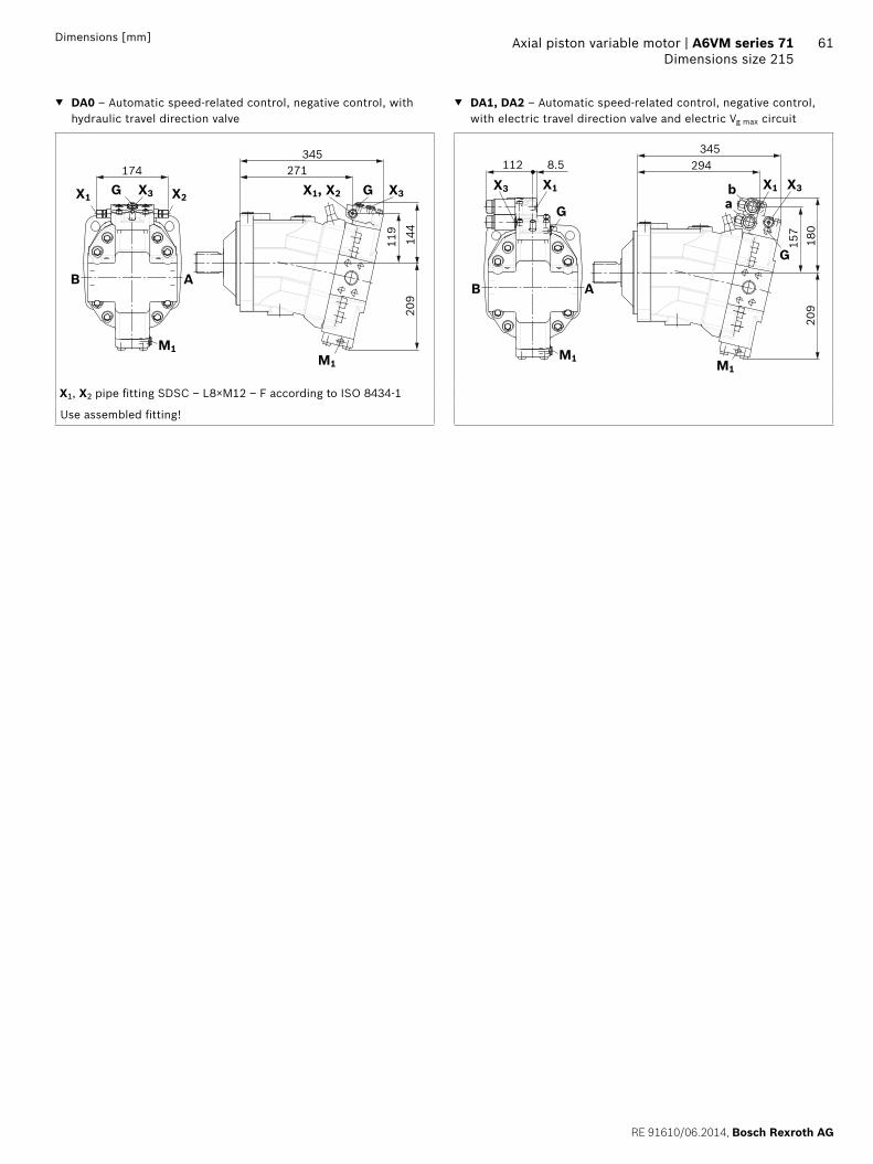
RE 91610062014 Bosch Rexroth AG
Axial piston variable motor | A6VM series 71 Dimensions size 215
61Dimensions [mm]
DA0 ndash Automatic speed-related control negative control with hydraulic travel direction valve
DA1 DA2 ndash Automatic speed-related control negative control with electric travel direction valve and electric Vg max circuit
M1
B A
X1 X2X3G X1 X2 X3G
M1
174 271345
209
144
119
209
180
157
294345
85112
M1
B A
M1
G
X1X3
G
X1 X3
ab
X1 X2 pipe fitting SDSC ndash L8timesM12 ndash F according to ISO 8434-1
Use assembled fitting
Bosch Rexroth AG RE 91610062014
62 A6VM series 71 | Axial piston variable motorConnector for solenoids
Connector for solenoids
DEUTSCH DT04-2P-EP04Molded connector 2-pin without bidirectional suppres-sor diode There is the following type of protection with mounted mating connector
IP67 (DINEN 60529) and IP69K (DIN 40050-9)
Circuit symbol
Mating connector DEUTSCH DT06-2S-EP04
Consisting of DT designation
1 housing DT06-2S-EP04
1 wedge W2S
2 sockets 0462-201-16141
The mating connector is not included in the scope of deliv-ery This can be supplied by Bosch Rexroth on request (material number R902601804)
NoteIf necessary you can change the connector orientation by turning the solenoid housingThe procedure can be taken from the instruction manual
RE 91610062014 Bosch Rexroth AG
Axial piston variable motor | A6VM series 71 Flushing and boost pressure valve
63
Flushing and boost pressure valve
The flushing and boost pressure valve is used to remove heat from the hydraulic circuitIn an open circuit it is used only for flushing the housingIn a closed circuit it ensures a minimum boost pressure level in addition to the case flushingHydraulic fluid is directed from the respective low pressure side into the motor housing This is then fed into the reser-voir together with the leakage The hydraulic fluid removed out of the closed circuit must be replaced by cooled hydraulic fluid from the boost pumpThe valve is mounted onto the port plate or integrated (depending on the control type and size)Cracking pressure of pressure retaining valve(observe when adjusting the primary valve)
Sizes 60 to 215 fixed setting 16 barSwitching pressure of flushing spool Dp
Sizes 60 to 115 (no flushing valve) 8plusmn1 bar Sizes 115 to 215 (medium and large flushing valve)
175plusmn15 barFlushing flow qv
Orifices can be used to adjust the flushing flows as required The following information is based on DpND = pND ndash pG = 25 bar and ν = 10 mm2s (pND = low pressure pG = case pressure)
Small flushing valve for sizes 60 to 115
Material number of orifice oslash [mm] qv [lmin] Code
R909651766 12 35 A
R909419695 14 5 B
R909419696 18 8 C
R909419697 20 10 D
R909444361 24 14 F
Medium flushing valve for size 115
Material number of orifice oslash [mm] qv [lmin] Code
R909431310 28 20 H
R909435172 35 25 J
R909449967 50 30 K
Large flushing valve for sizes 150 to 215
Material number of orifice oslash [mm] qv [lmin] Code
R909449998 18 8 C
R909431308 20 10 D
R909431309 25 17 G
R909431310 28 20 H
R902138235 31 25 J
R909435172 35 30 K
R909436622 40 35 L
R909449967 50 40 M
Schematic EP
G
T2
T1U
Sa
B
A
Vg min
Vg max
M1
Flushing spool
Pressure retain-ing valve
Flushing orifice
Notes Port Sa only for sizes 150 to 215 For a flushing flow greater than 35 l min it is recom-
mended that port Sa be connected in order to prevent an increase in case pressure An increased case pres-sure reduces the flushing flow
Bosch Rexroth AG RE 91610062014
64 A6VM series 71 | Axial piston variable motorFlushing and boost pressure valve
Dimensions [mm]
Dimensions of sizes 60 to 115 (small flushing valve)
A1 A4
HA1 HA2HP1 HP2EP1 EP2
HP5 HP6EP5 EP6DA
HZ7EZ7 EZ8
A3
A2
NG A1 A2 A3 A4
60 245 137 183 236
85 273 142 194 254
115 287 143 202 269
Dimensions for sizes 115 to 215 (large flushing valve)
Sa
Sa
Sa
Z
HA1 HA2HP1 HP2EP1 EP2
HP5 HP6 DAEP5 EP6HZ5 EZ5 EZ6
B4
A2B2
A3B
3
38
A1B1
NG A1 B1 A2 B2 A3 B3 B4
60 325 239 165 142 230 187 166
85 332 246 165 142 233 190 172
115 349 263 172 148 244 201 185
Dimensions of size 115 (medium flushing valve)
205
151
292
HA1 HA2HP1 HP2EP1 EP2
HP5 HP6EP5 EP6DA
NG Sa1)
150
M22 times 15 155 deep170
215
1) ISO 6149 ports plugged (in normal operation) For notes on tightening torques see instruction manual The spot face can be deeper than specified in the appropriate stan-dard
RE 91610062014 Bosch Rexroth AG
Axial piston variable motor | A6VM series 71 Counterbalance valve BVD and BVE
65
Counterbalance valve BVD and BVE
FunctionCounterbalance valves for travel drive and winch operations are designed to reduce the danger of overspeeding and cavitation of axial piston motors in open circuits Cavitation occurs if during braking when driving downhill or the load-lowering process the motor speed is greater than it should be for the given inlet flow causing the inlet pressure to collapseIf the pressure difference between the inflow and the out-flow drops below the value opening end of the piston in the counterbalance valve (see data sheet BVD ndash 95522 or BVE ndash 95525) the counterbalance spool will move to the closed position The cross-sectional area of the counterbalance valve return duct is then reduced creating a bottleneck in the return flow of the hydraulic fluid The pressure increases and brakes the motor until the rotational speed of the motor is again as it should be for the given inlet flow
Notes BVD available for sizes 60 to 215 and BVE available for
sizes 115 to 215 The counterbalance valve must be ordered additionally
We recommend ordering the counterbalance valve and the motor as a set Ordering example A6VM085HA1T30004A71MWV0N4S97W0-0 + BVD20F27S41BndashV03K16D0400S12
For safety reasons control systems with beginning of control at Vg min (z B HA) are not permissible for winch drives
The counterbalance valve does not replace the mechani-cal service brake and parking brake
Observe the detailed notes on the BVD counterbalance valve in data sheet 95522 and on the BVE counterbal-ance valve in data sheet 95525
For the design of the brake release valve we must know for the mechanical parking brake ndash the pressure at the start of opening ndash the volume of the counterbalance spool between
minimum travel (brake closed) and maximum travel (brake released with 21 bar)
ndash the required closing time for a warm device (oil vis-cosity approx 15 mm2s)
Permissible inlet flow or pressure when using DBV and BVDBVE
Without valve Limited values when using DBV and BVDBVE
Motor DBV1) BVD2)BVE3)
NG pnompmax [bar]
qV max [lmin]
NG pnompmax [bar]
qV [lmin]
Code NG pnompmax [bar]
qV [lmin]
Code
60 450500 276 22 350420 240 7 20 (BVD)
350420 220 7W
85 332
115 410 32 400
115 410 8 25 (BVDBVE)
320 8W
150 494
170 533
215 628 On request
1) Pressure-relief valve2) Counterbalance valve double-acting3) Counterbalance valve one-sided
Bosch Rexroth AG RE 91610062014
66 A6VM series 71 | Axial piston variable motorCounterbalance valve BVD and BVE
Counterbalance valve for travel drive BVDFApplication option
Travel drive for wheeled excavators (BVD and BVE)
Example schematic for travel drive on wheeled excavators
A6VM085HA1T30004A71MWV0N4S97W0-0 + BVD20F27S41BndashV03K16D0400S12
Bacute
A
M1
T2
T1
Vg min
Vg max
X
U
G
MB
MA
S
Gext
Gacute
Lacute
Aacute
B
Variable motor A6VMHA1T
Counterbalance valve BVD
Pump directional valve not included in the scope of delivery
Counterbalance valve for winches and track drives BVDW and BVEApplication option
Winch drives in cranes (BVD and BVE) Track drive in excavator crawlers (BVD)
Example schematic for winch drive in cranes
A6VM085HP5D10001A71MWV0N4S97W0-0 + BVE25W38S51ND-V100K00D4599T30S00-0
T2
T1
M1
Vg min
Vg max
B
A
G
X
U
MP1
VGVF
S
Gext
Mk
D
C
Dacute
Cacute
Gacute
Lacute
D1
D2
MB
MA
Variable motor A6VMHP5D
Winch with mechanical parking brake
Counterbalance valve BVE
Pump directional valve not included in the scope of delivery
RE 91610062014 Bosch Rexroth AG
Axial piston variable motor | A6VM series 71 Counterbalance valve BVD and BVE
67Dimensions [mm]
Dimensions
A6VMHA HP1 HP2 and EP1 EP2 A6VMHP5 HP6 and EP5 EP61)
MB (MA)
A BS
A8
B A
Gext
A2A1
A4A3
A6 A5A7
A2A9
MB (MA)
A4A1
0
Br
S
A8
A5 A6A7
B AA B
A6VM Counterbalance valve
NGplate Type Ports Dimensions
A B A1 A2 A3 A4 A5 A6 A7 A8 A9 A10
607 BVD2017 34 in 311 302 143 50 98 139 75 222 326 50
857 BVD2027 1 in 340 331 148 55 98 139 75 222 355 46
1157 BVD2028 1 in 362 353 152 59 98 139 84 234 377 41
1158 BVD2538 1 14 in 380 370 165 63 1205 175 84 238 395 56
1508 BVD2538 1 14 in 411 401 168 67 1205 175 84 238 426 53
1708 BVD2538 1 14 in 417 407 170 68 1205 175 84 238 432 51
2158 BVD2538 1 14 in 448 438 176 74 1205 175 84 299 463 46
1158 BVE2538 1 14 in 380 370 171 63 137 214 84 238 397 63
1508 BVE2538 1 14 in 411 401 175 67 137 214 84 238 423 59
1708 BVE2538 1 14 in 417 407 176 68 137 214 84 238 432 59
2158 BVE2538 1 14 in 448 438 182 74 137 214 84 299 463 52
Ports Version A6VM plate
Standard Size2) Pmax perm [bar]3) Status5)
A B Service line SAE J518 see table above 420 O
S Infeed BVD20 DIN 38524) M22 times 15 14 deep 30 X
BVD25 BVE25 DIN 38524) M27 times 2 16 deep 30 X
Br Brake release reduced high pressure
L 7 DIN 38524) M12 times 15 125 deep 30 O
8 DIN 38524) M12 times 15 12 deep 30 O
Gext Brake release high pressure S DIN 38524) M12 times 15 125 deep 420 X
MA MB Measuring pressure A and B ISO 61494) M18 times 15 145 deep 420 X
1) At the mounting version for the controls HP5 HP6 and EP5 EP6 the cast-in port designations A and B on the counterbalance valve BVD do not correspond with the connection drawing of the A6VM motor The designation of the ports on the installation drawing of the mo-tor is binding
2) For notes on tightening torques see instruction manual
3) Momentary pressure spikes may occur depending on the applica-tion Keep this in mind when selecting measuring devices and fit-tings
4) The spot face can be deeper than specified in the appropriate stan-dard
5) O = Must be connected (plugged on delivery) X = Plugged (in normal operation)
Bosch Rexroth AG RE 91610062014
68 A6VM series 71 | Axial piston variable motorCounterbalance valve BVD and BVE
Mounting the counterbalance valveWhen delivered the counterbalance valve is mounted to the motor with two tacking screws (transport lock) The tack-ing screws may not be removed while mounting the service lines If the counterbalance valve and motor are delivered separately the counterbalance valve must first be mounted to the motor port plate using the provided tacking screws The final mounting of the counterbalance valve on the motor is done with screw fitting of the SAE flange The screws to be used and the procedure mounting can be found in the instruction manual
RE 91610062014 Bosch Rexroth AG
Axial piston variable motor | A6VM series 71 Speed sensor
69
Speed sensor
Version A6VMU (prepared for speed sensor ie without sensor) is equipped with a spline on the rotary groupA signal proportional to motor speed can be generated with the fitted DSADSM speed sensor The DSADSM sensor registers the speed and direction of rotationOrdering code technical data dimensions and details on the connector plus safety instructions about the sensor can be found in the relevant data sheet (95132 for DSM 95133 for DSA)The sensor is mounted on the port provided for this pur-pose with a mounting bolt On deliveries without sensor the port is plugged with a pressure-resistant coverWe recommend ordering the A6VM variable motor complete with mounted sensor
Schematic EP
T2
T1UnU
Dimensions
V design with mounted speed sensor
A
C
B
Size 60 85 115 150 170 215
Number of teeth 54 58 67 72 75 80
A Insertion depth (tolerance -025) 184 184 184 184 184 184
B Contact surface 75 79 88 93 96 101
C 662 752 772 912 917 952
Bosch Rexroth AG RE 91610062014
70 A6VM series 71 | Axial piston variable motorSetting range for displacement
Setting range for displacement
60 85 115
Vg max (cm3rev) Vg min (cm3rev) Vg max (cm3rev) Vg min (cm3rev) Vg max (cm3rev) Vg min (cm3rev)
from to from to from to from to from to from to
A 620 620 00 150 852 852 00 315 1156 1156 00 240
without screw M10 times 60 R909154690
without screw M12 times 70 R909085976
without screw M12 times 70 R909085976
B 620 620 gt 150 305 852 852 gt 315 520 1156 1156 gt 240 475
without screw M10 times 70 R909153779
without screw M12 times 80 R909153075
without screw M12 times 80 R909153075
C 620 620 gt 305 430 852 852 gt 520 590 1156 1156 gt 475 710
without screw M10 times 80 R909154058
without screw M12 times 90 R909154041
without screw M12 times 90 R909154041
D x x x x 1156 1156 gt 710 800
without screw M12 times 100 R909153975
E lt 620 475 00 150 lt 852 555 00 315 lt 1156 935 00 240
M10 times 60 R909154690
M10 times 60 R909154690
M12 times 70 R909085976
M12 times 70 R909085976
M12 times 70 R909085976
M12 times 70 R909085976
F lt 620 475 gt 150 305 lt 852 555 gt 315 520 lt 1156 935 gt 240 475
M10 times 60 R909154690
M10 times 70 R909153779
M12 times 70 R909085976
M12 times 80 R909153075
M12 times 70 R909085976
M12 times 80 R909085976
G lt 620 475 gt 305 430 lt 852 555 gt 520 590 lt 1156 935 gt 475 71
M10 times 60 R909154690
M10 times 80 R909154058
M12 times 70 R909085976
M12 times 90 R909154041
M12 times 70 R909085976
M12 times 90 R909154041
H x x x times lt 1156 935 gt 710 800
M12 times 70 R909085976
M12 times 100 R909153975
J lt 475 330 00 150 lt 555 350 00 315 lt 935 710 00 240
M10 times 70 R909153779
M10 times 60 R909154690
M12 times 80 R909153075
M12 times 70 R909085976
M12 times 80 R909153075
M12 times 70 R909085976
K lt 475 330 gt 150 305 lt 555 350 gt 315 520 lt 935 710 gt 240 475
M10 times 70 R909153779
M10 times 70 R909153779
M12 times 80 R909153075
M12 times 80 R909153075
M12 times 80 R909153075
M12 times 80 R909153075
L lt 475 330 gt 305 430 lt 555 350 gt 520 590 lt 935 710 gt 475 710
M10 times 70 R909153779
M10 times 80 R909154058
M12 times 80 R909153075
M12 times 90 R909154041
M12 times 80 R909153075
M12 times 90 R909154041
M x x x x lt 935 710 gt 710 800
M12 times 80 R909153075
M12 times 100 R909153975
Specify exact settings for Vg min and Vg max in plain text when ordering
Vg min = cm3 Vg max = cm3
Theoretical maximum setting for Vg min = 07 times Vg max
for Vg max = 03 times Vg max
Settings that are not listed in the table may lead to damage Please contact us
RE 91610062014 Bosch Rexroth AG
Axial piston variable motor | A6VM series 71 Setting range for displacement
71
150 170 215
Vg max (cm3rev) Vg min (cm3rev) Vg max (cm3rev) Vg min (cm3rev) Vg max (cm3rev) Vg min (cm3rev)
from to from to from to from to from to from to
A 1521 1521 00 440 1718 1718 00 350 2165 2165 00 445
without screw M12 times 80 R909153075
without screw M12 times 80 R909153075
without screw M12 times 80 R909153075
B 1521 1521 gt 440 690 1718 1718 gt 350 635 2165 2165 gt 445 800
without screw M12 times 90 R909154041
without screw M12 times 90 R909154041
without screw M12 times 90 R909154041
C 1521 1521 gt 690 990 1718 1718 gt 635 980 2165 2165 gt 800 1150
without screw M12 times 100 R909153975
without screw M12 times 100 R909153975
without screw M12 times 100 R909153975
D 1521 1521 gt 990 1060 1718 1718 gt 980 1200 2165 2165 gt 1150 1500
without screw M12 times 110 R909154212
without screw M12 times 110 R909154212
without screw M12 times 110 R909154212
E lt 1521 1110 00 440 lt 1718 1390 00 350 lt 2165 1750 00 445
M12 times 80 R909153075
M12 times 80 R909153075
M12 times 80 R909153075
M10 times 80 R909153075
M12 times 80 R909153075
M12 times 80 R909153075
F lt 1521 1110 gt 440 690 lt 1718 1390 gt 350 635 lt 2165 1750 gt 445 800
M12 times 80 R909153075
M12 times 90 R909085976
M12 times 80 R909153075
M12 times 90 R909154041
M12 times 80 R909153075
M12 times 90 R909154041
G lt 1521 1110 gt 690 990 lt 1718 1390 gt 635 980 lt 2165 1750 gt 800 1150
M12 times 80 R909153075
M12 times 100 R909153975
M12 times 80 R909153075
M12 times 100 R909153975
M12 times 80 R909153075
M12 times 100 R909153975
H lt 1521 1110 gt 990 1060 lt 1718 1390 gt 980 1200 lt 2165 1750 gt 1150 1500
M12 times 80 R909153075
M12 times 110 R909154212
M12 times 80 R909153075
M12 times 110 R909154212
M12 times 80 R909153075
M12 times 110 R909154212
J lt 1110 870 00 440 lt 1390 1120 00 350 lt 1750 1410 00 445
M12 times 90 R909154041
M12 times 80 R909153075
M12 times 90 R909154041
M12 x 80 R909153075
M12 x 90 R909154041
M12 x 80 R909153075
K lt 1110 870 gt 440 690 lt 1390 1120 gt 350 635 lt 1750 1410 gt 445 800
M12 times 90 R909154041
M12 times 90 R909154041
M12 x 90 R909154041
M12 times 90 R909154041
M12 times 90 R909154041
M12 times 90 R909154041
L lt 1110 870 gt 690 990 lt 1390 1120 gt 635 980 lt 1750 1410 gt 800 1150
M12 times 90 R909154041
M12 times 100 R909153975
M12 times 90 R909154041
M12 times 100 R909153975
M12 times 90 R909154041
M12 times 100 R909153975
M lt 1110 870 gt 990 1060 lt 1390 1120 gt 980 1200 lt 1750 1410 gt 1150 1500
M12 times 90 R909154041
M12 times 110 R909154212
M12 times 90 R909154041
M12 times 110 R909154212
M12 times 90 R909154041
M12 times 110 R909154212
Specify exact settings for Vg min and Vg max in plain text when ordering
Vg min = cm3 Vg max = cm3
Theoretical maximum setting for Vg min = 07 times Vg max
for Vg max = 03 times Vg max
Settings that are not listed in the table may lead to damage Please contact us
Bosch Rexroth AG RE 91610062014
72 A6VM series 71 | Axial piston variable motorInstallation instructions
Installation instructions
GeneralDuring commissioning and operation the axial piston unit must be filled with hydraulic fluid and air bled This must also observed following a relatively long standstill as the axial piston unit may drain back to the reservoir via the hydraulic linesParticularly in the installation position drive shaft upwards filling and air bleeding must be carried out com-pletely as there is for example a danger of dry runningThe leakage in the motor housing must be directed to the reservoir via the highest available drain port (T1 T2)To achieve favorable noise values decouple all connecting lines using elastic elements and avoid above-reservoir installation In all operating conditions the drain line must flow into the reservoir below the minimum fluid level
NoteIn certain installation conditions an influence on the control charakteristic curves can be expected Gravity dead weight and case pressure can cause minor shifts in characteristics and changes in response time
Key
U Bearing flushing air bleed port
T1 T2 Drain port
ht min Minimum required immersion depth (200 mm)
hmin Minimum required spacing to reservoir bottom (100 mm)
Installation position See examples 1 to 8 below Additional installation positions are available upon requestRecommended installation position 1 and 2
Below-reservoir installation (standard)Below-reservoir installation means that the axial piston unit is installed outside of the reservoir below the minimum fluid level
Installation position Air bleed Filling
1
T2
T1U
ht min
hmin
T1
2
T2
T1 U
ht min
hmin
T2
3
T2
T1
U
ht min
hmin
T1
4
T2
T1
U
ht min
hmin
U T1
RE 91610062014 Bosch Rexroth AG
Axial piston variable motor | A6VM series 71 Installation instructions
73
Above-reservoir installationAbove-reservoir installation means that the axial piston unit is installed above the minimum fluid level of the reservoirRecommendation for installation position 8 (drive shaft upward) A check valve in the drain line (cracking pressure 05 bar) can prevent draining of the motor housing
Installation position Air bleed Filling
5
T2
T1U
L1
ht min
hmin
U (L1) T1 (L1)
6
T2
T1 U
L1
ht min
hmin
L1 T2 (L1)
7
T2T1
U
L1
ht min
hmin
L1 T1 (L1)
8
T2T1
UL1
05
bar
ht min
hmin
U T1 (L1)
NotePort L1 is not part of the motor and can be made available by the customer for straightforward filling and air bleed-ing
74
Bosch Rexroth AG RE 91610062014
Bosch Rexroth AGMobile ApplicationsGlockeraustraszlige 489275 Elchingen GermanyTel +49-7308-82-0infomaboschrexrothdewwwboschrexrothcom
copy This document as well as the data specifications and other information set forth in it are the exclusive property of Bosch Rexroth AG It may not be reproduced or given to third parties without its consent The data specified above only serve to describe the product No statements concerning a certain condition or suitability for a certain application can be derived from our information The information given does not release the user from the obligation of own judgment and verification It must be remembered that our products are subject to a natural process of wear and aging
A6VM series 71 | Axial piston variable motorProject planning note
Project planning note
The motor A6VM is designed to be used in open and closed circuits
The project planning installation and commissioning of the axial piston unit requires the involvement of quali-fied skilled person
Before using the axial piston unit please read the cor-responding instruction manual completely and thor-oughly If necessary these can be requested from Bosch Rexroth
Before finalizing your design request a binding installa-tion drawing
The data and notes contained herein must be adhered to
For safety reasons control systems with beginning of control at Vg min (eg HA) are not permissible for winch drives eg anchor winches
Depending on the operating conditions of the axial piston unit (operating pressure fluid temperature) the charakteristic curve may shift
Not all variants of the product are approved for use in safety functions according to ISO 13849 Please consult the responsible contact person at Bosch Rexroth if you require reliability parameters (eg MTTFd) for functional safety
Working ports ndash The ports and fastening threads are designed for the
specified maximum pressure The machine or system manufacturer must ensure that the connecting ele-ments and lines correspond to the specified applica-tion conditions (pressure flow hydraulic fluid tem-perature) with the necessary safety factors
ndash The working ports and function ports can only be used to accommodate hydraulic lines
Safety instructions
During and shortly after operation there is a risk of burns on the axial piston unit and especially on the solenoids Take appropriate safety measures (e g by wearing protective clothing)
Moving parts in control and regulation systems (eg valve spools) may in certain circumstances become stuck in an undefined position due to contamination (eg contaminated hydraulic fluid abrasion or residual dirt from components) As a result the hydraulic fluid flow or build-up of torque of the axial piston unit will no longer respond correctly to the operators commands Even the use of different filter cartridges (external or internal inlet filter) will not rule out a fault but merely minimize the risk The machinesystem manufacturer must test whether remedial measures are needed on the machine for the application concerned in order to set the consumer being driven to a safe position (eg safe stop) and if necessary to ensure it is properly imple-mented
If the axial piston motor is used in winch drives make sure that the technical limit values are not exceeded under all operating conditions If the axial piston motor is subjected to external overload (eg by exceeding the maximum permissible rotational speeds when lifting anchor while the ship is in motion) this could cause damage to the rotary group and in unfavorable cases to the axial piston motor bursting If necessary additional measures up to an including encapsulation are to be implemented by the machinesystem manufacturer
RE 91610062014 Bosch Rexroth AG
75 Axial piston variable motor | A6VM series 71
76
Bosch Rexroth AG RE 91610062014
Bosch Rexroth AGMobile ApplicationsGlockeraustraszlige 489275 Elchingen GermanyTel +49-7308-82-0infomaboschrexrothdewwwboschrexrothcom
copy This document as well as the data specifications and other information set forth in it are the exclusive property of Bosch Rexroth AG It may not be reproduced or given to third parties without its consent The data specified above only serve to describe the product No statements concerning a certain condition or suitability for a certain application can be derived from our information The information given does not release the user from the obligation of own judgment and verification It must be remembered that our products are subject to a natural process of wear and aging
A6VM series 71 | axial piston variable motor

Bosch Rexroth AG RE 91610062014
62 A6VM series 71 | Axial piston variable motorConnector for solenoids
Connector for solenoids
DEUTSCH DT04-2P-EP04Molded connector 2-pin without bidirectional suppres-sor diode There is the following type of protection with mounted mating connector
IP67 (DINEN 60529) and IP69K (DIN 40050-9)
Circuit symbol
Mating connector DEUTSCH DT06-2S-EP04
Consisting of DT designation
1 housing DT06-2S-EP04
1 wedge W2S
2 sockets 0462-201-16141
The mating connector is not included in the scope of deliv-ery This can be supplied by Bosch Rexroth on request (material number R902601804)
NoteIf necessary you can change the connector orientation by turning the solenoid housingThe procedure can be taken from the instruction manual
RE 91610062014 Bosch Rexroth AG
Axial piston variable motor | A6VM series 71 Flushing and boost pressure valve
63
Flushing and boost pressure valve
The flushing and boost pressure valve is used to remove heat from the hydraulic circuitIn an open circuit it is used only for flushing the housingIn a closed circuit it ensures a minimum boost pressure level in addition to the case flushingHydraulic fluid is directed from the respective low pressure side into the motor housing This is then fed into the reser-voir together with the leakage The hydraulic fluid removed out of the closed circuit must be replaced by cooled hydraulic fluid from the boost pumpThe valve is mounted onto the port plate or integrated (depending on the control type and size)Cracking pressure of pressure retaining valve(observe when adjusting the primary valve)
Sizes 60 to 215 fixed setting 16 barSwitching pressure of flushing spool Dp
Sizes 60 to 115 (no flushing valve) 8plusmn1 bar Sizes 115 to 215 (medium and large flushing valve)
175plusmn15 barFlushing flow qv
Orifices can be used to adjust the flushing flows as required The following information is based on DpND = pND ndash pG = 25 bar and ν = 10 mm2s (pND = low pressure pG = case pressure)
Small flushing valve for sizes 60 to 115
Material number of orifice oslash [mm] qv [lmin] Code
R909651766 12 35 A
R909419695 14 5 B
R909419696 18 8 C
R909419697 20 10 D
R909444361 24 14 F
Medium flushing valve for size 115
Material number of orifice oslash [mm] qv [lmin] Code
R909431310 28 20 H
R909435172 35 25 J
R909449967 50 30 K
Large flushing valve for sizes 150 to 215
Material number of orifice oslash [mm] qv [lmin] Code
R909449998 18 8 C
R909431308 20 10 D
R909431309 25 17 G
R909431310 28 20 H
R902138235 31 25 J
R909435172 35 30 K
R909436622 40 35 L
R909449967 50 40 M
Schematic EP
G
T2
T1U
Sa
B
A
Vg min
Vg max
M1
Flushing spool
Pressure retain-ing valve
Flushing orifice
Notes Port Sa only for sizes 150 to 215 For a flushing flow greater than 35 l min it is recom-
mended that port Sa be connected in order to prevent an increase in case pressure An increased case pres-sure reduces the flushing flow
Bosch Rexroth AG RE 91610062014
64 A6VM series 71 | Axial piston variable motorFlushing and boost pressure valve
Dimensions [mm]
Dimensions of sizes 60 to 115 (small flushing valve)
A1 A4
HA1 HA2HP1 HP2EP1 EP2
HP5 HP6EP5 EP6DA
HZ7EZ7 EZ8
A3
A2
NG A1 A2 A3 A4
60 245 137 183 236
85 273 142 194 254
115 287 143 202 269
Dimensions for sizes 115 to 215 (large flushing valve)
Sa
Sa
Sa
Z
HA1 HA2HP1 HP2EP1 EP2
HP5 HP6 DAEP5 EP6HZ5 EZ5 EZ6
B4
A2B2
A3B
3
38
A1B1
NG A1 B1 A2 B2 A3 B3 B4
60 325 239 165 142 230 187 166
85 332 246 165 142 233 190 172
115 349 263 172 148 244 201 185
Dimensions of size 115 (medium flushing valve)
205
151
292
HA1 HA2HP1 HP2EP1 EP2
HP5 HP6EP5 EP6DA
NG Sa1)
150
M22 times 15 155 deep170
215
1) ISO 6149 ports plugged (in normal operation) For notes on tightening torques see instruction manual The spot face can be deeper than specified in the appropriate stan-dard
RE 91610062014 Bosch Rexroth AG
Axial piston variable motor | A6VM series 71 Counterbalance valve BVD and BVE
65
Counterbalance valve BVD and BVE
FunctionCounterbalance valves for travel drive and winch operations are designed to reduce the danger of overspeeding and cavitation of axial piston motors in open circuits Cavitation occurs if during braking when driving downhill or the load-lowering process the motor speed is greater than it should be for the given inlet flow causing the inlet pressure to collapseIf the pressure difference between the inflow and the out-flow drops below the value opening end of the piston in the counterbalance valve (see data sheet BVD ndash 95522 or BVE ndash 95525) the counterbalance spool will move to the closed position The cross-sectional area of the counterbalance valve return duct is then reduced creating a bottleneck in the return flow of the hydraulic fluid The pressure increases and brakes the motor until the rotational speed of the motor is again as it should be for the given inlet flow
Notes BVD available for sizes 60 to 215 and BVE available for
sizes 115 to 215 The counterbalance valve must be ordered additionally
We recommend ordering the counterbalance valve and the motor as a set Ordering example A6VM085HA1T30004A71MWV0N4S97W0-0 + BVD20F27S41BndashV03K16D0400S12
For safety reasons control systems with beginning of control at Vg min (z B HA) are not permissible for winch drives
The counterbalance valve does not replace the mechani-cal service brake and parking brake
Observe the detailed notes on the BVD counterbalance valve in data sheet 95522 and on the BVE counterbal-ance valve in data sheet 95525
For the design of the brake release valve we must know for the mechanical parking brake ndash the pressure at the start of opening ndash the volume of the counterbalance spool between
minimum travel (brake closed) and maximum travel (brake released with 21 bar)
ndash the required closing time for a warm device (oil vis-cosity approx 15 mm2s)
Permissible inlet flow or pressure when using DBV and BVDBVE
Without valve Limited values when using DBV and BVDBVE
Motor DBV1) BVD2)BVE3)
NG pnompmax [bar]
qV max [lmin]
NG pnompmax [bar]
qV [lmin]
Code NG pnompmax [bar]
qV [lmin]
Code
60 450500 276 22 350420 240 7 20 (BVD)
350420 220 7W
85 332
115 410 32 400
115 410 8 25 (BVDBVE)
320 8W
150 494
170 533
215 628 On request
1) Pressure-relief valve2) Counterbalance valve double-acting3) Counterbalance valve one-sided
Bosch Rexroth AG RE 91610062014
66 A6VM series 71 | Axial piston variable motorCounterbalance valve BVD and BVE
Counterbalance valve for travel drive BVDFApplication option
Travel drive for wheeled excavators (BVD and BVE)
Example schematic for travel drive on wheeled excavators
A6VM085HA1T30004A71MWV0N4S97W0-0 + BVD20F27S41BndashV03K16D0400S12
Bacute
A
M1
T2
T1
Vg min
Vg max
X
U
G
MB
MA
S
Gext
Gacute
Lacute
Aacute
B
Variable motor A6VMHA1T
Counterbalance valve BVD
Pump directional valve not included in the scope of delivery
Counterbalance valve for winches and track drives BVDW and BVEApplication option
Winch drives in cranes (BVD and BVE) Track drive in excavator crawlers (BVD)
Example schematic for winch drive in cranes
A6VM085HP5D10001A71MWV0N4S97W0-0 + BVE25W38S51ND-V100K00D4599T30S00-0
T2
T1
M1
Vg min
Vg max
B
A
G
X
U
MP1
VGVF
S
Gext
Mk
D
C
Dacute
Cacute
Gacute
Lacute
D1
D2
MB
MA
Variable motor A6VMHP5D
Winch with mechanical parking brake
Counterbalance valve BVE
Pump directional valve not included in the scope of delivery
RE 91610062014 Bosch Rexroth AG
Axial piston variable motor | A6VM series 71 Counterbalance valve BVD and BVE
67Dimensions [mm]
Dimensions
A6VMHA HP1 HP2 and EP1 EP2 A6VMHP5 HP6 and EP5 EP61)
MB (MA)
A BS
A8
B A
Gext
A2A1
A4A3
A6 A5A7
A2A9
MB (MA)
A4A1
0
Br
S
A8
A5 A6A7
B AA B
A6VM Counterbalance valve
NGplate Type Ports Dimensions
A B A1 A2 A3 A4 A5 A6 A7 A8 A9 A10
607 BVD2017 34 in 311 302 143 50 98 139 75 222 326 50
857 BVD2027 1 in 340 331 148 55 98 139 75 222 355 46
1157 BVD2028 1 in 362 353 152 59 98 139 84 234 377 41
1158 BVD2538 1 14 in 380 370 165 63 1205 175 84 238 395 56
1508 BVD2538 1 14 in 411 401 168 67 1205 175 84 238 426 53
1708 BVD2538 1 14 in 417 407 170 68 1205 175 84 238 432 51
2158 BVD2538 1 14 in 448 438 176 74 1205 175 84 299 463 46
1158 BVE2538 1 14 in 380 370 171 63 137 214 84 238 397 63
1508 BVE2538 1 14 in 411 401 175 67 137 214 84 238 423 59
1708 BVE2538 1 14 in 417 407 176 68 137 214 84 238 432 59
2158 BVE2538 1 14 in 448 438 182 74 137 214 84 299 463 52
Ports Version A6VM plate
Standard Size2) Pmax perm [bar]3) Status5)
A B Service line SAE J518 see table above 420 O
S Infeed BVD20 DIN 38524) M22 times 15 14 deep 30 X
BVD25 BVE25 DIN 38524) M27 times 2 16 deep 30 X
Br Brake release reduced high pressure
L 7 DIN 38524) M12 times 15 125 deep 30 O
8 DIN 38524) M12 times 15 12 deep 30 O
Gext Brake release high pressure S DIN 38524) M12 times 15 125 deep 420 X
MA MB Measuring pressure A and B ISO 61494) M18 times 15 145 deep 420 X
1) At the mounting version for the controls HP5 HP6 and EP5 EP6 the cast-in port designations A and B on the counterbalance valve BVD do not correspond with the connection drawing of the A6VM motor The designation of the ports on the installation drawing of the mo-tor is binding
2) For notes on tightening torques see instruction manual
3) Momentary pressure spikes may occur depending on the applica-tion Keep this in mind when selecting measuring devices and fit-tings
4) The spot face can be deeper than specified in the appropriate stan-dard
5) O = Must be connected (plugged on delivery) X = Plugged (in normal operation)
Bosch Rexroth AG RE 91610062014
68 A6VM series 71 | Axial piston variable motorCounterbalance valve BVD and BVE
Mounting the counterbalance valveWhen delivered the counterbalance valve is mounted to the motor with two tacking screws (transport lock) The tack-ing screws may not be removed while mounting the service lines If the counterbalance valve and motor are delivered separately the counterbalance valve must first be mounted to the motor port plate using the provided tacking screws The final mounting of the counterbalance valve on the motor is done with screw fitting of the SAE flange The screws to be used and the procedure mounting can be found in the instruction manual
RE 91610062014 Bosch Rexroth AG
Axial piston variable motor | A6VM series 71 Speed sensor
69
Speed sensor
Version A6VMU (prepared for speed sensor ie without sensor) is equipped with a spline on the rotary groupA signal proportional to motor speed can be generated with the fitted DSADSM speed sensor The DSADSM sensor registers the speed and direction of rotationOrdering code technical data dimensions and details on the connector plus safety instructions about the sensor can be found in the relevant data sheet (95132 for DSM 95133 for DSA)The sensor is mounted on the port provided for this pur-pose with a mounting bolt On deliveries without sensor the port is plugged with a pressure-resistant coverWe recommend ordering the A6VM variable motor complete with mounted sensor
Schematic EP
T2
T1UnU
Dimensions
V design with mounted speed sensor
A
C
B
Size 60 85 115 150 170 215
Number of teeth 54 58 67 72 75 80
A Insertion depth (tolerance -025) 184 184 184 184 184 184
B Contact surface 75 79 88 93 96 101
C 662 752 772 912 917 952
Bosch Rexroth AG RE 91610062014
70 A6VM series 71 | Axial piston variable motorSetting range for displacement
Setting range for displacement
60 85 115
Vg max (cm3rev) Vg min (cm3rev) Vg max (cm3rev) Vg min (cm3rev) Vg max (cm3rev) Vg min (cm3rev)
from to from to from to from to from to from to
A 620 620 00 150 852 852 00 315 1156 1156 00 240
without screw M10 times 60 R909154690
without screw M12 times 70 R909085976
without screw M12 times 70 R909085976
B 620 620 gt 150 305 852 852 gt 315 520 1156 1156 gt 240 475
without screw M10 times 70 R909153779
without screw M12 times 80 R909153075
without screw M12 times 80 R909153075
C 620 620 gt 305 430 852 852 gt 520 590 1156 1156 gt 475 710
without screw M10 times 80 R909154058
without screw M12 times 90 R909154041
without screw M12 times 90 R909154041
D x x x x 1156 1156 gt 710 800
without screw M12 times 100 R909153975
E lt 620 475 00 150 lt 852 555 00 315 lt 1156 935 00 240
M10 times 60 R909154690
M10 times 60 R909154690
M12 times 70 R909085976
M12 times 70 R909085976
M12 times 70 R909085976
M12 times 70 R909085976
F lt 620 475 gt 150 305 lt 852 555 gt 315 520 lt 1156 935 gt 240 475
M10 times 60 R909154690
M10 times 70 R909153779
M12 times 70 R909085976
M12 times 80 R909153075
M12 times 70 R909085976
M12 times 80 R909085976
G lt 620 475 gt 305 430 lt 852 555 gt 520 590 lt 1156 935 gt 475 71
M10 times 60 R909154690
M10 times 80 R909154058
M12 times 70 R909085976
M12 times 90 R909154041
M12 times 70 R909085976
M12 times 90 R909154041
H x x x times lt 1156 935 gt 710 800
M12 times 70 R909085976
M12 times 100 R909153975
J lt 475 330 00 150 lt 555 350 00 315 lt 935 710 00 240
M10 times 70 R909153779
M10 times 60 R909154690
M12 times 80 R909153075
M12 times 70 R909085976
M12 times 80 R909153075
M12 times 70 R909085976
K lt 475 330 gt 150 305 lt 555 350 gt 315 520 lt 935 710 gt 240 475
M10 times 70 R909153779
M10 times 70 R909153779
M12 times 80 R909153075
M12 times 80 R909153075
M12 times 80 R909153075
M12 times 80 R909153075
L lt 475 330 gt 305 430 lt 555 350 gt 520 590 lt 935 710 gt 475 710
M10 times 70 R909153779
M10 times 80 R909154058
M12 times 80 R909153075
M12 times 90 R909154041
M12 times 80 R909153075
M12 times 90 R909154041
M x x x x lt 935 710 gt 710 800
M12 times 80 R909153075
M12 times 100 R909153975
Specify exact settings for Vg min and Vg max in plain text when ordering
Vg min = cm3 Vg max = cm3
Theoretical maximum setting for Vg min = 07 times Vg max
for Vg max = 03 times Vg max
Settings that are not listed in the table may lead to damage Please contact us
RE 91610062014 Bosch Rexroth AG
Axial piston variable motor | A6VM series 71 Setting range for displacement
71
150 170 215
Vg max (cm3rev) Vg min (cm3rev) Vg max (cm3rev) Vg min (cm3rev) Vg max (cm3rev) Vg min (cm3rev)
from to from to from to from to from to from to
A 1521 1521 00 440 1718 1718 00 350 2165 2165 00 445
without screw M12 times 80 R909153075
without screw M12 times 80 R909153075
without screw M12 times 80 R909153075
B 1521 1521 gt 440 690 1718 1718 gt 350 635 2165 2165 gt 445 800
without screw M12 times 90 R909154041
without screw M12 times 90 R909154041
without screw M12 times 90 R909154041
C 1521 1521 gt 690 990 1718 1718 gt 635 980 2165 2165 gt 800 1150
without screw M12 times 100 R909153975
without screw M12 times 100 R909153975
without screw M12 times 100 R909153975
D 1521 1521 gt 990 1060 1718 1718 gt 980 1200 2165 2165 gt 1150 1500
without screw M12 times 110 R909154212
without screw M12 times 110 R909154212
without screw M12 times 110 R909154212
E lt 1521 1110 00 440 lt 1718 1390 00 350 lt 2165 1750 00 445
M12 times 80 R909153075
M12 times 80 R909153075
M12 times 80 R909153075
M10 times 80 R909153075
M12 times 80 R909153075
M12 times 80 R909153075
F lt 1521 1110 gt 440 690 lt 1718 1390 gt 350 635 lt 2165 1750 gt 445 800
M12 times 80 R909153075
M12 times 90 R909085976
M12 times 80 R909153075
M12 times 90 R909154041
M12 times 80 R909153075
M12 times 90 R909154041
G lt 1521 1110 gt 690 990 lt 1718 1390 gt 635 980 lt 2165 1750 gt 800 1150
M12 times 80 R909153075
M12 times 100 R909153975
M12 times 80 R909153075
M12 times 100 R909153975
M12 times 80 R909153075
M12 times 100 R909153975
H lt 1521 1110 gt 990 1060 lt 1718 1390 gt 980 1200 lt 2165 1750 gt 1150 1500
M12 times 80 R909153075
M12 times 110 R909154212
M12 times 80 R909153075
M12 times 110 R909154212
M12 times 80 R909153075
M12 times 110 R909154212
J lt 1110 870 00 440 lt 1390 1120 00 350 lt 1750 1410 00 445
M12 times 90 R909154041
M12 times 80 R909153075
M12 times 90 R909154041
M12 x 80 R909153075
M12 x 90 R909154041
M12 x 80 R909153075
K lt 1110 870 gt 440 690 lt 1390 1120 gt 350 635 lt 1750 1410 gt 445 800
M12 times 90 R909154041
M12 times 90 R909154041
M12 x 90 R909154041
M12 times 90 R909154041
M12 times 90 R909154041
M12 times 90 R909154041
L lt 1110 870 gt 690 990 lt 1390 1120 gt 635 980 lt 1750 1410 gt 800 1150
M12 times 90 R909154041
M12 times 100 R909153975
M12 times 90 R909154041
M12 times 100 R909153975
M12 times 90 R909154041
M12 times 100 R909153975
M lt 1110 870 gt 990 1060 lt 1390 1120 gt 980 1200 lt 1750 1410 gt 1150 1500
M12 times 90 R909154041
M12 times 110 R909154212
M12 times 90 R909154041
M12 times 110 R909154212
M12 times 90 R909154041
M12 times 110 R909154212
Specify exact settings for Vg min and Vg max in plain text when ordering
Vg min = cm3 Vg max = cm3
Theoretical maximum setting for Vg min = 07 times Vg max
for Vg max = 03 times Vg max
Settings that are not listed in the table may lead to damage Please contact us
Bosch Rexroth AG RE 91610062014
72 A6VM series 71 | Axial piston variable motorInstallation instructions
Installation instructions
GeneralDuring commissioning and operation the axial piston unit must be filled with hydraulic fluid and air bled This must also observed following a relatively long standstill as the axial piston unit may drain back to the reservoir via the hydraulic linesParticularly in the installation position drive shaft upwards filling and air bleeding must be carried out com-pletely as there is for example a danger of dry runningThe leakage in the motor housing must be directed to the reservoir via the highest available drain port (T1 T2)To achieve favorable noise values decouple all connecting lines using elastic elements and avoid above-reservoir installation In all operating conditions the drain line must flow into the reservoir below the minimum fluid level
NoteIn certain installation conditions an influence on the control charakteristic curves can be expected Gravity dead weight and case pressure can cause minor shifts in characteristics and changes in response time
Key
U Bearing flushing air bleed port
T1 T2 Drain port
ht min Minimum required immersion depth (200 mm)
hmin Minimum required spacing to reservoir bottom (100 mm)
Installation position See examples 1 to 8 below Additional installation positions are available upon requestRecommended installation position 1 and 2
Below-reservoir installation (standard)Below-reservoir installation means that the axial piston unit is installed outside of the reservoir below the minimum fluid level
Installation position Air bleed Filling
1
T2
T1U
ht min
hmin
T1
2
T2
T1 U
ht min
hmin
T2
3
T2
T1
U
ht min
hmin
T1
4
T2
T1
U
ht min
hmin
U T1
RE 91610062014 Bosch Rexroth AG
Axial piston variable motor | A6VM series 71 Installation instructions
73
Above-reservoir installationAbove-reservoir installation means that the axial piston unit is installed above the minimum fluid level of the reservoirRecommendation for installation position 8 (drive shaft upward) A check valve in the drain line (cracking pressure 05 bar) can prevent draining of the motor housing
Installation position Air bleed Filling
5
T2
T1U
L1
ht min
hmin
U (L1) T1 (L1)
6
T2
T1 U
L1
ht min
hmin
L1 T2 (L1)
7
T2T1
U
L1
ht min
hmin
L1 T1 (L1)
8
T2T1
UL1
05
bar
ht min
hmin
U T1 (L1)
NotePort L1 is not part of the motor and can be made available by the customer for straightforward filling and air bleed-ing
74
Bosch Rexroth AG RE 91610062014
Bosch Rexroth AGMobile ApplicationsGlockeraustraszlige 489275 Elchingen GermanyTel +49-7308-82-0infomaboschrexrothdewwwboschrexrothcom
copy This document as well as the data specifications and other information set forth in it are the exclusive property of Bosch Rexroth AG It may not be reproduced or given to third parties without its consent The data specified above only serve to describe the product No statements concerning a certain condition or suitability for a certain application can be derived from our information The information given does not release the user from the obligation of own judgment and verification It must be remembered that our products are subject to a natural process of wear and aging
A6VM series 71 | Axial piston variable motorProject planning note
Project planning note
The motor A6VM is designed to be used in open and closed circuits
The project planning installation and commissioning of the axial piston unit requires the involvement of quali-fied skilled person
Before using the axial piston unit please read the cor-responding instruction manual completely and thor-oughly If necessary these can be requested from Bosch Rexroth
Before finalizing your design request a binding installa-tion drawing
The data and notes contained herein must be adhered to
For safety reasons control systems with beginning of control at Vg min (eg HA) are not permissible for winch drives eg anchor winches
Depending on the operating conditions of the axial piston unit (operating pressure fluid temperature) the charakteristic curve may shift
Not all variants of the product are approved for use in safety functions according to ISO 13849 Please consult the responsible contact person at Bosch Rexroth if you require reliability parameters (eg MTTFd) for functional safety
Working ports ndash The ports and fastening threads are designed for the
specified maximum pressure The machine or system manufacturer must ensure that the connecting ele-ments and lines correspond to the specified applica-tion conditions (pressure flow hydraulic fluid tem-perature) with the necessary safety factors
ndash The working ports and function ports can only be used to accommodate hydraulic lines
Safety instructions
During and shortly after operation there is a risk of burns on the axial piston unit and especially on the solenoids Take appropriate safety measures (e g by wearing protective clothing)
Moving parts in control and regulation systems (eg valve spools) may in certain circumstances become stuck in an undefined position due to contamination (eg contaminated hydraulic fluid abrasion or residual dirt from components) As a result the hydraulic fluid flow or build-up of torque of the axial piston unit will no longer respond correctly to the operators commands Even the use of different filter cartridges (external or internal inlet filter) will not rule out a fault but merely minimize the risk The machinesystem manufacturer must test whether remedial measures are needed on the machine for the application concerned in order to set the consumer being driven to a safe position (eg safe stop) and if necessary to ensure it is properly imple-mented
If the axial piston motor is used in winch drives make sure that the technical limit values are not exceeded under all operating conditions If the axial piston motor is subjected to external overload (eg by exceeding the maximum permissible rotational speeds when lifting anchor while the ship is in motion) this could cause damage to the rotary group and in unfavorable cases to the axial piston motor bursting If necessary additional measures up to an including encapsulation are to be implemented by the machinesystem manufacturer
RE 91610062014 Bosch Rexroth AG
75 Axial piston variable motor | A6VM series 71
76
Bosch Rexroth AG RE 91610062014
Bosch Rexroth AGMobile ApplicationsGlockeraustraszlige 489275 Elchingen GermanyTel +49-7308-82-0infomaboschrexrothdewwwboschrexrothcom
copy This document as well as the data specifications and other information set forth in it are the exclusive property of Bosch Rexroth AG It may not be reproduced or given to third parties without its consent The data specified above only serve to describe the product No statements concerning a certain condition or suitability for a certain application can be derived from our information The information given does not release the user from the obligation of own judgment and verification It must be remembered that our products are subject to a natural process of wear and aging
A6VM series 71 | axial piston variable motor

RE 91610062014 Bosch Rexroth AG
Axial piston variable motor | A6VM series 71 Flushing and boost pressure valve
63
Flushing and boost pressure valve
The flushing and boost pressure valve is used to remove heat from the hydraulic circuitIn an open circuit it is used only for flushing the housingIn a closed circuit it ensures a minimum boost pressure level in addition to the case flushingHydraulic fluid is directed from the respective low pressure side into the motor housing This is then fed into the reser-voir together with the leakage The hydraulic fluid removed out of the closed circuit must be replaced by cooled hydraulic fluid from the boost pumpThe valve is mounted onto the port plate or integrated (depending on the control type and size)Cracking pressure of pressure retaining valve(observe when adjusting the primary valve)
Sizes 60 to 215 fixed setting 16 barSwitching pressure of flushing spool Dp
Sizes 60 to 115 (no flushing valve) 8plusmn1 bar Sizes 115 to 215 (medium and large flushing valve)
175plusmn15 barFlushing flow qv
Orifices can be used to adjust the flushing flows as required The following information is based on DpND = pND ndash pG = 25 bar and ν = 10 mm2s (pND = low pressure pG = case pressure)
Small flushing valve for sizes 60 to 115
Material number of orifice oslash [mm] qv [lmin] Code
R909651766 12 35 A
R909419695 14 5 B
R909419696 18 8 C
R909419697 20 10 D
R909444361 24 14 F
Medium flushing valve for size 115
Material number of orifice oslash [mm] qv [lmin] Code
R909431310 28 20 H
R909435172 35 25 J
R909449967 50 30 K
Large flushing valve for sizes 150 to 215
Material number of orifice oslash [mm] qv [lmin] Code
R909449998 18 8 C
R909431308 20 10 D
R909431309 25 17 G
R909431310 28 20 H
R902138235 31 25 J
R909435172 35 30 K
R909436622 40 35 L
R909449967 50 40 M
Schematic EP
G
T2
T1U
Sa
B
A
Vg min
Vg max
M1
Flushing spool
Pressure retain-ing valve
Flushing orifice
Notes Port Sa only for sizes 150 to 215 For a flushing flow greater than 35 l min it is recom-
mended that port Sa be connected in order to prevent an increase in case pressure An increased case pres-sure reduces the flushing flow
Bosch Rexroth AG RE 91610062014
64 A6VM series 71 | Axial piston variable motorFlushing and boost pressure valve
Dimensions [mm]
Dimensions of sizes 60 to 115 (small flushing valve)
A1 A4
HA1 HA2HP1 HP2EP1 EP2
HP5 HP6EP5 EP6DA
HZ7EZ7 EZ8
A3
A2
NG A1 A2 A3 A4
60 245 137 183 236
85 273 142 194 254
115 287 143 202 269
Dimensions for sizes 115 to 215 (large flushing valve)
Sa
Sa
Sa
Z
HA1 HA2HP1 HP2EP1 EP2
HP5 HP6 DAEP5 EP6HZ5 EZ5 EZ6
B4
A2B2
A3B
3
38
A1B1
NG A1 B1 A2 B2 A3 B3 B4
60 325 239 165 142 230 187 166
85 332 246 165 142 233 190 172
115 349 263 172 148 244 201 185
Dimensions of size 115 (medium flushing valve)
205
151
292
HA1 HA2HP1 HP2EP1 EP2
HP5 HP6EP5 EP6DA
NG Sa1)
150
M22 times 15 155 deep170
215
1) ISO 6149 ports plugged (in normal operation) For notes on tightening torques see instruction manual The spot face can be deeper than specified in the appropriate stan-dard
RE 91610062014 Bosch Rexroth AG
Axial piston variable motor | A6VM series 71 Counterbalance valve BVD and BVE
65
Counterbalance valve BVD and BVE
FunctionCounterbalance valves for travel drive and winch operations are designed to reduce the danger of overspeeding and cavitation of axial piston motors in open circuits Cavitation occurs if during braking when driving downhill or the load-lowering process the motor speed is greater than it should be for the given inlet flow causing the inlet pressure to collapseIf the pressure difference between the inflow and the out-flow drops below the value opening end of the piston in the counterbalance valve (see data sheet BVD ndash 95522 or BVE ndash 95525) the counterbalance spool will move to the closed position The cross-sectional area of the counterbalance valve return duct is then reduced creating a bottleneck in the return flow of the hydraulic fluid The pressure increases and brakes the motor until the rotational speed of the motor is again as it should be for the given inlet flow
Notes BVD available for sizes 60 to 215 and BVE available for
sizes 115 to 215 The counterbalance valve must be ordered additionally
We recommend ordering the counterbalance valve and the motor as a set Ordering example A6VM085HA1T30004A71MWV0N4S97W0-0 + BVD20F27S41BndashV03K16D0400S12
For safety reasons control systems with beginning of control at Vg min (z B HA) are not permissible for winch drives
The counterbalance valve does not replace the mechani-cal service brake and parking brake
Observe the detailed notes on the BVD counterbalance valve in data sheet 95522 and on the BVE counterbal-ance valve in data sheet 95525
For the design of the brake release valve we must know for the mechanical parking brake ndash the pressure at the start of opening ndash the volume of the counterbalance spool between
minimum travel (brake closed) and maximum travel (brake released with 21 bar)
ndash the required closing time for a warm device (oil vis-cosity approx 15 mm2s)
Permissible inlet flow or pressure when using DBV and BVDBVE
Without valve Limited values when using DBV and BVDBVE
Motor DBV1) BVD2)BVE3)
NG pnompmax [bar]
qV max [lmin]
NG pnompmax [bar]
qV [lmin]
Code NG pnompmax [bar]
qV [lmin]
Code
60 450500 276 22 350420 240 7 20 (BVD)
350420 220 7W
85 332
115 410 32 400
115 410 8 25 (BVDBVE)
320 8W
150 494
170 533
215 628 On request
1) Pressure-relief valve2) Counterbalance valve double-acting3) Counterbalance valve one-sided
Bosch Rexroth AG RE 91610062014
66 A6VM series 71 | Axial piston variable motorCounterbalance valve BVD and BVE
Counterbalance valve for travel drive BVDFApplication option
Travel drive for wheeled excavators (BVD and BVE)
Example schematic for travel drive on wheeled excavators
A6VM085HA1T30004A71MWV0N4S97W0-0 + BVD20F27S41BndashV03K16D0400S12
Bacute
A
M1
T2
T1
Vg min
Vg max
X
U
G
MB
MA
S
Gext
Gacute
Lacute
Aacute
B
Variable motor A6VMHA1T
Counterbalance valve BVD
Pump directional valve not included in the scope of delivery
Counterbalance valve for winches and track drives BVDW and BVEApplication option
Winch drives in cranes (BVD and BVE) Track drive in excavator crawlers (BVD)
Example schematic for winch drive in cranes
A6VM085HP5D10001A71MWV0N4S97W0-0 + BVE25W38S51ND-V100K00D4599T30S00-0
T2
T1
M1
Vg min
Vg max
B
A
G
X
U
MP1
VGVF
S
Gext
Mk
D
C
Dacute
Cacute
Gacute
Lacute
D1
D2
MB
MA
Variable motor A6VMHP5D
Winch with mechanical parking brake
Counterbalance valve BVE
Pump directional valve not included in the scope of delivery
RE 91610062014 Bosch Rexroth AG
Axial piston variable motor | A6VM series 71 Counterbalance valve BVD and BVE
67Dimensions [mm]
Dimensions
A6VMHA HP1 HP2 and EP1 EP2 A6VMHP5 HP6 and EP5 EP61)
MB (MA)
A BS
A8
B A
Gext
A2A1
A4A3
A6 A5A7
A2A9
MB (MA)
A4A1
0
Br
S
A8
A5 A6A7
B AA B
A6VM Counterbalance valve
NGplate Type Ports Dimensions
A B A1 A2 A3 A4 A5 A6 A7 A8 A9 A10
607 BVD2017 34 in 311 302 143 50 98 139 75 222 326 50
857 BVD2027 1 in 340 331 148 55 98 139 75 222 355 46
1157 BVD2028 1 in 362 353 152 59 98 139 84 234 377 41
1158 BVD2538 1 14 in 380 370 165 63 1205 175 84 238 395 56
1508 BVD2538 1 14 in 411 401 168 67 1205 175 84 238 426 53
1708 BVD2538 1 14 in 417 407 170 68 1205 175 84 238 432 51
2158 BVD2538 1 14 in 448 438 176 74 1205 175 84 299 463 46
1158 BVE2538 1 14 in 380 370 171 63 137 214 84 238 397 63
1508 BVE2538 1 14 in 411 401 175 67 137 214 84 238 423 59
1708 BVE2538 1 14 in 417 407 176 68 137 214 84 238 432 59
2158 BVE2538 1 14 in 448 438 182 74 137 214 84 299 463 52
Ports Version A6VM plate
Standard Size2) Pmax perm [bar]3) Status5)
A B Service line SAE J518 see table above 420 O
S Infeed BVD20 DIN 38524) M22 times 15 14 deep 30 X
BVD25 BVE25 DIN 38524) M27 times 2 16 deep 30 X
Br Brake release reduced high pressure
L 7 DIN 38524) M12 times 15 125 deep 30 O
8 DIN 38524) M12 times 15 12 deep 30 O
Gext Brake release high pressure S DIN 38524) M12 times 15 125 deep 420 X
MA MB Measuring pressure A and B ISO 61494) M18 times 15 145 deep 420 X
1) At the mounting version for the controls HP5 HP6 and EP5 EP6 the cast-in port designations A and B on the counterbalance valve BVD do not correspond with the connection drawing of the A6VM motor The designation of the ports on the installation drawing of the mo-tor is binding
2) For notes on tightening torques see instruction manual
3) Momentary pressure spikes may occur depending on the applica-tion Keep this in mind when selecting measuring devices and fit-tings
4) The spot face can be deeper than specified in the appropriate stan-dard
5) O = Must be connected (plugged on delivery) X = Plugged (in normal operation)
Bosch Rexroth AG RE 91610062014
68 A6VM series 71 | Axial piston variable motorCounterbalance valve BVD and BVE
Mounting the counterbalance valveWhen delivered the counterbalance valve is mounted to the motor with two tacking screws (transport lock) The tack-ing screws may not be removed while mounting the service lines If the counterbalance valve and motor are delivered separately the counterbalance valve must first be mounted to the motor port plate using the provided tacking screws The final mounting of the counterbalance valve on the motor is done with screw fitting of the SAE flange The screws to be used and the procedure mounting can be found in the instruction manual
RE 91610062014 Bosch Rexroth AG
Axial piston variable motor | A6VM series 71 Speed sensor
69
Speed sensor
Version A6VMU (prepared for speed sensor ie without sensor) is equipped with a spline on the rotary groupA signal proportional to motor speed can be generated with the fitted DSADSM speed sensor The DSADSM sensor registers the speed and direction of rotationOrdering code technical data dimensions and details on the connector plus safety instructions about the sensor can be found in the relevant data sheet (95132 for DSM 95133 for DSA)The sensor is mounted on the port provided for this pur-pose with a mounting bolt On deliveries without sensor the port is plugged with a pressure-resistant coverWe recommend ordering the A6VM variable motor complete with mounted sensor
Schematic EP
T2
T1UnU
Dimensions
V design with mounted speed sensor
A
C
B
Size 60 85 115 150 170 215
Number of teeth 54 58 67 72 75 80
A Insertion depth (tolerance -025) 184 184 184 184 184 184
B Contact surface 75 79 88 93 96 101
C 662 752 772 912 917 952
Bosch Rexroth AG RE 91610062014
70 A6VM series 71 | Axial piston variable motorSetting range for displacement
Setting range for displacement
60 85 115
Vg max (cm3rev) Vg min (cm3rev) Vg max (cm3rev) Vg min (cm3rev) Vg max (cm3rev) Vg min (cm3rev)
from to from to from to from to from to from to
A 620 620 00 150 852 852 00 315 1156 1156 00 240
without screw M10 times 60 R909154690
without screw M12 times 70 R909085976
without screw M12 times 70 R909085976
B 620 620 gt 150 305 852 852 gt 315 520 1156 1156 gt 240 475
without screw M10 times 70 R909153779
without screw M12 times 80 R909153075
without screw M12 times 80 R909153075
C 620 620 gt 305 430 852 852 gt 520 590 1156 1156 gt 475 710
without screw M10 times 80 R909154058
without screw M12 times 90 R909154041
without screw M12 times 90 R909154041
D x x x x 1156 1156 gt 710 800
without screw M12 times 100 R909153975
E lt 620 475 00 150 lt 852 555 00 315 lt 1156 935 00 240
M10 times 60 R909154690
M10 times 60 R909154690
M12 times 70 R909085976
M12 times 70 R909085976
M12 times 70 R909085976
M12 times 70 R909085976
F lt 620 475 gt 150 305 lt 852 555 gt 315 520 lt 1156 935 gt 240 475
M10 times 60 R909154690
M10 times 70 R909153779
M12 times 70 R909085976
M12 times 80 R909153075
M12 times 70 R909085976
M12 times 80 R909085976
G lt 620 475 gt 305 430 lt 852 555 gt 520 590 lt 1156 935 gt 475 71
M10 times 60 R909154690
M10 times 80 R909154058
M12 times 70 R909085976
M12 times 90 R909154041
M12 times 70 R909085976
M12 times 90 R909154041
H x x x times lt 1156 935 gt 710 800
M12 times 70 R909085976
M12 times 100 R909153975
J lt 475 330 00 150 lt 555 350 00 315 lt 935 710 00 240
M10 times 70 R909153779
M10 times 60 R909154690
M12 times 80 R909153075
M12 times 70 R909085976
M12 times 80 R909153075
M12 times 70 R909085976
K lt 475 330 gt 150 305 lt 555 350 gt 315 520 lt 935 710 gt 240 475
M10 times 70 R909153779
M10 times 70 R909153779
M12 times 80 R909153075
M12 times 80 R909153075
M12 times 80 R909153075
M12 times 80 R909153075
L lt 475 330 gt 305 430 lt 555 350 gt 520 590 lt 935 710 gt 475 710
M10 times 70 R909153779
M10 times 80 R909154058
M12 times 80 R909153075
M12 times 90 R909154041
M12 times 80 R909153075
M12 times 90 R909154041
M x x x x lt 935 710 gt 710 800
M12 times 80 R909153075
M12 times 100 R909153975
Specify exact settings for Vg min and Vg max in plain text when ordering
Vg min = cm3 Vg max = cm3
Theoretical maximum setting for Vg min = 07 times Vg max
for Vg max = 03 times Vg max
Settings that are not listed in the table may lead to damage Please contact us
RE 91610062014 Bosch Rexroth AG
Axial piston variable motor | A6VM series 71 Setting range for displacement
71
150 170 215
Vg max (cm3rev) Vg min (cm3rev) Vg max (cm3rev) Vg min (cm3rev) Vg max (cm3rev) Vg min (cm3rev)
from to from to from to from to from to from to
A 1521 1521 00 440 1718 1718 00 350 2165 2165 00 445
without screw M12 times 80 R909153075
without screw M12 times 80 R909153075
without screw M12 times 80 R909153075
B 1521 1521 gt 440 690 1718 1718 gt 350 635 2165 2165 gt 445 800
without screw M12 times 90 R909154041
without screw M12 times 90 R909154041
without screw M12 times 90 R909154041
C 1521 1521 gt 690 990 1718 1718 gt 635 980 2165 2165 gt 800 1150
without screw M12 times 100 R909153975
without screw M12 times 100 R909153975
without screw M12 times 100 R909153975
D 1521 1521 gt 990 1060 1718 1718 gt 980 1200 2165 2165 gt 1150 1500
without screw M12 times 110 R909154212
without screw M12 times 110 R909154212
without screw M12 times 110 R909154212
E lt 1521 1110 00 440 lt 1718 1390 00 350 lt 2165 1750 00 445
M12 times 80 R909153075
M12 times 80 R909153075
M12 times 80 R909153075
M10 times 80 R909153075
M12 times 80 R909153075
M12 times 80 R909153075
F lt 1521 1110 gt 440 690 lt 1718 1390 gt 350 635 lt 2165 1750 gt 445 800
M12 times 80 R909153075
M12 times 90 R909085976
M12 times 80 R909153075
M12 times 90 R909154041
M12 times 80 R909153075
M12 times 90 R909154041
G lt 1521 1110 gt 690 990 lt 1718 1390 gt 635 980 lt 2165 1750 gt 800 1150
M12 times 80 R909153075
M12 times 100 R909153975
M12 times 80 R909153075
M12 times 100 R909153975
M12 times 80 R909153075
M12 times 100 R909153975
H lt 1521 1110 gt 990 1060 lt 1718 1390 gt 980 1200 lt 2165 1750 gt 1150 1500
M12 times 80 R909153075
M12 times 110 R909154212
M12 times 80 R909153075
M12 times 110 R909154212
M12 times 80 R909153075
M12 times 110 R909154212
J lt 1110 870 00 440 lt 1390 1120 00 350 lt 1750 1410 00 445
M12 times 90 R909154041
M12 times 80 R909153075
M12 times 90 R909154041
M12 x 80 R909153075
M12 x 90 R909154041
M12 x 80 R909153075
K lt 1110 870 gt 440 690 lt 1390 1120 gt 350 635 lt 1750 1410 gt 445 800
M12 times 90 R909154041
M12 times 90 R909154041
M12 x 90 R909154041
M12 times 90 R909154041
M12 times 90 R909154041
M12 times 90 R909154041
L lt 1110 870 gt 690 990 lt 1390 1120 gt 635 980 lt 1750 1410 gt 800 1150
M12 times 90 R909154041
M12 times 100 R909153975
M12 times 90 R909154041
M12 times 100 R909153975
M12 times 90 R909154041
M12 times 100 R909153975
M lt 1110 870 gt 990 1060 lt 1390 1120 gt 980 1200 lt 1750 1410 gt 1150 1500
M12 times 90 R909154041
M12 times 110 R909154212
M12 times 90 R909154041
M12 times 110 R909154212
M12 times 90 R909154041
M12 times 110 R909154212
Specify exact settings for Vg min and Vg max in plain text when ordering
Vg min = cm3 Vg max = cm3
Theoretical maximum setting for Vg min = 07 times Vg max
for Vg max = 03 times Vg max
Settings that are not listed in the table may lead to damage Please contact us
Bosch Rexroth AG RE 91610062014
72 A6VM series 71 | Axial piston variable motorInstallation instructions
Installation instructions
GeneralDuring commissioning and operation the axial piston unit must be filled with hydraulic fluid and air bled This must also observed following a relatively long standstill as the axial piston unit may drain back to the reservoir via the hydraulic linesParticularly in the installation position drive shaft upwards filling and air bleeding must be carried out com-pletely as there is for example a danger of dry runningThe leakage in the motor housing must be directed to the reservoir via the highest available drain port (T1 T2)To achieve favorable noise values decouple all connecting lines using elastic elements and avoid above-reservoir installation In all operating conditions the drain line must flow into the reservoir below the minimum fluid level
NoteIn certain installation conditions an influence on the control charakteristic curves can be expected Gravity dead weight and case pressure can cause minor shifts in characteristics and changes in response time
Key
U Bearing flushing air bleed port
T1 T2 Drain port
ht min Minimum required immersion depth (200 mm)
hmin Minimum required spacing to reservoir bottom (100 mm)
Installation position See examples 1 to 8 below Additional installation positions are available upon requestRecommended installation position 1 and 2
Below-reservoir installation (standard)Below-reservoir installation means that the axial piston unit is installed outside of the reservoir below the minimum fluid level
Installation position Air bleed Filling
1
T2
T1U
ht min
hmin
T1
2
T2
T1 U
ht min
hmin
T2
3
T2
T1
U
ht min
hmin
T1
4
T2
T1
U
ht min
hmin
U T1
RE 91610062014 Bosch Rexroth AG
Axial piston variable motor | A6VM series 71 Installation instructions
73
Above-reservoir installationAbove-reservoir installation means that the axial piston unit is installed above the minimum fluid level of the reservoirRecommendation for installation position 8 (drive shaft upward) A check valve in the drain line (cracking pressure 05 bar) can prevent draining of the motor housing
Installation position Air bleed Filling
5
T2
T1U
L1
ht min
hmin
U (L1) T1 (L1)
6
T2
T1 U
L1
ht min
hmin
L1 T2 (L1)
7
T2T1
U
L1
ht min
hmin
L1 T1 (L1)
8
T2T1
UL1
05
bar
ht min
hmin
U T1 (L1)
NotePort L1 is not part of the motor and can be made available by the customer for straightforward filling and air bleed-ing
74
Bosch Rexroth AG RE 91610062014
Bosch Rexroth AGMobile ApplicationsGlockeraustraszlige 489275 Elchingen GermanyTel +49-7308-82-0infomaboschrexrothdewwwboschrexrothcom
copy This document as well as the data specifications and other information set forth in it are the exclusive property of Bosch Rexroth AG It may not be reproduced or given to third parties without its consent The data specified above only serve to describe the product No statements concerning a certain condition or suitability for a certain application can be derived from our information The information given does not release the user from the obligation of own judgment and verification It must be remembered that our products are subject to a natural process of wear and aging
A6VM series 71 | Axial piston variable motorProject planning note
Project planning note
The motor A6VM is designed to be used in open and closed circuits
The project planning installation and commissioning of the axial piston unit requires the involvement of quali-fied skilled person
Before using the axial piston unit please read the cor-responding instruction manual completely and thor-oughly If necessary these can be requested from Bosch Rexroth
Before finalizing your design request a binding installa-tion drawing
The data and notes contained herein must be adhered to
For safety reasons control systems with beginning of control at Vg min (eg HA) are not permissible for winch drives eg anchor winches
Depending on the operating conditions of the axial piston unit (operating pressure fluid temperature) the charakteristic curve may shift
Not all variants of the product are approved for use in safety functions according to ISO 13849 Please consult the responsible contact person at Bosch Rexroth if you require reliability parameters (eg MTTFd) for functional safety
Working ports ndash The ports and fastening threads are designed for the
specified maximum pressure The machine or system manufacturer must ensure that the connecting ele-ments and lines correspond to the specified applica-tion conditions (pressure flow hydraulic fluid tem-perature) with the necessary safety factors
ndash The working ports and function ports can only be used to accommodate hydraulic lines
Safety instructions
During and shortly after operation there is a risk of burns on the axial piston unit and especially on the solenoids Take appropriate safety measures (e g by wearing protective clothing)
Moving parts in control and regulation systems (eg valve spools) may in certain circumstances become stuck in an undefined position due to contamination (eg contaminated hydraulic fluid abrasion or residual dirt from components) As a result the hydraulic fluid flow or build-up of torque of the axial piston unit will no longer respond correctly to the operators commands Even the use of different filter cartridges (external or internal inlet filter) will not rule out a fault but merely minimize the risk The machinesystem manufacturer must test whether remedial measures are needed on the machine for the application concerned in order to set the consumer being driven to a safe position (eg safe stop) and if necessary to ensure it is properly imple-mented
If the axial piston motor is used in winch drives make sure that the technical limit values are not exceeded under all operating conditions If the axial piston motor is subjected to external overload (eg by exceeding the maximum permissible rotational speeds when lifting anchor while the ship is in motion) this could cause damage to the rotary group and in unfavorable cases to the axial piston motor bursting If necessary additional measures up to an including encapsulation are to be implemented by the machinesystem manufacturer
RE 91610062014 Bosch Rexroth AG
75 Axial piston variable motor | A6VM series 71
76
Bosch Rexroth AG RE 91610062014
Bosch Rexroth AGMobile ApplicationsGlockeraustraszlige 489275 Elchingen GermanyTel +49-7308-82-0infomaboschrexrothdewwwboschrexrothcom
copy This document as well as the data specifications and other information set forth in it are the exclusive property of Bosch Rexroth AG It may not be reproduced or given to third parties without its consent The data specified above only serve to describe the product No statements concerning a certain condition or suitability for a certain application can be derived from our information The information given does not release the user from the obligation of own judgment and verification It must be remembered that our products are subject to a natural process of wear and aging
A6VM series 71 | axial piston variable motor

Bosch Rexroth AG RE 91610062014
64 A6VM series 71 | Axial piston variable motorFlushing and boost pressure valve
Dimensions [mm]
Dimensions of sizes 60 to 115 (small flushing valve)
A1 A4
HA1 HA2HP1 HP2EP1 EP2
HP5 HP6EP5 EP6DA
HZ7EZ7 EZ8
A3
A2
NG A1 A2 A3 A4
60 245 137 183 236
85 273 142 194 254
115 287 143 202 269
Dimensions for sizes 115 to 215 (large flushing valve)
Sa
Sa
Sa
Z
HA1 HA2HP1 HP2EP1 EP2
HP5 HP6 DAEP5 EP6HZ5 EZ5 EZ6
B4
A2B2
A3B
3
38
A1B1
NG A1 B1 A2 B2 A3 B3 B4
60 325 239 165 142 230 187 166
85 332 246 165 142 233 190 172
115 349 263 172 148 244 201 185
Dimensions of size 115 (medium flushing valve)
205
151
292
HA1 HA2HP1 HP2EP1 EP2
HP5 HP6EP5 EP6DA
NG Sa1)
150
M22 times 15 155 deep170
215
1) ISO 6149 ports plugged (in normal operation) For notes on tightening torques see instruction manual The spot face can be deeper than specified in the appropriate stan-dard
RE 91610062014 Bosch Rexroth AG
Axial piston variable motor | A6VM series 71 Counterbalance valve BVD and BVE
65
Counterbalance valve BVD and BVE
FunctionCounterbalance valves for travel drive and winch operations are designed to reduce the danger of overspeeding and cavitation of axial piston motors in open circuits Cavitation occurs if during braking when driving downhill or the load-lowering process the motor speed is greater than it should be for the given inlet flow causing the inlet pressure to collapseIf the pressure difference between the inflow and the out-flow drops below the value opening end of the piston in the counterbalance valve (see data sheet BVD ndash 95522 or BVE ndash 95525) the counterbalance spool will move to the closed position The cross-sectional area of the counterbalance valve return duct is then reduced creating a bottleneck in the return flow of the hydraulic fluid The pressure increases and brakes the motor until the rotational speed of the motor is again as it should be for the given inlet flow
Notes BVD available for sizes 60 to 215 and BVE available for
sizes 115 to 215 The counterbalance valve must be ordered additionally
We recommend ordering the counterbalance valve and the motor as a set Ordering example A6VM085HA1T30004A71MWV0N4S97W0-0 + BVD20F27S41BndashV03K16D0400S12
For safety reasons control systems with beginning of control at Vg min (z B HA) are not permissible for winch drives
The counterbalance valve does not replace the mechani-cal service brake and parking brake
Observe the detailed notes on the BVD counterbalance valve in data sheet 95522 and on the BVE counterbal-ance valve in data sheet 95525
For the design of the brake release valve we must know for the mechanical parking brake ndash the pressure at the start of opening ndash the volume of the counterbalance spool between
minimum travel (brake closed) and maximum travel (brake released with 21 bar)
ndash the required closing time for a warm device (oil vis-cosity approx 15 mm2s)
Permissible inlet flow or pressure when using DBV and BVDBVE
Without valve Limited values when using DBV and BVDBVE
Motor DBV1) BVD2)BVE3)
NG pnompmax [bar]
qV max [lmin]
NG pnompmax [bar]
qV [lmin]
Code NG pnompmax [bar]
qV [lmin]
Code
60 450500 276 22 350420 240 7 20 (BVD)
350420 220 7W
85 332
115 410 32 400
115 410 8 25 (BVDBVE)
320 8W
150 494
170 533
215 628 On request
1) Pressure-relief valve2) Counterbalance valve double-acting3) Counterbalance valve one-sided
Bosch Rexroth AG RE 91610062014
66 A6VM series 71 | Axial piston variable motorCounterbalance valve BVD and BVE
Counterbalance valve for travel drive BVDFApplication option
Travel drive for wheeled excavators (BVD and BVE)
Example schematic for travel drive on wheeled excavators
A6VM085HA1T30004A71MWV0N4S97W0-0 + BVD20F27S41BndashV03K16D0400S12
Bacute
A
M1
T2
T1
Vg min
Vg max
X
U
G
MB
MA
S
Gext
Gacute
Lacute
Aacute
B
Variable motor A6VMHA1T
Counterbalance valve BVD
Pump directional valve not included in the scope of delivery
Counterbalance valve for winches and track drives BVDW and BVEApplication option
Winch drives in cranes (BVD and BVE) Track drive in excavator crawlers (BVD)
Example schematic for winch drive in cranes
A6VM085HP5D10001A71MWV0N4S97W0-0 + BVE25W38S51ND-V100K00D4599T30S00-0
T2
T1
M1
Vg min
Vg max
B
A
G
X
U
MP1
VGVF
S
Gext
Mk
D
C
Dacute
Cacute
Gacute
Lacute
D1
D2
MB
MA
Variable motor A6VMHP5D
Winch with mechanical parking brake
Counterbalance valve BVE
Pump directional valve not included in the scope of delivery
RE 91610062014 Bosch Rexroth AG
Axial piston variable motor | A6VM series 71 Counterbalance valve BVD and BVE
67Dimensions [mm]
Dimensions
A6VMHA HP1 HP2 and EP1 EP2 A6VMHP5 HP6 and EP5 EP61)
MB (MA)
A BS
A8
B A
Gext
A2A1
A4A3
A6 A5A7
A2A9
MB (MA)
A4A1
0
Br
S
A8
A5 A6A7
B AA B
A6VM Counterbalance valve
NGplate Type Ports Dimensions
A B A1 A2 A3 A4 A5 A6 A7 A8 A9 A10
607 BVD2017 34 in 311 302 143 50 98 139 75 222 326 50
857 BVD2027 1 in 340 331 148 55 98 139 75 222 355 46
1157 BVD2028 1 in 362 353 152 59 98 139 84 234 377 41
1158 BVD2538 1 14 in 380 370 165 63 1205 175 84 238 395 56
1508 BVD2538 1 14 in 411 401 168 67 1205 175 84 238 426 53
1708 BVD2538 1 14 in 417 407 170 68 1205 175 84 238 432 51
2158 BVD2538 1 14 in 448 438 176 74 1205 175 84 299 463 46
1158 BVE2538 1 14 in 380 370 171 63 137 214 84 238 397 63
1508 BVE2538 1 14 in 411 401 175 67 137 214 84 238 423 59
1708 BVE2538 1 14 in 417 407 176 68 137 214 84 238 432 59
2158 BVE2538 1 14 in 448 438 182 74 137 214 84 299 463 52
Ports Version A6VM plate
Standard Size2) Pmax perm [bar]3) Status5)
A B Service line SAE J518 see table above 420 O
S Infeed BVD20 DIN 38524) M22 times 15 14 deep 30 X
BVD25 BVE25 DIN 38524) M27 times 2 16 deep 30 X
Br Brake release reduced high pressure
L 7 DIN 38524) M12 times 15 125 deep 30 O
8 DIN 38524) M12 times 15 12 deep 30 O
Gext Brake release high pressure S DIN 38524) M12 times 15 125 deep 420 X
MA MB Measuring pressure A and B ISO 61494) M18 times 15 145 deep 420 X
1) At the mounting version for the controls HP5 HP6 and EP5 EP6 the cast-in port designations A and B on the counterbalance valve BVD do not correspond with the connection drawing of the A6VM motor The designation of the ports on the installation drawing of the mo-tor is binding
2) For notes on tightening torques see instruction manual
3) Momentary pressure spikes may occur depending on the applica-tion Keep this in mind when selecting measuring devices and fit-tings
4) The spot face can be deeper than specified in the appropriate stan-dard
5) O = Must be connected (plugged on delivery) X = Plugged (in normal operation)
Bosch Rexroth AG RE 91610062014
68 A6VM series 71 | Axial piston variable motorCounterbalance valve BVD and BVE
Mounting the counterbalance valveWhen delivered the counterbalance valve is mounted to the motor with two tacking screws (transport lock) The tack-ing screws may not be removed while mounting the service lines If the counterbalance valve and motor are delivered separately the counterbalance valve must first be mounted to the motor port plate using the provided tacking screws The final mounting of the counterbalance valve on the motor is done with screw fitting of the SAE flange The screws to be used and the procedure mounting can be found in the instruction manual
RE 91610062014 Bosch Rexroth AG
Axial piston variable motor | A6VM series 71 Speed sensor
69
Speed sensor
Version A6VMU (prepared for speed sensor ie without sensor) is equipped with a spline on the rotary groupA signal proportional to motor speed can be generated with the fitted DSADSM speed sensor The DSADSM sensor registers the speed and direction of rotationOrdering code technical data dimensions and details on the connector plus safety instructions about the sensor can be found in the relevant data sheet (95132 for DSM 95133 for DSA)The sensor is mounted on the port provided for this pur-pose with a mounting bolt On deliveries without sensor the port is plugged with a pressure-resistant coverWe recommend ordering the A6VM variable motor complete with mounted sensor
Schematic EP
T2
T1UnU
Dimensions
V design with mounted speed sensor
A
C
B
Size 60 85 115 150 170 215
Number of teeth 54 58 67 72 75 80
A Insertion depth (tolerance -025) 184 184 184 184 184 184
B Contact surface 75 79 88 93 96 101
C 662 752 772 912 917 952
Bosch Rexroth AG RE 91610062014
70 A6VM series 71 | Axial piston variable motorSetting range for displacement
Setting range for displacement
60 85 115
Vg max (cm3rev) Vg min (cm3rev) Vg max (cm3rev) Vg min (cm3rev) Vg max (cm3rev) Vg min (cm3rev)
from to from to from to from to from to from to
A 620 620 00 150 852 852 00 315 1156 1156 00 240
without screw M10 times 60 R909154690
without screw M12 times 70 R909085976
without screw M12 times 70 R909085976
B 620 620 gt 150 305 852 852 gt 315 520 1156 1156 gt 240 475
without screw M10 times 70 R909153779
without screw M12 times 80 R909153075
without screw M12 times 80 R909153075
C 620 620 gt 305 430 852 852 gt 520 590 1156 1156 gt 475 710
without screw M10 times 80 R909154058
without screw M12 times 90 R909154041
without screw M12 times 90 R909154041
D x x x x 1156 1156 gt 710 800
without screw M12 times 100 R909153975
E lt 620 475 00 150 lt 852 555 00 315 lt 1156 935 00 240
M10 times 60 R909154690
M10 times 60 R909154690
M12 times 70 R909085976
M12 times 70 R909085976
M12 times 70 R909085976
M12 times 70 R909085976
F lt 620 475 gt 150 305 lt 852 555 gt 315 520 lt 1156 935 gt 240 475
M10 times 60 R909154690
M10 times 70 R909153779
M12 times 70 R909085976
M12 times 80 R909153075
M12 times 70 R909085976
M12 times 80 R909085976
G lt 620 475 gt 305 430 lt 852 555 gt 520 590 lt 1156 935 gt 475 71
M10 times 60 R909154690
M10 times 80 R909154058
M12 times 70 R909085976
M12 times 90 R909154041
M12 times 70 R909085976
M12 times 90 R909154041
H x x x times lt 1156 935 gt 710 800
M12 times 70 R909085976
M12 times 100 R909153975
J lt 475 330 00 150 lt 555 350 00 315 lt 935 710 00 240
M10 times 70 R909153779
M10 times 60 R909154690
M12 times 80 R909153075
M12 times 70 R909085976
M12 times 80 R909153075
M12 times 70 R909085976
K lt 475 330 gt 150 305 lt 555 350 gt 315 520 lt 935 710 gt 240 475
M10 times 70 R909153779
M10 times 70 R909153779
M12 times 80 R909153075
M12 times 80 R909153075
M12 times 80 R909153075
M12 times 80 R909153075
L lt 475 330 gt 305 430 lt 555 350 gt 520 590 lt 935 710 gt 475 710
M10 times 70 R909153779
M10 times 80 R909154058
M12 times 80 R909153075
M12 times 90 R909154041
M12 times 80 R909153075
M12 times 90 R909154041
M x x x x lt 935 710 gt 710 800
M12 times 80 R909153075
M12 times 100 R909153975
Specify exact settings for Vg min and Vg max in plain text when ordering
Vg min = cm3 Vg max = cm3
Theoretical maximum setting for Vg min = 07 times Vg max
for Vg max = 03 times Vg max
Settings that are not listed in the table may lead to damage Please contact us
RE 91610062014 Bosch Rexroth AG
Axial piston variable motor | A6VM series 71 Setting range for displacement
71
150 170 215
Vg max (cm3rev) Vg min (cm3rev) Vg max (cm3rev) Vg min (cm3rev) Vg max (cm3rev) Vg min (cm3rev)
from to from to from to from to from to from to
A 1521 1521 00 440 1718 1718 00 350 2165 2165 00 445
without screw M12 times 80 R909153075
without screw M12 times 80 R909153075
without screw M12 times 80 R909153075
B 1521 1521 gt 440 690 1718 1718 gt 350 635 2165 2165 gt 445 800
without screw M12 times 90 R909154041
without screw M12 times 90 R909154041
without screw M12 times 90 R909154041
C 1521 1521 gt 690 990 1718 1718 gt 635 980 2165 2165 gt 800 1150
without screw M12 times 100 R909153975
without screw M12 times 100 R909153975
without screw M12 times 100 R909153975
D 1521 1521 gt 990 1060 1718 1718 gt 980 1200 2165 2165 gt 1150 1500
without screw M12 times 110 R909154212
without screw M12 times 110 R909154212
without screw M12 times 110 R909154212
E lt 1521 1110 00 440 lt 1718 1390 00 350 lt 2165 1750 00 445
M12 times 80 R909153075
M12 times 80 R909153075
M12 times 80 R909153075
M10 times 80 R909153075
M12 times 80 R909153075
M12 times 80 R909153075
F lt 1521 1110 gt 440 690 lt 1718 1390 gt 350 635 lt 2165 1750 gt 445 800
M12 times 80 R909153075
M12 times 90 R909085976
M12 times 80 R909153075
M12 times 90 R909154041
M12 times 80 R909153075
M12 times 90 R909154041
G lt 1521 1110 gt 690 990 lt 1718 1390 gt 635 980 lt 2165 1750 gt 800 1150
M12 times 80 R909153075
M12 times 100 R909153975
M12 times 80 R909153075
M12 times 100 R909153975
M12 times 80 R909153075
M12 times 100 R909153975
H lt 1521 1110 gt 990 1060 lt 1718 1390 gt 980 1200 lt 2165 1750 gt 1150 1500
M12 times 80 R909153075
M12 times 110 R909154212
M12 times 80 R909153075
M12 times 110 R909154212
M12 times 80 R909153075
M12 times 110 R909154212
J lt 1110 870 00 440 lt 1390 1120 00 350 lt 1750 1410 00 445
M12 times 90 R909154041
M12 times 80 R909153075
M12 times 90 R909154041
M12 x 80 R909153075
M12 x 90 R909154041
M12 x 80 R909153075
K lt 1110 870 gt 440 690 lt 1390 1120 gt 350 635 lt 1750 1410 gt 445 800
M12 times 90 R909154041
M12 times 90 R909154041
M12 x 90 R909154041
M12 times 90 R909154041
M12 times 90 R909154041
M12 times 90 R909154041
L lt 1110 870 gt 690 990 lt 1390 1120 gt 635 980 lt 1750 1410 gt 800 1150
M12 times 90 R909154041
M12 times 100 R909153975
M12 times 90 R909154041
M12 times 100 R909153975
M12 times 90 R909154041
M12 times 100 R909153975
M lt 1110 870 gt 990 1060 lt 1390 1120 gt 980 1200 lt 1750 1410 gt 1150 1500
M12 times 90 R909154041
M12 times 110 R909154212
M12 times 90 R909154041
M12 times 110 R909154212
M12 times 90 R909154041
M12 times 110 R909154212
Specify exact settings for Vg min and Vg max in plain text when ordering
Vg min = cm3 Vg max = cm3
Theoretical maximum setting for Vg min = 07 times Vg max
for Vg max = 03 times Vg max
Settings that are not listed in the table may lead to damage Please contact us
Bosch Rexroth AG RE 91610062014
72 A6VM series 71 | Axial piston variable motorInstallation instructions
Installation instructions
GeneralDuring commissioning and operation the axial piston unit must be filled with hydraulic fluid and air bled This must also observed following a relatively long standstill as the axial piston unit may drain back to the reservoir via the hydraulic linesParticularly in the installation position drive shaft upwards filling and air bleeding must be carried out com-pletely as there is for example a danger of dry runningThe leakage in the motor housing must be directed to the reservoir via the highest available drain port (T1 T2)To achieve favorable noise values decouple all connecting lines using elastic elements and avoid above-reservoir installation In all operating conditions the drain line must flow into the reservoir below the minimum fluid level
NoteIn certain installation conditions an influence on the control charakteristic curves can be expected Gravity dead weight and case pressure can cause minor shifts in characteristics and changes in response time
Key
U Bearing flushing air bleed port
T1 T2 Drain port
ht min Minimum required immersion depth (200 mm)
hmin Minimum required spacing to reservoir bottom (100 mm)
Installation position See examples 1 to 8 below Additional installation positions are available upon requestRecommended installation position 1 and 2
Below-reservoir installation (standard)Below-reservoir installation means that the axial piston unit is installed outside of the reservoir below the minimum fluid level
Installation position Air bleed Filling
1
T2
T1U
ht min
hmin
T1
2
T2
T1 U
ht min
hmin
T2
3
T2
T1
U
ht min
hmin
T1
4
T2
T1
U
ht min
hmin
U T1
RE 91610062014 Bosch Rexroth AG
Axial piston variable motor | A6VM series 71 Installation instructions
73
Above-reservoir installationAbove-reservoir installation means that the axial piston unit is installed above the minimum fluid level of the reservoirRecommendation for installation position 8 (drive shaft upward) A check valve in the drain line (cracking pressure 05 bar) can prevent draining of the motor housing
Installation position Air bleed Filling
5
T2
T1U
L1
ht min
hmin
U (L1) T1 (L1)
6
T2
T1 U
L1
ht min
hmin
L1 T2 (L1)
7
T2T1
U
L1
ht min
hmin
L1 T1 (L1)
8
T2T1
UL1
05
bar
ht min
hmin
U T1 (L1)
NotePort L1 is not part of the motor and can be made available by the customer for straightforward filling and air bleed-ing
74
Bosch Rexroth AG RE 91610062014
Bosch Rexroth AGMobile ApplicationsGlockeraustraszlige 489275 Elchingen GermanyTel +49-7308-82-0infomaboschrexrothdewwwboschrexrothcom
copy This document as well as the data specifications and other information set forth in it are the exclusive property of Bosch Rexroth AG It may not be reproduced or given to third parties without its consent The data specified above only serve to describe the product No statements concerning a certain condition or suitability for a certain application can be derived from our information The information given does not release the user from the obligation of own judgment and verification It must be remembered that our products are subject to a natural process of wear and aging
A6VM series 71 | Axial piston variable motorProject planning note
Project planning note
The motor A6VM is designed to be used in open and closed circuits
The project planning installation and commissioning of the axial piston unit requires the involvement of quali-fied skilled person
Before using the axial piston unit please read the cor-responding instruction manual completely and thor-oughly If necessary these can be requested from Bosch Rexroth
Before finalizing your design request a binding installa-tion drawing
The data and notes contained herein must be adhered to
For safety reasons control systems with beginning of control at Vg min (eg HA) are not permissible for winch drives eg anchor winches
Depending on the operating conditions of the axial piston unit (operating pressure fluid temperature) the charakteristic curve may shift
Not all variants of the product are approved for use in safety functions according to ISO 13849 Please consult the responsible contact person at Bosch Rexroth if you require reliability parameters (eg MTTFd) for functional safety
Working ports ndash The ports and fastening threads are designed for the
specified maximum pressure The machine or system manufacturer must ensure that the connecting ele-ments and lines correspond to the specified applica-tion conditions (pressure flow hydraulic fluid tem-perature) with the necessary safety factors
ndash The working ports and function ports can only be used to accommodate hydraulic lines
Safety instructions
During and shortly after operation there is a risk of burns on the axial piston unit and especially on the solenoids Take appropriate safety measures (e g by wearing protective clothing)
Moving parts in control and regulation systems (eg valve spools) may in certain circumstances become stuck in an undefined position due to contamination (eg contaminated hydraulic fluid abrasion or residual dirt from components) As a result the hydraulic fluid flow or build-up of torque of the axial piston unit will no longer respond correctly to the operators commands Even the use of different filter cartridges (external or internal inlet filter) will not rule out a fault but merely minimize the risk The machinesystem manufacturer must test whether remedial measures are needed on the machine for the application concerned in order to set the consumer being driven to a safe position (eg safe stop) and if necessary to ensure it is properly imple-mented
If the axial piston motor is used in winch drives make sure that the technical limit values are not exceeded under all operating conditions If the axial piston motor is subjected to external overload (eg by exceeding the maximum permissible rotational speeds when lifting anchor while the ship is in motion) this could cause damage to the rotary group and in unfavorable cases to the axial piston motor bursting If necessary additional measures up to an including encapsulation are to be implemented by the machinesystem manufacturer
RE 91610062014 Bosch Rexroth AG
75 Axial piston variable motor | A6VM series 71
76
Bosch Rexroth AG RE 91610062014
Bosch Rexroth AGMobile ApplicationsGlockeraustraszlige 489275 Elchingen GermanyTel +49-7308-82-0infomaboschrexrothdewwwboschrexrothcom
copy This document as well as the data specifications and other information set forth in it are the exclusive property of Bosch Rexroth AG It may not be reproduced or given to third parties without its consent The data specified above only serve to describe the product No statements concerning a certain condition or suitability for a certain application can be derived from our information The information given does not release the user from the obligation of own judgment and verification It must be remembered that our products are subject to a natural process of wear and aging
A6VM series 71 | axial piston variable motor

RE 91610062014 Bosch Rexroth AG
Axial piston variable motor | A6VM series 71 Counterbalance valve BVD and BVE
65
Counterbalance valve BVD and BVE
FunctionCounterbalance valves for travel drive and winch operations are designed to reduce the danger of overspeeding and cavitation of axial piston motors in open circuits Cavitation occurs if during braking when driving downhill or the load-lowering process the motor speed is greater than it should be for the given inlet flow causing the inlet pressure to collapseIf the pressure difference between the inflow and the out-flow drops below the value opening end of the piston in the counterbalance valve (see data sheet BVD ndash 95522 or BVE ndash 95525) the counterbalance spool will move to the closed position The cross-sectional area of the counterbalance valve return duct is then reduced creating a bottleneck in the return flow of the hydraulic fluid The pressure increases and brakes the motor until the rotational speed of the motor is again as it should be for the given inlet flow
Notes BVD available for sizes 60 to 215 and BVE available for
sizes 115 to 215 The counterbalance valve must be ordered additionally
We recommend ordering the counterbalance valve and the motor as a set Ordering example A6VM085HA1T30004A71MWV0N4S97W0-0 + BVD20F27S41BndashV03K16D0400S12
For safety reasons control systems with beginning of control at Vg min (z B HA) are not permissible for winch drives
The counterbalance valve does not replace the mechani-cal service brake and parking brake
Observe the detailed notes on the BVD counterbalance valve in data sheet 95522 and on the BVE counterbal-ance valve in data sheet 95525
For the design of the brake release valve we must know for the mechanical parking brake ndash the pressure at the start of opening ndash the volume of the counterbalance spool between
minimum travel (brake closed) and maximum travel (brake released with 21 bar)
ndash the required closing time for a warm device (oil vis-cosity approx 15 mm2s)
Permissible inlet flow or pressure when using DBV and BVDBVE
Without valve Limited values when using DBV and BVDBVE
Motor DBV1) BVD2)BVE3)
NG pnompmax [bar]
qV max [lmin]
NG pnompmax [bar]
qV [lmin]
Code NG pnompmax [bar]
qV [lmin]
Code
60 450500 276 22 350420 240 7 20 (BVD)
350420 220 7W
85 332
115 410 32 400
115 410 8 25 (BVDBVE)
320 8W
150 494
170 533
215 628 On request
1) Pressure-relief valve2) Counterbalance valve double-acting3) Counterbalance valve one-sided
Bosch Rexroth AG RE 91610062014
66 A6VM series 71 | Axial piston variable motorCounterbalance valve BVD and BVE
Counterbalance valve for travel drive BVDFApplication option
Travel drive for wheeled excavators (BVD and BVE)
Example schematic for travel drive on wheeled excavators
A6VM085HA1T30004A71MWV0N4S97W0-0 + BVD20F27S41BndashV03K16D0400S12
Bacute
A
M1
T2
T1
Vg min
Vg max
X
U
G
MB
MA
S
Gext
Gacute
Lacute
Aacute
B
Variable motor A6VMHA1T
Counterbalance valve BVD
Pump directional valve not included in the scope of delivery
Counterbalance valve for winches and track drives BVDW and BVEApplication option
Winch drives in cranes (BVD and BVE) Track drive in excavator crawlers (BVD)
Example schematic for winch drive in cranes
A6VM085HP5D10001A71MWV0N4S97W0-0 + BVE25W38S51ND-V100K00D4599T30S00-0
T2
T1
M1
Vg min
Vg max
B
A
G
X
U
MP1
VGVF
S
Gext
Mk
D
C
Dacute
Cacute
Gacute
Lacute
D1
D2
MB
MA
Variable motor A6VMHP5D
Winch with mechanical parking brake
Counterbalance valve BVE
Pump directional valve not included in the scope of delivery
RE 91610062014 Bosch Rexroth AG
Axial piston variable motor | A6VM series 71 Counterbalance valve BVD and BVE
67Dimensions [mm]
Dimensions
A6VMHA HP1 HP2 and EP1 EP2 A6VMHP5 HP6 and EP5 EP61)
MB (MA)
A BS
A8
B A
Gext
A2A1
A4A3
A6 A5A7
A2A9
MB (MA)
A4A1
0
Br
S
A8
A5 A6A7
B AA B
A6VM Counterbalance valve
NGplate Type Ports Dimensions
A B A1 A2 A3 A4 A5 A6 A7 A8 A9 A10
607 BVD2017 34 in 311 302 143 50 98 139 75 222 326 50
857 BVD2027 1 in 340 331 148 55 98 139 75 222 355 46
1157 BVD2028 1 in 362 353 152 59 98 139 84 234 377 41
1158 BVD2538 1 14 in 380 370 165 63 1205 175 84 238 395 56
1508 BVD2538 1 14 in 411 401 168 67 1205 175 84 238 426 53
1708 BVD2538 1 14 in 417 407 170 68 1205 175 84 238 432 51
2158 BVD2538 1 14 in 448 438 176 74 1205 175 84 299 463 46
1158 BVE2538 1 14 in 380 370 171 63 137 214 84 238 397 63
1508 BVE2538 1 14 in 411 401 175 67 137 214 84 238 423 59
1708 BVE2538 1 14 in 417 407 176 68 137 214 84 238 432 59
2158 BVE2538 1 14 in 448 438 182 74 137 214 84 299 463 52
Ports Version A6VM plate
Standard Size2) Pmax perm [bar]3) Status5)
A B Service line SAE J518 see table above 420 O
S Infeed BVD20 DIN 38524) M22 times 15 14 deep 30 X
BVD25 BVE25 DIN 38524) M27 times 2 16 deep 30 X
Br Brake release reduced high pressure
L 7 DIN 38524) M12 times 15 125 deep 30 O
8 DIN 38524) M12 times 15 12 deep 30 O
Gext Brake release high pressure S DIN 38524) M12 times 15 125 deep 420 X
MA MB Measuring pressure A and B ISO 61494) M18 times 15 145 deep 420 X
1) At the mounting version for the controls HP5 HP6 and EP5 EP6 the cast-in port designations A and B on the counterbalance valve BVD do not correspond with the connection drawing of the A6VM motor The designation of the ports on the installation drawing of the mo-tor is binding
2) For notes on tightening torques see instruction manual
3) Momentary pressure spikes may occur depending on the applica-tion Keep this in mind when selecting measuring devices and fit-tings
4) The spot face can be deeper than specified in the appropriate stan-dard
5) O = Must be connected (plugged on delivery) X = Plugged (in normal operation)
Bosch Rexroth AG RE 91610062014
68 A6VM series 71 | Axial piston variable motorCounterbalance valve BVD and BVE
Mounting the counterbalance valveWhen delivered the counterbalance valve is mounted to the motor with two tacking screws (transport lock) The tack-ing screws may not be removed while mounting the service lines If the counterbalance valve and motor are delivered separately the counterbalance valve must first be mounted to the motor port plate using the provided tacking screws The final mounting of the counterbalance valve on the motor is done with screw fitting of the SAE flange The screws to be used and the procedure mounting can be found in the instruction manual
RE 91610062014 Bosch Rexroth AG
Axial piston variable motor | A6VM series 71 Speed sensor
69
Speed sensor
Version A6VMU (prepared for speed sensor ie without sensor) is equipped with a spline on the rotary groupA signal proportional to motor speed can be generated with the fitted DSADSM speed sensor The DSADSM sensor registers the speed and direction of rotationOrdering code technical data dimensions and details on the connector plus safety instructions about the sensor can be found in the relevant data sheet (95132 for DSM 95133 for DSA)The sensor is mounted on the port provided for this pur-pose with a mounting bolt On deliveries without sensor the port is plugged with a pressure-resistant coverWe recommend ordering the A6VM variable motor complete with mounted sensor
Schematic EP
T2
T1UnU
Dimensions
V design with mounted speed sensor
A
C
B
Size 60 85 115 150 170 215
Number of teeth 54 58 67 72 75 80
A Insertion depth (tolerance -025) 184 184 184 184 184 184
B Contact surface 75 79 88 93 96 101
C 662 752 772 912 917 952
Bosch Rexroth AG RE 91610062014
70 A6VM series 71 | Axial piston variable motorSetting range for displacement
Setting range for displacement
60 85 115
Vg max (cm3rev) Vg min (cm3rev) Vg max (cm3rev) Vg min (cm3rev) Vg max (cm3rev) Vg min (cm3rev)
from to from to from to from to from to from to
A 620 620 00 150 852 852 00 315 1156 1156 00 240
without screw M10 times 60 R909154690
without screw M12 times 70 R909085976
without screw M12 times 70 R909085976
B 620 620 gt 150 305 852 852 gt 315 520 1156 1156 gt 240 475
without screw M10 times 70 R909153779
without screw M12 times 80 R909153075
without screw M12 times 80 R909153075
C 620 620 gt 305 430 852 852 gt 520 590 1156 1156 gt 475 710
without screw M10 times 80 R909154058
without screw M12 times 90 R909154041
without screw M12 times 90 R909154041
D x x x x 1156 1156 gt 710 800
without screw M12 times 100 R909153975
E lt 620 475 00 150 lt 852 555 00 315 lt 1156 935 00 240
M10 times 60 R909154690
M10 times 60 R909154690
M12 times 70 R909085976
M12 times 70 R909085976
M12 times 70 R909085976
M12 times 70 R909085976
F lt 620 475 gt 150 305 lt 852 555 gt 315 520 lt 1156 935 gt 240 475
M10 times 60 R909154690
M10 times 70 R909153779
M12 times 70 R909085976
M12 times 80 R909153075
M12 times 70 R909085976
M12 times 80 R909085976
G lt 620 475 gt 305 430 lt 852 555 gt 520 590 lt 1156 935 gt 475 71
M10 times 60 R909154690
M10 times 80 R909154058
M12 times 70 R909085976
M12 times 90 R909154041
M12 times 70 R909085976
M12 times 90 R909154041
H x x x times lt 1156 935 gt 710 800
M12 times 70 R909085976
M12 times 100 R909153975
J lt 475 330 00 150 lt 555 350 00 315 lt 935 710 00 240
M10 times 70 R909153779
M10 times 60 R909154690
M12 times 80 R909153075
M12 times 70 R909085976
M12 times 80 R909153075
M12 times 70 R909085976
K lt 475 330 gt 150 305 lt 555 350 gt 315 520 lt 935 710 gt 240 475
M10 times 70 R909153779
M10 times 70 R909153779
M12 times 80 R909153075
M12 times 80 R909153075
M12 times 80 R909153075
M12 times 80 R909153075
L lt 475 330 gt 305 430 lt 555 350 gt 520 590 lt 935 710 gt 475 710
M10 times 70 R909153779
M10 times 80 R909154058
M12 times 80 R909153075
M12 times 90 R909154041
M12 times 80 R909153075
M12 times 90 R909154041
M x x x x lt 935 710 gt 710 800
M12 times 80 R909153075
M12 times 100 R909153975
Specify exact settings for Vg min and Vg max in plain text when ordering
Vg min = cm3 Vg max = cm3
Theoretical maximum setting for Vg min = 07 times Vg max
for Vg max = 03 times Vg max
Settings that are not listed in the table may lead to damage Please contact us
RE 91610062014 Bosch Rexroth AG
Axial piston variable motor | A6VM series 71 Setting range for displacement
71
150 170 215
Vg max (cm3rev) Vg min (cm3rev) Vg max (cm3rev) Vg min (cm3rev) Vg max (cm3rev) Vg min (cm3rev)
from to from to from to from to from to from to
A 1521 1521 00 440 1718 1718 00 350 2165 2165 00 445
without screw M12 times 80 R909153075
without screw M12 times 80 R909153075
without screw M12 times 80 R909153075
B 1521 1521 gt 440 690 1718 1718 gt 350 635 2165 2165 gt 445 800
without screw M12 times 90 R909154041
without screw M12 times 90 R909154041
without screw M12 times 90 R909154041
C 1521 1521 gt 690 990 1718 1718 gt 635 980 2165 2165 gt 800 1150
without screw M12 times 100 R909153975
without screw M12 times 100 R909153975
without screw M12 times 100 R909153975
D 1521 1521 gt 990 1060 1718 1718 gt 980 1200 2165 2165 gt 1150 1500
without screw M12 times 110 R909154212
without screw M12 times 110 R909154212
without screw M12 times 110 R909154212
E lt 1521 1110 00 440 lt 1718 1390 00 350 lt 2165 1750 00 445
M12 times 80 R909153075
M12 times 80 R909153075
M12 times 80 R909153075
M10 times 80 R909153075
M12 times 80 R909153075
M12 times 80 R909153075
F lt 1521 1110 gt 440 690 lt 1718 1390 gt 350 635 lt 2165 1750 gt 445 800
M12 times 80 R909153075
M12 times 90 R909085976
M12 times 80 R909153075
M12 times 90 R909154041
M12 times 80 R909153075
M12 times 90 R909154041
G lt 1521 1110 gt 690 990 lt 1718 1390 gt 635 980 lt 2165 1750 gt 800 1150
M12 times 80 R909153075
M12 times 100 R909153975
M12 times 80 R909153075
M12 times 100 R909153975
M12 times 80 R909153075
M12 times 100 R909153975
H lt 1521 1110 gt 990 1060 lt 1718 1390 gt 980 1200 lt 2165 1750 gt 1150 1500
M12 times 80 R909153075
M12 times 110 R909154212
M12 times 80 R909153075
M12 times 110 R909154212
M12 times 80 R909153075
M12 times 110 R909154212
J lt 1110 870 00 440 lt 1390 1120 00 350 lt 1750 1410 00 445
M12 times 90 R909154041
M12 times 80 R909153075
M12 times 90 R909154041
M12 x 80 R909153075
M12 x 90 R909154041
M12 x 80 R909153075
K lt 1110 870 gt 440 690 lt 1390 1120 gt 350 635 lt 1750 1410 gt 445 800
M12 times 90 R909154041
M12 times 90 R909154041
M12 x 90 R909154041
M12 times 90 R909154041
M12 times 90 R909154041
M12 times 90 R909154041
L lt 1110 870 gt 690 990 lt 1390 1120 gt 635 980 lt 1750 1410 gt 800 1150
M12 times 90 R909154041
M12 times 100 R909153975
M12 times 90 R909154041
M12 times 100 R909153975
M12 times 90 R909154041
M12 times 100 R909153975
M lt 1110 870 gt 990 1060 lt 1390 1120 gt 980 1200 lt 1750 1410 gt 1150 1500
M12 times 90 R909154041
M12 times 110 R909154212
M12 times 90 R909154041
M12 times 110 R909154212
M12 times 90 R909154041
M12 times 110 R909154212
Specify exact settings for Vg min and Vg max in plain text when ordering
Vg min = cm3 Vg max = cm3
Theoretical maximum setting for Vg min = 07 times Vg max
for Vg max = 03 times Vg max
Settings that are not listed in the table may lead to damage Please contact us
Bosch Rexroth AG RE 91610062014
72 A6VM series 71 | Axial piston variable motorInstallation instructions
Installation instructions
GeneralDuring commissioning and operation the axial piston unit must be filled with hydraulic fluid and air bled This must also observed following a relatively long standstill as the axial piston unit may drain back to the reservoir via the hydraulic linesParticularly in the installation position drive shaft upwards filling and air bleeding must be carried out com-pletely as there is for example a danger of dry runningThe leakage in the motor housing must be directed to the reservoir via the highest available drain port (T1 T2)To achieve favorable noise values decouple all connecting lines using elastic elements and avoid above-reservoir installation In all operating conditions the drain line must flow into the reservoir below the minimum fluid level
NoteIn certain installation conditions an influence on the control charakteristic curves can be expected Gravity dead weight and case pressure can cause minor shifts in characteristics and changes in response time
Key
U Bearing flushing air bleed port
T1 T2 Drain port
ht min Minimum required immersion depth (200 mm)
hmin Minimum required spacing to reservoir bottom (100 mm)
Installation position See examples 1 to 8 below Additional installation positions are available upon requestRecommended installation position 1 and 2
Below-reservoir installation (standard)Below-reservoir installation means that the axial piston unit is installed outside of the reservoir below the minimum fluid level
Installation position Air bleed Filling
1
T2
T1U
ht min
hmin
T1
2
T2
T1 U
ht min
hmin
T2
3
T2
T1
U
ht min
hmin
T1
4
T2
T1
U
ht min
hmin
U T1
RE 91610062014 Bosch Rexroth AG
Axial piston variable motor | A6VM series 71 Installation instructions
73
Above-reservoir installationAbove-reservoir installation means that the axial piston unit is installed above the minimum fluid level of the reservoirRecommendation for installation position 8 (drive shaft upward) A check valve in the drain line (cracking pressure 05 bar) can prevent draining of the motor housing
Installation position Air bleed Filling
5
T2
T1U
L1
ht min
hmin
U (L1) T1 (L1)
6
T2
T1 U
L1
ht min
hmin
L1 T2 (L1)
7
T2T1
U
L1
ht min
hmin
L1 T1 (L1)
8
T2T1
UL1
05
bar
ht min
hmin
U T1 (L1)
NotePort L1 is not part of the motor and can be made available by the customer for straightforward filling and air bleed-ing
74
Bosch Rexroth AG RE 91610062014
Bosch Rexroth AGMobile ApplicationsGlockeraustraszlige 489275 Elchingen GermanyTel +49-7308-82-0infomaboschrexrothdewwwboschrexrothcom
copy This document as well as the data specifications and other information set forth in it are the exclusive property of Bosch Rexroth AG It may not be reproduced or given to third parties without its consent The data specified above only serve to describe the product No statements concerning a certain condition or suitability for a certain application can be derived from our information The information given does not release the user from the obligation of own judgment and verification It must be remembered that our products are subject to a natural process of wear and aging
A6VM series 71 | Axial piston variable motorProject planning note
Project planning note
The motor A6VM is designed to be used in open and closed circuits
The project planning installation and commissioning of the axial piston unit requires the involvement of quali-fied skilled person
Before using the axial piston unit please read the cor-responding instruction manual completely and thor-oughly If necessary these can be requested from Bosch Rexroth
Before finalizing your design request a binding installa-tion drawing
The data and notes contained herein must be adhered to
For safety reasons control systems with beginning of control at Vg min (eg HA) are not permissible for winch drives eg anchor winches
Depending on the operating conditions of the axial piston unit (operating pressure fluid temperature) the charakteristic curve may shift
Not all variants of the product are approved for use in safety functions according to ISO 13849 Please consult the responsible contact person at Bosch Rexroth if you require reliability parameters (eg MTTFd) for functional safety
Working ports ndash The ports and fastening threads are designed for the
specified maximum pressure The machine or system manufacturer must ensure that the connecting ele-ments and lines correspond to the specified applica-tion conditions (pressure flow hydraulic fluid tem-perature) with the necessary safety factors
ndash The working ports and function ports can only be used to accommodate hydraulic lines
Safety instructions
During and shortly after operation there is a risk of burns on the axial piston unit and especially on the solenoids Take appropriate safety measures (e g by wearing protective clothing)
Moving parts in control and regulation systems (eg valve spools) may in certain circumstances become stuck in an undefined position due to contamination (eg contaminated hydraulic fluid abrasion or residual dirt from components) As a result the hydraulic fluid flow or build-up of torque of the axial piston unit will no longer respond correctly to the operators commands Even the use of different filter cartridges (external or internal inlet filter) will not rule out a fault but merely minimize the risk The machinesystem manufacturer must test whether remedial measures are needed on the machine for the application concerned in order to set the consumer being driven to a safe position (eg safe stop) and if necessary to ensure it is properly imple-mented
If the axial piston motor is used in winch drives make sure that the technical limit values are not exceeded under all operating conditions If the axial piston motor is subjected to external overload (eg by exceeding the maximum permissible rotational speeds when lifting anchor while the ship is in motion) this could cause damage to the rotary group and in unfavorable cases to the axial piston motor bursting If necessary additional measures up to an including encapsulation are to be implemented by the machinesystem manufacturer
RE 91610062014 Bosch Rexroth AG
75 Axial piston variable motor | A6VM series 71
76
Bosch Rexroth AG RE 91610062014
Bosch Rexroth AGMobile ApplicationsGlockeraustraszlige 489275 Elchingen GermanyTel +49-7308-82-0infomaboschrexrothdewwwboschrexrothcom
copy This document as well as the data specifications and other information set forth in it are the exclusive property of Bosch Rexroth AG It may not be reproduced or given to third parties without its consent The data specified above only serve to describe the product No statements concerning a certain condition or suitability for a certain application can be derived from our information The information given does not release the user from the obligation of own judgment and verification It must be remembered that our products are subject to a natural process of wear and aging
A6VM series 71 | axial piston variable motor

Bosch Rexroth AG RE 91610062014
66 A6VM series 71 | Axial piston variable motorCounterbalance valve BVD and BVE
Counterbalance valve for travel drive BVDFApplication option
Travel drive for wheeled excavators (BVD and BVE)
Example schematic for travel drive on wheeled excavators
A6VM085HA1T30004A71MWV0N4S97W0-0 + BVD20F27S41BndashV03K16D0400S12
Bacute
A
M1
T2
T1
Vg min
Vg max
X
U
G
MB
MA
S
Gext
Gacute
Lacute
Aacute
B
Variable motor A6VMHA1T
Counterbalance valve BVD
Pump directional valve not included in the scope of delivery
Counterbalance valve for winches and track drives BVDW and BVEApplication option
Winch drives in cranes (BVD and BVE) Track drive in excavator crawlers (BVD)
Example schematic for winch drive in cranes
A6VM085HP5D10001A71MWV0N4S97W0-0 + BVE25W38S51ND-V100K00D4599T30S00-0
T2
T1
M1
Vg min
Vg max
B
A
G
X
U
MP1
VGVF
S
Gext
Mk
D
C
Dacute
Cacute
Gacute
Lacute
D1
D2
MB
MA
Variable motor A6VMHP5D
Winch with mechanical parking brake
Counterbalance valve BVE
Pump directional valve not included in the scope of delivery
RE 91610062014 Bosch Rexroth AG
Axial piston variable motor | A6VM series 71 Counterbalance valve BVD and BVE
67Dimensions [mm]
Dimensions
A6VMHA HP1 HP2 and EP1 EP2 A6VMHP5 HP6 and EP5 EP61)
MB (MA)
A BS
A8
B A
Gext
A2A1
A4A3
A6 A5A7
A2A9
MB (MA)
A4A1
0
Br
S
A8
A5 A6A7
B AA B
A6VM Counterbalance valve
NGplate Type Ports Dimensions
A B A1 A2 A3 A4 A5 A6 A7 A8 A9 A10
607 BVD2017 34 in 311 302 143 50 98 139 75 222 326 50
857 BVD2027 1 in 340 331 148 55 98 139 75 222 355 46
1157 BVD2028 1 in 362 353 152 59 98 139 84 234 377 41
1158 BVD2538 1 14 in 380 370 165 63 1205 175 84 238 395 56
1508 BVD2538 1 14 in 411 401 168 67 1205 175 84 238 426 53
1708 BVD2538 1 14 in 417 407 170 68 1205 175 84 238 432 51
2158 BVD2538 1 14 in 448 438 176 74 1205 175 84 299 463 46
1158 BVE2538 1 14 in 380 370 171 63 137 214 84 238 397 63
1508 BVE2538 1 14 in 411 401 175 67 137 214 84 238 423 59
1708 BVE2538 1 14 in 417 407 176 68 137 214 84 238 432 59
2158 BVE2538 1 14 in 448 438 182 74 137 214 84 299 463 52
Ports Version A6VM plate
Standard Size2) Pmax perm [bar]3) Status5)
A B Service line SAE J518 see table above 420 O
S Infeed BVD20 DIN 38524) M22 times 15 14 deep 30 X
BVD25 BVE25 DIN 38524) M27 times 2 16 deep 30 X
Br Brake release reduced high pressure
L 7 DIN 38524) M12 times 15 125 deep 30 O
8 DIN 38524) M12 times 15 12 deep 30 O
Gext Brake release high pressure S DIN 38524) M12 times 15 125 deep 420 X
MA MB Measuring pressure A and B ISO 61494) M18 times 15 145 deep 420 X
1) At the mounting version for the controls HP5 HP6 and EP5 EP6 the cast-in port designations A and B on the counterbalance valve BVD do not correspond with the connection drawing of the A6VM motor The designation of the ports on the installation drawing of the mo-tor is binding
2) For notes on tightening torques see instruction manual
3) Momentary pressure spikes may occur depending on the applica-tion Keep this in mind when selecting measuring devices and fit-tings
4) The spot face can be deeper than specified in the appropriate stan-dard
5) O = Must be connected (plugged on delivery) X = Plugged (in normal operation)
Bosch Rexroth AG RE 91610062014
68 A6VM series 71 | Axial piston variable motorCounterbalance valve BVD and BVE
Mounting the counterbalance valveWhen delivered the counterbalance valve is mounted to the motor with two tacking screws (transport lock) The tack-ing screws may not be removed while mounting the service lines If the counterbalance valve and motor are delivered separately the counterbalance valve must first be mounted to the motor port plate using the provided tacking screws The final mounting of the counterbalance valve on the motor is done with screw fitting of the SAE flange The screws to be used and the procedure mounting can be found in the instruction manual
RE 91610062014 Bosch Rexroth AG
Axial piston variable motor | A6VM series 71 Speed sensor
69
Speed sensor
Version A6VMU (prepared for speed sensor ie without sensor) is equipped with a spline on the rotary groupA signal proportional to motor speed can be generated with the fitted DSADSM speed sensor The DSADSM sensor registers the speed and direction of rotationOrdering code technical data dimensions and details on the connector plus safety instructions about the sensor can be found in the relevant data sheet (95132 for DSM 95133 for DSA)The sensor is mounted on the port provided for this pur-pose with a mounting bolt On deliveries without sensor the port is plugged with a pressure-resistant coverWe recommend ordering the A6VM variable motor complete with mounted sensor
Schematic EP
T2
T1UnU
Dimensions
V design with mounted speed sensor
A
C
B
Size 60 85 115 150 170 215
Number of teeth 54 58 67 72 75 80
A Insertion depth (tolerance -025) 184 184 184 184 184 184
B Contact surface 75 79 88 93 96 101
C 662 752 772 912 917 952
Bosch Rexroth AG RE 91610062014
70 A6VM series 71 | Axial piston variable motorSetting range for displacement
Setting range for displacement
60 85 115
Vg max (cm3rev) Vg min (cm3rev) Vg max (cm3rev) Vg min (cm3rev) Vg max (cm3rev) Vg min (cm3rev)
from to from to from to from to from to from to
A 620 620 00 150 852 852 00 315 1156 1156 00 240
without screw M10 times 60 R909154690
without screw M12 times 70 R909085976
without screw M12 times 70 R909085976
B 620 620 gt 150 305 852 852 gt 315 520 1156 1156 gt 240 475
without screw M10 times 70 R909153779
without screw M12 times 80 R909153075
without screw M12 times 80 R909153075
C 620 620 gt 305 430 852 852 gt 520 590 1156 1156 gt 475 710
without screw M10 times 80 R909154058
without screw M12 times 90 R909154041
without screw M12 times 90 R909154041
D x x x x 1156 1156 gt 710 800
without screw M12 times 100 R909153975
E lt 620 475 00 150 lt 852 555 00 315 lt 1156 935 00 240
M10 times 60 R909154690
M10 times 60 R909154690
M12 times 70 R909085976
M12 times 70 R909085976
M12 times 70 R909085976
M12 times 70 R909085976
F lt 620 475 gt 150 305 lt 852 555 gt 315 520 lt 1156 935 gt 240 475
M10 times 60 R909154690
M10 times 70 R909153779
M12 times 70 R909085976
M12 times 80 R909153075
M12 times 70 R909085976
M12 times 80 R909085976
G lt 620 475 gt 305 430 lt 852 555 gt 520 590 lt 1156 935 gt 475 71
M10 times 60 R909154690
M10 times 80 R909154058
M12 times 70 R909085976
M12 times 90 R909154041
M12 times 70 R909085976
M12 times 90 R909154041
H x x x times lt 1156 935 gt 710 800
M12 times 70 R909085976
M12 times 100 R909153975
J lt 475 330 00 150 lt 555 350 00 315 lt 935 710 00 240
M10 times 70 R909153779
M10 times 60 R909154690
M12 times 80 R909153075
M12 times 70 R909085976
M12 times 80 R909153075
M12 times 70 R909085976
K lt 475 330 gt 150 305 lt 555 350 gt 315 520 lt 935 710 gt 240 475
M10 times 70 R909153779
M10 times 70 R909153779
M12 times 80 R909153075
M12 times 80 R909153075
M12 times 80 R909153075
M12 times 80 R909153075
L lt 475 330 gt 305 430 lt 555 350 gt 520 590 lt 935 710 gt 475 710
M10 times 70 R909153779
M10 times 80 R909154058
M12 times 80 R909153075
M12 times 90 R909154041
M12 times 80 R909153075
M12 times 90 R909154041
M x x x x lt 935 710 gt 710 800
M12 times 80 R909153075
M12 times 100 R909153975
Specify exact settings for Vg min and Vg max in plain text when ordering
Vg min = cm3 Vg max = cm3
Theoretical maximum setting for Vg min = 07 times Vg max
for Vg max = 03 times Vg max
Settings that are not listed in the table may lead to damage Please contact us
RE 91610062014 Bosch Rexroth AG
Axial piston variable motor | A6VM series 71 Setting range for displacement
71
150 170 215
Vg max (cm3rev) Vg min (cm3rev) Vg max (cm3rev) Vg min (cm3rev) Vg max (cm3rev) Vg min (cm3rev)
from to from to from to from to from to from to
A 1521 1521 00 440 1718 1718 00 350 2165 2165 00 445
without screw M12 times 80 R909153075
without screw M12 times 80 R909153075
without screw M12 times 80 R909153075
B 1521 1521 gt 440 690 1718 1718 gt 350 635 2165 2165 gt 445 800
without screw M12 times 90 R909154041
without screw M12 times 90 R909154041
without screw M12 times 90 R909154041
C 1521 1521 gt 690 990 1718 1718 gt 635 980 2165 2165 gt 800 1150
without screw M12 times 100 R909153975
without screw M12 times 100 R909153975
without screw M12 times 100 R909153975
D 1521 1521 gt 990 1060 1718 1718 gt 980 1200 2165 2165 gt 1150 1500
without screw M12 times 110 R909154212
without screw M12 times 110 R909154212
without screw M12 times 110 R909154212
E lt 1521 1110 00 440 lt 1718 1390 00 350 lt 2165 1750 00 445
M12 times 80 R909153075
M12 times 80 R909153075
M12 times 80 R909153075
M10 times 80 R909153075
M12 times 80 R909153075
M12 times 80 R909153075
F lt 1521 1110 gt 440 690 lt 1718 1390 gt 350 635 lt 2165 1750 gt 445 800
M12 times 80 R909153075
M12 times 90 R909085976
M12 times 80 R909153075
M12 times 90 R909154041
M12 times 80 R909153075
M12 times 90 R909154041
G lt 1521 1110 gt 690 990 lt 1718 1390 gt 635 980 lt 2165 1750 gt 800 1150
M12 times 80 R909153075
M12 times 100 R909153975
M12 times 80 R909153075
M12 times 100 R909153975
M12 times 80 R909153075
M12 times 100 R909153975
H lt 1521 1110 gt 990 1060 lt 1718 1390 gt 980 1200 lt 2165 1750 gt 1150 1500
M12 times 80 R909153075
M12 times 110 R909154212
M12 times 80 R909153075
M12 times 110 R909154212
M12 times 80 R909153075
M12 times 110 R909154212
J lt 1110 870 00 440 lt 1390 1120 00 350 lt 1750 1410 00 445
M12 times 90 R909154041
M12 times 80 R909153075
M12 times 90 R909154041
M12 x 80 R909153075
M12 x 90 R909154041
M12 x 80 R909153075
K lt 1110 870 gt 440 690 lt 1390 1120 gt 350 635 lt 1750 1410 gt 445 800
M12 times 90 R909154041
M12 times 90 R909154041
M12 x 90 R909154041
M12 times 90 R909154041
M12 times 90 R909154041
M12 times 90 R909154041
L lt 1110 870 gt 690 990 lt 1390 1120 gt 635 980 lt 1750 1410 gt 800 1150
M12 times 90 R909154041
M12 times 100 R909153975
M12 times 90 R909154041
M12 times 100 R909153975
M12 times 90 R909154041
M12 times 100 R909153975
M lt 1110 870 gt 990 1060 lt 1390 1120 gt 980 1200 lt 1750 1410 gt 1150 1500
M12 times 90 R909154041
M12 times 110 R909154212
M12 times 90 R909154041
M12 times 110 R909154212
M12 times 90 R909154041
M12 times 110 R909154212
Specify exact settings for Vg min and Vg max in plain text when ordering
Vg min = cm3 Vg max = cm3
Theoretical maximum setting for Vg min = 07 times Vg max
for Vg max = 03 times Vg max
Settings that are not listed in the table may lead to damage Please contact us
Bosch Rexroth AG RE 91610062014
72 A6VM series 71 | Axial piston variable motorInstallation instructions
Installation instructions
GeneralDuring commissioning and operation the axial piston unit must be filled with hydraulic fluid and air bled This must also observed following a relatively long standstill as the axial piston unit may drain back to the reservoir via the hydraulic linesParticularly in the installation position drive shaft upwards filling and air bleeding must be carried out com-pletely as there is for example a danger of dry runningThe leakage in the motor housing must be directed to the reservoir via the highest available drain port (T1 T2)To achieve favorable noise values decouple all connecting lines using elastic elements and avoid above-reservoir installation In all operating conditions the drain line must flow into the reservoir below the minimum fluid level
NoteIn certain installation conditions an influence on the control charakteristic curves can be expected Gravity dead weight and case pressure can cause minor shifts in characteristics and changes in response time
Key
U Bearing flushing air bleed port
T1 T2 Drain port
ht min Minimum required immersion depth (200 mm)
hmin Minimum required spacing to reservoir bottom (100 mm)
Installation position See examples 1 to 8 below Additional installation positions are available upon requestRecommended installation position 1 and 2
Below-reservoir installation (standard)Below-reservoir installation means that the axial piston unit is installed outside of the reservoir below the minimum fluid level
Installation position Air bleed Filling
1
T2
T1U
ht min
hmin
T1
2
T2
T1 U
ht min
hmin
T2
3
T2
T1
U
ht min
hmin
T1
4
T2
T1
U
ht min
hmin
U T1
RE 91610062014 Bosch Rexroth AG
Axial piston variable motor | A6VM series 71 Installation instructions
73
Above-reservoir installationAbove-reservoir installation means that the axial piston unit is installed above the minimum fluid level of the reservoirRecommendation for installation position 8 (drive shaft upward) A check valve in the drain line (cracking pressure 05 bar) can prevent draining of the motor housing
Installation position Air bleed Filling
5
T2
T1U
L1
ht min
hmin
U (L1) T1 (L1)
6
T2
T1 U
L1
ht min
hmin
L1 T2 (L1)
7
T2T1
U
L1
ht min
hmin
L1 T1 (L1)
8
T2T1
UL1
05
bar
ht min
hmin
U T1 (L1)
NotePort L1 is not part of the motor and can be made available by the customer for straightforward filling and air bleed-ing
74
Bosch Rexroth AG RE 91610062014
Bosch Rexroth AGMobile ApplicationsGlockeraustraszlige 489275 Elchingen GermanyTel +49-7308-82-0infomaboschrexrothdewwwboschrexrothcom
copy This document as well as the data specifications and other information set forth in it are the exclusive property of Bosch Rexroth AG It may not be reproduced or given to third parties without its consent The data specified above only serve to describe the product No statements concerning a certain condition or suitability for a certain application can be derived from our information The information given does not release the user from the obligation of own judgment and verification It must be remembered that our products are subject to a natural process of wear and aging
A6VM series 71 | Axial piston variable motorProject planning note
Project planning note
The motor A6VM is designed to be used in open and closed circuits
The project planning installation and commissioning of the axial piston unit requires the involvement of quali-fied skilled person
Before using the axial piston unit please read the cor-responding instruction manual completely and thor-oughly If necessary these can be requested from Bosch Rexroth
Before finalizing your design request a binding installa-tion drawing
The data and notes contained herein must be adhered to
For safety reasons control systems with beginning of control at Vg min (eg HA) are not permissible for winch drives eg anchor winches
Depending on the operating conditions of the axial piston unit (operating pressure fluid temperature) the charakteristic curve may shift
Not all variants of the product are approved for use in safety functions according to ISO 13849 Please consult the responsible contact person at Bosch Rexroth if you require reliability parameters (eg MTTFd) for functional safety
Working ports ndash The ports and fastening threads are designed for the
specified maximum pressure The machine or system manufacturer must ensure that the connecting ele-ments and lines correspond to the specified applica-tion conditions (pressure flow hydraulic fluid tem-perature) with the necessary safety factors
ndash The working ports and function ports can only be used to accommodate hydraulic lines
Safety instructions
During and shortly after operation there is a risk of burns on the axial piston unit and especially on the solenoids Take appropriate safety measures (e g by wearing protective clothing)
Moving parts in control and regulation systems (eg valve spools) may in certain circumstances become stuck in an undefined position due to contamination (eg contaminated hydraulic fluid abrasion or residual dirt from components) As a result the hydraulic fluid flow or build-up of torque of the axial piston unit will no longer respond correctly to the operators commands Even the use of different filter cartridges (external or internal inlet filter) will not rule out a fault but merely minimize the risk The machinesystem manufacturer must test whether remedial measures are needed on the machine for the application concerned in order to set the consumer being driven to a safe position (eg safe stop) and if necessary to ensure it is properly imple-mented
If the axial piston motor is used in winch drives make sure that the technical limit values are not exceeded under all operating conditions If the axial piston motor is subjected to external overload (eg by exceeding the maximum permissible rotational speeds when lifting anchor while the ship is in motion) this could cause damage to the rotary group and in unfavorable cases to the axial piston motor bursting If necessary additional measures up to an including encapsulation are to be implemented by the machinesystem manufacturer
RE 91610062014 Bosch Rexroth AG
75 Axial piston variable motor | A6VM series 71
76
Bosch Rexroth AG RE 91610062014
Bosch Rexroth AGMobile ApplicationsGlockeraustraszlige 489275 Elchingen GermanyTel +49-7308-82-0infomaboschrexrothdewwwboschrexrothcom
copy This document as well as the data specifications and other information set forth in it are the exclusive property of Bosch Rexroth AG It may not be reproduced or given to third parties without its consent The data specified above only serve to describe the product No statements concerning a certain condition or suitability for a certain application can be derived from our information The information given does not release the user from the obligation of own judgment and verification It must be remembered that our products are subject to a natural process of wear and aging
A6VM series 71 | axial piston variable motor

RE 91610062014 Bosch Rexroth AG
Axial piston variable motor | A6VM series 71 Counterbalance valve BVD and BVE
67Dimensions [mm]
Dimensions
A6VMHA HP1 HP2 and EP1 EP2 A6VMHP5 HP6 and EP5 EP61)
MB (MA)
A BS
A8
B A
Gext
A2A1
A4A3
A6 A5A7
A2A9
MB (MA)
A4A1
0
Br
S
A8
A5 A6A7
B AA B
A6VM Counterbalance valve
NGplate Type Ports Dimensions
A B A1 A2 A3 A4 A5 A6 A7 A8 A9 A10
607 BVD2017 34 in 311 302 143 50 98 139 75 222 326 50
857 BVD2027 1 in 340 331 148 55 98 139 75 222 355 46
1157 BVD2028 1 in 362 353 152 59 98 139 84 234 377 41
1158 BVD2538 1 14 in 380 370 165 63 1205 175 84 238 395 56
1508 BVD2538 1 14 in 411 401 168 67 1205 175 84 238 426 53
1708 BVD2538 1 14 in 417 407 170 68 1205 175 84 238 432 51
2158 BVD2538 1 14 in 448 438 176 74 1205 175 84 299 463 46
1158 BVE2538 1 14 in 380 370 171 63 137 214 84 238 397 63
1508 BVE2538 1 14 in 411 401 175 67 137 214 84 238 423 59
1708 BVE2538 1 14 in 417 407 176 68 137 214 84 238 432 59
2158 BVE2538 1 14 in 448 438 182 74 137 214 84 299 463 52
Ports Version A6VM plate
Standard Size2) Pmax perm [bar]3) Status5)
A B Service line SAE J518 see table above 420 O
S Infeed BVD20 DIN 38524) M22 times 15 14 deep 30 X
BVD25 BVE25 DIN 38524) M27 times 2 16 deep 30 X
Br Brake release reduced high pressure
L 7 DIN 38524) M12 times 15 125 deep 30 O
8 DIN 38524) M12 times 15 12 deep 30 O
Gext Brake release high pressure S DIN 38524) M12 times 15 125 deep 420 X
MA MB Measuring pressure A and B ISO 61494) M18 times 15 145 deep 420 X
1) At the mounting version for the controls HP5 HP6 and EP5 EP6 the cast-in port designations A and B on the counterbalance valve BVD do not correspond with the connection drawing of the A6VM motor The designation of the ports on the installation drawing of the mo-tor is binding
2) For notes on tightening torques see instruction manual
3) Momentary pressure spikes may occur depending on the applica-tion Keep this in mind when selecting measuring devices and fit-tings
4) The spot face can be deeper than specified in the appropriate stan-dard
5) O = Must be connected (plugged on delivery) X = Plugged (in normal operation)
Bosch Rexroth AG RE 91610062014
68 A6VM series 71 | Axial piston variable motorCounterbalance valve BVD and BVE
Mounting the counterbalance valveWhen delivered the counterbalance valve is mounted to the motor with two tacking screws (transport lock) The tack-ing screws may not be removed while mounting the service lines If the counterbalance valve and motor are delivered separately the counterbalance valve must first be mounted to the motor port plate using the provided tacking screws The final mounting of the counterbalance valve on the motor is done with screw fitting of the SAE flange The screws to be used and the procedure mounting can be found in the instruction manual
RE 91610062014 Bosch Rexroth AG
Axial piston variable motor | A6VM series 71 Speed sensor
69
Speed sensor
Version A6VMU (prepared for speed sensor ie without sensor) is equipped with a spline on the rotary groupA signal proportional to motor speed can be generated with the fitted DSADSM speed sensor The DSADSM sensor registers the speed and direction of rotationOrdering code technical data dimensions and details on the connector plus safety instructions about the sensor can be found in the relevant data sheet (95132 for DSM 95133 for DSA)The sensor is mounted on the port provided for this pur-pose with a mounting bolt On deliveries without sensor the port is plugged with a pressure-resistant coverWe recommend ordering the A6VM variable motor complete with mounted sensor
Schematic EP
T2
T1UnU
Dimensions
V design with mounted speed sensor
A
C
B
Size 60 85 115 150 170 215
Number of teeth 54 58 67 72 75 80
A Insertion depth (tolerance -025) 184 184 184 184 184 184
B Contact surface 75 79 88 93 96 101
C 662 752 772 912 917 952
Bosch Rexroth AG RE 91610062014
70 A6VM series 71 | Axial piston variable motorSetting range for displacement
Setting range for displacement
60 85 115
Vg max (cm3rev) Vg min (cm3rev) Vg max (cm3rev) Vg min (cm3rev) Vg max (cm3rev) Vg min (cm3rev)
from to from to from to from to from to from to
A 620 620 00 150 852 852 00 315 1156 1156 00 240
without screw M10 times 60 R909154690
without screw M12 times 70 R909085976
without screw M12 times 70 R909085976
B 620 620 gt 150 305 852 852 gt 315 520 1156 1156 gt 240 475
without screw M10 times 70 R909153779
without screw M12 times 80 R909153075
without screw M12 times 80 R909153075
C 620 620 gt 305 430 852 852 gt 520 590 1156 1156 gt 475 710
without screw M10 times 80 R909154058
without screw M12 times 90 R909154041
without screw M12 times 90 R909154041
D x x x x 1156 1156 gt 710 800
without screw M12 times 100 R909153975
E lt 620 475 00 150 lt 852 555 00 315 lt 1156 935 00 240
M10 times 60 R909154690
M10 times 60 R909154690
M12 times 70 R909085976
M12 times 70 R909085976
M12 times 70 R909085976
M12 times 70 R909085976
F lt 620 475 gt 150 305 lt 852 555 gt 315 520 lt 1156 935 gt 240 475
M10 times 60 R909154690
M10 times 70 R909153779
M12 times 70 R909085976
M12 times 80 R909153075
M12 times 70 R909085976
M12 times 80 R909085976
G lt 620 475 gt 305 430 lt 852 555 gt 520 590 lt 1156 935 gt 475 71
M10 times 60 R909154690
M10 times 80 R909154058
M12 times 70 R909085976
M12 times 90 R909154041
M12 times 70 R909085976
M12 times 90 R909154041
H x x x times lt 1156 935 gt 710 800
M12 times 70 R909085976
M12 times 100 R909153975
J lt 475 330 00 150 lt 555 350 00 315 lt 935 710 00 240
M10 times 70 R909153779
M10 times 60 R909154690
M12 times 80 R909153075
M12 times 70 R909085976
M12 times 80 R909153075
M12 times 70 R909085976
K lt 475 330 gt 150 305 lt 555 350 gt 315 520 lt 935 710 gt 240 475
M10 times 70 R909153779
M10 times 70 R909153779
M12 times 80 R909153075
M12 times 80 R909153075
M12 times 80 R909153075
M12 times 80 R909153075
L lt 475 330 gt 305 430 lt 555 350 gt 520 590 lt 935 710 gt 475 710
M10 times 70 R909153779
M10 times 80 R909154058
M12 times 80 R909153075
M12 times 90 R909154041
M12 times 80 R909153075
M12 times 90 R909154041
M x x x x lt 935 710 gt 710 800
M12 times 80 R909153075
M12 times 100 R909153975
Specify exact settings for Vg min and Vg max in plain text when ordering
Vg min = cm3 Vg max = cm3
Theoretical maximum setting for Vg min = 07 times Vg max
for Vg max = 03 times Vg max
Settings that are not listed in the table may lead to damage Please contact us
RE 91610062014 Bosch Rexroth AG
Axial piston variable motor | A6VM series 71 Setting range for displacement
71
150 170 215
Vg max (cm3rev) Vg min (cm3rev) Vg max (cm3rev) Vg min (cm3rev) Vg max (cm3rev) Vg min (cm3rev)
from to from to from to from to from to from to
A 1521 1521 00 440 1718 1718 00 350 2165 2165 00 445
without screw M12 times 80 R909153075
without screw M12 times 80 R909153075
without screw M12 times 80 R909153075
B 1521 1521 gt 440 690 1718 1718 gt 350 635 2165 2165 gt 445 800
without screw M12 times 90 R909154041
without screw M12 times 90 R909154041
without screw M12 times 90 R909154041
C 1521 1521 gt 690 990 1718 1718 gt 635 980 2165 2165 gt 800 1150
without screw M12 times 100 R909153975
without screw M12 times 100 R909153975
without screw M12 times 100 R909153975
D 1521 1521 gt 990 1060 1718 1718 gt 980 1200 2165 2165 gt 1150 1500
without screw M12 times 110 R909154212
without screw M12 times 110 R909154212
without screw M12 times 110 R909154212
E lt 1521 1110 00 440 lt 1718 1390 00 350 lt 2165 1750 00 445
M12 times 80 R909153075
M12 times 80 R909153075
M12 times 80 R909153075
M10 times 80 R909153075
M12 times 80 R909153075
M12 times 80 R909153075
F lt 1521 1110 gt 440 690 lt 1718 1390 gt 350 635 lt 2165 1750 gt 445 800
M12 times 80 R909153075
M12 times 90 R909085976
M12 times 80 R909153075
M12 times 90 R909154041
M12 times 80 R909153075
M12 times 90 R909154041
G lt 1521 1110 gt 690 990 lt 1718 1390 gt 635 980 lt 2165 1750 gt 800 1150
M12 times 80 R909153075
M12 times 100 R909153975
M12 times 80 R909153075
M12 times 100 R909153975
M12 times 80 R909153075
M12 times 100 R909153975
H lt 1521 1110 gt 990 1060 lt 1718 1390 gt 980 1200 lt 2165 1750 gt 1150 1500
M12 times 80 R909153075
M12 times 110 R909154212
M12 times 80 R909153075
M12 times 110 R909154212
M12 times 80 R909153075
M12 times 110 R909154212
J lt 1110 870 00 440 lt 1390 1120 00 350 lt 1750 1410 00 445
M12 times 90 R909154041
M12 times 80 R909153075
M12 times 90 R909154041
M12 x 80 R909153075
M12 x 90 R909154041
M12 x 80 R909153075
K lt 1110 870 gt 440 690 lt 1390 1120 gt 350 635 lt 1750 1410 gt 445 800
M12 times 90 R909154041
M12 times 90 R909154041
M12 x 90 R909154041
M12 times 90 R909154041
M12 times 90 R909154041
M12 times 90 R909154041
L lt 1110 870 gt 690 990 lt 1390 1120 gt 635 980 lt 1750 1410 gt 800 1150
M12 times 90 R909154041
M12 times 100 R909153975
M12 times 90 R909154041
M12 times 100 R909153975
M12 times 90 R909154041
M12 times 100 R909153975
M lt 1110 870 gt 990 1060 lt 1390 1120 gt 980 1200 lt 1750 1410 gt 1150 1500
M12 times 90 R909154041
M12 times 110 R909154212
M12 times 90 R909154041
M12 times 110 R909154212
M12 times 90 R909154041
M12 times 110 R909154212
Specify exact settings for Vg min and Vg max in plain text when ordering
Vg min = cm3 Vg max = cm3
Theoretical maximum setting for Vg min = 07 times Vg max
for Vg max = 03 times Vg max
Settings that are not listed in the table may lead to damage Please contact us
Bosch Rexroth AG RE 91610062014
72 A6VM series 71 | Axial piston variable motorInstallation instructions
Installation instructions
GeneralDuring commissioning and operation the axial piston unit must be filled with hydraulic fluid and air bled This must also observed following a relatively long standstill as the axial piston unit may drain back to the reservoir via the hydraulic linesParticularly in the installation position drive shaft upwards filling and air bleeding must be carried out com-pletely as there is for example a danger of dry runningThe leakage in the motor housing must be directed to the reservoir via the highest available drain port (T1 T2)To achieve favorable noise values decouple all connecting lines using elastic elements and avoid above-reservoir installation In all operating conditions the drain line must flow into the reservoir below the minimum fluid level
NoteIn certain installation conditions an influence on the control charakteristic curves can be expected Gravity dead weight and case pressure can cause minor shifts in characteristics and changes in response time
Key
U Bearing flushing air bleed port
T1 T2 Drain port
ht min Minimum required immersion depth (200 mm)
hmin Minimum required spacing to reservoir bottom (100 mm)
Installation position See examples 1 to 8 below Additional installation positions are available upon requestRecommended installation position 1 and 2
Below-reservoir installation (standard)Below-reservoir installation means that the axial piston unit is installed outside of the reservoir below the minimum fluid level
Installation position Air bleed Filling
1
T2
T1U
ht min
hmin
T1
2
T2
T1 U
ht min
hmin
T2
3
T2
T1
U
ht min
hmin
T1
4
T2
T1
U
ht min
hmin
U T1
RE 91610062014 Bosch Rexroth AG
Axial piston variable motor | A6VM series 71 Installation instructions
73
Above-reservoir installationAbove-reservoir installation means that the axial piston unit is installed above the minimum fluid level of the reservoirRecommendation for installation position 8 (drive shaft upward) A check valve in the drain line (cracking pressure 05 bar) can prevent draining of the motor housing
Installation position Air bleed Filling
5
T2
T1U
L1
ht min
hmin
U (L1) T1 (L1)
6
T2
T1 U
L1
ht min
hmin
L1 T2 (L1)
7
T2T1
U
L1
ht min
hmin
L1 T1 (L1)
8
T2T1
UL1
05
bar
ht min
hmin
U T1 (L1)
NotePort L1 is not part of the motor and can be made available by the customer for straightforward filling and air bleed-ing
74
Bosch Rexroth AG RE 91610062014
Bosch Rexroth AGMobile ApplicationsGlockeraustraszlige 489275 Elchingen GermanyTel +49-7308-82-0infomaboschrexrothdewwwboschrexrothcom
copy This document as well as the data specifications and other information set forth in it are the exclusive property of Bosch Rexroth AG It may not be reproduced or given to third parties without its consent The data specified above only serve to describe the product No statements concerning a certain condition or suitability for a certain application can be derived from our information The information given does not release the user from the obligation of own judgment and verification It must be remembered that our products are subject to a natural process of wear and aging
A6VM series 71 | Axial piston variable motorProject planning note
Project planning note
The motor A6VM is designed to be used in open and closed circuits
The project planning installation and commissioning of the axial piston unit requires the involvement of quali-fied skilled person
Before using the axial piston unit please read the cor-responding instruction manual completely and thor-oughly If necessary these can be requested from Bosch Rexroth
Before finalizing your design request a binding installa-tion drawing
The data and notes contained herein must be adhered to
For safety reasons control systems with beginning of control at Vg min (eg HA) are not permissible for winch drives eg anchor winches
Depending on the operating conditions of the axial piston unit (operating pressure fluid temperature) the charakteristic curve may shift
Not all variants of the product are approved for use in safety functions according to ISO 13849 Please consult the responsible contact person at Bosch Rexroth if you require reliability parameters (eg MTTFd) for functional safety
Working ports ndash The ports and fastening threads are designed for the
specified maximum pressure The machine or system manufacturer must ensure that the connecting ele-ments and lines correspond to the specified applica-tion conditions (pressure flow hydraulic fluid tem-perature) with the necessary safety factors
ndash The working ports and function ports can only be used to accommodate hydraulic lines
Safety instructions
During and shortly after operation there is a risk of burns on the axial piston unit and especially on the solenoids Take appropriate safety measures (e g by wearing protective clothing)
Moving parts in control and regulation systems (eg valve spools) may in certain circumstances become stuck in an undefined position due to contamination (eg contaminated hydraulic fluid abrasion or residual dirt from components) As a result the hydraulic fluid flow or build-up of torque of the axial piston unit will no longer respond correctly to the operators commands Even the use of different filter cartridges (external or internal inlet filter) will not rule out a fault but merely minimize the risk The machinesystem manufacturer must test whether remedial measures are needed on the machine for the application concerned in order to set the consumer being driven to a safe position (eg safe stop) and if necessary to ensure it is properly imple-mented
If the axial piston motor is used in winch drives make sure that the technical limit values are not exceeded under all operating conditions If the axial piston motor is subjected to external overload (eg by exceeding the maximum permissible rotational speeds when lifting anchor while the ship is in motion) this could cause damage to the rotary group and in unfavorable cases to the axial piston motor bursting If necessary additional measures up to an including encapsulation are to be implemented by the machinesystem manufacturer
RE 91610062014 Bosch Rexroth AG
75 Axial piston variable motor | A6VM series 71
76
Bosch Rexroth AG RE 91610062014
Bosch Rexroth AGMobile ApplicationsGlockeraustraszlige 489275 Elchingen GermanyTel +49-7308-82-0infomaboschrexrothdewwwboschrexrothcom
copy This document as well as the data specifications and other information set forth in it are the exclusive property of Bosch Rexroth AG It may not be reproduced or given to third parties without its consent The data specified above only serve to describe the product No statements concerning a certain condition or suitability for a certain application can be derived from our information The information given does not release the user from the obligation of own judgment and verification It must be remembered that our products are subject to a natural process of wear and aging
A6VM series 71 | axial piston variable motor

Bosch Rexroth AG RE 91610062014
68 A6VM series 71 | Axial piston variable motorCounterbalance valve BVD and BVE
Mounting the counterbalance valveWhen delivered the counterbalance valve is mounted to the motor with two tacking screws (transport lock) The tack-ing screws may not be removed while mounting the service lines If the counterbalance valve and motor are delivered separately the counterbalance valve must first be mounted to the motor port plate using the provided tacking screws The final mounting of the counterbalance valve on the motor is done with screw fitting of the SAE flange The screws to be used and the procedure mounting can be found in the instruction manual
RE 91610062014 Bosch Rexroth AG
Axial piston variable motor | A6VM series 71 Speed sensor
69
Speed sensor
Version A6VMU (prepared for speed sensor ie without sensor) is equipped with a spline on the rotary groupA signal proportional to motor speed can be generated with the fitted DSADSM speed sensor The DSADSM sensor registers the speed and direction of rotationOrdering code technical data dimensions and details on the connector plus safety instructions about the sensor can be found in the relevant data sheet (95132 for DSM 95133 for DSA)The sensor is mounted on the port provided for this pur-pose with a mounting bolt On deliveries without sensor the port is plugged with a pressure-resistant coverWe recommend ordering the A6VM variable motor complete with mounted sensor
Schematic EP
T2
T1UnU
Dimensions
V design with mounted speed sensor
A
C
B
Size 60 85 115 150 170 215
Number of teeth 54 58 67 72 75 80
A Insertion depth (tolerance -025) 184 184 184 184 184 184
B Contact surface 75 79 88 93 96 101
C 662 752 772 912 917 952
Bosch Rexroth AG RE 91610062014
70 A6VM series 71 | Axial piston variable motorSetting range for displacement
Setting range for displacement
60 85 115
Vg max (cm3rev) Vg min (cm3rev) Vg max (cm3rev) Vg min (cm3rev) Vg max (cm3rev) Vg min (cm3rev)
from to from to from to from to from to from to
A 620 620 00 150 852 852 00 315 1156 1156 00 240
without screw M10 times 60 R909154690
without screw M12 times 70 R909085976
without screw M12 times 70 R909085976
B 620 620 gt 150 305 852 852 gt 315 520 1156 1156 gt 240 475
without screw M10 times 70 R909153779
without screw M12 times 80 R909153075
without screw M12 times 80 R909153075
C 620 620 gt 305 430 852 852 gt 520 590 1156 1156 gt 475 710
without screw M10 times 80 R909154058
without screw M12 times 90 R909154041
without screw M12 times 90 R909154041
D x x x x 1156 1156 gt 710 800
without screw M12 times 100 R909153975
E lt 620 475 00 150 lt 852 555 00 315 lt 1156 935 00 240
M10 times 60 R909154690
M10 times 60 R909154690
M12 times 70 R909085976
M12 times 70 R909085976
M12 times 70 R909085976
M12 times 70 R909085976
F lt 620 475 gt 150 305 lt 852 555 gt 315 520 lt 1156 935 gt 240 475
M10 times 60 R909154690
M10 times 70 R909153779
M12 times 70 R909085976
M12 times 80 R909153075
M12 times 70 R909085976
M12 times 80 R909085976
G lt 620 475 gt 305 430 lt 852 555 gt 520 590 lt 1156 935 gt 475 71
M10 times 60 R909154690
M10 times 80 R909154058
M12 times 70 R909085976
M12 times 90 R909154041
M12 times 70 R909085976
M12 times 90 R909154041
H x x x times lt 1156 935 gt 710 800
M12 times 70 R909085976
M12 times 100 R909153975
J lt 475 330 00 150 lt 555 350 00 315 lt 935 710 00 240
M10 times 70 R909153779
M10 times 60 R909154690
M12 times 80 R909153075
M12 times 70 R909085976
M12 times 80 R909153075
M12 times 70 R909085976
K lt 475 330 gt 150 305 lt 555 350 gt 315 520 lt 935 710 gt 240 475
M10 times 70 R909153779
M10 times 70 R909153779
M12 times 80 R909153075
M12 times 80 R909153075
M12 times 80 R909153075
M12 times 80 R909153075
L lt 475 330 gt 305 430 lt 555 350 gt 520 590 lt 935 710 gt 475 710
M10 times 70 R909153779
M10 times 80 R909154058
M12 times 80 R909153075
M12 times 90 R909154041
M12 times 80 R909153075
M12 times 90 R909154041
M x x x x lt 935 710 gt 710 800
M12 times 80 R909153075
M12 times 100 R909153975
Specify exact settings for Vg min and Vg max in plain text when ordering
Vg min = cm3 Vg max = cm3
Theoretical maximum setting for Vg min = 07 times Vg max
for Vg max = 03 times Vg max
Settings that are not listed in the table may lead to damage Please contact us
RE 91610062014 Bosch Rexroth AG
Axial piston variable motor | A6VM series 71 Setting range for displacement
71
150 170 215
Vg max (cm3rev) Vg min (cm3rev) Vg max (cm3rev) Vg min (cm3rev) Vg max (cm3rev) Vg min (cm3rev)
from to from to from to from to from to from to
A 1521 1521 00 440 1718 1718 00 350 2165 2165 00 445
without screw M12 times 80 R909153075
without screw M12 times 80 R909153075
without screw M12 times 80 R909153075
B 1521 1521 gt 440 690 1718 1718 gt 350 635 2165 2165 gt 445 800
without screw M12 times 90 R909154041
without screw M12 times 90 R909154041
without screw M12 times 90 R909154041
C 1521 1521 gt 690 990 1718 1718 gt 635 980 2165 2165 gt 800 1150
without screw M12 times 100 R909153975
without screw M12 times 100 R909153975
without screw M12 times 100 R909153975
D 1521 1521 gt 990 1060 1718 1718 gt 980 1200 2165 2165 gt 1150 1500
without screw M12 times 110 R909154212
without screw M12 times 110 R909154212
without screw M12 times 110 R909154212
E lt 1521 1110 00 440 lt 1718 1390 00 350 lt 2165 1750 00 445
M12 times 80 R909153075
M12 times 80 R909153075
M12 times 80 R909153075
M10 times 80 R909153075
M12 times 80 R909153075
M12 times 80 R909153075
F lt 1521 1110 gt 440 690 lt 1718 1390 gt 350 635 lt 2165 1750 gt 445 800
M12 times 80 R909153075
M12 times 90 R909085976
M12 times 80 R909153075
M12 times 90 R909154041
M12 times 80 R909153075
M12 times 90 R909154041
G lt 1521 1110 gt 690 990 lt 1718 1390 gt 635 980 lt 2165 1750 gt 800 1150
M12 times 80 R909153075
M12 times 100 R909153975
M12 times 80 R909153075
M12 times 100 R909153975
M12 times 80 R909153075
M12 times 100 R909153975
H lt 1521 1110 gt 990 1060 lt 1718 1390 gt 980 1200 lt 2165 1750 gt 1150 1500
M12 times 80 R909153075
M12 times 110 R909154212
M12 times 80 R909153075
M12 times 110 R909154212
M12 times 80 R909153075
M12 times 110 R909154212
J lt 1110 870 00 440 lt 1390 1120 00 350 lt 1750 1410 00 445
M12 times 90 R909154041
M12 times 80 R909153075
M12 times 90 R909154041
M12 x 80 R909153075
M12 x 90 R909154041
M12 x 80 R909153075
K lt 1110 870 gt 440 690 lt 1390 1120 gt 350 635 lt 1750 1410 gt 445 800
M12 times 90 R909154041
M12 times 90 R909154041
M12 x 90 R909154041
M12 times 90 R909154041
M12 times 90 R909154041
M12 times 90 R909154041
L lt 1110 870 gt 690 990 lt 1390 1120 gt 635 980 lt 1750 1410 gt 800 1150
M12 times 90 R909154041
M12 times 100 R909153975
M12 times 90 R909154041
M12 times 100 R909153975
M12 times 90 R909154041
M12 times 100 R909153975
M lt 1110 870 gt 990 1060 lt 1390 1120 gt 980 1200 lt 1750 1410 gt 1150 1500
M12 times 90 R909154041
M12 times 110 R909154212
M12 times 90 R909154041
M12 times 110 R909154212
M12 times 90 R909154041
M12 times 110 R909154212
Specify exact settings for Vg min and Vg max in plain text when ordering
Vg min = cm3 Vg max = cm3
Theoretical maximum setting for Vg min = 07 times Vg max
for Vg max = 03 times Vg max
Settings that are not listed in the table may lead to damage Please contact us
Bosch Rexroth AG RE 91610062014
72 A6VM series 71 | Axial piston variable motorInstallation instructions
Installation instructions
GeneralDuring commissioning and operation the axial piston unit must be filled with hydraulic fluid and air bled This must also observed following a relatively long standstill as the axial piston unit may drain back to the reservoir via the hydraulic linesParticularly in the installation position drive shaft upwards filling and air bleeding must be carried out com-pletely as there is for example a danger of dry runningThe leakage in the motor housing must be directed to the reservoir via the highest available drain port (T1 T2)To achieve favorable noise values decouple all connecting lines using elastic elements and avoid above-reservoir installation In all operating conditions the drain line must flow into the reservoir below the minimum fluid level
NoteIn certain installation conditions an influence on the control charakteristic curves can be expected Gravity dead weight and case pressure can cause minor shifts in characteristics and changes in response time
Key
U Bearing flushing air bleed port
T1 T2 Drain port
ht min Minimum required immersion depth (200 mm)
hmin Minimum required spacing to reservoir bottom (100 mm)
Installation position See examples 1 to 8 below Additional installation positions are available upon requestRecommended installation position 1 and 2
Below-reservoir installation (standard)Below-reservoir installation means that the axial piston unit is installed outside of the reservoir below the minimum fluid level
Installation position Air bleed Filling
1
T2
T1U
ht min
hmin
T1
2
T2
T1 U
ht min
hmin
T2
3
T2
T1
U
ht min
hmin
T1
4
T2
T1
U
ht min
hmin
U T1
RE 91610062014 Bosch Rexroth AG
Axial piston variable motor | A6VM series 71 Installation instructions
73
Above-reservoir installationAbove-reservoir installation means that the axial piston unit is installed above the minimum fluid level of the reservoirRecommendation for installation position 8 (drive shaft upward) A check valve in the drain line (cracking pressure 05 bar) can prevent draining of the motor housing
Installation position Air bleed Filling
5
T2
T1U
L1
ht min
hmin
U (L1) T1 (L1)
6
T2
T1 U
L1
ht min
hmin
L1 T2 (L1)
7
T2T1
U
L1
ht min
hmin
L1 T1 (L1)
8
T2T1
UL1
05
bar
ht min
hmin
U T1 (L1)
NotePort L1 is not part of the motor and can be made available by the customer for straightforward filling and air bleed-ing
74
Bosch Rexroth AG RE 91610062014
Bosch Rexroth AGMobile ApplicationsGlockeraustraszlige 489275 Elchingen GermanyTel +49-7308-82-0infomaboschrexrothdewwwboschrexrothcom
copy This document as well as the data specifications and other information set forth in it are the exclusive property of Bosch Rexroth AG It may not be reproduced or given to third parties without its consent The data specified above only serve to describe the product No statements concerning a certain condition or suitability for a certain application can be derived from our information The information given does not release the user from the obligation of own judgment and verification It must be remembered that our products are subject to a natural process of wear and aging
A6VM series 71 | Axial piston variable motorProject planning note
Project planning note
The motor A6VM is designed to be used in open and closed circuits
The project planning installation and commissioning of the axial piston unit requires the involvement of quali-fied skilled person
Before using the axial piston unit please read the cor-responding instruction manual completely and thor-oughly If necessary these can be requested from Bosch Rexroth
Before finalizing your design request a binding installa-tion drawing
The data and notes contained herein must be adhered to
For safety reasons control systems with beginning of control at Vg min (eg HA) are not permissible for winch drives eg anchor winches
Depending on the operating conditions of the axial piston unit (operating pressure fluid temperature) the charakteristic curve may shift
Not all variants of the product are approved for use in safety functions according to ISO 13849 Please consult the responsible contact person at Bosch Rexroth if you require reliability parameters (eg MTTFd) for functional safety
Working ports ndash The ports and fastening threads are designed for the
specified maximum pressure The machine or system manufacturer must ensure that the connecting ele-ments and lines correspond to the specified applica-tion conditions (pressure flow hydraulic fluid tem-perature) with the necessary safety factors
ndash The working ports and function ports can only be used to accommodate hydraulic lines
Safety instructions
During and shortly after operation there is a risk of burns on the axial piston unit and especially on the solenoids Take appropriate safety measures (e g by wearing protective clothing)
Moving parts in control and regulation systems (eg valve spools) may in certain circumstances become stuck in an undefined position due to contamination (eg contaminated hydraulic fluid abrasion or residual dirt from components) As a result the hydraulic fluid flow or build-up of torque of the axial piston unit will no longer respond correctly to the operators commands Even the use of different filter cartridges (external or internal inlet filter) will not rule out a fault but merely minimize the risk The machinesystem manufacturer must test whether remedial measures are needed on the machine for the application concerned in order to set the consumer being driven to a safe position (eg safe stop) and if necessary to ensure it is properly imple-mented
If the axial piston motor is used in winch drives make sure that the technical limit values are not exceeded under all operating conditions If the axial piston motor is subjected to external overload (eg by exceeding the maximum permissible rotational speeds when lifting anchor while the ship is in motion) this could cause damage to the rotary group and in unfavorable cases to the axial piston motor bursting If necessary additional measures up to an including encapsulation are to be implemented by the machinesystem manufacturer
RE 91610062014 Bosch Rexroth AG
75 Axial piston variable motor | A6VM series 71
76
Bosch Rexroth AG RE 91610062014
Bosch Rexroth AGMobile ApplicationsGlockeraustraszlige 489275 Elchingen GermanyTel +49-7308-82-0infomaboschrexrothdewwwboschrexrothcom
copy This document as well as the data specifications and other information set forth in it are the exclusive property of Bosch Rexroth AG It may not be reproduced or given to third parties without its consent The data specified above only serve to describe the product No statements concerning a certain condition or suitability for a certain application can be derived from our information The information given does not release the user from the obligation of own judgment and verification It must be remembered that our products are subject to a natural process of wear and aging
A6VM series 71 | axial piston variable motor

RE 91610062014 Bosch Rexroth AG
Axial piston variable motor | A6VM series 71 Speed sensor
69
Speed sensor
Version A6VMU (prepared for speed sensor ie without sensor) is equipped with a spline on the rotary groupA signal proportional to motor speed can be generated with the fitted DSADSM speed sensor The DSADSM sensor registers the speed and direction of rotationOrdering code technical data dimensions and details on the connector plus safety instructions about the sensor can be found in the relevant data sheet (95132 for DSM 95133 for DSA)The sensor is mounted on the port provided for this pur-pose with a mounting bolt On deliveries without sensor the port is plugged with a pressure-resistant coverWe recommend ordering the A6VM variable motor complete with mounted sensor
Schematic EP
T2
T1UnU
Dimensions
V design with mounted speed sensor
A
C
B
Size 60 85 115 150 170 215
Number of teeth 54 58 67 72 75 80
A Insertion depth (tolerance -025) 184 184 184 184 184 184
B Contact surface 75 79 88 93 96 101
C 662 752 772 912 917 952
Bosch Rexroth AG RE 91610062014
70 A6VM series 71 | Axial piston variable motorSetting range for displacement
Setting range for displacement
60 85 115
Vg max (cm3rev) Vg min (cm3rev) Vg max (cm3rev) Vg min (cm3rev) Vg max (cm3rev) Vg min (cm3rev)
from to from to from to from to from to from to
A 620 620 00 150 852 852 00 315 1156 1156 00 240
without screw M10 times 60 R909154690
without screw M12 times 70 R909085976
without screw M12 times 70 R909085976
B 620 620 gt 150 305 852 852 gt 315 520 1156 1156 gt 240 475
without screw M10 times 70 R909153779
without screw M12 times 80 R909153075
without screw M12 times 80 R909153075
C 620 620 gt 305 430 852 852 gt 520 590 1156 1156 gt 475 710
without screw M10 times 80 R909154058
without screw M12 times 90 R909154041
without screw M12 times 90 R909154041
D x x x x 1156 1156 gt 710 800
without screw M12 times 100 R909153975
E lt 620 475 00 150 lt 852 555 00 315 lt 1156 935 00 240
M10 times 60 R909154690
M10 times 60 R909154690
M12 times 70 R909085976
M12 times 70 R909085976
M12 times 70 R909085976
M12 times 70 R909085976
F lt 620 475 gt 150 305 lt 852 555 gt 315 520 lt 1156 935 gt 240 475
M10 times 60 R909154690
M10 times 70 R909153779
M12 times 70 R909085976
M12 times 80 R909153075
M12 times 70 R909085976
M12 times 80 R909085976
G lt 620 475 gt 305 430 lt 852 555 gt 520 590 lt 1156 935 gt 475 71
M10 times 60 R909154690
M10 times 80 R909154058
M12 times 70 R909085976
M12 times 90 R909154041
M12 times 70 R909085976
M12 times 90 R909154041
H x x x times lt 1156 935 gt 710 800
M12 times 70 R909085976
M12 times 100 R909153975
J lt 475 330 00 150 lt 555 350 00 315 lt 935 710 00 240
M10 times 70 R909153779
M10 times 60 R909154690
M12 times 80 R909153075
M12 times 70 R909085976
M12 times 80 R909153075
M12 times 70 R909085976
K lt 475 330 gt 150 305 lt 555 350 gt 315 520 lt 935 710 gt 240 475
M10 times 70 R909153779
M10 times 70 R909153779
M12 times 80 R909153075
M12 times 80 R909153075
M12 times 80 R909153075
M12 times 80 R909153075
L lt 475 330 gt 305 430 lt 555 350 gt 520 590 lt 935 710 gt 475 710
M10 times 70 R909153779
M10 times 80 R909154058
M12 times 80 R909153075
M12 times 90 R909154041
M12 times 80 R909153075
M12 times 90 R909154041
M x x x x lt 935 710 gt 710 800
M12 times 80 R909153075
M12 times 100 R909153975
Specify exact settings for Vg min and Vg max in plain text when ordering
Vg min = cm3 Vg max = cm3
Theoretical maximum setting for Vg min = 07 times Vg max
for Vg max = 03 times Vg max
Settings that are not listed in the table may lead to damage Please contact us
RE 91610062014 Bosch Rexroth AG
Axial piston variable motor | A6VM series 71 Setting range for displacement
71
150 170 215
Vg max (cm3rev) Vg min (cm3rev) Vg max (cm3rev) Vg min (cm3rev) Vg max (cm3rev) Vg min (cm3rev)
from to from to from to from to from to from to
A 1521 1521 00 440 1718 1718 00 350 2165 2165 00 445
without screw M12 times 80 R909153075
without screw M12 times 80 R909153075
without screw M12 times 80 R909153075
B 1521 1521 gt 440 690 1718 1718 gt 350 635 2165 2165 gt 445 800
without screw M12 times 90 R909154041
without screw M12 times 90 R909154041
without screw M12 times 90 R909154041
C 1521 1521 gt 690 990 1718 1718 gt 635 980 2165 2165 gt 800 1150
without screw M12 times 100 R909153975
without screw M12 times 100 R909153975
without screw M12 times 100 R909153975
D 1521 1521 gt 990 1060 1718 1718 gt 980 1200 2165 2165 gt 1150 1500
without screw M12 times 110 R909154212
without screw M12 times 110 R909154212
without screw M12 times 110 R909154212
E lt 1521 1110 00 440 lt 1718 1390 00 350 lt 2165 1750 00 445
M12 times 80 R909153075
M12 times 80 R909153075
M12 times 80 R909153075
M10 times 80 R909153075
M12 times 80 R909153075
M12 times 80 R909153075
F lt 1521 1110 gt 440 690 lt 1718 1390 gt 350 635 lt 2165 1750 gt 445 800
M12 times 80 R909153075
M12 times 90 R909085976
M12 times 80 R909153075
M12 times 90 R909154041
M12 times 80 R909153075
M12 times 90 R909154041
G lt 1521 1110 gt 690 990 lt 1718 1390 gt 635 980 lt 2165 1750 gt 800 1150
M12 times 80 R909153075
M12 times 100 R909153975
M12 times 80 R909153075
M12 times 100 R909153975
M12 times 80 R909153075
M12 times 100 R909153975
H lt 1521 1110 gt 990 1060 lt 1718 1390 gt 980 1200 lt 2165 1750 gt 1150 1500
M12 times 80 R909153075
M12 times 110 R909154212
M12 times 80 R909153075
M12 times 110 R909154212
M12 times 80 R909153075
M12 times 110 R909154212
J lt 1110 870 00 440 lt 1390 1120 00 350 lt 1750 1410 00 445
M12 times 90 R909154041
M12 times 80 R909153075
M12 times 90 R909154041
M12 x 80 R909153075
M12 x 90 R909154041
M12 x 80 R909153075
K lt 1110 870 gt 440 690 lt 1390 1120 gt 350 635 lt 1750 1410 gt 445 800
M12 times 90 R909154041
M12 times 90 R909154041
M12 x 90 R909154041
M12 times 90 R909154041
M12 times 90 R909154041
M12 times 90 R909154041
L lt 1110 870 gt 690 990 lt 1390 1120 gt 635 980 lt 1750 1410 gt 800 1150
M12 times 90 R909154041
M12 times 100 R909153975
M12 times 90 R909154041
M12 times 100 R909153975
M12 times 90 R909154041
M12 times 100 R909153975
M lt 1110 870 gt 990 1060 lt 1390 1120 gt 980 1200 lt 1750 1410 gt 1150 1500
M12 times 90 R909154041
M12 times 110 R909154212
M12 times 90 R909154041
M12 times 110 R909154212
M12 times 90 R909154041
M12 times 110 R909154212
Specify exact settings for Vg min and Vg max in plain text when ordering
Vg min = cm3 Vg max = cm3
Theoretical maximum setting for Vg min = 07 times Vg max
for Vg max = 03 times Vg max
Settings that are not listed in the table may lead to damage Please contact us
Bosch Rexroth AG RE 91610062014
72 A6VM series 71 | Axial piston variable motorInstallation instructions
Installation instructions
GeneralDuring commissioning and operation the axial piston unit must be filled with hydraulic fluid and air bled This must also observed following a relatively long standstill as the axial piston unit may drain back to the reservoir via the hydraulic linesParticularly in the installation position drive shaft upwards filling and air bleeding must be carried out com-pletely as there is for example a danger of dry runningThe leakage in the motor housing must be directed to the reservoir via the highest available drain port (T1 T2)To achieve favorable noise values decouple all connecting lines using elastic elements and avoid above-reservoir installation In all operating conditions the drain line must flow into the reservoir below the minimum fluid level
NoteIn certain installation conditions an influence on the control charakteristic curves can be expected Gravity dead weight and case pressure can cause minor shifts in characteristics and changes in response time
Key
U Bearing flushing air bleed port
T1 T2 Drain port
ht min Minimum required immersion depth (200 mm)
hmin Minimum required spacing to reservoir bottom (100 mm)
Installation position See examples 1 to 8 below Additional installation positions are available upon requestRecommended installation position 1 and 2
Below-reservoir installation (standard)Below-reservoir installation means that the axial piston unit is installed outside of the reservoir below the minimum fluid level
Installation position Air bleed Filling
1
T2
T1U
ht min
hmin
T1
2
T2
T1 U
ht min
hmin
T2
3
T2
T1
U
ht min
hmin
T1
4
T2
T1
U
ht min
hmin
U T1
RE 91610062014 Bosch Rexroth AG
Axial piston variable motor | A6VM series 71 Installation instructions
73
Above-reservoir installationAbove-reservoir installation means that the axial piston unit is installed above the minimum fluid level of the reservoirRecommendation for installation position 8 (drive shaft upward) A check valve in the drain line (cracking pressure 05 bar) can prevent draining of the motor housing
Installation position Air bleed Filling
5
T2
T1U
L1
ht min
hmin
U (L1) T1 (L1)
6
T2
T1 U
L1
ht min
hmin
L1 T2 (L1)
7
T2T1
U
L1
ht min
hmin
L1 T1 (L1)
8
T2T1
UL1
05
bar
ht min
hmin
U T1 (L1)
NotePort L1 is not part of the motor and can be made available by the customer for straightforward filling and air bleed-ing
74
Bosch Rexroth AG RE 91610062014
Bosch Rexroth AGMobile ApplicationsGlockeraustraszlige 489275 Elchingen GermanyTel +49-7308-82-0infomaboschrexrothdewwwboschrexrothcom
copy This document as well as the data specifications and other information set forth in it are the exclusive property of Bosch Rexroth AG It may not be reproduced or given to third parties without its consent The data specified above only serve to describe the product No statements concerning a certain condition or suitability for a certain application can be derived from our information The information given does not release the user from the obligation of own judgment and verification It must be remembered that our products are subject to a natural process of wear and aging
A6VM series 71 | Axial piston variable motorProject planning note
Project planning note
The motor A6VM is designed to be used in open and closed circuits
The project planning installation and commissioning of the axial piston unit requires the involvement of quali-fied skilled person
Before using the axial piston unit please read the cor-responding instruction manual completely and thor-oughly If necessary these can be requested from Bosch Rexroth
Before finalizing your design request a binding installa-tion drawing
The data and notes contained herein must be adhered to
For safety reasons control systems with beginning of control at Vg min (eg HA) are not permissible for winch drives eg anchor winches
Depending on the operating conditions of the axial piston unit (operating pressure fluid temperature) the charakteristic curve may shift
Not all variants of the product are approved for use in safety functions according to ISO 13849 Please consult the responsible contact person at Bosch Rexroth if you require reliability parameters (eg MTTFd) for functional safety
Working ports ndash The ports and fastening threads are designed for the
specified maximum pressure The machine or system manufacturer must ensure that the connecting ele-ments and lines correspond to the specified applica-tion conditions (pressure flow hydraulic fluid tem-perature) with the necessary safety factors
ndash The working ports and function ports can only be used to accommodate hydraulic lines
Safety instructions
During and shortly after operation there is a risk of burns on the axial piston unit and especially on the solenoids Take appropriate safety measures (e g by wearing protective clothing)
Moving parts in control and regulation systems (eg valve spools) may in certain circumstances become stuck in an undefined position due to contamination (eg contaminated hydraulic fluid abrasion or residual dirt from components) As a result the hydraulic fluid flow or build-up of torque of the axial piston unit will no longer respond correctly to the operators commands Even the use of different filter cartridges (external or internal inlet filter) will not rule out a fault but merely minimize the risk The machinesystem manufacturer must test whether remedial measures are needed on the machine for the application concerned in order to set the consumer being driven to a safe position (eg safe stop) and if necessary to ensure it is properly imple-mented
If the axial piston motor is used in winch drives make sure that the technical limit values are not exceeded under all operating conditions If the axial piston motor is subjected to external overload (eg by exceeding the maximum permissible rotational speeds when lifting anchor while the ship is in motion) this could cause damage to the rotary group and in unfavorable cases to the axial piston motor bursting If necessary additional measures up to an including encapsulation are to be implemented by the machinesystem manufacturer
RE 91610062014 Bosch Rexroth AG
75 Axial piston variable motor | A6VM series 71
76
Bosch Rexroth AG RE 91610062014
Bosch Rexroth AGMobile ApplicationsGlockeraustraszlige 489275 Elchingen GermanyTel +49-7308-82-0infomaboschrexrothdewwwboschrexrothcom
copy This document as well as the data specifications and other information set forth in it are the exclusive property of Bosch Rexroth AG It may not be reproduced or given to third parties without its consent The data specified above only serve to describe the product No statements concerning a certain condition or suitability for a certain application can be derived from our information The information given does not release the user from the obligation of own judgment and verification It must be remembered that our products are subject to a natural process of wear and aging
A6VM series 71 | axial piston variable motor

Bosch Rexroth AG RE 91610062014
70 A6VM series 71 | Axial piston variable motorSetting range for displacement
Setting range for displacement
60 85 115
Vg max (cm3rev) Vg min (cm3rev) Vg max (cm3rev) Vg min (cm3rev) Vg max (cm3rev) Vg min (cm3rev)
from to from to from to from to from to from to
A 620 620 00 150 852 852 00 315 1156 1156 00 240
without screw M10 times 60 R909154690
without screw M12 times 70 R909085976
without screw M12 times 70 R909085976
B 620 620 gt 150 305 852 852 gt 315 520 1156 1156 gt 240 475
without screw M10 times 70 R909153779
without screw M12 times 80 R909153075
without screw M12 times 80 R909153075
C 620 620 gt 305 430 852 852 gt 520 590 1156 1156 gt 475 710
without screw M10 times 80 R909154058
without screw M12 times 90 R909154041
without screw M12 times 90 R909154041
D x x x x 1156 1156 gt 710 800
without screw M12 times 100 R909153975
E lt 620 475 00 150 lt 852 555 00 315 lt 1156 935 00 240
M10 times 60 R909154690
M10 times 60 R909154690
M12 times 70 R909085976
M12 times 70 R909085976
M12 times 70 R909085976
M12 times 70 R909085976
F lt 620 475 gt 150 305 lt 852 555 gt 315 520 lt 1156 935 gt 240 475
M10 times 60 R909154690
M10 times 70 R909153779
M12 times 70 R909085976
M12 times 80 R909153075
M12 times 70 R909085976
M12 times 80 R909085976
G lt 620 475 gt 305 430 lt 852 555 gt 520 590 lt 1156 935 gt 475 71
M10 times 60 R909154690
M10 times 80 R909154058
M12 times 70 R909085976
M12 times 90 R909154041
M12 times 70 R909085976
M12 times 90 R909154041
H x x x times lt 1156 935 gt 710 800
M12 times 70 R909085976
M12 times 100 R909153975
J lt 475 330 00 150 lt 555 350 00 315 lt 935 710 00 240
M10 times 70 R909153779
M10 times 60 R909154690
M12 times 80 R909153075
M12 times 70 R909085976
M12 times 80 R909153075
M12 times 70 R909085976
K lt 475 330 gt 150 305 lt 555 350 gt 315 520 lt 935 710 gt 240 475
M10 times 70 R909153779
M10 times 70 R909153779
M12 times 80 R909153075
M12 times 80 R909153075
M12 times 80 R909153075
M12 times 80 R909153075
L lt 475 330 gt 305 430 lt 555 350 gt 520 590 lt 935 710 gt 475 710
M10 times 70 R909153779
M10 times 80 R909154058
M12 times 80 R909153075
M12 times 90 R909154041
M12 times 80 R909153075
M12 times 90 R909154041
M x x x x lt 935 710 gt 710 800
M12 times 80 R909153075
M12 times 100 R909153975
Specify exact settings for Vg min and Vg max in plain text when ordering
Vg min = cm3 Vg max = cm3
Theoretical maximum setting for Vg min = 07 times Vg max
for Vg max = 03 times Vg max
Settings that are not listed in the table may lead to damage Please contact us
RE 91610062014 Bosch Rexroth AG
Axial piston variable motor | A6VM series 71 Setting range for displacement
71
150 170 215
Vg max (cm3rev) Vg min (cm3rev) Vg max (cm3rev) Vg min (cm3rev) Vg max (cm3rev) Vg min (cm3rev)
from to from to from to from to from to from to
A 1521 1521 00 440 1718 1718 00 350 2165 2165 00 445
without screw M12 times 80 R909153075
without screw M12 times 80 R909153075
without screw M12 times 80 R909153075
B 1521 1521 gt 440 690 1718 1718 gt 350 635 2165 2165 gt 445 800
without screw M12 times 90 R909154041
without screw M12 times 90 R909154041
without screw M12 times 90 R909154041
C 1521 1521 gt 690 990 1718 1718 gt 635 980 2165 2165 gt 800 1150
without screw M12 times 100 R909153975
without screw M12 times 100 R909153975
without screw M12 times 100 R909153975
D 1521 1521 gt 990 1060 1718 1718 gt 980 1200 2165 2165 gt 1150 1500
without screw M12 times 110 R909154212
without screw M12 times 110 R909154212
without screw M12 times 110 R909154212
E lt 1521 1110 00 440 lt 1718 1390 00 350 lt 2165 1750 00 445
M12 times 80 R909153075
M12 times 80 R909153075
M12 times 80 R909153075
M10 times 80 R909153075
M12 times 80 R909153075
M12 times 80 R909153075
F lt 1521 1110 gt 440 690 lt 1718 1390 gt 350 635 lt 2165 1750 gt 445 800
M12 times 80 R909153075
M12 times 90 R909085976
M12 times 80 R909153075
M12 times 90 R909154041
M12 times 80 R909153075
M12 times 90 R909154041
G lt 1521 1110 gt 690 990 lt 1718 1390 gt 635 980 lt 2165 1750 gt 800 1150
M12 times 80 R909153075
M12 times 100 R909153975
M12 times 80 R909153075
M12 times 100 R909153975
M12 times 80 R909153075
M12 times 100 R909153975
H lt 1521 1110 gt 990 1060 lt 1718 1390 gt 980 1200 lt 2165 1750 gt 1150 1500
M12 times 80 R909153075
M12 times 110 R909154212
M12 times 80 R909153075
M12 times 110 R909154212
M12 times 80 R909153075
M12 times 110 R909154212
J lt 1110 870 00 440 lt 1390 1120 00 350 lt 1750 1410 00 445
M12 times 90 R909154041
M12 times 80 R909153075
M12 times 90 R909154041
M12 x 80 R909153075
M12 x 90 R909154041
M12 x 80 R909153075
K lt 1110 870 gt 440 690 lt 1390 1120 gt 350 635 lt 1750 1410 gt 445 800
M12 times 90 R909154041
M12 times 90 R909154041
M12 x 90 R909154041
M12 times 90 R909154041
M12 times 90 R909154041
M12 times 90 R909154041
L lt 1110 870 gt 690 990 lt 1390 1120 gt 635 980 lt 1750 1410 gt 800 1150
M12 times 90 R909154041
M12 times 100 R909153975
M12 times 90 R909154041
M12 times 100 R909153975
M12 times 90 R909154041
M12 times 100 R909153975
M lt 1110 870 gt 990 1060 lt 1390 1120 gt 980 1200 lt 1750 1410 gt 1150 1500
M12 times 90 R909154041
M12 times 110 R909154212
M12 times 90 R909154041
M12 times 110 R909154212
M12 times 90 R909154041
M12 times 110 R909154212
Specify exact settings for Vg min and Vg max in plain text when ordering
Vg min = cm3 Vg max = cm3
Theoretical maximum setting for Vg min = 07 times Vg max
for Vg max = 03 times Vg max
Settings that are not listed in the table may lead to damage Please contact us
Bosch Rexroth AG RE 91610062014
72 A6VM series 71 | Axial piston variable motorInstallation instructions
Installation instructions
GeneralDuring commissioning and operation the axial piston unit must be filled with hydraulic fluid and air bled This must also observed following a relatively long standstill as the axial piston unit may drain back to the reservoir via the hydraulic linesParticularly in the installation position drive shaft upwards filling and air bleeding must be carried out com-pletely as there is for example a danger of dry runningThe leakage in the motor housing must be directed to the reservoir via the highest available drain port (T1 T2)To achieve favorable noise values decouple all connecting lines using elastic elements and avoid above-reservoir installation In all operating conditions the drain line must flow into the reservoir below the minimum fluid level
NoteIn certain installation conditions an influence on the control charakteristic curves can be expected Gravity dead weight and case pressure can cause minor shifts in characteristics and changes in response time
Key
U Bearing flushing air bleed port
T1 T2 Drain port
ht min Minimum required immersion depth (200 mm)
hmin Minimum required spacing to reservoir bottom (100 mm)
Installation position See examples 1 to 8 below Additional installation positions are available upon requestRecommended installation position 1 and 2
Below-reservoir installation (standard)Below-reservoir installation means that the axial piston unit is installed outside of the reservoir below the minimum fluid level
Installation position Air bleed Filling
1
T2
T1U
ht min
hmin
T1
2
T2
T1 U
ht min
hmin
T2
3
T2
T1
U
ht min
hmin
T1
4
T2
T1
U
ht min
hmin
U T1
RE 91610062014 Bosch Rexroth AG
Axial piston variable motor | A6VM series 71 Installation instructions
73
Above-reservoir installationAbove-reservoir installation means that the axial piston unit is installed above the minimum fluid level of the reservoirRecommendation for installation position 8 (drive shaft upward) A check valve in the drain line (cracking pressure 05 bar) can prevent draining of the motor housing
Installation position Air bleed Filling
5
T2
T1U
L1
ht min
hmin
U (L1) T1 (L1)
6
T2
T1 U
L1
ht min
hmin
L1 T2 (L1)
7
T2T1
U
L1
ht min
hmin
L1 T1 (L1)
8
T2T1
UL1
05
bar
ht min
hmin
U T1 (L1)
NotePort L1 is not part of the motor and can be made available by the customer for straightforward filling and air bleed-ing
74
Bosch Rexroth AG RE 91610062014
Bosch Rexroth AGMobile ApplicationsGlockeraustraszlige 489275 Elchingen GermanyTel +49-7308-82-0infomaboschrexrothdewwwboschrexrothcom
copy This document as well as the data specifications and other information set forth in it are the exclusive property of Bosch Rexroth AG It may not be reproduced or given to third parties without its consent The data specified above only serve to describe the product No statements concerning a certain condition or suitability for a certain application can be derived from our information The information given does not release the user from the obligation of own judgment and verification It must be remembered that our products are subject to a natural process of wear and aging
A6VM series 71 | Axial piston variable motorProject planning note
Project planning note
The motor A6VM is designed to be used in open and closed circuits
The project planning installation and commissioning of the axial piston unit requires the involvement of quali-fied skilled person
Before using the axial piston unit please read the cor-responding instruction manual completely and thor-oughly If necessary these can be requested from Bosch Rexroth
Before finalizing your design request a binding installa-tion drawing
The data and notes contained herein must be adhered to
For safety reasons control systems with beginning of control at Vg min (eg HA) are not permissible for winch drives eg anchor winches
Depending on the operating conditions of the axial piston unit (operating pressure fluid temperature) the charakteristic curve may shift
Not all variants of the product are approved for use in safety functions according to ISO 13849 Please consult the responsible contact person at Bosch Rexroth if you require reliability parameters (eg MTTFd) for functional safety
Working ports ndash The ports and fastening threads are designed for the
specified maximum pressure The machine or system manufacturer must ensure that the connecting ele-ments and lines correspond to the specified applica-tion conditions (pressure flow hydraulic fluid tem-perature) with the necessary safety factors
ndash The working ports and function ports can only be used to accommodate hydraulic lines
Safety instructions
During and shortly after operation there is a risk of burns on the axial piston unit and especially on the solenoids Take appropriate safety measures (e g by wearing protective clothing)
Moving parts in control and regulation systems (eg valve spools) may in certain circumstances become stuck in an undefined position due to contamination (eg contaminated hydraulic fluid abrasion or residual dirt from components) As a result the hydraulic fluid flow or build-up of torque of the axial piston unit will no longer respond correctly to the operators commands Even the use of different filter cartridges (external or internal inlet filter) will not rule out a fault but merely minimize the risk The machinesystem manufacturer must test whether remedial measures are needed on the machine for the application concerned in order to set the consumer being driven to a safe position (eg safe stop) and if necessary to ensure it is properly imple-mented
If the axial piston motor is used in winch drives make sure that the technical limit values are not exceeded under all operating conditions If the axial piston motor is subjected to external overload (eg by exceeding the maximum permissible rotational speeds when lifting anchor while the ship is in motion) this could cause damage to the rotary group and in unfavorable cases to the axial piston motor bursting If necessary additional measures up to an including encapsulation are to be implemented by the machinesystem manufacturer
RE 91610062014 Bosch Rexroth AG
75 Axial piston variable motor | A6VM series 71
76
Bosch Rexroth AG RE 91610062014
Bosch Rexroth AGMobile ApplicationsGlockeraustraszlige 489275 Elchingen GermanyTel +49-7308-82-0infomaboschrexrothdewwwboschrexrothcom
copy This document as well as the data specifications and other information set forth in it are the exclusive property of Bosch Rexroth AG It may not be reproduced or given to third parties without its consent The data specified above only serve to describe the product No statements concerning a certain condition or suitability for a certain application can be derived from our information The information given does not release the user from the obligation of own judgment and verification It must be remembered that our products are subject to a natural process of wear and aging
A6VM series 71 | axial piston variable motor
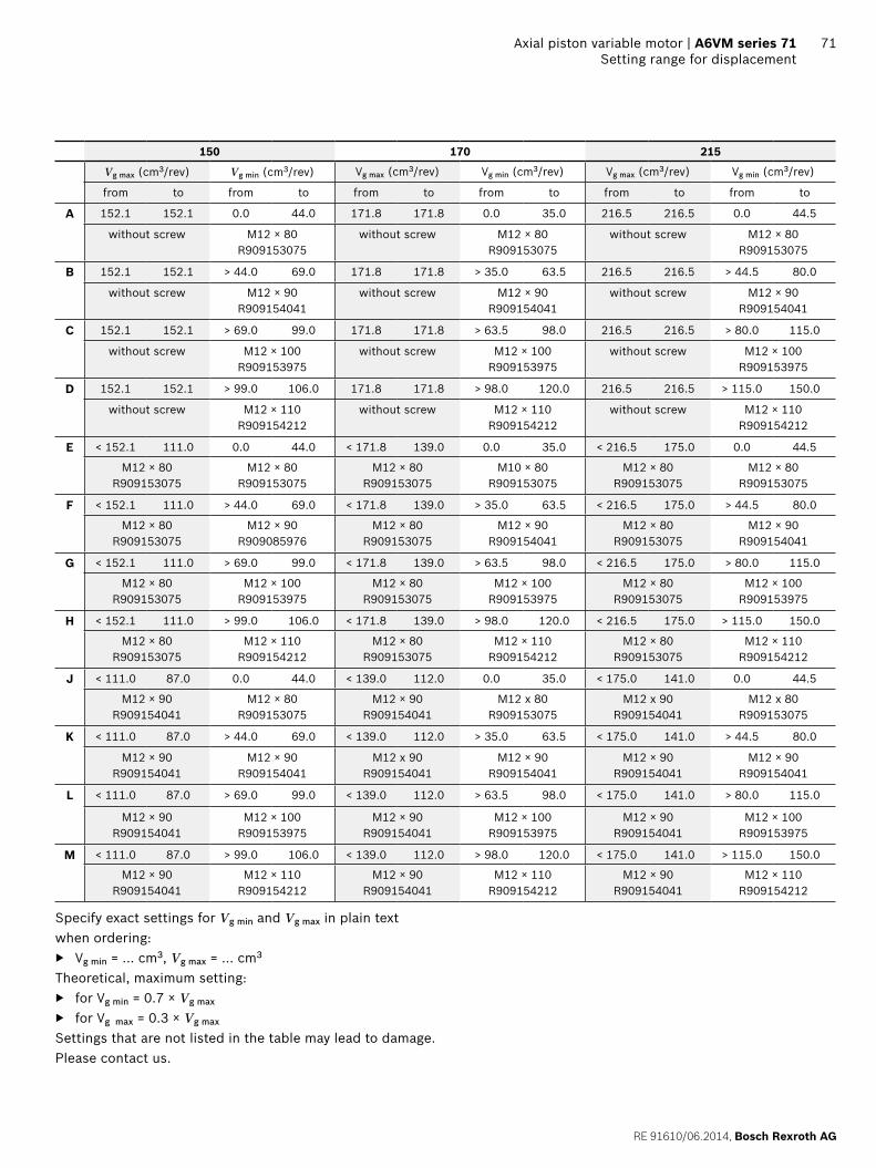
RE 91610062014 Bosch Rexroth AG
Axial piston variable motor | A6VM series 71 Setting range for displacement
71
150 170 215
Vg max (cm3rev) Vg min (cm3rev) Vg max (cm3rev) Vg min (cm3rev) Vg max (cm3rev) Vg min (cm3rev)
from to from to from to from to from to from to
A 1521 1521 00 440 1718 1718 00 350 2165 2165 00 445
without screw M12 times 80 R909153075
without screw M12 times 80 R909153075
without screw M12 times 80 R909153075
B 1521 1521 gt 440 690 1718 1718 gt 350 635 2165 2165 gt 445 800
without screw M12 times 90 R909154041
without screw M12 times 90 R909154041
without screw M12 times 90 R909154041
C 1521 1521 gt 690 990 1718 1718 gt 635 980 2165 2165 gt 800 1150
without screw M12 times 100 R909153975
without screw M12 times 100 R909153975
without screw M12 times 100 R909153975
D 1521 1521 gt 990 1060 1718 1718 gt 980 1200 2165 2165 gt 1150 1500
without screw M12 times 110 R909154212
without screw M12 times 110 R909154212
without screw M12 times 110 R909154212
E lt 1521 1110 00 440 lt 1718 1390 00 350 lt 2165 1750 00 445
M12 times 80 R909153075
M12 times 80 R909153075
M12 times 80 R909153075
M10 times 80 R909153075
M12 times 80 R909153075
M12 times 80 R909153075
F lt 1521 1110 gt 440 690 lt 1718 1390 gt 350 635 lt 2165 1750 gt 445 800
M12 times 80 R909153075
M12 times 90 R909085976
M12 times 80 R909153075
M12 times 90 R909154041
M12 times 80 R909153075
M12 times 90 R909154041
G lt 1521 1110 gt 690 990 lt 1718 1390 gt 635 980 lt 2165 1750 gt 800 1150
M12 times 80 R909153075
M12 times 100 R909153975
M12 times 80 R909153075
M12 times 100 R909153975
M12 times 80 R909153075
M12 times 100 R909153975
H lt 1521 1110 gt 990 1060 lt 1718 1390 gt 980 1200 lt 2165 1750 gt 1150 1500
M12 times 80 R909153075
M12 times 110 R909154212
M12 times 80 R909153075
M12 times 110 R909154212
M12 times 80 R909153075
M12 times 110 R909154212
J lt 1110 870 00 440 lt 1390 1120 00 350 lt 1750 1410 00 445
M12 times 90 R909154041
M12 times 80 R909153075
M12 times 90 R909154041
M12 x 80 R909153075
M12 x 90 R909154041
M12 x 80 R909153075
K lt 1110 870 gt 440 690 lt 1390 1120 gt 350 635 lt 1750 1410 gt 445 800
M12 times 90 R909154041
M12 times 90 R909154041
M12 x 90 R909154041
M12 times 90 R909154041
M12 times 90 R909154041
M12 times 90 R909154041
L lt 1110 870 gt 690 990 lt 1390 1120 gt 635 980 lt 1750 1410 gt 800 1150
M12 times 90 R909154041
M12 times 100 R909153975
M12 times 90 R909154041
M12 times 100 R909153975
M12 times 90 R909154041
M12 times 100 R909153975
M lt 1110 870 gt 990 1060 lt 1390 1120 gt 980 1200 lt 1750 1410 gt 1150 1500
M12 times 90 R909154041
M12 times 110 R909154212
M12 times 90 R909154041
M12 times 110 R909154212
M12 times 90 R909154041
M12 times 110 R909154212
Specify exact settings for Vg min and Vg max in plain text when ordering
Vg min = cm3 Vg max = cm3
Theoretical maximum setting for Vg min = 07 times Vg max
for Vg max = 03 times Vg max
Settings that are not listed in the table may lead to damage Please contact us
Bosch Rexroth AG RE 91610062014
72 A6VM series 71 | Axial piston variable motorInstallation instructions
Installation instructions
GeneralDuring commissioning and operation the axial piston unit must be filled with hydraulic fluid and air bled This must also observed following a relatively long standstill as the axial piston unit may drain back to the reservoir via the hydraulic linesParticularly in the installation position drive shaft upwards filling and air bleeding must be carried out com-pletely as there is for example a danger of dry runningThe leakage in the motor housing must be directed to the reservoir via the highest available drain port (T1 T2)To achieve favorable noise values decouple all connecting lines using elastic elements and avoid above-reservoir installation In all operating conditions the drain line must flow into the reservoir below the minimum fluid level
NoteIn certain installation conditions an influence on the control charakteristic curves can be expected Gravity dead weight and case pressure can cause minor shifts in characteristics and changes in response time
Key
U Bearing flushing air bleed port
T1 T2 Drain port
ht min Minimum required immersion depth (200 mm)
hmin Minimum required spacing to reservoir bottom (100 mm)
Installation position See examples 1 to 8 below Additional installation positions are available upon requestRecommended installation position 1 and 2
Below-reservoir installation (standard)Below-reservoir installation means that the axial piston unit is installed outside of the reservoir below the minimum fluid level
Installation position Air bleed Filling
1
T2
T1U
ht min
hmin
T1
2
T2
T1 U
ht min
hmin
T2
3
T2
T1
U
ht min
hmin
T1
4
T2
T1
U
ht min
hmin
U T1
RE 91610062014 Bosch Rexroth AG
Axial piston variable motor | A6VM series 71 Installation instructions
73
Above-reservoir installationAbove-reservoir installation means that the axial piston unit is installed above the minimum fluid level of the reservoirRecommendation for installation position 8 (drive shaft upward) A check valve in the drain line (cracking pressure 05 bar) can prevent draining of the motor housing
Installation position Air bleed Filling
5
T2
T1U
L1
ht min
hmin
U (L1) T1 (L1)
6
T2
T1 U
L1
ht min
hmin
L1 T2 (L1)
7
T2T1
U
L1
ht min
hmin
L1 T1 (L1)
8
T2T1
UL1
05
bar
ht min
hmin
U T1 (L1)
NotePort L1 is not part of the motor and can be made available by the customer for straightforward filling and air bleed-ing
74
Bosch Rexroth AG RE 91610062014
Bosch Rexroth AGMobile ApplicationsGlockeraustraszlige 489275 Elchingen GermanyTel +49-7308-82-0infomaboschrexrothdewwwboschrexrothcom
copy This document as well as the data specifications and other information set forth in it are the exclusive property of Bosch Rexroth AG It may not be reproduced or given to third parties without its consent The data specified above only serve to describe the product No statements concerning a certain condition or suitability for a certain application can be derived from our information The information given does not release the user from the obligation of own judgment and verification It must be remembered that our products are subject to a natural process of wear and aging
A6VM series 71 | Axial piston variable motorProject planning note
Project planning note
The motor A6VM is designed to be used in open and closed circuits
The project planning installation and commissioning of the axial piston unit requires the involvement of quali-fied skilled person
Before using the axial piston unit please read the cor-responding instruction manual completely and thor-oughly If necessary these can be requested from Bosch Rexroth
Before finalizing your design request a binding installa-tion drawing
The data and notes contained herein must be adhered to
For safety reasons control systems with beginning of control at Vg min (eg HA) are not permissible for winch drives eg anchor winches
Depending on the operating conditions of the axial piston unit (operating pressure fluid temperature) the charakteristic curve may shift
Not all variants of the product are approved for use in safety functions according to ISO 13849 Please consult the responsible contact person at Bosch Rexroth if you require reliability parameters (eg MTTFd) for functional safety
Working ports ndash The ports and fastening threads are designed for the
specified maximum pressure The machine or system manufacturer must ensure that the connecting ele-ments and lines correspond to the specified applica-tion conditions (pressure flow hydraulic fluid tem-perature) with the necessary safety factors
ndash The working ports and function ports can only be used to accommodate hydraulic lines
Safety instructions
During and shortly after operation there is a risk of burns on the axial piston unit and especially on the solenoids Take appropriate safety measures (e g by wearing protective clothing)
Moving parts in control and regulation systems (eg valve spools) may in certain circumstances become stuck in an undefined position due to contamination (eg contaminated hydraulic fluid abrasion or residual dirt from components) As a result the hydraulic fluid flow or build-up of torque of the axial piston unit will no longer respond correctly to the operators commands Even the use of different filter cartridges (external or internal inlet filter) will not rule out a fault but merely minimize the risk The machinesystem manufacturer must test whether remedial measures are needed on the machine for the application concerned in order to set the consumer being driven to a safe position (eg safe stop) and if necessary to ensure it is properly imple-mented
If the axial piston motor is used in winch drives make sure that the technical limit values are not exceeded under all operating conditions If the axial piston motor is subjected to external overload (eg by exceeding the maximum permissible rotational speeds when lifting anchor while the ship is in motion) this could cause damage to the rotary group and in unfavorable cases to the axial piston motor bursting If necessary additional measures up to an including encapsulation are to be implemented by the machinesystem manufacturer
RE 91610062014 Bosch Rexroth AG
75 Axial piston variable motor | A6VM series 71
76
Bosch Rexroth AG RE 91610062014
Bosch Rexroth AGMobile ApplicationsGlockeraustraszlige 489275 Elchingen GermanyTel +49-7308-82-0infomaboschrexrothdewwwboschrexrothcom
copy This document as well as the data specifications and other information set forth in it are the exclusive property of Bosch Rexroth AG It may not be reproduced or given to third parties without its consent The data specified above only serve to describe the product No statements concerning a certain condition or suitability for a certain application can be derived from our information The information given does not release the user from the obligation of own judgment and verification It must be remembered that our products are subject to a natural process of wear and aging
A6VM series 71 | axial piston variable motor

Bosch Rexroth AG RE 91610062014
72 A6VM series 71 | Axial piston variable motorInstallation instructions
Installation instructions
GeneralDuring commissioning and operation the axial piston unit must be filled with hydraulic fluid and air bled This must also observed following a relatively long standstill as the axial piston unit may drain back to the reservoir via the hydraulic linesParticularly in the installation position drive shaft upwards filling and air bleeding must be carried out com-pletely as there is for example a danger of dry runningThe leakage in the motor housing must be directed to the reservoir via the highest available drain port (T1 T2)To achieve favorable noise values decouple all connecting lines using elastic elements and avoid above-reservoir installation In all operating conditions the drain line must flow into the reservoir below the minimum fluid level
NoteIn certain installation conditions an influence on the control charakteristic curves can be expected Gravity dead weight and case pressure can cause minor shifts in characteristics and changes in response time
Key
U Bearing flushing air bleed port
T1 T2 Drain port
ht min Minimum required immersion depth (200 mm)
hmin Minimum required spacing to reservoir bottom (100 mm)
Installation position See examples 1 to 8 below Additional installation positions are available upon requestRecommended installation position 1 and 2
Below-reservoir installation (standard)Below-reservoir installation means that the axial piston unit is installed outside of the reservoir below the minimum fluid level
Installation position Air bleed Filling
1
T2
T1U
ht min
hmin
T1
2
T2
T1 U
ht min
hmin
T2
3
T2
T1
U
ht min
hmin
T1
4
T2
T1
U
ht min
hmin
U T1
RE 91610062014 Bosch Rexroth AG
Axial piston variable motor | A6VM series 71 Installation instructions
73
Above-reservoir installationAbove-reservoir installation means that the axial piston unit is installed above the minimum fluid level of the reservoirRecommendation for installation position 8 (drive shaft upward) A check valve in the drain line (cracking pressure 05 bar) can prevent draining of the motor housing
Installation position Air bleed Filling
5
T2
T1U
L1
ht min
hmin
U (L1) T1 (L1)
6
T2
T1 U
L1
ht min
hmin
L1 T2 (L1)
7
T2T1
U
L1
ht min
hmin
L1 T1 (L1)
8
T2T1
UL1
05
bar
ht min
hmin
U T1 (L1)
NotePort L1 is not part of the motor and can be made available by the customer for straightforward filling and air bleed-ing
74
Bosch Rexroth AG RE 91610062014
Bosch Rexroth AGMobile ApplicationsGlockeraustraszlige 489275 Elchingen GermanyTel +49-7308-82-0infomaboschrexrothdewwwboschrexrothcom
copy This document as well as the data specifications and other information set forth in it are the exclusive property of Bosch Rexroth AG It may not be reproduced or given to third parties without its consent The data specified above only serve to describe the product No statements concerning a certain condition or suitability for a certain application can be derived from our information The information given does not release the user from the obligation of own judgment and verification It must be remembered that our products are subject to a natural process of wear and aging
A6VM series 71 | Axial piston variable motorProject planning note
Project planning note
The motor A6VM is designed to be used in open and closed circuits
The project planning installation and commissioning of the axial piston unit requires the involvement of quali-fied skilled person
Before using the axial piston unit please read the cor-responding instruction manual completely and thor-oughly If necessary these can be requested from Bosch Rexroth
Before finalizing your design request a binding installa-tion drawing
The data and notes contained herein must be adhered to
For safety reasons control systems with beginning of control at Vg min (eg HA) are not permissible for winch drives eg anchor winches
Depending on the operating conditions of the axial piston unit (operating pressure fluid temperature) the charakteristic curve may shift
Not all variants of the product are approved for use in safety functions according to ISO 13849 Please consult the responsible contact person at Bosch Rexroth if you require reliability parameters (eg MTTFd) for functional safety
Working ports ndash The ports and fastening threads are designed for the
specified maximum pressure The machine or system manufacturer must ensure that the connecting ele-ments and lines correspond to the specified applica-tion conditions (pressure flow hydraulic fluid tem-perature) with the necessary safety factors
ndash The working ports and function ports can only be used to accommodate hydraulic lines
Safety instructions
During and shortly after operation there is a risk of burns on the axial piston unit and especially on the solenoids Take appropriate safety measures (e g by wearing protective clothing)
Moving parts in control and regulation systems (eg valve spools) may in certain circumstances become stuck in an undefined position due to contamination (eg contaminated hydraulic fluid abrasion or residual dirt from components) As a result the hydraulic fluid flow or build-up of torque of the axial piston unit will no longer respond correctly to the operators commands Even the use of different filter cartridges (external or internal inlet filter) will not rule out a fault but merely minimize the risk The machinesystem manufacturer must test whether remedial measures are needed on the machine for the application concerned in order to set the consumer being driven to a safe position (eg safe stop) and if necessary to ensure it is properly imple-mented
If the axial piston motor is used in winch drives make sure that the technical limit values are not exceeded under all operating conditions If the axial piston motor is subjected to external overload (eg by exceeding the maximum permissible rotational speeds when lifting anchor while the ship is in motion) this could cause damage to the rotary group and in unfavorable cases to the axial piston motor bursting If necessary additional measures up to an including encapsulation are to be implemented by the machinesystem manufacturer
RE 91610062014 Bosch Rexroth AG
75 Axial piston variable motor | A6VM series 71
76
Bosch Rexroth AG RE 91610062014
Bosch Rexroth AGMobile ApplicationsGlockeraustraszlige 489275 Elchingen GermanyTel +49-7308-82-0infomaboschrexrothdewwwboschrexrothcom
copy This document as well as the data specifications and other information set forth in it are the exclusive property of Bosch Rexroth AG It may not be reproduced or given to third parties without its consent The data specified above only serve to describe the product No statements concerning a certain condition or suitability for a certain application can be derived from our information The information given does not release the user from the obligation of own judgment and verification It must be remembered that our products are subject to a natural process of wear and aging
A6VM series 71 | axial piston variable motor

RE 91610062014 Bosch Rexroth AG
Axial piston variable motor | A6VM series 71 Installation instructions
73
Above-reservoir installationAbove-reservoir installation means that the axial piston unit is installed above the minimum fluid level of the reservoirRecommendation for installation position 8 (drive shaft upward) A check valve in the drain line (cracking pressure 05 bar) can prevent draining of the motor housing
Installation position Air bleed Filling
5
T2
T1U
L1
ht min
hmin
U (L1) T1 (L1)
6
T2
T1 U
L1
ht min
hmin
L1 T2 (L1)
7
T2T1
U
L1
ht min
hmin
L1 T1 (L1)
8
T2T1
UL1
05
bar
ht min
hmin
U T1 (L1)
NotePort L1 is not part of the motor and can be made available by the customer for straightforward filling and air bleed-ing
74
Bosch Rexroth AG RE 91610062014
Bosch Rexroth AGMobile ApplicationsGlockeraustraszlige 489275 Elchingen GermanyTel +49-7308-82-0infomaboschrexrothdewwwboschrexrothcom
copy This document as well as the data specifications and other information set forth in it are the exclusive property of Bosch Rexroth AG It may not be reproduced or given to third parties without its consent The data specified above only serve to describe the product No statements concerning a certain condition or suitability for a certain application can be derived from our information The information given does not release the user from the obligation of own judgment and verification It must be remembered that our products are subject to a natural process of wear and aging
A6VM series 71 | Axial piston variable motorProject planning note
Project planning note
The motor A6VM is designed to be used in open and closed circuits
The project planning installation and commissioning of the axial piston unit requires the involvement of quali-fied skilled person
Before using the axial piston unit please read the cor-responding instruction manual completely and thor-oughly If necessary these can be requested from Bosch Rexroth
Before finalizing your design request a binding installa-tion drawing
The data and notes contained herein must be adhered to
For safety reasons control systems with beginning of control at Vg min (eg HA) are not permissible for winch drives eg anchor winches
Depending on the operating conditions of the axial piston unit (operating pressure fluid temperature) the charakteristic curve may shift
Not all variants of the product are approved for use in safety functions according to ISO 13849 Please consult the responsible contact person at Bosch Rexroth if you require reliability parameters (eg MTTFd) for functional safety
Working ports ndash The ports and fastening threads are designed for the
specified maximum pressure The machine or system manufacturer must ensure that the connecting ele-ments and lines correspond to the specified applica-tion conditions (pressure flow hydraulic fluid tem-perature) with the necessary safety factors
ndash The working ports and function ports can only be used to accommodate hydraulic lines
Safety instructions
During and shortly after operation there is a risk of burns on the axial piston unit and especially on the solenoids Take appropriate safety measures (e g by wearing protective clothing)
Moving parts in control and regulation systems (eg valve spools) may in certain circumstances become stuck in an undefined position due to contamination (eg contaminated hydraulic fluid abrasion or residual dirt from components) As a result the hydraulic fluid flow or build-up of torque of the axial piston unit will no longer respond correctly to the operators commands Even the use of different filter cartridges (external or internal inlet filter) will not rule out a fault but merely minimize the risk The machinesystem manufacturer must test whether remedial measures are needed on the machine for the application concerned in order to set the consumer being driven to a safe position (eg safe stop) and if necessary to ensure it is properly imple-mented
If the axial piston motor is used in winch drives make sure that the technical limit values are not exceeded under all operating conditions If the axial piston motor is subjected to external overload (eg by exceeding the maximum permissible rotational speeds when lifting anchor while the ship is in motion) this could cause damage to the rotary group and in unfavorable cases to the axial piston motor bursting If necessary additional measures up to an including encapsulation are to be implemented by the machinesystem manufacturer
RE 91610062014 Bosch Rexroth AG
75 Axial piston variable motor | A6VM series 71
76
Bosch Rexroth AG RE 91610062014
Bosch Rexroth AGMobile ApplicationsGlockeraustraszlige 489275 Elchingen GermanyTel +49-7308-82-0infomaboschrexrothdewwwboschrexrothcom
copy This document as well as the data specifications and other information set forth in it are the exclusive property of Bosch Rexroth AG It may not be reproduced or given to third parties without its consent The data specified above only serve to describe the product No statements concerning a certain condition or suitability for a certain application can be derived from our information The information given does not release the user from the obligation of own judgment and verification It must be remembered that our products are subject to a natural process of wear and aging
A6VM series 71 | axial piston variable motor