Embed Size (px)
Citation preview
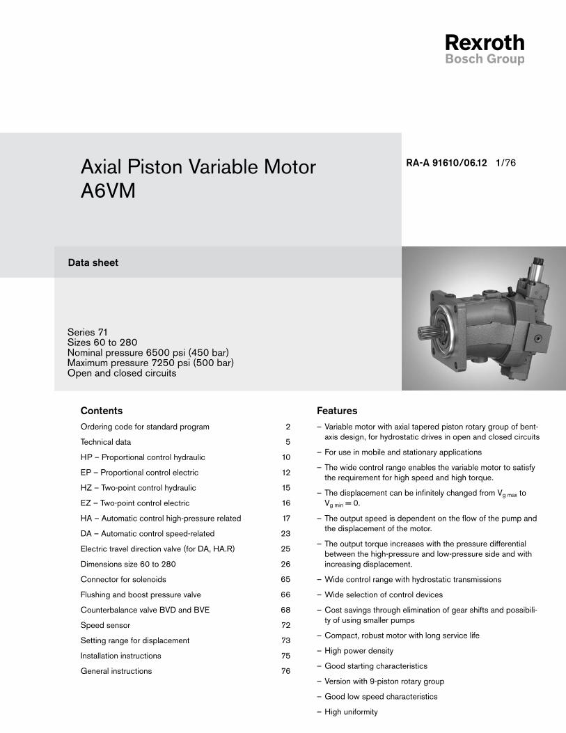
Axial Piston Variable Motor A6VM
Series 71Sizes 60 to 280Nominal pressure 6500 psi (450 bar)Maximum pressure 7250 psi (500 bar)Open and closed circuits
RA-A 91610/06.12 1/76
Data sheet
FeaturesVariable motor with axial tapered piston rotary group of bent- –axis design, for hydrostatic drives in open and closed circuits
For use in mobile and stationary applications –
The wide control range enables the variable motor to satisfy –the requirement for high speed and high torque.
The displacement can be infinitely changed from V – g max to Vg min = 0.
The output speed is dependent on the flow of the pump and –the displacement of the motor.
The output torque increases with the pressure differential –between the high-pressure and low-pressure side and with increasing displacement.
Wide control range with hydrostatic transmissions –
Wide selection of control devices –
Cost savings through elimination of gear shifts and possibili- –ty of using smaller pumps
Compact, robust motor with long service life –
High power density –
Good starting characteristics –
Version with 9-piston rotary group –
Good low speed characteristics –
High uniformity –
ContentsOrdering code for standard program 2
Technical data 5
HP – Proportional control hydraulic 10
EP – Proportional control electric 12
HZ – Two-point control hydraulic 15
EZ – Two-point control electric 16
HA – Automatic control high-pressure related 17
DA – Automatic control speed-related 23
Electric travel direction valve (for DA, HA.R) 25
Dimensions size 60 to 280 26
Connector for solenoids 65
Flushing and boost pressure valve 66
Counterbalance valve BVD and BVE 68
Speed sensor 72
Setting range for displacement 73
Installation instructions 75
General instructions 76
A6VM Series 71 RA-A 91610/06.122/76 Bosch Rexroth Corp.
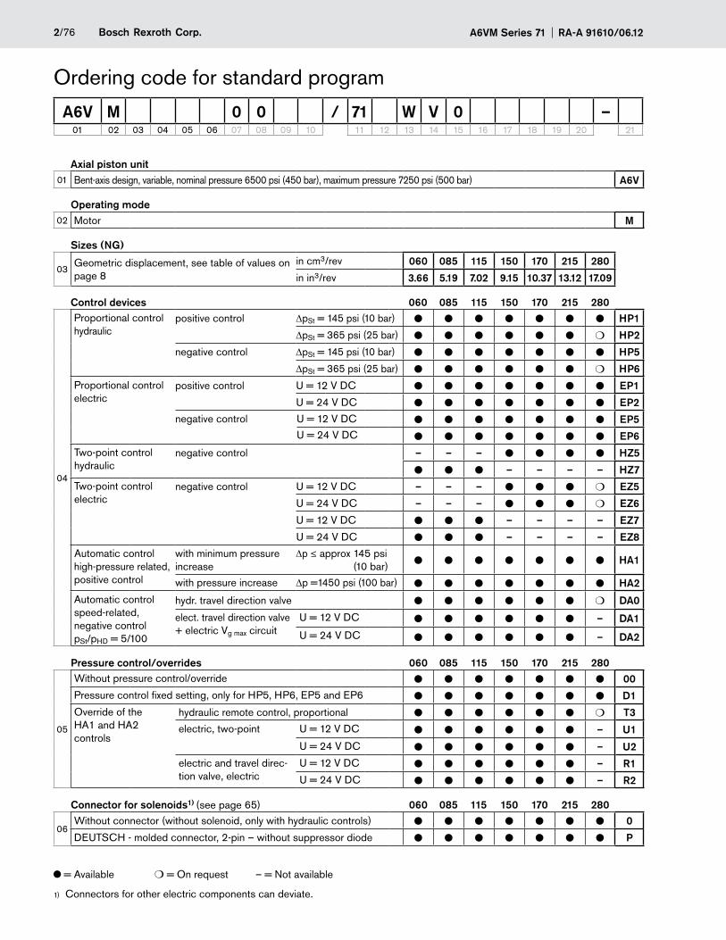
= Available m = On request – = Not available
Connectors for other electric components can deviate.1)
Axial piston unit01 Bent-axis design, variable, nominal pressure 6500 psi (450 bar), maximum pressure 7250 psi (500 bar) A6V
Operating mode02 Motor M
Sizes (NG)
03Geometric displacement, see table of values on page 8
in cm3/rev 060 085 115 150 170 215 280
in in3/rev 3.66 5.19 7.02 9.15 10.37 13.12 17.09
Control devices 060 085 115 150 170 215 280
04
Proportional control hydraulic
positive control DpSt = 145 psi (10 bar) l l l l l l l HP1
DpSt = 365 psi (25 bar) l l l l l l m HP2
negative control DpSt = 145 psi (10 bar) l l l l l l l HP5
DpSt = 365 psi (25 bar) l l l l l l m HP6
Proportional control electric
positive control U = 12 V DC l l l l l l l EP1
U = 24 V DC l l l l l l l EP2
negative control U = 12 V DC l l l l l l l EP5U = 24 V DC l l l l l l l EP6
Two-point control hydraulic
negative control – – – l l l l HZ5
l l l – – – – HZ7
Two-point control electric
negative control U = 12 V DC – – – l l l m EZ5
U = 24 V DC – – – l l l m EZ6
U = 12 V DC l l l – – – – EZ7
U = 24 V DC l l l – – – – EZ8
Automatic control high-pressure related, positive control
with minimum pressure increase
Dp ≤ approx 145 psi (10 bar) l l l l l l l HA1
with pressure increase Dp =1450 psi (100 bar) l l l l l l l HA2
Automatic control speed-related, negative control pSt/pHD = 5/100
hydr. travel direction valve l l l l l l m DA0
elect. travel direction valve + electric Vg max circuit
U = 12 V DC l l l l l l – DA1
U = 24 V DC l l l l l l – DA2
Pressure control/overrides 060 085 115 150 170 215 280
05
Without pressure control/override l l l l l l l 00
Pressure control fixed setting, only for HP5, HP6, EP5 and EP6 l l l l l l l D1
Override of the HA1 and HA2 controls
hydraulic remote control, proportional l l l l l l m T3
electric, two-point U = 12 V DC l l l l l l – U1
U = 24 V DC l l l l l l – U2
electric and travel direc-tion valve, electric
U = 12 V DC l l l l l l – R1
U = 24 V DC l l l l l l – R2
Connector for solenoids1) (see page 65) 060 085 115 150 170 215 280
06Without connector (without solenoid, only with hydraulic controls) l l l l l l l 0
DEUTSCH - molded connector, 2-pin – without suppressor diode l l l l l l l P
Ordering code for standard program
A6V M 0 0 / 71 W V 0 –01 02 03 04 05 06 07 08 09 10 11 12 13 14 15 16 17 18 19 20 21
3/76Bosch Rexroth Corp.RA-A 91610/06.12 A6VM Series 71
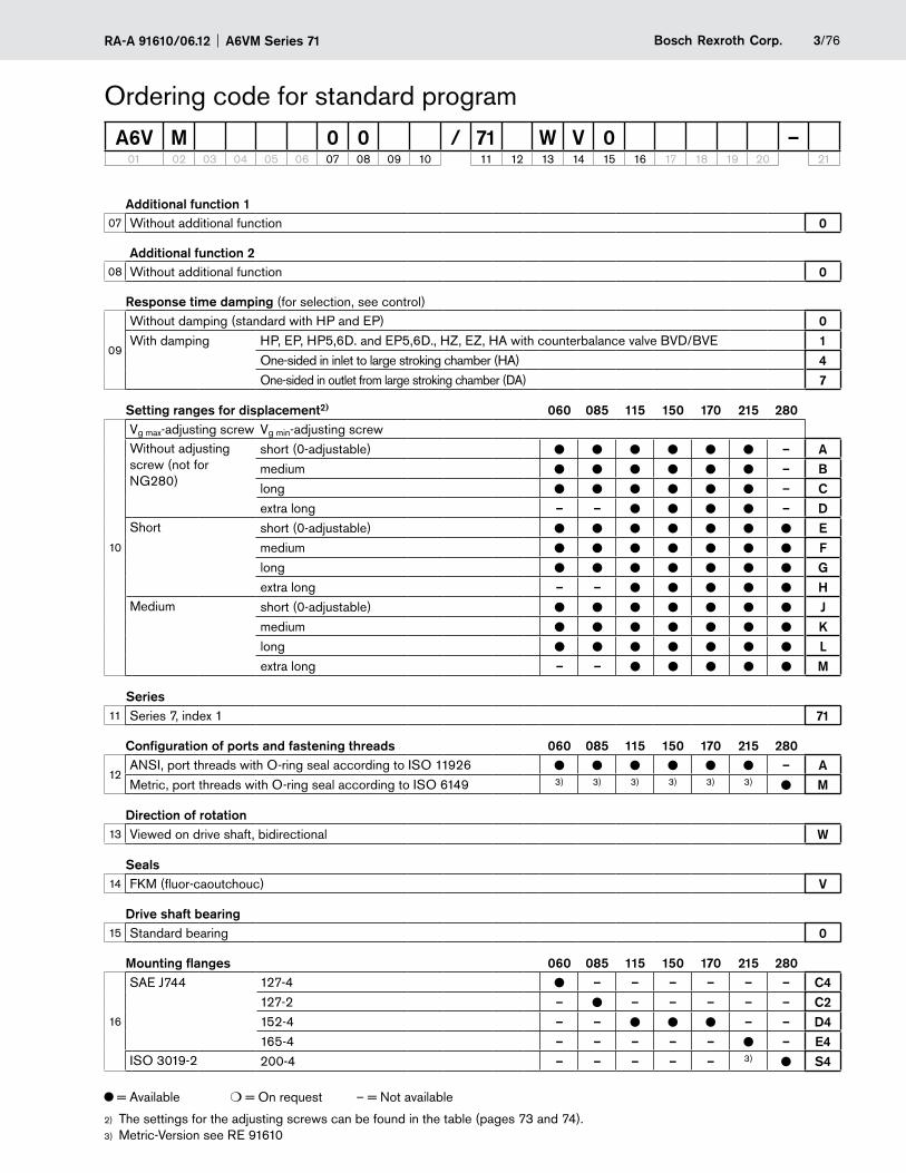
Additional function 107 Without additional function 0
Additional function 208 Without additional function 0
Response time damping (for selection, see control)
09
Without damping (standard with HP and EP) 0With damping HP, EP, HP5,6D. and EP5,6D., HZ, EZ, HA with counterbalance valve BVD/BVE 1
One-sided in inlet to large stroking chamber (HA) 4One-sided in outlet from large stroking chamber (DA) 7
Setting ranges for displacement2) 060 085 115 150 170 215 280
10
Vg max-adjusting screw Vg min-adjusting screwWithout adjusting screw (not for NG280)
short (0-adjustable) l l l l l l – Amedium l l l l l l – Blong l l l l l l – Cextra long – – l l l l – D
Short short (0-adjustable) l l l l l l l Emedium l l l l l l l Flong l l l l l l l Gextra long – – l l l l l H
Medium short (0-adjustable) l l l l l l l Jmedium l l l l l l l Klong l l l l l l l Lextra long – – l l l l l M
Series11 Series 7, index 1 71
Configuration of ports and fastening threads 060 085 115 150 170 215 280
12ANSI, port threads with O-ring seal according to ISO 11926 l l l l l l – AMetric, port threads with O-ring seal according to ISO 6149 3) 3) 3) 3) 3) 3) l M
Direction of rotation13 Viewed on drive shaft, bidirectional W
Seals14 FKM (fluor-caoutchouc) V
Drive shaft bearing15 Standard bearing 0
Mounting flanges 060 085 115 150 170 215 280
16
SAE J744 127-4 l – – – – – – C4127-2 – l – – – – – C2152-4 – – l l l – – D4165-4 – – – – – l – E4
ISO 3019-2 200-4 – – – – – 3) l S4
Ordering code for standard program
A6V M 0 0 / 71 W V 0 –01 02 03 04 05 06 07 08 09 10 11 12 13 14 15 16 17 18 19 20 21
= Available m = On request – = Not available
The settings for the adjusting screws can be found in the table (pages 72) 3 and 74).Metric-Version see RE 916103)
A6VM Series 71 RA-A 91610/06.124/76 Bosch Rexroth Corp.
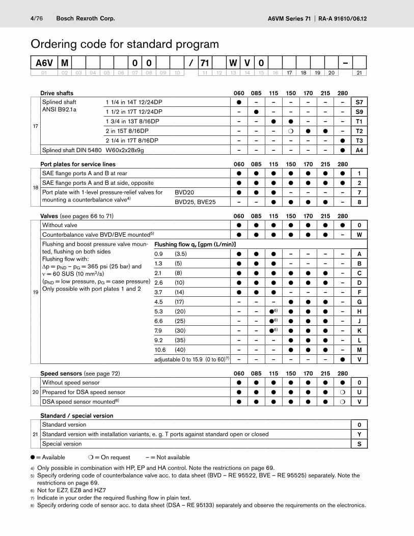
Drive shafts 060 085 115 150 170 215 280
17
Splined shaft ANSI B92.1a
1 1/4 in 14T 12/24DP l – – – – – – S7
1 1/2 in 17T 12/24DP – l – – – – – S9
1 3/4 in 13T 8/16DP – – l l – – – T1
2 in 15T 8/16DP – – – m l l – T2
2 1/4 in 17T 8/16DP – – – – – – l T3
Splined shaft DIN 5480 W60x2x28x9g – – – – – – l A4
Port plates for service lines 060 085 115 150 170 215 280
18
SAE flange ports A and B at rear l l l l l l l 1
SAE flange ports A and B at side, opposite l l l l l l l 2
Port plate with 1-level pressure-relief valves for mounting a counterbalance valve4)
BVD20 l l l – – – – 7
BVD25, BVE25 – – l l l l – 8
Valves (see pages 66 to 71) 060 085 115 150 170 215 280
19
Without valve l l l l l l l 0
Counterbalance valve BVD/BVE mounted5) l l l l l l – W
Flushing and boost pressure valve moun-ted, flushing on both sides Flushing flow with: Dp = pND – pG = 365 psi (25 bar) and ν = 60 SUS (10 mm2/s) (pND = low pressure, pG = case pressure) Only possible with port plates 1 and 2
Flushing flow qv [gpm (L/min)]
0.9 (3.5) l l l – – – – A
1.3 (5) l l l – – – – B
2.1 (8) l l l l l l – C
2.6 (10) l l l l l l – D
3.7 (14) l l l – – – – F
4.5 (17) – – – l l l – G
5.3 (20) – – l6) l l l – H
6.6 (25) – – l6) l l l – J
7.9 (30) – – l6) l l l – K
9.2 (35) – – – l l l – L
10.6 (40) – – – l l l – M
adjustable 0 to 15.9 (0 to 60)7) – – – – – – l V
Speed sensors (see page 72) 060 085 115 150 170 215 280
20
Without speed sensor l l l l l l l 0
Prepared for DSA speed sensor l l l l l l m U
DSA speed sensor mounted8) l l l l l l m V
Standard / special version
21
Standard version 0
Standard version with installation variants, e. g. T ports against standard open or closed Y
Special version S
= Available m = On request – = Not available
Ordering code for standard program
A6V M 0 0 / 71 W V 0 –01 02 03 04 05 06 07 08 09 10 11 12 13 14 15 16 17 18 19 20 21
Only possible in combination with HP, EP and HA control. Note the restrictions on page 4) 69.Specify ordering code of counterbalance valve acc. to data sheet (BVD – RE 95522, BVE – RE 95525) separately. 5) Note the restrictions on page 69.Not for EZ7, EZ8 and HZ76)
Indicate in your order the required flushing flow in plain text. 7)
Specify ordering code of sensor acc. to data sheet (DSA – RE 95133) separately and observe the requirements on the electronics.8)
5/76Bosch Rexroth Corp.RA-A 91610/06.12 A6VM Series 71
Technical dataHydraulic fluidBefore starting project planning, please refer to our data sheets RE 90220 (mineral oil), RE 90221 (environmentally acceptable hydraulic fluids) and RE 90222 (HFD hydraulic fluids) for detailed information regarding the choice of hydraulic fluid and application conditions.
The variable motor A6VM is not suitable for operation with HFA hydraulic fluid. If HFB, HFC or HFD or environmentally acceptable hydraulic fluids are used, the limitations regarding technical data or other seals must be observed. Please contact us.
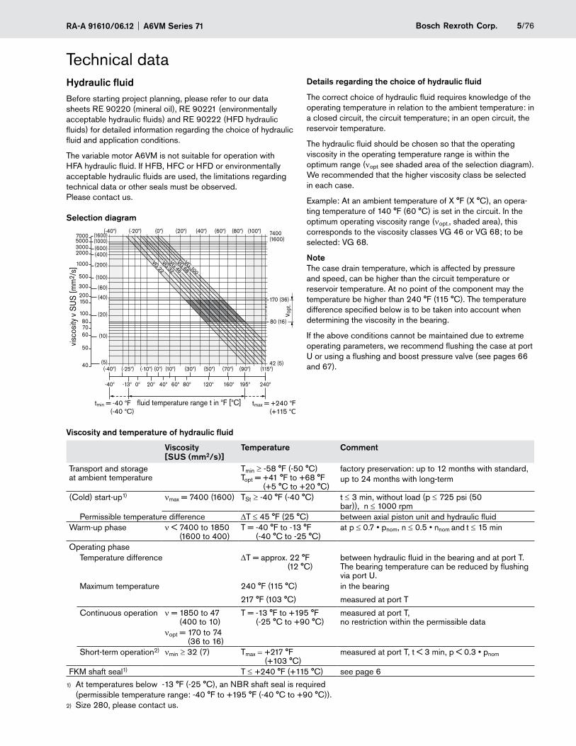
Selection diagram
VG 22VG 32VG 46VG 68VG 100
ν opt
.
80 (16)
170 (36)
(0°) (20°) (40°) (60°) (80°) (100°)(-40°) (-20°)
42 (5)
7400 (1600)
visco
sity
ν S
US
[mm
2 /s]
fluid temperature range t in °F [°C]tmin = -40 °F (-40 °C)
tmax = +240 °F (+115 °C)
(-40°) (-25°) (-10°) (0°) (10°) (30°) (50°) (70°) (90°) (115°)
-40° -13° 120°0° 20° 40° 60° 80° 160° 195° 240°
(1600)(1000)(600)(400)
(200)
(100)
(60)
(40)
(20)
(10)
(5)
7000500030002000
1000
500
300
150200
100807060
50
40
Details regarding the choice of hydraulic fluid
The correct choice of hydraulic fluid requires knowledge of the operating temperature in relation to the ambient temperature: in a closed circuit, the circuit temperature; in an open circuit, the reservoir temperature.
The hydraulic fluid should be chosen so that the operating viscosity in the operating temperature range is within the optimum range (νopt see shaded area of the selection diagram). We recommended that the higher viscosity class be selected in each case.
Example: At an ambient temperature of X °F (X °C), an opera-ting temperature of 140 °F (60 °C) is set in the circuit. In the optimum operating viscosity range (νopt., shaded area), this corresponds to the viscosity classes VG 46 or VG 68; to be selected: VG 68.
NoteThe case drain temperature, which is affected by pressure and speed, can be higher than the circuit temperature or reservoir temperature. At no point of the component may the temperature be higher than 240 °F (115 °C). The temperature difference specified below is to be taken into account when determining the viscosity in the bearing.
If the above conditions cannot be maintained due to extreme operating parameters, we recommend flushing the case at port U or using a flushing and boost pressure valve (see pages 66 and 67).
Viscosity and temperature of hydraulic fluid
Viscosity [SUS (mm2/s)]
Temperature Comment
Transport and storage at ambient temperature
Tmin ≥ -58 °F (-50 °C) Topt = +41 °F to +68 °F
(+5 °C to +20 °C)
factory preservation: up to 12 months with standard, up to 24 months with long-term
(Cold) start-up1) νmax = 7400 (1600) TSt ≥ -40 °F (-40 °C) t ≤ 3 min, without load (p ≤ 725 psi (50 bar)), n ≤ 1000 rpm
Permissible temperature difference DT ≤ 45 °F (25 °C) between axial piston unit and hydraulic fluidWarm-up phase ν < 7400 to 1850
(1600 to 400)T = -40 °F to -13 °F
(-40 °C to -25 °C)at p ≤ 0.7 • pnom, n ≤ 0.5 • nnom and t ≤ 15 min
Operating phaseTemperature difference DT = approx. 22 °F
(12 °C) between hydraulic fluid in the bearing and at port T. The bearing temperature can be reduced by flushing via port U.
Maximum temperature 240 °F (115 °C) in the bearing
217 °F (103 °C) measured at port T
Continuous operation ν = 1850 to 47 (400 to 10)
T = -13 °F to +195 °F (-25 °C to +90 °C)
measured at port T, no restriction within the permissible data
νopt = 170 to 74 (36 to 16)
Short-term operation2) νmin ≥ 32 (7) Tmax = +217 °F (+103 °C)
measured at port T, t < 3 min, p < 0.3 • pnom
FKM shaft seal1) T ≤ +240 °F (+115 °C) see page 6
At temperatures below 1) -13 °F (-25 °C), an NBR shaft seal is required (permissible temperature range: -40 °F to +195 °F (-40 °C to +90 °C)).Size 280, please contact us.2)
A6VM Series 71 RA-A 91610/06.126/76 Bosch Rexroth Corp.
Technical dataFiltration of the hydraulic fluidFiner filtration improves the cleanliness level of the hydraulic fluid, which increases the service life of the axial piston unit.
To ensure the functional reliability of the axial piston unit, a gravimetric analysis of the hydraulic fluid is necessary to de-termine the amount of solid contaminant and to determine the cleanliness level according to ISO 4406. A cleanliness level of at least 20/18/15 is to be maintained.
At very high hydraulic fluid temperatures (195 °F to maximum 240 °F (90 °C to maximum 115 °C)), a cleanliness level of at least 19/17/14 according to ISO 4406 is necessary.
If the above classes cannot be achieved, please contact us.
Shaft seal
Permissible pressure loading
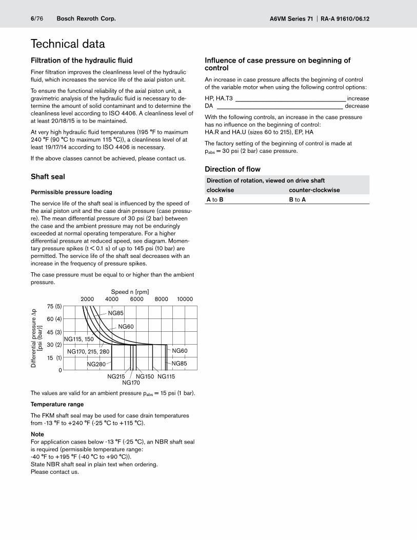
The service life of the shaft seal is influenced by the speed of the axial piston unit and the case drain pressure (case pressu-re). The mean differential pressure of 30 psi (2 bar) between the case and the ambient pressure may not be enduringly exceeded at normal operating temperature. For a higher differential pressure at reduced speed, see diagram. Momen-tary pressure spikes (t < 0.1 s) of up to 145 psi (10 bar) are permitted. The service life of the shaft seal decreases with an increase in the frequency of pressure spikes.
The case pressure must be equal to or higher than the ambient pressure.
Diff
eren
tial p
ress
ure
Dp
[psi
(ba
r)]
0
15 (1)
30 (2)
45 (3)
60 (4)
75 (5)2000 4000 6000 8000 10000
NG170, 215, 280
NG85
NG60
NG115, 150
NG170
NG60
NG85
NG115NG150NG215
NG280
Speed n [rpm]
The values are valid for an ambient pressure pabs = 15 psi (1 bar).
Temperature range
The FKM shaft seal may be used for case drain temperatures from -13 °F to +240 °F (-25 °C to +115 °C).
NoteFor application cases below -13 °F (-25 °C), an NBR shaft seal is required (permissible temperature range: -40 °F to +195 °F (-40 °C to +90 °C)). State NBR shaft seal in plain text when ordering. Please contact us.
Influence of case pressure on beginning of controlAn increase in case pressure affects the beginning of control of the variable motor when using the following control options:
HP, HA.T3 ____________________________________ increase DA _________________________________________ decrease
With the following controls, an increase in the case pressure has no influence on the beginning of control: HA.R and HA.U (sizes 60 to 215), EP, HA
The factory setting of the beginning of control is made at pabs = 30 psi (2 bar) case pressure.
Direction of flowDirection of rotation, viewed on drive shaft
clockwise counter-clockwise
A to B B to A
7/76Bosch Rexroth Corp.RA-A 91610/06.12 A6VM Series 71
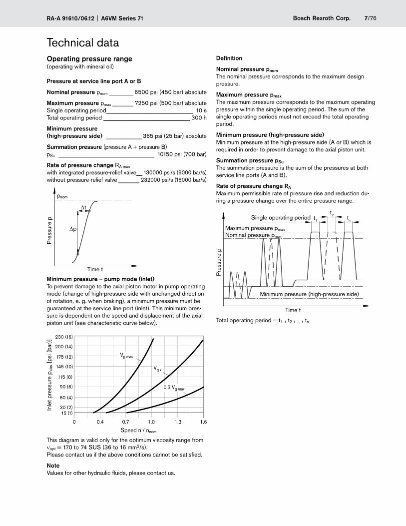
Technical dataOperating pressure range (operating with mineral oil)
Pressure at service line port A or B
Nominal pressure pnom ________ 6500 psi (450 bar) absolute
Maximum pressure pmax _______ 7250 psi (500 bar) absolute Single operating period _____________________________ 10 s Total operating period _____________________________ 300 h
Minimum pressure (high-pressure side) ____________365 psi (25 bar) absolute
Summation pressure (pressure A + pressure B) pSu ________________________________ 10150 psi (700 bar)
Rate of pressure change RA max
with integrated pressure-relief valve__ 130000 psi/s (9000 bar/s) without pressure-relief valve _______ 232000 psi/s (16000 bar/s)
pnom
Dt
Dp
Time t
Pre
ssur
e p
Minimum pressure – pump mode (inlet)To prevent damage to the axial piston motor in pump operating mode (change of high-pressure side with unchanged direction of rotation, e. g. when braking), a minimum pressure must be guaranteed at the service line port (inlet). This minimum pres-sure is dependent on the speed and displacement of the axial piston unit (see characteristic curve below).
Vg max
Vg x
0.3 Vg max
0 0.4 0.7 1.0 1.3 1.6
230 (16)
200 (14)
175 (12)
145 (10)
115 (8)
90 (6)
60 (4)
30 (2)15 (1)
Inle
t pre
ssur
e p a
bs [p
si (b
ar)]
Speed n / nnom
This diagram is valid only for the optimum viscosity range from νopt = 170 to 74 SUS (36 to 16 mm2/s). Please contact us if the above conditions cannot be satisfied.
NoteValues for other hydraulic fluids, please contact us.
Definition
Nominal pressure pnom
The nominal pressure corresponds to the maximum design pressure.
Maximum pressure pmax
The maximum pressure corresponds to the maximum operating pressure within the single operating period. The sum of the single operating periods must not exceed the total operating period.
Minimum pressure (high-pressure side)Minimum pressure at the high-pressure side (A or B) which is required in order to prevent damage to the axial piston unit.
Summation pressure pSu
The summation pressure is the sum of the pressures at both service line ports (A and B).
Rate of pressure change RA
Maximum permissible rate of pressure rise and reduction du-ring a pressure change over the entire pressure range.
Pre
ssur
e p
t1
t2 tnSingle operating period
Minimum pressure (high-pressure side)
Maximum pressure pmaxNominal pressure pnom
Time t
Total operating period = t1 + t2 + ... + tn
A6VM Series 71 RA-A 91610/06.128/76 Bosch Rexroth Corp.
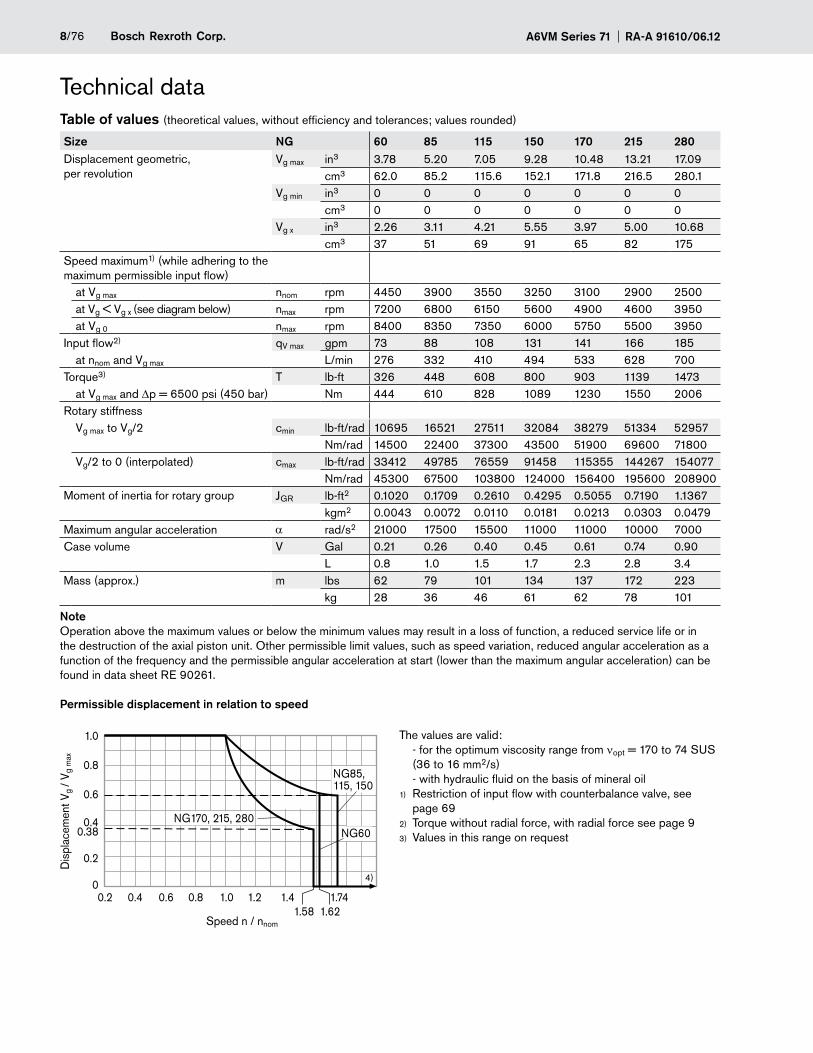
Technical dataTable of values (theoretical values, without efficiency and tolerances; values rounded)
Size NG 60 85 115 150 170 215 280Displacement geometric, per revolution
Vg max in3 3.78 5.20 7.05 9.28 10.48 13.21 17.09cm3 62.0 85.2 115.6 152.1 171.8 216.5 280.1
Vg min in3 0 0 0 0 0 0 0cm3 0 0 0 0 0 0 0
Vg x in3 2.26 3.11 4.21 5.55 3.97 5.00 10.68cm3 37 51 69 91 65 82 175
Speed maximum1) (while adhering to the maximum permissible input flow)
at Vg max nnom rpm 4450 3900 3550 3250 3100 2900 2500at Vg < Vg x (see diagram below) nmax rpm 7200 6800 6150 5600 4900 4600 3950at Vg 0 nmax rpm 8400 8350 7350 6000 5750 5500 3950
Input flow2) qV max gpm 73 88 108 131 141 166 185at nnom and Vg max L/min 276 332 410 494 533 628 700
Torque3) T lb-ft 326 448 608 800 903 1139 1473at Vg max and Dp = 6500 psi (450 bar) Nm 444 610 828 1089 1230 1550 2006
Rotary stiffnessVg max to Vg/2 cmin lb-ft/rad 10695 16521 27511 32084 38279 51334 52957
Nm/rad 14500 22400 37300 43500 51900 69600 71800Vg/2 to 0 (interpolated) cmax lb-ft/rad 33412 49785 76559 91458 115355 144267 154077
Nm/rad 45300 67500 103800 124000 156400 195600 208900Moment of inertia for rotary group JGR lb-ft2 0.1020 0.1709 0.2610 0.4295 0.5055 0.7190 1.1367
kgm2 0.0043 0.0072 0.0110 0.0181 0.0213 0.0303 0.0479Maximum angular acceleration a rad/s2 21000 17500 15500 11000 11000 10000 7000Case volume V Gal 0.21 0.26 0.40 0.45 0.61 0.74 0.90
L 0.8 1.0 1.5 1.7 2.3 2.8 3.4Mass (approx.) m lbs 62 79 101 134 137 172 223
kg 28 36 46 61 62 78 101
NoteOperation above the maximum values or below the minimum values may result in a loss of function, a reduced service life or in the destruction of the axial piston unit. Other permissible limit values, such as speed variation, reduced angular acceleration as a function of the frequency and the permissible angular acceleration at start (lower than the maximum angular acceleration) can be found in data sheet RE 90261.
Permissible displacement in relation to speed
0.2 0.4 0.6 0.8 1.0 1.2 1.4 1.74
NG170, 215, 280
NG85, 115, 150
4)
1.0
0.8
0.6
0.40.38
0.2
0
1.58 1.62
NG60
Dis
plac
emen
t Vg
/ Vg
max
Speed n / nnom
The values are valid: - for the optimum viscosity range from νopt = 170 to 74 SUS (36 to 16 mm2/s) - with hydraulic fluid on the basis of mineral oilRestriction of input flow with counterbalance valve, see 1)
page 69Torque without radial force, with radial force see page 92)
Values in this range on request3)
9/76Bosch Rexroth Corp.RA-A 91610/06.12 A6VM Series 71
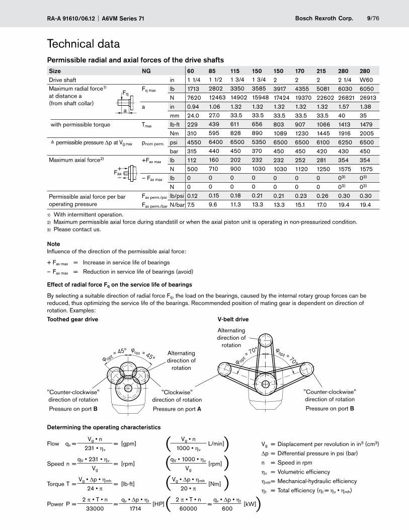
Permissible radial and axial forces of the drive shaftsSize NG 60 85 115 150 150 170 215 280 280Drive shaft in 1 1/4 1 1/2 1 3/4 1 3/4 2 2 2 2 1/4 W60Maximum radial force1) at distance a (from shaft collar)
a
FqFq max lb 1713 2802 3350 3585 3917 4355 5081 6030 6050
N 7620 12463 14902 15948 17424 19370 22602 26821 26913a in 0.94 1.06 1.32 1.32 1.32 1.32 1.32 1.57 1.38
mm 24.0 27.0 33.5 33.5 33.5 33.5 33.5 40 35with permissible torque Tmax lb-ft 229 439 611 656 803 907 1066 1413 1479
Nm 310 595 828 890 1089 1230 1445 1916 2005≙ permissible pressure Dp at Vg max pnom perm. psi 4550 6400 6500 5350 6500 6500 6100 6250 6500
bar 315 440 450 370 450 450 420 430 450Maximum axial force2)
+Fax
—
+Fax max lb 112 160 202 232 232 252 281 354 354N 500 710 900 1030 1030 1120 1250 1575 1575
– Fax max lb 0 0 0 0 0 0 0 03) 03)
N 0 0 0 0 0 0 0 03) 03)
Permissible axial force per bar operating pressure
Fax perm./psi lb/psi 0.12 0.15 0.18 0.21 0.21 0.23 0.26 0.30 0.30Fax perm./bar N/bar 7.5 9.6 11.3 13.3 13.3 15.1 17.0 19.4 19.4
With intermittent operation.1)
Maximum permissible axial force during standstill or when the axial piston unit is operating in non-pressurized condition.2)
Please contact us.3)
NoteInfluence of the direction of the permissible axial force:
+ Fax max = Increase in service life of bearings
– Fax max = Reduction in service life of bearings (avoid)
Effect of radial force Fq on the service life of bearings
By selecting a suitable direction of radial force Fq, the load on the bearings, caused by the internal rotary group forces can be reduced, thus optimizing the service life of the bearings. Recommended position of mating gear is dependent on direction of rotation. Examples:Toothed gear drive V-belt drive
"Counter-clockwise" direction of rotation
Pressure on port B
"Clockwise" direction of rotation
Pressure on port A
φopt = 45°φ opt = 45° φopt = 70°φ opt =
70°
"Counter-clockwise" direction of rotation
Pressure on port B
Alternating direction of
rotation
Alternating direction of
rotation
Determining the operating characteristics
Flow qv =Vg • n
= [gpm]Vg • n
L/min]231 • ηv 1000 • ηv
Speed n =qV • 231 • ηv
= [rpm]qV • 1000 • ηv
[rpm]Vg Vg
Torque T =Vg • Dp • ηmh
= [lb-ft]Vg • Dp • ηmh
[Nm]24 • π 20 • π
Power P =2 π • T • n
=qv • Dp • ηt
[HP]2 π • T • n
=qv • Dp • ηt
[kW]33000 1714 60000 600
))
)
)(((
(
Technical data
Vg = Displacement per revolution in in3 (cm3)
Dp = Differential pressure in psi (bar)
n = Speed in rpm
ηv = Volumetric efficiency
ηmh = Mechanical-hydraulic efficiency
ηt = Total efficiency (ηt = ηv • ηmh)
A6VM Series 71 RA-A 91610/06.1210/76 Bosch Rexroth Corp.
HP – Proportional control hydraulicThe proportional hydraulic control provides infinite setting of the displacement, proportional to the pilot pressure applied to port X.
HP1, HP2 positive controlBeginning of control at V – g min (minimum torque, maximum permissible speed at minimum pilot pressure)
End of control at V – g max (maximum torque, minimum speed at maximum pilot pressure)
HP5, HP6 negative controlBeginning of control at V – g max (maximum torque, minimum speed at minimum pilot pressure)
End of control at V – g min (minimum torque, maximum permissi-ble speed at maximum pilot pressure)
NoteMaximum permissible pilot pressure: p – St = 1450 psi (100 bar)
The control oil is internally taken out of the high-pressure –side of the motor (A or B). For reliable control, an operating pressure of at least 435 psi (30 bar) is required in A (B). If a control operation is performed at an operating pressure < 435 psi (30 bar), an auxiliary pressure of at least 435 psi (30 bar) must be applied at port G via an external check valve. For lower pressures, please contact us. Please note that pressures up to 7250 psi (500 bar) can occur at port G.
Please state the desired beginning of control in plain text –when ordering, e. g.: beginning of control at 145 psi (10 bar).
The beginning of control and the HP characteristic are –influenced by the case pressure. An increase in the case pressure causes an increase in the beginning of control (see page 6) and thus a parallel shift of the characteristic.
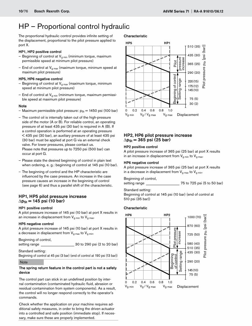
HP1, HP5 pilot pressure increase DpSt = 145 psi (10 bar)HP1 positive controlA pilot pressure increase of 145 psi (10 bar) at port X results in an increase in displacement from Vg min to Vg max.
HP5 negative controlA pilot pressure increase of 145 psi (10 bar) at port X results in a decrease in displacement from Vg max to Vg min.
Beginning of control, setting range __________________ 30 to 290 psi (2 to 20 bar)
Standard setting: Beginning of control at 45 psi (3 bar) (end of control at 190 psi (13 bar))
Note
The spring return feature in the control part is not a safety device
The control part can stick in an undefined position by inter-nal contamination (contaminated hydraulic fluid, abrasion or residual contamination from system components). As a result, the control will no longer respond correctly to the operator's commands.
Check whether the application on your machine requires ad-ditional safety measures, in order to bring the driven actuator into a controlled and safe position (immediate stop). If neces-sary, make sure these are properly implemented.
Characteristic
0 0.2 0.4 0.6 0.8 1.0Vg min Vg maxVg / Vg max
HP5 HP1510 (35)
435 (30)
365 (25)
290 (20)
220 (15)175 (12)145 (10)
75 (5)
30 (2)Beg
inni
ng o
f con
trol
Set
ting
rang
e
Displacement
Pilo
t pre
ssur
e p S
t [ps
i (ba
r)]
Pilo
t pr
essu
re
incr
ease
HP2, HP6 pilot pressure increase DpSt = 365 psi (25 bar)HP2 positive controlA pilot pressure increase of 365 psi (25 bar) at port X results in an increase in displacement from Vg min to Vg max.
HP6 negative controlA pilot pressure increase of 365 psi (25 bar) at port X results in a decrease in displacement from Vg max to Vg min.
Beginning of control, setting range __________________ 75 to 725 psi (5 to 50 bar)
Standard setting: Beginning of control at 145 psi (10 bar) (end of control at 510 psi (35 bar))
Characteristic
1000 (70)
870 (60)
725 (50)
580 (40)510 (35)435 (30)
290 (20)
145 (10)75 (5)
0 0.2 0.4 0.6 0.8 1.0Vg min Vg maxVg / Vg max
HP6 HP2
Beg
inni
ng
of c
ontro
l S
ettin
g ra
nge
Displacement
Pilo
t pre
ssur
e p S
t [ps
i (ba
r)]
Pilo
t pre
ssur
e in
crea
se
11/76Bosch Rexroth Corp.RA-A 91610/06.12 A6VM Series 71
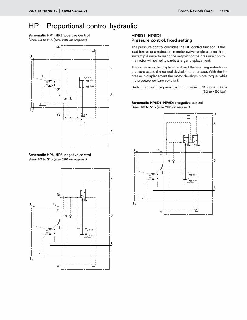
HP – Proportional control hydraulicSchematic HP1, HP2: positive controlSizes 60 to 215 (size 280 on request)
B
A
M1
T2
T1
G
X
Vg min
Vg max
U
Schematic HP5, HP6: negative controlSizes 60 to 215 (size 280 on request)
T2
T1
M1
Vg min
Vg max
B
A
U
X
G
HP5D1, HP6D1 Pressure control, fixed settingThe pressure control overrides the HP control function. If the load torque or a reduction in motor swivel angle causes the system pressure to reach the setpoint of the pressure control, the motor will swivel towards a larger displacement.
The increase in the displacement and the resulting reduction in pressure cause the control deviation to decrease. With the in-crease in displacement the motor develops more torque, while the pressure remains constant.
Setting range of the pressure control valve__ 1150 to 6500 psi (80 to 450 bar)
Schematic HP5D1, HP6D1: negative controlSizes 60 to 215 (size 280 on request)
T2
T1
M1
Vg min
Vg max
B
A
G
X
U
A6VM Series 71 RA-A 91610/06.1212/76 Bosch Rexroth Corp.
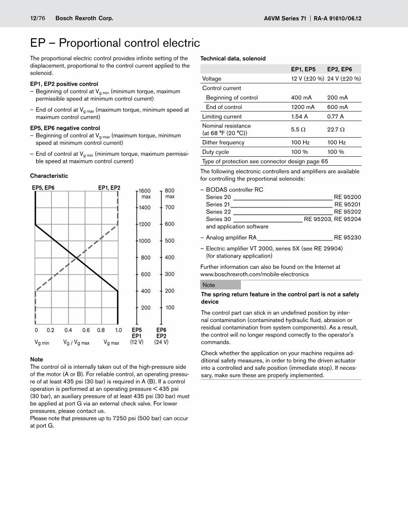
EP – Proportional control electricThe proportional electric control provides infinite setting of the displacement, proportional to the control current applied to the solenoid.
EP1, EP2 positive controlBeginning of control at V – g min (minimum torque, maximum permissible speed at minimum control current)
End of control at V – g max (maximum torque, minimum speed at maximum control current)
EP5, EP6 negative controlBeginning of control at V – g max (maximum torque, minimum speed at minimum control current)
End of control at V – g min (minimum torque, maximum permissi-ble speed at maximum control current)
Characteristic
0 0.2 0.4 0.6 0.8 1.0
1600max
1400
1200
1000
800
600
400
200
800max
700
600
500
400
300
200
100
EP5EP1
(12 V)
EP6EP2
(24 V)
EP5, EP6 EP1, EP2
Vg min Vg / Vg max Vg max
NoteThe control oil is internally taken out of the high-pressure side of the motor (A or B). For reliable control, an operating pressu-re of at least 435 psi (30 bar) is required in A (B). If a control operation is performed at an operating pressure < 435 psi (30 bar), an auxiliary pressure of at least 435 psi (30 bar) must be applied at port G via an external check valve. For lower pressures, please contact us. Please note that pressures up to 7250 psi (500 bar) can occur at port G.
Technical data, solenoid
EP1, EP5 EP2, EP6
Voltage 12 V (±20 %) 24 V (±20 %)
Control current
Beginning of control 400 mA 200 mA
End of control 1200 mA 600 mA
Limiting current 1.54 A 0.77 A
Nominal resistance (at 68 °F (20 °C))
5.5 Ω 22.7 Ω
Dither frequency 100 Hz 100 Hz
Duty cycle 100 % 100 %
Type of protection see connector design page 65
The following electronic controllers and amplifiers are available for controlling the proportional solenoids:
BODAS controller RC –Series 20 _________________________________ RE 95200 Series 21 __________________________________ RE 95201 Series 22 _________________________________ RE 95202 Series 30 _______________________ RE 95203, RE 95204 and application software
Analog amplifier RA – _________________________ RE 95230
Electric amplifier VT 2000, series 5X (see RE 29904) –(for stationary application)
Further information can also be found on the Internet at www.boschrexroth.com/mobile-electronics
Note
The spring return feature in the control part is not a safety device
The control part can stick in an undefined position by inter-nal contamination (contaminated hydraulic fluid, abrasion or residual contamination from system components). As a result, the control will no longer respond correctly to the operator's commands.
Check whether the application on your machine requires ad-ditional safety measures, in order to bring the driven actuator into a controlled and safe position (immediate stop). If neces-sary, make sure these are properly implemented.
13/76Bosch Rexroth Corp.RA-A 91610/06.12 A6VM Series 71
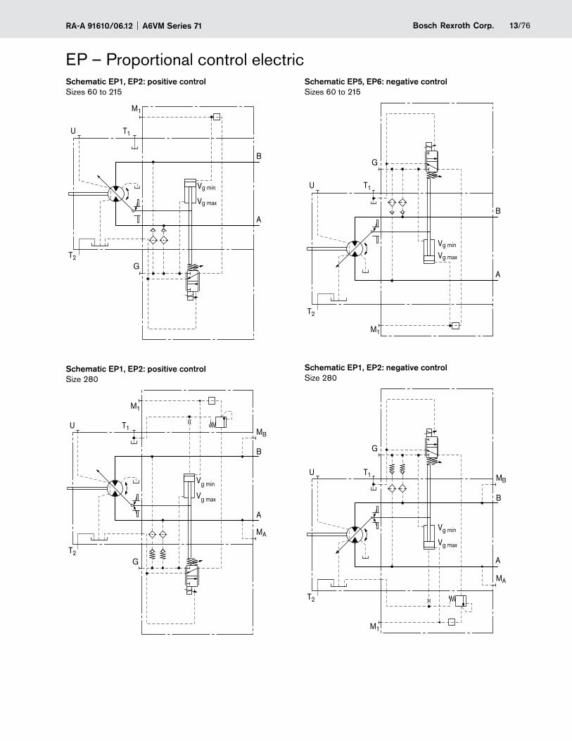
EP – Proportional control electricSchematic EP1, EP2: positive controlSizes 60 to 215
B
A
M1
T2
T1
G
Vg min
Vg max
U
Schematic EP1, EP2: positive controlSize 280
M1
GT2
T1U
B
A
Vg min
Vg max
MA
MB
Schematic EP5, EP6: negative controlSizes 60 to 215
U
T2
T1
M1
Vg min
Vg max
B
A
G
Schematic EP1, EP2: negative controlSize 280
M1
T2
B
MA
MBU T1
Vg min
Vg max
A
G
A6VM Series 71 RA-A 91610/06.1214/76 Bosch Rexroth Corp.
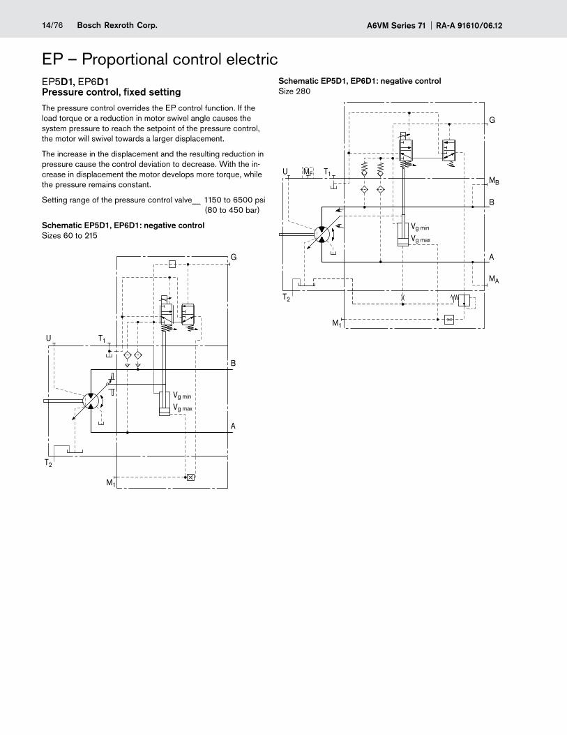
EP – Proportional control electricEP5D1, EP6D1 Pressure control, fixed settingThe pressure control overrides the EP control function. If the load torque or a reduction in motor swivel angle causes the system pressure to reach the setpoint of the pressure control, the motor will swivel towards a larger displacement.
The increase in the displacement and the resulting reduction in pressure cause the control deviation to decrease. With the in-crease in displacement the motor develops more torque, while the pressure remains constant.
Setting range of the pressure control valve__ 1150 to 6500 psi (80 to 450 bar)
Schematic EP5D1, EP6D1: negative controlSizes 60 to 215
U
T2
T1
Vg min
Vg max
B
A
G
M1
Schematic EP5D1, EP6D1: negative controlSize 280
U
T2
T1
Vg min
Vg max
B
A
G
M1
MA
MB
MF
15/76Bosch Rexroth Corp.RA-A 91610/06.12 A6VM Series 71
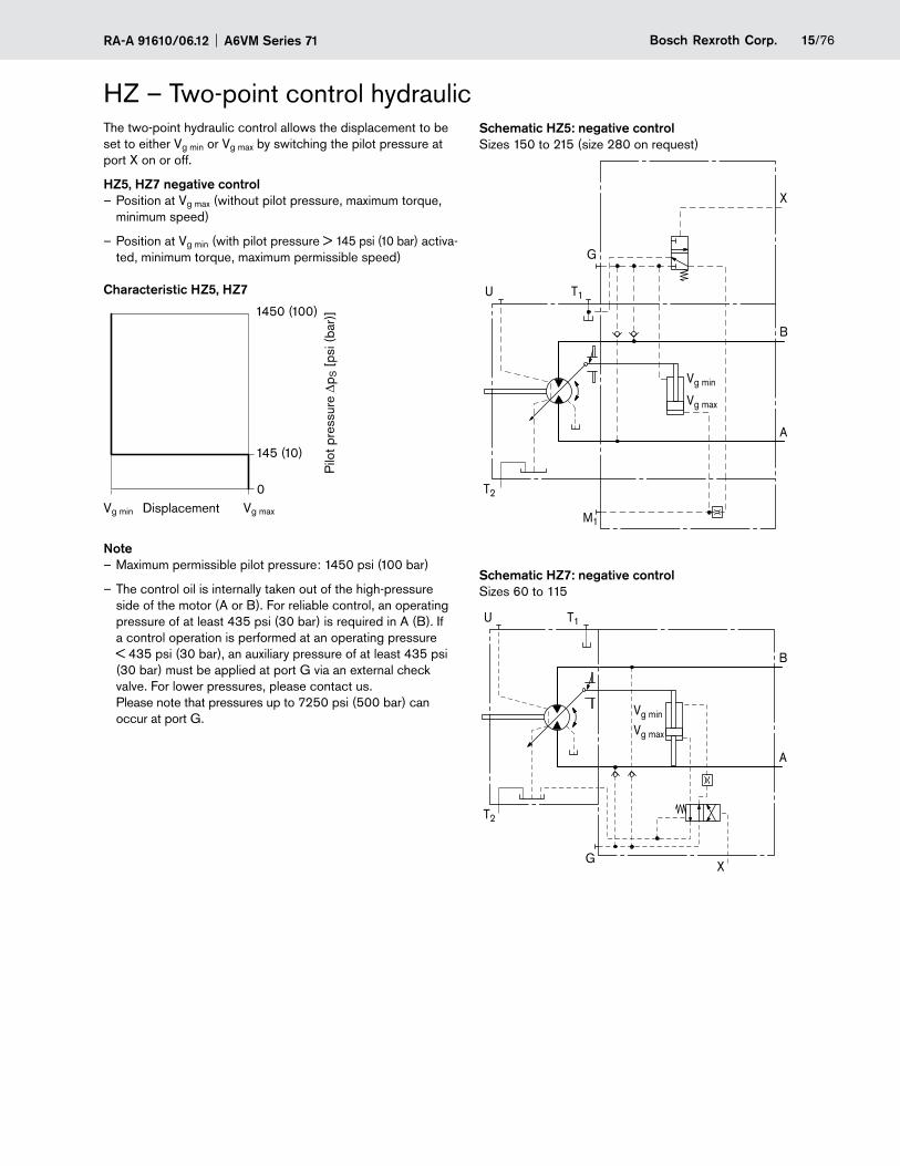
HZ – Two-point control hydraulicThe two-point hydraulic control allows the displacement to be set to either Vg min or Vg max by switching the pilot pressure at port X on or off.
HZ5, HZ7 negative controlPosition at V – g max (without pilot pressure, maximum torque, minimum speed)
Position at V – g min (with pilot pressure > 145 psi (10 bar) activa-ted, minimum torque, maximum permissible speed)
Characteristic HZ5, HZ7
Vg min Vg maxDisplacement0
145 (10)
Pilo
t pre
ssur
e Dp
S [
psi (
bar)
]1450 (100)
NoteMaximum permissible pilot pressure: – 1450 psi (100 bar)
The control oil is internally taken out of the high-pressure –side of the motor (A or B). For reliable control, an operating pressure of at least 435 psi (30 bar) is required in A (B). If a control operation is performed at an operating pressure < 435 psi (30 bar), an auxiliary pressure of at least 435 psi (30 bar) must be applied at port G via an external check valve. For lower pressures, please contact us. Please note that pressures up to 7250 psi (500 bar) can occur at port G.
Schematic HZ5: negative controlSizes 150 to 215 (size 280 on request)
T2
T1
M1
Vg min
Vg max
B
A
X
G
U
Schematic HZ7: negative controlSizes 60 to 115
T1U
T2
XG
Vg min
Vg max
B
A
A6VM Series 71 RA-A 91610/06.1216/76 Bosch Rexroth Corp.
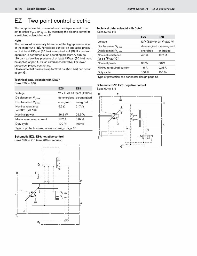
EZ – Two-point control electricThe two-point electric control allows the displacement to be set to either Vg min or Vg max by switching the electric current to a switching solenoid on or off.
NoteThe control oil is internally taken out of the high-pressure side of the motor (A or B). For reliable control, an operating pressu-re of at least 435 psi (30 bar) is required in A (B). If a control operation is performed at an operating pressure < 435 psi (30 bar), an auxiliary pressure of at least 435 psi (30 bar) must be applied at port G via an external check valve. For lower pressures, please contact us. Please note that pressures up to 7250 psi (500 bar) can occur at port G.
Technical data, solenoid with DIA37 Sizes 150 to 280
EZ5 EZ6
Voltage 12 V (±20 %) 24 V (±20 %)
Displacement Vg max de-energized de-energized
Displacement Vg min energized energized
Nominal resistance (at 68 °F (20 °C))
5.5 Ω 21.7 Ω
Nominal power 26.2 W 26.5 W
Minimum required current 1.32 A 0.67 A
Duty cycle 100 % 100 %
Type of protection see connector design page 65
Schematic EZ5, EZ6: negative controlSizes 150 to 215 (size 280 on request)
U
T2
T1
M1
Vg min
Vg max
B
A
G
Technical data, solenoid with DIA45 Sizes 60 to 115
EZ7 EZ8
Voltage 12 V (±20 %) 24 V (±20 %)
Displacement Vg max de-energized de-energized
Displacement Vg min energized energized
Nominal resistance (at 68 °F (20 °C))
4.8 Ω 19.2 Ω
Nominal power 30 W 30W
Minimum required current 1.5 A 0.75 A
Duty cycle 100 % 100 %
Type of protection see connector design page 65
Schematic EZ7, EZ8: negative controlSizes 60 to 115
T1U
T2
G
B
A
Vg min
Vg max
17/76Bosch Rexroth Corp.RA-A 91610/06.12 A6VM Series 71
HA – Automatic control high-pressure relatedThe automatic high-pressure related control adjusts the dis-placement automatically depending on the operating pressure.
The displacement of the A6VM motor with HA control is Vg min (maximum speed and minimum torque). The control unit mea-sures internally the operating pressure at A or B (no control line required) and upon reaching the beginning of control , the controller swivels the motor from Vg min to Vg max with increase of pressure. The displacement is modulated between Vg min and Vg max, thereby depending on load conditions.
HA1, HA2 positive control
Beginning of control at V – g min (minimum torque, maximum speed)
End of control at V – g max (maximum torque, minimum speed)
NoteFor safety reasons, winch drives are not permissible with –beginning of control at Vg min (standard for HA).
The control oil is internally taken out of the high-pressure –side of the motor (A or B). For reliable control, an operating pressure of at least 435 psi (30 bar) is required in A (B). If a control operation is performed at an operating pressure < 435 psi (30 bar), an auxiliary pressure of at least 435 psi (30 bar) must be applied at port G via an external check valve. For lower pressures, please contact us. Please note that pressures up to 7250 psi (500 bar) can occur at port G.
The beginning of control and the HA.T3 characteristic are –influenced by case pressure. An increase in case pressure causes an increase in the beginning of control (see page 6) and thus a parallel shift of the characteristic.
A6VM Series 71 RA-A 91610/06.1218/76 Bosch Rexroth Corp.
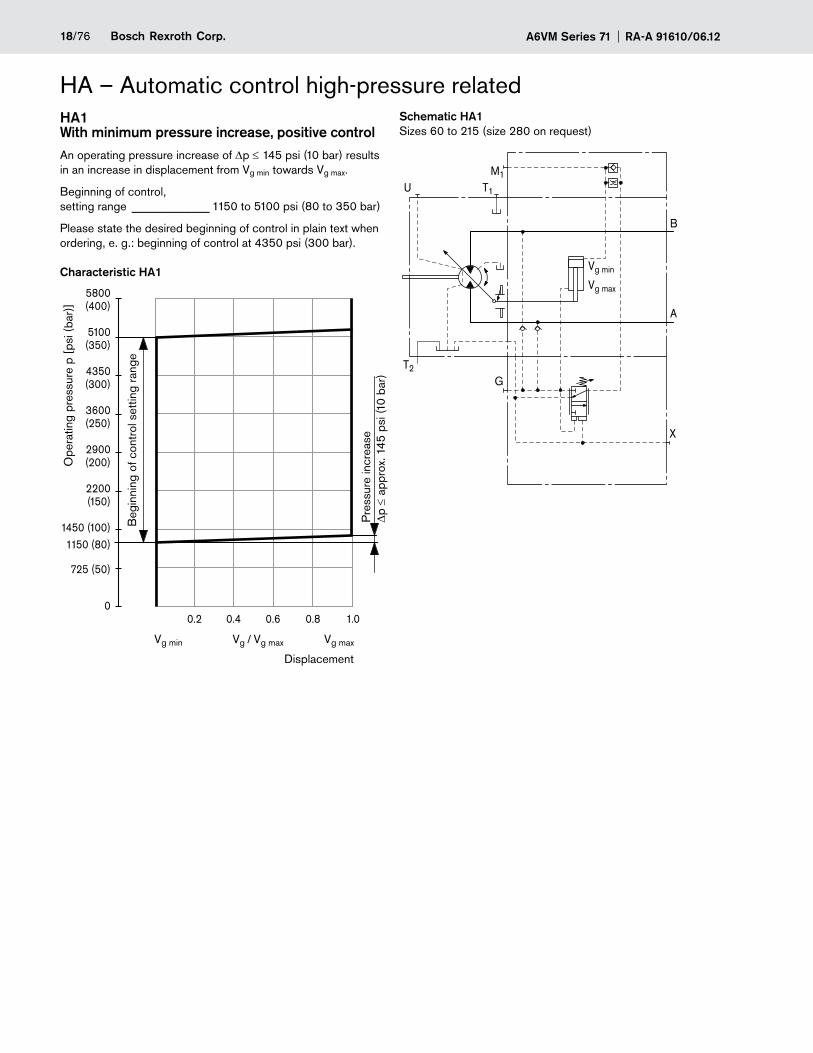
HA – Automatic control high-pressure relatedHA1 With minimum pressure increase, positive controlAn operating pressure increase of Dp ≤ 145 psi (10 bar) results in an increase in displacement from Vg min towards Vg max.
Beginning of control, setting range _____________ 1150 to 5100 psi (80 to 350 bar)
Please state the desired beginning of control in plain text when ordering, e. g.: beginning of control at 4350 psi (300 bar).
Characteristic HA1
Vg min
5800(400)
5100(350)
4350(300)
3600(250)
2900(200)
2200(150)
1450 (100)1150 (80)
725 (50)
0
Vg maxVg / Vg max
0.2 0.4 0.6 0.8 1.0
Pre
ssur
e in
crea
se
Dp ≤
app
rox.
145
psi
(10
bar)
Ope
ratin
g pr
essu
re p
[ps
i (ba
r)]
Beg
inni
ng o
f con
trol
set
ting
rang
e
Displacement
Schematic HA1Sizes 60 to 215 (size 280 on request)
B
A
M1
T2
T1
Vg min
Vg max
G
U
X
19/76Bosch Rexroth Corp.RA-A 91610/06.12 A6VM Series 71
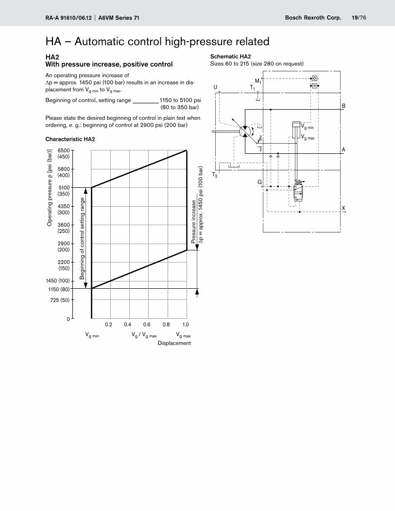
HA – Automatic control high-pressure relatedHA2 With pressure increase, positive controlAn operating pressure increase of Dp = approx. 1450 psi (100 bar) results in an increase in dis-placement from Vg min to Vg max.
Beginning of control, setting range _________1150 to 5100 psi (80 to 350 bar)
Please state the desired beginning of control in plain text when ordering, e. g.: beginning of control at 2900 psi (200 bar)
Characteristic HA2
Vg min
6500(450)
5800(400)
5100(350)
4350(300)
3600(250)
2900(200)
2200(150)
1450 (100)
1150 (80)
725 (50)
0
Vg maxVg / Vg max
0.2 0.4 0.6 0.8 1.0
Pre
ssur
e in
crea
se
Dp =
app
rox.
145
0 ps
i (10
0 ba
r)
Ope
ratin
g pr
essu
re p
[ps
i (ba
r)]
Beg
inni
ng o
f con
trol
set
ting
rang
e
Displacement
Schematic HA2Sizes 60 to 215 (size 280 on request)
B
A
M1
T2
T1
G
X
Vg min
Vg max
U
A6VM Series 71 RA-A 91610/06.1220/76 Bosch Rexroth Corp.
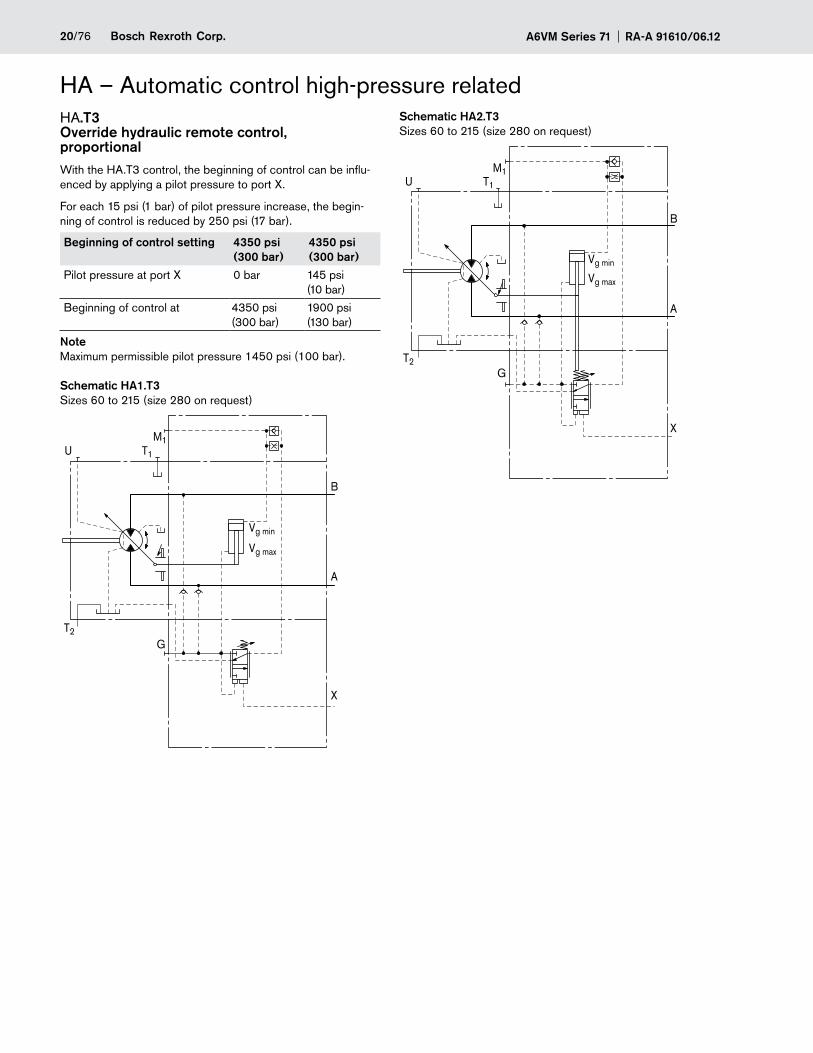
HA – Automatic control high-pressure relatedHA.T3 Override hydraulic remote control, proportionalWith the HA.T3 control, the beginning of control can be influ-enced by applying a pilot pressure to port X.
For each 15 psi (1 bar) of pilot pressure increase, the begin-ning of control is reduced by 250 psi (17 bar).
Beginning of control setting 4350 psi (300 bar)
4350 psi (300 bar)
Pilot pressure at port X 0 bar 145 psi (10 bar)
Beginning of control at 4350 psi (300 bar)
1900 psi (130 bar)
NoteMaximum permissible pilot pressure 1450 psi (100 bar).
Schematic HA1.T3Sizes 60 to 215 (size 280 on request)
B
A
M1
T2
T1
Vg min
Vg max
X
U
G
Schematic HA2.T3Sizes 60 to 215 (size 280 on request)
B
A
M1
T2
T1
G
X
Vg min
Vg max
U
21/76Bosch Rexroth Corp.RA-A 91610/06.12 A6VM Series 71
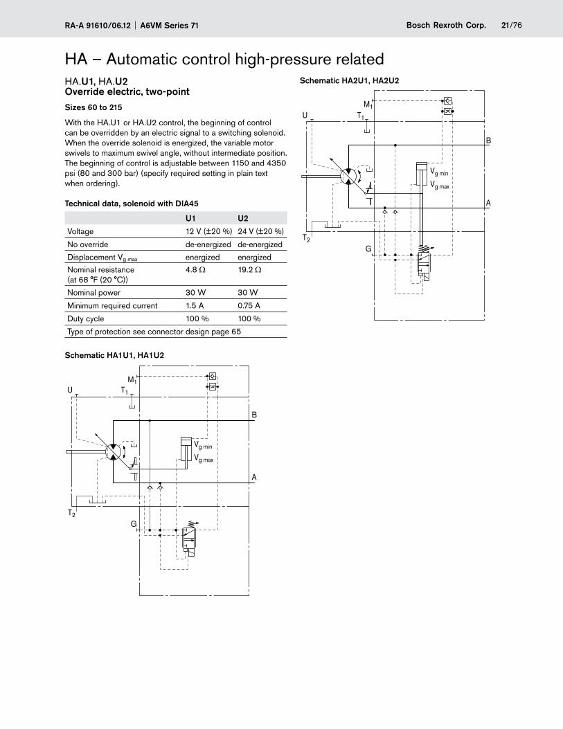
HA – Automatic control high-pressure relatedHA.U1, HA.U2 Override electric, two-pointSizes 60 to 215
With the HA.U1 or HA.U2 control, the beginning of control can be overridden by an electric signal to a switching solenoid. When the override solenoid is energized, the variable motor swivels to maximum swivel angle, without intermediate position. The beginning of control is adjustable between 1150 and 4350 psi (80 and 300 bar) (specify required setting in plain text when ordering).
Technical data, solenoid with DIA45
U1 U2
Voltage 12 V (±20 %) 24 V (±20 %)
No override de-energized de-energized
Displacement Vg max energized energized
Nominal resistance (at 68 °F (20 °C))
4.8 Ω 19.2 Ω
Nominal power 30 W 30 W
Minimum required current 1.5 A 0.75 A
Duty cycle 100 % 100 %
Type of protection see connector design page 65
Schematic HA1U1, HA1U2
G
B
A
M1
T2
T1
Vg min
Vg max
U
Schematic HA2U1, HA2U2
M1
T2
T1
B
A
Vg min
Vg max
G
U
A6VM Series 71 RA-A 91610/06.1222/76 Bosch Rexroth Corp.
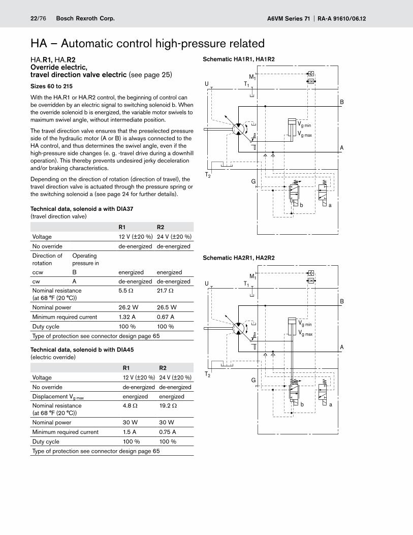
HA – Automatic control high-pressure relatedHA.R1, HA.R2 Override electric, travel direction valve electric (see page 25)
Sizes 60 to 215
With the HA.R1 or HA.R2 control, the beginning of control can be overridden by an electric signal to switching solenoid b. When the override solenoid b is energized, the variable motor swivels to maximum swivel angle, without intermediate position.
The travel direction valve ensures that the preselected pressure side of the hydraulic motor (A or B) is always connected to the HA control, and thus determines the swivel angle, even if the high-pressure side changes (e. g. -travel drive during a downhill operation). This thereby prevents undesired jerky deceleration and/or braking characteristics.
Depending on the direction of rotation (direction of travel), the travel direction valve is actuated through the pressure spring or the switching solenoid a (see page 24 for further details).
Technical data, solenoid a with DIA37 (travel direction valve)
R1 R2
Voltage 12 V (±20 %) 24 V (±20 %)
No override de-energized de-energized
Direction of rotation
Operating pressure in
ccw B energized energized
cw A de-energized de-energized
Nominal resistance (at 68 °F (20 °C))
5.5 Ω 21.7 Ω
Nominal power 26.2 W 26.5 W
Minimum required current 1.32 A 0.67 A
Duty cycle 100 % 100 %
Type of protection see connector design page 65
Technical data, solenoid b with DIA45 (electric override)
R1 R2
Voltage 12 V (±20 %) 24 V (±20 %)
No override de-energized de-energized
Displacement Vg max energized energized
Nominal resistance (at 68 °F (20 °C))
4.8 Ω 19.2 Ω
Nominal power 30 W 30 W
Minimum required current 1.5 A 0.75 A
Duty cycle 100 % 100 %
Type of protection see connector design page 65
Schematic HA1R1, HA1R2
ab
B
A
M1
T2
T1
Vg min
Vg max
U
G
Schematic HA2R1, HA2R2
M1
T2
T1
G
B
A
Vg min
Vg max
U
ab
23/76Bosch Rexroth Corp.RA-A 91610/06.12 A6VM Series 71
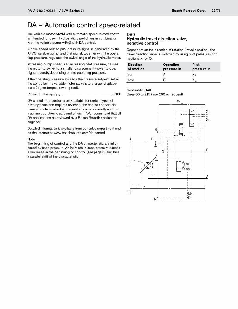
DA – Automatic control speed-relatedThe variable motor A6VM with automatic speed-related control is intended for use in hydrostatic travel drives in combination with the variable pump A4VG with DA control.
A drive-speed-related pilot pressure signal is generated by the A4VG variable pump, and that signal, together with the opera-ting pressure, regulates the swivel angle of the hydraulic motor.
Increasing pump speed, i.e. increasing pilot pressure, causes the motor to swivel to a smaller displacement (lower torque, higher speed), depending on the operating pressure.
If the operating pressure exceeds the pressure setpoint set on the controller, the variable motor swivels to a larger displace-ment (higher torque, lower speed).
Pressure ratio pSt/pHD ____________________________ 5/100
DA closed loop control is only suitable for certain types of drive systems and requires review of the engine and vehicle parameters to ensure that the motor is used correctly and that machine operation is safe and efficient. We recommend that all DA applications be reviewed by a Bosch Rexroth application engineer.
Detailed information is available from our sales department and on the Internet at www.boschrexroth.com/da-control.
NoteThe beginning of control and the DA characteristic are influ-enced by case pressure. An increase in case pressure causes a decrease in the beginning of control (see page 6) and thus a parallel shift of the characteristic.
DA0 Hydraulic travel direction valve, negative controlDependent on the direction of rotation (travel direction), the travel direction valve is switched by using pilot pressures con-nections X1 or X2.
Direction of rotation
Operating pressure in
Pilot pressure in
cw A X1
ccw B X2
Schematic DA0Sizes 60 to 215 (size 280 on request)
M1
T2
T1
Vg min
Vg max
B
A
G
X3
X2
X1
U
A6VM Series 71 RA-A 91610/06.1224/76 Bosch Rexroth Corp.
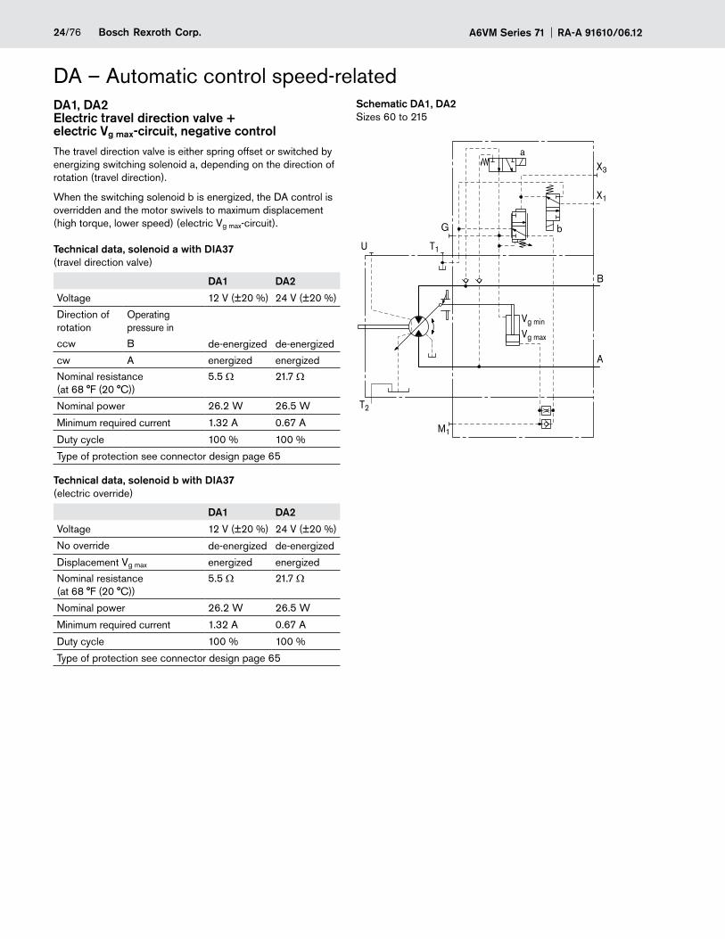
DA – Automatic control speed-relatedDA1, DA2 Electric travel direction valve + electric Vg max-circuit, negative controlThe travel direction valve is either spring offset or switched by energizing switching solenoid a, depending on the direction of rotation (travel direction).
When the switching solenoid b is energized, the DA control is overridden and the motor swivels to maximum displacement (high torque, lower speed) (electric Vg max-circuit).
Technical data, solenoid a with DIA37 (travel direction valve)
DA1 DA2
Voltage 12 V (±20 %) 24 V (±20 %)
Direction of rotation
Operating pressure in
ccw B de-energized de-energized
cw A energized energized
Nominal resistance (at 68 °F (20 °C))
5.5 Ω 21.7 Ω
Nominal power 26.2 W 26.5 W
Minimum required current 1.32 A 0.67 A
Duty cycle 100 % 100 %
Type of protection see connector design page 65
Technical data, solenoid b with DIA37 (electric override)
DA1 DA2
Voltage 12 V (±20 %) 24 V (±20 %)
No override de-energized de-energized
Displacement Vg max energized energized
Nominal resistance (at 68 °F (20 °C))
5.5 Ω 21.7 Ω
Nominal power 26.2 W 26.5 W
Minimum required current 1.32 A 0.67 A
Duty cycle 100 % 100 %
Type of protection see connector design page 65
Schematic DA1, DA2Sizes 60 to 215
T2
T1
M1
Vg min
Vg max
B
A
G
X3
a
b
X1
U
25/76Bosch Rexroth Corp.RA-A 91610/06.12 A6VM Series 71
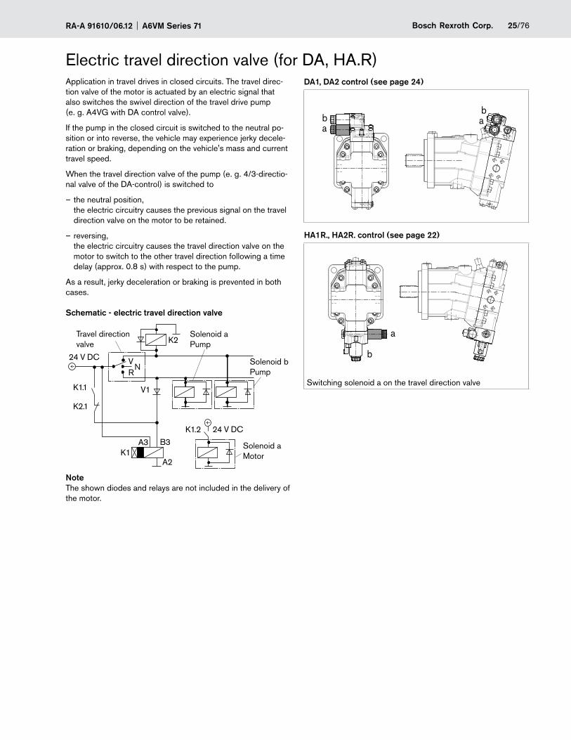
Electric travel direction valve (for DA, HA.R)Application in travel drives in closed circuits. The travel direc-tion valve of the motor is actuated by an electric signal that also switches the swivel direction of the travel drive pump (e. g. A4VG with DA control valve).
If the pump in the closed circuit is switched to the neutral po-sition or into reverse, the vehicle may experience jerky decele-ration or braking, depending on the vehicle's mass and current travel speed.
When the travel direction valve of the pump (e. g. 4/3-directio-nal valve of the DA-control) is switched to
the neutral position, –the electric circuitry causes the previous signal on the travel direction valve on the motor to be retained.
reversing, –the electric circuitry causes the travel direction valve on the motor to switch to the other travel direction following a time delay (approx. 0.8 s) with respect to the pump.
As a result, jerky deceleration or braking is prevented in both cases.
Schematic - electric travel direction valve
K1.1
K1.2
K1
K2.1
K2
A3 B3
A2
V1
V NR
24 V DC
24 V DC
Solenoid a Pump
Solenoid b Pump
Solenoid a Motor
Travel direction valve
NoteThe shown diodes and relays are not included in the delivery of the motor.
DA1, DA2 control (see page 24)
bab
a
HA1R., HA2R. control (see page 22)
a
b
Switching solenoid a on the travel direction valve
A6VM Series 71 RA-A 91610/06.1226/76 Bosch Rexroth Corp.
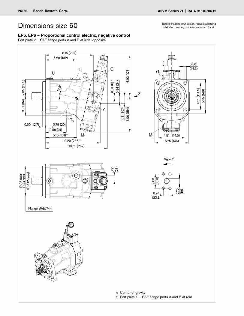
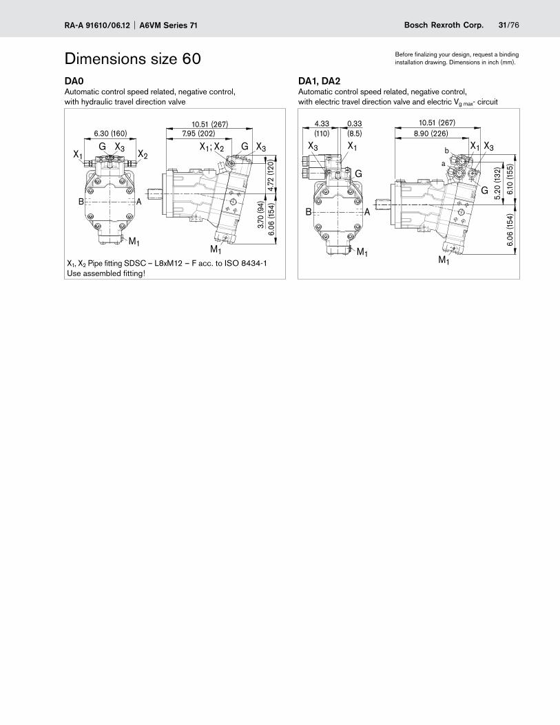
Dimensions size 60 Before finalizing your design, request a binding installation drawing. Dimensions in inch (mm).
EP5, EP6 – Proportional control electric, negative controlPort plate 2 — SAE flange ports A and B at side, opposite
12.5
°
0.91
(23)
UT1
T2
G
M1
Y
2.85
(72.
5)3.
31 (8
4)
9.29 (236)2)
0.79 (20)0.50 (12.7)
5.16 (131)1)
3.58 (91)6.
93 (1
76)
6.06
(154
)
8.15 (207)5.20 (132)
10.51 (267)
DIA
4.99
8D
IA5.
000
(DIA
127
)
-0.0
5
Z
2.00
(50.
8)
0.75
(19)
0.94(23.8)
0.94
(24)
1.18
(30)
2)
0.31
(8)1)
5.75 (146)
4.51
(114
.5)
5.75
(146
)
4.51 (114.5)
G
M1
0.56(14.3)
Flange SAEJ744
Center of gravity1)
Port plate 1 — SAE flange ports A and B at rear2)
View Y
27/76Bosch Rexroth Corp.RA-A 91610/06.12 A6VM Series 71
Dimensions size 60 Before finalizing your design, request a binding installation drawing. Dimensions in inch (mm).
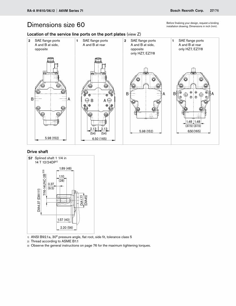
Location of the service line ports on the port plates (view Z)2 SAE flange ports
A and B at side, opposite
1 SAE flange ports A and B at rear
2 SAE flange ports A and B at side, opposite only HZ7, EZ7/8
1 SAE flange ports A and B at rear only HZ7, EZ7/8
B A
5.98 (152)
2.13(54)
6.50 (165)
2.13(54)
B A
5.98 (152)
AB
1.48(37.5)
AB
6.50 (165)
1.48(37.5)
Drive shaftS7 Splined shaft 1 1/4 in
14 T 12/24DP1)
2.20 (56)
DIA
4.37
(DIA
111)
1.89 (48)
7/16
-14U
NC
-2B 1.10
(28)
DIA
1.77
(DIA
45)
1.57 (40)
0.37(9.5)
2)3)
ANSI B92.1a, 30° pressure angle, flat root, side fit, tolerance class 51)
Thread according to 2) ASME B1.1Observe the general instructions on page 3) 76 for the maximum tightening torques.
A6VM Series 71 RA-A 91610/06.1228/76 Bosch Rexroth Corp.
Dimensions size 60 Before finalizing your design, request a binding installation drawing. Dimensions in inch (mm).
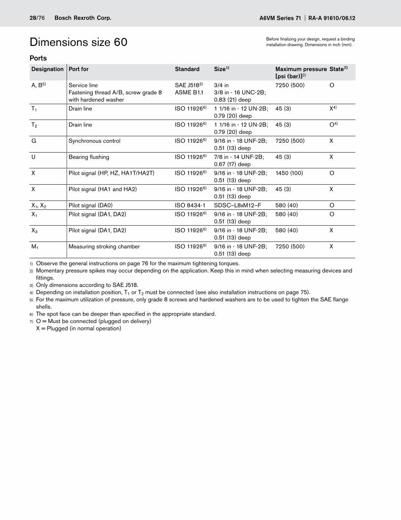
PortsDesignation Port for Standard Size1) Maximum pressure
[psi (bar)]2)State7)
A, B5) Service line Fastening thread A/B, screw grade 8 with hardened washer
SAE J5183) ASME B1.1
3/4 in 3/8 in - 16 UNC-2B; 0.83 (21) deep
7250 (500) O
T1 Drain line ISO 119266) 1 1/16 in - 12 UN-2B; 0.79 (20) deep
45 (3) X4)
T2 Drain line ISO 119266) 1 1/16 in - 12 UN-2B; 0.79 (20) deep
45 (3) O4)
G Synchronous control ISO 119266) 9/16 in - 18 UNF-2B; 0.51 (13) deep
7250 (500) X
U Bearing flushing ISO 119266) 7/8 in - 14 UNF-2B; 0.67 (17) deep
45 (3) X
X Pilot signal (HP, HZ, HA1T/HA2T) ISO 119266) 9/16 in - 18 UNF-2B; 0.51 (13) deep
1450 (100) O
X Pilot signal (HA1 and HA2) ISO 119266) 9/16 in - 18 UNF-2B; 0.51 (13) deep
45 (3) X
X1, X2 Pilot signal (DA0) ISO 8434-1 SDSC–L8xM12–F 580 (40) O
X1 Pilot signal (DA1, DA2) ISO 119266) 9/16 in - 18 UNF-2B; 0.51 (13) deep
580 (40) O
X3 Pilot signal (DA1, DA2) ISO 119266) 9/16 in - 18 UNF-2B; 0.51 (13) deep
580 (40) X
M1 Measuring stroking chamber ISO 119266) 9/16 in - 18 UNF-2B; 0.51 (13) deep
7250 (500) X
Observe the general instructions on page 1) 76 for the maximum tightening torques.Momentary pressure spikes may occur depending on the application. Keep this in mind when selecting measuring devices and 2)
fittings.Only dimensions according to SAE J518.3)
Depending on installation position, T4) 1 or T2 must be connected (see also installation instructions on page 75).For the maximum utilization of pressure, only grade 8 screws and hardened washers are to be used to tighten the SAE flange 5)
shells.The spot face can be deeper than specified in the appropriate standard.6)
O = Must be connected (plugged on delivery) 7)
X = Plugged (in normal operation)
29/76Bosch Rexroth Corp.RA-A 91610/06.12 A6VM Series 71
Dimensions size 60 Before finalizing your design, request a binding installation drawing. Dimensions in inch (mm).
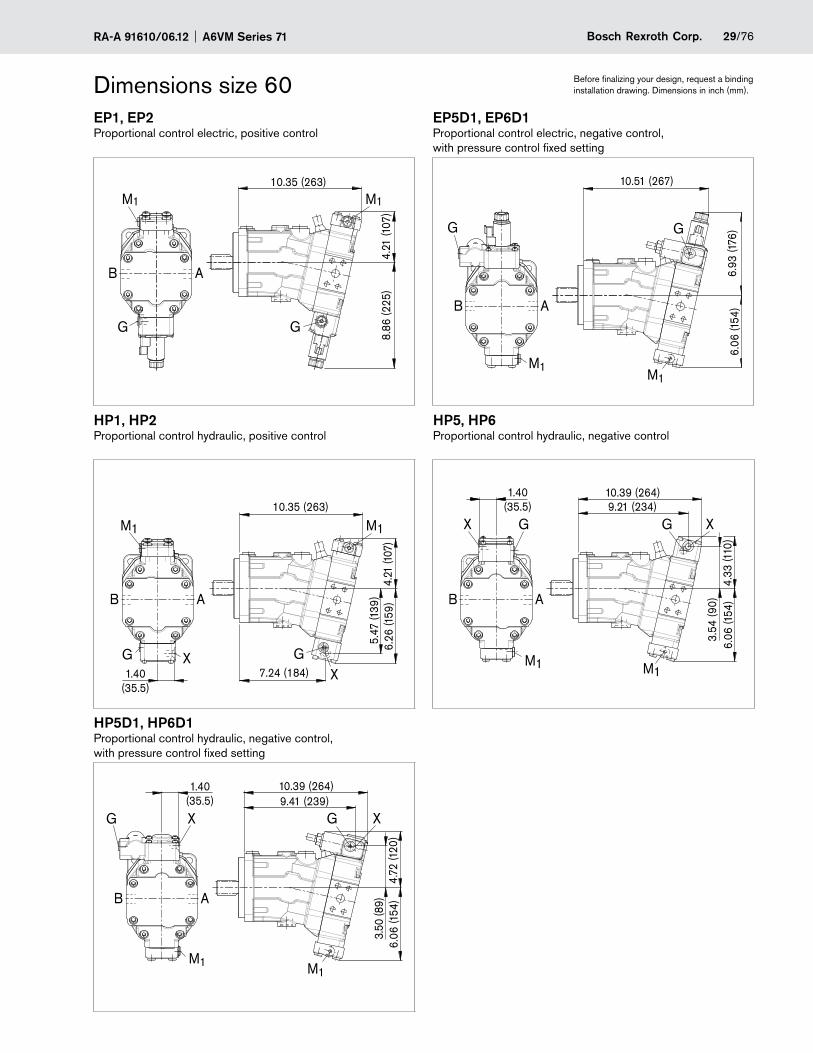
EP1, EP2 EP5D1, EP6D1Proportional control electric, positive control Proportional control electric, negative control,
with pressure control fixed setting
M1
B A
10.35 (263)
8.86
(225
)4.
21 (1
07)
GG
M1
M1M1
G
B A
G
6.06
(154
)6.
93 (1
76)
10.51 (267)
HP1, HP2 HP5, HP6Proportional control hydraulic, positive control Proportional control hydraulic, negative control
M1
XGX
G1.40
(35.5)7.24 (184)
10.35 (263)
B A
6.26
(159
)4.
21 (1
07)
5.47
(139
)
M1 X G XG9.21 (234)
10.39 (264)
6.06
(154
)3.
54 (9
0)4.
33 (1
10)
B A
1.40(35.5)
M1 M1
HP5D1, HP6D1Proportional control hydraulic, negative control, with pressure control fixed setting
1.40(35.5) 9.41 (239)
10.39 (264)
M1
GG X X
M1
B A
6.06
(154
)3.
50 (8
9)4.
72 (1
20)
A6VM Series 71 RA-A 91610/06.1230/76 Bosch Rexroth Corp.
Dimensions size 60 Before finalizing your design, request a binding installation drawing. Dimensions in inch (mm).
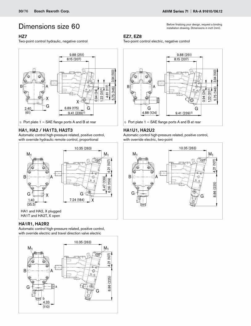
HZ7 EZ7, EZ8Two-point control hydraulic, negative control Two-point control electric, negative control
2.40(61)
G
X
AB
0.94
(24)
1.22
(31)
1)
5.75
(146
)
4.61
(117
)G6.89 (175)
9.41 (239)1)
X
8.15 (207)9.88 (251)
3.94
(100
)4.88 (124)
G
AB
G9.41 (239)1)
0.94
(24)
1.22
(31)
1)
5.75
(146
)
8.15 (207)9.88 (251)
3.94
(100
)
HA1, HA2 / HA1T3, HA2T3 HA1U1, HA2U2Automatic control high-pressure related, positive control, with override hydraulic remote control, proportional
Automatic control high-pressure related, positive control, with override electric, two-point
XGX
G1.40
(35.5)7.24 (184)
10.35 (263)
B A
6.26
(159
)4.
21 (1
07)
5.47
(139
)
M1 M1
B A
8.86
(225
)
GG
10.35 (263)
4.21
(107
)
M1M1
HA1R1, HA2R2Automatic control high-pressure related, positive control, with override electric and travel direction valve electric
a
b
GG
B A
4.33(110)
10.35 (263)
8.86
(225
)4.
21 (1
07)
M1M1
HA1 and HA2, X plugged HA1T and HA2T, X open
Port plate 1 — SAE flange ports A and B at rear1) Port plate 1 — SAE flange ports A and B at rear1)
31/76Bosch Rexroth Corp.RA-A 91610/06.12 A6VM Series 71
Dimensions size 60 Before finalizing your design, request a binding installation drawing. Dimensions in inch (mm).
DA0 DA1, DA2Automatic control speed related, negative control, with hydraulic travel direction valve
Automatic control speed related, negative control, with electric travel direction valve and electric Vg max- circuit
M1
7.95 (202)10.51 (267)
6.06
(154
)3.
70 (9
4)4.
72 (1
20)
6.30 (160)
M1
AB
G X3X1; X2G X3X1 X2
G
M1M1
5.20
(132
)
6.10
(155
)
G
X1
4.33(110)
0.33(8.5)
AB
b
a
8.90 (226)10.51 (267)
6.06
(154
)
X3X3 X1
X1, X2 Pipe fitting SDSC – L8xM12 – F acc. to ISO 8434-1 Use assembled fitting!
A6VM Series 71 RA-A 91610/06.1232/76 Bosch Rexroth Corp.
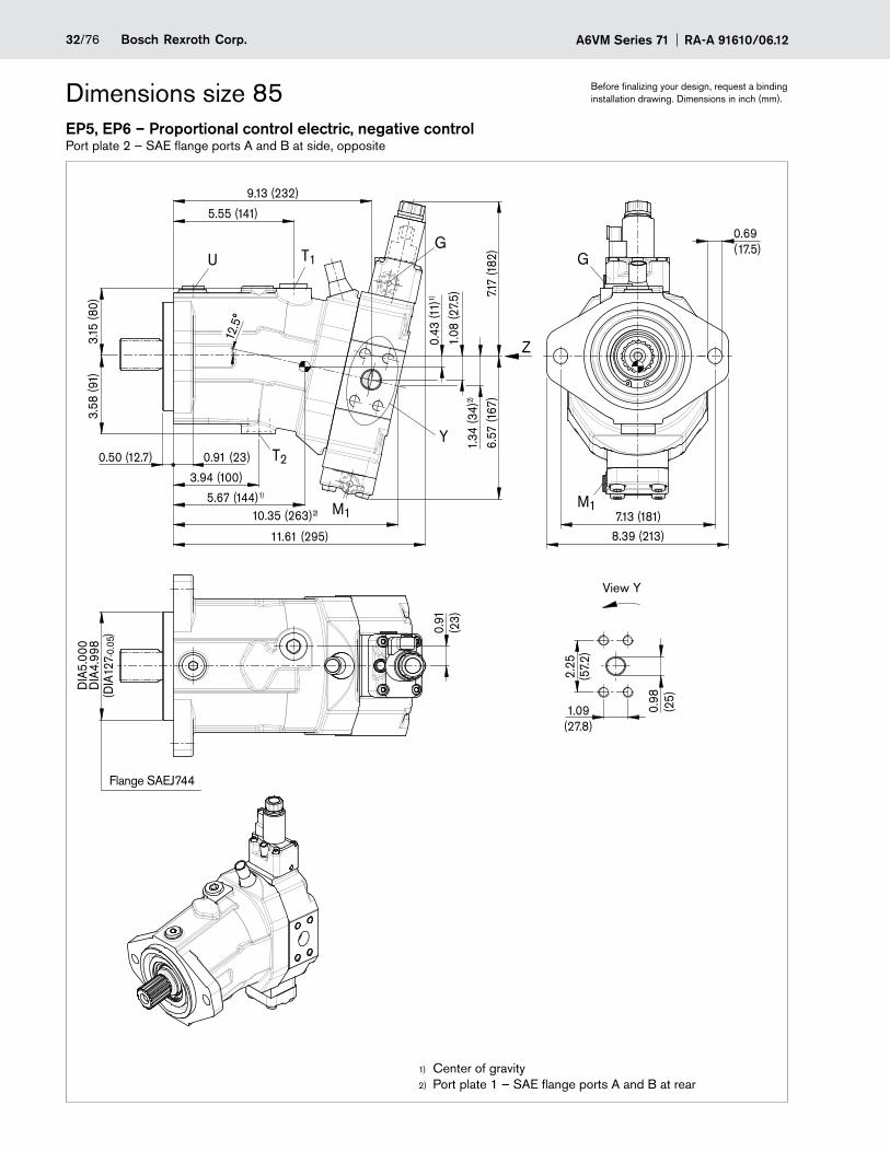
Dimensions size 85 Before finalizing your design, request a binding installation drawing. Dimensions in inch (mm).
EP5, EP6 – Proportional control electric, negative controlPort plate 2 — SAE flange ports A and B at side, opposite
T2
T1U
M1
3.58
(91)
Y
G
5.55 (141)
11.61 (295)
10.35 (263)2)
6.57
(167
)
0.50 (12.7) 0.91 (23)
3.15
(80)
1.08
(27.
5) 7.17
(182
)1.
34 (3
4)2)
0.91
(23)
9.13 (232)
2.25
(57.
2)
0.98
(25)
1.09(27.8)
DIA
4.99
8D
IA5.
000
Z
5.67 (144)1)
0.43
(11)
1)
3.94 (100)
0.69(17.5)
7.13 (181)8.39 (213)
12.5
°
G
(DIA
127
)
-0.0
5
M1
Center of gravity1)
Port plate 1 — SAE flange ports A and B at rear2)
Flange SAEJ744
View Y

33/76Bosch Rexroth Corp.RA-A 91610/06.12 A6VM Series 71
Dimensions size 85 Before finalizing your design, request a binding installation drawing. Dimensions in inch (mm).
Location of the service line ports on the port plates (view Z)2 SAE flange ports
A and B at side, opposite
1 SAE flange ports A and B at rear
2 SAE flange ports A and B at side, opposite only HZ7, EZ7/8
1 SAE flange ports A and B at rear only HZ7, EZ7/8
B A
6.46 (164)
B A
6.97 (177)
2.13(54)
2.13(54)
AB
6.46 (164)
B A
1.65(42)
1.65(42)6.97 (177)
Drive shaftS9 Splined shaft 1 1/2 in
17 T 12/24DP1)
2.44 (62)
DIA
4.33
(DIA
110)
2.13 (54)
7/16
-14U
NC
-2B 1.10
(28)
DIA
1.97
(DIA
50)
1.73 (44)
0.37(9.5)
2)3)
ANSI B92.1a, 30° pressure angle, flat root, side fit, tolerance class 51)
Thread according to 2) ASME B1.1Observe the general instructions on page 3) 76 for the maximum tightening torques.

A6VM Series 71 RA-A 91610/06.1234/76 Bosch Rexroth Corp.
Dimensions size 85 Before finalizing your design, request a binding installation drawing. Dimensions in inch (mm).
PortsDesignation Port for Standard Size1) Maximum pressure
[psi (bar)]2)State7)
A, B5) Service line Fastening thread A/B, screw grade 8 with hardened washer
SAE J5183) ASME B1.1
1 in 7/16 in - 14 UNC-2B; 0.87 (22) deep
7250 (500) O
T1 Drain line ISO 119266) 1 1/16 in - 12 UN-2B; 0.79 (20) deep
45 (3) X4)
T2 Drain line ISO 119266) 1 1/16 in - 12 UN-2B; 0.79 (20) deep
45 (3) O4)
G Synchronous control ISO 119266) 9/16 in - 18 UNF-2B; 0.51 (13) deep
7250 (500) X
U Bearing flushing ISO 119266) 7/8 in - 14 UNF-2B; 0.67 (17) deep
45 (3) X
X Pilot signal (HP, HZ, HA1T/HA2T) ISO 119266) 9/16 in - 18 UNF-2B; 0.51 (13) deep
1450 (100) O
X Pilot signal (HA1 and HA2) ISO 119266) 9/16 in - 18 UNF-2B; 0.51 (13) deep
45 (3) X
X1, X2 Pilot signal (DA0) ISO 8434-1 SDSC–L8xM12–F 580 (40) O
X1 Pilot signal (DA1, DA2) ISO 119266) 9/16 in - 18 UNF-2B; 0.51 (13) deep
580 (40) O
X3 Pilot signal (DA1, DA2) ISO 119266) 9/16 in - 18 UNF-2B; 0.51 (13) deep
580 (40) X
M1 Measuring stroking chamber ISO 119266) 9/16 in - 18 UNF-2B; 0.51 (13) deep
7250 (500) X
Observe the general instructions on page 1) 76 for the maximum tightening torques.Momentary pressure spikes may occur depending on the application. Keep this in mind when selecting measuring devices and 2)
fittings.Only dimensions according to SAE J518, 3) metric fastening thread is a deviation from standard.Depending on installation position, T4) 1 or T2 must be connected (see also installation instructions on page 75).For the maximum utilization of pressure, only grade 8 screws and hardened washers are to be used to tighten the SAE flange 5)
shells.The spot face can be deeper than specified in the appropriate standard.6)
O = Must be connected (plugged on delivery) 7)
X = Plugged (in normal operation)
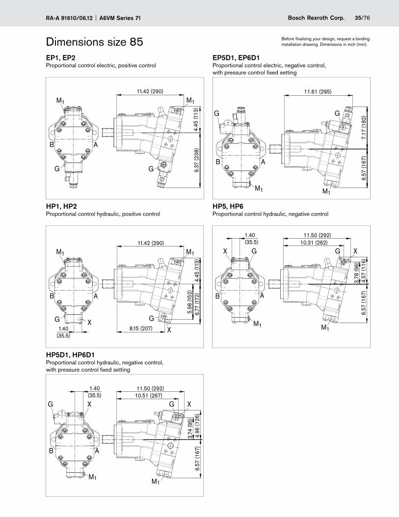
35/76Bosch Rexroth Corp.RA-A 91610/06.12 A6VM Series 71
Dimensions size 85 Before finalizing your design, request a binding installation drawing. Dimensions in inch (mm).
EP1, EP2 EP5D1, EP6D1Proportional control electric, positive control Proportional control electric, negative control,
with pressure control fixed setting
G
11.42 (290)
9.37
(238
)4.
45 (1
13)
AB
G
M1M1
G G
AB
11.61 (295)
7.17
(182
)6.
57 (1
67)
M1 M1
HP1, HP2 HP5, HP6Proportional control hydraulic, positive control Proportional control hydraulic, negative control
11.42 (290)
G X
6.77
(172
)4.
45 (1
13)
G
X8.15 (207)
5.98
(152
)
1.40(35.5)
AB
M1 M1 G XX
AB
G
1.40(35.5) 10.31 (262)
11.50 (292)
4.57
(116
)3.
78 (9
6)6.
57 (1
67)
M1 M1
HP5D1, HP6D1Proportional control hydraulic, negative control, with pressure control fixed setting
G
M1
X
1.40(35.5)
G X
M1
3.74
(95)
10.51 (267)
AB
11.50 (292)
4.96
(126
)6.
57 (1
67)
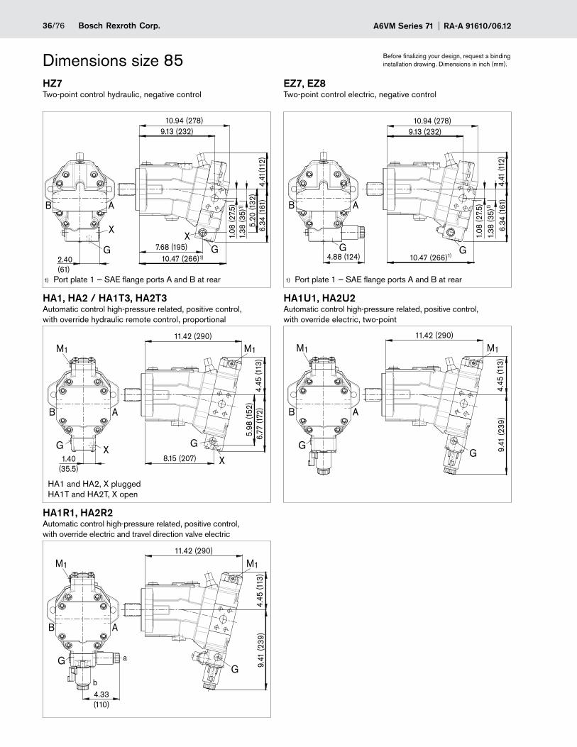
A6VM Series 71 RA-A 91610/06.1236/76 Bosch Rexroth Corp.
Dimensions size 85 Before finalizing your design, request a binding installation drawing. Dimensions in inch (mm).
HZ7 EZ7, EZ8Two-point control hydraulic, negative control Two-point control electric, negative control
10.47 (266)1)
9.13 (232)10.94 (278)
4.41
(112
)
1.08
(27.
5)1.
38 (3
5)1)
6.34
(161
)G
X7.68 (195)
AB
2.40(61)
5.20
(132
)G
X
4.88 (124)G
10.47 (266)1)
AB
9.13 (232)10.94 (278)
4.41
(112
)
1.08
(27.
5)1.
38 (3
5)1)
6.34
(161
)
G
HA1, HA2 / HA1T3, HA2T3 HA1U1, HA2U2Automatic control high-pressure related, positive control, with override hydraulic remote control, proportional
Automatic control high-pressure related, positive control, with override electric, two-point
G
M1
XG
X
5.98
(152
)
11.42 (290)
6.77
(172
)4.
45 (1
13)
M1
8.15 (207)1.40(35.5)
AB
M1
G
M1
G
11.42 (290)
9.41
(239
)4.
45 (1
13)
AB
HA1R1, HA2R2Automatic control high-pressure related, positive control, with override electric and travel direction valve electric
M1
G
M1
G
4.33(110)
a
b
11.42 (290)
9.41
(239
)4.
45 (1
13)
AB
HA1 and HA2, X plugged HA1T and HA2T, X open
Port plate 1 — SAE flange ports A and B at rear1) Port plate 1 — SAE flange ports A and B at rear1)
37/76Bosch Rexroth Corp.RA-A 91610/06.12 A6VM Series 71
Dimensions size 85 Before finalizing your design, request a binding installation drawing. Dimensions in inch (mm).
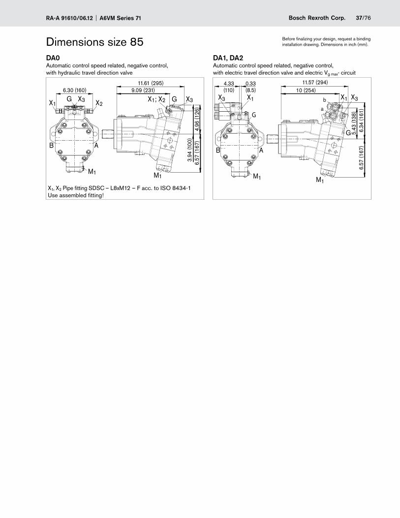
DA0 DA1, DA2Automatic control speed related, negative control, with hydraulic travel direction valve
Automatic control speed related, negative control, with electric travel direction valve and electric Vg max- circuit
M1
6.30 (160)
X3
9.09 (231)11.61 (295)
3.94
(100
)
X1; X2 GX1X3G X2
AB
4.96
(126
)6.
57 (1
67)
M1
G
M1M1
4.33(110)
0.33(8.5)
G
b
a
10 (254)11.57 (294)
5.43
(138
)
AB
6.34
(161
)6.
57 (1
67)
X1X3 X3X1
X1, X2 Pipe fitting SDSC – L8xM12 – F acc. to ISO 8434-1 Use assembled fitting!
A6VM Series 71 RA-A 91610/06.1238/76 Bosch Rexroth Corp.
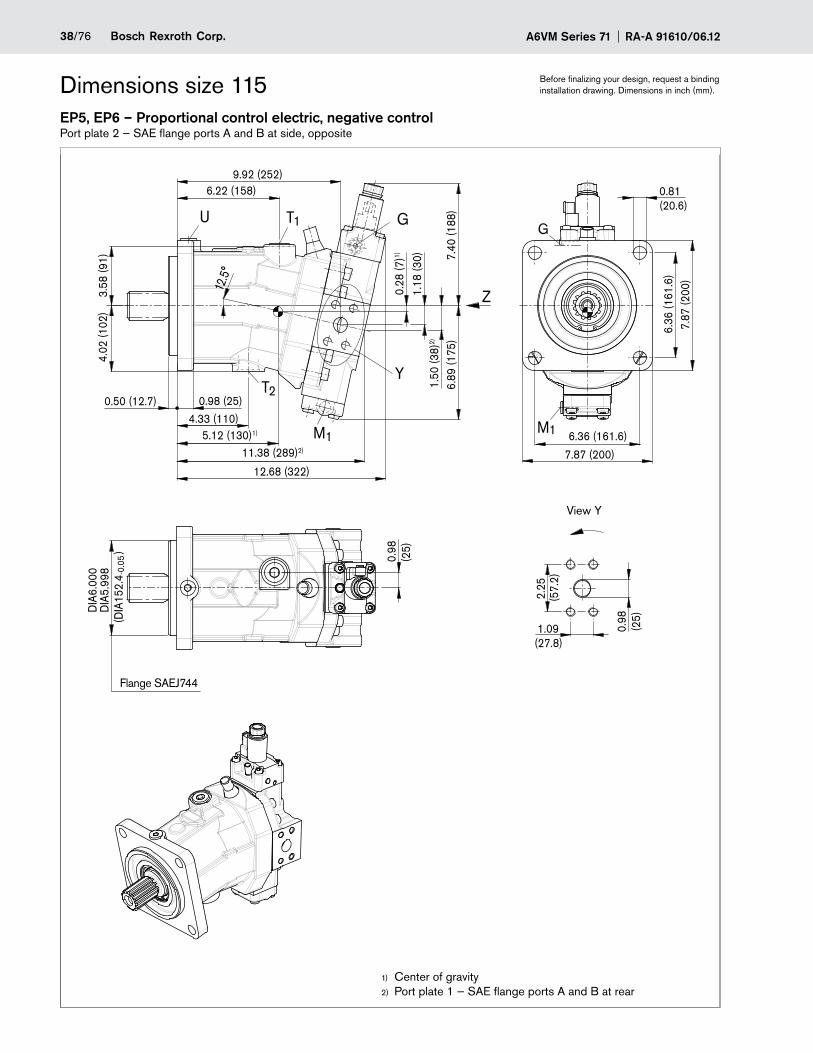
Dimensions size 115 Before finalizing your design, request a binding installation drawing. Dimensions in inch (mm).
EP5, EP6 – Proportional control electric, negative controlPort plate 2 — SAE flange ports A and B at side, opposite
6.22 (158)9.92 (252)
4.33 (110)
0.98
(25)
GU
T2
M1
Y
T1
2.25
(57.
2)
0.98
(25)
1.09(27.8)
DIA
6.00
0D
IA5.
998
7.87 (200)
6.36
(161
.6)
7.87
(200
)
6.36 (161.6)
12.5
°
3.58
(91)
4.02
(102
)
Z
7.40
(188
)6.
89 (1
75)
1.18
(30)
1.50
(38)
2)
0.28
(7)1)
12.68 (322)
0.50 (12.7)
11.38 (289)2)
5.12 (130)1)
0.98 (25)
G
0.81(20.6)
(DIA
152.
4
)
-0.0
5
M1
Center of gravity1)
Port plate 1 — SAE flange ports A and B at rear2)
Flange SAEJ744
View Y
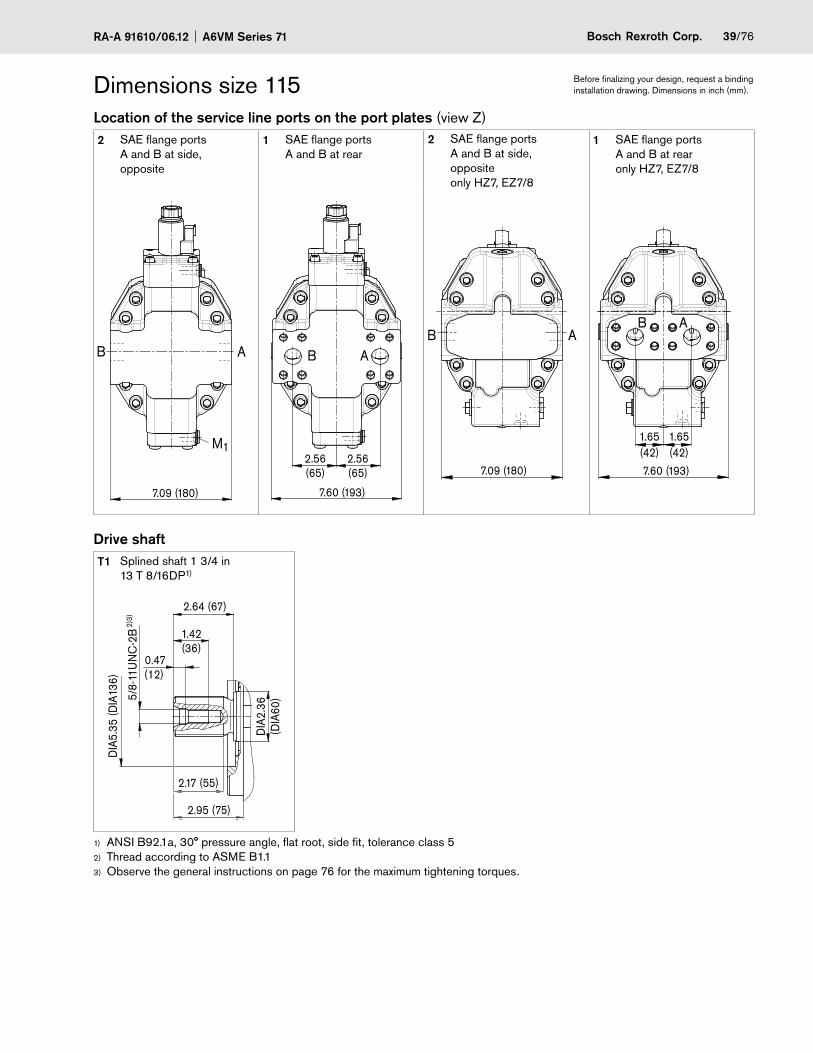
39/76Bosch Rexroth Corp.RA-A 91610/06.12 A6VM Series 71
Dimensions size 115 Before finalizing your design, request a binding installation drawing. Dimensions in inch (mm).
Location of the service line ports on the port plates (view Z)2 SAE flange ports
A and B at side, opposite
1 SAE flange ports A and B at rear
2 SAE flange ports A and B at side, opposite only HZ7, EZ7/8
1 SAE flange ports A and B at rear only HZ7, EZ7/8
M1
AB
7.09 (180)
B A
7.60 (193)
2.56(65)
2.56(65)
B A
7.09 (180)
B A
1.65(42)
1.65(42)
7.60 (193)
Drive shaftT1 Splined shaft 1 3/4 in
13 T 8/16DP1)
2.95 (75)
DIA
5.35
(DIA
136)
2.64 (67)
5/8-
11U
NC
-2B 1.42
(36)
DIA
2.36
(DIA
60)
2.17 (55)
0.47(12)
2)3)
ANSI B92.1a, 30° pressure angle, flat root, side fit, tolerance class 51)
Thread according to 2) ASME B1.1Observe the general instructions on page 3) 76 for the maximum tightening torques.

A6VM Series 71 RA-A 91610/06.1240/76 Bosch Rexroth Corp.
Dimensions size 115 Before finalizing your design, request a binding installation drawing. Dimensions in inch (mm).
PortsDesignation Port for Standard Size1) Maximum pressure
[psi (bar)]2)State7)
A, B5) Service line Fastening thread A/B, screw grade 8 with hardened washer
SAE J5183) ASME B1.1
1 in 7/16 in - 14 UNC-2B; 0.87 (22) deep
7250 (500) O
T1 Drain line ISO 119266) 1 1/16 in - 12 UN-2B; 0.79 (20) deep
45 (3) X4)
T2 Drain line ISO 119266) 1 5/16 in - 12 UN-2B; 0.79 (20) deep
45 (3) O4)
G Synchronous control ISO 119266) 9/16 in - 18 UNF-2B; 0.51 (13) deep
7250 (500) X
U Bearing flushing ISO 119266) 7/8 in - 14 UNF-2B; 0.67 (17) deep
45 (3) X
X Pilot signal (HP, HZ, HA1T/HA2T) ISO 119266) 9/16 in - 18 UNF-2B; 0.51 (13) deep
1450 (100) O
X Pilot signal (HA1 and HA2) ISO 119266) 9/16 in - 18 UNF-2B; 0.51 (13) deep
45 (3) X
X1, X2 Pilot signal (DA0) ISO 8434-1 SDSC–L8xM12–F 580 (40) O
X1 Pilot signal (DA1, DA2) ISO 119266) 9/16 in - 18 UNF-2B; 0.51 (13) deep
580 (40) O
X3 Pilot signal (DA1, DA2) ISO 119266) 9/16 in - 18 UNF-2B; 0.51 (13) deep
580 (40) X
M1 Measuring stroking chamber ISO 119266) 9/16 in - 18 UNF-2B; 0.51 (13) deep
7250 (500) X
Observe the general instructions on page 1) 76 for the maximum tightening torques.Momentary pressure spikes may occur depending on the application. Keep this in mind when selecting measuring devices and 2)
fittings.Only dimensions according to SAE J518, 3) metric fastening thread is a deviation from standard.Depending on installation position, T4) 1 or T2 must be connected (see also installation instructions on page 75).For the maximum utilization of pressure, only grade 8 screws and hardened washers are to be used to tighten the SAE flange 5)
shells.The spot face can be deeper than specified in the appropriate standard.6)
O = Must be connected (plugged on delivery)7) X = Plugged (in normal operation)

41/76Bosch Rexroth Corp.RA-A 91610/06.12 A6VM Series 71
Dimensions size 115 Before finalizing your design, request a binding installation drawing. Dimensions in inch (mm).
EP1, EP2 EP5D1, EP6D1Proportional control electric, positive control Proportional control electric, negative control,
with pressure control fixed setting
M1
4.76
(121
)
12.32 (313)
9.80
(249
)
M1
B A
G G
G
7.40
(188
)6.
89 (1
75)
G
12.68 (322)
B A
HP1, HP2 HP5, HP6Proportional control hydraulic, positive control Proportional control hydraulic, negative control
1.59(40.5)
G X
6.46
(164
)
9.09 (231)
4.76
(121
)7.
09 (1
80)
12.32 (313)
G
M1
X
M1
B A
GX11.38 (289)
M1
1.59(40.5)
G
4.76
(121
)6.
89 (1
75)
3.98
(101
)
12.60 (320)
M1
X
AB
HP5D1, HP6D1Proportional control hydraulic, negative control, with pressure control fixed setting
G X
M1
XG
M1
5.24
(133
)6.
89 (1
75)
3.98
(101
)
12.68 (322)11.42 (290)
1.59(40.5)
B A
A6VM Series 71 RA-A 91610/06.1242/76 Bosch Rexroth Corp.
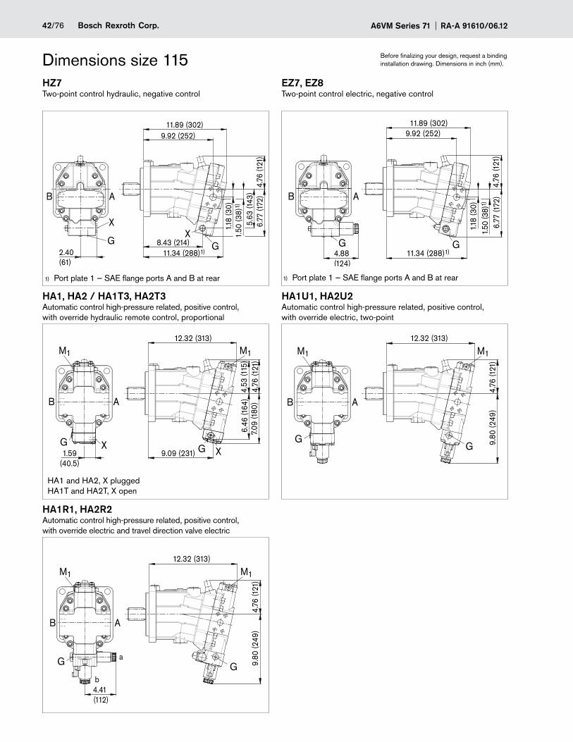
Dimensions size 115 Before finalizing your design, request a binding installation drawing. Dimensions in inch (mm).
HZ7 EZ7, EZ8Two-point control hydraulic, negative control Two-point control electric, negative control
5.63
(143
)8.43 (214) G
2.40(61)
XX
11.34 (288)1)4.
76 (1
21)
6.77
(172
)
1.18
(30)
1.50
(38)
1)
9.92 (252)11.89 (302)
B A
G11.34 (288)1)
1.18
(30)
G G4.88(124)
4.76
(121
)1.
50 (3
8)1)
9.92 (252)
B A
6.77
(172
)
11.89 (302)
HA1, HA2 / HA1T3, HA2T3 HA1U1, HA2U2Automatic control high-pressure related, positive control, with override hydraulic remote control, proportional
Automatic control high-pressure related, positive control, with override electric, two-point
1.59(40.5)
G X
6.46
(164
)
9.09 (231)
4.53
(115
)4.
76 (1
21)
7.09
(180
)
12.32 (313)
G
M1
X
M1
B A
4.76
(121
)9.
80 (2
49)
G
M1
G
M1
12.32 (313)
B A
HA1R1, HA2R2Automatic control high-pressure related, positive control, with override electric and travel direction valve electric
4.41 (112)
4.76
(121
)9.
80 (2
49)
G
M1
G
M1
12.32 (313)
B A
a
b
HA1 and HA2, X plugged HA1T and HA2T, X open
Port plate 1 — SAE flange ports A and B at rear1) Port plate 1 — SAE flange ports A and B at rear1)
43/76Bosch Rexroth Corp.RA-A 91610/06.12 A6VM Series 71
Dimensions size 115 Before finalizing your design, request a binding installation drawing. Dimensions in inch (mm).
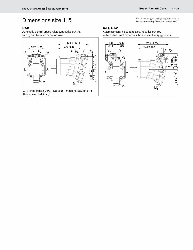
DA0 DA1, DA2Automatic control speed related, negative control, with hydraulic travel direction valve
Automatic control speed related, negative control, with electric travel direction valve and electric Vg max- circuit
G6.85 (174)
6.89
(175
)
12.68 (322)
5.20
(132
)4.
21 (1
07)
X3X1 X2X1, X2 G X3
M1 M1
B A
9.76 (248)4.41(112) 10.63 (270)
12.68 (322)
M1 M1
G
X3X1
G
X1
6.89
(175
)5.
71 (1
45)
6.61
(168
)
X3 ba
0.33(8.5)
B A
X1, X2 Pipe fitting SDSC – L8xM12 – F acc. to ISO 8434-1 Use assembled fitting!
A6VM Series 71 RA-A 91610/06.1244/76 Bosch Rexroth Corp.
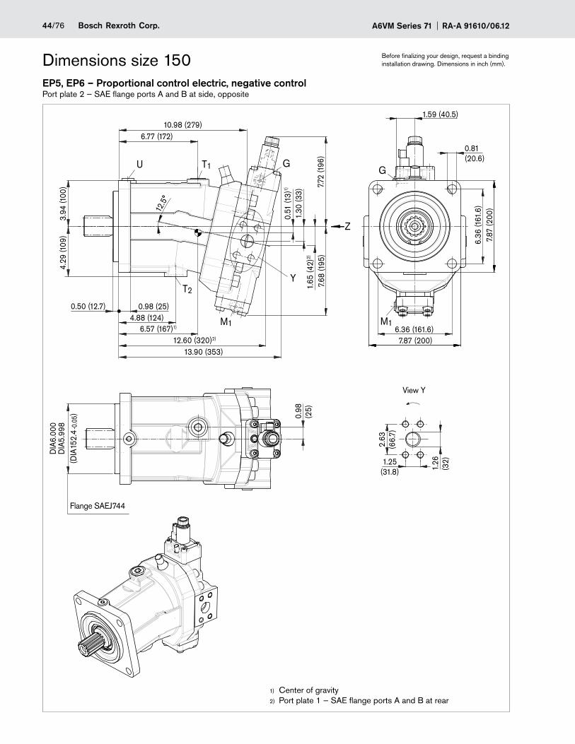
Dimensions size 150 Before finalizing your design, request a binding installation drawing. Dimensions in inch (mm).
EP5, EP6 – Proportional control electric, negative controlPort plate 2 — SAE flange ports A and B at side, opposite
M1
T1
T2
U
0.98
(25)
0.50 (12.7)
10.98 (279)
0.81(20.6)
13.90 (353)
2.63
(66.
7)
1.26
(32)1.25
(31.8)
12.60 (320)2)
0.51
(13)
1)
1.30
(33)
1.65
(42)
2)0.98 (25)
4.88 (124)
12.5
°
(DIA
152.
4
)
-0.0
5
4.29
(109
)3.
94 (1
00) 7.7
2 (1
96)
7.68
(195
)6.57 (167)1)
7.87 (200)
7.87
(200
)
Y
Z
G
DIA
6.00
0D
IA5.
998
6.77 (172)
6.36
(161
.6)
6.36 (161.6)
1.59 (40.5)
G
M1
Center of gravity1)
Port plate 1 — SAE flange ports A and B at rear2)
Flange SAEJ744
View Y
45/76Bosch Rexroth Corp.RA-A 91610/06.12 A6VM Series 71
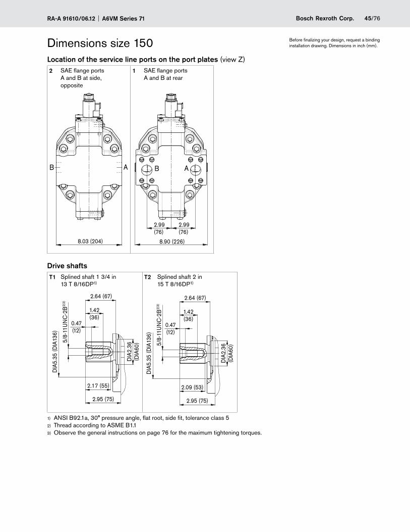
Dimensions size 150 Before finalizing your design, request a binding installation drawing. Dimensions in inch (mm).
Location of the service line ports on the port plates (view Z)2 SAE flange ports
A and B at side, opposite
1 SAE flange ports A and B at rear
AB
8.03 (204)
B A
2.99(76)
2.99(76)
8.90 (226)
Drive shaftsT1 Splined shaft 1 3/4 in
13 T 8/16DP1)T2 Splined shaft 2 in
15 T 8/16DP1)
2.95 (75)
DIA
5.35
(DIA
136)
1.42(36)
2.17 (55)
5/8-
11U
NC
-2B
2)3)
DIA
2.36
(DIA
60)
2.64 (67)
0.47(12)
2.95 (75)
DIA
5.35
(DIA
136)
1.42(36)
2.09 (53)
5/8-
11U
NC
-2B
2)3)
DIA
2.36
(DIA
60)
2.64 (67)
0.47(12)
ANSI B92.1a, 30° pressure angle, flat root, side fit, tolerance class 51)
Thread according to 2) ASME B1.1Observe the general instructions on page 3) 76 for the maximum tightening torques.

A6VM Series 71 RA-A 91610/06.1246/76 Bosch Rexroth Corp.
Dimensions size 150 Before finalizing your design, request a binding installation drawing. Dimensions in inch (mm).
PortsDesignation Port for Standard Size1) Maximum pressure
[psi (bar)]2)State7)
A, B5) Service line Fastening thread A/B, screw grade 8 with hardened washer
SAE J5183) ASME B1.1
1 1/4 in 1/2 in - 13 UNC-2B; 0.75 (19) deep
7250 (500) O
T1 Drain line ISO 119266) 1 1/16 in - 12 UN-2B; 0.79 (20) deep
45 (3)X4)
T2 Drain line ISO 119266) 1 5/16 in - 12 UN-2B; 0.79 (20) deep
45 (3)O4)
G Synchronous control ISO 119266) 9/16 in - 18 UNF-2B; 0.51 (13) deep
7250 (500)X
U Bearing flushing ISO 119266) 7/8 in - 14 UNF-2B; 0.67 (17) deep
45 (3)X
X Pilot signal (HP, HZ, HA1T/HA2T) ISO 119266) 9/16 in - 18 UNF-2B; 0.51 (13) deep
1450 (100)O
X Pilot signal (HA1 and HA2) ISO 119266) 9/16 in - 18 UNF-2B; 0.51 (13) deep
45 (3)X
X1, X2 Pilot signal (DA0) ISO 8434-1 SDSC–L8xM12–F 580 (40) O
X1 Pilot signal (DA1, DA2) ISO 119266) 9/16 in - 18 UNF-2B; 0.51 (13) deep
580 (40)O
X3 Pilot signal (DA1, DA2) ISO 119266) 9/16 in - 18 UNF-2B; 0.51 (13) deep
580 (40)X
M1 Measuring stroking chamber ISO 119266) 9/16 in - 18 UNF-2B; 0.51 (13) deep
7250 (500)X
Observe the general instructions on page 1) 76 for the maximum tightening torques.Momentary pressure spikes may occur depending on the application. Keep this in mind when selecting measuring devices and 2)
fittings.Only dimensions according to SAE J518, 3) metric fastening thread is a deviation from standard.Depending on installation position, T4) 1 or T2 must be connected (see also installation instructions on page 75).For the maximum utilization of pressure, only grade 8 screws and hardened washers are to be used to tighten the SAE flange 5)
shells.The spot face can be deeper than specified in the appropriate standard.6)
O = Must be connected (plugged on delivery)7) X = Plugged (in normal operation)
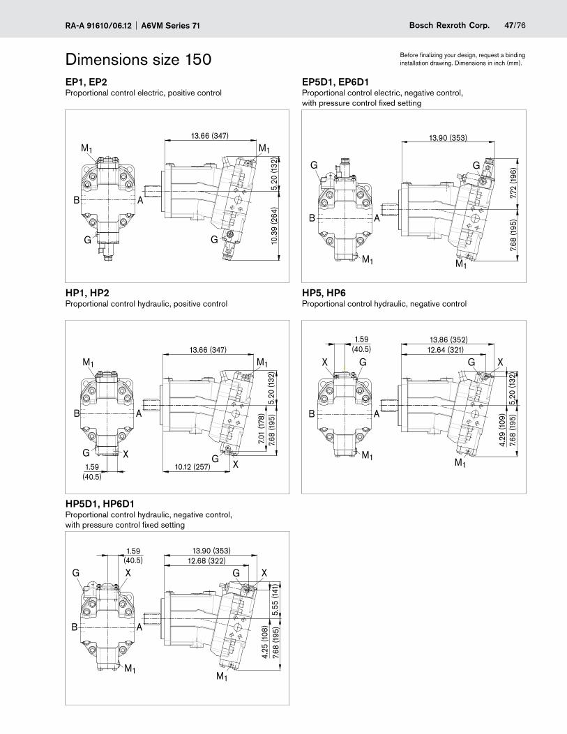
47/76Bosch Rexroth Corp.RA-A 91610/06.12 A6VM Series 71
Dimensions size 150 Before finalizing your design, request a binding installation drawing. Dimensions in inch (mm).
EP1, EP2 EP5D1, EP6D1Proportional control electric, positive control Proportional control electric, negative control,
with pressure control fixed setting
5.20
(132
)
13.66 (347)
10.3
9 (2
64)
G
M1
B A
M1
G
G G
7.72
(196
)7.
68 (1
95)
13.90 (353)
M1 M1
B A
HP1, HP2 HP5, HP6Proportional control hydraulic, positive control Proportional control hydraulic, negative control
1.59(40.5)
XG
7.01
(178
)
10.12 (257)
5.20
(132
)7.
68 (1
95)
13.66 (347)
M1 M1
XG
AB
X G G X
M1
B A
M1
5.20
(132
)7.
68 (1
95)
4.29
(109
)
13.86 (352)12.64 (321)
1.59(40.5)
HP5D1, HP6D1Proportional control hydraulic, negative control, with pressure control fixed setting
X X
M1 M1
B A
5.55
(141
)4.
25 (1
08)
G
13.90 (353)12.68 (322)
G
7.68
(195
)
1.59(40.5)
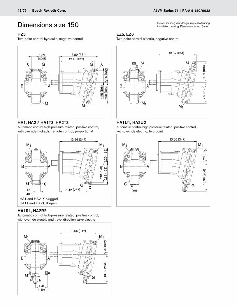
A6VM Series 71 RA-A 91610/06.1248/76 Bosch Rexroth Corp.
Dimensions size 150 Before finalizing your design, request a binding installation drawing. Dimensions in inch (mm).
HZ5 EZ5, EZ6Two-point control hydraulic, negative control Two-point control electric, negative control
1.59(40.5)
G
4.25
(108
)
12.48 (317)
5.20
(132
)7.
68 (1
95)
13.82 (351)
M1 M1
XG
B A
X
7.32
(186
)
13.82 (351)
7.68
(195
)
M1
B A
G
M1
G
HA1, HA2 / HA1T3, HA2T3 HA1U1, HA2U2Automatic control high-pressure related, positive control, with override hydraulic remote control, proportional
Automatic control high-pressure related, positive control, with override electric, two-point
1.59(40.5)
XG
7.01
(178
)
10.12 (257)
5.20
(132
)7.
68 (1
95)
13.66 (347)
M1 M1
XG
AB
5.20
(132
)
13.66 (347)
10.3
9 (2
64)
M1
G
AB
G
M1
HA1R1, HA2R2Automatic control high-pressure related, positive control, with override electric and travel direction valve electric
a
b
4.41(112)
5.20
(132
)
13.66 (347)
10.3
9 (2
64)
M1
G
AB
G
M1
HA1 and HA2, X plugged HA1T and HA2T, X open
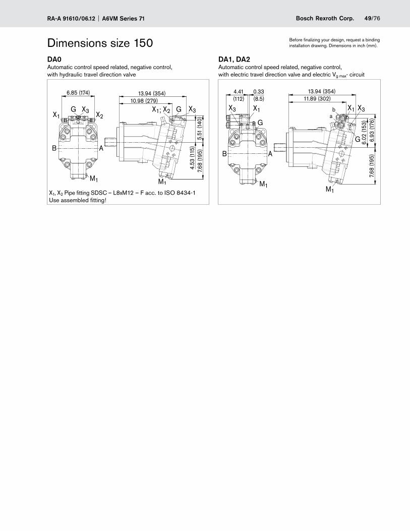
49/76Bosch Rexroth Corp.RA-A 91610/06.12 A6VM Series 71
Dimensions size 150 Before finalizing your design, request a binding installation drawing. Dimensions in inch (mm).
DA0 DA1, DA2Automatic control speed related, negative control, with hydraulic travel direction valve
Automatic control speed related, negative control, with electric travel direction valve and electric Vg max- circuit
6.85 (174)
X2X1G X3 G X3
7.68
(195
)5.
51 (1
40)
10.98 (279)13.94 (354)
M1
X1; X2
4.53
(115
)B A
M1
6.93
(176
)7.
68 (1
95)
6.02
(153
)
4.41(112)
M1
G
0.33(8.5)
B A
X1X3
M1
11.89 (302)13.94 (354)
G
X3X1ba
X1, X2 Pipe fitting SDSC – L8xM12 – F acc. to ISO 8434-1 Use assembled fitting!
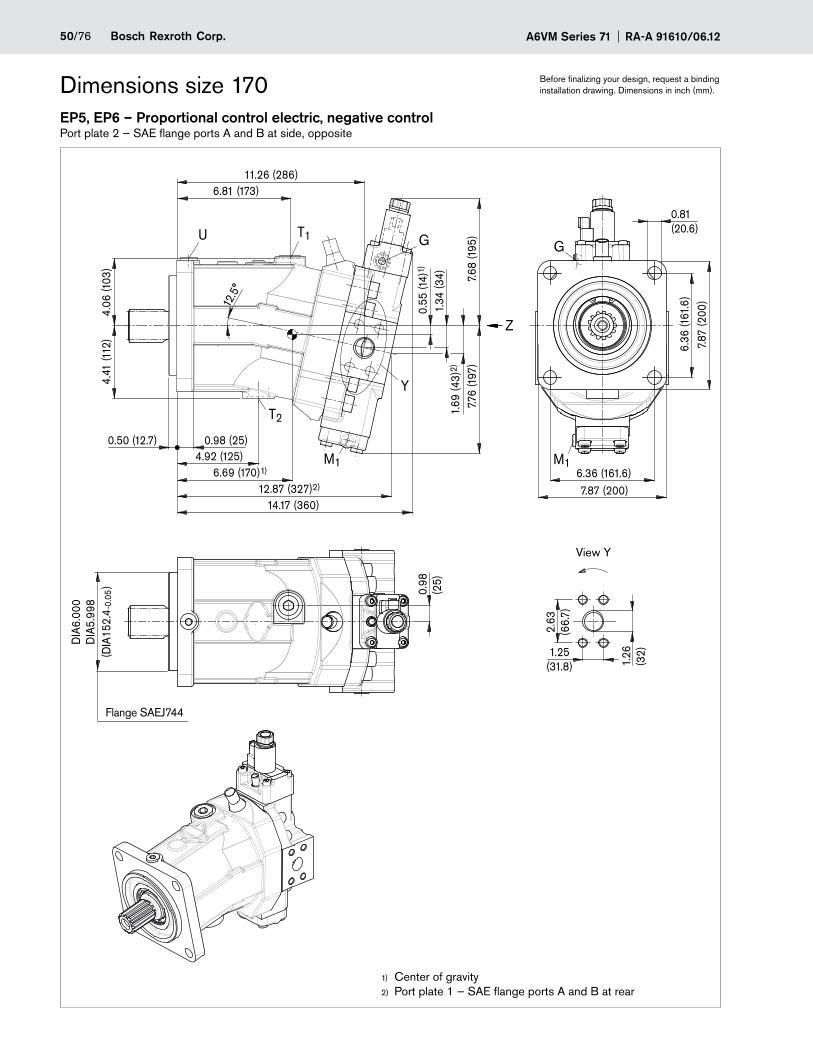
A6VM Series 71 RA-A 91610/06.1250/76 Bosch Rexroth Corp.
Dimensions size 170 Before finalizing your design, request a binding installation drawing. Dimensions in inch (mm).
EP5, EP6 – Proportional control electric, negative controlPort plate 2 — SAE flange ports A and B at side, opposite
G
Y
T2
M1
T1U
4.06
(103
)4.
41 (1
12)
6.69 (170)1)
12.87 (327)2)
14.17 (360)
12.5
°
2.63
(66.
7)
1.26
(32)1.25
(31.8)
6.36 (161.6)
0.81(20.6)
6.36
(161
.6)
0.98
(2
5)
4.92 (125)7.7
6 (1
97)
0.55
(14)
1)
1.34
(34)
1.69
(43)
2)
7.68
(195
)
6.81 (173)11.26 (286)
Z
7.87 (200)
7.87
(200
)
0.50 (12.7) 0.98 (25)
(DIA
152.
4
)
-0.0
5
DIA
6.00
0D
IA5.
998
G
M1
Center of gravity1)
Port plate 1 — SAE flange ports A and B at rear2)
Flange SAEJ744
View Y
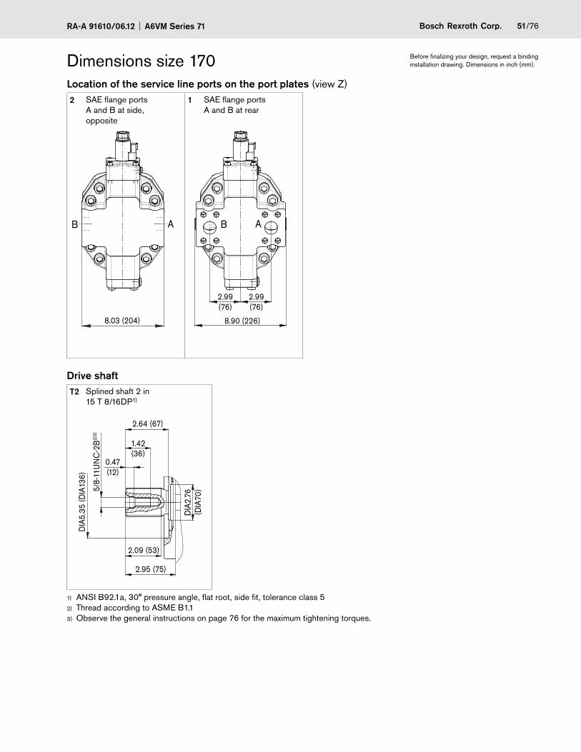
51/76Bosch Rexroth Corp.RA-A 91610/06.12 A6VM Series 71
Dimensions size 170 Before finalizing your design, request a binding installation drawing. Dimensions in inch (mm).
Location of the service line ports on the port plates (view Z)2 SAE flange ports
A and B at side, opposite
1 SAE flange ports A and B at rear
B A
8.03 (204)
B A
2.99(76)
8.90 (226)
2.99(76)
Drive shaftT2 Splined shaft 2 in
15 T 8/16DP1)
2.95 (75)
DIA
5.35
(DIA
136)
1.42(36)
2.09 (53)
5/8-
11U
NC
-2B
2)3)
DIA
2.76
(DIA
70)
2.64 (67)
0.47(12)
ANSI B92.1a, 30° pressure angle, flat root, side fit, tolerance class 51)
Thread according to 2) ASME B1.1Observe the general instructions on page 3) 76 for the maximum tightening torques.
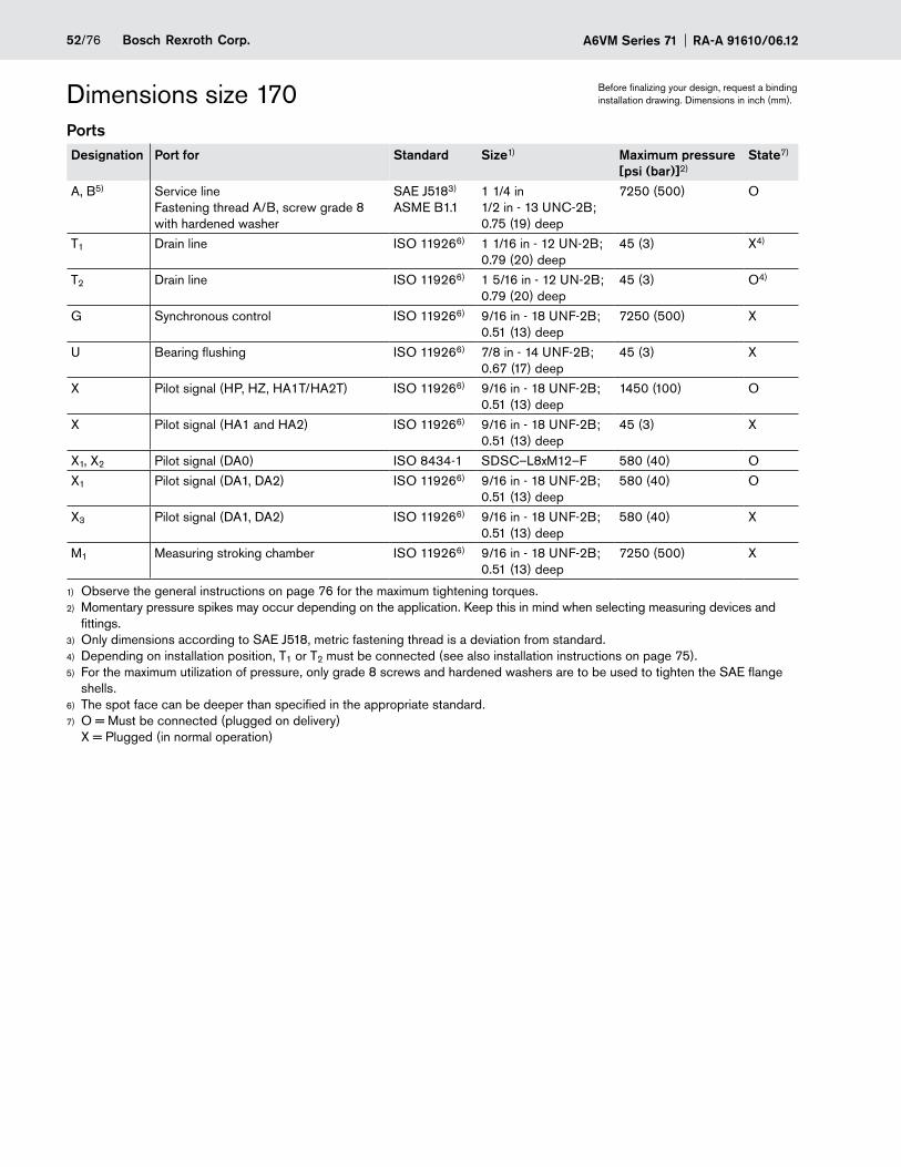
A6VM Series 71 RA-A 91610/06.1252/76 Bosch Rexroth Corp.
Dimensions size 170 Before finalizing your design, request a binding installation drawing. Dimensions in inch (mm).
PortsDesignation Port for Standard Size1) Maximum pressure
[psi (bar)]2)State7)
A, B5) Service line Fastening thread A/B, screw grade 8 with hardened washer
SAE J5183) ASME B1.1
1 1/4 in 1/2 in - 13 UNC-2B; 0.75 (19) deep
7250 (500) O
T1 Drain line ISO 119266) 1 1/16 in - 12 UN-2B; 0.79 (20) deep
45 (3) X4)
T2 Drain line ISO 119266) 1 5/16 in - 12 UN-2B; 0.79 (20) deep
45 (3) O4)
G Synchronous control ISO 119266) 9/16 in - 18 UNF-2B; 0.51 (13) deep
7250 (500) X
U Bearing flushing ISO 119266) 7/8 in - 14 UNF-2B; 0.67 (17) deep
45 (3) X
X Pilot signal (HP, HZ, HA1T/HA2T) ISO 119266) 9/16 in - 18 UNF-2B; 0.51 (13) deep
1450 (100) O
X Pilot signal (HA1 and HA2) ISO 119266) 9/16 in - 18 UNF-2B; 0.51 (13) deep
45 (3) X
X1, X2 Pilot signal (DA0) ISO 8434-1 SDSC–L8xM12–F 580 (40) O
X1 Pilot signal (DA1, DA2) ISO 119266) 9/16 in - 18 UNF-2B; 0.51 (13) deep
580 (40) O
X3 Pilot signal (DA1, DA2) ISO 119266) 9/16 in - 18 UNF-2B; 0.51 (13) deep
580 (40) X
M1 Measuring stroking chamber ISO 119266) 9/16 in - 18 UNF-2B; 0.51 (13) deep
7250 (500) X
Observe the general instructions on page 1) 76 for the maximum tightening torques.Momentary pressure spikes may occur depending on the application. Keep this in mind when selecting measuring devices and 2)
fittings.Only dimensions according to SAE J518, 3) metric fastening thread is a deviation from standard.Depending on installation position, T4) 1 or T2 must be connected (see also installation instructions on page 75).For the maximum utilization of pressure, only grade 8 screws and hardened washers are to be used to tighten the SAE flange 5)
shells.The spot face can be deeper than specified in the appropriate standard.6)
O = Must be connected (plugged on delivery) 7)
X = Plugged (in normal operation)

53/76Bosch Rexroth Corp.RA-A 91610/06.12 A6VM Series 71
Dimensions size 170 Before finalizing your design, request a binding installation drawing. Dimensions in inch (mm).
EP1, EP2 EP5D1, EP6D1Proportional control electric, positive control Proportional control electric, negative control,
with pressure control fixed setting
13.94 (354)
5.24
(133
)10
.47
(266
)
G
B
M1 M1
G
A
G
M1
7.68
(195
)7.7
6 (1
97)
14.17 (360)
M1
B A
G
HP1, HP2 HP5, HP6Proportional control hydraulic, positive control Proportional control hydraulic, negative control
1.59(40.5)
XG
M1
GX
7.13
(181
)B A
M1
5.24
(133
)7.7
6 (1
97)
13.94 (354)
10.39 (264)
1.59(40.5)
X G
M1
B A
G X
4.25
(108
)5.
24(1
33)
7.76
(197
)
12.91 (328)14.09 (358)
M1
HP5D1, HP6D1Proportional control hydraulic, negative control, with pressure control fixed setting
X XG
4.25
(108
)
G
M1
5.55
(141
)7.7
6 (1
97)B A
1.59(40.5)
14.17 (360)12.95 (329)
M1
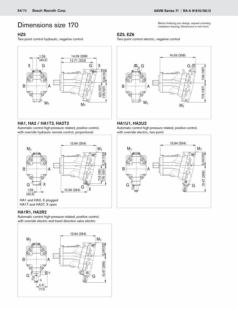
A6VM Series 71 RA-A 91610/06.1254/76 Bosch Rexroth Corp.
Dimensions size 170 Before finalizing your design, request a binding installation drawing. Dimensions in inch (mm).
HZ5 EZ5, EZ6Two-point control hydraulic, negative control Two-point control electric, negative control
7.76
(197
)4.2
1 (1
07)
5.24
(133
)
12.71 (323)14.09 (358)1.59
(40.5)
X G G
B A
X
M1 M1M1
G
B A
M1
7.76
(197
)7.
36 (1
87)
14.09 (358)
G
HA1, HA2 / HA1T3, HA2T3 HA1U1, HA2U2Automatic control high-pressure related, positive control, with override hydraulic remote control, proportional
Automatic control high-pressure related, positive control, with override electric, two-point
1.59(40.5)
XG
M1
G X
7.13
(181
)B A
M1
5.24
(133
)7.7
6 (1
97)
13.94 (354)
10.39 (264)
M1
B A
M1
G G
13.94 (354)
5.24
(133
)10
.47
(266
)
HA1R1, HA2R2Automatic control high-pressure related, positive control, with override electric and travel direction valve electric
a
bG
M1
G
B A
M1
5.24
(133
)10
.47
(266
)
13.94 (354)
4.41(112)
HA1 and HA2, X plugged HA1T and HA2T, X open
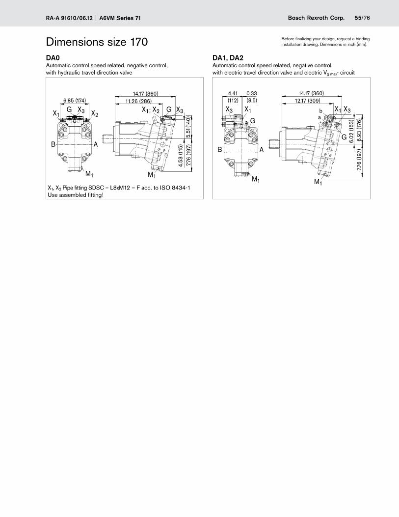
55/76Bosch Rexroth Corp.RA-A 91610/06.12 A6VM Series 71
Dimensions size 170 Before finalizing your design, request a binding installation drawing. Dimensions in inch (mm).
DA0 DA1, DA2Automatic control speed related, negative control, with hydraulic travel direction valve
Automatic control speed related, negative control, with electric travel direction valve and electric Vg max- circuit
6.85 (174)
X2X1G X3 G X3
7.76
(197
)5.
51(1
40)
11.26 (286)14.17 (360)
M1
X1; X2
4.53
(115
)B A
M1
B A
M1
G
X1X3
4.41(112)
0.33(8.5)
M1
G
X3X1
6.93
(176
)7.7
6 (1
97)
6.02
(153
)
12.17 (309)14.17 (360)
ab
X1, X2 Pipe fitting SDSC – L8xM12 – F acc. to ISO 8434-1 Use assembled fitting!
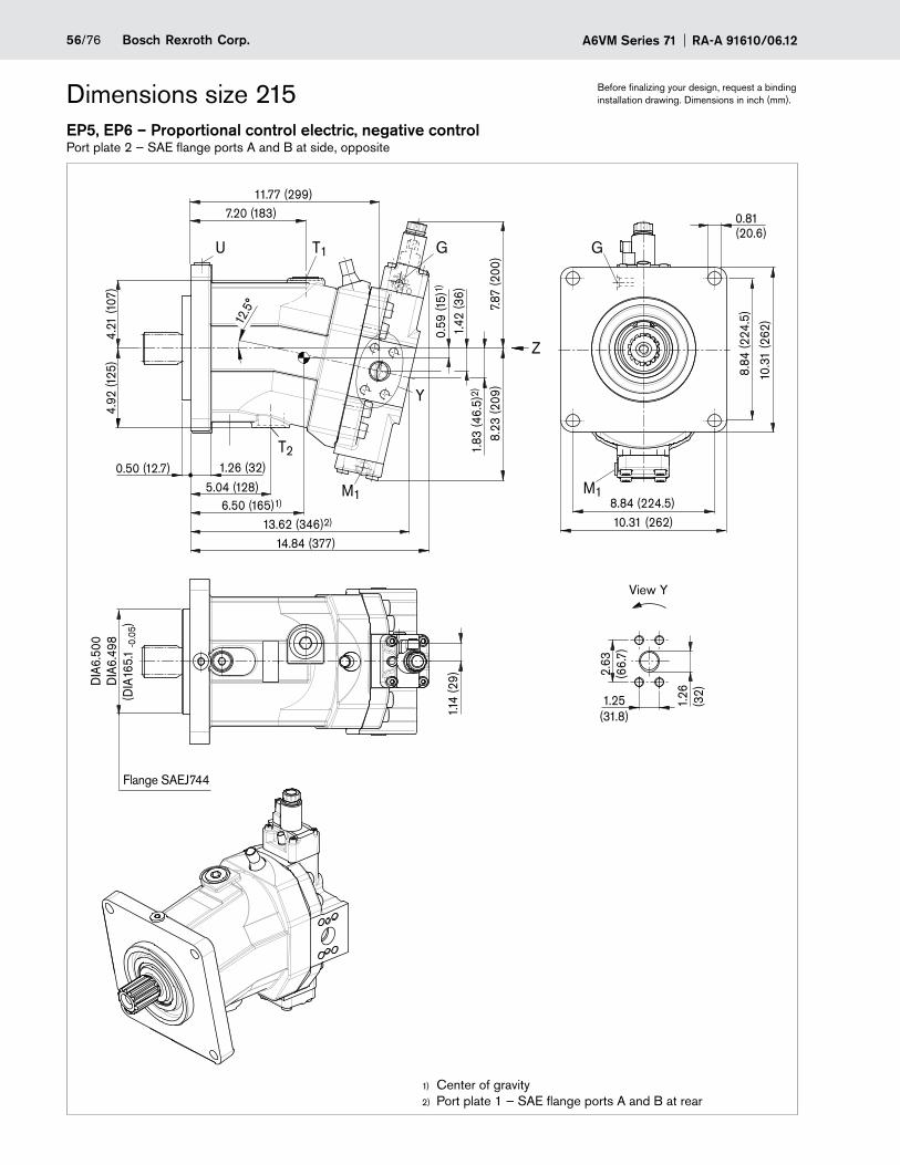
A6VM Series 71 RA-A 91610/06.1256/76 Bosch Rexroth Corp.
Dimensions size 215 Before finalizing your design, request a binding installation drawing. Dimensions in inch (mm).
EP5, EP6 – Proportional control electric, negative controlPort plate 2 — SAE flange ports A and B at side, opposite
View Y
T2
M1
T1U
6.50 (165)1)
13.62 (346)2)
14.84 (377)
2.63
(66.
7)
1.26
(3
2)1.25
(31.8)
8.84 (224.5)
0.81(20.6)
8.84
(224
.5)
1.14
(29)
5.04 (128)0.50 (12.7) 1.26 (32)
8.23
(209
)
0.59
(15)
1)
1.42
(36)
1.83
(46.
5)2)
7.87
(200
)
7.20 (183)11.77 (299)
4.21
(107
)4.
92 (1
25)
Y
DIA
6.50
0D
IA6.
498
10.31 (262)
Z
G
10.3
1 (2
62)
G
(DIA
165.
1 -0
.05)
M1
12.5
°
Center of gravity1)
Port plate 1 — SAE flange ports A and B at rear2)
Flange SAEJ744
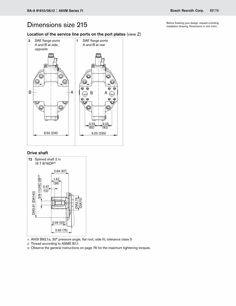
57/76Bosch Rexroth Corp.RA-A 91610/06.12 A6VM Series 71
Dimensions size 215 Before finalizing your design, request a binding installation drawing. Dimensions in inch (mm).
Location of the service line ports on the port plates (view Z)2 SAE flange ports
A and B at side, opposite
1 SAE flange ports A and B at rear
B A
8.50 (216)
B A
3.23(82)
9.25 (235)
3.23(82)
Drive shaftT2 Splined shaft 2 in
15 T 8/16DP1)
2.95 (75)
DIA
5.51
(DIA
140)
1.42(36)
2.09 (53)
5/8-
11U
NC
-2B
2)3)
DIA
2.76
(DIA
70)
2.64 (67)
0.47(12)
ANSI B92.1a, 30° pressure angle, flat root, side fit, tolerance class 51)
Thread according to 2) ASME B1.1Observe the general instructions on page 3) 76 for the maximum tightening torques.
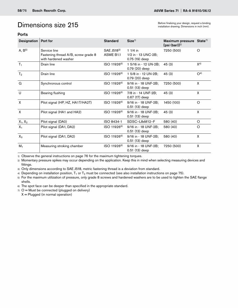
A6VM Series 71 RA-A 91610/06.1258/76 Bosch Rexroth Corp.
Dimensions size 215 Before finalizing your design, request a binding installation drawing. Dimensions in inch (mm).
PortsDesignation Port for Standard Size1) Maximum pressure
[psi (bar)]2)State7)
A, B5) Service line Fastening thread A/B, screw grade 8 with hardened washer
SAE J5183) ASME B1.1
1 1/4 in 1/2 in - 13 UNC-2B; 0.75 (19) deep
7250 (500) O
T1 Drain line ISO 119266) 1 5/16 in - 12 UN-2B; 0.79 (20) deep
45 (3) X4)
T2 Drain line ISO 119266) 1 5/8 in - 12 UN-2B; 0.79 (20) deep
45 (3) O4)
G Synchronous control ISO 119266) 9/16 in - 18 UNF-2B; 0.51 (13) deep
7250 (500) X
U Bearing flushing ISO 119266) 7/8 in - 14 UNF-2B; 0.67 (17) deep
45 (3) X
X Pilot signal (HP, HZ, HA1T/HA2T) ISO 119266) 9/16 in - 18 UNF-2B; 0.51 (13) deep
1450 (100) O
X Pilot signal (HA1 and HA2) ISO 119266) 9/16 in - 18 UNF-2B; 0.51 (13) deep
45 (3) X
X1, X2 Pilot signal (DA0) ISO 8434-1 SDSC–L8xM12–F 580 (40) O
X1 Pilot signal (DA1, DA2) ISO 119266) 9/16 in - 18 UNF-2B; 0.51 (13) deep
580 (40) O
X3 Pilot signal (DA1, DA2) ISO 119266) 9/16 in - 18 UNF-2B; 0.51 (13) deep
580 (40) X
M1 Measuring stroking chamber ISO 119266) 9/16 in - 18 UNF-2B; 0.51 (13) deep
7250 (500) X
Observe the general instructions on page 1) 76 for the maximum tightening torques.Momentary pressure spikes may occur depending on the application. Keep this in mind when selecting measuring devices and 2)
fittings.Only dimensions according to SAE J518, 3) metric fastening thread is a deviation from standard.Depending on installation position, T4) 1 or T2 must be connected (see also installation instructions on page 75).For the maximum utilization of pressure, only grade 8 screws and hardened washers are to be used to tighten the SAE flange 5)
shells.The spot face can be deeper than specified in the appropriate standard.6)
O = Must be connected (plugged on delivery)7) X = Plugged (in normal operation)
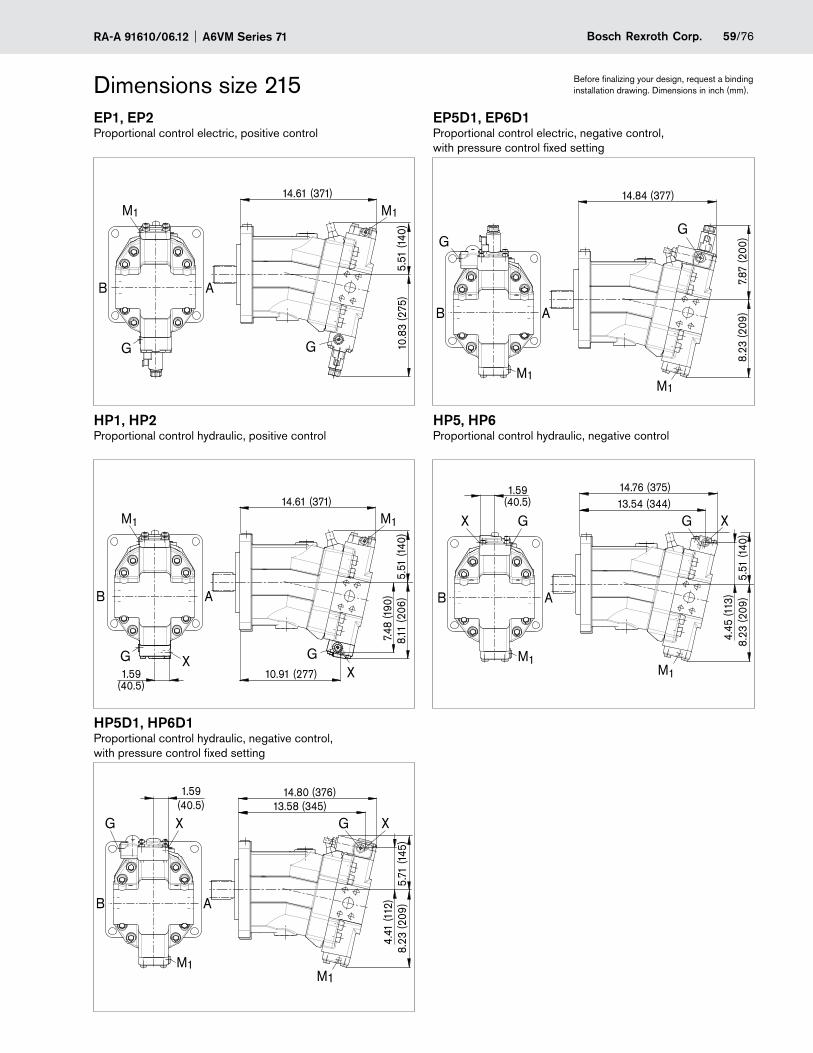
59/76Bosch Rexroth Corp.RA-A 91610/06.12 A6VM Series 71
Dimensions size 215 Before finalizing your design, request a binding installation drawing. Dimensions in inch (mm).
EP1, EP2 EP5D1, EP6D1Proportional control electric, positive control Proportional control electric, negative control,
with pressure control fixed setting
M1M1
G
14.61 (371)
5.51
(140
)10
.83
(275
)B A
G
B A
M1
G
8.23
(209
)7.
87 (2
00)
14.84 (377)
G
M1
HP1, HP2 HP5, HP6Proportional control hydraulic, positive control Proportional control hydraulic, negative control
M1
G
B A
X
M1
14.61 (371)
8.11
(206
)
10.91 (277)
GX
7.48
(190
)
1.59(40.5)
5.51
(140
)
M1
8.23
(209
)5.
51 (1
40)
14.76 (375)
M1
B A
X G X13.54 (344)
4.45
(113
)
G
1.59(40.5)
HP5D1, HP6D1Proportional control hydraulic, negative control, with pressure control fixed setting
M1
G
B A
M1
X
8.23
(209
)5.
71 (1
45)
G X13.58 (345)
14.80 (376)1.59(40.5)
4.41
(112
)
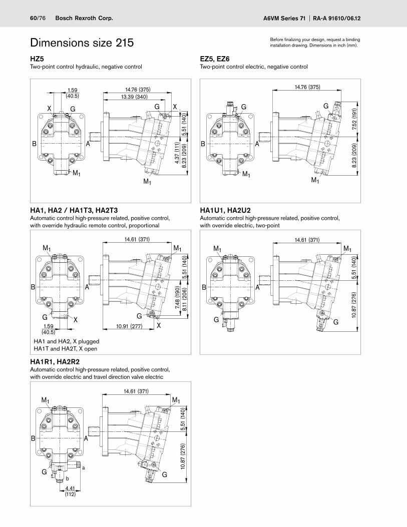
A6VM Series 71 RA-A 91610/06.1260/76 Bosch Rexroth Corp.
Dimensions size 215 Before finalizing your design, request a binding installation drawing. Dimensions in inch (mm).
HZ5 EZ5, EZ6Two-point control hydraulic, negative control Two-point control electric, negative control
M1
XG
5.51
(140
)8.
23 (2
09)
4.37
(111
)
13.39 (340)14.76 (375)
M1
X G
1.59(40.5)
B A
G
M1
G
B A
M1
7.52
(191
)8.
23 (2
09)
14.76 (375)
HA1, HA2 / HA1T3, HA2T3 HA1U1, HA2U2Automatic control high-pressure related, positive control, with override hydraulic remote control, proportional
Automatic control high-pressure related, positive control, with override electric, two-point
M1
G
B A
X
M1
14.61 (371)
8.11
(206
)
10.91 (277)
GX
7.48
(190
)
1.59(40.5)
5.51
(140
)
B A
M1
G
M1
14.61 (371)
G
10.8
7 (2
76)
5.51
(140
)HA1R1, HA2R2Automatic control high-pressure related, positive control, with override electric and travel direction valve electric
M1
10.8
7 (2
76)
5.51
(140
)
14.61 (371)
G
M1
B A
Ga
4.41(112)
b
HA1 and HA2, X plugged HA1T and HA2T, X open
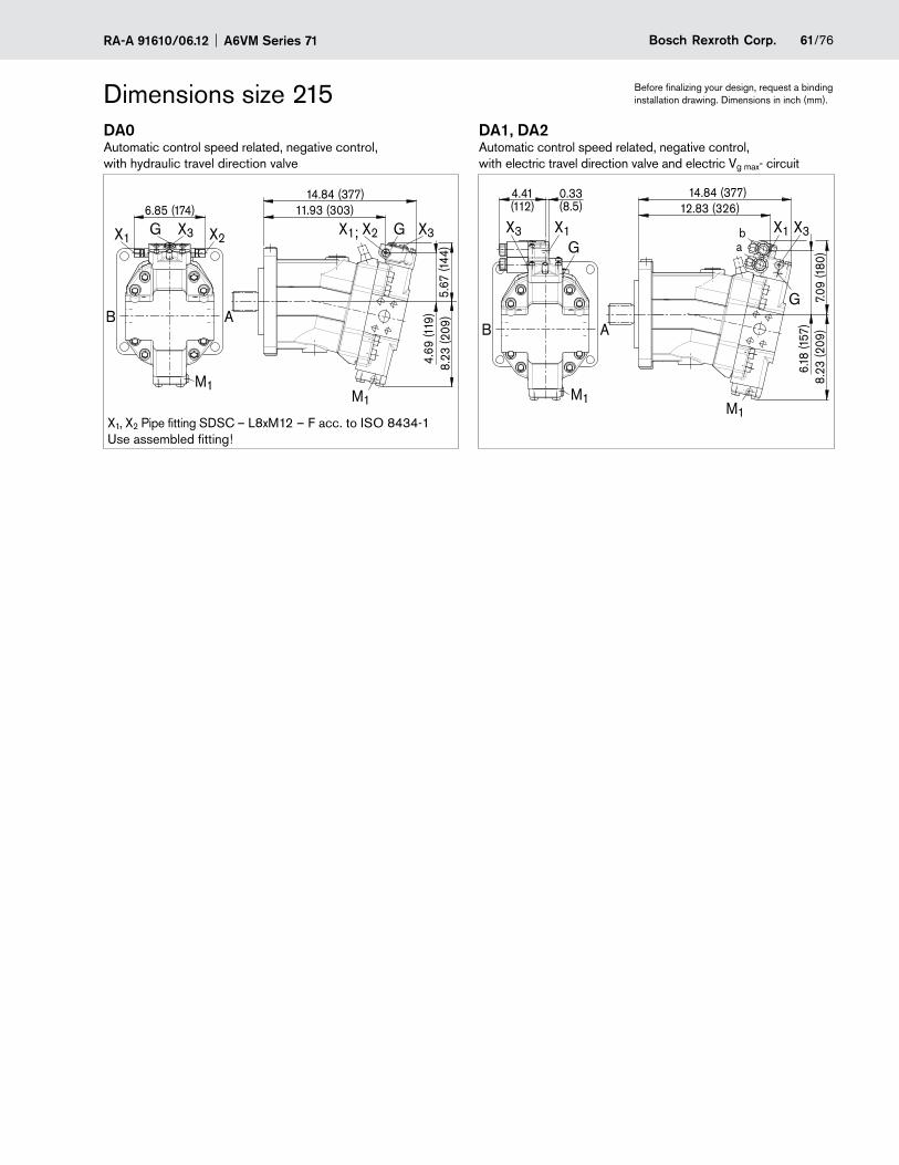
61/76Bosch Rexroth Corp.RA-A 91610/06.12 A6VM Series 71
Dimensions size 215 Before finalizing your design, request a binding installation drawing. Dimensions in inch (mm).
DA0 DA1, DA2Automatic control speed related, negative control, with hydraulic travel direction valve
Automatic control speed related, negative control, with electric travel direction valve and electric Vg max- circuit
M1
B A
6.85 (174)
X1 X2X3G X1; X2 X3G
11.93 (303)14.84 (377)
M1
8.23
(209
)5.
67 (1
44)
4.69
(119
)
M1
B A
M1
8.23
(209
)
GX1
0.33(8.5)
4.41(112)
X3
7.09
(180
)6.
18 (1
57)
12.83 (326)14.84 (377)
G
X1 X3ab
X1, X2 Pipe fitting SDSC – L8xM12 – F acc. to ISO 8434-1 Use assembled fitting!
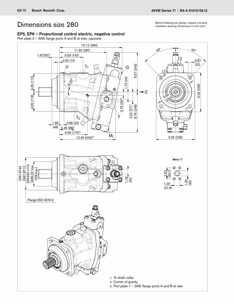
A6VM Series 71 RA-A 91610/06.1262/76 Bosch Rexroth Corp.
Dimensions size 280 Before finalizing your design, request a binding installation drawing. Dimensions in inch (mm).
EP5, EP6 – Proportional control electric, negative controlPort plate 2 — SAE flange ports A and B at side, opposite
13.2
5°
2.63
(66.
7)
1.26
(32)
1.25(31.8)
45° 45°
9.29 (236)
9.29
(236
)
1.18
(30)
DIA
6.22
max
.(1
58 m
ax.)
DIA
7.87
40D
IA7.
8712
-0
.072
T2
13.46 (342)3)
15.12 (384)
6.69 (170)2)
3.46 (88)1.89(48)
0.98 (25)
M1
T1U
4.45
(113
)4.
65 (1
18)
5.59 (142)1.97(50)1)
11.30 (287)
Y
G
9.76
(248
)
0.79
(20)
2)
1.73
(44)
2.24
(57)
3)
9.57
(243
)
Z
0.55 (14)
9.84
(250)
0.87(22)
(DIA
200
)
View Y
To shaft collar1)
Center of gravity2)
Port plate 1 — SAE flange ports A and B at rear3)
Flange ISO 3019-2
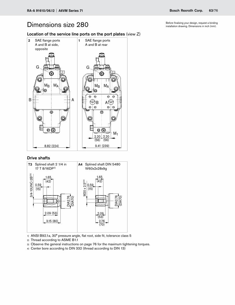
63/76Bosch Rexroth Corp.RA-A 91610/06.12 A6VM Series 71
Dimensions size 280 Before finalizing your design, request a binding installation drawing. Dimensions in inch (mm).
Location of the service line ports on the port plates (view Z)2 SAE flange ports
A and B at side, opposite
1 SAE flange ports A and B at rear
B A
MAMB
8.82 (224)
G G
M1
B A
MAMB
2.20(56)
9.41 (239)
2.20(56)
Drive shaftsT3 Splined shaft 2 1/4 in
17 T 8/16DP1)A4 Splined shaft DIN 5480
W60x2x28x9g
1.65(42)
2.09 (53)
3/4-
10U
NC
-2B
2)3)
DIA
2.76
(DIA
70)
3.15 (80)
0.59(15)
2.76(70)
2.09(53)
M20
x 2
.53)
4)
DIA
2.76
(DIA
70)
0.59(15)
1.65(42)
ANSI B92.1a, 30° pressure angle, flat root, side fit, tolerance class 51)
Thread according to 2) ASME B1.1Observe the general instructions on page 3) 76 for the maximum tightening torques.Center bore according to DIN 332 (thread according to DIN 13)4)
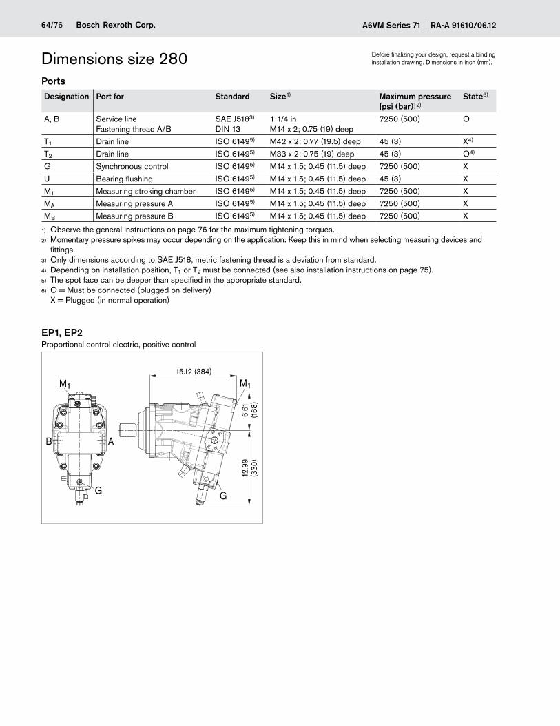
A6VM Series 71 RA-A 91610/06.1264/76 Bosch Rexroth Corp.
Dimensions size 280 Before finalizing your design, request a binding installation drawing. Dimensions in inch (mm).
PortsDesignation Port for Standard Size1) Maximum pressure
[psi (bar)]2)State6)
A, B Service line Fastening thread A/B
SAE J5183) DIN 13
1 1/4 in M14 x 2; 0.75 (19) deep
7250 (500) O
T1 Drain line ISO 61495) M42 x 2; 0.77 (19.5) deep 45 (3) X4)
T2 Drain line ISO 61495) M33 x 2; 0.75 (19) deep 45 (3) O4)
G Synchronous control ISO 61495) M14 x 1.5; 0.45 (11.5) deep 7250 (500) X
U Bearing flushing ISO 61495) M14 x 1.5; 0.45 (11.5) deep 45 (3) X
M1 Measuring stroking chamber ISO 61495) M14 x 1.5; 0.45 (11.5) deep 7250 (500) X
MA Measuring pressure A ISO 61495) M14 x 1.5; 0.45 (11.5) deep 7250 (500) X
MB Measuring pressure B ISO 61495) M14 x 1.5; 0.45 (11.5) deep 7250 (500) X
Observe the general instructions on page 1) 76 for the maximum tightening torques.Momentary pressure spikes may occur depending on the application. Keep this in mind when selecting measuring devices and 2)
fittings.Only dimensions according to SAE J518, 3) metric fastening thread is a deviation from standard.Depending on installation position, T4) 1 or T2 must be connected (see also installation instructions on page 75).The spot face can be deeper than specified in the appropriate standard.5)
O = Must be connected (plugged on delivery) 6)
X = Plugged (in normal operation)
EP1, EP2Proportional control electric, positive control
6.61
(168
)12
.99
(330
)
15.12 (384)
M1
AB
G G
M1
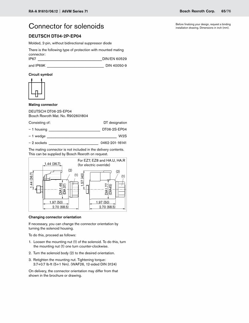
65/76Bosch Rexroth Corp.RA-A 91610/06.12 A6VM Series 71
Connector for solenoids Before finalizing your design, request a binding installation drawing. Dimensions in inch (mm).
DEUTSCH DT04-2P-EP04Molded, 2-pin, without bidirectional suppressor diode
There is the following type of protection with mounted mating connector: IP67 ___________________________________DIN/EN 60529
and IP69K _______________________________ DIN 40050-9
Circuit symbol
Mating connector
DEUTSCH DT06-2S-EP04 Bosch Rexroth Mat. No. R902601804
Consisting of: DT designation
– 1 housing ____________________________ DT06-2S-EP04
– 1 wedge ______________________________________ W2S
– 2 sockets ___________________________ 0462-201-16141
The mating connector is not included in the delivery contents. This can be supplied by Bosch Rexroth on request.
DIA
1.46
(DIA
37)
2.70 (68.5)1.97 (50)
1.44
(36.
7)
(2)(1)
1.44 (36.7)
1.57
(40)
2.70 (68.5)
DIA
1.77
(DIA
45)
1.97 (50)
(2)(1)
For EZ7, EZ8 and HA.U, HA.R (for electric override)
Changing connector orientation
If necessary, you can change the connector orientation by turning the solenoid housing.
To do this, proceed as follows:
1. Loosen the mounting nut (1) of the solenoid. To do this, turn the mounting nut (1) one turn counter-clockwise.
2. Turn the solenoid body (2) to the desired orientation.
3. Retighten the mounting nut. Tightening torque: 3.7+0.7 lb-ft (5+1 Nm). (WAF26, 12-sided DIN 3124)
On delivery, the connector orientation may differ from that shown in the brochure or drawing.
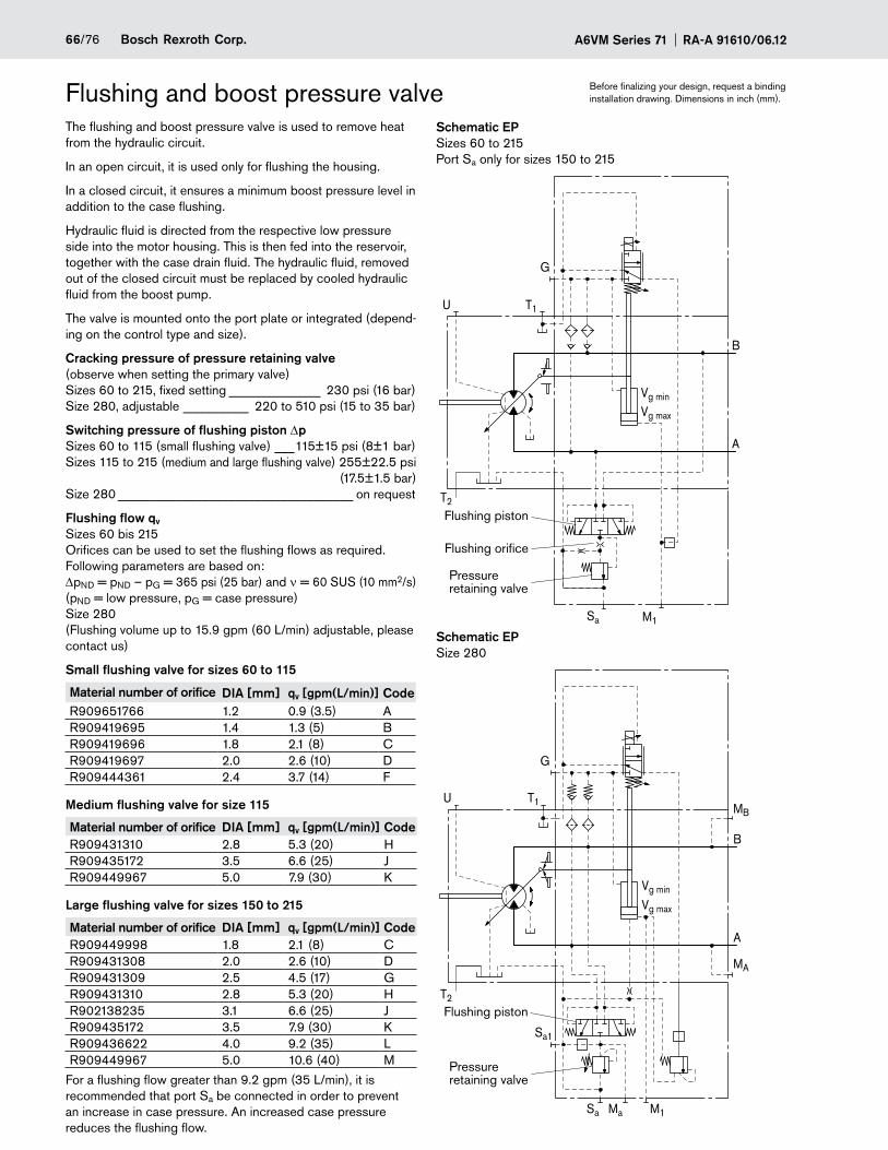
A6VM Series 71 RA-A 91610/06.1266/76 Bosch Rexroth Corp.
Flushing and boost pressure valve Before finalizing your design, request a binding installation drawing. Dimensions in inch (mm).
The flushing and boost pressure valve is used to remove heat from the hydraulic circuit.
In an open circuit, it is used only for flushing the housing.
In a closed circuit, it ensures a minimum boost pressure level in addition to the case flushing.
Hydraulic fluid is directed from the respective low pressure side into the motor housing. This is then fed into the reservoir, together with the case drain fluid. The hydraulic fluid, removed out of the closed circuit must be replaced by cooled hydraulic fluid from the boost pump.
The valve is mounted onto the port plate or integrated (depend-ing on the control type and size).
Cracking pressure of pressure retaining valve(observe when setting the primary valve)Sizes 60 to 215, fixed setting ______________ 230 psi (16 bar) Size 280, adjustable __________ 220 to 510 psi (15 to 35 bar)
Switching pressure of flushing piston DpSizes 60 to 115 (small flushing valve) ___115±15 psi (8±1 bar) Sizes 115 to 215 (medium and large flushing valve) 255±22.5 psi (17.5±1.5 bar) Size 280 ____________________________________ on request
Flushing flow qv
Sizes 60 bis 215 Orifices can be used to set the flushing flows as required. Following parameters are based on: DpND = pND – pG = 365 psi (25 bar) and ν = 60 SUS (10 mm2/s) (pND = low pressure, pG = case pressure) Size 280 (Flushing volume up to 15.9 gpm (60 L/min) adjustable, please contact us)
Small flushing valve for sizes 60 to 115
Material number of orifice DIA [mm] qv [gpm(L/min)] CodeR909651766 1.2 0.9 (3.5) AR909419695 1.4 1.3 (5) BR909419696 1.8 2.1 (8) CR909419697 2.0 2.6 (10) DR909444361 2.4 3.7 (14) F
Medium flushing valve for size 115
Material number of orifice DIA [mm] qv [gpm(L/min)] CodeR909431310 2.8 5.3 (20) HR909435172 3.5 6.6 (25) JR909449967 5.0 7.9 (30) K
Large flushing valve for sizes 150 to 215
Material number of orifice DIA [mm] qv [gpm(L/min)] CodeR909449998 1.8 2.1 (8) CR909431308 2.0 2.6 (10) DR909431309 2.5 4.5 (17) GR909431310 2.8 5.3 (20) HR902138235 3.1 6.6 (25) JR909435172 3.5 7.9 (30) KR909436622 4.0 9.2 (35) LR909449967 5.0 10.6 (40) M
For a flushing flow greater than 9.2 gpm (35 L/min), it is recommended that port Sa be connected in order to prevent an increase in case pressure. An increased case pressure reduces the flushing flow.
Schematic EPSizes 60 to 215 Port Sa only for sizes 150 to 215
G
T2
T1U
Sa
B
A
Vg min
Vg max
M1
Flushing orifice
Flushing piston
Pressure retaining valve
Schematic EPSize 280
T2
U T1
Sa M1Ma
G
B
A
Vg min
Vg max
MA
MB
Sa1
Flushing piston
Pressure retaining valve
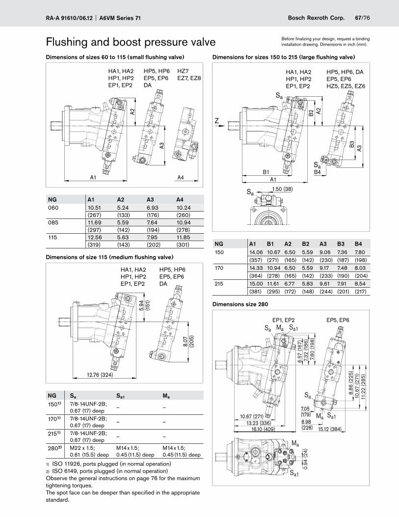
67/76Bosch Rexroth Corp.RA-A 91610/06.12 A6VM Series 71
Before finalizing your design, request a binding installation drawing. Dimensions in inch (mm).Flushing and boost pressure valve
Dimensions of sizes 60 to 115 (small flushing valve)
A1
A3
A2
A4
HA1, HA2HP1, HP2EP1, EP2
HP5, HP6EP5, EP6DA
HZ7EZ7, EZ8
NG A1 A2 A3 A4060 10.51 5.24 6.93 10.24
(267) (133) (176) (260)085 11.69 5.59 7.64 10.94
(297) (142) (194) (278)115 12.56 5.63 7.95 11.85
(319) (143) (202) (301)
Dimensions of size 115 (medium flushing valve)
8.07
(205
)
5.94
(151
)
12.76 (324)
HA1, HA2HP1, HP2EP1, EP2
HP5, HP6EP5, EP6DA
NG Sa Sa1 Ma
1501) 7/8-14UNF-2B; 0.67 (17) deep
– –
1701) 7/8-14UNF-2B; 0.67 (17) deep
– –
2151) 7/8-14UNF-2B; 0.67 (17) deep
– –
2802) M22 x 1.5; 0.61 (15.5) deep
M14 x 1.5; 0.45 (11.5) deep
M14 x 1.5; 0.45 (11.5) deep
ISO 11926, ports plugged (in normal operation)1)
ISO 6149, ports plugged (in normal operation)2)
Observe the general instructions on page 76 for the maximum tightening torques. The spot face can be deeper than specified in the appropriate standard.
Dimensions for sizes 150 to 215 (large flushing valve)
A3
Sa
A1B1 B4
A2B2
B3
Sa
1.50 (38)Sa
Z
HA1, HA2HP1, HP2EP1, EP2
HP5, HP6, DAEP5, EP6HZ5, EZ5, EZ6
NG A1 B1 A2 B2 A3 B3 B4150 14.06 10.67 6.50 5.59 9.06 7.36 7.80
(357) (271) (165) (142) (230) (187) (198)170 14.33 10.94 6.50 5.59 9.17 7.48 8.03
(364) (278) (165) (142) (233) (190) (204)215 15.00 11.61 6.77 5.83 9.61 7.91 8.54
(381) (295) (172) (148) (244) (201) (217)
Dimensions size 280
10.67 (271)13.23 (336)
EP1, EP2 EP5, EP6
Sa
7.32
(186
)6.
57 (1
67)
Sa
0.94
(24)
Sa1
16.10 (409)
Sa1
7.80
(198
)
10.6
7 (2
71)
8.86
(225
)
11.2
2 (2
85)
7.05 (179)8.98 (228) 15.12 (384)
Ma
Ma
Sa1Ma
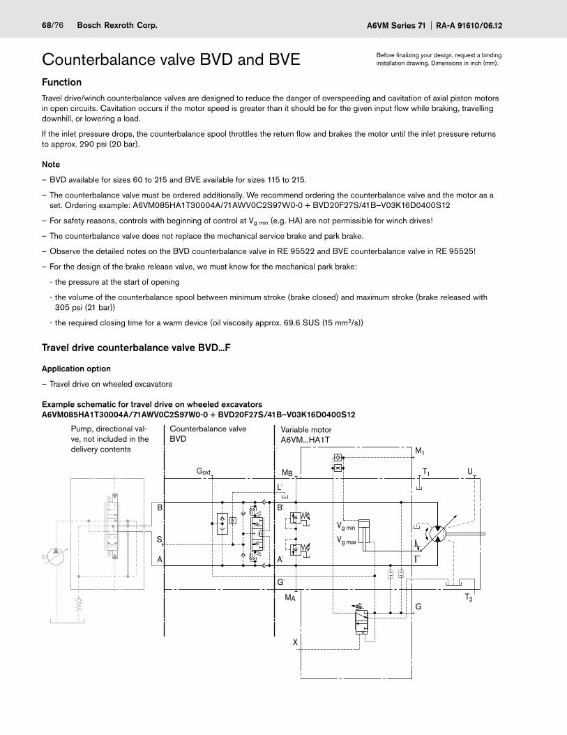
A6VM Series 71 RA-A 91610/06.1268/76 Bosch Rexroth Corp.
Counterbalance valve BVD and BVEFunctionTravel drive/winch counterbalance valves are designed to reduce the danger of overspeeding and cavitation of axial piston motors in open circuits. Cavitation occurs if the motor speed is greater than it should be for the given input flow while braking, travelling downhill, or lowering a load.
If the inlet pressure drops, the counterbalance spool throttles the return flow and brakes the motor until the inlet pressure returns to approx. 290 psi (20 bar).
Note
BVD available for sizes 60 to 215 and BVE available for sizes 115 to 215. –
The counterbalance valve must be – ordered additionally. We recommend ordering the counterbalance valve and the motor as a set. Ordering example: A6VM085HA1T30004A/71AWV0C2S97W0-0 + BVD20F27S/41B–V03K16D0400S12
For safety reasons, controls with beginning of control at V – g min (e.g. HA) are not permissible for winch drives!
The counterbalance valve does not replace the mechanical service brake and park brake. –
Observe the detailed notes on the BVD counterbalance valve in RE 95522 and BVE counterbalance valve in RE 95525 – !
For the design of the brake release valve, we must know for the mechanical park brake: –
the pressure at the start of opening -
the volume of the counterbalance spool between minimum stroke (brake closed) and maximum stroke (brake released with -305 psi (21 bar))
the required closing time for a warm device (oil viscosity approx. 69.6 SUS (15 mm - 2/s))
Travel drive counterbalance valve BVD...F
Application option
Travel drive on wheeled excavators –
Example schematic for travel drive on wheeled excavators A6VM085HA1T30004A/71AWV0C2S97W0-0 + BVD20F27S/41B–V03K16D0400S12
B´
A
M1
T2
T1
Vg min
Vg max
X
U
G
MB
MA
S
Gext
G´
L´
A´
B
Variable motor A6VM...HA1T
Counterbalance valve BVD
Pump, directional val-ve, not included in the delivery contents
Before finalizing your design, request a binding installation drawing. Dimensions in inch (mm).
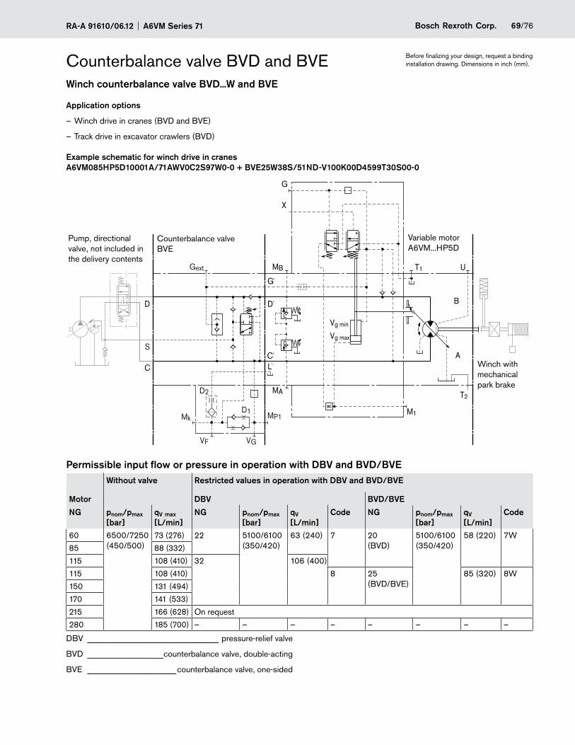
69/76Bosch Rexroth Corp.RA-A 91610/06.12 A6VM Series 71
Winch counterbalance valve BVD...W and BVE
Application options
Winch drive in cranes – (BVD and BVE)
Track drive in excavator crawlers – (BVD)
Example schematic for winch drive in cranes A6VM085HP5D10001A/71AWV0C2S97W0-0 + BVE25W38S/51ND-V100K00D4599T30S00-0
T2
T1
M1
Vg min
Vg max
B
A
G
X
U
MP1
VGVF
S
Gext
Mk
D
C
D´
C´
G´
L´
D1
D2
MB
MA
Counterbalance valve BVE
Pump, directional valve, not included in the delivery contents
Variable motor A6VM...HP5D
Winch with mechanical park brake
Permissible input flow or pressure in operation with DBV and BVD/BVEWithout valve Restricted values in operation with DBV and BVD/BVE
Motor DBV BVD/BVE
NG pnom/pmax [bar]
qV max [L/min]
NG pnom/pmax [bar]
qV [L/min]
Code NG pnom/pmax [bar]
qV [L/min]
Code
60 6500/7250 (450/500)
73 (276) 22 5100/6100 (350/420)
63 (240) 7 20 (BVD)
5100/6100 (350/420)
58 (220) 7W
85 88 (332)
115 108 (410) 32 106 (400)
115 108 (410) 8 25 (BVD/BVE)
85 (320) 8W
150 131 (494)
170 141 (533)
215 166 (628) On request
280 185 (700) – – – – – – – –
DBV _______________________________ pressure-relief valve
BVD __________________counterbalance valve, double-acting
BVE _____________________counterbalance valve, one-sided
Counterbalance valve BVD and BVE Before finalizing your design, request a binding installation drawing. Dimensions in inch (mm).
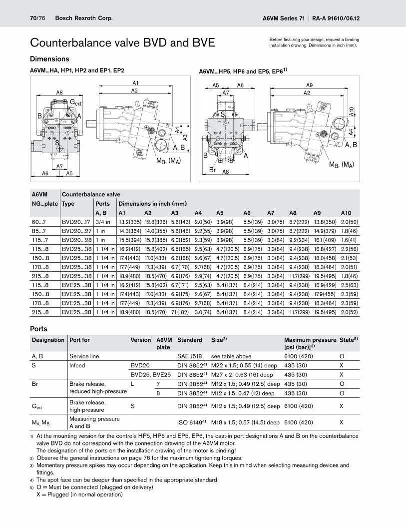
A6VM Series 71 RA-A 91610/06.1270/76 Bosch Rexroth Corp.
Counterbalance valve BVD and BVE Before finalizing your design, request a binding installation drawing. Dimensions in inch (mm).
DimensionsA6VM...HA, HP1, HP2 and EP1, EP2 A6VM...HP5, HP6 and EP5, EP61)
A2A1
MB, (MA)
A, B
A4A3
S
A8
A6 A5A7
B A
Gext
A2A9
MB, (MA)
A4A1
0
Br
S
A8
A5 A6A7
B AA, B
A6VM Counterbalance valve
NG...plate Type Ports Dimensions in inch (mm)
A, B A1 A2 A3 A4 A5 A6 A7 A8 A9 A1060...7 BVD20...17 3/4 in 13.2(335) 12.8(326) 5.6(143) 2.0(50) 3.9(98) 5.5(139) 3.0(75) 8.7(222) 13.8(350) 2.0(50)
85...7 BVD20...27 1 in 14.3(364) 14.0(355) 5.8(148) 2.2(55) 3.9(98) 5.5(139) 3.0(75) 8.7(222) 14.9(379) 1.8(46)
115...7 BVD20...28 1 in 15.5(394) 15.2(385) 6.0(152) 2.3(59) 3.9(98) 5.5(139) 3.3(84) 9.2(234) 16.1(409) 1.6(41)
115...8 BVD25...38 1 1/4 in 16.2(412) 15.8(402) 6.5(165) 2.5(63) 4.7(120.5) 6.9(175) 3.3(84) 9.4(238) 16.8(427) 2.2(56)
150...8 BVD25...38 1 1/4 in 17.4(443) 17.0(433) 6.6(168) 2.6(67) 4.7(120.5) 6.9(175) 3.3(84) 9.4(238) 18.0(458) 2.1(53)
170...8 BVD25...38 1 1/4 in 17.7(449) 17.3(439) 6.7(170) 2.7(68) 4.7(120.5) 6.9(175) 3.3(84) 9.4(238) 18.3(464) 2.0(51)
215...8 BVD25...38 1 1/4 in 18.9(480) 18.5(470) 6.9(176) 2.9(74) 4.7(120.5) 6.9(175) 3.3(84) 11.7(299) 19.5(495) 1.8(46)
115...8 BVE25...38 1 1/4 in 16.2(412) 15.8(402) 6.7(171) 2.5(63) 5.4(137) 8.4(214) 3.3(84) 9.4(238) 16.9(429) 2.5(63)
150...8 BVE25...38 1 1/4 in 17.4(443) 17.0(433) 6.9(175) 2.6(67) 5.4(137) 8.4(214) 3.3(84) 9.4(238) 17.9(455) 2.3(59)
170...8 BVE25...38 1 1/4 in 17.7(449) 17.3(439) 6.9(176) 2.7(68) 5.4(137) 8.4(214) 3.3(84) 9.4(238) 18.3(464) 2.3(59)
215...8 BVE25...38 1 1/4 in 18.9(480) 18.5(470) 7.1(182) 3.0(74) 5.4(137) 8.4(214) 3.3(84) 11.7(299) 19.5(495) 2.0(52)
PortsDesignation Port for Version A6VM
plateStandard Size2) Maximum pressure
[psi (bar)]3)State5)
A, B Service line SAE J518 see table above 6100 (420) O
S Infeed BVD20 DIN 38524) M22 x 1.5; 0.55 (14) deep 435 (30) X
BVD25, BVE25 DIN 38524) M27 x 2; 0.63 (16) deep 435 (30) X
Br Brake release, reduced high-pressure
L 7 DIN 38524) M12 x 1.5; 0.49 (12.5) deep 435 (30) O
8 DIN 38524) M12 x 1.5; 0.47 (12) deep 435 (30) O
GextBrake release, high-pressure
S DIN 38524) M12 x 1.5; 0.49 (12.5) deep 6100 (420) X
MA, MBMeasuring pressure A and B ISO 61494) M18 x 1.5; 0.57 (14.5) deep 6100 (420) X
At the mounting version for the controls HP5, HP6 and EP5, EP6, the cast-in port designations A and B on the counterbalance 1)
valve BVD do not correspond with the connection drawing of the A6VM motor. The designation of the ports on the installation drawing of the motor is binding!Observe the general instructions on page 2) 76 for the maximum tightening torques.Momentary pressure spikes may occur depending on the application. Keep this in mind 3) when selecting measuring devices and fittings.The spot face can be deeper than specified in the appropriate standard.4)
O = Must be connected (plugged on delivery) 5)
X = Plugged (in normal operation)
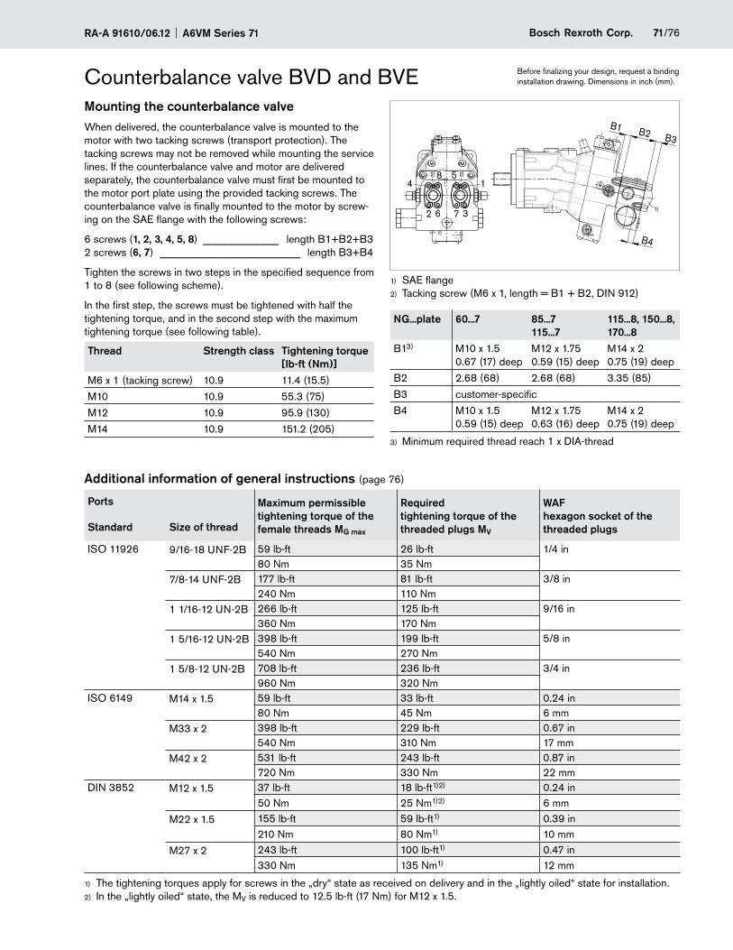
71/76Bosch Rexroth Corp.RA-A 91610/06.12 A6VM Series 71
Before finalizing your design, request a binding installation drawing. Dimensions in inch (mm).Counterbalance valve BVD and BVE
Mounting the counterbalance valveWhen delivered, the counterbalance valve is mounted to the motor with two tacking screws (transport protection). The tacking screws may not be removed while mounting the service lines. If the counterbalance valve and motor are delivered separately, the counterbalance valve must first be mounted to the motor port plate using the provided tacking screws. The counterbalance valve is finally mounted to the motor by screw-ing on the SAE flange with the following screws:
6 screws (1, 2, 3, 4, 5, 8) ______________ length B1+B2+B3 2 screws (6, 7) __________________________ length B3+B4
Tighten the screws in two steps in the specified sequence from 1 to 8 (see following scheme).
In the first step, the screws must be tightened with half the tightening torque, and in the second step with the maximum tightening torque (see following table).
Thread Strength class Tightening torque [lb-ft (Nm)]
M6 x 1 (tacking screw) 10.9 11.4 (15.5)
M10 10.9 55.3 (75)
M12 10.9 95.9 (130)
M14 10.9 151.2 (205)
B1
14
2 6 7 3
B2 B3
B4
1)
8 5 2)2)
SAE flange1)
Tacking screw (M6 x 1, length = B1 + B2, DIN 912)2)
NG...plate 60...7 85...7 115...7
115...8, 150...8, 170...8
B13) M10 x 1.5 0.67 (17) deep
M12 x 1.75 0.59 (15) deep
M14 x 2 0.75 (19) deep
B2 2.68 (68) 2.68 (68) 3.35 (85)
B3 customer-specific
B4 M10 x 1.5 0.59 (15) deep
M12 x 1.75 0.63 (16) deep
M14 x 2 0.75 (19) deep
Minimum required thread reach 1 x DIA-thread3)
Additional information of general instructions (page 76)
Ports Maximum permissible tightening torque of the female threads MG max
Required tightening torque of the threaded plugs MV
WAF hexagon socket of the threaded plugsStandard Size of thread
ISO 11926 9/16-18 UNF-2B 59 lb-ft 26 lb-ft 1/4 in80 Nm 35 Nm
7/8-14 UNF-2B 177 lb-ft 81 lb-ft 3/8 in240 Nm 110 Nm
1 1/16-12 UN-2B 266 lb-ft 125 lb-ft 9/16 in360 Nm 170 Nm
1 5/16-12 UN-2B 398 lb-ft 199 lb-ft 5/8 in540 Nm 270 Nm
1 5/8-12 UN-2B 708 lb-ft 236 lb-ft 3/4 in960 Nm 320 Nm
ISO 6149 M14 x 1.5 59 lb-ft 33 lb-ft 0.24 in80 Nm 45 Nm 6 mm
M33 x 2 398 lb-ft 229 lb-ft 0.67 in540 Nm 310 Nm 17 mm
M42 x 2 531 lb-ft 243 lb-ft 0.87 in720 Nm 330 Nm 22 mm
DIN 3852 M12 x 1.5 37 lb-ft 18 lb-ft1)2) 0.24 in50 Nm 25 Nm1)2) 6 mm
M22 x 1.5 155 lb-ft 59 lb-ft1) 0.39 in210 Nm 80 Nm1) 10 mm
M27 x 2 243 lb-ft 100 lb-ft1) 0.47 in330 Nm 135 Nm1) 12 mm
The tightening torques apply for screws in the „dry“ state as received on delivery and in the „lightly oiled“ state for installation.1)
In the „lightly oiled“ state, the 2) MV is reduced to 12.5 lb-ft (17 Nm) for M12 x 1.5.
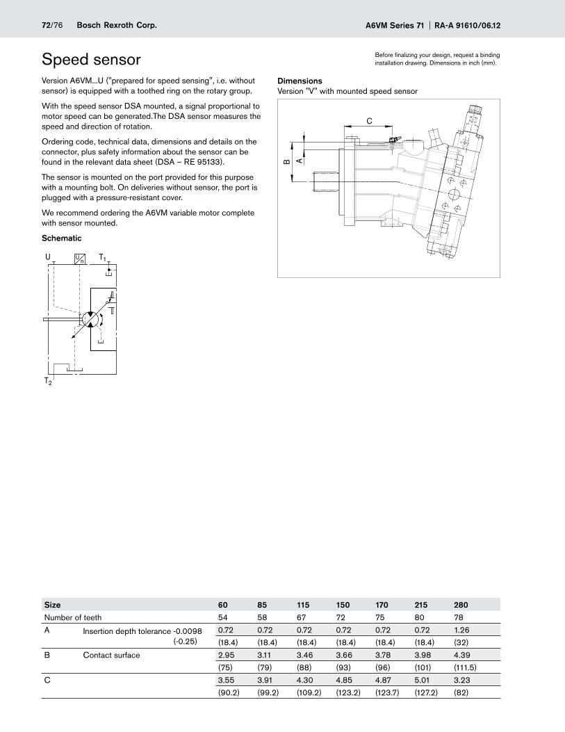
A6VM Series 71 RA-A 91610/06.1272/76 Bosch Rexroth Corp.
Version A6VM...U ("prepared for speed sensing", i.e. without sensor) is equipped with a toothed ring on the rotary group.
With the speed sensor DSA mounted, a signal proportional to motor speed can be generated.The DSA sensor measures the speed and direction of rotation.
Ordering code, technical data, dimensions and details on the connector, plus safety information about the sensor can be found in the relevant data sheet (DSA – RE 95133).
The sensor is mounted on the port provided for this purpose with a mounting bolt. On deliveries without sensor, the port is plugged with a pressure-resistant cover.
We recommend ordering the A6VM variable motor complete with sensor mounted.
Schematic
T2
T1Un
U
DimensionsVersion "V" with mounted speed sensor
A
C
B
Speed sensor
Size 60 85 115 150 170 215 280Number of teeth 54 58 67 72 75 80 78
A Insertion depth tolerance -0.0098 (-0.25)
0.72 0.72 0.72 0.72 0.72 0.72 1.26
(18.4) (18.4) (18.4) (18.4) (18.4) (18.4) (32)
B Contact surface 2.95 3.11 3.46 3.66 3.78 3.98 4.39
(75) (79) (88) (93) (96) (101) (111.5)
C 3.55 3.91 4.30 4.85 4.87 5.01 3.23
(90.2) (99.2) (109.2) (123.2) (123.7) (127.2) (82)
Before finalizing your design, request a binding installation drawing. Dimensions in inch (mm).
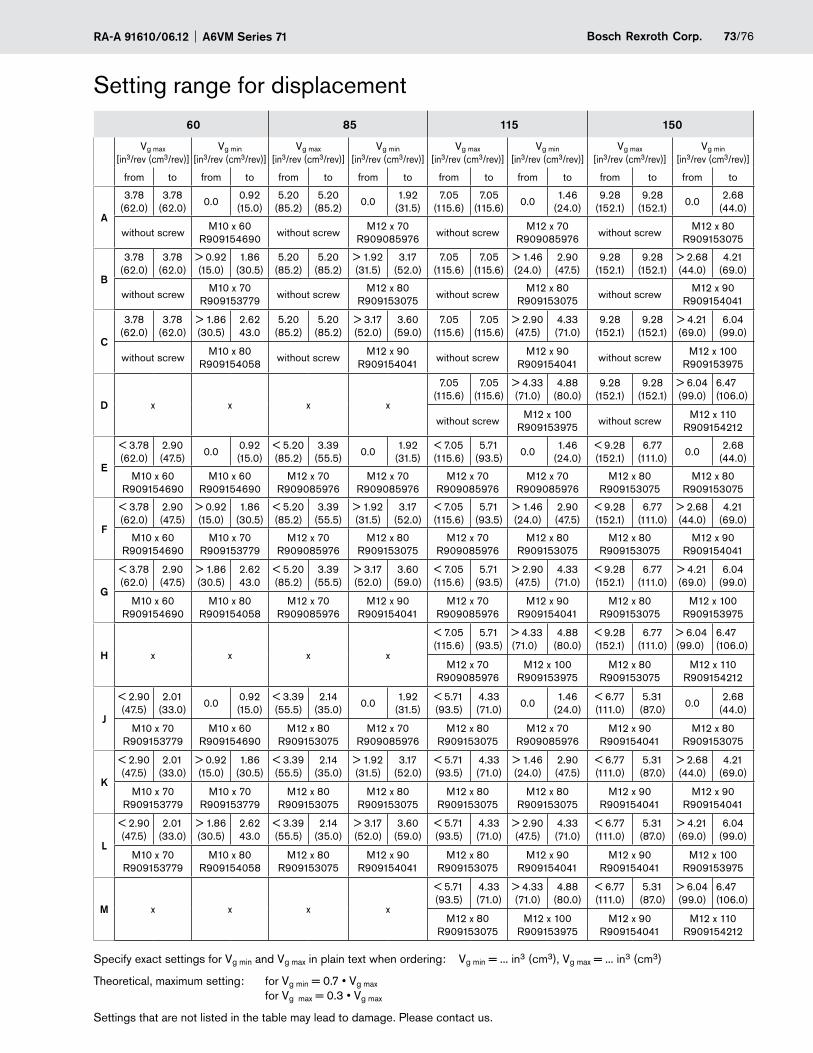
73/76Bosch Rexroth Corp.RA-A 91610/06.12 A6VM Series 71
Setting range for displacement
60 85 115 150
Vg max [in3/rev (cm3/rev)]
Vg min [in3/rev (cm3/rev)]
Vg max [in3/rev (cm3/rev)]
Vg min [in3/rev (cm3/rev)]
Vg max [in3/rev (cm3/rev)]
Vg min [in3/rev (cm3/rev)]
Vg max [in3/rev (cm3/rev)]
Vg min [in3/rev (cm3/rev)]
from to from to from to from to from to from to from to from to
A
3.78 (62.0)
3.78 (62.0)
0.00.92 (15.0)
5.20 (85.2)
5.20 (85.2)
0.01.92
(31.5)7.05
(115.6)7.05
(115.6)0.0
1.46 (24.0)
9.28 (152.1)
9.28 (152.1)
0.02.68
(44.0)
without screwM10 x 60
R909154690without screw
M12 x 70 R909085976
without screwM12 x 70
R909085976without screw
M12 x 80 R909153075
B
3.78 (62.0)
3.78 (62.0)
> 0.92 (15.0)
1.86 (30.5)
5.20 (85.2)
5.20 (85.2)
> 1.92 (31.5)
3.17 (52.0)
7.05 (115.6)
7.05 (115.6)
> 1.46 (24.0)
2.90 (47.5)
9.28 (152.1)
9.28 (152.1)
> 2.68 (44.0)
4.21 (69.0)
without screwM10 x 70
R909153779without screw
M12 x 80 R909153075
without screwM12 x 80
R909153075without screw
M12 x 90 R909154041
C
3.78 (62.0)
3.78 (62.0)
> 1.86 (30.5)
2.62 43.0
5.20 (85.2)
5.20 (85.2)
> 3.17 (52.0)
3.60 (59.0)
7.05 (115.6)
7.05 (115.6)
> 2.90 (47.5)
4.33 (71.0)
9.28 (152.1)
9.28 (152.1)
> 4.21 (69.0)
6.04 (99.0)
without screwM10 x 80
R909154058without screw
M12 x 90 R909154041
without screwM12 x 90
R909154041without screw
M12 x 100 R909153975
D x x x x
7.05 (115.6)
7.05 (115.6)
> 4.33 (71.0)
4.88 (80.0)
9.28 (152.1)
9.28 (152.1)
> 6.04 (99.0)
6.47 (106.0)
without screwM12 x 100
R909153975without screw
M12 x 110 R909154212
E
< 3.78 (62.0)
2.90 (47.5)
0.00.92 (15.0)
< 5.20 (85.2)
3.39 (55.5)
0.01.92
(31.5)< 7.05 (115.6)
5.71 (93.5)
0.01.46
(24.0)< 9.28 (152.1)
6.77 (111.0)
0.02.68
(44.0)
M10 x 60 R909154690
M10 x 60 R909154690
M12 x 70 R909085976
M12 x 70 R909085976
M12 x 70 R909085976
M12 x 70 R909085976
M12 x 80 R909153075
M12 x 80 R909153075
F
< 3.78 (62.0)
2.90 (47.5)
> 0.92 (15.0)
1.86 (30.5)
< 5.20 (85.2)
3.39 (55.5)
> 1.92 (31.5)
3.17 (52.0)
< 7.05 (115.6)
5.71 (93.5)
> 1.46 (24.0)
2.90 (47.5)
< 9.28 (152.1)
6.77 (111.0)
> 2.68 (44.0)
4.21 (69.0)
M10 x 60 R909154690
M10 x 70 R909153779
M12 x 70 R909085976
M12 x 80 R909153075
M12 x 70 R909085976
M12 x 80 R909153075
M12 x 80 R909153075
M12 x 90 R909154041
G
< 3.78 (62.0)
2.90 (47.5)
> 1.86 (30.5)
2.62 43.0
< 5.20 (85.2)
3.39 (55.5)
> 3.17 (52.0)
3.60 (59.0)
< 7.05 (115.6)
5.71 (93.5)
> 2.90 (47.5)
4.33 (71.0)
< 9.28 (152.1)
6.77 (111.0)
> 4.21 (69.0)
6.04 (99.0)
M10 x 60 R909154690
M10 x 80 R909154058
M12 x 70 R909085976
M12 x 90 R909154041
M12 x 70 R909085976
M12 x 90 R909154041
M12 x 80 R909153075
M12 x 100 R909153975
H x x x x
< 7.05 (115.6)
5.71 (93.5)
> 4.33 (71.0)
4.88 (80.0)
< 9.28 (152.1)
6.77 (111.0)
> 6.04 (99.0)
6.47 (106.0)
M12 x 70 R909085976
M12 x 100 R909153975
M12 x 80 R909153075
M12 x 110 R909154212
J
< 2.90 (47.5)
2.01 (33.0)
0.00.92 (15.0)
< 3.39 (55.5)
2.14 (35.0)
0.01.92
(31.5)< 5.71 (93.5)
4.33 (71.0)
0.01.46
(24.0)< 6.77 (111.0)
5.31 (87.0)
0.02.68
(44.0)
M10 x 70 R909153779
M10 x 60 R909154690
M12 x 80 R909153075
M12 x 70 R909085976
M12 x 80 R909153075
M12 x 70 R909085976
M12 x 90 R909154041
M12 x 80 R909153075
K
< 2.90 (47.5)
2.01 (33.0)
> 0.92 (15.0)
1.86 (30.5)
< 3.39 (55.5)
2.14 (35.0)
> 1.92 (31.5)
3.17 (52.0)
< 5.71 (93.5)
4.33 (71.0)
> 1.46 (24.0)
2.90 (47.5)
< 6.77 (111.0)
5.31 (87.0)
> 2.68 (44.0)
4.21 (69.0)
M10 x 70 R909153779
M10 x 70 R909153779
M12 x 80 R909153075
M12 x 80 R909153075
M12 x 80 R909153075
M12 x 80 R909153075
M12 x 90 R909154041
M12 x 90 R909154041
L
< 2.90 (47.5)
2.01 (33.0)
> 1.86 (30.5)
2.62 43.0
< 3.39 (55.5)
2.14 (35.0)
> 3.17 (52.0)
3.60 (59.0)
< 5.71 (93.5)
4.33 (71.0)
> 2.90 (47.5)
4.33 (71.0)
< 6.77 (111.0)
5.31 (87.0)
> 4.21 (69.0)
6.04 (99.0)
M10 x 70 R909153779
M10 x 80 R909154058
M12 x 80 R909153075
M12 x 90 R909154041
M12 x 80 R909153075
M12 x 90 R909154041
M12 x 90 R909154041
M12 x 100 R909153975
M x x x x
< 5.71 (93.5)
4.33 (71.0)
> 4.33 (71.0)
4.88 (80.0)
< 6.77 (111.0)
5.31 (87.0)
> 6.04 (99.0)
6.47 (106.0)
M12 x 80 R909153075
M12 x 100 R909153975
M12 x 90 R909154041
M12 x 110 R909154212
Specify exact settings for Vg min and Vg max in plain text when ordering: Vg min = ... in3 (cm3), Vg max = ... in3 (cm3)
Theoretical, maximum setting: for Vg min = 0.7 • Vg max for Vg max = 0.3 • Vg max
Settings that are not listed in the table may lead to damage. Please contact us.
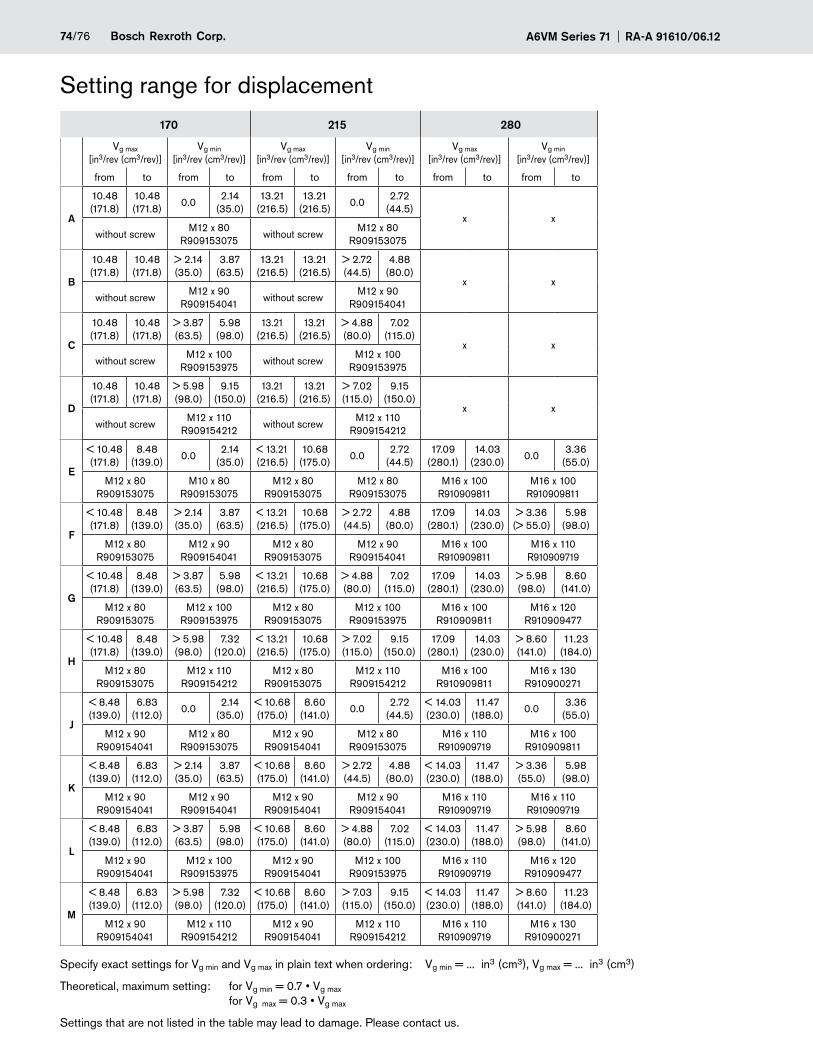
A6VM Series 71 RA-A 91610/06.1274/76 Bosch Rexroth Corp.
Setting range for displacement
170 215 280
Vg max [in3/rev (cm3/rev)]
Vg min [in3/rev (cm3/rev)]
Vg max [in3/rev (cm3/rev)]
Vg min [in3/rev (cm3/rev)]
Vg max [in3/rev (cm3/rev)]
Vg min [in3/rev (cm3/rev)]
from to from to from to from to from to from to
A
10.48 (171.8)
10.48 (171.8)
0.02.14
(35.0)13.21
(216.5)13.21
(216.5)0.0
2.72 (44.5)
x xwithout screw
M12 x 80 R909153075
without screwM12 x 80
R909153075
B
10.48 (171.8)
10.48 (171.8)
> 2.14 (35.0)
3.87 (63.5)
13.21 (216.5)
13.21 (216.5)
> 2.72 (44.5)
4.88 (80.0)
x xwithout screw
M12 x 90 R909154041
without screwM12 x 90
R909154041
C
10.48 (171.8)
10.48 (171.8)
> 3.87 (63.5)
5.98 (98.0)
13.21 (216.5)
13.21 (216.5)
> 4.88 (80.0)
7.02 (115.0)
x xwithout screw
M12 x 100 R909153975
without screwM12 x 100
R909153975
D
10.48 (171.8)
10.48 (171.8)
> 5.98 (98.0)
9.15 (150.0)
13.21 (216.5)
13.21 (216.5)
> 7.02 (115.0)
9.15 (150.0)
x xwithout screw
M12 x 110 R909154212
without screwM12 x 110
R909154212
E
< 10.48 (171.8)
8.48 (139.0)
0.02.14
(35.0)< 13.21 (216.5)
10.68 (175.0)
0.02.72
(44.5)17.09
(280.1)14.03
(230.0)0.0
3.36 (55.0)
M12 x 80 R909153075
M10 x 80 R909153075
M12 x 80 R909153075
M12 x 80 R909153075
M16 x 100 R910909811
M16 x 100 R910909811
F
< 10.48 (171.8)
8.48 (139.0)
> 2.14 (35.0)
3.87 (63.5)
< 13.21 (216.5)
10.68 (175.0)
> 2.72 (44.5)
4.88 (80.0)
17.09 (280.1)
14.03 (230.0)
> 3.36 (> 55.0)
5.98 (98.0)
M12 x 80 R909153075
M12 x 90 R909154041
M12 x 80 R909153075
M12 x 90 R909154041
M16 x 100 R910909811
M16 x 110 R910909719
G
< 10.48 (171.8)
8.48 (139.0)
> 3.87 (63.5)
5.98 (98.0)
< 13.21 (216.5)
10.68 (175.0)
> 4.88 (80.0)
7.02 (115.0)
17.09 (280.1)
14.03 (230.0)
> 5.98 (98.0)
8.60 (141.0)
M12 x 80 R909153075
M12 x 100 R909153975
M12 x 80 R909153075
M12 x 100 R909153975
M16 x 100 R910909811
M16 x 120 R910909477
H
< 10.48 (171.8)
8.48 (139.0)
> 5.98 (98.0)
7.32 (120.0)
< 13.21 (216.5)
10.68 (175.0)
> 7.02 (115.0)
9.15 (150.0)
17.09 (280.1)
14.03 (230.0)
> 8.60 (141.0)
11.23 (184.0)
M12 x 80 R909153075
M12 x 110 R909154212
M12 x 80 R909153075
M12 x 110 R909154212
M16 x 100 R910909811
M16 x 130 R910900271
J
< 8.48 (139.0)
6.83 (112.0)
0.02.14
(35.0)< 10.68 (175.0)
8.60 (141.0)
0.02.72
(44.5)< 14.03 (230.0)
11.47 (188.0)
0.03.36
(55.0)
M12 x 90 R909154041
M12 x 80 R909153075
M12 x 90 R909154041
M12 x 80 R909153075
M16 x 110 R910909719
M16 x 100 R910909811
K
< 8.48 (139.0)
6.83 (112.0)
> 2.14 (35.0)
3.87 (63.5)
< 10.68 (175.0)
8.60 (141.0)
> 2.72 (44.5)
4.88 (80.0)
< 14.03 (230.0)
11.47 (188.0)
> 3.36 (55.0)
5.98 (98.0)
M12 x 90 R909154041
M12 x 90 R909154041
M12 x 90 R909154041
M12 x 90 R909154041
M16 x 110 R910909719
M16 x 110 R910909719
L
< 8.48 (139.0)
6.83 (112.0)
> 3.87 (63.5)
5.98 (98.0)
< 10.68 (175.0)
8.60 (141.0)
> 4.88 (80.0)
7.02 (115.0)
< 14.03 (230.0)
11.47 (188.0)
> 5.98 (98.0)
8.60 (141.0)
M12 x 90 R909154041
M12 x 100 R909153975
M12 x 90 R909154041
M12 x 100 R909153975
M16 x 110 R910909719
M16 x 120 R910909477
M
< 8.48 (139.0)
6.83 (112.0)
> 5.98 (98.0)
7.32 (120.0)
< 10.68 (175.0)
8.60 (141.0)
> 7.03 (115.0)
9.15 (150.0)
< 14.03 (230.0)
11.47 (188.0)
> 8.60 (141.0)
11.23 (184.0)
M12 x 90 R909154041
M12 x 110 R909154212
M12 x 90 R909154041
M12 x 110 R909154212
M16 x 110 R910909719
M16 x 130 R910900271
Specify exact settings for Vg min and Vg max in plain text when ordering: Vg min = ... in3 (cm3), Vg max = ... in3 (cm3)
Theoretical, maximum setting: for Vg min = 0.7 • Vg max for Vg max = 0.3 • Vg max
Settings that are not listed in the table may lead to damage. Please contact us.
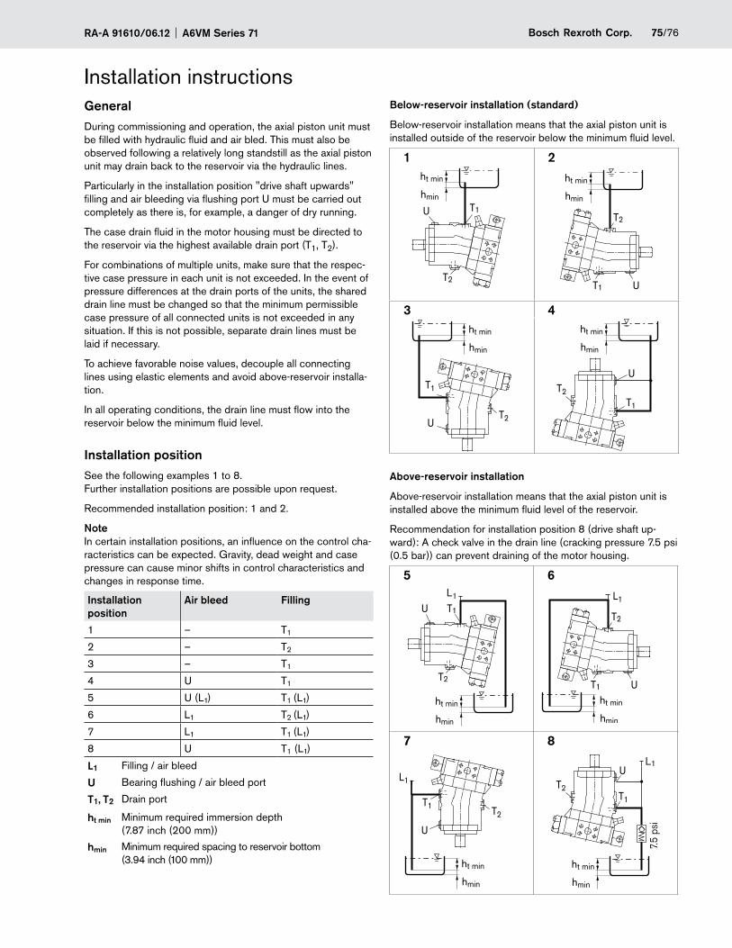
75/76Bosch Rexroth Corp.RA-A 91610/06.12 A6VM Series 71
Installation instructionsGeneralDuring commissioning and operation, the axial piston unit must be filled with hydraulic fluid and air bled. This must also be observed following a relatively long standstill as the axial piston unit may drain back to the reservoir via the hydraulic lines.
Particularly in the installation position "drive shaft upwards" filling and air bleeding via flushing port U must be carried out completely as there is, for example, a danger of dry running.
The case drain fluid in the motor housing must be directed to the reservoir via the highest available drain port (T1, T2).
For combinations of multiple units, make sure that the respec-tive case pressure in each unit is not exceeded. In the event of pressure differences at the drain ports of the units, the shared drain line must be changed so that the minimum permissible case pressure of all connected units is not exceeded in any situation. If this is not possible, separate drain lines must be laid if necessary.
To achieve favorable noise values, decouple all connecting lines using elastic elements and avoid above-reservoir installa-tion.
In all operating conditions, the drain line must flow into the reservoir below the minimum fluid level.
Installation positionSee the following examples 1 to 8. Further installation positions are possible upon request.
Recommended installation position: 1 and 2.
NoteIn certain installation positions, an influence on the control cha-racteristics can be expected. Gravity, dead weight and case pressure can cause minor shifts in control characteristics and changes in response time.
Installation position
Air bleed Filling
1 – T1
2 – T2
3 – T1
4 U T1
5 U (L1) T1 (L1)
6 L1 T2 (L1)
7 L1 T1 (L1)
8 U T1 (L1)
L1 Filling / air bleed
U Bearing flushing / air bleed port
T1, T2 Drain port
ht min Minimum required immersion depth (7.87 inch (200 mm))
hmin Minimum required spacing to reservoir bottom (3.94 inch (100 mm))
Below-reservoir installation (standard)
Below-reservoir installation means that the axial piston unit is installed outside of the reservoir below the minimum fluid level.
1 2ht min
hmin
T2
T1UT2
T1 U
ht min
hmin
3 4
T2
T1
U
ht min
hmin
ht min
hmin
T2T1
U
Above-reservoir installation
Above-reservoir installation means that the axial piston unit is installed above the minimum fluid level of the reservoir.
Recommendation for installation position 8 (drive shaft up-ward): A check valve in the drain line (cracking pressure 7.5 psi (0.5 bar)) can prevent draining of the motor housing.
5 6
T2
T1UL1
ht min
hmin
ht min
hmin
T2
T1 U
L1
7 8
T2T1
U
L1
ht min
hmin
7.5
psi
(0.5
bar
)
ht min
hmin
T2T1
UL1
A6VM Series 71 RA-A 91610/06.1276/76 Bosch Rexroth Corp.
© Bosch Rexroth Corporation
All rights reserved. Neither this document, nor any part of it, may be reproduced, duplicated, circulated or disseminated, whether by copy, electronic format or any other means, without the prior consent and authorization of Bosch Rexroth Corp.
The data and illustrations in this brochure/data sheet are intended only to descri-be or depict the products. No representation or warranty, either express or im-plied, relating to merchantability or fitness for intended use, is given or intended by virtue of the information contained in this brochure/data sheet. The information contained in this brochure/data sheet in no way relieves the user of its obligation to insure the proper use of the products for a specific use or application. All products contained in this brochure/data sheet are subject to normal wear and tear from usage.
Subject to change.
Bosch Rexroth CorporationMobile Applications8 Southchase CourtFountain Inn, SC 29644-9018, USATelephone (864) 967-2777Facsimile (864) 967-8900www.boschrexroth-us.com
The motor A6VM is designed to be used in open and closed –circuits.
The project planning, installation and commissioning of the axi- –al piston unit requires the involvement of qualified personnel.
Before using the axial piston unit, please read the corres- –ponding instruction manual completely and thoroughly. If necessary, these can be requested from Bosch Rexroth.
During and shortly after operation, there is a risk of burns on –the axial piston unit and especially on the solenoids. Take appropriate safety measures (e. g. by wearing protective clothing).
Depending on the operating conditions of the axial piston unit –(operating pressure, fluid temperature), the characteristic may shift.
Service line ports: –
The ports and fastening threads are designed for the spe- -cified maximum pressure. The machine or system manufac-turer must ensure that the connecting elements and lines correspond to the specified application conditions (pres-sure, flow, hydraulic fluid, temperature) with the necessary safety factors.
The service line ports and function ports can only be used -to accommodate hydraulic lines.
General instructionsThe data and notes contained herein must be adhered to. –
The product is not approved as a component for the safety –concept of a general machine according to ISO 13849.
The following tightening torques apply: –
Fittings: -Observe the manufacturer's instructions regarding the tightening torques of the fittings used.
Mounting bolts: -For mounting bolts with metric ISO thread according to DIN 13 or thread according to ASME B1.1, we recom-mend checking the tightening torque in individual cases in accordance with VDI 2230.
Female threads in the axial piston unit: -The maximum permissible tightening torques MG max are maximum values of the female threads and must not be exceeded. For values, see the following table.
Threaded plugs: -For the metallic threaded plugs supplied with the axial pis-ton unit, the required tightening torques of threaded plugs MV apply. For values, see table on page 75.