Embed Size (px)
Citation preview
1
IMPORTANT:
Go to www.extron.com for the complete
user guide, installation instructions, and
specifications before connecting the
product to the power source.
AXI 22 AT and AXI 44 AT • Setup Guide
This guide provides basic instructions for an experienced technician to install the AXI 22 AT and AXI 44 AT Audio Expansion Interfaces with Dante. For additional information and specifications, see the AXI 22 AT and AXI 44 AT product pages at www.extron.com.
NOTE: In this setup guide, the terms “AXI” and “device” are used to refer to the AXI 22 AT and the AXI 44 AT interchangeably.
Disconnect Power and Mount the AXI
Disconnect power from the AXI and turn off all devices that will be connected to it. The AXI is housed in a quarter rack width, 6 inch deep, 1U high metal enclosure that can be rack mounted or sit on a table with the provided rubber feet. Select a suitable mounting location, then choose an appropriate mounting option. Mounting information can be found in the AXI 22 AT and AXI 44 AT User Guide at www.extron.com.
Make all external device connections before applying power.
Rear Panel Connections
OFF
ON
+42+36+30+24+18+12
+60
GAIN
CLIP -
SIG -
+ 48V
ON
OFF
CONFIG
CONTROL INPUTS
OUTPUTS
INPUT 1
2
3
4
1
2
3
4
1 2
CLIP -
SIG -
3 4
AXI 44 AT
AT (PoE)POWER12V 0.6A MAX
1 2
3 4
1 2
3 4
MIC
/ L
INE
INP
UT
S
OU
TP
UT
S
R1 2
AT (PoE)POWER12V 0.5A MAX 1 2
MIC / LINE INS OUTPUTS
R
OFF
ON1
2
+42+36+30+24+18+12+6
0
GAIN
CLIP -
SIG -
+ 48V
ON
OFF
CONFIG
CONTROL INPUTS
OUTPUTS
INPUT
1
1
2
2
CLIP -
SIG -
AXI 22 AT
GAIN LEVELGAIN LEVEL
A C D
E
F G
H I
IB A C D
E
F G
H I
IB
A B C D E A B C D E
A 12 VDC Power Inlet D AT (PoE) Port
B Mic/Line Inputs E Reset Button
C Line Outputs
Figure 1. AXI 22 AT and AXI 44 AT Rear Panel Connections
A 12 VDC Power Inlet — Connect the optional 12 VDC power supply to the rear panel captive screw connector and plug the power cable into the IEC connector on the power supply (see figure 2 below and the attention notices on the next page). The power LED on the front panel blinks as the unit is powering on and lights steadily when the unit is operational.
As an alternative to the optional external power supply, the AXI can be powered over Ethernet (PoE) using the AT (PoE) port.Rear PanelPower Receptacle
DC Power Cord Captive Screw Connector
Ground all devices.
External Power Supply
12 VDC, 1 A max.
– Return+12 VDC input
Ridged
Smooth
1A M
AX
100-
240V
50-6
0Hz
Figure 2. Connecting the External Power Supply
figure 1 Rear Panel Connections
2
ATTENTION:• Always use a power supply provided by or specified by Extron. Use of an unauthorized power supply voids all
regulatory compliance certification and may cause damage to the supply and the end product.
• Utilisez toujours une source d’alimentation fournie par Extron. L’utilisation d’une source d’alimentation non autorisée annule toute conformité réglementaire et peut endommager la source d’alimentation ainsi que l’unité.
• Unless otherwise stated, the AC/DC adapters are not suitable for use in air handling spaces or in wall cavities. The power supply is to be located within the same vicinity as the Extron AV processing equipment in an ordinary location, Pollution Degree 2, secured to the equipment rack within the dedicated closet, podium, or desk.
• Sauf mention contraire, les adaptateurs AC/DC ne sont pas appropriés pour une utilisation dans les espaces d’aération ou dans les cavités murales. La source d’alimentation doit être située à proximité de l’équipement de traitement audiovisuel dans un endroit ordinaire, avec un degré 2 de pollution, fixé à un équipement de rack à l’intérieur d’un placard, d’une estrade, ou d’un bureau.
• The installation must always be in accordance with the applicable provisions of National Electrical Code ANSI/NFPA 70, article 725 and the Canadian Electrical Code part 1, section 16. The power supply shall not be permanently fixed to building structure or similar structure.
• Cette installation doit toujours être en accord avec les mesures qui s’applique au National Electrical Code ANSI/NFPA 70, article 725, et au Canadian Electrical Code, partie 1, section 16. La source d’alimentation ne devra pas être fixée de façon permanente à une structure de bâtiment ou à une structure similaire.
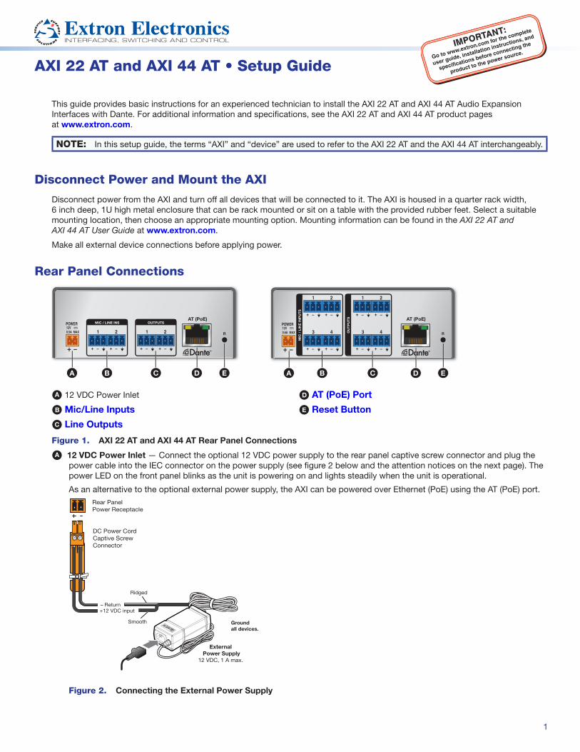
B Mic/Line Inputs — Use 3-pole 3.5 mm captive screw connectors to connect two balanced or unbalanced microphone or mono line level sources (AXI 22 AT) or four balanced or unbalanced microphone or mono line level sources (AXI 44 AT) (see 3-pole Audio Input Wiring in figure 3 below). Phantom power is available on all mic/line inputs.
Balanced or unbalanced stereo sources can also be connected using 6-pole captive screw connectors (see 6-pole Audio Input Wiring in figure 3 below).
" (5 mm) MAX. (typ)316
3-pole Audio INPUT WiringBalanced Input
SleeveRing
Tip TipSleeve
JumperUnbalanced Input
Tip
SleeveRing
Tip
SleeveRing
TipSleeve
TipSleeve
6-pole Audio INPUT WiringBalanced Input Unbalanced Input
Jumper
Jumper
Figure 3. Audio Input Wiring
NOTES: • Balanced or unbalanced stereo sources can be connected with 6-pole connectors.
• When using the 5-pole CSR adapter, connect it so the far left plug is inserted into the far left jack of the 6-pole input (see figure 4 below).
1
2
POWER12V 0.5A MAX
1
2
MIC / LINE INPUTS
OUTPUTS
R
AT (PoE)
1
2
/ LINE INPUTS
DO NOTConnect Here
5-pole CSR
Figure 4. 5-pole CSR Input Adapter
3
C Line Outputs — Use 6-pole 3.5 mm captive screw connectors to connect two balanced or unbalanced mono line level devices (AXI 22 AT) or four balanced or unbalanced mono line level devices (AXI 44 AT) (see 3-pole Audio Output Wiring in figure 5 below).
Balanced or unbalanced stereo devices can also be connected using 6-pole captive screw connectors (see 6-pole Audio Output Wiring in figure 5 below).
Tip
SleeveTip
Sleeve
Tip
SleeveRing
Tip
SleeveRing
6-pole Audio OUTPUT WiringBalanced Output Unbalanced Output
NO Ground Here
NO Ground Here
3-pole Audio OUTPUT WiringUnbalanced Output
Tip
SleeveNO Ground Here
Balanced Output
Tip
SleeveRing
Figure 5. Audio Output Wiring
ATTENTION: For unbalanced audio outputs, connect the sleeves to the ground contact. DO NOT connect the sleeves to the negative (-) contacts.
ATTENTION : Pour l’audio asymétrique, connectez les manchons au contact au sol. Ne PAS connecter les manchons aux contacts négatifs (–).
D AT (PoE) Port — Insert an Ethernet cable to this RJ-45 port to connect the AXI to a Dante network. This port supports power over Ethernet (PoE), communication with DSP Configurator for configuration, digital audio transport (AT), and communication with the Dante network for configuration via Dante Controller.
E Reset Button — The Reset button returns the AXI to different tiers of default states. When using the reset function, the LED blinks to indicate the different reset modes. When not using the reset function, the LED operates as a power indicator and matches the front panel power LED (see the Reset Modes topic in the AXI 22 AT and AXI 44 AT User Guide).
Front Panel Controls
OFF
ON
+42+36+30+24+18+12
+60
GAIN
CLIP -
SIG -
+ 48V
ON
OFF
CONFIG
CONTROL INPUTS
OUTPUTS
INPUT 1
2
3
4
1
2
3
4
1 2
CLIP -
SIG -
3 4
AXI 44 AT
AT (PoE)POWER12V 0.6A MAX
1 2
3 4
1 2
3 4
MIC
/ L
INE
INP
UT
S
OU
TP
UT
S
R1 2
AT (PoE)POWER12V 0.5A MAX 1 2
MIC / LINE INS OUTPUTS
R
OFF
ON1
2
+42+36+30+24+18+12+6
0
GAIN
CLIP -
SIG -
+ 48V
ON
OFF
CONFIG
CONTROL INPUTS
OUTPUTS
INPUT
1
1
2
2
CLIP -
SIG -
AXI 22 AT
GAIN LEVELGAIN LEVEL
A C D
E
F G
H I
IB A C D
E
F G
H I
IB
A B C D E A B C D E
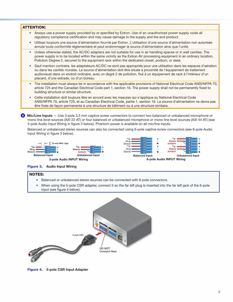
A Power Indicator LED F Gain Rotary Encoder
B USB Config Port G Phantom Power Switch
C Input Selector Button H Phantom Power Indicator LEDs
D Input Indicator LEDs I Input and Output Signal and Clip LEDs
E Input Level and Gain LED Stack
Figure 6. AXI 22 AT and AXI 44 AT Front Panel Controls
A Power Indicator LED — Blinks during boot up and lights steadily when the AXI is operational.
B USB Config Port — One USB Mini-B port is used for configuration. This port can also be used for firmware updates.
C Input Selector Button — Press this button to cycle through the AXI inputs. Select an input to adjust gain, set phantom power, and view input levels for that input.
D Input Indicator LEDs — These LEDs light to indicate which input is currently selected. Gain and phantom power adjustments only affect the currently selected input.
4
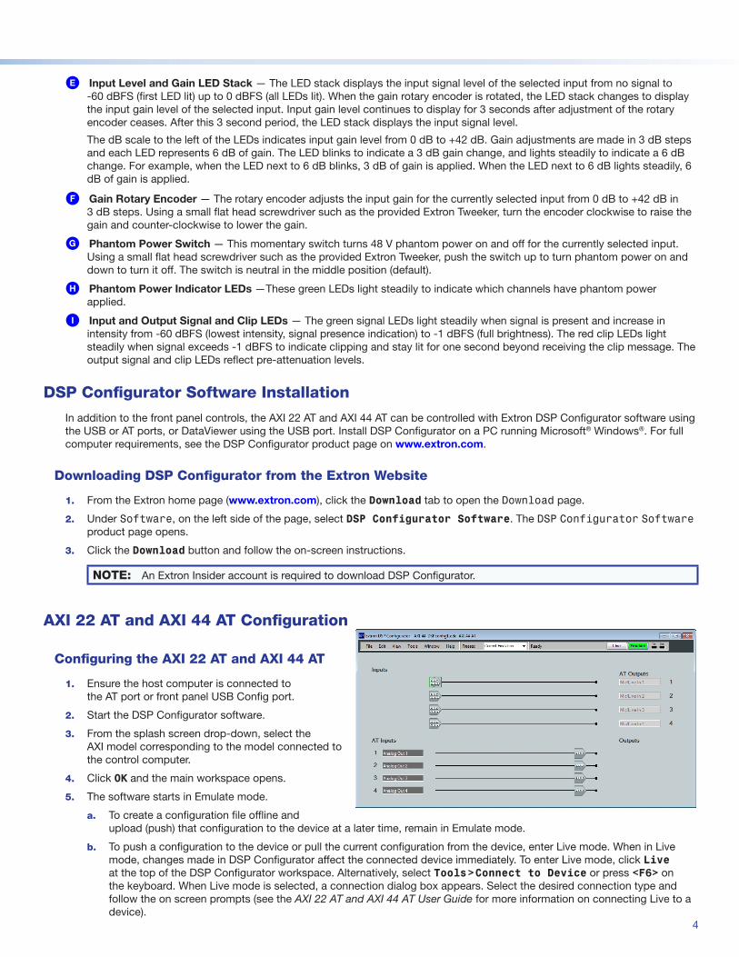
E Input Level and Gain LED Stack — The LED stack displays the input signal level of the selected input from no signal to -60 dBFS (first LED lit) up to 0 dBFS (all LEDs lit). When the gain rotary encoder is rotated, the LED stack changes to display the input gain level of the selected input. Input gain level continues to display for 3 seconds after adjustment of the rotary encoder ceases. After this 3 second period, the LED stack displays the input signal level.
The dB scale to the left of the LEDs indicates input gain level from 0 dB to +42 dB. Gain adjustments are made in 3 dB steps and each LED represents 6 dB of gain. The LED blinks to indicate a 3 dB gain change, and lights steadily to indicate a 6 dB change. For example, when the LED next to 6 dB blinks, 3 dB of gain is applied. When the LED next to 6 dB lights steadily, 6 dB of gain is applied.
F Gain Rotary Encoder — The rotary encoder adjusts the input gain for the currently selected input from 0 dB to +42 dB in 3 dB steps. Using a small flat head screwdriver such as the provided Extron Tweeker, turn the encoder clockwise to raise the gain and counter-clockwise to lower the gain.
G Phantom Power Switch — This momentary switch turns 48 V phantom power on and off for the currently selected input. Using a small flat head screwdriver such as the provided Extron Tweeker, push the switch up to turn phantom power on and down to turn it off. The switch is neutral in the middle position (default).
H Phantom Power Indicator LEDs —These green LEDs light steadily to indicate which channels have phantom power applied.
I Input and Output Signal and Clip LEDs — The green signal LEDs light steadily when signal is present and increase in intensity from -60 dBFS (lowest intensity, signal presence indication) to -1 dBFS (full brightness). The red clip LEDs light steadily when signal exceeds -1 dBFS to indicate clipping and stay lit for one second beyond receiving the clip message. The output signal and clip LEDs reflect pre-attenuation levels.
DSP Configurator Software Installation
In addition to the front panel controls, the AXI 22 AT and AXI 44 AT can be controlled with Extron DSP Configurator software using the USB or AT ports, or DataViewer using the USB port. Install DSP Configurator on a PC running Microsoft® Windows®. For full computer requirements, see the DSP Configurator product page on www.extron.com.
Downloading DSP Configurator from the Extron Website
1. From the Extron home page (www.extron.com), click the Download tab to open the Download page.
2. Under Software, on the left side of the page, select DSP Configurator Software. The DSP Configurator Software product page opens.
3. Click the Download button and follow the on-screen instructions.
NOTE: An Extron Insider account is required to download DSP Configurator.
AXI 22 AT and AXI 44 AT Configuration
Configuring the AXI 22 AT and AXI 44 AT
1. Ensure the host computer is connected to the AT port or front panel USB Config port.
2. Start the DSP Configurator software.
3. From the splash screen drop-down, select the AXI model corresponding to the model connected to the control computer.
4. Click OK and the main workspace opens.
5. The software starts in Emulate mode.
a. To create a configuration file offline and upload (push) that configuration to the device at a later time, remain in Emulate mode.
b. To push a configuration to the device or pull the current configuration from the device, enter Live mode. When in Live mode, changes made in DSP Configurator affect the connected device immediately. To enter Live mode, click Live at the top of the DSP Configurator workspace. Alternatively, select Tools>Connect to Device or press <F6> on the keyboard. When Live mode is selected, a connection dialog box appears. Select the desired connection type and follow the on screen prompts (see the AXI 22 AT and AXI 44 AT User Guide for more information on connecting Live to a device).
5
The main workspace provides access to input gain, phantom power, and output attenuation. It also provides a menu bar across the top with additional configuration tools. For more information about using DSP Configurator, see the DSP Configurator Software section of the AXI 22 AT and AXI 44 AT User Guide or the DSP Configurator Help, which can be accessed by selecting Help>Contents or pressing <F1> on the keyboard. Most dialog boxes within DSP Configurator contain a context sensitive Help button ( ) in the top right corner. Click this button to open the help file topic for that specific dialog box.
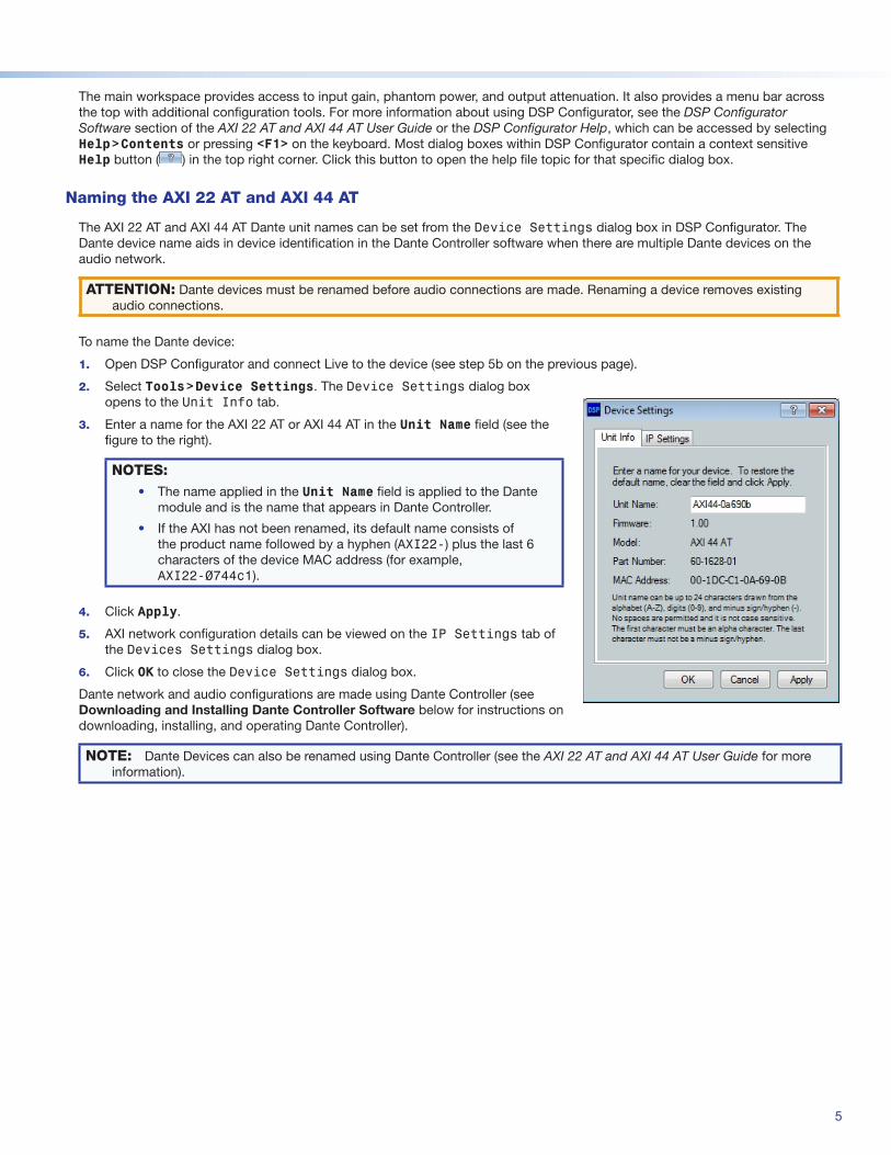
Naming the AXI 22 AT and AXI 44 AT
The AXI 22 AT and AXI 44 AT Dante unit names can be set from the Device Settings dialog box in DSP Configurator. The Dante device name aids in device identification in the Dante Controller software when there are multiple Dante devices on the audio network.
ATTENTION: Dante devices must be renamed before audio connections are made. Renaming a device removes existing audio connections.
To name the Dante device:
1. Open DSP Configurator and connect Live to the device (see step 5b on the previous page).
2. Select Tools>Device Settings. The Device Settings dialog box opens to the Unit Info tab.
3. Enter a name for the AXI 22 AT or AXI 44 AT in the Unit Name field (see the figure to the right).
NOTES: • The name applied in the Unit Name field is applied to the Dante
module and is the name that appears in Dante Controller.
• If the AXI has not been renamed, its default name consists of the product name followed by a hyphen (AXI22-) plus the last 6 characters of the device MAC address (for example, AXI22-0744c1).
4. Click Apply.
5. AXI network configuration details can be viewed on the IP Settings tab of the Devices Settings dialog box.
6. Click OK to close the Device Settings dialog box.
Dante network and audio configurations are made using Dante Controller (see Downloading and Installing Dante Controller Software below for instructions on downloading, installing, and operating Dante Controller).
NOTE: Dante Devices can also be renamed using Dante Controller (see the AXI 22 AT and AXI 44 AT User Guide for more information).
6
Downloading and Installing Dante Controller Software
Dante Controller from Audinate is required to select and route audio across the Dante network and for limited configuration of the device. Install Dante Controller on a PC running Microsoft® Windows® 7 or newer. For full details about computer requirements, see the Dante Controller product page at www.extron.com.
1. From the Extron home page (www.extron.com), click the Download tab to open the Download page.
2. Under Software, on the left side of the page, select Dante Controller. The Dante Controller product page opens.
3. Click the Download button and follow the on-screen instructions to complete the Dante Controller installation process.
NOTE: An Extron Insider account is required to download Dante Controller.
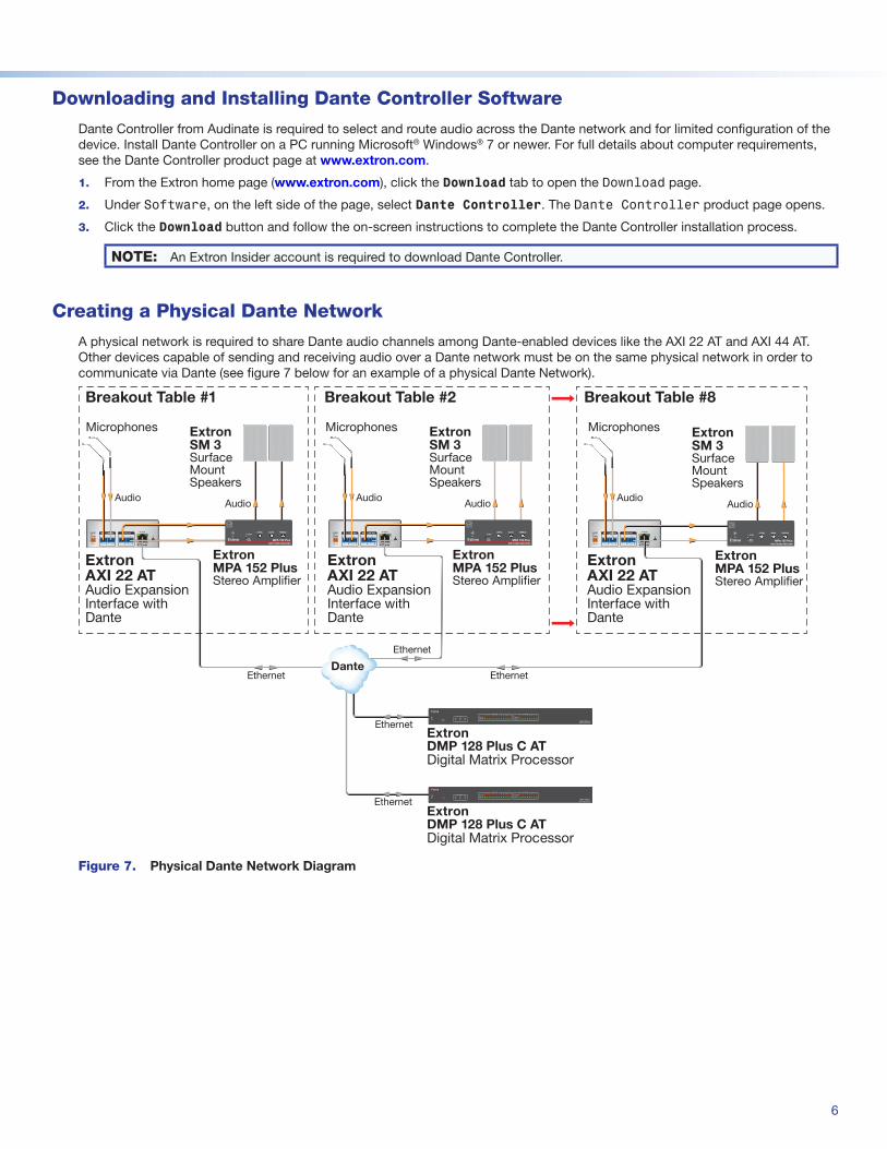
Creating a Physical Dante Network
A physical network is required to share Dante audio channels among Dante-enabled devices like the AXI 22 AT and AXI 44 AT. Other devices capable of sending and receiving audio over a Dante network must be on the same physical network in order to communicate via Dante (see figure 7 below for an example of a physical Dante Network).
AT (PoE)
R
MIC / LINE INS OUTPUTS--A MAX
POWER12V
AT (PoE)
R
MIC / LINE INS MIC / LINE INS
--A MAX
POWER12V
AT (PoE)
R
MIC / LINE INS OUTPUTS
--A MAX
POWER12V
Audio
ExtronMPA 152 PlusStereo Ampli�er
Extron Extron
Extron SM 3Surface Mount Speakers
Audio
ExtronMPA 152 PlusStereo Ampli�er
Extron Extron
Extron SM 3Surface Mount Speakers
Ethernet
Ethernet
Ethernet
Ethernet
ExtronDMP 128 Plus C ATDigital Matrix Processor
AudioAudio Audio
Microphones
ExtronMPA 152 PlusStereo Ampli�er
Extron Extron
Extron SM 3Surface Mount Speakers
Audio
Microphones
Breakout Table #1
ExtronAXI 22 AT Audio Expansion Interface with Dante
ExtronAXI 22 AT Audio Expansion Interface with Dante
ExtronAXI 22 AT Audio Expansion Interface with Dante
Microphones
Breakout Table #2 Breakout Table #8
Ethernet
Dante
DIGITAL MATRIX PROCESSOR
CONFIG
CLIPEXP LAN USB SIGNAL
CLIP
SIGNAL
1 2 3 4 5 6 7 8 1 2 3 4 5 6 7 89 10 11 12ACTIVITY
INPUTS OUTPUTS
DMP 128 Plus
ExtronDMP 128 Plus C ATDigital Matrix Processor
DIGITAL MATRIX PROCESSOR
CONFIG
CLIPEXP LAN USB SIGNAL
CLIP
SIGNAL
1 2 3 4 5 6 7 8 1 2 3 4 5 6 7 89 10 11 12ACTIVITY
INPUTS OUTPUTS
DMP 128 Plus
BASSLEVEL TREBLE
MINI POWER AMPLIFIER
MPA 152 Plus
STEREO
DUALMONO
BASSLEVEL TREBLE
MINI POWER AMPLIFIER
MPA 152 Plus
STEREO
DUALMONO
BASSLEVEL TREBLE
MINI POWER AMPLIFIER
MPA 152 Plus
STEREO
DUALMONO
Figure 7. Physical Dante Network Diagram
7
Dante Network Setup
Use a standard Ethernet cable to connect the AXI to a network via the RJ-45 AT (PoE) port (see figure 1, D on page 1) and power the device. Launch the Dante Controller program.
Dante Controller auto-discovers all Dante devices on the network and advertises itself to allow other Dante-enabled devices to communicate with it. The default device name is the model name followed by the last six characters of the device MAC address. Multiple devices on the same network can present difficulty in identifying inputs and outputs. To avoid confusion, rename each device to a unique and meaningful identifier.
NOTE: To simplify setup, connect only one Dante device to the network at a time.
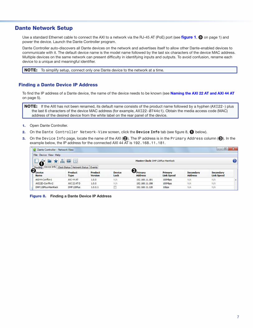
Finding a Dante Device IP Address
To find the IP address of a Dante device, the name of the device needs to be known (see Naming the AXI 22 AT and AXI 44 AT on page 5).
NOTE: If the AXI has not been renamed, its default name consists of the product name followed by a hyphen (AXI22-) plus the last 6 characters of the device MAC address (for example, AXI22-0744c1). Obtain the media access code (MAC) address of the desired device from the white label on the rear panel of the device.
1. Open Dante Controller.
2. On the Dante Controller Network-View screen, click the Device Info tab (see figure 8, 1 below).
3. On the Device Info page, locate the name of the AXI (2). The IP address is in the Primary Address column (3). In the example below, the IP address for the connected AXI 44 AT is 192.168.11.181.
Figure 8. Finding a Dante Device IP Address
68-2972-50 Rev. A05 17
Extron Headquarters+800.633.9876 Inside USA/Canada Only
Extron USA - West Extron USA - East+1.714.491.1500 +1.919.850.1000
+1.714.491.1517 FAX +1.919.850.1001 FAX
Extron Europe+800.3987.6673
Inside Europe Only
+31.33.453.4040
+31.33.453.4050 FAX
Extron Asia+65.6383.4400
+65.6383.4664 FAX
Extron Japan+81.3.3511.7655
+81.3.3511.7656 FAX
Extron China+86.21.3760.1568
+86.21.3760.1566 FAX
Extron Middle East+971.4.299.1800
+971.4.299.1880 FAX
Extron Australia+61.8.8113.6800+61.8.8351.2511 FAX
Extron India1800.3070.3777
(Inside India Only)
+91.80.3055.3777
+91.80.3055.3737 FAX
© 2017 Extron Electronics All rights reserved. All trademarks mentioned are the property of their respective owners. www.extron.com
Dante Operation
Dante Transmitters and Receivers
A Dante network is comprised of transmitters that output digital audio onto the Dante network and receivers that receive digital audio from the Dante network.
The AXI 22 AT and AXI 44 AT mic/line inputs are Dante transmitters because the analog audio input is converted into digital audio and transmitted onto the Dante network.
The AXI 22 AT and AXI 44 AT analog outputs are Dante receivers because they receive digital audio from the Dante network and output that signal as analog audio via the line outputs.
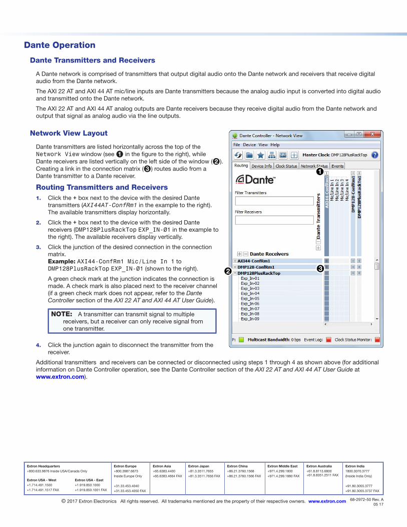
Network View Layout
Dante transmitters are listed horizontally across the top of the Network View window (see 1 in the figure to the right), while Dante receivers are listed vertically on the left side of the window (2). Creating a link in the connection matrix (3) routes audio from a Dante transmitter to a Dante receiver.
Routing Transmitters and Receivers1. Click the + box next to the device with the desired Dante
transmitters (AXI44AT-ConfRm1 in the example to the right). The available transmitters display horizontally.
2. Click the + box next to the device with the desired Dante receivers (DMP128PlusRackTop EXP_IN-01 in the example to the right). The available receivers display vertically.
3. Click the junction of the desired connection in the connection matrix. Example: AXI44-ConfRm1 Mic/Line In 1 to DMP128PlusRackTop EXP_IN-01 (shown to the right).
A green check mark at the junction indicates the connection is made. A check mark is also placed next to the receiver channel (if a green check mark does not appear, refer to the Dante Controller section of the AXI 22 AT and AXI 44 AT User Guide).
NOTE: A transmitter can transmit signal to multiple receivers, but a receiver can only receive signal from one transmitter.
4. Click the junction again to disconnect the transmitter from the receiver.
Additional transmitters and receivers can be connected or disconnected using steps 1 through 4 as shown above (for additional information on Dante Controller operation, see the Dante Controller section of the AXI 22 AT and AXI 44 AT User Guide at www.extron.com).

![AXI Protocol Checker v1 - Xilinx · The AXI Protocol Checker core monitors AXI interfaces. When attached to an interface, it ... See ARM AMBA® AXI Protocol v2.0 [Ref 1]. Performance](https://img.dokumen.tips/doc/110x75/5b158bc17f8b9ac7128d1298/axi-protocol-checker-v1-xilinx-the-axi-protocol-checker-core-monitors-axi.jpg)