Embed Size (px)
Citation preview

4 OTIy FILE COPY
I AEF7A`PROJECT NO. 8625 1 .
US ARMYAVIATIONSYSTEMS COMMAND
(PPRELIMINARY AIRWORTHINESS EVALUATION OF THE~-UH-6OAIESSS WITH HELLFIRE LAUNCHER INSTALLED
DAUMANTS BELTEý THOMAS L. REYNOLDSPROJECT OFFICER/ENGINEER MAJ, AV
PROJECT PILOT
THOMAS P. WALSH PAU L W. LOSIERICPT, AV MAJ, AV
APROJECT ENGINEER PROJECT PILOT
E RANDALL W.CASON OTICPROJECT PILOT UN O31988E
A OCTOBER 1987
FINAL REPORT
Approved for public release; distribution unlimited.
U S A-~MY AVIATION ENGINEERING FLIGHT ACTIVITYEDWARDS AIR FORCE BASE, CALIFORNIA 93523 - 5M0
'38 6 1 051

DISCLAIMER NOTICE
The findings of this report are not to be construed as an official Department ofthe Army position unle Po deugnated by other authorized documents.
DISPOSITION INSTRUCTIONS
Destroy this report when it is no longer needed. Do not return it to the originator.
TRADE NAMESThe use of trade names in this report does not constitute an official endorsementor approval of the use of the commercial hardware and software.
I:1

UNCLASS IFIED .NaSECURIIY CLASSIFICATION OF THIS PAGE ''JLJJTI 1 4"
Form Approved
REPORT DOCUMENTATION PAGE O146No. O7-18a
1i. REPORT SECURITY CLASSIFICATION lb. RESTRICTIVE MARKINGS
UNCLASSIFIED 1_1
2S. ECURITY CLASSIFICATION AUTHORITY 3. DISTRIBUTION/AVAILABILITY OF REPORTU.S. ARMY AVIATION SYSTEMS COMMAND Approved for public release, distrtbtitton
2b. DECLASSIFICATION/ DOWNGRADING SCHEDULE unlimited.
4. PERFORMING ORGANIZATION REPORT NUMBER(S) S. MONITORING ORGANIZATION REPORT NUMBER(S)
AEFA PROJECT NO. 86-25
6a. NAME OF PERFORMING ORGANIZATION 6b. OFFICE SYMBOL 7a. NAME OF MONITORING ORGANIZATION
U.S. ARMY AVIATION ENGINEERING (if appkable)
FLIGHT ACTIVITY II
Sc. ADDRESS (City, State, and ZIP Code) 7b. ADDRESS (City, State, and ZIP Code)
EDWARDS AIR FORCE BASE, CALIFORNIA 93523-5000
Ba. NAME OF FUNDING/SPONSORING 8b. OFFICE SYMBOL 9. PROCUREMENT INSTRUMENT IDENTIFICATION NUMBERORGANIZATION U . S * ARMY (If applikable)
AVIATION SYSTEMS COMMA0 I
S. ADDRESS (City, State, and ZIP Code) 10. SOURCE OF FUNDING NUMBERSPROGRAM PROJECT TASK WORK UNIT
4300 GOODFELLOW BLVD. ELEMENT NO. NO. NO ACCESSION NO.
ST. LOUIS, MO 63120-1998 68-6BH051-0 -68-EC
11. TITLE (Include Security Classification)PRELIMINARY AIRWORTHINESS EVALUATION OF THE UH-60A/ESSS WITH HELLFIRE LAUNCHERINSTALLED. UNCLASSIFIED12. PERSONAL AUTHOR(S)DAUMANTS BELTE, THOMAS P. WALSH, THOMAS L. REYNOLDS, PAUL W. LOSIER. RANDALL W. C.ASON
13a. TYPE OF REPORT 13b. TIME COVERED 14. DATE OF REPORT (Year, Month, Day) 15. PAGE COUNTFINAL ToFROM 21/05 T03/O6/ OCTOBER 1987 122
16. SUPPLEMENTARY NOTATION
17. COSATI CODES /18, SUP!-CT TERMS (Continue on revenre if necessary and identify by block number)
FIELD GROUP SUB-GROUP 'andling :alities; HELLFIRE ?(odular Xissile,eystem,Performance ,Becrement. .rleliminary AirworthinessEvaluation, UR-60A Helicopter
19. ABSTRACT (Continue on reverse iilecssary and ••entify by block number)A Preliminary Airworthin.eis Evaluatai5onf the UH-60A helicopter *-%S/N-84-23953)'>configuredwith the External Stores Support System (ESSS) and 16 HELLFIRE (4 HMMS) missiles installed
was conducted-by the U.S. Army Aviation Engineering Flight Activity. The test was conducted
<at the Sikorsky Flight Test Facility at West Palm Beach, Fl6ria, (elevation 28 feet). A
total of 16.2 productive hours during 18 flights were flown between 21 May and 3 June 1987.
Tests were conducted to determine handling qualities and performance of the UH-60A in the 16
HELLFIRE (4 HMMS) missile system configuration at an average mission gross weight of 17,000
pounds. The handling qualities of the UH-60A with the 16 HELLFIRE (4 HMMS) missile system
installed were essentially unchanged from those previously reported for the UH-60A in the
normal utility configuration. The equivalent flat plate area of the 16 HELLFIRE (4 HMM1S)
missile system was determined to be 11 square feet over that of the UH-60A in the ESSS only
configuration. One miscellaneous observation was made regarding the initial installation
and fit of the production ESSS fairings. hireyvds: W-lic0•¶s;
20. DISTRIBUTION/AVAILABILITY OF ABSTRACT '21. ABSTRACT SECURITY CLASSIFICATIONo3 UNCLASSIFIED/UNLIMITED 11 SAME AS RPT. 03 DTIC USERS UNCLASIFIED
22a. NAME OF RESPONSIBLE INDIVIDUAL 22b. TELEPHONE (include Area Code) 22c. OFFICE SYMBOLSHEILA R. LEWIS (805)277-2115 SAVTE-PR
DD Form 1473, JUN 86 Prevlous editions are obsolete. SECURITY CLASSIFICATION OF THIS PAGEUNCLASSIFIED

TABLE OF CONTENTS
Page
INTRODUCTION
Background. .... •.......... .. ... ....... . ... . 1Test Objective ............... ..... ...... IDescription .... ,.......*...... .............. 0.. ....... ITest Scope ... t o.............................. 9.......... 3Test Methodology .......... 0..........0............... . 4
RESULTS AND DISCUSSION
General ........... 0 .......... *00 ...................... 7
Level Flight Performance ..... . . ........ .. . ...... .... . 7Handling Qualities ...................... ..... ...... 7
General ....... o ....................... o.o.. . ...... 7
Control Positions in Trimmed Forward Flight ....... 8Static Longitudinal Stability ..................... 8Static Lateral-Directicnal Stability .............. 9Maneuvering Stability ............................. 10Dynamic Stability ........... . . ....... 0 ....... 4 .... 10
General ............................. ......... 0. 10Short-Term Response .......................... 11Long-Term Response ........... .. ............... 11
Low-Speed Flight Characteristics .................. 12Simulated Single-Engine Failure .......... .......... 13
Vibration .................. ............... ... ....... 13
Airspeed Calibration ............... ..... 14Miscellaneous ......... .......... .............. .. ... 14
CONCLUSIONS
General ................................ *............... 15
RECOMMENDATIONS .............. .... ......... . .......... 16
Aooession For
NTIS GRA&_IDTIC TAB 0Unannounced 0JuattIfIcatIon
Distribution/ ; ~ -
Availability CodesAvail and/or
Dist Special

APPENDIXES
A. References ................ . .. . ....... *............. 17B. Description ....... ........ 0 .4......... . .. . .. . . .... 19
C. Inatrumentation ........... ... .... .. ......... a..... 22D. Test Techniques and Data Analysis Methods ............. 30E. Test Data..ý. ..... ... .. .......... . . ........ 37F. Photographs . . . .... *....... ... . . . .. .. .. ........ ........... 39
DISTRIBUTION
F. P oto rap s .... ... ... .... ... ...... ... ... ... . I
II
INTRODUCTION
BACKGROUND
I. The U.S. Army is investigating the potential of the UH-60A,Black Hawk, helicopter for carrying the HELLFIRE m1piles on theExternal Stores Support System (ESSS). This capability will pro-vide the Army with an additional anti-tank weapon platform. InSeptember 1984, Sikorsky Aircraft Division of United TechnologiesCorporation and Rockwell International, Inc., were awarded con-tracts by the U.S. Army Aviation Systems Command (AVSCOM) todevelop and demonstrate the feasibill.ty of the UH-60A HELLFIREsystem. AVSCOH tasked the U.S. Army Aviation Engineering FlightActivity (AEFA) (ref 1, app A) to plan, conduct and report on aPre.iminary Airworthiness EvaluaLion (PAE) of the UH-60A withthe HELLFIRE missile system installed.
TEST OBJECTIVE
2. The objectives of this evaluation were to determine the air-worthiness of the HELLFIRE installation and whether any limita-tions to the UH-60A flight envelope exist in order to substantiatethe issuance of an airworthiness release for follow-on testing.
DESCRIPTION
3. The UH-60A, Black Hawk, helicopter is a twin-turbine, singlemain rotor helicopter capable of transporting cargo, 11 combattroops and weapons during day, night, vioual metvorological con-ditions, and instrument meteorological conditio'is. Conventionalwheel-type landing gear are provided. The mai n and tail rotorsPr2 both four-bladed. Manual main rotor blade and tail pylonfolding capabilities are provided for air transportability. Amovable horizontal stabilator is located on the lower portion ofthe tail rotor pylon. The helicopter is powered by two T700-CE-700turboshaft engines each having an uitinstalled thermodynamic rating(30 minute) of 1553 shaft horsepower (shp) (power turbine speedof 20,900 rpm) at sea level, standard day static conditions.Installed dual engine power is transmission limited to 2828 shp.
4. The UH-60A helicopter (USA S/N 84-23953) used for this testwas a production Black Hawk which incorporates the External StoresSupport System fixed provisions and fairings, the reoriented pro-duction airspeed probes and the modified production stabilatorschedule. A more detailed description of the UH-60A is containedin the Prime Item Development Specification (PIDS) (ref 2), theoperator's manual (ref 3), and appendix B. The test helicopter,configured with the HELLFIRE missile system, is depicted inphoto 1.
1

inS~~j¶UR~NAW~M¶S7¶WUow WflAIMJ NAJ!itW la nra r u..nmý an...a.a....n n
... ..
-4J
CA
U3UPQ
KY

5. The ESSS consists of the airframe fixed provisions atid theremovable external, stores subsystem. The ESSS is designed toenable the UHI-60A to carry external stores ouch as auxiliaryfuel tanks or various weapon subsystems such as the HELLFIREmissile sybtem. The UH-60A HELLFIRE system consists of UH-60AHELLFIRE Missile Equipment (UH-60A HME), aircraft fixed pro-visions, and support equipment. The UH-60A HlME is a kit, which'_onsists of the necessary electronics, electrical harnesses,hardware, and system controls required to interface with andmanage the HELLVIRE Modular Missile System (HMMS). Each HMMSconsists of four AGM-114A HELLFIRE missiles and a launcherassembly which mounts on the UH-60A ESSS pylons. The UH-60AESSS can accommodate up to four HNMS (two on a-ach side) for atotal of 16 HELLFIRE missiles.
6. The ESSS stores jettison system was fully operational, theHELLFIRE HMMS was installed with 16 inert HELLFIRE Missiles, andthe UH-60A HIE kit was not installed in the test aircraft. A
more detailed description of the HELLFIRE missile system isiacluded in references 4 and 5, appendix A, and appendix B.
TEST SCOPE
7. The PAE was conducted by AEFA personnel at the Sikorsk• FlightTest Facility at West Palm Beach, Florida (elevation 28 fect). Atotal of 16.2 productive hours during 18 flights were flownbetween 21 May and 3 June 1987. The contractor provided allmaintenance and logistical support of the test aircraft to includetest instrumentation and deta reduction support. Tests wereconducted to determine handling qualities and performance of theUH-60A in the 16 HELLFIRE (4HMMS) missile system configurationat an average mission gross weight of 17,000 pounds and an averagelongitudinal center of gravity (cg) at fuselage station 350.0.Results were compared to those published in the Airworthinessand Flight Characteristics (A&FC) test of the UH-60A helicopter(ref 6, app A), A&FC test of the UH-60A with the prototype ESSS(ref 7), the requirements of the Critical Item DevelopmentSpecification for a UH-60A HELLFIRE System (ref 3), and MIL-H-8501A (ref 8). Flight restrictions and operating limitationsobserved througout the evaluation are contained in the operator'smanual (ref 3) and the airworthiness release issued by AVSCOM(ref 9). Testing was conducted in accordance with the approvedtest plan (ref 10) at the conditions presented in tables I and 2.
3
OA
~~ ~~ U =RNA U MWfUAft ]LAI 3AUA fA INUNWW V jU~tn ~L~~A

TEST I•TOAOLOGY
8. The flight test data were recorded by hand from testinstrumnutation displayed in the cockpit, by on-board magnetictape recording equipment and via telemetry to the Sikorsky Real-Time Acquisition and Processing of In-flight Data system. Adetailed listing of test instrumentation is contained inappendix C. Flight test techniques and data reduction proceduresare described in appendix D.
I
41

Table 1. Level Flight Performance Test Conditions1
Average IAverage Average Longitudinal Average
Gross Thrust Center of Density AirspeedWeight Coefficient Gravity Altitude Range
(lb) (x10 4 ) (FS) 2 (ft) (KTAS) 3 Configuration
17,010 70.06 350.1 5,290 46 to 15416,810 79.91 349.2 9,330 50 to 154 ESSS Only16,880 89.78 349.5 12,350 52 to 146 Installed
16,950 69.91 350.0 5,250 45 to 149 FSSS with16,850 79.96 349.6 9,110 48 to 146 HELLFIRE16,980 90.16 350.1 12,190 51 to 139 (4HMMS)
Installed
NOTE:
1 Tests conducted with doors and windows closed, stability augmentationsystem (SAS) ON, pitch bias actuator (PBA) centered and locked, andengine bleed air systems OFF. Main rotor speed of 258 referredrpm. approximate mid lateral center of gravity location.
2FS: Fuselage station.3 KTAS: Knots true airspeed.
5

Table 2. Handling Qualities Test Conditionsa
Average Average TrimAverage Longitudinal Density Calibrated
Gross Center of Altitude AirspeedWeight Gravity (ft) (kt)
Type of Test (lb) RF) emarks
Control Positions 16,900 39.6 5,290 to 42 to 142 &SSs Only Installedin Trimmd Forward 12,350Plight3 .... =•
16,920 349.9 5,250 to 42 to 137 5SS with NILLFItR (4•0MS)12.190 tIktalled
Static LongitiodiialStabilitY3 16,900 350.0 6,220 100 and 134 Level Flight
Static Lateral-Directional Stability 16,900 350.0 6,400 100 and 132 Level flight
16,940 350.1 7,700 100 and 129 Leoft and Right Steady TurnsManeuveril ...._ _StabilityJ
17,100 35i.6 6,470 96 and 131 Symmetrical Pull-Up* and____ ........ _ _____ ________ ___ _ •ushovers.
Contro11,080 330.4 6 Soo 100 and 114 Pulse SAS4 and FPS5
Dynamic Stability3 Releases ON and SAS17,200 350.3 6.100 100 and 132 from Sideslip and FPS 0FF
Long-Ters16.680 349.1 6,400 100 and 133 Response
0 to 40 Atimutha: 0%, 90, 1060',Low Speed Flight (KTAS)6 270", 3150. Wheel
17,040 351.0 1.400 eilght 30 feet
Simulated Single- Level flightEngine Failures 17,080 350.7 7,320 62 to 133From Dual-Sngine
Flight3 jgp7 ClimbI
.. 16,900 350.0 7,820 S2 ..... Climb
NOTES:1Test conducted with External Stores Support Syates (ESSS) only and 4 HYLLFIRE Modular Missilesystem (RMiS) installed with the automatic flight control system (AnC$) ON unless otherwise indicated,pitch bias actuator (PS) centered and locked. Rotor speed of 256 rpm, approximate aid lateral center
gf gravity location.2tS: fuselaga station.3 Test conducted in ball-centered flight.4SAh: Stability Aulteentatton System.
5iPS: Flight Path Stabilization.61yTAS: Knots true airspeed.7IRP: Intermediate rated power.
6jI- --------

RESULTS AND DISCUSSION
GENERAL
9. Testing was conducted to determine the handling qualitiesand perforizarce effects of the HELLFIRE missile system on theUH-60A helicooter. The handling qualities of the UH-60A with the16 HELLFIRE (A HMMS) missile system installed were essentiallyunchanged from ,hose previously reported for the UH-60A in thenormal utility configuration. The equivwlent flat plate area ofthe 16 HELLFIRE (4 HMS) missile system was determined to be11 square feet over that of the UH-60A in the External StoresSupport System (ESSS) only configuration.
LEVEL FLIGHT PERFORMANCE
10. Limited performance flight testing was conducted to determinethe performance differences between the UH-60A helicopter in theESSS only configuration and with the HELLFIRE missile systeminstalled. Level flight performance tests were conducted inball-centered flight at three conditions for both configurationslisted in table 1 to determine the power required at variousairspeeds. Nondimensional level flight test results are presentedin figures 1 and 2, appendix E. Dimensional test results for theUH-60A in the ESSS only configuration are presented in figures 3
through 5, and with the HELLFIRE missile system installed infigures 6 through 8. Installation of the 16 HELLFIRE (4 HMMS)missile system resulted in an increase in equivalent flat platearea (uFe) of 11.0 square feet over the ESSS only configuration.
11. Performance data with the UH-60A in the normal utilityconfiguration at two comparable test conditions are availablefrom AEFA Project No. 86-10, a previous AEFA program flown usingthe same aircraft (ref 11). The drag increase between the UH-60Ain the normal utility configuration and the ESSS only configura-tion was 10.0 square feet A Fe. Figures 9 and 10 show theperformance data at two thrust coefficients for the ESSS onlyconfiguration and the corresponding curves for the normal utilityconfiguration derived from reference 11.
HANDLING QUALITIES
General
12. A limited handling qualities evaluation of the UH-60A config-ured with the HELLFIRE missile system was conducted to determineany changes caused by this installation. Handling qualities of
7 1

the UH-60A with the HELLFIRE missile system inastalled were quanti-~tatively and qualitatively evaluated and found to be essentiallythe same as the UH-60A in the normal utility conf iguration.
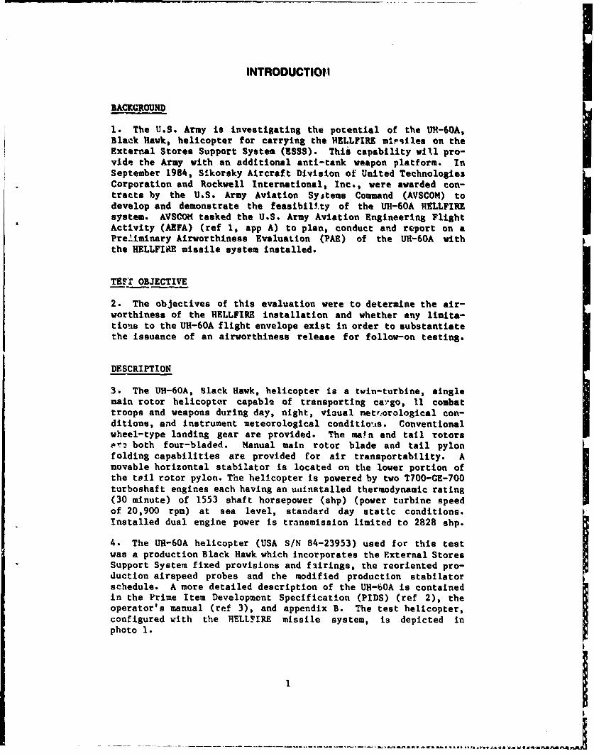
Control Positions in Trimmed Forward Flight
13. Control positions in trimmed, ball-centered, forward flightwere obtained in conjunction with level flight performance testingat the conditions presented in table 2. Representative levelflight data are presented in figures 11 through 16. The variationof longitudinal control position with airspeed during trimmedlevel flight generally required increased forward cyclic controlwith increased airspeed, similar to that previously reported inreference 7, appendix A. Control position trends for a UH-60Awith fixed-provision f airings only (normal utility configuration),the ESSS only, and the HELLFIRE missile system installed aresimilar. However, pitch attitudes during level flight varied asa function of change in equivalent flat plate area. Below 100knots calibrated airspeed (KCAS), the UH-60A with the ESSS onlyinstalled flew at a pitch attitude of approximately 2* morenose-down than the UR-60A with fixed-provision fairings only.The UH-60A with the HELLFIRE missile system installed flew at apitch attitude of approximately V more nose-down than the UH-60Awith the ESSS only. Above 100 KCAS, pitch attitude differenceswere significantly greater. Control positions in trimmedforward flight both with and without the HELLFIRE missile systeminstalled are satisfactory. The following CAUTION should beincorporated into the operator's manual.
CAUTION
Prior to installation of the HELLFIRE miisilesystem, insure that modified input modules(P/N 7035108001-046) have been installed in
the aircraft. The increased nose-down pitchattitudes during level flight when theIHELLFIRE missile system is installed mayresult in oil foaming and inadequate lubri-cation without the required gearbox modific-
ation.
Static Longitudinal Stability i14. The static longitudinal stability characteristics of theUH-60A configured with the HELLFIRE missile system were evaluatedat the conditions presented in table 2. The helicopter was
stabilized in ball-centered flight at the desired trim airspeed
and flight condition. The collective control was held fixed
8

while airspeed was varied approximately +20 knots about trim in5 knot 'ncrements. Test results are presented in figure 17,appendfi E. The static longitudinal stability (as indicated bythe variation of longitudinftl cyclic control position with air-speed) was positive (forward longitudinal cyclic control positionwith increased airspeed) and similar to that reported inreference 7, appendix A. However, longitudinal cyclic controlposition variation about trim was so small that cyclic positionchanges were imperceptible. Control force cues of longitudinalcyclic control displacement about trim were weak, but sufficientfor airspeed control within +2 knots (Handling Qualities RatingScale (HQRS) 3). The static longitudinal stability characteristicsof the UR-60A configurcd with the HELLFIRE missile system wereessentially the same as the UH-60A in the normal utility config-uration, are satisfactory and met the requirements of the PIDS.
Static Lateral-Directional Stability
15. The stat-ic lateral-directional stability characteristics ofthe UH-60A configured with the HELLFIRE missile system wereevaluated at the conditions presented in table 2. Tbe helicopterwas stabilized in ball-centered flight at the desired trim air-speed and flight condition. With the collective control heldfixed, the aircraft was then stabilized at incremental sideslipangles up to limit sideslip angle on each side of trim whilemaintaining a zero turn rate at the trim airspeed. Representativedata are presented in figure 18, appendix E.
16. Static directional stability (as indicated by the variationof directional control position with sideslip angle) was positive(increased left directional control required with increasedright sideslip). The directional control variation with sideslipwas essentially linear, similar to findings reported inreference 7, appendix A. The directional stability characteristicsof the UH-60A configured with the HELLFIRE missile system wereessentially the same as the UH-60A in the normal utility config-uration, are satisfactory, and met the requirements of MIL-H-8501A.
17. Dihedral effect (as indicated by the variation of lateralcyclic control position with sideslip angle) was positive(increased right cyclic control with increased right sideslip)and essentially linear. There were no discontinuities in forceor position cues. Similar results were previously reported inreference 7. The dihedral effect of the UH-60A configured withthe HELLFIRE missile system was essentially the same as theUH-60A in the normal utility configuration, is satisfactory, andmet the requirements of MIL-H-8501A.
9
----------.-.------------------

18. Sideforce characteristics (as indicated by the variation inbank angle with sWdealip) were positive (increased right bankahgle with increased right sideslip) and good out-of-trim caeswere evident. The sideforce characteristics of the UH-60Aconfigured with the HELLFIRE missile system were essentially thesame as the UR-60A iti the normal utility configuration, aresatisfactory, and met the requirements of MIL-f-8501A.
19. A pitch-due-to-sideslip coupling was evident in all test con-ditions. Generally, the longitudinal cyclic position versussideslip required inc-.eased forward longitudinal cyclic controlwith increased rigl. sideslip. The pitch-due-to-sideslip couplingexhibited was not considered objectionable and was similar tothat previously reported in reference 7.
Maneuvering Stability
20. The maneuvering stability characteristics of the UH-60A con-figured with the hELLFIRE missile system were evaluated at theconditions presented in table 2. The maneuvering stability testswere accomplished by initially stabilizing the helicopter in ball-centered level flight at the trim airupeed and then incrementallyincreasing the normal acceleration (g) by increasing the bankangle in left and right turns. Constant collective control posi-tion was maintained during the maneuvers and the pilot attemptedto maintain constant airspeed. Symmetrical pull-ups and pOuhoverswere conducted by alternately climbing and diving the helicopterto achieve varying g while the aircraft was passing through thetrim altitude at the desired airspeed. Test results are presentedin figures 19 through 22, appendix E.
21. The stick-fixed maneuvering stability (as indicated by thevariation of longitudinal cyclic control position with g), waspositive (increased aft cyclic control position with increasedg). There were no significant differences in the handling quali-ties characteristics in right or left turns. The variation inlongitudinal control position with g was essentially linear, andthe lateral cyclic control position remained essentially constantat all bank angles. Longitudinal control force cues were adequaL3at bank angles greater than 15 degrees. The maneuvering stabilitycharacteristics of the UH-60A configured with the HELLFIRE missilesystem are satisfactory.
Dynamic Stability
General:
22. The dynamic stability characteristics of the UH-60A configuredwith the HELLFIRE missile system were evaluated at the conditions
10

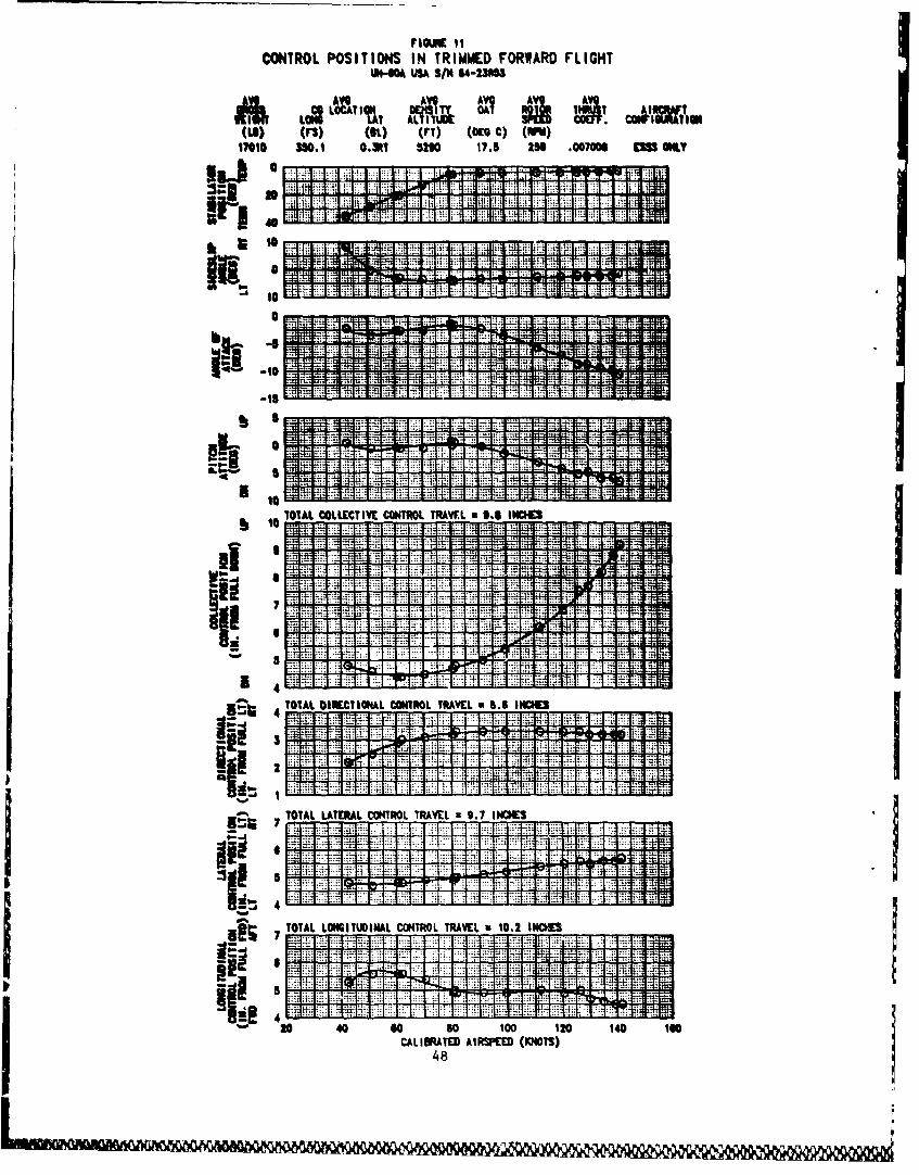
presented in table 2. The short-term response was excited in
al' '-.ontrol axes by making single-axis, 1 inch pulse inputs whichwe ield for approximately 0.5 second and by control releasesfrom limit sideslip values. Long-term longitudinal dynamicstability characteristics were evaluated by displacing the air-craft from trim airspeed approximately 10 to 15 knots, smoothlyreturning the longitudinal control to the trim position, andobserving/recording the resultant response. Testing was conductedin calm to light turbulence meteorological conditions, as definedin the Flight Information Handbook (ref 12). Representative timehistory data are presented in figures 23 through 34, appendix E.
Short-Term %esponse:
23. The stability augmentation system (SAS) ON short-term responsewas heavily damped in all axes, decaying to one-half amplitudewithin one cycle. The SAS OFF short-term response was character-ized by strong coupling into the longitudinal axis which rapidly
excited the long-term response. An aperiodic and divergentresponse resulted within 2 to 3 seconds requiring aircraftrecovery. However, during SAS OFF flight airspeed was maintained+10 knots with minimal pilot compensation (HQRS 3). The short-termresponse of the UH-60A configured with the HELLFIRE missilesystem was essentially the same as the UH-60A in the normalutility configuration (SAS ON and SAS OFF), is satisfactory, andmet the requirements of the PIDS.
24. The SAS ON lateral-directional oscillatory response resultingfrom steady heading sideslip releases were characterized asheavily damped with a maximum of two small heading overshootsprior to returning to within +2* of trim heading within 10 to 15seconds. The SAS OFF lateral-directional oscillatory responsewas characterized as aperiodic and divergent with an immediateroll away from sideslip and nose-up pitch change. Test limit'values of 60* angle of bank and 30" nose-up pitch attitude werereached in 2 to 3 seconds. However, during SAS OFF level flight,the lateral-directional oscillatory response required only small(1/4 inch) infrequent (every 5-7 seconds) lateral cyclic inputsto maintain heading +5* (HQRS 3). The lateral-directionaloscillatory response of the UH-60A configured with the HELLFIREmissile system was essentially the same as the UH-60A in thenormal utility configuration (SAS ON and SAS OFF), io satis-factory, and met the requirements of the PIDS.
Long-Term Response:
25. The SAS ON long-term response was heavily damped, returningto trim airspeed within +1 knot after only two small 5 knot
11

overshoots. The SAS OFF long-term response was easily excited andcharacterized as aperiodic and divergent within 2 to 3 aeconds.The long-term response of the UH-60A configured with the HELLFIREmissile system was essentially the same as the 'UT-60A in thenormal utility configuration (SAS ON and SAS OFF), is satis-factory, and met the requirements of the PIDS.
Low-Speed Flipt Characteristics
26. The low-speed flight characteristice of the UH-60A configuredwith the HELLFIRE missile system were evaluated at the conditionspresented in table 2. Tests were conducted at true airspeeds upto 45 knots in forward and rearward (0" and 180* relative azi-muths) and sideward (90, 270, and 315" relative azimuths)flight at a wheel height of 30 feet (as measured by the radaraltimeter). Surface winds were 5 knots or less and a groundpace vehicle was used as a speed reference. The low speed flighttest data are presented in figures 35 through 37, appendix E.
27. Pilot workload (frequency and magnitude of inputs) requiredto maintain speed, altitude, and heading control during forwardand rearward flight was qualitatively assessed as HQRS 3 between0 and 20 knots true airspeed (KTAS). Above 20 KTAS, the frequencyof inputs noticeably decreased, but the overall pilot workloadremained HQRS 3. Adequate control margins remained throughoutthe tested airspeed range during both forward and rearward flight.During forward and rearward flight, the low speed flight charac-teristics of the UH-60A with the HELLFIRE m.ssile system installedwere similar to that of a UH-60A ii the normal utility configur-ation and are satisfactory.
28. During left sideward flight, the lateral cyclic positioncues were noticeably weaker than during right sideward flight.Data taken during left sideward flight show a small band of essen-tially neutral lateral cyclic control position versus airspeedbetween 15 and 30 KTAS. This anomaly was not perceived by thepilot and was not considered objectionable. Stabilator programmingbegan to occur at approximately 20 XTAS during left sidewardflight, while the stabilator remained programmed in the fulltrailing edge down (40*) position during right sideward flight.During left sideward flight, the frequency of control inputs wasvery high (almost continuous) in all control axes. Adequatecontrol margins remained throughout this evaluation. Duringleit and right sideward flight, the low speed flight characteris-tics of the UH-60A with the HELLFIRE missile system installed weresimilar to that of a UH-60A in the normal utility configurationand are satisfactory.
12

29. The flight control variationh during sidevard flight at arelative wind azimuth of 3156 vere non-linear, but were notobjectionable. The non-linearities occurred as the stabilatorbegan to program inconsistently above approximately 20 KTAS.There were adequate control margins throughout the evaluation.Intermittent, variable intensity lateral accelerations referredto as "tail shake" by Sikorsky flight test personnel occurredmore frequently and with greater magnitude than during the otherwind azimuths evaluated. This is characteristic of the UH-60Ain the normal utility configuration and may have bten aggravatedsomewhat by the installation of the HELLFIRE missile system.During sideward flight at a relative wind azimuth of 315% thelow speed characteristics were similar to that of a UH-60A in the
normal utility configuration and are satisfactory.
Simulated Single-Engine FailureI
30. Simulated single-engine failure from dual-engine flight char-acteristics of the UH-60A configured with the HELLFIRE missilesystem were evaluated at the conditions presented in table 2.
Representative time histories are presented in figures 38 through40. The engine failures were simulated by rapidly pulling oneIengine power control lever from the flight Position to the idleposition and delaying pilot reaction for a minimum of 2 secondsor until recovery was required, whichever occurred first. Therewere no differences (handling qualities or failure cues) notedbetween a "failed" left engine or a "failed" right engine. Thesimulated engine failures were detected by an audible warningtone, the respective ENG OUT master caution light, a differencein cockpit engine parameters, and a noticeable 2* to 3* leftyaw. Other than the yaw excursion, no unusual attitude changesor control forces were observed during the simulated enginefailures and the subsequent transition to single-engine flight.The simulated single-engine failure .frcm dual-engine flightcharacteristics of the UH-60A configured with the HELLFIREmissile system was essentially the G.-me as the UH-60A in thenormal utility configuration and are satisfactory.
VIBRATION
31. Vibration characteristics obtained during level flightperformance teats are presented as a function of airspeed.Vertical, lateral, and longitudinal acceleration values forfrequencies of 1, 4, and 8 per main rotor revolution are shown atthe pilot's seat location (figs. 41 through 44) and on the cargocompartment floor at fuselage station 345 (figs. 45 tbrough 48).Both the ESSS only and HELLFIRE missile system installed aircraft
131

configurations a-e presented for nominal thrust coefficient (CT x104) values of '10 and 90. Aircraft vibration characteristicswere qualitatively and quantitatively evaluated for the UH-60Aconfigured with the ESSS only and with the HELLFIRE missilesystem installed as being slightly worse than the UH-60A in thenormal utility configuration in that "tail shake" occurred morefrequently and with greater magnitude, as previously discussed inparagraph 29.
AIRSPEED CALIBRATION
32. Airspeed calibration tests were conducted to determine theposition arror of the UH-60A's airspeed system in both the ESSSonly configuration and with the HELLFIRE missile system (4 HlNS)installed. The aircraft's pitot-static system was calibrated upto 117 knots indicated airspeed (KIAS) during level flight byuse of a calibrated trailing bomb (finned pitot-static system).Data for the normal utility configuration up to 156 KIAS wereavailable from AEFA Project No. 86-10, a previous program flownusing the same aircraft (ref 11). Data for the normal utilityconfiguration are presented in figure 49, appendix E and theESSS only and 4 HMMS configurations in figures 50 and 51,respectively. The position error was essentially the same forboth the ESSS and 4 HMMS configurations agreeing within one knotof each other. However, installation of the ESSS system increasedthe position error from the normal utility configuration byapproximately 1.5 knots at lower airspeeds (between 50 and 80KIAS) and up to 5 knots at higher speeds (120 KIAS). The positionerror data presented in figure 51 should be incorporated intothe applicable ESSS and HELLFIRE missile system operator's manual.
MISCELLANEOUS
33. The ESSS root attachments to the fixed provision mountingpoints (photo 7, app F) are designed to be covered with a fairingassembly. This evaluation was flown with prototype fairingsinstalled (photo 8) instead of the production fairings (photo 9).When the ESSS was initially installed, the production fairingscould not be made to fit because of fastener and hole misalignmentof the assembly and mismatched fairing edges projecting beyondthe sliding cargo track. At the end of the test program, after21.1 total flight hours with the ESSS installed, they were againfitted to the aircraft using the existing fastener locations.However, some interference with the cargo door track remained(photo 10). No exact cause for this change in ability to installthe production fairings was established. The fit and functionof the production fairings should be further evaluated.
14

CONCLUSIONS
GENERAL
34. Based on this evaluation, the following conclusions werereached regarding the installation of the HELLFIRE missile systemon the UH-60A helicopter.
a. Installation of the HELLFIRE Missile System increased thedrag of the UH-60A over the ESS8 only configuration by 11.0square feet equivalent flat plate area (para 10).
b. Installation of the ESSS incteased the drag of the UH-60Aover the normal utility configuration by 10.0 square feet equiva-lent flat plate area (para 11).
c. The handling qualities of the UH-60A with the HELLFIREmissile system installed were essentially the same as the UH-60Ain the normal utility configuration (para 12).
I
151

RECOMMENDATIONS
35. The following recommendations are submitted%
a. The UH-60A airspeed system position error data (HELLFIREmissile system installed) should be incorporated into the appli-cable HELLFIRE missile system operator's manual (para 32).
b. The following CAUTION should be incorporated into theoperator's manual (para 13).
CAUTION
Prior to installation of the HILLFIRE missilesystem insure that -modified Input modules(P/N 7035108001-046) have been installed inthe aircraft. The increased nose-down pitchattitudes during level flight when theHELLFIRE missile system is installed mayresult in oil foaming and inadequate lubri-cation without the required gearbox modific-ation.
c. The fit and function of the production ESSS fairings
should be further evaluated (para, 33).I
16j

APPENDIX A. REFERENCES
1. Letter, AVSCOM, AMSAV-8, 18 December 1986, subject: Prelim-inary Airworthiness Evaluation (PAE) of the UH-60A/ESSS with theHELLFIRE Launcher Installed.
2. Prime Item Development Specification, Sikorsky AircraftDivision, DARCOM CP-2222-S1000 F, 18 December 1981.
3. Technical Manual, TM 55-1520-217-10, Operapo"'s Manual,UH-60A Helioopter, 21 May 1979 with change 42 dated 8 June 1987.
4. Document, Critical Item Development Specification (CIDS) fora UH-60A HELLFIRE System, Document No. SES-700024, dated 20September 1984.
5. Document, UR-60A HELLFIRE Qualification Program PreliminaryDesign Review, 5-6 December 1984.
6. Final Report, AEFA Project No. 83-24, Airworthiness and
Flight; Characterietioc Teat of a Sixth Year Prodotion UH-60A,June 1985.
7. Final Report, AEFA Project No. 82-15, Airworthsines and lig.htCharacterietic,& Test of the UH-60A Confiured ,ith the PrototypeExternal Store Suppo-t System, December 1983.
8. Military Specification, YIL-q-8501A, Helicopter Flying andGrot.nd Handlinj qualities; General, Requirements for, with amend-ment 1, 3 April 1962.
9. Letter, IVSCOM, AMSAV-E, 3 March 1987, subject: AirworthinessRelease for the Cnnduct of a Preliminary Airiorthiness Evaluationof a IH-C'0A/ESSS Lonfi•gured with the HELLFIRE Launcher Installed.
10. Test Plan, AEFA Project No. 86-25, Preliminry Airworthine8sEValuatiun of the UH-60A Equipped w'.th the HELLb/IRE LauwherInstul.4e, Janiary 1987.
IL. Final Report, AEFA Project No. 86-10, Preliminary AiLwo,-thi,-neea Eval tatior. of the UH-RCA Equipped with the XM-124. VOLCANODiepensingj Syter, August 1987. I12. DoD Flight Irfurmation Publication, flight I?'omnationHandbook., Defense Mapping Agency Aerospace Center, 18 December
j6.`ngineering Design Handbook, Army Material Command, AMC h
Pn;q let 706-204, H'elicopter PevJ'orflrm e Testing, 1 August 1974.
17

I
14. flight Test Nanual, N&Val Air Test Center FTN No. 101,StabL•itit and Controt, 10 June 1968.
18

APPENDIX 6. DESCRIPTION
GENERAL
1. The UH-60A Black Hawk, is a twin turbine engine, single mainrotor helicopter with nonretractable wheel-type landing gear. Amovable horizontal stabilator is located on the lower portion ofthe tail rotor pylon. The main and tail rotor are both four-bladedwith a capability of manual main rotor blade and tail pylon fold-ing. The cross-bean tail rotor with composite blades is attachedto the right side of the pylon. The tail rotor shaft is canted20" upward from the horizontal. Primary mission $rose weight is16,260 pounds and maximum alternate groes weight is 20,250 pounds.The UH-60A is powered by two General Electric T700-GE-700 turbo-shaft engines each having an installed thermodynamic racinC(30 minute) of 1553 shaft horsepower (shp) (power turbine speedof 20,900 revolutions per minute) at sea level, standard-daystatic conditions. Instnlled dual-engine power is transmissionlimited to 2828 shp. The aircraft also has an automatic flightcontrol system and a comand instrument system. The test heul-copter, UH-60A U.S. Army S/N 84-23953, was manufactured bySikorsky Aircraft Division of United Technologies Corporationand is a production black Hawk equipped with fixed provisionmounting points. The main differencew between the test aircraftand a UH-60A in the normal utility configuration are the additionof the HELLFIRE missile s~ten and an external nose-sounted
airspeed boom and the associated special test instrumentation.Photos I through 4, appendix F, show views of the test aircraftwith the HELLFIRE Missile System installed. A more completedescription of the IJH-60A helicopter in the normal utility con-figuration can be found in reference 2, appendix A.
EXTERNAL STORES SUPPORT SYSTEM
2. The production External Stores Support System (ESSS) consistsof the airframe fixed provisions and the removable external storessubsystem. The ESSS was designed to enable the U1R-60A to carryexternal stores such as auxiliary fuel tanks or various weaponsystems, such as the HELLFIRE missile system.
3. The airframe fixed provisions (photos 5 through 7) are thefuselage attachment structure required for the installation ofthe removable external stores subsystem. The removable externalstores subsystem consists of the horizontal store support whichis a composite boxed I-beam structure, the support struts (twoon each wing) and the vertical stores pylons (two on each wing)all of which are enclosed with thin aluminum fairings. The
fairings at the wing root flown in this evaluation were prototypemodels (photo 8). Since the production versions (photo 9) could
19
IN0119 9 ID 0=01 MIMIND~N ý " ýI

not be fitted onto the aircrrAt initially. When the productionfairings were installed at the conclusion of the test program,some interference with the sliding cargo door seals remained(photo 10). BRU-22A ejector racks were mounted on the verticalstores pylons at a 1' nose-up angle with reference to the aircraftwaterline. The ESSS to shown installed in photo 11.
HELLFIRE MISSILE SYSTEM
4. The HELLFIRE missile is an air or ground launched anti-armorweapon which homes on a laser designation provided by an externalground or airborne source. The RELLFIRE system. as designed for
the UH-60A, does not include target acquisition or designationcapability. The primary mission of the UH-60A HELLFIRE missilesystem Is to provide the Corps Commander with the flexibility toreinforce the Corps attack helicopter assets in order to meetemergency surge requirements. The secondary mission is to serveas a resupply platform, delivering the missiles to the primaryattack helicopters.
5. The UR-60A HELLFIRE missile system incorporates a UN-60Aaircraft configured with the ESSS, the UH-60A RHLLFIRE system,and the HELLFIRE Modular Missile System (004S). The HELLFIREmissile system is designed to be easily and rapidly installedand removed from the aircraft.
6. The UH-60A HELLFIRE system consists of the aircraft ftitedprovisions, support equipment, and the UH-60A HELLFIRE MissileEquipment (UH-60A 1IME). The UH-60A HME was not installed forthis test, but a brief description is included here. The UH-60AHME is a kit consisting of a Control Display Unit (CDU), RemoteHELLFIRE Electronics (RIE), two Pilot Steering Indicators (PSI),a master arm panel, two firing switches, required electrical har-nesses, and the associated installation hardware. The CDU providescockpit control functions for the RELLFIRE syatem by displayingsystem status, missile inventory, and indicating selected modesand missile activation. The R.HE provides all control and manage-ment funtions of the UH-60A B1ME and is palletized for mountingin the aft cabin area along with the Automatic Target Hand-OffSystem (ATHS). The ATHS provides the capability of rapidlyreceiving automatic target Information for the RELLFIRE missilesystem. Two PSI's are mounted on top of the glareshield infront of the pilot and copilot to provide graphic "steer to"
information ir order to meet azimuth and elevation launch con-straints.
20
- - - -- - - - - - -- - - - --k M a.id,

7. The HINS consists of four AGt-1i4A HELLFIRE missiles weighing*nprri,.imately 98 pounds each and an M272 launcher assemblyvoig•inj approximately 142 pounds. Each launcher is designed tobw mourted on a UR-60A ESSS pylon. The ESSS can accommodate up tofour HMWN (two on each side) for a total capacity of 16 HELLFIREmissiles. Inert HELLFIRE missiles were used to simulate actualmissile weight and drag characteristics during this test, and areshown installed in photos 12 through 14. The ESSS stores jettisonsystem was fully operational, and the interface control panel isshown in photo 15.
MODIFICATIONS
8. Several modifications were made to the test aircraft to accom-modate ballast, instrumentation, or for safety purposes. Thesemodifications were not part of the HELLFIRE Missile System or aUH-60A in the normal utility configuration. Mounting provisionsto accomodate ballast are shown in photos 16 and 17. An instru-mentation package was installed In the cargo compartment and canbe seen in photo 18. Sikorsky drag estimates for the externalitems (photos 19 through 23) totalled 3.04 square feet of equiva-lent flat plate area. Each item is listed below:
ITEM
Standard size tail rotor slip ringMedium size main rotor slip ring with coverNose boomTail-mounted TM antennas (2)
Belly-mounted TM antennaMain rotor instrumentationAmbient air temperature sensorEmergency crew door handles (2)
21

GENER APPENDIX C. INSTRUMENTATION
I1. The test instrumentation was installed, calibrated and main-tained by Sikorsky Aircraft personnel. A test boom, with aswiveling pitot-static tube and angle-of-attack and sideslipvanes, was installed at the nose of the aircraft (photo 19,app F). Slip ring assemblies were installed on the main andtail rotor shafts (photos 20 and 21). Three telemetry antennaswere installed. Two were mounted to the top left side of thetail boom and one was mounted on the belly of the aircraft just
forward of the tail boom (photo 22). All other instrumentationwas installed insida the test aircraft. Data were obtained fromcalibrated instrumentation and displayed or recorded as indicatedbelow.
Pilot Panel
Airspeed (boom)Altitude (boom)Rate of climb (boom)
Rotor speedEngine torque* **Turbine gas temperature* **Power turbine speed (Np)* **
Gas producer speed (Ng)* **Control positions
LongitudinalLateralDirectionalCollective
Horizontal stabilator positionAngle of sideslip
Copilot Panel
Airspeed*Altitude*
Rotor speed*Engine torque* **Fuel remaining* **Total air temperatureInstrumentation controlsRun numberEvent switch
*Ship's systent** Both engines
22

2. Parameters recorded on board the aircraft in pulse codemodulation format and available for telemetry include thefollowing:
Airspeed (boom)Altitude (boom)Airspeed (ship's)Altitude (ship's)Radar altimeter (low range)Total air temperatureRotor speedGas generator speed**Power turbine speed**Engine fuel flow**Engine fuel temperature**Engine output shaft torque**Turbine gas temperature**Longitudinal acceleration at the cgLateral acceleration at the cgNormal acceleration at the cgStabilator positionControl positions
Longitudinal
LateralDirectionalCollective
Aircraft AttitudePitchRoll
HeadingAngular Acceleration
PitchRollYaw
SAS output positionLongitudinalLateralDirectional
Main rotor shaft torqueTail rotor shaft torqueTail rotor impressed pitch (blade angle at 0.75 blade span)Angle of sideslipAngle of attack
Time of dayRun numberPilot event switch
**Both engines
23
-..-- -'.'~' -,--'- ~ F~. fl.n U. Eji Ifl A A n nI. F1~ n Jul, X19 .. M ~~V

3. Vibration warn measured in the following locations and direc-tions and recorded in frequency modulation format onboard theaircraft:
Vertical pilot seatLateral pilot seatLongitudinal pilot seatLateral copilot seatVertical pilot floorLateral pilot floorLongitudinal pilot floorVertical copilot floorVertical pilot instrument panelVertical copilot instrument panelCenter of gravity verticalCenter of gravity lateralCenter of gravity longitudinalVertical tail rotor gearboxLateral tail rotor gearboxLongitudinal tail rotor gearbox
TEST BOOM AIRSPEED SYSTEM
4. The test boom airspeed system mounted at the nose of the testaircraft provided measurements of airspeed and altitude. Sensorsfor angles of attack and sideslip were also mounted on the testboom (photo 19, app F). The tip of the swiveling pitot-statictube warn at fuselage station 97, 79.6 inches forward of the noseof the aircraft, 25.7 inches to the right of the aircraft rafer-ence buttline, and at waterline 208, 7 inches below the forwardavionics bay floor.
5. The test boom airspeed system along with the ship's standardsystems were calibrated in level flight (ESSS only and HELLFIREImissile system configuration) using a calibrated trailing bombto determine the position error. The position error of theship's airspeed system and the boom airspeed system is presentedin figures 1 and 2.
ENGINE CALIBRATION I6. Calibrations of the engine torque sensor systems were con-ducted by the engine manufacturer, General Electric. Figures 3and 4 present the calibrations used to determine engine power.
24

SPECIAL EQUIPMENT
Weather Station
7. A portable weather station consisting of an anemometer, sensi-tive temperature gauge, relative humidity sensor and barometer,was used to record wind speed, wind direction, ambient tamperatureand humidity and pressure altitude at 50 feet above ground levelduring the low airspeed handling qualities tests.
Ground Pace Vehicle
8. Pace vehicle speedometers were calibrated by Sikoroky person-nel. The pace vehicles were used to establish precise groundspeed during the low airspeed handling qualities tests.
25

FIGURE 1BOOM AIRSPEED CALIBRATION
UH1-OA USA S/N 84-25953
AVG AVG AVG AVGGROSS C.C. LOCATION DENSITY OUTSIDE TEST
IGIT LONG LAT ALTITUDE AIR TEMP. METHODLB) (FS) (BL) (FEET) (DEG C)
17040 350.2 0.2 RT 6460 15.0 TRAILING BOMB
NOTES: 1. ESSS ONLY CONFIGURATION2. LEVEL FLIGHT5. BALL CENTERED TRIM CONDITION
10 ~ 4. MA.I N ROTOR 5PEED=258 RPM
0
-10I SO
VCAL =+ 2.5-8569
140.00034732 x VIC2010 .0000008495I. VIC3 .-
120
2004 08 0 2 4 6
ILINE OF ZERO CORRECTIOND
626
I
MNOT FOR HANDBOOK USE•
20 40 60 80 100 1 20 140 a6INDICATED AIRSPEED (KNOTS)

FIGURE 2BOOM AIRSPEED CALIBRATION
UH-GOA USA S/N 84-23953
AVG AVG AVG AVGGROSS C.G. LOCATION DENSITY OUTSIDE TEST
(I)~u mOm LAT ALTITUDE AIR TEMP. METHODL0 FJ (61.) (FEET) (DEC C)
16880 349.7 0.2 RT 5090 13.0 TRAILING BOMB
NOTES: 1. ESSS WITH HELLFIRE (4 H1MS) CONFIGURATION2. LEVEL FLIGHT3. BALL CENTERED TRIM CONDITION4. MAIN ROTOR SPEED=258 RPM
POLYNOMIAL CURVE FIT
VAL0 f l d ---
40.0030198 x VIC 2
1 0 P- 14.00.0 4 I ... ..
120
POLYOMIA CURV HADB OKUS
40
280
400
20,
INDICATED AIRSPEED (KNOTS)
27
-~~~IN OF ZER C -aT.I N - ~n aast

FIGURE 3ENGINE TORQUEMETER CALIBPATION
UH-G0A USA S/N 84-23953T700-GE-700 S/N 306625
NOTES: 1. NUMBER ONE ENGINE2. POWER TURBINE SPEED z 20,900 RPM3. DATA OBTAINED FROM 0 E
ENGINE PRODUCTION RATING SHEET
10
600
1300
5200
400
0 100 200 300 400 500 G00ENGINE TOROUEMETER (FT-LB)
28

FIGURE 4ENGINE TORQUEMETER CALIBRATION
UH-60A USA SIN 84-23953T700-GE-700 S/N 306262
NOTES: 1. NUMBE TWO ENGINE2. POWER TURBINE SPEED a 20,900 RPM3. DATA OBTAINED FROM G E
ENGINE PRODUCTION RATING SHEET
310 ............
0
- -5
I-1
100
400
0 100 200 300 400 500 600ENGINE TORQUEMETER (FT-LB)
29I

APPENDIX D. TEST TECHNIQUES AND DATA ANALYSIS METHODS
AIRCRAFT RIGGING
1. Prior to the start of testing, a flight controls engineeringrigging check was performed on the main and tail rotors bySikorsky Aircraft and monitored by the U.S. Army AviationEngineering Flight Activity. The stabilator control system wasalso checked to ensure compliance with the production stabilatorschedule. The rigging data are presented in table 1.
AIRCRAFT WEIGHT AND BALANCE
2. The test aircraft was weighed in both the ESSS only config-uration and with the HELLFIRE missile system installed, withfull oil and all fuel drained, all ballast removed, and testinstrumentation system and ballast mounting provisions installed.The initial weight of the aircraft in the ESSS only configurationwas 13,096 lb with a longitudinal center of gravity (cg) locatedat fuselage station 357.8 and a mid lateral cg, and in theHELLFIRE missi.e configuration was 15,176 lb with a longitudinalcg at IS 351.9. Installation of the HELLFIRE missLle systemincreased the empty weight of the aircraft by 2080 lb. The fuelweight for each performance test flight was determined by pro-
and post-flight aircraft weighings and fuel flowmeter instrumenta-tion.
PERFORMANCE
General
3. Performance data were obtained using the basic methodsdescribed in Army Material Command Pamphlet AHCP 706-204 (ref 13,app A). Level flight performance and control positions in levelflight were obtained in coordinated (ball-centered) flight.Referred rotor speed was maintained constant for all performancetests at 258 rpm. Longitudinal center of gravity (cg) was allowedto vary +1.5 inch during each test flight, but for each data set(consisting of several flights in the same aircraft configurationat different thrust coefficient values) the average cg locationwas maintained constant near the proposed mission value. Thedata were analyzed to determine the power required differencebetween the UH-60A in the ESSS only configuration and the UH-60Aconfigured with the HELLFIRE missile system in terms of change inequivalent flat plate area (6Fe).
4. Helicopter performance was generalized through the use ofnon-dimensional coefficients as follows usirg the 1968 U.S.Standard Atmosphere:
30

Table 1. Main and Tail Rotor Rigging Information
Main Rotor Rigging
Blade Anglet Flight ControlFlight Control Position (deg) Position (deg)
Long Lat CollLong Lat Coll Pedal 0 90 180 270 Cont" Cont 3 Cont 4
Aft *5 * * 20.0 -4.0 -12.0Block6 * * * 11.1 5.5 - 2.8Block * High * 20.0 16.2 11.4 15.0 - 0.6 -4.3 15.7Block * Low * 2.6 5.3 -1.9 -5.7 - 5.5 -2.3 0.1Aft * High * 26.8 4.8 -11,0Fwd Left Low * 7.7 -12.0 -8.1 11.0 11.5 -7.9 -0.4Block * * Right 6.7 9.6 1.5Block * * Left 15.2 0.3 - 7.5Fwd * * Right -1p.0 25.4 17.7Aft Left * Left 15.8 19.6 0.8 -4.5 -12.1 -8.3 7.5Nwd Right * Left 2.0 -5.2 13.9 20.4 12.8 6.0 7.8Aft * High Left 26.8 4.3 -11.3Fwd * High Right -1.4 32.2 16.8Fwd Right High Left 9.9 -1.6 20.9 32.0 16.8 5.5 15.3Aft Left High Right 24.0 22.9 8.2 9.1 -6.9 -7.9 16.1Aft Right Low Right -6.9 9.8 7.4 -9.9 -9.9 7.2 0.1Aft Left Low Left 6.9 8.9 -8.5 -10.3 -9.6 -7.7 -0.8
Tail Rotor Rigging
Flight Control Position Blade Angle (deg) 7
Collective Pedal
• Left 15.7* Right -15.4* * 0.5
Low * -7.3High Left 16.5High Right -5.6Low Right -15.7Low Left 8.2
NOTES:
'Measured on the Black Blade at the cuff.22700 reading minus 900 reading divided by 2.3180 reading mimus 0* reading divided by 2.4 Sum of all four readings divided by 4.5* Indicates appropriate control was pinned at a rigged position.6 Indicates a block was inserted between the aft longitudinal control stop
and the cyclic control such that no limiters are contacted to determinelongitudinal to collective coupling.
7Measured on the Blue Blade at the cu~f.31

a. Coefficient of Power (Cp):
SHP (550)Cpu - __ (1)
pk"UR)3
b. Coefficient of Thrust (CT):
GWCT = (2)
IA(tR)2
c. Advance Ratio (0):
"VT(1.6878)_ _ = (3)
UR
Where:
SHP - Engine output shaft horse ower (both)p a Ambient aft density (lb-sec2/ot4 )A a ~Main rotor disc area - 2262.03 ft 2
U Main rotor angular velocity (radians/sec)R - Main rotor radius - 26.833 ftCW - Gross weight (ib)
VE
VT - True airspeed (kt) -
1, 6878 ,v7'•
1.6878 - Conversion fa tor 4 (ft/sec-kt)-o - 0.0023769 (lb-sec /ft )
5. The engine output shaft torque was determined by use ofengine torque sensors. The power turbine shaft contains a torquesensor tube that mechanically displays the total twist of theshaft. A concentric reference shaft is secured by a pin at thefront end of the power turbine drive shaft and is free to rotaterelative to the power turbine shaft at the rear end. The relativerotation is due to transmitted torque, and the resulting phaseangle between the reference teeth on the two shafts is picked upby the torque sensor. This torque sensor was calibrated in atest cell by the engine manufacturer. The output from the engine
32
- - --M -W- m am~ A ~. MR MM M RMa " A.%ftlA4%~Ar

torque sensor was recorded by the on-board data recording system.The output SHP was determined from the engine's output shafttorque and rotational speed by the following equation:
2%Q(Np)SliP-= ____ (4)
33,000Where:
Q - Engine output shaft torque (ft-lb)Np - Engine output shaft rotational speed (rpm)
Level Flight Performance
6. Each speed power data set was flown in ball-centered flightby reference to the ship's turn and slip indicators at a pre-determined thrust coefficient (CT) and referred rotor speed(NH/RM). Both the pilot's and copilot's turn and slipindicators were checked for alignment with the airc:.aft positionedin a level attitude on the ground. To maintair, the ratio ofgross weight to pressure ratio (W/b) constant, altitude wasincreased as fuel was consumed. To maintain NR/v'iconstant,rotor speed was varied as appropriate for the ambient air temp-erature. Corrections to power required were made for the instal-lation of test instrumentation. The power consumption for theelectrical operation of the instrumentation equipment was measuredand determined to be 0.76 shaft horsepower (shp) and subtractedfrom the power required data. The effects of the externalinstrumentation and nonstandard aircraft equipment were estimatedby the contraccor to be the equivalent of 3.04 square feet ofequivalent flat plate area.
7. The nondimensional coefficients (equations 1 through 3) canbe expressed in terms of referred rotor speed as follows:
SHP (478935.3)
Cp to (5)
NR 33
33

CT - ~GW (91.19)()
(; 22
6(poAR)
VT (16.12)
- ____________(7)
(RA) ()Test-day level flight data were corrected to standard day condi-
tions by the following equations:
Where:
Subscript t - Teat daySubscript a w Standard day
0 Pesuerai 1 - (1454:1.15)52 83
TA + 273.15
0aTemperature ratio - .TA -Ambient air temperature (*C)
N1 -Main rotor apeed (rev/amm)47935.3 - Converaion factor (ft-lb-gec2 -rev3lmin3-SHp)
91.19 -Conversion factor (sec2-rev2/ijn2)
34

16.12 - Conversion factor (ft-rev/min-kt)
Test data corrected for instrumentation electrical power con-sumption and corrected to standard altitude and ambient tempeva-ture are presented in figures 3 through 10, appendix E.
8. The data obtained in the ESSS only configuration were analyzedby use of a simulated three dimensional plot (CT and 4 versus Cp).The reduction of this simulated three dimensional plot to a familyof curves of CT versus Cp, for a constant k value, allows deter-mination of the power required as a function of airspeed for anyvalue of CT. The data obtained in both aircraft configurationswere compared to determine change in the equivalent flat plate
.area using the following equation.
e a(2a)
(10)
Where:
'Fe = Change in equivalent flat plate area (ft 2 )
HANDLING QUALITIES
9. Handling qualities data were evaluated using standard test
methods described in Naval Air Test Center Flight Test Manual,
FTM No. 101 (ref 14). A Handling Qualities Rating Scale (HQRS)(fig. 1) was used to augment pilot comments regarding aircrafthandling qualities.
35

a) 4) 9 )
0 a. c c.a)
m E'A ) B E
c a)
Ew a) 0 - L9 .
EW E m k ! 2
=~ ~~~ W ý-
w <s
% oV)c 0 ct3 < 41j U L
U, ta o@L,
U cccw LU ccLULr ~~ zJ ccz mc ! ! o L 6I
aww
aa V)a r1m UmIU) t k<:)6
~~~UM~~~~tU~~~U MFUW-UAA tANJ NAA> -Af1At \W1XWNNN

APPENDIX E. TEST DATA
INDEX
Figure Figure Number
Level Flight Performance 1 through 10Control Positions in Trimmed Forward Flight 11 through 16Collective-Fixed Static Longitudinal Stability 17Static Lateral-Directional Stability 18Maneuvering Stability 19 through 22Dynamic Stability 23 through 34Low Speed Flight Characteristics 35 through 37Simulated Single-Engine Failure 38 through 40Vibration Characteristics 41 through 48Airspeed System Calibration 49 through 51
37

FIGCURE INOND IMENS IONAL LEVEL FL.I GHT PERFORMANCE
U+-.60A, USA S/N 84-23953
NOTES: I . ESSS ONLY CONFIGURATION2. BALL CENTERED TRIM CONDITION3. LONGITUDINAL CG AT FS 3504. LATERAL CC AT BL. 0.3 RIGHT
c; 5. REFERRED ROTOR SPEED = 258 RPMS . POINTS DERIVED FROM FIGURES 3 THRU 5
90-
80----- - -
80-
70 ----
60 f. -
50
40
I266 70 74 78 82 86 90 94
THRUST COEFFICIENT 1038

FIGUIRE 2NOND IMENS IONAL LEVEL FL IGHT PERFORMANCE
UH-60A USA S/N 84-23953
NOTES: 1. ESSS ONLY CON4FIGURAT ION2. BALL CENTERED TRIM CONDITION3. LON4GITUDINAL CG AT FS 3504. LATERAL CO AT OL. 0.3 RIGHT5. REFERRED ROTOR SPEED =258 RPM6. POINTS DERIVED FROM FIGURES 3 THRU 5
100
90
80
30
20
p!6 . 70 7 88 8 09
THUTCE0IIN
pO.39

FIGURE 3LEVEL FLIGHT PERFORMANCE
UH-60A USA S/N 84-23953
AVG AVG AVG AVG AVG AVGGROSS CG. LOCATION DENSITY OUTSIDE REFERRED COEFFICIENTEIGHT LONG LAT ALTITUDE AIR TEMP. ROTOR SPEED OF THRUSTLB) (FS) (BL) (FEET) (DEG C) (RPM)
17015 350.1 0.3 RT 5290 17.4 257.7 0.007006
"NOTES:1. ESSS ONLY CONFIGURATION2. BALL CENTERED TRIM CONDITION
0.15
_ 0.10
.
20Ot f
3000 '4
2600rt: f:.. ft2800 -"'
I 2200CURVE D)ERI VED FROM
... FIGS. I AND 2I-1800 .-rn7P<i1400
40 60 80 100 120 140 160 180TRUE AIRSPEED (KNOTS)
401

FIGURE 4LEVEL FLIGHT PERFORMANCE
UH-60A USA S/N 84-23953
AVG AVG AVG AVG AVG AVGGROSS C.G. LOCATION DENSITY OUTSIDE REFERRED COEFFICIENTWEIGHT LONG LAT ALTITUDE AIR TEMP. ROTOR SPEED OF THRUST
(LU) (FS) (eL) (FEET) (DEG C) (RPM)
16810 349.2 0.3 RT 9330 11.5 257.9 0.007991
NOTES:1. ESSS ONLY CONFIGURATION2. BALL CENTERED TRIM CONDITION0 .20 . ... .... ..
0.15 . .
- 0.10
0.05 C,
3000
2600
CURVEDRIG 1D 2FROM t: t!2200
i 80FIGS. I AND 2
1400
100040 60 s0 100 120 140 160 180
TRUE AIRSPEED (KNOTS)
41
' ,ir•• .. •,_ .......... . ,•,.••,.~vLr~ului~,MW•Jlr.xll~lL~qK~lLR~tL•,•R.• .••.

F IGURE 5LEVEL FLIGHT PERFORMANCE
UH-60A USA S/N 84-23953
AVG AVG AVG AVG AVG AVGGROSS C.G. LOCATION DENSITY OUTSIDE REFERRED COEFFICIENTWEIGHT LONG LAT ALTITUDE AIR TEMP. ROTOR SPEED OF THRUST(LB) (FS) (BL) (FEET) (DEG C) (RPM)
16880 349.5 0.3 RT 12350 6.0 25t. 1 0.008978
NOTES:1. ESSS ONLY CONFIGURAT ION2. BALL CENTERE TRIM CONDITION0.11
0.10
0.05 (
20m
2200
200-

FIGURE 6LEVEL FLIGHT PERFORMANCE
UH-6OA USA S/N 84-23953
AVG AVG AVG AVG AVG AVGGROSS C.G. LOCATION DENSITY OUTSIDE REFERRED COEFFICIENT
IONT LOG• LAT A;TIT E AIR 1EMP. ROTRRSEED OF THRUSTL (5) (BL) (DEC C) RPM
16950 350.0 0.3 RT 5250 16.0 258.0 0.006991
"NOTES:S[1. ESSS WITH HELLFIRE (4 HUMS) CONFIGURATION
2. BALL CENTERED TRIM CONDITION0.15
! 0.10
- 0.05 .
0 000
ooa.
O2oz-J
3000 -II
26O0
I 22002200
iso 10CURVE DERIVED FROM DASHEDW. ITH AF4 : 11.0RE FT INCORPORATED
1400
DAS I'LINE DERIED •10 FROM F IGS. I AMNWD 2
100020 40 60 80 100 120 140 160
TRUE AIRSPEED (KNOTS)
43
- - - - - - - - - - - - - - ---. kr

FIGURE 7LEVEL FLIGHT PERFORMANCE
UH-60A USA S/N 84-23953
AVG AVG AVG AVG AVG AVGGROSS C.G. LOCATION DENSITY OUTSIDE REFERRED COEFFICIENTIG T tjN LAT ALTITUDE AIR TEMP. ROTORt SPEED OF THRUST
Le S (BL) (FEET) (DEC C) (RPM)
16850 349.6 0.3 RT 9110 10,0 257.8 0.007996
NOTES:I. ESS$ WI~I4 HELLFIRE (4HMMS)COW13MUATION2. BALL CENTERED TRIMCODTN
0.15
0.05 -- :
.. : .*:: 2
22009
1400
20 0 6 8010012014016TRUE IRSPED (NOTS
,,.~nnar~,i nm fl~ .A ~Af~ rP~~.P.-Et

FIGURE 5LEVEL FLIGHT PERFORMANCE
ULf-6A USA S/N 84-23953
AVG AVG AVG AVG AVG AVGGROSS C.G. LOCATION DENSITY OUJTSIDE REFERRED COEFFICIENT
WEGH LN LAT A$TITLD AIR TEMP. ROTOR SPEED OF THRUST(LB5) BL) S) ET) (GC) (RPM)
16080 350.1 0.3 RT 12190 6.5 257.6 0.009016
NOTES:w ~1. ESSS WITH HELLFIRE (4 HMMS) COWIGURATION
2. BALL CENTERED TRIM cONDITI ON
0.10 . .... ..
- 0.05
0.00
3000
2600
3 2000
1800~~~~1 - QAEF ICROAE
1400
LINEWITHDAS 11. 7INEDRIE
100020 40 60 60 100 120 140 160
TRUE AIRSPEED (KNOTS)
45I

FIGURE 9
LEVEL FLIGHT PERFORMANCEUN-OG USA S/N 84-23953
AVG AVG AVG AV" AVG AVGMOSS C.G. LOCATION DENS ITY OUTSIDE REFERRED COEFFICIENTWI T LON LAT A~1t) AIR 7TE. ROTR SPEED OF THRUST
LB (S) (BL.) WI (DEC C) (wi)
16610 349.2 0.3 RT 9330 11.5 257.9 0.007991
NOTES-t1. E355 ONLY CONFIGURATIONI. 2. BALL CENTERE TRIM CONDITIONl
0.15 -
0.10
0.05
3000 vo
2600
2200
~ 80 CURVE DER IVED FROM DASEDI)
SOUARE FT INCORPORATED -
1400
AEFA REPORT 86-10 NO L.
100040 60 so 100 120 140 160 180
TRUE AIRSPEED (KNOTS)
46

FIGURE 10LEVEL FLIGHT PERFORMANCE
UH-GOA USA S/N 84-23953
AVG AVG AVG AVG AVG AVGGROSS C.G. LOCATION DENSITY OUTSIDE REFERRED COEFFICIENT
I T ~ LAT AITITP AIR TEMP. ROTOR SPEED OF THRUSTLJ(BL) (FEET) (DEC C) (RPM)
16880 340.5 0.3 RT 12350 6.0 258.1 0.008978
NOTES:1. ESSS ONLY CONFIGURATION2. BALL CENTERED TRIM CONDITION
0.20
- 0.10
fl *0.05
26O20
18000 ~ IEWT A.a1.
1400
CURVE D TRUEDO 'A-IRSEf+ED KO
47aI
Flow 11CONTROL POSITIONS IN TRIMMED FORWARD FLIGHT
UH-10A USA S/14 84-23M~
AA" A V " ALOCATI~ LTI MQ D
(tU) (1,S) (I) ry cc wmInto0 3111.1 0.3Nt 5290 17.5 to .0070010 ONLYSi.
"L" Ad!
A!:4 .7K:::z :;:1;y .
TZ:*r :J3 -ra t
. MITT7 WR . -1
N~-7
DITAL CLLECITIVENA CONTROL TRAME 9 1.2 INCH
44

room 12CONTROL POSITIONS IN TRIMMED FORWARD FLIGHT
Ul"OA USA S/0 64-23053
AALTITUEE CA O.WAVARAION((w()C (WMr)
1611,1 3411.2 256v .007931-om M NL
ror
.. ....
....
-15 t
~~lit
B ~1*TIACOLLECTIVE CONTROL TRAVEL 9.2 iHMj
4 495
TOTAL DIRECTIONAL COUITR TRAVEL *5.6 INCIES
TTAL LATERAL CONTROL TRAVEL m9.7 INCM,- 7 lj t:.:~
7
TOTALLONGTUDIAL OM RAVEL AIR.EE INCHES
-- -.. -~~ -" -. -, r * 4.. U. , a- T: ~ ~ k .. S S ~ S . .

FIGURE 13CONTROL POSITIONS IN TRIMMED FORWARD FLIGHT
U14-60A USA S/N 84-2395
AVG AVG AVG AVG AVGCC LOCATION DENSIT OAT ROTOR TRSAm LONG) (81T A(rTU (DEG c) (Rpm)
lo6 59.103R 12350 6.0 254 .008978 EM ONLY
10
S 0
4 itTOTt TRAVELM pll: I II
TOTAL COLACTERAL CONTROL TRAVEL 9.7 INCHES
~I!R Iii li0 i
CAall~)ARSED(KOS50it ý ý :

rlow 1s
CONTROL POSITIONS IN TRIMMED FORWARD FLIGHT5M-M uSA S/N 64-355
ccLOT A" CAVA AV" AVGMiI LONG T IdT Afil ST 1 3T&v TWUS AIRCRAFT(WB) (rS) (IL) (rT) (mc C) (EIsGS 350.0a 0.51T 52 16.0 256 .00111111 IELLFIE
10
40 rI.- 0
TTLCOLLECTIVE CONTROL TRAVEL * .U INCHE
4 .. . ... z. . ....... ........
C TOTAL DIRECTIONAL CONTROL TRAVEL *5.6 INCHE
TOTAL LANTERNAL CONTROL TRAVEL * 1.2 INOC
.21 120............
144U
CALIIURATED AIRSEE (iNOTS)
If r tltW lf f ntwni rwi nur i n EUKf E lEU~i W]~U U.WRM MU51tlV~ S

F I GUR 15CONTROL POSITIONS IN TRlIMMED FORWARD FLIGHT
U"-OA USA S/N 84-7,3955
AVG AVG AVG AVG AVGAt LOA TI'MN DE3SI TY OAT ROTOR THRUST AIRFM. L LAY ALT ITUDE SPEED COEFF. C011IUMAI IO(43) (Fls) (BL) (FT) (DEG C) (RPM)iism 39.6 O.3RT 91110 10.0 255 .007W6 *ELIFIK
0
..02 . .. I.......TOA OLCIV OTO0RAE
4:4d 3 .. ...
ý E~
:.:: 4!
141
TTL COLACTIERA CONTROL TRAVEL 9.7 JIENE
TTAL LONIRETUIONAL CONTROL TRAVEL 10.2 INCHES40~InoO 12
3A TAL IRE KOS

Flow IIICONTROL POSITIONS IN TRIMMED FORWARD FLIGHT
W-A USA S/N 64-366
110 CA T I Ca, IA" OAT ROO MT'S AIRCAFTA Lr ITIS CO. COWUSAI
(LB) (FS) (1111) (Fl) (Ol0 C) (111,1)IsmO 380.1 O.JRT 12190 6.5 254 .009010 NELLUIRE
;::! 10f h,: . ::. M
41
* 10TOA COLCTV .C. TROL.TRA.. u r I*5rNIE
0 :49
10 0 6 0 10 2 4 6TOALCOLETIE ONR'L TRADAIRVEL (K.8T1
55
t 2

FIGURE 17COLLECTIVE-FIXED STATIC I.ONGITUDINAL STABILITY
UH-6OA USA S/N 84-23953AVG AVG AVG AVG AVG TRIM
GROSS CG LOCATION DENSITY OAT ROTOR CALIBRATEDWEIGHT LONG LAT ALTITUDE SPEED AIRSPEED
SYMBOL (LB) (FS) (81.) (FT) (DEG C) (RPM) (KTS)El 17110 350.8 0.3 RT 6110 14.5 258 100o 16710 349.1 0.3 RT 6330 14.0 258 134
NOTE: 1. ESSS WITH HELLFIRE (4 HMMS) CONFIGURATION2. LEVEL FLIGHT3. SHADED SYMBOLS DENOTE TRIM POINTS4. BALL-CENfERED FLIGHT5. PBA CENTERED AND LOCKED
~0
1 0i
10
- TOTAL DIRECTIONAL CONTROL TRAVEL : 5.6 INCHES
.= F . ...... ...
-Jc 2
TOTAL LATERAL CONTROL TRAVEL ~.9.7 INCHES
~mI 6
TOTAL LONGITUDINAL CONTROL TRAVEL 10.2 INCHES
70 80 90 100 110 120 130 110 120 130 140 150 160 170CALIBRATED AIRSPEED (KNOTS)
54

FIGURE 18STATIC LATERAL-DIRECTIONAL STABILITY
UH-6A USA S/N 84-23953AVG AVG AVG AVG AVG TRIM
GROSS CC LOCATION DENSITY OAT ROTOR CALIBRATEDWEIGHT LONG LAT ALTITUDE SPEED AIRSPEED
SYMBOL (LB) (FS) (81) (FT) (DEG C) (RPM) (KTS)E 16800 349.5 0.3 RT 6460 13.0 258 100o 17020 350.4 0.3 RT 6360 13.5 258 132
NOTE: 1. ESSS WITH HELLFIRE (4 HMMS) INSTALLED2. LEVEL FLIGHT3. SHADED SYMBOLS DENOTE TRIM POINTS4. PBA CENTERED AND LOCKED
0
m uo -20
2C0
20
TOTAL LONGITUDINAL CONTROL TRAVEL : 10.2 INCHES
TOTAL LATERAL CONTROL TRAVEL : 9.7 INCHES
m~l 64
2
TOTAL DIRECTIONAL CONTROL TRAVEL u 5.6 INCHES
II4
it,-
""3 20 10 0 10 20 30 30 20 10 0 10 20 30
LEFT RIGHT LEFT RIGHTANGLE OF SIDESLIP (DEGREES)
55
STLMWWI,-!, -•:
'"•. " ••VtR'i EZ w-

FrM 19MANEUVERING STAB ILITYWH-OA USA S/N 84-23953
AV AVG AVG AVG AVG TRIM TRII! SASGOS CC LOCATION DENSITY OAT ROTOR CALIBRATED FLIGHT CONDITION
WEIGHT LON LAT ALT I TUDE SPEED A IRSPEED COND IT IONSYM (ýL) (IFS) (BL F(T) (DEC C) (RPM) (KTS)
El 1310 351.7 O.3 RT 600 12.5 258 99 RIGHT TURN ON0 17070 350.7 0.3 RT 7620 13.5 258 101 LEFT TURN ON
'NOTE: 1. ESSS WITH HELLFIRE (4 HMMS) CONFIGURATION2. SHADED SYMBOLS DENOTE TRIM POINT
10
10-
TOTAL LATERAL CONTROL TRAVEL :9.7 INCHES
7
6
5
4
OTAL L NORMWIAL ACCETRLETRATION 10. ,07 . . . . . .. ..56.

FIGURE 20MANEUVERING STABILITYUH-GOA USA S/N 84-23953
AVG AVG AVG AVG AVG TRIM TRIM SASGROSS CC LOCATION DENSITY OAT ROTOR CALIBRATED FLIGHT CONDITIONWEIGHT LONG LAT ALTITUDE SED AIRPE CONDITION
SYM (LB) (FS) 0 !39 (T) (DEC, C) (RPM) (KTS)o 16780 0.3 RT 13.0 258 129 RIGHT TURN ON0 16560 346.5 03 T 7 14.0 256 128 LEFT TUR ON
NOTE: 1. ESSS WITH HELLFIRE (4 HMMS) COW I GURAT ION2. SHADED SYMBOLS DENOTE TRIM POINT3. PBA CENTERED AN OCKED
10
~~101TOAL LATERAL CONTROL TRAVEL =9.7 INCHES
7 - - - - - -
4
TOTAL LONGITUDINAL CONTROL TRAVEL =10. 2 INCNBS
i~430.2 0.6 1.0 1.4 1.6 2.2
NORMAL ACCELERATION()57

FIGURE 21MANEUVERING STABILITY
SYMMTRICAL PUSHOVERS AND PULLUPSI14-OA USA S/N 84-23953
AVG AVG AVG AYG AV" TRIM SASGRtOSS CC LOCATION DENSITY OAT ROTOR CALIBRATED CONDITIONWEIGHT LONG LAT ALTITUDE SP EED AIRSPEED
() (F) (9%L) 7 (DEC C) (RPM) (KTS)1732 3517 0. 15.5 258 96 ON
NOTE: 1. ESSS WITH HELLFIRE (4HMMS) COWIOURATION2. PSA CENTERED AND LOCKED
40O
20
20
10
i10
STTLLATERAL CONTROL TRAVEL x-9.7 INCHESI
-J 3ITOTAL LONGITUDINAL CONTROL TRAVEL =10.2 INCHES
7I
3
NORMAL ACCELERATION (g)
58

FIGUR 22MANEUVERING STABILITY
SYMMETRICAL PUSHOVERS AND PULLUPSW4-GOA USA S/N 84-23953
AVG AVG AVG AVG AVG TRIM SASGROSS CC LOCATION DENSITY OAT ROTOR CALIBRATED CONDITIONWEIGHT LONG LAT ALTITUlDE SPEED AIRSPEED
(L) (FS) (Bl.ý (FT) (DEC C) (RPM) (KTS)1610 349.8 0. T 649a 15.5 258 131 ON
NOTE: I1. ESSS WITH HELLFIRE (4 HUMS) CONFIGURATION2. P9A CENTERED AND LOCKED
10 0ITOTAL LATERAL CONTROL TRAVEL a9.7 INCHES
5::
TTAL LONGITUDINAL CONTROL TRAVEL a10.2 INCHES
55

ArT LONSIIUDIhAL PULSE
Uw-16A USA S/uN 04-1350
LGB to 'evilt1 t4 CA~gISC.1fS Nloo , t1ivy II 311h Al" t
(it) (fS) (IL) (l I (K4 C) (mPm) (Kil)1660 540.1 0. I 11,1 0.11 M III IN
S•i.. NO(t, 1. 1il 1 WIN NLiF, (4 WUon) CoSISURIIONV LIMtIE it MIANICRII AN LOCKED
5.00 160 - 20 .......... ............... ....... ...........
~S400 ~6LT* 400 14 1o .... ..... ... ......1 0 ,. .. .........
6200 , 120 0 .......................... ......... ........1.........2.......................... .........
S.............................
D 0 cc to0L ......................... ...... .............. . . . . . . . . . . . . . . . .. . . . . . . . . .
::G 00 -a 1 ... I...... •....... .. ,........ .:........ ."........ €...... ... ,.......... ,......... •........., .......... :20 so -20 ................... ......... ...................................................................
UP re ATS10 to 10o ... .... .....
0 - 0
la.-to ~ -to 1-1 . . .....no., ON . l.LT
-20 -20 -- 0 ..... ..... .... . . ..... . .... ... ....toto --0 ." 0 ......... : .......... ................... ........ ........ ......... ......... ......... ............0 2 ,- O0
-2 0 - -10 *- 0 ......... ;.. ....... . ....... ......... ......... .......... ............................... ........... .
• ,10 --g O - -lO ......... ....... ." ...... .................. . . . . ........... ............. . . . . . . . .0 0 0 .... . . ...................... ......... ......... .... ...........
Sn -:.. . . . . . . ...... ....... .... .. ... .I".. .. ...".
it
.l-S -Z ' • ............ " . .. . . .... .. ... .... . ......... .........
$ . . . ..•. . . .. . . . . .. . . . . .. . . . .: . . . . .. . . ........... .......... . . . ..NO FWD LT
;0 1$ 4, 5 6 7 6 9 t0T-I0- - 0EC
60
• • "- •s' e' ' • "• ••"q• '• •e'APTM • •

MUMIjI 14
RIGHT LATERAL PULSEUN-BOA USA S/N 84-13951
,AVG AVG his A1S AVS"Ils c OCAVIIN WITT OAT 1001 CALINUIA1K C$N$Dkme.*1110? OU LAI At151111 1Pt I AINSPEED(Q) Vs) (It) (Fe) WeS C) (APu) (KIs)11#11 351.4 4.3 of 6416 61.0 251 lot ON
NOtE: 1. 155 WITH H.LLFtr, 14 NNWS) Co@UCURAIONSOLID LoWS SNO"t|: tool SHORNTE I A LLINE OAS CAH 1O AD LOcK
5611 0 t0o 20 ....................... ......... . ..... ......... 0....... .............................
S200 14 0 10 .1 ............................ ........ ......... ......................
2 -. -... _. .N'-- .. .-' ---.....-. ..... .
S000 O a 100 1 ., . 7 . 4 :- -.
•.UP uRT :T
4 1 0 to8 - -- o ............... ; ......... ........ ......... ...... ......... %............. .... ....
-0 -20 -20
40]
;O- 20 -o -10 ....... .................... .... ........ . ............ . . ........ ......... .......... ......... .
N.UN. L
-20 LO. ....... . ......... + . . ..:.......... . . . .+......... ......... , ....... •. ....... : .........
2 -,0 -o 40 -t . .... . .. .......... ......... + ................. .. ......... ... ........... ........
to 10 s l ~ 2 0 .................
cc.. .. . . . .. .
-tO - 10 -- 20 ............... ......... ......... ........ ............ ........
N. ON L----20 - 0 -4 .......... .................... 00..... ....... ....... ......... ......... ..........7 7° 5 ° : .... ..+......... i+......... ++......... +......... .......... !'....... '......... "..... .. ........... :m _
AF-0
""W.L -.= -. r , .'q,=.
7 7 0 5 " "......... ...... ....." . ......... . ........ ........ ..........: !n _ __• : --
5 ~ 5 3 -- I -------- I~I--- ----
S. -5 - 3t 2 .......... ............................ ............. .......... .. .. ....... ............ ........ .
N-ON.. 9 M. LT :? - 7 - 2 ................... ......... ................ ....... ....... ............ . . . .. . . . ... . . . .
5l,FN '" LT;
0 1 2 3 4 5 a 7 S 9 toTIME - SEC.
61I
Wwwe : : m:

hO4T PFDAL PULSEUN-UA VIA 11U 14-23113
veA 4,111 A0,1 ill CAN tutu O110APAN At" vo 'A' UII
Its) Its) III) (Fl) (KS C) I ams (Ils)
sos eu s ~NoltE 1. US sil julFI (4 mum$) CooNFiSUl!O24111 ISAS I:g ILcwu~ A WLCE
5400 14 1: 10 tAy
.5000 t00 ~-1 ....
20 20 -20 ........... ......... ......... ........
~.up N. AT
S 10 lb10 ..... .... .............. ..............%.....
0 ~ 1
-1 1-10 .....
-20 -20 -20.......I.................. .... ............................ I ....
20 -20 -40 ........... ... .N.Up es PIT. .
* 0 - 0 - 0 - ci, .....
-to ~ ~ - 0- 0 . . .............. ..... . .......... .......... ...
N. ON i4LT
- 0-.20 -..... ...... . ............... ......
W- x AT.. ...... .... .... ... ... .......... ...
a. ----------- I..-FHO ~NLT
3 _j 10 1 2 3 4 S a 7 3 9 t0
62 TIMN - SZC.

FORWARD LONCITUDMAL PULSEUN-6SA USA 3/N 4h4-21155
ANAVG MV All6 AVG TRIO IIASGloss CS LOCATION DENSITY CA I ROTO CALINRAT IS CONDITIONMGMIN LONG LAI ALTITUbE SPIE AllSPIC(LU) (FS) wk (it) wDe c) (1pv) (Nis)list 541.9 .5. kI Ms~l O 11. 5 MN 1off
SOLD ONS SHRTNOTE. I., ISSS 11ITH HELLFRE (4 Hmms) coNFounATINLINE DASH DASH 3 . PSA CENTERED AND LOCKED
56000 120 20 ...... ................
K ~6.LT
1 400 -- t Q ........... ......... ... . - - -.. ......
5200 - 1t0oo -0- . ...........
fn .. ..... ..... .....
:000 0 0 -10 .............in
UP c U. I9T-
34.ON c J 'k. LT
30 -20 -40 ... ... ... ...... ... ... .......
* 20 i ~ 10 -20 .. ..... ... ... .... .. . .... .... . .. ...%.. .. .. .... .. ....
to0 - 0 -0...... .... ....
.. .. ..LL .... ......
A FT N. T _ _ -
-FW -4a.L
TIME! SEC.63

onI ImcH ORWARD PULSEUN-64A USA S/N 54-23113
6165 S LAllI FEE ONIJO(L) (Fs) (iL) 01l) lot$ C) (RI (ITS)36 351.6 1.3 at 6Ill 11.1 2M Isl off
WE:t H LLS IT fuiE (4 HUMS) comnFsuIAioNMill 01114 SNORT I. RIONL F 'S
LINE DASH DASN 3. tPUAjRID AND LOCKER
~ILT-- ---- 4
U 4600 - 120 - ..... ..... .... .............
S 20 20 . . . . . . ... .... . .. ........... ............. . ..............40. iP t o .... .... .... ... ....I..... .... .......... . . . . . . .. . . .. ... ...~ RT
440 8 .2#..... ... .. . .... . ........ . .. ...... ... .... ... ... .. .. . . . . ... .
20 202 ... . .....I. .. . .... .... ... .... ... .... .... . ....I. ... .
0R
~ 10 ] to - f .. .. ... . .... .... .. .. ....... ...... ... .... .... .
N.up i.M
II-
ARFT - NT
.. . . . .. .. N .. . . . .
.. . . . .. . . . . . .. .. . . . .. . . . .
06 ~ ~ 2Lr _ 7 .. ..... ...... ..... ............ ......
-FO9LI0 1 2 3 4 s a 7 0 9 1 1121
64

FIGURE 20roRwARD LoNGiTUDINAL PULSE
UN-60A USA $IN 14-23535
A"G AVG Avg Avg All 111111 SASGROSS CC LOCATION DENSITY OAT ROTO1 CALISRATED CONDITIONWEIGT LONG LAI ALtITIUDE SpieD AIRSPEED
(Lo) 11's) (sL) (FT tots c) (Rm) (xis)1650 540.) 0.3 it Slos 15.0 257 Iss or
NOTE: 1. tISS WI1TH NEWL=R (4 PidS) cuNFIGURATIONSOLID LONG SHORT 2. LEVE FLIGHTLIN11 DASH DASH 3. PIA CENTERED AND LOCKED
8000 ISO0 20 .. . ............. ................. ....... .................
If0 LT '1
C3 0560 ~ 1 30 - 0... ..... ....... ... .......
~ 400 120 V -10 ..... .... .... ...
5200 110 -20 ...... ..... .. ......... ..... . ............. ..... .. .........
~MUP J.A
til
~~VI
Z4. ON '.LT
- M.)pc I
lb 2 02 . .. . . . . . . . . . .. . . . . . . . . . . . . . . . . .- .. .. . .... .. . .
06 .......6..8 1 110 ~ ~ ~ ~ ~ ~ ~ ~~~TN -2 .... ..... ... .... .. C.

AFt LONGITUDINAL PULSEUN-IOA USA S/N 84-23153
AV$ AV$ AV# AVG AVG RIMI $AS$Ross CO LOCATION DENSITY OAT ROTO3 CALIDRATED CONDITION11116"? LONG LA? ALTITUDE SpEED AIRSPEED(t3) (FS) (IL) (Fl) (DEt C) (RPM) (UIS)1S9S 541.6 0.5 Rf 6536o 11.5 255 of OFF
NOTE: I. 555 WITH HELLFRE (4 HUMS) CONFIGURATIONSOLID LONG SHOE? 2. LEVEL FLIOHI,INE SASH DASH 5 . HDA CENTERED AND LOCKED
5600 - 120 20 ..... ....... ....................... .....
5000 110 L : o ...... ..... .... .. .. ...-....- -....-.... .-.... .-... .
120 - 100 10................(............... ................ ý . ...........
5000 Z o ...... ......... . ..... ......... ....-..........-.....-......
20-- 10 - 10 ......... . .................- ................................-.... .........
I4UP c 'N. AT
ON IN L
sc 00 0 ... ..... r....11
46 10 c 0z 2 ........................
........-20 ~ ~ 2020 ................... ...........................
- 1 PH S ...... .. ....... .. .. .... ............ .. .... ..L. ..... .......
AF we 140 7 9 9 1 1 1
TIN -WE,
4 a-.... .... .... ........ ..66acI

FicuRE 3AFT LONGITUDINAL PULSEUN-40A USA SIN 84-23153
AVG Avg AVe AVO AVO RINM $ASGROSS CC LOCATION DENSITY OAT ROTOR CALIONATED CONDITION
WEIGHT LONG LA! ALTITUDE SPEED AIRSPEED4L1) VFS) (IL) (FT) (DES C) (RPM) (ITS)1414 347.1 0.3 Rt 6140 15.5 254 133 oFF
NOTE: 1. 1555 WI1TH HELLIRE (4 HMMS) CONFICUEATIONSOLID LONG SHORT 2. LEVEL FLIGHTLINE DASH DASH 3. PEA CENTERED AND kOCKED
If .LT
5800 i" 140 10 ......
5600 ISO ...... 0...
5400 120 a'-10 -~~
-Jl
5200 110 - -20 ......... ....
4.UPN.T 1
~~ 1 0 N An 0
10V 01 .... .... ... .. ... .... .. ... .. .... .. . ...\ ... ..... .. ....
0-20 j-20 - ...0 .
M O0 30L .................... .. ...
-2 2 2 .. .I. .... ....... ..... ....... ....... ........ ..... .. .... ..-. .....
a- ...----...
e 10 ~ 1 0 --.- ~ - - - - - -- - - - - I q ( -
-10 -4
I FT 115
_O I. Il.LAF CC CNR
4n I.- 3
2' -J3 J-
03 t- 22 a 9 1 1 1ol9-SC
67TIE-S.

LEFT LATERAL PULSEN-GOGA USA $IN 14-2)395
All AVG AV# AVG AVG 11111 $Sl01055 cc LOCATION DENSITY OAI 10101 CALIBRAIJO CONDITIONVJGILONG LAI ALTITUDE SpieC LIRSPEEto) IMS (EL) (Fl) (0EC C) (RPM) (115)
NOTE: 1. ESSS WITH HELLFIRE (4 HMNS) CSNFIGURATIONSOLID LONG SHORT 2. LEVEL FLIGTLINE DASH CASH 3. PiA CENICUID AND LOCKED
IfI. LT
o ... ..
g .........
200 20 go0o........... ....... ...........................
NUP RI.T -
0 . . . .. . ......... ..............................
4.DON "N. LT
N.UP .P T ......
.n 20 ........ ... .........- :--
1 2.......0 1 1
-1 -0-2 .. .. ... ... ... .. . .... . ... ... ... .. ... ... .. ... 68.. .

FiGuRE 31LEFT LATERAL PULSE
UN-66A USA S/N 84-13535
A"AVG AV AVG AVG RINM SASGRoss to LOCATION DENSITY OAI ROTOR CALI~RATto CONDITION
11EI141 LONG LAI AL1,1I1901 SPEED AIRSPE ED(Lo) (Fl) (IL) (n?) (DtG c) (arPm) (KiS)1640 547.5 0.5 of 7560 15.0 ass 532 oFF
NOTE: I. 1155 VITN HELLFIRE (4 HMMS) CONFIGURATIONlOtL WllN SHORT 2. LEVEL FLIGHTfLINE DASH DASH 3. PDA CENTERED AND LOCKED
6400 150O 20 ...... .. ........... ................ . ......
$ 0 p 140 . 10 .................. ........... ....I.....
130 ... .......
fa1 0
5600 120 v -10 ............... ...
5100 110 J -20 iv;N . ... ...
UP N.NT
Z'Tl I- - -... . I........Do. ON IL '.LT
N.UP cc 3N. PI
10 5 10 0 ....... ...... I...
N.ON ~WLT
IFT WT
5 5 4 .: ; - ..... ..... ... - ...- ........ . ... ...-.... ... .. ..... ... ... ..... ..
I-all
2 3 1
TIME SEC.
69

Filing 33MI~ PEDAL PULSE
UN-GOA USA SIN 14-13153
AV# Avg M1 AV# Alt 11111 IIA66005 CS LoCATION INITY OAI Not CALIU.tI CONDITION
iC~? Ot LOATIO 5L0Vl Pu(to) (rl) (It) (Ft) (Oc0 C) (Ipll (ItS)67is 541.2 0.3 of fille 64.6 M1 it O
Ift5 IOS NOTNoTl.. I 1 11111 MITHLLFIRt 14 lINUS) CONFIGURATIONINC AIN DASH i ENTERED AND LOCKED
5000 120 20 ............... ............
3400 Ito - lo ~~~..................... ................. ...... ........... 0 ...
~soa60 20............-. ............ . . .
52020 2 oo -0 .... ........
IPIT
.UP p.R
S-0 - 0 -0 ...... ..NIImia. ON 0- ~ ILT
C ~ .... A. ..- I10 - 0 - 0 .. ...... .... 2 .. .... .. .. .. .. . .. .. . .. .. ... .. ... ...0 . .... .. 2
6- cc
FIGURE 34LEFT PEDAL PULSE
UN-ISA USA S/N 84-13153
MS AVG AVG Avg AVG 11W111 MGloss CC LOCATION DENSITY CAI ROT0R CALIBRATED CONDITION
11EIGHT LOWS LAI ALIITUDE SPEED AIRSPEED(LI) VFs) (uL) (FI) (Dil C) (1m) (115)isle 396.1 0.3 11 6266 lO.G 2M 134 0rr
NOTE: I. * SSI WITH mELLIRE 14 IIWms) coNFIGUEATIONSOLID 1.ON4 SHORT 2. LEYI FLICHTLINE DASH QASH 3. PDA CENTERED AND LOCKED
5600 160O 20 ....................... ............ .......
If .LT- 5400 140 - 10 ......... .....
- 4*
5000 ..... 100... .....
400 60o -20.....
20 -20 -20 .............................. . .........
~4UP R Tdl
S0 - a0
04 ON c ,.'.L
-0 -20 -20...
-1 20 . . .. . . .. . .. . . . . . .. . .. . .. . . ... . .. . . . .. .... .. . . .. . . .. . .
W.0 am1 LT
RAFT N.
7 5, .z77 7. .* * 7..7
.... .. . . . .. . . .. . . . . .. . . . . . . . .
2 4j 2 I
0 1 2 3 4 5 6 7 8 9 to 11 12TIRIE SEC.
71

rig= 35LOUWD FORWAND AND REARWARD MOINT 04ARACTERISTICS
IM-OA 0U SA/N 84-23953
A"G A" A" A" AVG010 CC LOCATION @iAV" ROTOR MUL AIRKAT
UTWOL 111114 LONIG LALT 1113 OAT WEE MICUT COWIGMAT 13(LB) (Irs) %L) (1rM) (al C) (Ww) (r1)
Ia L
10
al,7TOTAL COLLECT wIVE CONTRL TRAVEL 9 .S 1 HM.,:.
TALDIRECTIONAL. CONTROL TRAVEL *5.6 INCHE
TOTAL LATERAL CONTROL TRAVEL a9.7 INCNCS . . . . .. . .-
S TOTAL LONGITUDINAL CONTROL TRAVEL *10.2 INCHE
so 40 30 20 1 0 2 0 a 5IERA M I W KOS- - ~---- .~ van~n~ AJ~BAL L UR.ALAUJ A3 L~RJ P~J~~~f~~h'~72.pM

PINK 38LOW SPEE NIGHT AND LEFT SIOCUARD FLIGHT7 CHARACTERISTICS
W*4AA UIA $/ W P2M1
~& CM LOCAT IN A ITY Al' 12 I$VM11L 110 LA L a I C ON LTION
NOuT: I: r6% L ~ TROL ECURSIOSG
..ui....u..IL ... A
TOA loTSA OTO TAE . NI
4::- "J1
TOAL L 17rATA CONRO TAEL 3.7 INCICS
TOTAL COLECT3IVEL CONROL TRAVEL 9 1.2 INCICS
Bib 1 0 20 3 0 5TleAtS lOT) IN
TO3A IIATOA OTO PVL56IM

flo 57LOW SPEED 315 DEGME AZIMUTH FLIGHT CHARACTERISTICS
0M4OA USA S/N 64-23955
A"I A"G A" A" A"GINOSS CO LOCATION DENSITY AVG ROTOR WHEEL AI RCAFTK I @H LOWS LAY ALTITUDECOAT SIME HEIGHT COWISMRATION(L,11) (rS) (91.) (FEET) (OEo C) (WM) (f T)
I7070 551.1 0.3 RIT 11430 27.0 2511 30 IIELLFIKNORI: VERTICAL LINE DENOTE CONTROL ECURASIONS
II.:K
TOTAL COLLECTIVE CONTROL TRAVEL 9 .8 INCHESI
fluE...... ...~ .................. .
TOTAL DIRECTIONAL CONTROL TRAVEL *5.6 INCHESt:-, ITOTAL LATERAL CONTROL TRAVEL u91.7 INCHES
TOTAL LONOITUD114AL CONTROL TRAVEL *10.2 INOCHS
-I 50 40 30 20 10 0 10 20 30 40 50TRU.E AlRP (KNOTS)
74

r100111 X
SIMiULAITE SWSLE ENOIN FAILUlfrn-ol vua 11 84-13"1
tocillN I I Iv I lot" CA cal(A-IIwt'l C,6,0101
£ i L" t 1C 4 In
*110"
! " 100-- : --IIt WIL
I ie
0 0 3 0 ................... ...... ............................... ........ . ......... ......
a oo..... .....
,, 30i ! i30! : i0
0 - -4 0 ........ ............ -.............................. .......
2 0 o -2 .. . . . . . . . .. . . . .. ... . . . ......... •. . . ., . . . . ............ •. . . ... . ....... - l... . . . .
0 - • 10 as - ........-. ---. ".... .. ......... . ... .... .. .- - • " ...-.-.. '-....• ... ... ....... -
. 20 120 0 .-..-. .......... . ...- ...... ....-... .. . ........
N.DON .n W. LT0-20 -0 -g0
s o - s o ... ... .. ... ........ .. ......... .... ............. .......... ......... .......... . . . . . .i. . . . .
soFT so -: T30 ........ • - ...... . ......... ........... -- ....... .....
0 0,4 .. .. . ... ._ .. ..... ... .. . .. ... ... ... ..... ... . .
2 0s 0 ............. ........ ............ ......... ......... ......... ......... ,
t o ,- -0 .. .......... .. ......
7 III7
2 • -J -t -j -3 • .. . .. .. .. ............................... ............. ......... ........ ........ ....... ...........
"7, - . 1 •"- . -T ............---------------
';.L 24 8 8 10 i2 14 15 18 20 22SS 075

SM11 hS INSLC tNINSU RAtUN04"U vu S/N 64-IIu
lu 41 P. i;ts ~
J1 11M 1-\mis a KIM i
*105 ........... ...... ..........lb
~S atoo
120 - 120 -0 ...... ..... .............. ....
so * - 90 ~ -to....
20 -30 -10 ... . ... ........ . ...... . .. ... ..
N. UP 'LI-iA
-t 0 0 0. .. . ........1......6 .1
N6 am~ SEC
-20 10 30 ..... . ... ... .... .. .. ... .. ... ... .. .... ...... . . .... .. ... ...

limaSIVULATCI 111611 ENGI~ FAILUh
A " t o , C At 'I ,i W 1 1 11 4c = 1 6 A "11 ,011NAl l
K4 91Ot
a ll 1 CUM0
11 10 , o . ........... ........ .. ...... ,...................... ... ..... .................
' - ......... i ~........ i..... t .. ... i ...... i......... i......- ......... i... 1 .....
4 -20... ...
8 O 100
I-
2!e 9 0 o . . . . ........... ; , .... . . ......... . .............. !..................... ........
O - es-4 ........ .................... _... I.... L........ :.......... :.......... :.................... .
U 0 $ 0 9-
12 1 0 -0 ..... .,..... ...... - .: ....... •... ..... .... , .. " **,**,,,,.. ...... .": ..... * *.... ....... I
o0 10 -SO
so-0 0 - -30 ".. ........... '"• ............... ....................... I....... .
"•0 0t "$- 0 .......... • ......... ......... ......... . ............................ ....................
20 - so - 10 ..................... - ....... .-"....... .......... ...... ....... ........................ .
M. up .c 'T
cc 10 to .. .... .........
o 04 2 . 10 12 14 1. 1..TIATI - SireC
77

FIGURE 41VIBRATION CHARACTERISTICS
PILOT SEATUH-6OA USA SIN 84-23353
AVG AVG AVG AVG AVG AVGGROSS CC LOCATION DENSITY OAT ROTOR THRUSTWEIGHT LONG. LAY ALTITUDE SPEED COEFFICIENI,~ljI VS) (It (F, (DEC C);.• (RPM)o 35s4.1 .3t 5 17.5 259 0.0070T6
NOTE: 1. ESSS ONLY CONFIGURATION2. LEVEL FLIGHT
0 I/REV a 4.3 Hz4/REV z 17.2 Hz
& 61/REV a 34.4 Hi
0........ ... .• . ...... .• .......... .... . ................. :. ........
..• ....... .: ......... . ......... ......... . ....... .. ...... . ......... 1 ......... . ........ . .. . . .
.... .. ..... .e. .. ...
..-
_ ......... . ......... ........... :......... ' ......... ......... ......... !. . ..... • ......... ..........
-mt I': :
r n , ? . . . . . . . ... . . . : . . .. . . . . : . .. . . . . .:. . . . . .. . . .. . . . .i. . . . .. . .... . . . . . . . . .
- *(J . ,0 * .. .... :. ..'
S4 ... .. . ... .. ... ... ... ..... ... ... .. ... ... ... ............. ....... ...................... :
SsI. . .. . ... . . . ......... ......... ......... ......... ......... ......... .......... •.........:
oi........ .... ........... .• .• .. •..... ... ...... ..... .. ........ .. i.........
Ia- :3 Ih.5 .0 - A . 6. 406
40 80 I0 IO 20U ICALIBRATED AIRSPEED (KNOTS)
78

FIGURE 42VIBRATION CHARACTERISTICS
PILOT SEATUH-GOA USA S/N 84-23953
AVG AVG AVG AVG AVG AVGOR•)S Cc LOCATION OENSITY OAT ROTOR THRUST
WEIGHT LONG LAI A01ITUOC SPEED COEFFICIENT(Lu (F) 5L) VT (DEC C) (RPM)
0 350.0 0.3 5 16.0 256 0.00oo11
NOTE: 1. ESSS WITH HELLFIRE (4 HMMS) CONFIGURATIONY. LEVEL FLIGHT
0 I/REV a 4.3 HzO4/.RCY a 17.2 HzS/REV a 34.4 Hz
I. .. ..... .. .. .... ..
.3.. .. . . .. . . ....... .....
.2l
• 2 ........ ~.................. ....: ......... , ........ ",................... :.................. •............
• , , • ............ ................ ... " ......... ........ t......... I......... l.. ....... ).. . . ..:. . . .. "
.1
w . .
L .0 .. ....
Si• ... . . .. . . .. . . .. . . .. . . .. . . .. . . .. . ............ :....... ............... ......
SI .. ... . .. .. ... ) ........ . ,...... I ......... I ........ I . . ..... I ......... ) ..... . .: .........00I ......... I ....... .
"I W•-I• •
0 4 80 120 160 zooCALIBRxIED7 AIRSPEED (KNOTS)
79)
aA

FIGURE 43VIBRATION CHARACTERISTICS
PILOT SEATUN-GOA USA $IN 84-23953
AVG AVG A0 AG AVAGGOS cc LOCATION DENVITY IOiAT I ADoI T HRNUT$VEGI LONG LA I ALTITUDE SPEED CO MN
(L) (rs) (1L1F1.DI ) RM880S 341.5 0.3 1 12350 6.0 354 0.005073
NOTE: 1. ESSS ONLY CONFiGURATION2. LEVEL FLIGHT
0 I/REV a 4.5 Hza VIREW a 17.2 Hza S/REV a 4.4 Hz
........... ........ ..................... I....
.C3
. . . . . . . . . ... ................ .....
1231
T4 .0.. ............................................ . ....... ....... ........ ......... .. . . . . . . . . . . .
I .0 .............
M .2....... ......... .......... ~....... ................
a. .3
I ............... ............. .... ...........
.6 ... ... ... ... ...... . . . . . . . . .. . . . . .
.0 40so1110 o
0 CALIBRATED AIRSPEED (KNOT$)
80I

FIGURE 44VIBRATION CHARACTERISTICS
PILOT SEAlUH-6OA USA S/N 84-23953
AVG AVG AVG AVG AVG AVGGROSS CC LOCATION DENSIT OAT ROTOR THRUSTWEIGHT LONG LAI ALTITUDE SPEED COEFFICIENT(ILI) (FS) 0(IL) (ýFl) \ (DEC C) (RPM)
6 550.1 0. t 1210 6.5 254 0.000016
NOTE: 1. ESSS WITH HELLFIRE (4 HUMS) CONFIGURATION2. LEVEL FLIGHT
0 I/REV a 4.3 HzS4/RIEV a 17.2 Hz
8/REV X 34.4 Hz
....................
I ......... ............................ . ....... ......... ......... ....... ........ ...................
• ......... ......... I ......... ......... ......... ......... I. ....... I.. . . .,, ...................
S. 1.9 ...... ....... ... . . ... . ...... . .. ...... . ......... ..........
ra • ' ° ........ .. . . . . . .. . . . . . . ........ .° " ......... ......... °.......... . . . ........
S• I ... .... .) ......... )......... :........... ......... l..........! ......... !......... ......................
St . . . . . ...... ........... . ... ... .,. . .• ... .......... ......... ,......... ..........
"M
.. ... ... .
. 0 . . . . .. . . . . . . .I. . . . . . .. .. . . .
340 0 120 160 200
CALIBRATED AIRSPEED (KNOTS)
81

FIGURE 45VIBRATION CHARACTERISTICS
CABIN FLOORUH-GSA USA S/N 54-23$53
AVG AVG AM AVG Avg AVGGROSS Cl LOCATION DIMS T AT ROTOR THRUSTWEIGHT LONW LAT ALITUDE SPECD COFFICIlENTj, 5 r,' o.1,ST J,,j (ceS C) (Rm)
4 51is 11.5 251 0.007001
NOTE: 1. ESSS ONLY CONFIGURATION2. LEVEL FLIGHT
8 41iRIV a ~H17.11/REV a 34.4 Hz
.4 ......... I ...... ......... € .............. I .. .............. . .
................ .......... . .... . .......... . ......... * .......... .
c • m
.......... ........ .......... .... ....................0 ... ....... 6.6 .42.M. ...R W........... ........~.
.......... ...... .. ....... ... . . ......... . ........
I............... ..... 4. ...... ................
I................................
S•• ......... . . .... . ..... ... o ........ €......... ...... ... !......... !......... )..........: ..........
........... (l.. 4 . 1 9 1 ..... ...
a ~ ........ ..........-......... ......... ......... ......... ........ I............................... p
..... ............................ .......... .........................
.: :0:
40 B0 120 160 200CALIBRATED AIRSPEED (KNOTS)
82J
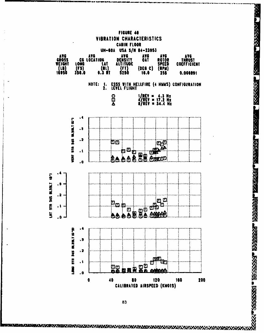
FIGURE 4#
VIBRATION CHARACTERISTICSCABIN FLOOR
UH-IOA USA SIN 64-23153AVG AVG AVG AV6 AVG AVG
GROSS Cl LOCATION DENSITY OAT ROTOR THRUSTWEIGHT LONG LAt ALTITUDE SPEED COEFFICIENT111.11 (FS) (,1L) T ((R)
525 350.0 .1 5 258 0.00|011
NOTE: 1. ESSS WITH HELLFIRE (4 HMMS) CONFIGLURATION2. LEVEL FLIGHT
oI/REV a 4.3 HzS4/REV a 17.2 Hz611REV 34.4 Hz
.. . ............. ... ...... .....-....
... . . .. . .. .. .. .........
.. ...... ........ .................. . ....
I............................... . ...........................
.0...........................................
! { • ............. • ......... •........ .......... •........ .......... •......... •......... •......... :.. ........
S......... .. ...... .. . ....... . ......... ...............
S....... ..... .....................
.............cc .2............... ......... r.......
830
.4 ......... •......... >............ ......... t ......... {..........I ......... 1......... •......... :.. .......
S,......... :......... .. ....... ........ ..........
0 40 so 120 tloo 206CALIBRATED AIRSPEED (KNOTS) i

FIGURE 47VIBRATION CHARACTERISTICS
CAIIN FLOORI
UN-BOA USA SIN 84-23553AVG AVG AVM AVG AVl AV$
GROSS IC LOCATION DENSITY OAT NITO O THRUSTIEIGH; LONG LAI ALJITUE El PEE i OEFFICIENTI'•11 (r !T0•)0 (etc.c) t"m) "IIFS) I3. 2 6.0 '24 0.0081178
NOTE: I. ESSS ONLY CONFIGURATION
2. LEVEL FLIGHT
E 3H1/,[V- 4. Hz
A IV, 34.4 Nz
- ............ ............. ................ .........
. ....... i........I ..... ......... ........ .
...... ...... ......... ........ .......... . ... ...
S.... ........ ...................
S............0 .................................
•4 .................... ......... ............. i .............. ............. i ................ .........
.2. . .. ......... ....... ........ .... . I...................
~ 1*. ... a................................. ........
0. ... . .. . . . . .. .... .... ... . .. . .... .
,1 I ......... '......... ......... ................... .......... ........ .................... ........
... ~J*kW*UiW~A..................
.......... . ......... .......... ......... ......... ......... :..........
S 2 .... ... ... .... ..... 4 . .... ....... ...... .................
O 40 80 120 ItO tooCALIBRATED AIRSPEED (KNOTS)
843

FIGURE 41VIBRATION CHARACTERISTICS
CANIN FLOORUH-GOA USA S/N 84-23953
AVG AVG AVG AVG AVG AVGGROSS CO LOCATION DENSITY OAT ROTOR THRUST
WEIGHT LONG LAI ALTITUDE SPEED COEFFICIENT
1.) (FS) (ILI Ftr) (DEC C) (RPM)9801 350.1 . tl . 254 O.O01901
NOTE: 1. ESSS WITH HELLFIRE (4 HUMS) CONFIGURATION2. LEVEL FLIGHT
0 I/REV 4,.3 H,S4/ZREV a 17.1 Hz
1/REV a S4.4 Hz
; ' 1 ...~ ~.....i ......... i.........i ........ i......... i......... i............ ......... !.......... .........
. ..... .......... .... •. .• .. ....... ....• ......... ......... ......... ..........
d . ;t , ~ ~ ~~...... .......... . . ...... : ........ . m ....... a,, ..., ......... ,......... .......... : ......... :
....... . ..... ... .................. .............. .- .........
............ ............................ ........
• i. .. .i... ... .• ....I ....... .......... . ..... ......... ......... ........ ..........
id:
4.Om ... .. .... "
a ....... ..................4.... 4. a....... .............
.2 ................ ..........................
9 .. . .. ......... ...... ..... ............... ....
I2................. I......I....
003
0 40 s0 120 16O 200
CALIBRATED AIRSPEED (KNOTS)
85

FIGURE 49SHIP AIRSPEED CALIBRATION
UH-60A, USA S/N 84-23953AVG AVG AVG AVG
GROSS C.G. LOCATION DENSITY OUTSIDE TEST5ThM WEIGHT LON LAT ALTITUI E A IR TEMP. METHOD
(19) (FS) (BL) (FEET)( DEG C)
0 15270 350.6 0.2 RT 5350 13.5 TRAILING BOMBA 18600 350.6 0.2 RT 6200 17.5 TRAILING BOMBOl 17500 350.0 0.2 RT -10 16.0 GRNO SPD CRSE
NOTES: 1. N4ORMAL UTILITY CONFIGURATION
2.LEVEL FLIGHTI3. BALL CENTERED TRIM CONDITION
4. MAIN ROTOR SPEED=258 RPM
- 10
160:......
204 0 0. 60872 80 10 104016INICTD ISPED(NOS
+ 0.000057 62xV A

FIGR•E 50SHIP AIRSPEED CALIBRATION
U-A USA S/N 84-23953
AVG AVG AVG AVGGROSS C.G. LOCATION DENSITY OUTSIDE TEST
EO/N•!FSJ LAT ALTITUDE AIR TEMP. METHODS (L) (FEET) (DEG C)
17040 350.2 0.2 RT 6460 15.0 TRAILING BOMB
NOTES: 1. ESSS ONLY CONFIGURATION2. LEVEL FLIGHT3. BALL CENTERD TRIM CONDITION4. MAIN ROTOR SPEED=258 RPM
out1160 0
S -10
1 6 0.. ....
P L omAL CURVE FIT ...... ...
iVCAL z + 18.75155140 i + 0.65325 VIC
20
21 0 40 60 60 100 120 140 160
IHDICATED AIRSPEED (KNOTS)
0.002817xV1

F IGURE 51SHIP AIRSPEED CALIBRATION
UH-60A USA S/N 84-23953
AVG AVG AVG AVGsROSS- C.O. LOCATION DENSITY OUTSIDE TESTWEIGHT LONG LAT ALTITUDE AIR TEMP. METHOD0(L9) (FS) (81.) (FEET) (DEG C)
168810 349.7 0.2 RT 6090 13.0 TRAILING BOOMB
NOTES: 1. ESSS WITH HELLFIRE (4 HMMS) COW I GURAT ION42. LEVEL FLIGHT3. BALL CENTERED TRIM CONDITION4. MAIN ROTOR SPEED=258 RPM
- 10
CII100
* ~ L 7r:- LIEO :ZRT ORETOI IINDIATE AIRSPEED0(KNOTS)
88 J.85 I

APPENDIX F. PHOTOGRAPHS IINDEX
Photograph Photograph Number
Test Aircraft with 4 HMMS Installed 1 through 4Fixed Provision Mounting Points 5 through 7
ESSS Fairing 8 through 10ESSS and HELLFIRE Inscallation 11 through 14Interface Control Panel 15Ballast Locations 16 and 17Test Instrumentation 18External Modifications 19 through 23
89

'S kmI
'N"'
N'4
-AMA
~' '90

W ~ "
"NO 'N N
MN\'M M*
'RIN,"MEW
g NN N N't`
N'. NN N4
"NNS
-r
'A'x
2M%NNN '¾
"N'kV4
> NN\4'Ncc
...N.. ..
N"'N64
'N N 91
VU~~~~*~* VW'WV ftLWIM ft U VV

S 41
'4j
-4
04-1
92.

'V
'-4-4w
w-4
JJ
'-I
0U
-4
C
-4
I-4
0t 0 I
(I 3

0
p b.'
I0"-4
0 -
6.1
944C'I
* *14

I Iý
Photo 7. ESSS Installation onto Fixed Provision Mounting Points
95
I O Q N ,111 11] 1ý 1111 1'p)

0.
04
4JV
96

.14
owl'
00
HM9.4EM-M0H 0I.
NOz
97%

Ain.7 S~fl ,4 WPflh rWZWU U -MM M ;- --. - - - - -- -- - -
km 060
930
"00
1.4
98-

0.0
99.
'aA ZKIW

at' w~~nr ~~' aran Ri Ni .X1LK9WRX Wfi KMW4WX wrUM XwU WIFWWWW~ w~kpywdWV Wb b flfl Wb WU WV Mi WUE U KMV WWf W-6 WVWVUW ffl wv lm t%
*1nEnU,
"OR 0
P4.
100

0Y4
101
101
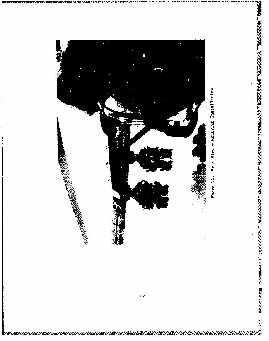
' II I'~ P.J I .
0-
gg'", 1,;
IFOI
'10
102

4)0
4.4
P40
103

14
00
IRI
104

Photo 17. Observer's Seat Ballast Mounting Location
105

0)
440
44I
106

Temperature Probe:-::
Nose Boom Assembly '
Photo 19. Boom System Installation andNose-Mounted Temperature Probe
107

r4
60
11*4
108

VUNIYU¶ Ku SI¶Afl x2t�'rw1nnr1¶KntA tr Mn SM Nfl XMMI¶ an-v �-ww-an v-u v-u wxrw I ruww� 5 SUqfllts rwwn. nv-a a ra�
A
I
& 1
0
Photo 21. Tail Rotor Slip Ring Assembly
gI.
I
109
IISI'

S~flW ~ fl ~ flfllfl- W- -Uf~r ~ lf -flu ----- - - -ur - -tw n l -~
W IN
1101

I•i "®R
Rele ase ....Knob ",. .:.::,. "•}
UWý Handle "i
Photo 23. Emergency Crew Door Handles
1ii

IDISTRIBUTION
HQDA (DALO-AV, DALO-FDQ, DAMO-HRS, DAMA-PPt4-T, 6
DAMA-RA, DAZ4A-WSA)
US Army Materiel Command (ANCDE-SA, AMCDE-P, AMCQA-SA, 4
AMCQA-ST)
US Army Training and Doctrine Command (ATCD-T, ATCD-B) 2
US Army Aviation Systems Command (AMSAV-8, AMSAV-Q, 8
AI4SAV-MC, AMSAV-ME, AMSAV-L, AMSAV-N, AMSAV-GTD)
US Army Test and Evaluation Command (AMSTE-TE-V, 2
AMSTE-TE-O)
US Army Logistics Evaluation Agency (DALO-LEI) 1
US Army Materiel Systems Analysis Agency (AMXSY-RV, AMXSY-NP) 8
US Army Operational Test and Evaluation Agency (CSTE-AVSD-E) 2
US Army Armor School (ATSB-CD--TE) I
US Army Aviation Center (ATZQ-D-T, ATZQ-CDC-C, ATZQ-TSM-A, 5
ATZQ-TSM-S, ATZQ-TSM-LH)
US Army Combined Arms Center (ATZL-TIE) 1
US Army Safety Center (PESC-SPA, PESC-SE) 2
US Army Cost and Economic Analysis Center (CACC-AM) 1
US Army Aviation Research and Technology Activity (AVSCOM) 3
NASA/Ames Research Center (SAVRT-R, SAVRT-M (Libvary)
US Army Aviation Research and Technology Activity (AVSCOM) 2
Aviation Applied Technology Directorate (SAVRT-TY--DRD
SAVRT-TY-TSC (Tech Library)
.1I

US Army Aviation Research and Technology Activity (AVSCON) 1
Aeroflightdynamics Directorate (SAVRT-AF-D)
US Army Aviation Research and Technology Activity (AVSCON) I
Propulsion Directorate (SAVRT-PN-D)
Defense Technical Informs ion Center (FDAC) 2
US Military Academy, Department of Mechanics I
(Aero Group Director)
ASD/AFXT, ASD/ENF 2
US Army Aviation Development Test Activity (STRBC-CT) 2
Assistant Technical Director for Projects, Code: CT-24
(Mr. Joseph Dunn) 2
6520 Test Group (ENML) I
Commander, Nav&1 Air Systems Command (AIR 5115S, AIR 5301) 3
Defense Intelligence Agency (DIA-DT-2D) I
Headquarters United States Army Aviation Center and
Fort Rucker (ATZQ-ESO-L) I
School of Aerospace Ziginaering (Dr. Daniel P. Schrage) I
Commander, US Arty Aviation Systems Command (AMSAV-EA,
AMSAV-EC, kMSAV-ES) 4
Project Mana6et, Black Hawk (AMCPM-BH-T) 4