Embed Size (px)
Citation preview

Aviation Recorder Overview
Dennis R. GrossiNational Transportation Safety Board
KEYWORDSAviation, Recordings, Overview, Investigation
INTRODUCTIONThere are a wide variety of airborne and ground-based aviation recording devices that can provide vitalinformation for accident prevention purposes. The primary information sources include the mandatorycrash-protected flight recorders, airborne quick access data recorders, and ground-based recordings of airtraffic control (ATC) radar returns and radio communications. Other sources of recorded information,such as aircraft system internal memory devices and recordings of airline operational communications,have also provided vital information to accident investigators. These devices can range from nonvolatilememory chips to state-of-the-art solid-state flight recorders. With the exception of the mandatory flightrecorders, these devices were designed primarily to provide recorded information for maintenancetrouble-shooting or specific operational requirements. Regardless of their original purpose, they have allbeen used in one form or another to investigate aviation accidents. This paper will give an overview ofthe evolution of flight recorder technology and regulatory requirements, and describe the capabilities andlimitations of the various types of recorded information available to the aviation community for accidentprevention and, in particular, accident/incident investigation.
CRASH-PROTECTED FLIGHT RECORDERS
Evolution of Regulatory RequirementsFirst Flight Data RecorderThe need for a crash-survivable recording device became apparent following a series of airline crashes inthe early 1940s. This spurred the Civil Aeronautics Board (CAB) to draft the first Civil AviationRegulations calling for a flight recording device for accident investigation purposes. However, recorderdevelopment was delayed by shortages brought about by World War II. As a result, such a device wasnot available, and after extending the compliance date three times, the CAB rescinded the requirement in1944. The CAB issued a similar flight recorder regulation in 1947, after the war, but a suitable recorderwas still not available and the regulation was rescinded the following year.
During the 9 years following the rescission of the 1947 flight recorder rule, the Civil Aviation Authority(CAA), the CAB, and aviation industry representatives studied the capabilities of recorder technology inan effort to develop new recorder requirements. Finally in 1957, after determining that suitable recordingdevices were available, the CAA issued a third round of flight recorder regulations. These regulationscalled for all air carrier airplanes over 12,500 pounds that operate above 25,000 feet to be fitted with acrash-protected flight recorder by July 1, 1958, that records altitude, airspeed, heading, and verticalaccelerations as a function of time. This marked the introduction of the, first true crash-protected flightdata recorder.

Figure 1 System schematic for a typical oscillographic foil recorder.
First Cockpit Voice Recorder (CVR)As a result of a CAB recommendation to record flight crew conversation for accident investigationpurposes, the Federal Aviation Administration (FAA) conducted a study in 1960 that established thefeasibility of CVRs. The FAA produced airworthiness installation approval criteria and operating rulesthat called for the installation of a CVR in transport category aircraft operated in air carrier service. Thecompliance dates were July 1, 1966, for all turbine-powered aircraft, and January 1, 1967, for allpressurized aircraft with four reciprocating engines.
1972 Flight Data Recorder Rule ChangeFDR requirements remained virtually unchanged until December 10, 1972, when the rules for transportcategory airplanes that received type certification after September 30, 1969, were amended to require anexpanded parameter digital flight data recorder (DFDR) system. The expanded parameter requirementsincluded existing parameters plus parameters for pitch and roll attitude; thrust for each engine; flapposition; flight control input or control surface position; lateral acceleration; pitch trim; and thrustreverser position for each engine. Unfortunately, this rule change, which was retroactive to include theBoeing 747, did not affect airplanes such as the Boeing 707, 727, and 737, and the McDonnell DouglasDC-8 and DC-9, all of which had type certificates issued prior to 1969. Therefore, existing and newlymanufactured versions of these older aircraft types could be operated under the same FDR rulesestablished in 1957. The flight recorder requirements remained essentially unaltered until the issuance ofrule changes in 1987 and 1988.
1987 and 1988 Flight Recorder Rule ChangesDuring the 30 years following the issuance of the original 1957 FDR regulations, the NationalTransportation Safety Board (NTSB) and its predecessor, the CAB, issued numerous safetyrecommendations to the FAA requesting upgraded recorder standards to meet the needs of accidentinvestigators. The recommendations called for:1. Replacement of original foil-type oscillographic recorder with digital recorders;2. Retrofit of exiting transport category airplanes fitted with the five-parameter FDRs with six
additional parameters;3. Expanded parameter requirements for newly manufactured transport category airplanes;4. Use of hot-microphones by the flight crew below 18,000 feet;
5. Recording of hot-microphone channels on CVR; and6. CVR and FDR requirements for some air taxi and corporate executive aircraft.
The FAA repeatedly sighted cost as the primary reason for not adopting the recommendations.Following a series of high visibility accidents in the early 1980s, the FAA issued flight recorder rulechanges in 1987 and again in 1988. These rule changes called for:1. Replacement of oscillographic foil-type FDRs digital recorders by May 26, 1989;2. The number of mandatory parameter for airplanes type certificated before October 1969, would be
increased to include pitch and roll attitude, longitudinal acceleration, thrust of each engine, andcontrol column or pitch control surface position. The original compliance date, May 26, 1994, wasextended by 1 year to May 26, 1995;
3. Transport category airplanes (20 or more passengers) manufactured after October 11, 1991, would berequired to record 28 parameters in a digital format;
4. Existing transport category airplanes (20 or more passengers) fitted with a digital data bus would berequired to record 28 parameters in a digital format;
5. All multiengine turbine-powered air taxi aircraft capable of carrying 10-19 passengers manufacturedafter October 11, 1991, would be required to have a 17-parameter FDR;
6. The CVR requirements were extended to multiengine turbine-powered aircraft capable of carrying 6or more passengers and requiring two pilots; and
7. Flight crews would be required to use existing CVR hot-microphone systems below 18,000 feet.
1997 Flight Data Recorder Rule ChangesFollowing two fatal Boeing 737 accidents (United Flight 585, Colorado Springs, CO, July 1989, andUSAir Flight 427, Pittsburgh, PA, September 1994), the NTSB reexamined FDR parameter requirements.As a result, the NTSB made safety recommendations to the FAA that called for:1. Additional parameters for most existing air transports that focused on recording crew flight control
inputs and the resulting control surface movements; parameter retrofits to be completed by January 1,1998;
2. Increased parameter requirements for transport airplanes manufactured January 1, 1996;3. Urgent retrofit of all Boeing 737 airplanes with FDR parameters to record lateral acceleration, and
crew flight control inputs and the resulting control surface movements by the end of 1995.
The FAA responded with rulemaking action that issued a notice of proposed rulemaking in August 1996and a final rule on August 18, 1997. Although the final rule generally met the requirements of the safetyrecommendations, the compliance dates were significantly relaxed from those recommended by theNTSB. In addition, the FAA did not agree with the urgent recommendation to retrofit Boeing 737 by theend of 1995. However, the final rule did include the requirement that air transports record flight controlcrew inputs and control surface position. The final rule calls for:1. Transport airplanes type certificated before October 1, 1969, and manufactured before October 11,
1991, to record as a minimum the first 18 to 22 parameters listed in the rule by August 18, 2001;2. Transport airplanes manufactured after October 11, 1991, and before August 18, 2001, to record as a
minimum the first 34 parameters listed in the rule by August 18, 2001;3. Transport airplanes manufactured after August 18, 2000, must record as a minimum the first 57 FDR
parameter listed in the rule;4. Transport airplanes manufactured after August 18, 2002, must record as a minimum all 88 FDR
parameter listed in the rule.
The specific parameter requirements are contained in Table 1.
March 9, 1999, NTSB and TSB Flight Recorder Recommendations

A recent set of flight recorder recommendations was a combined effort of the Transportation SafetyBoard of Canada (TSB) and the NTSB of the United States. These recommendations followed theSeptember 2, 1998, accident of Swissair flight 111, an MD-11, on a regularly scheduled passenger flightfrom New York to Geneva, Switzerland. The flight diverted to Halifax after the crew reported smoke inthe cockpit; the airplane crashed into the waters near Peggy’s Cove, Nova Scotia, killing all 229passengers and crew onboard. The investigation has been severely hampered by the lack of data from the CVR and FDR, whichstopped nearly 6 minutes before the airplane hit the water.
Table 1 Parameter Requirements for Air Carrier Flight Data Recorders.
The Swissair accident was just the latest in a long history of accident and incident investigations that were hinderedby the loss of flight recorder information due to the interruption of the aircraft electrical power to the flightrecorders. However, recent innovations in recorder and power supply technologies have made it possible to providean independent power source that would provide sufficient power to operate a solid-state flight recorder for 10minutes. In addition, the availability of combined voice and data recorders has introduced the possibility of fitting
Part 121.344, Flight Data Recorders for Transport Airplanes
No FDAU FDAU*
MANUFACTURED On Or BeforeOctober 11, 1991 (see Note:)
MANUFACTURED AfterOctober 11, 1991
58. Thrust Target #59. CG Trim fuel #60. Primary Nav. Sys. 61. Icing #62. Eng. Wrn. Vibration #63. Eng. Wrn. Temp. #64. Eng. Wrn. Oil Press. #65. Eng. Wrn. Ovr. Spd. #66. Yaw Trim pos. 67. Roll Trim pos.68. Brake Press. (sel. sys)69. Brake Ped. Pos. (lt.&rt.)70. Yaw angle #71. Engine Bleed Vlv. #72. De-iceing #73. Computed CG #74. AC bus status 75. DC bus status76. APU bleed vlv. #77. Hyd. press (each sys)78. Loss of cabin press.80. Heads-up #81. Para-visual #82. Trim input-pitch83. Trim input-roll84. Trim input-yaw85. Flap cntl. pos. TE.86. Flap cnt. pos. LE87. Grnd. Spoiler/Spd. Brk. pos. & sel. 88. All flight control input forces.
NEWLY MANUFACTURED
1. Time 2. Pressure Altitude 3. Indicated Airspeed 4. Heading 5. Vertical Acceleration 6. Pitch 7. Roll 8. Mic. Keying 9. Thrust (each eng.)10. Autopilot Status11. Longitudinal Accel.12. Pitch control input13. Lateral control input14. Rudder pedal pos.15. Pitch control surface16. Lateral control surface17. Yaw control surface 18. Lateral Accel. **
19. Pitch Trim (except 82)20. Trailing edge flaps (except 85)21. Leading edge flaps(except 86)22. Thrust Rev. (each eng.)
23. Ground spoilers (except 87)24. OAT25. AFCS modes/status26. Radio altitude27. Localizer deviation28. G/S deviation 29. Marker beacon 30. Master Warning31. Air/Ground switch32. Angle of Attack #33. Hydraulic pres. low34. Ground Speed #
35. Ground Prox.36. Landing gear pos. 37. Drift angle #38. Wind speed #39. Latitude/Longitude #40. Stall Warning #41. Windshear #42. Throttle lever pos.43. Additional engine prms.44. TCAS Warn.45. DME 1&2 distance46. NAV 1&2 frequency47. Selected Baro. #48. Selected Altitude #49. Selected Speed #50. Selected Mach #51. Selected Verticla Spd. #52. Selected Heading #53. Selected Flight Path #54. Selected Decision Height #55. EFIS display format #56. Mult-function eng/alers #57. Thrust commanded #
Compliance Dates: Next heavy maintenance afterAugust 18, 1999, but no later than Aug. 18, 2001
Manufactured AfterAugust 18, 2000
Manufactured AfterAugust 18, 2002
Compliance Date: August 18, 2001
* FDAU - Flight Data Acquisition Unit** For Airplanes with more than 2 engines, Lateral Acceleration is not required unless capacity is available# Not intended to require a change in installed equipmentTransport Airplane - 20 or more passengers
Airplanes that need not comply:Convair 580, 600, 640, de Havilland DHC-7, Fairchild FH227, Fokker F-27 (except Mark 50), F28, Mark 1000 & 4000, Gulfstream G-159, Lockheed E10-A, E10-B, E10-E, Maryland Ind. F-27, Mitsubishi YS-11, Shorts SD330, SD360
Note: The following recommended parameters were not listed for Non FDAU aircraft: Pitch trim, OAT, AOA, Thrust Rev. , Flaps, Grnd. Spoilers, AFCS modes Roll & Yaw Trim The following recommended parameters were not listed for FDAU aircraft mfg. before 10-11-91: OAT, AOA, AFCS modes, Roll & Yaw Trim The following recommended parameters were not recorded for aircraft mfg. after 10-11-91: Roll & Yaw Trim.

two combined recorders on newly manufactured airplanes, placing one recorder near the cockpit to reduce theprobability of a mechanical or electrical interruption of the signals and power supply, and the second recorder as faraft as practical to enhance survivability.
As a result, the U.S. NTSB and TSB of Canada issued safety recommendations on March 9, 1999, torequire:1. By January 1, 2005, the retrofit of a 2 hour solid-state CVR that is fitted with an independent power
supply capable of operating the CVR and area microphone for 10 minutes when aircraft power to theCVR is lost;
2. By January 1, 2003, all newly manufactured airplanes required to carry both a CVR and FDR befitted with two combined voice and data recorders, one recorder located as close to the cockpit aspractical and the other as far aft as practical;
3. Amend Title 14 U.S. Code of Federal Regulations to require that CVRs, FDRs, and combinationflight recorders be powered from separate generators busses with the highest reliability.
In a March 19, 1999 letter, the FAA agreed to the recommendations without revision and promised toissue a notice of proposed rulemaking by the end of thesummer.
EVOLUTION OF FLIGHT RECORDERSFlight data recorders can be traced back to the origins ofpower flight. Wilbur and Orville Wright’s historic firstflight was documented by the first flight data recorder. Thisrudimentary device recorded propeller rotation, distancetraveled through the air, and fight duration. CharlesLindbergh’s airplane the Spirit of St. Louis was also fittedwith a flight-recording device. Lindbergh’s recorder was abit more sophisticated, employing a barograph that markedchanges in barometric pressure or altitude on a rotating papercylinder (see Figure 2).
These early recordings survived because they were designedto record historical events, not mishaps. The first practical crash-protected flight data recorder was notintroduced until 1953. This recorder used styli to produce individual oscillographic tracings for eachparameter on metallic foil. Time was determined by foil movement, which typically advanced at a rate of6 inches per hour. This often resulted in an entire accident sequence being recorded within a 0.1 inch offoil movement. Investigators recovered the recorded information by optically reading the scribedmarkings through a microscope, and then converting the displacement of the scribed marks from thereference line to engineering units. This process was very time consuming and required a significantamount of reader interpretation.
The 1957 regulations that mandated the installation of FDRs by July 1958 created a market for FDRs thatattracted other manufacturers who also use the metal foil oscillographic technique (see Figure 3 and 4).The regulations also required compliance with Technical Standards Order TSO C-51. This TSO definedthe range accuracy, sampling interval, and type parameters to be recorded (altitude, airspeed, heading,vertical acceleration and time) and specified the requirement to survive a crash shock of 100 Gs andbeing enveloped in a 1100°C flame for 30 minutes. The TSO also defined three basic types of flightrecorders:
Figure 2 Spirit of St. Louis flight recorder.

Type I: Non-ejectable recorder, unrestricted location.
Type II: A non-ejectable recorder, minimum15 minutes firetest, restricted to any location more than ½ of the wing rootchord from the main wing structure through the fuselage andfrom any fuel tanks.Type III: An ejectable recorder, minimum 1.5 minutes fire test,unrestricted location.
The early recorders were all of the Type I design and most weremounted in the cockpit area or in the main gear wheel well.Unfortunately, these locations subjected the recorders to fireand impact forces that destroyed or severely damaged therecording medium. Type II and III recorders were never fittedto commercial air carriers; however, ejectable recorders are
currently in use on some military aircraft.
In the early 1960s, the CAB made a series of recommendationsto the FAA that called for additional protection for FDRsagainst impact force and fire damage, and also recommendedthe relocation of the recorders to the aft area of the fuselage toprovide maximum protection of the recording media. As aresult, the FAA issued rule changes that specified the locationof the recorder as far aft as practical and upgraded theperformance standards in TSO C-51 and reissued it as C-51a.The upgraded TSO specifications increased the impact shocktest from 100 Gs to 1,000 Gs and introduced static crush, impactpenetration, and aircraft fluid immersion tests. The fire test wasnot changed. Unfortunately, neither TSO contained an adequatetest protocol to ensure uniform and repeatable test conditions.
TSO C84CVR Requirements
TSO C-51FDR Requirements
TSO C-51aFDR Requirements
Fire 1100°C flame covering 50%of recorder for 30 minutes
1100°C flame covering 50%of recorder for 30 minutes
1100°C flame covering 50% ofrecorder for 30 minutes
Impact Shock 100 Gs 100 Gs 1000 Gs for 5 msStatic Crush None None 5,000 pounds for 5 minutes on
each axisFluidImmersion
None None Immersion in aircraft fluids (fuel, oil, etc.) for 24 hours
WaterImmersion
Immersion in sea water for48 hours
Immersion in sea water for36 hours
Immersion in sea water for 30days
PenetrationResistance
None None 500 lb. dropped from 10 ft. witha ¼-inch-diameter contact point
Table 2 Early flight recorder crash/fire survivability standards.
Figure 3 Early Lockheed model 109.
Figure 4 Sundstrand Model 542 FDR, 1/2 ATRlong format.
At about the same time as the foil recorders were being developed in the United States, recorders that usedmagnetic steel wire as a recording medium were being developed in the United Kingdom. The wirerecorders were the first to use digital pulse coding as a recording method. The robust design of the wirerecorder made it a fairly reliable recorder for its time. Although the wire recording medium was fairlyimpervious to post impact fires it did not fair as well with impact shock. The wire would often brake intoseveral sections and become entangled making it difficult and tedious to reassemble in the propersequence.
In the late 1940s, the French developed an FDR that used a photographic system that recorded data onlight- sensitive paper. It had obvious disadvantages: inflammability and the tendency of the recording todisappear when subjected to light. The French later adopted the metal foil oscillographic recorder.
Cockpit Voice RecorderIn response to CAB recommendations, the FAA conducted a study in 1960 to determine the feasibility ofrecording the spoken words of the flight crew for accident investigation purposes. Although cockpitambient noise levels posed a significant obstacle to 1960 recording technology, it was determined thatrecording crew conversation was feasible. The following equipment capabilities were initially proposed:1. Record each crewmember’s conversation, both transmitted and received, with ground facilities and
on the airplane’s intercommunication system. Also, other conversation in the cockpit not conductedover those media should be recorded. Sufficient channels should be provided so that there will be nopossibility of more than one crewmember recording on a channel at one time.
2. Retain the last 30 minutes of the crew’s conversation.3. Contain provisions for stopping the recorder in the case of a crash so that the last 30 minutes of
conversation is not erased or overwritten.4. Recorder should withstand the crash conditions required in TSO-C51.5. Recording should be intelligible over the ambient noise of the cockpit or it should be possible to
filter out the unwanted noise from the record with appropriate ground equipment.6. Recorder should be capable of recording crew voices, other than on the communication and
intercommunication systems, without the use of lip or throat microphones.7. It should contain indicating provisions to inform the crew when it is operating properly.
As a result, the FAA issued rules that mandated the use of CVRs on all transport category aircraft andissued TSO C-84, which established crash fire survivability and equipment approval standards.
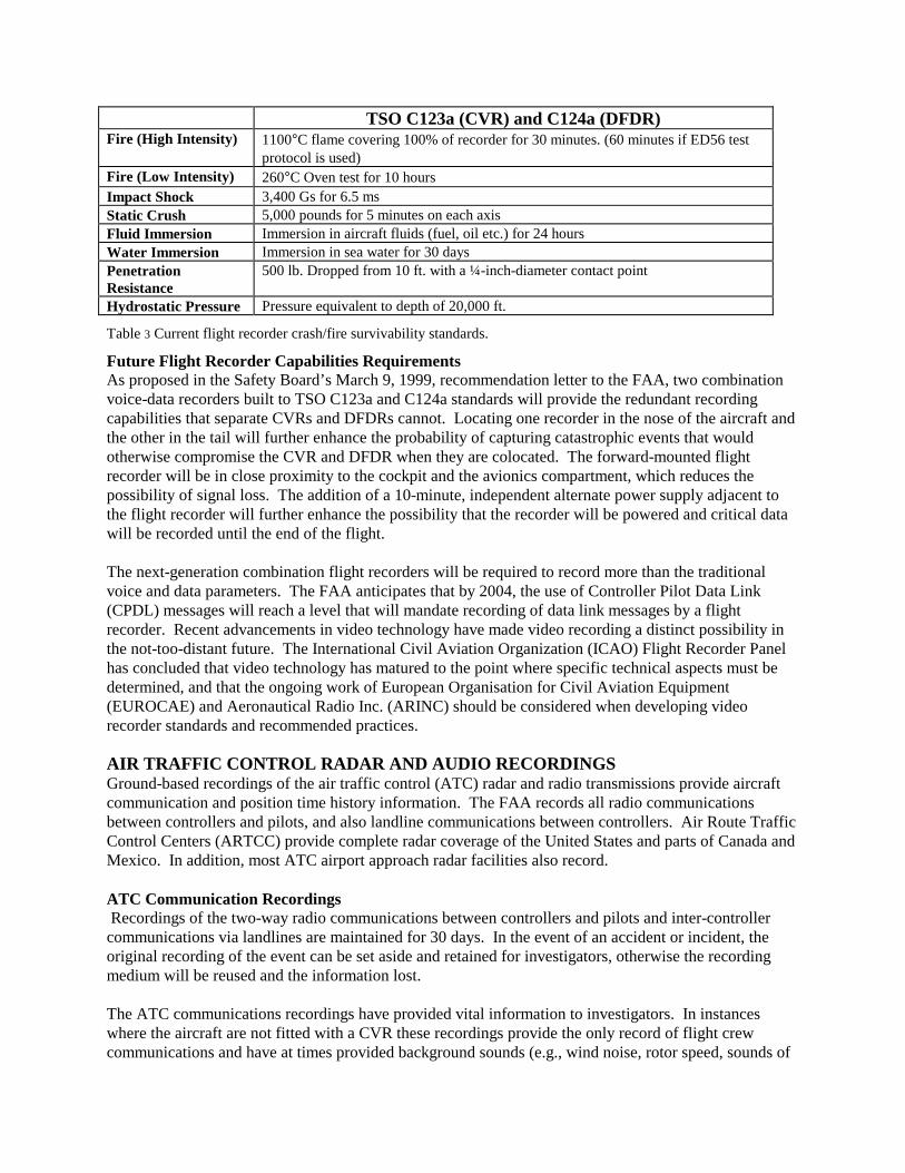
Magnetic Tape Flight RecordersThe introduction of the CVR in the late 1960s andDFDRs in the early 1970s made magnetic tape therecording medium of choice until the introduction ofsolid-state flight recorders in the late 1980s. Therewere a variety of tapes and tape transports used by thevarious recorder manufacturers. The most widely usedtapes were mylar, kapton, and metallic. The tapetransports were even more varied, using designs suchas coplaner reel to reel, coaxial reel-to-reel, endlessloop reel packs and endless loop random storage.Tape CVRs record four channels of audio for 30 minutes, and the DFDR records 25 hours of data. CVRsand FDRs record over the oldest data with the newest data in an endless loop-recording recording pattern.The DFDR tape transport and protective enclosure shown in Figure 5 is an endless loop real pack designadapted from a 1960s CVR.
Figure 5 Fairchild model F800 DFDR, 1/2 ATR long format.

All of the magnetic tape flight recorders, including the units that used metallic tape, were found to besusceptible to thermal damage during postcrash fires. Although the TSOs called for a high intensity firetest, the lack of a detailed test protocol allowed for a less-than-adequate design to be approved. Inaddition, the real world experience would show magnetic tape flight recorders to be most vulnerablewhen exposed to long duration fires, a test condition not required at the time tape flight recordersreceived TSO approval. In addition, metallic tapes were found to be vulnerable to impact shock, whichhad a tendency to snap the tape releasing the spring tension and unwinding the tape, causing further tapedamage and loss of data.
Digital Recording MethodThe DFDR and its companion recorder, the quick access recorder (QAR), were introduced about thesame time. DFDRs and QARs use the same recording techniques, but as the name implies, the QAR canbe quickly accessed and downloaded. Most early model QAR systems recorded far more parameters thanthe mandatory DFDR systems. As nonmandatory recorders, QARs were not designed to survive a crashimpact and postimpact fire, although a number have survived fairly significant crashes.
Most DFDRs and QARs require a flight data acquisition unit (FDAU) to provide an interface betweenthe various sensors and the DFDR. The FDAU converts analog signals from the sensors to digital signalsthat are then multiplexed into a serial data stream suitable for recording by the DFDR. Industrystandards dictated the format of the data stream, which for the vast majority of tape-based DFDRs is 6412-bit data words per second. The recording capacity of the tape DFDR is limited by the length of tapethat can be crash-protected and the data frame format. The capacity of the tape DFDRs was adequate forthe first generation of wide-body transports, but was quickly exceeded when aircraft like the Boeing 767and Airbus A320 with digital avionics were introduced.
Digital Avionics SystemsThe introduction of digital avionics systems into commercial aviation in the early 1980s significantlyincreased the amount of information available to DFDRs and QARs. Digital avionics also brought aboutdigital data buses, which carry digital data between systems. This made vast amounts of critical flight andaircraft system information available to the DFDR and QAR simply by tapping into the buses. Theintroduction of digital data buses also brought about digital FDAUs (DFDAU). The FDAU and DFDAUperform the same function except that DFDAUs can interface with the data buses and analog sensors.
Solid-State Flight RecordersThe introduction of solid-state flight recorders in the late1980s marked the most significant advance in evolution offlight recorder technology. The use of solid-state memorydevices in flight recorders has expanded recordingcapacity, enhanced crash/fire survivability, and improvedrecorder reliability. It is now possible to have 2-hourCVRs and DFDRs that can record up to 256 12-bit datawords per second, or 4 times the capacity of magnetic tapeDFDRs. Survivability issues identified during over theyears have been addressed with new crash/fire survivabilitystandards developed in close cooperation between accidentinvestigators and the recorder industry (see Table 3). The lack of moving parts in solid-state recordershas greatly improved recorder reliability.
Figure 6 Typical solid -state CVR and DFDR.
TSO C123a (CVR) and C124a (DFDR)Fire (High Intensity) 1100°C flame covering 100% of recorder for 30 minutes. (60 minutes if ED56 test
protocol is used)Fire (Low Intensity) 260°C Oven test for 10 hoursImpact Shock 3,400 Gs for 6.5 msStatic Crush 5,000 pounds for 5 minutes on each axisFluid Immersion Immersion in aircraft fluids (fuel, oil etc.) for 24 hoursWater Immersion Immersion in sea water for 30 daysPenetrationResistance
500 lb. Dropped from 10 ft. with a ¼-inch-diameter contact point
Hydrostatic Pressure Pressure equivalent to depth of 20,000 ft.
Table 3 Current flight recorder crash/fire survivability standards.
Future Flight Recorder Capabilities RequirementsAs proposed in the Safety Board’s March 9, 1999, recommendation letter to the FAA, two combinationvoice-data recorders built to TSO C123a and C124a standards will provide the redundant recordingcapabilities that separate CVRs and DFDRs cannot. Locating one recorder in the nose of the aircraft andthe other in the tail will further enhance the probability of capturing catastrophic events that wouldotherwise compromise the CVR and DFDR when they are colocated. The forward-mounted flightrecorder will be in close proximity to the cockpit and the avionics compartment, which reduces thepossibility of signal loss. The addition of a 10-minute, independent alternate power supply adjacent tothe flight recorder will further enhance the possibility that the recorder will be powered and critical datawill be recorded until the end of the flight.
The next-generation combination flight recorders will be required to record more than the traditionalvoice and data parameters. The FAA anticipates that by 2004, the use of Controller Pilot Data Link(CPDL) messages will reach a level that will mandate recording of data link messages by a flightrecorder. Recent advancements in video technology have made video recording a distinct possibility inthe not-too-distant future. The International Civil Aviation Organization (ICAO) Flight Recorder Panelhas concluded that video technology has matured to the point where specific technical aspects must bedetermined, and that the ongoing work of European Organisation for Civil Aviation Equipment(EUROCAE) and Aeronautical Radio Inc. (ARINC) should be considered when developing videorecorder standards and recommended practices.
AIR TRAFFIC CONTROL RADAR AND AUDIO RECORDINGSGround-based recordings of the air traffic control (ATC) radar and radio transmissions provide aircraftcommunication and position time history information. The FAA records all radio communicationsbetween controllers and pilots, and also landline communications between controllers. Air Route TrafficControl Centers (ARTCC) provide complete radar coverage of the United States and parts of Canada andMexico. In addition, most ATC airport approach radar facilities also record.
ATC Communication Recordings Recordings of the two-way radio communications between controllers and pilots and inter-controllercommunications via landlines are maintained for 30 days. In the event of an accident or incident, theoriginal recording of the event can be set aside and retained for investigators, otherwise the recordingmedium will be reused and the information lost.
The ATC communications recordings have provided vital information to investigators. In instanceswhere the aircraft are not fitted with a CVR these recordings provide the only record of flight crewcommunications and have at times provided background sounds (e.g., wind noise, rotor speed, sounds of

cockpit warnings, etc.) that have proven to be vital to the investigations. A time code is also recordedwith the audio communications to provide a time reference independent of any subtle recordinganomalies.
ATC and Other Radar RecordingsRecorded radar data can provide aircraft position time history information. This is accomplished byrecording the position coordinates of individual radar returns, time, and when available, altitude andidentification information transmitted from the aircraft. The altitude and identification data are producedby a transponder fitted to the aircraft that also reinforce the radar return. A transponder is areceiver/transmitter, which will generate a reply signal upon proper interrogation from a radar facility.
The rate at which the radar antenna rotates will determine the sampling interval between returns.ARTCC rotate at between 5 to 6 revolutions per minute (i.e., generating radar returns every 10 to 12seconds), whereas airport approach radar antennas do a complete rotation every 4.8 seconds. The mostaccurate position coordinates recorded by the ARTCC are in latitude and longitude, whereas approachradar records position coordinates as range and azimuth values, and both record the transponder-generated altitude values.
Military and private radar facilities can provide similar position time history information. Militaryaircraft (AWAC) and naval vessel radar data are also recorded and are available to investigators uponrequest.
Utilization of ATC Recordings by Accident InvestigatorsThe importance of ATC recorded data will be determined by the circumstances surrounding an accidentor incident. Accidents or incidents involving very dynamic conditions, such as aerodynamic stall andloss of control, are difficult to evaluate with ATC data alone. ATC data are more significant for lessdynamic accidents, such as controlled flight into terrain, or when used in conjunction with FDR and CVRdata.
The correlation of events common to the ATC recordings and the FDR and CVR recordings can providea very accurate local time reference. This can become critical because the FDR and CVR are onlyrequired to record relative time and the local time reference may vary from one ATC facility to the next.ATC radar and FDR data can be correlated by comparing the altitude time histories whereas ATCcommunication recordings can be correlated by the radio transmission time histories recorded by thevarious ATC facilities and the CVR and FDR.
In addition to a time reference, ATC-recorded information will also provide ground track reference,which is essential in performance-related accidents. A wind model can be developed when radar flightpath data are combined with FDR parameters such as altitude airspeed and heading and airplaneacceleration parameters. This is particularly useful in accidents or incidents involving dynamicmeteorological conditions such as wind shears or crosswind and turbulence conditions.
ATC radar data are particularly useful in evaluating the relative position of aircraft when multiple aircraftare involved. Investigations of mid-air collisions and wake turbulence encounters rely heavily on thisinformation.
There are significant accuracy and resolution limitations that must be taken into consideration whenusing recorded radar data. The accuracy limitations are known and should be factored into the groundtrack calculations. The sampling intervals of 4.7 to 12 seconds, presents a significant limitation onusefulness of recorded radar data.

NONVOLATILE MEMORY DEVICESModern aircraft utilize an increasing number of microprocessor-based electronic devices for operationaland maintenance purposes. As a result, aircraft are fitted with nonvolatile memory (NVM) to storeinformation such as flight crew entries to the navigation data base, system fault messages generated byelectronic control devices and system status messages. These devices, generally known as electronicallyerasable read-only memory (EEROM) provide temporary storage of transitional information duringpower interruptions. The term “nonvolatile” implies that the stored information will be availableregardless of whether the system is electrically powered or not.
Accident investigators have found NVM to be a valuable source of information. However, becauseNVM is not crash- or fire-protected, there is no assurance that it will be available following acatastrophic accident. With that said, there have been a significant number of cases where NVM hassurvived severe impacts and postimpact fires.
The recovery of information from NVM undamaged systems can be as simple as powering the systemand reading or downloading the information. Damaged units may require a trip to the manufacturer’sfacility where system experts can disassemble the unit to recover the information using specializedequipment and software.
The amount of effort and technical expertise needed to recover information from NVM will generally bedetermined by the amount of damage and system complexity. The first step in the recovery process is avisual inspection of the disassembled unit to determine the amount of damage. It may be possible tosimply replace a damaged connector or place the circuit board containing the memory device in aserviceable unit to recover the data. However, extreme caution must be taken when applying power tounits that are suspected of receiving impact shocks that exceed the normal design requirements: anundetected short or open circuit might result in the loss of the stored data.
Example: Lauda Air, Flight NG004, May 26, 1991The May 26, 1991, fatal accident of Lauda Air flight
NG004, a Boeing 767 that crashed in Suphan-BuriProvince, Thailand, demonstrated the importance ofNVM. The aircraft departed controlled flight whileclimbing through 24,000 feet and experienced an in-flight breakup during the recovery maneuver andsubsequently crashed into the jungle. The FDRmagnetic tape recording medium was destroyed by thepostcrash fire and provided no data. However, thecrew comments recorded by the CVR indicated aproblem with an engine thrust reverser just prior to theloss of control.
The electronic engine control (EEC) units for both engines were located andremoved from the aircraft wreckage and brought to the manufacturer’sfacility in Windsor Locks, Connecticut, to recover the fault messages storedin its NVM (see Figure 7). The EECs showed signs of severe impact shock. As a result, the EEROMs(identified in Figure 7 by the chevron symbols) containing the NVM were removed from the circuit
Figure 7 Damaged electronic engine control (EEC).

board and mounted on an identical laboratory test unit. A normal fault message download was performedand the data were subsequently processed using the manufacturer’s proprietary software.
Each time an EEC fault message was generated, the following information was captured and stored inNVM:• Diagnostic fault messages codes;• Values for N1 (high pressure compressor rotation speed), P2 (fan inlet total pressure), mach number,
temperature (cold junction compensation);• Fault time in elapsed hours;• Logging of flight and leg cycles.
The recovered data contained diagnostic messages from the last 390 hours of operation, which spanned95 flights. The EECs from the left engine, which experienced the uncommanded thrust reverserdeployment, provided a significant amount of information specifically relating to the faulty thrustreverser and ancillary altitude, airspeed, and engine thrust values provided key reference values, whichgained added significance in light of the loss of the FDR data. The EEC from the right engine, which didnot record any faults during the accident flight, yielded little additional information.
CONCLUSIONSAs far back as the early 1940s, it became apparent to the aviation community that public confidence mustbe gained and maintained if commercial aviation were to prosper. It was also recognized that to do thiswould require a quick and accurate determination of probable cause of any aviation mishap. It was alsoobvious that the nature of aviation accidents would make it necessary to fit air transports with recordingdevices to provide accident investigators with the information needed to determine the cause of a mishapand take the proper corrective action to prevent it from recurring.
The first flight recorders introduced over 40 years ago gave accident investigators their first appreciationof the recorder’s safety potential. However, the data provided by these early recorders was limited andoften of such poor quality that the investigators could only determine, at best, what happened but couldnot determine with a high degree of certainty why it happened.
Flight recording technology has had to adapt to a rapidly evolving commercial aviation industry, and thecorresponding needs of accident investigators. One of the most significant changes in recordertechnology occurred in the early 1970s, with the introduction of digital data recorders. The amount andquality of data provided by DFDRs, CVRs, other recorded data such as ATC radar, gave accidentinvestigators the first real opportunity to pursue an in-depth evaluation of the facts, conditions, andcircumstances surrounding an occurrence. The introduction of digital recordings also made it practical touse flight recorder data proactively.
The introduction of digital avionics and fly-by-wire technologies in the 1980s provided investigators withchallenges and opportunities. This new technology eliminated some well-established investigativetechniques while offering an opportunity to record and recover vast amounts of previously unattainableinformation. Indeed, the amount of available information overwhelmed early model DFDRs. However,the advent of solid-state recorders has solved the recorder capacity problem while improvingsurvivability and reliability.
The future of flight recording is promising. Advances in recorder and aircraft systems will allow for theintroduction of recording techniques to record video images of the cockpit and data link messages, aswell as providing more opportunities for the proactive use of flight data to prevent accidents.