Embed Size (px)
Citation preview
585-313-809Comcode 700223803Issue 4January 2002
������������� �Release 5.4MAP/5P System Maintenance

Copyright 2002, Avaya Inc.All Rights ReservedPrinted in U.S.A.
NoticeEvery effort was made to ensure that the information in this book was complete and accurate at the time of printing. However, information is subject to change.
Your Responsibility for Your System’s SecurityToll fraud is the unauthorized use of your telecommunications system by an unauthorized party, for example, persons other than your com-pany’s employees, agents, subcontractors, or persons working on your company’s behalf. Note that there may be a risk of toll fraud associ-ated with your telecommunications system and, if toll fraud occurs, it can result in substantial additional charges for your telecommunica-tions services.
You and your system manager are responsible for the security of your system, such as programming and configuring your equipment to pre-vent unauthorized use. The system manager is also responsible for reading all installation, instruction, and system administration docu-ments provided with this product in order to fully understand the fea-tures that can introduce risk of toll fraud and the steps that can be taken to reduce that risk. Avaya Inc. does not warrant that this product is immune from or will prevent unauthorized use of common-carrier tele-communication services or facilities accessed through or connected to it. Avaya Inc. will not be responsible for any charges that result from such unauthorized use.
Avaya Corporate SecurityWhether or not immediate support is required, all toll fraud incidents involving Avaya products or services should be reported to Avaya Cor-porate Security at 1 800 821-8235. In addition to recording the inci-dent, Avaya Corporate Security is available for consultation on security issues, investigation support, referral to law enforcement agencies, and educational programs.
Avaya Inc. Fraud InterventionIf you suspect that you are being victimized by toll fraud and you need technical support or assistance, call the Avaya Inc. National Customer Care Center Toll Fraud Intervention Hotline at 1 800 643-2353.
Federal Communications Commission StatementPart 15: Class A Statement. This equipment has been tested and found to comply with the limits for a Class A digital device, pursuant to Part 15 of the FCC Rules. These limits are designed to provide rea-sonable protection against harmful interference when the equipment is operated in a commercial environment. This equipment generates, uses, and can radiate radio-frequency energy and, if not installed and used in accordance with the instruction manual, may cause harmful interference to radio communications. Operation of this equipment in a residential area is likely to cause harmful interference in which case the user will be required to correct the interference at his own expense.
Part 68: Network Registration Number. This equipment is regis-tered with the FCC in accordance with Part 68 of the FCC Rules. It is identified by an FCC registration number.
Part 68: Answer-Supervision Signaling. Allowing this equipment to be operated in a manner that does not provide proper answer-supervi-sion signaling is in violation of Part 68 Rules. This equipment returns answer-supervision signals to the public switched network when:
• Answered by the called station• Answered by the attendant
• Routed to a recorded announcement that can be administered by the CPE user
This equipment returns answer-supervision signals on all DID calls forwarded back to the public switched telephone network. Permissible exceptions are:
• A call is unanswered• A busy tone is received• A reorder tone is received
Canadian Department of Communications (DOC)Interference InformationThis digital apparatus does not exceed the Class A limits for radio noise emissions set out in the radio interference regulations of the Canadian Department of Communications.
Le Présent Appareil Nomérique n’émet pas de bruits radioélectriques dépassant les limites applicables aux appareils numériques de la class A préscrites dans le reglement sur le brouillage radioélectrique édicté par le ministére des Communications du Canada.
TrademarksSee the section titled “About This Book.”
Ordering InformationCall: Avaya Inc. Publications Center
Voice 1 800 457-1235 International Voice 317 322-6791Fax 1 800 457-1764 International Fax 317 322-6699
Write: Avaya Inc. Publications Center2855 N. Franklin RoadIndianapolis, IN 46219
Order: Document No. 585-313-809Comcode 700223803Issue 4, January 2002
You can be placed on a standing order list for this and other documents you may need. Standing order will enable you to automatically receive updated versions of individual documents or document sets, billed to account information that you provide. For more information on stand-ing orders, or to be put on a list to receive future issues of this docu-ment, contact the Avaya Inc. Publications Center.
WarrantyAvaya Inc. provides a limited warranty on this product. Refer to the “Limited Use Software License Agreement” card provided with your package.
European Union Declaration of ConformityAvaya Inc. Business Communications Systems declares that the equip-ment specified in this document conforms to the referenced European Union (EU) Directives and Harmonized Standards listed below:EMC Directive 89/336/EECLow-Voltage Directive 73/23/EEC
The “CE” mark affixed to the equipment means that it conforms to the above directives.
CommentsTo comment on this document, see the section titled “About This Book.”
AcknowledgmentThis document was prepared by Technical Publications, Avaya Inc., Columbus, OH and Milpitas, CA.
Avaya Interchange Release 5.4MAP/5P System Maintenance 585-313-809
Issue 4January 2002
Contents iii
ContentsContents iii
About This Book ix
■ Purpose ix
■ Intended Audiences ix
■ Release History ix
■ How to Use This Book x
For Troubleshooting Information x
For Diagnostic Information x
For Common System Procedures x
For Hardware Information x
For Software Information x
■ Conventions Used in This Book xi
Terminology xi
Terminal Keys xiii
Screen Displays xiv
Other Typography xiv
Safety and Security Alert Labels xv
■ Trademarks and Service Marks xv
■ Related Resources xvii
Documentation xvii
Training xviii
Technical Assistance xviii
■ How to Comment on This Book xviii
■ Product Support xviii
1 Troubleshooting 1
■ Overview 1
■ Purpose 1
■ Modem Does Not Answer 2
■ The Tape Backup Alarm Is Activated Daily at 3:00 A.M. 3
■ Cannot Assign Voice Ports 4
■ System Does Not Boot 5
■ Optional Features Are Not Working 6
■ The Keyboard Is Not Operating 6

Avaya Interchange Release 5.4MAP/5P System Maintenance 585-313-809
Issue 4January 2002
Contents iv
■ Monitor Is Not Operating 7
■ Tip/Ring Circuit Card Is NotRecognized by the AvayaInterchange System 8
■ The Printer Is Not Operating 9
■ Hard Disk Drive Access Troubleshooting 10
The System Displays No Boot Device Available Message with Ident-Strings 10
The System Displays SCSI Target 0 LUN 0 Not Found Message with Several Additional Messages 12
The System Displays SCSI Target 0 LUN 0 Not Found Message and Stalls 13
No Ident-Strings Are DisplayedDuring Boot Procedure 14
The System Displays Failure to Load MIP, SIP, or vfs_mount Message 15
A Working System Displays WARNING Disk Drive HA0 TC0 LUX - Check Condition Message 16
The System Is Up But Not Fully Operationalor Is Unpredictable 16
System with Remote Maintenance Circuit Card Displays SCSI Disk Failure Message after POST 17
■ Troubleshooting Defective Blocks on Hard Disk Drives 17
2 Diagnostics 19
■ Overview 19
■ Purpose 19
■ Auditing Networking Databases 20
■ Conducting Diagnostics 22
Avaya Interchange Digital Networking Diagnostics 22
Performing a Network Snapshot 36
TCP/IP Diagnostics 37
Voice Port Diagnostics 43
Tip/Ring Circuit Card Diagnostics 45
3 Common System Procedures 51
■ Overview 51
■ Purpose 51
Avaya Interchange Release 5.4MAP/5P System Maintenance 585-313-809
Issue 4January 2002
Contents v
■ Accessing the Product IDMain Menu 52
■ About Cartridge Drives and Tapes 52
When to Change Cartridge Tapes 53
Inserting the Cartridge Tape 54
Removing the Cartridge Tape 55
Formatting Cartridge Tapes 55
■ About Diskette Drives and Diskettes 56
Types of Diskettes 56
Inserting and Removing Diskettes 56
Formatting Diskettes 57
■ Backing Up (Unattended) 58
How to Manage Tapes 58
What Data Is Backed Up 58
Verifying the Unattended Backup 59
■ Backing Up (Attended) 60
Data Types 60
Attended Backup 61
■ Restoring Backups 63
■ Administering Interchange 66
Starting the Voice System 66
Stopping the Voice System 67
■ Shutting Down and Rebooting theAvaya Interchange System 68
Shutting Down the Avaya Interchange System 68
Rebooting the System 69
■ Verifying the Date and Time 69
Checking the UNIX Date and Time Window 70
Changing the UNIX Date and Time Window 70
4 Getting Inside the Computer 75
■ Overview 75
■ Purpose 75
■ Protecting Against Damage fromElectrostatic Discharge 76
■ Removing Power from the MAP/5P 79
■ Removing the Dress Cover 80
■ Replacing the Dress Cover 82
Avaya Interchange Release 5.4MAP/5P System Maintenance 585-313-809
Issue 4January 2002
Contents vi
■ Restoring Power to the MAP/5P 82
5 Replacing or Installing Circuit Cards 83
■ Overview 83
■ Purpose 83
■ General Procedures 84
Removing a Circuit Card 84
Installing a Circuit Card 85
■ Circuit Card Settings 88
ACCX (AYC22) Circuit Card 88
Ethernet LAN Circuit Card 90
Tip/Ring Circuit Cards 95
SCSI Controller Circuit Card 99
Speech and Signal Processor Circuit Card 102
Remote Maintenance Circuit Cards 105
■ Installing a Remote MaintenanceCircuit Card, Version 2 114
Types of Remote Maintenance Circuit Cards 114
Setting the Resource Options 115
Installing the Remote Maintenance Circuit CardSoftware Package 116
Replacing a Defective Remote MaintenanceCircuit Card 117
6 Replacing the Hard Disk Drive 127
■ Overview 127
■ Purpose 127
■ Identifying a Failed Hard Disk Drive 127
■ Recovering from a Hard DiskDrive 0 Failure 128
■ Recovering from a Hard DiskDrive 1 Failure 128
■ Installing an Avaya InterchangeSystem with Two New Hard Disk Drives 128
■ Replacing a Hard Disk Drive 129
Replacing Hard Disk Drive 0 129
Replacing Hard Disk Drive 1 133
■ Cleaning a Hard Disk Drive 137
Using the fdisk Command 137

Avaya Interchange Release 5.4MAP/5P System Maintenance 585-313-809
Issue 4January 2002
Contents vii
Performing a Low-Level Format 139
7 Replacing Other Components 143
■ Overview 143
■ Purpose 143
■ Cartridge Tape Drive Replacement 144
Cartridge Tape Drive Removal 145
Cartridge Tape Drive Installation 147
■ CMOS Battery Replacement 148
CMOS Battery Removal 149
CMOS Battery Installation 150
■ Diskette Drive Replacement 151
Diskette Drive Removal 151
Diskette Drive Installation 154
■ Fan Replacement 156
Circuit Card Cage Fan Replacement 156
CPU Fan Replacement 158
■ Memory Replacement 160
SIMM Removal 160
SIMM Installation 163
■ Motherboard Replacement 164
Motherboard Removal 164
■ Power Supply Replacement 176
Power Supply Removal 177
Power Supply Installation 180
■ Riser Card Replacement 183
Riser Card Removal 183
Riser Card Installation 184
8 Installing an RFU (Remote Field Update) 187
■ Overview 187
A System Configuration 189
■ Memory and SIMM Description 189
■ Component Assignments 191
Fixed Assignments 194
Variable Assignments 194
Resource Allocation 196
Avaya Interchange Release 5.4MAP/5P System Maintenance 585-313-809
Issue 4January 2002
Contents viii
B Component Ordering Numbers 199
■ Component Ordering Numbers 199
C Disaster Recovery 203
■ Overview 203
D MAP/5P Platform Alarms 205
■ Overview 205
■ Purpose 205
■ Platform Alarms 206
GL Glossary 209
Index 241
About This Book ixPurpose
INTUITY Interchange Release 5.4MAP/5P System Maintenance 585-313-809
Issue 4January 2002
About This Book
Purpose
This book, Avaya Interchange Release 5.4 MAP/5P System Maintenance, 585-313-809, contains information for troubleshooting and diagnosing problems associated with MAP/5P hardware. Component replacement procedures and common system procedures are also included in the book. Appendices contain a system configuration description and a list of component ordering numbers.
Intended Audiences
This book is intended primarily for the onsite service technician and system administrators. Secondary audiences include the following from Avaya:
■ Field support — Technical Service Organization (TSO)
■ Field support — Global Support Organization (GSO)
■ Helpline personnel
We assume that the primary users of this book have completed the MAP/5P hardware installation training course (see Related Resources).
Release History
This is the third release of this book.

INTUITY Interchange Release 5.4MAP/5P System Maintenance 585-313-809
Issue 4January 2002
About This Book xHow to Use This Book
How to Use This Book
This book is designed to help you maintain your Avaya Interchange system. Use it as a quick reference to obtain specific information you might need on a particular topic.
For Troubleshooting Information
Basic troubleshooting information is available in Chapter 1, Troubleshooting.
For Diagnostic Information
Instructions for conducting diagnostics are available in Chapter 2, Diagnostics.
For Common System Procedures
Instructions for conducting common system procedures are available in Chapter 3, Common System Procedures.
For Hardware Information
Instructions for replacing or installing hardware components of the MAP/5P are available in Chapter 4, Getting Inside the Computer; Chapter 5, Replacing or Installing Circuit Cards; Chapter 6, Replacing the Hard Disk Drive; and Chapter 7, Replacing Other Components.
For Software Information
Instructions for replacing or installing software components of the MAP/5P are available in Chapter 8, Installing an RFU (Remote Field Update).
INTUITY Interchange Release 5.4MAP/5P System Maintenance 585-313-809
Issue 4January 2002
About This Book xiConventions Used in This Book
Conventions Used in This Book
This section describes the conventions used in this book.
Terminology
The following terms are used in this book:
■ The word “type” means to press the key or sequence of keys specified. For example, an instruction to type the letter “y” is shown as
Type y to continue.
■ The word "enter" means to type a value and then press . For example, an instruction to type the letter “y” and press is shown as
Enter y to continue.
■ The word “select” means to move the cursor to the desired menu item and then press . For example, an instruction to move the cursor to the start test option on the Network Loop-Around Test screen and then press
is shown as
Select Start Test.
■ The terms “subscriber” and “user” are interchangeable terms that describe a person administered on the Interchange system. The term “subscriber” is the preferred term in the text and is the command word you must type at the command line, for example, change subscriber “Jane Doe.”
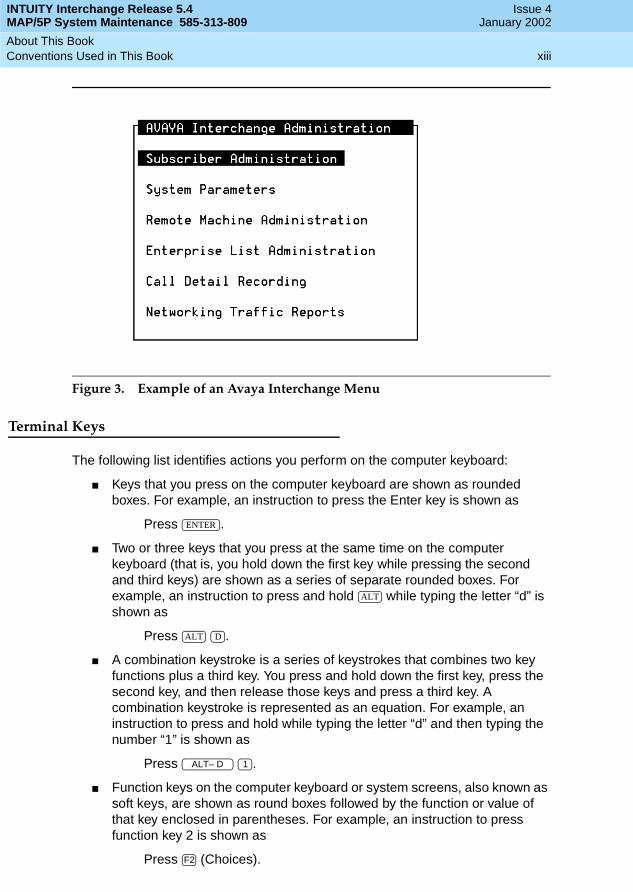
■ The Avaya Interchange system displays screens, windows, and menus. Screens make up the Interchange user interface through which you can enter data or commands or access windows or menus (Figure 1). Windows show and request system information (Figure 2). Menus present options from which you can choose to view another menu, screen or window (Figure 3).
ENTER
ENTER
ENTER
ENTER

INTUITY Interchange Release 5.4MAP/5P System Maintenance 585-313-809
Issue 4January 2002
About This Book xiiConventions Used in This Book
Figure 1. Example of an Avaya Interchange Screen
Figure 2. Example of an Avaya Interchange Window
INTUITY Interchange Release 5.4MAP/5P System Maintenance 585-313-809
Issue 4January 2002
About This Book xiiiConventions Used in This Book
Figure 3. Example of an Avaya Interchange Menu
Terminal Keys
The following list identifies actions you perform on the computer keyboard:
■ Keys that you press on the computer keyboard are shown as rounded boxes. For example, an instruction to press the Enter key is shown as
Press .
■ Two or three keys that you press at the same time on the computer keyboard (that is, you hold down the first key while pressing the second and third keys) are shown as a series of separate rounded boxes. For example, an instruction to press and hold while typing the letter “d” is shown as
Press .
■ A combination keystroke is a series of keystrokes that combines two key functions plus a third key. You press and hold down the first key, press the second key, and then release those keys and press a third key. A combination keystroke is represented as an equation. For example, an instruction to press and hold while typing the letter “d” and then typing the number “1” is shown as
Press .
■ Function keys on the computer keyboard or system screens, also known as soft keys, are shown as round boxes followed by the function or value of that key enclosed in parentheses. For example, an instruction to press function key 2 is shown as
Press (Choices).
ENTER
ALT
ALT D
ALT– D 1
F2

INTUITY Interchange Release 5.4MAP/5P System Maintenance 585-313-809
Issue 4January 2002
About This Book xivConventions Used in This Book
■ Keys that you press on the telephone keypad are shown as square boxes. For example, an instruction to press the first key on your telephone keypad is shown as
Press to record a message.
Screen Displays
The following list identifies formats used in Interchange screens:
■ Values, system messages, field names, and prompts that appear on the screen are shown in typewriter-style constant-width type, as shown in the following examples:
Example 1:
Enter the number of ports to be dedicated to outbound traffic in theMaximum Simultaneous Ports field.
Example 2:
Alarm Form Update was successful.
Press <Enter> to continue.
■ The sequence of menu options that you must select to display a specific screen or submenu is shown as follows:
Start at the Avaya Interchange Main Menu and select:
In this example, you would access the Avaya Interchange Main Menu and select the Customer/Service Administration menu. From the Customer/Service Administration menu, you would then select the Alarm Management screen.
■ Screens shown in this book are examples only. The screens you see on your machine are similar but not exactly the same.
Other Typography
The following list identifies how bold and italic type are used:
■ Commands and text you type in or enter appear in bold type, as in the following examples:
Example 1:
Enter change-switch-time-zone at the enter command: prompt.
1
> Alarm Management
> Customer/Services Administration

INTUITY Interchange Release 5.4MAP/5P System Maintenance 585-313-809
Issue 4January 2002
About This Book xvTrademarks and Service Marks
Example 2:
Type high or low in the Speed: field.
■ Command variables are shown in bold italic type when they are part of what you must type in and regular italic type when they are not, for example:
Enter ch ma machine_name, where machine_name is the name of the call delivery machine you just created.
Safety and Security Alert Labels
This book uses the following symbols to call your attention to potential problems that could cause personal injury, damage to equipment, loss of data, service interruptions, or breaches of toll fraud security:
! CAUTION:Indicates the presence of a hazard that if not avoided can or will cause minor personal injury or property damage, including loss of data.
! WARNING:Indicates the presence of a hazard that if not avoided can cause death or severe personal injury.
! DANGER:Indicates the presence of a hazard that if not avoided will cause death or severe personal injury.
! SECURITY ALERT:Indicates the presence of a toll fraud security hazard. Toll fraud is the unauthorized use of a telecommunications system by an unauthorized party.
Trademarks and Service Marks
The following trademarked products are mentioned in books in the Interchange document set:
■ 5ESS is a registered trademark of Lucent Technologies.
■ AT is a trademark of Hayes Microcomputer Products, Inc.
■ AUDIX is a registered trademark of Avaya Inc.
■ cc:Mail is a registered trademark of cc:Mail, a subsidiary of Lotus Development Corporation.

INTUITY Interchange Release 5.4MAP/5P System Maintenance 585-313-809
Issue 4January 2002
About This Book xviTrademarks and Service Marks
■ COMSPHERE is a registered trademark of Paradyne Corp.
■ CONVERSANT is a registered trademark of Avaya Inc.
■ DEFINITY is a registered trademark of Avaya Inc.
■ DMS-100 is a trademark of Northern Telecom Limited.
■ Dterm is a trademark of NEC Telephones, Inc.
■ Equinox is a trademark of Equinox Systems, Inc.
■ INTUITY is a registered trademark of Avaya Inc.
■ Lotus Notes is a registered trademark of Lotus Development Corporation.
■ Lucent is a trademark of Lucent Technologies.
■ MEGAPORT is a trademark of Equinox Systems, Inc.
■ MEGAPLEX is a trademark of Equinox Systems, Inc.
■ Meridian is a trademark of Northern Telecom Limited.
■ MERLIN LEGEND is a registered tradesman of Avaya Inc.
■ Microcom Networking Protocol is a registered trademark of Microcom, Inc.
■ Microsoft is a registered trademark of Microsoft Corporation.
■ MS is a registered trademark of Microsoft Corporation.
■ MS-DOS is a registered trademark of Microsoft Corporation.
■ Mitel is a trademark of Mitel Corporation.
■ Motorola is a registered trademark of Motorola, Inc.
■ NEAX is a trademark of NEC Telephone, Inc.
■ NEC is a registered trademark of NEC Telephone, Inc.
■ Netware is a registered trademark of Novell, Inc.
■ Netware Loadable Module is a trademark of Novell, Inc.
■ Northern Telecom is a registered trademark of Northern Telecom Limited.
■ Novell is a registered trademark of Novell, Inc.
■ Paradyne is a registered trademark of Paradyne Corporation.
■ Phillips is a registered trademark of Phillips Screw Company.
■ SL-1 is a trademark of Northern Telecom Limited.
■ softFAX is a registered trademark of VOXEM, Inc.
■ SUPERSET is a trademark of Mitel Corporation.
■ SX-100 is a trademark of Mitel Corporation.
■ SX-200 is a trademark of Mitel Corporation.
■ SX-2000 is a trademark of Mitel Corporation.

INTUITY Interchange Release 5.4MAP/5P System Maintenance 585-313-809
Issue 4January 2002
About This Book xviiRelated Resources
■ Telephony OneStop is a trademark of Lotus Development Corporation.
■ TMI is a trademark of Texas Micro Systems, Inc.
■ UNIX is a registered trademark of UNIX System Laboratories, Inc.
■ VB-PC is a trademark of Voice Technologies Group, Inc.
■ VoiceBridge is a registered trademark of Voice Technologies Group, Inc.
■ VOXEM is a registered tradesman of VOXEM, Inc.
■ VT100 is a trademark of Digital Equipment Corporation.
■ Windows is a trademark of Microsoft Corporation.
Related Resources
This section describes additional documentation and training available for you to learn more about installing the Avaya Interchange system.
Documentation
NOTE:Always refer to the appropriate book for specific information on planning, installing, administering, or maintaining an Avaya Interchange system.
It is suggested that you obtain and use the following books in conjunction with this installation book:
■ Avaya Interchange Release 5.4 MAP/100P System Installation, 585-313-809, for a source of installation procedures and troubleshooting information
■ Avaya Interchange Release 5.4 Installation and System Recovery for a source of procedures related to RFU installation and system recovery
It is recommended that you obtain and use the following book for information on security and toll fraud issues:
■ Avaya Products Security Handbook, 555-025-600
See the inside front cover for information on how to order Avaya Interchange documentation.

INTUITY Interchange Release 5.4MAP/5P System Maintenance 585-313-809
Issue 4January 2002
About This Book xviiiHow to Comment on This Book
Training
For more information on Interchange training, call the Avaya University at one of the following numbers:
■ Organizations within Avaya: (904) 636-3261
■ Avaya customers and all others: (800) 255-8988
Technical Assistance
The following resources are available for technical assistance:
■ Within the United States:
— Call 1-800-242-2121, extension 85474.
■ Within Canada:
— For all systems, call 1-800-242-1234.
■ Within any other country:
— For all systems, call your local distributor.
How to Comment on This Book
We are interested in your suggestions for improving this book. Please complete and return the reader comment card located behind this page. If the reader comment card has been removed, send your comments via the internet to [email protected] or mail your comments to:
Avaya Inc.Product DocumentationRoom D1-B531300 W. 120th AvenueDenver, Colorado 80234-2703 US
You may also fax your comments to the attention of the Avaya Interchange writing team at (303) 538-9625.
Product Support
If you have questions about how to use Avaya Interchange, contact one of the following resources:
■ Avaya Account Representative
■ Avaya Remote Support Center at + 800-242-2121
Troubleshooting 1Overview
1
INTUITY Interchange Release 5.4MAP/5P System Maintenance 585-313-809
Issue 4January 2002
11Troubleshooting
Overview
This chapter describes some basic troubleshooting procedures for the most common system problems with the Avaya Interchange.
Purpose
The purpose of this chapter is to provide the on-site technician or system administrator with repair procedures for the most common system procedures. All of the troubleshooting procedures can be performed with a craft login.

INTUITY Interchange Release 5.4MAP/5P System Maintenance 585-313-809
Issue 4January 2002
Troubleshooting 2Modem Does Not Answer
1
Modem Does Not Answer
Table 1-1. Modem Does Not Answer
Possible Cause Check/See Solution
There is no power to the modem.
Check the power source. Apply power to the modem.
The modem is not connected.
Ensure that the modem is connected with a D25F cord through a 9-pin to a 25-pin adapter to COM2.
Connect the modem correctly.
The normal D4 conductor cord is not plugged in to the correct port.
Make sure that the normal D4 cord is plugged into the Dial port of the modem. Verify that the cord is not plugged into the Phone port.
Plug the normal D4 cord into the Dial port of the modem.
There is no continuity. Check the Alarm Management window by doing the following:
1. Start at the Avaya Interchange Main menu window and select
Fill in the Alarm Screen.
1. Enter the product ID in the Product ID field.
If the product ID is not known, enter 2200000000.
2. Enter a valid telephone number in the Alarm Destination field.
3. Press (Chg-Keys).
4. Press (Test_Alrm).
5. If the product ID was not known in Step 1, call INADS for the correct number.
> Cstmr./Serv. Admin
> Alarm Management F8
F1

INTUITY Interchange Release 5.4MAP/5P System Maintenance 585-313-809
Issue 4January 2002
Troubleshooting 3The Tape Backup Alarm Is Activated Daily at 3:00 A.M.
1
The Tape Backup Alarm Is Activated Daily at 3:00 A.M.
Table 1-2. The Tape Backup Alarm Is Activated Daily at 3:00 A.M.
Possible Cause Check/See Solution
The tape is not in the drive Check the position of the tape in the drive.
Position the tape correctly.
The tape is write protected. Check the read/write dial on the tape.
Place the read/write dial in the Not Safe position. The small dial on the front of the tape should be in the horizontal position.
The tape is not compatible with the drive.
Check the type of tape in the drive.
All tapes created in a 2-GB tape drive can be read by a 525-MB tape drive. The only tapes created in a 525-MB tape drive that can be read by a 2-GB tape drive are Avaya Interchange system backup tapes.
Replace the tape with a compatible tape.
The tape is not formatted. Check the format status. Format the tape. See Formatting Cartridge Tapes, in Chapter 3, Common System Procedures, for the procedure.
The tape drive is not working correctly.
Check the operation of the tape drive during a backup. If the tape drive is spinning but there is no processor time being allotted to the cpio process, the tape drive is not working correctly.
Replace the tape drive. See Cartridge Tape Drive Replacement, in Chapter 7, Replacing Other Components for the procedure.

INTUITY Interchange Release 5.4MAP/5P System Maintenance 585-313-809
Issue 4January 2002
Troubleshooting 4Cannot Assign Voice Ports
1
Cannot Assign Voice Ports
Table 1-3. Cannot Assign Voice Ports
Possible Cause Check/See Solution
Additional port activation has not been purchased by the customer.
Verify the number of ports purchased by the customer. Access Customer/Services Administration from the Avaya Interchange Administration menu. Access the Feature Options screen and see the voice_ports line.
Refer the customer to sales personnel.
INTUITY Interchange Release 5.4MAP/5P System Maintenance 585-313-809
Issue 4January 2002
Troubleshooting 5System Does Not Boot
1
System Does Not Boot
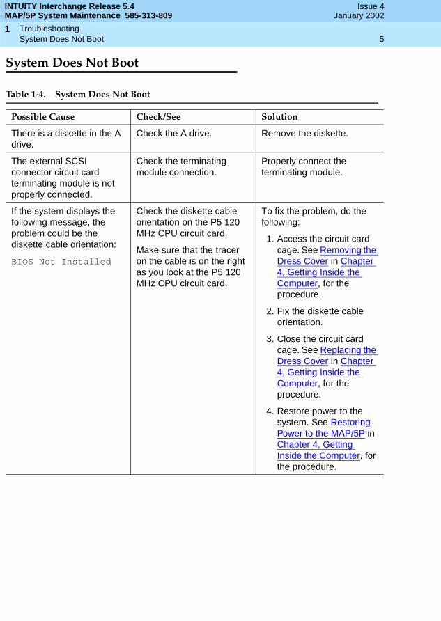
Table 1-4. System Does Not Boot
Possible Cause Check/See Solution
There is a diskette in the A drive.
Check the A drive. Remove the diskette.
The external SCSI connector circuit card terminating module is not properly connected.
Check the terminating module connection.
Properly connect the terminating module.
If the system displays the following message, the problem could be the diskette cable orientation:
BIOS Not Installed
Check the diskette cable orientation on the P5 120 MHz CPU circuit card.
Make sure that the tracer on the cable is on the right as you look at the P5 120 MHz CPU circuit card.
To fix the problem, do the following:
1. Access the circuit card cage. See Removing the Dress Cover in Chapter 4, Getting Inside the Computer, for the procedure.
2. Fix the diskette cable orientation.
3. Close the circuit card cage. See Replacing the Dress Cover in Chapter 4, Getting Inside the Computer, for the procedure.
4. Restore power to the system. See Restoring Power to the MAP/5P in Chapter 4, Getting Inside the Computer, for the procedure.
INTUITY Interchange Release 5.4MAP/5P System Maintenance 585-313-809
Issue 4January 2002
Troubleshooting 6Optional Features Are Not Working
1
Optional Features Are Not Working
The Keyboard Is Not Operating
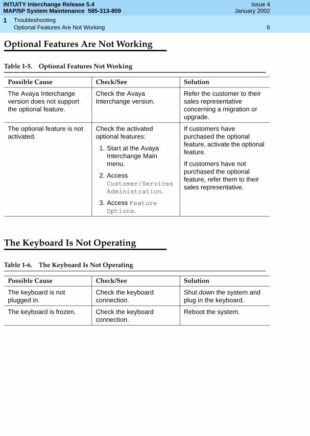
Table 1-5. Optional Features Not Working
Possible Cause Check/See Solution
The Avaya Interchange version does not support the optional feature.
Check the Avaya Interchange version.
Refer the customer to their sales representative concerning a migration or upgrade.
The optional feature is not activated.
Check the activated optional features:
1. Start at the Avaya Interchange Main menu.
2. Access Customer/ServicesAdministration.
3. Access Feature Options.
If customers have purchased the optional feature, activate the optional feature.
If customers have not purchased the optional feature, refer them to their sales representative.
Table 1-6. The Keyboard Is Not Operating
Possible Cause Check/See Solution
The keyboard is not plugged in.
Check the keyboard connection.
Shut down the system and plug in the keyboard.
The keyboard is frozen. Check the keyboard connection.
Reboot the system.

INTUITY Interchange Release 5.4MAP/5P System Maintenance 585-313-809
Issue 4January 2002
Troubleshooting 7Monitor Is Not Operating
1
Monitor Is Not Operating
Table 1-7. Monitor Is Not Operating
Possible Cause Check/See Solution
The monitor has not been turned on.
Check the monitor switch. Turn on the monitor.
The monitor brightness has been turned down.
Check the monitor brightness knob.
Turn up the brightness.

INTUITY Interchange Release 5.4MAP/5P System Maintenance 585-313-809
Issue 4January 2002
Troubleshooting 8Tip/Ring Circuit Card Is Not Recognized by the Avaya Interchange System
1
Tip/Ring Circuit Card Is NotRecognized by the AvayaInterchange System
Table 1-8. Tip/Ring Circuit Card Is Not Recognized by the Avaya Interchange System
Possible Cause Check/See Solution
The Tip/Ring card has incorrect switch settings.
Check the switch settings on the Tip/Ring cards. See Tip/Ring Circuit Cards, in Chapter 5, Replacing or Installing Circuit Cards, for the correct settings.
Correct the switch settings.
The Tip/Ring cards are incorrectly numbered.
There is nothing to check in this instance. If this is the suspected problem, continue with the solution.
Renumber the Tip/Ring circuit cards by doing the following:
NOTE:This action starts and stops the voice system.
1. Start at the Avaya Interchange Main menu and select
2. Press (Chg-Keys).
3. Select Renumber.
4. Press (Renumber).
> Voice System Admin.
> Voice Equipment
F8
F2

INTUITY Interchange Release 5.4MAP/5P System Maintenance 585-313-809
Issue 4January 2002
Troubleshooting 9The Printer Is Not Operating
1
The Printer Is Not Operating
Table 1-9. The Printer Is Not Operating
Possible Cause Check/See Solution
The printer is not turned on. Check the power indicator light.
Turn the printer on.
The printer cable is not connected correctly.
Check the printer connection.
Reconnect the printer.
The Avaya Interchange system has not been configured correctly.
Check the system configuration.
Reconfigure the system. See Chapter 4, Connecting Peripherals and Powering Up, in Avaya Interchange Release 5.4 MAP/5P System Installation.
The printer has not been configured correctly.
Check the printer configuration.
Reconfigure the printer. See Chapter 4, Connecting Peripherals and Powering Up, in Avaya Interchange Release 5.4 MAP/5P System Installation.
The printer is out of paper. Check the paper supply. Add paper.
The printer is jammed. Check the printer operating panel.
Remove the paper jam.

INTUITY Interchange Release 5.4MAP/5P System Maintenance 585-313-809
Issue 4January 2002
Troubleshooting 10Hard Disk Drive Access Troubleshooting
1
Hard Disk Drive Access Troubleshooting
In the event of a SCSI Bus cable or hard disk drive failure, the system stalls during the boot procedure. When the system stalls, it displays one of several messages. These messages are described in this section.
The System Displays No Boot Device Available Message with Ident-Strings
If the system displays the following message along with one or more SCSI device ident-strings, see the troubleshooting procedures in Table 1-10:
SCSI target 0 LUN 0 not foundTarget-LUN x-0.........Target-LUN y-0....
No boot device availableStrike F1 to retry boot, F2 for setup utility
Table 1-10. The System Displays No Boot Device Available Message with Ident-Strings
Possible Cause Check/See Solution
Insufficient power voltages. Check the power supply output voltage.
1. If the power voltage is not 5V, replace the power supply.
2. Reboot the system.
The power cable is not properly attached to Hard Disk Drive 0.
Check the Hard Disk Drive 0 power cable connection.
1. Correct the power cable connection to Hard Disk Drive 0.
2. Reboot the system.
The SCSI Bus cable is not properly attached to Hard Disk Drive 0.
Check the Hard Disk Drive 0 SCSI Bus cable connection.
1. Correct the SCSI Bus cable connection to Hard Disk Drive 0.
2. Reboot the system.
The SCSI Bus cable is defective.
Check the SCSI Bus cable. 1. Replace the SCSI Bus cable.
2. Reboot the system.
(1 of 2)
INTUITY Interchange Release 5.4MAP/5P System Maintenance 585-313-809
Issue 4January 2002
Troubleshooting 11Hard Disk Drive Access Troubleshooting
1
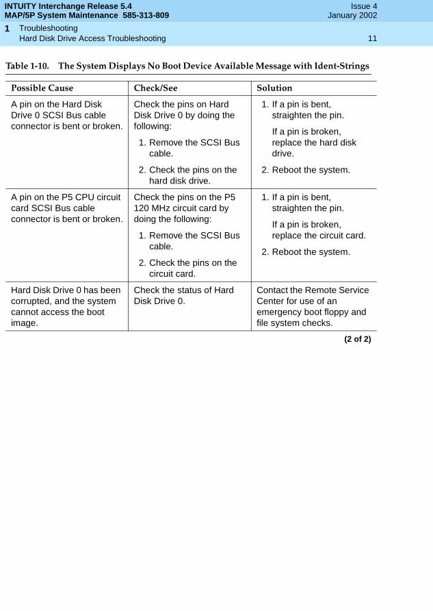
A pin on the Hard Disk Drive 0 SCSI Bus cable connector is bent or broken.
Check the pins on Hard Disk Drive 0 by doing the following:
1. Remove the SCSI Bus cable.
2. Check the pins on the hard disk drive.
1. If a pin is bent, straighten the pin.
If a pin is broken, replace the hard disk drive.
2. Reboot the system.
A pin on the P5 CPU circuit card SCSI Bus cable connector is bent or broken.
Check the pins on the P5 120 MHz circuit card by doing the following:
1. Remove the SCSI Bus cable.
2. Check the pins on the circuit card.
1. If a pin is bent, straighten the pin.
If a pin is broken, replace the circuit card.
2. Reboot the system.
Hard Disk Drive 0 has been corrupted, and the system cannot access the boot image.
Check the status of Hard Disk Drive 0.
Contact the Remote Service Center for use of an emergency boot floppy and file system checks.
Table 1-10. The System Displays No Boot Device Available Message with Ident-Strings
Possible Cause Check/See Solution
(2 of 2)
INTUITY Interchange Release 5.4MAP/5P System Maintenance 585-313-809
Issue 4January 2002
Troubleshooting 12Hard Disk Drive Access Troubleshooting
1
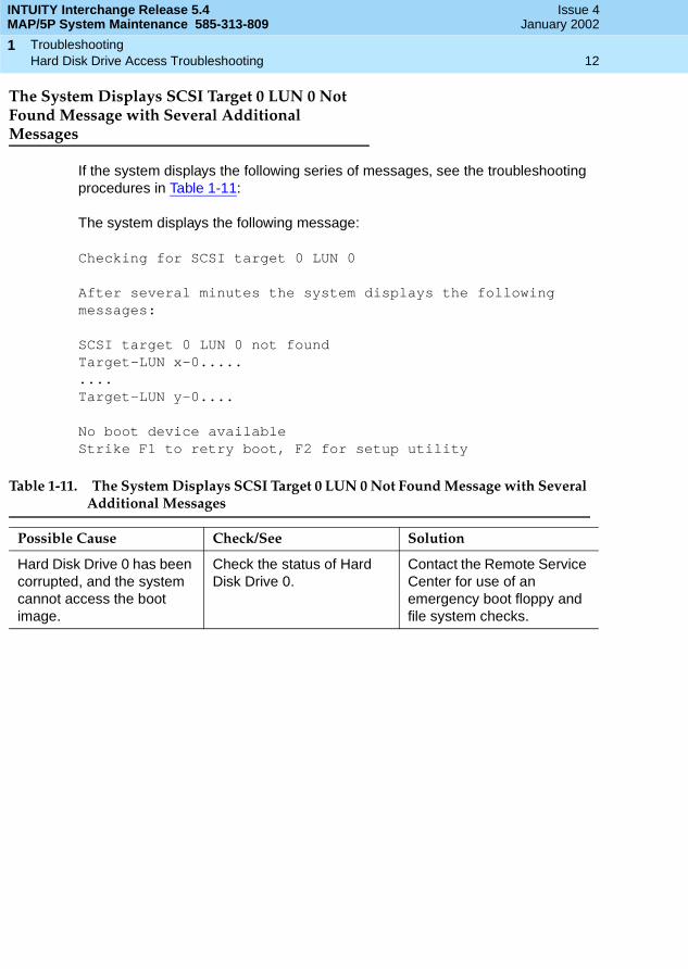
The System Displays SCSI Target 0 LUN 0 Not Found Message with Several Additional Messages
If the system displays the following series of messages, see the troubleshooting procedures in Table 1-11:
The system displays the following message:
Checking for SCSI target 0 LUN 0
After several minutes the system displays the following messages:
SCSI target 0 LUN 0 not foundTarget-LUN x-0.........Target-LUN y-0....
No boot device availableStrike F1 to retry boot, F2 for setup utility
Table 1-11. The System Displays SCSI Target 0 LUN 0 Not Found Message with Several Additional Messages
Possible Cause Check/See Solution
Hard Disk Drive 0 has been corrupted, and the system cannot access the boot image.
Check the status of Hard Disk Drive 0.
Contact the Remote Service Center for use of an emergency boot floppy and file system checks.

INTUITY Interchange Release 5.4MAP/5P System Maintenance 585-313-809
Issue 4January 2002
Troubleshooting 13Hard Disk Drive Access Troubleshooting
1
The System Displays SCSI Target 0 LUN 0 Not Found Message and Stalls
If the system displays the following message and stalls, see the troubleshooting procedures in Table 1-12:
SCSI target 0 LUN 0 not found
At this point the system stalls.
NOTE:If you press , the system displays the following message:
No boot device availableStrike F1 to retry boot, F2 for setup utility
Table 1-12. The System Displays SCSI Target 0 LUN 0 Not Found Message and Stalls
Possible Cause Check/See Solution
Hard Disk Drive 0 is defective.
Check the status of Hard Disk Drive 0.
Replace Hard Disk Drive 0.
CONTROL ALT DELETE
INTUITY Interchange Release 5.4MAP/5P System Maintenance 585-313-809
Issue 4January 2002
Troubleshooting 14Hard Disk Drive Access Troubleshooting
1
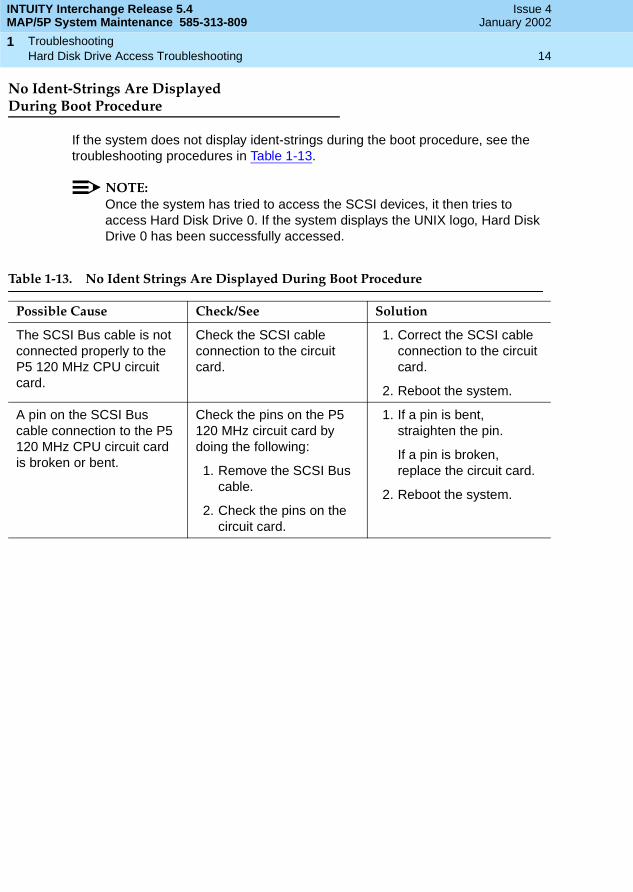
No Ident-Strings Are DisplayedDuring Boot Procedure
If the system does not display ident-strings during the boot procedure, see the troubleshooting procedures in Table 1-13.
NOTE:Once the system has tried to access the SCSI devices, it then tries to access Hard Disk Drive 0. If the system displays the UNIX logo, Hard Disk Drive 0 has been successfully accessed.
Table 1-13. No Ident Strings Are Displayed During Boot Procedure
Possible Cause Check/See Solution
The SCSI Bus cable is not connected properly to the P5 120 MHz CPU circuit card.
Check the SCSI cable connection to the circuit card.
1. Correct the SCSI cable connection to the circuit card.
2. Reboot the system.
A pin on the SCSI Bus cable connection to the P5 120 MHz CPU circuit card is broken or bent.
Check the pins on the P5 120 MHz circuit card by doing the following:
1. Remove the SCSI Bus cable.
2. Check the pins on the circuit card.
1. If a pin is bent, straighten the pin.
If a pin is broken, replace the circuit card.
2. Reboot the system.
INTUITY Interchange Release 5.4MAP/5P System Maintenance 585-313-809
Issue 4January 2002
Troubleshooting 15Hard Disk Drive Access Troubleshooting
1
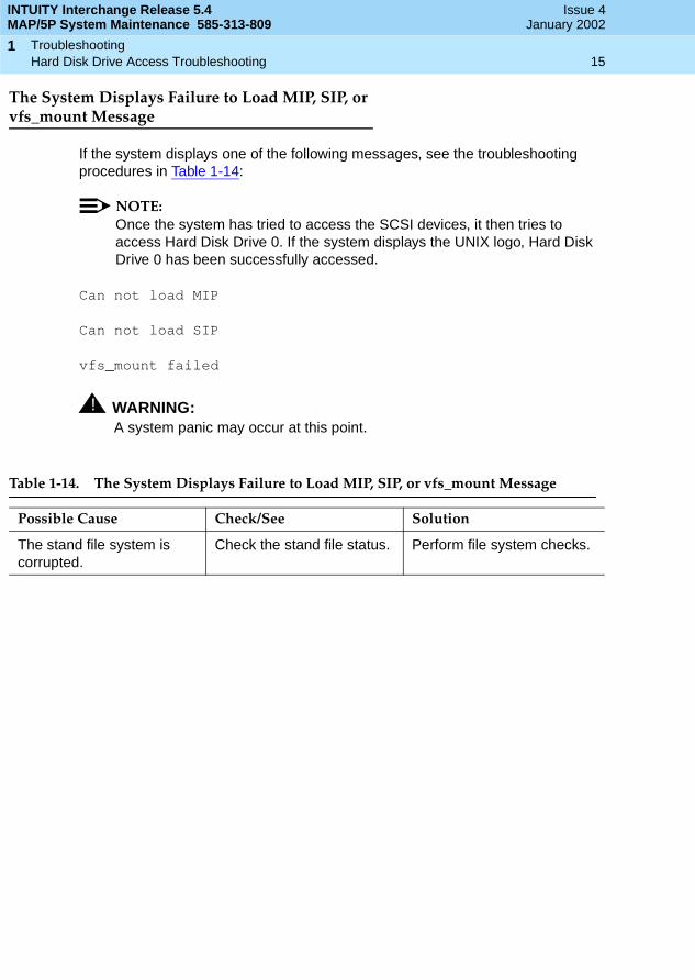
The System Displays Failure to Load MIP, SIP, or vfs_mount Message
If the system displays one of the following messages, see the troubleshooting procedures in Table 1-14:
NOTE:Once the system has tried to access the SCSI devices, it then tries to access Hard Disk Drive 0. If the system displays the UNIX logo, Hard Disk Drive 0 has been successfully accessed.
Can not load MIP
Can not load SIP
vfs_mount failed
! WARNING:A system panic may occur at this point.
Table 1-14. The System Displays Failure to Load MIP, SIP, or vfs_mount Message
Possible Cause Check/See Solution
The stand file system is corrupted.
Check the stand file status. Perform file system checks.
INTUITY Interchange Release 5.4MAP/5P System Maintenance 585-313-809
Issue 4January 2002
Troubleshooting 16Hard Disk Drive Access Troubleshooting
1
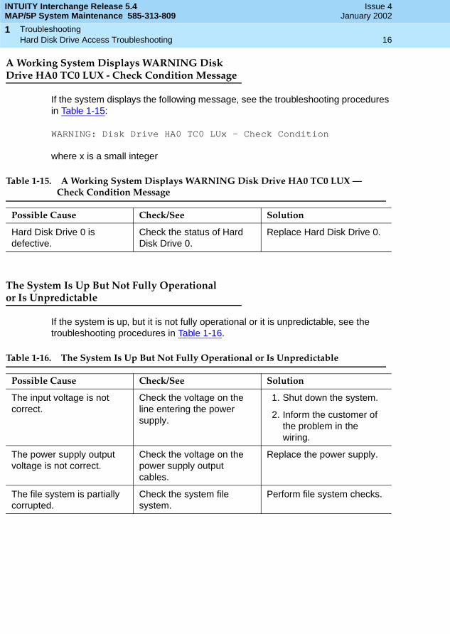
A Working System Displays WARNING Disk Drive HA0 TC0 LUX - Check Condition Message
If the system displays the following message, see the troubleshooting procedures in Table 1-15:
WARNING: Disk Drive HA0 TC0 LUx - Check Condition
where x is a small integer
The System Is Up But Not Fully Operationalor Is Unpredictable
If the system is up, but it is not fully operational or it is unpredictable, see the troubleshooting procedures in Table 1-16.
Table 1-15. A Working System Displays WARNING Disk Drive HA0 TC0 LUX — Check Condition Message
Possible Cause Check/See Solution
Hard Disk Drive 0 is defective.
Check the status of Hard Disk Drive 0.
Replace Hard Disk Drive 0.
Table 1-16. The System Is Up But Not Fully Operational or Is Unpredictable
Possible Cause Check/See Solution
The input voltage is not correct.
Check the voltage on the line entering the power supply.
1. Shut down the system.
2. Inform the customer of the problem in the wiring.
The power supply output voltage is not correct.
Check the voltage on the power supply output cables.
Replace the power supply.
The file system is partially corrupted.
Check the system file system.
Perform file system checks.

INTUITY Interchange Release 5.4MAP/5P System Maintenance 585-313-809
Issue 4January 2002
Troubleshooting 17Troubleshooting Defective Blocks on Hard Disk Drives
1
System with Remote Maintenance Circuit Card Displays SCSI Disk Failure Message after POST
If, after you have completed the power-on self test (POST) and memory test, the system stalls and displays messages indicating a remote maintenance circuit card and SCSI hard disk drive failure, see the troubleshooting procedures in Table 1-17.
Troubleshooting Defective Blocks on Hard Disk Drives
It is not always necessary to replace a hard disk drive with defective blocks. For example, if the defective blocks do not affect the overall system performance, you do not need to replace the drive. Monitor system performance prior to replacing a hard disk drive.
Table 1-17. System with Remote Maintenance Circuit Card Displays SCSI Disk Failure Message after POST
Possible Cause Check/See Solution
The remote maintenance circuit card address is set to C000-CFFF.
Check the remote maintenance circuit card address.
1. Place the BEE selector switch in the off position.
2. Shut down the system.
3. Reboot the system.
4. Set the remote maintenance circuit card address to DC000-DCFFF via BIOS.
5. Place the BEE selector switch in the On position.
6. Stop the voice system.
7. Start the voice system.

INTUITY Interchange Release 5.4MAP/5P System Maintenance 585-313-809
Issue 4January 2002
Troubleshooting 18Troubleshooting Defective Blocks on Hard Disk Drives
1
Diagnostics 19Overview
2
INTUITY Interchange Release 5.4MAP/5P System Maintenance 585-313-809
Issue 4January 2002
22Diagnostics
Overview
This chapter includes the following topics:
■ Conducting audits
■ Diagnosing AMIS Analog Networking
■ Diagnosing digital networking
■ Diagnosing multi-port serial circuit cards
■ Diagnosing switch integration
■ Diagnosing TCP/IP
■ Diagnosing voice ports
■ Diagnosing Tip/Ring circuit cards
Purpose
The purpose of this chapter is to provide the on-site technician or system administrator with the correct procedures to diagnose trouble with the Avaya Interchange system.

INTUITY Interchange Release 5.4MAP/5P System Maintenance 585-313-809
Issue 4January 2002
Diagnostics 20Auditing Networking Databases
2
Auditing Networking Databases
You can conduct audits on networking databases. The networking database consists of two parts: the networking administration database and the remote subscriber update status database.
The networking administration database contains data relevant to the following areas:
■ Connectivity to other Avaya Interchange systems, AMIS machines and VPIM machines
■ Local machine connectivity
■ Channel configuration information
The remote subscriber update status database contains the information used by the Avaya Interchange system to request and send remote updates of subscriber information.
Interchange Audit
The Interchange audit consists of a series of internal checks that verify, for example, that files are not corrupted and that values within the files are within the proper ranges.
The Interchange audit is performed automatically nightly, before the nightly unattended backup. This audit occurs whenever the voice system is restarted or the UNIX system is rebooted. You might want to perform this audit on demand when directed to do so by alarm repair actions.
To perform this audit on demand, do the following:
1. Start at the Avaya Interchange Main Menu (Figure 2-1).
Figure 2-1. Avaya Interchange Main Menu
INTUITY Interchange Release 5.4MAP/5P System Maintenance 585-313-809
Issue 4January 2002
Diagnostics 21Auditing Networking Databases
2
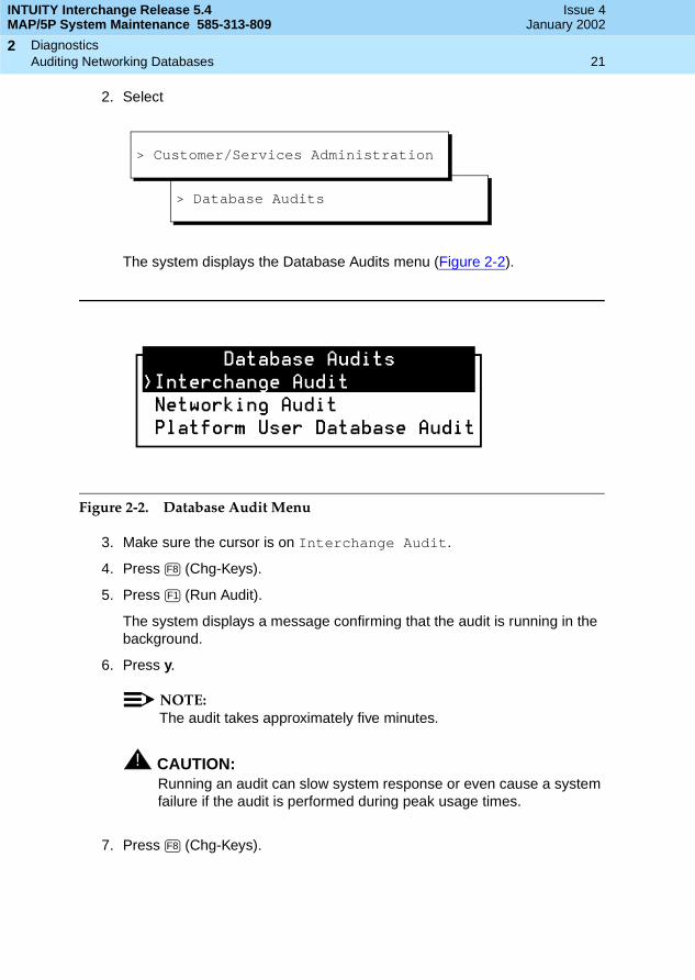
2. Select
The system displays the Database Audits menu (Figure 2-2).
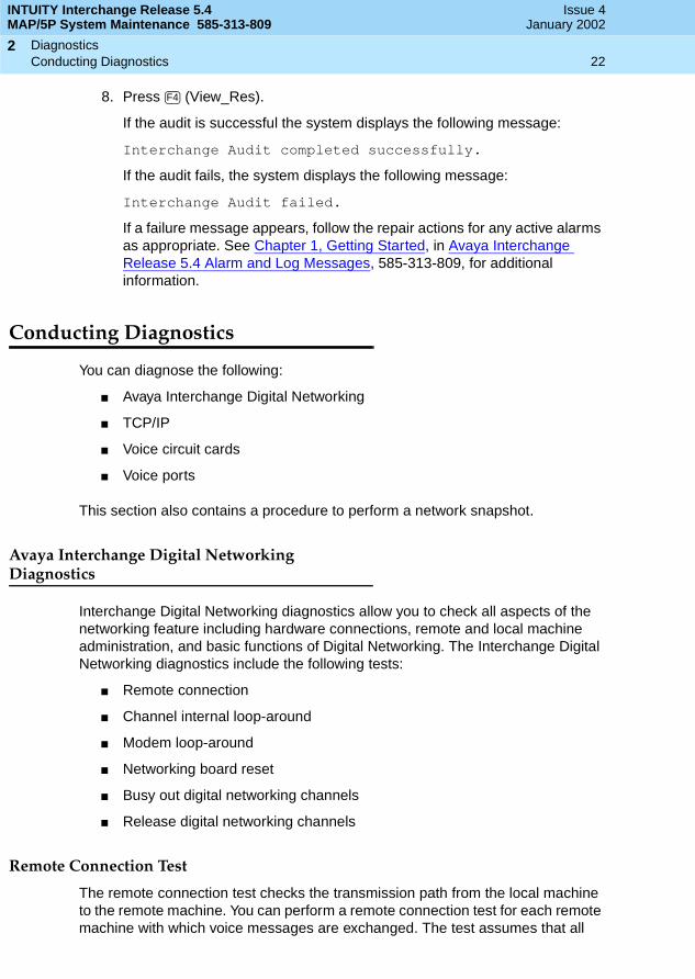
Figure 2-2. Database Audit Menu
3. Make sure the cursor is on Interchange Audit.
4. Press (Chg-Keys).
5. Press (Run Audit).
The system displays a message confirming that the audit is running in the background.
6. Press y.
NOTE:The audit takes approximately five minutes.
! CAUTION:Running an audit can slow system response or even cause a system failure if the audit is performed during peak usage times.
7. Press (Chg-Keys).
> Database Audits
> Customer/Services Administration
F8
F1
F8
INTUITY Interchange Release 5.4MAP/5P System Maintenance 585-313-809
Issue 4January 2002
Diagnostics 22Conducting Diagnostics
2
8. Press (View_Res).
If the audit is successful the system displays the following message:
Interchange Audit completed successfully.
If the audit fails, the system displays the following message:
Interchange Audit failed.
If a failure message appears, follow the repair actions for any active alarms as appropriate. See Chapter 1, Getting Started, in Avaya Interchange Release 5.4 Alarm and Log Messages, 585-313-809, for additional information.
Conducting Diagnostics
You can diagnose the following:
■ Avaya Interchange Digital Networking
■ TCP/IP
■ Voice circuit cards
■ Voice ports
This section also contains a procedure to perform a network snapshot.
Avaya Interchange Digital Networking Diagnostics
Interchange Digital Networking diagnostics allow you to check all aspects of the networking feature including hardware connections, remote and local machine administration, and basic functions of Digital Networking. The Interchange Digital Networking diagnostics include the following tests:
■ Remote connection
■ Channel internal loop-around
■ Modem loop-around
■ Networking board reset
■ Busy out digital networking channels
■ Release digital networking channels
Remote Connection Test
The remote connection test checks the transmission path from the local machine to the remote machine. You can perform a remote connection test for each remote machine with which voice messages are exchanged. The test assumes that all
F4
INTUITY Interchange Release 5.4MAP/5P System Maintenance 585-313-809
Issue 4January 2002
Diagnostics 23Conducting Diagnostics
2
components of the network, from the ACCX card to the remote machine administration, are operating and complete. If the remote connection test fails, see Network Connections Test.
Requirements
The following requirements are necessary to perform a remote connection test:
■ The remote machine name is needed.
■ The channel can be DCP or RS-232.
■ The channel must be equipped.
Procedure
To perform a remote connection test, do the following:
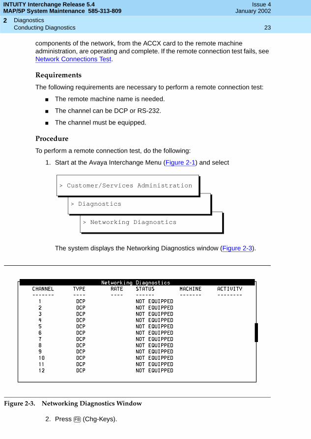
1. Start at the Avaya Interchange Menu (Figure 2-1) and select
The system displays the Networking Diagnostics window (Figure 2-3).
Figure 2-3. Networking Diagnostics Window
2. Press (Chg-Keys).
> Networking Diagnostics
> Diagnostics
> Customer/Services Administration
F8

INTUITY Interchange Release 5.4MAP/5P System Maintenance 585-313-809
Issue 4January 2002
Diagnostics 24Conducting Diagnostics
2
3. Press (Diagnose).
The system displays the Networking Diagnostics menu (Figure 2-4).
Figure 2-4. Networking Diagnostics Menu
4. Select
The system displays the Remote Connection Test window (Figure 2-5).
Figure 2-5. Remote Connection Test Window
5. Enter the name of the remote machine to be tested.
If you do not know the remote machine name, press (Choices) to access a menu of remote machines. Select from the menu by moving the selection bar over a machine name and pressing .
6. If you are testing a dedicated RS-232 connection, enter the number of the dedicated channel.
The system displays the message working... and attempts to connect with the remote machine.
F4
> Remote Connection Test
F2
ENTER
INTUITY Interchange Release 5.4MAP/5P System Maintenance 585-313-809
Issue 4January 2002
Diagnostics 25Conducting Diagnostics
2
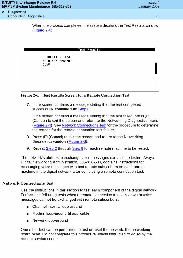
When the process completes, the system displays the Test Results window (Figure 2-6).
Figure 2-6. Test Results Screen for a Remote Connection Test
7. If the screen contains a message stating that the test completed successfully, continue with Step 8.
If the screen contains a message stating that the test failed, press (Cancel) to exit the screen and return to the Networking Diagnostics menu (Figure 2-4). See Network Connections Test for the procedure to determine the reason for the remote connection test failure.
8. Press (Cancel) to exit the screen and return to the Networking Diagnostics window (Figure 2-3).
9. Repeat Step 2 through Step 8 for each remote machine to be tested.
The network’s abilities to exchange voice messages can also be tested. Avaya Digital Networking Administration, 585-310-533, contains instructions for exchanging voice messages with test remote subscribers on each remote machine in the digital network after completing a remote connection test.
Network Connections Test
Use the instructions in this section to test each component of the digital network. Perform the following tests when a remote connection test fails or when voice messages cannot be exchanged with remote subscribers:
■ Channel internal loop-around
■ Modem loop-around (if applicable)
■ Network loop-around
One other test can be performed to test or reset the network: the networking board reset. Do not complete this procedure unless instructed to do so by the remote service center.
F6
F6

INTUITY Interchange Release 5.4MAP/5P System Maintenance 585-313-809
Issue 4January 2002
Diagnostics 26Conducting Diagnostics
2
Channel Internal Loop-Around Test
The channel internal loop-around test checks the operation of an individual channel on the ACCX board. Perform this test first to make sure the board is operating correctly. If the board does not operate properly, the other acceptance tests fail.
Requirements. The following requirements are necessary to perform a channel internal loop-around test:
■ The channel can be DCP or RS-232.
■ The channel must be equipped.
Procedure. To perform a channel internal loop-around test, do the following:
1. Start at the Avaya Interchange Menu (Figure 2-1) and select
The system displays the Networking Diagnostics window (Figure 2-3).
2. Press (Chg-Keys).
3. Press (Diagnose).
The system displays the Networking Diagnostics menu (Figure 2-4).
4. Select
> Networking Diagnostics
> Diagnostics
> Customer/Services Administration
F8
F4
> Channel Internal Loop-Around Test
INTUITY Interchange Release 5.4MAP/5P System Maintenance 585-313-809
Issue 4January 2002
Diagnostics 27Conducting Diagnostics
2
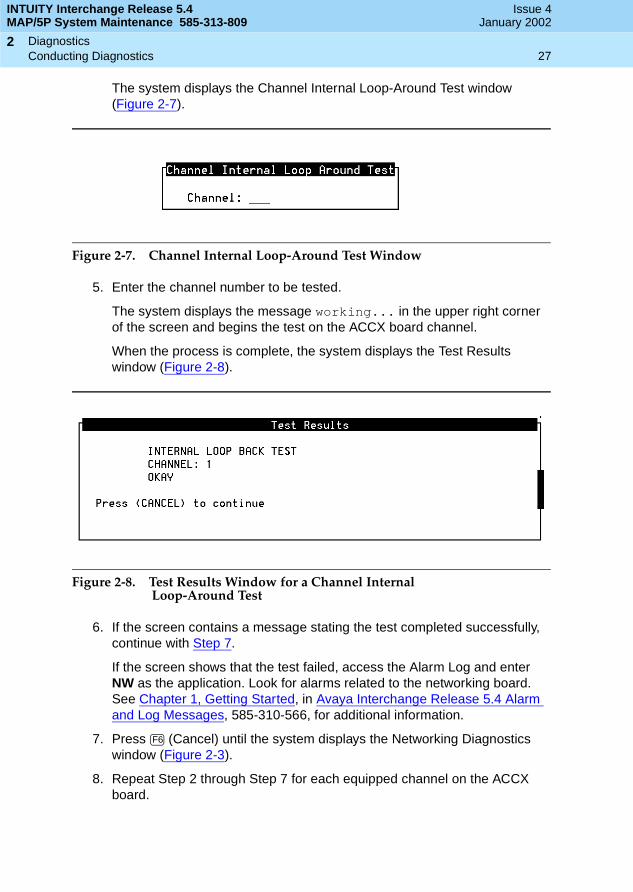
The system displays the Channel Internal Loop-Around Test window (Figure 2-7).
Figure 2-7. Channel Internal Loop-Around Test Window
5. Enter the channel number to be tested.
The system displays the message working... in the upper right corner of the screen and begins the test on the ACCX board channel.
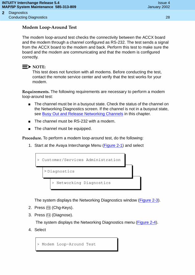
When the process is complete, the system displays the Test Results window (Figure 2-8).
Figure 2-8. Test Results Window for a Channel Internal Loop-Around Test
6. If the screen contains a message stating the test completed successfully, continue with Step 7.
If the screen shows that the test failed, access the Alarm Log and enter NW as the application. Look for alarms related to the networking board. See Chapter 1, Getting Started, in Avaya Interchange Release 5.4 Alarm and Log Messages, 585-310-566, for additional information.
7. Press (Cancel) until the system displays the Networking Diagnostics window (Figure 2-3).
8. Repeat Step 2 through Step 7 for each equipped channel on the ACCX board.
F6
INTUITY Interchange Release 5.4MAP/5P System Maintenance 585-313-809
Issue 4January 2002
Diagnostics 28Conducting Diagnostics
2
Modem Loop-Around Test
The modem loop-around test checks the connectivity between the ACCX board and the modem through a channel configured as RS-232. The test sends a signal from the ACCX board to the modem and back. Perform this test to make sure the board and the modem are communicating and that the modem is configured correctly.
NOTE:This test does not function with all modems. Before conducting the test, contact the remote service center and verify that the test works for your modem.
Requirements. The following requirements are necessary to perform a modem loop-around test:
■ The channel must be in a busyout state. Check the status of the channel on the Networking Diagnostics screen. If the channel is not in a busyout state, see Busy Out and Release Networking Channels in this chapter.
■ The channel must be RS-232 with a modem.
■ The channel must be equipped.
Procedure. To perform a modem loop-around test, do the following:
1. Start at the Avaya Interchange Menu (Figure 2-1) and select
The system displays the Networking Diagnostics window (Figure 2-3).
2. Press (Chg-Keys).
3. Press (Diagnose).
The system displays the Networking Diagnostics menu (Figure 2-4).
4. Select
> Networking Diagnostics
> Diagnostics
> Customer/Services Administration
F8
F4
> Modem Loop-Around Test

INTUITY Interchange Release 5.4MAP/5P System Maintenance 585-313-809
Issue 4January 2002
Diagnostics 29Conducting Diagnostics
2
The system displays the Modem Loop-Around Test window (Figure 2-9).
Figure 2-9. Modem Loop-Around Test Window
5. Enter the channel number to be tested. The channel must be RS-232 and have a modem connected.
The system displays the message working... in the upper right corner of the screen. The system begins the test on the channel with the modem connected. When the process completes, the system displays the Test Results screen (Figure 2-8).
6. If the screen contains a message stating the test completed successfully, proceed to Step 7.
If the screen shows that the test failed, access the Alarm Log and enter NW as the application. Look for alarms related to networking modems. See Chapter 1, Getting Started, in Avaya Interchange Release 5.4 Alarm and Log Messages 585-313-809, for additional information.
7. Press (Cancel) to exit the screen and return to the Networking Diagnostics screen (Figure 2-3).
8. Repeat Step 2 through Step 7 for each equipped channel that is RS-232 and has a modem connected.
Network Loop-Around Test
The network loop-around test checks the data transmission path that connects the local Avaya Interchange machine with the service office (SO) and the public network. When a channel is in loop-around mode, the channel cannot exchange information with remote machines.
Requirements. This test can be performed only on DCP channels. Coordinate the test with the local SO.
F6

INTUITY Interchange Release 5.4MAP/5P System Maintenance 585-313-809
Issue 4January 2002
Diagnostics 30Conducting Diagnostics
2
Operation. The test operates in the following manner.
■ To perform the test, specify the channel number and data rate and start the channel in network loop-around mode.
■ Notify the SO to send information to the channel to be tested.
■ The SO sends a message which loops through the Avaya Interchange Digital Network and returns to the SO.
■ The SO checks the message to verify that the same information sent was returned by the Avaya Interchange system.
Procedure. To perform a network loop-around test, do the following:
1. Start at the Avaya Interchange Menu (Figure 2-1) and select
The system displays the Networking Diagnostics window (Figure 2-3)
2. Press (Chg-Keys).
3. Press (Diagnose).
The system displays the Networking Diagnostics menu (Figure 2-4).
4. Select
> Networking Diagnostics
> Diagnostics
> Customer/Services Administration
F8
F4
> Start Test
> Network Loop-Around Test
INTUITY Interchange Release 5.4MAP/5P System Maintenance 585-313-809
Issue 4January 2002
Diagnostics 31Conducting Diagnostics
2
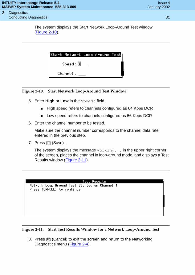
The system displays the Start Network Loop-Around Test window(Figure 2-10).
Figure 2-10. Start Network Loop-Around Test Window
5. Enter High or Low in the Speed: field.
■ High speed refers to channels configured as 64 Kbps DCP.
■ Low speed refers to channels configured as 56 Kbps DCP.
6. Enter the channel number to be tested.
Make sure the channel number corresponds to the channel data rate entered in the previous step.
7. Press (Save).
The system displays the message working... in the upper right corner of the screen, places the channel in loop-around mode, and displays a Test Results window (Figure 2-11).
Figure 2-11. Start Test Results Window for a Network Loop-Around Test
8. Press (Cancel) to exit the screen and return to the Networking Diagnostics menu (Figure 2-4).
F3
F6
INTUITY Interchange Release 5.4MAP/5P System Maintenance 585-313-809
Issue 4January 2002
Diagnostics 32Conducting Diagnostics
2
9. Contact the local telephone SO and instruct the office to place a call to the telephone number assigned to the channel placed in the loop-around mode. If the test is successful, any data sent by the SO passes through the Avaya Interchange channel and returns to the SO.
10. Stop the test and remove the channel from the loop-around mode by completing Step a and Step b:
a. Select
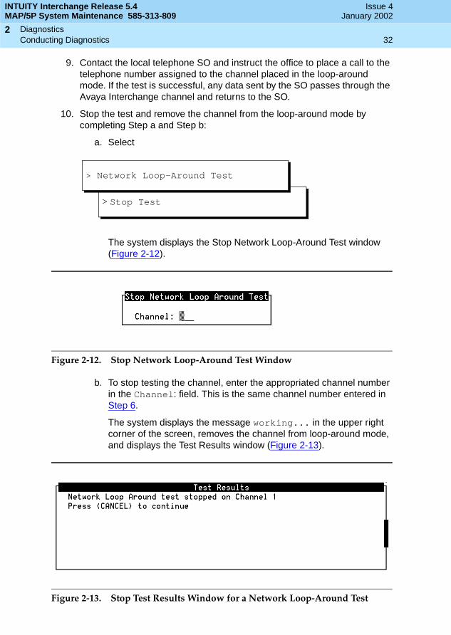
The system displays the Stop Network Loop-Around Test window (Figure 2-12).
Figure 2-12. Stop Network Loop-Around Test Window
b. To stop testing the channel, enter the appropriated channel number in the Channel: field. This is the same channel number entered in Step 6.
The system displays the message working... in the upper right corner of the screen, removes the channel from loop-around mode, and displays the Test Results window (Figure 2-13).
Figure 2-13. Stop Test Results Window for a Network Loop-Around Test
> Stop Test
> Network Loop-Around Test

INTUITY Interchange Release 5.4MAP/5P System Maintenance 585-313-809
Issue 4January 2002
Diagnostics 33Conducting Diagnostics
2
11. Press (Cancel) to exit the screen and return to the Networking Diagnostics menu (Figure 2-4).
12. Repeat Step 2 through Step 11 for each channel to be tested.
Networking Board Reset
This section provides instructions for resetting the ACCX card.
Requirements. The card might need to be reset after other networking diagnostic tests have been performed. In addition, the card might need to be reset as part of an alarm repair procedure.
Procedure. To reset the networking card, do the following:
1. Start at the Avaya Interchange Menu (Figure 2-1) and select
The system displays the Networking Diagnostics window (Figure 2-3).
2. Press (Chg-Keys).
3. Press (Diagnose).
The system displays the Networking Diagnostics menu (Figure 2-4).
4. Select
The system displays the Networking Board Reset window (Figure 2-14).
Figure 2-14. Networking Board Reset Window
5. Enter the number of the ACCX card to be reset.
F6
> Networking Diagnostics
> Diagnostics
> Customer/Services Administration
F8
F4
> Networking Board Reset
INTUITY Interchange Release 5.4MAP/5P System Maintenance 585-313-809
Issue 4January 2002
Diagnostics 34Conducting Diagnostics
2
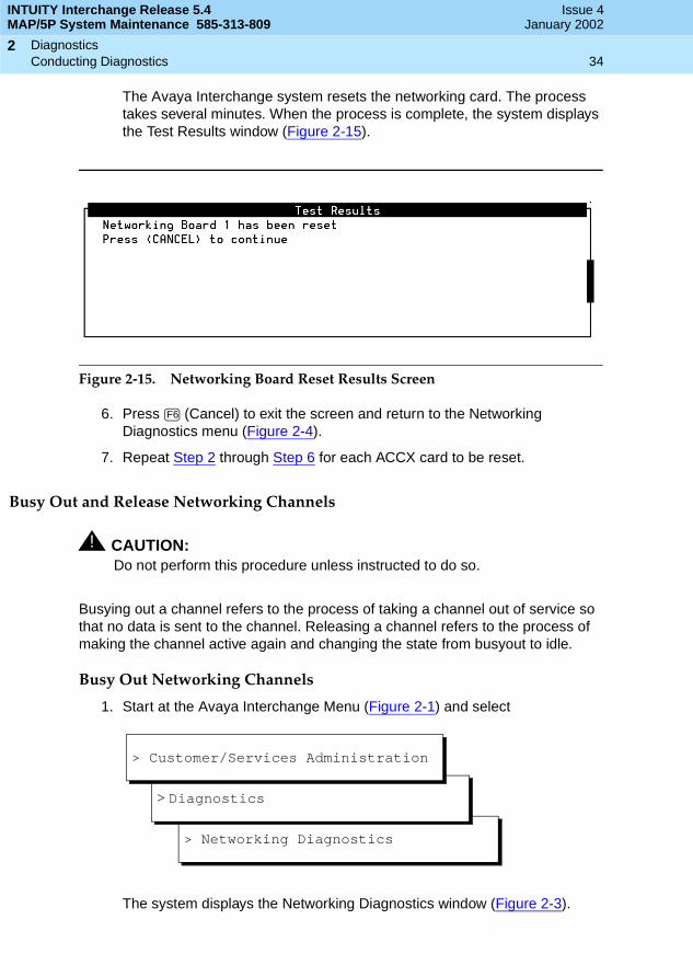
The Avaya Interchange system resets the networking card. The process takes several minutes. When the process is complete, the system displays the Test Results window (Figure 2-15).
Figure 2-15. Networking Board Reset Results Screen
6. Press (Cancel) to exit the screen and return to the Networking Diagnostics menu (Figure 2-4).
7. Repeat Step 2 through Step 6 for each ACCX card to be reset.
Busy Out and Release Networking Channels
! CAUTION:Do not perform this procedure unless instructed to do so.
Busying out a channel refers to the process of taking a channel out of service so that no data is sent to the channel. Releasing a channel refers to the process of making the channel active again and changing the state from busyout to idle.
Busy Out Networking Channels
1. Start at the Avaya Interchange Menu (Figure 2-1) and select
The system displays the Networking Diagnostics window (Figure 2-3).
F6
> Networking Diagnostics
> Diagnostics
> Customer/Services Administration
INTUITY Interchange Release 5.4MAP/5P System Maintenance 585-313-809
Issue 4January 2002
Diagnostics 35Conducting Diagnostics
2
2. Press (Chg-Keys).
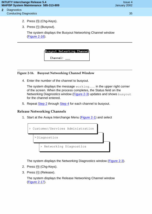
3. Press (Busyout).
The system displays the Busyout Networking Channel window(Figure 2-16).
Figure 2-16. Busyout Networking Channel Window
4. Enter the number of the channel to busyout.
The system displays the message working... in the upper right corner of the screen. When the process completes, the Status field on the Networking Diagnostics window (Figure 2-3) updates and shows busyout for the channel entered.
5. Repeat Step 2 through Step 4 for each channel to busyout.
Release Networking Channels
1. Start at the Avaya Interchange Menu (Figure 2-1) and select
The system displays the Networking Diagnostics window (Figure 2-3).
2. Press (Chg-Keys).
3. Press (Release).
The system displays the Release Networking Channel window (Figure 2-17).
F8
F2
> Networking Diagnostics
> Diagnostics
> Customer/Services Administration
F8
F2
INTUITY Interchange Release 5.4MAP/5P System Maintenance 585-313-809
Issue 4January 2002
Diagnostics 36Conducting Diagnostics
2
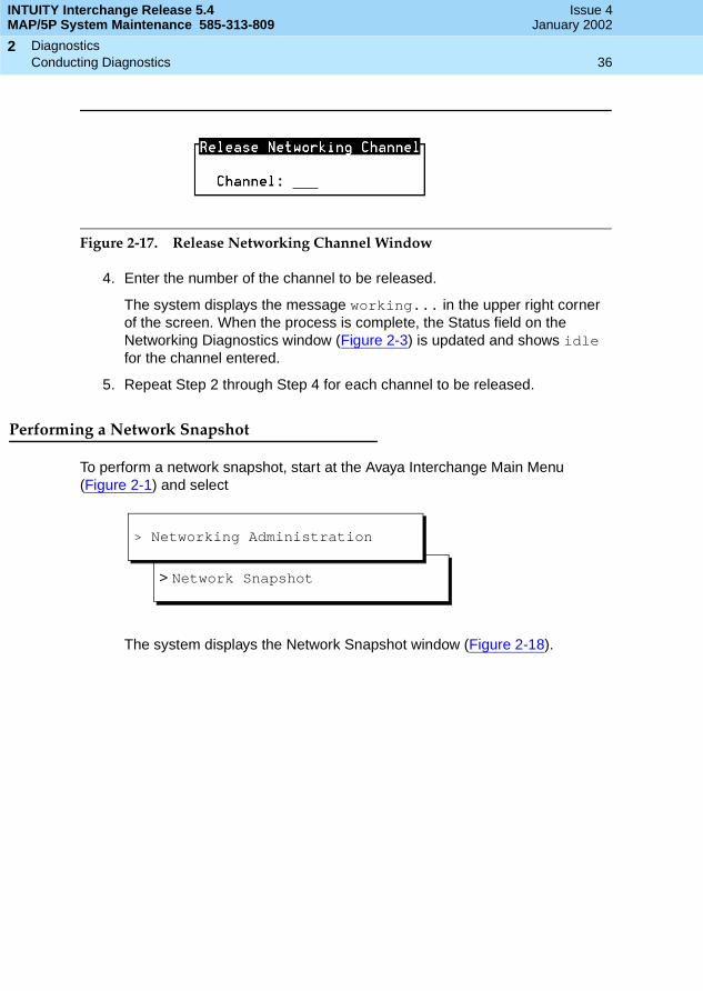
Figure 2-17. Release Networking Channel Window
4. Enter the number of the channel to be released.
The system displays the message working... in the upper right corner of the screen. When the process is complete, the Status field on the Networking Diagnostics window (Figure 2-3) is updated and shows idle for the channel entered.
5. Repeat Step 2 through Step 4 for each channel to be released.
Performing a Network Snapshot
To perform a network snapshot, start at the Avaya Interchange Main Menu (Figure 2-1) and select
The system displays the Network Snapshot window (Figure 2-18).
> Network Snapshot
> Networking Administration

INTUITY Interchange Release 5.4MAP/5P System Maintenance 585-313-809
Issue 4January 2002
Diagnostics 37Conducting Diagnostics
2
Figure 2-18. Network Snapshot Window
TCP/IP Diagnostics
Use the TCP/IP diagnostics screens when subscribers are experiencing problems with Avaya INTUITY Message Manager. These screens can help diagnose TCP/IP problems and can determine if the Avaya Interchange system is communicating properly with other machines.
You can use the TCP/IP diagnostics screens to do the following:
■ Test the Avaya Interchange system’s TCP/IP software.
■ Test the connection between the Avaya Interchange system and a subscriber’s PC.
■ View the statistics for the LAN card.
For the two tests, test data (packets) are sent back and forth from the Avaya Interchange system to a networked machine. If no problems exist, the data is returned exactly as it was sent.
Testing the TCP/IP Software
If subscribers are experiencing difficulties with Avaya INTUITY Message Manager, first ensure that the problem is not with the Avaya Interchange system’s UNIX TCP/IP software. For this procedure, run the diagnostic test on the Avaya Interchange system itself. This test does not involve the LAN card or the network.
INTUITY Interchange Release 5.4MAP/5P System Maintenance 585-313-809
Issue 4January 2002
Diagnostics 38Conducting Diagnostics
2
Procedure
To test the TCP/IP software, do the following:
1. Start at the Avaya Interchange Main Menu (Figure 2-1) and select
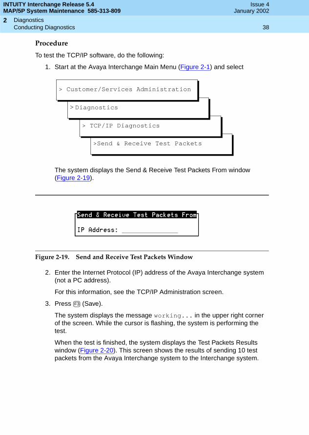
The system displays the Send & Receive Test Packets From window (Figure 2-19).
Figure 2-19. Send and Receive Test Packets Window
2. Enter the Internet Protocol (IP) address of the Avaya Interchange system (not a PC address).
For this information, see the TCP/IP Administration screen.
3. Press (Save).
The system displays the message working... in the upper right corner of the screen. While the cursor is flashing, the system is performing the test.
When the test is finished, the system displays the Test Packets Results window (Figure 2-20). This screen shows the results of sending 10 test packets from the Avaya Interchange system to the Interchange system.
>Send & Receive Test Packets
> TCP/IP Diagnostics
> Diagnostics
> Customer/Services Administration
F3

INTUITY Interchange Release 5.4MAP/5P System Maintenance 585-313-809
Issue 4January 2002
Diagnostics 39Conducting Diagnostics
2
Figure 2-20. Sample Test Packets Results Window
Results
Examine the packet loss values in the PING Statistics field displayed on the Test Packets Results screen. The value for this field is either 0% or 100%. The meanings of these values are as follows:
■ If 0% packet loss is reported, the test is successful. This result indicates that the problem is not with the Avaya Interchange system TCP/IP software; however, the problem might be with the LAN card or the network. To further isolate the problem, test the connection between the Avaya Interchange system and the troubled subscriber’s PC. See Testing the Connection Between the Avaya Interchange System and a Subscriber’s PC for this procedure.
■ If 100% packet loss is reported, the test failed. Check with the customer LAN administrator to ensure that you used the correct IP address for the system. This result might indicate a problem with the Avaya Interchange system’s UNIX TCP/IP software. Reboot the system, and repeat this test. If the test still fails, contact your remote services center. See Rebooting the System in Chapter 3, Common System Procedures, for this procedure.
INTUITY Interchange Release 5.4MAP/5P System Maintenance 585-313-809
Issue 4January 2002
Diagnostics 40Conducting Diagnostics
2
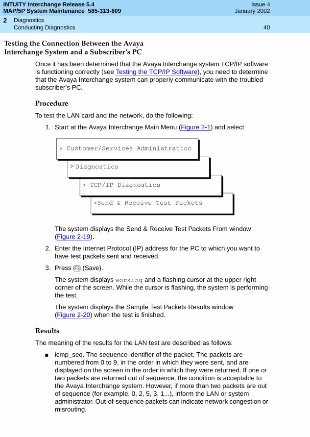
Testing the Connection Between the AvayaInterchange System and a Subscriber’s PC
Once it has been determined that the Avaya Interchange system TCP/IP software is functioning correctly (see Testing the TCP/IP Software), you need to determine that the Avaya Interchange system can properly communicate with the troubled subscriber’s PC.
Procedure
To test the LAN card and the network, do the following:
1. Start at the Avaya Interchange Main Menu (Figure 2-1) and select
The system displays the Send & Receive Test Packets From window (Figure 2-19).
2. Enter the Internet Protocol (IP) address for the PC to which you want to have test packets sent and received.
3. Press (Save).
The system displays working and a flashing cursor at the upper right corner of the screen. While the cursor is flashing, the system is performing the test.
The system displays the Sample Test Packets Results window (Figure 2-20) when the test is finished.
Results
The meaning of the results for the LAN test are described as follows:
■ icmp_seq. The sequence identifier of the packet. The packets are numbered from 0 to 9, in the order in which they were sent, and are displayed on the screen in the order in which they were returned. If one or two packets are returned out of sequence, the condition is acceptable to the Avaya Interchange system. However, if more than two packets are out of sequence (for example, 0, 2, 5, 3, 1...), inform the LAN or system administrator. Out-of-sequence packets can indicate network congestion or misrouting.
>Send & Receive Test Packets
> TCP/IP Diagnostics
> Diagnostics
> Customer/Services Administration
F3
INTUITY Interchange Release 5.4MAP/5P System Maintenance 585-313-809
Issue 4January 2002
Diagnostics 41Conducting Diagnostics
2
■ time. The round trip transmission time, in milliseconds (ms), of the packet. Round trip delays greater than 10,000 ms could indicate a network problem.
■ packet loss. The percentage of packets that were not returned during the test. The number of lost packets varies from network to network. Percentage of loss depends upon the number of users, the number of machines, and the distance between machines.
— Consider the test successful if the Avaya Interchange system reports a packet loss percentage of between 0 and 49%. Do, however, inform the LAN or system administrator if the loss is above 10%. Slow response time could be the result of such a loss.
— Consider the test a failure if the Avaya Interchange system reports a packet loss percentage of between 50% and 99%. In this range, Avaya INTUITY Message Manager performance is extremely slow or completely fails.
— A 100% packet loss indicates that the Avaya Interchange system has not established communication to the test machine address. The test does not report if packets are being sent to an incorrect or non-existent machine. Verify that you used the correct IP address for the PC. To further isolate the problem, repeat the test for a PC not experiencing problems with Avaya INTUITY Message Manager. If this test succeeds, the problem is with the first test PC. If this test fails, the problem is likely to be with the Avaya Interchange system’s LAN card or the network connection to the Avaya Interchange system.
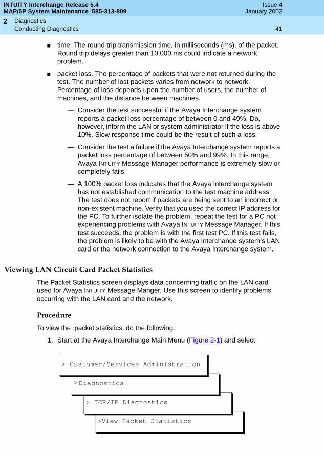
Viewing LAN Circuit Card Packet Statistics
The Packet Statistics screen displays data concerning traffic on the LAN card used for Avaya INTUITY Message Manger. Use this screen to identify problems occurring with the LAN card and the network.
Procedure
To view the packet statistics, do the following:
1. Start at the Avaya Interchange Main Menu (Figure 2-1) and select
>View Packet Statistics
> TCP/IP Diagnostics
> Diagnostics
> Customer/Services Administration

INTUITY Interchange Release 5.4MAP/5P System Maintenance 585-313-809
Issue 4January 2002
Diagnostics 42Conducting Diagnostics
2
The system displays the Packet Statistics window (Figure 2-21).
Figure 2-21. Packet Statistics Window
Interpreting the Packet Statistics Window
Table 2-1 explains each field on the Packet Statistics window. Once the system is turned on, packets (data) are sent over the network as interactions occur.
To see the statistics for the LAN card, examine the data for the line beginning with sme00. When the data on this screen indicates problems with the network, contact the customer LAN administrator.
Table 2-1. Fields on Packet Statistics Screen
Field Description
Name The name of the interface. The LAN card is sme00. An asterisk (*) in the field indicates that the interface is not enabled.
Mtu The maximum transmission unit in bytes. This field indicates the longest packet that can be transmitted without needing to be split.
Network The network to which the interface provides access. For the LAN card (sme00), the value for this field is always none.
Address The IP address assigned to this interface. For the LAN card (sme00), the value for this field is always none.
Ipkts The number of packets received over the network since the Avaya Interchange system was turned on.
Ierrs The number of damaged packets received. A value for this field greater than 10% of the packets received (Ipkts) indicates that the network is too busy and performance is slow.
(1 of 2)
INTUITY Interchange Release 5.4MAP/5P System Maintenance 585-313-809
Issue 4January 2002
Diagnostics 43Conducting Diagnostics
2
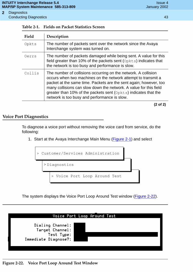
Voice Port Diagnostics
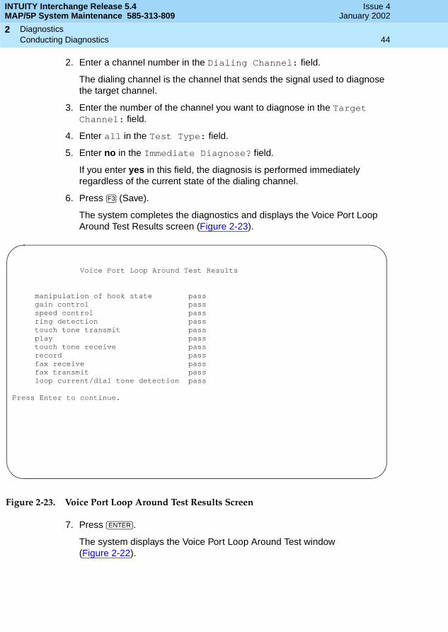
To diagnose a voice port without removing the voice card from service, do the following:
1. Start at the Avaya Interchange Main Menu (Figure 2-1) and select
The system displays the Voice Port Loop Around Test window (Figure 2-22).
Figure 2-22. Voice Port Loop Around Test Window
Opkts The number of packets sent over the network since the Avaya Interchange system was turned on.
Oerrs The number of packets damaged while being sent. A value for this field greater than 10% of the packets sent (Opkts) indicates that the network is too busy and performance is slow.
Collis The number of collisions occurring on the network. A collision occurs when two machines on the network attempt to transmit a packet at the same time. Packets are the sent again; however, too many collisions can slow down the network. A value for this field greater than 10% of the packets sent (Opkts) indicates that the network is too busy and performance is slow.
Table 2-1. Fields on Packet Statistics Screen
Field Description
(2 of 2)
> Voice Port Loop Around Test
> Diagnostics
> Customer/Services Administration
INTUITY Interchange Release 5.4MAP/5P System Maintenance 585-313-809
Issue 4January 2002
Diagnostics 44Conducting Diagnostics
2
2. Enter a channel number in the Dialing Channel: field.
The dialing channel is the channel that sends the signal used to diagnose the target channel.
3. Enter the number of the channel you want to diagnose in the Target Channel: field.
4. Enter all in the Test Type: field.
5. Enter no in the Immediate Diagnose? field.
If you enter yes in this field, the diagnosis is performed immediately regardless of the current state of the dialing channel.
6. Press (Save).
The system completes the diagnostics and displays the Voice Port Loop Around Test Results screen (Figure 2-23).
Figure 2-23. Voice Port Loop Around Test Results Screen
7. Press .
The system displays the Voice Port Loop Around Test window (Figure 2-22).
F3
Voice Port Loop Around Test Results
manipulation of hook state passgain control passspeed control passring detection passtouch tone transmit passplay passtouch tone receive passrecord passfax receive passfax transmit passloop current/dial tone detection pass
Press Enter to continue.
ENTER

INTUITY Interchange Release 5.4MAP/5P System Maintenance 585-313-809
Issue 4January 2002
Diagnostics 45Conducting Diagnostics
2
Tip/Ring Circuit Card Diagnostics
To determine which Tip/Ring circuit card is having a problem, look at the alarm log. See Chapter 1, Getting Started, in Avaya Interchange Release 5.4 Alarm and Log Messages, 585-310-566, for more information on the alarm log.
Procedure
To diagnose one or more Tip/Ring circuit cards, do the following:
1. Start at the Avaya Interchange Main Menu (Figure 2-1) and select
The system displays the Diagnose Equipment window (Figure 2-24).
Figure 2-24. Diagnose Equipment Window
Each voice card has a number (0 through 2) that is determined by the card address set by dip switches. A card number is shown on the first line of its display.
2. Enter card in the Equipment to diagnose: field.
3. Enter the number of the card or cards you want to diagnose in the Equipment Number: field.
> Diagnose
> Voice Board Diagnostics
> Diagnostics
> Customer/Services Administration

INTUITY Interchange Release 5.4MAP/5P System Maintenance 585-313-809
Issue 4January 2002
Diagnostics 46Conducting Diagnostics
2
! CAUTION:Do not diagnose all of the voice cards at once. This could leave no channels available on the system to accept incoming calls.
You can enter card numbers in several forms:
■ A single card number (for example, 1)
■ A range of card numbers (for example: 0–2)
■ A list of single card numbers (for example, 0,1,2)
■ A list of single cards and ranges (for example, 0–2)
4. Enter n in the Immediate Diagnosis? field so that the card is diagnosed when it is free of calls.
! CAUTION:Diagnosing voice cards immediately by entering y in the Immediate Diagnosis? field disconnects calls in progress. Do not enter y unless call traffic is extremely low. Diagnosing voice cards only when they are free of calls can take longer, but no calls are disconnected.
5. Press (Save).
Depending on the number of cards selected, diagnosis can take several minutes. When the diagnosis is complete, the system displays the following message:
Request to diagnose Tip/Ring card <number> is completed.
Press Enter to continue.
6. Press .
Results
The voice card diagnostics follows the order of these three main steps:
■ Each channel (and as a result the entire card) is taken out of service by changing its state to MANOOS (manually out of service).
■ Each channel is checked for loop current. Loop current is present on a channel when a live telephone line is physically connected between the IVC6 port and a properly administered switch port.
■ Each channel (and, as a result, the entire card) is put back into service by changing its states to INSERV (in service).
F3
ENTER

INTUITY Interchange Release 5.4MAP/5P System Maintenance 585-313-809
Issue 4January 2002
Diagnostics 47Conducting Diagnostics
2
If a card and all of its channels pass diagnostics, each channel is returned to its previous state (prior to the diagnostic), and the following message is shown in the Diagnose Equipment Results screen:
Diag TR number, Passed.
The following messages are normal outputs of the diagnostic process and do not affect the operation of the card:
■ Diag TR number, Not attempting dial tone training(/vs/switch/analog/noDTtrain exists)
For some switches, dial tone training is turned off because if the Avaya Interchange system tries to get a dial tone from many switch ports at one time, failures can occur on the switch side.
■ Found Loop current on channel number
This message indicates that there is a working telephone line attached to the voice port.
■ Request to diagnose Tip/Ring number completed
This message indicates that all requested tests have been completed.
The following list shows messages printed in the Diagnose Equipment Results screen that could signal problems.
■ No loop current on channel number
OR
Channel number changed to state FOOS
The Avaya Interchange system does not detect a working telephone line connected to the voice port. If this occurs, do the following:
1. Verify that the telephone line is securely connected to the voice card and the switch.
2. Verify that the analog line is set up properly on the switch. See the switch integration document included with your Avaya Interchange system documentation set for more information.
3. Verify that the switch port has a dial tone, by removing the analog line, plugging in an analog telephone, and listening with the handset for dial tone. If there is a dial tone, the voice card is likely the problem. If there is no dial tone, the problem is on the switch side. Verify switch wiring and administration.
■ Diag TR number: No dial tone frequencies set
The Avaya Interchange system did not detect a dial tone, but it did detect loop current (phone line is attached). Loop current could be a result of excessive load on the switch circuit pack. If this occurs, do the following:
1. Verify that the Avaya Interchange system analog lines are distributed over several switch circuit packs.

INTUITY Interchange Release 5.4MAP/5P System Maintenance 585-313-809
Issue 4January 2002
Diagnostics 48Conducting Diagnostics
2
2. Verify that the switch administration for the ports is valid.
■ Channel number changed to state BROKEN
OR
Card number changed to state BROKEN
The channel or card is not working. Replace the Tip/Ring circuit card. See Tip/Ring Circuit Cards in Chapter 5, Replacing or Installing Circuit Cards.
Busying out a Tip/Ring Circuit Card
Busying out a Tip/Ring circuit card takes all channels on that card out of service (MANOOS or manually out of service state) so that calls are not forwarded to those channels. You can also busy out one or more individual channels.
To busy out a Tip/Ring circuit card, do the following:
1. Start at the Avaya Interchange Main Menu (Figure 2-1) and select
The system displays the Busyout of Voice Equipment window(Figure 2-25).
Figure 2-25. Busyout of Voice Equipment Window
The New State: field displays manoos. This is the state to which the cards or channels selected is changed. This field cannot be changed.
2. Enter card or channel in the Equipment: field.
> Busy Out
> Voice Board Diagnostics
> Diagnostics
> Customer/Services Administration

INTUITY Interchange Release 5.4MAP/5P System Maintenance 585-313-809
Issue 4January 2002
Diagnostics 49Conducting Diagnostics
2
3. Enter the number of the card(s) or channel(s) you want to busy out in the Equipment Number: field.
! CAUTION:Do not busy out all of the voice cards at once. This could leave no channels available on the system to accept incoming calls.
Card numbers range from 0 to 2, channel numbers range from 0 to 17. You can enter card and channel numbers in several forms.
■ A single card number (for example, 1)
■ A range of card numbers (for example, 0–2)
■ A list of single card numbers (for example, 0,1,2)
■ A list of single cards and ranges (for example, 0–2)
4. Enter n in the Change Immediately? field so that the card or channel can busy out when it is free of calls.
! CAUTION:Busying out voice cards or channels immediately by entering y in the Change Immediately? field disconnects calls in progress. Do not enter y unless call traffic is extremely low. If n is entered, the voice cards or channels busy out when they are free of calls. Busying out voice cards and channels only when they are free of calls could take longer, but no calls are disconnected.
5. Press (Save).
When the state change is complete, the system displays a Command Output screen.
Releasing a Tip/Ring Circuit Card
Releasing a Tip/Ring circuit card puts all channels on that card in service (INSERV) so that they can accept and process calls. You can also release one or more individual channels.
To release a Tip/Ring circuit card or channels, do the following:
1. Start at the Avaya Interchange Main Menu (Figure 2-1) and select
F3

INTUITY Interchange Release 5.4MAP/5P System Maintenance 585-313-809
Issue 4January 2002
Diagnostics 50Conducting Diagnostics
2
The system displays the Release of Voice Equipment window (Figure 2-26).
Figure 2-26. Release of Voice Equipment Window
The New State: field displays inserv (in service). This is the state to which the cards or channels selected are changed. This field cannot be changed.
2. Enter card or channel in the Equipment: field.
3. Enter the number of the card(s) or channel(s) you want to release in the Equipment Number: field.
Card numbers range from 0 to 10, channel numbers range from 0 to 63. The card and channel numbers can be entered in several forms.
■ A single card number (for example, 1)
■ A range of card numbers (for example, 0–2)
■ A list of single card numbers (for example, 0,1,2)
■ A list of single cards and ranges (for example, 0–2)
4. Enter y in the Change Immediately? field so that the card or channel is released immediately.
5. Press (Save).
> Release
> Voice Board Diagnostics
> Diagnostics
> Customer/Services Administration
F3

Common System Procedures 51Overview
3
INTUITY Interchange Release 5.4MAP/5P System Maintenance 585-313-809
Issue 4January 2002
33Common System Procedures
Overview
This chapter describes:
■ Cartridge tape and diskette drive operating procedures
■ Backup and restore procedures
■ Voice system administration procedures
Purpose
The purpose of this chapter is to provide the procedures necessary to perform the most common procedures associated with the Avaya Interchange system.

INTUITY Interchange Release 5.4MAP/5P System Maintenance 585-313-809
Issue 4January 2002
Common System Procedures 52Accessing the Product IDMain Menu
3
Accessing the Product IDMain Menu
The product ID is a 10-digit number used to identify each Avaya Interchange system. You must have the product ID when contacting your remote maintenance service center.
To access the product ID, do the following:
1. Start at the Avaya Interchange Main Menu (Figure 2-1) and select
The system displays the Alarm Management window (Figure 3-1).
Figure 3-1. Alarm Management Window
2. Record the product ID for use with the remote maintenance center.
About Cartridge Drives and Tapes
Cartridge tapes provide for the storage of information used by the Avaya Interchange system. The MAP/5P reads information from and writes information to cartridge tapes through the tape drive. The tape drive is located in Bay 1 (Figure 3-2).
> Alarm Management
> Customer/Services Administration

INTUITY Interchange Release 5.4MAP/5P System Maintenance 585-313-809
Issue 4January 2002
Common System Procedures 53About Cartridge Drives and Tapes
3
Figure 3-2. Front View of the MAP/5P
When to Change Cartridge Tapes
The manufacturers of the cartridge tapes recommend that you replace a tape after approximately 30 full-capacity write or read operations. For example, if two tapes are being alternated for the unattended nightly backup, replace both tapes every two months.
1. Cartridge tape drive2. Diskette drive3. Circuit card cage fan4. Power button5. Reset button

INTUITY Interchange Release 5.4MAP/5P System Maintenance 585-313-809
Issue 4January 2002
Common System Procedures 54About Cartridge Drives and Tapes
3
Inserting the Cartridge Tape
To insert a cartridge tape, do the following:
1. Locate the tape drive on the front of the MAP/5P (Figure 3-2).
2. Check the Read/Write dial to make sure that the tape is not write protected. Verify that the small dial on the front of the tape is in the horizontal position.
3. Complete Steps a through c to insert the tape in the drive:
a. Press the button on the upper right corner of the drive to open the drive door.
b. Insert the tape (Figure 3-3).
c. Close the door to push in the tape.
Figure 3-3. Tape Insertion with a Tape Drive
NOTE:The light on the tape drive blinks when the drive is in use. If the light is lit and not blinking, the tape drive is idle.

INTUITY Interchange Release 5.4MAP/5P System Maintenance 585-313-809
Issue 4January 2002
Common System Procedures 55About Cartridge Drives and Tapes
3
Removing the Cartridge Tape
To remove a cartridge tape, do the following:
! CAUTION:You can remove the tape only when the drive is idle; that is, only when the light is not blinking.
1. Press the button on the upper right corner of the drive to reveal part of the tape.
2. Pull out the tape.
Formatting Cartridge Tapes
Formatting prepares a cartridge tape to receive data. To format a cartridge tape, do the following:
1. Start at the Avaya Interchange Main menu (Figure 2-1) and select
The system displays the Format UNIX Floppy/Tape menu (Figure 3-4).
Figure 3-4. Format UNIX Floppy/Tape Menu
2. Select Format Cartridge Tape.
3. Verify that the tape is not write protected and insert the tape into the tape drive. See About Cartridge Drives and Tapes for more information.
>Format UNIX Floppy/Tape
> UNIX Management
> System Management
> Customer/Services Administration
INTUITY Interchange Release 5.4MAP/5P System Maintenance 585-313-809
Issue 4January 2002
Common System Procedures 56About Diskette Drives and Diskettes
3
4. Press y.
The system displays a screen stating that the tape has been formatted.
5. Remove the tape from the tape drive.
6. Press .
About Diskette Drives and Diskettes
Diskettes can provide for the storage of information used by the Avaya Interchange system. If information must be transferred from a Avaya Interchange system without a LAN card, diskettes must be used.
Types of Diskettes
The Avaya Interchange system is not shipped with diskettes. If you need diskettes, use unformatted 3.5-inch disks. The diskettes can be either:
■ High density (1.44 MB)
■ Low density (720 KB)
Inserting and Removing Diskettes
Inserting the Diskettes
To insert a diskette, do the following:
1. Locate the diskette drive on the front of the MAP/5P (Figure 3-2).
2. Check the Read/Write switch to make sure that the diskette is not write protected.
3. Insert the diskette in the drive.
NOTE:The light on the diskette drive is on when the drive is in use. If the light is not on, the diskette drive is idle.
ENTER

INTUITY Interchange Release 5.4MAP/5P System Maintenance 585-313-809
Issue 4January 2002
Common System Procedures 57About Diskette Drives and Diskettes
3
Removing the Diskettes
To remove a diskette, do the following:
! CAUTION:You can remove the diskette only when the drive is idle; that is, only when the light is not on.
1. Press the button on the lower right corner of the diskette drive to reveal part of the diskette.
2. Pull out the diskette.
Formatting Diskettes
Formatting prepares a diskette to receive data. To format a diskette, do the following:
1. Start at the Avaya Interchange Main menu (Figure 2-1) and select
The system displays the Format UNIX Floppy/Tape menu (Figure 3-4).
2. Select Format 3.5 inch 1.44 MB (High Density) or Format 3.5 inch 720 Kbyte (Low Density), depending on the type of diskette being used.
3. Verify that the diskette is not write protected and insert the tape into the tape drive. See Inserting the Diskettes for more information.
4. Press y.
The system displays a screen stating that the diskette has been formatted.
5. Remove the diskette from the diskette drive.
6. Press .
>Format UNIX Floppy/Tape
> UNIX Management
> System Management
> Customer/Services Administration
ENTER
INTUITY Interchange Release 5.4MAP/5P System Maintenance 585-313-809
Issue 4January 2002
Common System Procedures 58Backing Up (Unattended)
3
Backing Up (Unattended)
The unattended backup contains all of the information necessary to bring the system back to an operational state after a service affecting event. However, the unattended backup alone cannot completely restore the system to its previous state. The unattended backup can bring the system back to an operational state only. Employ the disaster recovery procedures outlined in Appendix C, Disaster Recovery, to restore a system to the previous state.
Unattended backups do not require supervision and occur automatically. However, for the backup to be successful, you must ensure that a cartridge tape is in the tape drive.
Unattended backups occur nightly at 3:00 a.m. and can take up to four hours. Unattended backups do not degrade service.
After verifying that the unattended backup was successful, remove the tape. Label it with date and backup data type (for example, System Data) and store it. Insert a second tape in the tape drive. See Verifying the Unattended Backup for backup verification procedures.
How to Manage Tapes
! CAUTION:Do not leave the same tape in the tape drive day after day. Once the unattended backup begins, the previous day’s data is overwritten and becomes unretrievable. If today’s unattended backup fail, neither today’s nor yesterday’s data will be available.
To better manage the backed-up data, it is recommended that two tapes be used.
These two tapes can be alternated daily, or additional tapes can be used to implement a longer cycle (for example, seven tapes, each one labeled with a day of the week).
What Data Is Backed Up
An unattended backup saves:
■ Detailed system data on shared memory, speech file system pointers, and so on
■ Alarm management information
■ A list of enabled features
■ A list of installed software

INTUITY Interchange Release 5.4MAP/5P System Maintenance 585-313-809
Issue 4January 2002
Common System Procedures 59Backing Up (Unattended)
3
Verifying the Unattended Backup
The system administrator checks the administrator’s log daily to ensure that a successful unattended backup occurred. You can check the log by using the Log Administration menu.
Successful Backup Verification Using the LogAdministration Menu
To verify a successful unattended backup from the Log Administration menu, do the following:
1. Start at the Avaya Interchange Main menu (Figure 2-1) and select
The system displays the Administrator’s Log Display Selection window (Figure 3-5).
Figure 3-5. Administrator’s Log Display Selection Window
2. Place the cursor in the Event ID: field.
> Administrator’s Log
> Log Administration
> Customer/Services Administration
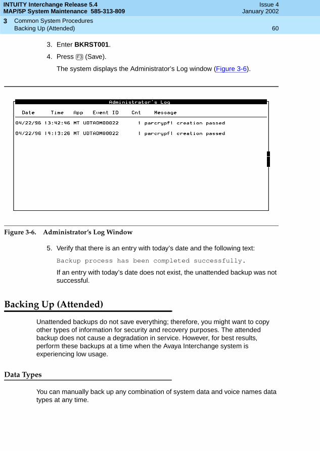
INTUITY Interchange Release 5.4MAP/5P System Maintenance 585-313-809
Issue 4January 2002
Common System Procedures 60Backing Up (Attended)
3
3. Enter BKRST001.
4. Press (Save).
The system displays the Administrator’s Log window (Figure 3-6).
Figure 3-6. Administrator’s Log Window
5. Verify that there is an entry with today’s date and the following text:
Backup process has been completed successfully.
If an entry with today’s date does not exist, the unattended backup was not successful.
Backing Up (Attended)
Unattended backups do not save everything; therefore, you might want to copy other types of information for security and recovery purposes. The attended backup does not cause a degradation in service. However, for best results, perform these backups at a time when the Avaya Interchange system is experiencing low usage.
Data Types
You can manually back up any combination of system data and voice names data types at any time.
F3
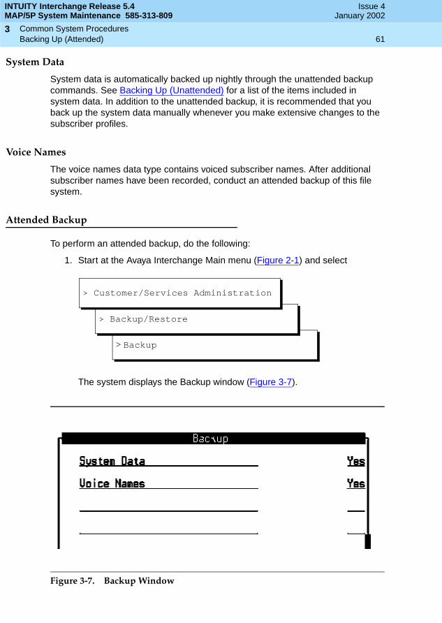
INTUITY Interchange Release 5.4MAP/5P System Maintenance 585-313-809
Issue 4January 2002
Common System Procedures 61Backing Up (Attended)
3
System Data
System data is automatically backed up nightly through the unattended backup commands. See Backing Up (Unattended) for a list of the items included in system data. In addition to the unattended backup, it is recommended that you back up the system data manually whenever you make extensive changes to the subscriber profiles.
Voice Names
The voice names data type contains voiced subscriber names. After additional subscriber names have been recorded, conduct an attended backup of this file system.
Attended Backup
To perform an attended backup, do the following:
1. Start at the Avaya Interchange Main menu (Figure 2-1) and select
The system displays the Backup window (Figure 3-7).
Figure 3-7. Backup Window
> Backup
> Backup/Restore
> Customer/Services Administration
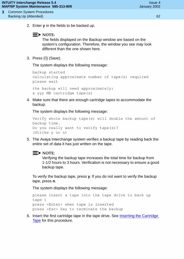
INTUITY Interchange Release 5.4MAP/5P System Maintenance 585-313-809
Issue 4January 2002
Common System Procedures 62Backing Up (Attended)
3
2. Enter y in the fields to be backed up.
NOTE:The fields displayed on the Backup window are based on the system’s configuration. Therefore, the window you see may look different than the one shown here.
3. Press (Save).
The system displays the following message:
backup startedcalculating approximate number of tape(s) requiredplease wait
the backup will need approximately:x yyy MB cartridge tape(s)
4. Make sure that there are enough cartridge tapes to accommodate the backup.
The system displays the following message:
Verify whole backup tape(s) will double the amount of backup time.Do you really want to verify tape(s)?(Strike y or n)
5. The Avaya Interchange system verifies a backup tape by reading back the entire set of data it has just written on the tape.
NOTE:Verifying the backup tape increases the total time for backup from 1-1/2 hours to 3 hours. Verification is not necessary to ensure a good backup tape.
To verify the backup tape, press y. If you do not want to verify the backup tape, press n.
The system displays the following message:
please insert a tape into the tape drive to back up tape 1press <Enter> when tape is insertedpress <Esc> key to terminate the backup
6. Insert the first cartridge tape in the tape drive. See Inserting the Cartridge Tape for this procedure.
F3

INTUITY Interchange Release 5.4MAP/5P System Maintenance 585-313-809
Issue 4January 2002
Common System Procedures 63Restoring Backups
3
7. Press when the tape drive is idle.
The system displays a series of messages indicating what is being stored on the backup tape.
NOTE:The light on the 2-GB drive blinks when the drive is in use. If the light is not blinking, the tape drive is idle.
8. If another tape is necessary:
a. Remove the current tape. See Removing the Cartridge Tape for this procedure.
b. Label the tape with the current date and back-up data type(s).
c. Insert the next tape. See Inserting the Cartridge Tape for this procedure.
If another tape is not necessary, continue with Step 10.
When the backup is complete, the system displays the following message:
backup process has been completed successfullypress any key to continue
9. Press .
Restoring Backups
The information stored on cartridge tapes during the unattended and attended backup procedures is used to restore the system to an operational state.
If a system problem or failure occurs, backups can be invaluable in returning the system to an operational state. You will likely restore only backups when directed to do so by an alarm repair action.
Depending on the severity of the situation, Avaya Interchange software may have to be reinstalled before any backups are restored. If system software needs reinstalling, see Chapter 4, New Installation and System Recovery Procedures in Avaya Interchange Release 5.4 Installation and System Recovery for the procedures.
NOTE:It takes approximately two hours to restore one tape.This procedure works for both attended and unattended backups.
To restore the backup, do the following:
1. Stop the voice system. See Stopping the Voice System for more information.
ENTER
ENTER
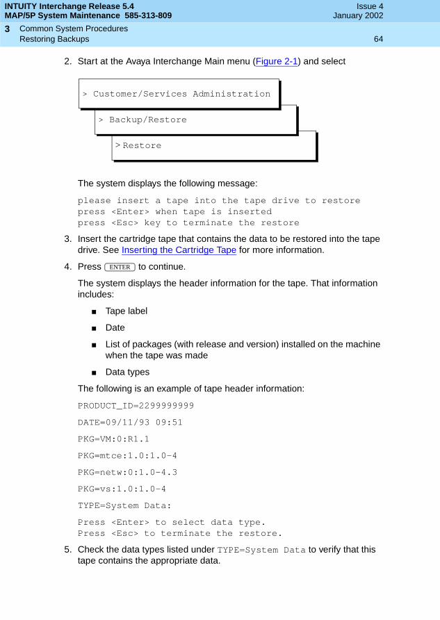
INTUITY Interchange Release 5.4MAP/5P System Maintenance 585-313-809
Issue 4January 2002
Common System Procedures 64Restoring Backups
3
2. Start at the Avaya Interchange Main menu (Figure 2-1) and select
The system displays the following message:
please insert a tape into the tape drive to restorepress <Enter> when tape is insertedpress <Esc> key to terminate the restore
3. Insert the cartridge tape that contains the data to be restored into the tape drive. See Inserting the Cartridge Tape for more information.
4. Press to continue.
The system displays the header information for the tape. That information includes:
■ Tape label
■ Date
■ List of packages (with release and version) installed on the machine when the tape was made
■ Data types
The following is an example of tape header information:
PRODUCT_ID=2299999999
DATE=09/11/93 09:51
PKG=VM:0:R1.1
PKG=mtce:1.0:1.0-4
PKG=netw:0:1.0-4.3
PKG=vs:1.0:1.0-4
TYPE=System Data:
Press <Enter> to select data type.Press <Esc> to terminate the restore.
5. Check the data types listed under TYPE=System Data to verify that this tape contains the appropriate data.
> Restore
> Backup/Restore
> Customer/Services Administration
ENTER
INTUITY Interchange Release 5.4MAP/5P System Maintenance 585-313-809
Issue 4January 2002
Common System Procedures 65Restoring Backups
3
If it does not:
a. Press .
b. Return to Step 3.
c. Try another tape.
If it does, continue with Step 6.
6. Press to continue.
The system displays the Restore window.
7. Enter y in the fields that display the data types you want to restore.
NOTE:The fields displayed on the Restore window are based on the data stored on the tape.
8. Enter n in all of the other fields.
9. Press (Save) to restore the data types selected.
10. Insert subsequent tapes if prompted to do so.
11. Press when the restore is complete.
The system displays the following message:
restore process has been completed successfullypress any key to continue
If the restore fails, the system displays the following message:
Restore Failed.
Do the following:
a. Rewind the tape by removing it from the tape drive and then reinserting it.
b. Return to Step 4 and attempt the restore again.
c. If the restore fails a second time, access the alarm log. See Chapter 1, Getting Started, in Avaya Interchange Release 5.4 Alarm and Log Messages and follow associated repair actions for any active alarms in the log.
12. Reboot the system. See Shutting Down and Rebooting the Avaya Interchange System for this procedure.
ESC
ENTER
F3
ENTER

INTUITY Interchange Release 5.4MAP/5P System Maintenance 585-313-809
Issue 4January 2002
Common System Procedures 66Administering Interchange
3
Administering Interchange
The voice system is the Avaya Interchange system base voice processing software.
Starting the Voice System
To start the voice system, do the following:
1. Start at the Avaya Interchange Main menu (Figure 2-1) and select
The system displays the following message:
The Voice System is starting.The Voice System is initializing cards.
Startup of the Voice System is complete.
Hit acknowledge key to continue.
2. Press (Acknowledge).
The system displays the System Control menu (Figure 3-8).
Figure 3-8. System Control Menu
You have completed this procedure.
>Start Voice System
> System Control
> System Management
> Customer/Services Administration
F1
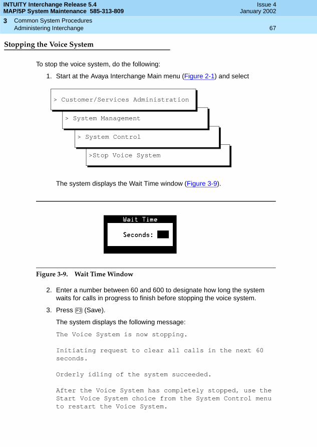
INTUITY Interchange Release 5.4MAP/5P System Maintenance 585-313-809
Issue 4January 2002
Common System Procedures 67Administering Interchange
3
Stopping the Voice System
To stop the voice system, do the following:
1. Start at the Avaya Interchange Main menu (Figure 2-1) and select
The system displays the Wait Time window (Figure 3-9).
Figure 3-9. Wait Time Window
2. Enter a number between 60 and 600 to designate how long the system waits for calls in progress to finish before stopping the voice system.
3. Press (Save).
The system displays the following message:
The Voice System is now stopping.
Initiating request to clear all calls in the next 60 seconds.
Orderly idling of the system succeeded.
After the Voice System has completely stopped, use the Start Voice System choice from the System Control menu to restart the Voice System.
>Stop Voice System
> System Control
> System Management
> Customer/Services Administration
F3

INTUITY Interchange Release 5.4MAP/5P System Maintenance 585-313-809
Issue 4January 2002
Common System Procedures 68Shutting Down and Rebooting the Avaya Interchange System
3
The Voice System has stopped.
Press Enter to Continue.
4. Press .
Shutting Down and Rebooting theAvaya Interchange System
You must shut down the Avaya Interchange system before you perform a reboot. This section describes both procedures.
Shutting Down the Avaya Interchange System
1. Stop the voice system. See Stopping the Voice System for this procedure.
2. Start at the Avaya Interchange Main menu (Figure 2-1) and select
The system displays the Wait Time window (Figure 3-9).
3. Enter a number between 0 and 60 to designate how long the system is to wait for users to log off.
4. Press (Save).
The system displays the following message:
Shutdown started.
When the system is completely shut down, the system displays the following message:
The system is down.Press Ctrl-Alt-Del to reboot your computer.
5. Continue with the next procedure, Rebooting the System.
ENTER
>Shutdown System
> System Control
> System Management
> Customer/Services Administration
F3

INTUITY Interchange Release 5.4MAP/5P System Maintenance 585-313-809
Issue 4January 2002
Common System Procedures 69Verifying the Date and Time
3
Rebooting the System
Rebooting the system can be done in two ways:
■ A warm reboot (performed while the computer is on)
■ A cold reboot (turning the computer off, then back on again)
Performing a Warm Reboot
To perform a warm reboot:
1. Make sure that there is no diskette in the floppy drive.
2. Press .
The system performs a power-on self test (POST). The screen lists various hardware components and the status of the tests performed on those components.
When the reboot is complete, the system displays the following prompt:
Startup of the Voice System is complete.Console Login:
3. If FAIL appears in the status column for any component do the following:
a. Record the component name.
b. Access the alarm log to begin troubleshooting. See Chapter 1, Getting Started, in Avaya Interchange Release 5.4 Alarm and Log Messages for this procedure.
Performing a Cold Reboot
To perform a cold reboot:
1. Make sure that there is no diskette in the floppy drive.
2. Turn the MAP/5P off by pressing the power button on the front of the unit (Figure 3-2).
3. Wait 30 seconds to allow the drives to come to a complete stop.
4. Turn the power on by pressing the power button on the front of the MAP/5P (Figure 3-2).
Verifying the Date and Time
This section details:
■ Checking the UNIX Date and Time window
■ Changing the UNIX Date and Time window
Ctrl-Alt-Del

INTUITY Interchange Release 5.4MAP/5P System Maintenance 585-313-809
Issue 4January 2002
Common System Procedures 70Verifying the Date and Time
3
Checking the UNIX Date and Time Window
1. Start at the Avaya Interchange Main menu (Figure 2-1) and select
The system displays the UNIX Date and Time window (Figure 3-10).
Figure 3-10. UNIX Date and Time Window
2. Review each of the fields under UNIX Date and Time.
If all of the fields are correct, press (Cancel).
If a field contains incorrect information, continue with the next procedure, Changing the UNIX Date and Time Window.
Changing the UNIX Date and Time Window
The user can change any of the displayed fields. To change one field in the Date and Time window, the user must either change or acknowledge the information in each field.
>UNIX Date and Time
> UNIX Management
> System Management
> Customer/Services Administration
F6

INTUITY Interchange Release 5.4MAP/5P System Maintenance 585-313-809
Issue 4January 2002
Common System Procedures 71Verifying the Date and Time
3
Changing the Date Field
The date field contains the month, day, and year.
Changing the Month
1. Place the cursor on the Month field in the UNIX Date and Time window (Figure 3-10).
2. If the month shown is not correct, complete Step a through Step d:
a. Press (Choices) to display the months of the year (Figure 3-11).
Figure 3-11. UNIX Month Choices Menu
b. Use or to move the cursor and highlight the correct month.
c. Press to place the name of the correct month into the month field.
NOTE:The user can also select the current month by entering the corresponding alphabetic abbreviation from this list: Ja, F, Mar, Ap, May, Jun, Jul, Au, S, O, N, D.
d. Continue with the next procedure, Changing the Day.
If the month shown is correct, press for no change and continue with the next procedure, Changing the Day.
F2
ENTER
ENTER
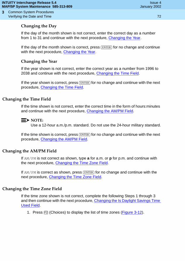
INTUITY Interchange Release 5.4MAP/5P System Maintenance 585-313-809
Issue 4January 2002
Common System Procedures 72Verifying the Date and Time
3
Changing the Day
If the day of the month shown is not correct, enter the correct day as a number from 1 to 31 and continue with the next procedure, Changing the Year.
If the day of the month shown is correct, press for no change and continue with the next procedure, Changing the Year.
Changing the Year
If the year shown is not correct, enter the correct year as a number from 1996 to 2038 and continue with the next procedure, Changing the Time Field.
If the year shown is correct, press for no change and continue with the next procedure, Changing the Time Field.
Changing the Time Field
If the time shown is not correct, enter the correct time in the form of hours:minutes and continue with the next procedure, Changing the AM/PM Field.
NOTE:Use a 12-hour a.m./p.m. standard. Do not use the 24-hour military standard.
If the time shown is correct, press for no change and continue with the next procedure, Changing the AM/PM Field.
Changing the AM/PM Field
If AM/PM is not correct as shown, type a for a.m. or p for p.m. and continue with the next procedure, Changing the Time Zone Field.
If AM/PM is correct as shown, press for no change and continue with the next procedure, Changing the Time Zone Field.
Changing the Time Zone Field
If the time zone shown is not correct, complete the following Steps 1 through 3 and then continue with the next procedure, Changing the Is Daylight Savings Time Used Field.
1. Press (Choices) to display the list of time zones (Figure 3-12).
ENTER
ENTER
ENTER
ENTER
F2

INTUITY Interchange Release 5.4MAP/5P System Maintenance 585-313-809
Issue 4January 2002
Common System Procedures 73Verifying the Date and Time
3
Figure 3-12. UNIX Time Zone Choices Menu
2. Use or to move the cursor and highlight the correct time zone.
3. Press to place the name of the correct time zone into the Timezone field.
If the time zone shown is correct, press for no change and continue with the next procedure, Changing the Is Daylight Savings Time Used Field.
Changing the Is Daylight Savings Time Used Field
1. Type y for yes or n for no depending upon whether or not daylight savings time is used at any time during the year.
2. Press (Save) to save the changes and continue with the next procedure, Acknowledging the Changes to the Date and Time Window.
Acknowledging the Changes to the Date and Time Window
After the changes have been made to the Date and Time window, ensure that the system recognizes the new information. To acknowledge the new information, do the following:
1. Reboot the Avaya Interchange system. See Shutting Down and Rebooting the Avaya Interchange System for this procedure.
At this time, the date and time changes take effect.
ENTER
ENTER
F3
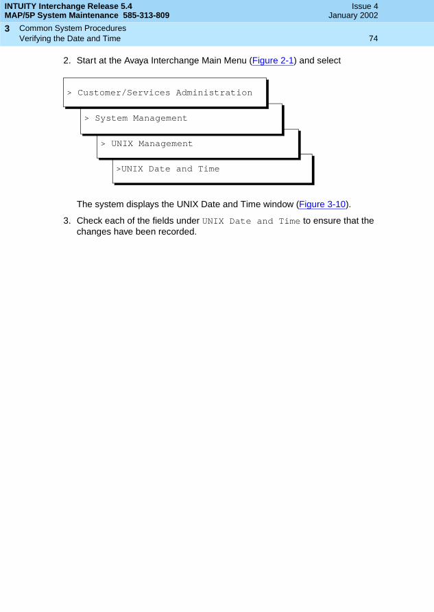
INTUITY Interchange Release 5.4MAP/5P System Maintenance 585-313-809
Issue 4January 2002
Common System Procedures 74Verifying the Date and Time
3
2. Start at the Avaya Interchange Main Menu (Figure 2-1) and select
The system displays the UNIX Date and Time window (Figure 3-10).
3. Check each of the fields under UNIX Date and Time to ensure that the changes have been recorded.
>UNIX Date and Time
> UNIX Management
> System Management
> Customer/Services Administration

Getting Inside the Computer 75Overview
4
INTUITY Interchange Release 5.4MAP/5P System Maintenance 585-313-809
Issue 4January 2002
44Getting Inside the Computer
Overview
This chapter describes procedures for:
■ Proper electrostatic discharge protection
■ Power removal and restoration
■ Computer chassis access
Purpose
The purpose of this chapter is to provide the correct procedures for accessing the internal components of the MAP/5P.
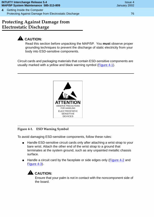
INTUITY Interchange Release 5.4MAP/5P System Maintenance 585-313-809
Issue 4January 2002
Getting Inside the Computer 76Protecting Against Damage from Electrostatic Discharge
4
Protecting Against Damage fromElectrostatic Discharge
! CAUTION:Read this section before unpacking the MAP/5P. You must observe proper grounding techniques to prevent the discharge of static electricity from your body into ESD-sensitive components.
Circuit cards and packaging materials that contain ESD-sensitive components are usually marked with a yellow and black warning symbol (Figure 4-1).
Figure 4-1. ESD Warning Symbol
To avoid damaging ESD-sensitive components, follow these rules:
■ Handle ESD-sensitive circuit cards only after attaching a wrist strap to your bare wrist. Attach the other end of the wrist strap to a ground that terminates at the system ground, such as any unpainted metallic chassis surface.
■ Handle a circuit card by the faceplate or side edges only (Figure 4-2 and Figure 4-3).
! CAUTION:Ensure that your palm is not in contact with the noncomponent side of the board.
ATTENTIONOBSERVE PRECAUTIONS
FOR HANDLING
ELECTROSTATICSENSITIVEDEVICES
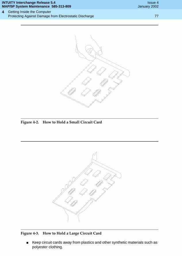
INTUITY Interchange Release 5.4MAP/5P System Maintenance 585-313-809
Issue 4January 2002
Getting Inside the Computer 77Protecting Against Damage from Electrostatic Discharge
4
Figure 4-2. How to Hold a Small Circuit Card
Figure 4-3. How to Hold a Large Circuit Card
■ Keep circuit cards away from plastics and other synthetic materials such as polyester clothing.

INTUITY Interchange Release 5.4MAP/5P System Maintenance 585-313-809
Issue 4January 2002
Getting Inside the Computer 78Protecting Against Damage from Electrostatic Discharge
4
■ Do not hand circuit cards to another person unless that person is grounded at the same potential level.
■ Hold devices such as a hard disk, floppy drive, or streaming tape in the same manner as a large circuit card. The ESD-sensitive area of these components is located on the bottom surface (Figure 4-4).
Figure 4-4. ESD-Sensitive Area of an Electronic Component
Recommendedholding points
ESD sensitivearea (bottomsurface)

INTUITY Interchange Release 5.4MAP/5P System Maintenance 585-313-809
Issue 4January 2002
Getting Inside the Computer 79Removing Power from the MAP/5P
4
Removing Power from the MAP/5P
The MAP/5P requires a dedicated circuit with a dedicated circuit breaker. The power cord connects to the rear of the MAP/5P at the point labeled “AC power inlet receptacle” (Figure 4-5). Before you begin any work in the MAP/5P, complete the following procedure to remove power from the MAP/5P.
Figure 4-5. Back View of the MAP/5P
1. Power supply fan intake2. Keyboard connector3. Mouse connector4. COM15. COM26. Parallel port7. Video connector8. AC power supply outlet9. Dress cover lock10. AC voltage selector switch11. AC power inlet receptacle
INTUITY Interchange Release 5.4MAP/5P System Maintenance 585-313-809
Issue 4January 2002
Getting Inside the Computer 80Removing the Dress Cover
4
1. Shut down the Avaya Interchange system. See Shutting Down the Avaya Interchange System in Chapter 3, Common System Procedures, for this procedure.
2. Turn off the power switch for the monitor.
Verify that green or amber lamp on the front bottom of the monitor is off.
3. Turn off the power switch on the front of the MAP/5P.
Verify that the green lamp labeled POWER ON on the front of the unit is off.
4. Unplug the MAP/5P from the power outlet.
5. Remove the MAP/5P power cord from the AC receptacle in the wall.
6. Observe the correct lock-out/tag-out precautions for isolating power as outlined in the Avaya lock-out/tag-out procedure.
Removing the Dress Cover
The dress cover provides protection for the internal components of the MAP/5P. You must remove the dress cover to access these components.
! DANGER:Shut power off before removing the dress cover. See Removing Power from the MAP/5P for this procedure.
To remove the dress cover, do the following:
1. Place the dress cover lock (Figure 4-5) in the open position.
NOTE:Figure 4-5 shows the dress cover lock in the locked position.
2. Simultaneously compress the dress cover latches on either side of the MAP/5P (Figure 4-6).
3. Slide the dress cover away from the MAP/5P.
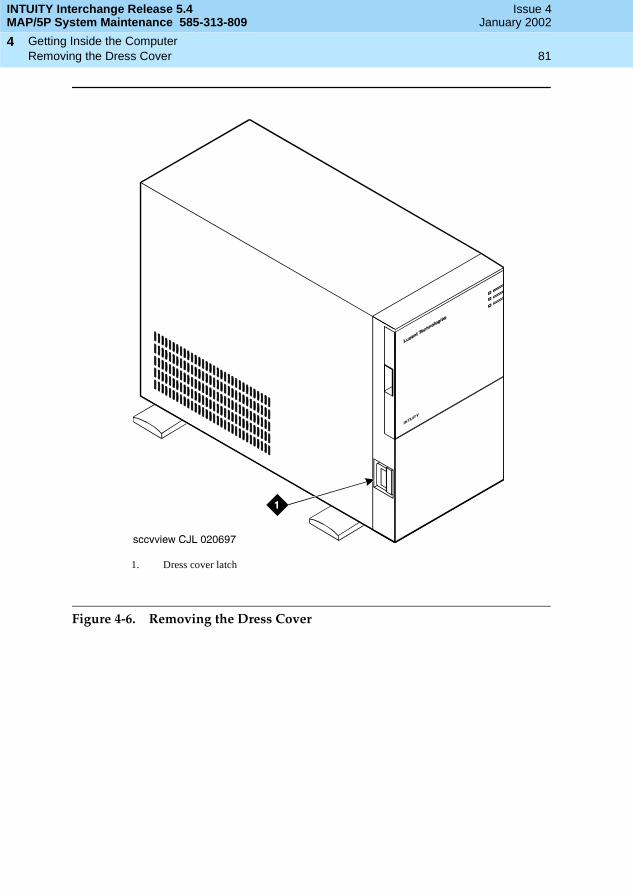
INTUITY Interchange Release 5.4MAP/5P System Maintenance 585-313-809
Issue 4January 2002
Getting Inside the Computer 81Removing the Dress Cover
4
Figure 4-6. Removing the Dress Cover
1. Dress cover latch

INTUITY Interchange Release 5.4MAP/5P System Maintenance 585-313-809
Issue 4January 2002
Getting Inside the Computer 82Replacing the Dress Cover
4
Replacing the Dress Cover
To replace the dress cover, do the following:
1. Align the dress cover with the MAP/5P chassis.
2. Slide the dress cover back until it locks into place.
3. Close the dress cover lock on the back of the MAP/5P chassis.
Restoring Power to the MAP/5P
To restore power to the MAP/5P, do the following:
1. Plug the MAP/5P power cord into the designated power outlet.
2. Fasten the power cord to the MAP/5P dress cover lock using a cable tie.
NOTE:Leave some slack in the power cord between the dress cover lock and the back of the MAP/5P.
3. Turn on the power switch for the monitor.
Verify that the green or amber lamp on the front bottom of the monitor lights up.
4. Press the power switch on the front of the MAP/5P.
Verify that the green lamp on the front of the unit lights up.

Replacing or Installing Circuit Cards 83Overview
5
INTUITY Interchange Release 5.4MAP/5P System Maintenance 585-313-809
Issue 4January 2002
55Replacing or Installing Circuit Cards
Overview
This chapter describes:
■ Configuring circuit cards in the MAP/5P
■ Types of circuit cards
■ General steps for circuit card installation
■ Specific procedures for installation of standard and optional MAP/5P circuit cards
■ Settings for resource options
Purpose
The purpose of this chapter is to ensure that:
■ Circuit cards are installed correctly.
■ Resource options are set correctly.
INTUITY Interchange Release 5.4MAP/5P System Maintenance 585-313-809
Issue 4January 2002
Replacing or Installing Circuit Cards 84General Procedures
5
General Procedures
The general procedures include:
■ Removing a Circuit Card
■ Installing a Circuit Card
Removing a Circuit Card
! CAUTION:Observe proper electrostatic discharge precautions when you handle computer components. Wear an antistatic wrist strap that touches your bare skin and connect the strap cable to an earth ground. See Protecting Against Damage from Electrostatic Discharge in Chapter 4, Getting Inside the Computer.
To remove a circuit card, you must:
■ Remove the Avaya Interchange system from service.
■ Access the circuit card.
■ Extract the circuit card.
Removing the Avaya Interchange Systemfrom Service
To remove the Avaya Interchange system from service, do the following:
1. Verify that the replacement equipment is on site and appears to be in usable condition, with no obvious shipping damage.
2. Stop the voice system. See Stopping the Voice System in Chapter 3, Common System Procedures, for this procedure.
3. Shut down the voice system. See Shutting Down the Avaya Interchange System in Chapter 3, Common System Procedures, for this procedure.
4. Remove the incoming power. See Removing Power from the MAP/5P in Chapter 4, Getting Inside the Computer, for this procedure.
Accessing the Circuit Card
To access the circuit card, remove the dress cover. See Removing the Dress Cover in Chapter 4, Getting Inside the Computer, for this procedure.
INTUITY Interchange Release 5.4MAP/5P System Maintenance 585-313-809
Issue 4January 2002
Replacing or Installing Circuit Cards 85General Procedures
5
Extracting the Circuit Card
To extract the circuit card, do the following:
1. Locate the circuit card to be replaced within the card cage.
2. Disconnect any attached cables.
NOTE:Pay close attention to the connectivity of each cable to make it easier to connect them to the replacement circuit card.
3. If there are cables attached to other circuit cards that could impede the removal of the circuit card, disconnect them and place them to the side.
NOTE:Pay close attention to the connectivity of each cable.
4. Remove the retaining screw from the circuit card faceplate and save it.
5. Remove the circuit card from the backplane slot by gently pulling on each corner of the circuit card.
NOTE:Note the slot assignment because you must install the replacement circuit card in the same backplane slot. See Component Assignments in Appendix A, System Configuration, for circuit card slot assignments.
6. Remove the circuit card from the MAP/5P.
! CAUTION:Hold the circuit card carefully by the edges and place it on a grounded mat. See Protecting Against Damage from Electrostatic Discharge in Chapter 4, Getting Inside the Computer, for detailed electrostatic discharge precautions.
7. If the circuit card being replaced is defective, note all symptoms of failure and include this information with the circuit card when it is returned.
Installing a Circuit Card
! CAUTION:Observe proper electrostatic discharge precautions when you handle computer components. Wear an antistatic wrist strap that touches your bare skin and connect the strap cable to an earth ground. See Protecting Against Damage from Electrostatic Discharge in Chapter 4, Getting Inside the Computer.

INTUITY Interchange Release 5.4MAP/5P System Maintenance 585-313-809
Issue 4January 2002
Replacing or Installing Circuit Cards 86General Procedures
5
To install a circuit card, you must:
■ Insert the circuit card.
■ Reassemble the MAP/5P.
■ Restore the Avaya Interchange system to service.
NOTE:If you are adding an additional circuit card to the Avaya Interchange system, complete the procedures, Removing the Avaya Interchange System from Service and Accessing the Circuit Card.
Inserting the Circuit Card
To insert the circuit card, do the following:
1. Remove the new circuit card from its ESD protective wrapping.
NOTE:Keep the package and all ESD protective wrapping. If you must return a circuit card for repair, use of the replacement unit packaging is necessary to meet the manufacturer’s warranty.
2. Verify that the circuit card switch and jumper settings. Ensure address switches and jumpers are set to match the old circuit card.
NOTE:See the specific instructions listed later in this chapter for each type of circuit card being installed. Then continue with Step 3.
3. Holding the circuit card by its upper corners, slide the circuit card into the backplane connector slot position from which you removed the damaged circuit card. If necessary, see Appendix A, System Configuration, to determine the correct slot in which to place the circuit card.
4. Apply even pressure to both corners of the circuit card until it is locked into the backplane.
5. Secure the circuit card faceplate into position by replacing the retaining screw.
6. Replace all cables on the new circuit card. Make sure these cables are attached to their proper terminations.
7. Replace all cables removed from other circuit cards. Make sure these cables are attached to their proper terminations.
Reassembling the MAP/5P
To reassemble the MAP/5P, replace the dress cover. See Replacing the Dress Cover in Chapter 4, Getting Inside the Computer, for this procedure.

INTUITY Interchange Release 5.4MAP/5P System Maintenance 585-313-809
Issue 4January 2002
Replacing or Installing Circuit Cards 87General Procedures
5
Restoring the Avaya Interchange Systemto Service
To restore the Avaya Interchange system to service, do the following:
1. Restore power to the MAP/5P. See Restoring Power to the MAP/5P in Chapter 4, Getting Inside the Computer, for this procedure.
2. Verify the installation of the circuit card by performing Step a and Step b.
NOTE:This procedure verifies only the installation of Tip/Ring and ACCX circuit cards.
a. Start at the Avaya Interchange Main Menu (Figure 2-1) and select
The system displays the View Installed Hardware window(Figure 5-1).
Figure 5-1. View Installed Hardware Window
b. Verify that the system has identified the new circuit card. Press the Down arrow key to view the complete list of installed hardware.
> View Installed Hardware
> System Verification
> Customer/Services Administration

INTUITY Interchange Release 5.4MAP/5P System Maintenance 585-313-809
Issue 4January 2002
Replacing or Installing Circuit Cards 88Circuit Card Settings
5
Circuit Card Settings
The following sections list the specific jumper and switch settings for optional circuit cards.
! CAUTION:Observe proper electrostatic discharge precautions when you handle computer components. Wear an antistatic wrist strap that touches your bare skin and connect the strap cable to an earth ground. See Protecting Against Damage from Electrostatic Discharge in Chapter 4, Getting Inside the Computer.
This section provides the following information on the optional feature circuit cards:
■ Switch and jumper settings
■ Other installation requirements that are specific to the particular circuit card you are installing
In general, circuit cards are not preset at the factory. You must set the switches and jumpers (resource options) before you install the circuit cards. When you set the switches according to the instructions in this book, remember that OFF is equivalent to open and ON is equivalent to closed.
ACCX (AYC22) Circuit Card
The Avaya Interchange system supports up to eight networking channels on the MAP/5P by means of digital and analog remote connections using DCP and RS-232 links respectively from the ACCX circuit card (Figure 5-2). An ACCX circuit card terminates four data channels in one of the following combinations:
■ Two DCP lines, each providing two I-channels for data. Depending on the version of the switch you are connecting to, you might be able to use only one of the two I-channels of each DCP circuit as shown in the following list:
— System 75 R1V3, DEFINITY® G1 R1V4, and DEFINITY G3i, G3s, or G3vs Version 1 support only one I-channel.
— DEFINITY G3i, G3s, and G3vs Version 2 can use both I-channels. The option must be purchased, installed, and administered on the switch before system administration is performed.
■ Four RS-232 ports.
■ One DCP line (two I-channels) and two RS-232 ports.
You can install a maximum of one ACCX circuit card in the MAP/5P.

INTUITY Interchange Release 5.4MAP/5P System Maintenance 585-313-809
Issue 4January 2002
Replacing or Installing Circuit Cards 89Circuit Card Settings
5
Figure 5-2. ACCX Networking Circuit Card
Switch(see ACCXswitch settingfigure)
72 pinD-Subconnector

INTUITY Interchange Release 5.4MAP/5P System Maintenance 585-313-809
Issue 4January 2002
Replacing or Installing Circuit Cards 90Circuit Card Settings
5
The ACCX circuit card includes eight dip switches. These switches represent address signals SA4 through SA11 on the ISA Bus and are used to set the address of the circuit card (Figure 5-3).
Figure 5-3. Switch Settings for the MAP/5P ACCX Circuit Card
See General Procedures for the ACCX circuit card installation procedure.
Ethernet LAN Circuit Card
The Ethernet LAN circuit card (Figure 5-4) allows you to connect the Avaya Interchange system to your local area network. Only one LAN circuit card can be installed in the MAP/5P.
! CAUTION:Do NOT cable the LAN circuit card until after the system has ben powered up and TCP/IP administration has been completed. This ensures that the customer’s LAN is not disrupted. See Chapter 6, Initial Administration and Test for TCP/IP LAN Connectivity, in Avaya Interchange Release 5.4 MAP/5P System Installation for more information on cabling and TCP/IP administration.
Base I/O address = 140 hexACCX (AYC22) Card #1
BaseACC

INTUITY Interchange Release 5.4MAP/5P System Maintenance 585-313-809
Issue 4January 2002
Replacing or Installing Circuit Cards 91Circuit Card Settings
5
Figure 5-4. Ethernet LAN Circuit Card
INTUITY Interchange Release 5.4MAP/5P System Maintenance 585-313-809
Issue 4January 2002
Replacing or Installing Circuit Cards 92Circuit Card Settings
5
The Ethernet LAN circuit card is software configured. The default software configuration is as follows:
■ IRQ - 10
■ I/O base address - 280
■ RAM base address - D8000
See General Procedures for the Ethernet LAN circuit card installation procedure.
Installing the LAN Circuit Card
Installation of the Ethernet LAN circuit card must be done in the following sequence of operation:
1. Install the Ethernet LAN circuit card in the MAP/5P. See Component Assignments in Appendix A, System Configuration, for the correct slot.
2. Restore power to the system. See Restoring Power to the MAP/5P in Chapter 4, Getting Inside the Computer, for this procedure.
3. Administer the TCP/IP. See Chapter 6, Initial Administration and Test for TCP/IP LAN Connectivity, in Avaya Interchange Release 5.4 MAP/5P System Installation for more information on TCP/IP administration.
4. Shut down the system. See Shutting Down the Avaya Interchange System in Chapter 3, Common System Procedures, for this procedure.
5. Cable the Ethernet LAN circuit card. See Appendix D, Cable Connectivity, in Avaya Interchange Release 5.4 MAP/5P System Installation for more information on TCP/IP administration.
6. Reboot the system. See Rebooting the System in Chapter 3, Common System Procedures, for this procedure.

INTUITY Interchange Release 5.4MAP/5P System Maintenance 585-313-809
Issue 4January 2002
Replacing or Installing Circuit Cards 93Circuit Card Settings
5
Configuring the LAN Circuit Card
To configure the LAN circuit card, do the following:
1. Start at the Avaya Interchange Main Menu (Figure 2-1) and select
The system displays the TCP/IP Administration window (Figure 5-5).
Figure 5-5. TCP/IP Administration Window
2. Press (Change Keys).
3. Press (Board Configuration).
The system displays the Ethernet Board Configuration window (Figure 5-6).
Figure 5-6. Ethernet Board Configuration Window
> TCP/IP Administration
> Networking Administration
F8
F2
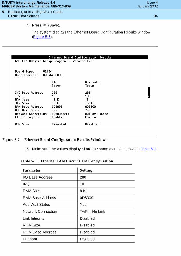
INTUITY Interchange Release 5.4MAP/5P System Maintenance 585-313-809
Issue 4January 2002
Replacing or Installing Circuit Cards 94Circuit Card Settings
5
4. Press (Save).
The system displays the Ethernet Board Configuration Results window (Figure 5-7).
Figure 5-7. Ethernet Board Configuration Results Window
5. Make sure the values displayed are the same as those shown in Table 5-1.
Table 5-1. Ethernet LAN Circuit Card Configuration
Parameter Setting
I/O Base Address 280
IRQ 10
RAM Size 8 K
RAM Base Address 0D8000
Add Wait States Yes
Network Connection TwPr - No Link
Link Integrity Disabled
ROM Size Disabled
ROM Base Address Disabled
Pnpboot Disabled
F3
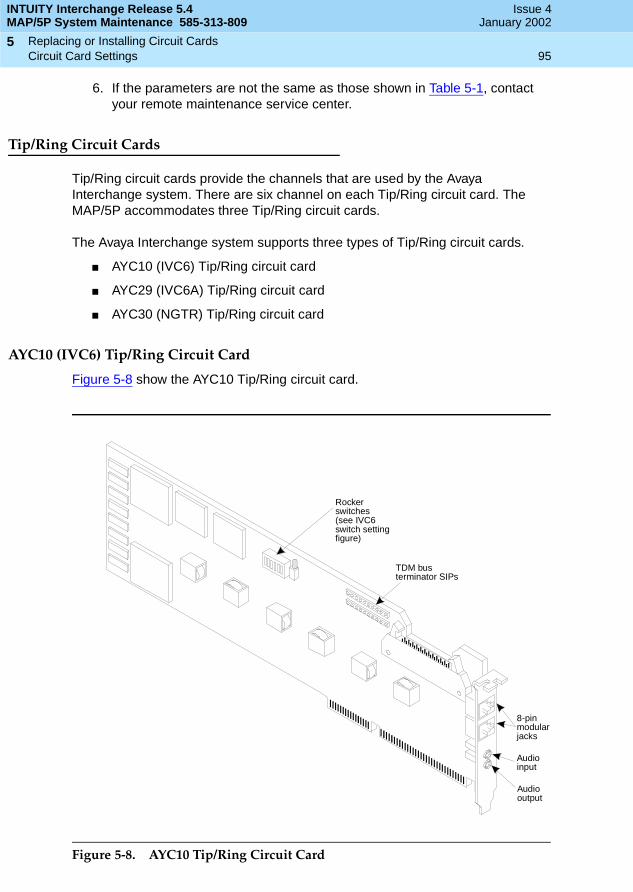
INTUITY Interchange Release 5.4MAP/5P System Maintenance 585-313-809
Issue 4January 2002
Replacing or Installing Circuit Cards 95Circuit Card Settings
5
6. If the parameters are not the same as those shown in Table 5-1, contact your remote maintenance service center.
Tip/Ring Circuit Cards
Tip/Ring circuit cards provide the channels that are used by the Avaya Interchange system. There are six channel on each Tip/Ring circuit card. The MAP/5P accommodates three Tip/Ring circuit cards.
The Avaya Interchange system supports three types of Tip/Ring circuit cards.
■ AYC10 (IVC6) Tip/Ring circuit card
■ AYC29 (IVC6A) Tip/Ring circuit card
■ AYC30 (NGTR) Tip/Ring circuit card
AYC10 (IVC6) Tip/Ring Circuit Card
Figure 5-8 show the AYC10 Tip/Ring circuit card.
Figure 5-8. AYC10 Tip/Ring Circuit Card
8-pinmodularjacks
Audioinput
Audiooutput
TDM busterminator SIPs
Rockerswitches(see IVC6switch settingfigure)

INTUITY Interchange Release 5.4MAP/5P System Maintenance 585-313-809
Issue 4January 2002
Replacing or Installing Circuit Cards 96Circuit Card Settings
5
Each of the possible three Tip/Ring circuit cards in the MAP/5P has a unique address. The addresses are set on the circuit card switch bank (Figure 5-9). There are no jumpers to set on the AYC10 Tip/Ring circuit card.
Figure 5-9. AYC10 Tip/Ring Switch Settings
AYC29 (IVC6A) Tip/Ring Circuit Card
The AYC29 Tip/Ring circuit card is the Australian version of the AYC10 Tip/Ring circuit card. See AYC10 (IVC6) Tip/Ring Circuit Card for jumper information.
Base I/O address = 100 Hex.
IVC6 T/R 0First card installed
Base I/O address = 200 Hex.
IVC6 T/R 1Second card installed
Base I/O address = 300 Hex.
IVC6 T/R 2Third card installed
Base I/O address = 500 Hex.
IVC6 T/R 3Fourth card installed
Base I/O address = 600 Hex.
IVC6 T/R 4Fifth card installed
Base I/O address = 700 Hex.
IVC6 T/R 5Sixth card installed
Base I/O address = 900 Hex.
IVC6 T/R 6Seventh card installed
Rocker switches 5 and 6 can beset either open or closed.
Note:
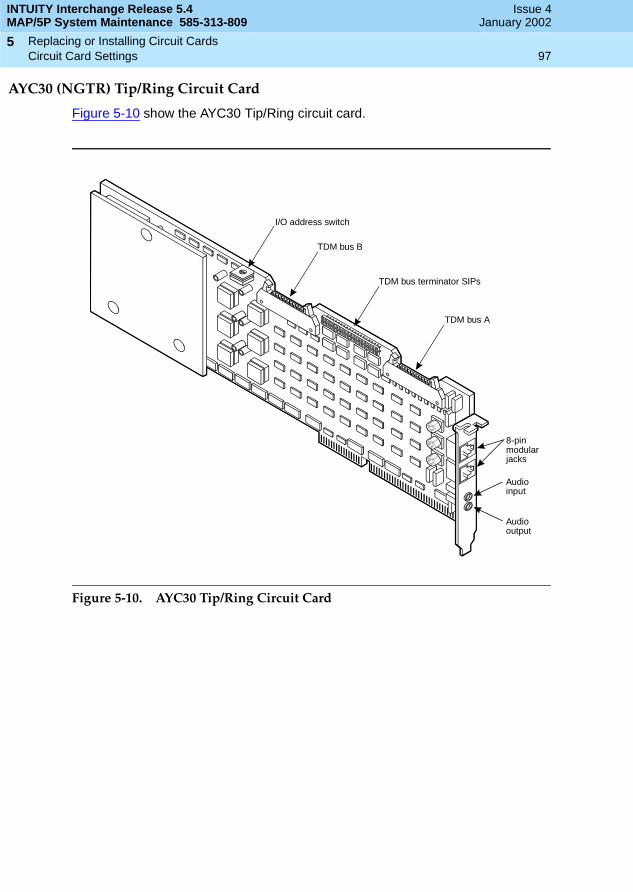
INTUITY Interchange Release 5.4MAP/5P System Maintenance 585-313-809
Issue 4January 2002
Replacing or Installing Circuit Cards 97Circuit Card Settings
5
AYC30 (NGTR) Tip/Ring Circuit Card
Figure 5-10 show the AYC30 Tip/Ring circuit card.
Figure 5-10. AYC30 Tip/Ring Circuit Card
I/O address switch
TDM bus B
TDM bus A
TDM bus terminator SIPs
8-pinmodularjacks
Audiooutput
Audioinput
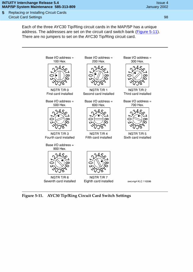
INTUITY Interchange Release 5.4MAP/5P System Maintenance 585-313-809
Issue 4January 2002
Replacing or Installing Circuit Cards 98Circuit Card Settings
5
Each of the three AYC30 Tip/Ring circuit cards in the MAP/5P has a unique address. The addresses are set on the circuit card switch bank (Figure 5-11). There are no jumpers to set on the AYC30 Tip/Ring circuit card.
Figure 5-11. AYC30 Tip/Ring Circuit Card Switch Settings
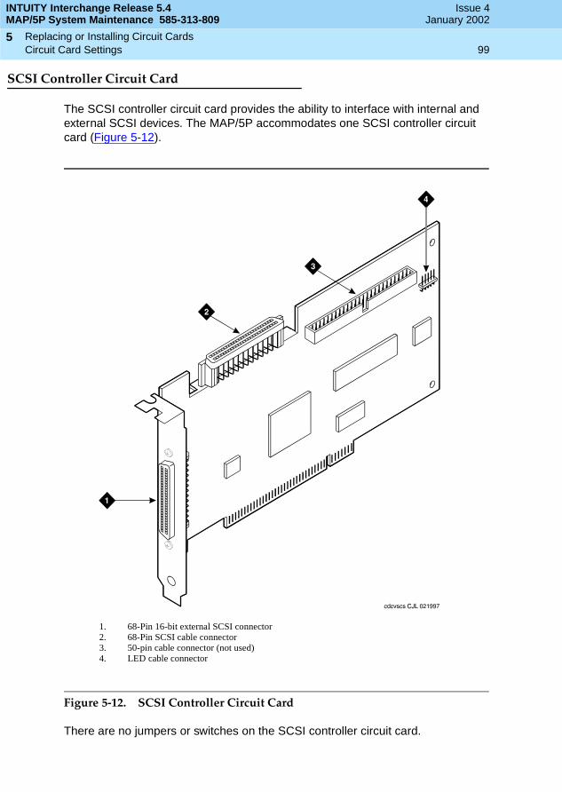
INTUITY Interchange Release 5.4MAP/5P System Maintenance 585-313-809
Issue 4January 2002
Replacing or Installing Circuit Cards 99Circuit Card Settings
5
SCSI Controller Circuit Card
The SCSI controller circuit card provides the ability to interface with internal and external SCSI devices. The MAP/5P accommodates one SCSI controller circuit card (Figure 5-12).
Figure 5-12. SCSI Controller Circuit Card
There are no jumpers or switches on the SCSI controller circuit card.
1. 68-Pin 16-bit external SCSI connector2. 68-Pin SCSI cable connector3. 50-pin cable connector (not used)4. LED cable connector
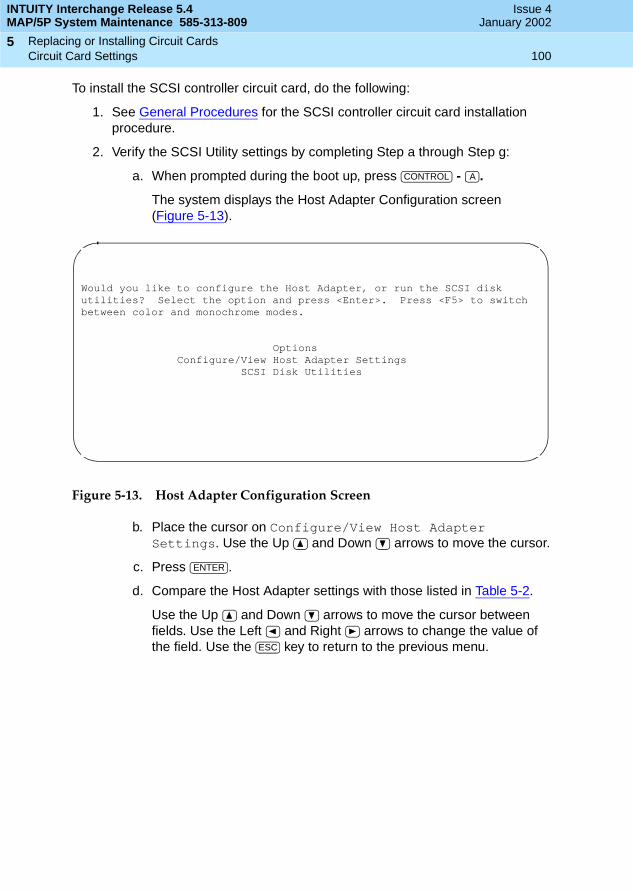
INTUITY Interchange Release 5.4MAP/5P System Maintenance 585-313-809
Issue 4January 2002
Replacing or Installing Circuit Cards 100Circuit Card Settings
5
To install the SCSI controller circuit card, do the following:
1. See General Procedures for the SCSI controller circuit card installation procedure.
2. Verify the SCSI Utility settings by completing Step a through Step g:
a. When prompted during the boot up, press - .
The system displays the Host Adapter Configuration screen (Figure 5-13).
Figure 5-13. Host Adapter Configuration Screen
b. Place the cursor on Configure/View Host Adapter Settings. Use the Up and Down arrows to move the cursor.
c. Press .
d. Compare the Host Adapter settings with those listed in Table 5-2.
Use the Up and Down arrows to move the cursor between fields. Use the Left and Right arrows to change the value of the field. Use the key to return to the previous menu.
CONTROL A
Would you like to configure the Host Adapter, or run the SCSI disk utilities? Select the option and press <Enter>. Press <F5> to switch between color and monochrome modes.
OptionsConfigure/View Host Adapter Settings
SCSI Disk Utilities
ENTER
ESC
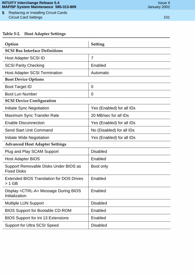
INTUITY Interchange Release 5.4MAP/5P System Maintenance 585-313-809
Issue 4January 2002
Replacing or Installing Circuit Cards 101Circuit Card Settings
5
Table 5-2. Host Adapter Settings
Option Setting
SCSI Bus Interface Definitions
Host Adapter SCSI ID 7
SCSI Parity Checking Enabled
Host Adapter SCSI Termination Automatic
Boot Device Options
Boot Target ID 0
Boot Lun Number 0
SCSI Device Configuration
Initiate Sync Negotiation Yes (Enabled) for all IDs
Maximum Sync Transfer Rate 20 MB/sec for all IDs
Enable Disconnection Yes (Enabled) for all IDs
Send Start Unit Command No (Disabled) for all IDs
Initiate Wide Negotiation Yes (Enabled) for all IDs
Advanced Host Adapter Settings
Plug and Play SCAM Support Disabled
Host Adapter BIOS Enabled
Support Removable Disks Under BIOS as Fixed Disks
Boot only
Extended BIOS Translation for DOS Drives > 1 GB
Enabled
Display <CTRL-A> Message During BIOS Initialization
Enabled
Multiple LUN Support Disabled
BIOS Support for Bootable CD-ROM Enabled
BIOS Support for Int 13 Extensions Enabled
Support for Ultra SCSI Speed Disabled

INTUITY Interchange Release 5.4MAP/5P System Maintenance 585-313-809
Issue 4January 2002
Replacing or Installing Circuit Cards 102Circuit Card Settings
5
e. When you have completed setting the SCSI utility, press .
The system displays the following message:
Do you want to save the SCSI Utility changes
YES NO
f. Place the cursor on YES.
g. Press .
Speech and Signal Processor Circuit Card
The SSP circuit card is equipped with 16 MB of memory contained on a dual in-line memory module (DIMM). The DIMM is located in the lower portion of the SSP circuit card. See Figure 5-14. There must be one SSP circuit card installed on the MAP/5P.
! CAUTION:The DIMM is not field serviceable.
There are no jumpers installed on the SSP card.
There are two types of switches on the SSP card:
■ Two-position switches, Figure 5-15
■ Rotary switch, Figure 5-16
If the SSP card is not located at the end of the TDM bus, set both two-position switches to open. If the SSP circuit card is located at the end of the bus, set the switches to closed.
The rotary switch must be set to zero. See the following procedures:
1. Removing a Circuit Card
2. Installing a Circuit Card
! CAUTION:Use this procedure when adding an SSP circuit card to a system that is not currently equipped with one. Do not use this procedure when replacing a defective circuit card.
To add an SSP circuit card to a Avaya Interchange system:
1. Make sure you have a TDM bus cable. The TDM bus cable connects all of the Tip/Ring circuit cards as well as the SSP circuit card
2. Remove the tip/ring circuit card in Slot 1. See Tip/Ring Circuit Cards.
ESC
ENTER
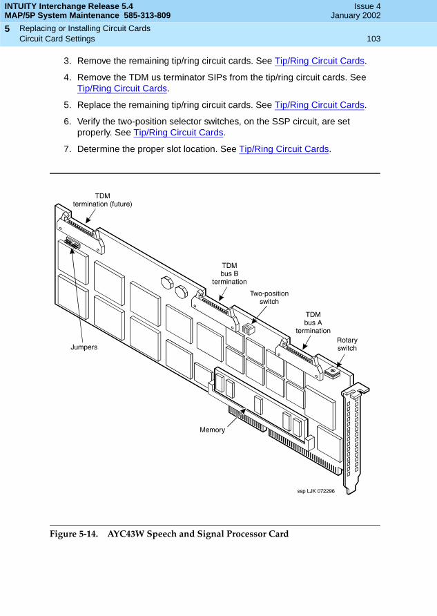
INTUITY Interchange Release 5.4MAP/5P System Maintenance 585-313-809
Issue 4January 2002
Replacing or Installing Circuit Cards 103Circuit Card Settings
5
3. Remove the remaining tip/ring circuit cards. See Tip/Ring Circuit Cards.
4. Remove the TDM us terminator SIPs from the tip/ring circuit cards. See Tip/Ring Circuit Cards.
5. Replace the remaining tip/ring circuit cards. See Tip/Ring Circuit Cards.
6. Verify the two-position selector switches, on the SSP circuit, are set properly. See Tip/Ring Circuit Cards.
7. Determine the proper slot location. See Tip/Ring Circuit Cards.
Figure 5-14. AYC43W Speech and Signal Processor Card

INTUITY Interchange Release 5.4MAP/5P System Maintenance 585-313-809
Issue 4January 2002
Replacing or Installing Circuit Cards 104Circuit Card Settings
5
Figure 5-15. SSP Two-Position Switch
Figure 5-16. SSP Rotary Switch
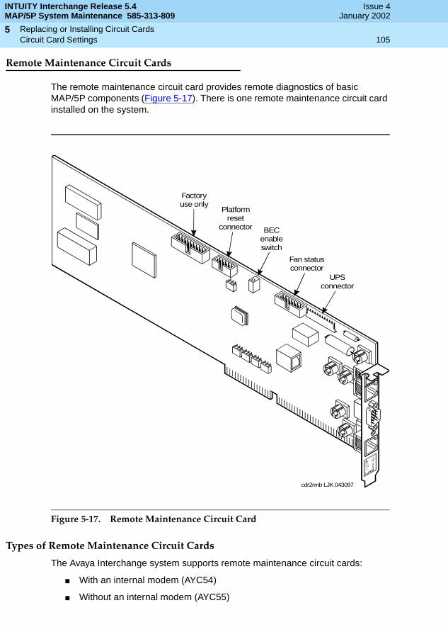
INTUITY Interchange Release 5.4MAP/5P System Maintenance 585-313-809
Issue 4January 2002
Replacing or Installing Circuit Cards 105Circuit Card Settings
5
Remote Maintenance Circuit Cards
The remote maintenance circuit card provides remote diagnostics of basic MAP/5P components (Figure 5-17). There is one remote maintenance circuit card installed on the system.
Figure 5-17. Remote Maintenance Circuit Card
Types of Remote Maintenance Circuit Cards
The Avaya Interchange system supports remote maintenance circuit cards:
■ With an internal modem (AYC54)
■ Without an internal modem (AYC55)
cdr2rmb LJK 043097
UPSconnector
Fan statusconnector
BECenableswitch
Platformreset
connector
Factoryuse only
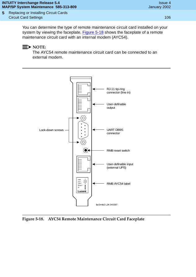
INTUITY Interchange Release 5.4MAP/5P System Maintenance 585-313-809
Issue 4January 2002
Replacing or Installing Circuit Cards 106Circuit Card Settings
5
You can determine the type of remote maintenance circuit card installed on your system by viewing the faceplate. Figure 5-18 shows the faceplate of a remote maintenance circuit card with an internal modem (AYC54).
NOTE:The AYC54 remote maintenance circuit card can be connected to an external modem.
Figure 5-18. AYC54 Remote Maintenance Circuit Card Faceplate
Lock-down screws
RMB reset switch
RMB AYC54 label
RJ-11 tip-ringconnector (line in)
User-definableoutput
User-definable input(external UPS)
UART DB9Sconnector
fpr2rmb2 LJK 041597
LINE
OUTUART
RESETIN
Rem
ote
Mai
nte
nanc
eB
oard
AY
C54
Lucent

INTUITY Interchange Release 5.4MAP/5P System Maintenance 585-313-809
Issue 4January 2002
Replacing or Installing Circuit Cards 107Circuit Card Settings
5
Figure 5-19 shows the faceplate of a remote maintenance circuit card without an internal modem (AYC55).
Figure 5-19. AYC55 Remote Maintenance Circuit Card Faceplate
Setting the Resource Options
The remote maintenance circuit card is equipped with a BEC enable switch (Figure 5-17) Ensure that this switch is set to the ON position (Figure 5-20).
Figure 5-20. BEC Enable Switch
Lock-down screws
RMB reset switch
RMB AYC55 label
User-definableoutput
User-definable input(external UPS)
UART DB9Sconnector
fpr2rmb3 LJK 043097
OUTUART
RESETIN
Rem
ote
Mai
nte
nanc
eB
oard
AY
C55
Lucent
ON 1
swr2bec LJK 063097

INTUITY Interchange Release 5.4MAP/5P System Maintenance 585-313-809
Issue 4January 2002
Replacing or Installing Circuit Cards 108Circuit Card Settings
5
Installing the Remote Maintenance Circuit Card Software Package
To install the remote maintenance circuit card software package, do the following:
1. Stop the voice system. See Stopping the Voice System in Chapter 3, Common System Procedures, for this procedure.
2. Start at the Avaya Interchange Main Menu (Figure 2-1) and select
The system displays the Software Install menu (Figure 5-21).
Figure 5-21. Software Install Menu
3. Select Tape drive.
The system displays the following message:
Insert a cartridge into Tape Drive 1.Type [go] when ready, or [q] to quit: (default:go)
4. Insert the tape labeled RMB Software Set in the tape drive.
5. Press .
The system displays the following message:
Installation in progress. Do not remote the cartridge tape.
The following sets are available: 1 RMBset Remote Maintenance Board Package
(AYC54/55)
Select package(s) you wish to process (or ‘all’ to process all packages). (default: all) [?,??,q]
>Software Install
> UNIX Management
> System Management
> Customer/Services Administration
ENTER
INTUITY Interchange Release 5.4MAP/5P System Maintenance 585-313-809
Issue 4January 2002
Replacing or Installing Circuit Cards 109Circuit Card Settings
5
6. Press .
The system displays the following message:
Processing:
Set: RMB Software Set R2.0 (RMBset) from <ctape1>.
Intuity RMB Software Set R2.0(i486)Using </> as the package base directory.
Please select the country code:
01 - United States02 - International
Country code [01]:
7. Enter the appropriate code.
The system displays the following message:
Insert a cartridge into Tape Drive 1.Type [go] when ready or [q] to quit: (default: go)
8. Enter q.
9. Remove the cartridge tape.
10. Start the voice system. See Starting the Voice System in Chapter 3, Common System Procedures, for this procedure.
Replacing a Defective Remote MaintenanceCircuit Card
See General Procedures for procedures on remote maintenance circuit card installation.
1. Complete the procedures listed in Removing a Circuit Card for the defective circuit card.
2. Complete the procedures listed in Inserting the Circuit Card and Reassembling the MAP/5P.
NOTE:Make sure the BEC enable switch on the remote maintenance circuit card is in the ON position (Figure 5-20).
3. Connect the modem line to the remote maintenance circuit card and the switch.
4. Connect the EMI suppression cable to the remote maintenance circuit card and the switch.
ENTER

INTUITY Interchange Release 5.4MAP/5P System Maintenance 585-313-809
Issue 4January 2002
Replacing or Installing Circuit Cards 110Circuit Card Settings
5
5. Complete the procedures listed in Restoring the Avaya Interchange System to Service.
6. Call your remote maintenance center. Inform them that you have replaced the remote maintenance circuit card.
The remote maintenance center logs in through the remote maintenance circuit card and:
■ Sets the passwords.
■ Verifies the product ID.
■ Verifies the alarm destination.
■ Configures all parameters as specified by the Services Organization.
Replacing a Modem with a Remote MaintenanceCircuit Card
See General Procedures for procedures on remote maintenance circuit card installation.
1. If the system is in service, do the following steps.
a. Stop the voice system. See Stopping the Voice System in Chapter 3, Common System Procedures, for this procedure.
b. Shut down the voice system. See Shutting Down the Avaya Interchange System in Chapter 3, Common System Procedures, for this procedure.
2. Remove power from the MAP/5P. See Removing Power from the MAP/5P in Chapter 4, Getting Inside the Computer, for power removal procedures.
3. Remove the dress cover. See Removing the Dress Cover in Chapter 4, Getting Inside the Computer, for power-removal procedures.
4. Complete the procedures included in Inserting the Circuit Card and Reassembling the MAP/5P.
NOTE:Make sure the BEC enable switch on the remote maintenance circuit card is in the ON position (Figure 5-20).
5. Connect the modem line to the remote maintenance circuit card and the switch.
! CAUTION:Step 6 must be completed during the reboot of the system.
INTUITY Interchange Release 5.4MAP/5P System Maintenance 585-313-809
Issue 4January 2002
Replacing or Installing Circuit Cards 111Circuit Card Settings
5
6. Disable COM2 by changing the Serial Ports 16550 Compatible UART 2 to DISABLED.
This setting is located in the CMOS advanced option settings for the CPU. See Verifying the CMOS Settings in Chapter 7, Replacing Other Components, for this procedure.
7. Reboot the Avaya Interchange system. See Rebooting the System in Chapter 3, Common System Procedures, for this procedure.
8. Install the Remote Maintenance Circuit Card Software package. See Installing the Remote Maintenance Circuit Card Software Package for this procedure.
9. Place the BEC enable switch on the remote maintenance circuit card in the ON position (Figure 5-20).
10. Press .
11. Reboot the Avaya Interchange system. See Rebooting the System in Chapter 3, Common System Procedures, for this procedure.
12. Call the remote maintenance center. Inform them that you have installed the remote maintenance circuit card.
The remote maintenance center logs in through the remote maintenance circuit card and:
■ Sets the passwords.
■ Verifies the product ID.
■ Verifies the alarm destination.
Replacing a Remote Maintenance Circuit Cardwith a Modem
To replace a remote maintenance circuit card with a modem, do the following:
1. Call the remote maintenance center. Inform them that you are removing a remote maintenance circuit card and restoring the COM2 Port.
See Removing a Circuit Card for procedures on remote maintenance circuit card removal.
The remote maintenance center completes Step a and Step b:
a. Log in through the remote maintenance circuit card and rested the tsc password.
b. Log off.
ENTER
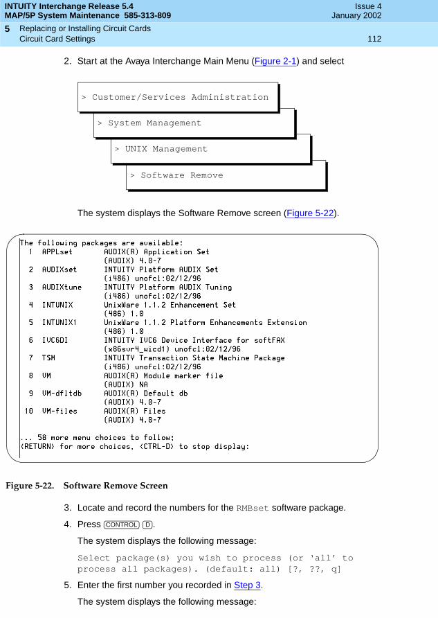
INTUITY Interchange Release 5.4MAP/5P System Maintenance 585-313-809
Issue 4January 2002
Replacing or Installing Circuit Cards 112Circuit Card Settings
5
2. Start at the Avaya Interchange Main Menu (Figure 2-1) and select
The system displays the Software Remove screen (Figure 5-22).
Figure 5-22. Software Remove Screen
3. Locate and record the numbers for the RMBset software package.
4. Press .
The system displays the following message:
Select package(s) you wish to process (or ‘all’ to process all packages). (default: all) [?, ??, q]
5. Enter the first number you recorded in Step 3.
The system displays the following message:
> Software Remove
> UNIX Management
> System Management
> Customer/Services Administration
CONTROL D
INTUITY Interchange Release 5.4MAP/5P System Maintenance 585-313-809
Issue 4January 2002
Replacing or Installing Circuit Cards 113Circuit Card Settings
5
The following set is currently installed:<package title> <package information>
Do you want to remove this set [y, n, q]
6. Enter y.
7. Repeat Step 5 and Step 6 for all remote maintenance circuit card packages.
8. Stop the voice system. See Stopping the Voice System in Chapter 3, Common System Procedures, for this procedure.
9. Shut down the Avaya Interchange system. See Shutting Down the Avaya Interchange System in Chapter 3, Common System Procedures, for this procedure.
10. Remove the remote maintenance circuit card from the MAP/5P. See Removing a Circuit Card for this procedure.
11. Make sure the COM2 port is correctly connected to the motherboard.
12. Replace the dress cover. See Replacing the Dress Cover in Chapter 4, Getting Inside the Computer, for power-removal procedures.
13. Apply power to the MAP/5P. See Restoring Power to the MAP/5P in Chapter 4, Getting Inside the Computer for this procedure.
14. Reboot the Avaya Interchange system. See Rebooting the System in Chapter 3, Common System Procedures, for this procedure.
15. Enable COM2 by changing the Serial Ports 16550 Compatible UART 2 to 02F8, IRQ3.
This setting is located in the CMOS advanced option settings for the CPU. See Verifying the CMOS Settings in Chapter 7, Replacing Other Components, for this procedure.
16. Reboot the Avaya Interchange system. See Rebooting the System in Chapter 3, Common System Procedures, for this procedure.
17. Install the modem.
18. Contact the remote maintenance center and inform them that the remote maintenance circuit card has been removed, the COM2 port has been enabled, and the modem has been installed.
The remote maintenance center then completes the procedure.
NOTE:At this point, verify that the modem has three lit LEDs.
19. Have the remote maintenance center login through the modem and change the tsc password back to the original password.
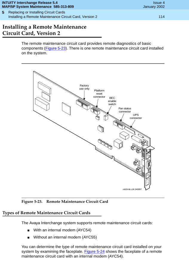
INTUITY Interchange Release 5.4MAP/5P System Maintenance 585-313-809
Issue 4January 2002
Replacing or Installing Circuit Cards 114Installing a Remote Maintenance Circuit Card, Version 2
5
Installing a Remote MaintenanceCircuit Card, Version 2
The remote maintenance circuit card provides remote diagnostics of basic components (Figure 5-23). There is one remote maintenance circuit card installed on the system.
Figure 5-23. Remote Maintenance Circuit Card
Types of Remote Maintenance Circuit Cards
The Avaya Interchange system supports remote maintenance circuit cards:
■ With an internal modem (AYC54)
■ Without an internal modem (AYC55)
You can determine the type of remote maintenance circuit card installed on your system by examining the faceplate. Figure 5-24 shows the faceplate of a remote maintenance circuit card with an internal modem (AYC54).
cdr2rmb LJK 043097
UPSconnector
Fan statusconnector
BECenableswitch
Platformreset
connector
Factoryuse only

INTUITY Interchange Release 5.4MAP/5P System Maintenance 585-313-809
Issue 4January 2002
Replacing or Installing Circuit Cards 115Installing a Remote Maintenance Circuit Card, Version 2
5
NOTE:The AYC54 remote maintenance circuit card can be connected to an external modem.
Figure 5-24. AYC54 Remote Maintenance Circuit Card Faceplate
Figure 5-19 shows the faceplate of a remote maintenance circuit card without an internal modem (AYC55).
Setting the Resource Options
The remote maintenance circuit card is equipped with a BEC enable switch (Figure 5-17). Ensure that this switch is set to the ON position (Figure 5-20).
Lock-down screws
RMB reset switch
RMB AYC54 label
RJ-11 tip-ringconnector (line in)
User-definableoutput
User-definable input(external UPS)
UART DB9Sconnector
fpr2rmb2 LJK 041597
LINE
OUTUART
RESETIN
Rem
ote
Mai
nte
nanc
eB
oard
AY
C54
Lucent

INTUITY Interchange Release 5.4MAP/5P System Maintenance 585-313-809
Issue 4January 2002
Replacing or Installing Circuit Cards 116Installing a Remote Maintenance Circuit Card, Version 2
5
Installing the Remote Maintenance Circuit CardSoftware Package
To install the remote maintenance circuit card software package, do the following:
1. Stop the voice system.
2. Start at the Avaya Interchange Main Menu (Figure 2-1) and select
The system displays the Software Install menu (Figure 5-25).
Figure 5-25. Software Install Menu
3. Select Tape drive.
The system displays the following message:
Insert a cartridge into Tape Drive 1.Type [go] when ready, or [q] to quit: (default:go)
4. Insert the tape labeled RMB Software Set into the tape drive.
5. Press .
The system displays the following message:
Installation in progress. Do not remote the cartridge tape.
The following sets are available: 1 RMBset INTUITY RMB V2 set
(i486) i.2.2
>Software Install
> UNIX Management
> System Management
> Customer/Services Administration
ENTER
INTUITY Interchange Release 5.4MAP/5P System Maintenance 585-313-809
Issue 4January 2002
Replacing or Installing Circuit Cards 117Installing a Remote Maintenance Circuit Card, Version 2
5
Select package(s) you wish to process (or ‘all’ to process all packages). (default: all) [?,??,q]
6. Press .
The system displays the following message:
Processing:
Set: RMB Software Set R2.0 (RMBset) from <ctape1>.
Intuity RMB Software Set R2.0(i486)Using </> as the package base directory.
Please select the country code:
01 - United States02 - International
Country code [01]:
7. Enter the appropriate code.
The system displays the following message:
Insert a cartridge into Tape Drive 1.Type [go] when ready or [q] to quit: (default: go)
8. Enter q.
9. Remove the cartridge tape.
10. Start the voice system.
Replacing a Defective Remote MaintenanceCircuit Card
To replace a defective remote maintenance circuit card, you must:
■ Remove the defective remote maintenance circuit card.
■ Install the new remote maintenance circuit card.
■ Attach external cables to the remote maintenance circuit card.
Removing the Defective Remote Maintenance Circuit Card
To remove the defective remote maintenance circuit card, do the following:
1. Verify that the replacement equipment is on site and appears to be in usable condition, with no obvious shipping damage.
ENTER
INTUITY Interchange Release 5.4MAP/5P System Maintenance 585-313-809
Issue 4January 2002
Replacing or Installing Circuit Cards 118Installing a Remote Maintenance Circuit Card, Version 2
5
NOTE:Note all symptoms of failure and include this information with the remote maintenance circuit card when it is returned.
If the system is in service, do the following:
a. Stop the voice system.
b. Shut down the voice system.
2. Remove power from the computer.
3. Access the circuit card cage.
4. Locate the remote maintenance circuit card.
5. If there are ribbon cables attached to other cards that could impede the removal of the card, disconnect them and place them to the side. Note the connectivity of each cable.
6. Remove the retaining screw from the circuit card faceplate and save it.
7. Remove the circuit card from the backplane slot by gently pulling on each corner of the card.
NOTE:Make sure to install the replacement remote maintenance circuit card in the same backplane slot.
8. Remove the circuit card from the chassis.
! CAUTION:Hold the circuit card carefully by the edges and place it on a grounded mat.
Installing the New Remote Maintenance Circuit Card
To install the new remote maintenance circuit card, you must:
■ Insert the circuit card.
■ Attach cables to the circuit card.
■ Restore the system.
■ Verify the installation.
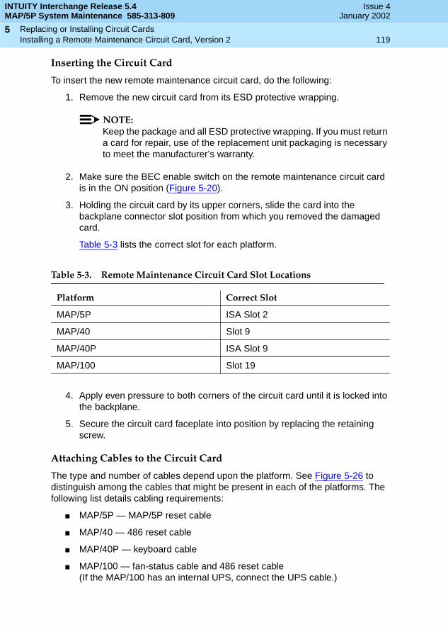
INTUITY Interchange Release 5.4MAP/5P System Maintenance 585-313-809
Issue 4January 2002
Replacing or Installing Circuit Cards 119Installing a Remote Maintenance Circuit Card, Version 2
5
Inserting the Circuit Card
To insert the new remote maintenance circuit card, do the following:
1. Remove the new circuit card from its ESD protective wrapping.
NOTE:Keep the package and all ESD protective wrapping. If you must return a card for repair, use of the replacement unit packaging is necessary to meet the manufacturer’s warranty.
2. Make sure the BEC enable switch on the remote maintenance circuit card is in the ON position (Figure 5-20).
3. Holding the circuit card by its upper corners, slide the card into the backplane connector slot position from which you removed the damaged card.
Table 5-3 lists the correct slot for each platform.
4. Apply even pressure to both corners of the circuit card until it is locked into the backplane.
5. Secure the circuit card faceplate into position by replacing the retaining screw.
Attaching Cables to the Circuit Card
The type and number of cables depend upon the platform. See Figure 5-26 to distinguish among the cables that might be present in each of the platforms. The following list details cabling requirements:
■ MAP/5P — MAP/5P reset cable
■ MAP/40 — 486 reset cable
■ MAP/40P — keyboard cable
■ MAP/100 — fan-status cable and 486 reset cable(If the MAP/100 has an internal UPS, connect the UPS cable.)
Table 5-3. Remote Maintenance Circuit Card Slot Locations
Platform Correct Slot
MAP/5P ISA Slot 2
MAP/40 Slot 9
MAP/40P ISA Slot 9
MAP/100 Slot 19

INTUITY Interchange Release 5.4MAP/5P System Maintenance 585-313-809
Issue 4January 2002
Replacing or Installing Circuit Cards 120Installing a Remote Maintenance Circuit Card, Version 2
5
! WARNING:If the UPS cable is connected to a MAP/100 with dual/redundant power supplies, then damage to the RMB results when power is supplied to the platform.
Figure 5-26. RMB Cables
The cable code (printed on the cable) is as follows:
■ ED5P 208-30 G 32 — fan status cable
■ ED5P 208-30 GR 31 — reset cable
Figure 5-27 and Figure 5-28 show the cable connectors on the remote maintenance circuit card.
UPS cableFan-status cable486/Pentiumreset cable
MAP/5PMAP/60
reset cable
cbr2mult LJK 050297
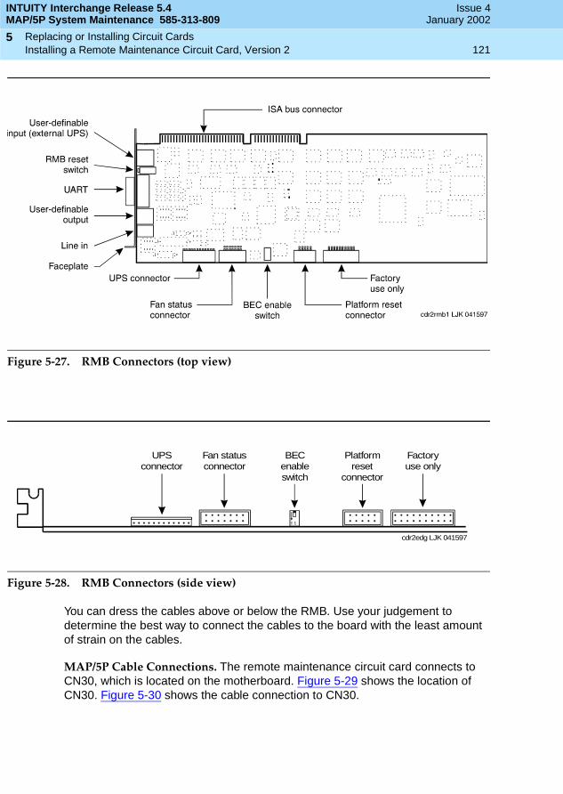
INTUITY Interchange Release 5.4MAP/5P System Maintenance 585-313-809
Issue 4January 2002
Replacing or Installing Circuit Cards 121Installing a Remote Maintenance Circuit Card, Version 2
5
Figure 5-27. RMB Connectors (top view)
Figure 5-28. RMB Connectors (side view)
You can dress the cables above or below the RMB. Use your judgement to determine the best way to connect the cables to the board with the least amount of strain on the cables.
MAP/5P Cable Connections. The remote maintenance circuit card connects to CN30, which is located on the motherboard. Figure 5-29 shows the location of CN30. Figure 5-30 shows the cable connection to CN30.
ON 1
cdr2edg LJK 041597
UPSconnector
Fan statusconnector
BECenableswitch
Platformreset
connector
Factoryuse only

INTUITY Interchange Release 5.4MAP/5P System Maintenance 585-313-809
Issue 4January 2002
Replacing or Installing Circuit Cards 122Installing a Remote Maintenance Circuit Card, Version 2
5
Figure 5-29. Motherboard Jumper Locations
1. JP5 — flash BIOS function2. JP6 — BIOS ROM type3. JP1 — BIOS type4. JP2 — LED function5. JP15 — standby power connector6. JP4 — second-level cache7. JP3 — second-level cache8. JP30 — external battery connector9. JP16 — software shutdown
10. JP42 — L2 cache mode11. JP43 — CPU voltage for I/O12. JP7 — regulator13. JP44 — CPU voltage for core14. JP11 — SMM/reset switch15. JP14 — power-on switch connector16. CN3017. CN19

INTUITY Interchange Release 5.4MAP/5P System Maintenance 585-313-809
Issue 4January 2002
Replacing or Installing Circuit Cards 123Installing a Remote Maintenance Circuit Card, Version 2
5
Figure 5-30. Motherboard Cable Connections
Restoring the System
To restore the system, do the following:
1. Replace all cables removed from other cards.
2. Make sure these cables are attached to their proper terminations.
3. Close the computer.
4. Reboot the voice system.
1. RMB reset cable connector (pins 1 and 2 of CN30)2. Reset switch connector (pins 19 and 20 of CN19)3. Turbo LED connector (pins 12 and 13 of CN19)4. Power LED connector (pins 3, 4, and 5 of CN19)

INTUITY Interchange Release 5.4MAP/5P System Maintenance 585-313-809
Issue 4January 2002
Replacing or Installing Circuit Cards 124Installing a Remote Maintenance Circuit Card, Version 2
5
Verifying the Installation
To verify the installation of the circuit card, do the following:
1. Start at the Avaya Interchange Main Menu (Figure 2-1) and select
The system displays the View Installed Hardware window(Figure 5-31).
Figure 5-31. View Installed Hardware Window
2. Verify that the system has identified the new circuit card.
Attaching External Cables to the Remote Maintenance Circuit Card
To connect the remote maintenance circuit card, do the following:
1. Connect the modem line to the remote maintenance circuit card and the switch.
2. Connect the external UPS line to the modem.
3. Connect the EMI suppression cable to the remote maintenance circuit card and the switch.
4. Restore the system to service.
> View Installed Hardware
> System Verification
> Customer/Services Administration
INTUITY Interchange Release 5.4MAP/5P System Maintenance 585-313-809
Issue 4January 2002
Replacing or Installing Circuit Cards 125Installing a Remote Maintenance Circuit Card, Version 2
5
5. Call the remote maintenance center. Inform them that you have installed the remote maintenance circuit card.
The remote maintenance center then logs in through the remote maintenance circuit card:
■ Sets the passwords
■ Verifies the product ID
■ Verifies the alarm destination
■ Configures all parameters as specified by the Services Organization

INTUITY Interchange Release 5.4MAP/5P System Maintenance 585-313-809
Issue 4January 2002
Replacing or Installing Circuit Cards 126Installing a Remote Maintenance Circuit Card, Version 2
5
Replacing the Hard Disk Drive 127Overview
6
INTUITY Interchange Release 5.4MAP/5P System Maintenance 585-313-809
Issue 4January 2002
66Replacing the Hard Disk Drive
Overview
This chapter describes:
■ Identifying a failed hard disk drive
■ Software procedures for preparing the system for a new hard disk drive
■ Hardware procedures for replacing a hard disk drive
■ Software procedures for initializing a hard disk drive
Purpose
The purpose of this chapter is to ensure that hard disk drives are installed in the proper manner.
Identifying a Failed Hard Disk Drive
Before a hard disk drive can be replaced, you must identify which drive has failed. This section details how to identify a failed hard disk drive in Avaya Interchange systems with two hard disk drives.
INTUITY Interchange Release 5.4MAP/5P System Maintenance 585-313-809
Issue 4January 2002
Replacing the Hard Disk Drive 128Recovering from a Hard Disk Drive 0 Failure
6
Recovering from a Hard DiskDrive 0 Failure
See the procedures in Chapter 4, New Installation and System Recovery Procedures, in Avaya Interchange Release 5.4 Installation and System Recovery for information on how to recover from this type of hard disk drive failure.
Recovering from a Hard DiskDrive 1 Failure
See the procedures in Chapter 4, New Installation and System Recovery Procedures, in Avaya Interchange Release 5.4 Installation and System Recovery for information on how to recover from this type of hard disk drive failure.
Installing an Avaya InterchangeSystem with Two New Hard Disk Drives
To install an Avaya Interchange system with two new hard disk drives, do the following:
1. Install the hard disk drives. See Hard Disk Drive 0 Installation and Hard Disk Drive 1 Installation for this procedure.
2. Complete the procedures in Chapter 4, New Installation and System Recovery Procedures, in Avaya Interchange Release 5.4 Installation and System Recovery.
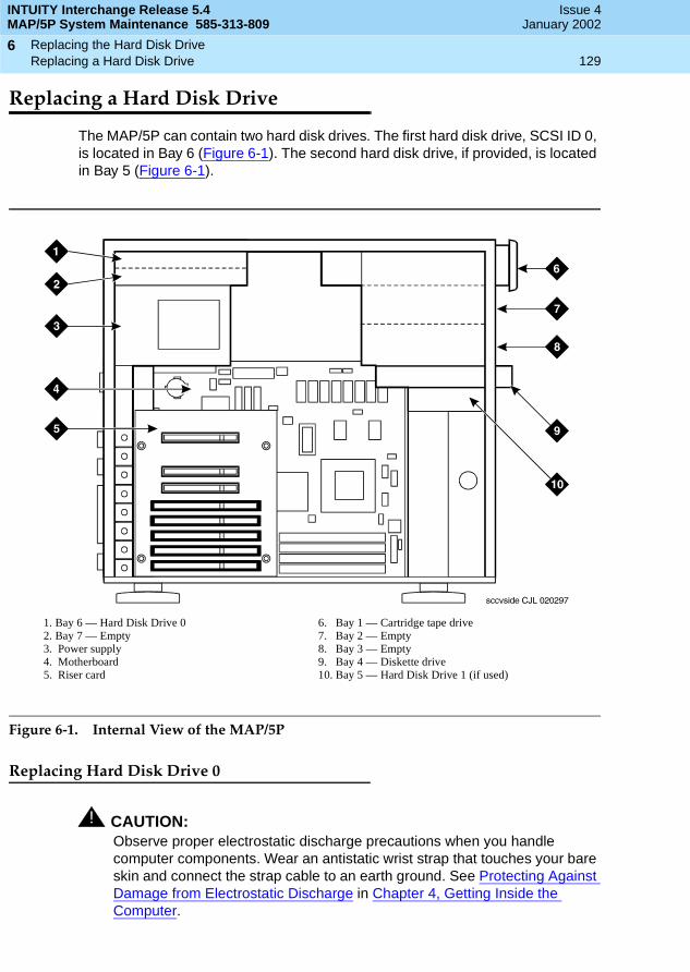
INTUITY Interchange Release 5.4MAP/5P System Maintenance 585-313-809
Issue 4January 2002
Replacing the Hard Disk Drive 129Replacing a Hard Disk Drive
6
Replacing a Hard Disk Drive
The MAP/5P can contain two hard disk drives. The first hard disk drive, SCSI ID 0, is located in Bay 6 (Figure 6-1). The second hard disk drive, if provided, is located in Bay 5 (Figure 6-1).
Figure 6-1. Internal View of the MAP/5P
Replacing Hard Disk Drive 0
! CAUTION:Observe proper electrostatic discharge precautions when you handle computer components. Wear an antistatic wrist strap that touches your bare skin and connect the strap cable to an earth ground. See Protecting Against Damage from Electrostatic Discharge in Chapter 4, Getting Inside the Computer.
1. Bay 6 — Hard Disk Drive 02. Bay 7 — Empty3. Power supply4. Motherboard5. Riser card
6. Bay 1 — Cartridge tape drive7. Bay 2 — Empty8. Bay 3 — Empty9. Bay 4 — Diskette drive10. Bay 5 — Hard Disk Drive 1 (if used)

INTUITY Interchange Release 5.4MAP/5P System Maintenance 585-313-809
Issue 4January 2002
Replacing the Hard Disk Drive 130Replacing a Hard Disk Drive
6
Hard Disk Drive 0 Removal
To remove Hard Disk Drive 0, you must:
■ Remove the Avaya Interchange system from service.
■ Access the hard disk drive.
■ Extract the hard disk drive.
Removing the Avaya Interchange System from Service
To remove the Avaya Interchange system from service, do the following.
NOTE:This procedure is not necessary if Hard Disk Drive 0 has failed on a single-disk system.
1. Verify that the replacement equipment is on site and appears to be in usable condition, with no obvious shipping damage.
2. Stop the voice system. See Stopping the Voice System in Chapter 3, Common System Procedures, for this procedure.
3. Shut down the voice system. See Shutting Down the Avaya Interchange System in Chapter 3, Common System Procedures, for this procedure.
4. Remove the incoming power. See Removing Power from the MAP/5P in Chapter 4, Getting Inside the Computer, for this procedure.
Accessing Hard Disk Drive 0
To access Hard Disk Drive 0, remove the dress cover. See Removing the Dress Cover in Chapter 4, Getting Inside the Computer, for this procedure.
Extracting Hard Disk Drive 0
To extract Hard Disk Drive 0, do the following:
1. Remove the SCSI cable from the back of the hard disk drive.
2. Remove the power cord from the back of the hard disk drive.
3. Locate the screws holding Hard Disk Drive 0 to the peripheral bay frame.
NOTE:Pay close attention to the location of the screws in both the peripheral frame and the hard disk drive.
4. Holding the rear of the hard disk drive, remove these screws.
5. Place the hard disk drive assembly, with the printed circuit board facing up, on an ESD-protected surface.
6. Continue with the next procedure, Hard Disk Drive 0 Installation.

INTUITY Interchange Release 5.4MAP/5P System Maintenance 585-313-809
Issue 4January 2002
Replacing the Hard Disk Drive 131Replacing a Hard Disk Drive
6
Hard Disk Drive 0 Installation
To install Hard Disk Drive 0, you do the following:
■ Set the jumper settings.
■ Insert the hard disk drive.
Setting the Hard Disk Drive 0 Jumper Settings
The Avaya Interchange system supports the following two types of hard disk drives:
■ Seagate (Figure 6-2)
■ Capricorn
Figure 6-2. Seagate Hard Disk Drive
Figure 6-3 shows the correct jumper settings for the Seagate hard disk drive SCSI ID 0.
drcvsg1 LJK 062397
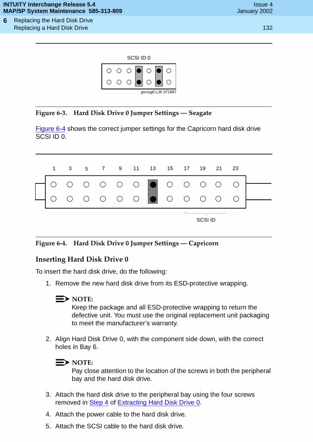
INTUITY Interchange Release 5.4MAP/5P System Maintenance 585-313-809
Issue 4January 2002
Replacing the Hard Disk Drive 132Replacing a Hard Disk Drive
6
Figure 6-3. Hard Disk Drive 0 Jumper Settings — Seagate
Figure 6-4 shows the correct jumper settings for the Capricorn hard disk drive SCSI ID 0.
Figure 6-4. Hard Disk Drive 0 Jumper Settings — Capricorn
Inserting Hard Disk Drive 0
To insert the hard disk drive, do the following:
1. Remove the new hard disk drive from its ESD-protective wrapping.
NOTE:Keep the package and all ESD-protective wrapping to return the defective unit. You must use the original replacement unit packaging to meet the manufacturer’s warranty.
2. Align Hard Disk Drive 0, with the component side down, with the correct holes in Bay 6.
NOTE:Pay close attention to the location of the screws in both the peripheral bay and the hard disk drive.
3. Attach the hard disk drive to the peripheral bay using the four screws removed in Step 4 of Extracting Hard Disk Drive 0.
4. Attach the power cable to the hard disk drive.
5. Attach the SCSI cable to the hard disk drive.
SCSI ID 0
jpcvsg0 LJK 071697
1 3 5 7 9 11 13 15 17 19 21 23
SCSI ID
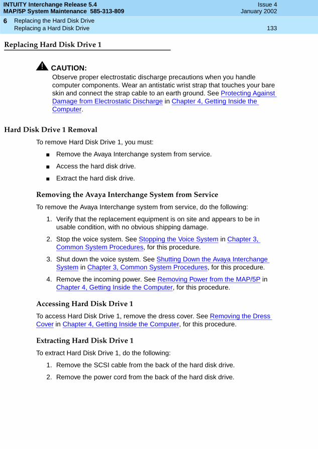
INTUITY Interchange Release 5.4MAP/5P System Maintenance 585-313-809
Issue 4January 2002
Replacing the Hard Disk Drive 133Replacing a Hard Disk Drive
6
Replacing Hard Disk Drive 1
! CAUTION:Observe proper electrostatic discharge precautions when you handle computer components. Wear an antistatic wrist strap that touches your bare skin and connect the strap cable to an earth ground. See Protecting Against Damage from Electrostatic Discharge in Chapter 4, Getting Inside the Computer.
Hard Disk Drive 1 Removal
To remove Hard Disk Drive 1, you must:
■ Remove the Avaya Interchange system from service.
■ Access the hard disk drive.
■ Extract the hard disk drive.
Removing the Avaya Interchange System from Service
To remove the Avaya Interchange system from service, do the following:
1. Verify that the replacement equipment is on site and appears to be in usable condition, with no obvious shipping damage.
2. Stop the voice system. See Stopping the Voice System in Chapter 3, Common System Procedures, for this procedure.
3. Shut down the voice system. See Shutting Down the Avaya Interchange System in Chapter 3, Common System Procedures, for this procedure.
4. Remove the incoming power. See Removing Power from the MAP/5P in Chapter 4, Getting Inside the Computer, for this procedure.
Accessing Hard Disk Drive 1
To access Hard Disk Drive 1, remove the dress cover. See Removing the Dress Cover in Chapter 4, Getting Inside the Computer, for this procedure.
Extracting Hard Disk Drive 1
To extract Hard Disk Drive 1, do the following:
1. Remove the SCSI cable from the back of the hard disk drive.
2. Remove the power cord from the back of the hard disk drive.
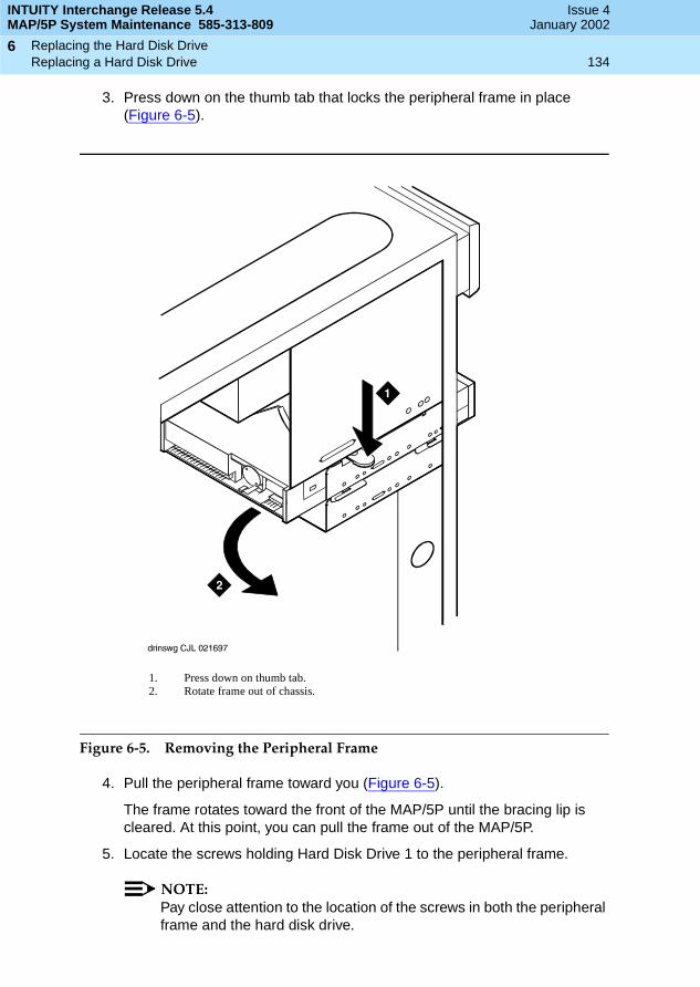
INTUITY Interchange Release 5.4MAP/5P System Maintenance 585-313-809
Issue 4January 2002
Replacing the Hard Disk Drive 134Replacing a Hard Disk Drive
6
3. Press down on the thumb tab that locks the peripheral frame in place (Figure 6-5).
Figure 6-5. Removing the Peripheral Frame
4. Pull the peripheral frame toward you (Figure 6-5).
The frame rotates toward the front of the MAP/5P until the bracing lip is cleared. At this point, you can pull the frame out of the MAP/5P.
5. Locate the screws holding Hard Disk Drive 1 to the peripheral frame.
NOTE:Pay close attention to the location of the screws in both the peripheral frame and the hard disk drive.
1. Press down on thumb tab.2. Rotate frame out of chassis.
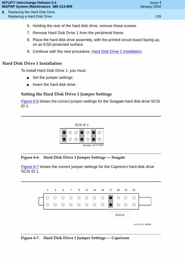
INTUITY Interchange Release 5.4MAP/5P System Maintenance 585-313-809
Issue 4January 2002
Replacing the Hard Disk Drive 135Replacing a Hard Disk Drive
6
6. Holding the rear of the hard disk drive, remove these screws.
7. Remove Hard Disk Drive 1 from the peripheral frame.
8. Place the hard disk drive assembly, with the printed circuit board facing up, on an ESD-protected surface.
9. Continue with the next procedure, Hard Disk Drive 1 Installation.
Hard Disk Drive 1 Installation
To install Hard Disk Drive 1, you must:
■ Set the jumper settings.
■ Insert the hard disk drive.
Setting the Hard Disk Drive 1 Jumper Settings
Figure 6-6 shows the correct jumper settings for the Seagate hard disk drive SCSI ID 1.
Figure 6-6. Hard Disk Drive 1 Jumper Settings — Seagate
Figure 6-7 shows the correct jumper settings for the Capricorn hard disk drive SCSI ID 1.
Figure 6-7. Hard Disk Drive 1 Jumper Settings — Capricorn
SCSI ID 1
jpcvsg1 LJK 071697
1 3 5 7 9 11 13 15 17 19 21 23
SCSI ID
scsi_io1 CJL 060696
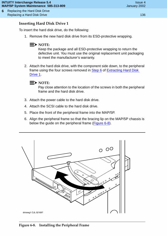
INTUITY Interchange Release 5.4MAP/5P System Maintenance 585-313-809
Issue 4January 2002
Replacing the Hard Disk Drive 136Replacing a Hard Disk Drive
6
Inserting Hard Disk Drive 1
To insert the hard disk drive, do the following:
1. Remove the new hard disk drive from its ESD-protective wrapping.
NOTE:Keep the package and all ESD-protective wrapping to return the defective unit. You must use the original replacement unit packaging to meet the manufacturer’s warranty.
2. Attach the hard disk drive, with the component side down, to the peripheral frame using the four screws removed in Step 6 of Extracting Hard Disk Drive 1.
NOTE:Pay close attention to the location of the screws in both the peripheral frame and the hard disk drive.
3. Attach the power cable to the hard disk drive.
4. Attach the SCSI cable to the hard disk drive.
5. Place the front of the peripheral frame into the MAP/5P.
6. Align the peripheral frame so that the bracing lip on the MAP/5P chassis is below the guide on the peripheral frame (Figure 6-8).
Figure 6-8. Installing the Peripheral Frame

INTUITY Interchange Release 5.4MAP/5P System Maintenance 585-313-809
Issue 4January 2002
Replacing the Hard Disk Drive 137Cleaning a Hard Disk Drive
6
7. Rotate the peripheral frame into the MAP/5P chassis until it is locked in place.
8. Check the cable connections to both the diskette drive and Hard Disk Drive 1.
Cleaning a Hard Disk Drive
A hard disk drive that contains data cannot be installed in a Avaya Interchange system. The hard disk drive must be cleaned before use. The hard disk drives can be cleaned by:
■ Using the fdisk command
■ Performing a low-level format
Using the fdisk Command
To clean a hard disk drive by using the fdisk command, do the following:
1. Log in to the system as root.
2. Enter fdisk /dev/rdsk/c0t1d0s0.
! CAUTION:The phrase c0t1d0s0 is the name of the disk to be cleaned. The phrase c0t1d0s0 is correct for Hard Disk Drive 1. Hard Disk Drive 0 is named c0t0d0s0.
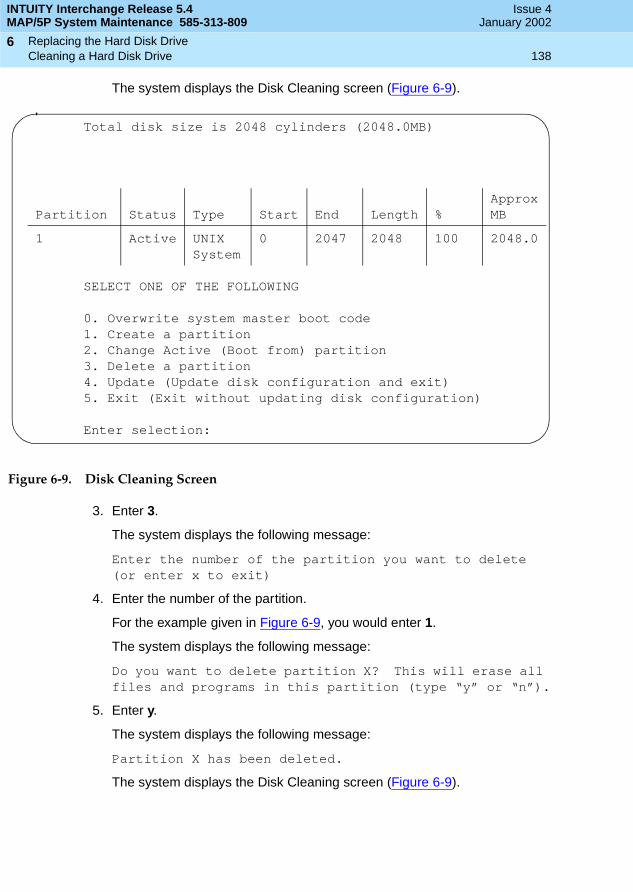
INTUITY Interchange Release 5.4MAP/5P System Maintenance 585-313-809
Issue 4January 2002
Replacing the Hard Disk Drive 138Cleaning a Hard Disk Drive
6
The system displays the Disk Cleaning screen (Figure 6-9).
Figure 6-9. Disk Cleaning Screen
3. Enter 3.
The system displays the following message:
Enter the number of the partition you want to delete(or enter x to exit)
4. Enter the number of the partition.
For the example given in Figure 6-9, you would enter 1.
The system displays the following message:
Do you want to delete partition X? This will erase all files and programs in this partition (type “y” or “n”).
5. Enter y.
The system displays the following message:
Partition X has been deleted.
The system displays the Disk Cleaning screen (Figure 6-9).
Total disk size is 2048 cylinders (2048.0MB)
SELECT ONE OF THE FOLLOWING
0. Overwrite system master boot code1. Create a partition2. Change Active (Boot from) partition3. Delete a partition4. Update (Update disk configuration and exit)5. Exit (Exit without updating disk configuration)
Enter selection:
Partition Status Type Start End Length %ApproxMB
1 Active UNIXSystem
0 2047 2048 100 2048.0

INTUITY Interchange Release 5.4MAP/5P System Maintenance 585-313-809
Issue 4January 2002
Replacing the Hard Disk Drive 139Cleaning a Hard Disk Drive
6
6. Enter 4.
The system displays the following message:
If you have created or altered a partition, you must initialize the partition to reflect the new configuration. For a UNIX System partition run the disksetup(1m) command. For a DOS partiton, run the DOS format command. Changes limited to the “Active” status field require no additional action.
You have completed the procedure for cleaning a hard disk drive.
Performing a Low-Level Format
To low-level format a hard disk drive, do the following:
1. Reboot the system. See Rebooting the System in Chapter 3, Common System Procedures.
2. Press - when prompted.
The system displays the Host Adapter Configuration screen (Figure 6-10).
Figure 6-10. Host Adapter Configuration Screen
3. Place the cursor on SCSI Disk Utilities. Use the Up andDown arrow keys to move the cursor.
4. Press .
CONTROL A
Would you like to configure the host adapter or run the SCSI disk utilities? Select the option and press <Enter>. Press <F5> to switch between color or monochrome.
OptionsConfigure/View Host Adapter SettingsSCSI Disk Utilities
ENTER
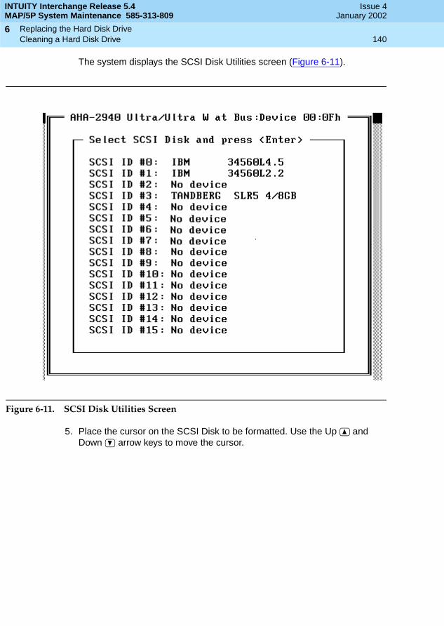
INTUITY Interchange Release 5.4MAP/5P System Maintenance 585-313-809
Issue 4January 2002
Replacing the Hard Disk Drive 140Cleaning a Hard Disk Drive
6
The system displays the SCSI Disk Utilities screen (Figure 6-11).
Figure 6-11. SCSI Disk Utilities Screen
5. Place the cursor on the SCSI Disk to be formatted. Use the Up and Down arrow keys to move the cursor.
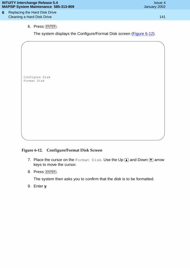
INTUITY Interchange Release 5.4MAP/5P System Maintenance 585-313-809
Issue 4January 2002
Replacing the Hard Disk Drive 141Cleaning a Hard Disk Drive
6
6. Press .
The system displays the Configure/Format Disk screen (Figure 6-12).
Figure 6-12. Configure/Format Disk Screen
7. Place the cursor on the Format Disk. Use the Up and Down arrow keys to move the cursor.
8. Press .
The system then asks you to confirm that the disk is to be formatted.
9. Enter y.
ENTER
Configure DiskFormat Disk
ENTER

INTUITY Interchange Release 5.4MAP/5P System Maintenance 585-313-809
Issue 4January 2002
Replacing the Hard Disk Drive 142Cleaning a Hard Disk Drive
6

Replacing Other Components 143Overview
7
INTUITY Interchange Release 5.4MAP/5P System Maintenance 585-313-809
Issue 4January 2002
77Replacing Other Components
Overview
This chapter describes the procedures for replacing the:
■ Cartridge tape drive
■ CMOS battery
■ Diskette drive
■ Fans
■ Memory
■ Motherboard
■ Riser card
■ Power supply
Purpose
The purpose of this chapter is to ensure that the correct procedures are used to replace the internal components of the MAP/5P. This chapter also provides information on the correct configuration and settings for the individual components.
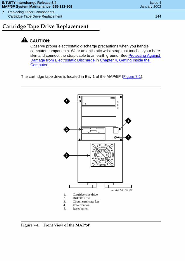
INTUITY Interchange Release 5.4MAP/5P System Maintenance 585-313-809
Issue 4January 2002
Replacing Other Components 144Cartridge Tape Drive Replacement
7
Cartridge Tape Drive Replacement
! CAUTION:Observe proper electrostatic discharge precautions when you handle computer components. Wear an antistatic wrist strap that touches your bare skin and connect the strap cable to an earth ground. See Protecting Against Damage from Electrostatic Discharge in Chapter 4, Getting Inside the Computer.
The cartridge tape drive is located in Bay 1 of the MAP/5P (Figure 7-1).
Figure 7-1. Front View of the MAP/5P
1. Cartridge tape drive2. Diskette drive3. Circuit card cage fan4. Power button5. Reset button

INTUITY Interchange Release 5.4MAP/5P System Maintenance 585-313-809
Issue 4January 2002
Replacing Other Components 145Cartridge Tape Drive Replacement
7
The following procedures detail removal and installation of the cartridge tape drive for the MAP/5P (Figure 7-2).
Figure 7-2. Cartridge Tape Drive
Cartridge Tape Drive Removal
To remove a cartridge tape drive, you complete the following tasks:
■ Remove the Avaya Interchange system from service.
■ Access the cartridge tape drive.
■ Extract the cartridge tape drive.
Removing the Avaya Interchange System from Service
To remove the Avaya Interchange system from service, do the following:
1. Verify that the replacement equipment is on site and appears to be in usable condition, with no obvious shipping damage.
2. Stop the voice system. See Stopping the Voice System in Chapter 3, Common System Procedures, for this procedure.
1. Jumpers 2. Terminating resistors
INTUITY Interchange Release 5.4MAP/5P System Maintenance 585-313-809
Issue 4January 2002
Replacing Other Components 146Cartridge Tape Drive Replacement
7
3. Shut down the voice system. See Shutting Down the Avaya Interchange System in Chapter 3, Common System Procedures, for this procedure.
4. Remove the incoming power. See Removing Power from the MAP/5P in Chapter 4, Getting Inside the Computer, for this procedure.
Accessing the Cartridge Tape Drive
To access the cartridge tape drive, remove the dress cover. See Removing the Dress Cover in Chapter 4, Getting Inside the Computer, for this procedure.
Extracting the Cartridge Tape Drive
To extract the cartridge tape drive, do the following:
1. Remove the SCSI cable from the cartridge tape drive.
NOTE:Make sure the SCSI cable pin adapter remains attached to the SCSI cable.
2. Remove the power cord from the cartridge tape drive.
3. Locate the four screws on peripheral bay chassis that secure the drive in Position 1 of the peripheral bay.
NOTE:Pay close attention to the location of the screws in both the peripheral bay chassis and the cartridge tape drive. If the screws are returned to a different position, the cartridge tape drive could protrude too much from the chassis or be recessed too far into the chassis.
4. Holding the rear of the drive, loosen and remove these mounting screws.
5. Slide the drive forward within the peripheral bay and remove through the front opening of the chassis.
! CAUTION:The drive fits tightly in the peripheral bay. Do not scrape the wiring or the components on the underside of the drive.
6. Continue with the next procedure, Cartridge Tape Drive Installation.

INTUITY Interchange Release 5.4MAP/5P System Maintenance 585-313-809
Issue 4January 2002
Replacing Other Components 147Cartridge Tape Drive Replacement
7
Cartridge Tape Drive Installation
To install a cartridge tape drive, you complete the following tasks:
■ Verify the resource options.
■ Insert the cartridge tape drive.
■ Reassemble the MAP/5P.
■ Restore the Avaya Interchange system.
Verifying the Resource Options
To verify the resource options, do the following:
1. Remove the three terminating resistors on the cartridge tape drive (Figure 7-2).
2. Verify that the settings are correct (Figure 7-3).
Figure 7-3. Jumper Settings for the Cartridge Tape Drive, SCSI ID = 3
Inserting the Cartridge Tape Drive
To insert the cartridge tape drive, do the following:
1. Remove the new cartridge tape unit from its ESD-protective wrapping.
NOTE:Keep the package and all ESD-protective wrapping to return the defective unit. You must use the original replacement unit packaging to meet the manufacturer’s warranty.
2. Place the new drive in the Position 1 of the peripheral bay chassis with the printed circuit board side down.
3. Position the unit so that the cartridge tape drive screw holes line up with the appropriate holes in the peripheral bay.
INTUITY Interchange Release 5.4MAP/5P System Maintenance 585-313-809
Issue 4January 2002
Replacing Other Components 148CMOS Battery Replacement
7
NOTE:Pay close attention to the location of the screws in both the peripheral bay chassis and the cartridge tape drive. If the screws are returned to a different position, the cartridge tape drive could protrude too much from the chassis or be recessed too far into the chassis.
4. Secure the drive in the peripheral bay using the four screws removed in Step 4 of the procedure, Extracting the Cartridge Tape Drive.
5. Attach the power cable to the cartridge tape drive.
6. Attach the SCSI cable to the cartridge tape drive.
NOTE:Make sure the SCSI cable pin adapter is attached to the SCSI cable.
Reassembling the MAP/5P
To reassemble the MAP/5P, replace the dress cover. See Replacing the Dress Cover in Chapter 4, Getting Inside the Computer, for this procedure.
Restoring the Avaya Interchange System
To restore the Avaya Interchange system, do the following:
1. Restore power to the MAP/5P. See Restoring Power to the MAP/5P in Chapter 4, Getting Inside the Computer, for this procedure.
2. Verify the Avaya Interchange system operation by placing a call to a user.
CMOS Battery Replacement
! CAUTION:Observe proper electrostatic discharge precautions when you handle computer components. Wear an antistatic wrist strap that touches your bare skin and connect the strap cable to an earth ground. See Protecting Against Damage from Electrostatic Discharge in Chapter 4, Getting Inside the Computer.
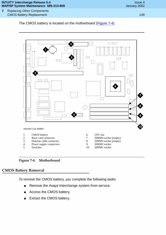
INTUITY Interchange Release 5.4MAP/5P System Maintenance 585-313-809
Issue 4January 2002
Replacing Other Components 149CMOS Battery Replacement
7
The CMOS battery is located on the motherboard (Figure 7-4).
Figure 7-4. Motherboard
CMOS Battery Removal
To remove the CMOS battery, you complete the following tasks:
■ Remove the Avaya Interchange system from service.
■ Access the CMOS battery.
■ Extract the CMOS battery.
1. CMOS battery2. Riser card connector3. Diskette cable connector4. Power supply connectors5. Switches
6. CPU fan7. SIMM4 socket (empty)8. SIMM3 socket (empty)9. SIMM2 socket10. SIMM1 socket
INTUITY Interchange Release 5.4MAP/5P System Maintenance 585-313-809
Issue 4January 2002
Replacing Other Components 150CMOS Battery Replacement
7
Removing the Avaya Interchange Systemfrom Service
To remove the Avaya Interchange system from service, do the following:
1. Verify that the replacement equipment is on site and appears to be in usable condition, with no obvious shipping damage.
2. Stop the voice system. See Stopping the Voice System in Chapter 3, Common System Procedures, for this procedure.
3. Shut down the voice system. See Shutting Down the Avaya Interchange System in Chapter 3, Common System Procedures, for this procedure.
4. Remove the incoming power. See Removing Power from the MAP/5P in Chapter 4, Getting Inside the Computer, for this procedure.
Accessing the CMOS Battery
To access the CMOS battery, remove the dress cover. See Removing the Dress Cover in Chapter 4, Getting Inside the Computer, for this procedure.
Extracting the CMOS Battery
To extract the CMOS battery, do the following:
1. Gently push the battery to the side, away from the rear of the MAP/5P, until it has cleared the retaining bracket.
2. Pull the battery from the motherboard.
CMOS Battery Installation
To install the CMOS battery, you complete the following tasks:
■ Insert the CMOS battery.
■ Reassemble the MAP/5P.
■ Restore the Avaya Interchange system.
■ Verify the CMOS settings.
Inserting the CMOS Battery
To insert the CMOS battery, do the following:
1. Gently push the battery to the side, away from the rear of the MAP/5P, until it has cleared the retaining bracket.
2. Push the battery into the motherboard.

INTUITY Interchange Release 5.4MAP/5P System Maintenance 585-313-809
Issue 4January 2002
Replacing Other Components 151Diskette Drive Replacement
7
Reassembling the MAP/5P
To reassemble the MAP/5P, replace the dress cover. See Replacing the Dress Cover in Chapter 4, Getting Inside the Computer, for this procedure.
Restoring the Avaya Interchange System
To restore the Avaya Interchange system, do the following:
1. Restore power to the MAP/5P. See Restoring Power to the MAP/5P in Chapter 4, Getting Inside the Computer, for this procedure.
2. Verify the Avaya Interchange system operation by placing a call to a user.
Verifying the CMOS Settings
To verify the CMOS settings, see Inserting the Motherboard.
Diskette Drive Replacement
! CAUTION:Observe proper electrostatic discharge precautions when you handle computer components. Wear an antistatic wrist strap that touches your bare skin and connect the strap cable to an earth ground. See Protecting Against Damage from Electrostatic Discharge in Chapter 4, Getting Inside the Computer.
The 1.44-MB. 3.5-inch diskette drive is located in Bay 4 of the peripheral bay, as shown in Figure 7-1. There are no jumpers associated with the diskette drive used in the MAP/5P.
NOTE:If you are replacing the diskette cable, you must remove the riser card. See Riser Card Replacement for this procedure.
Diskette Drive Removal
To remove the diskette drive, you complete the following tasks:
■ Remove the Avaya Interchange system from service.
■ Access the diskette drive.
■ Extract the diskette drive.

INTUITY Interchange Release 5.4MAP/5P System Maintenance 585-313-809
Issue 4January 2002
Replacing Other Components 152Diskette Drive Replacement
7
Removing the Avaya Interchange Systemfrom Service
To remove the Avaya Interchange system from service, do the following:
1. Verify that the replacement equipment is on site and appears to be in usable condition, with no obvious shipping damage.
2. Stop the voice system. See Stopping the Voice System in Chapter 3, Common System Procedures, for this procedure.
3. Shut down the voice system. See Shutting Down the Avaya Interchange System in Chapter 3, Common System Procedures, for this procedure.
4. Remove the incoming power. See Removing Power from the MAP/5P in Chapter 4, Getting Inside the Computer, for this procedure.
Accessing the Diskette Drive
To access the diskette drive, remove the dress cover. See Removing the Dress Cover in Chapter 4, Getting Inside the Computer, for this procedure.
Extracting the Diskette Drive
To extract the diskette drive, do the following:
1. Remove the diskette cable from the back of the diskette drive.
2. Remove the power cord from the back of the diskette drive.

INTUITY Interchange Release 5.4MAP/5P System Maintenance 585-313-809
Issue 4January 2002
Replacing Other Components 153Diskette Drive Replacement
7
3. Press down on the thumb tab which locks the peripheral frame in place (Figure 7-5).
Figure 7-5. Removing the Peripheral Frame
4. Pull the peripheral frame toward you (Figure 7-5).
The frame then rotates toward the front of the MAP/5P until the bracing lip is cleared. At this point, you can pull the frame out of the MAP/5P.
5. Locate the screws holding the diskette drive to the peripheral frame.
NOTE:Pay close attention to the location of the screws in both the peripheral frame and the diskette drive. If the screws are returned to a different position, the diskette drive could protrude too far from the chassis far or be recessed too much into the chassis.
1. Press down on thumb tab.2. Rotate frame out of chassis.

INTUITY Interchange Release 5.4MAP/5P System Maintenance 585-313-809
Issue 4January 2002
Replacing Other Components 154Diskette Drive Replacement
7
6. Holding the rear of the diskette drive, remove these screws.
7. Remove the diskette drive from the peripheral frame.
! CAUTION:Handle the diskette drive with care. The spindle motor, stepping motor, and printed circuit board are located on the bottom of the diskette drive. Do not place any force or strain on these components and do not touch the surface of the diskette drive printed circuit board.
8. Place the diskette drive assembly, with the printed circuit board facing up, on an ESD-protected surface.
9. Continue with the next procedure, Diskette Drive Installation.
Diskette Drive Installation
To install the diskette drive, you complete the following tasks:
■ Insert the diskette drive.
■ Reassemble the MAP/5P.
■ Restore the Avaya Interchange system.
Inserting the Diskette Drive
To insert the diskette drive, do the following:
1. Remove the new diskette drive from its ESD-protective wrapping.
NOTE:Keep the package and all ESD-protective wrapping to return the defective unit. You must use of the original replacement unit packaging to meet the manufacturer’s warranty.
2. Attach the diskette drive to the peripheral frame using the four screws removed in Step 6 of Extracting the Diskette Drive.
NOTE:Pay close attention to the location of the screws in both the peripheral frame and the diskette drive. If the screws are returned to a different position, the diskette drive could protrude too far from the chassis far or be recessed too much into the chassis.
3. Attach the power cable to the diskette drive.
4. Attach the diskette cable to the diskette drive.
5. Place the front of the peripheral frame into the MAP/5P.

INTUITY Interchange Release 5.4MAP/5P System Maintenance 585-313-809
Issue 4January 2002
Replacing Other Components 155Diskette Drive Replacement
7
6. Align the peripheral frame so that the bracing lip on the MAP/5P chassis is below the guide on the peripheral frame (Figure 7-6).
Figure 7-6. Installing the Peripheral Frame
7. Rotate the peripheral frame into the MAP/5P chassis until it is locked in place (Figure 7-6).
8. Check the cable connections to both the diskette drive and Hard Disk Drive 1 (if installed).
Reassembling the MAP/5P
To reassemble the MAP/5P, replace the dress cover. See Replacing the Dress Cover in Chapter 4, Getting Inside the Computer, for this procedure.
Restoring the Avaya Interchange System
To restore the Avaya Interchange system, do the following:
1. Restore power to the MAP/5P. See Restoring Power to the MAP/5P in Chapter 4, Getting Inside the Computer, for this procedure.
2. Verify the Avaya Interchange system operation by placing a call to a user.
INTUITY Interchange Release 5.4MAP/5P System Maintenance 585-313-809
Issue 4January 2002
Replacing Other Components 156Fan Replacement
7
Fan Replacement
! CAUTION:Observe proper electrostatic discharge precautions when you handle computer components. Wear an antistatic wrist strap that touches your bare skin and connect the strap cable to an earth ground. See Protecting Against Damage from Electrostatic Discharge in Chapter 4, Getting Inside the Computer.
The MAP/5P contains the following fans that provide cooling inside the unit:
■ Power supply fan
■ Circuit card cage fan
■ CPU fan
The power supply fan is located inside the power supply and is not serviceable. Never attempt repairs to this fan. If it fails, you must replace the entire power supply. See Power Supply Replacement for more information.
Circuit Card Cage Fan Replacement
The circuit card cage fan is located in front of the card cage, behind the dress cover (Figure 7-1). The circuit card cage fan forces air flow through the MAP/5P chassis, across the circuit cards.
Circuit Card Cage Fan Removal
To remove the circuit card cage fan, you complete the following tasks:
■ Remove the Avaya Interchange system from service.
■ Access the circuit card cage fan.
■ Extract the circuit card cage fan.
Removing the Avaya Interchange System from Service
To remove the Avaya Interchange system from service, do the following:
1. Verify that the replacement equipment is on site and appears to be in usable condition, with no obvious shipping damage.
2. Stop the voice system. See Stopping the Voice System in Chapter 3, Common System Procedures, for this procedure.
3. Shut down the voice system. See Shutting Down the Avaya Interchange System in Chapter 3, Common System Procedures, for this procedure.
4. Remove the incoming power. See Removing Power from the MAP/5P in Chapter 4, Getting Inside the Computer, for this procedure.

INTUITY Interchange Release 5.4MAP/5P System Maintenance 585-313-809
Issue 4January 2002
Replacing Other Components 157Fan Replacement
7
Accessing the Circuit Card Cage Fan
To access the circuit card cage fan, do the following:
1. Remove the dress cover. See Removing the Dress Cover in Chapter 4, Getting Inside the Computer, for this procedure.
2. Remove the protective aluminum screen that holds the circuit card cage fan in the chassis.
Extracting the Circuit Card Cage Fan
To extract the circuit card cage fan, do the following:
1. Lift the circuit card cage fan out of the chassis.
2. Unplug the 12-VDC power lead connector.
! CAUTION:Do not operate the MAP/5P for any length of time without the circuit card cage fan installed and operational.
3. Continue with the next procedure, Circuit Card Cage Fan Installation.
Circuit Card Cage Fan Installation
To install the circuit card cage fan, you complete the following tasks:
■ Insert the circuit card cage fan.
■ Reassemble the MAP/5P.
■ Restore the Avaya Interchange system.
Inserting the Circuit Card Cage Fan
To insert the circuit card cage fan, do the following:
1. Attach the 12-VDC connector to the circuit card cage fan.
2. Place the circuit card cage fan in the MAP/5P chassis.
NOTE:Make sure the air flow is directed into the MAP/5P chassis. There is an air flow direction arrow on the fan.
Reassembling the MAP/5P
To reassemble the MAP/5P, do the following:
1. Replace the aluminum screen.
2. Replace the dress cover. See Replacing the Dress Cover in Chapter 4, Getting Inside the Computer, for this procedure.

INTUITY Interchange Release 5.4MAP/5P System Maintenance 585-313-809
Issue 4January 2002
Replacing Other Components 158Fan Replacement
7
Restoring the Avaya Interchange System
To restore the Avaya Interchange system, do the following:
1. Restore power to the MAP/5P. See Restoring Power to the MAP/5P in Chapter 4, Getting Inside the Computer, for this procedure.
2. Verify that the replacement fan is operating by placing a small sheet of paper across the grill on the intake side of the fan. The paper should adhere to the grill.
If the fan is not operating or is spinning very slowly, check all wiring connections and voltages to ensure that the replacement unit is receiving power.
! CAUTION:Do not leave the MAP/5P powered up for any length of time until the circuit card cage fan is fully operational.
3. Verify the Avaya Interchange system operation by placing a call to a user.
CPU Fan Replacement
The CPU fan is located on the motherboard, on top of the CPU (Figure 7-4).
CPU Fan Removal
To remove the circuit card cage fan, you complete the following tasks:
■ Remove the Avaya Interchange system from service.
■ Access the CPU fan.
■ Extract the CPU fan.
Removing the Avaya Interchange System from Service
To remove the Avaya Interchange system from service, do the following:
1. Verify that the replacement equipment is on site and appears to be in usable condition, with no obvious shipping damage.
2. Stop the voice system. See Stopping the Voice System in Chapter 3, Common System Procedures, for this procedure.
3. Shut down the voice system. See Shutting Down the Avaya Interchange System in Chapter 3, Common System Procedures, for this procedure.
4. Remove the incoming power. See Removing Power from the MAP/5P in Chapter 4, Getting Inside the Computer, for this procedure.

INTUITY Interchange Release 5.4MAP/5P System Maintenance 585-313-809
Issue 4January 2002
Replacing Other Components 159Fan Replacement
7
Accessing the CPU Fan
To access the CPU fan, do the following:
1. Remove the dress cover. See Removing the Dress Cover in Chapter 4, Getting Inside the Computer, for this procedure.
2. Remove all of the circuit cards. See Removing a Circuit Card in Chapter 5, Replacing or Installing Circuit Cards, for this procedure.
NOTE:Pay close attention to the riser card connector slots from which each circuit card is removed. Replace the circuit cards in the same slots in the new riser card. See Component Assignments in Appendix A, System Configuration, for circuit card placement.
Extracting the CPU Fan
To extract the CPU fan, do the following:
1. Remove the two screws that hold the CPU fan to the motherboard.
2. Lift the CPU out of the chassis.
3. Unplug the 12-VDC power lead connector.
4. Continue with the next procedure, CPU Fan Installation.
CPU Fan Installation
To install the CPU fan, you complete the following tasks:
■ Insert the CPU fan.
■ Reassemble the MAP/5P.
■ Restore the Avaya Interchange system.
Inserting the CPU Fan
To insert the CPU fan, do the following:
1. Attach the 12-VDC connector to the CPU fan.
2. Place the CPU fan on the motherboard.
3. Replace the two screws that hold the CPU fan to the motherboard.
Reassembling the MAP/5P
To reassemble the MAP/5P, do the following:
1. Replace the circuit cards. See Installing a Circuit Card in Chapter 5, Replacing or Installing Circuit Cards, for this procedure.
2. Replace the dress cover. See Replacing the Dress Cover in Chapter 4, Getting Inside the Computer, for this procedure.

INTUITY Interchange Release 5.4MAP/5P System Maintenance 585-313-809
Issue 4January 2002
Replacing Other Components 160Memory Replacement
7
Restoring the Avaya Interchange System
To restore the Avaya Interchange system, do the following:
1. Restore power to the MAP/5P. See Restoring Power to the MAP/5P in Chapter 4, Getting Inside the Computer, for this procedure.
2. Verify the Avaya Interchange system operation by placing a call to a user.
Memory Replacement
Single in-line memory modules (SIMMs) are located in the lower right hand portion of the motherboard (Figure 7-4). The following situations could indicate a missing or defective SIMM:
■ The system does not boot up.
■ The power-on memory test fails.
■ A parity error on the motherboard occurs.
In the case of a defective SIMM, replace both SIMMs.
! CAUTION:Observe proper electrostatic discharge precautions when you handle computer components. Wear an antistatic wrist strap that touches your bare skin and connect the strap cable to an earth ground. See Protecting Against Damage from Electrostatic Discharge in Chapter 4, Getting Inside the Computer.
SIMM Removal
To remove the SIMMs, you complete the following tasks:
■ Remove the Avaya Interchange system from service.
■ Access the SIMMs.
■ Verify the SIMM seating.
■ Extract the SIMMs.
Removing the Avaya Interchange System from Service
To remove the Avaya Interchange system from service, do the following:
1. Verify that the replacement equipment is on site and appears to be in usable condition, with no obvious shipping damage.
2. Stop the voice system. See Stopping the Voice System in Chapter 3, Common System Procedures, for this procedure.

INTUITY Interchange Release 5.4MAP/5P System Maintenance 585-313-809
Issue 4January 2002
Replacing Other Components 161Memory Replacement
7
3. Shut down the voice system. See Shutting Down the Avaya Interchange System in Chapter 3, Common System Procedures, for this procedure.
4. Remove the incoming power. See Removing Power from the MAP/5P in Chapter 4, Getting Inside the Computer, for this procedure.
Accessing the SIMMs
To access the SIMMs, do the following:
1. Remove the dress cover. See Removing the Dress Cover in Chapter 4, Getting Inside the Computer, for this procedure.
2. Remove the circuit cards in the bottom three slots. See Removing a Circuit Card in Chapter 5, Replacing or Installing Circuit Cards.
Verifying the SIMM Seating
To verify the SIMM seating, do the following:
1. Apply pressure to both SIMMs to ensure they are properly seated.
2. If both SIMMs are properly seated, then replace both. Continue with the next procedure, Extracting the SIMMs.
If one or more of the SIMMs are not properly installed or seated, complete Step a through Step d:
a. Properly seat the SIMM.
b. Replace the dress cover. See Replacing the Dress Cover in Chapter 4, Getting Inside the Computer, for this procedure.
c. Restore the incoming power. See Restoring Power to the MAP/5P in Chapter 4, Getting Inside the Computer, for this procedure.
d. Reboot the system. See Rebooting the System in Chapter 3, Common System Procedures, for this procedure.
If the system shows an amount of memory equal to that installed, the problem has been corrected. Complete the following Steps 1 through 7:
1. Shut down the voice system. See Shutting Down the Avaya Interchange System in Chapter 3, Common System Procedures, for this procedure.
2. Remove the incoming power. See Removing Power from the MAP/5P in Chapter 4, Getting Inside the Computer, for this procedure.
3. Remove the dress cover. See Removing the Dress Cover in Chapter 4, Getting Inside the Computer, for this procedure.
4. Replace the circuit cards in the bottom three slots. See Installing a Circuit Card in Chapter 5, Replacing or Installing Circuit Cards.

INTUITY Interchange Release 5.4MAP/5P System Maintenance 585-313-809
Issue 4January 2002
Replacing Other Components 162Memory Replacement
7
5. Replace the dress cover. See Replacing the Dress Cover in Chapter 4, Getting Inside the Computer, for this procedure.
6. Restore the incoming power. See Restoring Power to the MAP/5P in Chapter 4, Getting Inside the Computer, for this procedure.
7. Reboot the system. See Rebooting the System in Chapter 3, Common System Procedures, for this procedure.
If the system shows an amount of memory less than that installed on the card, replace both of the SIMMs. Continue with the next procedure, Extracting the SIMMs.
Extracting the SIMMs
To extract the SIMMs, do the following:
1. Release the metal snap locks at the edge of the SIMM2 socket by gently pushing the locks to the outside (Figure 7-7).
Figure 7-7. SIMM Socket
2. Rotate the SIMM downward to approximately a 45-degree angle.
3. Remove the SIMM.
4. Repeat Step 1 through Step 3 for the SIMM located in the SIMM1 socket.
5. Continue with the next procedure, SIMM Installation.
1. SIMM in socket — top view 2. SIMM — side view
INTUITY Interchange Release 5.4MAP/5P System Maintenance 585-313-809
Issue 4January 2002
Replacing Other Components 163Memory Replacement
7
SIMM Installation
To install the SIMMs, you complete the following tasks:
■ Insert the SIMMs.
■ Reassemble the MAP/5P.
■ Restore the Avaya Interchange system.
Inserting the SIMMs
To insert the SIMMs, do the following:
1. Install a SIMM in the SIMM1 socket by positioning the SIMM at approximately a 45-degree angle with respect to the motherboard.
All SIMMs are keyed to prevent them from being inserted incorrectly.
2. Push down on the SIMM at that angle until the SIMM is reseated in the SIMM carrier.
3. Snap the SIMM into place by rotating it to an upright position.
The metal snap lock on the ends of the connector for the SIMM are first forced open and then lock when in the upright position.
4. Ensure the connector guide pins are seated in the clearance holes provided at each end of the SIMM.
When properly seated, the guides are fully extended into the circuit card clearance holes.
5. Repeat Step 1 through Step 4 to install a SIMM in the SIMM2 socket.
Reassembling the MAP/5P
To reassemble the MAP/5P, do the following:
1. Replace the circuit cards in the bottom three slots. See Installing a Circuit Card in Chapter 5, Replacing or Installing Circuit Cards.
2. Replace the dress cover. See Replacing the Dress Cover in Chapter 4, Getting Inside the Computer, for this procedure.
INTUITY Interchange Release 5.4MAP/5P System Maintenance 585-313-809
Issue 4January 2002
Replacing Other Components 164Motherboard Replacement
7
Restoring the Avaya Interchange System
To restore the Avaya Interchange system, do the following:
1. Restore power to the MAP/5P. See Restoring Power to the MAP/5P in Chapter 4, Getting Inside the Computer, for this procedure.
2. Verify the Avaya Interchange system operation by placing a call to a user.
Motherboard Replacement
! CAUTION:Observe proper electrostatic discharge precautions when you handle computer components. Wear an antistatic wrist strap that touches your bare skin and connect the strap cable to an earth ground. See Protecting Against Damage from Electrostatic Discharge in Chapter 4, Getting Inside the Computer.
Motherboard Removal
To remove the motherboard, you complete the following tasks:
■ Remove the Avaya Interchange system from service.
■ Access the motherboard.
■ Extract the motherboard.
Removing the Avaya Interchange System from Service
To remove the Avaya Interchange system from service, do the following:
1. Verify that the replacement equipment is on site and appears to be in usable condition, with no obvious shipping damage.
2. Stop the voice system. See Stopping the Voice System in Chapter 3, Common System Procedures, for this procedure.
3. Shut down the voice system. See Shutting Down the Avaya Interchange System in Chapter 3, Common System Procedures, for this procedure.
4. Remove the incoming power. See Removing Power from the MAP/5P in Chapter 4, Getting Inside the Computer, for this procedure.

INTUITY Interchange Release 5.4MAP/5P System Maintenance 585-313-809
Issue 4January 2002
Replacing Other Components 165Motherboard Replacement
7
Accessing the Motherboard
To access the motherboard, do the following:
1. Disconnect any cables attached to the ports in the back of the MAP/5P (Figure 7-8).
Figure 7-8. Rear View of the MAP/5P
1. Power supply fan intake2. Keyboard connector3. Mouse connector4. COM15. COM26. Parallel port7. Video connector8. AC power supply outlet9. Dress cover lock10. AC voltage selector switch11. AC power inlet receptacle

INTUITY Interchange Release 5.4MAP/5P System Maintenance 585-313-809
Issue 4January 2002
Replacing Other Components 166Motherboard Replacement
7
2. Remove the dress cover. See Removing the Dress Cover in Chapter 4, Getting Inside the Computer, for this procedure.
3. Remove all of the circuit cards. See Removing a Circuit Card in Chapter 5, Replacing or Installing Circuit Cards.
4. Remove the riser card. See Riser Card Removal for this procedure.
Extracting the Motherboard
To extract the motherboard, do the following:
1. Disconnect the diskette cable from the motherboard (Figure 7-4).
2. Disconnect the power supply connections from the motherboard (Figure 7-4).
3. Push up on the motherboard-retaining bracket.
4. Gently pull the motherboard forward until it has cleared the alignment pegs.
5. Slide the motherboard toward the front of the MAP/5P to allow the cable connectors, in the rear of the MAP/5P, to clear the chassis.
6. Remove the motherboard from the MAP/5P chassis.
7. Remove the memory from the motherboard. See SIMM Removal for this procedure.
NOTE:The new motherboard contains no memory. Use the memory from the defective motherboard to populate the replacement.
8. Continue with the next procedure, Motherboard Installation.
Motherboard Installation
To install the motherboard, you complete the following tasks:
■ Verify the resource options.
■ Insert the motherboard.
■ Reassemble the MAP/5P.
■ Restore the Avaya Interchange system.
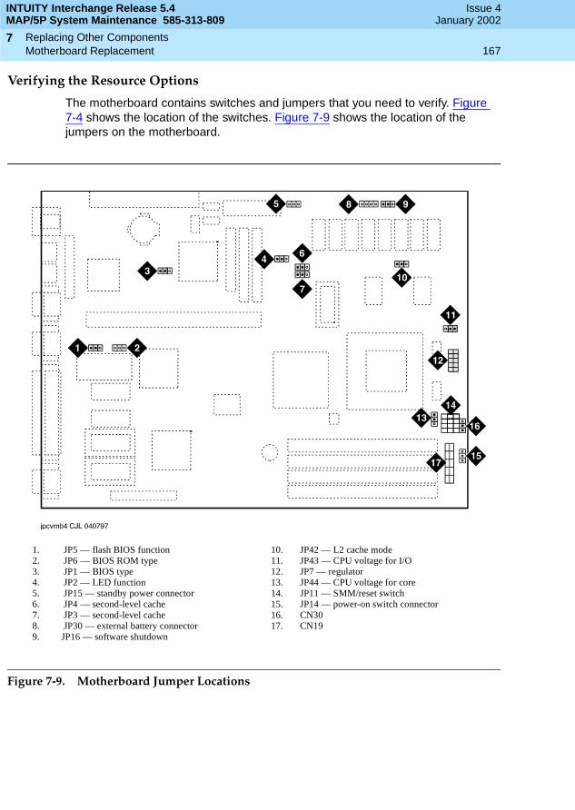
INTUITY Interchange Release 5.4MAP/5P System Maintenance 585-313-809
Issue 4January 2002
Replacing Other Components 167Motherboard Replacement
7
Verifying the Resource Options
The motherboard contains switches and jumpers that you need to verify. Figure 7-4 shows the location of the switches. Figure 7-9 shows the location of the jumpers on the motherboard.
Figure 7-9. Motherboard Jumper Locations
1. JP5 — flash BIOS function2. JP6 — BIOS ROM type3. JP1 — BIOS type4. JP2 — LED function5. JP15 — standby power connector6. JP4 — second-level cache7. JP3 — second-level cache8. JP30 — external battery connector9. JP16 — software shutdown
10. JP42 — L2 cache mode11. JP43 — CPU voltage for I/O12. JP7 — regulator13. JP44 — CPU voltage for core14. JP11 — SMM/reset switch15. JP14 — power-on switch connector16. CN3017. CN19

INTUITY Interchange Release 5.4MAP/5P System Maintenance 585-313-809
Issue 4January 2002
Replacing Other Components 168Motherboard Replacement
7
To verify the resource options, do the following:
1. Verify the jumper settings on the motherboard (Figure 7-10).
Figure 7-10. Motherboard Jumper Settings
2. Verify the switch settings on the motherboard (Figure 7-11).
Figure 7-11. Motherboard Switch Settings
INTUITY Interchange Release 5.4MAP/5P System Maintenance 585-313-809
Issue 4January 2002
Replacing Other Components 169Motherboard Replacement
7
Inserting the Motherboard
To insert the motherboard, do the following:
1. Place the SIMMs from the defective motherboard on to the replacement motherboard. See SIMM Installation for this procedure.
2. Place the motherboard in the MAP/5P.
3. Align the external cable connectors on the motherboard with the corresponding holes in the MAP/5P chassis.
4. Slide the motherboard to the rear of the MAP/5P so that the external cable connectors protrude through the rear of the unit.
5. Align the holes in the motherboard with the alignment pegs in the MAP/5P (Figure 7-4).
6. Gently push the motherboard into the MAP/5P until the retaining bracket has snapped into place (Figure 7-4).
7. Attach the diskette cable to the motherboard (Figure 7-4).
8. Attach the power supply connections to the motherboard (Figure 7-4).
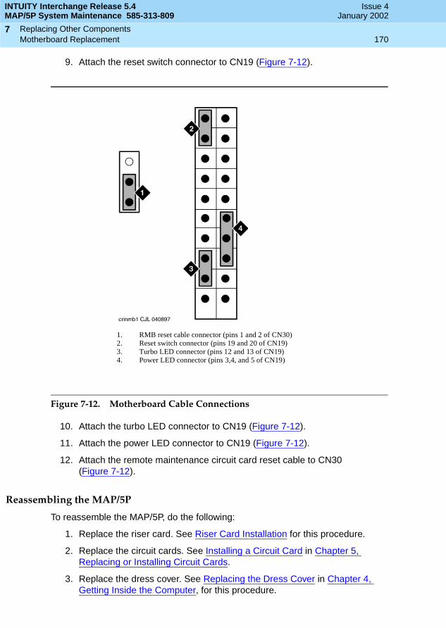
INTUITY Interchange Release 5.4MAP/5P System Maintenance 585-313-809
Issue 4January 2002
Replacing Other Components 170Motherboard Replacement
7
9. Attach the reset switch connector to CN19 (Figure 7-12).
Figure 7-12. Motherboard Cable Connections
10. Attach the turbo LED connector to CN19 (Figure 7-12).
11. Attach the power LED connector to CN19 (Figure 7-12).
12. Attach the remote maintenance circuit card reset cable to CN30 (Figure 7-12).
Reassembling the MAP/5P
To reassemble the MAP/5P, do the following:
1. Replace the riser card. See Riser Card Installation for this procedure.
2. Replace the circuit cards. See Installing a Circuit Card in Chapter 5, Replacing or Installing Circuit Cards.
3. Replace the dress cover. See Replacing the Dress Cover in Chapter 4, Getting Inside the Computer, for this procedure.
1. RMB reset cable connector (pins 1 and 2 of CN30)2. Reset switch connector (pins 19 and 20 of CN19)3. Turbo LED connector (pins 12 and 13 of CN19)4. Power LED connector (pins 3,4, and 5 of CN19)
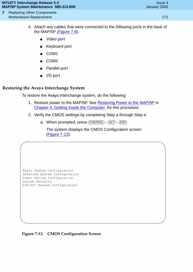
INTUITY Interchange Release 5.4MAP/5P System Maintenance 585-313-809
Issue 4January 2002
Replacing Other Components 171Motherboard Replacement
7
4. Attach any cables that were connected to the following ports in the back of the MAP/5P (Figure 7-8).
■ Video port
■ Keyboard port
■ COM1
■ COM2
■ Parallel port
■ I/O port
Restoring the Avaya Interchange System
To restore the Avaya Interchange system, do the following:
1. Restore power to the MAP/5P. See Restoring Power to the MAP/5P in Chapter 4, Getting Inside the Computer, for this procedure.
2. Verify the CMOS settings by completing Step a through Step e:
a. When prompted, press - -
The system displays the CMOS Configuration screen (Figure 7-13).
Figure 7-13. CMOS Configuration Screen
CONTROL ALT ESC
Basic System ConfigurationAdvanced System ConfigurationPower Saving ConfigurationSystem SecurityPnP/PCI System Configuration

INTUITY Interchange Release 5.4MAP/5P System Maintenance 585-313-809
Issue 4January 2002
Replacing Other Components 172Motherboard Replacement
7
b. Compare the CMOS settings with those listed in Figure 7-14 through Figure 7-22.
Use the Up and Down arrow keys to move the cursor between fields. Use the Left and Right arrow keys to change the value of the field. Use the key to return to the previous menu.
Press before entering the Advanced Settings; otherwise, you cannot see the last two CMOS setting screens.
Figure 7-14. Basic CMOS Settings Screen, Page 1
Figure 7-15. Basic CMOS Settings Screen, Page 2
ESC
F4
Basic Conf Page 1
DateTime
Diskette Drive A 1.44 MB 3.5 inchDiskette Drive B None
IDE Drive 0 Auto 1 Auto 2 Auto 3 Auto
Onboard IDE Controller Disabledtotal memory 64 MB
Basic Conf Page 2
Enhanced IDE Features
HD Block Disabled Advanced PIO Disabled Hard Disk > 504 Disabled Hard Disk 32 bit Disabled Large Memory Support Normal Num Lock After Boot Enabled Memory Test Enabled Quiet Boot Enabled Configuration Table Disabled

INTUITY Interchange Release 5.4MAP/5P System Maintenance 585-313-809
Issue 4January 2002
Replacing Other Components 173Motherboard Replacement
7
Figure 7-16. Advanced CMOS Settings Screen, Page 1
Figure 7-17. Advanced CMOS Settings Screen, Page 2
Advanced System Page 1
Internal Cache (CPU cache) EnabledExternal Cache Enabled Cache Scheme Write Back
ECC/Parity Mode Sel. ECCMemory at 15MB-16MB Receiver System use
Advanced System Page 2
DRAM config EDO Page Mode Read x-2-2-2 Page Mode Read x-3-3-3 EDO or Page Mode Write x-3-3-3 Pipelined Function Enabled

INTUITY Interchange Release 5.4MAP/5P System Maintenance 585-313-809
Issue 4January 2002
Replacing Other Components 174Motherboard Replacement
7
Figure 7-18. Advanced CMOS Settings Screen, Page 3
Figure 7-19. Basic CMOS Settings Screen, Page 4
Advanced System Page 3
PCI config CPU to PCI Enabled Linear — merge Enabled Word — merge Enabled Write — burst Enabled
Programmable Frame Buffer EnabledSize of Programmable Frame Buffer 2M
Advanced System Page 4
ISA config Clock Select Auto DMA Line Buffer Enabled ISA Line Buffer Enabled I/O Recovery Enabled Period 1.75US
Miscellaneous Refresh Cycle 15US 6x86 Burst 1+4
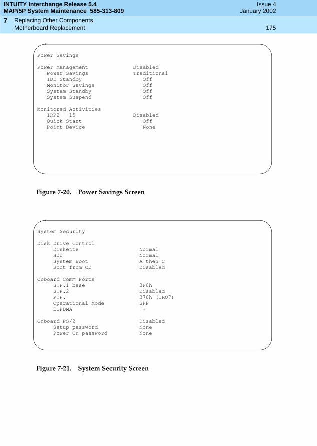
INTUITY Interchange Release 5.4MAP/5P System Maintenance 585-313-809
Issue 4January 2002
Replacing Other Components 175Motherboard Replacement
7
Figure 7-20. Power Savings Screen
Figure 7-21. System Security Screen
Power Savings
Power Management Disabled Power Savings Traditional IDE Standby Off Monitor Savings Off System Standby Off System Suspend Off
Monitored Activities IRP2 — 15 Disabled Quick Start Off Point Device None
System Security
Disk Drive Control Diskette Normal HDD Normal System Boot A then C Boot from CD Disabled
Onboard Comm Ports S.P.1 base 3F8h S.P.2 Disabled P.P. 378h (IRQ7) Operational Mode SPP ECPDMA —
Onboard PS/2 Disabled Setup password None Power On password None
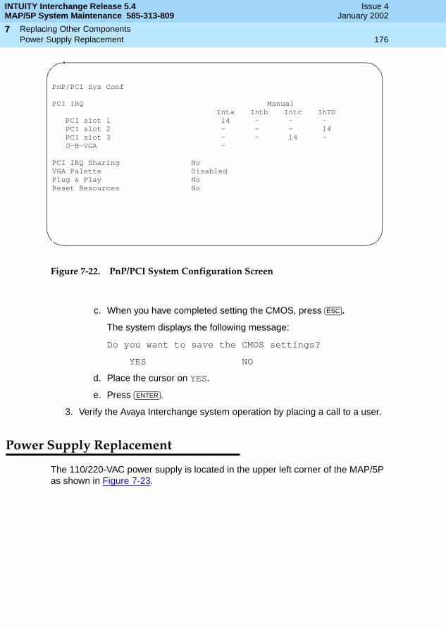
INTUITY Interchange Release 5.4MAP/5P System Maintenance 585-313-809
Issue 4January 2002
Replacing Other Components 176Power Supply Replacement
7
Figure 7-22. PnP/PCI System Configuration Screen
c. When you have completed setting the CMOS, press .
The system displays the following message:
Do you want to save the CMOS settings?
YES NO
d. Place the cursor on YES.
e. Press .
3. Verify the Avaya Interchange system operation by placing a call to a user.
Power Supply Replacement
The 110/220-VAC power supply is located in the upper left corner of the MAP/5P as shown in Figure 7-23.
PnP/PCI Sys Conf
PCI IRQ ManualInta Intb Intc IhTD
PCI slot 1 14 — — — PCI slot 2 — — — 14 PCI slot 3 — — 14 — O-B-VGA —
PCI IRQ Sharing NoVGA Palette DisabledPlug & Play NoReset Resources No
ESC
ENTER
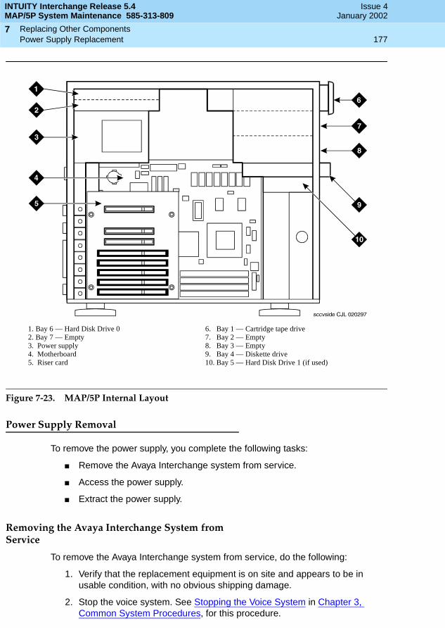
INTUITY Interchange Release 5.4MAP/5P System Maintenance 585-313-809
Issue 4January 2002
Replacing Other Components 177Power Supply Replacement
7
Figure 7-23. MAP/5P Internal Layout
Power Supply Removal
To remove the power supply, you complete the following tasks:
■ Remove the Avaya Interchange system from service.
■ Access the power supply.
■ Extract the power supply.
Removing the Avaya Interchange System from Service
To remove the Avaya Interchange system from service, do the following:
1. Verify that the replacement equipment is on site and appears to be in usable condition, with no obvious shipping damage.
2. Stop the voice system. See Stopping the Voice System in Chapter 3, Common System Procedures, for this procedure.
1. Bay 6 — Hard Disk Drive 02. Bay 7 — Empty3. Power supply4. Motherboard5. Riser card
6. Bay 1 — Cartridge tape drive7. Bay 2 — Empty8. Bay 3 — Empty9. Bay 4 — Diskette drive10. Bay 5 — Hard Disk Drive 1 (if used)
INTUITY Interchange Release 5.4MAP/5P System Maintenance 585-313-809
Issue 4January 2002
Replacing Other Components 178Power Supply Replacement
7
3. Shut down the voice system. See Shutting Down the Avaya Interchange System in Chapter 3, Common System Procedures, for this procedure.
4. Remove the incoming power. See Removing Power from the MAP/5P in Chapter 4, Getting Inside the Computer, for this procedure.
Accessing the Power Supply
To access the power supply, remove the dress cover. See Removing the Dress Cover in Chapter 4, Getting Inside the Computer, for this procedure.
Extracting the Power Supply
To extract the power supply, do the following:
1. Unplug the connector to the cartridge tape drive (Figure 7-24).
2. Unplug the connector to the diskette drive (Figure 7-24).
3. Unplug the connector to Hard Disk Drive 1, if provided (Figure 7-24).
4. Unplug the connector to Hard Disk Drive 0 (Figure 7-24).
5. Unplug both connectors to the motherboard (Figure 7-24).

INTUITY Interchange Release 5.4MAP/5P System Maintenance 585-313-809
Issue 4January 2002
Replacing Other Components 179Power Supply Replacement
7
Figure 7-24. MAP/5P Power Supply
6. Locate the power supply switch cable, which is mounted to the front of the chassis by a single screw.
7. Remove the screw holding the power supply switch (Figure 7-25).
1. Power-on switch cable2. Hard Disk Drive 0 connector3. Diskette drive connector4. Hard Disk Drive 1 connector5. Cartridge tape drive connector6. Motherboard connector
7. Motherboard connector8. Riser card9. Power supply retaining screws

INTUITY Interchange Release 5.4MAP/5P System Maintenance 585-313-809
Issue 4January 2002
Replacing Other Components 180Power Supply Replacement
7
Figure 7-25. Power Supply Switch
8. Remove the screw that holds the grounding wire to the chassis (Figure 7-25).
9. Slide the power supply switch out of the retaining slot.
10. Remove the four screws on the chassis rear area that secure the power supply unit (Figure 7-24).
11. Slide the unit slightly forward towards the front of the MAP/5P and tilt toward the riser card.
12. Lift and remove the power supply.
Power Supply Installation
To install the power supply, you complete the following tasks:
■ Insert the power supply.
■ Reassemble the MAP/5P.
■ Restore the Avaya Interchange system.
1. Power supply switch retaining screw2. Power supply grounding wire and screw
INTUITY Interchange Release 5.4MAP/5P System Maintenance 585-313-809
Issue 4January 2002
Replacing Other Components 181Power Supply Replacement
7
Inserting a Power Supply
To insert the power supply, do the following:
1. Remove the spare power supply unit from the shipping carton.
NOTE:Keep the package and all ESD-protective wrapping to return the defective unit. You must use the original replacement unit packaging to meet the manufacturer’s warranty.
2. Verify the input AC voltage selection switch, located on the chassis side close to the button edge, is in the correct position.
The switch is a slide type. Printed text on the surface indicates the input voltage requirements, either 115 or 230 volts. The correct position for systems installed in the United States is 115 volts.
3. Install the power supply unit into the chassis and align the screw holes.
4. Install the four screws on the chassis rear area that secure the power supply unit (Figure 7-24).
5. Attach the power supply DC output connectors to the motherboard (Figure 7-24).
NOTE:These connectors are keyed.
6. Attach the connector to the cartridge tape drive (Figure 7-24).
7. Attach the connector to the diskette drive (Figure 7-24).
8. Attach the connector to the Hard Disk Drive 1, if provided (Figure 7-24).
If Hard Disk Drive 1 is not installed, dress this lead back out of the way to reduce cable congestion.
9. Attach the connector to Hard Disk Drive 0 (Figure 7-24).
10. Dress the power switch cable around to the front of the MAP/5P (Figure 7-26).
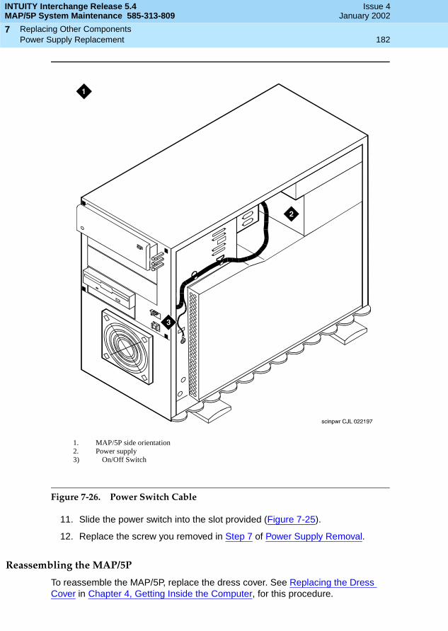
INTUITY Interchange Release 5.4MAP/5P System Maintenance 585-313-809
Issue 4January 2002
Replacing Other Components 182Power Supply Replacement
7
Figure 7-26. Power Switch Cable
11. Slide the power switch into the slot provided (Figure 7-25).
12. Replace the screw you removed in Step 7 of Power Supply Removal.
Reassembling the MAP/5P
To reassemble the MAP/5P, replace the dress cover. See Replacing the Dress Cover in Chapter 4, Getting Inside the Computer, for this procedure.
1. MAP/5P side orientation2. Power supply 3) On/Off Switch

INTUITY Interchange Release 5.4MAP/5P System Maintenance 585-313-809
Issue 4January 2002
Replacing Other Components 183Riser Card Replacement
7
Restoring the Avaya Interchange System
To restore the Avaya Interchange system, do the following:
1. Restore power to the MAP/5P. See Restoring Power to the MAP/5P in Chapter 4, Getting Inside the Computer, for this procedure.
2. Verify the Avaya Interchange system operation by placing a call to a user.
Riser Card Replacement
! CAUTION:Observe proper electrostatic discharge precautions when you handle computer components. Wear an antistatic wrist strap that touches your bare skin and connect the strap cable to an earth ground. See Protecting Against Damage from Electrostatic Discharge in Chapter 4, Getting Inside the Computer.
The following procedures detail the 6-slot riser card installation and removal. All of the circuit cards are connected to the riser card. The riser card (Figure 7-23) is located in the back of the MAP/5P card cage area. The riser card is connected to the motherboard.
Riser Card Removal
To remove the riser card, you complete the following tasks:
■ Remove the Avaya Interchange system from service.
■ Access the riser card.
■ Extract the riser card.
Removing the Avaya Interchange System from Service
To remove the Avaya Interchange system from service, do the following:
1. Verify that the replacement equipment is on site and appears to be in usable condition, with no obvious shipping damage.
2. Stop the voice system. See Stopping the Voice System in Chapter 3, Common System Procedures, for this procedure.
3. Shut down the voice system. See Shutting Down the Avaya Interchange System in Chapter 3, Common System Procedures, for this procedure.
4. Remove the incoming power. See Removing Power from the MAP/5P in Chapter 4, Getting Inside the Computer, for this procedure.

INTUITY Interchange Release 5.4MAP/5P System Maintenance 585-313-809
Issue 4January 2002
Replacing Other Components 184Riser Card Replacement
7
Accessing the Riser Card
To access the riser card, do the following:
1. Remove the dress cover. See Removing the Dress Cover in Chapter 4, Getting Inside the Computer, for this procedure.
2. Remove all of the circuit cards. See Removing a Circuit Card in Chapter 5, Replacing or Installing Circuit Cards, for this procedure.
NOTE:Pay close attention to the riser card connector slots from which each circuit card is removed. Replace the circuit cards in the same slots in the new riser card. See Component Assignments in Appendix A, System Configuration, for circuit card placement.
Extracting the Riser Card
To extract the riser card, do the following:
1. Remove the screw in the lower left corner of the riser card (Figure 7-23).
2. Gently pull the riser card away from the motherboard until the riser card connector is removed from the slot on the motherboard.
3. Continue with the next procedure, Riser Card Installation.
Riser Card Installation
To install the riser card, you complete the following tasks:
■ Insert the riser card.
■ Reassemble the MAP/5P.
■ Restore the Avaya Interchange system.
Inserting the Riser Card
To insert the riser card, do the following:
1. Remove the new riser card from its ESD-protective wrapping.
NOTE:Keep the package and all ESD-protective wrapping to return the defective unit. You must use the original replacement unit packaging to meet the manufacturer’s warranty.
2. Align the riser card connector with the slot on the motherboard.
3. Gently push the riser card connector into the motherboard.
4. Replace the screw in the bottom left corner of the riser card (Figure 7-23).

INTUITY Interchange Release 5.4MAP/5P System Maintenance 585-313-809
Issue 4January 2002
Replacing Other Components 185Riser Card Replacement
7
Reassembling the MAP/5P
To reassemble the MAP/5P, do the following:
1. Replace the circuit cards removed in Step 1 of Extracting the Riser Card.
NOTE:Be sure to mount these cards in their correct riser card slot. See Component Assignments in Appendix A, System Configuration, for circuit card placement.
2. Replace the Dress Cover. See Replacing the Dress Cover in Chapter 4, Getting Inside the Computer, for this procedure.
Restoring the Avaya Interchange System
To restore the Avaya Interchange system, do the following:
1. Restore power to the MAP/5P. See Restoring Power to the MAP/5P in Chapter 4, Getting Inside the Computer, for this procedure.
2. Verify the Avaya Interchange system operation by placing a call to a user.

INTUITY Interchange Release 5.4MAP/5P System Maintenance 585-313-809
Issue 4January 2002
Replacing Other Components 186Riser Card Replacement
7
Installing an RFU (Remote Field Update) 187Overview
8
INTUITY Interchange Release 5.4MAP/5P System Maintenance 585-313-809
Issue 4January 2002
88Installing an RFU (Remote Field Update)
Overview
See Chapter 2, RFU Installation, in Avaya Interchange Release 5.4 Installation and System Recovery, for the procedures to install a Remote Field Update (RFU).

INTUITY Interchange Release 5.4MAP/5P System Maintenance 585-313-809
Issue 4January 2002
Installing an RFU (Remote Field Update) 188Overview
8

System Configuration Page 189Memory and SIMM Description
A
INTUITY Interchange Release 5.4MAP/5P System Maintenance 585-313-809
Issue 4January 2002
AASystem Configuration
Memory and SIMM Description
The MAP/5P supports 64 MB of memory packaged on two 32-MB single in-line memory modules (SIMM). These modules are placed in sockets located in the bottom right corner of the motherboard (Figure A-1).

INTUITY Interchange Release 5.4MAP/5P System Maintenance 585-313-809
Issue 4January 2002
System Configuration Page 190Memory and SIMM Description
A
Figure A-1. Motherboard
The motherboard must be equipped with SIMMs in matched pairs.
NOTE:The Avaya Interchange system does not boot if there is an odd number of SIMMs. In addition, the system does not boot if the SIMM pairs are unmatched.
1. CMOS battery2. Riser card connector3. Diskette cable connector4. Power supply connectors5. Switches
6. CPU7. SIMM4 socket (empty)8. SIMM3 socket (empty)9. SIMM2 socket10. SIMM1 socket
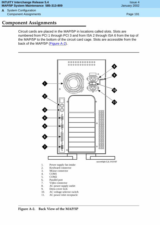
INTUITY Interchange Release 5.4MAP/5P System Maintenance 585-313-809
Issue 4January 2002
System Configuration Page 191Component Assignments
A
Component Assignments
Circuit cards are placed in the MAP/5P in locations called slots. Slots are numbered from PCI 1 through PCI 3 and from ISA 2 through ISA 6 from the top of the MAP/5P to the bottom of the circuit card cage. Slots are accessible from the back of the MAP/5P (Figure A-2).
Figure A-2. Back View of the MAP/5P
1. Power supply fan intake2. Keyboard connector3. Mouse connector4. COM15. COM26. Parallel port7. Video connector8. AC power supply outlet9. Dress cover lock10. AC voltage selector switch11. AC power inlet receptacle

INTUITY Interchange Release 5.4MAP/5P System Maintenance 585-313-809
Issue 4January 2002
System Configuration Page 192Component Assignments
A
Operating hardware is placed in the MAP/5P in locations called bays. Bays are numbered from 1 through 7. Bays 1 through 5 are accessible from the front of the MAP/5P (Figure A-3).
Figure A-3. Front View of the MAP/5P
1. INT drive indicator2. Speed indicator3. Power indicator
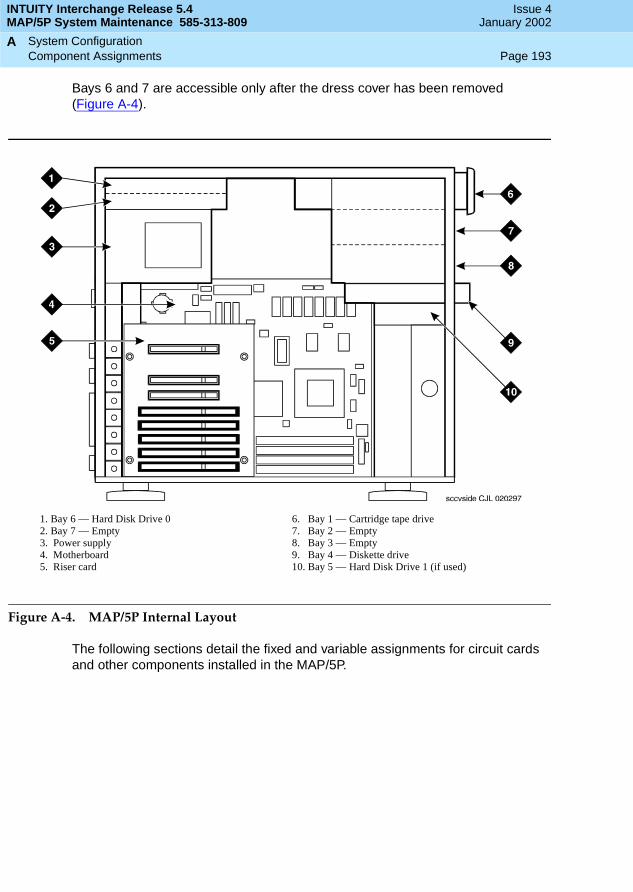
INTUITY Interchange Release 5.4MAP/5P System Maintenance 585-313-809
Issue 4January 2002
System Configuration Page 193Component Assignments
A
Bays 6 and 7 are accessible only after the dress cover has been removed (Figure A-4).
Figure A-4. MAP/5P Internal Layout
The following sections detail the fixed and variable assignments for circuit cards and other components installed in the MAP/5P.
1. Bay 6 — Hard Disk Drive 02. Bay 7 — Empty3. Power supply4. Motherboard5. Riser card
6. Bay 1 — Cartridge tape drive7. Bay 2 — Empty8. Bay 3 — Empty9. Bay 4 — Diskette drive10. Bay 5 — Hard Disk Drive 1 (if used)

INTUITY Interchange Release 5.4MAP/5P System Maintenance 585-313-809
Issue 4January 2002
System Configuration Page 194Component Assignments
A
Fixed Assignments
The following bay assignments are fixed in the MAP/5P:
■ Bay 1 — Cartridge Tape drive
■ Bay 2 — Empty
■ Bay 3 — Empty
■ Bay 4 — Diskette drive
■ Bay 5 — Hard Disk Drive 1 (if provided)
■ Bay 6 — Hard Disk Drive 0
■ Bay 7 — Empty
The following slot assignment is fixed in the MAP/5P:
■ PCI Slot 1 — SCSI controller circuit card
■ ISA Slot 2 — remote maintenance circuit card
Variable Assignments
The Tip/Ring, ACCX, LAN, multi-port, and switch interface circuit cards all have variable assignments in the MAP/5P. These assignments depend on how many cards have been installed. The following rules apply to the placement of optional cards in the MAP/5P. These rules presume that the required circuit cards are placed in the MAP/5P as specified in Fixed Assignments.
■ A maximum of three Tip/Ring circuit cards is supported.
■ All other circuit cards are supported as one per system.
■ Tip/Ring circuit cards are assigned slots sequentially, starting, at the bottom, with slot 6.
■ The ACCX circuit card is assigned in the lowest numbered available slot after all Tip/Ring circuit cards have been installed. For example, if Tip/Ring circuit cards are installed in ISA Slot 5 and ISA Slot 6, place the ACCX circuit card in ISA Slot 4.
■ The LAN circuit card, if provided, goes in the lowest numbered available ISA slot.
■ The switch interface circuit card, if provided, goes in the lowest numbered available ISA slot after the LAN circuit card, if provided, has been installed.
■ The multi-port serial circuit card, if provided, goes in the lowest numbered ISA slot after both the LAN and switch interface circuit cards, if provided, have been installed.
■ If any ISA slots are unoccupied, they need to be between the set of Tip/Ring and ACCX circuit cards and the set of LAN, switch interface, and multi-port serial circuit cards.

INTUITY Interchange Release 5.4MAP/5P System Maintenance 585-313-809
Issue 4January 2002
System Configuration Page 195Component Assignments
A
The following tables outline the variable slot locations for optional circuit cards when all of the available slots are to be filled. Each column, with the addition of the required cards listed in Fixed Assignments, is a configuration. In Table A-1, for example, the first column represents a configuration that includes seven Tip/Ring circuit cards in slots 4 through 6, no other optional circuit cards.
Table A-1 lists the variable slot locations for configurations with multiple Tip/Ring circuit cards and one other optional circuit card.
Table A-1 lists the variable slot locations for configurations with Tip/Ring circuit cards and multiple other optional circuit cards.
Table A-1. Variable Slot Assignments When System is Equipped with Tip/Ring Circuit Cards and One other Optional Circuit Card
Circuit Card Slots Slots Slots Slots Slots
Tip/Ring 4–6 4–6 4–6 4–6 4–6
ACCX (AYC22) — 3 — — —
LAN — — 3 — —
Multi-port serial — — — 3 —
Switch Interface — — — — 3
Table A-2. Variable Slot Assignments When System Is Equipped with Tip/Ring Circuit Cards and Multiple other Optional Circuit Cards
Circuit Card Slots Slots Slots Slots Slots Slots Slots Slots Slots Slots
Tip/Ring 5–6 5–6 5–6 5–6 5–6 5–6 6 6 6 6
ACCX (AYC22)
4 4 4 — — — 5 5 5 —
LAN 3 — — 3 3 — 3 3 — 3
multi-port serial
— — 3 4 — 4 4 — 4 5
Switch interface
— 3 — — 4 3 — 4 3 4

INTUITY Interchange Release 5.4MAP/5P System Maintenance 585-313-809
Issue 4January 2002
System Configuration Page 196Component Assignments
A
Resource Allocation
Table A-3 lists the resource assignments for all devices in the MAP/5P. It includes the circuit cards as well as devices that are included.
Table A-3. MAP/5P Resource Allocation
Device IRQ I/O Address RAM Address Notes
VGA controller — Plug & Play A0000-BFFFF
C0000-C7FFF
128 Kbyte video RAM required
32 Kbyte video BIOS required
System BIOS — — E0000-FFFF Located on CPU, required
LPT1 port 7 378-37F — Located on CPU, required
COM1 port 4 3F8-3FF — Located on CPU, required
COM2 port 3 2F8-2FF — Disable for remote maintenance circuit card
PCI SCSI 14 Plug & Play C8000-CBFFF SCSI ID 7, required
2-GB SCSI disk — — — 1 required, 1 optional
2-GB SCSI tape — — — SCSI ID 3, 1 required
Diskette drive 6 3F0-3F7 — DMA 2, controller located on SCSI controller card, required
LAN circuit card 10 280-29F D8000-D9FFF 1 optional
Tip/Ring circuit card
2 x00-x1F — x=1–3;1 required, 2 optional
ACCX circuit card 5 140-14F — 1 optional
(1 of 2)

INTUITY Interchange Release 5.4MAP/5P System Maintenance 585-313-809
Issue 4January 2002
System Configuration Page 197Component Assignments
A
Digital station interface circuit card
12 224-227 — 1 optional, not allowed with DCIU interface circuit card
Remote maintenance circuit card
3 180-187 DC000-DCFFF Disable COM2 on P5 120 MHz CPU
Table A-3. MAP/5P Resource Allocation
Device IRQ I/O Address RAM Address Notes
(2 of 2)

INTUITY Interchange Release 5.4MAP/5P System Maintenance 585-313-809
Issue 4January 2002
System Configuration Page 198Component Assignments
A
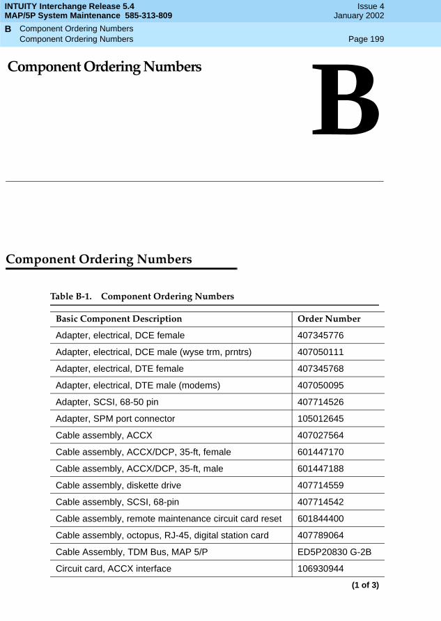
Component Ordering Numbers Page 199Component Ordering Numbers
B
INTUITY Interchange Release 5.4MAP/5P System Maintenance 585-313-809
Issue 4January 2002
BBComponent Ordering Numbers
Component Ordering Numbers
Table B-1. Component Ordering Numbers
Basic Component Description Order Number
Adapter, electrical, DCE female 407345776
Adapter, electrical, DCE male (wyse trm, prntrs) 407050111
Adapter, electrical, DTE female 407345768
Adapter, electrical, DTE male (modems) 407050095
Adapter, SCSI, 68-50 pin 407714526
Adapter, SPM port connector 105012645
Cable assembly, ACCX 407027564
Cable assembly, ACCX/DCP, 35-ft, female 601447170
Cable assembly, ACCX/DCP, 35-ft, male 601447188
Cable assembly, diskette drive 407714559
Cable assembly, SCSI, 68-pin 407714542
Cable assembly, remote maintenance circuit card reset 601844400
Cable assembly, octopus, RJ-45, digital station card 407789064
Cable Assembly, TDM Bus, MAP 5/P ED5P20830 G-2B
Circuit card, ACCX interface 106930944
(1 of 3)

INTUITY Interchange Release 5.4MAP/5P System Maintenance 585-313-809
Issue 4January 2002
Component Ordering Numbers Page 200Component Ordering Numbers
B
Circuit card, DCIU interface 601824956
Circuit card, digital station interface circuit card, Mitel 407780923
Circuit card, digital station interface circuit card, Nortel 407780956
Circuit card, digital station interface circuit card, Rolm 407780949
Circuit card, ethernet LAN interface 601834153
Circuit card, multi-port serial 407009406
Circuit card, remote maintenance, with on-board modem 107725467
Circuit card, remote maintenance without modem 107765109
Circuit card, SCSI controller 407711639
Circuit Card, Speech and Signal Processor (AYC43W) 601835820
Circuit card, Tip/Ring (AYC10) 106406580
Circuit card, Tip/Ring (AYC29) 107213944
Circuit card, Tip/Ring (AYC30) 107224586
Cord, 6-pin modular, 14-ft 102937604
Cord, AC power, United States, 6-ft 407714773
Cord, AC power, Australia, 8-ft 407051630
Cord, AC power, Chile (Italy–style), 6-ft 407515196
Cord, AC power, Germany, 6-ft 407051648
Cord, AC power, India, 8-ft 407406735
Cord, AC power, Japan, 8-ft 407406727
Cord, AC power, United Kingdom, 6-ft 406999243
Cord, power, monitor (PC style) 407714781
Cord, telephone, 25-ft 103623195
Cord, telephone, DW8A-SE, 25-ft 103848800
Cover, dress 407714609
Diskette drive, 1.44-MB 407714765
Disk drive, hard, SCSI, 2.0-GB, Capricorn 407711647
Disk drive, hard, SCSI, 2.0-GB, Seagate 407773555
Door, front 407714617
Fan, card cage 407714807
Table B-1. Component Ordering Numbers
Basic Component Description Order Number
(2 of 3)
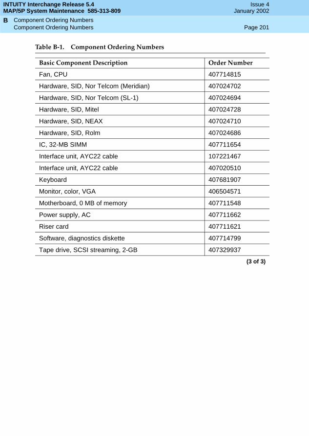
INTUITY Interchange Release 5.4MAP/5P System Maintenance 585-313-809
Issue 4January 2002
Component Ordering Numbers Page 201Component Ordering Numbers
B
Fan, CPU 407714815
Hardware, SID, Nor Telcom (Meridian) 407024702
Hardware, SID, Nor Telcom (SL-1) 407024694
Hardware, SID, Mitel 407024728
Hardware, SID, NEAX 407024710
Hardware, SID, Rolm 407024686
IC, 32-MB SIMM 407711654
Interface unit, AYC22 cable 107221467
Interface unit, AYC22 cable 407020510
Keyboard 407681907
Monitor, color, VGA 406504571
Motherboard, 0 MB of memory 407711548
Power supply, AC 407711662
Riser card 407711621
Software, diagnostics diskette 407714799
Tape drive, SCSI streaming, 2-GB 407329937
Table B-1. Component Ordering Numbers
Basic Component Description Order Number
(3 of 3)

INTUITY Interchange Release 5.4MAP/5P System Maintenance 585-313-809
Issue 4January 2002
Component Ordering Numbers Page 202Component Ordering Numbers
B

Disaster Recovery Page 203Overview
C
INTUITY Interchange Release 5.4MAP/5P System Maintenance 585-313-809
Issue 4January 2002
CCDisaster Recovery
Overview
See Chapter 4, New Installation and System Recovery Procedures, in Avaya Interchange Release 5.4 Installation and System Recovery, for disaster recovery procedures.

INTUITY Interchange Release 5.4MAP/5P System Maintenance 585-313-809
Issue 4January 2002
Disaster Recovery Page 204Overview
C

MAP/5P Platform Alarms Page 205Overview
D
INTUITY Interchange Release 5.4MAP/5P System Maintenance 585-313-809
Issue 4January 2002
DDMAP/5P Platform Alarms
Overview
This appendix contains alarms specific to the MAP/5P hardware platform. These alarms will appear on the console during a system reboot.
NOTE:These alarms are not generated by the Avaya Interchange system and are not documented in the Avaya Interchange alarm logs.
Purpose
The purpose of this appendix is to provide the service technician with information relating to the platform alarms generated by the MAP/5P.
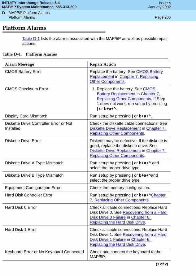
INTUITY Interchange Release 5.4MAP/5P System Maintenance 585-313-809
Issue 4January 2002
MAP/5P Platform Alarms Page 206Platform Alarms
D
Platform Alarms
Table D-1 lists the alarms associated with the MAP/5P as well as possible repair actions.
Table D-1. Platform Alarms
Alarm Message Repair Action
CMOS Battery Error Replace the battery. See CMOS Battery Replacement in Chapter 7, Replacing Other Components.
CMOS Checksum Error 1. Replace the battery. See CMOS Battery Replacement in Chapter 7, Replacing Other Components. If Step 1 does not work, run setup by pressing | or b+a+^.
Display Card Mismatch Run setup by pressing | or b+a+^.
Diskette Drive Controller Error or Not Installed
Check the diskette cable connections. See Diskette Drive Replacement in Chapter 7, Replacing Other Components.
Diskette Drive Error Diskette may be defective. If the diskette is good, replace the diskette drive. See Diskette Drive Replacement in Chapter 7, Replacing Other Components.
Diskette Drive A Type Mismatch Run setup by pressing | or b+a+^ and select the proper drive type.
Diskette Drive B Type Mismatch Run setup by pressing | or b+a+^and select the proper drive type.
Equipment Configuration Error. Check the memory configuration.
Hard Disk Controller Error Run setup by pressing | or b+a+^Chapter 7, Replacing Other Components.
Hard Disk 0 Error Check all cable connections. Replace Hard Disk Drive 0. See Recovering from a Hard Disk Drive 0 Failure in Chapter 6, Replacing the Hard Disk Drive.
Hard Disk 1 Error Check all cable connections. Replace Hard Disk Drive 1. See Recovering from a Hard Disk Drive 1 Failure in Chapter 6, Replacing the Hard Disk Drive.
Keyboard Error or No Keyboard Connected Check and connect the keyboard to the MAP/5P.
(1 of 2)

INTUITY Interchange Release 5.4MAP/5P System Maintenance 585-313-809
Issue 4January 2002
MAP/5P Platform Alarms Page 207Platform Alarms
D
Keyboard Interface Error Replace the keyboard.
Memory Error at:MMMM:SSSS:OOO(W:XXXX, R:YYYY)
where:M is MB, S is Segment, O is Offset, X/Y are write/read pattern
Replace the SIMMs. See Memory Replacement in Chapter 7, Replacing Other Components.
CPU Clock Mismatch 1. Run setup by pressing | or b+a+^ and check the CPU clock setting.
2. If the clock setting is correct, reboot the system.
3. If the error persists, contact the remote maintenance service center.
Onboard Serial Port 1 Conflict Run setup by pressing | or b+a+^ and disable the port.
Onboard Serial Port 2 Conflict Run setup by pressing | or b+a+^ and disable the port.
Onboard Parallel Port Conflict Run setup by pressing | or b+a+^ and disable the port.
Pointing Device Error Check the connections on the mouse.
Pointing Device Interface Error Replace the mouse.
Press | key to continue or b+a+^ for setup. Press | or b+a+^ to enter setup.
Real Time Clock Error Replace the battery. See CMOS Battery Replacement in Chapter 7, Replacing Other Components.
Table D-1. Platform Alarms
Alarm Message Repair Action
(2 of 2)

INTUITY Interchange Release 5.4MAP/5P System Maintenance 585-313-809
Issue 4January 2002
MAP/5P Platform Alarms Page 208Platform Alarms
D

INTUITY Interchange Release 5.4MAP/5P System Maintenance 585-313-809
Issue 4January 2002
Page 209Glossary
GL
Glossary
5ESS SwitchA central office switch manufactured by Lucent Technologies that can be integrated with the Avaya Interchange system.
A
accessed messageA message that was received and scanned (either the entire message or just the header).
ACASee automatic circuit assurance.
ACDSee automatic call distribution.
activity menuThe list of options spoken to users when they first access a messaging system. Selecting an activity is the starting point for all user operations.
ADAPSee administration and data acquisition package.
addressINTUITY AUDIX user identification, containing the user’s extension and machine, that indicates where the system needs to deliver a message. An address can include several users or mailing lists. Name or number addressing can be selected with the (Address) command.
adjunctA separate system closely integrated with a switch, such as an Avaya Interchange system or a call management system (CMS).
administrationThe process of setting up a system (such as a switch or a messaging system) to function as desired. Options and defaults are normally set up (translated) by the system administrator or ser-vice personnel.
administration and data acquisition package (ADAP)A software package that allows the system administrator to transfer system user, maintenance, or traffic data from an INTUITY AUDIX system to a personal computer (PC).
ADUSee asynchronous data unit.
alarm logA list of alarms that represent all of the active or resolved problems on an Avaya Interchange sys-tem. The alarm log is stored in a software file on disk and can be accessed either locally or remotely on a terminal connected to the system.
* A

INTUITY Interchange Release 5.4MAP/5P System Maintenance 585-313-809
Issue 4January 2002
Glossary Page 210
alarmsHardware, software, or environmental problems that can affect system operation. Alarms are classi-fied as major, minor, or warning.
alphanumericConsisting of alphabetic and numeric symbols or punctuation marks.
ALTSee assemble, load, and test.
American wire gauge (AWG)A standard measuring gauge for nonferrous conductors.
AMISSee Audio Messaging Interchange Specification.
AMIS prefixA number added to the destination number to indicate that it is an AMIS analog networking number.
analog networkingA method of transferring a message from one messaging system to another whereby the message is played back (voiced) during the transfer.
analog signalIn teleprocessing usage, a communications path that usually refers to a voice-grade telephone line.
announcementA placeholder within the Avaya Interchange system for playing fragments. Each event that may occur within AUDIX has one or more announcement numbers permanently assigned to it. Fragment numbers are then assigned to the announcement numbers.
announcement fragmentA numbered piece of spoken information that makes up a system message or prompt.
antistaticA treatment for material to prevent the build-up of static electricity.
APISee application programming interface.
applicationA computer software program.
application identifierA two-letter code used in the administrator’s log to identify the application or subsystem for which an alarm is being generated. There are eight application identifiers as follows: CA (Call Account-ing), ML (MERLIN LEGEND), MT (Maintenance), NW (Digital Networking), SW (Switch Integration), VM (Voice Messaging), VP (Voice Processing), and VR (Voice Response).
application programming interface (API)A set of formalized software calls and routines that an application program can reference to access underlying network services.
assemble, load, and test (ALT)The Avaya factory process that preloads software, installs hardware, and tests the system prior to shipping.
ASPadvanced signal processor

INTUITY Interchange Release 5.4MAP/5P System Maintenance 585-313-809
Issue 4January 2002
Glossary Page 211
asynchronous communicationA method of data transmission in which bits or characters are sent at irregular intervals and spaced by start and stop bits rather than by time. See also synchronous communication.
asynchronous data unit (ADU)An electronic communications device that can extend data transmission over asynchronous lines more than 50 feet in length. Recommended ADUs for use with the Avaya Interchange system include Z3A1 or Z3A4.
asynchronous transmissionA form of serial communications where each transmitted character is bracketed with a start bit and one or two stop bits. The Avaya Interchange system provides asynchronous EIA-232 capabilities for INTUITY AUDIX Digital Networking, if required.
attendant consoleA special-purpose telephone with numerous lines and features usually located at the front desk of a business or other organization. The front desk attendant uses this telephone to answer and transfer calls.
Audio Messaging Interchange Specification (AMIS)An analog networking protocol that allows users to exchange messages with any messaging sys-tem that also has AMIS Analog Networking capabilities. Messages can be exchanged with users on Avaya Interchange systems as well as with users on remote messaging systems made by vendors other than Avaya.
Audio Information Exchange (AUDIX)A complete messaging system accessed and operated by touchtone telephones and integrated with a switch.
auditA software program that resolves filesystem incompatibilities and updates restored filesystems to a workable level of service. Audits are done automatically on a periodic basis, or they can be per-formed on demand.
AUDIXSee Audio Information Exchange.
autodeleteAn INTUITY AUDIX feature that allows users to designate that faxes be automatically deleted from their mailboxes after they are printed.
automated attendantAn Avaya Interchange system feature that allows users to set up a main extension number with a menu of options that routes callers to an appropriate department at the touch of a button.
automatic call distribution (ACD)The System 85, Generic 2, or Generic 3 call-distribution group of analog ports that connects Avaya Interchange users to the system. See also call-distribution group.
automatic circuit assurance (ACA)A feature of the switch that keeps records of both very long and very short calls and notifies the attendant when these calls exceed a certain parameter. The logic is that many very short calls or one very long one can suggest a trunk that is hung, broken, or out of order. The attendant can then physically dial into the trunk to check it.
automatic message scan An INTUITY AUDIX feature that allows users to scan all message headers and messages at the touch of two buttons. With INTUITY FAX Messaging, this feature allows all new faxes to be bundled and transmitted over a single fax call delivery call. Also called autoscan.
INTUITY Interchange Release 5.4MAP/5P System Maintenance 585-313-809
Issue 4January 2002
Glossary Page 212
autoprintAn INTUITY AUDIX feature that allows users to designate that faxes be automatically sent to a spec-ified print destination.
autoscanSee automatic message scan.
AWGSee American wire gauge.
B
background testingTesting that runs continuously when the system is not busy doing other tasks.
backplaneA centrally located device within a computer to which individual circuit cards are plugged for com-munication across an internal bus.
backupA duplicate copy of files and directories saved on a removable medium such as a floppy diskette or a tape. The backed-up file system can be copied back (restored) if the active version is damaged (corrupted) or lost.
basic input/output system (BIOS)A system that contains the buffers for sending information from a program to the actual hardware device for which the information is intended.
basic call transferThe switch-hook flash method used to send the INTUITY AUDIX transfer command over analog voice ports.
basic rate accessSee basic rate interface.
basic rate interface (BRI)International standard protocol for connecting a station terminal to an integrated systems digital net-work (ISDN) switch. ISDN BRI supports two 64-Kbps information-bearer channels (B1 and B2), and one 16-Kbps call status and control (D) channel (a 2B + D format). Also called basic rate access.
binary synchronous communications (BSC)A character-oriented synchronous link protocol.
BIOSSee basic input/output system.
bodyThe part of an Avaya Interchange voice mail message that contains the actual spoken message. For a leave word calling (LWC) message, it is a standard system announcement.
boot The operation to start a computer system by loading programs from disk to main memory (part of system initialization). Booting is typically accomplished by physically turning on or restarting the system. Also called reboot.

INTUITY Interchange Release 5.4MAP/5P System Maintenance 585-313-809
Issue 4January 2002
Glossary Page 213
boot filesystemThe filesystem from which the system loads its initial programs.
BRISee basic rate interface.
broadcast messagingAn INTUITY AUDIX feature that enables the system administrator and other designated users to send a message to all users automatically.
BSCSee binary synchronous communications.
bufferA temporary storage area used to equalize or balance different operating speeds. A buffer can be used between a slow input device, such as a terminal keyboard, and the main computer, which operates at a very high speed.
bulletin boardAn INTUITY AUDIX feature that allows a message to be played to callers who dial the bulletin board extension. Callers cannot leave a message since this service is a listen-only service. Also called information service.
bundlingCombining several calls and handling them as a single call. See also automatic message scan.
busAn electrical connection/cable allowing two or more wires, lines, or peripherals to be connected together.
busy-out/releaseTo remove an Avaya Interchange device from service (make it appear busy or in use), and later restore it to service (release it). The Avaya Interchange switch data link, voice ports, or networking ports can be busied out when they appear faulty or when maintenance tests are run.
C
CACall accounting system application identifier. See application identifier.
call accounting system (CAS)A software device that monitors and records information about a calling system.
call-answerAn INTUITY AUDIX feature that allows the system to answer a call and record a message when the user is unavailable. Callers can be redirected to the system through the call coverage or call for-warding switch features. INTUITY AUDIX users can record a personal greeting for these callers.
call-answer language choiceThe capability of user mailboxes to accept messages in different languages. For the INTUITY AUDIX application, this capability exists when the multilingual feature is turned on.
callback numberIn AMIS analog networking, the telephone number transmitted to the recipient machine to be used in returning messages that cannot be delivered.

INTUITY Interchange Release 5.4MAP/5P System Maintenance 585-313-809
Issue 4January 2002
Glossary Page 214
call classification analysis (CCA)A process that enables application designers to use information available within the system to clas-sify the disposition of originated and transferred calls.
call coverageA switch feature that defines a preselected path for calls to follow if the first (or second) coverage points are not answered. The Avaya Interchange system can be placed at the end of a coverage path to handle redirected calls through call coverage, send all calls, go to cover, and so on.
call data handler process (CDH)A software process that accumulates generic call statistics and application events.
call detail recording (CDR)A switch feature that uses software and hardware to record call data. See also call detail recording utility.
call detail recording utility (CDRU)Applications software that collects, stores, optionally filters, and outputs call detail records for direct or polled output to peripheral devices. See also call detail recording.
call deliverySee message delivery.
call-distribution groupThe set of analog port cards on the switch that connects switch users to the Avaya Interchange sys-tem by distributing new calls to idle ports. This group (or split) is called automatic call distribution (ACD) on System 85, Generic 2, and Generic 3 and uniform call distribution (UCD) on System 75, Generic 1, and Generic 3. See also automatic call distribution and uniform call distribution.
call management system (CMS)An inbound call distribution and management reporting package.
called tone (CED tone)The distinctive tone generated by a fax endpoint when it answers a call (a constant 2100-Hz tone).
called subscriber information (CSI)The identifier for the answering fax endpoint. This identifier is sent in the T.30 protocol and is gener-ally the telephone number of the fax endpoint.
calling tone (CNG tone)The distinctive tone generated by a fax endpoint when placing a call (a constant 1100-Hz tone that is on for 1/2 second, off for 3 seconds).
call vectoringA System 85 R2V4, Generic 2, and Generic 3 feature that uses a vector (switch program) to allow a switch administrator to customize the behavior of calls sent to an automatic call distribution (ACD) group.
card cageAn area within the Avaya Interchange hardware platform that contains and secures all of the stan-dard and optional circuit cards used in the system.
cartridge tape driveA high-capacity data storage/retrieval device that can be used to transfer large amounts of informa-tion onto high-density magnetic cartridge tape based on a predetermined format. This tape is to be removed from the system and stored as a backup.
CASSee call accouting system.

INTUITY Interchange Release 5.4MAP/5P System Maintenance 585-313-809
Issue 4January 2002
Glossary Page 215
CCASee call classification analysis.
CDHSee call data handler process.
CDRSee call detail recording.
CDRUSee call detail recording utility (CDRU).
CED toneSee called tone.
CELPSee code excited linear prediction.
central office (CO)An office or location in which large telecommunication equipment such as telephone switches and network access facilities are maintained. In a CO, private customer lines are terminated and con-nected to the public network through common carriers.
central processing unit (CPU)The component of the computer that manipulates data and processes instructions coming from software.
channelA telecommunications transmission path for voice and/or data.
channel capacityA measure of the maximum bit rate through a channel.
class of restriction (COR)A feature that allows up to 64 classes of call-origination and call-termination restrictions for tele-phones, telephone groups, data modules, and trunk groups. See also class of service.
class of service (COS)The standard set of INTUITY AUDIX features given to users when they are first administered (set up with a voice mailbox). See also class of restriction.
clear to send (CTS)A function that is located on Pin 5 of the 25-conductor RS-232 interface. CTS is used in the transfer of data between the computer and a serial device.
clientA computer that not only sends, receives and uses data, but also shares a larger resource whose function is to do most data storage and processing. For INTUITY Message Manager, the user’s PC running Message Manager is the client. See also server.
CMSSee call management system.
CNG toneSee calling tone.
COSee central office.

INTUITY Interchange Release 5.4MAP/5P System Maintenance 585-313-809
Issue 4January 2002
Glossary Page 216
CORSee class of restriction.
COSSee class of service.
code excited linear prediction (CELP)An analog-to-digital voice coding scheme.
collocatedAn Avaya Interchange system installed in the same physical location as the host switch. See also local installation.
collocated adjunctTwo or more adjuncts that are serving the same switch (that is, each has voice port connections to the switch) or that are serving different switches but can be networked through a direct RS-232 con-nection because of their proximity.
comcodeA numbering system for telecommunications equipment used by Avaya Inc. Each comcode is a 9-digit number that represents a specific piece of hardware, software, or documentation.
commandAn instruction or request given by the user to the software to perform a particular function. An entire command consists of the command name and options. Also, one- or two-key touch tones that con-trol a mailbox activity or function.
communityA group of telephone users administered with special send and receive messaging capabilities. A community is typically comprised of people who need full access to each other by telephone on a frequent basis. See also default community.
compound messageA message that combines a voice message and a fax message into one unit, which INTUITY AUDIX then handles as a single message.
configurationThe particular combination of hardware and software components selected for a system, including external connections, internal options, and peripheral equipment.
controller circuit cardA circuit card used on a computer system that controls its basic functionality and makes the system operational. The controller circuit card is used to control magnetic peripherals, video monitors, and basic system communications.
COSSee class of service.
coverage pathThe sequence of alternate destinations to which a call to a user on an Avaya Interchange system is automatically sent when it is not answered by the user. This sequence is set up on the switch, nor-mally with the Avaya Interchange system as the last or only destination.
CPUSee central processing unit.
cross connectDistribution-system equipment used to terminate and administer communication circuits.
INTUITY Interchange Release 5.4MAP/5P System Maintenance 585-313-809
Issue 4January 2002
Glossary Page 217
cross connectionThe connection of one wire to another, usually by first anchoring each wire to a connecting block and then placing a third wire between them so that an electrical connection is made.
CSISee called subscriber information.
CTSSee clear to send.
D
DACSee dial access code.
databaseA structured set of files, records, or tables. Also, a collection of filesystems and files in disk memory that store the voice and nonvoice (program data) necessary for Avaya Interchange system opera-tion.
data communications equipment (DCE)Standard type of data interface normally used to connect to data terminal equipment (DTE) devices. DCE devices include the data service unit (DSU), the isolating data interface (IDI), and the modular processor data module (MPDM).
data communications interface unit (DCIU)A switch device that allows nonvoice (data) communication between an Avaya Interchange system and an Avaya switch. The DCIU is a high-speed synchronous data link that communicates with the common control switch processor over a direct memory access (DMA) channel that reads data directly from FP memory.
data linkA term used to describe the communications link used for data transmission from a source to a des-tination, for example, a telephone line for data transmission.
data service unit (DSU)A device used to access digital data channels. DATAPHONE II 2500 DSUs are synchronous data communications equipment (DCE) devices used for extended-local Avaya Interchange system con-nections. The 2600 or 2700 series can also be used; these support diagnostic testing and the DAT-APHONE II Service network system.
data setAnother term for a modem, although a data set usually includes the telephone. See also modem.
data terminal equipment (DTE)Standard type of data interface normally used for the endpoints in a connection. Normally the Avaya Interchange system, most terminals, and the switch data link are DTE devices.
DBPSee data base processor.
DCESee data communications equipment.
DCIUSee data communications interface unit.

INTUITY Interchange Release 5.4MAP/5P System Maintenance 585-313-809
Issue 4January 2002
Glossary Page 218
DCPSee digital communications protocol.
DCSSee distributed communications system.
debugSee troubleshooting.
dedicated lineA communications path that does not go through a switch. A dedicated (hard-wired) path can be formed with directly connected cables. MPDMs, DSUs, or other devices can also be used to extend the distance that signals can travel directly through the building wiring.
defaultA value that is automatically supplied by the system if no other value is specified.
default communityA group of telephone users administered with restrictions to prevent them from sending messages to or receiving messages from other communities. If a system is administered to use communities, the default community consists of all the users defined on that system.
default print numberThe user-administered extension to which autoprinted faxes are redirected upon their receipt into the user’s mailbox. This default print destination is also provided as a print option when the user is manually retrieving and printing faxes from the mailbox.
delivered messageA message that has been successfully transmitted to a recipient's incoming mailbox.
demand testingTesting performed on request (usually by service personnel).
diagnostic testingA program run for testing and determining faults in the system.
dial-ahead/dial-throughThe act of interrupting or preceding INTUITY AUDIX system announcements by typing (buffering) touchtone commands in the order the system would normally prompt for them.
dial stringA series of numbers used to initiate a call to a remote AMIS machine. A dial string tells the switch what type of call is coming (local or long distance) and gives the switch time to obtain an outgoing port, if applicable
dialed number identification service (*DNIS_SVC)An available channel service assignment on the Avaya Interchange system. Assigning this service to a channel permits the Avaya Interchange system to interpret information from the switch and operate the appropriate application for the incoming telephone call.
DIDSee direct inward dialing.
digital communications protocol (DCP)A 64-Kbps digital data transmission code with a 160-Kbps bipolar bit stream divided into two infor-mation (I) channels and one signaling (S) channel.
digital networkingA method of transferring messages between messaging systems in a digital format. See also INTU-
ITY AUDIX Digital Networking.

INTUITY Interchange Release 5.4MAP/5P System Maintenance 585-313-809
Issue 4January 2002
Glossary Page 219
digital signal processor (DSP)A specialized digital microprocessor that performs calculations on digitized signals that were origi-nally analog and then sends the results on.
DIP switchSee dual in-line package switch.
direct inward dialing (DID)The ability for an outside caller to call an internal extension without having to pass through an oper-ator or attendant.
direct memory access (DMA)A quick method of moving data from a storage device directly to RAM, which speeds processing.
directory1. An INTUITY AUDIX feature that allows you to hear a user’s name and extension after pressing
at the activity menu. 2. A group of related files accessed by a common name in software.
display terminalA data terminal with a screen and keyboard used for displaying Avaya Interchange screens and per-forming maintenance or administration activities.
distributed communications system (DCS)A network of two or more switches that uses logical and physical data links to provide full or partial feature transparency. Voice links are made by using tie trunks.
distribution listSee mailing list.
DMASee direct memory access.
DNISSee dialed number identification service.
domainAn area where data processing resources are under common control. The INTUITY AUDIX system is one domain, and an e-mail system is another domain.
DSPSee digital signal processor.
DSUSee data service unit.
DTESee data terminal equipment.
DTMFSee dual tone multifrequency.
dual in-line package (DIP) switchA small switch, usually attached to a printed circuit card, in which there are only two settings: on or off (or 0 or 1). DIP switches are used to configure the card in a semipermanent way.
dual language greetingsThe capability of INTUITY AUDIX users to create personal greetings in two different languages — one in a primary language and one in a secondary language. This capability exists when the multi-lingual feature is turned on and the prompts for user mailboxes can be in either of the two lan-guages.
** N

INTUITY Interchange Release 5.4MAP/5P System Maintenance 585-313-809
Issue 4January 2002
Glossary Page 220
dual tone multifrequency (DTMF)A way of signaling consisting of a pushbutton or touchtone dial that sends out a sound consisting of two discrete tones that can be picked up and interpreted by telephone switches.
E
EIA interfaceA set of standards developed by the Electrical Industries Association (EIA) that specifies various electrical and mechanical characteristics for interfaces between electronic devices such as comput-ers, terminals, and modems. Also known as RS-232.
ELAEnhanced-List Application
electrostatic discharge (ESD)Discharge of a static charge on a surface or body through a conductive path to ground. ESD can be damaging to integrated circuits.
electronic mailSee e-mail.
electrostatic discharge (ESD)The discharge of a static charge on a surface or body through a conductive path to ground, ESD can damage integrated circuits.
e-mailThe transfer of a wide variety of message types across a computer network (LAN or WAN). E-mail messages can be text messages containing only ASCII or can be complex multimedia messages containing embedded voice messages, software files, and images.
enabled/disabledThe state of a hardware device that indicates whether it is available for use by the Avaya Inter-change system. Devices must be equipped before they can be enabled (made active). See also equipped/unequipped.
endpointSee fax endpoint.
enhanced call transferAn INTUITY AUDIX feature that allows compatible switches to transmit messages digitally over the BX.25 (data) link. This feature is used for quick call transfers and requires a fully integrated digital switch. Callers can transfer only to other extensions in the switch dial plan.
enhanced serial data interface (ESDI)A software- and hardware-controlled method used to store data on magnetic peripherals.
equipped/unequippedThe state of a networking channel that indicates whether Avaya Interchange software has recog-nized it. Devices must be equipped before they can be enabled (made active). See also enabled/disabled.
error messageA message on the screen indicating that something is wrong with the system and possibly suggest-ing how to correct it.

INTUITY Interchange Release 5.4MAP/5P System Maintenance 585-313-809
Issue 4January 2002
Glossary Page 221
errorsProblems detected by the system during operation and recorded in the maintenance log. Errors can produce alarms if they exceed a threshold.
escape from replyThe ability to quickly return to getting messages for a user who encounters a problem trying to respond to a message. To escape, the user presses .
escape to attendantA feature that allows users with the call answer feature to have a personal attendant or operator administered to pick up their unanswered calls. A system-wide extension could also be used to send callers to a live agent.
ESDSee electrostatic discharge.
ESDISee enhanced serial data interface.
eventAn informational messages about the system’s activities. For example, an event is logged when the system is rebooted. Events may or may not be related to errors and alarms.
F
facilities restriction level (FRL)A value that determines which types of calls the users of a switch are allowed to make.
facility out-of-service (FOOS)State of operation during which the current channel is not receiving a dial tone and is not function-ing.
facsimile1. A digitized version of written, typed, or drawn material transmitted over telephone lines and printed out elsewhere. 2. Computer-generated text or graphics transmitted over computer networks. A computer-generated fax is typically printed to a fax machine, but can remain stored electronically.
fax See facsimile.
fax addressing prefixUnique prefix that identifies a particular fax endpoint to the Avaya Interchange system. This prefix is used by the system as a template to differentiate all call-delivery machines on the network from each other.
fax endpointAny device capable of receiving fax calls. Fax endpoints include fax machines, individual PC fax modems, fax ports on LAN fax servers, and ports on fax-enabled messaging systems.
fax print destination prefixA dial string that the Avaya Interchange system adds to the fax telephone number the user enters to print a fax. The system takes the full number (fax print destination prefix + fax telephone extension) and hunts through the machine translation numbers until it finds the specific fax endpoint.
fieldAn area on a screen, menu, or report where information can be typed or displayed.
#
INTUITY Interchange Release 5.4MAP/5P System Maintenance 585-313-809
Issue 4January 2002
Glossary Page 222
FIFOSee first-in/first-out.
fileA collection of data treated as a basic unit of storage.
filenameAlphanumeric characters used to identify a particular file.
file redundancySee mirroring.
file systemA collection of related files (programs or data) stored on disk that are required to initialize an Avaya Interchange system.
first-in/first-out (FIFO)A method of processing telephone calls or data in which the first call or data to be received is the first call or data to be processed.
F keySee function key.
FNPACSee foreign numbering-plan area code.
FOOSSee facility out-of-service.
foreign exchange (FX)A central office (CO) other than the one providing local access to the public telephone network.
foreign numbering-plan area code (FNPAC)An area code other than the local area code that must be dialed to call outside the local geographi-cal area.
formatTo set up a disk, floppy diskette, or tape with a predetermined arrangement of characters so that the system can read the information on it.
FRLSee facilities restriction level.
functionIndividual steps or procedures within a mailbox activity.
function key (F key)A key on a computer keyboard programmed to perform a defined function when pressed. The user interface for the Avaya Interchange system defines keys F1 through F8.
FXSee foreign exchange.

INTUITY Interchange Release 5.4MAP/5P System Maintenance 585-313-809
Issue 4January 2002
Glossary Page 223
G
Generic 1, 2, or 3Switch system software releases, designed for serving large communities of System 75 and Sys-tem 85 users.
generic tapeA copy of the standard software and stand-alone tape utilities that is shipped with a new Avaya Interchange system.
GOSSee grade of service.
grade of service (GOS)A parameter that describes the delays in accessing a port on the Avaya Interchange system. For example, if the GOS is P05, 95% of the callers hear the system answer, and 5% hear ringing until a port becomes available to answer the call.
guaranteed faxA feature of INTUITY FAX Messaging that temporarily stores faxes sent to a fax machine. In cases where the fax machine is busy or does not answer a call, the call is sent to an INTUITY AUDIX mail-box.
guest passwordA feature that allows callers who are not INTUITY AUDIX users to leave messages on the system by dialing a user’s extension and entering a systemwide guest password.
H
hard disk driveA high-capacity data-storage and -retrieval device that is located inside a computer. A hard disk drive stores data on nonremovable high-density magnetic media based on a predetermined format for retrieval by the system at a later date.
hardwareThe physical components of a computer system. The central processing unit, disks, tape, and floppy drives are all hardware.
headerInformation that the system creates to identify a message. A message header includes the origina-tor or recipient, type of message, creation time, and delivery time.
helpA command run by pressing or on an Avaya Interchange display terminal to show the options available at your current screen position. In the INTUITY AUDIX system, press
on the telephone keypad to get a list of options. See also online Help.
host switchThe switch directly connected to the Avaya Interchange system over the data link. Also, the physical link connecting an Avaya Interchange system to a distributed communications system (DCS) net-work.
HELP CTRL ?
*H

INTUITY Interchange Release 5.4MAP/5P System Maintenance 585-313-809
Issue 4January 2002
Glossary Page 224
hunt groupA group of analog ports on a switch usually administered to search for available ports in a circular pattern.
I
I/OInput/output.
IDISee isolating data interface.
IMAPISee INTUITY messaging application programming interface.
INADSSee initialization and administration system.
information serviceSee bulletin board.
initializationThe process of bringing a system to a predetermined operational state. The startup procedure tests hardware; loads the boot filesystem programs; locates, mounts, and opens other required filesys-tems; and starts normal service.
initialization and administration system (INADS)A computer-aided maintenance system used by remote technicians to track alarms.
initializeTo start up the system for the first time.
inputA signal fed into a circuit or channel.
integrated services digital network (ISDN)A network that provides end-to-end digital connectivity to support a wide range of voice and data services.
integrated voice processing CELP (IVC6) cardA computer circuit card that supports both fax processing and voice processing capabilities. It pro-vides two analog ports to support six analog channels. All telephone calls to and from the Avaya Interchange system are processed through the IVC6 card.
interfaceThe device or software that forms the boundary between two devices or parts of a system, allowing them to work together. See also user interface.
internal e-mailSoftware on a PC that provides messaging capability between users on the same AUDIX system or to administered remote AUDIX systems and users. Users can create, send, and receive a message that contains multiple media types, specifically, voice, fax, text, or file attachments (software files, such as word processing or spreadsheet files).
INTUITY Interchange Release 5.4MAP/5P System Maintenance 585-313-809
Issue 4January 2002
Glossary Page 225
interrupt request (IRQ)Within a PC, a signal sent from a device to the CPU to temporarily suspend normal processing and transfer control to an interrupt handling routine.
INTUITY AUDIX Digital NetworkingAn Avaya Interchange feature that allows customers to link together up to 500 remote Avaya Inter-change machines for a total of up to 500,000 remote users. See also digital networking.
INTUITY Message ManagerA Windows-based software product that allows INTUITY AUDIX users to receive, store, and send their voice/FAX messages from a PC. The software also enables users to create and send multime-dia messages that include voice, fax, file attachments, and text.
INTUITY messaging application programming interface (IMAPI)A software function-call interface that allows INTUITY AUDIX to interact with Avaya Interchange Mes-sage Manager.
IRQSee interrupt request.
ISDNSee integrated services digital network.
isolating data interface (IDI)A synchronous, full duplex data device used for cable connections between an Avaya Interchange GPSC-AT/E card and the switch data communications interface unit (DCIU).
IVC6See integrated voice processing CELP (IVC6) card.
J
jumpersPairs or sets of small prongs or pins on circuit cards and mother boards the placement of which determines the particular operation the computer selects. When two pins are covered, an electrical circuit is completed. When the jumper is uncovered, the connection is not made. The computer interprets these electrical connections as configuration information.
L
labelThe name assigned to a disk device (either a removable tape cartridge or permanent drive) through software. Cartridge labels can have a generic name (such as “3.3”) to show the software release, or a descriptive name if for backup copies (such as “back01”). Disk drive labels usually indicate the disk position (such as disk00 or disk02).
LANSee local area network.
last-in/first-out (LIFO)A method of processing telephone calls or data in which the last call (or data) received is the first call (or data) to be processed.
INTUITY Interchange Release 5.4MAP/5P System Maintenance 585-313-809
Issue 4January 2002
Glossary Page 226
LCDSee liquid crystal display.
leave word calling (LWC)A switch feature that allows the calling party to leave a standard (nonvoice) message for the called party using a feature button or dial access code.
LEDSee light emitting diode.
LIFOSee last-in/first-out.
light emitting diode (LED)A light on the hardware platform that shows the status of operations.
liquid crystal display (LCD)The 10-character alphanumeric display that shows the status of the system, including alarms.
loadThe process of reading software from external storage (such as disk) and placing a copy in system memory.
local area network (LAN)A network of PCs that communicate with each other and that normally share the resources of one or more servers. Operation of INTUITY Message Manager requires that the INTUITY AUDIX system and the users’ PCs be on a LAN.
local AUDIX machineThe Avaya Interchange system where a user's INTUITY AUDIX mailbox is located. All users on this home machine are called local users.
local installationA switch, adjunct, or peripheral device installed physically near the host switch or system. See also collocated.
local networkA network in which all Avaya Interchange systems are connected to the same switch.
loginA unique code a user must enter to gain approved access to the Avaya Interchange system. See also password.
login announcementA feature enabling the system administrator and other designated users to create a mail message that is automatically played to all INTUITY AUDIX users every time they log in to the system.
Lotus NotesInformation management software for work groups that allows individuals to share and manipulate information over a local or wide area network
LWCSee leave word calling.

INTUITY Interchange Release 5.4MAP/5P System Maintenance 585-313-809
Issue 4January 2002
Glossary Page 227
M
magnetic peripherals Data storage devices that use magnetic media to store information. Such devices include hard disk drives, floppy disk drives, and cartridge tape drives.
mailboxA portion of disk memory allotted to each Avaya Interchange system user for creating and storing outgoing and incoming messages.
mailing listA group of user addresses assigned a list ID# and public or private status. A mailing list can be used to simplify the sending of messages to several users.
maintenanceThe process of identifying system errors and correcting them, or taking steps to prevent problems from occurring.
major alarmAn alarm detected by Avaya Interchange software that affects at least one fourth of the Avaya Inter-change ports in service. Often a major alarm indicates that service is affected.
MANOOSSee manually out-of-service.
manually out-of-serviceState of operation during which a unit has been intentionally taken out of service.
MAPSee multi-application platform.
mean time between failuresThe average time a manufacturer estimates will elapse before a failure occurs in a component or system.
media typeThe form a message takes. The media types supported by the Avaya Interchange system are voice, text, file attachments, and fax.
memoryA device that stores logic states such that data can be accessed and retrieved. Memory can be temporary (such as system RAM) or permanent (such as disk).
menuA list of options displayed on a computer terminal screen or spoken by a voice processing system. Users choose the option that reflects what action they want the system to take.
menu treeThe way in which nested automated attendants are set up.
message categoriesGroups of messages in INTUITY AUDIX users’ mailboxes. Categories include new, unopened, and old for the incoming mailbox and delivered, accessed, undelivered, undeliverable (not deliverable), and file cabinet for the outgoing mailbox.
INTUITY Interchange Release 5.4MAP/5P System Maintenance 585-313-809
Issue 4January 2002
Glossary Page 228
message componentA media type included in a multimedia message. These types include voice, text, file attachments, and fax messages.
message deliveryAn optional INTUITY feature that permits users to send messages to any touchtone telephone, as long as the telephone number is in the range of allowable numbers. This feature is an extension of the AMIS analog networking feature and is automatically available when the AMIS feature is acti-vated.
Message ManagerSee INTUITY Message Manager.
message-waiting indicator (MWI)An indicator that alerts Avaya Interchange users that they have received new mail messages. An MWI can be an LED or neon lamp, or an audio tone (stutter dial tone).
message waiting lamp (MWL)See message-waiting indicator.
migrationAn installation that moves data to the Avaya Interchange system from another type of Avaya mes-saging system, for example, from AUDIX R1, DEFINITY AUDIX, or AUDIX Voice Power.
minor alarmAn alarm detected by maintenance software that affects less than one-fourth of the Avaya Inter-change ports in service but has exceeded error thresholds or may impact service.
mirroringAn Avaya Interchange system feature that allows data from crucial filesystems to be continuously copied to backed-up (mirror) file systems while the system is running. If the system has some prob-lem in which an original filesystem cannot be used, the backup filesystem is placed in service auto-matically.
MLMERLIN LEGEND application identifier. See application identifier.
mode code A string of touchtones from a MERLIN LEGEND switch. A mode code may send the INTUITY AUDIX system information such as call type, calling party, called party, and on/off signals for message wait-ing indicators.
modemA device that converts data from a form that is compatible with data processing equipment (digital) to a form compatible with transmission facilities (analog), and vice versa.
modularA term that describes equipment made of plug-in units that can be added together to make the sys-tem larger, improve its capabilities, or expand its size.
modular processor data module (MPDM)A data device that converts RS-232C or RS-449 protocol signals to digital communications protocol (DCP) used by System 75/85, Generic1, and Generic 3 switches. MPDMs can connect the Avaya Interchange system to a switch DCIU or SCI link or connect terminals to a switch port card.
MPDMSee modular processor data module.
INTUITY Interchange Release 5.4MAP/5P System Maintenance 585-313-809
Issue 4January 2002
Glossary Page 229
MTMaintenance application identifier. See application identifier.
MTBFSee mean time between failures.
multiapplication platform (MAP)The computer hardware platform used by the Avaya Interchange system.
multilingual featureA feature that allows announcement sets to be active simultaneously on the system in more than one language. Mailboxes can be administered so that users can hear prompts in the language of their choice.
MWISee message-waiting indicator.
MWLSee message-waiting lamp.
N
networkingSee INTUITY AUDIX Digital Networking.
networking prefixA set of digits that identifies an Avaya Interchange machine.
night attendantThe automated attendant created on a MERLIN LEGEND switch that automatically becomes active during off-hours. The night attendant substitutes for one or more daytime attendants.
not deliverable messageA message that could not be delivered after a specified number of attempts, usually indicating that the user’s mailbox is full.
NPASee numbering plan area.
NTNetworking application identifier. See application identifier.
MWLSee message waiting lamp.
Numbering plan areaFormal name for 3-digit telephone area codes in North America. Within an area code, no two tele-phone lines may have the same 7-digit phone number. The code is often designated as NXX, to indicate the three digits.
INTUITY Interchange Release 5.4MAP/5P System Maintenance 585-313-809
Issue 4January 2002
Glossary Page 230
O
off-hookSee switch hook.
on-hookSee switch hook.
online HelpAn Avaya Interchange system feature that provides information about user interface windows, screens, and menus by pressing a predetermined key. See also help.
open systems interconnection (OSI)An internationally accepted framework of standards for communication between systems made by different vendors.
operating system (OS)The set of software programs that runs the hardware and interprets software commands.
optionA choice selected from a menu or an argument used in a command line to specify program output by modifying the execution of a command. When you do not specify any options, the command exe-cutes according to its default options.
OSSee operating system.
OSISee open systems interconnection.
outcallingAn Avaya Interchange system feature that allows the system to dial users’ numbers to inform them that they have new messages.
outgoing mailboxA storage area on the Avaya Interchange system where users can keep copies of messages for future reference or action.
P
parallel transmissionThe transmission of several bits of data at the same time over different wires. Parallel transmission of data is usually faster than serial transmission.
password1. A word or character string recognized automatically by the Avaya Interchange system that allows a user access to his- or /her mailbox or a system administrator access to the system database. 2. An alphanumeric string assigned to local and remote networked machines to identify the machines or the network. See also login.
password agingAn INTUITY AUDIX feature that allows administrators to set a length of time after which a user’s AUDIX password or the administrator’s system password expires. The user or administrator must then change the password.
INTUITY Interchange Release 5.4MAP/5P System Maintenance 585-313-809
Issue 4January 2002
Glossary Page 231
PBXSee private branch exchange.
PCSee power converter.
PDM (processor data module)See modular processor data module (MPDM).
peripheral deviceEquipment such as a printer or terminal that is external to the Avaya Interchange cabinet but neces-sary for full operation and maintenance of the system. Also called a peripheral.
personal directoryAn INTUITY AUDIX feature that allows each user to create a private list of customized names.
personal fax extensionSee secondary extension.
PISee processor interface.
PIBSee processor interface.
pinoutsThe signal description per pin number for a particular connector.
PMSSee property management system.
portA connection or link between two devices that allows information to travel to a desired location. For example, a switch port connects to an Avaya Interchange voice port to allow a caller to leave a mes-sage.
POSTSee power-on self -est.
power-on self-test (POST)A set of diagnostics stored in ROM that tests components such as disk drives, keyboard, and mem-ory each time the system is booted. If problems are identified, a message is sent to the screen.
priority call answerAn INTUITY AUDIX feature that allows users to designate a call answer message as a priority mes-sage. To make a message a priority message, the caller presses after recording.
priority messagingAn INTUITY AUDIX feature that allows some users to send messages that are specially marked and preferentially presented to recipients. See also priority outcalling.
priority outcallingAn INTUITY AUDIX feature that works with the priority messaging feature by allowing the message recipient to elect to be notified by outcalling only when a priority message has been received. See also priority messaging.
private branch exchange (PBX)An analog, digital, or electronic telephone switching system where data and voice transmissions are not confined to fixed communications paths but are routed among available ports or channels. See also switch.
2

INTUITY Interchange Release 5.4MAP/5P System Maintenance 585-313-809
Issue 4January 2002
Glossary Page 232
private mailing listA list of addresses that only the Avaya Interchange system user who owns it can access.
private messagingA feature of INTUITY AUDIX that allows a user to send a message that cannot be forwarded by the recipient.
processor data module (PDM)See modular processor data module (MPDM).
processor interface (PI)A System 75, Generic 1, Generic 3i, Generic 3s, and Generic 3vs switch data link. Also called pro-cessor interface board (PIB).
programmed function keySee function key.
property management system (PMS)A product used by lodging establishments to automate the management of guest records, reserva-tions, room assignments, and billing. In an integrated PMS environment, special software links the PMS to the INTUITY Lodging system so that both systems share a common set of messages and commands.
protocolA set of conventions or rules governing the format and timing of message exchanges (signals) to control data movement and the detection and possible correction of errors.
public mailing listA list of addresses that any INTUITY AUDIX user can use if that user knows the owner’s list ID num-ber and extension number. Only the owner can modify a public mailing list.
pulse-to-tone converterA device connected to the switch that converts signals from a rotary pulses to touchtone signals. This device allows callers to use rotary telephones to access options in an Avaya Interchange user’s mailbox or in an automated attendant.
R
RAMSee random access memory.
random access memory (RAM)The memory used in most computers to store the results of ongoing work and to provide space to store the operating system and applications that are actually running at any given moment.
read-only memory (ROM)A form of computer memory that allows values to be stored only once. After the data is initially recorded, the computer can only read the contents. ROM is used to supply constant code elements such as bootstrap loaders, network addresses, and other more or less unvarying programs or instructions.
rebootSee boot.
INTUITY Interchange Release 5.4MAP/5P System Maintenance 585-313-809
Issue 4January 2002
Glossary Page 233
remote accessSending and receiving data to and from a computer or controlling a computer with terminals or PCs connected through communications (that is, telephone) links.
remote installationA system, site, or piece of peripheral equipment that is installed in a different location from the host switch or system.
remote maintenanceThe ability of Avaya personnel to interact with a remote computer through a telephone line or LAN connection to perform diagnostics and some system repairs. See also remote service center.
remote networkA network in which the systems are integrated with more than one switch.
remote service centerAn Avaya or Avaya-certified organization that provides remote support to Avaya Interchange cus-tomers. Depending upon the terms of the maintenance contract, your remote service center could be notified of all major and minor alarms and could have the ability to remotely log in to your system and remedy problems. See also remote maintenance.
remote terminalA terminal connected to a computer over a telephone line.
remote usersINTUITY AUDIX users whose mailboxes reside on a remote INTUITY AUDIX Digital Networking machine.
RENSee ringer equivalence number.
reply loop escapeAn INTUITY AUDIX feature that allows a user the option of continuing to respond to a message after trying to reply to a nonuser message.
reply to senderAn INTUITY AUDIX feature that allows users to immediately place a call to the originator of an incom-ing message if that person is in the switch’s dial plan.
request to send (RTS)One of the control signals on an EIA-232 connector that places the modem in the originate mode so that it can begin to send.
restart1. An Avaya Interchange feature that allows users who have reached the system through the call answer feature to access their own mailboxes by entering the (Restart) command. This fea-ture is especially useful for long distance calls or for users who want to access the Avaya Inter-change system when all the ports are busy. 2. The reinitialization of certain software, for example, restarting the messaging system.
restoreThe process of recovering lost or damaged files by retrieving them from available backup tapes, floppy diskettes, or other disk devices.
retention timeThe amount of time messages are saved on disk before being automatically deleted from a user’s mailbox.
* R

INTUITY Interchange Release 5.4MAP/5P System Maintenance 585-313-809
Issue 4January 2002
Glossary Page 234
reusable upgrade kit (RUK)A package shipped to the customer’s site prior to an upgrade that contains materials the technician needs to complete the installation. This package includes an A/B switch box, a keyboard, a 25-foot coaxial cable, two T adapters, and terminations to a LAN circuit card. It remains the property of Avaya once the installation is finished.
right-to-use (RTU) feeA charge to the customer to access certain functions or capacities that are otherwise restricted, for example, additional voice or networking ports or hours of speech storage. Avaya personnel can update RTU parameters either at the customer’s site or remotely via a modem.
ringer equivalence number (REN)A number required in the United States for registering your telephone equipment with a service pro-vider.
ROMSee read-only memory.
RS-232See EIA interface.
RTSSee request to send.
RUKSee reusable upgrade kit.
S
SCASee switch communications adapter.
scanTo automatically play mail messages, headers, or both.
scheduled delivery timeA time and/or date that an INTUITY AUDIX user can assign to a message that tells the system when to deliver it. If a delivery time is omitted, the system sends the message immediately.
screenThat portion of the Avaya Interchange user interface through which most administrative tasks are performed. Avaya Interchange screens request user input in the form of a command from the enter command: prompt.
SCSISee small computer system interface.
secondary extensionA second, fax-dedicated extension that directs incoming faxes directly into a user’s mailbox without ringing the telephone. The secondary extension shares the same mailbox as the voice extension but acts like a fax machine. Also called personal fax extension.
serial transmissionThe transmission of one bit at a time over a single wire.
INTUITY Interchange Release 5.4MAP/5P System Maintenance 585-313-809
Issue 4January 2002
Glossary Page 235
serverA computer that processes and stores data that is used by other smaller computers. See also client.
shielded cablesCables that are protected from interference with metallic braid or foil.
SIDSee switch integration device.
SIMMSee single in-line memory module.
simplified message service interface (SMSI)Type of data link connection to an integrated 1A ESS or 5ESS switch in the Avaya Interchange sys-tem.
simplified message desk interface (SMDI)Also known as station message desk interface. Type of data link from the central office that contains information and instructions for the Avaya Interchange system. With SMDI, the caller need not re-enter the called number once the call terminates to the Avaya Interchange system. See also sim-plified message service interface.
single in-line memory module (SIMM)A method of containing random access memory (RAM) chips on narrow strips that attach directly to sockets on the CPU circuit card. Multiple Sums are sometimes installed on a single CPU circuit card.
small computer systems interface (SCSI)An interface standard defining the physical, logical, and electrical connections to computer system peripherals such as tape and disk drives.
SMDISee station message desk interface.
SMDRSee station message detail recording.
SMSISee simplified message service interface.
SPsignal processor
SSPscalable signal processor
station message desk interface (SMDISee simplified message desk interface.
station message detail recordingSee call detail recording (CDR).
subscriberAn Avaya Interchange user who has been assigned the ability to access the INTUITY AUDIX Voice Messaging system.
surgeA sudden rise and fall of voltage in an electrical circuit.
INTUITY Interchange Release 5.4MAP/5P System Maintenance 585-313-809
Issue 4January 2002
Glossary Page 236
surge protectorA device that plugs into the telephone system and the commercial AC power outlet to protect the telephone system from damaging high-voltage surges.
SWSwitch integration application identifier. See application identifier.
switchAn automatic telephone exchange that allows the transmission of calls to and from the public tele-phone network. See also private branch exchange (PBX).
switched accessA connection made from one endpoint to another through switch port cards. This allows the end-point (such as a terminal) to be used for several applications.
switch hookThe device at the top of most telephones that is depressed when the handset is resting in the cradle (that is, when the telephone is on hook). This device is raised when the handset is picked up (that is, when the telephone is off hook).
switch-hook flashA signaling technique in which the signal is originated by momentarily depressing the switch hook.
switch integrationSharing of information between a messaging system and a switch to provide a seamless interface to callers and system users. A fully integrated INTUITY AUDIX system, for example, answers each incoming telephone call with information taken directly from the switch. Such information includes the number being called and the circumstances under which the call was sent to it, for example, covered from a busy or unanswered extension.
switch integration device (SID)A combination of hardware and software that passes information from the switch to the Avaya Inter-change system, thus allowing it to share information with non-Avaya switches. The operation of a SID is unique to the particular switch with which it interfaces.
switch networkTwo or more interconnected switching systems.
synchronized mailboxA mailbox that is paired with a corresponding mailbox in another domain and linked via software that keeps track of changes to either mailbox. When the contents of one mailbox change, the soft-ware replicates that change in the other mailbox.
synchronizerThe name given to the trusted server by the e-mail vendor, Lotus Notes.
synchronous communicationA method of data transmission in which bits or characters are sent at regular time intervals, rather than being spaced by start and stop bits. See also asynchronous communication.
synchronous transmissionA type of data transmission where the data characters and bits are exchanged at a fixed rate with the transmitter and receiver synchronized. This allows greater efficiency and supports more power-ful protocols.
System 75An advanced digital switch that supports up to 800 lines for voice and data communications.

INTUITY Interchange Release 5.4MAP/5P System Maintenance 585-313-809
Issue 4January 2002
Glossary Page 237
System 85An advanced digital switch manufactured that supports up to 3000 lines for voice and data commu-nications.
system configurationSee configuration.
T
T.30The standard for Group III fax machines that covers the protocol used to manage a fax session and negotiate the capabilities supported by each fax endpoint.
tape cartridgeOne or more spare removable cartridges required to back up system information.
tape driveThe physical unit that holds, reads, and writes to magnetic tape.
TCP/IPSee transmission control protocol/internet protocol.
TDDSee telecommunications device for the deaf.
TDMSee time division multiplexing.
telecommunications device for the deaf (TDD)A device with a keyboard and display unit that connects to or substitutes for a telephone. The TDD allows a deaf or hearing-impaired person to communicate over the telephone lines with other peo-ple who have TDDs. It also allows a deaf person to communicate with the INTUITY AUDIX system.
terminalSee display terminal.
terminal typeA number indicating the type of terminal from which a user is logging in to the Avaya Interchange system. Terminal type is the last required entry before gaining access to the Avaya Interchange dis-play screens.
terminating resistorA grounding resistor placed at the end of a bus, line, or cable to prevent signals from being reflected or echoed.
time division multiplexing (TDM)A method of serving multiple channels simultaneously over a common transmission path by assign-ing the transmission path sequentially to the channels, with each assignment being for a discrete time interval.
tip/ringA term used to denote the analog telecommunications interface.
tone generatorA device acoustically coupled to a rotary telephone used to produce touchtone signals.

INTUITY Interchange Release 5.4MAP/5P System Maintenance 585-313-809
Issue 4January 2002
Glossary Page 238
trafficThe flow of attempts, calls, and messages across a telecommunications network.
translationsSoftware assignments that tell a system what to expect on a certain voice port or the data link, or how to handle incoming data. Translations customize the Avaya Interchange system and switch fea-tures for users.
transmission control protocol/internet protocol (TCP/IP)A suite of protocols that allow disparate hosts to connect over a network. Transmission control pro-tocol (TCP) organizes data on both ends of a connection and ensures that the data that arrives matches that the data that was sent. Internet protocol (IP) ensures that a message passes through all the necessary routers to the proper destination.
T/RSee tip/ring.
troubleshootingThe process of locating and correcting errors in computer programs or systems. Also called debug-ging.
trusted serverA server that uses IMAPI to access an INTUITY AUDIX mailbox on behalf of a user and is empow-ered to do everything to a user’s message that INTUITY AUDIX can do.
TTSText-to-Speech
U
UCDSee uniform call distribution.
UndeleteAn INTUITY AUDIX feature that allows users to restore the last message deleted by pressing .
undelivered messageA message that has not yet been sent to an INTUITY AUDIX user's incoming mailbox. The message resides in the sender's outgoing mailbox and can be modified or redirected by the sender.
unequippedSee equipped/unequipped.
unfinished messageA message that was recorded but not approved or addressed, usually as the result of an interrupted INTUITY AUDIX session. Also called working message.
uniform call distribution (UCD)The type of call-distribution group (or hunt group) of analog port cards on some switches that con-nects users to the INTUITY AUDIX system. System 75, Generic 1, Generic 3, and some central office switches use UCD groups. See also call-distribution group.
uninterruptable power supply (UPS)An auxiliary power unit that provides continuous to provide power in cases in which commercial power is lost.
* U

INTUITY Interchange Release 5.4MAP/5P System Maintenance 585-313-809
Issue 4January 2002
Glossary Page 239
UNIX operating systemA multiuser, multitasking computer operating system.
upgradeAn installation that moves an Avaya Interchange system to a newer release.
untouched messageAn INTUITY AUDIX feature that allows a user to keep a message in its current category by using the
(Hold) command. If the message is in the new category, message-waiting indication remains active (for example, the message-waiting lamp remains lit).
UPSSee uninterruptable power supply.
U. S. 123An alternate announcement set in U. S. English whose prompts use numbers, not letters, to identify telephone keypad presses. For example, a prompt might say “Press star three” instead of “Press star D.”
user interfaceThe devices by which users access their mailboxes, manage mailing lists, administer personal greetings, and use other messaging capabilities. Types of user interfaces include a touchtone tele-phone keypad.
user populationA combination of different types of users on which Avaya Interchange configuration guidelines are based.
V
vectorA customized program in the switch for processing incoming calls.
VMVoice messaging application identifier. See application identifier.
voice linkThe Avaya Interchange analog connection(s) to a call-distribution group (or hunt group) of analog ports on the switch.
voice mailSee voice message.
voice mailboxSee mailbox.
voice messageDigitized information stored by the Avaya Interchange system on disk memory. Also called voice mail.
voice portThe IVC6 port that provides the interface between the Avaya Interchange system and the analog ports on the switch.
* * H

INTUITY Interchange Release 5.4MAP/5P System Maintenance 585-313-809
Issue 4January 2002
Glossary Page 240
voice terminalA telephone used for spoken communications with the Avaya Interchange system. A touchtone tele-phone with a message-waiting indicator is recommended for INTUITY AUDIX users.
voicing1. Speaking a message into the Avaya Interchange system during recording. 2. Having the system play back a message or prompt to a user.
VPVoice platform application identifier. See application identifier.
VRVoice response application identifier. See application identifier.
W
WANSee wide area network.
wide area network (WAN)A data network typically extending a local area network (LAN) over telephone lines to link with LANS in other buildings and/or geographic locations.
windowThat portion of the Avaya Interchange user interface through which you can view system informa-tion or status.

INTUITY Interchange Release 5.4MAP/5P System Maintenance 585-313-809
Issue 4January 2002
Index Page 241
Index
Numerics
486 reset cable, 120
A
ACCX circuit cardconfiguration, 88function, 88I/O address, 196IRQ, 196location, 194maximum installed, 88placement rules, 194switch settings, 90view, 89
attended backupsbacked-up data, 60procedure, 61
audit Interchange, 20AYC10 Tip/Ring circuit card
switch settings, 96view, 95
AYC29 Tip/Ring circuit cardswitch settings, 96view, 95
AYC30 Tip/Ring circuit cardswitch settings, 98view, 97
B
backplane, see riser cardbackups
attendedbacked-up data, 60procedure, 61
unattendedbacked-up data, 58verifying, 59
battery, CMOSinstalling, 150location, 149removing, 149
bay assignments, 194book purpose, ix

INTUITY Interchange Release 5.4MAP/5P System Maintenance 585-313-809
Issue 4January 2002
Index Page 242
busying outchannels, 34Tip/Ring circuit cards, 48
C
cartridge tapesdrives
installing, 147location, 144removing, 145troubleshooting, 3
formatting, 55inserting, 54managing, 58removing, 55when to change, 53
channelsbusying out, 34releasing, 35
circuit cardsACCX
configuration, 88function, 88I/O address, 196IRQ, 196location, 194maximum installed, 88placement rules, 194switch settings, 90view, 89
cage faninstalling, 157removing, 156view, 177
DCIU interface, location, 194digital station interface
I/O address, 197IRQ, 197RAM address, 197
Ethernet LANconfiguration, 92diagnostics, 41function, 90I/O address, 196IRQ, 196location, 194maximum installed, 90placement rules, 194RAM address, 196resource options, 92view, 91
holding, 77installing, 85

INTUITY Interchange Release 5.4MAP/5P System Maintenance 585-313-809
Issue 4January 2002
Index Page 243
circuit cards, (continued)multi-port serial
location, 194placement rules, 194
remote maintenancefunction, 105, 114I/O address, 197IRQ, 197maximum installed, 105, 114RAM address, 197replacing, 109, 117replacing with a modem, 111resource options, 107, 115upgrading to, 110view, 105, 114
removing, 84SCSI controller
function, 99host adapter settings, 101location, 194maximum installed, 99view, 99
Tip/RingAYC10, 95, 96AYC29, 95, 96AYC30, 97, 98busying out, 48diagnostics, 45function, 95I/O address, 196IRQ, 196location, 194maximum installed, 95placement rules, 194releasing, 49
verifying installation, 87, 124CMOS
batteryinstalling, 150location, 149removing, 149
comcodes, 199configuration
bay assignments, 194resource allocation, 196slot assignments
fixed, 194variable, 194
connectivity testing, 40connectors, 121
see also fan status connectorsee also platform reset outputsee also UPS connector

INTUITY Interchange Release 5.4MAP/5P System Maintenance 585-313-809
Issue 4January 2002
Index Page 244
D
dateacknowledging changes, 73changing, 71checking, 70
DCIU, location of interface circuit card, 194diagnostics
Digital Networkingnetwork connection tests, 26, 28, 29networking, 34, 35
reset board, 33remote connection test, 22
Ethernet LAN circuit card, 41TCP/IP, 37Tip/Ring circuit card, 45
digital networking diagnosticsnetwork connection tests, 26, 28, 29networking, 33, 34, 35remote connection test, 22
digital station interface circuit cardI/O address, 197IRQ, 197RAM address, 197
disaster recovery, 203diskette drives
I/O address, 196IRQ, 196location, 151RAM address, 196removing, 151size, 151
diskettesformatting, 57inserting, 56removing, 57
documentaudience, ixpurpose, ix
dress coverinstalling, 82removing, 80
INTUITY Interchange Release 5.4MAP/5P System Maintenance 585-313-809
Issue 4January 2002
Index Page 245
drivescartridge tape
inserting tapes, 54installing, 147location, 144removing, 145removing tapes, 55troubleshooting, 3
disketteI/O address, 196IRQ, 196location, 151RAM address, 196removing, 151size, 151
hard diskcleaning, 137primary, 130, 131, 194primary, jumper settings, 132secondary, 133, 135, 194secondary, jumper settings, 135
E
electrostatic dischargeprotecting against damage from, 76sensitive area of electronic components, 78warning symbol, 76
Ethernet LAN circuit cardconfiguration, 92diagnostics, 41function, 90I/O address, 196IRQ, 196location, 194maximum installed, 90placement rules, 194RAM address, 196resource options, 92view, 91
F
fanscircuit card cage
installing, 157removing, 156view, 177
CPUinstalling, 159removing, 158
power supply, 156
INTUITY Interchange Release 5.4MAP/5P System Maintenance 585-313-809
Issue 4January 2002
Index Page 246
formattingcartridge tapes, 55diskettes, 57
G
Glossary, 209
H
hard disk drivescleaning, 137primary
installing, 131jumper settings, 132location, 194removing, 130
secondaryinstalling, 135jumper settings, 135location, 194removing, 133
host adapter settings, 101
I
inserting cartridge tapes, 54installing RFUs, 187intended audiences, ixInterchange audit, 20Interchange system
dateacknowledging changes, 73changing, 71checking, 70
rebootingcold, 69warm, 69
shutting down, 68time
acknowledging changes, 73changing, 72checking, 70
IVC6, see Tip/Ring circuit card
K
keyboard, troubleshooting, 6

INTUITY Interchange Release 5.4MAP/5P System Maintenance 585-313-809
Issue 4January 2002
Index Page 247
L
LAN circuit card, see Ethernet LAN circuit card
M
MAP/5Pback view, 191front view, 192
memoryamount, 189location, 160modules, see SIMMs
modemsreplacing with a remote maintenance circuit card, 110, 111troubleshooting, 2
motherboardinstalling, 166jumper
locations, 122, 167settings, 168
removing, 164switch settings, 168
multi-port serial circuit cardlocation, 194placement rules, 194
N
names, storing during attended backup, 61network connection tests
channel internal loop-around test, 26modem loop-around test, 28network loop-around test, 29
networking, 33channels
busying out, 34releasing, 35
NGTR, see AYC30 Tip/Ring circuit card
O
optional features, troubleshooting, 6ordering numbers, 199
INTUITY Interchange Release 5.4MAP/5P System Maintenance 585-313-809
Issue 4January 2002
Index Page 248
P
powerremoving, 79restoring, 82
power supplyfan, 156installing, 180location, 176removing, 177view, 179
printer, troubleshooting, 9purpose, book, ix
R
rebootingcold, 69troubleshooting, 5warm, 69
releasingchannels, 35Tip/Ring circuit cards, 49
remoteconnection test, 22field update, see RFUmaintenance circuit card
function, 105, 114I/O address, 197IRQ, 197maximum installed, 105, 114RAM address, 197replacing, 109, 117replacing with a modem, 111resource options, 107, 115upgrading to, 110view, 105, 114
resource allocation, 196resources, related, xviiRFU installation, 187riser card
installing, 184location, 183removing, 183
RMB, see remote maintenance circuit card

INTUITY Interchange Release 5.4MAP/5P System Maintenance 585-313-809
Issue 4January 2002
Index Page 249
S
SCSI controller circuit cardfunction, 99host adapter settings, 101location, 194maximum installed, 99view, 99
shutting down the system, 68SIMMs
description, 189installing, 163location, 160removing, 160
slot assignmentsfixed, 194variable, 194
systemdata, storing during attended backup, 61date
acknowledging changes, 73changing, 71checking, 70
rebootingcold, 69warm, 69
shutting down, 68time
acknowledging changes, 73changing, 72checking, 70
T
tapesformatting, 55inserting, 54managing, 58removing, 55when to change, 53
TCP/IPdiagnostics, 37software testing, 37
terminal, troubleshooting, 7tests
channel internal loop-around, 26connectivity, 40network connection
modem loop, 28network loop-around, 29
remote connection, 22TCP/IP software, 37
INTUITY Interchange Release 5.4MAP/5P System Maintenance 585-313-809
Issue 4January 2002
Index Page 250
timeacknowledging changes, 73changing, 72checking, 70
Tip/Ring circuit cardAYC10
switch settings, 96view, 95
AYC29switch settings, 96view, 95
AYC30switch settings, 98view, 97
busying out, 48diagnostics, 45function, 95I/O address, 196IRQ, 196location, 194maximum installed, 95placement rules, 194releasing, 49
troubleshootingdefective blocks, 17hard disk drive access, 10keyboard, 6modems, 2optional features, 6printer, 9rebooting, 5tape drives, 3terminal, 7voice ports, 4
U
unattended backupsbacked-up data, 58verifying, 59
UPS cable, 120
V
voicecard, see Tip/Ring circuit cardports, troubleshooting, 4system
starting, 66stopping, 67
voiced names, storing during attended backup, 61