Embed Size (px)
Citation preview
84-9100005-02 Rev A
Quick Start Guide
AutoVISION Software

NOTE• All rights reserved.
• No part of this publication may be reproduced, stored in a retrieval system, or transmitted, in any
form, or by any means, mechanical, electronic, photocopying, recording, or otherwise, without the
prior written permission of OMRON.
• No patent liability is assumed with respect to the use of the information contained herein. Moreover,
because OMRON is constantly striving to improve its high-quality products, the information con-
tained in this manual is subject to change without notice. Every precaution has been taken in the
preparation of this manual. Nevertheless, OMRON assumes no responsibility for errors or omis-
sions.
Neither is any liability assumed for damages resulting from the use of the information contained in
this publication.
Trademarks• Sysmac and SYSMAC are trademarks or registered trademarks of OMRON Corporation in Japan
and other countries for OMRON factory automation products.
• Microsoft, Windows, Windows Vista, Excel, and Visual Basic are either registered trademarks or
trademarks of Microsoft Corporation in the United States and other countries.
• ODVA, CIP, CompoNet, DeviceNet, and EtherNet/IP are trademarks of ODVA.
• QR Code is a registered trademark of DENSO WAVE INCORPORATED.
Other company names and product names in this document are the trademarks or registered trade-
marks of their respective companies.
CopyrightsMicrosoft product screen shots reprinted with permission from Microsoft Corporation.

OMRON Microscan Systems, Inc © 2019 1
AutoVISION Quick Start Guide 1. Install and Start AutoVISION
1. Download the latest version of AutoVISION software from the website at: www.microscan.com2. Double click (run) the downloaded program, SetupAutoVISION3. Double click (run) the AutoVISION icon on your desktop
Minimum PC Requirements
Intel® Core™ i3 Processor @1.6GHz Internet Explorer 11 / Google Chrome 2GB RAM (Windows 7 SP1 / Windows 7 Embedded Standard SP1) 64GB hard drive space 32-bit color display, 1366 x 768 or 1280 x 960 4.0 Windows Experience Index (particularly for graphics) 1 USB 2.0 port and 1 Network port
For details on Safety Precautions, refer to Safety Precautions in the READ ME FIRST (Cat. No.83-9500134-01).
Precautions for Safe UseFor details on Precautions for Safe Use, refer to Safety Precautions in the READ ME FIRST (Cat. No.83-9500134-01). Precautions for Correct UseFor details on Precautions for Correct Use, refer to Safety Precautions in the READ ME FIRST (Cat. No.83-9500134-01).
Safety Precautions

AutoVISION Quick Start Guide September 2019
2. Connect to the CameraSelect the device to be used with AutoVISION.
4. Select the camera in the drop-down box. (figure 1)
5. The F430-F camera, by default, has an IP address of 192.168.188.2, subnet mask of 255.255.0.0.Set your computer to a compatible address, or if the network parameters need to be changed,
a. Click the Details button to see the IP Addressb. Click Modify to make changes. This will reset your camera. Reconnect when done.
6. Select Create a New Job.
4

AutoVISION Quick Start Guide September 2019
5b
5a 6

AutoVISION Quick Start Guide September 2019
3. Capture an ImageAdjust the camera and lighting settings to produce the best image.
7. Select the Image view to adjust your image for best performance.8. A new picture can be captured by clicking the blue camera icon.
a. NOTE: If using the Emulator, step 11 describes how to load the saved images intoAutoVISION.
9. The camera and lighting settings are available on the left side. These settings include Exposure,Gain, Focus and Lighting Modes.
a. TIP: Click the Auto Calibration icon to have the optimal camera parameters setautomatically. This feature works best if there are high contrast features in the centerof the image. After Auto Calibration has completed, click the blue camera icon tocapture a new image with these settings.
7
8
9
AutoVISION Quick Start Guide September 2019
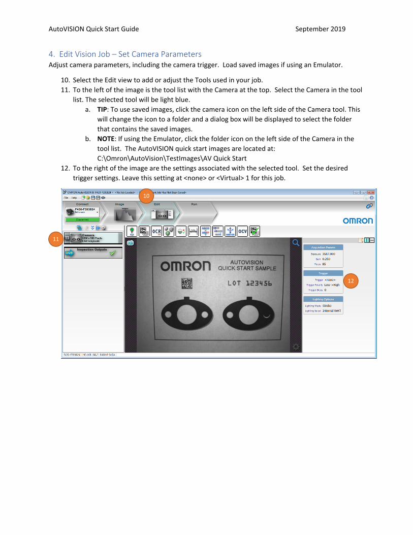
4. Edit Vision Job – Set Camera Parameters Adjust camera parameters, including the camera trigger. Load saved images if using an Emulator.
10. Select the Edit view to add or adjust the Tools used in your job. 11. To the left of the image is the tool list with the Camera at the top. Select the Camera in the tool
list. The selected tool will be light blue. a. TIP: To use saved images, click the camera icon on the left side of the Camera tool. This
will change the icon to a folder and a dialog box will be displayed to select the folder that contains the saved images.
b. NOTE: If using the Emulator, click the folder icon on the left side of the Camera in the tool list. The AutoVISION quick start images are located at: C:\Omron\AutoVision\TestImages\AV Quick Start
12. To the right of the image are the settings associated with the selected tool. Set the desired trigger settings. Leave this setting at <none> or <Virtual> 1 for this job.
10
11
12

AutoVISION Quick Start Guide September 2019
5. Edit Vision Job – Add LocatorLocate the part to compensate for part movement and rotation.
13. The available tools are shown in a toolbar just above the image. Click on the Locator to add thistool to the job.
14. This tool has two regions of interest (ROIs). The inner ROI (Template) is the locate pattern tolearn. The outer ROI (Locate Shape) is the search area for this pattern. Adjust the regions asshown below.
15. Click the Red Train icon in the upper left of the Template ROI. After training the ROIs willbecome green and a yellow outline should be seen around the learned pattern.
a. TIP: To reduce the inspection times, lower the Allowed Rotation value the requiredvalue.
13
15
15a

AutoVISION Quick Start Guide September 2019
6. Edit Vision Job – Add Decode ToolRead the Data Matrix symbol
16. Select the Decode (barcode) icon to add this tool to the job.17. Resize the Decode tool ROI around the Data Matrix Symbol. This tool typically works well with
default settings. No parameter changes are required here.a. TIP: Make the Decode tool ROI 20 % larger than the barcode to allow for the barcode
quiet zone / clean area.
16
17

AutoVISION Quick Start Guide September 2019
18. Enable the rotate option in the OCR parameters. When enabled the icon will be light blue. Thiswill allow the tool to rotate based on the angle of the Locator.
a. The tool rotation can be adjusted by clicking on the blue round rotation handle seen onthe right side of the ROI and dragging to the desired rotation.
18
18a
AutoVISION Quick Start Guide September 2019
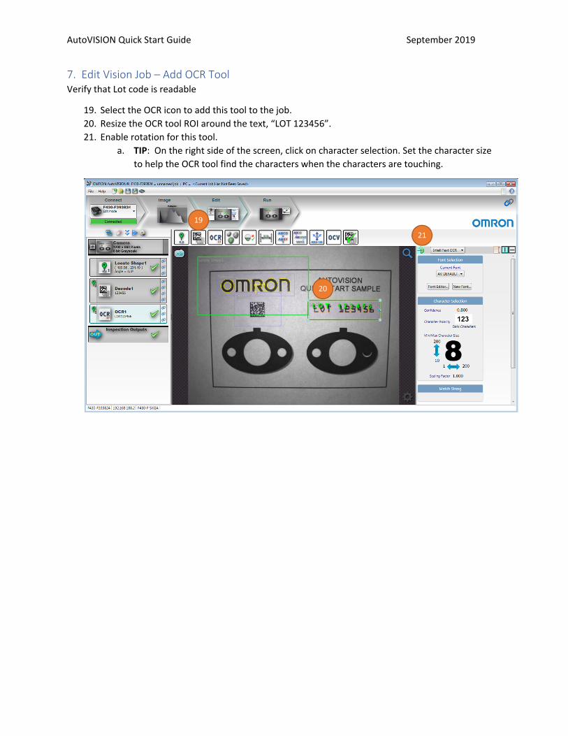
7. Edit Vision Job – Add OCR ToolVerify that Lot code is readable
19. Select the OCR icon to add this tool to the job.20. Resize the OCR tool ROI around the text, “LOT 123456”.21. Enable rotation for this tool.
a. TIP: On the right side of the screen, click on character selection. Set the character sizeto help the OCR tool find the characters when the characters are touching.
19
20
21

AutoVISION Quick Start Guide September 2019
8. Edit Vision Job – Add Count ToolVerify that two small holes are in the gasket.
22. Select the Count Objects icon to add this tool to the job.23. Resize the Count Blobs tool ROI around the left gasket. Enable rotation for this tool.24. Change the Blob settings to find the desired objects. Each blob will have a yellow perimeter with
a crosshair ( + ) in the center. In the parameter settings on right side of screen:a. Set Polarity to Light on Darkb. Adjust Min and Max blob size to count the two smaller white circles on each gasket.c. Change the max and min range of the Tolerance to 2 <–> 2 to make sure the tool only
passes if it finds the correct number of holes, which is this case is 2.
22
23
24
AutoVISION Quick Start Guide September 2019
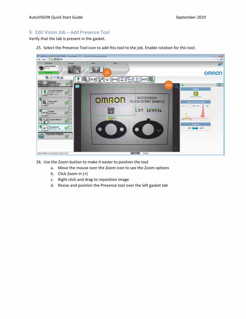
9. Edit Vision Job – Add Presence ToolVerify that the tab is present in the gasket.
25. Select the Presence Tool icon to add this tool to the job. Enable rotation for this tool.
26. Use the Zoom button to make it easier to position the toola. Move the mouse over the Zoom icon to see the Zoom optionsb. Click Zoom in (+)c. Right click and drag to reposition imaged. Resize and position the Presence tool over the left gasket tab
25
26a

AutoVISION Quick Start Guide September 2019
27. Change the Presence tool settings to pass when the gasket tab is present in the tool. The orange pixels inside the tool are the pixels that are counted.
a. Adjust the Upper/Lower Threshold, using the sliders, to make the gasket tab appear orange.
b. Set the Tolerance so that the Presence tool will pass when a gasket tab is in the tool but fails when the tool contains all light or dark pixels. Note the pixel count in the Presence1 tool on the left side of the screen. The lower and upper tolerance settings should bracket this value to determine if the tab is present.
c. Enable the Rotate option. 28. Click Zoom to Fit to see the entire image
26d
27c 26b
27a
27b
28

AutoVISION Quick Start Guide September 2019
10. Edit Vision Job – Add Measure Tool Measure the width of the gasket tab.
29. Select the Measure Tool icon to add this tool to the job. Width measure is default. 30. Resize and position the Measure tool over the right gasket tab. Zoom in if desired. Enable
rotation in this tool. 31. Change the Measure tool settings to pass when the gasket tab is the correct width
a. Adjust the Edge Strength to find the desired edge b. Adjust the Tolerance so that the tab only passes when it is the correct width. The
current width is shown in Measure1 in the tool list on left side of screen.
32. The Measure tool also has a quick calibration option. To use this feature a. Click Calibrate b. The current measurement in pixels is displayed in the Measured Value field c. In the Real World Value field enter the current measurement d. Enter the measurement units e. Click Calibrate
29
30
31

AutoVISION Quick Start Guide September 2019
32
AutoVISION Quick Start Guide September 2019
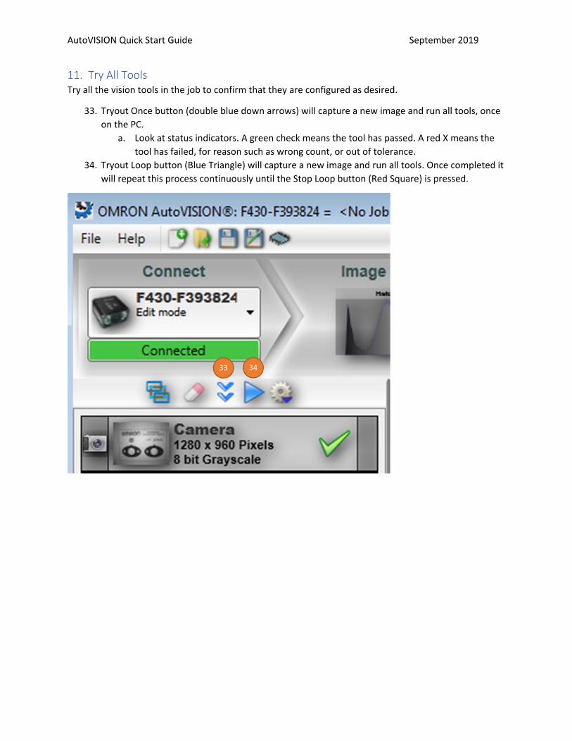
11. Try All ToolsTry all the vision tools in the job to confirm that they are configured as desired.
33. Tryout Once button (double blue down arrows) will capture a new image and run all tools, onceon the PC.
a. Look at status indicators. A green check means the tool has passed. A red X means thetool has failed, for reason such as wrong count, or out of tolerance.
34. Tryout Loop button (Blue Triangle) will capture a new image and run all tools. Once completed itwill repeat this process continuously until the Stop Loop button (Red Square) is pressed.
33 34
AutoVISION Quick Start Guide September 2019
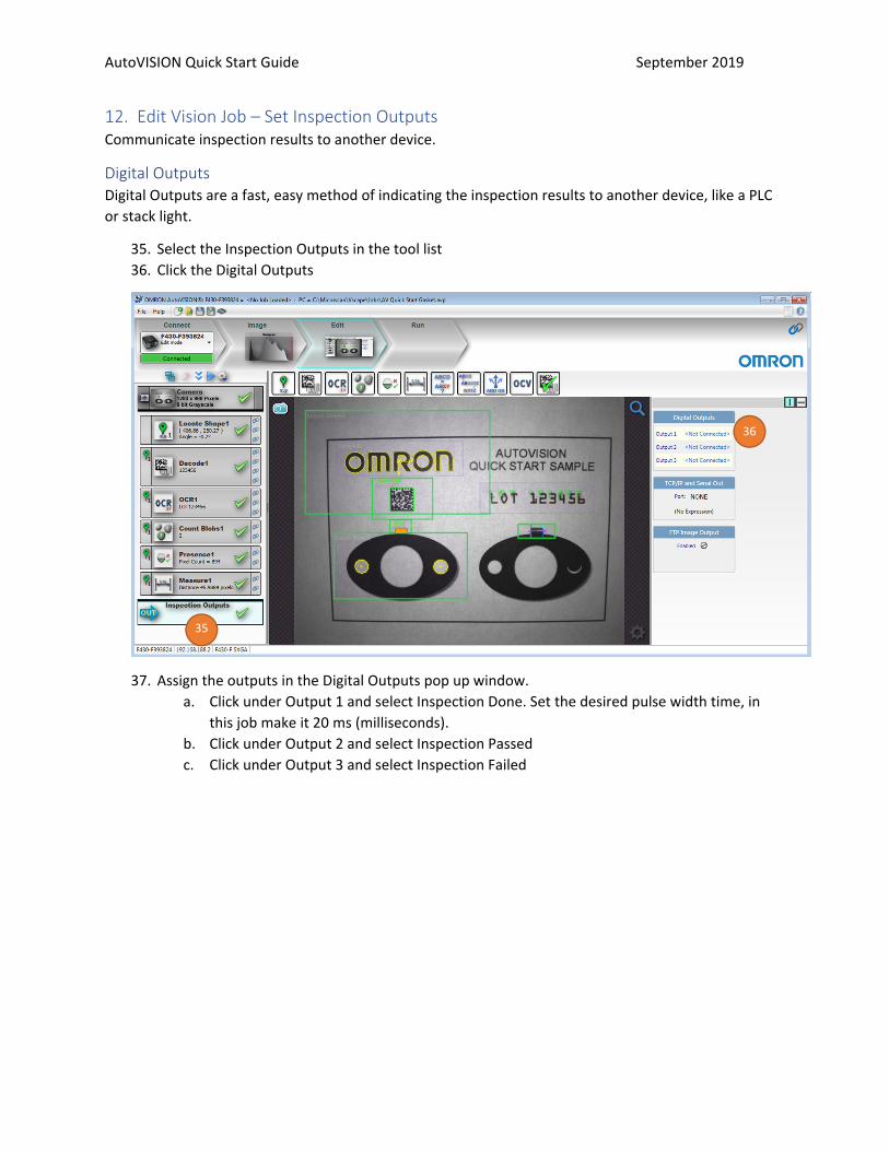
12. Edit Vision Job – Set Inspection OutputsCommunicate inspection results to another device.
Digital Outputs Digital Outputs are a fast, easy method of indicating the inspection results to another device, like a PLC or stack light.
35. Select the Inspection Outputs in the tool list36. Click the Digital Outputs
37. Assign the outputs in the Digital Outputs pop up window.a. Click under Output 1 and select Inspection Done. Set the desired pulse width time, in
this job make it 20 ms (milliseconds).b. Click under Output 2 and select Inspection Passedc. Click under Output 3 and select Inspection Failed
35
36

AutoVISION Quick Start Guide September 2019
37
AutoVISION Quick Start Guide September 2019
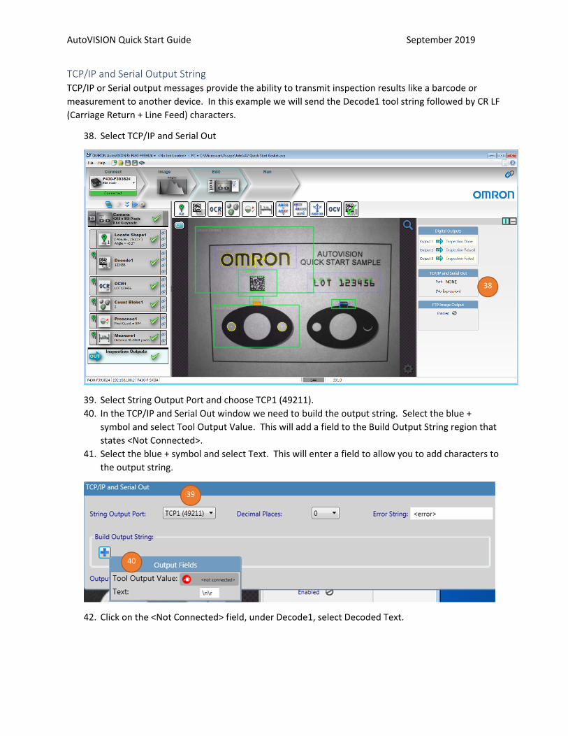
TCP/IP and Serial Output String TCP/IP or Serial output messages provide the ability to transmit inspection results like a barcode or measurement to another device. In this example we will send the Decode1 tool string followed by CR LF (Carriage Return + Line Feed) characters.
38. Select TCP/IP and Serial Out
39. Select String Output Port and choose TCP1 (49211). 40. In the TCP/IP and Serial Out window we need to build the output string. Select the blue +
symbol and select Tool Output Value. This will add a field to the Build Output String region that states <Not Connected>.
41. Select the blue + symbol and select Text. This will enter a field to allow you to add characters to the output string.
42. Click on the <Not Connected> field, under Decode1, select Decoded Text.
38
39
40

AutoVISION Quick Start Guide September 2019
43. Click in the blank text field and enter: \r\n
44. The results can be seen in a telnet client window when an inspection is completed in Edit mode using the Try Once or Try Loop buttons and in Run mode.
Opening Telnet Client to view results If the Telnet Client has not been enabled in Windows, please go to the link below and follow the instructions to enable this Windows feature.
https://social.technet.microsoft.com/wiki/contents/articles/38433.windows-10-enabling-telnet-client.aspx
45. Click the Windows Start button, type cmd.exe and hit the Enter key. 46. In the cmd.exe window type the following command listed. Replace the 192.168.188.2 with your
camera IP address. Note: Your camera IP address can be found if you click on the word Connect in AutoVISION. If using the Emulator use IP address: 127.0.0.1
a. telnet 192.168.188.2 49211
42
43

AutoVISION Quick Start Guide September 2019
47. Click the Try Once button in AutoVISION. Each time the Inspection is run the decoded text isshown in the Telnet window on a new line.
13. Save Job48. Go to the File menu > Save or click the Save icon
a. TIP: Go to the File menu and select Archive Job… This will save the AutoVISION(Visionscape) job and will make an additional file Visionscape Archive file that has an.AVZ extension. The Visionscape Archive file contains the AutoVISION job and all theadditional support files used by that job.
46
47
AutoVISION Quick Start Guide September 2019
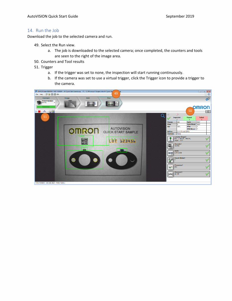
14. Run the JobDownload the job to the selected camera and run.
49. Select the Run view.a. The job is downloaded to the selected camera; once completed, the counters and tools
are seen to the right of the image area.50. Counters and Tool results51. Trigger
a. If the trigger was set to none, the inspection will start running continuously.b. If the camera was set to use a virtual trigger, click the Trigger icon to provide a trigger to
the camera.
49
51
50

AutoVISION Quick Start Guide September 2019
15. Save Job to flash memory on cameraSaving the job to flash memory on the camera is required to allow the camera to load and restart the job on power up.
52. Select the Edit view.53. Confirm that the job is correct and has been saved to the PC.
a. TIP: It is recommended that you select File > Archive Job… This will save the job to thePC and create an Archive file (*.avz) that contains the job and additional support filesused by the job.
54. Select the camera flash memory icon55. Select the memory slot to write
a. Select New Slot to write this job to the camera.b. If jobs exist on the camera, selecting an existing slot will overwrite that memory slot.
56. A pop-up window may appear which will allow you to select the desired job to save to thecamera.
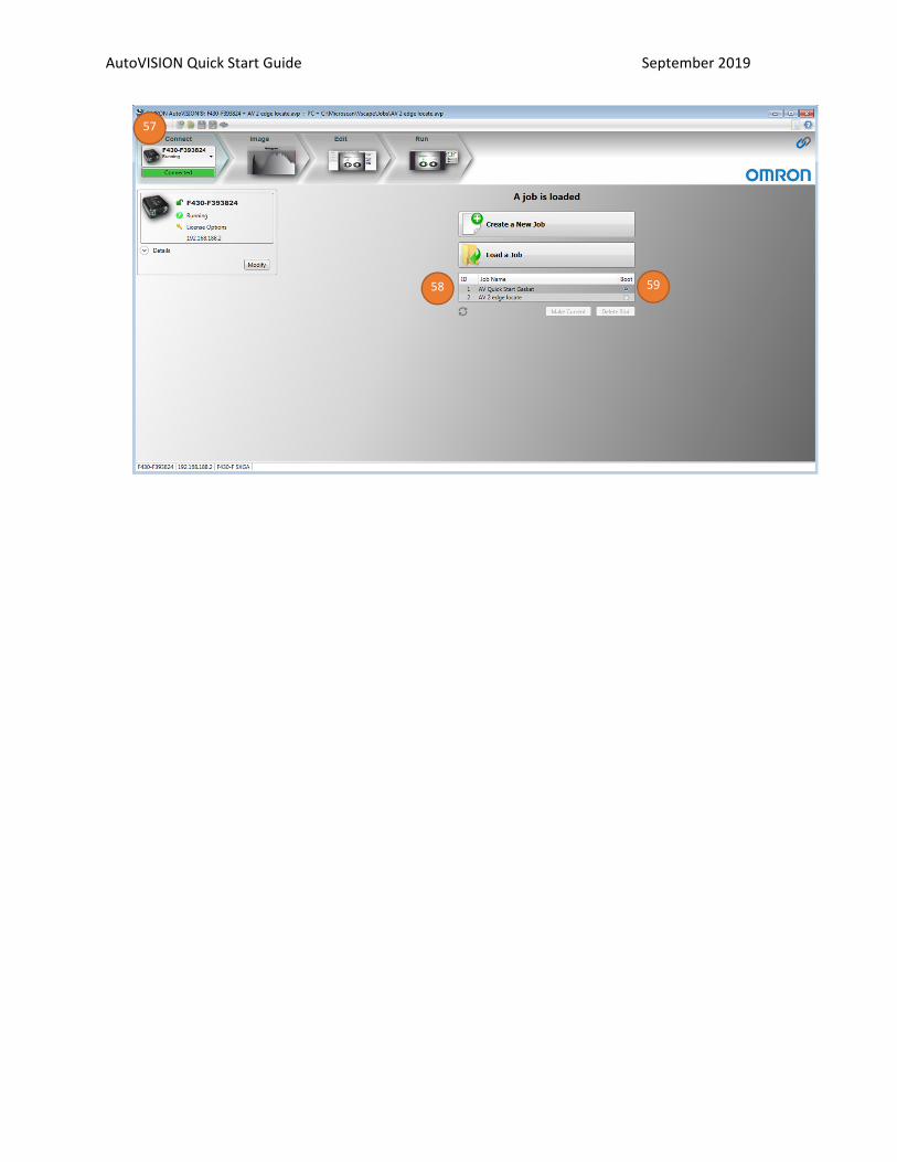
57. Select Connect viewa. TIP: Click on the word “Connect” above the camera selection.
58. Below the “Load a Job” button is a listing of the jobs stored in flash memory on the camera.59. If multiple jobs are stored in flash memory, select the desired job slot that should be loaded on
camera power up.
54
55a
56
AutoVISION Quick Start Guide September 2019
57
58 59

AutoVISION Quick Start Guide September 2019
Appendix A – Quick Start Samples Good Sample
Bad Sample

Authorized Distributor:
0919
© OMRON Corporation 2019 All Rights Reserved. In the interest of product improvement, specifications are subject to change without notice.
84-9100005-02 Rev A
OMRON Corporation Industrial Automation Company
OMRON ELECTRONICS LLC2895 Greenspoint Parkway, Suite 200 Hoffman Estates, IL 60169 U.S.A.Tel: (1) 847-843-7900/Fax: (1) 847-843-7787
Regional HeadquartersOMRON EUROPE B.V.Wegalaan 67-69, 2132 JD HoofddorpThe NetherlandsTel: (31)2356-81-300/Fax: (31)2356-81-388
Contact: www.ia.omron.comKyoto, JAPAN
OMRON ASIA PACIFIC PTE. LTD.No. 438A Alexandra Road # 05-05/08 (Lobby 2), Alexandra Technopark, Singapore 119967Tel: (65) 6835-3011/Fax: (65) 6835-2711
OMRON (CHINA) CO., LTD.Room 2211, Bank of China Tower, 200 Yin Cheng Zhong Road, PuDong New Area, Shanghai, 200120, ChinaTel: (86) 21-5037-2222/Fax: (86) 21-5037-2200