Embed Size (px)
Citation preview
IN DEGREE PROJECT TECHNOLOGY,FIRST CYCLE, 15 CREDITS
, STOCKHOLM SWEDEN 2018
AutoTruckAutomated docking with internal sensors
OSCAR ANDERSSON
LUCAS MOLIN
KTH ROYAL INSTITUTE OF TECHNOLOGYSCHOOL OF INDUSTRIAL ENGINEERING AND MANAGEMENT

AutoTruck
Automated docking with internal sensors
OSCAR ANDERSSONLUCAS MOLIN
Batchelor’s Thesis at ITMExaminer: Nihad Subasic
TRITA-ITM-EX 2018:69

AbstractThe purpose of this bachelor thesis was to discover how
an articulated vehicle can park itself using a pre-definedparking path with a combination of ultrasonic sensors aswell as a rotary angle sensor.
The project was divided into two parts: constructing asmall scale demonstrator and the software controlling thedemonstrator. The demonstrator was constructed from off-the-shelf components and custom parts. The truck was de-signed based on a rear wheel driven truck with Ackermannsteering. The localization of a parking spot and measuringother distances was done with ultrasonic sensors and thehitch angle was measured by a rotary angle sensor.
The performance of the demonstrator was evaluated bymeasuring the trailers angle difference from the center lineof the parking spot.
The performance was deemed to be reasonably goodwith successful parkings in 8 out of 10 attempts.
Mechatronics, Trailer, Truck, Articulated vehicle, Self driving

ReferatSjälvparkerande lastbil
Kandidatarbetet syftar till att undersoka hur ett ledatfordon kan parkera sig sjalvt efter en forbestamd parke-ringsrutt med en kombination av flera ultraljudssensorersamt en vinkelgivare.
Projektet bestar av tva delar; konstruktion av ett mi-niatyrfordon samt mjukvaran som styr fordonet. Fordonettillverkades fran butikskopta komponenter och skraddarsyddadelar. Lastbilens design var baserad pa en bakhjulsdrivenAckermannstyrd lastbil. Identifieringen av en parkerings-plats samt avstandsmatning hanterades av ultraljudssenso-rer och hitch vinkeln mattes av en vinkelgivare.
Miniatyrfordonets prestanda utvarderades genom attmata slapets vinkelskillnad fran centerlinjen av parkerings-platsen.
Prestandan ansags att vara tillrackligt god med lyckadeparkeringar i 8 av 10 tester.
Mekatronik,Trailer, Lastbil, Ledat fordon, Sjalvkorande

Acknowledgements
We would like to thank Nihad Subasic for rewarding discussions and helpful tips inmainly the problem formulation, but also throughout the project. We would alsolike to thank the assistants Johan Ehrenfors, Martin Gylling and Stanislav Minkofor invaluable help with persistent coding issues, and general guidance during thewhole process. We would like to extend a large thanks to Staffan Qvarnstromand Thomas Ostberg for guidance with respect to electric and mechanic problems.Furthermore, we would like to thank Jannis Angelis for inspiring the analysis aboutthe emergence of this technology in real life. Finally we would like to thank all thestudents in the mechatronics lab as well as down in the workshops for all the helpwith things large and small.

Contents
Contents
List of Figures
List of Tables
Introduction 2Background . . . . . . . . . . . . . . . . . . . . . . . . . . . . . . . . . . . 2Purpose . . . . . . . . . . . . . . . . . . . . . . . . . . . . . . . . . . . . . 2Method . . . . . . . . . . . . . . . . . . . . . . . . . . . . . . . . . . . . . 2Scope . . . . . . . . . . . . . . . . . . . . . . . . . . . . . . . . . . . . . . 3
Theory 4Ackermann Steering . . . . . . . . . . . . . . . . . . . . . . . . . . . . . . 4Docking . . . . . . . . . . . . . . . . . . . . . . . . . . . . . . . . . . . . . 5
Dynamics of articulated vehicles . . . . . . . . . . . . . . . . . . . . 5Human parking behaviour . . . . . . . . . . . . . . . . . . . . . . . . 5
Ultrasonic Distance measurement . . . . . . . . . . . . . . . . . . . . . . . 6PID Controller . . . . . . . . . . . . . . . . . . . . . . . . . . . . . . . . . 7
Demonstrator 8Electronics . . . . . . . . . . . . . . . . . . . . . . . . . . . . . . . . . . . 9
Sensors . . . . . . . . . . . . . . . . . . . . . . . . . . . . . . . . . . 9Arduino . . . . . . . . . . . . . . . . . . . . . . . . . . . . . . . . . . 9Adafruit motor shield . . . . . . . . . . . . . . . . . . . . . . . . . . 10
Truck . . . . . . . . . . . . . . . . . . . . . . . . . . . . . . . . . . . . . . 10Steering . . . . . . . . . . . . . . . . . . . . . . . . . . . . . . . . . . 10Sensors . . . . . . . . . . . . . . . . . . . . . . . . . . . . . . . . . . 11
Drivetrain . . . . . . . . . . . . . . . . . . . . . . . . . . . . . . . . . . . . 11Stepper Motor . . . . . . . . . . . . . . . . . . . . . . . . . . . . . . 11Rear axle . . . . . . . . . . . . . . . . . . . . . . . . . . . . . . . . . 12Cogwheels and Timing Belt . . . . . . . . . . . . . . . . . . . . . . . 12
Trailer . . . . . . . . . . . . . . . . . . . . . . . . . . . . . . . . . . . . . . 12Front . . . . . . . . . . . . . . . . . . . . . . . . . . . . . . . . . . . . 12

Rear . . . . . . . . . . . . . . . . . . . . . . . . . . . . . . . . . . . . 12Electronics . . . . . . . . . . . . . . . . . . . . . . . . . . . . . . . . . . . 13Software . . . . . . . . . . . . . . . . . . . . . . . . . . . . . . . . . . . . . 13
Emergence of automating docking in logistics centers 15Possible benefits of implementing automated docking . . . . . . . . . . . . 15Who would make the investment? . . . . . . . . . . . . . . . . . . . . . . 16Conclusions . . . . . . . . . . . . . . . . . . . . . . . . . . . . . . . . . . . 16
Experiments 17Test Area . . . . . . . . . . . . . . . . . . . . . . . . . . . . . . . . . . . . 17Experiment description . . . . . . . . . . . . . . . . . . . . . . . . . . . . 17Parking results . . . . . . . . . . . . . . . . . . . . . . . . . . . . . . . . . 18
Discussion and conclusions 19Performance of drivetrain . . . . . . . . . . . . . . . . . . . . . . . . . . . 19Problems with using a pre defined path . . . . . . . . . . . . . . . . . . . 19Performance of steering and PID . . . . . . . . . . . . . . . . . . . . . . . 19Conclusion . . . . . . . . . . . . . . . . . . . . . . . . . . . . . . . . . . . 20
Bibliography 21
Appendices 22
Arduino Code 23
Raw Data from Experiments 28

List of Figures
1 Ackermann Steering [4]. . . . . . . . . . . . . . . . . . . . . . . . . . . . 42 Kinematic model made by Amro Elhassan [3] . . . . . . . . . . . . . . . 6
3 Fully constructed demonstrator . . . . . . . . . . . . . . . . . . . . . . . 84 Demonstrators drivetrain . . . . . . . . . . . . . . . . . . . . . . . . . . 115 Cogwheel that is mounted on rear axle as well as motor axle. Picture
rendered with Keyshot 6 [15] . . . . . . . . . . . . . . . . . . . . . . . . 136 Flow chart of the algorithm. Made with draw.io [10] . . . . . . . . . . . 14
7 Test area and vehicle path. Made with Microsoft PowerPoint . . . . . . 17
List of Tables
1 Dimensions of the truck. . . . . . . . . . . . . . . . . . . . . . . . . . . . 92 Arduino Uno specifications. . . . . . . . . . . . . . . . . . . . . . . . . . 93 Adafruit motor shield v2.3 specifications. . . . . . . . . . . . . . . . . . 10
4 Experiment results from the ten tests conducted. . . . . . . . . . . . . . 18

List of Abbreviations
IDE Integrated Development Environment
PID Proportional, Integral, Derivative
PV C Poly Vinyl Chloride
PWM Pulse Width Modulation
RC Remotely Controlled
1
Introduction
BackgroundReversing a vehicle is considered by many human drivers to be the hardest part ofdriving, especially with a trailer attached, due to the somewhat counter-intuitivemovements required to position the trailer correctly. Professional truck drivers areof course better at handling their vehicle even though it is not an easy task. Whendocking with loading bays the vehicle often has to be reversed which makes thisa regular occurrence. An automated system should in theory be able to performthese actions better than a human driver could.
Several companies are working today with the total or partial automation oftrucks. Tesla is constructing their own truck [2] and Volvo says that ”We believethat automation will redefine the commercial transport solutions that most of usrely on every day.” [20].
PurposeThe purpose of this report is to answer the following question:
How can a parking algorithm be implemented to park an articulated vehicle intoa trailer loading dock?
To answer this question an autonomous demonstrator vehicle will be constructed.The tests will be made with the primary focus on if the vehicle is able to park safelybetween two trailers. The tests will use the PID-algorithm and a pre defined pathto park itself. A docking is considered successful when the trailer is within thedesignated docking spot.
MethodA model with the scale of 1:20 compared to a regular Scania truck [14] is constructedto resemble a truck with four wheels, Ackermann steering and rear wheel drive. Thevehicle will utilize an Arduino UNO microcontroller in order to control the motorsthat handles the movement and steering as well as receiving signals and processinginputs from the robot’s surroundings. Four ultrasonic sensors are used to measurethe distance to objects in proximity to the robot. One sensor will be placed on
2

the left side of the vehicle to be able to measure the size of the parking spot. Thetrailer will have one sensor at the rear and one on each side close to the middle ofthe trailer length. The performance of the vehicle will be simulated with a smallscale test that is constructed to resemble a truck parking in a loading dock. A testrun will begin with the autonomous vehicle travelling along a line of parked trailersuntil it finds a suitable parking spot which it will park itself into. The test run willbe deemed successful when the vehicle managed to align itself between two trailerswithout colliding into any of the trailers.
ScopeThe robot is assumed to be driven along a straight line of vehicles parked perpen-dicularly to the robots path on a flat surface. The path is modelled after a normalparking path. The only obstacles facing the vehicle during testing will be the parkedtrucks represented by cardboard boxes. To develop the project further a path plan-ner could be included to allow the vehicle to traverse more complex environments.The programming will not allow for manual control after the parking program hasbeen started. The vehicle will not be able to try again if a failed parking occurswithout manual resetting. A failed docking means that the vehicle got too close tothe obstacles, crashed into them, or that it did not enter the docking spot or didnot properly align itself inside the docking spot.
3

Theory
Ackermann SteeringWhen performing parking lot maneuvers at low speed the tires of a vehicle do notdevelop lateral forces. Instead the tires roll with no slip angle while turning as seenin figure 1. In the figure the principles of Ackermann Steering is shown.
Figure 1: Ackermann Steering [4].
Ackermann steering and the geometry behind it is a geometric arrangementwhere the linkages in the steering of vehicles are designed to avoid the need fortires to slip sideways when following paths around curves. The slip is caused by thewheels on the inside and outside having to trace out circles of different radii.
The Ackermann steering principle is implemented to compensate for this byhaving all wheels and their axles arranged as radii of circles with a common centrepoint. When the rear wheels are fixed, the center point moves on a line extendingfrom the rear axle. The steering arms are angled inwards in order to steer to agreater angle than the outside wheel. This angling allows the Ackermann angle to
4
be determined. In order to do this symmetry lines have to be drawn through thesteering arms to intersect with the rear axle’s centre line. The vehicle’s curve radiuscan then be measured as the distance between the intersection of the front wheelaxes symmetry lines and the centre of rear axle.
DockingThis vehicle will be able to identify and locate a suitable parking spot to the leftwhile driving in a straight line. A suitable docking spot is one measured by thevehicle. The chosen size was double the width of the demonstrator and was decidedwith regards to the demonstrators pre-defined docking path. The goal is to achievea safe and reliable park.
Dynamics of articulated vehiclesArticulated vehicles have many benefits compared to non articulated vehicles, butare much harder to drive in reverse. The main difference in reversing an articulatedvehicle compared to parking a normal vehicle is that the hitch angle, defined as theangle between the trailer and vehicle, is not directly steerable. Furthermore it is alsopossible to get into a state called ”Jackknifing” where it is impossible to recover andnot crash the truck into itself without driving forward. On the constructed modelthis should be 90° as the limitation will be the kinematic constraint, as the trailerdoes not hit the truck before that.
A kinematic model of the dynamics is described by Amro Elhassan [3] with thefollowing equations 1
xC = v cos(θ1 − θ2)cos(θ2)yC = cos(θ1 − θ2)sin(θ2)
θ1 = v tan(φ)L1
θ2 = v sin(θ1 − θ2)L2
(1)
This leads to the hitch angle being defined by the steering angle as equation 2
δ = θ1 − θ2 = v tan(φ)L1
− v sin(θ1 − θ2)L2
(2)
Figure 2 shows how all the variables are defined in the model.
Human parking behaviourIn the scope of this report a path planner is not included. Therefore somethingelse has to plan the path of the vehicle. The path taken will be inspired by howa professional driver today parks its truck in the situation that is modelled which
5
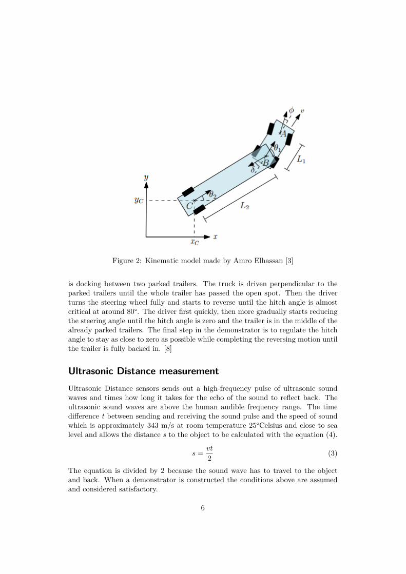
Figure 2: Kinematic model made by Amro Elhassan [3]
is docking between two parked trailers. The truck is driven perpendicular to theparked trailers until the whole trailer has passed the open spot. Then the driverturns the steering wheel fully and starts to reverse until the hitch angle is almostcritical at around 80°. The driver first quickly, then more gradually starts reducingthe steering angle until the hitch angle is zero and the trailer is in the middle of thealready parked trailers. The final step in the demonstrator is to regulate the hitchangle to stay as close to zero as possible while completing the reversing motion untilthe trailer is fully backed in. [8]
Ultrasonic Distance measurementUltrasonic Distance sensors sends out a high-frequency pulse of ultrasonic soundwaves and times how long it takes for the echo of the sound to reflect back. Theultrasonic sound waves are above the human audible frequency range. The timedifference t between sending and receiving the sound pulse and the speed of soundwhich is approximately 343 m/s at room temperature 25°Celsius and close to sealevel and allows the distance s to the object to be calculated with the equation (4).
s = vt
2 (3)
The equation is divided by 2 because the sound wave has to travel to the objectand back. When a demonstrator is constructed the conditions above are assumedand considered satisfactory.
6
PID ControllerControl systems are widely used in a lot of different systems, some examples arebalancing robots, cruise control in cars and autopilot in airplanes just to name afew.
Proportional-integral-derivative controller, (PID) controller is a control loopfeedback mechanism which calculates a continuous error value e(t) between a cur-rent measured value and a specified desired value, in order to then calculate therequired change u(t) to the control signal.
The PID controller equation is presented in equation (4) where the behaviour ofthe system is dependent on three parameters: proportional gain,Kp, integral gain,KI and derivative gain KD. [5]
u(t) = Kpe(t) +KI
∫ t
0e(τ)dτ +KD
d
dte(t) (4)
The system characteristics impacted by the choices of parameters are overshoot,static error, rise time and settling time.
Overshoot is when the signal exceeds its target value and is often caused byover-regulating the system.
Static error (steady state error) is a constant error term which remains over time,the error is proportional to process gain and inversely proportional to proportionalgain. Steady state error is usually compensated for by implementing an integralterm.
Settling time is the time from the instantaneous step response to the time atwhich the output has entered and remained within a specified margin of error fromthe desired value.
When regulating angles in control systems, too long of a rise time and too muchovershoot might lead to undesired behaviours such as collisions during parking. Thismay occur even though the system initially works and behaves in a desirable way.
7
Demonstrator
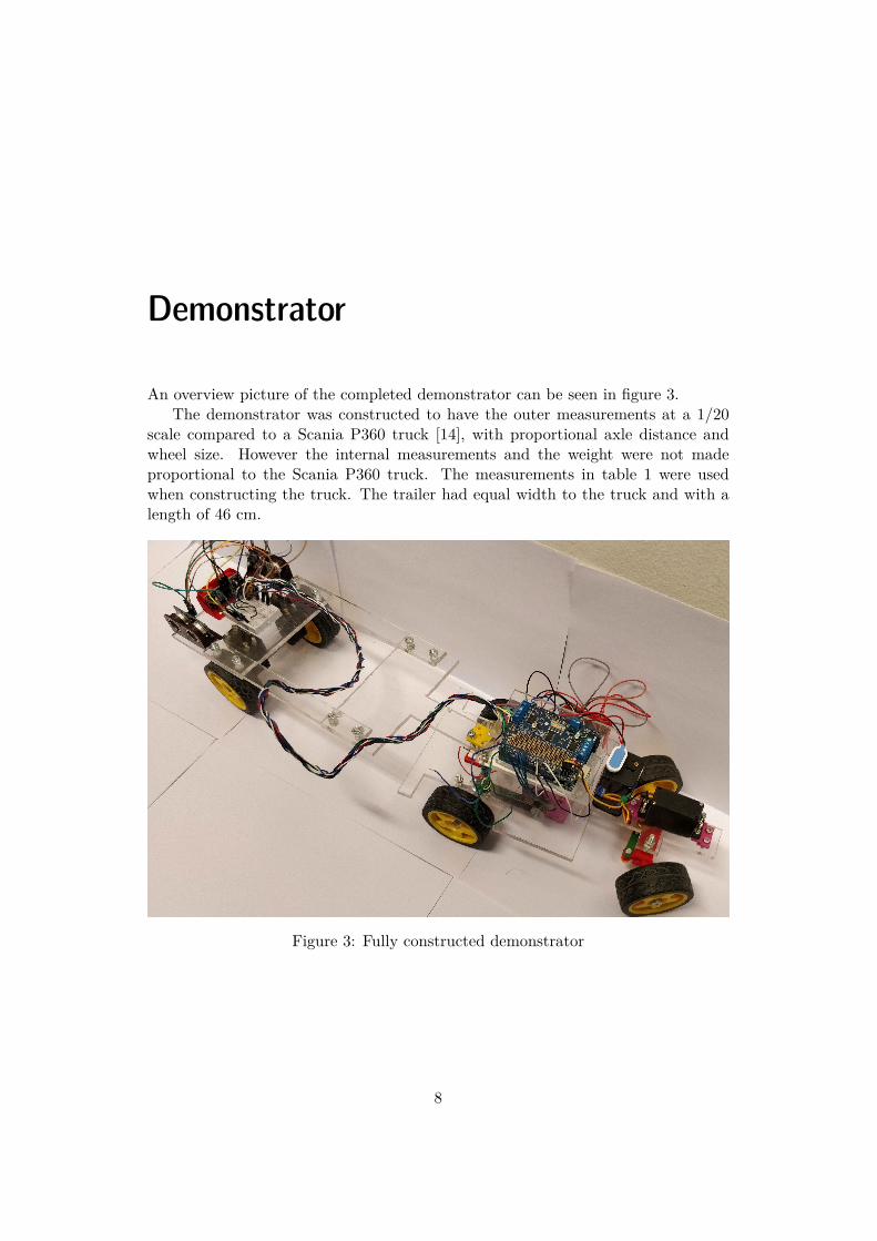
An overview picture of the completed demonstrator can be seen in figure 3.The demonstrator was constructed to have the outer measurements at a 1/20
scale compared to a Scania P360 truck [14], with proportional axle distance andwheel size. However the internal measurements and the weight were not madeproportional to the Scania P360 truck. The measurements in table 1 were usedwhen constructing the truck. The trailer had equal width to the truck and with alength of 46 cm.
Figure 3: Fully constructed demonstrator
8

Description ValueLength l 280 mmWidth b 130 mm
Table 1: Dimensions of the truck.
Electronics
SensorsUltrasonic sensor
The testbed uses 4 HC-SR04 Ultra sonic-sensors. HC-SR04 was chosen due to itssmall size and easy implementation. How the sensor works is described in chapter .
Rotary Angle Sensor
An off-the-shelf potentiometer was modified with a steelrod, so that it could workas a tow ball for the trailer. The sensor produces analog output between 0 and Vcc(5V DC) on the A3 connector with an angular range up to 300 degrees and a linearchange in value. Some manual adjustments were made in the code in order to makesure that a certain value corresponded to the trailer being aligned.
ArduinoThe Arduino Uno is an open-source microcontroller which in this project is usedto read input signals and turn them into output signals. Instructions for how theArduino handles input and output is programmed using Arduino IDE software. TheArduino handles input from the sensors and sends the output to the Adafruit motorshield v2.3 in order for it to control the motors. The Arduino Uno was chosen forthis project because of its relatively small size, while still being able to handle allsignals as well as take in and process the sensor data within a reasonable timeframe.
Table 2 includes the most necessary specifications for the Arduino Uno.
Description ValueOperating Voltage 5 V
Input Voltage 7 V - 12 VClock Speed 16 Mhz
Table 2: Arduino Uno specifications.
9

Adafruit motor shieldIn order to control all of the motors used in the project an Adafruit motor shieldv2.3 was implemented. The board connects to the Arduino Uno with regular pinheaders and has a dedicated PWM driver chip onboard. The chip allows the user tohandle all of the connected motors with different speed controls as well as allows therequired motor voltage of 6 V and 1 A to be supplied to the motor without damagingthe Arduino. Furthermore it has an Arduino software library for controlling themotors which simplifies software development.
The stepper motor is connected to a motor port on the Adafruit, and is controlledwith Adafruits Stepper library.
Table 3 includes the most necessary specifications for the Adafruit motor shieldv2.3.
Description ValuePower Supply Voltage 15 V
Output current 1.2 A (ave) / 3.2 A (peak)Number of Digital I/O Pins 14
Number of Analog Input Pins 6Number of PWN Digital I/O Pins 2
Table 3: Adafruit motor shield v2.3 specifications.
Truck
SteeringThe Ackermann steering was modeled based on the design from a bachelor thesis,Following Car,[18] but was remodeled to comply to the Ackermann principles andwith the outer dimensional constraints of the demonstrator. The reasoning behindchoosing Ackermann steering was partly based on the efficiency of said method aswell as the geometrical benefits.
The Ackermann steering pars were made with Solid Edge ST9: Siemens PLMSoftware [16] and 3D printed using Ultimaker 2 and Ultimaker 3 [19]. The steeringpars are held together with standard nuts and bolts.
A servo motor, Hitec Hs-300 RCD Apollo 5 was used to control the steering, as itcan guarantee that the required steering angle is met by the demonstrator, which isvery important in a non holomistic system when reversing the vehicle, where failureto meet the demanded steering angle could quickly result in a non recoverable state.
10
SensorsUltrasonic sensor
One HC-SR04 Ultra sonic-sensor was mounted on the middle left side of the truckin order to measure and identify a suitable parking spot.
Rotary Angle Sensor
The Rotary Angle Sensor was used to calculate the hitch angle between the trailerand the truck. It was mounted centrally above the rear axle of the truck, althoughon real trucks it is mounted in front of the rear axle. This was done because itsimplifies the transfer functions greatly [3] without impacting the dynamics muchin reality.
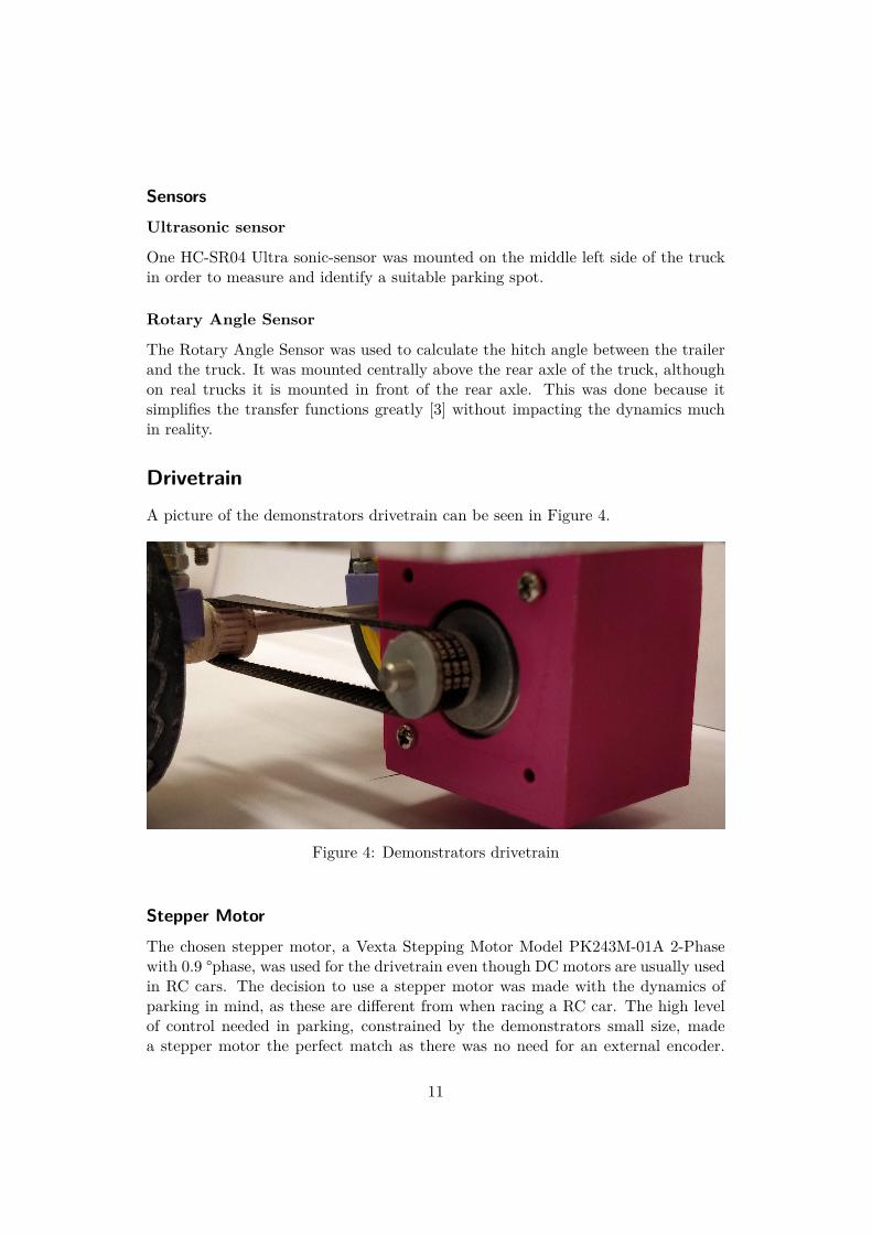
DrivetrainA picture of the demonstrators drivetrain can be seen in Figure 4.
Figure 4: Demonstrators drivetrain
Stepper MotorThe chosen stepper motor, a Vexta Stepping Motor Model PK243M-01A 2-Phasewith 0.9 °phase, was used for the drivetrain even though DC motors are usually usedin RC cars. The decision to use a stepper motor was made with the dynamics ofparking in mind, as these are different from when racing a RC car. The high levelof control needed in parking, constrained by the demonstrators small size, madea stepper motor the perfect match as there was no need for an external encoder.
11

The stepper motor is easily commanded to drive a certain number of steps, whichtranslates to a set number of centimeters driven, simplifying path design.
Motormounts were modeled in Solid Edge ST9: Siemens PLM Software [16] and3D printed using Ultimaker 2 and Ultimaker 3 [19] in order to hold the motor inplace under the truck.
Rear axleThe rear axle is a 5 mm thick steel axis which is held in place by two mounts.The mounts were made with Solid Edge ST9: Siemens PLM Software [16] and 3Dprinted using Ultimaker 2 and Ultimaker 3 [19]. The mounts were screwed onto theplate using nuts and bolts. The wheels on each side are held in place by a screw inorder to lock them in the axial direction.
Cogwheels and Timing BeltTwo cogwheels with a timing belt between them are used to transfer torque fromthe motor to the rear axle. The cogwheels were fitted tightly onto the axles.
In figure 5 the cogwheel mounted on the rear axle is shown. A similar cogwheelis mounted on the motor axle but with a different hole diameter. The cogwheel onthe rear axle is locked in place axially with a screw and the cogwheel on the motoris pressed onto the Stepper motor axle. The use of a timing belt ensured that thedesired amount of steps translated exactly to the driving axle.
The timing belt transfers torque from the Stepper motor to the rear axle. RSPro Timing Belt 85 Tooth was chosen for this purpose. Mainly due to the smallsize of the belt as it suits the demonstrator well. The timing belt is 172.2 mm longand 6 mm wide.
Trailer
FrontThe front was laser-cut from a PVC-board, in the shape of a T, to allow realistichitch angle of 90° while not taking space from the trucks electrical components. Theupper part of the tow ball mount was designed in Solid Edge ST9: Siemens PLMSoftware [16] and 3D printed using Ultimaker 2 and Ultimaker 3 [19], which wasmounted centrally on the laser cut parts. On the wide part there are two holes forfastening the extenders. The front was attached to the rear with two extenders. Thepair of extenders were laser-cut from PVC with two holes at each end for fastening.
RearThe rear was also laser-cut from acrylic plastic. It has three Ultrasonic sensorsSR-04 mounted on top of it, one in the middle, facing rear, and two symmetricallyplaced facing right and left. These are connected to a small breadboard, which in
12
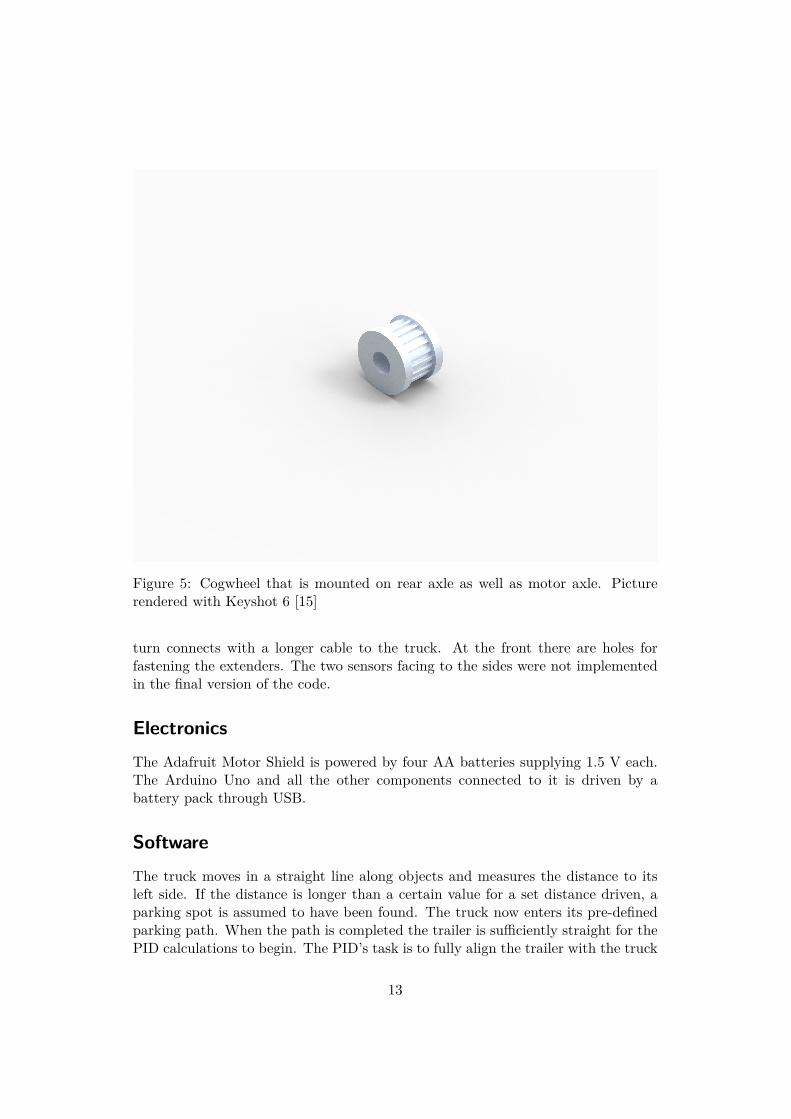
Figure 5: Cogwheel that is mounted on rear axle as well as motor axle. Picturerendered with Keyshot 6 [15]
turn connects with a longer cable to the truck. At the front there are holes forfastening the extenders. The two sensors facing to the sides were not implementedin the final version of the code.
ElectronicsThe Adafruit Motor Shield is powered by four AA batteries supplying 1.5 V each.The Arduino Uno and all the other components connected to it is driven by abattery pack through USB.
SoftwareThe truck moves in a straight line along objects and measures the distance to itsleft side. If the distance is longer than a certain value for a set distance driven, aparking spot is assumed to have been found. The truck now enters its pre-definedparking path. When the path is completed the trailer is sufficiently straight for thePID calculations to begin. The PID’s task is to fully align the trailer with the truck
13
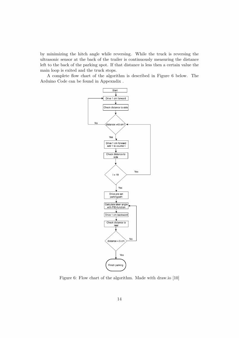
by minimizing the hitch angle while reversing. While the truck is reversing theultrasonic sensor at the back of the trailer is continuously measuring the distanceleft to the back of the parking spot. If that distance is less then a certain value themain loop is exited and the truck stops.
A complete flow chart of the algorithm is described in Figure 6 below. TheArduino Code can be found in Appexndix .
Figure 6: Flow chart of the algorithm. Made with draw.io [10]
14

Emergence of automating docking inlogistics centers
This work have focused on the technical solutions enabling an articulated vehicle toautonomously reverse into a loading dock. The demonstrator and the scope of thiswork would not in itself allow for completely automated loading areas, but couldbe a central part of a larger system, handling traffic and docking of trailers at alogistics centre.
This section will attempt to broadly describe the conditions and actors presentin the sector today, and their impact on the emergence of this technology in thefield.
Possible benefits of implementing automated dockingTraditional loading of a trailer takes up to 30 minutes but can take as low as 2minutes with automated loading [9]. The large difference in loading time createstwo different cases for automated trailer management. With 30 minutes loadingtime, truck drivers could arrive with one trailer and leave instantly with another,however this procedure would probably not be efficient with the short loading time.
In Sweden the average hourly salary for a truck driver is 140 kr [11]. Saving 30minutes at each end would therefore only yield a saving of 140 kr per transportedtrailer. This could probably be realized easier with an automated loading systemthan with a complex system of changing trailers only viable at very large reloadingcenters.[9]
However at very large loading areas the time to find the right dock, get checkedin etc, adds up, and the benefit of automating grows. Amazon has been investingheavily in making their supply chain more efficient and automated. In the fall of2017 Amazon launched an app called ”Relay” with the special goal of optimizingthe check in and docking process[17]. Automating the whole dockingprocess wouldfurther Amazon’s stated goals, and could be possible given Amazon’s opportunityto own or control all of the parts in the logistics chain.
This suggests that the benefits of implementing this technology would mainlybe visible for very large actors.
15

Who would make the investment?The logistics/transportation market is divided into three major players.[1]
• The customers, who want goods moved at the lowest price with the high-est convenience, for example Zalando, often owns warehouses and sometimeslogistics centers.
• The logistics firms, who plan routes and optimize paths for specific parcels,owns the trailers and the planning algorithms, and faces both the end cus-tomers and the freight forwarders.
• The freight forwarders contacted by the logistics firms to drive a certain route,often owns the trucks.
This dynamic creates a difficulty in finding an actor willing to invest in furtherdeveloping this technology. The technological developments in autonomous truckinghave mostly been focused on automating highway driving, as it is the easiest toautomate, while also taking up a lot of driving time [13].
The logistics companies do not own the trucks, where most of the tech wouldhave to be placed, and do not control the loading areas, which would have to beoptimized to utilize the technology. They would therefore be secondary actors inthe development of self parking trucks. Developing this technology would thereforeneed an actor with a more vertically integrated supply-chain (as noted in the sectionabout economical impacts).
ConclusionsThe fragmented market structure and limited profits for smaller actors implement-ing automated docking suggests that this type of automation will be implementedfurther into the future, as a part of a more generally automated logistics chain,rather than as a small automated part in a generally human dependant system.
Suggested by the technical conclusions of this thesis using automated dockingsystems, where a central system reliant on local positioning systems controls theplanning of trucks, and control their adherence to their paths would be a bettersystem than with the internal sensors and systems used for automated driving onoutside roads. This could create a ”handover”, where the systems used on the closedarea for docking hands over control to the trucks internal system, when the truckand trailer leaves the gates.
The structure of the market, and the moves made by Amazon, together withthe fact that only already autonomous trucks can be remotely controlled safelysuggests that the primary driver of innovation and the path of emergence will bechiefly influenced by Amazon or another player of similar characteristics.
16

Experiments
Test AreaThe test area was designed to resemble a large loading area with multiple docks ina row. In some of the docks trucks were already parked in order for the ultrasonicsensors to find an empty spot. A large loading area would in reality be very safe toautomate, since speeds are low, and the area can be closed off to the public. Theother trucks and trailers are represented by cardboard boxes.
Figure 7 shows a simple sketch of the test area as well as a part of the designatedpath.
Figure 7: Test area and vehicle path. Made with Microsoft PowerPoint
Experiment descriptionThe starting position of the demonstrator was set at a distance shorter than 40cm from trucks represented as cardboard boxes, with a steering angle of 0°. Thedemonstrator drives in a straight line until the distance becomes longer than 40 cmand if that distance continually is longer than 40 cm while the demonstrator drives18 cm forward, it has identified a suitable parking spot. The demonstrator entersthe parking mode function and parks itself, the last step is aligning the trailer withthe truck using a PID regulator.
17

For a successful experiment the demonstrator has to find a parking spot andenter the parking spot without colliding with anything.
The trailer’s angle from the parking spot will be measured after a successfulparking in order to determine how straight the trailer aligned itself.
Parking resultsThe demonstrator was able to identify a suitable parking spot in all of the ten testsperformed. The difference of the demonstrators angle from the center line was theonly calculation taken into consideration due to the fact that the actual positioninside the parking spot was solely dependent on the first distance driven in the predefined path.
When the demonstrator completed it’s parking two measurements were mea-sured in order to determine how close to 0° hitch angle the demonstrator was aligned.The first measurement was the distance from the parking spot’s right side to thecenter of the truck’s rear axle. Secondly, the distance from the parking spot’s rightside to the center of the trailer was measured. The distances were calculated intothe angle difference from the center line of the parking spot.
Table 4 presents the angle difference from the center line of the parking spotfrom the ten tests conducted. The complete data from the experiments can befound in Appendix .
Test number Calculated angle1 9.5°2 7.3°3 12.4°4 14.5°5 11.0°6 -7 1.5°8 5.1°9 -10 18.7°
Table 4: Experiment results from the ten tests conducted.
18

Discussion and conclusions
Performance of drivetrainThe stepper motor and timing belt did in a majority of test cases deliver the correctdriving distance with good accuracy. However, the open control combined with thefact that the stepper motor was working near maximum capacity lead to some timeswith more challenging conditions (i.e. dirt on the path, or large hitch angles) noncompleted steps. This resulted in the vehicle driving too short of a distance, leadingto completely failed parking attempts.
Problems with using a pre defined pathThe main problem of using a pre defined path is that the system becomes verysensitive to disturbances. Compared to earlier works [7] concerning parking pathswith non articulated vehicles, the disturbances do not amplify as much as in thesituation with an articulated vehicle. Furthermore if a small deviation in the hitchangle occurs in the beginning, it quickly amplifies if not corrected and the onlypossible solution for correcting it is to drive forward.
To implement a controller for following a path, whether pre-set for a situationor with a full scale path planner sensors outside the vehicle would be needed toposition the vehicle in an xy-plane. In addition the relationship between the trailerand truck i.e the hitch angle is important to take into consideration. In the scopeonly internal sensors were used which proved to be an important limitation on theend result.
Implementing a path planner for automating vehicles requires ”automated driv-ing under controlled environments” [6]. Automation and path planning for uncon-trolled environments require different kinds of path planning. [12]
Performance of steering and PIDFor the main part of the parking path the full possible steering angle in either direc-tion is used and the constructed steering worked very well at achieving full anglesquickly and correctly. However, in the final parking when the PID-algorithm wasused to try and align the trailer with the truck, problems arose. The construction
19

was not sufficient at achieving exact turning angles inside the physical limits, thislead to problems during the tuning of the PID. The PID could not correct smallerrors before they grew large, leading to oscillating system that kept turning thetrailer in the direction it was in when the PID first was engaged. This behaviourleads to the trailer being angled in the same direction in every successful parkingtest. Further tuning of the PID could have improved the behaviour, but with thelimitations in the steering the end result would not improve notably.
ConclusionThe demonstrator achieved a successful park 8 out of 10 times, which is reasonablygood performance. However the high accuracy needed for docking with a loadingdock, was only achieved once in the tests. Earlier work, including real world carshave shown the possibility of parking a simple vehicle with a predefined path usingonly on-board sensors. Noting the sources of error, and limitations in the demon-strator, it does not seem advisable to design a completely autonomous parkingalgorithm for an articulated vehicle.
20
Bibliography
[1] Johan Bergvall and Christoffer Gustavson. The economic impact of au-tonomous vehicles in the logistics industry. Master’s thesis, Jonkoping Uni-versity, 2017.
[2] Neal E. Boudette. Tesla Unveils an Electric Rival to Semi Trucks. The NewYork Times, 11 2017. [Online; accessed 16-May-2018].
[3] Amro Elhassan, A. Autonomous driving system for reversing an articulatedvehicle. Master’s thesis, Royal Institute of Technology, 2015.
[4] Thomas D. Gillespie. Fundamentals of vehicle dynamics. Society of AutomotiveEngineers, Warrendale, PA, 1992.
[5] Torkel Glad and Lennart Ljung. Reglerteknik: Grundlaggande Teori. Stu-dentlitteratur, Lund, 2006.
[6] Perez Joshue. Milanes Vicente. Gonzalez, David Rodrıguez. and Fawzi.Nashashibi.
[7] Lundell Victor Henriksson, Lovia. Self parking robot, automated parallel park-ing, 2017.
[8] David Crowley Trucking. Backing a Truck - 90 degree backs, 8 2017. [Online;accessed 16-May-2018].
[9] Loading Automation INC. AUTOMATION BEGINS ENDS AT THE DOCK[Online; accessed 17-May-2018].
[10] Draw IO. draw.io [Online; accessed 17-May-2018].
[11] Transportarbetaren Lena Blomquist. Parterna overens – transportavtalet klart[Online; accessed 16-May-2018].
[12] Bai. Li and Zhijiang. Shao. Precise trajectory optimization for articulatedwheeled vehicles in cluttered environments. Advances in Engineering Software,2 2016. [Online; accessed 24-May-2018].
21

[13] L. Neuweiler and P. V. Riedel. Autonomous driving in the logistics industry: Amulti-perspective view on self-driving trucks, changesin competitive advantagesand their implications. Master’s thesis, Jonkoping University, 2017.
[14] Scania. Scania SPECIFICATION P 360 LA4x2MNA Euro 5 – SCR.
[15] KeyShot 6 3D Rendering Software. Luxion Europe [Online; accessed 16-May-2018].
[16] Siemens Product Lifecycle Management Software. Solid Edge: Siemens PLMSoftware. [Online; accessed 16-May-2018].
[17] Supplychain247. Amazon Relay App Will Help Truck Drivers Get In and Outof Warehouses Faster [Online; accessed 16-May-2018].
[18] Simon Tonnes and Simon Storfeldt. Effects of using multiple sensors to guidean autonomous vehicle, 2017.
[19] Ultimaker. Ultimaker 3. [Online; accessed 16-May-2018].
[20] Volvo Group Volvo. THE FUTURE IS HAPPENING NOW Automation [On-line; accessed 16-May-2018].
22
Arduino Code
Arduino Uno Code
23

// Lucas Molin and Oscar Andersson
// Arduino code for bachelor project in Mechatronics 2018, AutoTruck
// Including librarys and setting pins as well as global variables
#include <Wire.h>
#include <Servo.h>
#include <Adafruit_MotorShield.h>
#include <PID_v1.h>
#define ROTARY_ANGLE_SENSOR A3
#define ADC_REF 5 // Reference voltage of ADC is 5v.If the Vcc switch on
the Arduino board switches to 3V3, the ADC_REF should be 3.3
#define GROVE_VCC 5 // VCC of the grove interface is normally 5v
#define FULL_ANGLE 300
int tv[2] = {4,5}; // Sensors mounted on the left side of the trailer
int th[2] = {2,3}; // Sensors mounted on the right side of the trailer
int tm[2] = {8,11}; // Sensors mounted in the middle of the trailer
int bv[2] = {6,7}; // Sensors mounted on the left side of the truck
int inPin = 12; // Switch read
double langd = 29; // 29 // 39 // 49
int x;
String str;
// PID
double Setpoint ; // Will be the desired value
double Input; // Hitch angle
double Output ; // Steering angle
// PID parameters
double Kp= 3, Ki=2, Kd=5;
Adafruit_MotorShield AFMS = Adafruit_MotorShield(); // Create the motor
shield object with the default I2C address
Adafruit_StepperMotor *myStepper = AFMS.getStepper(400, 2); // Connect a
stepper motor with 400 steps per revolution (0.9 degree) to motor port #2
(M3 and M4)
Servo servo1; // Declare servo
PID myPID(&Input, &Output, &Setpoint, Kp, Ki, Kd, DIRECT); // Declaring a
PID object
void setup() {
pinMode(LED_BUILTIN, OUTPUT); // Set pin #13 to Output
Serial.begin(9600); // Set up Serial library at 9600 bps
pinMode(ROTARY_ANGLE_SENSOR, INPUT); // Set analog pin #3 to Input
AFMS.begin(); // Create with the default frequency 1.6KHz
AFMS.begin(1000); OR with a different frequency, say 1KHz initialize the
variables we're linked to
Input = analogRead(ROTARY_ANGLE_SENSOR);
int distance(int trigPin,int echoPin); // Define distance
servo1.attach(9); // Attach a servo to pin #9
servo1.write(40); // Set the servo steering angle to 40
pinMode(inPin, INPUT); // Set servo pin to input
// PID continuing
Setpoint = 156;
// Turn the PID on
myPID.SetMode(AUTOMATIC); // Set the pin to automatic

myPID.SetTunings(Kp, Ki, Kd); // Delcare the PID parameters
myPID.SetOutputLimits(0, 80); // Set output limits for the PID to send to
servo
// Setup the stepper
myStepper->setSpeed(120); // Speed of 120 rpm
}
// Function to read and return distance from Ultrasonic sensors
int distance(int lista[2]){
int total;
int trigPin = lista[0];
int echoPin = lista[1];
pinMode(trigPin, OUTPUT); // Set every trig pin to output
pinMode(echoPin, INPUT); // Set every echopin to input
long duration, distance;
digitalWrite(trigPin, LOW); // Added this line
delayMicroseconds(2); // Added this line
digitalWrite(trigPin, HIGH); // Writes a high signal to trig pin
digitalWrite(trigPin, LOW); // Writes a low signal to trig pin
duration = pulseIn(echoPin, HIGH); // Reads the time for the measurment
distance = (duration/2) / 29.1;
return distance;
}
// Drive function, takes distance the truck should be driven as input
// Sends output to stepper
void drive(float cm) {
float steps = (cm*200)/(3.5*3.141592);
if (steps>0)
{
myStepper->step(steps, FORWARD, DOUBLE); // Declare how many steps the
stepper takes forward
}
if (steps<0)
{
float rsteps = -1*steps;
myStepper->step(rsteps, BACKWARD, DOUBLE); // Delcare how man steps the
stepper takes backwards
}
}
// Steering function for servomotor
void steer(int angle){
int servo_angle = angle+40;
servo1.write(servo_angle); // Writes an angle to sevro motor
int wait = 15*angle;
int wa = abs(wait);
delay(wa);
}
// Calculating the hitch angle
float hitch (){
int sensor_value = analogRead(ROTARY_ANGLE_SENSOR);
float voltage = (float)sensor_value*ADC_REF/1023;
float input_angle = (voltage*FULL_ANGLE)/GROVE_VCC;
float hitch_angle = input_angle-150;
return hitch_angle;
}
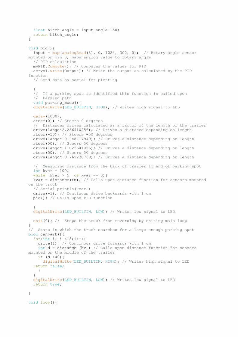
void pid(){
Input = map(analogRead(3), 0, 1024, 300, 0); // Rotary angle sensor
mounted on pin 3, maps analog value to rotary angle
// PID calculation
myPID.Compute(); // Computes the values for PID
servo1.write(Output); // Write the output as calculated by the PID
function
// Send data by serial for plotting
}
// If a parking spot is identified this function is called upon
// Parking path
void parking_mode(){
digitalWrite(LED_BUILTIN, HIGH); // Writes high signal to LED
delay(1000);
steer(0); // Steers 0 degrees
// Distances driven calculated as a factor of the length of the trailer
drive(langd*2.256410256); // Drives a distance depending on length
steer(-50); // Steers -50 degrees
drive(langd*-0.948717949); // Drives a distance depending on length
steer(50); // Steers 50 degrees
drive(langd*-1.025641026); // Drives a distance depending on length
steer(50); // Steers 50 degrees
drive(langd*-0.769230769); // Drives a distance depending on length
// Measuring distance from the back of trailer to end of parking spot
int kvar = 100;
while (kvar > 5 or kvar == 0){
kvar = distance(tm); // Calls upon distance function for sensors mounted
on the truck
// Serial.println(kvar);
drive(-1); // Continous drive backwards with 1 cm
pid(); // Calls upon PID function
}
digitalWrite(LED_BUILTIN, LOW); // Writes low signal to LED
exit(0); // Stops the truck from reversing by exiting main loop
}
// State in which the truck searches for a large enough parking spot
bool canpark(){
for(int i; i <18;i++){
drive(1); // Continous drive forwards with 1 cm
int d = distance (bv); // Calls upon distance function for sensors
mounted on the middle of the trailer
if (d <40){
digitalWrite(LED_BUILTIN, HIGH); // Writes high signal to LED
return false;
}
}
digitalWrite(LED_BUILTIN, LOW); // Writes low signal to LED
return true;
}
void loop(){

drive(1); // Continous drive forwards with 1 cm
if (canpark()){
parking_mode(); // Calls upon parking mode function
}
// The following code allows for the truck to be steered and driven
manually by entering serial inputs
if(Serial.available() > 0)
{
str = Serial.readStringUntil(' ');
x = Serial.parseInt();
if (str == "d"){
drive(x);
Serial.println(str);
Serial.println(x);
Serial.println(str);
}
if(str == "s") {
steer(x);
Serial.println(str);
Serial.println(x);
}
if(str == "p") {
for (int i ;i < x; i++ ){
pid();
drive(-1);
Serial.println(str);
Serial.println(x);
}
}
if(str == "c") {
int bvv = distance(bv);
Serial.println(str);
Serial.println(bvv);
}
}
}

Raw Data from Experiments
Test number Calculated angle Identified spot Distance, back [cm] Distance, Front [cm]1 9.5° Yes 16 9,52 7.3° Yes 15,5 10,53 12.4° Yes 17 8,54 14.5° Yes 19,5 9,55 11.0° Yes 15 7,56 - Yes - -7 1.5° Yes 9 88 5.1° Yes 10 6,59 - Yes - -10 18.7° Yes 26 13
28

TRITA ITM-EX 2018:69
www.kth.se