Embed Size (px)
Citation preview

industrial.omron.eu/mobile-robot
Autonomous intelligent vehiclesLD Mobile Robots
• No facilities modifications• Works collaboratively with people• Fleets of up to 100 vehicles

Autonomous intelligent vehicles - LD Mobile Robots2 3
Our mobile robots are Autonomous Intelligent Vehicles (AIVs) designed to dramatically
increase productivity in manufacturing and logistics operations. In addition to making your
employees more efficient by allowing them to focus on tasks that require complex human
skills, our mobile robots increase throughput, reduce machine dwell time, eliminate errors
and improve material traceability.
Modernize Your Workflow
Scalable
Fleets of up to 100 vehicles
· Job dispatch and management· Centralized configuration and map management· Facilitates traffic flow· Centralized point of communication
Flexible
Customizable Payload Designs
· Easy conveyor-top integration· Supports collaborative robotic arm· Transports carts and totes· Power, IO, Wi-Fi
Safe
Full safety compliance
· Works collaboratively with people· Able to avoid static and moving obstacles· Easy addition of E-Stop equipment
Easy to deploy
With true natural-feature navigation
· Reduces cost: no facilities modifications· No need to pre-program path· Self-mapping with onboard PC· Short installation time
Efficient
Optimize your operations
· Uses shortest allowable path· Automatic alternative route planning· Easily add pickup and delivery points
Robust 24x7 productivity
· Opportunistic charging· Capable of operating in highly dynamic environment· Proven worldwide installed base· >17 years of continuous experience

Autonomous intelligent vehicles - LD Mobile Robots4 5
Today, we have the largest installed base of Autonomous Intelligent Vehicles in manufacturing. Our mobile robots can be deployed in thousands of applications across multiple industries.
Thousands of possibilities to drive productivity gains
Automotive
Tire Assembly
Transport green tires from intermediate storage to curing press stations.
Automotive Electronics
Transport sub-assemblies from kitting to line side replenishment.
Automotive Accessories
Transport totes to and from injection molding stations.
Consumer Products
Jewelry Manufacturing
Transport finished jewelry molds to casting stations.
Designer Accessories
“Virtual conveyor” to transport boxes of sunglasses from ASRS to manual sorting stations.
Digital
Semiconductor Wafer Fab
Intra-bay WIP (SMIF Pods/FOUP) transport between stockers and process tools, or transport reticles for photolithography process.
Semiconductor Packaging and Test
Transport IC chip trays via cart.
Mobile Device Manufacturing
Transport totes of PCBs in handset assembly.
Data Center
Environmental (temperature, humidity, etc.) surveillance and troubleshooting.
Food, Beverage and Hospitality
Catering Facility
Transport baked food totes to stockroom.
Hotel
Linen and room service delivery.
Logistics
Warehouse
E-commerce order fulfillment.
Shipment Distribution Center
Transport totes from shelves to loading docks.
Medical
Sterilization
Transport surgical instruments to sterilization room.
Blood Lab
Secure sample transportation.

Autonomous intelligent vehicles - LD Mobile Robots6 7
Advanced, Integrated TechnologyWhy are our mobile robots the most advanced Autonomous Intelligent Vehicles?
Mapping and Navigation
Robust Navigation with Acuity (Patented)
Acuity provides an additional method of “localization” to the onboard laser, to allow the robot to operate in frequently changing environments. It identifies overhead lights and overlays the “light map” with the “floor map”. It also allows the robots to move easily across wide-open areas in large warehouses.
Fleet Management
Enterprise manager
Enterprise Manager is a network appliance that provides coordination of mobile robots while providing traceability, job allocation and traffic control across the entire fleet.
Transport Request (Job) Allocation:
Distributes across multiple mobile robots by selecting the best vehicle to perform the job.
Traffic Control:
Optimizes traffic flow of vehicles.
Communications:
Single point of contact for integration with factory systems (MES, WMS, ERP, etc.).
MobilePlanner:
PC-based software user interface to manage the robot or the fleet.
Safety
Our mobile robots are fully safety compliant1. They use an onboard laser and other sensors to detect obstacles in their path and, based on speed of travel, trigger an E-stop to prevent vehicle collision.
Sensors:· Safety Rated Main Laser· Lower Laser· Side Lasers (Patented)· Front Bumper· Rear Sonar· Rear Laser
1Safety std: ISO 12100, ISO 14121-2, ISO 13849-1, IEC 61010 (battery only), IEC 60950 (battery only), EN 1525, ANSI B56.5 Part 3, JIS D 6802, IEC 60204

1
Mobile Robots
LD SeriesAutonomous Intelligent Vehicles (AIVs),self-mapping, self-navigation. • Natural-feature navigation
Automatically plans routes to prevent collisions• Fleet management
Supervises and coordinates the entire fleet of up to 100 vehicles• Easy deployment
Short installation time: no facilities modifications
Ordering InformationMobile Robots-LD Platform
Appearance Product Type Product Name
Maximum Load
Maximum Speed Configuration & Attachment Model
OEM
LD-60 60 kg 1.8 m/s
Standard - 37031-00000Docking Station kit
Docking Station : 12477-000Battery Power Cable (0.45 m) : 12676-000 37031-00002
Starter kit
Docking Station : 12477-000Battery Power Cable (0.45 m) : 12676-000LMobilePlanner Software Licence : 13495-200Joystick : 13558-000Top Plate : 12944-000
37031-10004
LD-90 90 kg 1.35 m/s
Standard - 37041-00000Docking Station kit
Docking Station : 12477-000Battery Power Cable (0.45 m) : 12676-000 37041-00002
Starter kit
Docking Station : 12477-000Battery Power Cable (0.45 m) : 12676-000LMobilePlanner Software Licence : 13495-200Joystick : 13558-000Top Plate : 12944-000
37041-10004
Cart Transporter
LD-105CT 105 kg 1.35 m/s
Standard Touchscreen :13605-000Side Laser :13456-000 37141-00010
Docking Station kit
Touchscreen :13605-000Side Laser :13456-000Docking Station :12477-050Battery Power Cable (0.45 m) :12676-000
37141-00012
Starter kit
Touchscreen :13605-000Side Laser :13456-000Docking Station :12477-050Battery Power Cable (0.45 m) :12676-000LMobilePlanner Software Licence :13495-200Acuity Localization :13700-000Joystick :13558-000Cart :75020-000
37141-01014
LD-130CT 130 kg 0.9 m/s
Standard Touchscreen :13605-000Side Laser :13456-000 37161-00010
Docking Station kit
Touchscreen :13605-000Side Laser :13456-000Docking Station :12477-050Battery Power Cable (0.45 m) :12676-000
37161-00012
Starter kit
Touchscreen :13605-000Side Laser :13456-000Docking Station :12477-050Battery Power Cable (0.45 m) :12676-000LMobilePlanner Software Licence :13495-200Acuity Localization :13700-000Joystick :13558-000Cart :75020-000
37161-01014
Autonomous intelligent vehicles - LD Mobile Robots8
Let us help you mobilize your operations
40 1503000
countries
locations
Planning. Implementation.
Support.
We are ready to help you every step of the way, anywhere in the world.
Give us a call. Our expert feasibility study can help you determine if mobile autonomous vehicles are right for your application.
Test with real products Simulations
Global Collaborative Network
Robotics Expertise and Machine Automation Support provided by a unique global team.
application engineers
LD Series
2
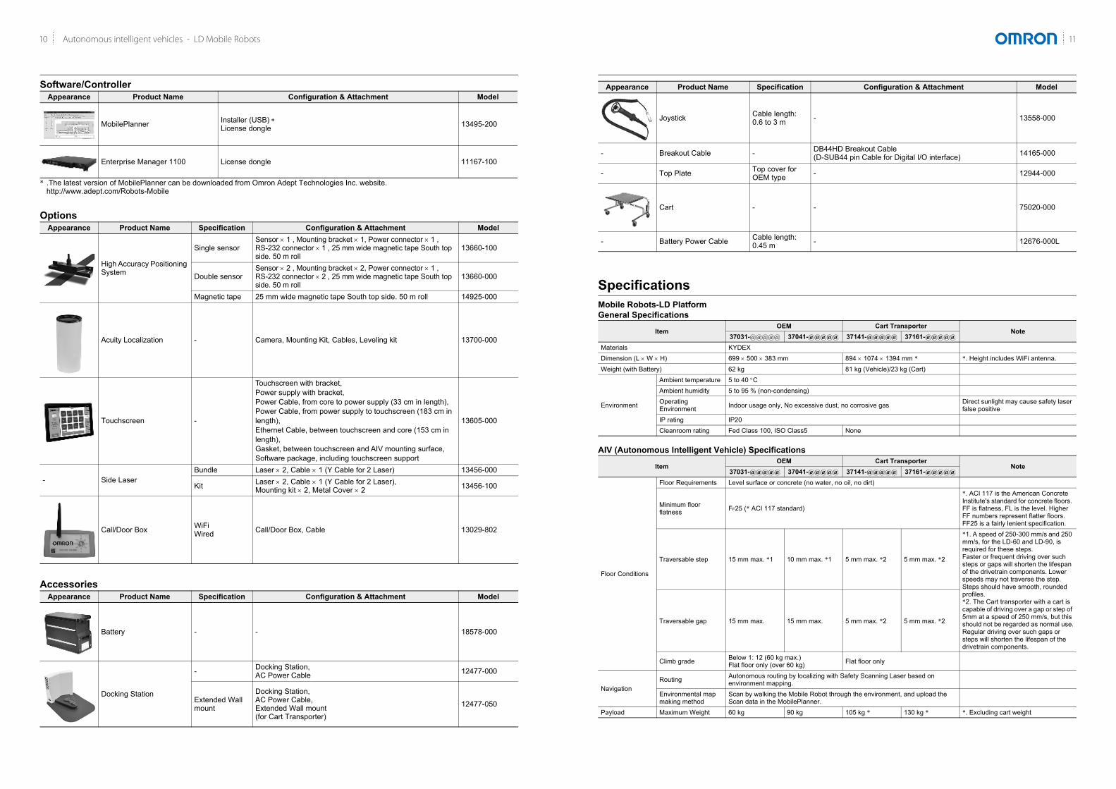
Software/Controller
* .The latest version of MobilePlanner can be downloaded from Omron Adept Technologies Inc. website.http://www.adept.com/Robots-Mobile
Options
Accessories
Appearance Product Name Configuration & Attachment Model
MobilePlanner Installer (USB) License dongle 13495-200
Enterprise Manager 1100 License dongle 11167-100
Appearance Product Name Specification Configuration & Attachment Model
High Accuracy Positioning System
Single sensorSensor 1 , Mounting bracket 1, Power connector 1 , RS-232 connector 1 , 25 mm wide magnetic tape South top side. 50 m roll
13660-100
Double sensorSensor 2 , Mounting bracket 2, Power connector 1 , RS-232 connector 2 , 25 mm wide magnetic tape South top side. 50 m roll
13660-000
Magnetic tape 25 mm wide magnetic tape South top side. 50 m roll 14925-000
Acuity Localization - Camera, Mounting Kit, Cables, Leveling kit 13700-000
Touchscreen -
Touchscreen with bracket, Power supply with bracket, Power Cable, from core to power supply (33 cm in length), Power Cable, from power supply to touchscreen (183 cm in length), Ethernet Cable, between touchscreen and core (153 cm in length), Gasket, between touchscreen and AIV mounting surface, Software package, including touchscreen support
13605-000
- Side LaserBundle Laser 2, Cable 1 (Y Cable for 2 Laser) 13456-000
Kit Laser 2, Cable 1 (Y Cable for 2 Laser), Mounting kit 2, Metal Cover 2 13456-100
Call/Door Box WiFiWired Call/Door Box, Cable 13029-802
Appearance Product Name Specification Configuration & Attachment Model
Battery - - 18578-000
Docking Station
- Docking Station, AC Power Cable 12477-000
Extended Wall mount
Docking Station, AC Power Cable, Extended Wall mount (for Cart Transporter)
12477-050
LD Series
3
SpecificationsMobile Robots-LD PlatformGeneral Specifications
AIV (Autonomous Intelligent Vehicle) Specifications
Joystick Cable length: 0.6 to 3 m - 13558-000
- Breakout Cable - DB44HD Breakout Cable (D-SUB44 pin Cable for Digital I/O interface) 14165-000
- Top Plate Top cover for OEM type - 12944-000
Cart - - 75020-000
- Battery Power Cable Cable length: 0.45 m - 12676-000L
ItemOEM Cart Transporter
Note37031-@@@@@ 37041-@@@@@ 37141-@@@@@ 37161-@@@@@
Materials KYDEXDimension (L W H) 699 500 383 mm 894 1074 1394 mm * *. Height includes WiFi antenna.Weight (with Battery) 62 kg 81 kg (Vehicle)/23 kg (Cart)
Environment
Ambient temperature 5 to 40 CAmbient humidity 5 to 95 % (non-condensing)Operating Environment Indoor usage only, No excessive dust, no corrosive gas Direct sunlight may cause safety laser
false positiveIP rating IP20Cleanroom rating Fed Class 100, ISO Class5 None
ItemOEM Cart Transporter
Note37031-@@@@@ 37041-@@@@@ 37141-@@@@@ 37161-@@@@@
Floor Conditions
Floor Requirements Level surface or concrete (no water, no oil, no dirt)
Minimum floor flatness FF25 (* ACI 117 standard)
*. ACI 117 is the American Concrete Institute's standard for concrete floors. FF is flatness, FL is the level. Higher FF numbers represent flatter floors. FF25 is a fairly lenient specification.
Traversable step 15 mm max. *1 10 mm max. *1 5 mm max. *2 5 mm max. *2
*1. A speed of 250-300 mm/s and 250 mm/s, for the LD-60 and LD-90, is required for these steps. Faster or frequent driving over such steps or gaps will shorten the lifespan of the drivetrain components. Lower speeds may not traverse the step. Steps should have smooth, rounded profiles.*2. The Cart transporter with a cart is capable of driving over a gap or step of 5mm at a speed of 250 mm/s, but this should not be regarded as normal use.Regular driving over such gaps or steps will shorten the lifespan of the drivetrain components.
Traversable gap 15 mm max. 15 mm max. 5 mm max. *2 5 mm max. *2
Climb grade Below 1: 12 (60 kg max.)Flat floor only (over 60 kg) Flat floor only
NavigationRouting Autonomous routing by localizing with Safety Scanning Laser based on
environment mapping.Environmental map making method
Scan by walking the Mobile Robot through the environment, and upload the Scan data in the MobilePlanner.
Payload Maximum Weight 60 kg 90 kg 105 kg * 130 kg * *. Excluding cart weight
Appearance Product Name Specification Configuration & Attachment Model
11Autonomous intelligent vehicles - LD Mobile Robots10

LD Series
4
Mobility
Maximum speed 1800 mm/s 1350 mm/s 1350 mm/s 900 mm/sMaximum rotation speed 180/s 180/s 100/s
Stop position accuracy 100 mm: Position * , 2:Rotation
*. 10 mm: Position, 0.5: Rotation with option, (High Accuracy Positioning System)
Drive wheelMaterials Non-marking Nylon foam-filled rubber, non-conductiveSize 200 dia. 50mm nominal, 2 wheels
Passive casterMaterials Conductive thermoplastic rubber on PolyolefinSize 75 dia. 41 mm nominal, 4 casters
Power
Battery 22-30 VDCCapacity 72 Ah Battery cell nominal capacityRun time 15 hours (continuous) approx. With no payload conditionRecharge Time 4 hours (5:1 ratio) approx.Battery Life cycles 2000 recharge cycles (Battery cell nominal)Charging method Automatic / Manual
Auxiliary Power
5 VDC±5%, 1 A Switched Aux power 12 VDC±5%, 1 A Switched Aux power 20 VDC±5%, 1 A Switched Aux power 22-30 VDC, 4 A Switched 222-30 VDC, 10 A Switched * 22-30 VDC, 10 A Safe, Switched *
5, 12, 20, and 22-30 VDC power can be provided to external devices.*. 10 A Switched and 10 A Safe, Switched share the 10 A of current.
StandardSafety Standard EN1525 / JIS D6802 / ANSI B56.5Wireless IEEE 802.11 a/b/g
Safety Features
Safety Scanning Laser
1 at frontClass 1PLd Safety per ISO13849-1Maximum range: 15 mField of view: 240°
Emergency Stop 1 at Operator panel 1 at HMI post touchscreen, 1 at Operator panel
Rear sonar 2 at rear, 2 m range Each pairs is one emitter and one receiver, working together
Front Bumper 1 at front of platform, 2pairs of sensors
Low Front Laser
1 at front of platformClass 1Maximum range: 4 mField of view: 270°
Side Laser Option *
2 on horizontal tubes of HMI postClass 1Maximum range: 4 mField of view: 270°
*. 2 on sides of payload structure, user-mounted
Flash light Light Disc in each side Light Disc in each side, Beacon on HMI post
Speaker 3.5", 80 W max.
Operator Interface
Screen / Touch panel 3.5 in. TFT 320 240 pixels, 256 K color screen
7.0 in. TFT LCD touch panel , 18/24 bit RGB
Button
ON Button: Green, OFF Button: Red, Brake-release button: Orange, Keyswitch (Disabled OFF Button)
ON Button: Green, OFF Button: Red, Brake-release button: Orange, Keyswitch (Disabled OFF Button), Latch Button, Unlatch Button
User I/F
Wireless IEEE 802.11 a/b/gEthernet port 1 User LAN , 1 × Maintenance LAN, Auto-MDIXSerial RS-232 2, CAN Bus B 1Digital I/O 16 inputs, 16 outputsAnalog I/O 8 inputs (0 to 30 V), 4 outputs (0-20 V)Audio Digital Audio Out, Audio In / Audio Out
Cart Latching Latching method Not available Automatic
ItemOEM Cart Transporter
Note37031-@@@@@ 37041-@@@@@ 37141-@@@@@ 37161-@@@@@
LD Series
5
MobilePlanner
Enterprise Manager 1100
*. typical 100 W
High Accuracy Positioning System
Acuity Localization
Touchscreen
Call/Door Box
Battery
Docking Station
*1. Thermal fuse in AC power switch (10 A Time-lag fuse at switch for legacy dock)
*2. ( ) for with Floor plate
Joystick
Cart
Model 13495-200
Operating systemWindows 7 (32-bit/64 bit version) / Windows 8 (32-bit/64-bit version) / Windows 10 (32-bit/64-bit version)
CPU 1.5 GHz dual-core CPU recommendedMain memory 1.5 GB min. (4 GB min. recommended)Hard disk At least 200 MB of available spaceVideo memory 256 MB min.Display XGA 1024 768, 16 million colorsCommunications ports USB port (for license key) Supported languages Japanese, English
Model 11167-100Dimensions- W × D × H 426.0 × 438.4 × 42.4 mmWeight 6.8 kg
Mounting method 1U rack mount in a standard 19-inch equipment rack
Power Supply 100-240 VAC *Power Consumption 200W max.Operating Temperature 10 to 35 CStorage Temperature -25 to 60 COperating Humidity 8 to 90%, non-condensingStorage Humidity 5 to 95%, non-condensingChassis protection class IP20 CPU Intel Xeon CPUMain Memory 4 GB DDR3Storage 32 GB SSDCommunication port 10/100/1000 Ethernet × 4, USB × 4, VGA
Model 13660-@00
Sensor
Depth 30 mmWidth 160 mmRating IP64Environment -40 to 85 C
LEDs Power, Tape present, Left marker, Right marker
Magnetic TapeWidth 25 mmOrientation South up
Markers (Magnetic Tape)
Width 25 mmLength 300 mm min. for 500 mm/s drive speedOrientation North upSeparation from tape 15 - 30 mm
Connections
Front sensor RS232-1 (/dev/ttyUSB9) on the coreRear sensor RS232-2 (/dev/ttyUSB10) on the corePower, both sensors
Aux Power, using the included splitter cable
Model 13700-@00Field of View 140
Power Input 12 VDC (10%) supplied from platform, through power connector
Power Consumption 3.3 W maximum
Model 13605-000
Touch Panel PCAP touch sensor, 5 simultaneous touches, black bordered cover lens
TFT DisplayTFT LCD panel, 18/24 bit RGB parallel interface.7.0 in. WVGA - Wide Viewing Angles, 5-Touch
Backlight Constant current LED supplyPower Input 5 VDC supplied through power connectorPower Consumption 6.5 W maximum
Model 13029-802Dimensions- W × D × H 141.4 × 74.7 × 30 mmWeight 190 g
Mounting method Mount to the provided wall frame with four screws
Power Supply 12 VDCPower Consumption 0.5 A, 6 W typicalWiFi IEEE 802.11 a/b/g/nCommunication port EthernetI/O Input × 2, Output × 2 (30 VDC, 2 A max)
Model 18578-000Run-time (no payload) 15 hours (continuous) approx.
Weight 19 kgVoltage 22-30 VDCCapacity 72 Ah (Battery cell nominal)Recharge time 4 hours, approx.
Life time2000 times 80% DOD (Battery cell nominal), 7 years, approx., 16 hrs/day, 5 days/wk4 years, approx., 19/7 (full-time)
Model 12477-0@0Current 8 A *1
Contacts 2Power 100 to 240 VAC, 50 to 60 HzPower consumption 800 WHumidity 5 to 95 % non-condensingTemperature 5 to 40 C
Dimensions- W D H 349 369 315 mm (495 495.5 317 mm) *2
Weight 8.2 kg
Mounting Wall bracket, directly to floor, or on floor with floor plate
Indicators Power on - blueCharging - yellow
Connector For out-of-platform battery charging
Model 13558-000Weight 550 gIP rating IP56
Model 75020-000Dimension (L W H) 592 846 480 mmWeight 23 kgRating ESP ratedPassive Casters 2 front, 2 rear, spring-loadedCaster diameter 100 mm nominalCaster Brakes at 2 rear casters
13Autonomous intelligent vehicles - LD Mobile Robots12

LD Series
6
OEM
Cart Transporter
Components and Functions
Operator PanelPower ON/OFF, Emergency Stop, Brake Button with 3.5 inch color monitor
Rear SonarObstacle sensor to detect rear side based on Sonar.
Light DiscsStatus indicator. Located both side
Front BumperStop when it hits obstacle
Low Front LaserObstacle sensor to detect low profile object in the forward direction.
Safety Scanning LaserSafety rated Laser using for SLAM (Simultaneous localization and mapping).It is also used for safety functionality.
WiFi antennaIEEE 802.11 a/b/g
Top Plate (Option)Upper plate come with Starter Kit. It is not necessary for building customer payload.
Operator Panel• 7” Color touchscreen.
(Status, Goal input)• WiFi antenna2• Emergency Stop• Power ON/OFF• Brake Button• Latch/Unlatch buttons for Cart• Beacon• Acuity Localization (Option)
OEMOEM with Cart Latching plate
Rear-facing LaserObstacle laser scanner to detect rear side.
Side LaserObstacle laser scanner to detect vertically
CartAutomatically latch/unlatched cart with manual break. Latching/Unlatching can be controlled by Software.
LD Series
7
OEM
Product Name Model Description Docking Station kit/Starter kit
① OEM 370@1-00000 A Mobile Robot OEM. The Battery is not included. Included in Docking Station kit and Starter kit
② Docking Station 12477-000 A docking station to charge the Battery installed in the Mobile Robot. Included in
Docking Station kit③ Battery Power Cable 12676-000L A cable to connect a Battery and Docking Station to charge the
Battery outside of the Mobile Robot.
④ Top Plate 12944-000 A upper plate of the Mobile Robot OEM. It is not necessary for building customer payload.
Included in Starter kit⑤ Joystick 13558-000 Used for manually controlling the Mobile Robot.
⑥ MobilePlanner 13495-200 PC software to configure, drive and observe the Mobile Robot, including a USB license dongle.
⑦ Battery 18578-000 A Battery that is installed in the Mobile Robot. -
⑧ Enterprise Manager 1100 11167-100 A system that manages a fleet of Mobile Robots, including a
network appliance, software, and a USB license dongle. -
⑨High Accuracy Positioning System (Single sensor)
13660-100A sensor and magnetic tape to achieve accurate alignment when the Mobile Robot follows driving forward. The sensor is attached to the Mobile Robot.
-
⑩High Accuracy Positioning System (Double sensor)
13660-000Two sensors and magnetic tape to achieve accurate alignment when the Mobile Robot follows driving both forward and backward. The sensors are attached to the Mobile Robot.
-
⑪ Magnetic tape 14925-000 Magnetic tape for the High Accuracy Positioning System. The tape is applied to signal the Mobile Robot where to stop. -
⑫ Acuity Localization 13700-000 Used where process layout or obstacle location changes often. Installed on a payload structure attached to the Mobile Robot. -
⑬ Touchscreen 13605-000Allows operators to check the status of the Mobile Robot, enter goals, and pause the Mobile Robot. Installed on a payload structure attached to the Mobile Robot.
-
⑭ Side Laser Bundle 13456-000Used to detect obstacles that are at heights the safety scanning laser of the Mobile Robot cannot detect. Installed on a payload structure attached to the Mobile Robot.
-
⑮ Side Laser Kit 13456-100 Includes the above mentioned Side Laser, mounting kit, and metal covers to protect from lasers. -
⑯ Call/Door Box 13029-802 Used to issue a request for a Mobile Robot to go to the goal or to open a closed door. Installed at the goal or door to open. -
⑰ Breakout Cable 14165-000 A D-SUB44 pin cable for digital I/O interface of the Mobile Robot. -
Enterprise Manager 1100
Acuity Localization
Touchscreen
Joystick
Call/Door Box
High Accuracy Positioning System
OEM
Docking Station
Battery Power Cable
Battery
Top Plate Top Plate Top Plate
System Configuration
15Autonomous intelligent vehicles - LD Mobile Robots14

LD Series
8
Cart Transporter
Product Name Model Description Docking Station kit/Starter kit
① Cart Transporter 371@1-00000 A Mobile Robot Cart Transporter. The Battery is not included.
Included in Docking Station kit and Starter kit
② Touchscreen 13605-000Allows operators to check the status of the Mobile Robot, enter goals, and pause the Mobile Robot. Installed on a payload structure attached to the Mobile Robot.
③ Side Laser 13456-000Used to detect obstacles that are at heights the safety scanning laser of the Mobile Robot cannot detect. Installed on a payload structure attached to the Mobile Robot.
④ Docking Station 12477-000 A docking station to charge the Battery installed in the Mobile Robot. Included in
Docking Station kit⑤ Battery Power Cable 12676-000L A cable to connect a Battery and Docking Station to charge the
Battery outside of the Mobile Robot.
⑥ Joystick 13558-000 Used for manually controlling the Mobile Robot.
Included in Starter kit⑦ MobilePlanner 13495-200 PC software to configure, drive and observe the Mobile Robot,
including a USB license dongle.
⑧ Acuity Localization 13700-000 Used where process layout or obstacle location changes often. Installed on a payload structure attached to the Mobile Robot.
⑨ Cart 75020-000 A cart designed for Mobile Robot Cart Transporter.
⑩ Battery 18578-000 A Battery that is installed in the Mobile Robot. -
⑪ Enterprise Manager 1100 11167-100 A system that manages a fleet of Mobile Robots, including a
network appliance, software, and a USB license dongle. -
⑫High Accuracy Positioning System (Single sensor)
13660-100A sensor and magnetic tape to achieve accurate alignment when the Mobile Robot follows driving forward. The sensors are attached to the Mobile Robot.
-
⑬High Accuracy Positioning System (Double sensor)
13660-000Two sensors and magnetic tape to achieve accurate alignment when the Mobile Robot follows driving both forward and backward. The sensors are attached to the Mobile Robot.
-
⑭ Magnetic tape 14925-000 Magnetic tape for the High Accuracy Positioning System. The tape is applied to signal the Mobile Robot where to stop. -
⑮ Call/Door Box 13029-802 Used to issue a request for a Mobile Robot to go to the goal or to open a closed door. Installed at the goal or door to open. -
⑯ Breakout Cable 14165-000 A D-SUB44 pin cable for digital I/O interface of the Mobile Robot. -
Enterprise Manager 1100
Acuity Localization
Touchscreen
Joystick
Call/Door Box
High Accuracy Positioning System
Cart Transporter
Docking Station
Battery Power Cable
Battery
Side Laser
Cart
LD Series
9
Mobile Robots-LD PlatformOEM
Cart Transporter
383
201
379
50500
699MountingSurface
Top ofcovers
431
48
699
894
84.0
195.0
96
144.6
626.6
1306.7
1393.2
133.1
504.9
500
416.0
1073.3
38 38
Ø 101.6
Dimensions (Unit: mm)CAD data can be downloaded from Omron Adept Technologies Inc. website.http://www.adept.com/Robots-CAD-File
17Autonomous intelligent vehicles - LD Mobile Robots16

LD Series
10
Enterprise Manager 1100
High Accuracy Positioning System
Acuity Localization
Touchscreen
85
215
179.7
166.9
107.6103 85.9
10.8
16
6
2274x Ø 4.5 Thru
13.2
4.2
7.6 7.6
20 20
34.4 227
(Unit: mm)
LD Series
11
Call/Door Box
Docking Station
Joystick
141.37
50
123
15 74.69
Base only
30
40
76Ø2.4 deep7.5×4
406
495
Free Standing
89 114
267
247
123
121
356
315
369
384
Wall Mount and Floor Mount
Wall Mount Bracket
98 ± 20
3x Ø6
8x 25
18x Ø6
349
146°
146°
(Unit: mm)
19Autonomous intelligent vehicles - LD Mobile Robots18

LD Series
12
Cart
Related Manuals
Manual No. English titleI611 Mobile Robots LD Platform User’s GuideI612 Mobile Robots LD Cart Transporter User’s GuideI613 Mobile Robots LD Platform Peripherals GuideI614 Mobile Robots Software Suite User's GuideI615 Enterprise Manager 1100 User’s GuideI616 Mobile Robot Safety GuideI617 Advanced Robotics Command Language Reference GuideI618 Advanced Robotics Command Language Enterprise Manager Integration Guide
591.82
480.06
845.82
254
234.44 254 295.4
8xM6 Threads
254234.44
254
234.44 234.44
• Intel, Xeon and Intel Xeon are trademarks of Intel Corporation in the U.S. and/or other countries.• Other company names and product names in this document are the trademarks or registered trademarks of their respective companies.• The product photographs and figures that are used in this catalog may vary somewhat from the actual products.• Microsoft product screen shot(s) reprinted with permission from Microsoft Corporation.
(Unit: mm)
Terms and Conditions AgreementRead and understand this catalog.
Please read and understand this catalog before purchasing the products. Please consult your OMRON representative if you have any questions or comments.
Warranties.(a) Exclusive Warranty. Omron’s exclusive warranty is that the Products will be free from defects in materials and workmanship
for a period of twelve months from the date of sale by Omron (or such other period expressed in writing by Omron). Omron disclaims all other warranties, express or implied.
(b) Limitations. OMRON MAKES NO WARRANTY OR REPRESENTATION, EXPRESS OR IMPLIED, ABOUT NON-INFRINGEMENT, MERCHANTABILITY OR FITNESS FOR A PARTICULAR PURPOSE OF THE PRODUCTS. BUYER ACKNOWLEDGES THAT IT ALONE HAS DETERMINED THAT THE PRODUCTS WILL SUITABLY MEET THE REQUIREMENTS OF THEIR INTENDED USE.
Omron further disclaims all warranties and responsibility of any type for claims or expenses based on infringement by the Products or otherwise of any intellectual property right. (c) Buyer Remedy. Omron’s sole obligation hereunder shall be, at Omron’s election, to (i) replace (in the form originally shipped with Buyer responsible for labor charges for removal or replacement thereof) the non-complying Product, (ii) repair the non-complying Product, or (iii) repay or credit Buyer an amount equal to the purchase price of the non-complying Product; provided that in no event shall Omron be responsible for warranty, repair, indemnity or any other claims or expenses regarding the Products unless Omron’s analysis confirms that the Products were properly handled, stored, installed and maintained and not subject to contamination, abuse, misuse or inappropriate modification. Return of any Products by Buyer must be approved in writing by Omron before shipment. Omron Companies shall not be liable for the suitability or unsuitability or the results from the use of Products in combination with any electrical or electronic components, circuits, system assemblies or any other materials or substances or environments. Any advice, recommendations or information given orally or in writing, are not to be construed as an amendment or addition to the above warranty.
See http://www.omron.com/global/ or contact your Omron representative for published information.
Limitation on Liability; Etc.OMRON COMPANIES SHALL NOT BE LIABLE FOR SPECIAL, INDIRECT, INCIDENTAL, OR CONSEQUENTIAL DAMAGES, LOSS OF PROFITS OR PRODUCTION OR COMMERCIAL LOSS IN ANY WAY CONNECTED WITH THE PRODUCTS, WHETHER SUCH CLAIM IS BASED IN CONTRACT, WARRANTY, NEGLIGENCE OR STRICT LIABILITY.
Further, in no event shall liability of Omron Companies exceed the individual price of the Product on which liability is asserted.
Suitability of Use.Omron Companies shall not be responsible for conformity with any standards, codes or regulations which apply to the combination of the Product in the Buyer’s application or use of the Product. At Buyer’s request, Omron will provide applicable third party certification documents identifying ratings and limitations of use which apply to the Product. This information by itself is not sufficient for a complete determination of the suitability of the Product in combination with the end product, machine, system, or other application or use. Buyer shall be solely responsible for determining appropriateness of the particular Product with respect to Buyer’s application, product or system. Buyer shall take application responsibility in all cases.
NEVER USE THE PRODUCT FOR AN APPLICATION INVOLVING SERIOUS RISK TO LIFE OR PROPERTY OR IN LARGE QUANTITIES WITHOUT ENSURING THAT THE SYSTEM AS A WHOLE HAS BEEN DESIGNED TO ADDRESS THE RISKS, AND THAT THE OMRON PRODUCT(S) IS PROPERLY RATED AND INSTALLED FOR THE INTENDED USE WITHIN THE OVERALL EQUIPMENT OR SYSTEM.
Programmable Products.Omron Companies shall not be responsible for the user’s programming of a programmable Product, or any consequence thereof.
Performance Data.Data presented in Omron Company websites, catalogs and other materials is provided as a guide for the user in determining suitability and does not constitute a warranty. It may represent the result of Omron’s test conditions, and the user must correlate it to actual application requirements. Actual performance is subject to the Omron’s Warranty and Limitations of Liability.
Change in Specifications.Product specifications and accessories may be changed at any time based on improvements and other reasons. It is our practice to change part numbers when published ratings or features are changed, or when significant construction changes are made. However, some specifications of the Product may be changed without any notice. When in doubt, special part numbers may be assigned to fix or establish key specifications for your application. Please consult with your Omron’s representative at any time to confirm actual specifications of purchased Product.
Errors and Omissions.Information presented by Omron Companies has been checked and is believed to be accurate; however, no responsibility is assumed for clerical, typographical or proofreading errors or omissions.
Autonomous intelligent vehicles - LD Mobile Robots20

23
Notes
Autonomous intelligent vehicles - LD Mobile Robots22
Omron at a glance
Sensing, Control Systems, Visualisation, Drives, Robots, Safety,
Quality Control & Inspection, Control and Switching Components
200,000
Innovation track record of 80 years1,200 employees dedicated to R&D
12,500 + issued and pending patents
6%37,500Employees worldwide
200Locations worldwide
22Countries in EMEA
Working for the benefit of society
Close to your needs Technical training & seminars, technical support, Automation Technology Centers, online community (MyOmron),
online catalogues and technical documentation, customer service & sales support, inter-operability labs (Tsunagi),
safety services, repairs.
Annual investment in Research & Development
products ranging Input, Logic, Output & Safety
Industrial automation 39%
Automotive components 16%
Electronic & mechanical components 12%
Healthcare 12%
Other businesses 11%
Social systems, solutions & services 10%

Although we strive for perfection, Omron Europe BV and/or its subsidiary and affiliated companies do not warrant or make any representations regarding the correctness or completeness of the information described in this document. We reserve the right to make any changes at any time without prior notice.ld_mobile_robots_en_02
Would you like to know more?
OMRON EUROPE
+31 (0) 23 568 13 00
industrial.omron.eu
Austria Tel: +43 (0) 2236 377 800 industrial.omron.at
Belgium Tel: +32 (0) 2 466 24 80 industrial.omron.be
Czech Republic Tel: +420 234 602 602 industrial.omron.cz
Denmark Tel: +45 43 44 00 11 industrial.omron.dk
Finland Tel: +358 (0) 207 464 200industrial.omron.fi
France Tel: +33 (0) 1 56 63 70 00industrial.omron.fr
Germany Tel: +49 (0) 2173 680 00 industrial.omron.de
Hungary Tel: +36 1 399 30 50 industrial.omron.hu
Italy Tel: +39 02 326 81 industrial.omron.it
Netherlands Tel: +31 (0) 23 568 11 00 industrial.omron.nl
Norway Tel: +47 22 65 75 00 industrial.omron.no
Poland Tel: +48 22 458 66 66 industrial.omron.pl
Portugal Tel: +351 21 942 94 00 industrial.omron.pt
Russia Tel: +7 495 648 94 50 industrial.omron.ru
South AfricaTel: +27 (0)11 579 2600 industrial.omron.co.za
Spain Tel: +34 902 100 221 industrial.omron.es
Sweden Tel: +46 (0) 8 632 35 00 industrial.omron.se
Switzerland Tel: +41 (0) 41 748 13 13 industrial.omron.ch
Turkey Tel: +90 (216) 556 51 30 industrial.omron.com.tr
United Kingdom Tel: +44 (0) 1908 258 258 industrial.omron.co.uk
More Omron representatives industrial.omron.eu