Embed Size (px)
Citation preview

DYNAMIC BEHAVIOUR OF LONG SPAN CANTILEVER STEEL‐CONCRETE COMPOSITE FLOOR
By: Ir. Amisah binti AhwangBahagian Rehabilitasi,Cawangan Kejuruteraan Awam dan Struktur,Ibu Pejabat JKR Malaysia.

Content
1. Introduction2. Literature Review3. Research Methodology4. Results & Discussion5. Conclusion

Introduction
1. Background of problem: ‐ Cantilever floor too slender‐ The design controlled by serviceability limit state‐ Increase chances of unwanted composite floor vibration problems
2. Problem statement: ‐ No research/study on vibration of long cantilever steel‐concrete composite floor
Introduction (cont…)
3. Objectives:
a. To model, analyze and design a 12.5m cantilever steel‐concrete composite floor of an actual proposed new office building subjected static loading.b. To analyze the floor structure with dynamic loading due to human activity to obtain dynamic behavior of the floor, namely natural frequency, and maximum acceleration.c. To determine whether the present design of cantilever floor is meeting the vibration serviceability limit as specified by guideline.d. To propose a strengthening method to meet the recommended peak acceleration range that is acceptable for human comfort

Introduction (cont…)
4. Scope of work: ‐ Investigate the vibration of a floor of a real steel‐concrete composite cantilever floor spanning at 12.5m length.‐ Software: STAAD PRO (finite element analysis) to get vibration acceleration
5. Significance of research: ‐ As a reference for engineers to advise their architects for future projects in estimating the economical span of cantilever floor
Literature Review
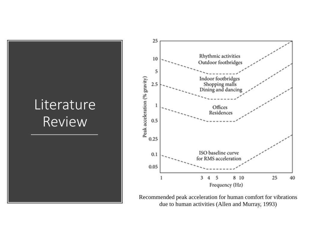
Recommended peak acceleration for human comfort for vibrations due to human activities (Allen and Murray, 1993)

Research Methodology

Research Methodology –Architectural Drawings
Part of initial second floor layout plan proposed by Architect

Research Methodology –Architectural Drawings (cont…)
Part of initial section of the cantilever floor proposed by Architect

Research Methodology‐Identify the Preliminary Size of the Structure’s
Component
1. Steel beam – Universal beam UB 914 x 419
2. Slab – composite steel decking and concrete slab with minimum thickness of 90mm

Research Methodology‐Preliminary Modelling, Analysis and Design for
Static Loading
1. Preliminary beam layout
2. Preliminary modelling in the software
3. Preliminary sizing limited to readily available size of steel beam in Malaysia
4. Only static loading was applied

Research Methodology‐
Detail Modelling, Analysis and
Design for Static Loading
Suggested limits for calculated deflections

Preliminary vs Detail Modelling ‐ 3D
Preliminary modelling Detail modelling

Preliminary vs Detail Modelling –Second floor beam layout
Preliminary modelling Detail modelling

Preliminary vs Detail Modelling –Side view (column)
Preliminary modelling Detail modelling

Research Methodology‐Detail Modelling with Dynamic
Loading Analysis
Footfall GRF of a 640N pedestrian pacing at 1.71 Hz (Brownjohn et.al, 2008)

Research Methodology‐Detail Modelling with Dynamic Loading Analysis (cont…)
Assumption:‐ Excitation point is assumed to be stationary
‐ Walking path is not taken into consideration
‐ Excitation at 3 locations along the cantilever floor’s span (5 points at each location)
‐ All locations were selected randomly

Research Methodology‐Detail Modelling with Dynamic
Loading Analysis (cont…)
At 8.5m from edge of the cantilever
Research Methodology‐Detail Modelling with Dynamic
Loading Analysis (cont…)
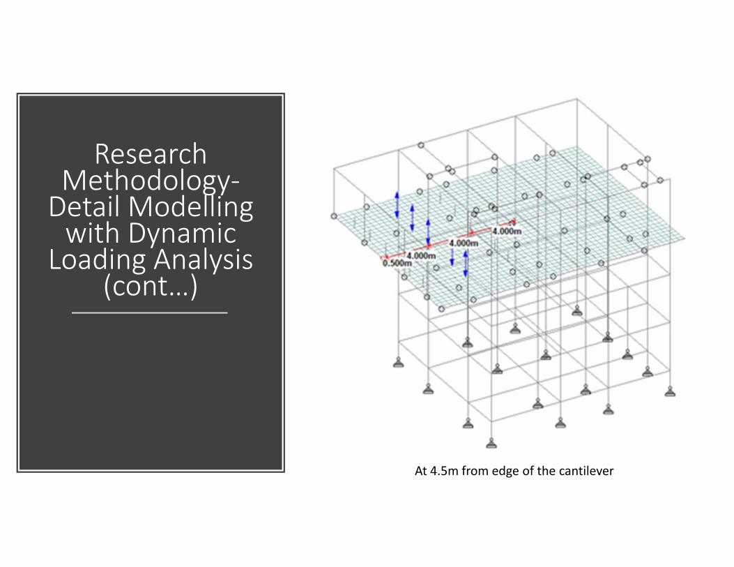
At 4.5m from edge of the cantilever

Research Methodology‐Detail Modelling with Dynamic
Loading Analysis (cont…)
At 0.5m from edge of the cantilever

Research Methodology‐Analyzing the STAAD PRO Dynamic Analysis Output
‐ Analysis in three (3) separate STAAD PRO models
‐ Results was in the form of mode shapes and acceleration vs time graph
‐ Maximum and minimum values of acceleration were evaluated
‐ Difference value of time at the maximum acceleration to the time at the minimum acceleration recorded was divided by the number of cycle in the one cycle’s family
Research Methodology‐Analyzing the STAAD PRO Dynamic Analysis Output
(cont…)
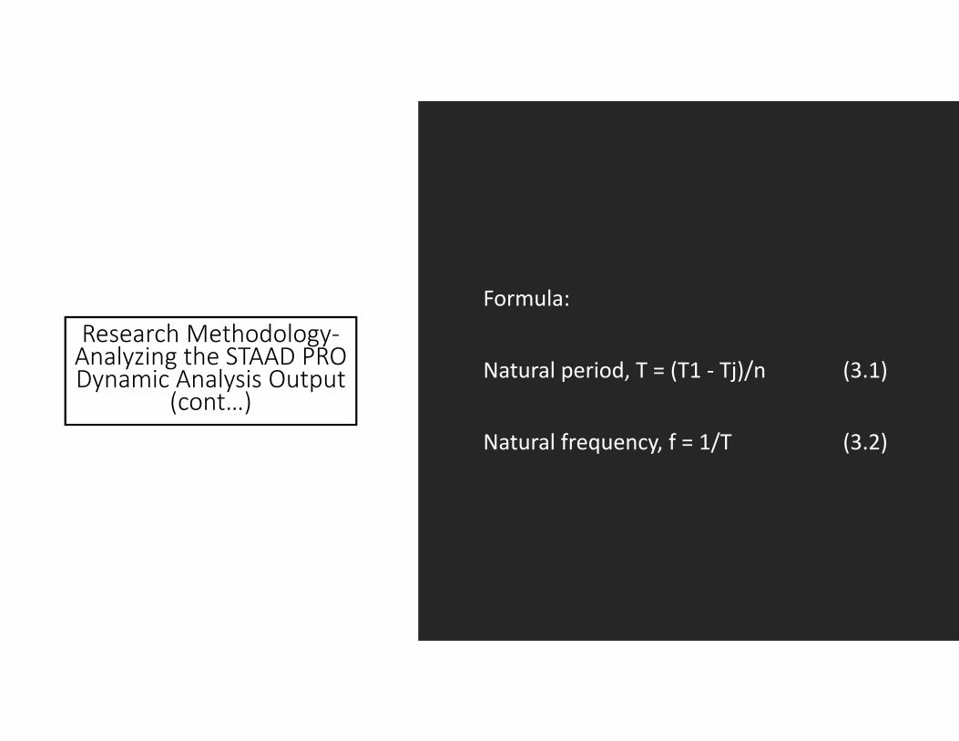
Formula:
Natural period, T = (T1 ‐ Tj)/n (3.1)
Natural frequency, f = 1/T (3.2)

Results and Discussion ‐Vertical
Displacement of the Structures due to Static Loading
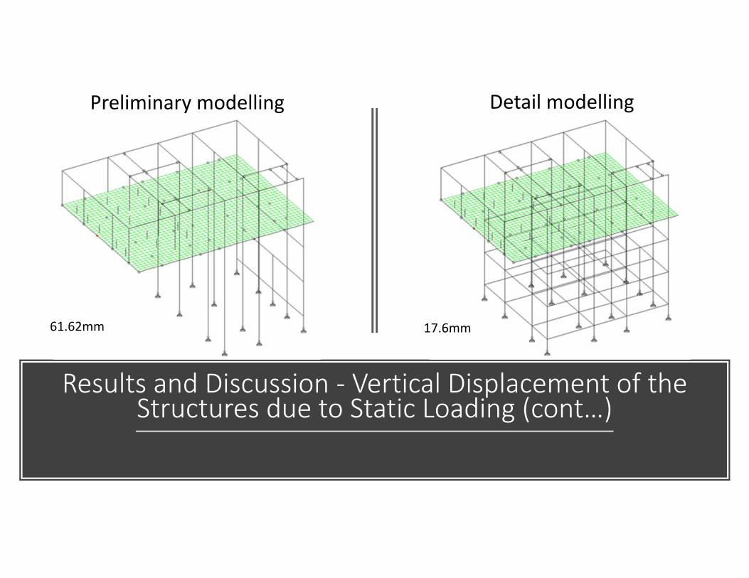
Results and Discussion ‐ Vertical Displacement of the Structures due to Static Loading (cont…)
Preliminary modelling Detail modelling
61.62mm 17.6mm

Results and Discussion ‐ Vertical Displacement of the Structures due to Static Loading (cont…)
Preliminary modelling Detail modelling
Max moment: 6230kNm
Max moment:1180kNm
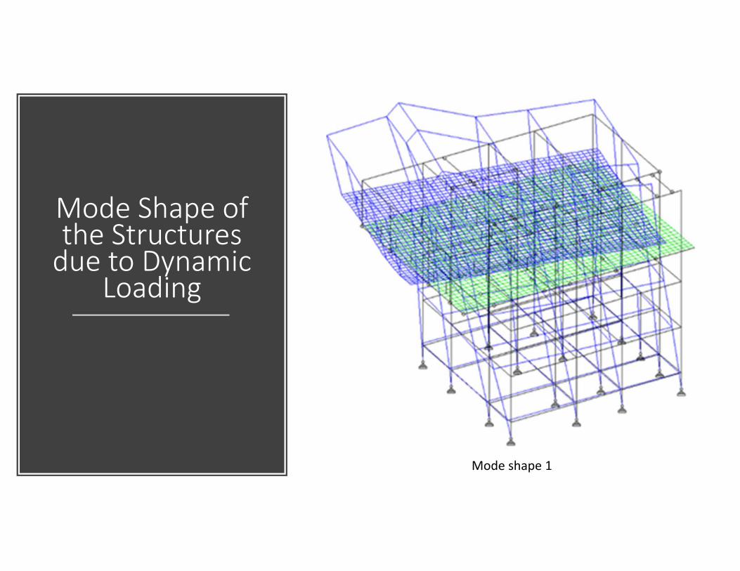
Mode Shape of the Structures due to Dynamic
Loading
Mode shape 1

Results and Discussion ‐ Natural Frequency of the Floor (8.5m)
4.80 Hz
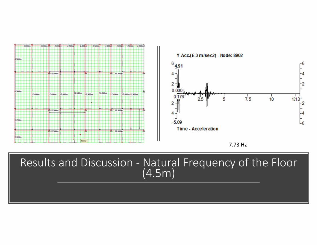
Results and Discussion ‐ Natural Frequency of the Floor (4.5m)
7.73 Hz

Results and Discussion ‐ Natural Frequency of the Floor (0.5m)
5.77 Hz
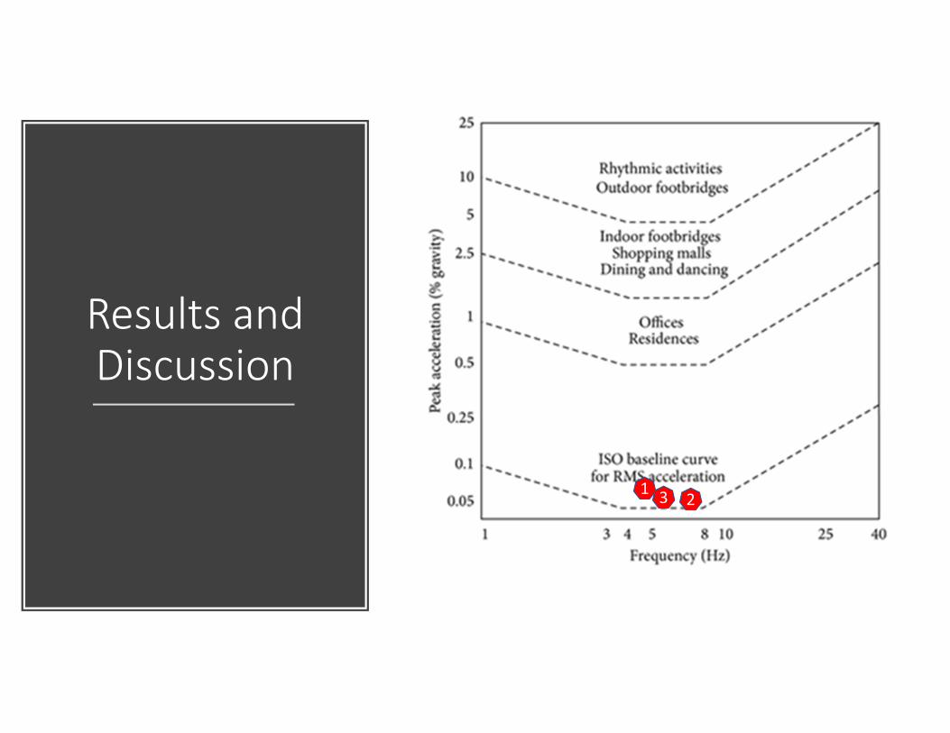
Results and Discussion
1 23
Conclusions
1. Analysis of the building in STAAD PRO software shows that the proposed layout of 12.5 was way too extreme to be design as conventional steel‐concrete composite cantilever floor. Due to that, the configuration and geometry of the structures need to be revised with an addition of a line of columns to shorten the cantilever span from 12.5m to 6m length. For a 6m cantilever steel‐concrete composite floor, the most economical size of steel beam to be used to sustain static loading was UB762x267x197 with a 90mm concrete slab with metal decking as a permanent formwork. This new configuration of structures produced a maximum of 17.8mm vertical displacement due to the live load of an office building, which is within the limit as stated in the code of BS5950‐1:2000
Conclusions (cont…)
2. In the analyzing of the floor structure with dynamic loading due to human activity, it is found that the combination of maximum acceleration and the natural frequencies of the most critical slab in every case of dynamic loading’s excitation was not in the range of peak acceleration recommended for human comfort due to human activity
Conclusions (cont…)
3. Due to the results found in Item (2), the present design of the cantilever steel‐concrete composite floor that is fit for static loading, however, does not meet the vibration limit as specified by the guideline
Conclusions (cont…)
4. From a literature reviews on topics in floor vibration, slab thickness was one of the factors that will affect the floor acceleration and natural frequencies. Therefore, for this study, it is proposed to thicken the slab to get a higher natural frequency of the slab. It is also expected to give the most ideal combination of natural frequencies and acceleration of the floors due to a dynamic loading excitation, and finally provides comfort for human usage

Thank you!