Embed Size (px)
Citation preview

0
Automotive Radar Systems: Status and
Future Developments
Jerry
Martinez
Advised by Janice Hudgings
Thesis submitted to Pomona College
in partial fulfillment for the award of the degree of
Bachelor of Arts
in Physics
2015-2016

1
Acknowledgements
I’d like to thank my thesis advisor Janice Hudgings for her all her patience and guidance on this project. I would also like to thank my advisor David Tanenbaum for aiding me in my undergraduate career, and I’d like to thank Phil Choi and Dwight Whitaker for helping me when I needed them most. I would also like to say a huge thank you to Vicente Robles for all the support and guidance throughout the years and for giving me the strength to finish this thesis.

2
Table of Contents
1. Introduction 3
1.1 Introduction to Radar Systems 3 1.2 Motivation 4 1.2.1 Clinic Project 4 1.2.2Thesis Project 5 1.3 Current Systems 6 1.4 Improvements for the Future 7
2. Radar Resolution 9
2.1 Angular Resolution 9 2.2 Range Resolution 10 2.3 Range Equation 11
3. Types of Automotive Radar Systems 12
3.1 Basic Radar Functions 13 3.2 Short Range Radar 14 3.3 Long Range Radar 15 3.4 Radar Designs for the future
4. Waveform Design 17
4.1 Frequency Modulated Continuous Wave 17 4.2 Frequency Shift Keying 19 4.3 Pulse Modulation 20
5. Conclusion 22

3
1 Introduction
1.1 Introduction to Radar Systems
Road traffic crashes have become a major global challenge. Every year 1.2 million
people are known to die in road accidents worldwide and as many as 50 million are
injured.[1] Because of this, systems for the improvement of road safety have become
a critical area of study. “Automotive radar systems […] have been identified as a
significant technology for the improvement of road safety by the EC.”[1] Automotive
radar devices are now appearing in passenger vehicles all over the world. These
devices are used in advanced cruise control systems, collision warning systems, blind-
spot monitoring, lane-change assistance, rear cross-traffic alerts, and back-up parking
assistance. More recently, advancements in radar technology have allowed these
systems to have the functionality of more preventative safety features such as
collision mitigation.
Automotive radar systems are very complex and have varying designs and functions.
But at the core; all automotive radar systems serve the same function. These systems
contain radar sensors that note vital information, such as range, angle and Doppler
velocity. With this information these systems can determine a particular driving
situation and warn the driver in potentially dangerous events. If the driver does not
take appropriate action in time and a crash is about to happen, advanced radar
systems can take control of the vehicle to avoid the crash or lessen the accident’s
severity. This high level of safety functionality is maintained in bad weather and no
light, when driving conditions are at their worst.
Despite the large leaps in improving safety with automotive radar, there still many
ways that these systems can be improved. Improving the range of object detection,
accuracy of information, and issues with interference effects are just some of these

4
ways. This paper will progress the steps made in this field, and relate the issues that
still need to be addressed.
1.2 Motivation
1.2.1 Clinic Project
To better understand the goals of this paper, we must first address the relation
between the Harvey Mudd Clinic project that this paper stems off of. To begin, the
Harvey Mudd Clinic Team was assigned a specific project tied to improving
automotive radar. As experts in the field of automotive radar, the sponsor of the
project presented the clinic team with a specific list of issues to be addressed. This
list is set by the Euro NCAP 2025 requirements for future automotive radar systems.
They include:
Detection and action at a quarter mile distance
Sweep 150 field of regard in 50 ms
Discern closely spaced objects to within a few degrees
Sweep in elevation, not just azimuth
Another important task assigned to the team, was to conduct further research on
how interference affects a radar system. These interference factors range from radar
signals bouncing off of multiple objects to other vehicles on the road sending their
own radar signals. These are all affects that will be researched and based on that
information; the clinic team will create a simulation test bed where these factors can
be studied more in depth. The team has chosen to focus efforts into this simulation
and because of time constraints, cannot focus on the Euro NCAP requirements.
1.2.2 Thesis
My thesis aims to take charge of one of these requirements, lending the team a
broader knowledge of radar while still satisfying a need of our sponsor. In particular,

5
this research will focus on the needs of understanding and improving radar
resolution.
The automotive radar industry is clearly moving towards improving active safety
systems. These systems may take control of the vehicle from the driver by
intervening with the braking or steering system. But in order for these systems to
function, the quality of information required from the sensors to enable this active
intervention needs to be sufficiently high, demanding both high spatial and angular
separation.[2] Improved range resolution, a subset of spatial resolution, is also
another requirement for improving these systems. Higher range resolutions allow
systems to separate and discriminate between several small closely spaced objects in
the radar field of view. [1]
Currently, many automotive radars work within narrow bandwidths and as a result
have low spatial resolutions. With low spatial resolution, multiple objects on the road
cannot be distinguished if they appear in the same range gate and objects are fused
into one virtual object (see Figure 1). [3]
Figure 1 : Low Spatial Resolution vs High Spatial Resolution
6
A high-resolution system has the ability to determine whether a vehicle will crash
into an object or narrowly miss. A low-resolution system will have a higher rate of
false alarms and will have greater chances of creating safety hazards and vehicle
accidents. The purpose of my research is to investigate the components which affect
how well a radar system discriminates different objects, and more specifically
investigate past/present methods used for improving spatial resolution.
1.3 Current Systems
Ever since the early 1990s when radar was first implemented onto commercial
vehicles, automotive radar technology has continued to evolve and improve. As a
result, today’s markets of automotive radar systems have a variety of functionalities.
Because of these variances, automotive radar systems have different forms of
classification. These systems can be grouped by their bandwidth (narrow-band or
wide-band), by their operation principle (pulsed or continuous wave) or by the
covered area (shortrange, mid-range and long-range radar). In this paper, these
systems will be classified with respect to their operating range and typical
applications.
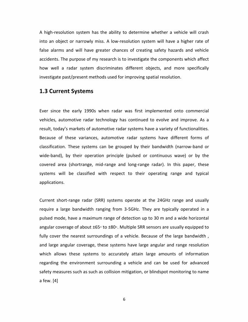
Current short-range radar (SRR) systems operate at the 24GHz range and usually
require a large bandwidth ranging from 3-5GHz. They are typically operated in a
pulsed mode, have a maximum range of detection up to 30 m and a wide horizontal
angular coverage of about ±65◦ to ±80◦. Multiple SRR sensors are usually equipped to
fully cover the nearest surroundings of a vehicle. Because of the large bandwidth ,
and large angular coverage, these systems have large angular and range resolution
which allows these systems to accurately attain large amounts of information
regarding the environment surrounding a vehicle and can be used for advanced
safety measures such as such as collision mitigation, or blindspot monitoring to name
a few. [4]

7
Mid-range radar (MRR) systems also use the 24 GHz frequency range but use a
narrower bandwidth of around 200MHz. These systems operate in continuous wave
mode using linear frequency modulation (LFM) or advanced modulation techniques
such as frequency shift keying (FSK) or frequency-stepped continuous wave (FSCW).
They have a maximum range of 70 m and an angular coverage of ±40◦ to ±50◦. Due to
the low available bandwidth, these systems have low range resolution. Therefore,
the primary targeted application for these sensors is the lane-change assistant. [4]
Long-range radar (LRR) systems mostly use the allocated 76-77GHz frequency range
and operate in the continuous wave mode using FMCW. Some however, reach similar
functionality using a narrow-band 24GHz frequency. The long-range sensors are
implemented typically for Automatic Cruise Control. [4]
Typically, LRR sensor performance degrades for targets very close to the vehicle (<
20m), resulting in a drop of range measurement stability and angular measurement
accuracy. The range resolution of most long range radar systems on the market today
comes close to the physical limits imposed by the sensor’s transmit frequency
bandwidth. Because of this limitation, many vehicles on the road today use a
combination of SRR and LRR to achieve multiple necessary functionalities. [4]
1.4 Improvements for the Future
As of today most automotive radar systems types (LRR,etc.) operate at separate
frequency ranges. As described previously, SRR currently operate at the 24GHz range,
and LRR operate at the 76GHz range. Originally it was expected that, by 2013, new
systems for the 79 GHz band would be available and that the use of the 24 GHz band
could therefore be phased out. However, the automotive industry has experienced
significant delay in developing SRR systems to operate in the 79 GHz band, and it has
become clear that new systems with 79 GHz technology would not be mature
enough for commercial deployment in cars by 2013.
8
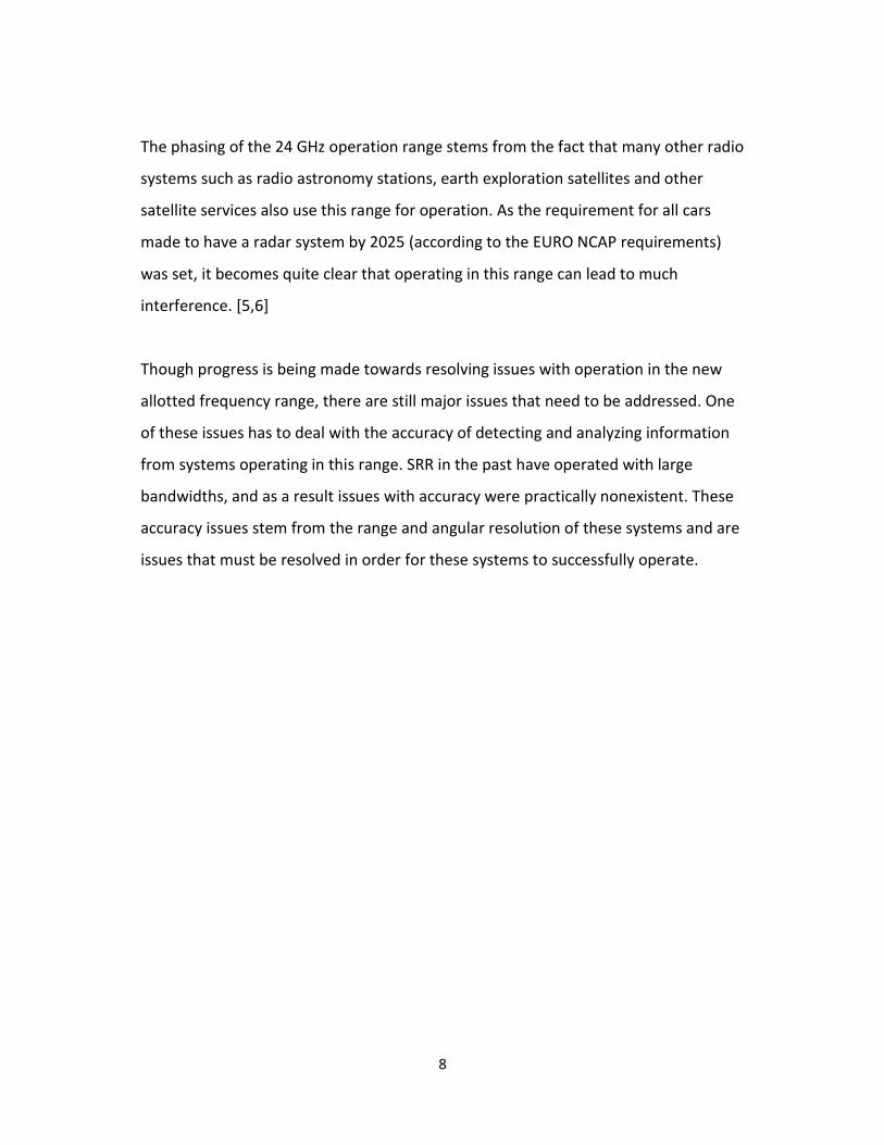
The phasing of the 24 GHz operation range stems from the fact that many other radio
systems such as radio astronomy stations, earth exploration satellites and other
satellite services also use this range for operation. As the requirement for all cars
made to have a radar system by 2025 (according to the EURO NCAP requirements)
was set, it becomes quite clear that operating in this range can lead to much
interference. [5,6]
Though progress is being made towards resolving issues with operation in the new
allotted frequency range, there are still major issues that need to be addressed. One
of these issues has to deal with the accuracy of detecting and analyzing information
from systems operating in this range. SRR in the past have operated with large
bandwidths, and as a result issues with accuracy were practically nonexistent. These
accuracy issues stem from the range and angular resolution of these systems and are
issues that must be resolved in order for these systems to successfully operate.

9
2. Radar Resolution
The target resolution of radar is its ability to distinguish between targets that are very
close in either range or bearing. This is an important characteristic for many radar
systems such as weapons-control radar, which requires great precision and should be
able to distinguish between targets that are only yards apart. In the same light,
resolution is also important for automotive radar because an improved resolution
can allow a vehicle to avoid potential devastating collision with other targets/vehicles
on the road. Radar resolution is usually divided into two categories; range resolution
and angular (bearing) resolution. [7]
2.1 Angular Resolution
Angular resolution is the minimum angular separation at which two equal targets at
the same range can be separated. The angular resolution characteristics of a radar
are determined by the antenna beam width represented by the -3 dB angle Θ which
is defined by the half-power (-3 dB) points. The half-power points of the antenna
radiation pattern (i.e. the -3 dB beam width) are normally specified as the limits of
the antenna beam width for the purpose of defining angular resolution; two identical
targets at the same distance are, therefore, resolved in angle if they are separated by
more than the antenna beam width. So the smaller the beam width Θ, the higher the
directivity of the radar antenna, and the better the bearing resolution. The angular
resolution as a distance between two targets depends on the slant-range and can be
calculated with help of the following formula:
𝑆𝐴 ≤ 2𝑅 sin𝜃
2 2.1)
Where 𝜃 is equal to antenna beam width, 𝑆𝐴 is equal to angular resolution as a
distance between two targets, and R is equal to an antenna variable. [7]
10
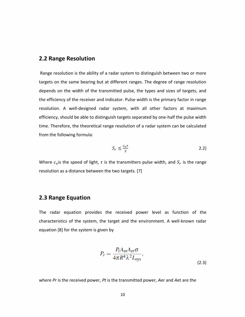
2.2 Range Resolution
Range resolution is the ability of a radar system to distinguish between two or more
targets on the same bearing but at different ranges. The degree of range resolution
depends on the width of the transmitted pulse, the types and sizes of targets, and
the efficiency of the receiver and indicator. Pulse width is the primary factor in range
resolution. A well-designed radar system, with all other factors at maximum
efficiency, should be able to distinguish targets separated by one-half the pulse width
time. Therefore, the theoretical range resolution of a radar system can be calculated
from the following formula:
𝑆𝑟 ≤𝑐𝑜𝜏
2 2.2)
Where 𝑐𝑜is the speed of light, 𝜏 is the transmitters pulse width, and 𝑆𝑟 is the range
resolution as a distance between the two targets. [7]
2.3 Range Equation
The radar equation provides the received power level as function of the
characteristics of the system, the target and the environment. A well-known radar
equation [8] for the system is given by
(2.3)
where Pr is the received power, Pt is the transmitted power, Aer and Aet are the

11
effective area of the receive and transmit antennas, respectively, R is the distance to
the target, σ is the radar cross-section (RCS), defined as the ratio of the scattered
power in a given direction to the incident power density and Lsys is the system
loss due to misalignment, antenna pattern loss, polarization mismatch, atmospheric
loss [3], but also due to analog to digital conversion and fast Fourier transform
(FFT) windowing. Taking into consideration that the effective area of the receive
and transmit antenna is related to the wavelength λ and to the antenna gain Gr and
Gt, as Aer = Grλ 2/4π and Aet = Gtλ 2/4π, respectively, the radar equation can be
rewritten as [4]
(2.4)

12
3. Types of Radar Systems
A lot of progress has been made for automotive radar during the last years. There are
two main types of automotive radar; “long-range radar at 77GHz with a range
capability up to 200m“ for automatic cruise control (ACC) and “short-range radar at
24/26 and 79GHz up to 30m“ for anti-collision. Long radar with narrow radiation
beam enables an automobile to maintain a cruising distance, while short-range radar
has attracted attention because of many applications such as pre-crush warning,
stop-and-go operation and lane change assist. The short-range radar with a very
broad lateral coverage has a few significant problems to be overcome such as target
detection and clutter suppression. This is because the widely radiated radar echo
contains not only automobile echo, but also unwanted echoes called clutter. It is
actually not easy to detect a target echo in increased clutter. Ultra-wideband
impulse-radio (UWB-IR) radar with high range-resolution has recently attracted much
attention for automotive use, because it offers many applications such as pre-crush
warning and lane change assist. [9]
3.1 Basic Radar Function
Radar systems are composed of a transmitter that radiates electromagnetic waves of
a particular waveform and a receiver that detects the echo returned from the target.
Only a small portion of the transmitted energy is re-radiated back to the radar, which
is then amplified, down-converted and processed. The range to the target is
evaluated from the travelling time of the wave. The direction of the target is
determined by the arrival angle of the echoed wave. The relative velocity of the
target is determined from the doppler shift of the returned signal. [4]

13
Figure 2: Signal being transmitted by vehicle A, and being reflected off of vehicle B with a Doppler shifted frequency [4]
3.1 Short Range Radar
Automotive short range radar is an important technology for present and future
automotive active safety and comfort functions. The UWB approach provides a real-
time high range resolution, which is of particular importance for the time critical
safety functions, e.g. pre-crash. The European frequency regulation for UWB
automotive SRR requires the shift from 24 GHz to the 79 GHz band in 2013. Beneath
this, offers the application of the same the 79 GHz frequency range offers application
of the same technology platform for LRR and UWB SRR. Furthermore, frequency
dependent parameters as angular and velocity resolution, are improved significantly.
[10]
As shown in Fig. 2 short range radar sensors can enable a variety of applications:
• ACC support with Stop&Go functionality
• Collision warning
• Collision mitigation
• Blind spot monitoring

14
• Parking aid (forward and reverse)
• Lane change assistant
• Rear crash collision warning
Figure 3: Short range radar and its safety applications. LRR functionality is also shown for ACC application
3.2 Long Range Radar
Automotive radar facilitates various functions which increase the drivers safety and
convenience. Exact measurement of distance and relative speed of objects in front,
beside, or behind the car allows the realization of systems which improve the drivers
ability to perceive objects during bad optical visibility or objects hidden in the blind
spot during parking or changing lanes. Radar technology has proved its ability for
automotive applications for several years [11]
Long Range Radar is one of the radar types used in motor vehicles today. Typical LRR
systems today show a maximum operation range of 150m for cars and motorcycles
which is sufficient for most applications. Since the path prediction of the own vehicle
based on e.g. steering angle and inertial sensors becomes more and more unreliable
for far range over 150m, there is no point in further enhancement of a LRR range
15
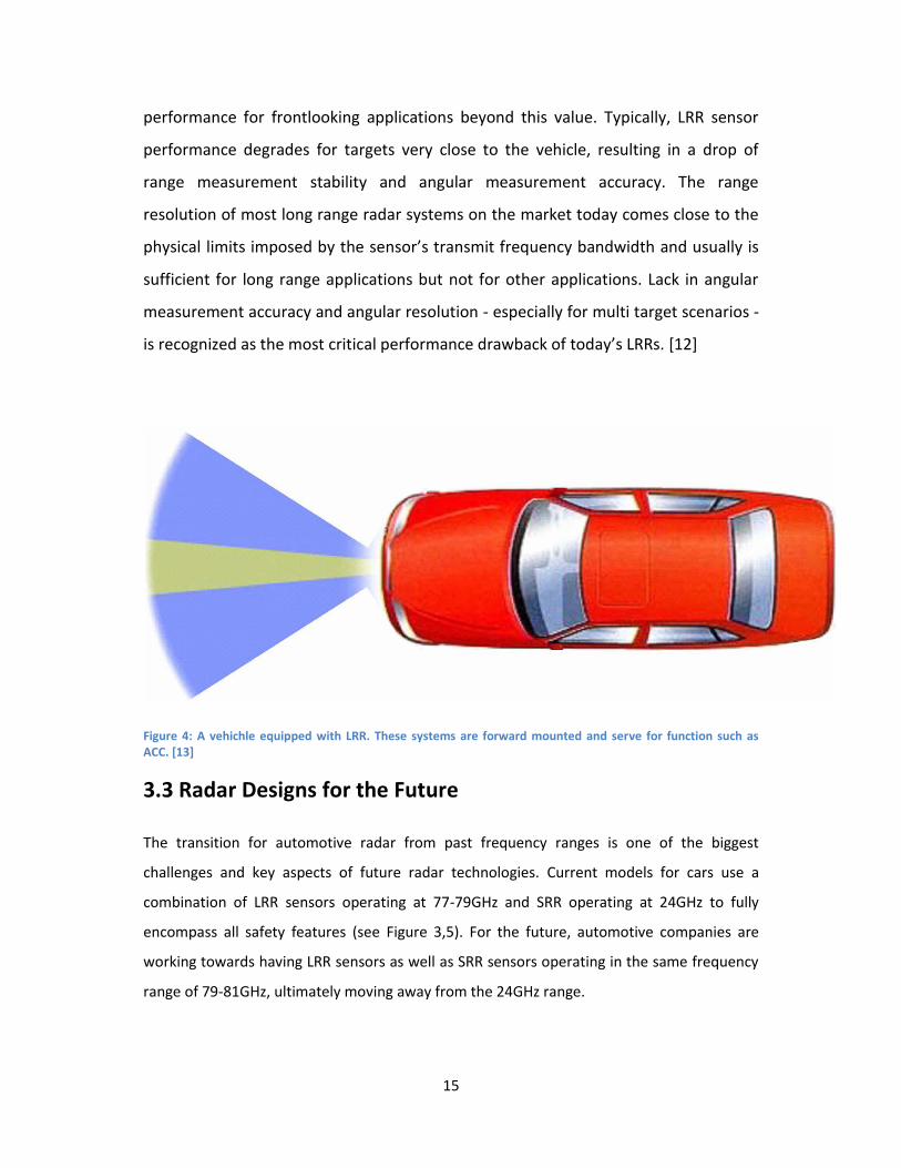
performance for frontlooking applications beyond this value. Typically, LRR sensor
performance degrades for targets very close to the vehicle, resulting in a drop of
range measurement stability and angular measurement accuracy. The range
resolution of most long range radar systems on the market today comes close to the
physical limits imposed by the sensor’s transmit frequency bandwidth and usually is
sufficient for long range applications but not for other applications. Lack in angular
measurement accuracy and angular resolution - especially for multi target scenarios -
is recognized as the most critical performance drawback of today’s LRRs. [12]
Figure 4: A vehichle equipped with LRR. These systems are forward mounted and serve for function such as ACC. [13]
3.3 Radar Designs for the Future
The transition for automotive radar from past frequency ranges is one of the biggest
challenges and key aspects of future radar technologies. Current models for cars use a
combination of LRR sensors operating at 77-79GHz and SRR operating at 24GHz to fully
encompass all safety features (see Figure 3,5). For the future, automotive companies are
working towards having LRR sensors as well as SRR sensors operating in the same frequency
range of 79-81GHz, ultimately moving away from the 24GHz range.

16
For future systems it is necessary that the radar system has a sufficiently high resolution in
the direction of propagation. It must be able to distinguish a person from other objects like
containers or street lamps. Furthermore it has to be sensitive enough to detect a weakly
reflecting obstacle in presence of a strong second reflector, for example a person standing in
front of a wall. This would be beneficial for parking maneuvers in areas with many buildings
and pedestrians. These and many other applications demand high resolution radar systems
in the short and mid range area. It is a well known fact that high resolutions are better
achievable in a higher frequency range. The step from 24 GHz to 79 GHz systems is still in
progress but should be completed by 2022. [14]
Figure 5: Automotive radar with SRR capability (green) and LRR capability (orange) with max range of detection of 15om. [13]
17
4. Waveform Design
Automotive radar systems have varying functions and one important attribute that lends to
these differences is waveform choice for the system. The choice of waveform directly
determines or is a major contributor to several fundamental radar system performance
metrics. These include the signal-to-noise ratio (SNR) c, the range resolution DR, the Doppler
(velocity) resolution DFD (Dv), ambiguities in range and Doppler, range and Doppler
sidelobes, and range-Doppler coupling. These metrics are determined by such waveform
attributes as the pulse duration, bandwidth, amplitude, and phase or frequency modulation.
While all of these metrics are discussed, the primary emphasis is on SNR, range resolution,
and Doppler resolution because these are the most fundamental drivers in choosing the
waveform. [15]
4.1 Frequency Modulated Continuous Wave
Unmodulated continuous-wave (CW) radars transmit a signal with constant
frequency. The lack of modulation of the source only allows for determination of the
relative target velocity via the Doppler shift. Frequency modulated continuous-wave
(FMCW) radar systems employ frequency modulation at the signal source to enable
propagation delay measurements for determination of the distance to the target.
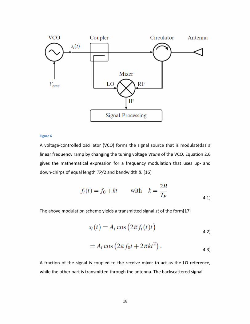
Figure 4 shows a block diagram of an FMCW radar transceiver.[16]
18
Figure 6
A voltage-controlled oscillator (VCO) forms the signal source that is modulatedas a
linear frequency ramp by changing the tuning voltage Vtune of the VCO. Equation 2.6
gives the mathematical expression for a frequency modulation that uses up- and
down-chirps of equal length TP/2 and bandwidth B. [16]
4.1)
The above modulation scheme yields a transmitted signal st of the form[17]
4.2)
4.3)
A fraction of the signal is coupled to the receive mixer to act as the LO reference,
while the other part is transmitted through the antenna. The backscattered signal

19
4.4)
with the propagation delay Δt and a Doppler shift fd is received and translated into
the baseband by means of a down-conversion mixer. Subsequently the intermediate
frequency (IF) signal is digitized and the determination of target range and velocity is
performed through a fast Fourier transformation (FFT).[16]
4.2 Frequency Shift Keying
Frequency shift keying (FSK) is one of several techniques used to transmit a digital
signal on an analogue transmission medium. The frequency of a sine wave carrier is
shifted up or down to represent either a single binary value or a specific bit pattern.
The simplest form of frequency shift keying is called binary frequency shift
keying (BFSK), in which the binary logic values one and zero are represented by the
carrier frequency being shifted above or below the centre frequency. In conventional
BFSK systems, the higher frequency represents a logic high (one) and is referred to as
the mark frequency. The lower frequency represents a logic low (zero) and is called
the space frequency. The two frequencies are equi-distant from the centre
frequency. A typical BFSK output waveform is shown below. [17]

20
Figure 7: Binary Frequency Shift Keying (BFSK)
If there is a discontinuity in phase when the frequency is shifted between the mark
and space values, the form of frequency shift keying used is said to be non-coherent,
otherwise it is said to be coherent. In more complex schemes, additional frequencies
are used to enable more than one bit to be represented by each frequency used. This
provides a higher data rate, but requires more bandwidth (representing a group of
two binary values, for example, would require four different frequencies). It also
increases the complexity of the modulator and demodulator circuitry, and increases
the probability of transmission errors occurring. [17]
4.3 Pulse Modulation
A pulsed-radar transmits modulated pulses at periodic intervals of time (i.e., a train
of modulated pulses) as illustrated in Fig. 8. Range is readily extracted by measuring
the time delay between the instants of pulse transmission and reception. Object
velocity can be determined by measuring the rate of change of range, or by
employing a bank of Doppler filters. Pulse radar waveforms are characterized by

21
three main parameters: (a) pulse-width, τp (b) carrier frequency, f0 and (c) pulse
repetition frequency, prf. The prf must be chosen to avoid range and Doppler
ambiguities and to maximize average transmitted power. Range ambiguity decreases
with decreasing prf, while Doppler ambiguity decreases with increasing prf. Radars
with high prf are usually called pulsed Doppler radars. Intentional pre-determined
jitter is sometimes introduced in the prf in order to avoid blind speeds and range and
Doppler ambiguities. In a pulsed-radar, the transmitter (TX) and the receiver (RX)
essentially operate in a time-duplexed manner, and hence a high dynamic range can
be attained. Although a complex timing engine with delay circuitry is required, pulsed
radar is the simplest architecture to implement. [18]
Figure 8: Typical transmit and receive waveform envelopes in a pulsed-radar

22
Conclusion
With vehicle accidents lending to one of the leading causes of death in the U.S.,
vehicle safety has become a very important area of research. To combat these
accidents, significant headway has been made towards vehicle safety features. The
most vital of active crash prevention comes from automotive radar and the
functionalities that they serve. From crash mitigation to automatic cruise
control(ACC), automotive radar have been a major key for vehicle safety and
comfort. As of today most automotive radar systems types come in the form of short
range radar (SRR) or long range radar (LRR) operating at 24GHz and 76GHz
respectively. While SRR serves the purpose of safety mitigation, LRR controls features
such as ACC.
In the future, automotive radar will be shifted towards operation in the 77-81GHz
range, and previous 24GHz operation will be phased out. This phasing of the 24 GHz
operation range is due to operation of other radio systems such as radio astronomy
stations, earth exploration satellites and other satellite services at this frequency and
range. And with the requirement for all cars made to have radar systems by 2025
(according to the EURO NCAP requirements), it becomes quite clear that operating in
this range can lead to much interference. [5, 6] This is a requirement set by the ECC
by 2022, and will lend to new changes in automotive radar technologies. One of the
biggest drawbacks facing current systems is shifting SRR capabilities towards the new
allocated range. The biggest reason for this issue comes from the amount and
accuracy of information coming from radar systems operating at higher frequencies
and lower bandwidths. With lower frequencies and bandwidths, the range and
angular resolution of these systems are compromised and as a result, valuable
information is lost that could be used for functionalities such as crash mitigation.
These are features that were dealt with coherently in the 24GHz range, but are

23
something that needs to be addressed in the future as we move towards a new
allocated frequency range.

24
References
1. Wenger, J. (2005). Automotive Radar – Status and Perspectives, 21–24. 2. Gresham,Ian. (2014) Automotive Radar Solutions, Anikiwave.Web.02 Feb.
2016. 3. Brizzolara,David. (2013) Future Trends for Automotive Radars: Towards the
79GHz Band, ITU News. Web. 2 Feb. 2016. 4. Issakov, V. (2010). Microwave Circuits for 24 GHz Automotive Radar in Silicon-
based Technologies, 5–19. 5. (2014) A radar for your Car-Digitial Agenda for Europe-European Comission,
Digital Agenda for Europe.European Comission, Web. 02 Feb. 2016. 6. Bloecher, H., Sailer, A., Rollmann, G., & Dickmann, J. (2013). Radio Science 79
GHz UWB automotive short range radar – Spectrum allocation and technology trends increased doppler ( Electronic Communications Committee of the • higher angular resolution with CEPT ) adopted decisions using 24 GHz spectrum in Europe until July 1 (December 2009), 61–65.
7. Basics, B. R. (2009). Radartutorial, 1–18. 8. Chang,K (2000) Wireless Communication Systems in RF and Microwave
Wireless Systems, John Wiley & Sons, Inc. 9. Akihiro Kajiwara (2011). Ultra-Wideband Automotive Radar, Advances in
Vehicular Networking Technologies, Dr Miguel Almeida (Ed.) 10. Bloecher, H., Sailer, A., Rollmann, G., & Dickmann, J. (2013). Radio Science 79
GHz UWB automotive short range radar – Spectrum allocation and technology trends increased doppler ( Electronic Communications Committee of the • higher angular resolution with CEPT ) adopted decisions using 24 GHz spectrum in Europe until July 1 (December 2009), 61–65.
11. Wengerl, J. (1998). Automotive mm-wave, 1–7. 12. Rasshofer, R. H., & Naab, K. (n.d.). 77 GHz Long Range Radar Systems Status ,
Ongoing Developments and Future Challenges, 2–5. 13. Wenger, J. (n.d.). RF-Applications in Vehicles – Today and Tomorrow
Automotive Applications of RF- Technology, 1–18. 14. Mike, K., Gumbmann, F., & Sch, J. (2010). Considerations for Future
Automotive Radar in the Frequency Range Above 100 GHz, 8(c), 284–287. 15. Waveforms, R. (n.d.). Radar Waveforms 4.1. 16. Kissinger, Dietmar (2012) Millimeter-Wave Receiver Concepts for 77 GHz
Automotive Radar in Silicon-Germanium Technology, 9-19 17. Frequency Shift Keying(FSK), TechnologyUK, N.p.,n.d. Web. 02 Feb. 2016 18. Jain, Vipul, Heydari, Payam (2013) Automotive Radar Sensors in Silicon
Technologies, 5-11

25