Embed Size (px)
Citation preview
AT 2302
Automotive Electrical
& Electronics
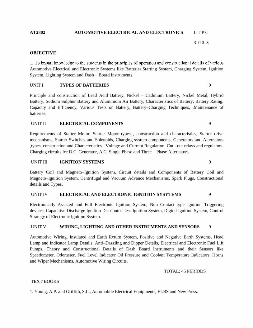
AT2302 AUTOMOTIVE ELECTRICAL AND ELECTRONICS L T P C
3 0 0 3
OBJECTIVE
Automotive Electrical and Electronic Systems like Batteries,Starting System, Charging System, Ignition
System, Lighting System and Dash – Board Instruments.
UNIT I TYPES OF BATTERIES 9
Principle and construction of Lead Acid Battery, Nickel – Cadmium Battery, Nickel Metal, Hybrid
Battery, Sodium Sulphur Battery and Aluminium Air Battery, Characteristics of Battery, Battery Rating,
Capacity and Efficiency, Various Tests on Battery, Battery–Charging Techniques, .Maintenance of
batteries.
UNIT II ELECTRICAL COMPONENTS 9
Requirements of Starter Motor, Starter Motor types , construction and characteristics, Starter drive
mechanisms, Starter Switches and Solenoids, Charging system components, Generators and Alternators
,types, construction and Characteristics . Voltage and Current Regulation, Cut –out relays and regulators,
Charging circuits for D.C. Generator, A.C. Single Phase and Three – Phase Alternators.
UNIT III IGNITION SYSTEMS 9
Battery Coil and Magneto–Ignition System, Circuit details and Components of Battery Coil and
Magneto–Ignition System, Centrifugal and Vacuum Advance Mechanisms, Spark Plugs, Constructional
details and Types.
UNIT IV ELECTRICAL AND ELECTRONIC IGNITION SYSYTEMS 9
Electronically–Assisted and Full Electronic Ignition System, Non–Contact–type Ignition Triggering
devices, Capacitive Discharge Ignition Distributor–less Ignition System, Digital Ignition System, Control
Strategy of Electronic Ignition System.
UNIT V WIRING, LIGHTING AND OTHER INSTRUMENTS AND SENSORS 9
Automotive Wiring, Insulated and Earth Return System, Positive and Negative Earth Systems, Head
Lamp and Indicator Lamp Details, Anti–Dazzling and Dipper Details, Electrical and Electronic Fuel Lift
Pumps, Theory and Constructional Details of Dash Board Instruments and their Sensors like
Speedometer, Odometer, Fuel Level Indicator Oil Pressure and Coolant Temperature Indicators, Horns
and Wiper Mechanisms, Automotive Wiring Circuits.
TOTAL: 45 PERIODS
TEXT BOOKS
1. Young, A.P. and Griffith, S.L., Automobile Electrical Equipments, ELBS and New Press.
2. Kholi .P.L.Automotive Electrical Equipment,Tata McGraw-Hill co ltd,New Delhi,2004
REFERENCES
1. Crouse.W.H. Automobile Electrical Equi\pment,McGraw Hill Book Co
Inc.NewYork,2005
2. Judge.A.W.Modern Electrical Equipments of Automobiles,Chapman & Hall, London
2004 .
3. Robert Bosch, Automotive Handbook, Bently Publishers,2004
UNIT I TYPES OF BATTERIES
Lead-acid batteries
Construction
Even after well over 100 years of development and much promising research into other
techniques of energy storage, the lead-acid battery is still the best choice for motor vehicle use.
This is particularly so when cost and energy density are taken into account. Incremental changes
over the years have made the sealed and maintenance-free battery now in common use very
reliable and long lasting. This may not always appear to be the case to some end-users, but note
that quality is often related to the price the customer pays. Many bottom-of-the-range cheap
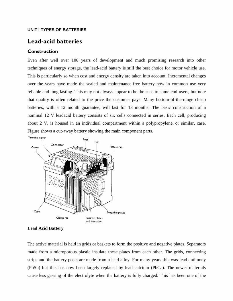
batteries, with a 12 month guarantee, will last for 13 months! The basic construction of a
nominal 12 V leadacid battery consists of six cells connected in series. Each cell, producing
about 2 V, is housed in an individual compartment within a polypropylene, or similar, case.
Figure shows a cut-away battery showing the main component parts.
Lead Acid Battery
The active material is held in grids or baskets to form the positive and negative plates. Separators
made from a microporous plastic insulate these plates from each other. The grids, connecting
strips and the battery posts are made from a lead alloy. For many years this was lead antimony
(PbSb) but this has now been largely replaced by lead calcium (PbCa). The newer materials
cause less gassing of the electrolyte when the battery is fully charged. This has been one of the
main reasons why sealed batteries became feasible, as water loss is considerably reduced.
However, even modern batteries described as sealed do still have a small vent to stop the
pressure build-up due to the very small amount of gassing. A further requirement of sealed
batteries is accurate control of charging voltage.
Battery rating
In simple terms, the characteristics or rating of a particular battery are determined by how much
current it can produce and how long it can sustain this current. The rate at which a battery can
produce current is determined by the speed of the chemical reaction.
This in turn is determined by a number of factors:
● Surface area of the plates.
● Temperature.
● Electrolyte strength.
● Current demanded.
The actual current supplied therefore determines the overall capacity of a battery. The rating of a
battery has to specify the current output and the time.
Ampere hour capacity
This is now seldom used but describes how much current the battery is able to supply for either
10 or 20 hours. The 20-hour figure is the most common. For example, a battery quoted as being
44 Ah (ampere-hour) will be able, if fully charged, to supply 2.2 A for 20 hours before being
completely discharged (cell voltage above 1.75 V).
Reserve capacity
A system used now on all new batteries is reserve capacity. This is quoted as a time in minutes
for which the battery will supply 25 A at 25 ° C to a final voltage of 1.75 V per cell. This is used
to give an indication of how long the battery could run the car if the charging system was not
working. Typically, a 44 Ah battery will have a reserve capacity of about 60 minutes.
Cold cranking amps
Batteries are given a rating to indicate performance at high current output and at low
temperature. A typical value of 170 A means that the battery will supply this current for one
minute at a temperature of _18 ° C, at which point the cell voltage will fall to 1.4 V (BS – British
Standards).
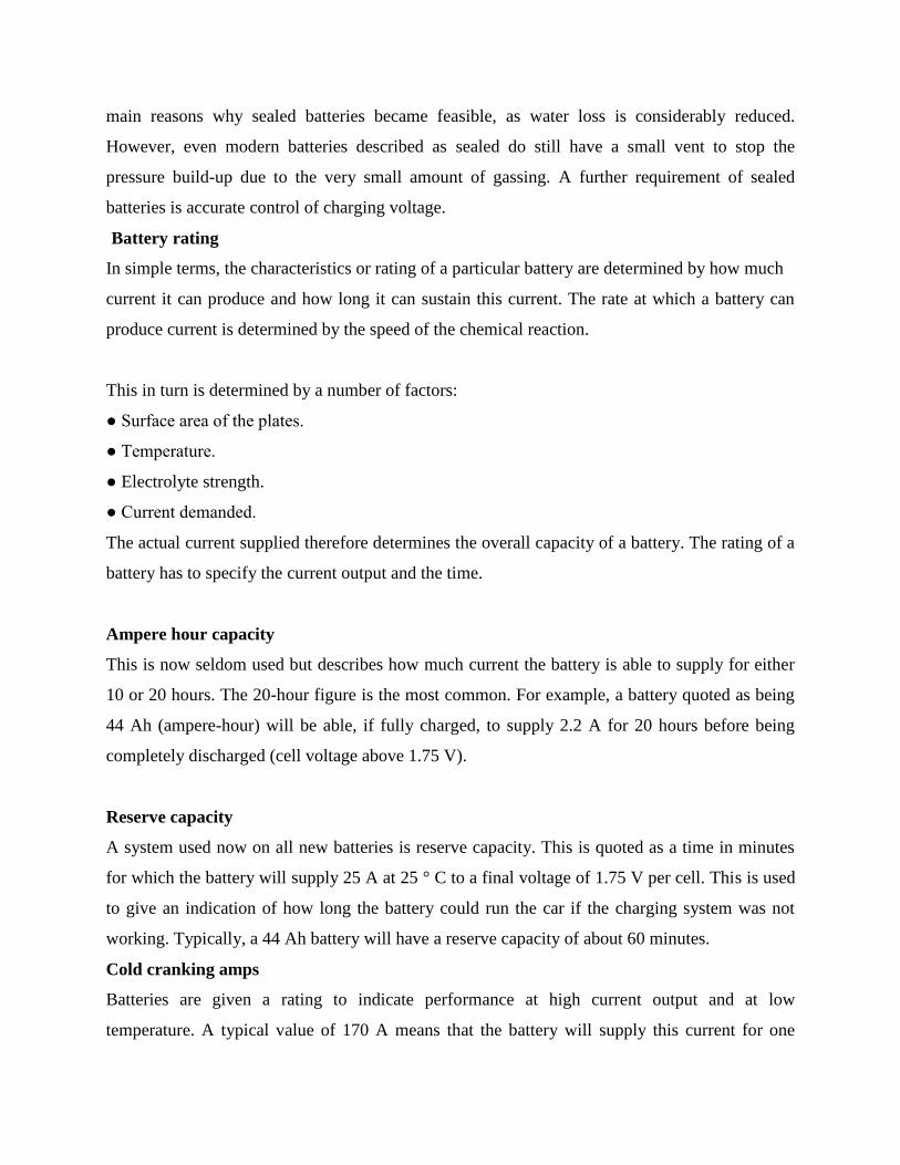
Note that the overall output of a battery is much greater when spread over a longer time.
As mentioned above, this is because the chemical reaction can only work at a certain speed.
Figure 5.3 shows the above three discharge characteristics and how they can be compared.
Battery discharge characteristics compared
Maintenance and charging
Maintenance
By far the majority of batteries now available are classed as ‘maintenance free’. This implies that
little attention is required during the life of the battery. Earlier batteries and some heavier types
do, however, still require the electrolyte level to be checked and topped up periodically.
Battery posts are still a little prone to corrosion and hence the usual service of cleaning with hot
water if appropriate and the application of petroleum jelly or proprietary terminal grease is still
recommended. Ensuring that the battery case and, in particular, the top remains clean, will help
to reduce the rate of self-discharge.
The state of charge of a battery is still very important and, in general, it is not advisable to
allow the state of charge to fall below 70% for long periods as the sulphate on the plates can
harden, making recharging difficult. If a battery is to be stored for a long period (more than a few
weeks , then it must be recharged every so often to prevent it from becoming sulphated.
Recommendations vary but a recharge every six weeks is a reasonable suggestion.
Battery Charging
The recharging recommendations of battery manufacturers vary slightly. The following
methods, however, are reasonably compatible and should not cause any problems. The
recharging process must ‘put back’ the same ampere-hour capacity as was used on discharge plus
a bit more to allow for losses. It is therefore clear that the main question about charging is not
how much, but at what rate.
The old recommendation was that the battery should be charged at a tenth of its ampere-
hour capacity for about 10 hours or less. This is assuming that the ampere-hour capacity is
quoted at the 20 hour rate, as a tenth of this figure will make allowance for the charge factor.
This figure is still valid, But as ampere-hour capacity is not always used nowadays, a different
method of deciding the rate is necessary. One way is to set a rate at 1/16 of the reserve capacity,
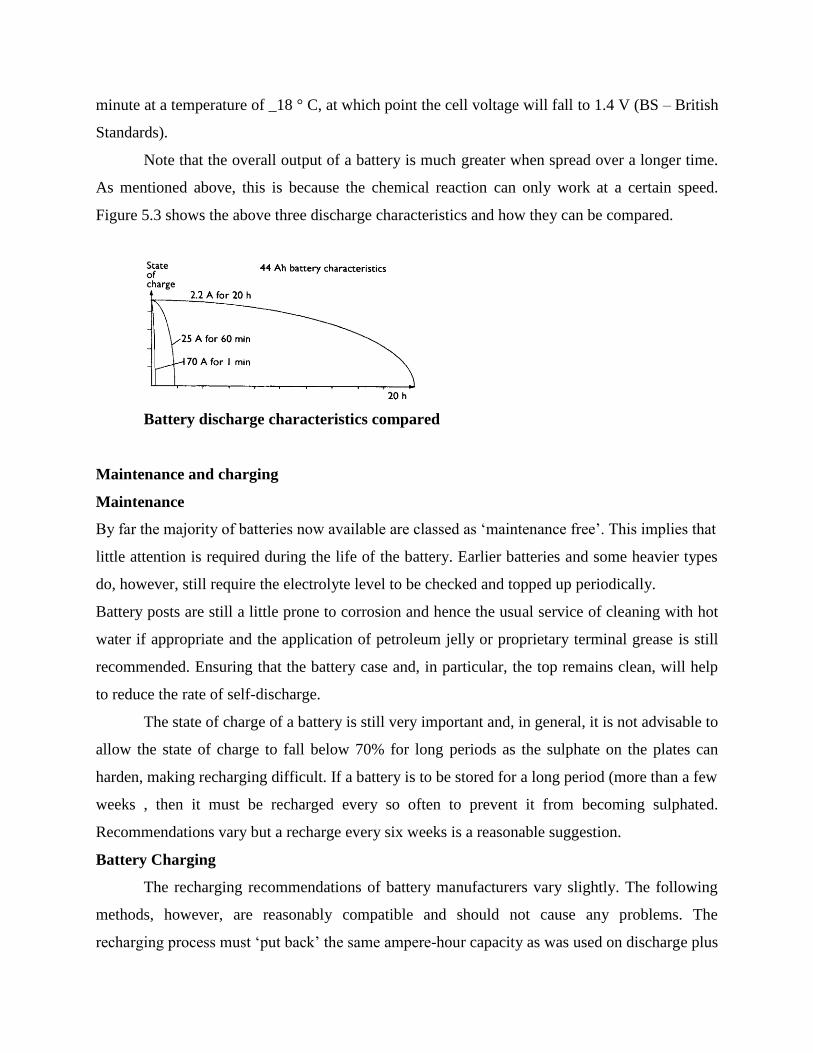
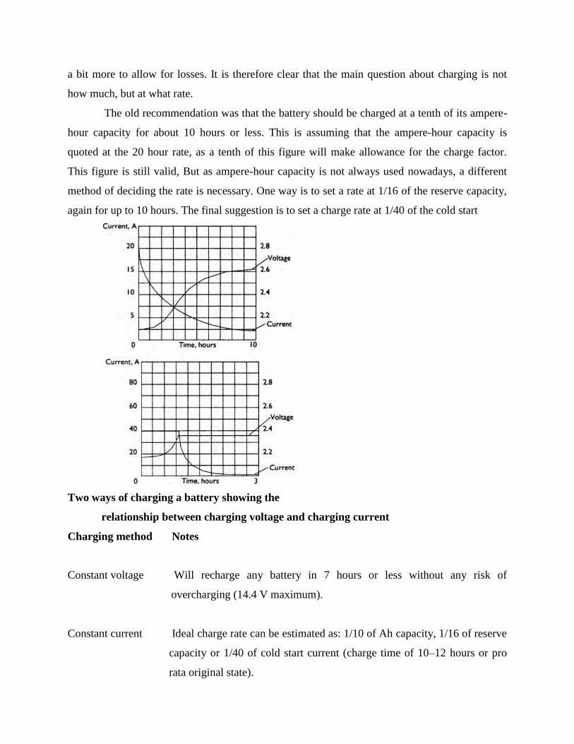
again for up to 10 hours. The final suggestion is to set a charge rate at 1/40 of the cold start
Two ways of charging a battery showing the
relationship between charging voltage and charging current
Charging method Notes
Constant voltage Will recharge any battery in 7 hours or less without any risk of
overcharging (14.4 V maximum).
Constant current Ideal charge rate can be estimated as: 1/10 of Ah capacity, 1/16 of reserve
capacity or 1/40 of cold start current (charge time of 10–12 hours or pro
rata original state).
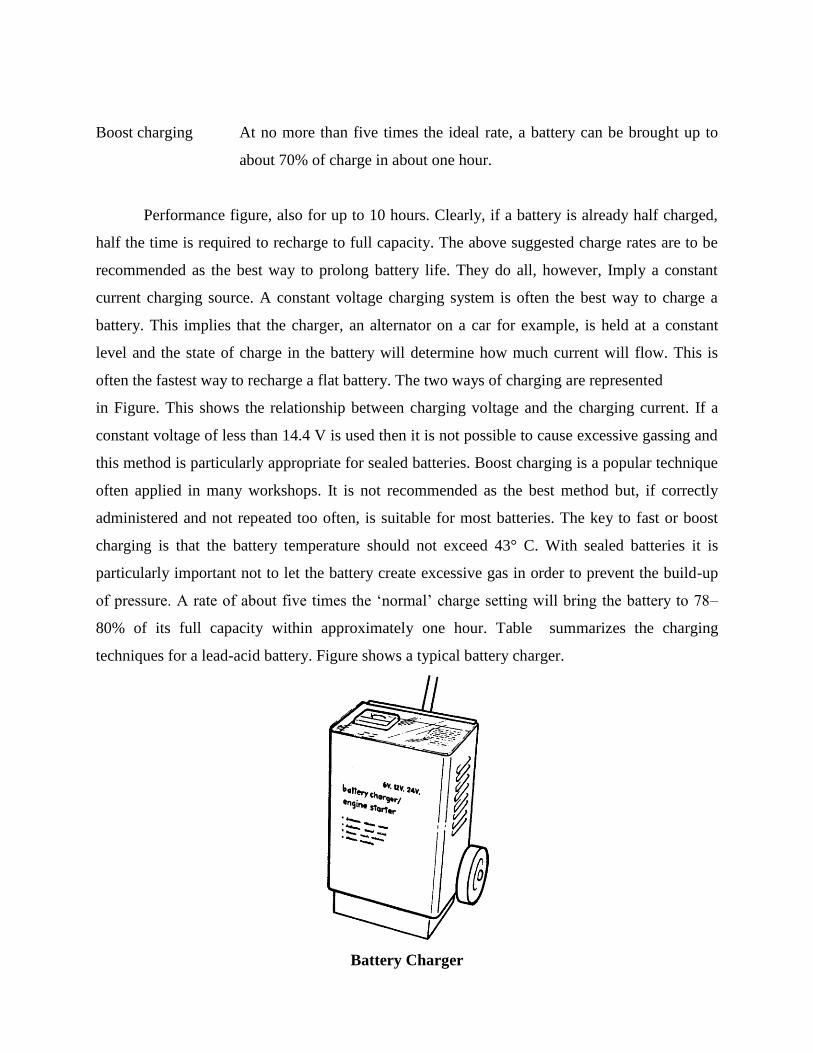
Boost charging At no more than five times the ideal rate, a battery can be brought up to
about 70% of charge in about one hour.
Performance figure, also for up to 10 hours. Clearly, if a battery is already half charged,
half the time is required to recharge to full capacity. The above suggested charge rates are to be
recommended as the best way to prolong battery life. They do all, however, Imply a constant
current charging source. A constant voltage charging system is often the best way to charge a
battery. This implies that the charger, an alternator on a car for example, is held at a constant
level and the state of charge in the battery will determine how much current will flow. This is
often the fastest way to recharge a flat battery. The two ways of charging are represented
in Figure. This shows the relationship between charging voltage and the charging current. If a
constant voltage of less than 14.4 V is used then it is not possible to cause excessive gassing and
this method is particularly appropriate for sealed batteries. Boost charging is a popular technique
often applied in many workshops. It is not recommended as the best method but, if correctly
administered and not repeated too often, is suitable for most batteries. The key to fast or boost
charging is that the battery temperature should not exceed 43° C. With sealed batteries it is
particularly important not to let the battery create excessive gas in order to prevent the build-up
of pressure. A rate of about five times the ‘normal’ charge setting will bring the battery to 78–
80% of its full capacity within approximately one hour. Table summarizes the charging
techniques for a lead-acid battery. Figure shows a typical battery charger.
Battery Charger
Various Tests on Battery
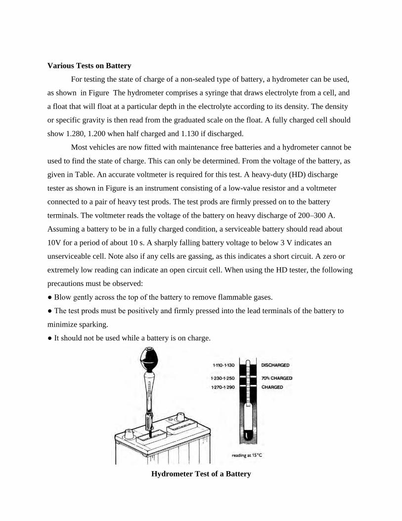
For testing the state of charge of a non-sealed type of battery, a hydrometer can be used,
as shown in Figure The hydrometer comprises a syringe that draws electrolyte from a cell, and
a float that will float at a particular depth in the electrolyte according to its density. The density
or specific gravity is then read from the graduated scale on the float. A fully charged cell should
show 1.280, 1.200 when half charged and 1.130 if discharged.
Most vehicles are now fitted with maintenance free batteries and a hydrometer cannot be
used to find the state of charge. This can only be determined. From the voltage of the battery, as
given in Table. An accurate voltmeter is required for this test. A heavy-duty (HD) discharge
tester as shown in Figure is an instrument consisting of a low-value resistor and a voltmeter
connected to a pair of heavy test prods. The test prods are firmly pressed on to the battery
terminals. The voltmeter reads the voltage of the battery on heavy discharge of 200–300 A.
Assuming a battery to be in a fully charged condition, a serviceable battery should read about
10V for a period of about 10 s. A sharply falling battery voltage to below 3 V indicates an
unserviceable cell. Note also if any cells are gassing, as this indicates a short circuit. A zero or
extremely low reading can indicate an open circuit cell. When using the HD tester, the following
precautions must be observed:
● Blow gently across the top of the battery to remove flammable gases.
● The test prods must be positively and firmly pressed into the lead terminals of the battery to
minimize sparking.
● It should not be used while a battery is on charge.
Hydrometer Test of a Battery
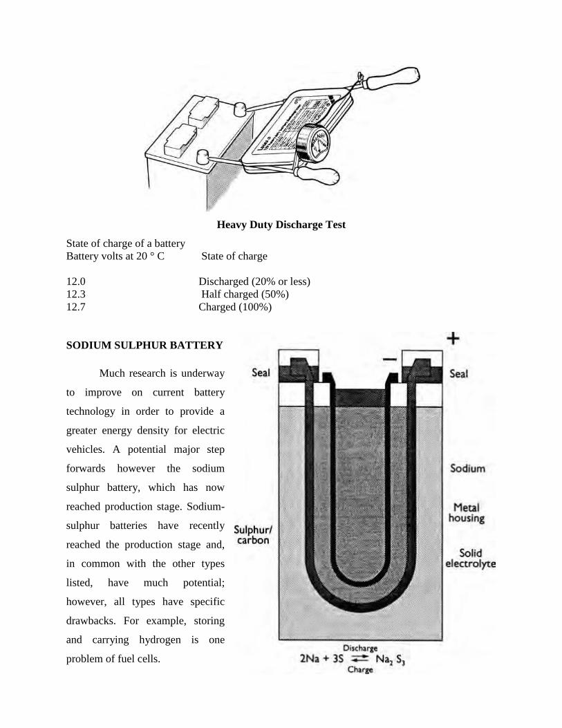
Heavy Duty Discharge Test
State of charge of a battery
Battery volts at 20 ° C State of charge
12.0 Discharged (20% or less)
12.3 Half charged (50%)
12.7 Charged (100%)
SODIUM SULPHUR BATTERY
Much research is underway
to improve on current battery
technology in order to provide a
greater energy density for electric
vehicles. A potential major step
forwards however the sodium
sulphur battery, which has now
reached production stage. Sodium-
sulphur batteries have recently
reached the production stage and,
in common with the other types
listed, have much potential;
however, all types have specific
drawbacks. For example, storing
and carrying hydrogen is one
problem of fuel cells.
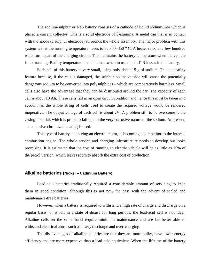
The sodium-sulphur or NaS battery consists of a cathode of liquid sodium into which is
placed a current collector. This is a solid electrode of β-alumina. A metal can that is in contact
with the anode (a sulphur electrode) surrounds the whole assembly. The major problem with this
system is that the running temperature needs to be 300–350 ° C. A heater rated at a few hundred
watts forms part of the charging circuit. This maintains the battery temperature when the vehicle
is not running. Battery temperature is maintained when in use due to I2 R losses in the battery.
Each cell of this battery is very small, using only about 15 g of sodium. This is a safety
feature because, if the cell is damaged, the sulphur on the outside will cause the potentially
dangerous sodium to be converted into polysulphides – which are comparatively harmless. Small
cells also have the advantage that they can be distributed around the car. The capacity of each
cell is about 10 Ah. These cells fail in an open circuit condition and hence this must be taken into
account, as the whole string of cells used to create the required voltage would be rendered
inoperative. The output voltage of each cell is about 2V. A problem still to be overcome is the
casing material, which is prone to fail due to the very corrosive nature of the sodium. At present,
an expensive chromized coating is used.
This type of battery, supplying an electric motor, is becoming a competitor to the internal
combustion engine. The whole service and charging infrastructure needs to develop but looks
promising. It is estimated that the cost of running an electric vehicle will be as little as 15% of
the petrol version, which leaves room to absorb the extra cost of production.
Alkaline batteries (Nickel – Cadmium Battery)
Lead-acid batteries traditionally required a considerable amount of servicing to keep
them in good condition, although this is not now the case with the advent of sealed and
maintenance-free batteries.
However, when a battery is required to withstand a high rate of charge and discharge on a
regular basis, or is left in a state of disuse for long periods, the lead-acid cell is not ideal.
Alkaline cells on the other hand require minimum maintenance and are far better able to
withstand electrical abuse such as heavy discharge and over-charging.
The disadvantages of alkaline batteries are that they are more bulky, have lower energy
efficiency and are more expensive than a lead-acid equivalent. When the lifetime of the battery
and servicing requirements are considered, the extra initial cost is worth it for some applications.
Bus and coach companies and some large goods-vehicle operators have used alkaline batteries.
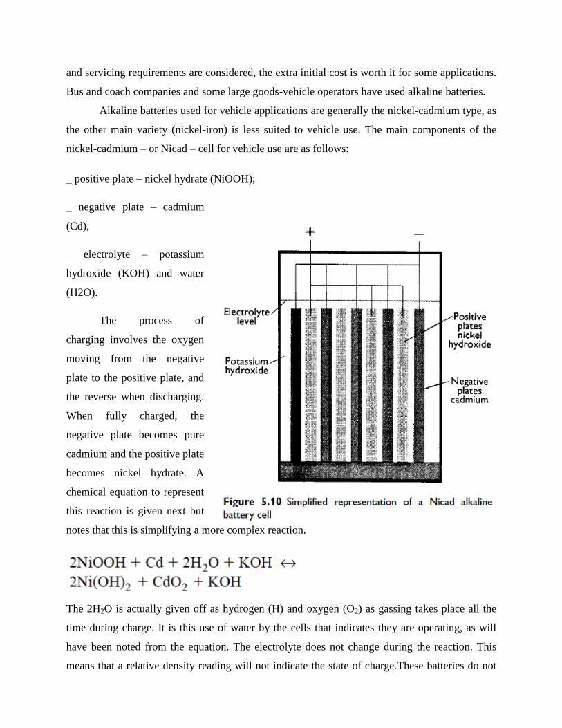
Alkaline batteries used for vehicle applications are generally the nickel-cadmium type, as
the other main variety (nickel-iron) is less suited to vehicle use. The main components of the
nickel-cadmium – or Nicad – cell for vehicle use are as follows:
_ positive plate – nickel hydrate (NiOOH);
_ negative plate – cadmium
(Cd);
_ electrolyte – potassium
hydroxide (KOH) and water
(H2O).
The process of
charging involves the oxygen
moving from the negative
plate to the positive plate, and
the reverse when discharging.
When fully charged, the
negative plate becomes pure
cadmium and the positive plate
becomes nickel hydrate. A
chemical equation to represent
this reaction is given next but
notes that this is simplifying a more complex reaction.
The 2H2O is actually given off as hydrogen (H) and oxygen (O2) as gassing takes place all the
time during charge. It is this use of water by the cells that indicates they are operating, as will
have been noted from the equation. The electrolyte does not change during the reaction. This
means that a relative density reading will not indicate the state of charge.These batteries do not
suffer from over-charging because once the cadmium oxide has changed to cadmium, no further
reaction can take place. The cell voltage of a fully charged cell is 1.4V but this falls rapidly to
1.3 V as soon as discharge starts. The cell is discharged at a cell voltage of 1.1V.
ALUMINIUM–AIR BATTERY
Aluminium–air batteries or Al–air batteries produce electricity from the reaction of
oxygen in the air with aluminium. They have one of the highest energy densities of all batteries,
but they are not widely used because of problems with high anode cost and byproduct removal
when using traditional electrolytes and this has restricted their use to mainly military
applications. However, an electric vehicle with aluminium batteries has the potential for up to
eight times the range of a lithium-ion battery with a significantly lower total weight.
Aluminium–air batteries are primary cells; i.e., non-rechargeable. Once the aluminium
anode is consumed by its reaction with atmospheric oxygen at a cathode immersed in a water-
based electrolyte to form hydrated aluminium oxide, the battery will no longer produce
electricity. However, it is possible to mechanically recharge the battery with new aluminium
anodes made from recycling the hydrated aluminium oxide. Such recycling would be essential if
aluminium–air batteries are to be widely adopted.
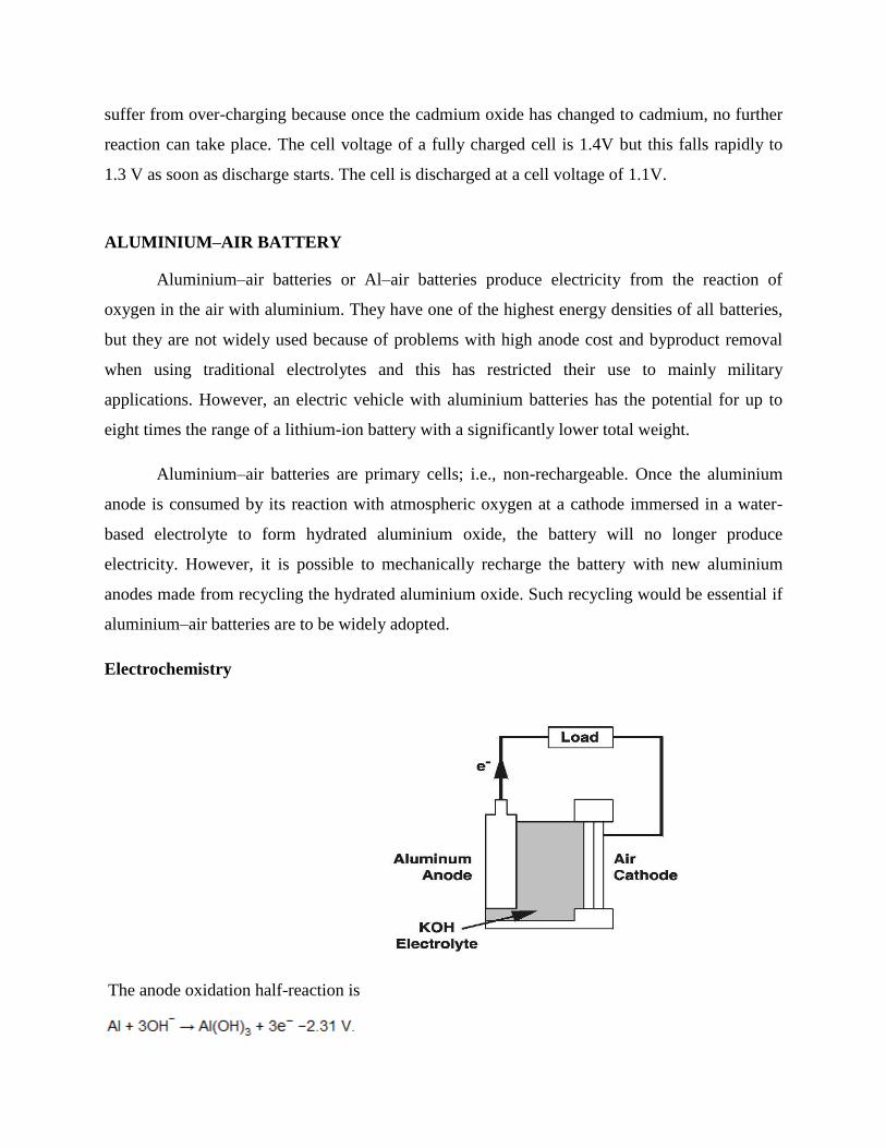
Electrochemistry
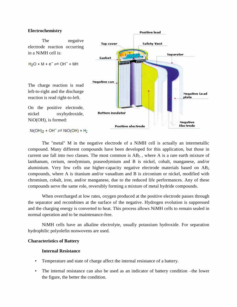
The anode oxidation half-reaction is
The cathode reduction half-reaction is
The total reaction is
About 1.2 volts potential difference is created by these reactions, and is achievable in practice
when potassium hydroxide is used as the electrolyte. Saltwater electrolyte achieves
approximately 0.7 volts per cell.
NICKEL–METAL HYDRIDE BATTERY
A nickel–metal hydride battery, abbreviated NiMH or Ni–MH, is a type of rechargeable
battery. Its chemical reactions are somewhat similar to the largely obsolete nickel–cadmium cell
(NiCd). NiMH use positive electrodes of nickel oxyhydroxide (NiOOH), like the NiCd, but the
negative electrodes use a hydrogen-absorbing alloy instead of cadmium, being in essence a
practical application of nickel–hydrogen battery chemistry. A NiMH battery can have two to
three times the capacity of an equivalent size NiCd, and their energy density approaches that of a
lithium-ion cell.
The typical specific energy for small NiMH cells is about 100 W·h/kg, and for larger
NiMH cells about 75 W·h/kg (270 kJ/kg). This is significantly better than the typical 40–
60 W·h/kg for NiCd, and similar to the 100–160 W·h/kg for lithium-ion batteries. NiMH has a
volumetric energy density of about 300 W·h/L (1,080 MJ/m3), significantly better than NiCd at
50–150 W·h/L, and about the same as lithium-ion at 250–360 W·h/L.
NiMH batteries have replaced NiCd for many roles, notably small rechargeable batteries.
NiMH batteries are very common for AA (penlight-size) batteries, which have nominal charge
capacities (C) of 1.1–2.8 A·h at 1.2 V, measured at the rate that discharges the cell in five hours.
Useful discharge capacity is a decreasing function of the discharge rate, but up to a rate of
around 1×C (full discharge in one hour), it does not differ significantly from the nominal
capacity. NiMH batteries normally operate at 1.2 V per cell, somewhat lower than conventional
1.5 V cells, but will operate most devices designed for that voltage.
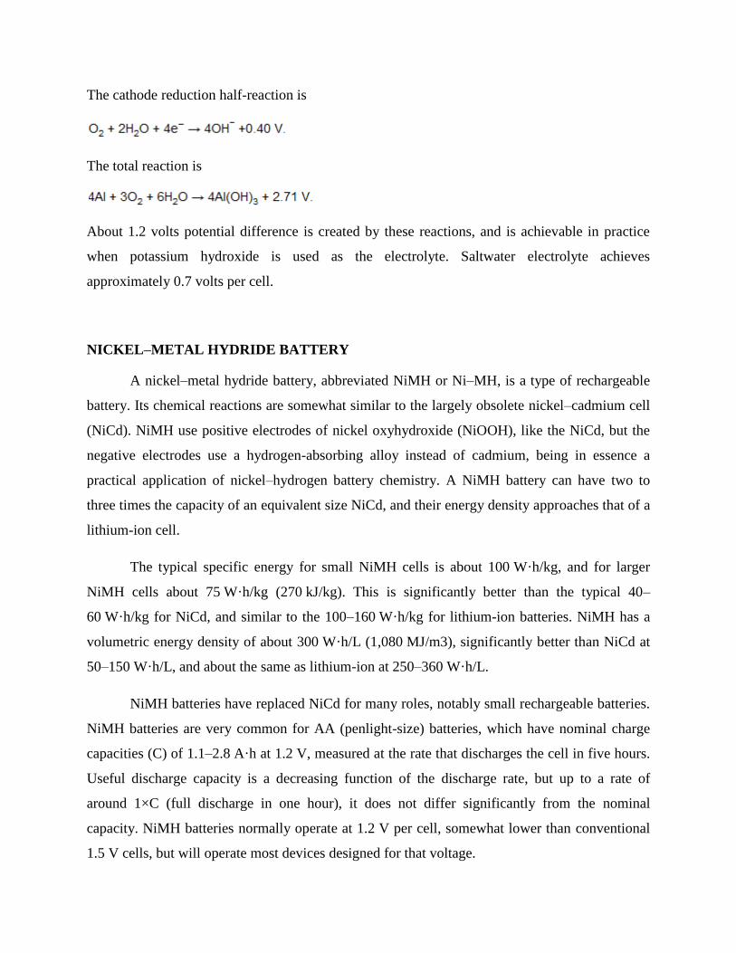
Electrochemistry
The negative
electrode reaction occurring
in a NiMH cell is:
The charge reaction is read
left-to-right and the discharge
reaction is read right-to-left.
On the positive electrode,
nickel oxyhydroxide,
NiO(OH), is formed:
The "metal" M in the negative electrode of a NiMH cell is actually an intermetallic
compound. Many different compounds have been developed for this application, but those in
current use fall into two classes. The most common is AB5 , where A is a rare earth mixture of
lanthanum, cerium, neodymium, praseodymium and B is nickel, cobalt, manganese, and/or
aluminium. Very few cells use higher-capacity negative electrode materials based on AB2
compounds, where A is titanium and/or vanadium and B is zirconium or nickel, modified with
chromium, cobalt, iron, and/or manganese, due to the reduced life performances. Any of these
compounds serve the same role, reversibly forming a mixture of metal hydride compounds.
When overcharged at low rates, oxygen produced at the positive electrode passes through
the separator and recombines at the surface of the negative. Hydrogen evolution is suppressed
and the charging energy is converted to heat. This process allows NiMH cells to remain sealed in
normal operation and to be maintenance-free.
NiMH cells have an alkaline electrolyte, usually potassium hydroxide. For separation
hydrophilic polyolefin nonwovens are used.
Characteristics of Battery
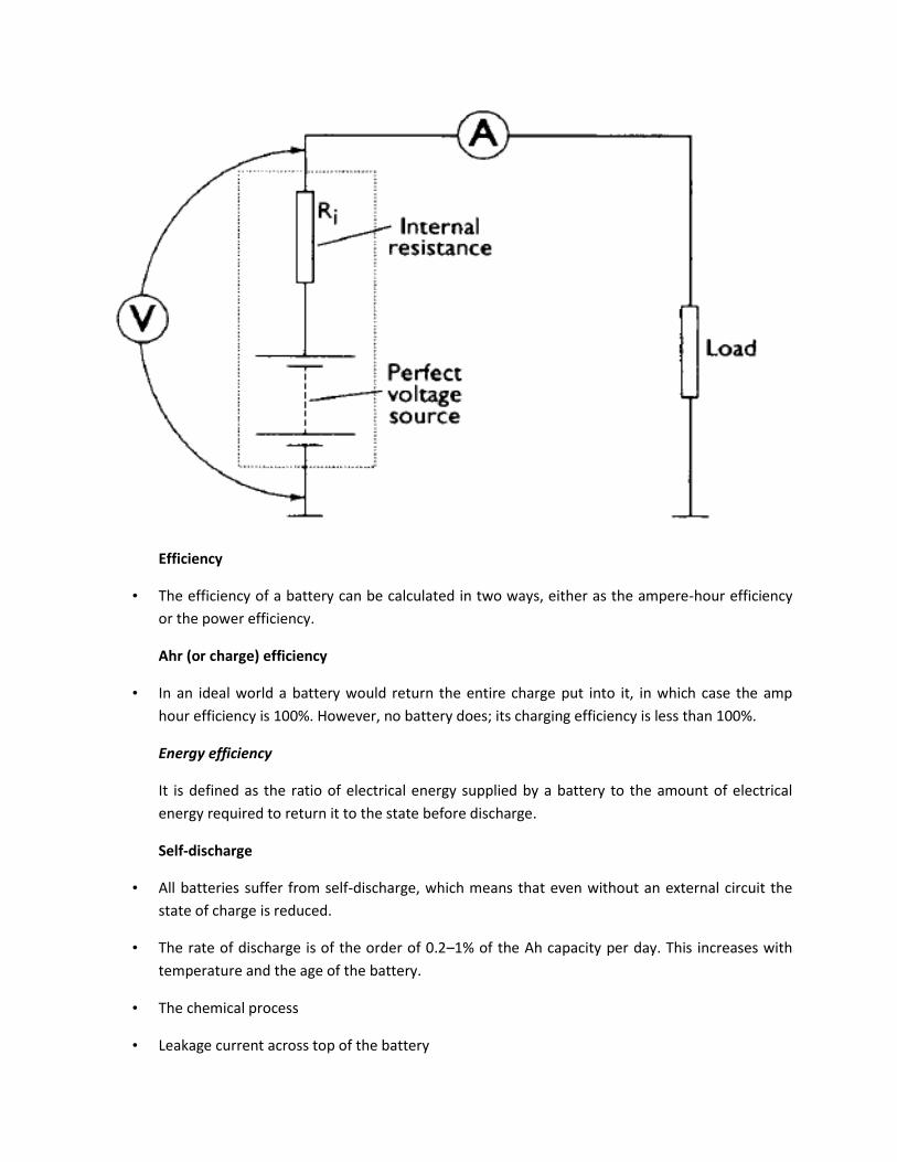
Internal Resistance
• Temperature and state of charge affect the internal resistance of a battery.
• The internal resistance can also be used as an indicator of battery condition –the lower
the figure, the better the condition.
Efficiency
• The efficiency of a battery can be calculated in two ways, either as the ampere-hour efficiency
or the power efficiency.
Ahr (or charge) efficiency
• In an ideal world a battery would return the entire charge put into it, in which case the amp
hour efficiency is 100%. However, no battery does; its charging efficiency is less than 100%.
Energy efficiency
It is defined as the ratio of electrical energy supplied by a battery to the amount of electrical
energy required to return it to the state before discharge.
Self-discharge
• All batteries suffer from self-discharge, which means that even without an external circuit the
state of charge is reduced.
• The rate of discharge is of the order of 0.2–1% of the Ah capacity per day. This increases with
temperature and the age of the battery.
• The chemical process
• Leakage current across top of the battery
Specific energy
• Specific energy is the amount of electrical energy stored for every kilogram of battery mass. It
has units of Wh.kg−1
Energy density
• Energy density is the amount of electrical energy stored per cubic meter of battery volume. It
normally has units of Wh.m−3
Specific power
• Specific power is the amount of power obtained per kilogram of battery. It is a highly variable
and rather anomalous quantity, since the power given out by the battery depends far more
upon the load connected to it than the battery itself.
Battery temperature, heating and cooling needs
• Although most batteries run at ambient temperature, some run at higher temperatures and
need heating to start with and then cooling when in use.
• In others, battery performance drops off at low temperatures, which is undesirable, but this
problem could be overcome by heating the battery.
Battery life and number of deep cycles
• Most rechargeable batteries will only undergo a few hundred deep cycles to 20% of the battery
charge.
• However, the exact number depends on the battery type, and also on the details of the battery
design, and on how the battery is used.
Unit-2
Electrical Components
Starter Motor types , construction and characteristics
Reducing electrical and mechanical stress at start-up, the starting current of an AC motor
can vary from 3 to 7times the nominal current. This is because a large amount of energy is
required to magnetise the motor enough to overcome the inertia the system has at standstill. The
high current drawn from the network can cause problems such as voltage drop, high transients
and, in some cases, uncontrolled shutdown. High starting current also causes great mechanical
stress on the motor’s rotor bars and windings, and can affect the driven equipment and the
foundations. Several starting methods exist, all aiming to reduce these stresses.
The load, the motor and the supply network determine the most appropriate starting
method. When selecting and dimensioning the starting equipment and any protective devices, the
following factors must be taken into account:
−− The voltage drop in the supply network when starting the motor
−− The required load torque during start
−− The required starting time
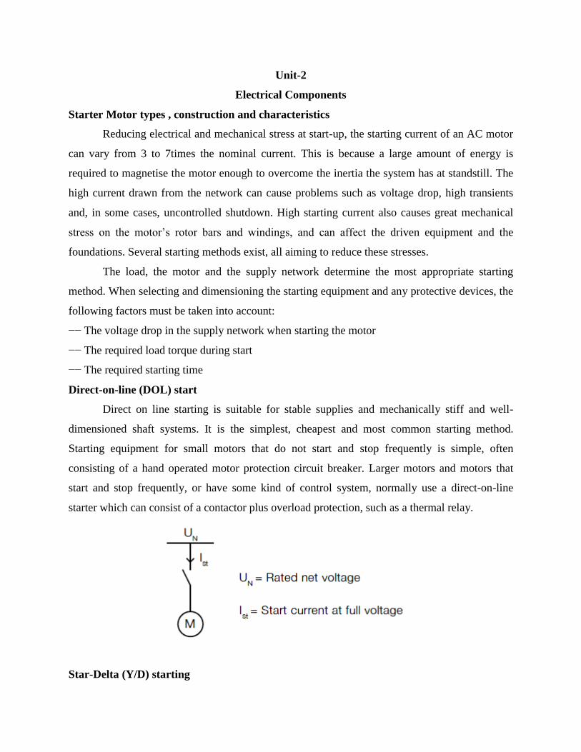
Direct-on-line (DOL) start
Direct on line starting is suitable for stable supplies and mechanically stiff and well-
dimensioned shaft systems. It is the simplest, cheapest and most common starting method.
Starting equipment for small motors that do not start and stop frequently is simple, often
consisting of a hand operated motor protection circuit breaker. Larger motors and motors that
start and stop frequently, or have some kind of control system, normally use a direct-on-line
starter which can consist of a contactor plus overload protection, such as a thermal relay.
Star-Delta (Y/D) starting
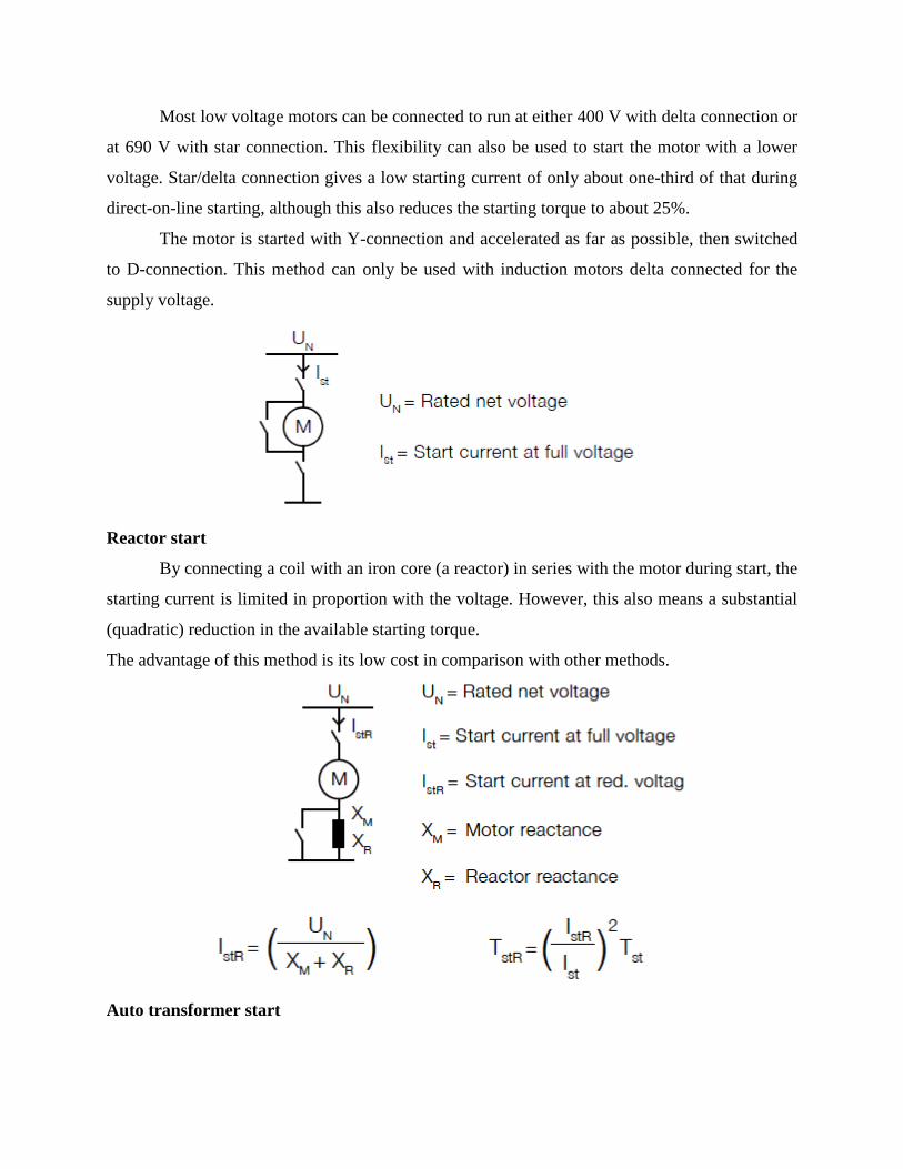
Most low voltage motors can be connected to run at either 400 V with delta connection or
at 690 V with star connection. This flexibility can also be used to start the motor with a lower
voltage. Star/delta connection gives a low starting current of only about one-third of that during
direct-on-line starting, although this also reduces the starting torque to about 25%.
The motor is started with Y-connection and accelerated as far as possible, then switched
to D-connection. This method can only be used with induction motors delta connected for the
supply voltage.
Reactor start
By connecting a coil with an iron core (a reactor) in series with the motor during start, the
starting current is limited in proportion with the voltage. However, this also means a substantial
(quadratic) reduction in the available starting torque.
The advantage of this method is its low cost in comparison with other methods.
Auto transformer start
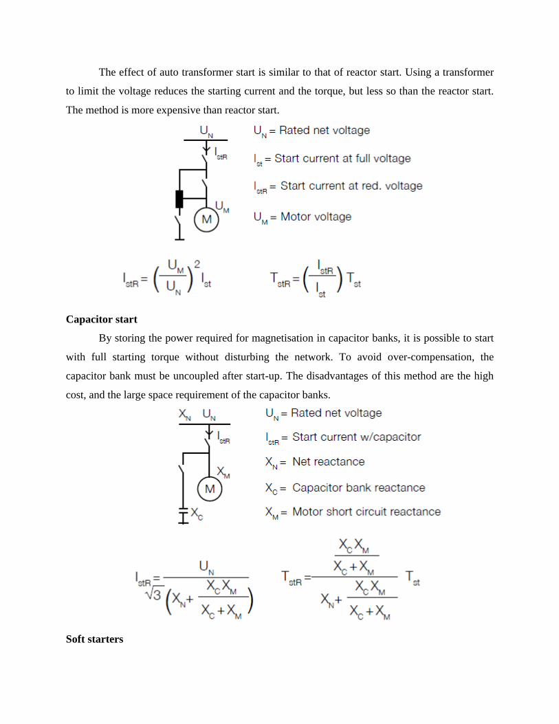
The effect of auto transformer start is similar to that of reactor start. Using a transformer
to limit the voltage reduces the starting current and the torque, but less so than the reactor start.
The method is more expensive than reactor start.
Capacitor start
By storing the power required for magnetisation in capacitor banks, it is possible to start
with full starting torque without disturbing the network. To avoid over-compensation, the
capacitor bank must be uncoupled after start-up. The disadvantages of this method are the high
cost, and the large space requirement of the capacitor banks.
Soft starters
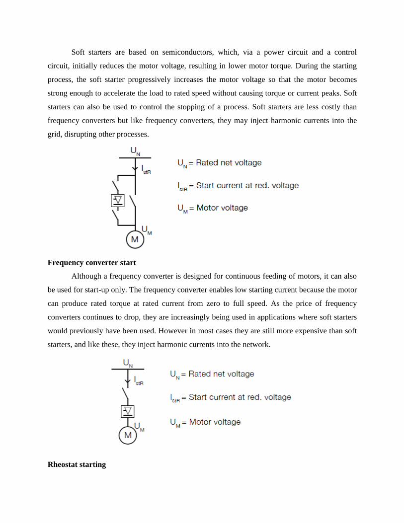
Soft starters are based on semiconductors, which, via a power circuit and a control
circuit, initially reduces the motor voltage, resulting in lower motor torque. During the starting
process, the soft starter progressively increases the motor voltage so that the motor becomes
strong enough to accelerate the load to rated speed without causing torque or current peaks. Soft
starters can also be used to control the stopping of a process. Soft starters are less costly than
frequency converters but like frequency converters, they may inject harmonic currents into the
grid, disrupting other processes.
Frequency converter start
Although a frequency converter is designed for continuous feeding of motors, it can also
be used for start-up only. The frequency converter enables low starting current because the motor
can produce rated torque at rated current from zero to full speed. As the price of frequency
converters continues to drop, they are increasingly being used in applications where soft starters
would previously have been used. However in most cases they are still more expensive than soft
starters, and like these, they inject harmonic currents into the network.
Rheostat starting
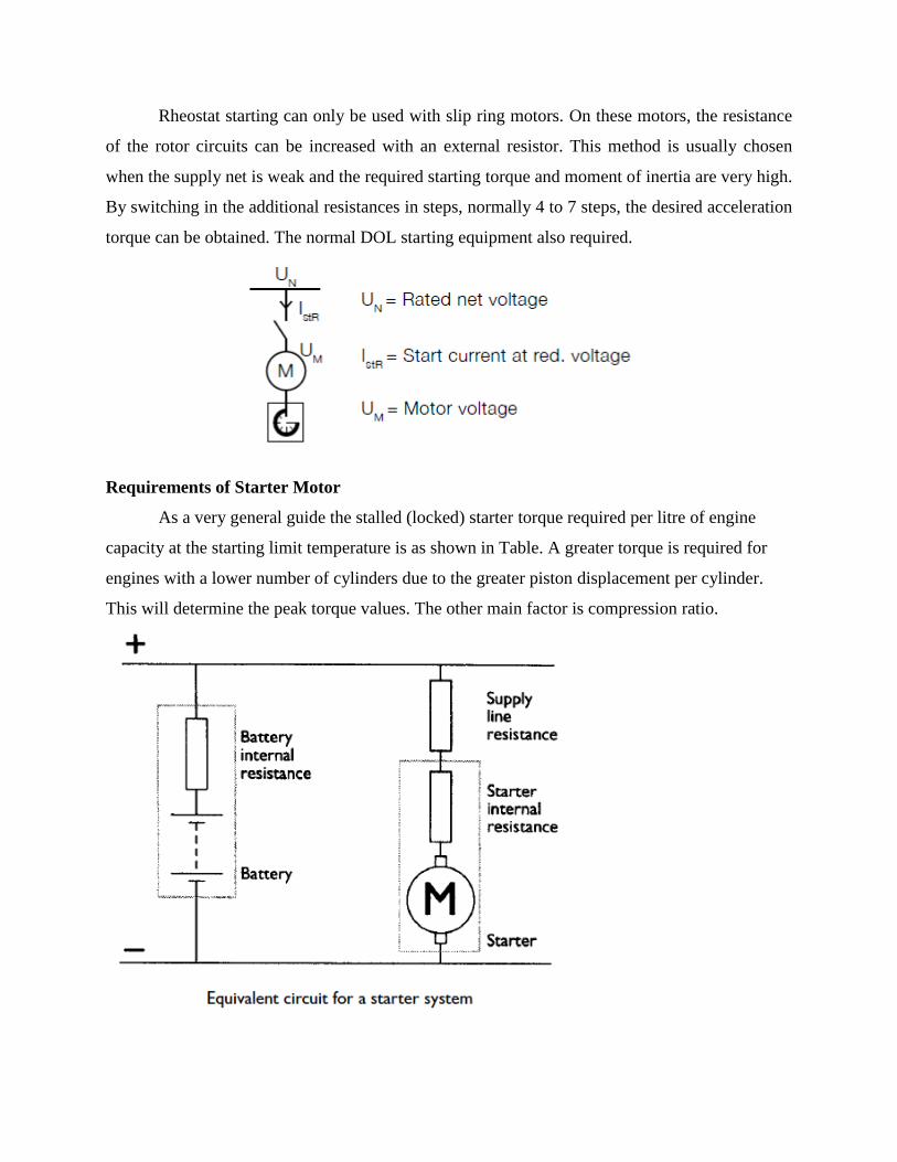
Rheostat starting can only be used with slip ring motors. On these motors, the resistance
of the rotor circuits can be increased with an external resistor. This method is usually chosen
when the supply net is weak and the required starting torque and moment of inertia are very high.
By switching in the additional resistances in steps, normally 4 to 7 steps, the desired acceleration
torque can be obtained. The normal DOL starting equipment also required.
Requirements of Starter Motor
As a very general guide the stalled (locked) starter torque required per litre of engine
capacity at the starting limit temperature is as shown in Table. A greater torque is required for
engines with a lower number of cylinders due to the greater piston displacement per cylinder.
This will determine the peak torque values. The other main factor is compression ratio.
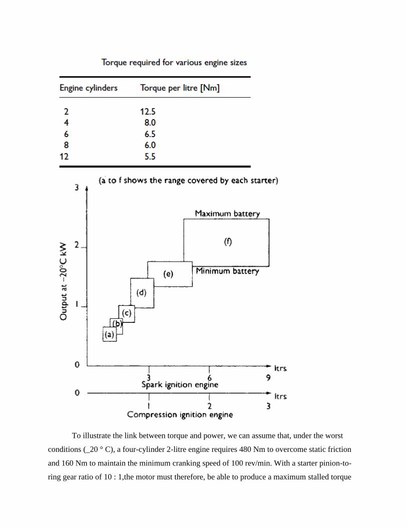
To illustrate the link between torque and power, we can assume that, under the worst
conditions (_20 ° C), a four-cylinder 2-litre engine requires 480 Nm to overcome static friction
and 160 Nm to maintain the minimum cranking speed of 100 rev/min. With a starter pinion-to-
ring gear ratio of 10 : 1,the motor must therefore, be able to produce a maximum stalled torque
of 48 Nm and a driving torque of 16 Nm. This is working on the assumption that stalled torque is
generally three to four times the cranking torque.
Starter drive mechanisms
Inertia starters
In all standard motor vehicle applications it is necessary to connect the starter to the
engine ring gear only during the starting phase. If the connection remained permanent, the
excessive speed at which the starter would be driven by the engine would destroy the motor
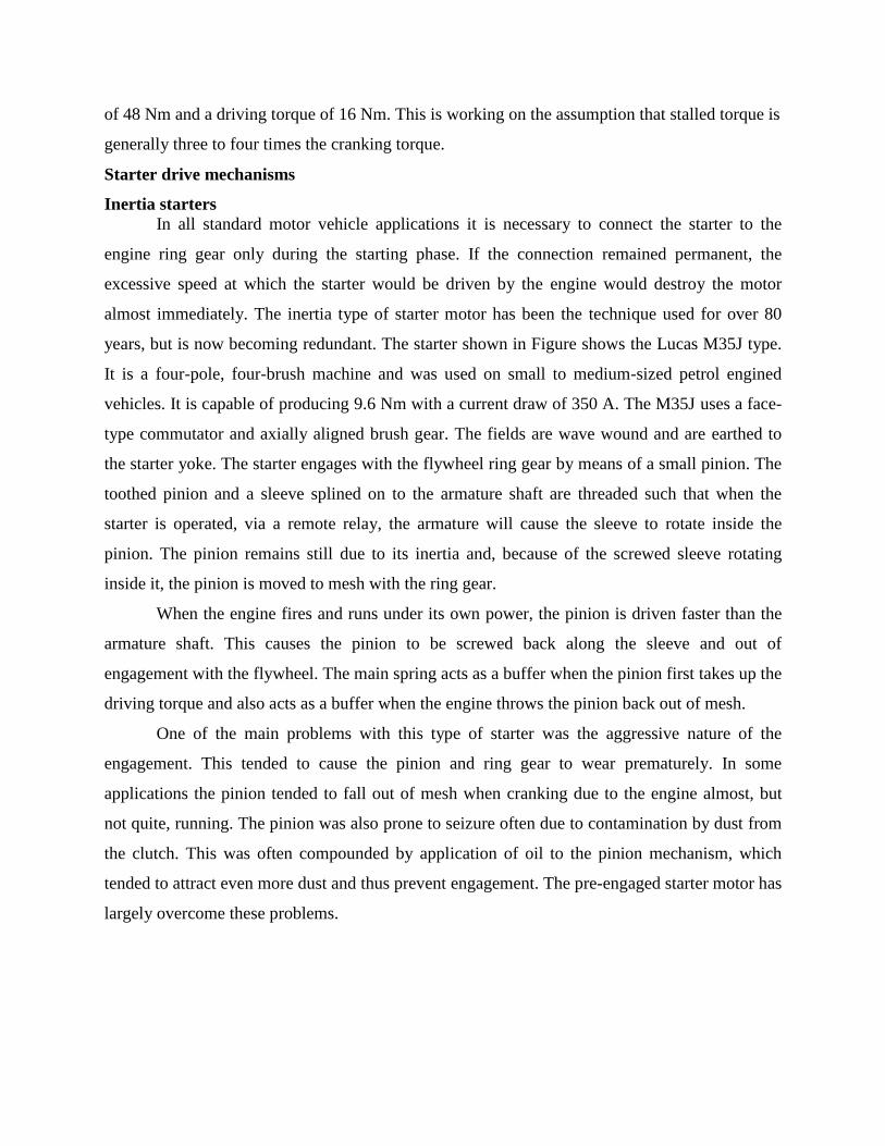
almost immediately. The inertia type of starter motor has been the technique used for over 80
years, but is now becoming redundant. The starter shown in Figure shows the Lucas M35J type.
It is a four-pole, four-brush machine and was used on small to medium-sized petrol engined
vehicles. It is capable of producing 9.6 Nm with a current draw of 350 A. The M35J uses a face-
type commutator and axially aligned brush gear. The fields are wave wound and are earthed to
the starter yoke. The starter engages with the flywheel ring gear by means of a small pinion. The
toothed pinion and a sleeve splined on to the armature shaft are threaded such that when the
starter is operated, via a remote relay, the armature will cause the sleeve to rotate inside the
pinion. The pinion remains still due to its inertia and, because of the screwed sleeve rotating
inside it, the pinion is moved to mesh with the ring gear.
When the engine fires and runs under its own power, the pinion is driven faster than the
armature shaft. This causes the pinion to be screwed back along the sleeve and out of
engagement with the flywheel. The main spring acts as a buffer when the pinion first takes up the
driving torque and also acts as a buffer when the engine throws the pinion back out of mesh.
One of the main problems with this type of starter was the aggressive nature of the
engagement. This tended to cause the pinion and ring gear to wear prematurely. In some
applications the pinion tended to fall out of mesh when cranking due to the engine almost, but
not quite, running. The pinion was also prone to seizure often due to contamination by dust from
the clutch. This was often compounded by application of oil to the pinion mechanism, which
tended to attract even more dust and thus prevent engagement. The pre-engaged starter motor has
largely overcome these problems.
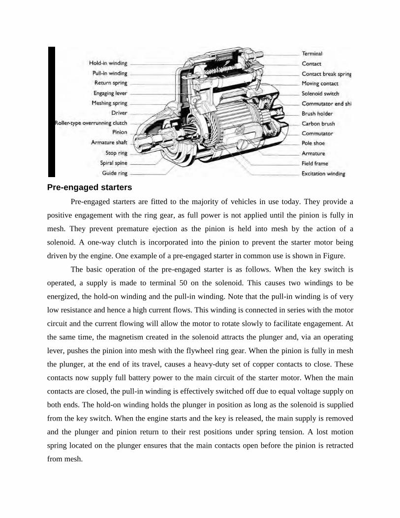
Pre-engaged starters
Pre-engaged starters are fitted to the majority of vehicles in use today. They provide a
positive engagement with the ring gear, as full power is not applied until the pinion is fully in
mesh. They prevent premature ejection as the pinion is held into mesh by the action of a
solenoid. A one-way clutch is incorporated into the pinion to prevent the starter motor being
driven by the engine. One example of a pre-engaged starter in common use is shown in Figure.
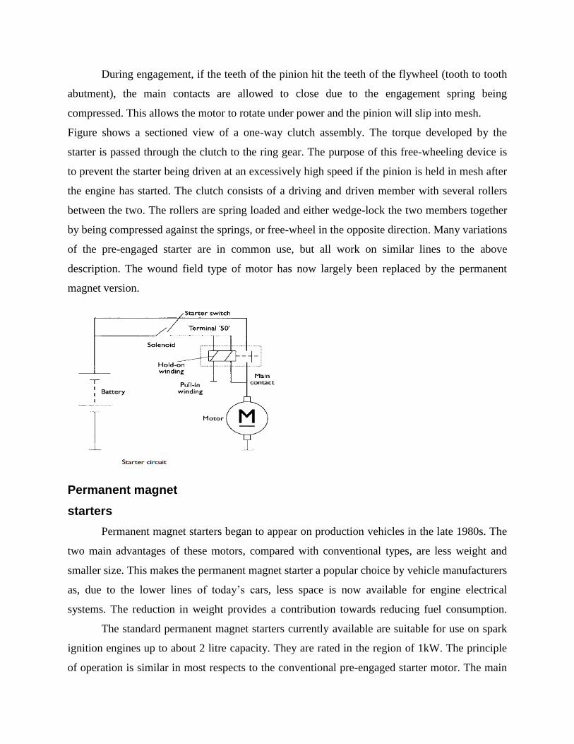
The basic operation of the pre-engaged starter is as follows. When the key switch is
operated, a supply is made to terminal 50 on the solenoid. This causes two windings to be
energized, the hold-on winding and the pull-in winding. Note that the pull-in winding is of very
low resistance and hence a high current flows. This winding is connected in series with the motor
circuit and the current flowing will allow the motor to rotate slowly to facilitate engagement. At
the same time, the magnetism created in the solenoid attracts the plunger and, via an operating
lever, pushes the pinion into mesh with the flywheel ring gear. When the pinion is fully in mesh
the plunger, at the end of its travel, causes a heavy-duty set of copper contacts to close. These
contacts now supply full battery power to the main circuit of the starter motor. When the main
contacts are closed, the pull-in winding is effectively switched off due to equal voltage supply on
both ends. The hold-on winding holds the plunger in position as long as the solenoid is supplied
from the key switch. When the engine starts and the key is released, the main supply is removed
and the plunger and pinion return to their rest positions under spring tension. A lost motion
spring located on the plunger ensures that the main contacts open before the pinion is retracted
from mesh.
During engagement, if the teeth of the pinion hit the teeth of the flywheel (tooth to tooth
abutment), the main contacts are allowed to close due to the engagement spring being
compressed. This allows the motor to rotate under power and the pinion will slip into mesh.
Figure shows a sectioned view of a one-way clutch assembly. The torque developed by the
starter is passed through the clutch to the ring gear. The purpose of this free-wheeling device is
to prevent the starter being driven at an excessively high speed if the pinion is held in mesh after
the engine has started. The clutch consists of a driving and driven member with several rollers
between the two. The rollers are spring loaded and either wedge-lock the two members together
by being compressed against the springs, or free-wheel in the opposite direction. Many variations
of the pre-engaged starter are in common use, but all work on similar lines to the above
description. The wound field type of motor has now largely been replaced by the permanent
magnet version.
Permanent magnet
starters
Permanent magnet starters began to appear on production vehicles in the late 1980s. The
two main advantages of these motors, compared with conventional types, are less weight and
smaller size. This makes the permanent magnet starter a popular choice by vehicle manufacturers
as, due to the lower lines of today’s cars, less space is now available for engine electrical
systems. The reduction in weight provides a contribution towards reducing fuel consumption.
The standard permanent magnet starters currently available are suitable for use on spark
ignition engines up to about 2 litre capacity. They are rated in the region of 1kW. The principle
of operation is similar in most respects to the conventional pre-engaged starter motor. The main
difference being the replacement of field windings and pole shoes with high quality permanent
magnets. The reduction in weight is in the region of 15% and the diameter of the yoke can be
reduced by a similar factor.
Permanent magnets provide constant excitation and it would be reasonable to expect the
speed and torque characteristic to be constant. However, due to the fall in battery voltage under
load and the low resistance of the armature windings, the characteristic is comparable to series
wound motors. In some cases, flux concentrating pieces or interpoles are used between the main
magnets. Due to the warping effect of the magnetic field, this tends to make the characteristic
curve very similar to that of the series motor.
Development by some manufacturers has also taken place in the construction of the
brushes. A copper and graphite mix is used but the brushes are made in two parts allowing a
higher copper content in the power zone and a higher graphite content in the commutation zone.
This results in increased service life and a reduction in voltage drop, giving improved starter
power.
For applications with a higher power requirement, permanent magnet motors with
intermediate transmission have been developed. These allow the armature to rotate at a higher
and more efficient speed whilst still providing the torque, due to the gear reduction. Permanent
magnet starters with intermediate transmission are available with power outputs of about 1.7 kW
and are suitable for spark ignition engines up to about 3 litres, or compression ignition engines
up to about 1.6 litres. This form of permanent magnet motor can give a weight saving of up to
40%. The principle of operation is again similar to the conventional pre-engaged starter. The
intermediate transmission, is of the epicyclic type. The sun gear is on the armature shaft and the
planet carrier drives the pinion. The ring gear or annulus remains stationary and also acts as an
intermediate bearing. This arrangement of gears gives a reduction ratio of about 5 : 1. This can
be calculated by the formula:
Ratio=AS/S
where A =number of teeth on the annulus, and
S =number of teeth on the sun gear.
The annulus gear in some types is constructed from a high grade polyamide compound
with mineral additives to improve strength and wear resistance.
The sun and planet gears are conventional steel. This combination of materials gives a
quieter and more efficient operation.
Heavy vehicle starters
The subject area of this book is primarily the electrical equipment on cars. This short
section is included for interest, hence further reference should be made to other sources for
greater detail about heavy vehicle starters.
The types of starter that are available for heavy duty applications are as many and varied
as the applications they serve. In general, higher voltages are used, which may be up to 110 V in
specialist cases, and two starters may even be running in parallel for very high power and torque
requirements.
Large road vehicles are normally 24 V and employ a wide range of starters. In some
cases the design is simply a large and heavy duty version of the pre-engaged type discussed
earlier. This starter may also be fitted with a thermal cut-out to prevent overheating damage
due to excessive cranking. Rated at 8.5kW, it is capable of producing over 80 Nm torque at
1000 rev/min. Other methods of engaging the pinion include sliding the whole armature or
pushing the pinion with a rod through a hollow armature. This type uses a solenoid to push the
pinion into mesh via a rod through the centre of the armature. Sliding-armature-type starters
work by positioning the field windings forwards from the main armature body, such that the
armature is attracted forwards when power is applied. A trip lever mechanism will then only
allow full power when the armature has caused the pinion to mesh.
Integrated starters
A device called a ‘dynastart’ was used on a number of vehicles from the 1930s through to
the 1960s.This device was a combination of the starter and a dynamo. The device, directly
mounted on the crankshaft, was a compromise and hence not very efficient. The method is now
known as an Integrated Starter Alternator Damper (ISAD). It consists of an electric motor, which
functions as a control element between the engine and the transmission, and can also be used to
start the engine and deliver electrical power to the batteries and the rest of the vehicle systems.
The electric motor replaces the mass of the flywheel. The motor transfers the drive from the
engine and is also able to act as a damper/vibration absorber unit. The damping effect is achieved
by a rotation capacitor. A change in relative speed between the rotor and the engine due to the
vibration, causes one pole of the capacitor to be charged. The effect of this is to take the energy
from the vibration. Using ISAD to start the engine is virtually noiseless, and cranking speeds of
700 rev/min are possible. Even at _25 ° C it is still possible to crank at about 400 rev/min. A
good feature of this is that a stop/start function is possible as an economy and emissions
improvement technique. Because of the high speed cranking, the engine will fire up in about
0.1–0.5 seconds. The motor can also be used to aid with acceleration of the vehicle. This feature
could be used to allow a smaller engine to be used or to enhance the performance of a standard
engine.
When used in alternator mode, the ISAD can produce up to 2 kW at idle speed. It can
supply power at different voltages as both AC and DC. Through the application of intelligent
control electronics, the ISAD can be up to 80% efficient. Citroën have used the ISAD system in
a Xsara model prototype. The car can produce 150 Nm for up to 30 seconds, which is
significantly more than the 135 Nm peak torque of the 1580 cc, 65 kW fuel injected version.
Citroën call the system ‘Dynalto’. A 220 V outlet is even provided inside the car to power
domestic electrical appliances!
Starter switches
An Ignition (or starter) switch is a switch in the control system of an internal combustion
engined motor vehicle that activates the main electrical systems for the vehicle. Besides
providing power to the starter solenoid and the ignition system components (including the engine
control unit and ignition coil) it also usually switches on power to many "accessories" (radio,
power windows, etc.). The ignition switch usually requires a key be inserted that works a lock
built into the switch mechanism. It is frequently combined with the starter switch which activates
the starter motor. The ignition locking system may be bypassed by disconnecting the wiring to
the switch and manipulating it directly; this is known as hotwiring.
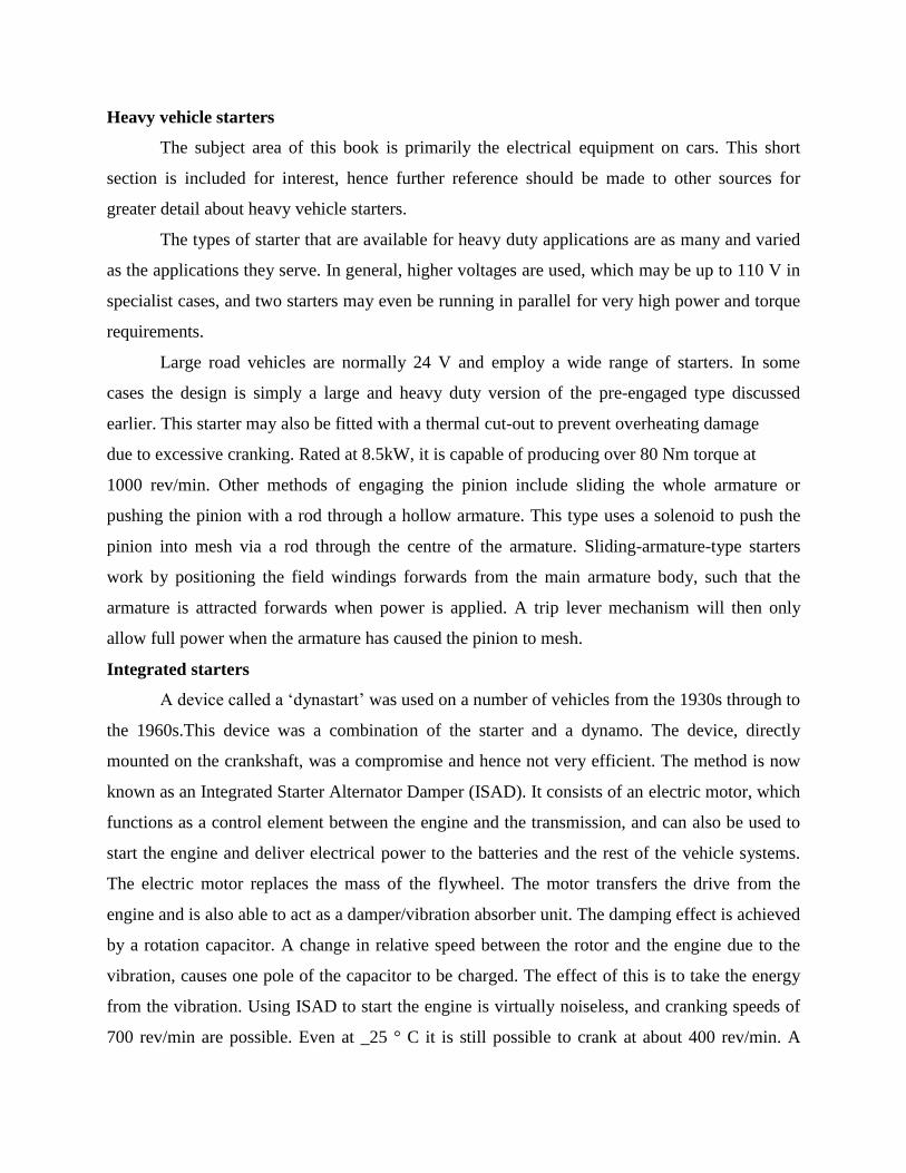
Regulation of output voltage
To prevent the vehicle battery from being overcharged the regulated system voltage
should be kept below the gassing voltage of the lead-acid battery. A figure of 14.2 +/- 0.2 V is
used for all 12 V charging systems. Accurate voltage control is vital with the ever-increasing use
of electronic systems. It has also enabled the wider use of sealed batteries, as the possibility of
over-charging is minimal. Figure 6.15 shows two common voltage regulators. Voltage regulation
is a difficult task on a vehicle alternator because of the constantly changing engine speed and
loads on the alternator. The output of an alternator without regulation would rise linearly in
proportion with engine speed. Alternator output is also proportional to magnetic field strength
and this, in turn, is proportional to the field current. It is the task of the regulator to control this
field current in response to alternator output voltage. Figure 6.16 shows a flow chart which
represents the action of the
regulator, showing how the field
current is switched off as output
voltage increases and then back on
again as output voltage falls. The
abrupt switching of the field current
does not cause abrupt changes in
output voltage due to the very high
inductance of the field (rotor)
windings. In addition, the whole
switching process only takes a few
milliseconds. Many regulators also
incorporate some temperature compensation
to allow
a higher charge rate in colder conditions and
to reduce the rate in hot conditions.
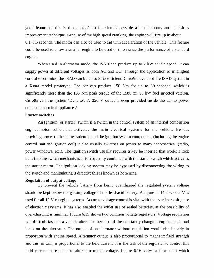
When working with regulator circuits, care must be taken to note ‘where’ the field circuit
is interrupted. For example, some alternator circuits supply a constant feed to the field windings
from the excitation diodes and the regulator switches the earth side. In other systems, one side of
the field windings is will switch off, allowing T2 to switch back on and so the cycle will
continue. The conventional diode, D1, absorbs the back EMF from the field windings and so
prevents damage to the other components. Electronic regulators can be made to sense either the
battery voltage, the machine voltage (alternator), or a combination of the two. Most systems in
use at present tend to be machine sensed as this offers some protection against over-voltage in
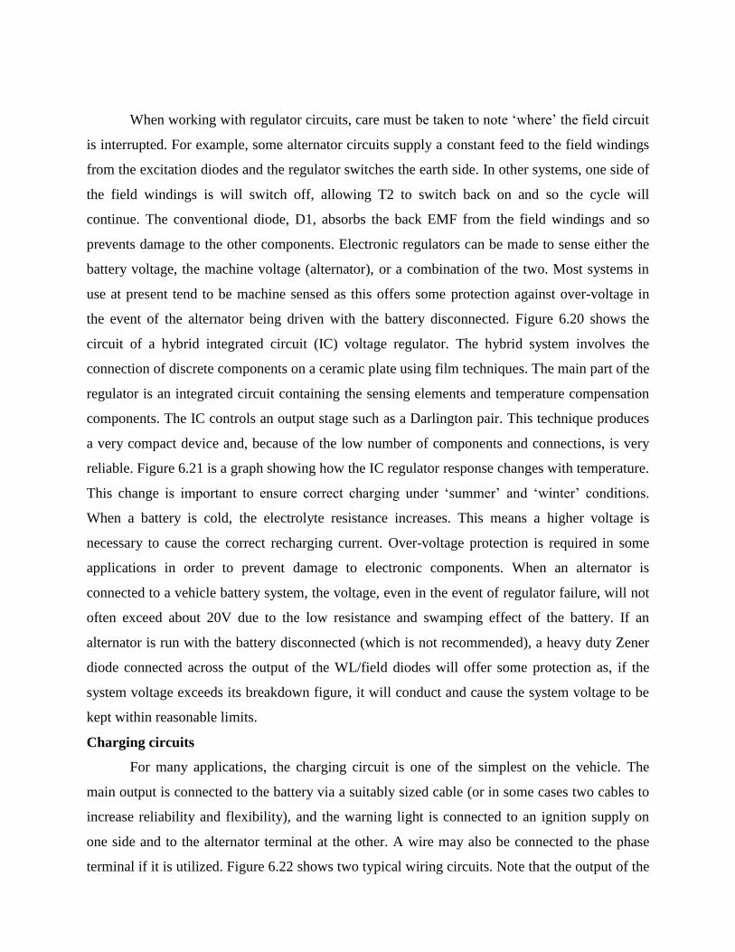
the event of the alternator being driven with the battery disconnected. Figure 6.20 shows the
circuit of a hybrid integrated circuit (IC) voltage regulator. The hybrid system involves the
connection of discrete components on a ceramic plate using film techniques. The main part of the
regulator is an integrated circuit containing the sensing elements and temperature compensation
components. The IC controls an output stage such as a Darlington pair. This technique produces
a very compact device and, because of the low number of components and connections, is very
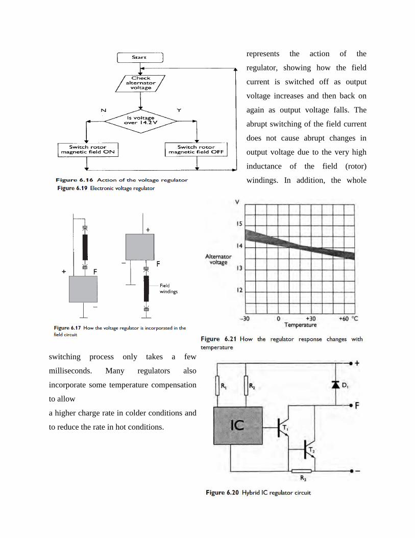
reliable. Figure 6.21 is a graph showing how the IC regulator response changes with temperature.
This change is important to ensure correct charging under ‘summer’ and ‘winter’ conditions.
When a battery is cold, the electrolyte resistance increases. This means a higher voltage is
necessary to cause the correct recharging current. Over-voltage protection is required in some
applications in order to prevent damage to electronic components. When an alternator is
connected to a vehicle battery system, the voltage, even in the event of regulator failure, will not
often exceed about 20V due to the low resistance and swamping effect of the battery. If an
alternator is run with the battery disconnected (which is not recommended), a heavy duty Zener
diode connected across the output of the WL/field diodes will offer some protection as, if the
system voltage exceeds its breakdown figure, it will conduct and cause the system voltage to be
kept within reasonable limits.
Charging circuits
For many applications, the charging circuit is one of the simplest on the vehicle. The
main output is connected to the battery via a suitably sized cable (or in some cases two cables to
increase reliability and flexibility), and the warning light is connected to an ignition supply on
one side and to the alternator terminal at the other. A wire may also be connected to the phase
terminal if it is utilized. Figure 6.22 shows two typical wiring circuits. Note that the output of the
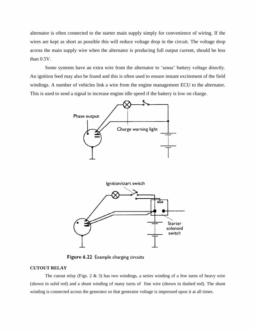
alternator is often connected to the starter main supply simply for convenience of wiring. If the
wires are kept as short as possible this will reduce voltage drop in the circuit. The voltage drop
across the main supply wire when the alternator is producing full output current, should be less
than 0.5V.
Some systems have an extra wire from the alternator to ‘sense’ battery voltage directly.
An ignition feed may also be found and this is often used to ensure instant excitement of the field
windings. A number of vehicles link a wire from the engine management ECU to the alternator.
This is used to send a signal to increase engine idle speed if the battery is low on charge.
CUTOUT RELAY
The cutout relay (Figs. 2 & 3) has two windings, a series winding of a few turns of heavy wire
(shown in solid red) and a shunt winding of many turns of fine wire (shown in dashed red). The shunt
winding is connected across the generator so that generator voltage is impressed upon it at all times.
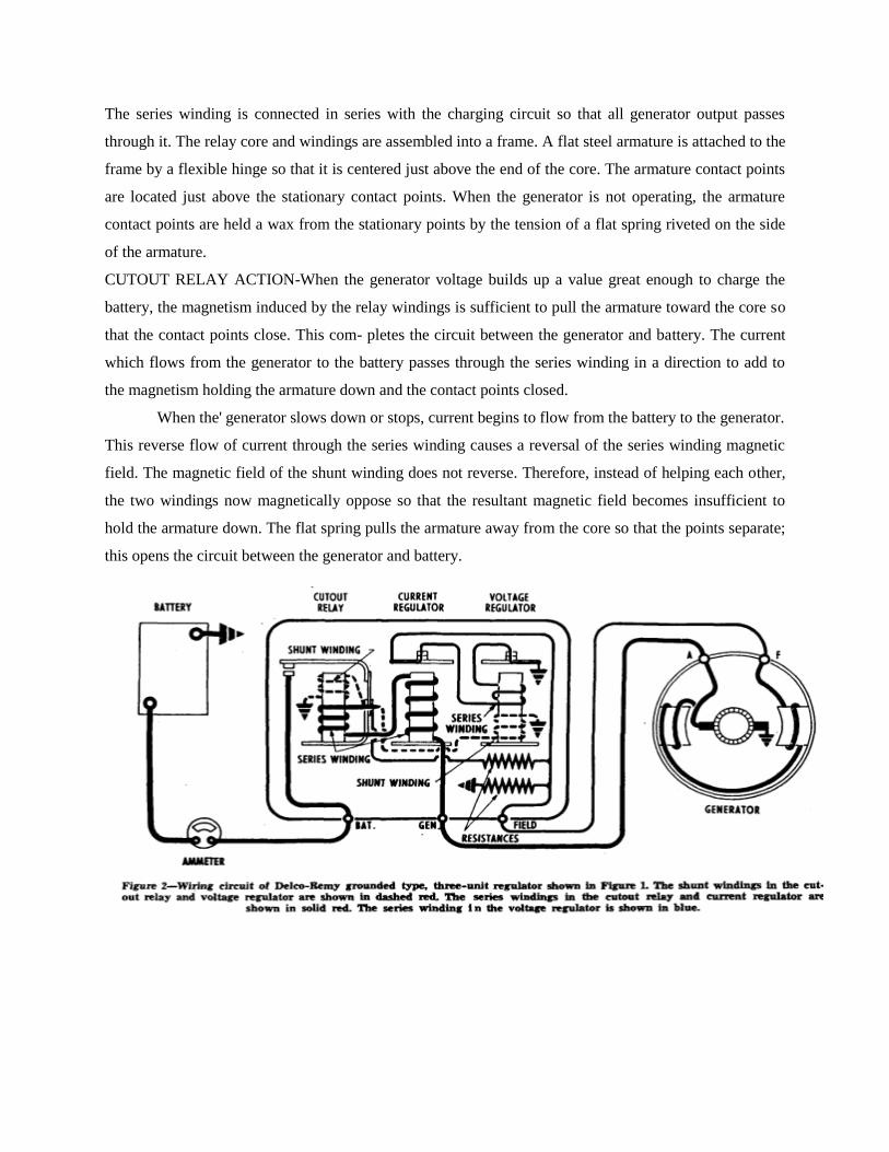
The series winding is connected in series with the charging circuit so that all generator output passes
through it. The relay core and windings are assembled into a frame. A flat steel armature is attached to the
frame by a flexible hinge so that it is centered just above the end of the core. The armature contact points
are located just above the stationary contact points. When the generator is not operating, the armature
contact points are held a wax from the stationary points by the tension of a flat spring riveted on the side
of the armature.
CUTOUT RELAY ACTION-When the generator voltage builds up a value great enough to charge the
battery, the magnetism induced by the relay windings is sufficient to pull the armature toward the core so
that the contact points close. This com- pletes the circuit between the generator and battery. The current
which flows from the generator to the battery passes through the series winding in a direction to add to
the magnetism holding the armature down and the contact points closed.
When the' generator slows down or stops, current begins to flow from the battery to the generator.
This reverse flow of current through the series winding causes a reversal of the series winding magnetic
field. The magnetic field of the shunt winding does not reverse. Therefore, instead of helping each other,
the two windings now magnetically oppose so that the resultant magnetic field becomes insufficient to
hold the armature down. The flat spring pulls the armature away from the core so that the points separate;
this opens the circuit between the generator and battery.
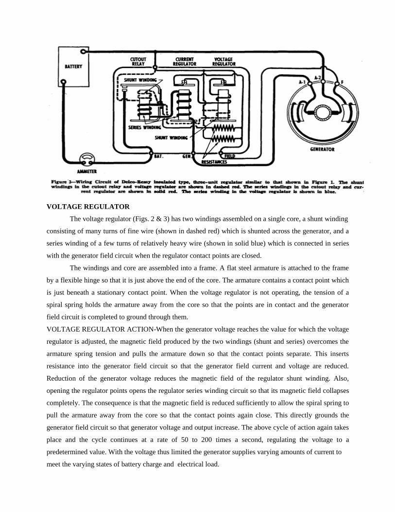
VOLTAGE REGULATOR
The voltage regulator (Figs. 2 & 3) has two windings assembled on a single core, a shunt winding
consisting of many turns of fine wire (shown in dashed red) which is shunted across the generator, and a
series winding of a few turns of relatively heavy wire (shown in solid blue) which is connected in series
with the generator field circuit when the regulator contact points are closed.
The windings and core are assembled into a frame. A flat steel armature is attached to the frame
by a flexible hinge so that it is just above the end of the core. The armature contains a contact point which
is just beneath a stationary contact point. When the voltage regulator is not operating, the tension of a
spiral spring holds the armature away from the core so that the points are in contact and the generator
field circuit is completed to ground through them.
VOLTAGE REGULATOR ACTION-When the generator voltage reaches the value for which the voltage
regulator is adjusted, the magnetic field produced by the two windings (shunt and series) overcomes the
armature spring tension and pulls the armature down so that the contact points separate. This inserts
resistance into the generator field circuit so that the generator field current and voltage are reduced.
Reduction of the generator voltage reduces the magnetic field of the regulator shunt winding. Also,
opening the regulator points opens the regulator series winding circuit so that its magnetic field collapses
completely. The consequence is that the magnetic field is reduced sufficiently to allow the spiral spring to
pull the armature away from the core so that the contact points again close. This directly grounds the
generator field circuit so that generator voltage and output increase. The above cycle of action again takes
place and the cycle continues at a rate of 50 to 200 times a second, regulating the voltage to a
predetermined value. With the voltage thus limited the generator supplies varying amounts of current to
meet the varying states of battery charge and electrical load.
Solenoid
A solenoid is simply a specially designed electromagnet. A solenoid usually consists of a
cylindrical coil wound with one or more layers of insulated wire and a movable iron core called
the armature. When current flows through a wire, a magnetic field is set up around the wire. If
we make a coil of many turns of wire, this magnetic field becomes many times stronger, flowing
around the coil and through its center in a doughnut shape. The length of the solenoid is much
larger in comparison with its diameter. When the coil of the solenoid is energized with current,
the core moves to increase the flux linkage by closing the air gap between the cores. The
movable core is usually spring-loaded to allow the core to retract when the current is switched
off. The force generated is approximately proportional to the square of the current and inversely
proportional to the square of the length of the air gap.
Solenoids are inexpensive, and their use is primarily limited to on-off applications such
as latching, locking, and triggering. They are frequently used in home appliances (e.g. washing
machine valves), office equipment (e.g. copy machines), automobiles (e.g. door latches and the
starter solenoid), pinball machines (e.g., plungers and bumpers), and factory automation.
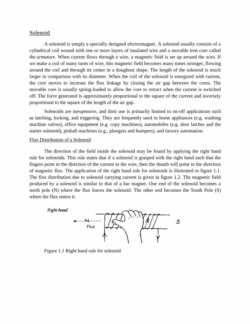
Flux Distribution of a Solenoid
The direction of the field inside the solenoid may be found by applying the right hand
rule for solenoids. This rule states that if a solenoid is grasped with the right hand such that the
fingers point in the direction of the current in the wire, then the thumb will point in the direction
of magnetic flux. The application of the right hand rule for solenoids is illustrated in figure 1.1.
The flux distribution due to solenoid carrying current is given in figure 1.2. The magnetic field
produced by a solenoid is similar to that of a bar magnet. One end of the solenoid becomes a
north pole (N) where the flux leaves the solenoid. The other end becomes the South Pole (S)
where the flux enters it.
Figure 1.1 Right hand rule for solenoid
Flux
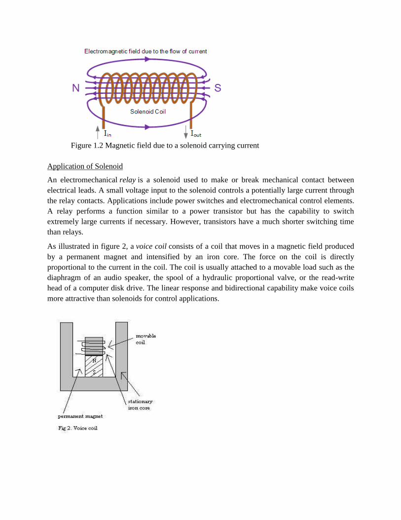
Figure 1.2 Magnetic field due to a solenoid carrying current
Application of Solenoid
An electromechanical relay is a solenoid used to make or break mechanical contact between
electrical leads. A small voltage input to the solenoid controls a potentially large current through
the relay contacts. Applications include power switches and electromechanical control elements.
A relay performs a function similar to a power transistor but has the capability to switch
extremely large currents if necessary. However, transistors have a much shorter switching time
than relays.
As illustrated in figure 2, a voice coil consists of a coil that moves in a magnetic field produced
by a permanent magnet and intensified by an iron core. The force on the coil is directly
proportional to the current in the coil. The coil is usually attached to a movable load such as the
diaphragm of an audio speaker, the spool of a hydraulic proportional valve, or the read-write
head of a computer disk drive. The linear response and bidirectional capability make voice coils
more attractive than solenoids for control applications.
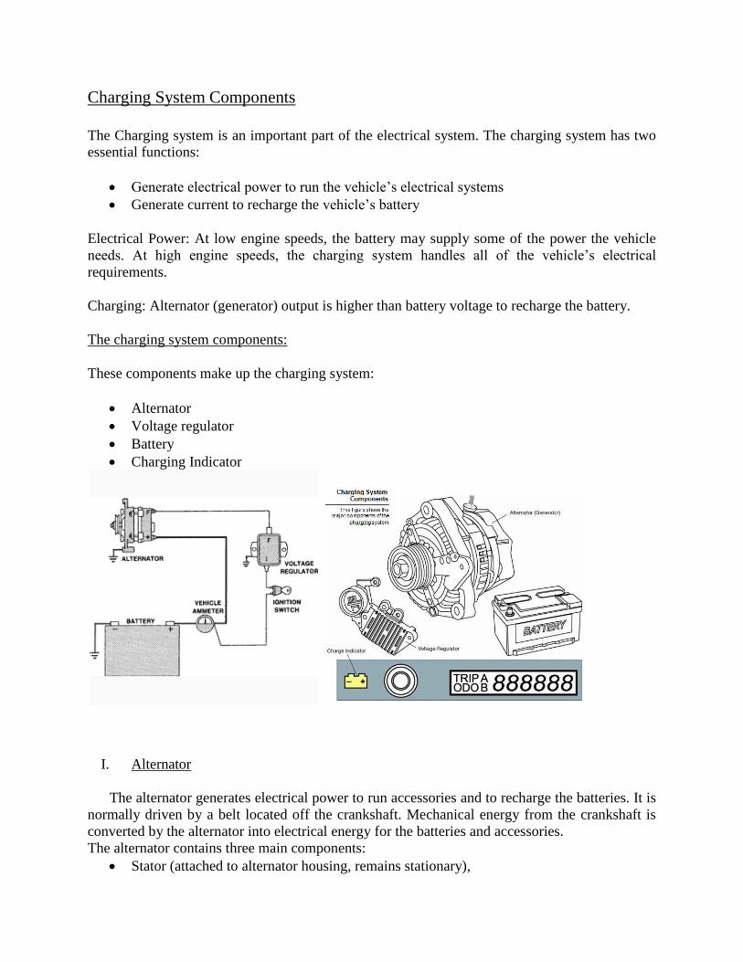
Charging System Components
The Charging system is an important part of the electrical system. The charging system has two
essential functions:
Generate electrical power to run the vehicle’s electrical systems
Generate current to recharge the vehicle’s battery
Electrical Power: At low engine speeds, the battery may supply some of the power the vehicle
needs. At high engine speeds, the charging system handles all of the vehicle’s electrical
requirements.
Charging: Alternator (generator) output is higher than battery voltage to recharge the battery.
The charging system components:
These components make up the charging system:
Alternator
Voltage regulator
Battery
Charging Indicator
I. Alternator
The alternator generates electrical power to run accessories and to recharge the batteries. It is
normally driven by a belt located off the crankshaft. Mechanical energy from the crankshaft is
converted by the alternator into electrical energy for the batteries and accessories.
The alternator contains three main components:
Stator (attached to alternator housing, remains stationary),
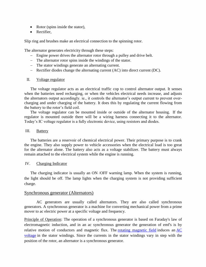
Rotor (spins inside the stator),
Rectifier,
Slip ring and brushes make an electrical connection to the spinning rotor.
The alternator generates electricity through these steps:
Engine power drives the alternator rotor through a pulley and drive belt.
The alternator rotor spins inside the windings of the stator.
The stator windings generate an alternating current.
Rectifier diodes change the alternating current (AC) into direct current (DC).
II. Voltage regulator
The voltage regulator acts as an electrical traffic cop to control alternator output. It senses
when the batteries need recharging, or when the vehicles electrical needs increase, and adjusts
the alternators output accordingly. ie., it controls the alternator’s output current to prevent over-
charging and under charging of the battery. It does this by regulating the current flowing from
the battery to the rotor’s field coil.
The voltage regulator can be mounted inside or outside of the alternator housing. If the
regulator is mounted outside there will be a wiring harness connecting it to the alternator.
Today’s IC voltage regulator is a fully electronic device, using resistors and diodes.
III. Battery
The batteries are a reservoir of chemical electrical power. Their primary purpose is to crank
the engine. They also supply power to vehicle accessories when the electrical load is too great
for the alternator alone. The battery also acts as a voltage stabilizer. The battery must always
remain attached to the electrical system while the engine is running.
IV. Charging Indicator
The charging indicator is usually an ON /OFF warning lamp. When the system is running,
the light should be off. The lamp lights when the charging system is not providing sufficient
charge.
Synchronous generator (Alternators)
AC generators are usually called alternators. They are also called synchronous
generators. A synchronous generator is a machine for converting mechanical power from a prime
mover to ac electric power at a specific voltage and frequency.
Principle of Operation: The operation of a synchronous generator is based on Faraday's law of
electromagnetic induction, and in an ac synchronous generator the generation of emf's is by
relative motion of conductors and magnetic flux. The rotating magnetic field induces an AC
voltage in the stator windings. Since the currents in the stator windings vary in step with the
position of the rotor, an alternator is a synchronous generator.
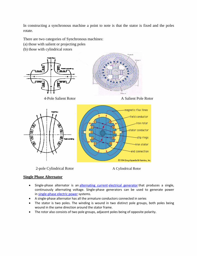
In constructing a synchronous machine a point to note is that the stator is fixed and the poles
rotate.
There are two categories of Synchronous machines:
(a) those with salient or projecting poles
(b) those with cylindrical rotors
4-Pole Salient Rotor A Salient Pole Rotor
2-pole Cylindrical Rotor A Cylindrical Rotor
Single Phase Alternator
Single-phase alternator is an alternating current electrical generator that produces a single, continuously alternating voltage. Single-phase generators can be used to generate power in single-phase electric power systems.
A single-phase alternator has all the armature conductors connected in series
The stator is two poles. The winding is wound in two distinct pole groups, both poles being wound in the same direction around the stator frame.
The rotor also consists of two pole groups, adjacent poles being of opposite polarity.
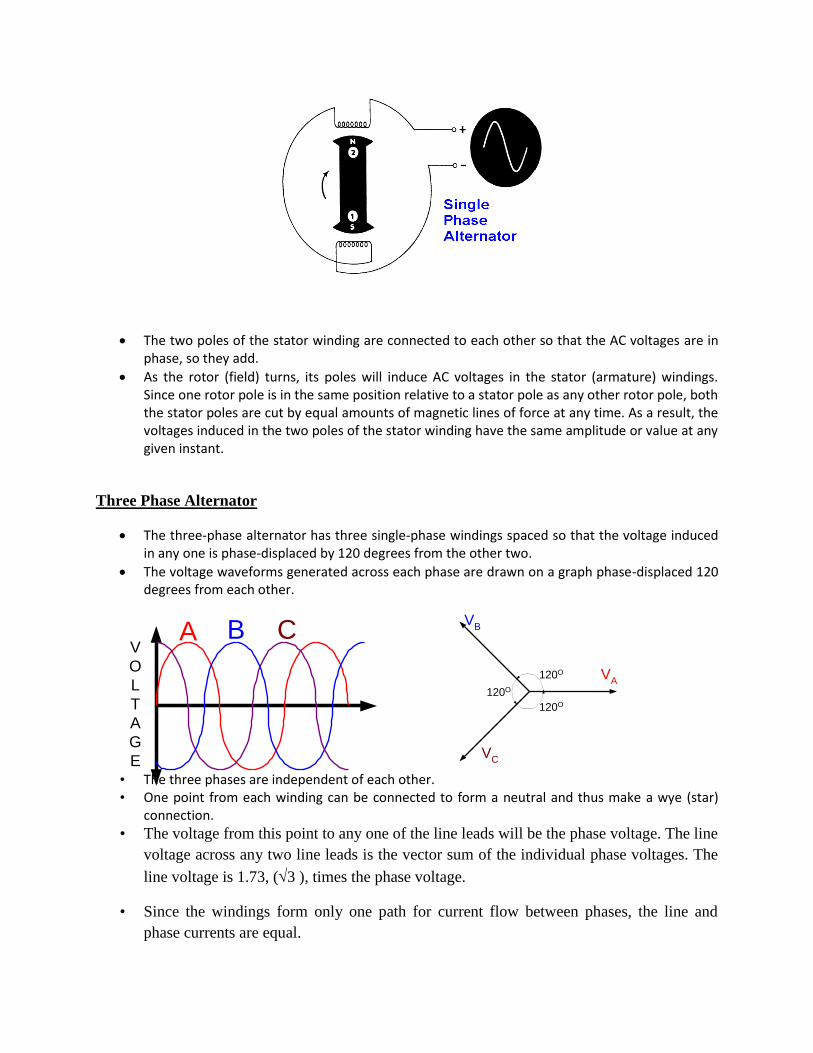
The two poles of the stator winding are connected to each other so that the AC voltages are in phase, so they add.
As the rotor (field) turns, its poles will induce AC voltages in the stator (armature) windings. Since one rotor pole is in the same position relative to a stator pole as any other rotor pole, both the stator poles are cut by equal amounts of magnetic lines of force at any time. As a result, the voltages induced in the two poles of the stator winding have the same amplitude or value at any given instant.
Three Phase Alternator
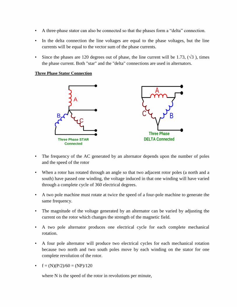
The three-phase alternator has three single-phase windings spaced so that the voltage induced in any one is phase-displaced by 120 degrees from the other two.
The voltage waveforms generated across each phase are drawn on a graph phase-displaced 120 degrees from each other.
• The three phases are independent of each other. • One point from each winding can be connected to form a neutral and thus make a wye (star)
connection.
• The voltage from this point to any one of the line leads will be the phase voltage. The line
voltage across any two line leads is the vector sum of the individual phase voltages. The
line voltage is 1.73, (3 ), times the phase voltage.
• Since the windings form only one path for current flow between phases, the line and
phase currents are equal.
A B CV
O
L
T
A
G
E
120O
120O
120O
VA
VB
VC
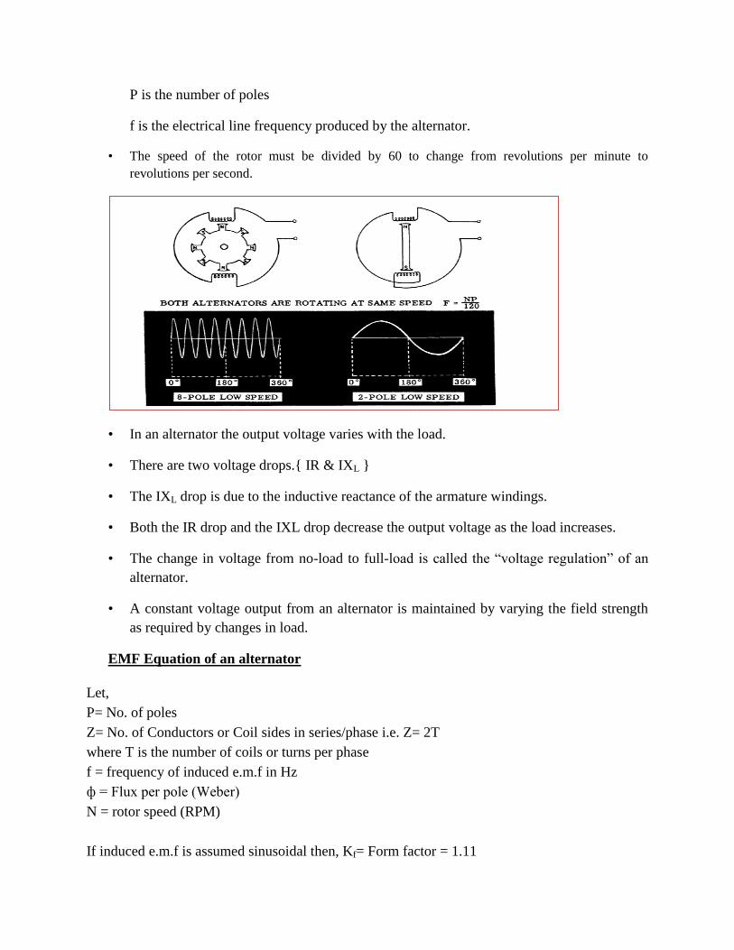
• A three-phase stator can also be connected so that the phases form a “delta” connection.
• In the delta connection the line voltages are equal to the phase voltages, but the line
currents will be equal to the vector sum of the phase currents.
• Since the phases are 120 degrees out of phase, the line current will be 1.73, (3 ), times
the phase current. Both "star" and the "delta" connections are used in alternators.
Three Phase Stator Connection
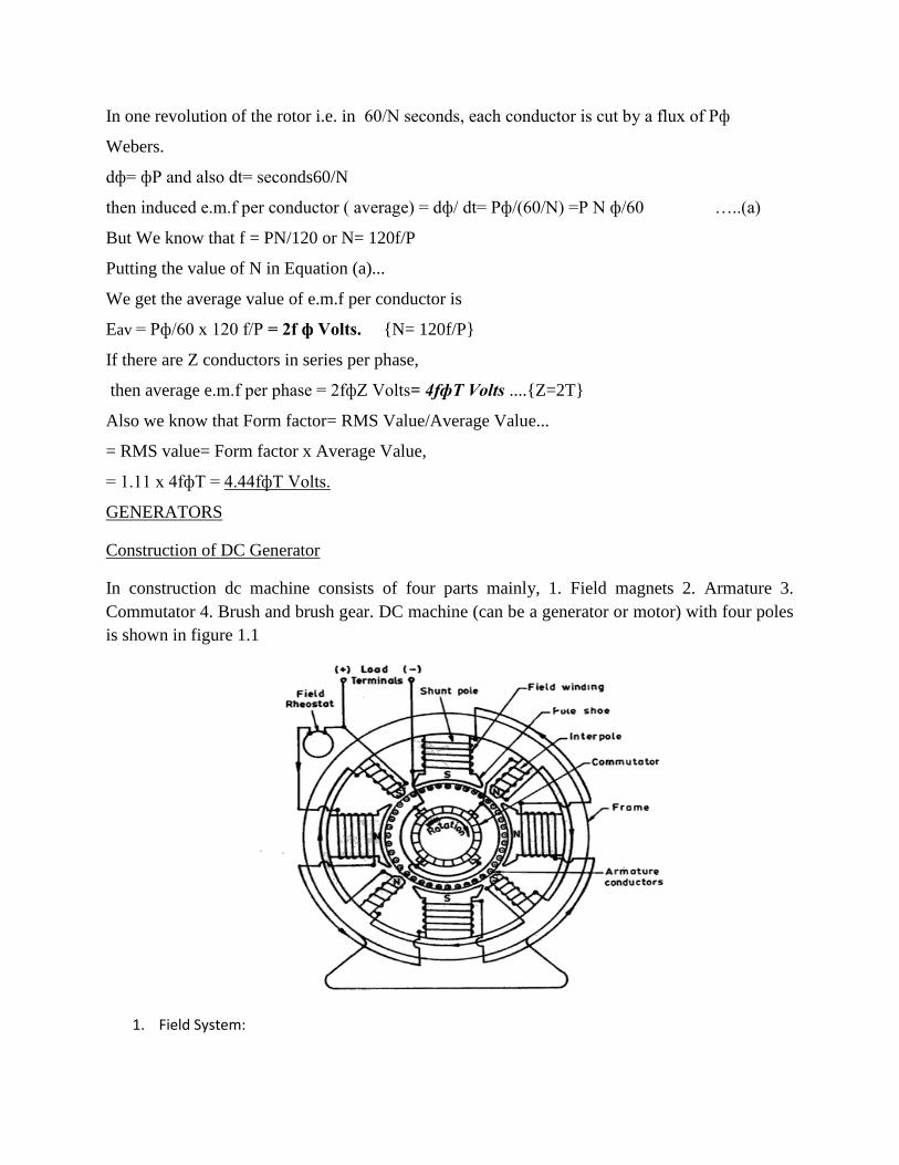
• The frequency of the AC generated by an alternator depends upon the number of poles
and the speed of the rotor
• When a rotor has rotated through an angle so that two adjacent rotor poles (a north and a
south) have passed one winding, the voltage induced in that one winding will have varied
through a complete cycle of 360 electrical degrees.
• A two pole machine must rotate at twice the speed of a four-pole machine to generate the
same frequency.
• The magnitude of the voltage generated by an alternator can be varied by adjusting the
current on the rotor which changes the strength of the magnetic field.
• A two pole alternator produces one electrical cycle for each complete mechanical
rotation.
• A four pole alternator will produce two electrical cycles for each mechanical rotation
because two north and two south poles move by each winding on the stator for one
complete revolution of the rotor.
• f = (N)(P/2)/60 = (NP)/120
where N is the speed of the rotor in revolutions per minute,
A
BC
Three Phase STAR
Connected
A
BC
Three Phase
DELTA Connected
P is the number of poles
f is the electrical line frequency produced by the alternator.
• The speed of the rotor must be divided by 60 to change from revolutions per minute to
revolutions per second.
• In an alternator the output voltage varies with the load.
• There are two voltage drops.{ IR & IXL }
• The IXL drop is due to the inductive reactance of the armature windings.
• Both the IR drop and the IXL drop decrease the output voltage as the load increases.
• The change in voltage from no-load to full-load is called the “voltage regulation” of an
alternator.
• A constant voltage output from an alternator is maintained by varying the field strength
as required by changes in load.
EMF Equation of an alternator
Let,
P= No. of poles
Z= No. of Conductors or Coil sides in series/phase i.e. Z= 2T
where T is the number of coils or turns per phase
f = frequency of induced e.m.f in Hz
ф = Flux per pole (Weber)
N = rotor speed (RPM)
If induced e.m.f is assumed sinusoidal then, Kf= Form factor = 1.11
In one revolution of the rotor i.e. in 60/N seconds, each conductor is cut by a flux of Pф
Webers.
dф= фP and also dt= seconds60/N
then induced e.m.f per conductor ( average) = dф/ dt= Pф/(60/N) =P N ф/60 …..(a)
But We know that f = PN/120 or N= 120f/P
Putting the value of N in Equation (a)...
We get the average value of e.m.f per conductor is
Eav = Pф/60 x 120 f/P = 2f ф Volts. {N= 120f/P}
If there are Z conductors in series per phase,
then average e.m.f per phase = 2fфZ Volts= 4fфT Volts ....{Z=2T}
Also we know that Form factor= RMS Value/Average Value...
= RMS value= Form factor x Average Value,
= 1.11 x 4fфT = 4.44fфT Volts.
GENERATORS
Construction of DC Generator
In construction dc machine consists of four parts mainly, 1. Field magnets 2. Armature 3.
Commutator 4. Brush and brush gear. DC machine (can be a generator or motor) with four poles
is shown in figure 1.1
1. Field System:
The object of the field system is to create a uniform magnetic field within with the armature
rotates. Electromagnets are preferred on the account of their magnetic effects and field strength
regulation which can be achieved by controlling the magnetizing current. Field magnets consist
of the following parts:
(i)Yoke or Frame (ii) Pole cores (iii) Pole shoes (iv) Magnetizing coils
Cylindrical yoke is usually used which acts as a frame of the machine and carries the
magnetic flux produced by the poles. Since the field is stationary there is no need to use
laminated yoke for normal machine. In small machines, cast iron yokes are used because of its
cheapness but yoke of large machines are made of fabricated steel due to its high permeability.
Pole core is usually of circular section and is used to carry the coils of insulated wires carrying
the exciting current. Pole cores are usually not laminated and made of cast steel.
Each pole core has a pole shoe serves having a curved surface. The pole shoe serves two
purposes:
(i) It supports the field coils
(ii) It increases the cross-sectional area of the magnetic circuit and reduces its reluctance.
Each pole core has one or more field coils or magnetizing coils placed over it to produce a
magnetic field. The field coils are connected in series with one another such that when the
current flows through the coils, alternate north and south poles are produced in the direction of
rotation.
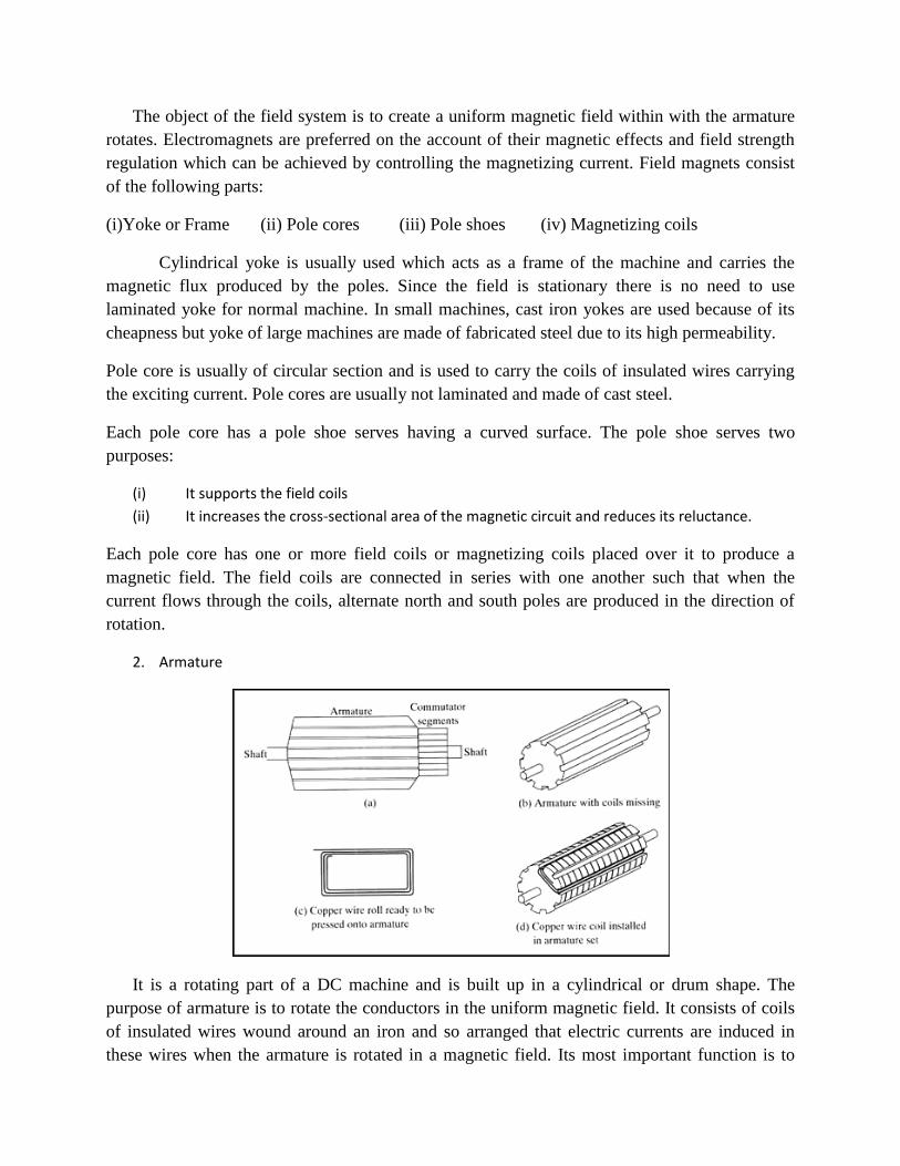
2. Armature
It is a rotating part of a DC machine and is built up in a cylindrical or drum shape. The
purpose of armature is to rotate the conductors in the uniform magnetic field. It consists of coils
of insulated wires wound around an iron and so arranged that electric currents are induced in
these wires when the armature is rotated in a magnetic field. Its most important function is to
provide a path of low reluctance to the magnetic flux. The armature core is made of high
permeability silicon-steel stampings.
3. Commutator:
It is a form of rotating switch. They are placed between armature and external circuit. The
commutator will reverse the connections to the external circuit at the instant aech reversal of
circuit in the armature coil.
4. Brushes & Bearings
Brushes are made of carbon or graphite. It collects current from the commutator and convey it to
external load resistance. It is rectangular in shape. Brushes are housed in brush holders and
mounted over brush holder studs. Ball bearings are used as they are reliable for light
machines.For heavy machines roller bearings are used.
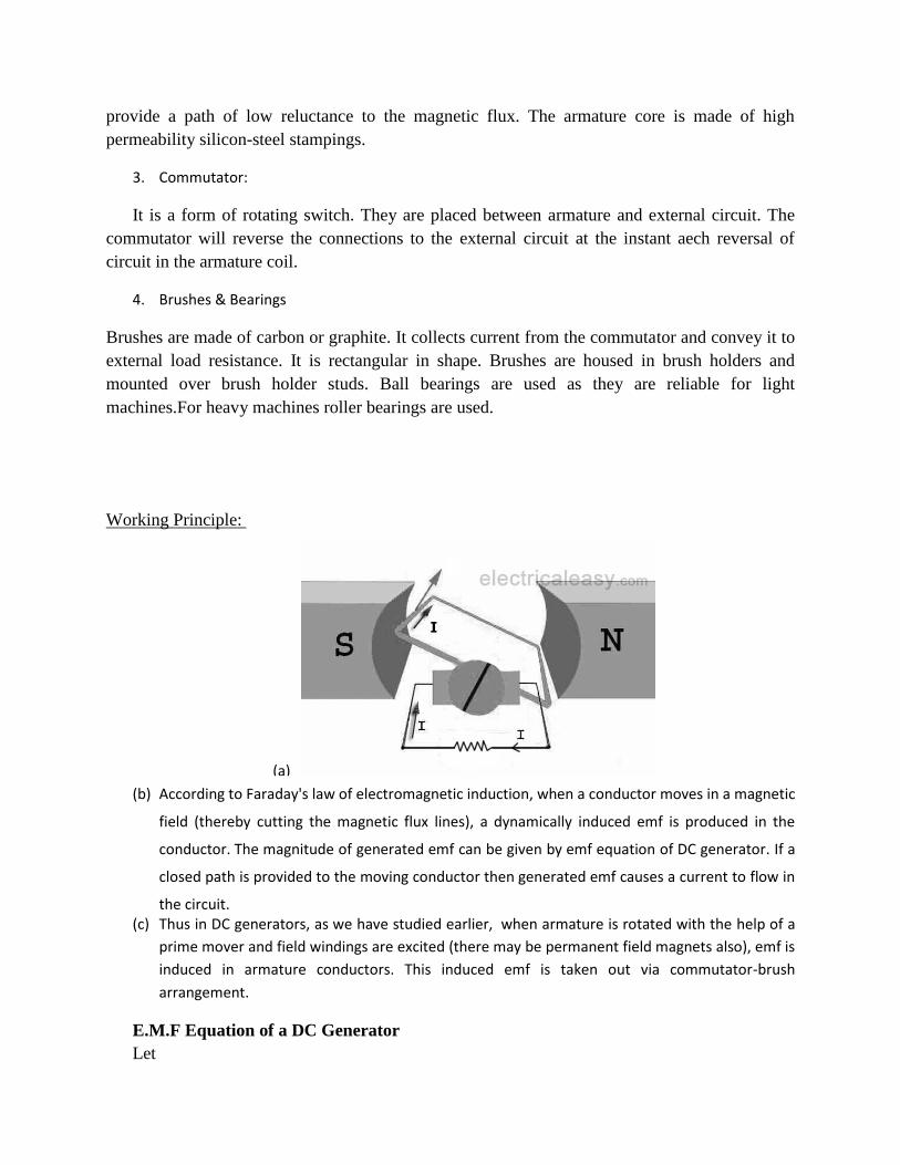
Working Principle:
(a)
(b) According to Faraday's law of electromagnetic induction, when a conductor moves in a magnetic
field (thereby cutting the magnetic flux lines), a dynamically induced emf is produced in the
conductor. The magnitude of generated emf can be given by emf equation of DC generator. If a
closed path is provided to the moving conductor then generated emf causes a current to flow in
the circuit. (c) Thus in DC generators, as we have studied earlier, when armature is rotated with the help of a
prime mover and field windings are excited (there may be permanent field magnets also), emf is
induced in armature conductors. This induced emf is taken out via commutator-brush
arrangement.
E.M.F Equation of a DC Generator
Let
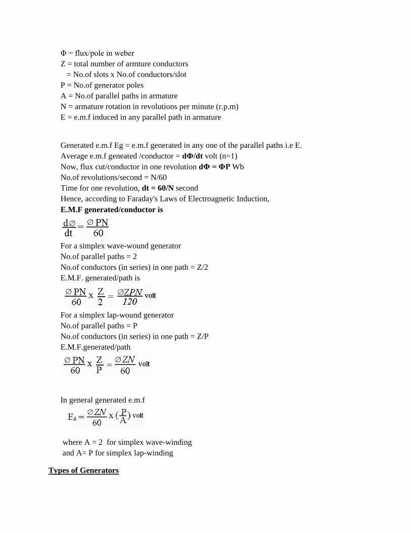
Φ = flux/pole in weber
Z = total number of armture conductors
= No.of slots x No.of conductors/slot
P = No.of generator poles
A = No.of parallel paths in armature
N = armature rotation in revolutions per minute (r.p.m)
E = e.m.f induced in any parallel path in armature
Generated e.m.f Eg = e.m.f generated in any one of the parallel paths i.e E.
Average e.m.f geneated /conductor = dΦ/dt volt (n=1)
Now, flux cut/conductor in one revolution dΦ = ΦP Wb
No.of revolutions/second = N/60
Time for one revolution, dt = 60/N second
Hence, according to Faraday's Laws of Electroagnetic Induction,
E.M.F generated/conductor is
For a simplex wave-wound generator
No.of parallel paths = 2
No.of conductors (in series) in one path = Z/2
E.M.F. generated/path is
For a simplex lap-wound generator
No.of parallel paths = P
No.of conductors (in series) in one path = Z/P
E.M.F.generated/path
In general generated e.m.f
where A = 2 for simplex wave-winding
and A= P for simplex lap-winding
Types of Generators
Generators are usually classified according to the way in which their fields are excited.The
field windings provide the excitation necessary to set up the magnetic fields in the machine.
There are various types of field windings that can be used in the generator or motor circuit. In
addition to the following field winding types, permanent magnet fields are used on some smaller
DC products.
Generators may be divided in to
(a) Separately-excited generators
(b) Self-excited generators.
Separately-excited generators are those whoe field magnets are energised from an independent
external source of DC current.
Self-excited generators are those whose field magnets are energused by the current produced by
the generators themselves.Due to residual magnetism, there is always present someflux in the
poles.When the armature is rotated, some e.m.f and hence some induced current is produced
which is partly or fully passed through the field coils thereby strengthening the residual pole
flux.
Self-excited generators are classed according to the type of field connection they use. There are
three general types of field connections —
SERIES-WOUND, SHUNT-WOUND (parallel), and COMPOUND-WOUND.
Compound-wound generators are further classified as cumulative-compound and differential-
compound.
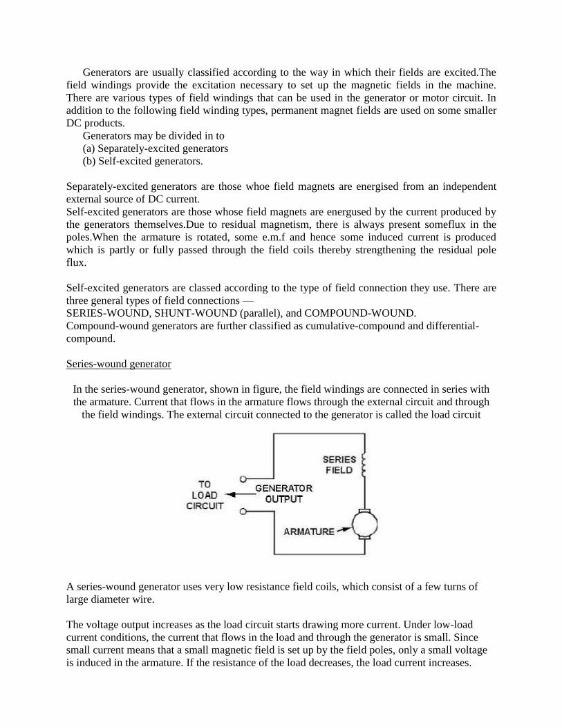
Series-wound generator
In the series-wound generator, shown in figure, the field windings are connected in series with
the armature. Current that flows in the armature flows through the external circuit and through
the field windings. The external circuit connected to the generator is called the load circuit
A series-wound generator uses very low resistance field coils, which consist of a few turns of
large diameter wire.
The voltage output increases as the load circuit starts drawing more current. Under low-load
current conditions, the current that flows in the load and through the generator is small. Since
small current means that a small magnetic field is set up by the field poles, only a small voltage
is induced in the armature. If the resistance of the load decreases, the load current increases.
Under this condition, more current flows through the field. This increases the magnetic field and
increases the output voltage. A series-wound dc generator has the characteristic that the output
voltage varies with load current. This is undesirable in most applications. For this reason, this
type of generator is rarely used in everyday practice.
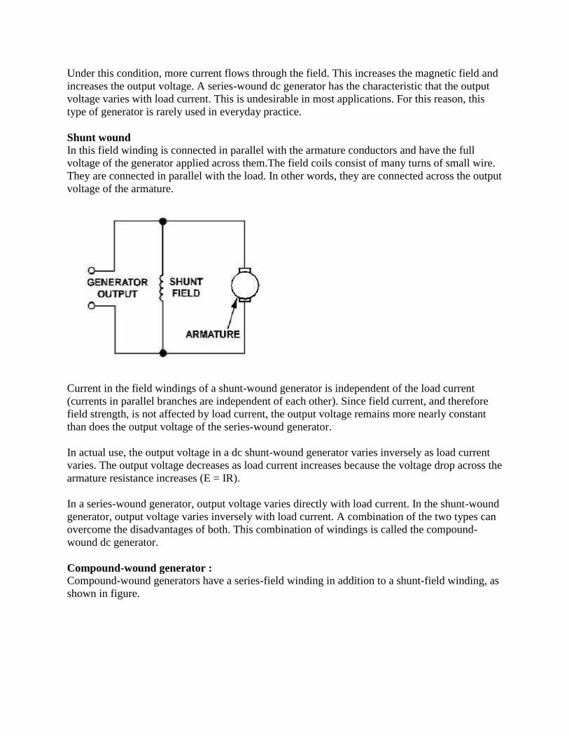
Shunt wound In this field winding is connected in parallel with the armature conductors and have the full
voltage of the generator applied across them.The field coils consist of many turns of small wire.
They are connected in parallel with the load. In other words, they are connected across the output
voltage of the armature.
Current in the field windings of a shunt-wound generator is independent of the load current
(currents in parallel branches are independent of each other). Since field current, and therefore
field strength, is not affected by load current, the output voltage remains more nearly constant
than does the output voltage of the series-wound generator.
In actual use, the output voltage in a dc shunt-wound generator varies inversely as load current
varies. The output voltage decreases as load current increases because the voltage drop across the
armature resistance increases (E = IR).
In a series-wound generator, output voltage varies directly with load current. In the shunt-wound
generator, output voltage varies inversely with load current. A combination of the two types can
overcome the disadvantages of both. This combination of windings is called the compound-
wound dc generator.
Compound-wound generator : Compound-wound generators have a series-field winding in addition to a shunt-field winding, as
shown in figure.
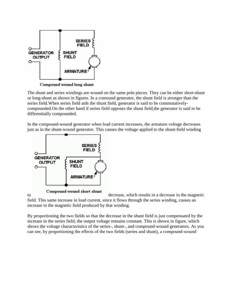
The shunt and series windings are wound on the same pole pieces. They can be either short-shunt
or long-shunt as shown in figures. In a comound generator, the shunt field is stronger than the
series field.When series field aids the shunt field, generator is said to be commutatively-
compounded.On the other hand if series field opposes the shunt field,the generator is said to be
differentially compounded.
In the compound-wound generator when load current increases, the armature voltage decreases
just as in the shunt-wound generator. This causes the voltage applied to the shunt-field winding
to decrease, which results in a decrease in the magnetic
field. This same increase in load current, since it flows through the series winding, causes an
increase in the magnetic field produced by that winding.
By proportioning the two fields so that the decrease in the shunt field is just compensated by the
increase in the series field, the output voltage remains constant. This is shown in figure, which
shows the voltage characteristics of the series-, shunt-, and compound-wound generators. As you
can see, by proportioning the effects of the two fields (series and shunt), a compound-wound
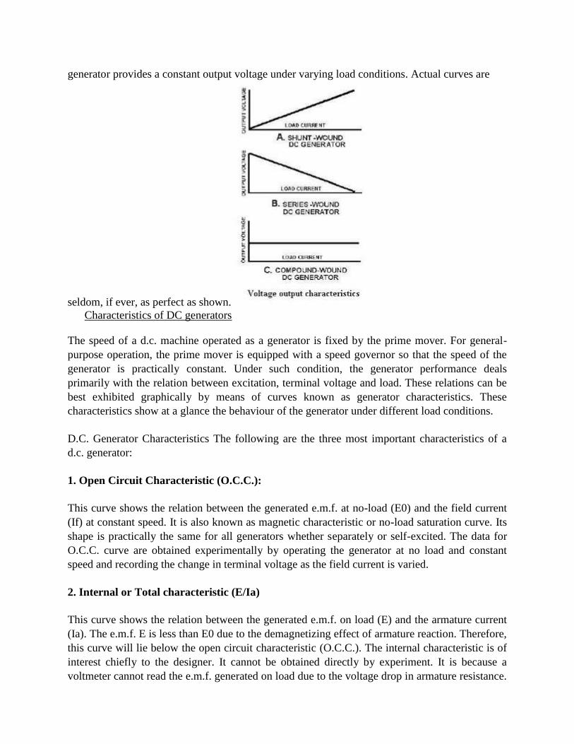
generator provides a constant output voltage under varying load conditions. Actual curves are
seldom, if ever, as perfect as shown.
Characteristics of DC generators
The speed of a d.c. machine operated as a generator is fixed by the prime mover. For general-
purpose operation, the prime mover is equipped with a speed governor so that the speed of the
generator is practically constant. Under such condition, the generator performance deals
primarily with the relation between excitation, terminal voltage and load. These relations can be
best exhibited graphically by means of curves known as generator characteristics. These
characteristics show at a glance the behaviour of the generator under different load conditions.
D.C. Generator Characteristics The following are the three most important characteristics of a
d.c. generator:
1. Open Circuit Characteristic (O.C.C.):
This curve shows the relation between the generated e.m.f. at no-load (E0) and the field current
(If) at constant speed. It is also known as magnetic characteristic or no-load saturation curve. Its
shape is practically the same for all generators whether separately or self-excited. The data for
O.C.C. curve are obtained experimentally by operating the generator at no load and constant
speed and recording the change in terminal voltage as the field current is varied.
2. Internal or Total characteristic (E/Ia)
This curve shows the relation between the generated e.m.f. on load (E) and the armature current
(Ia). The e.m.f. E is less than E0 due to the demagnetizing effect of armature reaction. Therefore,
this curve will lie below the open circuit characteristic (O.C.C.). The internal characteristic is of
interest chiefly to the designer. It cannot be obtained directly by experiment. It is because a
voltmeter cannot read the e.m.f. generated on load due to the voltage drop in armature resistance.
The internal characteristic can be obtained from external characteristic if winding resistances are
known because armature reaction effect is included in both characteristics
3. External characteristic (V/IL):
This curve shows the relation between the terminal voltage (V) and load current (IL). The
terminal voltage V will be less than E due to voltage drop in the armature circuit. Therefore, this
curve will lie below the internal characteristic. This characteristic is very important in
determining the suitability of a generator for a given purpose. It can be obtained by making
simultaneous measurements of terminal voltage and load current (with voltmeter and ammeter)
of a loaded generator.
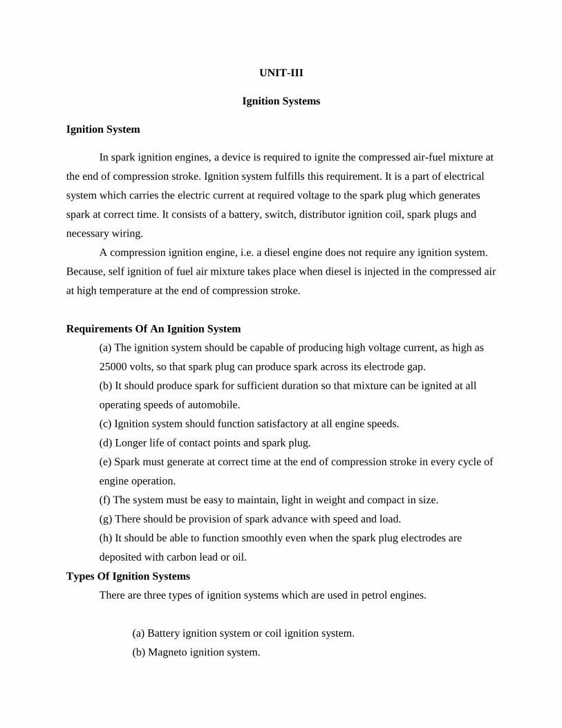
UNIT-III
Ignition Systems
Ignition System
In spark ignition engines, a device is required to ignite the compressed air-fuel mixture at
the end of compression stroke. Ignition system fulfills this requirement. It is a part of electrical
system which carries the electric current at required voltage to the spark plug which generates
spark at correct time. It consists of a battery, switch, distributor ignition coil, spark plugs and
necessary wiring.
A compression ignition engine, i.e. a diesel engine does not require any ignition system.
Because, self ignition of fuel air mixture takes place when diesel is injected in the compressed air
at high temperature at the end of compression stroke.
Requirements Of An Ignition System
(a) The ignition system should be capable of producing high voltage current, as high as
25000 volts, so that spark plug can produce spark across its electrode gap.
(b) It should produce spark for sufficient duration so that mixture can be ignited at all
operating speeds of automobile.
(c) Ignition system should function satisfactory at all engine speeds.
(d) Longer life of contact points and spark plug.
(e) Spark must generate at correct time at the end of compression stroke in every cycle of
engine operation.
(f) The system must be easy to maintain, light in weight and compact in size.
(g) There should be provision of spark advance with speed and load.
(h) It should be able to function smoothly even when the spark plug electrodes are
deposited with carbon lead or oil.
Types Of Ignition Systems
There are three types of ignition systems which are used in petrol engines.
(a) Battery ignition system or coil ignition system.
(b) Magneto ignition system.
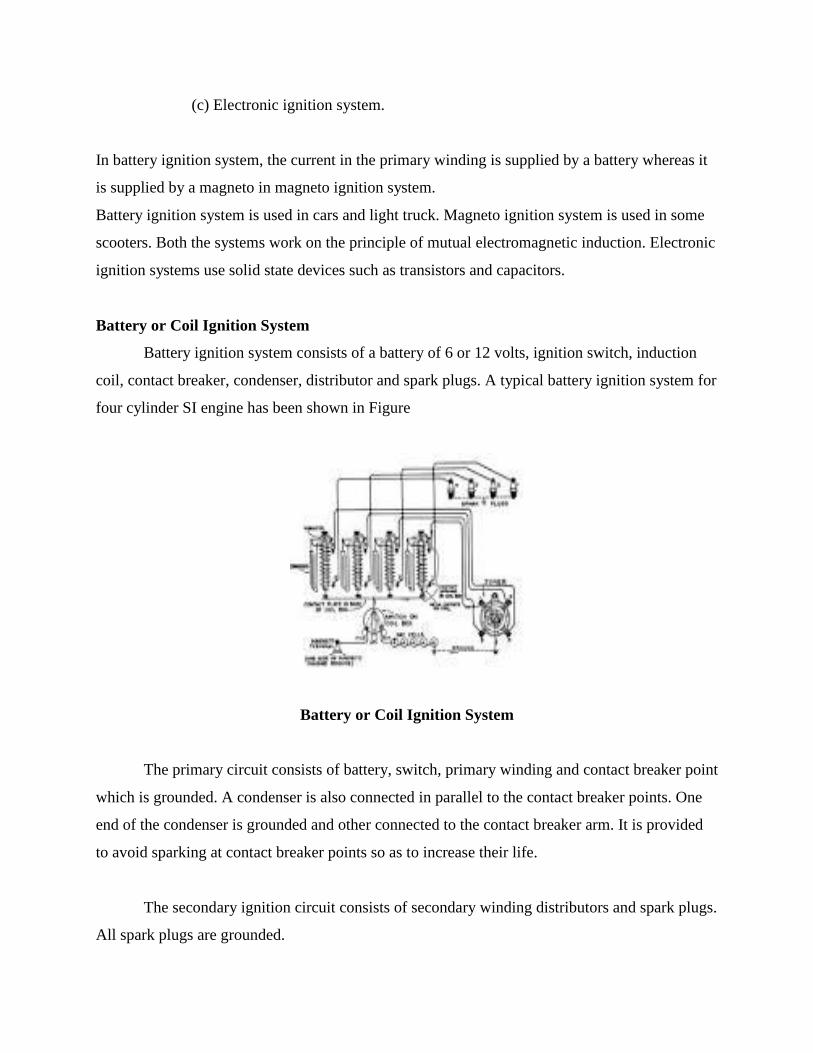
(c) Electronic ignition system.
In battery ignition system, the current in the primary winding is supplied by a battery whereas it
is supplied by a magneto in magneto ignition system.
Battery ignition system is used in cars and light truck. Magneto ignition system is used in some
scooters. Both the systems work on the principle of mutual electromagnetic induction. Electronic
ignition systems use solid state devices such as transistors and capacitors.
Battery or Coil Ignition System
Battery ignition system consists of a battery of 6 or 12 volts, ignition switch, induction
coil, contact breaker, condenser, distributor and spark plugs. A typical battery ignition system for
four cylinder SI engine has been shown in Figure
Battery or Coil Ignition System
The primary circuit consists of battery, switch, primary winding and contact breaker point
which is grounded. A condenser is also connected in parallel to the contact breaker points. One
end of the condenser is grounded and other connected to the contact breaker arm. It is provided
to avoid sparking at contact breaker points so as to increase their life.
The secondary ignition circuit consists of secondary winding distributors and spark plugs.
All spark plugs are grounded.
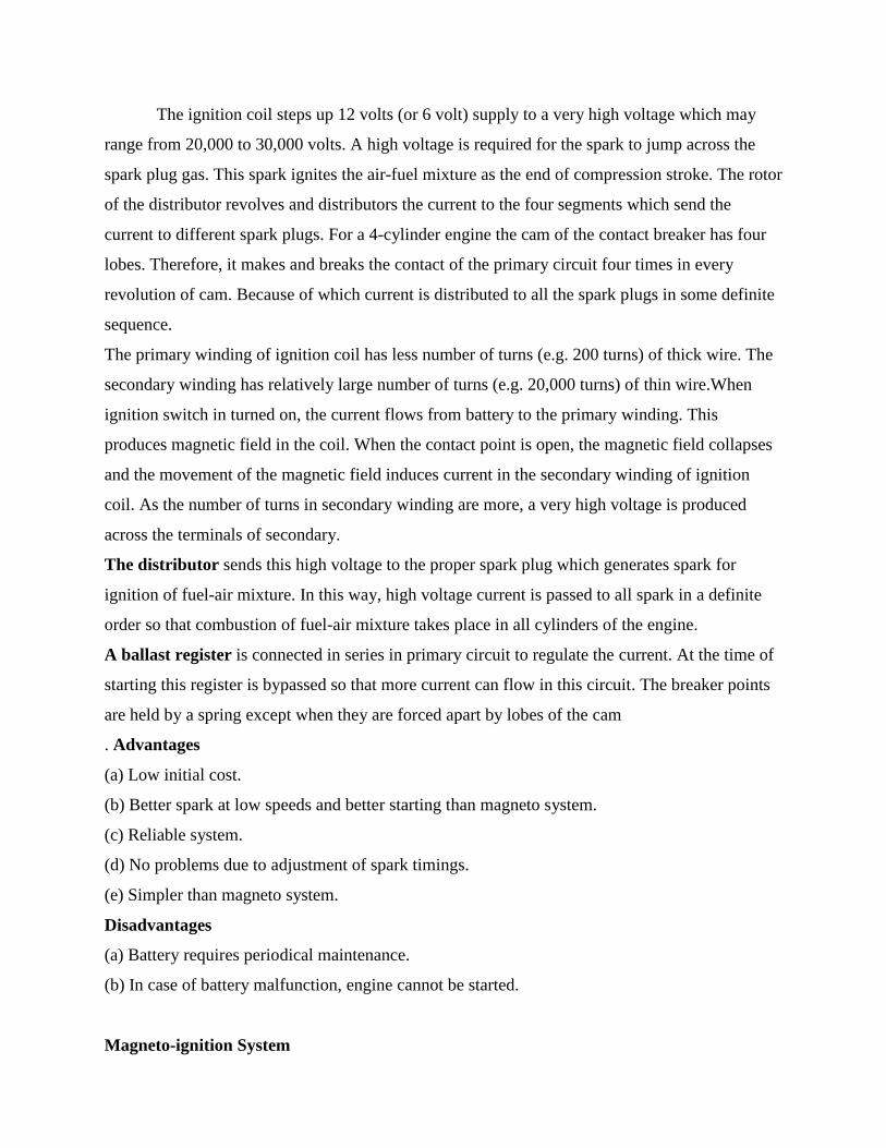
The ignition coil steps up 12 volts (or 6 volt) supply to a very high voltage which may
range from 20,000 to 30,000 volts. A high voltage is required for the spark to jump across the
spark plug gas. This spark ignites the air-fuel mixture as the end of compression stroke. The rotor
of the distributor revolves and distributors the current to the four segments which send the
current to different spark plugs. For a 4-cylinder engine the cam of the contact breaker has four
lobes. Therefore, it makes and breaks the contact of the primary circuit four times in every
revolution of cam. Because of which current is distributed to all the spark plugs in some definite
sequence.
The primary winding of ignition coil has less number of turns (e.g. 200 turns) of thick wire. The
secondary winding has relatively large number of turns (e.g. 20,000 turns) of thin wire.When
ignition switch in turned on, the current flows from battery to the primary winding. This
produces magnetic field in the coil. When the contact point is open, the magnetic field collapses
and the movement of the magnetic field induces current in the secondary winding of ignition
coil. As the number of turns in secondary winding are more, a very high voltage is produced
across the terminals of secondary.
The distributor sends this high voltage to the proper spark plug which generates spark for
ignition of fuel-air mixture. In this way, high voltage current is passed to all spark in a definite
order so that combustion of fuel-air mixture takes place in all cylinders of the engine.
A ballast register is connected in series in primary circuit to regulate the current. At the time of
starting this register is bypassed so that more current can flow in this circuit. The breaker points
are held by a spring except when they are forced apart by lobes of the cam
. Advantages
(a) Low initial cost.
(b) Better spark at low speeds and better starting than magneto system.
(c) Reliable system.
(d) No problems due to adjustment of spark timings.
(e) Simpler than magneto system.
Disadvantages
(a) Battery requires periodical maintenance.
(b) In case of battery malfunction, engine cannot be started.
Magneto-ignition System
This system consists of a magneto in place of a battery. So, the magneto produces and supplies
current in primary winding. Rest of the system is same as that in battery ignition system. A
magneto ignition system for a four cylinder SI engine has been shown in Figure .
The magneto consists of a fixed armature having primary and secondary windings and a rotating
magnetic assembly. This rotating assembly is driven by the engine.
Magneto Ignition System
Rotation of magneto generates current in primary winding having small number of turns.
Secondary winding having large number of turns generates high voltage current which is
supplied to distributor. The distributor sends this current to respective spark plugs. The magneto
may be of rotating armature type or rotating magnet type. In rotating armature type magneto, the
armature having primary and secondary windings and the condenser rotates between the poles of
a stationary horse shoe magnet. In magneto, the magnetic field is produced by permanent
magnets.
Advantages
(a) Better reliability due to absence of battery and low maintenance.
(b) Better suited for medium and high speed engines.
(c) Modern magneto systems are more compact, therefore require less space.
Disadvantages
(a) Adjustment of spark timings adversely affects the voltage.
(b) Burning of electrodes is possible at high engine speeds due to high voltage.
(c) Cost is more than that of magneto ignition systems.
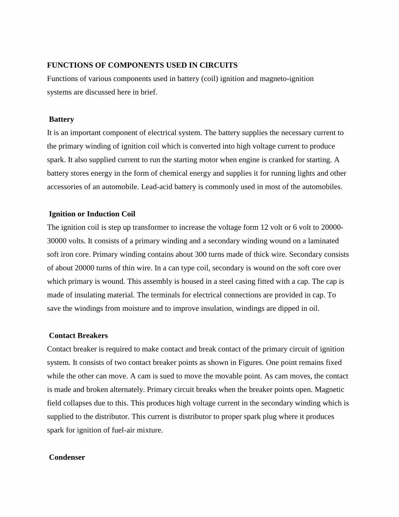
FUNCTIONS OF COMPONENTS USED IN CIRCUITS
Functions of various components used in battery (coil) ignition and magneto-ignition
systems are discussed here in brief.
Battery
It is an important component of electrical system. The battery supplies the necessary current to
the primary winding of ignition coil which is converted into high voltage current to produce
spark. It also supplied current to run the starting motor when engine is cranked for starting. A
battery stores energy in the form of chemical energy and supplies it for running lights and other
accessories of an automobile. Lead-acid battery is commonly used in most of the automobiles.
Ignition or Induction Coil
The ignition coil is step up transformer to increase the voltage form 12 volt or 6 volt to 20000-
30000 volts. It consists of a primary winding and a secondary winding wound on a laminated
soft iron core. Primary winding contains about 300 turns made of thick wire. Secondary consists
of about 20000 turns of thin wire. In a can type coil, secondary is wound on the soft core over
which primary is wound. This assembly is housed in a steel casing fitted with a cap. The cap is
made of insulating material. The terminals for electrical connections are provided in cap. To
save the windings from moisture and to improve insulation, windings are dipped in oil.
Contact Breakers
Contact breaker is required to make contact and break contact of the primary circuit of ignition
system. It consists of two contact breaker points as shown in Figures. One point remains fixed
while the other can move. A cam is sued to move the movable point. As cam moves, the contact
is made and broken alternately. Primary circuit breaks when the breaker points open. Magnetic
field collapses due to this. This produces high voltage current in the secondary winding which is
supplied to the distributor. This current is distributor to proper spark plug where it produces
spark for ignition of fuel-air mixture.
Condenser
The function of the condenser in the ignition system is to absorb and store the inductive current
generated in the coil. If condenser is not provided, the induced current will cause arcing at the
breaker points. This will cause burning of the breaker points.
Distributor
The distributor sends the high voltage current, generated in the secondary winding, to the proper
spark plug at proper time. If the automobile is having a four cylinder engine, it will have four
spark plugs.
The cap of the distributor is connected to the secondary winding of coil. It has a rotor which
rotates and comes in contact with the terminals (4 in number for 4 spark plugs) placed around the
rotor. As the rotor comes in contact with the terminals (numbered 1, 2, 3 and 4 in Figures), the
current is passed to the respective spark plug at proper time when spark is needed.
Ignition Switch
The function of the ignition switch is to connect the battery and starting motor in the automobiles
having self starting system.
Example : In car, jeep, etc.
Its function is to connect battery to induction coil in the battery ignition system.
Spark Plugs
The function of the spark plug is to produce spark between its electrodes. This spark is used to
ignite the fuel-air mixture in the spark ignition (SI) engines.
Magneto
Magneto is used in magneto ignition system. Magneto is a kind of generator to provide electrical
energy to run the ignition system. It is replacement of battery for ignition. When it is rotated by
the engine, it produces high voltage current to be supplied to spark plugs through the distributor.
Ignition Advance
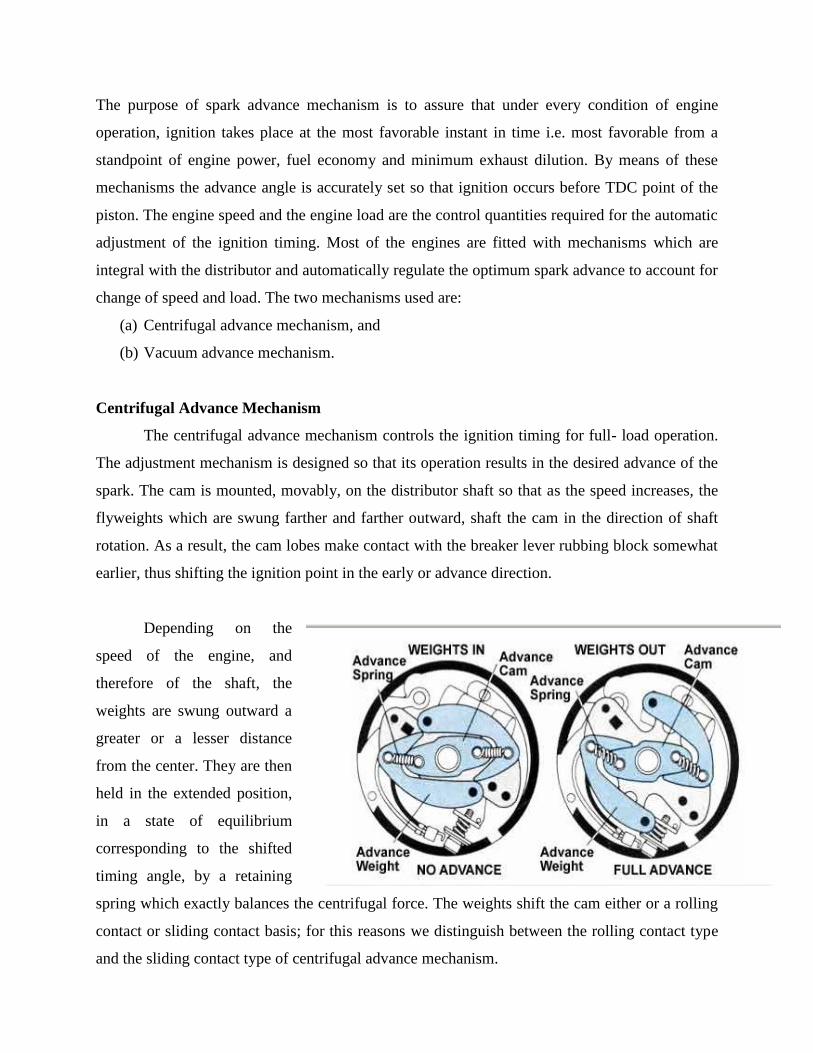
The purpose of spark advance mechanism is to assure that under every condition of engine
operation, ignition takes place at the most favorable instant in time i.e. most favorable from a
standpoint of engine power, fuel economy and minimum exhaust dilution. By means of these
mechanisms the advance angle is accurately set so that ignition occurs before TDC point of the
piston. The engine speed and the engine load are the control quantities required for the automatic
adjustment of the ignition timing. Most of the engines are fitted with mechanisms which are
integral with the distributor and automatically regulate the optimum spark advance to account for
change of speed and load. The two mechanisms used are:
(a) Centrifugal advance mechanism, and
(b) Vacuum advance mechanism.
Centrifugal Advance Mechanism
The centrifugal advance mechanism controls the ignition timing for full- load operation.
The adjustment mechanism is designed so that its operation results in the desired advance of the
spark. The cam is mounted, movably, on the distributor shaft so that as the speed increases, the
flyweights which are swung farther and farther outward, shaft the cam in the direction of shaft
rotation. As a result, the cam lobes make contact with the breaker lever rubbing block somewhat
earlier, thus shifting the ignition point in the early or advance direction.
Depending on the
speed of the engine, and
therefore of the shaft, the
weights are swung outward a
greater or a lesser distance
from the center. They are then
held in the extended position,
in a state of equilibrium
corresponding to the shifted
timing angle, by a retaining
spring which exactly balances the centrifugal force. The weights shift the cam either or a rolling
contact or sliding contact basis; for this reasons we distinguish between the rolling contact type
and the sliding contact type of centrifugal advance mechanism.
The beginning of the timing adjustment in the range of low engine speeds and the
continues adjustment based on the full load curve are determined by the size of the weights by
the shape of the contact mechanisms (rolling or sliding contact type), and by the retaining
springs, all of which can be widely differing designs. The centrifugal force controlled cam is
fitted with a lower limit stop for purposes of setting the beginning of the adjustment, and also
with an upper limit stop to restrict the greatest possible full load adjustment.
Vacuum Advance Mechanism
Vacuum advance mechanism shifts the ignition point under partial load operation.
The adjustment system is designed so that its operation results in the prescribed partial load
advance curve. In this mechanism the adjustment control quantity is the static vacuum prevailing
in the carburetor, a pressure which depends on the position of the throttle valve at any given time
and which is at a maximum when this valve is about half open. This explains the vacuum
maximum.
The diaphragm of a vacuum unit is moved by changes in gas pressure. The position of
this diaphragm is determined by the pressure differential at any given moment between the
prevailing vacuum and atmospheric pressure. The beginning of adjustment is set by the pre-
established tension on a compression spring. The diaphragm area, the spring force, and the
spring rigidity are all selected in accordance with the partial –load advance curve which is to be
followed and are all balanced with respect to each other. The diaphragm movement is
transmitted through a vacuum advance arm connected to the movable breaker plate, and this
movement shifts the breaker plate an additional amount under partial load Ignition Systems
condition in a direction opposite to the direction of rotation of the distributor shaft. Limit stops
on the vacuum advance arm in the base of the vacuum unit restrict the range of adjustment.
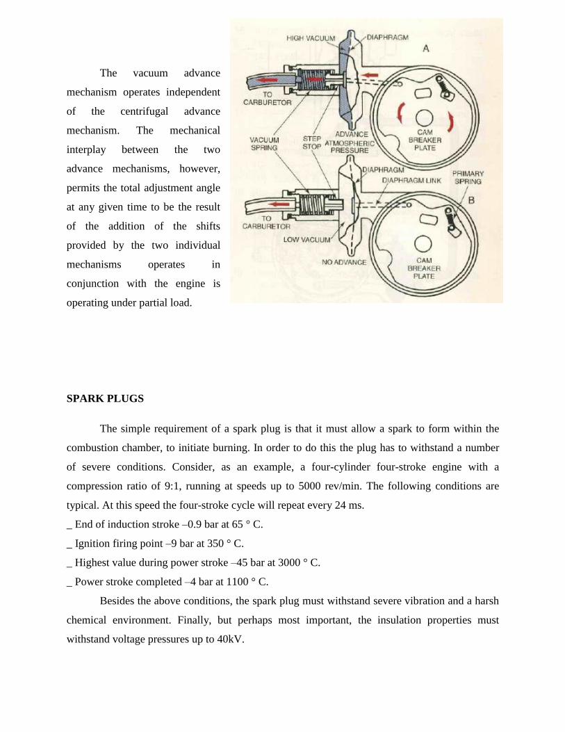
The vacuum advance
mechanism operates independent
of the centrifugal advance
mechanism. The mechanical
interplay between the two
advance mechanisms, however,
permits the total adjustment angle
at any given time to be the result
of the addition of the shifts
provided by the two individual
mechanisms operates in
conjunction with the engine is
operating under partial load.
SPARK PLUGS
The simple requirement of a spark plug is that it must allow a spark to form within the
combustion chamber, to initiate burning. In order to do this the plug has to withstand a number
of severe conditions. Consider, as an example, a four-cylinder four-stroke engine with a
compression ratio of 9:1, running at speeds up to 5000 rev/min. The following conditions are
typical. At this speed the four-stroke cycle will repeat every 24 ms.
_ End of induction stroke –0.9 bar at 65 ° C.
_ Ignition firing point –9 bar at 350 ° C.
_ Highest value during power stroke –45 bar at 3000 ° C.
_ Power stroke completed –4 bar at 1100 ° C.
Besides the above conditions, the spark plug must withstand severe vibration and a harsh
chemical environment. Finally, but perhaps most important, the insulation properties must
withstand voltage pressures up to 40kV.
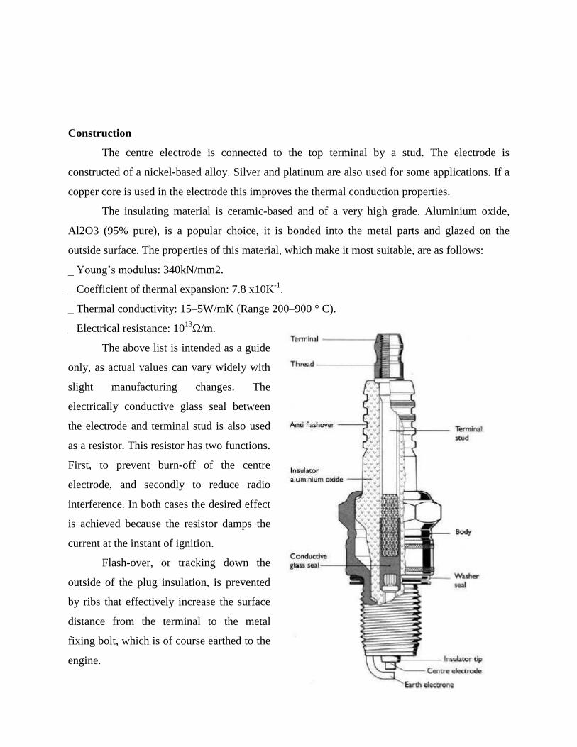
Construction
The centre electrode is connected to the top terminal by a stud. The electrode is
constructed of a nickel-based alloy. Silver and platinum are also used for some applications. If a
copper core is used in the electrode this improves the thermal conduction properties.
The insulating material is ceramic-based and of a very high grade. Aluminium oxide,
Al2O3 (95% pure), is a popular choice, it is bonded into the metal parts and glazed on the
outside surface. The properties of this material, which make it most suitable, are as follows:
_ Young’s modulus: 340kN/mm2.
_ Coefficient of thermal expansion: 7.8 x10K-1
.
_ Thermal conductivity: 15–5W/mK (Range 200–900 ° C).
_ Electrical resistance: 1013
Ω/m.
The above list is intended as a guide
only, as actual values can vary widely with
slight manufacturing changes. The
electrically conductive glass seal between
the electrode and terminal stud is also used
as a resistor. This resistor has two functions.
First, to prevent burn-off of the centre
electrode, and secondly to reduce radio
interference. In both cases the desired effect
is achieved because the resistor damps the
current at the instant of ignition.
Flash-over, or tracking down the
outside of the plug insulation, is prevented
by ribs that effectively increase the surface
distance from the terminal to the metal
fixing bolt, which is of course earthed to the
engine.
Electrode materials
The material chosen for the spark plug electrode must exhibit the following properties:
_ High thermal conductivity.
_ High corrosion resistance.
_ High resistance to burn-off.
For normal applications, alloys of nickel are used for the electrode material. Chromium,
manganese, silicon and magnesium are examples of the alloying constituents. These alloys
exhibit excellent properties with respect to corrosion and burn-off resistance.
To improve on the thermal conductivity, compound electrodes are used. These allow a
greater nose projection for the same temperature range, as discussed in the last section. A
common example of this type of plug is the copper-core spark plug.
Silver electrodes are used for specialist applications as silver has very good thermal and
electrical properties. Again, with these plugs nose length can be increased within the same
temperature range.
The thermal conductivity of some electrode materials is listed for comparison.
_ Silver 407 W/m K
_ Copper 384 W/m K
_ Platinum 70 W/m K
_ Nickel 59 W/m K
Compound electrodes have an average thermal conductivity of about 200 W/m K.
Platinum tips are used for some spark plug applications due to the very high burn-off resistance
of this material. It is also possible because of this to use much smaller diameter electrodes, thus
increasing mixture accessibility. Platinum also has a catalytic effect, further accelerating the
combustion process.
Electrode gap
Spark plug electrode gaps have, in general, increased as the power of the ignition systems
driving the spark has increased. The simple relationship between plug gap and voltage required
is that, as the gap increases so must the voltage (leaving aside engine operating conditions).
Furthermore, the energy available to form a spark at a fixed engine speed is constant, which
means that a larger gap using higher voltage will result in a shorter duration spark. A smaller gap

will allow a longer duration spark. For cold starting an engine and for igniting weak mixtures,
the duration of the spark is critical. Likewise the plug gap must be as large as possible to allow
easy access for the mixture in order to prevent quenching of the flame.
The final choice is therefore a compromise reached through testing and development of a
particular application. Plug gaps in the region of 0.6–1.2 mm seem to be the norm at present.
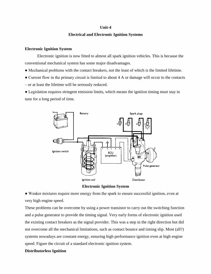
Unit-4
Electrical and Electronic Ignition Systems
Electronic Ignition System
Electronic ignition is now fitted to almost all spark ignition vehicles. This is because the
conventional mechanical system has some major disadvantages.
● Mechanical problems with the contact breakers, not the least of which is the limited lifetime.
● Current flow in the primary circuit is limited to about 4 A or damage will occur to the contacts
– or at least the lifetime will be seriously reduced.
● Legislation requires stringent emission limits, which means the ignition timing must stay in
tune for a long period of time.
Electronic Ignition System
● Weaker mixtures require more energy from the spark to ensure successful ignition, even at
very high engine speed.
These problems can be overcome by using a power transistor to carry out the switching function
and a pulse generator to provide the timing signal. Very early forms of electronic ignition used
the existing contact breakers as the signal provider. This was a step in the right direction but did
not overcome all the mechanical limitations, such as contact bounce and timing slip. Most (all?)
systems nowadays are constant energy, ensuring high performance ignition even at high engine
speed. Figure the circuit of a standard electronic ignition system.
Distributorless Ignition
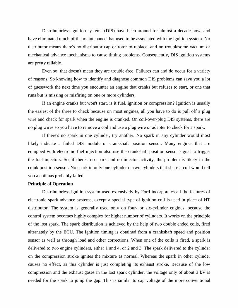
Distributorless ignition systems (DIS) have been around for almost a decade now, and
have eliminated much of the maintenance that used to be associated with the ignition system. No
distributor means there's no distributor cap or rotor to replace, and no troublesome vacuum or
mechanical advance mechanisms to cause timing problems. Consequently, DIS ignition systems
are pretty reliable.
Even so, that doesn't mean they are trouble-free. Failures can and do occur for a variety
of reasons. So knowing how to identify and diagnose common DIS problems can save you a lot
of guesswork the next time you encounter an engine that cranks but refuses to start, or one that
runs but is missing or misfiring on one or more cylinders.
If an engine cranks but won't start, is it fuel, ignition or compression? Ignition is usually
the easiest of the three to check because on most engines, all you have to do is pull off a plug
wire and check for spark when the engine is cranked. On coil-over-plug DIS systems, there are
no plug wires so you have to remove a coil and use a plug wire or adapter to check for a spark.
If there's no spark in one cylinder, try another. No spark in any cylinder would most
likely indicate a failed DIS module or crankshaft position sensor. Many engines that are
equipped with electronic fuel injection also use the crankshaft position sensor signal to trigger
the fuel injectors. So, if there's no spark and no injector activity, the problem is likely in the
crank position sensor. No spark in only one cylinder or two cylinders that share a coil would tell
you a coil has probably failed.
Principle of Operation
Distributorless ignition system used extensively by Ford incorporates all the features of
electronic spark advance systems, except a special type of ignition coil is used in place of HT
distributor. The system is generally used only on four- or six-cylinder engines, because the
control system becomes highly complex for higher number of cylinders. It works on the principle
of the lost spark. The spark distribution is achieved by the help of two double ended coils, fired
alternately by the ECU. The ignition timing is obtained from a crankshaft speed and position
sensor as well as through load and other corrections. When one of the coils is fired, a spark is
delivered to two engine cylinders, either 1 and 4, or 2 and 3. The spark delivered to the cylinder
on the compression stroke ignites the mixture as normal. Whereas the spark in other cylinder
causes no effect, as this cylinder is just completing its exhaust stroke. Because of the low
compression and the exhaust gases in the lost spark cylinder, the voltage only of about 3 kV is
needed for the spark to jump the gap. This is similar to cap voltage of the more conventional
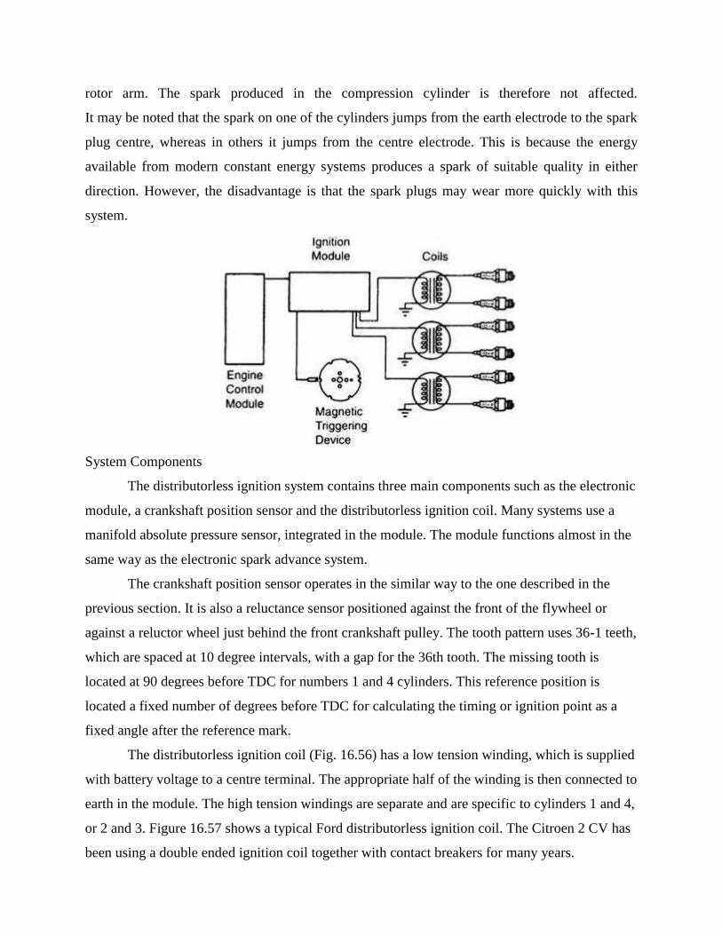
rotor arm. The spark produced in the compression cylinder is therefore not affected.
It may be noted that the spark on one of the cylinders jumps from the earth electrode to the spark
plug centre, whereas in others it jumps from the centre electrode. This is because the energy
available from modern constant energy systems produces a spark of suitable quality in either
direction. However, the disadvantage is that the spark plugs may wear more quickly with this
system.
System Components
The distributorless ignition system contains three main components such as the electronic
module, a crankshaft position sensor and the distributorless ignition coil. Many systems use a
manifold absolute pressure sensor, integrated in the module. The module functions almost in the
same way as the electronic spark advance system.
The crankshaft position sensor operates in the similar way to the one described in the
previous section. It is also a reluctance sensor positioned against the front of the flywheel or
against a reluctor wheel just behind the front crankshaft pulley. The tooth pattern uses 36-1 teeth,
which are spaced at 10 degree intervals, with a gap for the 36th tooth. The missing tooth is
located at 90 degrees before TDC for numbers 1 and 4 cylinders. This reference position is
located a fixed number of degrees before TDC for calculating the timing or ignition point as a
fixed angle after the reference mark.
The distributorless ignition coil (Fig. 16.56) has a low tension winding, which is supplied
with battery voltage to a centre terminal. The appropriate half of the winding is then connected to
earth in the module. The high tension windings are separate and are specific to cylinders 1 and 4,
or 2 and 3. Figure 16.57 shows a typical Ford distributorless ignition coil. The Citroen 2 CV has
been using a double ended ignition coil together with contact breakers for many years.
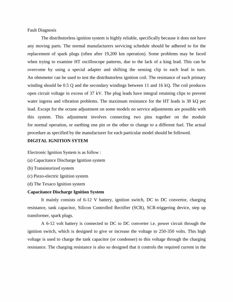
Fault Diagnosis
The distributorless ignition system is highly reliable, specifically because it does not have
any moving parts. The normal manufacturers servicing schedule should be adhered to for the
replacement of spark plugs (often after 19,200 km operation). Some problems may be faced
when trying to examine HT oscilloscope patterns, due to the lack of a king lead. This can be
overcome by using a special adapter and shifting the sensing clip to each lead in turn.
An ohmmeter can be used to test the distributorless ignition coil. The resistance of each primary
winding should be 0.5 Q and the secondary windings between 11 and 16 kQ. The coil produces
open circuit voltage in excess of 37 kV. The plug leads have integral retaining clips to prevent
water ingress and vibration problems. The maximum resistance for the HT leads is 30 kQ per
lead. Except for the octane adjustment on some models no service adjustments are possible with
this system. This adjustment involves connecting two pins together on the module
for normal operation, or earthing one pin or the other to change to a different fuel. The actual
procedure as specified by the manufacturer for each particular model should be followed.
DIGITAL IGNITION SYTEM
Electronic Ignition System is as follow :
(a) Capacitance Discharge Ignition system
(b) Transistorized system
(c) Piezo-electric Ignition system
(d) The Texaco Ignition system
Capacitance Discharge Ignition System
It mainly consists of 6-12 V battery, ignition switch, DC to DC convertor, charging
resistance, tank capacitor, Silicon Controlled Rectifier (SCR), SCR-triggering device, step up
transformer, spark plugs.
A 6-12 volt battery is connected to DC to DC converter i.e. power circuit through the
ignition switch, which is designed to give or increase the voltage to 250-350 volts. This high
voltage is used to charge the tank capacitor (or condenser) to this voltage through the charging
resistance. The charging resistance is also so designed that it controls the required current in the
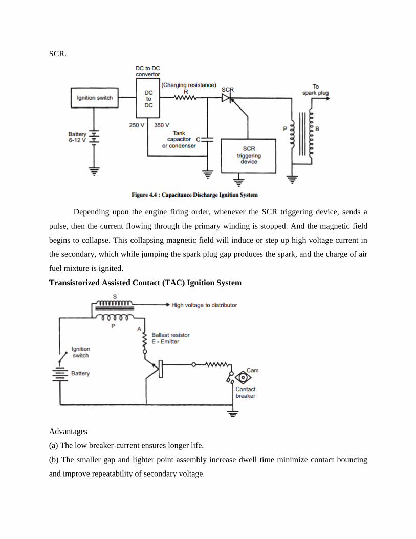
SCR.
Depending upon the engine firing order, whenever the SCR triggering device, sends a
pulse, then the current flowing through the primary winding is stopped. And the magnetic field
begins to collapse. This collapsing magnetic field will induce or step up high voltage current in
the secondary, which while jumping the spark plug gap produces the spark, and the charge of air
fuel mixture is ignited.
Transistorized Assisted Contact (TAC) Ignition System
Advantages
(a) The low breaker-current ensures longer life.
(b) The smaller gap and lighter point assembly increase dwell time minimize contact bouncing
and improve repeatability of secondary voltage.
(c) The low primary inductance reduces primary inductance reduces primary current drop-off at
high speeds.
Disadvantages
(a) As in the conventional system, mechanical breaker points are necessary for timing the spark.
(b) The cost of the ignition system is increased.
(c) The voltage rise-time at the spark plug is about the same as before.
Piezo-electric Ignition System
The development of synthetic piezo-electric materials producing about 22 kV by
mechanical loading of a small crystal resulted in some ignition systems for single cylinder
engines. But due to difficulties of high mechanical loading need of the order of 500 kg timely
control and ability to produce sufficient voltage, these systems have not been able to come up.
The Texaco Ignition System
Due to the increased emphasis on exhaust emission control, there has been a sudden
interest in exhaust gas recirculation systems and lean fuel-air mixtures. To avoid the problems of
burning of lean mixtures, the Texaco Ignition system has been developed. It provides a spark of
controlled duration which means that the spark duration in crank angle degrees can be made
constant at all engine speeds. It is a AC system. This system consists of three basic units, a
power unit, a control unit and a distributor sensor. This system can give stable ignition up to A/F
ratios as high as 24 : 1.
Non–Contact–type Ignition Triggering devices
Triggering is arranged so that the ignition coil is charged in sufficient time before the
actual ignition point. This requires the formation of a dwell period (coil saturation time) in the
ignition system. The energy to be released as a spark is usually stored in a coil as magnetic
energy (with conventional systems). In other cases, this can be replaced with a capacitor as
electrostatic energy, such as in a capacitive discharge ignition system (CDI), in which case the
role of the coil changes to simply that of an energy transfer device. The high tension results from
disconnecting the primary inductor from the power supply followed by transformation.
The high tension is then applied via the distributor to the cylinder currently performing
the working stroke. All this combines to produce the required firing voltage, which is determined
by the cylinder pressure, a byproduct of the inlet charge and compression, combined with the
gap, temperature and shape of the spark plug electrode. The ignition system will then only
deliver the voltage necessary to fire the spark plug. If all is well, the mixture will be successfully
ignited. If insufficient energy is available, ignition does not occur, thus allowing a misfire. This
is why adequate ignition must be provided.
Electronically–Assisted and Full Electronic Ignition System
The need for higher mileage, reduced emissions and greater reliability has led to the
development of the electronic ignition systems. These systems generate a much stronger spark
which is needed to ignite leaner fuel mixtures. Breaker point systems needed a resistor to reduce
the operating voltage of the primary circuit in order to prolong the life of the points. The primary
circuit of the electronic ignition systems operates on full battery voltage which helps to develop a
stronger spark. Spark plug gaps have widened due to the ability of the increased voltage to jump
the larger gap. Cleaner combustion and less deposit have led to longer spark plug life.
On some systems, the ignition coil has been moved inside the distributor cap. This system is said
to have an internal coil as opposed to the conventional external one.
Electronic Ignition systems are not as complicated as they may first appear. In fact, they
differ only slightly from conventional point ignition systems. Like conventional ignition systems,
electronic systems have two circuits: a primary circuit and a secondary circuit. The entire
secondary circuit is the same as in a conventional ignition system. In addition, the section of the
primary circuit from the battery to the battery terminal at the coil is the same as in a conventional
ignition system.
Electronic ignition systems differ from conventional ignition systems in the distributor
component area. Instead of a distributor cam, breaker plate, points, and condenser, an electronic
ignition system has an armature (called by various names such as a trigger wheel, reluctor, etc.),
a pickup coil (stator, sensor, etc.), and an electronic control module.
Essentially, all electronic ignition systems operate in the following manner: With the ignition
switch turned on, primary (battery) current flows from the battery through the ignition switch to
the coil primary windings. Primary current is turned on and off by the action of the armature as it
revolves past the pickup coil or sensor. As each tooth of the armature nears the pickup coil, it
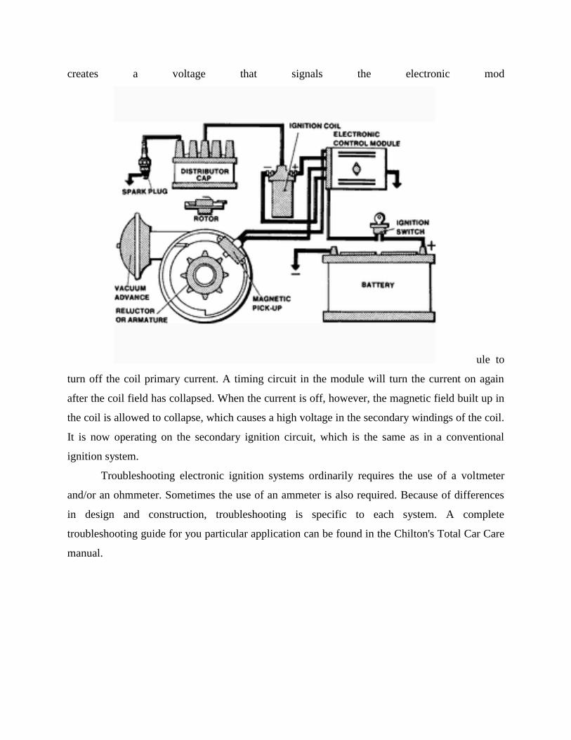
creates a voltage that signals the electronic mod
ule to
turn off the coil primary current. A timing circuit in the module will turn the current on again
after the coil field has collapsed. When the current is off, however, the magnetic field built up in
the coil is allowed to collapse, which causes a high voltage in the secondary windings of the coil.
It is now operating on the secondary ignition circuit, which is the same as in a conventional
ignition system.
Troubleshooting electronic ignition systems ordinarily requires the use of a voltmeter
and/or an ohmmeter. Sometimes the use of an ammeter is also required. Because of differences
in design and construction, troubleshooting is specific to each system. A complete
troubleshooting guide for you particular application can be found in the Chilton's Total Car Care
manual.
Unit-5
Wiring, Lighting and Other Instruments and Sensors
AUTOMOTIVE WIRING
Electrical power and control signals must be delivered to electrical devices reliably and
safely so that the electrical system functions are not impaired or converted to hazards. To fulfill
power distribution military vehicles, use one-and two-wire circuits, wiring harnesses, and
terminal connections.
Among your many duties will be the job of maintaining and repairing automotive
electrical systems. All vehicles are not wired in exactly the same manner; however, once you
understand the circuit of one vehicle, you should be able to trace an electrical circuit of any
vehicle using wiring diagrams and color codes.
ONE-AND TWO-WIRE CIRCUITS
Tracing wiring circuits, particularly those connecting lights or warning and signal
devices, is no simple task. The branch circuits making up the individual systems have one wire
to conduct electricity from the battery to the unit requiring it and ground connections at the
battery and the unit to complete the circuit. These are called ONE-WIRE CIRCUITS or branches
of a GROUND RETURN SYSTEM. In automotive electrical systems with branch circuits that
lead to all parts of the equipment, the ground return system saves installation time and eliminates
the need for an additional wiring to complete the circuit. The all-metal construction of the
automotive equipment makes it possible to use this system.
The TWO-WIRE CIRCUIT requires two wires to complete the electrical circuit- one
wire from the source of electrical energy to the unit it will operate, and another wire to complete
the circuit from the unit back to the source of the electrical power. Two-wire circuits provide
positive connection for light and electrical brakes on some trailers. The coupling between the
trailer and the equipment, although made of metal and a conductor of electricity, has to be
jointed to move freely. The rather loose joint or coupling does not provide the positive and
continuous connection required to use a ground return system between two vehicles. The two-
wire circuit is commonly used on equipment subject to frequent or heavy vibrations. Tracked
equipment, off-road vehicles (tactical), and many types of construction equipment are wired in
this manner.
Insulated Return
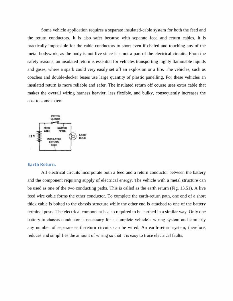
Some vehicle application requires a separate insulated-cable system for both the feed and
the return conductors. It is also safer because with separate feed and return cables, it is
practically impossible for the cable conductors to short even if chafed and touching any of the
metal bodywork, as the body is not live since it is not a part of the electrical circuits. From the
safety reasons, an insulated return is essential for vehicles transporting highly flammable liquids
and gases, where a spark could very easily set off an explosion or a fire. The vehicles, such as
coaches and double-decker buses use large quantity of plastic panelling. For these vehicles an
insulated return is more reliable and safer. The insulated return off course uses extra cable that
makes the overall wiring harness heavier, less flexible, and bulky, consequently increases the
cost to some extent.
Earth Return.
All electrical circuits incorporate both a feed and a return conductor between the battery
and the component requiring supply of electrical energy. The vehicle with a metal structure can
be used as one of the two conducting paths. This is called as the earth return (Fig. 13.51). A live
feed wire cable forms the other conductor. To complete the earth-return path, one end of a short
thick cable is bolted to the chassis structure while the other end is attached to one of the battery
terminal posts. The electrical component is also required to be earthed in a similar way. Only one
battery-to-chassis conductor is necessary for a complete vehicle’s wiring system and similarly
any number of separate earth-return circuits can be wired. An earth-return system, therefore,
reduces and simplifies the amount of wiring so that it is easy to trace electrical faults.
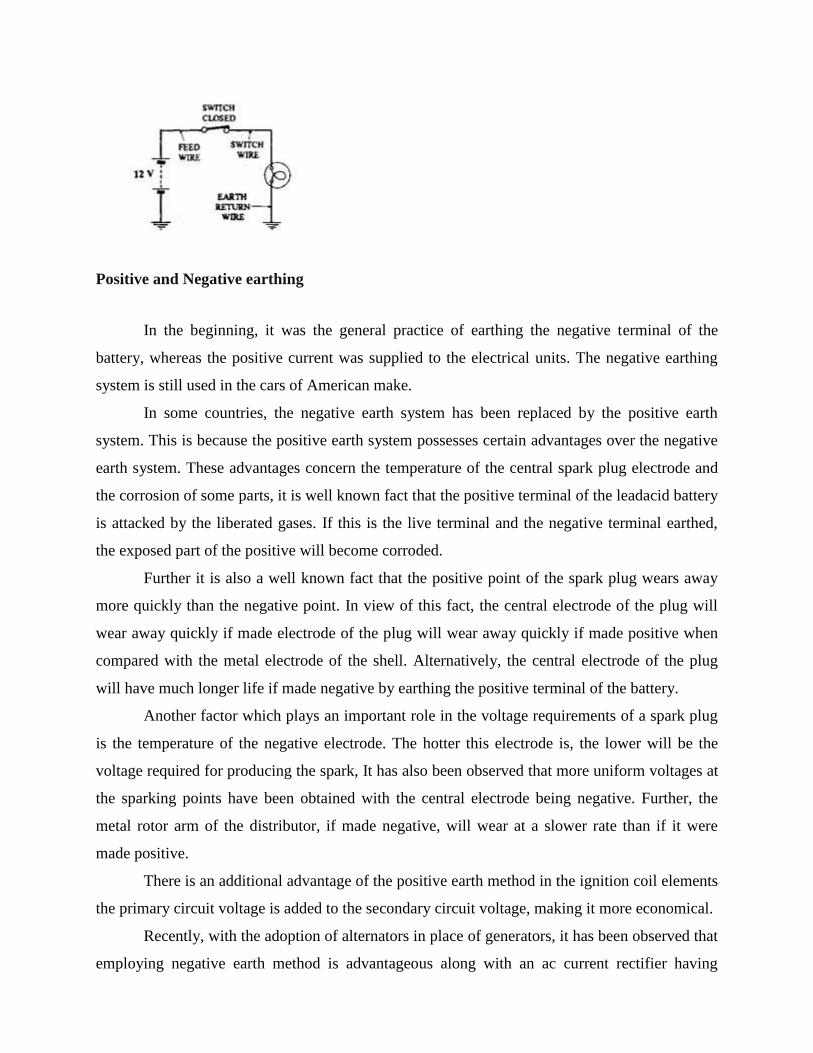
Positive and Negative earthing
In the beginning, it was the general practice of earthing the negative terminal of the
battery, whereas the positive current was supplied to the electrical units. The negative earthing
system is still used in the cars of American make.
In some countries, the negative earth system has been replaced by the positive earth
system. This is because the positive earth system possesses certain advantages over the negative
earth system. These advantages concern the temperature of the central spark plug electrode and
the corrosion of some parts, it is well known fact that the positive terminal of the leadacid battery
is attacked by the liberated gases. If this is the live terminal and the negative terminal earthed,
the exposed part of the positive will become corroded.
Further it is also a well known fact that the positive point of the spark plug wears away
more quickly than the negative point. In view of this fact, the central electrode of the plug will
wear away quickly if made electrode of the plug will wear away quickly if made positive when
compared with the metal electrode of the shell. Alternatively, the central electrode of the plug
will have much longer life if made negative by earthing the positive terminal of the battery.
Another factor which plays an important role in the voltage requirements of a spark plug
is the temperature of the negative electrode. The hotter this electrode is, the lower will be the
voltage required for producing the spark, It has also been observed that more uniform voltages at
the sparking points have been obtained with the central electrode being negative. Further, the
metal rotor arm of the distributor, if made negative, will wear at a slower rate than if it were
made positive.
There is an additional advantage of the positive earth method in the ignition coil elements
the primary circuit voltage is added to the secondary circuit voltage, making it more economical.
Recently, with the adoption of alternators in place of generators, it has been observed that
employing negative earth method is advantageous along with an ac current rectifier having
transistors and diodes. This has meant shifting back to the negative earth method. However it is
worth mentioning that the important advantages of the positive earth for the ignition system still
hold good.
LIGHTING
The lighting circuit includes the battery, vehicle frame, all the lights, and various
switches that control their use. The lighting circuit is known as a single-wire system since it uses
the vehicle frame for the return.
The complete lighting circuit of a vehicle can be broken down into individual circuits,
each having one or more lights and switches. In each separate circuit, the lights are connected in
parallel, and the controlling switch is in series between the group of lights and the battery.
The marker lights, for example, are connected in parallel and are controlled by a single
switch. In some installations, one switch controls the connections to the battery, while a selector
switch determines which of two circuits is energized. The headlights, with their high and low
beams, are an example of this type of circuit.
In some instances, such as the courtesy lights, several switches may be connected in
parallel so that any switch may be used to turn on the light. When a wiring diagram is being
studied, all light circuits can be traced from the battery through the ammeter to the switch (or
switches) to the individual light.
LAMPS
Small gas-filled incandescent lamps with tungsten filaments are used on automotive and
construction equipment. The filaments supply the light when sufficient current is flowing
through them. They are designed to operate on a low voltage current of 12 or 24 volts, depending
upon the voltage of the the vehicle will be of the single-or double-contact small one-half-
candlepower bulbs to large 50- candlepower bulbs. The greater the candlepower of the lamp, the
more current it requires when lighted. Lamps are identified by a number on the base. When you
replace a lamp in a vehicle, be sure the new lamp is of the proper rating. The lamps within
Lamps are rated as to size by the candlepower (luminous intensity) they produce. They range
from types with nibs to fit bayonet sockets, as shown in lamp is also whiter than a conventional
lamp, which increases lighting ability.
HEADLIGHTS
The headlights are sealed beam lamps that illuminate the road during nighttime operation.
Headlights consist of a lens, one or two elements, and a integral reflector. When current flows
through the element, the element gets white hot and glows. The reflector and lens direct the light
forward.
Many modern passenger vehicles use halogen headlights. A halogen headlight contains a
small, inner halogen lamp surrounded by a conventional sealed housing. A halogen headlamp
increases light output by 25 percent with no increase in current. The halogen The headlight
switch is an ON/ OFF switch and rheostat (variable resistor) in the dash panel ) or on the steering
column. The headlight switch controls current flow to the lamps of the headlight system. The
rheostat is for adjusting the brightness of the instrument panel lights.
Military vehicles that are used in tactical situations are equipped with a headlight switch
that is integrated with the blackout lighting switch. An important feature of this switch is that it
reduces the possibility of accidentally turning on the lights in a blackout.
With no lights on, the main switch can be turned to the left without operating the
mechanical switch to get blackout marker lights (including blackout taillights and stoplights) and
blackout driving lights. But for stoplights for daylight driving or headlights for ordinary night
driving, you must first lift the mechanical switch lever and then turn the main switch to the right.
The auxiliary switch gives panel lights when the main switch is in any of its ON positions. But it
will give parking lights only when the main switch is in service drive (to the extreme right).
When the main switch is off, the auxiliary switch should not be moved from the OFF position.
DIMMER SWITCH
The dimmer switch controls the high and low headlamp beam function and is normally
mounted on the floorboard or steering column. When the operator activates the dimmer switch, it
changes the electrical connection to the headlights.
In one position, the high beams are turned on, and, in the other position, the dimmer
changes them to low beam.
Aiming Headlights
The headlights can be aimed using a mechanical aimer or a wall screen. Either method
assures that the headlight beams point in the direction specified by the vehicle manufacturer.
Headlights that are aimed too high can blind oncoming vehicles. Headlights that are aimed too
low or to one side will reduce the operator's visibility.
TURN-SIGNAL SYSTEMS
Vehicles that operate on any public road must be equipped with turn signals. These
signals indicate a left or right turn by providing a flashing light signal at the rear and front of the
vehicle.
The turn-signal switch is located on the steering column. It is designed to shut off
automatically after the turn is completed by the action of the canceling cam. A common design
for a turn-signal system is to use the same rear light for both the stop and turn signals. This
somewhat complicates the design of the switch in that the stoplight circuit must pass through the
turn-signal switch. When the turn-signal switch is turned off, it must pass stoplight current to the
rear lights. As a left or right turn signal is selected, the stoplight circuit is open and the turn-
signal circuit is closed to the respective rear light.
The turn signal flasher unit creates the flashing of the turn signal lights. It consists
basically of a bimetallic (two dissimilar metals bonded together) strip wrapped in a wire coil.
The bimetallic strip serves as one of the contact points.
When the turn signals are actuated, current flows into the flasher- first through the
heating coil to the bimetallic strip, then through the contact points, then out of the flasher, where
the circuit is completed through the turn-signal light. This sequence of events will repeat a few
times a second, causing a steady flashing of the turn signals.
Electrical and Electronic Fuel Lift Pumps
In many modern cars the fuel pump is usually electric and located inside the fuel tank.
The pump creates positive pressure in the fuel lines, pushing the gasoline to the engine. The
higher gasoline pressure raises the boiling point. Placing the pump in the tank puts the
component least likely to handle gasoline vapor well (the pump itself) farthest from the engine,
submersed in cool liquid. Another benefit to placing the pump inside the tank is that it is less
likely to start a fire. Though electrical components (such as a fuel pump) can spark and ignite
fuel vapors, liquid fuel will not explode (see flammability limit) and therefore submerging the
pump in the tank is one of the safest places to put it. In most cars, the fuel pump delivers a
constant flow of gasoline to the engine; fuel not used is returned to the tank. This further reduces
the chance of the fuel boiling, since it is never kept close to the hot engine for too long.
The ignition switch does not carry the power to the fuel pump; instead, it activates a relay
which will handle the higher current load. It is common for the fuel pump relay to become
oxidized and cease functioning; this is much more common than the actual fuel pump failing.
Modern engines utilize solid-state control which allows the fuel pressure to be controlled via
pulse-width modulation of the pump voltage. This increases the life of the pump, allows a
smaller and lighter device to be used, and reduces electrical load.
Cars with electronic fuel injection have an electronic control unit (ECU) and this may be
programmed with safety logic that will shut the electric fuel pump off, even if the engine is
running. In the event of a collision this will prevent fuel leaking from any ruptured fuel line.
Additionally, cars may have an inertia switch (usually located underneath the front passenger
seat) that is "tripped" in the event of an impact, or a roll-over valve that will shut off the fuel
pump in case the car rolls over.
Some ECUs may also be programmed to shut off the fuel pump if they detect low or zero
oil pressure, for instance if the engine has suffered a terminal failure (with the subsequent risk of
fire in the engine compartment).
The fuel sending unit assembly may be a combination of the electric fuel pump, the filter,
the strainer, and the electronic device used to measure the amount of fuel in the tank via a float
attached to a sensor which sends data to the dash-mounted fuel gauge. The fuel pump by itself is
a relatively inexpensive part. But a mechanic at a garage might have a preference to install the
entire unit assembly.
Fuel Level Indicator
Most fuel gauges are operated electrically and are composed of two units- the gauge,
mounted on the instrument panel; and the sending unit, mounted in the fuel tank. The ignition
switch is included in the fuel gauge circuit, so the gauge operates only when the ignition switch
is in the ON position. Operation of the electrical gauge depends on either coil action or
thermostatic action. The four types of fuel gauges are as follows:
The THERMOSTATIC FUEL GAUGE, SELF-REGULATING contains an electrically
heated bimetallic strip that is linked to a pointer. A bimetallic strip consists of two dissimilar
metals that, when heated, expand at different rates, causing it to deflect or bend. In the case of
this gauge, the deflection of the bimetallic strip results in the movement of the pointer, causing
the gauge to give a reading. The sending unit consists of a hinged arm with a float on the end.
The movement of the arm controls a grounded point that makes contact with another point which
is attached to an electrically heated bimetallic strip. The heating coils in the tank and the gauge
are connected to each other in series.
The THERMOSTATIC FUEL GAUGE, EXTERNALLY REGULATED differs from a
self-regulating system in the use of a variable resistance fuel tank sending unit and an external
voltage-limiting device. The sending unit controls the gauge through the use of a rheostat (wire
wound resistance unit whose value varies with its effective length). The effective length of the
rheostat is controlled in the sending unit by a sliding brush that is operated by the float arm. The
power supply to the gauge is kept constant through the use of a voltage limiter. The voltage
limiter consists of a set of contact points that are controlled by an electrically heated bimetallic
arm.
The THERMOSTATIC FUEL GAUGE, DIFFERENTIAL TYPE is similar to the other
type of thermostatic fuel gauges, except that it uses two electrically heated bimetallic strips that
share equally in operating and supporting the gauge pointer. The pointer position is obtained by
dividing the available voltage between the two strips (differential). The tank unit is a rheostat
type similar to that already described; however, it contains a wire-wound resistor that is
connected between external terminals of one of the gauges of the bimetallic strip. The float arm
moves a grounded brush that raises resistance progressively to one terminal, while lowering
resistance to the other. This action causes the voltage division and resulting heat differential to
the gauge strips formulating the gauge reading.
The MAGNETIC FUEL GAUGE consists of a pointer mounted on an armature.
Depending upon the design, the armature may contain one or two poles. The gauge is motivated
by a magnetic field that is created by two separate magnetic coils that are contained in the gauge.
One of these coils is connected directly to the battery, producing a constant magnetic field. The
other coil produces a variable field, whose strength is determined by a rheostat-type tank unit.
The coils are placed 90 degrees apart.
Pressure Gauge
A pressure gauge is used widely in automotive and construction applications to keep
track of such things as oil pressure, fuel line pressure, air brake system pressure, and the pressure
in the hydraulic systems. Depending on the equipment, a mechanical gauge, an electrical gauge,
or an indicator lamp may be used.
TEMPERATURE GAUGE
The temperature gauge is a very important indicator in construction and automotive
equipment. The most common uses are to indicate engine coolant, transmission, differential oil,
and hydraulic system temperature. Depending on the type of equipment, the gauge may be
mechanical, electric, or a warning light.
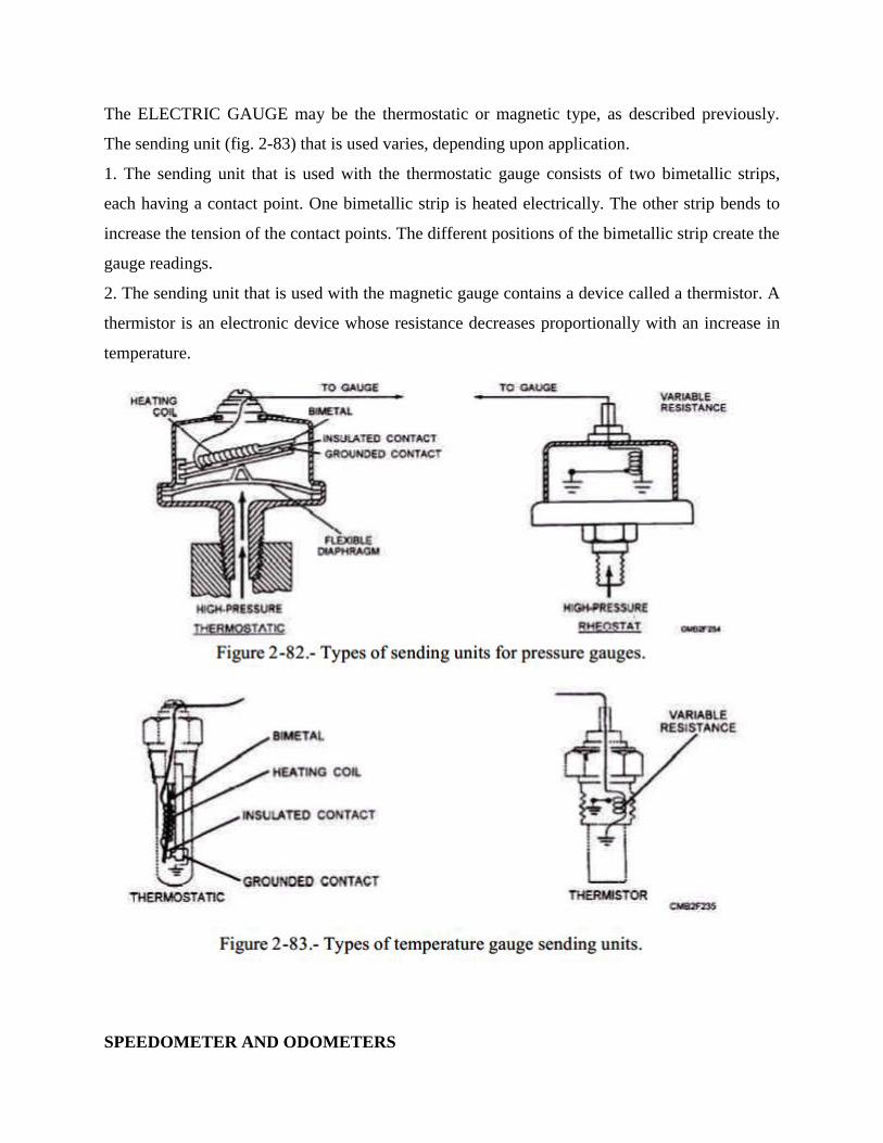
The ELECTRIC GAUGE may be the thermostatic or magnetic type, as described previously.
The sending unit (fig. 2-83) that is used varies, depending upon application.
1. The sending unit that is used with the thermostatic gauge consists of two bimetallic strips,
each having a contact point. One bimetallic strip is heated electrically. The other strip bends to
increase the tension of the contact points. The different positions of the bimetallic strip create the
gauge readings.
2. The sending unit that is used with the magnetic gauge contains a device called a thermistor. A
thermistor is an electronic device whose resistance decreases proportionally with an increase in
temperature.
SPEEDOMETER AND ODOMETERS
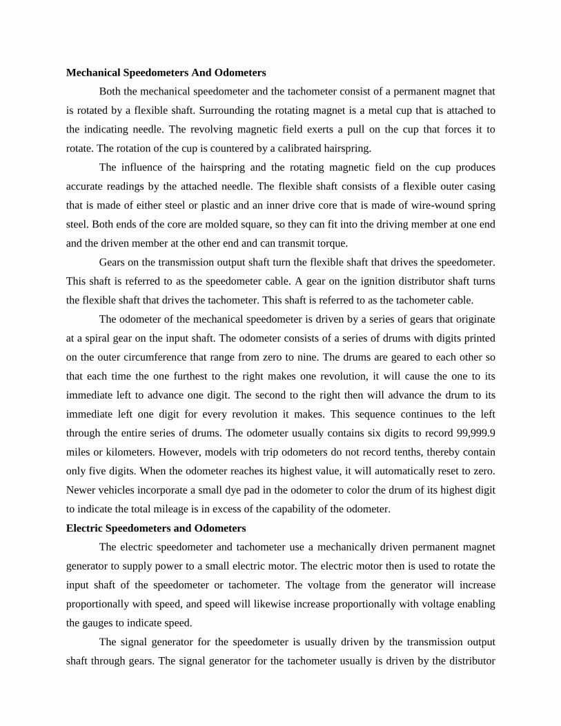
Mechanical Speedometers And Odometers
Both the mechanical speedometer and the tachometer consist of a permanent magnet that
is rotated by a flexible shaft. Surrounding the rotating magnet is a metal cup that is attached to
the indicating needle. The revolving magnetic field exerts a pull on the cup that forces it to
rotate. The rotation of the cup is countered by a calibrated hairspring.
The influence of the hairspring and the rotating magnetic field on the cup produces
accurate readings by the attached needle. The flexible shaft consists of a flexible outer casing
that is made of either steel or plastic and an inner drive core that is made of wire-wound spring
steel. Both ends of the core are molded square, so they can fit into the driving member at one end
and the driven member at the other end and can transmit torque.
Gears on the transmission output shaft turn the flexible shaft that drives the speedometer.
This shaft is referred to as the speedometer cable. A gear on the ignition distributor shaft turns
the flexible shaft that drives the tachometer. This shaft is referred to as the tachometer cable.
The odometer of the mechanical speedometer is driven by a series of gears that originate
at a spiral gear on the input shaft. The odometer consists of a series of drums with digits printed
on the outer circumference that range from zero to nine. The drums are geared to each other so
that each time the one furthest to the right makes one revolution, it will cause the one to its
immediate left to advance one digit. The second to the right then will advance the drum to its
immediate left one digit for every revolution it makes. This sequence continues to the left
through the entire series of drums. The odometer usually contains six digits to record 99,999.9
miles or kilometers. However, models with trip odometers do not record tenths, thereby contain
only five digits. When the odometer reaches its highest value, it will automatically reset to zero.
Newer vehicles incorporate a small dye pad in the odometer to color the drum of its highest digit
to indicate the total mileage is in excess of the capability of the odometer.
Electric Speedometers and Odometers
The electric speedometer and tachometer use a mechanically driven permanent magnet
generator to supply power to a small electric motor. The electric motor then is used to rotate the
input shaft of the speedometer or tachometer. The voltage from the generator will increase
proportionally with speed, and speed will likewise increase proportionally with voltage enabling
the gauges to indicate speed.
The signal generator for the speedometer is usually driven by the transmission output
shaft through gears. The signal generator for the tachometer usually is driven by the distributor
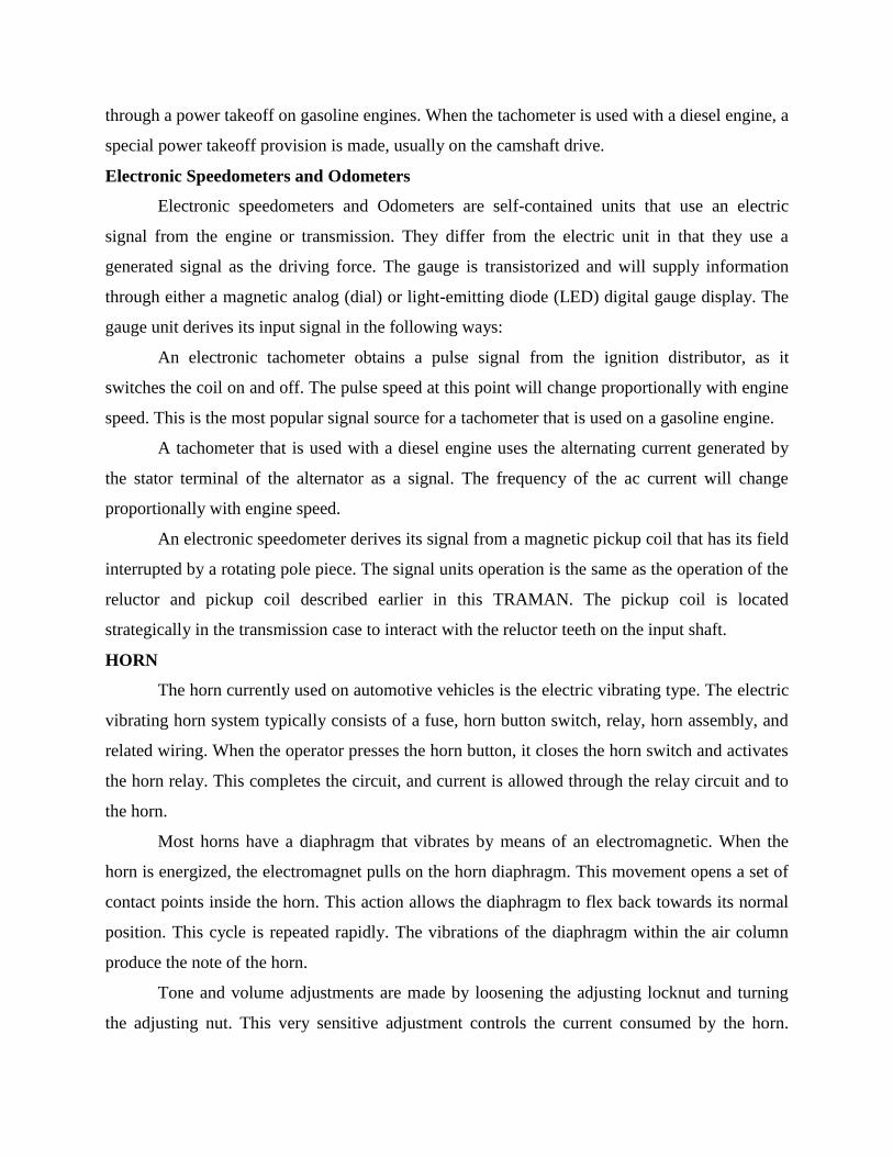
through a power takeoff on gasoline engines. When the tachometer is used with a diesel engine, a
special power takeoff provision is made, usually on the camshaft drive.
Electronic Speedometers and Odometers
Electronic speedometers and Odometers are self-contained units that use an electric
signal from the engine or transmission. They differ from the electric unit in that they use a
generated signal as the driving force. The gauge is transistorized and will supply information
through either a magnetic analog (dial) or light-emitting diode (LED) digital gauge display. The
gauge unit derives its input signal in the following ways:
An electronic tachometer obtains a pulse signal from the ignition distributor, as it
switches the coil on and off. The pulse speed at this point will change proportionally with engine
speed. This is the most popular signal source for a tachometer that is used on a gasoline engine.
A tachometer that is used with a diesel engine uses the alternating current generated by
the stator terminal of the alternator as a signal. The frequency of the ac current will change
proportionally with engine speed.
An electronic speedometer derives its signal from a magnetic pickup coil that has its field
interrupted by a rotating pole piece. The signal units operation is the same as the operation of the
reluctor and pickup coil described earlier in this TRAMAN. The pickup coil is located
strategically in the transmission case to interact with the reluctor teeth on the input shaft.
HORN
The horn currently used on automotive vehicles is the electric vibrating type. The electric
vibrating horn system typically consists of a fuse, horn button switch, relay, horn assembly, and
related wiring. When the operator presses the horn button, it closes the horn switch and activates
the horn relay. This completes the circuit, and current is allowed through the relay circuit and to
the horn.
Most horns have a diaphragm that vibrates by means of an electromagnetic. When the
horn is energized, the electromagnet pulls on the horn diaphragm. This movement opens a set of
contact points inside the horn. This action allows the diaphragm to flex back towards its normal
position. This cycle is repeated rapidly. The vibrations of the diaphragm within the air column
produce the note of the horn.
Tone and volume adjustments are made by loosening the adjusting locknut and turning
the adjusting nut. This very sensitive adjustment controls the current consumed by the horn.
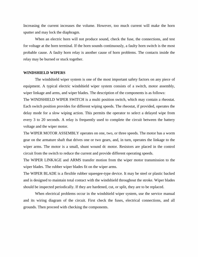
Increasing the current increases the volume. However, too much current will make the horn
sputter and may lock the diaphragm.
When an electric horn will not produce sound, check the fuse, the connections, and test
for voltage at the horn terminal. If the horn sounds continuously, a faulty horn switch is the most
probable cause. A faulty horn relay is another cause of horn problems. The contacts inside the
relay may be burned or stuck together.
WINDSHIELD WIPERS
The windshield wiper system is one of the most important safety factors on any piece of
equipment. A typical electric windshield wiper system consists of a switch, motor assembly,
wiper linkage and arms, and wiper blades. The description of the components is as follows:
The WINDSHIELD WIPER SWITCH is a multi position switch, which may contain a rheostat.
Each switch position provides for different wiping speeds. The rheostat, if provided, operates the
delay mode for a slow wiping action. This permits the operator to select a delayed wipe from
every 3 to 20 seconds. A relay is frequently used to complete the circuit between the battery
voltage and the wiper motor.
The WIPER MOTOR ASSEMBLY operates on one, two, or three speeds. The motor has a worm
gear on the armature shaft that drives one or two gears, and, in turn, operates the linkage to the
wiper arms. The motor is a small, shunt wound dc motor. Resistors are placed in the control
circuit from the switch to reduce the current and provide different operating speeds.
The WIPER LINKAGE and ARMS transfer motion from the wiper motor transmission to the
wiper blades. The rubber wiper blades fit on the wiper arms.
The WIPER BLADE is a flexible rubber squeegee-type device. It may be steel or plastic backed
and is designed to maintain total contact with the windshield throughout the stroke. Wiper blades
should be inspected periodically. If they are hardened, cut, or split, they are to be replaced.
When electrical problems occur in the windshield wiper system, use the service manual
and its wiring diagram of the circuit. First check the fuses, electrical connections, and all
grounds. Then proceed with checking the components.