Embed Size (px)
Citation preview

AUTOMATON
Team Members:
Andrew Watson, Brandon Parmeter, Blake Parmeter, Josh Townsend, Chris Brice
Faculty Advisor:
Daniel Barber, Institute for Simulation and Training
Faculty Statement: I certify that the vehicle has been significantly modified forthis year’s competition
Daniel Barber

AUTOMATON University of Central Florida IGVC 2013
1 Introduction
The Robotics Club at UCF is honored to announce AUTOMATON into the 21st
annual Intelligent Ground Vehicle Competition (IGVC). AUTOMATON is the cul-
mination of efforts from a variety of predominantly undergraduate engineers whose
efforts have yielded a remarkably competitive platform. With a focus on upgrading
capabilities and maintaining reliability the team members were divided into groups
which allowed their expertise to be honed in their respective fields. New camera sys-
tems, optimized power delivery, and new vision classification algorithms will allow
AUTOMATON to extend its faculties to an increasingly arduous competition.
2 Design Process
Figure 1: Agile Development Cy-
cle
The Agile method is the process utilized for con-
struction and fabrication of AUTOMATON, and
particularly its software. Agile development is
centered around an iterative process of team col-
laboration to improve project clarity and ensure
quality of work. This methodology promotes
constant releases of software to maintain discus-
sion of project direction. Development occurs
in conjunction with requirement refinement thus
ensuring minimum delays in progress. Progress
is centered on short term goals with the hope of
achieving an approach or strategy for solving a
more abstract problem. These short term goals are usually released as software
updates to AUTOMATON via open source software releases.
Figure 1 demonstrates the multiple loops involved in the Agile Development
strategy. Closer to the center are continuous iterations of development, analogous
to the daily software releases of AUTOMATON’s code. Further from the center are
the more abstract goals. This multi-loop system enables the team to develop in a
very dynamic way, reducing risks associated with challenges faced throughout the
design process.
3 Mechanical
1
AUTOMATON University of Central Florida IGVC 2013
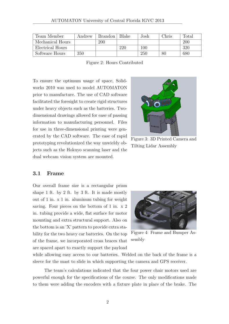
Team Member Andrew Brandon Blake Josh Chris TotalMechanical Hours 200 200Electrical Hours 220 100 320Software Hours 350 250 80 680
Figure 2: Hours Contributed
Figure 3: 3D Printed Camera and
Tilting Lidar Assembly
To ensure the optimum usage of space, Solid-
works 2010 was used to model AUTOMATON
prior to manufacture. The use of CAD software
facilitated the foresight to create rigid structures
under heavy objects such as the batteries. Two-
dimensional drawings allowed for ease of passing
information to manufacturing personnel. Files
for use in three-dimensional printing were gen-
erated by the CAD software. The ease of rapid
prototyping revolutionized the way unwieldy ob-
jects such as the Hokuyo scanning laser and the
dual webcam vision system are mounted.
3.1 Frame
Figure 4: Frame and Bumper As-
sembly
Our overall frame size is a rectangular prism
shape 1 ft. by 2 ft. by 3 ft. It is made mostly
out of 1 in. x 1 in. aluminum tubing for weight
saving. Four pieces on the bottom of 1 in. x 2
in. tubing provide a wide, flat surface for motor
mounting and extra structural support. Also on
the bottom is an ’X’ pattern to provide extra sta-
bility for the two heavy car batteries. On the top
of the frame, we incorporated cross braces that
are spaced apart to exactly support the payload
while allowing easy access to our batteries. Welded on the back of the frame is a
sleeve for the mast to slide in which supporting the camera and GPS receiver.
The team’s calculations indicated that the four power chair motors used are
powerful enough for the specifications of the course. The only modifications made
to them were adding the encoders with a fixture plate in place of the brake. The
2

AUTOMATON University of Central Florida IGVC 2013
fixture plate design allowed for four different mounting positions of the encoders
that enabled us to run the wires easily for a clean look. To mount the motors to the
frame, a fixture plate was fabricated that provided a flat surface for the motors to
mount over the welds. For easy steering, the motors are located center on the frame
in an exact square pattern measured from the apex of the center of the tires. The
hubs used were made for the motor spindles, held in place by a key way. No two
piece wheels were available that fit the hubs, so an interface plate was designed and
manufactured. This made the two compatible while allowing extra clearance room
between the tires and the frame.
3.2 Drive System
Figure 5: Skid Steering System
AUTOMATON’s drive system includes four
power chair motors mounted in a differential skid
steering configuration. The power chair motors
provide plenty of torque and speed to allow pre-
cise maneuvering through the course. Brakes
were removed from the wheelchair motors to al-
low fitment of the quadrature encoders. They
are used to monitor the speed of each individual
motor to close a feedback loop. An aluminum
plate was implemented to provide a flat surface
for the motors to mount to. An in house fab-
ricated adapting plate holds the wheel hubs to
the stock motor hubs. To circumvent adding a
heavy suspension system, inflatable tube tires
were chosen to absorb vibrations due to the
course’s terrain.
4 Electrical
The electrical system in AUTOMATON meant to be as strait forward as possible,
predominantly using off-the-shelf parts to minimize cost and reduce human error
during construction. This simple philosophy proved to be very effective in making
a solid platform which works consistently and effectively.
3

AUTOMATON University of Central Florida IGVC 2013
Figure 6: Microcontroller and RC Circuit Board
4.1 Motor Controllers and RC
Two Roboteq AX3500 motor controllers are employed to actuate the robot’s mo-
tors. Each controller can output 60A per channel, with one motor connected to
each channel. This allows the robot to have the capability to actuate each motor
independently of the others. Commands to the controller are sent over RS232 serial.
RC and PC control are toggled using an ARMmite processor on a customer circuit
board, enabling AUTOMOTON to be driven Without the onboard PC being turned
on.
4.2 Power System
Three 12 Volt 55 Amp-hour lead-acid marine batteries are used to power the plat-
form. Assuming maximum efficiency of the motors, a 1-mile operational range is
achieved. With all the sensors enabled and the computer on, a draw of 5 Amps
was recorded, allowing for a maximum run time of 11 hours.The robustness of this
battery technology allowed for the implementation of the four high-torque motors
and the power-hungry computer. Battery chargers are also built into the vehicle,
allowing for a convenient shore power setup.
4

AUTOMATON University of Central Florida IGVC 2013
4.3 Computer
AUTOMATON is equipped with a Quad-Core Hyper-threaded Intel Sandybridge
i7 processor. The computer also has 8 GB of DDR3 RAM. In addition, it has
support for connecting to devices which use 1394 FireWire, USB 2.0 and 3.0. RS232
communication is achieved using USB to Serial connectors external to the computer.
It has a 300 Watt power supply in order to give it significant room for the machine’s
95W processor.
4.4 Safety
Safety is a primary concern of the team, and thus precautions are in place in the
event of system failure. There are two main methods of disabling the vehicle: wire-
less ESTOP and hard ESTOP. The wireless ESTOP can be activated by the RC
controller, which bypasses the computer system and forces the robot to stop all
actuation. The hard ESTOP is activated by a button about 4 feet from the base
of the vehicle. This function completely disables the robot’s motion, requiring both
a reset of the ESTOP button and for the motor system to be power cycled. Addi-
tionally, the system is tied actively to the ESTOP button in such a way that if the
line connecting the button were disabled, the system would go into ESTOP mode
requiring a power cycle and reconnection of the button.
4.5 Sensors
Figure 7: Sensor Mast
AUTOMATON takes advantage of several different sen-
sors to understand its own kinematics and surroundings.
Kinematics are resolved using a 3-axis digital compass,
the Coral AHRS, along with 4 quadrature encoders (one
for each wheel), and a differential GPS to interpret its
motion. The encoders, which run at 180 ticks per revo-
lution before the gear box, deliver sub-millimeter accu-
racy in the rotation of each of the individual wheels en-
abling high precision closed-loop operation. The Differ-
ential GPS on board provides sub-meter accuracy, with
tests indicating 2 to 8 decimeters.
5

AUTOMATON University of Central Florida IGVC 2013
Sensor List
• Hokuyo UTM-30LX scanning laser
– Two dimensional scanning laser
• MicroStrain 3DM-GX1 compass accelerometer
– Compact compass and accelerometer, 0.5◦accuracy
• 2 x Logitech Webcam Pro 9000 camera
– Commercial off the shelf webcam
– Selected for superior image stability and color quality
• CSI Wireless MD Minimax GPS unit
– Global Positioning unit with sub meter accuracy
5 Software
The JAUS challenge has stringent requirements for adherence to the SAE JAUS
standard. The service-based architecture defines reusable capabilities of autonomous
vehicles broken down to the most abstract levels. The architecture heavily influenced
design of AUTOMATONs software and implementation in order to comply with the
standard. Continuing the success of previous iterations the software base utilizes
two separate programs for vehicle operation.
5.1 Structure
The two main programs ”Baseline” and ”Ground” are run on AUTOMATON to
complete all course challenges. The Baseline program is responsible for integration
of all hardware and sensors (I/O devices). Using JAUS as an abstraction Baseline
is a standalone program allowing for any JAUS compliant program to subscribe to
data streams and to request vehicle control. The ground program utilizes JAUS
messages to maintain control of the vehicle through the Baseline program. This
program contains all AI and intelligence including vision processing, path planning,
and obstacle avoidance. The JAUS library utilized is JAUS++ which is available on
sourceforge.net. The JAUS++ library was selected for its proven compliance with
the SAE standard at previous AUVSI competitions and strong documentation.
6
AUTOMATON University of Central Florida IGVC 2013
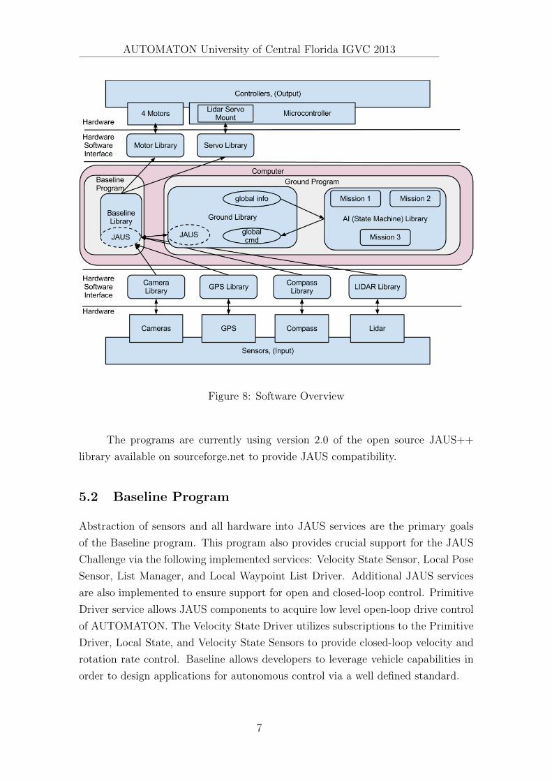
Figure 8: Software Overview
The programs are currently using version 2.0 of the open source JAUS++
library available on sourceforge.net to provide JAUS compatibility.
5.2 Baseline Program
Abstraction of sensors and all hardware into JAUS services are the primary goals
of the Baseline program. This program also provides crucial support for the JAUS
Challenge via the following implemented services: Velocity State Sensor, Local Pose
Sensor, List Manager, and Local Waypoint List Driver. Additional JAUS services
are also implemented to ensure support for open and closed-loop control. Primitive
Driver service allows JAUS components to acquire low level open-loop drive control
of AUTOMATON. The Velocity State Driver utilizes subscriptions to the Primitive
Driver, Local State, and Velocity State Sensors to provide closed-loop velocity and
rotation rate control. Baseline allows developers to leverage vehicle capabilities in
order to design applications for autonomous control via a well defined standard.
7

AUTOMATON University of Central Florida IGVC 2013
5.3 Ground Program
A stable platform with robust capabilities is at the focus of design of AUTOMA-
TON and all programmed intelligence therein. With Baseline as a host the Ground
program builds autonomy into the system with the use of object detection, path
planning, and finite state machine logic to accomplish tasks provided by the com-
petition. The separation of the AI allows developers to quickly analyze system and
algorithmic performance of the system as well as provide separate interfaces to the
different subsystems. The Ground program provides useful debugging tools by sup-
plying an interface for sensor data playback logged during practice runs. Logging
is useful for debugging all intelligence systems from vision classification to state
machine logic.
5.4 Computer Vision
All aspects of the IGVC course depend on the ability of vehicles to detect objects and
markers in a dynamic environment. AUTOMATON accomplishes this via a robust
detection system which leverages onboard vision processing from a dual webcam
vision system. The platform applies vision algorithms for locating boundary lines of
the course and providing supplemental cues to the AI of possible obstacles and other
regions of interest. Vision algorithms are responsible for classifying, estimating, and
detecting angles of lane boundaries. Other tasks include recognizing and filtering out
potential obstacles in the path of the vehicle. OpenCV is a computer vision library
utilized for all vision processing as it is powerful, well supported, and features many
useful tools for accomplishing both lane line and obstacle detection.
5.4.1 Lane Line Detection
Figure 9: Raw Image
The most fundamental asset of navigation in AUTOMA-
TON’s AI is the ability to estimate position relative to
lane lines discovered in vision processing. Software re-
search discovered existing approaches to the problem and
were used in conjunction with algorithms from previous
IGVC events. The solution applied to AUTOMATON re-
quires an application of a white filter to the image upon
removal of any obstacles seen. Bright areas of interest
are identified and the image is then passed through a Gaussian blur to smooth areas
of noise. Edge detection outlines contrasting areas of the remaining image and a
8

AUTOMATON University of Central Florida IGVC 2013
Canny edge detector outlines the edges of the white lines on the grass. To perfect
and improve reliability of lane line detection blob detection is used to remove any
edges smaller than predetermined levels so as to remove random noise caused by
uneven terrain or brown patches of grass.
Figure 10: Post Process-
ing
After all filters have been applied the image con-
sist of white outlines on a black background outlining the
lines. To compute a line the team utilized a RANSAC
(RANdom SAmple Consensus) algorithm. Tests of the
RANSAC against Hough line transforms proved more
consistent in line fitness and had an added benefit of
returning a single line rather than many. The algorithm
is run twice to detect both lines.
5.4.2 Obstacle Detection
Vision processing is used in conjunction with laser readings to detect obstacles.
Algorithms running blob and color classification are run on captured images from the
panoramic vision system. Images capture in the RGB color space are converted to
HLS (Hue Lightness Saturation) for more reliable color classification as hue becomes
the favored channel.
5.4.3 Perspective Correction
Figure 11: Homography
AUTOMATON’s single camera is mounted about 6 feet
above ground and aimed at a downward angle to see the
ground directly in front of the vehicle. In a 2D image
captured from the camera, objects and lines close to the
vehicle appear large or far apart, while objects and lines
further from the vehicle appear small or close together.
This is the illusion of perspective, and because of this
illusion an accurate mapping of line angles, lengths and
locations cannot be done without some transformation
of the 2D image.
Correcting perspective requires an offline calibra-
tion phase in which a rectangular object of known size is
placed on the ground plane in front of the vehicle. The
corners are picked out, and a matrix is generated that
9
AUTOMATON University of Central Florida IGVC 2013
transform relative pixel coordinates of the corners to the actual known relative cor-
ner positions. This matrix can then be applied to the entire image to correct each
pixel for perspective distortion. This has the primary benefit of correcting angles
that would be incorrect due to perspective, such as the illusion of parallel lines
converging in the distance.
The secondary benefit of this correction is that pixels can also be mapped to
an arbitrary unit of distance; in AUTOMATON’s case each pixel is mapped to 1
centimeter. This mapping only applies to features on the ground(such as lane lines),
and can be fairly accurate depending on the quality of image and calibration.
5.5 Real-Time Configuration
Most important variables that tweak AUTOMATON’s behavior have been added
to XML files which are easily human readable and modifiable. These files con-
tain information about the robots JAUS configuration, hardware devices, vehicle
dimensions, mission, and so on. For situations that require input or training, such
as vision processing or Proportional Integral Derivative (PID) controller tweaking,
AUTOMATON can load changes in real-time so that effects can be observed imme-
diately.
5.6 Logging and Playback
Recording data for analysis is an important part of improving performance of this
vehicle. Through XML, logging of all sensors, including video and LIDAR can be
turned on at any specified rate. Recording runs through courses will be valuable
data for not only the current team but for future UCF teams that wish to attend
this competition. Because of the flexibility and modular nature of AUTOMATON’s
software systems, logged data can be replayed through AUTOMATON’s AI, this
allows for a powerful way to understand the dynamics of AUTOMATON’s decision
making, as the system knows no difference between being fed logged data or real-
time data.
5.7 Real-Time Mapping
The Cartographer mapping library has been used before in previous competitions,
but not to the same extent as AUTOMATON. This year sees the addition of more
efficient map storage and retrieval, improved path planning and navigation and for
10
AUTOMATON University of Central Florida IGVC 2013
the first time cooperation with the vision processing subsystem. Lane lines found
through vision are merged with LIDAR data to create a detailed and cohesive map
of the environment around AUTOMATON.
6 Mapping
All of the maps are constructed in a framework called Cartographer. This framework
is very flexible, allowing the system to build vector or raster based maps depending
on what is deemed best for a given situation. Abstracting the type of underlying
map, developers can implement different types of path planning algorithms for ob-
stacle avoidance and navigation. This specific feature supports prototyping many
different algorithms to determine what works best for the challenges presented. The
map used is a 2 or 3 dimensional, top down view of the world. Map information
is stored in a Quadtree structure to take advantage of spatial locality of objects in
order to minimize search space for path searching algorithm.
6.1 Navigation Challenge
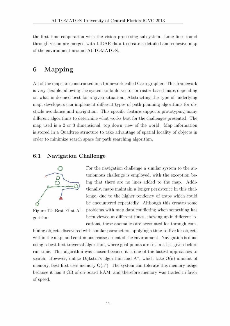
Figure 12: Best-First Al-
gorithm
For the navigation challenge a similar system to the au-
tonomous challenge is employed, with the exception be-
ing that there are no lines added to the map. Addi-
tionally, maps maintain a longer persistence in this chal-
lenge, due to the higher tendency of traps which could
be encountered repeatedly. Although this creates some
problems with map data conflicting when something has
been viewed at different times, showing up in different lo-
cations, these anomalies are accounted for through com-
bining objects discovered with similar parameters, applying a time-to-live for objects
within the map, and continuous reassessrnent of the environment. Navigation is done
using a best-first traversal algorithm, where goal points are set in a list given before
run time. This algorithm was chosen because it is one of the fastest approaches to
search. However, unlike Dijkstra’s algorithm and A*, which take O(n) amount of
memory, best-first uses memory O(n2). The system can tolerate this memory usage
because it has 8 GB of on-board RAM, and therefore memory was traded in favor
of speed.
11

AUTOMATON University of Central Florida IGVC 2013
6.2 Autonomous Challenge
Figure 13: Beam Search
Algorithm
For the autonomous challenge, there are two types of
objects added to the map. The first are points, generated
from the LIDAR, represent elements of a point cloud in
the environment. These points come together to form
barrels and other obstacles. The other type is the lines,
which are treated like Walls in the map’s representation.
The computer vision system projects the lane lines it
finds into the ground coordinate space and then added
to the map as a line segment (or Wall segment). All
obstacle avoidance is then carried out to navigate around these dots and lines. Lane
lines are given a unique ID within the map, for determination of lane direction and
center.
For path generation, a beam search algorithm was chosen. This type of algo-
rithm attempts to find a set of connected beams which will reach the desired goal
without hitting any obstacles. A depth of 3 beams slightly wider than the vehicle
are chosen to give tolerance to the size of the vehicle and also because it gave a
sufficient search space for the robot to a path in most instances. A single path is
chosen using a fitness function which Weighs paths on their length and proximity to
the goal. Using the results of the algorithm, a velocity and heading are generated
for closed-loop drive control.
Higher and lower speeds can be tolerated dynamically by adjusting the beam
length and depth. For instance, if the robot travels at a faster speed, the length of
the beams can be extended and the maximum angle which the beams are allowed
to bend is reduced so that the robot can anticipate motion in advance and does not
need to make as drastic of turns. Vehicle speeds are selected based on how cluttered
the surrounding environment is, with high speeds chosen in 10W density areas, and
low speeds when object density is high.
7 Innovative Features
Figure 14: 3D Laser Scan
AUTOMATON employs a plethora of innovative features
that will set the vehicle above the playing field in the 2013
IGVC competition. A wireless network bridge is imple-
mented to establish a reliable data link to the vehicle.
12

AUTOMATON University of Central Florida IGVC 2013
This bridge allows for a solid stream of up to 54Mbps to a mobile cart at a distance
of up to several miles! containing a computer and an uninterruptible power supply.
In previous submissions a scanning laser was employed, this sensor has since
been improved. This improvement consisted of a implementation of a servo motor
to change the pitch of the laser. This allowed for the sensor to be placed higher on
AUTOMATON in a more protected area. It also allowed for scanning on multiple
planes so that a Point cloud of the vehicle’s environment could be formed.
Figure 15: Camera Streams
This year the vision system was improved by implementing an array of two
webcams. The webcams provided a vibrant colors pallet when compared to other
video sources. The cameras were offset from each other to provide a wider field of
view than a single camera. The two video streams are put together using a stitching
algorithm and then sent to the computer vision system for processing. Another
Figure 16: Final Panorama
feature implemented in the 2013 submission is a video streaming server. The server
allows for multicast connections to clients vastly improving network efficiency. Al-
though only implemented for a single video source, this system allows for a wider
13
AUTOMATON University of Central Florida IGVC 2013
array of video input devices to be seamlessly integrated. Future video streams may
include a two dimensional representation of the environmental point cloud or an
infrared camera system.
8 Vehicle Performance & Analysis
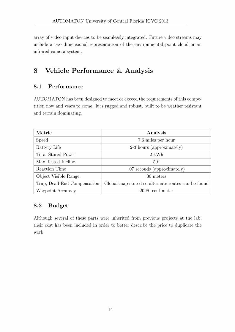
8.1 Performance
AUTOMATON has been designed to meet or exceed the requirements of this compe-
tition now and years to come. It is rugged and robust, built to be weather resistant
and terrain dominating.
Metric Analysis
Speed 7.6 miles per hour
Battery Life 2-3 hours (approximately)
Total Stored Power 2 kWh
Max Tested Incline 50◦
Reaction Time .07 seconds (approximately)
Object Visible Range 30 meters
Trap, Dead End Compensation Global map stored so alternate routes can be found
Waypoint Accuracy 20-80 centimeter
8.2 Budget
Although several of these parts were inherited from previous projects at the lab,
their cost has been included in order to better describe the price to duplicate the
work.
14

AUTOMATON University of Central Florida IGVC 2013
Item Unit Cost Quantity Total Cost
Computer $900.00 1 $900.00
Aluminum (box and sheet)for Frame $350.00 - $350.00
Welding Work $100.00 - $100.00
Wheelchair Motors with Gearbox $299.99 4 $1,199.96
Mini-MAX DGPS $2,000.00 1 $2,000.00
180 PPR Quadrature Optical Encoders $50.00 4 $200.00
Wheels, Inner tubes, Hubs $78.04 4 $312.16
Hokuyo LIDAR $5,000.00 1 $5,000.00
Dynamixel RX-24F $140.00 1 $140.00
Coral AHRS Digital Compass and IMU $1,245.00 1 $1,245.00
Logitech Webcam Pro 9000 $90.00 1 $180.00
Roboteq AX3500 $400.00 2 $800.00
Ubiquiti Wireless System $250.00 2 $500.00
Miscellaneous Electronics $700.00 - $700.00
Miscellaneous Mechanical $350.00 - $350.00
Total $13,977.12
9 Conclusion
AUTOMATON, The University of Central Florida’s entry to the 2013 International
Ground Vehicle Competition is a rugged platform for robotics education. The in-
tegration of hardware and software has yielded a vehicle that is robust enough to
navigate the most challenging obstacles in the most extreme environments that AU-
VSI has to offer.
15

![[DESIGN REPORT : LEO10 ] Leo10.pdfDesign Report IGVC 2010 LEO10 National University of Singapore’s Entry to IGVC 2010 Dev Chandan Behera, Ankit Sachdev, Hitesh Dhiman, Dr. Prahlad](https://img.dokumen.tips/doc/110x75/5f4e39a519564a78275cccd7/design-report-leo10-leo10pdf-design-report-igvc-2010-leo10-national-university.jpg)


![[SOFTWARE DESIGN FOR IGVC COMPETITON ]](https://img.dokumen.tips/doc/110x75/61dab469fc8c63207126e873/software-design-for-igvc-competiton-.jpg)