Embed Size (px)
Citation preview

6th
BETA CAE International Conference
AUTOMATION TOOL FOR SHEET METAL STAMPING USING ANSA 1Ramesh Venkatesan*, 2 Nanda Kumar, 3Jithesh Erancheri 1Kaizenat Technologies Pvt Ltd, India KEYWORDS – Sheet-metal, Process manager, Automation, Residual stress, LS-DYNA ABSTRACT – Sheet metal forming involves a wide range of processes that manufacture parts for a vast amount of purposes. Carrying forward the initial stresses and strains from the forming results to crash have been established as a standard practice in CAE industry. There are many tools dedicated for Sheet metal forming simulations, however, very few provides seamless interface for sheet metal forming and crash simulations. As ANSA is very widely used in CAE for Crashworthiness studies using multi-physics solver like LS-DYNA, we found building an automation tool for sheet metal stamping can be helpful to Crash simulation engineers. Sheet metal forming is often considered as a highly domain specific application where users should be aware of the process more than CAE aspects. This highly recommends having an automation tool for the same. The powerful scripting capabilities of ANSA are used to build this tool. Tooling engineers find face difficultly to setup and tune CAE parameters like element formulation, number integration points etc. This tool will enable them to focus on real engineering rather than spending time on CAE model building. In this tool, users are expected to do only few clicks to set up the entire input file for solvers like LS-DYNA carrying terminologies of manufacturing industries. And this will be a bridge between manufacturing & CAE expertise to get better results from different analysis like Crash, NVH & durability etc. ANSA is a powerful tool for model set up which has a tight integration with LSDYNA solver. For the scripting, we have used the BETA scripting language. 1. INTRODUCTION
Sheet metal forming simulations are divided in to two forms such as Inverse Metal forming solving (One Step Analysis) and Incremental Solving (Explicit analysis). An inverse metal forming solver uses implicit methodology to solve the problem. As the name hints, it provides a final blank (flat profile) from the finish part. Though these results are quick and have limited accuracy from a tool engineer perspective, for product design engineer, these results are more than enough to understand the feasibility of his product design. Hence these results acts as guidelines for any product design from a manufacturing feasibility perspective. Also for CAE validation of any sheet metal parts under impact loading, it is proven through various research and studies that forming effects needs to be mapped on to impact models for better correlation. This underlines the significance of One Step Analysis in the product development process of a sheet metal part. Incremental Analysis is a virtual validation of sheet metal forming process. This requires the complete tool geometries, flat blank profiles as an input. The input deck is solved in well proven LSDYNA software using explicit integration scheme. Most of the major Tool rooms & OEM’s across world uses this technology to predict the defects generated during the metal forming process. A CAE engineer also may get requests to do tooling simulation. A template for the same helps him to setup without any difficulty. So, Incremental analysis for any complex dies can be set up in few clicks using this new GUI.

6th
BETA CAE International Conference
Figure 1 – Interfaces for One-step and Incremental Analysis. 2. ONESTEP ANALYSIS The below shown GUI (Figure 2) demonstrates how quickly the One Step Analysis can be set up:
Figure 2 – Interface of One-step analysis 2.1 STEP 1: IMPORT CAD GEOMETRY Import CAD Geometry will perform the following actions:
Opens CAD surfaces and performs Topology
Deletes visible ‘HOT Points’
Mesh the surfaces with Adv.Front Mesh algorithm
‘Release’ elements from Macros
Deletes all the Macros
Assign thickness
Orient the elements to one direction
Step 1
Step 2
Step 3
6th
BETA CAE International Conference
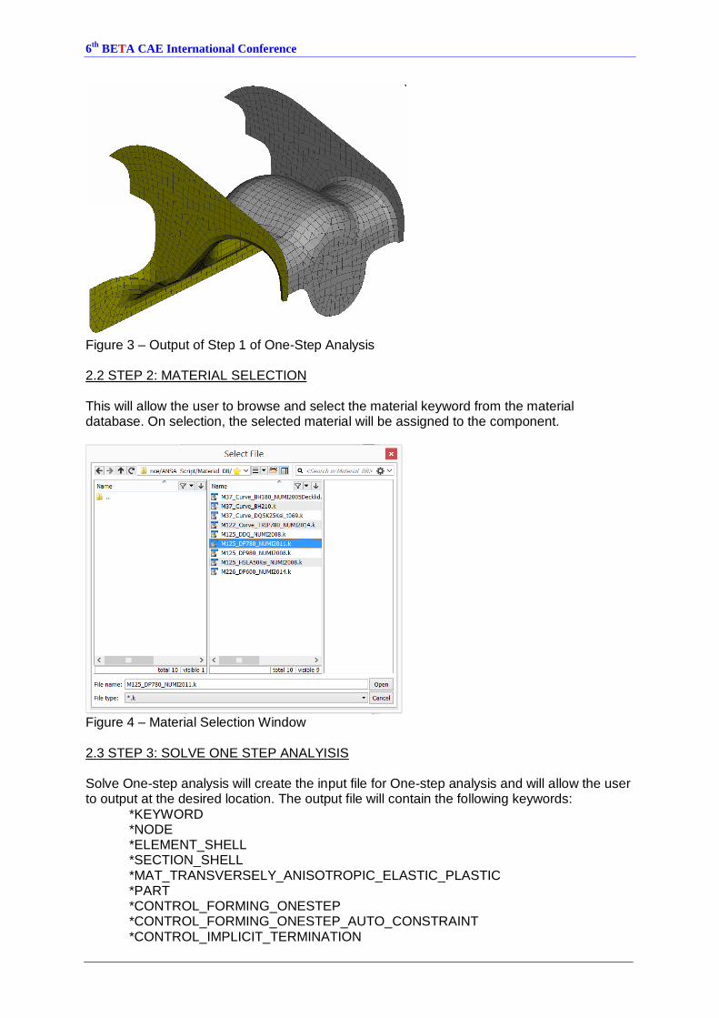
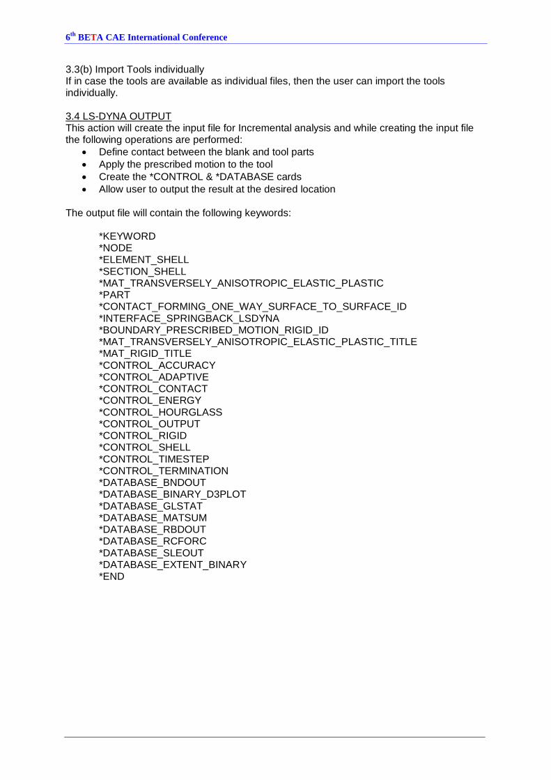
Figure 3 – Output of Step 1 of One-Step Analysis 2.2 STEP 2: MATERIAL SELECTION This will allow the user to browse and select the material keyword from the material database. On selection, the selected material will be assigned to the component.
Figure 4 – Material Selection Window
2.3 STEP 3: SOLVE ONE STEP ANALYISIS Solve One-step analysis will create the input file for One-step analysis and will allow the user to output at the desired location. The output file will contain the following keywords: *KEYWORD
*NODE *ELEMENT_SHELL *SECTION_SHELL *MAT_TRANSVERSELY_ANISOTROPIC_ELASTIC_PLASTIC *PART *CONTROL_FORMING_ONESTEP *CONTROL_FORMING_ONESTEP_AUTO_CONSTRAINT *CONTROL_IMPLICIT_TERMINATION

6th
BETA CAE International Conference
*CONTROL_IMPLICIT_GENERAL *CONTROL_IMPLICIT_NONLINEAR *CONTROL_TERMINATION *DATABASE_BINARY_D3PLOT *DATABASE_EXTENT_BINARY *END
2.4 LS-DYNA RESULTS
(a) Blank Development (b) Plastic Strain
Figure 5 – Output of One-Step Forming 3. INCREMENTAL ANALYSIS The below shown GUI (Figure 7) demonstrates how quickly the Incremental Analysis can be set up.
Figure 6 – Interface of Incremental Analysis

6th
BETA CAE International Conference
3.1 BLANK DETAILS 3.1.(a): IMPORT BLANK SURFACE This action will perform the following operations:
Opens CAD surfaces
Deletes visible ‘HOT Points’
Set the Perimeter Length
Mesh the surfaces with Adv.Front Mesh algorithm
‘Release’ elements from Macros
Deletes all the Macros
Assign thickness
Figure 7 – Meshed Blank 3.2 MATERIAL SELECTION This will allow the user to browse and select the material keyword from the pull down menu.
Figure 8 – Material Selection Window
Pull Down Menu

6th
BETA CAE International Conference
3.3 TOOL DETAILS The tools consist of die, punch and binder. They can be imported/extracted in two ways: 3.3(a): Offset punch and binder from die surfaces This action will perform the following sequence of operations:
Imports Die Surface
Mesh the surfaces with STL Mesh algorithm
Releases elements from Macros
Deletes all the Macros
User is allowed to select the binder region, on confirmation of the selection, binder and punch are created and named accordingly.
Then the tool parts are positioned automatically with reference to the binder.
*MAT_RIGID material is assigned to the tool parts
Figure 9 – Output of ‘Offset punch and binder from die surfaces’ option
Figure 10 – Auto-generation (of punch and binder from the die) and auto-positioning of tools w.r.t. the blank
Die
Blank
Punch
Binder
6th
BETA CAE International Conference
3.3(b) Import Tools individually If in case the tools are available as individual files, then the user can import the tools individually.
3.4 LS-DYNA OUTPUT This action will create the input file for Incremental analysis and while creating the input file the following operations are performed:
Define contact between the blank and tool parts
Apply the prescribed motion to the tool
Create the *CONTROL & *DATABASE cards
Allow user to output the result at the desired location The output file will contain the following keywords: *KEYWORD
*NODE *ELEMENT_SHELL *SECTION_SHELL *MAT_TRANSVERSELY_ANISOTROPIC_ELASTIC_PLASTIC *PART *CONTACT_FORMING_ONE_WAY_SURFACE_TO_SURFACE_ID *INTERFACE_SPRINGBACK_LSDYNA *BOUNDARY_PRESCRIBED_MOTION_RIGID_ID *MAT_TRANSVERSELY_ANISOTROPIC_ELASTIC_PLASTIC_TITLE *MAT_RIGID_TITLE *CONTROL_ACCURACY *CONTROL_ADAPTIVE *CONTROL_CONTACT *CONTROL_ENERGY *CONTROL_HOURGLASS *CONTROL_OUTPUT *CONTROL_RIGID *CONTROL_SHELL *CONTROL_TIMESTEP *CONTROL_TERMINATION *DATABASE_BNDOUT *DATABASE_BINARY_D3PLOT *DATABASE_GLSTAT *DATABASE_MATSUM *DATABASE_RBDOUT *DATABASE_RCFORC *DATABASE_SLEOUT *DATABASE_EXTENT_BINARY *END

6th
BETA CAE International Conference
3.5 LS-DYNA RESULTS
Figure 11 – Thinning Reduction Fringe Results
Figure 12 – Formability Plot Results

6th
BETA CAE International Conference
4. CONCLUSIONS Users can make use of this interface to simulate sheet metal forming with just few clicks. However, sheet metal forming is a vast topic which contains several stages. Our future scope of work includes building GUI for creating set up for different types of press and process like trimming, flanging, spring back prediction and compensation. ANSA’s scripting tool can also
be used to develop to call in ETA Post to create reports for interfaces for blank & trim line optimization. REFERENCES
(1) ANSA version 12.1.5 User’s Guide, BETA CAE Systems S.A., July 2008
(2) ETA PostProcessor version 6.2.0. User’s Guide, BETA CAE Systems S.A., June 2008
(3) LS-DYNA Keyword user's manual volume I (4) LS-DYNA Keyword user's manual volume II