Embed Size (px)
Citation preview
Application ReportSLOA175–February 2013
Automating Audio Bluetooth Connectivity Using NFCSecure Simple Pairing With TRF7970A, MSP430G2xx,
PCA9306, and CSR DEV-PC-1645J.Hicks and J. Wyatt .........................................................................................................................
ABSTRACT
The NFC Forum and the Bluetooth® Special Interest Group (SIG) collaborated to produce an applicationdocument entitled, NFC Forum Bluetooth Secure Simple Pairing Using NFC Application Document locatedat NFCForum-AD-BTSSP_1.0. This collaborative document is a follow up to a previously releasedspecification by the NFC Forum entitled, NFC Forum Connection Handover Specification, which began todefine the structure and sequence of interactions that enable two NFC-enabled devices to establish aconnection using other wireless communication technologies.
The purpose or intent of this application report is to explain how to implement the NFCForum-AD-BTSSP_1.0 specification in an embedded application using an I2C connection from the MSP430G2xx tothe host application MCU also controlling a Bluetooth™ radio and using SPI from that MSP430™ tocontrol the NFC Transceiver, the TRF7970A.
Project collateral and source code discussed in this application report can be downloaded from thefollowing URL: http://www.ti.com/lit/zip/sloa175.
Contents1 Using the Demonstration Hardware ...................................................................................... 22 Understanding the C Code Used for the CSR BC5MM ................................................................ 93 Understanding the C Code Used for the MSP430G2553 ............................................................. 94 References ................................................................................................................. 15
List of Figures
1 Components of the Demo.................................................................................................. 2
2 CSR Programming Setup .................................................................................................. 2
3 I2C TRF7970A Board Programming Connections...................................................................... 3
4 MSP430 Emulator Connection ............................................................................................ 3
5 Programming and Running Code Composer Studio Project .......................................................... 4
6 Connecting CSR Board and TI Boards .................................................................................. 4
7 Demo Setup ................................................................................................................. 5
8 Pairing the Bluetooth Device .............................................................................................. 6
9 Enabling Bluetooth and Connecting to the CSR Board ................................................................ 6
10 Play Music ................................................................................................................... 7
11 Figure 8. Control Buttons on CSR Board ................................................................................ 7
12 DEV-SYS-1309-1C Kit ..................................................................................................... 7
13 Disconnect ................................................................................................................... 8
14 Demo System Operation Logic Flow ..................................................................................... 8
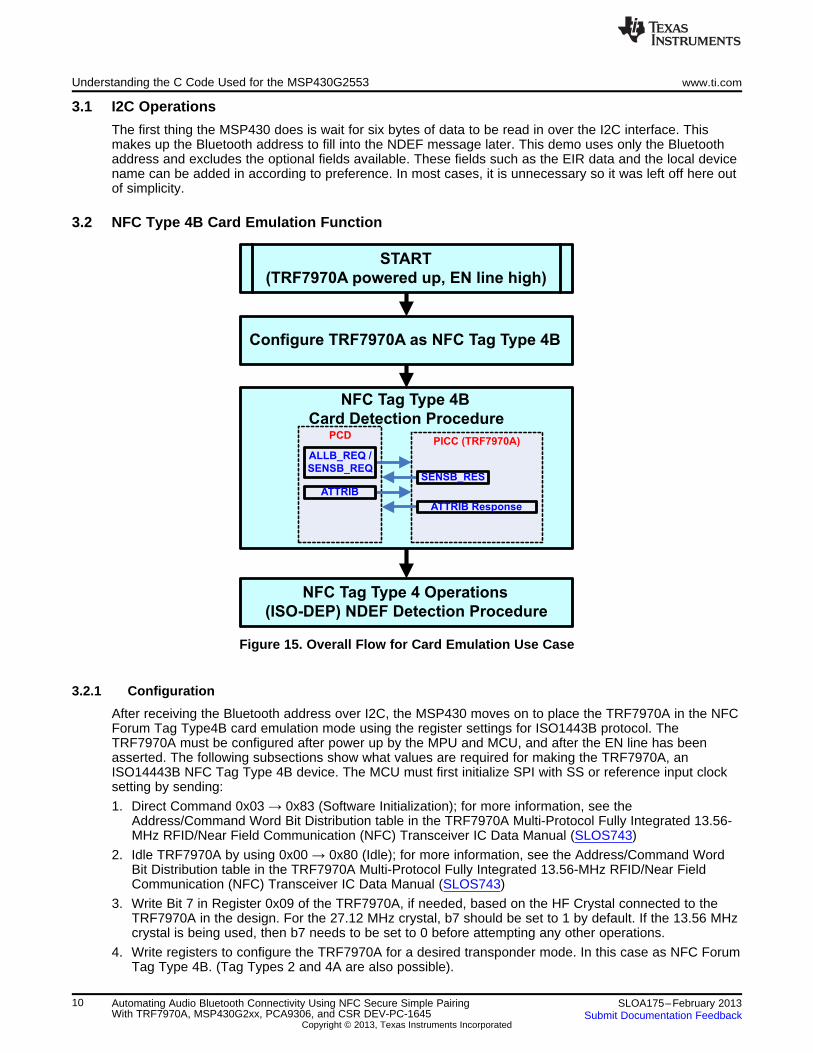
15 Overall Flow for Card Emulation Use Case............................................................................ 10
16 Card Activation and Selection Flow ..................................................................................... 13
Code Composer Studio is a trademark of Texas Instruments.Bluetooth is a registered trademark of Bluetooth SIG, Inc.All other trademarks are the property of their respective owners.
1SLOA175–February 2013 Automating Audio Bluetooth Connectivity Using NFC Secure Simple PairingWith TRF7970A, MSP430G2xx, PCA9306, and CSR DEV-PC-1645Submit Documentation Feedback
Copyright © 2013, Texas Instruments Incorporated
I2C TRF7970A_MSP430G2553
NFC/RFID board
CSR DEV-SYS-1645B3-1A
(BC5MM based)
Android Phone
(running v4.1.1 or higher)Speaker
Using the Demonstration Hardware www.ti.com
17 NDEF Detection, Selection, and Read Procedure .................................................................... 14
18 Pairing Failure.............................................................................................................. 14
List of Tables
1 TRF7970A Register Settings ............................................................................................ 11
1 Using the Demonstration Hardware
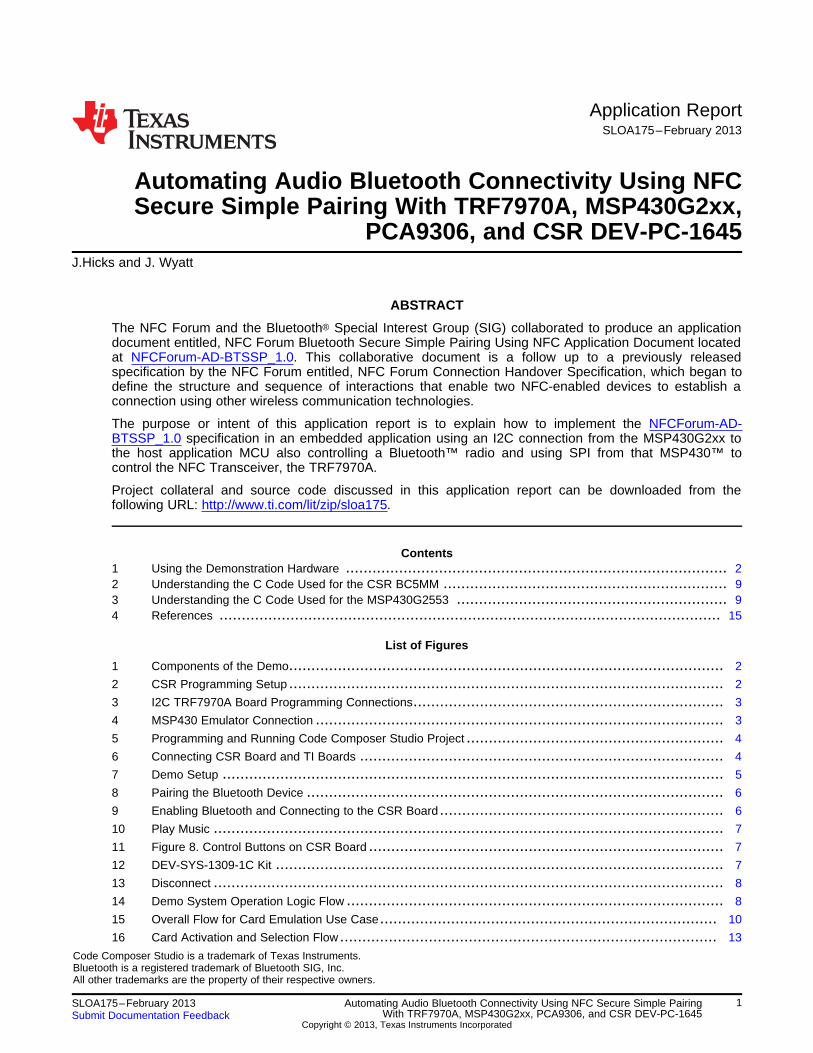
1.1 Contents of the Demo
In order to run the Bluetooth NFC audio connection handover demo, you must have an Android phone(with NFC and Bluetooth), a TI I2C TRF7970A_MSP430G2553 NFC and RFID board, a CSR DEV-PC-1645 board, and a speaker.
Figure 1. Components of the Demo
1.2 Preparing the Demo
Each board needs to be programmed before the demo can begin. Accompanying this document should bethe <NFC_BT_Pairing_demo_CSR1645.zip> containing the binary image to be used on the CSR 1645board and the Code Composer Studio™ IDE project code <spi_test.zip> for the TI MSP430/TRF7970Aboard.
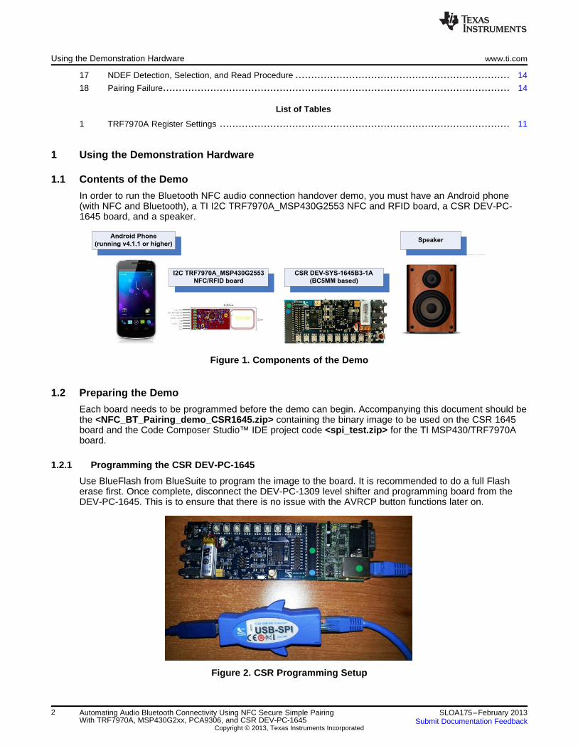
1.2.1 Programming the CSR DEV-PC-1645
Use BlueFlash from BlueSuite to program the image to the board. It is recommended to do a full Flasherase first. Once complete, disconnect the DEV-PC-1309 level shifter and programming board from theDEV-PC-1645. This is to ensure that there is no issue with the AVRCP button functions later on.
Figure 2. CSR Programming Setup
2 Automating Audio Bluetooth Connectivity Using NFC Secure Simple Pairing SLOA175–February 2013With TRF7970A, MSP430G2xx, PCA9306, and CSR DEV-PC-1645 Submit Documentation Feedback
Copyright © 2013, Texas Instruments Incorporated
J4 (on emulator) JP1 (on target)
1
2
3
4
5
6
EZ_VCC
SBWTCK
SBWTDIO
GND
1
2
3
4
5
6
GND
DVCC
7
8
SBWTCK
SBWTDIO
www.ti.com Using the Demonstration Hardware
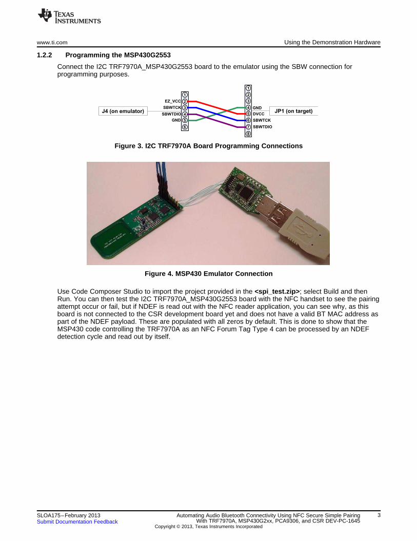
1.2.2 Programming the MSP430G2553
Connect the I2C TRF7970A_MSP430G2553 board to the emulator using the SBW connection forprogramming purposes.
Figure 3. I2C TRF7970A Board Programming Connections
Figure 4. MSP430 Emulator Connection
Use Code Composer Studio to import the project provided in the <spi_test.zip>; select Build and thenRun. You can then test the I2C TRF7970A_MSP430G2553 board with the NFC handset to see the pairingattempt occur or fail, but if NDEF is read out with the NFC reader application, you can see why, as thisboard is not connected to the CSR development board yet and does not have a valid BT MAC address aspart of the NDEF payload. These are populated with all zeros by default. This is done to show that theMSP430 code controlling the TRF7970A as an NFC Forum Tag Type 4 can be processed by an NDEFdetection cycle and read out by itself.
3SLOA175–February 2013 Automating Audio Bluetooth Connectivity Using NFC Secure Simple PairingWith TRF7970A, MSP430G2xx, PCA9306, and CSR DEV-PC-1645Submit Documentation Feedback
Copyright © 2013, Texas Instruments Incorporated
CSR PIO/AIO
Header
JP1 (TI Board)
PIO7
PIO6
1v8
GND
1
2
3
4
5
6
GND
DVCC
7
8
SBWTCK
SBWTDIO
SDA1
SCL1
1v8
VBAT
P2.5
8
7
22
20
21
Using the Demonstration Hardware www.ti.com
Figure 5. Programming and Running Code Composer Studio Project
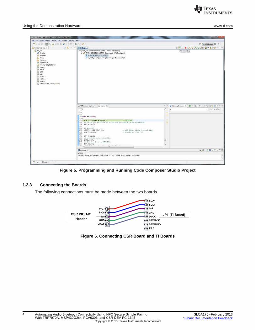
1.2.3 Connecting the Boards
The following connections must be made between the two boards.
Figure 6. Connecting CSR Board and TI Boards
4 Automating Audio Bluetooth Connectivity Using NFC Secure Simple Pairing SLOA175–February 2013With TRF7970A, MSP430G2xx, PCA9306, and CSR DEV-PC-1645 Submit Documentation Feedback
Copyright © 2013, Texas Instruments Incorporated
www.ti.com Using the Demonstration Hardware
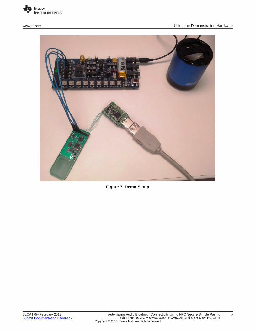
Figure 7. Demo Setup
5SLOA175–February 2013 Automating Audio Bluetooth Connectivity Using NFC Secure Simple PairingWith TRF7970A, MSP430G2xx, PCA9306, and CSR DEV-PC-1645Submit Documentation Feedback
Copyright © 2013, Texas Instruments Incorporated
Using the Demonstration Hardware www.ti.com
1.3 Operating the Demo
Power cycle the TI board to reset it. Power the CSR board by holding down the PWR/HOOK button untilyou see the Red and Blue LEDs alternating. This signals that the device is ready to pair.
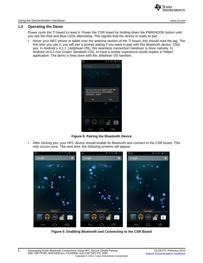
• Hover your NFC phone or tablet over the antenna section of the TI board, this should read the tag. Thefirst time you use it, you will see a prompt asking if you want to pair with this Bluetooth device. Clickyes. In Android v 4.1.1. (Jellybean OS), this seamless connection handover is done natively. InAndroid v4.0.4 (Ice Cream Sandwich OS), to have a similar experience would require a “helper”application. The demo is best done with the Jellybean OS handset.
Figure 8. Pairing the Bluetooth Device
• After clicking yes, your NFC device should enable its Bluetooth and connect to the CSR board. Thisonly occurs once. The next time, the following screens will appear.
Figure 9. Enabling Bluetooth and Connecting to the CSR Board
6 Automating Audio Bluetooth Connectivity Using NFC Secure Simple Pairing SLOA175–February 2013With TRF7970A, MSP430G2xx, PCA9306, and CSR DEV-PC-1645 Submit Documentation Feedback
Copyright © 2013, Texas Instruments Incorporated
HOLD
switch
www.ti.com Using the Demonstration Hardware
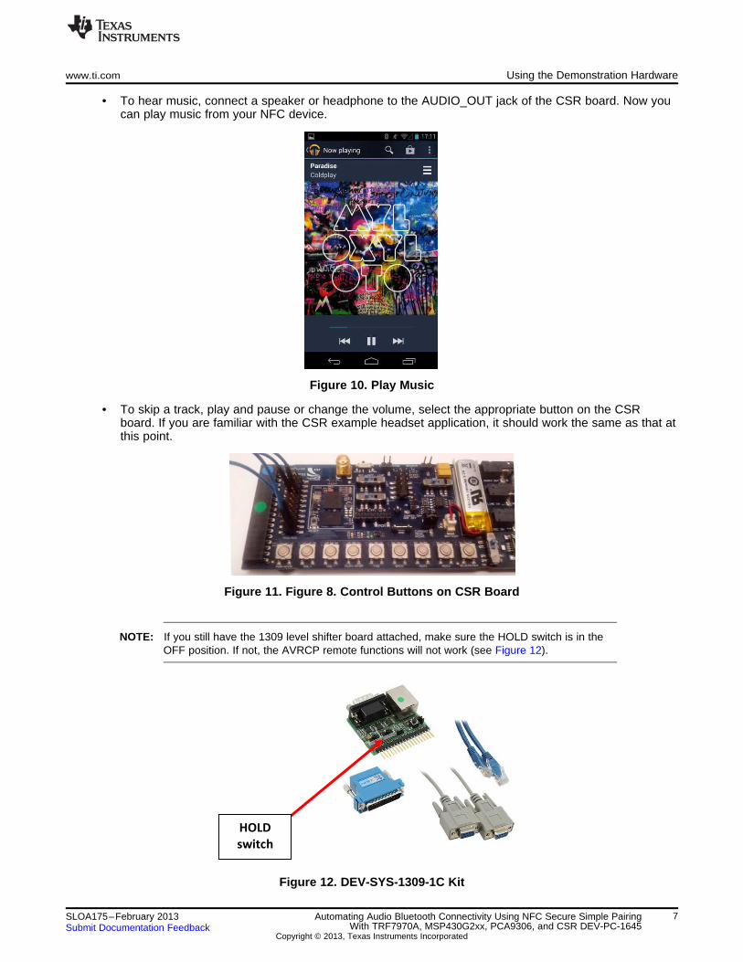
• To hear music, connect a speaker or headphone to the AUDIO_OUT jack of the CSR board. Now youcan play music from your NFC device.
Figure 10. Play Music
• To skip a track, play and pause or change the volume, select the appropriate button on the CSRboard. If you are familiar with the CSR example headset application, it should work the same as that atthis point.
Figure 11. Figure 8. Control Buttons on CSR Board
NOTE: If you still have the 1309 level shifter board attached, make sure the HOLD switch is in theOFF position. If not, the AVRCP remote functions will not work (see Figure 12).
Figure 12. DEV-SYS-1309-1C Kit
7SLOA175–February 2013 Automating Audio Bluetooth Connectivity Using NFC Secure Simple PairingWith TRF7970A, MSP430G2xx, PCA9306, and CSR DEV-PC-1645Submit Documentation Feedback
Copyright © 2013, Texas Instruments Incorporated
System PowerUp/Continue
BC5MM initializes, sendsI2C message to MSP430
(passing BT Address)
MSP430 ConfiguresTRF7970A for NFC ForumTag Type 4B Operations
Waiting for NFC Handsetto present a field and
issue ALLB_REQ orSENSB_REQ (REQB/WupB)
Handset enters field,activates and selects tag,performs NDEF Detection
and Message Retrieval
Handset OS performsconnection handover to
BT radio.
Using the Demonstration Hardware www.ti.com
• If you present antenna (usually a section of the back of the NFC handsets) over the antenna again, theBluetooth will disconnect.
Figure 13. Disconnect
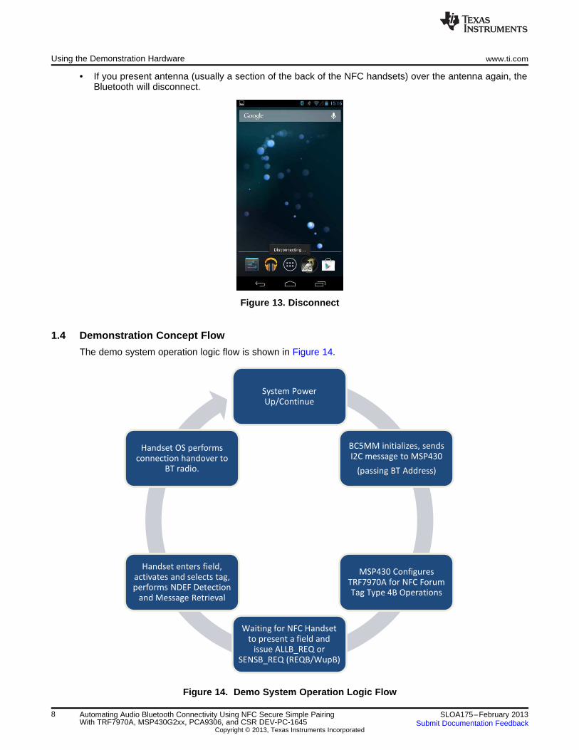
1.4 Demonstration Concept Flow
The demo system operation logic flow is shown in Figure 14.
Figure 14. Demo System Operation Logic Flow
8 Automating Audio Bluetooth Connectivity Using NFC Secure Simple Pairing SLOA175–February 2013With TRF7970A, MSP430G2xx, PCA9306, and CSR DEV-PC-1645 Submit Documentation Feedback
Copyright © 2013, Texas Instruments Incorporated
www.ti.com Understanding the C Code Used for the CSR BC5MM
2 Understanding the C Code Used for the CSR BC5MM
The I2C code used in the demo application on the BC5MM, acting as host MCU for the demo system, isshown below.
The Bluetooth address is read using PsFullRetrieve from ps.h. The BDADDR is stored in address 0x0001,however, when using the Headset SDK there is no data type available to store the 64-bit wide data. WhenPsFullRetrieve(0x0001, &addr_lap, 4) is executed, the lower three bytes of the address are stored inaddr_lap. The read at 0x0002 is used to store the upper three bytes of the address in addr_nap. Note thatwhile NAP refers to the first two bytes of the Bluetooth address, the third byte stored here is the UAP. Theformat of the return for addr_nap is UAP being the most significant byte and NAP being the leastsignificant two bytes.
As the Bluetooth address as been read out, it is then stored into an array of uint8 using the masking andshifting in the lines following the PsFullRetrieve calls. This processing matches up with how the data isexpected if using the code supplied for the MSP430 in this demo. The format can be manipulated asnecessary as long you it is done in both here for the CSR Bluetooth chip and for the MSP430 in thegeneration of the NDEF message.
I2cTransfer from i2c.h is used to send the data over the I2C interface. The return stored in i2check is thenumber of bytes that get successfully acknowledged.
This code should be integrated in the headset example application or your custom application so that itoccurs early on.
For the demo, this code was called from main after the LEDManagerInit() call.
#include <studio.h>#include <ps.h>#include <i2c.h>
void I2c_init (void){
uint32 addr_lap = 0;uint32 addr_nap = 0;
uint8 address[6];
uint16 i2check = 0;
PsFullRetrieve(0x0001, &addr_lap, 4);PsFullRetrieve(0x0002, &addr_nap, 4);
address[0] = (addr_lap & 0x0000ff)>>0;address[1] = (addr_lap & 0x00ff00)>>8;address[2] = (addr_lap & 0xff0000)>>16;address[3] = (addr_nap & 0xff0000)>>16;address[4] = (addr_nap & 0x0000ff)>>0;address[5] = (addr_nap & 0x00ff00)>>8;
i2check = I2cTransfer(0x48, (const uint8 *)address, 6, 0, 0);}
3 Understanding the C Code Used for the MSP430G2553
The code used in the demo application on the MSP430, acting as the TRF7970A master and as an I2Cslave to the host MCU for the demo system, was shown in Section 2. This code governs two functions tosuccessfully run the demo. First, it runs the MSP430's USCI_B channel to read in the I2C data sent fromthe CSR BC5MM. The demo uses the Bluetooth address only and leaves out the optional fields availablein the NFC specification. Second, it initializes and drives the TRF7970A in the card emulation mode.
9SLOA175–February 2013 Automating Audio Bluetooth Connectivity Using NFC Secure Simple PairingWith TRF7970A, MSP430G2xx, PCA9306, and CSR DEV-PC-1645Submit Documentation Feedback
Copyright © 2013, Texas Instruments Incorporated
NFC Tag Type 4B
Card Detection ProcedurePCD
PICC (TRF7970A)
START
(TRF7970A powered up, EN line high)
Configure TRF7970A as NFC Tag Type 4B
ALLB_REQ /
SENSB_REQ
ATTRIB
SENSB_RES
ATTRIB Response
NFC Tag Type 4 Operations
(ISO-DEP) NDEF Detection Procedure
Understanding the C Code Used for the MSP430G2553 www.ti.com
3.1 I2C Operations
The first thing the MSP430 does is wait for six bytes of data to be read in over the I2C interface. Thismakes up the Bluetooth address to fill into the NDEF message later. This demo uses only the Bluetoothaddress and excludes the optional fields available. These fields such as the EIR data and the local devicename can be added in according to preference. In most cases, it is unnecessary so it was left off here outof simplicity.
3.2 NFC Type 4B Card Emulation Function
Figure 15. Overall Flow for Card Emulation Use Case
3.2.1 Configuration
After receiving the Bluetooth address over I2C, the MSP430 moves on to place the TRF7970A in the NFCForum Tag Type4B card emulation mode using the register settings for ISO1443B protocol. TheTRF7970A must be configured after power up by the MPU and MCU, and after the EN line has beenasserted. The following subsections show what values are required for making the TRF7970A, anISO14443B NFC Tag Type 4B device. The MCU must first initialize SPI with SS or reference input clocksetting by sending:
1. Direct Command 0x03 → 0x83 (Software Initialization); for more information, see theAddress/Command Word Bit Distribution table in the TRF7970A Multi-Protocol Fully Integrated 13.56-MHz RFID/Near Field Communication (NFC) Transceiver IC Data Manual (SLOS743)
2. Idle TRF7970A by using 0x00 → 0x80 (Idle); for more information, see the Address/Command WordBit Distribution table in the TRF7970A Multi-Protocol Fully Integrated 13.56-MHz RFID/Near FieldCommunication (NFC) Transceiver IC Data Manual (SLOS743)
3. Write Bit 7 in Register 0x09 of the TRF7970A, if needed, based on the HF Crystal connected to theTRF7970A in the design. For the 27.12 MHz crystal, b7 should be set to 1 by default. If the 13.56 MHzcrystal is being used, then b7 needs to be set to 0 before attempting any other operations.
4. Write registers to configure the TRF7970A for a desired transponder mode. In this case as NFC ForumTag Type 4B. (Tag Types 2 and 4A are also possible).
10 Automating Audio Bluetooth Connectivity Using NFC Secure Simple Pairing SLOA175–February 2013With TRF7970A, MSP430G2xx, PCA9306, and CSR DEV-PC-1645 Submit Documentation Feedback
Copyright © 2013, Texas Instruments Incorporated
www.ti.com Understanding the C Code Used for the MSP430G2553
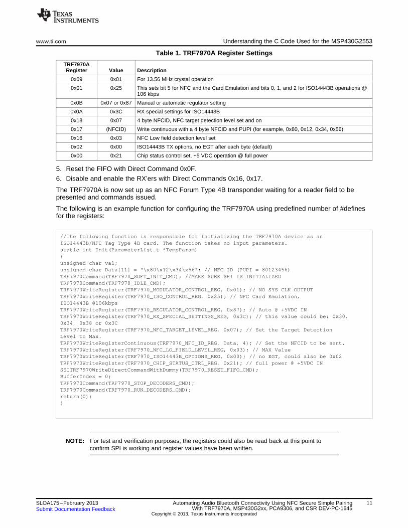
Table 1. TRF7970A Register Settings
TRF7970ARegister Value Description
0x09 0x01 For 13.56 MHz crystal operation
0x01 0x25 This sets bit 5 for NFC and the Card Emulation and bits 0, 1, and 2 for ISO14443B operations @106 kbps
0x0B 0x07 or 0x87 Manual or automatic regulator setting
0x0A 0x3C RX special settings for ISO14443B
0x18 0x07 4 byte NFCID, NFC target detection level set and on
0x17 (NFCID) Write continuous with a 4 byte NFCID and PUPI (for example, 0x80, 0x12, 0x34, 0x56)
0x16 0x03 NFC Low field detection level set
0x02 0x00 ISO14443B TX options, no EGT after each byte (default)
0x00 0x21 Chip status control set, +5 VDC operation @ full power
5. Reset the FIFO with Direct Command 0x0F.
6. Disable and enable the RX’ers with Direct Commands 0x16, 0x17.
The TRF7970A is now set up as an NFC Forum Type 4B transponder waiting for a reader field to bepresented and commands issued.
The following is an example function for configuring the TRF7970A using predefined number of #definesfor the registers:
//The following function is responsible for Initializing the TRF7970A device as anISO14443B/NFC Tag Type 4B card. The function takes no input parameters.static int Init(ParameterList_t *TempParam){unsigned char val;unsigned char Data[11] = "\x80\x12\x34\x56"; // NFC ID (PUPI = 80123456)TRF7970Command(TRF7970_SOFT_INIT_CMD); //MAKE SURE SPI IS INITIALIZEDTRF7970Command(TRF7970_IDLE_CMD);TRF7970WriteRegister(TRF7970_MODULATOR_CONTROL_REG, 0x01); // NO SYS CLK OUTPUTTRF7970WriteRegister(TRF7970_ISO_CONTROL_REG, 0x25); // NFC Card Emulation,ISO14443B @106kbpsTRF7970WriteRegister(TRF7970_REGULATOR_CONTROL_REG, 0x87); // Auto @ +5VDC INTRF7970WriteRegister(TRF7970_RX_SPECIAL_SETTINGS_REG, 0x3C); // this value could be: 0x30,0x34, 0x38 or 0x3CTRF7970WriteRegister(TRF7970_NFC_TARGET_LEVEL_REG, 0x07); // Set the Target DetectionLevel to Max.TRF7970WriteRegisterContinuous(TRF7970_NFC_ID_REG, Data, 4); // Set the NFCID to be sent.TRF7970WriteRegister(TRF7970_NFC_LO_FIELD_LEVEL_REG, 0x03); // MAX ValueTRF7970WriteRegister(TRF7970_ISO14443B_OPTIONS_REG, 0x00); // no EGT, could also be 0x02TRF7970WriteRegister(TRF7970_CHIP_STATUS_CTRL_REG, 0x21); // full power @ +5VDC INSSITRF7970WriteDirectCommandWithDummy(TRF7970_RESET_FIFO_CMD);BufferIndex = 0;TRF7970Command(TRF7970_STOP_DECODERS_CMD);TRF7970Command(TRF7970_RUN_DECODERS_CMD);return(0);}
NOTE: For test and verification purposes, the registers could also be read back at this point toconfirm SPI is working and register values have been written.
11SLOA175–February 2013 Automating Audio Bluetooth Connectivity Using NFC Secure Simple PairingWith TRF7970A, MSP430G2xx, PCA9306, and CSR DEV-PC-1645Submit Documentation Feedback
Copyright © 2013, Texas Instruments Incorporated
Understanding the C Code Used for the MSP430G2553 www.ti.com
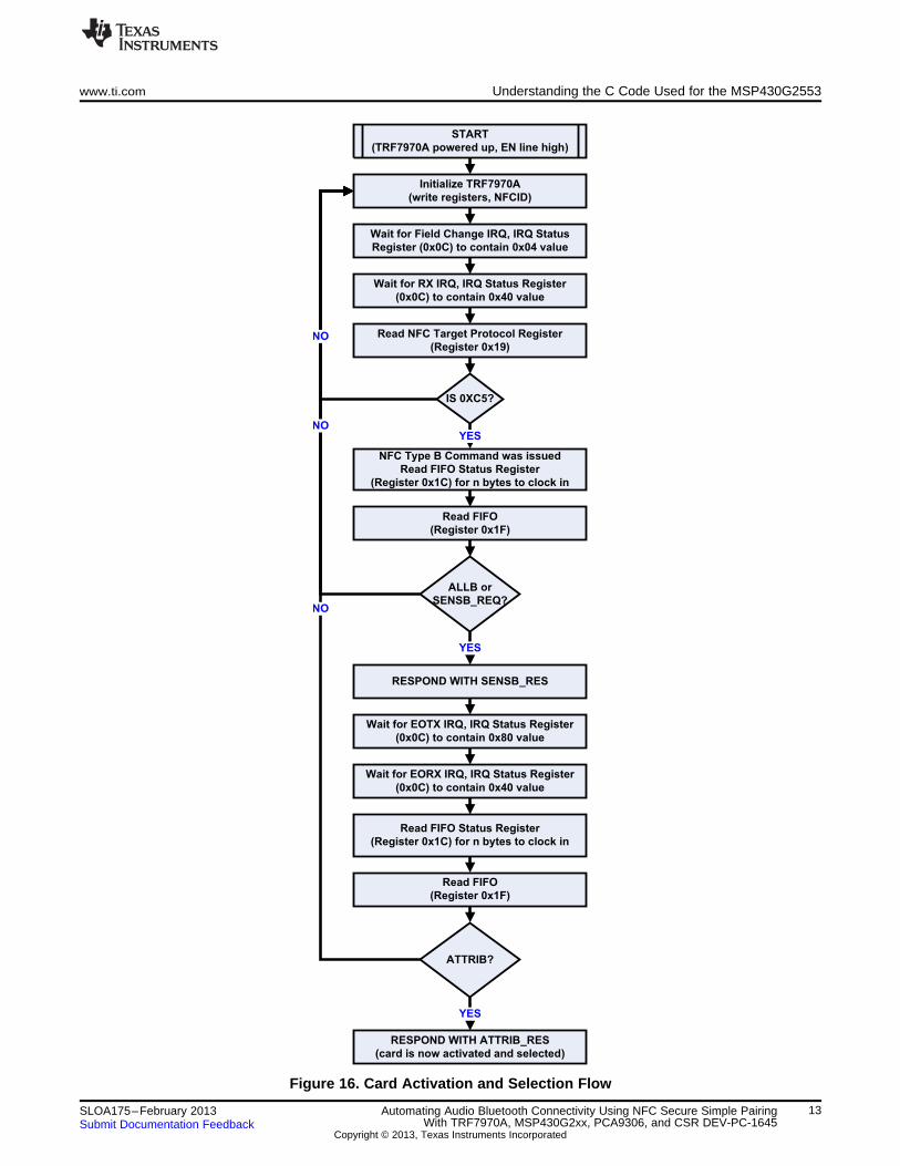
3.2.2 Activation and Selection
After initialization, the TRF7970A is waiting for an HF magnetic field to be presented by another NFCdevice (in this case the handset) which, when presented, causes it to generate an interrupt to the MCUreporting the field change.
In the normal unlocked screen mode, the handset is going through a round robin series of the NFC Forumpossible operations, including the tag type requests. When it reaches the NFCB request, the emulatedcard is ready to be activated, selected and then have its NDEF formatting be recognized, selected andread.
Card activation and selection is taken care of by the MSP430 code with the steps shown in Figure 16.
12 Automating Audio Bluetooth Connectivity Using NFC Secure Simple Pairing SLOA175–February 2013With TRF7970A, MSP430G2xx, PCA9306, and CSR DEV-PC-1645 Submit Documentation Feedback
Copyright © 2013, Texas Instruments Incorporated
NO
NO
START
(TRF7970A powered up, EN line high)
Initialize TRF7970A
(write registers, NFCID)
IS 0XC5?
Wait for Field Change IRQ, IRQ Status
Register (0x0C) to contain 0x04 value
Read NFC Target Protocol Register
(Register 0x19)NO
NFC Type B Command was issued
Read FIFO Status Register
(Register 0x1C) for n bytes to clock in
YES
Read FIFO
(Register 0x1F)
ALLB or
SENSB_REQ?
RESPOND WITH SENSB_RES
YES
Wait for RX IRQ, IRQ Status Register
(0x0C) to contain 0x40 value
Wait for EOTX IRQ, IRQ Status Register
(0x0C) to contain 0x80 value
Wait for EORX IRQ, IRQ Status Register
(0x0C) to contain 0x40 value
Read FIFO Status Register
(Register 0x1C) for n bytes to clock in
Read FIFO
(Register 0x1F)
ATTRIB?
RESPOND WITH ATTRIB_RES
(card is now activated and selected)
YES
www.ti.com Understanding the C Code Used for the MSP430G2553
Figure 16. Card Activation and Selection Flow
13SLOA175–February 2013 Automating Audio Bluetooth Connectivity Using NFC Secure Simple PairingWith TRF7970A, MSP430G2xx, PCA9306, and CSR DEV-PC-1645Submit Documentation Feedback
Copyright © 2013, Texas Instruments Incorporated
NFC Tag Type 4 Operations
(ISO-DEP) NDEF Detection Procedure
1. NDEF Tag Application Select
C-APDU (T4TOS, Section 5.4.2)
2. Capability Container Select
C-APDU (T4TOS, Section 5.4.3)
3. Read Binary (from CC file)
C-APDU (T4TOS, Section 5.4.4)
4. NDEF Select
C-APDU (T4TOS, Section 5.4.5)
5. Read Binary (for NLEN of NDEF file)
C-APDU (T4TOS, Section 5.4.6)
6. NDEF Select
C-APDU (T4TOS, Section 5.4.5)
7. Read Binary (for contents of NDEF file)
C-APDU (T4TOS, Section 5.4.6)
Understanding the C Code Used for the MSP430G2553 www.ti.com
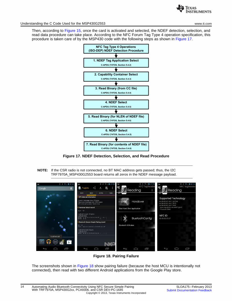
Then, according to Figure 15, once the card is activated and selected, the NDEF detection, selection, andread data procedure can take place. According to the NFC Forum Tag Type 4 operation specification, thisprocedure is taken care of by the MSP430 code with the following steps as shown in Figure 17.
Figure 17. NDEF Detection, Selection, and Read Procedure
NOTE: If the CSR radio is not connected, no BT MAC address gets passed; thus, the I2CTRF7970A_MSP430G2553 board returns all zeros in the NDEF message payload.
Figure 18. Pairing Failure
The screenshots shown in Figure 18 show pairing failure (because the host MCU is intentionally notconnected), then read with two different Android applications from the Google Play store.
14 Automating Audio Bluetooth Connectivity Using NFC Secure Simple Pairing SLOA175–February 2013With TRF7970A, MSP430G2xx, PCA9306, and CSR DEV-PC-1645 Submit Documentation Feedback
Copyright © 2013, Texas Instruments Incorporated
www.ti.com References
NOTE: The code is supplied using the static handover select NDEF response. If you would like tochange this to use the simple NDEF response or to modify either the NDEF message toinclude the optional fields left out of this demo, you need to change the value on line 447.The code following this section in main.c are the NDEF messages. Follow the instructions inthe comments to make the necessary modifications there. There should be no need tomodify code elsewhere.
Example 1. Code to Change for Type of Handover
else if( buffer[2] == 0xB0 && buffer[5] == 0x02) // read binary command, section 8.5,figure 20, command#5{
// Reset FIFO with an extra dummy clockbuffer[0] = 0x00;
RADIO_WRITERAW(RESET|BIT7, buffer,1);buffer[0] = 5; // Lengthbuffer[1] = 0x02;buffer[2] = 0x00;buffer[3] = 0x3E; //0x2D for simple response, 0x3e for static handover
// length of ndef messagebuffer[4] = 0x90;buffer[5] = 0x00;NFCSend(&buffer[0]); // sends read binary response, figure
}
4 References• TRF7970A Multi-Protocol Fully Integrated 13.56-MHz RFID/Near Field Communication (NFC)
Transceiver IC Data Manual (SLOS743)
• MSP430G2x53, MSP430G2x13 Mixed Signal Microcontroller Data Sheet (SLAS735)
• PCA9306 Dual Bidirectional I2C Bus and SMBus Voltage-Level Translator Data Sheet (SCPS113)
• ISO/IEC14443-3 →http://www.iso.org/iso/home/store/catalogue_tc/catalogue_detail.htm?csnumber=50942
• ISO/IEC14443-4 → http://www.iso.org/iso/catalogue_detail.htm?csnumber=50648
• ISO/IEC7816-4 → http://www.iso.org/iso/catalogue_detail.htm?csnumber=36134
• Tag Type 4 Operation Spec → http://www.nfc-forum.org/specs/spec_list/
• Connection Handover Spec → http://www.nfc-forum.org/specs/spec_list/
• Bluetooth Secure Simple Pairing Using NFC Application Document NFC Forum™ (NFCForum-AD-BTSSP_1.0, 2011-10-18) http://www.nfc-forum.org/resources/AppDocs/NFCForum_AD_BTSSP_1_0.pdf
• CSR Development Kit (DEV-SYS-1645B3-1A) http://www.digikey.com/product-detail/en/DEV-SYS-1645B3-1A/DEV-SYS-1645B3-1A-ND/1628331
15SLOA175–February 2013 Automating Audio Bluetooth Connectivity Using NFC Secure Simple PairingWith TRF7970A, MSP430G2xx, PCA9306, and CSR DEV-PC-1645Submit Documentation Feedback
Copyright © 2013, Texas Instruments Incorporated
IMPORTANT NOTICE
Texas Instruments Incorporated and its subsidiaries (TI) reserve the right to make corrections, enhancements, improvements and otherchanges to its semiconductor products and services per JESD46, latest issue, and to discontinue any product or service per JESD48, latestissue. Buyers should obtain the latest relevant information before placing orders and should verify that such information is current andcomplete. All semiconductor products (also referred to herein as “components”) are sold subject to TI’s terms and conditions of salesupplied at the time of order acknowledgment.
TI warrants performance of its components to the specifications applicable at the time of sale, in accordance with the warranty in TI’s termsand conditions of sale of semiconductor products. Testing and other quality control techniques are used to the extent TI deems necessaryto support this warranty. Except where mandated by applicable law, testing of all parameters of each component is not necessarilyperformed.
TI assumes no liability for applications assistance or the design of Buyers’ products. Buyers are responsible for their products andapplications using TI components. To minimize the risks associated with Buyers’ products and applications, Buyers should provideadequate design and operating safeguards.
TI does not warrant or represent that any license, either express or implied, is granted under any patent right, copyright, mask work right, orother intellectual property right relating to any combination, machine, or process in which TI components or services are used. Informationpublished by TI regarding third-party products or services does not constitute a license to use such products or services or a warranty orendorsement thereof. Use of such information may require a license from a third party under the patents or other intellectual property of thethird party, or a license from TI under the patents or other intellectual property of TI.
Reproduction of significant portions of TI information in TI data books or data sheets is permissible only if reproduction is without alterationand is accompanied by all associated warranties, conditions, limitations, and notices. TI is not responsible or liable for such altereddocumentation. Information of third parties may be subject to additional restrictions.
Resale of TI components or services with statements different from or beyond the parameters stated by TI for that component or servicevoids all express and any implied warranties for the associated TI component or service and is an unfair and deceptive business practice.TI is not responsible or liable for any such statements.
Buyer acknowledges and agrees that it is solely responsible for compliance with all legal, regulatory and safety-related requirementsconcerning its products, and any use of TI components in its applications, notwithstanding any applications-related information or supportthat may be provided by TI. Buyer represents and agrees that it has all the necessary expertise to create and implement safeguards whichanticipate dangerous consequences of failures, monitor failures and their consequences, lessen the likelihood of failures that might causeharm and take appropriate remedial actions. Buyer will fully indemnify TI and its representatives against any damages arising out of the useof any TI components in safety-critical applications.
In some cases, TI components may be promoted specifically to facilitate safety-related applications. With such components, TI’s goal is tohelp enable customers to design and create their own end-product solutions that meet applicable functional safety standards andrequirements. Nonetheless, such components are subject to these terms.
No TI components are authorized for use in FDA Class III (or similar life-critical medical equipment) unless authorized officers of the partieshave executed a special agreement specifically governing such use.
Only those TI components which TI has specifically designated as military grade or “enhanced plastic” are designed and intended for use inmilitary/aerospace applications or environments. Buyer acknowledges and agrees that any military or aerospace use of TI componentswhich have not been so designated is solely at the Buyer's risk, and that Buyer is solely responsible for compliance with all legal andregulatory requirements in connection with such use.
TI has specifically designated certain components as meeting ISO/TS16949 requirements, mainly for automotive use. In any case of use ofnon-designated products, TI will not be responsible for any failure to meet ISO/TS16949.
Products Applications
Audio www.ti.com/audio Automotive and Transportation www.ti.com/automotive
Amplifiers amplifier.ti.com Communications and Telecom www.ti.com/communications
Data Converters dataconverter.ti.com Computers and Peripherals www.ti.com/computers
DLP® Products www.dlp.com Consumer Electronics www.ti.com/consumer-apps
DSP dsp.ti.com Energy and Lighting www.ti.com/energy
Clocks and Timers www.ti.com/clocks Industrial www.ti.com/industrial
Interface interface.ti.com Medical www.ti.com/medical
Logic logic.ti.com Security www.ti.com/security
Power Mgmt power.ti.com Space, Avionics and Defense www.ti.com/space-avionics-defense
Microcontrollers microcontroller.ti.com Video and Imaging www.ti.com/video
RFID www.ti-rfid.com
OMAP Applications Processors www.ti.com/omap TI E2E Community e2e.ti.com
Wireless Connectivity www.ti.com/wirelessconnectivity
Mailing Address: Texas Instruments, Post Office Box 655303, Dallas, Texas 75265Copyright © 2013, Texas Instruments Incorporated


