Embed Size (px)
Citation preview

Automated Generation of Interactive 3D Exploded View DiagramsWilmot Li1,3 Maneesh Agrawala2 Brian Curless1 David Salesin1,3
1University of Washington 2University of California, Berkeley 3Adobe Systems
Abstract
We present a system for creating and viewing interactive explodedviews of complex 3D models. In our approach, a 3D input modelis organized into an explosion graph that encodes how parts ex-plode with respect to each other. We present an automatic methodfor computing explosion graphs that takes into account part hierar-chies in the input models and handles common classes of interlock-ing parts. Our system also includes an interface that allows users tointeractively explore our exploded views using both direct controlsand higher-level interaction modes.
CR Categories: I.3.5 [Computer Graphics]: Computational Geom-etry & Object Modeling; I.3.8 [Computer Graphics]: Applications
Keywords: exploded view illustration, interactive, visualization
1 Introduction
Complex 3D objects, such as mechanical assemblies, electronic de-vices, and architectural environments, are typically composed ofnumerous parts. To convey the internal structure of such objects, il-lustrators often create exploded views in which parts are separated(or “exploded”) away from one another to reveal parts of interest.Well designed exploded views not only expose internal parts, theyalso convey the global structure of the depicted object and the lo-cal spatial relationships between parts. Furthermore, unlike otherillustration techniques that reveal internal parts in situ by remov-ing or de-emphasizing occluding geometry, such as cutaways andtransparency, exploded views show the details of individual parts.
However, traditional static exploded views have several limitationsthat can make it difficult for viewers to browse the part structureof complex objects and focus on different subsets of parts. Sincemost exploded views expose all the parts in an object, they oftensuffer from excess visual clutter. As a result, the viewer may haveto carefully inspect the entire illustration to locate parts of interest.Furthermore, parts that are close to one another may end up far apartwhen the object is fully exploded, making it difficult for the viewerto determine how parts of interest are positioned and oriented withrespect to the rest of the model. Finally, static exploded views donot allow viewers to explore spatial relationships at different levelsof detail. For instance, a viewer might first want to see how two sub-assemblies fit together before examining their constituent parts.
In this paper, we present a system for creating and viewing inter-active 3D exploded views that allow users to explore the spatialrelationships between specific parts of interest. In our approach, we
Figure 1 Exploded view diagram generated by our system. Our system in-struments 3D models to enable interactive exploded views. This illustrationof a turbine model was automatically computed to expose the user-selectedtarget part labeled in red.
automatically determine the order and directions in which parts canexplode without violating blocking constraints (i.e., without pass-ing through each other) and then use this information to implementhigh-level viewing tools that expand and collapse parts dynami-cally. For instance, the user can select target parts of interest from alist, and the system automatically generates an exploded view thatexposes the targets without showing every other part in the object(see Figure 1). The user can then directly expand and collapse theexposed parts along their explosion directions to better see how theyfit together.
Our work makes several contributions. We present an automatictechnique for organizing 3D models into layers of explodable partsthat handles the most common classes of interlocking parts. We alsointroduce two algorithms for exposing user-selected target parts,one that explodes the necessary portions of the model in order tomake the targets visible, and one that combines explosions withthe dynamic cutaway views described by Li et al. [2007]. We alsopresent several interactive viewing tools that allow the user to di-rectly explore and browse our exploded views.
2 Related work
There is a large amount of existing work on visualizing the inter-nal structure of complex 3D objects. Here, we focus on previoustechniques that rearrange rather than remove geometry in order toexpose parts of interest.
A number of digital illustration systems provide tools for creatingexploded views [Adobe Inc. ; Agrawala et al. 2003; Driskill and Co-hen 1995; Li et al. 2004; Rist et al. 1994]. A limitation of most ofthese systems is that the user must manually specify the explosiondirections and blocking relationships for all parts in the model. Anotable exception is the work of Agrawala et al. [2003], whose tech-niques for generating step-by-step assembly instructions automati-cally determine the order and directions in which parts can explodewithout violating blocking constraints. We present an automatic al-gorithm for computing exploded views that extends this work totake into account part hierarchies and to handle the most commoncases in which parts interlock.
{Drill bit
sub-assembly
Explosiondirections
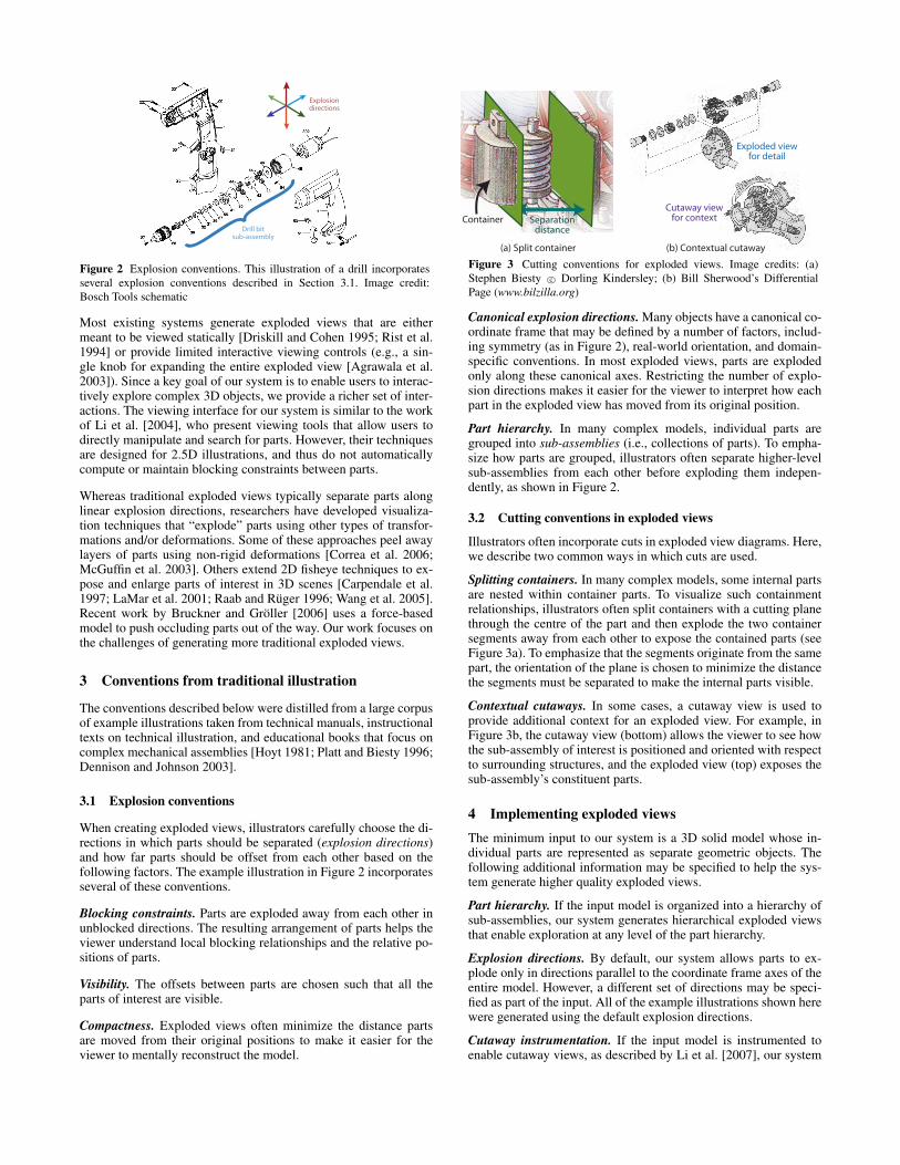
Figure 2 Explosion conventions. This illustration of a drill incorporatesseveral explosion conventions described in Section 3.1. Image credit:Bosch Tools schematic
Most existing systems generate exploded views that are eithermeant to be viewed statically [Driskill and Cohen 1995; Rist et al.1994] or provide limited interactive viewing controls (e.g., a sin-gle knob for expanding the entire exploded view [Agrawala et al.2003]). Since a key goal of our system is to enable users to interac-tively explore complex 3D objects, we provide a richer set of inter-actions. The viewing interface for our system is similar to the workof Li et al. [2004], who present viewing tools that allow users todirectly manipulate and search for parts. However, their techniquesare designed for 2.5D illustrations, and thus do not automaticallycompute or maintain blocking constraints between parts.
Whereas traditional exploded views typically separate parts alonglinear explosion directions, researchers have developed visualiza-tion techniques that “explode” parts using other types of transfor-mations and/or deformations. Some of these approaches peel awaylayers of parts using non-rigid deformations [Correa et al. 2006;McGuffin et al. 2003]. Others extend 2D fisheye techniques to ex-pose and enlarge parts of interest in 3D scenes [Carpendale et al.1997; LaMar et al. 2001; Raab and Ruger 1996; Wang et al. 2005].Recent work by Bruckner and Groller [2006] uses a force-basedmodel to push occluding parts out of the way. Our work focuses onthe challenges of generating more traditional exploded views.
3 Conventions from traditional illustration
The conventions described below were distilled from a large corpusof example illustrations taken from technical manuals, instructionaltexts on technical illustration, and educational books that focus oncomplex mechanical assemblies [Hoyt 1981; Platt and Biesty 1996;Dennison and Johnson 2003].
3.1 Explosion conventions
When creating exploded views, illustrators carefully choose the di-rections in which parts should be separated (explosion directions)and how far parts should be offset from each other based on thefollowing factors. The example illustration in Figure 2 incorporatesseveral of these conventions.
Blocking constraints. Parts are exploded away from each other inunblocked directions. The resulting arrangement of parts helps theviewer understand local blocking relationships and the relative po-sitions of parts.
Visibility. The offsets between parts are chosen such that all theparts of interest are visible.
Compactness. Exploded views often minimize the distance partsare moved from their original positions to make it easier for theviewer to mentally reconstruct the model.
Cutaway viewfor context
Exploded viewfor detail
Separation distance
Container
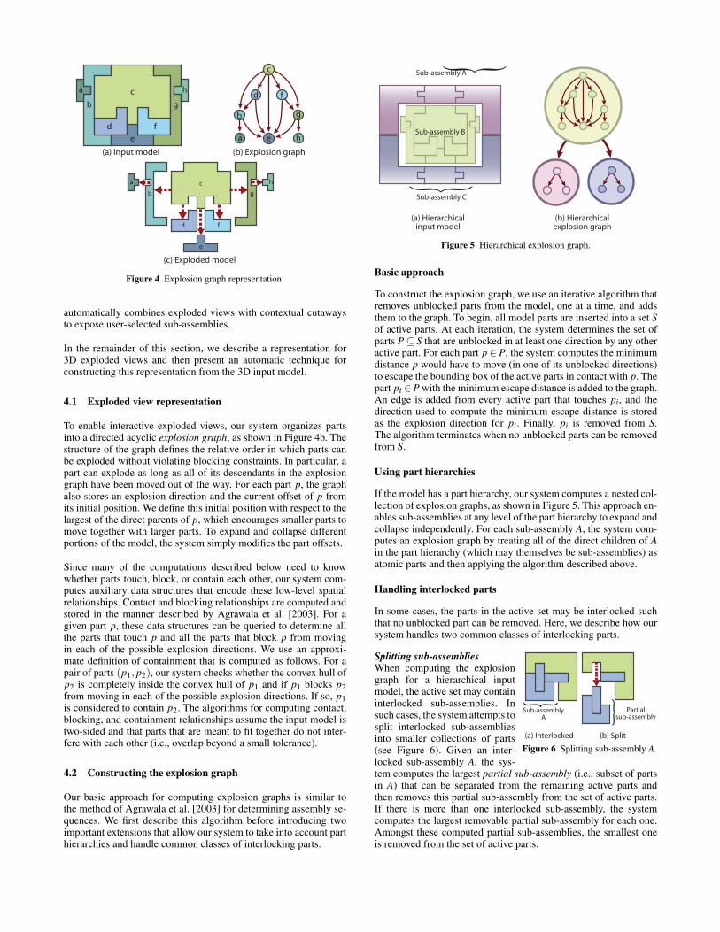
(a) Split container (b) Contextual cutaway
Figure 3 Cutting conventions for exploded views. Image credits: (a)Stephen Biesty c© Dorling Kindersley; (b) Bill Sherwood’s DifferentialPage (www.bilzilla.org)
Canonical explosion directions. Many objects have a canonical co-ordinate frame that may be defined by a number of factors, includ-ing symmetry (as in Figure 2), real-world orientation, and domain-specific conventions. In most exploded views, parts are explodedonly along these canonical axes. Restricting the number of explo-sion directions makes it easier for the viewer to interpret how eachpart in the exploded view has moved from its original position.
Part hierarchy. In many complex models, individual parts aregrouped into sub-assemblies (i.e., collections of parts). To empha-size how parts are grouped, illustrators often separate higher-levelsub-assemblies from each other before exploding them indepen-dently, as shown in Figure 2.
3.2 Cutting conventions in exploded views
Illustrators often incorporate cuts in exploded view diagrams. Here,we describe two common ways in which cuts are used.
Splitting containers. In many complex models, some internal partsare nested within container parts. To visualize such containmentrelationships, illustrators often split containers with a cutting planethrough the centre of the part and then explode the two containersegments away from each other to expose the contained parts (seeFigure 3a). To emphasize that the segments originate from the samepart, the orientation of the plane is chosen to minimize the distancethe segments must be separated to make the internal parts visible.
Contextual cutaways. In some cases, a cutaway view is used toprovide additional context for an exploded view. For example, inFigure 3b, the cutaway view (bottom) allows the viewer to see howthe sub-assembly of interest is positioned and oriented with respectto surrounding structures, and the exploded view (top) exposes thesub-assembly’s constituent parts.
4 Implementing exploded viewsThe minimum input to our system is a 3D solid model whose in-dividual parts are represented as separate geometric objects. Thefollowing additional information may be specified to help the sys-tem generate higher quality exploded views.
Part hierarchy. If the input model is organized into a hierarchy ofsub-assemblies, our system generates hierarchical exploded viewsthat enable exploration at any level of the part hierarchy.
Explosion directions. By default, our system allows parts to ex-plode only in directions parallel to the coordinate frame axes of theentire model. However, a different set of directions may be speci-fied as part of the input. All of the example illustrations shown herewere generated using the default explosion directions.
Cutaway instrumentation. If the input model is instrumented toenable cutaway views, as described by Li et al. [2007], our system
a
b
d
e
f
g
h
c
a
b
c
d
e
f
g
h
a
b
c
d
e
f
g
h
(a) Input model (b) Explosion graph
(c) Exploded model
Figure 4 Explosion graph representation.
automatically combines exploded views with contextual cutawaysto expose user-selected sub-assemblies.
In the remainder of this section, we describe a representation for3D exploded views and then present an automatic technique forconstructing this representation from the 3D input model.
4.1 Exploded view representation
To enable interactive exploded views, our system organizes partsinto a directed acyclic explosion graph, as shown in Figure 4b. Thestructure of the graph defines the relative order in which parts canbe exploded without violating blocking constraints. In particular, apart can explode as long as all of its descendants in the explosiongraph have been moved out of the way. For each part p, the graphalso stores an explosion direction and the current offset of p fromits initial position. We define this initial position with respect to thelargest of the direct parents of p, which encourages smaller parts tomove together with larger parts. To expand and collapse differentportions of the model, the system simply modifies the part offsets.
Since many of the computations described below need to knowwhether parts touch, block, or contain each other, our system com-putes auxiliary data structures that encode these low-level spatialrelationships. Contact and blocking relationships are computed andstored in the manner described by Agrawala et al. [2003]. For agiven part p, these data structures can be queried to determine allthe parts that touch p and all the parts that block p from movingin each of the possible explosion directions. We use an approxi-mate definition of containment that is computed as follows. For apair of parts (p1, p2), our system checks whether the convex hull ofp2 is completely inside the convex hull of p1 and if p1 blocks p2from moving in each of the possible explosion directions. If so, p1is considered to contain p2. The algorithms for computing contact,blocking, and containment relationships assume the input model istwo-sided and that parts that are meant to fit together do not inter-fere with each other (i.e., overlap beyond a small tolerance).
4.2 Constructing the explosion graph
Our basic approach for computing explosion graphs is similar tothe method of Agrawala et al. [2003] for determining assembly se-quences. We first describe this algorithm before introducing twoimportant extensions that allow our system to take into account parthierarchies and handle common classes of interlocking parts.
Sub-assembly C
Sub-assembly A
a
b
c
d
e
f
g
h
{
{Sub-assembly B
(a) Hierarchicalinput model
(b) Hierarchicalexplosion graph
Figure 5 Hierarchical explosion graph.
Basic approach
To construct the explosion graph, we use an iterative algorithm thatremoves unblocked parts from the model, one at a time, and addsthem to the graph. To begin, all model parts are inserted into a set Sof active parts. At each iteration, the system determines the set ofparts P⊆ S that are unblocked in at least one direction by any otheractive part. For each part p ∈ P, the system computes the minimumdistance p would have to move (in one of its unblocked directions)to escape the bounding box of the active parts in contact with p. Thepart pi ∈ P with the minimum escape distance is added to the graph.An edge is added from every active part that touches pi, and thedirection used to compute the minimum escape distance is storedas the explosion direction for pi. Finally, pi is removed from S.The algorithm terminates when no unblocked parts can be removedfrom S.
Using part hierarchies
If the model has a part hierarchy, our system computes a nested col-lection of explosion graphs, as shown in Figure 5. This approach en-ables sub-assemblies at any level of the part hierarchy to expand andcollapse independently. For each sub-assembly A, the system com-putes an explosion graph by treating all of the direct children of Ain the part hierarchy (which may themselves be sub-assemblies) asatomic parts and then applying the algorithm described above.
Handling interlocked parts
In some cases, the parts in the active set may be interlocked suchthat no unblocked part can be removed. Here, we describe how oursystem handles two common classes of interlocking parts.
Sub-assemblyA
{ Partialsub-assembly
{
(a) Interlocked (b) Split
Figure 6 Splitting sub-assembly A.
Splitting sub-assembliesWhen computing the explosiongraph for a hierarchical inputmodel, the active set may containinterlocked sub-assemblies. Insuch cases, the system attempts tosplit interlocked sub-assembliesinto smaller collections of parts(see Figure 6). Given an inter-locked sub-assembly A, the sys-tem computes the largest partial sub-assembly (i.e., subset of partsin A) that can be separated from the remaining active parts andthen removes this partial sub-assembly from the set of active parts.If there is more than one interlocked sub-assembly, the systemcomputes the largest removable partial sub-assembly for each one.Amongst these computed partial sub-assemblies, the smallest oneis removed from the set of active parts.

Container c
Splittingdirection
Cutting plane
Cutting plane
Segment c
Segment c
(a) Interlocked
(b) Split
1
2
Figure 7 Splitting container c.
Splitting containersIf any of the interlocked parts is anatomic container part whose onlyblockers are contained parts, thesystem splits the container into twosegments that are then removedfrom the set of active parts, asshown in Figure 7. To split a con-tainer c, the system selects one ofthe candidate explosion directionsand then splits c into two segmentsc1 and c2 with a cutting plane thatpasses through the bounding boxcentre of c and whose normal is par-allel to the chosen explosion direc-tion. The explosion direction is de-termined in a view-dependent man-ner. The system explodes the set ofcontained parts P and then, for eachcandidate direction, measures how far c1 and c2 would have to sep-arate in order to completely disocclude and escape the 3D boundingbox of P (see Figure 7b). In accordance with the cutting conventionsdescribed in Section 3.2, the container c is split in the direction thatrequires the smallest separation distance.
If some of the parts in P are themselves containers, the systememphasizes their concentric containment relationships by consid-ering only explosion directions where the bounding boxes of thenested containers remain inside the exploded bounding box of c.If none of the splitting directions satisfy this constraint, the systemchooses the splitting direction that causes the smallest total volumeof nested container bounding boxes to extend beyond the explodedbounding box of c.
4.3 Precomputation
Since the viewing direction can influence how container parts aresplit, explosion graphs may be view-dependent. Recomputing thesedata structures on the fly as the viewpoint changes can cause somelag in the viewing interface. Instead, our system precomputes ex-plosion graphs from the 26 viewpoints that correspond to the faces,edges and corners of an axis-aligned cube that is centered at themodel’s bounding box center and is large enough to ensure that theentire model is visible from each viewpoint. At viewing time, thesystem automatically switches to the precomputed explosion graphclosest to the current viewpoint.
5 Viewing interactive exploded views
Once the explosion graph is computed, the model can be exploredin our viewing interface, which provides both direct controls andhigher-level interaction modes to help users find parts of interestand explore specific portions of the model.
5.1 Animated expand/collapse
Our system allows the user to expand or collapse the entire ex-ploded view with a single click. Each part is animated to its fullyexploded or collapsed position by updating its current offset. Toensure that parts do not violate blocking constraints during the ani-mation, the system expands parts in reverse topological order (i.e.,outermost to innermost) with respect to the explosion graph. Inother words, the descendants of each part are expanded before thepart itself. For hierarchical models, higher-level (i.e., larger) sub-assemblies are expanded before lower-level sub-assemblies. Thesystem collapses parts in the opposite order.
5.2 Direct manipulation
The system also supports the direct manipulation of parts. As theuser drags a part p, the system slides p along its explosion directionand updates the current offset of p. If the user drags p past its fullyexploded or collapsed position, the system propagates the offsetthrough the explosion ancestors of p until it encounters a part witha different explosion direction. Propagating offsets in this mannerallows the user to expand or collapse an entire collection of parts,just by dragging a single part.
This type of constrained direct manipulation for exploded viewswas introduced in the image-based system of Li et al. [2004]. How-ever, that approach does not automatically compute and enforceblocking constraints. In our system, blocking constraints are main-tained in real time during direct manipulation. As the user dragspart p, the system checks for blocking parts amongst the descen-dants of p in the explosion graph and stops p from moving if suchparts are found. A single click causes the blocking parts to moveout of the way, which allows the user to continue dragging.
5.3 Riffling
The viewing interface also provides a riffling mode, in which partsare exploded away from adjacent portions of the model as the userhovers over them with the mouse. When the mouse moves away,the part that was beneath the mouse returns to its initial position.If the user clicks, the selected part remains separated as the mousemoves away. Although similar in feel to existing 3D fisheye view-ing techniques [LaMar et al. 2001; Sonnet et al. 2004], our rifflinginteraction restricts spatial distortions to the computed explosion di-rections. By riffling through the model, the user can quickly isolateparts or sub-assemblies and see how various portions of the modelcan expand without actually dragging on a part.
5.4 Automatically exposing target parts
In addition to the direct controls described above, the viewing sys-tem provides a high-level interface for generating exploded viewsthat expose user-selected target parts. The user just chooses the tar-gets from a list of parts and the system automatically generates alabeled exploded view illustration. Parts are smoothly animated totheir new positions to help the user see which portions of the modelhave been expanded and collapsed. The text labels are arranged us-ing the approach described by Ali et al. [2005].
We describe two different techniques for generating illustrations.By default, the system expands specific portions of the model toexpose the target parts. If the model has been instrumented for cut-aways (as described by Li et al. [2007]), the system can also gener-ate illustrations that combine explosions with contextual cutaways.
Exposing target parts with explosions
For non-hierarchical models, the algorithm works as follows. Givena set of target parts T , the system visits each part p in topologicalorder with respect to the explosion graph and moves p if necessaryto ensure that no visited target part is occluded by any other visitedpart. That is, p is moved to meet the following two conditions:
1. p does not occlude any previously visited target parts.2. if p ∈ T , p is not occluded by any visited part.
To visually isolate target parts from surrounding parts, the algo-rithm moves p to meet two additional conditions that ensure eachtarget is separated from its touching parts, even if those touchingparts do not actually occlude the target:
3. p is not occluded by any visited target part that touches p.4. if p ∈ T , p does not occlude any visited part that touches p.

p
p p
p
Condition 1 Condition 2 Condition 3 Condition 4
Visibility frustumfor target part
Targetpart
Condition 1:move p s.t. p does notocclude visited target
Condition 2:move p s.t. p is not
occluded by visited part
Condition 3:move p s.t. p is not
occluded by visited targetthat touches p
Condition 4:move p s.t. p does not
occlude visited partthat touches p
Figure 8 Conditions for moving part p. For each condition, the target partis outlined in red. The orange visibility frusta show how unwanted occlu-sions have been eliminated in each case.
To satisfy these conditions, the system performs the relevant occlu-sion tests and if necessary, moves p the minimum distance alongits explosion direction such that all unwanted occlusions are elim-inated (see Figure 8). To successfully eliminate unwanted occlu-sions, the explosion direction of p must not be exactly parallel tothe viewing direction. If it is parallel, the system informs the userthat one of the targets cannot be exposed from this viewpoint; inpractice, such failure cases rarely arise. If p is moved, its explo-sion graph descendants are also moved out of the way so that noblocking constraints are violated. Since the position of a part onlydepends on the positions of its explosion graph ancestors, visitedtargets are guaranteed to remain visible with respect to visited partsafter each part is processed. Thus, once every part has been pro-cessed, the resulting exploded view will have no occluded targets.
For hierarchical models, the algorithm starts by processing thehighest level sub-assembly in the part hierarchy. Atomic parts andsub-assemblies that do not contain any target parts are processed asdescribed above to eliminate target occlusions. However, when thealgorithm encounters a sub-assembly A that contains one or moretarget parts, the algorithm recursively processes the parts within Ato expose these targets. Once this recursive procedure returns, thesystem checks whether A (in its new configuration) violates block-ing constraints with respect to any visited parts or occludes anyvisited targets not contained in A. If so, the algorithm iterativelyincreases the current offset of A and then repeats the recursive com-putation for A until no blocking constraints are violated and all vis-ited targets are visible (see Figure 9). At each iteration, the cur-rent offset of A is increased by one percent of the bounding boxdiagonal for the entire model. The exploded views shown in Fig-ures 1, 10a, and 10b were generated using this algorithm.
Exposing target sub-assemblies with cutaways and explosions
If the input model is instrumented for cutaways and the user selectsan entire sub-assembly A as a target, the system first generates a cut-away view that exposes A in context and then explodes A away fromthe rest of the model through the cutaway hole. Finally, the systemexplodes A itself to expose its constituent parts (see Figure 11). Togenerate the cutaway, the system first chooses an explosion direc-tion for A. Given the viewing direction v, the system chooses theexplosion direction d that allows A to escape the model’s bound-ing box as quickly as possible and satisfies the constraint d · v < 0.Using the method of Li et al. [2007], the system creates a cutawaythat is large enough to allow A to explode away from the rest of themodel in direction d.
6 Results
We have used our system to generate exploded views of several3D models, as shown in Figures 1, 10, 11, 12, and 13. The iPodmodel was downloaded from TurboSquid (www.turbosquid.com),the arm dataset is from a commercially available model of humananatomy created by Zygote Media (www.zygote.com), and the rest
Target part
Visibility frustumfor target part
{Sub-assembly A
Iteration 1:move parts within
sub-assembly A
Iteration2:move sub-assembly A
Iteration 3:move parts within
sub-assembly A
Figure 9 Exposing a target part within a hierarchical model. To expose thetarget part within sub-assembly A, the algorithm iteratively removes targetocclusions within A (iteration 1) and moves A itself to enforce blockingconstraints (iteration 2). When the algorithm converges at iteration 3, thetarget is visible and all blocking constraints are satisfied.
of the datasets were obtained from a public repository for CADmodels. We made a few modifications to some of these models be-fore loading them into our system. To satisfy our input assump-tions, we scaled two of the transmission parts slightly to eliminateinterferences with adjacent parts. For the turbine, disk brake, andgrip mechanism examples, we omitted some of the original partsto reduce the preprocessing time required to compute contact andblocking relationships. The iPod model was poorly segmented, sowe manually grouped some of the geometry into parts before load-ing it into our system. We created part hierarchies for the disk brakeand transmission models based on the simple part groupings thatcame with the models. For the other CAD datasets, we created hi-erarchies based on the spatial organization and material propertiesof the parts. The arm model has no part hierarchy.
To generate the exploded view of the turbine shown in Figure 1, thesystem automatically determined how to split two container parts:the outer shell and the exhaust housing. The exploded views shownin Figures 1, 11, 10a, and 10b were generated automatically toexpose user-specified target parts. These illustrations clearly showthe parts of interest without exploding unnecessary portions of themodel. In addition, Figure 11 shows how a contextual cutawayview helps convey the position and orientation of the exploded sub-assembly with respect to the rest of the model.
Although exploded views are typically used to illustrate manufac-tured objects, we also tested our system with a musculoskeletalmodel of a human arm. Since many of the muscles in the arm twistaround each other where they attach to bones, we manually sec-tioned off part of the arm where the muscles are less intertwinedand then used this portion of the dataset as the input to our sys-tem. To emphasize how the muscles are layered from the outsideto the inside of the arm, we also restricted the system to use a sin-gle explosion direction. From this input, our system automaticallycomputed the exploded view shown in Figure 12.
Table 1 reports the number of parts and precomputation time foreach dataset. In general, computing contact and blocking relation-ships dominates the total precomputation cost. We do not report thecost of computing containment relationships because containmenttests are performed lazily only when the system encounters inter-locked parts during explosion graph construction. Since the turbineis the only dataset that includes container parts, its explosion graphcost includes the time required for containment tests.

(a) iPod (b) Transmission (c) Disk brake
Figure 10 Exploded views generated by our system. The illustrations of the iPod (a) and transmission (b) were automatically generated to expose theuser-selected target parts labeled in red. The sequence of images on the right shows the disk brake model exploding in stages (c).
Model Nparts Tcontact Tblock Tegraph TtotalDisk brake 18 440s 195s 0.016s 635s
iPod 19 215s 20s 0.016s 235sGrip mechanism 20 150s 50s 0.016s 200s
Arm 22 280s 40s 0.016s 320sTurbine 26 380s 200s 430s 1010s
Carburetor 42 135s 45s 0.16s 180sTransmission 55 885s 835s 2.5s 1778s
Table 1 Precomputation statistics. For each model, we report the num-ber of parts Nparts and the time (in seconds) required to compute contactsTcontact , blocking relationships Tblock , and explosion graphs Tegraph. Thetotal precomputation time Ttotal is listed on the right. All timings were per-formed on a MacBook Pro with a 2.6 GHz Intel Core 2 Duo, 4GB of mem-ory, and an nVidia GeForce 8600M GT graphics card.
7 Discussion
Although in general our system produces effective exploded viewdiagrams for a large class of 3D models, our approach does havesome limitations. As mentioned earlier, the contact, blocking, andcontainment computations assume the input model is two-sided andthat parts fit together without interferences. In addition, our algo-rithm for constructing explosion graphs assumes that all parts canbe separated via rigid linear translations. Thus, the system is notable to separate atomic parts with certain complex interlocking re-lationships (e.g., a screw modeled with realistic thread geometrywould have to rotate to be removed). Although not all 3D modelsadhere to these input assumptions, many CAD models are specifi-cally designed to fit together properly without interferences. Fur-thermore, for performance reasons, CAD programs typically in-clude part libraries with stylized models of standard screws, boltsand other fasteners that do not have realistic thread geometry.
Figure 13 illustrates two situations in which our approach can gen-erate less successful results. Since the blocking algorithm that weuse analyzes the normals of contact faces to determine blocking di-rections, the computation can be sensitive to noisy or irregular sur-face geometry where parts touch each other. For example, in Fig-ure 13a, the top shaft explodes sideways rather than upwards fromthe top spring because the complexity of the spring geometry causesthe system to compute the wrong blocking relationship. Figure 13bshows a case in which splitting a non-container part could help clar-ify spatial relationships. Although the illustration successfully ex-poses the target parts, it is not obvious how the exposed parts fittogether within the long hollow body. Splitting the body lengthwise
Figure 11 Exploded view with contextual cutaway. To expose the user-selected sub-assembly, the system first generates a cutaway view (left) andthen explodes the sub-assembly through the cutaway hole (right).
and then exploding the two halves away from each other wouldlikely provide better spatial context for the internal parts. However,since the parts are free to slide out of the body, the system does notconsider the body to be a container part (and thus, does not incor-porate any cuts).
Finally, although we have shown that our system can generate effec-tive visualizations of models with up to roughly 50 parts, there aresome challenges involved in scaling our approach to handle signifi-cantly more complex models. First, exposing an internal part mightrequire exploding many blocking parts, which could result in visualclutter. We believe our approach could be extended with level-of-detail controls to reduce the amount of clutter due to exploded parts.In addition, the cost of computing contact, blocking, and contain-ment relationships puts a practical limit on the complexity of the in-put geometry. Our current implementation incorporates simple spa-tial data structures to accelerate these computations, but for highlycomplex input models, more efficient algorithms would likely benecessary to avoid prohibitively large precomputation times.
8 Conclusions and future work
In this paper, we have presented techniques for creating and viewinginteractive exploded view illustrations of 3D models composed ofmany distinct parts. Our contributions include an automatic methodfor decomposing models into explodable layers and algorithms forgenerating dynamic exploded views that expose user-selected tar-get parts. Our results demonstrate that our approach can be used tocreate effective interactive exploded views for a variety of models.

Figure 12 Exploded view of arm. To create this visualization, we sectionedoff a portion of the arm to explode. Within this portion, our system auto-matically computed the layering relationships between the muscles.
We conclude by mentioning a few areas for future work:
Inferring parts to expose. Our system allows users to directly spec-ify target parts to expose. In some cases, showing additional partscan provide more context for the specific parts of interest. It wouldbe interesting to explore techniques that automatically infer whichadditional parts to expose based on the user-selected targets.
Continuous measure of blocking. It is difficult to detect the cor-rect blocking relationships for 3D models that contain interferingparts. One potential approach for handling such models would beto construct exploded views based on some continuous measure ofthe “amount” of blocking between parts.
Automatic guidelines. Guidelines can be useful for clarifyinghow exploded parts fit back together. Although some previouswork [Agrawala et al. 2003] has been done on computing guidelineplacement automatically, further investigation is required to iden-tify and implement all of the conventions that illustrators use tocreate effective guidelines.
Acknowledgments
The authors want to thank Sharon Lin for her work on the labellayout component of the system. We also thank Francois Chretien,Doug Johnson, and Dave Kasik for their feedback on the use ofCAD technology in industry. This work was supported by NSFgrants CCF-0643552 and EIA-0321235, the Alfred P. Sloan Foun-dation, the University of Washington Animation Research Labs, theWashington Research Foundation, Adobe, Microsoft, and Pixar.
References
ADOBE INC. Acrobat 3D.
AGRAWALA, M., PHAN, D., HEISER, J., HAYMAKER, J.,KLINGNER, J., HANRAHAN, P., AND TVERSKY, B. 2003.Designing effective step-by-step assembly instructions. ACMTransactions on Graphics 22, 3 (July), 828–837.
ALI, K., HARTMANN, K., AND STROTHOTTE, T. 2005. Labellayout for interactive 3D illustrations. In WCSG Journal, 1–8.
BRUCKNER, S., AND GROLLER, M. 2006. Exploded views forvolume data. IEEE Transactions on Visualization and ComputerGraphics 12, 5 (Sept./Oct.), 1077–1084.
CARPENDALE, M. S. T., COWPERTHWAITE, D. J., AND FRAC-CHIA, F. D. 1997. Extending distortion viewing from 2D to
(a) Carburetor (b) Grip mechanism
Figure 13 Less successful results. Due to the complexity of the spring ge-ometry, the system computes the wrong blocking relationship for the topshaft in the carburetor model (a). In the exploded view of the grip mecha-nism (b), it may be hard for the viewer to understand how the highlightedtarget parts fit together inside of the long hollow body.
3D. IEEE Computer Graphics and Applications: Special Issueon Information Visualization 17, 4, 42–51.
CORREA, C., SILVER, D., AND CHEN, M. 2006. Feature alignedvolume manipulation for illustration and visualization. IEEETransactions on Visualization and Computer Graphics 12, 5(Sept./Oct.), 1069–1076.
DENNISON, J. A., AND JOHNSON, C. D. 2003. Technical Illus-tration: Techniques and Applications. Goodheart-Wilcox.
DRISKILL, E., AND COHEN, E. 1995. Interactive design, analysisand illustration of assemblies. In Proceedings of the Symposiumon Interactive 3D Graphics.
HOYT, W. A. 1981. Complete Car Care Manual. Reader’s Digest.
LAMAR, E., HAMANN, B., AND JOY, K. I. 2001. A magnifi-cation lens for interactive volume visualization. In 9th PacificConference on Computer Graphics and Applications, 223–232.
LI, W., AGRAWALA, M., AND SALESIN, D. H. 2004. Interactiveimage-based exploded view diagrams. In Proceedings of Graph-ics Interface 04.
LI, W., RITTER, L., AGRAWALA, M., CURLESS, B., ANDSALESIN, D. 2007. Interactive cutaway illustrations of com-plex 3D models. ACM Transactions on Graphics 26, 3 (July),31:1–31:11.
MCGUFFIN, M. J., TANCAU, L., AND BALAKRISHNAN, R. 2003.Using deformations for browsing volumetric data. In Proceed-ings of IEEE Visualization 2003, 401–408.
PLATT, R., AND BIESTY, S. 1996. Stephen Biesty’s IncredibleExplosions. DK Children.
RAAB, A., AND RUGER, M. 1996. 3D-ZOOM: interactive visu-alization of structures and relations in complex graphics. In 3Dimage analysis and synthesis, 87–93.
RIST, R., KRUGER, A., SCHNEIDER, G., AND ZIMMERMANN,D. 1994. AWI: A workbench for semi-automated illustrationdesign. In Proceedings of Advanced Visual Interfaces 94.
SONNET, H., CARPENDALE, S., AND STROTHOTTE, T. 2004.Integrating expanding annotations with a 3D explosion probe. InProceedings of ACM AVI 2004, 63–70.
WANG, L., ZHAO, Y., MUELLER, K., AND KAUFMAN, A. E.2005. The magic volume lens: An interactive focus+contexttechnique for volume rendering. In Proceedings of IEEE Visual-ization 2005, 367–374.