Embed Size (px)
Citation preview

Autoclaved Aerated Concrete
Products
TECHNICAL GUIDE

TECHNICAL GUIDE
Lightweight Construction Company (LCC-Siporex)
Is originally the sole manufacturer and supplier of
lightweight Autoclaved Aerated Concrete (AAC)
to the Saudi Arabian Construction industry.
The company is wholly owned by Saudi nationals.
The Head Office of the Company is in Riyadh.
Production facilities are located at the Industrial City II on Al Kharj Road.

T E C H N I C A L G U I D EA A C B U I L D I N G S Y S T E M
S. N. CONTENTS PAGE NO.
1. Introduction 3
1.1 What is Siporex? 3
1.2 About our plant 4
1.3 Codes & Standards 5
2. Manufacturing 6
2.1 Manufacturing Process 6 - 7
2.2 Quality Control 8
2.3 Material Identification & Markings 9
2.4 Handling, Shipping & Storage 10
3. Properties & Benefits of Using Siporex 11
3.1 Benefits of Using Siporex 11 - 12
3.2 Properties of Siporex 13 - 17
4. Range of Products 19
4.1 Wall Panels 19 - 21
4.2 Lintels 22 - 23
4.3 Floor & Roof Slabs 24 - 25
4.4 Siporex Blocks 26 - 29
5. Design 30
5.1 General 30 - 31
5.2 Design Principle 32
5.3 Structural System 32
S. N. CONTENTS PAGE NO.
6. Erection 33
6.1 Guidelines for Estimating Erection Cost
33
6.2 Hand tools & Equipments 33 - 35
6.3 Erection Procedure 36 - 37
6.4 Repair of Siporex Panels 38
6.3 Illustrations Showing Erection Stages
39 - 40
7. Typical Connection Details 41 - 44
8. Electro-Mechanical 45
8.1 Chases & Penetrations 45
8.2 Electrical Installations 46
8.3 Plumbing Installations 46
9. Finishes 47 - 48
10. Fixings to Siporex 49
11. Glue for Siporex 50
12. Siporex Gesol 51
13. List of Some Projects 52
I N D E X

T E C H N I C A L G U I D EA A C B U I L D I N G S Y S T E M
SIPOREX is lightweight Autoclaved Aerated Concrete (AAC) which is also called cellular concrete.
is completely cured mix of calcareous materials such as cement and siliceous fine materials such asquartz sand with the addition of water and aluminum powder acting as foaming agent to form ahomogenous cellular structure known as Calcium Silicate Hydrate.
is a high quality structural material, load-bearing and extremely well insulating material due tonumerous tiny non-connecting air bubbles which gives Siporex its incredibly diverse qualities. The highpressure steam-curing in autoclaves achieves a physically and chemically stable product with anaverage density being approximately one fourth of normal concrete.
is produced as blocks and precast reinforced units, i.e., wall panels, lintels and floor/roof slabs forminga complete building system.
has been used on large scale projects such as housings, schools, hospitals, commercial, industrial andgovernment projects under all climatic conditions since the early nineteen thirties worldwide.
is definitely one of the major achievements in the field of construction. It is a revolutionary materialthat offers a unique combination of strength, lightweight, thermal insulation, sound absorption,unsurpassed fire resistance and unprecedented buildability.
is a natural and non-toxic construction material, saves energy, and is friendly to the environment.
as a building system, meets all the requirements of our modern age throughout the world. Itsproperties ensure a building material that outperforms all others. In view of the rapid developmentand increasing demand, we can claim with certain justification that Siporex is the ideal choice forbuilding construction.
1.1 What is Siporex?
3
1. Introduction

T E C H N I C A L G U I D EA A C B U I L D I N G S Y S T E M
1.2 About Our Plant
Industrial production of this versatile building material was started in 1929 and it has been produced and used
for building construction ever since. First in Europe and now world-wide.
Here in the Kingdom of Saudi Arabia, LCC Siporex Company was established in 1976 and has been producing
Siporex AAC material at our plant in the Second Industrial Estate, AlKharj Road.
With our continued expansion of additional manufacturing plant to sustain the growing demand, our current
total production capacity has intensified to about 350,000 cubic meters of Siporex AAC products per year.
Builders, engineers, architects and contractors not only appreciate the
excellent properties of Siporex, but also energy-saving and pollution-free
techniques used in its production. In fact, Siporex manufacturing process
produces neither polluting waste gases nor dangerous residues and there is no
waste of costly raw materials.
Siporex manufacturing plant in Riyadh, Saudi Arabia
4
After more than forty years
and having used by
several thousands of
projects, LCC Siporex
became the leading
supplier of this truly
amazing material not only
within the kingdom but
also to GCC countries,
Yemen, Jordan, Sudan,
Ethiopia and as far away
as Djibouti, Taiwan and
Japan.
1. Introduction
T E C H N I C A L G U I D EA A C B U I L D I N G S Y S T E M
1.3 Codes & Standards
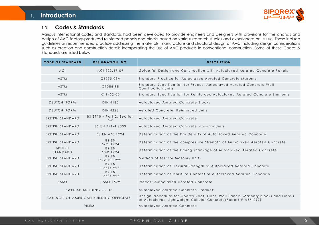
Various international codes and standards had been developed to provide engineers and designers with provisions for the analysis and
design of AAC factory-produced reinforced panels and blocks based on various research studies and experiences on its use. These include
guidelines or recommended practice addressing the materials, manufacture and structural design of AAC including design considerations
such as erection and construction details incorporating the use of AAC products in conventional construction. Some of these Codes &
Standards are listed below:
C O D E O R S T A N D A R D D E S I G N A T I O N N O . D E S C R I P T I O N
AC I AC I 5 2 3 . 4 R - 0 9 G u i d e f o r D e s i g n a n d C o n s t r u c t i o n w i th Au to c l a v e d Ae r a te d C o n c r e te P a n e l s
AS T M C 1 5 5 5 - 0 3 A S ta n d a r d P r a c t i c e f o r Au to c l a v e d Ae r a te d C o n c r e te M a s o n r y
AS T M C 1 3 8 6 - 9 8S ta n d a r d S p e c i f i c a t i o n f o r P r e c a s t Au to c l a v e d Ae r a te d C o n c r e te Wa l l C o n s t r u c t i o n U n i t s
AS T M C 1 4 5 2 - 0 0 S ta n d a r d S p e c i f i c a t i o n f o r R e i n f o r c e d Au to c l a v e d Ae r a te d C o n c r e te E l e m e n t s
D E U T C H N O R M D I N 4 1 6 5 Au to c l a v e d Ae r a te d C o n c r e te B l o c k s
D E U T C H N O R M D I N 4 2 2 3 Ae r a te d C o n c r e te ; R e i n f o r c e d U n i t s
B R I T I S H S T AN D AR DB S 8 1 1 0 – P a r t 2 , S e c t i o n
S i xAu to c l a v e d Ae r a te d C o n c r e te
B R I T I S H S T AN D AR D B S E N 7 7 1 - 4 : 2 0 0 3 Au to c l a v e d Ae r a te d C o n c r e te M a s o n r y U n i t s
B R I T I S H S T AN D AR D B S E N 6 7 8 : 1 9 9 4 D e te r m i n a t i o n o f th e D r y D e n s i t y o f Au to c l a v e d Ae r a te d Co n c r e te
B R I T I S H S T AN D AR DB S E N
6 7 9 : 1 9 9 4D e te r m i n a t i o n o f th e c o m p r e s s i v e S t r e n g th o f Au to c l a v e d Ae r a te d C o n c r e te
B R I T I S H
S T AN D AR D
B S E N 6 8 0 : 1 9 9 4
D e te r m i n a t i o n o f th e D r y i n g S h r i n k a g e o f Au to c l a v e d Ae r a te d C o n c r e te
B R I T I S H S T AN D AR DB S E N
7 7 2 - 1 0 : 1 9 9 9M e th o d o f te s t f o r M a s o n r y U n i t s
B R I T I S H S T AN D AR DB S E N
1 3 5 1 : 1 9 9 7D e te r m i n a t i o n o f F l e x u r a l S t r e n g th o f Au to c l a v e d Ae r a te d C o n c r e te
B R I T I S H S T AN D AR DB S E N
1 3 5 3 : 1 9 9 7D e te r m i n a t i o n o f M o i s tu r e C o n te n t o f Au to c l a v e d Ae r a te d C o n c r e te
S AS O S AS O 1 5 7 9 P r e c a s t Au to c l a v e d Ae r a te d C o n c r e te
S WE D I S H B U I L D I N G C O D E Au to c l a v e d Ae r a te d C o n c r e te P r o d u c t s
CO U N CI L O F AM E R I CAN B U I L D I N G O F F I C I AL SD e s i g n P r o c e d u r e f o r S i p o r e x R o o f , F l o o r , Wa l l P a n e l s , M a s o n r y B l o c k s a n d L i n te l s o f Au to c l a v e d L i g h tw e i g h t C e l l u l a r C o n c r e te ( R e p o r t # N E R - 2 9 7 )
R I L E M Au to c l a v e d Ae r a te d C o n c r e te
5
1. Introduction

T E C H N I C A L G U I D EA A C B U I L D I N G S Y S T E M
2.1 Manufacturing ProcessSiporex is produced by a highly complex and advanced manufacturing process in our factory under the careful control ofchemists and engineers. Siporex is made either as steel reinforced panels using moulds 6 meters long, 1.5 meters wide and600 mm deep or as non-reinforced blocks using moulds 6 meters long, 1.5 (or 1.2) meters wide and 600 mm deep. Aschematic diagram of manufacturing process is shown on fig. 1.
The basic raw materials are sand, water, aluminum powder and cement. The sandis ground to required fineness in a ball mill before mixing with other raw materialswith water to form slurry to which a trace of aluminum powder is added asexpanding agent.
All Siporex panels are reinforced with steel. Steel coils are straightened, cut andspot-welded into mats, where crossbars provide anchorage to the longitudinalreinforcements. Siporex blocks are not reinforced.
After dipping the welded mats in a homogenized anti-corrosion mix for rustprotection, they are dried and assembled into cages and set accurately in themoulds before the slurry is poured in.
Regulated amount of aluminum powder gives accurate control of density of thefinal product. Moulds are only partly filled with slurry which then expands in acontrolled reaction to fill the moulds.
When the mass is sufficiently hard, the moulds are stripped and the cake is wire-cutto close tolerances into panels and blocks using high-precision cutting technology.These are then steam cured under high pressure in autoclaves for up to 15 hours.
This completes the chemical process, resulting in a unique crystal structure ofcalcium silicate hydrate and ensuring a stable and inert product giving AACoutstanding qualities not found in other products.
After cooling to ambient temperature, the panels are demoulded and milled torequired profile as necessary. All Siporex panels are singled out for proper marking,and if required, dry cut and stacked for further handling and storage. The blocksare demoulded, strapped, marked and stored on wooden pallets.
The finished goods inspection programme ensures the products quality. Thematerial is now ready for loading and delivery.
6
2. Manufacturing

T E C H N I C A L G U I D EA A C B U I L D I N G S Y S T E M
Fig. 1 Siporex Production Process
7
2. Manufacturing
DELIVERY
GYPSUM FEEDER(MANUAL)
FORKLIFT /CRANE LOADING
STORING
MILLING, REBATINGARCH CUTTING
DEMOULDINGAUTOCLAVEASSEMBLY CASTING RISING CUTTING
STEAM
DRYINGWASTE SLURRY
SIPOREXMIXER
PUMP
STEAM
ALUMINUM SCALE
ALUMINUMSILO
(MANUALLY FED)
WASTE SLURRY
SILO
MAGNASITE FEEDER(MANUAL)
RUSTPROTECTING
SLURRY SCALE
SOLUBLE OIL
CEMENT SCALE
MAGNESITE GYPSUM SCALE
MAGNESITE SILO GYPSUM SILO
SAND SLURRY
SILO
PUMP
PUMP
WELDING
BLOW TANK
BLOW TANK
CEMENT SILOS
BLOW TANK
CEMENT DAY SILO
CYLPEBS
CEMENT TRUCK
BLEND WATER
HYDRATED LIME SILO
HYDRATED LIME FEEDER(MANUAL)
BLOW TANK
BALL MILL
PUMP
SAND PIT
WATER PLANT
TRUCK
SAND
PROCESSED WATER
BORE WELL
WIRE STRAIGHTENING
CUTTING MACHINE
WIRE DRAWING MACHINE
STEEL SPOOL
STEEL COIL
TRUCK
BOILER
REVERSE OSMOSIS
T E C H N I C A L G U I D EA A C B U I L D I N G S Y S T E M
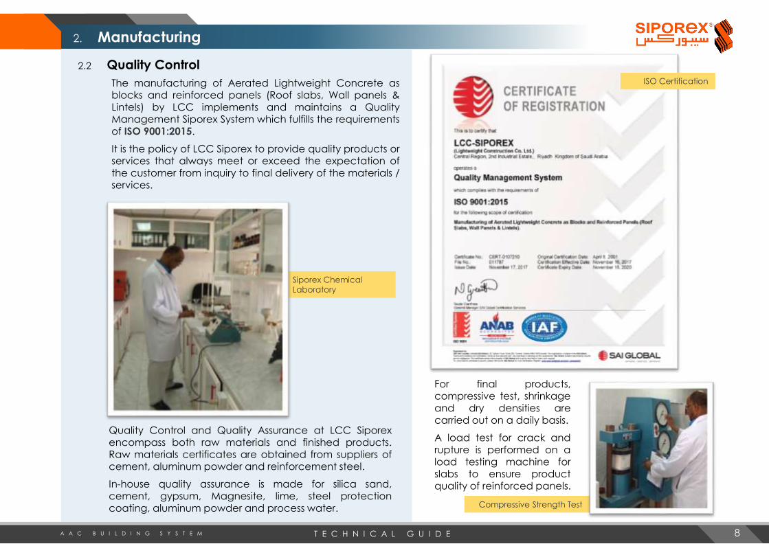
2.2 Quality Control
The manufacturing of Aerated Lightweight Concrete as blocks and reinforced panels (Roof slabs, Wall panels & Lintels) by LCC implements and maintains a Quality Management Siporex System which fulfills the requirements of ISO 9001:2015.
It is the policy of LCC Siporex to provide quality products or services that always meet or exceed the expectation of the customer from inquiry to final delivery of the materials / services.
Siporex Chemical
Laboratory
Quality Control and Quality Assurance at LCC Siporexencompass both raw materials and finished products.Raw materials certificates are obtained from suppliers ofcement, aluminum powder and reinforcement steel.
In-house quality assurance is made for silica sand,cement, gypsum, Magnesite, lime, steel protectioncoating, aluminum powder and process water.
For final products,compressive test, shrinkageand dry densities arecarried out on a daily basis.
A load test for crack andrupture is performed on aload testing machine forslabs to ensure productquality of reinforced panels.
Compressive Strength Test
8
2. Manufacturing
ISO Certification

T E C H N I C A L G U I D EA A C B U I L D I N G S Y S T E M
2.3 Material Identification & Markings
Siporex Blocks:
After autoclaving, Siporex blocksare ready for packing anddistribution. Blocks are strapped inbundles and marked with a stampdenoting block dimension, densitytype and batch number. Bundlesof blocks are arrange in stacks laidon wooden pallets and sent tostorage or distribution.
Typical Markings on Block Stack
Reinforced Panels:
Reinforced panels are marked afterautoclaving and demoulding, withstamp code containing informationabout the type of product, density,permissible load, dimensions, batchnumber and order number. An arrowindicating the top side of the panelswill be marked at one end of thefloor/roof slabs and lintels.
Typical Markings on Panels
The following abbreviations areused for the types of product:
WV – Vertical wall panels
WH – Horizontal wall panels
WP – Partition wall panels
WF – Fluted wall panels
RS – Roof slabs
FS – Floor slabsLW – Panel-type lintels
LA – Arch-type lintels
LB – Box-type lintels
B – Blocks
Density 5 – denotes nominaldry density of 550 kg/m3 forboth blocks and reinforcedpanels.
Density 4 – denotes nominaldry density of 450 kg/m3 forHordi blocks.
Permissible load – Indicatesservice load in kg/m2 for wallsand slabs or kg/lm in case oflintels.
9
2. Manufacturing

T E C H N I C A L G U I D EA A C B U I L D I N G S Y S T E M
2.4 Handling, Shipping and Storage
Siporex products are designed to resist normal handling and transport. Siporex blocks should be handled by forklifts and/orcranes with appropriate straps to avoid damage to the material.
Siporex materials are shipped by trucks or flat-bed trailers and can be transported by road, train and by sea for internationalprojects.
They have unlimited storage stability, provided that they are not exposed to extreme conditions. They must be supported byproperly placed bearers and stored in such a way that they cannot absorb water from the ground or be splashed with seawater. Siporex is an inorganic material and is not affected by termites and other insects.
Siporex Blocks
Bundles of blocks (60 cm high) are stored on woodenpallets. Each pallet can be stored with up to 3 bundles ofblocks (180 cm high). At the storage area, the floor shouldbe level to avoid tilting of stocks. Stocks of blocks can easilywithstand 3 pallets with 3 bundles each of Siporex blocks.
Reinforced Panels
On the ground, the stacks of reinforced panels shall besupported by wooden planks, one on each end, placedapproximately one fourth of the length from the ends.In transporting, the stacks are tied by strapping at bothends, protected with plastic angles.
10
2. Manufacturing

T E C H N I C A L G U I D EA A C B U I L D I N G S Y S T E M
3.1 Benefits of Using Siporex
The manufacturing process as well as the basic ingredients used provides Siporex its unique properties and benefits not found in other traditional building materials and will radically change the construction practices in this industry.
LightweightSiporex weighs less than a quarter compared to conventional concrete. Due to the lightweight property of Siporex, the foundation loads are greatly reduced resulting to big savings in the overall construction cost especially at areas having poor soil bearing capacity. Its light weight also means significant advantage in transportation cost.
Energy EfficientSiporex ensures pleasantly healthy and comfortable room temperature without the need for additional insulation. Its thermal insulation and heat retention offer a good protection against rapid cooling or heating up too much. This means lower power consumption in environmental management system.
Dimensional AccuracyThe production process guarantees the accurate dimensions of the panels and blocks that comprise thebuilding system. This allows for a straight and plumbed walls resulting in less on-site trimmings and reducesthe quantity of mortar and finishing materials required. The dimensional tolerance is ±3mm for thickness &width and ±5mm for length.
WorkabilitySiporex products can be sawn, cut, slot, drilled, chased and nailed with ordinary woodworking tools which makes them easier to install than other building materials. This also simplifies the installation of electro-mechanical services and other utilities, which means more cost savings.
Resistance to FireSiporex is totally inorganic and does not contain any combustible materials, which means it is resistant to fire. A 15 cm thick panel will resist fire for seven life-saving hours. Siporex is ideal for firewall application and as protection for structural steel construction.
11
3. Properties & Benefits of Using Siporex

T E C H N I C A L G U I D EA A C B U I L D I N G S Y S T E M
3.1 Benefits of Using Siporex
Acoustic InsulationSiporex meets the appropriate standards for sound insulation in house building, which means quieter andmore comfortable interior. In industrial construction, Siporex minimizes industrial noise pollution. The soundabsorption of untreated Siporex surface is better than that of dense concrete.
Non-toxicSiporex itself is ecologically harmless, since it neither contains gases nor fibers, it is neither dangerous to ground- water nor does it releases any radioactive radiation. No pollutants or toxic by-products are produced in the manufacturing process or even when subjected to fire.
DurabilitySiporex products do not contain any organic matter subject to deterioration and will not degrade evenunder severe weather conditions. Structures built several decades ago are still in active use today.
Quake ResistantThe low mass of Siporex results to reduced total dead load of the building and consequently reducing the applied seismic forces to its structure. Structures built in earthquake zones such as Japan & Mexico have shown good resistance to seismic forces in actual practice.
Speedy ConstructionSiporex has all the advantages of a precast system, i.e. eliminates shuttering, wet construction, curing, on-site testing & quality control resulting to reduced overall construction time and cost. It also requires minimal supervision and construction staff.
Pest ResistantSiporex provides airtight interior, does not contain any organic ingredient and makes your home uninviting to pest, insects or rodents.
12
3. Properties & Benefits of Using Siporex

T E C H N I C A L G U I D EA A C B U I L D I N G S Y S T E M
3.2 Properties of Siporex
3.2.1 WeightSiporex products are supplied with nominal dry density of Siporex products is 550 kg per cubic meter and weigh less thana quarter compared to conventional concrete. Other densities such as 450 or 600 kg per cubic meter can also beproduced upon request. Due to its light weight, the number of trailers required to transport Siporex materials is much lessthan those required to transport conventional precast panels and handling at site can be carried out with ease.
3.2.2 Compressive StrengthSiporex is solid and has a high compressive strength in relation to its weight, which in the aspect of application is verysufficient to take building loads. Siporex achieves its final strength during the autoclaving process. Following are theminimum characteristic strength of Siporex material corresponding to cube specimen and having nominal dry density of550 kg/m3: Compressive strength = 35 kg/cm2
Tensile strength = 20 to 40% of compressive strength Shear strength = 20 to 30% of compressive strength Modulus of elasticity = 16,000 kg/cm2
3.2.3 Thermal ConductivityThe thermal conductivity (“k” value) for completely dry Siporex is 0.144 W/mºC. The air bubbles trapped in Siporex aregiving10 times better insulation properties compared with conventional dense concrete. This is reflected in considerablesavings of electricity consumption and improved indoor comfort. A special independent study conducted by theResearch Institute of the King Fahd University of Petroleum and Minerals confirmed that 63% energy cost saving isachieved when using Siporex material based on a model 2-storey house with 525 m2 gross floor areas.
Other savings are also achieved by replacing a 30-35 cm thick sandwich wall by a single 20 cm thick Siporex wall. Thiswill reduce the size of R.C. beams, columns and foundations and will give more living space. Siporex construction systemis not only ideal for exterior and interior walls, but also for floor and roofs. All these result in a low average thermalconductivity value for whole building surface.
Siporex is the only structural material classified by the Saudi Electricity Company as an insulation material. Siporexqualities not only exceed their rival construction material but far more superior.
13
Fig. 3 Shows the superiority of Siporex over other conventional material. 0.144 0.55
1.097 1.1291.355
SIPOREX CLAY BRICKS CONCRETE
BLOCKS
SANDLIME
BRICKS
PREFAB
CONC.
THERMAL
CONDUCTIVITY ("K"
VALUE")
3. Properties & Benefits of Using Siporex

T E C H N I C A L G U I D EA A C B U I L D I N G S Y S T E M
3.2 Properties of Siporex
3.2.4 Fire ResistanceSiporex has remarkable fire resistance properties and is non-combustible.Heat migration takes place at a slow rate due to its low thermalconductivity, giving Siporex excellent fire resistance. Water in crystalline formwithin the material acts as a heat sink and the porous structure allows steamto escape without causing surface spalling. The temperature of Siporex islower in Siporex compared to dense concrete, not only on the non-exposedside but also on the side exposed to heat. This fact is vital as it affects theprotection of the reinforcing steel in structural units.
Due to its excellent fire resistance and very positive practical experienceobtained, Siporex panels and blocks had been widely gaining popularity inworldwide construction. In many cases of building fires, the structural parts ofSiporex were able to continue to serve with minor repairs, whichconsiderably reduced the cost of damage caused by the fire.
The following table shows the unsurpassed average fire-ratings of various thicknesses of Siporex walls:
3.2.5 Thermal ExpansionThe thermal expansion of Siporex is of the order of 8x10⁻⁶/°C. Expansion coefficient of regular concrete varies betweenabout 4 to 14x10-6/°C depending on the type of aggregate and curing procedure.
Thickness (cm) 10 15 20 25
Fire ratings (hrs) 4 7 7+ 8
3.2.6 Moisture ContentSiporex products have a moisture content of 25 to 40% of its weight when the material is delivered. As with all concreteproducts, Siporex will dry out until it reaches equilibrium with the moisture content of the surrounding air. In this state, itreaches a moisture content of 2% to 6% within one year from erection.
As with all other concrete finishes, slabs and walls should receive protection against water penetration, For external walls,this can be a single decorative coating.
3.2.7 ShrinkageLoss of moisture in AAC results in drying shrinkage. It is determined according to European Standard as the relative lengthchange for specimens at specified moisture contents of 30% and 6% by mass respectively. The average shrinkage for AACis 200x10-6 as compared to 500x10-6 for ordinary concrete. The lower shrinkage for AAC is attributed mainly to the highpressure steam curing (autoclaving) that the fresh material is subjected to during production.
3. Properties & Benefits of Using Siporex
14

T E C H N I C A L G U I D EA A C B U I L D I N G S Y S T E M
3.2 Properties of Siporex
3.2.8 Acoustic PropertiesThe Sound Transmission Class (STC) rating is a single number guide used to rate acoustic barriers according to theireffectiveness in reducing sound transmission. Sound reduction is the ratio of sound energy at its source to that at anyother location expressed as decibels (dB). It is important to note that the scale of decibel is logarithmic, i.e. an increase of10 dB means a reduction of sound to one-tenth, 20 db a reduction to one-hundredth etc. Figure 4 shows some STC ratingsof a few wall constructions consisting of Siporex material.
39
43
48
49
53
55
57
35 40 45 50 55 60
100mm thk Siporex wall panel without finishes
150mm thk Siporex wall panel without finishes
200mm thk Siporex wall panel with 3mm Serpo externally
and 2mm Serpospack internally
250mm thk Siporex wall panel without finishes
200mm thk Siporex wall panel with 3mm Serpocoat
externally and12.5mm gypsum board on 50mm steel stud
200mm thk Siporex wall panel with 3mm Serpocoat
externally, 40mm thk fiberglass and 12.5mm gypsum
board on 50mm steel stud
2x200mm thick Siporex wall panels with 50 mm gap and
2mm Serpospack on exposed faces
Sound Transmission Class
Figure 4.
Sound Transmission Class of
some few Siporex wall
constructions.
The unique structure ofSiporex also providessuperior sound absorptionbetter than normalconcrete and is moreapparent at higherfrequencies. This propertyreduces the echo effect(i.e. reflecting sound) inempty rooms.
3.2.9 Specific HeatAt normal equilibrium moisture content, the specific heat is 1.0 – 1.1 kJ/kg°C or about 0.24 – 0.26 kcal/kg°C.
3.2.10 Melting PointSiporex starts to sinter at about 1,000°C and melts at about 1,100 to 1,200°C. Certain physical transformation occurs atthese conditions, therefore, Siporex is not suitable for construction which are going to be exposed to high temperature,e.g. kilns, stoves, chimneys, etc.
15
3. Properties & Benefits of Using Siporex

T E C H N I C A L G U I D EA A C B U I L D I N G S Y S T E M
3.2 Properties of Siporex
3.2.11 Environmental Exposure of Siporex
Like any other cementitious materials, Siporex is deteriorated by strong acids. Acid salt solutions such as chlorides orsulphates may also degrade Siporex in long term. However, Siporex is normally unaffected by alkaline solutions.
The vital components of Siporex are water insoluble. However, like most concrete building materials, Siporex containssmall amount of water soluble salt which have no influence on the strength and resistance. Under severe conditions, theycan appear on the surface as efflorescence. The formation of efflorescence is mainly a matter of repeated wetting incombination of very bad drying conditions. Under normal drying conditions, it hardly ever occurs.
3.2.12 Airtightness
Even with normal construction procedures, Siporexbuildings have excellent airtightness qualities. Test onAAC buildings measured 1 to 2.5 air changes per hourat a reference pressure of 50 Pa. This comparesfavorably well with other types of construction, suchas concrete block, where normally the average airchange rate at 50 Pa is about 7. (Ref. NPCA , June 26,2000)
3.2.13 Colour, Texture
Siporex is grayish white with even surface.
The pores present in Siporex material can be dividedaccording to size into micropores (< 0.1 mm) andmacropores (0.1 to 1.0 mm). Of the total porosity orpores volume, approximately 35% is micropores andthe remainder 65% is macropores.
At the wire cut surface, the pores are not visible.Milling of the jointing surface after the steam curingmakes the pores visible.
16
3. Properties & Benefits of Using Siporex

T E C H N I C A L G U I D EA A C B U I L D I N G S Y S T E M
3.2 Properties of Siporex
3.2.14 Reinforcing Steel Properties
Steel reinforcement to be used in Siporex reinforced products shall satisfy the physical requirements of ASTM A615,A82 or A185. Siporex panels are supplied with corrosion protected steel mats. These mats are dipped inhomogenized anti-corrosion mix and allowed to dry under high temperature. The dipping/drying process isduplicated to ensure a double protection against harsh weather condition.
The minimum aerated concrete cover to the longitudinal reinforcement, “d”, is 12.5 mm for roof slabs / floor slabsand 25 mm for wall panels. Increased cover for greater fire resistance or allowances for chases can be arrangedupon request.
Bar position for possible reinforcing configuration
No. of Bars
2 A G
3 A D G
4 A C E G
5 A B D F G
6 A B C E F G
7 A B C D E F G
The number and diameter of bars varies, depending on the panel / slab design. Details of reinforcement can be obtainedfrom our technical department on request.
Positions Slab Length
1 + 2 < 3000 mm
1 + 2 + 3 ≥ 3000 mm but < 5000 mm
1 + 2 + 3 + 4 500 mm and over
17
Positioning of anchorage reinforcements (Cross bars) at panel end
3. Properties & Benefits of Using Siporex
Cross Section of panel / slab showing standard rebar position and spacing

T E C H N I C A L G U I D EA A C B U I L D I N G S Y S T E M
Lightweight…

T E C H N I C A L G U I D EA A C B U I L D I N G S Y S T E M
4.1 Wall Panels
4.1.1 Vertical Wall Panels (WV)
WV are reinforced units, for load bearing applications as either external or internalwalls in a wide variety of low and medium rise buildings. They can also be used asnon-load bearing cladding for steel or concrete framed structures. They may havesingle mat or double mat reinforcements depending on the structural requirements.
4.1.2 Horizontal Wall Panels (WH)
Similar to WV, they are also reinforced units with either single or double matreinforcements, but are used in horizontal positions. Applications include: lowparapet, boundary walls, wall claddings to steel or concrete framed structures andfor filling of space between lintels and ceiling. Tongue and groove joints are usuallyprovided for multi-layered WH construction for ease of on-site assembly.
4.1.3 Fluted Wall Panels (WF)
Wall panels are also available with fluted surface as an added feature. They makevery attractive features in building facades used either in small areas such as underwindow openings or as an all-over treatment. Fluted wall panels are also favoritefeatures for boundary walls. Flutes are available in depths of 25 mm or less.
4.1.4 Partition Wall Panels (WP)
These are normally used as non-loadbearing internal partitions withthickness ranging from 10 to 15 cmthick depending on the height ofwall. The flexibility in the design ofpartition wall panels means it can beprovided with central groove toaccept grouting or with standardtongue and groove, increasing theirease of on-site assembly. They aresimply fixed using steel angles or bygrouting where possible inside framedstructures or concrete-shell buildings.
19
4. Range of Products
T E C H N I C A L G U I D EA A C B U I L D I N G S Y S T E M
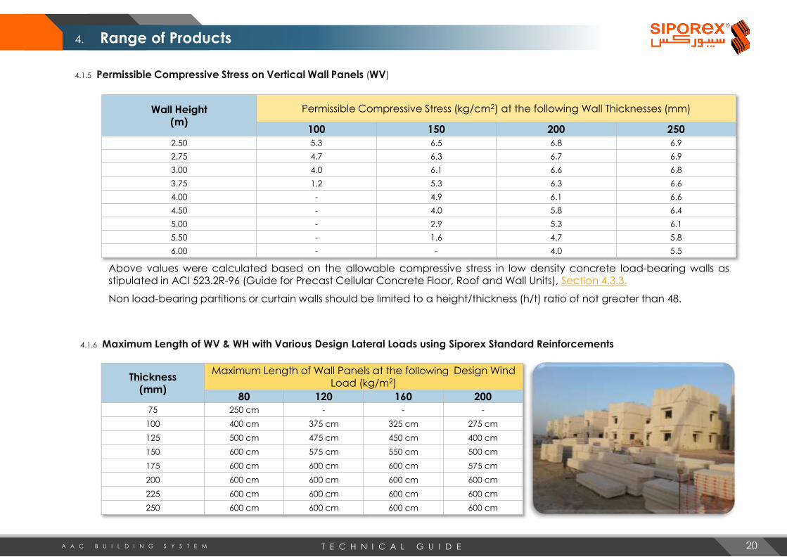
4.1.5 Permissible Compressive Stress on Vertical Wall Panels (WV)
Wall Height (m)
Permissible Compressive Stress (kg/cm2) at the following Wall Thicknesses (mm)
100 150 200 250
2.50 5.3 6.5 6.8 6.9
2.75 4.7 6.3 6.7 6.9
3.00 4.0 6.1 6.6 6.8
3.75 1.2 5.3 6.3 6.6
4.00 - 4.9 6.1 6.6
4.50 - 4.0 5.8 6.4
5.00 - 2.9 5.3 6.1
5.50 - 1.6 4.7 5.8
6.00 - - 4.0 5.5
Above values were calculated based on the allowable compressive stress in low density concrete load-bearing walls asstipulated in ACI 523.2R-96 (Guide for Precast Cellular Concrete Floor, Roof and Wall Units), Section 4.3.3.
Non load-bearing partitions or curtain walls should be limited to a height/thickness (h/t) ratio of not greater than 48.
4.1.6 Maximum Length of WV & WH with Various Design Lateral Loads using Siporex Standard Reinforcements
Thickness (mm)
Maximum Length of Wall Panels at the following Design Wind Load (kg/m2)
80 120 160 200
75 250 cm - - -
100 400 cm 375 cm 325 cm 275 cm
125 500 cm 475 cm 450 cm 400 cm
150 600 cm 575 cm 550 cm 500 cm
175 600 cm 600 cm 600 cm 575 cm
200 600 cm 600 cm 600 cm 600 cm
225 600 cm 600 cm 600 cm 600 cm
250 600 cm 600 cm 600 cm 600 cm
20
4. Range of Products
T E C H N I C A L G U I D EA A C B U I L D I N G S Y S T E M
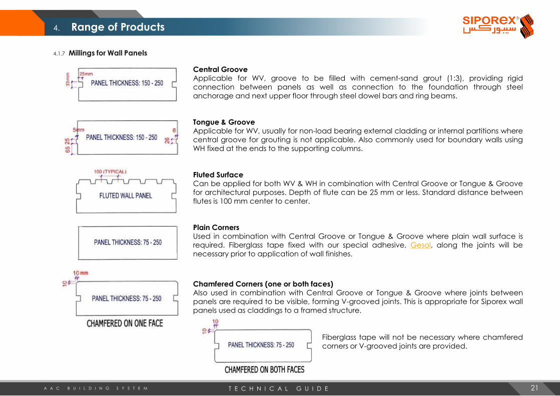
4.1.7 Millings for Wall Panels
Central GrooveApplicable for WV, groove to be filled with cement-sand grout (1:3), providing rigidconnection between panels as well as connection to the foundation through steelanchorage and next upper floor through steel dowel bars and ring beams.
Tongue & GrooveApplicable for WV, usually for non-load bearing external cladding or internal partitions wherecentral groove for grouting is not applicable. Also commonly used for boundary walls usingWH fixed at the ends to the supporting columns.
Fluted SurfaceCan be applied for both WV & WH in combination with Central Groove or Tongue & Groovefor architectural purposes. Depth of flute can be 25 mm or less. Standard distance betweenflutes is 100 mm center to center.
Plain CornersUsed in combination with Central Groove or Tongue & Groove where plain wall surface isrequired. Fiberglass tape fixed with our special adhesive, Gesol, along the joints will benecessary prior to application of wall finishes.
Chamfered Corners (one or both faces)Also used in combination with Central Groove or Tongue & Groove where joints betweenpanels are required to be visible, forming V-grooved joints. This is appropriate for Siporex wallpanels used as claddings to a framed structure.
Fiberglass tape will not be necessary where chamferedcorners or V-grooved joints are provided.
21
4. Range of Products

T E C H N I C A L G U I D EA A C B U I L D I N G S Y S T E M
4.2 Lintels
4.2.2 Arch Type Lintels (LA)
Arch type lintels are also load-bearing members but withadded architectural features that can be designed withvarious shape and sizes of arches applicable for openings atexternal facades or internal walls. Reinforcement mats arespecially arranged to facilitate fabrication and avoidexposure after cutting the required shape. Arches can bedesigned with single panel where height of arch does notexceed 30 cm or multi layers of panels for high arches.
4.2.1 Panel Type Lintels (LW)
Lintels are used as load-bearing members over window and door openings for externalor internal walls, eliminating the need for shuttering and in-situ concrete. They arebedded with special Siporex glue onto wall panels adjacent to the opening of reducedheight. The maximum obtainable lengths (free spans) in meters for lintels of variousdesign loads and thicknesses are shown in table of Section 4.2.4. LW’s usually havestandard height of 60 cm.
4.2.3 Box Type Lintels (LB)
Box type lintels are designed with special steel reinforcementarrangement to be used where lintel depth is limited. They aresuitable for block wall construction, produced with depth equalto the height of Siporex blocks for ease of construction. Thiseliminates shuttering and cast-in-situ works as well as avoidsthermal bridges caused by the use of traditional concrete lintels.The maximum obtainable lengths (free spans) in meters for Boxtype lintels of various design loads and thicknesses are shown intable of Section 4.2.5.
The minimum permissible end bearings for all types of lintels are as follows:
for L ≤ 2400 mm 200 mm each endfor L > 2400 mm 300 mm each end
Due to the special reinforcement arrangement, lintels must never be cut.
22
4. Range of Products

T E C H N I C A L G U I D EA A C B U I L D I N G S Y S T E M
4.2.4 Maximum Clear Span of Panel Type Lintels with Various Design Loads
(Height = 60 cm)
4.2.5 Maximum Clear Span of Box Type Lintels with Various Design Loads
(Height = 25 cm)
Design LoadThickness of Panel Type Lintel (mm)
100 150 200 250
500 kg/m 250 cm 450 cm 540 cm 540 cm
1000 kg/m 200 cm 325 cm 400 cm 450 cm
1500 kg/m 100 cm 275 cm 325 cm 375 cm
Design LoadThickness of Box Type Lintel (mm)
100 150 200 250
500 kg/m 200 cm 350 cm 360 cm 360 cm
1000 kg/m 150 cm 250 cm 260 cm 265 cm
1500 kg/m 75 cm 200 cm 210 cm 210 cm
Other heights and spans of lintels can be designed by ourtechnical department depending on their particularcondition and considering the clear span of openings as wellas design loads.
Since Siporex lintels are constructed with the same materialsas the wall panels or Siporex masonry blocks, the surfaces areeasily finished and the possibility of cracks due to differentthermal expansion is eliminated.
Various actual applications of Siporex lintels
23
4. Range of Products
T E C H N I C A L G U I D EA A C B U I L D I N G S Y S T E M
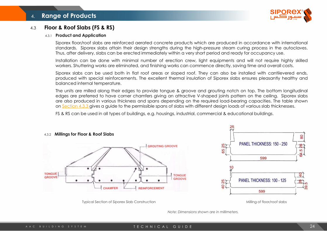
4.3 Floor & Roof Slabs (FS & RS)
4.3.1 Product and Application
Siporex floor/roof slabs are reinforced aerated concrete products which are produced in accordance with internationalstandards. Siporex slabs attain their design strengths during the high-pressure steam curing process in the autoclaves.Thus, after delivery, slabs can be erected immediately within a very short period and ready for occupancy use.
Installation can be done with minimal number of erection crew, light equipments and will not require highly skilledworkers. Shuttering works are eliminated, and finishing works can commence directly, saving time and overall costs.
Siporex slabs can be used both in flat roof areas or sloped roof. They can also be installed with cantilevered ends,produced with special reinforcements. The excellent thermal insulation of Siporex slabs ensures pleasantly healthy andbalanced internal temperature.
The units are milled along their edges to provide tongue & groove and grouting notch on top. The bottom longitudinaledges are preferred to have corner chamfers giving an attractive V-shaped joints pattern on the ceiling. Siporex slabsare also produced in various thickness and spans depending on the required load-bearing capacities. The table shownon Section 4.3.3 gives a guide to the permissible spans of slabs with different design loads of various slab thicknesses.
FS & RS can be used in all types of buildings, e.g. housings, industrial, commercial & educational buildings.
4.3.2 Millings for Floor & Roof Slabs
Typical Section of Siporex Slab Construction Milling of floor/roof slabs
Note: Dimensions shown are in millimeters.
24
4. Range of Products

T E C H N I C A L G U I D EA A C B U I L D I N G S Y S T E M
4.3.3 Permissible Spans of Various Slab Thickness and Design Loads
Design imposed DL + LL(kg/m2)
Permissible Spans with the following Thicknesses (mm)
100 150 200 250
110 kg/m2 4250 6000 6000 6000
160 kg/m2 4000 5750 6000 6000
210 kg/m2 3500 5500 6000 6000
250 kg/m2 3500 5250 6000 6000
300 kg/m2 3250 5000 6000 6000
350 kg/m2 3000 4750 6000 6000
400 kg/m2 2750 4500 5750 6000
500 kg/m2 2500 4000 5250 5750
Above design loads are in addition to the self-weight of the Siporex slabs. Siporex slabs are reinforced with double steelwelded mats and anti-corrosion coated in Siporex factory. Quantity and sizes are in accordance with Siporex steelreinforcement tables.
The minimum required end-bearing supports are 75 mm for masonry & concrete supports and 50 mm for steel beamsupports.
Various applications and
construction of Siporex
floor/roof slabs
25
4. Range of Products

T E C H N I C A L G U I D EA A C B U I L D I N G S Y S T E M
4.4 Siporex Blocks (B)
4.4.1 Product Application & Characteristic Data
Siporex solid blocks are used as load-bearing and non load-bearing walls and asthermally insulating roof tiles in addition to being used as Hordi blocks or infills forribbed slabs. They are produced with very precise dimensions with slim toleranceof ±3mm for thickness and width, therefore they are able to be laid by thin-bedmortar (Siporex glue) with a maximum of 3mm thick mortar joint. This results to ahigh quality wall structure with uniform thermal insulation and fast installation.
4.4.2 Masonry Blocks Dimensions
For the past decades, LCC Siporex had been supplying AAC blocks with a standard face size of 25cm high x 60 cm long only in various thicknesses. However, due to the increasing demand andgrowing popularity of the use of AAC blocks, LCC Siporex have started the production of newdimensions of blocks in line with the continued expansion of additional manufacturing plant tosustain the market requirements. Siporex blocks are now produced at the following standard sizes:
Standard face size: 25 cm high x 60 cm long: Thickness: 10, 15, 20, 25 and 30 cm
Standard face size: 20 cm high x 60 cm long: Thickness: 10, 15, 20, 30 and 40 cm
Above standard sizes with nominal dry density of 550 kg/m3 are usually available in our stocks. It is possible toproduce other dimensions on request, but should be referred to our Sales or Technical departments for verification.
4.4.3 Hordi Blocks
Hordi blocks or infill blocks for ribbed slabs can be produced in variousdimensions to form lightweight infill between in-situ reinforced concreteribs designed to span in one or both directions. Due to their excellentbondage to in-situ concrete, Siporex Hordi blocks are easily arranged toform permanent part of the slab, providing excellent thermal insulationas well as fire resistance material. Hordi blocks are produced withdensity of 450 kg/m3 according to the following dimensions:
Length : 60 cmWidth : 37/38 cm or 40 cmThickness : 20, 25, 30, 35 cm
Other sizes may be produced uponrequest only. Hordi blocks are notavailable in stock and aremanufactured against order only.
Hordi Blocks Application
26
4. Range of Products

T E C H N I C A L G U I D EA A C B U I L D I N G S Y S T E M
4.4.4 Thermal Insulating Tiles
Roof insulation of existing conventional roof can still beimproved with the use of Siporex thermal insulating tilesavailable at the following dimensions:
Other dimensions can be produced upon request.
4.4.5 Packing Data for Siporex Blocks
Siporex blocks are delivered ready for use and packed in easily transportablewooden pallets. The pallets should be unloaded at the site by construction-sitecranes, forklifts or other suitable hoisting equipments. For ease in unloading ofmaterials, it is suggested to order Siporex blocks in whole bundle or pallet volumeto avoid handling loose quantities. Following table is an easy reference in makingorder of some standard sizes of Siporex blocks in bundles or pallets.
Block DimensionsNo. of Blocks
per m3No. of Blocks
per m2No. of Blocks per Bundle
No. of Bundle Per Pallet
m3 per Bundle
m3 per Pallet
10 x 25 x 60 cm 66.66 6.67 75 2 1.125 2.25
15 x 25 x 60 cm 44.44 6.67 50 3 1.125 3.375
20 x 25 x 60 cm 33.33 6.67 35 3 1.05 3.15
25 x 25 x 60 cm 26.66 6.67 30 3 1.125 3.375
30 x 25 x 60 cm 22.22 6.67 25 3 1.125 3.375
10 x 20 x 60 cm 83.33 8.33 72 3 0.864 2.592
15 x 20 x 60 cm 55.55 8.33 48 3 0.864 2.592
20 x 20 x 60 cm 41.67 8.33 36 3 0.864 2.592
30 x 20 x 60 cm 27.78 8.33 24 3 0.864 2.592
40 x 20 x 60 cm 20.83 8.33 18 3 0.864 2.592
SIPOREX ROOF TILES
5 x 25 x 60 cm 133.33 6.67 150 2 1.125 2.25
7.5 x 25 x 60 cm 88.89 6.67 100 2 1.125 2.25
7.5 x 60 x 60 cm 37.04 2.78 40 3 1.08 3.24
SIPOREX HORDI BLOCKS
20 x 37/38 x 60 cm 22.22 4.44 21 3 0.945 2.835
20 x 40 x 60 cm 20.83 4.17 18 3 0.864 2.592
25 x 37/38 x 60 cm 17.78 4.44 18 3 1.013 3.038
30 x 37/38 x 60 cm 14.81 4.44 15 3 1.013 3.038
30 x 40 x 60 cm 13.89 4.17 12 3 0.864 2.592
35 x 37/38 x 60 cm 12.70 4.44 12 3 0.945 2.835
27
4. Range of Products
60 x 60 x 7.5 cm
60 x 25 x 7.5 cm60 x 25 x 5 cm

T E C H N I C A L G U I D EA A C B U I L D I N G S Y S T E M
4.4.6 Block Laying
The first course should be laid on cement-mortar bed of thickness about 1 to 3 cm depending on the evenness of the baseand should maintain a correct level for fast installation progress in the following courses. It is recommended to spray themortar face of the block before installation to keep damp at erection time especially during the hot seasons. Afterinstallation, spray with water twice a day for 3 consecutive days for curing of the mortar.
Three types of Mortars can be applied on the succeeding courses:
4.4.6.1 Glue for Siporex (for thin joints)
Pre-mixed mortar – only water is to be added. Thickness of glue should not exceed 3 mm in horizontal and vertical joints in order
to achieve the ideal consumption rate as follows:
• 7 kg/m2 for Siporex blocks 25 cm thick
• 6 kg/m2 for Siporex blocks 20 cm thick
• 5 kg/m2 for Siporex blocks 15 cm thick
4.4.6.2 Ordinary Mortar with Gesol
1:6 Cement : Sand (by volume) respectively in addition to water (with 10% of Gesol). The erection can be carried out normally as
for conventional blocks. (Gesol is a liquid material used as bonding agent and retardant for the mortar especially during hot
weather. Gesol is available at Siporex factory in 25 kg plastic containers).
4.4.6.3 Ordinary Mortar with Lime:
1:1:10 Cement : Lime : Sand (by volume)
4.4.7 Plastering of Siporex Block Wall
Before plastering, dirt and loose particles should be removed from walls. Spray walls with water and follow one of the twomethods mentioned below:
4.4.7.1 Traditional Plastering:
Similar to plastering of conventional block walls with the following mix:
• Splattering (3mm): Use 1 cement : 3 sand mixed with solution of water and Gesol (20% of the volume). Spray with water twice a
day.
• Ordinary Plastering Mortar: (1 – 1.5 cm thick, apply 24 hours after the splattering)
Use 1 cement : 6 sand mixed with solution of water and Gesol (10% of volume).
4.4.7.2 Plastering with Pre-mixed Mortar
Water is added to the pre-mixed plaster supplied in bags of 25 and 50 kgs. Surfaces should be thoroughly cleaned and wetted
without any splattering. Apply plaster directly with a thickness ranging between 0.5 to 1 cm
In both above methods, walls should be watered twice a day after plastering for three consecutive days.
4. Range of Products
28
T E C H N I C A L G U I D EA A C B U I L D I N G S Y S T E M
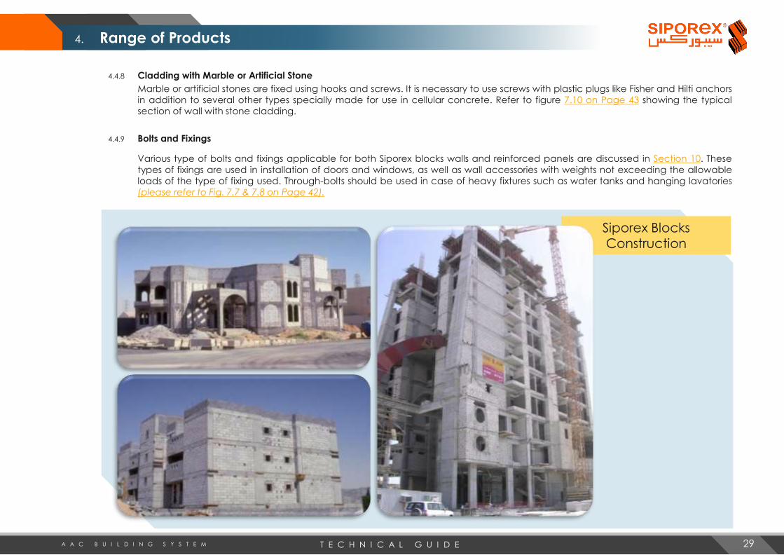
4.4.8 Cladding with Marble or Artificial Stone
Marble or artificial stones are fixed using hooks and screws. It is necessary to use screws with plastic plugs like Fisher and Hilti anchors
in addition to several other types specially made for use in cellular concrete. Refer to figure 7.10 on Page 43 showing the typical
section of wall with stone cladding.
4.4.9 Bolts and Fixings
Various type of bolts and fixings applicable for both Siporex blocks walls and reinforced panels are discussed in Section 10. These
types of fixings are used in installation of doors and windows, as well as wall accessories with weights not exceeding the allowable
loads of the type of fixing used. Through-bolts should be used in case of heavy fixtures such as water tanks and hanging lavatories
(please refer to Fig. 7.7 & 7.8 on Page 42).
Siporex Blocks Construction
29
4. Range of Products

T E C H N I C A L G U I D EA A C B U I L D I N G S Y S T E M
5.1 General
With its innovative physical properties,Siporex system offers design andengineering flexibility for a variety ofconstruction applications ranging fromsingle and multi-family residential tocommercial buildings, as well aswarehousing, schools and governmentfacilities.
Siporex system consists of various product types: wallpanels, floor/roof slabs and lintels which can becombined to form a load-bearing structure.
By using this system, costly labour and material intensivein-situ concrete structures of columns, beams, floor androof slabs can be eliminated.
This fact makes it particularly suited for the constructionof buildings up to six storeys.
30
5. Design
T E C H N I C A L G U I D EA A C B U I L D I N G S Y S T E M 31
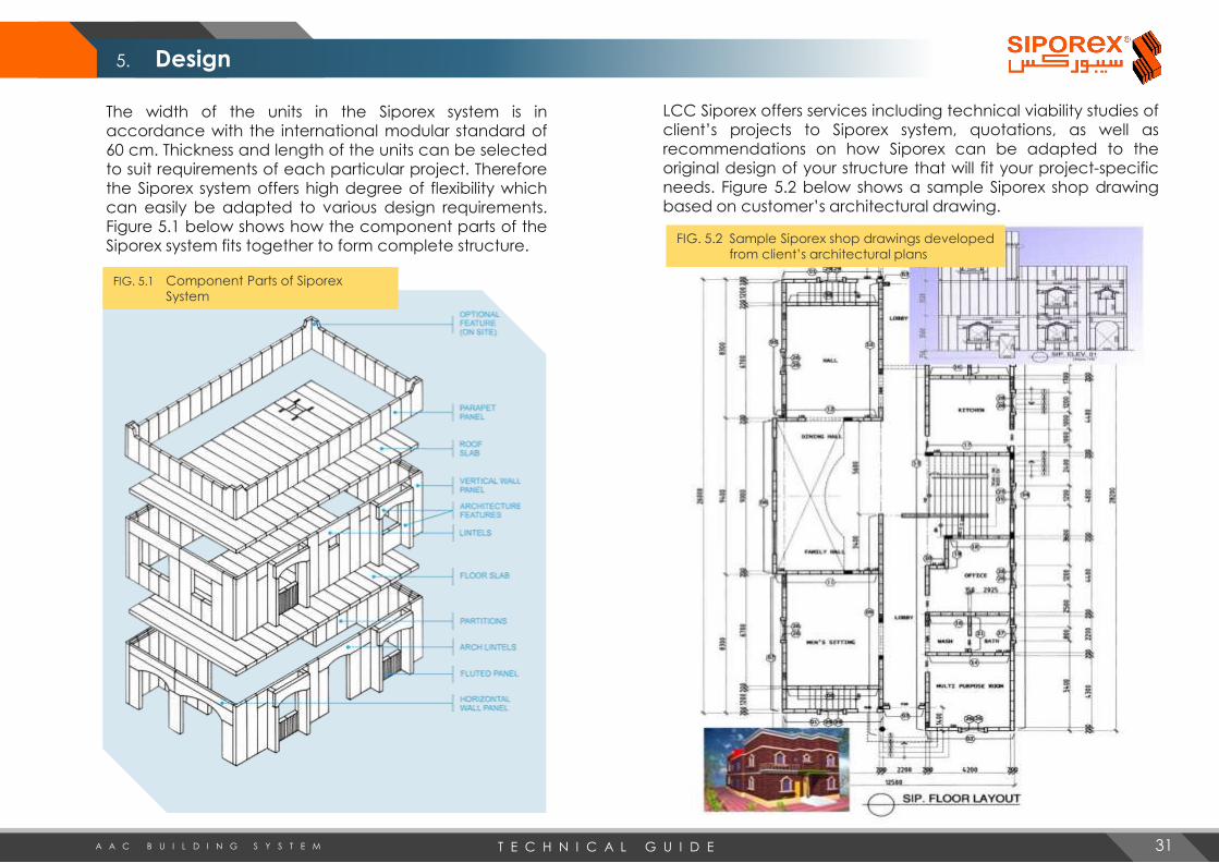
FIG. 5.1 Component Parts of Siporex
System
FIG. 5.2 Sample Siporex shop drawings developed
from client’s architectural plans
The width of the units in the Siporex system is inaccordance with the international modular standard of60 cm. Thickness and length of the units can be selectedto suit requirements of each particular project. Thereforethe Siporex system offers high degree of flexibility whichcan easily be adapted to various design requirements.Figure 5.1 below shows how the component parts of theSiporex system fits together to form complete structure.
LCC Siporex offers services including technical viability studies ofclient’s projects to Siporex system, quotations, as well asrecommendations on how Siporex can be adapted to theoriginal design of your structure that will fit your project-specificneeds. Figure 5.2 below shows a sample Siporex shop drawingbased on customer’s architectural drawing.
5. Design

T E C H N I C A L G U I D EA A C B U I L D I N G S Y S T E M
Much of the company’s work entails the conversion of client’s original designs from other materials to Siporex system,generally resulting in cost and energy savings. But the best and most economical use of Siporex is produced by designing inthe material from onset.
Optimum results and savings can be obtained through careful design work and meticulous planning before and duringexecution. Before commencing the architectural design for a project, the following guidelines should be noted:
1. The maximum span of Siporex panels is 6.00 meters. This means that the maximum clear span between the load bearingwalls should not exceed 5.85 meters considering 7.5 cm end bearing of floor/roof slabs. The distance between the non-load bearing walls is immaterial. If the clear span is more than 5.85 meters, then steel or concrete beams supported onsteel or concrete columns should be used to support the roof slabs.
2. Upper walls are recommended to be aligned with walls of the lower floor. Walls at upper floor supported directly onSiporex slabs are not allowed. When unsupported walls cannot be avoided, intermediate steel beam can be used orconvert the wall to non-load bearing lightweight dry wall partition, in order to achieve maximum economy.
3. The foundation should be made high enough such that the external wall panels will not absorb moisture from theground.
4. Width of door/window openings are recommended to be limited to the allowable spans shown in Sections 4.2.4 & 4.2.5in order to utilize Siporex lintels and avoid the use of in-situ concrete lintels.
Siporex buildings are designed based on box system principle. Siporex load-bearing walls act as shear walls resisting lateral forces due to wind or seismic loads. The wall panels have grooves along their edges which form joints when erected. These joints receive steel tie bars from the footing and at the top connecting the lower wall with the one above. As they penetrate the ring beam, a strong connection will be provided between the vertical and horizontal structures. These joints (3.3 x 5 cm) are grouted and they are able to transfer shear forces from one panel to the other.
The roof and floor slabs have tongue and groove as well as notch at the top to be reinforced with 8mm diameter bar between spans and grouted with cement-sand mortar (1:3) consequently eliminating differential deflection. Due to the ring and bond beams around the building, all slabs form membrane acting as laterally stiff diaphragms which can transfer lateral forces to the bearing walls .
These constitute the diaphragm action of the Siporex structural system. Lateral forces are distributed in proportion to the moment of inertia of the walls, that is, proportional to their stiffness. Based on actual experiences of actual occurrences in different countries, It has been noted that Siporex buildings are very resistant to earthquake forces.
5.2 Design Principle
5.3 Structural System
32
5. Design

T E C H N I C A L G U I D EA A C B U I L D I N G S Y S T E M
6.1 Guidelines for Estimating Erection Cost of Siporex Elements
6.1.1 Erection Manpower
Four (4) man-hours per cubic meter of Siporex panels for residentialconstruction is a good average figure. The figures cover erection of thesuperstructure on the prepared foundation base (level tolerance ±1 cm)and include grouting of wall and roof joints as well as repair works to makethe surface ready for application of finishes. The figures also include castingthe normal ring beam behind the rebated wall panel upstand.
6.1.2 Type of Crane & Crane Hours
Mobile telescopic crane 10 to 40 ton rangedepending on the reach is normally needed. Asingle crane with operator can serve twoerection crews at the same time. Crane usagewill be about 0.33 hours per cubic meter ofSiporex elements considering two crews or 0.66hours per cubic meter for one crew.
6.1.3 Cost of Auxiliary Materials and Consumables
SR 30 to 40 per cubic meter of Siporex elements.The figure includes cost of Siporex glue, sand-cement grout, concrete and reinforcements forring beams, plastic wedges, nails and dowel bars.Cost of large beams/columns requiring formworks shall be calculated separately. Major steelfixings and steel beams are not included.
List of Auxiliary Materials Approximate Consumption
Siporex glue for bedding and minor repairs10 kg per cubic meter of
Siporex
Sand-cement grout to fill joints between
wall panels
45 kg per cubic meter of
Siporex
Fiberglass tape for joints 3.5 lm per sq. m. of Siporex wall
Gesol (Adhesive liquid) for fixing fiberglass
tape
1 kg per 18 lm of fiberglass
tape
Dowels, Ø5.5mm x 250mm long, stitches to
connect walls2 pcs per wall panel
Plastic wedges – to support wall panels
temporarily2 pcs per wall panel - reusable
Galv. nails: 100mm 4 pcs per cubic meter of wall
Galv. nails: 125mm 2 pcs per cubic meter of slab
Siporex Sand paper1 lm per 200 cu. meter of
Siporex
Masonry nails, 50 mm 1 box per average villa
Reinforcements for ring beam1 kg per cubic meter of
Siporex
Concrete for ring beams 1 m3 per 20 m3 of Siporex slabNote:
Above data should be considered as general guidelines only. They are not substitute for careful evaluation of actual requirements of each project and a detailed bill ofquantities. The data supplied are based on LCC’s own experience and are correct to the best of our knowledge. However, no guarantee of any kind can be given asindividual projects vary a great deal.
33
6. Erection
A typical erection crew with crane & operator consists of the following:
1 – crane helper2 – erectors1 – panel preparation man2 – assistant erectors for general site works, grouting, repair works, dowel drilling, etc.
Note that one crane can serve 2 crews at a time.

T E C H N I C A L G U I D EA A C B U I L D I N G S Y S T E M
6.2 Hand Tools and Equipment
6.2.1 Siporex Erection Tools
The following tools are provided by LCC Siporex free of charge onreturn-basis against a refundable deposit as an extension of services tocustomers. They are to be returned to the Siporex factory uponcompletion of the erection works to serve other Siporex customers.
Roof Slab Grab width of slab = 600 mm
Lifting Grab for horizontal wall panels and lintels Lifting Hook for vertical wall panelsLifting Sling for slabs (7.8 m long and 2 tons capacity)
Wall Braces to temporarily support vertical wall
panelsCramp for closing joints between floor/roof slabsLever for raising partition walls against the
ceiling.
34
6. Erection

T E C H N I C A L G U I D EA A C B U I L D I N G S Y S T E M
The following tools (not provided by LCC Siporex) are also required in addition to the special erection tools during theinstallation of Siporex elements.
6.2.2 Other Hand Tools and Equipment
Grinding board
Plane for chamfering sharp edges
Siporex Saw with special blade for aerated
concrete (available for sale at Siporex
factory)
Hack Saw Blade for cutting steel
reinforcement
Electric Circular Saw with metal blade
Electric Grooving Machine for making
grooves on panels.
35
6. Erection

T E C H N I C A L G U I D EA A C B U I L D I N G S Y S T E M
6.3 Erection Procedure
6.3.1 R.C. foundation should be cast with a smooth and leveled surface. Thissaves a lot of work in leveling the tops of wall panels later.
6.3.2 Layout of wall panels should be marked on the foundation using chalk linesand ensuring that any overhang has been allowed for on the periphery ofthe foundation.
6.3.3 Steel dowels connecting the wall panels to the foundation are eitherplaced in their positions before casting the foundation or placed in a drilledhole of 4 cm in diameter in the foundation and then grouted. Anotheralternative is to make a hole of 8 mm diameter and fix the steel dowelsusing Hilti C10 epoxy or equivalent. These dowels are placed at each wallpanel joint as indicated on Siporex shop drawings.
6.3.4 Nylon offset lines should be used to ensure outside line of panels ismaintained.
6.3.5 Aluminum straight edge should be set to line and level to inside faceof the wall.
6.3.6 The longest elevation with least number of openings at the farthestreach should be selected for initial installation. This is to maintainsight lines between operator and erector and ensures correct signalscan be given to the crane operator.
6.3.7 Siporex glue mortar is used as a bed for the wall panels. Wedges areused for temporary support of wall panels and allow fine adjustmentfor plumb.
6.3.8 Corner elements are erected first and carefully positioned.Succeeding panels are erected as per mark numbers shown onSiporex shop drawings.
36
6. Erection

T E C H N I C A L G U I D EA A C B U I L D I N G S Y S T E M
6.3.9 Working with a fixed straight edge for alignment, the wall panels are liftedby a lifting hook, placed in position and checked for plumb. The top edgesare also aligned and are steadied by temporary wall braces at every 3rd or4th panel. Dowels of Ø5 mm x 250 mm long are used as stitches to connectthe top joints between the panels.
6.3.10 The tightly fixed together wall panels are grouted by thoroughly wetting thegrooves with water and then pouring in fluid cement-sand grout (1:3) andthen positioning steel dowels for the next storey panels. Note that Siporexproducts should always be well wetted with water before applying anyother materials (e,g, glue, grout, plaster,…etc.)
6.3.11 Lintels are placed on top of windows and door openings using a lintel grab.They are supported on and connected to the wall panels adjacent to theopenings. Steel dowels are drilled and grouted on top of the lintel prior toinstallation of vertical panels above.
6.3.12 Floor and roof slabs are lifted with a grab andcarefully positioned with specified end bearings onleveled wall panels. Minimum 50 mm side bearing isrequired on walls parallel to the span. Tongue andgroove joint faces provide firm connection betweenthe units which ensures the stability of the building.
6.3.13 The notches formed between the floor or roof slabsare concreted along with the ring/bond beamsafter placing all the connecting and continuity steelbars. Refer to the figure showing the different detailsfor continuity steel bars.
6.3.14 Any damages are repaired and any spacesbetween the panels are filled flush with Siporex glue.After repair and setting of the mortar, the repairedareas and joints are rubbed down with sand paperto give smooth surfaces.
37
6. Erection

T E C H N I C A L G U I D EA A C B U I L D I N G S Y S T E M
6.4.1 GuidelinesDamage to Siporex panels may be repaired atsite subject to certain limitations. Siporex unitswhich are structurally defective and unfit for thepurpose for which they are designed must notbe repaired but should be rejected andreplaced with sound units.
Broken floor/roof slabs must be rejected. Abroken floor/roof slab is a unit which due tofracture on its lower face (tension side) orthrough breakage and/ or fracturing of thebearing faces at the ends is no longer able tofulfill its structural functions for which it has beendesigned.
Slabs with transverse cracks which extendthrough the thickness of the slab should berejected. Slabs with hair-line cracks which donot penetrate to the tensile reinforcement willnormally be suitable for use.
Damage which exposes extensive parts of thereinforcement should not be repaired. Panelswith major damage to the bearing surfacewhich exposes the cross bars on the tensile steelshould not normally be repaired.
Spalling or peeling-off of fragments to face ofpanel can be repaired if maximum length ofrepair is 30 cm and depth is less than ¼ of thetotal panel thickness. Spalling to edge of panelcan be repaired if maximum dimension of repairis 30 cm and maximum width is 20 cm.
6.4.2 Repairing InstructionSiporex panels should be free from defects which wouldimpair their strength and structural integrity. Slight damagesare normal and can be repaired as per the followinginstructions:
6.4.2.1 Clean the defective surfaces thoroughly with a stiffbrush and remove all dirt and loose material. Wetthoroughly with water using s large brush. If a largepiece has broken-off and the broken-off section isavailable undamaged, the piece can be glued onby applying Gesol to both surfaces and pressingthe broken-off section into the unit to fit.
6.4.2.2 Place a suitable amount of Siporex glue in abucket. Add clean potable water with 10% Gesoland mix thoroughly with a mason’s spoon till a softputty consistency is achieved. Do not mix moremortar than can be consumed before the mortarstarts to set. Do not add water when mortar starts toset in order to restore workable consistency.
6.4.2.3 Deep repairs shall be reinforced with galvanizedcut nails before Siporex glue is applied. ApplySiporex glue to the damaged area with a mason’sspoon. During application, use slightly morematerial than is needed to fill the damaged area.
6.4.2.4 After application, leave the material untouched tillthe mortar starts to harden slightly. Then level with awood float. If necessary apply a small amount ofwater to the surface during leveling. Level bymoving the wood float towards the Siporexmaterial.
6.4 Repair of Siporex Panels
38
6. Erection

T E C H N I C A L G U I D EA A C B U I L D I N G S Y S T E M
6.5 Illustrations Showing Erection Stages
A) Starter bars are laid in position. B) Siporex glue is applied forbedding.
F) Top joints are stitched andgrooves are grouted.
D) Succeeding panels areerected.
E) Provide temporary wallbracings.
C) Corner panels are placed inposition.
39
6. Erection

T E C H N I C A L G U I D EA A C B U I L D I N G S Y S T E M
6.5 Illustrations Showing Erection Stages
G) Lintels are laid above openings.Dowel bars are provided for nextlevel.
H) Siporex glue is used as leveling bed attop. Dowel bars are positioned fornext level.
I) Floor/roof panels are laid.
J) Provide steel reinforcement forring beams
K) Continuity bars between spans arelaid.
L) Cast concrete alonggrooves and ring beams.Proceed with next upperlevel.
40
6. Erection

T E C H N I C A L G U I D EA A C B U I L D I N G S Y S T E M
7.1 Parapet connection 7.2 Roof slabs connection 7.3 External wall & slabconnection
7.4 Internal wall & slabconnection
7.5 External wall & foundationconnection
7.6 Internal wall & foundationconnection
41
7. Typical Connection Details

T E C H N I C A L G U I D EA A C B U I L D I N G S Y S T E M
7.7 Siporex wall cladding, fixed to R.C. main frame(External wall)
7.8 Siporex wall cladding, fixed to R.C. main frame(Internal partition)
42
7. Typical Connection Details

T E C H N I C A L G U I D EA A C B U I L D I N G S Y S T E M
Alternative 1:
Slab on top of steel beam
7.9 Siporex slabs supported on steel beams
Alternative 2:
Slab supported on steel beam web
Alternative 3:
Slab inserted between flanges
7.10 Siporex external wall cladding, fixed to
steel main frame
43
7. Typical Connection Details

T E C H N I C A L G U I D EA A C B U I L D I N G S Y S T E M
7.11 Water heater fixing detail
7.12 Lavatory fixing detail
7.13 Marble / artificial stone fixing
7.14 Wooden / aluminum door & windows
44
7. Typical Connection Details

T E C H N I C A L G U I D EA A C B U I L D I N G S Y S T E M
8.1 Chases and Penetrations
Small conduits can be chased easily into Siporexwall panels, but cutting of steel bars should beavoided. (refer to Section 3.2.14 for locations ofsteel bars). For large conduits requiring thecutting of the entire width of the wall panel, thecut portion should be filled with concrete andreinforced with steel mesh at both faces.
Large cut-outs and pipe-runs passing through thefloor / roof slabs can beaccommodated duringdesign stage to avoidunplanned cuttings.Panels with large cut-outswill have reinforcementspecially designed aroundthese cut-outs.
Panel board recesses can be providedneatly and economically by using alining panel to avoid large recesses inthe wall as shown on the above section.
45
8. Electro-Mechanical

T E C H N I C A L G U I D EA A C B U I L D I N G S Y S T E M
8.2 Typical Section Showing Electrical Installations in Siporex Building
8.3 Typical Section Showing Plumbing Installations in Siporex Building
46
8. Electro-Mechanical

T E C H N I C A L G U I D EA A C B U I L D I N G S Y S T E M
9.5 Roofs
Above sections shows the suggested arrangements of finishes on top of Siporex roof slabs (Accessible & Non-accessible roofs).
47
9. Finishes
9.1 Internal Walls
Joints between wall panels should be
taped with fiberglass tape. A thin wall
plaster to be applied in two coats gives
a very smooth surface as a base for
painting or wall papering. Where
required, the second coat may be
applied with a textured finish.
9.2 External Walls
Similarly, joints between wall
panels should be taped with
fiberglass tape unless if the joints
are V-grooved. Where Siporex
panels have V-grooved joints, two
coats of paint with textured finish
are recommended.
9.3 Ceiling
Siporex slabs make
attractive ceiling with the
visible V-grooved lines. Paint
applied in two coats will
give a very smooth base for
painting. Where required,
the second coat may be
applied with a texture finish.
Suspended ceiling systems
can also be used which are normal for bathroomareas to conceal waste pipe runs.
9.4 Floors
Compared to cast-in-situ
concrete floors, Siporex
floor slabs provide a
completely dry smooth floor
construction on which
decorative floor finishes of
tiles, parquet, linoleum and
other required finishes are
readily applied.
Various types of finishes used in conventional concrete construction are also applicable to Siporex system. Before applyingfinishes, damages should be repaired and chases or openings should be made good with Siporex glue mortar. Deep holes andchases can be dubbed with ordinary cement-sand mortar (1:6) to within 5 mm from the surface and finished with Siporex glue.
Finishes for Siporex
T E C H N I C A L G U I D EA A C B U I L D I N G S Y S T E M 48
9. Finishes

T E C H N I C A L G U I D EA A C B U I L D I N G S Y S T E M
Special types of commercially available fixings can be used with Siporex structures.
In fixing built-in units and other items; galvanized nails, bolt fastenings and wall plugs are used. Ordinary wire nails should not be usedsince their anchoring ability to Siporex is low. The type of anchoring method to be used depends on the holding capacity required. Themanufacturer’s recommendations should be consulted as to the maximum loads suitable for use with their products. Some of the typesof fixings and anchors suitable for use with Siporex AAC materials are as follows :
10.1 Galvanized Cut Nails
Galvanized Cut Nailscomes in differentlengths and areavailable at our SiporexFactory.
Cut nails are hammereddirectly into Siporex wallsand do not need to bepre-drilled They can beused to fasten light tomoderate weight itemsto Siporex.
10.2 Hilti HGN Anchors
HGN Gas Concrete Anchors, manufactured by Hilti Company isa Cadmium-free Polyamide anchor specially suitable for AACconcrete base. Available in various sizes, it provides highpressure per unit of area, as well as good resistance to turning inthe hole due to its large fins.
10.3 Fischer Anchors
Also available with plastic plugs suitable for light tomedium weight fixings in aerated concrete.
Technical data regarding the recommended tensile /shear loads for Siporex base are shown on the table onsection 10.4.
10.4 Permissible Loads of some Suitable Fixings to Siporex
Type DesignationPermissible
TensionPermissible Shear
Cut nails100 mm long 10 kg 25 kg125 mm long 12 kg 35 kg150 mm long 18 kg 40 kg
Hilti
HGN 8 30 kg 35 kgHGN 10 50 kg 60 kgHGN 12 65 kg 70 kgHGN 14 80 kg 80 kg
Fisher
S 10 18 kg 40 kg S 10 H 90 40 kg 80 kg
S14 50 kg 100 kg S 16 60 kg 120 kg
49
10. Fixings to Siporex
Technical data regardingthe recommended tensile/ shear loads for Siporexbase are shown on thetable below.

T E C H N I C A L G U I D EA A C B U I L D I N G S Y S T E M
Description
Glue for Siporex (we prefer block mortar from BONDCHEM) which is an adhesive mortar for quick and secure laying of Siporexblocks with a thin joint and for providing a leveling bed for the erection of Siporex wall panels and slabs.
It is in powder form consisting of white cement, limestone and special additives that improve workability and adhesion.
Properties
Setting time after mixing : 20 to 30 minutes depending on weather conditions
Coverage : For blocks face size of 25 x 60 cm: 35 kg per m3 of Siporex blocks with 3 mm thick joints.
For blocks face size of 20 x 60 cm: 45 kg per m3 of Siporex blocks with 3 mm thick joints.
Adhesive strength after setting : Not less than 4 kg/cm2
50
11. Glue for Siporex
Packaging and Storage
This glue is available in 25 kg paper bags. It should be stored in a dry placeprotected against rain and moisture from the ground.
The shelf life is approximately 3 to 6 months if unopened and when stored ina dry place.
Preparation
Prepare the glue mix in a clean trough with 5 liters of clean water per bag.
Mix thoroughly until a homogenous creamy paste is obtained.
Preferably use a high shear mixer on a drilling machine to obtain a uniformmix.
During the hot season and when the blocks have been lying under the sun,replace the mixing water with a mix of 5 parts of water to 1 part of Gesol, aretardant to prevent too rapid setting under hot or dry conditions.

T E C H N I C A L G U I D EA A C B U I L D I N G S Y S T E M
Description
Gesol is a highly concentrated, non-toxic, non-flammable copolymerwhich serves as a bonding agent in mortar and plaster mixes or as aprimer sealer for these substrates.
Gesol has excellent adhesive and cohesive strength.
Technical Data:
Solids 55 ± 1%
Viscosity (20 °C) 1500 mpa. s.
Mechanical stability Excellent
Density 1.05 g/cm3
Color White
51
12. Gesol
Instructions on usage:
Substrates must be sound, clean, free from oil and loosematerials.
Moisten porous subfloors until saturated before applying Gesol.
As a bonding agent (Mixing with cementitious products):
Use a mixture of 1 : 5 to 15 (by volume) of Gesol and water.
Application:
Gesol is used in the following applications:
To prevent too rapid setting in lime/cement materials and improve curingunder hot and dry conditions.
To seal and prepare substrates with a strong absorbent background,particularly in hot climatic regions.
As a primer to improve adhesion.
As a bonding agent for screeds, leveling compounds, repair mortars, plasters andrenders. To boost adhesion, compressive and flexural strength, abrasion resistance,etc.

13. Siporex Projects
T E C H N I C A L G U I D EA A C B U I L D I N G S Y S T E M
LIST OF SOME SIPOREX PROJECTS
Continued…
SN. CLIENT / CONTRACTOR NAME OF PROJECT LOCATION YEAR
01 Panda Stores 2 Storey Dormitory Riyadh 1981
02 Royal Commission for Jubail & Yanbu Contract No. 113-C02 EPC 419 Dwelling Units Jubail 1982
03 Royal Commission for Jubail & Yanbu Contract NO. 801-C06 E.P.P.C. Jubail 1982
04 Saudi Ceramic Dormitories & Ancillary Bldgs. Riyadh 1982
05 S C E C O Substations Jeddah & Taif 1982
06 AlJubail Petrochemical Co. (KEMYA) 27 Housing Units Jubail 1983
07 Essam Economic Co. Clinic & Residential Complex Jubail 1983
08 Gustav Epple & Pollenisky & Zoelner SCECO – Central PP 8 Power Station Riyadh 1983
09 Baker Trading & Contracting AMG (GAMA) 80 Units Compound Riyadh 1983
10 Saudi Petrochemical Co. (SADAF) E.P.C. Contract for 100 Houses Jubail 1984
11 AMAL Est. Saudi Diesel Compound AlKhobar 1984
12 Sirafi / Carlson Gr. Inc. University Staff Housing Ph.II Riyadh 1984
13 BETA Company Microwave Station Around Riyadh 1984
14 Brown Bovery & CIE AG 7 SCECO Substations Riyadh 1984
15 Hanshin Const. Co. Human Resources Dev. Institute Jubail 1985
16 Saudi Mcinerney Const. Co. Ltd. Kanoo Housing Complex Jubail 1985
17 Poong Lim Saudi Arabia National Methanol Housing Jubail 1985
18 JV SAAD Polensky & Zoellner / Gustav Epple Jamjoom Commercial Center Jeddah 1985
19 Societe Auxillaire D’ent., Dammam AlQatif Housing Project AlQatif 1986
20 Skanska Gen. Contr. Red Sea Hospital Jeddah 1986
21 Skanska Gen. Contr. Bisha Hospital Bisha 1986
22 Arabuilt Co. Ltd. KSU Housing Proj. Ph.II Riyadh 1986
23 Saudi Petrochemical Co. 136 Housing Units Jubail 1987
24 Haifco Bitas, Makkah Juffali Commercial Bldg Makkah 1987
25 A. A. AlTazi Corp. Aziziyah Beach Housing AlKhobar 1988
26 Sheikh AbdulAziz AlHamdan, Riyadh AlHamdan Commercial Complex Roof Covering Riyadh 1988
27 Jarir Furniture 8 Villa Compound Riyadh 1988
28 Meto Bau / AG. Jed. Steidle S.A. & Moll Arabia Ltd.Substation at AlZahir, Sisha, Makkah & Jubail,
Kubais & Power Plant 110 KV Extn.
Makkah &
Makkah / Taif1989
29 Ghassan A. AlKhalid Co. Various Houses, Chalets & Schools Kuwait 1990
30 Asahi Glass Co., Japan Siporex Wall Panels Japan 1990
31 ElEkam Gen. Contr. Girls School at Ajman U.A.E. 1990
32 AlMulla Est. Abjar Hotel at Dubai U.A.E. 1990
33 S A S C O Roadside Rest Areas Diff. sites 1990
34 Prince Khalid Bin Faisal Abha Exhibition Center Abha 1990
35 Hyundai, Riyadh King Fahad Medical City (Interstitial Floors) Riyadh 1990
36 A.K. Group School Building Dhahran 1991
37 Basem AlKhateeb Special Forces Accom. Riyadh 1991
38 A. Azhar Corp. Makkah Kindergarten Makkah 1991
39 Faraj AlQahtani Est. Faisal Islamic Bank Villas Jubail 1991
40 GAMA Services GAMA Compound Jeddah 1991
41 Projects & Trading Co. ABV MODA Resi. Camp Jeddah 1991
42 AlTarifi General Contracting Hospital Project for Ministry of Health Safwa AlLaith 1991
43 A.K. Group Aziziyah Housing 208 Villas AlKhobar 1992
44 AlShaden Cont. Est. AlHasawi Housing Compound AlKhobar 1992
45 AKC Contracting Khalifa Oly. Stadium Qatar 1992
46 Arch. Saleh Qadah AlMeftaha Village Abha 1992
52

13. Siporex Projects
T E C H N I C A L G U I D EA A C B U I L D I N G S Y S T E M
LIST OF SOME SIPOREX PROJECTS
Continued…
SN. CLIENT / CONTRACTOR NAME OF PROJECT LOCATION YEAR
47 Saudi Shinwha Co. Sharq Exp. Factory Jubail 1992
48 AlWaad Co. 8 Villa Compound Jubail 1992
49 Ghassan A. AlKhalid Different Chalets Kuwait 1992
50 ABV Rock Group / Arabian Gulf Co. SSSP Residential Compound 120 Units Madinah 1992
51 ABV Rock Group / Haif Est. SSSP Residential Compound 110 Units Abha 1993
52 ABV Rock Group / United Const. & Trdg Co. SSSP Residential Compound 110 Units Buraidah 1993
53 AlWasat Trading & Contracting Co. AlSulayyel Housing Compound AlSulayyel 1993
54 Kimma Construction Yanpet Housing Project 200 Villas Yanbu 1993
55 Ibn Zumaie Const./Maint. AlKaki Compound Jeddah 1993
56 AlBustan Company AlHada Dev. Project 20 Villas AlKhobar 1993
57 AlBustan Company Stemco Cmpd. 8 Villa AlKhobar 1993
58 Senam United Mod. Co. 20 Villa Compound Jubail 1993
59 ABV Rock Group ABV Compound Jeddah 1993
60 Ghassan A. AlKhalid Different Chalets Kuwait 1993
61 A.K. Group AlGossaibi Accommodation Dammam 1993
62 Saudi Constructioneers Est. GOSI Housing Project 36 Units Jubail 1993
63 UGETCO/Kuwait Hotels Dubaiya 30 Chalets Kuwait 1993
64 N A Z C O (Najeeb AlZamil Group) SAFCO Housing Project Jubail 1993
65 Nasser A. AlTuraiki 6 Villas Compound Dammam 1993
66 Nesma & AlFadl Cont. Co. Hadeed Housing Project Jubail 1993
67 Abdullah AlMubarak Est. Municipalities Dammam & Dhahran 1993
68 A.K. Group Base Commander Residential Dhahran 1994
69 U G E T C O Different Villas / Chalets Kuwait 1994
70 Saudi German Hospital Hospital Extension Jeddah 1994
71 A. K. Group Tabuk Gardens Village – 60 villas Tabuk 1994
72 Saudi Archirodon Ltd. Compound Extension Jeddah 1994
73 Armetal Labor Camp Riyadh 1994
74 AlMutabagani Health Serv Housing Compound 10 Villas Taif 1994
75 Hanil Development Co. Housing Compound AlJouf 1994
76 Moll Arabia Ltd. SCECO Substations Jeddah 1994
77 Saudi Wiemer & Trachte Hofuf Cement Factory Hofuf 1994
78 AlAjdal Trading Est. Sipenny’s Labor Camp Dubai-UAE 1994
79 Abdullah AlMubarak Est. Municipality Jubail 1994
80 AlGhurery Co. Manarat AlSharkia Schools Dammam 1994
81 Sata Engineering Blocks Taiwan 1994
82 Eng’r. AlBassam AlBassam’s Compound Riyadh 1994
83 Arabian Fal Co. Ibn Sina Housing Project Jubail 1994
84 Saudi Real Estate Co. D.Q. Housing Project Riyadh 1994
85 M.S. AlSuwaidi Cont. Est. Yanpet Housing Project Phase II 300 Villas Yanbu 1994
86 Bin Ayed Est. Panda No. 8 Renovation Riyadh 1995
87 AlOthman Agri. Prod. Various Projects Hofuf 1995
88 AlAjdal Trading Est. Cold Store Building Dubai 1995
89 AlThinayyan Dev. Co. Petrolube Factory Offices Riyadh 1995
90 U G E T C O Ministry of Interior Extn. Kuwait 1995
91 AlAjdal Trading Est. 92 Buildings Extension AbuDhabi 1995
92 AlAjdal Trading Est. American Hospital Dubai 1995
53

13. Siporex Projects
T E C H N I C A L G U I D EA A C B U I L D I N G S Y S T E M
LIST OF SOME SIPOREX PROJECTS
Continued…
SN. CLIENT / CONTRACTOR NAME OF PROJECT LOCATION YEAR
93 AlSarif Corporation AlWazir Center Riyadh 1995
94 AMERAB-ECO- Tawam 89 Villas & B. Walls AbuDhabi 1995
95 AlFanar Co. Iskan AlAam Substation Makkah 1995
96 Assad Said Corp. Office for Power Plant 9 Riyadh 1995
97 AlKhozaim Construction AlWalaan Showroom Riyadh 1995
98 AlMobti for Trad. & Cont. 273 Villas Compound Djibouti 1996
99 Arabian Turkish Cont. Co. AlMatroud Staff Accommodation Sihat 1996
100 Teamwork S.A. Ltd. Al Hayat Pharma. Plant Riyadh 1996
101 Shamsa Trading Est. 5 Buildings AlKharj 1996
102 ElSeif Eng. Cont. Est. PP 8 Phase II, Ext. II Riyadh 1996
103 Riyadh AlHuda Schools School Complex Jubail 1996
104 Delta Est. Office & Accommodations Riyadh 1996
105 ABV Rock Group KB. Boundary Walls Abha 1996
106 AlToukhi Co. Ind & Trad. AlBayaah Substation Madina 1996
107 Saudi Binladin Group Aqaba Substation Jordan 1996
108 Giant Crete Bldg. Mat. Wall Claddings Taiwan 1996
109 Moll Arabia Ltd. Faysaliyah New Substation Jeddah 1996
110 A.K. Group R.S.L.F. Housing Tabuk 1996
111 AlMasarah Cont, Est Yanpet Housing Phase 2 Ext. Yanbu 1996
112 A. K. Group Commanders Office 4 Bldgs. Taif 1996
113 A. K. Group Emarah Palace Complex Kharkhair 1996
114 Saudi Binladin Group Power Plant (PP 9) Riyadh 1996
115 AlKhulaifi Business Group 16 Villa Complex Qatar 1996
116 Amana Steel Hangers U.A.E. 1996
117 A. K. Group S S O C Compound Taif 1996
118 Ret Ser Yanbu Cement Factory Yanbu 1996
119 Saudi Build Barracks Gurrayat 1997
120 International Center Co. YCC – 40 Villas Yanbu 1997
121 C C C (ARAMCO) Residential & Industrial Compound Shaybah 1997
122 General Presidency for Girls Education 16 Colleges Buildings Different Locations 1997
123 Developed Building Co. 180 Villas (Roof Slabs) Qatar 1997
124 Giant Crete Bldg. Mat’ls. Wall Claddings Taiwan 1997
125 Dr. Khalid Idress Hospital Hospital Extension Jeddah 1997
126 Ibrahim AlSheikh Est. Central Electrical Bldg. Ext. Jeddah 1997
127 Tawam Gen. Cont. Co. Coast Guard Institute Project AbuDhabi 1997
128 Mr. Yaqub AlGhoul Chalets & Hotel Gizan 1998
129 AlSwayeh Co. Hyatt Regency Hotel Riyadh 1998
130 John Shenton Architects Princess Donnas Palace Ren. Riyadh 1998
131 Pax Kent Tea factory Jabel Ali 1998
132 Mannai Engineering Co. Intercontinental Hotel AlAhsa 1998
133 Tawam General Cont. Co. AlDukkan Project Diff. sites 1998
134 AlOthman Est. Wall Claddings for 2 Buildings AlAhsa 1998
135 Developed Building Co. 5 Villas Qatar 1998
136 Pax Kent Unilever Gulf Project Dubai 1998
137 Pax Kent GAC Distribution Center Dubai 1998
138 Assad Said Corporation Offices for SSOC AlKhaj 1998
54
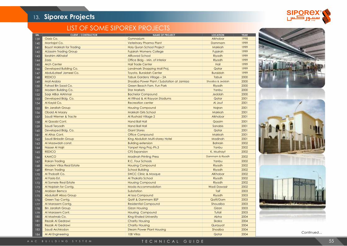
13. Siporex Projects
T E C H N I C A L G U I D EA A C B U I L D I N G S Y S T E M
LIST OF SOME SIPOREX PROJECTS
Continued…
SN. CLIENT / CONTRACTOR NAME OF PROJECT LOCATION YEAR
139 Oasis Co. Gymnasium Alkhobar 1998
140 Montajat Co. Veterinary Pharma Plant Dammam 1999
141 Boyot Makkah for Trading Holy Quran School Project Makkah 1999
142 AlJassim Trading Group Fujairah Womens College Fujairah 1999
143 Ibrahim AlKhalaf AlRuwad School Riyadh 1999
144 Zaas Office Bldg – Min. of Interior Riyadh 1999
145 Arch Center Hail Trade Center Hail 1999
146 Developed Building Co. Landmark Shopping Mall Proj. Qatar 1999
147 AbdulLateef Jameel Co. Toyota, Buraidah Center Buraidah 1999
148 REDICO Tabuk Gardens Village – 2A Tabuk 2000
149 Moll Arabia Shoaiba Power Plant / Substation at Jamiaa Shoaiba & Jeddah 2000
150 Fahad Bin Saad Co. Green Beach Fam. Fun Park Riyadh 2000
151 Modern Building Co. Star Markets Yanbu 2000
152 Saqr AlBar AlAhmar Bachelor Compound Jeddah 2000
153 Developed Bldg. Co. Al Ittihad & Al Rayyan Stadiums Qatar 2001
154 Al Kayid Co. Recreation center Al Jouf 2001
155 Bin Jarallah Group Housing Compound Najran 2001
156 Obaid Al Maary Makkah Girls School Makkah 2001
157 Saudi Wiemer & Tracte Al Rushaid Village 2 Alkhobar 2001
158 Al Qasabi Cont. Hand Ball Hall Qassim 2001
159 Saudi Teryadh Hand Ball Hall Sanabis 2001
160 Developed Bldg. Co. Giant Stores Qatar 2001
161 Al Afras Cont. Office Compound Makkah 2001
162 Saudi Binladin Group King Abdullah Multi-storey Hotel Madinah 2001
163 Al Maawdah const. Building extension Bahrain 2002
164 Nasser Al Hajri Yanpet Hsng Proj.-Ph.3 Yanbu 2002
165 REDICO CFS Expansion K. Mushayt 2002
166 KAMCO Madinah Printing Press Dammam & Riyadh 2002
167 Rakan Trading R.C. Four Schools Yanbu 2002
168 Modern Villas Real Estate Housing Compound Riyadh 2002
169 Riman Trading School Building Riyadh 2002
170 Al Thobaiti Co. SWCC Clinic & Mosque AlKhobar 2002
171 Al Fasla Est. Al Thakafa School Riyadh 2002
172 Al Someie Real Estate Housing Compound Riyadh 2002
173 Al Najdain for Contg. Moda Accommodation Wadi Dawasir 2002
174 Arabian Bemco Substation Taif 2003
175 Abdullatif AlIssa Group Al Issa Compound Riyadh 2003
176 Green Top Contg. Qatif & Dammam BSP Qatif/Dam 2003
177 Al Marasem Contg. Residential Compound Shouaiba 2003
178 Bin Jarallah Group Gizan Housing Gizan 2003
179 Al Marasem Cont. Housing Compound Tufail 2003
180 Al Mashrab Co. King Khaled University Abha 2004
181 Rezaik Al Gedrawi Charity Housing Skaka 2004
182 Rezaik Al Gedrawi Charity Housing Qurayyat 2004
183 Saudi Archirodon Steam Power Plant Housing Shoaiba 2004
184 Al Ali Engineering 108 Villas Qatar 2004
55

13. Siporex Projects
T E C H N I C A L G U I D EA A C B U I L D I N G S Y S T E M
LIST OF SOME SIPOREX PROJECTS
Continued…
SN. CLIENT / CONTRACTOR NAME OF PROJECT LOCATION YEAR
185 Al Ali Engineering Villaggio Qatar 2004
186 King Abdullah Foundation 2,500 villas - Developmental Housing Project Diff. sites 2004-2006
187 Contraco 380/110kV Substation Jeddah 2004
188 Al Fawzani Housing Compound – Clinic Jubail 2004
189 Arabian Bemco Cont. Substation Khaybar 2004
190 Al Marasem Medical Clinic Tufail 2004
191 EMECO Al Amar Gold Mine – Housing Quayyiah 2004
192 Al Fanar Co. 110 kV Zahra Substation Makkah 2005
193 Al Ma’awdah Const. 10 Villas for E.Alwan Bahrain 2005
194 Al Ali Engineering 30 Villas Qatar 2005
195 Al Othman Agri. NADA Accommodation Bldgs Hofuf 2005
196 Contraco Al Rabwa Substation Jeddah 2005
197 Saudi Archirodon Office Building Jeddah 2005
198 Biad Development Co. 110/13.8kV Substation Jeddah 2005
199 Mohd. Mousa Shahada Est. Al Jouf Municipality Al Jouf 2005
200 Al Yasser Gen. Cont. Jubail Municipality Jubail 2006
201 Wadi Maramer School Buildings Jizan 2006
202 Abdulaziz Trading Est. Hill View Real Estate-Phase I Ethiopia 2006
203 Philipp Holzman New Surgery Hospital Ext. Riyadh 2006
204 Al Rashid Abetong 10 units Building Extensions Riyadh 2006
205 Rezaik Al Gedrawi Admin. Buildings – 3 Bldgs. Al Jouf 2006
206 Al Ali Engineering 84 Villas Qatar 2006
207 Assad Said Corporation ASC Housing Compound Jubail 2006
208 Imar Development Co. Al Tilal Project Madinah 2006
209 Al Ma’awdah Const. 25 Villas Bahrain 2006
210 Haif Contracting Gazadco Shrimp Farm Jizan 2006
211 Assad Said Corporation Substations Abu Hadriya & Shoaiba 2007
212 Saudi Binladin Group Al Haram Shopping Center Madinah 2007
213 Royal Defense Command Renovation-Apartment Bldgs Jeddah 2007
214 Al Ali Engineering The Pearl Qatar Qatar 2007
215 Al Ali Engineering 58 Villas Qatar 2007
216 Al Gosaibi Labour Camp Jubail 2007
217 Makkah Co. Supply of Blocks Kuwait/Iraq 2007
218 Erfan Hospital Hospital Extension Jeddah 2007
219 Al Mabda Rezayat Housing Compound Jubail 2007
220 Project Building Est. Al-Mouwasat Hosp. FF Ext. Jubail 2007
221 Saudi Binladin Group Dar Al-Qibla Complex Madinah 2007
222 MEEDCO Substations Khurais / Shedgum 2007
223 Sinoma Hofuf Cement Factory Hofuf 2007
224 Al-Fanar Co. 380/110 kV Substation Thuwal 2007
225 Al-Marasem Co. Charity Housing Diff. sites 2007
226 Al-Rashid Co. Al-Rashid Mall Extension AlKhobar 2007
227 Al-Othman Agri. Prod. Housing Compound Hofuf 2008
228 Danash Co. Al Jouf Cement Factory – Housing Turaif 2008
229 Al Toukhi Co. Al Dhahiya Substation Dammam 2008
230 Framing Co. Developmental Housing Project Qurrayat 2008
56

13. Siporex Projects
T E C H N I C A L G U I D EA A C B U I L D I N G S Y S T E M
LIST OF SOME SIPOREX PROJECTSSN. CLIENT / CONTRACTOR NAME OF PROJECT LOCATION YEAR
231 Rezaik Gedrawi Developmental Housing Project Aflaj/Rafha 2008
232 Contraco South Aziziah Substation Makkah 2008
233 AlFanar Co. 380 kV Switching Station Rabigh 2008
234 Contraco 380/132 kV Substation Shuqaiq 2008
235 Saudi Binladin Group “KAUST” Central Services Building Thuwal 2008
236 Sulaiman A Al Rajhi SOHAR Project Qassim 2008
237 Saudi Al Terais Co. Al Kudmi Substation Jizan 2008
238 Al Muhaidib Co. Royal Commission Housing (240 villas) Yanbu 2008
239 Philipp Holzmann Co. Madareem Crown Hotel Riyadh 2008
240 Saudi Archirodon Ltd. Housing Project Jeddah 2008
241 Azmeel Contg. Royal Commission Housing (329 villas) Jubail 2009
242 Redico Royal Commission Housing (405 villas) Jubail 2009
243 Contraco Substations Quwaizah, Teiam, Thuwal 2009
244 Saudi Archirodon RSF Expt. Camp Jeddah 2009
245 Sahel Areej Trading Secondary School Jizan 2009
246 Al Ali Engineering Cont. Labour Accommodation Qatar 2009
247 Al Marasem Co. Housing Project Umluj 2009
248 Al Mabani Gen. Cont. Power Plant Project (PP10) Riyadh 2009
249 Al Refaie Co. SWCC Housing Project 5 sites 2009
250 Al Fanar Co. Substation – Jizan Economic City Jizan 2010
251 National Prawn Co. Accommodation Buildings Ghallah 2010
252 Al Ali Engineering Cont. Shopping Complex Qatar 2010
253 Al Saad Gen. Contg. Qassim Power Plant Qassim 2010
254 Al Fawzani SWCC – Housing Project Diff. Loc. 2010
255 Assad Said Corp. Princess Noura University Substation Riyadh 2010
256 Azmeel Contracting Royal Commission Housing (491 villas) Jubail 2011
257 Royal Air Force Housing Project Qahma 2011
258 King Saud University 460 Villa Extensions Riyadh 2011
259 BEMCO PP10 – Turbine Building Riyadh 2011
260 SCECO 5 Substations Diff. Loc. 2011
261 Nesma Co. Olaya Towers Riyadh 2011
262 Drake & Scull Jawhara Tower Jeddah 2011
263 AlMa’awdah Const. Different Tower Projects Bahrain 2011
264 D.C.C. Burj Rafal Riyadh 2012
265 Al Fanar Co. New Haramain Hi-Speed Railway S/S 6 sites 2012
266 Azmeel Corporation Royal Commission Housing, Ph.8, C13 Jubail 2012
267 Azmeel Corporation GOSI Housing Project Jubail 2012
268 Al-Fanar Co. Qurayyah Substation Qurayyah 2012
269 Al-Toukhi Co. Makkah North Substation Makkah 2012
270 Al-Arrab / CCC Ras Al-Khair Substation Ras Al-Khair 2012
271 REDCO Qatar Airways Housing Qatar 2012
272 Rezaik Al-Gedrawi King Abdullah Housing Project Najran 2012
273 Al Marasem King Abdullah Housing Project Wadi Hayat 2012
274 Al-Hokair Co. Hotel Jizan 2012
275 Gulf Elite Co. Shaybah RIC Expansion Project Shaybah 2013
276 Huta Marine Housing Compound Rabigh 2013
277 Go Green International Schools & Malls Qatar 2013 Continued…
57

13. Siporex Projects
T E C H N I C A L G U I D EA A C B U I L D I N G S Y S T E M
LIST OF SOME SIPOREX PROJECTSSN. CLIENT / CONTRACTOR NAME OF PROJECT LOCATION YEAR
278 Saudi Archirodon RSF Houses Jeddah 2013
279 MARCO & GS Imam University Buildings Riyadh 2013
280 Different Contractors Girls Technical Colleges Diff. locations 2013
281 Ansaq Co. Al Hajj Ministry – 5 buildings Mina 2013
282 Military Hospital Labour Housing Riyadh 2013
283 Enteria Arabia Special Forces Security Buildings Riyadh 2014
284 Ewaan Real Estate Al-Fareeda Housing Jeddah 2014
285 Al Haramain Est. Shops Arafat 2014
286 Saudi Gap Staff Accommodation Jubail 2014
287 Saudi Oger Different projects Diff. locations 2014
288 Rowwad Al-Maseel Housing Compound Riyadh 2014
289 Al-Fanar SWCC Yanbu-3 S/S & Power Plant Yanbu 2014
290 Ewaan Real Estate Limas Housing Project Jubail 2015
291 Monsha’at Al Mostaqbal MODA Project Rania/Hareeq 2015
292 Go Green International Indoor Arena Qatar 2015
293 Go Green International LuLu Hypermarket Qatar 2015
294 National Aquaculture Co. Farm 205 & 206 Accommodations Al Leith 2015
295 Go Green International Staff and Labor Accommodations Qatar 2015
296 Saudi Archirodon Al Salama Compound Jeddah 2015
297 MOBCO Ready-Built Factory Buildings Riyadh 2016
298 Al-Kifah for Contracting Defense Force Project, Phase 1 Jubail 2016
299 Retail Real Estate Co. Majma’ah Mall Majma’ah 2016
300 Go Green International Beach Compound Qatar 2016
301 Maher Hassan Al Magamsi Tamr Factory Jeddah 2016
302 Go Green International GWC Logostics Qatar 2016
303 Unicorp PP-12, Warehouse Durma 2016
304 Al-Hussan Const. School Extension Jubail 2016
305 Sinohydro Corp. Shaybah Residential Building Shaybah 2016
306 Go Green International Doha Oasis Qatar 2016
307 Ishada Contracting Sugar Refinery Jeddah 2016
308 Distinguished Brothers Karan Hotel Waad Al Shammal 2017
309 Azmeel Contracting Co. Aramco – South Dhahran Home Ownership Prog. Dhahran 2017
310 MODON Ready-Built Factories 32 diff. Places 2017
311 Al Raidah Co. Sandex Warehouses Riyadh/Jeddah 2017
312 Fast Contracting Jeddah Airport Jeddah 2017
313 Al Rajhi Saudi Group Labour Accommodations Jeddah 2017
314 Waleed Abu-Shawish Arabian Oud Warehouse Riyadh 2018
315 Engineering Union Est. Charity Housing Umluj/Jizan 2018
316 Prime Technical Masic - RBF Jeddah 2018
317 Al Bawani Contg. Co. Sharma Complex Sharma 2018
318 Tareg Al-Jaafari Contg. Worker’s Camp Dammam 2018
319 Delta Star Contg. Takmeel Warehouse Haradth 2018
320 Sadel Construction Deriyah Farm Riyadh 2018
58

Riyadh (Head Office)
Tel. +966 11 498 1800 Fax +966 11 498 2072 Email: [email protected] | [email protected]
Jeddah Branch
Tel. +966 12 645 3051 Fax +966 12 645 4931
Al Khobar Branch
Tel. +966 13 889 5751
w w w . L c c s i p o r e x . c o m