Embed Size (px)
Citation preview

6909
94/1
116-
V04
AUSTRALIAThetford Australia Pty. Ltd. 41 Lara WayCampbellfield VIC 3061Australia
T +61 3 9358 0700F +61 3 9357 7060E [email protected]
EUROPEAN HEADQUARTERSThetford B.V.Nijverheidsweg 29P.O. Box 1694870 AD Etten-LeurThe Netherlands
T +31 76 504 22 00F +31 76 504 23 00E [email protected]
UNITED KINGDOMThetford Ltd.Unit 6Brookfields WayManvers, RotherhamS63 5DL, EnglandUnited Kingdom
T +44 844 997 1960F +44 844 997 1961E [email protected]
GERMANYThetford GmbHSchallbruch 14D-42781 HaanDeutschland
T +49 2129 94250F +49 2129 942525E [email protected]
FRANCEThetford S.A.R.L.Parc BUROPLUS / Bâtiment 6 18, Boulevard de la Paix CS 80008 95895 CERGY PONTOISE CEDEXFrance
T +33 1 30 37 58 23F +33 1 30 37 97 67E [email protected]
ITALYThetford Italy c/o Tecma s.r.l.Via FlaminiaLoc. Castel delle Formiche05030 Otricoli (TR)Italia
T +39 0744 709071F +39 0744 719833E [email protected]
SPAIN AND PORTUGALMercè Grau SolàAgente para España y Portugalc/ Castellet, 36 bxs 2ª08800 Vilanova i la GeltrúBarcelonaEspaña
T +34 938 154 389F not availableE [email protected]
SCANDINAVIAThetford B.V.Representative Office ScandinaviaHantverkaregatan 32D521 61 StenstorpSverige
T +46 31 336 35 80F +46 31 44 85 70E [email protected]
CHINAThetford ChinaRm. 1207, Coastal Building (East Block) Haide 3rd Road, Nanshan District Shenzhen 518054 China
T +86 755 8627 1393 F +86 755 8627 1673 E [email protected]
Australian market
N3000 seriesInstallation Manual
© 2016 Thetford
www.thetford.com.au
2 11
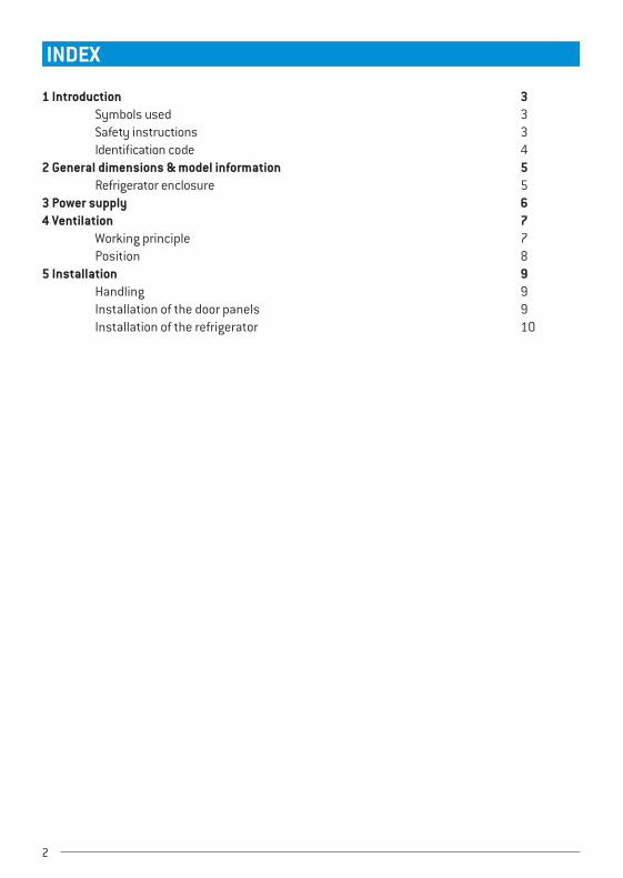
INDEX
1 Introduction 3 Symbols used 3 Safety instructions 3 Identification code 42 General dimensions & model information 5 Refrigerator enclosure 53 Power supply 64 Ventilation 7 Working principle 7 Position 85 Installation 9 Handling 9 Installation of the door panels 9 Installation of the refrigerator 10
5 Use 6 screws to fixate the refrigerator, place the white caps for finishing.
It is not allowed to screw into the fridge cabinet. If needed, please contact
Thetford for further assistance.
6 Connect the electrical components (see page 6 for further details)
7 Connect the LP gas components (see page 6 for further details)
Thetford is not responsible for printing errors and reserves the right to
make changes to product specifications without notice.

3
1 IntroductionThis Thetford appliance is specially developed for caravans and motorhomes. We advise you to read the manual before installing the appliance. It provides you with the necessary information for correct and safe installation of the Thetford appliance. Not all sections of this manual are relevant for all appliances. Make sure you completely read the parts of the manual that are relevant for your appliance. Keep this manual in a safe place for future reference.
For the latest version of the manual please visit www.thetford.com.au
Symbols used
Caution (possible risk of injury or product damage).
Attention. Important information.
Safety instructionsGeneral
Before installing a Thetford N3000 series refrigerator, you need to observe the
underneath precautions and general recommendations.
Improper installation, adjustment, alteration, service or maintenance can cause personal injury or property damage. Refer to this manual. For assistance or additional information, contact a qualified installer, service agency or the gas supplier.
• Do not install this refrigerator in below deck marine applications or in fixed indoor cabin or other dwelling applications. This refrigerator is made for use in RV and towable applications, and is correct for camping use.
• Do not install the refrigerator directly on carpet. Put the refrigerator on a metal or wood panel that extends the full width and depth of the refrigerator.
• The refrigerator is designed for powering by LP gas, 12V DC or 240V AC.
• Never open, damage, bend, drop, weld, move, drill, puncture, or hit the cooling device at the rear of the refrigerator. The cooling system is pressurised and contains substances harmful to health. The cooling system contains sodium
chromate. The breathing of certain chromium compounds can cause cancer. The cooling system contents can cause severe skin and eye burns, and can ignite and burn with an intense flame.
Installation Only a qualified person is allowed to install the refrigerator and its electrical and gas
components. Incorrect installation or maintenance of the refrigerator may cause physical injury and/
or damage to the refrigerator.
• Install the refrigerator in accordance with the local/national laws; • Dot not bypass or change the refrigerator’s electrical components or features; • Never expose the refrigerator to water or moisture, or spray liquids near electrical outlets, connections, or the refrigerator components. Many liquids are electrically conductive and can cause a shock hazard, electrical shorts, and in some cases fire; • The electrical connections and gas components must be installed in accordance with the latest technical regulations; • There are sharp edges and corners at the rear of the refrigerator and the installation frame. Always wear protection against cuts when installing the refrigerator. • Incorrect installation or maintenance of the refrigerator may cause physical injury and/or damage to the refrigerator; • The refrigerator must be sealed from the living area of the caravan or motor home according AS NZS 5601. Air for the burner must not be drawn from the living area of the caravan or motor home and combustion gases must not enter the living area; • Make sure that no sawdust, insulation, or other construction debris is on the refrigerator or in the enclosure. Debris can cause a combustion hazard and prevent the refrigerator from operating correctly; • The performance of the refrigerator may be affected by adjacent heat sources such as an oven or stove. Make sure the refrigerator is completely isolated from its heat generating components through the correct use of baffles and panel construction; • The refrigerator must be installed in a way that allows easy access for maintenance and repairs.
4
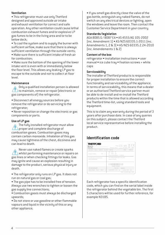
Ventilation • This refrigerator must use only Thetford designed and approved outside air intake and exhaust ventilation for correct and safe operation. Any other ventilation could cause lethal combustion exhaust fumes and/or explosive LP gas fumes to be in the living area and/or to be below deck; • To cool the system and to supply the burner with sufficient airflow, make sure that there is always sufficient ventilation through the outside vents; • Make sure there is sufficient intake of fresh air for combustion; • Make sure the bottom of the opening of the lower intake vent is even with or immediately below the floor level. This allows any leaking LP gas to escape to the outside and not to collect at floor level.
Maintenance Only a qualified installation person is allowed to maintain, remove or repair (electronic or
gas components of) the refrigerator.
• Disconnect all energy sources before you remove the refrigerator or do servicing to the refrigerator; • Never reposition or change the electronic or gas components or parts.
Use of LP gas The fully installed refrigerator must allow proper and complete discharge of
combustion gases. Combustion gases may contain carbon monoxide. Inhalation of this gas may cause tightness of the chest, dizziness and can lead to death.
Never use naked flames or create sparks whilst performing maintenance or repairs on
gas lines or when checking fittings for leaks. Gas may ignite and cause an explosion resulting in damage to the product, serious physical injury or death.
• The refrigerator only runs on LP gas. It does not run on natural gas or coal gas; • The gas pipe has to be installed free of tension. Always use two wrenches to tighten or loosen the gas supply line connections; • Combustion gases must always be discharged upwards; • Do not store or use gasoline or other flammable vapours and liquid in the vicinity of this or any other appliance;
• If you smell gas directly close the valve of the gas bottle, extinguish any naked flames, do not switch on any electrical devices or lighting, open the windows and leave the room. Then contact the Customer Service Department in your country.
Standards/legislation AGA 8085 G / 8087 EA • AS 4555/AG 105-2002 (inc. Amendment 1) • AS/NZS 60335.1-2011 (inc. Amendments 1, 2 & 3) • AS/NZS 60335.2.24-2010 (inc. Amendements 1 & 2)
Content of the box refrigerator • installation instructions • user manual • ice cube tray • fixation screws + white caps
Serviceability The installer of Thetford products is responsible for proper installation to ensure the correct functionality and serviceability of the appliance. In terms of serviceability, this means that a dealer or an authorised Thetford service partner must be able to de-install and re-install the Thetford products within the time that is allowed according the Thetford time-list, using standard tools and equipment.
This is to claim any warranty during the period of 3 years after purchase date. In case of any queries on this subject, please contact the Thetford local service representative before installing the product.
Identification code
Each refrigerator has a specific identification code, which you can find on the serial label inside the refrigerator behind the vegetable bin. The first 5 characters will be used for further reference, for example N3185.

5
2 General dimensions & model informationM
odel
Disp
lay
Dim
ensi
ons
HxW
xD (m
m) *
Gros
s vo
ume
(L)
Volu
me
free
zer
(L)
Gas
usag
e (M
J/h)
Net
wei
ght (
kg)
Door
pan
el s
ize
HxW
(mm
)
Doo
r pan
el
thic
knes
s (m
m)
N3185 LED+ or LCD 1250x546x628 177 31 1,5 39876x469
+ 275x469
3
* Depth inclusive door
Refrigerator enclosureDimensions (mm)
Model HT H* WT W** D A*** FC
N3185 1250 1245 546 531.5-534 585-620 135 - 170 78
* Maintain a minimum distance of 15mm from the floor
** If there is more than 13 mm of clearance between either side of the refrigerator and the wall, fill the space with fiberglass insulation or add a baffle to eliminate the excess clearance
*** For further instructions, please refer to page 9 “Installation of the refrigerator”
Floor Make sure the floor is solid and level. The floor must be metal or wood plate and extend the full length and width of the enclosure. The floor must be able to support the weight of the refrigerator and its contents.
Heat sources Make sure there are no adjacent heat sources such as a furnace vent or a hot heater vent.
6
3 Power supply
BATTERY PACKoption for E and E+ version
DISPLAY MODULE
only for N3185
SOLENOIDGAS VALVE AC HEATER
DC HEATER
4
3
2
3
2
3
POWER CONTROL MODULE
HCLCD+ -+ -+
DC CONNECTION
ACCONNECTION
240VACDIVIDER HEATER
ora
nge
bla
ck p
urpl
e
red
whi
te
THERMISTOR
SPARKELECTRODE
BURNERCONTROLMODULE
POWER CONTROL MODULE
HCLCD+ -+ -+
DC CONNECTION
ora
nge
bla
ck p
urpl
e
red
whi
te
FAN-1
DIODE
SWITCH
1 2 3
FAN-2
red
black
VENTILATOR CONNECTION
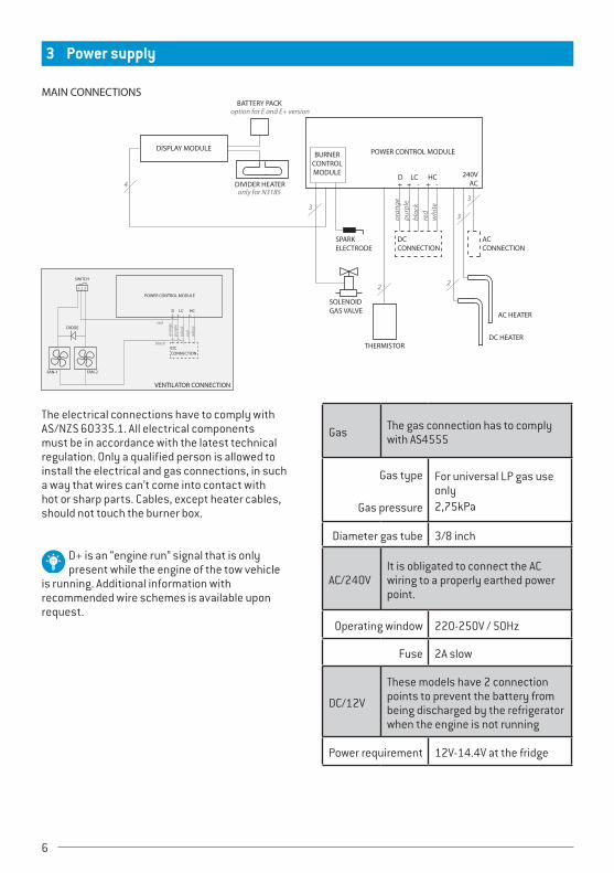
MAIN CONNECTIONS
The electrical connections have to comply with AS/NZS 60335.1. All electrical components must be in accordance with the latest technical regulation. Only a qualified person is allowed to install the electrical and gas connections, in such a way that wires can’t come into contact with hot or sharp parts. Cables, except heater cables, should not touch the burner box.
D+ is an “engine run” signal that is only present while the engine of the tow vehicle
is running. Additional information with recommended wire schemes is available upon request.
Gas The gas connection has to comply with AS4555
Gas type
Gas pressure
For universal LP gas use only2,75kPa
Diameter gas tube 3/8 inch
AC/240VIt is obligated to connect the AC wiring to a properly earthed power point.
Operating window 220-250V / 50Hz
Fuse 2A slow
DC/12V
These models have 2 connection points to prevent the battery from being discharged by the refrigerator when the engine is not running
Power requirement 12V-14.4V at the fridge

7
Cable dimensions (preferred)
<2.5m: 4mm2
<3.5m: 6mm2
<6m: 10mm2
Fuse high-current 20A
High current supply
red cable (+) and white cable (-) for heating element. Only switched if signal on D+
Low current supply
purple (+) and black (-) for electronics
D+ signal orange, + when engine runs
D+ signal not
present on vehicle
No cooling on DC/12V possible.
Additional information with recommended wire schemes is available upon request.
4 VentilationThe refrigerator performance depends on good ventilation. Thetford has several vents available. The choice depends on the refrigerator model used. Use the table below to define the correct vents.
N3185
Top vent Large vent
Bottom vent Large vent
Working principleVentilation takes place through two vents in the wall of the vehicle. Ventilation can also take place by means of a bottom vent and a roof vent. Cold air comes in through the lower vent, passes the cooling unit and leaves hot through the upper vent (chimney effect).

8
PositionRecommended: The recommended installation is when the vents aren’t covered.
Good: When installation is next to the caravan door, make sure that there will be at least a 25mm distance between the vents and the door.
Wrong: Make sure vents can’t be blocked. An insufficient air supply can result in incomplete combustion, the forming of carbon monoxide and reduction of cooling performance.
Not recommended: The installation is not recommended, when combustion gases may enter the living area.
Upper vent: Ventilation can be achieved through installation of an upper vent.
1 The vent must be installed at a minimal distance of 150mm from the top of fridge to the top of vent. This way, the top of the condensor (B) is in line with the bottom of the upper vent.
2 To prevent stagnant hot air in the area above the refrigerator a combustion flap (A) must be installated between the top of the refrigerator and the top of the upper vent.
3 Combustion gases will be extracted via the upper vent. Additional installation instructions are available for the connection of an independent flue kit.
Lower vent: This vent must be positioned behind the burner box and the power board. This vent is also used for periodical maintenance or repairs to the refrigerator.
If the lower vent is not on floor level, make sure all unburned gas will go to the outside
(for example via a hole in the floor).

9
5 Installation
Installation of the door panelsA door panel for a framed door should be fitted before installing the refrigerator
1 Demount the refrigerator door and freezer door from the refrigerator.
1
2 Remove the panel retainers and slide the door panels into the holders.
3 Replace the panel retainers and place the door back on the cabinet.
Installation of the refrigeratorThe refrigerator must be installed in a completely air-tight sealed place from the
living area of the vehicle. If the sealing is not complete, exhaust fumes can be present in the living area of the vehicle. The breathing of exhaust fumes can cause dizziness, nausea, or in extreme cases, death.
1 For optimal performance it is important to make sure that the air flow will entirely go through the condensor (B) of the refrigerator. Please follow the underneath instructions for safeguarding an optimal performance.
Option 1: Dimension A = 135 ± 5mm No baffle needed. Option 2: Dimension A = 140 < A < 170
Baffle (C) needed. Baffle dimension:
Dimension A (mm) Dimension C (mm)
140 - 150 30
150 - 160 40
160 - 170 50

10
2 Push the refrigerator into the enclosure until the installation frame touches the furniture.
The foam tape at the back of the installation frame is isolation foam
strip only!
3 For PVC tubes and/or water tubes within the sealing space, Thetford recommends using a heat shield or creating a minimal distance between exhaust pipes and tubes.
4 For optimum performance the refrigerator must be level. Performance is still guaranteed within the limits shown above. Tilt of the chassis or floor of the vehicle can already be a few degrees.
Nominal: 0° (level)Tolerance: ±2.5 °

2 11
INDEX
1 Introduction 3 Symbols used 3 Safety instructions 3 Identification code 42 General dimensions & model information 5 Refrigerator enclosure 53 Power supply 64 Ventilation 7 Working principle 7 Position 85 Installation 9 Handling 9 Installation of the door panels 9 Installation of the refrigerator 10
5 Use 6 screws to fixate the refrigerator, place the white caps for finishing.
It is not allowed to screw into the fridge cabinet. If needed, please contact
Thetford for further assistance.
6 Connect the electrical components (see page 6 for further details)
7 Connect the LP gas components (see page 6 for further details)
Thetford is not responsible for printing errors and reserves the right to
make changes to product specifications without notice.

6909
94/1
116-
V04
AUSTRALIAThetford Australia Pty. Ltd. 41 Lara WayCampbellfield VIC 3061Australia
T +61 3 9358 0700F +61 3 9357 7060E [email protected]
EUROPEAN HEADQUARTERSThetford B.V.Nijverheidsweg 29P.O. Box 1694870 AD Etten-LeurThe Netherlands
T +31 76 504 22 00F +31 76 504 23 00E [email protected]
UNITED KINGDOMThetford Ltd.Unit 6Brookfields WayManvers, RotherhamS63 5DL, EnglandUnited Kingdom
T +44 844 997 1960F +44 844 997 1961E [email protected]
GERMANYThetford GmbHSchallbruch 14D-42781 HaanDeutschland
T +49 2129 94250F +49 2129 942525E [email protected]
FRANCEThetford S.A.R.L.Parc BUROPLUS / Bâtiment 6 18, Boulevard de la Paix CS 80008 95895 CERGY PONTOISE CEDEXFrance
T +33 1 30 37 58 23F +33 1 30 37 97 67E [email protected]
ITALYThetford Italy c/o Tecma s.r.l.Via FlaminiaLoc. Castel delle Formiche05030 Otricoli (TR)Italia
T +39 0744 709071F +39 0744 719833E [email protected]
SPAIN AND PORTUGALMercè Grau SolàAgente para España y Portugalc/ Castellet, 36 bxs 2ª08800 Vilanova i la GeltrúBarcelonaEspaña
T +34 938 154 389F not availableE [email protected]
SCANDINAVIAThetford B.V.Representative Office ScandinaviaHantverkaregatan 32D521 61 StenstorpSverige
T +46 31 336 35 80F +46 31 44 85 70E [email protected]
CHINAThetford ChinaRm. 1207, Coastal Building (East Block) Haide 3rd Road, Nanshan District Shenzhen 518054 China
T +86 755 8627 1393 F +86 755 8627 1673 E [email protected]
Australian market
N3000 seriesInstallation Manual
© 2016 Thetford
www.thetford.com.au