Embed Size (px)
Citation preview

5/16/2012 1

REFORÇO DE ESTRUTURAS E FUNDAÇÕES DE EDIFÍCIOS E PONTES
1. Aplicações de Análise Não-Linear de Estruturas2. Reforço de Monumentos
Caso de Estudo – Claustros da FDUC
5/16/2012 2
Caso de Estudo – Claustros da FDUCCaso de Estudo – Catedral de PaviaCaso de Estudo – Capela S Jorge Aljubarrota
3. Reforço de Fundações
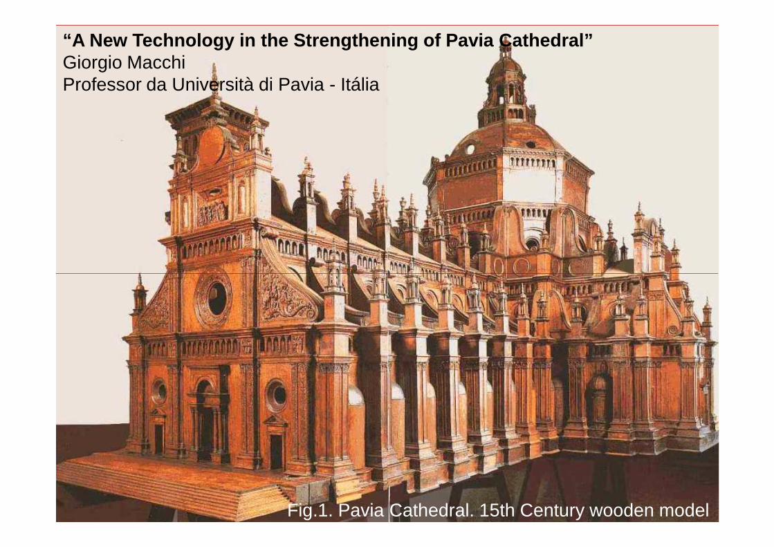
“A New Technology in the Strengthening of Pavia Cat hedral”Giorgio MacchiProfessor da Università di Pavia - Itália
5/16/2012 3
Fig.1. Pavia Cathedral. 15th Century wooden model
5/16/2012 4
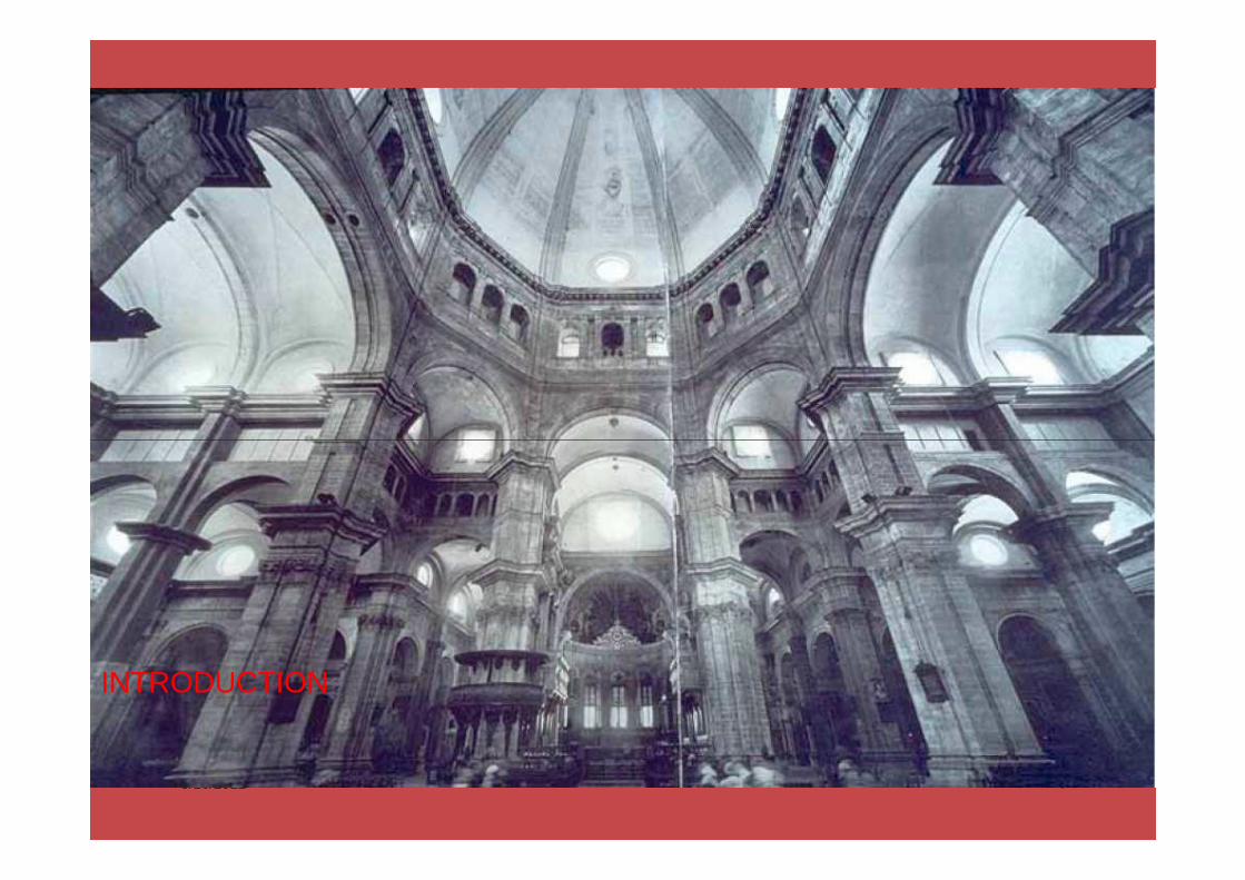
INTRODUCTION

5/16/2012 5
The construction began in 1488 following a concept which was left to us in theshape of the original wooden model. The works lasted more than 400 years, theconstruction of the 8 pillars of the central octagon was completed in 1755.

5/16/2012 6
the pillars were made by a resistant marble facing 350 mm thick and a poorrubble infill. The 30m diameter dome was built in brickwork in 1885, havingconsiderably modified the original concept (Fig.2)

5/16/2012 7
DIAGNOSIS

5/16/2012 8
The two different pathologies that were identified by ourdiagnosis are: (1) a massive fracture and spalling of thepillar stone facing, which was basically due to the greatincrease of load.

5/16/2012 9
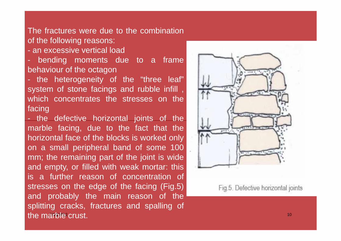
The fractures were due to the combinationof the following reasons:- an excessive vertical load- bending moments due to a framebehaviour of the octagon- the heterogeneity of the “three leaf”system of stone facings and rubble infill ,which concentrates the stresses on thefacing- the defective horizontal joints of the
5/16/2012 10
- the defective horizontal joints of themarble facing, due to the fact that thehorizontal face of the blocks is worked onlyon a small peripheral band of some 100mm; the remaining part of the joint is wideand empty, or filled with weak mortar: thisis a further reason of concentration ofstresses on the edge of the facing (Fig.5)and probably the main reason of thesplitting cracks, fractures and spalling ofthe marble crust.
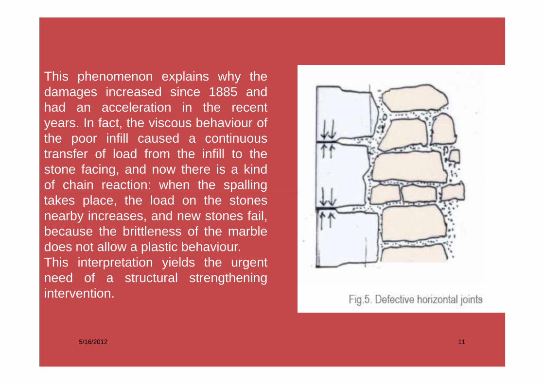
This phenomenon explains why thedamages increased since 1885 andhad an acceleration in the recentyears. In fact, the viscous behaviour ofthe poor infill caused a continuoustransfer of load from the infill to thestone facing, and now there is a kindof chain reaction: when the spalling
5/16/2012 11
takes place, the load on the stonesnearby increases, and new stones fail,because the brittleness of the marbledoes not allow a plastic behaviour.This interpretation yields the urgentneed of a structural strengtheningintervention.

The four alternatives for the strengthening interve ntions.
A. Addition of a new bearing facing.
5/16/2012 12
Fig. 7. Panthéon. Addition of new stones

The four alternatives for the strengthening interve ntions.
B. Demolition and rebuilding of the pillars
5/16/2012 13
Fig.8. Milan Cathedral. Rebuilding.

The four alternatives for the strengthening interve ntions.
C. Dismantling and reassemblage of the facings after strengthening of the core.
The idea of dismantling marble facings and reassemble them was suggestedyears ago for the Leaning Tower of Pisa and rejected. Dismantling thick marblefacings submitted to high states of stress requires cutting horizontal and verticaljoints with diamond tools and isolate totally every block avoiding sudden localcollapses. As many blocks are already fractured, it would result in a pure
5/16/2012 14
collapses. As many blocks are already fractured, it would result in a puredemolition, in the course of which only few blocks would be preserved and theintervention would be close to a total replacement.

D. The innovative technique: the partial transfer of the load from the facing to the core of the pillars, and strengthening without dismantling of the facing.
This option, which was in fact selected, takes into account the difficulties which are associated to the three previous solutions, and the need of giving priority to the structural safety and to the conservation principles. It appeared possible to fulfill the following criteria:- preserve both the original facing and the original infill;- stop the increasing process of fracture formation through a transfer of load on
5/16/2012 15
the core, which is now nearly unloaded; use totally the strength that the facing can provide;- strengthen the material of the core and improve its strength to vertical loads by an efficient horizontal prestress provided by stainless steel bars anchored in the facing;- avoid lateral instability of the marble facing through the bars, which work as ties between the opposite facings;- ensure durability of the steel bars ( minimal sensitivity to corrosion) and replaceability.

The basic intervention is summarized in the following steps:a. Pretensioned tendons (one 0.6" strand each) are applied around the pillar,one hoop every 700 mm. This temporary safeguard aims to avoid furtherfractures, to keep stable the facing and slightly increase the strength of the coreduring the work.
b. Stainless steel bars AISI 410 of 16 mm diameter are applied inside 32 mm
5/16/2012 16
b. Stainless steel bars AISI 410 of 16 mm diameter are applied inside 32 mmholes drilled across the pillar. The bars are mechanically anchored in themarble blocks of the opposite facings. At one end, the bar has an inverted coneanchor which works inside the block and does not appear on the surface. At theother end, the bar is tensioned by jacks and anchored by a steel plate of 60 mmdiameter, which is later on hidden by a marble plug. The role of the bars,applied in 6 different directions, is that of creating a low radial precompressionof the core, and provide a tensile resistant connection between the oppositefacings which will be subject to outward lateral pressure by the infill (Figs.9 and10).

5/16/2012 17

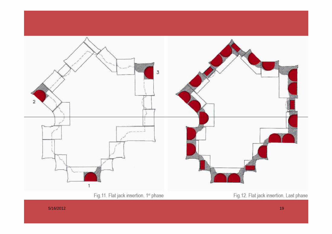
c. The horizontal joints of the facing are cut by a diamond-edged disk for adepth of 260 mm and a thickness of 4.5 mm. The aim of the cut is to release theexisting excessive compression of the crust, allow a small settlement of the jointand operate in such a way a partial transfer of load to the core, allow theremoval of the weak mortar from the inner part of the joint and its following
5/16/2012 18
removal of the weak mortar from the inner part of the joint and its followingreconstitution. The cut is operated in steps, at each step the cut section of thejoint is made again resistant by the insertion of flat jacks (Fig. 11).
5/16/2012 19

d. The lime mortar still existing in the inner part of the joint is weak and easilyremoved. It is replaced by a liquid cement grout which fills the void for the entirethickness of the marble. After hardening, the joint is filled of a “new marble”,with some 15 MPa strength and adequate E modulus.e. The joint is cut again with the diamond-edged disk. Now the joint has acalibrated thickness of 4.5 mm between two parallel surfaces having adequateresistance.
5/16/2012 20
resistance.f. Flat jacks are introduced in the reconstituted joint and raised to the designpressure. The worked area is now again efficient in carrying the load, and thework may proceed on the following step with new cuts (Fig.12).g. Remove flat jacks and introduce permanent fill of the joint. Three differenttypes of filling material have been tested.


![[how-to] FenixEdu FBA 2018-2019 - Matriculas · Title: Microsoft PowerPoint - [how-to] FenixEdu FBA 2018-2019 - Matriculas Author: Nuno Created Date: 9/9/2018 2:42:49 PM](https://img.dokumen.tips/doc/110x75/5e10574415903844ad712314/how-to-fenixedu-fba-2018-2019-matriculas-title-microsoft-powerpoint-how-to.jpg)