Embed Size (px)
DESCRIPTION
ATV-DVWK-A 127E Statical Calculation of Drains and Sewers
Citation preview

GERMAN ATV-DVWK-STANDARDS
STANDARD ATV-DVWK-A 127E
Static Calculation of Drains and Sewers
August 2000
ISBN 3-924063-42-7
Distribution:
.•
Deutsche Vereinigung für Wasserwirtschaft, Abwasser und Abfall e.V. Theodor-Heuss-Allee 17 • 0.53773 Hennef
P.O. Box 11 65 • D-53758 Hennef Tel.: 00 49 22 42/8 72-120 • Fax: 00 49 22 42/8 72-100 E-rv1ail: [email protected] • Internet: www.atv-dvwk.de

ATV-DVWK-A 127 E
Preparation
This Standard has been elaborated by the ATV-DVWK Warking Group "Static Calculation of Sewers" within the ATV-DVWK Specialist Committee "P!anning of Drainage Systems".
The Warking Group has the following members:
Dipl.-lng. Gert Bellinghausen, Sankt Augustin Dipl.-lng. Peter Brune, Gelsenkirchen Dipl.-lng. Günther·Buchholtz, Berlin (to April 1998) Prof. Dr.-lng. Bernhard Falter, Münster Dr.-lng. Christian Falk, Gelsenkirchen Dipl.-lng. Hans Fleckner, Bremen (to March 1999) Dipl.-lng. Kari-Heinz Flick, Köln Dr.-lng. Hansgeorg Hein, Brebach (to March 1994) Dr.-lng. Albert Hoch, Nürnberg Dr.-lng. Kar! Hornung, Stuttgart Dr.-lng. Harald 0. Howe, Köln Dipl.-lng. Dietmar Kittel, Planegg (Chairman to February 1997) Dr.-lng. Joachim Klein, Essen
•
Dipl.-lng. Jürgen Krahl, Kirn/Nahe . Dr.-lng. habil. Günter Leonhardt, Düsseldorf (Chairman from February 1997) Dipl.-lng. Manfred Magnus, Magdeburg (to December 1998) Dipl.-lng. Hans-Georg Müller, Darmagen Dipl.-lng. Reinhard Nowack, Ehringhausen Dipl.-lng. Norbert Raffenberg, Köln (to October 1966) Dipl.-lng. lngo Sievers, Berlin Dr.-lng. Peter Unger, Lieh (to March 1999) Prof. Dr.-lng. Volker Wagner, Berlin Dipl.-lng. Manfred Waller, Saarbrücken Dipl.-lng. Frank Zimmer, Neuss (to March 1999)
All rights, in particular those of translation into other languages, are reserved. No part of this Standard may be reproduced in any form - by photocopy, microfilm or any other process - or transferred into a language usable in machines, in particular data processing machines, without the written approval of the publisher.
©Gesellschaft zur Förderung der Abwassertechnik e.V. (GFA), Hennef 2000
Original German edition set and printed by: DCM, Meckenheim
August2000 im~

ATV-DVWK-A 127 E
Contents PREPARATION ............................................................................................................................................ 2
NOTES FOR USERS .................................................................................................................................... 6
1 PREAMBLE .......................................................................................................................................... 6 ND FORWARD TO THE 2 EDITION ............................................................................................................... 7
FORWARD TO THE 3"0 EDITION ............................................................................................................... 8
2 SYMBOLS ............................................................................................................................................ 9
3 TEGHNIGAL DETAILS ....................................................................................................................... 12
3.1 Types of Soil ............................................................................................... , ................................. 12
3.2 Traffic Loads ................................................................................................................................. 13
3.2.1 Road Traffic Loads ................................................................................................................ 13
3.2.2 Rail Traffic Loads .................................................................................................................. 14
3.2.3 Aircraft Traffic Loads ..............................................................................................•.............. 15
3.2 .2 Other Traffic Loads ................................................................................................................ 16
3.3 Area Loads .................................................................................................................................... 16
3.4 Pipe Materials ............................................................................................................................... 16
4 GONSTRUGTION WORK .................................................................................................................. 19
4.1 Suitable Types of Soi1 .................................................................................................................. 19
4.2 Notes for Installation ................................................................................................................... 19
5 LOADING ........................................................................................................................................... 20
5.1 Load Gases ................................................................................................................................... 20
5.2 Mean Vertical Soil Stresses at the Level of the Pipe Grown .................................................... 20
5.2.1 Earth Load and Evenly Distributed Area Loads (Bulk Materials) ........................................... 20
5.2.1.1 Silo Theory ........................................................................................................................ 20
5.2.1.2 Covering Conditions for the Backfilling of Trenches ......................................................... 21
5.2.1.3 Trench Shapes .................................................................................................................. 22
5.2. 1.3.1 Trench with Parallel Walls .......................................................................................... 22
5.2.1.3.2 Trench with Sloped Walls ........................................................................................... 23
5.2.1.3.3 Stepped Trench .......................................................................................................... 24
5.2.1 Traffic Loadsand Limited Area Loads ................................................................................... 25
5.2.2.1 Road Traffic Loads ............................................................................................................ 25
5.2.2.1 Rail Traffic Loads .............................................................................................................. 28
5.2.2.2 Aircraft Traffic Loads .................................................................................................. : ...... 29
5.2.2.3 Limited Area Loads ........................................................................................................... 30
5.2.2.4 Loading Oue to Construction Site Traffic .......................................................................... 30
5.2 Interna! Pressure .......................................................................................................................... 31
6 LOAD DISTRIBUTION ....................................................................................................................... 31
6.1 Redistribution of Soil Stresses ................................................................................................... 31
6.2 Relevant Parameters .................................................................................................................... 32
6.2.1 Embedding Conditions for the Pipeline ................................................................................. 32
6.2.2 Deformation Modulus E, ........................................................................................................ 33
6.2.3 Earth Pressure Ratio K2 ........................................................................................................ 36
6.2.4 Relative Projection a .............................................................................................................. 37
August 2000 II

ATV-DVWK-A 127 E
6.3 Goncentration Factors and Stiffness Ratio ............................................................................... 38
6.3.1 Maximum Goncentration Factor Max ) .................................................................................. 38
6.3.2 Goncentration Factars AR and ;\.8 ........................................................................................... 39
6.3.3 Stilfness Ratio ....................................................................................................................... 40
6.4 lniiuence of the Relative Trench \'Vidth ...................................................................................... 45
6.5 Limiting Value of the Goncentration Factor .............................................................................. 46
6.6 Vertical Total Load ....................................................................................................................... 47
7 PRESSURE DISTRIBUTION AT THE PIPE CIRCUMFERENCE ...................... : .............................. 47
7.1 Distribution of the lmposed Load ............................................................................................... 47
7.2 Bearing Pressures (Bedding Gases) ........................................................ ' .................................. 47
7.2.1 Bedding Case ! .. ., ............................................................... : ................................................. 47
7.2.2 Bedding Gase 11 ..................................................................................................................... 48
7.2.3 Bedding C;;Jse 111 .................................................................................................................... 48
7.3 Lateral Pressure .............................................................................................. : ............................. 48
8 SECTIONAL FORCES, STRESSES, ELONGATIONS, DEFORMATIONS ...................................... 50
8.1 Sectional Forces .......................................................................................................................... 50
8.2 Stresses ........................................................................................................................................ 51
8.3 Elongations ................................................................................................................................... 52
8.4 Deformations ................................................................................................................................ 52
9 DIMENSIONING ...................................................... : .......................................................................... 52
9.1 Relevant Verifications .................................................................................................................. 52
9.2 Verification of Stress/Elongation ................................................................................................ 53
9.3 Verification of Carrying Capacity ............................................................................................... 54
9.4 Verification of Deformation ......................................................................................................... 54
9.5 Verification of Stability ................................................................................................................ 55
9.5.1 General .................................................................................................................................. 55
9.5.2 lmperfections ......................................................................................................................... 56
9.5.3 Verification of Stability with Buckling and Percussion Loads ................................................. 56
9.5.3.1 Vertical Total Load ............................................................................................................ 56
9.5.3.2 Externat Wafer Pressure ................................................................................................... 57
9.5.3.3 Simultaneously Effective Vertical Total Load and Externat Wafer Pressure ..................... 58
9.5.4 Non-linear Stability Verification .............................................................................................. 58
9.5.4. 1 Calculation of a Rigid and Movable Bearings Model ......................................................... 58
9.5.4.2 Method of Approximation Using Enlargement Factars a11 ................................................. 59
9.6 Supplementary Notes for Profiled Pipes ................................................................................... 60
9.6.1 General ................................................................... : .............................................................. 60
9.6.2 Additions for Stress/Deformation Verification ........................................................................ 61
9.6.3 SupplementstoDeformation Verification .............................................................................. 61
9.6.4 SupplementstoStability Verification ....... , ............................................................................. 61
9.7 Safety ............................................................................................................................................. 62
9.7.1 Basis ...................................................................................................................................... 62
9.7.2 Safety Coelficient against Failure of Load Carrying .............................................................. 62
9.7.3 Safety against Non-permitted Large Deformations ............................................................... 63
9.7.4 Safety against Failure with Loading that is not Predominantly Permanent.. .......................... 63
August 2000 II

ATV-DVWK-A 127 E
APPENDIX 1: TABLES ...................................................................................................................................................... 66
APPENDIX2: DETAILS ON STATIC CALCULATION ...................................................................................................... 82
APPENDIX 3: CALCULATION EXAMPLES ...................................................................................................................... 83
APPENDIX4: LITERATURE ............................................................................................................................................. 91
'•
August2000 I

ATV-DVWK-A 127 E
Notes for Users
This ATV Standard is the result of honorary, technical-scientific/economic collaboration which has been achieved in accordance with the principles applicable therefor (statutes, rules of procedure of the ATV and ATV Standard ATV-A 400). For this, according to precedents, there exists an actual presumption that it is textually and technically correct and also generally recognised .
. The application of this Standard is open to everyone. However, an Obligation for application can arise from legal or administrative regulations, a contract or other legal reason. .•
This Standard is an important, however, not the sole source of information for correct solutions. With its application no one avoids responsibility for his own action or for the correct application in specific cases; this applies in particular for the correct handling of the margins described in the Standard.
1 Preamble
This standard applies for the static calculation of underground drains and sewers. lt can be used analogously for other pipes laid in the ground. With extreme conditions - for example, very large or very small amounts of cover, very large cross-sections, slopes -special consideration is necessary, which can be the basis for deviations from this standard. This also applies for special designs, for example for driven pipes 1l, unstable subsoil and elevated pipelines.
ln the standard is presented a calculation method corresponding with today's scientific Ievei, with which pipes of differing rigidity, covering and bedding conditions can be calculated. With this, the stresses compared with older calculation methods can be more accurately acquired. Prerequisites with the validity of the calculation method and for the mathematical security are the standardised material characteristics - ensured through the monitaring of materials- as weil as the design in accordance with DIN EN 1610-ensured by construction supervision.
The standard allows the selection of different parameters by the user. Characteristic values of materials and soil are so matched to the calculation methods that a good agreemenf with the results of component tests exists. As, in practice, very often no precise details on the types of soil and installation conditions are available, the selection of the assumptions for the calculation lies within the due discretion of the engineer. The standard, in this respect, can only give advice and Ieads for the normal case. ln particular, the assumptions of the soil mechanical characteristic values must take into account the later possibilities for monitaring on the construction site.
The safety coefficients, in accordance with Sect. 9.7, Tables 12 and 13, have been determined under the prerequisites given there and have been matched to the calculation model. lf, in the individual case, the measured dispersions of the coefficients of influence are verified, the other safety coefficients can result with the same probability of failure.
August 2000

ATV-DVWK-A 127 E
For the comparison of deformations in the installed state with the calculation results according to Sect. 8.4 - in particular taking into consideration of the dispersions - it is recommended that comparable measurements are carried out.
The standard is an important source of knowledge for specialised behaviour in the normal case. lt cannot cover all possible special cases, in which advanced or limited measures can be offered.
The calculation examples attached are to simplify the application of the standard.
ln the standard presented here numerous new ideas have been elaborated. The ATVDVWK therefore requests users to make available reports of exper(ence on the practical application of the standard. ·
Forward to the 2nd Edition
The 1st Edition of the ATV Standard of December 1984 was received positively and met with broad interest.
Experience gathered jn the meantime, supplemented by a direct exchange of ideas at seminars on the introduction of this new calculation method as weil as the development of the ATV/DVGW Standard ATV-DVWK-A 161 for the static calculation of driven pipes, carried out in the interval, made a new edition appear sensible.
Thus various additions and corrections, serving for better understanding, could be made.
Load assumptions were expanded for aircraft Ioads.
Table 3 was supplemented by the meanwhile standardised glass fibre reinforced plastic pipes (UP-GF).
The application of the reduction factor a8 (Diag. 05), previously recommended in a note, now becomes mandatory.
The Equation (6.04) for max. 'A was restored from the previous linear to the original form as, in the area of small effective relative projections, too great deviations resulted.
The calculation of AR could be simplified.
The calculation to take a deformation layer into account could be given more precisely.
For UP-GF pipes proof of outer fibre strain and a calculation example have been introduced in place of the standardised nominal stiffnesses of the modulus of elasticity.
Stress and bearing capacity verification is respectively carried out only with pressure distribution in accordance with Bedding Case I or II, the deformation verification according to Bedding Case II I.
August 2000 II

ATV-DVWK-A 127 E
The verification for not predominantly static Ioads was comprehensively formulated identical with ATV Standard ATV-A 161 for driven pipes and a table was supplemented with reduction factors for the respective traffic Ioads.
Appendix 2 with the necessary details for static calculation was newly and more clearly designed, so that it can also be used as text in the invitation to tender.
ln addition the contents of the preliminary remarks continues to be recommended for the attention of the user.
Forward to the 3rd Edition '•
The ATV Standard has proved itself for the static verification of underground drains and sewers. Thus, for example, the determination of the Goncentration factors for the loading above the pipe has also found international recognition with the concept of the rigid beam".
Based on new knowledge in pipe statics (trials, comparison with the finite Element Method, European Standardisation etc) and due to new developments with pipeline systems (e.g. pipes with profiled walls), a requirement for regulation has arisen in various sections of the standard, which are collected tagether here in a 3'd Edition.
With this one is concerned the following new regulations which, in part, also Iead to simplifications in the calculation process:
The material characteristic values are adjusted to the current DIN and DIN EN status and are secured through additional regulations.
The deformation module in pipeline zone E2 can, dependent on the Ioad stress, be increased with built-up embankment sand cover greater than 5 m.
With verification of deformation the reduction of the deformation module in the pipeline zone goes to 2/3.
Verifications of stress and deformation are carried out uniformly using the same support angle 2a (through this only two calculation runs are required with flexible pipes).
The mathematical boundaries between rigid and flexible behaviour is newly determined as VRs = 1.
With the determination of the bedding reactions (through compatibility of pipe and soil deformation in the springing) and with verification of deformation, under certain conditions the influence of the normal force and shearing force deformations is taken into consideration.
Deformations can now exceed the previously permitted limiting value of 6 % by up to 50 % if a non-linear stability verification is carried out. An approximation method is given for this. ,
With verification of stability the deformation of the pipes (structural and elastic) must also now be taken into account.
A new chapter for the peculiarities with the verification of profiled pipes is added; a corresponding Advisory LeafletATV-M 127, Part 3 is in preparation.
August 2000 I

ATV-DVWK-A 127 E
For the case of additional loading with vertical sheeting (e.g. sheet piling rammed under the pipe invert) attention is drawn to the ATV Warking Group 1.5.5 Report "Mathematical formulations for the loading of pipes in trenches using sheet piling revetment" (Korrespondenz Abwasser 12/97) [Not available in English].
in the foreward of the previous editions it has already been established !hat the validity of ATV Standard ATV-A 127E is limited to standard cases.
in March 1996 ATV Warking Group 1.2.3 "Pipe statics" published Advisory Leaflet ATVM 127-1 "Standard for the static calculation of drains for seepage water from landfills" .
.• lt is pointed out !hat rehabilitation systems (lining measures) may not be verified using Standard ATV-A 127E. Forthis Advisory Leaflet ATV-M 127-2E "Static calculation for the rehabilitation of drains and sewers using lining and assembly methods" (January 2000) is available.
2 Symbols
Symbol
A Ao a a' ap b bb bd C, Ch, Cv, . . Ch, Cv
c' CN CL
'
Dp, do d; de dm L'l.drraJdm Eo Ep Es EZ E1.E2, E3,E4 E2o F FA, FE Fw, Fe FN
Unit
m2, mm2
m2, mm2
1 1 1 m m m
% m m m m % N/mm2
N/mm2
N/mm2
1 N/mm2
N/mm2
kN/m kN/m
kN/m
Designation
Area Shear force area (=web area with profiled pipes) Relative outreach Effective relative outreach Gorreetion factor for road traffic Ioads Trench width at pipe crown Ievel Width of trench bottarn Width of deformation layer Deformation coefficients
Corrected deformation coefficients Deformation coefficients to Iake into account of the normal and/or shear forces Degree of compaction (based on simple Proctor density) Thickness of the deformation layer I nternal pipe diameter External pipe diarneter Mean pipe diameter Characteristic values of relative fracture deforrnation Modulus of elasticity of deformation layer Modulus of elasticity of pipe material Modulus of resilience of soil Installation figure Modulus of resilience in soil zones 1 - 4
Table value for calculation of E2
Force Auxiliary Ioads
Crown compressive force
August 2000

tot F f1 f2 G h hw J ksR K1,K2 K' K' M m N n Q
p, .Pv PE PF PE,A Pew Pt p; Ps q~ q h
qv qv,A rA,rE rm s
So a a s S;d
VRB
Vs w a a;;
as ap
ac ß
kN/m
kNm/m
kN/m
kN/m 2
kN/m2
kN/m2
kN/m 2
kN/m 2
kN/m2
kN/m2
kN/m2
kN/m2
kN/m2
m m
N/mm2
N/mm2
N/mm2,
N/m2,
kN/m2
N/mm2
N/m2
kN/mm2
mm mm
0
0
ATV-DVWK-A 127 E
Totalload Reduction factor for soil creep Reduction factor for E20 with groundwater Soil group Height of coyer above pipe crown Height of water Ievel above pipe crown Moment of lnertia Bedding modulus with constant radial bedding Ground pressure ratio in s6il zones 1 and 2 Coefficient for the bedding reaction pressure Modulus for deformation (subgradeomodulus) Bending moment Coefficient of moment
· Normal force Coefficient of normal force Maximum shear force in the pipe wall Soil stresses due to traffic Ioad Soil stresses due to ground Ioad and surface Ioad Soil stress taking into account buoyancy External water pressure Failure probability Interna! pressure Surface Ioad Horizontal soil stress at pipe Horizontal bedding reaction pressure Vertical soil stress at pipe Vertical soil stress taking into account buoyancy Auxiliary radii Radius of the centroidal axis of the pipe wall Area moment 1st grade about the centroidal axis of the cross-section (static moment) Bedding stiffnesses Stiffness of deformation layer Pipe stiffness
Weighted pipe stiffness
Wall thickness lmaginary wall thickness System stiffness Stiffness ratio Section modulus of the pipe wall Half bedding angle Enlargement ratio of the bending moment for non-linear verifications Reduction factor Penetration coefficient Gorreetion factor for curvature Slope angle
August2000 II

X Xfc
Xft
XP
Xpe
Xqv
xs ' xs
xw 1\dv M & E
~R
ER
~ K, Kß
Ko, Koß
Kv2. Ka1, Ka2
A.s Afu
Aft Ap,ApG,
maxA. V
cr GbT,GbP
~R
crR 2crA
' (jJ <p'
Indices
e h
q g K L V
w
kN/m3
kNfm3 kNfm3 kN/m3
mm
0
N/mm2
N/mm2
M/mm2
N/mm2
N/mm2
N/mm2
0
ATV-DVWK-A 127 E
Safety coefficient Safety coefficient for flexural compression Safety coefficient for flexural tension Specific gravity of the pipe material Safety coefficient for stabi!ity under external Safety coefficient for stability verification under Specific gravity of the soil Specific gravity of the soil und er buoyancy Specific gravity of water earth and traffic Ioads Change of diameter • Valuation constant Angle of wall friction Measured compression set of the deformation layer Calculated value of outer fibre strains Weighted calculated value of outer fibre strains Gorreetion factor for horizontal bedding stiffness Reduction factor for a trench Ioad i.a.w. the Silo Theory Reduction factor for a surface Ioad i.a.w. the Silo Theory Reduction factors of the critical buckling Ioad Goncentration factor in soil adjacent to pipe Upper Iimit value of concentration factor above pipe Lower Iimit value of concentration factor above pipe Goncentration factor above pipe
Transversal contraction number of the pipe material Stress Limits of tension of the pipe material with bending tension and compression Bending tensile strength, characteristic value Weighted bending tensile strength Stress range (of the pipe material) Transverse strain Impact allowance Angle of internal friction
external horizontal internal as a result of external Ioads as a result of own weight momentary values Iang-term values vertical as a result of water filling
August 2000 111

ATV-DVWK-A 127 E
3 Technical Details
3.1 Types of Soil
The foliovving types of soil can be differentiated (symbols in accordance with DIN 18 196 are given in brackets):
Group 1:
Group 2:
Group 3:
Group 4:
Non-cohesive soils (GE,GW,GI,SE,SW,SI)
Slightly cohesive soils (GU,GT,SU,ST)
Cohesive mixed soils, coarse clay (silty sand and gravel, cohesive stony residual soil)
- - - -( GU, GT, SU, ST ,UL,UM)
Cohesive soils (e.g. c/ay) (TL,TM,TA,OU,OT,OH,UA)
Table 1: Types of soil
Group Spec. Spec. Interna! Modulus of elasticity Es in Nlrnrn' gravity Gravity friction with degrees of compaction Op, in %
under angle buoyancy
Xs Xs <p'
kN/m3 kN/m' ' 85 90 92 95 97 100
G1 20 11 35 2'1 6 9 16 23 40
G2 20 11 30 1.2 3 4 8 11 20
G3 20 10 25 0.8 2 3 5 8 13
G4 20 10 20 0.6 1.5 2 4 6 10
•
Exponent Reduction in Eqn. factor for (3.02) creep
z f, -
0.50 1.0
0.35 1.0
0.20 0.8
0 0.5
The modulus of elasticity Es (secant modulus)applies as guidance value for the stress range between 0 and 0.1 N/mm'.
For programming the basic values of the modulus of elasticity Es with Ioad stresses from 5 m of covering (i.e. PE = 0.1 N/mm') can be calculated in accordance with Eqn. (3.01 ):
(3.01)
Here, G is the figure of the soil group (e.g. for Soil Group 1, G = 1 ).
For higher stresses the modulus of elasticity increases. Without special verification, one is to calculate using values in the table also in this case. The higher moduli of elasticity Es,cr with built-up cover is calculated as follows, dependent on the Ioad stress PE. in accordance with Eqns. (3.01) and (3.02):
21 Es values;, 2.0 Nimm' are to be rounded to whole numbers
August 2000

ATV-DVWK-A 127 E
E -E PE ( )
z
S,cr- S, 100 (3.02)
PE is to be applied in kN/m 2• For the various soil groups in accordance with Table 1, the
exponents z apply as given there.
So far as no precise details exist for the given soil groups, the characteristic values in Table 1 aretobe used in individual cases.
For types of soil without substances which cannot be assigned in Table 1 - for example, organic soils, bulk materials, waste - the characteristic values are t'b be determinative in the individual case. 'vVith this, particular attention is to be paid to the time-dependent creep behaviour of cohesive and organic soils using the reduction factor f1. For verification the plate bearing lest in accordance with DIN 18 134 can, for example, be applied; the secant module is for the stress range between 0 and the stress under live Ioads. ln the case of verification of the elasticity module at least five values are to be determined; the smallest value is decisive.
With appropriate calibration a check can also be carried out using the dynamic plate loading lest in accordance with TPBF-StB ( German technical lest conditions for work in road construction), Part 8.3.
3.2 Traffic Loads
3.2. 1 Road Traffic Loads
The standard vehicles (Fig. 1 ), defined in DIN 1072, are to be used for the determination of Ioads.
HGV 60, HGV 30
1.5 1.5
-=y-' --: y-1
.LL, .Cl I I
[~J [~J~ I I CJ c::t I I • • I I C"'ooo ~
,-..&-. -..&-. I I I I l--- •---
&.o • 1
Fig. 1: Standard vehicles
cv 12
= -y:!~~ j
I • •
~ :.~:J... C">
&.o .1
August2000

ATV-DVWK-A 127 E
Table 2: Loads and tyre contact areas of standard vehicles
Standard Totalload Wheelload Width of tyre Length vehicle contact area
KN KN m m
HGV60 600 100 0.6 0.2 .
HGV30 300 50 0.4 0.2
GV12 120 front 20 .•
0.2 0.2 rear 40 n ~ 0.2 U . .:l
Outside traffic areas, CV 12 (commercial vehicle) is tobe applied as minimum Ioad., EC vehicles in accordance with Directive 85/3 EGW are also covered with HGV 60 (heavy goods vehicle). These Ioad formulations correspond with DIN 1072 bridge classes 60/30 and 30/30 respectively.
3.2.2 Rai/ Traffic Loads
u1c11 j I l j 111111111111111111 . T"fll ITTTTTTT1' llllii ;,rrrmm~T: 11111
::J~L III I lilllillllill/lilllllf!:~;~;~·:lllllllllll 2:SOkN/m' III I
J'·'J 1.9 J 1.6 J 1.sJo·•J
1 j~nr ~ / Ä/1 II ;=; h 3.0 3.0
j- 4 0 ------+
· Fig. 2: Loading diagram UIC 71
August 2000 II

ATV-DVWK-A 127 E
The loading diagram of the UIC 71 (Fig. 2) given in the OS 804 3 of the Deutsche Bahn AG is relevant for Ioad determination. Tramlines to be taken into account according to special Ioad details.
3.2.3 Aircraft Traffic Loads
Loading diagrams DAC 90 to DAC 750 (Fig. 3) of the Federation of German Commercial Airports (Arbeitsgemeinschaft Deutscher Verkehrsflughafen) or the details of the airport administration concerned arerelevant for the determination of Ioad .
Dimensioning aircraft
t
DAC 90
DAC 180
DAC 350
DAC 550
DAC 750
Contact area of main undercarriage
m
_d 3.5 I+ 4.0-j 3.5 r-3'5 wm 1 m t i
r-4.3 .,...4.,0__,..4.3-j
'1'"'"''"'1 I !"""''"'/ ::::::::::: ' ::::::::::: 4.3 ........... I .......... . j_ ::::::::::: ::::::::::: ....... :.:. i .......... .
Load pressure
kNtrrr
150
150
150
150
150
Fig. 3: Loading diagrams of the dimensioning aircraft (DAC)
.•
3 OS 804: Regulations for Railway Bridges and other Engineering Structures (VEI); lssue 4, valid from 31.07.1996
August2000 lmil

ATV-DVWK-A 127 E
3.2.2 Other Traffic Loads
Traffic Ioads under construction site conditions are to be Iaken into account.
With Ioads, which are caused by special traffic, for example in heavy industry operations, the totai weight, axle Ioads, dimensions and the size of the wheel contact areas must be given for the individual case.
3.3 Area Loads
Bulk materials, structural foundations, and similar are to be accounted for as area Ioads (if required also as point Ioads). Compacted built-up embankments'and uncompacted fill do not count as area Ioads, they are to be dealt with as earth cover.
3.4 Pipe Materials
The characteristic values relevant for dimensioning follow different rules. They are particularly influenced by ageing, behaviour under Ieng-period stressing and temperature. These influences are to be Iaken into account through the following constraints for the dimensioning period which, however, do not always all have to be relevant:
Ageing Behaviour under long-period stressing: Pulse loading: Temperature, long-term: Temperature, short-term (corresponding to a period of two years in 50 years)
50 years 50 years 2: 2· 106 Ioad changes 20° c
DN s 400: 45° C DN > 400: 35° C
The characteristic values necessary for the determination of shear forces, strains and deformation are given for standard pipes, designed for laying underground, in Table 3. For loading cases with which high normal strains appear in the pipe wall supplementary determinations are to be made (e.g. Ioad case internal pressure with deep covering). Appropriate pipe standards and material characteristic values are to be applied analogously.
For areas of operation - in particular with chemical stresses - which go beyend the normal case, the relevant characteristic values for this are to be determined in the individual case. The observation of the tabular values in Table 3 or the increased values is to be confirmed by a recognised or accredited test centre and is to be monitared by quality assurance.
With reference to European standard specifications, the requirements of the part of the respective EN, non-harmonised within the scope of the building product directive, always apply.
August 2000

ATV-DVWK-A 127 E
Table 3: Material characteristic values
Material Representative value of Specific Representative value of Range of the modululo of elasticity41 gravity bending tensile strength51 stress 61
R XR <JR 2crA
Short-term Lang-term Short-term Lang-term ERK ERL GR,K 2 O'"R,L
2 Nimm' Nim'm' Nimm' KNim3 Nimm Nimm
Fibre cement 20,000 20 7) OA' ßRBTS
Concrete 30,000 24 8) OA' ßRBTS
Cast iron (CM) (ductile)91
170,000 70.5 10)
135
Cast iron 100,000 71.5 11) • 70
(laminar graphite)
Polyvinyl chloride 3,000 12; 13) 1 ~90 12) 14 15) 90 13) 16) 17) 50 13) 16) 17) 18)
(PVC-U) ' 3 14)
Polyprppylene (PP) 19
3,000 12) 13) 312 13)21) 9 22) 39 13) 16) 17) 17 13) 16) 17) 18) PP-8 and PP-H 201
PP-R 231 800 12) 13) 200 13)21) 9 22) 27 13) 16) 17) 14 13) 16) 17) 18)
Polyethylene hig1 density (PE-HO) 41
800 12) 13) 200 13) 25) 9A ''I 2113)16)17) 14 13) 16) 17) 18)
4) Details of figures are representative values which are determined from measurements of deformation on pipes. 51 The compressive strain can also be relevant, Jn particular with thin-walled pipes. For driven pipes the representative values in
ATV Standard ATV-A 125 and ATV-A 161 apply. 61 Observance of the required ring bend tensile strength, the strain in outer fibres or the hoop strength is to be verified after carrying
out the fatigue strength test. 71 DIN EN 588; The ring bending strengths are calculated from the lowest va!ues of the Ioad crushing forces {95 % fractile; AQL 4 %). B) DIN 4032; The ring bending strengths are calculated from the lowest values of the Ioad crushing forces {95% fractile; AQL 4 °/o). 9
) With verification of deformation and strength {see Sects. 9.4 and 9.5) the cement mortar (GM) cladding can be taken into aCcount in that a sixth of its layer thickness is added to cast iron wall thickness and one seventh of its layer thickness to the steel wall thickness respectively. With the imaginary wall thickness s1d so obtained, the moment of inertia I = si/12 which is tobe linked the modulus of elasticity ER .
10} DIN EN 598; the tensile strength is laid down in the standard specification. Thebending tensile strength is given as 550 N/mm2 in
the OVGW "Study an buried drinking water pipelines made from various materials", issued in June 1971 by the German Minister of the lnterior, Appendices 2 and 3.
11l DIN 19522~2; the ring bending tensile strength is tobe set the same as the· ring compression strength given in the standard
specification. 12
l Tested in accordance with DIN 54852 (4 point creep bending test), test directive in accordance with D!N 53457, test piece production in accordance with DIN 16776~2.
13l Higher representatlve values can be applied to the calculation if these are verified for the material used.
14) Determined from the momentary value and the creep ratio (2.0) in accordance with DIN EN 1401-1 and DIN EN ISO 9967 with
characteristic values for 2 years for the description of the Iang-term behaviour. Also permitted for the Iang-term verification for 50 years.
15l ln accordance with DIN EN 1401-1. 16
} For plastic materials the bending tensile strength is designated and given as bending strength. H) Smallest values (lower 95% fractite) corresponding to the Round Robin Test of the raw material producer as weil as on .the basis
of Test Report No. 36893/98-11 of the SKZ (Southern German Plastic Centre) Würzburg. 18
) 2 craoperat ~ 2 craper = (1 - 1 R) crmax.avail; with R = 0.2.- The resistance to fatigue with loading whlch is not mainly static is to be verified for n = 2 105 change of Ioad at 3 Hz.
19) PP~B =bleck copolymer; PP-H = homopolymer; PR-R = random copolymer.
20! DIN EN 1852-1. 2
1) Determined from the momentary value and the creep ratio (4.0) in accordance with DIN EN 1852-1 and- DIN EN ISO 9967 with characteristlc values for 2 years for the descriptfon of the long~term behaviour. Also permitted for the Iang-term verification for 50 years.
22) ln accordance with DIN EN 1852-1.
23' DIN EN 1852-1 and DVS 2205-2 (Supplement 1 (lssue 08/97)).
241 PE-HO as PE 63, PE 80 or PE 100 in accordance with DIN EN ISO 12162. 25
) Determined from the momentary value and the creep ratio (5.0) in accordance with characteristic values for 2 years for the description of the Iang-term behaviour. Also permitted for the Iang-term verification for 50 years.
26l ln accordance with prEN 12666-1.
August2000

ATV-DVWK-A 127 E
Material Representative value of Specific Representative value of Range 1?,1 the modulu<j, of elasticity'l gravity bending tensile strength'l stress 1
R XR O"R 2GA Short-term Lang-term Short-term Long-term
ER,K ERL
KNim 3 O"R K 0R,L ·2 Nimm' Nimm' Nimm' Nim'm' Nimm
Steel (CM) 91 210,000 77 27) 28)
Reinforced concrete 30,000 25 29) BST 500 P 80
Prestressed 39,000 25 30) 30)
concrete .• Vitrified clay 50,000 22 31) 32)
- Unsaturated 13} 33, 13) 34) 17.5 13) 35) 13) 35) 18)
polyester resin, glass fibre reinforced (UP-GF)
Representative values of Representative values of the hoop sliJY.less the relative Iailure strain
s, [Nim J Mrailidm [%] -SN 1250 1,250 625 30 18 -SN 2500 2,500 1,250 25 15 -SN 5000 5,000 2,500 20 12 -SN 10000 10,000 5,000 15 9
21) DIN 1629: in this standard speclfication minimum apparent Iimits of elasticity (0.2 %) and tensile strengths. As representative
value crR the apparent bending Iimit of elasticity is decisive which is 1.43 tlmes the minimum apparent Iimit of elasticity with mainly dead Ioad and with steels St 35 and St 37·2. Valid for steel pipes with wall thickness up to 16 mm. Under ,loading, which is not Mali static, the minimum apparent Iimit of elasticity given in the standard specification is tobe app!ied.
28l With loading which is not mainly static the values in accordance with ATV-DVWK Standard ATV-DVWK-A 161E: 1990, Sect 7.2,
are relevant. 29) DIN 4035. 30) DIN 4227. 31
) DIN EN 295: the ring tensile strengths are calculated from the minimum of the Ioad crushing forces (95% fracti!e; AQL 4 %) .. 32
) DIN EN 295-1. 33l So,min in accordance with prEN 1636. 34
J Determined from the momentary va!ue and the creep ratio (2.0) with characteristic values for 2 years for the description of the Iang-term behaviour. Also permitted for the Iang-term verification for 50 years. Tests take place in accordance with DIN EN 1228 (momentary) and DIN EN 1225 (Iang-term).
35) The following applies:cR;::;; ± 4.28 s/dm· 6-dfracldm with L'ldtrac in accordance with prEN 1636 {monentary and Iang-term) with the
respective values for s and dm.
August 2000 II

ATV-DVWK-A 127 E
4 Construction Work
Basis for the application of the calculation method is the placement of pipelines, in particular the support, embedding and compaction, laid down in DIN EN 1610 (see also ATV-DVWK--DVWK Standard A-139 36
l).
The type of shuttering is to be take into account with the calculation of the earth Ioad (see also DIN 4124 and DIN EN 1610 respectively).
Under traffic areas the [German] ZTVA-StB (Zusätzliche Technische Vertragsbedingungen und Richtlinien für Aufgrabungen ,in Verkehrsflächen [Supplementary Technical Contractual Conditions for Excavations in Traffic Areas]) apply. Outside t;affic areas these appiy analogously.
4.1 Suitable Types of Soil
ln the area of the pipeline zone (pipe support and bedding up to 0.15 m above the pipe crown, with embanked covering at least 1.5 de Iaieraiiy from the pipe). Only compactible soils or permitted types of soil in accordance with DIN EN 1610 may be used; for pipes, for whose dimensioning a verification of deformation is necessary, only soil from Groups G1, G2 and G3 (see Sect. 3.1) is to be placed. ln the area above the pipeline zone all types of soil given in Sect. 3.1. may be employed.
The laying of pipelines in organic soils (HN, HZ, F, see DIN 18 196)requires special measures with regard to the support and embedding of the pipes as weil as the filling of the open cut.
4.2 Notes for Installation
The embedding of the pipeline is part of the task of forming the pipe support and essentially determines the distribution of Ioad and the pressure distribution on the circumference of the pipe as weil as the possibility of forming a lateral ground pressure with a Ioad relieving effect on the pipeline. Attention is to be paid to agreement between the effective bedding angle with that of the static calculation.
Unfavourable effects with incorrect employment of shuttering plates and equipment cannot be included within the scope of the calculation model applied here. 8oth gradual drawing following compaction as weil as drawing following backfilling and compaction Iead to considerable disturbance in the soil. An approach to rough consideration is given in Sect. 6.2.2.
With groundwater effects there is a danger in the area of the pipeline zone. So far as they are not countered by design measures, the possible increase of the Ioad in the calculation in accordance with Table 8 is to be considered (reduction of the deformation module E2o).
36J ATV·Standard ATV-139" Laying and Testing of Drainsand Sewers, published by ATV-DVWK e.V. German Association for
Water, Waste and water, Theodor-Heuss-AIIee 17, D-53773 Hennef
August 2000

ATV-DVWK-A 127 E
Determination of loading according to surcharge condition A4 (Sec!. 5.2.1.2) or embedding condition 84 (Sec!. 6.2.1) respectively, assumes !hat, in the trench backfill, the degree of compaction in accordance with ZTVE-StB 937
) is verified. During the embedding of flexible pipes the increase of the vertical diameter (deformation) may not exceed the amount of the calculated short-term value of the deformation (reduction of the vertical diameter).
ln order to prevent the impairment of the pipelines through dynamic strains as a result öf soil compaction, only certain compactors are permitted with pipe laying. Which light equipment may be used in the pipeline zone and which medium and heavy equipment may be employed above the pipeline zone are given in ATV-DVWK Standard ATVDVWK-A 139E ahd in the "Advisory Leaflet for the Backfilling of Service Trenches".
Medium and heavy rammers and vibrators may first be employed upwards from 1 m above the pipe crown - measured in the compacted state. Dependent on the type of equipment (service weight), type of soil and covering height even larger effect depths and thus higher minimum covering result.
The static calculation in general assumes that loading and reaction over the pipe length are evenly distributed. The pipe bedding is therefore to be so formed that axial bending and point Ioads- for example at sleeve joints- are avoided.
5 Loading
5.1 Load Gases
Pipelines can be stressed through the Ioad cases earth Ioad, traffic Ioad and other area Ioads, which are covered in the following sections. The Ioad cases own weight, water filling and water pressure are dealt with in Section 8. Axial bending, temperature difference and buoyancy are also to be taken into account.
5.2 Mean Vertical Soil Stresses at the Level of the Pipe Crown
First, the stress in the soil is determined independent of the pipe material. The Ioad distribution on pipe and soil, which can Iead to an increase of stress above the pipe, is part of Sec!. 6.
5.2.1 Earth Load and Evenly Distributed Area Loads (Bulk Materials)
5.2.1.1 Silo Theory
Friction forces on existing trench walls can Iead to a reduction of the ground stress and justify the application of the Silo Theory under the assumption that the trench walls (friction surfaces) remain over a lang period. According to the Silo Theory, one obtains the average vertical stress as a result of the earth Ioad in a horizontal section of the trench backfill at a separation of h from the su rface
(5.01)
37l Additional Technical Regulationsand Standards for Earthworks in Road Construction, published by The Federa! German Ministry
for Traffic. Obtainable through the Research Cerparation for Road and Traffic Affairs, Alfred-Schütte-AIIee 10, D-50679 Köln
August2000 II

ATV-DVWK-A 127 E
For an evenly distributed area Ioad p0 the average vertical stress is
(5.02)
Further prerequisite for the application of the reduction factors is E1 :0: E3 for K and E1 < E3 for Ko and, for a/1 cases, a degree of compaction of the trench backfi/1 of Op, > 90 %.
With increasing trench widths b, K and KÜ steadily approach the value 1. in the case of embanked cover therefore
PE =xs · h + P (5.03)
A steady increase is also assumed for the dependence of the stress above the pipe on the trench width (see Sect. 6.4 ). With this the previous customary differentiation into trench conditions and embankment conditions is dispensed with. Decisive for the reduction of the earth Ioad are the side pressure on the trench walls, emphasised by the ratio k1 of horizontal to vertical earth Ioad, and the effective wa/1 friction angle o.
Thus, according to the Silo Theory
h -2-K 1 • tan Ii
1- e b K = __"",-----
h 2-K . tano
b 1
h -2-K1 · tanö
Ko=e b
Tab/es T1 and T2 are given in Appendix 1 for K andKo.
For o = 0, K = Ko = 1.
5.2. 1.2 Covering Conditions for the Backfilling of Trenches
(5.04)
(5.05)
With the trench backfi/1 above the pipeline zone, four covering conditions A 1 to A4 are differentiated:
A 1: Trench backfi/1 compacted against the natural soil by Jayers (without verification of the degree of compaction); applies also for beam pi/e walls (Berlin shuttering).
A2: Vertica/ shuttering of the pipe trench using trench sheeting, which is first removed after backfilling. Shuttering plates or equipment which, with the backfilling of the trench are removed step-by-step. Uncompacted trench backfi/1. Washing-in of the backfill (suitable only with soil of Group 1 ).
August 2000 II

ATV-DVWK-A 127 E
A3: Vertical shuttering of the pipe trench using sheet piling, lightweight piling profiles, wooden beams, shuttering plates or equipment which are first removed following compaction.
A4: Trench backfill compacted against the natural soil by layers, with verification of the degree of compaction required according to ZTVE-StB (see Sect. 4.2); applies also for beam pile walls (Berlin shuttering). Covering condition A4 is not applicable with soil of Group 4.
The allocated representative values K1 and 8 are to be Iaken from Table 4. The corresponding deformation modules EB are given in Sect. 6.2.2, Table 8.
Table 4: Earth pressure ratio K1 and wall friction angle 8
Covering K1 0 conditions
A1 0.5 2 ' -qJ 3
A2 0.5 1 ' -qJ 3
A3 0.5 0
A4 0.5 (jl'
lf soil other than !hat excavated is used for the backfill of the open cut then the respectively smaller friction angle is relevant.
5.2.1.3 Trench Shapes
5.2.1.3.1 Trench with Parallel Walls
The relevant geometrical values are to be Iaken from Fig. 4 For this case Eqns. (5.04) and (5.05) apply.
August 2000

'+ + + ++ + + • +I .. + . . . .. .. .. .. .. .. . . . > + + + + + t +I+ f +I . .. . .. .... . .. . .. . .. .. . .. . . . . . ... . . . . .
................ -~ ........................ .............. • • • + + +<0 I I I • I •
Fig.4:
• I+ I+ ...... .. . . . . .....
I .. I 4 I.
+I .. t + ..... + ..... ..... .. .. .. . .
J ...... .. . . . .. . . . . . -m
......... . .. . . . I+ t. 0 ...... . ......
. ....
...... . .... P..:-:-~..... . .. ...; ~~.... ....... . .... . .. . .. . . . .... .. ····· . . • • .......................................... ......................................................
·····················•·····•·····•·•···• .............................................. ...........................................
I· b -I Trench with parallel walls
5.2.1.3.2 Trench with Sloped Walls
.............. ............... ··········-····· ················
''~ii iii::,,' b
~:~m:::::::::::::::::::~ g; ·::::::::::::::::::::::::
Fig. 5: Trench with sloped walls
·············· .............. . ............. . ............... ................
ATV-DVWK-A 127 E
For an arbitrary slope angle ß one obtains Kß through linear interpolation according to the slope angle between Kß = 1 for ß = oo and K for ß = 90° (parallel walled trench, Eqn. 5.04 ), see also Diag. 01.
August 2000 m

ß ß K =1--+ K-
ß 90 90
Applies also for Koß
1
Kß Koß
0 0 ß
ß in degrees
Diag. 01: Kß and Koß for trenches with sloped walls
5.2.1.3.3Stepped Trench
ATV-DVWK-A 127 E
(5.06)
.•
The loading is made up as mean va/ue of two Ioad cases which correspond with the shape of the trench right and left of the trench axis. The ca/culated trench shapes for these Ioad cases result through mirroring of in each case a part of the trench on the symmetry axis of the pipe (see Fig. 6). For the upper pipe there also results a simple trench as weil as a partial/y formed trench which can be calcu/ated as further trench.
With other trench shapes one proceeds analogously.
August2000 lEE!

SA I
i '
SA
Fig. 6: Stepped trench
5.2.1 Traffic Loadsand Limited Area Loads
5.2.2.1 Road Traffic Loads
N ..c
"' ..c
ATV-DVWK-A 127 E
.•
The soil stress p as a result of road traffic Ioads in dependence on the cover height and on the pipe diameter are calculated according to the following approximate equation:
with
1
1 0.9 a F = - ---4-h"'"2 -+-h...,s,...
0.9 + % 1.1dm 3
3
2
3·F + E
2 · n· h2
1
5 2
(5.07)
(5.08)
(5.09)
(5.10
PF is an approximation for the maximum stress according to Boussinesq under wheel Ioads and wheel contact areas in accordance with DIN 1072 38l.
38l The loading-arrangements HGV 60/30 and 30/30 scheduled in DIN 1072 arenot used for buried p'tpelines as the calculated
increase of the total Ioad (earth and traffic Ioad) isslight and is balanced by arithmetic non~application of the increase of the side pressure. The existing earth cover additionally dampens momentary Ioads, also the impact coefficient covers minor increases of Ioad.
August2000 I5EI

ATV-DVWK-A 127 E
aF is a correction factor to Iake into account the pressure spread over the pipe crosssection and the length of pipe also carrying Ioads with small cover heights. This approximation is based on a pressure spread with the slope 2:1.
The auxiliary Ioads FA and FE as weil as the auxiliary radii rA andrE are given in Table 5.
Table 5: Auxiliary Ioads and auxiliary radii
Standard vehicle FA FE rA rE kN kN m m
HGV60 100 500 0.25 1.82 • HGV30 50 250 0.18 1.82
CV12 40 80 0.15 2.26
The dimensions h and dm are to be applied in m for the dimensionless factor aF to be applied in Eqn. (5.09). Eqn. (5.09) applies within the Iimits
h 2 0.5 m dm :.::5.0 m
The result of Eqn. (5.07) is shown in Diag. 02.
Special consideration is tobe given for cover heights h < 0.5 m.
Horizontal stresses in the soil as a result of traffic Ioads are not Iaken into account.
The vertical stresses in the soil as a result of traffic Ioads may be calculated for verification of security against fatigue loading behaviour(see Sect. 9.7.4), without special proof, with a cover height increased by 0.3 m. Through this it is Iaken into account that, for frequent Ioad change, a road surface with favourable Ioad distribution is always available.
0 50 p _____.. 100 [kN/m'] 150
0.~
1.0 h
[r~'
2.0
f--1 I I I I I I I I I"' I I
~ ·tfE ~qq q ~ q ~ ~. or: r-- """"'"' ll) 'lltM C\1 T"" T"" 0 0 C
L
rtt HGV60
Diag. D2a: Soil stress p as a result of HGV 60 h = 0.5 m to h = 2 m
August2000 ~

ATV-DVWK-A 127 E
0 50 p ... ~
100 [KIWm J 15 0
r--1- I I I I~ I I I-I-
0 ~" N ..- ':E: r--1- .,; \ . _::_.7 c ~ ci n I-I-
1 n I-~
h HGV30
.•
2.0
Diag. D2b: Soil stress p as a result of HGV 30 h = 0.5 m to h = 2 m
0 50 p .. ~ 100 [KN/m-j 15 0 -1 I I I I "'I I I I
- '=! '=! '=! "'! '=! "'! "! "": E'E n
=-L()~N----ooo "'0-..
I 1.0 h cv 12
tmJ
?n
Diag. D2c: Soil stress p as a result of CV 12 h = 0.5 m to h = 2 m
0 5 10 P ., 20 [kN/m'] 30 I II I I II I
Diag. D2d Soil stress p as a result of HGV 60, HGV 30, CV 12 h =2m to h =10m
August2000 EJ

ATV-DVWK-A 127 E
The stresses resulting from traffic Ioads are to be multiplied by the impact allowance <p:
Pv = <p' P
Coefficients of restitution are to be taken from Table 6.
Table 6: Coefficients of restitution for road traffic Ioads {in accordance with DIN 4033)
Standard vehicle <p
HGV60 1.2
HGV30 1.4
CV12 1.5
5.2.2.1 Rail Traffic Loads
(5.11)
•
The load-distributive effect on rails and sleepers is taken into account with the determination of the vertical stresses in the soil as a result of rail traffic Ioads. Calculation is in accordance with OS 804 with a vertical soil stress p in the Ievei of the pipe crown in dependence on the cover height h up to the upper edge of the sleepers (see Table 7 and Diag. 03).
Table 7: Soil stresses p as a result of rail traffic Ioads
h p in kN/m2
m 1 track 2 and more tracks
1.50 48 48
2.75 39 39
5.50 20 26
?. 10.00 10 15
Interpolation may be carried out linearly between the values given
August 2000 m

0
1
10 20 p - 40 [kN/m2]
5
h
l 10
- I
'--
---------t-
[m ]t-r-
15 r-
I I I
4!)..1-
39.1-V .,...,-;7
/ /
20 ;1'26 <1'/ /* ~ ~~ ~0 .,
·S'~ /'~~ V' / ~
10 15
10 20 30 40 50
Diag. 03: Soil stresses as a result of rail traffic Ioads
The minimum cover is the greater of the two values
h=1.50m
or
h = d1 Pv = <p. P
For pipes under tracks the impact al/owance is
<p = 1.40 - 0.1 O(h - 0.60) 2: 1.0
whereby h is to be applied in m.
5.2.2.2 Aircraft Traffic Loads
ATV-DVWK-A 127 E
.•
(5.12)
The soil stresses Pv as a result of dimensioning aircraft can be taken from Oiag. 04 for h 2: 1 m.
For aircraft Ioads the maximum impact factor of the relevant main undercarriage <p = 1.5. With the formulation of the soil stress Pv in accordance with Oiag. 04, the impact al/owance and the load-distributing effect of the aircraft Operating surfaces are already taken into account.
August 2000 m

ATV-DVWK-A 127 E
0 p -50 100 [kN/m2] 150
h pAc so"- ...-
rD AC 189,>V v ..- .-f::::- :;:... .-
I V_, / _,..;~V V// .<(, V DAC 350
5 LL/-< ~DAC 550
1/ I 'DAC 750
I I I
j_ I 10
'I [m]
15
Diag. 04: Soil stress Pv as a result of aircraft traffic Ioads
5.2.2.3 Limited Area Loads
The influence of limited area Ioads may be approximated as follows:
Area within the pressure propagation 2:1 Calculation of the stresses in the soil as isohedric Ioad within the area limited by the pressure propagation 2:1.
Area outside of partly outside the pressure propagation 2:1; but within pressure propagation 1:1
Calculation of the stresses in the soil as isohedric Ioad within the area limited by the pressure propagation 1:1.
Area outside pressure propagation 1:1 No influence from the concentrated area Ioads.
5.2.2.4 Loading Due to Construction Site Traffic
Possible higher Ioads in individual cases are to be taken into account.
August2000 ~

ATV-DVWK-A 127 E
5.2 lnternal Pressure
Stresses from internal pressure are superposed linearly on those from external Ioads. With higher operational pressures (above the Ievei of backwater) dimensioning can be carried out using non-linear superposition39>.
The introduction of internal pressure not only Ieads to additional stresses and extensions in the annular direction but can also change the deformation of flexible and semi-rigid pipes. ln addition, with pressure pipelines with changes of direction or other discontinuities, the tensile Ioads in the axial direction or the Iransverse forces are to be calculated 40
) '
With different values for stability under tensile Ioad and under bending tensile Ioad, these are, if necessary, to be taken into account in a suitable manner, with verification of safety, in a common, weighted safety coefficient.
6 Load Distribution
6.1 Redistribution of Soil Stresses
As a result of the different deformation capability of the pipe and of the surrounding soil the average soil stresses calculated in accordance with Sec!. 5.2.1 rearrange themselves.
The scale of this redistribution is given by the concentration factors AR for the stresses the pipe and above As for the stress in the soil alongside the pipe. The idealised forrn of the redistribution, with b/da = oo, can be seen in Fig. 7.
39l Netzer, W.: Pattls, 0.: Overlapping of internaland external pressure loading of buried pipelines (mathematical investigation with
the application of secend order theory). 3R international (1989) p. 96-105.
August2000 ~

ATV-DVWK-A 127 E
rrh<Yh<Y/2Yh<Yh<Yh<Ya:Ya:Y.a:Y/.W/.&I,&Y/.<'Y/.i<SV.W4
i h i ) i ! : Ap.p. /! !
•
, ..••.... ,.
11111
)
~/f'T"
, .. 4-d. ...,
Fig. 7: Redistribution of soil stresses (above: rigid pipe, below: flexible pipe)
40' See DIN EN 1295-1, September 1997, Chap. 6.1, Para. 2.
6.2 Relevant Parameters
6.2. 1 Embedding Conditions for the Pipeline
For the embedding in the pipeline zone four embedding conditions 81 to 84 are d ifferentiated:
81: Compacted embedding against the natural soil by layers or in the embanked covering (without verification of the degree of compaction); applies also for beam pile walls (8erlin shuttering).
82: Vertical shuttering in the pipeline zone using trench sheeting, which reaches the bottarn of the trench and which is first removed after backfilling. Shuttering plates or equipment under the assumption that the compaction of the soil takes place after withdrawal of the trench sheeting.
August 2000 m

ATV-DVWK-A 127 E
83: Vertical shuttering within the pipe/ine zone usin~ sheet piling or lightweight piling profi/es and compaction against the trench sheet 1l, which reaches down below the trench bottom.
84: Compacted embedding against the natural soil by Jayers or in the embanked covering, with verification of the degree of compaction required according to ZTVESt8 (see Sec!. 4.2). Embedding condition A4 is not applicable with soil of Group 4.
The representative va/ues Es and K2 are to be Iaken from the following sections.
6.2.2 Deformation Modulus Es '•
The deformation modu/es of the soil employed with the calculation are differentiated according to the following zones (see Fig. 8):
41) Vertical trench sheeting using wooden planks, revetting plates or devices, which are first removed following backfilllng and
compaction of the pipeline zone, cannot be calculated with certainty using a computer model. For the mathematical estimation of the increase of the Ioad as a result of ramming, attention is drawn to the ATV Warking Group 1.5.5 UMethods of revetting" ATV Report "Approaches for the calculation of pipe loading in trenches with sheet revetting" in Korrespondenz Abwasser 12/97 8Not translated into English]
August 2000 m

ATV-DVWK-A 127 E
E,
-·-·-·-·-·-·-a··-·-·-·-·-·-·-·-·-·-·-E2 E2
E, 0 E,
I E,
1-d.-> •
Fig. 8: Designation of the deformation modules for the various soil zones.
Covering above the pipe crown E1 Pipeline zone to the side of the pipe E2
Existing soil alongside the trench or emplaced soil alongside the pipeline zone E3 Soil below the pipe E4
The degrees of compaction corresponding with the covering conditions in accordance with Sect 5.2.1.2 and with the embedding conditions in accordance with Sect. 6.2.1 as weil as the deformation modules E1 and E20 (corresponding to E8 from Table 1) allocated as standard values are to be taken from Table 8.With this covering conditions A 1 to A4 appear randomly combined with embedding conditions 81 to 84.
As a rule, natural soils have a degree of compaction of Opr = 90 to 97 %; the associated values E3 can be taken from Table 3. With placement of the excavated soil in the pipeline zone in accordance with DIN EN 1610, E3 = E20 is to be applied. lf the excavated soil is to be placed as cover only, E3 = E1 is to be applied so far as, in the individual case, a higher degree of compaction for E3 is verified.
August2000 ~

ATV-DVWK-A 127 E
Table 8: Representative values of the deformation modules E1 and Ezo independent of the initial compaction
Covering condition A1 A2 and A3") A4
Embedding condition 81 82 and 83 84
Degree of compaction Op, in % Deformation module E1 and E2o in N/mm2
G1 95 16 90 6 97 23
Soil G2 95 8 90 3. 97 11
Group G3 92 3 90 2 95 5
G4 92 2 90 1.5 - -
With equal compaction of the soil alongside and above the pipe, E2o = E1 can be achieved. E2o may not assumed tobe greater than E1, with the exception of exchange of soil in the pipeline zone or embedding condition 84.
Lesser compaction alongside the pipe in narrow trenches is taken into account in Diag. 05 (Note minimum trench width in accordance with DIN EN 161 0!).
Subsidence as a result of the influence of groundwater in the pipeline zone is taken into account by a reduction of the E20 value using the factor f2 in accordance with Eqn. (6.01 ):
f _ Dp, - 75 1 (6.01) 2 - :;:;
20
") o,, is tobe applied for the calculation in line with the table value for the respective embedding condition.
""I Campaction and deformation modules according to A2 and A§ may be used only if the initial compaction A 1 is maintained
As a rule, with laying in the embankment, E1 = E20 = E3 can be set.
The notes with regard to E2 and E3 in Sect. 8.4 are to be additionally observed for the calculation of deformation.
With soils (loose rock) E4 = 10· E1 is assumed, so far as, in individual cases, no more accurate details are available. With foundation on rock (bed rock), E1 can be significantly greater.
ln order to take into account these influences as weil as the difficulties with compaction in narrow trenches in the earth Ioad calculations, the following formulation applies:
The effective deformation modulus E2 is calculated using f1 from Table 1, f2 from Table 8 and aB from Diag. 05 as
with
(E2o from Table 8)
(6.02)
August 2000 m

ATV-DVWK-A 127 E
1 (
b ) 1- lX 8; a 8 = - 4 - ;:- · 3
s 1 (6.03)
With trenches with additional embanked cover and a botiom width of bsa < 3de, E2 may not be applied greater than E3 .
1 84
1 '
CI90=2/3
~
tl
a:Ea"" 1/3
5
b/d ...
Diag. 05: Reduction factors as for E2
6.2.3 Earth Pressure Ratio K2
The earth pressure ratio in the soil alongside the pipe is determined a follows, taking into account the system stiffness VRs (see Sec!. 6.3.3:
For pipes with VRs > 1 , K2 is calculated in accordance with Table 9, Column 2. The horizontal bedding pressure qh* (see Sec!. 7.3) is then to made equal to zero. Alternatively one can also carry out the calculation using values according to Column 3.
For pipes with VRs s 1 is calculated using K2 in accordance with Table 9, Column 3, whereby qh* is estimated in accordance with Sec!. 7.3.
K2 values are not clear soil-mechanically defined characteristic values; they cover various types of influence with the aim of linearisation and are adjusted to measured values.
August 2000 ~

ATV-DVWK-A 127 E
Table 9: Ground pressure ratio K2
1 2 3
Soil K2 Group
VRs > 1 VRs :o; 1
G1 0.5 0.4
G2 0.5 0.3
G3 0.5 .• G4 0.5
Bedding reaction pressure q.h = 0 q.h > 0
6.2.4 Relative Projection a
The relative outreach a can be seen from the examples in Fig. 9.
The outreach a· da is the height of the soil layer alongside and, if necessary, laterally und er the pipe which, compared with the vertical deformation, can experience deviating subsidence.
/ /
1, da ,
1
ffit / /
Fig. 9: Relative outreach
August 2000 lfttl

ATV-DVWK-A 127 E
6.3 Goncentration Factors and Stiffness Ratio
The calculation of the concentration factor assumes infinitely rigid pipes on soft soils in wide cover. This gives a maximum concentration factor of max A.
The deformation of the pipe is taken into account in the next step. From this results the concentration factor AR which is determined through the stiffness ratio V s in accordance with Sect. 6.3.
6.3. 1 Maximum Goncentration Factor Max A-.•
The maximum concentration factor max. A is:
h
max A = 1 + -----------r-d"--8 -~-----o;---
3.5 2.2 -+ + a' .S.. · (a'- 0.25)
E,
with the effective relative outreach
E a' = a ·-1 :<: 0.26
E2
0.62 1.6 -- + =-------
a' .S.. · (a'- 0.25) E,
(6.04)
(6.05)
The function max. Ais represented in Diag. 06 for various values a' and for E4 = 1 o· E1.
3. 0
/·:=~ 5 ---/; /
~ - !a"=1.5 ..-'
'I& ~ --- ia'=1.0
-~ 1-,•'=0.5
2.
2.0
1.5
1.0
f
o:v.<"
max Ä
0 2.5 5 7.5 10 g.- 15 17.5 20
Diag. 06: Goncentration max. A. for b/de = oo and E4 = 10· E1
August2000 ~

ATV-DVWK-A 127 E
6.3.2 Goncentration Factars AR and ).s
The concentration factor A.p is dependent on the /arges! value A.max (see Sect. 6.3.1 ), on the stiffness ratio Vs (see Sect. 6.3.3 as weil as the effective relative outreach a' and on the ground pressure ratio K2 :
, V , 4 · K 2 K' maxA. - 1 max"· s + a · ----
3 a' --0.25 A.p = '
V ,3+K 2 ·K,
025maxA.-1
s+a ·a-. . 3 .
(6.06a)
.•
For pipes of high stiffness (VRP > 1) the ca/culation is continued using A.p in accordance with Sect. 6.3.1.
The following applies for K'
chqh · cv.qh + -·- · c . · K
C v,qh
K'=----~h,q~v--~-Cv qv + C h' . K'
' v,q
(6.06b)
The deformation coefficient Cv,vq = Cv.qh or ch.qv = -ch,qh respectively (also with 2a = 180° and with negligible N and Q deformation) K' = 1.
2.5
1
K,= 0.3 H+t++f--1-++H+il+
III 0 ·0o+. 1:--l-+-++++++1f--+-l-h4++1+1 o-l-+++f+c11""oo
v.
Diag. 07: Goncentration factor /cp for a' = 1, K2 = 0.3 and 0.5
The concentration factor A.s results from the imaginary form of the stress Iransposition (see Fig. 7) and from reasons of equi/ibrium as
August2000 ~

ATV-DVWK-A 127 E
(6.07)
As /es cannot be negative it results from Eqn. (6.07) that /es does not exceed the value 4.
He influence of the relative trench width on the stress Iransposition is dealt with in Sect. 6.4.
6.3.3 Stiffness Ratio
The stiffness ratio is dependent on the pipe stiffness Sp, on the coefficient of the vertical change of diameter Cv or Cv,qv, possibly from the stiffness of a deformation layer So as weil as on the vertical bedding stiffness of the soil to the side of the pipe Ssv-
Due to more idealised assumptions the calculation model applies only from a minimum pipe stiffness with long-term loading of min Sp 0 3· 10'3 N/mm2 and min So= 3.75' 10'3
N/mm2 respectively.
The stiffness ratio is calculated as follows:
a) taking into account the horizontal bedding reaction pressure
(6.08a)
b) without taking into account the horizontal bedding reaction pressure (see Sect. 6.2.3)
(6.08b)
c) taking into account a deformation layer above rigid pipes for simplified verification
(6.08c)
The relative effective outreach must be calculated taking into account the width and height of the deformation layer.
(6.09)
K2 = 0 is tobe applied in Eqn. (6.06a).
ln addition, b <: 2bo and h <: 2bo.
August2000 1!e1

ATV-DVWK-A 127 E
E1
h
I • •
L r--'" .,
·to Eo
E2
"'
Fig. 10: Deformation layer
For Eqns. (6.08a) to (6.08c) the following additional relationships apply:
pipe stiffness
(6.10a)
with smooth-walled pipes
or
s =~ 0 d 3
m
(6.10b)
i.e Sp = 8 · S0
Pipe stiffness So with long-term verification for pipes with nominal E-modules and nominal sizes
(6.10c)
Pipe stiffness So with long-term verification for pipes with nominal stiffness
August 2000 lnl

So = PE · SoL + Pv · SPK PE+ Pv
Stiffness of the deformation layer
ATV-DVWK-A 127 E
(6.1 Od)
(6 .11)
With non-linear deformation behaviour of the filling material, the deformation module
E - A,PG • PE 0 -
E
.• (6.11a)
is to be determined using the measured compression set E. The stress/compression set curve is to be determined on a sample d0 /b0 ::; 1,
with - deformation module of the deformation layer42) - width of the deformation layer - thickness of the deformation layer
Eo bo do E - measured compression set of the deformation layer
Vertical bedding stiffness
s - .§..;_ Bv - a
Coefficient for the vertical deformation ildv
with:
with:
Cv.qv = deformation coefficient for ildv as a result of qv C'{.qh• = deformation coefficient for !ldh as a result of qh K = bedding reaction pressure
Ch.qv = deformation coefficient for ildv as a result of qv Ch.qh• = deformation coefficient for !ldh as a result of qh
System stiffness
(6.12)
(6.13)
(6.14)
VRs = 8. So (6.15) SBh
August2000 ~

ATV-DVWK-A 127 E
The degree of the utilisation of horizontal bedding reaction pressures is covered with the system stiffness VRB·
Horizontal bedding stiffness
(6.16)
The factor 0.6 takes into account the propagation of stress in the soil under the horizontal bedding reaction pressure qh' (see Sect. 7.3).
The correction factor s for the horizontal bedding stiffness, assuming a parallel shaped distribution of the bedding reaction stresses (Diag. 8), is
with
s = 1.667
M + (1.667 - M)§_ E3
b --1
s= de :>;1.667
0.980 + 0.303( ~ -1)
(6.17)
(6.18)
lt takes into account the different deformation moduli of the soil alongside the pipe (E2) and the surrounding soil alongside the trench or alongside the pipeline zone (E3).
With sloped trenches, the trench width at abutment height is to be applied in the place of the trench width b. For E2 = E3, s = 1.
3.0
t 2.5
2.0
1J' 1.5
1.0
0.5
0.0
Diag. 08:
" ' 2.0 \ bld. = 1.5
2.5 -\'-.., \ 3.0 -.. ~ 5.0
~ ~I 1----.!0
=-
E,IE,
Gorreetion factor s
August2000 ~

ATV-DVWK-A 127 E
The deformation coefficient for Bedding Cases I and 111 described in Sec!. 7, are given in Tables 10a to 10c.
Table 1 Oa applies with negligible normal force deformations in the case
I ----;,-2 < 0.001 A·r m
and with negligible lateral force deformation in the case
I --::-2 · K 0 < 0.001 A-r m
with KO = AJAQ (= 1.2 with reetangular cross-sections) and AQ = = web area with profiled pipes.
•
(6.19a)
(6.19b)
lf the condition (6.19a) or (6.19b) is nor met, then the deformation coefficients c from Table 1 Oa aretobe corrected with the aid of cN and cL:
(6.20)
in this cN and cL, the deformation coefficients according to Tables 10b and 10c to Iake account the normal and lateral force deformations with the transversal contraction number u = 0.3.
Gorreetions according to Eqn. (6.20) are, as a rule, not necessary if smooth pipes with homogenaus wall structure and material (u"" 0.3) are calculated.
The deformation coefficients aretobe applied in Eqns. (7.02) and (8.16a;b) with the correct sign.
Table 10a: Deformation coefficients for bending moments
Bedding Vertical Horizontal angle
2a Cv,qv Cv,qh Cv,w Cv,qh* ch,qv ch,qh Cv,w ch,qh•
60° -0.1053 -0.0637 +0.1026 +0.0611 90o -0.0966 +0.0833 -0.0550 -0.0640 +0.0956 -0.0833 +0.0541 -0.0658
120° -0.0893 -0.0477 +0.0891 +0.0476
180° -0.0833 -0.0417 +0.0833 +0.0418
August 2000 m

ATV-DVWK-A 127 E
Table 10b: Deformation coefficients for normal forces 43)
Bedding Vertical Horizontal angle
2cx N cv,qv
N cv,qh
N cv,qh*
N ch,qv
N ch,qh
N ch,qh'
60° -0,704 -0.380 90o -0.697 -0.681 -0.247 -0.366 -0.684 -0.437
120° -0.683 -0.352
180° -0.648 -0.338 •
Table 10c: Deformation coefficients for lateral forces 43)
Bedding Vertical Horizontal angle
2cx L cv,qv
L cv,qh
L Cv,qh'
L ch,qv
L ch,qh
L ch,qh'
60° -0,439 +0.396
90o -0.389 +0.335 +0.243 +0.374 -0.335 -0.274
120° -0.359 +0.354
180° -0.335 +0.335
6.4 lnfluence of the Relative Trench Width
According to Fig 7, the stress transposition spreads ranges over a width of 4de. The following assumption is made .for the concentration factor /cPG in trenches with smaller widths:
1 b/d 4 ., _ Ap -1 ~ _4_-_lc.c..P :5: e :5: · "-PG - ' + -
3 d. 3 (6.21a)
For !arger trench widths the concentration factor remains unchanged:
4:5: b/d0
S CO: (6.21b)
The function APG is shown in Diag. 9 for various values /cp. The concentration factor /es is, according to Eqn. (6.07), independent of trench width.
lf, however, APG is limited by lcru or Afi for reasons of equilibrium within the trench, there results
(6.22)
August 2000 m

ATV-DVWK-A 127 E
3 !.
t Ap= 2.5
~ 1- '
Ap= 2.0 /-Y ~ ~= 1.5 ~~
APG ~ V Ap 1.o 1
b.5 ""p '
0 0 1 2 3 4 b/de .. Dig. 9: Goncentration factor /"p8
6.5 Limiting Value of the Goncentration Factor
The concentration factor is limited, both upwards and downwards, by the shear resistance of the soil.
The upper limiting value for APG is dependent on the parameters distortion gressure, friction, cohesion and structural resistance as weil as vertical stress in the soil 4
l. These dependencies are approximated through a linear tension dependent on the covering height h:
h s10m Ar,= 4.0-0.15 · h (6.23a)
whereby h is tobe applied in m.
h s10m Ar, = 2.5 = const (6.23b)
The lower limiting value, which can be relevant for flexible pipes or pipes with deformation layer, are calculated according to the silo theory. With this, in Eqn. (5.04) Kis replaced by Ato and b by de or bo. K1 and o are applied in accordance with Table 4, Covering Condition A4.
44) derivation for Aru:
Aru = 1 + 2TJ K 1tan <p'
11 is the height above the pipe crown up to which the shear forces are assumed to be effective; the figure 2 can be applied as constant for TJ. K1 = 1 with h: 0, reducing linearly to k1 = 0.5 with h;::: 10m ~· = 37S
August 2000 II

ATV-DVWK-A 127 E
6.6 Vertical Total Load
The vertical total Ioad of the pipe is
(6.24)
The right-hand side of the equation contains the results from Eqns. (5.01 ), (5.02) and (5.11).
7 Pressure Distribution at the Pipe Circumference •
The pressure distribution at the pipe circumference is dependent on the design of the support, on the backfill in the pipeline zone and on the deformation behaviour of the pipe. The simplified pressure distribution given in Sects. 7.2 and 7.3 are typical for the placement conditions normal in sewer construction.
7.1 Distribution of the lmposed Load
The imposed Ioad, for all types of pipe, is assumed to be vertically aligned and rectangularly distributed.
7.2 Bearing Pressures (Bedding Cases)
7.2. 1 Bedding Gase I
Support in the soil. Vertically aligned and rectangularly distributed reactiqns. This bedding case applies for the stress detection and elongation detection (short-term and long-term) of rigid and flexible pipes (see Sec!. 9.1 ). Forthedeformation detection the same bedding angle as for the stress and elongation detection is relevant.
With flexible pipes the bedding angle, as a rule, is assumed as 2a = 120° with bedding conditions 82 or 83; with 81 and 84 2a = 180° may be applied.
[[j]J Fig. 11: Bedding case I
August2000 ~

ATV-DVWK-A 127 E
7.2.2 Bedding Gase II
Solid concrete support only for rigid pipes (see Sec!. 9.1 ). Radially aligned and rectangularly distributed reactions.
IOUUII
•
Fig. 12: Bedding Case II
7.2.3 Bedding Gase !II
Support and bedding in soil for flexible pipes. Vertically aligned and rectangularly distributed reactions.
IIUOUI
lfftttttl Fig. 13: Bedding case 111
7.3 Lateral Pressure
The side pressure on the pipeline is made up from the component q' as a result of vertical earth Ioad and, if necessary, from the bedding reaction pressure qh' as a result of pipe deformation (see Fig. 14).
August 2000

ATV-DVWK-A 127 E
Bedding cases I and 111
Fig. 14: Side pressure
The side pressure qh - with Bedding Gase II only above the support - is dependent on the vertical pressure in the soil alongside the pipeline:
(7.01)
The bedding reaction pressure qh* resulting from pipe deformation is applied as a parabola with an aperture angle of 120°:
(7.02a)
with qv from Eqn. (7.01 ), VRs from Eqn. (6.15) and ch,qv, Ch,qh and ch,qh' from Table 1 Oa and, if required, Eqn. (6.20).
For the loading case with water filling the following applies:
(7 .02b)
with eh w from Table 1 Oa as weil as
August 2000

ATV-DVWK-A 127 E
(7.03)
and
(7.04)
8 Sectional Forces, Stresses, Elongations, Deformations
Below only sectional forces, stresses and deformation in the ~nnular direction are investigated, i.e. the pressure distribution in the longitudinal direction (loading and reaction) is assumed to be constant.
8.1 Sectional Forces
Corresponding with the pressure distributions at the pipe circumference (see Sect. 7), the bending moments M and normal forces N are determined for external Ioads as weil as for own weight and water filling and, if necessary, water pressure. The Iransverse forces in the annular direction can be ignored, however, not with profilad pipes (see Sect. 9.6). The coefficients of moment m and the coefficients of normal force n are given for various bedding cases, in Appx. 1, Table T3. The coefficients apply only for circular shapes with constant wall thickness over the circumference.
With non-constant wall thickness over the circumference or with non-constant moments of inertia as weil as with other than circular shapes, e.g. oval profile, mouth-shaped profile, reetangular cross-section, other sectional force coefficients apply. They are to be determined according to static rules.
Using the coefficients m and n, the sectional forces are determined according to the following equations.
Vertical total loading qv:
(8.01)
(8.02)
Side pressure qh:
(8.03)
(8.04)
Horizontal bedding reaction pressure qh. as a result of earth Ioads:
(8.05a)
(8.06a)
August 2000

ATV-DVWK-A 127 E
Horizontal bedding reaction pressure qh· as a result of water filling:
Own weight:
Ng = ng . XR . s . r m
or
with F = 2 · r · n · s · x g m R
Water filling:
or
with F' according to Eqn. (7.04)
Water pressure:
M ( ) (
1 r; · re I re J pw = P; - Pe r; · re -- 2 2 · n- .
2 r - r r ' e I I
8.2 Stresses
(8.05b)
(8.06b)
(8.07)
(8.08)
(8.07a)
(8.08a)
(8.09)
(8.10)
(8.09a)
(8.1 Oa)
(8.11)
(8.12)
Using the sectional forces determined in Sec!. 8.1 the stresses are calculated as
N M (J =- ± --(J.k
A W (8.13)
August2000 ljgl

ATV-DVWK-A 127 E
using the correction factor cxk to take into account the curvature of the inner and outer edge fibre
1s 3·d+5·s (Xk. = 1 + -- = ---'--' --
' 3r 3·d+3·S m '
(8.14a)
- 1 1 s - 3 . d; + s ak - + --- ----''---
• 3r 3·d+3·s m '
(8.14b)
8.3 Elongations •
Using the sectional forces determined in Sec!. 8.1 the edge fibre elongations are calculated as
a s (s·N ) E - - - --:--- · -6
- + M · ak - E - 2rm 3
· 8s0
(8.15)
8.4 Deformations
Depending on the pressure distribution at the circumference of the pipe, the change of vertical diameter L'l.dv as a result of external Ioads can be calculated in accordance with Eqn. (8.16a), whereby the slight influence of the water filling on the deformation can be neglected:
(8.16a)
with qv from Eqn. (6.24), qh from Eqn. (7.01), qh' from Eqn. (7.02a), S0 from Eqn. (6.10b) and Cv,qv. Cv,qh and Cv,qh' from Table 10a and, if necessary, from Eqn. (6.20).
For measurements of pipe deformation the horizontal change of diameter is to be determined if necessary:
The relative vertical deformation derives from Eqn. (8.16a).
0 = L'l.dv · 100 in% v 2 · r
m
9 . Dimensioning
9.1 Relevant Verifications
(8.16b)
(8.17)
Pipes are designated as rigid or flexible depending on the combined effect of pipe stiffness and soil deformation.
August 2000

ATV-DVWK-A 127 E
Pipes are rigid where the loading causes no significant deformation and thus has no effects on the pressure distribution (VRs :S 1 ). The verification of stress/elongation or the simplified verification of carrying capacity is tobe carried out in accordance with (9.02 for its dimensioning.
Pipes are flexible whose deformation significantly influence the loading and pressure distribution as the soil is a component part of the carrying system (VRB > 1 ). The verification of stress/elongation, verification of deformation and the verification of stability are to be carried out for its dimensioning.
Pipes whose behaviour is not clearly rigid or flexible are to be ,verified as rigid and flexible. ·
9.2 Verification of Stress/Elongation
The stresses determined in accordance with Sec!. 8.2 or the edge fibre elongation determined in accordance with Sec!. 8.3 for service conditions are to be compared with the characteristic values uR and ER from Table 3. The existing safety values result from the relationship of both stresses and elongations:
(9.01 a)
and
UR ER x=-=·- (9.01 b)
u E
With Iang-term verification for pipes with nominal moduli of elasticity and nominal size or nominal stiffness the following calculated values are to be employed:
(9.01 c)
and
(9.01d)
For the dimensioning of reinforced concrete pipes, DIBN 4025 (future DIN EN 1916 Iogether with Din 1201) applies; for the dimensioning of reinforced concrete and prestressed concrete pipes, DIN En 639, DIN EN 640 and DIN EN 642.
With predominantly tensile stresses (high internal pressure) the tensile strength is to be applied for uR and the ultimate elongation for ring tension applied for ER.
August 2000 II

ATV-DVWK-A 127 E
9.3 Verification of Carrying Capacity
For pipes with defined crown compressive force FN 45), the existing safety coefficient x is determined, taking into account the installation figure EZ, in accordance with Eqn. (9.02) as,
FN x=-·EZ
totF (9.02)
lf one calculates simplified without own weight of the .Pipe, without water filling and without side pressure, installation figures in accordance with table 1·~ apply as weil as
tot F = qv · d. (9.03)
For concrete pipes with a foot in accordance with DIN 4032 Form KFW with the wall thickness at the crown s2 and the wall thickness at the bottom s3, the following applies:
(9.04)
For pipes with oval cross-section in accordance with DIN 4032 Form EF, EZ can be applied = 2.1 = const.
Table 11: Installation figures46)
Bedding Bedding Installation case angle 2a figure {Bedding
figure) EZ
I 60° 1.59 90° 1.91 120° 2.18
II 90° 2.17 120° 2.50 180° 3.68
9.4 Verification of Deformation
For flexible pipes the vertical diameter change in accordance with Sect. 8.4 is to be compared with the permitted value perm. öv.
For long-term verification perm. öv = 6 %.
451 DIN EN 295, DIN EN 588, DIN 4032 (future DIN EN 1916 tagether with DIN 1201) 46) The installation figures are calculated from the ratio of the bending moments in the Ioad crushing test and the bending moments
in the emplaced condition, caused solely through verticalloading with the associated bedding reactions
August2000 II

ATV-DVWK-A 127 E
For deformations, which in justified individual cases exceeds the Iimit of 6 %, verification is to be carried out that the existing x 2: 5 x required x with the existing x according to Eqn. (9.12) and required x according to Table 13. With the existing x < 5 x required x the deformationov (maximum 9 %) has to be calculated using a non-linear procedure e.g. approximation by multiplication of the deformation determined according to Eqn. (8.17) using the enlargement ratio factor
1 a" =--1
1-x·
For pipes under railway lines perm. ov = 2 % and perm. 8 = 10 mm.
(9.05)
..
The associated short-term value which serves for verification immediately following installation is, in any case, determined without application of traffic and surface Ioads.
The . planner can apply perm. ov < 6 % if traffic area or type of traffic make this necessary.
9.5 Verification of Stability
9.5.1 General
The verification of stability serves for the determination of the safety separation between critical Ioad and actual existing loading. This takes place in the following taking into account the influence of vertical total Ioad (earth and traffic Ioad), external water pressure (groundwater) as weil as of superimposition of vertical total Ioad and external water pressure.
The verification of stability can additionally be carried out for verification with buckling and percussion Ioads in accordance with Sect. 9.5.3 ("classical verification") also as nonlinear stability verification (non-linear determination of sectional sizes and subsequent verification of stress) in accordance with Sect. 9.5.4. ln the case of relative vertical total deformations oV > 6 % an additional non-linear verification of stability must be carried out.
The imperfections to be applied with all verification of stability are to approximated as closely as possible to the relevant buckling shape.
With earth/traffic Ioads the relevant buckling shape for ca. VRs > 1 o·3 is double-wave and for lower values multiple-wave. However, calculations have · shown only a slight dependence of the size of deformation on the buckling Ioad so that here a global reduction suffices.
With external water pressure the relevant buckling shape with ca. VRs > 0.03 is doublewave (the limiting case is the unbedded pipe with an oval buckling shape) and for VRs > 0.03 single-wave (breakdown taking place, for example, at the bottom in heart shape). The types of imperfection associated with this must be differentiated as a sole occurrence of the more unfavourable single-wave figure is less probable in practice. A combination of both imperfections can be selected.
August 2000 II

ATV-DVWK-A 127 E
9.5.2 lmperfections
With all verification of stability the effects of imperfections on the critical Ioads are to be Iaken into account: lmperfections are deformations as result of
manufacturing and processing inaccuracies, effects of Iransport and. storage as weil as internal stresses (Type A);
placement, i.e. elastic deformations, according to Sec!. 9.4 (Type 8).
So far as no detailed verification takes place in individual cases, the elastic deformations .• (Type 8) in accordance with Eqn. (8.17) aretobe increased giobally by 1 % io cover deformations of Type A: these are then Iaken into account mathematically as doublewave imperfection (ovalisation).
lf locally limited (local) imperfections occur then their type and size are to be determined or accurately estimated. This applies generally for
- laying in groundwater with x :o; 5.0 with x in according to Eqn. (9.11 );
- pronounced single Ioads;
- covering h :o; de or h :o; 0.80 m with meta IIed roadw~ys;
- welding joints in the longitudinal direction (also with spiral welding).
The designation "preliminary deformation" is used below in place of "imperfection".
The reduction factors resulting from the shape (Type A; Type 8) and size of the preliminary deformation are to be Iaken from the following diagrams in Appendix 1:
- 011 for Kv2with double-wave preliminary deformations and earth/traffic Ioad;
- 012 for Kaz with double-wave preliminary deformations and external pressure (water pressure or vacuum;
- 013 for Ka1 with local preliminary deformations and external pressure (water pressure) or vacuum.
9.5.3 Verification of Stability with Buckling and Percussion Loads
The following relationships apply under the condition of constant radial bedding. A tangential bedding is ignored.
9.5.3.1 Vertica/ Total Load
First, the buckling Ioad crit qv is to be determined according to the following relationship:
(9.06a)
crit qv = Kv2 . (3 + 1
) . 8So for VRB > 0.1 3. VRB
(9.06b)
August 2000 II

ATV-DVWK-A 127 E
Kv2 = reduction factor to take into account the elastic-plastic soil mass law and of preliminary deformations in accordance with Oiag. 011.
The values for So and Sah result from the Eqns. (6.1 Oa) and (6.16). with plastic pipes S0
in Eqn. (9.06) is tobe replaced by So according to Eqns. (6.1 Oc,d).
lf, in deviation from the normal case, the soil types OU, OT or OH of Group G4 are present in the pipeline zone, the critical buckling Ioad crit qv is to be determined in accordance with Eqn. (9.08).
The safety coefficient against buckling· is
with the vertical total Ioad qv according to Eqn. (6.24).
9.5.3.2 External Wafer Pressure
(9.07)
lf, in comparison with the external water pressure, the earth pressure can be ignored, the following breakdown Ioad applies:
(9.08)
50
oi 45 ~
" ~c 40
t 35 ~ ..Jol\
30 ......... 2o ~'-• - :;;;I' ~
25 ""' 20
15
10 _L~
5 3
0 I I
0.0001 0.001 0.01 0.1 1
v ••
Diag. 010: Snap-Through coefficient ap for the critical external water pressure
with the snap-through coefficient aP as function of the system stiffness VRa, the radius/wall thickness ratio rm/s according to Oiag. 010 and the reduction factor Ka2 for preliminary deformation according to Oiag. 012 or Ka1 according to Oiag. 013.
With plastic pipes So is the long-term pipe stiffness in accordance with Eqn. (6.10b) with
August 2000

ATV-DVWK-A 127 E
lf there is a simultaneaus taking into consideration of double wave and local preliminary deformation necessary in accordance with Sect. 9.5.2, then the common reduction factor is tobe determined by multiplication:
(9.09)
The external water pressure relevant for the calculation is the hyd rostatic pressure on the bottom of the pipe, so far as a reduced formulation is not justified through permanently assured operating conditions (partial filling).
(9.1 0)
ln areas in which one has to recken with increase of groundwater Ievei, corresponding Ioads are to be taken into account.
The safety factor against buckling is
crit P. x= Pe
9.5.3.3 Simultaneously Effective Vertical Total Load and Externat Wafer Pressure
(9.11)
The superposition of both loading cases, using Eqns. (9.06a,b ). (9.08) and (9.1 0) as weil as taking into buoyancy with the vertical total Ioad, Ieads to security against buckling
1 x=------qv.A + Pe
(9.12)
crit qv crit P.
Verification of safety against buoyancy of the pipeline is to be carried out with pipes with small covering heights.
9.5.4 Non-linear Stability Verification
9.5.4.1 Calcu/ation of a Rigid and Movable Bearings Model
ln deviation from the verification in accordance with Sects. 9.5.1 and 9.5.2 the stability verification can also be carried out using a non-linear procedure 47>.
47l When taking into account the limiting conditions in the soil, if required also using the Finite Model Method
August 2000 II

ATV-DVWK-A 127 E
With this
the Ioad formulations in accordance with Sect. 7 without qh. are to be employed,
times x Ioads aretobe applied (x according to Table 12),
the elastic bedded circular ring with the exclusion of tension springs is to be employed as calculation model (partially bedded ring),
the springiness value from Ssh as discrete springs in close proximity (s 1 0') or as constant radial bedding using the bedding niodulus ksr = Ssh/rm ~re tobe applied,
pertinent imperfections of Type A are to be applied (approximated as geometric alternative deformations ),
justified assumptions are to be made on possible non-linear material behaviour of the pipe material.
With snap-through, such as in the external water pressure Ioad case, the limited validity of theories of small deformations, that is also the Second Order Theory, is to be observed. Normal rigid and moving bearings programmes in accordance with the Second Order Theory may therefore not be employed without estimation of the Iimits of their validity.
9.5.4.2 Method of Approximation Using Enlargement Factars o:11
ln place of the non-linear stability verification in accordance with Sec!. 9.5.4.1 as an approximation one can proceed as follows:
1. The sectional parameters from earth and traffic Ioads Nqv and Mqv are determined linearly, camp. Sec!. 8.1.
2. The normal force from external water pressure Npe is calculated in accordance with Eqn. (8.12) and the bending moment Mpe in accordance with Eqn. (9.13) with the aid of the coefficient mpe from Diag. 014 in Appendix 1:
(9.13)
Thebending moments (not the normal forces) aretobe increased by the factors a11,qv and a11.pe for the non-linear influences in accordance with Eqns. 89.14a,b):
1 all,pe = __ _:___ 1
_ Xqv · P. (9.14a)
crit qv
ln Eqn. (9.14a), for the safety coefficients with earth and traffic Ioads, Xqv = 2.0 applies for h/de < 3 and Xqv = 1.5 for h/de ;:: 3
1 with Xpe = 2 (9.14b) all,pe =
1 _ Xpe · P.
crit Pe
August 2000

ATV-DVWK-A 127 E
ln the critical Ioads crit qv and crit Pe. the preliminary deformations of the pipe are to be taken into account using the reduction factors K.
3. Finally, the maximum tensions and/or elongations in the bottom of the pipe are to be calculated separately for qv and Pe·
(9.15a)
(9.15b)
4. From this result the individual safety factors
Xqv = cr R and Xqv = ~ respectively er qv Eqv
(9.16a)
Xpe = cr R and Xpe = ER respectively crpe Epe
(9.16b)
With plastic pipes the verification (9.16a) is carried out using the short-term bending tensile strengths, and (9.16b) carried out using the long-term bending tensile strengths (or limiting elongations). With the simultaneaus occurrence of qv and Pe the interaction equation (9.12) is to be applied.
9.6 Supplementary Notes for Profiled Pipes
The statements below reflect the fundamentals according to which the suitability of the selected profile dimensions is to be verified in individual appraisals: The appraisal is to be produced by an expert recognised by the ATV-DVWK or analher member association of the EW A. Further Statements are part of the ATV Advisory Leaflet ATV-M 127E, Part 3, upon which work has started (Translator's note: This Advisory Leaflet is now available in both German and English).
9. 6. 1 General
Profiled pipes have wall cross-sections in accordance with DIN 19 566-1, Draft 2.96, Fig. 1 or, after publication, in DIN EN 13476-1. with profiled pipes the verification required in Sects. 9.2, 9.4 and 9.5 are to be modified and addition verification is to be carried out:
verification of a sufficient profile rigidity (buckling of thin-walled profile components, comp DIN 19 566-2, Draft 2.96 and mathematical verification).
if required, verification of multi-axial stress conditions.
The application of the equivalent wall thickness
s'=~
August 2000 II

ATV-DVWK-A 127 E
with profiled pipes is permitted for the determination of the pipe stiffness and the bending deformations only, not however for stress and stability verification.
9. 6.2 Additions for Stress/Deformation Verification
in Eqn. (8.13) there is tobe differentiation in the denominator between the resistance moments of both outer fibres We and W;. Eqns. (8.14a,b) apply only as approximations -if necessary ake and ak; are to be derived separately. Tensile and compressive stresses are to verified separately.
With direct pressure loading of the pipe surface thin-walled comf{onents of the crosssection are to be verified for these strains. the determinaiion of the seciionai parameters takes place in accordance with the rules of the plate or, if necessary, shell theories.
The maximum Iransverse stresses of the cross-section are to be determined:
with
Q-S -r=-
I · S; (9.17)
Q = maximum Iransverseforce in the pipe wall S = area moment, 151 degree, about the axis through the c of g (static moment) si = wall thickness at the point of the cross-section considered ( e.g. the web).
The Iransverse force can be calculated from the determined stress distribution araund the pipe circumference using equilibrium considerations. The verification for the Iransverse stress determined from the Iransverse force is to be carried out for 'R = 0.5crR (short-term and Iang-term) using safety coefficient x in accordance with Table 12.
At points on the pipe circumference with simultaneaus large bending moments and Iransverse forces (e.g. between abutment and the bottom), verification is to be carried out with associated values for N, M and Q.
lf !arger tension, compression and Iransverse stresses meet then, at this point, then the reduced stresses are to be verified using a failure criterion appropriate to the material (e.g. conical rupture criterion for HDPE).
9. 6. 3 Supplements to Deformation Verification
As a rule, with the determination of the deformation of pipes with profiled walls, the criterion 1/(A" rm2
) in accordance with Eqns. (6.19a,b) is not met. The deformation coefficient in accordance with Tables 1 Oa-c arealso valid for profiled pipes (u"' 0.3).
9.6.4 SupplementstoStability Verification
To take account of the normal force deformation of profiled pipes, the parameter k. in place of rm/s with the determination of the snap-through coefficients ao in accordance with Diag. 010.
k• ~ - r - 12"-:r m (9.18)
August 2000 II

ATV-DVWK-A 127 E
The snap-through coefficients a 0 in accordance with Diag. 010 apply only withKo :o; 5.
in addition, a sufficient profile stiffness is to be verified. This verification against buckling of thin-walled profile components can be carried out experimentally or as mathematical verification in accordance with the Glassie buckling theory taking into account material creep.
9.7 Safety
9.7.1 Basis
The safety coefficients are determined on the basis of probabilistic celiability theory. With this the spread of the !oading capacity of the pipes (e.g. stability, dimensions) and th_e loading (e.g. soil characteristics, traffic Ioads, placement conditions) are Iaken into account.
Due to the different spreads of stability, dimensions, stiffness and test methods as weil as the different demands on the support function of the soil, there are different safety factors for the various pipe materials with the same probability of failure.
For the loading case of internal pressure varying sub-safety coefficients can be applied.
9. 7.2 Safety Coefficient against Faifure of Load Carrying
Under this fall the failure types fracture and instability. The necessary safety coefficients are given, dependent on the safety classes, in Tables 12 and 13. Probabilities of failure p1 are allocated to the safety classes.
The safety coefficients refer to the materials
fibre cement cast iron (ZM), high density polyethylene (HDPE), polypropylene, polyvinyl chloride (PVC-U) and vitrified clay on the 5 % fractile of the ring bending tensile strength; reinforced concrete on the calculated values in accordance with DIN 1045; steel (ZM) on the 5% fractile of the minimum yield point (or 0.2% Iimit); unsaturated polyester, glass fibre reinforced (UP-GF) on the minimum ductility in accordance with DIN 19 565- 1, Tables 23/24 tagether with prEN 1636.
Safety Class A - normal case
hazarding of the groundwater prejudicing of usage failure has significant economic consequences.
Safety Class B: special case
no hazarding of groundwater
small prejudicing of usage failure hasslight economic consequences.
lf preliminary deformation is Iaken into account with stability verification then, for Safety Class B required x = 2.0 can be applied and, for safety Class B required x = 1.6.
August 2000 il

ATV-DVWK-A 127 E
Table 12: Safety coefficients, failure due to fracture
Pipe material Required x Safety Class A Safety Class b (normal case)
Pr= 1 o-s (special case)
Pr= 1 o·3
Fibre cement Concrete 2.2 . 1.8 Vitrified clay
Reinforced concrete 1.75 . 1.~
High density polyethyiene (HDPE) 2.5 2.0 Polyvinyl chloride (PVC-U)
Polypropylene (PP-B, PP-H, PP-R) 2.5 2.0
Steel -(ZM) 1.5 1.3 Cast iron -(ZM)
Unsaturated polyester 2.0 1.75 glass-fibre reinforced (UP-GF)
Table 13: Safety coefficients, failure through instability
. Pipe material Required x Safety Class A Safety Class b (normal case)
Pr= 10-5 (special case)
Pr= 10-3
Steel -(ZM) Cast iron -(ZM) 2.5 2.0 High density polyethylene (HDPE) (2.0 with the (1.6 with the Polypropylene (PP) taking into taking into Polyvinyl chloride (PVC-U) account of pipe account of pipe Unsaturated polyester preliminary preliminary glass-fibre reinforced (UP-GF) deformation) deformation)
9. 7.3 Safety against Non-permitted Large Deformations
With the permitted short- and Iang-term deformation according to Sect. 9.4 it is assumed that this limiting value applies as 90 % fractile.
9. 7.4 Safety against Failure with Loading that is not Predominantly Permanent
The verification of safety with Joading which is not predominantly static is necessary, if pipes are laid under the railway tracks and under aircraft movement areas. Verification can be necessary under roads; as a rule with a cover of more than 1.5 m this is not necessary.
Appropriate information on pipe driving under railway areas can be taken from ATV Standard ATV-A 125E48
) and OS 804.
August 2000

ATV-DVWK-A 127 E
Vertical stresses in the soil as a result of road traffic Ioads may, without special verification, be calculated using a covering height increased by 0.30 m. Through this account is Iaken that, for frequent changes of Ioad, a road surface with favourable Ioad distribution is always present.
When safety against failure with loading which is not predominantly static has to be verified, only those pipes may be employed whose stress range is standardised or has been determined by an officially recognised test institute and is ensured through quality assurance.
For the verification of fatigue strength (stress range) the transver~e forces from traffic loading may be multiplied by a reduction factor aV in accordance with Table 14.
dyn Pv = av . cp . p (9.19)
N =n ·dynp ·r qv qv V m
(9.20)
With flexible pipes the following additionally applies:
N . = n . dyn p . · r qh qh \!11 m
2 M.=m.dynp.·r
qh qh vh m (9 .21)
with
(9.22)
The supporting effect of the bedding reaction pressure dyn Pvh· may only be applied with Soil Groups G1 and G2 and Proctor densities Op, 2 97 % (Ssh 26 Nimm'). The dynamic stress component follows with
M + M. + ~q-' ~~-'-qh_ w k
(9.23)
and thus the fatigue verification
481 ATV-A 125E. lssue 1996, p.
dyn a,v ~ 2 () A 49)
X (9.24)
with 2crA = stress range of the pipe employed.
'• August 2000 ~~

ATV-DVWK-A 127 E
Table 14: Reduction factor av
Traffic Ioad Reduction factor av
HGV60 0.5 HGV30 0.8 UIC 71 1.0 DAC 0.6
A verification under loading which is not predominantly static is unnecessary for GV 12 as equivalent Ioad for placement in open spaces. ,
49l With UIC required safety x = 2, otherwise x = 1
August 2000 II
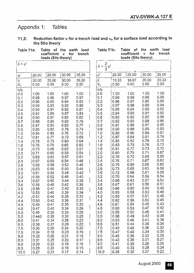
ATV-DVWK-A 127 E
Appendix 1: Tables
T1 ,2: Reduction factor K for a trench Ioad and Ko for a surface Ioad according to the Silo theory
Table T1 a: Table of the earth Ioad coefficient K for trench Ioads (Silo theory)
Ii = <p'
<p' 20.00 [25.00 T3o.oo -[35.00
Ii 20.00 25.00 30.00 35.00 K, 0.50 0.50 0.50 0.50
h/b 0.0 1.00 1.00 1.00 1.00 0.1 0.98 0.98 0.97 0.97 0.2 0.96 0.95 0.94 0.93 0.3 0.95 0.93 0.92 0.90 0.4 0.93 0.91 0.89 0.87 0.5 0.91 0.89 0.87 0.84 0.6 0.90 0.87 0.85 0.82 0.7 0.88 0.85 0.82 0.79 0.8 0.87 0.83 0.80 0.77 0.9 0.85 0.82 0.78 0.74 1.0 0.84 0.80 0.76 0.72 1.2 0.81 0.77 0.72 0.68 1.4 0.78 0.73 0.69 0.64 1.6 0.76 0.70 0.65 0.60 1.8 0.73 0.68 0.62 0.57 2.0 0.71 0.65 0.59 0.54 2.2 0.69 0.63 0.57 0.51 2.4 0.67 0.60 0.54 0.48 2.6 0.65 0.58 0.52 0.46 2.8 0.63 0.56 0.50 0.44 3.0 0.61 0.54 0.48 0.42 3.2 0.59 0.52 0.46 0.40 3.4 0.57 0.50 0.44 0.38 3.6 0.56 0.48 0.42 0.36 3.8 0.56 0.47 0.40 0.35 4.0 0.53 0.45 0.39 0.34 4.2 0.51 0.44 0.38 0.32 4.4 0.50 0.42 0.36 0.31 4.6 0.49 0.41 0.35 0.30 4.8 0.47 0.40 0.34 0.29 5.0 0.46 0.39 0.33 0.28 5.5 0.443 0.36 0.30 0.25 6.0 0.41 0.34 0.28 0.23 6.5 0.38 0.31 0.26 0.22 7.0 0.36 0.29 0.24 0.20 7.5 0.34 0.18 0.23 0.19 8.0 0.32 0.26 0.21 0.18 8.5 0.31 0.25 0.20 0.17 9.0 0.29 0.23 0.19 0.16 9.5 0.28 0.22 0.18 0.15 10.0 0.27 0.21 0.17 0.14
..
Table T1 b: Table of the earth Ioad coefficient K for trench Ioads (Silo theory)
2 ' 8=-<p
3 <p' 20.00 [25.00 [30.00 [35.00
0 13.33 16.67 20.00 23.33 K, 0.50 0.50 0.50 0.50
h/b 0.0 1.00 1.00 1.00 1.00 0.1 0.99 0.99 0.98 0.98 0.2 0.98 0.97 0.96 0.96 0.3 0.97 0.96 0.95 0.94 0.4 0.95 0.94 0.93 0.92 0.5 0.94 0.93 0.91 0.90 0.6 0.93 0.92 0.90 0.88 0.7 0.92 0.90 0.88 0.86 0.8 0.91 0.89 0.87 0.85 0.9 0.90 0.88 0.85 0.83 1.0 0.89 0.86 0.84 0.81 1.2 0.87 0.84 0.81 0.78 1.4 0.85 0.82 0.78 0.75 1.6 0.83 0.79 0.76 0.72 1.8 0.81 0.77 0.73 0.70 2.0 0.80 0.75 0.71 0.67 2.2 0.78 0.73 0.69 0.65 2.4 0.76 0.71 0.67 0.62 2.6 0.75 0.69 0.65 0.60 2.8 0.73 0.68 0.63 0.58 3.0 0.72 0.66 0.61 0.56 3.2 0.70 0.64 0.59 0.54
. 3.4 0.69 0.63 0.57 0.52 3.6 0.67 0.61 0.56 0.51 3.8 0.66 0.60 0.54 0.49 4.0 0.65 0.58 0.53 0.48 4.2 0.63 0.57 0.51 0.46 4.4 0.62 0.56 0.50 0.45 4.6 0.61 0.54 0.49 0.43 4.8 0.60 0.53 0.47 0.42 5.0 0.59 0.52 0.46 0.41 5.5 0.56 0.49 0.43 0.38 6.0 0.53 0.46 0.41 0.36 6.5 0.51 0.44 0.38 0.34 7.0 0.49 0.42 0.36 0.32 7.5 0.47 0.40 0.34 0.30 8.0 0.45 0.38 0.32 0.28 8.5 0.43 0.36 . 0.31 0.27 9.0 0.41 0.35 0.29 0.25 9.5 0.40 0.33 0.28 0.24 10.0 0.38 0.32 0.27 0.23
August 2000 ~~

ATV-DVWK-A 127 E
T1 ,2: Reduction factor K for a trench Ioad and Ko for a surface Ioad according to the Silo theory
Table T1 c: Table of the earth Ioad cciefficient K for trench Ioads (Silo theory)
cp' 20.00 125.00 130.00 135.00
8 6.67 8.33 10.00 11.67 K1 0.50 0.50 0.50 0.50
h/b 0.0 i.OO 1.00 i.OO i.OO 0.1 0.99 0.99 0.99 0.99 0.2 0.99 0.99 0.98 0.98 0.3 0.98 0.98 0.97 0.97 0.4 0.98 0.97 0.97 0.96 0.5 0.97 0.96 0.96 0.95 0.6 0.97 0.96 0.95 0.94 0.7 0.96 0.95 0.94 0.93 0.8 0.95 0.94 0.93 0.92 0.9 0.95 0.94 0.92 0.91 1.0 0.94 0.93 0.92 0.90 1.2 0.93 0.92 0.90 0.89 1.4 0.92 0.90 0.89 0.87 1.6 0.91 0.89 0.87 0.85 1.8 0.90 0.88 0.86 0.84 2.0 0.89 0.87 0.84 0.82 2.2 0.88 0.85 0.83 0.80 2.4 0.87 0.84 0.82 0.79 2.6 0.86 0.83 0.80 0.77 2.8 0.85 0.82 0.79 0.76 3.0 0.84 0.81 0.78 0.75 3.2 0.83 0.80 0.76 0.73 3.4 0.83 0.79 0.75 0.72 3.6 0.82 0.78 0.74 0.71 3.8 0.81 0.77 0.73 0.69 4.0 0.80 0.76 0.72 0.68 4.2 0.79 0.75 0.71 0.67 4.4 0.78 0.74 0.70 0.66 4.6 0.77 0.73 0.69 0.65 4.8 0.77 0.72 0.67 0.63 5.0 0.76 0.71 0.66 0.62 5.5 0.74 0.69 0.64 0.60 6.0 0.72 0.67 0.62 0.57 6.5 0.70 0.64 0.60 0.55 7.0 0.68 0.63 0.57 0.53 7.5 0.67 0.61 0.55 0.51 8.0 0.65 0.59 0.54 0.49 8.5 0.63 0.57 0.52 0.47 9.0 0.62 0.56 0.50 0.45 9.5 0.60 0.54 0.49 0.44 10.0 0.59 0.52 0.47 0.42
Table T2 a: Table of the earth Ioad coefficient Ko for trench Ioads (Silo theory)
ii=ep '
qi 20.00 125.00 130.00 135.00
ii 20.00 25.00 30.00 35.00 K1 0.50 0.50 0.50 0.50
h/b • 0.0 1.00 1.00 1.00 1.00 0.1 0.96 0.95 0.94 0.93 0.2 0.93 0.91 0.89 0.87 0.3 0.90 0.87 0.84 0.81 0.4 0.86 0.83 0.79 0.76 0.5 0.83 0.79 0.75 0.70 0.6 0.80 0.76 0.71 0.66 0.7 0.78 0.72 0.67 0.61 0.8 0.75 0.69 0.63 0.57 0.9 0.72 0.66 0.59 0.53 1.0 0.69 0.63 0.56 0.50 1.2 0.65 0.57 0.50 0.43 1.4 0.60 0.52 0.45 0.38 1.6 0.56 0.47 0.40 0.33 1.8 0.52 0.43 0.35 0.28 2.0 0.48 0.39 0.32 0.25 2.2 0.45 0.36 0.28 0.21 2.4 0.42 0.33 0.25 0.19 2.6 0.39 0.30 0.22 0.16 2.8 0.36 0.27 0.20 0.14 3.0 0.34 0.25 0.18 0.12 3.2 0.31 0.22 0.16 0.11 3.4 0.29 0.20 0.14 0.09 3.6 0.27 0.19 0.13 0.08 3.8 0.25 0.17 0.11 0.07 4.0 0.23 0.15 0.10 0.06 4.2 0.22 0.14 0.09 0.05 4.4 0.20 0.13 0.08 0.05 4.6 0.19 0.12 0.07 0.04 4.8 0.17 0.11 0.06 0.03 5.0 0.16 0.10 0.05 0.03 5.5 0.14 0.08 0.04 0.02 6.0 0.11 0.06 0.03 0.01 6.5 0.09 0.05 0.03 0.01 7.0 0.08 0.04 0.02 0.01 7.5 0.07 0.03 0.01 0.01 8.0 0.05 0.02 0.01 0.00 8.5 0.05 0.02 0.01 0.00 9.0 0.04 0.02 0.01 0.00 9.5 0.03 0.01 0.00 0.00 10.0 0.03 0.01 0.00 0.00
August 2000 II

Table T2 b: Table of the earth Ioad coefficient Ko for trench Ioads (Silo theory)
8 = ~<p' 3
<p ' 20.00 j25.00 j30.00 j35.00
8 13.33 16.67 20.00 23.33 K1 0.50 0.50 0.50 0.50
h/b 0.0 1.00 1.00 1.00 1.00 0.1 0.98 0.97 0.96 0.96 0.2 0.95 0.94 0.93 0.92 0.3 0.93 0.91 0.90 0.88 0.4 0.91 0.89 0.86 0.84 0.5 0.89 0.86 0.83 0.81 0.6 0.87 0.84 0.80 0.77 0.7 0.85 0.81 0.78 0.74 0.8 0.83 0.79 0.75 0.71 0.9 0.81 0.76 0.72 0.68 1.0 0.79 0.74 0.69 0.65 1.2 0.75 0.70 0.65 0.60 1.4 0.72 0.66 0.60 0.55 1.6 0.68 0.62 0.56 0.50 1.8 0.65 0.58 0.52 0.46 2.0 0.62 0.55 0.48 0.42 2.2 0.59 0.52 0.45 0.39 2.4 0.57 0.49 0.42 0.36 2.6 0.54 0.46 0.39 0.33 2.8 0.51 0.43 0.36 0.30 3.0 0.49 0.41 0.34 0.27 3.2 0.47 0.38 0.31 0.25 3.4 0.45 0.36 0.29 0.23 3.6 0.43 0.34 0.27 0.21 3.8 0.41 0.32 0.25 0.19 4.0 0.39 0.30 0.23 0.18 .
4.2 0.37 0.28 0.22 0.16 4.4 0.35 0.27 0.20 0.15 4.6 0.34 0.25 0.19 0.14 4.8 0.32 0.24 0.17 0.13 5.0 0.31 0.22 0.16 0.12 5.5 0.273 0.19 0.14 0.09 6.0 0.24 0.17 0.11 0.08 6.5 0.21 0.14 0.09 0.06 .
7.0 0.19 0.12 0.08 0.05 7.5 0.17 0.11 0.07 0.04 8.0 0.15 0.09 0.05 0.03 8.5 0.13 0.08 0.05 0.03 9.0 0.12 0.07 0.04 02 9.5 0.11 0.06 0.03 0.02 10.0 0.09 0.05 0.03 0.01
ATV-DVWK-A 127 E
Table T2 c: Table of the earth Ioad coefficient Ko for trench Ioads (Silo theory)
8 1 ' = -<p 3
cp' 20.00 125.00 130.00 j35.00
8 6.67 8.33 10.00 11.67 K1 0.50 0.50 0.50 0.50
h/b 0.0 1.00 1.00, 1.00 1.00 0.1 0.99 0.99 0.98 0.98 0.2 0.98 0.97 0.97 0.96 0.3 0.97 0.96 0.95 0.94 0.4 0.95 0.94 0.93 0.92 0.5 0.94 0.93 0.92 0.90 0.6 0.93 0.92 0.90 0.88 0.7 0.92 0.90 0.88 0.87 0.8 0.91 0.89 0.87 0.85 0.9 0.90 0.88 0.85 0.83 1.0 0.89 0.86 0.84 0.81 1.2 0.87 0.84 0.81 0.78 1.4 0.85 0.81 0.78 0.75 1.6 0.83 0.79 0.75 0.72 1.8 0.81 0.77 0.73 0.69 2.0 0.79 0.75 0.70 0.66 2.2 0.77 0.72 0.68 0.63 2.4 0.76 0.70 0.65 0.61 2.6 0.74 0.68 0.63 0.58 2.8 0.72 0.66 0.61 0.56 3.0 0.70 0.64 0.59 0.54 3.2 0.69 0.63 0.57 0.52 3.4 0.67 0.61 0.55 0.50 3.6 0.66 0.59 0.53 0.48 3.8 0.64 0.57 0.51 0.46 4.0 0.63 0.56 0.49 0.44 4.2 0.61 0.54 0.48 0.42 4.4 0.60 0.52 0.46 0.40 4.6 0.58 0.51 0.44 0.39 4.8 0.57 0.50 0.43 0.37 5.0 0.56 0.48 0.41 0.36 5.5 0.53 0.45 0.38 0.32 6.0 0.50 0.42 0.35 0.29 6.5 0.47 0.39 0.32 0.26 7.0 0.44 0.36 0.29 0.24 7.5 0.42 0.33 0.27 0.21 8.0 0.39 0.31 0.24 0.19 8.5 0.37 0.29 0.22 0.17 9.0 0.35 0.27 0.20 0.16 9.5 0.33 0.25 0.19 0.14 10.0 0.31 0.23 0.17 0.13
August 2000

ATV-DVWK-A 127 E
T3: Bending moments and normal force coefficients 501
Table T3 1: Bending moment and normal force coefficients
Moment coefficients Normalforce coefficients
Bedding Interface m,, m,, m*qh m, mw n,, n,, n*qh n, nw
case m', m'w n', n'w
l/2a
1/60" Crown +0.286 -0.250 -1.181 +0.459 +0.029 +0.080 -1.000 -0577 +0.417 +0.708
+0.073 +0.073 +0.066 +0.225
Abutment -0.293 +0.250 +0.208 -0.529 -0.264 -1.000 0 0 -1.571 +0.215
-0.840 -0.084 ., -0.250 +0.068
Bottom +0.377 -0.250 -0.181 +0.840 +0.420 -0.080 -1.000 -0.577 -0.417 +1.292
+0.134 +0.134 -0.066 +0.411
1/90" Crown +0.274 -0.250 -1.181 +0.419 +0.210 +0.053 -1.000 -0577 +0.333 +0.667
+0.067 +0.067 +0.053 +0.212
Abutment -0.279 +0.250 +0.208 -0.485 -0.243 -1.000 0 0 -1.571 +0.215
-0.077 -0.077 -0.250 +0.068
Bottom +0.314 -0.250 -0.181 +0.642 +0.321 -0.053 -1.000 -0.577 -0.333 +1.333
+0.102 +0.1 02 -0.053 +0.424
1/120" Crown +0.261 -0.250 -1.181 +0.381 +0.190 +0.027 -1.000 -0577 +0.250 +0.625
+0.061 +0.061 +0.040 +0.199
Abutment -0.265 +0.250 +0.208 -0.440 -0.220 -1.000 0 0 -1.571 +0.215
-0.070 -0.070 -0.250 +0.068
Bottom +0.275 -0.250 -0.181 +0.520 +0.260 -0.027 -1.000 -0.577 -0.250 +1.375
+0.083 +0.083 -0.040 +0.438
1/180" Crown +0.250 -0.250 -1.181 +0.345 +0.172 0 -1.000 -0577 +0.167 +0.583
+0.055 +0.055 +0.027 +0.186
Abutment -0.250 +0.250 +0.208 -0.393 -0.196 -1.000 0 0 -1.571 +0.215
-0.063 -0.063 -0.250 +0.068
Bottom +0.250 -0.250 -0.181 +0.441 +0.220 0 -1.000 -0.577 -0.167 +1.417
+0.070 +0.070 -0.027 +0.451
Mathematical sign: Moment + tension on inside of pipe Normal Force + tension
- tension on outside of pipe - compression
50) The table values apply only for circular pipes with the same moment of inertia all round. The associated m- and n-values are to be determined for other cross-sections (camp. Hornung/Kittel)
August 2000 II

ATV-DVWK-A 127 E
Table T3 II: Bending moment and normal force coefficients
Moment coefficients Normal force coefficients
Bedding Interface m,, mqh m, mw n,, n,h n, nw
case m', m'w n', n'w
ll/2a
goo Crown +0.286 -0.245 +0.396 +0.198 +0.038 -0.989 +0.285 +0.643 +0.063 +0.063 +0.045 +0.205
Abutment -0.271 +0.244 -0.460 -0.230 -1.000 0 -1.571 +0.215 -0.073 -0.073 -0.250 +0.068
Bottom +0.277 -0.224 +0.524 +0.262 -0.452 -0.718 -1.587 +0.707 +0.083 +0.083 .• -0.253 +0.225
120° Crown +0.240 -0.232 +0.314 +0.-157 +0.020 -0.960 +0.1 05 +0.552 . +0.050 +0.050 +0.016 +0.176
Abutment -0.240 +0.228 -0.362 -0.181 -1.000 0 -1.571 +0.215 -0.058 -0.058 -0.250 +0.068
Bottom +0.202 -0.187 +0.291 +0.145 -0.053 -0.540 -1.918 +0.541 +0.046 +0.046 -0.305 +0.172
180° Crown +0.163 -0.163 +0.071 +0.035 +0.212 -0.788 +0.500 +0.250 +0.011 +0.011 +0.080 +0.080
Abutment -0.125 +0.125 0 0 -1.000 0 -1.571 +0.215 0 0 -0.250 +0.068
Bottom +0.087 -0.087 -0.071 -0.035 -0.788 -0.212 -2.642 +0.179 -0.011 -0.011 -0.420 +0.057
Mathematical sign: Moment +- tension on inside of pipe Normal force + tension
- tension on outside of pipe - compression
August 2000 II

T4: Buckling of buried pipes
1.0
0.9
t 0.8
1 0.7 0.6
J 0.5
0.4
0.3
02
0.1
~ l'l
0.0
0.0001
~
~;..-
""' L'
" '
0.001
<p'- 35°
<p'1
= i6; I I I I
<.p'::::::: 25°
<p' = 200 I
0.01
VRB
ATV-DVWK-A 127 E
•
I
0.1
Diagram D 11: Reduction factorKv2 of buckling Ioads with earth/traffic Ioads qv
Approximation formula for Kv2 in accordance with Diagram D 11:
Kv2 =X+ 0.36· (log VRs + 4) :S: 0.9
with x = 0.52 for cp' = 35°
x = 0.5 for cp' = 30°
x = 0.46 for cp' = 25°
x = 0.4 for <p' = 20°
August 2000

ATV-DVWK-A 127 E
Approximation formulas for Ka2 in accordance with Diags. 12a and 12b:
liv= 1%
(D 12a)
Öv = 2%
(D 12b)
K, 2 = a · X2 + b · X + c
1 1 with X= logVRB• a = B · (k 0 - 2k 2 + k4 } b =- · (3k 0 - 4k2 + k4 )
4
rm/S 5
10 15 25 50
100
5 10 15 25 50
100
1.0
0.9
~ Ls 0.7
0.6
0.0001
ko k2 0.98 0.92 0.97 0.87 0.96 0.85
0.957 0.83 0.953 0.8 0.95 0.79
0.97 0.86 0.965 0.81 0.96 0.78
0.955 0.76 0.95 0.73 0.94 0.71
' I I
. '
.......
I
I
0.001
~ 0.96 0.95
0.952 0.95 0.94 0.92
0.93 0.92 0.91
0.905 0.85 0.85
' I I
' I I I I
I
' //. -:?· I"' I
'' I I I
I :. ' 'I
I I ' ' I '
ö, ' ,-;;r '
0.01 0.1 1
v., --
Diagram D 12c: Reduction factor Kaz of the snap-through Ioad with external water pressure (double wave preliminary deformation); Öv = 3%
August 2000 lil

ATV-DVWK-A 127 E
!.0
0.9
Ls ,I Ii II
Ko I I
' i
0. il I I 'I
ö, I
' I I ii
' '
I! 11,1 • !' ' ' I! I
().6 I " 0.0001 0.001
Diagram D 12a: Reduction factor Ka2 of the snap-through Ioad with external water pressure (double wave preliminary deformation); liv = 1 %
Approximation formulas for Ka2 and Ka1 in accordance with diagrams D 12a-f and D 13a-f:
x =log VRs 1 a=- (k 0 -2·k 2 +k 4 ) 8 1
b =- (3 · k0 - 4 · k2 + k4 ) 4
K 82 = a · X2 + b · X + k0
The supporting values k0, k2 and ~ are presented in an accompanying publication in the Korrespondenz Abwasser.
1.0 '
~"·· ~ ·· .. 0.9
Ls ..""..,
0.7
0.6
0.0001
I
. I
I I i
'
'I
'
0.001
',
'
'
I -
'
' I I
' '
'
I
I
'
'
0.01
v~-
I
~
0.1
-, '
y :J_
'(f '
' I
I I i
' I !
i i
' ~ 2%
I ' '
Diagram D 12b: Reduction factor Ka2 of the snap-through Ioad with external water pressure (double wave preliminary deformation); Öv = 2 %
August 2000

0.9
0.8
t 0.7 K.z
0.6
0.5
0.4
0.3 0.0001 0.001 0.01
VRB--0.1
ATV-DVWK-A 127 E
' ' '
1
Diagram D 12d: Reduction factor Ka2 of the snap-through Ioad with external water pressure (double wave preliminary deformation); Öv = 4%
Approximation formulas for Ka2 in accordance with Diags. 12cand 12d
Ka 2 = a · X 2 + b · X + c
1 b = _:1_ · (3k 0 - 4k 2 + k4 ) with X=logVRB• a =
8 · (k 0 - 2k 2 + k 4 }
4
rm/S ko k2 ~ 5 0.96 0.82 0.86
Ov = 3% 10 0.95 0.74 0.88 15 0.94 0.72 0.87
(D 12c 25 0.935 0.68 0.86 50 0.93 0.65 0.83
100 0.92 0.63 0.78
5 0.94 0.77 0.86
Ov = 4 10 0.93 0.69 0.84 15 0.92 0.66 0.83
(D 12d 25 0.915 0.63 0.82 50 0.91 0.6 0.78 100 0.9 0.59 0.73
August2000 lall

0.9
0.8
t 0.7 Kaz
0.6
0.5
0.4
0.3
0.0001 0.001 0.01 VRB--
0.1
ATV-DVWK-A 127 E
I
Diagram D 12e: Reduction factor Kaz of the snap-through Ioad with external water pressure (double wave preliminary deformation); 8v = 6%
Diagram D 12f:
1.0
0.9
0.8
t 0.7 Ka2
0.6 --= '·'"' ~
0.5
0.4
0.3
0.0001
~ ;::::: ~· ~ ·~
' '
0.001
'
' '
' '
0.01 VRB--
0.1
'
'
' o, .10%. '
I
Reduction factor Kaz of the snap-through Ioad with external water pressure (double wave preliminary deformation); ov = 10%
Approximation formulas for Kaz in accordance with Diags. 12a and 12b:
Ka2 = a · X 2 + b · X + c
with
August 2000

Ov = 6%
(D 12e)
liv=10%
(D 12f)
rm/S 5
10 15 25 50 100
5 10 15 25 50 100
1.0
0.9
1 0.8
K" 0.7
0.6
0.5
0.4
0.0001
ko 0.91 0.88
0.865 0.85
0.845 0.84
0.83 0.8
0.79 0.77 0.76 0.75
0.001
ATV-DVWK-A 127 E
k2 ~ 0.68 0.79 0.6 0.77
0.56 0.75 0.53 0.73 0.51 0.68 0.5 0.62
0.55 0.67 .,
0.46 0.62 0.44 0.6 0.41 0.57 0.39 0.51 0.38 0.45
~ - ' '
8, 1% ' '
'
0.01 0.1
Diag. D13a: Reduction factor Ka1 of the snap-through Ioad with external water pressure (local preliminary deformation); liv = 1%
August 2000 II

1.0
0.9
K_,
0.7
0.6
0.5
=-
0.4
0.0001
I
'
' ' ''' ' '
'
' ' '
' '
I '
'
' " ' 0.001
ATV-DVWK-A 127 E
' ' ' E
;;.:::: ' ' ' ' '
.?' %'
'
' ' ' '. '
' ' ' ' ' '
0.01 0.1
Diag. D13b: Reduction factor Ka1 of the snap·through Ioad with external water pressure (local preliminary deformation); .Sv= 2 %
Approximation formulas for Ka1 in accordance with Diags. 13a and 13b:
Ka 1 = a · X 2 + b · x + c
with X= log V RB• 1
b =.!. · (3k 0 - 4k 2 + k4 ) a = - · (k - 2k + k } 8 0 2 4 4
rm/S ko k2 ~ 5 0.99 0.96 0.963
.Sv= 1% 10 0.98 0.925 0.931 15 0.975 0.898 0.901
(D 13a) 25 0.97 0.863 0.849 50 0.968 0.826 0.743 100 0.963 0.804 0.622
5 0.953 0.924 0.927
.Sv= 2% 10 0.945 0.865 0.866 15 0.942 0.827 0.813
(D 13b) 25 0.935 0.784 0.723 50 0.93 0.744 0.568
100 0.923 0.722 0.436
August 2000 m

1.0
0.9
1 O.B
K., 0.7
0.6
0.5
0.4
0.0001
'
'
'
' '
' ' ;,, =' '
' " ' '
'
' ' ' ' '
0.001
ATV-DVWK-A 127 E
'
'
~I···
~ :o, '3 o/c'
' '
' ' ' '
' '
' '
'
0.01 0.1
Diag. 013b: Reduction factor 1ea1 of the snap-through Ioad with external water pressure (local preliminary deformation); Ov = 3 %
1.0
l 0.9
-~ 0.8 '
.
0.7 ' :s = K,, 0.6
0.5
0.4
0.3 ' ' n
0.0001 0.001 0.01 0.1
Diag. D13d: Reduction factor Ka1 of the snap-through Ioad with external water pressure (local preliminary deformation); Ov = 4 %
Approximation formulas for Ka1 in accordance with Diags. 13c and 13d:
Ka1 = a · X 2 + b · x + c
August2000 ~

ATV-DVWK-A 127 E
rm/S ko k2 k4 5 0.937 0.89 0.892
Öv = 3% 10 0.93 0.815 0.806 15 0.925 0.77 0.735
(D 13c) 25 0.915 0.725 0.618 50 0.91 0.684 0.444 100 0.905 0.663 0.321
5 0.929 0.859 0.859 10 0.921 0.771 0.751
.• Öv = 4%
15 0.92 0.723 0.664
(D 13d) 25 0.902 0.676 0.53 50 0.897 0.637 0.353 100 0.89 0.616 0.245
1.0 '
0.9
= "· ; ='
• 0.8
0.
·Ii .='6% '
,0
0.5
0.4
0.3
0.2
0.0001 0.001 0.01 0.1
Diag. D13e: Reduction factor Ka1 of the snap-through Ioad with external water pressure (local preliminary deformation); <'>v = 6 %
August 2000 IZlJ

1.0
0.9
n
,, .
0.3
0.2
0.0001
ATV-DVWK-A 127 E
0.001 0.01 0.1
Diag. D13f: Reduction factor Ka1 of the snap-through Ioad with external water pressure (local preliminary deformation); 8v = 10%
Approximation formulas for Ka1 in accordance with Diags. 13c and 13d:
K81 = a · X2 + b · X + c
1 1 with X=logVRB• a =- · (k 0 - 2k 2 + k 4 } b =- · (3k 0 - 4k 2 + k 4 )
8 4
rrr/S ko k2 ~ 5 0.888 0.802 0.797
Ov = 6% 10 0.863 0.698 0.652 15 0.85 0.647 0.544
(D 13e) 25 0.845 0.57 0.4 50 0.84 0.53 0.245 100 0.83 0.51 0.175
5 0.8 0.707 0.688
8v=10% 10 0.78 0.59 0.496 15 0.77 0.52 0.38
(D 13f) 25 0.75 0.46 0.255 50 0.74 0.41 0.175 100 0.73 0.37 0.143
August2000 lmml

0.08
0.07
t :.:: • E 0.04
0.03
0.02
0.01
0
I ! I! Ii I i f- rm'IY 1
1
0
[I II
I •
I I I I
I I 0.0001 0.001
0.09
0.08
t 0.07
I o.os :. 0.05
E 0.04
0.03
0.02
0.01
0
T rm/
II] III s = 20
I ·-d
I' •
I II 111~ III 1[11
TTTl1il, I I v wJrjj[JJ ~
.. I s~ll1 II
1 flll I I I ~ e o/.i I
I I I " :L II II! I •
Ii ]UJll II II I J;.l IT II II II II II I
0.01 0.1
v .. ---
IT!ll!lr I I. I r'l'I~J= 9
% .
I l.l/ I I
Ii! 0 0
IV !/
./ ~" 0 I
/ . 1''1 '/ I
I, l I Ii
111 'I II I 0.0001 0.001 0.01 0.1
v •• ----
III I I
I I
I I
II 1
~ II
I
•
II 1
o.12
1111111 1 · 111~
I 0.10 --1-- rm/S = 501ittlffil r-t-ltl}ffiifl/-ti:#l ffllj! ''
o.o8 1--t+tt+Hll--t-++tti+H'Ii-Y-H 1-.ffi\b~ ..-.-"171'ffi+l ~ /~ ~ "/
E 0.06 1---t-J-+.i.tllil--+-J...J..l-I+J~..L-J.A-JA.JIII!\--1 -+-J--J+I.fljj
w,/rm=9% /J [I I I • I
o .o4 ~--++IH+Illf· ~--Y'H+\1.~/,-,f.A-I ++++llt-+++++w _,....,.. ,.....: I/ ,
o.o2
--, I }t-rr,litlll 11 llr1 0.00 I I
0.0001 0.001 0.01 0.1 1
v •• ---
ATV-DVWK-A 127 E
Diag. 14a- c: Coefficients of bending moment mpa (bottom) for the loading case external water pressure (necessary for the nonlinear stability verification, approximation method}
August 2000 m

ATV-DVWK-A 127 E
Appendix 2: Details on static calculation
(Task questionnaire, recommended as performance description) TELEFAXlAddress
§ We request a no-charge offer
We commlsslon astalle calculatlon We commlsslon a statle examlnatlon
in accordance wlth the gl~en loadlng and Installation condlilons forthe proje.::t in:
LOADING AND EMPLACEMENT CONDITJONS- OPEN CUT
Nominal width ION ION !ON Pipeline length . _ _
Pipe made from· (s. A127. Table 3)
Details on the loading Coverlng helghl above pipe crown
min. h
max. h
Trafflc Ioad
m
m m
Bedding Type
Thlckness of the upper beddlng
~ or1 surround1ng so11 sand or gravel sand beodmg concrete bedd1ng
. .... . ...
~ 0.07-da (60" support) 0 15-da (00" support) 0.25-da (120" support) 0 Laying on flat trench botiom
and packing up of pendentive
Trench shape
I
~ HGV 60 HGV 30 cv 12 UIC 71 multltrack
UIC 71 slngle-track
No !lve Ioad
Type ~ Broad trench, back:fill or built-up.om·b· ankment Single trench"
Multiple trench" } Altach longttudnal Stepped trench" and cross-sectrons
........................... Area Load •• Interna! pres. P, Other
kN/m' on terrain surface
. bar from backpressure
Ioads
Soll type: l.a.w. ATV-A 127
ln-situ soil Cover Pipe-(Trench -lng lme
excavabon) zone
G 4: Cohesi.le solls (e.g. elay) Othersoil: ••••.••.••..••••••• ~ ~ ~ G 1: Noncohestve sand Md gravel G 2: SligMy cohesive sand and gravel G 3: Cotles'rve mixed soils and course clay
Degree or compaction ol in-situ soil: Dp,"··- .. ···········% Degree of compaction of other solls D,.,= ............... %
From ATV-A 127 } Unitwelghl ••••••• Table 1 Fncbon angle. • ••••• devrabng Soll Deformation module ••••••• ~~~~;~enstlc rn relevant
stress range 0 to .............. .
Subsoil: (underthe pipe)
Groundwater: Not present
Present
Max. height above crown max. h
§ Like surrounding soil
Very hard, stony or rocky Non Ioad bearing soil: ....
8
Fc;und~9-tri·e·~~iit-ie·-on:-
öep·th-ot'th,s·;o~;ic~rng·----below botiom of p1pe ••
8 8
.... kN/m'
... N/mm'
.... Nimm'
. ...•• m
m
Annexes
~ Soecmcatio. "". d sch.edule of pricesperformance descrrpt1on Site plan Longitudinal sectlon Cross-sectlon
• Load reducing effect appncable only i1' both trench walls remaln over a lang perk:ld 8 y.,
No
Details on constructiorl work
Trench wldth (mf';''~'~"~t~in~g=·~ioik~c~e~"~)~e~tp~ip~e!===3 Crown g m Bottom g,, m
Slope angle ß ~ w 50' go•
Trench sheeting
Horizontal (also Berlin) sheeting
Vertical trench sheeting Vertical light buikheads
Type ~ ~~-~~::~~ng
Vertical planks (area of CO'IIer only)
Vertlcal bulkheads'
................................................ • Fi:<lng depth ln soil
below bottom of trench t,"' ........... m
Dlsmantllng of sheet1ng
~Yt~1:N:dflv~h~f~i 1~~~~~~io0nnry § by steps with back:filling
1n one go afterbackfill'lng
--·······················-·-·---············· Soil compaction
Compact by layers, without verif~ation of the degree of compact1on compact by layers, with venlicatlon of the degree of compactron i.a,wZTVE-StB" (0", "'97 %) Uncompacted
Date: Stamp: (Address)
Signature:
~ Soil expert1se Additklnal technical regulations
~~:~:h~osa~~~~~~~---···--········
Bed- Covdmg errng
August 2000 m

ATV-DVWK-A 127 E
Appendix 3: Calculation examples
in the fol/owing examples are shown the ca/culation procedure for a rigid pipe, a flexible pipe using the modulus of elasticity E and a flexible pipe using nominal stiffness of nominal width DN 500.
The input data are selected for a normal case of placement, whereby peculiarities such as soil exchange, and the effects of groundwater and trench /ining arealso recorded.
The comp\ete formulas are not given in the calculatlon procedure t.pey can, however, be compared at any time with the text of the standard using the given formula, table, diagram and section numbers. ·
Input data Value Unit Rigid pipe 11 Flexible Flexible pipe pipe using
E2J using nominal
stiffness'1
Pipe
Nominal width DN [1] 500 500 500 Interna! diameter di [mm] 500 475.6 510 External diameter de [mm] 670 500 530 Wall thickness (pipe material) s [mm] 85 12.2 10 Cement mortar wall thickness sz [mm] - - -Crown compressive force FN [kN/m 80 - -Nominal stiffness SN [N/m
2J - 14 5000 SG gravity pipe material Xe [kN/m] 24 - 17.5 SG cement mortaring Xz [kNimj - 3000 -Modulus of elasticity of pipe material EeK [N/mm] -( short-term characteristic) Modulus of elasticity of pipe material Eec [N/mm 2
]
(long-term characteristic) Vertical fracture deformation (short- ÖvFM [%] term) Vertical fracture deformation (long-term) O".n [%] Safety class Safety coefficients: - [-]
failure due to fracture failure due to instability X [1]
Permitted vertical deformation of X [1 J diameter (Iang-term) 8, [%] Preliminary deformation (Type A)
? [%]
Soil
Surrounding soil: Soil group G [-] G3 G3 G3 Compactness DPr [%] 90 90 90 Interna! angle of friction cp ' ['] . 25 25 25 Soil characteristics from soil Yes 0 Yes 0 Yes 0 expertises No 0 No 0 No 0 Groundwater present Yes 0 Yes 0 Yes 0
No 0 No 0 No 0 Maximum groundwater Ievei above maxhw [m] 1.5 1.5 1.5 bottom of pipe Minimum groundwater Ievei below min hw [m] -0.5 -0.5 -0.5 bottom of pipe
Backfill of pipeline zone: Soil group G [-] G1 G1 G1 SG Xs [kN/m 3
] 20 20 20
August2000 ~

ATV-DVWK-A 127 E
Input data Value Uni! Rigid pipe11 Flexible Flexiblepipe pipe using
E21 using nominal
stiffnessE31
Interna! friction angle Cjl ' ['] 35 35 35
Covering: Soil group g [-] G3 G3 G3 SG Xs [kN/m
3] 20 20 20
SG under buoyancy Xs' [kN/m3] 10 10 10 Interna! friction angle Cjl ' ['] 25 25 25
Placement conditions Cover1ng helght c
" .• Trench width bb Embankment angle ß
A B
2a a
E, 'I E '1'1 ~0 7)
3 8)
E, 'I K,,l 8
Loading Trafflc Ioad:
Standard vehicle HGV60 HGV60 HGV60 Number of tracks - - -Dimensioning aircraft - - -
Area Ioad Po [kN/m2] - - - '
Water filling Xw [kN/m 3] 10 10 10
Interna! pressure P1 [kN/m2
] - - -
Footnote: 1) Concrete pipe DIN 4032 2) PVC-U pipe DIN V 19534 3) UP-GF pipe DIN 19565 4) From soil group and
August 2000 m

ATV-DVWK-A 127 E
Section Rigidpipe Flexiblepipe using E- Flexible pipe using
(Formula No.) modulus nominal stiffness
Table No. Calculation Stress Stress Deformation/ Elongation Elongation/
Diag No. step verification verificationl stability verificationl deformation/ deformation verification deformation stability
verification
Short-term Short-term Lang-term Short-term Leng-term
5.2.1 Earth road .• (5.04) K [1] 0.874 0.874 0.874 0.874 0.874 (5.06) Kß [1] - - - - -(5.01) PE [kNim2
] 52.5 52.5 52.5 52.5 52.5 5.2.2 Traffic Ioad D2d, (5.07) p [kNim 2
] 17.36 17.36 17.36 17.36 17.36 Table 6 cp [1] 1.2 1.2 1.2 1.2 1.2 (5.11) Pv [kNim2
] 20.8 20.8 20.8 20.8 20.8
6. Load distribut' 05 Os [1] 0.642 0.822 0.822 0.782 0.782
Table 1 f, [1] 1 1 1 1 1 (6.01) f, 1) [1] 0.75 0.75 0.75 0.75 0.75 Table 8, (6.02) E, [N/mm 2
] 2.90 3.70 3.70 3.52 3.52 rm [mm] 292.5 243.9 243.9 260 260
Table 3 Ee [N/mm2] 30,000 3,000 1,500 - -
(6.10e) I [mm4/mm~ 51' 180 151.3 151.3 83.3 83.3 (6.10b) s, [Nimm] 7.67 0.00391 0.00195 (6.10c) ~0 [N/mm 2
] 0.00251
DIN 19565-1 So [N/mm2] 0.005 0.0025
(6.1 Od) ~0 [Nimm2] 0.00321
(6.10) Ee [Nimm2] - - - 8436 5416
(6.18) M [1] 1.010 1.371 1.371 1.300 1.300
(6.17) I; [1] 0.851 0.869 0.869 0.857 0.857
(6.16) Sah [N/mm2] 1.47 1.929 1.929 1.8 1.81
(6.15) VRs [1] 41.60 0.0162 0.0104 0.0221 0.0142
6.2.3, Table 9 K2 [1] 0.5 0.4 0.4 0.4 0.4 (6.05) a' [1] 0.693 0.541 0-541 0.568 0-568
6.3.1' (6.04) max ;>,_[1] 1.40 1.344 1.344 1.357 1.357
(6.12) SBv [N/mm 2] - 3.70 3.70 3.52 3.52
(6.19a) I/Arm' [1] - 0.00021 0.00021 0.00012 0.00012 (6.19b)
2 0.00025 0.00025 0.00015 0.00015 I.KoiArm [1] -- < 0.001 < 0.001 < 0.001 < 0.001
Table 10a Cn,qv [1] - + 00891 + 0.0891 + 0.0891 + 0.0891
Table 10a cn,qh [1] - - 0.0833 - 0.0833 -0.0833 - 0.0833 Table 10a Cn,qn• [1] - - 0.0658 -0.0658 -0.0658 -0.0658
(6.14) K' [1] - 1.086 1.169 1.014 1.014 Table 10a Cv,qv [1] - - 0.0893 -0.0893 -0.0893 -0.0893 Table 1 Oa Cn,qh [1] - + 0.0833 + 0.0833 + 0.0833 + 0.0833
Table 10a Cn,qh* [1] + 0.0640 + 0.0640 + 0.0640 + 0.0640
(6.13) C/ [1] - - 0.0198 - 0.0145 -0.0244 - 0.0180 (6.08a) vs [1] 0.428 0.375 0.466 0.405
(6.08b) VS [1] 219.9 - - - -(6.06b) K' [1] - 0.927 0.921 0.927 0.925 (6.06a) ;>,_p [1] 1.40 'I 0.777 0.748 0.802 0.771
(6.21 a) i,_RG [1] 1.19 0.836 0.815 0.867 0.846 (1sbld,s4)
(6.23a) Afu [1] 3.55 3.55 3.55 3.55 3.55
6.5 Afl [1] 0.42 0.34 0.34 0.35 0.35
August2000 ~

ATV-DVWK-A 127 E
Section Rigidpipe Flexible pipe using E- Flexiblepipe using (Formula No.) modulus nominal stiffness
Table No. Calculation Stress Stress Deformation/ Elongation Elongation/ Diag No. step verification verification/ stability · verification/ deformation/
deformation verification deformation stability verification
Short time Short-term Long-term Short-term Long-term
(6.22) ?cB [1 J 0.866 1.074 1.084 1.066 1.076
"" v.v Vertica1 total • Ioad
(6 .24) q,'l [kN/m2] 83.0 64.7 63.6 66.4 65.2
7.3 Side pressure (7 .01) qh [kN/m2
] 26.1 24.5 24.7 24.5 24.7
(7.02a) qh· [kN/m2] - 45.4 47.3 44.1 46.9
(7.02b) qh•w [kN/m2] - 2.1 2.4 2.1 2.3
8.1 Cutting forces (Mqh" and Nqh" calculated using qh* and qh*w)
Crown (8.01) M,, [kNm/m] 1.946 1.005 0.988 1.172 1.150
(8.03) Mqh [kNm/m] - 0.558 - 0.365 - 0.368 - 0.414 -0.417
(8.05) Mqh* [kNm/m] - - 0.511 - 0.536 - 0.566 - 0.581
(8.07) Mg [kNm/m] 0.073 0.004 0.004 0.005 0.005
(8.09) Mw [kNm/m] 0.053 0.028 0.028 0.033 0.033
l:M [kNm/m] 1.514 0.160 0.116 0.230 0.190
(8.02) Nqv [kN/m] 1.287 0.426 0.419 0.466 0.457
(8.04) N,h [kN/m] - 7.629 -5.987 - 6.036 -6.370 - 6.422
(8.06) Nqh* [kN/m] - -6.685 - 7.000 - 6.937 - 7.382
(8.08)) Ng [kN/m] 0.199 0.010 0.010 0.011 0.011
(8.1 0) Nw [kN/m] 0.571 0.372 0.372 0.423 0.423
l:M [kN/m] -5.572 -11.8640 -12.235 -12.397 -12.913
Abutment (8.01) Mqv [kNm/m] - 1.982 - 1.020 - 1:003 -1.189 - 1.167
(8.03) Mqh [kNm/m] 0.588 0.365 0.368 0.414 0.417
(8.05) M,h * [kNm/m] - 0.588 0.616 0.648 0.692
(8.07) Mg [kNm/m] - 0.085 -0.004 - 0.004 -0.005 -0.005
(8.09) Mw [kNm/m] - 0.061 -0.032 - 0.032 -0.039 - 0.039
l:M [kNm/m] - 1.569 - 0.103 - 0.056 - 0.171 - 0.102
(8.02) N,, [kN/m] -24.284 -15.782 -15.518 -17 264 -16.951
(8.04) Nqh [kN/m] 0 0 0 0 0
(8.06) Nqh* [kN/m] - 0 0 0 0
(8.08)) Ng [kN/m] -0.937 - 0.065 -0.065 - 0.071 - 0.071
(8.1 0) Nw [kN/m] 0.184 0.128 0.128 0.145 0.145
l:M [kN/m] -25.038 -15.720 -15.455 -17.190 -16.877
lnvert (8.01) M,, [kNm/m] 2.230 1.059 1.041 1.234 1.211
(8.03) Mqh [kNm/m] -0.558 - 0.365 - 0.368 - 0.414 - 0.417
(8.05) Mqh * [kNm/m] - - 0.511 - 0.536 -0.566 -0.602
(8.07) Mg [kNm/m] 0.112 0.005 0.005 0.006 0.006
(8.09) Mw [kNm/m] 0.080 0.038 0.038 0.046 0.046
l:M [kNm/m] 1.865 0.225 0.180 0.306 0.244
August2000 ~

ATV-DVWK-A 127 E
Section Rigidpipe Flexible pipe using E- Flexible pipe using
(Formula No.) modulus nominal stiffness
Table No. Calculation Stress Stress Deformation/ Elongation Elongation/
Diag No. step verification verification/ stability verification/ deformation/ deformation verification deformation stability
verification
Short time Short-term Long-term Short-term Leng-term
(8.02) Nq, [kN/m] - 1.287 - 0.426 -0.419 - 0.466 - 0.457
(8.04) Nqh [kNimj - 7.629 - 5.987 -6.036 - 6.;370 - 6.422
(8.06) Nqh* [kN/m] - -6.685 - 7.000 -6.934 - 7.382
(8.08)) N, [kN/m] 0.199 0.010 - 0.010 0.011 0.011
(8.10) Nw [kNim] 1.140 0.818 0.818 0.929 0.929
~M [kNim] - 7.974 - 12.290 - 12.647 - 12 852 - 13.343
8.2 Stresses Cross-section values of the pipewall Area
A 85.0 12.2 12.2 10.0 10.0
[mm2imm] Resistance moment W = s2/6
. [mm3imm] 1204.2 24.8 ·24.8 16.7 16.7
(8.14a) aki [1] 1.097 1.017 1.017 1.013 1.013
(8.14b) ake [1] 0.903 0.983 0.983 0.987 0.987
Table 3 O'R [Nimm2] 6.4 90 50 - -
(9.01c) - [N/mm2] 61.4 O'R
(8.13) O'ccowo [Nimm2] + 1.31 + 5.59 + 3.76 - -
(8.13) O'abut [Nimm2] + 0.88 + 2.79 + 0.95 - -
(8.13) O';n,ert [Nimm2] + 1.60 + 8.22 + 6.46 - -
9.2 Stress verification (safety facts)
(9.01 a,b) Xccown [1] 4.9 16.1 16.3 - -(9.01 a,B) Xabut [1] 7.3 32.2 64.6 - -(9.01a,b) Xi"'ert [1] 4.0 10.9 9.5 - -Table 12 . necx[1] 2.2 2.5 2.5 - -8.3 Elongation Table 3 oR [%] - - - ±1.646 ±0.988
-(9.01 d) oR [%] - - - - ±1.175
(8.15) Ecrown [%] - - - - 0.176 - 0.231
(8.15) Eabut [%] - - - - 0.138 - 0.145
(8.15) Ejnvert [%] - - - - 0.222 - 0.291
(9.2) Elongation verification (safety facts)
(9.01a,b) Xccowo [1] - - - 9.4 5.1
(9.01a,B) Xabut [1] - - - 11.9 8.1 .
(9.01a,b) Xi"ert [1] - - - 7.4 4.0
Table 12 nec x[1] - - - 2.0 2.0
8.3 Deformation
August 2000 ~

ATV-DVWK-A 127 E
Section Rigidpipe Flexible pipe using E- Flexible pipe using
(Formula No.) modulus nominal stiffness
Table No. Calculation Stress Stress Deformation/ Elongation Elongation/
Diag No. step verification verification/ stability verification/ deformation/ deformation verification deformation stability
verification
Short time Short-term Long-term Short-term Long-term
(6.24) qv,E [kN/m2] - 43.9 - 45.5 -
(7 .01) qh,E [kN/m2] - 24.5 - 24.:; -
(7 .02) qh'.E [kN/m2] - 22.8 - 22.9 -
(8.16a) t>d, [mm] - - 6.5 -14.3 - 5.1 -15.5
(8.17) 8, [%] - 1.3 3.0 1.0 3.0
9.4 Deformation verification
9.4 Perm. Ov [%] - - 6 - 6 :::;;6%: linear calculation >6%: non-linear calculation
9.5 Stability verification (safety)
9.5.3.1 Vertical total Ioad
Table 1 <p' roJ - - 35 - 35 Appx. 1: 011, K,2 [1 J - - 0.9 - 0.9
approx. formula
(9.06) crit q, [N/mm2] - - 0.354 - 0.388
Table 1 x:B' [kN/m3] - - 10 - 10
(6.24) qv,A [N/mm2] - - 0.0565 - 0.0579
(9.07) )( [1 J - - 6.3 - 6.7
Table 13 nec x [1] - - 2.0 - 2.0
9.5.3.2 Ex!. water pressure 41
Calculated VRs [1 J 0.0081 0.0110
us'1ng S, 9.5.2 8,+1 [1 J - - 4.0 - 4.0
rrrls [%] - - 20 - 26 Appx. 1: 012 Ka2 [1 J - - 12.5 - 11.5
010 ao [1 J - - 16.3 - -
(9.08) crit Pe [N/mm2] - - 0.137 - 0.154
(9.10) p, [N/mm2] - - 0.015 - 0.015
(9.11) x [N/mm2] - - 9.1 - 10.3
Table 13 nec x[1] - - 2.0 - 2.0
9.5.3.3 Simult. acting vertical. total Ioad and ext. water pressure
(9. 12) )( [1 J - - 3.7 4.1 -Table 13 nec x[1] - - 2.0 2.0 -
August2000 ~

ATV-DVWK-A 127 E
Section Rigidpipe Flexible pipe using E- Flexible pipe using
(Formula No.) modulus nominal stiffness
Table No. Calculation Stress Stress Deformation/ Elongation Elongation/
Diag No. step verification verification/ stability verification/ deformation/ deformation verification deformation stability
verification
Short time Short-term Long-term Short-term Long-term
9.5.4 Non-linear stability verification (oniy necessary with deformations ov > 6% and available x < 5· .(lec. X
I Given 51 max hw [m] - - 2.5 - 2.5
Given 51 8, [%] - - 6.5 - 6.5
9.5.4.2 Vertical total Ioad
(6.24) q,A [N/mm 2] - - 0.0493 - 0.0504
(7.01) qh,A [Nimm 2j - - - 0.0162 - - 0.0161
(7.02a) qh'.A [Nimm 2] - - - 0.0399 - 0.0405
(9.14a) cxn.0 , [1] - - 1.26 - - 1.27
lnvert: (8.01) Mqv [kNmlm] - - 0.806 -(8.03) Mqh [kNmlm] - - - 0.241 -
(8.05) Mqh • [kNmlm] - - - 0.430 - 0.033
(8.07) Mg [kNmlm] - - 0.005 -
(8.09) Mw [kNmlm] - - - 6) -
LM [kNmlm] - - 0.140 - 0.189
(8.02) N,, [kNim] - - - 0.325 - 0.457
(8.04) N,h [kNim] - - - 3.951 - - 6.422
(8.06) Nqh* [kN/m] - - -5.615 - - 7.382
(8.08)) N, [kNim] - - 0.010 - 0.011
(8.1 0) Nw [kNim] - - - - 0.423
LM [kNim] - - - 9.901 - -12.913
(9.15a) crso [Nimm2] - - +6.42 -
(9.15b) oSo [%] - - - - - 1.167
(5.01) PE,A [kNim2] - - 35.0 - 0.417
9.5.4.2 -
[Nimm2] 64.9 0.692 S!R - - -
9.5.4.2 ER [%] - - - - - 0.005
(9.16) - - 10.1 - - 0.039
9.5.4.2 Ext. water pressure 4)
9.5.2 ov + 1 [%] - - 7.5 - 7.5
Appx 1: D12e,f Ka2 [19 - - 0.57 - 0.52
(9.08) crit p, [N/mm2] - - 0.111 - 0.120
(9.10) pe [Nimm 2] - - - 0.025 - - 0.025
(9.14b) CXII,pa [1] - - 1.82 - 1.71
D14b mpa [1] (9 .13) Mwpa [mmlmm] (8.12) Nso,pa [N/mml (9.15a) crso,pa [Nimm ]
August 2000 m

Section (Formula No.)
Table No. Diag No.
9.5.4.2 (6.1 0) (9.15b) 9.5.4.2 (9.16) 9.5.3.3
(9.12) Table 13
9.4
(9.12) 9.4 (9 .16) (9.05) 9.4 9.4
Footnotes:
Rigidpipe Flexiblepipe using E-modulus
Calculation Stress Stress Deformation/ step verification verification/ stability
deformation verification
Short time Short-term Lang-term
crp [N/mm2] - - 50
EP [N/mm2] - - -
Eso,pa [%] - - -Ep [%] - - -Xpa [1] - - 15.3 Simult. acting vertical. total Ioad and ext. water pressure
X [1] - 6.08 -necx[1] - 2.0 -
Non-linear verification of deformation Avail x [1] - - 6.08 <5 nec x - - <10 Xqv [1 J - - 10.1 <XII [1] ... - - 1 .11 <X11' Ov[%] - - 7.22 perm Ii, [%] - 9
E2 > E1 is permitted due to saH exchange in the pipeline zone. For pipes of greater stiffness (VRs > 1) AR= max A (6.3.2).
ATV-DVWK-A 127 E
Flexible pipe using nominal stiffness
Elongation Elongation/ verification/ deformation/ deformation stability
verification
Short-term Lang-term
- --• 4218 71
- 0.170 - ±0.988 - 5.81
- 2.53 - 2.0
- 2.53 - <10 - 4.48 - 1.29 - 8.39 - . 9
1) 2) 3) 4) 5)
As the groundwater can sink below the bottarn of the pipe q 11 can be ca!culated without buoyancy. Verification is necessary as groundwater exists above the bottom of the pipe.
6) 7)
The values max hw and Ov are increased compared with the initial examp!e in order to demonstrate the calculation step for non-linear verification. Forstability verification the Ioad case of pipe without waterfill is relevant. The calculation of the elongation in the pipe wa!l as a result of external water pressure takes place using the long~term E modulus of the pipe material.
August 2000 ll'fttl

Appendix 4:
ATV-DVWK-A 127 E
Literature [where there is no known translation into English a courtesy translation is provided in square brackets]
Leonhardt, G.: Einfluß der Bettungssteifigkeit auf dietragfähigkeitund die Verformungen von flexiblen Rohren
Falter, B.:
[lnfluence of the bedding stiffness on the carrying capability and deformation of flexible pipes].Straße-Brücke-Tunnel 24, Val. 4 (1972) p. 63-68.
Die Belastung von starren Rohrleitungen unter Dämmen. The Joading of rigid pipelines under embankments] Mitt. d. Jnst. f. Grundbau u. Bodenmechanik der TU Hannover, Val. 4 (1973) .• Die Erdlasten bei überschütteten Durchlässen. [Earth Ioads with surcharged culverts]. Die Bautechnik 56 (1979) p. 361-368.
Bodenmechanische Fragen der statischen Berechnung und Einbettung von erdvelegten Rohrleitungen. [Soil mechanical questions of the static calculation and embedment of buried pipelines]. Korrespondenz Abwasser (1979) p.489-493. Einige Bemerkungen zum statischen und bodenmechanischen Konzept des ATVArbeitsblattes ATV-A 127. [Same comments on the static and soil mechanical concept of ATV Standard ATV-A 127]. Korrespondenz Abwasser (1984) p.528-531.
Berechnung freier und einseitig elastisch gebetteten Kreisbögen und -ringe unter Außendruck mit großen Verschiebungen und Verdrehungen. [Calculation of free and one-sided elastically embedded arcs and rings under external pressure with !arge displacement and torsion]. Dissertation TU Hannover (1975).
Grenzlasten von einseitig elastisch gebetteten kreiszylindrischen Konstruktionen. [Uitirnate Ioads of one-sided elastically embedded cylindrical designs]. Bauingenieur 55 (1980) p.381-390.
Zum Stabilitätsnachweis von erdverlegten Rohren gegen äußeren Wasserdruck nach ATV-Arbeitsblatt ATV-A 127. [On the verification of stability of buried pipes against external water pressure in accordance with ATV Standard ATV-A 127]. Korrespondenz Abwasser (1984) p. 520-522.
Hornung, K.: Straßenverkehrsbelastung erdüberdeckter Rohre. [Road traffic loading of buried pipes]. Korrespondenz Abwasser (1984) p. 532-541.
Hornung, K./ Structural analysis of biJried pipes, Wiesbaden (1989) (in German and English). Kittel, D.:
Fuchs, W.: Grundzüge der problematischen Zuverlässigkeitstheorie und ihre Anwendungen auf im Erdboden verlegte Rohren
Netzer, W.! Pattis, 0.:
ATV-AG 1.5.5:
[Characteristics of the problematic reliability theory and its applications to buried pipes]. Korrespondenz Abwasser ( 1984) p. 523-527
Zuverlässigkeitsanalyse von Rohrleitungen aus unbewehrten Beton. [Reliability analysis of pipelines made from unreinforced concrete]. Dissertation TU München (1982).
Überlagerung von Innen- und Außendruckbelastung erdverlegter Rohrleitungen (Rechnerische Untersuchung bei Anwendung der Theorie II. Ordnung. [Overlaying of internal and external pressure Ioads on buried pipelines (Mathematical investigation with the application of the Second Order Theory]. 3R International (1989) p. 96-105.
Arbeitsbericht "Berechnungsansätze für die Rohrbelastung im Graben mit gespundetem Verbau". [A TV Report "Mathematical approaches for Ioads on pipes in the trench with grooved and tongued sheet piling". Korrespondenz Abwasser 12/97.
August 2000 _,.