Embed Size (px)
Citation preview

ATSC S32-230r56 Physical Layer Protocol 29 June 2016
i
ATSC Proposed Standard: Physical Layer Protocol
(A/322)
Doc. S32-230r56 29 June 2016
Advanced Television Systems Committee 1776 K Street, N.W. Washington, D.C. 20006 202-872-9160

ATSC S32-230r56 Physical Layer Protocol 29 June 2016
ii
The Advanced Television Systems Committee, Inc., is an international, non-profit organization developing voluntary standards for digital television. The ATSC member organizations represent the broadcast, broadcast equipment, motion picture, consumer electronics, computer, cable, satellite, and semiconductor industries.
Specifically, ATSC is working to coordinate television standards among different communications media focusing on digital television, interactive systems, and broadband multimedia communications. ATSC is also developing digital television implementation strategies and presenting educational seminars on the ATSC standards.
ATSC was formed in 1982 by the member organizations of the Joint Committee on InterSociety Coordination (JCIC): the Electronic Industries Association (EIA), the Institute of Electrical and Electronic Engineers (IEEE), the National Association of Broadcasters (NAB), the National Cable Telecommunications Association (NCTA), and the Society of Motion Picture and Television Engineers (SMPTE). Currently, there are approximately 150 members representing the broadcast, broadcast equipment, motion picture, consumer electronics, computer, cable, satellite, and semiconductor industries.
ATSC Digital TV Standards include digital high definition television (HDTV), standard definition television (SDTV), data broadcasting, multichannel surround-sound audio, and satellite direct-to-home broadcasting.
Note: The user's attention is called to the possibility that compliance with this standard may require use of an invention covered by patent rights. By publication of this standard, no position is taken with respect to the validity of this claim or of any patent rights in connection therewith. One or more patent holders have, however, filed a statement regarding the terms on which such patent holder(s) may be willing to grant a license under these rights to individuals or entities desiring to obtain such a license. Details may be obtained from the ATSC Secretary and the patent holder.
Disclaimer Not all optional settings that are combinations with non-optional settings have been tested at the time of release of this document.
Revision History Version Date Candidate Standard approved 28 September 2015 Standard approved Insert date here

ATSC S32-230r56 Physical Layer Protocol 29 June 2016
iii
Table of Contents 1. SCOPE ................................................................................................................................................... 15
1.1 Introduction and Background 15 1.2 Organization 15
2. REFERENCES ....................................................................................................................................... 16 2.1 Normative References 16 2.2 Informative References 16
3. DEFINITION OF TERMS ........................................................................................................................ 16 3.1 Compliance Notation 16 3.2 Treatment of Syntactic Elements 16
3.2.1 Reserved Elements 17 3.3 Acronyms, Abbreviations and Mathematical Operators 17 3.4 Terms 19
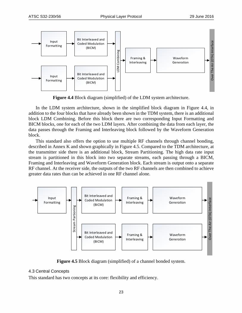
4. SYSTEM OVERVIEW ............................................................................................................................. 20 4.1 Features 20 4.2 System Architecture 21 4.3 Central Concepts 23
5. INPUT FORMATTING ............................................................................................................................ 24 5.1 Encapsulation and Compression 24
5.1.1 Number of PLPs 25 5.2 Baseband Formatting 25
5.2.1 Mapping ALP Packets to Baseband Packets 25 5.2.2 Baseband Packet Header 26 5.2.3 Scrambling of Baseband Packets 30
6. BIT INTERLEAVED CODING AND MODULATION (BICM) .................................................................. 31 6.1 Forward Error Correction (FEC) 31
6.1.1 FEC Frame Structure 31 6.1.2 Outer Encoding 33 6.1.3 Inner Encoding 35
6.2 Bit Interleavers 38 6.2.1 Parity Interleaver 38 6.2.2 Group-Wise Interleaver 39 6.2.3 Block Interleavers 39
6.3 Constellation Mapping 43 6.3.1 Constellation Overview 44 6.3.2 Modulation and Coding Combinations 44 6.3.3 Demultiplexing Operation 45 6.3.4 Bit to IQ Mapping 46
6.4 Layered Division Multiplexing (LDM) 48 6.4.1 LDM Encoding 48 6.4.2 Injection Level Controller 49 6.4.3 Power Normalizer 50 6.4.4 LDM Example 51
6.5 Protection for L1-signaling 52 6.5.1 Overview 52

ATSC S32-230r56 Physical Layer Protocol 29 June 2016
iv
6.5.2 Common Blocks for L1-Basic and L1-Detail 53 6.5.3 L1-Detail Specific Block Details 64
7. FRAMING AND INTERLEAVING ........................................................................................................... 68 7.1 Time Interleaving 69
7.1.1 Time Interleaver Modes 69 7.1.2 Time Interleaver Size 70 7.1.3 Extended Interleaving 70 7.1.4 Convolutional Time Interleaver (CTI) Mode 70 7.1.5 Hybrid Time Interleaver (HTI) Mode 72
7.2 Framing 81 7.2.1 Overview 81 7.2.2 Frame Structure 81 7.2.3 Number of Carriers 83 7.2.4 Frame Symbol Types 83 7.2.5 Preamble 84 7.2.6 Cell Multiplexing 86 7.2.7 PLP Multiplexing Approaches within a Subframe 95
7.3 Frequency Interleaving 104 8. WAVEFORM GENERATION ................................................................................................................ 108
8.1 Pilot Insertion 109 8.1.1 Introduction 109 8.1.2 Reference Sequence 109 8.1.3 Scattered Pilot Insertion 110 8.1.4 Continual Pilot Insertion 111 8.1.5 Edge Pilot Insertion 113 8.1.6 Preamble Pilot Insertion 113 8.1.7 Subframe Boundary Pilot Insertion 115
8.2 MISO 115 8.2.1 Transmit Diversity Code Filter Sets 115
8.3 Inverse Fast Fourier Transform (IFFT) 116 8.4 Peak to Average Power Ratio Reduction Techniques 119
8.4.1 Tone Reservation 119 8.4.2 Active Constellation Extension (ACE) 120
8.5 Guard Interval 120 8.5.1 Guard Interval Extension for Time-aligned Frames 120
8.6 Bootstrap 122 9. L1 SIGNALING ..................................................................................................................................... 122
9.1 Bootstrap 122 9.1.1 Versioning 122 9.1.2 Bootstrap Symbol 1 122 9.1.3 Bootstrap Symbol 2 123 9.1.4 Bootstrap Symbol 3 123
9.2 Syntax for L1-Basic Data 123 9.2.1 L1-Basic System and Frame Parameters 124 9.2.2 L1-Basic Parameters for L1-Detail 126 9.2.3 L1-Basic Parameters for First Subframe 127

ATSC S32-230r56 Physical Layer Protocol 29 June 2016
v
9.2.4 L1-Basic Miscellaneous Parameters 128 9.3 Syntax and Semantics for L1-Detail Data 129
9.3.1 L1-Detail Miscellaneous Parameters 131 9.3.2 L1-Detail Channel Bonding Parameters (Frame) 132 9.3.3 L1-Detail Subframe Parameters 132 9.3.4 L1-Detail PLP Parameters 136 9.3.5 L1-Detail LDM Parameters 138 9.3.6 L1-Detail Channel Bonding Parameters (PLP) 139 9.3.7 L1-Detail MIMO Parameters (PLP) 140 9.3.8 L1-Detail Cell Multiplexing Parameters 140 9.3.9 L1-Detail Time Interleaver (TI) Parameters 141
ANNEX A : LDPC CODES .......................................................................................................................... 143 A.1 LDPC Code Matrices (Ninner = 64800) 143 A.2 LDPC Code Matrices (Ninner = 16200) 155
ANNEX B : BIT INTERLEAVER SEQUENCES .......................................................................................... 160 B.1 Permutation sequences of group-wise interleaving for Ninner = 64800 (Ngroup = 180) 160 B.2 Permutation sequences of group-wise interleaving for Ninner = 16200 (Ngroup = 45) 173
ANNEX C : CONSTELLATION DEFINITIONS AND FIGURES .................................................................. 177 C.1 Constellation Definitions 177 C.2 Constellation Figures 184 C.3 Constellation Labeling 188
ANNEX D : CONTINUAL PILOT (CP) PATTERNS ..................................................................................... 191 D.1 Reference and Additional CP Indices 191
ANNEX E : SCATTERED PILOT (SP) PATTERNS .................................................................................... 195 E.1 SISO Scattered Pilot Patterns 195
ANNEX F : NUMBER OF ACTIVE DATA CELLS IN SUBFRAME BOUNDARY SYMBOL ....................... 200 F.1 Subframe Boundary Symbol Active Data Cell Tables 200 F.2 Calculation of Subframe Boundary Symbol Null Cells (Informative) 205
ANNEX G : TONE RESERVATION CARRIER INDICES ............................................................................ 206 G.1 Tone Reservation Carrier Indices 206
ANNEX H : PREAMBLE PARAMETERS FOR BOOTSTRAP .................................................................... 209 H.1 Preamble Structure Parameter Values 209
ANNEX I : TOTAL SYMBOL POWER ......................................................................................................... 213 I.1 Preamble Symbol Frequency Domain Power 213 I.2 Data and Subframe Boundary Symbol Frequency Domain Power 214
ANNEX J : MISO ......................................................................................................................................... 220 J.1 MISO Frequency Domain Coefficients 220
ANNEX K : CHANNEL BONDING .............................................................................................................. 225 K.1 Introduction 225 K.2 Plain Channel Bonding 226 K.3 Channel Bonding with SNR Averaging 227
ANNEX L : MIMO ........................................................................................................................................ 228 L.1 Overview 228 L.2 FEC Coding 229

ATSC S32-230r56 Physical Layer Protocol 29 June 2016
vi
L.3 Bit Interleaving 229 L.4 Demultiplexer 229 L.5 Constellations 229 L.6 Constellation Superposition for LDM 230 L.7 Precoding 230
L.7.1 Stream Combining 231 L.7.2 I/Q Polarization Interleaving 232 L.7.3 Phase Hopping 232
L.8 Time Interleaver 232 L.9 Framer 233 L.10 Frequency Interleaving 233 L.11 Pilot Patterns 233
L.11.1 Pilot Antenna Encoding 233 L.11.2 Pilot Schemes 235
L.12 MISO 243 L.13 PAPR Reduction 243 L.14 Channel Bonding 243 L.15 L1 signalling for MIMO 243
ANNEX M : PEAK TO AVERAGE POWER RATIO REDUCTION ALGORITHMS (INFORMATIVE) ......... 244 M.1 PAPR Reduction Algorithms 244 M.2 TR Algorithm 244 M.3 ACE Algorithms 246
M.3.1 1-D ACE algorithm 246 M.3.2 2-D ACE Algorithm 249 M.3.3 2-D ACE Constellation Diagrams 251
ANNEX N : TRANSMITTER IDENTIFICATION (TXID) ............................................................................... 254 N.1 Overview 254 N.2 Code Generation 254
N.2.1 Multiple Shift Registers 255 N.2.2 Clock Rate 256 N.2.3 Preloaded Values 256 N.2.4 Synchronization with Preamble Symbol 256
N.3 Code Transmission 257 N.3.1 BPSK Modulation 257 N.3.2 TxID Injection Level 257
N.4 Signaling Fields 258
ATSC S32-230r56 Physical Layer Protocol 29 June 2016
vii
Index of Figures Figure 4.1 Block diagram of the system architecture for one RF channel. .................................. 21 Figure 4.2 Block diagram (simplified) of a single PLP system architecture. .............................. 22 Figure 4.3 Block diagram (simplified) of a multiple PLP system architecture. .......................... 22 Figure 4.4 Block diagram (simplified) of the LDM system architecture. .................................... 23 Figure 4.5 Block diagram (simplified) of a channel bonded system. .......................................... 23 Figure 5.1 Block diagram of input formatting. ............................................................................ 24 Figure 5.2 Block diagram of baseband formatting. ..................................................................... 25 Figure 5.3 Baseband Packet structure showing Header, Payload and mapping example of
ALP packets to a Baseband Packet. .................................................................................. 26 Figure 5.4 Baseband Packet Header structure details. ................................................................. 27 Figure 5.5 Structure of extension field for the Mixed Extension Mode. ..................................... 29 Figure 5.6 Shift register of the PRBS encoder for baseband scrambling. ................................... 31 Figure 6.1 Block diagram of BICM. ............................................................................................ 31 Figure 6.2 Structure of FEC Frame when BCH or CRC is used as Outer Code. ......................... 32 Figure 6.3 Structure of FEC Frame when no Outer Code is used. .............................................. 32 Figure 6.4 Shift register for CRC-32. .......................................................................................... 34 Figure 6.5 Bit interleaver structure. ............................................................................................. 38 Figure 6.6 Parity interleaved LDPC codeword bit groups. .......................................................... 39 Figure 6.7 Write/Read operation of Type A block interleaving. ................................................. 42 Figure 6.8 Write operation of Part 1 Type B block interleaving for 256QAM. .......................... 43 Figure 6.9 Read operation of Part 1 Type B block interleaving for 256QAM. ........................... 43 Figure 6.10 Mapper structure. ...................................................................................................... 44 Figure 6.11 De-multiplexing of bits into sub-streams. ................................................................ 46 Figure 6.12 Example 16-NUC for code rate 6/15. ....................................................................... 47 Figure 6.13 Example 1024-NUC for code rate 6/15. ................................................................... 48 Figure 6.14 Block diagram of LDM encoding. ............................................................................ 48 Figure 6.15 Constellation superposition for two-layer LDM. ..................................................... 49 Figure 6.16 Examples of (a, left) Core Layer and (b. right) Enhanced Layer constellations. ..... 52 Figure 6.17 Example combined constellation after normalization. ............................................. 52 Figure 6.18 Block diagram of L1-Basic protection. .................................................................... 53 Figure 6.19 Block diagram of the L1-Detail protection. .............................................................. 53 Figure 6.20 Format of data after LDPC encoding of L1-Basic/-Detail signaling. ....................... 56 Figure 6.21 Parity interleaved LDPC codeword bit groups. ........................................................ 58 Figure 6.22 Parity Repetition (𝑵𝑵𝑵𝑵𝑵𝑵𝑵𝑵𝑵𝑵𝑵𝑵𝑵𝑵 ≤ 𝑵𝑵𝑵𝑵𝑵𝑵𝑵𝑵𝑵𝑵_𝑵𝑵𝑵𝑵𝑵𝑵𝒑𝒑𝑵𝑵𝒑𝒑). ................................................... 60 Figure 6.23 Parity Repetition (𝑵𝑵𝑵𝑵𝑵𝑵𝑵𝑵𝑵𝑵𝑵𝑵𝑵𝑵 > 𝑵𝑵𝑵𝑵𝑵𝑵𝑵𝑵𝑵𝑵_𝑵𝑵𝑵𝑵𝑵𝑵𝒑𝒑𝑵𝑵𝒑𝒑). ................................................... 60 Figure 6.24 Example 1 of parity puncturing after repetition. ...................................................... 62 Figure 6.25 Example 2 of parity puncturing after repetition. ...................................................... 62 Figure 6.26 Example of removal of zero-padding bits. ............................................................... 62 Figure 6.27 Block interleaving scheme. ....................................................................................... 63 Figure 6.28 Example of bit demultiplexing rule for 16-NUC. ..................................................... 63 Figure 6.29 Segmentation of L1-Detail signaling. ....................................................................... 65 Figure 6.30 Additional parity for L1-Detail signaling. ................................................................ 66 Figure 6.31 Repeated LDPC codeword. ...................................................................................... 66
Figure 6.32 Additional parity generation for L1-Detail signaling (NAP ≤Npunc). ......................... 67

ATSC S32-230r56 Physical Layer Protocol 29 June 2016
viii
Figure 6.33 Additional parity generation for L1-Detail signaling (NAP >Npunc). ......................... 68 Figure 7.1 Block diagram of framing and interleaving. ............................................................... 69 Figure 7.2 Block diagram for time interleaving for CTI Mode. .................................................. 71 Figure 7.3 Block diagram of the Convolutional Time Interleaver. .............................................. 71 Figure 7.4 Block diagram for time interleaving for HTI mode. .................................................. 72 Figure 7.5 Block diagram of the Cell Interleaver: (a) Linear writing operation,
(b) Pseudo-random reading operation. .............................................................................. 74 Figure 7.6 Example of joint operation of TBI and CDL in the HTI. ........................................... 76 Figure 7.7 Block diagram of Twisted Block Interleaver: (a) linear writing operation,
(b) diagonal-wise reading operation. ............................................................................... 78 Figure 7.8 Block diagram of Convolutional Delay Line used in the HTI. .................................. 79 Figure 7.9 Example of HTI for L1D_plp_HTI_inter_subframe = 0 and 1, and for
L1D_plp_HTI_num_ti_blocks = 0 and 1. ................................................................... 80 Figure 7.10 Frame structure. ........................................................................................................ 82 Figure 7.11 Mapping of L1-Basic and L1-Detail into Preamble symbol(s). ............................... 85 Figure 7.12 Data cell addressing when a Preamble symbol is associated with a subframe. ........ 87 Figure 7.13 Data cell addressing when a Preamble symbol is not associated with a subframe. . 88 Figure 7.14 Data carrier indices for null and active data carriers. ............................................... 93 Figure 7.15 Data cell indices used for illustrative multiplexing examples. ................................. 96 Figure 7.16 Example of cell multiplexing for a single PLP per subframe. .................................. 96 Figure 7.17 Example of time division multiplexing of PLPs. ..................................................... 97 Figure 7.18 LDM Example #1 (1 Core PLP, 1 Enhanced PLP). ................................................. 98 Figure 7.19 LDM Example #2 (2 Core PLPs, 1 Enhanced PLP). ................................................ 99 Figure 7.20 LDM Example #3 (2 Core PLPs, 2 Enhanced PLPs). .............................................. 99 Figure 7.21 LDM Example #4 (1 Core PLP, 3 Enhanced PLPs). .............................................. 100 Figure 7.22 LDM Example #5 (3 Core PLPs, 1 Enhanced PLP). .............................................. 101 Figure 7.23 Example Insertion of Enhanced Layer dummy cells when the HTI mode is
used with Layered-Division Multiplexing. ..................................................................... 101 Figure 7.24 Example of frequency division multiplexing of PLPs. ........................................... 103 Figure 7.25 Example of time and frequency division multiplexing of PLPs. ............................ 103 Figure 7.26 Frequency interleaving overview. .......................................................................... 104 Figure 7.27 FI address generation scheme for the 8K FFT size. ............................................... 105 Figure 7.28 FI address generation scheme for the 16K FFT size. ............................................. 105 Figure 7.29 FI address generation scheme for the 32K FFT size. ............................................. 106 Figure 8.1 Block diagram of waveform generation. .................................................................. 108 Figure 8.2 Reference sequence generator. ................................................................................. 110 Figure 8.3 Block diagram showing example MISO transmission. ............................................ 116 Figure 8.4 Illustration of the assignment of extra samples to the guard interval of each
non-Preamble OFDM symbol in a frame........................................................................ 121 Figure 8.5 Illustration of remaining leftover extra samples being assigned to a cyclic
postfix of the final OFDM symbol of the final subframe of the frame. .......................... 122 Figure 9.1 Illustration of the time information position and the time information being
transmitted in the Preamble. ........................................................................................... 132 Figure C.2.1 Constellation of QPSK. ........................................................................................ 185 Figure C.2.2 Constellations of 16QAM. .................................................................................... 185 Figure C.2.3 Constellations of 64QAM. .................................................................................... 186

ATSC S32-230r56 Physical Layer Protocol 29 June 2016
ix
Figure C.2.4 Constellations of 256QAM. .................................................................................. 186 Figure C.2.5 Constellations of 1024QAM. ................................................................................ 187 Figure C.2.6 Constellations of 4096QAM. ................................................................................ 187 Figure E.1.1 Scattered pilot pattern SP3_2 (SISO, DX = 3, DY= 2). ......................................... 195 Figure E.1.2 Scattered pilot pattern SP3_4 (SISO, DX = 3, DY = 4). ........................................ 195 Figure E.1.3 Scattered pilot pattern SP4_2 (SISO, DX = 4, DY= 2). ......................................... 195 Figure E.1.4 Scattered pilot pattern SP4_4 (SISO, DX = 4, DY = 4). ........................................ 196 Figure E.1.5 Scattered pilot pattern SP6_2 (SISO, DX = 6, DY = 2). ........................................ 196 Figure E.1.6 Scattered pilot pattern SP6_4 (SISO, DX= 6, DY = 4). ......................................... 196 Figure E.1.7 Scattered pilot pattern SP8_2 (SISO, DX = 8, DY = 2). ........................................ 196 Figure E.1.8 Scattered pilot pattern SP8_4 (SISO, DX = 8, DY = 4). ........................................ 197 Figure E.1.9 Scattered pilot pattern SP12_2 (SISO, DX = 12, DY = 2). .................................... 197 Figure E.1.10 Scattered pilot pattern SP12_4 (SISO, DX= 12, DY = 4). ................................... 197 Figure E.1.11 Scattered pilot pattern SP16_2 (SISO, DX = 16, DY = 2). .................................. 197 Figure E.1.12 Scattered pilot pattern SP16_4 (SISO, DX = 16, DY = 4). .................................. 198 Figure E.1.13 Scattered pilot pattern SP24_2 (SISO, DX= 24, DY = 2). ................................... 198 Figure E.1.14 Scattered pilot pattern SP24_4 (SISO, DX = 24, DY = 4). .................................. 198 Figure E.1.15 Scattered pilot pattern SP32_2 (SISO, DX= 32, DY = 2). ................................... 198 Figure E.1.16 Scattered pilot pattern SP32_4 (SISO, DX = 32, DY = 4). .................................. 199 Figure K.1.1 Simple block diagram of channel bonding. .......................................................... 225 Figure K.1.2 Transmitter side processing for channel bonding. ................................................ 226 Figure K.3.1 Cell exchange block. ............................................................................................ 227 Figure L.1.1 MIMO block diagram. .......................................................................................... 228 Figure L.7.1 Generic MIMO Precoding block diagram. ........................................................... 230 Figure L.7.2 Detailed MIMO precoding block diagram. ........................................................... 231 Figure L.11.1 MIMO pilot scheme MP3_2 for Walsh-Hadamard pilot encoding. ................... 236 Figure L.11.2 MIMO pilot scheme MP3_4 for Walsh-Hadamard pilot encoding. ................... 236 Figure L.11.3 MIMO pilot scheme MP4_2 for Walsh-Hadamard pilot encoding. ................... 237 Figure L.11.4 MIMO pilot scheme MP4_4 for Walsh-Hadamard pilot encoding. ................... 237 Figure L.11.5 MIMO pilot scheme MP6_2 for Walsh-Hadamard pilot encoding. ................... 237 Figure L.11.6 MIMO pilot scheme MP6_4 for Walsh-Hadamard pilot encoding. ................... 237 Figure L.11.7 MIMO pilot scheme MP8_2 for Walsh-Hadamard pilot encoding. ................... 238 Figure L.11.8 MIMO pilot scheme MP8_4 for Walsh-Hadamard pilot encoding. ................... 238 Figure L.11.9 MIMO pilot scheme MP12_2 for Walsh-Hadamard pilot encoding. ................. 238 Figure L.11.10 MIMO pilot scheme MP12_4 for Walsh-Hadamard pilot encoding. ............... 239 Figure L.11.11 MIMO pilot scheme MP16_2 for Walsh-Hadamard pilot encoding. ............... 239 Figure L.11.12 MIMO pilot scheme MP16_4 for Walsh-Hadamard pilot encoding. ............... 239 Figure L.11.13 MIMO pilot scheme MP3_2 for null pilot encoding. ....................................... 240 Figure L.11.14 MIMO pilot scheme MP3_4 for null pilot encoding. ....................................... 240 Figure L.11.15 MIMO pilot scheme MP4_2 for null pilot encoding. ....................................... 240 Figure L.11.16 MIMO pilot scheme MP4_4 for null pilot encoding. ....................................... 241 Figure L.11.17 MIMO pilot scheme MP6_2 for null pilot encoding. ....................................... 241 Figure L.11.18 MIMO pilot scheme MP6_4 for null pilot encoding. ....................................... 241 Figure L.11.19 MIMO pilot scheme MP8_2 for null pilot encoding. ....................................... 241 Figure L.11.20 MIMO pilot scheme MP8_4 for null pilot encoding. ....................................... 242 Figure L.11.21 MIMO pilot scheme MP12_2 for null pilot encoding. ..................................... 242

ATSC S32-230r56 Physical Layer Protocol 29 June 2016
x
Figure L.11.22 MIMO pilot scheme MP12_4 for null pilot encoding. ..................................... 242 Figure L.11.23 MIMO pilot scheme MP16_2 for null pilot encoding. ..................................... 242 Figure L.11.24 MIMO pilot scheme MP16_4 for null pilot encoding. ..................................... 243 Figure M.3.1 Implementation example of the ACE algorithm for 1-D constellations. ............. 247 Figure M.3.2 Implementation example of the ACE algorithm for 2-D constellations. ............. 249 Figure M.3.3 Constellation diagram for 16QAM when using the defined ACE algorithm. ..... 251 Figure M.3.4 Constellation diagram for 64QAM when using the defined ACE algorithm. ..... 252 Figure M.3.5 Constellation diagram for 256QAM when using the defined ACE algorithm. ... 253 Figure N.1.1 TxID generation and injection into ATSC3.0 host signals. .................................. 254 Figure N.2.1 TxID signal injection into the first Preamble symbol period (8K FFT). .............. 255 Figure N.2.2 TxID signal injection into the first Preamble symbol period (16K FFT). ............ 255 Figure N.2.3 TxID signal injection into the first Preamble symbol period (32K FFT). ............ 255 Figure N.2.4 TxID code generator based on Gold sequence. .................................................... 255

ATSC S32-230r56 Physical Layer Protocol 29 June 2016
xi
Index of Tables Table 5.1 OFI Description ............................................................................................................ 28 Table 5.2 EXT_TYPE Field Description for Extension Mode ................................................... 30 Table 6.1 Length of Kpayload (bits) for Ninner = 64800 ................................................................... 33 Table 6.2 Length of Kpayload (bits) for Ninner = 16200 ................................................................... 33 Table 6.3 BCH Polynomials......................................................................................................... 34 Table 6.4 Structure of LDPC Encoding Used for Each of the Code Rates and Lengths ............. 35 Table 6.5 Coding Parameters for Type A: Ninner = 64800 ............................................................ 37 Table 6.6 Coding Parameters for Type A: Ninner = 16200 ............................................................ 37 Table 6.7 Coding Parameters for Type B ..................................................................................... 37 Table 6.8 Block Interleaver Type for Codes of Length Ninner= 64800 Bits ................................. 40 Table 6.9 Block Interleaver Type for Codes of Length Ninner= 16200 Bits ................................. 40 Table 6.10 Type A Block Interleaver Configurations .................................................................. 40 Table 6.11 Parameters for Type B Block Interleaver ................................................................... 42 Table 6.12 Mandatory Modulation and Coding Combinations Ninner = 64800 Bits ..................... 45 Table 6.13 Mandatory Modulation and Coding Combinations Ninner = 16200 Bits ..................... 45 Table 6.14 Parameters for Bit-Mapping into Constellations ........................................................ 45 Table 6.15 Power Distributions Between Layers for Various Injection Levels ........................... 50 Table 6.16 Scaling and Normalizing Factors According to Enhanced Layer Injection Level ..... 51 Table 6.17 Configurations for L1-Basic and L1-Detail Signaling ............................................... 54 Table 6.18 Parameters for BCH Encoding of L1 Information ..................................................... 55 Table 6.19 Parameters for Zero Padding ...................................................................................... 55 Table 6.20 Shortening Pattern of Information Bit Group to be Padded ....................................... 57 Table 6.21 Group-wise Interleaving Pattern for all L1-Basic Modes, L1-Detail Modes 1
and 2 .................................................................................................................................. 59 Table 6.22 Group-wise Interleaving Pattern for L1-Detail Modes 3, 4, 5, 6 and 7 ..................... 59 Table 6.23 Parameters for Repetition ........................................................................................... 60 Table 6.24 Parameters for Puncturing .......................................................................................... 61 Table 6.25 Kseg for L1-Detail Signaling ....................................................................................... 64 Table 7.1 Number of Carriers NoC and Occupied Bandwidth .................................................... 83 Table 7.2 Number of Available Data Cells per Preamble Symbol .............................................. 89 Table 7.3 Number of Available Data Cells per Data Symbol ...................................................... 90 Table 7.4 Number of Available Data Cells per Data Symbol ...................................................... 91 Table 7.5 Total Number of Data Cells in a Subframe Boundary Symbol ................................... 92 Table 7.6 Total Number of Data Cells in a Subframe Boundary Symbol ................................... 92 Table 7.7 Example Parameters for the Cell Multiplexing of a Single PLP ................................. 96 Table 7.8 Example Parameters for Time Division Multiplexing of PLPs ................................... 97 Table 7.9 Example Parameters for Frequency Division Multiplexing of PLPs ......................... 102 Table 7.10 Example Parameters for Time and Frequency Division Multiplexing of PLPs ....... 103 Table 7.11 Values of 𝑀𝑀𝑀𝑀𝑀𝑀𝑀𝑀 for the Frequency Interleaver ...................................................... 106 Table 7.12 Wire Permutations for the 8K FFT Size .................................................................. 107 Table 7.13 Wire Permutations for the 16K FFT Size ................................................................ 107 Table 7.14 Wire Permutations for the 32K FFT Size ................................................................ 107 Table 8.1 Presence of the Various Types of Pilots in Each Type of Symbol ............................ 109 Table 8.2 Parameters DX and DY Defining the SISO Scattered Pilot Patterns ........................... 110
ATSC S32-230r56 Physical Layer Protocol 29 June 2016
xii
Table 8.3 Allowed Scattered Pilot Pattern for Each Combination of FFT Size and Guard Interval Pattern in SISO Mode ........................................................................................ 111
Table 8.4 Number of Common Continual Pilots in Each FFT Size ........................................... 112 Table 8.5 Boosting for the Common Continual Pilots ............................................................... 112 Table 8.6 Exact Power (dB) and Approximate Amplitudes of the Preamble Pilots .................. 114 Table 8.7 Approximate Elementary Periods T ........................................................................... 119 Table 8.8 OFDM Parameters ..................................................................................................... 119 Table 8.9 Duration of the Guard Intervals in Samples ............................................................... 120 Table 9.1 Defined Values of bsr_coefficient ......................................................................... 123 Table 9.2 L1-Basic Signaling Fields and Syntax ....................................................................... 123 Table 9.3 Signaling Format for L1B_mimo_scattered_pilot_encoding .......................... 124 Table 9.4 Signaling Format for L1B_time_info_flag ............................................................ 124 Table 9.5 Signaling Format for L1B_papr_reduction .......................................................... 125 Table 9.6 Signaling Format for L1B_L1_Detail_fec_type ................................................... 127 Table 9.7 Signaling Format for L1B_additional_parity_mode .......................................... 127 Table 9.8 L1-Detail Signaling Fields and Syntax ...................................................................... 129 Table 9.9 Signaling Format for L1D_miso and L1B_first_sub_miso ................................ 133 Table 9.10 Signaling Format for L1D_fft_size and L1B_first_sub_fft_size ..................... 133 Table 9.11 Signaling format for
L1D_guard_interval and L1B_first_sub_guard_interval ................................. 133 Table 9.12 Signaling Format for L1D_scattered_pilot_pattern and
L1B_first_sub_scattered_pilot_pattern for SISO ................................................ 134 Table 9.13 Signaling Format for L1D_scattered_pilot_pattern and
L1B_first_sub_scattered_pilot_pattern for MIMO ............................................. 134 Table 9.14 Signaling Format for L1D_scattered_pilot_boost (power in dB) .................... 135 Table 9.15 Equivalent Signaling Format for L1D_scattered_pilot_boost (amplitude) ...... 135 Table 9.16 Signaling Format for L1D_plp_scrambler_type ................................................ 136 Table 9.17 Signaling Format for L1D_plp_fec_type ............................................................. 137 Table 9.18 Signaling Format for L1D_plp_mod for SISO ..................................................... 137 Table 9.19 Signaling Format for L1D_plp_mod for MIMO .................................................... 137 Table 9.20 Signaling Format for L1D_plp_cod ...................................................................... 138 Table 9.21 Signaling Format for L1D_plp_TI_mode ............................................................. 138 Table 9.22 Signaling Format for L1D_plp_ldm_injection_level ........................................ 139 Table 9.23 Signaling Format for L1D_plp_channel_bonding_format ............................. 140 Table 9.24 Signaling Format for L1D_plp_CTI_depth .......................................................... 141 Table A.1.1 Rate = 2/15 (Ninner = 64800) ................................................................................... 143 Table A.1.2 Rate = 3/15 (Ninner = 64800) ................................................................................... 144 Table A.1.3 Rate = 4/15 (Ninner = 64800) ................................................................................... 145 Table A.1.4 Rate = 5/15 (Ninner = 64800) ................................................................................... 146 Table A.1.5 Rate = 6/15 (Ninner = 64800) ................................................................................... 147 Table A.1.6 Rate = 7/15 (Ninner = 64800) ................................................................................... 148 Table A.1.7 Rate = 8/15 (Ninner = 64800) ................................................................................... 149 Table A.1.8 Rate = 9/15 (Ninner = 64800) ................................................................................... 150 Table A.1.9 Rate = 10/15 (Ninner = 64800) ................................................................................. 151 Table A.1.10 Rate = 11/15 (Ninner = 64800) ............................................................................... 152 Table A.1.11 Rate = 12/15 (Ninner = 64800) ............................................................................... 153

ATSC S32-230r56 Physical Layer Protocol 29 June 2016
xiii
Table A.1.12 Rate = 13/15 (Ninner = 64800) ............................................................................... 154 Table A.2.1 Rate = 2/15 (Ninner = 16200) ................................................................................... 155 Table A.2.2 Rate = 3/15 (Ninner = 16200) ................................................................................... 155 Table A.2.3 Rate = 4/15 (Ninner = 16200) ................................................................................... 155 Table A.2.4 Rate = 5/15 (Ninner = 16200) ................................................................................... 156 Table A.2.5 Rate = 6/15 (Ninner = 16200) ................................................................................... 156 Table A.2.6 Rate = 7/15 (Ninner = 16200) ................................................................................... 156 Table A.2.7 Rate = 8/15 (Ninner = 16200) ................................................................................... 157 Table A.2.8 Rate = 9/15 (Ninner = 16200) ................................................................................... 157 Table A.2.9 Rate = 10/15 (Ninner = 16200) ................................................................................. 157 Table A.2.10 Rate = 11/15 (Ninner = 16200) ............................................................................... 158 Table A.2.11 Rate = 12/15 (Ninner = 16200) ............................................................................... 158 Table A.2.12 Rate = 13/15 (Ninner = 16200) ............................................................................... 159 Table B.1.1 QPSK (Ninner = 64800) ............................................................................................ 160 Table B.1.2 16QAM (Ninner = 64800) ......................................................................................... 163 Table B.1.3 64QAM (Ninner = 64800 bits) .................................................................................. 165 Table B.1.4 256QAM (Ninner = 64800)....................................................................................... 167 Table B.1.5 1024QAM (Ninner = 64800)..................................................................................... 169 Table B.1.6 4096QAM (Ninner = 64800)..................................................................................... 171 Table B.2.1 QPSK (Ninner = 16200) ............................................................................................ 173 Table B.2.2 16QAM (Code length = 16200 bits) ....................................................................... 174 Table B.2.3 64QAM (Ninner = 16200) ......................................................................................... 175 Table B.2.4 256QAM (Ninner = 16200)....................................................................................... 176 Table C.1.1 QPSK Definition Table for All Code Rates ........................................................... 177 Table C.1.2 16QAM Definition Table for Code Rates 2/15-7/15 ............................................. 177 Table C.1.3 16QAM Definition Table for Code Rates 8/15-13/15 ........................................... 177 Table C.1.4 64QAM Definition Table for Code Rates 2/15-7/15 ............................................. 178 Table C.1.5 64QAM Definition Table for Code Rates 8/15-13/15 ........................................... 178 Table C.1.6 256QAM Definition Table for Code Rates 2/15-7/15 ........................................... 179 Table C.1.7 256QAM Definition Table for Code Rates 8/15-13/15 ......................................... 180 Table C.1.8 1024QAM Definition Table for Code Rates 2/15-7/15 ......................................... 182 Table C.1.9 1024QAM Definition Table for Code Rates 8/15-13/15 ....................................... 182 Table C.1.10 4096QAM Definition Table for Code Rates 2/15-7/15 ....................................... 183 Table C.1.11 4096QAM Definition Table for Code Rates 8/15-13/15 ..................................... 184 Table C.3.1 Constellation Mapping for the Real Part of 1024QAM ......................................... 188 Table C.3.2 Constellation Mapping for the Imaginary Part of 1024QAM ................................ 188 Table C.3.3 Constellation Mapping for the Real Part of 4096QAM ......................................... 189 Table C.3.4 Constellation Mapping for the Imaginary Part of 4096QAM ................................ 190 Table D.1.1 Common CP Absolute Carrier Indices CP32 .......................................................... 191 Table D.1.2 Common CP Absolute Carrier Indices CP16 .......................................................... 192 Table D.1.3 Common CP Absolute Carrier Indices CP8 ........................................................... 192 Table D.1.4 Additional Scattered Pilot Bearing Continual Pilot Relative Carrier Indices
for Each FFT Size and Scattered Pilot Pattern Combination .......................................... 193 Table D.1.5 Additional Scattered Pilot Bearing Continual Pilot Relative Carrier Indices for
SP32_4 in 8K FFT .......................................................................................................... 194 Table F.1.1 Number of Active Data Cells in a SBS when Cred_coeff=0 ...................................... 200

ATSC S32-230r56 Physical Layer Protocol 29 June 2016
xiv
Table F.1.2 Number of Active Data Cells in a SBS when Cred_coeff=0 ...................................... 201 Table F.1.3 Number of Active Data Cells in a SBS when Cred_coeff=1 ...................................... 201 Table F.1.4 Number of Active Data Cells in a SBS when Cred_coeff=1 ...................................... 202 Table F.1.5 Number of Active Data Cells in a SBS when Cred_coeff=2 ...................................... 202 Table F.1.6 Number of Active Data Cells in a SBS when Cred_coeff=2 ...................................... 203 Table F.1.7 Number of Active Data Cells in a SBS when Cred_coeff=3 ...................................... 203 Table F.1.8 Number of Active Data Cells in a SBS when Cred_coeff=3 ...................................... 204 Table F.1.9 Number of Active Data Cells in a SBS when Cred_coeff=4 ...................................... 204 Table F.1.10 Number of Active Data Cells in a SBS when Cred_coeff=4 .................................... 205 Table G.1.1 Table Indices Corresponding to the Set of Reserved Carriers for PAPR
Reduction According to Each Type of Symbol .............................................................. 206 Table G.1.2 Set of Carriers Reserved for PAPR reduction for All Symbols Except the First
Preamble Symbol, the Other (NP – 1) Preamble Symbols of DX = 3, DX = 4, and DX = 8, and Subframe Boundary Symbols of DX = 3, DX = 4, and DX = 8 ......... 207
Table G.1.3 Set of Carriers Reserved for PAPR reduction in Preamble Symbols of DX = 3, DX = 4, and DX = 8 Except the First Preamble Symbol and in Subframe Boundary Symbols of DX = 3, DX = 4, and DX = 8...................................................... 208
Table H.1.1 Meaning of Signaled Values of preamble_structure ....................................... 209 Table I.1.1 Frequency Domain Total Power of the Preamble Symbol (PPreamble,l) ............... 213 Table I.2.1 Frequency Domain Total Power of Each Data and Subframe Boundary Symbol
(Pdata,m) when Cred_coeff=0 ............................................................................................. 214 Table I.2.2 Frequency Domain Total Power of Each Data and Subframe Boundary Symbol
(Pdata,m) when Cred_coeff=1 ............................................................................................. 215 Table I.2.3 Frequency Domain Total Power of Each Data and Subframe Boundary Symbol
(Pdata,m) when Cred_coeff=2 ............................................................................................. 216 Table I.2.4 Frequency Domain Total Power of Each Data and Subframe Boundary Symbol
(Pdata,m) when Cred_coeff=3 ............................................................................................. 217 Table I.2.5 Frequency Domain Total Power of Each Data and Subframe Boundary Symbol
(Pdata,m) when Cred_coeff=4 ............................................................................................. 218 Table J.1.1 Time Domain Impulse Response Vectors for 𝑁𝑁𝑀𝑀𝑁𝑁𝑁𝑁𝑁𝑁=64 ..................................... 220 Table J.1.2 Time Domain Impulse Response Vectors for 𝑁𝑁𝑀𝑀𝑁𝑁𝑁𝑁𝑁𝑁=256 ................................... 221 Table L.5.1 Bits Per Cell Unit and Modulation for MIMO ....................................................... 230 Table L.7.1 Rotation Angle for the Stream Combining ............................................................. 232 Table L.11.1 MIMO Pilot Schemes with Equivalent SISO Pilot Schemes and Equivalent
DX and DY Values .......................................................................................................... 235 Table L.11.2 Scattered Pilot Pattern to be Used for Each Allowed Combination of FFT
Size and Guard Interval in MIMO Mode ........................................................................ 236 Table M.3.1 ACE Algorithm Used for Each Modulation and Code Rate Combination ........... 246 Table M.3.2 Values of Angle θ of ACE Algorithm for 2-Dimensional Constellations............. 250 Table N.2.1 Code Sequence Generator Preloading .................................................................... 256 Table N.3.1 TxID Injection Levels Below Host ATSC 3.0 Preamble ....................................... 258

ATSC S32-230r56 Physical Layer Protocol 29 June 2016
15
ATSC Proposed Standard: Physical Layer Protocol
1. SCOPE This Standard describes the RF/Transmission of a physical layer waveform. This waveform enables flexible configurations of physical layer resources to target a variety of operating modes. The intent is to signal the applied technologies and allow for future technology adaptation.
1.1 Introduction and Background The ATSC physical layer protocol is intended to offer far more flexibility, robustness and efficient operations than the ATSC A/53 standard, and as a result it is non-backwards compatible with A/53. This physical layer allows broadcasters to choose from among a wide variety of physical layer parameters for personalized broadcaster performance that can satisfy many different broadcaster needs. There is the capability to have high-capacity/low-robustness and low-capacity/high-robustness modes in the same emission. Technologies can be selected for special use cases like Single Frequency Networks, Multiple Input Multiple Output channel operation, channel bonding and more, well beyond a single transmitting tower. There is a large range of selections for robustness including, but not limited to, a wide range of guard interval lengths, forward error correction code lengths and code rates.
Significant flexibility comes from a signaling structure that allows the physical layer to change technologies and evolve over time, while maintaining support of other ATSC systems. The starting point of this change is a physical layer offering highly spectral efficient operation with strong robustness across many different modes of operation.
1.2 Organization This document is organized as follows:
• Section 1 – The scope of this document and general introduction • Section 2 – References and applicable documents • Section 3 – Definition of terms, acronyms, and abbreviations used • Section 4 – System overview • Section 5 – The specification in detail for the Input Formatting part • Section 6 – The specification in detail for the Bit Interleaved and Coded Modulation part • Section 7 – The specification in detail for the Framing and Interleaving part • Section 8 –The specification in detail for the Waveform Generation part • Section 9 – The specification in detail for the Physical Layer Signaling • Annex A– LDPC Codes • Annex B– Bit Interleaver sequences • Annex C– Constellation Definitions and Figures • Annex D– Continual Pilot (CP) Patterns • Annex E– Scattered Pilot (SP) Patterns • Annex F– Number of Active Carriers in Subframe Boundary Symbols • Annex G– Tone Reservation Carrier Indices • Annex H– Preamble Parameters for Bootstrap

ATSC S32-230r56 Physical Layer Protocol 29 June 2016
16
• Annex I– Total Symbol Power • Annex J– MISO • Annex K– Channel Bonding of multiple RF channels • Annex L– MIMO • Annex M– PAPR Reduction Algorithms (Informative) • Annex N– Transmitter Identification (TxID)
2. REFERENCES All referenced documents are subject to revision. Users of this Standard are cautioned that newer editions might or might not be compatible.
2.1 Normative References The following documents, in whole or in part, as referenced in this document, contain specific provisions that are to be followed strictly in order to implement a provision of this Standard. [1] IEEE: “Use of the International Systems of Units (SI): The Modern Metric System,” Doc. SI
10, Institute of Electrical and Electronics Engineers, New York, N.Y. [2] ATSC: “ATSC: A/321, System Discovery and Signaling,” Doc. A/321:2016, Advanced
Television System Committee, Washington, D.C., 23 March 2016. [3] ATSC: “ATSC Candidate Standard: Link-Layer Protocol,” Doc. A/330, Advanced Television
System Committee, Washington, D.C., 24 May 2016. (Work in process.)
2.2 Informative References [4] ATSC: “ATSC Working Draft: Scheduler and Studio-Transmitter Link,” Doc. A/324,
Advanced Television System Committee, Washington, D.C., [date]. (Work in process.)
3. DEFINITION OF TERMS With respect to definition of terms, abbreviations, and units, the practice of the Institute of Electrical and Electronics Engineers (IEEE) as outlined in the Institute’s published standards [1] shall be used. Where an abbreviation is not covered by IEEE practice or industry practice differs from IEEE practice, the abbreviation in question will be described in Section 3.3 of this document.
3.1 Compliance Notation This section defines compliance terms for use by this document: shall – This word indicates specific provisions that are to be followed strictly (no deviation is
permitted). shall not – This phrase indicates specific provisions that are absolutely prohibited. should – This word indicates that a certain course of action is preferred but not necessarily
required. should not – This phrase means a certain possibility or course of action is undesirable but not
prohibited.
3.2 Treatment of Syntactic Elements This document contains symbolic references to syntactic elements used in the audio, video, and transport coding subsystems. These references are typographically distinguished by the use of a

ATSC S32-230r56 Physical Layer Protocol 29 June 2016
17
different font (e.g., restricted), may contain the underscore character (e.g., sequence_end_code) and may consist of character strings that are not English words (e.g., dynrng). 3.2.1 Reserved Elements One or more reserved bits, symbols, fields, or ranges of values (i.e., elements) may be present in this document. These are used primarily to enable adding new values to a syntactical structure without altering its syntax or causing a problem with backwards compatibility, but they also can be used for other reasons.
The ATSC default value for reserved bits is ‘1.’ There is no default value for other reserved elements. Use of reserved elements except as defined in ATSC Standards or by an industry standards setting body is not permitted. See individual element semantics for mandatory settings and any additional use constraints. As currently-reserved elements may be assigned values and meanings in future versions of this Standard, receiving devices built to this version are expected to ignore all values appearing in currently-reserved elements to avoid possible future failure to function as intended.
3.3 Acronyms, Abbreviations and Mathematical Operators The following acronyms and abbreviations are used within this document. 8K 8192 point FFT size 16K 16384 point FFT size 32K 32768 point FFT size ACE Active Constellation Extension ALP ATSC Link layer Protocol AP Additional Parity ATSC Advanced Television Systems Committee AWGN Additive White Gaussian Noise BBP BaseBand Packet BCH Bose, Chaudhuri, Hocquenghem BICM Bit-Interleaved Coded Modulation BIL Bit InterLeaver bpcu bits per cell unit BSR Baseband Sampling Rate CDL Convolutional Delay Line CL Core Layer Cod Code rate CP Continual Pilot CRC Cyclic Redundancy Check CTI Convolutional Time Interleaver dB deciBel EL Enhanced Layer FEC Forward Error Correction FI Frequency Interleaver GI Guard Interval FBSR FeedBack Shift Register

ATSC S32-230r56 Physical Layer Protocol 29 June 2016
18
FDM Frequency Division Multiplexing FFT Fast Fourier Transform FIFO First-In-First-Out HTI Hybrid Time Interleaver IF Interleaving Frame IFFT Inverse Fast Fourier Transform ISO International Organization for Standardization IU Interleaving Unit L1 Layer 1 LDM Layered Division Multiplexing LDPC Low-Density Parity Check LLS Low Level Signaling LSB Least-Significant Bit Mbps megabits per second MHz megahertz MIMO Multiple Input Multiple Output MISO Multiple Input Single Output Mod Modulation ModCod Modulation and Code Rate (combination) MSB Most-Significant Bit msec milliseconds N/A Not Allowed NoA Number of Active (cells) NoC Number of (useful) Carriers NUC Non-Uniform Constellation OFDM Orthogonal Frequency Division Multiplexing OFI Optional Field Indicator OTA Over The Air PAM Pulse Amplitude Modulation PAPR Peak-to-Average Power Ratio PH Phase Hopping PLP Physical Layer Pipe PRBS Pseudo Random Bit Sequence PTP Precision Time Protocol QAM Quadrature Amplitude Modulation QPSK Quaternary Phased Shift Keying RF Radio Frequency SBS Subframe Boundary Symbol SFN Single Frequency Network SIMO Single Input Multiple Output SISO Single Input Single Output SNR Signal-to-Noise Ratio

ATSC S32-230r56 Physical Layer Protocol 29 June 2016
19
SP Scattered Pilot STL Studio-Transmitter Link TBI Twisted Block Interleaver TDM Time Division Multiplexing TI Time Interleaver TR Tone Reservation XOR eXclusive OR X The greatest integer less than or equal to X
3.4 Terms The following terms are used within this document. Base Field – The first portion of a Baseband Packet Header. Baseband Packet – A set of Kpayload bits which form the input to a FEC encoding process. There
is one Baseband Packet per FEC Frame. Baseband Packet Header – The header portion of a Baseband Packet. Block Interleaver – An interleaver where the input data is written along the rows of a memory
configured as a matrix, and read out along the columns. Cell – One set of encoded I/Q components in a constellation. Cell Interleaver – An interleaver operating at the cell level. Combined PLP – A PLP after processing by the LDM injection block. Concatenated Code – A code having an Inner Code followed by an Outer Code. Constellation – A set of encoded (I component/Q component) points in the I/Q plane. Core Layer – The first layer of a 2-layer LDM system. The only layer in a non-LDM system. Core PLP – A PLP belonging to the Core Layer. Data Payload Symbols – Data and Subframe Boundary Symbols (i.e. non-Preamble symbols). Enhanced Layer – The second layer of a 2-layer LDM system. Enhanced PLP – A PLP belonging to the Enhanced Layer. Extension Field – The third portion of a Baseband Packet Header. FEC Frame – A single Baseband Packet with its associated FEC parity bits attached, having a
total size of 64800 or 16200 bits (per FEC Frame). FEC Block – A FEC Frame after mapping to cells. Frequency Interleaver – An interleaver which takes cells and interleaves them over a particular
symbol. Interleaver – A device used to counteract the effect of burst errors. Inner Code – One code of a Concatenated Code system. Layered Division Multiplexing – A multiplexing scheme where multiple PLPs are combined in
layers with a specific power ratio. ModCod – A combination of modulation and coding rate that together determine the robustness
of the PLP and the size of the Baseband Packet. Non-Uniform Constellation – A constellation with a non-uniform spread of constellation points. Optional Field – The second portion of a Baseband Packet Header. Outer Code – One code of a Concatenated Code system.

ATSC S32-230r56 Physical Layer Protocol 29 June 2016
20
Physical Layer Pipe – A structure specified to an allocated capacity and robustness that can be adjusted to broadcaster needs.
Preamble – The portion of the frame that carries L1 signaling data for the frame. Systematic – A property of a code in which the code word is composed of the original data in its
sequential order followed by the parity data for the codeword. Time Interleaver – An interleaver which takes cells and interleaves them over a particular time
period. TI Block – An integer number of FEC Blocks. Twisted Block Interleaver – An interleaver that performs intra-subframe interleaving by
interleaving TI Blocks. reserved – Set aside for future use by a Standard.
4. SYSTEM OVERVIEW
4.1 Features The ATSC physical layer protocol is intended to offer the flexibility to choose among many different operating modes depending on desired robustness/efficiency tradeoffs. It is built on the foundation of OFDM modulation with a suite of LDPC FEC codes, of which there are 2 code lengths and 12 code rates defined. There are three basic modes of multiplexing: time, layered and frequency, along with three frame types of SISO, MISO and MIMO. Signal protection starts with 12 selectable guard interval lengths to offer long echo protection lengths. Channel estimation can be done with 16 scattered pilot patterns along with continual pilot patterns. Three FFT sizes (8K, 16K and 32K) offer a choice of Doppler protection depending on the anticipated device mobility.
Supported bit rates in a 6MHz channel range from less than 1Mbps in the low-capacity most-robust mode, up to over 57Mbps when using the highest-capacity parameters. Data are carried in Physical Layer Pipes (PLPs), which are data structures that can be configured for a wide range of trade-offs between signal robustness and channel capacity utilization for a given data payload. Multiple PLPs can be used to carry different streams of data, all of which are required to assemble a complete delivered product. In addition, data streams required to assemble multiple delivered products can share PLPs if those data streams are to be carried with the same levels of robustness. Combinations of data streams necessary to assemble a particular delivered product are limited to carriage on a maximum of 4 PLPs. These capabilities enable scenarios such as robust audio, video, enhanced video, and application data each being sent on an individual PLP at different robustness levels. For channel impairment mitigation, the time interleaver can be configured for intra-subframe interleaving up to 200msec (up to 400msec in some limited modes using extended interleaving) and larger depths in inter-subframe interleaving for low-bit rate streams. Frequency interleaving can be used throughout the channel bandwidth on a per symbol basis to separate burst errors in frequency domain.
These pieces of technology are combined in an order described in the next section. The purpose of the physical layer is to offer a wide range of tools for broadcasters to choose the operating mode(s) that best fits their needs and targeted devices. This toolbox of technology is expected to grow over time and the ability to upgrade or swap out new technology is enabled with the extensive and extensible signaling in the Preamble. Broadcasters will have the ability to try new technologies out without breaking an existing service.

ATSC S32-230r56 Physical Layer Protocol 29 June 2016
21
The bootstrap, as described in [2], shows that each frame can be different, including non-ATSC related signals. The time of the next similar frame is signaled so that the existing service can continue. This standard describes the physical layer downlink signals after the bootstrap.
4.2 System Architecture A block diagram of the main data flow for the total transmitter system architecture is shown in Figure 4.1. The system architecture consists of four main parts: Input Formatting, Bit Interleaved and Coded Modulation (BICM), Framing and Interleaving, and Waveform Generation. For simplicity, control and signaling information flow is not shown in this diagram.
BICM Framing and Interleaving
Framing and Interleaving
Ove
r The
Air
(OTA
) Int
erfa
ce
MIM
O
DEM
UX
MIM
O P
reco
ding
FEC
BIL
BICM
FEC
BIL
MAP
MAP
MAP
TIM
E IN
T.
FRA
ME/
PREA
MBL
E
FREQ
. IN
T.
TIM
E IN
T.
FRA
ME/
PREA
MBL
E
FREQ
. IN
T.
Waveform Generation
MIS
O
IFFT
GU
ARD
INT.
PILO
TS
PAPR
Waveform Generation
MIS
O
IFFT
GU
ARD
INT.
PILO
TS
PAPR
Input Formatting
ENCA
P.
BB F
RAM
ING
SCH
EDU
LIN
G
Input Formatting
ENCA
P.
BB F
RAM
ING
SCH
EDU
LIN
G
BOO
TSTR
APBO
OTS
TRAP
LDM
Com
bini
g
Figure 4.1 Block diagram of the system architecture for one RF channel.
In this specification, Input Formatting is described in Section 5, BICM is described in Section 6, LDM Combining in Section 6.4, Framing and Interleaving in Section 7, and Waveform Generation in Section 8. The signaling required to configure all of the blocks is described in Section 9. MIMO Precoding is described in Annex L.
Not all blocks are used in each configuration. In Figure 4.1 the solid lines show blocks common to LDM and MIMO, dotted lines show blocks specific to LDM (MIMO blocks are not used) and dashed lines show blocks specific to MIMO (LDM blocks are not used).
Although not shown in Figure 4.1, there is a SFN/STL distribution interface located between the Scheduling and Baseband Framing blocks. The definition of interface format for SFNs and transmission from the studio to the tower is defined in [4].
A key concept in the Input Formatting and BICM blocks is the PLP (Physical Layer Pipe) which is a stream of data encoded with a specific modulation, coding rate and length. Figure 4.2 and Figure 4.3 show simplified block diagrams when there is only a single PLP (Figure 4.2) and when there are 4 PLPs (Figure 4.3), respectively. For each PLP a separate Input Formatting and BICM block is used. It is noted that after the Framing and Interleaving block there is only one stream of data, as the PLPs have been multiplexed onto OFDM symbols and then arranged in frames.

ATSC S32-230r56 Physical Layer Protocol 29 June 2016
22
Bit Interleaved and Coded Modulation
(BICM)
Framing & Interleaving
Ove
r The
Air
(OTA
) Int
erfa
ce
Waveform Generation
Input Formatting
Figure 4.2 Block diagram (simplified) of a single PLP system architecture.
BICM
Ove
r The
Air
(OTA
) Int
erfa
ce
Waveform Generation
Input Formatting
BICMInput Formatting
BICMInput Formatting
BICMInput Formatting
Framing and Interleaving
Figure 4.3 Block diagram (simplified) of a multiple PLP system architecture.
Although there are multiple methods of multiplexing the input data supported in this standard, two are described very briefly in this section, specifically Time Division Multiplexing (TDM) and Layered Division Multiplexing (LDM). The system architecture block diagrams for these two methods show how the overall system architecture diagram can be simplified for specific configurations.
In the TDM system architecture there are four main blocks: Input Formatting, Bit Interleaved and Coded Modulation (BICM), Framing and Interleaving and Waveform Generation. Input data is formatted in the Input Formatting block, and forward error correction applied and mapped to constellations in the BICM block. Interleaving, both time and frequency, and frame creation are done in the Framing and Interleaving block. It is in this block that the time division multiplexing of the multiple PLPs is done. Finally, the output waveform is created in the Waveform Generation block. The TDM system architecture can be realized using the simplified block diagram shown in Figure 4.3.
ATSC S32-230r56 Physical Layer Protocol 29 June 2016
23
Bit Interleaved and Coded Modulation
(BICM)
InputFormatting
Framing & Interleaving
InputFormatting
LDM
Com
bini
ng
Bit Interleaved and Coded Modulation
(BICM)
WaveformGeneration
Ove
r The
Air
(OTA
) Int
erfa
ce
Figure 4.4 Block diagram (simplified) of the LDM system architecture.
In the LDM system architecture, shown in the simplified block diagram in Figure 4.4, in addition to the four blocks that have already been shown in the TDM system, there is an additional block LDM Combining. Before this block there are two corresponding Input Formatting and BICM blocks, one for each of the two LDM layers. After combining the data from each layer, the data passes through the Framing and Interleaving block followed by the Waveform Generation block.
This standard also offers the option to use multiple RF channels through channel bonding, described in Annex K and shown graphically in Figure 4.5. Compared to the TDM architecture, at the transmitter side there is an additional block, Stream Partitioning. The high data rate input stream is partitioned in this block into two separate streams, each passing through a BICM, Framing and Interleaving and Waveform Generation block. Each stream is output onto a separate RF channel. At the receiver side, the outputs of the two RF channels are then combined to achieve greater data rates than can be achieved in one RF channel alone.
Bit Interleaved and Coded Modulation
(BICM)
Framing & Interleaving
Framing & Interleaving O
ver T
he A
ir (O
TA) I
nter
face
Bit Interleaved and Coded Modulation
(BICM)
Waveform Generation
Waveform Generation
Input Formatting
Stre
am P
artio
ning
Figure 4.5 Block diagram (simplified) of a channel bonded system.
4.3 Central Concepts This standard has two concepts at its core: flexibility and efficiency.

ATSC S32-230r56 Physical Layer Protocol 29 June 2016
24
For flexibility, the number of modulation and coding combinations offers a breadth of choice for operating point that have not been available in any previous broadcasting standard. Multiple multiplexing methods give options to the broadcaster to configure the transmission chain like never before. Individual blocks may be turned on and off with an extensive set of signaling. Furthermore, this standard has allowed “room to grow” as technologies evolve so that the standard may be extended in the future.
For efficiency, new forward error correcting options with the adoption of non-uniform-constellations has brought the operation of the BICM closer to the theoretical Shannon Limit; offering over 1dB of gain compared to the use of uniform constellations using the same operating parameters.
5. INPUT FORMATTING The input formatting consists of three blocks: encapsulation and compression of data, baseband framing and the scheduler. This is shown in Figure 5.1. The dotted line represents the flow of control information, while the solid lines represent the flow of data.
The encapsulation and compression operation of data is described in detail in Section 5.1, the operation of the scheduler is described in [4], and the Baseband Packet construction is described in Section 5.2.
Input Formatting
Data
Control Information
Encapsulation and
Compression
Scheduler
Encapsulation and
Compression
Encapsulation and
Compression
... ...
Data
Data
Baseband Packets for PLP0
Baseband Packets for PLP1
Baseband Formatting
Baseband Packets for PLPn
... ...
Baseband Formatting
Baseband Formatting
ALP Packets for PLP0
ALP Packets for PLP1
ALP Packets for PLPn
Figure 5.1 Block diagram of input formatting.
5.1 Encapsulation and Compression Input data packets shall be formatted according to the [3] specification in this block, including all necessary encapsulation and compression of the input data. The output packets are called ALP (ATSC Link layer Protocol) packets.

ATSC S32-230r56 Physical Layer Protocol 29 June 2016
25
The length of each ALP packet is variable and can be extracted from the ALP packet header. The maximum length of any single ALP packet, including all headers and data shall be as defined and constrained as in [3]. 5.1.1 Number of PLPs The maximum number of PLPs in each RF channel (6, 7 or 8 MHz) shall be 64. The minimum number of PLPs in an RF channel shall be one. The maximum number of PLPs in a frame carrying content requiring simultaneous recovery to assemble a single delivered product shall be four, subject to the constraints described in Section 7.1.2.
5.2 Baseband Formatting The baseband formatting block, shown in Figure 5.2, consists of three blocks, Baseband Packet Construction, Baseband Packet Header Addition and Baseband Packet Scrambling. The baseband formatting block creates one or more PLPs as directed by the Scheduler. At the output of the baseband formatting block, each PLP consists of a stream of Baseband Packets and there is exactly one Baseband Packet per defined FEC Frame.
Baseband Formatting
Baseband Packet
Construction
Baseband Packet Header
Addition
Baseband Packet
Scrambling
ALP Packets for PLPn
Baseband Packets for PLPn
Figure 5.2 Block diagram of baseband formatting.
The mapping operation of ALP packets to Baseband Packets is described in Section 5.2.1, the Baseband Packet Header construction is described in Section 5.2.2 and the scrambling of the entire Baseband Packet is described in Section 5.2.3. 5.2.1 Mapping ALP Packets to Baseband Packets A Baseband Packet shall consist of a header, described in Section 5.2.2, and a payload containing ALP packets, shown in Figure 5.3. Padding, if present, shall be added to the Baseband Packet Header. Baseband Packets have fixed length Kpayload, with the length determined by the outer code type, inner code rate and code length chosen for the target PLP. For specific values of Kpayload , see Table 6.1 and Table 6.2.
ALP packets shall be mapped to the payload part in the same order they are received. The reordering of ALP packets in the Baseband Packet is not permitted. When the received ALP packets are not sufficient to create a Baseband Packet of size Kpayload, padding shall be added to the Baseband Packet Header to complete the Baseband Packet. See Section 5.2.2.3.2 for details.
When the received ALP packets are enough to fill the Baseband Packet but the last ALP packet does not fit perfectly within the Baseband Packet, that ALP packet may be split between the current Baseband Packet with the remainder of the ALP packet transmitted at the start of the next Baseband Packet. When splitting is used, ALP packets shall be split in byte units only. When the final ALP packet in the Baseband Packet is not split, padding shall be used in the extension field of the Baseband Packet Header to completely fill the Baseband Packet. In Figure 5.3 the final ALP packet is split between the current Baseband Packet and the next Baseband Packet.

ATSC S32-230r56 Physical Layer Protocol 29 June 2016
26
Base Field Optional Field Extension Field
ALP Packet ALP Packet ALP Packet ALP Packet ALP Packet
Baseband Packet
PayloadHeader
... ...
Figure 5.3 Baseband Packet structure showing Header, Payload and mapping
example of ALP packets to a Baseband Packet.
5.2.2 Baseband Packet Header The Baseband Packet Header shall be composed of up to three parts, illustrated in Figure 5.3 and with more detail in Figure 5.4. The first part is called the Base Field and appears in every packet. The second part is called the Optional Field. The third part is called the Extension Field. The order of the fields shall be Base, Optional and Extension. The Optional Field may be used to provide signaling regarding the following Extension Field. When Extension Fields are used, the Optional Field shall always be present.

ATSC S32-230r56 Physical Layer Protocol 29 June 2016
27
Extension (0-31 bytes)
No Extension Mode
1 or 2 byte(s) 1 or 2 byte(s)
1 byte (8bits)
Base Field Optional Field Extension Field Payload
1 byte (8bits) 1 byte (8bits) 1 byte (8bits)
MODE(1b)
0
1
Pointer (LSB)(7b)
Pointer (LSB)(7b)
Pointer (MSB)(6b)
OFI(2b)
00
01
10
11
Short Extension Mode
Long Extension Mode
No Optional Field, no extension field
EXT_TYPE(3b)
EXT_LEN(5b)
EXT_TYPE(3b)
EXT_LEN (LSB)(5b)
EXT_LEN (MSB)(8b)
Extension(0-full BBP)
Mixed Extension Mode NUM_EXT (3b)
EXT_LEN (LSB)(5b)
EXT_LEN (MSB)(8b)
Extension(0-full BBP)
Figure 5.4 Baseband Packet Header structure details.
5.2.2.1 Base Field Since ALP packets may be split across Baseband Packets, the start of the payload of a Baseband Packet does not necessarily signify the start of an ALP packet. The Base Field of a Baseband Packet shall provide the start position of the first ALP packet that begins in the Baseband Packet through a pointer.
The value of the pointer shall be the offset (in bytes) from the beginning of the payload to the start of the first ALP packet that begins in that Baseband Packet. When an ALP packet begins at the start of the payload portion of a Baseband Packet, the value of the pointer shall be 0. When there is no ALP packet starting within that Baseband Packet, the value of the pointer shall be 8191 and a 2 byte base header shall be used. When there are no ALP packets and only padding is present, the value of the pointer shall also be 8191 and a 2 byte base header shall be used, together with any necessary optional and extension fields as signaled by the OFI (Optional Field Indicator) field.
Signaling of the Base Field is as defined below: MODE - This field shall indicate whether the Base Field has a length of one byte (MODE=0) or two
bytes (MODE=1), and shall thus indicate the absence or presence of the upper 6 MSB bits of the pointer field and the OFI field. When MODE=0 the pointer value shall be strictly less than 128 bytes. The pointer field length
shall be 7 bits and the value of the pointer shall be transmitted in Pointer_LSB only. Within Pointer_LSB the bits shall be ordered from most significant bit to least significant bit. The length of the Base Field shall be one byte and no Optional Field and Extension Field shall be used.
When MODE=1 the pointer field length shall be 13 bits and the pointer field shall consist of a concatenation of the fields Pointer_LSB and Pointer_MSB in the base field. Within both

ATSC S32-230r56 Physical Layer Protocol 29 June 2016
28
Pointer_LSB and Pointer_MSB the bits shall be ordered from most significant bit to least significant bit. The length of the Base Field shall be two bytes and the use of optional and extension fields shall be allowed. Note the order of the concatenation shall be as shown in Figure 5.4, with the lowest 7 bits (LSB) concatenated with the upper 6 bits (MSB). For example, if the decimal value of the pointer is 130, MODE=1 and the lower 7 bits of the pointer (0000010) shall be concatenated with the upper 6 bits of the pointer (000001) to give the output of the Baseband Packet Header as 10000010 00000100, assuming OFI=0.
Pointer_LSB - This field shall be the 7 least significant bits of the pointer field. Pointer_MSB - This field shall be the 6 most significant bits of the (13-bit) pointer field. OFI - This field shall indicate the Baseband Packet Header extension mode, specified in Table 5.1 .
Table 5.1 OFI Description OFI Description 00 No Extension Mode:
Absence of both optional and extension fields 01 Short Extension Mode:
Presence of the optional field, with length equal to 1 byte. 10 Long Extension Mode:
Presence of the optional field, with length equal to 2 bytes. 11 Mixed Extension Mode
Presence of the optional field, with length equal to 2 bytes
5.2.2.2 Optional Field The Optional Field shall only be present when OFI is set to ‘01’, ‘10’ or ‘11’. When OFI=01 it is known as Short Extension Mode and is defined in Section 5.2.2.2.1. When OFI =10 it is known as Long Extension Mode and is defined in Section 5.2.2.2.3. When OFI =11 it is known as Mixed Extension Mode and is defined in Section 5.2.2.2.3. 5.2.2.2.1 Short Extension Mode The Extension Field shall be composed according to the EXT_TYPE and EXT_LEN fields in the Optional Field. When the actual length of the signaled extension type is shorter than what is indicated by EXT_LEN, padding consisting of 0x00 shall be used to fill up the missing bytes as defined in Section 5.2.2.3.2.
The following fields shall be present: EXT_TYPE: This field shall indicate the type of the extension transmitted in the extension field, as
defined in Table 5.2. Only one extension type per Baseband Packet shall be used. EXT_LEN: This field shall indicate the length in bytes of the extension field in the range 0-31 bytes.
When EXT_LEN =0 this implies that no Extension Field is present. 5.2.2.2.2 Long Extension Mode The extension field shall be composed according to the EXT_TYPE and EXT_LEN (LSB) concatenated with EXT_LEN (MSB) fields in the optional field. When the actual length of the signaled extension type is shorter than what is indicated by the concatenation of EXT_LEN (LSB) and EXT_LEN (MSB) padding with 0x00 shall be used to fill up the missing bytes as defined in Section 5.2.2.3.2.
The following fields shall be present: EXT_TYPE: This field shall indicate the type of extension field, as defined in Table 5.2. Only one
extension type per Baseband Packet shall be used. EXT_LEN (LSB): This field shall indicate the LSB part of the 13-bit EXT_LEN

ATSC S32-230r56 Physical Layer Protocol 29 June 2016
29
EXT_LEN (MSB): This field shall indicate the MSB part of the 13-bit EXT_LEN The concatenation EXT_LEN (13 bits) of the fields EXT_LEN (LSB) and EXT_LEN (MSB) in the
Optional field shall indicate the actual length in bytes of any Extension field in the range 0 bytes to the end of the Baseband Packet. When EXT_LEN indicates an Extension Field of 0 bytes this implies that no Extension Field is present. 5.2.2.2.3 Mixed Extension Mode The extension field shall consist of N non-padding extensions (where 2 ≤ N ≤ 7) as well as any padding. The structure of the Extension Field shall be as defined in Figure 5.5.
Figure 5.5 Structure of extension field for the Mixed Extension Mode.
With N non-padding extensions there shall be one 2-byte header for each such extension, i.e. a total header part of the extension field of 2N bytes. In the extension field all N headers shall first be transmitted, followed by the N associated payload fields, following the same order, and finally any padding.
In each 2-byte header the first byte shall consist of a 3-bit field, EXT_TYPE, indicating the extension type followed by the 5-bit LSB part of the 13-bit EXT_LEN field of the particular extension. The second byte shall consist of the 8-bit MSB part of the same EXT_LEN field, which is the concatenation of the respective LSB and MSB parts. No header shall precede the padding bytes, if present, in the end of the extension field. The position and length of padding is implicit from other fields.
The following fields shall be present: NUM_EXT (3 bits): This field shall indicate the number of non-padding extensions N (2≤N≤7) in the
extension field. EXT_LEN (LSB) (5 bits): This field shall indicate the LSB part of the 13-bit EXT_LEN EXT_LEN (MSB) (8 bits): This field shall indicate the MSB part of the 13-bit EXT_LEN
The concatenation EXT_LEN (13 bits) of the fields EXT_LEN (LSB) and EXT_LEN (MSB) in the Optional Field shall indicate the actual length in bytes of the Extension Field in the range 4 bytes to end of Baseband Packet.
In the current version of the specification Extension Fields and associated EXT_TYPE entries shall be as defined in Table 5.2. Later specification versions may define additional extension types.
EXT_TYPE 1(3b)
EXT_LEN 1(13b)
EXT_TYPE N(3b)
EXT_LEN N(13b) Extension Payload 1 Extension Payload N Padding

ATSC S32-230r56 Physical Layer Protocol 29 June 2016
30
Table 5.2 EXT_TYPE Field Description for Extension Mode EXT_TYPE Description 000 Counter
A counter as defined in Section 5.2.2.3.1 shall be used 001-110 These fields are reserved for future extension types 111 All Padding
All bytes of the extension field are padded with 0x00 as defined in Section 5.2.2.3.2.
5.2.2.3 Extension Fields The Extension Field types are defined below. 5.2.2.3.1 Counter Type When EXT_TYPE =‘000’ a counter of length EXT_LEN bytes shall be added as the extension. In this case the maximum value of EXT_LEN shall be 2 bytes, and the minimum value of EXT_LEN shall be 1 byte.
The counter shall be initialized to 0 and shall increment linearly by one for each Baseband Packet of the current PLP. Independent counters shall be used for each PLP. When the counter reaches its maximum value, the next Baseband Packet counter value shall be reset to zero and the counting process shall begin again. Note that if a Baseband Packet with only padding needs to be sent, EXT_TYPE =111 shall be used and use of the counter type is unnecessary.
For a PLP employing channel bonding, a single counter shall be used to add the value to the Baseband Packet (see also Section K.1). This shall occur before the Baseband Packet is assigned to the specified RF channel.
As an example, if OFI=‘01’ and EXT_LEN =’1’, the counter will be 1 byte in length and the maximum counter value that can be used is 255. The length of the Base Field is 2 bytes, the length of the Optional Field is 1 byte and the length of the Extension Field is 1 byte for a total Baseband Packet Header length of 4 bytes. 5.2.2.3.2 All Padding Type For OFI=01 and OFI=10 an extension field may be entirely used for padding by setting EXT_TYPE =‘111’ as described in Table 5.2. When one or more non-padding extensions do not entirely fill the available Extension Field the last part of the Extension Field is filled with padding bytes, which in all cases have the value 0x00. In this latter case there is no explicit padding signaling.
The use of OFI=‘01’ together with an EXT_LEN field indicating a 0-byte length of the extension field is equivalent to introducing 1 byte of padding, compared to the OFI=00 case.
The use of OFI=‘10’ together with an EXT_LEN field indicating a 0-byte length of the extension field is equivalent to introducing 2 bytes of padding, compared to the OFI=00 case. 5.2.3 Scrambling of Baseband Packets In order to ensure that the data mapped to constellations is not assigned to the same point in an undesirable manner (which might occur for example when the payload consists of a repetitive sequence) the entire Baseband Packet, consisting of both the Baseband Packet Header and payload, shall always be scrambled before forward error correction encoding.
The scrambling sequence can be generated by the 16-bit shift register shown in Figure 5.6.

ATSC S32-230r56 Physical Layer Protocol 29 June 2016
31
1
X X2 X3 X4 X5 X6 X7 X8 X9 X10 X11 X12 X13 X14 X15 X16
111000110000000
D7D6D5D4D3D1D0 D2 Figure 5.6 Shift register of the PRBS encoder for baseband scrambling.
The generator polynomial shall be:
G(x) = 1+X+X3+X6+X7+X11+X12+X13+X16
The operation of the scrambling sequence shall be as follows: 1) The initial sequence (0xF180: 1111 0001 1000 0000) shall be loaded into the shift registers
at the start of every Baseband Packet. 2) Eight of the shift register outputs (D7, D6, …, D0) shall be used as a randomizing byte,
which is then XOR’d bitwise (MSB to MSB and so on until LSB to LSB) with the corresponding byte of Baseband Packet data.
3) The bits in the shift register shall be shifted once. Goto step 2 above. The first values of the baseband scrambling sequence are 1100 0000 0110 1101 0011 1111 …
(MSB first, or D7, D6, …, D0, D7, D6, …).
6. BIT INTERLEAVED CODING AND MODULATION (BICM) A simple block diagram of the Bit Interleaved Coding and Modulation (BICM) block is shown in Figure 6.1. The BICM block consists of three parts: The Forward Error Correction (FEC), the Bit Interleaver and the Mapper. The BICM block operates per PLP.
BICM
FEC
Inner Encoder(LDPC)
Outer Encoder(BCH, CRC,
none)
BitInterleaver
(BIL)Mapper
Baseband Packets for PLPn
Cells for PLPn
FEC Frames for PLPn
Figure 6.1 Block diagram of BICM.
6.1 Forward Error Correction (FEC) The input to the FEC part is a Baseband Packet and the output is a FEC Frame. The construction of the FEC Frame is described in Section 6.1.1, with the details of the forward error correction described in Sections 6.1.2 and 6.1.3. It should be noted that the size of the input Baseband Packet depends on the inner code rate and length and outer code type. The size of the FEC Frame depends on the code length only. 6.1.1 FEC Frame Structure A FEC Frame shall be formed by the concatenation of the Baseband Packet payload, an Outer Code and an Inner Code. The FEC Frame has size Ninner, expressed in bits, where the size comes from the length of the Inner Code.

ATSC S32-230r56 Physical Layer Protocol 29 June 2016
32
The Inner Code shall be a Low Density Parity Check (LDPC) code. There are two different sizes of LDPC code defined: Ninner =64800 bits and Ninner =16200 bits. The use of one of the defined Inner Codes is mandatory and is used to provide the redundancy needed for correct reception of transmitted Baseband Packets. The length of the Inner Code parity Minner depends on the code rate as well as Ninner. The choice of Inner Code type is signaled together with the Outer Code type using the L1D_plp_fec_type field.
There are three options for the Outer Code: Bose, Ray-Chaudhuri and Hocquenghem (BCH) Outer Code, a Cyclic Redundancy Check (CRC) or none. The Outer Code (BCH and CRC) adds Mouter parity bits to the input Baseband Packet. When using BCH codes the length of Mouter shall be 192 bits (for Ninner=64800 bit codes) and 168 bits (for Ninner=16200 bit codes), respectively. When using CRC the length of Mouter shall be 32 bits. The resulting structure of the concatenation of the payload, BCH or CRC parities and LDPC parities is defined as shown in Figure 6.2.
FEC Frame
Mouter MinnerKpayload
Ninner
Nouter
Baseband Packet(FEC Frame payload)
Inner Code Parity
Outer CodeParity
Figure 6.2 Structure of FEC Frame when BCH or CRC is used as Outer Code.
When neither BCH nor CRC are used the length of Mouter is zero, and the structure of the FEC Frame is as shown in Figure 6.3.
FEC Frame
MinnerKpayload
Ninner
Nouter
Baseband Packet (FEC Frame payload)
Inner Code Parity
Figure 6.3 Structure of FEC Frame when no Outer Code is used.
The size of Kpayload therefore, depends on the type of Outer Code used in addition to the code rate and length. The size of Kpayload, as well as Mouter, Minner and Nouter are shown in Table 6.1 and Table 6.2.

ATSC S32-230r56 Physical Layer Protocol 29 June 2016
33
Table 6.1 Length of Kpayload (bits) for Ninner = 64800
Code Rate
Kpayload (BCH)
Mouter (BCH)
Kpayload (CRC)
Mouter (CRC)
Kpayload (no outer)
Mouter (no outer)
Minner Nouter
2/15 8448 192 8608 32 8640 0 56160 8640 3/15 12768 192 12928 32 12960 0 51840 12960 4/15 17088 192 17248 32 17280 0 47520 17280 5/15 21408 192 21568 32 21600 0 43200 21600 6/15 25728 192 25888 32 25920 0 38880 25920 7/15 30048 192 30208 32 30240 0 34560 30240 8/15 34368 192 34528 32 34560 0 30240 34560 9/15 38688 192 38848 32 38880 0 25920 38880 10/15 43008 192 43168 32 43200 0 21600 43200 11/15 47328 192 47488 32 47520 0 17280 47520 12/15 51648 192 51808 32 51840 0 12960 51840 13/15 55968 192 56128 32 56160 0 8640 56160
Table 6.2 Length of Kpayload (bits) for Ninner = 16200 Code Rate
Kpayload (BCH)
Mouter (BCH)
Kpayload (CRC)
Mouter (CRC)
Kpayload (no outer)
Mouter (no outer)
Minner Nouter
2/15 1992 168 2128 32 2160 0 14040 2160 3/15 3072 168 3208 32 3240 0 12960 3240 4/15 4152 168 4288 32 4320 0 11880 4320 5/15 5232 168 5368 32 5400 0 10800 5400 6/15 6312 168 6448 32 6480 0 9720 6480 7/15 7392 168 7528 32 7560 0 8640 7560 8/15 8472 168 8608 32 8640 0 7560 8640 9/15 9552 168 9688 32 9720 0 6480 9720 10/15 10632 168 10768 32 10800 0 5400 10800 11/15 11712 168 11848 32 11880 0 4320 11880 12/15 12792 168 12928 32 12960 0 3240 12960 13/15 13872 168 14008 32 14040 0 2160 14040
6.1.2 Outer Encoding There are multiple choices for the Outer Code. The first is the BCH code and it provides additional error correction as well as error detection. The second is the use of a CRC, which provides no additional error correction, only error detection. As a third option, no Outer Code may be selected. 6.1.2.1 BCH When BCH is used for the Outer Code, 12-bit correctable BCH codes are used. These are determined as follows:
Let m(x) = m0xKpayload-1+m1xKpayload-2+…+mKpayload-1 be an information polynomial, whose coefficients m0, m1, …, mKpayload-1 are information to be encoded, and let g(x) be the generator polynomial of degree Mouter for BCH code where g(x) = g1(x)g2(x)…g12(x). Then code bits s0, s1, …, sNouter-1 are induced as coefficients of a codeword polynomial of degree Nouter-1, s(x) = s0xNouter-
1+s1xNouter-2+…+sNouter-1 = m(x)xMouter - p(x), where p(x) is the residue polynomial of m(x)xMouter/g(x). The definitions of component polynomials gi(x) for each mode are shown in Table 6.3.

ATSC S32-230r56 Physical Layer Protocol 29 June 2016
34
Table 6.3 BCH Polynomials Code Length Ninner=64800 Code Length Ninner=16200 g1(x) x16+x5+x3+x2+1 x14+x5+x3+x +1 g2(x) x16+x8+x6+x5+x4+x+1 x14+x11+x8+x6+1 g3(x) x16+x11+x10+x9+x8+x7+x5+x4+x3+x2+1 x14+x10+x9+x6+x2+x+1 g4(x) x16+x14+x12+x11+x9+x6+x4+x2+1 x14+x12+x10+x8+x7+x4+1 g5(x) x16+x12+x11+x10+x9+x8+x5+x3+x2+x+1 x14+x13+x11+x9+x8+x6+x4+x2+1 g6(x) x16+x15+x14+x13+x12+x10+x9+x8+x7+x5+x4+x2+1 x14+x13+x9+x8+x7+x3+1 g7(x) x16+x15+x13+x11+x10+x9+x8+x6+x5+x2+1 x14+x13+x11+x10+x7+x6+x5+x2+1 g8(x) x16+x14+x13+x12+x9+x8+x6+x5+x2+x+1 x14+x11+x10+x9+x8+x5+1 g9(x) x16+x11+x10+x9+x7+x5+1 x14+x10+x9+x3+x2+x+1 g10(x) x16+x14+x13+x12+x10+x8+x7+x5+x2+x+1 x14+x12+x11+x9+x6+x3+1 g11(x) x16+x13+x12+x11+x9+x5+x3+x2+1 x14+x12+x11+x4+1 g12(x) x16+x12+x11+x9+x7+x6+x5+x+1 x14+x13+x10+x8+x7+x6+x5+x3+x2+x+1
6.1.2.2 CRC When a CRC is used for the Outer Code, a 32-bit CRC shall be used. The CRC shall be computed as illustrated in Figure 6.4 and shall implement a feedback shift register characterized by the CRC code polynomial. The generator polynomial of degree n Gcrc(x) can be expressed as:
1.....)( 12
22
21
1 ++++++= −−
−− xgxgxgxgxxG n
nn
nn
crc
Data
gn-1gn-2g2g1
b0 b1 b2 bn-1bn-2
Figure 6.4 Shift register for CRC-32.
Computation of the CRC-32 is carried out using a shift register circuit such as shown in Figure 6.4. At the beginning of the computation (before the first data bit is input) all register stage contents are initialized to one. After applying the first bit (MSB first) of the data block to the input, the shift clock causes the register to shift its contents by one stage towards bn-1 while loading the tapped stages with the result of the appropriate operations. After the last data bit of the block is input, the contents of the register stages are read out to provide the 32 CRC bits {bi, i = 0,1…31) that shall then be appended to the data (in the order b0 ... b31) prior to inner encoding. For the CRC-32 used, all values of gi = 0 except for: g21 , g16, g11 which have a value of one. Thus the actual generator polynomial is:
1)( 11162132 ++++= xxxxxGcrc
6.1.2.3 Selection of Outer Code Configuration The outer BCH code is used to lower any potential LDPC error floor by correcting a predefined number of bit errors. For the BCH codes chosen up to 12 bit errors may be corrected. BCH code

ATSC S32-230r56 Physical Layer Protocol 29 June 2016
35
provides both improved error correction as well as error detection. For improved efficiency, at the cost of no additional error correction the CRC may be chosen. CRC provides only error detection. Finally, the Outer Code may be omitted if it is determined that the error correcting capability of the Inner Code is sufficient for the application; however, no additional error correction or detection is provided in this case. 6.1.3 Inner Encoding LDPC codes are used to create parity bits which are appended to the payload in each Baseband Packet. Cyclic-structured LDPC codes are employed. The indices list for each encoding can be found in Annex A.
There are two different coding structures used. These are called Type A (defined in Section 6.1.3.1) and Type B (defined in Section 6.1.3.2). The type used for each code rate and code length shall be as shown in Table 6.4. Type A has a code structure that shows better performance at low code rates while Type B code structure shows better performance at high code rates.
Table 6.4 Structure of LDPC Encoding Used for Each of the Code Rates and Lengths
Code Rate
LDPC Code Structure Type Ninner=64800 Ninner=16200
2/15 A A 3/15 A A 4/15 A A 5/15 A A 6/15 B B 7/15 A B 8/15 B B 9/15 B B 10/15 B B 11/15 B B 12/15 B B 13/15 B B
6.1.3.1 Type A LDPC Encoding Type A LDPC encoding shall be realized as follows.
An LDPC code is used to encode the information block 𝑁𝑁 = (𝑠𝑠0, 𝑠𝑠1, … , 𝑠𝑠𝑁𝑁𝑜𝑜𝑜𝑜𝑜𝑜𝑜𝑜𝑜𝑜−1). To generate a codeword Λ = �𝜆𝜆0, 𝜆𝜆1, … , 𝜆𝜆𝑁𝑁𝑖𝑖𝑖𝑖𝑖𝑖𝑜𝑜𝑜𝑜−1� of length 𝑁𝑁𝑖𝑖𝑖𝑖𝑖𝑖𝑖𝑖𝑖𝑖 = 𝑁𝑁𝑜𝑜𝑜𝑜𝑜𝑜𝑖𝑖𝑖𝑖 + 𝑀𝑀1 + 𝑀𝑀2, the parity bits 𝑃𝑃 =(𝑝𝑝0,𝑝𝑝1, … ,𝑝𝑝𝑀𝑀1+𝑀𝑀2−1) are calculated from S. The LDPC codeword is systematic and given by:
Λ = [𝑠𝑠0, 𝑠𝑠1, … , 𝑠𝑠𝑁𝑁𝑜𝑜𝑜𝑜𝑜𝑜𝑜𝑜𝑜𝑜−1,𝑝𝑝0,𝑝𝑝1, … ,𝑝𝑝𝑀𝑀1+𝑀𝑀2−1]
𝑀𝑀1 and 𝑀𝑀2 are parity lengths corresponding to a dual diagonal matrix and an identity matrix, respectively. The parity lengths depending on code rates shall be used as specified in Table 6.5 and Table 6.6. The detailed procedure to calculate parity bits shall be as follows:
i) Initialize 𝜆𝜆𝑖𝑖 = 𝑠𝑠𝑖𝑖 for 𝑖𝑖 = 0,1, . . .𝑁𝑁𝑜𝑜𝑜𝑜𝑜𝑜𝑖𝑖𝑖𝑖 − 1
𝑝𝑝𝑗𝑗 = 0 for 𝑗𝑗 = 0,1, . . .𝑀𝑀1 + 𝑀𝑀2 − 1

ATSC S32-230r56 Physical Layer Protocol 29 June 2016
36
Accumulate the first information bit, 𝜆𝜆0, at parity bit address specified in the first row of the tables in Annex A (Table A.1.1 to Table A.1.4, Table A.1.6, Table A.2.1 to Table A.2.4).
ii) For the next 359 information bits 𝜆𝜆𝑚𝑚,𝑀𝑀 = 1,2, … ,359, accumulate 𝜆𝜆𝑚𝑚 at parity bit addresses, which are calculated as follows:
(𝑀𝑀 + 𝑀𝑀 × 𝑄𝑄1) mod 𝑀𝑀1 if 𝑀𝑀 < 𝑀𝑀1
𝑀𝑀1 + {(𝑀𝑀 −𝑀𝑀1 + 𝑀𝑀 × 𝑄𝑄2)}mod 𝑀𝑀2 if 𝑀𝑀 ≥ 𝑀𝑀1
where x denotes the address of the parity bit accumulator corresponding to the first bit λ0. 𝑄𝑄1 = 𝑀𝑀1/360 and 𝑄𝑄2 = 𝑀𝑀2/360 are code rate dependent constants specified in Table 6.5 and Table 6.6.
iii) For the 361st information bit λ360, the addresses of the parity bit accumulators are given in the second row of the tables in Annex A. In a similar manner, the addresses of the parity bit accumulators for the following 359 information bits 𝜆𝜆𝑚𝑚, 𝑀𝑀 = 361,362, … ,719 are obtained using the equation in step (ii) where x denotes the address of the parity bit accumulator corresponding to the information bit 𝜆𝜆360, i.e. the entries in the second row of the tables in Annex A.
iv) In a similar manner, for every group of 360 new information bits, a new row from the tables in Annex A is used to find the addresses of the parity bit accumulators.
v) After the codeword bits from 𝜆𝜆0 to 𝜆𝜆𝑁𝑁𝑜𝑜𝑜𝑜𝑜𝑜𝑜𝑜𝑜𝑜−1 are exhausted, sequentially perform the following operations starting with i=1.
𝑝𝑝𝑖𝑖 = 𝑝𝑝𝑖𝑖 ⊕ 𝑝𝑝𝑖𝑖−1 for 𝑖𝑖 = 1,2, … ,𝑀𝑀1 − 1
vi) The parity bits from 𝜆𝜆𝑁𝑁𝑜𝑜𝑜𝑜𝑜𝑜𝑜𝑜𝑜𝑜 to 𝜆𝜆𝑁𝑁𝑜𝑜𝑜𝑜𝑜𝑜𝑜𝑜𝑜𝑜+𝑀𝑀1−1, which correspond to the dual diagonal matrix, are obtained using the following interleaving operation:
𝜆𝜆𝑁𝑁𝑜𝑜𝑜𝑜𝑜𝑜𝑜𝑜𝑜𝑜+360 ㆍ𝑜𝑜+𝑠𝑠 = 𝑝𝑝𝑄𝑄1ㆍ𝑠𝑠+𝑜𝑜 for 0 ≤ 𝑠𝑠 < 360, 0 ≤ 𝑡𝑡 < 𝑄𝑄1
vii) For every group of 360 new codeword bits from 𝜆𝜆𝑁𝑁𝑜𝑜𝑜𝑜𝑜𝑜𝑜𝑜𝑜𝑜 to 𝜆𝜆𝑁𝑁𝑜𝑜𝑜𝑜𝑜𝑜𝑜𝑜𝑜𝑜+𝑀𝑀1−1, a new row from the tables in Annex A and the equation in step (ii) are used to find the addresses of the parity bit accumulators.
viii) After the codeword bits from 𝜆𝜆𝑁𝑁𝑜𝑜𝑜𝑜𝑜𝑜𝑜𝑜𝑜𝑜 to 𝜆𝜆𝑁𝑁𝑜𝑜𝑜𝑜𝑜𝑜𝑜𝑜𝑜𝑜+𝑀𝑀1−1 are exhausted, the parity bits from 𝜆𝜆𝑁𝑁𝑜𝑜𝑜𝑜𝑜𝑜𝑜𝑜𝑜𝑜+𝑀𝑀1 to 𝜆𝜆𝑁𝑁𝑜𝑜𝑜𝑜𝑜𝑜𝑜𝑜𝑜𝑜+𝑀𝑀1+𝑀𝑀2−1, which correspond to the identity matrix, are obtained using the following interleaving operation:
𝜆𝜆𝑁𝑁𝑜𝑜𝑜𝑜𝑜𝑜𝑜𝑜𝑜𝑜+𝑀𝑀1+360 ㆍ𝑜𝑜+𝑠𝑠 = 𝑝𝑝𝑀𝑀1+𝑄𝑄2ㆍ𝑠𝑠+𝑜𝑜 for 0 ≤ 𝑠𝑠 < 360, 0 ≤ 𝑡𝑡 < 𝑄𝑄2

ATSC S32-230r56 Physical Layer Protocol 29 June 2016
37
Table 6.5 Coding Parameters for Type A: Ninner = 64800
Code Rate
Sizes 𝑴𝑴𝟏𝟏 𝑴𝑴𝟐𝟐 𝑸𝑸𝟏𝟏 𝑸𝑸𝟐𝟐
2/15 1800 54360 5 151 3/15 1800 50040 5 139 4/15 1800 45720 5 127 5/15 1440 41760 4 116 7/15 1080 33480 3 93
Table 6.6 Coding Parameters for Type A: Ninner = 16200
Code Rate
Sizes 𝑴𝑴𝟏𝟏 𝑴𝑴𝟐𝟐 𝑸𝑸𝟏𝟏 𝑸𝑸𝟐𝟐
2/15 3240 10800 9 30 3/15 1080 11880 3 33 4/15 1080 10800 3 30 5/15 720 10080 2 28
6.1.3.2 Type B LDPC Encoding Type B LDPC encoding shall be realized as follows.
Let s0, s1, …, sNouter-1 be information bits to be encoded and λ0, λ1,…, λNinner-1 be code bits to be calculated. Then for any k from 0 to Nouter-1, λk shall be set equal to sk, since the code is systematic. For the remaining code bits, set λNouter + k = pk (0 ≤ k < Minner) and these parity bits pk shall be calculated as follows. In the following, q(i, j, 0) denotes the j-th entry in the i-th row in the indices list, see Annex A, and q(i, j, l) = q(i, j, 0) + Qldpc·l (mod Minner) for 0<l<360, and all accumulations are realized by additions in GF(2). Qldpc shall be defined as in Table 6.7.
i) Initialize pk = 0 for 0≤k< Minner.
ii) For 0≤k< Nouter, set i= k/360, and l=k (mod 360). Now accumulate sk to pq(i, j, l) for all j: pq(i, 0, l) = pq(i, 0, l) + sk, pq(i, 1, l) = pq(i, 1, l) + sk, pq(i, 2, l) = pq(i, 2, l) + sk, … , pq(i, w(i)-1, l) = pq(i, w(i)-1, l) + sk,
where w(i) is the number of elements in the i-th row in the indices list in Annex A. iii) For all 0<k< Minner, pk = pk + pk-1.
From these steps, all code bits λ0, λ1,…, λNinner-1 shall be obtained.
Table 6.7 Coding Parameters for Type B Code Rate Qldpc (Ninner=64800) Qldpc (Ninner=16200)
6/15 108 27 7/15 N/A 24 8/15 84 21 9/15 72 18 10/15 60 15 11/15 48 12 12/15 36 9 13/15 24 6

ATSC S32-230r56 Physical Layer Protocol 29 June 2016
38
6.1.3.3 Tradeoffs Ninner=16200 bit LDPC codes have lower latency but worse performance. In general, Ninner =64800 bit codes are expected to be the first choice due to superior performance, however, for applications where latency is critical, or a simpler encoder / decoder structure is preferred, Ninner =16200 bit LDPC codes should be used.
6.2 Bit Interleavers The bit interleaver block takes a FEC Frame as input. The output of the bit interleaver block is a bit interleaved FEC Frame. The size of the FEC Frame does not change after the bit interleaving operation.
The bit interleaver block consists of a parity interleaver followed by a group-wise interleaver followed by a Block Interleaver. A block diagram giving the bit interleaver internal structure is shown in Figure 6.5.
Bit Interleaver
Parity Interleaver
Group-Wise Interleaver
Block Interleaver
FEC Frames for PLPn
Bit Interleaved FEC Frames
for PLPn
Figure 6.5 Bit interleaver structure.
The parity interleaver is described in Section 6.2.1, the group-wise interleaver in Section 6.2.2 and the Block Interleaver in Section 6.2.3, respectively. 6.2.1 Parity Interleaver The parity interleaver shall be used for Type B codes only, and shall not be used for Type A codes.
The parity interleaver output is denoted by U= (u0, u1, …, uNinner-1). In the parity interleaver, parity bits are interleaved as:
𝑢𝑢𝑖𝑖 = 𝜆𝜆𝑖𝑖 for 0 ≤ 𝑖𝑖 < 𝑁𝑁𝑜𝑜𝑜𝑜𝑜𝑜𝑖𝑖𝑖𝑖 (information bits are not interleaved)
𝑢𝑢𝑁𝑁𝑜𝑜𝑜𝑜𝑜𝑜𝑜𝑜𝑜𝑜+360𝑜𝑜+𝑠𝑠 = 𝜆𝜆𝑁𝑁𝑜𝑜𝑜𝑜𝑜𝑜𝑜𝑜𝑜𝑜+𝑄𝑄𝑙𝑙𝑙𝑙𝑙𝑙𝑙𝑙𝑠𝑠+𝑜𝑜 for 0 ≤ 𝑠𝑠 < 360, 0 ≤ 𝑡𝑡 < 𝑄𝑄𝑙𝑙𝑙𝑙𝑙𝑙𝑙𝑙
where Qldpc is defined in Table 6.7. The role of the parity interleaver is to convert the staircase structure of the parity-part of the
LDPC parity-check matrix into a quasi-cyclic structure similar to the information-part of the matrix.
The parity interleaved LDPC coded bits, (u0, u1, …, uNinner-1), are split into Ngroup = Ninner /360 bit groups as follows:
𝑋𝑋𝑗𝑗 = {𝑢𝑢𝑘𝑘|360 × 𝑗𝑗 ≤ 𝑘𝑘 < 360 × (𝑗𝑗 + 1), 0 ≤ 𝑘𝑘 < 𝑁𝑁𝑜𝑜𝑜𝑜𝑜𝑜𝑖𝑖𝑖𝑖 } 0 ≤ 𝑗𝑗 < 𝑁𝑁group

ATSC S32-230r56 Physical Layer Protocol 29 June 2016
39
where Xj represents the j-th bit group. For 0≤ j < Ngroup, each bit group Xj has 360 bits, as illustrated in Figure 6.6.
(Nouter) LDPC Information (Ninner – Nouter) LDPC parity bits
360 360 360 360
. . .... ... ... .... . .... ... ...
360 360 360
0th bit group 1st bit group (Nouter/360 -1)th bit group (Ninner/360 -1)th bit group
Figure 6.6 Parity interleaved LDPC codeword bit groups.
The parity-interleaved LDPC codeword is interleaved by the group-wise interleaver as follows:
𝑌𝑌𝑗𝑗 = 𝑋𝑋𝜋𝜋(𝑗𝑗) for 0 ≤ 𝑗𝑗 < 𝑁𝑁𝑔𝑔𝑖𝑖𝑜𝑜𝑜𝑜𝑙𝑙
where Yj represents the group-wise interleaved j-th bit group and π(j) denotes the permutation order for group-wise interleaving. The corresponding group-wise interleaving is optimized for each combination of modulation and LDPC code rate. Table series in B.1 and B.2 in Annex B show the permutation order of the group-wise interleaving π(j) for code lengths Ninner=64800 and Ninner=16200, respectively. 6.2.2 Group-Wise Interleaver The group-wise interleaved LDPC codeword denoted by (v0, v1, …, vNinner-1) is the concatenation of Yj as follows:
𝑉𝑉 = �𝑌𝑌0,𝑌𝑌1,⋯ ,𝑌𝑌𝑁𝑁𝑔𝑔𝑜𝑜𝑜𝑜𝑜𝑜𝑙𝑙−1�
6.2.3 Block Interleavers There are Type A and Type B Block Interleavers for each Type A and Type B FEC and constellation combination. Note that some Type A FEC and constellation combinations use a Type A Block Interleaver while other Type A FEC and constellation combinations use a Type B Block Interleaver, and similarly for Type B FEC and constellation combinations and Type A and Type B Block Interleavers. That is, Type A FEC and constellation combinations are not necessarily always paired with a Type A Block Interleaver, and Type B FEC and constellation combinations are not necessarily always paired with a Type B Block Interleaver. The Block Interleaver type is defined in Table 6.8 and Table 6.9. Type-A Block Interleaver is described in Section 6.2.3.1 and Type-B Block Interleaver is described in Section 6.2.3.2.

ATSC S32-230r56 Physical Layer Protocol 29 June 2016
40
Table 6.8 Block Interleaver Type for Codes of Length Ninner= 64800 Bits CR MOD 2/15 3/15 4/15 5/15 6/15 7/15 8/15 9/15 10/15 11/15 12/15 13/15
2 A A A A A A A A A A A A 4 A A A B A A B B A A A A 6 A A A A A B A B B A A B 8 A A A B B B B A B B A B 10 A A A B A B A B B B A A 12 A A A A A B A A A A A A
Table 6.9 Block Interleaver Type for Codes of Length Ninner= 16200 Bits CR MOD 2/15 3/15 4/15 5/15 6/15 7/15 8/15 9/15 10/15 11/15 12/15 13/15
2 A A A A B B A B A A A A 4 A A A A B B A B A B A B 6 A A A A B B A B A A A A 8 A A A A B A A A A B A A
6.2.3.1 Type A Block Interleaver Following the group-wise interleaver, the LDPC codeword is interleaved by the Block Interleaver as shown in Figure 6.7. Each column of the Type A Block Interleaver is composed of a first part and a second part. Part 1 and Part 2 are divided based on the number of columns of the Block Interleaver and the number of bits of the bit group. In Part 1, the bits constituting the bit group are written in the same column. In Part 2, the bits constituting the bit group are written in at least two columns.
The data bits vi from the group-wise interleaver shall be written serially into the Block Interleaver column-wise starting in Part 1 and continuing column-wise finishing in Part 2, and then read out serially row-wise from Part 1 and then row-wise from Part 2, as shown in Figure 6.7. Therefore, the bits from the same group in Part 1 are mapped onto the bits having the same bit position in each modulation symbol.
Part 1 and Part 2 block interleaving configurations for each modulation format and code length are specified in Table 6.10. The number of columns of the Block Interleaver is equal to the number of bits constituting a modulation symbol. The sum of Nr1 and Nr2 is equal to Ninner /Nc, and Nr1 (=�𝑁𝑁𝑔𝑔𝑖𝑖𝑜𝑜𝑜𝑜𝑙𝑙/𝑁𝑁𝑙𝑙 � × 360) is a multiple of 360, so that multiple bit groups are written into Part 1 of Block Interleaver.
Table 6.10 Type A Block Interleaver Configurations Modulation Rows in Part 1 Nr1 Rows in Part 2 Nr2 Columns
Nc Ninner = 64800 Ninner = 16200 Ninner = 64800 Ninner = 16200 QPSK 32400 7920 0 180 2 16QAM 16200 3960 0 90 4 64QAM 10800 2520 0 180 6 256QAM 7920 1800 180 225 8 1024QAM 6480 N/A 0 N/A 10 4096QAM 5400 N/A 0 N/A 12
The Block Interleaver is described as follows:

ATSC S32-230r56 Physical Layer Protocol 29 June 2016
41
The input bit vi with index i, for 0 ≤ 𝑖𝑖 < 𝑁𝑁𝑙𝑙 × 𝑁𝑁𝑖𝑖1, shall be written to column ci, row ri of Part 1 in the interleaver, where:
𝑐𝑐𝑖𝑖 = �𝑖𝑖𝑁𝑁𝑖𝑖1
�
𝑟𝑟𝑖𝑖 = (𝑖𝑖 mod 𝑁𝑁𝑖𝑖1 )
and then the input bit vi with index i, for 𝑁𝑁𝑙𝑙 × 𝑁𝑁𝑖𝑖1 ≤ 𝑖𝑖 < 𝑁𝑁𝑖𝑖𝑖𝑖𝑖𝑖𝑖𝑖𝑖𝑖, shall be written to column ci, row ri of Part 2 in the interleaver, where:
𝑐𝑐𝑖𝑖 = �(𝑖𝑖 − 𝑁𝑁𝑙𝑙 × 𝑁𝑁𝑖𝑖1)
𝑁𝑁𝑖𝑖2�
𝑟𝑟𝑖𝑖 = 𝑁𝑁𝑖𝑖1 + {(𝑖𝑖 − 𝑁𝑁𝑙𝑙 × 𝑁𝑁𝑖𝑖1) mod 𝑁𝑁𝑖𝑖2}
The output bit qj with index j, for 0 ≤ j < Ninner, is read from row rj, column cj, where:
𝑟𝑟𝑗𝑗 = �𝑗𝑗𝑁𝑁𝑙𝑙�
𝑐𝑐𝑗𝑗 = (𝑗𝑗 mod 𝑁𝑁𝑙𝑙 )
As an example, for 256QAM and Ninner = 64800, the output bit order of block interleaving would be:
(𝑞𝑞0, 𝑞𝑞1, 𝑞𝑞2,⋯ , 𝑞𝑞63357, 𝑞𝑞63358, 𝑞𝑞63359, 𝑞𝑞63360, 𝑞𝑞63361,⋯ , 𝑞𝑞64799) =(𝑣𝑣0, 𝑣𝑣7920, 𝑣𝑣15840,⋯ , 𝑣𝑣47519, 𝑣𝑣55439, 𝑣𝑣63359, 𝑣𝑣63360, 𝑣𝑣63540,⋯ , 𝑣𝑣64799).
A longer list of the indices on the right hand side, illustrating all 8 columns, is: 0, 7920, 15840, 23760, 31680, 39600, 47520, 55440, 1, 7921, 15841, 23761, 31681, 39601, 47521, 55441, …… , 7919, 15839, 23759, 31679, 39599, 47519, 55439, 63359, 63360, 63540, 63720, 63900, 64080, 64260, 64440, 64620, …… , 63539, 63719, 63899, 64079, 64259, 64439, 64619, 64799.

ATSC S32-230r56 Physical Layer Protocol 29 June 2016
42
. . .
Row 0
Row Nr1-1
Column 0 Column Nc-1
. . .Row Nr1+Nr2-1
Part 1
Part 2
ReadWrite
Column 0 Column Nc-1
Row Nr1
. . .
Row 0
Row Nr1-1
Column 0 Column Nc-1
. . .Row Nr1+Nr2-1
Part 1
Part 2
Column 0 Column Nc-1
Row Nr1
Figure 6.7 Write/Read operation of Type A block interleaving.
6.2.3.2 Type B Block Interleaver After the group-wise interleaving, Type B block interleaving shall be performed using the parameter NQCB_IG which is defined according to modulation order as shown in Table 6.11. Type B block interleaving consists of Part 1 and Part 2 processes. Npart1 and Npart2 refer to the number of bits processed in Part 1 and Part 2, respectively.
Table 6.11 Parameters for Type B Block Interleaver Modulation NQCB_IG Npart1 Npart2
Ninner = 64800 Ninner = 16200 Ninner = 64800 Ninner = 16200 QPSK 2 64800 15840 0 360 16QAM 4 64800 15840 0 360 64QAM 6 64800 15120 0 1080 256QAM 8 63360 14400 1440 1800 1024QAM 10 64800 N/A 0 N/A 4096QAM 12 64800 N/A 0 N/A
For Part 1, the Type B block interleaving process shall be performed with each set of NQCB_IG bit groups of the group-wise interleaver output. Part 1 process shall consist of writing and reading the bits of the NQCB_IG bit groups using 360 columns and NQCB_IG rows. In the write operation, bits from the group-wise interleaver output shall be written row-wise as illustrated in Figure 6.8. The read operation shall be performed column-wise to read out 1 bit from each row and is shown in Figure 6.9.
For Part 2, the remaining bits excluded from the repeated operation in Part 1 (i.e. Npart2 bits) shall be mapped to symbols sequentially without performing block interleaving.

ATSC S32-230r56 Physical Layer Protocol 29 June 2016
43
360 bits
v0 v1 v2 v3 v4QCB v358 v359
v0 v1 v2 v3 v4QCB v358 v359
v0 v1 v2 v3 v4QCB v358 v359
v0 v1 v2 v3 v4QCB v358 v359
v0 v1 v2 v3 v4QCB v358 v359
v0 v1 v2 v3 v4QCB v358 v359
v0 v1 v2 v3 v4QCB v358 v359
v0 v1 v2 v3 v4QCB v358 v359
NQCB_IG
Figure 6.8 Write operation of Part 1 Type B block interleaving for 256QAM.
360 bits
q0,0 QCB
QCB
QCB
QCB
QCB
QCB
QCB
QCB
NQCB_IG
q1,0
q2,0
q3,0
q4,0
q5,0
q6,0
q7,0
q0,l
q1,l
q2,l
q3,l
q4,l
q5,l
q6,l
q7,l
Mapped to 256-QAM
q0,359
q1,359
q2,359
q3,359
q4,359
q5,359
q6,359
q7,359
Figure 6.9 Read operation of Part 1 Type B block interleaving for 256QAM.
6.3 Constellation Mapping This section describes the mapping of FEC encoded and bit interleaved bits to complex valued quadrature amplitude modulation (QAM) constellation points on the IQ plane. The input to the constellation mapping block is a stream of bit-interleaved FEC Frames and the output is cells, grouped as a FEC Block when necessary.
The mapper consists of a DeMultiplexer block which followed by a bit-to-IQ mapping block. A block diagram of the Mapper is shown in Figure 6.10. The following sections describe the details to map the input FEC Frame bits to the constellation. First, the bits comprising a FEC Frame shall be demultiplexed into parallel streams as described in Section 6.3.3 to generate data cells. Next the data cells shall be mapped to constellation values, this is described in Section 6.3.4. The details for each type of modulation is described in Section 6.3.4.1 for QPSK, Section 6.3.4.2 for 16QAM to 256QAM and Section 6.3.4.3 for 1024 and 4096 QAM.

ATSC S32-230r56 Physical Layer Protocol 29 June 2016
44
Mapper
DeMultiplexer Bit to IQMapping
Cells forPLPn...
Bit Interleaved FEC Frames
for PLPn
Figure 6.10 Mapper structure.
6.3.1 Constellation Overview Six different modulation orders are defined: uniform QPSK modulation and five non-uniform constellation (NUC) sizes; 16QAM, 64QAM, 256QAM, 1024QAM and 4096QAM respectively. For each combination of NUC modulation order and code rate a different constellation exists. However, the constellation does not vary with code length, the same constellation is used for both Ninner=64800 and Ninner=16200 codes when the code rate and modulation order are held constant. The same QPSK constellation is used for all code rates.
The QPSK constellation is a 1-dimensional QAM form. The non-uniform constellations 16QAM, 64QAM and 256QAM are 2-dimensional (2D)
quadrant-symmetric QAM constellations and are constructed by symmetry from a single quadrant. To reduce the complexity during QAM de-mapping at the receiver, the 1024QAM and 4096QAM constellations are derived from non-uniform 1-dimensional (1D) PAM (pulse amplitude modulation) constellations for both in-phase (I) and quadrature (Q) components. 6.3.2 Modulation and Coding Combinations In order to reduce the implementation complexity, implementation of all the modulation and coding combinations is not mandatory. Table 6.12 and Table 6.13 show the mandatory modulation and coding combinations that must be implemented. Mandatory combinations are shown with a check mark ✔.

ATSC S32-230r56 Physical Layer Protocol 29 June 2016
45
Table 6.12 Mandatory Modulation and Coding Combinations Ninner = 64800 Bits Code Rate/ Constellation
2/ 15
3/ 15
4/ 15
5/ 15
6/ 15
7/ 15
8/ 15
9/ 15
10/ 15
11/ 15
12/ 15
13/ 15
QPSK ✔ ✔ ✔ ✔ ✔ ✔ ✔ ✔ ✔ 16QAM ✔ ✔ ✔ ✔ ✔ ✔ 64QAM ✔ ✔ ✔ ✔ ✔ ✔ ✔ ✔ ✔ 256QAM ✔ ✔ ✔ ✔ ✔ ✔ ✔ ✔ ✔ 1024QAM ✔ ✔ ✔ ✔ ✔ ✔ ✔ ✔ 4096QAM ✔ ✔ ✔ ✔ ✔
Table 6.13 Mandatory Modulation and Coding Combinations Ninner = 16200 Bits Code Rate/ Constellation
2/ 15
3/ 15
4/ 15
5/ 15
6/ 15
7/ 15
8/ 15
9/ 15
10/ 15
11/ 15
12/ 15
13/ 15
QPSK ✔ ✔ ✔ ✔ ✔ ✔ ✔ ✔ 16QAM ✔ ✔ ✔ ✔ ✔ 64QAM ✔ ✔ ✔ ✔ ✔ ✔ ✔ 256QAM ✔ ✔ ✔ ✔ ✔ ✔ ✔ ✔
6.3.3 Demultiplexing Operation The operation to map bits from each FEC Frame to parallel streams before constellation mapping is known as demultiplexing. The number of output data cells for each FEC Frame input and the effective number of bits per cell ηMOD is defined in Table 6.14.
Table 6.14 Parameters for Bit-Mapping into Constellations
Modulation ηMOD No. output data cells Ninner = 64800 bits
No. output data cells Ninner = 16200 bits
QPSK 2 32400 8100 16QAM 4 16200 4050 64QAM 6 10800 2700 256QAM 8 8100 2025 1024QAM 10 6480 N/A 4096QAM 12 5400 N/A
The bit-stream qj from the output of the block-interleaver within the bit interleaver shall be de-multiplexed into ηMOD sub-streams, as shown in Figure 6.11. The output of the de-multiplexer is a vector denoted as (y0,s, ..., yηMOD-1,s), with the first index describing the bit-level position, and the index s describing the discrete time index for enumerating all output data cells for one FEC Block.

ATSC S32-230r56 Physical Layer Protocol 29 June 2016
46
DeMultiplexer
Input Output
q0, q1, q2, ...
y0,0 = q0, y0,1 = qηMOD
, ...
y1,0 = q1, y1,1 = qηMOD+1
, ...
yηMOD-1,1
= q2xηMOD-1
, ...
Figure 6.11 De-multiplexing of bits into sub-streams.
6.3.4 Bit to IQ Mapping
6.3.4.1 QPSK The same constellation mapping for QPSK shall be used for all code rates.
A two bit input (y0,s, y1,s) shall be mapped to data cells following the mapping in Table C.1.1, where the first column represents the bits (y0,s, y1,s) and the second column represents the cell value at the output of the constellation mapper. 6.3.4.2 16QAM, 64QAM and 256QAM
For 16QAM, 64QAM and 256QAM, each input data cell word (y0,s, ..., yηMOD-1,s) shall be modulated using a 2D non-uniform constellation to give a constellation point zs. Index s denotes the discrete time index, and ηMOD is the number of bits per constellation symbol as defined in Table 6.14.
The vector of complex constellation points x = (x0, …, xM-1) includes all M constellation points of the QAM alphabet. The k-th element of this vector, xk, corresponds to the QAM constellation point for the input cell word (y0,s, …, yηMOD-1,s), if these bits take on the decimal number k (y0,s being the most significant bit (MSB), and yηMOD-1,s being the least significant bit (LSB)). Due to the quadrant symmetry, the complete vector x shall be derived by defining just the first quarter of the complex constellation points, i.e., (x0, …, xM/4-1), which corresponds to the first quadrant. The generation rule for the remaining points shall be as described below. Defining b = M/4, the first quarter of complex constellation points shall be denoted as the NUC position vector w = (w0, ..., wb-1). The position vectors are defined in Table C.1.2 to Table C.1.7.
As an example, the NUC position vector for 16QAM comprises the complex constellation points with the labels corresponding to the decimal values 0, i.e., (y0,s, …, yηMOD-1,s) = 0000, to b -1, i.e., (y0,s, …, yηMOD-1,s) = 0011. The remaining constellation points are derived as follows:
(x0, …, xb -1) = w (first quarter)
(xb, …, x2b -1) = -conj(w ) (second quarter) (x2b, …, x3b -1) = conj(w) (third quarter) (x3b, …, x4b -1) = -w (fourth quarter), with conj being the complex conjugate.
6.3.4.2.1 Example The NUC position vector for 16QAM and code rate 6/15 is constructed as follows. From Table C.1.2 w = (0.5115+j1.2092, 1.2092+j0.5115, 0.2663+j0.4530, 0.4530+j0.2663). Here and in the following, j=√(-1) is the imaginary unit. Assuming the input data cell word is (y0,s, …, yηMOD -1,s) = (1100), the corresponding QAM constellation point at time index s is zs = x12 = –w0 = –0.5115–

ATSC S32-230r56 Physical Layer Protocol 29 June 2016
47
j1.2092. The complete constellation for this NUC position vector is shown in Figure 6.12 with all input data cells marked at the corresponding constellation points.
Figure 6.12 Example 16-NUC for code rate 6/15.
6.3.4.3 1024QAM and 4096QAM
For 1024QAM and 4096QAM each input data cell word (y0,s, …, yηMOD-1,s) at discrete time index s shall be modulated using a 1-dimensional non-uniform QAM constellation to give a constellation point zs prior to normalization. 1-dimensional refers to the fact that a 2-dimensional QAM constellation can be separated into two 1-dimensional PAM constellations, one for each I and Q component. The exact values of the real and imaginary components Re(zs) and Im(zs) for each combination of the relevant input cell word (y0,s, …, yηMOD-1,s) shall be given by a 1D-NUC position vector u = (u0, …, uv-1), which defines the constellation point positions of the non-uniform constellation in one dimension. The number of elements of the 1D-NUC position vector u is defined by
2Mv =
.
The position vectors are defined in Table C.1.8 to Table C.1.11 and the bit labels are defined in Table C.3.1 to Table C.3.4. 6.3.4.3.1 Example The 1024-NUC for code rate 6/15 is defined by the NUC position vector from Table C.1.8, where u = (u0, ..., u15) = (0.1275, 0.1276, 0.1294, 0.1295, 0.3424, 0.3431, 0.3675, 0.3666, 0.6097, 0.6072, 0.7113, 0.7196, 0.9418, 1.0048, 1.2286, 1.5031). Assuming the input data cell (y0,s, …, yηMOD-1,s) = (0010011100) the corresponding QAM constellation point zs has Im(zs) = u3 = 0.1295 (defined by even index bit labels, i.e., 01010) and Re(zs)= u11 = 0.7196 (defined by odd index bit label, i.e., 00110). The complete constellation for this NUC position vector is shown in Figure 6.13.

ATSC S32-230r56 Physical Layer Protocol 29 June 2016
48
Figure 6.13 Example 1024-NUC for code rate 6/15.
6.4 Layered Division Multiplexing (LDM) LDM is a constellation superposition technology that combines multiple PLPs at different power levels, often with different modulation and channel coding schemes before transmission in one RF channel.
In this version of the specification only two-layer LDM is defined. The two layers shall be called Core Layer and Enhanced Layer, respectively. 6.4.1 LDM Encoding The block diagram of the encoding of a two-layer LDM system is shown in Figure 6.14.
BICM
Framing and Interleaving
Ove
r The
Air
(OTA
) Int
erfa
ce
FEC
BIL
BICM
FEC
BIL
MAP
TIM
E IN
T.
FRAM
E/PR
EAM
BLE
FREQ
. INT
.
Waveform Generation
MIS
O
IFFT
GUAR
D IN
T.
PILO
TS
PAPR
Input Formatting
ENCA
P.
BB FR
AMIN
G
SCHE
DULIN
G
Input Formatting
ENCA
P.
BB FR
AMIN
G
SCHE
DULIN
G
BOOT
STRA
P
LDM
Com
bini
ng
MAP
Figure 6.14 Block diagram of LDM encoding.
A two-layer LDM system shall combine two or more PLPs before time interleaving. Each layer shall consist of one or more PLPs. The Core Layer shall use an equal or more robust ModCod

ATSC S32-230r56 Physical Layer Protocol 29 June 2016
49
combination than the Enhanced Layer. Each PLP may use a different FEC encoding (including code length and code rate) and constellation mapping. For a 2-layer, 2-PLP LDM transmission, typically the code length will be the same, while the code rate and constellations will be different. For example the Core Layer might use Ninner=64800, code rate=4/15 and QPSK while the Enhanced Layer might use Ninner=64800, code rate=10/15 and 64QAM.
The Core PLPs and Enhanced PLPs shall be combined in an LDM Combiner block, depicted in Figure 6.15 .
LDM Combiner
Power Normalizer
BICM(Core Layer)
BICM(Enhanced Layer)
Injection Level Controller
)
Figure 6.15 Constellation superposition for two-layer LDM.
An injection level controller shall be used to reduce the power of the Enhanced Layer relative to the Core Layer so as to output the desired transmission energy for each layer. The transmission energy level shall be chosen in combination with the ModCod parameters in order to achieve the desired coverage area as well as the desired bit rate. The Enhanced Layer injection levels relative to the Core Layer are selectable from 0 dB to 25 dB below the Core Layer. 6.4.2 Injection Level Controller The injection level (of the Enhanced Layer signal relative to the Core Layer signal) is a transmission parameter which enables distribution of transmission power between the two layers. By varying the injection level, the transmission robustness of each layer is changed, providing an additional method of varying robustness in addition to the choice of ModCod parameters for each PLP. The dedicated power distributions for each layer according to the various allowed injection levels are listed in Table 6.15.

ATSC S32-230r56 Physical Layer Protocol 29 June 2016
50
Table 6.15 Power Distributions Between Layers for Various Injection Levels Injection level of EL below CL level (dB)
CL power ratio relative to total power (%)
EL power ratio relative to total power (%)
Reduction of CL power relative to total power (dB)
Reduction of EL power relative to total power (dB)
0.0 dB 50.0% 50.0% 3.01 3.01 +0.5 dB 52.9% 47.1% 2.77 3.27 +1.0 dB 55.7% 44.3% 2.54 3.54 +1.5 dB 58.5% 41.5% 2.32 3.82 +2.0 dB 61.3% 38.7% 2.12 4.12 +2.5 dB 64.0% 36.0% 1.94 4.44 +3.0 dB 66.6% 33.4% 1.76 4.76 +3.5 dB 69.1% 30.9% 1.60 5.10 +4.0 dB 71.5% 28.5% 1.46 5.46 +4.5 dB 73.8% 26.2% 1.32 5.82 +5.0 dB 76.0% 24.0% 1.19 6.19 +6.0 dB 79.9% 20.1% 0.97 6.97 +7.0 dB 83.4% 16.6% 0.79 7.79 +8.0 dB 86.3% 13.7% 0.64 8.64 +9.0 dB 88.8% 11.2% 0.51 9.51 +10.0 dB 90.9% 9.1% 0.41 10.41 +11.0 dB 92.6% 7.4% 0.33 11.33 +12.0 dB 94.1% 5.9% 0.27 12.27 +13.0 dB 95.2% 4.8% 0.21 13.21 +14.0 dB 96.2% 3.8% 0.17 14.17 +15.0 dB 96.9% 3.1% 0.14 15.14 +16.0 dB 97.5% 2.5% 0.11 16.11 +17.0 dB 98.0% 2.0% 0.09 17.09 +18.0 dB 98.4% 1.6% 0.07 18.07 +19.0 dB 98.8% 1.2% 0.05 19.05 +20.0 dB 99.0% 1.0% 0.04 20.04 +21.0 dB 99.2% 0.8% 0.03 21.03 +22.0 dB 99.4% 0.6% 0.03 22.03 +23.0 dB 99.5% 0.5% 0.02 23.02 +24.0 dB 99.6% 0.4% 0.02 24.02 +25.0 dB 99.7% 0.3% 0.01 25.01
6.4.3 Power Normalizer After combining the total power of combined signals shall be normalized to unity in the power normalizer block.
The value of the scaling factor of the injection level controller, 𝛼𝛼, and the normalizing factor of the power normalizer, 𝛽𝛽, depends on the injection level of the Enhanced Layer. Values allowed are listed in Table 6.16.

ATSC S32-230r56 Physical Layer Protocol 29 June 2016
51
Table 6.16 Scaling and Normalizing Factors According to Enhanced Layer Injection Level
Injection level of EL below CL level (dB)
Scaling factor 𝜶𝜶
Normalizing factor 𝜷𝜷
Injection level of EL below CL level (dB)
Scaling factor 𝜶𝜶
Normalizing factor 𝜷𝜷
0.0 dB 1.0000000 0.7071068 +11.0 dB 0.2818383 0.9625032 +0.5 dB 0.9440609 0.7271524 +12.0 dB 0.2511886 0.9698706 +1.0 dB 0.8912509 0.7465331 +13.0 dB 0.2238721 0.9758449 +1.5 dB 0.8413951 0.7651789 +14.0 dB 0.1995262 0.9806699 +2.0 dB 0.7943282 0.7830305 +15.0 dB 0.1778279 0.9845540 +2.5 dB 0.7498942 0.8000406 +16.0 dB 0.1584893 0.9876723 +3.0 dB 0.7079458 0.8161736 +17.0 dB 0.1412538 0.9901705 +3.5 dB 0.6683439 0.8314061 +18.0 dB 0.1258925 0.9921685 +4.0 dB 0.6309573 0.8457262 +19.0 dB 0.1122018 0.9937642 +4.5 dB 0.5956621 0.8591327 +20.0 dB 0.1000000 0.9950372 +5.0 dB 0.5623413 0.8716346 +21.0 dB 0.0891251 0.9960519 +6.0 dB 0.5011872 0.8940022 +22.0 dB 0.0794328 0.9968601 +7.0 dB 0.4466836 0.9130512 +23.0 dB 0.0707946 0.9975034 +8.0 dB 0.3981072 0.9290819 +24.0 dB 0.0630957 0.9980154 +9.0 dB 0.3548134 0.9424353 +25.0 dB 0.0562341 0.9984226 +10.0 dB 0.3162278 0.9534626
6.4.4 LDM Example An example for LDM illustrating a constellation for each of the Core and Enhanced Layers and the resulting constellation after combination and normalization is shown in Figure 6.16 and Figure 6.17.
In this example, the Core Layer uses the code rate 4/15 and QPSK modulation as shown in Figure 6.16(a), and the Enhanced Layer uses the code rate 10/15 and 64-QAM modulation as shown in Figure 6.16(b). The injection level of the Enhanced Layer below the Core Layer is set to 4 dB, where the scaling factors for power normalization are 𝛼𝛼 = 0.6309573 and 𝛽𝛽 = 0.8457262, respectively. The power ratio of the Core Layer relative to the total power is 71.5% whereas the power ratio of the Enhanced Layer relative to the total power is 28.5%. The resulting combined constellation is shown in Figure 6.17.

ATSC S32-230r56 Physical Layer Protocol 29 June 2016
52
Figure 6.16 Examples of (a, left) Core Layer and (b. right) Enhanced Layer
constellations.
Figure 6.17 Example combined constellation after normalization.
6.5 Protection for L1-signaling 6.5.1 Overview There are two separate L1 data sections that are input to the framing block to be inserted into the Preamble, L1-Basic data and L1-Detail data. This data shall be protected using the separate encoding methods detailed below. The input to the L1-Basic protection block is the 200 bits of L1-Basic information described in Section 9.2 while the input to the L1-Detail protection block is the variable number of data bits described in Section 9.3. The outputs of the L1-Basic and L1-Detail protection blocks are used in the construction of the Preamble (see Section 7.2.5).
Many of the blocks in L1-Basic and L1-Detail protection are common, these blocks are described in Section 6.5.2. Specific blocks used only for L1-Detail protection are described in Section 6.5.3.
The complete encoding chain of the L1-Basic signaling is shown in Figure 6.18.

ATSC S32-230r56 Physical Layer Protocol 29 June 2016
53
ScramblingL1-Basic BCH
EncodingZero
PaddingLDPC
Encoding
ParityPermutation
Repetition/Puncturing
ZeroRemoving Bit Demux Constellation
Mapping
Figure 6.18 Block diagram of L1-Basic protection.
With reference to Figure 6.18, Scrambling details are described in Section 6.5.2.2, BCH encoding is described in Section 6.5.2.3, Zero padding (or shortening) is described in Section 6.5.2.4, LDPC encoding is described in Section 6.5.2.5, Parity permutation in Section 6.5.2.6, Repetition in Section 6.5.2.7 and Parity Puncturing in Section 6.5.2.8, Zero removal is described in Section 6.5.2.9, Bit Demuxing in Section 6.5.2.10 and Constellation Mapping is described in Section 6.5.2.11.
The complete encoding chain of the L1-Detail signaling is shown in Figure 6.19.
Scrambling BCHEncoding
ZeroPadding
LDPC Encoding
Repetition/Puncturing
ZeroRemoving
Bit Demux
ConstellationMapping
Segm
enta
tion
L1-Detail ParityPermutation
AdditionalParity
GenerationBit
DemuxConstellation
Mapping
Figure 6.19 Block diagram of the L1-Detail protection.
The details of the L1-Detail specific blocks shown in Figure 6.19 are as follows. Segmentation details are defined in Section 6.5.3.1 and Additional Parity details are defined in Section 6.5.3.2. 6.5.2 Common Blocks for L1-Basic and L1-Detail
6.5.2.1 Overview of Common Blocks The L1-Basic and L1-Detail signaling are protected by a concatenation of BCH Outer Code and LDPC Inner Code. They shall be first scrambled and then BCH-encoded, where the BCH parity-check bits of the L1-Basic and L1-Detail signaling shall be appended to the L1-Basic and L1-Detail signaling bits, respectively. The concatenated signaling and BCH parity-check bits are further protected by a shortened and punctured 16K LDPC code, as described in sections 6.5.2.8 and 6.5.2.9. When required, repetition is applied before puncturing, as described in Section 6.5.2.7.
To provide various robustness levels suitable for wide SNR range, the protection level of L1-Basic and L1-Detail signaling is categorized into 7 modes based on LDPC codes, modulation order and shortening/puncturing parameter, i.e., a ratio of the number of bits to be punctured to the number of bits to be shortened. Each categorized mode employs a distinct combination of LDPC code, modulation order and constellation and shortening/puncturing pattern.

ATSC S32-230r56 Physical Layer Protocol 29 June 2016
54
Table 6.17 presents the ModCod configurations for the 7 modes each of L1-Basic and L1-Detail. The 16K LDPC codes and non-uniform constellations used for L1 signaling protection shall be the same as those for Baseband Packet payload.
Ksig means the number of information bits for a coded block, i.e., L1 signaling bits of size Ksig correspond to one LDPC coded block. The value of Ksig for L1-Basic is fixed as 200, however, the value of Ksig for L1-Detail is variable since the amount of L1-Detail signaling bits is variable. Segmentation operation shall be applied to L1-Detail signaling when the number of L1-Detail signaling bits is larger than the maximum value of Ksig defined in Table 6.17. Each segmented L1-Detail block of size Ksig corresponds to one LDPC coded block. The details of Segmentation are defined in Section 6.5.3.1.
Table 6.17 Configurations for L1-Basic and L1-Detail Signaling Signaling FEC Type Ksig Code Length Code Rate Constellation Length (Cells)
L1-Basic
Mode 1
200
16200
3/15 (Type A)
QPSK 3820 Mode 2 QPSK 934 Mode 3 QPSK 484 Mode 4 NUC_16_8/15 259 Mode 5 NUC_64_9/15 163 Mode 6 NUC_256_9/15 112 Mode 7 NUC_256_13/15 69
L1-Detail
Mode 1 200 ~ 2352 QPSK Mode 2 200 ~ 3072 QPSK Mode 3
200 ~ 6312 6/15 (Type B)
QPSK Mode 4 NUC_16_8/15 Mode 5 NUC_64_9/15 Mode 6 NUC_256_9/15 Mode 7 NUC_256_13/15
6.5.2.2 Scrambling Every Ksig bits of information shall be scrambled before BCH encoding. The generator polynomial, initialization and operation of the scrambler shall be the same as that of the Baseband Packet scrambler described in Section 5.2.3. 6.5.2.3 BCH Encoding The systematic BCH code for Ninner = 16200 defined in Section 6.1.2.1 shall be used for outer encoding of L1-Basic and L1-Detail signaling, followed by zero padding. The parameters for a shortened BCH code are given in Table 6.18.

ATSC S32-230r56 Physical Layer Protocol 29 June 2016
55
Table 6.18 Parameters for BCH Encoding of L1 Information Signaling FEC Type Ksig
= Kpayload Mouter Nouter =
Ksig + Mouter
L1-Basic
Mode 1
200
168
368
Mode 2 Mode 3 Mode 4 Mode 5 Mode 6 Mode 7
L1-Detail
Mode 1 200 ~ 2352 368 ~ 2520 Mode 2 200 ~ 3072 368 ~ 3240 Mode 3
200 ~ 6312 368 ~ 6480 Mode 4 Mode 5 Mode 6 Mode 7
6.5.2.4 Zero Padding Some of the information bits of the 16K LDPC code shall be padded with zeros in order to fill Kldpc information bits. The padding bits shall not be transmitted. Here, Kldpc is the number of LDPC encoder input information bits and has the same value of Kpayload in the case of no Outer Code, for Ninner =16200 in Section 6.1.1.
All Kldpc LDPC information bits, denoted by {i0, i1, …, iKldpc – 1}, are divided into Ninfo_group (= Kldpc/360) groups as follows:
𝑍𝑍𝑗𝑗 = �𝑖𝑖𝑘𝑘�𝑗𝑗 = � 𝑘𝑘360� , 0 ≤ 𝑘𝑘 < 𝐾𝐾𝑙𝑙𝑙𝑙𝑙𝑙𝑙𝑙� for 0 ≤ 𝑗𝑗 < 𝑁𝑁𝑖𝑖𝑖𝑖𝑖𝑖𝑜𝑜_𝑔𝑔𝑖𝑖𝑜𝑜𝑜𝑜𝑙𝑙
where Zj represents the jth bit group. The parameters (Nouter, Kldpc, Ninfo_group) for L1-Basic and L1-Detail signaling data are given in Table 6.19.
Table 6.19 Parameters for Zero Padding
Signaling FEC Type Nouter Kldpc Ninfo_group
L1-Basic (all modes) 368
3240 9 L1-Detail Mode 1 368 ~ 2520 L1-Detail Mode 2 368 ~ 3240 L1-Detail Mode 3
368 ~ 6480 6480 18 L1-Detail Mode 4 L1-Detail Mode 5 L1-Detail Mode 6 L1-Detail Mode 7
For 0≤j< Ninfo_group, each bit group Zj has 360 bits, as shown in Figure 6.20.

ATSC S32-230r56 Physical Layer Protocol 29 June 2016
56
LDPCFEC
Kldpc LDPC Information bits
0th
Bit Group1st
Bit Group2nd
Bit Group(Ninfo_group–2)th
Bit Group. . .
360 bits
(Ninfo_group–1)th
Bit Group
360 bits Figure 6.20 Format of data after LDPC encoding of L1-Basic/-Detail signaling.
When the length of BCH encoded bits for L1-Basic and L1-Detail signaling, i.e. Nouter(= Ksig+ Mouter) < Kldpc, the Kldpc LDPC information bits shall be filled with Nouter BCH encoded bits and (Kldpc – Nouter) zero-padded bits for LDPC encoding.
For the given Nouter, the number of zero-padding bits shall be calculated as (Kldpc – Nouter). Then, the shortening procedure shall be as follows: Step 1) Compute the number of groups in which all the bits shall be padded, Npad such that
𝑁𝑁𝑙𝑙𝑝𝑝𝑙𝑙 = �𝐾𝐾𝑙𝑙𝑙𝑙𝑙𝑙𝑙𝑙−𝑁𝑁𝑜𝑜𝑜𝑜𝑜𝑜𝑜𝑜𝑜𝑜360
�.
Step 2) When Npad is not zero, determine the list of Npad groups, 𝑍𝑍𝜋𝜋𝑆𝑆(0), 𝑍𝑍𝜋𝜋𝑆𝑆(1), …, 𝑍𝑍𝜋𝜋𝑆𝑆(𝑁𝑁𝑙𝑙𝑝𝑝𝑙𝑙− 1), with 𝜋𝜋𝑆𝑆(𝑗𝑗) being the shortening pattern order of the j-th bit group to be as described in Table 6.20. The information bits of the determined groups shall be padded with zeros. When Npad is zero, then the above procedure shall be skipped.
Step 3) For the group 𝑍𝑍𝜋𝜋𝑆𝑆(𝑁𝑁𝑙𝑙𝑝𝑝𝑙𝑙), (𝐾𝐾𝑙𝑙𝑙𝑙𝑙𝑙𝑙𝑙 − 𝑁𝑁𝑜𝑜𝑜𝑜𝑜𝑜𝑖𝑖𝑖𝑖 − 360 × 𝑁𝑁𝑙𝑙𝑝𝑝𝑙𝑙) information bits in the first part of 𝑍𝑍𝜋𝜋𝑆𝑆(𝑁𝑁𝑙𝑙𝑝𝑝𝑙𝑙) shall be additionally padded with zeros.
Step 4) Finally, Nouter BCH encoded bits shall be sequentially mapped to bit positions which are not padded in Kldpc LDPC information bits, {i0, i1, …, iKldpc – 1} by the above procedure.

ATSC S32-230r56 Physical Layer Protocol 29 June 2016
57
Table 6.20 Shortening Pattern of Information Bit Group to be Padded Signaling FEC Type
Ngroup 𝝅𝝅𝑺𝑺(𝒋𝒋) (𝟎𝟎 ≤ 𝒋𝒋 < 𝑵𝑵𝒈𝒈𝑵𝑵𝒈𝒈𝒈𝒈𝑵𝑵) 𝝅𝝅𝑺𝑺(𝟎𝟎) 𝝅𝝅𝑺𝑺(𝟏𝟏) 𝝅𝝅𝑺𝑺(𝟐𝟐) 𝝅𝝅𝑺𝑺(𝟑𝟑) 𝝅𝝅𝑺𝑺(𝟒𝟒) 𝝅𝝅𝑺𝑺(𝟓𝟓) 𝝅𝝅𝑺𝑺(𝟔𝟔) 𝝅𝝅𝑺𝑺(𝟕𝟕) 𝝅𝝅𝑺𝑺(𝟖𝟖) 𝝅𝝅𝑺𝑺(𝟗𝟗) 𝝅𝝅𝑺𝑺(𝟏𝟏𝟎𝟎) 𝝅𝝅𝑺𝑺(𝟏𝟏𝟏𝟏) 𝝅𝝅𝑺𝑺(𝟏𝟏𝟐𝟐) 𝝅𝝅𝑺𝑺(𝟏𝟏𝟑𝟑) 𝝅𝝅𝑺𝑺(𝟏𝟏𝟒𝟒) 𝝅𝝅𝑺𝑺(𝟏𝟏𝟓𝟓) 𝝅𝝅𝑺𝑺(𝟏𝟏𝟔𝟔) 𝝅𝝅𝑺𝑺(𝟏𝟏𝟕𝟕)
L1-Basic (for all modes)
9
4 1 5 2 8 6 0 7 3 - - - - - - - - -
L1-Detail Mode 1 7 8 5 4 1 2 6 3 0 - - - - - - - - -
L1-Detail Mode 2 6 1 7 8 0 2 4 3 5 - - - - - - - - -
L1-Detail Mode 3
18
0 12 15 13 2 5 7 9 8 6 16 10 14 1 17 11 4 3
L1-Detail Mode 4 0 15 5 16 17 1 6 13 11 4 7 12 8 14 2 3 9 10
L1-Detail Mode 5 2 4 5 17 9 7 1 6 15 8 10 14 16 0 11 13 12 3
L1-Detail Mode 6 0 15 5 16 17 1 6 13 11 4 7 12 8 14 2 3 9 10
L1-Detail Mode 7 15 7 8 11 5 10 16 4 12 3 0 6 9 1 14 17 2 13
6.5.2.5 LDPC Encoding The Kldpc output bits (i0, i1, …, iKldpc – 1) from zero inserter, including the (Kldpc – Nouter) zero padding bits and the Mouter = (Nouter – Ksig) BCH parity-check bits constitute the Kldpc information bits I = (i0, i1, …, iKldpc – 1) for the LDPC encoder. The LDPC encoder shall systematically encode the Kldpc information bits onto a codeword Λ of size Ninner: Λ = (c0, c1, …, cNinner – 1) = (i0, i1, …, iKldpc – 1, p0, p1, …, pNinner – Kldpc – 1) according to Section 6.1.3.1 (for all L1-Basic Modes and L1-Detail Modes 1 and 2) and Section 6.1.3.2 (for L1-Detail Modes 3, 4, 5, 6 and 7). The LDPC configurations are given in Table 6.6 and Table 6.7. 6.5.2.6 Parity Permutation The parity permutation shall be performed only for the parity part (not information part), and the operation shall consist of a parity interleaver and group-wise parity permutation.
Parity interleaving shall be used for L1-Detail Modes 3, 4, 5, 6 and 7 and shall not be used for L1-Basic and L1-Detail Modes 1 and 2, since parity interleaving is already included as part of the LDPC encoding process in these latter modes.
The parity interleaver output is denoted by U = (u0, u1, …, uNldpc – 1). In the parity interleaving, parity bits shall be interleaved as:
𝑢𝑢𝑖𝑖 = 𝑐𝑐𝑖𝑖 for 0 ≤ 𝑖𝑖 < 𝐾𝐾𝑙𝑙𝑙𝑙𝑙𝑙𝑙𝑙 (information bits are not interleaved.)
𝑢𝑢𝐾𝐾𝑙𝑙𝑙𝑙𝑙𝑙𝑙𝑙+360𝑜𝑜+𝑠𝑠 = 𝑐𝑐𝐾𝐾𝑙𝑙𝑙𝑙𝑙𝑙𝑙𝑙+27𝑠𝑠+𝑜𝑜 for 0 ≤ 𝑠𝑠 < 360, 0 ≤ 𝑡𝑡 < 27.
For L1-Basic and L1-Detail Modes 1 and 2, the parity interleaver is not used. Therefore
𝑢𝑢𝑖𝑖 = 𝑐𝑐𝑖𝑖 for 0 ≤ 𝑖𝑖 < 𝑁𝑁𝑖𝑖𝑖𝑖𝑖𝑖𝑖𝑖𝑖𝑖.
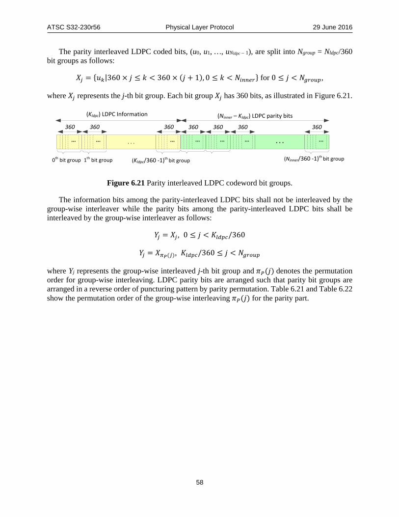
ATSC S32-230r56 Physical Layer Protocol 29 June 2016
58
The parity interleaved LDPC coded bits, (u0, u1, …, uNldpc – 1), are split into Ngroup = Nldpc/360 bit groups as follows:
𝑋𝑋𝑗𝑗 = {𝑢𝑢𝑘𝑘|360 × 𝑗𝑗 ≤ 𝑘𝑘 < 360 × (𝑗𝑗 + 1), 0 ≤ 𝑘𝑘 < 𝑁𝑁𝑖𝑖𝑖𝑖𝑖𝑖𝑖𝑖𝑖𝑖} for 0 ≤ 𝑗𝑗 < 𝑁𝑁𝑔𝑔𝑖𝑖𝑜𝑜𝑜𝑜𝑙𝑙,
where 𝑋𝑋𝑗𝑗 represents the j-th bit group. Each bit group 𝑋𝑋𝑗𝑗 has 360 bits, as illustrated in Figure 6.21.
(Kldpc) LDPC Information (Ninner – Kldpc) LDPC parity bits
360 360 360 360
. . .... ... ... .... . .... ... ...
360 360 360
0th bit group 1th bit group (Kldpc/360 -1)th bit group (Ninner/360 -1)th bit group
Figure 6.21 Parity interleaved LDPC codeword bit groups.
The information bits among the parity-interleaved LDPC bits shall not be interleaved by the group-wise interleaver while the parity bits among the parity-interleaved LDPC bits shall be interleaved by the group-wise interleaver as follows:
𝑌𝑌𝑗𝑗 = 𝑋𝑋𝑗𝑗, 0 ≤ 𝑗𝑗 < 𝐾𝐾𝑙𝑙𝑙𝑙𝑙𝑙𝑙𝑙/360
𝑌𝑌𝑗𝑗 = 𝑋𝑋𝜋𝜋𝑃𝑃(𝑗𝑗), 𝐾𝐾𝑙𝑙𝑙𝑙𝑙𝑙𝑙𝑙/360 ≤ 𝑗𝑗 < 𝑁𝑁𝑔𝑔𝑖𝑖𝑜𝑜𝑜𝑜𝑙𝑙
where Yj represents the group-wise interleaved j-th bit group and 𝜋𝜋𝑃𝑃(𝑗𝑗) denotes the permutation order for group-wise interleaving. LDPC parity bits are arranged such that parity bit groups are arranged in a reverse order of puncturing pattern by parity permutation. Table 6.21 and Table 6.22 show the permutation order of the group-wise interleaving 𝜋𝜋𝑃𝑃(𝑗𝑗) for the parity part.

ATSC S32-230r56 Physical Layer Protocol 29 June 2016
59
Table 6.21 Group-wise Interleaving Pattern for all L1-Basic Modes, L1-Detail Modes 1 and 2
Signaling FEC Type
Ngroup Order of Group-Wise Interleaving 𝝅𝝅𝑷𝑷(𝒋𝒋) (𝟗𝟗 ≤ 𝒋𝒋 < 𝟒𝟒𝟓𝟓)
πp(9) πp(10) πp(11) πp(12) πp(13) πp(14) πp(15) πp(16) πp(17) πp(18) πp(19) πp(20) πp(21) πp(22) πp(23) πp(24) πp(25) πp(26) πp(27) πp(28) πp(29) πp(30) πp(31) πp(32) πp(33) πp(34) πp(35) πp(36) πp(37) πp(38) πp(39) πp(40) πp(41) πp(42) πp(43) πp(44)
L1-Basic (all modes)
45
20 23 25 32 38 41 18 9 10 11 31 24 14 15 26 40 33 19 28 34 16 39 27 30 21 44 43 35 42 36 12 13 29 22 37 17
L1-Detail Mode 1
16 22 27 30 37 44 20 23 25 32 38 41 9 10 17 18 21 33 35 14 28 12 15 19 11 24 29 34 36 13 40 43 31 26 39 42
L1-Detail Mode 2
9 31 23 10 11 25 43 29 36 16 27 34 26 18 37 15 13 17 35 21 20 24 44 12 22 40 19 32 38 41 30 33 14 28 39 42
Table 6.22 Group-wise Interleaving Pattern for L1-Detail Modes 3, 4, 5, 6 and 7 Signaling FEC Type
Ngroup Order of Group-Wise Interleaving 𝝅𝝅𝑷𝑷(𝒋𝒋) (𝟏𝟏𝟖𝟖 ≤ 𝒋𝒋 < 𝟒𝟒𝟓𝟓)
πp(18) πp(19) πp(20) πp(21) πp(22) πp(23) πp(24) πp(25) πp(26) πp(27) πp(28) πp(29) πp(30) πp(31) πp(32) πp(33) πp(34) πp(35) πp(36) πp(37) πp(38) πp(39) πp(40) πp(41) πp(42) πp(43) πp(44)
L1-Detail Mode 3
45
19 37 30 42 23 44 27 40 21 34 25 32 29 24 26 35 39 20 18 43 31 36 38 22 33 28 41
L1-Detail Mode 4
20 35 42 39 26 23 30 18 28 37 32 27 44 43 41 40 38 36 34 33 31 29 25 24 22 21 19
L1-Detail Mode 5
19 37 33 26 40 43 22 29 24 35 44 31 27 20 21 39 25 42 34 18 32 38 23 30 28 36 41
L1-Detail Mode 6
20 35 42 39 26 23 30 18 28 37 32 27 44 43 41 40 38 36 34 33 31 29 25 24 22 21 19
L1-Detail Mode 7
44 23 29 33 24 28 21 27 42 18 22 31 32 37 43 30 25 35 20 34 39 36 19 41 40 26 38
6.5.2.7 Repetition For L1-Basic Mode 1 and L1-Detail Mode 1 only, additional 𝑁𝑁𝑖𝑖𝑖𝑖𝑙𝑙𝑖𝑖𝑝𝑝𝑜𝑜 bits shall be selected from within the encoded LDPC codeword and transmitted. Repetition shall not be performed for any other modes.
The repetition procedure is as follows:
Step 1) For a given 𝑁𝑁𝑜𝑜𝑜𝑜𝑜𝑜𝑖𝑖𝑖𝑖, the number of parity bits to be additionally transmitted per LDPC codeword, 𝑁𝑁𝑖𝑖𝑖𝑖𝑙𝑙𝑖𝑖𝑝𝑝𝑜𝑜, shall be calculated by multiplying Nouter by a fixed number C and adding an even integer D. The values of C and D shall be selected according to Table 6.23.
𝑁𝑁𝑖𝑖𝑖𝑖𝑙𝑙𝑖𝑖𝑝𝑝𝑜𝑜 = 2 × ⌊𝐶𝐶 × 𝑁𝑁𝑜𝑜𝑜𝑜𝑜𝑜𝑖𝑖𝑖𝑖⌋ + 𝐷𝐷.

ATSC S32-230r56 Physical Layer Protocol 29 June 2016
60
Table 6.23 Parameters for Repetition Nouter Ksig Kldpc C D Nldpc_parity
(= Ninner – Kldpc) 𝜼𝜼𝑴𝑴𝑴𝑴𝑴𝑴
L1-Basic Mode 1 368 200 3240 0 +3672 12960 2 L1-Detail Mode 1 368 ~ 2520 200 ~ 2352 3240 61/16 – 508 12960 2
Step 2) If 𝑁𝑁𝑖𝑖𝑖𝑖𝑙𝑙𝑖𝑖𝑝𝑝𝑜𝑜 ≤ 𝑁𝑁𝑙𝑙𝑙𝑙𝑙𝑙𝑙𝑙_𝑙𝑙𝑝𝑝𝑖𝑖𝑖𝑖𝑜𝑜𝑝𝑝 , the first 𝑁𝑁𝑖𝑖𝑖𝑖𝑙𝑙𝑖𝑖𝑝𝑝𝑜𝑜 bits of the LDPC parity with parity permutation shall be appended to the LDPC information bits, as shown in Figure 6.22.
(Nrepeat )
(Kldpc) Information (Nldpc_parity) parity bits
. . .... ... ... .... . .
. . .... ... ... .... . .
Repeat
Figure 6.22 Parity Repetition (𝑵𝑵𝑵𝑵𝑵𝑵𝑵𝑵𝑵𝑵𝑵𝑵𝑵𝑵 ≤ 𝑵𝑵𝑵𝑵𝑵𝑵𝑵𝑵𝑵𝑵_𝑵𝑵𝑵𝑵𝑵𝑵𝒑𝒑𝑵𝑵𝒑𝒑).
If 𝑁𝑁𝑖𝑖𝑖𝑖𝑙𝑙𝑖𝑖𝑝𝑝𝑜𝑜 > 𝑁𝑁𝑙𝑙𝑙𝑙𝑙𝑙𝑙𝑙_𝑙𝑙𝑝𝑝𝑖𝑖𝑖𝑖𝑜𝑜𝑝𝑝 , the 𝑁𝑁𝑙𝑙𝑙𝑙𝑙𝑙𝑙𝑙_𝑙𝑙𝑝𝑝𝑖𝑖𝑖𝑖𝑜𝑜𝑝𝑝 bits of the LDPC parity with parity permutation shall be appended to the LDPC information bits and the first (𝑁𝑁𝑖𝑖𝑖𝑖𝑙𝑙𝑖𝑖𝑝𝑝𝑜𝑜 − 𝑁𝑁𝑙𝑙𝑙𝑙𝑙𝑙𝑙𝑙_𝑙𝑙𝑝𝑝𝑖𝑖𝑖𝑖𝑜𝑜𝑝𝑝) bits of the LDPC parity with parity permutation shall be additionally appended to the first appended 𝑁𝑁𝑙𝑙𝑙𝑙𝑙𝑙𝑙𝑙_𝑙𝑙𝑝𝑝𝑖𝑖𝑖𝑖𝑜𝑜𝑝𝑝 bits, as shown in Figure 6.23.
Nldpc_parity
(Kldpc) Information (Nldpc_parity) parity bits
. . .... ... ... .... . .
. . .... ... ... .... . .
(Nrepeat – Nldpc_parity ) (Nldpc_parity) parity bits
Repeat
Figure 6.23 Parity Repetition (𝑵𝑵𝑵𝑵𝑵𝑵𝑵𝑵𝑵𝑵𝑵𝑵𝑵𝑵 > 𝑵𝑵𝑵𝑵𝑵𝑵𝑵𝑵𝑵𝑵_𝑵𝑵𝑵𝑵𝑵𝑵𝒑𝒑𝑵𝑵𝒑𝒑).
6.5.2.8 Parity Puncturing Some LDPC parity bits are punctured after parity permutation. These punctured bits are not transmitted in the frame carrying the L1 signaling bits.
For a given 𝑁𝑁𝑜𝑜𝑜𝑜𝑜𝑜𝑖𝑖𝑖𝑖, the number of parity bits to be punctured per LDPC codeword and the size of one coded block are determined as described in the following steps: Step 1)
𝑁𝑁𝑙𝑙𝑜𝑜𝑖𝑖𝑙𝑙_𝑜𝑜𝑖𝑖𝑚𝑚𝑙𝑙 = �𝐴𝐴 × �𝐾𝐾𝑙𝑙𝑙𝑙𝑙𝑙𝑙𝑙 − 𝑁𝑁𝑜𝑜𝑜𝑜𝑜𝑜𝑖𝑖𝑖𝑖�� + 𝐵𝐵
Depending on the Mode, the temporary size of puncturing bits shall be calculated by multiplying the shortening length by a ratio of the number of bits to be punctured to the number

ATSC S32-230r56 Physical Layer Protocol 29 June 2016
61
of bits to be shortened, A, and adding a constant integer B. 𝐾𝐾𝑙𝑙𝑙𝑙𝑙𝑙𝑙𝑙 , A and B shall be selected according to Table 6.24.
Table 6.24 Parameters for Puncturing
Signaling FEC Type Nouter Kldpc A B Nldpc_parity 𝜼𝜼𝑴𝑴𝑴𝑴𝑴𝑴
L1-Basic
Mode 1
368 3240
0
9360
12960
2 Mode 2 11460 2 Mode 3 12360 2 Mode 4 12292 4 Mode 5 12350 6 Mode 6 12432 8 Mode 7 12776 8
L1-Detail
Mode 1 368 ~ 2520 7/2 0 2 Mode 2 368 ~ 3240 2 6036 2 Mode 3
368 ~ 6480 6480
11/16 4653
9720
2 Mode 4 29/32 3200 4 Mode 5 3/4 4284 6 Mode 6 11/16 4900 8 Mode 7 49/256 8246 8
Step 2)
𝑁𝑁𝐹𝐹𝐹𝐹𝐹𝐹_𝑜𝑜𝑖𝑖𝑚𝑚𝑙𝑙 = 𝑁𝑁𝑜𝑜𝑜𝑜𝑜𝑜𝑖𝑖𝑖𝑖 + 𝑁𝑁𝑙𝑙𝑙𝑙𝑙𝑙𝑙𝑙_𝑙𝑙𝑝𝑝𝑖𝑖𝑖𝑖𝑜𝑜𝑝𝑝 − 𝑁𝑁𝑙𝑙𝑜𝑜𝑖𝑖𝑙𝑙_𝑜𝑜𝑖𝑖𝑚𝑚𝑙𝑙
where the number of LDPC parity bits, 𝑁𝑁𝑙𝑙𝑙𝑙𝑙𝑙𝑙𝑙_𝑙𝑙𝑝𝑝𝑖𝑖𝑖𝑖𝑜𝑜𝑝𝑝 shall be selected according to Table 6.24.
Step 3)
𝑁𝑁𝐹𝐹𝐹𝐹𝐹𝐹 = �𝑁𝑁𝐹𝐹𝐹𝐹𝐹𝐹_𝑜𝑜𝑜𝑜𝑡𝑡𝑙𝑙
𝜂𝜂𝑀𝑀𝑀𝑀𝑀𝑀� × 𝜂𝜂𝑀𝑀𝑀𝑀𝑀𝑀,
where 𝜂𝜂𝑀𝑀𝑀𝑀𝑀𝑀 denotes the modulation order, which is defined in Table 6.24. 𝑁𝑁𝐹𝐹𝐹𝐹𝐹𝐹 is an integer multiple of the modulation order. Step 4)
𝑁𝑁𝑙𝑙𝑜𝑜𝑖𝑖𝑙𝑙 = 𝑁𝑁𝑙𝑙𝑜𝑜𝑖𝑖𝑙𝑙_𝑜𝑜𝑖𝑖𝑚𝑚𝑙𝑙 − (𝑁𝑁𝐹𝐹𝐹𝐹𝐹𝐹 − 𝑁𝑁𝐹𝐹𝐹𝐹𝐹𝐹_𝑜𝑜𝑖𝑖𝑚𝑚𝑙𝑙)
where 𝑁𝑁𝐹𝐹𝐹𝐹𝐹𝐹 denotes the total number of encoded bits by BCH and LDPC for each information block.
The last 𝑁𝑁𝑙𝑙𝑜𝑜𝑖𝑖𝑙𝑙 bits of the whole LDPC codeword with parity permutation and repetition shall be punctured as shown in Figure 6.24 and Figure 6.25 when 𝑁𝑁𝑙𝑙𝑜𝑜𝑖𝑖𝑙𝑙 is a positive integer. Note that the repetition is applied only for L1-Basic Mode 1 and L1-Detail Mode 1.

ATSC S32-230r56 Physical Layer Protocol 29 June 2016
62
(Nrepeat )
(Kldpc) Information (Nldpc_parity) parity bits
. . .... ... ... .... . .
(Nldpc_parity + Nrepeat – Npunc) parity bits
. . .... ... ... .... . .
. . .... ... ... .... . .
Repeat
Puncturing
(Npunc ) Figure 6.24 Example 1 of parity puncturing after repetition.
Nldpc_parity
(Kldpc) Information (Nldpc_parity) parity bits
. . .... ... ... .... . .
(Nrepeat) (Nldpc_parity + Nrepeat – Npunc) parity bits
. . .... ... ... .... . .
. . .... ... ... .... . .
Puncturing
(Npunc )
(Nrepeat – Nldpc_parity ) (Nldpc_parity) parity bits
Repeat
Figure 6.25 Example 2 of parity puncturing after repetition.
6.5.2.9 Zero Removal The (Kldpc – Nouter) zero padding bits shall be removed and shall not be transmitted. This leaves a word consisting of the Ksig information bits, followed by the 168 BCH parity bits and (Ninner – Kldpc – Npunc) or (Ninner – Kldpc – Npunc + Nrepeat) parity bits, as illustrated in Figure 6.26. Note that the length of the whole LDPC codeword with repetition is (NFEC + Nrepeat).
L1 signaling information for transmission
zero-padded bits
0th 1st 2nd 3th 5th 6th 7th4th 8th
BC
HFEC
2nd0th 3th 6th
BC
HFEC
Figure 6.26 Example of removal of zero-padding bits.

ATSC S32-230r56 Physical Layer Protocol 29 June 2016
63
6.5.2.10 Bit Demuxing Following zero padded bit removal, the remaining bits of length NFEC or (NFEC + Nrepeat) shall be written serially into the Block Interleaver column-wise, where the number of columns shall be the same as the modulation order.
In the read operation, the bits for one constellation symbol shall be read out sequentially row-wise and fed into the bit demultiplexer block. These operations shall continue until the end of the column. Figure 6.27 shows the block interleaving process.
1 2
write
read
….
….
Figure 6.27 Block interleaving scheme.
Each block interleaved group is demultiplexed bit-by-bit in a group before constellation mapping. Depending on modulation order, there are two mapping rules. In the case of QPSK, the reliability of bits in a symbol is equal. Therefore, a bit group read out from the Block Interleaver shall be mapped directly to a QAM symbol without any intervening operation. In the cases of higher order modulations a bit group shall be mapped to a QAM symbol with the rule described as follows:
)1)%ηη((ib1)(ηc),...,1)%η((ib(1)c),(i%ηb(0)c
1)},(ηc(2),...,c(1),c(0),{c(i)S
1)},(ηb(2),...,b(1),b(0),{b(i)S
MODMODiMODiMODiiMODii
MODiiiidemux_out
MODiiiidemux_in
−+=−+==
−=
−=
where i is the bit group index corresponding to the row index in block interleaving, i.e. output bit group Sdemux_out(i) to map each QAM symbol is cyclically shifted from Sdemux_in(i) according to bit group index i.
a) block interleaving output
b) Bit demuxoutput
b0(0) b0(1) b0(2) b0(3) b1(0) b1(1) b1(2) b1(3)
c0(0) c0(1) c0(2) c0(3)
b2(0) b2(1) b2(2) b2(3)
s demux_out(0)
……
c2(0) c2(1) c2(2) c2(3)c1(0) c1(1) c1(2) c1(3)
s demux_out(1) s demux_out(2)
s demux_in(0) s demux_in(1) s demux_in(2)
Figure 6.28 Example of bit demultiplexing rule for 16-NUC.

ATSC S32-230r56 Physical Layer Protocol 29 June 2016
64
Figure 6.28 shows an example of the bit demultiplexing rule for 16-NUC. This operation continues until all bit groups have been read from the Block Interleaver.
6.5.2.11 Constellation Mapping Each demultiplexed LDPC block shall be mapped onto constellation symbols. According to the Mode 𝑁𝑁𝑙𝑙𝑖𝑖𝑚𝑚𝑜𝑜𝑑𝑑_𝑜𝑜𝑜𝑜𝑜𝑜𝑙𝑙𝑜𝑜𝑜𝑜(𝑖𝑖) shall be mapped to cells using constellations as described in Section 6.3. 6.5.3 L1-Detail Specific Block Details The following subsections refer to blocks that only occur in the encoding of L1-Detail information. 6.5.3.1 Segmentation The amount of L1-Detail signaling information bits is variable and depends mainly on the number of subframes and the number of PLPs. Therefore, one or more FEC Frames may be required for transmission of the total amount of signaling. The number of FEC Frames for the L1-Detail signaling, NL1D_FECFRAME, shall be determined as follows:
𝑁𝑁𝐿𝐿1𝑀𝑀_𝐹𝐹𝐹𝐹𝐹𝐹𝐹𝐹𝐹𝐹𝐹𝐹𝑀𝑀𝐹𝐹 = �𝐾𝐾𝐿𝐿1𝑀𝑀_𝑖𝑖𝑑𝑑_𝑙𝑙𝑝𝑝𝑙𝑙
𝐾𝐾𝑠𝑠𝑖𝑖𝑔𝑔�
where x means the smallest integer larger than or equal to x, Kseg for each L1-Detail Mode is defined in Table 6.25 and KL1D_ex_pad shall be determined by the value of the field L1B_L1_Detail_size_bytes in L1-Basic signaling, which denotes the length of the L1-Detail signaling (excluding L1 Padding bits), as described in Figure 6.29.
Kseg is a threshold number defined for segmentation based on the number of LDPC encoder input information bits (Kldpc). Kseg causes the number of information bits in a coded block after the segmentation (Ksig) to be less than or equal to (Kldpc – Mouter). Here, Kldpc and Mouter are given in Table 6.18 and Table 6.19 in Sections 6.5.2.3 and 6.5.2.4, respectively. Note that the value of Kseg for L1-Detail Mode 1 is set to (Kldpc – Mouter – 720) to provide sufficient robustness.
Table 6.25 Kseg for L1-Detail Signaling L1-Detail Kseg Mode 1 2352 Mode 2 3072 Mode 3
6312 Mode 4 Mode 5 Mode 6 Mode 7
The length of the L1_PADDING field for the L1-Detail signaling, KL1D_PAD, shall be calculated as follows:
𝐾𝐾𝐿𝐿1𝑀𝑀_𝑃𝑃𝐹𝐹𝑀𝑀 = �𝐾𝐾𝐿𝐿1𝑀𝑀_𝑖𝑖𝑑𝑑_𝑙𝑙𝑝𝑝𝑙𝑙
𝑁𝑁𝐿𝐿1𝑀𝑀_𝐹𝐹𝐹𝐹𝐹𝐹𝐹𝐹𝐹𝐹𝐹𝐹𝑀𝑀𝐹𝐹 × 8� × 8 × 𝑁𝑁𝐿𝐿1𝑀𝑀_𝐹𝐹𝐹𝐹𝐹𝐹𝐹𝐹𝐹𝐹𝐹𝐹𝑀𝑀𝐹𝐹 − 𝐾𝐾𝐿𝐿1𝑀𝑀_𝑖𝑖𝑑𝑑_𝑙𝑙𝑝𝑝𝑙𝑙 .
The L1_PADDING parts are filled with KL1D_PAD zeros, as shown in Figure 6.29. The final length of the whole L1-Detail signaling including the zero-padding bits, KL1D shall be set as follows:

ATSC S32-230r56 Physical Layer Protocol 29 June 2016
65
𝐾𝐾𝐿𝐿1𝑀𝑀 = 𝐾𝐾𝐿𝐿1𝑀𝑀_𝑖𝑖𝑑𝑑_𝑙𝑙𝑝𝑝𝑙𝑙 + 𝐾𝐾𝐿𝐿1𝑀𝑀_𝑃𝑃𝐹𝐹𝑀𝑀.
The number of information bits in each of NL1D _FECFRAME blocks, Ksig shall then be given by:
𝐾𝐾𝑠𝑠𝑖𝑖𝑔𝑔 =𝐾𝐾𝐿𝐿1𝑀𝑀
𝑁𝑁𝐿𝐿1𝑀𝑀_𝐹𝐹𝐹𝐹𝐹𝐹𝐹𝐹𝐹𝐹𝐹𝐹𝑀𝑀𝐹𝐹.
The L1-Detail signaling shall be segmented into NL1D_FECFRAME blocks when NL1D_FECFRAME is larger than 1, as illustrated in Figure 6.29
L1-Basic L1-Detail
L1-Detail 0L1
Padding
L1D_1
L1Padding
. . .
KL1D_ex_pad(L1B_L1_Detail_size_bits)
Ksig Ksig
Information bitsin first coded block
Information bitsin second coded block
Information bitsin NL1D_FECFRAME coded block
L1D_2
Ksig
L1D_N
Figure 6.29 Segmentation of L1-Detail signaling.
Each segmented L1-Detail block shall be protected according to the procedures described in Section 6.5.2. All of the bits of each L1-Detail block with information size of Ksig shall be scrambled according to Section 6.5.2.2. Each scrambled L1-Detail signaling block shall then be protected by a concatenation of a BCH Outer Code and an LDPC Inner Code. Each L1-Detail signaling block shall be first BCH-encoded, where Mouter (= 168) BCH parity-check bits are appended to Ksig information bits of each block. The resulting concatenation of the information bits of each block and the BCH parity bits shall then be protected by a shortened and punctured 16K LDPC code, as described in Sections 6.5.2.8 and 6.5.2.9. When required, repetition shall be applied before puncturing, as described in Section 6.5.2.7. 6.5.3.2 Additional Parity To increase further the robustness of the L1-Detail signaling, additional parity bits for the L1-Detail signaling of the frame #(i) may be transmitted in the closest (in time) previous frame #(i-1) that has the same bootstrap major/minor version as does the frame #(i). Figure 6.30 shows how additional parity bits for L1-Detail in frame #(i) shall be transmitted in the Preamble of frame #(i-1).
The use of additional parity bits for L1-Detail of frame #(i) with the same major/minor bootstrap version is signaled with L1B_L1_Detail_additional_parity_mode in the frame #(i-1). When L1B_L1_Detail_additional_parity_mode is set to ‘00’ in frame #(i-1), additional parity for L1-Detail signaling of the frame #(i) shall not be transmitted in frame #(i-1).

ATSC S32-230r56 Physical Layer Protocol 29 June 2016
66
...
L1-Detail (i-1) PLPs (DATA)
L1-Detail (i) PLPs (DATA)
L1-D(i-1)_1 Parity for L1-D(i-1)_1
AP for L1-D(i)_1
Frame # (i-1)
Frame # (i)
L1-Basic (i-1)
L1-Basic (i)
preamble
L1-D(i-1)_2 Parity for L1-D(i-1)_2 L1-D(i-1)_N Parity for
L1-D(i-1)_N... AP for L1-D(i)_M...
L1-D(i)_1 Parity for L1-D(i)_1
AP for L1-D(i+1)_1
Parity for L1-D(i)_M
AP for L1-D(i+1)_P...L1-D(i)_M
...L1B_L1_Detail_additional_parity_modeL1B_L1_Detail_total_cells...
L1-Basic (i)
Additional Parity
L1-Detail codewords in current frame #(i-1) Additional Parity for L1-Detail in next frame #(i)
Additional Parity for L1-Detail in next frame #(i+1)
L1-Detail codewords in current frame #(i)
MODCODL1-D(i)_1
MODCODL1-D(i)_2
MODCODL1-D(i)_M... MOD AP
L1-D(i+1)_1MOD AP
L1-D(i+1)_P...
L1B_L1_Detail_total_cells
Additional Parity for L1-Detail (i)
Additional Parity for L1-Detail (i+1)
Figure 6.30 Additional parity for L1-Detail signaling.
The result of using additional parity is diversity gain for the L1 signaling. When the number of punctured bits is larger than the number of additional parity bits, additional parity bits shall be generated by selecting the bits among punctured bits based on puncturing order. Otherwise, additional parity bits shall be generated by selecting all punctured bits and then selecting (NAP − Npunc) parity bits.
. . .... ... ... ...v0
(Nldpc_parity ) parity bits(Nrepeat ) (Kldpc)
vKldpc -1 vKldpc vKldpc+Nrepeat-1 vKldpc+Nrepeat vKldpc+Nrepeat-1
LDPC information Repeated Parity bits LDPC Parity bits Figure 6.31 Repeated LDPC codeword.
The number of additional parity bits shall be decided from the total number of transmitted bits in the current frame. Based on the repeated LDPC codeword denoted by V = (v0, v1, … , vNinner+Nrepeat-1) as shown in Figure 6.31, additional parity bits shall be generated by the following operations: Step 1) Compute the temporary number of additional parity bits such that
𝑁𝑁𝐹𝐹𝑃𝑃_𝑜𝑜𝑖𝑖𝑚𝑚𝑙𝑙 = min �0.5 × 𝐾𝐾 × �𝑁𝑁𝑜𝑜𝑜𝑜𝑜𝑜𝑖𝑖𝑖𝑖 + 𝑁𝑁𝑙𝑙𝑙𝑙𝑙𝑙𝑙𝑙_𝑙𝑙𝑝𝑝𝑖𝑖𝑖𝑖𝑜𝑜𝑝𝑝 − 𝑁𝑁𝑙𝑙𝑜𝑜𝑖𝑖𝑙𝑙 + 𝑁𝑁𝑖𝑖𝑖𝑖𝑙𝑙𝑖𝑖𝑝𝑝𝑜𝑜�,
�𝑁𝑁𝑙𝑙𝑙𝑙𝑙𝑙𝑙𝑙_𝑙𝑙𝑝𝑝𝑖𝑖𝑖𝑖𝑜𝑜𝑝𝑝 + 𝑁𝑁𝑙𝑙𝑜𝑜𝑖𝑖𝑙𝑙 + 𝑁𝑁𝑖𝑖𝑖𝑖𝑙𝑙𝑖𝑖𝑝𝑝𝑜𝑜��, K=0,1,2
where K corresponds to the field L1B_L1_Detail_additional_parity_mode in L1-Basic and where the operation

ATSC S32-230r56 Physical Layer Protocol 29 June 2016
67
min(a,b) = �𝑀𝑀, 𝑖𝑖𝑖𝑖 𝑀𝑀 ≤ 𝑏𝑏𝑏𝑏, 𝑖𝑖𝑖𝑖 𝑏𝑏 < 𝑀𝑀.
L1B_L1_Detail_additional_parity_mode is the ratio of the number of additional parity bits to half of the total number of bits in the transmitted coded L1-Detail signaling block, which is the L1-Detail signaling block following repetition, puncturing and zero-removal. Note that the value of L1B_L1_Detail_additional_parity_mode related to the L1-Detail of frame (#i) is carried in frame (#i-1); that is, the previous frame. Step 2) Derive the number of additional parity bits as the following integer multiple of the
modulation order:
𝑁𝑁𝐹𝐹𝑃𝑃 = �𝑁𝑁𝐹𝐹𝑃𝑃_𝑜𝑜𝑖𝑖𝑚𝑚𝑙𝑙
𝜂𝜂𝑀𝑀𝑀𝑀𝑀𝑀� × 𝜂𝜂𝑀𝑀𝑀𝑀𝑀𝑀
where the operation ⌊𝑀𝑀⌋ means the largest integer less than or equal to x and 𝜂𝜂𝑀𝑀𝑀𝑀𝑀𝑀 denotes the modulation order taking the value 2, 4, 6, and 8 for QPSK, 16-NUC, 64-NUC and 256-NUC, respectively.
Step 3) If NAP ≤ Npunc, then punctured parity bits
�𝑣𝑣𝑁𝑁𝑜𝑜𝑜𝑜𝑙𝑙𝑜𝑜𝑝𝑝𝑜𝑜+𝑁𝑁𝑖𝑖𝑖𝑖𝑖𝑖𝑜𝑜𝑜𝑜−𝑁𝑁𝑙𝑙𝑜𝑜𝑖𝑖𝑙𝑙 ,𝑣𝑣𝑁𝑁𝑜𝑜𝑜𝑜𝑙𝑙𝑜𝑜𝑝𝑝𝑜𝑜+𝑁𝑁𝑖𝑖𝑖𝑖𝑖𝑖𝑜𝑜𝑜𝑜−𝑁𝑁𝑙𝑙𝑜𝑜𝑖𝑖𝑙𝑙+1,⋯ , 𝑣𝑣𝑁𝑁𝑜𝑜𝑜𝑜𝑙𝑙𝑜𝑜𝑝𝑝𝑜𝑜+𝑁𝑁𝑖𝑖𝑖𝑖𝑖𝑖𝑜𝑜𝑜𝑜−𝑁𝑁𝑙𝑙𝑜𝑜𝑖𝑖𝑙𝑙+𝑁𝑁𝐴𝐴𝑃𝑃−1�
shall be selected for additional parity as shown in Figure 6.32.
(Nrepeat )
(Klppc )Information (Nldpc_parity) parity bits
. . .... ... ... .... . .
(Nldpc_parity + Nrepeat – Npunc)
. . .... ......
.... . .
. . .... ... ... .... . .
Repeat
Punctured Bits
(Npunc )
(Nldpc_parity + Nrepeat – Npunc)
... .... . .
Transmitted in frame #(i-1)Transmitted in frame #(i)
(NAP ) Additional parity bits
Figure 6.32 Additional parity generation for L1-Detail signaling (NAP ≤Npunc).

ATSC S32-230r56 Physical Layer Protocol 29 June 2016
68
Otherwise (NAP > Npunc); therefore all punctured parity bits
�𝑣𝑣𝑁𝑁𝑜𝑜𝑜𝑜𝑙𝑙𝑜𝑜𝑝𝑝𝑜𝑜+𝑁𝑁𝑖𝑖𝑖𝑖𝑖𝑖𝑜𝑜𝑜𝑜−𝑁𝑁𝑙𝑙𝑜𝑜𝑖𝑖𝑙𝑙 , 𝑣𝑣𝑁𝑁𝑜𝑜𝑜𝑜𝑙𝑙𝑜𝑜𝑝𝑝𝑜𝑜+𝑁𝑁𝑖𝑖𝑖𝑖𝑖𝑖𝑜𝑜𝑜𝑜−𝑁𝑁𝑙𝑙𝑜𝑜𝑖𝑖𝑙𝑙+1,⋯ , 𝑣𝑣𝑁𝑁𝑜𝑜𝑜𝑜𝑙𝑙𝑜𝑜𝑝𝑝𝑜𝑜+𝑁𝑁𝑖𝑖𝑖𝑖𝑖𝑖𝑜𝑜𝑜𝑜−1� shall be selected, and additionally, parity bits (𝑣𝑣𝐾𝐾𝑙𝑙𝑙𝑙𝑙𝑙𝑙𝑙 ,𝑣𝑣𝐾𝐾𝑙𝑙𝑙𝑙𝑙𝑙𝑙𝑙+1,⋯ , 𝑣𝑣𝐾𝐾𝑙𝑙𝑙𝑙𝑙𝑙𝑙𝑙+𝑁𝑁𝐴𝐴𝑃𝑃−𝑁𝑁𝑙𝑙𝑜𝑜𝑖𝑖𝑙𝑙−1) shall be selected and appended to the punctured bits as shown in Figure 6.33.
(Nldpc_parity) parity bits
. . ....
...
...
.... . .
(Nldpc_parity + Nrepeat – Npunc)
. . ....
...
...
.... . .
. . ....
...
...
.... . .
Repeat
Punctured bits
(Npunc )
(Nldpc_parity) parity bits
Transmitted in frame #(i-1)
. . ....
...
.... . .
Transmitted in frame #(i)
(NAP ) Additional parity bits(Nldpc_parity + Nrepeat – Npunc)
(Klppc )Information
Figure 6.33 Additional parity generation for L1-Detail signaling (NAP >Npunc).
Note that the number of bits for repetition, Nrepeat, is 0 for L1-Detail Modes 2, 3, 4, 5, 6 and 7. The additional parity bits shall be bit interleaved and mapped onto constellations as described
in Sections 6.5.2.10 and 6.5.2.11, respectively. The constellations generated for the additional parity bits shall be generated in the same manner as for the repeated, punctured and zero-removed L1-Detail signaling bits that are transmitted in the current frame. After mapping onto constellations, the additional parity bits shall be appended to coded L1-Detail signaling blocks in the frame preceding the current frame carrying the L1-Detail signaling of current frame, as illustrated in Figure 6.30.
7. FRAMING AND INTERLEAVING The framing and interleaving block consists of three parts: time interleaving, framing and frequency interleaving. The input to the time interleaving and framing blocks consists of one or more PLPs, however the output of the framing block is OFDM symbols, either Preamble or Data, which are arranged in the order in which they appear in the final frame. The frequency interleaver operates on OFDM symbols. A block diagram of the framing and interleaving is shown in Figure 7.1.

ATSC S32-230r56 Physical Layer Protocol 29 June 2016
69
Framing and Interleaving
FrequencyInterleaving......
Cells for PLP0
Cells for PLP1
Cells for PLPn
Time Interleaving
FramingTime
Interleaving
Time Interleaving
FrequencyInterleaved
Symbols
Preamble,Data or
SubframeBoundarySymbols
Figure 7.1 Block diagram of framing and interleaving.
7.1 Time Interleaving The input to the time interleaving block is a stream of cells output from the mapper block, and the output of the time interleaving block is a stream of time-interleaved cells. 7.1.1 Time Interleaver Modes Each PLP is configured with one of the following time interleaver modes as applicable: no time interleaving, Convolutional Time Interleaver (CTI) mode (see Section 7.1.4), or Hybrid Time Interleaver (HTI) mode (see Section 7.1.5). The time interleaver mode for a PLP is indicated by the L1-Detail signalling field L1D_plp_TI_mode. The time interleaver mode indicated for an Enhanced PLP shall be the same as the time interleaver mode indicated for the Core PLP(s) with which the Enhanced PLP is layered division multiplexed.
When, as determined at the input to the time interleaver, a complete delivered product is composed of only a single constant-cell-rate PLP or is composed of a single constant-cell-rate Core PLP and one or more Enhanced PLPs layered division multiplexed with that Core PLP, the PLP(s) comprising that complete delivered product shall be configured with one of the following time interleaver modes: no time interleaving, CTI mode, or HTI mode.
When, as determined at the input to the time interleaver, a complete delivered product is composed of PLPs having characteristics different from those described in the preceding paragraph, the PLPs comprising that complete delivered product shall be configured with one of the following time interleaver modes: no time interleaving or HTI mode.
The time interleaver mode(s) for the PLPs of a particular complete delivered product shall be configured independently of the time interleaver mode(s) for the PLP(s) of any other delivered products transmitted within the same RF channel. When a particular delivered product contains multiple Core PLPs and/or PLPs that are not layered division multiplexed, those PLPs may be configured with the same or different time interleaver modes (i.e., no time interleaving and/or HTI mode) and/or the same or different time interleaver parameters.
When a particular complete delivered product contains multiple Core PLPs that are not layered-division multiplexed and all of those Core PLPs use the HTI mode, either all of those Core PLPs shall use intra-subframe interleaving or else all of those Core PLPs shall use inter-subframe interleaving (i.e., all of those Core PLPs shall be configured with the same value of L1D_plp_HTI_inter_subframe). When inter-subframe interleaving is used for those Core PLPs (i.e.,

ATSC S32-230r56 Physical Layer Protocol 29 June 2016
70
L1D_plp_HTI_inter_subframe = 1), then all of those Core PLPs shall use the same time interleaving unit (NIU).
When a particular complete delivered product contains multiple Core PLPs that are not layered-division multiplexed and at least one of those Core PLPs uses the no-TI mode, any of those Core PLPs configured with the HTI mode shall use the intra-subframe interleaving mode (i.e., L1D_plp_HTI_inter_subframe = 0).
When time interleaving is not configured for a PLP, that PLP’s cells shall be output in the same order as that in which they would have arrived at the input of the time interleaving function and without delay. 7.1.2 Time Interleaver Size The maximum size of the TI memory for a single, complete delivered product shall be MTI= 219 cells, except for extended interleaving mode, for which the maximum size of the TI memory for a single, complete delivered product shall be MTI= 220 cells. The TI memory size shall include all necessary parts, that is, the Convolutional Time Interleaver in CTI mode and the cell, block and delay line interleavers in HTI mode.
In the CTI mode the entire TI memory may be used by the PLP associated with the particular CTI, depending on the configured depth of the Convolutional Time Interleaver.
In the HTI mode, the total memory shall be shared between PLPs carrying components of the same complete delivered product. The memory allocated for each PLP shall be determined from the throughput for that PLP.
Note that receiver manufacturers can choose always to implement the TDI memory with MTI= 219 cells, irrespective of the extended time interleaving mode, by quantizing the received data entering the time deinterleaver with a different resolution depending on the robustness of the constellation, that is, lower resolution for QPSK and extended time interleaving, and higher resolution for all other combinations. 7.1.3 Extended Interleaving Extended interleaving mode may be optionally enabled in order to increase the time interleaving depth. Extended interleaving mode is signaled by L1D_plp_TI_extended_interleaving. Extended interleaving shall only be used when the modulation is QPSK. Extended interleaving shall not be used for LDM. In the CTI mode when extended interleaving is used, L1D_plp_CTI_depth=’101’ shall signal Nrows = 1254, and L1D_plp_CTI_depth=’110’ shall signal Nrows = 1448, corresponding to a time interleaving depth of approximately 300 ms, and 400 ms, respectively.
In the HTI mode when extended interleaving is used for a PLP, the maximum TI memory size is 220 cells and the maximum number of FEC Blocks per interleaving frame NBLOCKS_IF_MAX shall not exceed 517. In the HTI mode when extended interleaving is not used for a PLP, the maximum TI memory size is 219 cells and NBLOCKS_IF_MAX shall not exceed 258. Note that the extended time interleaving mode for HTI allows to approximately double the number of FEC Blocks per interleaving frame. 7.1.4 Convolutional Time Interleaver (CTI) Mode The time interleaving block for the CTI Mode is shown in Figure 7.2. It consists of a Convolutional Time Interleaver. The input and output of the time interleaving block is a sequence of cells.

ATSC S32-230r56 Physical Layer Protocol 29 June 2016
71
Time Interleaving (CTI Mode)
PLPn PLPnConvolutionalInterleaver
Figure 7.2 Block diagram for time interleaving for CTI Mode.
7.1.4.1 Convolutional Time Interleaver The Convolutional Time Interleaver is depicted in Figure 7.3.
0 1 2 3 Ncolumns-1
Figure 7.3 Block diagram of the Convolutional Time Interleaver.
The input to the Convolutional Time Interleaver block shall be a sequence of cells gq (where q = 0,1,…) from the mapper output. The CTI shall consist of Nrows delay lines, with the k-th line having k delay elements, k = 0, 1, …, Nrows-1. Each delay element shall be capable of storing one cell. The number of columns Ncolumns shall be Nrows – 1. Input and output shall be controlled by two commutators, cyclically switching downwards after one cell is written in or read out, respectively. For each cell gq, the commutators shall be located in the same position k. The resulting total number of delay elements is Nrows × Ncolumns / 2.
When the input commutator is located at position k, a cell gq shall be written to this delay line. First, each delay element from this line shall shift its memory content to the neighbouring right delay element, and the content from the right-most delay element shall be output via the output commutator. Next, the input cell gq shall be written to the left-most delay element of this line. Both commutators shall then move cyclically to the next line (k+1) mod Nrows.

ATSC S32-230r56 Physical Layer Protocol 29 June 2016
72
The structures for CTI Mode are defined in terms of the parameter Nrows, see Table 9.24 for details. The values Nrows ∈ {1024, 887, 724, 512} represent a time interleaving depth of approximately 200 ms, 150 ms, 100 ms and 50 ms, respectively, assuming the Core PLP occupies the full channel bandwidth. The depth of the Convolutional Time Interleaver, shall be indicated by the parameter L1D_plp_CTI_depth.
In contrast to HTI Mode, the CTI Mode TI outputs cells continuously and insertion of dummy modulation values to achieve an integer number of FEC Blocks per subframe is not required, thus reducing the overhead. The position of the interleaver selector at the start of each subframe shall be signaled by L1D_plp_CTI_start_row and the position of the start of the first complete FEC Block shall be signaled by L1D_plp_CTI_fec_block_start. 7.1.4.2 Initial State of the Delay Elements For CTI according to Section 7.1.4.1 both with and without extended interleaving according to Section 7.1.3, the initial contents of the delay elements shall be defined as follows:
Since the number of delay elements in the CTI is Nrows × Ncolumns / 2, a total number of ηMOD × Nrows × Ncolumns / 2 bits shall be generated using the same PRBS generator described in Section 5.2.3, starting from the initial state. ηMOD is the modulation order as defined in Table 6.14, and shall be used according to the chosen modulation of the Core PLP. These bits shall be mapped to QAM cells according to Section 6.3, forming a sequence of cells gq.
The delay elements shall be then filled by gq from left to right and from top to bottom. This means g0 shall be the initial state of the delay element in row k = 1, and g1 shall be the initial state of the left-most delay element in row k = 2, while g2 shall be the initial state of the second delay element in this row. In row k = 3, the three delay elements from left to right have initial states g3, g4, g5 and so on until the last of these cells forms the initial state of the right-most delay element of the last row, k = Nrows -1. 7.1.5 Hybrid Time Interleaver (HTI) Mode The time interleaving for the HTI mode is shown in Figure 7.4, and it consists of a Cell Interleaver, a Twisted Block Interleaver (TBI), and a Convolutional Delay Line (CDL). The input to the hybrid time interleaver is a sequence of cells from the mapper block, and the output is a sequence of time-interleaved cells.
The Cell Interleaver takes input cells in FEC Blocks and arranges them into TI Blocks. A TI Block consists of one or more FEC Blocks. The Cell Interleaver interleaves cells within each FEC Block. The use of the Cell Interleaver is optional and is indicated by the parameter L1D_plp_HTI_cell_interleaver.
Time Interleaving (HTI Mode)
PLPn PLPnCellInterleaver
Twisted Block Interleaver (TBI)
Convolutional Delay Line (CDL)
Figure 7.4 Block diagram for time interleaving for HTI mode.

ATSC S32-230r56 Physical Layer Protocol 29 June 2016
73
The Twisted Block Interleaver (TBI) performs intra-subframe interleaving by interleaving TI Blocks. A TI Block is composed of one or more cell-interleaved FEC Blocks (L1D_plp_HTI_cell_interleaver=1) or non-cell-interleaved FEC Blocks directly from the mapper block (L1D_plp_HTI_cell_interleaver=0).
After block interleaving, the Convolutional Delay Line optionally performs inter-subframe interleaving. When configured, it spreads a block-interleaved TI Block over several subframes. The use of the Convolutional Delay Line is signaled with the parameter L1D_plp_HTI_inter_subframe. 7.1.5.1 Relationship between IF and TI Blocks FEC Blocks from the mapper block shall be grouped into interleaving frames (IFs). Note that interleaving frames and physical layer frames (as specified in Section 7.2) are independent constructs. Each IF shall contain a dynamically variable whole number of FEC Blocks. The number of FEC Blocks in the IF of index 𝑛𝑛 is denoted by 𝑁𝑁𝐵𝐵𝐿𝐿𝑀𝑀𝐹𝐹𝐾𝐾𝑆𝑆_𝐼𝐼𝐹𝐹(𝑛𝑛). 𝑁𝑁𝐵𝐵𝐿𝐿𝑀𝑀𝐹𝐹𝐾𝐾𝑆𝑆_𝐼𝐼𝐹𝐹(𝑛𝑛) may vary from a minimum value of 1 to a maximum value 𝑁𝑁𝐵𝐵𝐿𝐿𝑀𝑀𝐹𝐹𝐾𝐾𝑆𝑆_𝐼𝐼𝐹𝐹_𝑀𝑀𝐹𝐹𝑀𝑀. Each IF is either mapped directly onto one subframe or spread out over multiple subframes. Each IF is also divided into one or more TI Blocks, where a TI Block is the basic unit to operate Cell Interleaver, Twisted Block Interleaver and convolutional interleaver. The number of TI Blocks in an interleaving frame, denoted by 𝑁𝑁𝑇𝑇𝐼𝐼, shall be an integer and is signaled by L1D_plp_HTI_num_ti_blocks in conjunction with L1D_plp_HTI_inter_subframe (i.e. L1D_plp_HTI_inter_subframe = 0). The TI Blocks within an IF may contain slightly different numbers of FEC Blocks. When an IF extends over multiple subframes (i.e. L1D_plp_HTI_inter_subframe = 1), then one IF contains exactly one TI Block and 𝑁𝑁𝑇𝑇𝐼𝐼 = 1. The number of FEC Blocks in a TI Block of index 𝑠𝑠 of an interleaving frame 𝑛𝑛 is denoted by 𝑁𝑁𝐹𝐹𝐹𝐹𝐹𝐹_𝑇𝑇𝐼𝐼(𝑛𝑛, 𝑠𝑠), where 0 ≤ 𝑠𝑠 < 𝑁𝑁𝑇𝑇𝐼𝐼.
When 𝑁𝑁𝑇𝑇𝐼𝐼 = 1 , then there will be only one TI Block, with index 𝑠𝑠 = 0 , per IF and 𝑁𝑁𝐹𝐹𝐹𝐹𝐹𝐹_𝑇𝑇𝐼𝐼(𝑛𝑛, 𝑠𝑠), shall be equal to the number of FEC Blocks in the IF, 𝑁𝑁𝐵𝐵𝐿𝐿𝑀𝑀𝐹𝐹𝐾𝐾𝑆𝑆_𝐼𝐼𝐹𝐹(𝑛𝑛).
When 𝑁𝑁𝑇𝑇𝐼𝐼 > 1, then the value of 𝑁𝑁𝐹𝐹𝐹𝐹𝐹𝐹_𝑇𝑇𝐼𝐼(𝑛𝑛, 𝑠𝑠) for each TI Block (index s) within the IF (index 𝑛𝑛) shall be calculated as follows:
𝑁𝑁𝐹𝐹𝐹𝐹𝐹𝐹_𝑇𝑇𝐼𝐼(𝑛𝑛, 𝑠𝑠) =
⎩⎪⎨
⎪⎧ �
𝑁𝑁𝐵𝐵𝐿𝐿𝑀𝑀𝐹𝐹𝐾𝐾𝑆𝑆_𝐼𝐼𝐹𝐹(𝑛𝑛)𝑁𝑁𝑇𝑇𝐼𝐼
� , 𝑠𝑠 < 𝑁𝑁𝑇𝑇𝐼𝐼 − [𝑁𝑁𝐵𝐵𝐿𝐿𝑀𝑀𝐹𝐹𝐾𝐾𝑆𝑆𝐼𝐼𝐹𝐹(𝑛𝑛) mod 𝑁𝑁𝑇𝑇𝐼𝐼]
�𝑁𝑁𝐵𝐵𝐿𝐿𝑀𝑀𝐹𝐹𝐾𝐾𝑆𝑆_𝐼𝐼𝐹𝐹(𝑛𝑛)
𝑁𝑁𝑇𝑇𝐼𝐼� + 1 , 𝑠𝑠 ≥ 𝑁𝑁𝑇𝑇𝐼𝐼 − [𝑁𝑁𝐵𝐵𝐿𝐿𝑀𝑀𝐹𝐹𝐾𝐾𝑆𝑆𝐼𝐼𝐹𝐹(𝑛𝑛) mod 𝑁𝑁𝑇𝑇𝐼𝐼]
This ensures that the values of 𝑁𝑁𝐹𝐹𝐹𝐹𝐹𝐹_𝑇𝑇𝐼𝐼(𝑛𝑛, 𝑠𝑠), for the TI Blocks within an IF differ by at most one FEC Block and that the smaller TI Blocks come first. The FEC Blocks at the input shall be assigned to TI Blocks in increasing order of s. 𝑁𝑁𝐹𝐹𝐹𝐹𝐹𝐹_𝑇𝑇𝐼𝐼(𝑛𝑛, 𝑠𝑠) may vary in time from a minimum value of 1 to a maximum value 𝑁𝑁𝐹𝐹𝐹𝐹𝐹𝐹_𝑇𝑇𝐼𝐼_𝑀𝑀𝐹𝐹𝑀𝑀 . 𝑁𝑁𝐹𝐹𝐹𝐹𝐹𝐹_𝑇𝑇𝐼𝐼_𝑀𝑀𝐹𝐹𝑀𝑀 can be determined from 𝑁𝑁𝐵𝐵𝐿𝐿𝑀𝑀𝐹𝐹𝐾𝐾𝑆𝑆_𝐼𝐼𝐹𝐹_𝑀𝑀𝐹𝐹𝑀𝑀 by the following formula:
𝑁𝑁𝐹𝐹𝐹𝐹𝐹𝐹_𝑇𝑇𝐼𝐼_𝑀𝑀𝐹𝐹𝑀𝑀 = �𝑁𝑁𝐵𝐵𝐿𝐿𝑀𝑀𝐹𝐹𝐾𝐾𝑆𝑆_𝐼𝐼𝐹𝐹_𝑀𝑀𝐹𝐹𝑀𝑀
𝑁𝑁𝑇𝑇𝐼𝐼�.
Note that 𝑁𝑁𝐵𝐵𝐿𝐿𝑀𝑀𝐹𝐹𝐾𝐾𝑆𝑆_𝐼𝐼𝐹𝐹(𝑛𝑛) is signaled as L1D_plp_HTI_num_fec_blocks and 𝑁𝑁𝐵𝐵𝐿𝐿𝑀𝑀𝐹𝐹𝐾𝐾𝑆𝑆_𝐼𝐼𝐹𝐹_𝑀𝑀𝐹𝐹𝑀𝑀 is signaled as L1D_plp_HTI_num_fec_blocks_max.

ATSC S32-230r56 Physical Layer Protocol 29 June 2016
74
7.1.5.2 Cell Interleaver The input to the Cell Interleaver is a sequence of cells 𝐺𝐺(𝑟𝑟) = (𝑔𝑔𝑖𝑖,0,𝑔𝑔𝑖𝑖,1,𝑔𝑔𝑖𝑖,2,⋯ ,𝑔𝑔𝑖𝑖,𝑁𝑁𝑙𝑙𝑖𝑖𝑙𝑙𝑙𝑙𝑠𝑠−1), arranged in FEC Blocks, where 𝑟𝑟 represents the incremental index of a FEC Block within a TI Block and shall be reset to zero at the beginning of each TI Block. 𝑁𝑁𝑙𝑙𝑖𝑖𝑙𝑙𝑙𝑙𝑠𝑠 indicates the FEC Block length and is determined by 𝑁𝑁𝑙𝑙𝑙𝑙𝑙𝑙𝑙𝑙/𝜂𝜂𝑀𝑀𝑀𝑀𝑀𝑀 (see Table 6.14).
Figure 7.5 shows the cell interleaving operation; cell interleaving shall be accomplished by writing a FEC Block into memory and reading the FEC Block pseudo-randomly according to the method described below. The permutation sequence varies every FEC Block within a TI Block. Each permutation sequence shall be determined by shifting one pseudo random sequence differently.
FEC BlockIndex (r) 0
1234
...
01234
... ...
...
...
01234
...01234
... ...
...
...
TI Block
... ...
(a) (b)
Figure 7.5 Block diagram of the Cell Interleaver: (a) Linear writing operation, (b) Pseudo-random reading operation.
From Figure 7.5 the output of the Cell Interleaver shall be a vector 𝐷𝐷(𝑟𝑟) =(𝑑𝑑𝑖𝑖,0,𝑑𝑑𝑖𝑖,1,𝑑𝑑𝑖𝑖,2,⋯ ,𝑑𝑑𝑖𝑖,𝑁𝑁𝑙𝑙𝑖𝑖𝑙𝑙𝑙𝑙𝑠𝑠−1) with 𝑑𝑑𝑖𝑖,𝑞𝑞, defined by
𝑑𝑑𝑖𝑖,𝑞𝑞 = 𝑔𝑔𝑖𝑖,𝐿𝐿𝑜𝑜(𝑞𝑞) for each 𝑞𝑞 = 0,1,⋯ ,𝑁𝑁𝑙𝑙𝑖𝑖𝑙𝑙𝑙𝑙𝑠𝑠 − 1,
𝐿𝐿𝑖𝑖(𝑞𝑞) is a permutation function applied to the 𝑟𝑟-th FEC Block of the TI Block and is given by

ATSC S32-230r56 Physical Layer Protocol 29 June 2016
75
𝐿𝐿𝑖𝑖(𝑞𝑞) = [𝐿𝐿0(𝑞𝑞) + 𝑃𝑃(𝑟𝑟)] mod 𝑁𝑁𝑙𝑙𝑖𝑖𝑙𝑙𝑙𝑙𝑠𝑠
where 𝐿𝐿0(𝑞𝑞) is the basic permutation function (typically for the first FEC Block of a TI Block) and 𝑃𝑃(𝑟𝑟) is the shift value to be used in the 𝑟𝑟-th FEC Block of the TI Block.
A constant shift (modulo 𝑁𝑁𝑙𝑙𝑖𝑖𝑙𝑙𝑙𝑙𝑠𝑠) shall be added to the basic permutation in order to generate a different interleaving sequence over each FEC Block.
The basic permutation function 𝐿𝐿0(𝑞𝑞) is defined by the following algorithm. An 𝑁𝑁𝑙𝑙-bit binary word 𝑁𝑁𝑖𝑖 is defined as follows:
For all 𝑖𝑖: 𝑁𝑁𝑖𝑖[𝑁𝑁𝑙𝑙 − 1] = (𝑖𝑖 mod 2), For 𝑖𝑖 = 0,1: 𝑁𝑁𝑖𝑖[𝑁𝑁𝑙𝑙 − 2,𝑁𝑁𝑙𝑙 − 3,⋯ ,1,0] = [0,0,⋯ ,0,0], For 𝑖𝑖 = 2: 𝑁𝑁2[𝑁𝑁𝑙𝑙 − 2,𝑁𝑁𝑙𝑙 − 3,⋯ ,1,0] = [0,0,⋯ ,0,1], For 2 < 𝑖𝑖 < 2𝑁𝑁𝑙𝑙: 𝑁𝑁𝑖𝑖[𝑁𝑁𝑙𝑙 − 3,𝑁𝑁𝑙𝑙 − 4,⋯ ,1,0] = 𝑁𝑁𝑖𝑖−1[𝑁𝑁𝑙𝑙 − 2,𝑁𝑁𝑙𝑙 − 3,⋯ ,2,1], for 𝑁𝑁𝑙𝑙 = 11: 𝑁𝑁𝑖𝑖[9] = 𝑁𝑁𝑖𝑖−1[0]⨁𝑁𝑁𝑖𝑖−1[3], for 𝑁𝑁𝑙𝑙 = 12: 𝑁𝑁𝑖𝑖[10] = 𝑁𝑁𝑖𝑖−1[0]⨁𝑁𝑁𝑖𝑖−1[2], for 𝑁𝑁𝑙𝑙 = 13: 𝑁𝑁𝑖𝑖[11] = 𝑁𝑁𝑖𝑖−1[0]⨁𝑁𝑁𝑖𝑖−1[1]⨁𝑁𝑁𝑖𝑖−1[4]⨁𝑁𝑁𝑖𝑖−1[6], for 𝑁𝑁𝑙𝑙 = 14: 𝑁𝑁𝑖𝑖[12] = 𝑁𝑁𝑖𝑖−1[0]⨁𝑁𝑁𝑖𝑖−1[1]⨁𝑁𝑁𝑖𝑖−1[4]⨁𝑁𝑁𝑖𝑖−1[5]⨁𝑁𝑁𝑖𝑖−1[9]⨁𝑁𝑁𝑖𝑖−1[11], for 𝑁𝑁𝑙𝑙 = 15: 𝑁𝑁𝑖𝑖[13] = 𝑁𝑁𝑖𝑖−1[0]⨁𝑁𝑁𝑖𝑖−1[1]⨁𝑁𝑁𝑖𝑖−1[2]⨁𝑁𝑁𝑖𝑖−1[12],
where 𝑁𝑁𝑙𝑙 = ⌈log2 𝑁𝑁𝑙𝑙𝑖𝑖𝑙𝑙𝑙𝑙𝑠𝑠⌉. The sequence 𝐿𝐿0(𝑞𝑞) is then generated by discarding values of 𝑁𝑁𝑖𝑖 greater than or equal to 𝑁𝑁𝑙𝑙𝑖𝑖𝑙𝑙𝑙𝑙𝑠𝑠 as defined in the following algorithm:
𝑞𝑞 = 0; for (𝑖𝑖 = 0; 𝑖𝑖 < 2𝑁𝑁𝑙𝑙; 𝑖𝑖 = 𝑖𝑖 + 1) { 𝐿𝐿0(𝑞𝑞) = ∑ 𝑁𝑁𝑖𝑖(𝑗𝑗)2𝑗𝑗𝑁𝑁𝑙𝑙−1
𝑗𝑗=0 ; if (𝐿𝐿0(𝑞𝑞) < 𝑁𝑁𝑙𝑙𝑖𝑖𝑙𝑙𝑙𝑙𝑠𝑠), 𝑞𝑞 = 𝑞𝑞 + 1; }
The shift value 𝑃𝑃(𝑟𝑟) to be applied in the 𝑟𝑟-th FEC Block is the conversion to decimal of the bit-reversed value of a counter 𝑘𝑘 in binary notation over 𝑁𝑁𝑙𝑙 bits. The counter is incremented if the bit-reversed value is too large.

ATSC S32-230r56 Physical Layer Protocol 29 June 2016
76
𝑘𝑘 = 0; for �𝑟𝑟 = 0; 𝑟𝑟 < 𝑁𝑁𝐹𝐹𝐹𝐹𝐹𝐹_𝑇𝑇𝐼𝐼(𝑛𝑛, 𝑠𝑠); 𝑟𝑟 + +� { 𝑃𝑃(𝑟𝑟) = 𝑁𝑁𝑙𝑙𝑖𝑖𝑙𝑙𝑙𝑙𝑠𝑠; while (𝑃𝑃(𝑟𝑟) ≥ 𝑁𝑁𝑙𝑙𝑖𝑖𝑙𝑙𝑙𝑙𝑠𝑠) {
𝑃𝑃(𝑟𝑟) = ∑ �𝑘𝑘−� 𝑘𝑘
2𝑗𝑗+1�2𝑗𝑗+1
2𝑗𝑗�𝑁𝑁𝑙𝑙−1
𝑗𝑗=0 2𝑁𝑁𝑙𝑙−1−𝑗𝑗;
𝑘𝑘 = 𝑘𝑘 + 1; } }
where 𝑁𝑁𝐹𝐹𝐹𝐹𝐹𝐹_𝑇𝑇𝐼𝐼(𝑛𝑛, 𝑠𝑠) is the number of FEC Blocks in TI Block index 𝑠𝑠 of interleaving frame 𝑛𝑛. For example, under the condition of 𝑁𝑁𝑙𝑙𝑖𝑖𝑙𝑙𝑙𝑙𝑠𝑠 = 10800 and 𝑁𝑁𝑙𝑙 = 14, the shift value 𝑃𝑃(𝑟𝑟) to be added to the basic permutation (for 𝑟𝑟 = 0,1,2,3, etc.) would be 0, 8192, 4096, 2048, 10240, 6144, 1024, 9216, etc. 7.1.5.3 Joint Operation of Twisted Block Interleaver and Convolutional Delay Line in HTI Mode As a joint operation of Twisted Block Interleaver (TBI) and Convolutional Delay Line (CDL) Figure 7.6 depicts an operational example.
Memory-Afor
Twisted BlockInterleaver
Memory-BFor
Twisted BlockInterleaver
Memory-C for
ConvolutionalDelay Line
PLPk(k=0,…,n)
READ
READWRITE
WRITE
PLPk(k=0,…,n)
Switching
Figure 7.6 Example of joint operation of TBI and CDL in the HTI.
For each PLP, the first TI Block is written to the first memory for the Twisted Block Interleaver. The second TI Block is written to the second memory for the Twisted Block Interleaver while the first memory is being read. Simultaneously, the read-out TI Block (intra-subframe interleaved TI Block) from the first memory is delivered to the memory for the convolutional interleaver through a first-in-first-out shift register (FIFO) process and so on. For intra-subframe interleaving only the Twisted Block Interleaver is used, while for inter-subframe interleaving both the Twisted Block Interleaver and convolutional interleaver are operated jointly.

ATSC S32-230r56 Physical Layer Protocol 29 June 2016
77
7.1.5.4 Twisted Block Interleaver In the interleaving of each TI Block, the TBI shall store in its memory (one per PLP) the cells 𝑑𝑑𝑖𝑖,𝑠𝑠,0,0 ,𝑑𝑑𝑖𝑖,𝑠𝑠,0,1, …, 𝑑𝑑𝑖𝑖,𝑠𝑠,0,𝑁𝑁𝑙𝑙𝑜𝑜𝑙𝑙𝑙𝑙𝑐𝑐−1 , 𝑑𝑑𝑖𝑖,𝑠𝑠,1,0,𝑑𝑑𝑖𝑖,𝑠𝑠,1,1, …, 𝑑𝑑𝑖𝑖,𝑠𝑠,𝑁𝑁𝐹𝐹𝐹𝐹𝐹𝐹_𝑇𝑇𝐼𝐼(𝑖𝑖,𝑠𝑠)−1,0 , 𝑑𝑑𝑖𝑖,𝑠𝑠,𝑁𝑁𝐹𝐹𝐹𝐹𝐹𝐹_𝑇𝑇𝐼𝐼(𝑖𝑖,𝑠𝑠)−1,1 , …, 𝑑𝑑𝑖𝑖,𝑠𝑠,𝑁𝑁𝐹𝐹𝐹𝐹𝐹𝐹_𝑇𝑇𝐼𝐼(𝑖𝑖,𝑠𝑠)−1,𝑁𝑁𝑙𝑙𝑜𝑜𝑙𝑙𝑙𝑙𝑐𝑐−1 of the 𝑁𝑁𝐹𝐹𝐹𝐹𝐹𝐹_𝑇𝑇𝐼𝐼(𝑛𝑛, 𝑠𝑠) FEC Blocks from the output of the Cell Interleaver, where 𝑑𝑑𝑖𝑖,𝑠𝑠,𝑖𝑖,𝑞𝑞 is the output cell from the Cell Interleaver, belonging to TI Block 𝑠𝑠 in interleaving frame 𝑛𝑛.
In the Twisted Block Interleaver, the number of rows 𝑁𝑁𝑖𝑖 shall be equal to the number of cells in a FEC Block while the number of columns 𝑁𝑁𝑙𝑙 shall be set to 𝑁𝑁𝐹𝐹𝐹𝐹𝐹𝐹_𝑇𝑇𝐼𝐼_𝑀𝑀𝐹𝐹𝑀𝑀 . A graphical representation of the Twisted Block Interleaver is shown in Figure 7.7. Additionally, in the interleaving operation, the concept of a virtual FEC Block is defined and the number of virtual FEC Blocks in a TI Block is denoted by 𝑁𝑁𝐹𝐹𝐹𝐹𝐹𝐹_𝑇𝑇𝐼𝐼_𝑀𝑀𝑖𝑖𝑖𝑖𝑖𝑖(𝑛𝑛, 𝑠𝑠) = 𝑁𝑁𝐹𝐹𝐹𝐹𝐹𝐹_𝑇𝑇𝐼𝐼_𝑀𝑀𝐹𝐹𝑀𝑀 − 𝑁𝑁𝐹𝐹𝐹𝐹𝐹𝐹_𝑇𝑇𝐼𝐼(𝑛𝑛, 𝑠𝑠). Note that any virtual FEC Blocks that are included in a TI Block shall be ahead of data FEC Blocks in the same TI Block for the interleaving in a given memory. A non-zero value of 𝑁𝑁𝐹𝐹𝐹𝐹𝐹𝐹_𝑇𝑇𝐼𝐼_𝑀𝑀𝑖𝑖𝑖𝑖𝑖𝑖(𝑛𝑛, 𝑠𝑠) ≠ 0 indicates that the number of FEC Blocks (or columns) varies between TI Blocks depending on the cell rate.
The FEC Blocks shall be serially written column-wise into the Twisted Block Interleaver memory part as shown in Figure 7.7(a), where it is generally assumed that 𝑁𝑁𝐹𝐹𝐹𝐹𝐹𝐹_𝑇𝑇𝐼𝐼_𝑀𝑀𝑖𝑖𝑖𝑖𝑖𝑖(𝑛𝑛, 𝑠𝑠) ≠ 0. Then, cells shall be read out diagonal-wise from the first row (rightwards along the row beginning with the left-most column) to the last row out as shown in Figure 7.7(b). During the reading process, virtual cells belonging to virtual FEC Blocks shall be skipped.
In a block interleaving array, the diagonal-wise reading can be performed by calculating the position for data and virtual cells with a coordinate (𝑅𝑅𝑖𝑖 ,𝐶𝐶𝑖𝑖) (for 𝑖𝑖 = 0,⋯ ,𝑁𝑁𝑖𝑖𝑁𝑁𝑙𝑙 − 1):
𝑅𝑅𝑖𝑖 = 𝑖𝑖 mod 𝑁𝑁𝑖𝑖,
𝑇𝑇𝑖𝑖 = 𝑅𝑅𝑖𝑖 mod 𝑁𝑁𝑙𝑙,
𝐶𝐶𝑖𝑖 = �𝑇𝑇𝑖𝑖 + � 𝑖𝑖𝑁𝑁𝑜𝑜� �mod 𝑁𝑁𝑙𝑙,
where 𝑅𝑅𝑖𝑖 and 𝐶𝐶𝑖𝑖 indicate the row and column indexes, respectively, and 𝑇𝑇𝑖𝑖 is a twisting parameter. Assuming cells are read out sequentially from a linear memory array, the cell position can be calculated as 𝜃𝜃𝑖𝑖 = 𝑁𝑁𝑖𝑖𝐶𝐶𝑖𝑖 + 𝑅𝑅𝑖𝑖. Note that virtual cells shall be skipped during the reading process if the condition of 𝜃𝜃𝑖𝑖 ≥ 𝑁𝑁𝐹𝐹𝐹𝐹𝐹𝐹_𝑇𝑇𝐼𝐼_𝑀𝑀𝑖𝑖𝑖𝑖𝑖𝑖(𝑛𝑛, 𝑠𝑠) ∙ 𝑁𝑁𝑖𝑖 is not satisfied.

ATSC S32-230r56 Physical Layer Protocol 29 June 2016
78
0123
..
..
Data FEC Blocks
...
(a) (b)
..
Virtual FEC Blocks
0123
..
..
...
..
Virtual FEC cells are skipped during readingprocessing
.. ..
Figure 7.7 Block diagram of Twisted Block Interleaver: (a) linear writing
operation, (b) diagonal-wise reading operation.
7.1.5.5 Convolutional Delay Line The Convolutional Delay Line spreads FEC Blocks over multiple subframes in order to realize inter-subframe interleaving. The block diagram of the CDL is shown in Figure 7.8. The delay-line consists of 𝑁𝑁𝐼𝐼𝐼𝐼 branches, which split a TI Block into 𝑁𝑁𝐼𝐼𝐼𝐼 interleaving units and spread these interleaving units over 𝑁𝑁𝐼𝐼𝐼𝐼 subframes. To this end, each branch is connected to a sequence of FIFO registers acting as delay elements. The number of cells which a FIFO register can store maximally is denoted as 𝑀𝑀𝑖𝑖,𝑗𝑗. The top branch does not contain any FIFO register; each lower branch adds an additional FIFO register.
The FIFO register sizes are obtained as follows: • 𝐿𝐿IU = floor(𝑁𝑁𝑖𝑖 𝑁𝑁𝐼𝐼𝐼𝐼⁄ ), where floor(x) is the largest integer ≤ x. • Each FIFO register present in the first 𝑁𝑁large = 𝑁𝑁r mod 𝑁𝑁IU branches (this includes the first
branch of the CDL which does not contain any FIFO registers) contains 𝑀𝑀𝑖𝑖,𝑗𝑗 = (𝐿𝐿IU + 1) ∙𝑁𝑁𝐹𝐹𝐹𝐹𝐹𝐹_𝑇𝑇𝐼𝐼_𝑀𝑀𝐹𝐹𝑀𝑀 cells. Here mod represents the modulo-operation.
• Each FIFO register present in the following 𝑁𝑁𝑠𝑠𝑚𝑚𝑝𝑝𝑙𝑙𝑙𝑙 = 𝑁𝑁IU − 𝑁𝑁large branches contains 𝑀𝑀𝑖𝑖,𝑗𝑗 = 𝐿𝐿IU ∙ 𝑁𝑁𝐹𝐹𝐹𝐹𝐹𝐹_𝑇𝑇𝐼𝐼_𝑀𝑀𝐹𝐹𝑀𝑀 cells.

ATSC S32-230r56 Physical Layer Protocol 29 June 2016
79
All FIFO registers contain exactly 𝐿𝐿IU ∙ 𝑁𝑁𝐹𝐹𝐹𝐹𝐹𝐹_𝑇𝑇𝐼𝐼_𝑀𝑀𝐹𝐹𝑀𝑀 cells for the case when 𝑁𝑁r is an integer multiple of 𝑁𝑁IU such that 𝑁𝑁large = 0. The number of columns in the Twisted Block Interleaver, 𝑁𝑁𝐹𝐹𝐹𝐹𝐹𝐹_𝑇𝑇𝐼𝐼(𝑛𝑛, 𝑠𝑠), may change between TI Blocks.
M1,1
M2,1 M2,2
Mi,j
MN_large-1,N_large-1MN_large-1,2MN_large-1,1
MN_large,1 MN_large,2 MN_large,N_large-1 MN_large,N_large
MN_IU-1,1 MN_IU-1,2 MN_IU-1,N_IU-1
Twisted Block-Inter-leaver
0 1 2
N_large-1
N_large
N_IU-1
012
N_large-1
N_large
N_IU-1
s0 s1
FIFO-registers, Mi,j Figure 7.8 Block diagram of Convolutional Delay Line used in the HTI.
Switch s0 connects the TBI to the CDL. Switch s1 connects the CDL to the framing block. The movement of the switches shall be synchronized; i.e., they shall always point to identical branches of the CDL. From the last branch of the CDL the switches shall then move back to the first branch of the CDL. Both switches (s0 and s1) shall move from branch n of the CDL to the immediately subjacent branch n+1 of the CDL when NFEC_TI_MAX cells, consisting of NFEC_TI (n,s) data cells and (NFEC_TI_MAX - NFEC_TI (n,s)) virtual cells, are written to the CDL. Both switches (s0 and s1) shall be reset to the first branch of the CDL (i.e., branch 0) at the start of every subframe. Virtual cells shall not be read from the TBI and shall not be passed on to the CDL. However, after each row of NFEC_TI
(n,s) data cells is written from the TBI to the CDL (as described in Section 7.1.5.4), a set of (NFEC_TI_MAX - NFEC_TI (n,s)) new virtual cells for the CDL shall then be input to the CDL prior to switches s0 and s1 moving to the next branch of the CDL. Virtual cells shall not be written to the HTI output, neither from the TBI nor from the CDL.
𝑁𝑁𝐹𝐹𝐹𝐹𝐹𝐹_𝑇𝑇𝐼𝐼_𝑀𝑀𝐹𝐹𝑀𝑀 corresponds to the maximum number of columns of the block-interleaver. Hence, the switches s0 and s1 change their position every time a row from the Twisted Block Interleaver has been read.
The total number of cells contained in the HTI amounts to 𝑀𝑀𝐻𝐻𝑇𝑇𝐼𝐼 = 𝑁𝑁𝑖𝑖 + 0.5 × 𝑁𝑁𝐹𝐹𝐹𝐹𝐹𝐹_𝑇𝑇𝐼𝐼_𝑀𝑀𝐹𝐹𝑀𝑀 ×
�2𝑁𝑁𝑖𝑖 + (𝐿𝐿𝐼𝐼𝐼𝐼 + 1)𝑁𝑁𝑙𝑙𝑝𝑝𝑖𝑖𝑔𝑔𝑖𝑖�𝑁𝑁𝑙𝑙𝑝𝑝𝑖𝑖𝑔𝑔𝑖𝑖 − 1� + 𝐿𝐿𝐼𝐼𝐼𝐼 �𝑁𝑁𝐼𝐼𝐼𝐼(𝑁𝑁𝐼𝐼𝐼𝐼 − 1) − 𝑁𝑁𝑙𝑙𝑝𝑝𝑖𝑖𝑔𝑔𝑖𝑖�𝑁𝑁𝑙𝑙𝑝𝑝𝑖𝑖𝑔𝑔𝑖𝑖 − 1��� for the case that 𝑁𝑁𝑖𝑖 is not an integer multiple of 𝑁𝑁𝐼𝐼𝐼𝐼 , which simplifies to 𝑁𝑁𝑖𝑖 + 0.5 × 𝑁𝑁𝐹𝐹𝐹𝐹𝐹𝐹_𝑇𝑇𝐼𝐼_𝑀𝑀𝐹𝐹𝑀𝑀 × 𝑁𝑁𝑖𝑖 ×(𝑁𝑁𝐼𝐼𝐼𝐼 + 1) for the case that 𝑁𝑁𝑖𝑖 is an integer multiple of 𝑁𝑁𝐼𝐼𝐼𝐼.

ATSC S32-230r56 Physical Layer Protocol 29 June 2016
80
7.1.5.6 HTI Options In HTI mode there are two basic options that can be selected, intra-subframe interleaving and inter-subframe interleaving.
• Intra-subframe interleaving: Each interleaving frame is mapped directly to one subframe and the interleaving frame is composed of one or more TI Blocks as shown in Figure 7.9 on the left-hand side. Each of the TI Blocks can be de-interleaved and decoded immediately after its complete reception in the receiver. This allows the maximum bit-rate for the PLP to be increased. This option is signaled as L1D_plp_HTI_inter_subframe = 0. For this option, the number of TI Blocks per interleaving frame is set to 𝑁𝑁𝑇𝑇𝐼𝐼 = L1D_plp_HTI_num_ti_blocks+1, and 𝑁𝑁𝐼𝐼𝐼𝐼 = 1.
• Inter-subframe interleaving: Each interleaving frame contains one TI Block and is mapped to multiple subframes. Figure 7.9 shows on the right-hand side an example in which one interleaving frame is mapped onto two subframes. This gives greater time diversity for low data-rate services. This option is signaled in the L1-signaling by L1D_plp_HTI_inter_subframe = 1. For this option, the number of TI Blocks per interleaving frame is set to 𝑁𝑁𝑇𝑇𝐼𝐼 = 1, and 𝑁𝑁𝐼𝐼𝐼𝐼= L1D_plp_HTI_num_ti_blocks+1.
Observe that in case of L1D_plp_HTI_num_ti_blocks being set to 0 (i.e. NTI = 1), each interleaving frame contains one TI Block and is mapped directly to one subframe, irrespective of the value of L1D_plp_HTI_inter_subframe (in the middle of Figure 7.9 ).
Note that the HTI in its entirety; i.e., including Cell Interleaver, Twisted Block-Interleaver, and Convolutional Delay Line, shall not be in use when L1D_plp_TI_mode = ‘00’ (see Table 9.21).
FEC Blocks
0Interleaving
Frames
0ATSC 3.0subframes
0 0 0 1
0 1TI Blocks
Interleaving
0 0 0 1
1
L1D_plp_HTI_inter_subframe=0L1D_plp_HTI_num_ti_blocks=NTI-1
e.g. NTI=2 e.g. NTI=1
L1D_plp_HTI_inter_subframe=1L1D_plp_HTI_num_ti_blocks=NIU-1
e.g. NIU=1 e.g. NIU=2
Intra-subframe interleaving
Inter-subframe interleaving
Figure 7.9 Example of HTI for L1D_plp_HTI_inter_subframe = 0 and 1, and for L1D_plp_HTI_num_ti_blocks = 0 and 1.
7.1.5.7 Initial State of the HTI’s CDL for Inter-Subframe Interleaving For HTI with inter-subframe interleaving, the initial contents of the HTI memory (i.e., the CDL) shall be defined as follows.

ATSC S32-230r56 Physical Layer Protocol 29 June 2016
81
Define 𝑀𝑀𝐹𝐹𝑀𝑀𝐿𝐿 = �𝑁𝑁𝐼𝐼𝐼𝐼(𝑁𝑁𝐼𝐼𝐼𝐼 − 1)𝐿𝐿𝐼𝐼𝐼𝐼 + 𝑁𝑁𝑙𝑙𝑝𝑝𝑖𝑖𝑔𝑔𝑖𝑖�𝑁𝑁𝑙𝑙𝑝𝑝𝑖𝑖𝑔𝑔𝑖𝑖 − 1�� 2⁄ . A total number of ηMOD × 𝑀𝑀𝐹𝐹𝑀𝑀𝐿𝐿 bits shall be generated using the same PRBS generator described in Section 5.2.3, starting from the initial state. ηMOD is the modulation order as defined in Table 6.14, and shall be used according to the chosen modulation of the respective PLP. These bits shall be mapped to QAM cells according to Section 6.3, forming a sequence of 𝑀𝑀𝐹𝐹𝑀𝑀𝐿𝐿 initialization cells gq. The initialization cells gq shall be input in order directly into the CDL according to the following procedure.
• Initialization cell inputs shall begin with the first delay branch (i.e., branch 1). No initialization cells shall be input to branch 0.
• Immediately after each initialization cell is input to the current branch of the CDL, 𝑁𝑁𝐹𝐹𝐹𝐹𝐹𝐹_𝑇𝑇𝐼𝐼_𝑀𝑀𝐹𝐹𝑀𝑀 − 1 virtual cells shall be input to the same branch of the CDL.
• Branch 𝑖𝑖 of the CDL shall receive: o 0 initialization cells if 𝑖𝑖 = 0 o 𝑖𝑖 × (𝐿𝐿𝐼𝐼𝐼𝐼 + 1) initialization cells if 𝑁𝑁𝑙𝑙𝑝𝑝𝑖𝑖𝑔𝑔𝑖𝑖 > 0 and 0 < 𝑖𝑖 < 𝑁𝑁𝑙𝑙𝑝𝑝𝑖𝑖𝑔𝑔𝑖𝑖 o 𝑖𝑖 × 𝐿𝐿𝐼𝐼𝐼𝐼 initialization cells if 𝑁𝑁𝑙𝑙𝑝𝑝𝑖𝑖𝑔𝑔𝑖𝑖 > 0 and 𝑁𝑁𝑙𝑙𝑝𝑝𝑖𝑖𝑔𝑔𝑖𝑖 ≤ 𝑖𝑖 < 𝑁𝑁𝐼𝐼𝐼𝐼 o 𝑖𝑖 × 𝐿𝐿𝐼𝐼𝐼𝐼 initialization cells if 𝑁𝑁𝑙𝑙𝑝𝑝𝑖𝑖𝑔𝑔𝑖𝑖 = 0 and 0 < 𝑖𝑖 < 𝑁𝑁𝐼𝐼𝐼𝐼
• Each branch of the CDL shall receive all of its initialization cells before moving on to the next branch of the CDL.
When a CDL in an HTI is initialized, interleaving frame 0 for the corresponding PLP shall be considered to begin in the first subframe of actual transmission for the PLP following HTI initialization. All interleaving frames for that PLP that are considered to begin in subframes prior to that first subframe of actual transmission shall be considered to contain a TI block that contains exactly one FEC Block (i.e., 𝑁𝑁𝐹𝐹𝐹𝐹𝐹𝐹𝑇𝑇𝐼𝐼(𝑛𝑛, 𝑠𝑠) = 1 for −𝑁𝑁𝐼𝐼𝐼𝐼 < 𝑛𝑛 < 0 and 𝑠𝑠 = 0).
7.2 Framing 7.2.1 Overview The framing block takes inputs from one or more physical layer pipes in the form of data cells, and outputs frame symbols. Frame symbols represent a set of frequency domain content prior to optional frequency interleaving, followed by pilot insertion, and then conversion to a time domain OFDM symbol via an IFFT and guard interval insertion. 7.2.2 Frame Structure
7.2.2.1 Frame Components A frame shall consist of a combination of three basic components as shown in Figure 7.10.
• One bootstrap, located at the beginning of each frame. The bootstrap shall be created as described in [2]. Further details of the bootstrap are described in Section 8.6. The exact time period from the start of a bootstrap to the start of the next bootstrap that matches the same major and minor bootstrap versions shall be an integer multiple of the sample time of the baseband sampling rate indicated by the first bootstrap.
• One Preamble, located immediately following the bootstrap. The Preamble shall contain L1 control signaling applicable to the remainder of the frame. The Preamble is described in detail in Section 7.2.5.

ATSC S32-230r56 Physical Layer Protocol 29 June 2016
82
• One or more subframes shall be located immediately following the Preamble. If multiple subframes are present in a frame, then those subframes shall be concatenated together in time as shown in Figure 7.10.
Boo
tstr
ap
Prea
mbl
e
Time
Freq
uenc
y
Frame
Subframe 0 Subframe n-1. . .
Figure 7.10 Frame structure.
A subframe shall consist of a set of time-frequency resources within a frame. A subframe shall span the full range of configured carriers in the frequency dimension and shall consist of an integer number of OFDM symbols in the time dimension. The waveform attributes of a subframe constitute a subframe type, with those waveform attributes defined as: the FFT size, the GI length, the scattered pilot pattern, the number of useful carriers (NoC), whether or not frequency interleaving is enabled for the subframe, and whether the subframe is SISO, MISO, or MIMO. When a subframe is configured for MISO, the waveform attributes defining the subframe type of that subframe additionally shall include the number of transmitters (𝑁𝑁𝑇𝑇𝑀𝑀 ∈ {2,3,4}) and the time domain span of the filters (𝑁𝑁𝑀𝑀𝐼𝐼𝑆𝑆𝑀𝑀 ∈ {64,256}). A subframe’s waveform attributes shall remain fixed over the duration of that subframe. A frame may contain multiple subframes of the same subframe type and/or multiple subframes of different subframe types. Subframes within the same frame may have different numbers of OFDM symbols. The FFT size and the signaled GI length of the Preamble and the FFT size and the signaled GI length of the first subframe of a frame shall be the same.
A particular PLP shall be mapped only to subframes of the same subframe type. When a PLP is time-interleaved across multiple subframes within an RF channel, those subframes shall be of the same subframe type and may be located in the same frame and/or different frames. Note that this means there may be more subframes in a frame than PLPs, indeed the number of subframes in a frame may exceed the maximum number of PLPs, however the maximum number of PLPs is as defined in section 5.1.1, regardless of the number of subframes in a frame. 7.2.2.2 Frame Duration The duration of a frame shall be specified in one of two ways, time-aligned or symbol-aligned.
A time-aligned frame shall use the signaled guard interval length for each subframe within the frame to define a minimum guard interval length for each non-Preamble OFDM symbol within a frame. An overall frame length shall be signaled for a time-aligned frame, where the frame length shall be equal to the sum of the lengths of the bootstrap, the Preamble and the subframe(s) contained within the frame. A time-aligned frame can be recognized by signaling of L1B_frame_length_mode=0.

ATSC S32-230r56 Physical Layer Protocol 29 June 2016
83
A symbol-aligned frame shall use the signaled guard interval lengths for OFDM symbols and shall not insert any extra samples into any guard intervals within the frame or into any other portions of the frame. A symbol-aligned frame can be recognized by signaling of L1B_frame_length_mode=1.
The maximum duration of a frame shall be 5s. The minimum duration of a frame shall be 50 ms. 7.2.2.3 Subframe Duration The minimum duration of a subframe shall be the greater of 20ms or the duration in ms of 4×DY data and subframe boundary symbols of that subframe. At least 4×DY data and subframe boundary symbols shall be present in every subframe. 7.2.3 Number of Carriers The number of carriers 𝑁𝑁𝑁𝑁𝐶𝐶 shall be defined by the equation NoC = NoCmax – Cred_coeff × Cunit where Cred_coeff is a positive integer indicating a coefficient to multiply by a control unit value to determine the number of carriers to be reduced. Cred_coeff ranges from 0 to 4 and is signaled using the parameters L1B_preamble_reduced_carriers, L1B_first_sub_reduced carriers, and L1D_reduced_carriers for the Preamble symbols following the first Preamble symbol, the first subframe of the frame, and the second and subsequent subframes of the frame, respectively. The maximum number of carriers in a symbol is denoted by 𝑁𝑁𝑁𝑁𝐶𝐶𝑀𝑀𝑝𝑝𝑑𝑑. The control unit Cunit = max(Dx) takes a value of 96 for 8K FFT, 192 for 16K FFT and 384 for 32K FFT, respectively.
Table 7.1 shows the values for 𝑁𝑁𝑁𝑁𝐶𝐶 for various values of Cred_coeff. The value of 𝑁𝑁𝑁𝑁𝐶𝐶𝑚𝑚𝑝𝑝𝑑𝑑 can be inferred from the table when Cred_coeff=0, that is 6913 for 8K FFT, 13285 for 16K FFT and 27649 for 32K FFT.
Table 7.1 Number of Carriers NoC and Occupied Bandwidth Cred_coeff Number of Carriers (NoC) Occupied Bandwidth
8K FFT 16K FFT 32K FFT bsr_coefficient = 2 bsr_coefficient = 5 bsr_coefficient = 8 0 6913 13825 27649 5.832844 6.804984 7.777125 1 6817 13633 27265 5.751844 6.710484 7.669125 2 6721 13441 26881 5.670844 6.615984 7.561125 3 6625 13249 26497 5.589844 6.521484 7.453125 4 6529 13057 26113 5.508844 6.426984 7.345125
7.2.4 Frame Symbol Types Each subframe shall consist of a combination of the following types of symbols in the stated order from the beginning of the subframe to the end of the subframe.
• Subframe boundary symbol (zero or one) • Data symbols • Subframe boundary symbol (zero or one) Note that subframe boundary symbols may not be present in a subframe, and that a subframe
may consist of only data symbols. 7.2.4.1 Subframe Boundary Symbols Subframe boundary symbols shall have a greater scattered pilot density than do data symbols in order to facilitate accurate channel estimation at a receiver.

ATSC S32-230r56 Physical Layer Protocol 29 June 2016
84
The first symbol of a subframe shall be a subframe boundary symbol when none of the following conditions is satisfied. The first symbol of a subframe may be a subframe boundary symbol when at least one of the following conditions is satisfied.
• The subframe is immediately preceded by a Preamble symbol and the Preamble symbol and subframe use the same subframe type waveform attributes (as defined in Section 7.2.2.1) with the exception of whether or not frequency interleaving is enabled.
• The considered subframe is immediately preceded by another subframe within the same frame and both subframes have the same subframe type (as defined in Section 7.2.2.1) with the exception of whether or not frequency interleaving is enabled and the last symbol of the preceding subframe is a subframe boundary symbol.
The last symbol of a subframe shall be a subframe boundary symbol when the following condition is not satisfied. The last symbol of a subframe may be a subframe boundary symbol when the following condition is satisfied:
• The considered subframe is immediately followed by another subframe within the same frame and both subframes have the same subframe type (as defined in Section 7.2.2.1) with the exception of whether or not frequency interleaving is enabled and the first symbol of the following subframe is a subframe boundary symbol.
The presence or absence of a subframe boundary symbol at the beginning and end of each subframe shall be explicitly signaled. 7.2.4.2 Data Symbols A data symbol shall have a scattered pilot density according to the scattered pilot pattern that is indicated in the control signaling for the corresponding subframe.
The following condition shall be satisfied when the FFT size for a subframe is 32K: • The sum of the number of data and subframe boundary symbols present in the subframe
shall always be even, except for the first subframe of a frame where the sum of the number of Preamble, subframe boundary and data symbols shall be even.
When present at the beginning of a subframe, a subframe boundary symbol shall immediately precede any data symbols for the same subframe.
When present at the end of a subframe, a subframe boundary symbol shall immediately follow the last data symbol for the same subframe. 7.2.5 Preamble The Preamble shall consist of one or more Preamble symbols, which carry the L1 signaling data for the frame. 7.2.5.1 Preamble Symbol(s) The FFT size, guard interval and scattered pilot pattern of the Preamble symbols shall be signaled by the bootstrap as detailed in Section 9.1.
The number of Preamble symbols in the Preamble NP shall be indicated by the L1 signaling. For the first Preamble symbol, the NoC used shall be the minimum for the FFT size used for
that first Preamble symbol while the NoC for the remaining Preamble symbols shall be signaled in L1-Basic.
The frequency interleaver shall always be applied to all of the Preamble symbol(s) as described in Section 7.3.

ATSC S32-230r56 Physical Layer Protocol 29 June 2016
85
7.2.5.2 Mapping of L1 Signaling Data to Preamble Symbol(s) L1-Basic and L1-Detail signaling data shall be encoded and modulated as described in Section 6.5.
L1-Basic cells shall be mapped only to the available cells of the first Preamble symbol, as shown in Figure 7.11. L1-Detail cells shall be interleaved and mapped to the remaining available cells of the first Preamble symbol directly after the L1-Basic cells and to the available cells of the other (NP – 1) Preamble symbols.
Figure 7.11 Mapping of L1-Basic and L1-Detail into Preamble symbol(s).
Modulated L1-Detail cells are interleaved and mapped to the Preamble symbols(s) as follows. The L1B_L1_Detail_total_cells cells of L1-Detail shall be interleaved across all the NP Preamble
symbols. Within the first Preamble symbol, L1-Detail shall occupy the data cells that are not occupied by L1-Basic. The L1-Detail interleaver is a Block Interleaver comprised of Lc = NP columns and Lr = ⌊L1B_L1_Detail_total_cells/𝑁𝑁𝑃𝑃⌋ rows.
The first 𝐿𝐿𝑙𝑙 × 𝐿𝐿𝑖𝑖 L1-Detail cells shall be written sequentially into the Block Interleaver row-wise and read out column by column. The relationship between the L1-Detail cells which form the interleaver input x(m) and its output y(n), m,n = 0,1,.. L1B_L1_Detail_total_cells -1 is described by the following equation:
𝑦𝑦(𝑛𝑛) = �𝑀𝑀(𝑗𝑗 × 𝐿𝐿𝑙𝑙 + 𝑖𝑖) where 𝑛𝑛 = (𝑖𝑖 × 𝐿𝐿𝑖𝑖 + 𝑗𝑗) and 0 ≤ 𝑛𝑛 < 𝐿𝐿𝑖𝑖 × 𝐿𝐿𝑙𝑙
𝑀𝑀(𝑛𝑛) 𝐿𝐿𝑖𝑖 × 𝐿𝐿𝑙𝑙 ≤ 𝑛𝑛 < L1B_L1_Detail_total_cells
for j = 0,1, .. Lr-1 and i = 0,1, .. Lc-1.
The output cells of the interleaver y(n) shall be mapped sequentially to the unoccupied data cells of the Preamble symbols, beginning with the first unoccupied data cell of the first Preamble symbol and filling each Preamble symbol before moving on to the next Preamble symbol until all the L1B_L1_Detail_total_cells are so mapped.
The available cells that are not used for L1-Detail cells in the last Preamble symbol shall be used for payload data cells.

ATSC S32-230r56 Physical Layer Protocol 29 June 2016
86
7.2.5.3 Generating Preamble waveform After frequency interleaving, the Preamble pilots shall be inserted in each Preamble symbol as described in Section 8.1.6. Then the Preamble symbol shall pass through an IFFT as described in Section 8.3, followed by addition of a guard interval as detailed in Section 8.5.
MISO or MIMO shall not be applied to any Preamble symbol(s). LDM shall not be applied to any cells in the Preamble carrying L1-Basic or L1-Detail data but
may be applied to payload data cells in the last Preamble symbol. The FFT size and the duration of the guard interval shall be the same for each Preamble symbol
and shall be as indicated by the preamble_structure parameter of the bootstrap as shown in Table 9.2. 7.2.6 Cell Multiplexing The frame builder maps cells from the time interleaver output to the data cells of each subframe as described in the following subsections. 7.2.6.1 Data Cell Indexing Data cells within a subframe shall be indexed in a one-dimensional fashion beginning at 0 for the first data cell and incrementing the index by 1 for each subsequent data cell. Data cell indexing shall begin with the first frame symbol associated with a subframe for the purposes of data cell multiplexing, which shall be one of the following: the final symbol of a Preamble (only possible for the first subframe of a frame), a subframe boundary symbol, or a data symbol. All of the data cells within a frame symbol shall be indexed before moving on to the following frame symbol of the same subframe. Within a frame symbol, data cell indexing shall begin with the data cell that maps to the lowest index carrier and shall proceed to the data cell that maps to the next lowest index carrier, and so on until all data cells within the frame symbol have been indexed.
Data cells are the cells of the OFDM symbols which are not used for pilots nor used for PAPR reduction via tone reservation (TR) (see Section 8.4.1) nor used as null cells.
Figure 7.12 shows an example of data cell indexing for a subframe that begins with the final symbol of a Preamble, concludes with a subframe boundary symbol, and contains data symbols between these two boundaries. In this example, multiple Preamble symbols may be contained within the frame’s Preamble, but only the final Preamble symbol is actually able to carry PLP data and has therefore been included in this example.
Similarly, Figure 7.13 shows an example data cell indexing for a subframe that begins with a subframe boundary symbol, concludes with a subframe boundary symbol, and contains data symbols between these two boundaries. No Preamble symbol is associated with this latter example subframe.
Within Figure 7.12 and Figure 7.13, the following quantities are defined: • 𝑁𝑁𝐹𝐹𝑃𝑃 is the number of available data cells in the final symbol of a Preamble. • 𝑁𝑁𝐹𝐹𝑀𝑀 is the number of available data cells in a data symbol. • 𝑁𝑁𝐹𝐹𝐵𝐵 is the number of available data cells in a subframe boundary symbol. • 𝑁𝑁𝑆𝑆𝑀𝑀 is the number of data symbols present in a subframe.

ATSC S32-230r56 Physical Layer Protocol 29 June 2016
87
Time (OFDM Symbol)
Freq
uenc
y (D
ata
Cel
l Ind
ex)
012...
Final preamble symbol
Subframe boundary symbol
Data symbols
Preamble signaling cell Data cell
1−PCN
...
PCN
1−+ DC
PC NN
DC
PC NN +
12 −+ DC
PC NN
( ) DC
DS
PC NNN 1−+
1−+ DC
DS
PC NNN
DC
DS
PC NNN +
1−++ BC
DC
DS
PC NNNN
Figure 7.12 Data cell addressing when a Preamble symbol is associated with a
subframe.

ATSC S32-230r56 Physical Layer Protocol 29 June 2016
88
Time (OFDM Symbol)
Freq
uenc
y (D
ata
Cel
l Ind
ex)
Subframe boundary symbol
Data symbols
Data cell
...
Subframe boundary symbol
012...
1−BCN
BCN
1−+ DC
BC NN
DC
BC NN + D
CDS
BC NNN +
12 −+ DC
DS
BC NNN
( ) DC
DS
BC NNN 1−+
12 −+ DC
BC NN 1−+ D
CDS
BC NNN
Figure 7.13 Data cell addressing when a Preamble symbol is not associated with
a subframe.
7.2.6.2 Number of Available Data Cells for Preamble Symbols The number of available data cells per Preamble symbol (𝑁𝑁𝐹𝐹𝑃𝑃 ) is a function of the following quantities.
• The Number of Carriers (NoC) is as described in Section 7.2.3. • The number of Preamble pilots, which is a function of the Preamble pilot pattern (DX) and
the NoC • The number of continual pilots per Preamble symbol, which is a function of the Preamble
FFT size and the NoC. • Whether or not tone reservation is configured for peak-to-average power ratio (PAPR)
reduction. The number of carriers used for TR (if configured) is a function of the FFT size as shown in Table G.1.2.
Note that the data cells in Preamble symbols are primarily used for carrying encoded and modulated L1-Basic and L1-Detail signaling. Data cells in the final Preamble symbol that do not carry L1-Basic or L1-Detail signaling can be used for carrying PLP data cells (see Sections 7.2.5.2 and 7.2.6.1).
The number of available data cells per Preamble symbol shall be as listed in Table 7.2 when tone reservation is not enabled.

ATSC S32-230r56 Physical Layer Protocol 29 June 2016
89
When tone reservation is enabled, the number of available data cells per data symbol shall be equal to the corresponding quantities from Table 7.2 minus the number of reserved carriers for the associated FFT size as shown in Table G.1.2.
Table 7.2 Number of Available Data Cells per Preamble Symbol FFT Size GI Length
(samples) Pilot Pattern (DX)
Cred_coeff 0 1 2 3 4
8K 192 16 6432 6342 6253 6164 6075 8K 384 8 6000 5916 5833 5750 5667 8K 512 6 5712 5632 5553 5474 5395 8K 768 4 5136 5064 4993 4922 4851 8K 1024 3 4560 4496 4433 4370 4307 8K 1536 4 5136 5064 4993 4922 4851 8K 2048 3 4560 4496 4433 4370 4307 16K 192 32 13296 13110 12927 12742 12558 16K 384 16 12864 12684 12507 12328 12150 16K 512 12 12576 12400 12227 12052 11878 16K 768 8 12000 11832 11667 11500 11334 16K 1024 6 11424 11264 11107 10948 10790 16K 1536 4 10272 10128 9987 9844 9702 16K 2048 3 9120 8992 8867 8740 8614 16K 2432 3 9120 8992 8867 8740 8614 16K 3072 4 10272 10128 9987 9844 9702 16K 3648 4 10272 10128 9987 9844 9702 16K 4096 3 9120 8992 8867 8740 8614 32K 192 32 26592 26220 25854 25484 25116 32K 384 32 26592 26220 25854 25484 25116 32K 512 24 26304 25936 25574 25208 24844 32K 768 16 25728 25368 25014 24656 24300 32K 1024 12 25152 24800 24454 24104 23756 32K 1536 8 24000 23664 23334 23000 22668 32K 2048 6 22848 22528 22214 21896 21580 32K 2432 6 22848 22528 22214 21896 21580 32K 3072 8 24000 23664 23334 23000 22668 32K 3072 3 18240 17984 17734 17480 17228 32K 3648 8 24000 23664 23334 23000 22668 32K 3648 3 18240 17984 17734 17480 17228 32K 4096 3 18240 17984 17734 17480 17228 32K 4864 3 18240 17984 17734 17480 17228
7.2.6.3 Number of Available Data Cells for Data Symbols The number of available data cells per data symbol (𝑁𝑁𝐹𝐹𝑀𝑀) is a function of the following quantities.
• The Number of Carriers (NoC) is as described in Section 7.2.3. • The number of scattered pilots per OFDM symbol, which is a function of the scattered pilot
pattern and the NoC. • The number of continual pilots per OFDM symbol, which is a function of the FFT size and
the NoC.

ATSC S32-230r56 Physical Layer Protocol 29 June 2016
90
• Whether or not tone reservation is configured for peak-to-average power ratio (PAPR) reduction. The number of carriers used for TR (if configured) is a function of the FFT size as shown in Table G.1.2.
The number of available data cells per data symbol shall be as listed in Table 7.3 and Table 7.4 when tone reservation is not enabled. Table entries shown in brackets and italicized are for FFT size and scattered pilot pattern combinations that are not allowed (refer to Table 8.3).
When tone reservation is enabled, the number of available data cells per data symbol shall be equal to the corresponding quantities from Table 7.3 and Table 7.4 minus the number of reserved carriers for the associated FFT size as shown in Table G.1.2.
Table 7.3 Number of Available Data Cells per Data Symbol FFT Size Cred_coeff NoC Available data cells per data symbol
SP3_2 SP3_4 SP4_2 SP4_4 SP6_2 SP6_4 SP8_2 SP8_4 8K 0 6913 5711 6285 5999 6429 6287 6573 6431 6645
1 6817 5631 6197 5915 6339 6199 6481 6341 6552 2 6721 5552 6110 5832 6250 6112 6390 6252 6460 3 6625 5473 6023 5749 6161 6025 6299 6163 6368 4 6529 5394 5936 5666 6072 5938 6208 6074 6276
16K 0 13825 11423 12573 11999 12861 12575 13149 12863 13293 1 13633 11263 12397 11831 12681 12399 12965 12683 13107 2 13441 11106 12224 11666 12504 12226 12784 12506 12924 3 13249 10947 12049 11499 12325 12051 12601 12327 12739 4 13057 10789 11875 11333 12147 11877 12419 12149 12555
32K 0 27649 22847 (25149) N/A N/A 25151 (26301) 25727 (26589) 1 27265 22527 (24797) N/A N/A 24799 (25933) 25367 (26217) 2 26881 22213 (24451) N/A N/A 24453 (25571) 25013 (25851) 3 26497 21895 (24101) N/A N/A 24103 (25205) 24655 (25481) 4 26113 21579 (23753) N/A N/A 23755 (24841) 24299 (25113)

ATSC S32-230r56 Physical Layer Protocol 29 June 2016
91
Table 7.4 Number of Available Data Cells per Data Symbol FFT Size
Cred_ coeff
NoC Available data cells per data symbol SP12_2 SP12_4 SP16_2 SP16_4 SP24_2 SP24_4 SP32_2 SP32_4
8K 0 6913 6575 6717 6647 6753 (6719) (6789) 6755 6807 1 6817 6483 6623 6554 6660 (6625) (6694) 6661 6714 2 6721 6392 6530 6462 6565 (6532) (6600) 6567 6619 3 6625 6301 6437 6370 6473 (6439) (6506) 6474 6524 4 6529 6210 6344 6278 6378 (6346) (6412) 6380 6429
16K 0 13825 13151 13437 13295 13509 13439 13581 13511 13617 1 13633 12967 13249 13109 13320 13251 13391 13322 13428 2 13441 12786 13064 12926 13134 13066 13204 13136 13239 3 13249 12603 12877 12741 12946 12879 13015 12948 13051 4 13057 12421 12691 12557 12759 12693 12827 12761 12861
32K 0 27649 26303 (26877) 26591 (27021) 26879 (27165) 27023 (27237) 1 27265 25935 (26501) 26219 (26643) 26503 (26785) 26645 (26856) 2 26881 25573 (26131) 25853 (26271) 26133 (26411) 26273 (26481) 3 26497 25207 (25757) 25483 (25895) 25759 (26033) 25897 (26102) 4 26113 24843 (25385) 25115 (25521) 25387 (25657) 25523 (25725)
7.2.6.4 Number and Position of Available Data Cells for Subframe Boundary Symbols The following terms are defined:
• 𝑁𝑁𝑀𝑀𝑝𝑝𝑜𝑜𝑝𝑝𝐵𝐵 is the total number of data cells (non-pilot cells) including both null and active data cells in a subframe boundary symbol.
• 𝑁𝑁𝑁𝑁𝐴𝐴𝑆𝑆𝐵𝐵𝑆𝑆 is the number of active data cells in a subframe boundary symbol. The number of available data cells per subframe boundary symbol for cell multiplexing purposes is 𝑁𝑁𝐹𝐹𝐵𝐵 =𝑁𝑁𝑁𝑁𝐴𝐴𝑆𝑆𝐵𝐵𝑆𝑆
• 𝑁𝑁𝑁𝑁𝑜𝑜𝑙𝑙𝑙𝑙𝐵𝐵 is the number of null cells in a subframe boundary symbol. 𝑁𝑁𝑁𝑁𝑜𝑜𝑙𝑙𝑙𝑙𝐵𝐵 = 𝑁𝑁𝑀𝑀𝑝𝑝𝑜𝑜𝑝𝑝𝐵𝐵 − 𝑁𝑁𝑁𝑁𝐴𝐴𝑆𝑆𝐵𝐵𝑆𝑆 The total number of data cells in a subframe boundary symbol (𝑁𝑁𝑀𝑀𝑝𝑝𝑜𝑜𝑝𝑝𝐵𝐵 ) shall be as listed in
Table 7.5 and Table 7.6 when tone reservation is not enabled. Table entries shown in brackets and italicized are for FFT size and scattered pilot pattern combinations that are not allowed (refer to Table 8.3).
When tone reservation is enabled, the total number of data cells in a subframe boundary symbol shall be equal to the corresponding quantities from Table 7.5 and Table 7.6 minus the number of reserved carriers for the associated FFT size as shown in Table G.1.2 and Table G.1.3, that is 72 for 8K FFT, 144 for 16K FFT and 288 for 32K FFT size respectively.

ATSC S32-230r56 Physical Layer Protocol 29 June 2016
92
Table 7.5 Total Number of Data Cells in a Subframe Boundary Symbol FFT Size Cred_
coeff NoC Total data cells in a subframe boundary symbol
SP3_2 SP3_4 SP4_2 SP4_4 SP6_2 SP6_4 SP8_2 SP8_4 8K 0 6913 4560 4560 5136 5136 5712 5712 6000 6000
1 6817 4496 4496 5064 5064 5632 5632 5916 5916 2 6721 4433 4433 4993 4993 5553 5553 5833 5833 3 6625 4370 4370 4922 4922 5474 5474 5750 5750 4 6529 4307 4307 4851 4851 5395 5395 5667 5667
16K 0 13825 9120 9120 10272 10272 11424 11424 12000 12000 1 13633 8992 8992 10128 10128 11264 11264 11832 11832 2 13441 8867 8867 9987 9987 11107 11107 11667 11667 3 13249 8740 8740 9844 9844 10948 10948 11500 11500 4 13057 8614 8614 9702 9702 10790 10790 11334 11334
32K 0 27649 18240 (18240) N/A N/A 22848 (22848) 24000 (24000) 1 27265 17984 (17984) N/A N/A 22528 (22528) 23664 (23664) 2 26881 17734 (17734) N/A N/A 22214 (22214) 23334 (23334) 3 26497 17480 (17480) N/A N/A 21896 (21896) 23000 (23000) 4 26113 17228 (17228) N/A N/A 21580 (21580) 22668 (22668)
Table 7.6 Total Number of Data Cells in a Subframe Boundary Symbol FFT Size Cred_
coeff NoC Total data cells in a subframe boundary symbol
SP12_2 SP12_4 SP16_2 SP16_4 SP24_2 SP24_4 SP32_2 SP32_4 8K 0 6913 6288 6288 6432 6432 (6576) (6576) 6648 6648
1 6817 6200 6200 6342 6342 (6484) (6484) 6555 6555 2 6721 6113 6113 6253 6253 (6393) (6393) 6463 6463 3 6625 6026 6026 6164 6164 (6302) (6302) 6371 6371 4 6529 5939 5939 6075 6075 (6211) (6211) 6279 6279
16K 0 13825 12576 12576 12864 12864 13152 13152 13296 13296 1 13633 12400 12400 12684 12684 12968 12968 13110 13110 2 13441 12227 12227 12507 12507 12787 12787 12927 12927 3 13249 12052 12052 12328 12328 12604 12604 12742 12742 4 13057 11878 11878 12150 12150 12422 12422 12558 12558
32K 0 27649 25152 (25152) 25728 (25728) 26304 (26304) 26592 (26592) 1 27265 24800 (24800) 25368 (25368) 25936 (25936) 26220 (26220) 2 26881 24454 (24454) 25014 (25014) 25574 (25574) 25854 (25854) 3 26497 24104 (24104) 24656 (24656) 25208 (25208) 25484 (25484) 4 26113 23756 (23756) 24300 (24300) 24844 (24844) 25116 (25116)
The number of active data cells in a subframe boundary symbol (𝑁𝑁𝑁𝑁𝐴𝐴𝑆𝑆𝐵𝐵𝑆𝑆) is dependent on the amplitude of the scattered pilots signaled with L1D_scattered_pilot_boost.
The number of active data cells in a subframe boundary symbol for each L1_scattered_pilot_boost value shall be as listed in Table F.1.1 to Table F.1.10. Table entries shown in brackets and italicized are for FFT size and scattered pilot pattern combinations that are not allowed (refer to Table 8.3).
When tone reservation is enabled, the number of active data cells in a subframe boundary symbol shall be equal to the corresponding quantities from Table F.1.1 to Table F.1.10 minus the

ATSC S32-230r56 Physical Layer Protocol 29 June 2016
93
number of reserved carriers for the associated FFT size as shown in Table G.1.2 and Table G.1.3, that is 72 for 8K FFT, 144 for 16K FFT and 288 for 32K FFT size respectively.
The number of null cells in a subframe boundary symbol (𝑁𝑁𝑁𝑁𝑜𝑜𝑙𝑙𝑙𝑙𝐵𝐵 ) is also dependent on the amplitude of the scattered pilots of the subframe (determined from the value signaled by L1D_scattered_pilot_boost). The number of null cells in a subframe boundary symbol can be obtained by subtracting the number of active data cells in a subframe boundary symbol from the total number of data cells (Table 7.5 and Table 7.6). The number of null cells in a subframe boundary symbol shall be signaled by L1D_sbs_null_cells.
The active data cells shall be centered within the total data cells, with half of the null cells being positioned at each band edge as shown in Figure 7.14.
• Null cells shall occupy the ⌊𝑁𝑁𝑁𝑁𝑜𝑜𝑙𝑙𝑙𝑙𝐵𝐵 2⁄ ⌋ lowest-frequency data carriers and the ⌈𝑁𝑁𝑁𝑁𝑜𝑜𝑙𝑙𝑙𝑙𝐵𝐵 2⁄ ⌉ highest-frequency data carriers.
• The data carriers between these two sets of null carriers shall be active data carriers and shall be indexed as described in Section 7.2.6.1 for the purposes of data cell multiplexing.
12
−
BNullN0
2
BNullN
−
2
BNullB
DataNN
1−BDataN
... ... ...
12
−
−
BNullB
DataNN
Figure 7.14 Data carrier indices for null and active data carriers.
7.2.6.5 Insertion of Dummy Modulation Values Depending upon the exact subframe configuration and PLP multiplexing parameters, the available data cells of a subframe may be fully or partially occupied by PLP data. In the event that not all of the available data cells have PLP data mapped to them, it is important that these unoccupied data cells are modulated rather than remaining as unmodulated null cells in order to ensure a constant transmit power. This is accomplished by assigning pseudo-random dummy modulation values to the unoccupied data cells.
Unoccupied data cells could conceivably occur anywhere within a subframe, depending upon the exact PLP multiplexing parameters. Therefore, all of the available data cells of a subframe shall first be filled with dummy modulation values, and then the cell multiplexing process shall overwrite the dummy modulation values of occupied data cells with actual PLP data. This approach ensures that every available data cell in a subframe is modulated either by a PLP cell or by a dummy modulation value.
Let 𝑁𝑁𝑙𝑙𝑖𝑖𝑙𝑙𝑙𝑙 be the total number of available data cells in a subframe with those data cells being indexed from 0 to 𝑁𝑁𝑙𝑙𝑖𝑖𝑙𝑙𝑙𝑙 − 1 as described in Section 7.2.6.1.
Let 𝑑𝑑𝑖𝑖 be the dummy modulation value for the data cell with index 𝑖𝑖 (0 ≤ 𝑖𝑖 < 𝑁𝑁𝑙𝑙𝑖𝑖𝑙𝑙𝑙𝑙). Let 𝑏𝑏𝑖𝑖 (0 ≤ 𝑖𝑖 < 𝑁𝑁𝑙𝑙𝑖𝑖𝑙𝑙𝑙𝑙) represent the ith value of the Baseband Packet scrambling sequence
described in Section 5.2.3.

ATSC S32-230r56 Physical Layer Protocol 29 June 2016
94
Then the dummy modulation value for the ith data cell (0 ≤ 𝑖𝑖 < 𝑁𝑁𝑙𝑙𝑖𝑖𝑙𝑙𝑙𝑙) shall be calculated as given in the following pair of equations.
Re{𝑑𝑑𝑖𝑖} = 1 − 2 × 𝑏𝑏𝑖𝑖
Im{𝑑𝑑𝑖𝑖} = 0
Each of the 𝑁𝑁𝑙𝑙𝑖𝑖𝑙𝑙𝑙𝑙 available data cells in the subframe shall have its corresponding dummy modulation value assigned to it prior to any PLP data being multiplexed into the subframe. Following the insertion of these dummy modulation values, PLP data belonging to the current subframe shall be mapped to the corresponding data cells allocated for that PLP data and shall overwrite the dummy modulation values previously assigned to those data cells. 7.2.6.6 PLP Types Each PLP that is not an LDM Enhanced PLP shall be one of the following two PLP types: a non-dispersed PLP or a dispersed PLP.
The data cells of a non-dispersed PLP shall be allocated to contiguous data cell indices of the subframe. That is, all of the data cell indices between the lowest data cell index allocated to a non-dispersed PLP and the highest data cell index allocated to the same non-dispersed PLP, inclusive, shall also be allocated to the same non-dispersed PLP.
A dispersed PLP shall consist of two or more subslices. The data cells within a single subslice of a dispersed PLP shall be allocated to contiguous data cell indices of the subframe. However, two consecutive subslices of the same dispersed PLP shall not have contiguous data cell indices with each other. That is, the difference between the lowest data cell index allocated to a subslice of a dispersed PLP and the highest data cell index allocated to the immediately preceding subslice of the same dispersed PLP shall be greater than one.
The type of a particular PLP L1D_plp_type shall be signaled independently for each subframe in which that PLP appears. A PLP shall not be constrained to be of the same type for two different subframes in which that PLP appears.
When LDM is used, L1D_plp_type shall be signaled only for Core PLPs. Enhanced PLPs shall not have a specific PLP type associated with them. 7.2.6.7 PLP Positioning The starting position of a PLP L1D_plp_start may lie anywhere within a subframe regardless of the type of the PLP. The starting position of a PLP shall be the index of the data cell assigned to hold the first data cell value of the PLP.
The length of a PLP L1D_plp_size shall indicate the total number of data cells contained by the PLP for the current subframe.
The starting position and length of a PLP in a subframe shall be independent of and shall be signaled independently of the starting position and length of the same PLP in all other subframes. The starting position and length of every PLP present in a subframe shall be signaled, regardless of whether or not LDM is used.
A PLP’s cell allocation parameters (i.e. the starting position, length, and subslicing parameters (the subslicing parameters shall only be included for a dispersed PLP)) shall be configured so that all data cells allocated to that PLP lie within the range of valid data cell indices for the current subframe.
Each data cell within a subframe shall be allocated to a maximum of one PLP per LDM layer.

ATSC S32-230r56 Physical Layer Protocol 29 June 2016
95
Let 𝑁𝑁𝑃𝑃𝐿𝐿𝑃𝑃 be the size and 𝑃𝑃𝑠𝑠𝑜𝑜𝑝𝑝𝑖𝑖𝑜𝑜 be the starting position of a non-dispersed PLP within a subframe. The non-dispersed PLP’s input data cells 0 through 𝑁𝑁𝑃𝑃𝐿𝐿𝑃𝑃 − 1 , inclusive, shall be mapped respectively to data cell indices 𝑃𝑃𝑠𝑠𝑜𝑜𝑝𝑝𝑖𝑖𝑜𝑜 through 𝑃𝑃𝑠𝑠𝑜𝑜𝑝𝑝𝑖𝑖𝑜𝑜 + 𝑁𝑁𝑃𝑃𝐿𝐿𝑃𝑃 − 1, inclusive, within the subframe. 7.2.6.8 Subslicing A dispersed PLP shall be divided into two or more subslices. Each subslice shall occupy a set of contiguous data cell indices, but the highest data cell index of a subslice shall be non-contiguous to the lowest data cell index of the following subslice of the same PLP.
Every subslice, with the possible exception of the final subslice, of a particular dispersed PLP within a subframe shall have the same non-zero size. The size of the final subslice of a dispersed PLP within a subframe shall be greater than zero and less than or equal to the size of the other subslices of the same PLP within the same subframe. The subslice interval (L1D_plp_subslice_interval) between the lowest data cell index of a subslice of a dispersed PLP and the lowest data cell index of the following subslice of the same PLP shall be the same for all subslices of that PLP within a subframe.
The number of subslices, subslice size, and subslice interval for a dispersed PLP shall be independent of and shall be signaled independently of the number of subslices, subslice size and subslice interval of all other dispersed PLPs within the same subframe.
The number of subslices, subslice size, and subslice interval for a dispersed PLP in a subframe shall be independent of and shall be signaled independently of the number of subslices, subslice size, and subslice interval of the same PLP in all other subframes.
When LDM is used, the number of subslices and subslice interval shall be signaled only for dispersed Core PLPs.
Let 𝑁𝑁𝑃𝑃𝐿𝐿𝑃𝑃 be the size, 𝑃𝑃𝑠𝑠𝑜𝑜𝑝𝑝𝑖𝑖𝑜𝑜 be the starting position, 𝑁𝑁𝑠𝑠𝑜𝑜𝑠𝑠𝑠𝑠𝑙𝑙𝑖𝑖𝑙𝑙𝑖𝑖𝑠𝑠 be the number of subslices, and 𝑁𝑁𝑠𝑠𝑜𝑜𝑠𝑠𝑠𝑠𝑙𝑙𝑖𝑖𝑙𝑙𝑖𝑖 be the subslice interval of a dispersed PLP within a subframe. The subslice size of the dispersed PLP can be calculated as 𝑁𝑁𝑠𝑠𝑜𝑜𝑠𝑠𝑠𝑠𝑙𝑙𝑖𝑖𝑙𝑙𝑖𝑖 = ⌈𝑁𝑁𝑃𝑃𝐿𝐿𝑃𝑃 𝑁𝑁𝑠𝑠𝑜𝑜𝑠𝑠𝑠𝑠𝑙𝑙𝑖𝑖𝑙𝑙𝑖𝑖𝑠𝑠⁄ ⌉. Data cell 𝑘𝑘 of the dispersed PLP’s input data (0 ≤ 𝑘𝑘 < 𝑁𝑁𝑃𝑃𝐿𝐿𝑃𝑃) shall be mapped to data cell index 𝑃𝑃𝑠𝑠𝑜𝑜𝑝𝑝𝑖𝑖𝑜𝑜 + ⌊𝑘𝑘/𝑁𝑁𝑠𝑠𝑜𝑜𝑠𝑠𝑠𝑠𝑙𝑙𝑖𝑖𝑙𝑙𝑖𝑖⌋ ×𝑁𝑁𝑠𝑠𝑜𝑜𝑠𝑠𝑠𝑠𝑙𝑙𝑖𝑖𝑙𝑙𝑖𝑖 + 𝑘𝑘 mod 𝑁𝑁𝑠𝑠𝑜𝑜𝑠𝑠𝑠𝑠𝑙𝑙𝑖𝑖𝑙𝑙𝑖𝑖within the subframe.
A non-dispersed PLP shall not be subsliced and shall not have any subslicing parameters associated with it. 7.2.7 PLP Multiplexing Approaches within a Subframe This section contains an overview on how the cell multiplexing method described in Section 7.2.6 can be used to enable specific styles of PLP multiplexing, complete with an illustrative example of each multiplexing approach. The examples included here use the example data cell indices shown in Figure 7.15. Layered Division Multiplexing of PLPs is considered in detail in Section 7.2.7.4.

ATSC S32-230r56 Physical Layer Protocol 29 June 2016
96
000001002003004005006007008009
020021022023024025026027028029
010011012013014015016017018019
030031032033034035036037038039
040041042043044045046047048049
050051052053054055056057058059
070071072073074075076077078079
060061062063064065066067068069
080081082083084085086087088089
090091092093094095096097098099
100101102103104105106107108109
120121122123124125126127128129
110111112113114115116117118119
130131132133134135136137138139
140141142143144145146147148149
150151152153154155156157158159
170171172173174175176177178179
160161162163164165166167168169
180181182183184185186187188189
190191192193194195196197198199
200201202203204205206207208209
220221222223224225226227228229
210211212213214215216217218219
230231232233234235236237238239
240241242243244245246247248249
250251252253254255256257258259
TimeFrequency
Figure 7.15 Data cell indices used for illustrative multiplexing examples.
7.2.7.1 Overview
7.2.7.1.1 Simple Multiplexing of PLPs The simplest multiplexing strategy is when there is only one Core PLP, and the output of the time interleaver is mapped to data cells which are ordered in data symbols within the subframe. This is described in Section 7.2.7.2. For all other cases apart from this single PLP per subframe case, there are various ways to multiplex the multiple PLPs onto the frame. The following sections describe the multiplexing techniques used in this specification. The specific multiplexing techniques defined are:
• Time division multiplexing (TDM) , described in Section 7.2.7.3 • Layered division multiplexing (LDM), described in Section 7.2.7.4 • Frequency division multiplexing (FDM) , described in Section 7.2.7.4.6
7.2.7.1.2 Complex Multiplexing of PLPs LDM can be combined in many ways, some of them quite complex. Complex LDM examples are described in Sections 7.2.7.4.2 to 7.2.7.4.5. Furthermore, there are various combinations of the multiplexing techniques that can be used. Time and frequency division multiplexing (TFDM) is described in Section 7.2.7.6. 7.2.7.2 Single Physical Layer Pipe The simplest structure for a physical layer frame is when there is only one PLP per subframe.
Table 7.7 and Figure 7.16 show an example of the cell multiplexing parameters and the resulting graphical view of the cell multiplexing.
Table 7.7 Example Parameters for the Cell Multiplexing of a Single PLP L1D_plp_ id
L1D_plp _ size
L1D_plp_ type
L1D_plp _ start
L1D_plp_ num_subslices
L1D_plp_ subslice_interval
A 260 0 (Non-dispersed) 000 N/A N/A
A001A002A003A004A005A006A007A008A009
A010A011A012A013A014A015A016A017A018A019
A020A021A022A023A024A025
A000
A026A027A028A029
A031A032A033A034A035A036A037A038A039
A040A041A042A043A044A045A046A047A048A049
A050A051A052A053A054A055
A030
A056A057A058A059
A061A062A063A064A065A066A067A068A069
A060A071A072A073A074A075A076A077A078A079
A070A081A082A083A084A085A086A087A088A089
A080A091A092A093A094A095A096A097A098A099
A090A101A102A103A104A105A106A107A108A109
A110A111A112A113A114A115A116A117A118A119
A120A121A122A123A124A125
A100
A126A127A128A129
A131A132A133A134A135A136A137A138A139
A140A141A142A143A144A145A146A147A148A149
A150A151A152A153A154A155
A130
A156A157A158A159
A161A162A163A164A165A166A167A168A169
A160A171A172A173A174A175A176A177A178A179
A170A181A182A183A184A185A186A187A188A189
A180A191A192A193A194A195A196A197A198A199
A190A201A202A203A204A205A206A207A208A209
A210A211A212A213A214A215A216A217A218A219
A220A221A222A223A224A225
A200
A226A227A228A229
A231A232A233A234A235A236A237A238A239
A240A241A242A243A244A245A246A247A248A249
A250A251A252A253A254A255
A230
A256A257A258A259
TimeFrequency
Figure 7.16 Example of cell multiplexing for a single PLP per subframe.

ATSC S32-230r56 Physical Layer Protocol 29 June 2016
97
7.2.7.3 Time Division Multiplexing (TDM) The concatenation in time of multiple PLPs within a subframe can be achieved simply by using non-dispersed PLPs instead of dispersed PLPs.
Table 7.8 and Figure 7.17 show the cell multiplexing parameters and the resulting graphical view for an example of the time division multiplexing of six PLPs.
Table 7.8 Example Parameters for Time Division Multiplexing of PLPs L1D_plp_ id
L1D_plp_ size
L1D_plp_type L1D_plp_ start
L1D_plp_num_ subslices
L1D_plp_ subslice_interval
A 12 Non-dispersed 000 N/A N/A B 24 Non-dispersed 012 N/A N/A C 80 Non-dispersed 036 N/A N/A D 52 Non-dispersed 116 N/A N/A E 60 Non-dispersed 168 N/A N/A F 32 Non-dispersed 228 N/A N/A
A00A01A02A03A04A05A06A07A08A09
B00B01B02B03B04B05B06B07
B08B09
C00C01C02C03
C04C05C06C07C08C09C10C11C12C13
C14C15C16C17C18C19C20C21C22C23
C24C25C26C27C28C29C30C31C32C33
C34C35C36C37C38C39C40C41C42C43
C44C45C46C47
C72C73
C74C75C76C77C78C79
C56C57C58C59C60C61C62C63
C64C65C66C67C68C69C70C71
C48C49C50C51C52C53
C54C55
D00D01D02D03
D04D05D06D07D08D09D10D11D12D13
D14D15D16D17D18D19D20D21D22D23
D24D25D26D27D28D29D30D31D32D33
D34D35D36D37
D40D41D42D43
D44D45D46D47D48D49D50D51
D38D39
E01
E02E03E04E05E06E07E08E09E10E11
E12E13E14E15E16E17E18E19E20E21
E22E23E24E25
E00
E26E27E28E29
E31
E32E33E34E35E36E37E38E39E40E41
E42E43E44E45E46E47E48E49E50E51
E52E53E54E55
E30
E56E57E58E59F00F01
F02F03F04F05F06F07F08F09F10F11
F12F13F14F15F16F17F18F19F20F21
F22F23F24F25F26F27F28F29F30F31
TimeFrequency
B10B11B12B13B14B15B16B17
B18B19B20B21B22B23
A10A11
Figure 7.17 Example of time division multiplexing of PLPs.
7.2.7.4 Layered Division Multiplexing (LDM) When Layered Division Multiplexing (LDM) is used, each PLP present in a subframe shall be classified as either a Core PLP or an Enhanced PLP. The LDM layer with which a PLP is associated shall be indicated by L1D_plp_layer. There shall always be one Core Layer, regardless of whether or not LDM is used. There shall be no Enhanced Layers when LDM is not used. There shall be one or more Enhanced Layers when LDM is used. The current version of the specification shall have a maximum of one Enhanced Layer for LDM.
Each Core PLP within a subframe shall represent one time interleaver group. Each Core PLP shall therefore belong to exactly one time interleaver group within a subframe and shall have directly associated L1 control signaling specifying the time interleaving parameters for that PLP. Each Enhanced PLP shall be associated with one or more time interleaver groups within a subframe and shall not have directly associated L1 control signaling related to time interleaving. An Enhanced PLP shall follow the time interleaving of the time interleaving group(s) with which it is associated.
Time interleaver groups shall be implicitly indexed within a subframe according to the order in which the associated Core PLPs appear in the control signaling for that subframe. That is, the first Core PLP whose parameter set appears in the control signaling for the corresponding subframe shall be indexed as TI_Group_0, the second Core PLP whose parameter set appears in the control signaling for the corresponding subframe shall be indexed as TI_Group_1, and so on. Note that the implicit indices of and the ordering of the implicit indices of time interleaver groups shall be independent of the L1D_plp_id values for Core PLPs present in a subframe.

ATSC S32-230r56 Physical Layer Protocol 29 June 2016
98
Time interleaving, cell multiplexing, and subslicing (if applicable) shall be performed based on Core PLPs. An Enhanced PLP shall follow the time interleaving and cell multiplexing of the Core PLP(s) (time interleaver group(s)) with which the Enhanced PLP is associated.
An injection level shall be signaled for each Enhanced PLP. Injection levels shall not be signaled for Core PLPs.
When an Enhanced PLP is layered-division multiplexed with at least one Core PLP that uses the HTI mode, then that Enhanced PLP shall have an integer number of FEC Blocks within each subframe.
When an Enhanced PLP is spread over multiple TI groups, either all Core PLPs associated with that Enhanced PLP shall use the HTI mode or else all Core PLPs associated with that Enhanced PLP shall use the no TI Mode. When all Core PLPs associated with that Enhanced PLP use the HTI mode, each such Core PLP shall use the intra-subframe interleaving mode (i.e., L1D_plp_HTI_inter_subframe = 0). When all Core PLPs associated with that Enhanced PLP use the no TI Mode, each such Core PLP shall consist of an integer number of FEC Blocks within each subframe in which that Core PLP is layered-division multiplexed with that Enhanced PLP. This implies that the use of dummy modulation values as described in Section 7.2.6.5 will likely be required in this scenario in order to achieve an integer number of FEC Blocks per subframe. 7.2.7.4.1 Simple LDM Example Figure 7.18 shows the simplest possible LDM example, with one Core PLP (L1D_PLP_id_0) and one Enhanced PLP (L1D_PLP_id_1), each with the same starting position and length. With only one Core PLP, there is also only one time interleaver group (TI_Group_0). When LDM is applied within a subframe containing only one Core PLP, Convolutional Time Interleaver mode (see Section 7.1.3) may be used.
L1D_PLP_id_0
L1D_PLP_id_1
TI_Group_0
L1D_PLP_start_0
L1D_PLP_start_1
L1D_PLP_size_0
L1D_PLP_size_1
L1D_PLP_layer = 0
L1D_PLP_layer = 1
Figure 7.18 LDM Example #1 (1 Core PLP, 1 Enhanced PLP).
7.2.7.4.2 Two Core PLPs LDM example Figure 7.19 shows a more complex LDM example, with two Core PLPs (L1D_PLP_id_0 and L1D_PLP_id_1) and one Enhanced PLP (L1D_PLP_id_2). The Enhanced PLP (L1D_PLP_id_2) is exactly aligned with the corresponding Core PLP (L1D_PLP_id_1), with both PLPs having the same start position and length. There are two time interleaver groups (TI_Group_0 and TI_Group_1), one for each Core PLP.

ATSC S32-230r56 Physical Layer Protocol 29 June 2016
99
L1D_PLP_id_0 L1D_PLP_id_1
L1D_PLP_id_2
TI_Group_1
L1D_PLP_start_1
L1D_PLP_start_2
L1D_PLP_size_1
L1D_PLP_size_2
L1D_PLP_layer = 0
L1D_PLP_layer = 1
TI_Group_0
L1D_PLP_size_0
L1D_PLP_start_0
Figure 7.19 LDM Example #2 (2 Core PLPs, 1 Enhanced PLP).
7.2.7.4.3 Non-aligned Enhanced Layer LDM example Figure 7.20 shows an LDM example of Enhanced PLPs that are not aligned with Core PLPs. There are two time interleaver groups, one for each Core PLP.
L1D_PLP_id_2
L1D_PLP_id_0 L1D_PLP_id_1
L1D_PLP_id_3
TI_Group_1
L1D_PLP_start_1
L1D_PLP_start_3
L1D_PLP_size_1
L1D_PLP_size_3
L1D_PLP_layer = 0
L1D_PLP_layer = 1
TI_Group_0
L1D_PLP_size_0
L1D_PLP_start_0
L1D_PLP_start_2
L1D_PLP_size_2
Figure 7.20 LDM Example #3 (2 Core PLPs, 2 Enhanced PLPs).
L1D_PLP_id_2 is an Enhanced PLP associated with TI_Group_0, which can be easily determined since L1D_PLP_start_0 and L1D_PLP_start_2 are equal, and L1D_PLP_size_2 is less than L1D_PLP_size_0 (thereby implying that L1D_PLP_id_2 is fully contained within TI_Group_0). L1D_PLP_id_2 is layered-division multiplexed into the first L1D_PLP_size_2 data cells of TI_Group_0.
L1D_PLP_id_3 is an Enhanced PLP associated with both TI_Group_0 and TI_Group_1. L1D_PLP_start_3 corresponds to a data cell index that is associated with TI_Group_0, according to the cell multiplexing parameters specified for L1D_PLP_id_0. Since L1D_PLP_id_3 is too long to completely fit into TI_Group_0, L1D_PLP_id_3 automatically continues on into the next implicitly indexed time interleaver group (TI_Group_1).
The first L1D_PLP_size_0 – L1D_PLP_size_2 data cells of L1D_PLP_id_3 are layered-division multiplexed into the last L1D_PLP_size_0 – L1D_PLP_size_2 data cells of TI_Group_0. The last L1D_PLP_size_3 – (L1D_PLP_size_0 – L1D_PLP_size_2) data cells of L1D_PLP_id_3 are layered-division multiplexed into TI_Group_1.

ATSC S32-230r56 Physical Layer Protocol 29 June 2016
100
7.2.7.4.4 Three Enhanced PLPs LDM Example Figure 7.21 shows an LDM example with one Core PLP (L1D_PLP_id_0) and three Enhanced PLPs (L1D_PLP_id_1, L1D_PLP_id_2, L1D_PLP_id_3), all of which belong to the same time interleaving group (TI_Group_0). L1D_PLP_start_0 and L1D_PLP_start_1 are equal. Both L1D_PLP_start_2 and L1D_PLP_start_3 correspond to data cell indices that are associated with TI_Group_0, according to the cell multiplexing parameters specified for L1D_PLP_id_0. The sum of the lengths of the three Enhanced PLPs (L1D_PLP_size_1, L1D_PLP_size_2, L1D_PLP_size_3) is equal to the length of the Core PLP (L1D_PLP_size_0), so all PLPs fit within the same time interleaving group.
L1D_PLP_id_2
L1D_PLP_id_0
L1D_PLP_id_1 L1D_PLP_id_3
L1D_PLP_start_3
L1D_PLP_size_3
L1D_PLP_layer = 0
L1D_PLP_layer = 1
L1D_PLP_size_0
L1D_PLP_start_0
L1D_PLP_start_2
L1D_PLP_size_2
L1D_PLP_start_1
TI_Group_0
L1D_PLP_size_1
Figure 7.21 LDM Example #4 (1 Core PLP, 3 Enhanced PLPs).
7.2.7.4.5 Three Core PLPs LDM Example Figure 7.22 shows an LDM example with three Core PLPs (L1D_PLP_id_0, L1D_PLP_id_1, L1D_PLP_id_2) and one Enhanced PLP (L1D_PLP_id_3). There are three time interleaver groups (TI_Group_0, TI_Group_1, TI_Group_2), one for each of the three Core PLPs.
L1D_PLP_id_3 is an Enhanced PLP associated with all three time interleaver groups. L1D_PLP_start_3 is equal to L1D_PLP_start_0, which implies that the first L1D_PLP_size_0 data cells of L1D_PLP_id_3 are associated with TI_Group_0. Since L1D_PLP_id_3 is too long to completely fit into TI_Group_0, L1D_PLP_id_3 automatically continues on into the next implicitly indexed time interleaver group (TI_Group_1) and then continues even further into the following implicitly indexed time interleaver group (TI_Group_2). The middle L1D_PLP_size_1 data cells of L1D_PLP_id_3 are associated with TI_Group_1, and the last L1D_PLP_size_2 data cells of L1D_PLP_id_3 are associated with TI_Group_2.

ATSC S32-230r56 Physical Layer Protocol 29 June 2016
101
L1D_PLP_id_2L1D_PLP_id_0 L1D_PLP_id_1
L1D_PLP_id_3
TI_Group_2
L1D_PLP_start_2
L1D_PLP_start_3
L1D_PLP_size_2
L1D_PLP_size_3
L1D_PLP_layer = 0
L1D_PLP_layer = 1
TI_Group_0
L1D_PLP_size_0
L1D_PLP_start_0
TI_Group_1
L1D_PLP_start_1
L1D_PLP_size_1
Figure 7.22 LDM Example #5 (3 Core PLPs, 1 Enhanced PLP).
7.2.7.4.6 Insertion of Enhanced Layer Dummy Cells in HTI Mode with Layered Division Multiplexing When time interleaving is configured as HTI mode, which uses an integer number of FEC Blocks for the actual PLP data, the total number of cells of Core PLP(s) may be different from that of Enhanced PLP(s) depending on ModCod configurations of each PLP. In such cases, Enhanced Layer dummy cells shall be inserted after actual data cells of the last Enhanced PLP in a subframe so that the total number of Enhanced Layer cells shall be the same as the total number of Core Layer cells in that subframe as shown in Figure 7.23. Enhanced Layer dummy cells shall not be inserted in the Core Layer since TI groups are configured with respect to Core PLP(s).
L1D_PLP_id_2
L1D_PLP_id_0 L1D_PLP_id_1
TI_Group_1
L1D_PLP_layer = 0
L1D_PLP_layer = 1
TI_Group_0
Dummy
Figure 7.23 Example Insertion of Enhanced Layer dummy cells when the HTI
mode is used with Layered-Division Multiplexing.
The insertion of Enhanced Layer dummy cells shall be performed after the BICM stages and before Core PLP(s) and Enhanced PLP(s) are combined. For the generation of Enhanced Layer dummy cells, the Baseband Packet scrambling sequence defined in Section 5.2.3 shall be used. Then, this sequence shall be modulated by using the same constellation mapping that is used for the last Enhanced PLP in each subframe.
The modulated Enhanced Layer dummy cells shall have the same power as the preceding Enhanced PLP so that the same scaling factor and normalizing factor in Table 6.16 are applied for the Enhanced Layer dummy cells. Note that when the number of cells allocated to each PLP varies

ATSC S32-230r56 Physical Layer Protocol 29 June 2016
102
from subframe to subframe due to variable bit rates, the number of Enhanced Layer dummy cells would also change from subframe to subframe. 7.2.7.5 Frequency Division Multiplexing (FDM) The frequency division multiplexing of multiple PLPs within a subframe can be achieved by using dispersed PLPs with appropriate parameter settings. The subslice interval of each dispersed PLP shall be set to the number of data cells per data symbol for the current subframe configuration. The number of subslices shall be set such that the resulting size of each subslice is less than the number of data cells per data symbol for the current subframe configuration.
Note that the frequency division multiplexing effect can only be achieved if frequency interleaving of the corresponding subframe is disabled. In addition, for full frequency division multiplexing, PLP data cannot be mapped to data cells that belong either to the final Preamble symbol (only applicable for the first subframe of a frame) or to a subframe boundary symbol, since those data cells will not be aligned in frequency with the allocated data cells that belong to a normal data symbol. It may be possible to map PLP data to the final Preamble symbol (for the first subframe of a frame) and/or to a subframe boundary symbol if the limitation of a frequency division multiplexed PLP being mapped to a different portion of the frequency spectrum at the beginning and/or end of a subframe is acceptable. For example, a low-power receiver would have to receive the full system bandwidth of a transmitted signal at the beginning of a frame anyway in order to correctly receive and decode the Preamble (L1-Basic and L1-Detail), so could also receive a frequency division multiplexed PLP that begins in the final Preamble symbol and which is then confined to only a specific portion of the frequency spectrum for the remainder of the subframe (which would thus permit lower-power receiver processing of those data symbols).
Table 7.9 and Figure 7.24 show the cell multiplexing parameters and the resulting graphical view for an example of the frequency division multiplexing of six PLPs. Note that L1D_plp_num_subslices is set equal to one less than the number of subslices for a given dispersed PLP (refer to Section 9.3.4), so the actual number of subslices for a dispersed PLP is one more than the number given in Table 7.9.
Table 7.9 Example Parameters for Frequency Division Multiplexing of PLPs L1D_plp_ id
L1D_plp_ size
L1D_plp_ type
L1D_plp_ start
L1D_plp_num _ subslices
L1D_plp_ subslice _interval
A 26 Dispersed 0 25 10 B 52 Dispersed 1 25 10 C 26 Dispersed 3 25 10 D 78 Dispersed 4 25 10 E 26 Dispersed 7 25 10 F 52 Dispersed 8 25 10

ATSC S32-230r56 Physical Layer Protocol 29 June 2016
103
A00 A01 A02 A03 A04 A05 A06 A07 A08 A09B00B01
B02B03
B04B05
B06B07
B08B09
C00 C01 C02 C03 C04 C05 C06 C07 C08 C09 C10 C11 C12 C13 C14 C15 C16 C17 C18 C19 C20 C21 C22 C23 C24 C25D00D01D02
D03D04D05
D06D07D08
D09D10D11
D12D13D14
D15D16D17
D18D19D20
D21D22D23
D24D25D26
D27D28D29
D30D31D32
D33D34D35
D36D37 D40
D41
D42D43D44
D45D46D47
D48D49D50
D51
D38
D39
E01 E02 E03 E04 E05 E06 E07 E08 E09 E10 E11 E12 E13 E14 E15 E16 E17 E18 E19 E20 E21 E22 E23 E24 E25E00F00F01
F02F03
F04F05
F06F07
F08F09
F10F11
F12F13
F14F15
F16F17
F18F19
F20F21
F22F23
F24F25
F26F27
F28F29
F30F31
TimeFrequency
B10B11
B12B13
B14B15
B16B17
B18B19
B20B21
B22B23
A10 A11 A12 A13 A14 A15 A16 A17 A18 A19 A20 A21 A22 A23 A24 A25
F32F33
F34F35
F36F37
F38F39
F40F41
F42F43
F44F45
F46F47
F48F49
F50F51
B24B25
B26B27
B28B29
B30B31
B32B33
B34B35
B36B37
B38B39
B40B41
B42B43
B44B45
B46B47
B48B49
B50B51
D52D53
D54D55D56
D57D58D59
D60D61D62
D63D64D65
D66D67 D70
D71
D72D73D74
D75D76D77D68
D69
Figure 7.24 Example of frequency division multiplexing of PLPs.
7.2.7.6 Time Frequency Division Multiplexing (TFDM) A mix of time and frequency division multiplexing can be accomplished by applying the approach used to achieve frequency division multiplexing (Section 7.2.7.4) and setting PLP size and subslicing parameters such that the resulting PLP mappings are multiplexed not only in frequency but also in time.
One or more non-dispersed PLPs can also optionally be included in a TFDM subframe. The same limitations on frequency division multiplexing as described in Section 7.2.7.4.6 are
also applicable to TFDM, although data cells belonging either to the final Preamble symbol or to a subframe boundary symbol could be allocated to a time division multiplexed PLP at either the beginning or end of a subframe, in order to facilitate the full frequency division multiplexing of PLPs within the middle portion of a subframe.
Table 7.10 and Figure 7.25 show the cell multiplexing parameters and the resulting graphical view for an example of the time and frequency division multiplexing of six PLPs. Note that L1D_plp_num_subslices is set equal to one less than the number of subslices for a given dispersed PLP (refer to Section 9.3.4), so the actual number of subslices for a dispersed PLP is one more than the number given in Table 7.10.
Table 7.10 Example Parameters for Time and Frequency Division Multiplexing of PLPs
L1D_plp_ id
L1D_plp_ size
L1D_plp_ type
L1D_plp_ start
L1D_num _ subslices
L1D_subslice _ interval
A 50 Non-dispersed 0 N/A N/A B 33 Dispersed 50 10 10 C 42 Dispersed 53 20 10 D 20 Dispersed 55 3 10 E 85 Dispersed 95 16 10 F 30 Dispersed 160 9 10
A00 B00 F00
C01D00 E00D01D02D03
C02
D04
D05D06D07
C03
D08D09
D10D11
C04
D12D13D14
D15C05
C06C07
C08C09
C10C11
C12C13
C14C15
C16C17
C18C19
C20C21
C22C23
C24C25
C00
E01E02E03E04
E05E06E07E08E09
E10E11E12E13E14
E15E16E17E18E19
E20E21E22E23E24
E25E26E27E28E29
E30E31E32E33E34
E35E36E37E38E39
E40E41E42E43E44
E45E46E47 E72
E73E74
E75E76E77E78E79
E80E81E82E83E84
E56E57E58E59
E60E61E62E63E64
E65E66E67E68E69
E70E71
E48E49
E50E51E52E53E54
E55
A01 B01B02
B03B04B05
B06B07B08
B09B10B11
B12B13B14
B15B16B17
B18B19B20
B21B22B23
B24B25B26
B27B28B29
B30B31B32
F01F02
F03F04F05
F06F07F08
F09F10F11
F12F13F14
F15F16F17
F18F19F20
F21F22F23
F24F25F26
F27F28F29A02
A03A04A05A06A07A08A09
A10A11A12A13A14A15A16A17A18A19
A20A21A22A23A24A25A26A27A28A29
A30A31A32A33A34A35A36A37A38A39
A40A41A42A43A44A45A46A47A48A49
TimeFrequency C26C27
C28C29
C30C31
C32C33
C34C35
C36C37
C38C39
C40C41
D16D17D18D19
Figure 7.25 Example of time and frequency division multiplexing of PLPs.

ATSC S32-230r56 Physical Layer Protocol 29 June 2016
104
7.3 Frequency Interleaving Frequency interleaving (FI) shall operate on the data cells of one OFDM symbol. Use of the FI for the data and subframe boundary symbols of a particular subframe is optional and is signaled with L1D_frequency_interleaver. However, the frequency interleaver shall always be used for Preamble symbols.
Frequency InterleavingXm,l Am,l
Figure 7.26 Frequency interleaving overview.
In Figure 7.26 the input cells of the FI (the output cells of the framing) are defined by 𝑋𝑋𝑚𝑚,𝑙𝑙 =(𝑀𝑀𝑚𝑚,𝑙𝑙,0, 𝑀𝑀𝑚𝑚,𝑙𝑙,1, 𝑀𝑀𝑚𝑚,𝑙𝑙,2,⋯ , 𝑀𝑀𝑚𝑚,𝑙𝑙,𝑁𝑁𝑙𝑙𝑝𝑝𝑜𝑜𝑝𝑝−1), where 𝑀𝑀𝑚𝑚,𝑙𝑙,𝑞𝑞 denotes the cell index 𝑞𝑞 of the symbol 𝑙𝑙 (𝑙𝑙 =0, … , 𝐿𝐿𝐹𝐹𝑚𝑚 − 1) and where LFm is the number of Preamble, data and subframe boundary symbols in the first subframe (m=1) or the number of data and subframe boundary symbols in the second and subsequent subframe m. 𝑁𝑁𝑙𝑙𝑝𝑝𝑜𝑜𝑝𝑝 denotes the number of data cells in a symbol as specified in Table 7.2 for Preamble symbols, Table 7.3 and Table 7.4 for data symbols, and Table 7.5 and Table 7.6 for subframe boundary symbols. 𝐴𝐴𝑚𝑚,𝑙𝑙 = (𝑀𝑀𝑚𝑚,𝑙𝑙,0,𝑀𝑀𝑚𝑚,𝑙𝑙,1, 𝑀𝑀𝑚𝑚,𝑙𝑙,2,⋯ ,𝑀𝑀𝑚𝑚,𝑙𝑙,𝑁𝑁𝑙𝑙𝑝𝑝𝑜𝑜𝑝𝑝−1) denotes the FI output cells for symbol l of subframe m. Note that the counters l used for symbol number and m used for subframe index are unique to this section. In subframe boundary symbols, the frequency interleaver shall operate on both null and active cells.
Figure 7.27, Figure 7.28 and Figure 7.29 show the FI address generator diagrams for the 8K, 16K, and 32K FFT sizes, respectively. Each FI address generator consists of three generation blocks: the (MSB) toggle (T) block, an interleaving sequence generator with a wire permutation, and a symbol offset generator. The address-check block validates whether the generated address is within the range of the allowable carrier indices for the particular OFDM symbol being frequency interleaved.

ATSC S32-230r56 Physical Layer Protocol 29 June 2016
105
54
10
119
1012
6 5 4 3 2 1 07891011
Wire Permutations
12
13
CntrlUnit
T
XOR13
R’
R
G
13
Hl(p)
Address Check
Figure 7.27 FI address generation scheme for the 8K FFT size.
6 5 4 3 2 1 0789101112
Wire Permutations
13
14
CntrlUnit
T
XOR14
G
21
03
1213
R’
R
14
Hl(p)
Address Check
Figure 7.28 FI address generation scheme for the 16K FFT size.

ATSC S32-230r56 Physical Layer Protocol 29 June 2016
106
6 5 4 3 2 1 0789101112
Wire Permutations
14
15
CntrlUnit
T
XOR15
G
21
03
1213
R’
R
13
Hl(p)
145
15
Address Check
Figure 7.29 FI address generation scheme for the 32K FFT size.
In detail, in the interleaving sequence generator, an 𝑁𝑁𝑖𝑖bit binary word 𝑅𝑅′𝑖𝑖 shall be generated according to the following procedure:
𝑖𝑖 = 0,1 : 𝑅𝑅′𝑖𝑖[𝑁𝑁𝑖𝑖 − 2,𝑁𝑁𝑖𝑖 − 3,⋯ ,1,0] = [0,0,⋯ ,0,0], 𝑖𝑖 = 2 : 𝑅𝑅′𝑖𝑖[𝑁𝑁𝑖𝑖 − 2,𝑁𝑁𝑖𝑖 − 3,⋯ ,1,0] = [0,0,⋯ ,0,1], 2 < 𝑖𝑖 < 𝑀𝑀𝑚𝑚𝑝𝑝𝑑𝑑 : {𝑅𝑅′𝑖𝑖[𝑁𝑁𝑖𝑖 − 3,𝑁𝑁𝑖𝑖 − 4,⋯ ,1,0] = 𝑅𝑅′𝑖𝑖−1[𝑁𝑁𝑖𝑖 − 2,𝑁𝑁𝑖𝑖 − 3,⋯ ,2,1]; 8K FFT size: 𝑅𝑅′𝑖𝑖[11] = 𝑅𝑅′𝑖𝑖−1[0]⨁𝑅𝑅′𝑖𝑖−1[1]⨁𝑅𝑅′𝑖𝑖−1[4]⨁𝑅𝑅′𝑖𝑖−1[6], 16K FFT size: 𝑅𝑅′𝑖𝑖[12] = 𝑅𝑅′𝑖𝑖−1[0]⨁𝑅𝑅′𝑖𝑖−1[1]⨁𝑅𝑅′𝑖𝑖−1[4]⨁𝑅𝑅′𝑖𝑖−1[5]⨁𝑅𝑅′𝑖𝑖−1[9]⨁𝑅𝑅′𝑖𝑖−1[11], 32K FFT size: 𝑅𝑅′𝑖𝑖[13] = 𝑅𝑅′𝑖𝑖−1[0]⨁𝑅𝑅′𝑖𝑖−1[1]⨁𝑅𝑅′𝑖𝑖−1[2]⨁𝑅𝑅′𝑖𝑖−1[12]}.
where 𝑁𝑁𝑖𝑖 = log2 𝑀𝑀𝑚𝑚𝑝𝑝𝑑𝑑 and the parameter 𝑀𝑀𝑚𝑚𝑝𝑝𝑑𝑑is defined in Table 7.11.
Table 7.11 Values of 𝑀𝑀𝑚𝑚𝑝𝑝𝑑𝑑 for the Frequency Interleaver FFT Size 𝑴𝑴𝒎𝒎𝑵𝑵𝒎𝒎 8K 8192 16K 16384 32K 32768
The wire permutations for each mode are defined by the relation of bit word 𝑅𝑅′𝑖𝑖 and bit word 𝑅𝑅𝑖𝑖 as shown in Table 7.12, Table 7.13, and Table 7.14.

ATSC S32-230r56 Physical Layer Protocol 29 June 2016
107
Table 7.12 Wire Permutations for the 8K FFT Size R'i bit positions 11 10 9 8 7 6 5 4 3 2 1 0
Ri bit positions (even) 5 11 3 0 10 8 6 9 2 4 1 7
Ri bit positions (odd) 8 10 7 6 0 5 2 1 3 9 4 11
Table 7.13 Wire Permutations for the 16K FFT Size R'i bit positions 12 11 10 9 8 7 6 5 4 3 2 1 0
Ri bit positions (even) 8 4 3 2 0 11 1 5 12 10 6 7 9
Ri bit positions (odd) 7 9 5 3 11 1 4 0 2 12 10 8 6
Table 7.14 Wire Permutations for the 32K FFT Size R'i bit positions 13 12 11 10 9 8 7 6 5 4 3 2 1 0
Ri bit positions 6 5 0 10 8 1 11 12 2 9 4 3 13 7
The symbol offset generator generates a new offset every two symbols, i.e. the symbol offset value is constant for two consecutive symbols (2𝑛𝑛 and 2𝑛𝑛 + 1). In the symbol offset generator, an 𝑁𝑁𝑖𝑖bit binary word 𝐺𝐺𝑘𝑘 shall be generated according to the following procedure:
𝑘𝑘 = 0 : 𝐺𝐺𝑘𝑘[𝑁𝑁𝑖𝑖 − 1,𝑁𝑁𝑖𝑖 − 2,⋯ ,1,0] = [1,1,⋯ ,1,1], 0 < 𝑘𝑘 < ⌊𝐿𝐿𝐹𝐹𝑚𝑚/2⌋ : {𝐺𝐺𝑘𝑘[𝑁𝑁𝑖𝑖 − 2,𝑁𝑁𝑖𝑖 − 3,⋯ ,1,0] = 𝐺𝐺𝑘𝑘−1[𝑁𝑁𝑖𝑖 − 1,𝑁𝑁𝑖𝑖 − 2,⋯ ,2,1]; 8K FFT size: 𝐺𝐺𝑘𝑘[12] = 𝐺𝐺𝑘𝑘−1[0]⊕𝐺𝐺𝑘𝑘−1[1]⊕𝐺𝐺𝑘𝑘−1[4]⊕𝐺𝐺𝑘𝑘−1[5]⊕𝐺𝐺𝑘𝑘−1[9]⊕𝐺𝐺𝑘𝑘−1[11], 16K FFT size: 𝐺𝐺𝑘𝑘[13] = 𝐺𝐺𝑘𝑘−1[0]⊕𝐺𝐺𝑘𝑘−1[1]⊕𝐺𝐺𝑘𝑘−1[2]⊕𝐺𝐺𝑘𝑘−1[12], 32K FFT size: 𝐺𝐺𝑘𝑘[14] = 𝐺𝐺𝑘𝑘−1[0]⊕𝐺𝐺𝑘𝑘−1[1]}.
where ⊕ represents an XOR operation. From Figure 7.27, Figure 7.28, and Figure 7.29, the interleaving sequence 𝐻𝐻𝑙𝑙(𝑝𝑝) (𝑝𝑝 =
0,⋯ ,𝑁𝑁𝑙𝑙𝑝𝑝𝑜𝑜𝑝𝑝 − 1) to interleave the input symbol 𝑋𝑋𝑚𝑚,𝑙𝑙 shall be generated as follows:
for (𝑙𝑙 = 0; 𝑙𝑙 < 𝐿𝐿𝐹𝐹𝑚𝑚; 𝑙𝑙 = 𝑙𝑙 + 1) { 𝑝𝑝 = 0; for (𝑖𝑖 = 0; 𝑖𝑖 < 𝑀𝑀𝑚𝑚𝑝𝑝𝑑𝑑; 𝑖𝑖 = 𝑖𝑖 + 1) { 𝐻𝐻𝑙𝑙(𝑝𝑝) = �((𝑖𝑖 mod 2)2𝑁𝑁𝑜𝑜−1 + ∑ 𝑅𝑅𝑖𝑖[𝑗𝑗]2𝑗𝑗)𝑁𝑁𝑜𝑜−2
𝑗𝑗=0 ⊕∑ 𝐺𝐺⌊𝑙𝑙/2⌋[𝑗𝑗]2𝑗𝑗𝑁𝑁𝑜𝑜−1𝑗𝑗=0 �;
if (𝐻𝐻𝑙𝑙(𝑝𝑝) < 𝑁𝑁𝑙𝑙𝑝𝑝𝑜𝑜𝑝𝑝) 𝑝𝑝 = 𝑝𝑝 + 1;} }
Note that for the 8K and 16K FFT sizes, two different wire permutations are used. For a given symbol l the particular wire permutation used shall depend on the value of (𝑙𝑙 mod 2) as shown in Table 7.12 and Table 7.13. This indicates that a different interleaving sequence is used every symbol. For the 32K FFT size, a single permutation shall be used as shown in Table 7.14, which indicates a different interleaving sequence is used every symbol pair.

ATSC S32-230r56 Physical Layer Protocol 29 June 2016
108
For each FFT size, using the interleaving sequence 𝐻𝐻𝑙𝑙(𝑝𝑝) ( 𝑝𝑝 = 0,⋯ ,𝑁𝑁𝑙𝑙𝑝𝑝𝑜𝑜𝑝𝑝 − 1) , the interleaved symbol 𝐴𝐴𝑚𝑚,𝑙𝑙 = (𝑀𝑀𝑚𝑚,𝑙𝑙,0,𝑀𝑀𝑚𝑚,𝑙𝑙,1,𝑀𝑀𝑚𝑚,𝑙𝑙,2,⋯ ,𝑀𝑀𝑚𝑚,𝑙𝑙,𝑁𝑁𝑙𝑙𝑝𝑝𝑜𝑜𝑝𝑝−1) is defined as follows.
For the 32K FFT size, the input-output relation of the FI is
𝑀𝑀𝑚𝑚,𝑙𝑙,𝐻𝐻𝑙𝑙(𝑙𝑙) = 𝑀𝑀𝑚𝑚,𝑙𝑙,𝑙𝑙, for the even symbol of a symbol pair, 𝑙𝑙 = 0,2,4, … ,
𝑀𝑀𝑚𝑚,𝑙𝑙,𝑙𝑙 = 𝑀𝑀𝑚𝑚,𝑙𝑙,𝐻𝐻⌊𝑙𝑙⌋(𝑙𝑙), for the odd symbol of a symbol pair, 𝑙𝑙 = 1,3,5, … .
For the 8K and 16K FFT sizes, the input-output relation of the FI is:
𝑀𝑀𝑚𝑚,𝑙𝑙,𝑙𝑙 = 𝑀𝑀𝑚𝑚,𝑙𝑙,𝐻𝐻𝑙𝑙(𝑙𝑙), for any symbol, 𝑙𝑙 = 0,1,2, ….
The following clauses describe how the FI shall operate on a frame basis: 1) On the first Preamble symbol of the frame, the symbol offset generator and the interleaving
sequence generator shall be reset, i.e. the contents of the symbol offset generator FBSR G shall be set to [1111…11] and the contents of the interleaving sequence generator FBSR R’ shall be set to [0000…00].
2) With the exception of the first subframe in the frame, on the first symbol of the second and subsequent subframes in the frame the symbol offset generator and the interleaving sequence generator shall be reset, i.e. the contents of the symbol offset generator FBSR G shall be set to [1111…11] and the contents of the interleaving sequence generator FBSR R’ shall be set to [0000…00]. The first symbol of a subframe may be a data symbol or a subframe boundary symbol.
8. WAVEFORM GENERATION The block diagram of the Waveform Generation part is shown in Figure 8.1.
Waveform Generation
MISO IFFTPilotInsertion
Guard Interval (GI) Insertion BootstrapPAPR
Figure 8.1 Block diagram of waveform generation.
The waveform generation section consists of pilot insertion in Section 8.1 followed by optional MISO predistortion in Section 8.2. The resultant signal is passed through an IFFT, described in Section 8.3. Optional peak-to-average-power reduction techniques may be applied as described in Section 8.4, followed by guard interval insertion as detailed in Section 8.5. Finally the bootstrap signal is prefixed to the beginning of each frame as shown in Figure 7.10.

ATSC S32-230r56 Physical Layer Protocol 29 June 2016
109
8.1 Pilot Insertion 8.1.1 Introduction Various cells within the OFDM frame are modulated with reference information whose transmitted value is known to the receiver. Cells containing reference information may be transmitted at a boosted power level. These cells are called scattered, continual, edge, Preamble or subframe boundary pilots. The locations and amplitudes of these pilots are defined in Sections 8.1.3 to Section 8.1.7. The value of the pilot information is derived from a reference sequence, which is a series of values, one for each transmitted carrier on any given symbol, described in Section 8.1.2. The pilots can be used for synchronization, channel estimation, transmission mode identification and phase noise estimation, among other uses.
Table 8.1 gives an overview of the different types of pilot and the symbols in which they appear, where a check mark ✔indicates the presence of pilots in that symbol type.
Table 8.1 Presence of the Various Types of Pilots in Each Type of Symbol Symbol Type Preamble
Pilot Scattered Pilot
Subframe Boundary Pilot
Common Continual Pilot
Additional Continual Pilot
Edge Pilot
Preamble ✔ ✔
Data ✔ ✔ ✔ ✔
Subframe Boundary
✔ ✔ ✔ ✔
The following sections specify values for cm,l,k, for certain values of m, l and k, where m and l are the subframe and symbol number, and k is the OFDM carrier index. The symbol number l begins at zero for the first symbol of the Preamble and is incremented every symbol thereafter. The symbol number l is reset to zero at the first symbol in each subframe.
Carrier indices can be considered to be either absolute carrier indices or relative carrier indices. Absolute carrier indices are indexed on the maximum possible number of carriers regardless of whether carrier reduction has been configured and hence range from 0 to NoCmax – 1. Relative carrier indices are indexed on the configured number of carriers (which is a function in part of the configured carrier reduction coefficient) and hence range from 0 to NoC – 1. Preamble, scattered, subframe boundary, edge, and additional continual pilot locations depend on the relative carrier indices. Common continual pilot locations depend on the absolute carrier indices. 8.1.2 Reference Sequence The pilots are modulated according to a reference sequence, rk, where k is the relative carrier index as previously defined. This reference sequence is applied to all the pilots (i.e. scattered, both common and additional continual, edge, Preamble and boundary pilots) of each symbol of a frame. The reference sequence can be generated according to Figure 8.2. The initial sequence shall be 0000 0000 1101 1 and shall be loaded at the start of each symbol.
The generator polynomial G(x) shall be:
G(x) = 1+X^9+x^10+X^12+X^13
The first 24 values of the reference pilot sequence are 1101 1000 0000 0001 0100 0000.

ATSC S32-230r56 Physical Layer Protocol 29 June 2016
110
Initial sequence
x1 x2 x3 x4 x5 x6 x7 x8 x9 x10 x11 x12 x13
0 0 0 0 0 0 0 0 1 1 0 1 1rk
XOR Figure 8.2 Reference sequence generator.
8.1.3 Scattered Pilot Insertion Reference information, taken from the reference sequence, shall be transmitted in scattered pilot cells in every data symbol. Scattered pilots shall not be transmitted in Preamble symbols and subframe boundary symbols. The locations of the scattered pilots are defined in Section 8.1.3.1, the amplitudes are defined in Section 8.1.3.2 and the modulation is defined in Section 8.1.3.3. 8.1.3.1 Locations of the scattered pilots A given relative carrier k of the OFDM signal on a given symbol l shall be a scattered pilot if the appropriate equation below is satisfied:
k mod (DX DY) = DX (l mod DY)
where: the values of DX and DY are as defined in Table 8.2: The following definitions apply to the scattered pilots: DX: Separation of pilot bearing carriers (that is, in the frequency direction) DY: Number of symbols forming one scattered pilot sequence (time direction) SPa_b: pilot pattern designation where a = DX and b = DY.
Table 8.2 Parameters DX and DY Defining the SISO Scattered Pilot Patterns Pilot Pattern DX DY Pilot Pattern DX DY SP3_2 3 2 SP12_2 12 2 SP3_4 3 4 SP12_4 12 4 SP4_2 4 2 SP16_2 16 2 SP4_4 4 4 SP16_4 16 4 SP6_2 6 2 SP24_2 24 2 SP6_4 6 4 SP24_4 24 4 SP8_2 8 2 SP32_2 32 2 SP8_4 8 4 SP32_4 32 4
The combinations of scattered pilot patterns, FFT size and guard interval which shall be allowed are defined in Table 8.3. N/A indicates a FFT size/ GI combination that has no valid scattered pilot pattern.

ATSC S32-230r56 Physical Layer Protocol 29 June 2016
111
Table 8.3 Allowed Scattered Pilot Pattern for Each Combination of FFT Size and Guard Interval Pattern in SISO Mode
GI Pattern Samples 8K FFT 16K FFT 32K FFT GI1_192 192 SP32_2, SP32_4,
SP16_2, SP16_4 SP32_2, SP32_4 SP32_2
GI2_384 384 SP16_2, SP16_4, SP8_2, SP8_4
SP32_2, SP32_4, SP16_2, SP16_4
SP32_2
GI3_512 512 SP12_2, SP12_4, SP6_2, SP6_4
SP24_2, SP24_4, SP12_2, SP12_4
SP24_2
GI4_768 768 SP8_2, SP8_4, SP4_2, SP4_4
SP16_2, SP16_4, SP8_2, SP8_4
SP32_2, SP16_2
GI5_1024 1024 SP6_2, SP6_4, SP3_2, SP3_4
SP12_2, SP12_4, SP6_2, SP6_4
SP24_2, SP_12_2
GI6_1536 1536 SP4_2, SP4_4 SP8_2, SP8_4, SP4_2, SP4_4
SP16_2, SP8_2
GI7_2048 2048 SP3_2, SP3_4 SP6_2, SP6_4, SP3_2, SP3_4
SP12_2, SP6_2
GI8_2432 2432 N/A SP6_2, SP6_4, SP3_2, SP3_4
SP12_2, SP6_2
GI9_3072 3072 N/A SP4_2, SP4_4 SP8_2, SP3_2 GI10_3648 3648 N/A SP4_2, SP4_4 SP8_2, SP3_2 GI11_4096 4096 N/A SP3_2, SP3_4 SP6_2, SP3_2 GI12_4864 4864 N/A N/A SP6_2, SP3_2
The scattered pilot patterns are illustrated in Annex E. 8.1.3.2 Amplitudes of the Scattered Pilots The amplitude of the scattered pilots, ASP, shall be determined from the parameter L1D_scattered_pilot_boost and the scattered pilot pattern. The range of L1D_scattered_pilot_boost is defined from 0 to 4. Approximate amplitude values are listed in Table 9.15 and any amplitude value shall be calculated from the exact power values listed in Table 9.14. 8.1.3.3 Modulation of the Scattered Pilots The phases of the scattered pilots are derived from the reference sequence given in Section 8.1.2.
The modulation value of the scattered pilots shall be given by:
Re{cm,l,k} = 2 ASP (1/2 -rk)
Im{ cm,l,k } = 0
where ASP is as defined in Section 8.1.3.2, rk is defined in Section 8.1.2, m is the subframe index, k is the relative index of the carriers and l is the time index of the symbols. 8.1.4 Continual Pilot Insertion In addition to the scattered pilots, a number of continual pilots (CP) are inserted in every symbol of the frame, including the Preamble symbols and any subframe boundary symbols. The location of the continual pilots is described in Section 8.1.4.1, the amplitude is described in Section 8.1.4.2 and the modulation is described in Section 8.1.4.3.

ATSC S32-230r56 Physical Layer Protocol 29 June 2016
112
8.1.4.1 Locations of the Continual Pilots Continual pilot locations shall be determined from a common CP set with additional locations from an additional CP set.
The common continual pilot locations for 32K are as described in Table D.1.1 and are called the common CP set CP32. The locations of the common CPs have been chosen such that they do not fall on scattered pilot (SP) locations. The locations of the common CPs do not depend on the SP pattern.
The common continual pilot locations for 8K and 16K FFT sizes shall be derived from the locations of the common CP set CP32 using the following equations:
4/)''4()''(
2/)'2()'(
328
3216
kCPkCPkCPkCP
==
for k’ = 0, 1,…, 95 and k’’ = 0, 1,…, 47 where the brackets denote the ceiling operation. As well as the common CPs (which do not occur on SP carrier locations), a very small number
of additional CPs shall be added at carrier locations that may be SP locations as described in Table D.1.4. The reason for the additional CPs is to ensure a constant number of data carriers in every data symbol, since the number of data carriers varies due to the differing number of SPs per symbol. The additional CP sets therefore depend on the scattered pilot patterns as well as the FFT size.
If the bandwidth of the total signal is reduced, that is Cred_coeff >0, any CP positions which fall outside of the number of carriers NoC as defined in Table 7.1 shall be ignored.
The total number of common continual pilots for each FFT size and value of Cred_coeff are defined in Table 8.4.
Table 8.4 Number of Common Continual Pilots in Each FFT Size Cred_coeff 8K 16K 32K 0 48 96 192 1 48 96 192 2 47 93 186 3 46 92 184 4 45 90 180
8.1.4.2 Amplitudes of the Continual Pilots The common continual pilots shall be transmitted at boosted power levels, where the boosting depends on the FFT size. Table 8.5 gives the modulation amplitude ACP of the common continual pilots for each FFT size. The dB values are exact, the linear values are approximate and this is shown by the use of italics.
Table 8.5 Boosting for the Common Continual Pilots FFT size 8K 16K 32K ACP 2.67 2.67 2.67
ACP (dB) 8.52 8.52 8.52
For additional continual pilots, the modulation amplitude of the scattered pilot pattern (ASP) shall be used.

ATSC S32-230r56 Physical Layer Protocol 29 June 2016
113
8.1.4.3 Modulation of the Continual Pilots The phases of the continual pilots shall be derived from the reference sequence rk given in Section 8.1.2. The modulation value for the continual pilots shall be given by:
Re{cm,l,k} = 2 ACP (1/2 -rk)
Im{ cm,l,k } = 0.
where ACP is as defined in Table 8.5.
8.1.5 Edge Pilot Insertion The edge carriers, that is carriers with the relative carrier indices k=0 and k= NoC – 1, shall be edge pilots in every symbol except for the Preamble symbol(s). They are inserted in order to allow frequency interpolation up to the edge of the spectrum. The modulation of these cells shall be exactly the same as for the scattered pilots, as defined in Section 8.1.3.3:
Re{cm,l,k} = 2 ASP (1/2 -rk)
Im{ cm,l,k } = 0.
8.1.6 Preamble Pilot Insertion The DX value used for the Preamble pilots of a frame shall be less than or equal to the DX value used for the scattered pilots of the first subframe of the same frame, in order to provide more accurate equalization for the Preamble symbols. 8.1.6.1 Locations of the Preamble Pilots Preamble pilots shall always use DY = 1, that is the pilots shall occur in the same locations for each Preamble symbol. The DX value of the Preamble pilots shall be signaled by the preamble_structure in the bootstrap. Details of the valid DX values for preamble_structure are described in Table H.1.1 of Annex H.
The cells in a Preamble symbol for which the relative carrier index k mod DX = 0, shall be Preamble pilots. 8.1.6.2 Amplitudes of the Preamble Pilots The pilot cells in the Preamble symbol(s) shall be transmitted at boosted power levels. Table 8.6 gives the exact power (in dB) and the approximate equivalent modulation amplitude APreamble for the Preamble pilots.

ATSC S32-230r56 Physical Layer Protocol 29 June 2016
114
Table 8.6 Exact Power (dB) and Approximate Amplitudes of the Preamble Pilots FFT Size GI Length
(samples) Pilot Pattern (DX)
Power (dB) Equivalent Amplitude (APreamble)
8K 192 16 5.30 1.841 8K 384 8 3.60 1.514 8K 512 6 2.90 1.396 8K 768 4 1.80 1.230 8K 1024 3 0.90 1.109 8K 1536 4 1.80 1.230 8K 2048 3 0.90 1.109 16K 192 32 6.80 2.188 16K 384 16 5.30 1.841 16K 512 12 4.60 1.698 16K 768 8 3.60 1.514 16K 1024 6 2.90 1.396 16K 1536 4 2.10 1.274 16K 2048 3 1.30 1.161 16K 2432 3 1.30 1.161 16K 3072 4 2.10 1.274 16K 3648 4 2.10 1.274 16K 4096 3 1.30 1.161 32K 192 32 6.80 2.188 32K 384 32 6.80 2.188 32K 512 24 6.20 2.042 32K 768 16 5.30 1.841 32K 1024 12 4.60 1.698 32K 1536 8 4.00 1.585 32K 2048 6 3.20 1.445 32K 2432 6 3.20 1.445 32K 3072 8 4.00 1.585 32K 3072 3 1.30 1.161 32K 3648 8 4.00 1.585 32K 3648 3 1.30 1.161 32K 4096 3 1.30 1.161 32K 4864 3 1.30 1.161
8.1.6.3 Modulation of the Preamble Pilots The phases of the Preamble pilots shall be derived from the reference sequence given in Section 8.1.2.
The corresponding modulation shall be given by:
Re{cm,l,k} = 2 APreamble (1/2 - rk)
Im{cm,l,k} = 0
where m is the subframe index, k is the frequency index of the carriers and l is the symbol index.

ATSC S32-230r56 Physical Layer Protocol 29 June 2016
115
8.1.7 Subframe Boundary Pilot Insertion The pilots for subframe boundary symbols are denser than for the adjacent normal data symbols of the same subframe. 8.1.7.1 Locations of the Subframe Boundary Pilots The cells in a subframe boundary symbol for which the relative carrier indices k mod DX = 0, except when k = 0 and k = NoC – 1, shall be subframe boundary pilots, where DX is the value from Table 8.2 for the scattered pilot pattern in use for that subframe. Cells in a subframe boundary symbol for which k = 0 or k = NoC – 1 shall be edge pilots, see Section 8.1.5. 8.1.7.2 Amplitudes of the Subframe Boundary Pilots The subframe boundary pilots shall be boosted by the same factor as the scattered pilots, ASP.
8.1.7.3 Modulation of the Subframe Boundary Pilots The phases of the subframe boundary pilots shall be derived from the reference sequence given in Section 8.1.2. The corresponding modulation shall be given by:
Re{cm,l,k} = 2 ASP (1/2 - rk)
Im{cm,l,k} = 0
where m is the subframe index, k is the relative carrier index of the carriers and l is the time index of the symbols.
8.2 MISO 8.2.1 Transmit Diversity Code Filter Sets The Transmit Diversity Code Filter Set is a MISO pre-distortion technique that artificially decorrelates signals from multiple transmitters in a Single Frequency Network in order to minimize potential destructive interference. The linear frequency domain filters are all-pass filters with minimized cross-correlation under the constraints of the number of transmitters 𝑁𝑁𝑇𝑇𝑀𝑀 ∈ {2,3,4} and the time domain span of the filters 𝑁𝑁𝑀𝑀𝐼𝐼𝑆𝑆𝑀𝑀 ∈ {64,256}.
MISO shall be applied only to subframe OFDM symbols and shall not be applied to the bootstrap or Preamble. The use of MISO shall be signaled with the parameters L1B_first_sub_miso and L1D_miso on a per subframe basis.
Figure 8.3 shows a multi-transmitter system where the 𝑁𝑁𝑇𝑇𝑀𝑀 pre-distortion filters shall be applied in the frequency domain on the OFDM symbols of each subframe.

ATSC S32-230r56 Physical Layer Protocol 29 June 2016
116
Pre-Distortion
Pre-Distortion
Pre-Distortion
SubframeOFDM
symbols
...
IFFT Bootstrap
IFFT Bootstrap
IFFT Bootstrap
PAPR
PAPR
PAPR
Guard Interval (GI)
Insertion
Guard Interval (GI)
Insertion
Guard Interval (GI)
Insertion][kTXNΦ
][2 kΦ
][1 kΦ
klmNTXc ,,,
klmc ,,,1
klmc ,,,2
klmc ,,
TXNTX
1TX
2TX
Figure 8.3 Block diagram showing example MISO transmission.
Code filter frequency domain pre-distortion function Φ𝑑𝑑[𝑘𝑘] shall be determined using the Time Domain Impulse Response Vectors from Table J.1.1 and Table J.1.2 and using a zero-padded FFT of size 𝑁𝑁𝐹𝐹𝐹𝐹𝑇𝑇𝑚𝑚 associated with current subframe 𝑀𝑀:
Φ𝑑𝑑[𝑘𝑘] = exp �𝑗𝑗 arg� � ℎ𝑑𝑑[𝑛𝑛]𝑒𝑒−𝑗𝑗2𝜋𝜋𝑘𝑘𝑖𝑖𝑁𝑁𝐹𝐹𝐹𝐹𝑇𝑇
𝑡𝑡
𝑁𝑁𝑀𝑀𝐼𝐼𝑆𝑆𝑀𝑀−1
𝑖𝑖=0
�� ; 𝑘𝑘 ∈ {0, … ,𝑁𝑁𝑁𝑁𝐶𝐶 − 1}, 𝑀𝑀 ∈ {1, … ,𝑁𝑁𝑇𝑇𝑀𝑀}
where exp() represents the natural exponentiation function and arg() represents the argument function which provides the angle in radians of a complex value.
Function Φ𝑑𝑑[𝑘𝑘] shall be applied as:
𝑐𝑐𝑑𝑑,𝑚𝑚,𝑙𝑙,𝑘𝑘 = Φ𝑑𝑑[𝑘𝑘]𝑐𝑐𝑚𝑚,𝑙𝑙,𝑘𝑘; 𝑘𝑘 ∈ {0, … ,𝑁𝑁𝑁𝑁𝐶𝐶 − 1}, 𝑀𝑀 ∈ {1, … ,𝑁𝑁𝑇𝑇𝑀𝑀}
where: k denotes the carrier number; l denotes the OFDM symbol index which shall start from 0 at the first OFDM symbol of
each subframe; m denotes the subframe index, 0 ≤ m < NSF; x denotes the transmitter index, 𝑀𝑀 ∈ {1, … ,𝑁𝑁𝑇𝑇𝑀𝑀}; cm,l,k is the complex modulation value for carrier k of the OFDM symbol number l in
subframe number m; cx,m,l,k is the post-MISO complex modulation value for carrier k of the OFDM symbol index l
in subframe index m for transmitter index x.
8.3 Inverse Fast Fourier Transform (IFFT) The transmitted signal is organized into frames, and each frame further divided into a bootstrap, Preamble symbol(s) and subframe(s). This section specifies the OFDM structure of the Preamble symbols and subframes.
The subframes in a frame shall be numbered from 0 to m. Each subframe m has a duration of TSFm, and consists of LSFm OFDM symbols.
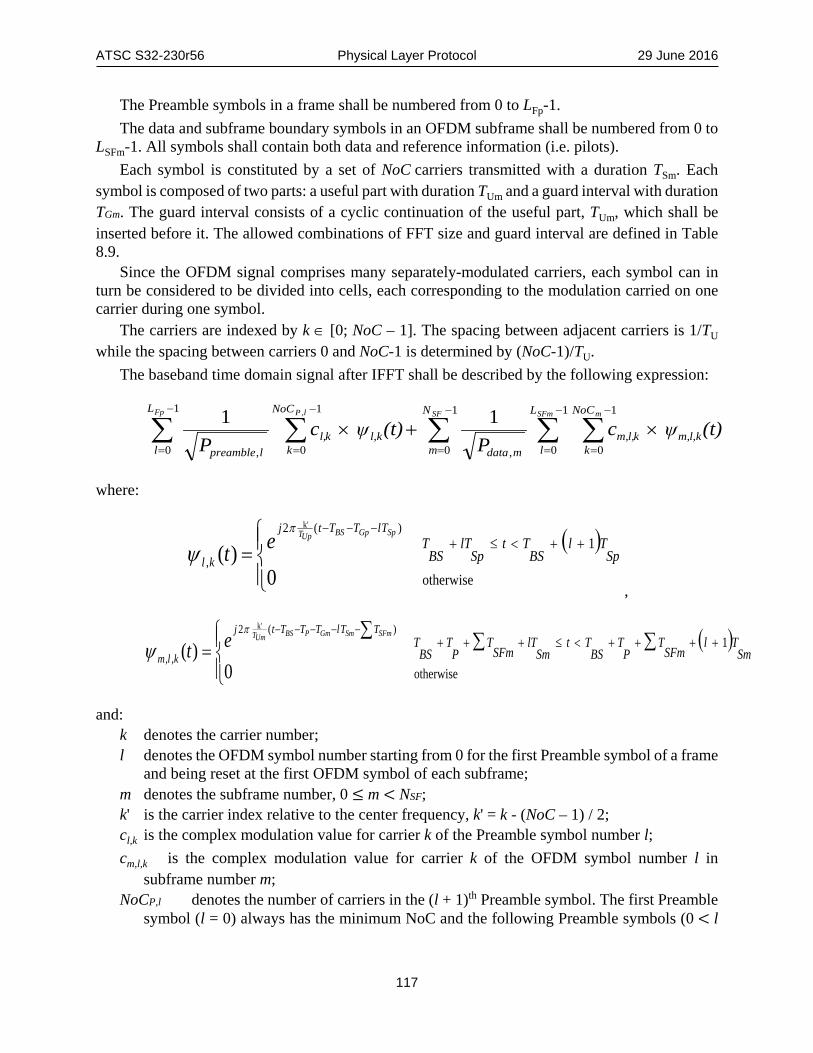
ATSC S32-230r56 Physical Layer Protocol 29 June 2016
117
The Preamble symbols in a frame shall be numbered from 0 to LFp-1. The data and subframe boundary symbols in an OFDM subframe shall be numbered from 0 to
LSFm-1. All symbols shall contain both data and reference information (i.e. pilots). Each symbol is constituted by a set of NoC carriers transmitted with a duration TSm. Each
symbol is composed of two parts: a useful part with duration TUm and a guard interval with duration TGm. The guard interval consists of a cyclic continuation of the useful part, TUm, which shall be inserted before it. The allowed combinations of FFT size and guard interval are defined in Table 8.9.
Since the OFDM signal comprises many separately-modulated carriers, each symbol can in turn be considered to be divided into cells, each corresponding to the modulation carried on one carrier during one symbol.
The carriers are indexed by k ∈ [0; NoC – 1]. The spacing between adjacent carriers is 1/TU while the spacing between carriers 0 and NoC-1 is determined by (NoC-1)/TU.
The baseband time domain signal after IFFT shall be described by the following expression:
∑ ∑ ∑∑ ∑−
=
−
=
−
=
−
=
−
=
×+×1
0
1
0
1
0,
1
0
1
0,
11 , SF SFm mFp lP N
m
L
l
NoC
kkl,m,kl,m,
mdata
L
l
NoC
kkl,kl,
lpreamble
(t)ψcP
(t)ψcP
where:
( )
= ++<≤+−−−
otherwise
1
0)(
)(2
,
k'
SpTl
BSTt
SplT
BST
SpGpBSUpT TlTTtj
klet
π
ψ,
( )
∑∑∑
= ++++<≤+++−−−−−
otherwise
1
0)(
)(2
,,
k'
SmTl
SFmT
PT
BSTt
SmlT
SFmT
PT
BST
SFmSmGmPBSUmT TTlTTTtj
klmet
π
ψ
and: k denotes the carrier number; l denotes the OFDM symbol number starting from 0 for the first Preamble symbol of a frame
and being reset at the first OFDM symbol of each subframe; m denotes the subframe number, 0 ≤ m < NSF; k' is the carrier index relative to the center frequency, k' = k - (NoC – 1) / 2; cl,k is the complex modulation value for carrier k of the Preamble symbol number l; cm,l,k is the complex modulation value for carrier k of the OFDM symbol number l in
subframe number m; NoCP,l denotes the number of carriers in the (l + 1)th Preamble symbol. The first Preamble
symbol (l = 0) always has the minimum NoC and the following Preamble symbols (0 < l

ATSC S32-230r56 Physical Layer Protocol 29 June 2016
118
< LFp) share the same NoC value that is signaled in L1-Basic as explained in Sections 7.2.5.1 and 9.2.2;
NoCm denotes the number of carriers of subframe m as defined in Table 8.8; LSFm is the number of data and subframe boundary symbols in subframe m; LFp is the number of OFDM symbols in a Preamble; TSm is the total symbol duration of each data and subframe boundary symbol in subframe
m, and TSm = TUm + TGm; TUm is the useful symbol duration for each data and subframe boundary symbol in subframe
m, defined in Table 8.8; TGm is the duration of the guard interval for each data and subframe boundary symbol in
subframe m including extra samples for each data and subframe boundary symbol as defined in Section 8.5;
TBS is the duration of the bootstrap; TP is the total duration of the Preamble, where TP= LFp TSp;
TSp is the total symbol duration of each Preamble symbol and TSp = TUp + TGp;
TUp is the useful symbol duration for each Preamble symbol; TGp is the duration of the guard interval for each Preamble symbol; TSFm is the total duration of all data and subframe boundary symbols in subframe m; ∑𝑇𝑇𝑆𝑆𝐹𝐹𝑚𝑚 is the summation of the total duration of subframes from 0 to m-1, ∑𝑇𝑇𝑆𝑆𝐹𝐹𝑚𝑚 =
∑ 𝑇𝑇𝑁𝑁𝑆𝑆𝑀𝑀𝑚𝑚−10 , ∑𝑇𝑇𝑆𝑆𝐹𝐹𝑚𝑚 = 0 if 𝑀𝑀 = 0;
NSF is the number of subframes in a frame;
PPreamble,l is the frequency domain total power of the (l + 1)th Preamble symbol; Pdata,m is the frequency domain total power of each data and subframe boundary symbol
in subframe m. The IFFT power normalization factor shall be used to normalize the average power of the
baseband time domain signal to one regardless of the waveform parameters in use. Because the OFDM symbol power before power normalization significantly varies depending on the waveform parameters such as FFT size, scattered pilot pattern, amplitude of the scattered pilot, and the number of carriers, different IFFT power normalization factors shall be used for different settings of waveform parameters. The IFFT power normalization factor for the Preamble, 1 �𝑃𝑃𝑙𝑙𝑖𝑖𝑖𝑖𝑝𝑝𝑚𝑚𝑠𝑠𝑙𝑙𝑖𝑖,𝑙𝑙⁄ , can be obtained using the frequency domain total power of the Preamble symbol which is summarized in Table I.1.1. The IFFT power normalization factor for data and subframe boundary symbols, 1 �𝑃𝑃𝑙𝑙𝑝𝑝𝑜𝑜𝑝𝑝,𝑚𝑚⁄ , can be obtained in a similar way using the frequency domain total power of the data and subframe boundary symbol which is summarized in Table I.2.1 to Table I.2.5.
The OFDM parameters are summarized in Table 8.8. The values for the various time-related parameters are given in multiples of the elementary period T and in microseconds. The elementary period T is specified by 1/(0.384MHz * (16+bsr_coefficient)), where bsr_coefficient is defined in Table 9.1 for each bandwidth, and approximate values for T are shown in Table 8.7 for convenience. The bandwidth of the system is determined from the value of system_bandwidth signaled in bootstrap symbol 1. See Section 9.1 for details of the bootstrap.

ATSC S32-230r56 Physical Layer Protocol 29 June 2016
119
Table 8.7 Approximate Elementary Periods T bsr_coefficient 2 5 8 Elementary period T (µs) 0.1447 0.1240 0.1085
Table 8.8 OFDM Parameters Parameter 8K FFT 16K FFT 32K FFT
Number of carriers NoC
Cred_coeff = 0 6913 13825 27649 Cred_coeff = 1 6817 13633 27265 Cred_coeff = 2 6721 13441 26881 Cred_coeff = 3 6625 13249 26497 Cred_coeff = 4 6529 13057 26113
Duration TU 8192 T 16384 T 32768 T
Duration TU (µs) (see note 1 and 2)
1185.185 2370.370 4740.741
Carrier spacing 1/TU (Hz) (see note 2)
843.75 421.875 210.9375
Spacing between carriers 0 and NoC – 1 (NoC-1)/TU (MHz) (see note 2)
Cred_coeff = 0 5.832 5.832 5.832 Cred_coeff = 1 5.751 5.751 5.751 Cred_coeff = 2 5.670 5.670 5.670 Cred_coeff = 3 5.589 5.589 5.589 Cred_coeff = 4 5.508 5.508 5.508
Note 1: Numerical values in italics are approximate values. Note 2: Values are for bsr_coefficient=2 and system_bandwidth=6 MHz.
8.4 Peak to Average Power Ratio Reduction Techniques In order to reduce the Peak to Average Power Ratio of the output OFDM signal, modifications to the transmitted OFDM signal—tone reservation described in Section 8.4.1 and Active Constellation Extension (ACE) described in Section 8.4.2—may be used. None, one or both techniques may be used. Guard interval insertion is applied after the PAPR reduction. 8.4.1 Tone Reservation When TR is enabled, some OFDM carriers shall be reserved to allow the insertion of cells designed to reduce the overall PAPR of the output waveform. These cells shall not contain any payload data or signaling information.
The sets of carriers reserved for PAPR reduction in Preamble, data and subframe boundary symbols shall be as defined in Table G.1.2 and Table G.1.3.
Depending on the data OFDM symbol index, the carriers in the tables specified above or the circular shifts of these values are used. The amount of circular shift depends on the pilot spacing DX and DY. In a data symbol corresponding to an index l , the reserved carrier set lS shall be calculated as:
endTRnYXkl dldNnSiDlDiS ≤≤<≤∈+= 00 ,0,),mod(*

ATSC S32-230r56 Physical Layer Protocol 29 June 2016
120
where S0 represents the set of reserved carriers corresponding to carrier indices defined in the tables specified above, TRN is the number of reserved cells per OFDM symbol, 0d represents the index of the first OFDM symbol of the subframe and endd represents the index of the last data symbol.
An example algorithm for generating the values inserted into the tone reservation carriers is described in Annex M.2. 8.4.2 Active Constellation Extension (ACE) The Active Constellation Extension (ACE) algorithm reduces the PAPR by the modification of the transmitted constellation points. The active constellation extension technique shall not be applied to pilot carriers or reserved tones. ACE shall not be used in conjunction with LDM, MISO or MIMO.
An example algorithm for ACE is described in Annex M.3.
8.5 Guard Interval In Table 8.9 twelve guard intervals are defined in terms of the absolute guard interval length expressed in samples. Table 8.9 additionally defines with a check mark ✔which guard interval patterns shall be allowed for each FFT size, those guard interval patterns not allowed are shown by N/A.
Table 8.9 Duration of the Guard Intervals in Samples GI Pattern Duration in Samples 8K FFT 16K FFT 32K FFT GI1_192 192 ✔ ✔ ✔ GI2_384 384 ✔ ✔ ✔ GI3_512 512 ✔ ✔ ✔ GI4_768 768 ✔ ✔ ✔ GI5_1024 1024 ✔ ✔ ✔ GI6_1536 1536 ✔ ✔ ✔ GI7_2048 2048 ✔ ✔ ✔ GI8_2432 2432 N/A ✔ ✔ GI9_3072 3072 N/A ✔ ✔ GI10_3648 3648 N/A ✔ ✔ GI11_4096 4096 N/A ✔ ✔ GI12_4864 4864 N/A N/A ✔
8.5.1 Guard Interval Extension for Time-aligned Frames The contents of this section shall apply when time-aligned frames are indicated. The contents of this section shall not apply when symbol-aligned frames are indicated.
When a time-aligned frame is indicated, zero or more extra samples in addition to the indicated guard interval (see Table 8.9) shall be inserted to make the total actual frame length equal to the signaled frame length. These extra samples shall be distributed to the specific portions of the non-Preamble OFDM symbols within the frame using the following algorithm. The approach detailed here ensures that all OFDM symbols within a given subframe have the same guard interval length and that an equal number of extra samples are distributed to the guard interval of every non-Preamble OFDM symbol within a frame.

ATSC S32-230r56 Physical Layer Protocol 29 June 2016
121
• 𝑇𝑇𝑠𝑠𝑜𝑜𝑜𝑜𝑜𝑜𝑠𝑠𝑜𝑜𝑖𝑖𝑝𝑝𝑙𝑙 is the total time length (in seconds) of the bootstrap for the current frame. • 𝑇𝑇𝑖𝑖𝑖𝑖𝑝𝑝𝑚𝑚𝑖𝑖 is the indicated total frame time length in seconds. • 𝐵𝐵𝑁𝑁𝑅𝑅 is the baseband sampling rate (in MSamples/s) for the non-bootstrap portion of the
current frame. • 𝑁𝑁𝑠𝑠𝑝𝑝𝑚𝑚𝑠𝑠𝑜𝑜𝑙𝑙𝑠𝑠
𝑙𝑙𝑖𝑖𝑖𝑖𝑝𝑝𝑚𝑚𝑠𝑠𝑙𝑙𝑖𝑖 is the number of Preamble symbols.
• 𝑁𝑁𝐹𝐹𝐹𝐹𝑇𝑇𝑙𝑙𝑖𝑖𝑖𝑖𝑝𝑝𝑚𝑚𝑠𝑠𝑙𝑙𝑖𝑖 is the FFT size of the Preamble symbols.
• 𝑁𝑁𝐺𝐺𝐼𝐼𝑙𝑙𝑖𝑖𝑖𝑖𝑝𝑝𝑚𝑚𝑠𝑠𝑙𝑙𝑖𝑖 is the guard interval length (in samples) for the Preamble symbols.
• 𝑁𝑁𝑠𝑠𝑜𝑜𝑠𝑠 is the total number of subframes in the frame. • 𝑁𝑁𝑠𝑠𝑝𝑝𝑚𝑚𝑠𝑠𝑜𝑜𝑙𝑙𝑠𝑠
𝑘𝑘 is the number of OFDM symbols (including any subframe boundary symbols) in the kth subframe.
• 𝑁𝑁𝐹𝐹𝐹𝐹𝑇𝑇𝑘𝑘 is the FFT size for the kth subframe. • 𝑁𝑁𝐺𝐺𝐼𝐼𝑘𝑘 is the indicated guard interval length (in samples) for the kth subframe. • 𝑁𝑁𝑖𝑖𝑑𝑑𝑜𝑜𝑖𝑖𝑝𝑝 is the total number of extra samples required to be inserted into a frame in order to
make the actual and signaled frame lengths equal. 𝑁𝑁𝑖𝑖𝑑𝑑𝑜𝑜𝑖𝑖𝑝𝑝 shall be calculated as:
𝑁𝑁𝑖𝑖𝑑𝑑𝑜𝑜𝑖𝑖𝑝𝑝 = �𝑇𝑇𝑖𝑖𝑖𝑖𝑝𝑝𝑚𝑚𝑖𝑖 − 𝑇𝑇𝑠𝑠𝑜𝑜𝑜𝑜𝑜𝑜𝑠𝑠𝑜𝑜𝑖𝑖𝑝𝑝𝑙𝑙� × 𝐵𝐵𝑁𝑁𝑅𝑅 − 𝑁𝑁𝑠𝑠𝑝𝑝𝑚𝑚𝑠𝑠𝑜𝑜𝑙𝑙𝑠𝑠𝑙𝑙𝑖𝑖𝑖𝑖𝑝𝑝𝑚𝑚𝑠𝑠𝑙𝑙𝑖𝑖 × �𝑁𝑁𝐹𝐹𝐹𝐹𝑇𝑇
𝑙𝑙𝑖𝑖𝑖𝑖𝑝𝑝𝑚𝑚𝑠𝑠𝑙𝑙𝑖𝑖 + 𝑁𝑁𝐺𝐺𝐼𝐼𝑙𝑙𝑖𝑖𝑖𝑖𝑝𝑝𝑚𝑚𝑠𝑠𝑙𝑙𝑖𝑖�
− � 𝑁𝑁𝑠𝑠𝑝𝑝𝑚𝑚𝑠𝑠𝑜𝑜𝑙𝑙𝑠𝑠𝑘𝑘 × �𝑁𝑁𝐹𝐹𝐹𝐹𝑇𝑇𝑘𝑘 + 𝑁𝑁𝐺𝐺𝐼𝐼𝑘𝑘 �
𝑁𝑁𝑐𝑐𝑜𝑜𝑠𝑠
𝑘𝑘=1
• 𝑁𝑁𝑠𝑠𝑝𝑝𝑚𝑚𝑠𝑠𝑜𝑜𝑙𝑙𝑠𝑠 = ∑ 𝑁𝑁𝑠𝑠𝑝𝑝𝑚𝑚𝑠𝑠𝑜𝑜𝑙𝑙𝑠𝑠𝑘𝑘𝑁𝑁𝑐𝑐𝑜𝑜𝑠𝑠
𝑘𝑘=1 is the total number of non-Preamble OFDM symbols contained in the frame (across all 𝑁𝑁𝑠𝑠𝑜𝑜𝑠𝑠 subframes).
• The guard interval of each non-Preamble OFDM symbol in the frame shall receive floor�𝑁𝑁𝑖𝑖𝑑𝑑𝑜𝑜𝑖𝑖𝑝𝑝 𝑁𝑁𝑠𝑠𝑝𝑝𝑚𝑚𝑠𝑠𝑜𝑜𝑙𝑙𝑠𝑠⁄ � extra samples as illustrated in Figure 8.4, where floor(𝑀𝑀) is defined as the largest integer that is less than or equal to 𝑀𝑀.
Useful portion Useful portion Useful portion
Signaled guard interval length
Extra samples for the guard intervalsCyclic postfix on final
OFDM symbol of the frame
...
Figure 8.4 Illustration of the assignment of extra samples to the guard interval of
each non-Preamble OFDM symbol in a frame.
• The remaining leftover 𝑁𝑁𝑖𝑖𝑑𝑑𝑜𝑜𝑖𝑖𝑝𝑝 mod 𝑁𝑁𝑠𝑠𝑝𝑝𝑚𝑚𝑠𝑠𝑜𝑜𝑙𝑙𝑠𝑠 extra samples, if any, shall be inserted immediately following the final OFDM symbol of the final subframe of the frame. These samples shall represent a cyclic postfix of that OFDM symbol consisting of the requisite number of samples copied from the beginning of the useful portion of that OFDM symbol, as illustrated in Figure 8.5.

ATSC S32-230r56 Physical Layer Protocol 29 June 2016
122
Useful portion of OFDM symbolGuard interval (includes extra samples)
Cyclic postfix
Figure 8.5 Illustration of remaining leftover extra samples being assigned to a cyclic postfix of the final OFDM symbol of the final subframe of the frame.
8.6 Bootstrap The bootstrap symbol construction is defined in detail in [2]. Section 9.1 establishes constraints of the payload contents of the bootstrap to represent the set of capabilities that this standard supports.
9. L1 SIGNALING L1-signaling provides the necessary information to configure the physical layer parameters. The term ‘L1’ refers to Layer-1, the lowest layer of the ISO 7 layer model. L1-signaling consists of three parts: constraints on the bootstrap, described in Section 9.1, L1-Basic which is described in Section 9.2 and L1-Detail which is described in Section 9.3. Both L1-Basic and L1-Detail are carried in the Preamble symbols.
L1-Basic conveys the most fundamental signaling information of the system and also defines the parameters needed to decode L1-Detail. The length of L1-Basic signaling is fixed at 200 bits.
L1-Detail details the data context and the required information to decode it. The length of L1-Detail signaling may vary from frame to frame.
Note: Some signaling fields represent quantities for which the actual value zero is not valid (e.g., zero Preamble symbols is not a valid configuration). Therefore, signaling of a value one less than the actual value is used in these cases to maximize the efficiency of the range of values that can be signaled by the number of signaling bits available for each signaling field.
9.1 Bootstrap This section establishes constraints on the payload contents of the bootstrap symbols to represent the set of capabilities that this standard supports. Versioning is defined in Section 9.1.1, and the bootstrap symbol contents are defined in Sections 9.1.2, 9.1.3 and 9.1.4 respectively. Any contents not explicitly defined here shall follow [2]. 9.1.1 Versioning The value of bootstrap_major_version as defined by [2] shall be 0.
The value of bootstrap_minor_version as defined by [2] shall be 0. 9.1.2 Bootstrap Symbol 1 The constraints and meanings for the contents of bootstrap symbol 1 are completely defined by [2].

ATSC S32-230r56 Physical Layer Protocol 29 June 2016
123
9.1.3 Bootstrap Symbol 2 The value for the bsr_coefficient defined in [2] (part of bootstrap symbol 2) shall be one of the values shown in Table 9.1, and shall be the one that is applicable to the bandwidth of the emission.
Table 9.1 Defined Values of bsr_coefficient bsr_coefficient Applicability 2 6 MHz bandwidth 5 7 MHz bandwidth 8 8 MHz bandwidth
9.1.4 Bootstrap Symbol 3 The value for the preamble_structure defined in [2] (bootstrap symbol 3) shall be one of the non-reserved values listed in Table H.1.1.
9.2 Syntax for L1-Basic Data The syntax and field semantics of the L1-Basic signaling fields are defined in Table 9.2 and the following subsections. The names of signaling fields in L1-Basic are always prefixed with ‘L1B_’.
Table 9.2 L1-Basic Signaling Fields and Syntax Syntax No. of Bits Format L1_Basic_signaling() { L1B_version 3 uimsbf L1B_mimo_scattered_pilot_encoding 1 uimsbf L1B_lls_flag 1 uimsbf L1B_time_info_flag 2 uimsbf L1B_return_channel_flag 1 uimsbf L1B_papr_reduction 2 uimsbf L1B_frame_length_mode 1 uimsbf if ( L1B_frame_length_mode=0 ) { L1B_frame_length 10 uimsbf L1B_excess_samples_per_symbol 13 uimsbf } else { L1B_time_offset 16 uimsbf L1B_additional_samples 7 uimsbf } L1B_num_subframes 8 uimsbf L1B_preamble_num_symbols 3 uimsbf L1B_preamble_reduced_carriers 3 uimsbf L1B_L1_Detail_content_tag 2 uimsbf L1B_L1_Detail_size_bytes 13 uimsbf L1B_L1_Detail_fec_type 3 uimsbf L1B_L1_Detail_additional_parity_mode 2 uimsbf L1B_L1_Detail_total_cells 19 uimsbf L1B_first_sub_mimo 1 uimsbf L1B_first_sub_miso 2 uimsbf L1B_first_sub_fft_size 2 uimsbf L1B_first_sub_reduced_carriers 3 uimsbf

ATSC S32-230r56 Physical Layer Protocol 29 June 2016
124
Syntax No. of Bits Format L1B_first_sub_guard_interval 4 uimsbf L1B_first_sub_num_ofdm_symbols 11 uimsbf L1B_first_sub_scattered_pilot_pattern 5 uimsbf L1B_first_sub_scattered_pilot_boost 3 uimsbf L1B_first_sub_sbs_first 1 uimsbf L1B_first_sub_sbs_last 1 uimsbf L1B_reserved 48 uimsbf L1B_crc 32 uimsbf }
9.2.1 L1-Basic System and Frame Parameters The following parameters provide information related to the entire frame. L1B_version – This field shall indicate the version of the L1-Basic signaling structure that is used
for the current frame. For the current version of the specification L1B_version shall be set to 0. It is envisaged that when new L1-Basic signaling fields are introduced into an updated L1-Basic signaling structure in such a manner that the presence or absence of at least one of those new L1-Basic signaling fields cannot be otherwise deduced, L1B_version would be incremented by 1. New L1-Basic signaling fields that are introduced into an L1-Basic signaling structure corresponding to a particular L1B_version should be added in such a manner that they do not interfere with the parsing of L1-Basic signaling fields by receivers that have been provisioned only up to an earlier L1B_version.
L1B_mimo_scattered_pilot_encoding – This field shall indicate the appropriate MIMO pilot encoding scheme used by any MIMO subframes in the current frame as given in Table 9.3. When there are no MIMO subframes in the current frame, the value of L1B_mimo_scattered_pilot_encoding shall be signaled as 0.
Table 9.3 Signaling Format for L1B_mimo_scattered_pilot_encoding Value Meaning 0 Walsh-Hadamard pilots or no MIMO subframes 1 Null pilots
L1B_lls_flag – This field shall indicate the presence or absence of Low Level Signaling (LLS) in one or more PLPs in the current frame. L1B_lls_flag=0 shall indicate there is no LLS signaling in the current frame, while L1B_lls_flag=1 shall indicate there is LLS signaling carried in this frame. The PLP(s) which carry LLS shall be indicated by L1D_plp_lls_flag.
L1B_time_info_flag – This field shall indicate the presence or absence of timing information in the current frame, and the precision to which it is signaled according to Table 9.4.
Table 9.4 Signaling Format for L1B_time_info_flag Value Meaning 00 Time information is not included in the current frame 01 Time information is included in the current frame and signaled to ms precision 10 Time information is included in the current frame and signaled to µs precision 11 Time information is included in the current frame and signaled to ns precision

ATSC S32-230r56 Physical Layer Protocol 29 June 2016
125
L1B_return_channel_flag – This field shall indicate whether a dedicated return channel (DRC) is present. Specifically, L1B_return_channel_flag = 1 shall indicate that DRC is supported in the current frame of the current frequency band and current broadcast network. L1B_return_channel_flag = 0 shall indicate that DRC is not supported in the current frame of the current frequency band and current broadcast network.
L1B_papr_reduction – This field shall indicate the technique to reduce the peak to average power ratio within the current frame as given in Table 9.5. The PAPR reduction technique shall apply to all OFDM symbols contained within the current frame, with the exception of the first Preamble symbol. L1B_papr_reduction=10 and L1B_papr_reduction=11 shall not be indicated when any of the following conditions is satisfied. • L1B_first_sub_miso=01 or L1B_first_sub_miso=10 and/or L1D_miso=01 or L1D_miso=10 for
any subframe within the current frame • L1B_first_sub_mimo=1 and/or L1D_mimo=1 for any subframe within the current frame • L1D_plp_layer>0 for any PLP within the current frame
Table 9.5 Signaling Format for L1B_papr_reduction Value Meaning 00 No PAPR reduction used 01 tone reservation only 10 ACE only 11 Both TR and ACE
L1B_frame_length_mode – This field shall be set to L1B_frame_length_mode=0 to indicate that the current frame is time-aligned with excess sample distribution to the guard intervals of Data Payload OFDM symbols (i.e. non-Preamble OFDM symbols) as described in Section 8.5.1. The field shall be set to L1B_frame_length_mode=1 to indicate that the current frame is symbol-aligned with no excess sample distribution.
L1B_frame_length – This field shall only be included when L1B_frame_length_mode=0 (i.e. when time-aligned frames are configured) and shall indicate the time period measured from the beginning of the first sample of the bootstrap associated with the current frame to the end of the final sample associated with the current frame (i.e. the signaled frame length also includes the length of the bootstrap). The time period indicated shall be expressed in units of 5 ms (i.e. time period = L1B_frame_length × 5 ms). As stated in Section 7.2.2.2, the minimum frame length is 50 ms and the maximum frame length is 5 seconds, which implies that 10 ≤ L1B_frame_length ≤ 1000.
L1B_excess_samples_per_symbol – This field shall only be included when L1B_frame_length_mode=0 (i.e. when time-aligned frames are configured) and shall indicate the additional number of excess samples included in the guard interval of each non-Preamble OFDM symbol of the post-bootstrap portion of the current frame when time-aligned frames are used. The same number of excess samples is included in the guard interval of each and every non-Preamble OFDM symbol of the post-bootstrap portion of a frame according to the excess sample insertion algorithm described in Section 8.5.1. The total length of the guard interval for each OFDM symbol belonging to a particular subframe of the current frame shall be equal to the sum of the guard interval length for that particular subframe (as indicated by L1B_first_sub_guard_interval for the first subframe and by the appropriate L1D_guard_interval for any subsequent subframes) and the value signaled by L1B_excess_samples_per_symbol.

ATSC S32-230r56 Physical Layer Protocol 29 June 2016
126
L1B_time_offset – This field shall only be included when L1B_frame_length_mode=1 (i.e. when symbol-aligned frames are configured) and shall indicate the number of sample periods (using the BSR configured for the current frame) between the nearest preceding or coincident millisecond boundary and the leading edge of the frame.
L1B_additional_samples – This field shall only be included when L1B_frame_length_mode=1 (i.e. when symbol-aligned frames are configured) and shall indicate the number of additional samples added at the end of a frame to facilitate sampling clock alignment. For the current version of the specification, L1B_additional_samples shall be set to 0 when present.
L1B_num_subframes – This field shall be set to 1 less than the number of subframes present within the current frame. That is, L1B_num_subframes=0 shall indicate that 1 subframe is present within the current frame, L1B_num_subframes=1 shall indicate that two subframes are present within the current frame, and so on.
9.2.2 L1-Basic Parameters for L1-Detail The following parameters provide information required to decode the remainder of the Preamble, that is L1-Detail. L1B_preamble_num_symbols – This field shall be set to one less than the total number of Preamble
OFDM symbols. Example: When there is just one Preamble symbol, L1B_preamble_num_symbols would be set equal to 0.
L1B_preamble_reduced_carriers – This field shall indicate the number of control units of carriers by which the maximum number of carriers for the FFT size used for the Preamble is reduced. This carrier reduction shall apply to all of the Preamble symbols of the current frame with the exception of the first Preamble symbol. See Section 7.2.6.3 for details. When there is only one Preamble symbol, the value of this field shall be zero.
L1B_L1_Detail_content_tag – This field shall be incremented by 1 whenever the L1-Detail contents of the current frame have been modified as compared to the L1-Detail contents of the previous frame with a bootstrap of the same major and minor version as the current frame. The following signaling fields are excluded from determination of when to increment L1B_L1_Detail_content_tag: L1D_time_sec, L1D_time_msec, L1D_time_usec, L1D_time_nsec (including the presence or absence of any of these listed time fields) L1D_plp_lls_flag, L1D_plp_fec_block_start, L1D_plp_CTI_fec_block_start, and L1D_plp_CTI_start_row. The initial value of L1B_L1_Detail_content_tag shall be 0. When L1B_L1_Detail_content_tag is incremented after reaching the maximum value, it shall wrap, and the next transmitted value shall be 0.
L1B_L1_Detail_size_bytes – This field shall indicate the size (in bytes) of the L1-Detail information. The indicated number of L1-Detail information bytes shall not include any additional parity bits that are included in the current frame for the next frame’s L1-Detail. The minimum value of this field shall be 25 bytes.
L1B_L1_Detail_fec_type – This field shall indicate the FEC type for L1-Detail information protection as given in Table 9.6. The details of the FEC type are described in Section 6.5.2.1.

ATSC S32-230r56 Physical Layer Protocol 29 June 2016
127
Table 9.6 Signaling Format for L1B_L1_Detail_fec_type
Value FEC Type 000 Mode 1 001 Mode 2 010 Mode 3 011 Mode 4 100 Mode 5 101 Mode 6 110 Mode 7 111 Reserved
L1B_L1_Detail_additional_parity_mode – This field shall indicate the Additional Parity Mode (defined in Section 6.5.3.2) which gives the ratio (K) of the number of additional parity bits for the next frame’s L1-Detail that are carried in the current frame to half of the number of coded bits for the next frame’s L1-Detail signaling. (Here, the next frame shall be considered to be the next frame whose bootstrap has the same major and minor version as the current frame.) The value of the field shall be given as shown in Table 9.7.
Table 9.7 Signaling Format for L1B_additional_parity_mode Value Additional Parity Mode 00 K = 0 (No additional parity used) 01 K = 1 10 K = 2 11 Reserved for future use
L1B_L1_Detail_total_cells – This field shall indicate the total size (specified in OFDM cells) of the combined coded and modulated L1-Detail signaling for the current frame and the modulated additional parity bits for L1-Detail signaling of the next frame.
9.2.3 L1-Basic Parameters for First Subframe The parameters of the first subframe of the current frame are signaled within L1-Basic to facilitate the immediate initial OFDM processing of this first subframe at a receiver without needing to wait until L1-Detail is decoded. L1B_first_sub_mimo – This field shall indicate whether MIMO (see Annex L) is used for the first
subframe of the current frame. A value of 1 shall indicate that MIMO is used, and a value of 0 shall indicate that MIMO is not used.
L1B_first_sub_miso – This field shall indicate the MISO (see Section 8.2) option used for the first subframe of the current frame as given in Table 9.9.
L1B_first_sub_fft_size – This field shall indicate the FFT size associated with the first subframe of the current frame as given in Table 9.10. Note that the FFT size of a frame's Preamble and the FFT size of the same frame's first subframe are the same, as specified in Section 7.2.2.1.
L1B_first_sub_reduced_carriers – This field shall indicate the number of control units of carriers by which the maximum number of carriers for the FFT size used for the first subframe of the current frame is reduced. This carrier reduction shall apply to all of the symbols of the first subframe of the current frame (see Section 7.2.3 for details).

ATSC S32-230r56 Physical Layer Protocol 29 June 2016
128
L1B_first_sub_guard_interval – This field shall indicate the guard interval length used for the OFDM symbols of the first subframe of the current frame as given in Table 9.11. Guard interval lengths (e.g. 192 samples for GI1_192) shall be as defined in Table 8.9. Note that the signaled guard interval length for the first subframe of a frame is the same as the guard interval length indicated for that same frame's Preamble, as specified in Section 7.2.2.1.
L1B_first_sub_num_ofdm_symbols – This field shall be set equal to one less than the total number of data payload OFDM symbols, including any subframe boundary symbol(s), present within the first subframe of the current frame. The number of data payload OFDM symbols in a subframe is greater than or equal to 4×DY where DY is taken from the scattered pilot pattern that is configured for the subframe (see Section 7.2.4.2). OFDM symbols containing Preamble signaling shall not be included within this count, although OFDM symbols containing Preamble signaling may also carry portions of PLPs associated with the first subframe of a frame if data cells are available on those OFDM symbols.
L1B_first_sub_scattered_pilot_pattern – This field shall indicate the scattered pilot pattern used for the first subframe of the current subframe as given in Table 9.12 for SISO, and as given in Table 9.13 for MIMO. SP pattern values (e.g. SP3_2, MIMO3_2) shall be as defined in Table 8.2 (SISO) and Table L.11.1 (MIMO).
L1B_first_sub_scattered_pilot_boost – The value of this field combined with the scattered pilot pattern shall represent the power of the scattered pilots (in dB) used for the first subframe of the current frame. The exact power values (used to calculate the amplitude) shall be as defined in Table 9.14. Equivalent but approximate amplitudes (after conversion from dB to linear) of the scattered pilots are listed in Table 9.15. The values of 101, 110 and 111 shall be reserved for future use.
L1B_first_sub_sbs_first – This field shall indicate whether or not the first symbol of the first subframe of the current frame is a subframe boundary symbol. L1B_first_sub_sbs_first=0 shall indicate that the first symbol of the first subframe of the current frame is not a subframe boundary symbol. L1B_first_sub_sbs_first=1 shall indicate that the first symbol of the first subframe of the current frame is a subframe boundary symbol.
L1B_first_sub_sbs_last – This field shall indicate whether or not the last symbol of the first subframe of the current frame is a subframe boundary symbol. L1B_first_sub_sbs_last=0 shall indicate that the last symbol of the first subframe of the current frame is not a subframe boundary symbol. L1B_first_sub_sbs_last=1 shall indicate that the last symbol of the first subframe of the current frame is a subframe boundary symbol.
9.2.4 L1-Basic Miscellaneous Parameters The remaining miscellaneous parameters in L1-Basic are as follows. L1B_reserved – This field shall contain reserved bits as required to pad L1-Basic out to the total
length. It is envisaged that any new signaling fields defined for a newer version of the L1-Basic signaling structure would occupy a portion of these reserved bits to maintain backward-compatibility for legacy receivers. Receivers are expected to ignore the contents of L1B_reserved.
L1B_crc – This field shall contain the CRC value as computed according to Section 6.1.2.2 over the contents of L1-Basic excluding the L1B_crc field.

ATSC S32-230r56 Physical Layer Protocol 29 June 2016
129
9.3 Syntax and Semantics for L1-Detail Data The syntax and field semantics of the L1-Detail signaling fields are defined in Table 9.8 and the following subsections. The names of signaling fields in L1-Detail are always prefixed with ‘L1D_’.
Table 9.8 L1-Detail Signaling Fields and Syntax Syntax No. of Bits Format L1_Detail_signaling() { L1D_version 4 uimsbf L1D_num_rf 3 uimsbf for (L1D_rf_id=1 .. L1D_num_rf) { L1D_rf_frequency 19 uimsbf } if (L1B_time_info_flag != 00) { L1D_time_sec 32 uimsbf L1D_time_msec 10 uimsbf if (L1B_time_info_flag != 01) { L1D_time_usec 10 uimsbf if (L1B_time_info_flag != 10) { L1D_time_nsec 10 uimsbf } } } for (i=0 .. L1B_num_subframes) { if (i > 0) { L1D_mimo 1 uimsbf L1D_miso 2 uimsbf L1D_fft_size 2 uimsbf L1D_reduced_carriers 3 uimsbf L1D_guard_interval 4 uimsbf L1D_num_ofdm_symbols 11 uimsbf L1D_scattered_pilot_pattern 5 uimsbf L1D_scattered_pilot_boost 3 uimsbf L1D_sbs_first 1 uimsbf L1D_sbs_last 1 uimsbf } if (L1B_num_subframes>0) { L1D_subframe_multiplex 1 uimsbf } L1D_frequency_interleaver 1 uimsbf if (((i=0)&&(L1B_first_sub_sbs_first || L1B_first_sub_sbs_last)) || ((i>0)&&(L1D_sbs_first | L1D_sbs_last))) { L1D_sbs_null_cells 13 uimsbf } L1D_num_plp 6 uimsbf for (j=0 .. L1D_num_plp) { L1D_plp_id 6 uimsbf

ATSC S32-230r56 Physical Layer Protocol 29 June 2016
130
Syntax No. of Bits Format L1D_plp_lls_flag 1 uimsbf L1D_plp_layer 2 uimsbf L1D_plp_start 24 uimsbf L1D_plp_size 24 uimsbf L1D_plp_scrambler_type 2 uimsbf L1D_plp_fec_type 4 uimsbf if (L1D_plp_fec_type∈{0,1,2,3,4,5}) { L1D_plp_mod 4 uimsbf L1D_plp_cod 4 uimsbf } L1D_plp_TI_mode 2 uimsbf if (L1D_plp_TI_mode=00) { L1D_plp_fec_block_start 15 uimsbf } else if (L1D_plp_TI_mode=01) { L1D_plp_CTI_fec_block_start 22 uimsbf } if (L1D_num_rf>0) { L1D_plp_num_channel_bonded 3 uimsbf if (L1D_plp_num_channel_bonded>0) { L1D_plp_channel_bonding_format 2 uimsbf for (k=0..L1D_plp_num_channel_bonded){ L1D_plp_bonded_rf_id 3 uimsbf } } } if (i=0 && L1B_first_sub_mimo=1) || (i >1 && L1D_mimo=1) { L1D_plp_mimo_stream_combining 1 uimsbf L1D_plp_mimo_IQ_interleaving 1 uimsbf L1D_plp_mimo_PH 1 uimsbf } if (L1D_plp_layer=0) { L1D_plp_type 1 uimsbf if (L1D_plp_type=1) { L1D_plp_num_subslices 14 uimsbf L1D_plp_subslice_interval 24 uimsbf } if (((L1D_plp_TI_mode=01) || (L1D_plp_TI_mode=10))&&(L1D_plp_mod=0000)) { L1D_plp_TI_extended_interleaving 1 uimsbf } if (L1D_plp_TI_mode=01) { L1D_plp_CTI_depth 3 uimsbf L1D_plp_CTI_start_row 11 uimsbf }else if (L1D_plp_TI_mode=10) { L1D_plp_HTI_inter_subframe 1 uimsbf L1D_plp_HTI_num_ti_blocks 4 uimsbf L1D_plp_HTI_num_fec_blocks_max 12 uimsbf

ATSC S32-230r56 Physical Layer Protocol 29 June 2016
131
Syntax No. of Bits Format if (L1D_plp_HTI_inter_subframe=0) { L1D_plp_HTI_num_fec_blocks 12 uimsbf }else { for (k=0..L1D_plp_HTI_num_ti_blocks) { L1D_plp_HTI_num_fec_blocks 12 uimsbf } } L1D_plp_HTI_cell_interleaver 1 uimsbf } }else { L1D_plp_ldm_injection_level 5 uimsbf } } } L1D_reserved as needed uimsbf L1D_crc 32 uimsbf }
9.3.1 L1-Detail Miscellaneous Parameters The following miscellaneous parameters are included in L1-Detail. L1D_version – This field shall indicate the version of the L1-Detail signaling structure that is used
for the current frame. For the current version of the specification L1D_version shall be set to 0. It is envisaged that when new L1-Detail signaling fields are introduced into an updated L1-Detail signaling structure in such a manner that the presence or absence of at least one of those new L1-Detail signaling fields cannot be otherwise deduced, L1D_version would be incremented by 1. New L1-Detail signaling fields that are introduced into an L1-Detail signaling structure corresponding to a particular L1D_version should be added in such a manner that they do not interfere with the parsing of L1-Detail signaling fields by receivers that have been provisioned only up to an earlier L1D_version.
L1D_time_sec – This field shall indicate the seconds component of the time information. The time information shall indicate the precise time at which the first sample of the first symbol of the most recently received bootstrap was transmitted, shown as the time information position in Figure 9.1. L1D_time_sec shall contain the 32 least significant bits of PTP seconds of the time information. For example, if the precise time was 17:31:24 on the 12th February 2016 there would have been exactly 1455298284 seconds elapsed since the PTP epoch on 1st January 1970 and the value transmitted in this field would be 0x56BE16EC. The time value shall be transmitted at least once in every 5 second interval.

ATSC S32-230r56 Physical Layer Protocol 29 June 2016
132
Payload Bootstrap
... Preamble Payload Bootstrap Preamble ...
Time Information Position
Time Information (L1D_time_sec, L1D_time_msec, L1D_time_usec, L1D_time_nsec)
Figure 9.1 Illustration of the time information position and the time information
being transmitted in the Preamble.
L1D_time_msec – This field shall indicate the milliseconds component of the time information. For example, if the portion of the time information less than one second is 0.123456789 this field shall be 123.
L1D_time_usec – This field shall indicate the microseconds component of the time information. For example, if the portion of the time information less than one second is 0.123456789 this field shall be 456.
L1D_time_nsec – This field shall indicate the nanoseconds component of the time information. For example, if the portion of the time information less than one second is 0.123456789 this field shall be 789.
L1D_reserved – This field shall contain reserved bits as needed to pad L1-Detail out to the total bit length indicated by L1B_L1_Detail_size_bytes. It is expected that one primary use of L1D_reserved on the transmitter side will be to ensure byte alignment of the total length of L1-Detail by including from 0 to 7 padding bits as required. Future versions of the L1-Detail signaling structure may add new signaling fields, which would be seen as part of the L1D_reserved field by legacy receivers. Receivers are therefore expected not to make any assumptions about the expected contents and/or length of L1D_reserved.
L1D_crc – This field shall contain the CRC value as computed in Section 6.1.2.2 over the contents of L1-Detail excluding the L1D_crc field.
9.3.2 L1-Detail Channel Bonding Parameters (Frame) The following L1-Detail signaling fields are related to channel bonding. L1D_num_rf – This field shall indicate the number of frequencies involved in channel bonding, not
including the frequency of the present channel. For the current version of the specification L1D_num_rf shall have a maximum value of 1 (i.e. bonding of the current channel with one other channel). L1D_num_rf=0 shall indicate that channel bonding is not used for the current frame.
L1D_rf_id – This implicitly defined field shall specify the IDs of the other RF channels involved in channel bonding. The current RF channel shall be assigned an implicit L1D_rf_id of 0. The first RF channel in the list shall be assigned an implicit L1D_rf_id of 1, and so on. For the current version of the specification L1D_rf_id, if defined, shall have a maximum value of 1.
L1D_rf_frequency – This field shall indicate the center frequency (in 10 kHz units) of the other RF channel involved in channel bonding, associated with the implicit ID of L1D_rf_id. The frequency of the current channel is already known and shall not be signaled.
9.3.3 L1-Detail Subframe Parameters L1-Detail parameters related to subframe configuration are as follows.

ATSC S32-230r56 Physical Layer Protocol 29 June 2016
133
L1D_mimo – This flag shall indicate whether MIMO (see Annex L) is used for the current subframe. A value of 1 shall indicate that MIMO is used, and a value of 0 shall indicate that MIMO is not used.
L1D_miso – This field shall indicate the MISO (see Section 8.2) option used for the current subframe as given in Table 9.9.
Table 9.9 Signaling Format for L1D_miso and L1B_first_sub_miso Value MISO option 00 No MISO 01 MISO with 64 coefficients 10 MISO with 256 coefficients 11 Reserved
L1D_fft_size – This field shall indicate the FFT size associated with the current subframe as given in Table 9.10.
Table 9.10 Signaling Format for L1D_fft_size and L1B_first_sub_fft_size Value FFT Size 00 8K 01 16K 10 32K 11 Reserved
L1D_reduced_carriers – This field shall indicate the number of control units of carriers by which the maximum number of carriers for the FFT size used for the current subframe of the current frame is reduced. This carrier reduction shall apply to all of the symbols of the current subframe of the current frame (see Section 7.2.3 for details).
L1D_guard_interval – This field shall indicate the guard interval length used for the OFDM symbols of the current subframe as given in Table 9.11. Guard interval values from Table 9.11 (e.g. GI1_192) shall be as defined in Table 8.9.
Table 9.11 Signaling format for L1D_guard_interval and L1B_first_sub_guard_interval Value Guard Interval Value Guard Interval 0000 Reserved 1000 GI8_2432 0001 GI1_192 1001 GI9_3072 0010 GI2_384 1010 GI10_3648 0011 GI3_512 1011 GI11_4096 0100 GI4_768 1100 GI12_4864 0101 GI5_1024 1101 Reserved 0110 GI6_1536 1110 Reserved 0111 GI7_2048 1111 Reserved
L1D_num_ofdm_symbols – This field shall be set equal to one less than the total number of data payload OFDM symbols, including any subframe-boundary symbol(s), present within the current subframe. The number of data payload OFDM symbols in a subframe is greater than or equal to 4×DY where DY is taken from the scattered pilot pattern that is configured for the

ATSC S32-230r56 Physical Layer Protocol 29 June 2016
134
subframe (see Section 7.2.4.2). OFDM symbols containing Preamble signaling shall not be included within this count.
L1D_scattered_pilot_pattern – This field shall indicate the scattered pilot pattern used for the current subframe as given in Table 9.12 for SISO, and as given in Table 9.13 for MIMO. SP pattern values (e.g. SP3_2, MP3_2) shall be as defined in Table 8.2 (SISO) and Table L.11.1 (MIMO).
Table 9.12 Signaling Format for L1D_scattered_pilot_pattern and L1B_first_sub_scattered_pilot_pattern for SISO
Value SP pattern Value SP pattern Value SP pattern 00000 SP3_2 01000 SP12_2 10000 Reserved 00001 SP3_4 01001 SP12_4 … … 00010 SP4_2 01010 SP16_2 … … 00011 SP4_4 01011 SP16_4 … … 00100 SP6_2 01100 SP24_2 … … 00101 SP6_4 01101 SP24_4 … … 00110 SP8_2 01110 SP32_2 … … 00111 SP8_4 01111 SP32_4 11111 Reserved
Table 9.13 Signaling Format for L1D_scattered_pilot_pattern and L1B_first_sub_scattered_pilot_pattern for MIMO
Value SP pattern Value SP pattern Value SP pattern 00000 MP3_2 01000 MP12_2 10000 Reserved 00001 MP3_4 01001 MP12_4 … … 00010 MP4_2 01010 MP16_2 … … 00011 MP4_4 01011 MP16_4 … … 00100 MP6_2 01100 MP24_2 … … 00101 MP6_4 01101 MP24_4 … … 00110 MP8_2 01110 MP32_2 … … 00111 MP8_4 01111 MP32_4 11111 Reserved
L1D_scattered_pilot_boost – The value of this field combined with the scattered pilot pattern shall represent the power of the scattered pilots (in dB) used for the current subframe. The exact power values (used to calculate the amplitude) shall be as defined in Table 9.14. Equivalent but approximate amplitudes (after conversion from dB to linear) of the scattered pilots are listed in Table 9.15. The values of 101, 110 and 111 shall be reserved for future use (RFU).

ATSC S32-230r56 Physical Layer Protocol 29 June 2016
135
Table 9.14 Signaling Format for L1D_scattered_pilot_boost (power in dB) Pilot Pattern (SISO / MIMO)
L1D_scattered_pilot_boost 000 001 010 011 100 101 110 111
SP3_2 / MP3_2 0.00 0.00 1.40 2.20 2.90 RFU RFU RFU SP3_4 / MP3_4 0.00 1.40 2.90 3.80 4.40 RFU RFU RFU SP4_2 / MP4_2 0.00 0.60 2.10 3.00 3.60 RFU RFU RFU SP4_4 / MP4_4 0.00 2.10 3.60 4.40 5.10 RFU RFU RFU SP6_2 / MP6_2 0.00 1.60 3.10 4.00 4.60 RFU RFU RFU SP6_4 / MP6_4 0.00 3.00 4.50 5.40 6.00 RFU RFU RFU SP8_2 / MP8_2 0.00 2.20 3.80 4.60 5.30 RFU RFU RFU SP8_4 / MP8_4 0.00 3.60 5.10 6.00 6.60 RFU RFU RFU SP12_2 / MP12_2 0.00 3.20 4.70 5.60 6.20 RFU RFU RFU SP12_4 / MP12_4 0.00 4.50 6.00 6.90 7.50 RFU RFU RFU SP16_2 / MP16_2 0.00 3.80 5.30 6.20 6.80 RFU RFU RFU SP16_4 / MP16_4 0.00 5.20 6.70 7.60 8.20 RFU RFU RFU SP24_2 / MP24_2 0.00 4.70 6.20 7.10 7.70 RFU RFU RFU SP24_4 / MP24_4 0.00 6.10 7.60 8.50 9.10 RFU RFU RFU SP32_2 / MP32_2 0.00 5.40 6.90 7.70 8.40 RFU RFU RFU SP32_4 / MP32_4 0.00 6.70 8.20 9.10 9.70 RFU RFU RFU
Table 9.15 Equivalent Signaling Format for L1D_scattered_pilot_boost (amplitude) Pilot Pattern (SISO / MIMO)
L1D_scattered_pilot_boost 000 001 010 011 100 101 110 111
SP3_2 / MP3_2 1.000 1.000 1.175 1.288 1.396 RFU RFU RFU SP3_4 / MP3_4 1.000 1.175 1.396 1.549 1.660 RFU RFU RFU SP4_2 / MP4_2 1.000 1.072 1.274 1.413 1.514 RFU RFU RFU SP4_4 / MP4_4 1.000 1.274 1.514 1.660 1.799 RFU RFU RFU SP6_2 / MP6_2 1.000 1.202 1.429 1.585 1.698 RFU RFU RFU SP6_4 / MP6_4 1.000 1.413 1.679 1.862 1.995 RFU RFU RFU SP8_2 / MP8_2 1.000 1.288 1.549 1.698 1.841 RFU RFU RFU SP8_4 / MP8_4 1.000 1.514 1.799 1.995 2.138 RFU RFU RFU SP12_2 / MP12_2 1.000 1.445 1.718 1.905 2.042 RFU RFU RFU SP12_4 / MP12_4 1.000 1.679 1.995 2.213 2.371 RFU RFU RFU SP16_2 / MP16_2 1.000 1.549 1.841 2.042 2.188 RFU RFU RFU SP16_4 / MP16_4 1.000 1.820 2.163 2.399 2.570 RFU RFU RFU SP24_2 / MP24_2 1.000 1.718 2.042 2.265 2.427 RFU RFU RFU SP24_4 / MP24_4 1.000 2.018 2.399 2.661 2.851 RFU RFU RFU SP32_2 / MP32_2 1.000 1.862 2.213 2.427 2.630 RFU RFU RFU SP32_4 / MP32_4 1.000 2.163 2.570 2.851 3.055 RFU RFU RFU
L1D_sbs_first – This flag shall indicate whether or not the first symbol of the current subframe is a subframe boundary symbol. L1D_sbs_first=0 shall indicate that the first symbol of the subframe is not a subframe boundary symbol. L1D_sbs_first=1 shall indicate that the first symbol of the subframe is a subframe boundary symbol.
L1D_sbs_last – This flag shall indicate whether or not the last symbol of the current subframe is a subframe boundary symbol. L1D_sbs_last=0 shall indicate that the last symbol of the subframe

ATSC S32-230r56 Physical Layer Protocol 29 June 2016
136
is not a subframe boundary symbol. L1D_sbs_last=1 shall indicate that the last symbol of the subframe is a subframe boundary symbol.
L1D_subframe_multiplex – This field shall indicate whether the current subframe is time-division multiplexed / concatenated in time (L1D_subframe_multiplex=0) with adjacent subframes. L1D_subframe_multiplex=1 shall be reserved for future use.
L1D_frequency_interleaver – This flag shall indicate whether the frequency interleaver is enabled or bypassed for the current subframe. L1D_frequency_interleaver=1 shall indicate that the frequency interleaver is enabled, L1D_frequency_interleaver=0 shall indicate that the frequency interleaver is bypassed and not used.
L1D_sbs_null_cells – This field shall indicate the number of null cells in the subframe boundary symbol(s) of the current subframe. When there are no subframe boundary symbols in the current subframe, this field shall not be transmitted.
9.3.4 L1-Detail PLP Parameters The following L1-Detail signaling fields are related to PLP characteristics. L1D_num_plp – This field shall be set to 1 less than the total number of PLPs used within the current
subframe. L1D_plp_id – This field shall be set equal to the ID of the current PLP, with a range from 0 to 63,
inclusive. This field shall identify a PLP uniquely within each RF channel. For channel-bonded systems, the combination of L1D_rf_id and this field can be used to create a unique identifier for each PLP within the bonded system.
L1D_plp_lls_flag – This field shall indicate whether the current PLP contains LLS information. The purpose of this flag is to allow receivers to quickly locate upper layer signaling information
L1D_plp_size – This field shall be set equal to the number of data cells allocated to the current PLP within the current subframe. L1D_plp_size shall be greater than zero.
L1D_plp_scrambler_type – This field shall indicate the choice of scrambler type for the PLP as given in Table 9.16.
Table 9.16 Signaling Format for L1D_plp_scrambler_type Value Description 00 Scrambler defined in Section 5.2.3 01 Reserved for future use 10 Reserved for future use 11 Reserved for future use
L1D_plp_fec_type – This field shall indicate the Forward Error Correction (FEC) method used for encoding the current PLP. The correspondence between a signaled value of L1D_plp_fec_type and a particular FEC method shall be as given in Table 9.17. Here, 16K LDPC refers to the LDPC FEC coding that generates a set of 16200 coded bits per code block, and 64K LDPC refers to the LDPC FEC coding that generates a set of 64800 coded bits per code block.

ATSC S32-230r56 Physical Layer Protocol 29 June 2016
137
Table 9.17 Signaling Format for L1D_plp_fec_type Value Forward Error Correction Method 0000 BCH + 16K LDPC 0001 BCH + 64K LDPC 0010 CRC + 16K LDPC 0011 CRC + 64K LDPC 0100 16K LDPC only 0101 64K LDPC only 0110 - 1111 Reserved for future use
L1D_plp_mod – This field shall indicate the modulation used for the current PLP as given in Table 9.18 for SISO, and as given in Table 9.19 for MIMO. Modulations of 1024QAM-NUC and 4096QAM-NUC shall only be indicated when L1D_plp_fec_type for the same PLP indicates a 64K LDPC.
Table 9.18 Signaling Format for L1D_plp_mod for SISO Value Modulation 0000 QPSK 0001 16QAM-NUC 0010 64QAM-NUC 0011 256QAM-NUC 0100 1024QAM-NUC 0101 4096QAM-NUC 0110-1111 Reserved
Table 9.19 Signaling Format for L1D_plp_mod for MIMO Value Bits per Cell Unit MIMO Modulation
0000 4 Tx1 QPSK Tx2 QPSK
0001 8 Tx1 16QAM-NUC Tx2 16QAM-NUC
0010 12 Tx1 64QAM-NUC Tx2 64QAM-NUC
0011 16 Tx1 256QAM-NUC Tx2 256QAM-NUC
0100 20 Tx1 1024QAM-NUC Tx2 1024QAM-NUC
0101 24 Tx1 4096QAM-NUC Tx2 4096QAM-NUC
0110 to 1111 Reserved Reserved
L1D_plp_cod – This field shall indicate the code rate used for the current PLP as shown in Table 9.18.

ATSC S32-230r56 Physical Layer Protocol 29 June 2016
138
Table 9.20 Signaling Format for L1D_plp_cod Value Code Rate 0000 2/15 0001 3/15 0010 4/15 0011 5/15 0100 6/15 0101 7/15 0110 8/15 0111 9/15 1000 10/15 1001 11/15 1010 12/15 1011 13/15 1100-1111 Reserved
L1D_plp_TI_mode – This field shall indicate the time interleaving mode for the PLP as given in Table 9.21.
Table 9.21 Signaling Format for L1D_plp_TI_mode Value Time interleaving mode 00 No time interleaving mode (neither CTI nor HTI) 01 Convolutional time interleaving (CTI) mode 10 Hybrid time interleaving (HTI) mode 11 Reserved for future use
L1D_plp_fec_block_start – This field shall indicate the start position of the first FEC Block that begins within the current PLP during the current subframe. L1D_plp_fec_block_start for either a Core PLP or a PLP that is not layered division multiplexed shall indicate the relative position, within and relative to the start of that PLP’s data cells for the current subframe, of the first cell of the first FEC Block of the PLP beginning within the current subframe. L1D_plp_fec_block_start for an Enhanced PLP shall indicate the relative position of the Core PLP cell with which the first cell of the Enhanced PLP’s first FEC Block beginning within the current subframe is layered division multiplexed. This relative position shall be determined within, and relative to the start of, the data cells in the current subframe that belong to that same Core PLP. L1D_plp_fec_block_start shall be determined prior to cell multiplexing. When no FEC Block begins within the current PLP during the current subframe, L1D_plp_fec_block_start shall be set to its maximum possible value (i.e. all bits of L1D_plp_fec_block_start shall be set to 1s). When LDM is used, L1D_plp_fec_block_start shall be signaled for both Core and Enhanced PLPs since the start positions of the first FEC Block of Core and Enhanced PLPs that have been layered division multiplexed together, in general, are different. L1D_plp_fec_block_start shall be signalled only when L1D_plp_TI_mode=00 (i.e. when no time interleaving mode is configured).
9.3.5 L1-Detail LDM Parameters The following L1-Detail signaling fields are related to Layered Division Multiplexing (LDM).

ATSC S32-230r56 Physical Layer Protocol 29 June 2016
139
L1D_plp_layer – This field shall be set equal to the layer index of the current PLP. L1D_plp_layer=0 shall correspond to the Core Layer, while L1D_plp_layer>0 shall correspond to an Enhanced Layer. For the current version of the specification, L1D_plp_layer shall only be set to values of 0 or 1.
L1D_plp_ldm_injection_level – This field shall indicate the Enhanced PLP’s injection level relative to the Core PLP. The correspondence between a signaled value of L1D_plp_ldm_injection_level and a particular injection level shall be as given in Table 9.22. Injection levels are defined in Table 6.15. This field shall only be included when the index of the current layer is greater than 0 (i.e. when L1D_plp_layer > 0).
Table 9.22 Signaling Format for L1D_plp_ldm_injection_level Value Injection level [dB] Value Injection level [dB] 00000 0.0 10000 11.0 00001 0.5 10001 12.0 00010 1.0 10010 13.0 00011 1.5 10011 14.0 00100 2.0 10100 15.0 00101 2.5 10101 16.0 00110 3.0 10110 17.0 00111 3.5 10111 18.0 01000 4.0 11000 19.0 01001 4.5 11001 20.0 01010 5.0 11010 21.0 01011 6.0 11011 22.0 01100 7.0 11100 23.0 01101 8.0 11101 24.0 01110 9.0 11110 25.0 01111 10.0 11111 Reserved
9.3.6 L1-Detail Channel Bonding Parameters (PLP) The following L1-Detail signaling fields are related to channel bonding on a PLP basis. These signaling fields shall not be included when L1D_num_rf=0. L1D_plp_num_channel_bonded – This field shall indicate the number of frequencies, not including
the frequency of the present channel, involved in channel bonding of the current PLP. L1D_plp_num_channel_bonded shall have a maximum value of L1D_num_rf. When the current PLP is not channel bonded this shall be indicated by L1D_plp_num_channel_bonded=0. For the current version of the specification L1D_plp_num_channel_bonded shall have a maximum value of 1 (i.e. bonding with one other channel).
L1D_plp_bonded_rf_id – This field shall indicate the RF id(s) (L1D_rf_id, which is not a signaled parameter) of the channel(s) that are used for channel bonding with the current PLP. It shall only be included when L1D_plp_num_channel_bonded > 0.
L1D_plp_channel_bonding_format – This field shall indicate the channel bonding format for the current PLP according to Table 9.23. When a PLP is bonded between multiple RF channels, the same bonding format shall be used for that PLP in each of those RF channels.

ATSC S32-230r56 Physical Layer Protocol 29 June 2016
140
Table 9.23 Signaling Format for L1D_plp_channel_bonding_format Value Meaning 00 Plain channel bonding 01 SNR averaged channel bonding 10 Reserved for future use 11 Reserved for future use
9.3.7 L1-Detail MIMO Parameters (PLP) The following L1-Detail signaling fields are related to MIMO on a PLP basis. These signaling fields shall not be included when L1B_first_sub_mimo or L1D_mimo (as appropriate for the current subframe) has a value of 0. L1D_plp_mimo_stream_combining – This flag shall indicate whether the stream combining option of
MIMO precoding is used in the given PLP, as described in Section L.7.1. A value of 1 shall indicate that stream combining is used, and a value of 0 shall indicate that the stream combining option is not used.
L1D_plp_mimo_IQ_interleaving – This flag shall indicate whether the IQ polarization interleaving option of MIMO precoding is used in the given PLP, as described in Section L.7.2. A value of 1 shall indicate that IQ polarization interleaving is used, and a value of 0 shall indicate that the IQ polarization interleaving option is not used.
L1D_plp_mimo_PH – This flag shall indicate whether the phase hopping option of MIMO precoding is used in the given PLP, as described in Section L.7.3. A value of 1 shall indicate that phase hopping is used, and a value of 0 shall indicate that the phase hopping option is not used.
9.3.8 L1-Detail Cell Multiplexing Parameters The following L1-Detail signaling fields are related to cell multiplexing. L1D_plp_start – This field shall be set equal to the index of the data cell that holds the first data cell
of the current PLP in the current subframe. L1D_plp_type – This flag shall be set to L1D_plp_type=0 when the current PLP is non-dispersed (i.e.
all data cells of the current PLP have contiguous logical addresses and subslicing is not used for the current PLP) or to L1D_plp_type=1 when the current PLP is dispersed (i.e. not all data cells of the current PLP have contiguous logical addresses and subslicing is used for the current PLP). L1D_plp_type shall only be present when L1D_plp_layer=0 (i.e. only Core PLPs have a PLP type associated with them).
L1D_plp_num_subslices – This field shall only be included when L1D_plp_type=1 and shall be set equal to one less than the actual number of subslices used for the current PLP within the current subframe. L1D_plp_num_subslices=0 shall be a reserved value, since it is not possible for a dispersed PLP to have only one subslice. The maximum allowable value for L1D_plp_num_subslices shall be 16383, corresponding to 16384 actual subslices. L1D_plp_num_subslices shall be set for each dispersed PLP.
L1D_plp_subslice_interval – This field shall only be included when L1D_plp_type=1 and shall be set equal to the number of sequentially-indexed data cells measured from the beginning of a subslice for a PLP to the beginning of the next subslice for the same PLP. As an illustrative example, if L1D_plp_start=100 and L1D_plp_subslice_interval=250, then the first data cell of the first subslice of the current PLP would be located at index 100, and the first data cell of the second subslice of the current PLP would be located at index 100+250=350. L1D_plp_subslice_interval shall be set for each dispersed PLP.

ATSC S32-230r56 Physical Layer Protocol 29 June 2016
141
9.3.9 L1-Detail Time Interleaver (TI) Parameters L1D_plp_TI_extended_interleaving – This flag shall indicate whether extended interleaving is used for
this PLP. A value of 1 shall indicate that extended interleaving is used. A value of 0 shall indicate that extended interleaving is not used. A value of 1 shall not be selected when LDM is used.
9.3.9.1 Convolutional Time Interleaver Mode Parameters The following parameters shall indicate the configuration of the Convolutional Time Interleaver in CTI mode. L1D_plp_CTI_depth – This field shall indicate the number of rows used in the Convolutional Time
Interleaver. L1D_plp_CTI_depth shall be signaled according to Table 9.24.
Table 9.24 Signaling Format for L1D_plp_CTI_depth Value Number of Rows 000 512 001 724 010 887 (non-extended interleaving) or 1254 (extended interleaving) 011 1024 (non-extended interleaving) or 1448 (extended interleaving) 100 Reserved for future use 101 Reserved for future use 110 Reserved for future use 111 Reserved for future use
L1D_plp_CTI_start_row – This field shall indicate the position of the interleaver selector at the start of the subframe.
L1D_plp_CTI_fec_block_start – This field shall indicate the start position of the first complete FEC Block for the current PLP leaving the CTI in the current or a subsequent subframe (L1D_plp_CTI_fec_block_start may exceed subframe boundaries and thus may indicate a position in the PLP data that belongs to a subsequent subframe.) L1D_plp_CTI_fec_block_start for either a Core PLP or a PLP that is not layered division multiplexed shall indicate the relative position of the first cell of the first FEC Block of that PLP leaving the CTI in the current or a subsequent subframe. This relative position shall be determined within that PLP’s data cells and relative to the start of that PLP’s data cells in the current subframe. L1D_plp_CTI_fec_block_start for an Enhanced PLP shall indicate the relative position of the Core PLP cell that is layered division multiplexed with the first cell of the first FEC Block of the Enhanced PLP leaving the CTI in the current or a subsequent subframe. This relative position shall be determined within that Core PLP’s data cells and relative to the start of that Core PLP’s data cells in the current subframe. L1D_plp_CTI_fec_block_start shall be determined prior to cell multiplexing. In order to signal only FEC Blocks which will begin in the current subframe, the following
condition shall be fulfilled L1D_plp_CTI_fec_block_start ≥ Rs · (Nrows +1), where Rs is the row index for the L1D_plp_CTI_fec_block_start-th cell within the PLP data and is defined as Rs := (L1D_plp_CTI_fec_block_start + L1D_plp_CTI_start_row) modulo Nrows.
If the start position of a FEC Block does not fulfil the above condition, that is if cells belonging to the same FEC Block appear also in previously transmitted subframes (due to the delaying nature of the Convolutional Time Interleaver) the next FEC Block start position shall be checked and used if it meets the conditions, and so on until a FEC Block which meets the conditions is found.

ATSC S32-230r56 Physical Layer Protocol 29 June 2016
142
When LDM is used, L1D_plp_CTI_fec_block_start shall be signaled separately for both Core PLPs and Enhanced PLPs since the start positions of the first complete FEC Blocks of Core PLPs and Enhanced PLPs that have been layered division multiplexed together are in general different. 9.3.9.2 Hybrid Time Interleaver (Mode) Parameters The following parameters shall indicate the configuration of the hybrid time interleaver which shall be used when HTI mode is configured for the current PLP. L1D_plp_HTI_inter_subframe – This field shall indicate the hybrid time interleaving mode.
L1D_plp_HTI_inter_subframe=0 shall indicate that inter-subframe interleaving is not used (i.e. only intra-subframe interleaving is used). L1D_plp_HTI_inter_frame=1 shall indicate that inter-subframe interleaving is used with one TI Block per interleaving frame spread over multiple subframes.
L1D_plp_HTI_num_ti_blocks – This field shall indicate either the number of TI Blocks per interleaving frame, NTI, when L1D_plp_HTI_inter_subframe=0 or the number of subframes, NIU, over which cells from one TI Block are carried when L1D_plp_HTI_inter_subframe=1. The value indicated by L1D_plp_HTI_num_ti_blocks shall be one less than the actual value of NTI or NIU to permit a range from 1 to 16 to be signaled.
L1D_plp_HTI_num_fec_blocks_max – This field shall indicate one less than the maximum number of FEC Blocks per interleaving frame for the current PLP.
L1D_plp_HTI_num_fec_blocks – This field shall indicate one less than the number of FEC Blocks contained in the current interleaving frame for the current PLP. When L1D_plp_HTI_inter_subframe=1 (i.e., when the HTI is configured for inter-subframe interleaving), L1D_plp_HTI_num_fec_blocks at index k=0 (in Table 9.8) indicates one less than the number of FEC Blocks in the interleaving frame that begins in the current subframe. L1D_plp_HTI_num_fec_blocks at index k=1 indicates one less than the number of FEC Blocks in the interleaving frame that began in the previous subframe that contained the current PLP, and so on.
L1D_plp_HTI_cell_interleaver – This flag shall indicate whether the Cell Interleaver is used. A value of 1 shall indicate that the Cell Interleaver is used, and a value of 0 shall indicate that the Cell Interleaver is not used.

ATSC S32-230r56 Physical Layer Protocol, Annex A 29 June 2016
143
Annex A: LDPC Codes
A.1 LDPC CODE MATRICES (NINNER = 64800)
Table A.1.1 Rate = 2/15 (Ninner = 64800) 615 898 1029 6129 8908 10620 13378 14359 21964 23319 26427 26690 28128 33435 36080 40697 43525 44498 50994 165 1081 1637 2913 8944 9639 11391 17341 22000 23580 32309 38495 41239 44079 47395 47460 48282 51744 52782 426 1340 1493 2261 10903 13336 14755 15244 20543 29822 35283 38846 45368 46642 46934 48242 49000 49204 53370 407 1059 1366 2004 5985 9217 9321 13576 19659 20808 30009 31094 32445 39094 39357 40651 44358 48755 49732 692 950 1444 2967 3929 6951 10157 10326 11547 13562 19634 34484 38236 42918 44685 46172 49694 50535 55109 1087 1458 1574 2335 3248 6965 17856 23454 25182 37359 37718 37768 38061 38728 39437 40710 46298 50707 51572 1098 1540 1711 7723 9549 9986 16369 19567 21185 21319 25750 32222 32463 40342 41391 43869 48372 52149 54722 514 1283 1635 6602 11333 11443 17690 21036 22936 24525 25425 27103 28733 29551 39204 42525 49200 54899 54961 357 609 1096 2954 4240 5397 8425 13974 15252 20167 20362 21623 27190 42744 47819 49096 51995 55504 55719 25 448 1501 11572 13478 24338 29198 29840 31428 33088 34724 37698 37988 38297 40482 46953 47880 53751 54943 328 1096 1262 10802 12797 16053 18038 20433 20444 25422 32992 34344 38326 41435 46802 48766 49807 52966 55751 34 790 987 5082 5788 10778 12824 18217 23278 24737 28312 34464 36765 37999 39603 40797 43237 53089 55319 226 1149 1470 3483 8949 9312 9773 13271 17804 20025 20323 30623 38575 39887 40305 46986 47223 49998 52111 1088 1091 1757 2682 5526 5716 9665 10733 12997 14440 24665 27990 30203 33173 37423 38934 40494 45418 48393 809 1278 1580 3486 4529 6117 6212 6823 7861 9244 11559 20736 30333 32450 35528 42968 44485 47149 54913 369 525 1622 2261 6454 10483 11259 16461 17031 20221 22710 25137 26622 27904 30884 31858 44121 50690 56000 423 1291 1352 7883 26107 26157 26876 27071 31515 35340 35953 36608 37795 37842 38527 41720 46206 47998 53019 540 662 1433 2828 14410 22880 24263 24802 28242 28396 35928 37214 39748 43915 44905 46590 48684 48890 55926 214 1291 1622 7311 8985 20952 22752 23261 24896 25057 28826 37074 37707 38742 46026 51116 51521 52956 54213 109 1305 1676 2594 7447 8943 14806 16462 19730 23430 24542 34300 36432 37133 41199 43942 45860 47598 48401 49407 242 388 1360 6721 14220 21029 22536 25126 32251 33182 39192 42436 44144 45252 46238 47369 47607 47695 50635 51469 199 958 1111 13661 18809 19234 21459 25221 25837 28256 36919 39031 39107 39262 43572 45018 45959 48006 52387 55811 668 1087 1451 2945 3319 12519 21248 21344 22627 22701 28152 29670 31430 32655 38533 42233 43200 44013 44459 51398 244 1133 1665 8222 8740 11285 12774 15922 20147 20978 28927 35086 40197 40583 41066 41223 42104 44650 45391 48437 5623 8050 9679 12978 15846 16049 21807 23364 27226 27758 28661 38147 46337 48141 51364 51927 55124 10369 13704 14491 18632 19430 21218 33392 36182 36722 37342 37415 46322 47449 51136 53392 54356 55108 7460 9411 11132 11739 13722 15501 25588 26463 26738 31980 31981 35002 39659 39783 41581 51358 55114 8915 15253 15264 16513 16896 18367 19110 23492 32074 33302 42443 43797 44715 47538 48515 53464 53548 5884 8910 10123 11311 13654 14207 16122 18113 23100 23784 24825 39629 46372 52454 52799 55039 55973

ATSC S32-230r56 Physical Layer Protocol, Annex A 29 June 2016
144
Table A.1.2 Rate = 3/15 (Ninner = 64800) 920 963 1307 2648 6529 17455 18883 19848 19909 24149 24249 38395 41589 48032 50313 297 736 744 5951 8438 9881 15522 16462 23036 25071 34915 41193 42975 43412 49612 10 223 879 4662 6400 8691 14561 16626 17408 22810 31795 32580 43639 45223 47511 629 842 1666 3150 7596 9465 12327 18649 19052 19279 29743 30197 40106 48371 51155 857 953 1116 8725 8726 10508 17112 21007 30649 32113 36962 39254 46636 49599 50099 700 894 1128 5527 6216 15123 21510 24584 29026 31416 37158 38460 42511 46932 51832 430 592 1521 3018 10430 18090 18092 18388 20017 34383 35006 38255 41700 42158 45211 91 1485 1733 11624 12969 17531 21324 23657 27148 27509 28753 35093 43352 48104 51648 18 34 117 6739 8679 11018 12163 16733 24113 25906 30605 32700 36465 40799 43359 481 1545 1644 4216 4606 6015 6609 14659 16966 18056 19137 26670 28001 30668 49061 174 1208 1387 10580 11507 13751 16344 22735 23559 26492 27672 33399 44787 44842 45992 1151 1185 1472 6727 10701 14755 15688 17441 21281 23692 23994 31366 35854 37301 43148 200 799 1583 3451 5880 7604 8194 13428 16109 18584 20463 22373 31977 47073 50087 346 843 1352 13409 17376 18233 19119 19382 20578 24183 32052 32912 43204 48539 49893 76 457 1169 13516 14520 14638 22391 25294 31067 31325 36711 44072 44854 49274 51624 759 798 1420 6661 12101 12573 13796 15510 18384 26649 30875 36856 38994 43634 49281 551 797 1000 3999 10040 11246 15793 23298 23822 38480 39209 45334 46603 46625 47633 441 875 1554 5336 25948 28842 30329 31503 39203 39673 46250 47021 48555 49229 51421 963 1470 1642 3180 3943 6513 9125 15641 17083 18876 28499 32764 42420 43922 45762 293 324 867 8803 10582 17926 19830 22497 24848 30034 34659 37721 41523 42534 47806 687 975 1356 2721 3002 3874 4119 12336 17119 21251 22482 22833 24681 26225 48514 549 951 1268 9144 11710 12623 18949 19362 22769 32603 34559 34683 36338 47140 51069 52 890 1669 3905 5670 14712 18314 22297 30328 33389 35447 35512 35516 40587 41918 656 1063 1694 3338 3793 4513 6009 7441 13393 20920 26501 27576 29623 31261 42093 425 1018 1086 9226 10024 17552 24714 24877 25853 28918 30945 31205 33103 42564 47214 32 1145 1438 4916 4945 14830 17505 19919 24118 28506 30173 31754 34230 48608 50291 559 1216 1272 2856 8703 9371 9708 16180 19127 24337 26390 36649 41105 42988 44096 362 658 1191 7769 8998 14068 15921 18471 18780 31995 32798 32864 37293 39468 44308 1136 1389 1785 8800 12541 14723 15210 15859 26569 30127 31357 32898 38760 50523 51715 44 80 1368 2010 2228 6614 6767 9275 25237 30208 39537 42041 49906 50701 51199 1522 1536 1765 3914 5350 10869 12278 12886 16379 22743 23987 26306 30966 33854 41356 212 648 709 3443 7007 7545 12484 13358 17008 20433 25862 31945 39207 39752 40313 789 1062 1431 12280 17415 18098 23729 37278 38454 38763 41039 44600 50700 51139 51696 825 1298 1391 4882 12738 17569 19177 19896 27401 37041 39181 39199 41832 43636 45775 992 1053 1485 3806 16929 18596 22017 23435 23932 30211 30390 34469 37213 46220 49646 771 850 1039 5180 7653 13547 17980 23365 25318 34374 36115 38753 42993 49696 51031 7383 14780 15959 18921 22579 28612 32038 36727 40851 41947 42707 50480 8733 9464 13148 13899 19396 22933 23039 25047 29938 33588 33796 48930 2493 12555 16706 23905 35400 36330 37065 38866 40305 43807 43917 50621 6437 11927 14542 16617 17317 17755 18832 24772 29273 31136 36925 46663 2191 3431 6288 6430 9908 13069 23014 24822 29818 39914 46010 47246

ATSC S32-230r56 Physical Layer Protocol, Annex A 29 June 2016
145
Table A.1.3 Rate = 4/15 (Ninner = 64800) 276 1754 1780 3597 8549 15196 26305 27003 33883 37189 41042 41849 42356 730 873 927 9310 9867 17594 21969 25106 25922 31167 35434 37742 45866 925 1202 1564 2575 2831 2951 5193 13096 18363 20592 33786 34090 40900 973 1045 1071 8545 8980 11983 18649 21323 22789 22843 26821 36720 37856 402 1038 1689 2466 2893 13474 15710 24137 29709 30451 35568 35966 46436 263 271 395 5089 5645 15488 16314 28778 29729 34350 34533 39608 45371 387 1059 1306 1955 6990 20001 24606 28167 33802 35181 38481 38688 45140 53 851 1750 3493 11415 18882 20244 23411 28715 30722 36487 38019 45416 810 1044 1772 3906 5832 16793 17333 17910 23946 29650 34190 40673 45828 97 491 948 12156 13788 24970 33774 37539 39750 39820 41195 46464 46820 192 899 1283 3732 7310 13637 13810 19005 24227 26772 31273 37665 44005 424 531 1300 4860 8983 10137 16323 16888 17933 22458 26917 27835 37931 130 279 731 3024 6378 18838 19746 21007 22825 23109 28644 32048 34667 938 1041 1482 9589 10065 11535 17477 25816 27966 35022 35025 42536 170 454 1312 5326 6765 23408 24090 26072 33037 38088 42985 46413 220 804 843 2921 4841 7760 8303 11259 21058 21276 34346 37604 676 713 832 11937 12006 12309 16329 26438 34214 37471 38179 42420 714 931 1580 6837 9824 11257 15556 26730 32053 34461 35889 45821 28 1097 1340 8767 9406 17253 29558 32857 37856 38593 41781 47101 158 722 754 14489 23851 28160 30371 30579 34963 44216 46462 47463 833 1326 1332 7032 9566 11011 21424 26827 29789 31699 32876 37498 251 504 1075 4470 7736 11242 20397 32719 34453 36571 40344 46341 330 581 868 15168 20265 26354 33624 35134 38609 44965 45209 46909 729 1643 1732 3946 4912 9615 19699 30993 33658 38712 39424 46799 546 982 1274 9264 11017 11868 15674 16277 19204 28606 39063 43331 73 1160 1196 4334 12560 13583 14703 18270 18719 19327 38985 46779 1147 1625 1759 3767 5912 11599 18561 19330 29619 33671 43346 44098 104 1507 1586 9387 17890 23532 27008 27861 30966 33579 35541 39801 1700 1746 1793 4941 7814 13746 20375 27441 30262 30392 35385 42848 183 555 1029 3090 5412 8148 19662 23312 23933 28179 29962 35514 891 908 1127 2827 4077 4376 4570 26923 27456 33699 43431 46071 404 1110 1782 6003 14452 19247 26998 30137 31404 31624 46621 47366 886 1627 1704 8193 8980 9648 10928 16267 19774 35111 38545 44735 268 380 1214 4797 5168 9109 9288 17992 21309 33210 36210 41429 572 1121 1165 6944 7114 20978 23540 25863 26190 26365 41521 44690 18 185 496 5885 6165 20468 23895 24745 31226 33680 37665 38587 289 527 1118 11275 12015 18088 22805 24679 28262 30160 34892 43212 658 926 1589 7634 16231 22193 25320 26057 26512 27498 29472 34219 337 801 1525 2023 3512 16031 26911 32719 35620 39035 43779 44316 248 534 670 6217 11430 24090 26509 28712 33073 33912 38048 39813 82 1556 1575 7879 7892 14714 22404 22773 25531 34170 38203 38254 247 313 1224 3694 14304 24033 26394 28101 37455 37859 38997 41344 790 887 1418 2811 3288 9049 9704 13303 14262 38149 40109 40477 1310 1384 1471 3716 8250 25371 26329 26997 30138 40842 41041 44921 86 288 367 1860 8713 18211 22628 22811 28342 28463 40415 45845 719 1438 1741 8258 10797 29270 29404 32096 34433 34616 36030 45597 215 1182 1364 8146 9949 10498 18603 19304 19803 23685 43304 45121 1243 1496 1537 8484 8851 16589 17665 20152 24283 28993 34274 39795 6320 6785 15841 16309 20512 25804 27421 28941 43871 44647 2207 2713 4450 12217 16506 21188 23933 28789 38099 42392 14064 14307 14599 14866 17540 18881 21065 25823 30341 36963 14259 14396 17037 26769 29219 29319 31689 33013 35631 37319 7798 10495 12868 14298 17221 23344 31908 39809 41001 41965

ATSC S32-230r56 Physical Layer Protocol, Annex A 29 June 2016
146
Table A.1.4 Rate = 5/15 (Ninner = 64800) 221 1011 1218 4299 7143 8728 11072 15533 17356 33909 36833 360 1210 1375 2313 3493 16822 21373 23588 23656 26267 34098 544 1347 1433 2457 9186 10945 13583 14858 19195 34606 37441 37 596 715 4134 8091 12106 24307 24658 34108 40591 42883 235 398 1204 2075 6742 11670 13512 23231 24784 27915 34752 204 873 890 13550 16570 19774 34012 35249 37655 39885 42890 221 371 514 11984 14972 15690 28827 29069 30531 31018 43121 280 549 1435 1889 3310 10234 11575 15243 20748 30469 36005 223 666 1248 13304 14433 14732 18943 21248 23127 38529 39272 370 819 1065 9461 10319 25294 31958 33542 37458 39681 40039 585 870 1028 5087 5216 12228 16216 16381 16937 27132 27893 164 167 1210 7386 11151 20413 22713 23134 24188 36771 38992 298 511 809 4620 7347 8873 19602 24162 29198 34304 41145 105 830 1212 2415 14759 15440 16361 16748 22123 32684 42575 659 665 668 6458 22130 25972 30697 31074 32048 36078 37129 91 808 953 8015 8988 13492 13987 15979 28355 34509 39698 594 983 1265 3028 4029 9366 11069 11512 27066 40939 41639 506 740 1321 1484 10747 16376 17384 20285 31502 38925 42606 338 356 975 2022 3578 18689 18772 19826 22914 24733 27431 709 1264 1366 4617 8893 25226 27800 29080 30277 37781 39644 840 1179 1338 2973 3541 7043 12712 15005 17149 19910 36795 1009 1267 1380 4919 12679 22889 29638 30987 34637 36232 37284 466 913 1247 1646 3049 5924 9014 20539 34546 35029 36540 374 697 984 1654 5870 10883 11684 20294 28888 31612 34031 117 240 635 5093 8673 11323 12456 14145 21397 39619 42559 122 1265 1427 13528 14282 15241 16852 17227 34723 36836 39791 595 1180 1310 6952 17916 24725 24971 27243 29555 32138 35987 140 470 1017 13222 13253 18462 20806 21117 28673 31598 37235 7 710 1072 8014 10804 13303 14292 16690 26676 36443 41966 48 189 759 12438 14523 16388 23178 27315 28656 29111 29694 285 387 410 4294 4467 5949 25386 27898 34880 41169 42614 474 545 1320 10506 13186 18126 27110 31498 35353 36193 37322 1075 1130 1424 11390 13312 14161 16927 25071 25844 34287 38151 161 396 427 5944 17281 22201 25218 30143 35566 38261 42513 233 247 694 1446 3180 3507 9069 20764 21940 33422 39358 271 508 1013 6271 21760 21858 24887 29808 31099 35475 39924 8 674 1329 3135 5110 14460 28108 28388 31043 31137 31863 1035 1222 1409 8287 16083 24450 24888 29356 30329 37834 39684 391 1090 1128 1866 4095 10643 13121 14499 20056 22195 30593 55 161 1402 6289 6837 8791 17937 21425 26602 30461 37241 110 377 1228 6875 13253 17032 19008 23274 32285 33452 41630 360 638 1355 5933 12593 13533 23377 23881 24586 26040 41663 535 1240 1333 3354 10860 16032 32573 34908 34957 39255 40759 526 936 1321 7992 10260 18527 28248 29356 32636 34666 35552 336 785 875 7530 13062 13075 18925 27963 28703 33688 36502 36 591 1062 1518 3821 7048 11197 17781 19408 22731 24783 214 1145 1223 1546 9475 11170 16061 21273 38688 40051 42479 1136 1226 1423 20227 22573 24951 26462 29586 34915 42441 43048 26 276 1425 6048 7224 7917 8747 27559 28515 35002 37649 127 294 437 4029 8585 9647 11904 24115 28514 36893 39722 748 1093 1403 9536 19305 20468 31049 38667 40502 40720 41949 96 638 743 9806 12101 17751 22732 24937 32007 32594 38504 649 904 1079 2770 3337 9158 20125 24619 32921 33698 35173 401 518 984 7372 12438 12582 18704 35874 39420 39503 39790 10 451 1077 8078 16320 17409 25807 28814 30613 41261 42955 405 592 1178 15936 18418 19585 21966 24219 30637 34536 37838 50 584 851 9720 11919 22544 22545 25851 35567 41587 41876 911 1113 1176 1806 10058 10809 14220 19044 20748 29424 36671 441 550 1135 1956 11254 18699 30249 33099 34587 35243 39952 510 1016 1281 8621 13467 13780 15170 16289 20925 26426 34479 4969 5223 17117 21950 22144 24043 27151 39809 11452 13622 18918 19670 23995 32647 37200 37399 6351 6426 13185 13973 16699 22524 31070 31916 4098 10617 14854 18004 28580 36158 37500 38552

ATSC S32-230r56 Physical Layer Protocol, Annex A 29 June 2016
147
Table A.1.5 Rate = 6/15 (Ninner = 64800) 1606 3402 4961 6751 7132 11516 12300 12482 12592 13342 13764 14123 21576 23946 24533 25376 25667 26836 31799 34173 35462 36153 36740 37085 37152 37468 37658 4621 5007 6910 8732 9757 11508 13099 15513 16335 18052 19512 21319 23663 25628 27208 31333 32219 33003 33239 33447 36200 36473 36938 37201 37283 37495 38642 16 1094 2020 3080 4194 5098 5631 6877 7889 8237 9804 10067 11017 11366 13136 13354 15379 18934 20199 24522 26172 28666 30386 32714 36390 37015 37162 700 897 1708 6017 6490 7372 7825 9546 10398 16605 18561 18745 21625 22137 23693 24340 24966 25015 26995 28586 28895 29687 33938 34520 34858 37056 38297 159 2010 2573 3617 4452 4958 5556 5832 6481 8227 9924 10836 14954 15594 16623 18065 19249 22394 22677 23408 23731 24076 24776 27007 28222 30343 38371 3118 3545 4768 4992 5227 6732 8170 9397 10522 11508 15536 20218 21921 28599 29445 29758 29968 31014 32027 33685 34378 35867 36323 36728 36870 38335 38623 1264 4254 6936 9165 9486 9950 10861 11653 13697 13961 15164 15665 18444 19470 20313 21189 24371 26431 26999 28086 28251 29261 31981 34015 35850 36129 37186 111 1307 1628 2041 2524 5358 7988 8191 10322 11905 12919 14127 15515 15711 17061 19024 21195 22902 23727 24401 24608 25111 25228 27338 35398 37794 38196 961 3035 7174 7948 13355 13607 14971 18189 18339 18665 18875 19142 20615 21136 21309 21758 23366 24745 25849 25982 27583 30006 31118 32106 36469 36583 37920 2990 3549 4273 4808 5707 6021 6509 7456 8240 10044 12262 12660 13085 14750 15680 16049 21587 23997 25803 28343 28693 34393 34860 35490 36021 37737 38296 955 4323 5145 6885 8123 9730 11840 12216 19194 20313 23056 24248 24830 25268 26617 26801 28557 29753 30745 31450 31973 32839 33025 33296 35710 37366 37509 264 605 4181 4483 5156 7238 8863 10939 11251 12964 16254 17511 20017 22395 22818 23261 23422 24064 26329 27723 28186 30434 31956 33971 34372 36764 38123 520 2562 2794 3528 3860 4402 5676 6963 8655 9018 9783 11933 16336 17193 17320 19035 20606 23579 23769 24123 24966 27866 32457 34011 34499 36620 37526 10106 10637 10906 34242 1856 15100 19378 21848 943 11191 27806 29411 4575 6359 13629 19383 4476 4953 18782 24313 5441 6381 21840 35943 9638 9763 12546 30120 9587 10626 11047 25700 4088 15298 28768 35047 2332 6363 8782 28863 4625 4933 28298 30289 3541 4918 18257 31746 1221 25233 26757 34892 8150 16677 27934 30021 8500 25016 33043 38070 7374 10207 16189 35811 611 18480 20064 38261 25416 27352 36089 38469 1667 17614 25839 32776 4118 12481 21912 37945 5573 13222 23619 31271 18271 26251 27182 30587 14690 26430 26799 34355 13688 16040 20716 34558 2740 14957 23436 32540 3491 14365 14681 36858 4796 6238 25203 27854 1731 12816 17344 26025 19182 21662 23742 27872 6502 13641 17509 34713 12246 12372 16746 27452 1589 21528 30621 34003 12328 20515 30651 31432 3415 22656 23427 36395 632 5209 25958 31085 619 3690 19648 37778 9528 13581 26965 36447 2147 26249 26968 28776 15698 18209 30683 1132 19888 34111 4608 25513 38874 475 1729 34100 7348 32277 38587 182 16473 33082 3865 9678 21265 4447 20151 27618 6335 14371 38711 704 9695 28858 4856 9757 30546 1993 19361 30732 756 28000 29138 3821 24076 31813 4611 12326 32291 7628 21515 34995 1246 13294 30068 6466 33233 35865 14484 23274 38150 21269 36411 37450 23129 26195 37653

ATSC S32-230r56 Physical Layer Protocol, Annex A 29 June 2016
148
Table A.1.6 Rate = 7/15 (Ninner = 64800) 460 792 1007 4580 11452 13130 26882 27020 32439 35 472 1056 7154 12700 13326 13414 16828 19102 45 440 772 4854 7863 26945 27684 28651 31875 744 812 892 1509 9018 12925 14140 21357 25106 271 474 761 4268 6706 9609 19701 19707 24870 223 477 662 1987 9247 18376 22148 24948 27694 44 379 786 8823 12322 14666 16377 28688 29924 104 219 562 5832 19665 20615 21043 22759 32180 41 43 870 7963 13718 14136 17216 30470 33428 592 744 887 4513 6192 18116 19482 25032 34095 456 821 1078 7162 7443 8774 15567 17243 33085 151 666 977 6946 10358 11172 18129 19777 32234 236 793 870 2001 6805 9047 13877 30131 34252 297 698 772 3449 4204 11608 22950 26071 27512 202 428 474 3205 3726 6223 7708 20214 25283 139 719 915 1447 2938 11864 15932 21748 28598 135 853 902 3239 18590 20579 30578 33374 34045 9 13 971 11834 13642 17628 21669 24741 30965 344 531 730 1880 16895 17587 21901 28620 31957 7 192 380 3168 3729 5518 6827 20372 34168 28 521 681 4313 7465 14209 21501 23364 25980 269 393 898 3561 11066 11985 17311 26127 30309 42 82 707 4880 4890 9818 23340 25959 31695 189 262 707 6573 14082 22259 24230 24390 24664 383 568 573 5498 13449 13990 16904 22629 34203 585 596 820 2440 2488 21956 28261 28703 29591 755 763 795 5636 16433 21714 23452 31150 34545 23 343 669 1159 3507 13096 17978 24241 34321 316 384 944 4872 8491 18913 21085 23198 24798 64 314 765 3706 7136 8634 14227 17127 23437 220 693 899 8791 12417 13487 18335 22126 27428 285 794 1045 8624 8801 9547 19167 21894 32657 386 621 1045 1634 1882 3172 13686 16027 22448 95 622 693 2827 7098 11452 14112 18831 31308 446 813 928 7976 8935 13146 27117 27766 33111 89 138 241 3218 9283 20458 31484 31538 34216 277 420 704 9281 12576 12788 14496 15357 20585 141 643 758 4894 10264 15144 16357 22478 26461 17 108 160 13183 15424 17939 19276 23714 26655 109 285 608 1682 20223 21791 24615 29622 31983 123 515 622 7037 13946 15292 15606 16262 23742 264 565 923 6460 13622 13934 23181 25475 26134 202 548 789 8003 10993 12478 16051 25114 27579 121 450 575 5972 10062 18693 21852 23874 28031 507 560 889 12064 13316 19629 21547 25461 28732 664 786 1043 9137 9294 10163 23389 31436 34297 45 830 907 10730 16541 21232 30354 30605 31847 203 507 1060 6971 12216 13321 17861 22671 29825 369 881 952 3035 12279 12775 17682 17805 34281 683 709 1032 3787 17623 24138 26775 31432 33626 524 792 1042 12249 14765 18601 25811 32422 33163 137 639 688 7182 8169 10443 22530 24597 29039 159 643 749 16386 17401 24135 28429 33468 33469 107 481 555 7322 13234 19344 23498 26581 31378 249 389 523 3421 10150 17616 19085 20545 32069 395 738 1045 2415 3005 3820 19541 23543 31068 27 293 703 1717 3460 8326 8501 10290 32625 126 247 515 6031 9549 10643 22067 29490 34450 331 471 1007 3020 3922 7580 23358 28620 30946 222 542 1021 3291 3652 13130 16349 33009 34348 532 719 1038 5891 7528 23252 25472 31395 31774 145 398 774 7816 13887 14936 23708 31712 33160 88 536 600 1239 1887 12195 13782 16726 27998 151 269 585 1445 3178 3970 15568 20358 21051 650 819 865 15567 18546 25571 32038 33350 33620 93 469 800 6059 10405 12296 17515 21354 22231 97 206 951 6161 16376 27022 29192 30190 30665 412 549 986 5833 10583 10766 24946 28878 31937 72 604 659 5267 12227 21714 32120 33472 33974 25 902 912 1137 2975 9642 11598 25919 28278 420 976 1055 8473 11512 20198 21662 25443 30119 1 24 932 6426 11899 13217 13935 16548 29737 53 618 988 6280 7267 11676 13575 15532 25787 111 739 809 8133 12717 12741 20253 20608 27850 120 683 943 14496 15162 15440 18660 27543 32404 600 754 1055 7873 9679 17351 27268 33508 344 756 1054 7102 7193 22903 24720 27883 582 1003 1046 11344 23756 27497 27977 32853 28 429 509 11106 11767 12729 13100 31792 131 555 907 5113 10259 10300 20580 23029 406 915 977 12244 20259 26616 27899 32228 46 195 224 1229 4116 10263 13608 17830 19 819 953 7965 9998 13959 30580 30754 164 1003 1032 12920 15975 16582 22624 27357 8433 11894 13531 17675 25889 31384 3166 3813 8596 10368 25104 29584 2466 8241 12424 13376 24837 32711

ATSC S32-230r56 Physical Layer Protocol, Annex A 29 June 2016
149
Table A.1.7 Rate = 8/15 (Ninner = 64800) 2768 3039 4059 5856 6245 7013 8157 9341 9802 10470 11521 12083 16610 18361 20321 24601 27420 28206 29788 2739 8244 8891 9157 12624 12973 15534 16622 16919 18402 18780 19854 20220 20543 22306 25540 27478 27678 28053 1727 2268 6246 7815 9010 9556 10134 10472 11389 14599 15719 16204 17342 17666 18850 22058 25579 25860 29207 28 1346 3721 5565 7019 9240 12355 13109 14800 16040 16839 17369 17631 19357 19473 19891 20381 23911 29683 869 2450 4386 5316 6160 7107 10362 11132 11271 13149 16397 16532 17113 19894 22043 22784 27383 28615 28804 508 4292 5831 8559 10044 10412 11283 14810 15888 17243 17538 19903 20528 22090 22652 27235 27384 28208 28485 389 2248 5840 6043 7000 9054 11075 11760 12217 12565 13587 15403 19422 19528 21493 25142 27777 28566 28702 1015 2002 5764 6777 9346 9629 11039 11153 12690 13068 13990 16841 17702 20021 24106 26300 29332 30081 30196 1480 3084 3467 4401 4798 5187 7851 11368 12323 14325 14546 16360 17158 18010 21333 25612 26556 26906 27005 6925 8876 12392 14529 15253 15437 19226 19950 20321 23021 23651 24393 24653 26668 27205 28269 28529 29041 29292 2547 3404 3538 4666 5126 5468 7695 8799 14732 15072 15881 17410 18971 19609 19717 22150 24941 27908 29018 888 1581 2311 5511 7218 9107 10454 12252 13662 15714 15894 17025 18671 24304 25316 25556 28489 28977 29212 1047 1494 1718 4645 5030 6811 7868 8146 10611 15767 17682 18391 22614 23021 23763 25478 26491 29088 29757 59 1781 1900 3814 4121 8044 8906 9175 11156 14841 15789 16033 16755 17292 18550 19310 22505 29567 29850 1952 3057 4399 9476 10171 10769 11335 11569 15002 19501 20621 22642 23452 24360 25109 25290 25828 28505 29122 2895 3070 3437 4764 4905 6670 9244 11845 13352 13573 13975 14600 15871 17996 19672 20079 20579 25327 27958 612 1528 2004 4244 4599 4926 5843 7684 10122 10443 12267 14368 18413 19058 22985 24257 26202 26596 27899 1361 2195 4146 6708 7158 7538 9138 9998 14862 15359 16076 18925 21401 21573 22503 24146 24247 27778 29312 5229 6235 7134 7655 9139 13527 15408 16058 16705 18320 19909 20901 22238 22437 23654 25131 27550 28247 29903 697 2035 4887 5275 6909 9166 11805 15338 16381 18403 20425 20688 21547 24590 25171 26726 28848 29224 29412 5379 17329 22659 23062 11814 14759 22329 22936 2423 2811 10296 12727 8460 15260 16769 17290 14191 14608 29536 30187 7103 10069 20111 22850 4285 15413 26448 29069 548 2137 9189 10928 4581 7077 23382 23949 3942 17248 19486 27922 8668 10230 16922 26678 6158 9980 13788 28198 12422 16076 24206 29887 8778 10649 18747 22111 21029 22677 27150 28980 7918 15423 27672 27803 5927 18086 23525 3397 15058 30224 24016 25880 26268 1096 4775 7912 3259 17301 20802 129 8396 15132 17825 28119 28676 2343 8382 28840 3907 18374 20939 1132 1290 8786 1481 4710 28846 2185 3705 26834
5496 15681 21854 12697 13407 22178 12788 21227 22894 629 2854 6232 2289 18227 27458 7593 21935 23001 3836 7081 12282 7925 18440 23135 497 6342 9717 11199 22046 30067 12572 28045 28990 1240 2023 10933 19566 20629 25186 6442 13303 28813 4765 10572 16180 552 19301 24286 6782 18480 21383 11267 12288 15758 771 5652 15531 16131 20047 25649 13227 23035 24450 4839 13467 27488 2852 4677 22993 2504 28116 29524 12518 17374 24267 1222 11859 27922 9660 17286 18261 232 11296 29978 9750 11165 16295 4894 9505 23622 10861 11980 14110 2128 15883 22836 6274 17243 21989 10866 13202 22517 11159 16111 21608 3719 18787 22100 1756 2020 23901 20913 29473 30103 2729 15091 26976 4410 8217 12963 5395 24564 28235 3859 17909 23051 5733 26005 29797 1935 3492 29773 11903 21380 29914 6091 10469 29997 2895 8930 15594 1827 10028 20070

ATSC S32-230r56 Physical Layer Protocol, Annex A 29 June 2016
150
Table A.1.8 Rate = 9/15 (Ninner = 64800) 113 1557 3316 5680 6241 10407 13404 13947 14040 14353 15522 15698 16079 17363 19374 19543 20530 22833 24339 271 1361 6236 7006 7307 7333 12768 15441 15568 17923 18341 20321 21502 22023 23938 25351 25590 25876 25910 73 605 872 4008 6279 7653 10346 10799 12482 12935 13604 15909 16526 19782 20506 22804 23629 24859 25600 1445 1690 4304 4851 8919 9176 9252 13783 16076 16675 17274 18806 18882 20819 21958 22451 23869 23999 24177 1290 2337 5661 6371 8996 10102 10941 11360 12242 14918 16808 20571 23374 24046 25045 25060 25662 25783 25913 28 42 1926 3421 3503 8558 9453 10168 15820 17473 19571 19685 22790 23336 23367 23890 24061 25657 25680 0 1709 4041 4932 5968 7123 8430 9564 10596 11026 14761 19484 20762 20858 23803 24016 24795 25853 25863 29 1625 6500 6609 16831 18517 18568 18738 19387 20159 20544 21603 21941 24137 24269 24416 24803 25154 25395 55 66 871 3700 11426 13221 15001 16367 17601 18380 22796 23488 23938 25476 25635 25678 25807 25857 25872 1 19 5958 8548 8860 11489 16845 18450 18469 19496 20190 23173 25262 25566 25668 25679 25858 25888 25915 7520 7690 8855 9183 14654 16695 17121 17854 18083 18428 19633 20470 20736 21720 22335 23273 25083 25293 25403 48 58 410 1299 3786 10668 18523 18963 20864 22106 22308 23033 23107 23128 23990 24286 24409 24595 25802 12 51 3894 6539 8276 10885 11644 12777 13427 14039 15954 17078 19053 20537 22863 24521 25087 25463 25838 3509 8748 9581 11509 15884 16230 17583 19264 20900 21001 21310 22547 22756 22959 24768 24814 25594 25626 25880 21 29 69 1448 2386 4601 6626 6667 10242 13141 13852 14137 18640 19951 22449 23454 24431 25512 25814 18 53 7890 9934 10063 16728 19040 19809 20825 21522 21800 23582 24556 25031 25547 25562 25733 25789 25906 4096 4582 5766 5894 6517 10027 12182 13247 15207 17041 18958 20133 20503 22228 24332 24613 25689 25855 25883 0 25 819 5539 7076 7536 7695 9532 13668 15051 17683 19665 20253 21996 24136 24890 25758 25784 25807 34 40 44 4215 6076 7427 7965 8777 11017 15593 19542 22202 22973 23397 23423 24418 24873 25107 25644 1595 6216 22850 25439 1562 15172 19517 22362 7508 12879 24324 24496 6298 15819 16757 18721 11173 15175 19966 21195 59 13505 16941 23793 2267 4830 12023 20587 8827 9278 13072 16664 14419 17463 23398 25348 6112 16534 20423 22698 493 8914 21103 24799 6896 12761 13206 25873 2 1380 12322 21701 11600 21306 25753 25790 8421 13076 14271 15401 9630 14112 19017 20955 212 13932 21781 25824 5961 9110 16654 19636 58 5434 9936 12770 6575 11433 19798 2731 7338 20926 14253 18463 25404 21791 24805 25869 2 11646 15850 6075 8586 23819 18435 22093 24852 2103 2368 11704 10925 17402 18232 9062 25061 25674 18497 20853 23404 18606 19364 19551 7 1022 25543 6744 15481 25868 9081 17305 25164 8 23701 25883 9680 19955 22848
56 4564 19121 5595 15086 25892 3174 17127 23183 19397 19817 20275 12561 24571 25825 7111 9889 25865 19104 20189 21851 549 9686 25548 6586 20325 25906 3224 20710 21637 641 15215 25754 13484 23729 25818 2043 7493 24246 16860 25230 25768 22047 24200 24902 9391 18040 19499 7855 24336 25069 23834 25570 25852 1977 8800 25756 6671 21772 25859 3279 6710 24444 24099 25117 25820 5553 12306 25915 48 11107 23907 10832 11974 25773 2223 17905 25484 16782 17135 20446 475 2861 3457 16218 22449 24362 11716 22200 25897 8315 15009 22633 13 20480 25852 12352 18658 25687 3681 14794 23703 30 24531 25846 4103 22077 24107 23837 25622 25812 3627 13387 25839 908 5367 19388 0 6894 25795 20322 23546 25181 8178 25260 25437 2449 13244 22565 31 18928 22741 1312 5134 14838 6085 13937 24220 66 14633 25670 47 22512 25472 8867 24704 25279 6742 21623 22745 147 9948 24178 8522 24261 24307 19202 22406 24609

ATSC S32-230r56 Physical Layer Protocol, Annex A 29 June 2016
151
Table A.1.9 Rate = 10/15 (Ninner = 64800) 316 1271 3692 9495 12147 12849 14928 16671 16938 17864 19108 20502 21097 21115 2341 2559 2643 2816 2865 5137 5331 7000 7523 8023 10439 10797 13208 15041 5556 6858 7677 10162 10207 11349 12321 12398 14787 15743 15859 15952 19313 20879 349 573 910 2702 3654 6214 9246 9353 10638 11772 14447 14953 16620 19888 204 1390 2887 3835 6230 6533 7443 7876 9299 10291 10896 13960 18287 20086 541 2429 2838 7144 8523 8637 10490 10585 11074 12074 15762 16812 17900 18548 733 1659 3838 5323 5805 7882 9429 10682 13697 16909 18846 19587 19592 20904 1134 2136 4631 4653 4718 5197 10410 11666 14996 15305 16048 17417 18960 20303 734 1001 1283 4959 10016 10176 10973 11578 12051 15550 15915 19022 19430 20121 745 4057 5855 9885 10594 10989 13156 13219 13351 13631 13685 14577 17713 20386 968 1446 2130 2502 3092 3787 5323 8104 8418 9998 11681 13972 17747 17929 3020 3857 5275 5786 6319 8608 11943 14062 17144 17752 18001 18453 19311 21414 709 747 1038 2181 5320 8292 10584 10859 13964 15009 15277 16953 20675 21509 1663 3247 5003 5760 7186 7360 10346 14211 14717 14792 15155 16128 17355 17970 516 578 1914 6147 9419 11148 11434 13289 13325 13332 19106 19257 20962 21556 5009 5632 6531 9430 9886 10621 11765 13969 16178 16413 18110 18249 20616 20759 457 2686 3318 4608 5620 5858 6480 7430 9602 12691 14664 18777 20152 20848 33 2877 5334 6851 7907 8654 10688 15401 16123 17942 17969 18747 18931 20224 87 897 7636 8663 11425 12288 12672 14199 16435 17615 17950 18953 19667 20281 1042 1832 2545 2719 2947 3672 3700 6249 6398 6833 11114 14283 17694 20477 326 488 2662 2880 3009 5357 6587 8882 11604 14374 18781 19051 19057 20508 854 1294 2436 2852 4903 6466 7761 9072 9564 10321 13638 15658 16946 19119 194 899 1711 2408 2786 5391 7108 8079 8716 11453 17303 19484 20989 21389 1631 3121 3994 5005 7810 8850 10315 10589 13407 17162 18624 18758 19311 20301 736 2424 4792 5600 6370 10061 16053 16775 18600 1254 8163 8876 9157 12141 14587 16545 17175 18191 388 6641 8974 10607 10716 14477 16825 17191 18400 5578 6082 6824 7360 7745 8655 11402 11665 12428 3603 8729 13463 14698 15210 19112 19550 20727 21052 48 1732 3805 5158 15442 16909 19854 21071 21579 11707 14014 21531 1542 4133 4925 10083 13505 21198 14300 15765 16752 778 1237 11215 1325 3199 14534 2007 14510 20599 1996 5881 16429 5111 15018 15980 4989 10681 12810 3763 10715 16515 2259 10080 15642 9032 11319 21305 3915 15213 20884 11150 15022 20201 1147 6749 19625 12139 12939 18870 3840 4634 10244 1018 10231 17720 2708 13056 13393 5781 11588 18888 1345 2036 5252 5908 8143 15141 1804 13693 18640 10433 13965 16950 9568 10122 15945 547 6722 14015 321 12844 14095 2632 10513 14936 6369 11995 20321 9920 19136 21529 1990 2726 10183 5763 12118 15467 503 10006 19564 9839 11942 19472 11205 13552 15389 8841 13797 19697 124 6053 18224 6477 14406 21146 1224 8027 16011 3046 4422 17717 739 12308 17760 4014 4130 7835 2266 5652 11981 2711 7970 18317 2196 15229 17217 8636 13302 16764 5612 15010 16657
615 1249 4639 3821 12073 18506 1066 16522 21536 11307 18363 19740 3240 8560 10391 3124 11424 20779 1604 8861 17394 2083 7400 8093 3218 7454 9155 9855 15998 20533 316 2850 20652 5583 9768 10333 7147 7713 18339 12607 17428 21418 14216 16954 18164 8477 15970 18488 1632 8032 9751 4573 9080 13507 11747 12441 13876 1183 15605 16675 4408 10264 17109 5495 7882 12150 1010 3763 5065 9828 18054 21599 6342 7353 15358 6362 9462 19999 7184 13693 17622 4343 4654 10995 7099 8466 18520 11505 14395 15138 6779 16691 18726 7146 12644 20196 5865 16728 19634 4657 8714 21246 4580 5279 18750 3767 6620 18905 9209 13093 17575 12486 15875 19791 8046 14636 17491 2120 4643 13206 6186 9675 12601 784 5770 21585

ATSC S32-230r56 Physical Layer Protocol, Annex A 29 June 2016
152
Table A.1.10 Rate = 11/15 (Ninner = 64800) 696 989 1238 3091 3116 3738 4269 6406 7033 8048 9157 10254 12033 16456 16912 444 1488 6541 8626 10735 12447 13111 13706 14135 15195 15947 16453 16916 17137 17268 401 460 992 1145 1576 1678 2238 2320 4280 6770 10027 12486 15363 16714 17157 1161 3108 3727 4508 5092 5348 5582 7727 11793 12515 12917 13362 14247 16717 17205 542 1190 6883 7911 8349 8835 10489 11631 14195 15009 15454 15482 16632 17040 17063 17 487 776 880 5077 6172 9771 11446 12798 16016 16109 16171 17087 17132 17226 1337 3275 3462 4229 9246 10180 10845 10866 12250 13633 14482 16024 16812 17186 17241 15 980 2305 3674 5971 8224 11499 11752 11770 12897 14082 14836 15311 16391 17209 0 3926 5869 8696 9351 9391 11371 14052 14172 14636 14974 16619 16961 17033 17237 3033 5317 6501 8579 10698 12168 12966 14019 15392 15806 15991 16493 16690 17062 17090 981 1205 4400 6410 11003 13319 13405 14695 15846 16297 16492 16563 16616 16862 16953 1725 4276 8869 9588 14062 14486 15474 15548 16300 16432 17042 17050 17060 17175 17273 1807 5921 9960 10011 14305 14490 14872 15852 16054 16061 16306 16799 16833 17136 17262 2826 4752 6017 6540 7016 8201 14245 14419 14716 15983 16569 16652 17171 17179 17247 1662 2516 3345 5229 8086 9686 11456 12210 14595 15808 16011 16421 16825 17112 17195 2890 4821 5987 7226 8823 9869 12468 14694 15352 15805 16075 16462 17102 17251 17263 3751 3890 4382 5720 10281 10411 11350 12721 13121 14127 14980 15202 15335 16735 17123 26 30 2805 5457 6630 7188 7477 7556 11065 16608 16859 16909 16943 17030 17103 40 4524 5043 5566 9645 10204 10282 11696 13080 14837 15607 16274 17034 17225 17266 904 3157 6284 7151 7984 11712 12887 13767 15547 16099 16753 16829 17044 17250 17259 7 311 4876 8334 9249 11267 14072 14559 15003 15235 15686 16331 17177 17238 17253 4410 8066 8596 9631 10369 11249 12610 15769 16791 16960 17018 17037 17062 17165 17204 24 8261 9691 10138 11607 12782 12786 13424 13933 15262 15795 16476 17084 17193 17220 88 11622 14705 15890 304 2026 2638 6018 1163 4268 11620 17232 9701 11785 14463 17260 4118 10952 12224 17006 3647 10823 11521 12060 1717 3753 9199 11642 2187 14280 17220 14787 16903 17061 381 3534 4294 3149 6947 8323 12562 16724 16881 7289 9997 15306 5615 13152 17260 5666 16926 17027 4190 7798 16831 4778 10629 17180 10001 13884 15453 6 2237 8203 7831 15144 15160 9186 17204 17243 9435 17168 17237 42 5701 17159 7812 14259 15715 39 4513 6658 38 9368 11273 1119 4785 17182 5620 16521 16729 16 6685 17242 210 3452 12383 466 14462 16250 10548 12633 13962 1452 6005 16453 22 4120 13684 5195 11563 16522 5518 16705 17201 12233 14552 15471 6067 13440 17248 8660 8967 17061 8673 12176 15051 5959 15767 16541 3244 12109 12414 31 15913 16323 3270 15686 16653 24 7346 14675 12 1531 8740 6228 7565 16667
16936 17122 17162 4868 8451 13183 3714 4451 16919 11313 13801 17132 17070 17191 17242 1911 11201 17186 14 17190 17254 11760 16008 16832 14543 17033 17278 16129 16765 17155 6891 15561 17007 12741 14744 17116 8992 16661 17277 1861 11130 16742 4822 13331 16192 13281 14027 14989 38 14887 17141 10698 13452 15674 4 2539 16877 857 17170 17249 11449 11906 12867 285 14118 16831 15191 17214 17242 39 728 16915 2469 12969 15579 16644 17151 17164 2592 8280 10448 9236 12431 17173 9064 16892 17233 4526 16146 17038 31 2116 16083 15837 16951 17031 5362 8382 16618 6137 13199 17221 2841 15068 17068 24 3620 17003 9880 15718 16764 1784 10240 17209 2731 10293 10846 3121 8723 16598 8563 15662 17088 13 1167 14676 29 13850 15963 3654 7553 8114 23 4362 14865 4434 14741 16688 8362 13901 17244 13687 16736 17232 46 4229 13394 13169 16383 16972 16031 16681 16952 3384 9894 12580 9841 14414 16165 5013 17099 17115 2130 8941 17266 6907 15428 17241 16 1860 17235 2151 16014 16643 14954 15958 17222 3969 8419 15116 31 15593 16984 11514 16605 17255

ATSC S32-230r56 Physical Layer Protocol, Annex A 29 June 2016
153
Table A.1.11 Rate = 12/15 (Ninner = 64800) 584 1472 1621 1867 3338 3568 3723 4185 5126 5889 7737 8632 8940 9725 221 445 590 3779 3835 6939 7743 8280 8448 8491 9367 10042 11242 12917 4662 4837 4900 5029 6449 6687 6751 8684 9936 11681 11811 11886 12089 12909 2418 3018 3647 4210 4473 7447 7502 9490 10067 11092 11139 11256 12201 12383 2591 2947 3349 3406 4417 4519 5176 6672 8498 8863 9201 11294 11376 12184 27 101 197 290 871 1727 3911 5411 6676 8701 9350 10310 10798 12439 1765 1897 2923 3584 3901 4048 6963 7054 7132 9165 10184 10824 11278 12669 2183 3740 4808 5217 5660 6375 6787 8219 8466 9037 10353 10583 11118 12762 73 1594 2146 2715 3501 3572 3639 3725 6959 7187 8406 10120 10507 10691 240 732 1215 2185 2788 2830 3499 3881 4197 4991 6425 7061 9756 10491 831 1568 1828 3424 4319 4516 4639 6018 9702 10203 10417 11240 11518 12458 2024 2970 3048 3638 3676 4152 5284 5779 5926 9426 9945 10873 11787 11837 1049 1218 1651 2328 3493 4363 5750 6483 7613 8782 9738 9803 11744 11937 1193 2060 2289 2964 3478 4592 4756 6709 7162 8231 8326 11140 11908 12243 978 2120 2439 3338 3850 4589 6567 8745 9656 9708 10161 10542 10711 12639 2403 2938 3117 3247 3711 5593 5844 5932 7801 10152 10226 11498 12162 12941 1781 2229 2276 2533 3582 3951 5279 5774 7930 9824 10920 11038 12340 12440 289 384 1980 2230 3464 3873 5958 8656 8942 9006 10175 11425 11745 12530 155 354 1090 1330 2002 2236 3559 3705 4922 5958 6576 8564 9972 12760 303 876 2059 2142 5244 5330 6644 7576 8614 9598 10410 10718 11033 12957 3449 3617 4408 4602 4727 6182 8835 8928 9372 9644 10237 10747 11655 12747 811 2565 2820 8677 8974 9632 11069 11548 11839 12107 12411 12695 12812 12890 972 4123 4943 6385 6449 7339 7477 8379 9177 9359 10074 11709 12552 12831 842 973 1541 2262 2905 5276 6758 7099 7894 8128 8325 8663 8875 10050 474 791 968 3902 4924 4965 5085 5908 6109 6329 7931 9038 9401 10568 1397 4461 4658 5911 6037 7127 7318 8678 8924 9000 9473 9602 10446 12692 1334 7571 12881 1393 1447 7972 633 1257 10597 4843 5102 11056 3294 8015 10513 1108 10374 10546 5353 7824 10111 3398 7674 8569 7719 9478 10503 2997 9418 9581 5777 6519 11229 1966 5214 9899 6 4088 5827 836 9248 9612 483 7229 7548 7865 8289 9804 2915 11098 11900 6180 7096 9481 1431 6786 8924 748 6757 8625 3312 4475 7204 1852 8958 11020 1915 2903 4006 6776 10886 12531 2594 9998 12742 159 2002 12079 853 3281 3762 5201 5798 6413 3882 6062 12047 4133 6775 9657 228 6874 11183 7433 10728 10864 7735 8073 12734 2844 4621 11779 3909 7103 12804 6002 9704 11060 5864 6856 7681 3652 5869 7605 2546 2657 4461 2423 4203 9111 244 1855 4691 1106 2178 6371 391 1617 10126 250 9259 10603 3435 4614 6924 1742 8045 9529 7667 8875 11451
4023 6108 6911 8621 10184 11650 6726 10861 12348 3228 6302 7388 1 1137 5358 381 2424 8537 3256 7508 10044 1980 2219 4569 2468 5699 10319 2803 3314 12808 8578 9642 11533 829 4585 7923 59 329 5575 1067 5709 6867 1175 4744 12219 109 2518 6756 2105 10626 11153 5192 10696 10749 6260 7641 8233 2998 3094 11214 3398 6466 11494 6574 10448 12160 2734 10755 12780 1028 7958 10825 8545 8602 10793 392 3398 11417 6639 9291 12571 1067 7919 8934 1064 2848 12753 6076 8656 12690 5504 6193 10171 1951 7156 7356 4389 4780 7889 526 4804 9141 1238 3648 10464 2587 5624 12557 5560 5903 11963 1134 2570 3297 10041 11583 12157 1263 9585 12912 3744 7898 10646 45 9074 10315 1051 6188 10038 2242 8394 12712 3598 9025 12651 2295 3540 5610 1914 4378 12423 1766 3635 12759 5177 9586 11143 943 3590 11649 4864 6905 10454 5852 6042 10421 6095 8285 12349 2070 7171 8563 718 12234 12716 512 10667 11353 3629 6485 7040 2880 8865 11466 4490 10220 11796 5440 8819 9103 5262 7543 12411 516 7779 10940 2515 5843 9202 4684 5994 10586 573 2270 3324 7870 8317 10322 6856 7638 12909 1583 7669 10781 8141 9085 12555 3903 5485 9992 4467 11998 12904

ATSC S32-230r56 Physical Layer Protocol, Annex A 29 June 2016
154
Table A.1.12 Rate = 13/15 (Ninner = 64800) 142 2307 2598 2650 4028 4434 5781 5881 6016 6323 6681 6698 8125 2932 4928 5248 5256 5983 6773 6828 7789 8426 8494 8534 8539 8583 899 3295 3833 5399 6820 7400 7753 7890 8109 8451 8529 8564 8602 21 3060 4720 5429 5636 5927 6966 8110 8170 8247 8355 8365 8616 20 1745 2838 3799 4380 4418 4646 5059 7343 8161 8302 8456 8631 9 6274 6725 6792 7195 7333 8027 8186 8209 8273 8442 8548 8632 494 1365 2405 3799 5188 5291 7644 7926 8139 8458 8504 8594 8625 192 574 1179 4387 4695 5089 5831 7673 7789 8298 8301 8612 8632 11 20 1406 6111 6176 6256 6708 6834 7828 8232 8457 8495 8602 6 2654 3554 4483 4966 5866 6795 8069 8249 8301 8497 8509 8623 21 1144 2355 3124 6773 6805 6887 7742 7994 8358 8374 8580 8611 335 4473 4883 5528 6096 7543 7586 7921 8197 8319 8394 8489 8636 2919 4331 4419 4735 6366 6393 6844 7193 8165 8205 8544 8586 8617 12 19 742 930 3009 4330 6213 6224 7292 7430 7792 7922 8137 710 1439 1588 2434 3516 5239 6248 6827 8230 8448 8515 8581 8619 200 1075 1868 5581 7349 7642 7698 8037 8201 8210 8320 8391 8526 3 2501 4252 5256 5292 5567 6136 6321 6430 6486 7571 8521 8636 3062 4599 5885 6529 6616 7314 7319 7567 8024 8153 8302 8372 8598 105 381 1574 4351 5452 5603 5943 7467 7788 7933 8362 8513 8587 787 1857 3386 3659 6550 7131 7965 8015 8040 8312 8484 8525 8537 15 1118 4226 5197 5575 5761 6762 7038 8260 8338 8444 8512 8568 36 5216 5368 5616 6029 6591 8038 8067 8299 8351 8565 8578 8585 1 23 4300 4530 5426 5532 5817 6967 7124 7979 8022 8270 8437 629 2133 4828 5475 5875 5890 7194 8042 8345 8385 8518 8598 8612 11 1065 3782 4237 4993 7104 7863 7904 8104 8228 8321 8383 8565 2131 2274 3168 3215 3220 5597 6347 7812 8238 8354 8527 8557 8614 5600 6591 7491 7696 1766 8281 8626 1725 2280 5120 1650 3445 7652 4312 6911 8626 15 1013 5892 2263 2546 2979 1545 5873 7406 67 726 3697 2860 6443 8542 17 911 2820 1561 4580 6052 79 5269 7134 22 2410 2424 3501 5642 8627 808 6950 8571 4099 6389 7482 4023 5000 7833 5476 5765 7917 1008 3194 7207 20 495 5411 1703 8388 8635 6 4395 4921 200 2053 8206 1089 5126 5562 10 4193 7720 1967 2151 4608 22 738 3513 3385 5066 8152 440 1118 8537 3429 6058 7716 5213 7519 8382 5564 8365 8620 43 3219 8603 4 5409 5815 5 6376 7654 4091 5724 5953 5348 6754 8613 1634 6398 6632 72 2058 8605 3497 5811 7579 3846 6743 8559 15 5933 8629 2133 5859 7068 4151 4617 8566 2960 8270 8410 2059 3617 8210 544 1441 6895 4043 7482 8592 294 2180 8524 3058 8227 8373 364 5756 8617 5383 8555 8619
1704 2480 4181 7338 7929 7990 2615 3905 7981 4298 4548 8296 8262 8319 8630 892 1893 8028 5694 7237 8595 1487 5012 5810 4335 8593 8624 3509 4531 5273 10 22 830 4161 5208 6280 275 7063 8634 4 2725 3113 2279 7403 8174 1637 3328 3930 2810 4939 5624 3 1234 7687 2799 7740 8616 22 7701 8636 4302 7857 7993 7477 7794 8592 9 6111 8591 5 8606 8628 347 3497 4033 1747 2613 8636 1827 5600 7042 580 1822 6842 232 7134 7783 4629 5000 7231 951 2806 4947 571 3474 8577 2437 2496 7945 23 5873 8162 12 1168 7686 8315 8540 8596 1766 2506 4733 929 1516 3338 21 1216 6555 782 1452 8617 8 6083 6087 667 3240 4583 4030 4661 5790 559 7122 8553 3202 4388 4909 2533 3673 8594 1991 3954 6206 6835 7900 7980 189 5722 8573 2680 4928 4998 243 2579 7735 4281 8132 8566 7656 7671 8609 1116 2291 4166 21 388 8021 6 1123 8369 311 4918 8511 0 3248 6290 13 6762 7172 4209 5632 7563 49 127 8074 581 1735 4075 0 2235 5470 2178 5820 6179 16 3575 6054 1095 4564 6458 9 1581 5953 2537 6469 8552 14 3874 4844 0 3269 3551 2114 7372 7926 1875 2388 4057 3232 4042 6663 9 401 583 13 4100 6584 2299 4190 4410 21 3670 4979

ATSC S32-230r56 Physical Layer Protocol, Annex A 29 June 2016
155
A.2 LDPC CODE MATRICES (NINNER = 16200)
Table A.2.1 Rate = 2/15 (Ninner = 16200) 2889 3122 3208 4324 5968 7241 13215 281 923 1077 5252 6099 10309 11114 727 2413 2676 6151 6796 8945 12528 2252 2322 3093 3329 8443 12170 13748 575 2489 2944 6577 8772 11253 11657 310 1461 2482 4643 4780 6936 11970 8691 9746 10794 13582 3717 6535 12470 12752 6011 6547 7020 11746 5309 6481 10244 13824 5327 8773 8824 13343 3506 3575 9915 13609 3393 7089 11048 12816 3651 4902 6118 12048 4210 10132 13375 13377
Table A.2.2 Rate = 3/15 (Ninner = 16200) 8 372 841 4522 5253 7430 8542 9822 10550 11896 11988 80 255 667 1511 3549 5239 5422 5497 7157 7854 11267 257 406 792 2916 3072 3214 3638 4090 8175 8892 9003 80 150 346 1883 6838 7818 9482 10366 10514 11468 12341 32 100 978 3493 6751 7787 8496 10170 10318 10451 12561 504 803 856 2048 6775 7631 8110 8221 8371 9443 10990 152 283 696 1164 4514 4649 7260 7370 11925 11986 12092 127 1034 1044 1842 3184 3397 5931 7577 11898 12339 12689 107 513 979 3934 4374 4658 7286 7809 8830 10804 10893 2045 2499 7197 8887 9420 9922 10132 10540 10816 11876 2932 6241 7136 7835 8541 9403 9817 11679 12377 12810 2211 2288 3937 4310 5952 6597 9692 10445 11064 11272
Table A.2.3 Rate = 4/15 (Ninner = 16200) 19 585 710 3241 3276 3648 6345 9224 9890 10841 181 494 894 2562 3201 4382 5130 5308 6493 10135 150 569 919 1427 2347 4475 7857 8904 9903 1005 1018 1025 2933 3280 3946 4049 4166 5209 420 554 778 6908 7959 8344 8462 10912 11099 231 506 859 4478 4957 7664 7731 7908 8980 179 537 979 3717 5092 6315 6883 9353 9935 147 205 830 3609 3720 4667 7441 10196 11809 60 1021 1061 1554 4918 5690 6184 7986 11296 145 719 768 2290 2919 7272 8561 9145 10233 388 590 852 1579 1698 1974 9747 10192 10255 231 343 485 1546 3155 4829 7710 10394 11336 4381 5398 5987 9123 10365 11018 11153 2381 5196 6613 6844 7357 8732 11082 1730 4599 5693 6318 7626 9231 10663

ATSC S32-230r56 Physical Layer Protocol, Annex A 29 June 2016
156
Table A.2.4 Rate = 5/15 (Ninner = 16200) 69 244 706 5145 5994 6066 6763 6815 8509 257 541 618 3933 6188 7048 7484 8424 9104 69 500 536 1494 1669 7075 7553 8202 10305 11 189 340 2103 3199 6775 7471 7918 10530 333 400 434 1806 3264 5693 8534 9274 10344 111 129 260 3562 3676 3680 3809 5169 7308 8280 100 303 342 3133 3952 4226 4713 5053 5717 9931 83 87 374 828 2460 4943 6311 8657 9272 9571 114 166 325 2680 4698 7703 7886 8791 9978 10684 281 542 549 1671 3178 3955 7153 7432 9052 10219 202 271 608 3860 4173 4203 5169 6871 8113 9757 16 359 419 3333 4198 4737 6170 7987 9573 10095 235 244 584 4640 5007 5563 6029 6816 7678 9968 123 449 646 2460 3845 4161 6610 7245 7686 8651 136 231 468 835 2622 3292 5158 5294 6584 9926 3085 4683 8191 9027 9922 9928 10550 2462 3185 3976 4091 8089 8772 9342
Table A.2.5 Rate = 6/15 (Ninner = 16200) 27 430 519 828 1897 1943 2513 2600 2640 3310 3415 4266 5044 5100 5328 5483 5928 6204 6392 6416 6602 7019 7415 7623 8112 8485 8724 8994 9445 9667 27 174 188 631 1172 1427 1779 2217 2270 2601 2813 3196 3582 3895 3908 3948 4463 4955 5120 5809 5988 6478 6604 7096 7673 7735 7795 8925 9613 9670 27 370 617 852 910 1030 1326 1521 1606 2118 2248 2909 3214 3413 3623 3742 3752 4317 4694 5300 5687 6039 6100 6232 6491 6621 6860 7304 8542 8634 990 1753 7635 8540 933 1415 5666 8745 27 6567 8707 9216 2341 8692 9580 9615 260 1092 5839 6080 352 3750 4847 7726 4610 6580 9506 9597 2512 2974 4814 9348 1461 4021 5060 7009 1796 2883 5553 8306 1249 5422 7057 3965 6968 9422 1498 2931 5092 27 1090 6215 26 4232 6354
Table A.2.6 Rate = 7/15 (Ninner = 16200) 553 742 901 1327 1544 2179 2519 3131 3280 3603 3789 3792 4253 5340 5934 5962 6004 6698 7793 8001 8058 8126 8276 8559 503 590 598 1185 1266 1336 1806 2473 3021 3356 3490 3680 3936 4501 4659 5891 6132 6340 6602 7447 8007 8045 8059 8249 795 831 947 1330 1502 2041 2328 2513 2814 2829 4048 4802 6044 6109 6461 6777 6800 7099 7126 8095 8428 8519 8556 8610 601 787 899 1757 2259 2518 2783 2816 2823 2949 3396 4330 4494 4684 4700 4837 4881 4975 5130 5464 6554 6912 7094 8297 4229 5628 7917 7992 1506 3374 4174 5547 4275 5650 8208 8533 1504 1747 3433 6345 3659 6955 7575 7852 607 3002 4913 6453 3533 6860 7895 8048 4094 6366 8314 2206 4513 5411 32 3882 5149 389 3121 4626 1308 4419 6520 2092 2373 6849 1815 3679 7152 3582 3979 6948 1049 2135 3754 2276 4442 6591

ATSC S32-230r56 Physical Layer Protocol, Annex A 29 June 2016
157
Table A.2.7 Rate = 8/15 (Ninner = 16200) 5 519 825 1871 2098 2478 2659 2820 3200 3294 3650 3804 3949 4426 4460 4503 4568 4590 4949 5219 5662 5738 5905 5911 6160 6404 6637 6708 6737 6814 7263 7412 81 391 1272 1633 2062 2882 3443 3503 3535 3908 4033 4163 4490 4929 5262 5399 5576 5768 5910 6331 6430 6844 6867 7201 7274 7290 7343 7350 7378 7387 7440 7554 105 975 3421 3480 4120 4444 5957 5971 6119 6617 6761 6810 7067 7353 6 138 485 1444 1512 2615 2990 3109 5604 6435 6513 6632 6704 7507 20 858 1051 2539 3049 5162 5308 6158 6391 6604 6744 7071 7195 7238 1140 5838 6203 6748 6282 6466 6481 6638 2346 2592 5436 7487 2219 3897 5896 7528 2897 6028 7018 1285 1863 5324 3075 6005 6466 5 6020 7551 2121 3751 7507 4027 5488 7542 2 6012 7011 3823 5531 5687 1379 2262 5297 1882 7498 7551 3749 4806 7227 2 2074 6898 17 616 7482 9 6823 7480 5195 5880 7559
Table A.2.8 Rate = 9/15 (Ninner = 16200) 212 255 540 967 1033 1517 1538 3124 3408 3800 4373 4864 4905 5163 5177 6186 275 660 1351 2211 2876 3063 3433 4088 4273 4544 4618 4632 5548 6101 6111 6136 279 335 494 865 1662 1681 3414 3775 4252 4595 5272 5471 5796 5907 5986 6008 345 352 3094 3188 4297 4338 4490 4865 5303 6477 222 681 1218 3169 3850 4878 4954 5666 6001 6237 172 512 1536 1559 2179 2227 3334 4049 6464 716 934 1694 2890 3276 3608 4332 4468 5945 1133 1593 1825 2571 3017 4251 5221 5639 5845 1076 1222 6465 159 5064 6078 374 4073 5357 2833 5526 5845 1594 3639 5419 1028 1392 4239 115 622 2175
300 1748 6245 2724 3276 5349 1433 6117 6448 485 663 4955 711 1132 4315 177 3266 4339 1171 4841 4982 33 1584 3692 2820 3485 4249 1716 2428 3125 250 2275 6338 108 1719 4961
Table A.2.9 Rate = 10/15 (Ninner = 16200) 352 747 894 1437 1688 1807 1883 2119 2159 3321 3400 3543 3588 3770 3821 4384 4470 4884 5012 5036 5084 5101 5271 5281 5353 505 915 1156 1269 1518 1650 2153 2256 2344 2465 2509 2867 2875 3007 3254 3519 3687 4331 4439 4532 4940 5011 5076 5113 5367 268 346 650 919 1260 4389 4653 4721 4838 5054 5157 5162 5275 5362 220 236 828 1590 1792 3259 3647 4276 4281 4325 4963 4974 5003 5037 381 737 1099 1409 2364 2955 3228 3341 3473 3985 4257 4730 5173 5242 88 771 1640 1737 1803 2408 2575 2974 3167 3464 3780 4501 4901 5047 749 1502 2201 3189 2873 3245 3427 2158 2605 3165 1 3438 3606 10 3019 5221 371 2901 2923 9 3935 4683 1937 3502 3735 507 3128 4994 25 3854 4550 1178 4737 5366 2 223 5304 1146 5175 5197 1816 2313 3649 740 1951 3844 1320 3703 4791 1754 2905 4058 7 917 5277 3048 3954 5396 4804 4824 5105 2812 3895 5226 0 5318 5358 1483 2324 4826 2266 4752 5387

ATSC S32-230r56 Physical Layer Protocol, Annex A 29 June 2016
158
Table A.2.10 Rate = 11/15 (Ninner = 16200) 49 719 784 794 968 2382 2685 2873 2974 2995 3540 4179 272 281 374 1279 2034 2067 2112 3429 3613 3815 3838 4216 206 714 820 1800 1925 2147 2168 2769 2806 3253 3415 4311 62 159 166 605 1496 1711 2652 3016 3347 3517 3654 4113 363 733 1118 2062 2613 2736 3143 3427 3664 4100 4157 4314 57 142 436 983 1364 2105 2113 3074 3639 3835 4164 4242 870 921 950 1212 1861 2128 2707 2993 3730 3968 3983 4227 185 2684 3263 2035 2123 2913 883 2221 3521 1344 1773 4132 438 3178 3650 543 756 1639 1057 2337 2898 171 3298 3929 1626 2960 3503 484 3050 3323 2283 2336 4189
2732 4132 4318 225 2335 3497 600 2246 2658 1240 2790 3020 301 1097 3539 1222 1267 2594 1364 2004 3603 1142 1185 2147 564 1505 2086 697 991 2908 1467 2073 3462 2574 2818 3637 748 2577 2772 1151 1419 4129 164 1238 3401
Table A.2.11 Rate = 12/15 (Ninner = 16200) 3 394 1014 1214 1361 1477 1534 1660 1856 2745 2987 2991 3124 3155 59 136 528 781 803 928 1293 1489 1944 2041 2200 2613 2690 2847 155 245 311 621 1114 1269 1281 1783 1995 2047 2672 2803 2885 3014 79 870 974 1326 1449 1531 2077 2317 2467 2627 2811 3083 3101 3132 4 582 660 902 1048 1482 1697 1744 1928 2628 2699 2728 3045 3104 175 395 429 1027 1061 1068 1154 1168 1175 2147 2359 2376 2613 2682 1388 2241 3118 3148 143 506 2067 3148 1594 2217 2705 398 988 2551 1149 2588 2654 678 2844 3115 1508 1547 1954 1199 1267 1710 2589 3163 3207 1 2583 2974 2766 2897 3166 929 1823 2742
1113 3007 3239 1753 2478 3127 0 509 1811 1672 2646 2984 965 1462 3230 3 1077 2917 1183 1316 1662 968 1593 3239 64 1996 2226 1442 2058 3181 513 973 1058 1263 3185 3229 681 1394 3017 419 2853 3217 3 2404 3175 2417 2792 2854 1879 2940 3235 647 1704 3060

ATSC S32-230r56 Physical Layer Protocol, Annex A 29 June 2016
159
Table A.2.12 Rate = 13/15 (Ninner = 16200) 71 334 645 779 786 1124 1131 1267 1379 1554 1766 1798 1939 6 183 364 506 512 922 972 981 1039 1121 1537 1840 2111 6 71 153 204 253 268 781 799 873 1118 1194 1661 2036 6 247 353 581 921 940 1108 1146 1208 1268 1511 1527 1671 6 37 466 548 747 1142 1203 1271 1512 1516 1837 1904 2125 6 171 863 953 1025 1244 1378 1396 1723 1783 1816 1914 2121 1268 1360 1647 1769 6 458 1231 1414 183 535 1244 1277 107 360 498 1456 6 2007 2059 2120 1480 1523 1670 1927 139 573 711 1790 6 1541 1889 2023 6 374 957 1174 287 423 872 1285 6 1809 1918 65 818 1396 590 766 2107 192 814 1843 775 1163 1256 42 735 1415 334 1008 2055 109 596 1785 406 534 1852 684 719 1543
401 465 1040 112 392 621 82 897 1950 887 1962 2125 793 1088 2159 723 919 1139 610 839 1302 218 1080 1816 627 1646 1749 496 1165 1741 916 1055 1662 182 722 945 5 595 1674

ATSC S32-230r56 Physical Layer Protocol, Annex B 29 June 2016
160
Annex B: Bit Interleaver Sequences
B.1 PERMUTATION SEQUENCES OF GROUP-WISE INTERLEAVING FOR NINNER = 64800 (NGROUP = 180)
Table B.1.1 QPSK (Ninner = 64800)
Code Rate
Order of Group-Wise Interleaving π(j) (0 ≤ j < 180)
0 1 2 3 4 5 6 7 8 9 10 11 12 13 14 15 16 17 18 19 20 21 22
23 24 25 26 27 28 29 30 31 32 33 34 35 36 37 38 39 40 41 42 43 44 45 46 47 48 49 50 51 52 53 54 55 56 57 58 59 60 61 62 63 64 65 66 67 68 69 70 71 72 73 74 75 76 77 78 79 80 81 82 83 84 85 86 87 88 89 90 91 92 93 94 95 96 97 98 99 100 101 102 103 104 105 106 107 108 109 110 111 112 113 114 115 116 117 118 119 120 121 122 123 124 125 126 127 128 129 130 131 132 133 134 135 136 137 138 139 140 141 142 143 144 145 146 147 148 149 150 151 152 153 154 155 156 157 158 159 160
161 162 163 164 165 166 167 168 169 170 171 172 173 174 175 176 177 178 179
2/15
70 149 136 153 104 110 134 61 129 126 58 150 177 168 78 71 120 60 155 175 9 161 103 123 91 173 57 106 143 151 89 86 35 77 133 31 7 23 51 5 121 83 64 176 119 98 49 130 128 79 162 32 172 87 131 45 114 93 96 39 68 105 85 109 13 33 145 18 12 54 111 14 156 8 16 73 2 84 47 42 101 63 88 25 52 170 24 69 142 178 20 65 97 66 80 11 59 19 115 154 26 147 28 50 160 102 55 139 125 116 138 167 53 169 165 99 159 148 179 0 146 90 6 100 74 117 48 75 135 41 137 76 92 164 113 152 72 36 3 163 15 46 21 44 108 34 56 140 127 158 94 67 122 1 27 171 30 157 112 81 118 43 29 124 22 62 37 40 4 107 166 82 95 10 144 141 132 174 38 17
3/15
75 170 132 174 7 111 30 4 49 133 50 160 92 106 27 126 116 178 41 166 88 84 80 153 103 51 58 107 167 39 108 24 145 96 74 65 8 40 76 140 44 68 125 119 82 53 152 102 38 28 86 162 171 61 93 147 117 32 150 26 59 3 148 173 141 130 154 97 33 172 115 118 127 6 16 0 143 9 100 67 98 110 2 169 47 83 164 155 123 159 42 105 12 158 81 20 66 57 121 25 1 90 175 35 60 79 87 135 10 139 156 177 77 89 73 113 52 109 134 36 176 54 69 146 31 15 71 18 95 124 85 14 78 129 161 19 72 13 122 21 63 137 120 144 91 157 48 34 46 22 29 104 45 56 151 62 43 94 163 99 64 138 101 23 11 17 136 128 114 112 165 5 142 179 37 70 131 55 168 149
4/15
141 86 22 20 176 21 37 82 6 122 130 40 62 44 24 117 8 145 36 79 172 149 127 163 9 160 73 100 16 153 124 110 49 154 152 4 168 54 177 158 113 57 2 102 161 147 18 103 1 41 104 144 39 105 131 77 69 108 159 61 45 156 0 83 157 119 112 118 92 109 75 67 142 96 51 139 31 166 179 89 167 23 34 60 93 165 128 90 19 33 70 173 174 129 55 98 88 97 146 123 84 111 132 71 140 136 10 115 63 46 42 50 138 81 59 53 15 52 72 164 150 29 17 91 101 14 38 35 66 64 7 125 151 56 126 171 68 121 28 65 106 78 47 143 12 169 120 27 74 48 133 43 116 137 94 3 25 134 13 107 162 32 99 85 175 80 170 5 135 178 11 26 76 95 87 155 58 30 148 114
5/15
39 47 96 176 33 75 165 38 27 58 90 76 17 46 10 91 133 69 171 32 117 78 13 146 101 36 0 138 25 77 122 49 14 125 140 93 130 2 104 102 128 4 111 151 84 167 35 127 156 55 82 85 66 114 8 147 115 113 5 31 100 106 48 52 67 107 18 126 112 50 9 143 28 160 71 79 43 98 86 94 64 3 166 105 103 118 63 51 139 172 141 175 56 74 95 29 45 129 120 168 92 150 7 162 153 137 108 159 157 173 23 89 132 57 37 70 134 40 21 149 80 1 121 59 110 142 152 15 154 145 12 170 54 155 99 22 123 72 177 131 116 44 158 73 11 65 164 119 174 34 83 53 24 42 60 26 161 68 178 41 148 109 87 144 135 20 62 81 169 124 6 19 30 163 61 179 136 97 16 88

ATSC S32-230r56 Physical Layer Protocol, Annex B 29 June 2016
161
6/15
0 14 19 21 2 11 22 9 8 7 16 3 26 24 27 80 100 121 107 31 36 42 46 49 75 93 127 95 119 73 61 63 117 89 99 129 52 111 124 48 122 82 106 91 92 71 103 102 81 113 101 97 33 115 59 112 90 51 126 85 123 40 83 53 69 70 132 134 136 138 140 142 144 146 148 150 152 154 156 158 160 162 164 166 168 170 172 174 176 178 4 5 10 12 20 6 18 13 17 15 1 29 28 23 25 67 116 66 104 44 50 47 84 76 65 130 56 128 77 39 94 87 120 62 88 74 35 110 131 98 60 37 45 78 125 41 34 118 38 72 108 58 43 109 57 105 68 86 79 96 32 114 64 55 30 54 133 135 137 139 141 143 145 147 149 151 153 155 157 159 161 163 165 167 169 171 173 175 177 179
7/15
152 172 113 167 100 163 159 144 114 47 161 125 99 89 179 123 149 177 1 132 37 26 16 57 166 81 133 112 33 151 117 83 52 178 85 124 143 28 59 130 31 157 170 44 61 102 155 111 153 55 54 176 17 68 169 20 104 38 147 7 174 6 90 15 56 120 13 34 48 122 110 154 76 64 75 84 162 77 103 156 128 150 87 27 42 3 23 96 171 145 91 24 78 5 69 175 8 29 106 137 131 43 93 160 108 164 12 140 71 63 141 109 129 82 80 173 105 9 66 65 92 32 41 72 74 4 36 94 67 158 10 88 142 45 126 2 86 118 73 79 121 148 95 70 51 53 21 115 135 25 168 11 136 18 138 134 119 146 0 97 22 165 40 19 60 46 14 49 139 58 101 39 116 127 30 98 50 107 35 62
8/15
0 2 4 6 8 10 12 14 16 18 20 22 24 26 28 30 32 34 36 38 40 42 44 46 48 50 52 54 56 58 60 62 64 66 68 70 72 74 76 78 80 82 84 86 88 90 92 94 96 98 100 102 104 106 108 110 112 114 116 118 120 122 124 126 128 130 132 134 136 138 140 142 144 146 148 150 152 154 156 158 160 162 164 166 168 170 172 174 176 178 1 3 5 7 9 11 13 15 17 19 21 23 25 27 29 31 33 35 37 39 41 43 45 47 49 51 53 55 57 59 61 63 65 67 69 71 73 75 77 79 81 83 85 87 89 91 93 95 97 99 101 103 105 107 109 111 113 115 117 119 121 123 125 127 129 131 133 135 137 139 141 143 145 147 149 151 153 155 157 159 161 163 165 167 169 171 173 175 177 179
9/15
0 2 4 6 8 10 12 14 16 18 20 22 24 26 28 30 32 34 36 38 40 42 44 46 48 50 52 54 56 58 60 62 64 66 68 70 72 74 76 78 80 82 84 86 88 90 92 94 96 98 100 102 104 106 108 110 112 114 116 118 120 122 124 126 128 130 132 134 136 138 140 142 144 146 148 150 152 154 156 158 160 162 164 166 168 170 172 174 176 178 1 3 5 7 9 11 13 15 17 19 21 23 25 27 29 31 33 35 37 39 41 43 45 47 49 51 53 55 57 59 61 63 65 67 69 71 73 75 77 79 81 83 85 87 89 91 93 95 97 99 101 103 105 107 109 111 113 115 117 119 121 123 125 127 129 131 133 135 137 139 141 143 145 147 149 151 153 155 157 159 161 163 165 167 169 171 173 175 177 179
10/15
0 2 4 6 8 10 12 14 16 18 20 22 24 26 28 30 32 34 36 38 40 42 44 46 48 50 52 54 56 58 60 62 64 66 68 70 72 74 76 78 80 82 84 86 88 90 92 94 96 98 100 102 104 106 108 110 112 114 116 118 120 122 124 126 128 130 132 134 136 138 140 142 144 146 148 150 152 154 156 158 160 162 164 166 168 170 172 174 176 178 1 3 5 7 9 11 13 15 17 19 21 23 25 27 29 31 33 35 37 39 41 43 45 47 49 51 53 55 57 59 61 63 65 67 69 71 73 75 77 79 81 83 85 87 89 91 93 95 97 99 101 103 105 107 109 111 113 115 117 119 121 123 125 127 129 131 133 135 137 139 141 143 145 147 149 151 153 155 157 159 161 163 165 167 169 171 173 175 177 179
11/15
0 14 19 21 2 11 22 9 8 7 16 3 26 24 27 80 100 121 107 31 36 42 46 49 75 93 127 95 119 73 61 63 117 89 99 129 52 111 124 48 122 82 106 91 92 71 103 102 81 113 101 97 33 115 59 112 90 51 126 85 123 40 83 53 69 70 132 134 136 138 140 142 144 146 148 150 152 154 156 158 160 162 164 166 168 170 172 174 176 178 4 5 10 12 20 6 18 13 17 15 1 29 28 23 25 67 116 66 104 44 50 47 84 76 65 130 56 128 77 39 94 87 120 62 88 74 35 110 131 98 60 37 45 78 125 41 34 118 38 72 108 58 43 109 57 105 68 86 79 96 32 114 64 55 30 54 133 135 137 139 141 143 145 147 149 151 153 155 157 159 161 163 165 167 169 171 173 175 177 179
12/15
0 2 4 6 8 10 12 14 16 18 20 22 24 26 28 30 32 34 36 38 40 42 44 46 48 50 52 54 56 58 60 62 64 66 68 70 72 74 76 78 80 82 84 86 88 90 92 94 96 98 100 102 104 106 108 110 112 114 116 118 120 122 124 126 128 130 132 134 136 138 140 142 144 146 148 150 152 154 156 158 160 162 164 166 168 170 172 174 176 178 1 3 5 7 9 11 13 15 17 19 21 23 25 27 29 31 33 35 37 39 41 43 45 47 49 51 53 55 57 59 61 63 65 67 69 71 73 75 77 79 81 83 85 87 89 91 93 95 97 99 101 103 105 107 109 111 113 115 117 119 121 123 125 127 129 131 133 135 137 139 141 143 145 147 149 151 153 155 157 159 161 163 165 167 169 171 173 175 177 179

ATSC S32-230r56 Physical Layer Protocol, Annex B 29 June 2016
162
13/15
0 2 4 6 8 10 12 14 16 18 20 22 24 26 28 30 32 34 36 38 40 42 44 46 48 50 52 54 56 58 60 62 64 66 68 70 72 74 76 78 80 82 84 86 88 90 92 94 96 98 100 102 104 106 108 110 112 114 116 118 120 122 124 126 128 130 132 134 136 138 140 142 144 146 148 150 152 154 156 158 160 162 164 166 168 170 172 174 176 178 1 3 5 7 9 11 13 15 17 19 21 23 25 27 29 31 33 35 37 39 41 43 45 47 49 51 53 55 57 59 61 63 65 67 69 71 73 75 77 79 81 83 85 87 89 91 93 95 97 99 101 103 105 107 109 111 113 115 117 119 121 123 125 127 129 131 133 135 137 139 141 143 145 147 149 151 153 155 157 159 161 163 165 167 169 171 173 175 177 179

ATSC S32-230r56 Physical Layer Protocol, Annex B 29 June 2016
163
Table B.1.2 16QAM (Ninner = 64800)
Code Rate
Order of Group-Wise Interleaving π(j) (0 ≤ j < 180)
0 1 2 3 4 5 6 7 8 9 10 11 12 13 14 15 16 17 18 19 20 21 22 23 24 25 26 27 28 29 30 31 32 33 34 35 36 37 38 39 40 41 42 43 44 45 46 47 48 49 50 51 52 53 54 55 56 57 58 59 60 61 62 63 64 65 66 67 68 69 70 71 72 73 74 75 76 77 78 79 80 81 82 83 84 85 86 87 88 89 90 91
92 93 94 95 96 97 98 99 100 101 102 103 104 105 106 107 108 109 110 111 112 113 114 115 116 117 118 119 120 121 122 123 124 125 126 127 128 129 130 131 132 133 134 135 136 137 138 139 140 141 142 143 144 145 146 147 148 149 150 151 152 153 154 155 156 157 158 159 160 161 162 163 164 165 166 167 168 169 170 171 172 173 174 175 176 177 178 179
2/15
5 58 29 154 125 34 0 169 80 59 13 42 77 167 32 87 24 92 124 143 114 120 166 138 64 136 149 57 18 101 119 35 33 113 75 108 104 3 27 39 172 159 129 62 146 142 19 147 111 70 74 79 10 132 1 161 155 90 15 133 47 112 84 28 160 117 150 49 7 81 44 63 118 4 158 148 82 69 36 162 86 71 22 26 61 40 126 170 177 23 91 68 56 110 21 93 107 85 20 128 109 66 83 12 179 141 97 78 157 72 130 99 165 45 11 152 168 14 16 2 137 140 121 173 50 55 94 144 73 51 98 174 178 17 100 9 122 54 38 156 131 127 164 102 116 176 30 37 139 95 43 135 53 89 106 171 76 175 153 96 151 115 52 6 123 134 31 103 163 65 105 48 25 8 60 67 88 46 41 145
3/15
52 92 175 26 45 81 117 74 119 147 120 135 144 87 3 51 20 170 143 125 15 39 5 174 79 16 176 44 19 69 11 111 121 37 160 88 50 76 129 138 157 86 113 164 142 98 9 93 166 78 73 167 168 40 131 27 89 156 177 171 116 152 0 127 36 8 153 59 75 13 105 55 122 132 172 2 58 126 162 30 77 158 17 96 100 42 63 134 154 6 90 128 83 60 146 124 178 99 123 108 133 159 151 145 61 53 68 31 41 94 35 21 49 82 80 4 155 7 57 95 62 56 65 140 163 148 23 161 169 47 67 139 72 43 110 46 150 109 115 32 14 179 85 165 112 25 64 173 10 102 114 71 66 84 24 141 29 104 107 54 12 91 1 118 136 18 101 149 130 103 106 38 70 48 28 137 97 34 22 33
4/15
165 8 136 2 58 30 127 64 38 164 123 45 78 17 47 105 159 134 124 147 148 109 67 98 157 57 156 170 46 12 172 29 9 3 144 97 83 151 26 52 10 39 50 104 92 163 72 125 36 14 55 48 1 149 33 110 6 130 140 89 77 22 171 139 112 113 152 16 7 85 11 28 153 73 62 44 135 116 4 61 117 53 111 178 94 81 68 114 173 75 101 88 65 99 126 141 43 15 18 90 35 24 142 25 120 19 154 0 174 93 167 150 107 86 129 175 87 21 66 106 82 179 118 41 95 145 37 23 168 166 49 103 108 56 91 69 128 121 96 133 100 161 143 119 102 59 20 40 70 79 80 51 13 177 131 132 176 155 31 63 5 162 76 42 160 115 71 158 54 137 146 32 169 122 138 84 74 60 34 27
5/15
129 65 160 140 32 50 162 86 177 57 157 9 134 104 24 7 122 46 17 77 31 92 163 148 133 99 18 0 167 101 110 135 124 71 107 5 123 69 108 141 179 96 113 83 176 52 117 81 125 59 15 137 170 63 112 88 34 61 106 3 42 100 152 87 171 72 161 4 178 64 150 10 128 49 26 75 41 102 28 2 168 93 156 12 38 45 151 142 44 66 25 139 173 51 29 147 175 90 164 80 131 58 114 145 121 70 115 146 120 55 158 8 39 97 159 138 33 47 116 79 174 74 21 6 130 54 109 76 35 98 155 144 36 94 23 78 165 56 154 89 132 67 119 143 40 53 20 136 172 91 27 13 127 73 105 85 30 103 19 84 37 48 153 11 166 60 111 14 169 95 118 1 126 68 22 149 43 62 16 82
6/15
55 146 83 52 62 176 160 68 53 56 81 97 79 113 163 61 58 69 133 108 66 71 86 144 57 67 116 59 70 156 172 65 149 155 82 138 136 141 111 96 170 90 140 64 159 15 14 37 54 44 63 43 18 47 7 25 34 29 30 26 39 16 41 45 36 0 23 32 28 27 38 48 33 22 49 51 60 46 21 4 3 20 13 50 35 24 40 17 42 6 112 93 127 101 94 115 105 31 19 177 74 10 145 162 102 120 126 95 73 152 129 174 125 72 128 78 171 8 142 178 154 85 107 75 12 9 151 77 117 109 80 106 134 98 1 122 173 161 150 110 175 166 131 119 103 139 148 157 114 147 87 158 121 164 104 89 179 123 118 99 88 11 92 165 84 168 124 169 2 130 167 153 137 143 91 100 5 76 132 135
7/15
174 148 56 168 38 7 110 9 42 153 160 15 46 21 121 88 114 85 13 83 74 81 70 27 119 118 144 31 80 109 73 141 93 45 16 77 108 57 36 78 124 79 169 143 6 58 75 67 5 104 125 140 172 8 39 17 29 159 86 87 41 99 89 47 128 43 161 154 101 163 116 94 120 71 158 145 37 112 68 95 1 113 64 72 90 92 35 167 44 149 66 28

ATSC S32-230r56 Physical Layer Protocol, Annex B 29 June 2016
164
82 178 176 152 23 115 130 98 123 102 24 129 150 34 136 171 54 107 2 3 60 69 10 117 91 157 33 105 155 62 162 40 127 14 165 26 52 19 48 137 4 22 122 173 18 11 111 106 76 53 61 147 97 175 32 59 166 179 135 177 103 100 139 50 146 134 133 96 49 126 151 84 156 30 138 164 132 12 0 20 63 170 142 65 55 25 51 131
8/15
71 81 170 101 143 77 128 112 155 41 40 54 57 28 179 114 97 13 18 151 91 88 79 92 137 27 122 107 135 82 125 103 74 36 9 93 0 86 63 158 148 25 167 116 70 43 102 106 149 24 169 113 127 34 165 100 136 75 134 156 96 84 178 150 140 20 126 73 68 130 121 48 53 22 129 99 11 33 124 157 161 29 123 160 55 26 168 98 67 15 7 94 144 1 61 65 146 42 172 115 59 76 4 162 39 85 12 72 58 44 132 47 141 35 176 104 139 80 6 95 87 90 173 163 69 32 8 154 145 23 177 111 60 38 171 62 46 21 5 153 49 78 2 109 147 89 166 152 138 31 14 131 50 37 16 117 66 19 10 159 142 105 3 164 51 83 174 108 52 17 64 119 45 133 175 110 56 30 120 118
9/15
23 89 10 142 19 41 1 146 68 87 9 51 114 92 121 69 107 97 166 162 55 174 126 149 110 128 172 28 111 78 82 120 71 52 5 141 29 30 132 148 72 85 17 160 156 154 131 164 65 76 125 50 16 130 129 143 133 98 0 42 63 83 173 49 74 43 8 147 61 36 167 119 27 86 102 48 115 99 38 163 73 101 4 153 118 90 124 151 66 93 123 157 24 44 168 80 15 39 178 45 21 37 11 136 113 77 122 158 64 81 6 60 54 35 13 57 171 100 117 46 62 33 175 137 59 103 127 70 108 88 179 40 112 104 170 140 67 32 105 159 26 96 169 135 109 47 177 56 116 79 106 150 25 94 134 152 22 84 176 139 20 34 165 138 7 91 12 145 58 95 2 144 53 75 14 155 18 31 3 161
10/15
68 71 54 19 25 21 102 32 105 29 16 79 53 82 107 91 67 94 85 48 83 58 42 57 28 76 31 26 96 65 119 114 109 9 125 81 43 103 93 70 46 89 112 61 45 66 38 77 115 56 87 113 100 75 72 60 47 92 36 98 4 59 6 44 20 86 3 73 95 104 8 34 0 84 111 35 30 64 55 80 40 97 101 2 69 63 74 62 118 110 159 18 50 33 7 175 51 131 106 134 88 140 117 132 147 153 116 161 10 39 126 136 90 37 174 41 158 5 120 12 52 99 146 144 78 155 128 165 141 179 150 157 171 143 108 170 22 49 11 27 160 178 133 142 121 168 173 123 13 15 154 127 139 151 163 172 138 176 145 129 162 152 177 137 149 167 1 14 169 124 148 164 130 17 156 122 23 166 135 24
11/15
21 11 12 9 0 6 24 25 85 103 118 122 71 101 41 93 55 73 100 40 106 119 45 80 128 68 129 61 124 36 126 117 114 132 136 140 144 148 152 156 160 164 168 172 176 20 18 10 13 16 8 26 27 54 111 52 44 87 113 115 58 116 49 77 95 86 30 78 81 56 125 53 89 94 50 123 65 83 133 137 141 145 149 153 157 161 165 169 173 177 2 17 1 4 7 15 29 82 32 102 76 121 92 130 127 62 107 38 46 43 110 75 104 70 91 69 96 120 42 34 79 35 105 134 138 142 146 150 154 158 162 166 170 174 178 19 5 3 14 22 28 23 109 51 108 131 33 84 88 64 63 59 57 97 98 48 31 99 37 72 39 74 66 60 67 47 112 90 135 139 143 147 151 155 159 163 167 171 175 179
12/15
120 32 38 113 71 31 65 109 36 106 134 66 29 86 136 108 83 70 79 81 105 48 30 125 107 44 99 75 64 78 51 95 88 49 60 54 122 140 137 89 74 129 82 164 59 3 67 92 98 42 77 28 121 87 18 21 93 72 2 142 112 9 50 8 90 139 14 97 63 85 104 124 52 20 118 34 5 94 41 68 80 110 12 133 131 53 116 123 96 61 111 33 173 165 175 166 169 174 159 148 158 155 145 178 126 100 154 156 179 157 46 149 171 37 153 163 152 146 177 103 160 147 76 172 144 150 132 176 168 167 162 170 138 151 161 40 26 130 119 114 117 115 84 57 62 13 47 24 0 7 10 69 19 127 17 16 27 91 4 73 35 102 15 55 23 25 11 56 45 58 128 43 135 1 143 141 6 22 101 39
13/15
0 4 8 12 16 20 24 28 32 36 40 44 48 52 56 60 64 68 72 76 80 84 88 92 96 100 104 108 112 116 120 124 128 132 136 140 144 148 152 156 160 164 168 172 176 1 5 9 13 17 21 25 29 33 37 41 45 49 53 57 61 65 69 73 77 81 85 89 93 97 101 105 109 113 117 121 125 129 133 137 141 145 149 153 157 161 165 169 173 177 2 6 10 14 18 22 26 30 34 38 42 46 50 54 58 62 66 70 74 78 82 86 90 94 98 102 106 110 114 118 122 126 130 134 138 142 146 150 154 158 162 166 170 174 178 3 7 11 15 19 23 27 31 35 39 43 47 51 55 59 63 67 71 75 79 83 87 91 95 99 103 107 111 115 119 123 127 131 135 139 143 147 151 155 159 163 167 171 175 179
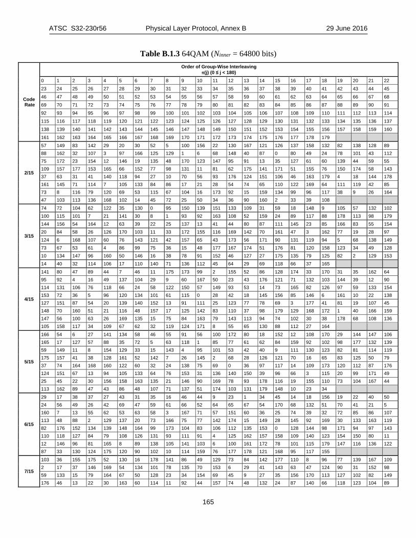
ATSC S32-230r56 Physical Layer Protocol, Annex B 29 June 2016
165
Table B.1.3 64QAM (Ninner = 64800 bits)
Code Rate
Order of Group-Wise Interleaving π(j) (0 ≤ j < 180)
0 1 2 3 4 5 6 7 8 9 10 11 12 13 14 15 16 17 18 19 20 21 22 23 24 25 26 27 28 29 30 31 32 33 34 35 36 37 38 39 40 41 42 43 44 45 46 47 48 49 50 51 52 53 54 55 56 57 58 59 60 61 62 63 64 65 66 67 68 69 70 71 72 73 74 75 76 77 78 79 80 81 82 83 84 85 86 87 88 89 90 91
92 93 94 95 96 97 98 99 100 101 102 103 104 105 106 107 108 109 110 111 112 113 114 115 116 117 118 119 120 121 122 123 124 125 126 127 128 129 130 131 132 133 134 135 136 137 138 139 140 141 142 143 144 145 146 147 148 149 150 151 152 153 154 155 156 157 158 159 160 161 162 163 164 165 166 167 168 169 170 171 172 173 174 175 176 177 178 179
2/15
57 149 83 142 29 20 30 52 5 100 156 22 130 167 121 126 137 158 132 82 138 128 89 88 162 32 107 3 97 166 125 129 1 6 68 148 40 87 0 80 49 24 78 101 43 112 75 172 23 154 12 146 19 135 48 170 123 147 95 91 13 35 127 61 60 139 44 59 55 109 157 177 153 165 66 152 77 98 131 11 81 62 175 141 171 51 155 76 150 174 58 143 37 63 31 41 140 118 94 27 10 70 56 93 176 124 151 106 46 163 179 4 18 144 178 161 145 71 114 7 105 133 84 86 17 21 28 54 74 65 110 122 169 64 111 119 42 85 73 8 116 79 120 69 53 115 67 104 16 173 92 15 159 134 99 96 117 38 9 26 164 47 103 113 136 168 102 14 45 72 25 50 34 36 90 160 2 33 39 108
3/15
74 72 104 62 122 35 130 0 95 150 139 151 133 109 31 59 18 148 9 105 57 132 102 100 115 101 7 21 141 30 8 1 93 92 163 108 52 159 24 89 117 88 178 113 98 179 144 156 54 164 12 63 39 22 25 137 13 41 44 80 87 111 145 23 85 166 83 55 154 20 84 58 26 126 170 103 11 33 172 155 116 169 142 70 161 47 3 162 77 19 28 97 124 6 168 107 60 76 143 121 42 157 65 43 173 56 171 90 131 119 94 5 68 138 149 73 67 53 61 4 86 99 75 36 15 48 177 167 174 51 176 81 120 158 123 34 49 128 10 134 147 96 160 50 146 16 38 78 91 152 46 127 27 175 135 79 125 82 2 129 153 14 40 32 114 106 17 110 140 71 136 112 45 64 29 69 118 66 37 165
4/15
141 80 47 89 44 7 46 11 175 173 99 2 155 52 86 128 174 33 170 31 35 162 64 95 92 4 16 49 137 104 29 9 60 167 50 23 43 176 121 71 132 103 144 39 12 90 114 131 106 76 118 66 24 58 122 150 57 149 93 53 14 73 165 82 126 97 59 133 154 153 72 36 5 96 120 134 101 61 115 0 28 42 18 145 156 85 146 6 161 10 22 138 127 151 87 54 20 139 140 152 13 91 111 25 123 77 78 69 3 177 41 81 19 107 45 148 70 160 51 21 116 48 157 17 125 142 83 110 37 98 179 129 168 172 1 40 166 159 147 56 100 63 26 169 135 15 75 84 163 79 143 113 94 74 102 30 38 178 68 108 136 105 158 117 34 109 67 62 32 119 124 171 8 55 65 130 88 112 27 164
5/15
166 54 6 27 141 134 58 46 55 91 56 100 172 80 18 152 12 108 170 29 144 147 106 165 17 127 57 88 35 72 5 63 118 1 85 77 61 62 84 159 92 102 98 177 132 139 59 149 11 8 154 129 33 15 143 4 95 101 53 42 40 9 111 130 123 82 81 114 119 175 157 41 38 128 161 52 142 7 26 145 2 68 28 126 121 70 16 65 83 125 50 79 37 74 164 168 160 122 60 32 24 138 75 69 0 36 97 117 14 109 173 120 112 87 176 124 151 67 13 94 105 133 64 76 153 31 136 140 150 39 96 66 3 115 20 99 171 49 25 45 22 30 156 158 163 135 21 146 90 169 78 93 178 116 19 155 110 73 104 167 44 113 162 89 47 43 86 48 107 71 137 51 174 103 131 179 148 10 23 34
6/15
29 17 38 37 27 43 31 35 16 46 44 9 23 1 34 45 14 18 156 19 22 40 50 24 56 49 26 42 69 47 59 61 66 52 64 65 67 54 170 68 132 51 70 41 21 5 160 7 13 55 62 53 63 58 3 167 71 57 151 60 36 25 74 39 32 72 85 86 107 113 48 88 2 129 137 20 73 166 75 77 142 174 15 149 28 145 92 169 30 133 163 119 82 176 152 134 139 148 164 99 173 104 83 106 112 135 153 0 128 144 98 171 94 97 143 110 118 127 84 79 108 126 131 93 111 91 4 125 162 157 158 109 140 123 154 150 80 11 12 146 96 81 165 8 89 138 105 141 103 6 100 161 172 78 101 115 179 147 116 136 122 87 33 130 124 175 120 90 102 10 114 159 76 177 178 121 168 95 117 155
7/15
103 36 155 175 52 130 16 178 141 86 49 129 73 84 142 177 110 8 96 77 139 167 109 2 17 37 146 169 54 134 101 78 135 70 153 6 29 41 143 63 47 124 90 31 152 98 59 133 15 79 164 67 50 128 23 34 154 69 45 9 27 35 156 170 113 127 102 82 149 176 46 13 22 30 163 60 114 11 92 44 157 74 48 132 24 87 140 66 118 123 104 89

ATSC S32-230r56 Physical Layer Protocol, Annex B 29 June 2016
166
136 64 107 14 99 43 115 71 117 12 26 38 147 62 57 131 94 33 151 172 116 10 25 75 144 179 51 120 20 80 160 174 106 1 21 88 137 61 105 5 18 32 158 72 56 125 28 42 161 168 53 7 100 40 145 171 55 3 95 83 162 173 119 126 91 39 150 165 112 122 93 76 138 166 108 121 97 81 148 65 111 4 19 85 159 68 58 0
8/15
86 71 51 48 89 94 46 81 67 49 80 37 55 61 36 57 52 92 60 82 76 72 44 42 91 62 50 90 40 78 53 58 47 85 70 4 69 43 54 84 93 38 8 64 6 18 77 95 66 59 83 73 17 87 3 75 65 88 79 14 151 117 32 22 123 30 33 162 144 9 121 108 139 142 24 34 20 157 159 138 143 29 140 163 150 175 114 31 12 35 145 28 27 26 16 98 102 103 133 161 21 25 107 153 45 156 23 125 141 56 166 5 1 170 119 68 134 41 74 179 2 129 169 101 99 109 127 168 176 11 0 122 110 113 146 132 165 19 13 39 7 164 106 172 154 149 10 173 131 167 63 147 155 100 171 158 160 15 178 148 152 104 124 177 97 130 118 137 111 126 120 105 115 136 112 96 135 116 174 128
9/15
175 60 133 11 5 4 70 97 131 80 42 136 50 104 32 75 176 87 109 61 39 107 0 172 23 90 54 160 48 173 27 100 129 14 7 142 20 103 38 126 157 144 21 64 44 79 105 146 49 93 1 84 81 145 18 15 106 91 12 169 63 71 125 37 120 138 17 113 31 130 140 8 25 74 134 115 9 171 46 68 33 116 2 179 52 92 36 78 164 177 24 72 122 118 162 121 16 73 45 53 77 110 30 66 29 76 158 148 111 94 43 83 139 10 56 98 114 117 152 174 47 62 128 85 155 178 26 96 41 82 150 143 58 69 127 86 13 141 35 101 149 108 3 154 51 95 132 135 163 137 28 102 123 112 151 167 59 19 156 119 153 168 55 65 34 6 159 170 57 67 40 89 147 165 22 99 124 88 161 166
10/15
16 163 92 56 111 141 65 118 78 55 5 148 19 153 75 128 32 178 22 156 99 124 4 168 20 115 87 122 9 166 27 155 94 134 38 137 67 161 90 127 43 171 64 162 98 133 34 138 73 154 100 58 103 169 23 117 88 50 13 175 68 39 102 54 37 149 29 150 104 59 3 139 69 110 77 131 42 142 25 158 80 47 35 143 72 151 84 57 8 176 61 46 41 51 10 173 63 107 125 48 11 177 24 30 91 76 109 140 74 114 82 120 1 79 66 119 93 159 36 174 26 112 101 123 44 145 60 157 97 45 33 167 70 152 85 126 40 135 62 108 95 49 31 147 71 113 89 132 6 144 18 105 83 130 2 172 17 164 81 52 7 179 28 160 136 121 14 146 15 106 86 129 12 170 21 116 96 53 0 165
11/15
12 15 2 16 27 50 35 74 38 70 108 32 112 54 30 122 72 116 36 90 49 85 132 138 144 150 156 162 168 174 0 14 9 5 23 66 68 52 96 117 84 128 100 63 60 127 81 99 53 55 103 95 133 139 145 151 157 163 169 175 10 22 13 11 28 104 37 57 115 46 65 129 107 75 119 110 31 43 97 78 125 58 134 140 146 152 158 164 170 176 4 19 6 8 24 44 101 94 118 130 69 71 83 34 86 124 48 106 89 40 102 91 135 141 147 153 159 165 171 177 3 20 7 17 25 87 41 120 47 80 59 62 88 45 56 131 61 126 113 92 51 98 136 142 148 154 160 166 172 178 21 18 1 26 29 39 73 121 105 77 42 114 93 82 111 109 67 79 123 64 76 33 137 143 149 155 161 167 173 179
12/15
83 93 94 47 55 40 38 77 110 124 87 61 102 76 33 35 92 59 74 11 138 72 67 37 10 95 139 131 44 57 97 53 142 0 136 9 143 86 100 21 15 75 62 19 65 129 101 79 22 68 73 23 18 81 98 112 8 128 103 25 43 126 54 90 28 109 46 91 41 82 113 134 52 105 78 27 135 96 56 140 64 66 89 34 120 108 63 45 69 121 88 39 29 133 106 117 127 32 42 58 71 118 51 84 85 80 104 132 111 30 26 48 50 31 141 116 123 114 70 107 178 145 173 36 144 130 176 171 175 125 99 162 159 20 164 115 169 172 165 161 151 119 122 152 157 4 137 148 153 170 154 166 13 150 16 167 174 163 49 6 168 147 146 1 149 158 179 12 5 160 177 60 24 156 7 155 17 3 2 14
13/15
146 91 63 144 46 12 58 137 25 79 70 33 134 148 66 38 163 118 139 130 72 92 160 23 133 153 128 86 152 106 53 93 61 5 158 172 121 135 44 149 168 0 124 143 27 30 151 114 113 43 138 89 159 17 120 136 102 81 170 176 142 104 21 78 155 8 52 95 62 40 174 6 131 48 18 1 179 34 123 77 26 84 157 85 56 147 67 76 162 10 51 103 140 87 175 115 4 101 69 80 169 75 49 97 154 83 14 2 132 96 16 37 166 109 54 42 28 32 171 119 55 94 65 20 165 3 47 90 117 88 177 11 59 68 73 41 150 111 127 100 110 31 167 13 122 145 71 22 173 116 126 141 29 39 178 57 125 36 19 7 156 107 9 98 74 45 161 112 50 99 24 35 164 64 129 15 60 82 108 105

ATSC S32-230r56 Physical Layer Protocol, Annex B 29 June 2016
167
Table B.1.4 256QAM (Ninner = 64800)
Code Rate
Order of Group-Wise Interleaving π(j) (0 ≤ j < 180)
0 1 2 3 4 5 6 7 8 9 10 11 12 13 14 15 16 17 18 19 20 21 22 23 24 25 26 27 28 29 30 31 32 33 34 35 36 37 38 39 40 41 42 43 44 45 46 47 48 49 50 51 52 53 54 55 56 57 58 59 60 61 62 63 64 65 66 67 68 69 70 71 72 73 74 75 76 77 78 79 80 81 82 83 84 85 86 87 88 89 90 91
92 93 94 95 96 97 98 99 100 101 102 103 104 105 106 107 108 109 110 111 112 113 114 115 116 117 118 119 120 121 122 123 124 125 126 127 128 129 130 131 132 133 134 135 136 137 138 139 140 141 142 143 144 145 146 147 148 149 150 151 152 153 154 155 156 157 158 159 160 161 162 163 164 165 166 167 168 169 170 171 172 173 174 175 176 177 178 179
2/15
112 78 104 6 59 80 49 120 114 27 113 3 109 44 69 164 91 137 39 31 21 127 151 8 47 176 117 68 122 148 79 73 7 166 51 50 116 66 152 61 29 107 22 154 118 94 24 35 55 38 88 54 2 15 19 67 101 74 169 138 41 162 175 136 62 161 121 163 115 135 123 25 140 156 58 33 119 111 146 129 150 147 97 18 60 4 81 168 43 105 36 65 13 5 108 145 23 70 20 173 159 100 128 172 170 1 37 83 102 103 157 139 179 32 144 92 131 75 155 14 9 149 63 11 134 53 99 17 57 90 30 98 64 40 87 158 77 93 124 46 171 141 133 85 177 132 26 160 42 34 82 96 48 10 142 125 178 153 72 45 89 52 28 126 143 167 76 86 130 110 174 16 165 56 84 95 0 106 12 71
3/15
136 28 85 38 40 89 133 117 3 58 154 77 14 179 96 101 26 169 37 83 162 165 24 66 109 126 10 155 70 157 105 175 67 158 32 42 147 140 30 7 92 59 119 56 0 5 90 174 13 47 76 88 86 108 27 18 12 8 61 145 75 125 112 69 120 137 116 20 178 98 176 29 68 168 124 21 35 150 131 159 163 84 23 123 65 103 93 99 102 31 64 74 46 94 80 129 142 128 148 111 134 173 60 118 2 170 135 1 115 143 95 177 73 43 11 114 91 78 107 172 25 36 164 149 153 110 44 146 82 127 45 33 50 41 52 156 34 4 79 141 138 122 53 160 81 16 100 130 71 121 132 9 22 113 6 152 15 171 17 57 49 151 161 63 55 139 166 97 19 51 72 167 106 48 144 87 104 62 54 39
4/15
13 121 137 29 27 1 70 116 35 132 109 51 55 58 11 67 136 25 145 7 75 107 45 21 127 52 90 22 100 123 69 112 155 92 151 59 5 179 44 87 56 139 65 170 46 0 124 78 166 8 61 97 120 103 4 19 64 79 28 134 93 86 60 135 126 53 63 14 122 17 150 76 42 39 23 153 95 66 50 141 176 34 161 26 106 10 43 85 131 2 147 148 144 54 115 146 101 172 114 119 3 96 133 99 167 164 9 142 68 149 94 83 16 175 73 38 143 159 130 84 169 18 138 102 72 47 32 160 82 81 168 30 12 173 156 158 125 98 62 178 48 163 117 110 91 37 80 105 31 174 111 49 113 108 74 157 128 24 118 40 88 177 154 6 162 129 77 36 165 20 89 140 15 33 104 152 71 171 57 41
5/15
39 45 128 84 143 148 2 75 43 50 130 87 137 151 7 71 55 51 133 90 140 149 6 177 37 124 99 83 23 159 0 176 41 121 96 89 30 161 18 172 60 49 134 104 139 166 14 179 62 48 129 105 146 160 16 174 33 54 132 112 145 150 9 77 34 117 92 82 136 165 4 67 36 44 101 81 141 156 3 175 58 47 91 102 32 158 13 178 63 118 100 85 26 167 1 173 38 116 131 107 138 162 8 72 42 115 98 108 24 152 17 171 64 123 94 110 28 147 19 169 61 46 97 106 144 164 5 70 59 53 127 88 31 153 10 73 66 119 126 111 29 155 15 170 57 120 125 80 142 168 11 68 56 52 95 103 27 154 21 78 40 122 93 86 25 163 20 79 35 114 135 109 22 157 12 69 65 74 76 113
6/15
99 100 15 107 54 76 153 174 61 0 36 71 62 137 108 114 65 98 151 19 112 109 152 117 35 93 43 90 154 73 150 165 23 16 91 5 169 175 120 149 26 59 49 56 156 136 110 80 58 55 40 103 159 83 127 111 155 167 11 52 116 142 133 1 2 96 77 86 122 6 131 29 51 21 17 45 126 12 3 168 41 30 37 64 164 78 8 118 113 39 48 140 14 60 82 134 25 33 50 84 28 105 123 145 7 27 34 92 115 147 74 10 68 102 67 63 101 18 66 129 24 4 119 87 42 170 143 121 38 57 95 148 89 81 158 171 32 22 69 53 130 104 161 75 141 9 47 79 162 146 124 157 70 106 31 132 166 128 138 125 44 13 85 88 135 144 173 163 20 46 97 94 139 172 72 160 176 177 178 179
7/15
24 157 0 43 126 172 135 65 32 18 114 42 162 67 104 61 23 11 4 96 163 75 109 58 79 154 3 95 168 73 103 60 84 148 113 40 164 173 143 49 29 156 7 89 132 179 138 53 85 12 117 36 122 66 107 64 28 147 2 90 131 70 144 55 26 15 112 35 128 176 106 59 80 19 6 92 129 174 99 62 82 13 121 41 127 71 139 63 25 151 9 39

ATSC S32-230r56 Physical Layer Protocol, Annex B 29 June 2016
168
159 69 142 52 77 21 119 38 167 178 101 56 87 155 5 91 166 169 146 50 81 20 111 88 165 177 108 47 27 149 115 33 161 72 102 57 86 16 110 97 123 68 100 48 31 14 8 93 130 170 133 44 78 150 118 94 158 76 134 46 83 152 1 37 160 171 136 54 22 17 116 34 125 175 105 45 30 153 10 98 124 74 137 51 120 141 140 145
8/15
85 3 148 161 96 99 154 13 78 160 61 36 21 141 121 115 82 1 59 72 43 135 168 139 46 10 56 67 108 134 111 105 66 89 137 130 104 143 113 11 84 157 32 73 90 38 117 146 53 2 60 93 91 71 114 19 47 4 26 75 109 41 50 153 54 163 31 24 106 42 170 62 80 164 65 128 12 142 167 155 88 8 22 131 158 33 178 145 70 9 51 69 102 140 173 147 83 165 30 126 100 138 171 103 45 159 27 74 97 122 120 16 52 162 132 124 94 133 172 149 86 77 25 68 177 64 174 15 0 125 63 35 34 40 179 20 44 7 55 28 101 150 110 18 119 5 29 76 107 136 112 144 48 81 57 49 92 95 118 17 156 166 23 129 79 37 175 152 87 6 58 127 98 123 39 14 116 169 176 151
9/15
58 70 23 32 26 63 55 48 35 41 53 20 38 51 61 65 44 29 7 2 113 68 96 104 106 89 27 0 119 21 4 49 46 100 13 36 57 98 102 9 42 39 33 62 22 95 101 15 91 25 93 132 69 87 47 59 67 124 17 11 31 43 40 37 85 50 97 140 45 92 56 30 34 60 107 24 52 94 64 5 71 90 66 103 88 86 84 19 169 159 147 126 28 130 14 162 144 166 108 153 115 135 120 122 112 139 151 156 16 172 164 123 99 54 136 81 105 128 116 150 155 76 18 142 170 175 83 146 78 109 73 131 127 82 167 77 110 79 137 152 3 173 148 72 158 117 1 6 12 8 161 74 143 133 168 171 134 163 138 121 141 160 111 10 149 80 75 165 157 174 129 145 114 125 154 118 176 177 178 179
10/15
45 31 67 35 159 157 177 2 44 23 73 148 163 118 176 4 14 97 142 37 143 149 179 3 12 32 140 42 167 166 41 126 13 30 144 57 113 147 173 6 52 24 39 64 80 112 104 174 11 151 71 109 162 79 171 127 46 92 38 132 81 120 100 1 53 88 76 60 103 139 99 125 48 93 135 161 77 110 107 121 18 95 69 63 83 111 170 7 16 98 141 61 86 116 172 130 49 25 40 65 87 108 101 5 21 89 75 43 82 146 105 128 17 29 106 34 160 155 175 124 15 28 134 62 119 145 72 10 58 91 74 36 68 150 8 9 54 26 137 56 165 115 114 0 47 27 22 20 168 154 102 123 50 94 66 33 85 59 164 131 51 90 70 138 84 117 178 122 19 96 156 55 78 158 169 129 133 152 136 153
11/15
27 68 35 117 138 83 127 10 60 73 47 115 155 81 170 9 65 66 52 112 150 77 171 161 22 20 39 106 147 90 126 165 23 16 45 113 154 86 173 158 24 71 40 107 136 94 128 163 31 72 33 101 134 80 175 7 61 19 49 111 135 92 130 6 62 74 43 116 133 89 129 8 28 15 34 105 146 84 174 4 32 75 44 118 132 96 169 159 58 18 42 100 141 87 131 157 63 11 48 108 151 79 177 168 26 17 36 102 137 95 122 1 25 21 50 120 153 97 121 0 55 14 46 114 152 91 178 3 30 13 37 103 145 82 125 166 57 76 51 99 144 85 123 162 56 12 53 119 139 78 179 5 64 70 54 110 148 93 172 164 29 69 38 109 143 88 124 160 59 67 41 104 149 98 176 2 167 156 140 142
12/15
51 122 91 111 95 100 119 130 78 57 65 26 61 126 105 143 70 132 39 102 115 116 6 14 3 21 71 134 2 0 140 106 7 118 23 35 20 17 50 48 112 13 66 5 75 42 129 107 30 45 137 114 37 87 53 85 101 141 120 99 88 117 64 28 135 138 108 113 58 97 38 124 86 33 74 32 29 128 67 104 80 127 56 34 89 94 49 55 93 136 68 62 54 40 81 103 121 76 44 84 96 123 154 98 82 142 46 169 131 72 47 69 125 31 83 36 59 90 79 52 133 60 92 139 110 27 73 43 77 109 63 41 168 147 161 165 175 162 164 158 157 160 150 171 167 145 151 153 9 155 170 146 166 149 15 159 11 176 152 156 144 148 172 178 24 22 179 4 163 174 173 19 10 177 12 16 1 8 18 25
13/15
59 85 108 128 49 91 163 3 58 16 106 126 74 141 167 35 57 82 30 123 68 95 160 42 62 21 102 131 52 142 157 10 55 79 24 130 73 92 179 2 61 11 104 122 45 140 159 43 148 19 23 111 76 135 169 39 63 77 25 117 75 94 155 5 145 14 26 127 46 138 158 38 64 86 105 118 50 137 175 7 144 84 22 113 54 98 172 9 146 17 27 114 51 139 156 37 147 78 103 115 66 97 168 34 60 83 107 121 48 93 174 33 65 87 99 124 71 136 154 0 150 20 101 112 70 96 170 1 149 80 28 125 53 90 173 6 153 13 29 116 72 88 165 8 143 12 31 119 47 89 164 40 151 81 109 110 44 134 162 36 152 15 100 129 67 133 166 41 56 18 32 120 69 132 161 4 177 176 178 171

ATSC S32-230r56 Physical Layer Protocol, Annex B 29 June 2016
169
Table B.1.5 1024QAM (Ninner = 64800)
Code Rate
Order of Group-Wise Interleaving π(j) (0 ≤ j < 180)
0 1 2 3 4 5 6 7 8 9 10 11 12 13 14 15 16 17 18 19 20 21 22 23 24 25 26 27 28 29 30 31 32 33 34 35 36 37 38 39 40 41 42 43 44 45 46 47 48 49 50 51 52 53 54 55 56 57 58 59 60 61 62 63 64 65 66 67 68 69 70 71 72 73 74 75 76 77 78 79 80 81 82 83 84 85 86 87 88 89 90 91
92 93 94 95 96 97 98 99 100 101 102 103 104 105 106 107 108 109 110 111 112 113 114 115 116 117 118 119 120 121 122 123 124 125 126 127 128 129 130 131 132 133 134 135 136 137 138 139 140 141 142 143 144 145 146 147 148 149 150 151 152 153 154 155 156 157 158 159 160 161 162 163 164 165 166 167 168 169 170 171 172 173 174 175 176 177 178 179
2/15
157 25 107 160 37 138 111 35 29 44 15 162 66 20 49 126 89 147 159 174 142 26 146 10 164 152 57 110 83 167 169 16 6 172 62 173 7 145 4 67 115 50 39 72 79 74 40 132 42 30 163 161 55 143 63 117 86 121 2 28 69 150 24 177 43 158 27 21 128 46 118 114 127 135 92 76 19 94 179 3 52 101 137 84 73 108 91 120 47 1 102 58 68 82 59 119 64 31 61 105 103 151 124 70 8 155 90 166 41 45 178 113 140 75 148 109 100 125 11 116 34 36 176 170 156 136 171 122 78 87 106 123 149 17 99 175 18 9 165 153 12 81 77 60 93 104 13 5 88 96 141 133 154 144 48 97 23 14 98 53 134 112 65 0 130 32 168 33 131 22 38 56 80 95 71 85 139 129 51 54
3/15
113 153 13 8 103 115 137 69 151 111 18 38 42 150 179 130 148 6 4 31 44 68 145 126 106 24 100 93 21 35 143 57 166 65 53 41 122 7 29 25 136 162 158 26 124 32 17 168 56 12 39 176 131 132 51 89 101 160 49 87 14 55 127 37 169 110 83 134 107 46 33 114 108 82 125 109 95 174 62 164 144 16 121 58 80 2 163 159 157 90 104 23 172 112 19 133 102 75 45 86 63 22 54 105 155 77 178 70 98 40 118 84 78 0 99 123 5 34 71 96 175 10 30 72 28 74 154 61 91 85 135 152 15 88 165 60 52 149 147 59 116 120 3 64 140 67 94 27 9 81 43 11 167 139 92 129 20 117 128 50 119 47 1 156 142 170 171 48 177 66 161 79 73 76 173 97 36 141 146 138
4/15
114 133 4 73 8 139 7 5 177 88 66 11 24 74 49 45 167 81 117 137 46 22 165 51 68 110 6 1 16 132 130 143 169 2 20 140 94 21 91 126 172 27 162 34 113 142 166 115 106 160 84 136 175 0 26 151 69 174 59 159 161 170 52 164 80 108 3 23 101 33 125 111 63 124 98 40 145 9 39 155 149 147 67 76 48 120 119 53 54 138 179 156 127 13 152 129 123 141 109 89 121 50 10 37 104 144 86 178 96 148 128 56 64 153 95 12 105 41 154 99 25 171 92 17 134 19 61 32 85 102 14 71 146 163 173 118 57 18 36 42 78 31 97 55 58 116 90 168 43 72 15 112 93 60 38 103 87 158 35 29 176 150 77 79 122 47 28 135 100 83 65 131 75 157 62 70 44 30 107 82
5/15
128 4 162 8 77 29 91 44 176 107 149 1 150 9 119 99 71 124 104 41 62 5 118 50 174 54 111 40 156 92 46 11 17 52 47 97 179 24 153 145 129 2 12 88 101 139 114 69 96 32 134 55 167 132 123 136 112 102 159 31 87 141 15 61 84 98 37 63 20 85 53 7 39 117 170 138 116 126 161 120 57 13 76 6 121 155 175 38 158 35 86 78 10 103 166 95 125 172 67 30 177 73 151 169 163 23 108 43 81 157 58 105 65 26 122 135 146 72 142 34 133 0 148 89 168 60 109 83 18 27 131 70 56 48 64 93 68 127 21 75 110 80 14 49 82 143 115 178 154 100 59 74 152 51 137 140 36 42 19 25 94 45 164 16 113 79 22 28 66 106 130 171 147 90 144 165 3 173 160 33
6/15
66 21 51 55 54 24 33 12 70 63 47 65 145 8 0 57 23 71 59 14 40 42 62 56 2 43 64 58 67 53 68 61 39 52 69 1 22 31 161 38 30 19 17 18 4 41 25 44 136 29 36 26 126 177 15 37 148 9 13 45 46 152 50 49 27 77 60 35 48 178 28 34 106 127 76 131 105 138 75 130 101 167 117 173 113 108 92 135 124 121 97 149 143 81 32 96 3 78 107 86 98 16 162 150 111 158 172 139 74 142 166 7 5 119 20 144 151 90 11 156 100 175 83 155 159 128 88 87 93 103 94 140 165 6 137 157 10 85 141 129 146 122 73 112 132 125 174 169 168 79 84 118 179 147 91 160 163 115 89 80 102 104 134 82 95 133 164 154 120 110 170 114 153 72 109 171 176 99 116 123
7/15
117 61 46 179 24 161 142 133 11 6 121 44 103 76 22 63 136 151 33 8 123 60 105 175 18 160 138 147 10 0 125 57 49 75 21 154 140 150 9 169 124 55 48 173 23 157 97 129 30 7 122 54 99 74 19 153 94 128 15 170 87 59 51 80 111 64 137 146 13 2 83 62 45 176 108 71 91 131 34 168 82 56 102 72 26 155 92 132 31 166 119 36

ATSC S32-230r56 Physical Layer Protocol, Annex B 29 June 2016
170
101 178 113 67 98 152 14 5 118 41 104 177 114 70 96 134 32 162 84 40 100 174 110 158 93 149 27 4 86 38 53 77 115 159 143 130 35 163 89 58 106 73 20 66 90 127 16 3 85 37 107 172 116 156 95 144 17 165 81 43 50 78 109 68 135 126 29 167 120 39 47 171 112 69 141 145 28 1 88 42 52 79 25 65 139 148 12 164
8/15
77 48 82 51 57 69 65 6 71 90 84 81 50 88 61 55 53 73 39 13 79 75 41 18 38 89 49 93 36 64 47 40 42 76 70 56 3 72 2 54 52 145 19 78 80 63 87 67 86 10 1 58 17 14 175 91 68 85 94 15 43 74 60 66 37 92 4 9 16 83 46 44 102 30 112 122 110 29 20 105 138 101 174 33 137 136 131 166 59 34 62 125 28 26 45 24 23 21 157 98 35 95 22 32 103 27 113 31 119 173 168 118 120 114 149 159 155 179 160 161 130 123 172 139 124 153 0 109 167 128 107 117 147 177 96 164 152 11 148 158 129 163 176 151 171 8 106 144 150 169 108 162 143 111 141 133 178 134 146 99 132 142 104 115 135 121 100 12 170 156 126 5 127 154 97 140 116 165 7 25
9/15
42 36 135 126 3 17 82 87 172 32 65 70 143 131 10 1 85 147 31 176 66 47 97 128 8 9 146 73 162 164 57 64 139 91 5 110 150 83 18 27 48 45 133 132 111 124 89 78 177 19 46 50 102 103 122 4 74 161 175 34 60 58 136 100 115 118 81 75 28 21 40 61 140 138 113 112 157 151 23 30 69 41 94 96 7 109 152 149 33 179 71 43 92 105 12 13 154 159 178 24 44 49 107 98 16 2 76 155 35 168 62 56 129 141 116 123 160 77 25 170 54 39 90 95 121 11 72 153 169 167 51 67 104 134 0 117 79 80 26 29 37 55 99 142 108 114 86 88 166 163 59 63 101 93 119 15 144 145 165 22 52 53 130 137 125 6 158 84 20 174 38 68 127 106 14 120 148 156 171 173
10/15
100 22 60 121 40 44 164 170 176 101 88 26 35 4 21 173 140 145 175 174 81 28 72 112 132 106 42 56 151 147 82 49 91 64 179 89 160 52 139 17 97 63 116 131 154 71 109 96 135 146 55 38 166 117 65 127 120 129 15 136 74 23 98 43 123 130 69 99 143 161 46 51 94 61 83 67 156 33 144 148 163 47 92 2 122 24 86 75 108 152 14 77 7 10 29 19 104 128 142 1 79 107 162 0 118 66 54 153 141 9 85 37 32 114 53 134 41 158 178 138 76 50 78 84 172 48 133 168 125 13 169 25 16 8 124 159 167 58 5 11 68 95 27 110 93 62 102 137 126 150 87 105 113 30 119 6 103 57 31 149 80 70 45 165 111 73 36 157 171 3 20 18 90 12 59 39 115 34 177 155
11/15
33 73 90 107 99 94 53 151 124 8 12 117 21 58 158 77 72 59 123 2 125 157 50 62 109 75 42 146 118 153 85 10 131 70 32 41 24 143 113 1 93 162 20 35 74 45 149 161 173 4 28 23 127 148 34 61 96 144 171 140 119 16 126 39 40 57 165 106 172 139 81 47 164 92 63 105 108 170 3 135 101 121 68 6 111 65 147 150 122 7 84 46 22 103 86 169 134 44 175 167 89 128 27 31 56 43 102 156 160 141 67 9 110 159 133 78 154 176 174 5 82 11 25 80 130 163 88 36 166 137 104 48 129 87 95 55 49 145 178 0 98 64 54 100 37 79 69 38 177 136 114 17 52 19 30 97 51 168 132 138 83 76 13 18 115 71 91 179 112 155 15 14 26 60 29 116 66 120 142 152
12/15
91 19 11 106 14 40 20 67 32 22 31 23 78 68 79 141 117 95 88 136 52 121 1 133 4 2 21 122 38 12 69 111 81 82 58 46 112 60 33 73 53 92 75 48 47 110 80 76 138 87 85 65 130 57 102 83 64 86 100 39 49 125 108 119 6 118 35 61 71 30 45 94 26 116 98 37 55 44 70 25 7 34 114 135 128 137 84 51 28 97 27 89 29 62 50 139 56 109 77 59 127 142 96 105 99 90 13 124 120 115 126 143 149 74 41 178 129 18 131 42 165 101 134 36 140 132 103 72 164 93 54 166 43 123 113 0 154 10 63 107 162 157 66 104 17 147 167 174 179 3 173 160 155 161 152 156 177 24 170 9 159 16 15 148 5 146 163 172 175 151 169 176 150 153 171 158 168 144 8 145
13/15
49 2 57 47 31 35 24 39 59 0 45 41 55 53 51 37 33 43 56 38 48 32 50 23 34 54 1 36 44 52 40 58 122 46 42 30 3 75 73 65 145 71 79 67 69 83 85 147 63 81 77 61 5 26 62 64 74 70 82 149 76 4 78 84 80 86 66 68 72 6 60 154 103 95 101 143 9 89 141 128 97 137 133 7 13 99 91 93 87 11 136 90 88 94 10 8 14 96 104 92 132 142 100 98 12 102 152 139 150 106 146 130 27 108 153 112 114 29 110 134 116 15 127 125 123 120 148 151 113 126 124 135 129 109 25 28 158 117 105 115 111 131 107 121 18 170 164 20 140 160 166 162 119 155 168 178 22 174 172 176 16 157 159 171 161 118 17 163 21 165 19 179 177 167 138 173 156 144 169 175

ATSC S32-230r56 Physical Layer Protocol, Annex B 29 June 2016
171
Table B.1.6 4096QAM (Ninner = 64800)
Code Rate
Order of Group-Wise Interleaving π(j) (0 ≤ j < 180)
0 1 2 3 4 5 6 7 8 9 10 11 12 13 14 15 16 17 18 19 20 21 22 23 24 25 26 27 28 29 30 31 32 33 34 35 36 37 38 39 40 41 42 43 44 45 46 47 48 49 50 51 52 53 54 55 56 57 58 59 60 61 62 63 64 65 66 67 68 69 70 71 72 73 74 75 76 77 78 79 80 81 82 83 84 85 86 87 88 89 90 91
92 93 94 95 96 97 98 99 100 101 102 103 104 105 106 107 108 109 110 111 112 113 114 115 116 117 118 119 120 121 122 123 124 125 126 127 128 129 130 131 132 133 134 135 136 137 138 139 140 141 142 143 144 145 146 147 148 149 150 151 152 153 154 155 156 157 158 159 160 161 162 163 164 165 166 167 168 169 170 171 172 173 174 175 176 177 178 179
2/15
14 129 71 96 171 36 144 64 162 4 86 128 113 7 105 131 2 133 106 79 11 152 26 118 158 126 17 55 45 111 138 84 6 52 167 38 20 101 31 120 5 112 74 69 121 9 154 15 146 116 63 1 114 83 124 109 39 75 123 57 49 30 21 40 43 77 157 44 13 99 34 147 166 56 155 176 95 102 119 161 37 159 97 68 122 163 89 61 107 22 10 127 87 103 179 172 66 59 8 145 88 132 110 54 47 153 25 32 73 42 148 150 28 91 18 24 19 53 136 48 76 35 151 173 149 142 160 94 117 169 165 141 80 67 170 164 82 65 60 135 168 23 100 134 90 98 125 85 137 81 41 156 50 3 29 16 72 177 0 78 62 139 93 46 12 175 130 51 178 92 115 174 27 70 58 33 104 140 108 143
3/15
136 20 44 36 17 120 89 142 66 35 42 116 14 119 117 29 47 125 11 158 74 25 37 175 41 145 100 131 173 179 16 77 112 40 58 23 82 168 106 83 34 49 122 2 157 107 79 137 53 96 33 70 19 38 121 90 118 126 165 109 154 140 10 178 143 92 63 176 146 134 177 139 3 113 172 9 50 138 61 93 94 88 132 105 151 170 86 12 1 7 56 59 101 155 95 54 85 13 39 15 76 130 97 110 174 72 150 55 73 99 111 162 26 21 156 28 160 149 133 104 81 69 84 4 6 147 48 115 169 127 161 71 68 80 91 98 8 57 171 135 52 5 141 65 75 163 43 144 167 159 129 46 31 30 166 0 148 128 102 103 60 32 18 51 87 114 64 22 164 24 123 27 62 124 152 78 108 67 153 45
4/15
91 52 36 30 35 6 121 29 150 47 163 2 89 39 65 157 64 122 101 40 84 69 90 129 10 9 15 162 21 171 43 44 132 158 104 4 72 169 177 103 76 28 78 53 1 151 161 88 148 42 160 109 100 126 138 108 38 25 3 112 17 124 155 172 134 86 119 94 145 178 68 26 130 140 115 152 139 37 22 102 14 118 11 98 154 61 146 164 107 131 159 63 93 7 79 5 137 165 59 77 55 80 117 13 173 144 85 153 66 106 49 34 48 41 143 142 27 136 18 111 175 123 147 114 19 125 166 149 113 46 31 141 120 57 74 8 20 96 170 128 97 16 60 110 156 45 82 105 62 99 23 92 32 50 73 56 167 95 24 168 33 116 75 127 81 67 179 174 70 12 58 87 176 0 51 135 83 133 54 71
5/15
146 89 57 16 164 138 91 78 90 66 122 12 9 157 14 68 112 128 74 45 28 87 158 56 61 168 18 161 95 99 139 22 65 130 166 118 150 49 142 44 36 1 121 6 46 29 88 47 0 58 105 43 80 64 107 21 55 151 8 145 163 7 98 123 17 11 153 136 52 3 13 34 160 102 125 114 152 84 32 97 33 60 62 79 37 129 38 165 71 75 59 144 127 132 104 53 162 103 120 54 155 116 48 77 76 73 113 119 179 177 41 19 92 109 31 143 178 108 39 140 106 40 5 25 81 176 101 124 126 72 111 4 173 156 134 86 174 2 170 35 175 137 15 24 69 96 30 117 67 171 149 169 63 23 20 167 27 147 51 10 82 131 85 110 94 135 172 148 50 154 42 70 115 26 83 141 100 133 93 159
6/15
66 21 51 55 117 24 33 12 70 63 47 65 145 8 0 57 23 71 59 14 40 42 15 56 2 43 64 58 67 53 68 61 39 52 69 1 22 31 161 38 30 19 17 18 4 41
25 44 136 29 36 26 126 177 62 37 148 9 13 45 46 152 50 49 27 77 60 35 48
178 28 34 106 127 76 131 105 138 75 130 101 167 54 173 113 108 92 135 124 121 97 149
143 81 32 96 3 78 107 86 98 16 162 150 111 158 172 139 74 142 166 7 5 119 20
144 151 90 11 156 100 175 83 155 159 128 88 87 93 103 94 140 165 6 137 157 10 85
141 129 146 122 73 112 132 125 174 169 168 79 84 118 179 147 91 160 163 115 89 80 102
104 134 82 95 133 164 154 120 110 170 114 153 72 109 171 176 99 116 123
7/15
59 122 161 93 37 112 111 62 42 102 119 72 60 144 34 120 46 31 129 172 149 94 65 9 0 76 13 61 3 70 40 78 127 35 145 28 48 162 92 73 6 134 66 160 133 101 4 5 87 106 79 104 168 163 170 57 83 44 54 110 30 50 82 10 148 98 41 22 96 49 90 100 29 39 175 38 109 91 74 159 139 177 71 47 146 63 86 45 123 33 138 51

ATSC S32-230r56 Physical Layer Protocol, Annex B 29 June 2016
172
89 88 167 80 142 108 69 7 103 115 99 135 36 11 166 169 8 165 68 173 140 95 179 2 125 105 1 116 150 174 15 75 64 176 81 55 130 151 156 53 171 16 113 24 117 154 157 164 143 12 56 152 20 85 84 77 158 107 32 153 147 132 124 52 121 58 118 137 114 97 19 155 67 25 17 126 23 43 27 21 136 131 26 14 18 128 141 178
8/15
77 48 82 51 57 69 65 6 71 90 84 81 50 88 61 55 53 73 39 13 79 75 41 18 38 89 49 93 36 64 47 40 42 76 70 56 3 72 2 54 52 145 19 78 80 63
87 67 86 10 1 58 17 14 175 91 68 85 94 15 43 74 60 66 37 92 4 9 16
83 46 44 102 30 112 122 110 29 20 105 138 101 174 33 137 136 131 166 59 34 62 125
28 26 45 24 23 21 157 98 35 95 22 32 103 27 113 31 119 173 168 118 120 114 149
159 155 179 160 161 130 123 172 139 124 153 0 109 167 128 107 117 147 177 96 164 152 11
148 158 129 163 176 151 171 8 106 144 150 169 108 162 143 111 141 133 178 134 146 99 132
142 104 115 135 121 100 12 170 156 126 5 127 154 97 140 116 165 7 25
9/15
67 79 72 175 1 92 63 65 36 73 18 3 43 78 5 40 82 20 15 76 28 84 59 91 93 54 58 60 2 19 66 44 85 48 0 50 166 89 41 24 83 75 55 64 52 98
39 141 34 74 33 45 99 46 10 69 94 101 56 9 97 96 37 14 31 70 106 113 80
62 100 13 32 88 57 127 53 68 146 61 7 107 71 51 161 81 49 86 95 103 30 25
126 87 22 47 27 171 102 6 132 77 90 38 167 4 35 26 118 140 104 128 179 124 109
159 42 110 21 105 148 142 134 23 117 122 160 12 154 114 156 151 145 169 11 139 177 129
155 178 138 176 147 121 136 165 170 133 149 150 174 168 125 116 115 164 29 119 153 157 162
173 112 144 172 123 137 16 120 131 111 135 163 17 130 152 108 8 158 143
10/15
36 21 117 71 38 108 42 61 13 88 97 68 2 67 50 64 95 63 100 9 82 51 45 78 31 18 103 39 119 25 40 28 72 11 73 86 131 84 111 24 58 60 81 37 89 1
93 56 69 96 35 57 116 130 55 74 41 169 54 14 26 65 83 165 107 0 52 144 75
101 8 115 118 85 48 112 80 90 32 173 76 33 16 77 164 104 46 20 98 109 29 114
7 110 99 53 133 70 87 106 145 4 113 27 59 34 5 102 148 142 79 19 44 159 174
155 136 94 43 49 152 161 66 3 121 135 147 17 157 30 153 154 137 168 92 149 171 10
177 134 143 176 179 105 172 47 146 160 23 175 141 91 140 163 132 6 126 124 12 170 167
151 125 139 150 15 129 162 120 166 156 62 158 178 128 127 22 122 123 138
11/15
77 97 3 44 119 72 83 116 40 0 111 8 68 43 24 102 49 92 65 31 93 60 17 76 89 118 70 87 15 67 22 59 95 46 38 125 48 58 140 104 73 47 14 120 1 50
80 63 62 45 9 25 114 19 82 54 150 121 130 123 37 55 23 98 81 122 103 85 126
101 78 5 128 148 57 12 107 36 2 109 52 39 66 115 42 156 90 51 91 29 84 18
144 10 94 64 100 86 71 27 30 32 110 33 113 131 35 34 112 26 108 16 61 56 75
41 117 69 172 96 149 127 124 173 13 74 105 53 161 146 174 79 88 28 129 134 139 136
145 170 135 158 154 162 7 169 99 106 137 165 143 4 175 138 133 171 168 147 167 141 163
176 179 142 11 177 153 151 159 132 20 164 6 157 178 21 166 155 160 152
12/15
110 16 64 100 55 70 48 26 60 71 93 1 59 88 97 136 67 94 90 72 49 23 41 92 9 35 37 113 101 111 8 52 56 19 134 151 84 126 159 63 44 65 139 31 57 103
22 116 172 38 95 36 46 141 114 4 106 149 85 86 66 51 121 105 109 87 6 135 127
47 123 39 10 148 43 131 147 45 143 5 108 81 2 140 120 132 76 58 137 18 29 125
17 30 32 156 133 78 91 161 104 174 53 61 50 74 77 33 171 138 28 69 112 119 12
102 20 167 99 122 117 24 98 115 124 42 7 79 75 128 82 68 80 3 11 54 96 40
129 142 107 73 175 14 83 150 165 118 89 130 15 163 34 166 173 146 168 153 154 177 62
145 0 178 155 157 179 144 158 152 13 25 176 162 169 164 27 21 160 170
13/15
87 50 6 42 82 54 96 0 62 124 109 126 23 64 53 20 41 111 145 135 68 2 122 128 107 7 28 14 125 136 154 10 92 99 84 86 151 108 24 94 148 29 123 13 88 52
35 61 102 132 95 70 40 129 101 36 51 150 142 152 121 131 116 97 104 31 59 137 83
112 113 57 77 32 93 49 58 117 78 1 149 37 11 100 85 79 72 66 130 18 63 55
91 46 146 21 143 44 110 75 138 16 76 45 114 144 119 38 140 65 30 133 153 33 89
71 115 105 90 56 25 103 147 73 60 47 118 27 69 9 74 48 19 39 43 34 81 139
3 164 106 134 5 67 80 141 120 98 155 8 156 162 163 165 26 161 168 176 159 170 4
127 22 173 157 171 178 158 17 174 179 167 12 172 166 160 177 169 175 15

ATSC S32-230r56 Physical Layer Protocol, Annex B 29 June 2016
173
B.2 PERMUTATION SEQUENCES OF GROUP-WISE INTERLEAVING FOR NINNER = 16200 (NGROUP = 45)
Table B.2.1 QPSK (Ninner = 16200)
Code Rate
Order of Group-Wise Interleaving π(j) (0 ≤ j < 45)
0 1 2 3 4 5 6 7 8 9 10 11 12 13 14 15 16 17 18 19 20 21 22 23 24 25 26 27 28 29 30 31 32 33 34 35 36 37 38 39 40 41 42 43 44
2/15 0 2 4 6 8 10 12 14 16 18 20 22 24 26 28 30 32 34 36 38 40 42 1 3 5 7 9 11 13 15 17 19 21 23 25 27 29 31 33 35 37 39 41 43 44
3/15 15 22 34 19 7 17 28 43 30 32 14 1 11 0 3 9 10 38 24 4 23 18 27 39 29 33 8 2 40 21 20 36 44 12 37 13 35 6 31 26 16 25 42 5 41
4/15 0 2 4 6 8 10 12 14 16 18 20 22 24 26 28 30 32 34 36 38 40 42 1 3 5 7 9 11 13 15 17 19 21 23 25 27 29 31 33 35 37 39 41 43 44
5/15 35 7 29 11 14 32 38 28 20 17 25 39 19 4 1 12 10 30 0 44 43 2 21 5 13 34 37 23 15 36 18 42 16 33 31 27 22 3 6 40 24 41 9 26 8
6/15 7 4 0 5 27 30 25 13 31 9 34 10 17 11 8 12 15 16 18 19 20 21 22 23 1 35 24 29 33 6 26 14 32 28 2 3 36 37 38 39 40 41 42 43 44
7/15 3 7 1 4 18 21 22 6 9 5 17 14 13 15 10 20 8 19 16 12 0 11 2 23 24 25 26 27 28 29 30 31 32 33 34 35 36 37 38 39 40 41 42 43 44
8/15 0 2 4 6 8 10 12 14 16 18 20 22 24 26 28 30 32 34 36 38 40 42 1 3 5 7 9 11 13 15 17 19 21 23 25 27 29 31 33 35 37 39 41 43 44
9/15 0 1 2 3 4 5 6 7 8 9 10 11 12 13 14 15 16 17 18 19 20 21 22 23 24 25 26 27 28 29 30 31 32 33 34 35 36 37 38 39 40 41 42 43 44
10/15 1 4 5 6 24 21 18 7 17 12 8 20 23 29 28 30 32 34 36 38 40 42 0 2 3 14 22 13 10 25 9 27 19 16 15 26 11 31 33 35 37 39 41 43 44
11/15 0 2 4 6 8 10 12 14 16 18 20 22 24 26 28 30 32 34 36 38 40 42 1 3 5 7 9 11 13 15 17 19 21 23 25 27 29 31 33 35 37 39 41 43 44
12/15 0 2 4 6 8 10 12 14 16 18 20 22 24 26 28 30 32 34 36 38 40 42 1 3 5 7 9 11 13 15 17 19 21 23 25 27 29 31 33 35 37 39 41 43 44
13/15 26 10 12 38 28 15 0 44 34 24 14 8 40 30 20 13 42 32 22 11 9 36 25 7 5 37 27 4 16 43 33 23 2 18 39 29 19 6 41 31 21 3 17 35 1

ATSC S32-230r56 Physical Layer Protocol, Annex B 29 June 2016
174
Table B.2.2 16QAM (Code length = 16200 bits)
Code Rate
Order of Group-Wise Interleaving π(j) (0 ≤ j < 45)
0 1 2 3 4 5 6 7 8 9 10 11 12 13 14 15 16 17 18 19 20 21 22 23 24 25 26 27 28 29 30 31 32 33 34 35 36 37 38 39 40 41 42 43 44
2/15 5 33 18 8 29 10 21 14 30 26 11 23 27 4 7 6 24 44 38 31 34 43 13 0 15 42 17 2 20 12 40 39 35 32 1 3 41 37 9 25 19 22 16 28 36
3/15 18 16 5 29 26 43 23 6 1 24 7 19 37 2 27 3 10 15 36 39 22 12 35 33 4 17 30 31 21 9 11 41 0 32 20 40 25 8 34 38 28 14 44 13 42
4/15 34 3 19 35 25 2 17 36 26 38 0 40 27 10 7 43 21 28 15 6 1 37 18 30 32 33 29 22 12 13 5 23 44 14 4 31 20 39 42 11 9 16 41 8 24
5/15 3 33 39 2 38 29 0 10 25 17 7 21 44 37 8 34 20 1 4 31 11 42 22 13 12 28 26 43 30 14 16 23 24 15 5 18 9 36 6 19 32 40 41 35 27
6/15 12 13 15 30 27 25 11 34 9 4 31 22 6 32 7 21 17 3 1 26 10 33 19 2 18 5 28 35 8 16 29 23 14 0 20 24 36 37 38 39 40 41 42 43 44
7/15 19 3 32 38 16 17 29 33 14 10 6 2 20 15 40 39 12 22 23 34 31 13 44 43 36 24 37 42 0 9 4 21 5 35 26 41 7 28 11 25 8 18 1 30 27
8/15 36 5 22 26 1 13 3 33 9 6 23 20 35 10 17 41 30 15 21 42 29 11 37 4 2 38 44 0 18 19 8 31 28 43 14 34 32 25 40 12 16 24 39 27 7
9/15 4 6 19 2 5 30 20 11 22 12 15 0 36 37 38 39 26 14 34 35 16 13 18 42 7 10 25 43 40 17 41 24 33 31 23 32 21 3 27 28 8 9 29 1 44
10/15 27 11 20 1 7 5 29 35 9 10 34 18 25 28 6 13 17 0 23 16 41 15 19 44 24 37 4 31 8 32 14 42 12 2 40 30 36 39 43 21 3 22 26 33 38
11/15 2 4 41 8 13 7 0 24 3 22 5 32 10 9 36 37 29 11 25 16 20 21 35
34 15 1 6 14 27 30 33 12 17 28 23 40 26 31 38 39 18 19 42 43 44 12/15
3 6 7 27 2 23 10 30 22 28 24 20 37 21 4 14 11 42 16 9 15 26 33 40 5 8 44 34 18 0 32 29 19 41 38 17 25 43 35 36 13 39 12 1 31
13/15 12 7 20 43 29 13 32 30 25 0 17 18 9 1 41 42 6 33 28 14 16 11 39 40 15 4 23 5 2 24 22 38 10 8 19 34 26 36 37 27 21 31 3 35 44

ATSC S32-230r56 Physical Layer Protocol, Annex B 29 June 2016
175
Table B.2.3 64QAM (Ninner = 16200)
Code Rate
Order of Group-Wise Interleaving π(j) (0 ≤ j < 45)
0 1 2 3 4 5 6 7 8 9 10 11 12 13 14 15 16 17 18 19 20 21 22 23 24 25 26 27 28 29 30 31 32 33 34 35 36 37 38 39 40 41 42 43 44
2/15 7 11 4 38 19 25 2 43 15 26 18 14 9 29 44 32 0 5 35 10 1 12 6 36 21 33 37 34 3 31 20 16 40 23 41 22 30 39 13 24 17 42 28 8 27
3/15 19 34 22 6 29 25 23 36 7 8 24 16 27 43 11 35 5 28 13 4 3 17 15 38 20 0 26 12 1 39 31 41 44 30 9 21 42 18 14 32 10 2 37 33 40
4/15 41 34 32 37 5 8 13 15 30 31 22 25 42 20 23 17 1 40 44 12 6 43 7 29 33 16 11 0 35 4 14 28 21 3 24 19 18 36 10 38 26 2 39 27 9
5/15 25 44 8 39 37 2 11 7 0 12 4 31 33 38 43 21 26 13 28 29 1 27 18 17 34 3 42 10 19 20 32 36 40 9 41 5 35 30 22 15 16 6 24 23 14
6/15 31 12 39 32 30 24 28 15 38 23 27 41 0 6 17 37 42 20 11 4 40 2 3 26 10 7 13 25 1 18 8 5 14 36 35 33 22 9 44 16 34 19 21 29 43
7/15 2 14 10 0 37 42 38 40 24 29 28 35 18 16 20 27 41 30 15 19 9 43 25 3 6 7 31 32 26 36 17 1 13 5 39 33 4 8 23 22 11 34 44 12 21
8/15 36 6 2 20 43 17 33 22 23 25 13 0 10 7 21 1 19 26 8 14 31 35 16 5 29 40 11 9 4 34 15 42 32 28 18 37 30 39 24 41 3 38 27 12 44
9/15 21 5 43 38 40 1 3 17 11 37 10 41 9 15 25 44 14 27 7 18 20 35 16 0 6 19 8 22 29 28 34 31 33 30 32 42 13 4 24 26 36 2 23 12 39
10/15 14 22 18 11 28 26 2 38 10 0 5 12 24 17 29 16 39 13 23 8 25 43 34 33 27 15 7 1 9 35 40 32 30 20 36 31 21 41 44 3 42 6 19 37 4
11/15 31 20 21 25 4 16 9 3 17 24 5 10 12 28 6 19 8 15 13 11 29 22 27 14 23 34 26 18 42 2 37 44 39 33 35 41 0 36 7 40 38 1 30 32 43
12/15 17 11 14 7 31 10 2 26 0 32 29 22 33 12 20 28 27 39 37 15 4 5 8 13 38 18 23 34 24 6 1 9 16 44 21 3 36 30 40 35 43 42 25 19 41
13/15 9 7 15 10 11 12 13 6 21 17 14 20 26 8 25 32 34 23 2 4 31 18 5 27 29 3 38 36 39 43 41 42 40 44 1 28 33 22 16 19 24 0 30 35 37

ATSC S32-230r56 Physical Layer Protocol, Annex B 29 June 2016
176
Table B.2.4 256QAM (Ninner = 16200)
Code Rate
Order of Group-Wise Interleaving π(j) (0 ≤ j < 45)
0 1 2 3 4 5 6 7 8 9 10 11 12 13 14 15 16 17 18 19 20 21 22 23 24 25 26 27 28 29 30 31 32 33 34 35 36 37 38 39 40 41 42 43 44
2/15 31 3 38 9 34 6 4 18 15 1 21 19 42 20 12 13 30 26 14 2 10 35 28 44 23 11 22 16 29 40 27 37 25 41 5 43 39 36 7 24 32 17 33 8 0
3/15 5 22 23 26 29 27 16 1 4 25 41 21 12 2 6 8 7 19 44 42 39 40 43 35 10 28 13 15 37 32 3 24 36 38 11 18 33 30 14 9 34 20 0 17 31
4/15 38 20 0 34 33 41 14 30 44 7 37 8 4 9 43 15 19 32 23 5 22 26 10 12 3 31 36 21 24 11 16 18 17 29 35 42 13 40 1 28 2 25 6 39 27
5/15 4 23 3 6 18 5 0 2 7 26 21 27 39 42 38 31 1 34 20 37 40 24 43 25 33 9 22 36 30 35 11 10 17 32 13 12 41 15 14 19 16 8 44 29 28
6/15 17 13 25 24 14 21 1 37 2 3 11 22 18 5 10 23 12 4 26 16 38 36 33 39 0 6 7 31 32 34 27 35 15 9 30 28 19 8 20 29 40 41 42 43 44
7/15 13 16 4 12 44 15 8 14 0 3 30 20 35 21 10 6 19 17 26 39 7 24 9 27 5 37 23 32 40 31 38 42 34 25 36 2 22 43 33 28 1 18 11 41 29
8/15 41 2 12 6 33 1 13 11 26 10 39 43 36 23 42 7 44 20 8 38 18 22 24 40 4 28 29 19 14 5 9 0 30 25 35 37 27 32 31 34 21 3 15 17 16
9/15 5 7 9 22 10 12 3 43 6 4 24 13 14 11 15 18 19 17 16 41 25 26 20 23 21 33 31 28 39 36 30 37 27 32 34 35 29 2 42 0 1 8 40 38 44
10/15 28 20 18 38 39 2 3 30 19 4 14 36 7 0 25 17 10 6 33 15 8 26 42 24 11 21 23 5 40 41 29 32 37 44 43 31 35 34 22 1 16 27 9 13 12
11/15 8 13 0 11 9 4 36 37 16 3 10 14 24 20 33 34 25 2 21 31 12 19 7 5 27 23 26 1 18 22 35 6 32 30 28 15 29 17 39 38 40 41 42 43 44
12/15 28 21 10 15 8 22 26 2 14 1 27 3 39 20 34 25 12 6 7 40 30 29 38 16 43 33 4 35 9 32 5 36 0 41 37 18 17 13 24 42 31 23 19 11 44
13/15 9 13 10 7 11 6 1 14 12 8 21 15 4 36 25 30 24 28 29 20 27 5 18 17 22 33 0 16 23 31 42 3 40 39 41 43 37 44 26 2 19 38 32 35 34

ATSC S32-230r56 Physical Layer Protocol, Annex C 29 June 2016
177
Annex C: Constellation Definitions and Figures
C.1 CONSTELLATION DEFINITIONS This Annex contains the definitions of the constellations used. Table C.1.1 describes the mapping for QPSK. Table C.1.2 to Table C.1.7 define the position vectors for the NUCs from 16QAM up to 256QAM. Table C.1.8 to Table C.1.11 summarize the position vectors for the NUCs for 1024QAM and 4096QAM.
Table C.1.1 QPSK Definition Table for All Code Rates Input Data Cell y Constellation Point zs 00 (1 + j1)/√2 01 (-1 + j1) /√2 10 (+1 - j1) /√2 11 (-1 - j1) /√2
Table C.1.2 16QAM Definition Table for Code Rates 2/15-7/15 w/CR 2/15 3/15 4/15 5/15 6/15 7/15 w0 0.7062+j0.7075 0.3620+j0.5534 0.3412+j0.5241 0.3192+j0.5011 0.5115+j1.2092 0.2592+j0.4888 w1 0.7075+j0.7062 0.5534+j0.3620 0.5241+j0.3412 0.5011+j0.3192 1.2092+j0.5115 0.4888+j0.2592 w2 0.7072+j0.7077 0.5940+j1.1000 0.5797+j1.1282 0.5575+j1.1559 0.2663+j0.4530 0.5072+j1.1980 w3 0.7077+j0.7072 1.1000+j0.5940 1.1282+j0.5797 1.1559+j0.5575 0.4530+j0.2663 1.1980+j0.5072
Table C.1.3 16QAM Definition Table for Code Rates 8/15-13/15 w/CR 8/15 9/15 10/15 11/15 12/15 13/15 w0 0.2535+j0.4923 0.2386+j0.5296 0.4487+j1.1657 0.9342+j0.9847 0.9555+j0.9555 0.9517+j0.9511 w1 0.4923+j0.2535 0.5296+j0.2386 1.2080+j0.5377 0.9866+j0.2903 0.9555+j0.2949 0.9524+j0.3061 w2 0.4927+j1.2044 0.4882+j1.1934 0.2213+j0.4416 0.2716+j0.9325 0.2949+j0.9555 0.3067+j0.9524 w3 1.2044+j0.4927 1.1934+j0.4882 0.6186+j0.2544 0.2901+j0.2695 0.2949+j0.2949 0.3061+j0.3067

ATSC S32-230r56 Physical Layer Protocol, Annex C 29 June 2016
178
Table C.1.4 64QAM Definition Table for Code Rates 2/15-7/15 w/CR 2/15 3/15 4/15 5/15 6/15 7/15 w0 0.6474+j0.9831 0.5472+j1.1591 0.5008+j1.2136 1.4327+j0.3305 1.4521+j0.3005 0.1567+j0.3112 w1 0.6438+j0.9829 0.5473+j1.1573 0.4994+j1.2194 1.0909+j0.2971 1.2657+j0.8178 0.1709+j0.3037 w2 0.6471+j0.9767 0.5467+j1.1599 0.5313+j1.1715 1.2484+j0.7803 1.0666+j0.2744 0.2093+j0.6562 w3 0.6444+j0.9762 0.5479+j1.1585 0.5299+j1.1788 0.9762+j0.5715 0.9500+j0.5641 0.3315+j0.6038 w4 0.9839+j0.6475 1.1578+j0.5478 1.2107+j0.5037 0.3309+j1.4326 0.3011+j1.4529 0.3112+j0.1567 w5 0.9778+j0.6474 1.1576+j0.5475 1.2209+j0.5008 0.2979+j1.0923 0.8202+j1.2651 0.3037+j0.1709 w6 0.9835+j0.6434 1.1591+j0.5475 1.1715+j0.5299 0.7829+j1.2477 0.2750+j1.0676 0.6562+j0.2093 w7 0.9777+j0.6433 1.1591+j0.5475 1.1802+j0.5270 0.5739+j0.9763 0.5656+j0.9499 0.6038+j0.3315 w8 0.4659+j0.6393 0.3163+j0.5072 0.2744+j0.4762 0.3901+j0.2112 0.3553+j0.1948 0.2959+j1.4877 w9 0.4643+j0.6386 0.3163+j0.5072 0.2729+j0.4762 0.5317+j0.2475 0.3569+j0.2094 0.8427+j1.2612 w10 0.4661+j0.6353 0.3163+j0.5072 0.2773+j0.4791 0.3945+j0.2289 0.5596+j0.2431 0.2389+j1.0228 w11 0.4639+j0.6350 0.3163+j0.5072 0.2773+j0.4791 0.5236+j0.2894 0.5410+j0.3002 0.5559+j0.8912 w12 0.6378+j0.4671 0.5087+j0.3163 0.4762+j0.2729 0.2108+j0.3911 0.1946+j0.3566 1.4877+j0.2959 w13 0.6352+j0.4673 0.5087+j0.3163 0.4762+j0.2729 0.2475+j0.5327 0.2094+j0.3579 1.2612+j0.8427 w14 0.6385+j0.4656 0.5087+j0.3163 0.4791+j0.2773 0.2287+j0.3955 0.2430+j0.5607 1.0228+j0.2389 w15 0.6353+j0.4653 0.5087+j0.3163 0.4791+j0.2758 0.2898+j0.5246 0.3004+j0.5417 0.8912+j0.5559
Table C.1.5 64QAM Definition Table for Code Rates 8/15-13/15 w/CR 8/15 9/15 10/15 11/15 12/15 13/15 w0 1.4827+j0.2920 0.1305+j0.3311 0.1177+j0.1729 1.4443+j0.2683 1.4480+j0.2403 1.4319+j0.2300 w1 1.2563+j0.8411 0.1633+j0.3162 0.1601+j0.3212 0.7471+j1.2243 0.6406+j1.1995 1.0762+j0.9250 w2 1.0211+j0.2174 0.1622+j0.7113 0.1352+j0.7279 1.1749+j0.7734 1.0952+j0.9115 0.6290+j1.1820 w3 0.8798+j0.5702 0.3905+j0.6163 0.3246+j0.6148 0.7138+j0.8201 0.6868+j0.8108 0.6851+j0.8072 w4 0.2920+j1.4827 0.3311+j0.1305 0.4192+j0.1179 0.1638+j1.0769 1.0500+j0.1642 1.0443+j0.1688 w5 0.8410+j1.2563 0.3162+j0.1633 0.4033+j0.2421 0.2927+j1.4217 0.7170+j0.1473 1.0635+j0.5305 w6 0.2174+j1.0211 0.7113+j0.1622 0.7524+j0.1581 0.1462+j0.7457 1.0519+j0.5188 0.7220+j0.1540 w7 0.5702+j0.8798 0.6163+j0.3905 0.5996+j0.4330 0.4134+j0.7408 0.7146+j0.4532 0.7151+j0.4711 w8 0.3040+j0.1475 0.2909+j1.4626 0.2902+j1.4611 1.0203+j0.1517 0.1677+j1.0405 0.2099+j1.4205 w9 0.3028+j0.1691 0.8285+j1.2399 0.8180+j1.2291 0.6653+j0.1357 0.2402+j1.4087 0.1190+j0.6677 w10 0.6855+j0.1871 0.2062+j1.0367 0.2036+j1.0575 0.9639+j0.4465 0.1369+j0.7073 0.2031+j1.0551 w11 0.6126+j0.3563 0.5872+j0.8789 0.5641+j0.8965 0.6746+j0.4339 0.4044+j0.7057 0.3722+j0.7548 w12 0.1475+j0.3040 1.4626+j0.2909 1.4453+j0.2907 0.1271+j0.1428 0.1374+j0.1295 0.1438+j0.1287 w13 0.1691+j0.3028 1.2399+j0.8285 1.2157+j0.8186 0.3782+j0.1406 0.4185+j0.1357 0.1432+j0.3903 w14 0.1871+j0.6855 1.0367+j0.2062 1.0447+j0.2242 0.1311+j0.4288 0.1325+j0.3998 0.4298+j0.1384 w15 0.3563+j0.6126 0.8789+j0.5872 0.8497+j0.6176 0.3919+j0.4276 0.4122+j0.4120 0.4215+j0.4279

ATSC S32-230r56 Physical Layer Protocol, Annex C 29 June 2016
179
Table C.1.6 256QAM Definition Table for Code Rates 2/15-7/15 w/Shape NUC_256_2/15 NUC_256_3/15 NUC_256_4/15 NUC_256_5/15 NUC_256_6/15 NUC_256_7/15 w0 0.5553+j1.1262 0.5229+j1.1810 0.2975+j1.0564 0.1524+j0.3087 0.1430+j0.3078 0.1170+j0.3003 w1 0.5673+j1.1336 0.5384+j1.1625 0.5862+j0.9617 0.1525+j0.3087 0.1430+j0.3077 0.1171+j0.3003 w2 0.5593+j1.1204 0.5148+j1.1943 0.2909+j1.0696 0.1513+j0.3043 0.1413+j0.3003 0.1204+j0.3233 w3 0.5636+j1.1321 0.5288+j1.1751 0.5796+j0.9689 0.1513+j0.3043 0.1414+j0.3002 0.1204+j0.3233 w4 0.5525+j1.1249 0.4985+j1.2202 0.2953+j1.3357 0.1682+j0.3004 0.1637+j0.2973 0.1454+j0.2877 w5 0.5637+j1.1320 0.5111+j1.1973 0.7488+j1.2365 0.1682+j0.3005 0.1636+j0.2973 0.1453+j0.2877 w6 0.5598+j1.1181 0.4889+j1.2357 0.3004+j1.5114 0.1663+j0.2964 0.1604+j0.2905 0.1566+j0.3074 w7 0.5659+j1.1274 0.5045+j1.2113 0.8151+j1.3816 0.1663+j0.2964 0.1603+j0.2905 0.1565+j0.3074 w8 0.5579+j1.1381 0.5222+j1.1817 0.3004+j1.0535 0.1964+j0.6584 0.1768+j0.6686 0.1427+j0.6856 w9 0.5617+j1.1471 0.5370+j1.1640 0.5847+j0.9631 0.1965+j0.6583 0.1793+j0.6679 0.1562+j0.6826 w10 0.5593+j1.1346 0.5133+j1.1950 0.2931+j1.0659 0.1967+j0.6652 0.1769+j0.6707 0.1422+j0.6584 w11 0.5672+j1.1430 0.5303+j1.1751 0.5825+j0.9668 0.1968+j0.6652 0.1793+j0.6700 0.1529+j0.6560 w12 0.5533+j1.1355 0.4971+j1.2216 0.2953+j1.3189 0.3371+j0.5987 0.3506+j0.5961 0.3840+j0.5856 w13 0.5632+j1.1421 0.5126+j1.1995 0.7466+j1.2168 0.3370+j0.5987 0.3484+j0.5974 0.3723+j0.5931 w14 0.5567+j1.1325 0.4882+j1.2371 0.2960+j1.4654 0.3414+j0.6039 0.3523+j0.5975 0.3651+j0.5660 w15 0.5641+j1.1363 0.5045+j1.2128 0.8297+j1.3539 0.3413+j0.6039 0.3501+j0.5987 0.3559+j0.5718 w16 1.1309+j0.5597 1.1795+j0.5251 1.0637+j0.2960 0.3087+j0.1524 0.3078+j0.1430 0.3003+j0.1170 w17 1.1405+j0.5660 1.1625+j0.5384 0.9617+j0.5811 0.3087+j0.1525 0.3077+j0.1430 0.3003+j0.1171 w18 1.1348+j0.5588 1.1914+j0.5133 1.0732+j0.2931 0.3043+j0.1513 0.3003+j0.1413 0.3233+j0.1204 w19 1.1491+j0.5638 1.1744+j0.5296 0.9682+j0.5818 0.3043+j0.1513 0.3002+j0.1414 0.3233+j0.1204 w20 1.1245+j0.5615 1.2209+j0.4993 1.3619+j0.2997 0.3004+j0.1682 0.2973+j0.1637 0.2877+j0.1454 w21 1.1333+j0.5627 1.2002+j0.5148 1.2249+j0.7546 0.3005+j0.1682 0.2973+j0.1636 0.2877+j0.1453 w22 1.1284+j0.5578 1.2342+j0.4882 1.5427+j0.3106 0.2964+j0.1663 0.2905+j0.1604 0.3074+j0.1566 w23 1.1436+j0.5636 1.2142+j0.5052 1.3969+j0.8523 0.2964+j0.1663 0.2905+j0.1603 0.3074+j0.1565 w24 1.1196+j0.5620 1.1803+j0.5229 1.0615+j0.2945 0.6584+j0.1964 0.6686+j0.1768 0.6856+j0.1427 w25 1.1347+j0.5665 1.1640+j0.5399 0.9631+j0.5818 0.6583+j0.1965 0.6679+j0.1793 0.6826+j0.1562 w26 1.1379+j0.5611 1.1921+j0.5133 1.0710+j0.2924 0.6652+j0.1967 0.6707+j0.1769 0.6584+j0.1422 w27 1.1440+j0.5638 1.1758+j0.5303 0.9675+j0.5825 0.6652+j0.1968 0.6700+j0.1793 0.6560+j0.1529 w28 1.1221+j0.5594 1.2209+j0.4971 1.3255+j0.2975 0.5987+j0.3371 0.5961+j0.3506 0.5856+j0.3840 w29 1.1318+j0.5686 1.2024+j0.5148 1.1979+j0.7495 0.5987+j0.3370 0.5974+j0.3484 0.5931+j0.3723 w30 1.1302+j0.5619 1.2349+j0.4889 1.4560+j0.3040 0.6039+j0.3414 0.5975+j0.3523 0.5660+j0.3651 w31 1.1386+j0.5662 1.2150+j0.5045 1.3269+j0.8414 0.6039+j0.3413 0.5987+j0.3501 0.5718+j0.3559 w32 0.3394+j0.5381 0.2740+j0.4771 0.2493+j0.5585 0.3183+j1.5992 0.2071+j1.6690 0.1683+j1.7041 w33 0.3397+j0.5360 0.2762+j0.4801 0.2960+j0.5344 0.3186+j1.5991 0.4482+j1.6210 0.4972+j1.6386 w34 0.3387+j0.5324 0.2733+j0.4757 0.2450+j0.5417 0.2756+j1.3848 0.2080+j1.3641 0.1495+j1.3560 w35 0.3400+j0.5335 0.2748+j0.4779 0.2873+j0.5191 0.2759+j1.3847 0.3307+j1.3397 0.3814+j1.3099 w36 0.3374+j0.5306 0.2703+j0.4742 0.2049+j0.3922 0.9060+j1.3557 1.0341+j1.3264 1.0862+j1.3238 w37 0.3405+j0.5343 0.2725+j0.4764 0.2173+j0.3806 0.9058+j1.3559 0.8297+j1.4630 0.8074+j1.5101 w38 0.3379+j0.5324 0.2696+j0.4727 0.1990+j0.3755 0.7846+j1.1739 0.8178+j1.1114 0.8534+j1.0644 w39 0.3400+j0.5317 0.2718+j0.4749 0.2107+j0.3645 0.7843+j1.1741 0.7138+j1.1809 0.6568+j1.1958 w40 0.3397+j0.5370 0.2740+j0.4779 0.2493+j0.5599 0.2257+j0.9956 0.1957+j0.9674 0.1552+j0.9481 w41 0.3400+j0.5383 0.2755+j0.4793 0.2975+j0.5351 0.2259+j0.9956 0.2170+j0.9629 0.2200+j0.9352 w42 0.3381+j0.5347 0.2725+j0.4757 0.2450+j0.5439 0.2276+j1.0326 0.1977+j1.0341 0.1577+j1.0449 w43 0.3382+j0.5347 0.2748+j0.4779 0.2887+j0.5213 0.2278+j1.0326 0.2288+j1.0277 0.2548+j1.0255 w44 0.3379+j0.5342 0.2711+j0.4734 0.2056+j0.3937 0.5446+j0.8635 0.5458+j0.8224 0.5609+j0.7800

ATSC S32-230r56 Physical Layer Protocol, Annex C 29 June 2016
180
w45 0.3389+j0.5332 0.2725+j0.4764 0.2187+j0.3820 0.5445+j0.8636 0.5276+j0.8342 0.5060+j0.8167 w46 0.3402+j0.5347 0.2696+j0.4720 0.1998+j0.3762 0.5694+j0.8910 0.5916+j0.8709 0.6276+j0.8501 w47 0.3384+j0.5340 0.2711+j0.4742 0.2122+j0.3667 0.5692+j0.8911 0.5651+j0.8883 0.5452+j0.9052 w48 0.5350+j0.3394 0.4771+j0.2740 0.5607+j0.2486 1.5992+j0.3183 1.6690+j0.2071 1.7041+j0.1683 w49 0.5363+j0.3397 0.4786+j0.2762 0.5381+j0.2960 1.5991+j0.3186 1.6210+j0.4482 1.6386+j0.4972 w50 0.5342+j0.3389 0.4764+j0.2725 0.5439+j0.2442 1.3848+j0.2756 1.3641+j0.2080 1.3560+j0.1495 w51 0.5384+j0.3380 0.4771+j0.2748 0.5220+j0.2865 1.3847+j0.2759 1.3397+j0.3307 1.3099+j0.3814 w52 0.5329+j0.3363 0.4734+j0.2703 0.3908+j0.2049 1.3557+j0.9060 1.3264+j1.0341 1.3238+j1.0862 w53 0.5330+j0.3387 0.4757+j0.2725 0.3813+j0.2173 1.3559+j0.9058 1.4630+j0.8297 1.5101+j0.8074 w54 0.5311+j0.3389 0.4734+j0.2696 0.3740+j0.1998 1.1739+j0.7846 1.1114+j0.8178 1.0644+j0.8534 w55 0.5332+j0.3380 0.4742+j0.2711 0.3653+j0.2100 1.1741+j0.7843 1.1809+j0.7138 1.1958+j0.6568 w56 0.5313+j0.3397 0.4771+j0.2740 0.5643+j0.2486 0.9956+j0.2257 0.9674+j0.1957 0.9481+j0.1552 w57 0.5324+j0.3400 0.4779+j0.2762 0.5410+j0.2967 0.9956+j0.2259 0.9629+j0.2170 0.9352+j0.2200 w58 0.5339+j0.3402 0.4764+j0.2725 0.5475+j0.2435 1.0326+j0.2276 1.0341+j0.1977 1.0449+j0.1577 w59 0.5360+j0.3405 0.4771+j0.2748 0.5257+j0.2880 1.0326+j0.2278 1.0277+j0.2288 1.0255+j0.2548 w60 0.5285+j0.3397 0.4742+j0.2703 0.3937+j0.2049 0.8635+j0.5446 0.8224+j0.5458 0.7800+j0.5609 w61 0.5317+j0.3379 0.4749+j0.2725 0.3850+j0.2187 0.8636+j0.5445 0.8342+j0.5276 0.8167+j0.5060 w62 0.5319+j0.3381 0.4734+j0.2696 0.3762+j0.1998 0.8910+j0.5694 0.8709+j0.5916 0.8501+j0.6276 w63 0.5327+j0.3395 0.4749+j0.2711 0.3689+j0.2114 0.8911+j0.5692 0.8883+j0.5651 0.9052+j0.5452
Table C.1.7 256QAM Definition Table for Code Rates 8/15-13/15 w/Shape NUC_256_8/15 NUC_256_9/15 NUC_256_10/15 NUC_256_11/15 NUC_256_12/15 NUC_256_13/15 w0 0.0995+j0.2435 0.0899+j0.1337 0.0754+j0.2310 0.0593+j0.2193 1.1980+j1.1541 1.2412+j1.0688 w1 0.0996+j0.2434 0.0910+j0.1377 0.0768+j0.2305 0.0690+j0.3047 0.9192+j1.2082 1.2668+j0.8034 w2 0.1169+j0.3886 0.0873+j0.3862 0.0924+j0.4136 0.0663+j0.4879 1.2778+j0.8523 0.9860+j1.1758 w3 0.1179+j0.3883 0.0883+j0.3873 0.1043+j0.4125 0.1151+j0.4474 1.0390+j0.9253 1.0365+j0.9065 w4 0.1192+j0.2345 0.1115+j0.1442 0.0829+j0.1135 0.1689+j0.2163 0.6057+j1.2200 1.2111+j0.5135 w5 0.1192+j0.2345 0.1135+j0.1472 0.0836+j0.1149 0.1971+j0.2525 0.7371+j1.4217 1.4187+j0.6066 w6 0.1953+j0.3558 0.2067+j0.3591 0.2682+j0.3856 0.3096+j0.3796 0.6678+j1.0021 1.0103+j0.4879 w7 0.1944+j0.3563 0.1975+j0.3621 0.2531+j0.3906 0.2489+j0.3933 0.8412+j0.9448 1.0380+j0.6906 w8 0.1293+j0.7217 0.1048+j0.7533 0.0836+j0.7817 0.0790+j0.7970 1.2128+j0.5373 0.6963+j1.3442 w9 0.1616+j0.7151 0.1770+j0.7412 0.2052+j0.7608 0.2340+j0.7710 1.0048+j0.5165 0.7089+j1.1122 w10 0.1287+j0.6355 0.1022+j0.5904 0.0838+j0.6034 0.0723+j0.6395 1.4321+j0.6343 0.1256+j1.4745 w11 0.1456+j0.6318 0.1191+j0.5890 0.1394+j0.5961 0.1896+j0.6163 1.0245+j0.7152 0.8331+j0.9455 w12 0.4191+j0.6016 0.4264+j0.6230 0.4861+j0.6331 0.5090+j0.6272 0.6384+j0.6073 0.6615+j0.6012 w13 0.3916+j0.6198 0.3650+j0.6689 0.3661+j0.7034 0.3787+j0.7126 0.8175+j0.5684 0.6894+j0.7594 w14 0.3585+j0.5403 0.3254+j0.5153 0.3732+j0.5159 0.4079+j0.5049 0.6568+j0.7801 0.8373+j0.5633 w15 0.3439+j0.5497 0.2959+j0.5302 0.3095+j0.5511 0.3088+j0.5677 0.8311+j0.7459 0.8552+j0.7410 w16 0.2435+j0.0995 0.3256+j0.0768 0.3030+j0.0811 0.0675+j0.0626 0.1349+j1.4742 1.2666+j0.1027 w17 0.2434+j0.0996 0.3266+j0.0870 0.3017+j0.0853 0.3475+j0.0595 0.1105+j1.2309 1.4915+j0.1198 w18 0.3886+j0.1169 0.4721+j0.0994 0.4758+j0.0932 0.5482+j0.0626 0.0634+j0.9796 1.0766+j0.0945 w19 0.3883+j0.1179 0.4721+j0.1206 0.4676+j0.1242 0.4784+j0.1124 0.1891+j1.0198 0.9007+j0.0848 w20 0.2345+j0.1192 0.2927+j0.1267 0.2425+j0.1081 0.1674+j0.0751 0.4142+j1.4461 1.2454+j0.3064 w21 0.2345+j0.1192 0.2947+j0.1296 0.2447+j0.1115 0.2856+j0.1132 0.3323+j1.2279 1.4646+j0.3600 w22 0.3558+j0.1953 0.3823+j0.2592 0.3837+j0.2813 0.4134+j0.3028 0.4998+j0.9827 1.0570+j0.2995 w23 0.3563+j0.1944 0.3944+j0.2521 0.3959+j0.2642 0.4235+j0.2289 0.3467+j1.0202 0.9140+j0.2530 w24 0.7217+j0.1293 0.7755+j0.1118 0.7929+j0.0859 0.8258+j0.0840 0.0680+j0.6501 0.5461+j0.0679

ATSC S32-230r56 Physical Layer Protocol, Annex C 29 June 2016
181
w25 0.7151+j0.1616 0.7513+j0.2154 0.7652+j0.2324 0.7936+j0.2483 0.2016+j0.6464 0.5681+j0.1947 w26 0.6355+j0.1287 0.6591+j0.1033 0.6365+j0.0872 0.6788+j0.0783 0.0719+j0.8075 0.6874+j0.0537 w27 0.6318+j0.1456 0.6446+j0.1737 0.6207+j0.1757 0.6501+j0.2025 0.2088+j0.8146 0.7375+j0.1492 w28 0.6016+j0.4191 0.5906+j0.4930 0.6149+j0.5145 0.6246+j0.5211 0.4809+j0.6296 0.6290+j0.4553 w29 0.6198+j0.3916 0.6538+j0.4155 0.6987+j0.3934 0.7241+j0.3961 0.3374+j0.6412 0.6007+j0.3177 w30 0.5403+j0.3585 0.4981+j0.3921 0.5063+j0.4029 0.5144+j0.4089 0.4955+j0.8008 0.7885+j0.4231 w31 0.5497+j0.3439 0.5373+j0.3586 0.5526+j0.3356 0.5918+j0.3146 0.3431+j0.8141 0.7627+j0.2849 w32 0.1665+j1.6859 0.1630+j1.6621 0.1598+j1.6262 0.1631+j1.5801 1.2731+j0.1108 0.0816+j1.1632 w33 0.4919+j1.6211 0.4720+j1.5898 0.4733+j1.5637 0.4806+j1.5133 1.0794+j0.0977 0.0830+j0.9813 w34 0.1360+j1.3498 0.1268+j1.3488 0.1307+j1.3502 0.1260+j1.3365 1.5126+j0.1256 0.2528+j1.2315 w35 0.3914+j1.2989 0.3752+j1.2961 0.3877+j1.2983 0.3750+j1.2897 0.9029+j0.0853 0.2502+j1.0100 w36 1.0746+j1.3096 1.0398+j1.2991 1.0328+j1.2617 1.0324+j1.2029 0.5429+j0.0694 0.0732+j0.6827 w37 0.7987+j1.4940 0.7733+j1.4772 0.7675+j1.4398 0.7737+j1.3837 0.6795+j0.0559 0.0811+j0.8293 w38 0.8585+j1.0504 0.8380+j1.0552 0.8496+j1.0508 0.8350+j1.0529 0.5628+j0.1945 0.2159+j0.6673 w39 0.6419+j1.1951 0.6242+j1.2081 0.6297+j1.1967 0.6147+j1.1949 0.7326+j0.1410 0.2359+j0.8283 w40 0.1334+j0.9483 0.1103+j0.9397 0.0910+j0.9531 0.0929+j0.9596 1.2283+j0.3217 0.4302+j1.4458 w41 0.2402+j0.9271 0.2415+j0.9155 0.2649+j0.9198 0.2768+j0.9260 1.0269+j0.3261 0.5852+j0.9680 w42 0.1323+j1.0786 0.1118+j1.1163 0.1080+j1.1340 0.1095+j1.1349 1.4663+j0.3716 0.4528+j1.2074 w43 0.2910+j1.0470 0.3079+j1.0866 0.3214+j1.0926 0.3250+j1.0941 0.9085+j0.2470 0.4167+j1.0099 w44 0.5764+j0.7648 0.5647+j0.7638 0.5941+j0.7527 0.6086+j0.7556 0.6160+j0.4549 0.5035+j0.6307 w45 0.4860+j0.8252 0.4385+j0.8433 0.4371+j0.8528 0.4514+j0.8566 0.7818+j0.4247 0.5359+j0.7954 w46 0.6693+j0.8561 0.6846+j0.8841 0.7093+j0.8880 0.7161+j0.8933 0.5938+j0.3170 0.3580+j0.6532 w47 0.5348+j0.9459 0.5165+j1.0034 0.5235+j1.0090 0.5294+j1.0121 0.7600+j0.2850 0.3841+j0.8207 w48 1.6859+j0.1665 1.6489+j0.1630 1.6180+j0.1602 1.5809+j0.1471 0.0595+j0.0707 0.0576+j0.0745 w49 1.6211+j0.4919 1.5848+j0.4983 1.5540+j0.4734 1.5253+j0.4385 0.1722+j0.0706 0.0581+j0.2241 w50 1.3498+j0.1360 1.3437+j0.1389 1.3411+j0.1336 1.3380+j0.1363 0.0599+j0.2119 0.1720+j0.0742 w51 1.2989+j0.3914 1.2850+j0.4025 1.2883+j0.3955 1.2837+j0.4026 0.1748+j0.2114 0.1753+j0.2222 w52 1.3096+j1.0746 1.2728+j1.0661 1.2561+j1.0337 1.2476+j0.9785 0.4134+j0.0701 0.0652+j0.5269 w53 1.4940+j0.7987 1.4509+j0.7925 1.4311+j0.7676 1.4137+j0.7196 0.2935+j0.0705 0.0611+j0.3767 w54 1.0504+j0.8585 1.0249+j0.8794 1.0362+j0.8626 1.0246+j0.8681 0.4231+j0.2066 0.1972+j0.5178 w55 1.1951+j0.6419 1.1758+j0.6545 1.1845+j0.6419 1.1771+j0.6494 0.2979+j0.2100 0.1836+j0.3695 w56 0.9483+j0.1334 0.9629+j0.1113 0.9546+j0.0957 0.9782+j0.0985 0.0638+j0.5002 0.4145+j0.0709 w57 0.9271+j0.2402 0.9226+j0.2849 0.9163+j0.2834 0.9383+j0.2922 0.1905+j0.4966 0.4266+j0.2100 w58 1.0786+j0.1323 1.1062+j0.1118 1.1282+j0.1128 1.1455+j0.1158 0.0612+j0.3552 0.2912+j0.0730 w59 1.0470+j0.2910 1.0674+j0.3393 1.0838+j0.3340 1.0972+j0.3418 0.1810+j0.3533 0.2982+j0.2177 w60 0.7648+j0.5764 0.7234+j0.6223 0.7329+j0.6204 0.7446+j0.6273 0.4630+j0.4764 0.4766+j0.4821 w61 0.8252+j0.4860 0.8211+j0.4860 0.8428+j0.4615 0.8573+j0.4721 0.3231+j0.4895 0.4497+j0.3448 w62 0.8561+j0.6693 0.8457+j0.7260 0.8680+j0.7295 0.8767+j0.7377 0.4416+j0.3397 0.3334+j0.5025 w63 0.9459+j0.5348 0.9640+j0.5518 0.9959+j0.5426 1.0059+j0.5518 0.3083+j0.3490 0.3125+j0.3601

ATSC S32-230r56 Physical Layer Protocol, Annex C 29 June 2016
182
Table C.1.8 1024QAM Definition Table for Code Rates 2/15-7/15 u/ CR 2/15 3/15 4/15 5/15 6/15 7/15 u0 0.3317 0.2382 0.1924 0.1313 0.1275 0.0951 u1 0.3321 0.2556 0.1940 0.1311 0.1276 0.0949 u2 0.3322 0.2749 0.2070 0.1269 0.1294 0.1319 u3 0.3321 0.2558 0.2050 0.1271 0.1295 0.1322 u4 0.3327 0.2748 0.3056 0.3516 0.3424 0.3170 u5 0.3328 0.2949 0.3096 0.3504 0.3431 0.3174 u6 0.3322 0.2749 0.2890 0.3569 0.3675 0.3936 u7 0.3322 0.2558 0.2854 0.3581 0.3666 0.3921 u8 0.9369 0.9486 0.7167 0.6295 0.6097 0.5786 u9 0.9418 0.8348 0.7362 0.6301 0.6072 0.5789 u10 0.9514 0.7810 0.7500 0.6953 0.7113 0.7205 u11 0.9471 0.8348 0.7326 0.6903 0.7196 0.7456 u12 0.9448 0.9463 0.9667 0.9753 0.9418 0.9299 u13 0.9492 0.8336 0.9665 1.0185 1.0048 1.0084 u14 0.9394 0.9459 1.1332 1.2021 1.2286 1.2349 u15 0.9349 1.4299 1.4761 1.4981 1.5031 1.5118
Table C.1.9 1024QAM Definition Table for Code Rates 8/15-13/15 u/CR 8/15 9/15 10/15 11/15 12/15 13/15 u0 0.0773 0.0638 0.0592 0.0502 0.0354 0.0325 u1 0.0773 0.0638 0.0594 0.0637 0.0921 0.0967 u2 0.1614 0.1757 0.1780 0.1615 0.1602 0.1623 u3 0.1614 0.1756 0.1790 0.1842 0.2185 0.2280 u4 0.3086 0.3069 0.2996 0.2760 0.2910 0.2957 u5 0.3085 0.3067 0.3041 0.3178 0.3530 0.3645 u6 0.4159 0.4333 0.4241 0.4040 0.4264 0.4361 u7 0.4163 0.4343 0.4404 0.4686 0.4947 0.5100 u8 0.5810 0.5765 0.5561 0.5535 0.5763 0.5878 u9 0.5872 0.5862 0.6008 0.6362 0.6531 0.6696 u10 0.7213 0.7282 0.7141 0.7293 0.7417 0.7566 u11 0.7604 0.7705 0.8043 0.8302 0.8324 0.8497 u12 0.9212 0.9218 0.9261 0.9432 0.9386 0.9498 u13 1.0349 1.0364 1.0639 1.0704 1.0529 1.0588 u14 1.2281 1.2234 1.2285 1.2158 1.1917 1.1795 u15 1.4800 1.4646 1.4309 1.3884 1.3675 1.3184

ATSC S32-230r56 Physical Layer Protocol, Annex C 29 June 2016
183
Table C.1.10 4096QAM Definition Table for Code Rates 2/15-7/15 u/CR 2/15 3/15 4/15 5/15 6/15 7/15 u0 0.2826 0.2038 0.1508 0.1257 0.1041 0.0810 u1 0.2885 0.2038 0.1468 0.1257 0.1041 0.0808 u2 0.2944 0.2155 0.1456 0.1257 0.1087 0.0807 u3 0.2885 0.2155 0.1479 0.1257 0.1089 0.0810 u4 0.2944 0.2155 0.1491 0.1257 0.1094 0.1456 u5 0.3003 0.2155 0.1444 0.1257 0.1094 0.1457 u6 0.2944 0.2097 0.1491 0.1257 0.1094 0.1456 u7 0.2885 0.2038 0.1508 0.1257 0.1109 0.1456 u8 0.2944 0.2796 0.3368 0.3599 0.3319 0.3059 u9 0.3003 0.2912 0.3368 0.3599 0.3319 0.3060 u10 0.3003 0.3029 0.3334 0.3484 0.3348 0.3056 u11 0.3003 0.2970 0.3363 0.3484 0.3348 0.3056 u12 0.2944 0.2970 0.3386 0.3484 0.3657 0.4043 u13 0.3003 0.3029 0.3357 0.3484 0.3657 0.4042 u14 0.2944 0.2796 0.3340 0.3599 0.3657 0.4036 u15 0.2885 0.2796 0.3374 0.3599 0.3657 0.4036 u16 0.9714 0.7222 0.6448 0.6112 0.5875 0.5684 u17 0.8596 0.7397 0.6569 0.6112 0.5876 0.5682 u18 0.7889 0.7455 0.7101 0.6969 0.5876 0.5700 u19 0.8478 0.7339 0.6979 0.7026 0.5877 0.5704 u20 0.8242 0.7397 0.6974 0.6969 0.6648 0.7155 u21 0.7771 0.7513 0.7124 0.6969 0.6651 0.7186 u22 0.8360 0.7455 0.6575 0.6112 0.6968 0.7425 u23 0.9184 0.7339 0.6465 0.6112 0.7018 0.7385 u24 1.1657 1.3046 1.3549 1.4052 0.9102 0.9163 u25 0.9479 1.0833 1.1931 1.2281 0.9102 0.9089 u26 0.8419 0.9785 1.0117 1.0054 0.9780 0.9771 u27 0.9302 1.0134 0.9857 0.9482 0.9842 1.0012 u28 0.9950 0.9901 0.9689 0.9425 1.1892 1.1766 u29 0.8713 0.9610 0.9967 0.9939 1.2411 1.2355 u30 1.0185 1.0658 1.1683 1.1882 1.4707 1.4381 u31 1.4660 1.6424 1.6391 1.6566 1.7274 1.6851

ATSC S32-230r56 Physical Layer Protocol, Annex C 29 June 2016
184
Table C.1.11 4096QAM Definition Table for Code Rates 8/15-13/15 u/CR 8/15 9/15 10/15 11/15 12/15 13/15 u0 0.0501 0.0415 0.0397 0.0253 0.0262 0.0176 u1 0.0553 0.0478 0.0397 0.0285 0.0262 0.0487 u2 0.0562 0.0592 0.0659 0.0844 0.0828 0.0781 u3 0.0562 0.0592 0.0659 0.0848 0.0842 0.1080 u4 0.1677 0.1656 0.1443 0.1460 0.1337 0.1399 u5 0.1687 0.1663 0.1453 0.1460 0.1389 0.1713 u6 0.1687 0.1663 0.1819 0.2078 0.1887 0.2053 u7 0.1718 0.1663 0.1826 0.2078 0.2018 0.2378 u8 0.2963 0.2861 0.2591 0.2708 0.2466 0.2720 u9 0.2963 0.2863 0.2591 0.2708 0.2675 0.3076 u10 0.2963 0.2877 0.3128 0.3360 0.3096 0.3412 u11 0.2968 0.2877 0.3128 0.3360 0.3393 0.3754 u12 0.4234 0.4144 0.3872 0.4051 0.3796 0.4156 u13 0.4240 0.4178 0.3872 0.4052 0.4118 0.4522 u14 0.4248 0.4204 0.4549 0.4742 0.4506 0.4893 u15 0.4248 0.4204 0.4549 0.4742 0.4897 0.5260 u16 0.5584 0.5352 0.5290 0.5417 0.5296 0.5643 u17 0.5590 0.5370 0.5302 0.5446 0.5712 0.6051 u18 0.5679 0.5673 0.6069 0.6118 0.6136 0.6469 u19 0.5729 0.5683 0.6081 0.6209 0.6586 0.6885 u20 0.7078 0.6848 0.6911 0.6857 0.7060 0.7336 u21 0.7090 0.6848 0.6969 0.7107 0.7544 0.7790 u22 0.7610 0.7694 0.7787 0.7734 0.8043 0.8255 u23 0.7640 0.7838 0.8012 0.8174 0.8624 0.8776 u24 0.8966 0.8808 0.8802 0.8791 0.9152 0.9254 u25 0.8979 0.9039 0.9248 0.9425 0.9718 0.9749 u26 1.0135 1.0050 1.0037 1.0131 1.0325 1.0276 u27 1.0393 1.0619 1.0861 1.0904 1.1017 1.0870 u28 1.1817 1.1797 1.1870 1.1787 1.1756 1.1474 u29 1.2459 1.2898 1.2894 1.2766 1.2541 1.2121 u30 1.4232 1.4381 1.4122 1.3852 1.3405 1.2835 u31 1.6336 1.6223 1.5629 1.5162 1.4431 1.3644
C.2 CONSTELLATION FIGURES The constellations are shown graphically in Figure C.2.1 for QPSK, Figure C.2.2 for 16QAM, Figure C.2.3 for 64QAM, Figure C.2.4 for 256QAM, Figure C.2.5 for 1024QAM to Figure C.2.6 for 4096QAM.

ATSC S32-230r56 Physical Layer Protocol, Annex C 29 June 2016
185
Figure C.2.1 Constellation of QPSK.
Figure C.2.2 Constellations of 16QAM.
-1.5 -1 -0.5 0 0.5 1 1.5-1.5
-1
-0.5
0
0.5
1
1.5
Re{xl}
Im{x
l}
0 00 1
1 01 1

ATSC S32-230r56 Physical Layer Protocol, Annex C 29 June 2016
186
Figure C.2.3 Constellations of 64QAM.
Figure C.2.4 Constellations of 256QAM.

ATSC S32-230r56 Physical Layer Protocol, Annex C 29 June 2016
187
Figure C.2.5 Constellations of 1024QAM.
Figure C.2.6 Constellations of 4096QAM.

ATSC S32-230r56 Physical Layer Protocol, Annex C 29 June 2016
188
C.3 CONSTELLATION LABELING The bit labeling of the non-uniform constellations shall be defined according to the following four tables. The real and imaginary parts shall use the same bit labeling.
Table C.3.1 Constellation Mapping for the Real Part of 1024QAM y1,s 1 1 1 1 1 1 1 1 1 1 1 1 1 1 1 1 y3,s 0 0 0 0 0 0 0 0 1 1 1 1 1 1 1 1 y5,s 0 0 0 0 1 1 1 1 1 1 1 1 0 0 0 0 y7,s 0 0 1 1 1 1 0 0 0 0 1 1 1 1 0 0 y9,s 0 1 1 0 0 1 1 0 0 1 1 0 0 1 1 0 Re(zs) -u15 -u14 -u13 -u12 -u11 -u10 -u9 -u8 -u7 -u6 -u5 -u4 -u3 -u2 -u1 -u0 y1,s 0 0 0 0 0 0 0 0 0 0 0 0 0 0 0 0 y3,s 1 1 1 1 1 1 1 1 0 0 0 0 0 0 0 0 y5,s 0 0 0 0 1 1 1 1 1 1 1 1 0 0 0 0 y7,s 0 0 1 1 1 1 0 0 0 0 1 1 1 1 0 0 y9,s 0 1 1 0 0 1 1 0 0 1 1 0 0 1 1 0 Re(zs) u0 u1 u2 u3 u4 u5 u6 u7 u8 u9 u10 u11 u12 u13 u14 u15
Table C.3.2 Constellation Mapping for the Imaginary Part of 1024QAM y0,s 1 1 1 1 1 1 1 1 1 1 1 1 1 1 1 1 y2,s 0 0 0 0 0 0 0 0 1 1 1 1 1 1 1 1 y4,s 0 0 0 0 1 1 1 1 1 1 1 1 0 0 0 0 y6,s 0 0 1 1 1 1 0 0 0 0 1 1 1 1 0 0 y8,s 0 1 1 0 0 1 1 0 0 1 1 0 0 1 1 0 Im(zs) -u15 -u14 -u13 -u12 -u11 -u10 -u9 -u8 -u7 -u6 -u5 -u4 -u3 -u2 -u1 -u0 y0,s 0 0 0 0 0 0 0 0 0 0 0 0 0 0 0 0 y2,s 1 1 1 1 1 1 1 1 0 0 0 0 0 0 0 0 y4,s 0 0 0 0 1 1 1 1 1 1 1 1 0 0 0 0 y6,s 0 0 1 1 1 1 0 0 0 0 1 1 1 1 0 0 y8,s 0 1 1 0 0 1 1 0 0 1 1 0 0 1 1 0 Im(zs) u0 u1 u2 u3 u4 u5 u6 u7 u8 u9 u10 u11 u12 u13 u14 u15

ATSC S32-230r56 Physical Layer Protocol, Annex C 29 June 2016
189
Table C.3.3 Constellation Mapping for the Real Part of 4096QAM y1,s 1 1 1 1 1 1 1 1 1 1 1 1 1 1 1 y3,s 0 0 0 0 0 0 0 0 0 0 0 0 0 0 0 0 y5,s 0 0 0 0 0 0 0 0 1 1 1 1 1 1 1 1 y7,s 0 0 0 0 1 1 1 1 1 1 1 1 0 0 0 0 y9,s 0 0 1 1 1 1 0 0 0 0 1 1 1 1 0 0 y11,s 0 1 1 0 0 1 1 0 0 1 1 0 0 1 1 0 Re(zs) -u31 -u30 -u29 -u28 -u27 -u26 -u25 -u24 -u23 -u22 -u21 -u20 -u19 -u18 -u17 -u16 y1,s 1 1 1 1 1 1 1 1 1 1 1 1 1 1 1 1 y3,s 1 1 1 1 1 1 1 1 1 1 1 1 1 1 1 1 y5,s 1 1 1 1 1 1 1 1 0 0 0 0 0 0 0 0 y7,s 0 0 0 0 1 1 1 1 1 1 1 1 0 0 0 0 y9,s 0 0 1 1 1 1 0 0 0 0 1 1 1 1 0 0 y11,s 0 1 1 0 0 1 1 0 0 1 1 0 0 1 1 0 Re(zs) -u15 -u14 -u13 -u12 -u11 -u10 -u9 -u8 -u7 -u6 -u5 -u4 -u3 -u2 -u1 -u0 y1,s 0 0 0 0 0 0 0 0 0 0 0 0 0 0 0 0 y3,s 1 1 1 1 1 1 1 1 1 1 1 1 1 1 1 1 y5,s 0 0 0 0 0 0 0 0 1 1 1 1 1 1 1 1 y7,s 0 0 0 0 1 1 1 1 1 1 1 1 0 0 0 0 y9,s 0 0 1 1 1 1 0 0 0 0 1 1 1 1 0 0 y11,s 0 1 1 0 0 1 1 0 0 1 1 0 0 1 1 0 Re(zs) u0 u1 u2 u3 u4 u5 u6 u7 u8 u9 u10 u11 u12 u13 u14 u15 y1,s 0 0 0 0 0 0 0 0 0 0 0 0 0 0 0 0 y3,s 0 0 0 0 0 0 0 0 0 0 0 0 0 0 0 0 y5,s 1 1 1 1 1 1 1 1 0 0 0 0 0 0 0 0 y7,s 0 0 0 0 1 1 1 1 1 1 1 1 0 0 0 0 y9,s 0 0 1 1 1 1 0 0 0 0 1 1 1 1 0 0 y11,s 0 1 1 0 0 1 1 0 0 1 1 0 0 1 1 0 Re(zs) u16 u17 u18 u19 u20 u21 u22 u23 u24 u25 u26 u27 u28 u29 u30 u31

ATSC S32-230r56 Physical Layer Protocol, Annex C 29 June 2016
190
Table C.3.4 Constellation Mapping for the Imaginary Part of 4096QAM y0,s 1 1 1 1 1 1 1 1 1 1 1 1 1 1 1 1 y2,s 0 0 0 0 0 0 0 0 0 0 0 0 0 0 0 0 y4,s 0 0 0 0 0 0 0 0 1 1 1 1 1 1 1 1 y6,s 0 0 0 0 1 1 1 1 1 1 1 1 0 0 0 0 y8,s 0 0 1 1 1 1 0 0 0 0 1 1 1 1 0 0 y10,s 0 1 1 0 0 1 1 0 0 1 1 0 0 1 1 0 Im(zs) -u31 -u30 -u29 -u28 -u27 -u26 -u25 -u24 -u23 -u22 -u21 -u20 -u19 -u18 -u17 -u16 y0,s 1 1 1 1 1 1 1 1 1 1 1 1 1 1 1 1 y2,s 1 1 1 1 1 1 1 1 1 1 1 1 1 1 1 1 y4,s 1 1 1 1 1 1 1 1 0 0 0 0 0 0 0 0 y6,s 0 0 0 0 1 1 1 1 1 1 1 1 0 0 0 0 y8,s 0 0 1 1 1 1 0 0 0 0 1 1 1 1 0 0 y10,s 0 1 1 0 0 1 1 0 0 1 1 0 0 1 1 0 Im(zs) -u15 -u14 -u13 -u12 -u11 -u10 -u9 -u8 -u7 -u6 -u5 -u4 -u3 -u2 -u1 -u0 y0,s 0 0 0 0 0 0 0 0 0 0 0 0 0 0 0 0 y2,s 01 1 1 1 1 1 1 1 1 1 1 1 1 1 1 1 y4,s 0 0 0 0 0 0 0 1 1 1 1 1 1 1 1 y6,s 0 0 0 0 1 1 1 1 1 1 1 1 0 0 0 0 y8,s 0 0 1 1 1 1 0 0 0 0 1 1 1 1 0 0 y10,s 0 1 1 0 0 1 1 0 0 1 1 0 0 1 1 0 Im(zs) u0 u1 u2 u3 u4 u5 u6 u7 u8 u9 u10 u11 u12 u13 u14 u15 y0,s 0 0 0 0 0 0 0 0 0 0 0 0 0 0 0 0 y2,s 0 0 0 0 0 0 0 0 0 0 0 0 0 0 0 0 y4,s 1 1 1 1 1 1 1 1 0 0 0 0 0 0 0 0 y6,s 0 0 0 0 1 1 1 1 1 1 1 1 0 0 0 0 y8,s 0 0 1 1 1 1 0 0 0 0 1 1 1 1 0 0 y10,s 0 1 1 0 0 1 1 0 0 1 1 0 0 1 1 0 Im(zs) u16 u17 u18 u19 u20 u21 u22 u23 u24 u25 u26 u27 u28 u29 u30 u31

ATSC S32-230r56 Physical Layer Protocol, Annex D 29 June 2016
191
Annex D: Continual Pilot (CP) Patterns
D.1 REFERENCE AND ADDITIONAL CP INDICES Table D.1.1 gives the absolute carrier indices for the common CP set CP32. Table D.1.2 gives the absolute carrier indices for the common CP set CP16. Table D.1.3 gives the absolute carrier indices for the common CP set CP8. Table D.1.4 gives the relative carrier indices for the additional scattered pilot bearing continual pilot sets arranged by FFT size and scattered pilot pattern.
Carrier indices specified in this annex represent either absolute carrier indices or relative carrier indices as indicated. Absolute carrier indices are indexed on the maximum possible number of carriers regardless of whether carrier reduction has been configured and hence range from 0 to NoCmax – 1. Relative carrier indices are indexed on the configured number of carriers (which is a function in part of the configured carrier reduction coefficient) and hence range from 0 to NoC – 1. Any continual pilots with absolute carrier indices that lie outside the configured range of carriers for transmission shall not be transmitted.
Table D.1.1 Common CP Absolute Carrier Indices CP32 236 316 356 412 668 716 868 1100 1228 1268 1340 1396 1876 1916 2140 2236 2548 2644 2716 2860 3004 3164 3236 3436 3460 3700 3836 4028 4124 4132 4156 4316 4636 5012 5132 5140 5332 5372 5500 5524 5788 6004 6020 6092 6428 6452 6500 6740 7244 7316 7372 7444 7772 7844 7924 8020 8164 8308 8332 8348 8788 8804 9116 9140 9292 9412 9436 9604 10076 10204 10340 10348 10420 10660 10684 10708 11068 11132 11228 11356 11852 11860 11884 12044 12116 12164 12268 12316 12700 12772 12820 12988 13300 13340 13564 13780 13868 14084 14308 14348 14660 14828 14876 14948 15332 15380 15484 15532 15604 15764 15788 15796 16292 16420 16516 16580 16940 16964 16988 17228 17300 17308 17444 17572 18044 18212 18236 18356 18508 18532 18844 18860 19300 19316 19340 19484 19628 19724 19804 19876 20204 20276 20332 20404 20908 21148 21196 21220 21556 21628 21644 21860 22124 22148 22276 22316 22508 22516 22636 23012 23332 23492 23516 23524 23620 23812 23948 24188 24212 24412 24484 24644 24788 24932 25004 25100 25412 25508 25732 25772 26252 26308 26380 26420 26548 26780 26932 26980 27236 27292 27332 27412
Note: The common set of absolute carrier indices CP32 can also be calculated from only half the number of absolute carriers (e.g. absolute carrier indices 236 to 13780 and here defined as CP32,L). The right half of CP32, that is CP32,R can be generated by reversing and shifting CP32,L to give a mirror image of the first half of CP32. This is summarized by the following equations:
[ ]RL
LR
CPCPCPkCPkCP
,32,3232
,32,32
,)95(27648)(
=
−−=
for k = 0, 1,…, 95 where [a,b] indicates concatenation of a and b.

ATSC S32-230r56 Physical Layer Protocol, Annex D 29 June 2016
192
Table D.1.2 Common CP Absolute Carrier Indices CP16 118 178 334 434 614 670 938 1070 1274 1358 1502 1618 1730 1918 2062 2078 2318 2566 2666 2750 2894 3010 3214 3250 3622 3686 3886 3962 4082 4166 4394 4558 4646 4718 5038 5170 5210 5342 5534 5614 5926 5942 6058 6134 6350 6410 6650 6782 6934 7154 7330 7438 7666 7742 7802 7894 8146 8258 8470 8494 8650 8722 9022 9118 9254 9422 9650 9670 9814 9902 10102 10166 10454 10598 10778 10822 11062 11138 11254 11318 11666 11758 11810 11974 12106 12242 12394 12502 12706 12866 13126 13190 13274 13466 13618 13666
The common set of absolute carrier indices CP16 can also be calculated as described in Section 8.1.4.1.
Table D.1.3 Common CP Absolute Carrier Indices CP8 59 167 307 469 637 751 865 1031 1159 1333 1447 1607 1811 1943 2041 2197 2323 2519 2605 2767 2963 3029 3175 3325 3467 3665 3833 3901 4073 4235 4325 4511 4627 4825 4907 5051 5227 5389 5531 5627 5833 5905 6053 6197 6353 6563 6637 6809
The common set of absolute carrier indices CP8 can also be calculated as described in Section 8.1.4.1.

ATSC S32-230r56 Physical Layer Protocol, Annex D 29 June 2016
193
Table D.1.4 Additional Scattered Pilot Bearing Continual Pilot Relative Carrier Indices for Each FFT Size and Scattered Pilot Pattern Combination
Pilot Pattern FFT Size
32K 16K 8K SP3_2 6939 3471 1731
SP3_4 6939 3471 1731 11562 5778 2886 22929 11469 5733
SP4_2 6932 3460 1732
SP4_4 6932 3460 1732 11560 5768 2888 22924 11452 5724
SP6_2 6942 3462 1734
SP6_4 6942 3462 1734 11556 5772 2892 22938 11466 5730
SP8_2 6920 3464 1736
SP8_4 6920 3464 1736 11536 5776 2896 22904 11448 5720
SP12_2 6924 3468 1740
SP12_4 6924 3468 1740 11544 5784 2904 22932 11460 5748
SP16_2 6928 3472 1744
SP16_4 6928 3472 1744 11552 5792 (2912) 22896 11440 (5744)
SP24_2 6936 3480 1752
SP24_4 6936 3480 1752 11568 5808 2832 22920 11496 5736
SP32_2 6944 3488 (1696)
SP32_4 6944 3488 See 11584 (5824) Table D.1.5 22880 (11488)
Relative carrier indices given in parentheses in Table D.1.4 are not used if Cred_coeff is an odd number.
For 8K FFT size with SP32_4, additional CP sets for various values of Cred_coeff are given in Table D.1.5.

ATSC S32-230r56 Physical Layer Protocol, Annex D 29 June 2016
194
Table D.1.5 Additional Scattered Pilot Bearing Continual Pilot Relative Carrier Indices for SP32_4 in 8K FFT
Cred_coeff 0 1 2 3 4 1696 none 1696 1696 1696 2880 2880 2880 5728 5728

ATSC S32-230r56 Physical Layer Protocol, Annex E 29 June 2016
195
Annex E: Scattered Pilot (SP) Patterns
E.1 SISO SCATTERED PILOT PATTERNS The scattered pilot patterns are shown in the figures below.
Edge Pilot Scattered Pilot Payload Cell
0 12 24 36 48 60
Carrier Number (Frequency)
OFD
M S
ymbo
l (Ti
me)
Figure E.1.1 Scattered pilot pattern SP3_2 (SISO, DX = 3, DY= 2).
Edge Pilot Scattered Pilot Payload Cell
0 12 24 36 48 60
Carrier Number (Frequency)
OFD
M S
ymbo
l (Ti
me)
Figure E.1.2 Scattered pilot pattern SP3_4 (SISO, DX = 3, DY = 4).
Edge Pilot Scattered Pilot Payload Cell
0 16 32 48 64
Carrier Number (Frequency)
OFD
M S
ymbo
l (Ti
me)
Figure E.1.3 Scattered pilot pattern SP4_2 (SISO, DX = 4, DY= 2).

ATSC S32-230r56 Physical Layer Protocol, Annex E 29 June 2016
196
Edge Pilot Scattered Pilot Payload Cell
0 16 32 48 64
Carrier Number (Frequency)
OFD
M S
ymbo
l (Ti
me)
Figure E.1.4 Scattered pilot pattern SP4_4 (SISO, DX = 4, DY = 4).
Edge Pilot Scattered Pilot Payload Cell
0 12 24 36 48 60
Carrier Number (Frequency)
OFD
M S
ymbo
l (Ti
me)
Figure E.1.5 Scattered pilot pattern SP6_2 (SISO, DX = 6, DY = 2).
Edge Pilot Scattered Pilot Payload Cell
0 12 24 36 48 60
Carrier Number (Frequency)
OFDM
Sym
bol (
Tim
e)
Figure E.1.6 Scattered pilot pattern SP6_4 (SISO, DX= 6, DY = 4).
Edge Pilot Scattered Pilot Payload Cell
0 16 32 48 64
Carrier Number (Frequency)
OFD
M S
ymbo
l (Ti
me)
Figure E.1.7 Scattered pilot pattern SP8_2 (SISO, DX = 8, DY = 2).

ATSC S32-230r56 Physical Layer Protocol, Annex E 29 June 2016
197
Edge Pilot Scattered Pilot Payload Cell
0 16 32 48 64
Carrier Number (Frequency)
OFDM
Sym
bol (
Tim
e)
Figure E.1.8 Scattered pilot pattern SP8_4 (SISO, DX = 8, DY = 4).
Edge Pilot Scattered Pilot Payload Cell
0 12 24 36 48 60
Carrier Number (Frequency)
OFD
M S
ymbo
l (Ti
me)
Figure E.1.9 Scattered pilot pattern SP12_2 (SISO, DX = 12, DY = 2).
Edge Pilot Scattered Pilot Payload Cell
0 12 24 36 48 60
Carrier Number (Frequency)
OFD
M S
ymbo
l (Ti
me)
Figure E.1.10 Scattered pilot pattern SP12_4 (SISO, DX= 12, DY = 4).
Edge Pilot Scattered Pilot Payload Cell
0 16 32 48 64
Carrier Number (Frequency)
OFD
M S
ymbo
l (Ti
me)
Figure E.1.11 Scattered pilot pattern SP16_2 (SISO, DX = 16, DY = 2).

ATSC S32-230r56 Physical Layer Protocol, Annex E 29 June 2016
198
Edge Pilot Scattered Pilot Payload Cell
0 16 32 48 64
Carrier Number (Frequency)
OFD
M S
ymbo
l (Ti
me)
Figure E.1.12 Scattered pilot pattern SP16_4 (SISO, DX = 16, DY = 4).
Edge Pilot Scattered Pilot Payload Cell
0 12 24 36 48 60
Carrier Number (Frequency)
OFD
M S
ymbo
l (Ti
me)
Figure E.1.13 Scattered pilot pattern SP24_2 (SISO, DX= 24, DY = 2).
Edge Pilot Scattered Pilot Payload Cell
0 12 24 36 48 60
Carrier Number (Frequency)
OFD
M S
ymbo
l (Ti
me)
Figure E.1.14 Scattered pilot pattern SP24_4 (SISO, DX = 24, DY = 4).
Edge Pilot Scattered Pilot Payload Cell
0 16 32 48 64
Carrier Number (Frequency)
OFD
M S
ymbo
l (Ti
me)
Figure E.1.15 Scattered pilot pattern SP32_2 (SISO, DX= 32, DY = 2).
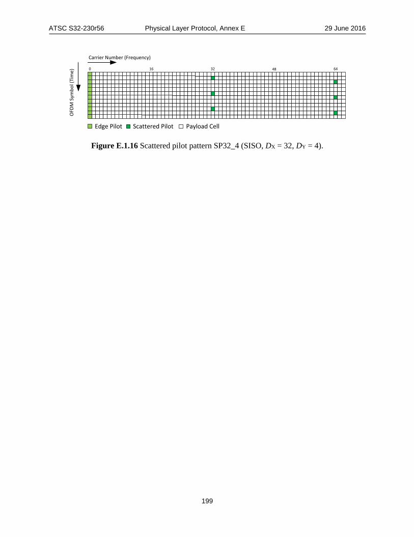
ATSC S32-230r56 Physical Layer Protocol, Annex E 29 June 2016
199
Edge Pilot Scattered Pilot Payload Cell
0 16 32 48 64
Carrier Number (Frequency)
OFD
M S
ymbo
l (Ti
me)
Figure E.1.16 Scattered pilot pattern SP32_4 (SISO, DX = 32, DY = 4).

ATSC S32-230r56 Physical Layer Protocol, Annex F 29 June 2016
200
Annex F: Number of Active Data Cells in Subframe Boundary Symbol
F.1 SUBFRAME BOUNDARY SYMBOL ACTIVE DATA CELL TABLES The number of active data cells in a subframe boundary symbol (SBS) for various configurations shall be as listed below. Tone reservation is not configured in any of the tables in this Annex. When tone reservation is configured, refer to Section 7.2.6.4 to determine the number of active data cells in a subframe boundary symbol. In the following tables L1D_SPB is shorthand for L1D_scattered_pilot_boost.
Table F.1.1 Number of Active Data Cells in a SBS when Cred_coeff=0 FFT Size L1D_SPB Active Data Cells in a Subframe Boundary Symbol
SP3_2 SP3_4 SP4_2 SP4_4 SP6_2 SP6_4 SP8_2 SP8_4
8K
0 4560 4560 5136 5136 5712 5712 6000 6000 1 4560 3904 5009 4332 5456 4856 5716 5168 2 4123 2922 4600 3467 5114 4147 5398 4558 3 3801 2148 4278 2868 4843 3588 5188 4078 4 3467 1534 4022 2245 4629 3146 4971 3697
16K
0 9120 9120 10272 10272 11424 11424 12000 12000 1 9120 7807 10017 8663 10912 9708 11431 10331 2 8244 5841 9199 6930 10225 8288 10793 9109 3 7601 4290 8554 5731 9684 7168 10375 8146 4 6933 3063 8043 4484 9256 6282 9939 7383
32K
0 18240 (18240) N/A N/A 22848 (22848) 24000 (24000) 1 18240 (15612) N/A N/A 21823 (19412) 22861 (20658) 2 16488 (11678) N/A N/A 20449 (16570) 21585 (18212) 3 15202 (8576) N/A N/A 19367 (14329) 20747 (16283) 4 13865 (6121) N/A N/A 18510 (12555) 19876 (14755)

ATSC S32-230r56 Physical Layer Protocol, Annex F 29 June 2016
201
Table F.1.2 Number of Active Data Cells in a SBS when Cred_coeff=0 FFT Size L1D_SPB Active Data Cells in a Subframe Boundary Symbol
SP12_2 SP12_4 SP16_2 SP16_4 SP24_2 SP24_4 SP32_2 SP32_4
8K
0 6288 6288 6432 6432 (6576) (6576) 6648 6648 1 5976 5508 6132 5691 (6297) (5922) 6384 6064 2 5729 5010 5919 5252 (6123) (5564) 6231 5757 3 5533 4616 5751 4906 (5986) (5282) 6125 5515 4 5379 4305 5618 4633 (5877) (5058) 6015 5324
16K
0 12576 12576 12864 12864 13152 13152 13296 13296 1 11950 11011 12262 11374 12593 11834 12766 12116 2 11455 10010 11835 10493 12243 11113 12458 11497 3 11064 9221 11499 9798 11968 10544 12245 11008 4 10755 8596 11233 9248 11750 10094 12024 10622
32K
0 25152 (25152) 25728 (25728) 26304 (26304) 26592 (26592) 1 23899 (22016) 24521 (22740) 25183 (23658) 25529 (24221) 2 22907 (20010) 23667 (20974) 24483 (22211) 24913 (22976) 3 22124 (18429) 22994 (19581) 23931 (21070) 24486 (21995) 4 21505 (17177) 22461 (18479) 23494 (20167) 24042 (21218)
Table F.1.3 Number of Active Data Cells in a SBS when Cred_coeff=1 FFT Size L1D_SPB Active Data Cells in a Subframe Boundary Symbol
SP3_2 SP3_4 SP4_2 SP4_4 SP6_2 SP6_4 SP8_2 SP8_4
8K
0 4496 4496 5064 5064 5632 5632 5916 5916 1 4496 3849 4938 4272 5380 4788 5636 5096 2 4065 2881 4535 3419 5042 4089 5322 4494 3 3748 2117 4218 2828 4775 3538 5116 4021 4 3418 1513 3966 2214 4564 3102 4901 3645
16K
0 8992 8992 10128 10128 11264 11264 11832 11832 1 8992 7697 9876 8541 10759 9572 11271 10187 2 8129 5758 9070 6833 10082 8171 10642 8982 3 7495 4229 8434 5650 9549 7068 10229 8032 4 6835 3019 7930 4420 9126 6194 9800 7280
32K
0 17984 (17984) N/A N/A 22528 (22528) 23664 (23664) 1 17984 (15393) N/A N/A 21517 (19140) 22541 (20369) 2 16256 (11513) N/A N/A 20163 (16337) 21282 (17956) 3 14988 (8454) N/A N/A 19095 (14127) 20456 (16054) 4 13669 (6033) N/A N/A 18250 (12378) 19597 (14548)

ATSC S32-230r56 Physical Layer Protocol, Annex F 29 June 2016
202
Table F.1.4 Number of Active Data Cells in a SBS when Cred_coeff=1 FFT Size L1D_SPB Active Data Cells in a Subframe Boundary Symbol
SP12_2 SP12_4 SP16_2 SP16_4 SP24_2 SP24_4 SP32_2 SP32_4
8K
0 6200 6200 6342 6342 (6484) (6484) 6555 6555 1 5892 5431 6046 5608 (6209) (5839) 6294 5971 2 5648 4940 5836 5173 (6038) (5486) 6142 5664 3 5456 4552 5671 4831 (5902) (5208) 6037 5422 4 5304 4245 5540 4559 (5795) (4988) 5928 5231
16K
0 12400 12400 12684 12684 12968 12968 13110 13110 1 11783 10857 12090 11215 12416 11668 12587 11941 2 11294 9870 11669 10346 12072 10957 12284 11327 3 10909 9091 11338 9661 11800 10397 12074 10844 4 10604 8475 11075 9118 11585 9953 11856 10461
32K
0 24800 (24800) 25368 (25368) 25936 (25936) 26220 (26220) 1 23564 (21707) 24178 (22422) 24830 (23327) 25172 (23882) 2 22586 (19730) 23336 (20680) 24140 (21900) 24564 (22654) 3 21815 (18170) 22672 (19307) 23596 (20775) 24143 (21687) 4 21204 (16936) 22146 (18220) 23165 (19885) 23705 (20921)
Table F.1.5 Number of Active Data Cells in a SBS when Cred_coeff=2 FFT Size
L1D_SPB Active Data Cells in a Subframe Boundary Symbol SP3_2 SP3_4 SP4_2 SP4_4 SP6_2 SP6_4 SP8_2 SP8_4
8K
0 4433 4433 4993 4993 5553 5553 5833 5833 1 4433 3796 4869 4212 5304 4720 5557 5024 2 4008 2841 4472 3371 4971 4032 5247 4432 3 3695 2088 4158 2788 4708 3488 5044 3964 4 3371 1492 3910 2183 4500 3058 4833 3595
16K
0 8867 8867 9987 9987 11107 11107 11667 11667 1 8867 7591 9739 8422 10609 9438 11114 10045 2 8016 5679 8943 6738 9942 8058 10494 8857 3 7391 4172 8316 5572 9416 6970 10087 7920 4 6741 2979 7820 4360 8999 6108 9664 7179
32K
0 17734 (17734) N/A N/A 22214 (22214) 23334 (23334) 1 17734 (15179) N/A N/A 21217 (18873) 22227 (20085) 2 16031 (11354) N/A N/A 19882 (16110) 20986 (17707) 3 14780 (8339) N/A N/A 18829 (13932) 20171 (15831) 4 13480 (5951) N/A N/A 17996 (12207) 19324 (14347)

ATSC S32-230r56 Physical Layer Protocol, Annex F 29 June 2016
203
Table F.1.6 Number of Active Data Cells in a SBS when Cred_coeff=2 FFT Size L1D_SPB Active Data Cells in a Subframe Boundary Symbol
SP12_2 SP12_4 SP16_2 SP16_4 SP24_2 SP24_4 SP32_2 SP32_4
8K
0 6113 6113 6253 6253 (6393) (6393) 6463 6463 1 5810 5355 5961 5532 (6122) (5757) 6207 5890 2 5569 4870 5754 5106 (5953) (5409) 6058 5589 3 5380 4488 5591 4770 (5820) (5135) 5955 5351 4 5229 4186 5462 4504 (5714) (4918) 5848 5164
16K
0 12227 12227 12507 12507 12787 12787 12927 12927 1 11619 10706 11921 11058 12243 11506 12412 11780 2 11137 9732 11507 10202 11903 10805 12113 11178 3 10757 8965 11180 9526 11636 10252 11906 10703 4 10456 8358 10921 8992 11424 9815 11691 10328
32K
0 24454 (24454) 25014 (25014) 25574 (25574) 25854 (25854) 1 23236 (21405) 23841 (22109) 24484 (23002) 24821 (23549) 2 22271 (19455) 23011 (20392) 23803 (21595) 24221 (22339) 3 21511 (17918) 22356 (19038) 23267 (20486) 23806 (21385) 4 20909 (16701) 21838 (17967) 22842 (19608) 23375 (20630)
Table F.1.7 Number of Active Data Cells in a SBS when Cred_coeff=3 FFT Size L1D_SPB Active Data Cells in a Subframe Boundary Symbol
SP3_2 SP3_4 SP4_2 SP4_4 SP6_2 SP6_4 SP8_2 SP8_4
8K
0 4370 4370 4922 4922 5474 5474 5750 5750 1 4370 3742 4800 4152 5229 4653 5478 4953 2 3951 2800 4408 3323 4901 3974 5173 4369 3 3643 2058 4099 2749 4641 3439 4972 3908 4 3323 1471 3855 2152 4436 3015 4764 3544
16K
0 8740 8740 9844 9844 10948 10948 11500 11500 1 8740 7482 9599 8302 10457 9303 10955 9901 2 7901 5597 8815 6642 9799 7943 10344 8730 3 7285 4112 8197 5492 9281 6870 9942 7807 4 6644 2936 7708 4297 8870 6021 9525 7076
32K
0 17480 (17480) N/A N/A 21896 (21896) 23000 (23000) 1 17480 (14962) N/A N/A 20913 (18603) 21909 (19798) 2 15801 (11192) N/A N/A 19597 (15879) 20685 (17453) 3 14568 (8219) N/A N/A 18560 (13732) 19882 (15604) 4 13287 (5866) N/A N/A 17738 (12032) 19048 (14141)

ATSC S32-230r56 Physical Layer Protocol, Annex F 29 June 2016
204
Table F.1.8 Number of Active Data Cells in a SBS when Cred_coeff=3 FFT Size L1D_SPB Active Data Cells in a Subframe Boundary Symbol
SP12_2 SP12_4 SP16_2 SP16_4 SP24_2 SP24_4 SP32_2 SP32_4
8K
0 6026 6026 6164 6164 (6302) (6302) 6371 6371 1 5727 5279 5876 5450 (6035) (5675) 6117 5809 2 5490 4801 5672 5028 (5868) (5333) 5970 5514 3 5303 4425 5512 4695 (5737) (5062) 5868 5281 4 5155 4126 5385 4432 (5633) (4848) 5762 5097
16K
0 12052 12052 12328 12328 12604 12604 12742 12742 1 11452 10552 11751 10900 12068 11341 12234 11606 2 10977 9593 11342 10056 11733 10650 11940 11010 3 10603 8837 11020 9390 11469 10106 11735 10540 4 10307 8238 10765 8863 11260 9675 11523 10168
32K
0 24104 (24104) 24656 (24656) 25208 (25208) 25484 (25484) 1 22903 (21099) 23500 (21793) 24133 (22673) 24465 (23212) 2 21952 (19177) 22681 (20100) 23463 (21286) 23875 (22019) 3 21203 (17661) 22036 (18766) 22934 (20193) 23466 (21079) 4 20609 (16462) 21525 (17710) 22515 (19328) 23040 (20335)
Table F.1.9 Number of Active Data Cells in a SBS when Cred_coeff=4 FFT Size L1D_SPB Active Data Cells in a Subframe Boundary Symbol
SP3_2 SP3_4 SP4_2 SP4_4 SP6_2 SP6_4 SP8_2 SP8_4
8K
0 4307 4307 4851 4851 5395 5395 5667 5667 1 4307 3688 4731 4092 5154 4586 5399 4881 2 3894 2760 4345 3275 4830 3917 5098 4306 3 3591 2029 4040 2710 4575 3390 4901 3852 4 3275 1450 3799 2121 4372 2972 4695 3493
16K
0 8614 8614 9702 9702 10790 10790 11334 11334 1 8614 7374 9461 8182 10306 9169 10797 9758 2 7787 5517 8688 6546 9658 7828 10194 8604 3 7180 4053 8079 5413 9147 6771 9799 7695 4 6549 2894 7597 4236 8743 5934 9388 6974
32K
0 17228 (17228) N/A N/A 21580 (21580) 22668 (22668) 1 17228 (14746) N/A N/A 20612 (18335) 21593 (19512) 2 15573 (11031) N/A N/A 19315 (15651) 20387 (17202) 3 14359 (8101) N/A N/A 18292 (13534) 19596 (15380) 4 13096 (5782) N/A N/A 17483 (11859) 18773 (13938)
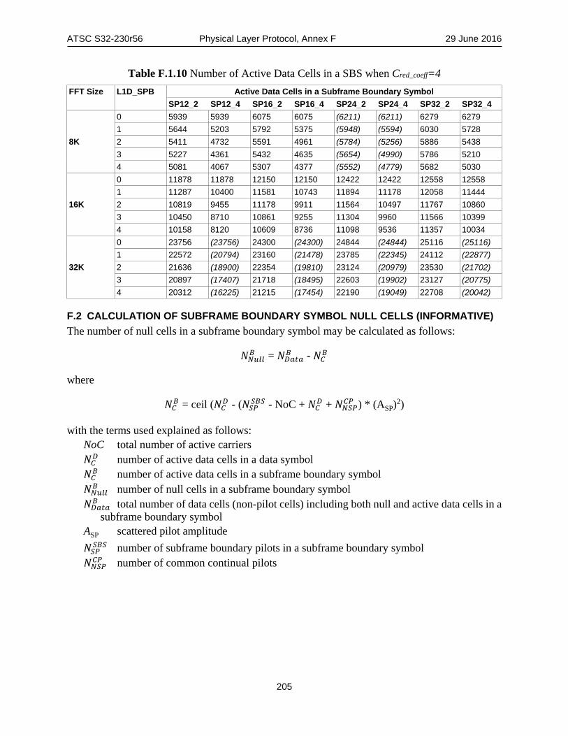
ATSC S32-230r56 Physical Layer Protocol, Annex F 29 June 2016
205
Table F.1.10 Number of Active Data Cells in a SBS when Cred_coeff=4 FFT Size L1D_SPB Active Data Cells in a Subframe Boundary Symbol
SP12_2 SP12_4 SP16_2 SP16_4 SP24_2 SP24_4 SP32_2 SP32_4
8K
0 5939 5939 6075 6075 (6211) (6211) 6279 6279 1 5644 5203 5792 5375 (5948) (5594) 6030 5728 2 5411 4732 5591 4961 (5784) (5256) 5886 5438 3 5227 4361 5432 4635 (5654) (4990) 5786 5210 4 5081 4067 5307 4377 (5552) (4779) 5682 5030
16K
0 11878 11878 12150 12150 12422 12422 12558 12558 1 11287 10400 11581 10743 11894 11178 12058 11444 2 10819 9455 11178 9911 11564 10497 11767 10860 3 10450 8710 10861 9255 11304 9960 11566 10399 4 10158 8120 10609 8736 11098 9536 11357 10034
32K
0 23756 (23756) 24300 (24300) 24844 (24844) 25116 (25116) 1 22572 (20794) 23160 (21478) 23785 (22345) 24112 (22877) 2 21636 (18900) 22354 (19810) 23124 (20979) 23530 (21702) 3 20897 (17407) 21718 (18495) 22603 (19902) 23127 (20775) 4 20312 (16225) 21215 (17454) 22190 (19049) 22708 (20042)
F.2 CALCULATION OF SUBFRAME BOUNDARY SYMBOL NULL CELLS (INFORMATIVE) The number of null cells in a subframe boundary symbol may be calculated as follows:
𝑁𝑁𝑁𝑁𝑜𝑜𝑙𝑙𝑙𝑙𝐵𝐵 = 𝑁𝑁𝑀𝑀𝑝𝑝𝑜𝑜𝑝𝑝𝐵𝐵 - 𝑁𝑁𝐹𝐹𝐵𝐵
where
𝑁𝑁𝐹𝐹𝐵𝐵 = ceil (𝑁𝑁𝐹𝐹𝑀𝑀 - (𝑁𝑁𝑆𝑆𝑃𝑃𝑆𝑆𝐵𝐵𝑆𝑆 - NoC + 𝑁𝑁𝐹𝐹𝑀𝑀 + 𝑁𝑁𝑁𝑁𝑆𝑆𝑃𝑃𝐹𝐹𝑃𝑃 ) * (ASP)2)
with the terms used explained as follows: NoC total number of active carriers 𝑁𝑁𝐹𝐹𝑀𝑀 number of active data cells in a data symbol 𝑁𝑁𝐹𝐹𝐵𝐵 number of active data cells in a subframe boundary symbol 𝑁𝑁𝑁𝑁𝑜𝑜𝑙𝑙𝑙𝑙𝐵𝐵 number of null cells in a subframe boundary symbol 𝑁𝑁𝑀𝑀𝑝𝑝𝑜𝑜𝑝𝑝𝐵𝐵 total number of data cells (non-pilot cells) including both null and active data cells in a
subframe boundary symbol ASP scattered pilot amplitude 𝑁𝑁𝑆𝑆𝑃𝑃𝑆𝑆𝐵𝐵𝑆𝑆 number of subframe boundary pilots in a subframe boundary symbol 𝑁𝑁𝑁𝑁𝑆𝑆𝑃𝑃𝐹𝐹𝑃𝑃 number of common continual pilots

ATSC S32-230r56 Physical Layer Protocol, Annex G 29 June 2016
206
Annex G: Tone Reservation Carrier Indices
G.1 TONE RESERVATION CARRIER INDICES When tone reservation is used, the set of reserved carriers for PAPR reduction in all symbols (except the first Preamble symbol) depends on the type of symbol and DX. Table G.1.1 shows the table indices corresponding to the set of reserved carriers for PAPR reduction according to each type of symbol. Tone reservation shall never be applied to the first Preamble symbol.
Table G.1.1 Table Indices Corresponding to the Set of Reserved Carriers for PAPR Reduction According to Each Type of Symbol
Symbol Index Preamble Symbol Subframe Boundary Symbol
Data Symbol l = 0 0 < l < NP
DX All 3, 4, 8 6, 12, 16, 24, 32
3, 4, 8 6, 12, 16, 24, 32
Set of carriers reserved for PAPR reduction
N/A Table G.1.3 Table G.1.2 Table G.1.3 Table G.1.2 Table G.1.2
Carrier indices specified in this Annex represent absolute carrier indices. Absolute carrier indices are indexed on the maximum possible number of carriers regardless of whether carrier reduction has been configured and hence range from 0 to NoCmax – 1.

ATSC S32-230r56 Physical Layer Protocol, Annex G 29 June 2016
207
Table G.1.2 Set of Carriers Reserved for PAPR reduction for All Symbols Except the First Preamble Symbol, the Other (NP – 1) Preamble Symbols of DX = 3, DX =
4, and DX = 8, and Subframe Boundary Symbols of DX = 3, DX = 4, and DX = 8
FFT (# of Reserved tones)
TR Carrier Indices
8k (72)
250, 386, 407, 550, 591, 717, 763, 787, 797, 839, 950, 1090, 1105, 1199, 1738, 1867, 1903, 1997, 2114, 2260, 2356, 2427, 2428, 2444, 2452, 2475, 2564, 2649, 2663, 2678, 2740, 2777, 2819, 2986, 3097, 3134, 3253, 3284, 3323, 3442, 3596, 3694, 3719, 3751, 3763, 3836, 4154, 4257, 4355, 4580, 4587, 4678, 4805, 5084, 5126, 5161, 5229, 5321, 5445, 5649, 5741, 5746, 5885, 5918, 6075, 6093, 6319, 6421, 6463, 6511, 6517, 6577
16k (144)
421, 548, 589, 621, 644, 727, 770, 813, 857, 862, 1113, 1187, 1201, 1220, 1393, 1517, 1821, 1899, 1924, 2003, 2023, 2143, 2146, 2290, 2474, 2482, 2597, 2644, 2749, 2818, 2951, 3014, 3212, 3237, 3363, 3430, 3515, 3517, 3745, 3758, 4049, 4165, 4354, 4399, 4575, 4763, 4789, 4802, 4834, 4970, 5260, 5386, 5395, 5402, 5579, 5716, 5734, 5884, 5895, 6073, 6123, 6158, 6212, 6243, 6521, 6593, 6604, 6607, 6772, 6842, 6908, 6986, 7220, 7331, 7396, 7407, 7588, 7635, 7665, 7893, 7925, 7949, 8019, 8038, 8167, 8289, 8295, 8338, 8549, 8555, 8660, 8857, 8925, 9007, 9057, 9121, 9364, 9375, 9423, 9446, 9479, 9502, 9527, 9860, 9919, 9938, 10138, 10189, 10191, 10275, 10333, 10377, 10988, 11109, 11261, 11266, 11362, 11390, 11534, 11623, 11893, 11989, 12037, 12101, 12119, 12185, 12254, 12369, 12371, 12380, 12401, 12586, 12597, 12638, 12913, 12974, 13001, 13045, 13052, 13111, 13143, 13150, 13151, 13300
32K (288
803, 805, 811, 901, 1001, 1027, 1245, 1258, 1318, 1478, 1507, 1509, 1556, 1577, 1655, 1742, 1978, 2001, 2056, 2110, 2164, 2227, 2305, 2356, 2408, 2522, 2563, 2780, 2805, 2879, 3010, 3019, 3128, 3389, 3649, 3730, 3873, 4027, 4066, 4087, 4181, 4246, 4259, 4364, 4406, 4515, 4690, 4773, 4893, 4916, 4941, 4951, 4965, 5165, 5222, 5416, 5638, 5687, 5729, 5930, 5997, 6005, 6161, 6218, 6292, 6344, 6370, 6386, 6505, 6974, 7079, 7114, 7275, 7334, 7665, 7765, 7868, 7917, 7966, 8023, 8055, 8089, 8091, 8191, 8374, 8495, 8651, 8690, 8755, 8821, 9139, 9189, 9274, 9561, 9611, 9692, 9711, 9782, 9873, 9964, 10011, 10209, 10575, 10601, 10623, 10690, 10967, 11045, 11083, 11084, 11090, 11128, 11153, 11530, 11737, 11829, 11903, 11907, 11930, 11942, 12356, 12429, 12484, 12547, 12562, 12605, 12767, 12863, 13019, 13052, 13053, 13167, 13210, 13244, 13259, 13342, 13370, 13384, 13447, 13694, 13918, 14002, 14077, 14111, 14216, 14243, 14270, 14450, 14451, 14456, 14479, 14653, 14692, 14827, 14865, 14871, 14908, 15215, 15227, 15284, 15313, 15333, 15537, 15643, 15754, 15789, 16065, 16209, 16213, 16217, 16259, 16367, 16369, 16646, 16780, 16906, 16946, 17012, 17167, 17192, 17325, 17414, 17629, 17687, 17746, 17788, 17833, 17885, 17913, 18067, 18089, 18316, 18337, 18370, 18376, 18440, 18550, 18680, 18910, 18937, 19047, 19052, 19117, 19383, 19396, 19496, 19601, 19778, 19797, 20038, 20357, 20379, 20455, 20669, 20707, 20708, 20751, 20846, 20853, 20906, 21051, 21079, 21213, 21267, 21308, 21355, 21523, 21574, 21815, 21893, 21973, 22084, 22172, 22271, 22713, 22905, 23039, 23195, 23303, 23635, 23732, 23749, 23799, 23885, 23944, 24149, 24311, 24379, 24471, 24553, 24585, 24611, 24616, 24621, 24761, 24789, 24844, 24847, 24977, 25015, 25160, 25207, 25283, 25351, 25363, 25394, 25540, 25603, 25647, 25747, 25768, 25915, 25928, 26071, 26092, 26139, 26180, 26209, 26270, 26273, 26278, 26326, 26341, 26392, 26559, 26642, 26776, 26842

ATSC S32-230r56 Physical Layer Protocol, Annex G 29 June 2016
208
Table G.1.3 Set of Carriers Reserved for PAPR reduction in Preamble Symbols of DX = 3, DX = 4, and DX = 8 Except the First Preamble Symbol and in Subframe
Boundary Symbols of DX = 3, DX = 4, and DX = 8
FFT Size TR Carrier Indices
8k (72)
295, 329, 347, 365, 463, 473, 481, 553, 578, 602, 742, 749, 829, 922, 941, 1115, 1123, 1174, 1363, 1394, 1402, 1615, 1657, 1702, 1898, 1910, 1997, 2399, 2506, 2522, 2687, 2735, 3043, 3295, 3389, 3454, 3557, 3647, 3719, 3793, 3794, 3874, 3898, 3970, 4054, 4450, 4609, 4666, 4829, 4855, 4879, 4961, 4969, 5171, 5182, 5242, 5393, 5545, 5567, 5618, 5630, 5734, 5861, 5897, 5987, 5989, 6002, 6062, 6074, 6205, 6334, 6497
16k (144)
509, 739, 770, 890, 970, 989, 1031, 1033, 1121, 1223, 1231, 1285, 1526, 1559, 1603, 1615, 1690, 1771, 1903, 1910, 1958, 2033, 2146, 2225, 2302, 2306, 2345, 2447, 2477, 2561, 2578, 2597, 2635, 2654, 2687, 2891, 2938, 3029, 3271, 3479, 3667, 3713, 3791, 3977, 4067, 4150, 4217, 4387, 4501, 4541, 4657, 4733, 4742, 4963, 5011, 5149, 5311, 5362, 5491, 5531, 5609, 5722, 5747, 5798, 5842, 5881, 5959, 5983, 6059, 6166, 6178, 6214, 6230, 6382, 6557, 6625, 6811, 6881, 6994, 7261, 7535, 7546, 7711, 7897, 7898, 7918, 7997, 8125, 8398, 8483, 8530, 8686, 8731, 8855, 9001, 9026, 9110, 9206, 9223, 9325, 9466, 9493, 9890, 9893, 10537, 10570, 10691, 10835, 10837, 11098, 11126, 11146, 11198, 11270, 11393, 11629, 11657, 11795, 11867, 11909, 11983, 12046, 12107, 12119, 12353, 12482, 12569, 12575, 12662, 12691, 12739, 12787, 12902, 12917, 12985, 13010, 13022, 13073, 13102, 13141, 13159, 13225, 13255, 13303
32K (288)
793, 884, 899, 914, 1004, 1183, 1198, 1276, 1300, 1339, 1348, 1444, 1487, 1490, 1766, 1870, 1903, 1909, 1961, 2053, 2092, 2099, 2431, 2572, 2578, 2618, 2719, 2725, 2746, 2777, 2798, 2891, 2966, 2972, 3023, 3037, 3076, 3257, 3284, 3326, 3389, 3425, 3454, 3523, 3602, 3826, 3838, 3875, 3955, 4094, 4126, 4261, 4349, 4357, 4451, 4646, 4655, 4913, 5075, 5083, 5306, 5317, 5587, 5821, 6038, 6053, 6062, 6137, 6268, 6286, 6490, 6517, 6529, 6554, 6593, 6671, 6751, 6827, 6845, 7043, 7111, 7147, 7196, 7393, 7451, 7475, 7517, 7750, 7769, 7780, 8023, 8081, 8263, 8290, 8425, 8492, 8939, 8986, 9113, 9271, 9298, 9343, 9455, 9476, 9637, 9821, 9829, 9913, 9953, 9988, 10001, 10007, 10018, 10082, 10172, 10421, 10553, 10582, 10622, 10678, 10843, 10885, 10901, 11404, 11674, 11959, 12007, 12199, 12227, 12290, 12301, 12629, 12631, 12658, 12739, 12866, 12977, 13121, 13294, 13843, 13849, 13852, 13933, 14134, 14317, 14335, 14342, 14407, 14651, 14758, 14815, 14833, 14999, 15046, 15097, 15158, 15383, 15503, 15727, 15881, 16139, 16238, 16277, 16331, 16444, 16490, 16747, 16870, 16981, 17641, 17710, 17714, 17845, 18011, 18046, 18086, 18097, 18283, 18334, 18364, 18431, 18497, 18527, 18604, 18686, 18709, 18731, 18740, 18749, 18772, 18893, 19045, 19075, 19087, 19091, 19099, 19127, 19169, 19259, 19427, 19433, 19450, 19517, 19526, 19610, 19807, 19843, 19891, 20062, 20159, 20246, 20420, 20516, 20530, 20686, 20801, 20870, 20974, 21131, 21158, 21565, 21635, 21785, 21820, 21914, 21926, 22046, 22375, 22406, 22601, 22679, 22699, 22772, 22819, 22847, 22900, 22982, 22987, 23063, 23254, 23335, 23357, 23561, 23590, 23711, 23753, 23902, 24037, 24085, 24101, 24115, 24167, 24182, 24361, 24374, 24421, 24427, 24458, 24463, 24706, 24748, 24941, 25079, 25127, 25195, 25285, 25444, 25492, 25505, 25667, 25682, 25729, 25741, 25765, 25973, 26171, 26180, 26227, 26353, 26381, 26542, 26603, 26651, 26671, 26759, 26804, 26807, 26827

ATSC S32-230r56 Physical Layer Protocol, Annex H 29 June 2016
209
Annex H: Preamble Parameters for Bootstrap
H.1 PREAMBLE STRUCTURE PARAMETER VALUES The allowed values for preamble_structure are shown in Table H.1.1. Note that in the present release of the specification the defined preamble_structure values do not make use of L1-Basic Modes 6 and 7.
Table H.1.1 Meaning of Signaled Values of preamble_structure
preamble_structure FFT Size GI Length (samples)
Preamble Pilot DX
L1-Basic FEC Mode
0 8K 192 16 L1-Basic Mode 1 1 8K 192 16 L1-Basic Mode 2 2 8K 192 16 L1-Basic Mode 3 3 8K 192 16 L1-Basic Mode 4 4 8K 192 16 L1-Basic Mode 5 5 8K 384 8 L1-Basic Mode 1 6 8K 384 8 L1-Basic Mode 2 7 8K 384 8 L1-Basic Mode 3 8 8K 384 8 L1-Basic Mode 4 9 8K 384 8 L1-Basic Mode 5 10 8K 512 6 L1-Basic Mode 1 11 8K 512 6 L1-Basic Mode 2 12 8K 512 6 L1-Basic Mode 3 13 8K 512 6 L1-Basic Mode 4 14 8K 512 6 L1-Basic Mode 5 15 8K 768 4 L1-Basic Mode 1 16 8K 768 4 L1-Basic Mode 2 17 8K 768 4 L1-Basic Mode 3 18 8K 768 4 L1-Basic Mode 4 19 8K 768 4 L1-Basic Mode 5 20 8K 1024 3 L1-Basic Mode 1 21 8K 1024 3 L1-Basic Mode 2 22 8K 1024 3 L1-Basic Mode 3 23 8K 1024 3 L1-Basic Mode 4 24 8K 1024 3 L1-Basic Mode 5 25 8K 1536 4 L1-Basic Mode 1 26 8K 1536 4 L1-Basic Mode 2 27 8K 1536 4 L1-Basic Mode 3 28 8K 1536 4 L1-Basic Mode 4 29 8K 1536 4 L1-Basic Mode 5 30 8K 2048 3 L1-Basic Mode 1 31 8K 2048 3 L1-Basic Mode 2

ATSC S32-230r56 Physical Layer Protocol, Annex H 29 June 2016
210
preamble_structure FFT Size GI Length (samples)
Preamble Pilot DX
L1-Basic FEC Mode
32 8K 2048 3 L1-Basic Mode 3 33 8K 2048 3 L1-Basic Mode 4 34 8K 2048 3 L1-Basic Mode 5 35 16K 192 32 L1-Basic Mode 1 36 16K 192 32 L1-Basic Mode 2 37 16K 192 32 L1-Basic Mode 3 38 16K 192 32 L1-Basic Mode 4 39 16K 192 32 L1-Basic Mode 5 40 16K 384 16 L1-Basic Mode 1 41 16K 384 16 L1-Basic Mode 2 42 16K 384 16 L1-Basic Mode 3 43 16K 384 16 L1-Basic Mode 4 44 16K 384 16 L1-Basic Mode 5 45 16K 512 12 L1-Basic Mode 1 46 16K 512 12 L1-Basic Mode 2 47 16K 512 12 L1-Basic Mode 3 48 16K 512 12 L1-Basic Mode 4 49 16K 512 12 L1-Basic Mode 5 50 16K 768 8 L1-Basic Mode 1 51 16K 768 8 L1-Basic Mode 2 52 16K 768 8 L1-Basic Mode 3 53 16K 768 8 L1-Basic Mode 4 54 16K 768 8 L1-Basic Mode 5 55 16K 1024 6 L1-Basic Mode 1 56 16K 1024 6 L1-Basic Mode 2 57 16K 1024 6 L1-Basic Mode 3 58 16K 1024 6 L1-Basic Mode 4 59 16K 1024 6 L1-Basic Mode 5 60 16K 1536 4 L1-Basic Mode 1 61 16K 1536 4 L1-Basic Mode 2 62 16K 1536 4 L1-Basic Mode 3 63 16K 1536 4 L1-Basic Mode 4 64 16K 1536 4 L1-Basic Mode 5 65 16K 2048 3 L1-Basic Mode 1 66 16K 2048 3 L1-Basic Mode 2 67 16K 2048 3 L1-Basic Mode 3 68 16K 2048 3 L1-Basic Mode 4 69 16K 2048 3 L1-Basic Mode 5 70 16K 2432 3 L1-Basic Mode 1 71 16K 2432 3 L1-Basic Mode 2 72 16K 2432 3 L1-Basic Mode 3 73 16K 2432 3 L1-Basic Mode 4 74 16K 2432 3 L1-Basic Mode 5 75 16K 3072 4 L1-Basic Mode 1 76 16K 3072 4 L1-Basic Mode 2 77 16K 3072 4 L1-Basic Mode 3

ATSC S32-230r56 Physical Layer Protocol, Annex H 29 June 2016
211
preamble_structure FFT Size GI Length (samples)
Preamble Pilot DX
L1-Basic FEC Mode
78 16K 3072 4 L1-Basic Mode 4 79 16K 3072 4 L1-Basic Mode 5 80 16K 3648 4 L1-Basic Mode 1 81 16K 3648 4 L1-Basic Mode 2 82 16K 3648 4 L1-Basic Mode 3 83 16K 3648 4 L1-Basic Mode 4 84 16K 3648 4 L1-Basic Mode 5 85 16K 4096 3 L1-Basic Mode 1 86 16K 4096 3 L1-Basic Mode 2 87 16K 4096 3 L1-Basic Mode 3 88 16K 4096 3 L1-Basic Mode 4 89 16K 4096 3 L1-Basic Mode 5 90 32K 192 32 L1-Basic Mode 1 91 32K 192 32 L1-Basic Mode 2 92 32K 192 32 L1-Basic Mode 3 93 32K 192 32 L1-Basic Mode 4 94 32K 192 32 L1-Basic Mode 5 95 32K 384 32 L1-Basic Mode 1 96 32K 384 32 L1-Basic Mode 2 97 32K 384 32 L1-Basic Mode 3 98 32K 384 32 L1-Basic Mode 4 99 32K 384 32 L1-Basic Mode 5 100 32K 512 24 L1-Basic Mode 1 101 32K 512 24 L1-Basic Mode 2 102 32K 512 24 L1-Basic Mode 3 103 32K 512 24 L1-Basic Mode 4 104 32K 512 24 L1-Basic Mode 5 105 32K 768 16 L1-Basic Mode 1 106 32K 768 16 L1-Basic Mode 2 107 32K 768 16 L1-Basic Mode 3 108 32K 768 16 L1-Basic Mode 4 109 32K 768 16 L1-Basic Mode 5 110 32K 1024 12 L1-Basic Mode 1 111 32K 1024 12 L1-Basic Mode 2 112 32K 1024 12 L1-Basic Mode 3 113 32K 1024 12 L1-Basic Mode 4 114 32K 1024 12 L1-Basic Mode 5 115 32K 1536 8 L1-Basic Mode 1 116 32K 1536 8 L1-Basic Mode 2 117 32K 1536 8 L1-Basic Mode 3 118 32K 1536 8 L1-Basic Mode 4 119 32K 1536 8 L1-Basic Mode 5 120 32K 2048 6 L1-Basic Mode 1 121 32K 2048 6 L1-Basic Mode 2 122 32K 2048 6 L1-Basic Mode 3 123 32K 2048 6 L1-Basic Mode 4

ATSC S32-230r56 Physical Layer Protocol, Annex H 29 June 2016
212
preamble_structure FFT Size GI Length (samples)
Preamble Pilot DX
L1-Basic FEC Mode
124 32K 2048 6 L1-Basic Mode 5 125 32K 2432 6 L1-Basic Mode 1 126 32K 2432 6 L1-Basic Mode 2 127 32K 2432 6 L1-Basic Mode 3 128 32K 2432 6 L1-Basic Mode 4 129 32K 2432 6 L1-Basic Mode 5 130 32K 3072 8 L1-Basic Mode 1 131 32K 3072 8 L1-Basic Mode 2 132 32K 3072 8 L1-Basic Mode 3 133 32K 3072 8 L1-Basic Mode 4 134 32K 3072 8 L1-Basic Mode 5 135 32K 3072 3 L1-Basic Mode 1 136 32K 3072 3 L1-Basic Mode 2 137 32K 3072 3 L1-Basic Mode 3 138 32K 3072 3 L1-Basic Mode 4 139 32K 3072 3 L1-Basic Mode 5 140 32K 3648 8 L1-Basic Mode 1 141 32K 3648 8 L1-Basic Mode 2 142 32K 3648 8 L1-Basic Mode 3 143 32K 3648 8 L1-Basic Mode 4 144 32K 3648 8 L1-Basic Mode 5 145 32K 3648 3 L1-Basic Mode 1 146 32K 3648 3 L1-Basic Mode 2 147 32K 3648 3 L1-Basic Mode 3 148 32K 3648 3 L1-Basic Mode 4 149 32K 3648 3 L1-Basic Mode 5 150 32K 4096 3 L1-Basic Mode 1 151 32K 4096 3 L1-Basic Mode 2 152 32K 4096 3 L1-Basic Mode 3 153 32K 4096 3 L1-Basic Mode 4 154 32K 4096 3 L1-Basic Mode 5 155 32K 4864 3 L1-Basic Mode 1 156 32K 4864 3 L1-Basic Mode 2 157 32K 4864 3 L1-Basic Mode 3 158 32K 4864 3 L1-Basic Mode 4 159 32K 4864 3 L1-Basic Mode 5 160-255 Reserved Reserved Reserved Reserved

ATSC S32-230r56 Physical Layer Protocol, Annex I 29 June 2016
213
Annex I: Total Symbol Power
I.1 PREAMBLE SYMBOL FREQUENCY DOMAIN POWER The following tables describe the total frequency domain power in Preamble symbols.
Table I.1.1 Frequency Domain Total Power of the Preamble Symbol (PPreamble,l)
FFT Size GI Length (samples)
Pilot Pattern (DX)
PPreamble (FD total power) Cred_coeff 0
Cred_coeff 1
Cred_coeff 2
Cred_coeff 3
Cred_coeff 4
8K 192 16 8240.53 8130.20 8013.76 7897.31 7780.87 8K 384 8 8322.93 8211.44 8093.84 7976.24 7858.64 8K 512 6 8301.50 8190.31 8073.00 7955.69 7838.38 8K 768 4 8094.28 7985.96 7871.52 7757.08 7642.65 8K 1024 3 7737.10 7633.73 7524.25 7414.77 7305.30 8K 1536 4 8094.28 7985.96 7871.52 7757.08 7642.65 8K 2048 3 7737.10 7633.73 7524.25 7414.77 7305.30 16K 192 32 16051.13 15836.42 15603.37 15382.54 15155.60 16K 384 16 16477.67 16257.01 16018.01 15791.24 15558.36 16K 512 12 16583.95 16361.81 16121.33 15893.08 15658.71 16K 768 8 16643.58 16420.60 16179.28 15950.19 15714.99 16K 1024 6 16601.06 16378.66 16137.94 15909.43 15674.81 16K 1536 4 16561.26 16339.42 16099.24 15871.28 15637.21 16K 2048 3 16020.04 15805.70 15573.04 15352.59 15126.04 16K 2432 3 16020.04 15805.70 15573.04 15352.59 15126.04 16K 3072 4 16561.26 16339.42 16099.24 15871.28 15637.21 16K 3648 4 16561.26 16339.42 16099.24 15871.28 15637.21 16K 4096 3 16020.04 15805.70 15573.04 15352.59 15126.04 32K 192 32 32097.48 31668.05 31201.95 30760.29 30306.41 32K 384 32 32097.48 31668.05 31201.95 30760.29 30306.41 32K 512 24 32475.84 32041.14 31569.77 31122.85 30663.71 32K 768 16 32951.95 32510.63 32032.64 31579.09 31113.33 32K 1024 12 33165.03 32720.74 32239.78 31783.27 31314.54 32K 1536 8 34048.92 33592.35 33099.12 32630.32 32149.31 32K 2048 6 33842.90 33389.18 32898.80 32432.87 31954.71 32K 2432 6 33842.90 33389.18 32898.80 32432.87 31954.71 32K 3072 8 34048.92 33592.35 33099.12 32630.32 32149.31 32K 3072 3 32038.72 31610.06 31144.72 30703.83 30250.72 32K 3648 8 34048.92 33592.35 33099.12 32630.32 32149.31 32K 3648 3 32038.72 31610.06 31144.72 30703.83 30250.72 32K 4096 3 32038.72 31610.06 31144.72 30703.83 30250.72 32K 4864 3 32038.72 31610.06 31144.72 30703.83 30250.72

ATSC S32-230r56 Physical Layer Protocol, Annex I 29 June 2016
214
I.2 DATA AND SUBFRAME BOUNDARY SYMBOL FREQUENCY DOMAIN POWER The following tables describe the total frequency domain power in data and subframe boundary symbols.
Table I.2.1 Frequency Domain Total Power of Each Data and Subframe Boundary Symbol (Pdata,m) when Cred_coeff=0
FFT Size Pilot Pattern L1D_scattered_pilot_boost
000 001 010 011 100
8K
SP3_2 7206.33 7206.33 7646.12 7967.68 8302.73 SP3_4 7206.33 7427.12 7757.73 8018.64 8223.83 SP4_2 7206.33 7335.49 7745.44 8069.14 8324.24 SP4_4 7206.33 7477.44 7769.24 7971.39 8181.27 SP6_2 7206.33 7463.93 7809.46 8080.54 8295.62 SP6_4 7206.33 7497.87 7737.93 7927.21 8077.51 SP8_2 7206.33 7492.88 7814.32 8024.02 8243.34 SP8_4 7206.33 7490.93 7698.42 7862.96 7992.15 SP12_2 7206.33 7522.86 7773.18 7969.29 8125.67 SP12_4 7206.33 7475.54 7648.41 7783.36 7891.04 SP16_2 7206.33 7512.03 7727.53 7897.38 8031.80 SP16_4 7206.33 7466.13 7618.63 7738.99 7835.14 SP24_2 7206.33 7491.23 7669.09 7809.50 7920.09 SP24_4 7206.33 7440.66 7568.35 7669.30 7748.41 SP32_2 7206.33 7477.75 7635.15 7744.12 7857.61 SP32_4 7206.33 7420.32 7532.04 7620.18 7690.50
16K
SP3_2 14411.67 14411.67 15288.86 15932.70 16602.50 SP3_4 14411.67 14851.86 15510.50 16028.89 16439.91 SP4_2 14411.67 14668.83 15488.26 16134.29 16645.20 SP4_4 14411.67 14952.26 15532.20 15935.04 16353.30 SP6_2 14411.67 14926.41 15613.87 16156.56 16586.36 SP6_4 14411.67 14989.75 15467.04 15842.95 16141.04 SP8_2 14411.67 14983.09 15623.25 16044.16 16480.28 SP8_4 14411.67 14974.58 15386.60 15711.94 15968.72 SP12_2 14411.67 15041.63 15540.41 15932.96 16244.17 SP12_4 14411.67 14943.26 15282.84 15550.82 15762.46 SP16_2 14411.67 15019.66 15448.67 15787.59 16055.82 SP16_4 14411.67 14920.95 15221.58 15458.22 15645.66 SP24_2 14411.67 14978.51 15331.00 15609.88 15830.29 SP24_4 14411.67 14867.25 15115.96 15311.51 15466.70 SP32_2 14411.67 14950.04 15261.41 15477.36 15702.29 SP32_4 14411.67 14823.96 15040.47 15210.22 15345.66
32K
SP3_2 28822.33 28822.33 30576.34 31863.75 33202.05 SP3_4 (28822.33) (29700.34) (31015.05) (32051.38) (32872.06) SP4_2 N/A N/A N/A N/A N/A SP4_4 N/A N/A N/A N/A N/A SP6_2 28822.33 29850.37 31224.70 32309.62 33167.83 SP6_4 (28822.33) (29973.50) (30925.26) (31675.43) (32269.09) SP8_2 28822.33 29963.53 31243.10 32082.43 32955.18

ATSC S32-230r56 Physical Layer Protocol, Annex I 29 June 2016
215
SP8_4 (28822.33) (29942.86) (30763.97) (31410.90) (31921.87) SP12_2 28822.33 30080.16 31074.87 31858.28 32479.17 SP12_4 (28822.33) (29877.71) (30551.70) (31083.74) (31504.30) SP16_2 28822.33 30033.92 30890.95 31567.00 32101.85 SP16_4 (28822.33) (29830.59) (30426.47) (30895.69) (31267.72) SP24_2 28822.33 29951.08 30654.84 31209.63 31648.70 SP24_4 (28822.33) (29720.43) (30211.16) (30597.95) (30904.27) SP32_2 28822.33 29893.61 30514.92 30944.83 31391.67 SP32_4 (28822.33) (29632.24) (30056.33) (30391.32) (30655.98)
Table I.2.2 Frequency Domain Total Power of Each Data and Subframe Boundary Symbol (Pdata,m) when Cred_coeff=1
FFT Size Pilot Pattern L1D_scattered_pilot_boost
000 001 010 011 100
8K
SP3_2 7110.33 7110.33 7543.95 7861.57 8191.33 SP3_4 7110.33 7327.95 7654.33 7910.88 8114.70 SP4_2 7110.33 7236.94 7641.52 7961.26 8213.26 SP4_4 7110.33 7378.52 7666.26 7865.29 8072.61 SP6_2 7110.33 7364.80 7704.79 7972.35 8184.48 SP6_4 7110.33 7397.95 7634.83 7821.73 7969.81 SP8_2 7110.33 7392.96 7709.54 7917.41 8132.67 SP8_4 7110.33 7391.44 7595.59 7758.19 7885.30 SP12_2 7110.33 7422.14 7668.57 7863.25 8017.32 SP12_4 7110.33 7375.99 7546.56 7680.17 7786.06 SP16_2 7110.33 7411.63 7624.20 7792.37 7925.08 SP16_4 7110.33 7363.26 7511.56 7629.46 7721.49 SP24_2 7110.33 7391.43 7567.41 7704.99 7814.54 SP24_4 7110.33 7341.37 7467.34 7566.98 7645.90 SP32_2 7110.33 7377.35 7531.46 7638.46 7749.85 SP32_4 7110.33 7313.29 7419.22 7502.79 7569.50
16K
SP3_2 14219.67 14219.67 15085.51 15720.49 16379.71 SP3_4 14219.67 14653.51 15302.71 15814.36 16219.64 SP4_2 14219.67 14472.72 15281.42 15918.52 16422.23 SP4_4 14219.67 14752.42 15325.23 15721.83 16133.97 SP6_2 14219.67 14727.15 15405.54 15941.18 16364.07 SP6_4 14219.67 14789.90 15259.85 15632.00 15925.64 SP8_2 14219.67 14783.26 15414.68 15828.94 16259.96 SP8_4 14219.67 14775.60 15181.94 15502.39 15756.02 SP12_2 14219.67 14841.20 15332.19 15719.86 16026.47 SP12_4 14219.67 14744.17 15079.15 15342.45 15551.49 SP16_2 14219.67 14818.87 15242.01 15576.56 15840.38 SP16_4 14219.67 14722.22 15018.45 15252.17 15436.38 SP24_2 14219.67 14777.90 15126.65 15400.85 15618.19 SP24_4 14219.67 14668.66 14913.92 15107.88 15260.67 SP32_2 14219.67 14750.23 15058.02 15271.03 15492.78 SP32_4 14219.67 14620.90 14830.83 14997.45 15128.66
32K SP3_2 28438.33 28438.33 30167.65 31437.32 32756.47

ATSC S32-230r56 Physical Layer Protocol, Annex I 29 June 2016
216
SP3_4 (28438.33) (29304.65) (30600.47) (31622.33) (32431.52) SP4_2 N/A N/A N/A N/A N/A SP4_4 N/A N/A N/A N/A N/A SP6_2 28438.33 29451.86 30808.03 31876.86 32723.26 SP6_4 (28438.33) (29573.80) (30511.88) (31251.52) (31837.30) SP8_2 28438.33 29563.87 30824.95 31653.00 32513.53 SP8_4 (28438.33) (29543.90) (30352.64) (30990.81) (31495.47) SP12_2 28438.33 29678.30 30659.43 31433.10 32044.77 SP12_4 (28438.33) (29478.52) (30144.31) (30668.01) (31083.35) SP16_2 28438.33 29633.34 30478.63 31144.96 31671.98 SP16_4 (28438.33) (29433.12) (30020.22) (30483.58) (30850.16) SP24_2 28438.33 29550.86 30245.14 30792.57 31225.49 SP24_4 (28438.33) (29324.25) (29808.09) (30189.68) (30492.22) SP32_2 28438.33 29495.00 30107.15 30531.17 30971.65 SP32_4 (28438.33) (29237.11) (29655.05) (29985.78) (30246.99)
Table I.2.3 Frequency Domain Total Power of Each Data and Subframe Boundary Symbol (Pdata,m) when Cred_coeff=2
FFTSize Pilot Pattern L1D_scattered_pilot_boost
000 001 010 011 100
8K
SP3_2 7008.22 7008.22 7435.66 7748.36 8074.82 SP3_4 7008.22 7223.66 7544.82 7798.01 7998.45 SP4_2 7008.22 7133.27 7532.48 7846.26 8095.17 SP4_4 7008.22 7272.48 7556.17 7752.08 7956.83 SP6_2 7008.22 7258.56 7594.01 7858.05 8067.22 SP6_4 7008.22 7290.91 7525.63 7709.14 7855.00 SP8_2 7008.22 7286.93 7598.64 7803.69 8016.90 SP8_4 7008.22 7284.84 7487.64 7646.30 7773.33 SP12_2 7008.22 7316.32 7558.85 7751.09 7901.86 SP12_4 7008.22 7270.34 7437.60 7569.88 7674.96 SP16_2 7008.22 7305.13 7514.76 7680.24 7811.25 SP16_4 7008.22 7260.28 7409.39 7526.82 7619.74 SP24_2 7008.22 7285.51 7458.63 7595.36 7702.87 SP24_4 7008.22 7235.96 7360.21 7458.55 7536.28 SP32_2 7008.22 7272.84 7425.66 7531.68 7641.99 SP32_4 7008.22 7211.14 7317.29 7400.29 7467.39
16K
SP3_2 14009.33 14009.33 14862.84 15488.94 16139.59 SP3_4 14009.33 14437.84 15077.59 15582.50 15982.03 SP4_2 14009.33 14259.28 15055.24 15683.41 16180.94 SP4_4 14009.33 14534.24 15098.94 15490.30 15897.32 SP6_2 14009.33 14509.56 15178.87 15706.47 16123.45 SP6_4 14009.33 14570.72 15035.33 15401.71 15690.92 SP8_2 14009.33 14565.10 15187.77 15596.39 16021.30 SP8_4 14009.33 14557.28 14957.94 15273.51 15523.99 SP12_2 14009.33 14622.43 15106.64 15488.44 15790.44 SP12_4 14009.33 14526.74 14856.11 15116.75 15323.18 SP16_2 14009.33 14599.75 15018.01 15347.20 15607.61

ATSC S32-230r56 Physical Layer Protocol, Annex I 29 June 2016
217
SP16_4 14009.33 14504.15 14796.99 15026.78 15209.77 SP24_2 14009.33 14559.96 14902.97 15174.49 15388.75 SP24_4 14009.33 14452.74 14694.55 14884.91 15036.31 SP32_2 14009.33 14533.10 14836.30 15046.37 15264.94 SP32_4 14009.33 14410.50 14620.85 14786.35 14918.33
32K
SP3_2 28017.67 28017.67 29723.29 30974.22 32275.22 SP3_4 (28017.67) (28871.29) (30149.22) (31157.61) (31954.31) SP4_2 N/A N/A N/A N/A N/A SP4_4 N/A N/A N/A N/A N/A SP6_2 28017.67 29016.68 30353.69 31407.43 32242.01 SP6_4 (28017.67) (29136.44) (30061.84) (30791.94) (31368.85) SP8_2 28017.67 29127.54 30371.14 31186.90 32035.22 SP8_4 (28017.67) (29107.27) (29905.65) (30534.05) (31032.40) SP12_2 28017.67 29240.78 30207.33 30970.25 31573.71 SP12_4 (28017.67) (29043.66) (29699.25) (30216.61) (30625.74) SP16_2 28017.67 29196.10 30029.64 30686.24 31206.44 SP16_4 (28017.67) (28997.98) (29577.29) (30033.81) (30395.92) SP24_2 28017.67 29114.97 29798.77 30338.84 30765.60 SP24_4 (28017.67) (28891.40) (29368.35) (29744.74) (30042.50) SP32_2 28017.67 29059.72 29662.71 30080.84 30515.97 SP32_4 (28017.67) (28805.32) (29218.10) (29543.57) (29801.34)
Table I.2.4 Frequency Domain Total Power of Each Data and Subframe Boundary Symbol (Pdata,m) when Cred_coeff=3
FFT Size Pilot Pattern L1D_scattered_pilot_boost
000 001 010 011 100
8K
SP3_2 6906.11 6906.11 7327.38 7636.14 7957.32 SP3_4 6906.11 7118.38 7434.32 7684.13 7882.20 SP4_2 6906.11 7029.60 7422.45 7732.26 7978.08 SP4_4 6906.11 7166.45 7446.08 7639.87 7841.06 SP6_2 6906.11 7153.32 7484.23 7743.75 7949.97 SP6_4 6906.11 7184.88 7415.42 7597.55 7741.20 SP8_2 6906.11 7180.91 7488.74 7689.97 7900.13 SP8_4 6906.11 7179.24 7378.70 7535.42 7660.37 SP12_2 6906.11 7209.49 7449.13 7637.93 7787.40 SP12_4 6906.11 7164.68 7329.64 7460.59 7562.86 SP16_2 6906.11 7198.63 7405.31 7569.12 7698.43 SP16_4 6906.11 7151.31 7296.21 7410.19 7500.99 SP24_2 6906.11 7179.60 7349.84 7484.74 7591.21 SP24_4 6906.11 7130.55 7254.08 7350.12 7426.65 SP32_2 6906.11 7165.32 7315.85 7419.91 7528.12 SP32_4 6906.11 7109.00 7215.35 7298.80 7365.28
16K
SP3_2 13811.22 13811.22 14652.38 15269.62 15910.69 SP3_4 13811.22 14233.38 14863.69 15361.87 15755.65 SP4_2 13811.22 14057.06 14842.28 15461.53 15951.87 SP4_4 13811.22 14329.28 14885.87 15270.98 15671.88 SP6_2 13811.22 14304.20 14963.42 15483.98 15895.05

ATSC S32-230r56 Physical Layer Protocol, Annex I 29 June 2016
218
SP6_4 13811.22 14364.76 14823.03 15183.64 15469.41 SP8_2 13811.22 14359.16 14973.09 15375.06 15793.87 SP8_4 13811.22 14351.19 14746.17 15057.86 15304.17 SP12_2 13811.22 14414.89 14892.31 15269.23 15567.63 SP12_4 13811.22 14320.54 14646.31 14903.28 15106.09 SP16_2 13811.22 14393.85 14805.24 15130.07 15387.07 SP16_4 13811.22 14299.30 14587.75 14814.62 14994.37 SP24_2 13811.22 14354.24 14692.51 14959.35 15170.53 SP24_4 13811.22 14248.04 14486.41 14675.16 14824.17 SP32_2 13811.22 14327.18 14626.80 14832.92 15048.32 SP32_4 13811.22 14201.32 14406.10 14567.47 14695.23
32K
SP3_2 27621.44 27621.44 29302.38 30535.58 31818.42 SP3_4 (27621.44) (28463.38) (29723.42) (30716.34) (31502.55) SP4_2 N/A N/A N/A N/A N/A SP4_4 N/A N/A N/A N/A N/A SP6_2 27621.44 28605.95 29923.80 30963.45 31785.21 SP6_4 (27621.44) (28724.52) (29636.24) (30355.81) (30924.84) SP8_2 27621.44 28715.66 29940.78 30745.24 31582.35 SP8_4 (27621.44) (28696.09) (29482.10) (30101.74) (30592.78) SP12_2 27621.44 28826.70 29779.67 30531.84 31126.09 SP12_4 (27621.44) (28633.25) (29279.63) (29788.66) (30192.56) SP16_2 27621.44 28783.31 29604.09 30251.97 30764.35 SP16_4 (27621.44) (28588.29) (29158.82) (29609.48) (29966.13) SP24_2 27621.44 28702.53 29377.85 29909.56 30330.17 SP24_4 (27621.44) (28483.00) (28953.06) (29324.25) (29618.22) SP32_2 27621.44 28647.89 29243.71 29655.96 30083.72 SP32_4 (27621.44) (28397.97) (28804.59) (29125.81) (29380.12)
Table I.2.5 Frequency Domain Total Power of Each Data and Subframe Boundary Symbol (Pdata,m) when Cred_coeff=4
FFT Size Pilot Pattern L1D_scattered_pilot_boost
000 001 010 011 100
8K
SP3_2 6804.00 6804.00 7219.10 7523.92 7839.81 SP3_4 6804.00 7013.10 7324.81 7571.26 7765.96 SP4_2 6804.00 6925.93 7313.42 7618.26 7859.99 SP4_4 6804.00 7060.42 7335.99 7527.66 7725.28 SP6_2 6804.00 7048.08 7373.45 7630.44 7832.71 SP6_4 6804.00 7078.84 7306.22 7485.96 7627.39 SP8_2 6804.00 7074.88 7377.85 7577.25 7783.36 SP8_4 6804.00 7072.64 7269.76 7424.54 7547.41 SP12_2 6804.00 7102.67 7339.41 7525.78 7672.94 SP12_4 6804.00 7059.02 7221.68 7350.29 7451.76 SP16_2 6804.00 7093.12 7296.87 7457.00 7584.60 SP16_4 6804.00 7049.33 7194.04 7308.55 7399.24 SP24_2 6804.00 7073.68 7242.05 7374.11 7479.54 SP24_4 6804.00 7026.15 7146.95 7242.69 7318.03 SP32_2 6804.00 7060.81 7210.05 7313.13 7420.25

ATSC S32-230r56 Physical Layer Protocol, Annex I 29 June 2016
219
SP32_4 6804.00 7006.86 7112.42 7196.30 7263.17
16K
SP3_2 13607.00 13607.00 14435.81 15044.18 15676.67 SP3_4 13607.00 14022.81 14644.67 15135.12 15523.16 SP4_2 13607.00 13849.72 14623.21 15233.53 15716.68 SP4_4 13607.00 14117.21 14665.68 15045.56 15441.33 SP6_2 13607.00 14092.72 14742.86 15255.38 15661.54 SP6_4 13607.00 14152.69 14603.62 14959.46 15240.79 SP8_2 13607.00 14147.11 14751.29 15148.62 15561.33 SP8_4 13607.00 14138.99 14528.28 14836.09 15078.25 SP12_2 13607.00 14202.24 14672.87 15043.92 15337.71 SP12_4 13607.00 14109.22 14430.39 14683.69 14883.90 SP16_2 13607.00 14180.85 14586.36 14906.82 15159.41 SP16_4 13607.00 14088.34 14372.40 14596.34 14773.87 SP24_2 13607.00 14142.41 14475.94 14739.09 14947.20 SP24_4 13607.00 14038.22 14273.15 14458.30 14605.93 SP32_2 13607.00 14116.15 14410.20 14614.37 14826.59 SP32_4 13607.00 13997.04 14202.24 14363.48 14491.01
32K
SP3_2 27213.00 27213.00 28869.25 30085.70 31349.40 SP3_4 (27213.00) (28042.25) (29284.40) (30262.84) (31037.56) SP4_2 N/A N/A N/A N/A N/A SP4_4 N/A N/A N/A N/A N/A SP6_2 27213.00 28184.00 29482.69 30506.24 31317.19 SP6_4 (27213.00) (28300.38) (29199.42) (29907.46) (30468.61) SP8_2 27213.00 28291.55 29499.19 30292.36 31116.26 SP8_4 (27213.00) (28271.68) (29047.33) (29658.20) (30141.93) SP12_2 27213.00 28400.40 29340.78 30081.21 30667.25 SP12_4 (27213.00) (28209.62) (28846.79) (29349.48) (29747.17) SP16_2 27213.00 28357.29 29167.33 29805.48 30311.03 SP16_4 (27213.00) (28165.37) (28728.11) (29171.93) (29523.12) SP24_2 27213.00 28278.87 28943.71 29468.06 29882.51 SP24_4 (27213.00) (28061.37) (28525.54) (28891.53) (29180.72) SP32_2 27213.00 28224.84 28811.49 29217.85 29640.26 SP32_4 (27213.00) (27978.40) (28379.87) (28695.83) (28946.69)

ATSC S32-230r56 Physical Layer Protocol, Annex J 29 June 2016
220
Annex J: MISO
J.1 MISO FREQUENCY DOMAIN COEFFICIENTS
Table J.1.1 Time Domain Impulse Response Vectors for 𝑁𝑁𝑀𝑀𝐼𝐼𝑆𝑆𝑀𝑀=64 n M=2 M=3 M=4
h1 h2 h1 h2 h3 h1 h2 h3 h4 0 -0.0082-j0.0031 0.0570+j0.0402 -0.0202-j0.0157 -0.0351-j0.0356 0.0436+j0.0054 0.0240-j0.0409 -0.0263-j0.0479 -0.0233-j0.0047 -0.0233-j0.0047
1 0.0041-j0.0092 -0.0200+j0.0170 -0.0397-j0.0295 0.0087-j0.0039 0.0171-j0.0086 0.0012-j0.0723 -0.0301-j0.0107 0.0235+j0.0189 0.0235+j0.0189
2 -0.0192-j0.0795 -0.0538+j0.0115 0.0051-j0.0108 -0.0400-j0.0028 -0.0079-j0.0112 -0.0192-j0.0187 0.0333-j0.0063 0.0180+j0.0330 0.0180+j0.0330
3 -0.0321+j0.0025 -0.0197-j0.1022 0.0365-j0.0003 0.0228+j0.0060 0.0037-j0.0093 0.0487+j0.0256 0.0204+j0.0289 -0.0042-j0.0688 -0.0042-j0.0688
4 -0.0234+j0.0615 -0.0244-j0.0409 -0.0195-j0.0111 0.0347-j0.0134 0.0549-j0.0019 0.0508-j0.0429 -0.0105+j0.0583 0.0140-j0.0162 0.0140-j0.0162
5 -0.0257-j0.0544 0.0925+j0.0289 -0.1033+j0.0267 -0.0351-j0.0292 -0.0391+j0.0219 -0.0400-j0.0598 -0.0649-j0.1346 -0.0297+j0.0627 -0.0297+j0.0627
6 -0.0599-j0.0362 -0.0082+j0.0075 -0.0409+j0.0354 -0.0091-j0.0239 -0.0306-j0.0150 -0.0299+j0.0292 -0.0243-j0.0626 -0.0144-j0.0526 -0.0144-j0.0526
7 -0.0472+j0.0203 0.0795+j0.0501 -0.0243-j0.0359 -0.1048-j0.0459 0.0398+j0.0042 0.0171-j0.0085 0.0599-j0.0728 -0.0466+j0.0299 -0.0466+j0.0299
8 0.0925-j0.0460 0.0124-j0.0371 -0.0291-j0.0020 0.0814-j0.0157 -0.0360+j0.0737 -0.0452-j0.0488 0.0119+j0.0809 0.0060+j0.0085 0.0060+j0.0085
9 0.0217-j0.0165 0.0266+j0.0384 0.0027+j0.1260 0.0278+j0.0517 0.0432-j0.0191 -0.1012+j0.0784 0.0566+j0.0771 0.0173+j0.1123 0.0173+j0.1123
10 -0.1060+j0.0672 -0.0644-j0.0655 0.0495+j0.0905 -0.0310+j0.0042 -0.0297-j0.0303 0.0182+j0.0737 -0.0317-j0.1009 -0.0095-j0.0079 -0.0095-j0.0079
11 0.0356+j0.0135 -0.0565+j0.0211 0.0206-j0.0591 0.0082-j0.0551 -0.0421-j0.0442 0.0460-j0.0497 0.0592+j0.0811 0.0554+j0.0071 0.0554+j0.0071
12 -0.0765-j0.0388 0.0711+j0.0100 -0.0658+j0.0847 -0.1074-j0.1147 -0.0423+j0.0888 -0.1181+j0.0534 -0.1045-j0.1392 0.0341-j0.0753 0.0341-j0.0753
13 -0.1158+j0.1144 -0.0186+j0.0228 0.0361+j0.0878 0.0709+j0.0104 0.0681-j0.0220 -0.0447+j0.1291 -0.1084+j0.0149 -0.0615+j0.0015 -0.0615+j0.0015
14 0.0197+j0.1516 0.1920-j0.0084 0.1156-j0.0646 0.0134-j0.0183 -0.1486-j0.0084 0.1023-j0.0167 0.0758-j0.0852 -0.1283+j0.0457 -0.1283+j0.0457
15 -0.0359+j0.0376 0.0029-j0.0932 -0.1034-j0.0663 0.0391+j0.0550 0.1086-j0.0260 -0.0501-j0.1357 0.0799-j0.0393 0.0546-j0.1677 0.0546-j0.1677
16 -0.0932+j0.0818 0.1438+j0.0361 -0.1042-j0.0011 0.2130+j0.1695 -0.0102+j0.0763 -0.0843-j0.1035 0.2092+j0.1991 -0.0932+j0.2335 -0.0932+j0.2335
17 -0.0454+j0.1093 -0.0405+j0.0996 0.0373+j0.0515 -0.2063+j0.0635 -0.0520-j0.0592 -0.0382-j0.0540 -0.1139-j0.0389 -0.1123+j0.0290 -0.1123+j0.0290
18 0.0692-j0.0114 -0.1229+j0.1549 -0.1169-j0.0665 -0.0821+j0.0257 0.0022-j0.0342 -0.0657-j0.1025 -0.0529-j0.0304 0.1421+j0.0877 0.1421+j0.0877
19 -0.0801-j0.0271 -0.0177-j0.1009 -0.1598-j0.0456 -0.1664-j0.1884 -0.0331+j0.0601 -0.0362-j0.0847 -0.0902-j0.1026 0.0467-j0.1229 0.0467-j0.1229
20 -0.1156-j0.0505 0.0610-j0.0604 0.0191-j0.0271 0.0600+j0.0789 -0.0826+j0.0136 0.0219-j0.0437 0.0859+j0.0258 0.0059+j0.0987 0.0059+j0.0987
21 0.2071-j0.0987 0.3258-j0.0067 0.0155-j0.0469 0.1633+j0.1717 0.1155+j0.2692 0.0146-j0.0333 0.1311+j0.1771 0.0374-j0.0089 0.0374-j0.0089
22 0.0217+j0.1298 0.0486+j0.1430 -0.0536+j0.1606 -0.1040+j0.1295 0.0776-j0.2126 -0.1189+j0.1498 0.0212+j0.0289 -0.0469-j0.1116 -0.0469-j0.1116
23 0.0305+j0.1189 0.0057+j0.0169 -0.0881+j0.1063 0.1314-j0.0204 0.0330-j0.0684 -0.1678+j0.0733 0.1347-j0.0075 -0.0315+j0.0372 -0.0315+j0.0372
24 0.1325+j0.1816 -0.0468+j0.0400 0.0136+j0.1160 -0.1336+j0.0564 0.0150-j0.0269 -0.0205+j0.0349 -0.0492+j0.1194 -0.0329+j0.0249 -0.0329+j0.0249
25 0.0220+j0.1673 -0.0580+j0.1502 -0.0165+j0.0980 -0.0383+j0.1788 -0.1286+j0.0254 -0.0220+j0.1345 -0.0598+j0.0809 -0.1220+j0.1634 -0.1220+j0.1634
26 0.2034-j0.1647 0.0839+j0.2601 0.3054-j0.0506 -0.1792+j0.2524 -0.0529-j0.3026 0.2133-j0.0547 -0.0676+j0.2751 0.0901-j0.0367 0.0901-j0.0367
27 0.1139+j0.0092 -0.0909-j0.0273 0.1229+j0.1970 -0.0639+j0.0308 0.0871+j0.1886 0.1213+j0.1973 -0.0033+j0.0489 0.1698+j0.1548 0.1698+j0.1548
28 -0.0485+j0.2120 0.0683+j0.0433 -0.1988+j0.2747 -0.0327+j0.0499 -0.0810+j0.0120 -0.1696+j0.3086 -0.1294+j0.1162 -0.0707-j0.0577 -0.0707-j0.0577
29 0.0006+j0.0205 -0.1055+j0.0668 0.0473+j0.0365 -0.0426-j0.0327 0.0934-j0.0558 -0.0591-j0.0141 -0.1280+j0.0001 -0.1228+j0.0759 -0.1228+j0.0759
30 -0.0667+j0.0071 -0.2471-j0.0933 -0.0451+j0.1114 -0.1421-j0.0480 0.1699-j0.0469 0.0167+j0.0481 -0.0536-j0.1314 0.2568+j0.0969 0.2568+j0.0969
31 -0.2077-j0.2282 0.0682+j0.2381 -0.1865-j0.1219 0.0324+j0.1438 0.1644-j0.1603 -0.1727-j0.1232 0.0334+j0.1431 -0.0160+j0.0148 -0.0160+j0.0148
32 -0.1265+j0.0798 0.0195-j0.1981 -0.0820-j0.0034 0.0780-j0.0666 -0.1104+j0.0125 -0.0513+j0.0157 0.0520+j0.0127 0.1090-j0.0340 0.1090-j0.0340
33 0.0276+j0.1123 -0.0465+j0.0036 -0.1170+j0.0836 -0.1150-j0.0442 0.0423-j0.0163 -0.1042+j0.1508 -0.0859-j0.0728 -0.0061+j0.2155 -0.0061+j0.2155
34 -0.0043+j0.1419 -0.0331+j0.0257 0.0354+j0.0839 0.1399+j0.0277 0.0720+j0.0480 0.0128+j0.0261 -0.0147+j0.0550 0.0134+j0.0477 0.0134+j0.0477
35 0.0147-j0.0002 0.1589+j0.0603 0.2146+j0.0002 0.0795+j0.0892 0.0027-j0.0066 0.1502+j0.0075 0.1340+j0.2318 0.0510+j0.0546 0.0510+j0.0546
36 0.0066-j0.0353 0.0641+j0.1233 0.1105-j0.1351 -0.0085-j0.0374 -0.0916+j0.0016 0.1558-j0.0742 -0.0182-j0.0708 -0.0063+j0.0183 -0.0063+j0.0183
37 -0.1775+j0.1532 0.0678+j0.1191 -0.0920+j0.0875 0.0953+j0.0980 -0.0783+j0.2550 -0.1810+j0.0746 0.0938+j0.1883 -0.0733+j0.1909 -0.0733+j0.1909
38 -0.0491+j0.0762 0.0271-j0.2271 -0.0300-j0.1244 0.1254-j0.1780 -0.1807+j0.1094 0.0573-j0.0604 0.0505-j0.0878 -0.0475+j0.1187 -0.0475+j0.1187
39 -0.1185-j0.1370 0.0877+j0.1282 -0.1987-j0.0400 -0.1259+j0.0849 0.0347+j0.1010 -0.1213-j0.1572 -0.0316+j0.0609 -0.0415+j0.1335 -0.0415+j0.1335
40 0.1381+j0.1197 -0.1054+j0.0719 0.0853+j0.0506 -0.1303+j0.0004 -0.0434+j0.1560 -0.0473+j0.2651 -0.1373+j0.0291 0.0628+j0.1182 0.0628+j0.1182
41 0.0402-j0.1385 0.1926-j0.0134 -0.1360-j0.1131 0.1888+j0.0584 0.0427+j0.1170 -0.1701-j0.1300 0.2823+j0.0664 -0.0947+j0.0036 -0.0947+j0.0036
42 -0.0414-j0.0215 0.0272-j0.0083 0.0036+j0.0701 -0.1031-j0.0692 -0.0744-j0.0089 -0.0475+j0.0891 0.0269-j0.0262 0.0648-j0.2780 0.0648-j0.2780
43 0.0425-j0.2408 -0.0126+j0.0324 0.1415-j0.1823 -0.0871-j0.0654 -0.1619-j0.0234 0.0860-j0.1701 -0.0174-j0.0057 -0.0856+j0.0200 -0.0856+j0.0200
44 0.0778+j0.1461 0.1290-j0.0779 -0.0022+j0.1309 -0.0039-j0.0491 0.1864+j0.1523 0.0287-j0.0118 0.0651-j0.0408 0.0757+j0.0776 0.0757+j0.0776
45 -0.2283+j0.0223 0.1207-j0.0885 -0.1185-j0.1542 -0.0021+j0.0591 0.1173-j0.0573 -0.2152-j0.1151 0.1702+j0.0152 0.0913-j0.1074 0.0913-j0.1074
46 0.0196+j0.0578 -0.0827-j0.1182 0.0331-j0.0297 -0.1821-j0.1699 -0.0136+j0.0547 0.0911-j0.0229 -0.1067-j0.1807 -0.0469-j0.0884 -0.0469-j0.0884
47 -0.0309-j0.1078 -0.0020-j0.0275 -0.0268-j0.0252 -0.0221+j0.0450 -0.0126-j0.0084 0.0227+j0.0191 -0.0661-j0.0909 0.0390-j0.2093 0.0390-j0.2093
48 0.0340+j0.0156 0.0280-j0.0564 0.1085+j0.1090 -0.1060+j0.1698 -0.0269+j0.0097 0.0164+j0.0224 -0.1148+j0.1257 0.0610-j0.1203 0.0610-j0.1203
49 0.0431-j0.0505 -0.1056-j0.0500 -0.1165-j0.0823 0.0634+j0.0286 0.1539+j0.0925 -0.0265-j0.0111 -0.0864-j0.0229 0.0021+j0.1465 0.0021+j0.1465
50 -0.0656-j0.1008 -0.1652-j0.0210 0.0427-j0.0327 0.0531+j0.0341 -0.0388+j0.0407 -0.0469-j0.0784 -0.0557-j0.0173 -0.0649+j0.0788 -0.0649+j0.0788
51 0.0719+j0.1280 -0.0103+j0.1312 -0.0317-j0.0209 0.0299+j0.0984 -0.0974+j0.1576 -0.0250+j0.1309 -0.0489+j0.1720 -0.2232+j0.0983 -0.2232+j0.0983
52 -0.0367-j0.0387 -0.0025+j0.0292 -0.0064+j0.0446 0.0960-j0.0295 -0.0565+j0.0087 -0.0179-j0.0898 0.0189+j0.0422 0.0063-j0.0601 0.0063-j0.0601
53 0.0549+j0.0875 0.0094-j0.0186 -0.0394+j0.0371 0.1152-j0.0318 -0.1553-j0.1074 0.0119+j0.0266 0.1237+j0.0095 -0.0743-j0.1217 -0.0743-j0.1217

ATSC S32-230r56 Physical Layer Protocol, Annex J 29 June 2016
221
54 -0.0199-j0.0339 0.0529+j0.0211 0.0534-j0.0665 -0.0462-j0.0994 0.0834+j0.0164 0.0177-j0.0294 0.0096+j0.0209 -0.0850+j0.0442 -0.0850+j0.0442
55 0.0247-j0.0080 0.0285+j0.0582 0.0524+j0.0609 -0.0231-j0.0581 0.1502-j0.0071 0.0367-j0.0083 -0.0192-j0.0478 0.0500-j0.0122 0.0500-j0.0122
56 -0.0482-j0.0159 0.0386-j0.0935 -0.0057-j0.0144 -0.0681+j0.0278 0.1019+j0.1022 -0.0132-j0.0501 0.0511-j0.0060 0.0083+j0.0355 0.0083+j0.0355
57 0.0474-j0.0310 0.0283-j0.0598 0.0164+j0.0052 -0.0226+j0.0018 0.0256+j0.0919 0.0458-j0.0252 0.0123+j0.0400 0.0793+j0.0643 0.0793+j0.0643
58 -0.0262+j0.0055 -0.0550+j0.0053 -0.0345-j0.0144 -0.0124-j0.0168 -0.0529+j0.0828 -0.0354+j0.0197 -0.0456-j0.0497 0.0799+j0.0421 0.0799+j0.0421
59 -0.0185-j0.0061 0.0113-j0.0073 0.0396+j0.0416 -0.0306+j0.0504 -0.0240+j0.0590 0.0074+j0.0287 -0.0084+j0.0188 -0.0598+j0.0669 -0.0598+j0.0669
60 0.0547+j0.0236 -0.0100-j0.0336 -0.0661+j0.0017 -0.0153+j0.0185 -0.0182-j0.0669 0.0374+j0.0192 -0.0052+j0.0608 -0.0535-j0.0376 -0.0535-j0.0376
61 -0.0084+j0.0174 -0.0605+j0.0318 0.0363+j0.0182 0.0665-j0.0023 -0.0049-j0.0340 0.0393-j0.0109 0.0208-j0.0086 -0.0449-j0.0622 -0.0449-j0.0622
62 0.0030+j0.0153 -0.0212+j0.0315 0.0092-j0.0382 -0.0147-j0.0080 0.0299-j0.0039 -0.0036-j0.0001 0.0235-j0.0157 0.0532-j0.0191 0.0532-j0.0191
63 -0.0339-j0.0449 0.0100+j0.0136 0.0467+j0.0337 -0.0025-j0.0243 -0.0036-j0.0072 -0.0159-j0.0341 -0.0051+j0.0114 0.0824-j0.0414 0.0824-j0.0414
Table J.1.2 Time Domain Impulse Response Vectors for 𝑁𝑁𝑀𝑀𝐼𝐼𝑆𝑆𝑀𝑀=256 n M=2 M=3 M=4
h1 h2 h1 h2 h3 h1 h2 h3 h4 0 0.0045+j0.0013 -0.0073-j0.0104 0.0093+j0.0035 -0.0061-j0.0171 0.0090-j0.0232 0.0004+j0.0031 -0.0095-j0.0115 0.0211-j0.0237 0.0211-j0.0237
1 -0.0108-j0.0006 0.0166-j0.0106 -0.0144-j0.0004 0.0228-j0.0183 -0.0063+j0.0283 -0.0165+j0.0023 0.0214-j0.0144 -0.0070+j0.0292 -0.0070+j0.0292
2 0.0279-j0.0059 0.0135+j0.0047 0.0299-j0.0033 0.0092-j0.0013 0.0035-j0.0104 0.0245-j0.0058 0.0091-j0.0007 0.0116-j0.0123 0.0116-j0.0123
3 0.0071+j0.0211 0.0036-j0.0299 0.0160+j0.0102 -0.0034-j0.0253 -0.0032+j0.0081 0.0167+j0.0009 -0.0083-j0.0244 -0.0091+j0.0070 -0.0091+j0.0070
4 0.0110+j0.0023 -0.0134-j0.0009 0.0199+j0.0220 -0.0078+j0.0053 0.0186+j0.0177 0.0120+j0.0131 -0.0058+j0.0098 0.0220+j0.0165 0.0220+j0.0165
5 0.0030+j0.0203 -0.0218+j0.0179 -0.0067+j0.0215 -0.0151+j0.0060 0.0051-j0.0115 -0.0032+j0.0200 -0.0153+j0.0044 -0.0054-j0.0128 -0.0054-j0.0128
6 0.0056-j0.0249 0.0187-j0.0170 0.0100-j0.0293 0.0271-j0.0174 0.0117+j0.0091 -0.0019-j0.0154 0.0193-j0.0141 0.0086+j0.0114 0.0086+j0.0114
7 0.0092-j0.0039 0.0149-j0.0003 0.0134-j0.0010 0.0351+j0.0050 -0.0202-j0.0270 0.0200+j0.0029 0.0248+j0.0116 -0.0135-j0.0310 -0.0135-j0.0310
8 -0.0148-j0.0216 -0.0432+j0.0004 -0.0009-j0.0266 -0.0410+j0.0009 -0.0039+j0.0029 0.0042-j0.0238 -0.0403+j0.0087 -0.0046+j0.0073 -0.0046+j0.0073
9 0.0227+j0.0006 0.0045-j0.0103 0.0204-j0.0031 0.0096+j0.0047 0.0039-j0.0035 0.0157-j0.0064 0.0065-j0.0029 -0.0007-j0.0182 -0.0007-j0.0182
10 -0.0354+j0.0028 -0.0252+j0.0062 -0.0355-j0.0003 -0.0122+j0.0075 -0.0183-j0.0057 -0.0295-j0.0042 -0.0225+j0.0106 -0.0266+j0.0079 -0.0266+j0.0079
11 0.0068-j0.0218 0.0069-j0.0264 0.0197-j0.0093 0.0137-j0.0335 0.0455+j0.0020 0.0148-j0.0095 0.0148-j0.0256 0.0448+j0.0005 0.0448+j0.0005
12 -0.0016+j0.0243 0.0301-j0.0145 0.0086+j0.0150 0.0226+j0.0110 -0.0392+j0.0015 0.0146+j0.0196 0.0306+j0.0029 -0.0357+j0.0075 -0.0357+j0.0075
13 0.0215+j0.0011 -0.0007-j0.0090 0.0244-j0.0167 -0.0041-j0.0116 0.0321+j0.0336 0.0070-j0.0012 -0.0124-j0.0195 0.0398+j0.0369 0.0398+j0.0369
14 0.0128+j0.0190 -0.0085-j0.0159 0.0133+j0.0135 -0.0114-j0.0232 0.0056+j0.0009 0.0049+j0.0226 -0.0092-j0.0208 0.0146-j0.0004 0.0146-j0.0004
15 -0.0170-j0.0274 0.0549-j0.0085 0.0090-j0.0159 0.0509+j0.0034 -0.0306-j0.0043 0.0121-j0.0134 0.0573-j0.0050 -0.0320-j0.0088 -0.0320-j0.0088
16 0.0130+j0.0133 -0.0089-j0.0140 0.0168+j0.0208 0.0064-j0.0086 -0.0091-j0.0140 0.0223+j0.0167 0.0105-j0.0097 -0.0078-j0.0245 -0.0078-j0.0245
17 -0.0226-j0.0192 0.0317+j0.0104 -0.0210-j0.0375 0.0288+j0.0066 -0.0241+j0.0136 -0.0111-j0.0337 0.0427+j0.0125 -0.0258+j0.0186 -0.0258+j0.0186
18 0.0310+j0.0146 0.0254+j0.0035 0.0229+j0.0021 0.0295+j0.0044 0.0288-j0.0617 0.0202-j0.0008 0.0247+j0.0039 0.0122-j0.0585 0.0122-j0.0585
19 -0.0464+j0.0068 0.0057+j0.0023 -0.0420+j0.0028 0.0101+j0.0048 -0.0103+j0.0207 -0.0357+j0.0115 0.0036+j0.0034 -0.0119+j0.0227 -0.0119+j0.0227
20 -0.0146-j0.0082 -0.0407+j0.0112 -0.0246+j0.0031 -0.0181+j0.0293 -0.0092-j0.0465 -0.0241+j0.0010 -0.0096+j0.0298 -0.0018-j0.0460 -0.0018-j0.0460
21 -0.0006-j0.0058 0.0213+j0.0073 -0.0080-j0.0268 0.0283+j0.0201 0.0419+j0.0171 -0.0029-j0.0266 0.0317+j0.0184 0.0422+j0.0124 0.0422+j0.0124
22 0.0176-j0.0200 -0.0034+j0.0153 0.0371-j0.0356 0.0050+j0.0085 -0.0087-j0.0099 0.0274-j0.0347 0.0046+j0.0082 -0.0073-j0.0089 -0.0073-j0.0089
23 0.0024+j0.0210 -0.0092-j0.0131 -0.0136+j0.0227 -0.0110-j0.0237 -0.0135-j0.0066 -0.0138+j0.0159 -0.0107-j0.0248 -0.0126-j0.0086 -0.0126-j0.0086
24 -0.0225-j0.0259 0.0175-j0.0359 -0.0170-j0.0142 0.0366-j0.0282 0.0237+j0.0160 -0.0062-j0.0129 0.0334-j0.0321 0.0212+j0.0121 0.0212+j0.0121
25 -0.0081+j0.0521 0.0068-j0.0005 -0.0045+j0.0480 0.0072+j0.0156 -0.0426-j0.0066 -0.0062+j0.0346 0.0025+j0.0164 -0.0488-j0.0056 -0.0488-j0.0056
26 -0.0164-j0.0158 0.0384-j0.0283 -0.0071-j0.0366 0.0320-j0.0332 0.0553-j0.0275 -0.0111-j0.0339 0.0374-j0.0319 0.0524-j0.0306 0.0524-j0.0306
27 0.0399+j0.0106 0.0472-j0.0463 0.0288+j0.0179 0.0196-j0.0537 -0.0581+j0.0043 0.0195+j0.0310 0.0079-j0.0462 -0.0643+j0.0008 -0.0643+j0.0008
28 -0.0185+j0.0221 0.0095-j0.0010 -0.0264+j0.0225 0.0318-j0.0046 0.0345-j0.0152 -0.0181+j0.0247 0.0337-j0.0101 0.0315-j0.0157 0.0315-j0.0157
29 -0.0036-j0.0069 0.0449+j0.0161 0.0237-j0.0035 0.0559+j0.0270 -0.0210+j0.0039 0.0279-j0.0055 0.0577+j0.0256 -0.0223-j0.0032 -0.0223-j0.0032
30 0.0136-j0.0067 0.1051+j0.0253 0.0027-j0.0245 0.1062+j0.0272 -0.0105+j0.0159 0.0034-j0.0307 0.0958+j0.0245 -0.0123+j0.0214 -0.0123+j0.0214
31 0.0455-j0.0925 -0.0274+j0.0124 0.0570-j0.0796 -0.0388+j0.0178 0.0426+j0.0036 0.0588-j0.0812 -0.0413+j0.0127 0.0434+j0.0052 0.0434+j0.0052
32 0.0238+j0.0229 0.0293-j0.0257 -0.0026+j0.0246 0.0426-j0.0314 -0.0281+j0.0163 -0.0080+j0.0307 0.0530-j0.0345 -0.0231+j0.0217 -0.0231+j0.0217
33 -0.0113-j0.0309 -0.0134+j0.0156 0.0161-j0.0355 0.0089+j0.0377 0.0215-j0.0323 0.0104-j0.0341 -0.0017+j0.0302 0.0270-j0.0297 0.0270-j0.0297
34 0.0486+j0.0256 0.0053+j0.0121 0.0537+j0.0316 0.0225+j0.0198 -0.0262+j0.0474 0.0543+j0.0322 0.0160+j0.0250 -0.0221+j0.0443 -0.0221+j0.0443
35 -0.0266-j0.0014 0.0281-j0.0126 -0.0233-j0.0263 0.0222+j0.0202 0.0091+j0.0464 -0.0239-j0.0256 0.0101+j0.0312 0.0056+j0.0435 0.0056+j0.0435
36 0.0609-j0.0451 -0.0056+j0.0137 0.0668-j0.0349 0.0023+j0.0194 -0.0014-j0.0165 0.0737-j0.0372 -0.0038+j0.0149 -0.0002-j0.0108 -0.0002-j0.0108
37 -0.0094+j0.0148 -0.0692-j0.0589 -0.0130+j0.0105 -0.0601-j0.0445 -0.0202-j0.0010 -0.0150+j0.0085 -0.0561-j0.0541 -0.0257-j0.0058 -0.0257-j0.0058
38 -0.0168-j0.0255 0.1044-j0.0731 0.0028-j0.0168 0.0963-j0.0611 -0.0209-j0.0709 0.0014-j0.0074 0.0918-j0.0501 -0.0278-j0.0707 -0.0278-j0.0707
39 -0.0434+j0.0156 -0.0079-j0.0032 -0.0471-j0.0035 -0.0236+j0.0244 -0.0302+j0.0489 -0.0607-j0.0073 -0.0360+j0.0266 -0.0369+j0.0560 -0.0369+j0.0560
40 -0.0064-j0.0473 0.0135+j0.0164 -0.0180-j0.0594 -0.0036+j0.0153 0.0063-j0.0627 -0.0182-j0.0675 0.0022+j0.0090 0.0098-j0.0661 0.0098-j0.0661
41 0.0249+j0.0037 0.0163+j0.0300 0.0146-j0.0098 0.0120+j0.0385 -0.0171+j0.0505 0.0246+j0.0110 0.0212+j0.0352 -0.0130+j0.0416 -0.0130+j0.0416
42 -0.0279+j0.0322 0.0539-j0.0584 -0.0399+j0.0276 0.0571-j0.0499 -0.0339-j0.0098 -0.0361+j0.0162 0.0541-j0.0472 -0.0414-j0.0028 -0.0414-j0.0028
43 0.0254+j0.0327 0.0336+j0.0218 0.0364+j0.0317 0.0250+j0.0444 0.0145+j0.0195 0.0417+j0.0262 0.0411+j0.0436 0.0282+j0.0239 0.0282+j0.0239
44 -0.0553+j0.0010 0.0577+j0.0849 -0.0817-j0.0368 0.0264+j0.1035 0.0267-j0.0250 -0.0793-j0.0438 0.0226+j0.1087 0.0148-j0.0251 0.0148-j0.0251
45 0.0388-j0.0333 0.0275+j0.0792 0.0265-j0.0181 0.0474+j0.0883 -0.0936-j0.0208 0.0282-j0.0134 0.0453+j0.0905 -0.0901-j0.0192 -0.0901-j0.0192
46 -0.0175+j0.0221 0.0076+j0.0362 -0.0291+j0.0104 -0.0033+j0.0433 0.0327+j0.0580 -0.0271+j0.0225 0.0125+j0.0543 0.0346+j0.0590 0.0346+j0.0590
47 -0.0027+j0.0341 -0.0318+j0.0028 -0.0115+j0.0348 -0.0500+j0.0338 -0.0453-j0.0261 -0.0082+j0.0245 -0.0285+j0.0339 -0.0529-j0.0171 -0.0529-j0.0171
48 -0.0651+j0.0130 0.0068-j0.0110 -0.0526+j0.0168 -0.0017+j0.0269 0.0377-j0.0197 -0.0516+j0.0234 -0.0091+j0.0193 0.0401-j0.0214 0.0401-j0.0214
49 -0.0144-j0.0090 -0.0429+j0.0708 -0.0236-j0.0148 -0.0472+j0.0554 -0.1004+j0.0349 -0.0201-j0.0263 -0.0279+j0.0665 -0.1002+j0.0356 -0.1002+j0.0356
50 0.0138+j0.0292 0.0552+j0.0007 0.0075+j0.0208 0.0348-j0.0027 0.0878-j0.0337 0.0029+j0.0384 0.0298+j0.0005 0.0908-j0.0431 0.0908-j0.0431
51 0.0051-j0.0164 -0.0155-j0.0319 -0.0096-j0.0143 -0.0051-j0.0271 0.0121-j0.0175 -0.0074-j0.0198 -0.0094-j0.0321 0.0073-j0.0057 0.0073-j0.0057
52 0.0316-j0.0102 -0.0311-j0.0200 0.0194-j0.0003 -0.0375-j0.0075 0.0215+j0.0272 0.0063+j0.0011 -0.0423+j0.0058 0.0238+j0.0227 0.0238+j0.0227
53 0.0151-j0.0249 0.1112+j0.0758 -0.0019-j0.0297 0.1114+j0.0689 0.0574+j0.0202 -0.0095-j0.0239 0.1175+j0.0629 0.0621+j0.0123 0.0621+j0.0123
54 -0.0074+j0.0144 0.0359+j0.0300 -0.0099+j0.0034 0.0183+j0.0028 0.0233+j0.0823 -0.0131+j0.0117 0.0007+j0.0022 0.0217+j0.0780 0.0217+j0.0780
55 0.0317-j0.0189 -0.0004+j0.0000 0.0373+j0.0004 0.0039-j0.0187 0.0185-j0.0212 0.0365+j0.0050 -0.0003-j0.0056 0.0150-j0.0200 0.0150-j0.0200

ATSC S32-230r56 Physical Layer Protocol, Annex J 29 June 2016
222
56 0.0506+j0.0009 0.1122+j0.0658 0.0504+j0.0041 0.0969+j0.0775 0.0251+j0.0704 0.0614-j0.0123 0.0961+j0.0775 0.0298+j0.0636 0.0298+j0.0636
57 0.0413+j0.0186 -0.0340+j0.0650 0.0396+j0.0078 -0.0375+j0.0498 -0.0387-j0.0211 0.0199+j0.0308 -0.0342+j0.0347 -0.0417-j0.0142 -0.0417-j0.0142
58 -0.0218-j0.0459 -0.0472+j0.0367 -0.0280-j0.0447 -0.0777+j0.0331 -0.0156+j0.0313 -0.0288-j0.0496 -0.0584+j0.0244 -0.0049+j0.0294 -0.0049+j0.0294
59 -0.0635-j0.0790 0.0490+j0.0665 -0.0684-j0.0761 0.0574+j0.0589 -0.0131-j0.0118 -0.0569-j0.0760 0.0618+j0.0488 -0.0120-j0.0143 -0.0120-j0.0143
60 0.0002-j0.0665 0.0144-j0.0037 0.0013-j0.0687 0.0109-j0.0109 -0.0195-j0.0356 -0.0029-j0.0749 0.0094-j0.0103 -0.0142-j0.0272 -0.0142-j0.0272
61 -0.0110+j0.0071 0.0780-j0.0095 -0.0266+j0.0135 0.0641-j0.0317 0.0014+j0.0456 -0.0351+j0.0013 0.0690-j0.0288 -0.0087+j0.0500 -0.0087+j0.0500
62 -0.0320+j0.0072 0.0143+j0.0539 -0.0276+j0.0057 -0.0058+j0.0511 0.0110+j0.0026 -0.0374+j0.0085 -0.0118+j0.0348 0.0184+j0.0114 0.0184+j0.0114
63 -0.0526-j0.0819 -0.0611-j0.0106 -0.0436-j0.0795 -0.0697-j0.0182 -0.0485+j0.0302 -0.0520-j0.0930 -0.0829-j0.0168 -0.0512+j0.0293 -0.0512+j0.0293
64 0.0762-j0.0814 -0.0369+j0.0393 0.0698-j0.0933 -0.0316+j0.0295 0.0904+j0.0699 0.0676-j0.0855 -0.0220+j0.0329 0.0972+j0.0890 0.0972+j0.0890
65 0.0174+j0.0191 0.0945-j0.0140 0.0147+j0.0168 0.0957-j0.0299 -0.0286+j0.0004 0.0141+j0.0020 0.0963-j0.0196 -0.0258-j0.0021 -0.0258-j0.0021
66 -0.0698-j0.0311 0.0182-j0.0327 -0.0625-j0.0461 0.0137-j0.0455 -0.0297+j0.0070 -0.0583-j0.0240 0.0076-j0.0453 -0.0160+j0.0054 -0.0160+j0.0054
67 -0.0830-j0.0056 -0.0032+j0.0410 -0.0810-j0.0069 -0.0044+j0.0211 -0.0921-j0.0328 -0.0727+j0.0025 -0.0010+j0.0152 -0.0876-j0.0250 -0.0876-j0.0250
68 -0.0097-j0.0280 -0.1006+j0.0134 -0.0145-j0.0330 -0.0894+j0.0093 -0.0425+j0.0557 -0.0034-j0.0268 -0.1000+j0.0111 -0.0553+j0.0453 -0.0553+j0.0453
69 -0.0109-j0.0085 0.0526-j0.1420 -0.0062-j0.0128 0.0554-j0.1531 0.0766-j0.0651 -0.0029-j0.0087 0.0512-j0.1350 0.0790-j0.0639 0.0790-j0.0639
70 -0.0552+j0.0284 0.0129+j0.0012 -0.0499+j0.0237 0.0222-j0.0039 -0.0009+j0.0275 -0.0646+j0.0253 0.0320+j0.0005 -0.0140+j0.0222 -0.0140+j0.0222
71 0.0061+j0.0184 -0.0032-j0.0237 -0.0014+j0.0290 -0.0145-j0.0322 0.0874-j0.0547 -0.0019+j0.0340 -0.0234-j0.0242 0.0795-j0.0535 0.0795-j0.0535
72 -0.0163+j0.0371 -0.1229+j0.0849 -0.0104+j0.0420 -0.1159+j0.0877 0.1048+j0.0251 -0.0122+j0.0312 -0.1218+j0.1005 0.1055+j0.0278 0.1055+j0.0278
73 0.0668+j0.0585 0.0452-j0.0062 0.0406+j0.0562 0.0507+j0.0012 0.0894-j0.0730 0.0516+j0.0568 0.0513+j0.0074 0.0957-j0.0663 0.0957-j0.0663
74 -0.0539-j0.0087 -0.0511+j0.0225 -0.0764-j0.0041 -0.0471+j0.0277 -0.0084-j0.1051 -0.0689-j0.0054 -0.0450+j0.0322 -0.0064-j0.1034 -0.0064-j0.1034
75 -0.0005+j0.0255 -0.0449-j0.0377 0.0070+j0.0200 -0.0506-j0.0361 -0.1391+j0.0839 0.0023+j0.0206 -0.0457-j0.0417 -0.1420+j0.0702 -0.1420+j0.0702
76 -0.0018+j0.0540 -0.0078+j0.0208 0.0039+j0.0623 0.0072+j0.0263 0.0437-j0.0193 0.0071+j0.0487 0.0226+j0.0302 0.0524-j0.0166 0.0524-j0.0166
77 0.0266+j0.1584 -0.0057-j0.0098 0.0325+j0.1543 -0.0025-j0.0177 0.0022-j0.0410 0.0229+j0.1551 -0.0042-j0.0095 -0.0174-j0.0368 -0.0174-j0.0368
78 0.0391-j0.0546 -0.0526+j0.0390 0.0254-j0.0333 -0.0447+j0.0313 0.0307+j0.0856 0.0456-j0.0233 -0.0636+j0.0291 0.0305+j0.0873 0.0305+j0.0873
79 -0.0285-j0.1144 0.0603-j0.0091 -0.0331-j0.1260 0.0686+j0.0117 0.0037-j0.0202 -0.0221-j0.1167 0.0688+j0.0167 0.0137-j0.0178 0.0137-j0.0178
80 -0.0200-j0.0217 -0.0054+j0.0590 -0.0274-j0.0175 0.0058+j0.0581 0.0605+j0.0380 -0.0036-j0.0234 0.0092+j0.0675 0.0631+j0.0323 0.0631+j0.0323
81 -0.1922+j0.0431 0.0583-j0.0276 -0.1802+j0.0386 0.0462-j0.0329 0.0200-j0.0606 -0.1774+j0.0352 0.0504-j0.0324 0.0218-j0.0448 0.0218-j0.0448
82 -0.0887-j0.0415 -0.0347-j0.0286 -0.0826-j0.0474 -0.0295+j0.0021 0.0209+j0.0041 -0.0914-j0.0488 -0.0296+j0.0041 0.0269-j0.0052 0.0269-j0.0052
83 -0.0105-j0.0153 -0.0600+j0.0194 -0.0258-j0.0101 -0.0257+j0.0303 -0.0083-j0.0650 -0.0358-j0.0015 -0.0358+j0.0213 -0.0200-j0.0671 -0.0200-j0.0671
84 -0.0595-j0.0274 -0.0010+j0.0072 -0.0292-j0.0202 0.0089-j0.0029 -0.0048+j0.0147 -0.0459-j0.0274 0.0073-j0.0085 -0.0154+j0.0155 -0.0154+j0.0155
85 0.0361-j0.0148 -0.0057-j0.0407 0.0240-j0.0226 -0.0159-j0.0158 0.0523+j0.0753 0.0158-j0.0174 -0.0088-j0.0135 0.0603+j0.0687 0.0603+j0.0687
86 -0.0054+j0.0302 0.0432-j0.0783 0.0220+j0.0285 0.0659-j0.0864 0.0217-j0.0103 0.0203+j0.0313 0.0602-j0.0961 0.0208-j0.0089 0.0208-j0.0089
87 0.0166-j0.0056 0.0234+j0.0464 0.0227-j0.0061 0.0261+j0.0398 0.0224+j0.0076 0.0291-j0.0062 0.0388+j0.0246 0.0244+j0.0041 0.0244+j0.0041
88 -0.0272-j0.0169 0.0314+j0.0385 -0.0075+j0.0059 0.0223+j0.0414 -0.0859+j0.0419 -0.0112+j0.0039 0.0285+j0.0402 -0.0808+j0.0414 -0.0808+j0.0414
89 -0.0845+j0.0007 0.0422+j0.0630 -0.0633-j0.0120 0.0315+j0.0625 -0.0562-j0.0692 -0.0673-j0.0204 0.0256+j0.0598 -0.0620-j0.0623 -0.0620-j0.0623
90 -0.0234+j0.0606 0.0459-j0.0138 -0.0072+j0.0634 0.0268-j0.0225 -0.0042+j0.0299 -0.0190+j0.0629 0.0152-j0.0258 0.0037+j0.0448 0.0037+j0.0448
91 -0.0715-j0.0344 0.0434+j0.1201 -0.0747-j0.0503 0.0560+j0.1229 0.0196+j0.0285 -0.0741-j0.0483 0.0571+j0.1337 0.0269+j0.0228 0.0269+j0.0228
92 0.0904+j0.0345 0.0294-j0.0702 0.1021+j0.0365 0.0180-j0.0793 0.0202-j0.1407 0.0910+j0.0376 0.0309-j0.0841 0.0126-j0.1322 0.0126-j0.1322
93 -0.0377-j0.0186 -0.0677+j0.0032 -0.0387-j0.0253 -0.0775-j0.0089 0.0079-j0.1756 -0.0519-j0.0298 -0.0649-j0.0067 0.0072-j0.1659 0.0072-j0.1659
94 -0.0195-j0.0167 0.0379+j0.0265 -0.0190-j0.0086 0.0208+j0.0134 -0.0528-j0.0365 -0.0258+j0.0056 0.0187+j0.0060 -0.0507-j0.0395 -0.0507-j0.0395
95 0.0785+j0.0161 0.0332-j0.0218 0.0925-j0.0026 0.0352-j0.0306 -0.1356-j0.0097 0.0995-j0.0009 0.0298-j0.0296 -0.1385-j0.0139 -0.1385-j0.0139
96 -0.0205+j0.0282 -0.0077-j0.0185 -0.0192+j0.0061 -0.0008-j0.0056 -0.0179+j0.0041 -0.0163+j0.0086 0.0099-j0.0219 -0.0272+j0.0014 -0.0272+j0.0014
97 -0.0373-j0.0270 0.1006+j0.0250 -0.0179-j0.0295 0.0968+j0.0162 -0.0175+j0.0530 -0.0276-j0.0308 0.0864+j0.0268 -0.0127+j0.0379 -0.0127+j0.0379
98 -0.0798+j0.1285 0.1501+j0.0007 -0.0634+j0.1162 0.1337-j0.0187 0.1435+j0.0091 -0.0626+j0.1174 0.1200-j0.0282 0.1341+j0.0126 0.1341+j0.0126
99 -0.0070+j0.1068 -0.0057-j0.0668 -0.0086+j0.1066 -0.0097-j0.0872 -0.0251+j0.0045 -0.0080+j0.1113 -0.0172-j0.0794 -0.0116-j0.0024 -0.0116-j0.0024
100 0.1014+j0.0033 -0.0199-j0.0404 0.1164-j0.0125 -0.0026-j0.0177 -0.0297-j0.0197 0.1088-j0.0207 -0.0092-j0.0296 -0.0320-j0.0221 -0.0320-j0.0221
101 -0.0322-j0.0503 0.0267+j0.0521 -0.0330-j0.0678 0.0288+j0.0528 0.0118+j0.0239 -0.0399-j0.0708 0.0288+j0.0582 0.0143+j0.0308 0.0143+j0.0308
102 0.0449+j0.1164 -0.0138+j0.0048 0.0361+j0.1303 -0.0186+j0.0019 0.0001-j0.0607 0.0527+j0.1480 -0.0240+j0.0075 0.0050-j0.0549 0.0050-j0.0549
103 -0.0837+j0.0089 0.0307-j0.0880 -0.0722+j0.0055 0.0252-j0.0790 0.0362+j0.0672 -0.0622-j0.0033 0.0306-j0.0892 0.0392+j0.0657 0.0392+j0.0657
104 0.0767-j0.0548 0.0652+j0.0565 0.0765-j0.0633 0.0650+j0.0691 -0.0078-j0.0508 0.0701-j0.0610 0.0711+j0.0671 -0.0081-j0.0568 -0.0081-j0.0568
105 0.0749+j0.0176 -0.0290-j0.1216 0.0801+j0.0101 -0.0285-j0.1187 -0.0297+j0.0046 0.0942+j0.0181 -0.0231-j0.1139 -0.0231+j0.0137 -0.0231+j0.0137
106 -0.0111-j0.0612 -0.0985+j0.0166 -0.0155-j0.0604 -0.1006+j0.0184 0.0222+j0.0018 -0.0106-j0.0759 -0.0977+j0.0218 0.0250-j0.0043 0.0250-j0.0043
107 0.0415+j0.0154 -0.0584+j0.0611 0.0460-j0.0040 -0.0675+j0.0707 -0.0378+j0.0158 0.0476+j0.0020 -0.0753+j0.0668 -0.0278+j0.0171 -0.0278+j0.0171
108 -0.0571+j0.0488 0.0113+j0.1151 -0.0541+j0.0487 0.0096+j0.0992 0.0262+j0.0463 -0.0402+j0.0468 0.0236+j0.1099 0.0166+j0.0358 0.0166+j0.0358
109 0.0505+j0.1136 0.0194+j0.0388 0.0762+j0.1252 0.0079+j0.0400 -0.0882-j0.0328 0.0710+j0.1213 0.0064+j0.0485 -0.0774-j0.0310 -0.0774-j0.0310
110 0.0158+j0.0007 -0.0285+j0.0831 0.0262-j0.0261 -0.0326+j0.0988 0.0488-j0.0531 0.0390-j0.0065 -0.0175+j0.1053 0.0464-j0.0477 0.0464-j0.0477
111 -0.0648+j0.0715 -0.0233+j0.0246 -0.0705+j0.0612 -0.0202+j0.0068 -0.0234-j0.0290 -0.0622+j0.0677 -0.0145+j0.0059 -0.0226-j0.0205 -0.0226-j0.0205
112 0.0750+j0.0274 0.0403-j0.0920 0.0666+j0.0218 0.0375-j0.0783 -0.0133+j0.0278 0.0692+j0.0101 0.0530-j0.0856 -0.0268+j0.0262 -0.0268+j0.0262
113 -0.1055-j0.0100 -0.0303+j0.0736 -0.0930-j0.0127 -0.0111+j0.0627 -0.1071+j0.0391 -0.0946-j0.0057 -0.0101+j0.0664 -0.1065+j0.0432 -0.1065+j0.0432
114 -0.0026+j0.0536 0.0705-j0.0641 -0.0211+j0.0416 0.0643-j0.0670 0.0277+j0.0094 -0.0317+j0.0370 0.0534-j0.0607 0.0427-j0.0003 0.0427-j0.0003
115 0.0586+j0.0059 0.0103-j0.0475 0.0489+j0.0103 0.0061-j0.0695 0.0234+j0.0454 0.0522+j0.0168 0.0027-j0.0533 0.0213+j0.0455 0.0213+j0.0455
116 0.0467+j0.0333 -0.1161-j0.0656 0.0547+j0.0219 -0.1313-j0.0666 -0.0869-j0.0849 0.0450+j0.0263 -0.1386-j0.0592 -0.0832-j0.0728 -0.0832-j0.0728
117 0.0458-j0.0547 0.0182-j0.0046 0.0406-j0.0510 0.0041+j0.0003 -0.1123+j0.0835 0.0403-j0.0497 0.0098-j0.0105 -0.1055+j0.0820 -0.1055+j0.0820
118 -0.0488+j0.0044 -0.0357-j0.0162 -0.0610-j0.0032 -0.0214-j0.0243 0.0058+j0.0668 -0.0698-j0.0020 -0.0293-j0.0176 0.0307+j0.0616 0.0307+j0.0616
119 0.0052-0.1456 -0.0784-j0.0139 0.0174-j0.1520 -0.0860-j0.0068 0.0248-j0.0445 0.0136-j0.1523 -0.1022-j0.0058 0.0310-j0.0445 0.0310-j0.0445
120 -0.0093-j0.0251 0.0477-j0.0928 -0.0048-j0.0278 0.0457-j0.0899 -0.0160+j0.0586 -0.0092-j0.0333 0.0386-j0.0929 -0.0074+j0.0516 -0.0074+j0.0516
121 -0.0297-j0.1343 -0.0445+j0.0424 -0.0312-j0.1294 -0.0288+j0.0457 0.0533+j0.1065 -0.0302-j0.1293 -0.0250+j0.0395 0.0457+j0.1129 0.0457+j0.1129
122 -0.1614+j0.0594 0.1160-j0.0114 -0.1835+j0.0412 0.1070-j0.0230 -0.0375+j0.0816 -0.1819+j0.0251 0.1014-j0.0147 -0.0388+j0.0792 -0.0388+j0.0792
123 0.0151-j0.0335 -0.0406+j0.0022 0.0143-j0.0269 -0.0502-j0.0085 0.1120-j0.0408 0.0168-j0.0055 -0.0455-j0.0205 0.1166-j0.0501 0.1166-j0.0501
124 -0.0481-j0.0023 -0.0588+j0.0083 -0.0468-j0.0009 -0.0755-j0.0086 0.0768+j0.0141 -0.0513+j0.0073 -0.0699-j0.0078 0.0675+j0.0185 0.0675+j0.0185
125 0.1284-j0.0284 0.1201+j0.0709 0.1080-j0.0278 0.1177+j0.0525 -0.1202-j0.0365 0.0941-j0.0179 0.1111+j0.0509 -0.1232-j0.0267 -0.1232-j0.0267
126 0.0053+j0.0053 0.0719-j0.0576 -0.0166+j0.0021 0.0503-j0.0514 -0.0703-j0.0366 -0.0100-j0.0069 0.0550-j0.0562 -0.0747-j0.0479 -0.0747-j0.0479
127 0.0109+j0.0756 0.0269-j0.0645 0.0001+j0.0837 0.0223-j0.0592 -0.0003-j0.0631 0.0060+j0.0862 0.0116-j0.0573 -0.0015-j0.0661 -0.0015-j0.0661

ATSC S32-230r56 Physical Layer Protocol, Annex J 29 June 2016
223
128 0.0179+j0.0187 -0.0094-j0.0132 0.0418+j0.0247 0.0022-j0.0192 -0.0174-j0.0283 0.0444+j0.0322 0.0005-j0.0406 -0.0185-j0.0200 -0.0185-j0.0200
129 -0.0849+j0.0130 -0.0260+j0.0080 -0.0937+j0.0054 -0.0135-0.0044 -0.0231-j0.0272 -0.0899+j0.0144 -0.0107-j0.0072 -0.0255-j0.0336 -0.0255-j0.0336
130 0.0319-j0.0024 0.0712+j0.0184 0.0022-j0.0310 0.0899+j0.0276 0.0753-j0.0495 -0.0003-j0.0191 0.0956+j0.0168 0.0772-j0.0365 0.0772-j0.0365
131 0.0061-j0.0114 -0.0098-j0.0490 0.0079-j0.0270 -0.0168-j0.0333 0.0223+j0.1358 0.0013-j0.0402 -0.0160-j0.0290 0.0150+j0.1393 0.0150+j0.1393
132 -0.0701+j0.0393 0.0169-j0.0200 -0.0614+j0.0397 0.0201-j0.0270 -0.0420+j0.0580 -0.0732+j0.0329 0.0138-j0.0271 -0.0412+j0.0707 -0.0412+j0.0707
133 0.0817+j0.0911 0.0203+j0.0482 0.0787+j0.0843 0.0118+j0.0374 -0.0073+j0.0303 0.0754+j0.0799 0.0265+j0.0422 0.0105+j0.0223 0.0105+j0.0223
134 -0.0037+j0.0605 -0.0081+j0.1039 -0.0033+j0.0474 -0.0057+j0.1278 -0.0350-j0.0312 0.0019+j0.0442 -0.0136+j0.1175 -0.0414-j0.0247 -0.0414-j0.0247
135 -0.1555+j0.1231 -0.0098+j0.0478 -0.1693+j0.1235 -0.0035+j0.0442 -0.0489-j0.0041 -0.1632+j0.1292 0.0113+j0.0467 -0.0508-j0.0152 -0.0508-j0.0152
136 0.0104-j0.0311 0.0522-j0.1121 0.0122-j0.0348 0.0435-j0.0966 -0.0194-j0.0817 -0.0033-j0.0291 0.0348-j0.0961 -0.0168-j0.0904 -0.0168-j0.0904
137 0.0484-j0.0483 0.0408+j0.0629 0.0387-j0.0324 0.0481+j0.0619 0.0573+j0.0646 0.0383-j0.0287 0.0489+j0.0669 0.0574+j0.0713 0.0574+j0.0713
138 -0.0707-j0.0378 -0.0345+j0.0585 -0.0448-j0.0390 -0.0270+j0.0647 0.0364-j0.0137 -0.0484-j0.0328 -0.0121+j0.0693 0.0329-j0.0123 0.0329-j0.0123
139 -0.0296-j0.0045 -0.0329+j0.0637 -0.0475-j0.0173 -0.0510+j0.0717 0.0049+j0.0492 -0.0322-j0.0234 -0.0607+j0.0727 -0.0088+j0.0524 -0.0088+j0.0524
140 0.0104-j0.0154 0.0160-j0.0203 -0.0027-j0.0088 0.0150-j0.0242 -0.1662-j0.0627 -0.0061-j0.0265 0.0182-j0.0324 -0.1721-j0.0558 -0.1721-j0.0558
141 -0.0072-j0.0372 -0.0493-j0.0943 -0.0096-j0.0209 -0.0541-j0.0933 -0.0128-j0.0749 -0.0050-j0.0108 -0.0608-j0.0964 -0.0176-j0.0641 -0.0176-j0.0641
142 -0.0587+j0.0054 0.0236-j0.0585 -0.0452-j0.0022 0.0074-j0.0543 0.0567-j0.0294 -0.0351+j0.0002 0.0113-j0.0474 0.0461-j0.0371 0.0461-j0.0371
143 -0.0199+j0.2233 -0.0631+j0.0471 -0.0217+j0.2017 -0.0476+j0.0423 0.0623+j0.1011 -0.0227+j0.2009 -0.0469+j0.0469 0.0703+j0.1032 0.0703+j0.1032
144 0.0575-j0.0194 0.0101-j0.0456 0.0453-j0.0255 0.0045-j0.0336 -0.0303+j0.0183 0.0349-j0.0280 0.0054-j0.0206 -0.0320+j0.0071 -0.0320+j0.0071
145 -0.0081-j0.0201 -0.0138+j0.0179 0.0117-j0.0240 -0.0098+j0.0224 0.0269+j0.0697 0.0191-j0.0241 -0.0110+j0.0124 0.0412+j0.0825 0.0412+j0.0825
146 -0.0102+j0.0222 -0.0227-j0.0014 -0.0084+j0.0352 -0.0402-j0.0055 -0.0031+j0.0668 -0.0037+j0.0320 -0.0400-j0.0097 0.0114+j0.0560 0.0114+j0.0560
147 0.0369+j0.0553 0.0072+j0.0436 0.0314+j0.0585 0.0088+j0.0368 0.0580-j0.0482 0.0299+j0.0478 0.0029+j0.0327 0.0612-j0.0583 0.0612-j0.0583
148 -0.0254+j0.0855 0.0784-j0.0961 -0.0147+j0.0617 0.0933-j0.0768 0.0086+j0.0708 -0.0168+j0.0554 0.1017-j0.0656 -0.0033+j0.0810 -0.0033+j0.0810
149 -0.0859+j0.0052 -0.0035-j0.0955 -0.0818+j0.0112 -0.0030-j0.0857 0.0217+j0.0084 -0.0853+j0.0271 -0.0125-j0.0844 0.0267+j0.0067 0.0267+j0.0067
150 0.0024-j0.1180 0.0078-j0.0019 0.0153-j0.1124 0.0169+j0.0099 -0.0453+j0.0194 0.0122-j0.1058 0.0095+j0.0143 -0.0649+j0.0093 -0.0649+j0.0093
151 -0.0433-j0.0601 0.0166-j0.0644 -0.0542-j0.0647 -0.0096-j0.0692 -0.0693-j0.0918 -0.0472-j0.0635 -0.0060-j0.0671 -0.0820-j0.0942 -0.0820-j0.0942
152 0.0338-j0.0535 0.0060-j0.0507 0.0387-j0.0697 0.0046-j0.0480 -0.0003-j0.0054 0.0330-j0.0822 0.0098-j0.0611 -0.0005-j0.0039 -0.0005-j0.0039
153 0.0082+j0.0065 0.0093-j0.0139 0.0013-j0.0080 -0.0241-j0.0164 -0.0853-j0.0203 -0.0081-j0.0194 -0.0325-j0.0162 -0.0726-j0.0264 -0.0726-j0.0264
154 0.0114+j0.0212 0.0398+j0.0278 0.0163+j0.0258 0.0245+j0.0362 -0.0377+j0.0002 0.0177+j0.0373 0.0254+j0.0433 -0.0392-j0.0038 -0.0392-j0.0038
155 0.0669+j0.0914 0.0575-j0.0057 0.0604+j0.0681 0.0285+j0.0048 -0.0319-j0.1253 0.0732+j0.0810 0.0294+j0.0107 -0.0386-j0.1308 -0.0386-j0.1308
156 -0.0076-j0.0434 -0.0053-j0.0052 -0.0043-j0.0310 -0.0206+j0.0028 0.0039-j0.0257 -0.0119-j0.0275 -0.0319+j0.0160 0.0072-j0.0195 0.0072-j0.0195
157 -0.1692-j0.0465 0.0534-j0.0198 -0.1639-j0.0362 0.0289-j0.0211 -0.0704+j0.0516 -0.1534-j0.0349 0.0346-j0.0148 -0.0786+j0.0574 -0.0786+j0.0574
158 0.0061-j0.0173 -0.0734+j0.0097 0.0066-j0.0128 -0.0816+j0.0201 0.0259+j0.0011 0.0106-j0.0138 -0.0849+j0.0119 0.0202-j0.0029 0.0202-j0.0029
159 -0.0372+j0.0321 -0.1609+j0.0359 -0.0273+j0.0416 -0.1449+j0.0270 0.0336-j0.0439 -0.0240+j0.0397 -0.1517+j0.0193 0.0342-j0.0378 0.0342-j0.0378
160 -0.0847+j0.0183 -0.0013-j0.1555 -0.0722+j0.0292 -0.0024-j0.1677 -0.0019+j0.1157 -0.0689+j0.0332 -0.0099-j0.1525 -0.0011+j0.1198 -0.0011+j0.1198
161 -0.0148+j0.0309 -0.0824+j0.0782 -0.0326+j0.0257 -0.0629+j0.0872 0.0170+j0.1459 -0.0435+j0.0261 -0.0549+j0.0977 0.0202+j0.1299 0.0202+j0.1299
162 -0.1216-j0.0398 0.0067+j0.0088 -0.1075-j0.0301 0.0209-j0.0268 0.0538+j0.0024 -0.1036-j0.0213 0.0163-j0.0293 0.0584+j0.0041 0.0584+j0.0041
163 0.0472-j0.0588 -0.0857+j0.0026 0.0540-j0.0550 -0.0689-j0.0030 -0.0130+j0.0329 0.0646-j0.0473 -0.0692-j0.0100 -0.0159+j0.0202 -0.0159+j0.0202
164 -0.0243-j0.0721 -0.0223+j0.0247 -0.0210-j0.0760 -0.0246+j0.0289 0.0025+j0.0075 -0.0205-j0.0833 -0.0214+j0.0268 0.0091+j0.0178 0.0091+j0.0178
165 -0.0627+j0.0034 0.0467+j0.0719 -0.0843+j0.0032 0.0570+j0.0683 0.0163-j0.0529 -0.0855+j0.0084 0.0630+j0.0659 0.0185-j0.0474 0.0185-j0.0474
166 -0.0449-j0.0218 -0.0371-j0.0235 -0.0484-j0.0353 -0.0236+j0.0091 0.0152+j0.1191 -0.0499-j0.0329 -0.0328+j0.0053 0.0144+j0.1223 0.0144+j0.1223
167 0.0586-j0.0129 0.1241-j0.0040 0.0611-j0.0004 0.1468-j0.0052 0.0377+j0.0726 0.0729-j0.0157 0.1390-j0.0042 0.0401+j0.0643 0.0401+j0.0643
168 -0.0841-j0.1519 -0.0691-j0.0179 -0.0873-j0.1528 -0.0256-j0.0040 0.0256-j0.0046 -0.0924-j0.1429 -0.0129+j0.0032 0.0179+j0.0047 0.0179+j0.0047
169 0.1192+j0.0433 -0.0694-j0.0322 0.1130+j0.0324 -0.0394-j0.0396 -0.0175+j0.0525 0.1104+j0.0347 -0.0456-j0.0309 -0.0192+j0.0552 -0.0192+j0.0552
170 0.0221-j0.0551 -0.0237-j0.0702 0.0239-j0.0506 -0.0086-j0.0762 -0.0248-j0.0085 0.0309-j0.0577 -0.0114-j0.0780 -0.0144-j0.0140 -0.0144-j0.0140
171 0.0011-j0.0331 -0.0382-j0.0010 -0.0057-j0.0426 -0.0559-j0.0037 0.0992+j0.0558 -0.0019-j0.0302 -0.0361-j0.0061 0.0939+j0.0553 0.0939+j0.0553
172 0.0077+j0.0482 0.0987+j0.0983 0.0094+j0.0433 0.0971+j0.0881 0.0660+j0.0236 -0.0015+j0.0362 0.1016+j0.0845 0.0667+j0.0266 0.0667+j0.0266
173 0.0634+j0.0303 0.0142+j0.0170 0.0779+j0.0424 -0.0250+j0.0422 -0.0761+j0.0151 0.0603+j0.0414 -0.0185+j0.0375 -0.0589+j0.0117 -0.0589+j0.0117
174 -0.0655-j0.0616 0.0795+j0.0375 -0.0453-j0.0686 0.0617+j0.0549 0.0410-j0.0222 -0.0494-j0.0734 0.0561+j0.0548 0.0418-j0.0183 0.0418-j0.0183
175 -0.0098-j0.0318 -0.0703-j0.0213 -0.0141-j0.0384 -0.0982+j0.0005 0.0590+j0.0093 -0.0120-j0.0379 -0.0945+j0.0013 0.0583+j0.0065 0.0583+j0.0065
176 0.0003-j0.0170 0.0191-j0.0326 0.0009-j0.0171 0.0371-j0.0353 -0.0004+j0.0330 0.0004-j0.0254 0.0399-j0.0431 0.0014+j0.0365 0.0014+j0.0365
177 -0.0281+j0.0317 -0.0402-j0.0195 -0.0260+j0.0515 -0.0202-j0.0135 0.0649+j0.0620 -0.0266+j0.0435 -0.0148-j0.0108 0.0670+j0.0566 0.0670+j0.0566
178 -0.0389+j0.0493 -0.0722-j0.0347 -0.0537+j0.0259 -0.0738-j0.0271 -0.0426-j0.0069 -0.0488+j0.0352 -0.0760-j0.0227 -0.0439-j0.0116 -0.0439-j0.0116
179 0.0888+j0.0021 0.0038+j0.0505 0.1000-j0.0170 -0.0150+j0.0348 -0.0110+j0.0108 0.1058-j0.0267 -0.0134+j0.0459 -0.0124+j0.0081 -0.0124+j0.0081
180 0.0174-j0.0422 -0.0703+j0.0704 0.0177-j0.0343 -0.0879+j0.0849 0.0210-j0.0116 0.0173-j0.0380 -0.0696+j0.0830 0.0177-j0.0023 0.0177-j0.0023
181 0.0724+j0.0211 -0.0400+j0.0791 0.0729+j0.0267 -0.0230+j0.0642 -0.0669+j0.0569 0.0812+j0.0322 -0.0221+j0.0703 -0.0724+j0.0590 -0.0724+j0.0590
182 0.0177+j0.0137 -0.0438-j0.1108 0.0347-j0.0025 -0.0425-j0.1001 0.0071-j0.0049 0.0258+j0.0056 -0.0422-j0.1036 0.0115-j0.0082 0.0115-j0.0082
183 0.0176+j0.0210 0.0007+j0.0204 0.0127+j0.0253 0.0341+j0.0200 -0.0207-j0.0154 0.0144+j0.0159 0.0373+j0.0137 -0.0267+j0.0039 -0.0267+j0.0039
184 0.0103+j0.0242 -0.0389-j0.0243 0.0169+j0.0058 -0.0240-j0.0101 -0.0979+j0.0411 0.0149+j0.0106 -0.0222-j0.0047 -0.0838+j0.0484 -0.0838+j0.0484
185 -0.0493-j0.0425 0.0136-j0.0136 -0.0396-j0.0369 0.0172+j0.0061 0.0491+j0.0319 -0.0484-j0.0422 0.0168+j0.0170 0.0519+j0.0317 0.0519+j0.0317
186 0.0317-j0.0938 0.1022+j0.0397 0.0277-j0.0957 0.1050+j0.0404 -0.0284+j0.0140 0.0146-j0.0976 0.1070+j0.0484 -0.0288+j0.0090 -0.0288+j0.0090
187 0.0321+j0.0157 0.0214+j0.1137 0.0200+j0.0116 0.0082+j0.1332 -0.0762+j0.0748 0.0217+j0.0224 0.0021+j0.1277 -0.0736+j0.0737 -0.0736+j0.0737
188 -0.0674-j0.0269 -0.0226+j0.0733 -0.0572-j0.0277 -0.0019+j0.0629 -0.0723+j0.0291 -0.0622-j0.0254 0.0101+j0.0724 -0.0842+j0.0166 -0.0842+j0.0166
189 0.0594+j0.0010 -0.0638-j0.0740 0.0446-j0.0165 -0.0665-j0.0687 -0.1319-j0.0100 0.0412-j0.0070 -0.0653-j0.0750 -0.1247-j0.0084 -0.1247-j0.0084
190 0.0275+j0.0796 0.0503+j0.0227 0.0166+j0.0693 0.0794+j0.0071 -0.0602-j0.0470 0.0223+j0.0752 0.0776+j0.0021 -0.0482-j0.0541 -0.0482-j0.0541
191 -0.0422+j0.0024 0.0187-j0.0026 -0.0497+j0.0294 0.0007-j0.0082 0.0365-j0.0101 -0.0536+j0.0136 -0.0003-j0.0222 0.0330-j0.0078 0.0330-j0.0078
192 0.0128-j0.0425 0.0239-j0.0151 0.0200-j0.0486 0.0285-j0.0298 -0.0518+j0.0999 0.0261-j0.0386 0.0137-j0.0263 -0.0502+j0.1074 -0.0502+j0.1074
193 0.0095+j0.0124 0.0727+j0.0336 0.0217+j0.0014 0.0588+j0.0246 -0.0264-j0.0501 0.0222-j0.0023 0.0611+j0.0247 -0.0202-j0.0499 -0.0202-j0.0499
194 -0.0093-j0.0187 0.0205+j0.0658 -0.0288-j0.0162 -0.0006+j0.0671 -0.0346-j0.0091 -0.0280-j0.0185 -0.0122+j0.0609 -0.0393-j0.0030 -0.0393-j0.0030
195 0.0284-j0.0222 0.0344+j0.0325 0.0267-j0.0192 0.0164+j0.0152 -0.0037+j0.0303 0.0213-j0.0039 0.0219+j0.0131 -0.0041+j0.0345 -0.0041+j0.0345
196 0.0003-j0.0051 -0.0090-j0.0018 0.0130-j0.0113 -0.0104-j0.0073 0.0188-j0.0382 0.0238-j0.0043 -0.0120-j0.0151 0.0255-j0.0323 0.0255-j0.0323
197 0.0309+j0.0301 0.0009-j0.0165 0.0261+j0.0148 0.0115-j0.0268 -0.0540-j0.0178 0.0264+j0.0105 0.0236-j0.0190 -0.0610-j0.0145 -0.0610-j0.0145
198 -0.0119+j0.0321 -0.0239-j0.0247 -0.0077+j0.0362 -0.0158-j0.0287 0.0162+j0.0476 -0.0012+j0.0556 -0.0021-j0.0433 0.0197+j0.0492 0.0197+j0.0492
199 -0.0168-j0.0029 0.0152+j0.0166 -0.0126-j0.0088 0.0239-j0.0027 0.0451-j0.0400 -0.0148-j0.0191 0.0209-j0.0087 0.0438-j0.0425 0.0438-j0.0425

ATSC S32-230r56 Physical Layer Protocol, Annex J 29 June 2016
224
200 -0.0005+j0.0212 -0.0063-j0.0585 -0.0037+j0.0234 -0.0232-j0.0698 -0.0468+j0.0327 -0.0112+j0.0218 -0.0177-j0.0797 -0.0535+j0.0342 -0.0535+j0.0342
201 -0.0300+j0.0279 -0.0400+j0.0258 -0.0291+j0.0419 -0.0193+j0.0157 -0.0018+j0.0444 -0.0326+j0.0460 -0.0266+j0.0221 0.0051+j0.0403 0.0051+j0.0403
202 0.0030-j0.0286 0.0200-j0.0259 -0.0118-j0.0150 0.0189-j0.0266 0.0426+j0.0093 -0.0083-j0.0179 0.0276-j0.0203 0.0502+j0.0121 0.0502+j0.0121
203 0.0259-j0.0401 -0.0428+j0.0083 0.0271-j0.0399 -0.0346+j0.0221 -0.0286+j0.0071 0.0381-j0.0502 -0.0296+j0.0109 -0.0407+j0.0151 -0.0407+j0.0151
204 -0.0012+j0.0127 0.0151-j0.0258 -0.0121+j0.0032 0.0152-j0.0248 -0.0309-j0.0092 -0.0122+j0.0119 0.0119-j0.0177 -0.0401-j0.0054 -0.0401-j0.0054
205 -0.0093-j0.0073 0.0086-j0.0107 -0.0013-j0.0016 0.0249+j0.0116 0.0002-j0.0121 -0.0064+j0.0024 0.0224+j0.0098 0.0063-j0.0152 0.0063-j0.0152
206 -0.0100-j0.0059 0.0368+j0.0410 0.0084-j0.0097 0.0519+j0.0550 0.0177-j0.0057 0.0007-j0.0033 0.0411+j0.0575 0.0193+j0.0040 0.0193+j0.0040
207 -0.0290+j0.0482 0.0339+j0.0077 -0.0451+j0.0443 0.0259+j0.0332 0.0381-j0.0057 -0.0437+j0.0369 0.0389+j0.0251 0.0305-j0.0091 0.0305-j0.0091
208 -0.0415+j0.0294 -0.0005+j0.0073 -0.0418+j0.0570 0.0395-j0.0015 -0.0155+j0.0047 -0.0468+j0.0519 0.0300+j0.0071 -0.0145+j0.0101 -0.0145+j0.0101
209 -0.0072-j0.0452 0.0138-j0.0317 -0.0074-j0.0479 0.0087-j0.0280 -0.0199-j0.0427 0.0014-j0.0422 0.0106-j0.0328 -0.0102-j0.0379 -0.0102-j0.0379
210 -0.0037-j0.0259 -0.0218+j0.0017 -0.0110-j0.0353 0.0015-j0.0216 0.0336-j0.0453 0.0029-j0.0339 -0.0148-j0.0189 0.0358-j0.0500 0.0358-j0.0500
211 -0.0238+j0.0300 -0.0089+j0.0010 -0.0296+j0.0323 -0.0233-j0.0243 0.0236-j0.0113 -0.0288+j0.0223 -0.0229-j0.0278 0.0188-j0.0027 0.0188-j0.0027
212 0.0270-j0.0398 0.0143+j0.0550 0.0311-j0.0309 0.0148+j0.0589 0.0058-j0.0313 0.0145-j0.0327 -0.0030+j0.0476 0.0091-j0.0166 0.0091-j0.0166
213 0.0298+j0.0227 0.0341+j0.0227 0.0226+j0.0182 0.0122+j0.0175 0.0267-j0.0149 0.0238+j0.0242 0.0127+j0.0214 0.0185-j0.0087 0.0185-j0.0087
214 -0.0142+j0.0130 -0.0066-j0.0270 -0.0110+j0.0048 -0.0142-j0.0128 -0.0090+j0.0204 -0.0043+j0.0048 -0.0086-j0.0198 -0.0185+j0.0229 -0.0185+j0.0229
215 -0.0046-j0.0189 0.0312-j0.0149 -0.0075-j0.0243 0.0437-j0.0276 -0.0159+j0.0128 -0.0117-j0.0185 0.0357-j0.0229 -0.0081+j0.0080 -0.0081+j0.0080
216 0.0017-j0.0298 0.0246-j0.0301 -0.0034-j0.0296 0.0127-j0.0329 0.0109+j0.0014 -0.0012-j0.0296 0.0305-j0.0416 0.0103+j0.0002 0.0103+j0.0002
217 0.0026-j0.0097 0.0039+j0.0004 0.0066-j0.0163 0.0097+j0.0065 -0.0308+j0.0018 0.0078-j0.0234 -0.0011+j0.0044 -0.0278-j0.0017 -0.0278-j0.0017
218 0.0260-j0.0108 0.0133-j0.0151 0.0301-j0.0276 0.0053-j0.0199 -0.0089+j0.0047 0.0232-j0.0268 0.0051-j0.0390 -0.0086+j0.0020 -0.0086+j0.0020
219 0.0105+j0.0164 -0.0198+j0.0153 -0.0012+j0.0204 -0.0337+j0.0096 -0.0033+j0.0279 -0.0131+j0.0102 -0.0337+j0.0131 -0.0058+j0.0267 -0.0058+j0.0267
220 0.0120-j0.0159 -0.0092-j0.0096 0.0144-j0.0319 -0.0270-j0.0152 -0.0257+j0.0005 0.0147-j0.0376 -0.0243-j0.0181 -0.0254-j0.0042 -0.0254-j0.0042
221 0.0331-j0.0039 -0.0429-j0.0106 0.0366-j0.0166 -0.0427-j0.0096 -0.0130-j0.0374 0.0345-j0.0043 -0.0384+j0.0004 -0.0116-j0.0383 -0.0116-j0.0383
222 -0.0298-j0.0136 0.0097-j0.0737 -0.0130-j0.0112 0.0130-j0.0695 0.0131+j0.0205 -0.0098-j0.0122 0.0128-j0.0635 0.0108+j0.0329 0.0108+j0.0329
223 0.0280+j0.0142 0.0046-j0.0130 0.0272+j0.0151 0.0180-j0.0115 -0.0130+j0.0354 0.0235-j0.0001 0.0252-j0.0093 -0.0202+j0.0263 -0.0202+j0.0263
224 0.0106+j0.0348 0.0129-j0.0058 0.0137+j0.0274 0.0152-j0.0091 -0.0193-j0.0178 0.0117+j0.0275 0.0063+j0.0004 -0.0184-j0.0273 -0.0184-j0.0273
225 -0.0280+j0.0100 0.0170-j0.0132 -0.0393+j0.0249 -0.0013-j0.0065 -0.0342+j0.0057 -0.0366+j0.0143 0.0024-j0.0111 -0.0317+j0.0100 -0.0317+j0.0100
226 -0.0124-j0.0233 -0.0002+j0.0411 -0.0048-j0.0319 -0.0011+j0.0314 0.0141-j0.0183 -0.0001-j0.0301 -0.0090+j0.0421 0.0196-j0.0292 0.0196-j0.0292
227 0.0088+j0.0097 -0.0181+j0.0117 0.0107+j0.0053 -0.0328+j0.0188 0.0017-j0.0167 0.0227+j0.0184 -0.0289+j0.0131 -0.0052-j0.0148 -0.0052-j0.0148
228 -0.0110-j0.0159 -0.0175+j0.0156 -0.0056-j0.0216 -0.0220+j0.0128 -0.0351+j0.0126 -0.0073-j0.0195 -0.0206+j0.0193 -0.0308+j0.0140 -0.0308+j0.0140
229 0.0194-j0.0227 0.0171-j0.0348 0.0226-j0.0259 0.0021-j0.0353 -0.0064-j0.0034 0.0278-j0.0195 -0.0057-j0.0389 -0.0090-j0.0070 -0.0090-j0.0070
230 0.0193+j0.0144 -0.0171+j0.0149 0.0116+j0.0031 0.0068-j0.0003 0.0078-j0.0102 0.0095-j0.0022 0.0056-j0.0005 0.0127-j0.0124 0.0127-j0.0124
231 0.0087+j0.0212 -0.0010-j0.0102 0.0016+j0.0153 0.0081-j0.0041 -0.0159+j0.0141 -0.0081+j0.0198 -0.0024+j0.0033 -0.0128+j0.0053 -0.0128+j0.0053
232 -0.0011-j0.0032 -0.0067+j0.0091 0.0231-j0.0165 -0.0087+j0.0017 -0.0029-j0.0209 0.0206-j0.0085 -0.0068+j0.0040 -0.0087-j0.0211 -0.0087-j0.0211
233 0.0008-j0.0128 0.0035+j0.0365 0.0008-j0.0113 0.0058+j0.0142 0.0256-j0.0014 -0.0043-j0.0150 -0.0015+j0.0212 0.0289+j0.0034 0.0289+j0.0034
234 -0.0143+j0.0075 -0.0154-j0.0095 -0.0108+j0.0108 -0.0212-j0.0038 -0.0088+j0.0150 0.0038+j0.0112 -0.0220-j0.0047 -0.0091-j0.0004 -0.0091-j0.0004
235 0.0067+j0.0023 -0.0002+j0.0072 0.0191+j0.0025 0.0021-j0.0034 -0.0086-j0.0279 0.0204+j0.0041 0.0031+j0.0026 -0.0156-j0.0245 -0.0156-j0.0245
236 0.0048-j0.0023 0.0148-j0.0097 -0.0050+j0.0091 0.0088-j0.0018 -0.0030-j0.0175 -0.0062-j0.0044 0.0070-j0.0146 0.0092-j0.0066 0.0092-j0.0066
237 0.0019+j0.0119 -0.0171+j0.0066 -0.0096+j0.0202 -0.0041+j0.0040 0.0255-j0.0158 -0.0074+j0.0108 -0.0035-j0.0004 0.0224-j0.0202 0.0224-j0.0202
238 0.0062-j0.0109 0.0117-j0.0174 0.0193-j0.0312 0.0154-j0.0112 0.0069-j0.0032 0.0211-j0.0214 0.0091-j0.0077 0.0037+j0.0032 0.0037+j0.0032
239 0.0046-j0.0070 -0.0061-j0.0079 0.0156-j0.0061 -0.0038+j0.0045 -0.0011+j0.0091 0.0184-j0.0080 0.0033+j0.0068 0.0033+j0.0121 0.0033+j0.0121
240 0.0029+j0.0001 -0.0015-j0.0015 -0.0002-j0.0026 0.0004-j0.0105 -0.0081-j0.0122 0.0038+j0.0089 -0.0061-j0.0087 -0.0031-j0.0144 -0.0031-j0.0144
241 -0.0022+j0.0163 -0.0070-j0.0044 0.0108+j0.0230 -0.0160-j0.0010 -0.0012-j0.0213 0.0050+j0.0260 -0.0139-j0.0002 -0.0002-j0.0118 -0.0002-j0.0118
242 -0.0295+j0.0057 -0.0049+j0.0038 -0.0212+j0.0071 -0.0099-j0.0058 0.0165+j0.0158 -0.0251+j0.0103 -0.0114+j0.0032 0.0163+j0.0145 0.0163+j0.0145
243 -0.0101-j0.0004 -0.0119-j0.0071 -0.0185-j0.0032 -0.0224+j0.0001 0.0004-j0.0053 -0.0140-j0.0046 -0.0124-j0.0053 0.0008-j0.0097 0.0008-j0.0097
244 0.0114+j0.0042 -0.0049-j0.0088 0.0123-j0.0045 -0.0095-j0.0042 -0.0204-j0.0001 0.0102-j0.0027 -0.0035-j0.0025 -0.0129-j0.0002 -0.0129-j0.0002
245 -0.0068-j0.0129 0.0226-j0.0010 -0.0010-j0.0055 0.0204+j0.0067 -0.0004-j0.0044 -0.0022+j0.0001 0.0208+j0.0024 -0.0003-j0.0054 -0.0003-j0.0054
246 0.0088-j0.0014 -0.0028+j0.0009 0.0232-j0.0064 0.0001+j0.0198 0.0019-j0.0211 0.0288+j0.0004 0.0006+j0.0152 0.0086-j0.0256 0.0086-j0.0256
247 0.0313+j0.0246 0.0186-j0.0140 0.0365+j0.0228 0.0130+j0.0022 0.0152-j0.0104 0.0359+j0.0226 0.0058+j0.0051 0.0285-j0.0079 0.0285-j0.0079
248 0.0066+j0.0117 0.0041+j0.0084 0.0001+j0.0158 -0.0015+j0.0081 0.0322+j0.0028 -0.0069+j0.0128 -0.0016+j0.0084 0.0262+j0.0063 0.0262+j0.0063
249 -0.0040+j0.0040 -0.0156+j0.0193 0.0126+j0.0173 -0.0116+j0.0104 -0.0033+j0.0097 0.0070+j0.0100 -0.0100+j0.0088 -0.0029+j0.0076 -0.0029+j0.0076
250 -0.0100+j0.0104 -0.0136-j0.0069 -0.0084+j0.0106 -0.0090-j0.0136 -0.0019+j0.0100 -0.0129+j0.0045 -0.0045-j0.0140 0.0045+j0.0081 0.0045+j0.0081
251 -0.0125-j0.0134 -0.0173-j0.0058 -0.0184-j0.0067 -0.0215-j0.0125 0.0099-j0.0165 -0.0151-j0.0074 -0.0190-j0.0092 0.0050-j0.0155 0.0050-j0.0155
252 -0.0138-j0.0121 0.0017+j0.0120 -0.0067-j0.0112 0.0023+j0.0051 0.0045-j0.0186 -0.0007-j0.0046 0.0034+j0.0046 -0.0008-j0.0144 -0.0008-j0.0144
253 0.0010+j0.0004 -0.0063+j0.0088 0.0002+j0.0045 -0.0128+j0.0100 0.0165+j0.0075 -0.0020+j0.0061 -0.0031+j0.0174 0.0179+j0.0127 0.0179+j0.0127
254 -0.0000+j0.0090 0.0119+j0.0029 -0.0115+j0.0071 0.0076+j0.0087 0.0158+j0.0100 -0.0150+j0.0070 0.0075+j0.0059 0.0155+j0.0098 0.0155+j0.0098
255 -0.0002-j0.0013 0.0166+j0.0096 0.0020-j0.0006 0.0229+j0.0085 -0.0073+j0.0084 -0.0005-j0.0001 0.0212+j0.0115 -0.0062+j0.0095 -0.0062+j0.0095

ATSC S32-230r56 Physical Layer Protocol, Annex K 29 June 2016
225
Annex K: Channel Bonding
K.1 INTRODUCTION In channel bonding, data of a single PLP connection is spread over two or more different RF channels. Primarily channel bonding enables total service data rates that exceed the net capacity of a single RF channel, but it can also be used to exploit the frequency diversity among multiple RF channels. In this Annex the description is of channel bonding for two channels. The two RF channels may be located at any channel frequency, not necessarily adjacent to each other. The use of channel bonding is optional, but when it is used it shall conform to the description in this Annex.
Channel bonding shall not be used with MIMO. Other features are compatible with channel bonding, including but not limited to LDM, PAPR reduction, MISO and so on.
Channel bonding is processed transparently, such that the output stream on the receiver side is equal to the corresponding input stream on the transmitter side.
Figure K.1.1 shows a simple block diagram of a channel bonded system.
Bit Interleaved and Coded Modulation
(BICM)
Framing & Interleaving
Framing & Interleaving
Bit Interleaved and Coded Modulation
(BICM)
Waveform Generation
Waveform Generation
Input Formatting
Stre
am P
artit
ioni
ng
RF Channel 1
RF Channel 2
Cell
Exch
ange
Figure K.1.1 Simple block diagram of channel bonding.
All data packets of a PLP transmitted in channel bonding mode shall pass through a common input formatting block, where the Baseband Header of the Baseband Packet is inserted. When channel bonding is used, the Baseband Header extension counter shall always be used (see Section 5.2.2.3.1 for details). The size of the counter is implementation dependent. This allows for correct reordering of the packets from different RF channels at the receiver side even in the presence of different delays on each RF channel. The ordering of Baseband Packets shall be maintained. At the output of the stream partitioning block, the Baseband Packets of the bonded PLP for each of the two partitioned streams shall be FEC encoded, interleaved and modulated individually and transmitted on different RF channels. The use of channel bonding does not depend on the cell multiplexing method, channel bonding may be used with any valid multiplexing method, including LDM.
Since there are two BICM chains used in channel bonding, the total required TI memory will be twice that of a single chain.

ATSC S32-230r56 Physical Layer Protocol, Annex K 29 June 2016
226
Figure K.1.2 shows the transmitter side processing for channel bonding, with the joint input formatting stage showing Baseband Header insertion followed by stream partitioning.
Baseband framer & scrambler
Stream Partitioning
BICM BICM
Input StreamPackets 1
32
4
65
Input Formatting
BasebandHeader
1 2 3
543Baseband Packets
543
1 2 3
Figure K.1.2 Transmitter side processing for channel bonding.
Channel bonding is possible in two operation modes, which can be selected by L1D_plp_channel_bonding_format as described in Table 9.23. The first mode is Plain Channel Bonding and is described in Section K.2, the second is Channel Bonding with SNR Averaging and is described in Section K.3.
K.2 PLAIN CHANNEL BONDING For plain channel bonding, the cell exchange stage in Figure K.3.1 shall be disabled, that is the two transmitter chains shall operate without any interaction after stream partitioning.
For plain channel bonding, each RF channel may use different parameter settings such as bandwidth, modulation, coding, FFT, guard interval length, and so on. Each RF channel is effectively handled as a standalone signal.
In order to limit the memory size of the reconstruction circuit at the receiver side, load balancing is applied in the stream partitioner for plain channel bonding: The Baseband Packets shall be assigned to the two different modulation and encoding chains of the RF channel in proportion to their respective PLP rates. For example if the same PLP rate is used in the two RF channels, Baseband Packets are equally split between the two RF channels. Note that PLP rate refers to uncoded PLP payload bitrate, i.e. the net data rate before Baseband Packet Header insertion and FEC encoding.
In addition, the stream partitioner shall create not more than 5 consecutive Baseband Packets on the same RF channel.

ATSC S32-230r56 Physical Layer Protocol, Annex K 29 June 2016
227
As an example this mode can be used for different robustness and mobility levels for Core and Enhanced Layers across two RF channels, for example on one VHF and one UHF channel.
K.3 CHANNEL BONDING WITH SNR AVERAGING When channel bonding with SNR averaging is used , the cell exchange block after the BICM stages shall be enabled. This bonding mode is intended to improve the PLP performance by increased diversity across the two RF channels.
For channel bonding with SNR averaging, the PLP rate on each RF path shall be the same. The stream partitioning block shall create Baseband Packets in an alternating way for the two BICM encoders.
Cell exchange
Si,1 Si,2
gi,1 gi,2
From BICM stages
To TI of RF1
To TI of RF2
Figure K.3.1 Cell exchange block.
The cell exchange shall be applied on PLP level and shall multiply the vector including both cells for each input path at index i (i = 0…Ncells-1) by a cell exchange matrix:
�𝑔𝑔𝑖𝑖,1𝑔𝑔𝑖𝑖,2� = �1 0
0 1� ∙ �𝑠𝑠𝑖𝑖,1𝑠𝑠𝑖𝑖,2� for i even
�𝑔𝑔𝑖𝑖,1𝑔𝑔𝑖𝑖,2� = �0 1
1 0� ∙ �𝑠𝑠𝑖𝑖,1𝑠𝑠𝑖𝑖,2� for i odd,
with, si,1 and si,2 defined as the input cells of the cell exchange and gi,1 and gi,2 defined as the output cells towards the time interleavers of the RF channels RF 1 and RF 2. RF 1 and RF 2 shall be used as listed by the parameter L1D_rf_id in the RF frequency loop of the L1-Detail signaling.
As a result, every second cell of every BICM encoder is sent to the other transmitter signal. This provides SNR averaging across the two RF channels used and results in an overall improved decoding performance of channel bonded PLPs, due to increased diversity.
To enable low-complexity cell re-exchange on the receiver side, the framing of both RF channels shall be synchronized. This includes time synchronicity for bootstrap, Preamble, same OFDM waveform parameters as well as the same scheduling of the PLP in the payload frame. In this mode, the PLP of each RF channel shall use the same ModCod setting, same Inner Code and Outer Code, number of FEC Blocks per subframe as well as TI mode and configuration.

ATSC S32-230r56 Physical Layer Protocol, Annex L 29 June 2016
228
Annex L: MIMO
L.1 OVERVIEW MIMO (Multiple-Input Multiple-Output) improves robustness via additional spatial diversity and/or increases capacity by sending two data streams in a single RF channel (spatial multiplexing). The spatial multiplexing gain is achieved only in the case of MIMO, and allows overcoming the capacity limit of single antenna wireless communications in a given channel bandwidth without increasing the total transmission power. For SIMO (Single-Input Multiple-Output) and MISO (Multiple-Input Single-Output) only the spatial diversity gain is achieved. MIMO is an optional technology but when adopted shall conform to the requirements of this Annex.
In this version of the specification, MIMO processing is restricted to a 2×2 antenna system. This means that at least two antenna aerials are present at both transmitter and receiver side. In practice, cross-polarized MIMO (i.e., horizontal and vertical polarization) should be used. The transmitter should include individually-fed cross-polar antennas, and the receiver should include a cross-polar pair of antennas in order to receive and decode the MIMO signal.
Figure L.1.1 depicts the MIMO transmission chain. Two new blocks can be identified: MIMO demultiplexer and MIMO Precoding block. The MIMO transmission chain re-uses as many blocks as possible from SISO, including FEC codes, bit interleavers, constellations and frequency and time interleavers. Additional pilot patterns have been defined for MIMO such that the same echo tolerance/Doppler performance as for SISO is achieved. All blocks not specifically mentioned in this Annex, such as the input formatting, inverse Fast Fourier transform, guard interval, etc. shall follow the specification for SISO.
BICM
InputFormatting
Framing & Interleaving
WaveformGeneration
Framing & Interleaving
WaveformGeneration
MIM
O DE
MU
X
FEC
BIL
MIM
O P
reco
ding
MAP
MAP
Ove
r The
Air
(OTA
) Int
erfa
ce
Figure L.1.1 MIMO block diagram.

ATSC S32-230r56 Physical Layer Protocol, Annex L 29 June 2016
229
MIMO processing shall not be applied to the Bootstrap or Preamble. MIMO processing shall only be applied to the data path. MIMO shall not be applied to signaling elements.
MIMO shall not be used with ACE nor LDM nor Channel Bonding, however the remaining features of the specification are compatible with MIMO.
L.2 FEC CODING The same FEC codes as in Section 6.1 shall be used for MIMO.
L.3 BIT INTERLEAVING The same bit interleavers as in Section 6.2 shall be used for MIMO.
L.4 DEMULTIPLEXER The MIMO demultiplexer is composed of two stages. The first stage is exactly same as the SISO demultiplexing described in section 6.3.3. The second stage evenly spreads the output vectors of the first stage SISO demultiplexer into two constellation mappers, one for each transmit antenna.
At the second stage, the even vector (y0,2n, ..., yηMOD-1,2n) and the odd vector (y0,2n+1, ..., yηMOD-
1,2n+1) are input to the mapper of transmit antenna #1 and #2 respectively, where n is the value for indexing each vector:
𝑛𝑛 = (0, 1, 2, … ,𝑁𝑁 − 1), 𝑁𝑁 = �𝑁𝑁𝑙𝑙𝑖𝑖𝑙𝑙𝑙𝑙
2�
Ncell is the number of the output data cells for each FEC Frame input to the demultiplexer, as shown in Table 6.14.
L.5 CONSTELLATIONS The same constellations as in Section 6.3 shall be used for MIMO. The same modulation order shall be transmitted from both antennas.
The combination of 256QAM and FEC codes with lengths Ninner=16200 bits shall not be allowed, since it does not yield an integer number of bits per antenna per cell. All remaining ModCod combinations are feasible for MIMO.
For MIMO L1 signaling does not signal the modulation order as for SISO but the bits per cell unit (bpcu), which defines the overall spectrum efficiency per cell for the two antennas, as shown in Table L.5.1.

ATSC S32-230r56 Physical Layer Protocol, Annex L 29 June 2016
230
Table L.5.1 Bits Per Cell Unit and Modulation for MIMO Bits per Cell Unit (bpcu) MIMO Modulation
4 Tx1 QPSK Tx2 QPSK
8 Tx1 16QAM Tx2 16QAM
12 Tx1 64QAM Tx2 64QAM
16 Tx1 256QAM Tx2 256QAM
20 Tx1 1024QAM Tx2 1024QAM
24 Tx1 4096QAM Tx2 4096QAM
L.6 CONSTELLATION SUPERPOSITION FOR LDM The use of constellation superposition for LDM with MIMO is not defined in this version of the specification.
L.7 PRECODING MIMO precoding acts on a pair of input constellation symbols (X2i, X2i+1), where 𝑖𝑖 is the index of the cell pair within the FEC Block, and creates a pair of output constellation symbols as depicted in Figure L.7.1. Encoded cell pairs (S2i, S2i+1) shall be transmitted on the same OFDM symbol and carrier from transmit antenna #1 (Tx1) and transmit antenna #2 (Tx2), respectively.
MIMO precoding is never applied to the Bootstrap or the Preamble, only to data symbols.
MIMOPrecoding
X2i(Tx1)
X2i+1(Tx2)
S2i(Tx1)
S2i+1(Tx2)
Figure L.7.1 Generic MIMO Precoding block diagram.
MIMO precoding is based on spatial multiplexing, and consists of three different steps, as depicted in Figure L.7.2:
• Stream combining • IQ polarization interleaving • Phase hopping

ATSC S32-230r56 Physical Layer Protocol, Annex L 29 June 2016
231
StreamCombining
X2i(Tx1)
X2i+1(Tx2)
S2i(Tx1)
S2i+1(Tx2)
IQPolarizationInterleaving
Y2i(Tx1)
Y2i+1(Tx2)
PhaseHopping
Z2i(Tx1)
Z2i+1(Tx2)
MIMO Precoding
Figure L.7.2 Detailed MIMO precoding block diagram.
MIMO precoding shall be applied at the PLP level. Each of the three sub-blocks of MIMO precoding are optional. This allows for the possibility of configuring the precoder in a transparent way in the transmission chain, such that the output pair of cells are exactly the input pair of cells. This particular case is known as plain spatial multiplexing.
𝑁𝑁2𝑖𝑖(Tx1) = 𝑍𝑍2𝑖𝑖(Tx1) = 𝑌𝑌2𝑖𝑖(Tx1) = 𝑋𝑋2𝑖𝑖(Tx1)
𝑁𝑁2𝑖𝑖+1(Tx2) = 𝑍𝑍2𝑖𝑖+1(Tx2) = 𝑌𝑌2𝑖𝑖+1(Tx2) = 𝑋𝑋2𝑖𝑖+1(Tx2)
The next subsections describe the signal processing performed at each sub-block of the precoding when used. If not used, the output pair of cells shall be exactly same as the input pair of cells.
L.7.1 Stream Combining The stream combining consists of a combination of the pair of input constellation symbols based on a rotation matrix with angle 𝜃𝜃. The value of the rotation angle is fixed and its value depends on the modulation and coding used in the PLP. The stream combination operation shall be mathematically expressed as follows:
� 𝑌𝑌2𝑖𝑖(Tx1)
𝑌𝑌2𝑖𝑖+1(Tx2)� = �cos 𝜃𝜃 sin𝜃𝜃sin𝜃𝜃 − cos𝜃𝜃� �
𝑋𝑋2𝑖𝑖(Tx1)𝑋𝑋2𝑖𝑖+1(Tx2)�
Table L.7.1 defines the value of the rotation angle 𝜃𝜃 for each modulation order and coding rate.

ATSC S32-230r56 Physical Layer Protocol, Annex L 29 June 2016
232
Table L.7.1 Rotation Angle for the Stream Combining MIMO Code Rate
MIMO Modulation Order 4bpcu (QPSK pairs)
8bpcu (16QAM pairs)
12bpcu (64QAM pairs)
16bpcu (256QAM pairs)
20bpcu (1kQAM |pairs)
24bpcu (4kQAM pairs)
2/15 0° 0° 0° 0° 0° 0° 3/15 0° 0° 0° 0° 0° 0° 4/15 0° 0° 0° 0° 0° 0° 5/15 0° 0° 0° 0° 0° 0° 6/15 5° 0° 0° 0° 0° 0° 7/15 5° 0° 0° 0° 0° 0° 8/15 20° 0° 0° 0° 0° 0° 9/15 20° 0° 0° 0° 0° 0° 10/15 35° 0° 0° 0° 0° 0° 11/15 35° 5° 0° 0° 0° 0° 12/15 35° 5° 0° 0° 0° 0° 13/15 45° 5° 0° 0° 0° 0°
L.7.2 I/Q Polarization Interleaving The I/Q polarization interleaver is simply a switching interleaving operation, such that the output cells consist of the real (In-phase) component of one input symbol and the imaginary (Quadrature) component of the other input symbol. The I/Q polarization interleaving shall be described by the following equations:
𝑍𝑍2𝑖𝑖(Tx1) = 𝑅𝑅𝑒𝑒{𝑌𝑌2𝑖𝑖(Tx1)} + 𝑗𝑗 · 𝑁𝑁𝑀𝑀{𝑌𝑌2𝑖𝑖+1(Tx2)}
𝑍𝑍2𝑖𝑖+1(Tx2) = 𝑅𝑅𝑒𝑒{𝑌𝑌2𝑖𝑖+1(Tx2)} + 𝑗𝑗 · 𝑁𝑁𝑀𝑀{𝑌𝑌2𝑖𝑖(Tx1)}
L.7.3 Phase Hopping The phase hopping consists of a phase rotation to the symbols of the second transmit antenna. The phase hopping operation shall be mathematically expressed as follows:
� 𝑁𝑁2𝑖𝑖(𝑇𝑇𝑀𝑀1)
𝑁𝑁2𝑖𝑖+1(𝑇𝑇𝑀𝑀2)� = �1 00 𝑒𝑒𝑗𝑗𝑗𝑗(𝑖𝑖)� �
𝑍𝑍2𝑖𝑖(𝑇𝑇𝑀𝑀1)𝑍𝑍2𝑖𝑖+1(𝑇𝑇𝑀𝑀2)�
where 𝜙𝜙 is the phase rotation angle, defined by the following equation:
𝜙𝜙(𝑖𝑖) =2𝜋𝜋𝑁𝑁𝑖𝑖, (𝑁𝑁 = 9), 𝑖𝑖 = 0, … ,
𝑁𝑁𝑙𝑙𝑖𝑖𝑙𝑙𝑙𝑙𝑠𝑠2
− 1
where 𝑁𝑁𝑙𝑙𝑖𝑖𝑙𝑙𝑙𝑙𝑠𝑠 is the number of cells per FEC Block. The phase rotation is initialized to 0 radians at the beginning of each FEC Block and is incremented by 2π/9 for every cell pair.
L.8 TIME INTERLEAVER The same time interleaver as in Section 7.1 shall be used for MIMO. Since the time interleaving is carried out after the generation of two MIMO streams there are two parallel time interleavers. The time interleaving applied to both MIMO streams shall be identical. The total memory

ATSC S32-230r56 Physical Layer Protocol, Annex L 29 June 2016
233
requirement as described in Section 7.1.2 applies for each time interleaver of each antenna. Hence, time interleaving for MIMO requires twice the memory as for SISO.
L.9 FRAMER MIMO frames shall be built according to Section 7.2.
The specific multiplexing techniques allowed for MIMO shall be the following: • Time division multiplexing (TDM), as described in Section 7.2.7.3. • Frequency division multiplexing (FDM), as described in Section 7.2.7.4.6. • Time and frequency division multiplexing (TFDM), as described in Section 7.2.7.6. The number of available data cells for cell multiplexing can be obtained from tables in section
7.2.6. Equivalent SISO pilot patterns that have the same number and position as those of MIMO scattered pilot patterns shall be used for a table lookup. Equivalent SISO scattered pilot patterns are shown in Table L.11.1.
L.10 FREQUENCY INTERLEAVING The same frequency interleaver as in Section 7.3 shall be used for MIMO.
L.11 PILOT PATTERNS
L.11.1 Pilot Antenna Encoding In MIMO, the phases of the scattered, continual, edge, and subframe boundary pilots may be modified compared to SISO. Two MIMO pilot antenna encoding algorithms are defined, namely:
• Walsh-Hadamard encoding. • Null pilots encoding. When MIMO is configured, only one MIMO pilot algorithm shall be used in a given frame.
MIMO pilots are divided into two groups, namely group 1 and group 2, depending on the pilot encoding scheme used, as described in Section L.11.2. Group 1 pilots shall be transmitted from antenna #1, and group 2 pilots shall be transmitted from antenna #2. Each pilot encoding algorithm applies a specific signal processing to each pilot group in each antenna.
L.11.1.1. Walsh-Hadamard
With Walsh-Hadamard MIMO pilot encoding, the phases of the scattered, continual, edge, and subframe boundary pilots for group 2 are modified in the signal transmitted from antenna #2. Both antennas shall transmit in all pilot positions.
The scattered pilots from antenna #2 shall be inverted compared to antenna #1 on alternate scattered-pilot-bearing carriers:
Re{𝑐𝑐𝑚𝑚,𝑙𝑙,𝑘𝑘} = 2 · (−1)𝑘𝑘
2𝑀𝑀𝑋𝑋 · 𝐴𝐴𝑆𝑆𝑃𝑃 · (12− 𝑟𝑟𝑘𝑘)
Im{𝑐𝑐𝑚𝑚,𝑙𝑙,𝑘𝑘} = 0
The few additional continual pilots from transmitters in antenna #2 falling on scattered-pilot-bearing carriers shall be inverted compared to antenna #1 on carriers for which the scattered pilots

ATSC S32-230r56 Physical Layer Protocol, Annex L 29 June 2016
234
are inverted. Common continual pilots on non-scattered-pilot-bearing carriers shall not be inverted for either transmit antenna:
Re{𝑐𝑐𝑚𝑚,𝑙𝑙,𝑘𝑘} = 2 · (−1)𝑘𝑘/2𝑀𝑀𝑋𝑋 · 𝐴𝐴𝑆𝑆𝑃𝑃 · (12− 𝑟𝑟𝑘𝑘) for 𝑘𝑘 mod 2𝐷𝐷𝑀𝑀 = 0
Re{𝑐𝑐𝑚𝑚,𝑙𝑙,𝑘𝑘} = 2 · 𝐴𝐴𝐹𝐹𝑃𝑃 · (12− 𝑟𝑟𝑘𝑘) otherwise
Im{𝑐𝑐𝑚𝑚,𝑙𝑙,𝑘𝑘} = 0
Note: Those cells which would be both an additional continual pilot and a scattered pilot are treated as scattered pilots as described above and therefore have the amplitude ASP.
The edge pilots from transmitters in antenna #2 shall be inverted compared to antenna #1 on odd-numbered OFDM symbols:
Re�𝑐𝑐𝑚𝑚,𝑙𝑙,𝑘𝑘� = 2 · (−1)𝑙𝑙 · 𝐴𝐴𝑆𝑆𝑃𝑃 · �12− 𝑟𝑟𝑘𝑘�
Im{𝑐𝑐𝑚𝑚,𝑙𝑙,𝑘𝑘} = 0
The subframe boundary pilots from transmitters in antenna #2 shall be inverted compared to antenna #1 on alternate scattered-pilot-bearing carriers:
Re�𝑐𝑐𝑚𝑚,𝑙𝑙,𝑘𝑘� = 2 · (−1)𝑘𝑘
2𝑀𝑀𝑋𝑋 · 𝐴𝐴𝑆𝑆𝑃𝑃 · �12− 𝑟𝑟𝑘𝑘�
Im{𝑐𝑐𝑚𝑚,𝑙𝑙,𝑘𝑘} = 0
L.11.1.2. Null Pilots
With MIMO null pilot encoding, the amplitudes of the scattered pilots are modified in the signal transmitted from both transmit antennas #1 and #2. In opposition to Walsh-Hadamard encoding, with null pilots encoding each antenna transmits only on pilots belonging to one single group (either group 1 or group 2) with 3 dB increased transmit power to compensate for the null pilots not transmitted in the other group.
The null pilots shall be inserted in the scattered pilots from antenna #1 on alternate scattered-pilot-bearing carriers and OFDM symbols:
Re{𝑐𝑐𝑚𝑚,𝑙𝑙,𝑘𝑘} = √2 · �1 + (−1)𝑘𝑘
𝑀𝑀𝑋𝑋𝑀𝑀𝑌𝑌+(𝑀𝑀𝑌𝑌−1)𝑙𝑙
𝑀𝑀𝑌𝑌 � · 𝐴𝐴𝑆𝑆𝑃𝑃 · (12− 𝑟𝑟𝑘𝑘)
Im{𝑐𝑐𝑚𝑚,𝑙𝑙,𝑘𝑘} = 0
The scattered pilots transmitted from antenna #2 shall be as given in the following equations:
Re{𝑐𝑐𝑚𝑚,𝑙𝑙,𝑘𝑘} = √2 · �1 + (−1)𝑘𝑘
𝑀𝑀𝑋𝑋𝑀𝑀𝑌𝑌+(𝑀𝑀𝑌𝑌−1)𝑙𝑙
𝑀𝑀𝑌𝑌+1� · 𝐴𝐴𝑆𝑆𝑃𝑃 · (
12− 𝑟𝑟𝑘𝑘)

ATSC S32-230r56 Physical Layer Protocol, Annex L 29 June 2016
235
Im{𝑐𝑐𝑚𝑚,𝑙𝑙,𝑘𝑘} = 0
With MIMO null pilot encoding, the amplitudes of the common continual pilots that do not fall in scattered pilots, edge pilots, and subframe boundary pilots shall be modified in the signal transmitted from transmit antennas #2 using Walsh-Hadamard encoding as described in the previous section. The few additional continual pilots falling on scattered-pilot-bearing carriers shall be encoded using the null pilot encoding for scattered pilots.
L.11.2 Pilot Schemes This section illustrates each of the scattered pilot patterns for MIMO following the same model as used for the SISO pilot schemes in Section 8.1. Continual pilots and reserved carriers are not shown. Figures from Figure L.11.1 to Figure L.11.12 illustrate the two MIMO pilot groups, MIMO group 1 and MIMO group 2, for Walsh-Hadamard pilot encoding, and figures from Figure L.11.13 to Figure L.11.24 show the MIMO pilot groups for null pilot encoding.
Twelve MIMO pilot schemes are defined. The terminology employed for the MIMO pilot patterns is MIMOa_b, where a = DX and b = DY are defined taking into account the two transmit antennas, such that MIMO pilot patterns have equivalent SISO patterns with pilots in exactly the same positions.
Table L.11.1 shows the equivalent SISO pilot schemes for MIMO and the equivalent values of DX and DY. Note that the equivalent values of DX and DY per transmit antenna for the two available MIMO pilot encoding schemes are not shown in the table.
Table L.11.1 MIMO Pilot Schemes with Equivalent SISO Pilot Schemes and Equivalent DX and DY Values
MIMO Pilot Scheme
Equivalent SISO Pilot Scheme
DX DY
MP3_2 SP3_2 3 2 MP3_4 SP3_4 3 4 MP4_2 SP4_2 4 2 MP4_4 SP4_4 4 4 MP6_2 SP6_2 3 2 MP6_4 SP6_4 3 4 MP8_2 SP8_2 8 2 MP8_4 SP8_4 8 4 MP12_2 SP12_2 12 2 MP12_4 SP12_4 12 4 MP16_2 SP16_2 12 2 MP16_4 SP16_4 12 4
The same restrictions for the MIMO pilot schemes in terms of the FFT and the GI apply as for SISO, as described in Table 8.3. The allowed combinations of MIMO scattered pilot patterns, FFT size and guard interval are defined in Table L.11.2. N/A indicates a combination of FFT size and GI that has no valid scattered pilot pattern.

ATSC S32-230r56 Physical Layer Protocol, Annex L 29 June 2016
236
Table L.11.2 Scattered Pilot Pattern to be Used for Each Allowed Combination of FFT Size and Guard Interval in MIMO Mode
GI Pattern Samples 8K FFT 16K FFT 32K FFT GI1_192 192 MP16_2, MP16_4,
MP8_2, MP8_4 MP16_2, MP16_4 MP16_2
GI2_384 384 MP8_2, MP8_4, MP4_2, MP4_4
MP16_2, MP16_4, MP8_2, MP8_4
MP16_2
GI3_512 512 MP6_2, MP6_4, MP3_2, MP3_4
MP12_2, M12_4, MP6_2, MP_4
MP12_2
GI4_768 768 MP4_2, MP4_4 M8_2, M8_4, MP4_2, MP4_4
MP16_2, MP8_2
GI5_1024 1024 MP3_2, MP3_4 MP6_2, MP6_4, MP3_2, MP3_4
MP12_2, MP6_2
GI6_1536 1536 N/A MP4_2, MP4_4 MP8_2, MP4_2
GI7_2048 2048 N/A MP3_2, MP3_4 MP6_2, MP3_2
GI8_2432 2432 N/A MP3_2, MP3_4 MP6_2, MP3_2
GI9_3072 3072 N/A N/A MP3_2 GI10_3648 3648 N/A N/A MP3_2 GI11_4096 4096 N/A N/A MP3_2 GI12_4864 4864 N/A N/A MP3_2
L.11.2.1. Walsh-Hadamard
0 12 24 36 48 60
Carrier Number (Frequency)
OFD
M S
ymbo
l (Ti
me)
Edge Pilot Group 1
Scattered PilotGroup 1 Payload CellEdge Pilot
Group 2Scattered Pilot
Group 2 Figure L.11.1 MIMO pilot scheme MP3_2 for Walsh-Hadamard pilot encoding.
0 12 24 36 48 60
Carrier Number (Frequency)
OFD
M S
ymbo
l (Ti
me)
Edge Pilot Group 1
Scattered PilotGroup 1 Payload CellEdge Pilot
Group 2Scattered Pilot
Group 2 Figure L.11.2 MIMO pilot scheme MP3_4 for Walsh-Hadamard pilot encoding.

ATSC S32-230r56 Physical Layer Protocol, Annex L 29 June 2016
237
0 16 32 48 64
Carrier Number (Frequency)
OFD
M S
ymbo
l (Ti
me)
Edge Pilot Group 1
Scattered PilotGroup 1 Payload CellEdge Pilot
Group 2Scattered Pilot
Group 2 Figure L.11.3 MIMO pilot scheme MP4_2 for Walsh-Hadamard pilot encoding.
0 16 32 48 64
Carrier Number (Frequency)
OFD
M S
ymbo
l (Ti
me)
Edge Pilot Group 1
Scattered PilotGroup 1 Payload CellEdge Pilot
Group 2Scattered Pilot
Group 2 Figure L.11.4 MIMO pilot scheme MP4_4 for Walsh-Hadamard pilot encoding.
Edge Pilot Group 1
Scattered PilotGroup 1 Payload Cell
0 12 24 36 48 60
Carrier Number (Frequency)
OFD
M S
ymbo
l (Ti
me)
Edge Pilot Group 2
Scattered PilotGroup 2
Figure L.11.5 MIMO pilot scheme MP6_2 for Walsh-Hadamard pilot encoding.
0 12 24 36 48 60
Carrier Number (Frequency)
OFD
M S
ymbo
l (Ti
me)
Edge Pilot Group 1
Scattered PilotGroup 1 Payload CellEdge Pilot
Group 2Scattered Pilot
Group 2 Figure L.11.6 MIMO pilot scheme MP6_4 for Walsh-Hadamard pilot encoding.

ATSC S32-230r56 Physical Layer Protocol, Annex L 29 June 2016
238
0 16 32 48 64
Carrier Number (Frequency)
OFD
M S
ymbo
l (Ti
me)
Edge Pilot Group 1
Scattered PilotGroup 1 Payload CellEdge Pilot
Group 2Scattered Pilot
Group 2 Figure L.11.7 MIMO pilot scheme MP8_2 for Walsh-Hadamard pilot encoding.
0 16 32 48 64
Carrier Number (Frequency)
OFD
M S
ymbo
l (Ti
me)
Edge Pilot Group 1
Scattered PilotGroup 1 Payload CellEdge Pilot
Group 2Scattered Pilot
Group 2 Figure L.11.8 MIMO pilot scheme MP8_4 for Walsh-Hadamard pilot encoding.
0 12 24 36 48 60
Carrier Number (Frequency)
OFD
M S
ymbo
l (Ti
me)
Edge Pilot Group 1
Scattered PilotGroup 1 Payload CellEdge Pilot
Group 2Scattered Pilot
Group 2 Figure L.11.9 MIMO pilot scheme MP12_2 for Walsh-Hadamard pilot encoding.

ATSC S32-230r56 Physical Layer Protocol, Annex L 29 June 2016
239
0 12 24 36 48 60
Carrier Number (Frequency)
OFD
M S
ymbo
l (Ti
me)
Edge Pilot Group 1
Scattered PilotGroup 1 Payload CellEdge Pilot
Group 2Scattered Pilot
Group 2 Figure L.11.10 MIMO pilot scheme MP12_4 for Walsh-Hadamard pilot
encoding.
0 16 32 48 64
Carrier Number (Frequency)
OFD
M S
ymbo
l (Ti
me)
Edge Pilot Group 1
Scattered PilotGroup 1 Payload CellEdge Pilot
Group 2Scattered Pilot
Group 2 Figure L.11.11 MIMO pilot scheme MP16_2 for Walsh-Hadamard pilot
encoding.
0 16 32 48 64
Carrier Number (Frequency)
OFD
M S
ymbo
l (Ti
me)
Edge Pilot Group 1
Scattered PilotGroup 1 Payload CellEdge Pilot
Group 2Scattered Pilot
Group 2 Figure L.11.12 MIMO pilot scheme MP16_4 for Walsh-Hadamard pilot
encoding.

ATSC S32-230r56 Physical Layer Protocol, Annex L 29 June 2016
240
L.11.2.2. Null Pilots
0 12 24 36 48 60
Carrier Number (Frequency)O
FDM
Sym
bol (
Tim
e)
Edge Pilot Group 1
Scattered PilotGroup 1 Payload CellEdge Pilot
Group 2Scattered Pilot
Group 2 Figure L.11.13 MIMO pilot scheme MP3_2 for null pilot encoding.
0 12 24 36 48 60
Carrier Number (Frequency)
OFD
M S
ymbo
l (Ti
me)
Edge Pilot Group 1
Scattered PilotGroup 1 Payload CellEdge Pilot
Group 2Scattered Pilot
Group 2 Figure L.11.14 MIMO pilot scheme MP3_4 for null pilot encoding.
0 16 32 48 64
Carrier Number (Frequency)
OFD
M S
ymbo
l (Ti
me)
Edge Pilot Group 1
Scattered PilotGroup 1 Payload CellEdge Pilot
Group 2Scattered Pilot
Group 2 Figure L.11.15 MIMO pilot scheme MP4_2 for null pilot encoding.

ATSC S32-230r56 Physical Layer Protocol, Annex L 29 June 2016
241
0 16 32 48 64
Carrier Number (Frequency)
OFD
M S
ymbo
l (Ti
me)
Edge Pilot Group 1
Scattered PilotGroup 1 Payload CellEdge Pilot
Group 2Scattered Pilot
Group 2 Figure L.11.16 MIMO pilot scheme MP4_4 for null pilot encoding.
Edge Pilot Group 1
Scattered PilotGroup 1 Payload Cell
0 12 24 36 48 60
Carrier Number (Frequency)
OFD
M S
ymbo
l (Ti
me)
Edge Pilot Group 2
Scattered PilotGroup 2
Figure L.11.17 MIMO pilot scheme MP6_2 for null pilot encoding.
0 12 24 36 48 60
Carrier Number (Frequency)
OFD
M S
ymbo
l (Ti
me)
Edge Pilot Group 1
Scattered PilotGroup 1 Payload CellEdge Pilot
Group 2Scattered Pilot
Group 2 Figure L.11.18 MIMO pilot scheme MP6_4 for null pilot encoding.
Edge Pilot Group 1
Scattered PilotGroup 1 Payload Cell
0 12 24 36 48 60
Carrier Number (Frequency)
OFD
M S
ymbo
l (Ti
me)
Edge Pilot Group 2
Scattered PilotGroup 2
Figure L.11.19 MIMO pilot scheme MP8_2 for null pilot encoding.

ATSC S32-230r56 Physical Layer Protocol, Annex L 29 June 2016
242
0 16 32 48 64
Carrier Number (Frequency)
OFD
M S
ymbo
l (Ti
me)
Edge Pilot Group 1
Scattered PilotGroup 1 Payload CellEdge Pilot
Group 2Scattered Pilot
Group 2 Figure L.11.20 MIMO pilot scheme MP8_4 for null pilot encoding.
0 12 24 36 48 60
Carrier Number (Frequency)
OFD
M S
ymbo
l (Ti
me)
Edge Pilot Group 1
Scattered PilotGroup 1 Payload CellEdge Pilot
Group 2Scattered Pilot
Group 2 Figure L.11.21 MIMO pilot scheme MP12_2 for null pilot encoding.
0 12 24 36 48 60
Carrier Number (Frequency)
OFD
M S
ymbo
l (Ti
me)
Edge Pilot Group 1
Scattered PilotGroup 1 Payload CellEdge Pilot
Group 2Scattered Pilot
Group 2 Figure L.11.22 MIMO pilot scheme MP12_4 for null pilot encoding.
0 16 32 48 64
Carrier Number (Frequency)
OFD
M S
ymbo
l (Ti
me)
Edge Pilot Group 1
Scattered PilotGroup 1 Payload CellEdge Pilot
Group 2Scattered Pilot
Group 2 Figure L.11.23 MIMO pilot scheme MP16_2 for null pilot encoding.

ATSC S32-230r56 Physical Layer Protocol, Annex L 29 June 2016
243
0 16 32 48 64
Carrier Number (Frequency)
OFD
M S
ymbo
l (Ti
me)
Edge Pilot Group 1
Scattered PilotGroup 1 Payload CellEdge Pilot
Group 2Scattered Pilot
Group 2 Figure L.11.24 MIMO pilot scheme MP16_4 for null pilot encoding.
L.12 MISO The use of MISO, as described in Section 8.2 of the baseline specification, may be optionally added to MIMO with a unique MISO code applied per station or per antenna.
L.13 PAPR REDUCTION The Peak to Average Power Ratio reduction technique tone reservation, as described in Section 8.4.1, may be used with MIMO. The Active Constellation Extension (ACE) technique, as described in Section 8.4.2, shall not be used with MIMO.
L.14 CHANNEL BONDING The use of Channel Bonding with MIMO is not defined in this version of the specification, and Channel Bonding shall not be used together with MIMO.
L.15 L1 SIGNALLING FOR MIMO This section highlights the L1 signaling data specific to MIMO defined in Section 9.
The use of MIMO in the first subframe of the current frame is signaled in the Preamble with the L1-Basic parameter L1B_first_sub_mimo.
The use of MIMO in subframes after the first subframe of the current frame is signaled in the Preamble with the L1-Detail parameter L1D_mimo.
The configuration of the MIMO precoding is signaled with the L1-Detail parameters L1D_plp_mimo_stream_combining, L1D_plp_mimo_IQ_interleaving, and L1D_plp_mimo_PH.
The choice of the scattered pilot pattern for MIMO is signaled with the L1-Basic parameter L1B_first_sub_scattered_pilot_pattern if MIMO is used in the first subframe of the current frame, and with the L1-Detail parameter L1D_scattered_pilot_pattern for subframes after the first subframe. These signaling parameters are also used for SISO but with a different interpretation.
The choice of the bits per cell use for MIMO is signaled with the L1-Detail parameter L1D_plp_mod. This signaling parameter is also used for SISO but with a different interpretation.

ATSC S32-230r56 Physical Layer Protocol, Annex M 29 June 2016
244
Annex M: Peak to Average Power Ratio Reduction Algorithms (Informative)
M.1 PAPR REDUCTION ALGORITHMS The specific algorithms used to reduce peak to average power ratio are left to manufacturers to devise the most appropriate method for implementation on their equipment. For reference, Section M.2 outlines one algorithm for tone reservation and Section M.3 outlines a possible algorithm for the active constellation extension (ACE) method.
M.2 TR ALGORITHM The tone reservation method consists of reserving a set of carriers TRN to reduce the signal peaks.
The following definitions are used for the PAPR reduction algorithm description: n The sample index, FFTNn <≤0 . i The iteration number of the TR algorithm.
nx The n-th sample of the complex baseband time-domain input to the TR algorithm.
nx′ The n-th sample of the complex baseband time-domain output of the TR algorithm. )(i
nc The n-th sample of the time-domain reduction signal in the i-th iteration of the TR algorithm.
rk(i), The modulation value in the i-th iteration for the reserved tone whose carrier index is k pn The n-th sample of the reference kernel signal, defined by:
( )
∑∈
−
=l
FFT
c
Sk
NKknj
TRn e
Np
π21
where l is the OFDM symbol index and Sl is the set of reserved carrier indices for symbol l, and ( ) 2/minmax KKKC += is the index k of the center (“DC”) carrier.
Note 1: The reference kernel corresponds to the inverse Fourier Transform of a (NFFT, 1) vector 1TR having NTR elements of ones at the positions corresponding to the reserved carrier indices k ∈ Sl. This PAPR reduction algorithm is described below.
Initialization: The initial values for the peak reduction signal are set to zero:
0)0( =nc , FFTNn <≤0

ATSC S32-230r56 Physical Layer Protocol, Annex M 29 June 2016
245
lk Skr ∈= ,0)0(
Iteration: 1) i starts from 1. 2) Find the maximum magnitude of )1( −+ i
nn cx , denoted by y(i), and the corresponding sample index, m(i) in the ith iteration.
,1,...1,0for,maxarg
max
)1()(
)1()(
−=
+=
+=
−
−
FFTinn
ni
inn
ni
Nncxm
cxy
If y(i) is less than or equal to a desired clipping magnitude level, Vclip then decrease i by 1 and go to step 9.
3) Calculate a unit-magnitude phasor u(i) in the direction of the peak to be cancelled:
)(
)1()( )()(
i
immi
y
cxu
ii−+
=
4) For each reserved tone, calculate the maximum magnitude of correction )(ikα that can be
applied without causing the reserved carrier amplitude to exceed the maximum allowed
value total
TRmax 27
105K
NA ×= as follows:
( ){ } ( ){ })1(*)(2
)1(*)(2max
)( ReIm −− +−= ik
ik
ik
ik
ik rvrvAα
where
( )
−−=
FFT
iCii
k NmKkjuv
)()()( 2exp π
5) Find )(iα , the largest magnitude of correction allowed without causing any reserved carrier amplitudes to exceed Amax:
−=
∈
)()()( min,min ikSk
clipii
l
Vy αα
If 0)( =iα , then decrease i by 1 and go to step 9. 6) Update the peak reduction signal cn(i) by subtracting the reference kernel signal, scaled and
cyclically shifted by m(i):
FFTi Nmn
iiin
in pucc mod)(
)()()1()()(−
− −= α
7) Update the frequency domain coefficient for each reserved tone lSk ∈ :

ATSC S32-230r56 Physical Layer Protocol, Annex M 29 June 2016
246
)()()1()( ik
iik
ik vrr α−= −
,
Note 2: If only 1 iteration is required, step 7 can be omitted, and steps 4 and 5 reduce to the following:
),min( max)1()1( AVy clip−=α
.
8) If i is less than a maximum allowed number of iterations, increase i by 1and return to step 2. Otherwise, go to step 9.
9) Terminate the iterations. The transmitted signal, nx′ is obtained by adding the peak reduction signal to the data signal:
)(innn cxx +=′
M.3 ACE ALGORITHMS Two types of algorithms for active constellation extension are proposed, the use of which depends upon the constellation dimension and the FEC coding rate. The 1-dimensional (1D) constellation algorithm is described in Section M.3.1 and the 2-dimensional (2D) constellation algorithm is described in Section M.3.2. Table M.3.1 indicates the ACE algorithm that shall be used for each modulation and coding combination.
Table M.3.1 ACE Algorithm Used for Each Modulation and Code Rate Combination
Code Rate/ Constellation
2/ 15
3/ 15
4/ 15
5/ 15
6/ 15
7/ 15
8/ 15
9/ 15
10/ 15
11/ 15
12/ 15
13/ 15
QPSK 1D 1D 1D 1D 1D 1D 1D 1D 1D 1D 1D 1D 16QAM 1D 2D 2D 2D 2D 2D 2D 2D 2D 1D 1D 1D 64QAM 2D 2D 2D 2D 2D 2D 2D 2D 2D 2D 2D 2D 256QAM 2D 2D 2D 2D 2D 2D 2D 2D 2D 2D 2D 2D 1024QAM 1D 1D 1D 1D 1D 1D 1D 1D 1D 1D 1D 1D 4096QAM 1D 1D 1D 1D 1D 1D 1D 1D 1D 1D 1D 1D
The Active Constellation Extension algorithm produces a time domain signal 𝑀𝑀𝐹𝐹𝐹𝐹𝐹𝐹 that replaces the original time domain signal 𝑀𝑀 = �𝑀𝑀0, 𝑀𝑀1, … , 𝑀𝑀𝑁𝑁𝐹𝐹𝐹𝐹𝑇𝑇−1� produced by the IFFT from a set of frequency domain values 𝑋𝑋 = �𝑋𝑋0,𝑋𝑋1, … ,𝑋𝑋𝑁𝑁𝐹𝐹𝐹𝐹𝑇𝑇−1�.
M.3.1 1-D ACE algorithm The 1-D ACE algorithm is used for the 1-dimensional constellations.

ATSC S32-230r56 Physical Layer Protocol, Annex M 29 June 2016
247
Figure M.3.1 Implementation example of the ACE algorithm for 1-D
constellations.
𝑀𝑀′ = �𝑀𝑀0′ , 𝑀𝑀1′ , … , 𝑀𝑀𝑁𝑁𝐹𝐹𝐹𝐹𝑇𝑇−1′ � is obtained from 𝑀𝑀 through interpolation by a factor of 4.
The combination of IFFT, oversampling and lowpass filtering is implemented using zero padding and a four times oversized IFFT operator. 𝑀𝑀′′ = �𝑀𝑀0′′, 𝑀𝑀1′′, … , 𝑀𝑀𝑁𝑁𝐹𝐹𝐹𝐹𝑇𝑇−1
′′ � is obtained by applying a clipping operator to 𝑀𝑀′. The clipping operator is defined as follows:
𝑀𝑀𝑘𝑘′′ = � 𝑀𝑀𝑘𝑘′ , if |𝑀𝑀𝑘𝑘′ | ≤ 𝑉𝑉𝑙𝑙𝑙𝑙𝑖𝑖𝑙𝑙
𝑉𝑉𝑙𝑙𝑙𝑙𝑖𝑖𝑙𝑙 ∙𝑀𝑀𝑘𝑘′
|𝑀𝑀𝑘𝑘′ | , if |𝑀𝑀𝑘𝑘′ | > 𝑉𝑉𝑙𝑙𝑙𝑙𝑖𝑖𝑙𝑙
The clipping threshold 𝑉𝑉𝑙𝑙𝑙𝑙𝑖𝑖𝑙𝑙 is a parameter of the ACE algorithm. 𝑀𝑀𝑙𝑙 = �𝑀𝑀𝑙𝑙0, 𝑀𝑀𝑙𝑙1, … , 𝑀𝑀𝑙𝑙𝑁𝑁𝐹𝐹𝐹𝐹𝑇𝑇−1� is obtained from 𝑀𝑀′′ through decimation by a factor of 4.
The combination of lowpass filtering, downsampling and FFT is implemented using a four times oversized FFT operator.
𝑋𝑋𝑙𝑙 is obtained from 𝑀𝑀𝑙𝑙 through an FFT operation. A new signal 𝑋𝑋𝑙𝑙′ is obtained by combining 𝑋𝑋𝑙𝑙 and 𝑋𝑋 as follows:
𝑋𝑋𝑙𝑙′ = 𝑋𝑋 + 𝐺𝐺 ∙ (𝑋𝑋𝑙𝑙 − 𝑋𝑋)
The extension gain 𝐺𝐺 is a parameter of the ACE algorithm.
yes
no
IFFT
FFT
Clip
+
IFFT
Gain : G
X
+- Xc
XACE
x x'’
xACE
++
+ Xc’
↑4
↓4
LPF π/4
LPF π/4
x'
Threshold: Vclip
xc
SaturateX
c’’
Extension Limit: L
Extendable&
Extended&
Same sign
Re
Re
Re
ImIm
Im
yes
no

ATSC S32-230r56 Physical Layer Protocol, Annex M 29 June 2016
248
𝑋𝑋𝑙𝑙′′ is obtained from 𝑋𝑋𝑙𝑙′ using a saturation operator which operates separately with real and imaginary components, ensuring that individual component magnitude cannot exceed a given value 𝐿𝐿.
Re�𝑋𝑋𝑙𝑙,𝑘𝑘′′ � =
⎩⎪⎨
⎪⎧Re�𝑋𝑋𝑙𝑙,𝑘𝑘
′ � , if �Re�𝑋𝑋𝑙𝑙,𝑘𝑘′ �� ≤ 𝐿𝐿 ;
𝐿𝐿 , if Re�𝑋𝑋𝑙𝑙,𝑘𝑘′ � > 𝐿𝐿 ;
−𝐿𝐿 , if Re�𝑋𝑋𝑙𝑙,𝑘𝑘′ � < −𝐿𝐿 ;
Im�𝑋𝑋𝑙𝑙,𝑘𝑘′′ � =
⎩⎪⎨
⎪⎧Im�𝑋𝑋𝑙𝑙,𝑘𝑘
′ � , if �Im�𝑋𝑋𝑙𝑙,𝑘𝑘′ �� ≤ 𝐿𝐿 ;
𝐿𝐿 , if Im�𝑋𝑋𝑙𝑙,𝑘𝑘′ � > 𝐿𝐿 ;
−𝐿𝐿 , if Im�𝑋𝑋𝑙𝑙,𝑘𝑘′ � < −𝐿𝐿 ;
The extension limit 𝐿𝐿 is a parameter of the ACE algorithm. 𝑋𝑋𝐹𝐹𝐹𝐹𝐹𝐹 is then constructed by simple selection of the real and imaginary components from those
of 𝑋𝑋 , 𝑋𝑋𝑙𝑙′′ .
Re�𝑋𝑋𝐹𝐹𝐹𝐹𝐹𝐹,𝑘𝑘� =
⎩⎪⎪⎨
⎪⎪⎧ Re�𝑋𝑋𝑙𝑙,𝑘𝑘
′′ � , if Re{𝑋𝑋𝑘𝑘} is extendable
AND �Re�𝑋𝑋𝑙𝑙,𝑘𝑘′′ �� ≤ |Re{𝑋𝑋𝑘𝑘}|
AND Re�𝑋𝑋𝑙𝑙,𝑘𝑘′′ � ∙ Re{𝑋𝑋𝑘𝑘} > 0
Re{𝑋𝑋𝑘𝑘} , otherwise
Im�𝑋𝑋𝐹𝐹𝐹𝐹𝐹𝐹,𝑘𝑘� =
⎩⎪⎪⎨
⎪⎪⎧ Im�𝑋𝑋𝑙𝑙,𝑘𝑘
′′ � , if Im{𝑋𝑋𝑘𝑘} is extendable
AND �Im�𝑋𝑋𝑙𝑙,𝑘𝑘′′ �� ≤ |Im{𝑋𝑋𝑘𝑘}|
AND Im�𝑋𝑋𝑙𝑙,𝑘𝑘′′ � ∙ Im{𝑋𝑋𝑘𝑘} > 0
Im{𝑋𝑋𝑘𝑘} , otherwise
𝑀𝑀𝐹𝐹𝐹𝐹𝐹𝐹 is obtained from 𝑋𝑋𝐹𝐹𝐹𝐹𝐹𝐹 through an IFFT operation. A component is defined as extendable if it is an active cell (i.e. an OFDM cell carrying a
constellation point), and if its absolute amplitude is greater than or equal to the maximal component value associated to the modulation constellation used for that cell; a component is also defined as extendable if it is a dummy cell or a null cell in a subframe boundary symbol. As an example, a component belonging to a 1024QAM 9/15 modulated cell is extendable if its absolute amplitude is greater than or equal to 1.4646. (see values u15 in Table C.1.9)
The value for the gain 𝐺𝐺 shall be selectable in the range between 1 and 31 in steps of 1. The clipping threshold 𝑉𝑉𝑙𝑙𝑙𝑙𝑖𝑖𝑙𝑙 shall be selectable in the range between +0 dB and +12.7 dB in
0.1 dB steps above the standard deviation of the original time-domain signal.

ATSC S32-230r56 Physical Layer Protocol, Annex M 29 June 2016
249
The maximal extension value 𝐿𝐿 shall be selectable in the range between 0.7 and 2.4 in 0.1 steps.
M.3.2 2-D ACE Algorithm The 2-D ACE algorithm is used for the 2-dimensional constellations.
Figure M.3.2 Implementation example of the ACE algorithm for 2-D
constellations.
𝑀𝑀′ = �𝑀𝑀0′ , 𝑀𝑀1′ , … , 𝑀𝑀𝑁𝑁𝐹𝐹𝐹𝐹𝑇𝑇−1′ � is obtained from 𝑀𝑀 through interpolation by a factor of 4.
The combination of IFFT, oversampling and low-pass filtering is implemented using zero padding and a four times oversized IFFT operator. 𝑀𝑀′′ = �𝑀𝑀0′′, 𝑀𝑀1′′, … , 𝑀𝑀𝑁𝑁𝐹𝐹𝐹𝐹𝑇𝑇−1
′′ � is obtained by applying a clipping operator to 𝑀𝑀′. The clipping operator is defined as follows:
𝑀𝑀𝑘𝑘′′ = � 𝑀𝑀𝑘𝑘′ , if |𝑀𝑀𝑘𝑘′ | ≤ 𝑉𝑉𝑙𝑙𝑙𝑙𝑖𝑖𝑙𝑙
𝑉𝑉𝑙𝑙𝑙𝑙𝑖𝑖𝑙𝑙 ∙𝑀𝑀𝑘𝑘′
|𝑀𝑀𝑘𝑘′ | , if |𝑀𝑀𝑘𝑘′ | > 𝑉𝑉𝑙𝑙𝑙𝑙𝑖𝑖𝑙𝑙
The clipping threshold 𝑉𝑉𝑙𝑙𝑙𝑙𝑖𝑖𝑙𝑙 is a parameter of the ACE algorithm. 𝑀𝑀𝑙𝑙 = �𝑀𝑀𝑙𝑙0, 𝑀𝑀𝑙𝑙1, … , 𝑀𝑀𝑙𝑙𝑁𝑁𝐹𝐹𝐹𝐹𝑇𝑇−1� is obtained from 𝑀𝑀′′ through decimation by a factor of 4.
The combination of low-pass filtering, downsampling and FFT is implemented using a four times oversized FFT operator.
𝑋𝑋𝑙𝑙 is obtained from 𝑀𝑀𝑙𝑙 through FFT.
IFFT
FFT
Clip
+
IFFT
Gain : G
X
+- Xc
XACE
x x'’
xACE
E
↑4
↓4
LPF π/4
LPF π/4
x'
Threshold: Vclip
xc
Vext
Extension Limit: LExtendable
Projection / Saturate
+yes
no

ATSC S32-230r56 Physical Layer Protocol, Annex M 29 June 2016
250
The Error vector 𝐸𝐸 is obtained by combining 𝑋𝑋𝑙𝑙 and 𝑋𝑋 as follows:
𝐸𝐸 = 𝐺𝐺 ∙ (𝑋𝑋𝑙𝑙 − 𝑋𝑋)
The extension gain 𝐺𝐺 is a parameter of the ACE algorithm. The Extension vector 𝑉𝑉𝑖𝑖𝑑𝑑𝑜𝑜 is obtained as follows:
arg�𝑉𝑉𝑖𝑖𝑑𝑑𝑜𝑜,𝑘𝑘� =
⎩⎪⎨
⎪⎧
𝜃𝜃2
, if 𝜃𝜃2
< 𝜑𝜑𝑖𝑖,𝑘𝑘 < 90°;
−𝜃𝜃2
, if − 90° < 𝜑𝜑𝑖𝑖,𝑘𝑘 < −𝜃𝜃2
;
𝜑𝜑𝑖𝑖,𝑘𝑘 , otherwise
�𝑉𝑉𝑖𝑖𝑑𝑑𝑜𝑜,𝑘𝑘� = �|𝐸𝐸𝑘𝑘| , if (|𝐸𝐸𝑘𝑘| ≤ 𝐿𝐿 − |𝑋𝑋𝑘𝑘|) AND �−90° < 𝜑𝜑𝑖𝑖,𝑘𝑘 < 90°�
𝐿𝐿 − |𝑋𝑋𝑘𝑘| , if (|𝐸𝐸𝑘𝑘| > 𝐿𝐿 − |𝑋𝑋𝑘𝑘|) AND �−90° < 𝜑𝜑𝑖𝑖,𝑘𝑘 < 90°�0, otherwise
Where 𝜑𝜑𝑖𝑖 denotes the angle between the argument of reference symbol 𝑋𝑋 and the Error vector 𝐸𝐸 . The extension limit L is an input parameter of the ACE algorithm.
The angle θ is an input parameter of the ACE block and is dependent upon the 2-Dimensional constellation and code rate. The values of angle θ (in degrees) are given in Table M.3.2.
Table M.3.2 Values of Angle θ of ACE Algorithm for 2-Dimensional Constellations
Code Rate/ Cont.
2/ 15
3/ 15
4/ 15
5/ 15
6/ 15
7/ 15
8/ 15
9/ 15
10/ 15
11/ 15
12/ 15
13/ 15
16QAM NA 33.26° 35.6° 38.5° 44.14° 44.1° 44.49° 44.49° 42.1° NA NA NA 64QAM 22.96° 39.36° 41.26° 19.01° 21.17° 22.49° 22.28° 22.49° 22.4° 19.75° 18.42° 16.81° 256QAM 36.67° 40.26° 19.11° 22.47° 8.38° 11.23° 11.23° 10.93° 11.22° 10.63° 8.8° 8.34°
𝑋𝑋𝐹𝐹𝐹𝐹𝐹𝐹 is then constructed by adding the Extension vector 𝑉𝑉𝑖𝑖𝑑𝑑𝑜𝑜 to the signal 𝑋𝑋 as follows:
𝑋𝑋𝐹𝐹𝐹𝐹𝐹𝐹,𝑘𝑘 = � 𝑋𝑋𝑘𝑘 + 𝑉𝑉𝑖𝑖𝑑𝑑𝑜𝑜,𝑘𝑘, if 𝑋𝑋𝑘𝑘 is extendable;
𝑋𝑋𝑘𝑘 , otherwise
𝑀𝑀𝐹𝐹𝐹𝐹𝐹𝐹 is obtained from 𝑋𝑋𝐹𝐹𝐹𝐹𝐹𝐹 through an IFFT operation. A component 𝑋𝑋𝑘𝑘 is defined as extendable if it is an active cell (i.e. an OFDM cell carrying a
constellation point), and if it carries a boundary point of the modulation constellation used for that cell. A component is also defined as extendable if it is a dummy cell or a null cell in a subframe boundary symbol. As an example, a component belonging to a 256QAM 9/15 modulated cell is a boundary point of the constellation if its modulus is greater than or equal to 1.65.
The value for the gain 𝐺𝐺 shall be selectable in the range between 1 and 31 in steps of 1. The clipping threshold 𝑉𝑉𝑙𝑙𝑙𝑙𝑖𝑖𝑙𝑙 shall be selectable in the range between +0 dB and +12.7 dB in
0.1 dB steps above the standard deviation of the original time-domain signal.

ATSC S32-230r56 Physical Layer Protocol, Annex M 29 June 2016
251
The maximal extension value 𝐿𝐿 shall be selectable in the range between 0.7 and 2.4 in 0.1 steps.
M.3.3 2-D ACE Constellation Diagrams The following figures show graphically the 2-dimensional constellation extension using the 2-D ACE algorithm.
16-QAM, CR 3/15 16-QAM, CR 4/15 16-QAM, CR 5/15
16-QAM, CR 6/15 16-QAM, CR 7/15 16-QAM, CR 8/15
16-QAM, CR 9/15 16-QAM, CR 10/15 Figure M.3.3 Constellation diagram for 16QAM when using the defined ACE
algorithm.

ATSC S32-230r56 Physical Layer Protocol, Annex M 29 June 2016
252
64-QAM, CR 2/15 64-QAM, CR 3/15 64-QAM, CR 4/15
64-QAM, CR 5/15 64-QAM, CR 6/15 64-QAM, CR 7/15
64-QAM, CR 8/15 64-QAM, CR 9/15 64-QAM, CR 10/15
64-QAM, CR 11/15 64-QAM, CR 12/15 64-QAM, CR 13/15 Figure M.3.4 Constellation diagram for 64QAM when using the defined ACE
algorithm.

ATSC S32-230r56 Physical Layer Protocol, Annex M 29 June 2016
253
256-QAM, CR 2/15 256-QAM, CR 3/15 256-QAM, CR 4/15
256-QAM, CR 5/15 256-QAM, CR 6/15 256-QAM, CR 7/15
256-QAM, CR 8/15 256-QAM, CR 9/15 256-QAM, CR 10/15
256-QAM, CR 11/15 256-QAM, CR 12/15 256-QAM, CR 13/15 Figure M.3.5 Constellation diagram for 256QAM when using the defined ACE
algorithm.

ATSC S32-230r56 Physical Layer Protocol, Annex N 29 June 2016
254
Annex N: Transmitter Identification (TxID)
N.1 OVERVIEW Transmitter identification (TxID) allows uniquely identifying each individual transmitter. Identification is achieved via an RF watermark, which enables system monitoring and measurements, interference source determination, geolocation, and other applications. One of the specific uses of the TxID signal is to allow channel impulse response components of each transmitter to be measured independently to support in-service system adjustments including the power levels and delay offsets of individual transmitters. Such channel impulse response information can be measured by special monitoring instruments but does not need to be processed or otherwise dealt with by ordinary consumer ATSC 3.0 receivers, i.e., the TxID signal appears to such receivers as a small amount of noise in the ATSC 3.0 waveform. TxID is an optional technology but when adopted shall conform to the requirements of this Annex.
Figure N.1.1 depicts the block diagram of the overall transmission system architecture including TxID signal generation. If instructed to do so by signaling from the controlling scheduler, each transmitter in a network will include its TxID in its over-the-air transmission. The TxID signal is a direct sequence buried spread spectrum (DSBSS) RF watermark signal carrying a unique Gold code sequence. Each TxID signal is injected into the host ATSC 3.0 signal in the time domain and is transmitted synchronously with the host ATSC 3.0 signal.
Bit Interleaved and Coded Modulation
(BICM)
Framing and Interleaving
OVE
R TH
E AI
R IN
TERF
ACE
Waveform Generation
Input Formatting
TxID SignalGeneration
Figure N.1.1 TxID generation and injection into ATSC3.0 host signals.
N.2 CODE GENERATION The TxID signal carries a Gold code sequence that is unique to each transmitter on a given RF channel within the largest possible geographic region and is transmitted only within the Preamble symbol period as depicted from Figure N.2.1 to Figure N.2.3, where it is added at a reduced level relative to the emissions from the particular transmitter with which it is associated. The code is generated by a pair of shift registers having specified feedback arrangements and set to known values at specified times. The shift registers are clocked at the same baseband sample rate as is used for the host ATSC 3.0 Preamble.

ATSC S32-230r56 Physical Layer Protocol, Annex N 29 June 2016
255
GI preamble symbol #0 preamble symbol #1 . . .Bootstrap
TxID signal
8191
GI
Figure N.2.1 TxID signal injection into the first Preamble symbol period (8K
FFT).
. . .Bootstrap
TxID signal
8191
preamble symbol #0 preamble symbol #1
TxID signal
GI GI
Figure N.2.2 TxID signal injection into the first Preamble symbol period (16K
FFT).
GI . . .Bootstrap
TxID signal
8191
preamble symbol #0
TxID signal TxID signal TxID signal
Figure N.2.3 TxID signal injection into the first Preamble symbol period (32K
FFT).
N.2.1 Multiple Shift Registers The code transmitted by the TxID signal shall be generated by a pair of shift registers that shall have the lengths, feedback paths, and summing functions defined in Figure N.2.4. The shift registers also shall have inputs through which they can be preloaded during specified setup intervals. The combined output of the shift registers shall be sent to the BPSK modulator described in Section N.3.1 for subsequent injection into and transmission with the ATSC 3.0 host signal.
Figure N.2.4 TxID code generator based on Gold sequence.
The two shift registers shall be defined by the following generator polynomials: • Tier 1 generator polynomial: 𝑀𝑀13 + 𝑀𝑀4 + 𝑀𝑀3 + 𝑀𝑀 + 1
𝒎𝒎13 𝒎𝒎12 𝒎𝒎11 𝒎𝒎10 𝒎𝒎9 𝒎𝒎8 𝒎𝒎7 𝒎𝒎6 𝒎𝒎5 𝒎𝒎4 𝒎𝒎3 𝒎𝒎2 𝒎𝒎
𝒎𝒎13 𝒎𝒎12 𝒎𝒎11 𝒎𝒎10 𝒎𝒎9 𝒎𝒎8 𝒎𝒎7 𝒎𝒎6 𝒎𝒎5 𝒎𝒎4 𝒎𝒎3 𝒎𝒎2 𝒎𝒎
Tier 1
Tier 2

ATSC S32-230r56 Physical Layer Protocol, Annex N 29 June 2016
256
• Tier 2 generator polynomial: 𝑀𝑀13 + 𝑀𝑀12 + 𝑀𝑀10 + 𝑀𝑀9 + 𝑀𝑀7 + 𝑀𝑀6 + 𝑀𝑀5 + 𝑀𝑀 + 1
N.2.2 Clock Rate The clock applied to the shift registers shown in Figure N.2.4 shall operate at the baseband sample rate of the host ATSC 3.0 payload signal, as defined by the bsr_coefficient field of bootstrap symbol 2 [2]. For example, if the signaled value of bsr_coefficient were 2, then the baseband sample rate would be 6.912 = (0.384 × (2+16)) MHz.
N.2.3 Preloaded Values Each of the two shift registers shown in Figure N.2.4 shall be preloaded prior to the generation of the TxID sequence for each frame. The shift register in Tier 1 of the Gold code sequence generator of Figure N.2.4 shall be preloaded with a value of 1 in the 𝑀𝑀 stage and 0 in all the other stages. A 13-bit txid_address shall be preloaded into the 𝑀𝑀13 through 𝑀𝑀1 stages of the Tier 2 shift register of the code sequence generator; the msb shall be preloaded into the 𝑀𝑀13 stage and the lsb into the 𝑀𝑀1 stage. A txid_address value shall be uniquely assigned to each transmitter on a given RF channel, and that value shall be used by the scheduler for controlling each individual transmitter. The preloading of the shift registers of the code sequence generator shall be as defined in Table N.2.1 . In the table, values denoted as 𝑡𝑡 are the respective bits of the txid_address field with 𝑡𝑡13 representing the msb and 𝑡𝑡1 representing the lsb. According to Table N.2.1 , the TxID sequence has a total length of 213 − 1 = 8191 bits, and the total number of sequences to be assigned to individual transmitters is 213 = 8192.
Table N.2.1 Code Sequence Generator Preloading Tier 1 Tier 2 𝑀𝑀13 0 𝑡𝑡13 𝑀𝑀12 0 𝑡𝑡12 𝑀𝑀11 0 𝑡𝑡11 𝑀𝑀10 0 𝑡𝑡10 𝑀𝑀9 0 𝑡𝑡9 𝑀𝑀8 0 𝑡𝑡8 𝑀𝑀7 0 𝑡𝑡7 𝑀𝑀6 0 𝑡𝑡6 𝑀𝑀5 0 𝑡𝑡5 𝑀𝑀4 0 𝑡𝑡4 𝑀𝑀3 0 𝑡𝑡3 𝑀𝑀2 0 𝑡𝑡2 𝑀𝑀1 1 𝑡𝑡1
N.2.4 Synchronization with Preamble Symbol The first bit of the TxID pattern shall be output from the shift register arrangement of Figure N.2.4 after the shift registers have been preloaded and after the shift registers have been clocked for the first time after the preloading. This first TxID bit shall be modulated and emitted simultaneously with the first sample of the first Preamble symbol including that symbol’s guard interval. The second TxID bit shall be modulated and emitted simultaneously with the second sample of the first Preamble symbol including that symbol’s guard interval, and so on.

ATSC S32-230r56 Physical Layer Protocol, Annex N 29 June 2016
257
When an 8K FFT Preamble symbol is used, the TxID sequence that has a length of 8191 bits shall be emitted once per frame as depicted in Figure N.2.1. When a 16K FFT Preamble symbol is used, the TxID sequence of length 8191 shall be repeated twice within the first Preamble symbol period so that the total length of the TxID sequence shall be 16382 bits as depicted in Figure N.2.2. In this case, the second TxID sequence shall have the opposite polarity to the first TxID sequence in order to average out DC components. When a 32K FFT Preamble symbol is used, the TxID sequence of length 8191 shall be repeated four times within the first Preamble symbol period so that the total length of the TxID sequence shall be 32764 bits as depicted in Figure N.2.3. In this case, the second and fourth TxID sequences shall have the opposite polarities to the first TxID sequence, while the third TxID sequence shall have the same polarity as the first TxID sequence. The FFT size of the Preamble symbols is indicated by the preamble_structure parameter of the bootstrap symbol 3 as defined in [2].
N.3 CODE TRANSMISSION
N.3.1 BPSK Modulation The generated Gold code sequence shall be BPSK modulated before injection into the host ATSC 3.0 Preamble symbol. If the generated sequence bit is ‘zero’, it shall be modulated as ‘-1’. If the generated sequence bit is ‘one’, it shall be modulated as ‘+1’. The BPSK modulated TxID signal shall be injected into the in-phase part of the host ATSC 3.0 Preamble and shall not be injected into the quadrature part.
N.3.2 TxID Injection Level A wide range of injection levels for injecting a TxID signal into the host ATSC 3.0 Preamble is available so that an operator can minimize the performance degradation of the Preamble while maintaining the desired TxID detection performance. The TxID injection level to use, including turning off emission of the TxID signal, shall be provided from the controlling scheduler to transmitter(s).
The TxID injection level shall be defined by the dB values in Table N.3.1 , and the scaled TxID signals shall be injected into the host ATSC 3.0 Preamble immediately following the bootstrap. Note that the dB values are exact, while the linear scaling factors in italics are approximate.

ATSC S32-230r56 Physical Layer Protocol, Annex N 29 June 2016
258
Table N.3.1 TxID Injection Levels Below Host ATSC 3.0 Preamble TxID Injection Level Code
TxID Injection Level Below Preamble (dB)
Scaling Factor (Amplitude)
0000 OFF 0 0001 45.0 dB 0.0056234 0010 42.0 dB 0.0079433 0011 39.0 dB 0.0112202 0100 36.0 dB 0.0158489 0101 33.0 dB 0.0223872 0110 30.0 dB 0.0316228 0111 27.0 dB 0.0446684 1000 24.0 dB 0.0630957 1001 21.0 dB 0.0891251 1010 18.0 dB 0.1258925 1011 15.0 dB 0.1778279 1100 12.0 dB 0.2511886 1101 9.0 dB 0.3548134 1110 Reserved - 1111 Reserved -
N.4 SIGNALING FIELDS Signaling fields for control of TxID emission are defined within [4]
— End of Document —