Embed Size (px)
Citation preview

Advanced Television Systems Committee, Inc.1776 K Street, N.W., Suite 200
Washington, D.C. 20006
ATSC Recommended Practice:Program and System Information Protocol
Implementation Guidelines for Broadcasters
Document A/69:2009, 25 December 2009

Advanced Television Systems Committee Document A/69:2009
The Advanced Television Systems Committee, Inc., is an international, non-profit organizationdeveloping voluntary standards for digital television. The ATSC member organizations representthe broadcast, broadcast equipment, motion picture, consumer electronics, computer, cable,satellite, and semiconductor industries.
Specifically, ATSC is working to coordinate television standards among differentcommunications media focusing on digital television, interactive systems, and broadbandmultimedia communications. ATSC is also developing digital television implementationstrategies and presenting educational seminars on the ATSC standards.
ATSC was formed in 1982 by the member organizations of the Joint Committee onInterSociety Coordination (JCIC): the Electronic Industries Association (EIA), the Institute ofElectrical and Electronic Engineers (IEEE), the National Association of Broadcasters (NAB), theNational Cable Telecommunications Association (NCTA), and the Society of Motion Picture andTelevision Engineers (SMPTE). Currently, there are approximately 140 members representing thebroadcast, broadcast equipment, motion picture, consumer electronics, computer, cable, satellite,and semiconductor industries.
ATSC Digital TV Standards include digital high definition television (HDTV), standarddefinition television (SDTV), data broadcasting, multichannel surround-sound audio, and satellitedirect-to-home broadcasting. Contact information is given below.
The revision history of this document is given below.
Mailing address Advanced Television Systems Commmittee, Inc.1776 K Street, N.W., Suite 200Washington, D.C. 20006
Telephone 202-872-9160 (voice), 202-872-9161 (fax)
Web site http://www.atsc.org, E-mail: [email protected]
Note: The user's attention is called to the possibility that compliance with this recommendedpractice may require use of an invention covered by patent rights. By publication of thisdocument, no position is taken with respect to the validity of this claim or of any patent rights inconnection therewith. One or more patent holders may have filed a statement regarding the termson which such patent holder(s) may be willing to grant a license under these rights to individualsor entities desiring to obtain such a license. The ATSC Patent Policy and Patent Statements areavailable at http://www.atsc.org.
A/69 Revision History
A/69 approved 25 June 2002
A/69:2009 approved 25 December 2009
2

PSIP Implementation Guidelines for Broadcasters 25 December 2009
Table of Contents
1. SCOPE 9
1.1 The Need for this Document 91.2 Other System Considerations 101.3 Organization 101.4 Use of This Document 11
2. REFERENCES 11
2.1 Acquiring Reference Documents 122.1.1 ATSC Standards 122.1.2 CEA Standards and Bulletins 122.1.3 ISO Standards 12
3. DEFINITION OF TERMS 12
3.1 Treatment of Syntactic Elements 133.2 Acronyms and Abbreviation 133.3 Definition of Terms 15
4. PSIP STRUCTURE 16
5. BASIC PSIP REQUIREMENTS FOR BROADCASTERS 18
5.1 The Basics 195.2 Accuracy of Contents 20
5.2.1 Practical Considerations 225.2.2 Unanticipated and Emergency Situations 22
5.3 Program Guide 225.4 Most Common Mistakes 23
6. THE PSIP TABLES 23
6.1 General Considerations 246.2 Master Guide Table 256.3 Virtual Channel Table 26
6.3.1 VCT Structure 266.3.2 Station-Specific Data 30
6.3.2.1 VCT Standard and Calculated Data 316.3.3 Descriptors 316.3.4 Source ID 31
6.3.4.1 NTSC TSID 326.3.4.2 Tuning Functions 326.3.4.3 Updating the VCT 33
6.4 Event Information Table 336.4.1 EIT Structure 34
6.5 Extended Text Table 356.6 System Time Table 356.7 The Rating Region Table 36
6.7.1 RRT Structure 376.8 Directed Channel Change 376.9 Service Descriptors 38
3

Advanced Television Systems Committee Document A/69:2009
6.9.1 Content Advisory Descriptor 406.9.2 AC-3 Audio Descriptor 406.9.3 Caption Service Descriptor 40
7. CONSTRUCTION OF THE PSIP TABLES 40
7.1 Text Representation 427.2 Transport Stream and Transmission Signal IDs 437.3 Event Information Functions 43
7.3.1 Example Case 447.4 Packetization and Transport 45
7.4.1 Tuning Operations and Table Access 457.5 MPEG Transport Stream Considerations 477.6 Consistency Errors in PSIP Tables and MPEG PSI 487.7 Considerations Regarding Large PSIP Tables in the Base PID 48
Annex A: Fundamental PSIP Structure 49A1. INTRODUCTION 49
A1.1 System Functional Requirements 49A1.1.1 The PSIP Solution 50
A.1.1.1.1 Channel Mapping 51A.1.1.1.2 The “Program Paradigm” 53
A1.2 PSIP Information Flow 53
Annex B: Example Settings for PSIP Parameters 55B.1 INTRODUCTION 55
B.1.1 Terrestrial Virtual Channel Table Settings 55B.1.2 Event Information Table 56B.1.3 Caption Service Descriptor 57B.1.4 Content Advisory Descriptor 57B.1.5 I. PSIP Generator Calculated Tables 58
B.1.5.1 System Time Table 58B.1.5.2 Master Guide Table 58B.1.5.3 PSIP Driven MPEG System Tables (selected critical fields) 59
Annex C: PSIP for Cable Applications 61C.1 INTRODUCTION 61
C.1.1 PSIP Tables for Cable 61C.1.1.1 Channel Numbers 62C.1.1.2 PSIP Data on Cable 62C.1.1.3 Re-Multiplexing Issues 62
Annex D: Understanding PSIP Table Syntax 65D.1 CONVENTIONS 65
D.1.1 Formatting 65D.1.2 Conditional Statements 66D.1.3 Loop Statements 66
4

PSIP Implementation Guidelines for Broadcasters 25 December 2009
Annex E: GPS Time 71E.1 INTRODUCTION 71
E.2 PSIP AND GPS TIME 71
E2.1 An Example 72
Annex F: NVOD Examples 73F.1 INTRODUCTION 73
F.1.1 NVOD Example #1 Notes 73F.1.2 NVOD Example #2 Notes 74
Annex G: Interpretation of MGT Table Version Numbers 75G.1 INTRODUCTION 75
G.1.1 Examples 75
Annex H: Use of Analog Transmission Signal ID 77H.1 INTRODUCTION 77
Annex I: Use of Component Name Descriptor 79I.1 OVERVIEW 79
Annex J: Sources of PSIP Information for the DTV Station 81J.1 PREFACE 81
J.2 OVERVIEW 81
Annex K: Coding of the Rating Region Table 83K.1 INTRODUCTION 83
K.1.1 Excerpt of RRT Section 83
Annex L: An Overview of Directed Channel Change 85L.1 INTRODUCTION 85
L.2 DCC SWITCH CRITERIA 85
L.2.1 Unconditional Switch 86L.2.2 Postal Code, Zip Code, or Location Code 86L.2.3 Program Identifier 86L.2.4 Demographic Category 86L.2.5 Content Subject Category 86L.2.6 Authorization Level 87L.2.7 Content Advisory Level 87L.2.8 User Specified Category 87L.2.9 Arriving/Departing Request 87
L.3 DOWNLOADABLE SELECTION CODE TABLE 87
5
Advanced Television Systems Committee Document A/69:2009
Index of Tables
Table 5.1 Suggested Repetition Intervals for Mandatory PSIP Table 20Table 5.2 Suggested Repetition Intervals for Optional PSIP Tables 20Table 6.1 PSIP Tables Required for Transmission in the Broadcast and Cable Modes 24Table 6.2 Receiver Behavior with hidden and hide_guide Attributes 28Table 6.3 Station-Specific PSIP Data 30Table 6.4 VCT Example Entries 31Table 6.5a List and Location of PSIP Descriptors – Terrestrial Broadcast 39Table 6.5b List and Location of PSIP Descriptors – Cable 39Table 7.1 An Example of EIT Coverage Times 44Table 7.2 First Three Hour Segment Described in VCT and EIT-0 45Table 7.3 Second Three Hour Segment Described in VCT and EIT-1 45Table 7.4 Bandwidth Considerations for Some PSIP Tables 48Table B.1 Example Settings for the T-VCT 55Table B.2 Example Settings for Event Information Table 56Table B.3 Example Settings for Caption Service Descriptor 57Table B.4 Example Settings for Content Advisory Descriptor 57Table B.5 Example System Time Table Parameters 58Table B.6 Example PAT Settings 59Table B.7 Example PMT (TS_program_map_section) 59Table D.1 Table Format 65Table D.2 If Statement 66Table D.3 For-loop Example 1 67Table D.4 For-loop Example 2 67Table D.5 General Descriptor Format 68Table D.6 For-loop Example 3 69Table K.1 Verbose Coding Method 83Table K.2 Simplified Coding Method 84
6
PSIP Implementation Guidelines for Broadcasters 25 December 2009
Index of Figures
Figure 4.1 Overall structure of the PSIP tables. 17Figure 4.2 Extended text tables in the PSIP hierarchy. 18Figure 5.1 Recommended PSIP table transmissions. 21Figure 6.1 Example content of the Master Guide Table. 25Figure 6.2 Selected typical content of a Virtual Channel Table. 27Figure 6.3 Content of EIT-0 for NBZ-S. 35Figure 6.4 An Instance of a Rating Region Table (RRT). 37Figure 7.1 Example of the relationship among PSIP tables. 41Figure 7.2 Relationship among PSIP tables for a cable application. 42Figure 7.3 Packetization and transport of the PSIP tables. 46Figure 7.4 Extraction of the VCT from the transport stream. 46Figure 7.5 Acquisition of audio/visual components. 47Figure A.1 Example of two-dimensional channel navigation. 52Figure A.2 Block diagram of the PSIP generation and insertion process. 53Figure A.3 Block diagram of the ATSC transmission system, including PSIP generation
and insertion. 54Figure A.4 Bock diagram of an ATSC decoder, including PSIP extraction and program
guide generation. 54Figure F.1 NVOD Example #1. 73Figure F.2 NVOD Example #2. 74
7

ATSC Recommended Practice:Program and System Information Protocol
Implementation Guidelines for Broadcasters
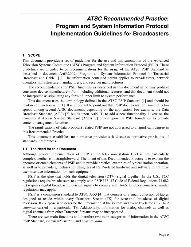
1. SCOPE
This document provides a set of guidelines for the use and implementation of the AdvancedTelevision Systems Committee (ATSC) Program and System Information Protocol (PSIP). Theseguidelines are intended to be recommendations for the usage of the ATSC PSIP Standard asdescribed in document A/65:2009, “Program and System Information Protocol for TerrestrialBroadcast and Cable” [1]. The information contained herein applies to broadcasters, networkoperators, infrastructure manufacturers, and receiver manufacturers.
The recommendations for PSIP functions as described in this document in no way prohibitconsumer device manufacturers from including additional features, and this document should notbe interpreted as stipulating any form of upper limit to system performance.
This document uses the terminology defined in the ATSC PSIP Standard [1] and should beread in conjunction with [1]. It is important to point out that PSIP documentation is—in effect—spread among several ATSC documents, depending on the application. For example, the DataBroadcast Standard (A/90) [2] builds upon A/65 [1] to add a new functionality. Likewise, theConditional Access System Standard (A/70) [3] builds upon the PSIP foundation to providecontent management functions.
The ramifications of data broadcast-related PSIP are not addressed to a significant degree inthis Recommended Practice.
This document establishes no normative provisions; it discusses normative provisions ofstandards it references.
1.1 The Need for this Document
Although proper implementation of PSIP at the television station level is not particularlycomplex, neither is it straightforward. The intent of this Recommended Practice is to explain theoperator-oriented elements of PSIP and to provide practical examples of typical station operation,as well as to provide guidelines for designers of PSIP-related hardware and software to optimizeuser interface information for such equipment.
PSIP is the glue that holds the digital television (DTV) signal together. In the U.S., FCCregulations require broadcasters to comply with PSIP. U.S. 47 Code of Federal Regulations 73.682(d) requires digital broadcast television signals to comply with A/65. In other countries, similarregulations may apply.
PSIP is a companion standard to ATSC A/53 [4] that consists of a small collection of tablesdesigned to reside within every Transport Stream (TS) for terrestrial broadcast of digitaltelevision. Its purpose is to describe the information at the system and event levels for all virtualchannels carried in a particular TS. Additionally, information for analog channels as well asdigital channels from other Transport Streams may be incorporated.
There are two main functions and therefore two main categories of information in the ATSCPSIP Standard, system information and program data:
Page 9

Advanced Television Systems Committee Document A/69:2009
• System information allows navigation and access of the channels within the DTVtransport stream.
• Program data provides information to facilitate efficient browsing and event selection. Some tables announce future events and some are used to locate the digital streams than make
up an event. The PSIP data are carried via a collection of hierarchically arranged tables.
1.2 Other System Considerations
The ATSC television system relies upon digital video, audio, and related data, along with PSIPtransmitted to viewers in an MPEG-2 Transport Stream (TS). This TS is a complex construct, andstation operators need reliable tools to monitor its health. The ATSC has provided aRecommended Practice on this topic, A/78 [5]. Readers should ensure their broadcast stations areequipped with monitoring devices following the A/78 paradigm1. SCTE produced a TSverification Recommended Practice with extensions for cable-only aspects. The SCTE documentis ANSI/SCTE 142 [6].
1.3 Organization
The sections of this document are organized as follows:• Section 1. Provides this general introduction.• Section 2. Lists references and applicable documents.• Section 3. Provides a definition of terms and a list of acronyms and abbreviations used in
this document.• Section 4. Describes the overall PSIP structure.• Section 5. Describes the basic PSIP requirements for broadcasters.• Section 6. Describes format and structure of the PSIP tables.• Section 7. Describes the interrelation of the PSIP tables.• Annex A. Explains the need for PSIP, the history of the standard, and the fundamental
structure of the system.• Annex B. Provides an example of a typical PSIP implementation.• Annex C. Briefly explains the differences between PSIP for terrestrial broadcast and cable
applications.• Annex D. Provides an overview of the syntax and format of the tables used in the PSIP
Standard.• Annex E. Describes the concepts behind and the use of GPS time, a key element in PSIP
operation.• Annex F. Provides examples of near-video on demand.• Annex G Provides additional explanation of the PSIP Master Guide Table.• Annex H. Summarizes the use of analog transmission signal ID information.• Annex I. Expands upon the use of the component name descriptor.• Annex J. Explains the sources of PSIP information for the DTV station.• Annex K. Explains specific coding issues related to the Rating Region Table.
1. Many older Transport Stream analyzers assess noncompliance with A/65 strictly, without regard for the severityof the non-compliance. A/78, in contrast, is oriented towards emphasizing important deviations based on theseverity of each error in a real-world manner.
10

PSIP Implementation Guidelines for Broadcasters 25 December 2009
• Annex L. Explains the operation of Directed Channel Change.
1.4 Use of This Document
The authors of this document recommended that it be studied in its entirety. The subject of PSIP iscomplex and a full understanding is facilitated by following the logical progression of topicsprovided in this Recommended Practice. However, in recognition of the practical time limitationsfaced by engineers today, the following sections are identified as “must-read”:
• For television station engineers: Section 5, Section 6, Annex A, and Annex B.• For PSIP generator manufacturers: Section 5, Section 6, Section 7, Annex C, Annex D,
Annex E, Annex F, Annex G, Annex H, and Annex I. In addition, manufacturers arereferred to ATSC Standard A/65 [1].
For those readers who are unfamiliar with the genesis of the PSIP Standard and why it isimportant to broadcasters, the authors recommend that Annex A be read first as it providesvaluable background information on the subject.
As an additional aid to readers, specific recommendations in this document are noted by thegraphic: .
2. REFERENCES
At the time of publication, the editions indicated below were valid. All standards are subject torevision, and parties to agreement based on this document are encouraged to investigate thepossibility of applying the most recent editions of the documents listed below.
[1] ATSC: “Program and System Information Protocol for Terrestrial Broadcast and Cable,”Doc. A/65:2009, Advanced Television Systems Committee, Washington, D.C., 14 April2009.
[2] ATSC: “ATSC Data Broadcast Standard,” including Amendment 1 and Corrigendum 1 andCorrigendum 2,” Advanced Television Systems Committee, Washington, D.C., 26 July 2000(Amendment 1 dated 14 May 2002; Corrigendum 1 and 2 dated 1 April 2002).
[3] ATSC: “Conditional Access System for Terrestrial Broadcast, Revision A, with AmendmentNo. 1,” Doc. A/70A, Advanced Television Systems Committee, Washington, D.C., 22 July2004 (Amendment No. 1 dated 11 September 2006).
[4] ATSC: “ATSC Digital Television Standard, Parts 1–6,” Doc A/53:2007/2009, AdvancedTelevision Systems Committee, Washington, D.C., 3 January 2007 and 7 August 2009.
[5] ATSC: “Recommended Practice, Transport Stream Verification,” Doc. A/78A, AdvancedTelevision Systems Committee, Washington, D.C., 9 May 2007.
[6] SCTE: “Recommended Practice for Transport Stream Verification,” Doc. ANSI/SCTE 142-2009, Society of Cable Telecommunications Engineers, Exton, PA, 2009.
[7] IEEE: “Use of the International Systems of Units (SI): The Modern Metric System,” Doc.IEEE/ASTM SI 10-2002, Institute of Electrical and Electronics Engineers, New York, N.Y.
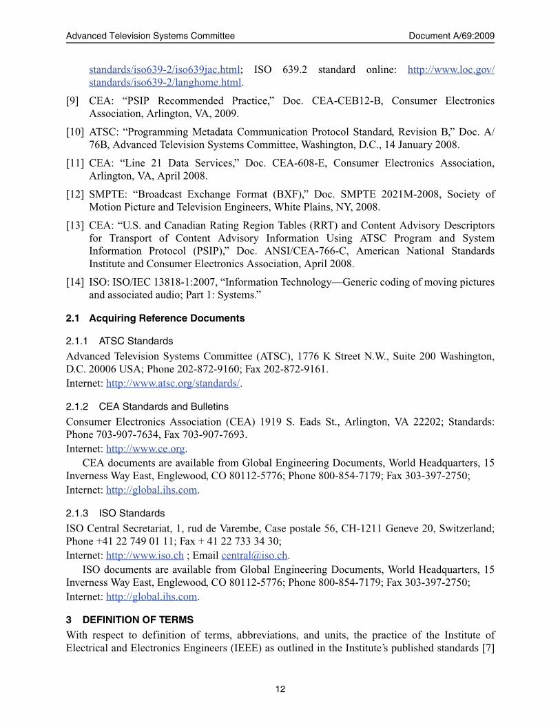
[8] ISO: ISO 639.2, “Code for the Representation of Names of Languages — Part 2: alpha-3code,” as maintained by the ISO 639/Joint Advisory Committee (ISO 639/JAC), http://www.loc.gov/standards/iso639-2/iso639jac.html. JAC home page: http://www.loc.gov/
11
Advanced Television Systems Committee Document A/69:2009
standards/iso639-2/iso639jac.html; ISO 639.2 standard online: http://www.loc.gov/standards/iso639-2/langhome.html.
[9] CEA: “PSIP Recommended Practice,” Doc. CEA-CEB12-B, Consumer ElectronicsAssociation, Arlington, VA, 2009.
[10] ATSC: “Programming Metadata Communication Protocol Standard, Revision B,” Doc. A/76B, Advanced Television Systems Committee, Washington, D.C., 14 January 2008.
[11] CEA: “Line 21 Data Services,” Doc. CEA-608-E, Consumer Electronics Association,Arlington, VA, April 2008.
[12] SMPTE: “Broadcast Exchange Format (BXF),” Doc. SMPTE 2021M-2008, Society ofMotion Picture and Television Engineers, White Plains, NY, 2008.
[13] CEA: “U.S. and Canadian Rating Region Tables (RRT) and Content Advisory Descriptorsfor Transport of Content Advisory Information Using ATSC Program and SystemInformation Protocol (PSIP),” Doc. ANSI/CEA-766-C, American National StandardsInstitute and Consumer Electronics Association, April 2008.
[14] ISO: ISO/IEC 13818-1:2007, “Information Technology—Generic coding of moving picturesand associated audio; Part 1: Systems.”
2.1 Acquiring Reference Documents
2.1.1 ATSC Standards
Advanced Television Systems Committee (ATSC), 1776 K Street N.W., Suite 200 Washington,D.C. 20006 USA; Phone 202-872-9160; Fax 202-872-9161.Internet: http://www.atsc.org/standards/.
2.1.2 CEA Standards and Bulletins
Consumer Electronics Association (CEA) 1919 S. Eads St., Arlington, VA 22202; Standards:Phone 703-907-7634, Fax 703-907-7693.Internet: http://www.ce.org.
CEA documents are available from Global Engineering Documents, World Headquarters, 15Inverness Way East, Englewood, CO 80112-5776; Phone 800-854-7179; Fax 303-397-2750;Internet: http://global.ihs.com.
2.1.3 ISO Standards
ISO Central Secretariat, 1, rud de Varembe, Case postale 56, CH-1211 Geneve 20, Switzerland;Phone +41 22 749 01 11; Fax + 41 22 733 34 30; Internet: http://www.iso.ch ; Email [email protected].
ISO documents are available from Global Engineering Documents, World Headquarters, 15Inverness Way East, Englewood, CO 80112-5776; Phone 800-854-7179; Fax 303-397-2750;Internet: http://global.ihs.com.
3 DEFINITION OF TERMS
With respect to definition of terms, abbreviations, and units, the practice of the Institute ofElectrical and Electronics Engineers (IEEE) as outlined in the Institute’s published standards [7]
12
PSIP Implementation Guidelines for Broadcasters 25 December 2009
are used. Where an abbreviation is not covered by IEEE practice or industry practice differs fromIEEE practice, the abbreviation in question will be described in Section 3.2 of this document.
3.1 Treatment of Syntactic Elements
This document contains symbolic references to syntactic elements used in the audio, video, andtransport coding subsystems. These references are typographically distinguished by the use of adifferent font (e.g., restricted), may contain the underscore character (e.g., sequence_end_code) andmay consist of character strings that are not English words (e.g., dynrng).
3.2 Acronyms and Abbreviation
The following acronyms and abbreviations are used within the ATSC PSIP Standard [1] or thisdocument and are repeated here for quick reference.
ATSC – Advanced Television Systems Committee
BMP – basic multilingual plane
bslbf – bit serial, leftmost bit first
CAT – conditional access table
CEA – Consumer Electronics Association
CRC – cyclic redundancy check
CVCT – cable virtual channel table
DCC – directed channel change
DCCSCT – directed channel change selection code table
DET – data event table
DTV – digital television
EIT – event information table
EMM – entitlement management message
EPG – electronic program guide
ETM – extended text message
ETT – extended text table
GPS – Global Positioning System
IEC – International Electrotechnical Commission
IPG – interactive program guide
ISO – International Standards Organization
kbps – kilo (1000) bits per second
MGT – master guide table
MHz – megahertz
MPAA – Motion Picture Association of America
13
Advanced Television Systems Committee Document A/69:2009
MPEG – Moving Picture Experts Group
NTSC – National Television Systems Committee
NVOD – near video on demand
OOB – out of band
PAT – program association table
PCR – program clock reference
PES – packetized elementary stream
PID – packet identifier
PMT – program map table
PSI – program specific information
PSIP – program and system information protocol
PTC – physical transmission channel
QAM – quadrature amplitude modulation
RCU – remote control unit
rpchof – remainder polynomial coefficients, highest order first
RRT – rating region table
RTT – ratings text table
SCTE – Society of Cable Telecommunications Engineers
SD – standard definition
SDTV – standard definition television
SI – system or service information
SLD – Service Location Descriptor
SMPTE – Society of Motion Picture and Television Engineers
STD – system target decoder
STT – system time table
TS – transport stream
TSID – transport stream ID or transmission signal ID
TVCT – terrestrial virtual channel table
TVPG – Television Parental Guidelines
uimsbf – unsigned integer, most significant bit first
unicode – Unicode™
UTC – Coordinated Universal Time
14
PSIP Implementation Guidelines for Broadcasters 25 December 2009
VBI – vertical blanking interval
VC – virtual channel
VCT – virtual channel table; used in reference to either TVCT or CVCT
VSB – vestigial sideband
3.3 Definition of Terms
The following key terms that are used in the ATSC PSIP standard [1] are repeated here for ease ofreference:
base PID – A packet identifier of fixed value 0x1FFB.
descriptor – A data structure of the format: descriptor_tag, descriptor_length, and a variable amount ofdata. The tag and length fields are each 8 bits in length. The length specifies the length of datathat begins immediately following the descriptor_length field itself. A descriptor whosedescriptor_tag identifies a type not recognized by a particular decoder is expected to be ignoredby that decoder. Descriptors can be included in certain specified places within PSIP tables,subject to certain restrictions. Descriptors may be used to extend data represented as fixedfields within the tables. They make the protocol very flexible because they can be includedonly as needed. New descriptor types can be standardized and included without affectingreceivers that have not been designed to recognize and process the new types.
digital channel – A set of one or more digital elementary streams. See virtual channel.
event – A collection of elementary streams with a common time base, an associated start time,and an associated end time. An event is equivalent to the common industry usage of“television program.”
instance – See table instance.
logical channel – See virtual channel.
major channel – The first number in a two-part number used to identify a virtual channel. Eachvirtual channel carries one service, such as a television program.
minor channel – The second number in a two-part number used to identify a virtual channel. Theminor number changes for each different service that is or will be present in a DTV transportstream.
packet identifier – Also known as PID. A unique integer value used to identify packets in aTransport Stream.
physical channel – A generic term to refer to the each of the 6 MHz frequency bands wheretelevision signals are embedded for transmission. Also known as the physical transmissionchannel (PTC). One analog virtual channel fits in one PTC but multiple digital virtualchannels typically coexist in one PTC.
physical transmission channel – See physical channel.
program element – A generic term for one of the elementary streams or other data streams thatmay be included in a program. For example: audio, video, data, and so on.
15

Advanced Television Systems Committee Document A/69:2009
program – In MPEG terminology, a collection of program elements. Program elements may bestreams of data such as video, data, and audio. Program elements need not have any definedtime base; those that do have a common time base are intended for synchronized presentation.The term program is also commonly used in the context of a “television program” such as ascheduled daily news broadcast. In ATSC standards, the term “event” is used to refer to a“television program” to avoid confusion with the MPEG technical definition.
region – As used in the PSIP document, a region is a geographical area consisting of one or morecountries.
section – A data structure comprising a portion of an ISO/IEC 13818-1 (MPEG Systems) definedtable, such as the Program Association Table (PAT), Conditional Access Table (CAT), orProgram Map Table (PMT). All sections begin with the table_id and end with the CRC_32 field,and their starting points within a packet payload are indicated by the pointer_field mechanismdefined in the ISO/IEC 13818-1 International Standard.
stream – An ordered series of bytes. The usual context for the term stream is the series of bytesextracted from transport stream packet payloads which have a common unique PID value(e.g., video PES packets or Program Map Table sections).
table, PSIP – A collection of tables describing virtual channel attributes, event features, and otherelements. PSIP tables are compliant with the private section syntax of ISO/IEC 13818-1.
table, instance – Tables are identified by the table_id field. However, in cases such as the RRT andEIT, several tables with different content can be defined simultaneously; each of these is atable instance. All instances have the same PID and table_id but a different table_id_extension.
version number – A number that increments each time there is a change in a referenced table.
virtual channel – A virtual channel (VC) is the numeric designation that is recognizable by theuser as the single entity that will provide access to a TV program. It is called “virtual”because its identification (name and number) may be defined independently from itsphysical (RF) location. Examples of virtual channels include: digital radio (audio only), atypical cable analog TV channel, a typical digital TV channel (composed of one audio andone video stream), multi-visual digital channels (composed of several video streams and oneor more audio tracks), or a data broadcast channel (composed of one or more data streams).In the case of an analog TV channel, the virtual channel designation will link to a specificphysical transmission channel. In the case of a digital TV channel, the virtual channeldesignation will link both to the physical transmission channel and to the particular videoand audio streams within that physical transmission channel that make up the event currentlyon that VC.
4. PSIP STRUCTURE
PSIP is a collection of tables, each of which describes elements of typical digital televisionservices [1]. Figure 4.1 shows the primary components and the notation used to describe them.The packets of the base tables are all labeled with a base packet identifier (PID) (base_PID). Thebase tables are:
• System Time Table (STT)• Rating Region Table (RRT)
16

PSIP Implementation Guidelines for Broadcasters 25 December 2009
• Master Guide Table (MGT)• Virtual Channel Table (VCT) The Event Information Tables (EIT) are a second set of tables, whose packet identifiers are
defined in the MGT. The Extended Text Tables (ETT) are a third set of tables, and similarly, theirPIDs are defined in the MGT.
The System Time Table is a small data structure that fits in one Transport Stream packet andserves as a reference for time-of-day functions. Receivers can use this table to manage variousoperations and scheduled events, as well as display time-of-day.
The Rating Region Table has been designed to transmit the rating system in use for eachcountry using the ratings. In the U.S., this is incorrectly but frequently referred to as the “V-chip”system; the proper title is Television Parental Guidelines (TVPG). Provisions have been made inthe PSIP Standard [1] for multi-country systems.
The Master Guide Table provides indexing information for the other tables that comprise thePSIP Standard. It also defines table sizes necessary for memory allocation during decoding,defines version numbers to identify those tables that need to be updated, and generates the packetidentifiers that label the tables.
The Virtual Channel Table, also referred to as the Terrestrial VCT (TVCT), contains a list ofall the channels that are or will be on-line, plus their attributes. Among the attributes given are thechannel name and channel number.
source_id
source_id
source_id
source_id
source_id
source_id
RRT
STT
MGT
VCT
base_PID
PID-K PID-L PID-M
EIT-0 EIT-1 EIT-2
source_id
For channel x:
For channel y:
source_id
Figure 4.1 Overall structure of the PSIP tables.
17

Advanced Television Systems Committee Document A/69:2009
There are up to 128 Event Information Tables, EIT-0 through EIT-127, each of whichdescribes the events or television programs for a time interval of three hours. Because themaximum number of EITs is 128, up to 16 days of programming may be advertised in advance. Atminimum, the first four EITs are required to always be present in every transport stream, and 24are recommended. Each EIT-k may have multiple instances, one for each virtual channel in theVCT.
As illustrated in Figure 4.2, there may be multiple Extended Text Tables, one or more channelETT sections describing the virtual channels in the VCT, and an ETT-k for each EIT-k, describingthe events in the EIT-k. These are all listed in the MGT. An ETT-k contains a table instance foreach event in the associated EIT-k. As the name implies, the purpose of the ETT is to carry textmessages. For example, for channels in the VCT, the messages can describe channel information,cost, coming attractions, and other related data. Similarly, for an event such as a movie listed inthe EIT, the typical message would be a short paragraph that describes the movie itself. ExtendedText Tables are optional in the ATSC system.
5. BASIC PSIP REQUIREMENTS FOR BROADCASTERS
The three main tables (VCT, EIT, and STT) contain information to facilitate suitably equippedreceivers to find the components needed to present a program (event). Although receivers areexpected to use stored information to speed channel acquisition, sometimes parameters changeand the MGT, VCT, and EIT-0 are the tables that are most critical each and every instant as theyprovide the actual connection path and critical information that can affect the display of theevents. If nothing has changed since an EIT was sent for an event, then the anticipatory use of thedata is expected to proceed, and when there is a change the new parts would be used. Additionaltables provide TV parental advisory information and extended text messages about certain events.These relationships—and the tables that carry them—are designed to be kept with the DTV signalwhen it is carried by a cable system.
5.1 The Basics
There are certain PSIP elements that are required, and there are certain rules to be followed. Ifthese PSIP elements are missing or wrong, there may be severe consequences, which vary
MGT
PID-X PID-Y PID-Z
ETT-0 ETT-1 ETT-2
Text messages for EIT-0
Text messages for EIT-1
Text messages for EIT-2
PID-V
ETT-V Text messages for VCT
Figure 4.2 Extended text tables in the PSIP hierarchy.
18
PSIP Implementation Guidelines for Broadcasters 25 December 2009
depending on the design of receiver. The following are key elements that are required to be setand/or checked by each station:
• Transport Stream Identification (TSID). The pre-assigned TSIDs are required to be setcorrectly in all three locations (PAT, VCT common information, and virtual channel-specific information). See Section 6.3.1 for more information.
• System Time Table (SST). The System Time is required to be accurate to within plus orminus one second. It should be checked daily and, ideally, locked to GPS time. See Section6.6. A/65 recommends that the STT be inserted into the TS a few milliseconds before eachseconds-count increment of the house time with the to-be-valid value.
• Short Channel Name. This is a seven-character name that can be set to any desired nameindicating the virtual channel name. For example, a station’s call letters followed by SD1,SD2, SD3, and SD4 to indicated various SDTV virtual channels or anything else torepresent the station’s identity (e.g., WNABSD1, KNABSD2, WNAB-HD, KIDS, etc.).See Section 6.3.1.
• Major Channel. A number from 1 – 992. For the U.S., the major channel number is theFCC-assigned RF channel number (2 – 69) for each NTSC broadcast licensee. See Section6.3.1 for more detail and exceptions.
• Service Type. The service type selects DTV, NTSC, audio only, data, etc., and is requiredto be set as operating modes require. See Section 6.3.1.
• Source ID. The Source ID is a number that associates virtual channels to events on thosechannels. It typically is automatically updated by PSIP equipment or updated from anoutside vendor. See Section 6.3.4.
• Service Location Descriptor (SLD). Contains the MPEG references to the contents ofeach component of the programs plus a language code for audio (ISO 639-2 [8]). SeeSection 6.3.3. The PID values for the components identified here are required to be thesame for the elements of an event/program that appear in the PMT. PID values assigned toa VC should not be changed as it is recommended that receivers be designed to rely upontheir constancy to speed average channel change time.
The maximum cycle time/repetition rate of the tables should be set or confirmed to conformto the suggested guidelines given in Table 5.1 for mandatory PSIP tables and Table 5.2 foroptional PSIP tables.
2. The major channel number used in the CVCT has a larger range, 0 – 999. See Annex C.
19

Advanced Television Systems Committee Document A/69:2009
It is recommended that broadcasters send populated EITs covering at least three days (seeSection 6.4 for more detail). The primary cycle time guidelines are illustrated in Figure 5.1.
The recommended table transmission times given in this section result in a minimal demandon overall system bandwidth. Considering the importance of the information that these PSIPtables provide to the receiver, the bandwidth penalty is trivial. (Additional details on the impact oftable transmission times on DTV system bandwidth can be found in Section 7.6.)
5.2 Accuracy of Contents
The PSIP standard applies to the construction of the media and metadata contents of the TransportStream and the requirement to avoid inconsistencies amongst that data. PSIP metadata consists ofinformation intended for use within the receiving device (for example, tuning) and informationmeant to be displayed to the user (for example the contents of the ETTs—event descriptions). Theactual contents for user readable fields are under the control of the broadcaster and therefore outof scope of a technical standard. However, the system is required to be able to accurately andconsistently transport whatever media data and metadata is provided. The standard also attemptsto describe the system concepts and how the data should be used for maximum benefit to both theconsumer and the broadcaster.
To amplify and explain the balance between technical precision and operational flexibilitytext, let us examine the text from Section 6.5 of A/65 [1] which says:
Table 5.1 Suggested Repetition Intervals for Mandatory PSIP Table
PSIP Table Suggested Repetition Interval Required Repetition Interval
MGT 150 ms > = 150 ms
TVCT 400 ms > = 400 ms
EIT-0 Once every 0.5 seconds n/a
EIT-1 Once every three seconds n/a
EIT-2 and EIT-3 Once every minute n/a
STT Once every second > = 1000 ms
RRT (not required in some areasa) Once every minute > = 1 minute
a The U.S. is one such area.
Table 5.2 Suggested Repetition Intervals for Optional PSIP Tables
PSIP Table Transmission Interval
ETT Once every minute
EIT-4 and higher Once every minute
DCCSCT Once per hour
DCCT
A/65 [1] specifies the following repetition rates for DCC per specified conditions.
DCC request in progress 150 msec
2 seconds prior to DCC request 400 msec
No DCC n/a
20

PSIP Implementation Guidelines for Broadcasters 25 December 2009
“The contents of the fields and the descriptors in each events descriptor loop shallbe accurate representations of the known information about each event at the timethe event instance is created and shall be updated if more accurate informationbecomes available.”
The key to understanding this provision is the meaning of the word “known” in the technicalcontext. The word “known” was inserted during the drafting to address the practical reality of thevariation in capability of broadcast station infrastructure. In this usage, “known” by definitioncannot be ambiguous, it must be certain. In precise technical terms the scope of the standard isonly the PSIP data stream as transmitted, and the standard does not establish how humanknowledge gets into the facility equipment in general. It also does not address the use of PMCP orBXF protocols (or others) as tools to facilitate getting accurate information from one piece ofequipment to another, but certainly use of such protocols can greatly facilitate matters.Additionally, the “known information” technically must be electronically communicated using thedefined PSIP protocol as receivers rely upon the data conveyed.
So it is the broadcast stream generation equipment that must “know” this information. Asinformation can be created in multiple locations, and the standard just covers the end result, it isthat piece of equipment which creates the particular data structure that must have the certain“knowledge”, so that the data can be made consistent (within the transport). The standarddescribes the equipment’s required capability and not what or when an input was provided to theequipment. So these provisions require standards-compliant equipment to make the correctassociation and send the correct information.
The PSIP data is contained in multiple table structures. As the stream is serial, not parallel,these tables are transmitted at different points in time. If a change is made, there will be briefmoments where the information sent will, by necessity, differ from the last transmission of theassociated tables. At the point where the information is changed there can be an interval (usually
MGT
TVCT
EIT-0
STT
RRT
0 t (sec)
150 ms
400 ms
500 ms(recommended)
1 sec
60 sec
1 2 3 4 5 6 7
Figure 5.1 Recommended PSIP table transmissions.
21
Advanced Television Systems Committee Document A/69:2009
much less than a second) where the data differs. However, once all of the updated tables aretransmitted, the information is then in synch again.
5.2.1 Practical Considerations
Requirements on the PSIP generator and the roles of the human or the equipment that sendscommands to that generator are important to keep separate. The PSIP standard only covers thedata that must be able to be emitted, when it is emitted, and exactly how it is structured. There isno requirement for when a human must enter data, or for when commands are to be sent from anycontrol system. Accordingly the time accuracy for changes is not normatively asserted in the PSIPstandard. The standard just requires construction of accurate data structures from the input data.Not stated, but expected in practical implementations, that as soon as the PSIP generator cangenerate corrected data, it will be emitted at the next time slot for each impacted table section.The key point is that PSIP equipment that meets the current version of the PSIP standard enablessending updated event titles, start times and durations (along with other event related metadata).The practical issue is management and control of the data. When an event (program) runs over,there is a ripple impact to later programs. Should the next program be shortened or should it beshifted in time and some later program shortened (or the broadcast day extended)? This is usuallyconsidered a traffic system issue and usually requires human intervention. The standard is silenton this aspect of operation and only covers the construction of relevant parts of the data steambased on the information it is provided. Please refer to the discussion in ATSC A/78 [5]“Consistency Errors” for additional background on this topic.
Also please note the footnote 10 at the beginning of Section 6.5 of A/65 [1], which isimportant notwithstanding its placement as a note. It documents the intent of the change to requireequipment to be more accurate. It says in relevant part “These EITs should be populated with thecorrect information, so that the user knows what programs are on for this [9 to] 12 hour period.”The word “should” here applies to the entire set of information in the EIT.
5.2.2 Unanticipated and Emergency Situations
When a response to an unanticipated occurrence, such as an emergency situation, results inmodification of program audio and/or video content, adjustment of PSIP metadata to reflecttransient (short-duration) conditions need not be made. This may result, for example, in all virtualchannels carrying the announcement in the same language and the language tags for some audiotracks being temporarily incorrect. Other examples of temporarily inconsistent data includeprogram name and caption service descriptions.
5.3 Program Guide
Support for an Electronic Program Guide (EPG) or Interactive Program Guide (IPG) is anotherimportant function enabled by the PSIP Standard. The concept is to provide a way for viewers tofind out “what’s on” directly from their television sets, similar to the programming guides that aretypically available for cable and satellite broadcast services. In a terrestrial broadcastenvironment, each broadcaster needs to include this type of information within the broadcaststream. Viewers’ receivers that follow the CEA recommendations in CEA-CEB-12 [9] are able toscan all the available channels can create a program guide channel from the consolidatedinformation3. Viewers will have the ability not only to choose what channel to watch but also beable to select from multiple options within a broadcast. Examples include selecting from a set of
22

PSIP Implementation Guidelines for Broadcasters 25 December 2009
alternative audio tracks in different languages, or choosing one of several SDTV programs shownat the same time on different virtual channels.
5.4 Most Common Mistakes
Experience in the U.S. has shown that certain errors in configuration of PSIP generationequipment can occur if proper care is not given to their setup or maintenance. These problemsmay include the following:
• Missing tables, particularly the STT and EIT.• Major channel number set to the DTV RF channel number, rather than the associated
(legacy) NTSC channel number.• TSID set to 0 or 1, the NTSC TSID, or another station’s TSID; or not correctly set in the
three required places.• System time inaccuracy.• Not populating all required PSIP fields.• Not providing accurate and up-to-date information in the fields, such as meaningful event
titles, as contrasted with such titles as “TV Program,” or “TBA”.• Inconsistent table data, either between PSIP tables or between PSIP and the PAT/PMT. See
Section 7.6 for more details.
6. THE PSIP TABLES
The following sections describe the basic functions of the PSIP tables and indicate where the datain the tables originates, as well as generic information about the data itself. In general, the datacomes from the following sources4:
• Provided by the broadcast station as input to the PSIP system user software; this is station-specific information (for example, the major and minor channel numbers).
• Set as default in PSIP software; this information is usually MPEG-2 data that is ATSC-specific (for example, all table IDs).
• Calculated by the PSIP generator (for example, the descriptor length).• Provided from or to the audio or video encoder (for example the elementary PID for the
video or audio).• Provided from or to the Closed Captioning system (for example the language of the
captions).The user software supplied with the PSIP encoder system will typically guide the user in
inputting the needed information, so it is not normally necessary for users to be concerned aboutthe formal details of the PSIP table structure as presented in ATSC Standard A/65 [1] (see AnnexB for specific examples). More importantly, users should first understand what data they arerequired to provide to the user software and second what the correct data is.
It should be noted that the PSIP tables are constructed using a form of “C Code” syntax andformat. Annex D explains this construction scheme.
3. Note: Receivers built prior to the publication of CEA-CEB12 [9] may not have implemented itsrecommendations.
4. See also Annex J.
23

Advanced Television Systems Committee Document A/69:2009
6.1 General Considerations
Not all of the tables are required for all terrestrial and cable applications, as summarized in Table6.1.
The VCT comes in two flavors, one specifically for terrestrial broadcast—the TerrestrialVirtual Channel Table (TVCT)—and the other for cable—the Cable VCT (CVCT).
All PSIP tables are extensible via the descriptor method. In PSIP, some descriptors aremandatory, while others are optional. A receiver that does not recognize a descriptor of a certaintype is required to simply ignore it, so addition of new features via new descriptor definitions is apowerful way to add new features to the protocol while maintaining backwards compatibility.
One hard-coded PID value has been chosen for the transport packets that carry all PSIP dataexcept the program guide data and extended text. PID 0x1FFB was chosen so as not to collidewith other known fixed-assigned PID values.
As detailed in Section 5, all ATSC-compatible digital broadcast television multiplexes arerequired to carry at least the following PSIP tables:
• Master Guide Table, repeated at a required minimum rate of once every 150 msec.• System Time Table, repeated at a required minimum rate of once per second.• Rating Region Table, repeated at a required minimum rate of once per minute if present.• Terrestrial Virtual Channel Table, repeated at a required minimum rate of once each 400
msec.• The first four Event Information Tables, representing up to twelve hours of program
schedules (see Tables 5.1 and 5.2 for recommended repetition rates).Further EITs may be transmitted if a broadcaster wishes to provide program schedules beyond
half a day; it is recommended that at least 24 be sent. (See Section 6.4 for more information.)A receiver is required to handle data rates of PSIP data in PID 0x1FFB (base_PID) of up to 250
kbps. Each EIT and event text PID can also be sent at a rate of up to 250 kbps.The A/65 Standard [1] defers to SCTE for specification of data rates on cable systems in
North America, but does state that the MGT, STT, and cable VCT are required, as detailed inTable 6.1. Cable systems may elect to supply program guide data in a format other than PSIP’s
Table 6.1 PSIP Tables Required for Transmission in the Broadcast and Cable Modes
Table Required for Broadcast? Required for Cable?
STT Yes Yes
MGT Yes Yes
VCT Yes (TVCT) (CVCT is optional) Yes (CVCT)
RRT Conditional a Conditional a
EIT Yes (EIT-0, -1, -2, -3); all others optional Conditional b
ETT Optional Optional
a If a content advisory descriptor is transmitted, the associated RRT—except for RRT 01—is required to be transmitted.
b On 18 January 2001, the FCC issued its first Report and Order on Cable Carriage of DTV (Docket 98-120), which in paragraph #83, required carriage of PSIP data related to the primary video service when present, but does not require generation of such data for channels that do not have PSIP data.
24
PSIP Implementation Guidelines for Broadcasters 25 December 2009
EIT/ETT (this is the typical case in the U.S. and Canada) and U.S. cable system operators areallowed to constrain the total data rate of the PSIP data by removing optional table instances (orcontents therein) and adjusting the MGT to so reflect when large amounts of PSIP data are beingsent by a broadcaster.
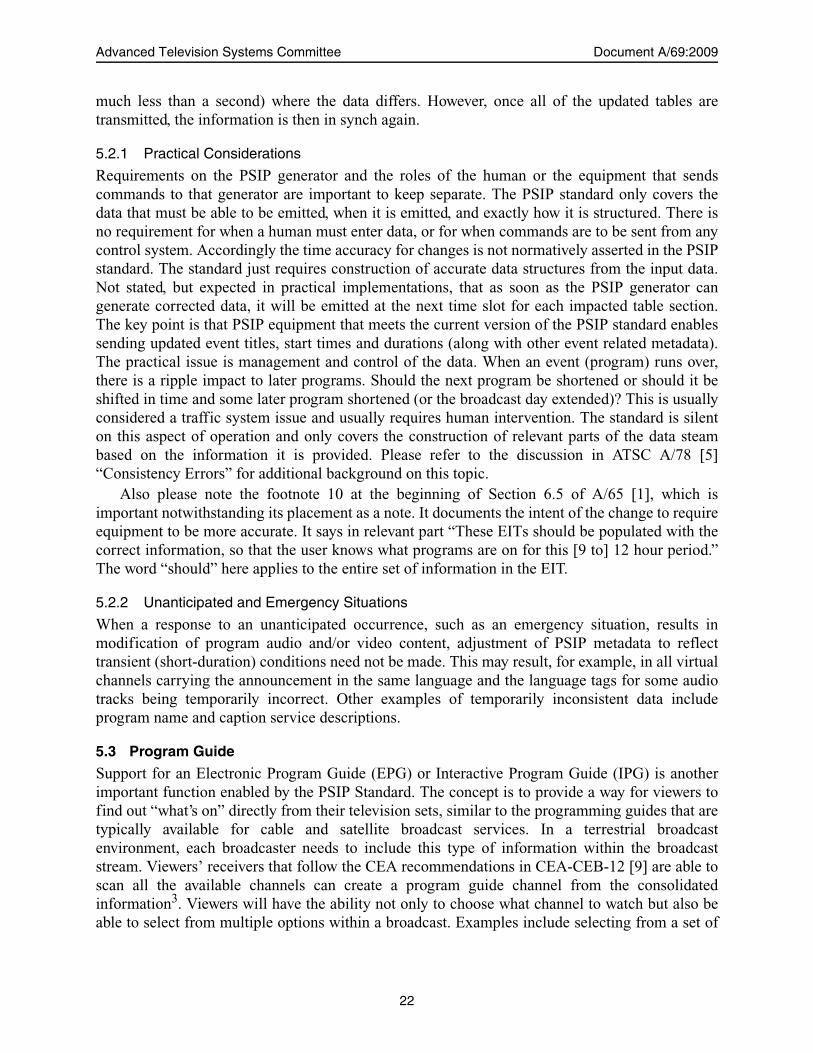
6.2 Master Guide Table
The purpose of the MGT is to describe everything about the other tables, listing features such asversion numbers, table sizes, and packet identifiers (PIDs). Figure 6.1 shows a typical MasterGuide Table indicating, in this case, the existence in the Transport Stream of a Virtual ChannelTable, the Rating Region Table, four EITs, one Extended Text Table for channels, and twoExtended Text Tables for events.
The first entry of the MGT describes the version number and size of the Virtual ChannelTable. The second entry corresponds to an instance of the Rating Region Table. Notice that thebase_PID (0x1FFB) are required to be used for the VCT and the RRT instances as specified inPSIP.
The next entries shown in the MGT example above (no ordering of elements is required)correspond to the first four EITs that are required to be supplied in the transport stream. Thebroadcaster is free to choose the PID values (subject to the constraints in A/53 Part 3, Section 6.9)as long as they are unique in the Transport Stream. After the EITs, the MGT example indicates the
MGT
table_type PID version_num. table size VCT 0x1FFB (base_PID) 4 391 bytes RRT – USA 0x1FFB (base_PID) 1 959 bytes EIT-0 0x1FD0 6 970 bytes EIT-1 0x1FD1 4 970 bytes EIT-2 0x1DD1 2 970 bytes EIT-3 0x1DB3 7 970 bytes ETT for VCT 0x1AA0 21 312 bytes ETT-0 0x1BA0 10 2543 bytes ETT-1 0x1BA1 2 2543 bytes
Figure 6.1 Example content of the Master Guide Table.
25

Advanced Television Systems Committee Document A/69:2009
existence of a channel Extended Text Table using PID 0x1AA0. Similarly, the last two entries inthe MGT signal the existence of two Extended Text Tables, one for EIT-0 and the other for EIT-1.
Descriptors can be added for each entry as well as for the entire MGT. By using descriptors,future improvements can be incorporated without modifying the basic structure of the MGT. TheMGT is like a flag table that continuously informs the decoder about the status of all the othertables (except the STT, which has an independent function). The MGT is continuously monitoredat the receiver to prepare and anticipate changes in the channel/event structure. When tables arechanged at the broadcast side, their version numbers are incremented and the new versionnumbers are listed in the MGT. Based on the version updates and on the memory requirements,the decoder can reload the newly defined tables for proper operation.
6.3 Virtual Channel Table
This table contains the set of data that enables a receiver to tune and locate the service beingbroadcast. The Virtual Channel Table is essentially a list containing information about eachservice that a broadcaster creates or has announced that it will create within the DTV transportstream, as well as information about the broadcaster’s associated analog channel5. See Figure 6.2for an example VCT. The VCT consists of one or more virtual channel definitions. The majorelements of these definitions are:
• The two-part (major/minor) channel number the user will use to access the service.• Its short name (up to seven characters).6
• How the service is physically delivered (carrier frequency7 and modulation mode).• The service channel_TSID8.• Its MPEG-2 program_number.• The type of service (analog TV, digital TV, audio only, data).• Its “source ID” 9.• Descriptors indicating what PIDs are being used to identify packets transporting parts of
the service and descriptors for extended channel name information.Other data specific to each terrestrial virtual channel includes a flag that tells whether the
service requires one of several special handling conditions, and an indication as to whether“extended text” is available to provide a textual description of the service.
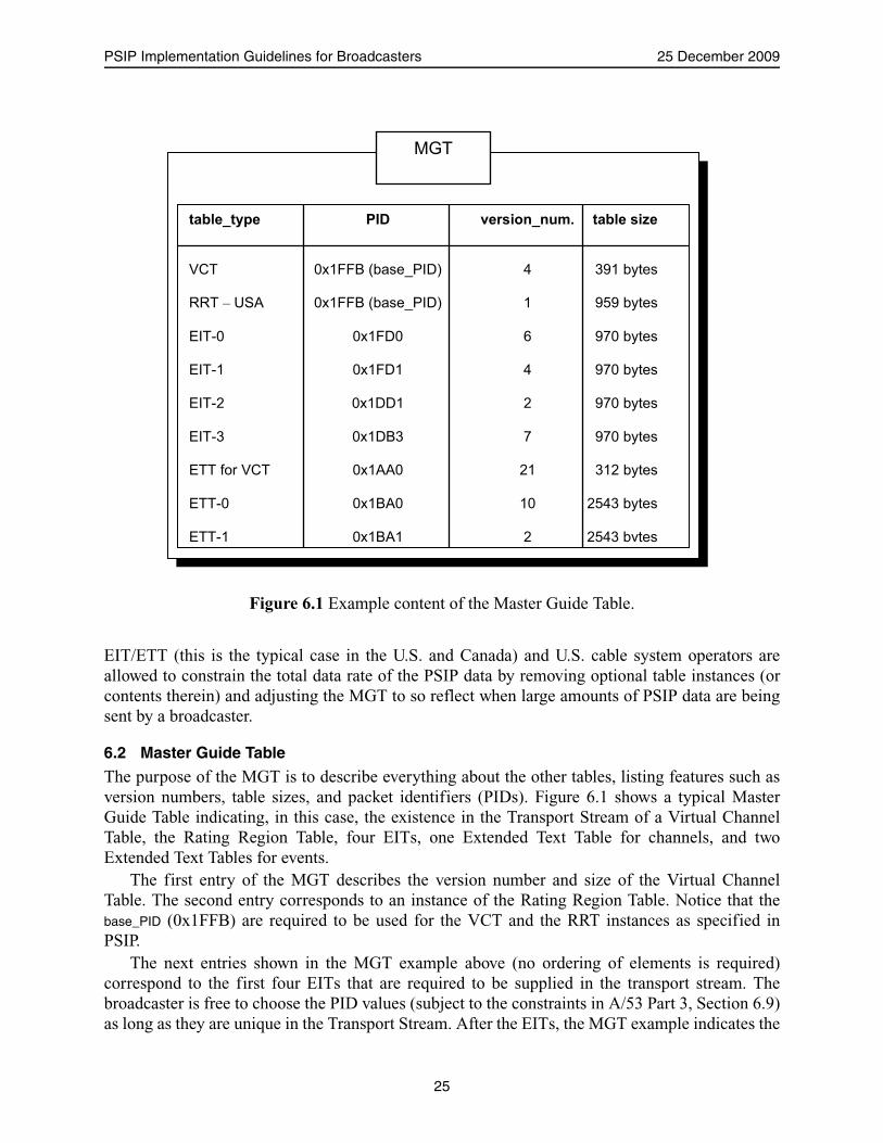
6.3.1 VCT Structure
The field number_of_channels_in_section indicates the number of channels described in this section ofthe VCT. In normal applications, as in the example being considered here, all channel informationwill fit into one section.10 In the example (Figure 6.2) the number_channels_insection is 5.
5. The PSIP Standard also supports sending information about Virtual Channels that are transmitted in anotherbroadcaster’s transport streams, but this is not the typical case.
6. PSIP provides a descriptor mechanism to define longer channel names as needed.7. Use of the carrier frequency field caused implementation issues in cases where the DTV signal was shifted in
frequency. Its use was deprecated in an amendment to the original Standard to avoid the hardware complexitythat otherwise would have been required when each such frequency shift was made.
8. This is required to be the same as the TSID of the stream where the DTV service is being transmitted.9. This is the key link to the announcements in the EITs.
26
PSIP Implementation Guidelines for Broadcasters 25 December 2009
The fields major_channel_number and minor_channel_number are used for identification of theservice on a virtual channel. The major channel number is used to group all channels that are to beidentified as belonging to a particular broadcaster (or particular identifying number such as 12 inthis case). In the U.S., the original NTSC RF channel is required to be used as a major channelnumber. Refer to A/65 [1] Annex B for complete details on the channel number assignment rulesfor U.S. broadcasting. In the example, channel 12 was originally assigned as an NTSC channeland the associated digital channel assigned by the FCC also used the channel 12 “brand;” so thatall the programming for broadcaster “NBZ” can be accessed together through surfing or in apaper or electronic program guide. Services that are unrelated to the NTSC brand may haveanother major channel number. The minor channel number specifies a particular channel withinthe group with each major number.
10. However, there may be rare times when most of the physical channel is used to convey dozens of low-bandwidthservices such as audio-only and data channels in addition to one video program. In those cases, the channelinformation may be larger than the VCT section limit of 1 kbyte and therefore VCT segmentation will berequired. Information about a channel cannot be split across two sections. For example, assuming that a physicalchannel conveys 20 low-bandwidth services in addition to a TV program, and assuming that their VCTinformation exceeds 1 kbyte, then two or more sections may be defined. The first section may describe 12 virtualchannels and the second 9 if such a partition leads to VCT sections with less than 1 kbyte.
VCT
current_next_indicator = 1 number_channels_in_section = 5
major num.
minor num.
short name
carrier freq. (MHz)
channel TSID
progr. num.
flags type
service id source descriptors
12 0 NBZ 0 0x0AA0 0xFFFF -- analog 12 ch_name 12 1 NBZD 0 0x0AA1 0x0001 -- digital 1 ch_name
serv_locat. 12 2 NBZ-S 0 0x0AA1 0x0002 -- digital 2 ch_name
serv_locat. 12 3 NBZ-M 0 0x0AA1 0x0003 -- digital 3 ch_name
serv_locat. 12 4 NBZ-H 0 0x0AA1 0x0004 -- digital 4 ch_name
serv_locat.
Figure 6.2 Selected typical content of a Virtual Channel Table.
27

Advanced Television Systems Committee Document A/69:2009
Note: When the hidden flag is set to ‘1’ and the hide_guide flag is set to ‘0’ (inactivechannel), the program number for the inactive channel is set to 0x00 and the SLDis not present in the VCT, per A/65. This enables a receiving device to determinethat the channel status is inactive.
The field short_name is a seven-character name for the channel that allows receivers to use text-assisted access and navigation.
The field modulation_mode gives information to the receiver that may help it configure todemodulate a service.
In the U.S. the FCC assigns a TSID for each digital station upon authorization of digitaltransmission. The TSID for the digital station is an odd hex number in the range of 0x0001 to0xFFFE. The FCC has assigned the next lowest even hex number to the paired analog station. Inthe example (Figure 6.2), channel 12 digital is assigned 0x0AA1. The range for TSID values forCanada and Mexico have been allocated. The range for Canada is in two parts: 0x4000 to 0x5FFFwill be made available for immediate use and 0x6000 to 0x7FFF is assigned for future use. Therange for Mexico is 0x8000 to 0xBFFF.
The channel_TSIDs listed in the VCT are required to match the TSID listed in the MPEGProgram Association Table (PAT) where the digital service is transmitted. This may be doneautomatically by the PSIP encoder, but should be verified by the broadcaster or changed in thespecial cases of cross announcement agreements or other special circumstances.
The program_number is included to associate the VCT with the MPEG PAT and Program MapTable. This is an arbitrary number between 1 and 65,534. When an analog channel is referenced,the number is required to be 65,535. The communication path between encoder/multiplexerequipment and PSIP encoder is outside the scope of this recommendation. Private and PMCP [10]implementations exist which facilitate consistency in the program_number values used. If there is noelectronic communication, the broadcaster is required to insure that the corresponding valuesmatch.
The link between the VCT and the SLD is via the program_number. If values for the transportstream_id, program_number, and SLD information are specified by the broadcaster in setting up theVCT, the PAT/PMT combination can be automatically generated by some PSIP encoders. Otherequipment configurations require direct settings of the video encoder and/or the emissionmultiplexer. It is recommended that all PSIP encoders automatically control these relationships.
The hidden and hide_guide fields provide information to the receiver on how to offer access tovirtual channels to the receiver user. Table 6.2 shows expected DTV receiver behavior for thevarious combinations of the hidden and hide_guide attributes.
A channel that is currently active should be available by surfing (sequential channel displayvia repeated activation of a single control by the receiver user) as well as through the receiver’s
Table 6.2 Receiver Behavior with hidden and hide_guide Attributes
hidden hide_guide Receiver Behavior Description
Surf Guide
0 X ü ü Normal channel
1 1 Special access only
1 0 ü Inactive channel
28

PSIP Implementation Guidelines for Broadcasters 25 December 2009
program guide user interface or by direct entry of the two part channel number in a remotecontrol. The broadcaster indicates this by setting hidden to ‘0’. When hidden is ‘0’ the value ofhide_guide is meaningless and should be ignored. When a channel is currently inactive, the receivershould skip over that channel while the user is surfing, but future program listings should beviewable in the program guide. The broadcaster should assign ‘1’ to hidden and ‘0’ to hide_guide tothese channels in the current VCT. This combination may be used by broadcasters that change thenumber of services during each day. Both hidden and hide_guide may be set to ‘1’ when transmittingtest signals, for example.
The field service_type is a description of the type of service offered, and is included to help thereceiving device configure properly where:
• 1 denotes an NTSC analog service • 2 denotes an ATSC full digital TV service including video, audio (if present) and data (if
present)• 3 denotes an ATSC audio and data (if present) service• 4 denotes a ATSC data serviceThe source_id is a critical internal index for representing the particular logical channel.
Broadcasters can assign arbitrary source_id numbers from 1 to 4095. The source IDs are used in each Event Information Table to identify which minor channel will
carry its programming for each 3 hour period. In the example, if channel 12.1 is or will be activeduring any part of a specific EITs time slot, that EIT will reference source_id 1 when listing thatchannel’s programs. The PSIP encoder interface software will provide the source_id cross referencefor each EIT once the decision about which virtual channel should carry the program is made bythe broadcaster.
The Extended Text Tables also use the source_id for each minor channel (along with an event_id
from the Event Information Table) to associate the extended text messages with the appropriateminor channel and event. (See Sections 6.4 and 6.5 for details.)
Two descriptors are associated with the logical channels in the example. The first one isextended_channel_name and—as its name indicates—it gives the full name of the channel. Anexample for channel NBZ-S could be: “NBZ Sports and Fitness.” The broadcaster simply entersthis information for each minor channel.
The other one, the service_location descriptor, is used to list the available bit streams and theirPIDs necessary to locate their packets at the receiver. Assuming that NBZ-M offers bilingualtransmission, then the following attributes are tabulated within its service_location descriptor:
When the VCT refers11 to an analog service type, the channel_TSID does not refer to theidentifier of a “Transport Stream” in the MPEG-2 sense. Analog NTSC broadcast signals can,however, carry a 16-bit unique identifier called a “Transmission Signal Identifier.” For theexample VCT in Figure 6.2, the Transmission Signal Identifier for channel 12.0 was 0x0AA0. A
PID_audio_1 AC-3 audio EnglishPID_audio_2 AC-3 audio SpanishPID_video MPEG-2 video No language
11. In the U.S., use of this referencing capability will decline to zero over time, as NTSC services are being shutdown.
29

Advanced Television Systems Committee Document A/69:2009
receiver can use the Transmission Signal ID given in the analog channel’s channel_TSID field toverify that the received NTSC signal is actually the desired signal.
When a broadcaster adds EIT data for a virtual channel, that channel is required to be includedin the VCT, even if it is currently off-air. This means if no current program was using 7.7, and if aprogram 16 days from now was being announced for 7.7, that 7.7 would be in the VCT. Thiswould enable receivers to include the channel number in a program guide presented to theconsumer. Any channels in the VCT that are not currently active are required to have the hiddenattribute set to ‘1’ and the hide_guide attribute set to ‘0’. So, if a program is announced in the EIT,the receiver can determine from the values of the hidden and hide_guide bits that the channel iscurrently inactive. Receiver behavior is undefined, with the presumption that if a consumerdirectly enters a major-minor combination that is inactive, the receiver will gracefully handle thesituation.
6.3.2 Station-Specific Data
There is essential station-specific VCT information that the broadcaster is required to input forviewers to be able to properly tune programs. This information is given in Table 6.3.
The PIDs for each component in a minor channel should not be changed without cause as anychanges are expected to increase the time it takes for the receiver to tune the station.
Table 6.3 Station-Specific PSIP Data
Data Action by Broadcaster Example
major channel numberEntered once. (Use the same channel number as the NTSC channel number assignment. If no paired NTSC channel, use the assigned DTV channel number. For special cases, see text.)
2
minor channel numbers Entered once per virtual channel. (See text.) 1
TSID Entered once. (See text.) 0x0D4B
service location descriptor Pointers to each video, audio, and data stream.
source id Entered once for each virtual channel or automatically generated. (See text.) 0x17E9
service type Entered once. (Tells the receiver whether the associated minor channel is providing digital or analog service.) 2
short name Input once. “NAB-DT”
modulation mode Entered once for each virtual-minor number 0x04
carrier frequency Recommend zero. 0
MPEG program numberEntered once for each virtual channel. (See text.) The MPEG program number is required to be unique within the transport stream and not be zero.
1
ETM location None N/A
access controlled yes/no 0
Hidden yes/no 0
hide guide yes/no 1
30

PSIP Implementation Guidelines for Broadcasters 25 December 2009
It is recognized that PID changes might be required if, for example, consecutive programs ona minor channel have differing numbers of audio tracks or the source of pre-compressed contentfor a virtual channel changes unexpectedly.
6.3.2.1 VCT Standard and Calculated Data
A station is required to provide the data described previously in this section to allow station- andprogram-specific VCTs to be constructed by the PSIP encoder system; however, much of the VCTdata is standard to the ATSC system in general so it need only be supplied once to the PSIPencoder. This data may come preloaded in the PSIP software. Also, some of the VCT entries arecalculated by the PSIP encoder. Examples are given in Table 6.4. (Also see Annex B.)
6.3.3 Descriptors
Any VCT definition can include descriptors to further describe a service. The Service LocationDescriptor was designed to reduce the time it takes to change virtual channels when tuning viaPSIP tables. This descriptor contains the video PID that is currently used (and should always beused) for that VC.
Use of the stored PID values also avoids the sequential decoding of the PAT and PMT to locatethe PID values. The PID values in the VCT are required to be the same as the corresponding onesin the PMT.
PSIP also defines an Extended Channel Name descriptor that allows a broadcaster or cablesystem operator to give any channel a name exceeding the seven characters offered by the basicVCT record. The seven-character limit for the basic name label was chosen to support on-screenprogram guides in which a limited amount of screen real estate is available for the name text.
A third type of descriptor can be used to indicate that the channel carries programmingidentical to another channel, except time-shifted by a given amount.
6.3.4 Source ID
A source ID is defined as a number that uniquely identifies a source of scheduled programming.PSIP introduced a new level of flexibility into the definition of source ID by stating that the scopeof uniqueness is local to the transport stream for values in the range zero to 0x0FFF, and the scopeis network-wide for values 0x1000 or above. This means each station can freely assign unique
Table 6.4 VCT Example Entries
Examples of Default or Fixed VCT Entries
table_id 0xC8
section_syntax_indicator one bit set to ‘1’
private_indicator one bit set to ‘1’
protocol_version 0x00
last_section_number Default to 0x00 as seldom need more than one section
Examples of Automatically Calculated VCT Entries
section_length Number of bytes of this section of the VCT starting immediately after this field
section_number If more than one section is used, which section is currently being filled is determined
version_number Incremented when contents of table section changed
CRC_32 Based on the contents of the table section
31

Advanced Television Systems Committee Document A/69:2009
numbers below 0x1000. A system to enable use of higher numbers by terrestrial broadcasters hasnot been defined, but numbers above 0x1000 are not prohibited and may occur in some cablesystems associated with non-broadcast sources.
6.3.4.1 NTSC TSID
For analog broadcasting, it is necessary that the NTSC TSID be added to line 21, field 2 in orderfor the receiver to locate any programs referenced in PSIP. Some receivers may not be able toassociate the NTSC channel with the major channel number when it is received if this TSID is notpresent.
To permit the digital receiver to correctly associate the analog signal, the XDS capability ofthe closed captioning system, which is documented in CEA-608 [11] is used. To announce NTSCprogramming in the DTV signal, the NTSC TSID is required to be present in the NTSC signal tobe in compliance with the PSIP standard.
6.3.4.2 Tuning Functions
The DTV receiver is expected to use the information in the channel’s VCT together with theinformation contained in other channels’ VCTs to build a navigation aid for the viewer so thatboth analog and DTV programs can be selected.
During set-up, the DTV receiver is expected to scan the broadcast band and store the locationof each active major channel per its physical channel number (i.e., the RF channel numberassigned for that specific 6 MHz channel, or some internal key representing that frequency band).Unlike analog television, the DTV receiver does not use the physical channel number to identifythe source of digital programming. Instead, the receiver looks at the major channel assignment inthe channel’s VCT and utilizes that number as the major channel number for navigation via thevirtual channel number. This way, the viewer uses a channel number, labeled by the station itselfand stored in the receiver’s memory along with the station frequency information, to identify andtune the RF emission from the station. The receiver also looks at and stores the minor channelinformation carried in the VCT and uses it in conjunction with major channel number fornavigation. The stored information for each virtual channel allows the receiver to select thedesired video and audio information from among all the other video and audio streams that maybe in the DTV station’s emission stream. Because some of the VCT information may change overtime, the Consumer Electronics Association has recommended in CEA-CEB12 [9] that receiversrescan the broadcast band when convenient (typically when “off ”) to get updates on VCT andfuture program information from all the stations. Maintaining these relationships is key toenabling the shortest possible channel change time by the receiver. To improve receiverperformance when acquiring digital channels, once assigned, the same PID should be used forvideo or audio packets for a given virtual channel.
Note that selecting a DTV program by attempting to input the physical channel number to thereceiver may result in acquisition of an undesired channel or other unexpected behavior. Thevirtual channel number is the number the receiver looks for, and the DTV channel seldom willcoincide with the number of the physical channel that the station occupies. Newspaper andmagazine program guides are expected to list programs by their virtual major and minor channelnumbers.
32
PSIP Implementation Guidelines for Broadcasters 25 December 2009
6.3.4.3 Updating the VCT
Even though the TSID and other parameters for each virtual channel can be a permanentassignment, the minor channels that the station is using may change over time. When a newvirtual channel is created, it is recommended that the VCT be updated first to reflect a change inthe channel lineup and then to use the appropriate source_id in constructing the EITs.
A new VCT containing updated information can be transmitted at any time with theversion_number increased by one. It is required that the virtual channel be in the VCT as soon as anEIT that will use that virtual channel is sent. This gives receivers the opportunity to scan thefrequencies and detect the channel presence. This is an additional benefit from recommendingthree days of EITs be programmed for transmission. It is recommended to send three days worthof EITs to reduce the risk of the receiver not having information at the time of tuning.
Delivery of the “next” VCT (value 0 in the field current_next_indicator) should be avoided.
6.4 Event Information Table
The Event Information Table (EIT) is the PSIP table that carries program schedule information foreach virtual channel. In ATSC standards, TV programs are called events. Each instance of an EITcovers a three-hour time span, and provides the following information for each programmingsource:
• Event start time• Event duration• Event title• A pointer to optional descriptive text for the event• Program content advisory data (optional, but if present it is required to be placed here)• Caption service data service signaling (sometimes optional, but when present is required
to be placed here)• AC-3 Audio Stream Descriptor (required if audio is present)Most of this data may be provided from other systems12 to the PSIP generator. Regardless of
the source, the broadcaster needs to ensure the information is provided to describe what programsare on and when.
Each EIT covers a period of three hours. The PSIP generator should automatically convertfrom local time to the universal time used inside the system. (The receiver converts back to thatreceiver’s local time.) EIT-0 represents the “current” three hours of programming. For terrestrialPSIP, the first four EITs (EIT-0, EIT-1, EIT-2, and EIT-3) are required by A/65 [1]. The maximumnumber of EITs is 128, permitting up to 16 days of program information to be delivered toreceivers.
It is strongly recommended that at least 24 EITs be sent at all times (three days).Daily updates of the EITs can be done for all programming, but the current EIT has some
additional needs (see below). The EITs should be updated as often as it is practical to do so. It isstrongly recommended that at the minimum, a daily update be done and that this update contain atleast three days worth of station-correct programming announcements (24 EITs). As receivers areexpected to acquire future EITs while “off,” a broadcaster following this recommendation willenable their virtual channels to be offered among the choices available in the program guide. It is
12. Other standards, for example ATSC A/76 (PMCP) [10] and SMPTE 2021M (BXF) [12], have been developed formetadata communication within a broadcast facility.
33

Advanced Television Systems Committee Document A/69:2009
desirable to send all 16 days worth of EITs to enable consumers’ pre-setting of recorders further inadvance.
EIT-0 plays an additional role, as it provides signaling information pertaining to the currentprogram and therefore is particularly important with respect to the carriage of closed captioninformation, ratings information, language information and other essential data. The connectionfrom broadcast station equipment to the PSIP generator should enable direct updates of currentprogram parameters in EIT-0. By contrast, the EITs for the future are primarily informational andless critical to system performance as long as the station virtual channel line-up is not changed.
EITs should not be sent describing test signal occurrences in a virtual channel. Each EIT has space for event titles. The receiver recommendation is to display the first 30
characters of the title, and it is recommended that the first 30 characters be chosen carefully tomaximize the chance of meaningful display by receivers. If it is desired to send additionalinformation about the entire event, this is sent in another structure—the Extended Text Table(ETT). Such information would optionally be presented to consumers, usually after an action.Receivers may have limited support for descriptive text so there may be a trade-off betweencovering more events and more data about each event. Also, the rate this information is sent canbe adjusted by setting the time interval between ETTs to make more efficient use of bandwidth. Ifhowever, these were set longer than one minute apart, receiver “off ” search time would beincreased.
6.4.1 EIT Structure
PSIP tables can have a multitude of instances. The different instances of a table share the sametable_id value and PID but use different table_id_extension values. An instance of EIT-k contains thelist of events for a single virtual channel with a unique source_id. For this reason, thetable_id_extension has been renamed as source_id in the EIT syntax. Figure 6.3 shows, for example,the NBZ-S instance for EIT-0. Following similar procedures, the NBZ-D, NBZ-M, and NBZ-Hinstances of EIT-0 can be constructed. The process can be extended and repeated to obtain all ofthe instances for the other tables in the time sequence: EIT-1, EIT-2, and so on.
The three events programmed for the 3-hour period for NBZ-S are listed in the Figure. Thefield event_id is a number used to identify each event. If an event time period extends over morethan one EIT, the same event_id has to be used. The event_id is used to link events with theirmessages defined in the ETT, and therefore it has to be unique only within a virtual channel and a3-hour interval defined by EITs. The event_id is followed by the start_time and then thelength_in_seconds. Notice that events can have start times before the activation time (14:00 EDT inthis example) of the table. The ETM_location specifies the existence and the location of an ExtendedText Message (ETM) for this event. ETMs are simply long textual descriptions. The collection ofETMs constitutes an Extended Text Table (ETT).
An example of an ETM for the car racing event might be:
“Live coverage from Indianapolis. This car race has become the largest single-daysporting event in the world. Two hundred laps of full action and speed.”
Several descriptors can be associated with each event. One is the Content AdvisoryDescriptor, which assigns a rating value according to one or more systems. Recall that the actualrating system definitions are tabulated within the RRT. Another is a Closed Caption Descriptor,which signals the existence of closed captioning and lists the necessary parameters for decoding.
34
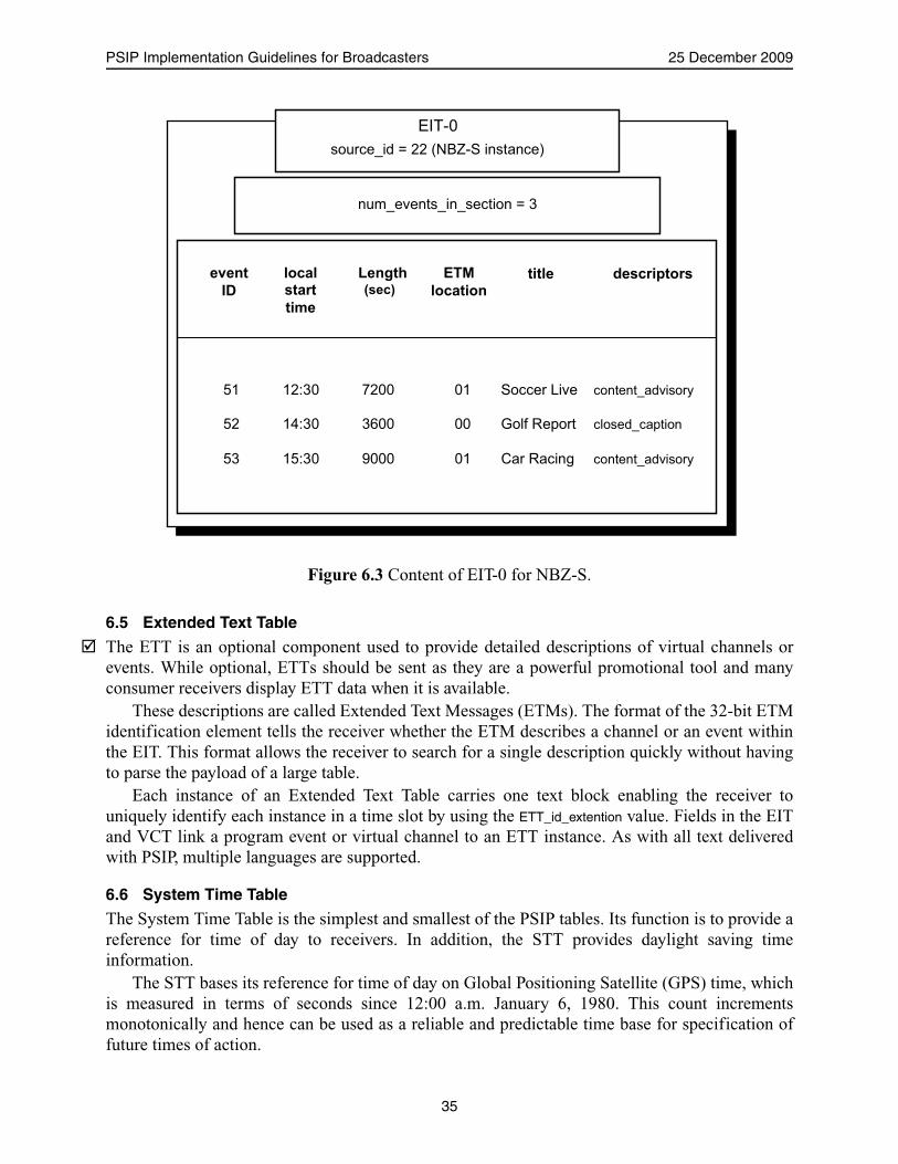
PSIP Implementation Guidelines for Broadcasters 25 December 2009
6.5 Extended Text Table
The ETT is an optional component used to provide detailed descriptions of virtual channels orevents. While optional, ETTs should be sent as they are a powerful promotional tool and manyconsumer receivers display ETT data when it is available.
These descriptions are called Extended Text Messages (ETMs). The format of the 32-bit ETMidentification element tells the receiver whether the ETM describes a channel or an event withinthe EIT. This format allows the receiver to search for a single description quickly without havingto parse the payload of a large table.
Each instance of an Extended Text Table carries one text block enabling the receiver touniquely identify each instance in a time slot by using the ETT_id_extention value. Fields in the EITand VCT link a program event or virtual channel to an ETT instance. As with all text deliveredwith PSIP, multiple languages are supported.
6.6 System Time Table
The System Time Table is the simplest and smallest of the PSIP tables. Its function is to provide areference for time of day to receivers. In addition, the STT provides daylight saving timeinformation.
The STT bases its reference for time of day on Global Positioning Satellite (GPS) time, whichis measured in terms of seconds since 12:00 a.m. January 6, 1980. This count incrementsmonotonically and hence can be used as a reliable and predictable time base for specification offuture times of action.
event
ID
local
start
time
Length (sec)
ETM
location
title descriptors
51 12:30 7200 01 Soccer Live content_advisory 52 14:30 3600 00 Golf Report closed_caption 53 15:30 9000 01 Car Racing content_advisory
EIT-0 source_id = 22 (NBZ-S instance)
num_events_in_section = 3
Figure 6.3 Content of EIT-0 for NBZ-S.
35
Advanced Television Systems Committee Document A/69:2009
A receiver needs one other piece of information to derive Coordinated Universal Time (UTC):the current count of the number of leap seconds that have occurred since the beginning of GPStime. The STT delivers this data as well. Leap seconds account for the difference between timebased on atomic clocks (as is GPS time) and time based on astronomical events such as the earth’srotation.
The STT also provides daylight saving time status (whether or not daylight saving time is ineffect), and indicates the day of the month and the hour that the next transition will occur.
A receiver needs two pieces of additional information before it can use the STT data to tracklocal time of day: 1) the offset in hours from UTC (the time zone), and 2) whether or not daylightsaving time is observed locally. For a digital television, this information may be entered directlyby the consumer via a unit setup function. For a cable set-top box, this information may bedelivered by the system operator.
The System Time data is required to be no less accurate than plus or minus one second withreference to GPS time; by locking it to the station master clock, the DTV receiver could be one ofthe most accurate timepieces in the household. The STT seconds count should be set to the nextsecond and sent approximately 2T milliseconds before the seconds count is due to increment,where T represents the average number of milliseconds between TS packets identified with the SIbase_PID (0x1FFB). Note that use of an adjusted insertion point typically can mitigate the effectsof small contributors to timing errors due to factors such as propagation delay from station tostation and normal passage through the processing of a translator may result in small excursionsbeyond the plus or minus one second tolerance. The exact interval before the seconds transition isstation configuration dependent.
Where a translator station demodulates the relayed signal to baseband and reconstructs the TSfor transmission, the STT should be re-established within plus or minus one second accuracy.
Most PSIP generators convert local time to GPS time internally (for the STT and all othertables with time).
6.7 The Rating Region Table
The function of the RRT is to define a rating system for a given region, where the rating system ischaracterized by a number of rating dimensions, each of which is composed of two or more ratinglevels. An example of a typical rating dimension used on cable is the Motion Picture Associationof America (MPAA) system. The levels within the MPAA dimension include “G,” “PG,” “PG-13,”and so on.
Once a receiver learns the dimensions and levels of a rating system it can do two things:• Provide a user interface to allow the user to set limits on program content• Interpret content advisory data on individual program eventsBased on a user’s preference for certain program content, the receiver can block programming
that exceeds a desired threshold.PSIP does not define the actual dimensions and levels of any rating region; rather, it provides
the transport mechanism to deliver the table. The table structure in PSIP allows one or moreinstances of the RRT to be sent, as needed, where each instance defines one region. For terrestrialbroadcast, for many parts of the U.S., only the U.S. Rating Region will be applicable. For areasclose to national borders, however, a Canadian13 or Mexican rating table may be sent in addition.
13. See ANSI/CEA-766 [13]
36
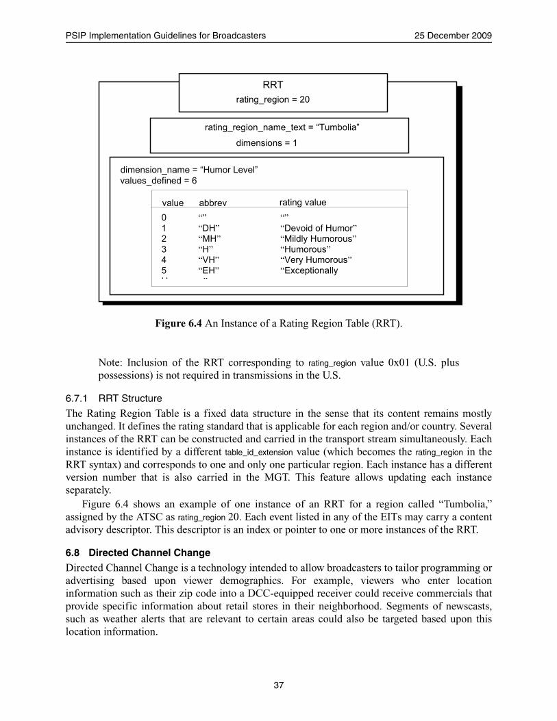
PSIP Implementation Guidelines for Broadcasters 25 December 2009
Note: Inclusion of the RRT corresponding to rating_region value 0x01 (U.S. pluspossessions) is not required in transmissions in the U.S.
6.7.1 RRT Structure
The Rating Region Table is a fixed data structure in the sense that its content remains mostlyunchanged. It defines the rating standard that is applicable for each region and/or country. Severalinstances of the RRT can be constructed and carried in the transport stream simultaneously. Eachinstance is identified by a different table_id_extension value (which becomes the rating_region in theRRT syntax) and corresponds to one and only one particular region. Each instance has a differentversion number that is also carried in the MGT. This feature allows updating each instanceseparately.
Figure 6.4 shows an example of one instance of an RRT for a region called “Tumbolia,”assigned by the ATSC as rating_region 20. Each event listed in any of the EITs may carry a contentadvisory descriptor. This descriptor is an index or pointer to one or more instances of the RRT.
6.8 Directed Channel Change
Directed Channel Change is a technology intended to allow broadcasters to tailor programming oradvertising based upon viewer demographics. For example, viewers who enter locationinformation such as their zip code into a DCC-equipped receiver could receive commercials thatprovide specific information about retail stores in their neighborhood. Segments of newscasts,such as weather alerts that are relevant to certain areas could also be targeted based upon thislocation information.
RRT rating_region = 20
rating_region_name_text = “Tumbolia”
dimensions = 1
dimension_name = “Humor Level” values_defined = 6
value abbrev rating value
0 “” “” 1 “DH” “Devoid of Humor” 2 “MH” “Mildly Humorous” 3 “H” “Humorous” 4 “VH” “Very Humorous” 5 “EH” “Exceptionally H ”
Figure 6.4 An Instance of a Rating Region Table (RRT).
37
Advanced Television Systems Committee Document A/69:2009
A channel change may also be based upon the subject matter of the content of the program.Nearly 140 categories of subject matter have been tabulated that can be assigned to select theprogram content. A broadcaster can use this category of DCC request switching to direct a viewerto a program based upon the viewer’s desire to receive that subject matter. For additionalinformation on Directed Channel Change, see Annex L.
Note that all information in the Directed Channel Change Selection Code Table (DCCSCT) isfor comparison and redirection decision purposes only, and is not an alternative method tocommunicate information about the programs.
6.9 Service Descriptors
Digital television receivers are required to decode closed captioning and to support blocking ofprogramming based on content advisory information. They may also offer the option to decodealternate audio services (similar to NTSC SAP). In order to inform the viewer that closedcaptioning and alternate audio are available from the broadcast station and to provide easy accessto these services, receivers depend on data that can be sent by the broadcaster via PSIP. Contentadvisory information, also sent in PSIP, is directly acted on by the receiver to block programs.
This information is carried in PSIP data structures called descriptors. Descriptors are ageneral purpose, extensible tool provided by the MPEG-2 Systems standard (ISO/IEC 13818-1).All descriptors have a format that begins with an 8-bit tag value followed by an 8-bit descriptorlength and data fields. The tag value tells the receiver what type of descriptor it is. The lengthfield permits devices which do not understand the descriptor to easily bypass it. Delivery of thefollowing three descriptors is mandatory when the element described is part of a program:
• The Content Advisory Descriptor (EIT)• AC-3 Audio Descriptor (EIT and PMT)• Caption Service Descriptor (EIT)Table 6.4 lists most of the core descriptors and their descriptor tags for terrestrial broadcast
applications. (See Standard A/65 [1] for a complete list.) The Service Location Descriptor isrequired to always be present in the Terrestrial VCT (shown with an “S”). When present, somedescriptors are required to be (and only are allowed to be) in certain locations (shown with an“M”). Some descriptors also may be present in a second location within either the terrestrial or thecable case (shown with an “O”). Asterisks mark the tables where the descriptors may appearwithout restrictions.
38

PSIP Implementation Guidelines for Broadcasters 25 December 2009
Table 6.5a List and Location of PSIP Descriptors – Terrestrial Broadcast
Descriptor Name Descriptor TagTerrestrial Broadcast
PMT MGT VCT EIT DCCT DCC SCT
stuffing descriptor 0x80 * * * * * *
AC-3 audio descriptor 0x81 M M
caption service descriptor 0x86 O M
content advisory descriptor 0x87 O M
extended channel name descriptor 0xA0 M
service location descriptor 0xA1 S
time-shifted service descriptor 0xA2 M
component name descriptor 0xA3 M
DCC departing request descriptor 0xA8 M
DCC arriving request descriptor 0xA9 M
redistribution control descriptor 0xAA M M
ATSC private information descriptor 0xAD * * * * * *
ISO 639 descriptor 0x0A O*
genre descriptor 0xAB M
Table 6.5b List and Location of PSIP Descriptors – Cable
Descriptor Name DescriptorTag
Cable
PMT MGT VCT EIT DCCT DCCSCT
stuffing descriptor 0x80 * * * * * *
AC-3 audio descriptor 0x81 M M
caption service descriptor 0x86 M M
content advisory descriptor 0x87 M M
extended channel name descriptor 0xA0 M
service location descriptor 0xA1 M
time-shifted service descriptor 0xA2 M
component name descriptor 0xA3 M
DCC departing request descriptor 0xA8 M
DCC arriving request descriptor 0xA9 M
redistribution control descriptor 0xAA M Ma
ATSC private information descriptor 0xAD * * * * * *
ISO 639 descriptor 0x0A M*
genre descriptor 0xAB M
Notes:a When the EIT is present.
39

Advanced Television Systems Committee Document A/69:2009
SCTE 54 requires this descriptor when there is more than one audio track. It is stronglyrecommended that it be provided in such cases where the content is expected to be distributed in aSCTE 54 compliant system.
6.9.1 Content Advisory Descriptor
Parental advisory (so-called “V-chip” information) is carried in the Content Advisory Descriptor.The receiver uses this information directly to block programs that exceed the ratings selected in auser set up procedure, and may be used by the receiver to provide on screen information about aprograms rating for objectionable material.
6.9.2 AC-3 Audio Descriptor
The receiver looks for and uses the AC-3 Audio Descriptor to create viewer information about theaudio services that are available. In addition to describing possible alternate audio services that abroadcaster might send, this descriptor provides the receiver with audio set up information such aswhether the program is in stereo or surround sound.
Digital television can carry audio streams in different languages. Analog television allowed aclear distinction between primary and secondary audio. A flag has been introduced into the AC-3Audio Descriptor structure to replicate this function, allowing a broadcaster to indicate whichaudio stream is to be considered primary. Additionally, as of 1 March 2008, inclusion of ISO-639language code bytes in the AC-3 descriptor provides signaling and announcement of the languageused for the audio service. While the previous mechanism (the ISO-639 Language Descriptor) isnow deprecated, it is strongly recommended to include this descriptor in the emission to supportolder receivers that may not understand the newer method.
6.9.3 Caption Service Descriptor
Captioning text itself, which is carried in an area of the video data set aside for captioning, doesnot carry a description of the type of captioning that it is (such as English or Spanish), so receiversare expected to rely on the Captioning Service Descriptor to provide the data needed to create on-screen captioning information.
The intention of the caption service announcement in PSIP data is to indicate to the viewerswhether the main programming (described by the program name and description in EIT/ETT) isscheduled to be captioned, and if so, in what language(s). During an advertising insert within theprogram, caption data is not required [1] to match the description in the Caption ServiceDescriptor.
More importantly, the receiver is expected to rely on the Caption Service Descriptor to tell itthat the program is captioned in the first place; the presence of captioning text is not used by mostreceivers to indicate to the viewer that the program is captioned. In addition to viewer information,the Caption Service Descriptor contains important control information needed by the receiver forproper display of captioning.
7. CONSTRUCTION OF THE PSIP TABLES
The tables described in Section 6 are interrelated to form a seamless structure for conveyingprogram and system information. The PSIP generator should manage these internal relationships,which generally should not be exposed to the operations personnel. For clarification, however,
40

PSIP Implementation Guidelines for Broadcasters 25 December 2009
Figure 7.1 provides a simplified view of the relationship among the PSIP tables (the ETT is notshown).
As indicated in the figure, the MGT, Terrestrial or Cable VCT, RRT, and STT are transportedin the “base PID,” 0x1FFB. The MGT provides location (PID), version, and length (not shown) ofall tables except STT. In the example, the two EITs are transported in PIDs 0x3E00 and 0x3E01.
The Virtual Channel Table defines a set of services available, including (at minimum) thoseon the Transport Stream carrying the VCT itself. In this case, two channels named KVGN-S andKVGN-M are shown. The VCT gives the channel numbers associated with the channels (10.1 and10.2), the MPEG-2 program numbers the receiver would use to extract the elementary streamsfrom the multiplex, and the source ID values for each.
As indicated in the figure, source ID is used to link the VCT with the EPG data delivered inthe EITs. Each PSIP EIT describes program events for a three-hour time slot, and lists, for each
Event Information Table (EIT) 0
00:00 - 03:00 UTC(7-10pm local)
System Time Table (STT)
Rating Region Table (RRT)
Master Guide Table (MGT)
Virtual Channel Table (VCT)
Base PID = 0x1FFB
name = KVGN-S channel no. = 10.1MPEG p.n. = 0x746Esource_ID = 5000...name = KVGN-Mchannel no. = 10.2MPEG p.n. = 0xE9A7source_ID = 5010
List of channels:
List of events (local time): 7-8 pm: Tennis news 8-9 pm: Basketball today 9-10 pm: Hockey report
source_ID = 5000
source_ID = 5010List of events (local time): 7-7:30 pm: "Happy Days" 7:30-8pm: "Cosby" 8-11 pm: Movie: "Popeye"
PID = 0x3E00
List of tables:type = EIT-0PID = 0x3E00 version = 1
type = EIT-1PID = 0x3E01 version = 1
type = RRTPID = 0x1FFB version = 0
type = TVCT or CVCTPID = 0x1FFB version = 0
Event Information Table (EIT) 1
03:00 - 06:00 UTC(10pm-1am local)
List of events (local time): 10-12 pm: Hockey game
source_ID = 5000
source_ID = 5010List of events (local time): 8-11 pm: Movie: "Popeye"11pm-1am: Movie: "Hi-5"
PID = 0x3E01
Figure 7.1 Example of the relationship among PSIP tables.
41
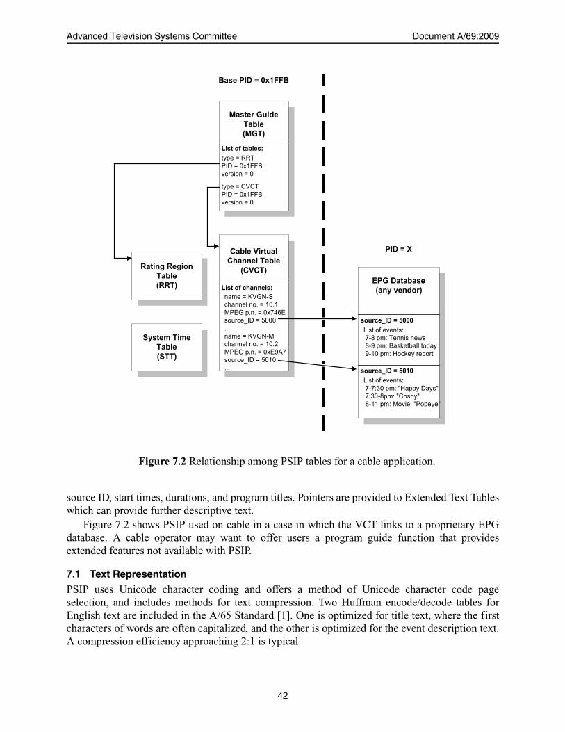
Advanced Television Systems Committee Document A/69:2009
source ID, start times, durations, and program titles. Pointers are provided to Extended Text Tableswhich can provide further descriptive text.
Figure 7.2 shows PSIP used on cable in a case in which the VCT links to a proprietary EPGdatabase. A cable operator may want to offer users a program guide function that providesextended features not available with PSIP.
7.1 Text Representation
PSIP uses Unicode character coding and offers a method of Unicode character code pageselection, and includes methods for text compression. Two Huffman encode/decode tables forEnglish text are included in the A/65 Standard [1]. One is optimized for title text, where the firstcharacters of words are often capitalized, and the other is optimized for the event description text.A compression efficiency approaching 2:1 is typical.
EPG Database
(any vendor)
System Time
Table
(STT)
Rating Region
Table
(RRT)
Master Guide
Table
(MGT)
Cable Virtual
Channel Table
(CVCT)
Base PID = 0x1FFB
name = KVGN-Schannel no. = 10.1MPEG p.n. = 0x746Esource_ID = 5000...name = KVGN-Mchannel no. = 10.2MPEG p.n. = 0xE9A7source_ID = 5010...
List of channels:
List of events: 7-8 pm: Tennis news 8-9 pm: Basketball today 9-10 pm: Hockey report
source_ID = 5000
source_ID = 5010
List of events: 7-7:30 pm: "Happy Days" 7:30-8pm: "Cosby" 8-11 pm: Movie: "Popeye"
PID = X
List of tables:
type = RRTPID = 0x1FFBversion = 0
type = CVCTPID = 0x1FFBversion = 0
Figure 7.2 Relationship among PSIP tables for a cable application.
42

PSIP Implementation Guidelines for Broadcasters 25 December 2009
7.2 Transport Stream and Transmission Signal IDs
PSIP, like all current System/Service Information standards for digital television, is based on theMPEG-2 Systems Standard, ISO/IEC 13818-1. Most digital television delivered over cable orterrestrial broadcast today uses a transport protocol defined by the MPEG-2 standard. Digital datais divided into a sequence of 188-byte transport packets. Each packet is associated with a datastream such as an audio or video service by means of a tag called the Packet Identifier (PID).Special PIDs identify packets carrying the SI and program guide data in the multiplex. Thecombination of service streams comprising the services and control data (SI and PSI) is called theMPEG-2 Transport Stream.
The MPEG-2 Standard defines a way to identify the multiplex itself so that it can bereferenced within a larger network of digital multiplexes: each transport stream is identified by a16-bit number called the Transport Stream ID (TSID). In the U.S., the FCC assigned values ofTSID to the broadcasters to ensure uniqueness. Canada, Mexico and U.S. have formally agreed toallocate ranges of TSID values distinct from one another. North America can be considered a“network” in the sense that TSID values are required to be unique within a network.
Either analog or digital TSID values can appear in Virtual Channel Tables. In the normal casefor terrestrial broadcast, the VCT will contain channel definitions for digital channels carried onthe same multiplex that carries the VCT. The analog TSID is important for PSIP and digitalreceivers because it allows the receiver to verify that a received analog signal is actually the onereferenced by the PSIP data.
In most cases, a receiver will not be able to receive more than one broadcaster’s signal on anyphysical channel. Receivers on the fringe areas or those with directional or movable antennas,however, may be able to pick up more than one signal on a given frequency. A check of TSID datawill allow the receiver to correctly identify and display channel name and/or program guide data.
Use of TSID data in the receiver actually makes it possible for the receiver to correctly displaychannel data and perform navigation without the frequency data being signaled. PSIP data doesnot include frequency information because a broadcast translator may shift the frequency of atransmitted signal without modifying the PSIP data. A receiver will find the signal when it“learns” the channel lineup, however, and it can take note of the frequency at which this particularTSID was found.
7.3 Event Information Functions
The Event Information Tables contain information or announcements of events on definedchannels. Each EIT covers a time interval of three hours. The maximum time span covered by theEITs is 16 days (128 three-hour EITs). The rate of transmission is not defined, and some expertshave suggested that EITs further in the future be transmitted with longer intervals. EITs aretypically a few tens of bytes per event therein.
Start times for EITs are constrained to be one of the following UTC times: 0:00 (midnight),3:00, 6:00, 9:00, 12:00 (noon), 15:00, 18:00, and 21:00. Imposing constraints on the start times aswell as the interval duration is necessary for the purpose of re-multiplexing. During re-multiplexing, EIT tables coming from several distinct transport streams may end up groupedtogether or vice versa. If no constraints were imposed, re-multiplexing equipment would have toparse EITs by content in real time, which is a difficult task.
For example, consider a broadcast corporation operating in the Eastern time zone of the U.S.This corporation decides to carry 6 EITs (18 hours of TV program information). If at present, the
43

Advanced Television Systems Committee Document A/69:2009
Eastern Time is 15:30 EDT (19:30 UTC), then the coverage times for the EIT tables are as shownin Table 7.1.
The abbreviation “nd” denotes next day (from EIT-0). Before 17:00 EDT, the MGT will listthe currently valid PIDs as: 123, 190, 237, 177, 295, and 221. At 17:00 EDT, table EIT-0 willbecome obsolete while the other ones will remain valid. At that time, the PID list can be changedto 190, 237, 177, 295, 221, maintaining the version number list as 4, 2, 7, 8, 15. Therefore, bysimply shifting the listed PID values in the MGT, table EIT-1 can become EIT-0, table EIT-2 canbecome EIT-1, and so on. Typically, a new EIT-5 would be generated at that time withprogramming information for the time period 12:00 – 15:00 (UTC). This could go in PID 123,replacing the obsolete data there, or could go in a new PID.
However, it is also possible to regenerate one or several EITs at any time for correcting and/orupdating the content (e.g., in cases where “to be assigned” events become known). Regenerationof EITs is flagged by updating version fields in the MGT. For example, if table EIT-2 needs to beupdated at 16:17 EDT, then the new table is required to be transmitted with a version numberequal to 3. Whenever the decoder monitoring the MGT detects a change in the version number ofa table, it assumes that the table has changed and needs to be reloaded.
7.3.1 Example Case
For the purpose of example, we assume that a broadcaster, here denominated NBZ, manages thefrequency bands for RF channels 12 and 39. In this example, Channel 12 is (or was, after analogshut-off) its analog channel whereas Channel 39 is used or will be used for digital broadcast. NBZis required to carry the PSIP tables in the digital transport stream of RF channel 39. The tables arerequired to describe TV programs and other services provided on RF channel 39 but can alsodescribe information for the analog RF channel 12.
Assume that NBZ operates in the Eastern Time zone of the U.S., and that the current time is15:30 EDT (19:30 UTC). NBZ decides to operate in minimal configuration, therefore only thefirst four EITs need to be transmitted. As explained previously, EIT-0 is required to carry eventinformation for the current time window, which is between 14:00 and 17:00 EDT, whereas EIT-1to EIT-3 will cover the subsequent 9 hours. For the first 6 hours, the following scenario applies(see Table 7.2 and Table 7.3).
Table 7.1 An Example of EIT Coverage Times
EIT Number Version Number Assigned PID Coverage (UTC) Coverage (EDT)
0 6 123 18:00 - 21:00 14:00 - 17:00
1 4 190 21:00 - 24:00 17:00 - 20:00
2 2 237 0:00 - 3:00 (nd) 20:00 - 23:00
3 7 177 3:00 - 6:00 (nd) 23:00 - 2:00 (nd)
4 8 295 6:00 - 9:00 (nd) 2:00 (nd) - 5:00 (nd)
5 15 221 9:00 - 12:00 (nd) 5:00 (nd) - 8:00 (nd)
44

PSIP Implementation Guidelines for Broadcasters 25 December 2009
Similar tables can be built for the next 6 hours (for EIT-2 and EIT-3). According to thisscenario, NBZ broadcasts four regular digital channels (also called virtual channels and denotedas VC), one matching the analog transmission (simulcast), another for sports, and a third one formovies. The fourth one supports a service displaying headlines with text and images.
7.4 Packetization and Transport
Typically, the MGT, STT, VCT, and each instance of the RRT and EIT will have one or at most afew sections. For each table, the sections are appended one after the other, and then segmentedinto 184-byte packets. After adding the 4-byte MPEG-2 transport stream header, the packets aremultiplexed with the others carrying audio, video, data, and any other components of the service.Figure 7.3 illustrates this process.
7.4.1 Tuning Operations and Table Access
As described by the PSIP protocol, each transport stream will carry a set of tables describingsystem information and event description. For channel tuning, the first step is to collect the VCTfrom the transport stream that contains the current list of services available. Figure 7.4 shows thisprocess.
Once the VCT has been collected, a user can tune to any virtual channel present in thetransport stream by referring to the major and minor channel numbers. Assuming that in this case,
Table 7.2 First Three Hour Segment Described in VCT and EIT-0
CH 14:00–14:30 14:30–15:00 15:00–15:30 15:30–16:00 16:00–16:30 16:30–17:00
12.0 NBZ City Life City Life Travel Show Travel Show News News
12.1 NBZ-D1 City Life City Life Travel Show Travel Show News News
12.2 NBZ-D2 Soccer Golf Report Golf Report Car Racing Car Racing Car Racing
12.3 NBZ-D3 Secret Agent Secret Agent Lost Worlds Lost Worlds Lost Worlds Lost Worlds
12.4 NBZ-D4 Headlines Headlines Headlines Headlines Headlines Headlines
Table 7.3 Second Three Hour Segment Described in VCT and EIT-1
CH 17:00–17:30 17:30–18:00 18:00–18:30 18:30–19:00 19:00–19:30 19:30–20:00
12.0 NBZ Music Today NY Comedy World View World View News News
12.1 NBZ-D1 Music Today NY Comedy World View World View News News
12.2 NBZ-D2 Car Racing Car Racing Sports News Tennis Playoffs Tennis Playoffs Tennis
Playoffs
12.3 NBZ-D3 Preview The Bandit The Bandit The Bandit The Bandit Preview
12.4 NBZ-D4 Headlines Headlines Headlines Headlines Headlines Headlines
45
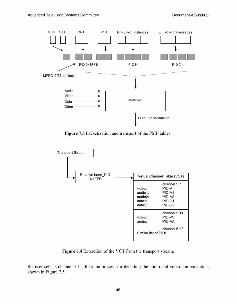
Advanced Television Systems Committee Document A/69:2009
the user selects channel 5.11, then the process for decoding the audio and video components isshown in Figure 7.5.
Multiplex
Audio
PID 0x1FFB
Data Other
MPEG-2 TS packets
Output to modulator
STT RRT VCT EIT-0 with instances ETT-0 with messages MGT
PID K PID X
Video
Figure 7.3 Packetization and transport of the PSIP tables.
Transport Stream
Receive base_PID 0x1FFB
Virtual Channel Table (VCT)
channel 5.7 video: PID-V audio1: PID-A1 audio2: PID-A2 data1: PID-D1 data2: PID-D2
channel 5.11 video: PID-VV audio: PID-AA
channel 5.22 Similar list of PIDS…
Figure 7.4 Extraction of the VCT from the transport stream.
46
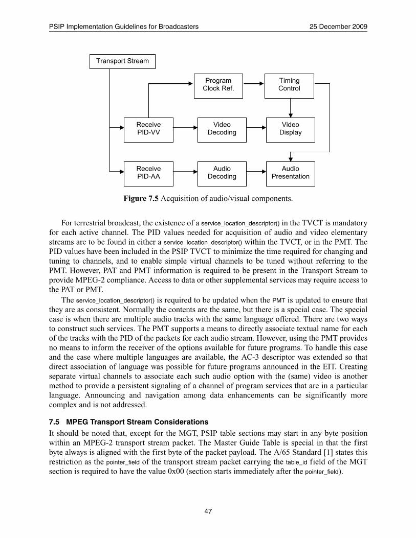
PSIP Implementation Guidelines for Broadcasters 25 December 2009
For terrestrial broadcast, the existence of a service_location_descriptor() in the TVCT is mandatoryfor each active channel. The PID values needed for acquisition of audio and video elementarystreams are to be found in either a service_location_descriptor() within the TVCT, or in the PMT. ThePID values have been included in the PSIP TVCT to minimize the time required for changing andtuning to channels, and to enable simple virtual channels to be tuned without referring to thePMT. However, PAT and PMT information is required to be present in the Transport Stream toprovide MPEG-2 compliance. Access to data or other supplemental services may require access tothe PAT or PMT.
The service_location_descriptor() is required to be updated when the PMT is updated to ensure thatthey are as consistent. Normally the contents are the same, but there is a special case. The specialcase is when there are multiple audio tracks with the same language offered. There are two waysto construct such services. The PMT supports a means to directly associate textual name for eachof the tracks with the PID of the packets for each audio stream. However, using the PMT providesno means to inform the receiver of the options available for future programs. To handle this caseand the case where multiple languages are available, the AC-3 descriptor was extended so thatdirect association of language was possible for future programs announced in the EIT. Creatingseparate virtual channels to associate each such audio option with the (same) video is anothermethod to provide a persistent signaling of a channel of program services that are in a particularlanguage. Announcing and navigation among data enhancements can be significantly morecomplex and is not addressed.
7.5 MPEG Transport Stream Considerations
It should be noted that, except for the MGT, PSIP table sections may start in any byte positionwithin an MPEG-2 transport stream packet. The Master Guide Table is special in that the firstbyte always is aligned with the first byte of the packet payload. The A/65 Standard [1] states thisrestriction as the pointer_field of the transport stream packet carrying the table_id field of the MGTsection is required to have the value 0x00 (section starts immediately after the pointer_field).
Receive PID-VV
Video Decoding
Video Display
Receive PID-AA
Audio Decoding
Audio Presentation
Timing Control
Program Clock Ref.
Transport Stream
Figure 7.5 Acquisition of audio/visual components.
47
Advanced Television Systems Committee Document A/69:2009
In general, table sections may span packet boundaries. Also, if the table sections are smallenough, more than one PSIP table section may be present within a single transport stream packet.The MPEG-2 pointer_field mechanism is used to indicate the first byte of a table within a packetpayload. The starting byte of subsequent tables that might be in the same payload is determined byprocessing successive section_length fields. The location of the section_length field is guaranteed tobe consistent for any type of PSIP table section, as the format conforms to MPEG-2 definedProgram Specific Information (PSI) tables.
If a packet payload does not include the start of a table section, the payload_unit_start_indicator bitin the packet header is set to ‘0’ and the pointer_field is not present.
7.6 Consistency Errors in PSIP Tables and MPEG PSI
ATSC A/78 [5] Section 8 says:
“Before a receiver can decode a transport stream, it must identify the relationshipbetween components in the stream. Some components contain audio and video(Elementary Streams), and other components contain information describing therelationship between them (Metadata). The receiver uses metadata to identify eachcomponent, determine its function and select an appropriate set of componentswhen the user selects a virtual channel for decoding. Conflicts and problemswithin the structure of metadata are called “consistency errors.”
This summary lays out the potential pitfalls of an emission with inconsistent tables. Differentreceivers will react in different ways to the inconsistent data. Since various parts of the emissionsystem may generate different parts of the tables, care must be taken to ensure they are alwaysconsistent. A Transport Stream analyzer supporting the A/78 analysis paradigm should be used.See A/78 [5] for additional methodology regarding classification of errors as to their level ofseverity.
7.7 Considerations Regarding Large PSIP Tables in the Base PID
The PSIP Base PID carries a mixture of short tables with short repeat cycles and larger tables withlong cycle times. Transmission of one table section is required to be completed before the nextsection can be sent: time-interleaving of parts of sections carried by one PID is not allowed. Thus,transmission of large table sections (even with long cycle times) are required to be completedwithin a short period in order to allow fast cycling tables to achieve specified time interval. Theresult is a PID stream that has a bursty characteristic, which may lead to bandwidth inefficiency ifupstream multiplexers reserve bandwidth for the peak PSIP requirement.
Table 7.4 lists typical characteristics for various table types.
Table 7.4 Bandwidth Considerations for Some PSIP Tables
Table Type Section Size (bytes)
Number of Packets
Repeat Interval
Average BW (kbps)
Peak BW (kbps)
MGT (24 EITs) 589 4 150 msec 40.1 40.1
VCT (5 VCs) 356 2 400 msec 7.5 20
STT 20 <usually in spare space> 1000 msec 0.2 0.2
48
Annex A:Fundamental PSIP Structure
A.1INTRODUCTION
The primary purpose of PSIP is to facilitate acquisition and navigation among analog and digitalservices available to a particular receiver or set-top box, but it also serves as a support platform forapplications such as data broadcasting.
In analog broadcast or cable television, if a user selects channel “4,” the receiver knows to tunethe frequency of channel 4 as standardized by the FCC—the 66–72 MHz band. The situationchanges, however, with advent of digital transmission—digital broadcasters have the freedom todefine channel numbers independently of the radio frequency (RF) band used to carry the signal.PSIP is built around the concept of virtual channels. A virtual channel is called “virtual” becauseits definition is given by indirect reference through a data structure called a virtual channel table.So, when an end-user selects “channel 4” the receiver is actually selecting the channel recordassociated with user channel number 4. The definition of the channel as given in the VCTincludes:
• The frequency and method of modulation• Textual name• Channel type (analog audio/video, digital audio/video, audio only, or data)• Channel number the user may use to access itThe A/65 protocol [1] introduced a powerful navigational concept, the “two-part” channel
number. Broadcasters declared the need, as new digital services are introduced, to retain thebrand-identity they currently have as a result of years of marketing and advertising. Forbroadcasters, the first part of the two-part number (called the major channel number) is requiredto be the same as the FCC channel number already in use for the analog service. The second partof the number (called the minor channel number) identifies one service within the group ofservices defined by the major number. From the point of view of the user, where before there wasjust “Channel 4,” now there may also be Channels 4.1, 4.2, 4.3, and so on.
Broadcasters may deliver a Rating Region Table that defines the structure of a multi-dimensional content advisory system for a specific region (e.g., country), and a content advisorydescriptor that can be used to associate specific program events with rating levels defined in theRRT.
A.1.1 System Functional Requirements
The following list comprises the basic set of system functional requirements that ATSC adoptedas their starting point:
• Provide direct access to any channel. The navigational model is required to support theability to access any analog or digital channel by direct entry of its channel number or callletters.
• Support grouping of selected digital services with an existing analog service, or withdigital services on other multiplexes. There will be a period of time in which broadcastersoperate an analog channel in addition to a digital multiplex. The navigation model is
Page 49
Advanced Television Systems Committee Document A/69:2009
required to include a grouping concept to support channel surfing within a set of relatedanalog and digital channels.
• Preserve channel branding. When a broadcaster begins a digital service, the system isrequired to allow association of the new programming with the channel label used in pastyears of advertising.
• Harmonized with cable standards. The chosen solution for broadcast is required torecognize that cable set-tops and cable-ready receivers will also employ navigational andchannel naming methods. These are required to work in harmony with methods definedfor terrestrial broadcast.
• Accommodate the flexibility of digital transport. The MPEG-2 standard provides a greatdeal of latitude in defining a “service” on the multiplex. The approach is required toaccommodate the wide variety of service structures possible via digital transport.
• Allow a broadcaster to “package” or “market” some services separately from others on themultiplex. For example, as a public service, the owner of a digital broadcasting licensemay offer a couple of spare megabits/sec of SDTV bandwidth to a college or communityaccess channel, or to a government affairs (city politics) channel. It is required to bepossible for the operator to label that channel separately from the other services offered onthe multiplex.
In addition to these general requirements, an important consideration was identified specificto cable transmission media: the cable system operator must be able to label digital servicesindependently of the RF channel number used to transmit them. In other words, cable would use a“virtual channel” scheme. Each cable operator is free to use whatever frequency slot the companychooses to deliver the digital signal and still be able to label it for the user in a meaningful way.Practically speaking, when the cable operator takes an off-air digital broadcast signal and re-modulates for cable, the operator should be able to label it the same as the broadcaster does fortelevisions that receive the signal directly off-air.
Lastly, two requirements were identified specific to terrestrial broadcasting. First, the systemis required to accommodate terrestrial broadcast translators. Broadcasters do not want to have tore-process PSI or the program guide data if they transmit the same MPEG-2 transport stream onan alternate frequency. Second, the receiver should be able to deal with a movable antenna, eithersteerable by the user or because the receiver itself is movable.
A.1.1.1The PSIP Solution
The ATSC A/65 PSIP Standard [1] addresses all these system concerns for both terrestrialbroadcasting and cable. Specifically:
• Direct access. The user can access any service, whether it is an audio/video service, anaudio only service, or a data broadcast service, by specifying either its channel number orits service name. The channel number method is compatible with numeric-keypad remotecontrol units (RCUs).
• Channel grouping. Channel numbers are assigned through the Virtual Channel Table.The two-part channel number scheme provides a grouping function in that the majorchannel number identifies the group and the minor number the member of the group.Broadcasters are required to use the RF channel for the current analog NTSC broadcastchannel as the major channel numbers for all the new digital services.
50
PSIP Implementation Guidelines for Broadcasters, Annex A 25 December 2009
• Channel branding. As described, the broadcasters keep the “brand identity” associatedwith their analog channels because the new digital channels use that same number for theirmajor channel number.
• Harmonized with cable. PSIP was designed with the needs of cable in mind. The overalldesign of System Information tables in PSIP achieves nearly complete parallelismbetween the methods used for cable and terrestrial broadcast. There are only a few placeswhere the specification differentiates cable and terrestrial broadcast. One example is thatmajor channel numbers on cable can range from 1 to 999 for video services, where onterrestrial broadcast the range is limited to 2 to 99.
• Accommodates flexibility of digital transport. PSIP builds upon the MPEG-2 Systemsstandard [14] without imposing constraints on its use. Any service that can be representedby the MPEG-2 standard method can be referenced by the PSIP VCT. Note that this is incontrast to the original A/53 ATSC Digital Television Standard [4] which mandated theuse of the so-called “program paradigm” for broadcast television.
• Separate packaging of services. PSIP states that for the U.S., in addition to using themajor channel number that matches the analog broadcasting license for some services, abroadcaster may label one or more virtual channels on the multiplex with major channelnumbers in the 70 – 99 range. Certain conditions are required to be met, however:assignment of major channel numbers are required to be coordinated such that they areunique within a region. Otherwise, one receiver could access two different digital serviceslabeled with the same channel number, and that would cause user confusion.
• Cable virtual channels. This requirement is met because PSIP is based on the virtualchannel concept. The more significant aspect is that digital terrestrial broadcasting is alsobased on virtual channels.
• Broadcast translators. If a digital broadcast is shifted in frequency at a translator, all SIand EPG information that it carries remains correct except for frequency references. As ithappens, even though carrier frequency information is included in the SI tables, a receiveris expected to correctly operate without it (or, more likely, ignore frequency discrepanciesit might find).
• Movable broadcast receivers and antennas. PSIP tables are delivered repetitively.Broadcast virtual channel tables, for example, are repeated no less often than once each400 msec. A receiver may therefore quickly learn the labels to use for navigation. If areceiver itself is moving, even as one signal fades out and another is acquired, navigationaland channel label data will always be readily accessible.
A.1.1.1.1 Channel Mapping
Within the broadcaster community, the initial view was that channel mapping was not needed, andthe extra complexity was not worth the effort. When considering a 6 MHz channel carrying adigital multiplex with just one HDTV program, the channel numbering paradigm in use for analogTV seemed to work just fine. When the ATSC recognized that standard definition formats werepossible and desirable, they acknowledged that a method was needed for selection of just oneprogram in the multiplex. The MPEG-2 Systems specification provides data called programspecific information (PSI) that included a parameter called a “program number,” which seemed tofit this purpose. It was assumed that the user could specify or enter the MPEG-2 program numberdirectly.
51
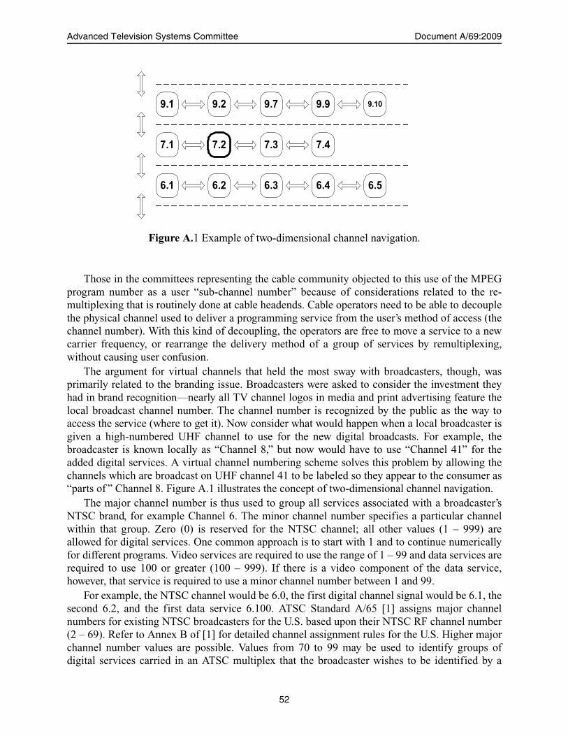
Advanced Television Systems Committee Document A/69:2009
Those in the committees representing the cable community objected to this use of the MPEGprogram number as a user “sub-channel number” because of considerations related to the re-multiplexing that is routinely done at cable headends. Cable operators need to be able to decouplethe physical channel used to deliver a programming service from the user’s method of access (thechannel number). With this kind of decoupling, the operators are free to move a service to a newcarrier frequency, or rearrange the delivery method of a group of services by remultiplexing,without causing user confusion.
The argument for virtual channels that held the most sway with broadcasters, though, wasprimarily related to the branding issue. Broadcasters were asked to consider the investment theyhad in brand recognition—nearly all TV channel logos in media and print advertising feature thelocal broadcast channel number. The channel number is recognized by the public as the way toaccess the service (where to get it). Now consider what would happen when a local broadcaster isgiven a high-numbered UHF channel to use for the new digital broadcasts. For example, thebroadcaster is known locally as “Channel 8,” but now would have to use “Channel 41” for theadded digital services. A virtual channel numbering scheme solves this problem by allowing thechannels which are broadcast on UHF channel 41 to be labeled so they appear to the consumer as“parts of ” Channel 8. Figure A.1 illustrates the concept of two-dimensional channel navigation.
The major channel number is thus used to group all services associated with a broadcaster’sNTSC brand, for example Channel 6. The minor channel number specifies a particular channelwithin that group. Zero (0) is reserved for the NTSC channel; all other values (1 – 999) areallowed for digital services. One common approach is to start with 1 and to continue numericallyfor different programs. Video services are required to use the range of 1 – 99 and data services arerequired to use 100 or greater (100 – 999). If there is a video component of the data service,however, that service is required to use a minor channel number between 1 and 99.
For example, the NTSC channel would be 6.0, the first digital channel signal would be 6.1, thesecond 6.2, and the first data service 6.100. ATSC Standard A/65 [1] assigns major channelnumbers for existing NTSC broadcasters for the U.S. based upon their NTSC RF channel number(2 – 69). Refer to Annex B of [1] for detailed channel assignment rules for the U.S. Higher majorchannel number values are possible. Values from 70 to 99 may be used to identify groups ofdigital services carried in an ATSC multiplex that the broadcaster wishes to be identified by a
7.1 7.2 7.3 7.4
6.1 6.2 6.3 6.4 6.5
9.1 9.2 9.7 9.9 9.10
Figure A.1 Example of two-dimensional channel navigation.
52
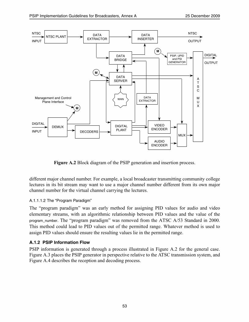
PSIP Implementation Guidelines for Broadcasters, Annex A 25 December 2009
different major channel number. For example, a local broadcaster transmitting community collegelectures in its bit stream may want to use a major channel number different from its own majorchannel number for the virtual channel carrying the lectures.
A.1.1.1.2 The “Program Paradigm”
The “program paradigm” was an early method for assigning PID values for audio and videoelementary streams, with an algorithmic relationship between PID values and the value of theprogram_number. The “program paradigm” was removed from the ATSC A/53 Standard in 2000.This method could lead to PID values out of the permitted range. Whatever method is used toassign PID values should ensure the resulting values lie in the permitted range.
A.1.2 PSIP Information Flow
PSIP information is generated through a process illustrated in Figure A.2 for the general case.Figure A.3 places the PSIP generator in perspective relative to the ATSC transmission system, andFigure A.4 describes the reception and decoding process.
NTSC PLANTNTSC
INPUT
DATAEXTRACTOR
DATAINSERTER
DATABRIDGE
PSIP, UPIDand PSI
GENERATOR
M
ATSC
MUX
DIGITAL
OUTPUT
DATASERVER
M
MUX
VIDEOENCODER
AUDIOENCODER
DATAEXTRACTOR
DIGITALPLANT
WAN
DECODERS
DEMUX
M
DIGITAL
INPUT
NTSC
OUTPUT
Management and ControlPlane Interface
Figure A.2 Block diagram of the PSIP generation and insertion process.
53

Advanced Television Systems Committee Document A/69:2009
MPEG-2Encoder
Videoone of
18 formats
AC-3Encoder
Audioup to
5.1 channels
MPEG-2Bitstream
AC-3Bitstream Trans-
portMux
SPTransportStream(s)
3 - 18 Mb/s
DataTransportStream
MPTrans-
portMux
PAT: ProgramAssociation Table
PMT: Program MapTable
PSI: Program SpecificInformation
SP: Single ProgramMP: Multi Program
MPTransportStream
19.4 Mb/sChannelCoderand
8-VSBModulator
DTVTransmitter
Single-Program Encoder
PAT
PSI andPSIP Generator PSIP
PMT
6 MHzRF Channel
(Data)
Figure A.3 Block diagram of the ATSC transmission system, including PSIP generation and insertion.
TransportStream
19.4 Mb/s
MPEG-2Decoder
Video
AC-3Decoder
Audio
MPEG-2Bitstream
AC-3Bitstream
Program GuideDatabase
Single-Program Decoder
8-VSBDemod-ulator
DTVTuner
PhysicalChannelSelect
Clock Recoveryand A/V
SynchronizationPCR’s
ProgramSelect
TimeStamps
DisplayProcessing
Program Select(from User)
Trans-port
Demux
PSIP Data
Figure A.4 Bock diagram of an ATSC decoder, including PSIP extraction and program guide generation.
54
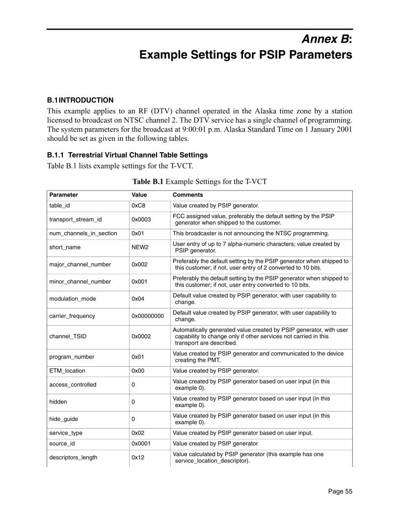
Annex B:Example Settings for PSIP Parameters
B.1INTRODUCTION
This example applies to an RF (DTV) channel operated in the Alaska time zone by a stationlicensed to broadcast on NTSC channel 2. The DTV service has a single channel of programming.The system parameters for the broadcast at 9:00:01 p.m. Alaska Standard Time on 1 January 2001should be set as given in the following tables.
B.1.1 Terrestrial Virtual Channel Table Settings
Table B.1 lists example settings for the T-VCT.
Table B.1 Example Settings for the T-VCT
Parameter Value Comments
table_id 0xC8 Value created by PSIP generator.
transport_stream_id 0x0003 FCC assigned value, preferably the default setting by the PSIP generator when shipped to the customer.
num_channels_in_section 0x01 This broadcaster is not announcing the NTSC programming.
short_name NEW2 User entry of up to 7 alpha-numeric characters; value created by PSIP generator.
major_channel_number 0x002 Preferably the default setting by the PSIP generator when shipped to this customer; if not, user entry of 2 converted to 10 bits.
minor_channel_number 0x001 Preferably the default setting by the PSIP generator when shipped to this customer; if not, user entry converted to 10 bits.
modulation_mode 0x04 Default value created by PSIP generator, with user capability to change.
carrier_frequency 0x00000000 Default value created by PSIP generator, with user capability to change.
channel_TSID 0x0002Automatically generated value created by PSIP generator, with user capability to change only if other services not carried in this transport are described.
program_number 0x01 Value created by PSIP generator and communicated to the device creating the PMT.
ETM_location 0x00 Value created by PSIP generator.
access_controlled 0 Value created by PSIP generator based on user input (in this example 0).
hidden 0 Value created by PSIP generator based on user input (in this example 0).
hide_guide 0 Value created by PSIP generator based on user input (in this example 0).
service_type 0x02 Value created by PSIP generator based on user input.
source_id 0x0001 Value created by PSIP generator
descriptors_length 0x12 Value calculated by PSIP generator (this example has one service_location_descriptor).
Page 55

Advanced Television Systems Committee Document A/69:2009
B.1.2 Event Information Table
For simplicity, one three-hour program in EIT-0 is assumed; it has a caption service descriptor anda content advisory descriptor.
descriptor_tag 0xA1 Value created by PSIP generator alone.
descriptor_length 0x11 Value calculated by the PSIP generator.
PCR_PID 0x09FF Value created by PSIP generator; normally the same as the PID used for the video.
number_elements 0x02 Value calculated by the PSIP generator.
first stream_type 0x02 Video. Value created by PSIP generator based on user input.
elementary_PID 0x09FF Value created by PSIP generator; is required to be the same as the elementary_PID in the PMT (in this case 0x09FF).
ISO_639_language_code 0x000000 Value created by PSIP generator based on language of the associated elementary stream.
second stream_type 0x81 Audio. Value created by PSIP generator based on user input that audio is present.
elementary_PID 0x09FE Arbitrary value created by PSIP generator; is required to be the same as the elementary_PID in the PMT (in this case 0x09FE).
ISO_639_language_code 0x737061 Value created by PSIP generator based on language selection (in this case Spanish).
additional_descriptors_length 0 Value calculated by the PSIP generator.
additional_descriptor In this example not sent.
CRC_32 (not shown) Value calculated by the PSIP generator.
Table B.2 Example Settings for Event Information Table
Parameter Value
event_information_table_section() {
table_id 0xCB
section_length 12
source_id 0x0001
version_number 0x00
num_events_in_section 0x01
event_id 0x0041
start_time 0x27 7E 7F 7F
ETM_location 0x0
length_in_seconds 0x2A30
title_length 8
title_text() STARTREK
Table B.1 Example Settings for the T-VCT
56

PSIP Implementation Guidelines for Broadcasters, Annex B 25 December 2009
B.1.3 Caption Service Descriptor
The caption service in this program is assumed to have standard and wide aspect ratio captions.
B.1.4 Content Advisory Descriptor
This program is assumed to have a rating of TV-Y.
Table B.3 Example Settings for Caption Service Descriptor
Parameter Value
descriptor_tag 0x86
number_of_services 0x02
language 0x656E67
cc_type 1
reserved 1
reserved 11111
line21_field 1
first caption_service_number 0x01
first service easy_reader 0
first service wide_aspect_ratio 0
language 0x737061
cc_type 1
reserved 1
reserved 11111
line21_field 1
second caption_service_number 0x02
second service easy_reader 0
second service wide_aspect_ratio 1
Table B.4 Example Settings for Content Advisory Descriptor
Parameter Value
descriptor_tag 0x87
descriptor_length 0x05
rating_region_count 0x01
rating_region 0x01
rated_dimensions 0x01
first rating_dimension_j 0x01
rating_value 0x1
rating_description_length 0x00
rating_description_text() not present
57

Advanced Television Systems Committee Document A/69:2009
B.1.5 I. PSIP Generator Calculated Tables
B.1.5.1 System Time Table
It is expected that the following values would be calculated by the PSIP generator from user inputsof:
•The local time zone•Whether or not DST was observed at that station•The current GPS_UTC_offset (15 seconds as of midnight 31 December 2008)
For this example, the values for the variable fields in the STT are given in Table B.5.
B.1.5.2 Master Guide Table
There are 25 tables in this example, so:
The first table in the list is the VCT:
There are no table type descriptors for the VCT:
The table_type_descriptors_length is zero as there are none for the VCT:
The next table in the list is the EIT-0 for the sole virtual channel:
There are no descriptors for this EIT-0 in this example:
Table B.5 Example System Time Table Parameters
Parameter Value Comments
system_time 0x27 7E 7F 80 Value created by PSIP generator.
GPS_UTC_offset 0x0D (13) Value created by PSIP generator.
daylight_saving 0x6000 Value created by PSIP generator.
tables_defined 0x19 Value calculated by PSIP generator.
table_type 0x0000 Value created by PSIP generator.
table_type_PID 0x1FFB Value created by PSIP generator.
table_type_version_number 00000 Value created and maintained by PSIP generator.
number_bytes 0x0002 Value calculated by the PSIP generator.
table_type_descriptors_length 0x000 Value calculated by the PSIP generator.
table_type 0x0100 Value created by PSIP generator.
table_type_PID 0x0FF0 Value created by PSIP generator.
table_type_version_number 0x00 Value created and maintained by PSIP generator.
number_bytes 0x00000002 Value calculated by the PSIP generator.
table_type_descriptors_length 0x0 Value created by PSIP generator.
58

PSIP Implementation Guidelines for Broadcasters, Annex B 25 December 2009
The next tables in the MGT list are EIT-1 through EIT-23 (the descriptors_length field for the MGTis zero as there are none):
B.1.5.3 PSIP Driven MPEG System Tables (selected critical fields)
Example settings for the PAT and PMT are given below.
descriptors_length 0 Value calculated by PSIP generator.
CRC_32 value Not shown here. Value calculated by PSIP generator.
Table B.6 Example PAT Settings
Parameter Value Comments
transport_stream_id 0x0C33FCC assigned value, preferably the default setting by the PSIP generator when shipped to the customer. (Example is KOMO-DT, Seattle)
program_number 0x0010 Value assigned by PSIP generator.
program_map_PID 0x0FFA Arbitrary value assigned by PAT generator.
Table B.7 Example PMT (TS_program_map_section)
Parameter Value Comments
program_number 0x0010 Arbitrary value assigned by PSIP generator.
PCR_PID 0x09FFArbitrary value assigned by PSIP generator; is required to be the same as the PCR_PID in the VCT’s SLD (usually the same as video packets).
first stream_type 0x02 Value created by PSIP generator based on user input.
elementary_PID 0x09FF Arbitrary value created by PSIP generator; is required to be the same as the elementary_PID in the VCT’s SLD.
second stream_type 0x81 Value created by PSIP generator based on user input that audio is present.
elementary_PID 0x09FE Arbitrary value created by PSIP generator; is required to be the same as the elementary_PID in the VCT’s SLD.
59


Annex C:PSIP for Cable Applications
C.1 INTRODUCTION
Typical cable systems use an out of band (OOB) control channel for addressable control and tocarry much of the same information that is defined in PSIP. The cable operator is thus affordedguaranteed access at all times to control or to update data tables in each cable-system-owned boxand potential access to each cable-ready receiver. SI or EPG data delivered on the OOB channelcan flow at low data rates because each cable terminal will store the received data in RAM forinstant access. In-band PSIP data, on the other hand, is repeated at a higher rate on the assumptionthat the conditions may have changed since the last time a receiver accessed the data and, thus,needs to be verified as soon as possible.
Digital cable-ready receivers and VCRs will typically include an interface for a replaceablePOD security module that handles conditional access descrambling. The POD module alsoreceives the cable OOB data and delivers appropriate parts of it to the receiver or VCR, using astandardized format. When such a POD is present, the cable operator’s potential access to controland/or update data tables becomes guaranteed access. In addition, the receiver or VCR can receiveand process in-band PSIP data from those multiplexes that include it.
PSIP was designed to allow the owner of a single digital terrestrial multiplex to include SI andEPG data describing services on that same multiplex (plus EPG data for an associated analogNTSC service). A cable-ready receiver can use PSIP on cable in just the same way—it can collectSI data from each multiplex that incorporates PSIP data as it is acquired and aggregate that datainto a larger channel map and EPG database.
C.1.1 PSIP Tables for Cable
PSIP was designed, as much as possible, to be independent of the physical system used to deliverthe MPEG-2 multiplex. Therefore, the System Time Table, Master Guide Table, Virtual ChannelTable, Event Information Table, and Extended Text Table are generally applicable equally as wellto cable as to terrestrial broadcast delivery methods.
The differences can be summarized as follows:• For cable, the Cable Virtual Channel Table provides the VCT function, while the
Terrestrial Virtual Channel Table applies for terrestrial broadcast. The cable VCT includestwo parameters not applicable to the terrestrial broadcast case, and the syntax of severalparameters in the table is slightly different for cable compared with the terrestrialbroadcast case.
• Under applicable SCTE standards, use of the program guide portion of PSIP (future EITsand ETTs) is considered optional on a cable system, while it is mandatory on a terrestrialbroadcast signal. Note that per FCC rules cable operators are required to pass throughPSIP data delivered on broadcast channels but are not required to add PSIP to cableprogramming channels or to broadcast channels.
• While the syntax of the cable and terrestrial VCTs are nearly identical, the cable VCT hastwo parameters not present in the terrestrial VCT: a path select bit, and a bit that canindicate that a given virtual channel is transported out of band (OOB). Also, the semantics
Page 61
Advanced Television Systems Committee Document A/69:2009
of the major and minor channel number fields and the source ID differ for the cable VCTcompared with its terrestrial broadcast counterpart.
C.1.1.1 Channel Numbers
When PSIP is used for terrestrial broadcast, stations are required to take care in the assignment ofmajor and minor channel numbers to avoid conflicts. For example, the PSIP standard requires thatfor the U.S. and its possessions, a terrestrial broadcaster with an existing NTSC license arerequired to use a major channel number for digital services that corresponds to the NTSC RFchannel number in present use for the analog signal. For cable, these restrictions are technicallyunnecessary as the cable operator can insure that no duplicate numbers exist. For terrestrialbroadcast, the major channel number is limited to the range 2 to 99 for ATSC digital television oraudio services. For cable, major channel numbers can range from 0 to 999. The technicalcapability exists to communicate the two-part number to a cable-ready digital TV.
Cable operators often placed analog versions of each local broadcast channel at the samefrequency and physical channel number that the broadcaster used for the analog terrestrialbroadcast. But for digital cable, several different broadcast channels may be multiplexed togetherby the cable operator and carried on the same cable physical channel. Any one-part or two-partchannel number may be displayed to the user for any broadcast channel, independent of thephysical channel it is carried on. Broadcast channels delivered on cable and displayed on cable-ready DTV receivers typically use the same two-part channel numbers as the off-air signal, butcable set top boxes typically display only a one-part number. That one-part channel number foreach digital station might be negotiated so that all of the DTV stations in the market are clusteredaround the same group of numbers.
Digital cable-ready receivers with a POD security module use the channel numbering schemedefined by the cable operator.
C.1.1.2 PSIP Data on Cable
PSIP data carried on cable in-band is analogous to PSIP included in the terrestrial digitalbroadcast multiplex: a receiver can discover the structure of digital services carried on thatmultiplex by collecting the current VCT from it. A cable-ready digital TV can visit each digitalsignal on the cable, in sequence, and record from each a portion of the full cable VCT. This isexactly the same process a terrestrial digital broadcast receiver performs to build the terrestrialchannel map.
C.1.1.3 Re-Multiplexing Issues
A cable operator may wish to take incoming digital transport streams from various sources(terrestrial broadcast, satellite, or locally generated), add or delete services or elementary streams,and then re-combine them into output transport streams. If the incoming transport streams carryPSIP data, cable operators are required to process this data in the re-multiplexer such that theresultant multiplex conforms to A/65. Specifically, the re-multiplexer needs to account for anyMPEG or PSIP fields or variables that are scoped to be unique within the transport stream. Suchfields include PID values, MPEG program numbers, certain source ID tags, and event ID fields.Additionally, PSIP utilizes PIDs that are not announced in the PAT/PMT, so cable remultiplexersneed to be aware of the PSIP PID allocation mechanisms. The timing of the updates of sequentialtable sections and the packet substitutions are implementation issues.
62

PSIP Implementation Guidelines for Broadcasters, Annex C 25 December 2009
The ATSC A/53 Standard requires language signaling to be placed in the extended AC-3descriptor, and does not require the ISO 639 language descriptor to be placed in thePMT. However, SCTE 54 requires the presence of the ISO 639 language descriptor in the PMT forlanguage identification in order to support legacy equipment in cable systems.
Broadcasters are encouraged to continue to include the ISO 639 language descriptor in thePMT in addition to the extended AC-3 descriptor to signal the language of each audio service forprograms carried over cable.
63


Annex D:Understanding PSIP Table Syntax
D.1 CONVENTIONS
ATSC and MPEG-2 standards use a common convention for specifying how to construct the datastructures defined in the standards. This convention consists of a table specifying the syntax (thein-order concatenation of the fields), following by a section specifying the semantics (the detaileddefinitions of the syntax fields). The syntax is specified using C-language “like” constructs,meaning statements that take the form of the computer language, but would not necessarily beexpected to produce reasonable results if run through a compiler.
The tables typically have three columns, as shown in the fragment in Table D.1.• Syntax: The name of the field or a “C-like” construct• Bits: The size of the field in bits.• Format: Either how to order the bits in the field (an acronym or mnemonic is used, which
is defined earlier in the standard—in this example, uimsbf means unsigned integer, mostsignificant bit first)—or, when the field has a pre-defined value, the value itself (typicallyin either binary or hex notation).
It should be noted that when the data structures are constructed, the fields are concatenatedusing big-endian byte-ordering. This means that for a multi-byte field, the most significant byte isencountered first. A common practice for implementation is to step through the syntax structureand copying the values for the fields to a memory buffer. The end result of this type of operationmay vary for multi-byte fields, depending upon the computer architecture (especially for “Intelprocessors”, which are little-endian [least significant byte encountered first]). It is thereforerecommended that implementations use byte oriented instructions to construct the data (i.e., maskand shift operations).
D.1.1 Formatting
The curly-bracket characters (‘{’ and ‘}’) are used to group a series of fields together. In thesample shown in Table D.1, the curly-bracket characters are used to indicate that all of the fieldsbetween the paired curly-brackets belong to the “typical_PSI_table()”. For the conditional and loopstatements that follow below, curly-bracket pairs are used to indicate the fields affected by eitherthe conditional or loop statements.
Table D.1 Table Format
Syntax No. of Bits Format
typical_PSI_table() {
table_id 8 uimsbf
section_syntax_indicator 1 ‘1’
…. … …
}
Page 65
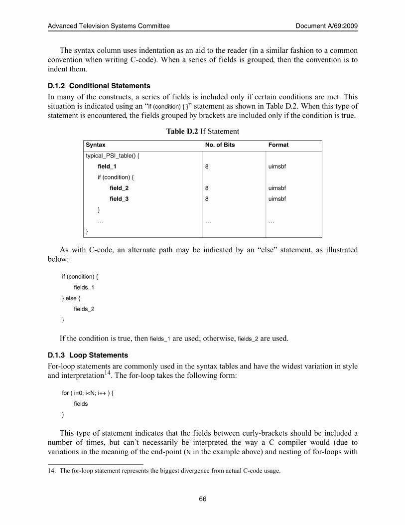
Advanced Television Systems Committee Document A/69:2009
The syntax column uses indentation as an aid to the reader (in a similar fashion to a commonconvention when writing C-code). When a series of fields is grouped, then the convention is toindent them.
D.1.2 Conditional Statements
In many of the constructs, a series of fields is included only if certain conditions are met. Thissituation is indicated using an “if (condition) { }” statement as shown in Table D.2. When this type ofstatement is encountered, the fields grouped by brackets are included only if the condition is true.
As with C-code, an alternate path may be indicated by an “else” statement, as illustratedbelow:
If the condition is true, then fields_1 are used; otherwise, fields_2 are used.
D.1.3 Loop Statements
For-loop statements are commonly used in the syntax tables and have the widest variation in styleand interpretation14. The for-loop takes the following form:
This type of statement indicates that the fields between curly-brackets should be included anumber of times, but can’t necessarily be interpreted the way a C compiler would (due tovariations in the meaning of the end-point (N in the example above) and nesting of for-loops with
Table D.2 If Statement
Syntax No. of Bits Format
typical_PSI_table() {
field_1 8 uimsbf
if (condition) {
field_2 8 uimsbf
field_3 8 uimsbf
}
… … …
}
if (condition) {
fields_1
} else {
fields_2
}
for ( i=0; i<N; i++ ) {
fields
}
14. The for-loop statement represents the biggest divergence from actual C-code usage.
66
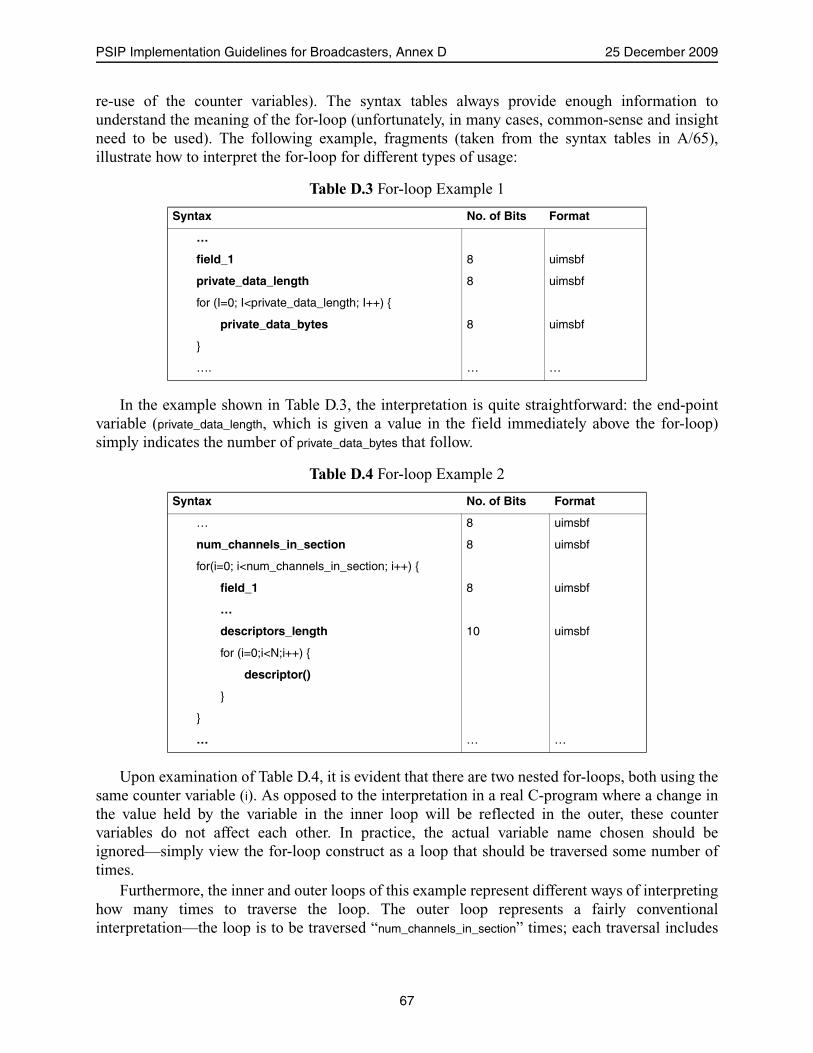
PSIP Implementation Guidelines for Broadcasters, Annex D 25 December 2009
re-use of the counter variables). The syntax tables always provide enough information tounderstand the meaning of the for-loop (unfortunately, in many cases, common-sense and insightneed to be used). The following example, fragments (taken from the syntax tables in A/65),illustrate how to interpret the for-loop for different types of usage:
In the example shown in Table D.3, the interpretation is quite straightforward: the end-pointvariable (private_data_length, which is given a value in the field immediately above the for-loop)simply indicates the number of private_data_bytes that follow.
Upon examination of Table D.4, it is evident that there are two nested for-loops, both using thesame counter variable (i). As opposed to the interpretation in a real C-program where a change inthe value held by the variable in the inner loop will be reflected in the outer, these countervariables do not affect each other. In practice, the actual variable name chosen should beignored—simply view the for-loop construct as a loop that should be traversed some number oftimes.
Furthermore, the inner and outer loops of this example represent different ways of interpretinghow many times to traverse the loop. The outer loop represents a fairly conventionalinterpretation—the loop is to be traversed “num_channels_in_section” times; each traversal includes
Table D.3 For-loop Example 1
Syntax No. of Bits Format
…
field_1 8 uimsbf
private_data_length 8 uimsbf
for (I=0; I<private_data_length; I++) {
private_data_bytes 8 uimsbf
}
…. … …
Table D.4 For-loop Example 2
Syntax No. of Bits Format
… 8 uimsbf
num_channels_in_section 8 uimsbf
for(i=0; i<num_channels_in_section; i++) {
field_1 8 uimsbf
…
descriptors_length 10 uimsbf
for (i=0;i<N;i++) {
descriptor()
}
}
… … …
67
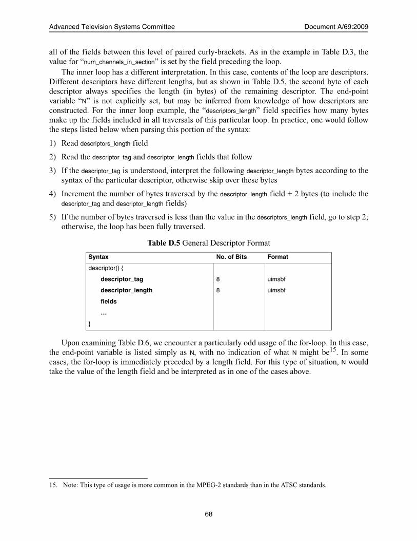
Advanced Television Systems Committee Document A/69:2009
all of the fields between this level of paired curly-brackets. As in the example in Table D.3, thevalue for “num_channels_in_section” is set by the field preceding the loop.
The inner loop has a different interpretation. In this case, contents of the loop are descriptors.Different descriptors have different lengths, but as shown in Table D.5, the second byte of eachdescriptor always specifies the length (in bytes) of the remaining descriptor. The end-pointvariable “N” is not explicitly set, but may be inferred from knowledge of how descriptors areconstructed. For the inner loop example, the “descriptors_length” field specifies how many bytesmake up the fields included in all traversals of this particular loop. In practice, one would followthe steps listed below when parsing this portion of the syntax:
1) Read descriptors_length field
2) Read the descriptor_tag and descriptor_length fields that follow
3) If the descriptor_tag is understood, interpret the following descriptor_length bytes according to thesyntax of the particular descriptor, otherwise skip over these bytes
4) Increment the number of bytes traversed by the descriptor_length field + 2 bytes (to include thedescriptor_tag and descriptor_length fields)
5) If the number of bytes traversed is less than the value in the descriptors_length field, go to step 2;otherwise, the loop has been fully traversed.
Upon examining Table D.6, we encounter a particularly odd usage of the for-loop. In this case,the end-point variable is listed simply as N, with no indication of what N might be15. In somecases, the for-loop is immediately preceded by a length field. For this type of situation, N wouldtake the value of the length field and be interpreted as in one of the cases above.
Table D.5 General Descriptor Format
Syntax No. of Bits Format
descriptor() {
descriptor_tag 8 uimsbf
descriptor_length 8 uimsbf
fields
…
}
15. Note: This type of usage is more common in the MPEG-2 standards than in the ATSC standards.
68
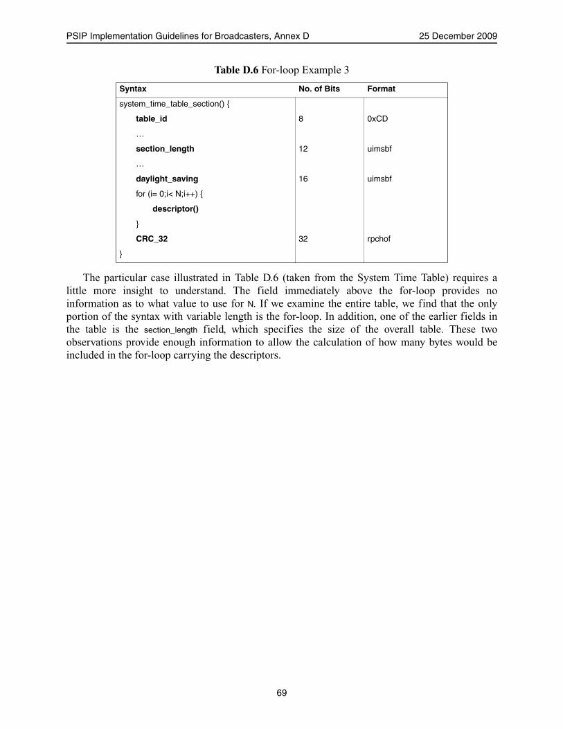
PSIP Implementation Guidelines for Broadcasters, Annex D 25 December 2009
The particular case illustrated in Table D.6 (taken from the System Time Table) requires alittle more insight to understand. The field immediately above the for-loop provides noinformation as to what value to use for N. If we examine the entire table, we find that the onlyportion of the syntax with variable length is the for-loop. In addition, one of the earlier fields inthe table is the section_length field, which specifies the size of the overall table. These twoobservations provide enough information to allow the calculation of how many bytes would beincluded in the for-loop carrying the descriptors.
Table D.6 For-loop Example 3
Syntax No. of Bits Format
system_time_table_section() {
table_id 8 0xCD
…
section_length 12 uimsbf
…
daylight_saving 16 uimsbf
for (i= 0;i< N;i++) {
descriptor()
}
CRC_32 32 rpchof
}
69

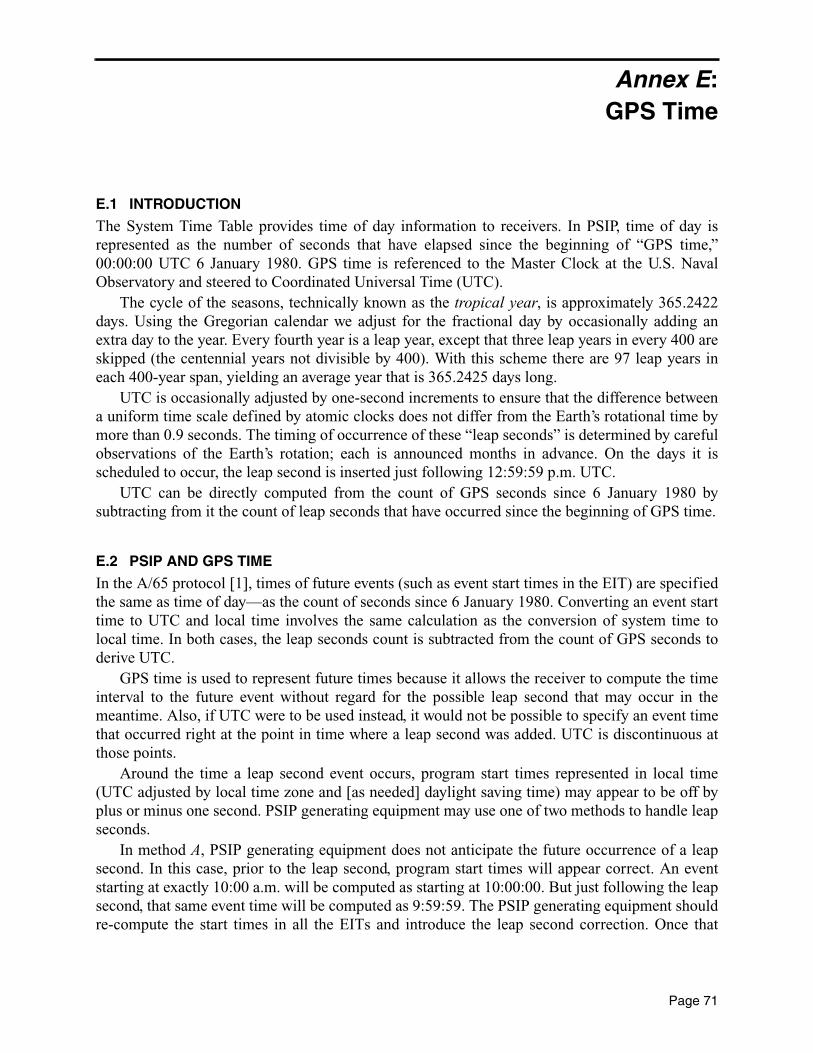
Annex E:GPS Time
E.1 INTRODUCTION
The System Time Table provides time of day information to receivers. In PSIP, time of day isrepresented as the number of seconds that have elapsed since the beginning of “GPS time,”00:00:00 UTC 6 January 1980. GPS time is referenced to the Master Clock at the U.S. NavalObservatory and steered to Coordinated Universal Time (UTC).
The cycle of the seasons, technically known as the tropical year, is approximately 365.2422days. Using the Gregorian calendar we adjust for the fractional day by occasionally adding anextra day to the year. Every fourth year is a leap year, except that three leap years in every 400 areskipped (the centennial years not divisible by 400). With this scheme there are 97 leap years ineach 400-year span, yielding an average year that is 365.2425 days long.
UTC is occasionally adjusted by one-second increments to ensure that the difference betweena uniform time scale defined by atomic clocks does not differ from the Earth’s rotational time bymore than 0.9 seconds. The timing of occurrence of these “leap seconds” is determined by carefulobservations of the Earth’s rotation; each is announced months in advance. On the days it isscheduled to occur, the leap second is inserted just following 12:59:59 p.m. UTC.
UTC can be directly computed from the count of GPS seconds since 6 January 1980 bysubtracting from it the count of leap seconds that have occurred since the beginning of GPS time.
E.2 PSIP AND GPS TIME
In the A/65 protocol [1], times of future events (such as event start times in the EIT) are specifiedthe same as time of day—as the count of seconds since 6 January 1980. Converting an event starttime to UTC and local time involves the same calculation as the conversion of system time tolocal time. In both cases, the leap seconds count is subtracted from the count of GPS seconds toderive UTC.
GPS time is used to represent future times because it allows the receiver to compute the timeinterval to the future event without regard for the possible leap second that may occur in themeantime. Also, if UTC were to be used instead, it would not be possible to specify an event timethat occurred right at the point in time where a leap second was added. UTC is discontinuous atthose points.
Around the time a leap second event occurs, program start times represented in local time(UTC adjusted by local time zone and [as needed] daylight saving time) may appear to be off byplus or minus one second. PSIP generating equipment may use one of two methods to handle leapseconds.
In method A, PSIP generating equipment does not anticipate the future occurrence of a leapsecond. In this case, prior to the leap second, program start times will appear correct. An eventstarting at exactly 10:00 a.m. will be computed as starting at 10:00:00. But just following the leapsecond, that same event time will be computed as 9:59:59. The PSIP generating equipment shouldre-compute the start times in all the EITs and introduce the leap second correction. Once that
Page 71

Advanced Television Systems Committee Document A/69:2009
happens, and receivers have updated their EIT data, the computed time will again show as10:00:00. In this way the disruption can be limited to a matter of seconds.
In method B, PSIP generating equipment does anticipate the occurrence of a leap second, andadjusts program start times for events happening after the new leap second is added. If the leapsecond event is to occur at midnight tonight, an event starting at 10:00 a.m. tomorrow will becomputed by receiving equipment as starting at 10:00:01.
For certain types of events, the precision of method B is necessary. By specifying events usinga time system that involves no discontinuities, difficulties involving leap seconds are avoided.Events such as program start times do not require that level of precision. Therefore, method Aworks well.
E.2.1 An Example
Consider the following example. Times are given relative to UTC, and would be corrected to localtime zone and daylight saving time as necessary.
• Time of day (UTC): 1:00 p.m., 30 December 1998• Event start time (UTC): 2:00 p.m., 2 January 1999• A leap second event will occur just after 12:59:59 p.m. on 31 December 1998• Leap seconds count on 30 December is 12
The data in the System Time message is:• GPS seconds = 599,058,012 = 0x23B4E65C• GPS to UTC offset = 12
Using method A (upcoming leap second event is not accounted for):• Event start time in EIT: 599,320,812 = 0x23B8E8EC• Converted to UTC: 2:00:00 p.m., 2 January 1999• Number of seconds to event: 262,800 = 73 hours, 0 minutes, 0 seconds
Using method B (upcoming leap second event is anticipated):• Event start time in EIT: 599,320,813 = 0x23B8E8ED• Converted to UTC: 2:00:01 p.m., 2 January 1999 • Number of seconds to event: 262,801 = 73 hours, 0 minutes, 1 secondNote that when using method B, the number of seconds to event is correct, and did not need to
be recomputed when the leap seconds count moved from 12 to 13 at year-end.
Note: The leap second count became 15 at the end of 2008.
The current leap second count can be found at http://tf.nist.gov/pubs/bulletin/leapsecond.htm.Further information may be found at http://tycho.usno.navy.mil/leapsec.html.
72

Annex F:NVOD Examples
F.1 INTRODUCTION
The examples within this annex describe an NVOD Base channel with four Child channels. Themost delayed Child channel runs four hours after its Base channel.
F.1.1 NVOD Example #1 Notes
As there are no events that have expired in the base channel, all EIT and ETT entries are the sameas those for an ordinary channel. To find what event starts on channel Delta at 18:00 the steps are:
1) Subtract the channel’s time offset (4 hours) from 18:00, giving 14:00.
2) Calculate which EIT window covers 14:00, giving EIT#0.
3) Look in EIT#0 of the base channel for the event at 14:00, giving event E2.
E1 E2 E3 E4 E5 E6
E1 E2 E3 E4 E5 E6
E1 E2 E3 E4 E5 E6
E1 E2 E3 E4 E5 E6
E1 E2 E3 E4 E5 E6
Child (+1 hr)
EIT#0
Child (+2 hr)
Child (+3 hr)
Child (+4 hr)— Delta
EIT#1 EIT#2 EIT#3 EIT#4 EIT#5 EIT#6
Base Channel
12:00 15:00 18:00 21:00 21:00 21:00 00:00 03:00 06:00 09:00 12:00 15:00 18:00
EIT#7 EIT#8 EIT#9 EIT#10 EIT#11 EIT#12
Five channel NVOD system. The base channel, which contains the time_shifted_service_descriptor() has six two-hour events per day. The child channels are delayed by one, two, three, and four hours respectively.
EIT
EIT#0 E1 E2 EIT#1 E2 E3 EIT#2 E4 E5 EIT#3 E5 E6 EIT#4 EIT#5 EIT#6 EIT#7 EIT#8 V1 V2 EIT#9 V2 V3 EIT#10 V4 V5 EIT#11 V5 V6 EIT#12 V6
Generate EIT now
V1 V2 V3 V4 V5 V6
V1 V2 V3 V4 V5 V6
V1 V2 V3 V4 V5 V6
V1 V2 V3 V4 V5 V6
V1 V2 V3 V4 V5 V6
Figure F.1 NVOD Example #1.
Page 73

Advanced Television Systems Committee Document A/69:2009
F.1.2 NVOD Example #2 Notes
1) E1 has expired on channel Delta (the most delayed child); it is no longer listed in the EIT.
2) E2 and E3 have not expired on channel Delta (although they have expired on the basechannel); they have to be listed in EIT#0.
3) EIT#1 and above are still the same as for a normal channel.
4) To find what event starts on channel Delta at 18:00 the steps are:
• Subtract the channel’s time offset (4 hours) from 18:00, giving 14:00.• Calculate which EIT window covers 14:00, giving EIT#-2 (i.e. minus two). A negative
number is not legal for a window => We must use EIT#0.• Look in EIT#0 of the base channel for the event at 14:00, giving event E2.
E1 E2 E3 E4 E5 E6
E1 E2 E3 E4 E5 E6
E1 E2 E3 E4 E5 E6
E1 E2 E3 E4 E5 E6
E1 E2 E3 E4 E5 E6
Child (+1 hr)
EIT#0
Child (+2 hr)
Child (+3 hr)
Child (+4 hr)—Delta
EIT#1 EIT#2 EIT#3 EIT#4 EIT#5 EIT#6
Base Channel
12:00 15:00 18:00 21:00 21:00 21:00 00:00 03:00 06:00 09:00 12:00 15:00 18:00
EIT#7 EIT#8 EIT#9 EIT#10
Five channel NVOD system.
EIT
EIT#0 E2 E3 E4 E5 EIT#1 E5 E6 EIT#2 EIT#3 EIT#4 EIT#5 EIT#6 V1 V2 EIT#7 V2 V3 EIT#8 V4 V5 EIT#9 V5 V6
EIT#10
Generate EIT now
V1 V2 V3 V4 V5 V6
V1 V2 V3 V4 V5 V6
V1 V2 V3 V4 V5 V6
V1 V2 V3 V4 V5 V6
V1 V2 V3 V4 V5 V6
The base channel, which contains the time_shifted_service_descriptor() has six two-hour events per day. The child channels are delayed by one, two, three, and four hours
Figure F.2 NVOD Example #2.
74
Annex G:Interpretation of MGT Table Version Numbers
G.1 INTRODUCTION
At first glance, it may appear that the Master Guide Table (MGT) simply provides the versionnumbers for the table sections that make up the EIT/ETT tables for each timeslot. For example,the MGT may indicate a table_type_version_number of 5 for a table_type value of 0x0100 (EIT-0),which could lead one to say “EIT-0 is at version 5.” In fact, the MGT does give table versioninformation for all transmitted tables, but a careful and correct interpretation of the data provided,including table_type_PID, is required to be made to avoid errors in processing.
The proper interpretation of table_type_version_number is to consider it to reflect theversion_number field in the referenced table. In accordance with MPEG-2 Systems, the scope oftable version_number is limited to table sections delivered in transport packets with a common PIDvalue. For example, among table sections with a given value of table_ID, a table section delivered intransport packets with PID value 0x1E00 and version_number 6 is required to be interpreted as aseparate and distinct table from a table section delivered in transport packets with PID value0x1E01 and version_number 6.
The following example is designed to illustrate the distinction between the simple (incorrect)interpretation and the correct one. In the illustration, the incorrect interpretation leads toprocessing errors, which involve re-loading tables that have not in fact changed, or (moreseriously) not updating tables that have changed.
G.1.1 Examples
For the following example, the time zone offset is 0. Each EIT table instance is associated with aseparate PID (as per A/65 [1] rules):
1) Assume that it is noon. From noon to 3:00 p.m. the following is true:
a) The EIT describing noon to 3:00 p.m. is in PID16 0x1000; version number is 0
b) The EIT describing 3:00 p.m. to 6:00 p.m. is in PID 0x1001; version number is 1
c) The EIT describing 6:00 p.m. to 9:00 p.m. is in PID 0x1002; version number is 0
d) The EIT describing 9:00 p.m. to midnight is in PID 0x1003; version number is 0
e) The MGT is at version 7 and indicates:
• EIT-0, PID 0x1000, version number 0• EIT-1, PID 0x1001, version number 1• EIT-2, PID 0x1002, version number 0• EIT-3, PID 0x1003, version number 0
16. The expression “in PID” as used here is a shorthand way of saying that the indicated table section is “carried intransport packets with a PID value equal to” the indicated value.
Page 75

Advanced Television Systems Committee Document A/69:2009
2) The time moves to 3:00 p.m., crossing a timeslot boundary. Assume that the EIT describing6:00 p.m. to 9:00 p.m. is changed now too.
a) The EIT for noon to 3:00 p.m. is no longer sent, since its time has passed
b) The EIT for 3:00 p.m. to 6:00 p.m. is still in PID 0x1001; version number is still 1
c) The EIT for 6:00 p.m. to 9:00 p.m. is still in PID 0x1002; version number is moved to 1
d) The EIT for 9:00 p.m. to midnight is still in PID 0x1003; version number is still 0
e) MGT moves to version 8 and indicates:
• EIT-0, PID 0x1001, version number 1• EIT-1, PID 0x1002, version number 1• EIT-2, PID 0x1003, version number 0
f) What is now EIT-0 did not change. What is now EIT-1 did change.
For this case, if the MGT is interpreted to give the version numbers of EIT-n for each value ofn, the receiver will see the version of EIT-0 change from 0 to one and refresh it. It will decide theversion of EIT-1 has not changed, and not refresh it. But both inferences are incorrect: in thisexample, EIT-0 has not changed, and EIT-1 has changed.
The correct interpretation involves processing version numbers with respect to the associatedPID values. Looking at the same example, the MGT indicates that the table associated with PID0x1001 did not change versions. Likewise, the table associated with PID value 0x1002 changedfrom version 0 to 1 and should be refreshed.
76

Annex H:Use of Analog Transmission Signal ID
H.1 INTRODUCTION
The Virtual Channel Table in PSIP associates a user-friendly definition of a service (a channelname and number) with the physical location of that service. Both digital and analog services areaccommodated. For digital services, the Transport Stream ID (TSID) parameter defined in ISO/IEC 13818-1 (MPEG-2 Systems) is used as a unique identifier at the TS level. For analogservices, an identifier called the Transmission Signal ID (the acronym is also TSID) may be used.
The analog TSID, like its digital counterpart, is a 16-bit number that uniquely identifies theNTSC signal within which it is carried. CEA-608 [11] Section 9.5.3.4 defines the data format forcarriage of the Transmission Signal ID within eXtended Data Service (XDS) packets in the NTSCVertical Blanking Interval.
In the U.S., the system is designed with the expectation that the analog TSID will be includedin any NTSC broadcast signal referenced by PSIP data. Whenever PSIP data provides a referenceto an analog service, the receiver is expected to use that service’s analog TSID to make a positiveidentification. The receiver is expected to not associate any channel or program information datawith an NTSC service that does not broadcast its analog TSID. As NTSC is being phased out inthe U.S., the use of this capability will diminish toward zero over time.
Page 77

Annex I:Use of Component Name Descriptor
I.1 OVERVIEW
The component_name_descriptor() provides a mechanism to associate a multilingual textual label withan Elementary Stream component of any MPEG-2 program. If the program consists of one videostream and one audio track, such a label would not add much value. A program may be offeredmultilingually, for example with separate French and English tracks. In that case, a receivingdevice may choose, without need for user intervention, the track corresponding to the language setup as the user’s preferred language.
It may be, however, that the service happens to have two English-language audio tracks. Inanother case, one or more of the audio tracks may not be associated with a spoken language. Anexample of such a track, sometimes called “clean effects,” is ambient sound such as crowd noisefrom a sporting event. In both of these cases, use of the component_name_descriptor() is mandatory bythe rules established in the PSIP Standard. The net result is that a display device will always havesufficient information to either choose an audio track by its language, or will have text describingeach track that can be used to create an on-screen user dialog to facilitate the user’s choice.
Page 79

Annex J:Sources of PSIP Information for the DTV Station
J.1 PREFACE
It is important to note that this is not the only possible scenario for introduction of PSIPinformation into a PSIP generator and that there may be sources of PSIP information not detailedhere.
J.2 OVERVIEW
Just as there are many possible sources of programming for a DTV station, there are manypossible methods of supplying PSIP information to the DTV station PSIP generator. There arehowever two simple paths. Data may be entered into the PSIP generator manually via a keyboard.This keyboard may be attached to the PSIP generator directly or to a PC-like device that is—inturn—connected to the PSIP generator.
In a similar fashion the PSIP generator may be connected in some fashion to one of the manysystems that contain schedule information relevant to the station: listing services, traffic systems,program management systems, and/or automation systems. Each of these systems can becharacterized as having different depths of information about the current scheduling, as well asdifferent degrees of accuracy concerning event details (such as start time, duration, ratings, etc.).The PSIP generator may accept schedule information from one or more of these sources. In thecase where there are multiple sources, it is recommended to prioritize the information sources.Information may be obtained by polling the source at periodic intervals (pull) or by having theinformation source send updates when available (push).
If the programming is part of a continuous DTV stream from a network or syndication source,then this source may include in the stream properly formatted PSIP tables at reasonable intervals.The PSIP generator (or some ancillary input device to it) should then extract from this stream thePSIP data that is relevant for the current emission. Note that a station may be fed by more than oneof these DTV sources, which might not be an MPEG-2 Transport Stream.
Standardized protocols have been developed for exchange of PSIP information:• Programming Metadata Communication Protocol (PMCP), defined in ATSC A/76 [10]• BXF, as defined in SMPTE 2021 [12]
Note that the SMPTE BXF standard references PMCP for some of its functionality. There are alsoproprietary interfaces and protocols in use.
Page 81


Annex K:Coding of the Rating Region Table
K.1 INTRODUCTION
There may be some confusion caused by the semantics for abbrev_rating_value_text andrating_value_text, whether an explicit (verbose) coding of the null string is required or if a shorterrepresentation is acceptable.
The verbose method requires 20 bytes to describe abbrev_rating_value and rating_value text strings“”. The short method requires 2 bytes. These two strings with “” value are repeated for each of the8 defined dimensions of rating region 1. Using the short method can save over 100 bytes over theverbose method.
The ANSI/CEA-766 [13] constraint of compression_type = 0 was placed to reduce thecomplexity of receiver implementations.
K.1.1 Excerpt of RRT Section
Tables K.1 and K.2 compare the verbose and the simplified methods.
Table K.1 Verbose Coding Method
Syntax No. of Bits Value
…
values_defined 4
for (j=0; j<values_defined; j++) {
abbrev_rating_value_length 8 0x08
abbrev_rating_value_text() {
number_strings 8 0x01
for (i= 0; i< number_strings; i++) {
ISO_639_language_code 8*3 ‘eng’
number_segments 8 0x01
for (j=0; j<number_segments; j++){
compression_type 8 0x00
mode 8 0x00
number_bytes 8 0x01
for (k= 0; k<number_bytes; k++)
compressed_string_byte [k] 8 0x00
}
}
}
rating_value_length 8 0x08
rating_value_text() {
Page 83
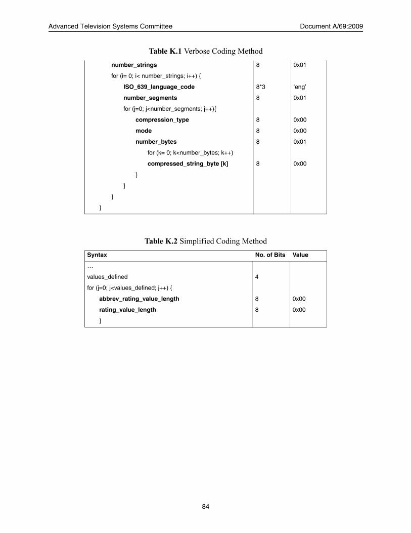
Advanced Television Systems Committee Document A/69:2009
number_strings 8 0x01
for (i= 0; i< number_strings; i++) {
ISO_639_language_code 8*3 ‘eng’
number_segments 8 0x01
for (j=0; j<number_segments; j++){
compression_type 8 0x00
mode 8 0x00
number_bytes 8 0x01
for (k= 0; k<number_bytes; k++)
compressed_string_byte [k] 8 0x00
}
}
}
}
Table K.2 Simplified Coding Method
Syntax No. of Bits Value
…
values_defined 4
for (j=0; j<values_defined; j++) {
abbrev_rating_value_length 8 0x00
rating_value_length 8 0x00
}
Table K.1 Verbose Coding Method
84

Annex L:An Overview of Directed Channel Change
L.1 INTRODUCTION
The PSIP Standard established a forward-looking capability to dynamically allocate content at thereceiver. Deployment requires access to alternative program stream, and receiver support. Thisadvanced synergistic capability requires resource allocations by both broadcasters and receivermanufacturers, and while some broadcast products support the capability, only limitedexperimentation has occurred as of this update.
A Directed Channel Change request is a trigger event sent within the PSIP stream of the DTVmultiplex that will cause a “DCC-capable DTV reference receiver” (DCCRR) to select a differentvirtual channel from that to which it is already tuned. Depending upon the kind of DCC request,the change to a different virtual channel can occur without intervention by the viewer, if theviewer has enabled the capability by providing required information during a setup process orduring operation of the display. Alternatively, the change can take place under direct control of theviewer, for instance using a remote control device.
To enable the automatic carrying out of a DCC request within a DCCRR, the DTV viewer willbe required to provide information to the display system. This may be accomplished through aninteractive setup session or may be done during operation of the receiver, as different viewingoptions become available. The information provided by the viewer to the DCCRR will permit theunit to determine which, if any, alternate virtual channel the DCCRR should display upon receiptof a DCC request. This selection will take place through the DCCRR matching the viewerinformation with categorization information or other selection criteria sent by the broadcaster orsystem operator. There are also forms of DCC request that enable real time viewer selectionsamong alternate program streams, such as, for example, alternate camera views of a sportingevent.
L.2 DCC SWITCH CRITERIA
A switch from a currently viewed virtual channel to another virtual channel may be accomplishedupon occurrence of any of the following selection criteria, some of which may be used incombination:
• Unconditional switch17
• Postal code, zip code17, or location code• Program Identifier17
• Demographic category• Content subject category• Authorization level• Content advisory value
17. Items required within a DTV device providing minimal support for Directed Channel Change as defined by the“reference receiver” (DCCRR) specification in A/65.
Page 85

Advanced Television Systems Committee Document A/69:2009
• One of eight user categories17
In addition to the criteria listed above that serve to include groups of viewers into a DCCrequest, several of the criteria may also be used to exclude viewers from inclusion in a request. Forexample, instead of listing many zip codes for inclusion of viewers in a DCC request, the inverselogic may be used to specify the group of all viewers not included within a group of zip codes.
Two other DCC request actions have also been defined: an action to be taken upon a viewerswitching away from a channel, and an action to be taken upon a viewer switching into a channel.
The broadcaster may specify more than one type of selection criteria within a single DCCrequest. For example, it is possible to specify several individual zip codes by employing the loopstructure within the DCC Table.
L.2.1 Unconditional Switch
An unconditional switch would cause all viewers’ channel, regardless of any other DCC selectioncriteria selected within the DCCRR, to switch to a specified virtual channel. A potential use ofthis criterion would be to aggregate viewers on different virtual channels to a single channel.
L.2.2 Postal Code, Zip Code, or Location Code
A channel change based upon the viewer’s location may be accomplished by using one or more ofthese location-based criteria. Broadcasters may use these capabilities to provide targetedprogramming based upon a viewer’s location within the viewing area. Note that the location_code
field currently is defined only for U.S. geographic entities.
L.2.3 Program Identifier
A channel change based upon a program’s episode and version number may be accomplished withthis criteria. Use of this function would permit a broadcaster to direct a viewer’s attention to abroadcast of a particular program having a certain episode and version number. If the viewer hadpreviously enabled a function within the DCCRR that would “remember” a particular program’sepisode/version number, the viewer could be directed to that program again upon detection of thiscriteria within the multiplex.
L.2.4 Demographic Category
A Directed Channel Change may be accomplished using demographic categories as a switchingcriterion. Demographics such as age group and gender can be selected.
L.2.5 Content Subject Category
A channel change based upon the subject matter of the content of the program can beaccomplished. Nearly 140 categories of subject matter have been tabulated that can be assigned todescribe the content of a program. A broadcaster may use this category of DCC request switchingto direct a viewer to a program based upon the viewer’s desire to receive content of that subjectmatter. Although nearly 140 subject categories have been identified for inclusion in the currentversion of the specification, additional categories may be determined in the future and may betransmitted to the DCCRR through a table revision mechanism (the Directed Channel ChangeSelection Code Table).
86

PSIP Implementation Guidelines for Broadcasters, Annex L 25 December 2009
L.2.6 Authorization Level
A channel change may be accomplished using this mechanism in the event that the viewerattempts to switch to a virtual channel that he or she is not authorized to view. This category ofDCC would permit the DCCRR to be directed to an alternative channel (such as a “barker”channel informing the viewer of ineligibility to view the channel) instead of the channel theviewer attempted to tune.
L.2.7 Content Advisory Level
This category of DCC is similar to that described in the preceding section (Authorization Level)but would redirect the viewer to another channel based on the content advisory level in theDCCRR.
L.2.8 User Specified Category
This category of DCC would allow a broadcaster to specify one of eight classifications of aprogram so that if a viewer pressed one of eight “viewer-direct-select” buttons on a remotecontrol, he or she would be directed to a virtual channel airing a program having thatclassification. This function would permit a broadcaster to define classifications not anticipatedby this standard and then permit the viewer to be directed to programs or segments having thoseclassifications.
L.2.9 Arriving/Departing Request
Two additional Directed Channel Change request actions are specified:• A Departing Request descriptor may be used within a DCC signal the occurrence of a
departing request or to cause a text box to appear for a definable amount of time prior toperforming a channel change requested by the viewer. The text box may be used by thebroadcaster to present information to the viewer, such as plot elements remaining in theprogram or upcoming segment schedule information.
• An Arriving Request descriptor may be used to signal the occurrences of an arrivingrequest or cause a text box to appear for a definable amount of time upon arrival at a newlytuned virtual channel. For example, the text box may be used by the broadcaster to conveystory line information up to this point in time, or even program schedule change orpreemption information such as a program delayed announcement due to the previous orcurrent program running long.
L.3 DOWNLOADABLE SELECTION CODE TABLE
Through an optional downloadable table mechanism called the Directed Channel ChangeSelection Code Table, updated information may be delivered to DCC-capable DTV referencereceivers over the broadcast link.
87

Advanced Television Systems Committee, Inc.1776 K Street, N.W., Suite 200
Washington, D.C. 20006